editorial team
editorial team
editorial team

Create successful ePaper yourself
Turn your PDF publications into a flip-book with our unique Google optimized e-Paper software.
Bennajah, Maalmi, Darmane and Touhami<br />
39<br />
Table 1. Water properties<br />
Properties<br />
pH<br />
Alkalinity (◦f)<br />
Total hardness (◦f)<br />
Turbidity (NTU)<br />
Conductivity (µS)<br />
Chloride [Cl − ] (mg L -1 )<br />
Values<br />
7.85<br />
15<br />
35<br />
0.15<br />
1600 (20°C)<br />
400<br />
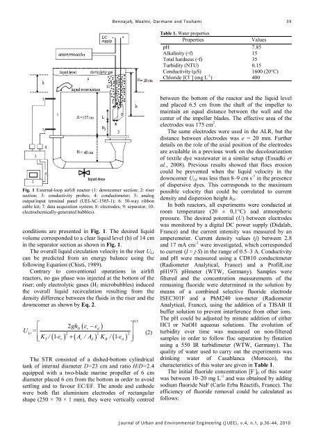
Fig. 1 External-loop airlift reactor (1: downcomer section; 2: riser<br />
section; 3: conductivity probes; 4: conductimeter; 5: analog<br />
output/input terminal panel (UEI-AC-1585-1); 6: 50-way ribbon<br />
cable kit; 7: data acquisition system; 8: electrodes; 9: separator; 10:<br />
electrochemically-generated bubbles).<br />
conditions are presented in Fig. 1. The desired liquid<br />
volume corresponded to a clear liquid level (h) of 14 cm<br />
in the separator section as shown in Fig. 1.<br />
The overall liquid circulation velocity in the riser U Lr<br />
can be predicted from an energy balance using the<br />
following Equation (Chisti, 1989).<br />
Contrary to conventional operations in airlift<br />
reactors, no gas phase was injected at the bottom of the<br />
riser; only electrolytic gases (H 2 microbubbles) induced<br />
the overall liquid recirculation resulting from the<br />
density difference between the fluids in the riser and the<br />
downcomer as shown by Eq. 2.<br />
⎡<br />
2ghD ( εr − εd<br />
)<br />
( 1 ) + ( ) ( 1 )<br />
U<br />
Lr= ⎢<br />
2 2 2<br />
⎢ K<br />
T / -ε<br />
r A<br />
r / A<br />
d K<br />
B / -ε<br />
d<br />
⎣<br />
⎤<br />
⎥<br />
⎥⎦<br />
05 .<br />
(2)<br />
The STR consisted of a dished-bottom cylindrical<br />
tank of internal diameter D=23 cm and ratio H/D=2.4<br />
equipped with a two-blade marine propeller of 6 cm<br />
diameter placed 6 cm from the bottom in order to avoid<br />
settling and to favour EC/EF. The anode and cathode<br />
were both flat aluminium electrodes of rectangular<br />
shape (250 × 70 × 1 mm), they were vertically centred<br />
between the bottom of the reactor and the liquid level<br />
and placed 6.5 cm from the shaft of the impeller to<br />
maintain an equal distance between the wall and the<br />
center of the impeller blades. The effective area of the<br />
electrodes was 175 cm 2 .<br />
The same electrodes were used in the ALR, but the<br />
distance between electrodes was e = 20 mm. Further<br />
details on the role of the axial position of the electrodes<br />
are available in a previous work on the decolourization<br />
of textile dye wastewater in a similar setup (Essadki et<br />
al., 2008). Previous results showed that flocs erosion<br />
could be prevented when the liquid velocity in the<br />
downcomer U Ld was less than 8–9 cm s -1 in the presence<br />
of dispersive dyes. This corresponds to the maximum<br />
possible velocity that could be correlated to current<br />
density and dispersion height h D .<br />
In both reactors, all experiments were conducted at<br />
room temperature (20 ± 0,1°C) and atmospheric<br />
pressure. The desired potential (U) between electrodes<br />
was monitored by a digital DC power supply (Didalab,<br />
France) and the current intensity was measured by an<br />
amperemeter. Current density values (j) between 2.8<br />
and 17 mA cm -2 were investigated, which corresponded<br />
to current (I = j·S) in the range of 0.5–3 A. Conductivity<br />
and pH were measured using a CD810 conductimeter<br />
(Radiometer Analytical, France) and a ProfilLine<br />
pH197i pHmeter (WTW, Germany). Samples were<br />
filtered and the concentration measurements of the<br />
remaining fluoride were determined in the solution by<br />
means of a combined selective fluoride electrode<br />
ISEC301F and a PhM240 ion-meter (Radiometer<br />
Analytical, France), using the addition of a TISAB II<br />
buffer solution to prevent interference from other ions.<br />
The pH could be adjusted by minute addition of either<br />
HCl or NaOH aqueous solutions. The evolution of<br />
turbidity over time was measured on non-filtered<br />
samples in order to follow floc separation by flotation<br />
using a 550 IR turbidimeter (WTW, Germany). The<br />
quality of water used to carry out the experiments was<br />
drinking water of Casablanca (Morocco), the<br />
characteristics of this water are given in Table 1.<br />
The initial fluoride concentration [F - ] 0 of this water<br />
was between 10–20 mg L -1 and was obtained by adding<br />
sodium fluoride NaF (Carlo Erba Réactifs, France). The<br />
efficiency of fluoride removal could be calculated as<br />
follows:<br />
Journal of Urban and Environmental Engineering (JUEE), v.4, n.1, p.36-44, 2010