Platform Cable USB 2 JTAG (for Xilinx)
Platform Cable USB 2 JTAG (for Xilinx)
Platform Cable USB 2 JTAG (for Xilinx)

You also want an ePaper? Increase the reach of your titles
YUMPU automatically turns print PDFs into web optimized ePapers that Google loves.
CERTIFIED<br />
R<br />
0<br />
R<br />
<strong>Plat<strong>for</strong>m</strong> <strong>Cable</strong> <strong>USB</strong><br />
DS300 (v3.0) March 2, 2007 0 0 Product Specification<br />
Features<br />
<strong>Plat<strong>for</strong>m</strong> <strong>Cable</strong> <strong>USB</strong> has these features:<br />
• Supported on Windows and Red Hat Enterprise Linux<br />
• Automatically senses and adapts to target I/O voltage<br />
• Interfaces to devices operating at 5V (TTL), 3.3V<br />
(LVCMOS), 2.5V, 1.8V, and 1.5V<br />
• LED Status Indicator<br />
• CE, <strong>USB</strong>-IF, and FCC compliant<br />
• Intended <strong>for</strong> development — not recommended <strong>for</strong><br />
production programming<br />
• Pb-free (RoHS-compliant)<br />
• Configures all <strong>Xilinx</strong> devices<br />
♦<br />
♦<br />
♦<br />
♦<br />
♦<br />
♦<br />
All Virtex FPGA families<br />
All Spartan FPGA families<br />
XC9500 / XC9500XL / XC9500XV CPLDs<br />
CoolRunner XPLA3 / CoolRunner-II CPLDs<br />
XC18V00 ISP PROMs<br />
XCF00S / XCF00P <strong>Plat<strong>for</strong>m</strong> Flash PROMs<br />
♦ XC4000 series FPGAs<br />
• Programs serial peripheral interface (SPI) flash<br />
PROMs<br />
<strong>Plat<strong>for</strong>m</strong> <strong>Cable</strong> <strong>USB</strong> Description<br />
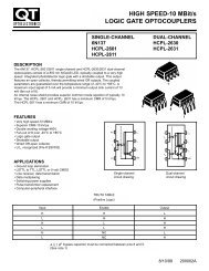
<strong>Plat<strong>for</strong>m</strong> <strong>Cable</strong> <strong>USB</strong> (Figure 1) is a high-per<strong>for</strong>mance<br />
download cable attaching to user hardware <strong>for</strong> the purpose of<br />
programming or configuring any of the following <strong>Xilinx</strong> devices:<br />
• ISP Configuration PROMs<br />
• CPLDs<br />
• FPGAs<br />
<strong>Plat<strong>for</strong>m</strong> <strong>Cable</strong> <strong>USB</strong> attaches to the <strong>USB</strong> port on a desktop<br />
or laptop PC with an off-the-shelf Hi-Speed <strong>USB</strong> A-B cable.<br />
It derives all operating power from the hub port controller.<br />
No external power supply is required. A sustained<br />
slave-serial FPGA configuration transfer rate of 24 Mb/s is<br />
possible in a Hi-Speed <strong>USB</strong> environment. Actual transfer<br />
rates can vary if bandwidth of the hub is being shared with<br />
other <strong>USB</strong> peripheral devices.<br />
Device configuration and programming operations using<br />
<strong>Plat<strong>for</strong>m</strong> <strong>Cable</strong> <strong>USB</strong> are supported by iMPACT download<br />
software using boundary-scan (IEEE 1149.1 / IEEE 1532),<br />
slave-serial mode, or serial peripheral interface (SPI). Target<br />
clock speeds are selectable from 750 kHz to 24 MHz.<br />
<strong>Plat<strong>for</strong>m</strong> <strong>Cable</strong> <strong>USB</strong> attaches to target systems using a<br />
14-conductor ribbon cable designed <strong>for</strong> high-bandwidth data<br />
transfers. An optional adapter that allows attachment of a<br />
flying lead set is included <strong>for</strong> backward compatibility with<br />
target systems that do not use the ribbon cable connector.<br />
Physical Description<br />
The <strong>Plat<strong>for</strong>m</strong> <strong>Cable</strong> <strong>USB</strong> electronics are housed in a<br />
recyclable, fire-retardant plastic case (Figure 2). An internal<br />
EMI shield attenuates internally generated emissions and<br />
protects against susceptibility to radiated emissions.<br />
Top View<br />
Side View<br />
1.00<br />
Figure 1: <strong>Xilinx</strong> <strong>Plat<strong>for</strong>m</strong> <strong>Cable</strong> <strong>USB</strong><br />
RoHS<br />
Compliant<br />
HI-SPEED<br />
<strong>USB</strong><br />
<strong>Plat<strong>for</strong>m</strong> <strong>Cable</strong> <strong>USB</strong><br />
Model DLC9G<br />
Power 5V 0.07A<br />
Serial UHG - 1 2 3 4 5<br />
Made in U.S.A.<br />
All dimensions are in inches.<br />
4.55<br />
2mm<br />
CONNECTOR<br />
SIGNALS<br />
STATUS<br />
DS300_01_081006<br />
ds300_02_081006<br />
Figure 2: Plastic Case Physical Dimensions<br />
<strong>JTAG</strong><br />
----<br />
----<br />
TDI<br />
TDO<br />
TCK<br />
TMS<br />
Vref<br />
or Serial<br />
INIT<br />
----<br />
DIN<br />
DONE<br />
CCLK<br />
PROG<br />
Vref<br />
Gnd<br />
1.5 < Vref < 5.0 VDC<br />
0.65<br />
2.10<br />
© 2004–2007 <strong>Xilinx</strong>, Inc. All rights reserved. All <strong>Xilinx</strong> trademarks, registered trademarks, patents, and disclaimers are as listed at http://www.xilinx.com/legal.htm.<br />
PowerPC is a trademark of IBM, Inc. All other trademarks are the property of their respective owners. All specifications are subject to change without notice.<br />
DS300 (v3.0) March 2, 2007 www.xilinx.com PN 0010989 01<br />
Product Specification 1
R<br />
<strong>Plat<strong>for</strong>m</strong> <strong>Cable</strong> <strong>USB</strong><br />
Operation<br />
This section describes how to connect and use <strong>Plat<strong>for</strong>m</strong><br />
<strong>Cable</strong> <strong>USB</strong>.<br />
Minimum Host Computer Requirements<br />
The host computer must contain a <strong>USB</strong> Host Controller with<br />
one or more <strong>USB</strong> ports. The controller can reside on the PC<br />
motherboard, or can be added using a PCI expansion card<br />
or PCMCIA card.<br />
<strong>Plat<strong>for</strong>m</strong> <strong>Cable</strong> <strong>USB</strong> is supported on systems that meet the<br />
<strong>Xilinx</strong> ISE system requirements. For environmental<br />
details, go to:<br />
http://www.xilinx.com/products/design_resources/<br />
design_tool/index.htm<br />
and select the ISE tool of choice. <strong>Plat<strong>for</strong>m</strong> <strong>Cable</strong> <strong>USB</strong> is<br />
designed to take full advantage of the bandwidth of <strong>USB</strong> 2.0<br />
ports, but it is also backward-compatible with <strong>USB</strong> 1.1 ports.<br />
Refer to "Hub Types and <strong>Cable</strong> Per<strong>for</strong>mance," page 15 <strong>for</strong><br />
additional in<strong>for</strong>mation on connection environments and<br />
bandwidth.<br />
Operating Power<br />
<strong>Plat<strong>for</strong>m</strong> <strong>Cable</strong> <strong>USB</strong> is a bus-powered device that draws<br />
less than 100 mA from the host <strong>USB</strong> port under all<br />
operating conditions, automatically adapting to the<br />
capabilities of the host <strong>USB</strong> port to achieve the highest<br />
possible per<strong>for</strong>mance.<br />
<strong>Plat<strong>for</strong>m</strong> <strong>Cable</strong> <strong>USB</strong> enumerates on any <strong>USB</strong> port type (<strong>for</strong><br />
example, <strong>USB</strong> ports on root hubs, external bus-powered<br />
hubs, or external self-powered hubs), including legacy <strong>USB</strong><br />
1.1 hubs. However, per<strong>for</strong>mance is not optimal when<br />
attached to <strong>USB</strong> 1.1 hubs (refer to "Hot Plug and Play,"<br />
page 4 <strong>for</strong> an explanation of <strong>USB</strong> enumeration.).<br />
Note: The DLC9G and legacy DLC9LP cable models draw less<br />
than 100 mA from the host <strong>USB</strong> port. The legacy DLC9 cable<br />
model requires 230 mA to operate in <strong>USB</strong> 2.0 Hi-Speed mode or<br />
150 mA to operate in <strong>USB</strong> 2.0/1.1 full-speed mode. Some older<br />
root hubs or external bus-powered hubs might restrict devices to<br />
100 mA. The legacy DLC9 cable model does not enumerate on<br />
hubs with the 100 mA restriction.<br />
Firmware Updates<br />
<strong>Plat<strong>for</strong>m</strong> <strong>Cable</strong> <strong>USB</strong> is a RAM-based product. Application<br />
code is downloaded each time the cable is detected by the<br />
host operating system. <strong>USB</strong> protocol guarantees that the<br />
code is successfully downloaded.<br />
All files necessary <strong>for</strong> successful cable communication are<br />
included with every <strong>Xilinx</strong> ISE software installation CD.<br />
Revised application code is periodically distributed in<br />
subsequent software releases. ISE Service Pack and<br />
WebPACK releases can be downloaded from<br />
www.xilinx.com. Project Navigator automatically checks <strong>for</strong><br />
new releases when an Internet connection is detected.<br />
When <strong>Xilinx</strong> applications are invoked and a connection is<br />
established with <strong>Plat<strong>for</strong>m</strong> <strong>Cable</strong> <strong>USB</strong>, version in<strong>for</strong>mation <strong>for</strong><br />
several software components is displayed in a command log.<br />
<strong>Plat<strong>for</strong>m</strong> <strong>Cable</strong> <strong>USB</strong> also contains an embedded in-circuit<br />
programmable CPLD. Each time a <strong>Xilinx</strong> application is<br />
invoked, the firmware version <strong>for</strong> the CPLD is examined.<br />
The CPLD is automatically reprogrammed over the cable if<br />
the firmware version is out of date (see Figure 3).<br />
Although a rare event, when CPLD reprogramming is<br />
necessary, the CPLD reprogramming process can take<br />
considerable time and must not be interrupted once started.<br />
The reprogramming time via a <strong>USB</strong> 2.0 port can typically<br />
take 10 to 15 minutes. Reprogramming time varies<br />
depending on the ISE software version, the type of <strong>USB</strong><br />
port, and the per<strong>for</strong>mance of the host system. Later<br />
versions of the ISE software can reprogram CPLDs faster<br />
than older versions.<br />
During a CPLD update, the Status LED illuminates red, and<br />
a progress bar indicates communication activity (see<br />
Figure 4). CPLD updates should never be interrupted. When<br />
an update is complete, the Status LED returns to either<br />
amber or green, and the cable is ready <strong>for</strong> normal operation.<br />
Device Driver Installation<br />
A proprietary device driver is required to use <strong>Plat<strong>for</strong>m</strong> <strong>Cable</strong><br />
<strong>USB</strong>. <strong>Xilinx</strong> ISE software releases and service packs<br />
incorporate this device driver beginning with version 6.3.03i<br />
<strong>for</strong> the Windows operating system or 7.1i <strong>for</strong> the Linux<br />
operating system. <strong>Plat<strong>for</strong>m</strong> <strong>Cable</strong> <strong>USB</strong> is not recognized by<br />
the operating system until an appropriate <strong>Xilinx</strong> ISE,<br />
ChipScope Pro or <strong>Plat<strong>for</strong>m</strong> Studio (EDK) software<br />
installation has been completed.<br />
Refer to UG344, <strong>USB</strong> <strong>Cable</strong> Installation Guide, <strong>for</strong> a<br />
complete guide to installation of the <strong>Plat<strong>for</strong>m</strong> <strong>Cable</strong> <strong>USB</strong><br />
and its device drivers.<br />
Figure 3: CPLD Update Notification<br />
DS300_03_112504<br />
DS300 (v3.0) March 2, 2007 www.xilinx.com PN 0010989 01<br />
Product Specification 2
R<br />
<strong>Plat<strong>for</strong>m</strong> <strong>Cable</strong> <strong>USB</strong><br />
Found New Hardware Wizard<br />
(<strong>for</strong> Windows Only)<br />
<strong>Plat<strong>for</strong>m</strong> <strong>Cable</strong> <strong>USB</strong> should be disconnected from the host<br />
system during the initial software installation. The first time<br />
a cable is attached after software installation, Windows<br />
invokes the Found New Hardware wizard and registers<br />
device drivers <strong>for</strong> the <strong>Plat<strong>for</strong>m</strong> <strong>Cable</strong> <strong>USB</strong> Firmware Loader<br />
(see Figure 5) and <strong>for</strong> the <strong>Plat<strong>for</strong>m</strong> <strong>Cable</strong> <strong>USB</strong> itself (see<br />
Figure 6).<br />
Windows invokes the Found New Hardware flow each time<br />
<strong>Plat<strong>for</strong>m</strong> <strong>Cable</strong> <strong>USB</strong> is plugged into a different physical <strong>USB</strong><br />
port <strong>for</strong> the first time. The wizard screens could be slightly<br />
different <strong>for</strong> Windows 2000 environments.<br />
Figure 4: CPLD Update Progress Bar<br />
DS300_04_110604<br />
Figure 5: a) Firmware Loader PID Detected; b) Firmware Loader Driver Registered<br />
ds300_05_112904<br />
Figure 6: a) Application PID Detected; b) Application Driver Registered<br />
ds300_06_112904<br />
DS300 (v3.0) March 2, 2007 www.xilinx.com PN 0010989 01<br />
Product Specification 3
R<br />
<strong>Plat<strong>for</strong>m</strong> <strong>Cable</strong> <strong>USB</strong><br />
Hot Plug and Play<br />
The cable can be attached and removed from the host<br />
computer without the need to power-down or reboot. There<br />
is a momentary delay after connecting the cable to an<br />
available port be<strong>for</strong>e the Status LED illuminates. This<br />
process is called enumeration.<br />
When <strong>Plat<strong>for</strong>m</strong> <strong>Cable</strong> <strong>USB</strong> completes the enumeration<br />
process on a Windows system, a "Programming cables" entry<br />
appears in the Windows Device Manager (see Figure 7). To<br />
display Device Manager, right-click on My Computer, then<br />
select Properties → Hardware → Device Manager.<br />
DS300_08_110604<br />
Figure 8: iMPACT <strong>Cable</strong> Selection Drop-Down Menu<br />
DS300_07_110604<br />
Figure 7: Device Manager <strong>Cable</strong> Identification<br />
iMPACT Configuration <strong>Cable</strong> Selection<br />
<strong>Plat<strong>for</strong>m</strong> <strong>Cable</strong> <strong>USB</strong> can be designated as the "active"<br />
configuration cable by following the auto-connect sequence<br />
<strong>for</strong> configuring devices that is displayed when first starting<br />
an iMPACT session.<br />
Note: During the auto-connect sequence, iMPACT selects PC4<br />
as the "active" cable if both PC4 and <strong>Plat<strong>for</strong>m</strong> <strong>Cable</strong> <strong>USB</strong> are<br />
connected simultaneously.<br />
Alternatively, the cable can be manually selected using the<br />
Output→<strong>Cable</strong> Setup option on the iMPACT toolbar (see<br />
Figure 8).<br />
When the <strong>Cable</strong> Communications Setup dialog box is<br />
displayed (Figure 9), the Communication Mode radio<br />
button must be set to "<strong>Plat<strong>for</strong>m</strong> <strong>Cable</strong> <strong>USB</strong>."<br />
Be<strong>for</strong>e switching from the 'Boundary-Scan' mode to the<br />
'Slave Serial' mode or vice versa, use Output→<strong>Cable</strong><br />
Disconnect. After the mode switch is complete, reestablish<br />
the cable connection using the Output→<strong>Cable</strong> Setup<br />
dialog.<br />
If an iMPACT session is active when the cable is removed,<br />
the Status bar immediately indicates "No Connection."<br />
Figure 9: iMPACT <strong>Cable</strong> Communication Setup Dialog<br />
Configuration Clock Speed<br />
The <strong>Plat<strong>for</strong>m</strong> <strong>Cable</strong> <strong>USB</strong> configuration clock<br />
(TCK_CCLK_SCK) frequency is selectable. Table 1 shows<br />
the complete set of available TCK_CCLK_SCK speed<br />
selections <strong>for</strong> high-power <strong>USB</strong> ports.<br />
Table 1: Speed Selection <strong>for</strong> High-Power Ports<br />
Selection<br />
TCK_CCLK_SCK<br />
Frequency<br />
DS300_09_110604<br />
Units<br />
1 24 MHz<br />
2 12 MHz<br />
3 (default) 6 MHz<br />
4 3 MHz<br />
5 1.5 MHz<br />
6 750 kHz<br />
In slave-serial or SPI mode, the TCK_CCLK_SCK speed<br />
can be set to any one of the available selections. By default,<br />
the TCK_CCLK_SCK speed is set to 6 MHz. Users should<br />
take care to select a TCK_CCLK_SCK frequency that<br />
DS300 (v3.0) March 2, 2007 www.xilinx.com PN 0010989 01<br />
Product Specification 4
R<br />
<strong>Plat<strong>for</strong>m</strong> <strong>Cable</strong> <strong>USB</strong><br />
matches the slave-serial clock (CCLK or SPI clock)<br />
specification of the target device.<br />
In boundary-scan mode, iMPACT 7.1i (and later) queries<br />
the BSDL file of each device in a target boundary-scan<br />
chain to determine the maximum boundary-scan clock<br />
(<strong>JTAG</strong> TCK) frequency. iMPACT 7.1i (and later)<br />
automatically restricts the available TCK_CCLK_SCK<br />
selections to frequencies that are less than or equal to the<br />
slowest device in the chain. By default, iMPACT 7.1i (or<br />
later) selects either 6 MHz or the highest common<br />
frequency when any device in the boundary-scan chain is<br />
not capable of 6 MHz operation. Table 2 shows the<br />
maximum supported <strong>JTAG</strong> TCK frequency <strong>for</strong> a variety of<br />
<strong>Xilinx</strong> devices. See the device data sheet or BSDL file <strong>for</strong><br />
maximum <strong>JTAG</strong> TCK specifications.<br />
Note: iMPACT versions earlier than 7.1i do not restrict the<br />
TCK_CCLK_SCK selections in boundary-scan mode. Accordingly,<br />
users should take care to select a TCK_CCLK_SCK frequency<br />
that matches the <strong>JTAG</strong> TCK specifications <strong>for</strong> the slowest device<br />
in the target boundary-scan chain.<br />
Table 2: Maximum <strong>JTAG</strong> Clock Frequencies<br />
Device Family<br />
Maximum <strong>JTAG</strong> Clock<br />
Frequency<br />
Units<br />
XC9500/XL/XV 10 MHz<br />
XPLA3 10 MHz<br />
CoolRunner-II 33 MHz<br />
XC18V00 10 MHz<br />
XCF00S/XCF00P 15 MHz<br />
Virtex 33 MHz<br />
Virtex-II 33 MHz<br />
Virtex-II Pro 33 MHz<br />
Virtex-4 33 MHz<br />
Virtex-5 33 MHz<br />
Spartan 5 MHz<br />
Spartan-II 33 MHz<br />
Spartan-3 33 MHz<br />
Spartan-3A 10 MHz<br />
Spartan-3E 10 MHz<br />
A Status bar on the bottom edge of the iMPACT GUI<br />
provides useful in<strong>for</strong>mation about operating conditions. If<br />
the host port is <strong>USB</strong> 1.1, <strong>Plat<strong>for</strong>m</strong> <strong>Cable</strong> <strong>USB</strong> connects at<br />
full-speed, and the Status bar shows "usb-fs." If the host<br />
port is <strong>USB</strong> 2.0, <strong>Plat<strong>for</strong>m</strong> <strong>Cable</strong> <strong>USB</strong> connects at Hi-Speed<br />
and the Status bar shows "usb-hs."<br />
The active TCK_CCLK_SCK frequency is shown in the<br />
lower right-hand corner of the Status bar (see Figure 10).<br />
The command log also includes in<strong>for</strong>mation about<br />
communication with the cable. When the cable is selected<br />
using the <strong>Cable</strong> Communication Setup dialog box, the<br />
command log indicates:<br />
Firmware version = 1<br />
CPLD file version = 0004h<br />
CPLD version = 0004h<br />
<strong>Cable</strong> Connection Established<br />
Note: The actual revision number can be expected to change<br />
with new software releases.<br />
Status Indicator<br />
Command Log<br />
Text Display<br />
Active <strong>Cable</strong><br />
Identification<br />
Figure 10: iMPACT Status Bar<br />
Full-Speed or<br />
High-Speed<br />
Connection<br />
<strong>Plat<strong>for</strong>m</strong> <strong>Cable</strong> <strong>USB</strong> uses a bi-color Status LED to indicate<br />
the presence of target voltage. When the ribbon cable is<br />
connected to a mating connector on the target system, the<br />
Status LED is illuminated as a function of the voltage<br />
present on pin 2 (V REF ).<br />
Users must design their system hardware with pin 2<br />
attached to a voltage plane that supplies the <strong>JTAG</strong>, SPI, or<br />
slave-serial pins on the target device(s). Some devices<br />
have separate power pins <strong>for</strong> this purpose (VAUX), while<br />
others have a common supply <strong>for</strong> both VCCIO and the<br />
<strong>JTAG</strong> pins (TCK, TMS, TDI, and TDO). Refer to the target<br />
device Data Sheet <strong>for</strong> details on slave-serial or <strong>JTAG</strong> pins.<br />
The Status LED is amber (see Figure 11) when any one or<br />
more of the following conditions exist:<br />
• The ribbon cable is not connected to a target system<br />
• The target system is not powered<br />
• The voltage on the V REF pin is < +1.5V.<br />
The Status LED is green when all of the following conditions<br />
exist:<br />
• The ribbon cable is connected to a target system<br />
• The target system is powered<br />
• The voltage on the V REF pin is ≥ +1.5V.<br />
Active<br />
TCK_CCLK<br />
Frequency<br />
DS300_10_111904<br />
DS300 (v3.0) March 2, 2007 www.xilinx.com PN 0010989 01<br />
Product Specification 5
R<br />
<strong>Plat<strong>for</strong>m</strong> <strong>Cable</strong> <strong>USB</strong><br />
The Status LED is Off whenever <strong>Plat<strong>for</strong>m</strong> <strong>Cable</strong> <strong>USB</strong> enters a<br />
Suspend state, or is disconnected from a powered <strong>USB</strong> port.<br />
Amber indicates no target voltage<br />
• There is an extended period of time without data<br />
transfer activity on the cable when connected to a<br />
desktop PC configured with an "Energy Efficiency"<br />
option.<br />
The purpose of the Suspend state is to reduce overall<br />
power consumption. Suspend requests can be either global<br />
or port-specific.<br />
<strong>Plat<strong>for</strong>m</strong> <strong>Cable</strong> <strong>USB</strong> must consume less than 500 µA from<br />
the hub port when it enters the Suspend state.<br />
Consequently, the Status LED is turned off and remains off<br />
until commanded to resume.<br />
Green indicates target voltage present<br />
If an iMPACT operation is in progress when Suspend is<br />
attempted, iMPACT displays a message indicating that<br />
Suspend is blocked until the operation is complete or is<br />
prematurely terminated (Figure 12).<br />
Suspend State<br />
DS300_11_081006<br />
Figure 11: Status LEDs Indicating Target Voltage<br />
Every <strong>USB</strong> device, including <strong>Plat<strong>for</strong>m</strong> <strong>Cable</strong> <strong>USB</strong>, can be<br />
placed into a Suspend state by the host operating system.<br />
This can occur during any of the following usage scenarios:<br />
• The Suspend function key on a laptop computer is<br />
pressed.<br />
• The display panel of a laptop is placed in the closed<br />
position <strong>for</strong> transport while applications are running.<br />
• There is an extended period of time without data<br />
transfer activity on the cable when connected to a<br />
battery-powered laptop.<br />
ds300_11a_113004<br />
Figure 12: Suspend Warning When iMPACT Is Busy<br />
The target interface logic, including drivers <strong>for</strong><br />
TCK_CCLK_SCK, TMS_PROG_SS, and TDI_DIN_MOSI,<br />
is not powered in the Suspend mode. These signals float to<br />
any DC bias level provided by the target hardware during<br />
Suspend.<br />
Note: Some computers remove power entirely from the <strong>USB</strong> port<br />
in Suspend mode. This is equivalent to a physical disconnect of<br />
the cable. When operation resumes, it is necessary to manually<br />
re-establish a connection to the cable using the Output → <strong>Cable</strong><br />
Setup toolbar selection.<br />
DS300 (v3.0) March 2, 2007 www.xilinx.com PN 0010989 01<br />
Product Specification 6
CERTIFIED<br />
HI-SPEED<br />
R<br />
ADAPTER<br />
R<br />
<strong>JTAG</strong> | SERIAL Vref | Vref<br />
GND | GND<br />
TCK | CCLK<br />
--- | INIT<br />
TDO | DONE<br />
TDI | DIN<br />
TMS | PROG<br />
R<br />
<strong>Plat<strong>for</strong>m</strong> <strong>Cable</strong> <strong>USB</strong><br />
<strong>Plat<strong>for</strong>m</strong> <strong>Cable</strong> <strong>USB</strong> Connections<br />
This section of the data sheet discusses physical<br />
connections from <strong>Plat<strong>for</strong>m</strong> <strong>Cable</strong> <strong>USB</strong> to the host PC and<br />
the target system.<br />
High-Per<strong>for</strong>mance Ribbon <strong>Cable</strong><br />
A 6" ribbon cable is supplied and recommended <strong>for</strong><br />
connection to target systems (refer to Figure 13). The cable<br />
incorporates multiple signal-ground pairs and facilitates<br />
error-free connections.<br />
To take advantage of the ribbon cable, a mating connector<br />
must be incorporated into the target system. This connector<br />
is normally installed only during prototype checkout. When<br />
the production hardware is functional and the ISP devices<br />
can be configured from alternate sources, the connector can<br />
be eliminated as a cost reduction option. Maintaining the<br />
footprint <strong>for</strong> this connector is a wise choice if space permits.<br />
The connector is a 2 mm shrouded keyed header. See<br />
"Target Interface Connectors," page 8 <strong>for</strong> vendor part<br />
numbers and pin assignments.<br />
flying wires <strong>for</strong> connection to distributed terminals on a<br />
target system.<br />
The adapter is a small circuit board with two connectors<br />
(Figure 15). The connector on the bottom side of the<br />
adapter mates with the 14-pin <strong>Plat<strong>for</strong>m</strong> <strong>Cable</strong> <strong>USB</strong> male<br />
2 mm connector. A 7-pin right-angle header on the top side<br />
of the adapter mates with the standard <strong>Xilinx</strong> flying wire set<br />
(included).<br />
RoHS<br />
Compliant<br />
<strong>USB</strong><br />
<strong>Plat<strong>for</strong>m</strong> <strong>Cable</strong> <strong>USB</strong><br />
Model DLC9G<br />
Power 5V 0.07A<br />
Serial UHG - 1 2 3 4 5<br />
Made in U.S.A.<br />
2mm<br />
CONNECTOR<br />
SIGNALS<br />
Gnd<br />
<strong>JTAG</strong> or Serial<br />
---- INIT<br />
---- ----<br />
TDI DIN<br />
TDO DONE<br />
TCK CCLK<br />
TMS PROG<br />
Vref Vref<br />
1.5 < Vref < 5.0 VDC<br />
STATUS<br />
DS300_13_081006<br />
Figure 14: Flying Wire Adapter (Top) with Wires<br />
DS300_14_113004<br />
Figure 15: Flying Wire Adapter (Side) w/o Wires<br />
Note: This method of connection is not recommended because it<br />
can result in poor signal integrity. Additionally, damage can result if<br />
the leads are unintentionally connected to high voltages.<br />
Physical Connection to the Host<br />
DS300_12_090506<br />
Figure 13: High-Per<strong>for</strong>mance Ribbon <strong>Cable</strong><br />
Each <strong>Plat<strong>for</strong>m</strong> <strong>Cable</strong> <strong>USB</strong> includes a detachable, Hi-Speed<br />
certified 1.8 meter A-B cable (Figure 16). Under no<br />
circumstances should user-supplied cables exceed 5 meters.<br />
Sub-channel cables (intended <strong>for</strong> low-speed 1.5 Mb/s<br />
signaling) should not be used with <strong>Plat<strong>for</strong>m</strong> <strong>Cable</strong> <strong>USB</strong>.<br />
A standard series B receptacle is incorporated into the left<br />
side of the case <strong>for</strong> mating with the detachable Hi-Speed A-B<br />
cable. A separate chassis ground is attached to the A-B cable<br />
drain wire and returns ESD current to the host system ground.<br />
Notes:<br />
1. Ribbon <strong>Cable</strong>: 14 conductor, 1.0 mm center, round<br />
conductor flat cable, 28 AWG (7x36) stranded<br />
conductors, gray PVC with pin 1 edge marked.<br />
2. 2 mm ribbon female polarized connector, IDC<br />
connection to ribbon. Contacts are beryllium copper<br />
plated, 30 micro-inches gold plating over 50<br />
micro-inches nickel. The connectors mate to 0.5 mm<br />
square posts on 2 mm centers.<br />
Flying Wire Adapter<br />
An adapter is provided <strong>for</strong> attachment to legacy target<br />
systems that do not incorporate a shrouded male 2 mm<br />
connector (Figure 14). The adapter makes it possible to use<br />
Figure 16: Standard A-B Host Interface<br />
<strong>Cable</strong> and Series B Receptacle<br />
ds300_15_110804<br />
DS300 (v3.0) March 2, 2007 www.xilinx.com PN 0010989 01<br />
Product Specification 7
R<br />
<strong>Plat<strong>for</strong>m</strong> <strong>Cable</strong> <strong>USB</strong><br />
Target Interface Connectors<br />
Mating connectors <strong>for</strong> attachment of the high-per<strong>for</strong>mance ribbon cable to a target system are available in both through-hole<br />
and surface mount configurations (Figure 17). Shrouded and/or keyed versions should always be used to guarantee proper<br />
orientation when inserting the cable. The connector requires only 0.162 in 2 of board space.<br />
The target system voltage applied to pin 2 of this connector is used as a reference <strong>for</strong> the output buffers that drive the<br />
TDI_DIN_MOSI, TCK_CCLK_SCK, and TMS_PROG_SS pins.Table 3 provides some third-party sources <strong>for</strong> mating<br />
connectors that are compatible with the <strong>Plat<strong>for</strong>m</strong> <strong>Cable</strong> <strong>USB</strong> ribbon cable.<br />
0.248"<br />
0.299"<br />
SPI<br />
Slave Serial<br />
<strong>JTAG</strong><br />
0.0787" (2 mm)<br />
NC<br />
NC<br />
MOSI<br />
MISO<br />
SCK<br />
SS<br />
V REF<br />
INIT NC 14<br />
NC NC 12<br />
DIN TDI 10<br />
DONE TDO 8<br />
CCLK TCK 6<br />
PROG TMS 4<br />
V REF V REF 2<br />
13 GND<br />
11 GND<br />
9 GND<br />
7 GND<br />
5 GND<br />
3 GND<br />
1 GND (1)<br />
0.0787"<br />
TYP.<br />
0.472"<br />
0.656"<br />
Figure 17: Target Interface Connector Dimensions and Signal Assignments<br />
Table 3: Mating Connectors <strong>for</strong> 2 mm pitch, 14-Conductor Ribbon <strong>Cable</strong><br />
Manufacturer (1)<br />
SMT,<br />
Vertical<br />
Through-Hole,<br />
Vertical<br />
Through-Hole,<br />
Right Angle<br />
Web Site<br />
Molex 87832-1420 87831-1420 87833-1420 www.molex.com<br />
FCI 98424-G52-14 98414-G06-14 98464-G61-14 www.fciconnect.com<br />
Comm Con Connectors 2475-14G2 2422-14G2 2401R-G2-14 www.commcon.com<br />
Notes:<br />
0.020" (0.5 mm) SQ. TYP.<br />
DS300_16_021507<br />
1. Some manufacturer pin assignments do not con<strong>for</strong>m to <strong>Xilinx</strong> pin assignments. Please refer to the manufacturer’s data sheet <strong>for</strong> more<br />
in<strong>for</strong>mation.<br />
2. Additional ribbon cables can be purchased separately from the <strong>Xilinx</strong> Online Store.<br />
DS300 (v3.0) March 2, 2007 www.xilinx.com PN 0010989 01<br />
Product Specification 8
R<br />
<strong>Plat<strong>for</strong>m</strong> <strong>Cable</strong> <strong>USB</strong><br />
TDI_DIN_MOSI and TMS_PROG_SS Timing Specifications<br />
For <strong>JTAG</strong>, SPI, and slave-serial configuration modes, the<br />
TDI_DIN_MOSI and TMS_PROG_SS outputs change on<br />
falling edges of TCK_CCLK_SCK (Figure 18). Target<br />
devices sample TDI_DIN_MOSI and TMS_PROG_SS on<br />
rising edges of TCK_CCLK_SCK. The minimum setup time<br />
T TTSU(MIN) <strong>for</strong> target device sampling of TDI_DIN_MOSI or<br />
TMS_PROG_SS is:<br />
T TTSU(MIN) = T CLK / 2 – T CPD(MAX)<br />
= 20.83 ns – 9.2 ns<br />
= 11.63 ns<br />
where T CLK/2 is the TCK_CCLK_SCK Low time at 24 MHz,<br />
and T CPD(MAX) is the maximum TDI_DIN_MOSI or<br />
TMS_PROG_SS propagation delay relative to<br />
TCK_CCLK_SCK inherent in the output stage of the cable.<br />
Reducing the TCK_CCLK_SCK frequency increases the<br />
data setup time at the target.<br />
Note: Timing specifications apply when VREF = 3.3V. Operation<br />
at 24 MHz might not be possible when using a VREF below 3.3V<br />
due to the increased propagation delay through the output buffer<br />
stage of the cable.<br />
TMS_PROG_SS Changes on Negative<br />
Edge of TCK_CCLK_SCK (G1)<br />
TDI_DIN_MOSI Changes<br />
on Negative Edge of<br />
TCK_CCLK_SCK (G2)<br />
DS300_17_021707<br />
Figure 18: TDI_DIN_MOSI and TMS_PROG_SS Timing with Respect to TCK_CCLK_SCK<br />
TDO/MISO Timing Issues<br />
When read operations are being per<strong>for</strong>med in<br />
Boundary-Scan or SPI mode, there must be sufficient time<br />
during each one-half clock cycle <strong>for</strong> TDO/MISO to<br />
propagate back to the cable <strong>for</strong> sampling. Figure 19,<br />
Figure 20, page 10, and Figure 21, page 10 illustrate a<br />
potential problem when a 24 MHz TCK_CCLK_SCK<br />
frequency is selected. An output buffer in <strong>Plat<strong>for</strong>m</strong> <strong>Cable</strong><br />
<strong>USB</strong> introduces a phase delay of 4 ns between the cable<br />
and the target. (See cursors C1 and C2 in Figure 19,<br />
page 10 <strong>for</strong> the CBL_TCK to TCK_CCLK_SCK delay.)<br />
The target device has a variable propagation delay from the<br />
negative edge of TCK_CCLK_SCK to assertion of<br />
TDO_DONE_MISO. (Refer to Figure 20 <strong>for</strong> the<br />
TCK_CCLK_SCK to TDO_DONE_MISO delay.) For<br />
example, Figure 20 shows a 12 ns TDO delay <strong>for</strong> an<br />
XC2C256-VQ100 CPLD.<br />
Finally, signal conditioning circuitry in <strong>Plat<strong>for</strong>m</strong> <strong>Cable</strong> <strong>USB</strong><br />
introduces a third-phase delay of approximately 12 ns<br />
between TDO_DONE_MISO and the logic that samples the<br />
signal.<br />
Note: (Refer to Figure 21, page 10 <strong>for</strong> the TDO_DONE_MISO to<br />
CBL_TDO delay.)<br />
Data is sampled approximately 11 ns after the rising edge of<br />
CBL_TCK. The total propagation delay must be carefully<br />
considered to successfully operate at 24 MHz. Refer to<br />
Figure 30, page 18 <strong>for</strong> set-up timing requirements.<br />
DS300 (v3.0) March 2, 2007 www.xilinx.com PN 0010989 01<br />
Product Specification 9
R<br />
<strong>Plat<strong>for</strong>m</strong> <strong>Cable</strong> <strong>USB</strong><br />
DS300_18_110204<br />
Figure 19: TDO_DONE_MISO Timing with Respect to TCK_CCLK_SCK (CBL_TCK to TCK_CCLK_SCK Delay)<br />
DS300_19_110204<br />
Figure 20: TDO_DONE_MISO Timing with Respect to TCK_CCLK_SCK (TCK_CCLK_SCK to TDO_DONE_MISO Delay)<br />
DS300_20_110204<br />
Figure 21: TDO_DONE_MISO Timing with Respect to TCK_CCLK_SCK (TDO_DONE_MISO to CBL_TDO Delay)<br />
DS300 (v3.0) March 2, 2007 www.xilinx.com PN 0010989 01<br />
Product Specification 10
R<br />
<strong>Plat<strong>for</strong>m</strong> <strong>Cable</strong> <strong>USB</strong><br />
Target Reference Voltage Sensing (V REF )<br />
<strong>Plat<strong>for</strong>m</strong> <strong>Cable</strong> <strong>USB</strong> incorporates an over-voltage clamp on<br />
the V REF pin of the 2 mm ribbon cable connector. The<br />
clamped voltage (V REF_A ) supplies a high-slew-rate buffer<br />
(NC7SZ125) that drives each of the three output signals.<br />
V REF must be a regulated voltage.<br />
Each signal is routed to an external NC7SZ125 high-speed<br />
CMOS buffer (Figure 22). Series-damping resistors (30Ω)<br />
reduce reflections. Weak pull-up resistors (20 kΩ) maintain<br />
a defined logic level when the buffers are set to high-Z. The<br />
pull-up resistors terminate to V REF_A .<br />
Note: Do not insert a current-limiting resistor in the target system<br />
between the VREF supply and pin 2 on the 2 mm connector.<br />
V CC33_SW<br />
V REF_A<br />
No damage to <strong>Plat<strong>for</strong>m</strong> <strong>Cable</strong> <strong>USB</strong> occurs if the A-B cable<br />
is unplugged from the host while the ribbon cable or flying<br />
leads are attached to a powered target system. Similarly, no<br />
damage to target systems occurs if <strong>Plat<strong>for</strong>m</strong> <strong>Cable</strong> <strong>USB</strong> is<br />
powered and attached to the target system while the target<br />
system power is off.<br />
Buffers <strong>for</strong> the output signals (TCK_CCLK_SCK,<br />
TMS_PROG_SS, and TDI_DIN_MOSI) are set to high-Z<br />
when V REF drops below 1.40V. The output buffer amplitude<br />
linearly tracks voltage changes on the V REF pin when<br />
1.40V ≤ V REF ≤ 3.30V. Amplitude is clamped at<br />
approximately 3.30V when 3.30 ≤ V REF ≤ 5.00V.<br />
Refer to Table 4 <strong>for</strong> the relationship between V REF voltage<br />
and output signal amplitude.<br />
CPLD<br />
Internal<br />
Three-State<br />
Control<br />
I/O<br />
High-Z<br />
V REF_A<br />
NC7SZ125<br />
2 mm Connector<br />
XFCE PIN<br />
DS300_22_120904<br />
Figure 22: Target Interface Driver Topology<br />
Refer to Figure 23 to determine the expected value of<br />
V REF_A as a function of V REF .<br />
Table 4: Output Signal Level as a Function of the V REF<br />
V REF Voltage on Target<br />
System (VDC)<br />
Output Signal<br />
Levels (VDC)<br />
Status LED<br />
Color<br />
0.00 ≤ V REF < 1.40 High-Z Amber<br />
1.40 ≤ V REF < 3.30 V REF Green<br />
3.30 ≤ V REF ≤ 5.00 ≅ 3.3 Green<br />
Notes:<br />
1. There are weak pull-up resistors to VREF_A on each of the three<br />
output drivers (TCK_CCLK_SCK, TMS_PROG_SS, and<br />
TDI_DIN_MOSI). The output drivers are active only during<br />
configuration and programming operations. Between operations,<br />
the drivers are set to high-Z.<br />
<strong>Xilinx</strong> applications actively drive the outputs to Logic 1<br />
be<strong>for</strong>e setting the respective buffer to high-Z. This avoids<br />
the possibility of a slow rise-time transition caused by a<br />
charge path through the pull-up resistor into parasitic<br />
capacitance on the target system.<br />
Output Driver Structure<br />
<strong>Plat<strong>for</strong>m</strong> <strong>Cable</strong> <strong>USB</strong> drives three target signals:<br />
TCK_CCLK_SCK, TMS_PROG_SS, and TDI_DIN_MOSI.<br />
Each of these signals incorporates the same driver<br />
topology. A <strong>Xilinx</strong> XC2C256 Coolrunner-II CPLD generates<br />
the output signals.<br />
Figure 23: V REF_A as a Function of V REF<br />
Input Receiver Structure<br />
DS300_22_113004<br />
A Schottky diode is used to protect the TDO_DONE_MISO<br />
voltage comparator (Figure 24, page 12). In effect, <strong>Plat<strong>for</strong>m</strong><br />
<strong>Cable</strong> <strong>USB</strong> looks <strong>for</strong> voltages below V IL MAX to detect logic<br />
0, and tolerates voltages much higher than V REF_A because<br />
TDO could be terminated to a supply other than V REF .<br />
DS300 (v3.0) March 2, 2007 www.xilinx.com PN 0010989 01<br />
Product Specification 11
R<br />
<strong>Plat<strong>for</strong>m</strong> <strong>Cable</strong> <strong>USB</strong><br />
CPLD<br />
V CC33<br />
V REF_A<br />
Figure 25 are followed. Buffering is essential if target<br />
devices are distributed over a large PCB area.<br />
Each differential driver and/or receiver pair contributes<br />
approximately 5 ns of propagation delay. This is<br />
insignificant when using 12 MHz or slower clock speeds.<br />
I/O<br />
LT1719<br />
BAT54<br />
2 mm Connector<br />
XFCE PIN<br />
Each differential receiver can drive multiple target devices if<br />
there are no branches on the PCB trace and the total trace<br />
length is less than four inches. A series termination resistor<br />
should be placed adjacent to the single-ended output of the<br />
differential receiver.<br />
Figure 24: Target Interface Receiver Topology<br />
Signal Integrity<br />
DS300_23_120904<br />
<strong>Plat<strong>for</strong>m</strong> <strong>Cable</strong> <strong>USB</strong> uses high-slew-rate buffers to drive<br />
TCK_CCLK_SCK, TMS_PROG_SS, and TDI_DIN_MOSI.<br />
Each buffer has a 30Ω series termination resistor. Users<br />
should pay close attention to PCB layout to avoid<br />
transmission line effects. Visit the <strong>Xilinx</strong> Signal Integrity<br />
Central website, and see specifically <strong>Xilinx</strong> Application Note<br />
XAPP361, Planning <strong>for</strong> High Speed XC9500XV Designs,<br />
<strong>for</strong> detailed signal integrity assistance.<br />
If the target system has only one programmable device, the<br />
2 mm connector should be located as close as possible to<br />
the target device. If there are multiple devices in a single<br />
chain on the target system, users should consider buffering<br />
TCK_CCLK_SCK. Differential driver/receiver pairs provide<br />
excellent signal quality when the rules identified in<br />
TCK_CCLK<br />
Route A & B traces <strong>for</strong> each differential<br />
SN65LVDS105<br />
Four Differential<br />
pair in parallel with equal length and<br />
consistent spacing<br />
Drivers SN65LVDS2 (2)<br />
Series Termination Resistor<br />
1<br />
TCK_CCLK_1<br />
4 TCK_CCLK_4<br />
Locate one receiver adacent<br />
to each target device<br />
Locate driver package adjacent to 2mm connector<br />
Figure 25: Differential Clock Buffer Example<br />
Four<br />
Buffered<br />
Clocks<br />
DS300_24_110804<br />
Note: If the target system incorporates a buffer <strong>for</strong><br />
TCK_CCLK_SCK and the 24 MHz clock rate is used, it is<br />
recommended that the same buffer type also be provided <strong>for</strong><br />
TMS_PROG_SS. This maintains a consistent phase relationship<br />
between TCK_CCLK_SCK and TMS_PROG_SS. A buffer is not<br />
needed <strong>for</strong> TDI_DIN_MOSI, because it sees only one load.<br />
DS300 (v3.0) March 2, 2007 www.xilinx.com PN 0010989 01<br />
Product Specification 12
R<br />
<strong>Plat<strong>for</strong>m</strong> <strong>Cable</strong> <strong>USB</strong><br />
Target System Connections<br />
Multiple devices can be cascaded when using either <strong>JTAG</strong><br />
or slave-serial topology in target systems. Figure 27 shows<br />
typical <strong>JTAG</strong> connections, and Figure 28, page 14 shows<br />
an example of slave-serial routing.<br />
The <strong>Plat<strong>for</strong>m</strong> <strong>Cable</strong> <strong>USB</strong> can connect directly to a single<br />
SPI flash device. Figure 26 shows example SPI flash<br />
connections. Refer to XAPP951, Configuring <strong>Xilinx</strong> FPGAs<br />
with SPI Serial Flash, <strong>for</strong> a detailed reference design<br />
showing the cable connections <strong>for</strong> programming an FPGA<br />
bitstream into a SPI flash device.<br />
+3.3V<br />
2 mm<br />
Connector<br />
V REF<br />
2<br />
MISO<br />
MOSI<br />
SS<br />
SCK<br />
GND (2)<br />
8<br />
10<br />
4<br />
6<br />
X<br />
SPI Bus (3)<br />
D<br />
Q<br />
S<br />
C<br />
+3.3V<br />
VCC<br />
ST Micro<br />
M25Pxx (1)<br />
Serial Flash<br />
GND<br />
W<br />
‘1’<br />
HOLD ‘1’<br />
The DONE pin on FPGAs can be programmed to be an<br />
open-drain or active driver. For cascaded slave-serial<br />
topologies, an external pull-up resistor should be used, and<br />
all devices should be programmed <strong>for</strong> open-drain operation.<br />
If the 2 mm connector is located a significant distance from<br />
the target device, it is best to buffer TCK_CCLK_SCK, at a<br />
minimum. These diagrams are intended to represent the<br />
logical relationship between <strong>Plat<strong>for</strong>m</strong> <strong>Cable</strong> <strong>USB</strong> and target<br />
devices. Refer to "Signal Integrity," page 12 <strong>for</strong> additional<br />
buffering and termination in<strong>for</strong>mation.<br />
Notes:<br />
1. The example shows pin names <strong>for</strong> an STMicrosystems M25Pxx serial flash<br />
device. SPI flash devices from other vendors can have different pin names and<br />
requirements. See the SPI flash data sheet <strong>for</strong> the equivalent pins and device<br />
requirements.<br />
2. Attach the following 2 mm connector pins to digital ground: 1, 3, 5, 7, 9, 11, 13.<br />
3. Typically, an FPGA and other slave SPI devices, which are not shown, are<br />
connected to the SPI bus. The other devices on the SPI bus must be disabled<br />
when the cable is connected to the 2 mm connector to avoid signal contention.<br />
When a <strong>Xilinx</strong> FPGA is connected to the SPI bus, the FPGA PROG_B pin can<br />
be held Low to ensure the FPGA pins are kept in a high-impedance state.<br />
Figure 26: Example of SPI Topology<br />
DS300_30_021607<br />
2 mm<br />
Connector<br />
V CCAUX<br />
(1)<br />
V REF 2<br />
TDO<br />
TDI<br />
TMS<br />
TCK<br />
8<br />
10<br />
4<br />
6<br />
TDI<br />
ISP<br />
PROM<br />
TMS<br />
TCK<br />
TDO<br />
TDI<br />
FPGA<br />
TMS TCK<br />
TDO<br />
TDI<br />
CPLD<br />
TMS TCK<br />
TDO<br />
GND (2)<br />
X<br />
Notes:<br />
1. Example implies that V CCO , V CCJ , V CC_CONFIG and V CCAUX <strong>for</strong> various devices are set to the<br />
same voltage. See device data sheets <strong>for</strong> appropriate <strong>JTAG</strong> voltage-supply levels.<br />
2. Attach the following 2 mm connector pins to digital ground: 1, 3, 5, 7, 9, 11, 13.<br />
DS300_26_031006<br />
Figure 27: Example of <strong>JTAG</strong> Chain Topology<br />
DS300 (v3.0) March 2, 2007 www.xilinx.com PN 0010989 01<br />
Product Specification 13
R<br />
<strong>Plat<strong>for</strong>m</strong> <strong>Cable</strong> <strong>USB</strong><br />
V CCAUX<br />
(2)<br />
V CCAUX<br />
(2)<br />
2 mm Connector<br />
Optional<br />
Pull-Up<br />
V REF 2<br />
DONE 8<br />
PROG 4<br />
DIN 10<br />
INIT<br />
CCLK<br />
14<br />
6<br />
GND (3) X<br />
VCCO<br />
DIN<br />
PROG DONE<br />
PROG DONE<br />
PROG DONE<br />
FPGA 1 DOUT<br />
DIN FPGA 2 DOUT<br />
DIN FPGA n<br />
INIT CCLK<br />
INIT CCLK<br />
INIT CCLK<br />
DOUT<br />
Notes:<br />
1. Set Mode pins (M2-M0) on each FPGA to Slave-serial mode when using the <strong>USB</strong> cable, so that CCLK is treated<br />
as an input.<br />
2. V CCAUX is 3.3V <strong>for</strong> Virtex-II FPGAs, 2.5V <strong>for</strong> Virtex-II Pro FPGAs, or 2.5V <strong>for</strong> Spartan-3/3E FPGAs. The V CCAUX<br />
<strong>for</strong> Spartan-3A FPGAs can be 2.5V or 3.3V. Virtex-4/5 serial configuration pins are on a dedicated<br />
VCC_CONFIG (VCCO_0), 2.5V supply. Other FPGA families do not have a separate V CCAUX supply.<br />
3. Attach the following 2 mm connector pins to digital ground: 1, 3, 5, 7, 9, 11, 13.<br />
Figure 28: Example of Cascaded Slave-Serial Topology<br />
DS300_25_021507<br />
DS300 (v3.0) March 2, 2007 www.xilinx.com PN 0010989 01<br />
Product Specification 14
R<br />
<strong>Plat<strong>for</strong>m</strong> <strong>Cable</strong> <strong>USB</strong><br />
Hub Types and <strong>Cable</strong> Per<strong>for</strong>mance<br />
There are two important hub specifications that affect the<br />
per<strong>for</strong>mance of <strong>Plat<strong>for</strong>m</strong> <strong>Cable</strong> <strong>USB</strong>: maximum port current<br />
and total bandwidth.<br />
Maximum Port Current<br />
<strong>Plat<strong>for</strong>m</strong> <strong>Cable</strong> <strong>USB</strong> is a bus-powered device that draws<br />
less than 100 mA from the host <strong>USB</strong> port under all<br />
operating conditions.<br />
Note: The DLC9G and legacy DLC9LP cable models draw less<br />
than 100 mA from the host <strong>USB</strong> port. The legacy DLC9 cable<br />
model requires 230 mA to operate in <strong>USB</strong> 2.0 Hi-Speed mode or<br />
150 mA to operate in <strong>USB</strong> 2.0/1.1 full-speed mode. Some older<br />
root hubs or external bus-powered hubs might restrict devices to<br />
100 mA. The legacy DLC9 cable model does not enumerate on<br />
hubs with the 100 mA restriction.<br />
Total Bandwidth<br />
The maximum achievable bandwidth <strong>for</strong> a single <strong>USB</strong> 1.1<br />
full-speed device is 8 Mb/s. The maximum theoretical<br />
bandwidth <strong>for</strong> a single <strong>USB</strong> 2.0 Hi-Speed device is 56 Mb/s.<br />
Because hub bandwidth must be shared among all<br />
connected devices, actual bandwidth could be lower.<br />
If <strong>Plat<strong>for</strong>m</strong> <strong>Cable</strong> <strong>USB</strong> is attached to a 1.1 hub,<br />
configuration speed is degraded. Communication overhead<br />
and protocol limit any given device to approximately 30% of<br />
total bandwidth. For 1.1 hubs, the best achievable<br />
throughput is approximately 3.6 Mb/s (refer to Figure 29).<br />
If an external 2.0 hub is attached to a 1.1 root hub, operation<br />
is at full speed (refer to Figure 29B). Hi-Speed <strong>USB</strong><br />
operation is guaranteed only if <strong>Plat<strong>for</strong>m</strong> <strong>Cable</strong> <strong>USB</strong> is<br />
attached directly to a 2.0 root hub, or to an external<br />
self-powered 2.0 hub that is connected to a 2.0 root hub<br />
(refer to Figure 29D and Figure 29E).<br />
If <strong>Plat<strong>for</strong>m</strong> <strong>Cable</strong> <strong>USB</strong> is attached to an external,<br />
bus-powered 2.0 hub, it could enumerate as a full-speed<br />
device (refer to Figure 29C). Bus-powered hubs can deliver<br />
a total of 500 mA to all connected devices. If individual ports<br />
on bus-powered hubs are limited to less than 150 mA,<br />
<strong>Plat<strong>for</strong>m</strong> <strong>Cable</strong> <strong>USB</strong> does not enumerate and is unavailable<br />
<strong>for</strong> use by host software applications.<br />
(A) (B) (C) (D) (E)<br />
12 Mb/s Bus Speed 12 Mb/s Bus Speed 480 Mb/s Bus Speed 480 Mb/s Bus Speed 480 Mb/s Bus Speed<br />
1.X Root Hub<br />
1.X Root Hub<br />
2.0 Root Hub<br />
2.0 Root Hub<br />
2.0 Root Hub<br />
500<br />
mA<br />
500<br />
mA<br />
500<br />
mA<br />
Power<br />
500<br />
mA<br />
500<br />
mA<br />
<strong>Plat<strong>for</strong>m</strong> <strong>Cable</strong><br />
<strong>USB</strong><br />
2.0 External<br />
Bus-Powered<br />
Hub<br />
2.0 External<br />
Bus-Powered<br />
Hub<br />
2.0 External<br />
Self-Powered<br />
Hub<br />
<strong>Plat<strong>for</strong>m</strong> <strong>Cable</strong><br />
<strong>USB</strong><br />
Enumerates at<br />
full-speed because<br />
root hub only<br />
operates at full<br />
speed —<br />
Degraded<br />
per<strong>for</strong>mance due<br />
to slow bus speed<br />
< 500<br />
mA<br />
<strong>Plat<strong>for</strong>m</strong> <strong>Cable</strong><br />
<strong>USB</strong><br />
< 500<br />
mA<br />
<strong>Plat<strong>for</strong>m</strong> <strong>Cable</strong><br />
<strong>USB</strong><br />
500<br />
mA<br />
<strong>Plat<strong>for</strong>m</strong> <strong>Cable</strong><br />
<strong>USB</strong><br />
Enumerates at<br />
Hi-Speed since<br />
root hub can<br />
supply 500 mA<br />
per port — Best<br />
per<strong>for</strong>mance due<br />
to high bus speed<br />
Enumerates at<br />
full-speed because<br />
root hub only<br />
operates at full-speed<br />
— Degraded<br />
per<strong>for</strong>mance due to<br />
slow bus speed<br />
Typically, enumerates<br />
at full-speed because<br />
bus-powered external<br />
hub supplies < 500 mA<br />
per port — Possible<br />
degraded per<strong>for</strong>mance<br />
due to slow bus speed<br />
Enumerates at<br />
Hi-Speed since external<br />
self-powered hub can<br />
supply 500 mA per port<br />
— Best per<strong>for</strong>mance<br />
due to high bus speed<br />
DS300_27_021607<br />
Figure 29: <strong>Plat<strong>for</strong>m</strong> <strong>Cable</strong> <strong>USB</strong> Per<strong>for</strong>mance with Various Hub Types<br />
DS300 (v3.0) March 2, 2007 www.xilinx.com PN 0010989 01<br />
Product Specification 15
R<br />
<strong>Plat<strong>for</strong>m</strong> <strong>Cable</strong> <strong>USB</strong><br />
Interface Pin Descriptions<br />
Table 5: SS/<strong>JTAG</strong>/SPI Port: 14-Pin Ribbon <strong>Cable</strong> Connector<br />
Ribbon<br />
<strong>Cable</strong><br />
Number<br />
Slave-Serial<br />
Configuration<br />
Mode<br />
<strong>JTAG</strong><br />
Configuration<br />
Mode<br />
SPI (2)<br />
Programming<br />
Mode<br />
Type<br />
Description<br />
2 V REF V REF – In Target Reference Voltage. (3) This pin should be connected to a<br />
voltage bus on the target system that serves the <strong>JTAG</strong>, slave-serial<br />
interface. or SPI. For example, when programming a Coolrunner-II<br />
device using the <strong>JTAG</strong> port, V REF should be connected to the target<br />
VAUX bus.<br />
4 PROG – – Out Configuration Reset. This pin is used to <strong>for</strong>ce a reconfiguration of<br />
the target FPGA(s). It should be connected to the PROG_B pin of the<br />
target FPGA <strong>for</strong> a single-device system, or to the PROG_B pin of all<br />
FPGAs in parallel in a daisy-chain configuration.<br />
6 CCLK – – Out Configuration Clock. FPGAs load one configuration bit per CCLK<br />
cycle in slave-serial mode. CCLK should be connected to the CCLK<br />
pin on the target FPGA <strong>for</strong> a single-device configuration, or to the<br />
CCLK pin of all FPGAs in parallel in a daisy-chain configuration.<br />
8 DONE – – In Configuration Done. This pin indicates to <strong>Plat<strong>for</strong>m</strong> <strong>Cable</strong> <strong>USB</strong> that<br />
target FPGAs have received the entire configuration bitstream. It<br />
should be connected to the Done pin on all FPGAs in parallel <strong>for</strong><br />
daisy-chained configurations. Additional CCLK cycles are issued<br />
following the positive transition of Done to insure that the<br />
configuration process is complete.<br />
10 DIN – – Out Configuration Data Input. This is the serial input data stream <strong>for</strong><br />
target FPGAs. It should be connected to the DIN pin of the target<br />
FPGA in a single-device system, or to the DIN pin of the first FPGA<br />
in a daisy-chain configuration.<br />
12 N/C N/C – – Reserved. This pin is reserved <strong>for</strong> <strong>Xilinx</strong> diagnostics and should not<br />
be connected to any target circuitry.<br />
14 INIT – – BIDIR Configuration Initialize. This pin indicates that configuration<br />
memory is being cleared. It should be connected to the INIT_B pin of<br />
the target FPGA <strong>for</strong> a single-device system, or to the INIT_B pin on<br />
all FPGAs in parallel in a daisy-chain configuration.<br />
4 – TMS – Out Test Mode Select. This is the <strong>JTAG</strong> mode signal that establishes<br />
appropriate TAP state transitions <strong>for</strong> target ISP devices. It should be<br />
connected to the TMS pin on all target ISP devices that share the<br />
same data stream.<br />
6 – TCK – Out Test Clock. This is the clock signal <strong>for</strong> <strong>JTAG</strong> operations, and should<br />
be connected to the TCK pin on all target ISP devices that share the<br />
same data stream.<br />
8 – TDO – In Test Data Out. This is the serial data stream received from the TDO<br />
pin on the last device in a <strong>JTAG</strong> chain.<br />
10 – TDI – Out Test Data In. This is the serial data stream transmitted to the TDI pin<br />
on the first device in a <strong>JTAG</strong> chain.<br />
10<br />
8<br />
6<br />
4<br />
1, 3, 5, 7,<br />
9, 11, 13<br />
– –<br />
– –<br />
– –<br />
– –<br />
MOSI<br />
MISO<br />
SCK<br />
SS<br />
Out<br />
In<br />
Out<br />
Out<br />
– – – – Digital Ground. (1)<br />
SPI Master-Output Slave-Input. This pin is the target serial input<br />
data stream <strong>for</strong> SPI operations and should be connected to the D (2)<br />
pin on the SPI flash PROM.<br />
SPI Master-Input, Slave-Output. This pin is the target serial output<br />
data stream <strong>for</strong> SPI operations and should be connected to the Q (2)<br />
pin on the SPI flash PROM.<br />
SPI Clock. This pin is the clock signal <strong>for</strong> SPI operations and should<br />
be connected to the C (2) pin on the SPI flash PROM.<br />
SPI Select. This pin is the active-Low SPI chip select signal. This<br />
should be connected to the S (2) pin on the SPI flash PROM.<br />
Notes:<br />
1. All odd pins (1, 3, 5, 7, 9, 11, and 13) should be connected to digital ground on the target end of the ribbon cable. Minimum crosstalk is<br />
achieved when using all grounds.<br />
2. The listed SPI pin names match those of SPI flash memories from STMicroelectronics. Pin names of compatible SPI devices from other<br />
vendors can be different. Consult the vendor's SPI device data sheet <strong>for</strong> corresponding pin names.<br />
Caution! The PROG_B pin of the FPGA, which is connected to a target SPI device, must be asserted Low during SPI programming to<br />
ensure the FPGA does not contend with the SPI programming operation.<br />
3. The target reference voltage must be regulated and must not have a current-limiting resistor in series with the V REF pin.<br />
DS300 (v3.0) March 2, 2007 www.xilinx.com PN 0010989 01<br />
Product Specification 16
R<br />
<strong>Plat<strong>for</strong>m</strong> <strong>Cable</strong> <strong>USB</strong><br />
<strong>Plat<strong>for</strong>m</strong> <strong>Cable</strong> <strong>USB</strong> Operating Characteristics<br />
Table 6: Absolute Maximum Ratings<br />
Symbol Description Conditions Value Units<br />
V Bus <strong>USB</strong> Port Supply Voltage 5.25 V<br />
V REF Target Reference Voltage 6.00 V<br />
I REF Target Supply Current V REF = 5.25V 110 mA<br />
T A Operating Temperature 70 o C<br />
I CC1 Dynamic Current (1) V BUS = 5.25V; TCK = 24 MHz 90 mA<br />
I CC2 Dynamic Current (2) V BUS = 5.25V; TCK = 6 MHz 75 mA<br />
I CCSU Suspend Current V BUS = 5.25V 350 μA<br />
I OUT<br />
DC Output Current (TCK_CCLK_SCK,<br />
TMS_PROG_SS, TDI_DIN_MOSI,<br />
and INIT)<br />
+24 mA<br />
Notes:<br />
1. Operating at Hi-Speed on a <strong>USB</strong> 2.0 port. The I CC1 value in the table applies to the DLC9G and legacy DLC9LP cable models. The legacy<br />
DLC9 cable model I CC1 value is 230 mA.<br />
2. Operating at full-speed on a low-power <strong>USB</strong> 1.1 port. The I CC2 table value applies to the DLC9G and legacy DLC9LP cable models. The<br />
legacy DLC9 cable model I CC2 value is 98 mA.<br />
3. Exposure to Absolute Maximum Rating conditions <strong>for</strong> extended periods of time can affect product reliability. These are stress ratings only<br />
and functional operation of the product at these or any other condition beyond those listed under Recommended Operating Conditions is not<br />
implied.<br />
Table 7: Recommended DC Operating Conditions<br />
Symbol Description Conditions Min Max Units<br />
V Bus <strong>USB</strong> Port Supply Voltage 4.00 5.25 V<br />
V REF Target Reference Voltage 1.5 5.00 V<br />
I REF Target Supply Current V REF = 3.30V 1 18 mA<br />
T A Operating Temperature 0 70 o C<br />
T SIG Storage Temperature –40 +85 o C<br />
V OH High-Level Output Voltage V REF = 3.3V; I OH = –8 mA 3.0 V<br />
V OL Low-Level Output Voltage V REF = 3.3V; I OH = 8 mA 0.4 V<br />
V OH High-Level Output Voltage V REF = 1.5V; I OH = –8 mA 1.3 V<br />
V OL Low-Level Output Voltage V REF = 1.5V; I OH = 8 mA 0.4 V<br />
V IH High-Level Input Voltage V REF = 1.5V 1.2 V<br />
V IL Low-Level Input Voltage V REF = 1.5V 0.4 V<br />
DS300 (v3.0) March 2, 2007 www.xilinx.com PN 0010989 01<br />
Product Specification 17
R<br />
<strong>Plat<strong>for</strong>m</strong> <strong>Cable</strong> <strong>USB</strong><br />
Table 8: AC Operating Characteristics<br />
Symbol Description Conditions Min Max Units<br />
T CLK Clock Period TCK_CCLK_SCK_S<br />
CK frequency:<br />
T CPD<br />
T TSU<br />
T CSU<br />
T TPD<br />
<strong>Cable</strong> Propagation Delay Time<br />
TDI_DIN_MOSI (TMS_PROG_SS)<br />
relative to the negative edge<br />
of TCK_CCLK_SCK @ 24 MHz<br />
Target Setup Time<br />
TDI_DIN_MOSI (TMS_PROG_SS)<br />
relative to the positive edge<br />
of TCK_CCLK_SCK @ 24 MHz<br />
<strong>Cable</strong> Setup Time<br />
TDO_DONE_MISO relative to the<br />
positive edge<br />
of TCK_CCLK_SCK @ 24 MHz<br />
Target Propagation Delay Time<br />
TDO_DONE_MISO relative to the<br />
negative edge<br />
of TCK_CCLK_SCK @ 24 MHz<br />
750 kHz 41.66 ns<br />
24 MHz 1333 ns<br />
Target system V REF : 3.3V 9.2 ns<br />
2.5V TBD ns<br />
1.8V TBD ns<br />
Target system V REF : 3.3V 11 ns<br />
2.5V TBD ns<br />
1.8V TBD ns<br />
Target system V REF : 3.3V 11 ns<br />
2.5V TBD ns<br />
1.8V TBD ns<br />
Target system V REF : 3.3V 10 ns<br />
2.5V TBD ns<br />
1.8V TBD ns<br />
T CLK<br />
Target device samples TMS_PROG_SS and<br />
TDI_DIN_MOSI on positive edge of TCK_CCLK_SCK<br />
Target device asserts TDO_DONE_MISO<br />
on negative edge of TCK_CCLK_SCK<br />
T TSU<br />
TCK_CCLK_SCK<br />
T CPD<br />
T TPD<br />
DS300_28_021707<br />
TMS_PROG_SS/<br />
TDI_DIN_MOSI<br />
<strong>Plat<strong>for</strong>m</strong> <strong>Cable</strong> <strong>USB</strong> asserts<br />
TMS_PROG_SS and TDI_DIN_MOSI<br />
on negative edge of TCK_CCLK_SCK<br />
T CSU<br />
TDO_DONE_MISO<br />
<strong>Plat<strong>for</strong>m</strong> cable <strong>USB</strong> samples<br />
TDO_DONE_MISO approximately<br />
15 ns after positive<br />
Notes:<br />
edge of TCK_CCLK_SCK<br />
1. All times are in nanoseconds and are relative to the target system interface connector.<br />
2. T TSU Min is the minimum setup time guaranteed by <strong>Plat<strong>for</strong>m</strong> <strong>Cable</strong> <strong>USB</strong> relative to the positive edge of TCK_CCLK_SCK.<br />
3. T CSU Min is the minimum setup required by <strong>Plat<strong>for</strong>m</strong> <strong>Cable</strong> <strong>USB</strong> to properly sample TDO_DONE_MISO.<br />
4. Propagation delays associated with buffers on the target system must be taken into account to satisfy the minimum setup times.<br />
Figure 30: <strong>Plat<strong>for</strong>m</strong> <strong>Cable</strong> <strong>USB</strong> Timing Diagram<br />
DS300 (v3.0) March 2, 2007 www.xilinx.com PN 0010989 01<br />
Product Specification 18
R<br />
<strong>Plat<strong>for</strong>m</strong> <strong>Cable</strong> <strong>USB</strong><br />
FCC Notice<br />
This equipment has been tested and found to comply with<br />
the limits <strong>for</strong> a Class A digital device, pursuant to Part 15 of<br />
the FCC Rules. These limits are designed to provide<br />
reasonable protection against harmful interference when<br />
the equipment is operated in a commercial environment.<br />
This equipment generates, uses, and can radiate radio<br />
frequency energy and, if not installed and used in<br />
accordance with the data sheet, could cause harmful<br />
interference to radio communications. Operation of this<br />
equipment in a residential area is likely to cause harmful<br />
interference, in which case, the user is required to correct<br />
the interference at his own expense.<br />
Industry Canada In<strong>for</strong>mation<br />
Ordering In<strong>for</strong>mation<br />
The low-power, RoHS-compliant product number is<br />
HW-<strong>USB</strong>-G.<br />
Marking In<strong>for</strong>mation<br />
Table 9: Marking In<strong>for</strong>mation <strong>for</strong> <strong>Cable</strong> Models<br />
Model Name Serial Prefix Description<br />
DLC9G UHG Low-power, RoHS-compliant<br />
cable.<br />
Legacy <strong>Cable</strong> Models<br />
DLC9LP ULP Legacy low-power cable.<br />
(Not available)<br />
DLC9 UH Original cable. (Not available)<br />
This Class A digital apparatus complies with Canadian<br />
ICES-003.<br />
Revision History<br />
The following table shows the revision history <strong>for</strong> this document.<br />
Date Version Revision<br />
12/10/04 1.0 Initial <strong>Xilinx</strong> release.<br />
03/14/06 1.1 • Added Table 3, page 8.<br />
• Figure 28 and Figure 27, page 13 updated <strong>for</strong> clarity.<br />
• Other minor edits and revisions.<br />
04/14/06 2.0 Added Pb-free (RoHS Compliant) <strong>Plat<strong>for</strong>m</strong> <strong>Cable</strong> <strong>USB</strong> details to data sheet.<br />
06/14/06 2.0.1 Minor edits <strong>for</strong> consistent use of the term, Pb-free.<br />
03/02/07 3.0 • Promote data sheet to Product Specification from Advance Product Specification.<br />
• Updated cable connection and signal descriptions to include SPI flash support.<br />
• Added marking in<strong>for</strong>mation <strong>for</strong> the DLC9G, legacy DLC9LP, and original DLC9 cables to Table 9,<br />
page 19.<br />
• Updated the "<strong>Plat<strong>for</strong>m</strong> <strong>Cable</strong> <strong>USB</strong> Operating Characteristics," page 17 to show the characteristics<br />
of the low-power, Pb-free DLC9G cable.<br />
• Update all cable top labels and pictures with cable top labels with the new "Pb-free" HW-<strong>USB</strong>-G<br />
label.<br />
DS300 (v3.0) March 2, 2007 www.xilinx.com PN 0010989 01<br />
Product Specification 19