
You also want an ePaper? Increase the reach of your titles
YUMPU automatically turns print PDFs into web optimized ePapers that Google loves.
0RG%86 578 &RPPXQLFDWLRQ SURWRFRO<br />
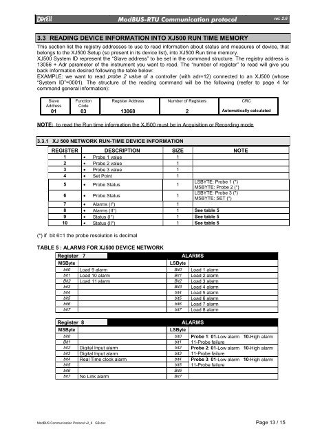
3.3 READING DEVICE INFORMATION INTO XJ500 RUN TIME MEMORY<br />
ModBUS Communication Protocol v2_6 GB.doc Page 13 / 15<br />
rel. 2.6<br />
This section list the registry addresses to use to read information about status and measures of device, that<br />
belongs to the XJ500 Setup (so present in its device list), into XJ500 Run time memory.<br />
XJ500 System ID represent the “Slave address” to be set in the command structure. The registry address is<br />
13056 + Adr parameter of the instrument you want to read. The “number of register” to read will give you<br />
back information desired following the table below:<br />
EXAMPLE: we want to read probe 2 value of a controller (with adr=12) connected to an XJ500 (whose<br />
“System ID”=0001). The structure of the reading command will be the following (reefer to page 4 for<br />
command general information):<br />
Slave<br />
Address<br />
01<br />
Function<br />
Code<br />
03<br />
Register Address<br />
13068<br />
Number of Registers<br />
2<br />
CRC<br />
Automatically calculated<br />
NOTE: to read the Run time information the XJ500 must be in Acquisition or Recording mode<br />
3.3.1 XJ 500 NETWORK RUN-TIME DEVICE INFORMATION<br />
REGISTER DESCRIPTION SIZE NOTE<br />
1 • Probe 1 value 1<br />
2 • Probe 2 value 1<br />
3 • Probe 3 value 1<br />
4 • Set Point 1<br />
5 • Probe Status 1<br />
LSBYTE: Probe 1 (*)<br />
MSBYTE: Probe 2 (*)<br />
6 • Probe Status 1<br />
LSBYTE: Probe 3 (*)<br />
MSBYTE: SET (*)<br />
7 • Alarms (I°) 1<br />
8 • Alarms (II°) 1 See table 5<br />
9 • Status (I°) 1 See table 5<br />
10 • Status (II°) 1 See table 5<br />
(*) if bit 6=1 the probe resolution is decimal<br />
TABLE 5 : ALARMS FOR XJ500 DEVICE NETWORK<br />
Register 7 ALARMS<br />
MSByte LSByte<br />
bit0 Load 9 alarm Bit0 Load 1 alarm<br />
bit1 Load 10 alarm Bit1 Load 2 alarm<br />
Bit2 Load 11 alarm Bit2 Load 3 alarm<br />
bit3 Bit3 Load 4 alarm<br />
bit4 bit4 Load 5 alarm<br />
bit5 bit5 Load 6 alarm<br />
bit6 bit6 Load 7 alarm<br />
bit7 bit7 Load 8 alarm<br />
Register 8 ALARMS<br />
MSByte LSByte<br />
bit0 bit0 Probe 1: 01-Low alarm 10-High alarm<br />
Bit1 bit1 11-Probe failure<br />
bit2 Digital Input alarm bit2 Probe 2: 01-Low alarm 10-High alarm<br />
bit3 Digital Input alarm bit3 11-Probe failure<br />
bit4 Real Time clock alarm bit4 Probe 3: 01-Low alarm 10-High alarm<br />
bit5 bit5 11-Probe failure<br />
bit6 Bit6<br />
bit7 No Link alarm Bit7