
You also want an ePaper? Increase the reach of your titles
YUMPU automatically turns print PDFs into web optimized ePapers that Google loves.
0RG%86 578 &RPPXQLFDWLRQ SURWRFRO<br />
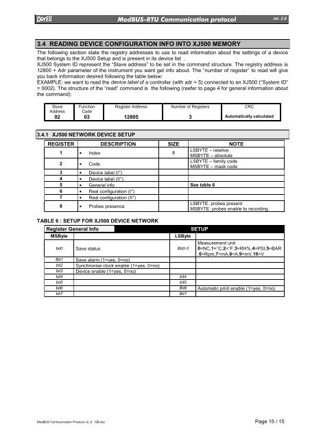
3.4 READING DEVICE CONFIGURATION INFO INTO XJ500 MEMORY<br />
ModBUS Communication Protocol v2_6 GB.doc Page 15 / 15<br />
rel. 2.6<br />
The following section state the registry addresses to use to read information about the settings of a device<br />
that belongs to the XJ500 Setup and is present in its device list .<br />
XJ500 System ID represent the “Slave address” to be set in the command structure. The registry address is<br />
12800 + Adr parameter of the instrument you want get info about. The “number of register” to read will give<br />
you back information desired following the table below:<br />
EXAMPLE: we want to read the device label of a controller (with adr = 5) connected to an XJ500 (“System ID”<br />
= 0002). The structure of the “read” command is the following (reefer to page 4 for general information about<br />
the command):<br />
Slave<br />
Address<br />
02<br />
Function<br />
Code<br />
03<br />
Register Address<br />
12805<br />
Number of Registers<br />
3<br />
CRC<br />
Automatically calculated<br />
3.4.1 XJ500 NETWORK DEVICE SETUP<br />
REGISTER DESCRIPTION SIZE NOTE<br />
1 • Index 8<br />
LSBYTE – relative<br />
MSBYTE – absolute<br />
2 • Code<br />
LSBYTE – family code<br />
MSBYTE – mask code<br />
3 • Device label (I°)<br />
4 • Device label (II°)<br />
5 • General info See table 6<br />
6 • Real configuration (I°)<br />
7 • Real configuration (II°)<br />
8 • Probes presence<br />
LSBYTE: probes present<br />
MSBYTE: probes enable to recording<br />
TABLE 6 : SETUP FOR XJ500 DEVICE NETWORK<br />
Register General Info SETUP<br />
MSByte LSByte<br />
Measurement unit<br />
bit0 Save status Bit0-3 0=NC,1=°C,2=°F,3=RH%,4=PSI,5=BAR<br />
,6=Rpm,7=mA,8=A,9=mV,10=V<br />
Bit1 Save alarm (1=yes, 0=no)<br />
bit2 Synchronise clock enable (1=yes, 0=no)<br />
bit3 Device enable (1=yes, 0=no)<br />
bit4 bit4<br />
bit5 bit5<br />
bit6 Bit6 Automatic print enable (1=yes, 0=no)<br />
bit7 Bit7