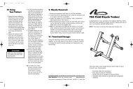
NB-T5000E Nashbar Watt Master Mag Trainer
NB-T5000E Nashbar Watt Master Mag Trainer
NB-T5000E Nashbar Watt Master Mag Trainer

You also want an ePaper? Increase the reach of your titles
YUMPU automatically turns print PDFs into web optimized ePapers that Google loves.
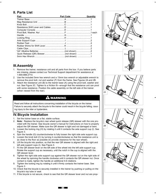
II. Parts List<br />
I<br />
H<br />
Part Part Code Quantity<br />
<strong>Trainer</strong> Base..........................................................A ........................................1<br />
<strong>Mag</strong> Resistance Unit ............................................B ........................................1<br />
Knob Bolt ..............................................................C ........................................1<br />
Resistance Shift Lever and Cables ......................D ........................................1<br />
Computer Console ................................................E ........................................1<br />
Pivot Bolt, Washer, Nut ........................................F ........................................1 each<br />
Handle ..................................................................G ........................................1<br />
Locking Ring ........................................................H ........................................1<br />
Axle Support Cups ................................................I ........................................2<br />
Rubber Feet ..........................................................J ........................................4<br />
Rubber Shims for Shift Lever................................K ........................................2<br />
Cable Clips.............................................................L ........................................2<br />
“AA” Alkaline Batteries ...........................................(not shown)........................2<br />
Quick Release (QR) Skewer..................................(not shown) ......................1<br />
5mm Hex Wrench ..................................................(not shown) ......................1<br />
1<br />
B<br />
C<br />
L<br />
E<br />
A<br />
J<br />
G<br />
III.Assembly<br />
1. Remove the trainer, resistance unit and all parts from the box. If you believe parts<br />
are missing, please contact our Technical Support department for assistance at<br />
1-800-888-2710.<br />
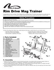
2. Use the included 5mm hex wrench and a 13mm box wrench or adjustable wrench to<br />
remove the pivot bolt, nut and washer (F) from the frame. See Figures 2A and 2B.<br />
3. Attach the resistance unit (B) to the trainer base (A) using the pivot bolt, washer and<br />
nut. See Figure 2C. Tighten to a friction fit—enough that the resistance unit can pivot<br />
with some resistance. Position the cable assembly on the left side of the trainer<br />
(when viewed from the rear).<br />
2A<br />
D<br />
▲! WARNING<br />
Read and follow all instructions concerning installation of the bicycle on the trainer.<br />
Failure to securely attach the bicycle to the trainer could result in the bicycle falling, causing<br />
injury to the rider or bystanders.<br />
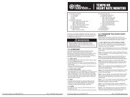
IV.Bicycle Installation<br />
1. Set the trainer base on a flat, stable surface.<br />
2. Note: Replace the bicycle’s rear wheel quick release (QR) skewer with the one provided<br />
with the trainer. See bicycle owner’s manual for instructions on how to properly<br />
adjust the QR skewer. Make sure the QR skewer is tight and not damaged or bent.<br />
3. Loosen the locking ring (H) by rotating it until it contacts the axle support cup (I). See<br />
Figure 3.<br />
4. Spin the handle (G) counterclockwise to fully loosen the right side axle support cup.<br />
5. Loosen the knob bolt (C) by turning it counterclockwise so that the resistance unit is<br />
as close to the floor as possible (to provide clearance for the rear wheel).<br />
6. Lift the bicycle into position, so that the rear QR skewer is aligned with the right and<br />
left axle support cups (I). See Figure 4.<br />
7. Fit the QR skewer lever on the left side of the wheel into the left axle support cup.<br />
Rotate the support cup as necessary, until the notch in the cup is aligned with the<br />
QR skewer lever.<br />
8. Tighten the right side axle support cup against the QR skewer nut on the right side of<br />
the wheel by spinning the handle clockwise until it contacts the QR skewer nut. Once<br />
contact is made, tighten the handle an additional 4-6 rotations.<br />
9. Tighten the locking ring by rotating it until it firmly contacts the trainer base. See<br />
Figure 3.<br />
10. Check that the bicycle is securely installed in the trainer by pushing or pulling on the<br />
bicycle’s top tube or seat.<br />
11. If the bicycle is not secure, check to see that the QR skewer lever and nut are prop-<br />
2B<br />
2C<br />
F<br />
3