Click for Instruction Manual - Nashbar
Click for Instruction Manual - Nashbar
Click for Instruction Manual - Nashbar

You also want an ePaper? Increase the reach of your titles
YUMPU automatically turns print PDFs into web optimized ePapers that Google loves.
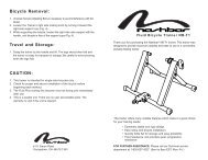
For Technical support, call 1-800-888-27100211-1 BN-WMF11 Made in Italy
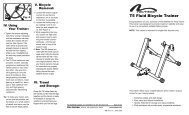
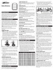
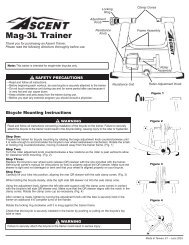
9. Once the extension length of the left side axle support cup is adjusted correctly, make sure it is still oriented with the notch at the top(to accommodate the QR skewer lever—see Figure 9) and set your bicycle aside. While holding the left axle support cup so it doesn’tspin, fully tighten the locking ring (E) as shown in Figure 15.10. Now lift the bicycle into place again, fitting the QR skewer lever into the left side axle support cup. Close the lever handle (D) with thepalm of your hand so that the right side axle support cup presses against the QR skewer nut, clamping the bicycle in place. See Figure16. Make sure the QR skewer lever and QR skewer nut are fully seated in the axle support cups.11. Check that the bicycle is securely attached to the trainer by pushing or pulling on the bicycle’s top tube or seat.12. If the bicycle is not secure, check to see that the QR skewer lever and nut are properly positioned in the axle support cups, and thatthe lever handle is in the closed position.WARNINGFailure to securely attach bicycle to trainer could result in serious injury.13. Check the position of the rear wheel on the resistance unit roller. While it is not necessary <strong>for</strong> the rear tire to be perfectly centered onthe roller, you may encounter a clearance issue between the tire and resistance unit if the wheel is not centered (particularly whenusing wider tires). To center the wheel on the roller, loosen the resistance unit attachment bolts (H), slide the resistance unit left or rightas necessary, and re-tighten the bolts. See Figure 17.14. If further adjustment is required to center the wheel, the entire base plate (C) can be adjusted left or right as necessary. Loosen the baseplate attachment bolt (I), slide the base plate left or right as necessary and re-tighten the bolt. See Figure 17.15. Attach the computer console to the handlebar, preferably near the stem. It may be necessary to remove one or both of the rubbershims from the console bracket in order to fit larger diameter handlebars.16. Connect the computer console cable to the console body as shown in Figure 18.Setup:Data generated by the Watt Master Wireless computer will be accurate only if you first per<strong>for</strong>m the following simple set-up procedure. Theset-up screens cannot be accessed while the trainer is in use.Note: In order to provide accurate data, the weight setting (rider weight + bicycle weight) must be programmed <strong>for</strong> each user. Whenswitching riders, be sure to adjust the weight setting (see below).1. To enter the set-up screens, press and hold the right (MODE) button <strong>for</strong> 4 seconds. See Figure 19.2. Select metric or imperial units of measure. Press the left (SET) button to select between KM/H, Meters and Kilos, or M/H, Feet andPounds (Lb). See Figure 20. Press the MODE button to confirm your selection and proceed to the Weight set-up screen.3. The weight value will appear on the top line of the display screen, with the right digit flashing. See Figure 21. Note: This valuerepresents the combined weight of the rider and the bicycle. Enter the combined weight of the rider and bicycle by pressing the SETbutton to adjust the flashing digit. Press the MODE button to confirm the value and proceed to the next digit. Repeat this process to setthe remaining digits. When finished, press the MODE button to confirm the value and proceed to the Type set-up screen.4. The correct Type setting <strong>for</strong> the Watt Master Fluid Wireless is Type 3. See Figure 22. Press the SET button until “type 3” is displayed.Press the MODE button to confirm your selection and exit the set-up screens.Using Your Trainer:Once the bicycle is mounted to the trainer (see section IV), and the initial set-up is complete (see section V), you’re ready to ride.1. The weight of the bicycle and rider automatically governs the amount of pressure between the tire and the resistance unit roller, sothere’s no need <strong>for</strong> an adjusting knob or other device to adjust the pressure.2. Press either button on the computer console (SET or MODE) or begin pedaling to activate the computer. Current Speed and other datashould immediately appear on the display screen.Note: The Slope and Power readings will vary from rider to rider according to the weight value entered in the set-up process (see sectionV). There<strong>for</strong>e, the Slope and Power readings may differ <strong>for</strong> two riders riding at the same speed. For accurate Slope, Power and ElevationGain data, remember to reset the weight value when switching riders.3. Fluid resistance provides smooth, naturally progressive resistance that varies according to your wheel speed. You can use your bicycle’sgearing the same way you would on the road---lower gearing will generate less resistance (suitable <strong>for</strong> a warm-up or light recoveryriding) while higher gearing will generate more resistance and a more intense workout.4. To make your indoor workout as quiet as possible, set the trainer on a trainer mat and use a rear tire with a smooth tread pattern.5. Riding on an indoor trainer may cause your rear tire to wear more quickly than riding on the road. To minimize tire wear, avoid letting thetire slip against the roller. Apply power evenly when accelerating, and pedal with a smooth stroke. DO NOT apply the rear brake whileusing the trainer. Use a smooth tread tire that is at least 23mm wide and maintain the maximum recommended inflation pressure <strong>for</strong>your tire.COMPUTER CONSOLEA. ScreensThree display screens provide various training data as described below. Use the MODE button to scroll between the three screens. Allscreens can be viewed during a ride.3
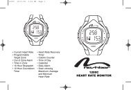
Screen 1 (Figure 23)Displays current values <strong>for</strong> Power (watts), Speed, Slope, Trip Distance and Ride Time. The speed comparison arrows in the upper rightcorner of the screen compare current speed to average speed. An upward arrow indicates your current speed is above your averagespeed. A downward arrow indicates your current speed is below your average speed.A. Current PowerB. Current SpeedC. SlopeD. Trip DistanceE. Ride TimeF. Speed ComparisonScreen 2 (Figure 24)Displays average values <strong>for</strong> Power (watts), Speed and Slope. Also displayed are Trip Distance, Ride Time and Speed Comparison arrows.A. Average PowerB. Average SpeedC. Average SlopeD. Trip DistanceE. Ride TimeF. Speed ComparisonScreen 3 (Figure 25)Displays maximum values <strong>for</strong> Power (watts) and Speed, Elevation Gain, Total Distance (odometer) and Total Ride Time. Also displayed arethe Speed Comparison arrows. The Total Distance and Total Ride Time values represent total distance and time accumulated on all ridesto date, and will not be reset when the data screens are cleared (see Section C, “Reset”).A. Maximum PowerB. Maximum SpeedC. Elevation GainD. Total DistanceE. Total Ride TimeF. Speed ComparisonB. Battery Life IndicatorWhen battery life is low, a battery icon will flash in the display screen to indicate only a few hours of battery life remain. See Figure 26.When the battery icon appears, replace the transmitter batteries (in the resistance unit) and console batteries as soon as possible.C. ResetAt the beginning of each ride you’ll want to per<strong>for</strong>m a reset to clear from memory the data from your previous ride.1. To clear the data, press and hold the SET button. After 3 seconds, “CLEAR” will be displayed (at this point no data has been deleted).Continue to hold the SET button and in another 3 seconds “DONE” will appear, indicating that all accumulated data (except TotalDistance and Total Ride Time) has been cleared from memory. See Figure 27.2. To reset Total Distance and Total Ride Time (as well as all other data), press and hold both the SET and MODE buttons. After 8 seconds“CLEAR” will be displayed (at this point no data has been deleted). Continue to hold the SET and MODE buttons, and in another 2seconds “DONE” will appear, indicating that all accumulated data has been cleared from memory.D. Auto OffAfter 2 minutes of inactivity (no pedaling or button presses) the system will automaticallyswitch off to prolong battery life. Current values will be maintained. To turn the system back on press either button (SET or MODE) or beginpedaling.E. Summary List of Ride Data4
Synchronizing Console and Resistance Unit:The handlebar console and resistance unit on your Watt Master Fluid Wireless Trainer have been linked so that the console receives onlycoded data transmitted from your resistance unit. This eliminates interference when you train with other riders using Watt Master trainers, orwhen you’re near another wireless device transmitting data on the same frequency.Should you ever need to re-establish the synchronization link between the console and resistance unit, follow the procedure below.1. Remove the resistance unit from the spring plate (C).2. Remove the cap at the top of the tube on the underside of the resistance unit. See Figure 31. Inside the tube is a small button.3. If your handlebar console has a power switch, turn it to the “off” position. If your console does not have a power switch, wait 2 minutes <strong>for</strong>the console to enter sleep mode.4. Now turn the console on again, either by moving the power switch to the “on” position or by pressing the SET or MODE button.5. Once the computer is turned on, depress the small button inside the tube on the underside of the resistance unit TWICE within 15 seconds.If you can’t reach the button with your finger, use a pencil or similar item.6. If the synchronization procedure is successful, a speed reading of 99.9 Km/h will appear in the display screen <strong>for</strong> one second. Your handlebarconsole will now receive data only from the resistance unit to which it has been linked. This link will remain even after a battery change.Troubleshooting:1. If the console display screen remains blank (no data appears while riding), or if data values are erratic, check the cable connection tothe computer console and consider replacing the batteries in the computer console and/or resistance unit.2. If the low battery indicator appears in the display screen, replace the batteries in the computer console and/or resistance unit.Changing Batteries:The computer console and resistance unit transmitter each use 2 “AA” batteries. When the low battery life indicator appears in the display,or if the display is erratic, faint or disappears altogether, new batteries are needed.ConsoleTo replace the console batteries, remove the battery cover from the underside of the computer console. Remove the used batteries anddispose of properly. Install fresh batteries according to the diagram inside the battery compartment, and replace the cover.TransmitterTo replace the transmitter batteries, remove the screws and open the cover on the underside of the resistance unit. See Figure 2. Removethe used batteries and dispose of properly. Install fresh batteries according to the diagram on the battery compartment cover, and replacethe cover.Note: During a battery change, current data and set-up values will be retained in memory.Bicycle Removal:1. While supporting the bicycle, open the lever handle (D) and lift the rear wheel up and <strong>for</strong>ward to remove the rear axle from the axlesupport cups. See Figure 28.2. Note: The QR skewer provided with the trainer can be used when riding the bicycle off the trainer as well. If you choose to reinstallyour bicycle’s original skewer, refer to your bicycle owner’s manual <strong>for</strong> instructions on properly adjusting the skewer. Be<strong>for</strong>e riding,ensure the quick release skewer is tight.3. To fold the trainer <strong>for</strong> transport or storage, lower the upright frame legs carefully against the resistance unit (Figure 29), or fold the them360 degrees against the underside of the frame base tubes (Figure 30).Specifications:Battery Type:4 “AA” Alkaline CellsBattery Life:Approximately 300 hoursComputer Data Fields:Power (watts): up to 999 wattsSpeed: up to 99.9 miles/hour or 99.9 kilometers/hourDistance: up to 999.99 miles or kilometersOdometer: up to 99999 miles or kilometersRide Time: up to 9 hours, 99 minutes, 59 secondsTotal Time: up to 999 hours, 59 minutesElevation Gain: up to 9999 feet or metersWeight Input Field:up to 330 pounds or 150 kilogramsUnits of Measurement:Metric: Distance in Kilometers, Elevation in Meters, Weight in Kilograms, Speed in Kilometers/HourImperial: Distance in Miles, Elevation in Feet, Weight in Pounds, Speed in Miles/HourRide safely and enjoy your <strong>Nashbar</strong> Watt Master Fluid Wireless Trainer!5