Delta Wireless - Performance Bike
Delta Wireless - Performance Bike
Delta Wireless - Performance Bike

Create successful ePaper yourself
Turn your PDF publications into a flip-book with our unique Google optimized e-Paper software.
<strong>Delta</strong> <strong>Wireless</strong><br />
INTRODUCTION<br />
Thank you for your purchase of an Ascent cycle<br />
computer. With all the features that a professional rider<br />
needs to keep track of a ride, the Ascent <strong>Delta</strong> <strong>Wireless</strong><br />
is the perfect accessory for any cyclist. The added<br />
convenience of wireless transmission makes<br />
installation simple!<br />
BATTERY INSTALLATION<br />
To help you get started quickly, the computer and<br />
transmitter batteries have been installed at the factory.<br />
Under normal use the batteries should last one to two<br />
years. The <strong>Delta</strong> <strong>Wireless</strong> uses a 3V CR2032 button<br />
cell battery (available at most drug stores or electronic<br />
shops) in both the computer and the sensor/transmitter.<br />
NOTE: Most problems that occur with cyclocomputers<br />
are caused by dead or weak batteries.<br />
Should you need to replace the batteries, follow the<br />
steps below.<br />
COMPUTER HEAD<br />
1. NOTE: During a battery change, all data will be cleared<br />
from memory. Make a note of your current wheel size<br />
settings and cumulative odometer mileage before<br />
replacing the battery so you can reprogram these<br />
values once the new battery is installed (see “Program<br />
Wheel Size” and “Program the Odometer”).<br />
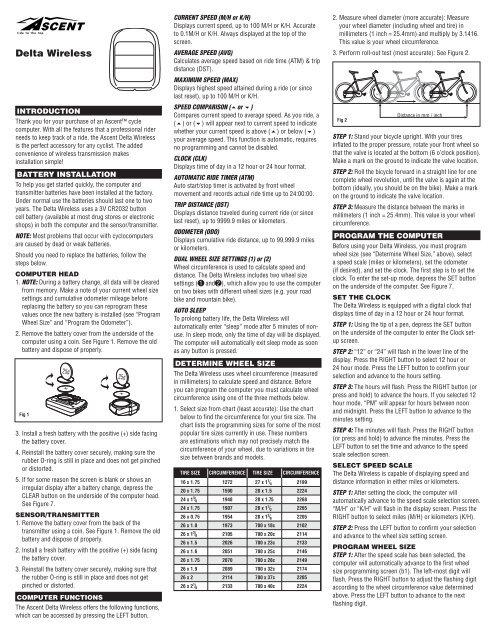
2. Remove the battery cover from the underside of the<br />
computer using a coin. See Figure 1. Remove the old<br />
battery and dispose of properly.<br />
Fig 1<br />
3. Install a fresh battery with the positive (+) side facing<br />
the battery cover.<br />
4. Reinstall the battery cover securely, making sure the<br />
rubber O-ring is still in place and does not get pinched<br />
or distorted.<br />
5. If for some reason the screen is blank or shows an<br />
irregular display after a battery change, depress the<br />
CLEAR button on the underside of the computer head.<br />
See Figure 7.<br />
SENSOR/TRANSMITTER<br />
1. Remove the battery cover from the back of the<br />
transmitter using a coin. See Figure 1. Remove the old<br />
battery and dispose of properly.<br />
2. Install a fresh battery with the positive (+) side facing<br />
the battery cover.<br />
3. Reinstall the battery cover securely, making sure that<br />
the rubber O-ring is still in place and does not get<br />
pinched or distorted.<br />
COMPUTER FUNCTIONS<br />
The Ascent <strong>Delta</strong> <strong>Wireless</strong> offers the following functions,<br />
which can be accessed by pressing the LEFT button.<br />
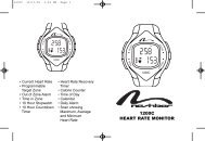
CURRENT SPEED (M/H or K/H)<br />
Displays current speed, up to 100 M/H or K/H. Accurate<br />
to 0.1M/H or K/H. Always displayed at the top of the<br />
screen.<br />
AVERAGE SPEED (AVG)<br />
Calculates average speed based on ride time (ATM) & trip<br />
distance (DST).<br />
MAXIMUM SPEED (MAX)<br />
Displays highest speed attained during a ride (or since<br />
last reset), up to 100 M/H or K/H.<br />
SPEED COMPARISON (5or 6)<br />
Compares current speed to average speed. As you ride, a<br />
(5) or (6) will appear next to current speed to indicate<br />
whether your current speed is above (5) or below (6)<br />
your average speed. This function is automatic, requires<br />
no programming and cannot be disabled.<br />
CLOCK (CLK)<br />
Displays time of day in a 12 hour or 24 hour format.<br />
AUTOMATIC RIDE TIMER (ATM)<br />
Auto start/stop timer is activated by front wheel<br />
movement and records actual ride time up to 24:00:00.<br />
TRIP DISTANCE (DST)<br />
Displays distance traveled during current ride (or since<br />
last reset), up to 9999.9 miles or kilometers.<br />
ODOMETER (ODO)<br />
Displays cumulative ride distance, up to 99,999.9 miles<br />
or kilometers.<br />
DUAL WHEEL SIZE SETTINGS (1) or (2)<br />
Wheel circumference is used to calculate speed and<br />
distance. The <strong>Delta</strong> <strong>Wireless</strong> includes two wheel size<br />
settings ( 1 and 2 ), which allow you to use the computer<br />
on two bikes with different wheel sizes (e.g. your road<br />
bike and mountain bike).<br />
AUTO SLEEP<br />
To prolong battery life, the <strong>Delta</strong> <strong>Wireless</strong> will<br />
automatically enter “sleep” mode after 5 minutes of nonuse.<br />
In sleep mode, only the time of day will be displayed.<br />
The computer will automatically exit sleep mode as soon<br />
as any button is pressed.<br />
27 x 1 / 4 16 x 1.75 1272<br />
2199<br />
1x<br />
Fig 2<br />
TIRE SIZE CIRCUMFERENCE TIRE SIZE CIRCUMFERENCE<br />
20 x 1.75<br />
24 x 1<br />
/ 8<br />
24 x 1.75<br />
26 x 0.75<br />
26 x 1.0<br />
26 x 1<br />
/<br />
1590<br />
1948<br />
1907<br />
1954<br />
1973<br />
2105<br />
28 x 1.5<br />
28 x 1.75<br />
28 x 1 / 2<br />
28 x 1 / 8<br />
700 x 18c<br />
700 x 20c<br />
2224<br />
2268<br />
2265<br />
2205<br />
2102<br />
2114<br />
8<br />
26 x 1.5<br />
26 x 1.6<br />
2026<br />
2051<br />
700 x 23c<br />
700 x 25c<br />
2133<br />
2146<br />
26 x 1.75<br />
26 x 1.9<br />
26 x 2<br />
26 x 2<br />
/ 8<br />
2070<br />
2089<br />
2114<br />
2133<br />
700 x 28c<br />
700 x 32c<br />
700 x 37c<br />
700 x 40c<br />
2149<br />
2174<br />
2205<br />
2224<br />
DETERMINE WHEEL SIZE<br />
The <strong>Delta</strong> <strong>Wireless</strong> uses wheel circumference (measured<br />
in millimeters) to calculate speed and distance. Before<br />
you can program the computer you must calculate wheel<br />
circumference using one of the three methods below.<br />
1. Select size from chart (least accurate): Use the chart<br />
below to find the circumference for your tire size. The<br />
chart lists the programming sizes for some of the most<br />
popular tire sizes currently in use. These numbers<br />
are estimations which may not precisely match the<br />
circumference of your wheel, due to variations in tire<br />
size between brands and models.<br />
2. Measure wheel diameter (more accurate): Measure<br />
your wheel diameter (including wheel and tire) in<br />
millimeters (1 inch = 25.4mm) and multiply by 3.1416.<br />
This value is your wheel circumference.<br />
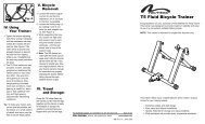
3. Perform roll-out test (most accurate): See Figure 2.<br />
Distance in mm / inch<br />
STEP 1: Stand your bicycle upright. With your tires<br />
inflated to the proper pressure, rotate your front wheel so<br />
that the valve is located at the bottom (6 o’clock position).<br />
Make a mark on the ground to indicate the valve location.<br />
STEP 2: Roll the bicycle forward in a straight line for one<br />
complete wheel revolution, until the valve is again at the<br />
bottom (ideally, you should be on the bike). Make a mark<br />
on the ground to indicate the valve location.<br />
STEP 3: Measure the distance between the marks in<br />
millimeters (1 inch = 25.4mm). This value is your wheel<br />
circumference.<br />
PROGRAM THE COMPUTER<br />
Before using your <strong>Delta</strong> <strong>Wireless</strong>, you must program<br />
wheel size (see “Determine Wheel Size,” above), select<br />
a speed scale (miles or kilometers), set the odometer<br />
(if desired), and set the clock. The first step is to set the<br />
clock. To enter the set-up mode, depress the SET button<br />
on the underside of the computer. See Figure 7.<br />
SET THE CLOCK<br />
The <strong>Delta</strong> <strong>Wireless</strong> is equipped with a digital clock that<br />
displays time of day in a 12 hour or 24 hour format.<br />
STEP 1: Using the tip of a pen, depress the SET button<br />
on the underside of the computer to enter the Clock setup<br />
screen.<br />
STEP 2: “12” or “24” will flash in the lower line of the<br />
display. Press the RIGHT button to select 12 hour or<br />
24 hour mode. Press the LEFT button to confirm your<br />
selection and advance to the hours setting.<br />
STEP 3: The hours will flash. Press the RIGHT button (or<br />
press and hold) to advance the hours. If you selected 12<br />
hour mode, “PM” will appear for hours between noon<br />
and midnight. Press the LEFT button to advance to the<br />
minutes setting.<br />
STEP 4: The minutes will flash. Press the RIGHT button<br />
(or press and hold) to advance the minutes. Press the<br />
LEFT button to set the time and advance to the speed<br />
scale selection screen.<br />
SELECT SPEED SCALE<br />
The <strong>Delta</strong> <strong>Wireless</strong> is capable of displaying speed and<br />
distance information in either miles or kilometers.<br />
STEP 1: After setting the clock, the computer will<br />
automatically advance to the speed scale selection screen.<br />
“M/H” or “K/H” will flash in the display screen. Press the<br />
RIGHT button to select miles (M/H) or kilometers (K/H).<br />
STEP 2: Press the LEFT button to confirm your selection<br />
and advance to the wheel size setting screen.<br />
PROGRAM WHEEL SIZE<br />
STEP 1: After the speed scale has been selected, the<br />
computer will automatically advance to the first wheel<br />
size programming screen (b1). The left-most digit will<br />
flash. Press the RIGHT button to adjust the flashing digit<br />
according to the wheel circumference value determined<br />
above. Press the LEFT button to advance to the next<br />
flashing digit.
STEP 2: Repeat this sequence until the correct wheel size<br />
has been entered. Then press the LEFT button to advance<br />
to the second wheel size setting screen (b2).<br />
STEP 3: The left-most digit will flash. Press the RIGHT<br />
button to adjust the flashing digit. Press the LEFT button<br />
to advance to the next flashing digit.<br />
STEP 4: Repeat this sequence until the second wheel size<br />
has been entered. Then press the LEFT button to<br />
advance to the odometer programming screen for the<br />
first wheel size.<br />
PROGRAM THE ODOMETER<br />
STEP 1: After programming both wheel sizes, the<br />
computer will automatically advance to the odometer<br />
setting screen for the first wheel size. (If you don’t wish<br />
to program the odometer, press the SET button on the<br />
underside of the computer to exit the set-up mode.) The<br />
left-most digit will flash. Press the RIGHT button to adjust<br />
the value. Press the LEFT button to advance to the next<br />
flashing digit.<br />
STEP 2: Repeat this sequence until the odometer value<br />
for the first wheel size has been set. Then press the LEFT<br />
button to advance to the odometer programming screen<br />
for the second wheel size.<br />
STEP 3: Program the odometer value for the second<br />
wheel size as described above. Once the odometer value<br />
has been set correctly, press the SET button on the<br />
underside of the computer to exit the set-up mode and<br />
return to the main display screen.<br />
INSTALLATION<br />
Since your Ascent computer is wireless, installation is<br />
simple. Begin by attaching the handlebar bracket.<br />
HANDLEBAR BRACKET INSTALLATION<br />
The handlebar bracket can be configured for stem or<br />
handlebar mounting. To change the configuration, remove<br />
the assembly screw, rotate the bracket base 90° and<br />
retighten the screw. Use the included zip-ties to attach the<br />
bracket in the desired location as shown in Figure 3. Once<br />
the bracket is securely installed, trim the excess zip-tie<br />
ends with scissors or fingernail clippers.<br />
OR<br />
WHEEL MAGNET AND SENSOR<br />
INSTALLATION<br />
STEP 1: Using the included zip-ties, loosely mount the<br />
sensor (so that you can slide it around) to the fork blade<br />
so that it’s on the same side of the bike as the handlebar<br />
bracket. The battery cover on the sensor/transmitter<br />
should face the wheel and should be attached to the<br />
front (leading) edge of the fork blade (to avoid problems<br />
should it ever come in contact with the spokes). See<br />
Figure 5. The <strong>Delta</strong> <strong>Wireless</strong> transmission range is 24”<br />
(60cm). The sensor/transmitter must be mounted within<br />
24” of the receiver (computer head) in order for the signal<br />
to be received.<br />
Fig 5<br />
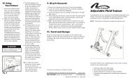
STEP 2: Attach the wheel magnet loosely to one of the<br />
spokes on the same side of the wheel as the sensor/<br />
transmitter. Adjust the position of the magnet and sensor<br />
by sliding both pieces up or down to achieve 1-3mm of<br />
clearance between the two (1mm is about the thickness<br />
of a penny). See Figure 6. If the magnet and sensor<br />
are not close enough, the computer will not pick up a<br />
reading or readings will be inconsistent and erratic. Most<br />
problems that occur when installing a new computer are<br />
related to magnet and sensor alignment and spacing.<br />
Fig 6<br />
3mm Max<br />
Bladed<br />
Spoke<br />
Round<br />
Spoke<br />
as heart rate monitors). If you experience unusually high<br />
speed readings, check your surroundings for possible<br />
sources of electromagnetic signals and move away from<br />
the source.<br />
CHOOSE WHEEL SIZE<br />
When switching your computer between bikes with<br />
different wheel sizes, don’t forget to select the appropriate<br />
wheel size setting ( 1 or 2 ) for each bike. In the Trip<br />
Distance/Automatic Rider Timer display screen (DST/<br />
ATM), press and hold the RIGHT button for three seconds<br />
to change the wheel size.<br />
RESET DISPLAY SCREENS<br />
PARTIAL RESET<br />
The <strong>Delta</strong> <strong>Wireless</strong> maintains a separate memory of<br />
Average Speed, Maximum Speed, Ride Time, Trip<br />
Distance and Odometer for each wheel size ( 1 and 2 ).<br />
The memory for each wheel size must be reset separately.<br />
During a partial reset, only data for the currently<br />
displayed wheel size will be cleared.<br />
1. To simultaneously reset Average Speed, Maximum<br />
Speed, Trip Distance and Ride Timer, press and hold<br />
the LEFT and RIGHT buttons for 4 seconds in any<br />
display screen.<br />
2. To reset only Average Speed and Maximum Speed,<br />
press and hold the RIGHT button for four seconds in<br />
the AVS/MAX display screen.<br />
3. To reset only Trip Distance, press and hold the RIGHT<br />
button for four seconds in the DST/ODO display screen.<br />
4. To reset only the Automatic Ride Timer, press and hold<br />
the RIGHT button for four seconds in the CLK/ATM<br />
display screen.<br />
GLOBAL RESET<br />
To reset ALL display screens for both wheel sizes and<br />
ALL programmed settings (including Clock, Odometer<br />
and wheel size settings), press the CLEAR button on the<br />
underside of the computer. See Figure 7.<br />
NOTE: Please note that entering the set-up mode (by<br />
depressing the SET button on the underside of the<br />
computer) will not reset the display screens or clear any<br />
data. This means you can enter set-up mode to adjust<br />
wheel size settings, program the odometer or change the<br />
speed scale (miles/kilometers) without losing any data.<br />
Fig 3<br />
CLEAR<br />
COMPUTER HEAD INSTALLATION<br />
Slide the computer head onto the bracket from back to<br />
front until you hear a ‘CLICK’, indicating that the unit<br />
is locked in the bracket. See Figure 4. To remove the<br />
computer head, press the release tab at the front of the<br />
bracket and slide the computer head out of the bracket.<br />
Fig 4<br />
Press to<br />
Release<br />
STEP 3: Once the transmitter and wheel magnet are<br />
aligned properly, securely tighten both in place and trim<br />
the excess zip-tie ends with scissors or<br />
fingernail clippers.<br />
TEST OF INSTALLATION<br />
Once installation is complete, test the unit to make sure<br />
everything is adjusted and working properly. Pick up the<br />
front end of the bicycle and spin the front wheel. The<br />
computer should register a speed reading within 1-2<br />
seconds. If not, check the alignment of the wheel magnet<br />
and sensor, and make sure that the space between the<br />
magnet and sensor is 3mm or less. Adjust as necessary<br />
and re-test.<br />
NOTE: <strong>Wireless</strong> cyclocomputers are occasionally affected<br />
by electromagnetic interference. Common sources of<br />
electromagnetic signals include high voltage power lines,<br />
motor driven equipment and other wireless devices (such<br />
Fig 7<br />
SET<br />
MAINTENANCE<br />
LOW BATTERY INDICATOR<br />
When the computer battery is low, the low battery<br />
indicator will be displayed. Although this only indicates<br />
the state of the battery in the computer head, it's<br />
generally a good idea to replace both batteries (computer<br />
head and sensor/transmitter) at the same time (see<br />
"Battery Installation").<br />
Made in China 300000000971 0708_2