T66 Fluid Bicycle Trainer - Nashbar
T66 Fluid Bicycle Trainer - Nashbar
T66 Fluid Bicycle Trainer - Nashbar

Create successful ePaper yourself
Turn your PDF publications into a flip-book with our unique Google optimized e-Paper software.
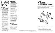
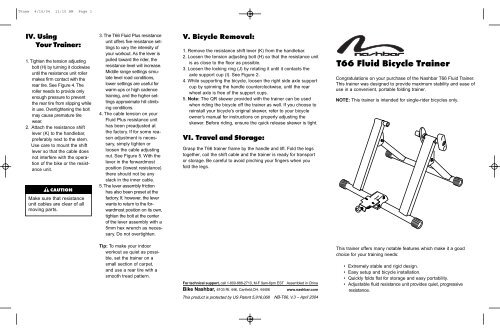
T6new 4/15/04 11:10 AM Page 1IV. UsingYour <strong>Trainer</strong>:1. Tighten the tension adjustingbolt (H) by turning it clockwiseuntil the resistance unit rollermakes firm contact with therear tire. See Figure 4. Theroller needs to provide onlyenough pressure to preventthe rear tire from slipping whilein use. Overtightening the boltmay cause premature tirewear.2. Attach the resistance shiftlever (K) to the handlebar,preferably next to the stem.Use care to mount the shiftlever so that the cable doesnot interfere with the operationof the bike or the resistanceunit.▲! CAUTIONMake sure that resistanceunit cables are clear of allmoving parts.3. The <strong>T66</strong> <strong>Fluid</strong> Plus resistanceunit offers five resistance settingsto vary the intensity ofyour workout. As the lever ispulled toward the rider, theresistance level will increase.Middle range settings simulatelevel road conditions,lower settings are useful forwarm-ups or high cadencetraining, and the higher settingsapproximate hill climbingconditions.4. The cable tension on your<strong>Fluid</strong> Plus resistance unithas been preadjusted atthe factory. If for some reasonadjustment is necessary,simply tighten orloosen the cable adjustingnut. See Figure 5. With thelever in the forwardmostposition (lowest resistance)there should not be anyslack in the inner cable.5. The lever assembly frictionhas also been preset at thefactory. If, however, the leverwants to return to the forwardmostposition on its own,tighten the bolt at the centerof the lever assembly with a5mm hex wrench as necessary.Do not overtighten.V. <strong>Bicycle</strong> Removal:1. Remove the resistance shift lever (K) from the handlebar.2. Loosen the tension adjusting bolt (H) so that the resistance unitis as close to the floor as possible.3. Loosen the locking ring (J) by rotating it until it contacts theaxle support cup (I). See Figure 2.4. While supporting the bicycle, loosen the right side axle supportcup by spinning the handle counterclockwise, until the rearwheel axle is free of the support cups.5. Note: The QR skewer provided with the trainer can be usedwhen riding the bicycle off the trainer as well. If you choose toreinstall your bicycle’s original skewer, refer to your bicycleowner’s manual for instructions on properly adjusting theskewer. Before riding, ensure the quick release skewer is tight.VI. Travel and Storage:Grasp the <strong>T66</strong> trainer frame by the handle and lift. Fold the legstogether, coil the shift cable and the trainer is ready for transportor storage. Be careful to avoid pinching your fingers when youfold the legs.<strong>T66</strong> <strong>Fluid</strong> <strong>Bicycle</strong> <strong>Trainer</strong>Congratulations on your purchase of the <strong>Nashbar</strong> <strong>T66</strong> <strong>Fluid</strong> <strong>Trainer</strong>.This trainer was designed to provide maximum stability and ease ofuse in a convenient, portable folding trainer.NOTE: This trainer is intended for single-rider bicycles only.Tip: To make your indoorworkout as quiet as possible,set the trainer on asmall section of carpet,and use a rear tire with asmooth tread pattern.For technical support, call 1-800-888-2710, M-F 9am-6pm EST Assembled in ChinaBike <strong>Nashbar</strong>, 6103 Rt. 446, Canfield,OH. 44406 www.nashbar.comThis product is protected by US Patent 5,916,068NB-<strong>T66</strong>, V.3 – April 2004This trainer offers many notable features which make it a goodchoice for your training needs:• Extremely stable and rigid design.• Easy setup and bicycle installation.• Quickly folds flat for storage and easy portability.• Adjustable fluid resistance unit provides quiet, progressiveresistance.
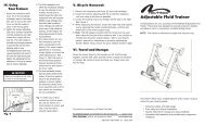
T6new 4/15/04 11:10 AM Page 2I. Parts Included:NO. DESCRIPTION QTYA <strong>Trainer</strong> Frame 1B Handle 1C M5 Bolts and Washers 2 eachD Plastic Feet 4E <strong>Fluid</strong> Resistance Unit 1F Resistance Unit Mount Plate 1HFASafety Precautions• Read and follow all instructions.• Before each workout, ensure the bicycle is securelyattached to the trainer.• During use, the resistance unit may become hot enough tocause burns. Do not touch the resistance unit during use orfor some time after use, until the unit has had sufficienttime to cool.• Keep children and pets away from the trainer during use.• Before beginning any exercise program, consult your physician.• This trainer is intended for single rider bicycles only.LEFTINO. DESCRIPTION QTYG Pivot Bolt, Washer, Nut 1 eachH Tension Adjusting Bolt 1I Axle Support Cups 2J Locking Ring 1K Resistance Shift Lever 1L Quick Release Skewer 1RIGHTJDKBII. Assembly:1. Remove the trainer, resistanceunit and all parts fromthe box. If you believe partsare missing, please contactour technical service departmentfor assistance at 1-800-888-2710 from 9 am to 6 pmEST (Mon.-Fri.).2. Use the included 5mm hexwrench and a 13mm boxwrench or adjustablewrench to attach the resistanceunit mount plate (F) tothe trainer frame (A) asshown in Figure 1. Tightento a friction fit—enough thatthe mount plate can pivotwith some resistance.3. Attach the resistance unit(E) to the mount plate using2 M5 bolts and washers (C)as shown in Figure 1. Thecable assembly should bepositioned on the left side ofthe trainer (when viewedfromthe rear).C HGJIUNLOCKEDLOCKEDFig. 3ILEFTEFFig. 1BFig. 2J BRIGHTIII. <strong>Bicycle</strong> Installation:▲! WARNINGRead and follow all instructions concerning installation of thebicycle on the trainer. Failure to securely attach the bicycle tothe trainer may allow the bicycle to fall, resulting in injury tothe rider or bystanders.1. Set the <strong>T66</strong> trainer on a flat,stable surface.2. NOTE: Replace the bicycle’srear wheel quickrelease (QR) skewer withthe one provided with thetrainer (K). See bicycleowner’s manual forinstructions on how toproperly adjust the QRskewer. Make sure the QRskewer is tight and notdamaged or bent.3. Loosen the locking ring (J)by rotating it until it contactsthe axle support cup. SeeFigure 2.4. Spin the handle (B) counterclockwiseto fully loosen theright side axle support cup.5. Loosen the tension adjustingbolt (H) by turning it counterclockwiseso that the resistanceunit is as close to thefloor as possible (to allowclearance for the rear wheel).6. Lift the bicycle into position,so that the rear QR skeweris aligned with the right andleft axle support cups (I).See Figure 3.7. Fit the QR skewer lever onthe left side of the wheel intothe left axle support cup.Rotate the support cup asnecessary, until the notch inthe cup is aligned with theQR skewer lever.8. Tighten the right side axle supportcup against the QRskewer nut on the right side ofthe wheel by spinning thehandle clockwise until it contactsthe QR skewer nut.Once contact is made, tightenthe handle an additional 4-6rotations or so.9. Tighten the locking ring byrotating it until it firmly contactsthe trainer frame. SeeFigure 2.10. Check that the bicycle issecurely installed in the trainerby pushing or pulling onthe bicycle’s top tube or seat.11. If the bicycle is not secure,check to see that the quickrelease skewer lever and nutare properly positioned in theaxle support cups, and thatthe right side axle supportcup is securley tightened.▲! WARNINGFailure to securely attach the bicycle to the trainer couldresult in serious injury.