NB-T5000E Nashbar Watt Master Mag Trainer
NB-T5000E Nashbar Watt Master Mag Trainer
NB-T5000E Nashbar Watt Master Mag Trainer

Create successful ePaper yourself
Turn your PDF publications into a flip-book with our unique Google optimized e-Paper software.
For Technical support, call 1-800-888-2710, M-F 9am-6pm EST<br />
Bike <strong>Nashbar</strong>, 6103 Rt. 446, Canfield,OH 44406<br />
Made in Italy<br />
www.<strong>Nashbar</strong>.com<br />
<strong>NB</strong>-<strong>T5000E</strong>, V.1 – June 2004
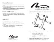
<strong>Watt</strong> <strong>Master</strong> <strong>Mag</strong> <strong>Trainer</strong><br />
Congratulations on your purchase of the <strong>Nashbar</strong> <strong>Watt</strong> <strong>Master</strong> bicycle training system. Your new trainer provides<br />
the same data on speed, distance and time that is available from a full-featured cycling computer, plus information<br />
on power output (expressed in watts), elevation gain and slope (percent grade). Your indoor training has never<br />
been as fun or effective as it will be with your new <strong>Watt</strong> <strong>Master</strong>!<br />
NOTE: This trainer is intended for single-rider bicycles only.<br />
▲! CAUTION<br />
• Read and follow all instructions.<br />
• Before beginning each workout, be sure bicycle is securely attached to trainer.<br />
• Do not touch resistance unit during or immediately after use as it may become very hot.<br />
• Keep children and pets away from trainer during use.<br />
• Before you start any exercise program you should consult a physician.
Table of Contents<br />
I. About Your <strong>Nashbar</strong> <strong>Watt</strong> <strong>Master</strong> <strong>Trainer</strong> . . . . . . . . . . . . . . . . . . . . . . . .2<br />
II. Parts List . . . . . . . . . . . . . . . . . . . . . . . . . . . . . . . . . . . . . . . . . . . . . . . . .3<br />
III. Assembly . . . . . . . . . . . . . . . . . . . . . . . . . . . . . . . . . . . . . . . . . . . . . . . . .3<br />
IV. Bicycle Installation . . . . . . . . . . . . . . . . . . . . . . . . . . . . . . . . . . . . . . . . .3<br />
V. Set-Up . . . . . . . . . . . . . . . . . . . . . . . . . . . . . . . . . . . . . . . . . . . . . . . . . . .4<br />
VI. Using Your <strong>Nashbar</strong> <strong>Watt</strong> <strong>Master</strong> <strong>Trainer</strong> . . . . . . . . . . . . . . . . . . . . . . . .4<br />
A. Screens . . . . . . . . . . . . . . . . . . . . . . . . . . . . . . . . . . . . . . . . . . . .5<br />
B. Battery Life Indicator . . . . . . . . . . . . . . . . . . . . . . . . . . . . . . . . .5<br />
C. Reset . . . . . . . . . . . . . . . . . . . . . . . . . . . . . . . . . . . . . . . . . . . . . .5<br />
D. Auto Off . . . . . . . . . . . . . . . . . . . . . . . . . . . . . . . . . . . . . . . . . . .6<br />
E. Summary List of Ride Data . . . . . . . . . . . . . . . . . . . . . . . . . . . .6<br />
VII. Troubleshooting . . . . . . . . . . . . . . . . . . . . . . . . . . . . . . . . . . . . . . . . . . .6<br />
VIII. Changing the Batteries . . . . . . . . . . . . . . . . . . . . . . . . . . . . . . . . . . . . . .7<br />
IX. Bicycle Removal . . . . . . . . . . . . . . . . . . . . . . . . . . . . . . . . . . . . . . . . . . .7<br />
X. Travel and Storage . . . . . . . . . . . . . . . . . . . . . . . . . . . . . . . . . . . . . . . . .7<br />
XI. Specifications . . . . . . . . . . . . . . . . . . . . . . . . . . . . . . . . . . . . . . . . . . . . .7<br />
Quick-start Instructions (for those who do not like to read instruction manuals)<br />
While the <strong>Nashbar</strong> <strong>Watt</strong> <strong>Master</strong> unit is ready to use right out of the box, please note that<br />
the slope and elevation gain information will only be accurate after you have entered<br />
your weight in the Set-Up screen. See section V, “Setup”, for details.<br />
I. About Your <strong>Nashbar</strong> <strong>Watt</strong> <strong>Master</strong> <strong>Trainer</strong><br />
The <strong>Nashbar</strong> <strong>Watt</strong> <strong>Master</strong> <strong>Trainer</strong> provides a fun, effective workout using your own bicycle<br />
in the comfort of your own home, and can easily be switched from bike to bike or<br />
between riders. Customize your workout as desired, and get the feedback you need to<br />
create a great training program!<br />
<strong>Trainer</strong> Base<br />
The <strong>Watt</strong> <strong>Master</strong> resistance unit is mounted to a trainer base constructed of heavy-gauge<br />
powder-coated steel with rubber, shock-absorbing feet to provide a stable platform for<br />
any level of training.<br />
Adjustable <strong>Mag</strong>netic Resistance Unit<br />
The <strong>Nashbar</strong> <strong>Watt</strong> <strong>Master</strong> resistance unit is equipped with a handlebar-mounted shift lever<br />
and computer console. The adjustable magnetic resistance unit provides a wide range of<br />
variable resistance, characterized by smooth, quiet operation. An integrated sensor in the<br />
resistance unit sends data to the computer console mounted on your handlebar.<br />
Handlebar-Mounted Shift Lever<br />
The handlebar shift lever allows on-the-fly selection of 5 resistance levels, which simulate<br />
slope.<br />
Computer Console<br />
The computer console calculates and displays data provided by the resistance unit sensor.<br />
The large LCD screen mounts directly to the handlebar, and presents the data in an<br />
easy to read format.<br />
Functions<br />
The <strong>Watt</strong> <strong>Master</strong> bicycle training system provides the following valuable training<br />
feedback:<br />
Speed: Current, Average, Maximum<br />
Distance: Trip Distance, Total Distance (Odometer)<br />
Time: Ride Time, Total Time<br />
Power (<strong>Watt</strong>s): Current, Average, Maximum<br />
Slope (% Grade): Current, Average (Slope is simulated by the level of resistance.<br />
Please note that at any given resistance level Slope will vary<br />
according to rider weight.)<br />
Elevation Gain: Total Elevation Gain, based on Trip Distance and Slope<br />
2
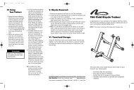
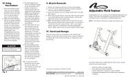
VIII. Changing the Batteries<br />
The computer console uses 2 “AA” batteries. When the low battery life indicator appears<br />
in the display, or if the display is erratic, faint or disappears altogether, new batteries are<br />
needed.<br />
1. To replace the batteries, remove the battery cover from the underside of the computer<br />
console.<br />
2. Remove the used batteries and dispose of properly.<br />
3. Install fresh batteries according to the orientation diagram inside the battery compartment,<br />
and replace the cover.<br />
Note: During a battery change, current data and set-up values will be retained in memory.<br />
IX. Bicycle Removal<br />
1. Remove the shift lever assembly from the handlebar.<br />
2. Loosen the knob bolt (C) so that the resistance unit is as close to the floor as possible.<br />
3. Loosen the locking ring (H) by rotating it until it contacts the axle support cup (I). See<br />
Figure 3.<br />
4. While supporting the bicycle, loosen the right side axle support cup by spinning the<br />
handle (G) counterclockwise, until the rear wheel axle is free of the support cups.<br />
5. Note: The QR skewer provided with the trainer can be used when riding the bicycle<br />
off the trainer as well. If you choose to reinstall your bicycle’s original skewer, refer to<br />
your bicycle owner’s manual for instructions on properly adjusting the skewer. Before<br />
riding, ensure the quick release skewer is tight.<br />
X. Travel and Storage<br />
1. Grasp the trainer frame by the handle and lift. Fold the legs together, and the trainer<br />
is ready for transport or storage. Be careful when folding the legs to avoid pinching<br />
your fingers.<br />
XI. Specifications<br />
Battery Type: 2 “AA” Alkaline Cells<br />
Battery Life: Approximately 300 hours<br />
Computer Data Fields:<br />
Power (watts): up to 999 watts<br />
Speed: up to 99.9 miles/hour or 99.9 kilometers/hour<br />
Distance: up to 999.99 miles or kilometers<br />
Odometer: up to 99999 miles or kilometers<br />
Ride Time: up to 9 hours, 99 minutes, 59 seconds<br />
Total Time: up to 999 hours, 59 minutes<br />
Elevation Gain: up to 9999 feet or meters<br />
Weight Input Field: up to 330 pounds or 150 kilograms<br />
Units of Measurement:<br />
Metric: Distance in Kilometers, Elevation in Meters, Weight in Kilograms, Speed in<br />
Kilometers/Hour<br />
Imperial: Distance in Miles, Elevation in Feet, Weight in Pounds, Speed in Miles/Hour<br />
7
Low<br />
Battery<br />
Indicator<br />
3 6 Seconds<br />
13<br />
14<br />
When battery life is low, a battery icon will flash in the display screen to indicate only a<br />
few hours of battery life remain. See Figure 13. When the battery icon appears, replace<br />
the batteries as soon as possible (See section VIII, “Changing the Batteries”).<br />
C. Reset<br />
At the beginning of each ride you’ll want to perform a reset to clear from memory the<br />
data from your previous ride.<br />
1. To clear the data, press and hold the SET button. After 3 seconds, “CLEAR” will be<br />
displayed (at this point no data has been deleted). Continue to hold the SET button<br />
and in another 3 seconds “DONE” will appear, indicating that all accumulated data<br />
(except Total Distance and Total Ride Time) has been cleared from memory. See<br />
Figure 14.<br />
2. To reset Total Distance and Total Ride Time (as well as all other data), press and<br />
hold both the SET and MODE buttons. After 8 seconds “CLEAR” will be displayed (at<br />
this point no data has been deleted). Continue to hold the SET and MODE buttons,<br />
and in another 2 seconds “DONE” will appear, indicating that all accumulated data<br />
has been cleared from memory.<br />
D. Auto Off<br />
After 2 minutes of inactivity (no pedaling or button presses) the system will automatically<br />
switch off to prolong battery life. Current values will be maintained. To turn the system<br />
back on press either button (SET or MODE) or begin pedaling.<br />
E. Summary List of Ride Data<br />
VII. Troubleshooting<br />
1. Display not working<br />
a. Check cable connections to the computer console.<br />
b. Replace the batteries in the computer console. See section VIII, “Changing the<br />
Batteries.”<br />
2. Resistance level indicator stays on level 1<br />
a. Check cable connection between the computer console and the shift lever.<br />
3. Data Values Erratic<br />
a. Check cable connections to the computer console.<br />
b. Replace the batteries in the computer console. See section VIII, “Changing the<br />
Batteries.”<br />
4. Low Battery Indicator Appears<br />
a. Replace the batteries in the computer console. See section VIII, “Changing the<br />
Batteries.”<br />
Note: The resistance unit and the computer console contain no user-serviceable parts.<br />
6
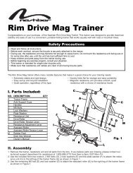
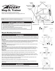
II. Parts List<br />
I<br />
H<br />
Part Part Code Quantity<br />
<strong>Trainer</strong> Base..........................................................A ........................................1<br />
<strong>Mag</strong> Resistance Unit ............................................B ........................................1<br />
Knob Bolt ..............................................................C ........................................1<br />
Resistance Shift Lever and Cables ......................D ........................................1<br />
Computer Console ................................................E ........................................1<br />
Pivot Bolt, Washer, Nut ........................................F ........................................1 each<br />
Handle ..................................................................G ........................................1<br />
Locking Ring ........................................................H ........................................1<br />
Axle Support Cups ................................................I ........................................2<br />
Rubber Feet ..........................................................J ........................................4<br />
Rubber Shims for Shift Lever................................K ........................................2<br />
Cable Clips.............................................................L ........................................2<br />
“AA” Alkaline Batteries ...........................................(not shown)........................2<br />
Quick Release (QR) Skewer..................................(not shown) ......................1<br />
5mm Hex Wrench ..................................................(not shown) ......................1<br />
1<br />
B<br />
C<br />
L<br />
E<br />
A<br />
J<br />
G<br />
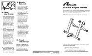
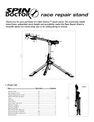
III.Assembly<br />
1. Remove the trainer, resistance unit and all parts from the box. If you believe parts<br />
are missing, please contact our Technical Support department for assistance at<br />
1-800-888-2710.<br />
2. Use the included 5mm hex wrench and a 13mm box wrench or adjustable wrench to<br />
remove the pivot bolt, nut and washer (F) from the frame. See Figures 2A and 2B.<br />
3. Attach the resistance unit (B) to the trainer base (A) using the pivot bolt, washer and<br />
nut. See Figure 2C. Tighten to a friction fit—enough that the resistance unit can pivot<br />
with some resistance. Position the cable assembly on the left side of the trainer<br />
(when viewed from the rear).<br />
2A<br />
D<br />
▲! WARNING<br />
Read and follow all instructions concerning installation of the bicycle on the trainer.<br />
Failure to securely attach the bicycle to the trainer could result in the bicycle falling, causing<br />
injury to the rider or bystanders.<br />
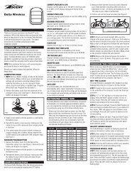
IV.Bicycle Installation<br />
1. Set the trainer base on a flat, stable surface.<br />
2. Note: Replace the bicycle’s rear wheel quick release (QR) skewer with the one provided<br />
with the trainer. See bicycle owner’s manual for instructions on how to properly<br />
adjust the QR skewer. Make sure the QR skewer is tight and not damaged or bent.<br />
3. Loosen the locking ring (H) by rotating it until it contacts the axle support cup (I). See<br />
Figure 3.<br />
4. Spin the handle (G) counterclockwise to fully loosen the right side axle support cup.<br />
5. Loosen the knob bolt (C) by turning it counterclockwise so that the resistance unit is<br />
as close to the floor as possible (to provide clearance for the rear wheel).<br />
6. Lift the bicycle into position, so that the rear QR skewer is aligned with the right and<br />
left axle support cups (I). See Figure 4.<br />
7. Fit the QR skewer lever on the left side of the wheel into the left axle support cup.<br />
Rotate the support cup as necessary, until the notch in the cup is aligned with the<br />
QR skewer lever.<br />
8. Tighten the right side axle support cup against the QR skewer nut on the right side of<br />
the wheel by spinning the handle clockwise until it contacts the QR skewer nut. Once<br />
contact is made, tighten the handle an additional 4-6 rotations.<br />
9. Tighten the locking ring by rotating it until it firmly contacts the trainer base. See<br />
Figure 3.<br />
10. Check that the bicycle is securely installed in the trainer by pushing or pulling on the<br />
bicycle’s top tube or seat.<br />
11. If the bicycle is not secure, check to see that the QR skewer lever and nut are prop-<br />
2B<br />
2C<br />
F<br />
3
I<br />
H<br />
G<br />
erly positioned in the axle support cups, and that the right side axle support cup is<br />
securely tightened.<br />
12. Tighten the knob bolt (C) until the drive roller contacts the rear tire. Then, turn the<br />
knob bolt an additional 3 complete rotations. If the tire slips on the roller, turn the<br />
knob bolt by additional 1 / 2 turns as necessary to eliminate any slippage.<br />
UNLOCKED<br />
3<br />
▲! WARNING<br />
Failure to securely attach the bicycle to the trainer could result in serious injury.<br />
LOCKED<br />
I<br />
I<br />
H<br />
G<br />
4<br />
13. Install the included “AA” batteries in the computer console (E). Remove the battery<br />
cover from the underside of the console, install the batteries according to the orientation<br />
diagram inside the battery compartment, and replace the cover.<br />
14. Attach the resistance shift lever (D) and computer console (E) to the handlebar,<br />
preferably close to the stem. Use care to mount the shift lever so that the cable does<br />
not interfere with the operation of the bike or the resistance unit. It may be necessary<br />
to remove one or both of the rubber shims (K) from the shift lever bracket in order to<br />
fit larger diameter handlebars. For smoother shifting, avoid kinks or sharp bends in<br />
the cable.<br />
15. Connect the computer console cable and the resistance unit data cable to the shift<br />
lever body. See Figure 5A and 5B.<br />
Tip: To make your indoor workout as quiet as possible, set the trainer on a small<br />
section of carpet, and use a rear tire with a smooth tread pattern.<br />
▲! CAUTION<br />
Make sure that resistance unit cables are clear of all moving bicycles parts.<br />
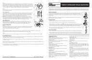
V. Setup<br />
5A<br />
Data generated by the <strong>Watt</strong> <strong>Master</strong> computer will be accurate only if you first perform the<br />
following simple set-up procedure. The set-up screens cannot be accessed while the<br />
trainer is in use.<br />
Note: In order to provide accurate data, the weight setting (rider weight + bicycle<br />
weight) must be programmed for each user. When switching riders, be sure to program<br />
the weight setting (see below).<br />
Set<br />
K<br />
Mode<br />
5B<br />
6<br />
1. To enter the set-up screens, press and hold the right (MODE) button for 4 seconds. See<br />
Figure 6.<br />
2. Select metric or imperial units of measure. Press the left (SET) button to select<br />
between KM/H, Meters and Kilos, or M/H, Feet and Pounds (Lb). See Figure 7.<br />
Press the MODE button to enter your selection and proceed to the Weight set-up<br />
screen.<br />
3. The weight value will appear on the top line of the display screen, with the right digit<br />
flashing. See Figure 8. Note: This value represents the combined weight of the rider<br />
and the bicycle. Enter the combined weight of the rider and bicycle by pressing the<br />
SET button to adjust the flashing digit. Press the MODE button to enter your setting<br />
and proceed to the next digit. Repeat this process to set the remaining digits. When<br />
finished, press the MODE button to enter the value and proceed to the Type set-up<br />
screen.<br />
4. The correct Type setting for the <strong>Watt</strong> <strong>Master</strong> <strong>Mag</strong> is Type 1. See Figure 9. Press the<br />
SET button until “type 1” is displayed. Press the MODE button to enter your<br />
selection and exit the set-up screens.<br />
VI. Using Your <strong>Watt</strong> <strong>Master</strong> <strong>Mag</strong> <strong>Trainer</strong><br />
Once the bicycle is mounted to the trainer (see section IV), and the initial set-up is complete<br />
(see section V), you are ready to ride.<br />
4
1. Press either button (SET or MODE) or begin pedaling to activate the computer.<br />
Current Speed and other data should immediately appear in the display screen.<br />
2. Adjust the resistance level (simulated slope) using the shift lever. Rotating the shift<br />
lever from the lowest setting (1) to the highest setting (5) will increase the resistance.<br />
7<br />
Note: The Slope and Power readings will vary from rider to rider according to the weight<br />
value entered in the set-up process (see section V). Therefore, the Slope and Power<br />
readings may differ for two riders riding at the same speed and same resistance level<br />
settings. The indicated Slope value for each resistance setting is calculated based on the<br />
combined rider and bicycle weight.<br />
Note: For accurate Slope, Power and Elevation Gain data, remember to reset the<br />
weight value (see section V) when switching between riders.<br />
8<br />
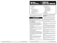
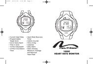
A. Screens<br />
Three display screens provide various training data as described below. Use the MODE<br />
button to scroll between the three screens. All screens can be viewed during a ride.<br />
Screen 1 (Figure 10)<br />
Displays current values for Power (watts), Speed, Slope, Trip Distance and Ride<br />
Time. Current resistance level setting is indicated on the right side of the display.<br />
The speed comparison arrows in the upper right corner of the screen compare<br />
current speed to average speed. An upward arrow indicates your current speed is above<br />
your average speed. A downward arrow indicates your current speed is below your average<br />
speed.<br />
9<br />
A. Current Power<br />
B. Current Speed<br />
C. Slope<br />
D. Trip Distance<br />
E. Ride Time<br />
F. Resistance Level<br />
G. Speed Comparison<br />
Screen 2 (Figure 11)<br />
Displays average values for Power (watts), Speed and Slope. Also displays Trip<br />
Distance, Ride Time, resistance level setting and Speed Comparison arrows.<br />
A. Average Power<br />
B. Average Speed<br />
C. Average Slope<br />
D. Trip Distance<br />
E. Ride Time<br />
F. Resistance Level<br />
G. Speed Comparison<br />
Screen 3 (Figure 12)<br />
Displays maximum values for Power (watts) and Speed, Elevation Gain, Total<br />
Distance (odometer) and Total Ride Time. Also displays resistance level setting and<br />
Speed Comparison arrows. The Total Distance and Total Ride Time values represent<br />
total distance and time accumulated on all rides to date, and will not be reset when<br />
the data screens are cleared (see Section C, “Reset”).<br />
A. Maximum Power<br />
B. Maximum Speed<br />
C. Elevation Gain<br />
D. Total Distance<br />
E. Total Ride Time<br />
F. Resistance Level<br />
G. Speed Comparison<br />
10<br />
11<br />
12<br />
B. Battery Life Indicator<br />
5