RP-01638
RP-01638
RP-01638

You also want an ePaper? Increase the reach of your titles
YUMPU automatically turns print PDFs into web optimized ePapers that Google loves.
13<br />
8<br />
-6<br />
7<br />
9<br />
10<br />
A B C<br />
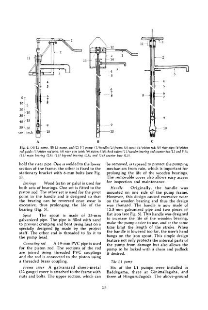
Fig. 4. (A) LI pump, (B) L3 pump, and (C) VI pump: (1) handle; (2) (rame; (3) spout; (4) piston rod; (5) riser pipe; (6) piston<br />
rod guide; (7) piston rod joint; (8) riser pipe joint; (9) piston; (10) check valve; (I I) wooden bearing and counter box (L7 and V I );<br />
(12) main bearing (L3); (13) big-end bearing (L3); and (14) counter base (L3).<br />
hold the riser pipe. One is welded to the lower<br />
section of the (rame, the other is fixed to the<br />
stationary bracket with 6-mm bolts (see Fig.<br />
5).<br />
Bearings Wood (satin or palu) is used for<br />
both sets of bearings. One set is fitted to the<br />
piston rod. The other set is used for the pivot<br />
point in the handle and is designed so that<br />
the bearing can be reversed once wear is<br />
excessive, thus prolonging the life of the<br />
bearing (Fig. 5).<br />
Spout The spout is made of 25-mm<br />
galvanized pipe. The pipe is filled with sand<br />
to prevent crimping and bent using heat on a<br />
specially designed jig made by the project<br />
staff. The other end is threaded to fix it to<br />
the pump head.<br />
Connecting rod A 19-mm PVC pipe is used<br />
for the piston rod. The sections of the rod<br />
are joined using threaded PVC couplings<br />
and the rod is connected to the piston using<br />
a threaded brass coupling.<br />
A galvanized sheet-metal<br />
Frame caver<br />
(22 gauge) cover is attached to the frame with<br />
nuts and bolts. The upper section, which can<br />
be removed, is tapered to protect the pumping<br />
mechanism from rain, which is important for<br />
prolonging the life of the wooden bearings.<br />
The removable cover also allows easy access<br />
for inspection and maintenance.<br />
Handle Originally, the handle was<br />
mounted on one side of the pump frame.<br />
However, this design caused excessive wear<br />
on the wooden bearing and thus the design<br />
was changed. The handle is now made of<br />
12.5-mm galvanized pipe and two pieces of<br />
flat iron (see Fig. 5). This handle was designed<br />
to increase the life of the wooden bearing,<br />
make the pump easier to use, and at the same<br />
time limit the length of the stroke. When<br />
the handle is lowered too far, the user's hand<br />
bangs on the iron spout. This simple design<br />
feature not only protects the internai parts of<br />
the pump from damage but also allows the<br />
pump to be locked with a chain and padlock<br />
if desired.<br />
The LI pump<br />
Six of the Li pumps were installed in<br />
Baddegama, three at Ginimallagaha, and<br />
three at Hingurudugoda. The above-ground<br />
15