RP-01638
RP-01638
RP-01638

Create successful ePaper yourself
Turn your PDF publications into a flip-book with our unique Google optimized e-Paper software.
L -'<br />
0<br />
inch 3<br />
cm 8<br />
A<br />
B<br />
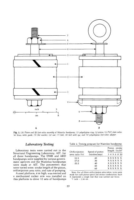
Fig. 1. (A) Piston and (B) foot-valve assembly of Waterloo handpump: (1) polyethylene ring; (2) piston; (3) PVC plate valve;<br />
(4) brass valve guide; (5) flat washer; (6) nui; (7) boit; (8) boit with eye; and (9) polyethylene foot-valve adapter.<br />
Laboratory Testing<br />
Laboratory tests were carried out in the<br />
Structural Engineering Laboratory, AIT, for<br />
all three handpumps. The DMR and ARD<br />
handpumps were supplied by various government<br />
agencies and the Waterloo handpumps<br />
were made at AIT. The parameters that<br />
were varied were: stroke length of the piston,<br />
orifice/piston area ratio, and rate of pumping.<br />
A steel platform, 4 m high, was erected and<br />
a mechanized rocker arm was installed on<br />
this platform to drive 12 sets of handpumps<br />
Table 2. Testing prograrn for Waterloo handpump.<br />
Piston stroke<br />
length (inch)'<br />
Orifice/piston Speed of piston<br />
area ratio (%) (strokeslmin) 3 4 5 6 8 10<br />
12.5 20 XXXXX X<br />
17.0 30 XXXXX X<br />
22.2 40 XXXXX X<br />
50 XXXXX X<br />
60 XXXXX X<br />
Note: For all three orifice/piston area ratios, tests were<br />
made for each piston speed and stroke combination. Each<br />
X represents a single test that was carried out twice.<br />
'l inch = 2.54 cm.<br />
23