
Create successful ePaper yourself
Turn your PDF publications into a flip-book with our unique Google optimized e-Paper software.
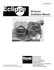
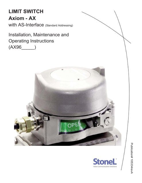
<strong>LIMIT</strong> <strong>SWITCH</strong><br />
<strong>Axiom</strong> - <strong>AX</strong><br />
with AS-Interface (Standard Addressing)<br />
Installation, Maintenance and<br />
Operating Instructions<br />
(<strong>AX</strong>96_____)<br />
Publication# 105334revA
2<br />
Table of Contents<br />
Publication# 105334revA<br />
Table Of Contents ............................................................................................................................................ Page 2<br />
<strong>Axiom</strong> Model Guide .......................................................................................................................................... Page 3<br />
Dimensions and General Specifications ...........................................................................................................Page 4<br />
Pneumatic Valve Specifications ....................................................................................................................... Page 5<br />
Assembly and Mounting Instructions ................................................................................................................Page 6<br />
<strong>Axiom</strong> Assembly Drawing .................................................................................................................................Page 7<br />
Communication Module Specifications .............................................................................................................Page 8<br />
Sensor Setting Instructions and Wiring Diagram ..............................................................................................Page 8<br />
Prefilter Removal Procedure ............................................................................................................................ Page 9<br />
READ THESE INSTRUCTIONS FIRST!<br />
These instructions provide information about safe handling and operation of the limit switch.<br />
If you require additional assistance, please contact the manufacturer or manufacturer’s representative.<br />
Address and phone numbers are printed on the back cover.<br />
SAVE THESE INSTRUCTIONS!<br />
Subject to change without notice.<br />
All trademarks are property of their respective owners.<br />
<strong>StoneL</strong><br />
Factory phone +1 (218) 739-5774
Publication# 105334revA<br />
Model Guide<br />
SERIES<br />
<strong>AX</strong> Explosionproof<br />
FUNCTION<br />
Sensor/switching modules<br />
33S SST N.O. sensor (2-wire AC/DC solid state sensor)<br />
35S SST N.O. sensor (2-wire AC/DC solid state sensor; 240VAC)<br />
44S Namur sensor (EN 60957-5-6; IS)<br />
80S Expeditor<br />
PNEUMATIC VALVE<br />
Single solenoid<br />
1H 0.6 Watt universal voltage input<br />
1J 4.5 W; 240 VAC coil<br />
1D 0.5 W; 24 VDC coil<br />
1B 1.8 W; 24 VDC coil<br />
1E 0.5 W; 12 VDC IS coil<br />
1A Piezo Electric<br />
PNEUMATIC OVERRIDE/Cv<br />
0.7Cv solenoid<br />
N<br />
M<br />
L<br />
Internal momentary override only<br />
External momentary and internal override<br />
External latching and internal override<br />
PNEUMATIC TEMPERATURE<br />
S<br />
T<br />
Standard<br />
Extended<br />
ENCLOSURE<br />
Epoxy-coated aluminum<br />
A<br />
V<br />
L<br />
North America<br />
International<br />
Brazilian<br />
Valve Communication Terminals (VCTs)<br />
71D 4-20mA with HART Diagnostics<br />
92S DeviceNet VCT<br />
93S FOUNDATION Fieldbus VCT (bus powered; IS)<br />
94S FOUNDATION Fieldbus VCT (externally powered)<br />
95S Modbus VCT<br />
96S AS-Interface with Standard Addressing VCT<br />
96D AS-Interface with Standard Addressing and Diagnostics VCT<br />
97S AS-Interface with Extended Addressing VCT<br />
Dual solenoid<br />
2H 0.6 Watt universal voltage input<br />
2J 4.5 W; 240 VAC coil<br />
2D 0.5 W; 24 VDC coil<br />
2B 1.8 W; 24 VDC coil<br />
2E 0.5 W; 12 VDC IS coil<br />
2A Piezo Electric<br />
1.2Cv solenoid<br />
E<br />
Y<br />
G<br />
CONDUIT ENTRY<br />
02 2 - 3/4” NPT<br />
05 2 - M25<br />
VISUAL INDICATOR<br />
R<br />
G<br />
1<br />
2<br />
X<br />
Internal momentary override only<br />
External momentary and internal override<br />
External latching and internal override<br />
Stainless steel<br />
S North America SS<br />
T International SS<br />
M Brazilian SS<br />
Red Closed/Green Open<br />
Green Closed/Red Open<br />
Three-way #1<br />
Three-way #2<br />
Special<br />
BRANDING<br />
A<br />
M<br />
<strong>StoneL</strong><br />
Metso<br />
3<br />
Model number example<br />
MODEL NUMBER<br />
Partnership ID*<br />
*Some models may include<br />
5-digit suffix for partnership<br />
identification<br />
<strong>AX</strong> 96S 1D L S A 02 R A - (optional)<br />
Technical hotline +1 (218) 737-0701<br />
www.<strong>StoneL</strong>.com
4<br />
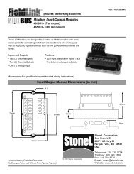
Dimensions Inches [mm]<br />
Publication# 105334revA<br />
6.57”<br />
[167.0mm]<br />
** 5.17”<br />
[131.4mm]<br />
2 3<br />
1/4” NPT Air Ports (2)<br />
6.31”<br />
[160.2mm]<br />
**1.0” [25mm] vertical clearance<br />
required for cover removal<br />
E3<br />
E2<br />
S1<br />
3/4” NPT (2) or M25 (2)<br />
0.7Cv = 1/4” NPT Air Ports (3)<br />
1.2Cv = 3/8” NPT Air Ports (3)<br />
Materials of Construction<br />
Housing: Epoxy Coated Anodized Aluminum or 316<br />
stainless steel<br />
Valve Manifold: Epoxy Coated Anodized Aluminum or 316<br />
stainless steel<br />
Visual Indicator Drum: Polysolphone<br />
Visual Indicator Cover: Polycarbonate<br />
Fasteners<br />
Stainless Steel<br />
O-Rings:<br />
Nitrile compound<br />
Operating Life:<br />
1 million cycles (500,000 cycles for the<br />
Expeditor)<br />
Temperature Range: See Solenoid Specifications<br />
Enclosure Type 4, 4X & IP66/67<br />
Warranty<br />
Sensing & Communication Module: Five Years<br />
Mechanical Components:<br />
Five Years<br />
<strong>StoneL</strong><br />
General Specifications and Ratings<br />
Position Sensing<br />
Accuracy: Within 1°<br />
Repeatability: Within 1°<br />
Setting Buffer:<br />
4° from set point<br />
(Rotational distance from original set point<br />
where switch will energize on return stroke)<br />
Dead Band:<br />
6° from set point<br />
(Rotational distance from original set point<br />
where switch will de-energize)<br />
Max Rotational Range: 120°<br />
Enclosure Ratings<br />
Explosion Proof<br />
<strong>AX</strong> models*<br />
Ex d Zone 1; Class I&II, Div 1<br />
Nonincendive<br />
<strong>AX</strong> models*<br />
Ex n Zone 2; Class I&II, Div 2<br />
Intrinsically Safe<br />
Functions 44 and 93 only*<br />
Ex ia Zone 0; Class I&II, Div 1<br />
Approvals*<br />
Go to www.stonel.com/approvals for<br />
specific approvals information<br />
Factory phone +1 (218) 739-5774
Publication# 105334revA<br />
General Pneumatic Specifications<br />
Valve Design:<br />
Pilot operated spool valve<br />
Pilot Operator Options: Solenoid Coil or Piezo<br />
Configuration:<br />
Single Pilot:<br />
5-Way, 2-Position, Spring Return<br />
Dual Pilot:<br />
5-Way, 2-Position, Shuttle Piston<br />
Flow Rating:<br />
0.70Cv (Kv = 0.60 based on flow m3/h)<br />
1.20Cv (Kv = 1.04 based on flow m3/h)<br />
<strong>Axiom</strong> Porting:<br />
1/4” NPT (0.7Cv); 3/8” NPT (1.2Cv)<br />
Manifold Porting:<br />
1/4” NPT (0.7Cv and 1.2Cv)<br />
Operating Pressure: 40 psi to 120 psi (2.7 to 7.5 bar)<br />
Operating Temperature (0.7Cv)<br />
Standard Temp Coil: -18° C to 50° C (0° F to 120° F)<br />
Extended Temp Coil: -40° C to 80° C (-40° F to 176° F) (NEC)<br />
-40° C to 70° C (-40° F to 158° F) (IEC)<br />
Operating Temperature (1.2Cv)<br />
Standard Temp Coil: -10° C to 50° C (14° F to 120° F)<br />
Extended Temp Coil: -10° C to 80° C (14° F to 176° F) (NEC)<br />
-10° C to 70° C (14° F to 158° F) (IEC)<br />
Operating Life:<br />
1 million cycles<br />
(500,000 cycles for the Expeditor)<br />
Manual Override:<br />
Internal momentary<br />
Optional external momentary available<br />
Optional external latching available<br />
Material of Construction:<br />
Aluminum Enclosure<br />
Spool:<br />
Nickel plated aluminum<br />
Body:<br />
Epoxy coated anodized aluminum<br />
Seal Spacers:<br />
Polysulphone<br />
Spool Seals :<br />
Nitrile compound<br />
O-rings<br />
Buna-N compound<br />
End Caps & Fasteners: 316 stainless steel<br />
Stainless steel Enclosure<br />
Spool:<br />
Nickel plated, Teflon coated stainless steel<br />
Body:<br />
316L stainless steel<br />
Seal Spacers:<br />
Polysulphone<br />
Spool Seals :<br />
Nitrile compound<br />
O-rings<br />
Buna-N compound<br />
End Caps & Fasteners: 316 stainless steel<br />
Pneumatic Valve Specifications<br />
Solenoid Coil Specifications<br />
Universal (1H, 2H)<br />
For “33” Function<br />
Operating Voltage:<br />
22 VDC/130 VAC<br />
Power Consumption: 0.6 Watts<br />
Filtration Requirements: 40 Microns<br />
For “35” Function<br />
Operating Voltage:<br />
Power Consumption:<br />
Filtration Requirements:<br />
240 VAC (1J, 2J)<br />
Operating Voltage:<br />
Power Consumption:<br />
Filtration Requirements:<br />
24 VDC (1B, 2B)<br />
Operating Voltage:<br />
Power Consumption:<br />
Filtration Requirements:<br />
24 VDC (1D, 2D)<br />
Operating Voltage:<br />
Power Consumption:<br />
Filtration Requirements:<br />
20-60 VDC/20-250 VAC<br />
0.6 Watts<br />
40 Microns<br />
240 VAC<br />
4.5 Watts<br />
40 Microns<br />
24 VDC<br />
1.8 Watts<br />
40 Microns<br />
24 VDC<br />
0.5 Watts<br />
40 Microns<br />
12 VDC (1E, 2E) (Intrinsically Safe)<br />
Operating Voltage:<br />
12 VDC (output of barrier)<br />
Power Consumption: 0.5 Watts<br />
Filtration Requirements: 40 Microns<br />
Entity Parameters:<br />
Ui=28VDC; Ii=120mA; Ci=0; Li=0; Pi=1.0W<br />
Piezo (1A, 2A)<br />
Operating Voltage:<br />
5.5 VDC to 9.0 VDC<br />
Current Consumption: 2.0 mA @ 6.5 VDC<br />
Temperature Range: -10° C to 60° C (14° F to 140° F)<br />
Filtration Requirements: Dried/30 Microns<br />
5<br />
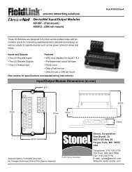
Spring Return Actuator with Rebreather Open<br />
Double Acting Actuator with Rebreather Closed<br />
Actuator<br />
Actuator<br />
3<br />
2<br />
3<br />
2<br />
SR<br />
DA<br />
<strong>Axiom</strong> Pneumatic Valve<br />
E3 S1 E2<br />
<strong>Axiom</strong> Pneumatic Valve<br />
E3 S1 E2<br />
Technical hotline +1 (218) 737-0701<br />
www.<strong>StoneL</strong>.com
6<br />
Publication# 105334revA<br />
Assembly and Mounting Instructions<br />
SPECIAL NOTES<br />
Note<br />
Mounting of the <strong>Axiom</strong> requires a <strong>StoneL</strong> mounting kit specific to the actuator the <strong>Axiom</strong> is to be mounted to.<br />
Note<br />
It is recommended that thread lubricant or anti-seize be used on the <strong>Axiom</strong> Body Screws (Item# 3) prior to assembly.<br />
Note<br />
Referring to Step 3 below. Depending on the version of <strong>Axiom</strong>, the DA/SR Plug (Item# 5) may be located in the <strong>Axiom</strong> Body<br />
(Item# 4) or the Air Manifold Plate of the mounting kit (Item# 14).<br />
Note<br />
In high cycle or high vibration applications, blue Loctite® may be used on the Air Manifold Mounting Screws (Item# 11) and<br />
the Visual Indicator Drum Retaining Screw (Item# 9).<br />
Note<br />
It is highly recommended that exhaust ports E2 and E3 be fitted with low restriction mufflers or breather vent caps to<br />
prevent ingestion of water and debris into the pneumatic valve.<br />
Note<br />
For epoxy coated aluminum models, conduit seal-offs are required with in 18” of the unit. Seal-offs are not required on<br />
models with a stainless steel housing.<br />
1. Refer to <strong>Axiom</strong> Assembly Drawing located on Page 7 when performing mounting and assembly procedures.<br />
2. Remove <strong>Axiom</strong> unit from shipping container. Ensure all listed items are present.<br />
3. Determine if the actuator the <strong>Axiom</strong> is to be mounted on is double acting (DA) or spring return (SR). Ensure the DA/SR Plug<br />
(Item# 5) is in the correct position. (See Detail - A on Page 7). If the DA/SR Plug is in the incorrect position, gently remove plug with<br />
a pair of pliers and insert into the proper orifice. (Note: For aluminum <strong>AX</strong> units, the DA/SR Plug is included in the manifold plate of<br />
the mounting kit. If there is a black DA/SR plug in the body of aluminum <strong>AX</strong> housing, this needs to be removed and discarded. For<br />
stainless steel <strong>AX</strong> units the DA/SR plug is located in the body of the stainless steel <strong>AX</strong> housing.)<br />
4. From the mounting kit package, locate the Air Manifold Plate (Item# 14). Place the Air Manifold Plate on the actuator. Using an M4<br />
allen wrench, fasten down with the four Air Manifold Mounting Screws (Item# 11). Torque screws to 25 - 30 in.lbs (2.8 - 3.4Nm).<br />
5. Place Visual Indicator Drive Block (Item# 10) into slot on the actuator shaft. Place Visual Indicator Drum Coupler (Item# 8) onto the<br />
Visual Indicator Drive Block. Next, place the Visual Indicator Drum (Item# 7) onto the Visual Indicator Drum Coupler. Align the<br />
holes in all three items with the the threaded hole in the actuator shaft and fasten down with the Visual Indicator Drum Retaining<br />
Screw (Item# 9). Leave screw loose in order to facilitate indexing of the visual indicator.<br />
6. With the actuator in the closed position, center the Visual Indicator Drum until the “OPEN” quadrant is centered between the “V.I<br />
INDEX” markings on the AIr Manifold Plate. (See Detail - B on Page 7). Tighten down with the Visual Indicator Drum Retaining<br />
Screw 15 - 20 in.lbs (1.7 - 2.3Nm).<br />
7. Verify Air Manifold Plate Orifice O-rings (Item# 12) and Visual Indicator Cover O-ring (Item# 13) are in place.<br />
8. Place the Visual Indicator Cover (Item# 6) over the Visual Indicator Drum assembly then set the <strong>Axiom</strong> Body (Item# 4) in place.<br />
With an M5 allen wrench, torque the <strong>Axiom</strong> Body Screws (Item# 3) to 8 - 10 ft. lbs (10.8 - 13.5Nm).<br />
9. After all wiring and sensor setting procedures have been completed, install <strong>Axiom</strong> Cover and tighten the <strong>Axiom</strong> Cover Lock set<br />
screw (Item# 2).<br />
<strong>StoneL</strong><br />
Factory phone +1 (218) 739-5774
Publication# 105334revA<br />
7<br />
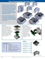
<strong>Axiom</strong> Assembly Drawing<br />
ITEM# DESCRIPTION QTY<br />
1 <strong>Axiom</strong> Cover 1<br />
2 <strong>Axiom</strong> Cover Lock 1<br />
1<br />
3 <strong>Axiom</strong> Body Screws 4<br />
4 <strong>Axiom</strong> Body 1<br />
5 DA/SR Plug (may be located in mtg kit) 1<br />
6 Visual Indicator Cover 1<br />
7 Visual Indicator Drum 1<br />
8 Visual Indicator Drum Coupler 1<br />
2<br />
Item# 9 thru 14 are provided with the mounting kit.<br />
Mounting kits are sold separately<br />
9 Visual Indicator Drum Retaining Screw 1<br />
10 Visual Indicator Drive Block 1<br />
3<br />
11 Air Manifold Plate Mounting Screws 4<br />
12 Air Manifold Plate Orifice O-rings 3<br />
13 Visual Indicator Cover O-ring 1<br />
14 Air Manifold Plate 1<br />
4<br />
DA/SR Plug Placement<br />
PLUG FOR SR<br />
PLUG FOR DA<br />
8<br />
6<br />
7<br />
6<br />
8<br />
7<br />
5<br />
Bottom side of <strong>Axiom</strong> Body<br />
FOR DA<br />
PLUG FOR SR<br />
PLUG<br />
9<br />
V.I. INDEX<br />
7<br />
SR<br />
SED<br />
6<br />
6<br />
DA<br />
OPEN<br />
7<br />
8<br />
V.I. INDEX<br />
CLO<br />
8<br />
Air Manifold Plate<br />
10<br />
Detail - A<br />
Visual Indicator Indexing<br />
11<br />
12<br />
13<br />
V.I. INDEX<br />
6<br />
7<br />
OPEN<br />
SED<br />
14<br />
8<br />
V.I. INDEX<br />
CLO<br />
Detail - B<br />
Technical hotline +1 (218) 737-0701<br />
www.<strong>StoneL</strong>.com
8<br />
Publication# 105334revA<br />
AS-Interface Standard Addressing Sensing & Communications Module<br />
AS-Interface Module w/Standard Address Specifications Max. Output Current: 160mA (4 watts; both outputs combined<br />
Communication Protocol: AS-Interface v3.0<br />
ID/IO Codes:<br />
ID = F; IO = 4; ID1 = F; ID2 = E<br />
Configuration:<br />
(2) Discrete Inputs (Sensors)<br />
Default Address: 00<br />
(2) Auxiliary Discrete Inputs<br />
Bit Assignment: Inputs Outputs<br />
(2) Discrete Outputs (Solenoids)<br />
Bit 1 = Aux Input 1 Bit 1 = Not Used<br />
Voltage:<br />
26.5-30.6 VDC (AS-I Voltage)<br />
Bit 2 = Aux input 2 Bit 2 = Not Used<br />
Bit 3 = Green LED Bit 3 = OUT 1<br />
Output Voltage:<br />
24 VDC<br />
Bit 4 = Red LED Bit 4 = OUT 2<br />
Current Consumption: 42mA (1) 0.5w coil; 64mA (2) 0.5w coils<br />
96mA (1) 1.8w coil; 171mA (2) 1.8w coils<br />
To Bench Test an AS-Interface Sensing & Communications Module:<br />
To test sensors, use a 24 Vdc power supply. No series load resistor is required. Operate actuator to the closed position. Apply power<br />
across the “ASI+” and “ASI-” terminal points. Press and hold “Closed Set” button until “Closed LED is lit (two seconds). Release<br />
button. Operate actuator to the open position. Press and hold “Open Set” button until “Open LED is lit (two seconds). Release button.<br />
Set points are retained even after power is removed. A functioning AS-Interface network is required to test communications.<br />
WARNING:<br />
DO NOT APPLY EXTERNAL POWER TO THE OUTPUT TERMINALS. THIS WILL CAUSE PERMANENT DAMAGE TO THE UNIT<br />
Wiring Diagram<br />
SET<br />
OPEN<br />
SET<br />
CLOSED<br />
OPEN<br />
CLOSED<br />
Setup Instructions:<br />
Operate Actuator to Closed<br />
Position and Push SET CLOSED<br />
for 2 seconds.<br />
Operate Actuator to Open<br />
Position and Push SET OPEN<br />
for 2 seconds<br />
SOLENOID 1<br />
SOLENOID 2<br />
OUT 1 - (1)<br />
OUT 1 + (2)<br />
OUT 2 - (3)<br />
OUT 2 + (4)<br />
3 wire RTN (5)<br />
Aux IN 2 - (6)<br />
Aux IN 1 - (7)<br />
Aux IN + (8)<br />
ASI - (9)<br />
ASI + (10)<br />
Sensor Setting Instructions<br />
1. With the Sensor & Communication Module (CCM) wired to the control system and power applied, operate actuator to the closed<br />
position.<br />
2. Press and hold “Closed Set” button until “Closed LED is lit (two seconds). Release button.<br />
3. Operate actuator to the open position.<br />
4. Press and hold “Open Set” button until “Open LED is lit (two seconds). Release button.<br />
5. Set points are retained even after power is removed.<br />
<strong>StoneL</strong><br />
Factory phone +1 (218) 739-5774
Publication# 105334revA<br />
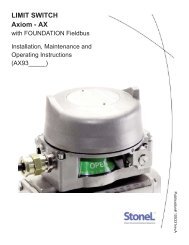
Prefilter Removal Procedure<br />
9<br />
WARNING<br />
Secure electrical power and supply air to <strong>Axiom</strong> unit prior to performing the Prefilter Removal Procedure.<br />
1. Secure electrical power and supply air to the <strong>Axiom</strong> unit.<br />
2. Loosen Cover Lock set screw and remove <strong>Axiom</strong> Cover.<br />
3. With an M3 allen wrench, loosen the two captive screws located next to the pilot valve/s. These hold the internal air interface plate<br />
in place. (See Fig. 1)<br />
4. Carefully lift the internal air interface plate to expose the prefilter (see Fig. 2).<br />
5. With an M8 allen wrench, remove the prefilter (See Fig. 3). Inspect and clean as necessary.<br />
6. Re-install prefilter and torque to 25 - 30 in.lbs (2.8 - 3.4Nm).<br />
7. Re-install the internal air interface plate and torque screws to 25 - 30 in.lbs (2.8 - 3.4Nm).<br />
8. Install unit cover and place unit back into service.<br />
Fig. 1 Fig. 2<br />
Fig. 3<br />
Technical hotline +1 (218) 737-0701<br />
www.<strong>StoneL</strong>.com