
Create successful ePaper yourself
Turn your PDF publications into a flip-book with our unique Google optimized e-Paper software.
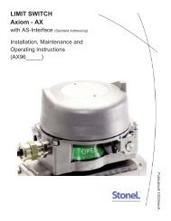
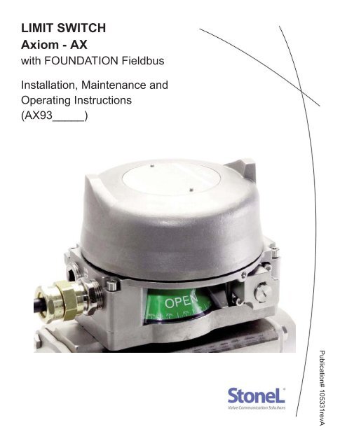
<strong>LIMIT</strong> <strong>SWITCH</strong><strong>Axiom</strong> - <strong>AX</strong>with FOUNDATION FieldbusInstallation, Maintenance andOperating Instructions(<strong>AX</strong>93_____)Publication# 105331revA
2Table of ContentsPublication# 105331revATable Of Contents ............................................................................................................................................ Page 2<strong>Axiom</strong> Model Guide .......................................................................................................................................... Page 3Dimensions and General Specifications ...........................................................................................................Page 4Pneumatic Valve Specifications ....................................................................................................................... Page 5Assembly and Mounting Instructions ................................................................................................................Page 6<strong>Axiom</strong> Assembly Drawing .................................................................................................................................Page 7Communication Module Specifications .............................................................................................................Page 8Sensor Setting Instructions and Wiring Diagram ..............................................................................................Page 9Prefilter Removal Procedure ............................................................................................................................ Page 10READ THESE INSTRUCTIONS FIRST!These instructions provide information about safe handling and operation of the limit switch.If you require additional assistance, please contact the manufacturer or manufacturer’s representative.Address and phone numbers are printed on the back cover.SAVE THESE INSTRUCTIONS!Subject to change without notice.All trademarks are property of their respective owners.<strong>StoneL</strong>Factory phone +1 (218) 739-5774
Publication# 105331revAModel GuideSERIES<strong>AX</strong> ExplosionproofFUNCTIONSensor/switching modules33S SST N.O. sensor (2-wire AC/DC solid state sensor)35S SST N.O. sensor (2-wire AC/DC solid state sensor; 240VAC)44S Namur sensor (EN 60957-5-6; IS)80S ExpeditorPNEUMATIC VALVESingle solenoid1H 0.6 Watt universal voltage input1J 4.5 W; 240 VAC coil1D 0.5 W; 24 VDC coil1B 1.8 W; 24 VDC coil1E 0.5 W; 12 VDC IS coil1A Piezo ElectricPNEUMATIC OVERRIDE/Cv0.7Cv solenoidNMLInternal momentary override onlyExternal momentary and internal overrideExternal latching and internal overridePNEUMATIC TEMPERATURESTStandardExtendedENCLOSUREEpoxy-coated aluminumAVLNorth AmericaInternationalBrazilianValve Communication Terminals (VCTs)71D 4-20mA with HART Diagnostics92S DeviceNet VCT93S FOUNDATION Fieldbus VCT (bus powered; IS)94S FOUNDATION Fieldbus VCT (externally powered)95S Modbus VCT96S AS-Interface with Standard Addressing VCT96D AS-Interface with Standard Addressing and Diagnostics VCT97S AS-Interface with Extended Addressing VCTDual solenoid2H 0.6 Watt universal voltage input2J 4.5 W; 240 VAC coil2D 0.5 W; 24 VDC coil2B 1.8 W; 24 VDC coil2E 0.5 W; 12 VDC IS coil2A Piezo Electric1.2Cv solenoidEYGCONDUIT ENTRY02 2 - 3/4” NPT05 2 - M25VISUAL INDICATORRG12XInternal momentary override onlyExternal momentary and internal overrideExternal latching and internal overrideStainless steelS North America SST International SSM Brazilian SSRed Closed/Green OpenGreen Closed/Red OpenThree-way #1Three-way #2SpecialBRANDINGAM<strong>StoneL</strong>Metso3Model number exampleMODEL NUMBERPartnership ID**Some models may include5-digit suffix for partnershipidentification<strong>AX</strong> 96S 1D L S A 02 R A - (optional)Technical hotline +1 (218) 737-0701www.<strong>StoneL</strong>.com
4Dimensions Inches [mm]Publication# 105331revA6.57”[167.0mm]** 5.17”[131.4mm]2 31/4” NPT Air Ports (2)6.31”[160.2mm]**1.0” [25mm] vertical clearancerequired for cover removalE3E2S13/4” NPT (2) or M25 (2)0.7Cv = 1/4” NPT Air Ports (3)1.2Cv = 3/8” NPT Air Ports (3)Materials of ConstructionHousing: Epoxy Coated Anodized Aluminum or 316stainless steelValve Manifold: Epoxy Coated Anodized Aluminum or 316stainless steelVisual Indicator Drum: PolysolphoneVisual Indicator Cover: PolycarbonateFastenersStainless SteelO-Rings:Nitrile compoundOperating Life:1 million cycles (500,000 cycles for theExpeditor)Temperature Range: See Solenoid SpecificationsEnclosure Type 4, 4X & IP66/67WarrantySensing & Communication Module: Five YearsMechanical Components:Five Years<strong>StoneL</strong>General Specifications and RatingsPosition SensingAccuracy: Within 1°Repeatability: Within 1°Setting Buffer:4° from set point(Rotational distance from original set pointwhere switch will energize on return stroke)Dead Band:6° from set point(Rotational distance from original set pointwhere switch will de-energize)Max Rotational Range: 120°Enclosure RatingsExplosion Proof<strong>AX</strong> models*Ex d Zone 1; Class I&II, Div 1Nonincendive<strong>AX</strong> models*Ex n Zone 2; Class I&II, Div 2Intrinsically SafeFunctions 44 and 93 only*Ex ia Zone 0; Class I&II, Div 1Approvals*Go to www.stonel.com/approvals forspecific approvals informationFactory phone +1 (218) 739-5774
Publication# 105331revAGeneral Pneumatic SpecificationsValve Design:Pilot operated spool valvePilot Operator Options: Solenoid Coil or PiezoConfiguration:Single Pilot:5-Way, 2-Position, Spring ReturnDual Pilot:5-Way, 2-Position, Shuttle PistonFlow Rating:0.70Cv (Kv = 0.60 based on flow m3/h)1.20Cv (Kv = 1.04 based on flow m3/h)<strong>Axiom</strong> Porting:1/4” NPT (0.7Cv); 3/8” NPT (1.2Cv)Manifold Porting:1/4” NPT (0.7Cv and 1.2Cv)Operating Pressure: 40 psi to 120 psi (2.7 to 7.5 bar)Operating Temperature (0.7Cv)Standard Temp Coil: -18° C to 50° C (0° F to 120° F)Extended Temp Coil: -40° C to 80° C (-40° F to 176° F) (NEC)-40° C to 70° C (-40° F to 158° F) (IEC)Operating Temperature (1.2Cv)Standard Temp Coil: -10° C to 50° C (14° F to 120° F)Extended Temp Coil: -10° C to 80° C (14° F to 176° F) (NEC)-10° C to 70° C (14° F to 158° F) (IEC)Operating Life:1 million cycles(500,000 cycles for the Expeditor)Manual Override:Internal momentaryOptional external momentary availableOptional external latching availableMaterial of Construction:Aluminum EnclosureSpool:Nickel plated aluminumBody:Epoxy coated anodized aluminumSeal Spacers:PolysulphoneSpool Seals :Nitrile compoundO-ringsBuna-N compoundEnd Caps & Fasteners: 316 stainless steelStainless steel EnclosureSpool:Nickel plated, Teflon coated stainless steelBody:316L stainless steelSeal Spacers:PolysulphoneSpool Seals :Nitrile compoundO-ringsBuna-N compoundEnd Caps & Fasteners: 316 stainless steelPneumatic Valve SpecificationsSolenoid Coil SpecificationsUniversal (1H, 2H)For “33” FunctionOperating Voltage:22 VDC/130 VACPower Consumption: 0.6 WattsFiltration Requirements: 40 MicronsFor “35” FunctionOperating Voltage:Power Consumption:Filtration Requirements:240 VAC (1J, 2J)Operating Voltage:Power Consumption:Filtration Requirements:24 VDC (1B, 2B)Operating Voltage:Power Consumption:Filtration Requirements:24 VDC (1D, 2D)Operating Voltage:Power Consumption:Filtration Requirements:20-60 VDC/20-250 VAC0.6 Watts40 Microns240 VAC4.5 Watts40 Microns24 VDC1.8 Watts40 Microns24 VDC0.5 Watts40 Microns12 VDC (1E, 2E) (Intrinsically Safe)Operating Voltage:12 VDC (output of barrier)Power Consumption: 0.5 WattsFiltration Requirements: 40 MicronsEntity Parameters:Ui=28VDC; Ii=120mA; Ci=0; Li=0; Pi=1.0WPiezo (1A, 2A)Operating Voltage:5.5 VDC to 9.0 VDCCurrent Consumption: 2.0 mA @ 6.5 VDCTemperature Range: -10° C to 60° C (14° F to 140° F)Filtration Requirements: Dried/30 Microns5Spring Return Actuator with Rebreather OpenDouble Acting Actuator with Rebreather ClosedActuatorActuator3232SRDA<strong>Axiom</strong> Pneumatic ValveE3 S1 E2<strong>Axiom</strong> Pneumatic ValveE3 S1 E2Technical hotline +1 (218) 737-0701www.<strong>StoneL</strong>.com
6Publication# 105331revAAssembly and Mounting InstructionsSPECIAL NOTESNoteMounting of the <strong>Axiom</strong> requires a <strong>StoneL</strong> mounting kit specific to the actuator the <strong>Axiom</strong> is to be mounted to.NoteIt is recommended that thread lubricant or anti-seize be used on the <strong>Axiom</strong> Body Screws (Item# 3) prior to assembly.NoteReferring to Step 3 below. Depending on the version of <strong>Axiom</strong>, the DA/SR Plug (Item# 5) may be located in the <strong>Axiom</strong> Body(Item# 4) or the Air Manifold Plate of the mounting kit (Item# 14).NoteIn high cycle or high vibration applications, blue Loctite® may be used on the Air Manifold Mounting Screws (Item# 11) andthe Visual Indicator Drum Retaining Screw (Item# 9).NoteIt is highly recommended that exhaust ports E2 and E3 be fitted with low restriction mufflers or breather vent caps toprevent ingestion of water and debris into the pneumatic valve.NoteFor epoxy coated aluminum models, conduit seal-offs are required with in 18” of the unit. Seal-offs are not required onmodels with a stainless steel housing.1. Refer to <strong>Axiom</strong> Assembly Drawing located on Page 7 when performing mounting and assembly procedures.2. Remove <strong>Axiom</strong> unit from shipping container. Ensure all listed items are present.3. Determine if the actuator the <strong>Axiom</strong> is to be mounted on is double acting (DA) or spring return (SR). Ensure the DA/SR Plug(Item# 5) is in the correct position. (See Detail - A on Page 7). If the DA/SR Plug is in the incorrect position, gently remove plug witha pair of pliers and insert into the proper orifice. (Note: For aluminum <strong>AX</strong> units, the DA/SR Plug is included in the manifold plate ofthe mounting kit. If there is a black DA/SR plug in the body of aluminum <strong>AX</strong> housing, this needs to be removed and discarded. Forstainless steel <strong>AX</strong> units the DA/SR plug is located in the body of the stainless steel <strong>AX</strong> housing.)4. From the mounting kit package, locate the Air Manifold Plate (Item# 14). Place the Air Manifold Plate on the actuator. Using an M4allen wrench, fasten down with the four Air Manifold Mounting Screws (Item# 11). Torque screws to 25 - 30 in.lbs (2.8 - 3.4Nm).5. Place Visual Indicator Drive Block (Item# 10) into slot on the actuator shaft. Place Visual Indicator Drum Coupler (Item# 8) onto theVisual Indicator Drive Block. Next, place the Visual Indicator Drum (Item# 7) onto the Visual Indicator Drum Coupler. Align theholes in all three items with the the threaded hole in the actuator shaft and fasten down with the Visual Indicator Drum RetainingScrew (Item# 9). Leave screw loose in order to facilitate indexing of the visual indicator.6. With the actuator in the closed position, center the Visual Indicator Drum until the “OPEN” quadrant is centered between the “V.IINDEX” markings on the AIr Manifold Plate. (See Detail - B on Page 7). Tighten down with the Visual Indicator Drum RetainingScrew 15 - 20 in.lbs (1.7 - 2.3Nm).7. Verify Air Manifold Plate Orifice O-rings (Item# 12) and Visual Indicator Cover O-ring (Item# 13) are in place.8. Place the Visual Indicator Cover (Item# 6) over the Visual Indicator Drum assembly then set the <strong>Axiom</strong> Body (Item# 4) in place.With an M5 allen wrench, torque the <strong>Axiom</strong> Body Screws (Item# 3) to 8 - 10 ft. lbs (10.8 - 13.5Nm).9. After all wiring and sensor setting procedures have been completed, install <strong>Axiom</strong> Cover and tighten the <strong>Axiom</strong> Cover Lock setscrew (Item# 2).<strong>StoneL</strong>Factory phone +1 (218) 739-5774
Publication# 105331revA7<strong>Axiom</strong> Assembly DrawingITEM# DESCRIPTION QTY1 <strong>Axiom</strong> Cover 12 <strong>Axiom</strong> Cover Lock 113 <strong>Axiom</strong> Body Screws 44 <strong>Axiom</strong> Body 15 DA/SR Plug (may be located in mtg kit) 16 Visual Indicator Cover 17 Visual Indicator Drum 18 Visual Indicator Drum Coupler 12Item# 9 thru 14 are provided with the mounting kit.Mounting kits are sold separately9 Visual Indicator Drum Retaining Screw 110 Visual Indicator Drive Block 1311 Air Manifold Plate Mounting Screws 412 Air Manifold Plate Orifice O-rings 313 Visual Indicator Cover O-ring 114 Air Manifold Plate 14DA/SR Plug PlacementPLUG FOR SRPLUG FOR DA8676875Bottom side of <strong>Axiom</strong> BodyFOR DAPLUG FOR SRPLUG9V.I. INDEX7SRSED66DAOPEN78V.I. INDEXCLO8Air Manifold Plate10Detail - AVisual Indicator Indexing111213V.I. INDEX67OPENSED148V.I. INDEXCLODetail - BTechnical hotline +1 (218) 737-0701www.<strong>StoneL</strong>.com
8Publication# 105331revAFoundation Sensing & Communications Module SpecificationsSpecificationsCommunication Protocol: Foundation Fieldbus (H1)Configuration:(2) Discrete Inputs (Sensors)(2) Discrete Outputs (Piezo Valves)Function Blocks 2 DI; 2 DOExecution TimeMaximum 30ms per DI and DOVoltage:9-32 VDC (Bus Voltage)Output Voltage:6.5 VDCMax. Output Current: 2.0mA @ 6.5 VDCCurrent Draw:16mADevices per Network Maximum of 16 devices recommendedStandard Channel AssignmentsChannel 1 (DI1) - Discrete Input 1 (Red LED);Channel 2 (DI2) - Discrete Input 2 (Green LED);Channel 3 (DO1) - Discrete Output 1 (OUT 1);Channel 4 (DO2) - Discrete Output 2 (OUT 2);1 = True; 0 = False1 = True; 0 = False1 = True; 0 = False1 = True; 0 = FalseSpecial Channel AssignmentsChannel 8 (DO1) - Discrete Output 1 (OUT 1) with state report from Discrete Input 1 (READBACK_D)Channel 9 (DO2) - Discrete Output 2 (OUT 2) with state report from Discrete Input 2 (READBACK_D)Valve Control Single Block ModeChannel 10 (DO1) - Discrete Output 1 (OUT 1) with state report Discrete Inputs 1&2 (READBACK_D):READBACK_D Values:0 = None1 = Discrete Input 1 is True2 = Discrete Input 2 is True3 = Both Discrete Inputs 1&2 are True<strong>StoneL</strong>Factory phone +1 (218) 739-5774
Publication# 105331revA9Wiring DiagramWARNING:DO NOT APPLY EXTERNAL POWER TO THE OUTPUT TERMINALS. THIS WILL CAUSE PERMANENT DAMAGE TO THE UNITTo Bench Test a Foundation Fieldbus Sensing & Communications Module:To test sensors, use a 9-32 Vdc power supply. No series load resistor is required. Operate actuator to the closed position. Apply poweracross the “FB+” and “FB-” terminal points. Press and hold “Closed Set” button until “Closed LED is lit (2 seconds). Release button.Operate actuator to the open position. Press and hold “Open Set” button until “Open LED is lit (2 seconds). Release button. Set pointsare retained even after power is removed. A functioning Foundation Fieldbus network is required to test communications.SETOPENOPENSetup Instructions:Operate Actuator to ClosedPosition and Push SETCLOSED for 2 seconds.Operate Actuator to OpenPosition and Push SET OPENfor 2 secondsSETCLOSEDCLOSEDSOLENOIDPOWERSIM JMPR (1)SIM JMPR (2)OUT 2 - (3)OUT 2 + (4)OUT 1 - (5)OUT 1 + (6)FB - (7)FB + (8)Sensor Setting Instructions1. With the Sensor & Communication Module (CCM) wired to the control system and power applied, operate actuator to the closedposition.2. Press and hold “Closed Set” button until “Closed LED is lit (two seconds). Release button.3. Operate actuator to the open position.4. Press and hold “Open Set” button until “Open LED is lit (two seconds). Release button.5. Set points are retained even after power is removed.Technical hotline +1 (218) 737-0701www.<strong>StoneL</strong>.com
10Publication# 105331revAPrefilter Removal ProcedureWARNINGSecure electrical power and supply air to <strong>Axiom</strong> unit prior to performing the Prefilter Removal Procedure.1. Secure electrical power and supply air to the <strong>Axiom</strong> unit.2. Loosen Cover Lock set screw and remove <strong>Axiom</strong> Cover.3. With an M3 allen wrench, loosen the two captive screws located next to the pilot valve/s. These hold the internal air interface platein place. (See Fig. 1)4. Carefully lift the internal air interface plate to expose the prefilter (see Fig. 2).5. With an M8 allen wrench, remove the prefilter (See Fig. 3). Inspect and clean as necessary.6. Re-install prefilter and torque to 25 - 30 in.lbs (2.8 - 3.4Nm).7. Re-install the internal air interface plate and torque screws to 25 - 30 in.lbs (2.8 - 3.4Nm).8. Install unit cover and place unit back into service.Fig. 1 Fig. 2Fig. 3<strong>StoneL</strong>Factory phone +1 (218) 739-5774