
You also want an ePaper? Increase the reach of your titles
YUMPU automatically turns print PDFs into web optimized ePapers that Google loves.
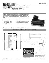
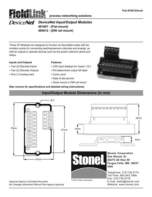
Pub #105123revAprocess networking solutions<strong>DeviceNet</strong> Input/Output <strong>Module</strong>s461007 - (Flat mount)465012 - (DIN rail mount)These I/O <strong>Module</strong>s are designed to function as <strong>DeviceNet</strong> nodes with terminationpoints for connecting switches/sensors (discrete and analog), aswell as outputs to operate devices such as low power solenoid valves andrelays.Inputs and Outputs- Two (2) Discrete Inputs- Two (2) Discrete Outputs- One (1) Analog InputFeatures- LED input displays for Inputs 1 & 2- Pre-determined output fail state- Cycle count- Date of last service- Direct mount or DIN rail mount(See reverse for specifications and detailed wiring instructions)Input/Output <strong>Module</strong> Dimensions (in mm)Ø 342mm75mm67mm14mm8mm42mm<strong>StoneL</strong> CorporationOne <strong>StoneL</strong> Dr26275 US Hwy 59Fergus Falls, MN 56537USAApproval Agency Controlled Document.No Changes Authorized Without Prior Agency Approval© 2001 <strong>StoneL</strong> CorporationTelephone: 218.739.5774Toll Free: 800.843.7866Fax: 218.739.5776E-mail: sales@stonel.comWebsite: www.stonel.com
Pub #105123revAInput/Output <strong>Module</strong> SpecificationsPage 2<strong>DeviceNet</strong> 2 DI/2 DO/1 AI Input/Output <strong>Module</strong>sOperating Voltage 24 VDC via <strong>DeviceNet</strong> voltage Bit Assignment:Discrete Inputs (2) 7mA @ 24 VDC gold contact Inputs: (3 Bytes)Outputs (1 Byte)mechanical, low power reed, or 2 wire Bit 0 = Input 1 (Red) Bit 0 = Output 1and 3 wire PNP solid state sensors Bit 1 = Input 2 (Green) Bit 1 = Output 2Analog Input (1) Analog (4-20 mA) input. 8 bitresolution (0.4%)Bit 4 = Fault Bit (On if bothInput 1 and Input 2 bits are set)Outputs(2) 24 VDC - Bus Powered(4 Watts total power available)Bits 8-15 = Analog Input (Low Byte)Bits 16-23 = Analog Input (High Byte)Current Usage 60mA (no I/O enabled)Temp Range -40° to +85° C (-23° to 185° F)Default Address 63Operating Life UnlimitedWarrantyTwo YearsInput/Output <strong>Module</strong> Wiring Diagram and Installation NotesRED LEDOUTPUT2 -INPUT1 +5OUTPUTS +OUTPUT1 -INPUT1 - (Red LED)INPUT2 +32ANLG IN -ANLG IN +INPUT2 - (Green Led)RTN FOR 3 WIRE PNP SENSORS4V-CAN_L1SHIELDCAN_HV+GREEN LED12345INSTALLAT<strong>IO</strong>N NOTES:1. <strong>DeviceNet</strong> bus communications connection points.2. 24 VDC Bus powered Analog Input device connection points. (4-20mA)3. Bus powered Discrete Input connection points for low power (7mA @ 24 VDC) gold contact mechanicalswitches, low power reed, or 2 wire and 3 wire PNP solid state proximity sensors (max allowable current leakageof sensors 0.165mA). Red LED is local indication of discrete Input 1 on/off status and the Green LED for discreteInput 2 on/off status.4. Connection point for the “return” of 3 wire PNP sensors. (See Note 3)5. Connection points for 24 VDC Bus powered Discrete Outputs (4 watts total power available) for low powersolenoid valves and relays.