Valve Communication Terminals (VCTs) Devic - StoneL
Valve Communication Terminals (VCTs) Devic - StoneL
Valve Communication Terminals (VCTs) Devic - StoneL

You also want an ePaper? Increase the reach of your titles
YUMPU automatically turns print PDFs into web optimized ePapers that Google loves.
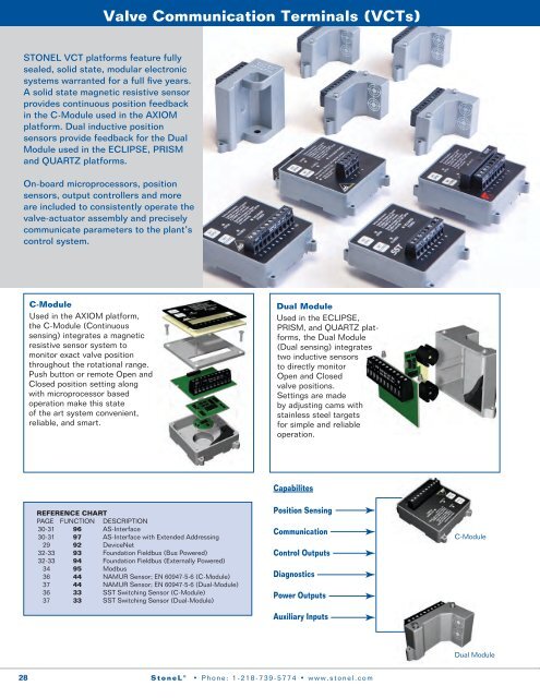
<strong>Valve</strong> <strong>Communication</strong> <strong>Terminals</strong> (<strong>VCTs</strong>)STONEL VCT platforms feature fullysealed, solid state, modular electronicsystems warranted for a full five years.A solid state magnetic resistive sensorprovides continuous position feedbackin the C-Module used in the AXIOMplatform. Dual inductive positionsensors provide feedback for the DualModule used in the ECLIPSE, PRISMand QUARTZ platforms.On-board microprocessors, positionsensors, output controllers and moreare included to consistently operate thevalve-actuator assembly and preciselycommunicate parameters to the plant’scontrol system.C-ModuleUsed in the AXIOM platform,the C-Module (Continuoussensing) integrates a magneticresistive sensor system tomonitor exact valve positionthroughout the rotational range.Push button or remote Open andClosed position setting alongwith microprocessor basedoperation make this stateof the art system convenient,reliable, and smart.Dual ModuleUsed in the ECLIPSE,PRISM, and QUARTZ platforms,the Dual Module(Dual sensing) integratestwo inductive sensorsto directly monitorOpen and Closedvalve positions.Settings are madeby adjusting cams withstainless steel targetsfor simple and reliableoperation.CapabilitesREFERENCE CHARTPAGE FUNCTION DESCRIPTION30-31 96 AS-Interface30-31 97 AS-Interface with Extended Addressing29 92 <strong>Devic</strong>eNet32-33 93 Foundation Fieldbus (Bus Powered)32-33 94 Foundation Fieldbus (Externally Powered)34 95 Modbus36 44 NAMUR Sensor; EN 60947-5-6 (C-Module)37 44 NAMUR Sensor; EN 60947-5-6 (Dual-Module)36 33 SST Switching Sensor (C-Module)37 33 SST Switching Sensor (Dual-Module)Position Sensing<strong>Communication</strong>Control OutputsDiagnosticsPower OutputsAuxiliary InputsC-ModuleDual Module28<strong>StoneL</strong> ® • Phone: 1-218-739-5774 • www.stonel.com
<strong>Devic</strong>eNet Dual Module<strong>Devic</strong>eNet Protocol<strong>Devic</strong>eNet dramatically cuts installation costs byintegrating up to 62 devices on a 4-wire trunk network.<strong>Devic</strong>eNet interfaces directly with many popular PCsand PLCs including Allen Bradley, GE Fanuc and others.The <strong>Devic</strong>eNet protocol is based on CAN (Controller AreaNetwork) technology originally developed for automotiveapplications and extensively used throughout that industry.<strong>Devic</strong>eNet enables youto directly attach simplediscrete and complex analog devices. Power is carried over twowires with data on another bundled two wires makingup the four wire bus. <strong>Devic</strong>eNet has been designed for, andproven in, mission critical applications such as anti-lock brakesand air bags. It also has high noise immunity, making it suitablefor industrial and process environments.<strong>Devic</strong>eNet <strong>VCTs</strong> feature an electronic data sheet (EDS),which includes a definition of the device’s configuredparameters and public interfaces to those parameters. ODVA(Open <strong>Devic</strong>eNet Vendors Association) and <strong>StoneL</strong> maintain adirectory of the EDS files for you to download from ourWeb Site.System Benefits• Save over 30% on installation costs.• Power and communication supplied over 4-wire bus.• Install up to 62 devices on the same bus network.• Cycle count for automated valve and otherdiagnostics available.• Electronic Data Sheet provides for rapid commissioningof devices.• Auxiliary bus-powered 4 to 20 mA input attachesconventional analog devices for more wire savings.• Open/Closed sensor inputs and 2 power outputsavailable to handle all On/Off automated valveapplications.• Hot insertion of devices may be done withoutdropping bus power (non-hazardous applications.)Economic AnalysisConventional <strong>Devic</strong>eNetVCT with Solenoid $ 500 $ 680Conduit & Wiring ($8/ft) $1,200 $ 300I/O Cards; <strong>Devic</strong>eNet Scanner $ 30 $ 100Power Supply $ 10 $ 10Total Installed Cost (per VCT) $1,740 $1,090A $650 or 37% savings has been demonstrated using<strong>Devic</strong>eNet over conventional systems. This analysis is basedon 20 <strong>VCTs</strong> in a hazardous area. More savings may berealized for design time reduction, space savings,wiring flexibility and additional devices on the samenetwork.valve communication and controlNetwork SpecificationsTopologyTrunk line with drop and branchlines, trunk terminators requiredCablingTwo separate shielded twistedpairs contained in one shieldedcable (<strong>Devic</strong>eNet Specifications.)Number of <strong>Devic</strong>es 62 per networkData Delivery8 bytes of data for I/O;can be unlimited if usingfragmentation servicesCurrent Carrying Capacity 8 Amps @ 24 VDC (Thick cable)Cable Length (Thick cable) Dependent on bus transmissionrate (see table below)TransmissionDrop LengthRate Trunk Length Maximum Cumulative125 kb/s 500m (1,640ft) 6m (20ft) 156m (512ft)250 kb/s 250m (820ft) 6m (20ft) 78m (256ft)500 kb/s 100m (328ft) 6m (20ft) 39m (128ft)<strong>Communication</strong> MethodData SignalError DetectionVCT Wiring Diagram (92)Master/Slave, multi-master andpeer-to-peer pollingNon-Return to zero withbit stuffingAutomatic retransmission ofcorrupted messages andautonomous switching off ofdefective nodesC-ModuleDual ModuleVCT Specifications (92)Configuration(2) Discrete Inputs(Open & Closed)(2) Power Outputs (Solenoids)(1) 4-20 mA Auxiliary Input, 8 BitResolution; No Additional PowerSource RequiredBaud RatesSoftware Selectable 125K, 250Kor 500K baudMessagingPolling, Cyclic & Change of StateOutputsMax. Current 160mA,Both Outputs CombinedMax. Power4 Watts, Both Outputs CombinedOutputs, Voltage 24 VDCTemperature Range -40° to 80°C (-40º to 176ºF)VCT/Sensors<strong>Devic</strong>eNet is a trademark of the Open <strong>Devic</strong>eNet Vendor Association, Inc.<strong>StoneL</strong> ® • Phone: 1-218-739-5774 • www.stonel.com29
AS-Interface VCT<strong>Valve</strong> <strong>Communication</strong> <strong>Terminals</strong> (<strong>VCTs</strong>)Actuator Sensor Interface ProtocolUp to 31 <strong>VCTs</strong> (96) or 62 <strong>VCTs</strong> (97) may be linked on asingle pair of wires using the AS-Interface protocol. Powerand control is supplied to solenoid valves over the AS-Interface two wire network.The AS-Interface (Actuator Sensor Interface) protocol isbecoming a worldwide standard for discrete apparatusand now offers analog input capabilities.TheAS-Interface network is simple, reliable and fieldproven. It is suitable for both general purpose andhazardous area processenvironments.AS-Interface is designed tocom plement higher level bus networks. It is well suited to directlygateway into existing networks usingModbus or Modbus+, which have become de facto standardsfor SCADA in the process industries.AS-Interface also conveniently gateways into PROFIBUS,<strong>Devic</strong>eNet and Ethernet.System Benefits• Cut installation costs by over 40%.• Suitable for both hazardous and general purposeenvironments (nonincendive and explosion proof.)• Simple electronics for robust performance.• Two wire unshielded cable for both power and data deliveryis very low cost.• High tolerance to electromagnetic interference.• Easy to install and understand.• Free choice of network topology.• Gateways seamlessly to higher level networks.• Offers diagnostic capabilities with the AXIOM series(see page 7)Network SpecificationsTopology<strong>Devic</strong>es per NetworkAddressingCablingCable Length*Transmission RateSignal CodingCycle TimeData per MessageAccess ProcedureError DetectionLinear, Star, Tree or Ring62, maximumAS-i Master or HandheldUnshielded 2-wire for Data &Power (30VDC up to 8 Amps)Standard Round or AS-i Flat100 meters per master or300 meters with two repeaters167 Kbits/secondManchester type withAlternating Pulse Modulation10 msec. max. with 62 <strong>Devic</strong>es4 bit bi-directionalMaster/Slave1 parity bit + signal qualitymonitoring*Cable length may be extended beyond 300 meters by wiring parallel repeaters.Typical AS-Interface ConfigurationsEconomic AnalysisConventional AS-iVCT with Solenoid $ 500 $ 580Conduit & Wiring ($8/ft) $1,200 $ 240I/O Cards; Gateway (AS-i) $ 30 $ 100Power Supply $ 10 $ 50Total Installed Cost (per VCT) $1,740 $ 970A $770 or 44% savings has been demonstrated usingAS-Interface over conventional systems. This analysis isbased on 10 <strong>VCTs</strong> in a hazardous area. More savings maybe realized for space savings, wiring flexibility and additionaldevices on the same network.30<strong>StoneL</strong> ® • Phone: 1-218-739-5774 • www.stonel.com
AS-Interface VCTVCT Specifications (96)Configuration(2) Discrete Sensor Inputs(2) Auxiliary Discrete Inputs(2) Power Outputs (Solenoids)Max. Current160mA, Both OutputsCombined (Current Limitedto 200mA)Auxiliary Inputs24 VDC @ 120 mA(Self Powered)Outputs, Max. Power 4 Watts, BothOutputs CombinedOutputs, Voltage25 to 30 VDCTemperature Range -40° to 80°C (-40º to 176ºF)Configuration Code F4; User Defined 4 in/2 outAS-i Version 2.1<strong>Devic</strong>es per Network 31valve communication and controlVCT Wiring Diagram (96)C-ModuleDual ModuleVCT Specifications with Extended Addressing (97)Configuration(2) Discrete Sensor Inputs(2) Auxiliary Discrete Inputs(1) Power Output (Solenoid)Max. Current100mAOutput, Max. Power 2.4 wattsOutput, Voltage25 to 30 VDCTemperature Range -40º to 80ºC (-40º to 176ºF)Configuration Code A4; User Defined 4 in/1 outAS-i Version 2.1<strong>Devic</strong>es per Network 62VCT Wiring Diagram with Extended Addressing (97)C-ModuleDual ModuleAXIOM C-Module OnlyVCT Specifications (96) with Diagnostics (D) CapabilitiesProtocolAS-Interface (AMI96)Version 2.1 or greaterInput Voltage26.5 to 31.6 VDC(AS-i power supply)<strong>Devic</strong>es per Network 31Input Configuration (1) Open & (1) Closed(1) Low Supply Pressure(1) Bad Solenoid Coil or StuckSpool/Pilot <strong>Valve</strong>*(1) Stuck Process <strong>Valve</strong>/ActuatorOutput Configuration (1) Solenoid Power0.5 W @ 24VDC(1) Wink Operation(1) Remote Set Open(1) Remote Set ClosedPressure Accuracy ± 2 psi (0.13 bar)Supply Pres. Default 40 psi (2.7 bar) minimumSystem Interface AS-i 2.1 master or greaterrequiredVCT Wiring Diagram (96) with Diagnostics (D) CapabilitesC-ModuleVCT/Sensors<strong>StoneL</strong> ® • Phone: 1-218-739-5774 • www.stonel.com31
<strong>Valve</strong> <strong>Communication</strong> <strong>Terminals</strong> (<strong>VCTs</strong>)Foundation Fieldbus VCTFoundation Fieldbus ProtocolDesigned for use in the process industries, Foundationfieldbus offers multi-drop capabilities, long trunk length, andis fully compatible with intrinsic safety circuits. Foundationfieldbus H1 level has been designed as the ideal digital busreplacement for the 4 to 20 mA analog standard in theprocess industries.Foundation fieldbus has a uniqueuser layer that features <strong>Devic</strong>eDescription (DD) and a set ofcommunication blocks. The DD isa standardized description of thefunctions in a device. It enables thehost device to learn about capabilities of other devices on thenetwork even though some capabilities may have never beenseen before. Function blocks, one type of communication blockin the user layer, describe the control and I/O behavior of thedevice in object form. By interconnecting function blocks, theuser may construct PID control loops and other process controlalgorithms.Network SpecificationsTopologyBus/tree, terminators requiredCablingShielded twisted pairBus PowerTypically 20mA/device at9 to 32 VDCNumber of <strong>Devic</strong>es 2 to 16 per network typicalData DeliveryUnlimitedMax. Cable Length 1900 meters, 120 meters/spurTransmission Rate 31.25 kbits/secondCycle TimeLink Active Schedulerdetermines priority<strong>Communication</strong> Method Delegated token passing withcyclic and acyclic optionData SignalManchester Biphase-Ldecoding with synchronousserial signalingError Detection Frame check sequencecomparisonThe physical layer of Foundation fieldbus has been designedto operate with intrinsically safe wiring. It is standardized byISA, S50.02-1992 and IEC 1158.2.© 2002 Fieldbus FoundationSystem Benefits• Same bus may be used for both analog and discreteprocess instrumentation.• Intrinsic safety wiring option for hazardousenvironments.• Standardized function block descriptions representprocess variables and speed control setup. (Multiplefunction blocks may reside in a single device.)• Long bus length of 1900m (6,175ft) and spurs upto 120m (390ft) span most process systems.• Bus wiring may be the same as standard 4 to 20 mAwiring to further reduce wiring costs.• FF is a worldwide standard for use in the processindustry and is supported by many of the world’s processinstrumentation suppliers.• FF dual module offers separately powered (isolated frombus) power outputs, or bus powered outputs.Economic AnalysisConventional FFVCT with Piezo $ 500 $ 990Conduit & Wiring ($8/ft) $1,200 $ 200I/O Cards; FF Master $ 30 $ 100Power Supply $ 10 $ 10Total Installed Cost $1,740 $1,300Foundation fieldbus <strong>VCTs</strong> offer a $440 wiring savings overconventional monitors. This analysis is based on 10 <strong>VCTs</strong> ina hazardous area. More savings may be realized for spacesavings, wiring flexibility and additional devices on the samenetwork or by IS wiring.32<strong>StoneL</strong> ® • Phone: 1-218-739-5774 • www.stonel.com
valve communication and controlFoundation Fieldbus VCTVCT Specifications (93) Bus Powered (uses piezo)Configuration(2) Discrete Inputs, DI(Open & Closed)(2) Discrete Outputs, DO(Piezo <strong>Valve</strong>s)Outputs2mA @ 6.5 VDC each; CurrentLimited to 2mA (Bus Powered)Temperature Range -40° to 80°C (-40º to 176º F)Other Features Stores Number of ActuationsStores Date of Last ServicePredetermined Output Fail StateVCT Wiring Diagram (93) Bus PoweredC-ModuleDual ModuleVCT Specifications (94) Externally PoweredConfiguration(2) Discrete Inputs, DI(Open & Closed)(2) Power Outputs, DO(Solenoids)Outputs4 watts total @ 24VDC Bothoutputs combined (CurrentLimited to 200mA)(externally powered)Temperature Range -40° to 80°C (-40º to 176º F)Other Features Stores Number of ActuationsStores Date of Last ServicePredetermined Output Fail StateVCt Wiring Diagram (94) Externally PoweredC-ModuleDual ModulePiezo Ultra Low Power <strong>Valve</strong>for use with (93) Bus PoweredFoundation FieldbusUse either the 0.5 Cv or the 1.3 Cv Namur mountpneumatic valve with <strong>StoneL</strong> Foundation FieldbusBus Powered <strong>VCTs</strong>. These are Ultra Low Power valves thatuse piezo technology to actuate, utilizing just2mA @ 7.5VDC to operate either device. Both of these5-Way 2 position, spring return pneumatic valves aredesigned to meet the Namur standards for actuator padmount solenoid valves.Piezo Specifications0.5 Cv and 1.3 Cv ModelsConfigurationPiezo Operated 5-way spool valve,2 position, spring returnOperating Pressure 36 to 120 psi (2.5 to 7.5 bar)MediaDried / filtered air (30 micron)Manual Override ExternalOperating Life 1 million cyclesOperating Temperature -10° to 60° C (14° to 140° F)DC Coil Power 2mA@6.5VDCOperating Voltage 5.5 to 9 VDCMounting2 Screws (M5) per Namur standardsConnectionPlug to DIN 43650BElectrical Protection Ex ia IIC T6Namur Mount 0.5Cv (443015)Flow Rating Cv - 0.5 (Kv - 7.1)Manifold Porting G 1/4” (BSP)Exhaust Porting G 1/4” (BSP)VCT/SensorsNamur Mount 1.3Cv (443016)Flow Rating Cv - 1.3 (Kv - 18.5)Manifold Porting G 1/4” (BSP)Exhaust Porting G 1/4” (BSP)0.5 Cv (443015) 1.3 Cv (443016)<strong>StoneL</strong> ® • Phone: 1-218-739-5774 • www.stonel.com33
Modbus <strong>VCTs</strong><strong>Valve</strong> <strong>Communication</strong> <strong>Terminals</strong> (<strong>VCTs</strong>)Modbus ProtocolModbus has been the de facto standard for interfacing fieldI/O systems to the DCS in the process industries for thepast 15 years. Manyplants arecurrently usingModbus based field networks. This enables rapid connectioninto the existing control architecture using existing softwaredrivers.The Modbus protocol uses either an RS232, RS422 or anRS485 serial interface for its physical layer (wiringtopology and electrical connections). For field use RS485is the preferred serial interface featuring a long trunk length(over 1200 meters) and 32 drops to individual field devices.Since RS485 does not carry power, an additional 24 VDCpower supply wire pair is recommended to power the fielddevices.System Benefits• Same bus may be used for both analog and discreteprocess instrumentation.• Interfaces readily into most DCS systems and software.• Install up to 32 devices on the same trunk network.• Long bus length of up to 1200m (4,000 ft).• Separately powered outputs supply up to 4 watts.• Voltage regulator keeps output for powering auxiliarysolenoids at 24 VDC with supply levels as lowas 10 VDC.• Modbus Dual Module accepts a standard 4 to 20 mAinput from conventional analog instrumentation.Economic AnalysisConventional ModbusVCT with Solenoid $500 $680Conduit and Wiring ($8/ft) $1,200 $200I/O Cards; Modbus Interface $30 $20Power Supply $10 $10Total Installed Cost $1,740 $910Modbus <strong>VCTs</strong> offer an $850 wiring savings overconventional monitors. This analysis is based on 10 <strong>VCTs</strong> ina hazardous area. More savings may be realized for spacesavings, wiring flexibility and additional devices on the samenetwork.Network SpecificationsTopologyBus/tree, terminators requiredCablingOne shielded twisted pair forsignal and one pair for24 VDC supply.Bus PowerMust have auxiliary24 VDC supplyMax. Number of <strong>Devic</strong>es 32 per networkData DeliveryUnlimitedMax. Cable Length 1,200 meters (4,000 feet)Typical Data Access Cyclic Polling using Query-Response MethodTransmission Rate 1.2 to 115 kbits/secondApproximate Cycle Time 74 msec for 32 field devices@ 38.4 kbits/secondError DetectionCyclic Redundancy CheckVCT Wiring Diagram (95)C-ModuleDual ModuleVCT Specifications (95)Configuration(2) Discrete Inputs(Open and Closed)(2) Power Outputs (Solenoids)(1) 4-20mA Auxiliary Input,10 Bit ResolutionInput Impedance 250 ΩOutputs4 Watts @ 24 VDC BothOutputs Combined (CurrentLimited to 200mA)Outputs, Max. Power 4 Watts, Both OutputsCombinedOutputs, Volt. Supply 24 VDC (Regulated with rangefrom 10 to 24 VDC)Transmission Rate Software selectable for 9.6,19.6 or 38.4 kbits/secTransmission Mode RTU (Remote Terminal Unit)Temperature Range -40° to 80° C (-40º to 176º F)Other Features Predetermined Output Fail State34<strong>StoneL</strong> ® • Phone: 1-218-739-5774 • www.stonel.com
Dual Modules - Switching & Namur(ECLIPSE, PRISM, & QUARTz)valve communication and controlSST & Namur Dual ModulesThe Dual Module integrates two separate sensor circuitsand solenoid wire terminations in a fully sealed module.Sensor circuits are available in either SST switching orNamur outputs. Each SST sensor circuit and each Namursensor circuit are electrically isolated. Although they arepackaged together they operate independently.Specifications and RatingsSST Switching Sensors (33)Configuration(2) SST Solid StateSensors(2) Wire Terminationsfor One SolenoidOperationCam Selectable NO or NCMaximum CurrentInrush 2.0 Amps @ 125 VAC/VDCContinuous 0.3 Amps @ 125 VAC/VDCMinimum On Current 2.0 mAMax Leakage Current 0.5 mAVoltage Range 8 to 125 VDC24 to 125 VACMaximum Voltage Drop 6.5 Volts @ 10 mA7.0 Volts @ 100 mATemperature Range -40° to 80° C (-40º to 176º F)WarrantyFive YearsOperating Life UnlimitedSST Wiring Diagram (33)<strong>Valve</strong>Open<strong>Valve</strong>ClosedSolenoidSolenoidPower1212CommonNormally OpenCommonNormally OpenNamur Sensors (44)Configuration(2) Namur Sensors(2) Wire Terminationsfor One SolenoidVoltage Range 5 to 25 VDCCurrent Ratings Target On I3 mATemperature Range -40° to 80° C (-40º to 176º F)WarrantyOperating LifeFive YearsUnlimited(Use Namur sensor with intrinsic safety repeater barrier.Conforms to EN 60947-5-6 standard.)VCT/SensorsNamur Wiring Diagram (44)SolenoidSolenoidPower<strong>Valve</strong>Open<strong>Valve</strong>Closed1212+−+−<strong>StoneL</strong> ® • Phone: 1-218-739-5774 • www.stonel.com37
Proximity Sensors (QUARTz)Sensors and SwitchesSST SwitchingSensorSolid state SST proximitysensors are ideal for usein AC and DC computerinput circuits. They arerobust and well suited forgeneral applications incontrolSST Switching Sensors (__X)OperationCam Selectable NO or NCMaximum CurrentInrush 2.0 Amps @ 125 VAC/VDCContinuous 0.3 Amps @ 125 VAC/VDCMinimum On Current 2.0 mALeakage Current Less than 0.50 mAVoltage Range 8 to 125 VDC24 to 125 VACMaximum Voltage Drop 6.5 Volts @ 10 mA7.0 Volts @ 100 mATemperature Range -40° to 80° C (-40º to 176º F)Operating Life UnlimitedWarrantyFive YearsMaxx-GuardProximity SwitchMaxx-Guard hermeticallysealed reed switches aresuitable for computer inputcircuits and general purposeapplications. SPDT tungstencontacts are designedfor 125VAC computerinputs and 240VAC moderate power applications. SPDTrhodium contacts are suitable for both 24VDC and 120VACcomputer inputs. SPST ruthenium contacts are ideal foreither 24VDC or 125VAC low power computer inputs.Specifications and RatingsMaxx-Guard Proximity Switch (G, H, M & S)Single-Pole Double-Throw (SPDT)Temperature Range -40° to 80° C (-40º to 176º F)SealHermetically SealedOperating Life 5 Million CyclesWarrantyTwo YearsG SwitchConfigurationElectrical RatingsMax. Voltage DropContact CompositionSPDT0.30 Amp @ 24VDC0.2 Amp @ 120VAC0.1 Volts @ 10mA0.5 Volts @ 100mARhodiumSpecifications and RatingsMaxx-Guard Proximity Switch (J, L & P)Single-Pole Single-Throw (SPST)Temperature Range -40° to 80° C (-40º to 176º F)SealHermetically SealedOperating Life 5 Million CyclesWarrantyTwo YearsH SwitchConfigurationElectrical RatingsMax. Voltage DropContact CompositionSPDT240 VAC max; 3 Amp max100 Watts max; 2.0 Watts min0.1 Volts @ 10mA0.5 Volts @ 100mATungstenJ SwitchConfigurationElectrical RatingsMax. Voltage DropContact CompositionSPST; Passive (Intrinsically Safe)0.15 Amp @ 30VDC0.1 Volts @ 10mA0.5 Volts @ 100mARutheniumM SwitchConfigurationElectrical RatingsMax. Voltage DropContact CompositionSPDT; Passive (Intrinsically Safe)0.15 Amp @ 24VDC0.1 Volts @ 10mA0.5 Volts @ 100mARhodiumL SwitchConfigurationElectrical RatingsMax. Voltage DropContact CompositionSPST (LED)0.15 Amp @ 30 VDC/125VAC3.5 Volts @ 10 mA6.5 Volts @ 100 mARutheniumS SwitchConfigurationElectrical RatingsMax. Voltage DropContact CompositionSPDT (LED)0.30 Amp @ 125VAC3.5 Volts @ 10 mA6.5 Volts @ 100 mATungstenP SwitchConfigurationElectrical RatingsMax. Voltage DropContact CompositionSPST0.15 Amp @ 30VDC/125VAC0.1 Volts @ 10mA0.5 Volts @ 100mARuthenium38<strong>StoneL</strong> ® • Phone: 1-218-739-5774 • www.stonel.com
Mechanical Switch (SPDT)Low cost single-pole doublethrowmechanical switcheswith silver contacts are recommendedfor high power 125 VACapplications. Gold contacts maybe used in 30 VDC computerinput applications.CNCNOvalve communication and controlMechanical Switches and Transmitters (QUARTz)Specifications and RatingsSilver Contacts (V Function)Electrical Ratings10 Amp @ 125/250 VAC0.5 Amp @ 125 VDCTemperature Range -40° to 80° C (-40º to 176º F)Operating Life400,000 CyclesNot recommended for electrical circuits operatingat less than 20 mA @ 24VDC.Gold Contacts (W Function)Electrical Ratings1.0 Amp @ 125 VAC0.5 Amp @ 30 VDCTemperature Range -40° to 80° C (-40º to 176º F)Operating Life100,000 CyclesMechanical Switch (DPDT)Double-pole double-throwmechanical switches enable twoelectrical circuits to be activatedsimultaneously. Each switchcircuit is electrically isolatedfrom the other. As with standardsilver contacts, DPDT switchesare designed to operate in highpower applications.CNCNO14 FunctionElectrical Ratings 4.5 Amp @ 125/250 VACTemperature Range -40° to 80° C (-40º to 176º F)Operating Life250,000 CyclesNot recommended for electrical circuits operating at less than20 mA @ 24VDC.NCCNO4 to 20 mAPosition TransmitterPosition transmitters provide aprecise 4 to 20 mA signal ona two wire DC loop. Controlvalves and dampers areaccurately monitored throughtheir range of travel offering youassurance of exact valve positionat all times. Select a standardpotentiometer or a vibrationproof, high-performancepotentiometer on your positiontransmitter.OutputTwo Wire 4 to 20 mASupply Source 10-40 VDCSpan Range* 35° to 270° (Adjustable)Maximum Loading 700 Ohms @ 24 VDCLinearity ErrorStandard (5) +/-0.85° MaximumHigh Perf. (7) +/- 0.35°Cycle LifeStandard (5) 2 Million RotationsHigh Perf. (7) 50 Million RotationsVibration ToleranceStandard (5) AcceptableHigh Per. (7) OutstandingTemperature Range -40° to 80° C (-40º to 176º F)*Please consult factory for higher spans.VCT/SensorsLoad CurveElectricalSchematic55%4 - 20 mA ReadoutVoltage Supply<strong>StoneL</strong> ® • Phone: 1-218-739-5774 • www.stonel.com39