Create successful ePaper yourself
Turn your PDF publications into a flip-book with our unique Google optimized e-Paper software.
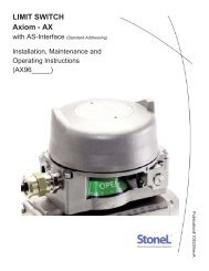
6Publication# 105331revAAssembly and Mounting InstructionsSPECIAL NOTESNoteMounting of the <strong>Axiom</strong> requires a <strong>StoneL</strong> mounting kit specific to the actuator the <strong>Axiom</strong> is to be mounted to.NoteIt is recommended that thread lubricant or anti-seize be used on the <strong>Axiom</strong> Body Screws (Item# 3) prior to assembly.NoteReferring to Step 3 below. Depending on the version of <strong>Axiom</strong>, the DA/SR Plug (Item# 5) may be located in the <strong>Axiom</strong> Body(Item# 4) or the Air Manifold Plate of the mounting kit (Item# 14).NoteIn high cycle or high vibration applications, blue Loctite® may be used on the Air Manifold Mounting Screws (Item# 11) andthe Visual Indicator Drum Retaining Screw (Item# 9).NoteIt is highly recommended that exhaust ports E2 and E3 be fitted with low restriction mufflers or breather vent caps toprevent ingestion of water and debris into the pneumatic valve.NoteFor epoxy coated aluminum models, conduit seal-offs are required with in 18” of the unit. Seal-offs are not required onmodels with a stainless steel housing.1. Refer to <strong>Axiom</strong> Assembly Drawing located on Page 7 when performing mounting and assembly procedures.2. Remove <strong>Axiom</strong> unit from shipping container. Ensure all listed items are present.3. Determine if the actuator the <strong>Axiom</strong> is to be mounted on is double acting (DA) or spring return (SR). Ensure the DA/SR Plug(Item# 5) is in the correct position. (See Detail - A on Page 7). If the DA/SR Plug is in the incorrect position, gently remove plug witha pair of pliers and insert into the proper orifice. (Note: For aluminum <strong>AX</strong> units, the DA/SR Plug is included in the manifold plate ofthe mounting kit. If there is a black DA/SR plug in the body of aluminum <strong>AX</strong> housing, this needs to be removed and discarded. Forstainless steel <strong>AX</strong> units the DA/SR plug is located in the body of the stainless steel <strong>AX</strong> housing.)4. From the mounting kit package, locate the Air Manifold Plate (Item# 14). Place the Air Manifold Plate on the actuator. Using an M4allen wrench, fasten down with the four Air Manifold Mounting Screws (Item# 11). Torque screws to 25 - 30 in.lbs (2.8 - 3.4Nm).5. Place Visual Indicator Drive Block (Item# 10) into slot on the actuator shaft. Place Visual Indicator Drum Coupler (Item# 8) onto theVisual Indicator Drive Block. Next, place the Visual Indicator Drum (Item# 7) onto the Visual Indicator Drum Coupler. Align theholes in all three items with the the threaded hole in the actuator shaft and fasten down with the Visual Indicator Drum RetainingScrew (Item# 9). Leave screw loose in order to facilitate indexing of the visual indicator.6. With the actuator in the closed position, center the Visual Indicator Drum until the “OPEN” quadrant is centered between the “V.IINDEX” markings on the AIr Manifold Plate. (See Detail - B on Page 7). Tighten down with the Visual Indicator Drum RetainingScrew 15 - 20 in.lbs (1.7 - 2.3Nm).7. Verify Air Manifold Plate Orifice O-rings (Item# 12) and Visual Indicator Cover O-ring (Item# 13) are in place.8. Place the Visual Indicator Cover (Item# 6) over the Visual Indicator Drum assembly then set the <strong>Axiom</strong> Body (Item# 4) in place.With an M5 allen wrench, torque the <strong>Axiom</strong> Body Screws (Item# 3) to 8 - 10 ft. lbs (10.8 - 13.5Nm).9. After all wiring and sensor setting procedures have been completed, install <strong>Axiom</strong> Cover and tighten the <strong>Axiom</strong> Cover Lock setscrew (Item# 2).<strong>StoneL</strong>Factory phone +1 (218) 739-5774