VersaPlanetary User's Guide - VEX Robotics
VersaPlanetary User's Guide - VEX Robotics
VersaPlanetary User's Guide - VEX Robotics

You also want an ePaper? Increase the reach of your titles
YUMPU automatically turns print PDFs into web optimized ePapers that Google loves.
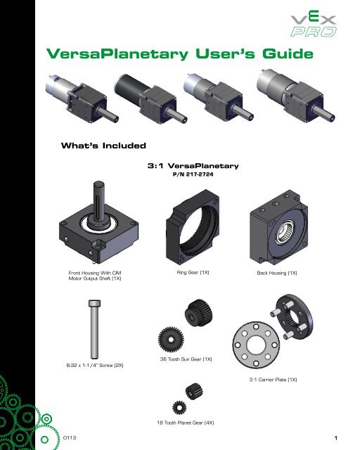
<strong>VersaPlanetary</strong> User’s <strong>Guide</strong>What’s Included3:1 <strong>VersaPlanetary</strong>P/N 217-2724Front Housing With CIMMotor Output Shaft (1X)Ring Gear (1X)Back Housing (1X)8-32 x 1-1/4” Screw (2X)36 Tooth Sun Gear (1X)3:1 Carrier Plate (1X)18 Tooth Planet Gear (4X)01131
<strong>VersaPlanetary</strong> User’s <strong>Guide</strong>Front Housing With CIMMotor Output Shaft (1X)4:1 <strong>VersaPlanetary</strong>P/N 217-2725Ring Gear (1X)Back Housing (1X)8-32 x 1-1/4” Screw (2X)24 Tooth Planet Gear (4X) 36 Tooth Sun Gear (1X)4:1 Carrier Plate (1X)5:1 <strong>VersaPlanetary</strong>P/N 217-2526Front Housing With 1/2”Hex Output Shaft (1X)Ring Gear (1X)Back Housing (1X)8-32 x 1-1/4”Screw (2X)18 Tooth Sun Gear (1X) 27 Tooth Planet Gear (4X)5:1 Carrier Plate (1X)2
<strong>VersaPlanetary</strong> User’s <strong>Guide</strong>InputCouplerBAG CollarCollarClearanceHoleSet ScrewSplit andNotchAlignmentRS-550 CollarRS-775 CollarAM-9015 CollarStep 2:Insert the appropriate Collar into the Input Coupler as shown. Take note of the orientation of the Collar(highlighted Red) and the Set Screw (highlighted green). The “split” in the Collar should align with the notchin the Input Coupler as shown. The Set Screw should align with the Clearance Hole on side of the InputHousing as illustrated by the blue line. DO NOT TIGHTEN THE SET SCREW.Step 2Step 18-32 x 1/2” screws (4X)Step 3:To ensure Motor concentricity it is critical that the following processes are done in order.1. Insert the Motor Output Shaft into the Collar. Take care not to rotate the Collar or the Input Coupler.2. Mount the Step 1 Assembly with (4X) 8-32 x 1/2” Screws.3. Use a 3/32” Hex Key to tighten the Set Screw.4. Loosen the (4X) 8-32 x 1/2” Mounting Screws by about 1/4 turn.5. Re-tighten the (4X) 8-32 x 1/2” Mounting Screws.8
<strong>VersaPlanetary</strong> User’s <strong>Guide</strong><strong>VersaPlanetary</strong> Assembly with AM-9015 Motorand 10:1 First StageStep 1:Use (2X) M3 x 8mm screws to mount an AM-9015 Motor to the Motor Plate as shown.Split andNotchAlignmentInputCouplerCollarAM-9015 CollarSet ScrewStep 2:Insert the AM-9015 Collar into the Input Coupler as shown. Take note of the orientation of the Collar andthe Set Screw (highlighted green). The “split” in the Collar should align with the notch in the Input Coupler asshown. The Set Screw should align with the Clearance Hole on side of the Input Housing as illustrated by theblue line. DO NOT TIGHTEN THE SET SCREW.9
<strong>VersaPlanetary</strong> User’s <strong>Guide</strong><strong>VersaPlanetary</strong> Shaft ChangeWhat you will need:Snap Ring Pliers with tips smaller than .055”9/64” Hex KeyAlternate <strong>VersaPlanetary</strong> Output ShaftFront Housing<strong>VersaPlanetary</strong>Body8-32 x screws (2X)Step 1:Remove (2X) 8-32 screws from the Front Housing and set the <strong>VersaPlanetary</strong> Body aside.Old Output ShaftFront HousingSnap RingStep 2:Use Snap Ring Pliers to remove the Snap Ring. Set aside the old output shaft. Take care not to let thebearings slide out of the Front Housing.11
<strong>VersaPlanetary</strong> User’s <strong>Guide</strong>New Output ShaftFullySeatedFront HousingSnap RingStep 3:Insert new Output Shaft and install Snap Ring using Snap Ring Pliers. Ensure that the snap ring is fullyseated in the Snap Ring Groove.Step 4:Mount the Front Housing to the <strong>VersaPlanetary</strong> Body using the (2X) 8-32 Screws removed in Step 1.12
<strong>VersaPlanetary</strong> User’s <strong>Guide</strong>Planet GearsCarrier PlateStep 3:Slide all included Planet Gears onto the Carrier Plate (included with the user selected Gear Kit) as shown.Step 4:Star Gears (X3)Sun GearStep 4:Slide the assembly from Step 3 onto the Sun Gear as shown.14
<strong>VersaPlanetary</strong> User’s <strong>Guide</strong>Ring GearStep 5:Slide the Ring Gear (included with the <strong>VersaPlanetary</strong> Ring Gear Add-on Kit) onto the assembly as shown.8-32 Screw (2X)Front HousingStep 6:For a 3 Stage <strong>VersaPlanetary</strong>, repeat Steps 4 & 5. Otherwise, use (2X) 8-32 Screws to mount the FrontHousing as shown.# of Stages Screw1 8-32 x 1-1/4”2 8-32 x 1-3/4”3 8-32 x 2-1/4”15
<strong>VersaPlanetary</strong> User’s <strong>Guide</strong><strong>VersaPlanetary</strong> Gear Change8-32 Screw (2X)Front HousingStep 1:Remove (2X) 8-32 Screws and the Front Housing.16
<strong>VersaPlanetary</strong> User’s <strong>Guide</strong>Ring GearPlanet Gears& CarrierSun GearStep 2:Remove the old Ring Gear, Carrier Plate, Planet Gears and the Sun Gear.New Sun GearStep 3:Insert the new Sun Gear into the Carrier Plate as shown.17
<strong>VersaPlanetary</strong> User’s <strong>Guide</strong>New CarrierPlateStep 4:Slide the new Sun Gears onto the new Carrier Plate.Step 4Sun GearStep 5:Slide the assembly from Step 4 onto the Sun Gear as shown.18
<strong>VersaPlanetary</strong> User’s <strong>Guide</strong>Ring GearStep 6:Slide the Ring Gear onto the assembly as shown.8-32 Screw (2X)Front HousingStep 7:Use (2X) 8-32 screws to mount the Front Housing as shown.19
<strong>VersaPlanetary</strong> User’s <strong>Guide</strong><strong>VersaPlanetary</strong> Direct Drive8-32 x 1-1/4”” screws (2X)Front HousingStep 1:Remove (2X) 8-32 Screws and the Front Housing.20
<strong>VersaPlanetary</strong> User’s <strong>Guide</strong>Sun GearRing GearCarrier Plate &Planet GearsStep 2:Remove the Ring Gear, Carrier Plate, Planet Gears, and the Sun Gear.8-32 x 3/4”” screws (2X)Front HousingStep 3:Use (2X) 8-32 screws to mount the Front Housing as shown.21
<strong>VersaPlanetary</strong> User’s <strong>Guide</strong><strong>VersaPlanetary</strong> SingleStage Exploded View22
<strong>VersaPlanetary</strong> Load Ratings<strong>VersaPlanetary</strong> Load RatingsIntroductionThe ratings in this guide are based on actual test data conducted by <strong>VEX</strong> <strong>Robotics</strong> on the final product versions of the<strong>VersaPlanetary</strong> gear box. All load ratings are based on a Safety Factor (SF) of 1.2 to accommodate manufacturingtolerance differences.How to Use the Rating TablesThere are two types of rating tables in this guide:(1) Simple-Load Ratingsa. Conservative ratings based on a simplified loading case using just torsion.(2) Combined-Load Ratingsa. Load ratings that take bending loads into account as well as torsion.Most users are recommended to mount their <strong>VersaPlanetary</strong> gearboxes in such a way that they can use the“Simple Load Ratings” table.IMPORTANT NOTE:The “Simple Loading Ratings” tables assume that the output of your shaft has minimal overhungloading (i.e. your sprocket is really close to the base of the shaft, or you support the tip of theshaft). See below examples.Sprocket close to transmissionUse Simple-Load RatingsSprocket Tip is supportedUse Simple‐Load RatingsSprocket NOT close to transmissionSprocket Tip is un-supportedUse Combined-Load Ratings23
<strong>VersaPlanetary</strong> Load RatingsThe “Simple Load Ratings” tables use a red/green rating system. If the motor / gear ratio / output shaftcombination you want to use is highlighted green, then it is within our maximum gear ratio recommendations.If the motor / gear ratio / output shaft combination is highlighted red, then the maximum motor torque will becapable of damaging the gearbox (with a significant enough load on the output shaft) and should be used withcaution.Example: User wants to use a RS-775 motor with a 2 stage gearbox with a 100:1 gear ratio and a 3/8” HexShaft. Is this combination recommended?Using Table 3 (excerpt shown below), that combination is not recommended as indicated in red.However, all other gear ratio combinations are recommended for that motor.Stage 2Motor Stage 1 3:1 4:1 5:1 10-:13:1 9 12 15 30AM- 90154:1 12 16 20 405:1 15 20 25 5010:1 30 40 50 1003:1 9 12 15 30BB RS- 5504:1 12 16 20 405:1 15 20 25 5010:1 30 40 50 1003:1 9 12 15 30BB RS- 7754:1 12 16 20 405:1 15 20 25 5010:1 30 40 50 10024
<strong>VersaPlanetary</strong> Load RatingsSimple Load Ratings TablesStage 2Motor Stage 1 3:1 4:1 5:1 10-:1AM- 9015BB RS- 550BB RS- 775FP-0673BAG Motor3:1 9 12 15 304:1 12 16 20 405:1 15 20 25 5010:1 30 40 50 1003:1 9 12 15 304:1 12 16 20 405:1 15 20 25 5010:1 30 40 50 1003:1 9 12 15 304:1 12 16 20 405:1 15 20 25 5010:1 30 40 50 1003:1 9 12 15 304:1 12 16 20 405:1 15 20 25 5010:1 30 40 50 1003:1 9 12 15 304:1 12 16 20 405:1 15 20 25 5010:1 30 40 50 100Table 1 - 2 Stage Max Gear Ratio w/ 1/2" Hex OutputShaftStage 2Motor Stage 1 3:1 4:1 5:1 10-:1AM- 9015BB RS- 550BB RS- 775FP-0673BAG Motor3:1 9 12 15 304:1 12 16 20 405:1 15 20 25 5010:1 30 40 50 1003:1 9 12 15 304:1 12 16 20 405:1 15 20 25 5010:1 30 40 50 1003:1 9 12 15 304:1 12 16 20 405:1 15 20 25 5010:1 30 40 50 1003:1 9 12 15 304:1 12 16 20 405:1 15 20 25 5010:1 30 40 50 1003:1 9 12 15 304:1 12 16 20 405:1 15 20 25 5010:1 30 40 50 100Table 2 – 2 Stage Max Gear Ratio w/ ½” Round OutputShaft25
<strong>VersaPlanetary</strong> Load RatingsStage 2Motor Stage 1 3:1 4:1 5:1 10-:1AM- 9015BB RS- 550BB RS- 775FP-0673BAG Motor3:1 9 12 15 304:1 12 16 20 405:1 15 20 25 5010:1 30 40 50 1003:1 9 12 15 304:1 12 16 20 405:1 15 20 25 5010:1 30 40 50 1003:1 9 12 15 304:1 12 16 20 405:1 15 20 25 5010:1 30 40 50 1003:1 9 12 15 304:1 12 16 20 405:1 15 20 25 5010:1 30 40 50 1003:1 9 12 15 304:1 12 16 20 405:1 15 20 25 5010:1 30 40 50 100Table 3 - 2 Stage Max Gear Ratio w/ 3/8” Hex OutputShaftStage 2Motor Stage 1 3:1 4:1 5:1 10-:13:1 9 12 15 30AM- 90154:1 12 16 20 405:1 15 20 25 5010:1 30 40 50 1003:1 9 12 15 30BB RS- 5504:1 12 16 20 405:1 15 20 25 5010:1 30 40 50 1003:1 9 12 15 30BB RS- 7754:1 12 16 20 405:1 15 20 25 5010:1 30 40 50 1003:1 9 12 15 30FP-06734:1 12 16 20 405:1 15 20 25 5010:1 30 40 50 1003:1 9 12 15 30BAG Motor4:1 12 16 20 405:1 15 20 25 5010:1 30 40 50 100Table 4 - 2 Stage Max Gear Ratio CIM Motor Output Shaft26
<strong>VersaPlanetary</strong> Load RatingsStage 3Motor Stage 1 & 2 3:1 4:1 5:1 10-:19:1 27 36 45 9012:1 36 48 60 12015:1 45 60 75 15016:1 48 64 80 160AM- 9015BB RS- 55020:1 60 80 100 20025:1 75 100 125 25030:1 90 120 150 30040:1 120 160 200 40050:1 150 200 250 500100:1 300 400 500 10009:1 27 36 45 9012:1 36 48 60 12015:1 45 60 75 15016:1 48 64 80 16020:1 60 80 100 20025:1 75 100 125 250Stage 3Ratio Motor Stage 1 & 2 3:1 4:1 5:1 10-:199:1 27 36 45 9012 12:1 36 48 60 12015 15:1 45 60 75 15016 16:1 48 64 80 16020 20:1 60 80 100 200AM- 901525 25:1 75 100 125 25030 30:1 90 120 150 30040 40:1 120 160 200 40050 50:1 150 200 250 500100 100:1 300 400 500 100099:1 27 36 45 9012 12:1 36 48 60 12015 15:1 45 60 75 15016 16:1 48 64 80 16020 20:1 60 80 100 200BB RS- 55025 25:1 75 100 125 25030:1 90 120 150 30040:1 120 160 200 40050:1 150 200 250 500100:1 300 400 500 100030 30:1 90 120 150 30040 40:1 120 160 200 40050 50:1 150 200 250 500100 100:1 300 400 500 10009:1 27 36 45 9099:1 27 36 45 90BB RS- 77512:1 36 48 60 12015:1 45 60 75 15016:1 48 64 80 16020:1 60 80 100 20025:1 75 100 125 25030:1 90 120 150 30040:1 120 160 200 40050:1 150 200 250 500100:1 300 400 500 100012 12:1 36 48 60 12015 15:1 45 60 75 15016 16:1 48 64 80 16020 20:1 60 80 100 200BB RS- 77525 25:1 75 100 125 25030 30:1 90 120 150 30040 40:1 120 160 200 40050 50:1 150 200 250 500100 100:1 300 400 500 10009:1 27 36 45 9099:1 27 36 45 90FP-067312:1 36 48 60 12015:1 45 60 75 15016:1 48 64 80 16020:1 60 80 100 20025:1 75 100 125 25030:1 90 120 150 30040:1 120 160 200 40050:1 150 200 250 500100:1 300 400 500 100012 12:1 36 48 60 12015 15:1 45 60 75 15016 16:1 48 64 80 16020 20:1 60 80 100 200FP-067325 25:1 75 100 125 25030 30:1 90 120 150 30040 40:1 120 160 200 40050 50:1 150 200 250 500100 100:1 300 400 500 10009:1 27 36 45 9099:1 27 36 45 90BAG Motor12:1 36 48 60 12015:1 45 60 75 15016:1 48 64 80 16020:1 60 80 100 20025:1 75 100 125 25030:1 90 120 150 30040:1 120 160 200 40050:1 150 200 250 50012 12:1 36 48 60 12015 15:1 45 60 75 15016 16:1 48 64 80 16020 20:1 60 80 100 200BAG Motor25 25:1 75 100 125 25030 30:1 90 120 150 30040 40:1 120 160 200 40050 50:1 150 200 250 500100:1 300 400 500 1000Table 5 – 3 Stage Max Gear Ratio w/ ½” Hex Shaft100 100:1 300 400 500 1000Table 6 – 3 Stage Max Gear Ratio w/ ½” Round Shaft27
<strong>VersaPlanetary</strong> Load RatingsStage 3Motor Stage 1 & 2 3:1 4:1 5:1 10-:19:1 27 36 45 9012:1 36 48 60 12015:1 45 60 75 15016:1 48 64 80 160AM- 9015BB RS- 55020:1 60 80 100 20025:1 75 100 125 25030:1 90 120 150 30040:1 120 160 200 40050:1 150 200 250 500100:1 300 400 500 10009:1 27 36 45 9012:1 36 48 60 12015:1 45 60 75 15016:1 48 64 80 16020:1 60 80 100 20025:1 75 100 125 250Stage 3Ratio Motor Stage 1 & 2 3:1 4:1 5:1 10-:199:1 27 36 45 9012 12:1 36 48 60 12015 15:1 45 60 75 15016 16:1 48 64 80 16020 20:1 60 80 100 200AM- 901525 25:1 75 100 125 25030 30:1 90 120 150 30040 40:1 120 160 200 40050 50:1 150 200 250 500100 100:1 300 400 500 100099:1 27 36 45 9012 12:1 36 48 60 12015 15:1 45 60 75 15016 16:1 48 64 80 16020 20:1 60 80 100 200BB RS- 55025 25:1 75 100 125 25030:1 90 120 150 30040:1 120 160 200 40050:1 150 200 250 500100:1 300 400 500 100030 30:1 90 120 150 30040 40:1 120 160 200 40050 50:1 150 200 250 500100 100:1 300 400 500 10009:1 27 36 45 9099:1 27 36 45 90BB RS- 77512:1 36 48 60 12015:1 45 60 75 15016:1 48 64 80 16020:1 60 80 100 20025:1 75 100 125 25030:1 90 120 150 30040:1 120 160 200 40050:1 150 200 250 500100:1 300 400 500 100012 12:1 36 48 60 12015 15:1 45 60 75 15016 16:1 48 64 80 16020 20:1 60 80 100 200BB RS- 77525 25:1 75 100 125 25030 30:1 90 120 150 30040 40:1 120 160 200 40050 50:1 150 200 250 500100 100:1 300 400 500 10009:1 27 36 45 9099:1 27 36 45 90FP-067312:1 36 48 60 12015:1 45 60 75 15016:1 48 64 80 16020:1 60 80 100 20025:1 75 100 125 25030:1 90 120 150 30040:1 120 160 200 40050:1 150 200 250 500100:1 300 400 500 100012 12:1 36 48 60 12015 15:1 45 60 75 15016 16:1 48 64 80 16020 20:1 60 80 100 200FP-067325 25:1 75 100 125 25030 30:1 90 120 150 30040 40:1 120 160 200 40050 50:1 150 200 250 500100 100:1 300 400 500 10009:1 27 36 45 9099:1 27 36 45 90BAG Motor12:1 36 48 60 12015:1 45 60 75 15016:1 48 64 80 16020:1 60 80 100 20025:1 75 100 125 25030:1 90 120 150 30040:1 120 160 200 40050:1 150 200 250 50012 12:1 36 48 60 12015 15:1 45 60 75 15016 16:1 48 64 80 16020 20:1 60 80 100 200BAG Motor25 25:1 75 100 125 25030 30:1 90 120 150 30040 40:1 120 160 200 40050 50:1 150 200 250 500100:1 300 400 500 1000Table 7 - 3 Stage Max Gear Ratio w/ 3/8” Hex Shaft100 100:1 300 400 500 1000Table 8 – 3 Stage Max Gear Ratio w/ CIM Motor Shaft28
<strong>VersaPlanetary</strong> Load RatingsCombined Load Ratings TablesThe <strong>VersaPlanetary</strong> gearbox is designed to accommodate significant overhung loading with an unsupported shaft.However, as you will determine from this section, the torque carrying capability significantly increases if the gear,sprocket, or pulley is placed close to the mounting face or the end of the shaft is supported with another bearing.The <strong>VersaPlanetary</strong> gearbox may fail in one of two different modes: (1) output shaft yield stress failure or (2) 10:1carrier plate ultimate stress failure. However, improper lubrication combined with typical FRC practice robot drivingtime would also result in gear failure (eventually). Refer to the “<strong>VersaPlanetary</strong> User’s <strong>Guide</strong>” for more informationon proper maintenance.Failure mode #2 (carrier plate failure) is not dependent upon the overhung loading and is solely determined by Table9. However, all other failure modes listed in Table 9 are beam yield failures and that depend on both torsional failureand beam bending failure.Failure mode #1 depends upon distance from the mounting face, gear / sprocket diameter, and torque load. Usersshould reference table 9 and the below charts to determine the maximum allowable loading for your design.LRFRated Load – Pure TorsionFailure Mode N-m ft-lbs1/2” Hex Shaft Yield Stress 157 1161/2” Round Shaft Yield Stress 130 963/8” Hex Shaft Yield Stress 57 42CIM Motor Shaft Yield Stress 29 2110:1 Carrier Plate Yield Stress 100 74Table 9 – <strong>VersaPlanetary</strong> Output Torque Limits29
<strong>VersaPlanetary</strong> Load RatingsMax Allowable Torque (ft-lbs)1201101009080706050Max Output Torque vs. Pitch Diameter1/2” Hex Output ShaftLoad atMountingFaceLoad atEnd ofShaft401.001.101.201.301.401.501.601.701.801.902.00Sprocket, Gear, or Pulley Pitch Diameter (in)100Max Output Torque vs. Pitch Diameter1/2” Round Output ShaftMax Allowable Torque (ft-lbs)90807060504030Load atMountingFaceLoad atEnd ofShaft201.001.101.201.301.401.501.601.701.801.902.00Sprocket, Gear, or Pulley Pitch Diameter (in)30
<strong>VersaPlanetary</strong> Load RatingsMax Allowable Torque (ft-lbs)45403530252015Max Output Torque vs. Pitch Diameter3/8” Hex Output ShaftLoad atMountingFaceLoad atEnd ofShaft101.001.101.201.301.401.501.601.701.801.902.00Sprocket, Gear, or Pulley Pitch Diameter (in)25Max Output Torque vs. Pitch Diameter8mm CIM Motor Output ShaftMax Allowable Torque (ft-lbs)2321191715131197Load atMountingFaceLoad atEnd ofShaft51.001.101.201.301.401.501.601.701.801.902.00Sprocket, Gear, or Pulley Pitch Diameter (in)31