3: EMC Sub Rack Magic-/Spirit-Kit 11 - Elion
3: EMC Sub Rack Magic-/Spirit-Kit 11 - Elion
3: EMC Sub Rack Magic-/Spirit-Kit 11 - Elion

Create successful ePaper yourself
Turn your PDF publications into a flip-book with our unique Google optimized e-Paper software.
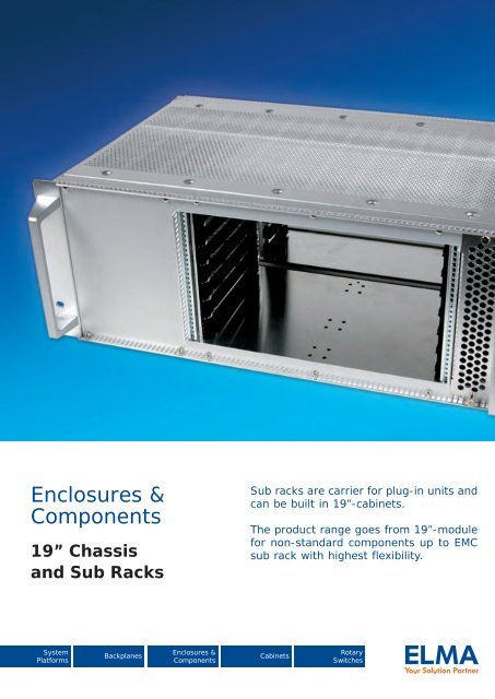
Chapter Overview1. Slimkit 10The new slim 19-inch <strong>EMC</strong> chassis with anoverall height of 1 UA2. Ecokit <strong>11</strong>The economic way to build up a simple cardcage in different variants3. <strong>Magic</strong>- /<strong>Spirit</strong>-<strong>Kit</strong> <strong>11</strong><strong>EMC</strong> sub rack in sheet steel with a very fastassembly and <strong>EMC</strong> without gaskets4. Systemkit 12KModern designed <strong>EMC</strong> sub rack with a large selection ofassembly optionswww.elma.comElmasetA | 1
AA | 2Elmasetwww.elma.com
A1: Slimkit 101.1 <strong>EMC</strong>-Slimkit 10 Overview• 19“ <strong>EMC</strong> chassis 1 U• Basic model can be transformed into a complete case by adding a rearpanel, top cover as well as a mounting chassis• Design allows numerous combinations to be assembled according tothe application• Hard and wear resistant aluminium front panel• With or without perforations for optimised thermal solution• <strong>EMC</strong>-Slimkit 10 can be presented in a number of attractive finishesfor individual product tailoringTechnical features• 19“ chassis with excellent <strong>EMC</strong> feature• Front panel: aluminium, frame construction: sheet steel, pre-galvanised• Vibration-proof• <strong>EMC</strong> shielding without gaskets is standard• Fast assembly• Easy access• Front- and rear panel can be removed for easy machiningApplications• Accommodates flat components• Slim test equipment• Controls• Telecommunication equipment• Audio and radio equipment• Signal ConvertersTop CoverMounting ChassisBasic TrayRear PanelFront PanelFeet (optional)A | 1_2Elmasetwww.elma.com
1: Slimkit 10<strong>EMC</strong>“Electromagnetic comptability is the ability of a system to operate in the intended environment without causing or suffering unacceptabledegradation of performance due to unintentinal electromagnetic radiation or response.”The <strong>EMC</strong> characterstics of a system therefore consist of an appropriate immunity from interference (noise immunity) and a limited emissionof interference (noise emission).AElma’s <strong>EMC</strong> concept describes three levels of electromagnetic shielding performance (Performance Level). The attenuation levels willsimplify the selection of sub racks for the user.Test setup: The first measurement E1 is without the enclosure. The next measurement E2 is made with the transmitting antenna installed insidethe enclosure. The difference between the received signal without and with the enclosure represents the shielding effectiveness in dB.Performance Level 30 - 230 MHz 230 - 1000 MHz 1000 - 2000 MHz1 / Elma: Basic level 20 dB 10 dB 0 dB2 / Elma: Advanced level 40 dB 30 dB 20 dB3 / Elma: Superior level 60 dB 50 dB 40 dBThe standard configuration will provide you with an advanced <strong>EMC</strong> level (Basic level with perforation).The integrated <strong>EMC</strong> solution<strong>EMC</strong> contacts• Top cover to rear panel<strong>EMC</strong> contacts• Bottom tray to rear panel• Bottom tray to front panel• Top cover to front panel<strong>EMC</strong> contacts• Top cover to bottom traywww.elma.com ElmasetA | 1_3
1: Slimkit 10ConfigurationABasic Tray1.2.1- 1 U- 240 mm / 360 mm- Solid / perforatedFront Panel1.2.2- With / without handles- Different coloursRear Panel1.2.3Top Cover1.2.4- 240 mm / 360 mm- Solid / perforatedMounting Chassis1.2.5- 240 mm / 360 mmAccessories1.3- Earthing <strong>Kit</strong>- Case feetA | 1_4Elmasetwww.elma.com
A1: Slimkit 101.2 Slimkit 10 <strong>EMC</strong> Chassis1.2.1 Slimkit 10 Basic Tray• 0.75 mm sheet steel, pre-galvanised• With holes for fastening of mounting chassis, feet, earthing terminals,front / rear panel, top cover• Scope of delivery:• Basic Tray• Assembly material for mounting front panel, rear panel, mounting chassis,top cover (12 round head SHEETtracs ® screws 3,0 x 6, Torx T10)• Front Panel see 1.2.2• Rear Panel see 1.2.3• Top Cover see 1.2.4• Mounting Chassis see 1.2.51.2.1 Slimkit 10 Basic TrayHeight Depth Perforation Air Passage Part-No.mm inch mm 2 sq. inch1 U 240 9.45 Solid - - 10-9<strong>11</strong>00-001 U 240 9.45 Perforated 18095 28.04 10-9<strong>11</strong>01-001 U 360 14.17 Solid - - 10-9<strong>11</strong>10-001 U 360 14.17 Perforated 21714 33.65 10-9<strong>11</strong><strong>11</strong>-00www.elma.com ElmasetA | 1_5
1: Slimkit 101.2.2 Front PanelA• 1.0 mm aluminium• Rear: conductive, front: clear anodised / powder coated black (RAL 9005) /powder coated light grey (RAL 7035)• With or without black handles• Customised front panel upon request (see front panel service)• Scope of delivery:• Front panel• Handle set (2 black U-handles, 4 countersunk screws M2.5 x 8, Torx T8)in handle versions only• Assembly material for mounting front panel included in basic tray set1.2.2 Front PanelHeight Front Handles Part-No.1 U Clear anodised Yes 10-46100-001 U Clear anodised No 10-451-001 U Black powder coated Yes 10-46160-001 U Black powder coated No 10-451-601 U Light grey powder coated Yes 10-46130-001 U Light grey powder coated No 10-451-301.2.3 Rear Panel• 0.75 mm sheet steel, pre-galvanised• Rear panel with customised cut outs upon request• Scope of delivery:• Rear panel• Assembly material for mounting rear panel included in basic tray set1.2.3 Rear PanelDescriptionPart-No.Slimkit 10 Rear Panel 1 U 10-901-00A | 1_6Elmasetwww.elma.com
1: Slimkit 101.2.4 Top Cover• 0.75 mm sheet steel, pre-galvanised• With or without air perforation• Scope of delivery:• Top cover• Assembly material for mounting top cover included in basic tray setA1.2.4 Top CoverDepth Perforation Air Passage Part-No.mm inch mm 2 sq. inch240 9.45 Solid - - 10-920-00240 9.45 Perforated 18095 28.04 10-920-01360 14.17 Solid - - 10-920-10360 14.17 Perforated 21714 33.65 10-920-<strong>11</strong>1.2.5 Mounting Chassis• For mounting components• Mounting chassis 240 mm can be mounted in Slimkit 10 with depth 360 mm• 1.25 mm sheet steel, pre-galvanised• Mounting chassis with customised cut outs upon request• Scope of delivery:• Mounting chassis• Assembly material for mounting chassis included in basic tray set1.2.5 Mounting ChassisDescriptionPart-No.Slimkit 10 mounting chassis 240 mm 10-930-50Slimkit 10 mounting chassis 360 mm 10-931-50www.elma.com ElmasetA | 1_7
1: Slimkit 10A1.3 Accessories1.3.1 Earthing Set• Enables cases to be earthed in conformance with EN / VDE / SEV• Scope of delivery:• 1 press-in threaded bolt M4• 2 serrated lock washers• 2 hexagonal nuts M4• 1 terminal clamp• 1 earthing symbol1.3.1 Earthing SetDescriptionPart-No.Earthing set according to EN VDE / SEV 63-1741.3.2 Case Feet• Tilt foot / Non-tilt foot• Choice of colours: light grey (RAL 7035) or black (RAL 9005)• Glass-fiber reinforced plastic, UL94 V-0• Up to 30 kg carrying capacity per set• Scope of delivery:• 1 set of feet• Assembly material (8 cross recessed countersunk PT-screw 3.5 x 8)1.3.2 Case FeetDescription Colour Part-No.Case feet, 4 x b Light grey (RAL 7035) 63-019Case feet, 4 x b Black (RAL 9005) 63-321Case feet, 2 x a + 2 x b Light grey (RAL 7035) 63-018Case feet, 2 x a + 2 x b Black (RAL 9005) 63-320A | 1_8Elmasetwww.elma.com
A1: Slimkit 101.4 Technical Information1.4.1 Line Drawings for Slimkit 10Front view Front viewFront viewPlan viewPlan view482,6 482,6465,1 465,1A A482,6465,1AA(440,5 incl.(440,5screws)incl. screws)341,9 / 353,6341,9 A / 353,67710,510,531,843,631,843,65,931,817,543,617,55,9710,55,9Side Side view viewSide viewPlan view(440,5 incl. screws)341,9 / 353,6Hole Ø 4,0Hole Ø 4,0Hole Ø 4,018<strong>11</strong>4,2 / 133,7 <strong>11</strong>4,2 32,1 / 133,7 32,1240,1 / 360,1 240,1 / 360,<strong>11</strong>14,2 / 133,72,5182,517,532,1240,1 / 360,131030,6Mounting chassisA-A182,5329,6<strong>11</strong>1.4.2 Assembly SHEETtracs ® Screw• For a secure thin sheet metal joint with pre-hole1.4.2 SHEETtracs ® ScrewDescription Material Part-No.1 pc. 100 pcs.3 x 6, Torx T10 Steel, zinc-plated 5477-01 -1. Initial position 2. Thread grooving 3. Tighteningwww.elma.com ElmasetA | 1_9
A2: Ecokit <strong>11</strong>2.1 Ecokit <strong>11</strong> Overview A | 2_32.2 Ecokit <strong>11</strong> <strong>Sub</strong> <strong>Rack</strong> Configuration A | 2_52.2.1 Width A | 2_52.2.2 Height / Depth A | 2_62.2.3 Handles A | 2_62.2.4 Line Drawing A | 2_72.3 Adaptation <strong>Kit</strong>s A | 2_82.3.1 Adaptation <strong>Kit</strong> A | 2_82.3.2 Front <strong>Sub</strong> Division Horizontal IEC for Card Guides A | 2_92.3.3 Front <strong>Sub</strong> Division Horizontal IEC A | 2_92.3.4 Edge Connector Extrusion 66-145 A | 2_102.3.5 Edge Connector Extrusion 66-147 A | 2_102.4 Assembly Accessories A | 2_<strong>11</strong>2.4.1 Front <strong>Sub</strong> Division Vertical 6 U / 3 U A | 2_<strong>11</strong>2.4.2 Horizontal Card Mounting <strong>Kit</strong> A | 2_122.4.3 Fan Front Panels for Horizontal Mounting <strong>Kit</strong>s A | 2_13A | 2_1Elmasetwww.elma.com
2: Ecokit <strong>11</strong>2.5 General Accessories A | 2_142.5.1 Perforated Cover Plates A | 2_142.5.2 Earthing Set A | 2_15A2.5.3 Card Guides IEC A | 2_162.5.4 Flat Front Panels A | 2_182.5.5 Fan Front Panel for Horizontal Ventilation A | 2_192.5.6 Fan Front Panels for Direct Fan Mounting A | 2_202.5.7 Extruded Front Panels A | 2_212.5.8 Front Panel with Cutouts for IEC Ejector Handles A | 2_232.5.9 Ergonomic Ejector Handles acc. to IEC A | 2_232.5.10 Card Locks and Card Handles A | 2_242.5.<strong>11</strong> Card Holder acc. to IEC Standard A | 2_262.5.12 Middle Part A | 2_272.5.13 Protective Cover for 6 U Printed Board A | 2_272.5.14 Spacers A | 2_282.5.15 Mounting Plates A | 2_292.5.16 Hexagonal Spacers M3 Thread A | 2_292.5.17 Covering Caps A | 2_302.5.18 Mounting Bracket A | 2_302.6 Extrusions A | 2_312.6.1 Front Extrusions A | 2_312.6.2 Height Extrusions A | 2_322.6.3 Internal Extrusions A | 2_322.6.4 Center Extrusions A | 2_342.6.5 Edge Connector Extrusions A | 2_35www.elma.com ElmasetA | 2_2
A2: Ecokit <strong>11</strong>2.1 Ecokit <strong>11</strong> Overview• Side panels are of 2 mm sheet aluminium• The extruded aluminium 19" mounting sections have an effective thickness of 3 mm (Standard only)• For mounting PCBs and plug-in units based on standard Eurocard sizes with depths of 160, 220 and 280 mm• The use of cover plates is recommended where the sub rack is subjected to continuous vibration• Side panel with integrated 19" section as a cost-saving solution for Ecokit <strong>11</strong> Integrated• Features on the side panels allows the extrusions to be fixed with only half the number of screwsAssembly example:Ecokit <strong>11</strong> StandardEcokit <strong>11</strong> IntegratedInternal extrusionInternal extrusionCenter extrusionCenter extrusionAssembly materialAssembly materialSide panelSide panelFront extrusionFront extrusionLabel stripLabel stripTapped stripVertical sectionA | 2_3Elmasetwww.elma.com
2: Ecokit <strong>11</strong>Configuration<strong>Sub</strong> <strong>Rack</strong>Width2.2.1- 42 HP / 63 HP / 84 HP(incl. assembly material))A2.2.1.1 Label StripsHeight / Depth2.2.2- 3 U / 6 U- With / without holes for handles- Standard / integrated- 216 mm / 276 mm / 336 mm2.2.3 Handles2.3 Adaptation <strong>Kit</strong>s2.4 Assembly Accessories2.5 General Accessories2.6 Extrusionswww.elma.com ElmasetA | 2_4
A2: Ecokit <strong>11</strong>2.2 Ecokit <strong>11</strong> <strong>Sub</strong> <strong>Rack</strong> Configuration2.2.1 Width• Choose the width of your sub rack• Set with or without centre extrusion• Scope of delivery:• 2 front extrusions, aluminium, clear anodised• 4 tapped strips M2.5 (6 for version with centre extrusion)• 2 internal extrusions• 1 centre extrusion (version with centre extrusion only)• Insulating strips (Backplane mounting only)• Assembly material (Torx screws)• Label strips see below• Choose the right height and depth on the next step (see 2.2.2)2.2.1 WidthDescription 42 HP 63 HP 84 HPSet Standard without centre extrusion <strong>11</strong>E101 <strong>11</strong>E102 <strong>11</strong>E103Set insulated backplane mounting withoutcentre extrusion<strong>11</strong>E104 <strong>11</strong>E105 <strong>11</strong>E106Set Standard with centre extrusion <strong>11</strong>E107 <strong>11</strong>E108 <strong>11</strong>E109Set insulated backplane mounting withcentre extrusion<strong>11</strong>E<strong>11</strong>0 <strong>11</strong>E<strong>11</strong>1 <strong>11</strong>E<strong>11</strong>22.2.1.1 Label Strips• Scope of delivery:• 1 label strip consisting of 4 single tapesScope of Delivery2 pcs. each(upper and lower)42 HP(01-42/42-01)63 HP(01-63/63-01)84 HP(01-84/84-01)63-142 63-143 63-046A | 2_5Elmasetwww.elma.com
A2: Ecokit <strong>11</strong>2.3 Adaptation <strong>Kit</strong>s2.3.1 Adaptation <strong>Kit</strong>• For recessed mounting of Eurocard without front panels• Scope of delivery:• 2 internal extrusions• 2 tapped strips M2.5• Assembly material (8 Torx cylinder head screws M4 x 10, size T20)2.3.1 Adaptation <strong>Kit</strong>Description Width Part-No.Mounting for recessed eurocards without front panels 42 HP <strong>11</strong>E532Mounting for recessed eurocards without front panels 63 HP <strong>11</strong>E531Mounting for recessed eurocards without front panels 84 HP <strong>11</strong>E530160/2203 U160/220606 UT=276/33660T=276/336www.elma.com ElmasetA | 2_8
2: Ecokit <strong>11</strong>2.3.2 Front <strong>Sub</strong> Division Horizontal IEC for Card GuidesA• For sub division of front• Card guides can be applied• Only one special extrusion needed• Easy and quick assembly• Cost effective solution• Delivered in kit form• Usable width: 84 HP• Other sizes available on request• Scope of delivery:• 1 pc. front double extrusion IEC-Special clear passivated• 2 pcs. tapped strips M2.5• 4 pcs. Torx cylinder head screws M4 x 10 (T20)2.3.2 Front <strong>Sub</strong> Division Horizontal IECDescriptionPart-No.<strong>EMC</strong> front sub division horizontal IEC for card guides 63K837-242.3.3 Front <strong>Sub</strong> Division Horizontal IEC• For sub division of front• Without possibility of using card guides• Only one special extrusion needed• Easy and quick assembly• Cost effective solution• Delivered in kit form• Usable width: 84 HP• Other sizes available on request• Scope of delivery:• 1 pc. front double extrusion IEC-Special clear passivated• 2 pcs. tapped strips M2.5• 4 pcs. Torx cylinder head screws M4 x 10 (T20)2.3.3 Front <strong>Sub</strong> Division Horizontal IECDescriptionPart-No.<strong>EMC</strong> front sub division horizontal IEC 63K837-22A | 2_9Elmasetwww.elma.com
2: Ecokit <strong>11</strong>2.3.4 Edge Connector Extrusion 66-145• For use with standard extrusion 66-144• Edge connector extrusion without assembly materialA19.815.7Ø3.2/5.082.3500 3.25.7M2.5/5.081.7.5.1 Edge Connector Extrusion 66-145LengthPart-No.for HP mm inch clear passivated raw8 40.6 1.59 66-145-4018 91.4 3.59 66-145-4128 142.2 5.60 66-145-4242 213.4 8.40 66-145-6363 320.0 12.60 66-145-6581 4<strong>11</strong>.5 16.20 66-145-2284 426.7 16.80 66-145-521350.0 53.14 66-145-19Assembly MaterialDescriptionPart-No.Assembly material M2.5 (for 2 supplementary extrusions) 63-2142.3.5 Edge Connector Extrusion 66-147• For use with extrusions for backplanes 66-193• Edge connector extrusion without assembly materialØ3.2/5.0822.218.62.400 3.2 6.1M2.5/5.087.4.2.1 Edge Connector ExtrusionLengthPart-No.for HP mm inch clear passivated raw8 40.6 1.59 66-147-4018 91.4 3.59 66-147-4128 142.2 5.60 66-147-4242 213.4 8.40 66-147-6363 320.0 12.60 66-147-6581 4<strong>11</strong>.5 16.20 66-147-2284 426.7 16.80 66-147-521350.0 53.14 66-147-19Assembly MaterialDescriptionPart-No.Assembly material M2.5 (for 2 supplementary extrusions) 63-214www.elma.com ElmasetA | 2_10
A2: Ecokit <strong>11</strong>2.4 Assembly Accessories2.4.1 Front <strong>Sub</strong> Division Vertical 6 U / 3 U• Allows both single and double eurocards to be mounted togetherin a 6 U Ecokit <strong>11</strong>• Scope of delivery:• 1 divider extrusion front• 1 divider extrusion rear• 2 front extrusions• 2 internal extrusions• 1 set assembly material (cross recessed)6 U• Tapped strip see below• Card guides see 2.5.3cba2.4.1 Front <strong>Sub</strong> Division Vertical 6 U / 3 UUsableWidth bWidth a 42 HP 63 HP 84 HP Part-No.21 HP c = 19 HP c = 40 HP c = 61 HP <strong>11</strong>-979-228 HP c = 12 HP c = 33 HP c = 54 HP <strong>11</strong>-969-232 HP c = 8 HP c = 29 HP c = 50 HP <strong>11</strong>-959-242 HP - c = 19 HP c = 40 HP <strong>11</strong>-949-263 HP - - c = 19 HP <strong>11</strong>-939-22.4.1.1 Tapped Strips for Front ExtrusionScope of Delivery Description Part-No.1 pc. tapped strip61-459M2.5 21 HP = 106.68 mm10 pcs. tapped strips 63-1821 pc. tapped strip61-458M2.5 28 HP = 142.24 mm10 pcs. tapped strips 63-1831 pc. tapped strip61-463M2.5 32 HP = 162.56 mm10 pcs. tapped strips 63-1901 pc. tapped strip61-464M2.5 42 HP = 212.9 mm10 pcs. tapped strips 63-0571 pc. tapped strip61-469M2.5 63 HP = 319.6 mm10 pcs. tapped strips 63-062A | 2_<strong>11</strong>Elmasetwww.elma.com
A2: Ecokit <strong>11</strong>2.4.2 Horizontal Card Mounting <strong>Kit</strong>• For double eurocards (6 U)• Independent of card depth• Scope of delivery:• 4 distance plates (2 front / 2 rear)• 4 length extrusions (2 front / 2 rear)• 1 centre extrusion• 6 tapped strips M2.5• 1 set assembly material (Torx)• Top and bottom cover plate when no overall fan front panel (2.4.3) is used• Top and bottom cover plate has to be ordered separately (see table)• Fan front panels for horizontal mounting kits see 2.4.3• Card guides see 2.5.3• Extruded front panels see 2.5.7Double eurocards = 52 HPTriple eurocards = 78 HP84 HP32 HP6 HP2.4.2 Horizontal Card Mounting <strong>Kit</strong>MountingHeightUsable Height Backplane Cover platetop*Cover platebottom*3 U 20 HP 14K971-60 21N602-90 21N602-906 U 48 HP 14K991-60 21N606-90 21N607-90* Assembly material for cover plate see 2.4.3.1www.elma.com ElmasetA | 2_12
2: Ecokit <strong>11</strong>2.4.3 Fan Front Panels for Horizontal Mounting <strong>Kit</strong>sA• For horizontal mounting of double eurocards• Aluminium 2.5 mm, clear anodised (non-conductive)• Scope of delivery:• 1 perforated fan front panel• Front panel screw see below• On-off switch see below2.4.3 Fan Front Panels for Horizontal Mounting <strong>Kit</strong>sDescription Height Width Air passage Part-No.mm 2 sq. inchWithout switch opening 3 U 63 HP 3195 4.95 21N363-07With switch opening 3 U 63 HP 2662 4.12 21N363-022.4.3.1 Front Panel Screws• Set of 10 screws• With threaded or press-fit bush• 8 screws are necessary per front panelDescriptionPart-No.10 pcs.Recessed round head screw M2.5 x <strong>11</strong> with threaded bush M5 x 0.5 63-129Recessed round head screw M2.5 x <strong>11</strong> with press-fit bush Ø3.7 63-4442.4.3.2 On-Off Switch• Black body, plastic• 2 pole (only on-off switches)• 250V, 16A• Quick-connect terminal 6.3 x 0.8 mm• Panel cutout for 69-410-05: 13 x 20 mm (0.51" x 0.78")DescriptionPart-No.On-off switch, indicator light green (for fan front panel 3 U) 69-410-05A | 2_13Elmasetwww.elma.com
A2: Ecokit <strong>11</strong>2.5 General Accessories2.5.1 Perforated Cover Plates• 1 mm sheet aluminium, perforated• Front extrusions and internal extrusions are pre-drilledto accept the fixing screws• Provides mechanical protection for the card area• Scope of delivery:• 1 perforated cover plate• Assembly material see below• Cover plates for card depths 300 mm and 400 mm upon request2.5.1 Perforated Cover PlatesCaseWidthCardDepthA B C D Part-No.42 HP63 HP84 HP160 mm6.30"220 mm8.66"160 mm6.30"220 mm8.66"160 mm6.30"220 mm8.66"280 mm<strong>11</strong>.02"217.64 mm8.56"217.64 mm8.56"324.32 mm12.76"324.32 mm12.76"431 mm16.96"431 mm16.96"431 mm16.96"149 mm5.86"209 mm8.22"149 mm5.86"209 mm8.22"149 mm5.86"209 mm8.22"269 mm10.59"207.5 mm8.16"207.5 mm8.16"3<strong>11</strong>.5 mm12.26"3<strong>11</strong>.5 mm12.26"415.5 mm16.35"415.5 mm16.35"415.5 mm16.35"107.25 mm4.22"159.75 mm6.28"107.25 mm4.22"159.75 mm6.28"107.25 mm4.22"159.75 mm6.28"212.25 mm8.35"<strong>11</strong>-70<strong>11</strong>1-702<strong>11</strong>-703<strong>11</strong>-704<strong>11</strong>-706<strong>11</strong>-707<strong>11</strong>-708Assembly MaterialDescription Scope of Delivery Part-No.Pack size 8 pieces 63-195Cross recessed screw M3x6Pack size 100 pieces 63-372Torx cylinder head earthing screw M3x6, size T10 Pack size 1 piece 5443-04www.elma.com ElmasetA | 2_14
2: Ecokit <strong>11</strong>A2.5.2 Earthing Set• Enables cases to be earthed in conformance with EN / VDE / SEV• Scope of delivery:• 1 press-in threaded bolt M4 x 8• 1 washer• 1 serrated lock washer• 1 hexagonal nut M4Press-in threadedbold M4 x 8Ø 4,1Lock washerWasherHexagonal nut M4Side panel2.5.2 Earthing SetDescriptionPart-No.Earthing set according to EN / VDE / SEV 63-127A | 2_15Elmasetwww.elma.com
A2: Ecokit <strong>11</strong>2.5.3 Card Guides IEC• For positive location of circuit boards and plug-in units conforming to thedimensions of card depths of 80 mm, 160 mm, 220 mm and 280 mm• The card guides are non-flammable, made from a high quality plasticmaterial reinforced with fibreglass (UL94 V-0)• Including ESD provisions150 81,3(For card depth 160 mm)(For rear card depth 80 mm)150 15081,3(For card depth 210 160 (For mm) card depth 160 mm)(For rear card depth (Fo 80(For card depth 220 mm)210(For card depth 220 (For mm) card depth 220 mm)2102.5.3.1 Card Guides 1-Slot, IEC• Scope of delivery:• Card guide black plastic UL94 V-0• ESD Clip see below (not usable for card depth 80 mm)Card Thickness Card Depth Part-No.10 pcs.mm inch mm inch1.6 0.062.0 0.082.5.3.2 ESD Clips• Connecting printed board with case• Stainless steelDescriptionPart-No.100 pcs.Part-No.1000 pcs.80 3.15 63-319 63-322160 6.30 63-028 63-029 63-478220 8.66 63-103 63-104 63-479280 <strong>11</strong>.02 63-323 63-324 61-017-3160 6.30 63-328 63-329220 8.66 63-303 63-304280 <strong>11</strong>.02 63-445 63-446Part-No.10 pcs.Part-No.100 pcs.ESD clip front bottom/rear top 63-863 63-864ESD clip front top/rear bottom 63-865 63-866www.elma.com ElmasetA | 2_16
2: Ecokit <strong>11</strong>A2.5.3.3 Card Guides 7-Slot in 4 HP Steps, IEC• For reduced assembly time of multiple slot applications• For use with single, double and triple eurocards with a depth of 160 mm• For card thickness: 1.6 mm / 0.06"• Black plastic, UL94 V-0• ESD Clip not usableCard Thickness Card Depth Part-No.mm inch mm inch1 pc.Part-No.50 pcs.1.6 0.06 160 6.30 61-076 63-3642.5.3.4 Aluminium Card Guides 1-Slot, 3 Parts, IEC• Extrusion: Aluminium• End feet: plastic, UL94 HB• For card thickness: 1.6 mm / 0.06"• Card guide extrusion, aluminium, clear anodised• ESD clip not usableExtrusionCard Depth Length Part-No.mm inch mm inchAluminium160 6.30 <strong>11</strong>2.5 4.43 66-122-20220 8.66 172.5 6.79 66-122-21280 <strong>11</strong>.02 232.5 9.15 66-122-22340 13.38 292.5 <strong>11</strong>.51 66-122-23400 15.74 352.5 13.87 66-122-24- - 1350 53.15 66-122-14End FeetDescriptionPart-No.1 PairPart-No.50 PairsEnd feet plastic, UL94 HB 61-069 63-030Board-retentionCard guide2.5.3.5 Card Guide Board-Retention BarDescriptionPart-No.20 pcs.Board-retention bar, zinc-plated steel 61-291Assembly MaterialDescriptionPart-No.Cross recessed round head screw M3 x 4 (100 pcs.) 1912-04Torx cylinder head screw M3 x 4, size T10 (1 pc.) 5470-01Front extrusionA | 2_17Elmasetwww.elma.com
A2: Ecokit <strong>11</strong>2.5.4 Flat Front Panels• For sub racks and enclosures, solid• Aluminium 2.5 mm, clear anodised (non-conductive)• Scope of delivery:• Flat front panel• Front panel screws, see below• 1 HP and 2 HP are divider extrusions (not flat panels)m x 44.45-4.65m x 44.45-10.857.52n ≤ 8 HP (>2 HP)m x 44.45-4.65m x 44.45-10.859-84 HPB7.52 7.522.5.4 Flat Front Panels for <strong>Sub</strong> <strong>Rack</strong>s and Enclosures, SolidWidth B Part-No.mminch3 U128.7mm6 U262.0mm1 HP 5.0 0.19 66-<strong>11</strong>5-21 66-<strong>11</strong>5-252 HP 10.0 0.39 66-107-44 66-107-473 HP 15.2 0.59 21N303 21N6034 HP 20.1 0.79 21N304 21N6045 HP 25.2 0.99 21N305 21N6056 HP 30.3 1.19 21N306 21N6067 HP 35.3 1.38 21N307 21N6078 HP 40.4 1.59 21N308 21N60810 HP 50.6 1.99 21N310 21N610<strong>11</strong> HP 55.7 2.19 21N3<strong>11</strong> -12 HP 60.7 2.38 21N312 21N61214 HP 70.9 2.79 21N314 21N61416 HP 81.1 3.19 21N316 21N61620 HP 101.4 3.59 21N320 21N62021 HP 106.5 4.19 21N321 21N62128 HP 142.0 5.59 21N328 21N62832 HP 162.3 6.38 21N332 -42 HP 213.1 8.38 21N342 21N64252 HP 263.9 10.38 21N352 21N65263 HP 319.8 12.59 21N363 21N66381 HP 4<strong>11</strong>.3 16.19 21N381 21N68184 HP 426.5 16.79 21N384 21N684• Other front panels see chapter C2.5.4.1 Front Panel Screws• Set of 10 screws, with screw retainerPart-No.Description10 pcs.Torx screws M2.5 x <strong>11</strong>.3, size T8 with plastic screw retainer63K159Milled edge screws recessed M2.5 x <strong>11</strong>.3 with plastic screw retainer 63-159www.elma.com ElmasetA | 2_18
A2: Ecokit <strong>11</strong>2.5.5 Fan Front Panel for Horizontal Ventilation• Aluminium 2.5 mm, clear anodised (non-conductive)• Scope of delivery:• 1 perforated fan front panel• Front panel screws see below2.5.5 Fan Front Panel for Horizontal VentilationHeight Width Air passage Part-No.mm 2sq. inch3 U8 HP 3195 4.95 21N308-0<strong>11</strong>2 HP 4793 7.42 21N312-016 U8 HP 6390 9.90 21N608-0<strong>11</strong>2 HP 9586 14.85 21N612-012.5.5.1 Front Panel Screws• Set of 10 screws• With screw retainer• Fan front panel width up to 8 HP = 2 screws; ≥ 12 HP = 4 screwsDescriptionTorx screws M2.5 x <strong>11</strong>.3, size T8 with plastic screw retainerPart-No.10 pcs.63K159Milled edge screws recessed M2.5 x <strong>11</strong>.3 with plastic screw retainer 63-159A | 2_19Elmasetwww.elma.com
2: Ecokit <strong>11</strong>2.5.6 Fan Front Panels for Direct Fan Mounting• Aluminium 2.5 mm, clear anodised (non-conductive)• Scope of delivery:• 1 perforated fan front panel• Front panel screws see below• Assembly material for fan mounting has to be ordered separatelyA2.5.6 Fan Front Panels for Direct Fan MountingDescription Height Width Air passage Part-No.mm 2sq. inchWithout switch opening 3 U 20 HP 4051 6.27 21N320-042.5.6.1 Front Panel Screws• Set of 10 screws• With screw retainer• Per front panel 4 screws are neededDescriptionTorx screws M2.5 x <strong>11</strong>.3, size T8 with plastic screw retainerPart-No.10 pcs.63K159Milled edge screws recessed M2.5 x <strong>11</strong>.3 with plastic screw retainer 63-1592.5.6.2 Assembly Material for Fan MountingDescriptionPart-No.1 pc.Part-No.100 pcs.Countersunk screw, recessed M4 x 10 5342-10 1906-24Hexagonal nut M4, 0.8D 5620-51 1907-20www.elma.com ElmasetA | 2_20
A2: Ecokit <strong>11</strong>2.5.7 Extruded Front Panels• Aluminium 2.5 mm, clear anodised (non-conductive)• PCB mounting lugs are formed on the rear face of the panel• No PCB fixing screws on the front face of the panel, leaving more space for silkscreening and mounting front panel components• Suitable for all sub racks and cases• Thickness of the mounting lugs (3.48 mm) allows PCBs to be mounted on either side• At rear drill marks for handle fixing holes• Scope of delivery:• Extruded front panel, clear anodised• Front panel screws see below2.5.7 Extruded Front Panels, without OpeningsWidth B Part-No.Part-No.mminch3 U6 U3 HP 15.0 0.59 26N303 26N6034 HP 20.1 0.79 26N304 26N6045 HP 25.2 0.99 26N305 26N6056 HP 30.3 1.19 26N306 26N6067 HP 35.3 1.38 26N307 26N6078 HP 40.4 1.59 26N308 26N60810 HP 50.6 1.99 26N310 26N61012 HP 60.7 2.38 26N312 26N61214 HP 70.9 2.79 26N314 26N61416 HP 81.1 3.19 26N316 26N61621 HP 106.5 4.19 26N3212.5.7.1 Front Panel Screws• Set of 10 screws• With screw retainer• Front panel width up to 9 HP = 2 screws; ≥ 10 HP = 4 screwsDescriptionPart-No.10 pcs.63K159Torx screws M2.5 x <strong>11</strong>.3, size T8, with plastic screw retainerMilled edge screws recessed M2.5 x <strong>11</strong>.3, with plastic screw retainer 63-159A | 2_21Elmasetwww.elma.com
2: Ecokit <strong>11</strong>2.5.7.2 Rigid-Mounted Unit Handles with Identification Label• Black, plastic UL94 V-0, label aluminium anodised• Scope of delivery:• Rigid-mounted handle• Identification label• Assembly material see belowA2.5.7.2 Rigid-Mounted Handle with Identification LabelWidth Scope of Delivery Part-No.4 HP 10 pcs. 60-200-045 HP 10 pcs. 60-200-056 HP 10 pcs. 60-200-067 HP 10 pcs. 60-200-078 HP 10 pcs. 60-200-0810 HP 10 pcs. 60-200-1012 HP 10 pcs. 60-200-1214 HP 1 pc. 60-200-14• Other sizes (up to 84 HP) are available upon requestAssembly MaterialDescriptionPart-No.1 pc.Part-No.100 pcs.Recessed round head screw 61-276 1902-702.5.7.3 Fluted Handles• Extruded aluminium handles, shaped to facilitate withdrawal of plug-in units• Two grooves in the front face will accept identification strips (0.5 x 9 mm)• Scope of delivery:• Extruded handle, clear anodised• Assembly material2.5.7.3 Fluted Handles for Front Panels to IECFront Panel Width Handle Length Part-No.Width HP mm inch mm inch3 HP 15.0 0.59 12.5 0.49 60-1034 HP 20.1 0.79 17.6 0.69 60-1045 HP 25.2 0.99 22.6 0.88 60-1056 HP 30.3 1.19 27.7 1.09 60-1067 HP 35.3 1.38 33.5 1.31 60-1078 HP 40.4 1.59 37.9 1.49 60-10810 HP 50.6 1.99 48.0 1.88 60-<strong>11</strong>012 HP 60.8 2.39 58.2 2.29 60-<strong>11</strong>214 HP 70.9 2.79 69.1 2.72 60-<strong>11</strong>416 HP 81.1 3.19 78.5 3.09 60-<strong>11</strong>621 HP 106.5 4.18 104.6 4.<strong>11</strong> 60-12130 HP 152.2 5.99 149.6 5.88 60-13040 HP 203.0 7.99 200.4 7.88 60-14060 HP 304.6 <strong>11</strong>.99 302.0 <strong>11</strong>.88 60-16084 HP 426.5 16.79 424.0 16.69 60-184www.elma.com ElmasetA | 2_22
2: Ecokit <strong>11</strong>A2.5.8 Front Panel with Cutouts for IEC Ejector Handles• Aluminium 2.5 mm, clear anodised (non-conductive)• PCB mounting lugs are formed on the rear face of the panel(3 U Version only)• No PCB fixing screws on the front face of the panel, leaving morespace for silk screening and mounting front panel components• Suitable for all sub racks and cases• 3 U front panels prepared for one handle• 6 U front panels prepared for two handles• Scope of delivery:• Front panel, clear anodised• Front panel screws see below (for 3 U-Version only)• IEC ejector handles, see 2.5.92.5.8 Front Panel with Cutout for IEC Ejector HandleWidth B Part-No.Part-No.mm inch3 U6 U4 HP 20.0 0.79 26N304-51 21N604-516 HP 30.2 1.19 21N606-518 HP 40.3 1.59 21N608-5<strong>11</strong>0 HP 50.5 1.99 21N610-512.56.2M2.5= =<strong>11</strong>5.36.0320.17.52.66.036.03235.42.5= =19.92.613.25261.9235.46.032.59.920.26 HP = 30.088 HP= 40.24261.9235.42.613.256.032.59.920.250.42.6Front Panel Screws (for 3 U-Version only)• Set of 10 screws• With screw retainer• Front panel 3 U = 1 screwDescriptionPart-No.10 pcs.63K159Torx screws M2.5 x <strong>11</strong>.3, size T8, with plastic screw retainerMilled edge screws recessed M2.5 x <strong>11</strong>.3, with plastic screw retainer 63-1592.5.9 Ergonomic Ejector Handles acc. to IEC• Simple assembly of plug-in units• Allows trouble free extraction of electronic units with multipole connectors• Main features in one part: card holder, ejector handle and centring pin• Reset spring for safe insertion• One version for top and bottom only• Handle is injection moulded, glass-reinforced plastic, UL94 V-0• Card holder is zinc die-cast, nickel plated• Reset spring is stainless steel22.615.214.72.5M2.516.819.8523.35• Scope of delivery:• Ejector handle• Assembly material (cross recessed screws M2.5 for fixing ofcard holder/printed board/front panel)19.6• Front panel with special cutouts have to be ordered separately2.5.9 Ejector Handle acc. to IECDescriptionPart-No.10 pcs.Part-No.100 pcs.Ejector handle black 81-233-1 81-233-2Ejector handle grey 81-234-1 81-234-2Extraction process:Rest position Extraction End positionLabelDescriptionPart-No.1 sheet A4 of 220 labels 81-031A | 2_23Elmasetwww.elma.com
A2: Ecokit <strong>11</strong>2.5.10 Card Locks and Card Handles• The card lock is easily mounted onto the upper or lower front profile• When the PCB is pushed home, it is automatically locked into position• The card eject mechanism can be attached to the top or bottom front edge of the PCBand is used in conjunction with the card lock• The lever action ensures smooth and jerk-free card removal, especially useful whenmulti-pole connectors are being used• Transparent windows in different colours and self-adhesive labels set into the front faceof the eject mechanism make card identification easy• The card lock and eject mechanism does not inhibit the use of front panels• For recessed cards, a special card lock is available, suitable for use with profile 66-144• Scope of delivery:• Card locks, eject mechanisms, windows and labels2.5.10.1 Card Locks, Card Injector/Ejector HandlesDescription Colour Part-No.10 pcs.Part-No.100 pcs.Card ejector handles 63-151 63-152Card locks 63-153 63-154Card locks to 66-144 63-163 63-164Transparent windowClear 63-155-1 63-156-1Red 63-155-4 63-156-4• Other colours (yellow, green, blue, orange) upon requestLabelsDescriptionPart-No.1 sheet A4 of 105 63-161Print PCB28,8 14,8www.elma.com ElmasetA | 2_24
2: Ecokit <strong>11</strong>2.5.10.2 Card HandlesA• Coloured, transparent handles which will accept labels facilitate the handlingand identification of PCBs• Scope of delivery:• 1 card handle• Two screws M2.5 x 5 are needed per handle and have to be ordered separately2.5.10.2 Card HandlesDescription Colour Part-No.1 pc.Card handleclear 1091-51red 1091-54Part-No.100 pcs.Cylindrical recessed screw M2.5 x 5 5571-05 1901-05Torx cylinder head screw M2.5 x 5, size T8 5470-07Labels (1 A4 sheet of 185) 1091-59• Other colours (blue, yellow, green, orange) upon requestA | 2_25Elmasetwww.elma.com
2: Ecokit <strong>11</strong>2.5.<strong>11</strong> Card Holder acc. to IEC Standard• By using the zinc die-cast card holder, flat front panels can be connected to a PCB toform a plug-in unit to IEC 60297• The card can be mounted both in the standard position and offset 1 HP (5.08 mm)• For better positioning of 6 U cards, there is a card holder centre piece made of nylon(see 2.5.13)• The injector-/ejector handle can be used with the card holder• Scope of delivery:• 1 card holder• Assembly material see 2.5.12.3A2.5.<strong>11</strong>.1 Card Holder without Swivel StopDescription Application D Part-No.1 pc.Card holder withoutswivel stopCard holder withoutswivel stopWithout injector/ejectorhandleWith injector/ejectorhandlePart-No.10 pcs.Part-No.100 pcs.M2.5 61-156 63-366 63-466Ø 2.5 61-155 63-365 63-4652.5.<strong>11</strong>.2 Card Holder with Swivel StopDescription Application D Part-No.1 pc.Card holder with swivelstopCard holder with swivelstopWithout injector/ejectorhandleWith injector/ejectorhandlePart-No.100 pcs.M2.5 61-156-01 61-156-01-2Ø 2.5 61-155-01 61-155-01-22.5.<strong>11</strong>.3 Assembly MaterialDescription Application Part-No.1 pc.Part-No.100 pcs.Cross recessed countersunkscrew M2.5 x 8For card holder 5322-08 1906-08Torx countersunk screw M2.5x 8, size T8For card holder 5470-21Slotted pan head screw M2.5For printed boardx 65571-06 1901-06Torx cylinder head screwM2.5 x 6, size T8For printed board 5470-04www.elma.com ElmasetA | 2_26
2: Ecokit <strong>11</strong>A2.5.12 Middle Part• Usable for all front panels• For positioning and fixing of 6 U and 9 U PCB• Card thickness 1.6 mm• Self-adhesive, can optionally be screwed onto front panel and printed board• Material: Plastic black UL94 V-0• Scope of delivery:• Plastic middle part• Assembly material, see belowA1.62.5.12 Middle PartFor Front Panels out of A Part-No.10 pcs.mminchPart-No.100 pcs.Aluminium 2.5 mm 2.5 0.10 61-960-1 61-960-2Assembly MaterialDescriptionPart-No.1 pc.Part-No.100 pcs.PT-countersunk screw, 2.5 x 6 5534-06 5534-06-22.5.13 Protective Cover for 6 U Printed Board1. Slide protective cover between front panel and printed board2. Press adhesive tape on protective cover through pins of connectors to attach ontoprinted board2.5.13 Protective Cover for 6 U Printed Board• Material: Polyester film mat, thickness 0.2 mm, UL94 VTM-2• Mechanical protection of soldering sideFor Card DepthPart-No.mminch160 6.30 81-010-02A | 2_27Elmasetwww.elma.com
2: Ecokit <strong>11</strong>2.5.14 Spacers• Four-sided, nickel-plated brass spacers with M2.5 internal threads at both ends• Using these spacers, additional PCBs may be mounted at a horizontal pitch of 5.08 mm• Mounting plate is 1.5 mm galvanized steel with mounting holes corresponding to PCBs conforming to IEC 60297A(X-1) x 5,08X x 5,08 -1,6n x 5,08<strong>11</strong>,04 X x 5,08ABAC1,6 (n-6) x 5,08 13,64(n-6) x 5,08n * 5.08 = theoretical width of front panelx * 5.08 = distance of printed PCBsn = multiple of the 5.08 pitch of the selected front panelx = selected multiple of the 5.08 pitch for the distance of printed PCBs2.5.14.1 Spacers Series A• Use between PCB mounting lugs and PCBs• Gives 5.08 mm pitchLength LPart-No.mminch10 pcs.10.16 0.40 63-25415.24 0.60 63-25620.32 0.80 63-25830.48 1.20 63-26235.56 1.40 63-26481.28 3.20 63-2742.5.14.2 Spacers Series B• Use between two PCBs• Gives 5.08 mm pitchSeries ASeries BLength LLength LPart-No.mminch10 pcs.13.64 0.53 63-27518.72 0.73 63-27723.80 0.93 63-2792.5.14.3 Spacers Series C• Use between a PCB with connector and a second PCBLength LPart-No.mminch10 pcs.7.64 0.30 63-296Length LSeries Cwww.elma.com ElmasetA | 2_28
2: Ecokit <strong>11</strong>2.5.15 Mounting PlatesA• Dimensions identical to eurocard dimensions• 1.5 mm galvanized sheet steel• Scope of delivery:• 1 mounting plate• Assembly material, see below2.5.16 Mounting PlatesHeight Dimensions Part-No.3 U 100 x 160 mm (3.93" x 6.29") 61-3506 U 233.35 x 160 mm (9.18" x 6.29") 61-351Assembly MaterialDescriptionPart-No.1 pc.Part-No.100 pcs.Screws recessed M2.5 x 5 5571-05 1901-05Screws recessed M2.5 x 18 5571-18 1901-092.5.16 Hexagonal Spacers M3 Thread• Galvanised steel• Ideal for use as supports or spacers• Scope of delivery:• 1 spacer2.5.16 Hexagonal Spacers, M3 ThreadLength LPart-No.mminch1 pc.10 0.39 1922-0<strong>11</strong>5 0.59 1922-0220 0.78 1922-0325 0.98 1922-0430 1.18 1922-0540 1.57 1922-0750 1.96 1922-091922-0xLength LPart-No.mminch1 pc.8.5 0.33 1923-0<strong>11</strong>3.5 0.53 1923-02M36 6M35.5Length L1923-0xM35.5 6.5M35.5Length LA | 2_29Elmasetwww.elma.com
A2: Ecokit <strong>11</strong>2.6 Extrusions2.6.1 Front Extrusions2.6.1.1 Front Extrusion 66-<strong>11</strong>1, IEC• For sub rack and cases front• Accept 2 x 6 mm tapped strips• Scope of delivery:• 1 front extrusion without assembly material* 14,0 for Systemkit 12K2.6.1.1 Standard VersionLength106.430M43.2/5.080 3<strong>11</strong>18Card Guide Mounting sidePart-No.for clear clearHP mm inch anodised passivated raw21 <strong>11</strong>1.8 4.40 66-<strong>11</strong>1-26 — —28 147.3 5.80 66-<strong>11</strong>1-25 — —32 167.6 6.80 66-<strong>11</strong>1-62 66-<strong>11</strong>1-162* —42 218.4 8.60 66-<strong>11</strong>1-60 66-<strong>11</strong>1-75 —42 218.4 8.60 — 66-<strong>11</strong>1-160* —63 325.1 12.80 66-<strong>11</strong>1-61 66-<strong>11</strong>1-76 —81 416.6 16.40 66-<strong>11</strong>1-22 66-<strong>11</strong>1-77 —5029.3 35.384 431.8 17.00 66-<strong>11</strong>1-23 66-<strong>11</strong>1-78 —1350.0 53.15 — — 66-<strong>11</strong>1-19* for Systemkit 12K2.6.1.2 Height Divider RightLengthPart-No.for HP mm inch anodised4.5 22.86 0.90 66-<strong>11</strong>1-708.5 43.18 1.70 66-<strong>11</strong>1-7<strong>11</strong>2.5 63.50 2.50 66-<strong>11</strong>1-7216.5 83.82 3.30 66-<strong>11</strong>1-732.6.1.3 Height Divider LeftLengthPart-No.for HP mm inch anodised4.5 22.86 0.90 66-<strong>11</strong>1-808.5 43.18 1.70 66-<strong>11</strong>1-8<strong>11</strong>2.5 63.50 2.50 66-<strong>11</strong>1-8216.5 83.82 3.30 66-<strong>11</strong>1-83A | 2_31Elmasetwww.elma.com
2: Ecokit <strong>11</strong>2.6.2 Height Extrusions2.6.2.1 Height Extrusion 19" 66-175• 19" height extrusion type <strong>11</strong>• For standard side panel 2 mm• Scope of delivery:• 1 height extrusion without assembly materialA27.86.5 4.5405.63023fixing holefor handleLengthPart-No.clear anodisedforfixing hole for handleU mm inch without with3 132.5 5.20 66-175-23 66-175-334 177.0 6.96 66-175-24 66-175-346 165.9 10.46 66-175-26 66-175-367 310.3 12.20 66-175-27 66-175-378 354.8 13.96 66-175-28 66-175-389 399.2 15.71 66-175-29 66-175-3910 443.7 17.47 - 66-175-4012 532.6 20.96 66-175-32 66-175-422.6.3 Internal Extrusions8.62.6.3.1 Standard Internal Extrusion 66-1445.22.2• Standard extrusion for mounting supplementary edge connector0extrusions in sub racks and casesM4• Accept 2 x 6 mm tapped strips3.2/5.08• Scope of delivery:0 3<strong>11</strong>• 1 internal extrusion without assembly material1829.3Card Guide Mounting side2.6.3.1 Standard VersionLengthPart-No.for HP mm inch clear passivated raw42 218.4 8.60 66-144-60 -63 325.1 12.80 66-144-61 -81 416.6 16.40 66-144-22 -84 431.8 17.00 66-144-23 -1350.0 53.14 - 66-144-194.302.6.3.2 Internal Extrusion 66-193 for Insulated Backplane Mounting• For mounting backplanes in sub racks• Insulating strip see 2.6.3.3• Accept 1.8 x 5 mm tapped strips• Scope of delivery:• 1 extrusion without assembly material8.756.4303.2/5.080 3<strong>11</strong>1829.1Card Guide Mounting side2.6.3.2 Internal Extrusion 66-193 for Use of Insulating StripLengthPart-No.for HP mm inch clear passivated81 416.6 16.40 66-193-2484 431.8 17.00 66-193-25M450www.elma.com ElmasetA | 2_32
2: Ecokit <strong>11</strong>A2.6.3.3 Insulating Strips 66-901• Plastic grey• In use with extrusions 66-<strong>11</strong>2, 66-192, 66-193, 66-288• Scope of delivery:• 1 insulating strip without assembly material4.352.402.44.35Ø3.2/5.082.6.3.3 Insulating Strips 66-901Length01.8 3.2Part-No.for HP mm inch42 216.44 8.52 66-901-2063 323.12 12.72 66-901-2181 414.56 16.32 66-901-2284 429.80 16.92 66-901-23Insulation stripScrew M2.5 x 12Mounting with Insulation StripsDescriptionPart-No.1 pcs. 100 pcs.Cross recessed cylinderhead earthing screw M2.5 x 12 5325-12 1910-07BackplaneInternal extrusionTapped strip2.6.3.4 Internal Extrusion 66-194 for Conductive Backplane Mounting• For mounting backplanes without an insulating strip• Scope of delivery:• 1 extrusion without assembly material8.756.430M43.2/5.080 350<strong>11</strong> 18Card Guide Mounting side 32.22.6.3.4 Internal Extrusion 66-194 without Use of Insulating StripLength Holes Part-No.for HP mm inch n x C clear passivated81 416.6 16.40 2 x 170.48 66-194-2484 431.8 17.00 2 x 178.1 66-194-2584 431.8 17.00 4 X 89.05 66-194-29A | 2_33Elmasetwww.elma.com
2: Ecokit <strong>11</strong>2.6.4 Center Extrusions2.6.4.1 Double Extrusion 66-192 for Insulated Backplane Mounting• For mounting backplanes, matches 66-193, 66-288• For use with insulating strips• Insulating strip see 2.6.3.3• Accept 2 x 6 mm tapped strips• Scope of delivery:• 1 extrusion without assembly materialALength Part-No.for HP mm inch clear passivated raw10.35.5084 431.81350.017.0053.1466-192-24--66-192-145.5LengthPart-No.10.3for HP mm inch clear passivatedM342 213.4 8.40 66-192-200 3 7.363 320.0 12.59 66-192-2181 4<strong>11</strong>.5 16.20 66-192-2284 426.7 16.79 66-192-23Assembly material with adapter: 63-175 (63K175 with Torx)2.6.4.2 Double Extrusion 66-195 for Conductive Backplane Mounting• For mounting backplanes without insulating strips• Matches 66-194, 66-289, 66-290• Accept 2 x 6 mm tapped strips• Scope of delivery:• 1 extrusion without assembly materialLengthPart-No.for HP mm inch clear passivated10.384 431.8 17.00 66-195-245.50LengthPart-No.5.5for HP mm inch clear passivated10.381 4<strong>11</strong>.5 16.20 66-195-22M384 426.7 16.77 66-195-23Assembly material with adapter: 63-175 (63K175 with Torx)0 3 10.42.6.4.3 Double Extrusion 66-124• For mounting of supplementary edge connector extrusion• Matches 66-144• Accept 2 x 6 mm tapped strips• Scope of delivery:• 1 extrusion without assembly material16.9LengthPart-No.13.98.4for HP mm inch clear passivated raw42 218.4 8.60 66-124-60 -063 325.1 12.80 66-124-61 -8.413.981 416.6 16.40 66-124-22 -16.984 431.8 17.00 66-124-23 -1350.0 53.14 - 66-124-14M4www.elma.com ElmasetA | 2_34
2: Ecokit <strong>11</strong>2.6.5 Edge Connector ExtrusionsA2.6.5.1 Edge Connector Extrusion 66-145• Supplementary edge connector extrusion for IEC 60603-2 connectors• Matches 66-144, 66-133 and 66-124• Scope of delivery:• 1 supplemenatry edge connector extrusion without assembly material19.815.7Ø3.2/5.082.3500 3.25.7M2.5/5.082.6.5.1 Edge Connector Extrusion 66-145LengthPart-No.for HP mm inch clear passivated raw8 40.6 1.59 66-145-4018 91.4 3.59 66-145-4128 142.2 5.60 66-145-4242 213.4 8.40 66-145-6363 320.0 12.60 66-145-6581 4<strong>11</strong>.5 16.20 66-145-2284 426.7 16.80 66-145-521350.0 53.14 66-145-192.6.5.2 Edge Connector Extrusion 66-147• Supplementary edge connector extrusion for IEC 60603-2• Matches 66-<strong>11</strong>2, 66-192 and 66-193• Scope of delivery:• 1 supplemenatry edge connector extrusion without assembly materialØ3.2/5.0822.218.62.400 3.2 6.1M2.5/5.082.6.5.2 Edge Connector Extrusion 66-147LengthPart-No.for HP mm inch clear passivated raw8 40.6 1.59 66-147-4018 91.4 3.59 66-147-4128 142.2 5.60 66-147-4242 213.4 8.40 66-147-6363 320.0 12.60 66-147-6581 4<strong>11</strong>.5 16.20 66-147-2284 426.7 16.80 66-147-521350.0 53.14 66-147-19A | 2_35Elmasetwww.elma.com
A2: Ecokit <strong>11</strong>cPCI ExpressMuch higher data transfer rate compared to cPCISerial point-to-point high speed connections with up to 5 Gigabit/s per lanePCI to PCI Express bridge implemented as separatedrear pallet modulecPCI Express is hardware and softwarecompatible with existing PCI-based systemswww.elma.comwww.elma.com ElmasetA | 2_36
A3: <strong>EMC</strong> <strong>Sub</strong> <strong>Rack</strong> <strong>Magic</strong>-/<strong>Spirit</strong>-<strong>Kit</strong> <strong>11</strong>3.1 <strong>Magic</strong>- /<strong>Spirit</strong>-<strong>Kit</strong> <strong>11</strong> Overview A | 3_33.2 Basic Case A | 3_73.2.1 <strong>Magic</strong>-<strong>Kit</strong> <strong>11</strong> (IEC 60297) A | 3_73.2.2 <strong>Spirit</strong>-<strong>Kit</strong> <strong>11</strong> (IEEE <strong>11</strong>01.10 and CompactPCI) A | 3_73.2.3 Rear Panel A | 3_73.2.4 Line Drawings A | 3_83.3 Adaptation <strong>Kit</strong> A | 3_93.3.1 Adaptation <strong>Kit</strong> A | 3_93.3.2 Edge Connector Extrusion 66-147 A | 3_93.4 Assembly Accessories A | 3_103.4.1 Front <strong>Sub</strong> Division Vertical for 6 U System or 6 U Assembly A | 3_103.4.2 <strong>EMC</strong> Front <strong>Sub</strong> Division Vertical Small A | 3_<strong>11</strong>3.4.3 Horizontal Card Mounting <strong>Kit</strong> for Double Eurocards (6 U) A | 3_<strong>11</strong>3.4.4 Fan Front Panels for Horizontal Mounting <strong>Kit</strong>s A | 3_123.4.5 Mounting Chassis A | 3_133.4.6 <strong>EMC</strong> Contact Strips (Advanced <strong>EMC</strong>-level) A | 3_133.4.7 Earthing Set A | 3_14A | 3_1Elmasetwww.elma.com
3: <strong>EMC</strong> <strong>Sub</strong> <strong>Rack</strong> <strong>Magic</strong>-/<strong>Spirit</strong>-<strong>Kit</strong> <strong>11</strong>3.5 General Accessories A | 3_153.5.1 Card Guides IEC A | 3_153.5.2 Card Guides acc. to IEEE A | 3_17A3.6 Front Panels A | 3_203.6.1 Flat Front Panels A | 3_203.6.2 <strong>EMC</strong> Flat Front Panels A | 3_213.6.3 Fan Front Panels A | 3_243.6.4 Hinged Front Panels A | 3_263.6.5 Plug-In Units acc. to IEC A | 3_283.6.6 <strong>EMC</strong> Plug-In Units acc. to IEC A | 3_313.6.7 Plug-In Units acc. to IEEE A | 3_353.7 Extrusions A | 3_393.7.1 Front Extrusions A | 3_393.7.2 Internal Extrusions A | 3_41www.elma.com ElmasetA | 3_2
A3: <strong>EMC</strong> <strong>Sub</strong> <strong>Rack</strong> <strong>Magic</strong>-/<strong>Spirit</strong>-<strong>Kit</strong> <strong>11</strong>3.1 <strong>Magic</strong>- /<strong>Spirit</strong>-<strong>Kit</strong> <strong>11</strong> OverviewTechnical features• Advanced <strong>EMC</strong> shielding without gaskets is standard• Internal adaption parts freely accessible• Rapid assembly• Easy access for maintenance• Sheet steel, pre-galvanised• Vibration-proof• Dimensions and adaptations according to IEC 60297• Suitable for IEC 60297 or IEEE <strong>11</strong>01.10Scope of delivery• Numerous accessories• Vertical and horizontal card mountingTop cover panelSide panelRear panelInternal extrusionFront extrusionBottom cover panelTapped stripA | 3_3Elmasetwww.elma.com
3: <strong>EMC</strong> <strong>Sub</strong> <strong>Rack</strong> <strong>Magic</strong>-/<strong>Spirit</strong>-<strong>Kit</strong> <strong>11</strong><strong>Magic</strong>-<strong>Kit</strong> <strong>11</strong>Front extrusions according toIEC 60297 specifications.<strong>Spirit</strong>-<strong>Kit</strong> <strong>11</strong>Front extrusions according toIEEE <strong>11</strong>01.10 and CompactPCIspecifications, specially designed forplug-in units with high insert /extract forces.AWidth84 HPHeight <strong>Magic</strong>-<strong>Kit</strong> <strong>11</strong> <strong>Spirit</strong>-<strong>Kit</strong> <strong>11</strong>3 U6 UDepth 240 mm 300 mm 390 mm9.44" <strong>11</strong>.81" 15.35"The cost-optimised solution• by integrated 19"-lugs• by use of sheet steel, pre-galvanised• by integrated <strong>EMC</strong> contacts• by fast assemblywww.elma.com ElmasetA | 3_4
3: <strong>EMC</strong> <strong>Sub</strong> <strong>Rack</strong> <strong>Magic</strong>-/<strong>Spirit</strong>-<strong>Kit</strong> <strong>11</strong>A<strong>EMC</strong>“Electromagnetic comptability is the ability of a system to operate in the intended environment without causing or suffering unacceptabledegradation of performance due to unintentinal electromagnetic radiation or response.” The <strong>EMC</strong> characterstics of a system thereforeconsist of an appropriate immunity from interference (noise immunity) and a limited emission of interference (noise emission).Elma’s <strong>EMC</strong> concept describes three levels of electromagnetic shielding performance (Performance Level). The attenuation levels will simplifythe selection of sub racks for the user. Test setup: The first measurement E1 is without the enclosure. The next measurement E2 is madewith the transmitting antenna installed inside the enclosure. The difference between the received signal without and with the enclosurerepresents the shielding effectiveness in dB.Performance Level 30 - 230 MHz 230 - 1000 MHz 1000 - 2000 MHz1 / Elma: Basic level 20 dB 10 dB 0 dB2 / Elma: Advanced level 40 dB 30 dB 20 dB3 / Elma: Superior level 60 dB 50 dB 40 dBThe standard configuration will provide you with an advanced <strong>EMC</strong> level. If you require a superior <strong>EMC</strong> level for your system, you needto talk to an engineer.Typical shielding effectiveness for <strong>Magic</strong>-/<strong>Spirit</strong>-<strong>Kit</strong> <strong>11</strong>in dB100908070605040302010010 20 50 100 200 500 1000Frequency in MHzBy means of standard snap-fit andscrew connections suitable fordemanding applications.A | 3_5Elmasetwww.elma.com
A3: <strong>EMC</strong> <strong>Sub</strong> <strong>Rack</strong> <strong>Magic</strong>-/<strong>Spirit</strong>-<strong>Kit</strong> <strong>11</strong>Economical 5-minute assembly1 min Open the package and lay out the parts...4 min...screw together the two side panels,four extrusions and four tapped strips- and the frame is ready.4.5 min Insert top and bottom cover, tighten four screws...5 min...and your <strong>EMC</strong> sub rack is fully assembled- without additional gaskets.www.elma.com ElmasetA | 3_6
A3: <strong>EMC</strong> <strong>Sub</strong> <strong>Rack</strong> <strong>Magic</strong>-/<strong>Spirit</strong>-<strong>Kit</strong> <strong>11</strong>3.2 Basic Case• Advanced <strong>EMC</strong> shielding is standard• Dimensions according to IEC 60297• Rapid assembly• Top and bottom covers fully perforated• Aluminium extrusions, electrically conductive• Side plates, top and bottom covers of pre-galvanised sheet steel• Scope of delivery:• 2 side panels• 2 front extrusions• 2 internal extrusions• 4 tapped strips (6 pcs. for 6 U Version)• 2 insulating strips (for backplane, insulated mounting only);4 pcs. for 6 U Version• 2 top / bottom covers, perforated• Assembly material• <strong>EMC</strong>-gasket for front / side• 1 double extrusion (6 U Version only)• Rear panel has to be ordererd separately3.2.1 <strong>Magic</strong>-<strong>Kit</strong> <strong>11</strong> (IEC 60297)Height Width Backplane DepthU HP Mounting 240 mm/9.44" 300 mm/<strong>11</strong>.81" 390mm/ 15.35"3 U 84 Insulated <strong>11</strong>A131-6 <strong>11</strong>A132-6 <strong>11</strong>A133-63 U 84 Conductive <strong>11</strong>A131-7 <strong>11</strong>A132-7 <strong>11</strong>A133-76 U 84 Insulated <strong>11</strong>A161-6 <strong>11</strong>A162-6 <strong>11</strong>A163-66 U 84 Conductive <strong>11</strong>A161-7 <strong>11</strong>A162-7 <strong>11</strong>A163-73.2.2 <strong>Spirit</strong>-<strong>Kit</strong> <strong>11</strong> (IEEE <strong>11</strong>01.10 and CompactPCI)HeightUWidthHPBackplaneMountingDepth240 mm/9.44" 300 mm/<strong>11</strong>.81" 390mm/ 15.35"3 U 84 Insulated <strong>11</strong>B131-6 <strong>11</strong>B132-6 <strong>11</strong>B133-63 U 84 Conductive <strong>11</strong>B131-7 <strong>11</strong>B132-7 <strong>11</strong>B133-76 U 84 Insulated <strong>11</strong>B161-6 <strong>11</strong>B162-6 <strong>11</strong>B163-66 U 84 Conductive <strong>11</strong>B161-7 <strong>11</strong>B162-7 <strong>11</strong>B163-73.2.3 Rear Panel• Galvanized sheet steel• Scope of delivery:• 1 rear panel• Assembly material included in caseHeight Description Part-No.3 U Rear panel 22-3846 U Rear panel 22-684A | 3_7Elmasetwww.elma.com
3: <strong>EMC</strong> <strong>Sub</strong> <strong>Rack</strong> <strong>Magic</strong>-/<strong>Spirit</strong>-<strong>Kit</strong> <strong>11</strong>3.2.4 Line DrawingsFront view(465.9)Side viewAe1HsH426.9 (84 HP)t482.4 (19")Top view433.8414.9Hole - Ø 3.2404TM<strong>Spirit</strong>kit<strong>Magic</strong>kitHeightsfor H Hs e1mm inch mm inch mm inch3 U 132.50 5.21 <strong>11</strong>2.50 4.42 57.20 2.256 U 265.85 10.46 245.85 9.67 190.55 7.50DepthsTtmm inch mm inch240 9.44 232.6 9.15300 <strong>11</strong>.81 292.6 <strong>11</strong>.51390 15.35 382.6 15.06Air flowDepth M Air flowmm inch mm inch mm 2 sq. inch240 9.44 186.8 7.35 28953 44.87300 <strong>11</strong>.81 244.0 9.60 37638 58.33390 15.35 333.2 13.<strong>11</strong> 52<strong>11</strong>5 80.77www.elma.com ElmasetA | 3_8
A3: <strong>EMC</strong> <strong>Sub</strong> <strong>Rack</strong> <strong>Magic</strong>-/<strong>Spirit</strong>-<strong>Kit</strong> <strong>11</strong>3.3 Adaptation <strong>Kit</strong>3.3.1 Adaptation <strong>Kit</strong>3 U / 6 U16060 80T = 3003.3.1 Adaptation <strong>Kit</strong>• Range of Application:• Recessed mounting of single / double eurocards, depth 160 – 220 mm• Without individual front panels• Scope of delivery:• 2 internal extrusions• 2 tapped strips• 1 set assembly materialDescriptionRecessed mounting of single / double eurocardswithout front panels84 HP<strong>11</strong>-5303 U / 6 U160/22060140T = 3903.3.2 Edge Connector Extrusion 66-147• For use with extrusions for backplanes 66-193• Scope of delivery:• 1 aluminium extrusion, clear passivated (conductive)3.3.6 Edge Connector ExtrusionDescription 8 HP 18 HP 28 HP 42 HP 63 HP 84 HPFor edgeconnector, IEC60603-266-147-40 66-147-41 66-147-42 66-147-63 66-147-65 66-147-52Assembly MaterialDescriptionPart-No.Assembly material M2.5 (for 2 supplementary extrusions) 63-214A | 3_9Elmasetwww.elma.com
A3: <strong>EMC</strong> <strong>Sub</strong> <strong>Rack</strong> <strong>Magic</strong>-/<strong>Spirit</strong>-<strong>Kit</strong> <strong>11</strong>3.4 Assembly Accessories3.4.1 Front <strong>Sub</strong> Division Vertical for 6 U System or 6 U Assembly• Allows both single and double eurocards to be mounted togetherin a 6 U <strong>Magic</strong>-/Sprit-<strong>Kit</strong> <strong>11</strong>• Scope of delivery:• 1 divider extrusion front• 1 divider extrusion rear• 2 front extrusions• 2 internal extrusions• 1 assembly material• Tapped strips for front extrusion see below• Card guides see 3.5.16 Uc84 HPa3.4.1 Front <strong>Sub</strong> Division Vertical for 6 U AssemblyNominal WidthPart-No.6 U (c) 2 x 3 U (a) IEC 6029750 HP 32 HP <strong>11</strong>-959-240 HP 42 HP <strong>11</strong>-949-219 HP 63 HP <strong>11</strong>-939-2Tapped Strips for Front ExtrusionScope of Delivery Description Part-No.1 pc. tapped strip61-463M2,5 32 HP = 162.56 mm10 pcs. tapped strips 63-1901 pc. tapped strip61-464M2,5 42 HP = 213.36 mm10 pcs. tapped strips 63-057www.elma.com ElmasetA | 3_10
3: <strong>EMC</strong> <strong>Sub</strong> <strong>Rack</strong> <strong>Magic</strong>-/<strong>Spirit</strong>-<strong>Kit</strong> <strong>11</strong>A3.4.2 <strong>EMC</strong> Front <strong>Sub</strong> Division Vertical Small• For dividing 6 U-systems• Direct mounting onto the side panel• For width of 4 HP and 8 HP• Other sizes available upon request• Scope of delivery:• 2 divider extrusions front• 2 divider extrusions rear• 2 tapped strips M2.5• 8 round head screws M4 x 10 recessed, Torx• 4 slotted countersunk screws M4 x 10 recessed, Torx• 2 set screws for fixing of tapped strips M2.5 x 8• 2 card guides 160mm (4 pcs. for 8 HP version)6 Ud3.4.2 <strong>EMC</strong> Front <strong>Sub</strong> Division Vertical SmallDescriptionPart-No.d = 4 HPPart-No.d = 8 HPFront sub division vertical small IEEE 80-504-<strong>11</strong> 80-508-<strong>11</strong>Front sub division vertical small IEC 80-204-<strong>11</strong> 80-208-<strong>11</strong>3.4.3 Horizontal Card Mounting <strong>Kit</strong> for Double Eurocards (6 U)• For double eurocards (6 U)• Independent of card depth• Scope of delivery:• 4 distance plates (2 front / 2 rear)• 4 length extrusions (2 front / 2 rear)• 1 centre extrusion• 6 tapped strips M2.5• 1 set assembly material• Top and bottom cover plate when no overall fan front panel (3.4.4) is used• Top and bottom cover plate has to be ordered separately• Fan front panels for horizontal mounting kits see 3.4.4• Card guides see 3.5.1• Extruded front panels see 3.6.5Double eurocards = 52 HPTriple eurocards = 78 HP84 HP32 HP6 HP3.4.3 Horizontal Card Mounting <strong>Kit</strong>MountingheightUsableheightIEC 60603-2 Backplane Cover platetop*Cover plate bottom*3 U 20 HP 14-971-30 14-971-60 21N602-90 21N602-906 U 48 HP - 14-991-60 21N606-90 21N607-90* Assembly material for cover plate see below3.4.3.1 Front Panel Screws• For cover panel• Set of 10 screws• With screw retainerDescriptionTorx screws M2.5 x <strong>11</strong>.3 , size T8, with plastic screw retainerPart-No.10 pcs.63K159Milled edge screws recessed M2.5 x <strong>11</strong>.3, with plastic screw retainer 63-159A | 3_<strong>11</strong>Elmasetwww.elma.com
3: <strong>EMC</strong> <strong>Sub</strong> <strong>Rack</strong> <strong>Magic</strong>-/<strong>Spirit</strong>-<strong>Kit</strong> <strong>11</strong>3.4.4 Fan Front Panels for Horizontal Mounting <strong>Kit</strong>s• For horizontal mounting of double eurocards• Aluminium 2.5 mm, clear anodised (non-conductive)• Scope of delivery:• 1 perforated fan front panel• Front panel screw see below• On-off switch see belowA3.4.4 Fan Front Panels for Horizontal Mounting <strong>Kit</strong>sDescription Height Width Air passage Part-No.mm 2 sq. inchWithout switch opening 3 U 63 HP 3195 4.95 21N363-07With switch opening 3 U 63 HP 2662 4.12 21N363-023.4.4.1 Front Panel Screws• Set of 10 screws• With threaded or press-fit bush• 8 screws are necessary per front panelDescriptionPart-No.10 pcs.Recessed round head screw M2.5 x <strong>11</strong> with threaded bush M5 x 0.5 63-129Recessed round head screw M2.5 x <strong>11</strong> with press-fit bush Ø3.7 63-4443.4.4.2 On-Off Switch• Black body, plastic• 2 pole (only on-off switches)• 250V, 16A• Quick-connect terminal 6.3 x 0.8 mm• Cut-out for 69-410-05: 13 x 20 mm (0.51" x 0.78")DescriptionPart-No.On-off switch, indicator light green (for fan front panel 3 U) 69-410-05www.elma.com ElmasetA | 3_12
3: <strong>EMC</strong> <strong>Sub</strong> <strong>Rack</strong> <strong>Magic</strong>-/<strong>Spirit</strong>-<strong>Kit</strong> <strong>11</strong>3.4.5 Mounting ChassisA• For mounting non-standard modules and components• Mounting chassis is fixed directly to the side panel• Scope of delivery:• 1 mounting chassis• 1 set of assembly material (4 earthing nuts, 4 screws M4 x 6)3.4.5.2 For Mounting of Power Supplies, etc.Chassis depth 80 mmFrame Width A D Part-No.mm inch mm inch84 HP 431.5 16.98 2 0.08 14-832-50DA8 167Chassis depth 140 mmFrame Width A D Part-No.mm inch mm inch84 HP 431.5 16.98 2.0 0.08 14-836-50DA8 167140100804.1504.13.4.6 <strong>EMC</strong> Contact Strips (Advanced <strong>EMC</strong>-level)• 2 contact strips• For front panels, fixing on extrusion• Self-adhesiveFor HP Length Part-No.84 424.2 mm 63-836-70A | 3_13Elmasetwww.elma.com
3: <strong>EMC</strong> <strong>Sub</strong> <strong>Rack</strong> <strong>Magic</strong>-/<strong>Spirit</strong>-<strong>Kit</strong> <strong>11</strong>3.4.7 Earthing Set• Enables cases to be earthed in conformance with EN / VDE / SEV• Scope of delivery:• 1 press-in threaded bolt M4• 2 serrated lock washers• 2 hexagonal nuts M4• 1 terminal clamp• 1 earthing symbolPress-inthreadedM4x12Earthing terminal symbolSide panelSerrated lock washerHexagonal nutClamp strapSerrated lock washerHexagonal nutA3.4.9 Earthing SetDescriptionPart-No.Earthing set according to EN VDE / SEV 63-174www.elma.com ElmasetA | 3_14
3: <strong>EMC</strong> <strong>Sub</strong> <strong>Rack</strong> <strong>Magic</strong>-/<strong>Spirit</strong>-<strong>Kit</strong> <strong>11</strong>3.5.1.2 Card Guides 7-Slot in 4 HP Steps, IEC• For reduced assembly time of multiple slot applications• For use with single, double and triple eurocards with a depth of 160 mm• For card thickness: 1.6 mm / 0.06"• Black plastic, UL94 V-0• ESD Clip not usableACard Thickness Card Depth Part-No. Part-No.mm inch mm inch1 pc.50 pcs.1.6 0.06 160 6.30 61-076 63-3643.5.1.3 Aluminium Card Guides 1-Slot, 3 Parts, IEC• Extrusion: Aluminium• End feet: plastic, UL94 HB• For card thickness: 1.6 mm / 0.06"• Card guide extrusion, aluminium, clear anodised• ESD clip not usableExtrusionCard Depth Length Part-No.mm inch mm inchAluminium160 6.30 <strong>11</strong>2.5 4.43 66-122-20220 8.66 172.5 6.79 66-122-21280 <strong>11</strong>.02 232.5 9.15 66-122-22340 13.38 292.5 <strong>11</strong>.51 66-122-23400 15.74 352.5 13.87 66-122-24- - 1350 53.15 66-122-14End FeetDescriptionPart-No.1 PairPart-No.50 PairsEnd feet plastic, UL94 HB 61-069 63-030Board-retention3.5.1.4 Card Guide Board-Retention BarDescriptionPart-No.20 pcs.Board-retention bar, zinc-plated steel 61-291Assembly MaterialDescriptionPart-No.Card guideCross recessed round head screw M3 x 4 (100 pcs.) 1912-04Torx cylinder head screw M3 x 4, size T10 (1 pc.) 5470-01Front extrusionwww.elma.com ElmasetA | 3_16
A3: <strong>EMC</strong> <strong>Sub</strong> <strong>Rack</strong> <strong>Magic</strong>-/<strong>Spirit</strong>-<strong>Kit</strong> <strong>11</strong>3.5.2 Card Guides acc. to IEEE• For positive location of PCBs and plug-in units conforming to thedimensions of card depths 80 mm, 160 mm, 220 mm, 280 mmand 340 mm• The card guides are non-flammable, made from a highquality plastic material reinforced with fibreglass UL94 V-0• With ESD provisions• With keying and alignment pin possibilities150 3370(For card depth 160 mm)(For rear card depth 80 mm)3.5.2.1 Card Guides 1-Slot, IEEE• Card thickness 1.6 mm / 0.06" and 2.0 mm / 0.08"• Plastic UL94 V-0Card Depth Colour Part-No. Part-No.mminch5 Pairs50 Pairs80 3.15 black 61-949-01-1 61-949-01-2Card Depth Colour Part-No. Part-No.mminch10 pcs.100 pcs.160 6.30 black 61-950-01-1 61-950-01-2160 6.30 red 61-950-03-1 61-950-03-23.5.2.2 Card Guides 1-Slot, incl. mounted ESD-Components, IEEE• Bottom: 1 ESD clip and 1 ESD spring• Top: 1 ESD spring• Black plastic UL94 V-0Card Depth Description Part-No.mminch5 PairsPart-No.50 Pairs80 3.15 1 pair top/bottom 61-949-02-1 61-949-02-2Card Depth Description Part-No. Part-No.mminch10 pcs.100 pcs.160 6.30 1 piece bottom 61-950-02-1 61-950-02-2160 6.30 1 piece top 61-950-04-1 61-950-04-2ClipSpringSpringClipSpringA | 3_17ClipElmasetwww.elma.com
3: <strong>EMC</strong> <strong>Sub</strong> <strong>Rack</strong> <strong>Magic</strong>-/<strong>Spirit</strong>-<strong>Kit</strong> <strong>11</strong>3.5.2.3.1 Aluminium Card Guides 1-Slot, 3 Parts, IEEE• Extrusion: Aluminium• End feet: Plastic UL94 V-0• For card thickness 1.6 mm / 0.06" and 2.0 mm / 0.08"ExtrusionACard DepthPart-No. Part-No. Part-No.mminch1 pc.10 pcs.100 pcs.160 6.30 66-452-20 66-452-20-1 66-452-20-2220 8.66 66-452-25 66-452-25-1 66-452-25-2280 <strong>11</strong>.02 66-452-30 66-452-30-1 66-452-30-2340 13.38 66-452-35 66-452-35-1 66-452-35-2End FeetColourPart-No.1 PairPart-No.5 PairsPart-No.50 PairsBlack 61-955-01 61-955-01-1 61-955-01-2Red 61-955-03 61-955-03-1 61-955-03-2End Feet OffsetColourPart-No.1 PairPart-No.5 PairsPart-No.50 PairsPearlwhite 61-961-01 61-961-01-1 61-961-01-23.5.2.3.2 Aluminium Card Guides 1-Slot, 3 Parts, IEEE• Extrusion: Aluminium• End feet: Plastic UL94 V-0• For card thickness 2.4 mm / 0.094"ExtrusionCard DepthPart-No. Part-No. Part-No.mminch1 pc.10 pcs.100 pcs.160 6.30 66-453-20 66-453-20-1 66-453-20-2220 8.66 66-453-25 66-453-25-1 66-453-25-2280 <strong>11</strong>.02 66-453-30 66-453-30-1 66-453-30-2340 13.38 66-453-35 66-453-35-1 66-453-35-2End FeetColourPart-No.1 PairPart-No.5 PairsPart-No.50 PairsBlack 61-956-01 61-956-01-1 61-956-01-23.5.2.4 ESD Clips• Connecting printed board with caseDescriptionPart-No.10 pcs.Part-No.100 pcs.ESD clip front bottom/rear top 63-863 63-864ESD clip front top/rear bottom 63-865 63-866www.elma.com ElmasetA | 3_18
3: <strong>EMC</strong> <strong>Sub</strong> <strong>Rack</strong> <strong>Magic</strong>-/<strong>Spirit</strong>-<strong>Kit</strong> <strong>11</strong>A3.5.2.5 ESD Spring• Connecting ESD pin with case• BeCu tinned• Note: Notch inward-lookingDescriptionPart-No.10 pcs.Part-No.100 pcs.ESD spring 61-420-1 61-420-23.5.2.6 Coding Pins• Acc. to IEC 60297-3-103• Plastic, UL94 V-0• Can be rotated in 4 positionsDescriptionPart-No.1 pc.Part-No.100 pcs.Grey 81-054-02 81-054-02-2Dark red 81-054-06 81-054-06-2Black 81-054-04 81-054-04-2A | 3_19Elmasetwww.elma.com
A3: <strong>EMC</strong> <strong>Sub</strong> <strong>Rack</strong> <strong>Magic</strong>-/<strong>Spirit</strong>-<strong>Kit</strong> <strong>11</strong>3.6 Front Panels3.6.1 Flat Front Panels• For sub racks and enclosures, solid• Aluminium 2.5 mm, clear anodised (non-conductive)• Scope of delivery:• Flat front panel• Front panel screws, see below• 1 HP and 2 HP are divider extrusions (not flat panels)m x 44.45-4.65m x 44.45-10.857.52n ≤ 8 HP (>2 HP)m x 44.45-4.65m x 44.45-10.859-84 HPB7.52 7.523.6.1 Flat Front Panels for <strong>Sub</strong> <strong>Rack</strong>s and Enclosures, SolidWidth B Part-No.mminch3 U128.7 mm6 U262.0 mm1 HP 5.0 0.19 66-<strong>11</strong>5-21 66-<strong>11</strong>5-252 HP 10.0 0.39 66-107-44 66-107-473 HP 15.2 0.59 21N303 21N6034 HP 20.1 0.79 21N304 21N6045 HP 25.2 0.99 21N305 21N6056 HP 30.3 1.19 21N306 21N6067 HP 35.3 1.38 21N307 21N6078 HP 40.4 1.59 21N308 21N60810 HP 50.6 1.99 21N310 21N610<strong>11</strong> HP 55.7 2.19 21N3<strong>11</strong>12 HP 60.7 2.38 21N312 21N61214 HP 70.9 2.79 21N314 21N61416 HP 81.1 3.19 21N316 21N61620 HP 101.4 3.59 21N320 21N62021 HP 106.5 4.19 21N321 21N62128 HP 142.0 5.59 21N328 21N62832 HP 162.3 6.38 21N33242 HP 213.1 8.38 21N342 21N64252 HP 263.9 10.38 21N352 21N65263 HP 319.8 12.59 21N363 21N66381 HP 4<strong>11</strong>.3 16.19 21N381 21N68184 HP 426.5 16.79 21N384 21N684• Other front panels see chapter CFront Panel Screws• Set of 10 screws, with screw retainerDescriptionPart-No.10 pcs.63K159Torx screws M2.5 x <strong>11</strong>.3, size T8 with plastic screw retainerMilled edge screws recessed M2.5 x <strong>11</strong>.3 with plastic screw retainer 63-159www.elma.com ElmasetA | 3_20
3: <strong>EMC</strong> <strong>Sub</strong> <strong>Rack</strong> <strong>Magic</strong>-/<strong>Spirit</strong>-<strong>Kit</strong> <strong>11</strong>3.6.2 <strong>EMC</strong> Flat Front PanelsA3.6.2.1 <strong>EMC</strong> Filler Panel with <strong>EMC</strong> Gasket• High stability (U-profile)• Extruded aluminium• Pressed-in centring pin and bushes M2.5• Front side clear anodised, rear side conductive• Scope of delivery:• <strong>EMC</strong> front panel incl. pressed-in centering pin and bushes M2.5• <strong>EMC</strong>-gasket see below• Front panel screw see below3.6.2.1 <strong>EMC</strong> Front PanelWidthPart-No.3 UPart-No.6 U4 HP 66-514-73 66-514-765 HP 66-515-73 66-515-766 HP 66-516-73 66-516-768 HP 66-518-73 66-518-769 HP 66-519-73 66-519-7610 HP 66-520-73 66-520-7612 HP 66-522-73 66-522-7614 HP 66-534-73 66-534-76<strong>EMC</strong> Gasket (Stainless Steel)Height Part-No.1 pc.Part-No.10 pcs.Part-No.100 pcs.3 U 81-062-03 81-062-03-1 81-062-03-26 U 81-062-06 81-062-06-1 81-062-06-2Front Panel Screws• Front panel width up to 9 HP = 2 screws; ≥ 10 HP = 4 screwsDescriptionPart-No.1 pc.Part-No.100 pcs.Torx screw, M2.5 x <strong>11</strong>.3, size T8 5443-08 1904K41Round head screw, cross recessed M2.5 x 12.7 61-287 1904-413.6.2.2 <strong>EMC</strong> Filler Panel without <strong>EMC</strong>-Gasket• Front panel standard, solid• Front clear anodised• Rear conductive• Basic level <strong>EMC</strong>• Scope of delivery:• 1 front panel incl. press-fit bushes M2.5 (pressed-in)• Front panel screws, see below• Spacer see next page3.6.2.2 <strong>EMC</strong> Filler Panel without GasketWidthPart-No.3 U4 HP 21B30410 HP 21B31012 HP 21B31216 HP 21B316Part-No.6 U21 HP 21B321 21B62142 HP 21B342 21B64263 HP 21B36384 HP 21B384 21B684Front Panel Screws• Front panel width up to 9 HP = 2 screws; ≥ 10 HP = 4 screwsDescriptionPart-No.1 pc.Part-No.100 pcs.Torx screw, M2.5 x <strong>11</strong>.3, size T8 5443-08 1904K41Round head screw, cross recessed M2.5 x 12.7 61-287 1904-41A | 3_21Elmasetwww.elma.com
3: <strong>EMC</strong> <strong>Sub</strong> <strong>Rack</strong> <strong>Magic</strong>-/<strong>Spirit</strong>-<strong>Kit</strong> <strong>11</strong>Spacer for <strong>EMC</strong> Front Panel Flat• <strong>EMC</strong>-Level: Advanced• Scope of delivery:• 1 spacer incl. gasket• 2 Torx sheet metal screws 2.9 x 6.5; size T 10HeightPart-No.3 U 81K0236 U 81K026AOptional Cross Recessed Screws for Spacer(Torx round head screws as standard included)DescriptionPart-No.1 set (2 screws) 63-607Holes in some casesneeded for mountingtelescopic rails3.6.2.3 <strong>EMC</strong> Flat Front Panels• Aluminium 2.5 mm (conductive)• Closes the front or rear of the sub rack with very high shielding effectiveness• Contact between the flat front panel and the case is made via <strong>EMC</strong> gaskets43 12742 HP32,85 12712763 HP22,7 12712712784 HP1 U - 3 U3.6.2.3 Advanced <strong>EMC</strong> Level• Scope of delivery:• <strong>EMC</strong> flat front panel• Contact angle, incl. screws (6 U version only)• <strong>EMC</strong> gasket for contact angle (6 U version only)• Front panel screws see below• Front panel width 42 HP = 4 screws• Front panel width 63 HP = 6 screws• Front panel width 84 HP = 8 screwsWidthPart-No.3 U42 HP 21C342 -63 HP 21C363 -Part-No.6 U84 HP 21C384 21C684Front Panel ScrewsDescriptionTorx screws M2.5 x <strong>11</strong>.3, size T8, with press-fit bushPart-No.10 pcs.63K480Screw recessed M2.5 x <strong>11</strong>.3, with press-fit bush 63-444Screw cross recessed M2.5 x 12.7, with press-fit bush 63-4804 U - 6 UContact angle<strong>EMC</strong> gasket partial(side/front panel)www.elma.com ElmasetA | 3_22
3: <strong>EMC</strong> <strong>Sub</strong> <strong>Rack</strong> <strong>Magic</strong>-/<strong>Spirit</strong>-<strong>Kit</strong> <strong>11</strong>A3.6.2.4 Superior <strong>EMC</strong> Level• Scope of delivery:• <strong>EMC</strong> flat front panel• Contact angle, incl. screws• <strong>EMC</strong> gasket for contact angle• <strong>EMC</strong> gasket for frontextrusion/front panel• Front panel screws, see below• Front panel width 42 HP = 4 screws• Front panel width 63 HP = 6 screws• Front panel width 84 HP = 8 screws2 U - 6 U<strong>EMC</strong> gasket(front extrusion / front panel)Contact anglewith conductive tape<strong>EMC</strong> gasket full height(side/front panel)WidthPart-No.3 U42 HP 21D34263 HP 21D363Part-No.6 U84 HP 21D384 21D684Front Panel ScrewsDescriptionPart-No.10 pcs.63K480Torx screws M2.5 x <strong>11</strong>.3, size T8, with press-fit bushScrew recessed M2.5 x <strong>11</strong>.3, with press-fit bush 63-444Screw cross recessed M2.5 x 12.7, with press-fit bush 63-480A | 3_23Elmasetwww.elma.com
A3: <strong>EMC</strong> <strong>Sub</strong> <strong>Rack</strong> <strong>Magic</strong>-/<strong>Spirit</strong>-<strong>Kit</strong> <strong>11</strong>3.6.3 Fan Front Panels3.6.3.1 Fan Front Panel for Horizontal Ventilation• Aluminium 2.5 mm, clear anodised (non-conductive)• Scope of delivery:• 1 perforated fan front panel• Front panel screws see below3.6.3.1 Fan Front Panel for Horizontal VentilationHeight Width Air passage Part-No.3 U6 Umm 2sq. inch8 HP 3195 4.95 21N308-0<strong>11</strong>2 HP 4793 7.42 21N312-018 HP 6390 9.90 21N608-0<strong>11</strong>2 HP 9586 14.85 21N612-01Front Panel Screws• Set of 10 screws• With screw retainer• Fan front panel width up to 8 HP = 2 screws; ≥ 12 HP = 4 screwsDescriptionTorx screws M2.5 x <strong>11</strong>.3 , size T8, with plastic screw retainerPart-No.10 pcs.63K159Milled edge screws recessed M2.5 x <strong>11</strong>.3, with plastic screw retainer 63-159www.elma.com ElmasetA | 3_24
3: <strong>EMC</strong> <strong>Sub</strong> <strong>Rack</strong> <strong>Magic</strong>-/<strong>Spirit</strong>-<strong>Kit</strong> <strong>11</strong>A3.6.3.2 Fan Front Panels for Direct Fan Mounting• Aluminium 2.5 mm, clear anodised (non-conductive)• Scope of delivery:• 1 perforated fan front panel• Front panel screws see below• Assembly material for fan mounting has to be ordered separately3.6.3.2 Fan Front Panels for Direct Fan MountingDescription Height Width Air passage Part-No.mm 2 sq. inch 1 pc.Without switch opening 3 U 20 HP 4051 6.27 21N320-04Front Panel Screws• Set of 10 screws• With screw retainer• Per front panel 4 screws are neededDescriptionTorx screws M2.5 x <strong>11</strong>.3 , size T8, with plastic screw retainerPart-No.10 pcs.63K159Milled edge screws recessed M2.5 x <strong>11</strong>.3, with plastic screw retainer 63-159Assembly Material for Fan MountingDescriptionPart-No.100 pcs.Countersunk screw, recessed M4 x 10 1906-24Hexagonal nut M4, 0.8D 1907-20A | 3_25Elmasetwww.elma.com
A3: <strong>EMC</strong> <strong>Sub</strong> <strong>Rack</strong> <strong>Magic</strong>-/<strong>Spirit</strong>-<strong>Kit</strong> <strong>11</strong>3.6.4 Hinged Front Panels3.6.4.1 Top/Bottom-Hinged Front Panel• Hinges are attached to the front extrusions of the sub rack or case• Aluminium 2.5 mm, clear anodised (non-conductive)• Scope of delivery:• Front panel• Hinge extrusion• Assembly material M2.5, incl. hinges3.6.4.1 Top/Bottom-Hinged Front PanelWidthPart-No.3 U63 HP 25N363-19Part-No.6 U84 HP 25N384-19 25N684-19DimensionsNominal WidthWidth BHP mm inch mm inch63 HP 320.04 12.60 319.8 12.5984 HP 426.72 16.80 426.5 16.79Nominal Height Height H Height hU mm inch mm inch3 U 128.7 5.07 <strong>11</strong>7 4.616 U 262.05 10.31 250.3 9.85www.elma.com ElmasetA | 3_26
3: <strong>EMC</strong> <strong>Sub</strong> <strong>Rack</strong> <strong>Magic</strong>-/<strong>Spirit</strong>-<strong>Kit</strong> <strong>11</strong>A3.6.4.2 <strong>EMC</strong> Top / Bottom-Hinged Front Panel• Width: 84 HP• Offers optimum protection from electromagnetic interference• Aluminium 2.5 mm, front anodised, rear conductive• Scope of delivery:• <strong>EMC</strong> front panel• Hinge extrusions• Assembly material M2.5, incl. hinges• <strong>EMC</strong> gaskets3.6.4.2 <strong>EMC</strong> Top / Bottom-Hinged Front Panel<strong>EMC</strong> LevelPart-No.3 UPart-No.6 UAdvanced 25C384-<strong>11</strong> 25C684-<strong>11</strong>Superior 25D384-<strong>11</strong> 25D684-<strong>11</strong>1 1 / 2 HP 4 1 / 2 HP3.6.4.3 Side-Hinged Front Panel• Aluminium 2.5 mm, clear anodised (non-conductive)• Scope of delivery:• Front panel• Hinge extrusion• Assembly material M2.5, incl. hingesb-9.5b3.6.4.3 Side-Hinged Front PanelWidthPart-No.3 UPart-No.6 U42 HP 25N342-29 25N642-2963 HP 25N363-29 25N663-2984 HP 25N384-29 25N684-29DimensionsNominal Width Width B Width bHP mm inch mm inch mm inch42 HP 213.36 8.40 213.1 8.39 201 7.9163 HP 320.04 12.60 319.8 12.59 307.7 12.<strong>11</strong>84 HP 426.72 16.80 426.5 16.79 414.3 16.31Nominal HeightHeight HU mm inch3 U 128.7 5.066 U 262.05 10.31A | 3_27Elmasetwww.elma.com
A3: <strong>EMC</strong> <strong>Sub</strong> <strong>Rack</strong> <strong>Magic</strong>-/<strong>Spirit</strong>-<strong>Kit</strong> <strong>11</strong>3.6.5 Plug-In Units acc. to IEC3.6.5.1 Extruded Front Panel• Aluminium 2.5 mm, clear anodised (non-conductive)• PCB mounting lugs are formed on the rear face of the panel• No PCB fixing screws on the front face of the panel, leaving more spacefor silk screening and mounting front panel components• Suitable for all sub racks and cases• Thickness of the mounting lugs (3.48 mm) allows PCBs to be mountedon either side of the lugs• Drill marks at rear for handle-fixing holes• Scope of delivery:• Extruded front panel, clear anodised• Front panel screws see belown ≤ 8 HP (>2 HP)3.6.5.1 Extruded Front Panels, without OpeningsWidth B Part-No. Part-No.mminch3 U6 U3 HP 15.0 0.59 26N303 26N6034 HP 20.1 0.79 26N304 26N6045 HP 25.2 0.99 26N305 26N6056 HP 30.3 1.19 26N306 26N6067 HP 35.3 1.38 26N307 26N6078 HP 40.4 1.59 26N308 26N60810 HP 50.6 1.99 26N310 26N61012 HP 60.7 2.38 26N312 26N61214 HP 70.9 2.79 26N314 26N61416 HP 81.1 3.19 26N316 26N61621 HP 106.5 4.19 26N321m x 44.45-4.65m x 44.45-10.857.52Front Panel Screws• Set of 10 screws• With screw retainer• Front panel width up to 9 HP = 2 screws; ≥ 10 HP = 4 screwsDescriptionTorx screws M2.5 x <strong>11</strong>.3 , size T8, with plastic screw retainerPart-No.10 pcs.63K159Milled edge screws recessed M2.5 x <strong>11</strong>.3, with plastic screw retainer 63-159www.elma.com ElmasetA | 3_28
3: <strong>EMC</strong> <strong>Sub</strong> <strong>Rack</strong> <strong>Magic</strong>-/<strong>Spirit</strong>-<strong>Kit</strong> <strong>11</strong>A3.6.5.2 Rigid-Mounted Unit Handles with Identification Label• Black, plastic UL94 V-0, label aluminium anodised• Scope of delivery:• Rigid-mounted handle• Identification label• Assembly material see belowRigid-Mounted Handle with Identification LabelWidth Scope of Delivery Part-No.4 HP 10 pcs. 60-200-045 HP 10 pcs. 60-200-056 HP 10 pcs. 60-200-067 HP 10 pcs. 60-200-078 HP 10 pcs. 60-200-0810 HP 10 pcs. 60-200-1012 HP 10 pcs. 60-200-1214 HP 1 pc. 60-200-14• Other sizes (up to 84 HP) are available upon requestAssembly MaterialDescriptionPart-No.1 pc.Part-No.100 pcs.Recessed round head screw 61-276 1902-703.6.5.3 Fluted Handles• Extruded aluminium handles, shaped to facilitate withdrawal of plug-in units• Two grooves in the front face will accept identification strips (0.5 x 9 mm)• Scope of delivery:• Extruded handle, clear anodised• Assembly materialFluted Handles for Front Panels to IECFront Panel Width Handle Length Part-No.mm inch mm inch3 HP 15.0 0.59 12.5 0.49 60-1034 HP 20.1 0.79 17.6 0.69 60-1045 HP 25.2 0.99 22.6 0.88 60-1056 HP 30.3 1.19 27.7 1.09 60-1067 HP 35.3 1.38 33.5 1.31 60-1078 HP 40.4 1.59 37.9 1.49 60-10810 HP 50.6 1.99 48.0 1.88 60-<strong>11</strong>012 HP 60.8 2.39 58.2 2.29 60-<strong>11</strong>214 HP 70.9 2.79 69.1 2.72 60-<strong>11</strong>416 HP 81.1 3.19 78.5 3.09 60-<strong>11</strong>621 HP 106.5 4.18 104.6 4.<strong>11</strong> 60-12130 HP 152.2 5.99 149.6 5.88 60-13040 HP 203.0 7.99 200.4 7.88 60-14060 HP 304.6 <strong>11</strong>.99 302.0 <strong>11</strong>.88 60-16084 HP 426.5 16.79 424.0 16.69 60-184A | 3_29Elmasetwww.elma.com
3: <strong>EMC</strong> <strong>Sub</strong> <strong>Rack</strong> <strong>Magic</strong>-/<strong>Spirit</strong>-<strong>Kit</strong> <strong>11</strong>3.6.5.4 Front Panel with Cutouts for IEC Ejector Handles• Aluminium 2.5 mm, clear anodised (non-conductive)• PCB mounting lugs are formed on the rear face of the panel (3 U-Version only)• No PCB fixing screws on the front face of the panel, leaving more spacefor silk screening and mounting front panel components• Suitable for all sub racks and cases• 3 U front panels prepared for one handle• 6 U front panels prepared for two handels• Scope of delivery:• Front panel, clear anodised• Front panel screws see below (for 3 U-Version only)• IEC ejector handles, see 3.6.5.53.6.5.4 Front Panel with Cutout for IEC Ejector HandleWidth B Part-No.Part-No.mm inch3 U6 U4 HP 20.0 0.79 26N304-51 21N604-516 HP 30.2 1.19 21N606-518 HP 40.3 1.59 21N608-5<strong>11</strong>0 HP 50.5 1.99 21N610-512.56.2M2.5= =<strong>11</strong>5.36.0320.17.52.66.036.03235.42.5= =19.92.613.25261.9235.46.032.59.920.26 HP = 30.088 HP= 40.2413.25261.9235.42.66.032.59.920.250.42.6AFront Panel Screws (for 3 U-Version only)• Set of 10 screws• With screw retainer• Front panel 3 U = 1 screwDescriptionPart-No.10 pcs.63K159Torx screws M2.5 x <strong>11</strong>.3, size T8, with plastic screw retainerMilled edge screws recessed M2.5 x <strong>11</strong>.3, with plastic screw retainer 63-1593.6.5.5 Ergonomic Ejector Handles acc. to IEC• Simple assembly of plug-in units• Allows trouble-free extraction of electronic units with multi-pole connectors• Main features in one part: card holder, ejector handle and centring pin• Reset spring for safe insertion• One version for top and bottom only• Handle is injection moulded, glass-reinforced plastic, UL94 V-0• Card holder is zinc die-cast, nickel plated• Reset spring is stainless steel• Scope of delivery:• Ejector handle• Assembly material (cross recessed screws M2.5 for fixing ofcard holder/printed board/front panel)• Front panel with special cutouts have to be ordered separately19.622.615.214.72.5M2.516.819.8523.353.6.5.5 Ejector Handle acc. to IECDescriptionPart-No.10 pcs.Part-No.100 pcs.Ejector handle black 81-233-1 81-233-2Ejector handle grey 81-234-1 81-234-2Extraction process:Rest position Extraction End positionLabelDescriptionPart-No.1 sheet A4 of 220 labels 81-031www.elma.com ElmasetA | 3_30
A3: <strong>EMC</strong> <strong>Sub</strong> <strong>Rack</strong> <strong>Magic</strong>-/<strong>Spirit</strong>-<strong>Kit</strong> <strong>11</strong>3.6.6 <strong>EMC</strong> Plug-In Units acc. to IEC• Excellent <strong>EMC</strong> shielding• Made of aluminium extrusions• Rear side: conductive surface finish (clear passivated)• Used in the assembly of plug-in units• The <strong>EMC</strong>-gasket is integrated into the front panel profile to protect it from damage• A pressfit centering pin guarantees optimum positioning of the panel as well as the right pressurebetween the contact strip and the next panel3.6.6.1 <strong>EMC</strong> Filler Panel without Openings• High stability• Extruded aluminium• Pressed-in centring pin and bushes M2.5• Front side clear anodised, rear side conductive• Scope of delivery:• <strong>EMC</strong> front panel, incl. pressed-in centering pin and bushes M2.5• <strong>EMC</strong>-gasket see below• Front panel screw see below• Handles and card holders cannot be fitted with this type of front panelWidthPart-No.3 UPart-No.6 U4 HP 66-514-73 66-514-766 HP 66-516-73 66-516-768 HP 66-518-73 66-518-76<strong>EMC</strong> Gasket (Stainless Steel)HeightPart-No.1 pc.Part-No.10 pcs.Part-No.100 pcs.3 U 81-062-03 81-062-03-1 81-062-03-26 U 81-062-06 81-062-06-1 81-062-06-2Front Panel Screws• Front panel width up to 8 HP = 2 screwsDescriptionPart-No.1 pc.Part-No.100 pcs.Torx screw, M2.5 x <strong>11</strong>.3, size T8 5443-08 1904K41Round head screw, cross recessed M2.5 x 12.7 61-287 1904-41Use Elma's font panel service for machining and screen printing of your panels!A | 3_31Elmasetwww.elma.com
3: <strong>EMC</strong> <strong>Sub</strong> <strong>Rack</strong> <strong>Magic</strong>-/<strong>Spirit</strong>-<strong>Kit</strong> <strong>11</strong>3.6.6.2 <strong>EMC</strong> Front Panels for IEC Plug-In Units with Cutouts for Ejector Handles acc. to IEC• <strong>EMC</strong> Front Panels Aluminium with <strong>EMC</strong> Gasket• Excellent <strong>EMC</strong> shielding• Immune to snagging• <strong>EMC</strong>-gasket slides onto the extrusion• Scope of delivery:• <strong>EMC</strong> front panel, incl. pressed-in bushes M2.5 (size ≥ 9 HP)• <strong>EMC</strong>-gasket see below• Handle has to be ordered separately, see 3.6.6.4• Front panel screw (size ≥10 HP), see belowA3.6.6.2 Front Anodised, Rear Conductive (2 cutouts)• With 2 cutouts (bottom + top)Width Part-No.3 UPart-No.6 UPart-No.9 U4 HP 66-514-23 66-514-26 66-514-295 HP 66-515-23 66-515-26 -6 HP 66-516-23 66-516-26 66-516-297 HP 66-517-23 66-517-26 -8 HP 66-518-23 66-518-26 66-518-299 HP 66-519-23 66-519-26 -10 HP 66-520-23 66-520-26 66-520-2912 HP 66-522-23 66-522-26 66-522-2914 HP 66-534-23 66-534-26 -L 2L 3L 13.6.6.2.1 Front Anodised, Rear Conductive (1 cutout)• With 1 cutout (bottom)• Incl. pressed-in centring pin and bush M2.5 (top)• Incl. cutout for mounting of card holder 61-156 (top) with screw 5322-08 (see 3.6.6.5)WidthPart-No.3 U4 HP 66-514-435 HP 66-515-436 HP 66-516-437 HP 66-517-438 HP 66-518-439 HP 66-519-4310 HP 66-520-4312 HP 66-522-4314 HP 66-534-433.6.6.2.2. Front and Rear Side Raw• With 2 cutouts (bottom + top)WidthPart-No.3 UPart-No.6 U4 HP 66-514-63 66-514-666 HP 66-516-63 66-516-668 HP 66-518-63 66-518-6610 HP 66-520-63 66-520-6612 HP 66-522-63 66-522-66M 2,54 HP -0,35/6/7/8 HP -0,37,47 + n x 5,089/10/12/14 HP -0,36,2DimensionsHeight L1 mm L1 inch L2 mm L2 inch L3 mm L3 inch3 U 128.55 5.06 102.05 4.01 122.50 4.826 U 261.90 10.31 235.40 9.27 255.85 10.079 U 395.25 15.56 368.75 14.51 389.20 15.32www.elma.com ElmasetA | 3_32
3: <strong>EMC</strong> <strong>Sub</strong> <strong>Rack</strong> <strong>Magic</strong>-/<strong>Spirit</strong>-<strong>Kit</strong> <strong>11</strong>A3.6.6.3 <strong>EMC</strong>-Gasket (Stainless Steel)UnitPart-No.3 UPart-No.6 UPart-No.9 U1 pc. 81-062-03 81-062-06 81-062-0910 pcs. 81-062-03-1 81-062-06-1 81-062-09-<strong>11</strong>00 pcs. 81-062-03-2 81-062-06-2 81-062-09-23.6.6.3.1 Front Panel Screw• For <strong>EMC</strong> front panels size ≥ 10 HP = 2 additional screws are neededDescriptionPart-No.2 pcs.Part-No.100 pcs.Cross recessed round head screws M2.5 x 12.7 61-287-4 1904-41Torx screws M2.5 x <strong>11</strong>.3, size T8 63K482 1904K413.6.6.4 Ergonomic Ejector Handles acc. to IEC• Simple assembly of plug-in units• Allows trouble-free extraction of electronic units with multi-pole connectors• Main features in one part: card holder, ejector handle and centring pin• Reset spring for safe insertion• One version for top and bottom only• Handle is injection moulded, glass-reinforced plastic, UL94 V-0• Card holder is zinc die-cast, nickel plated• Reset spring is stainless steel22.615.214.72.5M2.516.819.8523.35• Scope of delivery:• Ejector handle• Assembly material (cross recessed screws M2.5 for fixing ofcard holder/printed board/front panel)• Front panel with special cutouts have to be ordered separately19.63.6.6.4 Ejector Handle acc. to IECDescriptionPart-No.10 pcs.Part-No.100 pcs.Ejector handle black 81-233-1 81-233-2Ejector handle grey 81-234-1 81-234-2Extraction process:Rest position Extraction End positionLabelDescriptionPart-No.1 sheet A4 of 220 labels 81-031A | 3_33Elmasetwww.elma.com
3: <strong>EMC</strong> <strong>Sub</strong> <strong>Rack</strong> <strong>Magic</strong>-/<strong>Spirit</strong>-<strong>Kit</strong> <strong>11</strong>3.6.6.5 Card Holder acc. to IEC Standard• By using the zinc die-cast card holder, flat front panels and <strong>EMC</strong> front panels acc. toIEC can be connected to a PC card to form a plug-in unit• The card can be mounted both in the standard position and offset 1 HP (5.08 mm)• Scope of delivery:• Card holder• Assembly material see belowA3.6.6.5 Card Holder without Swivel StopDescription Application D Part-No.1 pc.Card holder withoutswivel stopWithout injector / ejectorhandlePart-No.10 pcs.Part-No.100 pcs.M2.5 61-156 63-366 63-466Assembly MaterialDescription Application Part-No.1 pc.Part-No.100 pcs.Cross recessed countersunkscrew M2.5 x 8For card holder 5322-08 1906-08Torx countersunk screw M2.5x 8, size T8For card holder 5470-21Slotted pan head screw M2.5For printed boardx 65571-06 1901-06Torx cylinder head screwM2.5 x 6, size T8For printed board 5470-043.6.6.6 Card Holder/End Piece without ESD Pin• Scope of delivery:• End piece card holder (zinc die-cast, nickel plated)• Assembly material(screws M2.5 for fixing of front panel/card holder/printed board)Card Holder/End Piece without ESD PinDescriptionPart-No.1 pc.Part-No.100 pcs.Top 81-018-01 81-018-01-2Bottom 81-019-01 81-019-01-2www.elma.com ElmasetA | 3_34
A3: <strong>EMC</strong> <strong>Sub</strong> <strong>Rack</strong> <strong>Magic</strong>-/<strong>Spirit</strong>-<strong>Kit</strong> <strong>11</strong>3.6.7 Plug-In Units acc. to IEEE3.6.7.1 <strong>EMC</strong> Front Panels Aluminium with <strong>EMC</strong> Gasket acc. IEEE• Excellent <strong>EMC</strong> shielding• Immune to snagging• <strong>EMC</strong>-gasket slides onto the extrusion• Scope of delivery:• <strong>EMC</strong> front panel, incl. press-in bushes M2.5 (size ≥ 10 HP)• <strong>EMC</strong> gasket see below• Handle has to be ordered separately, see 3.6.7.5• Front panel screw (size ≥10 HP), see below3.6.7.1 Front Anodised, Side Conductive (2 cutouts)• With 2 cutouts (bottom + top)WidthPart-No.3 UPart-No.6 U4 HP 66-514-23 66-514-265 HP 66-515-23 66-515-266 HP 66-516-23 66-516-267 HP 66-517-23 66-517-268 HP 66-518-23 66-518-269 HP 66-519-23 66-519-2610 HP 66-520-23 66-520-2612 HP 66-522-23 66-522-2614 HP 66-534-23 66-534-263.6.7.2 Front Anodised, Rear Conductive (1 cutout)• With 1 cutout (bottom)• Incl. pressed-in centring pin and bush M2.5 (top)• Incl. cutout for mounting of card holder 61-156 (top) with screw 5322-08 (see 2.7.6.2)Width Part-No.3 U4 HP 66-514-435 HP 66-515-436 HP 66-516-437 HP 66-517-438 HP 66-518-439 HP 66-519-4310 HP 66-520-4312 HP 66-522-4314 HP 66-534-43A | 3_35Elmasetwww.elma.com
3: <strong>EMC</strong> <strong>Sub</strong> <strong>Rack</strong> <strong>Magic</strong>-/<strong>Spirit</strong>-<strong>Kit</strong> <strong>11</strong>3.6.7.3 Front and Rear Side Raw• With 2 cutouts (bottom + top)Width Part-No.3 UPart-No.6 U4 HP 66-514-63 66-514-666 HP 66-516-63 66-516-668 HP 66-518-63 66-518-6610 HP 66-520-63 66-520-6612 HP 66-522-63 66-522-66A<strong>EMC</strong>-Gasket (Stainless Steel)UnitPart-No.3 UPart-No.6 U1 pc. 81-062-03 81-062-0610 pcs. 81-062-03-1 81-062-06-<strong>11</strong>00 pcs. 81-062-03-2 81-062-06-2Front Panel Screw• For <strong>EMC</strong> front panels size ≥ 10 HP = 2 additional screws are neededDescriptionPart-No.2 pcs.Part-No.100 pcs.Cross recessed round head screws M2.5 x 12.7 61-287-4 1904-41Torx screws M2.5 x <strong>11</strong>.3, size T8 63K482 1904K41L 2L 3L 14 HP -0,35/6/7/8 HP -0,3M 2,57,47 + n x 5,089/10/12/14 HP -0,3DimensionsHeight L1 mm L1 inch L2 mm L2 inch L3 mm L3 inch3 U 128.55 5.06 102.05 4.01 122.50 4.826 U 261.90 10.31 235.40 9.27 255.85 10.076,23.6.7.4 <strong>EMC</strong> Front Panel Stainless Steel acc. IEEE• Very good <strong>EMC</strong> shielding• Economic solution• <strong>EMC</strong>-spring integrated in front panel• Stainless steel• Scope of delivery:• <strong>EMC</strong> front panel• Handle has to be ordered separately, see 3.6.7.5L 2L 14 HP -0,38 HP -0,3Integrated <strong>EMC</strong> gasket6,23.6.7.4 Front and Rear Side Untreated, Stainless SteelWidthPart-No.3 UPart-No.6 U4 HP 28-304 28-6048 HP 28-308 28-608www.elma.com ElmasetA | 3_36
3: <strong>EMC</strong> <strong>Sub</strong> <strong>Rack</strong> <strong>Magic</strong>-/<strong>Spirit</strong>-<strong>Kit</strong> <strong>11</strong>AClassicTelecom longErgonomicErgonomicHot SwapTelecomMicroswitch3.6.7.5 Injector/Ejector Handles acc. to IEEEType Mounting ESD Pin Colour Part-No1 pc.Part-No.100 pcs.Ergonomic Bottom With ESD-pin Black 81-076 81-076-2Ergonomic Top With ESD-pin Black 81-075 81-075-2Ergonomic Bottom Without ESD-pin Black 81-076-01 81-076-01-2Ergonomic Top Without ESD-pin Black 81-075-01 81-075-01-2Ergonomic Hot Swap Bottom With ESD-pin Black 81-096 81-096-2Ergonomic Hot Swap Top With ESD-pin Black 81-095 81-095-2Ergonomic Hot Swap Bottom Without ESD-pin Black 81-096-01 81-096-01-2Ergonomic Hot Swap Top Without ESD-pin Black 81-095-01 81-095-01-2Ergonomic Hot Swap Offset Bottom With ESD-pin Black 81-185 81-185-2Ergonomic Hot Swap Offset Top With ESD-pin Black 81-184 81-184-2Classic Bottom With ESD-pin Black 81-261 81-261-2Classic Top With ESD-pin Black 81-260 81-260-2Classic Offset Bottom With ESD-pin Black 81-161 81-161-2Classic Offset Top With ESD-pin Black 81-160 81-160-2Classic Hot Swap Bottom With ESD-pin Black 81-256 81-256-2Classic Hot Swap Top With ESD-pin Black 81-255 81-255-2Classic Hot Swap Offset Bottom With ESD-pin Black 81-156 81-156-2Classic Hot Swap Offset Top With ESD-pin Black 81-155 81-155-2Telecom Hot Swap Bottom With ESD-pin Black 81-206 81-206-2Telecom Hot Swap Top With ESD-pin Black 81-205 81-205-2Telecom Hot Swap Bottom Without ESD-pin Black 81-206-01 81-206-01-2Telecom Hot Swap Top Without ESD-pin Black 81-205-01 81-205-01-2Telecom Hot Swap Offset Bottom With ESD-pin Black 81-189 81-189-2Telecom Hot Swap Offset Top With ESD-pin Black 81-188 81-188-2Telecom long Hot Swap Bottom With ESD-pin Black 81-215 81-215-2Telecom long Hot Swap Top With ESD-pin Black 81-214 81-214-2Telecom long Hot Swap Offset Bottom With ESD-pin Black 81-<strong>11</strong>6 81-<strong>11</strong>6-2Telecom long Hot Swap Offset Top With ESD-pin Black 81-<strong>11</strong>7 81-<strong>11</strong>7-2Microswitch81-088-1(10 pcs.)81-088-2For more information refer to chapter C | 3 "Handles".A | 3_37Elmasetwww.elma.com
3: <strong>EMC</strong> <strong>Sub</strong> <strong>Rack</strong> <strong>Magic</strong>-/<strong>Spirit</strong>-<strong>Kit</strong> <strong>11</strong>3.6.7.6 Card Holder and Coding Pins acc. to IEEE• Scope of delivery:• End piece card holder (zinc die-cast, nickel plated)• Assembly material(screws M2.5 for fixing of front panel/card holder/printed board)ACard Holder/End Piece with ESD PinDescriptionPart-No.1 pc.Part-No.100 pcs.Top 81-018 81-018-2Bottom 81-019 81-019-2Card Holder/End Piece without ESD PinDescriptionPart-No.1 pc.Part-No.100 pcs.Top 81-018-01 81-018-01-2Bottom 81-019-01 81-019-01-21.6AMiddle Part• Usable for all front panels• For positioning and fixing of 6 U and 9 U cards, card thickness 1.6 mm• Material: Plastic UL94 V-0Description A Part-No.mm inch 10 pcs.Part-No.100 pcs.Aluminium 2.5 mm 2.5 0.10 61-960-1 61-960-2Assembly MaterialDescriptionPart-No.100 pcs.100 screws (PT-countersunk, 2.5 x 6) 5534-06-2Coding Pins• Acc. to IEC 60297-3-103• Plastic, UL94 V-0• Can be rotated in 4 positionsDescriptionPart-No.1 pc.Part-No.100 pcs.Grey 81-054-02 81-054-02-2Dark red 81-054-06 81-054-06-2Black 81-054-04 81-054-04-2www.elma.com ElmasetA | 3_38
A3: <strong>EMC</strong> <strong>Sub</strong> <strong>Rack</strong> <strong>Magic</strong>-/<strong>Spirit</strong>-<strong>Kit</strong> <strong>11</strong>3.7 Extrusions3.7.1 Front Extrusions3.7.1.1 Front Extrusion 66-665• For <strong>Magic</strong>-<strong>Kit</strong> <strong>11</strong> according to IEC/EN standard• Accept 2 x 6 mm tapped strips• Scope of delivery:• 1 front extrusion without assembly material1030For M43.2 /5.08505.083.7.1.1 Standard VersionLength0 3<strong>11</strong> 18Card Guide Mounting side 29.3 35.3Part-No.for HP mm inch clear passivated84 431.8 17.00 66-665-53Length3.7.1.2 Front Extrusion 66-666• For <strong>Spirit</strong>-<strong>Kit</strong> <strong>11</strong> according to IEEE standard• Accept 2 x 6 mm tapped strips• Scope of delivery:• 1 front extrusion without assembly material5.5 20.85.08 3.23.5LengthR 1.53.7.1.2 Standard VersionLength1030Part-No.for HP mm inch clear passivated84 431.8 17.00 66-666-53for M40 3<strong>11</strong> 1829.3 Card Guide Mounting side 39.350A | 3_39Elmasetwww.elma.com
3: <strong>EMC</strong> <strong>Sub</strong> <strong>Rack</strong> <strong>Magic</strong>-/<strong>Spirit</strong>-<strong>Kit</strong> <strong>11</strong>3.7.1.3 Front Extrusion 66-<strong>11</strong>1, IEC• For sub racks and cases front• Accept 2 x 6 mm tapped strips• Scope of delivery:• 1 front extrusion without assembly material3.2/5.080 3<strong>11</strong>18Card Guide Mounting sideStandard VersionLengthPart-No.for clear black clearHP mm inch anodised anodised passivated raw21 <strong>11</strong>1.8 4.40 66-<strong>11</strong>1-26 - - -28 147.3 5.80 66-<strong>11</strong>1-25 - - -32 167.6 6.80 66-<strong>11</strong>1-62 - 66-<strong>11</strong>1-162 -42 218.4 8.60 66-<strong>11</strong>1-60 - 66-<strong>11</strong>1-75 -63 325.1 12.80 66-<strong>11</strong>1-61 - 66-<strong>11</strong>1-76 -81 416.6 16.40 66-<strong>11</strong>1-22 - 66-<strong>11</strong>1-77 -84 431.8 17.00 66-<strong>11</strong>1-23 66-<strong>11</strong>1-56 66-<strong>11</strong>1-78 -1350.0 53.15 - - - 66-<strong>11</strong>1-19106.430M45029.3 35.3A<strong>EMC</strong> VersionLength Holes Part-No.forHP mm inch n x C clear passivated42 218.4 8.60 2 x 71.42 66-<strong>11</strong>1-5063 325.1 12.80 3 x 83.17 66-<strong>11</strong>1-5181 416.6 16.40 4 x 85.24 66-<strong>11</strong>1-5284 431.8 17.00 4 x 89.05 66-<strong>11</strong>1-53Height Divider RightLengthPart-No.for HP mm inch anodised4.5 22.86 0.90 66-<strong>11</strong>1-708.5 43.18 1.70 66-<strong>11</strong>1-7<strong>11</strong>2.5 63.50 2.50 66-<strong>11</strong>1-7216.5 83.82 3.30 66-<strong>11</strong>1-73Height Divider LeftLengthPart-No.for HP mm inch anodised4.5 22.86 0.90 66-<strong>11</strong>1-808.5 43.18 1.70 66-<strong>11</strong>1-8<strong>11</strong>2.5 63.50 2.50 66-<strong>11</strong>1-8216.5 83.82 3.30 66-<strong>11</strong>1-83www.elma.com ElmasetA | 3_40
3: <strong>EMC</strong> <strong>Sub</strong> <strong>Rack</strong> <strong>Magic</strong>-/<strong>Spirit</strong>-<strong>Kit</strong> <strong>11</strong>A3.7.2 Internal Extrusions3.7.2.1 Internal Extrusion 66-193 for Insulated Backplane Mounting• For mounting backplanes in sub racks• Insulating strip see 3.7.2.5• Scope of delivery:• 1 extrusion without assembly materialStandard VersionLengthPart-No.8.756.430M43.2/5.080 3<strong>11</strong>18Card Guide Mounting sidefor HP mm inch clear passivated raw32 167.6 6.60 66-193-2642 218.4 8.60 66-193-2063 325.1 12.80 66-193-2181 416.6 16.40 66-193-2284 431.8 17.00 66-193-231350.0 53.14 66-193-1929.150<strong>EMC</strong> VersionLengthPart-No.for HP mm inch clear passivated84 431.8 17.00 66-193-633.7.2.2 Internal Extrusion 66-194 for Conductive Backplane Mounting• For mounting backplanes without an insulating strip• Scope of delivery:• 1 extrusion without assembly material8.756.430M43.2/5.080 35032.2Standard VersionCard Guide Mounting side<strong>11</strong> 18LengthPart-No.for HP mm inch clear passivated raw84 431.8 17.00 66-194-231350.0 53.14 66-194-19A | 3_41Elmasetwww.elma.com
3: <strong>EMC</strong> <strong>Sub</strong> <strong>Rack</strong> <strong>Magic</strong>-/<strong>Spirit</strong>-<strong>Kit</strong> <strong>11</strong>3.7.2.3 Double Extrusion 66-192 for Insulated Backplane Mounting• For mounting backplanes, matches 66-193, 66-288• For use with insulating strips• Insulating strip see 3.7.2.5• Scope of delivery:• 1 extrusion without assembly materialA10.35.505.510.3M30 3 7.3LengthPart-No.for HP mm inch clear passivated raw84 431.8 17.00 66-192-241350.0 53.14 66-192-14LengthPart-No.for HP mm inch clear passivated42 213.4 8.40 66-192-2063 320.0 12.59 66-192-2181 4<strong>11</strong>.5 16.20 66-192-2284 426.7 16.79 66-192-23Assembly material with adapter: 63-1753.7.2.4 Double Extrusion 66-195 for Conductive Backplane Mounting• For mounting backplanes without insulating strips• Matches 66-194, 66-289, 66-290• Scope of delivery:• 1 extrusion without assembly material10.35.505.510.3M30 3 10.4LengthPart-No.for HP mm inch clear passivated84 431.8 17.00 66-195-24LengthPart-No.for HP mm inch clear passivated81 4<strong>11</strong>.5 16.20 66-195-2284 426.7 16.77 66-195-23Assembly material with adapter: 63-175www.elma.com ElmasetA | 3_42
AApplicationSource: TransiNor AS, Norwaywww.elma.com ElmasetA | 3_44
A4: Systemkit 12K4.1 Systemkit 12K Overview A | 4_34.1.1 Basic Set-up Overview A | 4_74.2 Step A: Applications A | 4_94.2.1 CPCI, VME, VME64x 19" Basic Set A | 4_94.2.2 Internal Extrusion A | 4_104.3 Step B: Applications Range A | 4_<strong>11</strong>4.3.1 Height Extrusions for 19" Version A | 4_<strong>11</strong>4.3.2 Height Extrusions for 19" Version (for Telescopic Rails) A | 4_124.4 Step C: Assembly Options A | 4_134.4.1 Reduction <strong>Kit</strong> 1 /3 U + 2 /3 U for Front Mounting, Solid A | 4_134.4.2 Reduction <strong>Kit</strong> 1 /3 U + 2 /3 U for 60 mm Recessed Mounting A | 4_134.4.3 Reduction <strong>Kit</strong> ½ U + ½ U for Front Mounting A | 4_144.4.4 Reduction <strong>Kit</strong> ½ U + ½ U for 60 mm Recessed Mounting A | 4_144.4.5 Bottom / Top Panel Solid A | 4_154.4.6 Bottom / Top Panel Perforated A | 4_154.5 Step D: Assembly Accessories A | 4_164.5.1 Rear I/O Card Mounting A | 4_164.5.2 Front <strong>Sub</strong> Divisions A | 4_164.5.3 Horizontal Card Mounting <strong>Kit</strong>s A | 4_194.5.4 Drive Modules A | 4_21A | 4_1Elmasetwww.elma.com
4: Systemkit 12K4.6 Step E: <strong>EMC</strong> Shielding A | 4_234.6.1 <strong>EMC</strong>-Set for Bottom/Top Panel, Depth (Advanced <strong>EMC</strong>-level) A | 4_234.6.2 <strong>EMC</strong>-Set for Bottom / Top Panel, Width (Advanced <strong>EMC</strong>-level) A | 4_23A4.6.3 Extrusion for Recessed <strong>EMC</strong> Mounting (Basic <strong>EMC</strong>-level) A | 4_244.6.4 <strong>EMC</strong>-Gasket for Height Extrusion, Front Panel (Advanced <strong>EMC</strong>-level) A | 4_244.6.5 <strong>EMC</strong> Contact Strips (Advanced <strong>EMC</strong>-level) A | 4_244.7 Step F: General Accessories A | 4_254.7.1 Mounting Chassis A | 4_254.7.2 Card Guides A | 4_264.7.3 Plug-in Units A | 4_314.7.4 Front Panels A | 4_384.7.5 Telesopic Rails A | 4_424.8 Step G: Extrusions A | 4_434.8.1 Front Extrusions A | 4_434.8.2 Internal Extrusions A | 4_434.8.3 Height Extrusions A | 4_46www.elma.com ElmasetA | 4_2
A4: Systemkit 12K4.1 Systemkit 12K OverviewThe origin of the Systemkit 12K is our highly succesful type 12. The Systemkit has several advantages, already in the standard version:• Choose between a VME, a VME64x or a CPCI application• Possibility for Rear I/O card mounting• A basic <strong>EMC</strong> level is attained with the basic version (without additional <strong>EMC</strong> parts)• Choose from the most common case heights and depths as standard version• New sets have been created to facilitate the order of complementary partsand last but not least:• The Systemkit 12K gives the ideal platform basis for modified standards and customised productsCPCI/VME/VME64XThe first step when ordering your system is to choose the application. This can be either CPCI, VME64x or VME. Some of the parts shown in this catalogueare for CPCI, VME64x or for VME only. Whenever there is no indication on neither CPCI, VME64x or VME the part can be used for all applications.Modified StandardsExamples for possible modifications are:• Other dimensions for mounting different card depth• Combination of rear I/O and recessed mounting• Other materials and/or colours• For more information contact our sales supportA | 4_3Elmasetwww.elma.com
4: Systemkit 12K<strong>EMC</strong>“Electromagnetic comptability is the ability of a system to operate in the intended environment without causing or suffering unacceptable degradation ofperformance due to unintentinal electromagnetic radiation or response.” The <strong>EMC</strong> characterstics of a system therefore consist of an appropriate immunityfrom interference (noise immunity) and a limited emission of interference (noise emission).AElma’s <strong>EMC</strong> concept describes three levels of electromagnetic shielding performance (Performance Level). The attenuation levels will simplify the selection ofsub racks for the user. Test setup: The first measurement E1 is without the enclosure. The next measurement E2 is made with the transmitting antenna installedinside the enclosure. The difference between the received signal without and with the enclosure represents the shielding effectiveness in dB.Performance Level 30 - 230 MHz 230 - 1000 MHz 1000 - 2000 MHz1 / Elma: Basic level 20 dB 10 dB 0 dB2 / Elma: Advanced level 40 dB 30 dB 20 dB3 / Elma: Superior level 60 dB 50 dB 40 dBThe standard configuration will provide you with a basic <strong>EMC</strong> level. If you require an advanced <strong>EMC</strong> level for your system, you need to order additional<strong>EMC</strong> parts. Throughout the catalogue we have put these <strong>EMC</strong> parts in a yellow table.RoHS - the Systemkit 12K is 100% RoHS Compliant"Restriction of the use of certain hazardous substances in electrical and electronic equipment"Elma Electronic AG is fully aware of its responsibilities towards its customers and the environment and therefore started a corresponding project which isfinished in the meantime.The new sub rack family Systemkit 12K fulfils the directive 2002/95/EG (RoHS)!After our present knowledge all parts found in this catalogue do not contain materials, whose placing on the market is forbidden in accordance with RoHS.So it is specially mentioned that for the optimisation of the corrosion and wear protection as well as the improvement of the electrical conductivity as basis ofan optimal <strong>EMC</strong> protection of the electronics the metal surfaces are electro-plated. In co-operation with proven specialised experts we have analysed differentRoHS conformal procedures which fulfils our high requirements concerning quality, <strong>EMC</strong>, corrosion protection and optics.The procedure for the RoHS compliant surface treatment, selected by us, obtained outstanding results with all tests and examinations. It is particularly worthmentioning that with the climatic test in accordance with IEC 61587-1 the highest requirement (Performance level C3 and A3) were successfully fulfilled byour products.<strong>Sub</strong>stantial results of the surface treatment:• Optically identical surfaces to the past procedures (colourless)• High <strong>EMC</strong> protection• Optimal adhesion for coloured surface coatings• Fulfils the highest performance level (C3, A3) of climatic tests in accordance to IEC 61587-1 (*)(*) acc. to IEC 61587-1:Performance Level: C3 (Cold, dry heat and damp heat, cyclic)• Example of use: Extreme climatic impact (eg. outdoor, tropical environment) with temperature between -40°C and +85°C, relative humidity of 20%to 95%, no condensationPerformance Level: A3 (Industrial atmosphere)• Example of use: strong concentration of toxic substances and exposure through maritime climate at the same time (eg. off-shore chemical engineering,oil platform) with concentration of acc. to IEC 60654-4:• SO 2 at average: 5 cm 3 /m 3 , max. 15 cm 3 /m 3• H 2 S at average: 10 cm 3 /m 3 , max. 50cm 3 /m 3www.elma.com ElmasetA | 4_4
4: Systemkit 12KClimatic and Mechanical TestsAThe Systemkit 12K fulfils the following test according to:• Vibration EN 60068-2-6• Shock EN 60068-2-27• Dry Heat EN 60068-2-2• Damp heat, cyclic EN 60068-2-30• Cold EN 60068-2-1• Salt Spray test DIN 50021The functionality of the sub rack was ensured during all tests.Detail information to climatic and mechanical tests:• Vibration EN 60068-2-6Resonance search:Frequency: 3 Hz to 100Hz, Sweeprate: 1 Oct/min.1 Cycle / Axle (X, Y, Z)Resonance stay: (Z: 50.7 Hz, Y = 89.5Hz, X = 70.9Hz)10 m/s 2 15 min30 m/s 2 2 min• Shock EN 60068-2-27Shockform: Halfsinus Acceleration: 50 m/s 2 Duration: <strong>11</strong> msNumber of Shocks: 3 per AxleTotal: 18 Shocks• Dry heat EN 60068-2-2Temperature: +85 °CDuration: 16 h• Damp heat, cyclic EN 60068-2-30Upper temperature: +55 °C Duration: 9 h Damp: 95 % r.H.Lower temperature: +25 °C Duration: 9 h Damp: 95 % r.H.Ramp: In 3h from +25 °C to +55 °C and in 3 h back again.Number of cycles: 2 Time: 24 h Total time: 48 h• Cold EN 60068-2-1Temperature: -40 °CDuration: 16 h• Salt Spray test DIN 50021Salt concentration: 50 g/l Duration: 16 h Temperature: +35 °CA | 4_5Elmasetwww.elma.com
4: Systemkit 12KConfiguration4.2 Step A:Application- Basic Set CPCI, VME, VME64X- Internal ExtrusionA4.3 Step B:Application Range- Height Extrusion 19"4.4 Step C:Assembly Options- Reduction <strong>Kit</strong> 1 / 2 + 1 / 2- Reduction <strong>Kit</strong> 1 / 3 + 2 /3- Front or Recessed Mounting- Bottom/Top Panel Solid and Perforated4.5 Step D:Assembly Accessories- Rear I/O Card Mounting- Front <strong>Sub</strong> Divisions- Horizontal Mounting <strong>Kit</strong>s- Drive Modules4.6 Step E:<strong>EMC</strong> Shielding4.7 Step F:General Accessories4.8 Step G:Extrusionswww.elma.com ElmasetA | 4_6
A4: Systemkit 12K4.2 Step A: Applications4.2.1 CPCI, VME, VME64x 19" Basic Set• Scope of delivery:• 2 side panels• 4 front extrusions• 4 tapped strips M2.5• 1 set assembly material (16 cylinder head screws M4 x 10, Torx T20)4.2.1.1 CPCI Applications (IEEE<strong>11</strong>01.10/IEEE<strong>11</strong>01.<strong>11</strong>)3 U4 U6 U7 U9 UDepth 132.5 mm 177.0 mm 265.9 mm 310.3 mm 399.2 mm289 mm 12K001 12K002 12K008 12K0<strong>11</strong> -400 mm 12K041 12K003 12K042 12K012 12K021500 mm - 12K004 12K043 12K013 12K0224.2.1.2 VME64x Applications (IEEE<strong>11</strong>01.10/IEEE<strong>11</strong>01.<strong>11</strong>)Depth3 U132.5 mm4 U177.0 mm6 U265.9 mm7 U310.3 mm9 U399.2 mm291 mm 12K023 12K025 12K029 12K032 -371 mm - 12K026 - 12K033 -400 mm 12K024 12K027 12K030 12K034 12K036500 mm - 12K028 12K031 12K035 12K0374.2.1.3 VME Applications (IEC60297)Depth3 U132.5 mm4 U177.0 mm6 U265.9 mm7 U310.3 mm9 U399.2 mm291 mm 12K019 12K038 12K039 12K040 -371 mm - 12K005 - 12K014 -400 mm 12K020 12K006 12K009 12K015 12K017500 mm 12K044 12K007 12K010 12K016 12K018A | 4_9Elmasetwww.elma.com
4: Systemkit 12K4.2.2 Internal Extrusion4.2.2.1 Internal Extrusion for Insulatad Backplane Mounting• Scope of delivery:• 2 internal extrusions• 2 tapped strips M2.5• 2 insulating strips• Assembly material (8 cylinder head screws M4 x 10, Torx T20)ADescriptionInsulated mounting of backplanePart-No.12K5064.2.2.2 Internal Extrusions for Non-Insulated Backplane Mounting• Scope of delivery:• 2 internal extrusions• 2 tapped strips M2.5• Assembly material (8 cylinder head screws M4 x 10, Torx T20)DescriptionNon-insulated mounting of backplanePart-No.12K5074.2.2.3 Double Extrusion for Insulated Backplane Mounting• For 6 U cards only• Stiffener for VME Monolithic• Fixing for J1 and J2 Backplanes• Scope of delivery:• 1 double extrusion• 2 tapped strips• 2 insulating strips• Assembly material (8 x M4 x 6, Torx T20,2 x M3 x 10, Torx T20, 2 x adapter)DescriptionPart-No.1 set double extrusion for insulated backplane mounting 12K5084.2.2.4 Double Extrusion for Non-Insulated Backplane Mounting• For 6 U cards only• Stiffener for VME Monolithic• Fixing for J1 and J2 Backplanes• Scope of delivery:• 1 double extrusion• 2 tapped strips M2.5• Assembly material (8 x M4 x 6, Torx T202 x M3 x 10, Torx T20 2 x adapter)DescriptionPart-No.1 set double extrusion for non-insulated backplane mounting 12K509www.elma.com ElmasetA | 4_10
4: Systemkit 12K4.3.1.2 Die Cast Aluminium Handle (Wet painted RAL 9006)• Scope of delivery:• 1 handle for height extrusion• 2 countersunk screws M4 x 10, Torx T20• Per sub rack 2 handles have to be orderedCase size: 3 U 4 U 6 U 7 U 9 U3 U4 U6 U4 U6 UHandle size (A):M4 x 8(88.9 mm) (133.4 mm) (222.3 mm) (133.4 <strong>11</strong> mm) (222.3 mm)4.5 12.2Part-No.: 60-563 60-564 60-566 60-564 60-566243 - 6 UA38M4 x 84.592494<strong>11</strong>2.241A4.3.2 Height Extrusions for 19" Version (for Telescopic Rails)• Suitable for telescopic rail mounting• Scope of delivery:• 2 height extrusions (19" front)• 2 height extrusions (rear)• 2 die cast aluminium handles• Assembly material (4 countersunk screws M4 x 10, Torx T20)• Telescopic rails, see below• <strong>EMC</strong>-gaskets see 4.6.44.3.2 Height Extrusions for 19" Version (for Telescopic Rails)Height: 3 U 4 U 6 U 7 U 9 UPart-No.: 12K400 12K401 12K402 12K403 12K4044.3.2.1 Telescopic Rails, Set (Load Capacity up to 60 kg/Pair)• Telescopic rails, suitable for all heights• Scope of delivery:• 2 telescopic rails• Mounting bracket and assembly material for mounting into cabinet and on moduleMax. withdraw Usable depth Part-No.min.max.5<strong>11</strong>.2 mm 463 mm 681.8 mm 65-051596.4 mm 564.6 mm 783.4 mm 65-052719.6 mm 666.2 mm 885.0 mm 65-0534.3.3.1 Rugged Telescopic Rails, Set (Load Capacity up to 90 kg/Pair)• Telescopic rails, for 6, 7 + 9 U only• Scope of delivery:• 2 telescopic rails• mounting bracket• Assembly material see belowMax. withdraw Usable depth Part-No.min.max.566.5 mm 581.8 mm 801.3 mm 65-152-05Assembly Material for Rugged Telescopic RailsScope of delivery Range Part-No.1 set mounting into cabinet 63-7651 set mounting on module 63-763www.elma.com ElmasetA | 4_12
A4: Systemkit 12K4.4 Step C: Assembly Options4.4.1 Reduction <strong>Kit</strong> 1 / 3 U + 2 / 3 U for Front Mounting, Solid• Material: Aluminium 1.5 mm, conductive, depth independent (to be used in conjunction with the bottom/top panel)• For 160 mm card depth, for 4 U case (eurocard) / for 7 U case (double eurocard)• Scope of delivery:• 1 adapter top ( 1 / 3 U), 1 adapter bottom ( 2 / 3 U) incl. fan panel• 1 set assembly material (6x M3 x 8, Torx T10/ 4x M4 x 10, Torx T20)4.4.1 Reduction <strong>Kit</strong> 1 /3 U + 2 /3 U for Front Mounting, SolidDescriptionReduction kit solid incl. fan panelReduction kit solid without fan panel4.4.1.1 Additional fan plate• For easy access and maintenance of the fans• Scope of delivery:• 1 fan plate• 8 milled edge screws M3 x 5, Torx T10DescriptionAdditional fan plate incl. 1 set assembly materialPart-No.12K73212K738Part-No.12K7374.4.2 Reduction <strong>Kit</strong> 1 /3 U + 2 /3 U for 60 mm Recessed Mounting• Material: Aluminium 1.5 mm, conductive, depth independent (to be used in conjunction with the bottom/top panel)• For 60 mm recessed only, for 160 mm card depth, for 4 U case (eurocard) / for 7 U case (double eurocard)• Scope of delivery:• 1 adapter top ( 1 / 3 U), 1 adapter bottom ( 2 / 3 U) incl. fan panel• 1 set assembly material (6x M3 x 8 Torx T10, 4x M4 x 10 Torx T20)4.4.2 Reduction <strong>Kit</strong> 1 /3 U + 2 /3 U for 60 mm Recessed MountingPart-No. perforated*12K500* only bottom part ( 2 / 3 U) is perforated4.4.2.1 Additional fan plate• For easy access and maintenance of the fans• Scope of delivery:• 1 fan plate• 8 milled edge screws M3 x 5, Torx T10DescriptionAdditional fan plate incl. 1 set assembly materialPart-No. solid12K501Part-No.12K737A | 4_13Elmasetwww.elma.com
4: Systemkit 12K4.4.3 Reduction <strong>Kit</strong> ½ U + ½ U for Front Mounting• Material: Aluminium 1.5 mm, conductive, depth independent (to be used in conjunction with the bottom/top panel)• For 4 U case (eurocard) / for 7 U case (double eurocard)• Scope of delivery:• 1 adapter (½ U)• No assembly material needed• Per sub rack 2 pcs. (4 pcs. with Rear I/O) have to be used (ordered)A4.4.3 Reduction <strong>Kit</strong> ½ U + ½ U for Front MountingPart-No. perforated12K7<strong>11</strong>Part-No. solid12K7104.4.4 Reduction <strong>Kit</strong> ½ U + ½ U for 60 mm Recessed Mounting• Material: Aluminium 1.5 mm, conductive, depth independant (to be used in conjunction with the bottom/top panel)• For 4 U case (eurocard) / for 7 U case (double eurocard)• Scope of delivery:• 1 adapter (½ U)• 1 set assembly material (2 cylinder head screws M4 x 10, Torx T20)• Per sub rack 2 pcs. have to be used (ordered)! the depth independent ½ U adapter are to be used in conjunction with the bottom/top panel4.4.4 Reduction <strong>Kit</strong> 1 / 2 U + 1 / 2 U for 60 mm Recessed MountingPart-No. perforated12K731Part-No. solid12K730www.elma.com ElmasetA | 4_14
4: Systemkit 12KA4.4.5 Bottom / Top Panel Solid• Material: Aluminium 1.5 mm, conductive• <strong>EMC</strong>-level: basic (for an advanced <strong>EMC</strong>-level use <strong>EMC</strong>-sets, see 4.6)• Scope of delivery:• 1 bottom/top panel solid• 1 set assembly material (18 cylinder head screws M3 x 6 Torx T10)4.4.5 Bottom / Top Panel SolidDepthPart-No.289 mm 12K746291 mm 12K720371 mm 12K722400 mm 12K723500 mm 12K7244.4.6 Bottom / Top Panel Perforated• Material: Aluminium 1.5 mm, conductive• <strong>EMC</strong>-level: basic (for an advanced <strong>EMC</strong>-level use <strong>EMC</strong>-sets, see 4.6)• Scope of delivery:• 1 bottom/top panel perforated• 1 set assembly material (18 cylinder head screws M3 x 6 Torx T10)4.4.6 Bottom / Top Panel PerforatedDepthPart-No.289 mm 12K749291 mm 12K725371 mm 12K727400 mm 12K728500 mm 12K729A | 4_15Elmasetwww.elma.com
4: Systemkit 12KA4.5.2.2 <strong>EMC</strong> Front <strong>Sub</strong> Division Horizontal IEC for Card Guides• For sub division of front or rear• Card guides can be applied• Superior <strong>EMC</strong>-level• Only one special extrusion needed• Easy and quick assembly• Cost effective solution• Delivered in kit form• Usable width: 84 HP• Other sizes available on request• Scope of delivery:• 1 front double extrusion IEC-Special clear passivated• 2 tapped strips M2.5• 4 Torx cylinder head screws M4 x 10 (T20)• For HF spring see 4.5.2.4.1• For <strong>EMC</strong> contact strips see 4.5.2.4.2□3.2/5.08For M420.8517.8530Card Guide Mounting side0 3<strong>11</strong>1829.335.315.85504.5.2.2 <strong>EMC</strong> Front <strong>Sub</strong> Division Horizontal IECDescriptionPart-No.<strong>EMC</strong> front sub division horizontal IEC for card guides 63K837-244.5.2.3 <strong>EMC</strong> Front <strong>Sub</strong> Division Horizontal IEC• For sub division of front or rear• Without possibility of using card guides• Superior <strong>EMC</strong>-level• Only one special extrusion needed• Easy and quick assembly• Cost effective solution• Delivered in kit form• Usable width: 84 HP• Other sizes available on request• Scope of delivery:• 1 front double extrusion IEC-Special clear passivated• 2 tapped strips M2.5• 4 Torx cylinder head screws M4 x 10 (T20)• For HF spring see 4.5.2.4.1• For <strong>EMC</strong> contact strips see 4.5.2.4.2For M420.8517.85300314.820.815.85504.5.2.3. <strong>EMC</strong> Front <strong>Sub</strong> Division Horizontal IECDescriptionPart-No.<strong>EMC</strong> front sub division horizontal IEC 63K837-22A | 4_17Elmasetwww.elma.com
4: Systemkit 12K4.5.2.4 <strong>EMC</strong> Front <strong>Sub</strong> Division Horizontal IEEE for card guidesCard Guide Mounting side• Superior <strong>EMC</strong>-level• Only one special extrusion needed• Card guides can be applied• Easy and quick assembly• Cost effective solution• Usable width: 84 HP• Other sizes available on request□3.2/5.08For M420.8517.8530A• Scope of delivery:• 1 front double extrusion IEEE-Special clear passivated• 2 tapped strips M2.5• 4 Torx cylinder head screws M4 x 10 (T20)• For HF spring see below• For <strong>EMC</strong> contact strips see below0 3<strong>11</strong>1829.339.315.85504.5.2.4 <strong>EMC</strong> Front <strong>Sub</strong> Division Horizontal IEEEDescriptionPart-No.<strong>EMC</strong> front sub division horizontal IEEE 63K837-234.5.2.4.1 HF Spring• Stainless steel• Snapped-in on the extrusion• Scope of delivery:• 2 HF spring 84 HPDescriptionPart-No.1 set of 2 HF spring 84 HP 7739-14-44.5.2.4.2 <strong>EMC</strong> Contact Strips• BeCu galvanized• For front panels, fixing on extrusion• Self-adhesive0.84.1• Scope of delivery:• 2 <strong>EMC</strong> contact stripsDouble sidedtape20.08For HP Length Part-No.mminch84 424.2 16.70 63-836-70www.elma.com ElmasetA | 4_18
4: Systemkit 12K4.5.2.5 Front <strong>Sub</strong> Division Vertical for 6 U System or 6 U AssemblyA• Scope of delivery:• 1 divider extrusion front• 1 divider extrusion rear• 2 front extrusion• 2 internal extrusion• Assembly material(16 cylinderhead screws M4 x 10, Torx T20(4 cylinderhead screws M3 x 12, Torx T10)• Tapped strips for front extrusion see below6 Uc84 HPa4.5.2.5 Front <strong>Sub</strong> Division Vertical for 6 U System or 6 U AssemblyNominal width6 U (c)Nominal width2 x 3 U (a)Part-No.IEC60297Part-No.IEEE<strong>11</strong>01.1050 HP 32 HP 12K959-2 12K959-340 HP 42 HP 12K949-2 12K949-3Tapped Strips for Front ExtrusionScope of delivery Description Part-No.1 pc. tapped strip61-463M2,5 32 HP = 162.56 mm10 pcs. tapped strips 63-1901 pc. tapped strip61-464M2,5 42 HP = 213.36 mm10 pcs. tapped strips 63-0574.5.3 Horizontal Card Mounting <strong>Kit</strong>s4.5.3.1 Horizontal Card Mounting <strong>Kit</strong> for Double Eurocards (6 U) (for VME)• Card depth independent• Installation width: 52 HP• Scope of delivery:• 1 complete set incl. assembly material6U• Assembly material for cover plates see belowDouble eurocard = 52 HP32 HP84 HP4.4.7 Horizontal Card Mounting <strong>Kit</strong> for Double Eurocards (6 U) (for VME)Height/nominalwidthPart-No.Part-No. forcover plate topPart-No. forcover plate bottom3 U - 20 HP 14K971-60 21N602-90 21N602-904 U - 28 HP 14K981-60 21N602-90 21N603-906 U - 48 HP 14K991-60 21N606-90 21N607-90Front Panel Screws• Set of 10 screws, with screw retainerDescriptionTorx screws M2.5 x <strong>11</strong>.3, size T8 with plastic screw retainerPart-No.63K159Milled edge screws recessed M2.5 x <strong>11</strong>.3 with plastic screw retainer 63-159A | 4_19Elmasetwww.elma.com
4: Systemkit 12K4.5.3.2 <strong>EMC</strong> Horizontal Card Mounting <strong>Kit</strong> for Double Eurocards (6 U)• For 160 mm card depth• For backplane mounting• Scope of delivery:• Card mounting kit incl. fan tray and connector• Assembly material included! Fan module has to be on the right side of the horizontal card mounting kit• Fan not included in the scope of delivery8 TE* 60 TE*This space is necessary for the air flow.Assemble blind panel or monitoring moduleA4.5.3.2 <strong>EMC</strong> Horizontal Card Mounting <strong>Kit</strong> for Double Eurocards (6 U)U Nominal height Part-No. CPCI Part-No. VME Part-No. VME64x4 28 HP 14K987-60 14K986-60 14K988-604.5.3.3 <strong>EMC</strong> Horizontal Card Mounting for 80 / 160 mm Rear I/O Double Eurocards (6 U)• For 160 mm card depth (VME + VME64x)• For 80 mm card depth (CPCI)• For backplane mounting• Scope of delivery:• 1 complete set incl. assembly material and cover on side371 for VME/VME64x289 for CPCITop view4.5.3.3 <strong>EMC</strong> Horizontal Card Mounting for 80 / 160 mm RearI/O Double Eurocards (6 U)U Nominal height Part-No. CPCI Part-No. VME Part-No. VME64x4 28 HP 14K988-10 14K989-10 14K990-10www.elma.com ElmasetA | 4_20
4: Systemkit 12K4.5.4 Drive ModulesA4.5.4.1 Drive Module 3 ½" (plug in)• Drive module incl. assembly material• Scope of delivery:• 1 side panel• 1 front panel• 4 cylinderhead screws M2.5 x 4, Torx T8 (3 and 4 U Version)• 2 cylinderhead screws M2.5 x 6, Torx T82 countersunk screws M2.5 x 6, Torx T8 (6 U Version)• Front panel screw see below173.151654.5.4.1 Drive Module 3 ½" (plug in)Description U HP Part-No.Cut out: 26 x 102 mm3 8 27K308-414 8 27K408-41Cut out: 2 x 26 x 102 mm 6 8 27K608-51Front Panel Screws• Set of 10 screws, with screw retainerDescriptionTorx screws M2.5 x <strong>11</strong>.3, size T8 with plastic screw retainerPart-No.63K159Milled edge screws recessed M2.5 x <strong>11</strong>.3 with plastic screw retainer 63-1594.5.4.2 Drive Modules 5 ¼" (plug in)• Drive module incl. assembly material• Scope of delivery:• 1 side panel• 1 front panel• 4 countersunk screws M3 x 6, Torx T10 (3 and 4 U Version)• 6 countersunk screws M3 x 6, Torx T10 (6 U Version)• Front panel screw see below1684.5.4.2 Drive Modules 5 ¼" (plug in)Description U HP Part-No.Cut out: 84.8 x 147 mm3 32 27K332-314 22 27K422-21Cut out: 2 x 84.8 x 147 mm 6 32 27K632-71Front Panel Screws• Set of 10 screws, with screw retainerDescriptionTorx screws M2.5 x <strong>11</strong>.3, size T8 with plastic screw retainerPart-No.63K159Milled edge screws recessed M2.5 x <strong>11</strong>.3 with plastic screw retainer 63-159A | 4_21Elmasetwww.elma.com
4: Systemkit 12K4.5.4.3 Blind Cover for Drive Modules 5 ¼"• Aluminium, front clear anodised• Scope of delivery• 1 blind cover• 2 nuts M3• 2 milled edge screws M3 x 6, Torx T10A4.5.4.3 Blind Cover for Drive Modules 5 ¼"DescriptionBlind cover for 5¼" drive modulePart-No.27K340www.elma.com ElmasetA | 4_22
A4: Systemkit 12K4.6 Step E: <strong>EMC</strong> ShieldingWidth4.6.1 <strong>EMC</strong>-Set for Bottom/Top Panel, Depth (Advanced <strong>EMC</strong>-level)• Use in conjunction with 4.6.2• Scope of delivery:• 4 <strong>EMC</strong>-gasket for depthThickness~3 TapeNeopreneAluminium4.6.1 <strong>EMC</strong>-Set for Bottom/Top Panel, Depth (Advanced <strong>EMC</strong>-level)DepthPart-No.289 / 291 mm 63K836-15371 mm 63K836-16400 mm 63K836-04500 mm 63K836-054.6.2 <strong>EMC</strong>-Set for Bottom / Top Panel, Width (Advanced <strong>EMC</strong>-level)• Use in conjunction with 4.6.1• Scope of delivery:• 4 <strong>EMC</strong>-gasket for width4.6.2 <strong>EMC</strong>-Set for Bottom / Top Panel, Width (Advanced <strong>EMC</strong>-level)Description4 gaskets, 4 mm x 7 mm x 84 HP, when using height reduction kits 4.4.1 -4.4.4 at front and rear4 gaskets, 6 mm x 7 mm x 84 HP, use without height reduction kits (onlyextrusions)2 gaskets, 6 mm x 7 mm x 84 HP and 2 gaskets 4 mm x 7 mm x 84 HP,when using only one height reduction kit 4.4.1 - 4.4.4 at front or rearPart-No.63K836-0163K836-0263K836-03A | 4_23Elmasetwww.elma.com
4: Systemkit 12K4.6.3 Extrusion for Recessed <strong>EMC</strong> Mounting (Basic <strong>EMC</strong>-level)gaskettowards rear• Interior fitting: extrusion bolts with side panel• Scope of delivery:• 2 <strong>EMC</strong>-extrusions• 8 cylinderhead screws M2.5 x 4, Torx T8• Application: recessed installation of front panel! Can be used in conjunction with <strong>EMC</strong> sets 4.6.1 + 4.6.2 and gasket (4.6.4)to achieve advanced <strong>EMC</strong> level4.6.3 Extrusion for Recessed <strong>EMC</strong> Mounting (Basic <strong>EMC</strong>-level)System height Extrusion height in mm Part-No.4 U ~3 U 140 mm 63K6087 U ~6 U 280 mm 63K609A4.6.4 <strong>EMC</strong>-Gasket for Height Extrusion, Front Panel (Advanced <strong>EMC</strong>-level)• Front / rear recessed mounting• Front panels; 1. slot• Application: height extrusion front/rear, front panel• The gasket is installed onto the extrusion• Use the <strong>EMC</strong>-gasket in card height whenever used in additon with cards• When a height reduction is used, choose height between reductions! Can be used in conjunction with <strong>EMC</strong> sets (4.6.1 - 4.6.3) to achieve advanced <strong>EMC</strong> level4.6.4 <strong>EMC</strong>-Gasket for Height Extrusion, Font Panel (Advanced <strong>EMC</strong>-level)U in mm 1 pc. 10 pcs. 100 pcs.3 101.60 mm 81-062-03 81-062-03-1 81-062-03-24 146.05 mm 81-062-04 81-062-04-1 81-062-04-26 234.95 mm 81-062-06 81-062-06-1 81-062-06-27 279.40 mm 81-062-07 81-062-07-1 81-062-07-29 368.30 mm 81-062-09 81-062-09-1 81-062-09-24.6.5 <strong>EMC</strong> Contact Strips (Advanced <strong>EMC</strong>-level)• For front panels, fixing on extrusion• Self adhesive• Scope of delivery:• 2 contact strips4.6.5 <strong>EMC</strong> Contact Strips (Advanced <strong>EMC</strong>-level)HP Length Part-No.42 212.1 mm = 8.48" 63-836-6784 424.2 mm = 16.97" 63-836-70www.elma.com ElmasetA | 4_24
A4: Systemkit 12K4.7 Step F: General Accessories4.7.1 Mounting Chassis4.7.1.1 Mounting Chassis, Rugged Design (Aluminium, 2 mm)• Scope of delivery:• Assembly material included(4 earthing nuts M4, 4 cylinderhead screws M4 x 6, Torx T20)• Mounting chassis 85 HP (431.8 mm)10108073.6133.6140(29)21(29)214.7.1.1 Mounting Chassis, Rugged Design (Aluminium, 2 mm)DescriptionPart-No.Depth: 80 mm 14K832-50Depth: 140 mm 14K836-50A | 4_25Elmasetwww.elma.com
4: Systemkit 12KA4.7.2.1.2 ESD Clips• Connecting printed board with case• Stainless steelDescriptionPart-No.10 pcs.Part-No.100 pcs.ESD clip front bottom/rear top 63-863 63-864ESD clip front top/rear bottom 63-865 63-8664.7.2.1.3 Card Guides 7-Slot in 4 HP Steps, IEC• For reduced assembly time of multiple slot applications• For use with single, double and triple eurocards with a depth of 160 mm• For card thickness: 1.6 mm / 0.06"• Black plastic, UL94 V-0• ESD Clip not usableCard Thickness Card Depth Part-No. Part-No.mm inch mm inch1 pc.50 pcs.1.6 0.06 160 6.30 61-076 63-3644.7.2.1.4 Aluminium Card Guides 1-Slot, 3 Parts, IEC• Extrusion: Aluminium• End feet: plastic, UL94 HB• For card thickness: 1.6 mm / 0.06"• Card guide extrusion, aluminium, clear anodised• ESD clip not usableExtrusionCard Depth Length Part-No.mm inch mm inchAluminium160 6.30 <strong>11</strong>2.5 4.43 66-122-20220 8.66 172.5 6.79 66-122-21280 <strong>11</strong>.02 232.5 9.15 66-122-22340 13.38 292.5 <strong>11</strong>.51 66-122-23400 15.74 352.5 13.87 66-122-24- - 1350 53.15 66-122-14End FeetDescriptionPart-No.1 PairPart-No.50 PairsEnd feet plastic, UL94 HB 61-069 63-030Board-retentionCard guide4.7.2.1.5 Card Guide Board-Retention BarDescriptionPart-No.20 pcs.Board-retention bar, zinc-plated steel 61-291Assembly MaterialDescriptionPart-No.Cross recessed round head screw M3 x 4 (100 pcs.) 1912-04Torx cylinder head screw M3 x 4, size T10 (1 pc.) 5470-01Front extrusionA | 4_27Elmasetwww.elma.com
A4: Systemkit 12K4.7.2.2 Card Guides acc. to IEEE• For positive location of PCBs and plug-in unitsconforming to the dimensions of card depths 80 mm,160 mm, 220 mm, 280 mm and 340 mm• The card guides are non-flammable, made froma highquality plastic material reinforced with fibreglass UL94 V-0• With ESD provisions• With keying and alignment pin possibilities150 3370(For card depth 160 mm)(For rear card depth 80 mm)4.7.2.2.1 Card Guides 1-Slot, IEEE• Card thickness 1.6 mm / 0.06" and 2.0 mm / 0.08"• Plastic UL94 V-0Card Depth Colour Part-No. Part-No.mminch5 Pairs50 Pairs80 3.15 black 61-949-01-1 61-949-01-2Card Depth Colour Part-No. Part-No.mminch10 pcs.100 pcs.160 6.30 black 61-950-01-1 61-950-01-2160 6.30 red 61-950-03-1 61-950-03-24.7.2.2.2 Card Guides 1-Slot, incl. mounted ESD-Components, IEEE• Bottom: 1 ESD clip and 1 ESD spring• Top: 1 ESD spring• Black plastic UL94 V-0Card Depth Description Part-No. Part-No.mminch5 Pairs50 Pairs80 3.15 1 pair top/bottom 61-949-02-1 61-949-02-2Card Depth Description Part-No. Part-No.mminch10 pcs.100 pcs.160 6.30 1 piece bottom 61-950-02-1 61-950-02-2160 6.30 1 piece top 61-950-04-1 61-950-04-2ClipSpringSpringClipSpringwww.elma.com ElmasetA | 4_28Clip
4: Systemkit 12KA4.7.2.2.3 Aluminium Card Guides 1-Slot, 3 Parts, 1.6 mm, IEEE• Extrusion: Aluminium• End feet: Plastic UL94 V-0• For card thickness 1.6 mm / 0.06" and 2.0 mm / 0.08"ExtrusionCard DepthPart-No. Part-No. Part-No.mminch1 pc.10 pcs.100 pcs.160 6.30 66-452-20 66-452-20-1 66-452-20-2220 8.66 66-452-25 66-452-25-1 66-452-25-2280 <strong>11</strong>.02 66-452-30 66-452-30-1 66-452-30-2340 13.38 66-452-35 66-452-35-1 66-452-35-2End FeetColourPart-No.1 PairPart-No.5 PairsPart-No.50 PairsBlack 61-955-01 61-955-01-1 61-955-01-2Red 61-955-03 61-955-03-1 61-955-03-2End Feet OffsetColourPart-No.1 PairPart-No.5 PairsPart-No.50 PairsPearlwhite 61-961-01 61-961-01-1 61-961-01-24.7.2.2.4 Aluminium Card Guides 1-Slot, 3 Parts, 2.4 mm, IEEE• Extrusion: Aluminium• End feet: Plastic UL94 V-0• For card thickness 2.4 mm / 0.094"ExtrusionCard DepthPart-No. Part-No. Part-No.mminch1 pc.10 pcs.100 pcs.160 6.30 66-453-20 66-453-20-1 66-453-20-2220 8.66 66-453-25 66-453-25-1 66-453-25-2280 <strong>11</strong>.02 66-453-30 66-453-30-1 66-453-30-2340 13.38 66-453-35 66-453-35-1 66-453-35-2End FeetColourPart-No.1 PairPart-No.5 PairsPart-No.50 PairsBlack 61-956-01 61-956-01-1 61-956-01-2A | 4_29Elmasetwww.elma.com
4: Systemkit 12K4.7.2.2.5 ESD Clips• Connecting printed board with caseDescriptionPart-No.10 pcs.Part-No.100 pcs.ESD clip front bottom/rear top 63-863 63-864ESD clip front top/rear bottom 63-865 63-866A4.7.2.2.6 ESD Spring• Connecting ESD pin with case• BeCu tinned• Note: Notch inward-lookingDescriptionPart-No.10 pcs.Part-No.100 pcs.ESD spring 61-420-1 61-420-24.7.2.2.7 Coding Pins• Acc. to IEC 60297-3-103• Plastic, UL94 V-0• Can be rotated in 4 positionsDescriptionPart-No.1 pc.Part-No.100 pcs.Grey 81-054-02 81-054-02-2Dark red 81-054-06 81-054-06-2Black 81-054-04 81-054-04-2www.elma.com ElmasetA | 4_30
4: Systemkit 12K4.7.3 Plug-in Units4.7.3.1 <strong>EMC</strong> Front Panels for IEC Plug-In Units with Cutouts for Ejector Handles acc. to IECA• <strong>EMC</strong> Front Panels Aluminium with <strong>EMC</strong> Gasket• Excellent <strong>EMC</strong> shielding• Immune to snagging• <strong>EMC</strong>-gasket slides onto the extrusionL 2L 3L 1• Scope of delivery:• <strong>EMC</strong> front panel, incl. pressed-in bushes M2.5 (size ≥ 10 HP)• <strong>EMC</strong>-gasket see below• Handle has to be ordered separately, see 4.7.3.2• Front panel screw (size ≥10 HP), see below4 HP -0,3M 2,57,47 + n x 5,085/6/7/8 HP -0,39/10/12/14 HP -0,36,24.7.3.1.1 Front Anodised, Rear Conductive (2 cutouts)• With 2 cutouts (bottom + top)WidthPart-No.3 UPart-No.6 UPart-No.9 U4 HP 66-514-23 66-514-26 66-514-295 HP 66-515-23 66-515-266 HP 66-516-23 66-516-26 66-516-297 HP 66-517-23 66-517-268 HP 66-518-23 66-518-26 66-518-299 HP 66-519-23 66-519-2610 HP 66-520-23 66-520-26 66-520-2912 HP 66-522-23 66-522-26 66-522-2914 HP 66-534-23 66-534-264.7.3.1.2 Front Anodised, Rear Conductive (1 cutout)• With 1 cutout (bottom)• Incl. pressed-in centring pin and bush M2.5 (top)• Incl. cutout for mounting of card holder 61-156 (top) with screw 5322-08 (see 2.2.2.7)WidthPart-No.3 U4 HP 66-514-435 HP 66-515-436 HP 66-516-437 HP 66-517-438 HP 66-518-439 HP 66-519-4310 HP 66-520-4312 HP 66-522-4314 HP 66-534-434.7.3.1.3 Front and Rear Side Raw• With 2 cutouts (bottom + top)WidthPart-No.3 UPart-No.6 U4 HP 66-514-63 66-514-666 HP 66-516-63 66-516-668 HP 66-518-63 66-518-6610 HP 66-520-63 66-520-6612 HP 66-522-63 66-522-66DimensionsHeight L1 mm L1 inch L2 mm L2 inch L3 mm L3 inch3 U 128.55 5.06 102.05 4.01 122.50 4.826 U 261.90 10.31 235.40 9.27 255.85 10.079 U 395.25 15.56 368.75 14.51 389.20 15.32A | 4_31Elmasetwww.elma.com
4: Systemkit 12K4.7.3.1.4 <strong>EMC</strong>-Gasket (Stainless Steel)UnitPart-No.3 UPart-No.6 UPart-No.9 U1 pc. 81-062-03 81-062-06 81-062-0910 pcs. 81-062-03-1 81-062-06-1 81-062-09-<strong>11</strong>00 pcs. 81-062-03-2 81-062-06-2 81-062-09-2AFront Panel Screw• For <strong>EMC</strong> front panels size ≥ 10 HP = 2 additional screws are neededDescriptionPart-No.2 pcs.Part-No.100 pcs.Cross recessed round head screws M2.5 x 12.7 61-287-4 1904-41Torx screws M2.5 x <strong>11</strong>.3, size T8 63K482 1904K414.7.3.2 Ergonomic Ejector Handles acc. to IEC• Simple assembly of plug-in units• Allows trouble-free extraction of electronic units with multi-pole connectors• Main features in one part: card holder, ejector handle and centring pin• Reset spring for safe insertion• One version for top and bottom only• Handle is injection moulded, glass-reinforced plastic, UL94 V-0• Card holder is zinc die-cast, nickel plated• Reset spring is stainless steel22.615.214.7M2.516.819.8523.35• Scope of delivery:• Ejector handle• Assembly material (cross recessed screws M2.5 for fixing ofcard holder/printed board/front panel)• Front panel with special cutouts have to be ordered separately19.62.54.7.3.2 Ergonomic Ejector Handles acc. to IECDescriptionPart-No.10 pcs.Part-No.100 pcs.Ejector handle black 81-233-1 81-233-2Ejector handle grey 81-234-1 81-234-2Extraction process:Rest position Extraction End positionLabelDescriptionPart-No.1 sheet A4 of 220 labels 81-031www.elma.com ElmasetA | 4_32
4: Systemkit 12K4.7.3.5 <strong>EMC</strong> Front Panels Aluminium with <strong>EMC</strong> Gasket acc. IEEE• Excellent <strong>EMC</strong> shielding• Immune to snagging• <strong>EMC</strong>-gasket slid onto the extrusion• Scope of delivery:• <strong>EMC</strong> front panel, incl. press-in bushes M2.5 (size ≥ 10 HP)• <strong>EMC</strong>-gasket see below• Handle has to be ordered separately, see 4.7.3.7• Front panel screw (size ≥10 HP), see 4.7.3.5.5A4.7.3.5.1 Front Anodised, Rear Conductive (2 cutouts)• With 2 cutouts (bottom + top)WidthPart-No.3 UPart-No.6 U4 HP 66-514-23 66-514-265 HP 66-515-23 66-515-266 HP 66-516-23 66-516-267 HP 66-517-23 66-517-268 HP 66-518-23 66-518-269 HP 66-519-23 66-519-2610 HP 66-520-23 66-520-2612 HP 66-522-23 66-522-2614 HP 66-534-23 66-534-264.7.3.5.2 Front Anodised, Rear Conductive (1 cutout)• With 1 cutout (bottom)• Incl. pressed-in centring pin and bush M2.5 (top)• Incl. cutout for mounting of card holder 61-156 (top) with screw 5322-08 (see 2.2.2.4)Width Part-No.3 U4 HP 66-514-435 HP 66-515-436 HP 66-516-437 HP 66-517-438 HP 66-518-439 HP 66-519-4310 HP 66-520-4312 HP 66-522-4314 HP 66-534-434.7.3.5.3 Front and Rear Side Raw• With 2 cutouts (bottom + top)Width Part-No.3 UPart-No.6 U4 HP 66-514-63 66-514-666 HP 66-516-63 66-516-668 HP 66-518-63 66-518-6610 HP 66-520-63 66-520-6612 HP 66-522-63 66-522-66www.elma.com ElmasetA | 4_34
4: Systemkit 12KA4.7.3.5.4 <strong>EMC</strong>-Gasket (Stainless Steel)UnitPart-No.3 UPart-No.6 U1 pc. 81-062-03 81-062-0610 pcs. 81-062-03-1 81-062-06-<strong>11</strong>00 pcs. 81-062-03-2 81-062-06-24.7.3.5.5 Front Panel Screw• For <strong>EMC</strong> front panels size ≥ 10 HP = 2 additional screws are neededDescriptionPart-No.2 pcs.Part-No.100 pcs.Cross recessed round head screws M2.5 x 12.7 61-287-4 1904-41Torx screws M2.5 x <strong>11</strong>.3, size T8 63K482 1904K41L 2L 3L 14 HP -0,35/6/7/8 HP -0,3M 2,57,47 + n x 5,089/10/12/14 HP -0,3DimensionsHeight L1 mm L1 inch L2 mm L2 inch L3 mm L3 inch3 U 128.55 5.06 102.05 4.01 122.50 4.826 U 261.90 10.31 235.40 9.27 255.85 10.076,24.7.3.6 <strong>EMC</strong> Front Panel Stainless Steel acc. IEEE• Very good <strong>EMC</strong> shielding• Economic solution• <strong>EMC</strong>-spring integrated in front panel• Stainless steel• Scope of delivery:• <strong>EMC</strong> front panel• Handle has to be ordered separately, see 4.7.3.7L 2L 14 HP -0,38 HP -0,3Integrated <strong>EMC</strong> gasket6,24.7.3.6 Front and Rear Side Untreated, Stainless SteelWidth Part-No.3 UPart-No.6 U4 HP 28-304 28-6048 HP 28-308 28-608A | 4_35Elmasetwww.elma.com
4: Systemkit 12KClassicTelecom longAErgonomicErgonomicHot SwapTelecomMicroswitch4.7.3.7 Injector/Ejector Handles acc. to IEEEType Mounting ESD Pin Colour Part-No1 pc.Part-No.100 pcs.Ergonomic Bottom With ESD-pin Black 81-076 81-076-2Ergonomic Top With ESD-pin Black 81-075 81-075-2Ergonomic Bottom Without ESD-pin Black 81-076-01 81-076-01-2Ergonomic Top Without ESD-pin Black 81-075-01 81-075-01-2Ergonomic Hot Swap Bottom With ESD-pin Black 81-096 81-096-2Ergonomic Hot Swap Top With ESD-pin Black 81-095 81-095-2Ergonomic Hot Swap Bottom Without ESD-pin Black 81-096-01 81-096-01-2Ergonomic Hot Swap Top Without ESD-pin Black 81-095-01 81-095-01-2Ergonomic Hot Swap Offset Bottom With ESD-pin Black 81-185 81-185-2Ergonomic Hot Swap Offset Top With ESD-pin Black 81-184 81-184-2Classic Bottom With ESD-pin Black 81-261 81-261-2Classic Top With ESD-pin Black 81-260 81-260-2Classic Offset Bottom With ESD-pin Black 81-161 81-161-2Classic Offset Top With ESD-pin Black 81-160 81-160-2Classic Hot Swap Bottom With ESD-pin Black 81-256 81-256-2Classic Hot Swap Top With ESD-pin Black 81-255 81-255-2Classic Hot Swap Offset Bottom With ESD-pin Black 81-156 81-156-2Classic Hot Swap Offset Top With ESD-pin Black 81-155 81-155-2Telecom Hot Swap Bottom With ESD-pin Black 81-206 81-206-2Telecom Hot Swap Top With ESD-pin Black 81-205 81-205-2Telecom Hot Swap Bottom Without ESD-pin Black 81-206-01 81-206-01-2Telecom Hot Swap Top Without ESD-pin Black 81-205-01 81-205-01-2Telecom Hot Swap Offset Bottom With ESD-pin Black 81-189 81-189-2Telecom Hot Swap Offset Top With ESD-pin Black 81-188 81-188-2Telecom long Hot Swap Bottom With ESD-pin Black 81-215 81-215-2Telecom long Hot Swap Top With ESD-pin Black 81-214 81-214-2Telecom long Hot Swap Offset Bottom With ESD-pin Black 81-<strong>11</strong>6 81-<strong>11</strong>6-2Telecom long Hot Swap Offset Top With ESD-pin Black 81-<strong>11</strong>7 81-<strong>11</strong>7-2Microswitch 81-088-1 (10 pcs.) 81-088-2For more information refer to chapter C|3 "Handles".www.elma.com ElmasetA | 4_36
4: Systemkit 12KA4.7.8.8 Card Holder and Coding Pins acc. to IEEE• Scope of delivery:• End piece card holder (zinc die-cast, nickel plated)• Assembly material(screws M2.5 for fixing of front panel/card holder/printed board)4.7.3.8.1 Card Holder/End Piece with ESD PinDescriptionPart-No.1 pc.Part-No.100 pcs.Top 81-018 81-018-2Bottom 81-019 81-019-24.7.3.8.2 Card Holder/End Piece without ESD PinDescriptionPart-No.1 pc.Part-No.100 pcs.Top 81-018-01 81-018-01-2Bottom 81-019-01 81-019-01-21.6A4.7.3.8.3 Middle Part• Usable for all front panels• For positioning and fixing of 6 U and 9 U cards, card thickness 1.6 mm• Material: Plastic UL94 V-0Description A Part-No.mm inch 10 pcs.Part-No.100 pcs.Aluminium 2.5 mm 2.5 0.10 61-960-1 61-960-2Assembly MaterialDescriptionPart-No.100 pcs.100 screws (PT-countersunk, 2.5 x 6) 5534-06-24.7.3.8.4 Coding Pins• Acc. to IEC 60297-3-103• Plastic, UL94 V-0• Can be rotated in 4 positionsDescriptionPart-No.1 pc.Part-No.100 pcs.Grey 81-054-02 81-054-02-2Dark red 81-054-06 81-054-06-2Black 81-054-04 81-054-04-2A | 4_37Elmasetwww.elma.com
4: Systemkit 12K4.7.4 Front Panels4.7.4.1 <strong>EMC</strong> Flat Front Panels• Aluminium 2.5 mm (conductive)• Closes the front or rear of the sub rack with very high shielding effectiveness• Contact between the flat front panel and the case is made via <strong>EMC</strong> gasketsA43 12742 HP32,85 12712763 HP22,7 12712712784 HP1 U - 3 U4 U - 6 U4.7.4.1.1 Advanced <strong>EMC</strong> Level• Scope of delivery:• <strong>EMC</strong> flat front panel• Contact angle, incl. screws (4 + 6 U version only)• <strong>EMC</strong> gasket for contact angle (4 + 6 U version only)• Front panel screws see below• Front panel width 42 HP = 4 screws• Front panel width 63 HP = 6 screws• Front panel width 84 HP = 8 screwsWidthPart-No.1 UPart-No.2 UPart-No.3 U42 HP 21C242 21C342Part-No.4 U63 HP 21C263 21C363 21C463Part-No.6 U84 HP 21C184 21C284 21C384 21C484 21C6844.7.4.1.2 Front Panel ScrewsDescriptionTorx screws M2.5 x <strong>11</strong>.3, size T8, with press-fit bushPart-No.10 pcs.63K480Screw recessed M2.5 x <strong>11</strong>.3, with press-fit bush 63-444Screw cross recessed M2.5 x 12.7, with press-fit bush 63-480Contact angle<strong>EMC</strong> gasket partial(side/front panel)4.7.4.2 Superior <strong>EMC</strong> Level• Scope of delivery:• <strong>EMC</strong> flat front panel• Contact angle, incl. screws• <strong>EMC</strong> gasket for contact angle• <strong>EMC</strong> gasket for frontextrusion/front panel• Front panel screws, see below• Front panel width 42 HP = 4 screws• Front panel width 63 HP = 6 screws• Front panel width 84 HP = 8 screws2 U - 6 U4.7.4.2 Superior <strong>EMC</strong> LevelWidthPart-No.2 UPart-No.3 U42 HP 21D242 21D342Part-No.4 U63 HP 21D263 21D363 21D463Part-No.6 U84 HP 21D284 21D384 21D484 21D6844.7.4.2.1 Front Panel ScrewsDescriptionTorx screws M2.5 x <strong>11</strong>.3, size T8, with press-fit bush<strong>EMC</strong> gasket(front extrusion / front panel)Part-No.10 pcs.63K480Screw recessed M2.5 x <strong>11</strong>.3, with press-fit bush 63-444Screw cross recessed M2.5 x 12.7, with press-fit bush 63-480Contact anglewith conductive tape<strong>EMC</strong> gasket full height(side/front panel)www.elma.com ElmasetA | 4_38
4: Systemkit 12KA4.7.4.3 Perforated <strong>EMC</strong> Front Panel 84 HP• Front anodised, rear conductive• Advanced <strong>EMC</strong> level• Width: 84 HP• Scope of delivery:• Perforated flat front panel• Front panel screws see below• On-off switch see belowØ 64.7.4.3 Perforated <strong>EMC</strong> Front Panel 84 HPHeightAirSwitch OpeningPassagePart-No. with Part-No. without1 U 39.65 mm 1.56" 4’100 mm 2 21C184-012 U 84.1 mm 3.31" 12’300/<strong>11</strong>’700 mm 2 21C284-02 21C284-01Front Panel ScrewsDescriptionTorx screws M2.5 x <strong>11</strong>.3, size T8, with press-fit bushPart-No.10 pcs.63K480Screws recessed M2.5 x <strong>11</strong>.3, with press-fit bush 63-444Screws cross recessed M2.5 x 12.7, with press-fit bush 63-480On-Off Switch• Black body, plastic• 2 pole (only on-off switches)• 250V, 16A• Quick-connect terminal 6.3 x 0.8 mm• Cut-out: 12.3 x 27.2 mm (0.48" x 1.07")DescriptionPart-No.On-off switch, indicator light green 69-410-04On-off switch, without signal light 69-410-09Single pole switch with momentary function 69-410-10A | 4_39Elmasetwww.elma.com
4: Systemkit 12K4.7.4.4 <strong>EMC</strong> Filler Panel without <strong>EMC</strong>-Gasket• Front panel standard, solid• Front clear anodised• Rear conductive• Basic level <strong>EMC</strong>• Scope of delivery:• 1 front panel incl. press-fit bushes M2.5 (pressed-in)• Front panel screws, see below• Spacer see belowA4.7.4.4 <strong>EMC</strong> Filler Panel without GasketWidthPart-No.3 U4 HP 21B30410 HP 21B31012 HP 21B312Part-No.4 U16 HP 21B316 21B416Part-No.6 U21 HP 21B321 21B421 21B62142 HP 21B342 21B442 21B64263 HP 21B363 21B46384 HP 21B384 21B484 21B684Front Panel Screws• Front panel width up to 9 HP = 2 screws; ≥ 10 HP = 4 screwsDescriptionPart-No.1 pc.Part-No.100 pcs.Torx screw, M2.5 x <strong>11</strong>.3, size T8 5443-08 1904K41Round head screw, cross recessed M2.5 x 12.7 61-287 1904-414.7.4.4.1 Spacer for <strong>EMC</strong> Front Panel Flat• <strong>EMC</strong>-Level: Advanced• Scope of delivery:• 1 spacer incl. gasket• 2 Torx sheet metal screws 2.9 x 6.5; size T 10HeightPart-No.3 U 81K0234 U 81K0246 U 81K0267 U 81K027Optional Cross Recessed Screws for Spacer(Torx round head screws as standard included)DescriptionPart-No.1 set (2 screws) 63-607Holes in some casesneeded for mountingtelescopic railswww.elma.com ElmasetA | 4_40
4: Systemkit 12KA4.7.4.5 Flat Front Panels• For sub racks and enclosures, solid• Aluminium 2.5 mm, clear anodised (non-conductive)• Scope of delivery:• Flat front panel• Front panel screws, see below(1)• 1 HP and 2 HP are divider extrusions (not flat panels)m x 44.45-4.65m x 44.45-10.857.52n ≤ 8 HP (>2 HP)m x 44.45-4.65m x 44.45-10.859-84 HPB7.52 7.524.7.4.5.1 Flat Front Panels for <strong>Sub</strong> <strong>Rack</strong>s and Enclosures, SolidWidth B Height Part-No.mminch1 U39.8 mmca. 1 U*42.15 mm2 U84.2 mm3 U128.7 mm4 U173.1 mm6 U262.0 mm7 U306.5 mm9 U395.4 mm1 HP (1) 5.0 0.19 – – – 66-<strong>11</strong>5-21 – 66-<strong>11</strong>5-25 – 66-<strong>11</strong>5-262 HP (1) 10.0 0.39 – – – 66-107-44 66-107-45 66-107-47 – 66-107-493 HP 15.2 0.59 – – – 21N303 21N403 21N603 – –4 HP 20.1 0.79 – – – 21N304 21N404 21N604 – 21N9045 HP 25.2 0.99 – – – 21N305 21N405 21N605 – –6 HP 30.3 1.19 – – – 21N306 21N406 21N606 – –7 HP 35.3 1.38 – – – 21N307 21N407 21N607 – –8 HP 40.4 1.59 – – – 21N308 21N408 21N608 – –10 HP 50.6 1.99 – – – 21N310 21N410 21N610 – –<strong>11</strong> HP 55.7 2.19 – – – 21N3<strong>11</strong> – – – –12 HP 60.7 2.38 – – – 21N312 21N412 21N612 – –14 HP 70.9 2.79 – – – 21N314 21N414 21N614 – –16 HP 81.1 3.19 – – – 21N316 21N416 21N616 – –20 HP 101.4 3.59 – – – 21N320 21N420 21N620 – –21 HP 106.5 4.19 – – – 21N321 21N421 21N621 – –28 HP 142.0 5.59 – – – 21N328 – 21N628 – –32 HP 162.3 6.38 – – – 21N332 21N432 – – –42 HP 213.1 8.38 – – 21N242 21N342 21N442 21N642 – –52 HP 263.9 10.38 – – – 21N352 21N452 21N652 – –63 HP 319.8 12.59 – – 21N263 21N363 21N463 21N663 – –81 HP 4<strong>11</strong>.3 16.19 – – 21N281 21N381 21N481 21N681 – –84 HP 426.5 16.79 21N184 21N084* 21N284 21N384 21N484 21N684 21N784 21N984* Coverplates for 1 U fan openingFront Panel Screws• Set of 10 screws, with screw retainerDescriptionPart-No.10 pcs.Torx screws M2.5 x <strong>11</strong>.3, size T8 with plastic screw retainer63K159Milled edge screws recessed M2.5 x <strong>11</strong>.3 with plastic screw retainer 63-159A | 4_41Elmasetwww.elma.com
4: Systemkit 12K4.7.5 Telesopic Rails4.7.5.1 Telescopic Rails, Set (Load Capacity up to 60 kg/Pair)• Telescopic rails, suitable for all heights• Scope of delivery:• 2 telescopic rails• Mounting bracket• Assembly materal for mounting into cabinet and on moduleA4.7.5.1 Telescopic Rails, Set (Load Capacity up to 60 kg/Pair)Max. withdrawUsable depthmin.max.Part-No.5<strong>11</strong>.2 mm 463 mm 681.8 mm 65-051596.4 mm 564.6 mm 783.4 mm 65-052719.6 mm 666.2 mm 885.0 mm 65-0534.7.5.2 Rugged Telescopic Rails, Set (Load Capacity up to 90 kg/Pair)• Telescopic rails, for 6, 7 + 9 U only• Scope of delivery:• 2 telescopic rails• Mounting bracket• Assembly material see below4.7.5.2 Rugged Telescopic Rails, Set (Load Capacity up to 90 kg/Pair)Usable depthPart-No.max. withdrawmin.max.566.5 mm 581.8 mm 801.3 mm 65-152-054.7.5.2.1 Assembly material for rugged telescopic railsScope of delivery Range Part-No.1 set mounting into cabinet 63-7651 set mounting on module 63-763www.elma.com ElmasetA | 4_42
4: Systemkit 12K4.8.2.2 Internal Extrusion 66-194 for Conductive Backplane Mounting• For mounting backplanes without an insulating strip• Accept 1.8 x 5 mm tapped strips• Scope of delivery:• 1 extrusion without assembly material8.756.430M43.2/5.080 350A32.2Card Guide Mounting side<strong>11</strong> 184.8.2.2 Internal Extrusion 66-194 for Conductive Backplane MountingLengthPart-No.for HP mm inch clear passivated84 431.8 17.00 66-194-23Card guide4.8.2.3 Internal Extrusion 66-138 for Card Guides• For mounting card guides• Tapped strip not required• Scope of delivery:• 1 extrusion without assembly material4.8.2.3. Standard VersionLengthPart-No.for HP mm inch clear passivated84 431.8 17.00 66-138-23M46.433.2/5.08 00 3<strong>11</strong> 18 2<strong>11</strong>0.35.54.8.2.5 Double Extrusion 66-192 for Insulated Backplane Mounting0• For mounting backplanes, matches 66-193, 66-2885.5• For use with insulating strips10.3• Insulating strip see 4.8.2.7• Accept 2 x 6 mm tapped stripsM3• Scope of delivery:• 1 extrusion without assembly material0 3 7.34.8.2.4 Double Extrusion 66-192 for Insulated Backplane MountingLengthPart-No.for HP mm inch clear passivated84 426.7 16.79 66-192-23Assembly material with adapter: 63-175 (63K175 with Torx)10.35.505.54.8.2.5 Double Extrusion 66-195 for Conductive Backplane Mounting10.3• For mounting backplanes without insulating strips• Matches 66-194, 66-289, 66-290M3• Accept 2 x 6 mm tapped strips• Scope of delivery:0 3 10.4• 1 extrusion without assembly material4.8.2.5 Double Extrusion 66-195 for Conductive Backplane MountingLengthPart-No.for HP mm inch clear passivated84 426.7 16.77 66-195-23Assembly material with adapter: 63-175 (63K175 with Torx)www.elma.com ElmasetA | 4_44
4: Systemkit 12KA4.8.2.6 Edge Connector Extrusion 66-147• For use with extrusions for backplanes 66-193• Scope of delivery:• Edge connector extrusion without assembly materialØ3.2/5.0822.218.62.400 3.2 6.1M2.5/5.084.8.2.6 Edge Connector ExtrusionLengthPart-No.for HP mm inch clear passivated raw8 40.6 1.59 66-147-4018 91.4 3.59 66-147-4128 142.2 5.60 66-147-4242 213.4 8.40 66-147-6363 320.0 12.60 66-147-6581 4<strong>11</strong>.5 16.20 66-147-2284 426.7 16.80 66-147-521350.0 53.14 66-147-19Assembly MaterialDescriptionPart-No.Assembly material M2.5 (for 2 supplementary extrusions) 63-2144.8.2.7 Insulating Strips 66-901• Plastic grey• In use with extrusions 66-<strong>11</strong>2, 66-192, 66-193, 66-288• Scope of delivery:• 1 insulating strip without assembly material4.352.402.44.35Ø3.2/5.080 1.8 3.2 84 429.80 16.92 66-901-234.8.2.7 Insulating Strips 66-901LengthPart-No.for HP mm inch42 216.44 8.52 66-901-2063 323.12 12.72 66-901-2181 414.56 16.32 66-901-22Insulation stripScrew M2.5 x 12Mounting with Insulation StripsDescriptionPart-No.1 pc. 100 pcs.Cross recessed cylinderhead earthing screw M2.5 x 12 5325-12 1910-07BackplaneInternal extrusionTapped strip4.8.2.8 Assembly Material for ExtrusionsScope of delivery Description Part-No.100 pcs. screws Torx screws M4 x 10, size T20 5443-01-21'000 pcs. screws Torx screws M4 x 10, size T20 5443-01-3100 pcs. screws Screws cross recessed M4 x 10 1904-121'000 pcs. screws Screws cross recessed M4 x 10 61-260-3100 pcs. screws Philips countersunk cross recessed M4 x 10 1906-24100 pcs. screws Philips countersunk Torx recessed M4 x 10 5470-26-2A | 4_45Elmasetwww.elma.com
4: Systemkit 12K4.8.3 Height Extrusions4.8.3.1 Height Extrusions 19" 66-275• 19" height extrusion type Systemkit 12K• For standard side panel 2 mm• Shape to direct mounting of the <strong>EMC</strong>-gasket 81-062-XX• Scope of delivery:• 1 height extrusion without assembly material27.656.494.392.140230 3 10.03 fixing holefor handleA4.8.3.1 Height Extrusions 19" 66-275LengthPart-No.clear passivatedforfixing hole for handleU mm inch without with3 132.5 5.20 66-275-23 66-275-334 177.0 6.96 66-275-24 66-275-346 265.9 10.46 66-275-26 66-275-367 310.3 12.21 66-275-27 66-275-379 399.2 15.71 66-275-29 66-275-398.54 6.49 4.39 2.14 04.8.3.2 Height Extrusions 66-274• 19" height extrusion type Systemkit 12K• For standard side panel 2 mm• Shape to direct mounting of the <strong>EMC</strong>-gasket 81-062-XX• Scope of delivery:• 1 height extrusion without assembly material0 5 230 5,6 10,034.8.3.2 Height Extrusions 66-274LengthPart-No.for U mm inch clear passivated3 132.5 5.20 66-274-234 177.0 6.96 66-274-246 265.9 10.46 66-274-267 310.3 12.21 66-274-279 399.2 15.71 66-274-294.8.3.3 Height Extrusions with Cut-out for Telescopic Rails• 19" height extrusion type Systemkit 12K• For standard side panel 2 mm• Cut-out for telescopic rails• Shape to direct mounting of the <strong>EMC</strong>-gasket 81-062-XX• Scope of delivery:• 1 height extrusion without assembly material4.8.3.3 Height Extrusions with Cut-out for Telescopic RailsLengthPart-No.clear passivatedfor U mm inch left right3 132.5 5.20 66-274-634 177.0 6.96 66-274-646 265.9 10.46 66-274-66 66-274-767 310.3 12.21 66-274-67 66-274-779 399.2 15.71 66-274-69 66-274-79www.elma.com ElmasetA | 4_46
Elma Electronic AGHofstrasse 93, PostfachCH-8620 WetzikonPhone +41 44 933 41 <strong>11</strong>Fax +41 44 933 42 15sales@elma.chElma ElectronicFrance SASUZA du Buisson RondF-38460 VillemoirieuPhone +33 4 37 06 21 10Fax +33 4 37 06 21 19sales@elma-electronic.frElma Electronic Inc.44350 Grimmer Blvd.Fremont, CA 94538Phone +1 510 656 3400Fax +1 510 656 3783sales@elma.comElma Bustronic Corp.44350 Grimmer Blvd.Fremont, CA 94538Phone +1 510 490 7388Fax +1 510 490 1853sales@elmabustronic.comElma Electronic/Optima EPS2166 Mountain Industrial Blvd.Tucker, GA 30084Phone +1 770 496-4000Fax +1 770 496-4041sales@elma.comACT/Technico760 Veterans CircleWarminster, PA 18974-3531Phone +1 215 956-1200Fax +1 215 956-1201sales@acttechnico.comElma TrenewElectronic GmbHStuttgarter Strasse <strong>11</strong>D-75179 PforzheimPhone +49 7231 97 34 0Fax +49 7231 97 34 97info@elma.deElma ElectronicIsrael Ltd.34, Modi'in St.IL-I.Z. Sgula Petach Tikva 49271Phone +972 3 930 5025Fax +972 3 931 3134sales@elma.co.ilElma Electronic UK LimitedSolutions HouseFraser Road, Priory Business ParkBedford, MK44 3BFPhone +44 1234 838 822Fax +44 1234 836 650sales@elma-mektron.co.ukElma ElectronicRomania SRLCalea Buziasului Nr. <strong>11</strong> A300699 TimisoaraPhone +40 256 222 290Fax +40 256 222 490Elma Electronic(China) Co., Ltd.8F, 355, Fu Te Road (West 1)Wai Gao Qiao Free Trade ZonePudong DistrictShanghai, 200131, ChinaPhone +86 21 5866 5908Fax +86 21 5866 5918sales@elmachina.comElma Asia Pacific Pte Ltd<strong>11</strong>5-A Commonwealth Drive#03-14 Tanglin Halt Industrial Estate149596 SingaporePhone +65 6479 8552Fax +65 6479 8662Your local solution partner:part of the Elmaset catalogueK-2000-3Edition 07/09 Ewww.elma.com