Heater Catalog (Section) - Circulation Heaters - Watlow
Heater Catalog (Section) - Circulation Heaters - Watlow
Heater Catalog (Section) - Circulation Heaters - Watlow

Create successful ePaper yourself
Turn your PDF publications into a flip-book with our unique Google optimized e-Paper software.
<strong>Circulation</strong> <strong>Heater</strong>sMax. Operating Typical Max.Temperatures Watt Densities<strong>Circulation</strong> <strong>Heater</strong>s Sheath Materials °F °C W/in 2 W/cm 2 PageSTARFLOW 316L stainless steel 1000 537 30 4.6 329WATROD and FIREBAR ® Alloy 800/840 1600 870 120 18.6Stainless steel 1200 650 120 18.6Steel 750 400 120 18.6331Alloy 800 350 175 120 18.6Booster <strong>Heater</strong>s Alloy 800 350 175 60 9.3Steel 750 400 23 3.6377Engine Preheaters Alloy 800 1600 870 90 13.9 379<strong>Circulation</strong> <strong>Heater</strong>sWATLOW ®327
328 WATLOW ®
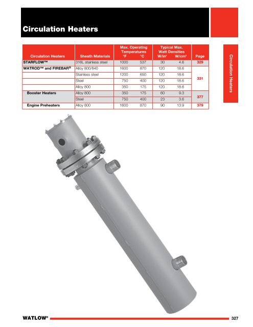
<strong>Circulation</strong> <strong>Heater</strong>sSTARFLOW <strong>Heater</strong>sThe STARFLOW circulation heater is engineered toheat a flowing gas stream to 1000°F (537°C). The 316Lstainless steel chamber houses a small diameter sheathedelement, which allows for quick response to both heat-upand cool down cycles.<strong>Watlow</strong>’s starwound, coiled cable heater providesextremely efficient and reliable heating by maximizingthe contact area of the gas or fluid with the element.Because the element is sheathed, the unit can operatein gas streams requiring a clean environment as well asatmospheres containing contaminants and moisture.This provides superior performance compared to unitswith internally exposed or open element wires.Performance Capabilities• Temperatures up to 1000°F (537°C), 316L stainlesssteel sheath• Maximum watt densities up to 30 W/in 2 (4.7 W/cm 2 )• Maximum voltage up to 240VFeatures and BenefitsSmall diameter heater• Allows for quick response timeInternal starwound element• Provides fast, efficient heatingSheathed element• Provides the ability to heat in clean or impure streamsFlexibility in configurations• Allows for adaptability to any process316L stainless steel• Provides a rugged and corrosion resistant constructionElectropolishing available on all wetted surface• Reduces particulate contaminationNote: Contact your <strong>Watlow</strong> representative for ultra-highpurity applicationsLow pressure loss• Minimizes flow restrictionNote: Not suitable for use as a pressure vesselType J or K thermocouples• Provide precise control and high-limit safetyReplaceable heater and thermocouple• Reduces replacement costShipment from stock• Reduces downtimeOutletTubeCable<strong>Circulation</strong><strong>Heater</strong>ProcessThermocoupleFittingO-Ring GrooveTypical Applications• Semiconductor processing• Curing and drying• Electronics• Heat shrinking• Thermoforming/sealingInlet Tube<strong>Heater</strong> <strong>Heater</strong> Adapter AdapterExit ExitWATLOW ®329
<strong>Circulation</strong> <strong>Heater</strong>sSTARFLOW <strong>Heater</strong>s10 in. (254 mm)9.25 in. (235 mm)4 in. (102 mm)ø.3.5 in.(89 mm)ø.2.5 in.(64 mm) 1.26 in. Ref.(32 mm)Process T/C Fitting2 in. (51 mm)Inlet TubeOutlet Tube<strong>Heater</strong> Adapter Exit1.32 in. Ref.(34 mm)0.25 in.(6 mm)O-Ring Grooveø3 in. (76 mm) B.C.(8) : ¼-20 ThreadsOrdering InformationPart Number1 2CH3 4 5 6 7 8 9 10Type ofInletType ofOutlet<strong>Heater</strong>Wattage11Internal T/CCalibration(<strong>Heater</strong>)12Surface Finishof Assemblyand <strong>Heater</strong>13Process T/CCalibration(Assembly)14O-RingMaterial3 4Type of InletET = 1 /4 in. (6 mm) O.D. tubeJT =5 61 /2 in. (13 mm) O.D. tubeType of OutletET = 1 /4 in. (6 mm) O.D. tubeJT = 1 /2 in. (13 mm) O.D. tube12X =E =13J =K =Surface Finish of Assembly and <strong>Heater</strong>UnfinishedElectropolishedProcess Thermocouple Calibration (Assembly)Type JType K7 8 9 100375 = 120V, 375 W0500 = 120V, 500 W0750 = 120V, 750 W1500 = 240V, 1500 W2000 = 240V, 2000 W3000 = 240V, 3000 W<strong>Heater</strong> Wattage14A =M =T =O-Ring MaterialFKM (FPM) 500°F (260°C)Alloy X750 1300°F (704°C)PTFE encapsulated FKM (FPM) 392°F (200°C)11J =K =Internal Thermocouple Calibration (<strong>Heater</strong>)Type JType KRAPID SHIP• Next day shipment330 WATLOW ®
<strong>Circulation</strong> <strong>Heater</strong>sWATROD and FIREBAR ®<strong>Circulation</strong> <strong>Heater</strong>s<strong>Circulation</strong> heaters provide a ready-made means toinstall electric heating with a minimal amount of timeand labor. This is accomplished by combining heatingelements, vessel, insulation, terminal enclosure,mounting brackets and inlet and outlet connectionsinto a complete assembly.Made from NPT screw plug or ANSI flange heaterassemblies mated with a pressure vessel (tank),circulation heaters are designed to heat forced-circulationair, gases or liquids. Ideal for either in-line or side-armoperations, these assemblies direct fluids past FIREBAR ®or WATROD heating elements, to deliver fast responseand even heat distribution.<strong>Watlow</strong> ® meets virtually all your circulation heaterassembly needs with made-to-order units. These unitscan be made from a wide range of heating elementsheath materials, wattages, vessel sizes and materials,pressure ratings, terminal enclosures and controls.Performance Capabilities• Watt densities up to 120 W/in 2 (18.6 W/cm 2 )• Wattages up to three megawatts• UL ® and CSA component recognition up to 690VAC• Ratings up to ANSI Class 600 pressure class• Alloy 800/840 sheath temperatures up to 1600°F(870°C)• Passivated 316 stainless steel sheath temperatures upto 1200°F (650°C)• Steel sheath temperatures up to 750°F (400°C)Features and Benefits<strong>Catalog</strong> screw plug and flange part numbers• Provides a wide selection of WATROD and FIREBARelements to meet specific application requirementsTypeSizes (in.)NPT Screw Plugs 1 1 /4, 2 1 /2ANSI flanges 3, 4, 5, 6, 8, 10, 12, 14FlangeAssemblyThreadedPipe OutletJacket1 in. (25 mm)InsulationThreadedPipe InletGasketMountingLugsPressureVesselFIREBAR assemblies pack more wattage in asmaller heater bundle• Replaces larger flanges with round tubular elements,with a smaller packageCompacted MgO insulation filled elements• Maximizes dielectric strength, heat transfer and life1 inch (25 mm) thermal insulation rated to750°F (400°C)• Reduces heat loss from the vesselHeavy-gauge steel jacket (shroud)• Protects thermal insulation and heating vessel andcomes with protective primer coatingANSI B16.5 Class 150 on 4 or 6 inch FIREBARelement flanges and 3 to 14 inch WATRODelement flanges• Meets recognized agency standardsWATLOW ®331
<strong>Circulation</strong> <strong>Heater</strong>sWATROD and FIREBAR<strong>Circulation</strong> <strong>Heater</strong>sOptions (Continued)Direction of FlowDirection of FlowBafflesBaffles mounted on the heating element bundle enhanceand/or modify liquid or gas flow for better heat transfer.For critical sheath temperature and low flow conditions,baffles may be required.Contact your <strong>Watlow</strong> representative for details.ThermocouplesTo sense process or element sheath temperature, ASTMType J or K thermocouples are available.See Screw Plug Immersion <strong>Heater</strong>s, page 168 andFlange Immersion <strong>Heater</strong>s, on page 239 for details.Process Thermocouple in Nozzle(Must specify which nozzle)Direction of FlowSheath MaterialsThe following sheath materials are available on WATRODand FIREBAR heating elements:Standard Sheath MaterialsWATROD Alloy 800/840316 SSSteelFIREBARAlloy 800, 304 SSMade-to-Order Sheath MaterialsWATROD304 SSAlloy 600TitaniumHastelloy C276Wattages and Voltages<strong>Watlow</strong> routinely supplies circulation heaters with120 to 690VAC as well as wattages from 500 wattsto one megawatt. If required, <strong>Watlow</strong> will configurecirculation heaters with voltages and wattages outsidethese parameters.For more information on special voltage and wattageconfigurations, contact your <strong>Watlow</strong> representative.RefTRef. Ref. DimensionTank Size Nozzle Size “A”1 1 /4 3 /4 NPT 8 3 /162 1 /2 1 NPT 8 3 /163 1 NPT 8 3 /164 1 1 /2 NPT 10 3 /85 2 NPT 11 1 /166 2 1 /2 NPT 13 3 /88 2 1 /2 NPT 14 3 /8For 10 in. (254 mm) and larger tanks contact your <strong>Watlow</strong> representativefor dimension.WATLOW ®333
<strong>Circulation</strong> <strong>Heater</strong>sWATROD and FIREBAR<strong>Circulation</strong> <strong>Heater</strong>sOptions (Continued)Pressure VesselsAll catalog pressure vessel (tank) materials consist ofstandard schedule and 150# class forged fittings and aremade from one of the following materials:• Carbon steel• 316 stainless steelAll catalog pressure vessels (tanks) are steel unlessotherwise noted.316 stainless steel pressure vessels (tanks) arepassivated on all wetted surfaces. Available fromAssembly Stock on 2 1 /2 inch NPT and 4 or 6 inch ANSIflange circulation heaters.Passivated FinishFor critical applications, passivation will remove free ironfrom all wetted surfaces.Contact your <strong>Watlow</strong> representative for details.GasketsRubber, asbestos-free and spiral wound gaskets areavailable for all heater flange, and inlet and outletflange sizes.<strong>Watlow</strong> recommends ordering spares in case replacementbecomes necessary.To order, specify gasket type, flange size/rating andprocess operating temperature.For details on gasket materials and temperature ratings,see page 240.Inlet and Outlet Nozzle ConnectionsAll inlet and outlet materials are compatible with thepressure vessel material and pressure class rating.Vessel sizes from 1 1 /4 to 8 inches are typicallyconfigured with MNPT (Male National Pipe Thread)nozzles. Optional NPT and flange sizes can be suppliedto mate with existing piping.10 inch and larger vessels are supplied with Class 150inlet and outlet flanges. Optional Class 300 or Class 600can be provided to mate with existing piping.To order, specify type, size and pressure class ratingfor both inlet and outlet nozzle/flange connections.Protective Steel Jacket (Shroud)To protect circulation heaters from weather orwash-down conditions, partially welded (standard) outerprotective steel jackets are available. Standard steel, ormade-to-order 304 or 316 stainless steel or aluminumcan be supplied. Jacket diameter is dependent uponthermal insulation thickness.To order, specify protective steel jacket, material typeand weatherproof, if desired.334 WATLOW ®
<strong>Circulation</strong> <strong>Heater</strong>sWATROD and FIREBAR<strong>Circulation</strong> <strong>Heater</strong>sTechnical DataMaximum VelocitiesThe rate at which a gas or liquid flows through inlet andoutlet pipes is critical to maintaining the desired outputtemperature. Pressure drop through the circulation heatermust be considered to properly size blowers or pumps.The Maximum Velocity to Avoid Excessive Pressure Dropchart gives recommended maximum velocities, in feet persecond and meters per second of gas or liquid beingheated and nominal pipe size.Maximum Velocity to Avoid Excessive Pressure DropNominal Pipe Size Maximum VelocityFluid in. ft/sec (m/sec)Gases All 200 (61.0)Liquid 4 and smaller 10 (3.0)Liquid 6-8 15 (5.0)Liquid 10-12 19 (6.0)Liquid 14-16 21 (6.4)Liquid 18-20 23 (7.0)Liquid 24 24 (7.3)Vessel Orientation GuidelinesCorrectly orienting the heating vessel assures lowerterminal enclosure temperatures and element immersion.Detailed instructions on vessel orientation are containedin the Installation and Maintenance Instructions thataccompanies all circulation heaters.The following are guidelines for vessel orientation in liquidand gas heating applications.LiquidsOrient circulation heater:• Horizontally with inlet and outlet pipes pointing up• Vertically with the terminal enclosure up and the inletpipe on the bottomThese orientations ensure the heating elements will beimmersed at all times and help prevent premature failure.Air or GasesOrient circulation heater:• Horizontally with the inlet nozzle closest to the terminalenclosure• Vertically with terminal enclosure at the bottom of thetank. Use the nozzle nearest the bottom as the inletconnectionIf installation constraints do not allow mounting inaccordance with these guidelines, contact your<strong>Watlow</strong> representative.WATLOW ®Application Hints• Select the recommended heating element sheathmaterial and watt density for the substance beingheated. Use the Supplemental Applications Chart onpages 555 to 558. If unable to determine thecorrect heating element type and material, contactyour <strong>Watlow</strong> representative.• Assure selecting proper vessel by considering thepressure or flow rate, process temperature andcorrosiveness of the media being heated. If assistancewith vessel selection is required, contact your <strong>Watlow</strong>representative.• For maintenance/replacement procedures, retain anarea twice the circulation heater’s overall length topermit easy removal and inspection of screw plugor flange heater assemblies.• Choose a FIREBAR assembly when you require:• A smaller package• More kilowatts or lower watt density in an equallysized WATROD circulation tank• Minimize problems associated with low flow or lowliquid level conditions with a low liquid level sensorand/or sheath high-limit control.• Ensure wiring integrity by making sure terminal enclosuretemperature does not exceed 400°F (205°C).• Size power feeder wires in accordance with nationalelectrical code guidelines and other applicable codes.• Protect against electrical shock by properly groundingthe unit per NEC requirements.• One or more circulation heaters may be connected inseries to achieve the desired total kilowatt ortemperature output.335
<strong>Circulation</strong> <strong>Heater</strong>sExtendedCapabilityWATROD and FIREBAR<strong>Circulation</strong> <strong>Heater</strong>sPerformance Capabilities• Up to 3000psi design pressureFeatures and BenefitsOffering includes units rated above ANSI pressureclass 600• Pressure vessel tanks are available in “H” seriesstainless steel, Titanium, alloy 800, alloy 600, ChromeMoly, alloy 400, Duplex and 321 stainless steelOptionsExotic Sheath MaterialsContact your <strong>Watlow</strong> representative for details andavailability.Pressure VesselsMade-to-order units can be made in a variety of materials,flange sizes and pressure classes.To order, specify pressure vessel (tank) size, materialand pressure class.Ratings to ANSI class 2500 pressure class are availablefor high-pressure applications.High-Temperature Thermal InsulationTo further minimize heat loss, the pressure vessel’sstandard one inch thermal insulation wrap may bereplaced with thicker or higher temperature insulation.For more information, contact your <strong>Watlow</strong> representative.To order, specify insulation thickness, standard orhigh temperature insulation and temperature rating.Vessels may be supplied with a primer coatingwithout insulation.To order, specify no insulation.Support SaddlesTo mate with an existing installation, customized supportsaddle(s) and/or mounting lugs are available.To order, specify mounting lugs or support saddlesand supply a dimensional drawing.336 WATLOW ®
SCREW PLUG<strong>Circulation</strong> <strong>Heater</strong>sBB67⁄16 in. Ref.(163.5 mm)¾ in.NPT Inletand Outlet¾ in.NPT Inletand OutletA Ref.A Ref.WATROD and FIREBAR<strong>Circulation</strong> <strong>Heater</strong>sApplication: Clean Water 5• WATROD or FIREBAR elements• Without thermostat• General purpose enclosure# PartShip Wt. “A” Dim. “B” Dim. “C” Dim.Description Volts kW Ph Circ. Number Del. lbs (kg) in. (mm) in. (mm) in. (mm)2 1 /2 inch NPT Screw Plug (FIREBAR)90 W/in 2 8 240 15.0 3 1 CBLNF15C3S M 22 (10) 34 3 /4 (881) 22 1 2 1/2 NPT/2 (572) 16 1 /2 (419)SCREW PLUG 2 1/2 NPTSteel Tank480 15.0 3 1 CBLNF15C5S M 22 (10) 343-Alloy 800/4 (881) 22 1 /2 (572) SCREW PLUG 16 1 /2 (419)Elements 240 20.0 3 1 CBLNF18C3S M 23 (11) 34 3 /4 (881) 22 1 /2 (572) 16 1 /2 (419)(14 W/cm 2 ) 480 20.0 3 1 CBLNF18C5S 3 M 23 (11) 34 3 /4 (881) 22 1 /2 (572) 16 1 /2 (419)480 25.0 3 1 CBLNF23C5S M 31 (14) 34 3 /4 (881) 22 1 /2 (572) 16 1 /2 (419)480 32.0 3 1 CBLNF28L5S M 34 (16) 44 3 /4 (1135) 32 1 /2 (1129) 26 1 /2 (673)480 38.0 3 1 CBLNF33L5S M 35 (16) 44 3 /4 (1135) 32 1 /2 (1129) 26 1 /2 (673)C Ref.3¾ in.(95 mm)3¾ in.(95 mm)2 1 /2 inch NPT Screw PlugB4 in.(102 mm)½ in.NPTDrain73⁄16 in. Ref.(182.673⁄16mm)in. Ref. 113⁄16 in.(182.6 mm) (284.2 113⁄16 mm) in.1 in.(284.2 mm)NPT Inlet 1 in.and Outlet NPT Inletand Outlet1¼1¼in.in.(32 (32 mm) mm)A Ref.CA Ref.C3 inch - 150 lb ANSI Flange (WATROD)60 W/in 2120 6.0 1 1 CFMN715J10S RS 66 (30) 35 1 /4 (894) 22 1 /2 (573) 16 1 415⁄16/2 (419)415⁄16 in. in.(125.4 (125.4 mm) mm)Steel Tank240 6.0 3 1 CFMN715J3S RS 66 (30) 353-Alloy 8001 /4 (894) 22 1 /2 (573) 16 1 Ref. Ref./2 (419)½ in. ½ in.Elements 480 6.0 1 1 CFMN715J11S RS 66 (30) 35 1 /4 (894) 22 1 /2 (573) 16 1 /2 (419)55⁄8 in. NPT NPT Drain Drain3⁄8-16 3⁄8-16 UNC UNC 55⁄8 in.(9.3 W/cm 2 ) 480 6.0 3 1 CFMN715J5S RS 66 (30) 35 1 /4 (894) 22 1 /2 (573) 16 1 (Threads (Threads (142.9 (142.9 mm) mm)/2 (419) (4 Places) (4 Places)120 9.0 1 1 CFMN721J10S RS 70 (32) 35 1 /4 (894) 22 1 /2 (573) 16 1 31⁄8 31⁄8in.in./2 (419)(79.4 mm)(79.4 mm)240 9.0 3 1 CFMN721J3S RS 70 (32) 35 1 /4 (894) 22 1 /2 (573) 16 1 /2 (419)43⁄8 in.480 9.0 1 1 CFMN721J11S RS 70 (32) 35 1 /4 (894) 22 1 /2 (573) 16 1 43⁄8 (111.1 in. mm)/2 (419)(111.1 mm)480 9.0 3 1 CFMN721J5S RS 70 (32) 35 1 /4 (894) 22 1 /2 (573) 16 1 /2 (419)3 inch - 150 lb ANSI Flange240 12.0 3 1 CFMN727A3S M 80 (37) 45 1 /4 (1148) 32 1 /2 (826) 26 1 /2 (673)43⁄8 in.480 12.0 1 1 CFMN727A11S M 80 (37) 45 1 /4 (1148) 32 1 /2 (826) 26 1 /2 (673)43⁄8 (111.1 in. mm)3"-150#480 12.0 3 1 CFMN727A5S M 80 (37) 45 1 /4 (1148) 32 1 3"-150# FLANGE/2 (826) 26 1 (111.1 mm)/2 (673)FLANGE240 15.0 3 1 CFMN732J3S M 96 (44) 45 1 /4 (1148) 32 1 /2 (826) 26 1 ½ in./2 (673)NPT Drain½480 15.0 1 1 CFMN732J11S M 96 (44) 45 1 /4 (1148) 32 1 /2 (826) 26 1 in./2 (673)NPT Drain480 15.0 3 1 CFMN732J5S M 96 (44) 45 1 /4 (1148) 32 1 /2 (826) 26 1 /2 (673)711⁄16 in. Ref.(195.3 mm)11½ in. Ref.240 18.0 3 1 CFMN738A3S M 98 (45) 57 3 /4 (1465) 45 (1143) 39 (991)711⁄16 in. Ref.(292 mm)(195.3 mm)11½ in. Ref.480 18.0 1 1 CFMN738A11S M 98 (45) 57 3 1 in./4 (1465) 45 (1143) 39 (991)NPT Inlet (292 mm)480 18.0 3 1 CFMN738A5S M 98 (45) 57 3 A Ref. 1 in. & Outlet/4 (1465) 45 (1143) 39 (991) BNPT InletCA Ref. & Outlet3 Wired for 3-phase operation onlyB1¼ C in.RAPID SHIP(32 mm)5 When steel vessel materials are used in this(2 Places)• RS - Next day shipmentapplication, some rust may be present in the1¼ in.up to 5 pieces3⁄8-16 UNC(32 55⁄8 mm) in. Ref.process media(Threads(2(142.9 Places) mm)• M - Manufacturing lead times(4 Places)8 Can be wired for 1-phase operation 3⁄8-16 UNC55⁄8 ½ in. in. Ref.(Threads 31⁄8 in. Dia.(142.9 NPT mm)Truck Shipment only(4 Places) (79.4 mm) Ref.Drain½ in.31⁄8 in. Dia.NPT(79.4 mm) Ref.DrainBC Ref.®4 in.(102 mm)®½ in.NPTDrain338 WATLOW ®
3½ in.<strong>Circulation</strong> <strong>Heater</strong>sWATROD and FIREBAR<strong>Circulation</strong> <strong>Heater</strong>s®®Application: Clean Water 5• WATROD or FIREBAR elements• Without thermostat• General purpose enclosure# PartShip Wt. “A” Dim. “B” Dim. “C” Dim. 4 inch - 150 lb ANSI FlangeDescription Volts kW Ph Circ. Number Del. lbs (kg) in. (mm) in. (mm) in. (mm)4"-150#513⁄16 in.4 inch - 150 lb ANSI Flange (WATROD)FLANGE(147.6 mm)60 W/in 2240 12.0 1 2 CFON715J10S M 124 (57) 39 (989) 20 1 /2 (521) 17 (432)Steel Tank240 12.0 3 1 CFON715J3S M 124 (57) 39 (989) 20 ½ in.6-Alloy 8001 /2 (521) 17 (432)NPT DrainElements 480 12.0 1 1 CFON715J11S M 124 (57) 39 (989) 20 1 /2 (521) 17 (432)(9.3 W/cm 2 ) 480 12.0 3 1 CFON715J5S M 124 (57) 39 (989) 20 1 /2 (521) 17 (432) 125⁄8 in. Ref.143⁄8 in. Ref.(320.7 mm)240 18.0 1 2 CFON721J10S M 127 (58) 39 (989) 20 1 /2 (521) 17 (432)(365.1 mm)240 18.0 3 1 CFON721J3S M 127 (58) 39 (989) 20 1 /2 (521) 17 (432)1½ in.A Ref. NPT Inlet480 18.0 1 1 CFON721J11S M 127 (58) 39 (989) 20 1 /2 (521) 17 (432)and OutletBC480 18.0 3 1 CFON721J5S M 127 (58) 39 (989) 20 1 /2 (521) 17 (432)240 24.0 1 2 CFON727A10S M 160 (73) 49 1 /2 (1256) 31 (787) 27 1 /2 (699)240 24.0 3 2 CFON727A3S M 160 (73) 49 1 /2 (1256) 31 (787) 27 1 /2 (699)480 24.0 1 1 CFON727A11S M 160 (73) 49 1 /2 (1256) 31 (787) 27 1 /2 (699) 3⁄8-16 UNC(Threads480 24.0 3 1 CFON727A5S M 160 (73) 49 1 /2 (1256) 31 (787) 27 1 /2 (699) (4 Places)311⁄16 in.240 30.0 3 2 CFON732J3S M 163 (74) 49 1 /2 (1256) 31 (787) 27 1 /2 (699) (93.7 mm)480 30.0 1 2 CFON732J11S M 163 (74) 49 1 /2 (1256) 31 (787) 27 1 /2 (699)480 30.0 3 1 CFON732J5S M 163 (74) 49 1 /2 (1256) 31 (787) 27 1 /2 (699)5"-150#240 36.0 3 2 CFON738A3S M 229 (104) 70 1 /2 (1789) 52 (1321) 48 1 /2 (1232)FLANGE480 36.0 1 2 CFON738A11S M 229 (104) 70 1 /2 (1789) 52 (1321) 48 1 /2 (1232)480 36.0 3 1 CFON738A5S M 229 (104) 70 1 /2 (1789) 52 (1321) 48 1 /2 (1232)480 50.0 3 2 CFON751A5S M 234 (107) 70 1 /2 (1789) 52 (1321) 48 1 /2 (1232)480 60.0 3 2 CFON760J5S M 297 (135) 91 1 /2 (2326) 73 (1854) 66 (1676)• M - Manufacturing lead times125⁄8 in. Ref.(320.7 mm)5 When steel vessel materials are used in this2 in.application, some rust may be present in the NPT Inletprocess mediaA Ref. and OutletBTruck Shipment only1¼ in.(32 mm)(2 Places)65⁄8 in.(168.3 mm)½ in.NPTDrain59⁄16 in. Ref.(141.3 mm)½ in.NPT DrainC25 in.(635 mm)1¼ in.(32 mm)(2 Places)3⁄8-16 UNC(Threads(4 Places)75⁄8 in.(193.7 mm)½ in.NPTDrain4¼ in.(108 mm)6"-150#FLANGE65⁄8 in. Ref.(168.3 mm)½ in.NPT Drain1211⁄16 in. Ref.(322.3 mm)147⁄16 in. Ref.(366.7 mm)WATLOW ®A Ref.B2½ in.NPT Inletand OutletC339
513⁄16 in.(147.6 mm)513⁄16 in.(147.6 mm)½ in.NPT Drain½ in.NPT Drain125⁄8 in. Ref.143⁄8 in. Ref.(320.7 mm)(365.1 mm)125⁄8 in. Ref.143⁄8 in. Ref.(320.7 mm)1½ in.(365.1 mm)A Ref. NPT Inletand OutletB1½ in.®CA Ref. NPT Inlet ®and OutletBC1¼ in.(32 mm)1¼ (2 Places) in.3⁄8-16 UNC65⁄8 (32 in. mm)(Threads(168.3 (2 Places) mm)3⁄8-16 (4 Places) UNC65⁄8 in. ½ in.(Threads311⁄16 in.(168.3 mm) NPT(4 Places)(93.7 mm)½ in. Drain311⁄16 in.NPT(93.7 mm)Drain# PartShip Wt. “A” Dim. “B” Dim. “C” Dim. 5 inch - 150 lb ANSI FlangeDescription Volts kW Ph Circ. Number Del lbs (kg) in. (mm) in. (mm) in. (mm)5"-150#59⁄16 in. Ref.5 inch - 150 lb ANSI Flange (WATROD)FLANGE(141.3 mm)5"-150#59⁄16 in. Ref.60 W/in 2 240 24.0 1 3 CFNN727A10S M 140 (64) 49 1 /4 (1249.0) 30 (762) 14 7 /8 (378.8)FLANGE(141.3 mm) ½ in.Steel Tank 240 24.0 3 2 CFNN727A3S M 140 (64) 49 1 /4 (1249.0) 30 (762) 14 7 /8 (378.8)NPT Drain6-Alloy 800 480 24.0 1 3 CFNN727A11S M 140 (64) 49 1 /4 (1249.0) 30 (762) 14 7 /8 (378.8)½ in.ElementsNPT Drain480 24.0 3 1 CFNN727A5S M 140 (64) 49 1 /4 (1249.0) 30 (762) 14 7 /8 (378.8)(9.3 W/cm 2 )125⁄8 in. Ref.240 30.0 3 2 CFNN732J3S M 142 (65) 49 1 /4 (1249.0) 30 (762) 14 7 /8 (378.8) (320.7 mm)125⁄8 in. Ref.C480 30.0 1 2 CFNN732J11S M 142 (65) 49 1 /4 (1249.0) 30 (762) 14 7 /8 (378.8)(320.7 mm)480 30.0 3 1 CFNN732J5S M 142 (65) 49 1 /4 (1249.0) 30 (762) 14 7 /8 (378.8)C2 in.240 36.0 3 2 CFNN738A3S M 160 (73) 56 1 /4 (1427.0) 37 (940) 18 5 /8 (473.1) NPT InletA Ref. and 2 in. Outlet480 36.0 1 2 CFNN738A11S M 160 (73) 56 1 /4 (1427.0) 37 (940) 18 5 /8 (473.1)25 in.BNPT InletA Ref. and Outlet(635 mm)480 36.0 3 1 CFNN738A5S M 160 (73) 56 1 /4 (1427.0) 37 (940) 18 5 /8 (473.1)25 in.B480 50.0 3 2 CFNN751A5S M 180 (82) 67 3 /4 (1719.0) 48 1 /2 (1232) 25 (633.0)(635 mm)1¼ in.480 60.0 3 2 CFNN760J5S M 190 (87) 81 1 /8 (2060.6) 61 7 /8 (1572) 30 7 /8 (784.2)(32 mm)1¼ (2 Places) in.(32 mm)(2 Places)5 inch - 150 lb ANSI Flange (WATROD)3⁄8-16 UNC75⁄8 in.60 W/in 2(Threads(193.7 mm)240 36.0 3 3 CFNN727A3XS M 145 (66) 49 1 /4 (1249.0) 30 (762) 14 7 /8 (378.8)3⁄8-16 (4 Places) UNC75⁄8 in.Steel Tank 480 36.0 1 3 CFNN727A11XS M 145 (66) 49 1 /4 (1249.0) 30 (762) 14 7 /8 (378.8)(Threads(193.7 mm) ½ in.(4 Places)NPT9-Alloy 800½ in. DrainElementsNPTDrain(9.3 W/cm 2 )4"-150#FLANGE4"-150#FLANGE<strong>Circulation</strong> <strong>Heater</strong>sWATROD and FIREBAR<strong>Circulation</strong> <strong>Heater</strong>sApplication: Clean Water 5• WATROD or FIREBAR elements• Without thermostat• General purpose enclosure480 36.0 3 1 CFNN727A5XS M 145 (66) 49 1 /4 (1249.0) 30 (762) 14 7 /8 (378.8)240 45.0 3 3 CFNN732J3XS M 147 (67) 49 1 /4 (1249.0) 30 (762) 14 7 /8 (378.8)4¼ in.480 45.0 1 3 CFNN732J11XS M 147 (67) 49 1 /4 (1249.0) 30 (762) 14 7 /8 (378.8) (108 mm)4¼ in.480 45.0 3 3 CFNN732J5XS M 147 (67) 49 1 /4 (1249.0) 30 (762) 14 7 /8 (378.8) (108 mm)240 54.0 3 3 CFNN738A3XS M 166 (76) 56 1 /4 (1427.0) 37 (940) 18 5 /8 (473.1)480 54.0 1 3 CFNN738A11XS M 166 (76) 56 1 /4 (1427.0) 37 (940) 18 5 /8 (473.1) 6 inch - 150 lb ANSI Flange 65⁄8 in. Ref.6"-150#480 54.0 3 3 CFNN738A5XS M 166 (76) 56 1 /4 (1427.0) 37 (940) 18 5 /8 (473.1)(168.3 mm)FLANGE65⁄8 in. Ref.480 75.0 3 3 CFNN751A5XS M 188 (86) 67 3 /4 (1719.0) 48 1 /26"-150#(1232) 25 (633.0)(168.3 mm)FLANGE480 90.0 3 3 CFNN760J5XS M 200 (91) 81 1 /8 (2060.6) 61 7 /8 (1572) 30 7 /8 (784.2)½ in.NPT Drain½ in.NPT Drain6 inch - 150 lb ANSI Flange (WATROD)1211⁄16 in. Ref.60 W/in 2147⁄16 in. Ref.(322.3 mm)1211⁄16 in. Ref.(366.7 mm)Steel Tank147⁄16 in. Ref.(322.3 mm)(366.7 mm)12-Alloy 8002½ in.ElementsNPT Inlet2½A Ref. and in.(9.3 W/cm 2 )OutletNPT InletBCA Ref. and OutletBC240 24.0 1 3 CFPN715G10S M 212 (97) 40 1 /2 (1027) 20 1 /2 (521) 17 (432)240 24.0 3 2 CFPN715G3S M 212 (97) 40 1 /2 (1027) 20 1 /2 (521) 17 (432)480 24.0 1 2 CFPN715G11S M 212 (97) 40 1 /2 (1027) 20 1 /2 (521) 17 (432)480 24.0 3 1 CFPN715G5S M 212 (97) 40 1 /2 (1027) 20 1 /2 (521) 17 (432)240 36.0 1 4 CFPN721G10S M 217 (99) 40 1 /2 (1027) 20 1 /2 (521) 17 (432)240 36.0 3 2 CFPN721G3S M 217 (99) 40 1 /2 (1027) 20 1 /2 (521) 17 (432)480 36.0 1 2 CFPN721G11S M 217 (99) 40 1 /2 (1027) 20 1 /2 (521) 17 (432)480 36.0 3 1 CFPN721G5S M 217 (99) 40 1 /2 (1027) 20 1 /2 (521) 17 (432)240 48.0 3 4 CFPN726R3S M 222 (101) 51 (1294) 31 (787) 27 1 /2 (699)480 48.0 1 3 CFPN726R11S M 222 (101) 51 (1294) 31 (787) 27 1 /2 (699)480 48.0 3 2 CFPN726R5S M 222 (101) 51 (1294) 31 (787) 27 1 /2 (699)240 60.0 3 4 CFPN732G3S M 288 (131) 51 (1294) 31 (787) 27 1 /2 (699)480 60.0 1 3 CFPN732G11S M 288 (131) 51 (1294) 31 (787) 27 1 /2 (699)480 60.0 3 2 CFPN732G5S M 288 (131) 51 (1294) 31 (787) 27 1 /2 (699)240 72.0 3 4 CFPN737R3S M 290 (132) 72 (1827) 52 (1321) 48 1 /2 (1232)480 72.0 3 2 CFPN737R5S M 290 (132) 72 (1827) 52 (1321) 48 1 /2 (1232)480 100.0 3 4 CFPN750R5S M 298 (136) 72 (1827) 52 (1321) 48 1 /2 (1232)480 120.0 3 4 CFPN760G5S M 360 (164) 93 (2361) 73 (1854) 66 (1676)• M - Manufacturing lead times5 When steel vessel materials are used in thisapplication, some rust may be present in theprocess mediaTruck Shipment only¾-10 UNC 2B(Threads¾-10 UNC 2B(Threads(4 Places)(4 Places)4¾ in.4¾ (121in.mm)(121 mm)3½ in.(89 mm)3½(2 Places)in.(89 mm)(28¾ Places) in.(222 mm)8¾ in.(222 mm)½ in.½ in.NPTNPTDrainDrain340 WATLOW ®
½ in.NPT Drain<strong>Circulation</strong> <strong>Heater</strong>sWATROD and FIREBAR<strong>Circulation</strong> <strong>Heater</strong>sApplication: Clean Water 5• WATROD or FIREBAR elements• Without thermostat• General purpose enclosure# PartShip Wt. “A” Dim. “B” Dim. “C” Dim.Description Volts kW Ph Circ. Number Del lbs (kg) in. (mm) in. 6"-150# (mm) in. (mm)6 inch - 150 lb ANSI Flange (WATROD)FLANGE60 W/in 2240 30.0 1 3 CFPN715G10XS M 215 (98) 40 1 /2 (1027) 20 1 /2 (521) 17 (432)Steel Tank15-Alloy 800240 30.0 3 5 CFPN715G3XS M 215 (98) 40 1 /2 (1027) 20 1 /2 (521) 17 (432)Elements 480 30.0 1 3 CFPN715G11XS M 215 (98) 40 1 /2 (1027) 20 1 /2 (521) 17 (432)(9.3 W/cm 2 ) 480 30.0 3 1 CFPN715G5XS M 215 (98) 40 1 /2 (1027) 20 1 /2 (521) 17 (432)240 45.0 1 5 CFPN721G10XS M 223 (102) 40 1 /2 (1027) 20 1 /2 (521) 17 (432)240 45.0 3 5 CFPN721G3XS M 223 (102) 40 1 /2 (1027) 20 1 /2 (521) 17 (432)480 45.0 1 3 CFPN721G11XS M 223 (102) 40 1 /2 (1027) 20 1 /2 (521) 17 (432)480 45.0 3 5 CFPN721G5XS M 223 (102) 40 1 /2 (1027) 20 1 /2 (521) 17 (432)240 60.0 3 5 CFPN726R3XS M 226 (103) 51 (1294) 31 (787) 27 1 /2 (699)480 60.0 1 3 CFPN726R11XS M 226 (103) 51 (1294) 31 (787) 27 1 /2 (699)480 60.0 3 5 CFPN726R5XS M 226 (103) 51 (1294) 31 (787) 27 1 /2 (699)240 75.0 3 5 CFPN732G3XS M 288 (131) 51 (1294) 31 (787) 27 1 /2 (699)480 75.0 1 5 CFPN732G11XS M 288 (131) 51 (1294) 31 (787) 27 1 /2 (699)480 75.0 3 5 CFPN732G5XS M 288 (131) 51 (1294) 31 (787) 27 1 /2 (699)240 90.0 3 5 CFPN737R3XS M 296 (134) 72 (1827) 52 (1321) 48 1 /2 (1232)480 90.0 3 5 CFPN737R5XS M 296 (134) 72 (1827) 52 (1321) 48 1 /2 (1232)480 125.0 3 5 CFPN750R5XS M 306 (139) 72 (1827) 52 (1321) 48 1 /2 (1232)480 150.0 3 5 CFPN760G5XS M 370 (168) 93 (2361) 73 (1854) 66 (1676)125⁄8 in. Ref.(320.7 mm)2 in.NPT InletA Ref. and OutletB3⁄8-16 UNC(Threads(4 Places)4¼ in.(108 mm)75⁄8 in.(193.7 mm)½ in.NPTDrain6 inch - 150 lb ANSI FlangeA Ref.B1211⁄16 in. Ref.(322.3 mm)2½ in.NPT Inletand Outlet¾-10 UNC 2B(Threads(4 Places)4¾ in.(121 mm)®8 inch - 150 lb ANSI FlangeC25 in.(635 mm)1¼ in.(32 mm)(2 Places)65⁄8 in. Ref.(168.3 mm)½ in.NPT Drain147⁄16 in. Ref.(366.7 mm)C®3½ in.(89 mm)(2 Places)8¾ in.(222 mm)½ in.NPTDrain8 inch - 150 lb ANSI Flange (WATROD)8"-150#60 W/in 2240 50.0 3 3 CFRN721N3S M 340 (155) 47 1 /4 (1199.0) 24 3 /4FLANGE(627.0) 21 1 /4 (538.0)Steel Tank18-Alloy 800480 50.0 1 3 CFRN721N11S M 340 (155) 47 1 /4 (1199.0) 24 3 /4 (627.0) 21 1 /4 (538.0)Elements 480 50.0 3 2 CFRN721N5S M 340 (155) 47 1 /4 (1199.0) 24 3 /4 (627.0) 21 1 /4 (538.0)(7.5 W/cm 2 ) 240 75.0 3 6 CFRN729N3S M 360 (164) 55 1 /4 (1402.0) 32 3 /4 (830.0) 29 1 /4 (741.0)480 75.0 3 2 CFRN729N5S M 360 (164) 55 1 /4 (1402.0) 32 3 /4 (830.0) 29 1 /4 (741.0)240 100.0 3 6 CFRN737E3S M 385 (175) 62 1 /4 (1580.0) 39 3 /4(1008.0) 36 1 /4 (919.0)480 100.0 3 3 CFRN737E5S M 385 (175) 62 1 /4 (1580.0) 39 3 /4(1008.0) 36 1 /4 (919.0)240 125.0 3 6 CFRN745E3S M 410 (186) 69 7 /8 (1774.8) 47 3 /8(1203.3) 43 7 /8 (1114.4)480 125.0 3 6 CFRN745E5S M 410 (186) 69 7 /8 (1774.8) 47 3 /8(1203.3) 43 7 /8 (1114.4)480 150.0 3 6 CFRN752N5S M 440 (200) 79 3 /8 (2016.1) 56 7 /8(1444.6) 53 3 /8 (1355.7)480 175.0 3 6 CFRN760N5S M 465 (211) 88 3 /8 (2244.7) 65 7 /8(1673.2) 62 3 /8 (1584.3)480 200.0 3 6 CFRN768E5S M 510 (232) 98 3 /8 (2498.7) 75 7 /8(1927.2) 72 3 /8 (1838.3)• M - Manufacturing lead times5 When steel vessel materials are used in thisapplication, some rust may be present in theprocess mediaTruck Shipment onlyA Ref.B1411⁄16 in. Ref.(373.1 mm)¾-10 UNC 2B(Threads(4 Places)2½ in.NPT Inletand Outlet5¾ in.(146 mm)75⁄8 in.(193.7 mm)½ in.NPT Drain14½ in. Ref.(368 mm)C3½ in.(89 mm)(2 Places)10¾ in.(273 mm)½ in.NPTDrainWATLOW ®10"-150#FLANGE3 in.1215⁄16 in.(328.6 mm) 341(2) ¾ -10UNC 2B
(163.5 mm)<strong>Circulation</strong> <strong>Heater</strong>sB¾ in.NPT Inletand OutletA Ref.WATROD and FIREBAR<strong>Circulation</strong> <strong>Heater</strong>sApplication: Deionized or Demineralized Water• WATROD or FIREBAR elements• Without thermostat• General purpose enclosure# PartShip Wt. “A” Dim. “B” Dim. “C” Dim.Description Volts kW Ph Circ. Number Del. lbs (kg) in. (mm) in. (mm) in. (mm)2 1 /2 inch NPT Screw Plug (WATROD)2 1/2 NPT60 W/in 2240 6.0 3 1 CBLR714L3S RS 24 (11) 34 3 /4 (881) 22 1 /2 (572) 16 1 /2 (419)SCREW PLUG316 SS480 6.0 3 1 CBLR714L5S RS 24 (11) 34Tank/4 (881) 22 1 /2 (572) 16 1 /2 (419)3-316 SS 240 7.5 3 1 CBLR717L3S RS 24 (11) 34 3 /4 (881) 22 1 /2 (572) 16 1 /2 (419)Elements 480 7.5 3 1 CBLR717L5S RS 24 (11) 34 3 /4 (881) 22 1 /2 (572) 16 1 /2 (419)(9.3 W/cm 2 )Passivated240 9.0 3 1 CBLR720L3S RS 26 (12) 34 3 /4 (881) 22 1 /2 (572) 16 1 /2 (419)480 9.0 3 1 CBLR720L5S RS 26 (12) 34 3 /4 (881) 22 1 /2 (572) 16 1 /2 (419)240 12.0 3 1 CBLR726C3S RS 27 (13) 44 3 /4 (1135) 32 1 /2 (1129) 26 1 /2 (673)480 12.0 3 1 CBLR726C5S RS 27 (13) 44 3 /4 (1135) 32 1 /2 (1129) 26 1 /2 (673)240 15.0 3 1 CBLR731L3S RS 29 (14) 44 3 /4 (1135) 32 1 /2 (1129) 26 1 /2 (673)480 15.0 3 1 CBLR731L5S RS 29 (14) 44 3 /4 (1135) 32 1 /2 (1129) 26 1 /2 (673)240 18.0 3 1 CBLR737C3S RS 30 (14) 57 1 /4 (1453) 45 (1143) 39 (991)480 18.0 3 1 CBLR737C5S RS 30 (14) 57 1 /4 (1453) 45 (1143) 39 (991)342 NPT Inlet WATLOW ®BC Ref.½ in.NPTDrain73⁄16 in. Ref.(182.6 mm) 113⁄16 in.(284.2 mm)1 in.NPT Inletand Outlet415⁄16 in.(125.4 mm)3⁄8-16 UNC(Threads(4 Places)4 in.(102 mm)3¾ in.(95 mm)2 1 /2 inch NPT Screw Plug1¼ in.(32 mm)A Ref.CRef.½ in.55⁄8 in. NPT Drain(142.9 mm)4 inch - 150 lb ANSI Flange (WATROD)31⁄8 in.(79.4 mm)60 W/in 2240 12.0 1 2 CFOR716A10S M 124 (57) 39 (989) 20 1 /2 (521) 17 (432)316 SS43⁄8 in.240 12.0 3 1 CFOR716A3S M 124 (57) 39 (989) 20Tank/2 (521) 17 (432)(111.1 mm)6-316 SS 480 12.0 1 1 CFOR716A11S M 124 (57) 39 (989) 20 1 /2 (521) 17 (432)Elements 480 12.0 3 1 CFOR716A5S M 124 (57) 39 (989) 20 1 /2 (521) 17 (432)4 inch - 150 lb ANSI Flange(9.3 W/cm 2 )240 18.0 1 2 CFOR722A10S M 127 (58) 39 (989) 20 4"-150#513⁄16 43⁄8 in.Passivated/2 (521) 17 (432)FLANGE(111.1 (147.6 mm)3"-150#240 18.0 3 1 CFOR722A3S M 127 (58) 39 (989) 20 1 /2 (521) 17 (432)FLANGE480 18.0 1 1 CFOR722A11S M 127 (58) 39 (989) 20 1 /2 (521) 17 (432)½ in.480 18.0 3 1 CFOR722A5S M 127 (58) 39 (989) 20 1 /2 (521) 17 (432)NPT Drain240 24.0 1 2 CFOR727J10S M 160 (73) 49 1 /2 (1256) 31 (787) 27 1 /2 (699)711⁄16 in. 125⁄8 Ref. in. Ref.240 24.0 3 2 CFOR727J3S M 160 (73) 49 1 /2 (1256) 31 (787) 27 1 /2 (699)143⁄8 in. Ref.(195.3 mm) (320.7 mm) 11½ (365.1 in. Ref. mm)480 24.0 1 1 CFOR727J11S M 160 (73) 49 1 /2 (1256) 31 (787) 27 1 /2 (699)(292 mm)11½ in.480 24.0 3 1 CFOR727J5S M 160 (73) 49 1 /2 (1256) 31 (787) 27 1 /2 (699)in.A Ref.NPT NPT Inlet Inlet240 30.0 3 2 CFOR733A3S M 163 (74) 49 1 A Ref. & and Outlet/2 (1256) 31 (787) 27 1 /2 (699)OutletB BCC480 30.0 1 2 CFOR733A11S M 163 (74) 49 1 /2 (1256) 31 (787) 27 1 /2 (699)480 30.0 3 1 CFOR733A5S M 163 (74) 49 1 /2 (1256) 31 (787) 27 1 /2 (699)1¼ 1¼ in. in.(32 (32 mm)240 36.0 3 2 CFOR738J3S M 229 (104) 70 1 /2 (1789) 52 (1321) 48 1 /2 (1232)(2 (2 Places)3⁄8-16 UNC3⁄8-16 (Threads UNC55⁄8 65⁄8 in. in. Ref.480 36.0 1 2 CFOR738J11S M 229 (104) 70 1 /2 (1789) 52 (1321) 48 1 /2 (1232)(168.3(Threads (4 Places)(142.9mm)mm)480 36.0 3 1 CFOR738J5S M 229 (104) 70 1 /2 (1789) 52 (1321) 48 1 /2 (1232)(4 Places)½ in.311⁄16 in.NPT½ in.Drain480 50.0 3 2 CFOR751J5S M 234 (107) 70 1 /2 (1789) 52 (1321) 48 1 /2 (1232) 31⁄8 (93.7in. Dia.mm)NPT480 60.0 3 2 CFOR761A5S M 297 (135) 91 1 /2 (2326) 73 (1854) 66(79.4 mm) Ref.(1676)DrainRAPID SHIP• RS - Next day shipmentup to 5 pieces• M - Manufacturing lead timesTruck Shipment only5"-150#FLANGE125⁄8 in. Ref.(320.7 mm)2 in.A Ref. and OutletB®59⁄16 in. Ref.(141.3 mm)½ in.NPT DrainC®25 in.(635 mm)
½ in.NPT Drain<strong>Circulation</strong> <strong>Heater</strong>sWATROD and FIREBAR<strong>Circulation</strong> <strong>Heater</strong>sApplication: Deionized or Demineralized Water• WATROD or FIREBAR elements• Without thermostat• General purpose enclosure125⁄8 in. Ref.(320.7 mm)2 in.NPT InletA Ref. and OutletB3⁄8-16 UNC(Threads(4 Places)4¼ in.(108 mm)75⁄8 in.(193.7 mm)½ in.NPTDrain# PartShip Wt. “A” Dim. “B” Dim. “C” Dim. 6 inch - 150 lb ANSI FlangeDescription Volts kW Ph Circ. Number Del. lbs (kg) in. (mm) in. (mm)6"-150#in. (mm)6 inch - 150 lb ANSI Flange (WATROD)FLANGE60 W/in 2240 24.0 1 3 CFPR715N10S M 212 (97) 40 1 /2 (1027) 20 1 /2 (521) 17 (432)316 SS Tank240 24.0 3 2 CFPR715N3S M 212 (97) 40 1 /2 (1027) 20 1 /2 (521) 17 (432)12-316 SSElements480 24.0 1 2 CFPR715N11S M 212 (97) 40 1 /2 (1027) 20 1 /2 (521) 17 (432)(9.3 W/cm 2 ) 480 24.0 3 1 CFPR715N5S M 212 (97) 40 1 /2 (1027) 20 1 1211⁄16 in. Ref./2 (521) 17 (432) (322.3 mm)Passivated 240 36.0 1 4 CFPR721N10S M 217 (99) 40 1 /2 (1027) 20 1 /2 (521) 17 (432)240 36.0 3 2 CFPR721N3S M 217 (99) 40 1 /2 (1027) 20 1 /2 (521) 17 (432)2½ in.480 36.0 1 2 CFPR721N11S M 217 (99) 40 1 /2 (1027) 20 1 NPT Inlet/2 (521) 17 (432) A Ref. and Outlet480 36.0 3 1 CFPR721N5S M 217 (99) 40 1 /2 (1027) 20 1 /2 (521) 17 (432) B240 48.0 3 4 CFPR727E3S M 222 (101) 51 (1294) 31 (787) 27 1 /2 (699)480 48.0 1 3 CFPR727E11S M 222 (101) 51 (1294) 31 (787) 27 1 /2 (699)480 48.0 3 2 CFPR727E5S M 222 (101) 51 (1294) 31 (787) 27 1 /2 (699)240 60.0 3 4 CFPR732N3S M 226 (103) 51 (1294) 31 (787) 27 1 /2 (699)480 60.0 1 3 CFPR732N11S M 226 (103) 51 (1294) 31 (787) 27 1 ¾-10 UNC 2B/2 (699) (Threads480 60.0 3 2 CFPR732N5S M 226 (103) 51 (1294) 31 (787) 27 1 /2 (699)(4 Places)240 72.0 3 4 CFPR738E3S M 290 (132) 72 (1827) 52 (1321) 48 1 /2 (1232)480 72.0 3 2 CFPR738E5S M 290 (132) 72 (1827) 52 (1321) 48 1 /2 (1232)4¾ in.480 100.0 3 4 CFPR751E5S M 298 (136) 72 (1827) 52 (1321) 48 1 (121 mm)/2 (1232)480 120.0 3 4 CFPR760N5S M 360 (164) 93 (2361) 73 (1854) 66 (1676)®C25 in.(635 mm)1¼ in.(32 mm)(2 Places)65⁄8 in. Ref.(168.3 mm)C®½ in.NPT Drain147⁄16 in. Ref.(366.7 mm)3½ in.(89 mm)(2 Places)8¾ in.(222 mm)½ in.NPTDrain6 inch - 150 lb ANSI Flange (WATROD)60 W/in 2240 30.0 1 3 CFPR715N10XS M 215 (98) 40 1 /2 (1027) 20 1 /2 (521) 17 (432)316 SS Tank240 30.0 3 5 CFPR715N3XS M 215 (98) 40 1 /2 (1027) 20 1 /2 (521) 17 (432)15-316 SSElements480 30.0 1 3 CFPR715N11XS M 215 (98) 40 1 /2 (1027) 20 1 /2 (521) 17 (432)(9.3 W/cm 2 ) 480 30.0 3 1 CFPR715N5XS M 215 (98) 40 1 /2 (1027) 20 1 /2 (521) 17 (432)Passivated 240 45.0 1 5 CFPR721N10XS M 223 (102) 40 1 /2 (1027) 20 1 /2 (521) 17 (432)240 45.0 3 5 CFPR721N3XS M 223 (102) 40 1 /2 (1027) 20 1 /2 (521) 17 (432)480 45.0 1 3 CFPR721N11XS M 223 (102) 40 1 /2 (1027) 20 1 /2 (521) 17 (432)480 45.0 3 5 CFPR721N5XS M 223 (102) 40 1 /2 (1027) 20 1 /2 (521) 17 (432)240 60.0 3 5 CFPR727E3XS M 226 (103) 51 (1294) 31 (787) 27 1 /2 (699)480 60.0 1 3 CFPR727E11XS M 226 (103) 51 (1294) 31 (787) 27 1 /2 (699)480 60.0 3 5 CFPR727E5XS M 226 (103) 51 (1294) 31 (787) 27 1 /2 (699)240 75.0 3 5 CFPR732N3XS M 288 (131) 51 (1294) 31 (787) 27 1 /2 (699)480 75.0 1 5 CFPR732N11XS M 288 (131) 51 (1294) 31 (787) 27 1 /2 (699)480 75.0 3 5 CFPR732N5XS M 288 (131) 51 (1294) 31 (787) 27 1 /2 (699)240 90.0 3 5 CFPR738E3XS M 296 (135) 72 (1827) 52 (1321) 48 1 /2 (1232)480 90.0 3 5 CFPR738E5XS M 296 (135) 72 (1827) 52 (1321) 48 1 /2 (1232)480 125.0 3 5 CFPR751E5XS M 306 (139) 72 (1827) 52 (1321) 48 1 /2 (1232)480 150.0 3 5 CFPR760N5XS M 370 (168) 93 (2361) 73 (1854) 66 (1676)• M - Manufacturing lead timesTruck Shipment onlyWATLOW ®343
<strong>Circulation</strong> <strong>Heater</strong>sWATROD and FIREBAR<strong>Circulation</strong> <strong>Heater</strong>s®®Application: Process Water 5• WATROD or FIREBAR elements• Without thermostat• General purpose enclosure# PartShip Wt. “A” Dim. “B” Dim. 1 1/4 NPT“C” Dim. 1 1 /4 inch NPT Screw PlugDescription Volts kW Ph Circ. Number Del. lbs (kg) in. (mm) in. (mm) SCREW in. PLUG (mm)1 1 /4 inch NPT Screw Plug (FIREBAR)1 1/4 NPT67⁄16 in. Ref.45 W/in 2 8 240 2.0 3 1 CBDNF13A27S M 25 (12) 24 5 SCREW PLUG/8 (625.5) 15 (381) 3 1 /8 (79.4) (163.5 mm)Steel Tank240 2.5 3 1 CBDNF15J27S M 26 (12) 24 5 /8 (625.5) 15 (381) 3 1 67⁄16 in. Ref./8 (79.4) (163.5 mm)1-Alloy 800Element240 3.0 3 1 CBDNF18A27S M 30 (14) 32 5 /8 (828.7) 23 (584) 3 1 /8 (79.4)(7 W/cm 2 ) 240 4.0 3 1 CBDNF22J27S M 31 (14) 32 5 /8 (828.7) 23 (584) 3 1 ¾ in./8 (79.4)NPT Inlet480 4.0 3 1 CBDNF22J28S M 31 (14) 32 5 /8 (828.7) 23 (584) 3 1 /8 (79.4)¾ and in. OutletNPT InletA Ref.240 5.0 3 1 CBDNF27J27S M 43 (20) 42 5 /8 (1082.7) 32 (813) 4 3 /8 (111.1) and OutletB480 5.0 3 1 CBDNF27J28S M 43 (20) 42 5 /8 (1082.7) 32 (813) 4 3 A Ref./8 (111.1)B240 6.0 3 1 CBDNF32J27S M 44 (20) 42 5 /8 (1082.7) 32 (813) 4 3 /8 (111.1)480 6.0 3 1 CBDNF32J28S M 44 (20) 42 5 /8 (1082.7) 32 (813) 4 3 /8 (111.1)240 8.0 3 1 CBDNF42A27S M 69 (32) 63 5 /8 (1616.1) 53 (1346) 4 3 /8 (111.1)480 8.0 3 1 CBDNF42A28S M 69 (32) 63 5 /8 (1616.1) 53 (1346) 4 3 /8 (111.1)C Ref.240 10.0 3 1 CBDNF51J27S M 71 (33) 63 5 /8 (1616.1) 53 (1346) 4 3 /8 (111.1)C Ref.480 10.0 3 1 CBDNF51J28S M 71 (33) 63 5 /8 (1616.1) 53 (1346) 4 3 ½ in./8 (111.1)4 in.½ in. NPT4 (102 in. mm) NPT Drain(102 mm) Drain2 1 /2 inch NPT Screw Plug (WATROD)48 W/in 2 8 240 6.0 3 1 CBLN717G3S RS 24 (11) 34 3 /4 (881) 22 1 /2 (572) 16 1 /2 (419)Steel Tank480 6.0 3 1 CBLN717G5S RS 24 (11) 34 3 /4 (881) 22 1 /2 (572) 16 1 /2 (419)3¾ in.3-Alloy 800Elements240 7.5 3 1 CBLN719R3S RS 26 (12) 34 3 /4 (881) 22 1 /2 (572) 16 1 3¾ (95 in. mm)/2 (419)(95 mm)(7.5 W/cm 2 ) 480 7.5 3 1 CBLN719R5S RS 26 (12) 34 3 /4 (881) 22 1 /2 (572) 16 1 /2 (419)240 9.0 3 1 CBLN724R3S RS 27 (13) 34 3 /4 (881) 22 1 /2 (572) 16 1 /2 (419) 2 1 /2 inch NPT Screw Plug480 9.0 3 1 CBLN724R5S RS 27 (13) 34 3 /4 (881) 22 1 /2 (572) 16 1 /2 (419)240 12.0 3 1 CBLN732G3S RS 29 (14) 44 3 /4 (1135) 32 1 /2 (1129) 26 1 /2 (673)480 12.0 3 1 CBLN732G5S RS 29 (14) 44 3 /4 (1135) 32 1 2 1/2 NPT73⁄16 73⁄16/2 (1129) 26 1 in.in.Ref.Ref.2 1/2 NPT /2 (673) (182.6 (182.6 mm) mm)SCREW PLUG113⁄16 113⁄16 in. in.240 15.0 3 1 CBLN739R3S RS 31 (14) 57 1 SCREW PLUG/4 (1453) 45 (1143) 39 (991)(284.2 (284.2 mm) mm)480 15.0 3 1 CBLN739R5S RS 31 (14) 57 1 1 in. 1 in./4 (1453) 45 (1143) 39 (991) NPT NPT Inlet Inlet240 18.0 3 1 CBLN747G3S RS 32 (15) 57 1 /4 (1453) 45 (1143) 39 (991) and and Outlet Outlet480 18.0 3 1 CBLN747G5S RS 32 (15) 57 1 /4 (1453) 45 (1143) 39 (991)B BA Ref. A Ref.C C2 1 /2 inch NPT Screw Plug (FIREBAR)45 W/in 2 8 240 6.0 3 1 CBLNF12A27S M 21 (10) 34 3 /4 (881) 22 1 /2 (572) 16 1 /2 (419)1¼ in. 1¼ in.Steel Tank240 7.5 3 1 CBLNF14J27S M 22 (10) 34 3 /4 (881) 22 1 /2 (572) 16 1 (32 mm) (32 mm)/2 (419)3-Alloy 800Elements240 9.0 3 1 CBLNF17A27S M 23 (11) 34 3 /4 (881) 22 1 /2 (572) 16 1 /2 (419)(7 W/cm 2 ) 240 12.0 3 1 CBLNF21J27S M 31 (14) 34 3 /4 (881) 22 1 /2 (572) 16 1 415⁄16/2 (419) 415⁄16in.in.(125.4 mm)480 12.0 3 1 CBLNF21J28S M 31 (14) 34 3 /4 (881) 22 1 /2 (572) 16 1 (125.4 mm) Ref./2 (419)Ref.½ in.240 15.0 3 1 CBLNF26J27S M 34 (16) 44 3 /4 (1135) 32 1 /2 (1129) 26 1 NPT Drain ½ in./2 (673) 3⁄8-16 UNC 55⁄8 in.55⁄8 in. NPT Drain480 15.0 3 1 CBLNF26J28S M 34 (16) 44 3 /4 (1135) 32 1 /2 (1129) 26 1 (Threads 3⁄8-16 UNC (142.9 mm)/2 (673)(142.9 mm)(4 Places) (Threads240 18.0 3 1 CBLNF31J27S M 35 (16) 44 3 /4 (1135) 32 1 /2 (1129) 26 1 (4 Places)31⁄8 in./2 (673)(79.4 mm) 31⁄8 in.480 18.0 3 1 CBLNF31J28S M 35 (16) 44 3 /4 (1135) 32 1 /2 (1129) 26 1 (79.4 mm)/2 (673)480 24.0 3 1 CBLNF41A28S M 44 (20) 57 1 /4 (1453) 45 (1143) 39 (991)43⁄8 in.43⁄8480 30.0 3 1 CBLNF50J28S M 52 (24) 63 3 /4 (1618) 51 1 /2 (1308) 46 1 (111.1 mm) in./2 (1181)(111.1 mm)5 When steel vessel materials are used in thisRAPID SHIPapplication, some rust may be present in theprocess media43⁄8 in.• RS - Next day shipment • M - Manufacturing lead times(111.13"-150#43⁄8 mm)up to 5 piecesin.8 Can be wired for 1-phase operationFLANGE(111.1 mm)3"-150#344 WATLOW ®FLANGE½ in.NPT Drain½ in.
<strong>Circulation</strong> <strong>Heater</strong>s2 1/2 NPTSCREW PLUGB73⁄16 in. Ref.(182.6 mm) 113⁄16 in.(284.2 mm)1 in.NPT Inletand OutletA Ref.CWATROD and FIREBAR<strong>Circulation</strong> <strong>Heater</strong>sApplication: Process Water 5• WATROD or FIREBAR elements• Without thermostat• General purpose enclosure# PartShip Wt. “A” Dim. “B” Dim. “C” Dim.Description Volts kW Ph Circ. Number Del. lbs (kg) in. (mm) in. (mm) in. (mm)3 inch - 150 lb ANSI Flange (WATROD)3"-150#48 W/in 2 240 6.0 1 1 CFMN718A10S RS 68 (31) 35 1 /4 (894) 22 1 /2 (573) 16 1 /2 FLANGE (419)Steel Tank 240 6.0 3 1 CFMN718A3S RS 68 (31) 35 1 /4 (894) 22 1 /2 (573) 16 1 /2 (419)3-Alloy 800 480 6.0 1 1 CFMN718A11S RS 68 (31) 35 1 /4 (894) 22 1 /2 (573) 16 1 /2 (419)Elements 480 6.0 3 1 CFMN718A5S RS 68 (31) 35 1 /4 (894) 22 1 /2 (573) 16 1 /2 (419)(7.5 W/cm 2 ) 240 7.5 1 1 CFMN720J10S RS 70 (32) 35 1 /4 (894) 22 1 /2 (573) 16 1 /2 (419)240 7.5 3 1 CFMN720J3S RS 70 (32) 35 1 /4 (894) 22 1 /2 (573) 16 1 /2 (419)480 7.5 1 1 CFMN720J11S RS 70 (32) 35 1 /4 (894) 22 1 /2 (573) 16 1 /2 (419)480 7.5 3 1 CFMN720J5S RS 70 (32) 35 1 /4 (894) 22 1 /2 (573) 16 1 /2 (419)240 9.0 1 1 CFMN725J10S M 78 (36) 45 1 /4 (1148) 32 1 /2 (826) 26 1 /2 (673)240 9.0 3 1 CFMN725J3S M 78 (36) 45 1 /4 (1148) 32 1 /2 (826) 26 1 /2 (673)480 9.0 1 1 CFMN725J11S M 78 (36) 45 1 /4 (1148) 32 1 /2 (826) 26 1 /2 (673)480 9.0 3 1 CFMN725J5S M 78 (36) 45 1 /4 (1148) 32 1 /2 (826) 26 1 /2 (673)240 12.0 3 1 CFMN733A3S M 96 (44) 45 1 /4 (1148) 32 1 /2 (826) 26 1 /2 (673)480 12.0 1 1 CFMN733A11S M 96 (44) 45 1 /4 (1148) 32 1 /2 (826) 26 1 /2 (673)480 12.0 3 1 CFMN733A5S M 96 (44) 45 1 /4 (1148) 32 1 /2 826) 26 1 /2 (673)240 15.0 3 1 CFMN740J3S M 100 (46) 57 3 /4 (1465) 45 (1143) 39 (991)480 15.0 1 1 CFMN740J11S M 100 (46) 57 3 /4 (1465) 45 (1143) 39 (991)480 15.0 3 1 CFMN740J5S M 100 (46) 57 3 /4 (1465) 45 (1143) 39 (991)240 18.0 3 1 CFMN748A3S M 107 (49) 57 3 /4 (1465) 45 (1143) 39 (991)480 18.0 1 1 CFMN748A11S M 107 (49) 57 3 /4 (1465) 45 (1143) 39 (991)480 18.0 3 1 CFMN748A5S M 107 (49) 57 3 /4 (1465) 45 (1143) 39 (991)4 inch - 150 lb ANSI Flange (WATROD)48 W/in 2 240 9.0 1 1 CFON713J10S M 122 (56) 39 (989) 20 1 /2 (521) 17 (432)Steel Tank 240 9.0 3 1 CFON713J3S M 122 (56) 39 (989) 20 1 4"-150#/2 (521) FLANGE 17 (432)6-Alloy 800 480 9.0 1 1 CFON713J11S M 122 (56) 39 (989) 20 1 /2 (521) 17 (432)Elements 480 9.0 3 1 CFON713J5S M 122 (56) 39 (989) 20 1 /2 (521) 17 (432)(7.5 W/cm 2 ) 240 12.0 1 2 CFON718A10S M 125 (57) 39 (989) 20 1 /2 (521) 17 (432)240 12.0 3 1 CFON718A3S M 125 (57) 39 (989) 20 1 /2 (521) 17 (432)480 12.0 1 1 CFON718A11S M 125 (57) 39 (989) 20 1 /2 (521) 17 (432)480 12.0 3 1 CFON718A5S M 125 (57) 39 (989) 20 1 /2 (521) 17 (432)240 15.0 1 2 CFON720J10S M 127 (58) 39 (989) 20 1 /2 (521) 17 (432)240 15.0 3 1 CFON720J3S M 127 (58) 39 (989) 20 1 /2 (521) 17 (432)480 15.0 1 1 CFON720J11S M 127 (58) 39 (989) 20 1 /2 (521) 17 (432)480 15.0 3 1 CFON720J5S M 127 (58) 39 (989) 20 1 /2 (521) 17 (432)240 18.0 1 2 CFON725J10S M 160 (73) 39 (989) 20 1 /2 (521) 17 (432)240 18.0 3 1 CFON725J3S M 160 (73) 39 (989) 20 1 /2 (521) 17 (432)480 18.0 1 1 CFON725J11S M 160 (73) 39 (989) 20 1 /2 (521) 17 (432)480 18.0 3 1 CFON725J5S M 160 (73) 39 (989) 20 1 /2 (521) 17 (432)240 24.0 1 2 CFON733A10S M 163 (74) 49 1 /2 (1256) 31 (787) 27 1 /2 (699)240 24.0 3 2 CFON733A3S M 163 (74) 49 1 /2 (1256) 31 (787) 27 1 /2 (699)480 24.0 1 1 CFON733A11S M 163 (74) 49 1 /2 (1256) 31 (787) 27 1 /2 (699)480 24.0 3 1 CFON733A5S M 163 (74) 49 1 /2 (1256) 31 (787) 27 1 /2 (699)240 30.0 3 2 CFON740J3S M 229 (104) 70 1 /2 (1789) 52 (1321) 48 1 /2 (1232)480 30.0 1 2 CFON740J11S M 229 (104) 70 1 /2 (1789) 52 (1321) 48 1 /2 (1232)480 30.0 3 1 CFON740J5S M 229 (104) 70 1 5"-150#/2 (1789) 52 (1321) 48 1 FLANGE /2 (1232)240 36.0 3 2 CFON748A3S M 234 (107) 70 1 /2 (1789) 52 (1321) 48 1 /2 (1232)480 36.0 1 2 CFON748A11S M 234 (107) 70 1 /2 (1789) 52 (1321) 48 1 /2 (1232)480 36.0 3 1 CFON748A5S M 234 (107) 70 1 /2 (1789) 52 (1321) 48 1 /2 (1232)RAPID SHIP• RS - Next day shipmentup to 2 piecesWATLOW ®• M - Manufacturing lead times5 When steel vessel materials are used in thisapplication, some rust may be present in theprocess mediaTruck Shipment onlyA Ref.B415⁄16 in.(125.4 mm)3⁄8-16 UNC(Threads(4 Places)711⁄16 in. Ref.(195.3 mm)3⁄8-16 UNC(Threads(4 Places)1¼ in.(32 mm)Ref.½ in.55⁄8 in. NPT Drain(142.9 mm)1 in.NPT Inlet& Outlet31⁄8 in. Dia.(79.4 mm) Ref.43⁄8 in.(111.1 mm)3 inch - 150 lb ANSI Flange31⁄8 in.(79.4 mm)43⁄8 in.(111.1 mm)4 inch - 150 lb ANSI Flange1½ in.A Ref. NPT Inletand OutletB3⁄8-16 UNC(Threads(4 Places)125⁄8 in. Ref.(320.7 mm)311⁄16 in.(93.7 mm)125⁄8 in. Ref.(320.7 mm)2 in.NPT InletA Ref. and OutletB®½ in.NPT Drain11½ in. Ref.(292 mm)1¼ in.(32 mm)(2 Places)55⁄8 in. Ref.(142.9 mm)½ in.NPTDrain513⁄16 in.(147.6 mm)½ in.NPT DrainC½ in.NPT Drain143⁄8 in. Ref.(365.1 mm)C1¼ in.(32 mm)(2 Places)65⁄8 in.(168.3 mm)½ in.NPTDrain59⁄16 in. Ref.(141.3 mm)®C34525 in.(635 mm)
<strong>Circulation</strong> <strong>Heater</strong>sWATROD and FIREBAR<strong>Circulation</strong> <strong>Heater</strong>s®®Application: Process Water 5• WATROD or FIREBAR elements• Without thermostat• General purpose enclosure# PartShip Wt. “A” Dim. “B” Dim. “C” Dim. 4 inch - 150 lb ANSI FlangeDescription Volts kW Ph Circ. Number Del. lbs (kg) in. (mm) in. (mm) in. (mm)4"-150#513⁄16 in.4 inch - 150 lb ANSI Flange (FIREBAR)FLANGE(147.6 mm)45 W/in 2240 12.0 3 1 CFONF13G27S M 125 (57) 39 (989) 20 1 4"-150#513⁄16 in./2 (521) 17 (432)FLANGE(147.6 mm)Steel Tank240 15.0 3 1 CFONF16A27S M 128 (58) 39 (989) 206-Alloy 8001 /2 (521) 17 (432)½ in.NPT DrainElements 240 18.0 3 1 CFONF18G27S M 130 (59) 39 (989) 20 1 /2 (521) 17 (432)½ in.(7 W/cm 2 ) 240 24.0 3 2 CFONF22R27S M 133 (61) 39 (989) 20 1 /2 (521) 17 (432) 125⁄8 in. Ref.NPT Drain143⁄8 in. Ref.480 24.0 3 1 CFONF22R28S M 133 (61) 39 (989) 20 1 (320.7 mm)(365.1 mm)/2 (521) 17 (432)240 30.0 3 2 CFONF27R27S M 168 (77) 49 1 /2 (1256) 31 (787) 27 1 /2 (699)125⁄8 in. Ref.143⁄8 in. Ref.(320.7 1½ in. mm)480 30.0 3 1 CFONF27R28S M 168 (77) 49 1 /2 (1256) 31 (787) 27 1 A Ref. NPT Inlet(365.1 mm)/2 (699)and Outlet240 36.0 3 2 CFONF32R27S M 170 (78) 49 1 /2 (1256) 31 (787) 27 1 BC/2 (699)1½ in.480 36.0 3 1 CFONF32R28S M 170 (78) 49 1 /2 (1256) 31 (787) 27 1 A Ref. NPT Inlet/2 (699)and Outlet480 48.0 3 2 CFONF42G28S M 236 (107) 70 1 /2 (1789) 52 (1321) 48 1 B1¼ in. C/2 (1232)(32 mm)(2 Places)480 60.0 3 2 CFONF51R28S M 240 (109) 70 1 /2 (1789) 52 (1321) 48 1 3⁄8-16 UNC/2 (1232)65⁄8 in.(Threads(168.3 mm)(4 Places)1¼ in.½ in. (32 mm)311⁄16 in.NPT (2 Places)5 inch - 150 lb ANSI Flange (WATROD)3⁄8-16 (93.7 UNC mm)Drain 65⁄8 in.48 W/in 2240 24.0 1 3 CFNN733A10S M 145 (66) 49 1 /4 (1249) 30 (762) 14 7 (Threads(168.3 mm)/8 (377.8) (4 Places)Steel Tank½240 24.0 3 2 CFNN733A3S M 145 (66) 496-Alloy 8001 /4 (1249) 30 (762) 14 7 in./8 (377.8) 311⁄16 in.NPTElements 480 24.0 1 2 CFNN733A11S M 145 (66) 49 1 5"-150#/4 (1249) 30 (762) 14 7 (93.7 mm) 59⁄16 in. Ref. DrainFLANGE /8 (377.8)(141.3 mm)(7.5 W/cm 2 ) 480 24.0 3 1 CFNN733A5S M 145 (66) 49 1 /4 (1249) 30 (762) 14 7 /8 (377.8) 5 inch - 150 lb ANSI Flange ½ in.240 30.0 3 2 CFNN740J3S M 167 (76) 56 1 /4 (1427) 37 (940) 18 5 NPT Drain/8 (473.1)5"-150#59⁄16 in. Ref.480 30.0 1 2 CFNN740J11S M 167 (76) 56 1 /4 (1427) 37 (940) 18 FLANGE 5 (141.3 mm)/8 (473.1)480 30.0 3 1 CFNN740J5S M 167 (76) 56 1 /4 (1427) 37 (940) 18 5 125⁄8 in. Ref./8 (473.1) (320.7 mm)½ in.240 36.0 3 2 CFNN748A3S M 180 (82) 67 3 /4 (1719) 48 1 NPT DrainC/2 (1232) 25 (633.0)480 36.0 1 2 CFNN748A11S M 180 (82) 67 3 /4 (1719) 48 1 2 in./2 (1232) 25 (633.0) NPT Inlet125⁄8480 36.0 3 1 CFNN748A5S M 180 (82) 67 3 /4 (1719) 48 1 A Ref. and in. Outlet Ref./2 (1232) 25 (633.0) B(320.7 mm)25 in.(635 mm) C5 inch - 150 lb ANSI Flange (WATROD)2 in.NPT Inlet48 W/in 2240 36.0 3 3 CFNN733A3XS M 150 (68) 49 1 /4 (1249) 30 (762) 14 7 /8 (377.8) A Ref. and OutletSteel Tank480 36.0 1 3 CFNN733A11XS M 150 (68) 499-Alloy 800/4 (1249) 30 (762) 14 7 B/8 (377.8) 3⁄8-16 UNCElements 480 36.0 3 1 CFNN733A5XS M 150 (68) 49 1 /4 (1249) 30 (762) 14 7 (Threads/8 (377.8) (4 Places)(7.5 W/cm 2 ) 240 45.0 3 3 CFNN740J3XS M 173 (79) 56 1 /4 (1427) 37 (940) 18 5 /8 (473.1)480 45.0 1 3 CFNN740J11XS M 173 (79) 56 1 /4 (1427) 37 (940) 18 5 /8 (473.1)4¼ in.480 45.0 3 3 CFNN740J5XS M 173 (79) 56 1 /4 (1427) 37 (940) 18 5 3⁄8-16 UNC (108 mm)/8 (473.1) (Threads240 54.0 3 3 CFNN748A3XS M 188 (86) 67 3 /4 (1719) 48 1 /2 (1232) 25 (633.0)(4 Places)480 54.0 1 3 CFNN748A11XS M 188 (86) 67 3 /4 (1719) 48 1 /2 (1232) 25 (633.0)480 54.0 3 3 CFNN748A5XS M 188 (86) 67 3 /4 (1719) 48 1 6"-150#/2 (1232) 25 (633.0)FLANGE4¼ in.(108 mm)• M - Manufacturing lead times5 When steel vessel materials are used in thisapplication, some rust may be present in theprocess mediaTruck Shipment only1211⁄16 in. Ref.6"-150#(322.3 mm)FLANGE1¼ in.(32 mm)(2 Places)25 in.75⁄8 in.(635 mm)(193.7 mm)½ in. 1¼ in.NPT (32 mm)Drain (2 Places)75⁄8 in.(193.7 mm)½ in.NPTDrain65⁄8 in. Ref.(168.3 mm)½ in.NPT Drain147⁄16 65⁄8 in. in. Ref.(168.3 (366.7 mm)2½ in.NPT InletA Ref. and OutletB1211⁄16 in. Ref.(322.3 mm)½ in.NPT DrainC147⁄16 in. Ref.(366.7 mm)346 WATLOW ®
½ in.NPT Drain<strong>Circulation</strong> <strong>Heater</strong>sWATROD and FIREBAR<strong>Circulation</strong> <strong>Heater</strong>sApplication: Process Water 5• WATROD or FIREBAR elements• Without thermostat• General purpose enclosure# PartDescription Volts kW Ph Circ. Number6 inch - 150 lb ANSI Flange (WATROD)48 W/in 2Steel Tank12-Alloy 800Elements(7.5 W/cm 2 )Del.Ship Wt.lbs (kg)“A” Dim.in. (mm)“B” Dim.in. (mm)6"-150#FLANGE“C” Dim.in. (mm)240 18.0 1 2 CFPN713G10S M 212 (97) 40 1 /2 (1027) 20 1 /2 (521) 17 (432)240 18.0 3 1 CFPN713G3S M 212 (97) 40 1 /2 (1027) 20 1 /2 (521) 17 (432)480 18.0 1 1 CFPN713G11S M 212 (97) 40 1 /2 (1027) 20 1 /2 (521) 17 (432)480 18.0 3 1 CFPN713G5S M 212 (97) 40 1 /2 (1027) 20 1 /2 (521) 17 (432)240 24.0 1 3 CFPN717R10S M 214 (97) 40 1 /2 (1027) 20 1 /2 (521) 17 (432)240 24.0 3 2 CFPN717R3S M 214 (97) 40 1 /2 (1027) 20 1 /2 (521) 17 (432)480 24.0 1 2 CFPN717R11S M 214 (97) 40 1 /2 (1027) 20 1 /2 (521) 17 (432)480 24.0 3 1 CFPN717R5S M 214 (97) 40 1 /2 (1027) 20 1 /2 (521) 17 (432)240 30.0 1 3 CFPN720G10S M 217 (99) 40 1 /2 (1027) 20 1 /2 (521) 17 (432)240 30.0 3 2 CFPN720G3S M 217 (99) 40 1 /2 (1027) 20 1 /2 (521) 17 (432)480 30.0 1 2 CFPN720G11S M 217 (99) 40 1 /2 (1027) 20 1 /2 (521) 17 (432)480 30.0 3 1 CFPN720G5S M 217 (99) 40 1 /2 (1027) 20 1 /2 (521) 17 (432)240 36.0 1 4 CFPN725G10S M 222 (101) 40 1 /2 (1027) 20 1 /2 (521) 17 (432)240 36.0 3 2 CFPN725G3S M 222 (101) 40 1 /2 (1027) 20 1 /2 (521) 17 (432)480 36.0 1 2 CFPN725G11S M 222 (101) 40 1 /2 (1027) 20 1 /2 (521) 17 (432)480 36.0 3 1 CFPN725G5S M 222 (101) 40 1 /2 (1027) 20 1 /2 (521) 17 (432)240 48.0 3 4 CFPN732R3S M 226 (103) 51 (1294) 31 (787) 27 1 /2 (699)480 48.0 1 3 CFPN732R11S M 226 (103) 51 (1294) 31 (787) 27 1 /2 (699)480 48.0 3 2 CFPN732R5S M 226 (103) 51 (1294) 31 (787) 27 1 /2 (699)240 60.0 3 4 CFPN740G3S M 290 (132) 72 (1827) 52 (1321) 48 1 /2 (1232)480 60.0 1 3 CFPN740G11S M 290 (132) 72 (1827) 52 (1321) 48 1 /2 (1232)480 60.0 3 2 CFPN740G5S M 290 (132) 72 (1827) 52 (1321) 48 1 /2 (1232)240 72.0 3 4 CFPN747R3S M 298 (136) 72 (1827) 52 (1321) 48 1 /2 (1232)480 72.0 3 2 CFPN747R5S M 298 (136) 72 (1827) 52 (1321) 48 1 /2 (1232)125⁄8 in. Ref.(320.7 mm)2 in.NPT InletA Ref. and OutletB3⁄8-16 UNC(Threads(4 Places)4¼ in.(108 mm)1¼ in.(32 mm)(2 Places)75⁄8 in.(193.7 mm)½ in.NPTDrain6 inch - 150 lb ANSI Flange65⁄8 in. Ref.(168.3 mm)A Ref.B1211⁄16 in. Ref.(322.3 mm)2½ in.NPT Inletand Outlet¾-10 UNC 2B(Threads(4 Places)4¾ in.(121 mm)®C25 in.(635 mm)½ in.NPT Drain147⁄16 in. Ref.(366.7 mm)C®3½ in.(89 mm)(2 Places)8¾ in.(222 mm)½ in.NPTDrain6 inch - 150 lb ANSI Flange (WATROD)48 W/in 2 240 23.0 1 3 CFPN713G10XS M 215 (98) 40 1 /2 (1027) 20 1 /2 (521) 17 (432)Steel Tank 240 23.0 3 5 CFPN713G3XS M 215 (98) 40 1 /2 (1027) 20 1 /2 (521) 17 (432)15-Alloy 800 480 23.0 1 1 CFPN713G11XS M 215 (98) 40 1 /2 (1027) 20 1 /2 (521) 17 (432)Elements 480 23.0 3 1 CFPN713G5XS M 215 (98) 40 1 /2 (1027) 20 1 /2 (521) 17 (432)(7.5 W/cm 2 ) 240 30.0 1 3 CFPN717R10XS M 217 (99) 40 1 /2 (1027) 20 1 /2 (521) 17 (432)240 30.0 3 5 CFPN717R3XS M 217 (99) 40 1 /2 (1027) 20 1 /2 (521) 17 (432)480 30.0 1 3 CFPN717R11XS M 217 (99) 40 1 /2 (1027) 20 1 /2 (521) 17 (432)480 30.0 3 1 CFPN717R5XS M 217 (99) 40 1 /2 (1027) 20 1 /2 (521) 17 (432)240 38.0 1 5 CFPN720G10XS M 223 (102) 40 1 /2 (1027) 20 1 /2 (521) 17 (432)240 38.0 3 5 CFPN720G3XS M 223 (102) 40 1 /2 (1027) 20 1 /2 (521) 17 (432)480 38.0 1 3 CFPN720G11XS M 223 (102) 40 1 /2 (1027) 20 1 /2 (521) 17 (432)480 38.0 3 1 CFPN720G5XS M 223 (102) 40 1 /2 (1027) 20 1 /2 (521) 17 (432)240 45.0 1 5 CFPN725G10XS M 226 (103) 40 1 /2 (1027) 20 1 /2 (521) 17 (432)240 45.0 3 5 CFPN725G3XS M 226 (103) 40 1 /2 (1027) 20 1 /2 (521) 17 (432)480 45.0 1 3 CFPN725G11XS M 226 (103) 40 1 /2 (1027) 20 1 /2 (521) 17 (432)480 45.0 3 5 CFPN725G5XS M 226 (103) 40 1 /2 (1027) 20 1 /2 (521) 17 (432)240 60.0 3 5 CFPN732R3XS M 288 (131) 51 (1294) 31 (787) 27 1 /2 (699)480 60.0 1 3 CFPN732R11XS M 288 (131) 51 (1294) 31 (787) 27 1 /2 (699)480 60.0 3 5 CFPN732R5XS M 288 (131) 51 (1294) 31 (787) 27 1 /2 (699)240 75.0 3 5 CFPN740G3XS M 296 (135) 72 (1827) 52 (1321) 48 1 /2 (1232)480 75.0 1 5 CFPN740G11XS M 296 (135) 72 (1827) 52 (1321) 48 1 /2 (1232)480 75.0 3 5 CFPN740G5XS M 296 (135) 72 (1827) 52 (1321) 48 1 /2 (1232)240 90.0 3 5 CFPN747R3XS M 306 (139) 72 (1827) 52 (1321) 48 1 /2 (1232)480 90.0 3 5 CFPN747R5XS M 306 (139) 72 (1827) 52 (1321) 48 1 /2 (1232)• M - Manufacturing lead times Truck Shipment only5 When steel vessel materials are used in thisapplication, some rust may be present in theprocess mediaWATLOW ®347
½ in.NPT Drain<strong>Circulation</strong> <strong>Heater</strong>sWATROD and FIREBAR<strong>Circulation</strong> <strong>Heater</strong>sApplication: Process Water 5• WATROD or FIREBAR elements• Without thermostat• General purpose enclosure# PartShip Wt. “A” Dim. “B” Dim. “C” Dim.6 inch - 150 lb ANSI FlangeDescription Volts kW Ph Circ. Number Del. lbs (kg) in. (mm) in. (mm) in. (mm)6"-150#6 inch - 150 lb ANSI Flange (FIREBAR)FLANGE45 W/in 2240 30.0 3 5 CFPNF13G27S M 217 (99) 40 1 /2 (1027) 20 1 /2 (521) 17 (432)Steel Tank240 37.5 3 5 CFPNF16A27S M 220 (100) 40 1 /2 (1027) 20 1 /2 (521) 17 (432)15-Alloy 800Elements240 45.0 3 5 CFPNF18G27S M 223 (102) 40 1 /2 (1027) 20 1 /2 (521) 17 (432)(7 W/cm 2 ) 240 60.0 3 5 CFPNF22R27S M 226 (103) 40 1 /2 (1027) 20 1 /2 (521) 17 (432) 1211⁄16 in. Ref.480 60.0 3 5 CFPNF22R28S M 226 (103) 40 1 /2 (1027) 20 1 (322.3 mm)/2 (521) 17 (432)240 75.0 3 5 CFPNF27R27S M 232 (106) 51 (1294) 31 (787) 27 1 /2 (699)2½ in.480 75.0 3 5 CFPNF27R28S M 232 (106) 51 (1294) 31 (787) 27 1 /2 (699) NPT Inlet240 90.0 3 5 CFPNF32R27S M 236 (107) 51 (1294) 31 (787) 27 1 A Ref. and Outlet/2 (699) B480 90.0 3 5 CFPNF32R28S M 236 (107) 51 (1294) 31 (787) 27 1 /2 (699)480 120.0 3 5 CFPNF42G28S M 304 (138) 72 (1827) 52 (1321) 48 1 /2(1232)480 150.0 3 5 CFPNF51R28S M 314 (143) 72 (1827) 52 (1321) 48 1 /2(1232)8 inch - 150 lb ANSI Flange (WATROD)48 W/in 2240 67.0 3 4 CFRN726D3XS M 358 (163) 55 1 /4(1402.0) 32 3 /4(830.0) 29 1 /4 (741.0)Steel Tank480 67.0 1 3 CFRN726D11XS M 358 (163) 55 1 /4(1402.0) 32 3 /4(830.0) 29 1 /4 (741.0)24-Alloy 800Elements480 67.0 3 2 CFRN726D5XS M 358 (163) 55 1 /4(1402.0) 32 3 /4(830.0) 29 1 /4 (741.0)(7.5 W/cm 2 ) 240 100.0 3 8 CFRN736D3XS M 392 (178) 62 1 /4(1580.0) 39 3 /4(1008.0) 36 1 /4 (919.0)480 100.0 3 4 CFRN736D5XS M 392 (178) 62 1 /4(1580.0) 39 3 /4(1008.0) 36 1 /4 (919.0)240 133.0 3 8 CFRN744M3XS M 425 (193) 69 7 /8(1774.8) 47 3 ⁄8 (1203.3) 43 7 /8 (1114.4)480 133.0 3 4 CFRN744M5XS M 425 (193) 69 7 /8(1774.8) 47 3 ⁄8 (1203.3) 43 7 /8 (1114.4)240 167.0 3 8 CFRN754M3XS M 463 (210) 79 3 /8(2016.1) 56 7 /8(1444.6) 53 3 /8 (1355.7)480 167.0 3 8 CFRN754M5XS M 463 (210) 79 3 /8(2016.1) 56 7 /8(1444.6) 53 3 /8 (1355.7)480 200.0 3 8 CFRN763M5XS M 511 (232) 88 3 /8(2244.7) 65 7 /8(1673.2) 62 3 /8 (1584.3)480 233.0 3 8 CFRN773D5XS M 554 (252) 98 3 /8(2498.7) 75 7 /8(1927.2) 72 3 /8 (1838.3)480 267.0 3 8 CFRN782M5XS M 587 (267) 98 3 /8(2498.7) 75 7 /8(1927.2) 72 3 /8 (1838.3)125⁄8 in. Ref.(320.7 mm)2 in.NPT InletA Ref. and OutletB3⁄8-16 UNC(Threads(4 Places)4¼ in.(108 mm)1¼ in.(32 mm)(2 Places)75⁄8 in.(193.7 mm)½ in.NPTDrain348FlangeWATLOW Holes ®10"-150#FLANGEC25 in.(635 mm)65⁄8 in. Ref.(168.3 mm)8 inch - 150 lb ANSI Flange (WATROD)¾-10 UNC 2B(Threads48 W/in 2240 50.0 3 3 CFRN725N3S M 350 (159) 55 1 /4(1402.0) 32 3 /4(830.0) 29 1 /4 (741.0)(4 Places)Steel Tank480 50.0 1 3 CFRN725N11S M 350 (159) 55 1 /4(1402.0) 32 3 /4(830.0) 29 1 /4 (741.0)18-Alloy 800Elements480 50.0 3 2 CFRN725N5S M 350 (159) 55 1 /4(1402.0) 32 3 /4(830.0) 29 1 /4 (741.0)4¾ in.(7.5 W/cm 2 ) 240 75.0 3 6 CFRN735N3S M 380 (173) 62 1 /4(1580.0) 39 3 /4(1008.0) 36 1 (121 mm)/4 (919.0)480 75.0 3 2 CFRN735N5S M 380 (173) 62 1 /4(1580.0) 39 3 /4(1008.0) 36 1 /4 (919.0)8 inch - 150 lb ANSI Flange240 100.0 3 6 CFRN744E3S M 410 (186) 69 7 /8(1774.8) 47 3 /8(1203.3) 43 7 /8 (1114.4)480 100.0 3 3 CFRN744E5S M 410 (186) 69 7 /8(1774.8) 47 3 8"-150# /8(1203.3) 43 7 /8 (1114.4)240 125.0 3 6 CFRN754M3S M 445 (202) 79 3 /8(2016.1) 56 7 FLANGE/8(1444.6) 53 3 /8 (1355.7)480 125.0 3 6 CFRN754M5S M 445 (202) 79 3 /8(2016.1) 56 7 /8(1444.6) 53 3 /8 (1355.7)480 150.0 3 6 CFRN763M5S M 490 (223) 88 3 /8(2244.7) 65 7 /8(1673.2) 62 3 /8 (1584.3)480 175.0 3 6 CFRN773D5S M 530 (241) 98 3 /8(2498.7) 75 7 /8(1927.2) 72 3 /8 (1838.3)480 200.0 3 6 CFRN782M5S M 560 (254) 98 3 /8(2498.7) 75 7 /8(1927.2) 72 3 /8 (1838.3) 1411⁄16 in. Ref.(373.1 mm)• M - Manufacturing lead times5 When steel vessel materials are used in thisapplication, some rust may be present in theprocess mediaTruck Shipment onlyA Ref.B¾-10 UNC 2B(Threads(4 Places)3 in.Inlet &Outlet2½ in.NPT Inletand Outlet5¾ in.(146 mm)11½ in.®½ in.NPT Drain147⁄16 in. Ref.(366.7 mm)C3½ in.(89 mm)(2 Places)8¾ in.(222 mm)½ in.NPTDrain75⁄8 in.(193.7 mm)®½ in.NPT Drain14½ in. Ref.(368 mm)C3½ in.(89 mm)(2 Places)10¾ in.(273 mm)½ in.NPTDrain1215⁄16 in.(328.6 mm)(2) ¾ -10UNC 2B
<strong>Circulation</strong> <strong>Heater</strong>sWATROD and FIREBAR<strong>Circulation</strong> <strong>Heater</strong>s®®"-150#NGEApplication: Process Water 5• WATROD or FIREBAR elements• Without thermostat• General purpose enclosureDescription Volts kW# PartShip Wt. “A” Dim. “B” Dim. “C” 5 Dim. in. FlangeInlet & OutletPh75⁄8Circ. Number Del. lbs (kg) in. (mm) in. (mm) in. (mm)in.10 inch - 150 lb ANSI Flange (193.7(WATROD)mm)48 W/in 2 8Steel Tank480 262.0 3 9½ in.CFSN773E5S M 600 (273) 106 5 /8 (2708.3) 90 7 /8 (2308.2) 97 5 /16(2471.7)163⁄16 in. Ref.(411.2 mm)27-Alloy 800NPT DrainElements(7.5 W/cm 2 )1411⁄16 in. Ref.(373.1 mm)14½ in. Ref.(368 mm)12 inch, 150 lb ANSI Flange (WATROD)2½ in.48 A W/in Ref. 480 350.0 3 12 CFTN773C5S 2NPT InletCSteel Tank B and OutletM 6507(295) 106 1 /2 (2705) 90 3 /8 (2295.5) 97 1 /8 (2467.0)36-Alloy 800Elements(7.5 W/cm 2 )3½ in.147⁄8 in.(89 mm)(377.8 mm)(2 Places)¾-10 UNC 2B10¾ in.14 inch (Threads - 150 lb ANSI Flange (273(WATROD)mm)(4 Places)48 W/in 2 480 315.0 3 15 CFWN754J5S M 600 (273) 83 1 /4 (2115) 67 (1700) 73 11 4½ in./16 (1871.7)Steel TankNPT480 375.0 3 15DrainCFWN763J5S M 650 (295) 90 3 /4 (2305) 74 1 /2 (1891) 81 3 /16 (2062.2)12½ in.45-Alloy 800(318 mm)Elements 5¾ in.(7.5 W/cm(146 2 ) mm)• M - Manufacturing lead times5 When steel vessel materials are used in this application,Truck Shipment onlysome rust may be present in the process media8 Can be wired for 1-phase operation10 inch - 150 lb ANSI Flange12 inch - 150 lb ANSI Flange 14 inch - 150 lb ANSI Flange3 in.FlangeInlet &Outlet11½ in.(292 mm)15¾ in. Ref.(400 mm)A Ref.B14 in.1215⁄16 in.(356 mm)(328.6 mm) 12"-150#14"-150#FLANGE(2) ¾ -10(2) ¾ -10 FLANGEUNC 2BUNC 2BHolesHoles5 in. FlangeInlet & Outlet9 in. Ref.(229 mm)½ in.NPT DrainCA Ref.163⁄16 in. Ref.(411.2 mm)8B12"-150#FLANGE91⁄16 in. Ref.(230.2 mm)½ in.NPT DrainCA Ref.B6 in. FlangeInlet & OutletA Ref.165⁄16 in. Ref.(414.3 mm)B914 in.(356 mm)15 in.(381 mm)11½ in.(292 mm)(2) ¾ -10UNC 2BHoles91⁄16 in. Ref.(230.2 mm)½ in.NPT Drain½ in.(13 mm)C7⁄8 in. (22.2 mm) X2 in. (51 mm) Slot(2) ¾ -10UNC 2BHoles9¼ in. Ref.(235 mm)½ in.NPT DrainC127⁄8 in.(327 mm)½ in.(13 mm)7⁄8 in. (22.2 mm) X2 in. (51 mm) Slot147⁄8 in.(377.8 mm)½ in.(13 mm)7⁄8 in. (22.2 mm) X2 in. (51 mm) Slot3½ in.(89 mm)161⁄8 in.(410 mm)½ in.(13 mm)7⁄8 in. (22.2 mm) X2 in. (51 mm) Slot44412½ in.(318 mm)12½ in.(318 mm)12½ in.(318 mm)WATLOW ®349
<strong>Circulation</strong> <strong>Heater</strong>sWATROD and FIREBAR<strong>Circulation</strong> <strong>Heater</strong>s®®Application: Forced Air and Caustic Solutions• WATROD or FIREBAR elements• Without thermostat• General purpose enclosure# PartShip Wt. “A” Dim. “B” Dim. “C” Dim.1 1 /4 inch NPT Screw Plug1 1/4 NPTDescription Volts kW Ph Circ. Number Del. lbs (kg) in. (mm) in. 1 (mm) 1/4 NPTin.(mm)1 1 SCREWSCREWPLUGPLUG/4 inch NPT Screw Plug (WATROD)23 W/in 2 4 120/240 1.0 1 1 CBEN13G6S RS 21 (10) 24 5 /8 (625.5) 15 (381) 3 1 /8 (79.4)67⁄16 67⁄16 in. in. Ref. Ref.(163.5 (163.5 mm) mm)Steel Tank120/240 1.5 1 1 CBEN19A6S RS 29 (14) 242-Alloy 800/8 (625.5) 15 (381) 3 1 /8 (79.4)Elements 120/240 2.0 1 1 CBEN24G6S RS 29 (14) 32 5 /8 (828.7) 23 (584) 3 1 /8 (79.4)(3.6 W/cm 2 )¾ in. ¾ in.NPT NPT Inlet Inletand and Outlet OutletA Ref. A Ref.2 1 /2 inch NPT Screw Plug (WATROD)B B23 W/in 2240 3.0 3 1 CBLNA17G3S RS 24 (11) 34 3 /4 (881) 22 1 /2 (572) 16 1 /2 (419)Steel Tank3-Alloy 800480 3.0 3 1 CBLNA17G5S RS 24 (11) 34 3 /4 (881) 22 1 /2 (572) 16 1 /2 (419)Elements 240 4.5 3 1 CBLNA24R3S RS 27 (13) 44 3 /4 (1135) 32 1 /2 (1129) 26 1 /2 (673)(3.6 W/cm 2 ) 480 4.5 3 1 CBLNA24R5S RS 27 (13) 44 3 /4 (1135) 32 1 /2 (1129) 26 1 /2 (673)240 6.0 3 1 CBLNA32G3S RS 29 (14) 44 3 /4 (1135) 32 1 /2 (1129) 26 1 C Ref./2 (673)C Ref.480 6.0 3 1 CBLNA32G5S RS 29 (14) 44 3 /4 (1135) 32 1 /2 (1129) 26 1 /2 (673)½ in.4 in.240 7.5 3 1 CBLNA39R3S RS 31 (14) 57 1 NPT ½ in./4 (1453) 45 (1143) 39 (991)(102 mm) 4 in. Drain NPT(102 mm) Drain480 7.5 3 1 CBLNA39R5S RS 31 (14) 57 1 /4 (1453) 45 (1143) 39 (991)240 9.0 3 1 CBLNA47G3S RS 32 (15) 57 1 /4 (1453) 45 (1143) 39 (991)480 9.0 3 1 CBLNA47G5S RS 32 (15) 57 1 /4 (1453) 45 (1143) 39 (991)3¾ in.(95 mm) 3¾ in.4 Wired for higher voltage(95 mm)RAPID SHIP• RS - Next day shipmentup to 5 pieces2 1/2 NPTSCREW PLUG2 1/2 NPTSCREW PLUG350 WATLOW(111.13"-150#½ in. mm) ®3"-150#FLANGEFLANGE2 1 /2 inch NPT Screw Plug73⁄16 in. Ref.(182.6 mm)73⁄16 in. Ref.113⁄16 in.(182.6 mm) (284.2 mm)113⁄16 in.1 in.(284.2 mm)NPT Inletand Outlet 1 in.NPT Inletand OutletA Ref.BCA Ref.B1¼ in.C(32 mm)1¼ in.(32 mm)415⁄16 in.(125.4 mm)Ref.415⁄16 in.½ in.(125.4 mm)NPT Drain3⁄8-16 UNC Ref. 55⁄8 in.(Threads (142.9 mm)½ in.(4 Places)55⁄8 in. NPT Drain3⁄8-16 UNC31⁄8 in.(Threads (142.9 mm) (79.4 mm)(4 Places)43⁄8 in.(111.1 mm)43⁄8 in.(111.1 mm)43⁄8 in.(111.1 mm)31⁄8 in.(79.4 mm)43⁄8 in.NPT Drain
<strong>Circulation</strong> <strong>Heater</strong>sWATROD and FIREBAR<strong>Circulation</strong> <strong>Heater</strong>sApplication: Forced Air and Caustic Solutions• WATROD or FIREBAR elements• Without thermostat• General purpose enclosure2 1/2 NPTSCREW PLUGB73⁄16 in. Ref.(182.6 mm) 113⁄16 in.(284.2 mm)1 in.NPT Inletand Outlet415⁄16 in.(125.4 mm)3⁄8-16 UNC(Threads(4 Places)®1¼ in.(32 mm)A Ref.CRef.½ in.55⁄8 in. NPT Drain(142.9 mm)43⁄8 in.(111.1 mm)®31⁄8 in.(79.4 mm)# PartShip Wt. “A” Dim. “B” Dim. “C” Dim.3 inch - 150 lb ANSI FlangeDescription Volts kW Ph Circ. Number Del. lbs (kg) in. (mm) in. (mm) in. (mm)3 inch - 150 lb ANSI Flange (WATROD)3"-150#FLANGE23 W/in 2240 3.0 1 1 CFMNA18A10S RS 68 (31) 35 1 /4 (894) 22 1 /2 (573) 16 1 /2 (419)Steel Tank3-Alloy 800240 3.0 3 1 CFMNA18A3S RS 68 (31) 35 1 /4 (894) 22 1 /2 (573) 16 1 /2 (419)Elements 480 3.0 1 1 CFMNA18A11S RS 68 (31) 35 1 /4 (894) 22 1 /2 (573) 16 1 /2 (419)711⁄16 in. Ref.(3.6 W/cm 2 ) 480 3.0 3 1 CFMNA18A5S RS 68 (31) 35 1 /4 (894) 22 1 /2 (573) 16 1 /2 (419) (195.3 mm)240 4.5 1 1 CFMNA25J10S M 78 (36) 45 1 /4 (1148) 32 1 /2 (826) 26 1 /2 (673)1 in.240 4.5 3 1 CFMNA25J3S M 78 (36) 45 1 /4 (1148) 32 1 /2 (826) 26 1 /2 (673)NPT InletA Ref. & OutletB480 4.5 1 1 CFMNA25J11S M 78 (36) 45 1 /4 (1148) 32 1 /2 (826) 26 1 /2 (673)480 4.5 3 1 CFMNA25J5S M 78 (36) 45 1 /4 (1148) 32 1 /2 (826) 26 1 /2 (673)240 6.0 1 1 CFMNA33A10S M 96 (44) 45 1 /4 (1148) 32 1 /2 (826) 26 1 /2 (673)240 6.0 3 1 CFMNA33A3S M 96 (44) 45 1 /4 (1148) 32 1 /2 (826) 26 1 /2 (673) 3⁄8-16 UNC480 6.0 1 1 CFMNA33A11S M 96 (44) 45 1 /4 (1148) 32 1 /2 (826) 26 1 /2 (673)(Threads(4 Places)480 6.0 3 1 CFMNA33A5S M 96 (44) 45 1 /4 (1148) 32 1 /2 (826) 26 1 /2 (673) 31⁄8 in. Dia.240 7.5 1 1 CFMNA40J10S M 100 (46) 57 3 /4 (1465) 45 (1143) 39 (991)(79.4 mm) Ref.240 7.5 3 1 CFMNA40J3S M 100 (46) 57 3 /4 (1465) 45 (1143) 39 (991)480 7.5 1 1 CFMNA40J11S M 100 (46) 57 3 /4 (1465) 45 (1143) 39 (991)480 7.5 3 1 CFMNA40J5S M 100 (46) 57 3 /4 (1465) 45 (1143) 39 (991)240 9.0 1 1 CFMNA48A10S M 107 (49) 57 3 /4 (1465) 45 (1143) 39 (991)240 9.0 3 1 CFMNA48A3S M 107 (49) 57 3 /4 (1465) 45 (1143) 39 (991)480 9.0 1 1 CFMNA48A11S M 107 (49) 57 3 /4 (1465) 45 (1143) 39 (991)480 9.0 3 1 CFMNA48A5S M 107 (49) 57 3 /4 (1465) 45 (1143) 39 (991)RAPID SHIP• RS - Next day shipmentup to 5 pieces• M - Manufacturing lead timesTruck Shipment only43⁄8 in.(111.1 mm)½ in.NPT Drain11½ in. Ref.(292 mm)1¼ in.(32 mm)(2 Places)55⁄8 in. Ref.(142.9 mm)½ in.NPTDrainCWATLOW ®351
<strong>Circulation</strong> <strong>Heater</strong>sWATROD and FIREBAR<strong>Circulation</strong> <strong>Heater</strong>s®®Application: Forced Air and Caustic Solutions• WATROD or FIREBAR elements• Without thermostat• General purpose enclosure# PartShip Wt. “A” Dim. “B” Dim. “C” Dim.4 inch - 150 lb ANSI FlangeDescription Volts kW Ph Circ. Number Del. lbs (kg) in. (mm) in.4"-150#(mm) in. (mm)513⁄16 in.4 inch - 150 lb ANSI Flange (WATROD)FLANGE(147.6 mm)23 W/in 2 6 240 6.0 1 1 CFONA18A10S M 125 (57) 39 (989) 20 1 /2 (521) 17 (432)Steel Tank 240 6.0 3 1 CFONA18A3S M 125 (57) 39 (989) 20 1 4"-150#513⁄16 in./2 FLANGE (521) 17 (432)(147.6 mm)½ in.6-Alloy 800NPT DrainElements(3.6 W/cm 2 )½ in.480 6.0 1 1 CFONA18A11S M 125 (57) 39 (989) 20 1 /2 (521) 17 (432)480 6.0 3 1 CFONA18A5S M 125 (57) 39 (989) 20 1 /2 (521) 17 (432)240 9.0 1 1 CFONA25J10S M 160 (73) 39 (989) 20 1 /2 (521) 17 (432)240 9.0 3 1 CFONA25J3S M 160 (73) 39 (989) 20 1 /2 (521) 17 (432)480 9.0 1 1 CFONA25J11S M 160 (73) 39 (989) 20 1 /2 (521) 17 (432)480 9.0 3 1 CFONA25J5S M 160 (73) 39 (989) 20 1 /2 (521) 17 (432)240 12.0 1 2 CFONA33A10S M 163 (74) 49 1 /2 (1256) 31 (787) 27 1 /2 (699)240 12.0 3 1 CFONA33A3S M 163 (74) 49 1 /2 (1256) 31 (787) 27 1 /2 (699)480 12.0 1 1 CFONA33A11S M 163 (74) 49 1 /2 (1256) 31 (787) 27 1 /2 (699)480 12.0 3 1 CFONA33A5S M 163 (74) 49 1 /2 (1256) 31 (787) 27 1 /2 (699)240 15.0 1 2 CFONA40J10S M 229 (104) 70 1 /2 (1789) 52 (1321) 48 1 /2 (1232)240 15.0 3 1 CFONA40J3S M 229 (104) 70 1 /2 (1789) 52 (1321) 48 1 /2 (1232)480 15.0 1 1 CFONA40J11S M 229 (104) 70 1 /2 (1789) 52 (1321) 48 1 /2 (1232)480 15.0 3 1 CFONA40J5S M 229 (104) 70 1 /2 (1789) 52 (1321) 48 1 /2 (1232)240 18.0 1 2 CFONA48A10S M 234 (107) 70 1 /2 (1789) 52 (1321) 48 1 /2 (1232)240 18.0 3 1 CFONA48A3S M 234 (107) 70 1 /2 (1789) 52 (1321) 48 1 /2 (1232)480 18.0 1 1 CFONA48A11S M 234 (107) 70 1 /2 (1789) 52 (1321) 48 1 /2 (1232)480 18.0 3 1 CFONA48A5S M 234 (107) 70 1 /2 (1789) 52 (1321) 48 1 /2 (1232)½ in.311⁄16 in.240 25.0 3 2 CFONA64J3S M 298 (136) 91 1 5"-150#59⁄16 in. Ref.NPT(93.7 mm)Drain/2 (2326) 73 (1854) FLANGE 66 (1676)(141.3 mm)480 25.0 1 2 CFONA64J11S M 298 (136) 91 1 /2 (2326) 73 (1854) 66 (1676) 5 inch - 150 lb ANSI Flange½480 25.0 3 1 CFONA64J5S M 298 (136) 91 1 in./2 (2326) 73 (1854) 66 (1676)NPT Drain240 30.0 3 2 CFONA77A3S M 306 (139) 91 1 /2 (2326) 73 (1854) 5"-150# 66 (1676)59⁄16 in. Ref.480 30.0 1 2 CFONA77A11S M 306 (139) 91 1 /2 (2326) 73 (1854)FLANGE(141.3 mm)66 (1676) 125⁄8480 30.0 3 1 CFONA77A5S M 306 (139) 91 1 in. Ref./2 (2326) 73 (1854) 66 (1676) (320.7 mm)½ in. CNPT Drain5 inch - 150 lb ANSI Flange (WATROD)2 in.23 W/in 2 NPT Inlet6A Ref. 125⁄8 and in. Outlet Ref.25 in.Steel TankB(320.7 mm)(635 mm) C6-Alloy 800Elements2 in.1¼ in.(3.6 W/cm 2 )(32 mm)NPT Inlet240 9.0 1 1 CFNNA25J10S M 140 (64) 49 1 /4(1249.0) 30 (762.0) 14 7 /8(377.8)240 9.0 3 1 CFNNA25J3S M 140 (64) 49 1 /4(1249.0) 30 (762.0) 14 7 /8(377.8)480 9.0 1 1 CFNNA25J11S M 140 (64) 49 1 /4(1249.0) 30 (762.0) 14 7 /8(377.8)480 9.0 3 1 CFNNA25J5S M 140 (64) 49 1 /4(1249.0) 30 (762.0) 14 7 /8(377.8)240 12.0 1 2 CFNNA33A10S M 145 (66) 56 1 /4(1427.0) 37 (940.0) 18 5 /8(473.1)240 12.0 3 1 CFNNA33A3S M 145 (66) 56 1 /4(1427.0) 37 (940.0) 18 5 /8(473.1)480 12.0 1 1 CFNNA33A11S M 145 (66) 56 1 /4(1427.0) 37 (940.0) 18 5 /8(473.1)480 12.0 3 1 CFNNA33A5S M 145 (66) 56 1 /4(1427.0) 37 (940.0) 18 5 /8(473.1)240 15.0 1 2 CFNNA40J10S M 167 (76) 56 1 /4(1427.0) 37 (940.0) 18 5 /8(473.1)240 15.0 3 1 CFNNA40J3S M 167 (76) 56 1 /4(1427.0) 37 (940.0) 18 5 /8(473.1)480 15.0 1 1 CFNNA40J11S M 167 (76) 56 1 /4(1427.0) 37 (940.0) 18 5 /8(473.1)480 15.0 3 1 CFNNA40J5S M 167 (76) 56 1 /4(1427.0) 37 (940.0) 18 5 /8(473.1)240 18.0 1 2 CFNNA48A10S M 180 (82) 67 3 /4(1719.0) 48 1 /2(1232.0) 25 (633.0)240 18.0 3 1 CFNNA48A3S M 180 (82) 67 3 /4(1719.0) 48 1 /2(1232.0) 25 (633.0)480 18.0 1 1 CFNNA48A11S M 180 (82) 67 3 /4(1719.0) 48 1 /2(1232.0) 25 (633.0)480 18.0 3 1 CFNNA48A5S M 180 (82) 67 3 /4(1719.0) 48 1 /2(1232.0) 25 (633.0)240 25.0 3 2 CFNNA64J3S M 195 (89) 81 1 /8(2060.6) 61 7 FLANGE/8(1571.6) 25 (633.0)480 25.0 1 2 CFNNA64J11S M 195 (89) 81 1 /8(2060.6) 61 7 /8(1571.6) 25 (633.0)480 25.0 3 1 CFNNA64J5S M 195 (89) 81 1 /8(2060.6) 61 7 /8(1571.6) 25 (633.0)240 30.0 3 2 CFNNA77A3S M 220 (100) 94 1 /8(2390.8) 75 (1902.0) 25 (633.0)480 30.0 1 2 CFNNA77A11S M 220 (100) 94 1 /8(2390.8) 75 (1902.0) 6"-150# 25 (633.0)480 30.0 3 1 CFNNA77A5S M 220 (100) 94 1 /8(2390.8) 75 (1902.0) FLANGE 25 (633.0)• M - Manufacturing lead times6 Can be wired 3-phase wye to produce1 /3 of the rated kW and watt densityTruck Shipment only352 1211⁄16 in. Ref. WATLOW ®6"-150#125⁄8 1½ in. in. Ref.A Ref.(320.7 NPT Inlet mm)and OutletB1½ in.A Ref. NPT Inletand OutletB3⁄8-16 UNC(Threads(4 Places)B3⁄8-16 UNC(Threads(4 Places)A Ref.B125⁄8 in. Ref.(320.7 mm)311⁄16 in.3⁄8-16 (93.7 UNC mm)(Threads(4 Places)A Ref.and Outlet4¼ in.3⁄8-16 UNC (108 mm)(Threads(4 Places)4¼ in.(108 mm)1211⁄16 in. Ref.(322.3 mm)2½ in.NPT Inletand Outlet(322.3 mm)143⁄8 NPT in. Drain Ref.(365.1 mm)143⁄8 in. Ref.(365.1 mm)C1¼ in.(32 mm) C(2 Places)65⁄8 in.(168.3 mm)1¼ in.½ in. (32 mm)NPT (2 Places)Drain65⁄8 in.(168.3 mm)(2 Places)25 in.75⁄8 in. (635 mm)(193.7 mm)½ in. 1¼ in.NPT (32 mm)Drain (2 Places)75⁄8 in.(193.7 mm)½ in.NPT65⁄8 in.DrainRef.(168.3 mm)½ in.NPT Drain65⁄8 147⁄16 in. in. Ref. Ref.(168.3 (366.7 mm)½ in.NPT DrainC147⁄16 in. Ref.(366.7 mm)
4"-150# 4"-150#FLANGE FLANGE513⁄16 513⁄16 in. in.(147.6 (147.6 mm) mm)½ in. ½ in.NPT NPT Drain Drain<strong>Circulation</strong> <strong>Heater</strong>s125⁄8 125⁄8 in. in. Ref. Ref.(320.7 (320.7 mm) mm)143⁄8 143⁄8 in. in. Ref. Ref.(365.1 (365.1 mm) mm)WATROD and FIREBAR<strong>Circulation</strong> <strong>Heater</strong>s1½ 1½ in. in.A Ref. NPT InletA Ref. NPT Inletand and OutletB OutletB®®C CApplication: Forced Air and Caustic Solutions• WATROD or FIREBAR elements• Without thermostat• General purpose enclosure# PartDescription Volts kW Ph Circ. Number5 inch - 150 lb ANSI Flange (WATROD)23 W/in 2 6Steel Tank9-Alloy 800Elements(3.6 W/cm 2 )WATLOW ®Del.Ship Wt.lbs (kg)“A” Dim.in. (mm)240 14.0 1 3 CFNNA25J10XS M 145 (66) 49 1 /4(1249.0) 30 (762.0) 14 7 /8 (377.8)240 14.0 3 1 CFNNA25J3XS M 145 (66) 49 1 /4(1249.0) 30 (762.0) 14 7 /8 (377.8)480 14.0 1 1 CFNNA25J11XS M 145 (66) 49 1 /4(1249.0) 30 (762.0) 14 7 /8 (377.8)480 14.0 3 1 CFNNA25J5XS M 145 (66) 49 1 /4(1249.0) 30 (762.0) 14 7 /8 (377.8)240 18.0 1 3 CFNNA33A10XS M 150 (68) 56 1 /4(1427.0) 37 (940.0) 18 5 /8 (473.1)240 18.0 3 1 CFNNA33A3XS M 150 (68) 56 1 /4(1427.0) 37 (940.0) 18 5 /8 (473.1)480 18.0 1 1 CFNNA33A11XS M 150 (68) 56 1 /4(1427.0) 37 (940.0) 18 5 /8 (473.1)480 18.0 3 1 CFNNA33A5XS M 150 (68) 56 1 /4(1427.0) 37 (940.0) 18 5 /8 (473.1)240 23.0 1 3 CFNNA40J10XS M 174 (79) 56 1 /4(1427.0) 37 (940.0) 18 5 /8 (473.1)240 23.0 3 3 CFNNA40J3XS M 174 (79) 56 1 /4(1427.0) 37 (940.0) 18 5 /8 (473.1) B25 in.480 23.0 1 1 CFNNA40J11XS M 174 (79) 56 1 /4(1427.0) 37 (940.0) 18 5 B(635 (635 mm) mm)/8 (473.1)480 23.0 3 1 CFNNA40J5XS M 174 (79) 56 1 /4(1427.0) 37 (940.0) 18 5 /8 (473.1)240 27.0 1 3 CFNNA48A10XS M 189 (86) 67 3 /4(1719.0) 48 1 1¼ 1¼ in. in./2(1232.0) 25 (633.0)(32 (32 mm) mm)240 27.0 3 3 CFNNA48A3XS M 189 (86) 67 3 /4(1719.0) 48 1 /2(1232.0) 25 (633.0)(2 Places) (2 Places)480 27.0 1 3 CFNNA48A11XS M 189 (86) 67 3 /4(1719.0) 48 1 /2(1232.0) 25 (633.0)480 27.0 3 1 CFNNA48A5XS M 189 (86) 67 3 /4(1719.0) 48 1 3⁄8-16 3⁄8-16 UNC UNC75⁄8 75⁄8 in. in./2(1232.0) 25 (633.0)240 38.0 3 3 CFNNA64J3XS M 207 (94) 81 1 /8 (2060.6) 61 7 (Threads (Threads(193.7 (193.7 mm) mm)/8 (1571.6) 25 (633.0) (4 Places) (4 Places)480 38.0 1 3 CFNNA64J11XS M 207 (94) 81 1 /8 (2060.6) 61 7 ½ in. ½ in./8 (1571.6) 25 (633.0)NPT NPT480 38.0 3 1 CFNNA64J5XS M 207 (94) 81 1 /8 (2060.6) 61 7 /8 (1571.6) 25 (633.0)Drain Drain240 45.0 3 3 CFNNA77A3XS M 233 (106) 94 1 /8(2389.0) 75 (1902.0) 25 (633.0) 4¼ 4¼ in. in.480 45.0 1 3 CFNNA77A11XS M 233 (106) 94 1 (108 mm)/8(2389.0) 75 (1902.0) 25 (633.0) (108 mm)480 45.0 3 3 CFNNA77A5XS M 233 (106) 94 1 /8(2389.0) 75 (1902.0) 25 (633.0)6 inch - 150 lb ANSI Flange6 inch - 150 lb ANSI Flange (WATROD)23 W/in 2 6Steel Tank12-Alloy 800Elements(3.6 W/cm 2 )240 12.0 1 2 CFPNA17R10S M 214 (97) 40 1 /2 (1027) 206"-150#1 /2 (521) 17 (432)240 12.0 3 1 CFPNA17R3S M 214 (97) 40 1 FLANGE/2 (1027) 20 1 FLANGE/2 (521) 17 (432)480 12.0 1 1 CFPNA17R11S M 214 (97) 40 1 /2 (1027) 20 1 /2 (521) 17 (432)480 12.0 3 1 CFPNA17R5S M 214 (97) 40 1 /2 (1027) 20 1 /2 (521) 17 (432)240 18.0 1 2 CFPNA25G10S M 222 (101) 40 1 /2 (1027) 20 1 /2 (521) 17 (432)240 18.0 3 1 CFPNA25G3S M 222 (101) 40 1 /2 (1027) 20 1 /2 (521) 17 (432)480 18.0 1 1 CFPNA25G11S M 222 (101) 40 1 /2 (1027) 20 1 /2 (521) 17 (432)480 18.0 3 1 CFPNA25G5S M 222 (101) 40 1 /2 (1027) 20 1 /2 (521) 17 (432)240 24.0 1 3 CFPNA32R10S M 226 (103) 51 (1294) 31 (787) 27 1 /2 (699)240 24.0 3 2 CFPNA32R3S M 226 (103) 51 (1294) 31 (787) 27 1 /2 (699)480 24.0 1 2 CFPNA32R11S M 226 (103) 51 (1294) 31 (787) 27 1 /2 (699)480 24.0 3 1 CFPNA32R5S M 226 (103) 51 (1294) 31 (787) 27 1 /2 (699)240 30.0 1 3 CFPNA40G10S M 290 (132) 72 (1827) 52 (1321) 48 1 /2 (1232)240 30.0 3 2 CFPNA40G3S M 290 (132) 72 (1827) 52 (1321) 48 1 /2 (1232)480 30.0 1 2 CFPNA40G11S M 290 (132) 72 (1827) 52 (1321) 48 1 /2 (1232)480 30.0 3 1 CFPNA40G5S M 290 (132) 72 (1827) 52 (1321) 48 1 /2 (1232)240 36.0 1 4 CFPNA47R10S M 298 (136) 72 (1827) 52 (1321) 48 1 /2 (1232)240 36.0 3 2 CFPNA47R3S M 298 (136) 72 (1827) 52 (1321) 48 1 /2 (1232)480 36.0 1 2 CFPNA47R11S M 298 (136) 72 (1827) 52 (1321) 48 1 /2 (1232)480 36.0 3 1 CFPNA47R5S M 298 (136) 72 (1827) 52 (1321) 48 1 /2 (1232)240 50.0 3 4 CFPNA64G3S M 360 (164) 93 (2361) 73 (1854) 66 (1676)480 50.0 1 3 CFPNA64G11S M 360 (164) 93 (2361) 73 (1854) 66 (1676)480 50.0 3 2 CFPNA64G5S M 360 (164) 93 (2361) 73 (1854) 66 (1676)240 60.0 3 4 CFPNA76R3S M 368 (167) 93 (2361) 73 (1854) 66 (1676)480 60.0 1 3 CFPNA76R11S M 368 (167) 93 (2361) 73 (1854) 66 (1676)480 60.0 3 2 CFPNA76R5S M 368 (167) 93 (2361) 73 (1854) 66 (1676)• M - Manufacturing lead times“B” Dim. “C” Dim. 5 inch - 150 lb ANSI Flangein. (mm) in. (mm)5"-150#59⁄16 in. Ref.5"-150#59⁄16 in. Ref.(141.3 (141.3 mm) mm)6"-150#FLANGE FLANGE6 Can be wired 3-phase wye to produce1 /3 of the rated kW and watt densityTruck Shipment only3⁄8-16 3⁄8-16 UNC UNC(Threads (Threads(4 Places) (4 Places)311⁄16 311⁄16 in. in.(93.7 (93.7 mm) mm)125⁄8 125⁄8 in. in. Ref. Ref.(320.7 (320.7 mm) mm)2 in. 2 in.NPT NPT Inlet InletA Ref. A Ref. and and Outlet Outlet1211⁄16 1211⁄16 in. in. Ref. Ref.(322.3 (322.3 mm) mm)2½ 2½ in. in.NPT NPT Inlet InletA Ref. A Ref. and and Outlet OutletB B¾-10 ¾-10 UNC UNC 2B 2B(Threads (Threads(4 Places) (4 Places)4¾ 4¾ in. in.(121 (121 mm) mm)1¼ 1¼ in. in.(32 (32 mm) mm)(2 Places) (2 Places)65⁄8 65⁄8 in. in.(168.3 (168.3 mm) mm)½ in. ½ in.NPT NPTDrain Drain½ in. ½ in.NPT NPT Drain DrainC C25 in.65⁄8 65⁄8 in. in. Ref. Ref.(168.3 (168.3 mm) mm)½ in. ½ in.NPT NPT Drain Drain147⁄16 147⁄16 in. in. Ref. Ref.(366.7 (366.7 mm) mm)C C3½ 3½ in. in.(89 (89 mm) mm)(2 Places) (2 Places)8¾ 8¾ in. in.(222 (222 mm) mm)½ in. ½ in.NPT NPTDrain Drain353
½ in.NPT Drain<strong>Circulation</strong> <strong>Heater</strong>sWATROD and FIREBAR<strong>Circulation</strong> <strong>Heater</strong>sApplication: Forced Air and Caustic Solutions• WATROD or FIREBAR elements• Without thermostat• General purpose enclosure# PartDescription Volts kW Ph Circ. Number6 inch - 150 lb ANSI Flange (WATROD)23 W/in 2Steel Tank15-Alloy 800Elements(3.6 W/cm 2 )Del.Ship Wt.lbs (kg)“A” Dim.in. (mm)“B” Dim.in. (mm)“C” Dim.in. (mm)240 15.0 1 3 CFPNA17R10XS M 217 (99) 40 1 /2 (1027) 20 1 /2 (521) 17 (432)240 15.0 3 1 CFPNA17R3XS M 217 (99) 40 1 /2 (1027) 20 1 /2 (521) 17 (432)480 15.0 1 1 CFPNA17R11XS M 217 (99) 40 1 /2 (1027) 20 1 /2 (521) 17 (432)480 15.0 3 1 CFPNA17R5XS M 217 (99) 40 1 /2 (1027) 20 1 /2 (521) 17 (432)240 23.0 1 3 CFPNA25G10XS M 226 (103) 40 1 /2 (1027) 20 1 /2 (521) 17 (432)240 23.0 3 5 CFPNA25G3XS M 226 (103) 40 1 /2 (1027) 20 1 /2 (521) 17 (432)480 23.0 1 1 CFPNA25G11XS M 226 (103) 40 1 /2 (1027) 20 1 /2 (521) 17 (432)480 23.0 3 1 CFPNA25G5XS M 226 (103) 40 1 /2 (1027) 20 1 /2 (521) 17 (432)240 30.0 1 3 CFPNA32R10XS M 288 (131) 51 (1294) 31 (787) 27 1 /2 (699)240 30.0 3 5 CFPNA32R3XS M 288 (131) 51 (1294) 31 (787) 27 1 /2 (699)480 30.0 1 3 CFPNA32R11XS M 288 (131) 51 (1294) 31 (787) 27 1 /2 (699)480 30.0 3 1 CFPNA32R5XS M 288 (131) 51 (1294) 31 (787) 27 1 /2 (699)240 38.0 1 5 CFPNA40G10XS M 296 (135) 72 (1827) 52 (1321) 48 1 /2 (1232)240 38.0 3 5 CFPNA40G3XS M 296 (135) 72 (1827) 52 (1321) 48 1 /2 (1232)480 38.0 1 3 CFPNA40G11XS M 296 (135) 72 (1827) 52 (1321) 48 1 /2 (1232)480 38.0 3 1 CFPNA40G5XS M 296 (135) 72 (1827) 52 (1321) 48 1 /2 (1232)240 45.0 1 5 CFPNA47R10XS M 306 (139) 72 (1827) 52 (1321) 48 1 /2 (1232)240 45.0 3 5 CFPNA47R3XS M 306 (139) 72 (1827) 52 (1321) 48 1 /2 (1232)480 45.0 1 3 CFPNA47R11XS M 306 (139) 72 (1827) 52 (1321) 48 1 /2 (1232)480 45.0 3 5 CFPNA47R5XS M 306 (139) 72 (1827) 52 (1321) 48 1 /2 (1232)240 63.0 3 5 CFPNA64G3XS M 370 (168) 93 (2361) 73 (1854) 66 (1676)480 63.0 1 3 CFPNA64G11XS M 370 (168) 93 (2361) 73 (1854) 66 (1676)480 63.0 3 5 CFPNA64G5XS M 370 (168) 93 (2361) 73 (1854) 66 (1676)240 75.0 3 5 CFPNA76R3XS M 381 (173) 93 (2361) 73 (1854) 66 (1676)480 75.0 1 5 CFPNA76R11XS M 381 (173) 93 (2361) 73 (1854) 66 (1676)FLANGE480 75.0 3 5 CFPNA76R5XS M 381 (173) 93 (2361) 73 (1854) 66 (1676)8 inch - 150 lb ANSI Flange (WATROD)23 W/in 2Steel Tank18-Alloy 800Elements(3.6 W/cm 2 )240 30.0 1 3 CFRNA32N10S M 370 (168) 55 1 /4(1402.0) 32 3 /4 (830.0) 29 1 /4(741.0)240 30.0 3 2 CFRNA32N3S M 370 (168) 55 1 /4(1402.0) 32 3 /4 (830.0) 29 1 /4(741.0)480 30.0 1 2 CFRNA32N11S M 370 (168) 55 1 /4(1402.0) 32 3 /4 (830.0) 29 1 /4(741.0)480 30.0 3 1 CFRNA32N5S M 370 (168) 55 1 /4(1402.0) 32 3 /4 (830.0) 29 1 /4(741.0)240 40.0 3 3 CFRNA43E3S M 410 (186) 62 1 /4(1580.0) 39 3 /4(1008.0) 36 1 /4(919.0)480 40.0 1 2 CFRNA43E11S M 410 (186) 62 1 /4(1580.0) 39 3 /4(1008.0) 36 1 /4(919.0)480 40.0 3 3 CFRNA43E5S M 410 (186) 62 1 /4(1580.0) 39 3 /4(1008.0) 36 1 /4(919.0)240 50.0 3 3 CFRNA51M3S M 440 (200) 69 7 /8(1774.8) 47 3 /8(1203.3) 43 7 /8(1114.4)480 50.0 1 3 CFRNA51M11S M 440 (200) 69 7 /8(1774.8) 47 3 /8(1203.3) 43 7 /8(1114.4)480 50.0 3 2 CFRNA51M5S M 440 (200) 69 7 /8(1774.8) 47 3 /8(1203.3) 43 7 /8(1114.4)8 inch - 150 lb ANSI Flange (WATROD)23 W/in 2Steel Tank24-Alloy 800Elements(3.6 W/cm 2 )240 40.0 1 4 CFRNA33D10XS M 382 (174) 55 1 /4(1402.0) 32 3 /4 (830.0) 29 1 /4(741.0)240 40.0 3 4 CFRNA33D3XS M 382 (174) 55 1 /4(1402.0) 32 3 /4 (830.0) 29 1 /4(741.0)480 40.0 1 2 CFRNA33D11XS M 382 (174) 55 1 /4(1402.0) 32 3 /4 (830.0) 29 1 /4(741.0)480 40.0 3 2 CFRNA33D5XS M 382 (174) 55 1 /4(1402.0) 32 3 /4 (830.0) 29 1 /4(741.0)240 53.0 3 4 CFRNA43M3XS M 425 (193) 62 1 /4(1580.0) 39 3 /4(1008.0) 36 1 /4(919.0)480 53.0 1 3 CFRNA43M11XS M 425 (193) 62 1 /4(1580.0) 39 3 /4(1008.0) 36 1 /4(919.0)480 53.0 3 2 CFRNA43M5XS M 425 (193) 62 1 /4(1580.0) 39 3 /4(1008.0) 36 1 /4(919.0)240 67.0 3 4 CFRNA51M3XS M 457 (207) 69 7 /8 (1774.8) 47 3 /8 (1203.3) 43 7 /8(1114.4)480 67.0 1 3 CFRNA51M11XS M 457 (207) 69 7 /8 (1774.8) 47 3 /8 (1203.3) 43 7 /8(1114.4)480 67.0 3 2 CFRNA51M5XS M 457 (207) 69 7 /8 (1774.8) 47 3 /8 (1203.3) 43 7 /8(1114.4)• M - Manufacturing lead times6 inch - 150 lb ANSI Flange354FlangeWATLOW Holes ®6"-150#FLANGE8"-150#Truck Shipment only10"-150#FLANGE125⁄8 in. Ref.(320.7 mm)2 in.NPT InletA Ref. and OutletB3⁄8-16 UNC(Threads(4 Places)A Ref.B4¼ in.(108 mm)1211⁄16 in. Ref.(322.3 mm)2½ in.NPT Inletand Outlet¾-10 UNC 2B(Threads(4 Places)4¾ in.(121 mm)C25 in.(635 mm)1¼ in.(32 mm)(2 Places)75⁄8 in.(193.7 mm)½ in.NPTDrain65⁄8 in. Ref.(168.3 mm)½ in.NPT Drain8 inch - 150 lb ANSI FlangeA Ref.B1411⁄16 in. Ref.(373.1 mm)¾-10 UNC 2B(Threads(4 Places)3 in.Inlet &Outlet2½ in.NPT Inletand Outlet5¾ in.(146 mm)11½ in.®147⁄16 in. Ref.(366.7 mm)C3½ in.(89 mm)(2 Places)8¾ in.(222 mm)½ in.NPTDrain75⁄8 in.(193.7 mm)®½ in.NPT Drain14½ in. Ref.(368 mm)C3½ in.(89 mm)(2 Places)10¾ in.(273 mm)½ in.NPTDrain1215⁄16 in.(328.6 mm)(2) ¾ -10UNC 2B
<strong>Circulation</strong> <strong>Heater</strong>sWATROD and FIREBAR<strong>Circulation</strong> <strong>Heater</strong>s®®Application: Forced Air and Caustic Solutions• WATROD or FIREBAR elements12"-150#• Without thermostatFLANGE• General purpose enclosure5 in. Flange75⁄8 in. # PartShip Wt. “A” Dim. “B” Dim. “C” Inlet Dim. & OutletDescription Volts kW (193.7 Ph Circ. mm) Number Del. lbs (kg) in. (mm) in. (mm) in. (mm)10 inch - 150 lb ANSI Flange (WATROD)23 W/in 2240 60.0 3 3 CFSNA43N3S M 515 (234) 76 5 /8(1946.3) 60 7 /8(1546.2) 67 5 /16(1709.7)163⁄16 in. Ref.½ in.Steel Tank480 60.0 3 3 CFSNA43N5S M 515 (234) 76 5 /8(1946.3) 60 7 /8(1546.2) 67 5 (411.2 mm)NPT Drain/16(1709.7)27-Alloy 800Elements240 75.0 3 9 CFSNA51N3S M 530 (241) 84 1 /8(2136.8) 68 3 /8(1736.2) 74 13 /16(1900.2)(3.6 W/cm 1411⁄16 2 in. ) Ref. 480 75.0 314½ in. 3 Ref. CFSNA51N5S M 530 (241) 84 1 /8(2136.8) 68 3 /8(1736.2) 74 13 /16(1900.2)(373.1 mm)(368 mm)A Ref.2½ in.B12 A Ref. inch - NPT 150 Inlet lb ANSI Flange (WATROD) CB23 W/in 2 and Outlet480 80.0 3 3 CFTNA43L5S M 565 (257) 76 7 /8(1952.6) 60 3 /4 (1541) 67 1 /2(1714.0)Steel Tank480 100.0 3 3 CFTNA51L5S M 585 (266) 84 3 /8(2143.1) 68 1 /4 (1732) 75 (1905.0)36-Alloy 8003½ in.Elements(89 mm)(3.6 W/cm 2 )(2 Places)¾-10 UNC 2B10¾ in.(Threads(273 mm)(4 Places)14 inch - 150 lb ANSI Flange (WATROD) ½ in.23 W/in 2 480 100.0 3 3NPTCFWNA43J5S M 570 (259) 75 3 /4 (1924) 59 1 /2 (1510) 66 3 /16(1681.2)DrainSteel Tank 480 125.0 3 5 CFWNA51J5S M 590 (268) 83 1 /4 (2115) 67 (1700) 73 11 /16(1871.7)45-Alloy 800 5¾ in.Elements (146 mm)(3.6 W/cm 2 )• M - Manufacturing lead timesTruck Shipment only7147⁄8 in.(377.8 mm)14 in.(356 mm)12½ in.(318 mm)(2) ¾ -10UNC 2BHoles91⁄16 in. Ref.(230.2 mm)½ in.NPT Drain½ in.(13 mm)C7⁄8 in. (22.2 mm) X2 in. (51 mm) Slot4"-150#NGE10 inch - 150 lb ANSI Flange3 in.FlangeInlet &Outlet11½ in.(292 mm)15¾ in. Ref.(400 mm)A Ref.B127⁄8 in.(327 mm)12½ in.(318 mm)14 in.1215⁄16 in.(356 mm)(328.6 mm) 12"-150#FLANGE (2)(2) ¾¾ -10-1014"-150#UNC 2BUNC 2BFLANGEHolesHoles5 in. FlangeInlet & Outlet9 in. Ref.(229 mm)½ in.NPT Drain½ in.(13 mm)4C7⁄8 in. (22.2 mm) X2 in. (51 mm) Slot12 inch - 150 lb ANSI Flange 14 inch - 150 lb ANSI FlangeA Ref.163⁄16 in. Ref.(411.2 mm)B8147⁄8 in.(377.8 mm)12½ in.(318 mm)91⁄16 in. Ref.(230.2 mm)½ in.NPT Drain½ in.(13 mm)C7⁄8 in. (22.2 mm) X2 in. (51 mm) Slot46 in. FlangeInlet & OutletA Ref.165⁄16 in. Ref.(414.3 mm)B93½ in.(89 mm)161⁄8 in.(410 mm)15 in.(381 mm)11½ in.(292 mm)12½ in.(318 mm)9¼ in. Ref.(235 mm)½ in.NPT Drain½ in.(13 mm)4(2) ¾ -10UNC 2BHolesC7⁄8 in. (22.2 mm) X2 in. (51 mm) SlotWATLOW ®355
<strong>Circulation</strong> <strong>Heater</strong>sWATROD and FIREBAR<strong>Circulation</strong> <strong>Heater</strong>s®®Application: Lightweight Oils and Heat Transfer Oils• WATROD or FIREBAR elements• Without thermostat• General purpose enclosureDescription Volts kW Ph# PartShip Wt. “A” Dim. “B” Dim. “C” Dim.1 1/4 NPTCirc. Number Del. lbs (kg) in. (mm) in. (mm) in. (mm)SCREW PLUG1 1 /4 inch NPT Screw Plug (WATROD)23 W/in 2 4 120/240 1.5 1 1 CBES19G6S RS 29 (14) 24 5 /8(625.5) 15 (381) 3 1 /8 (79.4)Steel Tank2-SteelElement(3.6 W/cm 2 )120/240 2.0 1 1 CBES25G6S RS 29 (14) 32 5 /8(828.7) 23 (584) 3 (76.0)1 1 /4 inch NPT Screw Plug (FIREBAR)30 W/in 2240 1.7 3 1 CBDNF16G12S M 26 (12) 24 5 /8(625.5) 15 (381) 3 1 /8 (79.4)Steel Tank1-Alloy 800480 1.7 3 1 CBDNF16G13S M 26 (12) 24 5 /8(625.5) 15 (381) 3 1 /8 (79.4)Element 240 2.2 3 1 CBDNF19G12S M 30 (14) 32 5 /8(828.7) 23 (584) 3 1 /8 (79.4)(4.7 W/cm 2 ) 480 2.2 3 1 CBDNF19G13S M 30 (14) 32 5 /8(828.7) 23 (584) 3 1 /8 (79.4)240 2.8 3 1 CBDNF24L12S M 31 (14) 32 5 /8(828.7) 23 (584) 3 1 /8 (79.4)480 2.8 3 1 CBDNF24L13S M 31 (14) 32 5 /8(828.7) 23 (584) 3 1 /8 (79.4)240 3.5 3 1 CBDNF29R12S M 43 (20) 42 5 /8(1082.7) 32 (813) 4 3 /8 (111.1)480 3.5 3 1 CBDNF29R13S M 43 (20) 42 5 /8(1082.7) 32 (813) 4 3 /8 (111.1)240 4.3 3 1 CBDNF34R12S M 44 (20) 42 5 /8(1082.7) 32 (813) 4 3 /8 (111.1)480 4.3 3 1 CBDNF34R13S M 44 (20) 42 5 /8(1082.7) 32 (813) 4 3 /8 (111.1)240 5.7 3 1 CBDNF45G12S M 69 (32) 63 5 /8(1616.1) 53 (1346) 4 3 /8 (111.1)480 5.7 3 1 CBDNF45G13S M 69 (32) 63 5 /8(1616.1) 53 (1346) 4 3 /8 (111.1)240 7.2 3 1 CBDNF55R12S M 71 (33) 63 5 /8(1616.1) 53 (1346) 4 3 /8 (111.1)480 7.2 3 1 CBDNF55R13S M 71 (33) 63 5 /8(1616.1) 53 (1346) 4 3 /8 (111.1)1 1 /4 inch NPT Screw Plug (FIREBAR)2 1/2 NPTSCREW PLUG23 W/in 2240 1.25 3 1 CBDNF16G20S M 26 (12) 24 5 /8 (625.5) 15 (381) 3 1 /8 (79.4)Steel Tank1-Alloy 800240 1.65 3 1 CBDNF19G20S M 30 (14) 32 5 /8 (828.7) 23 (584) 3 1 /8 (79.4)Element 240 2.15 3 1 CBDNF24L20S M 31 (14) 32 5 /8 (828.7) 23 (584) 3 1 /8 (79.4)(3.6 W/cm 2 ) 480 2.15 3 1 CBDNF24L19S M 31 (14) 32 5 /8 (828.7) 23 (584) 3 1 /8 (79.4)240 2.65 3 1 CBDNF29R20S M 43 (20) 42 5 /8(1082.7) 32 (813) 4 3 /8 (111.1)480 2.65 3 1 CBDNF29R19S M 43 (20) 42 5 /8(1082.7) 32 (813) 4 3 /8 (111.1)240 3.20 3 1 CBDNF34R20S M 44 (20) 42 5 /8(1082.7) 32 (813) 4 3 /8 (111.1)480 3.20 3 1 CBDNF34R19S M 44 (20) 42 5 /8 (1082.7) 32 (813) 4 3 /8 (111.1)240 4.25 3 1 CBDNF45G20S M 69 (32) 63 5 /8(1616.1) 53 (1346) 4 3 /8 (111.1)480 4.25 3 1 CBDNF45G19S M 69 (32) 63 5 /8(1616.1) 53 (1346) 4 3 /8 (111.1)240 5.40 3 1 CBDNF55R20S M 71 (33) 63 5 /8(1616.1) 53 (1346) 4 3 /8 (111.1)480 5.40 3 1 CBDNF55R19S M 71 (33) 63 5 /8(1616.1) 53 (1346) 4 3 /8 (111.1)4 Wired for higher voltageRAPID SHIP• RS - Next day shipmentup to 5 pieces• M - Manufacturing lead times1 1 /4 inch NPT Screw PlugBB67⁄16 in. Ref.(163.5 mm)¾ in.NPT Inletand OutletC Ref.A Ref.½ in.NPTDrain73⁄16 in. Ref.(182.6 mm) 113⁄16 in.(284.2 mm)1 in.NPT Inletand Outlet415⁄16 in.(125.4 mm)3⁄8-16 UNC(Threads(4 Places)4 in.(102 mm)3¾ in.(95 mm)1¼ in.(32 mm)A Ref.CRef.½ in.55⁄8 in. NPT Drain(142.9 mm)43⁄8 in.(111.1 mm)31⁄8 in.(79.4 mm)356 3"-150#WATLOW ®FLANGE43⁄8 in.(111.1 mm)
(163.5 mm)<strong>Circulation</strong> <strong>Heater</strong>sB¾ in.NPT Inletand OutletA Ref.WATROD and FIREBAR<strong>Circulation</strong> <strong>Heater</strong>sApplication: Lightweight Oils and Heat Transfer Oils• WATROD or FIREBAR elements• Without thermostat• General purpose enclosureC Ref.3¾ in.(95 mm)®4 in.(102 mm)½ in.NPTDrain®# PartShip Wt. “A” Dim. “B” Dim. “C” Dim. 2 1 /2 inch NPT Screw PlugDescription Volts kW Ph Circ. Number Del. lbs (kg) in. (mm) in. (mm) in. (mm)2 1 /2 inch NPT Screw Plug (WATROD)73⁄16 in. Ref.23 W/in 2240 3.0 3 1 CBLS717E3S RS 24 (11) 34 3 /4 (881) 22 1 2 1/2 NPT/2 (572) 16 1 /2 (419) (182.6 mm) 113⁄16 in.SCREW PLUGSteel Tank(284.2 mm)3-Steel1 in.(3.6 W/cm 2 )NPT Inletand Outlet480 3.0 3 1 CBLS717E5S RS 24 (11) 34 3 /4 (881) 22 1 /2 (572) 16 1 /2 (419)240 4.5 3 1 CBLS724N3S RS 27 (13) 34 3 /4 (881) 22 1 /2 (572) 16 1 /2 (419)480 4.5 3 1 CBLS724N5S RS 27 (13) 34 3 /4 (881) 22 1 /2 (572) 16 1 /2 (419)240 6.0 3 1 CBLS732E3S RS 29 (14) 44 3 /4 (1135) 32 1 /2 (1129) 26 1 /2 (673)480 6.0 3 1 CBLS732E5S RS 29 (14) 44 3 /4 (1135) 32 1 /2 (1129) 26 1 /2 (673)240 7.5 3 1 CBLS739N3S RS 31 (14) 57 1 /4 (1453) 45 (1143) 39 (991)480 7.5 3 1 CBLS739N5S RS 31 (14) 57 1 /4 (1453) 45 (1143) 39 (991)240 9.0 3 1 CBLS747E3S RS 32 (15) 57 1 /4 (1453) 45 (1143) 39 (991)480 9.0 3 1 CBLS747E5S RS 32 (15) 57 1 /4 (1453) 45 (1143) 39 (991)2 1 /2 inch NPT Screw Plug (FIREBAR)30 W/in 2 3Steel Tank3-Alloy 800Elements(4.7 W/cm 2 )240 5.0 3 1 CBLNF15C12S M 22 (10) 34 3 /4 (881) 22 1 /2 (572) 16 1 /2 (419)480 5.0 3 1 CBLNF15C13S M 22 (10) 34 3 /4 (881) 22 1 /2 (572) 16 1 /2 (419)240 6.5 3 1 CBLNF18C12S M 23 (11) 34 3 /4 (881) 22 1 /2 (572) 16 1 /2 (419)480 6.5 3 1 CBLNF18C13S M 23 (11) 34 3 /4 (881) 22 1 /2 (572) 16 1 /2 (419)240 8.5 3 1 CBLNF23C12S M 31 (14) 34 3 /4 (881) 22 1 /2 (572) 16 1 /2 (419)480 8.5 3 1 CBLNF23C13S M 31 (14) 34 3 /4 (881) 22 1 /2 (572) 16 1 /2 (419)240 10.5 3 1 CBLNF28L12S M 34 (16) 44 3 /4 (1135) 32 1 /2 (1129) 26 1 /2 (673)480 10.5 3 1 CBLNF28L13S M 34 (16) 44 3 /4 (1135) 32 1 /2 (1129) 26 1 /2 (673)240 12.8 3 1 CBLNF33L12S M 35 (16) 44 3 /4 (1135) 32 1 /2 (1129) 26 1 /2 (673)480 12.8 3 1 CBLNF33L13S M 35 (16) 44 3 /4 (1135) 32 1 3"-150#/2 (1129) 26 1 /2 (673)FLANGE240 17.0 3 1 CBLNF44C12S M 44 (20) 57 1 /4 (1453) 45 (1143) 39 (991)480 17.0 3 1 CBLNF44C13S M 44 (20) 57 1 /4 (1453) 45 (1143) 39 (991)480 21.5 3 1 CBLNF54L13S M 52 (24) 63 3 /4 (1618) 51 1 /2 (1308) 46 1 /2 (1181)711⁄16 in. Ref.2 1 /2 inch NPT Screw Plug (FIREBAR)(195.3 mm)23 W/in 2 8 240 3.80 3 1 CBLNF15C20S M 22 (10) 34 3 /4 (881) 22 1 /2 (572) 16 1 /2 (419)Steel Tank 240 4.90 3 1 CBLNF18C20S M 23 (11) 34 3 /4 (881) 22 1 /2 (572) 16 1 /2 (419)3-Alloy 800A Ref.BElements(3.6 W/cm 2 )240 6.40 3 1 CBLNF23C20S M 31 (14) 34 3 /4 (881) 22 1 /2 (572) 16 1 /2 (419)480 6.40 3 1 CBLNF23C19S M 31 (14) 34 3 /4 (881) 22 1 /2 (572) 16 1 /2 (419)240 7.90 3 1 CBLNF28L20S M 34 (16) 44 3 /4 (1135) 32 1 /2 (1129) 26 1 /2 (673)480 7.90 3 1 CBLNF28L19S M 34 (16) 44 3 /4 (1135) 32 1 /2 (1129) 26 1 /2 (673)240 9.60 3 1 CBLNF33L20S M 35 (16) 44 3 /4 (1135) 32 1 /2 (1129) 26 1 /2 (673) 3⁄8-16 UNC(Threads480 9.60 3 1 CBLNF33L19S M 35 (16) 44 3 /4 (1135) 32 1 /2 (1129) 26 1 /2 (673)(4 Places)240 12.80 3 1 CBLNF44C20S M 44 (20) 57 1 /4 (1453) 45 (1143) 39 (991) 31⁄8 in. Dia.480 12.80 3 1 CBLNF44C19S M 44 (20) 57 1 /4 (1453) 45 (1143) 39(79.4 mm) Ref.(991)240 16.10 3 1 CBLNF54L20S M 52 (24) 63 3 /4 (1618) 51 1 /2 (1308) 46 1 /2 (1181)480 16.10 3 1 CBLNF54L19S M 52 (24) 63 3 /4 (1618) 51 1 /2 (1308) 46 1 /2 (1181)RAPID SHIP• RS - Next day shipmentup to 5 pieces• M - Manufacturing lead times3 Wired for 3-phase operation only8 Can be wired for 1-phase operationB415⁄16 in.(125.4 mm)3⁄8-16 UNC(Threads(4 Places)1¼ in.(32 mm)A Ref.CRef.½ in.55⁄8 in. NPT Drain(142.9 mm)1 in.NPT Inlet& Outlet43⁄8 in.(111.1 mm)31⁄8 in.(79.4 mm)43⁄8 in.(111.1 mm)½ in.NPT Drain11½ in. Ref.(292 mm)1¼ in.(32 mm)(2 Places)55⁄8 in. Ref.(142.9 mm)½ in.NPTDrainCWATLOW ®357
<strong>Circulation</strong> <strong>Heater</strong>s2 1/2 NPTSCREW PLUGB73⁄16 in. Ref.(182.6 mm) 113⁄16 in.(284.2 mm)1 in.NPT Inletand OutletA Ref.CWATROD and FIREBAR<strong>Circulation</strong> <strong>Heater</strong>sApplication: Lightweight Oils and Heat Transfer Oils• WATROD or FIREBAR elements• Without thermostat• General purpose enclosure# PartShip Wt. “A” Dim. “B” Dim. “C” Dim.Description Volts kW Ph Circ. Number Del. lbs (kg) in. (mm) in. (mm) in. (mm)3 inch - 150 lb ANSI Flange (WATROD)23 W/in 2 240 3.0 1 1 CFMS718A10S RS 68 (31) 35 1 /4 (894) 22 1 /2 (573) 16 1 /23"-150#(419)Steel Tank 240 3.0 3 1 CFMS718A3S RS 68 (31) 35 1 /4 (894) 22 1 /2 (573) 16 1 FLANGE/2 (419)3-Steel 480 3.0 1 1 CFMS718A11S RS 68 (31) 35 1 /4 (894) 22 1 /2 (573) 16 1 /2 (419)Elements 480 3.0 3 1 CFMS718A5S RS 68 (31) 35 1 /4 (894) 22 1 /2 (573) 16 1 /2 (419)(3.6 W/cm 2 ) 240 4.5 1 1 CFMS725J10S M 78 (36) 35 1 /4 (894) 22 1 /2 (573) 16 1 /2 (419)240 4.5 3 1 CFMS725J3S M 78 (36) 35 1 /4 (894) 22 1 /2 (573) 16 1 /2 (419)480 4.5 1 1 CFMS725J11S M 78 (36) 35 1 /4 (894) 22 1 /2 (573) 16 1 /2 (419)480 4.5 3 1 CFMS725J5S M 78 (36) 35 1 /4 (894) 22 1 /2 (573) 16 1 /2 (419)240 6.0 1 2 CFMS733A10S M 96 (44) 45 1 /4 (1148) 32 1 /2 (826) 26 1 /2 (673)240 6.0 3 1 CFMS733A3S M 96 (44) 45 1 /4 (1148) 32 1 /2 (826) 26 1 /2 (673)480 6.0 1 1 CFMS733A11S M 96 (44) 45 1 /4 (1148) 32 1 /2 (826) 26 1 /2 (673)480 6.0 3 1 CFMS733A5S M 96 (44) 45 1 /4 (1148) 32 1 /2 (826) 26 1 /2 (673)240 7.5 1 2 CFMS740J10S M 100 (46) 57 3 /4 (1465) 45 (1143) 39 (991)240 7.5 3 1 CFMS740J3S M 100 (46) 57 3 /4 (1465) 45 (1143) 39 (991)480 7.5 1 1 CFMS740J11S M 100 (46) 57 3 /4 (1465) 45 (1143) 39 (991)480 7.5 3 1 CFMS740J5S M 100 (46) 57 3 /4 (1465) 45 (1143) 39 (991)240 9.0 1 2 CFMS748A10S M 107 (49) 57 3 /4 (1465) 45 (1143) 39 (991)240 9.0 3 1 CFMS748A3S M 107 (49) 57 3 /4 (1465) 45 (1143) 39 (991)480 9.0 1 1 CFMS748A11S M 107 (49) 57 3 /4 (1465) 45 (1143) 39 (991)480 9.0 3 1 CFMS748A5S M 107 (49) 57 3 /4 (1465) 45 (1143) 39 (991)4 inch - 150 lb ANSI Flange (WATROD)23 W/in 2 240 6.0 1 1 CFOS718A10S M 125 (57) 39 (989) 20 1 /2 (521) 17 (432)Steel Tank 240 6.0 3 1 CFOS718A3S M 125 (57) 39 (989) 20 1 /2 (521) 17 (432)6-Steel 480 6.0 1 1 CFOS718A11S M 125 (57) 39 (989) 20 1 4"-150#/2 (521) 17FLANGEElements(432)(3.6 W/cm 2 )480 6.0 3 1 CFOS718A5S M 125 (57) 39 (989) 20 1 /2 (521) 17 (432)240 9.0 1 1 CFOS725J10S M 160 (73) 39 (989) 20 1 /2 (521) 17 (432)240 9.0 3 1 CFOS725J3S M 160 (73) 39 (989) 20 1 /2 (521) 17 (432)480 9.0 1 1 CFOS725J11S M 160 (73) 39 (989) 20 1 /2 (521) 17 (432)480 9.0 3 1 CFOS725J5S M 160 (73) 39 (989) 20 1 /2 (521) 17 (432)240 12.0 1 2 CFOS733A10S M 163 (74) 49 1 /2 (1256) 31 (787) 27 1 /2 (699)240 12.0 3 1 CFOS733A3S M 163 (74) 49 1 /2 (1256) 31 (787) 27 1 /2 (699)480 12.0 1 1 CFOS733A11S M 163 (74) 49 1 /2 (1256) 31 (787) 27 1 /2 (699)480 12.0 3 1 CFOS733A5S M 163 (74) 49 1 /2 (1256) 31 (787) 27 1 /2 (699)240 15.0 1 2 CFOS740J10S M 229 (104) 70 1 /2 (1789) 52 (1321) 48 1 /2 (1232)240 15.0 3 1 CFOS740J3S M 229 (104) 70 1 /2 (1789) 52 (1321) 48 1 /2 (1232)480 15.0 1 1 CFOS740J11S M 229 (104) 70 1 /2 (1789) 52 (1321) 48 1 /2 (1232)480 15.0 3 1 CFOS740J5S M 229 (104) 70 1 /2 (1789) 52 (1321) 48 1 /2 (1232)240 18.0 1 2 CFOS748A10S M 234 (107) 70 1 /2 (1789) 52 (1321) 48 1 /2 (1232)240 18.0 3 1 CFOS748A3S M 234 (107) 70 1 /2 (1789) 52 (1321) 48 1 /2 (1232)480 18.0 1 1 CFOS748A11S M 234 (107) 70 1 /2 (1789) 52 (1321) 48 1 /2 (1232)480 18.0 3 1 CFOS748A5S M 234 (107) 70 1 /2 (1789) 52 (1321) 48 1 /2 (1232)240 25.0 3 2 CFOS764J3S M 298 (136) 91 1 /2 (2326) 73 (1854) 66 (1676)480 25.0 1 2 CFOS764J11S M 298 (136) 91 1 /2 (2326) 73 (1854) 66 (1676)480 25.0 3 1 CFOS764J5S M 298 (136) 91 1 /2 (2326) 73 (1854) 66 5"-150# (1676)240 30.0 3 2 CFOS777A3S M 306 (139) 91 1 /2 (2326) 73 (1854) 66 (1676)480 30.0 1 2 CFOS777A11S M 306 (139) 91 1 /2 (2326) 73 (1854) 66 (1676)480 30.0 3 1 CFOS777A5S M 306 (139) 91 1 /2 (2326) 73 (1854) 66 (1676)RAPID SHIP• RS - Next day shipment up to 5 pieces • M - Manufacturing lead times415⁄16 in.(125.4 mm)Ref.½ in.55⁄8 in. NPT Drain(142.9 mm)358 2 in. WATLOW ®FLANGETruck Shipment onlyA Ref.B3⁄8-16 UNC(Threads(4 Places)711⁄16 in. Ref.(195.3 mm)3⁄8-16 UNC(Threads(4 Places)1 in.NPT Inlet& Outlet31⁄8 in. Dia.(79.4 mm) Ref.43⁄8 in.(111.1 mm)1¼ in.(32 mm)3 inch - 150 lb ANSI Flange1½ in.A Ref. NPT Inletand OutletB3⁄8-16 UNC(Threads(4 Places)A Ref.125⁄8 in. Ref.(320.7 mm)311⁄16 in.(93.7 mm)125⁄8 in. Ref.(320.7 mm)NPT Inletand Outlet®31⁄8 in.(79.4 mm)43⁄8 in.(111.1 mm)4 inch - 150 lb ANSI Flange½ in.NPT Drain11½ in. Ref.(292 mm)1¼ in.(32 mm)(2 Places)55⁄8 in. Ref.(142.9 mm)½ in.NPTDrain513⁄16 in.(147.6 mm)½ in.NPT DrainC½ in.NPT Drain143⁄8 in. Ref.(365.1 mm)C1¼ in.(32 mm)(2 Places)65⁄8 in.(168.3 mm)½ in.NPTDrain59⁄16 in. Ref.(141.3 mm)C25 in.®
<strong>Circulation</strong> <strong>Heater</strong>sWATROD and FIREBAR<strong>Circulation</strong> <strong>Heater</strong>s®®Application: Lightweight Oils and Heat Transfer Oils• WATROD or FIREBAR elements• Without thermostat• General purpose enclosure# PartShip Wt. “A” Dim. “B” Dim. “C” Dim.Description Volts kW Ph Circ. Number Del. lbs (kg) in. (mm) in. (mm) in. (mm)4"-150#4 inch - 150 lb ANSI Flange (FIREBAR)FLANGE30 W/in 2 240 10.0 3 1 CFONF16J12S M 128 (58) 39 (989) 20 1 /24"-150#(521) 17 (432)Steel Tank6-Alloy 800Elements(4.7 W/cm 2 )480 10.0 3 1 CFONF16J13S M 128 (58) 39 (989) 20 1 /2 FLANGE (521) 17 (432)WATLOW ®240 13.0 3 1 CFONF19J12S M 130 (59) 39 (989) 20 1 /2 (521) 17 (432)480 13.0 3 1 CFONF19J13S M 130 (59) 39 (989) 20 1 /2 (521) 17 (432)240 17.0 3 1 CFONF24J12S M 133 (61) 39 (989) 20 1 /2 (521) 17 (432)480 17.0 3 1 CFONF24J13S M 133 (61) 39 (989) 20 1 /2 (521) 17 (432)240 21.0 3 2 CFONF30A12S M 168 (77) 49 1 /2 (1256) 31 (787) 27 1 /2 (699)480 21.0 3 1 CFONF30A13S M 168 (77) 49 1 /2 (1256) 31 (787) 27 1 /2 (699)240 25.5 3 2 CFONF35A12S M 170 (78) 49 1 /2 (1256) 31 (787) 27 1 /2 (699)480 25.5 3 1 CFONF35A13S M 170 (78) 49 1 /2 (1256) 31 (787) 27 1 /2 (699)240 34.0 3 2 CFONF45J12S M 236 (107) 70 1 /2 (1789) 52 (1321) 48 1 /2 (1232)480 34.0 3 1 CFONF45J13S M 236 (107) 70 1 /2 (1789) 52 (1321) 48 1 /2 (1232)480 43.0 3 2 CFONF56A13S M 240 (109) 70 1 /2 (1789) 52 (1321) 48 1 /2 (1232)4 inch - 150 lb ANSI Flange (FIREBAR)23 W/in 2Steel Tank6-Alloy 800Elements(3.6 W/cm 2 )240 7.5 3 1 CFONF16J20S M 128 (58) 39 (989) 20 1 /2 (521) 17 (432)240 10.0 3 1 CFONF19J20S M 130 (59) 39 (989) 20 1 /2 (521) 17 (432)240 12.8 3 1 CFONF24J20S M 133 (61) 39 (989) 20 1 /2 (521) 17 (432)480 12.8 3 1 CFONF24J19S M 133 (61) 39 (989) 20 1 /2 (521) 17 (432)240 15.8 3 1 CFONF30A20S M 168 (77) 49 1 /2 (1256) 31 (787) 27 1 /2 (699)480 15.8 3 1 CFONF30A19S M 168 (77) 49 1 FLANGE/2 (1256) 31 (787) 27 1 /2 (699)240 19.0 3 1 CFONF35A20S M 170 (78) 49 1 /2 (1256) 31 (787) 27 1 /2 (699)480 19.0 3 1 CFONF35A19S M 170 (78) 49 1 /2 (1256) 31 (787) 27 1 /2 (699)5 inch - 150 lb ANSI Flange (WATROD)23 W/in 2Steel Tank6-SteelElements(3.6 W/cm 2 )240 12.00 1 2 CFNS733A10S M 145 (66) 56 1 /4(1427.0) 37 (940.0) 18 5 /8(473.1)240 12.00 3 1 CFNS733A3S M 145 (66) 56 1 /4(1427.0) 37 (940.0) 18 5 /8(473.1)480 12.00 1 1 CFNS733A11S M 145 (66) 56 1 /4(1427.0) 37 (940.0) 18 5 /8(473.1)480 12.00 3 1 CFNS733A5S M 145 (66) 56 1 /4(1427.0) 37 (940.0) 18 5 /8(473.1)240 15.00 1 2 CFNS740J10S M 167 (76) 56 1 /4(1427.0) 37 (940.0) 18 5 /8(473.1)240 15.00 3 1 CFNS740J3S M 167 (76) 56 1 /4(1427.0) 37 (940.0) 18 5 /8(473.1)480 15.00 1 1 CFNS740J11S M 167 (76) 56 1 /4(1427.0) 37 (940.0) 18 5 /8(473.1)480 15.00 3 1 CFNS740J5S M 167 (76) 56 1 /4(1427.0) 37 (940.0) 18 5 /8(473.1)240 18.00 1 2 CFNS748A10S M 180 (82) 67 3 /4(1719.0) 48 1 /2(1232.0) 18 5 /8(473.1)240 18.00 3 1 CFNS748A3S M 180 (82) 67 3 /4(1719.0) 48 1 /2(1232.0) 18 5 /8(473.1)480 18.00 1 1 CFNS748A11S M 180 (82) 67 3 /4(1719.0) 48 1 /2(1232.0) 18 5 /8(473.1)480 18.00 3 1 CFNS748A5S M 180 (82) 67 3 /4(1719.0) 48 1 /2(1232.0) 18 5 /8(473.1)240 25.00 3 2 CFNS764J3S M 195 (89) 81 1 /8(2060.6) 61 7 /8(1571.6) 25 (633.0)480 25.00 1 2 CFNS764J11S M 195 (89) 81 1 /8(2060.6) 61 7 /8(1571.6) FLANGE 25 (633.0)480 25.00 3 1 CFNS764J5S M 195 (89) 81 1 /8(2060.6) 61 7 /8(1571.6) 25 (633.0)240 30.00 3 2 CFNS777A3S M 220 (100) 94 1 /8(2390.8) 75 (1902.0) 25 (633.0)480 30.00 1 2 CFNS777A11S M 220 (100) 94 1 /8(2390.8) 75 (1902.0) 25 (633.0)480 30.00 3 1 CFNS777A5S M 220 (100) 94 1 /8(2390.8) 75 (1902.0) 25 (633.0)6"-150#• M - Manufacturing lead timesTruck FLANGE Shipment only6"-150#5"-150#4 inch - 150 lb ANSI Flange125⁄8 in. Ref.(320.7 mm)125⁄81½in. Ref.in.(320.7A Ref. NPT Inlet mm)and OutletB1½ in.A Ref. NPT Inletand OutletB5"-150#240 25.0 3 2 CFONF45J20S M 236 (107) 70 1 /2 (1789) 52 (1321) FLANGE 48 1 /2 (1232)480 25.0 3 1 CFONF45J19S M 236 (107) 70 1 /2 (1789) 52 (1321) 48 1 /2 (1232)240 32.3 3 2 CFONF56A20S M 240 (109) 70 1 /2 (1789) 52 (1321) 48 1 /2 (1232)480 32.3 3 1 CFONF56A19S M 240 (109) 70 1 /2 (1789) 52 (1321) 48 1 /2 (1232)2 in.NPT InletA Ref. 125⁄8 and in. Outlet Ref.(320.7 B mm)513⁄16 in.(147.6 mm)513⁄16 in.(147.6 mm)½ in.NPT Drain½ in.143⁄8 NPT in. Drain Ref.(365.1 mm)143⁄8 in. Ref.(365.1 mm)C1¼ in.(32 mm) C(2 Places)3⁄8-16 UNC65⁄8 in.(Threads(168.3 mm)(4 Places)1¼ in.½ in. (32 mm)311⁄16 in.NPT (2 Places)3⁄8-16 (93.7 UNC mm)65⁄8 Drainin.(Threads(168.3 mm)(4 Places)½ in.311⁄16 in.NPT(93.7 mm)59⁄16 in. Ref. Drain(141.3 mm)5 inch - 150 lb ANSI Flange½ in.NPT Drain59⁄16 in. Ref.(141.3 mm)125⁄8 in. Ref.(320.7 mm)½ in.A Ref.B3⁄8-16 UNC(Threads(4 Places)4¼ in.3⁄8-16 UNC (108 mm)(Threads(4 Places)A Ref.B2 in.NPT Inletand Outlet4¼ in.(108 mm)1211⁄16 in. Ref.(322.3 mm)2½ in.NPT Inletand Outlet1211⁄16 in. Ref.(322.3 mm)CNPT Drain25 in.(635 mm) C1¼ in.(32 mm)(2 Places)25 in.75⁄8 in. (635 mm)(193.7 mm)½ in. 1¼ in.NPT (32 mm)Drain (2 Places)75⁄8 in.(193.7 mm)½ in.NPTDrain65⁄8 in. Ref.(168.3 mm)½ in.NPT Drain65⁄8 147⁄16 in. in. Ref. Ref.(168.3 (366.7 mm)½ in.NPT DrainC359147⁄16 in. Ref.(366.7 mm)
4"-150# 4"-150#FLANGE FLANGE513⁄16 513⁄16 in. in.(147.6 (147.6 mm) mm)½ in. ½ in.NPT NPT Drain Drain<strong>Circulation</strong> <strong>Heater</strong>s125⁄8 125⁄8 in. in. Ref. Ref.(320.7 (320.7 mm) mm)143⁄8 143⁄8 in. in. Ref. Ref.(365.1 (365.1 mm) mm)WATROD and FIREBAR<strong>Circulation</strong> <strong>Heater</strong>s1½ 1½ in. in.A Ref. A Ref. NPT NPT Inlet Inletand and Outlet OutletB B®®C CApplication: Lightweight Oils and Heat Transfer Oils• WATROD or FIREBAR elements• Without thermostat• General purpose enclosure# PartDescription Volts kW Ph Circ. Number5 inch - 150 lb ANSI Flange (WATROD)23 W/in 2Steel Tank9-SteelElements(3.6 W/cm 2 )Del.Ship Wt.lbs (kg)“A” Dim.in. (mm)“B” Dim.in. (mm)240 18.0 1 3 CFNS733A10XS M 150 (68) 56 1 /4(1427.0) 37 (940.0) 18 5 /8(471.1)240 18.0 3 1 CFNS733A3XS M 150 (68) 56 1 /4(1427.0) 37 (940.0) 18 5 /8 (471.1480 18.0 1 1 CFNS733A11XS M 150 (68) 56 1 /4(1427.0) 37 (940.0) 18 5 /8 (471.1480 18.0 3 1 CFNS733A5XS M 150 (68) 56 1 /4(1427.0) 37 (940.0) 18 5 /8 (471.1240 23.0 1 3 CFNS740J10XS M 173 (79) 56 1 /4(1427.0) 37 (940.0) 18 5 /8 (471.1240 23.0 3 3 CFNS740J3XS M 173 (79) 56 1 /4(1427.0) 37 (940.0) 18 5 /8 (471.1480 23.0 1 1 CFNS740J11XS M 173 (79) 56 1 /4(1427.0) 37 (940.0) 18 5 /8 (471.1480 23.0 3 1 CFNS740J5XS M 173 (79) 56 1 /4(1427.0) 37 (940.0) 18 5 /8 (471.1240 27.0 1 3 CFNS748A10XS M 188 (86) 67 3 /4(1719.0) 48 1 /2(1232.0) 25 (633.0) A Ref. A Ref.240 27.0 3 3 CFNS748A3XS M 188 (86) 67 3 /4(1719.0) 48 1 B B/2(1232.0) 25 (633.0)480 27.0 1 3 CFNS748A11XS M 188 (86) 67 3 /4(1719.0) 48 1 /2(1232.0) 25 (633.0)480 27.0 3 1 CFNS748A5XS M 188 (86) 67 3 ⁄4 (1719.0) 48 1 /2(1232.0) 25 (633.0)240 38.0 3 3 CFNS764J3XS M 206 (94) 81 1 /8(2060.6) 61 7 /8(1571.6) 25 (633.0)480 38.0 1 3 CFNS764J11XS M 206 (94) 81 1 /8(2060.6) 61 7 /8(1571.6) 25 (633.0)480 38.0 3 1 CFNS764J5XS M 206 (94) 81 1 /8(2060.6) 61 7 3⁄8-16 3⁄8-16 UNC UNC/8(1571.6) 25 (633.0)(Threads240 45.0 3 3 CFNS777A3XS M 233 (106) 94 1 (4 Places) (4 Places)/8(2390.8) 75 (1902.0) 25 (633.0)480 45.0 1 3 CFNS777A11XS M 233 (106) 94 1 /8(2390.8) 75 (1902.0) 25 (633.0)480 45.0 3 3 CFNS777A5XS M 233 (106) 94 1 /8(2390.8) 75 (1902.0) 25 (633.0)6 inch - 150 lb ANSI Flange (WATROD)23 W/in 2Steel Tank12-SteelElements(3.6 W/cm 2 )5"-150# 5"-150#FLANGE FLANGE240 12.0 1 2 CFPS717R10S M 214 (97) 40 1 /2 (1027) 20 1 /2 (521) 17 (432)240 12.0 3 1 CFPS717R3S M 214 (97) 40 1 /2 (1027) 20 1 /2 (521) 17 (432)480 12.0 1 1 CFPS717R11S M 214 (97) 40 1 /2 (1027) 20 1 /26"-150#(521) 17 (432)6"-150#480 12.0 3 1 CFPS717R5S M 214 (97) 40 1 /2 (1027) 20FLANGE1 /2FLANGE(521) 17 (432)240 18.0 1 2 CFPS725G10S M 222 (101) 40 1 /2 (1027) 20 1 /2 (521) 17 (432)240 18.0 3 1 CFPS725G3S M 222 (101) 40 1 /2 (1027) 20 1 /2 (521) 17 (432)480 18.0 1 1 CFPS725G11S M 222 (101) 40 1 /2 (1027) 20 1 /2 (521) 17 (432)480 18.0 3 1 CFPS725G5S M 222 (101) 40 1 /2 (1027) 20 1 /2 (521) 17 (432)240 24.0 1 3 CFPS732R10S M 226 (103) 51 (1294) 31 (787) 27 1 /2 (699)240 24.0 3 2 CFPS732R3S M 226 (103) 51 (1294) 31 (787) 27 1 /2 (699)480 24.0 1 2 CFPS732R11S M 226 (103) 51 (1294) 31 (787) 27 1 /2 (699)480 24.0 3 1 CFPS732R5S M 226 (103) 51 (1294) 31 (787) 27 1 /2 (699)240 30.0 1 3 CFPS740G10S M 290 (132) 72 (1827) 52 (1321) 48 1 /2(1232)240 30.0 3 2 CFPS740G3S M 290 (132) 72 (1827) 52 (1321) 48 1 /2(1232)480 30.0 1 2 CFPS740G11S M 290 (132) 72 (1827) 52 (1321) 48 1 /2(1232)480 30.0 3 1 CFPS740G5S M 290 (132) 72 (1827) 52 (1321) 48 1 /2(1232)240 36.0 1 4 CFPS747R10S M 298 (136) 72 (1827) 52 (1321) 48 1 /2(1232)240 36.0 3 2 CFPS747R3S M 298 (136) 72 (1827) 52 (1321) 48 1 /2(1232)480 36.0 1 2 CFPS747R11S M 298 (136) 72 (1827) 52 (1321) 48 1 /2(1232)480 36.0 3 1 CFPS747R5S M 298 (136) 72 (1827) 52 (1321) 48 1 /2(1232)240 50.0 3 4 CFPS764G3S M 360 (164) 93 (2361) 73 (1854) 66 (1676)480 50.0 1 3 CFPS764G11S M 360 (164) 93 (2361) 73 (1854) 66 (1676)480 50.0 3 2 CFPS764G5S M 360 (164) 93 (2361) 73 (1854) 66 (1676)240 60.0 3 4 CFPS776R3S M 368 (167) 93 (2361) 73 (1854) 66 (1676)480 60.0 1 3 CFPS776R11S M 368 (167) 93 (2361) 73 (1854) 66 (1676)480 60.0 3 2 CFPS776R5S M 368 (167) 93 (2361) 73 (1854) 66 (1676)• M - Manufacturing lead timesTruck Shipment only3⁄8-16 3⁄8-16 UNC UNC(Threads(4 Places) (4 Places)311⁄16 311⁄16 in. in.(93.7 (93.7 mm) mm)125⁄8 125⁄8 in. in. Ref. Ref.(320.7 (320.7 mm) mm)2 in. 2 in.NPT NPT Inlet Inletand and Outlet Outlet4¼ 4¼ in. in.(108 (108 mm) mm)1211⁄16 1211⁄16 in. in. Ref. Ref.(322.3 (322.3 mm) mm)2½ 2½ in. in.NPT NPT Inlet InletA Ref. A Ref. and and Outlet OutletB B¾-10 ¾-10 UNC UNC 2B 2B(Threads(4 Places) (4 Places)4¾ 4¾ in. in.(121 (121 mm) mm)1¼ 1¼ in. in.(32 (32 mm) mm)(2 Places) (2 Places)65⁄8 65⁄8 in. in.(168.3 (168.3 mm) mm)½ in. ½ in.NPT NPTDrain Drain“C” Dim. 5 inch - 150 lb ANSI Flangein. (mm)59⁄16 59⁄16 in. in. Ref. Ref.(141.3 (141.3 mm) mm)½ in. ½ in.NPT NPT Drain DrainC C25 25 in. in.(635 (635 mm) mm)1¼ 1¼ in. in.(32 (32 mm) mm)(2 Places) (2 Places)75⁄8 75⁄8 in. in.(193.7 (193.7 mm) mm)½ in. ½ in.NPT NPTDrain Drain6 inch - 150 lb ANSI Flange65⁄8 65⁄8 in. in. Ref. Ref.(168.3 (168.3 mm) mm)½ in. ½ in.NPT NPT Drain Drain147⁄16 147⁄16 in. in. Ref. Ref.(366.7 (366.7 mm) mm)C C3½ 3½ in. in.(89 (89 mm) mm)(2 Places) (2 Places)8¾ 8¾ in. in.(222 (222 mm) mm)½ in. ½ in.NPT NPTDrain Drain360 WATLOW ®
½ in.NPT Drain<strong>Circulation</strong> <strong>Heater</strong>sWATROD and FIREBAR<strong>Circulation</strong> <strong>Heater</strong>sApplication: Lightweight Oils and Heat Transfer Oils• WATROD or FIREBAR elements• Without thermostat• General purpose enclosure125⁄8 in. Ref.(320.7 mm)2 in.NPT InletA Ref. and OutletB3⁄8-16 UNC(Threads(4 Places)4¼ in.(108 mm)®C25 in.(635 mm)1¼ in.(32 mm)(2 Places)75⁄8 in.(193.7 mm)½ in.NPTDrain®# PartDescription Volts kW Ph Circ. Number6 inch - 150 lb ANSI Flange (WATROD)23 W/in 2Steel Tank15-SteelElements(3.6 W/cm 2 )Del.Ship Wt.lbs (kg)“A” Dim.in. (mm)“B” Dim.in. (mm)6"-150#FLANGE“C” Dim.in. (mm)240 15.0 1 3 CFPS717R10XS M 217 (99) 40 1 /2 (1027) 20 1 /2 (521) 17 (432)240 15.0 3 1 CFPS717R3XS M 217 (99) 40 1 /2 (1027) 20 1 /2 (521) 17 (432)480 15.0 1 1 CFPS717R11XS M 217 (99) 40 1 /2 (1027) 20 1 /2 (521) 17 (432)480 15.0 3 1 CFPS717R5XS M 217 (99) 40 1 /2 (1027) 20 1 /2 (521) 17 (432)240 23.0 1 3 CFPS725G10XS M 222 (101) 40 1 /2 (1027) 20 1 /2 (521) 17 (432)240 23.0 3 5 CFPS725G3XS M 222 (101) 40 1 /2 (1027) 20 1 /2 (521) 17 (432)480 23.0 1 1 CFPS725G11XS M 222 (101) 40 1 /2 (1027) 20 1 /2 (521) 17 (432)480 23.0 3 1 CFPS725G5XS M 222 (101) 40 1 /2 (1027) 20 1 /2 (521) 17 (432)240 30.0 1 3 CFPS732R10XS M 226 (103) 51 (1294) 31 (787) 27 1 /2 (699)240 30.0 3 5 CFPS732R3XS M 226 (103) 51 (1294) 31 (787) 27 1 /2 (699)480 30.0 1 3 CFPS732R11XS M 226 (103) 51 (1294) 31 (787) 27 1 /2 (699)480 30.0 3 1 CFPS732R5XS M 226 (103) 51 (1294) 31 (787) 27 1 /2 (699)240 38.0 1 5 CFPS740G10XS M 290 (132) 72 (1827) 52 (1321) 48 1 /2 (1232)240 38.0 3 5 CFPS740G3XS M 290 (132) 72 (1827) 52 (1321) 48 1 /2 (1232)480 38.0 1 3 CFPS740G11XS M 290 (132) 72 (1827) 52 (1321) 48 1 /2 (1232)480 38.0 3 1 CFPS740G5XS M 290 (132) 72 (1827) 52 (1321) 48 1 /2 (1232)240 45.0 1 5 CFPS747R10XS M 298 (136) 72 (1827) 52 (1321) 48 1 /2 (1232)240 45.0 3 5 CFPS747R3XS M 298 (136) 72 (1827) 52 (1321) 48 1 /2 (1232)480 45.0 1 3 CFPS747R11XS M 298 (136) 72 (1827) 52 (1321) 48 1 /2 (1232)480 45.0 3 5 CFPS747R5XS M 298 (136) 72 (1827) 52 (1321) 48 1 /2 (1232)240 63.0 3 5 CFPS764G3XS M 360 (164) 93 (2361) 73 (1854) 66 (1676)480 63.0 1 3 CFPS764G11XS M 360 (164) 93 (2361) 73 (1854) 66 (1676)480 63.0 3 5 CFPS764G5XS M 360 (164) 93 (2361) 73 (1854) 66 (1676)240 75.0 3 5 CFPS776R3XS M 368 (167) 93 (2361) 73 (1854) 66 (1676)480 75.0 1 5 CFPS776R11XS M 368 (167) 93 (2361) 73 (1854) 66 (1676)480 75.0 3 5 CFPS776R5XS M 368 (167) 93 (2361) 73 (1854) 66 (1676)6 inch - 150 lb ANSI FlangeA Ref.B1211⁄16 in. Ref.(322.3 mm)2½ in.NPT Inletand Outlet¾-10 UNC 2B(Threads(4 Places)4¾ in.(121 mm)65⁄8 in. Ref.(168.3 mm)½ in.NPT Drain147⁄16 in. Ref.(366.7 mm)C3½ in.(89 mm)(2 Places)8¾ in.(222 mm)½ in.NPTDrain6 inch - 150 lb ANSI Flange (FIREBAR)30 W/in 2 3 240 25.0 3 5 CFPNF16J12S M 220 (100) 40 1 /2 (1027) 20 1 /2 (521) 17 (432)Steel Tank 480 25.0 3 5 CFPNF16J13S M 220 (100) 40 1 /2 (1027) 20 1 /2 (521) 17 (432)15-Alloy 800240 32.0 3 5 CFPNF19J12S M 223 (102) 40Elements/2 (1027) 20 1 /2 (521) 17 (432)(4.7 W/cm 2 ) 480 32.0 3 5 CFPNF19J13S M 223 (102) 40 1 /2 (1027) 20 1 /2 (521) 17 (432)240 42.0 3 5 CFPNF24J12S M 226 (103) 40 1 /2 (1027) 20 1 /2 (521) 17 (432)480 42.0 3 5 CFPNF24J13S M 226 (103) 40 1 /2 (1027) 20 1 /2 (521) 17 (432)240 52.0 3 5 CFPNF30A12S M 232 (106) 51 (1294) 31 (787) 27 1 /2 (699)480 52.0 3 5 CFPNF30A13S M 232 (106) 51 (1294) 31 (787) 27 1 /2 (699)240 64.0 3 5 CFPNF35A12S M 236 (107) 51 (1294) 31 (787) 27 1 /2 (699)480 64.0 3 5 CFPNF35A13S M 236 (107) 51 (1294) 31 (787) 27 1 /2 (699)240 85.0 3 5 CFPNF45J12S M 304 (138) 72 (1827) 52 (1321) 48 1 /2 (1232)480 85.0 3 5 CFPNF45J13S M 304 (138) 72 (1827) 52 (1321) 48 1 /2 (1232)480 110.0 3 5 CFPNF56A13S M 314 (143) 72 (1827) 52 (1321) 48 1 /2 (1232)• M - Manufacturing lead times3 Wired for 3-phase operation onlyTruck Shipment onlyWATLOW ®361
½ in.NPT Drain<strong>Circulation</strong> <strong>Heater</strong>sWATROD and FIREBAR<strong>Circulation</strong> <strong>Heater</strong>sApplication: Lightweight Oils and Heat Transfer Oils• WATROD or FIREBAR elements• Without thermostat• General purpose enclosure125⁄8 in. Ref.(320.7 mm)2 in.NPT InletA Ref. and OutletB3⁄8-16 UNC(Threads(4 Places)4¼ in.(108 mm)75⁄8 in.(193.7 mm)½ in.NPTDrain# PartShip Wt. “A” Dim. “B” Dim. “C” Dim. 6 inch - 150 lb ANSI FlangeDescription Volts kW Ph Circ. Number Del. lbs (kg) in. (mm) in. (mm) in. (mm)6"-150#6 inch - 150 lb ANSI Flange (FIREBAR)FLANGE23 W/in 2240 19.0 3 5 CFPNF16J20S M 220 (100) 40 1 /2 (1027) 20 1 /2 (521) 17 (432)Steel Tank15-Alloy 800240 24.0 3 5 CFPNF19J20S M 223 (102) 40 1 /2 (1027) 20 1 /2 (521) 17 (432)Elements 240 32.0 3 5 CFPNF24J20S M 226 (103) 40 1 /2 (1027) 20 1 /2 (521) 17 (432)(3.6 W/cm 2 ) 480 32.0 3 5 CFPNF24J19S M 226 (103) 40 1 /2 (1027) 20 1 1211⁄16 in. Ref./2 (521) 17 (432) (322.3 mm)240 40.0 3 5 CFPNF30A20S M 232 (106) 51 (1294) 31 (787) 27 1 /2 (699)480 40.0 3 5 CFPNF30A19S M 232 (106) 51 (1294) 31 (787) 27 1 /2 (699)2½ in.NPT Inlet240 48.0 3 5 CFPNF35A20S M 236 (107) 51 (1294) 31 (787) 27 1 /2 (699) A Ref. and OutletB480 48.0 3 5 CFPNF35A19S M 236 (107) 51 (1294) 31 (787) 27 1 /2 (699)240 64.0 3 5 CFPNF45J20S M 304 (138) 72 (1827) 52 (1321) 48 1 /2 (1232)480 64.0 3 5 CFPNF45J19S M 304 (138) 72 (1827) 52 (1321) 48 1 /2 (1232)240 80.0 3 5 CFPNF56A20S M 314 (143) 72 (1827) 52 (1321) 48 1 /2 (1232)480 80.0 3 5 CFPNF56A19S M 314 (143) 72 (1827) 52 (1321) 48 1 /2 (1232) ¾-10 UNC 2B(Threads(4 Places)8 inch - 150 lb ANSI Flange (WATROD)23 W/in 2240 30.0 1 3 CFRS732N10S M 370 (168) 55 1 /4(1402.0) 32 3 /4 (830.0) 29 1 /4 (741.0)4¾ in.Steel Tank240 30.0 3 2 CFRS732N3S M 370 (168) 5518-Steel/4(1402.0) 32 3 /4 (830.0) 29 1 (121 mm)/4 (741.0)Elements 480 30.0 1 2 CFRS732N11S M 370 (168) 55 1 /4(1402.0) 32 3 /4 (830.0) 29 1 /4 (741.0)(3.6 W/cm 2 ) 480 30.0 3 1 CFRS732N5S M 370 (168) 55 1 /4(1402.0) 32 3 /4 (830.0) 29 1 /4 (741.0)8 inch - 150 lb ANSI Flange240 40.0 3 3 CFRS743E3S M 410 (186) 62 1 /4(1580.0) 39 3 /4(1008.0) 36 1 /4 (919.0)8"-150#480 40.0 1 2 CFRS743E11S M 410 (186) 62 1 /4(1580.0) 39 3 /4 FLANGE (1008.0) 36 1 /4 (919.0)480 40.0 3 2 CFRS743E5S M 410 (186) 62 1 /4(1580.0) 39 3 /4(1008.0) 36 1 /4 (919.0)240 50.0 3 3 CFRS751M3S M 440 (200) 69 7 /8(1774.8) 47 3 /8(1203.3) 43 7 /8(1114.4)480 50.0 1 3 CFRS751M11S M 440 (200) 69 7 /8(1774.8) 47 3 /8(1203.3) 43 7 /8(1114.4)480 50.0 3 2 CFRS751M5S M 440 (200) 69 7 /8(1774.8) 47 3 /8(1203.3) 43 7 /8(1114.4)1411⁄16 in. Ref.240 60.0 3 6 CFRS762D3S M 480 (218) 79 3 /8(2016.1) 56 7 /8(1444.6) 53 3 /8(1355.7)(373.1 mm)480 60.0 1 3 CFRS762D11S M 480 (218) 79 3 /8(2016.1) 56 7 /8(1444.6) 53 3 /8(1355.7)2½ in.480 60.0 3 2 CFRS762D5S M 480 (218) 79 3 /8(2016.1) 56 7 /8(1444.6) 53 3 A Ref./8(1355.7)NPT InletB and Outlet240 70.0 3 6 CFRS770M3S M 530 (241) 88 3 /8(2244.7) 65 7 /8(1673.2) 62 3 /8(1584.3)480 70.0 1 6 CFRS770M11S M 530 (241) 88 3 /8(2244.7) 65 7 /8(1673.2) 62 3 /8(1584.3)480 70.0 3 2 CFRS770M5S M 530 (241) 88 3 /8(2244.7) 65 7 /8(1673.2) 62 3 /8(1584.3)240 80.0 3 6 CFRS779M3S M 610 (277) 98 3 /8(2498.7) 75 7 /8(1927.2) 72 3 /8(1838.3)¾-10 UNC 2B(Threads480 80.0 3 3 CFRS779M5S M 610 (277) 98 3 /8(2498.7) 75 7 /8(1927.2) 72 3 /8(1838.3)(4 Places)• M - Manufacturing lead timesTruck Shipment only5¾ in.(146 mm)®C25 in.(635 mm)1¼ in.(32 mm)(2 Places)65⁄8 in. Ref.(168.3 mm)½ in.NPT Drain147⁄16 in. Ref.(366.7 mm)C3½ in.(89 mm)(2 Places)8¾ in.(222 mm)½ in.NPTDrain75⁄8 in.(193.7 mm)®½ in.NPT Drain14½ in. Ref.(368 mm)C3½ in.(89 mm)(2 Places)10¾ in.(273 mm)½ in.NPTDrainUNC 2B362 WATLOW ®10"-150#FLANGE3 in.FlangeInlet &Outlet1215⁄16 in.(328.6 mm)(2) ¾ -10Holes
<strong>Circulation</strong> <strong>Heater</strong>sWATROD and FIREBAR<strong>Circulation</strong> <strong>Heater</strong>s®®Application: Lightweight Oils and Heat Transfer Oils• WATROD or FIREBAR elements• Without thermostat• General purpose enclosure# PartShip Wt. “A” Dim. “B” Dim. “C” Dim. 8 inch - 150 lb ANSI FlangeDescription Volts kW Ph Circ. Number Del. lbs (kg) in. (mm) in. (mm) in. (mm)8 inch - 150 lb ANSI Flange (WATROD)8"-150#23 W/in 2240 40.0 1 4 CFRS733D10XS M 382 (174) 55 1 /4(1402.0) 32 3 FLANGE/4 (830.0) 29 1 /4 (741.0)Steel Tank24-Steel240 40.0 3 4 CFRS733D3XS M 382 (174) 55 1 /4(1402.0) 32 3 /4 (830.0) 29 1 /4 (741.0)(3.6 W/cm 2 ) 480 40.0 1 2 CFRS733D11XS M 382 (174) 55 1 /4(1402.0) 32 3 /4 (830.0) 29 1 /4 (741.0)480 40.0 3 2 CFRS733D5XS M 382 (174) 55 1 /4(1402.0) 32 3 /4 (830.0) 29 1 /4 (741.0)240 53.0 3 4 CFRS743M3XS M 425 (193) 62 1 /4(1580.0) 39 3 /4 (1008.0) 36 1 1411⁄16 in. Ref./4 (919.0) (373.1 mm)480 53.0 1 3 CFRS743M11XS M 425 (193) 62 1 /4(1580.0) 39 3 /4 (1008.0) 36 1 /4 (919.0)480 53.0 3 2 CFRS743M5XS M 425 (193) 62 1 /4(1580.0) 39 3 /4 (1008.0) 36 1 /4 (919.0)2½ in.A Ref.240 67.0 3 4 CFRS751M3XS M 457 (208) 69 7 /8(1774.8) 47 3 /8 (1203.3) 43 7 NPT Inlet/8 (1114.4) B and Outlet480 67.0 1 3 CFRS751M11XS M 457 (208) 69 7 /8(1774.8) 47 3 /8 (1203.3) 43 7 /8 (1114.4)480 67.0 3 2 CFRS751M5XS M 457 (208) 69 7 /8(1774.8) 47 3 /8 (1203.3) 43 7 /8 (1114.4)240 80.0 3 8 CFRS762D3XS M 461 (209) 79 3 /8(2016.1) 56 7 /8 (1444.6) 53 3 /8 (1355.7)¾-10 UNC 2B480 80.0 1 4 CFRS762D11XS M 461 (209) 79 3 /8(2016.1) 56 7 /8 (1444.6) 53 3 /8 (1355.7) (Threads(4 Places)480 80.0 3 4 CFRS762D5XS M 461 (209) 79 3 /8(2016.1) 56 7 /8 (1444.6) 53 3 /8 (1355.7)240 93.0 3 8 CFRS770M3XS M 554 (252) 88 3 /8(2244.7) 65 7 /8 (1673.2) 62 3 /8 (1584.3)480 93.0 1 6 CFRS770M11XS M 554 (252) 88 3 /8(2244.7) 65 7 /8 (1673.2) 62 3 /8 (1584.3)480 93.0 3 4 CFRS770M5XS M 554 (252) 88 3 /8(2244.7) 65 7 /8 (1673.2) 62 3 5¾ in./8 (1584.3) (146 mm)240 107.0 3 8 CFRS779M3XS M 636 (289) 98 3 /8(2498.7) 75 7 /8 (1927.2) 72 3 /8 (1838.3)480 107.0 3 4 CFRS779M5XS M 636 (289) 98 3 /8(2498.7) 75 7 /8 (1927.2) 72 3 /8 (1838.3)• M - Manufacturing lead timesTruck Shipment only75⁄8 in.(193.7 mm)½ in.NPT Drain14½ in. Ref.(368 mm)C3½ in.(89 mm)(2 Places)10¾ in.(273 mm)½ in.NPTDrain710"-150#FLANGE3 in.FlangeInlet &Outlet11½ in.(292 mm)15¾ in. Ref.(400 mm)1215⁄16 in.(328.6 mm)(2) ¾ -10UNC 2BHoles9 in. Ref.(229 mm)½ in.NPT DrainA Ref.BC½ in.(13 mm)127⁄8 in.(327 mm)7⁄8 in. (22.2 mm) X2 in. (51 mm) Slot412½ in.(318 mm)WATLOW ®363
<strong>Circulation</strong> <strong>Heater</strong>sWATROD and FIREBAR<strong>Circulation</strong> <strong>Heater</strong>s®®Application: Lightweight Oils and Heat Transfer Oils• WATROD or FIREBAR elements• Without thermostat• General purpose enclosure5 in. Flange75⁄8 in. # PartShip Wt. “A” Dim. “B” Dim.Inlet & Outlet“C” Dim.Description Volts kW (193.7 Ph mm) Circ. Number Del. lbs (kg) in. (mm) in. (mm) in. (mm)10 inch - 150 lb ANSI Flange (WATROD)163⁄1623 W/in 2480 90.0 3 3 CFSS762E5S M 540 (245) 91 1 /4 (2316.0) 75 1 /2(1916.0) 81 15 in. Ref.½ in./16(2081.2) (411.2 mm)Steel TankNPT Drain480 105.0 3 3 CFSS770N5S M 600 (645) 9927-Steel/8 (2517.8) 83 3 /8(2117.7) 89 13 /16(2281.2)Elements 480 120.0 3 3 CFSS778N5S M 645 (293) 106 5 /8 (2708.3) 90 7 /8(2308.2) 97 5 /16(2471.7)1411⁄16 in. Ref.14½ in. Ref.(3.6 W/cm (373.1 2 ) mm)(368 mm)A Ref.B12 inch - 150 2½ in.A Ref. lb ANSI Flange (WATROD)NPT InletC23 W/inB2 and Outlet 480 140.0 3 4 CFTS770L5S M 650 (295) 99 (2515) 82 7 /8(2105.0) 89 5 /8 (2276.5)Steel Tank480 160.0 3 4 CFTS778L5S M 700 (318) 10636-Steel1 /2(2705) 90 3 /8(2295.5) 97 1 /8 (2467.0)Elements3½ in.(89 mm)(3.6 W/cm 2 )(2 Places)¾-10 UNC 2B10¾ in.(Threads(273 mm)(4 Places)14 inch - 150 lb ANSI Flange (WATROD) ½ in.23 W/in 2480 150.0 3 5NPTCFWS762A5S M 650 (295) 90 3 /4 (2305) 74 1 /2 (1891) 81 3 /16 (2062.2)DrainSteel Tank480 175.0 3 5 CFWS770J5S M 700 (318) 9845-Steel1 /4 (2496) 82 (2081) 88 11 /16 (2252.7)5¾ in.Elements 480 200.0 3 5 CFWS778J5S M 780 (354) 105 3 /4(2686) 89 1 /2 (2272) 96 3 /16 (2443.2)(146 mm)(3.6 W/cm 2 )• M - Manufacturing lead times712"-150#FLANGETruck Shipment only147⁄8 in.(377.8 mm)14 in.(356 mm)12½ in.(318 mm)(2) ¾ -10UNC 2BHoles91⁄16 in. Ref.(230.2 mm)½ in.NPT Drain½ in.(13 mm)C7⁄8 in. (22.2 mm) X2 in. (51 mm) Slot410 inch - 150 lb ANSI Flange3 in.FlangeInlet &Outlet11½ in.(292 mm)15¾ in. Ref.(400 mm)A Ref.B127⁄8 in.(327 mm)12½ in.(318 mm)14 in.1215⁄16 in.(356 mm)(328.6 mm) 12"-150#FLANGE(2) ¾ -10(2) ¾ 14"-150# -10UNC 2BUNC FLANGE 2BHolesHoles5 in. FlangeInlet & Outlet9 in. Ref.(229 mm)½ in.NPT Drain½ in.(13 mm)4C7⁄8 in. (22.2 mm) X2 in. (51 mm) Slot12 inch - 150 lb ANSI Flange 14 inch - 150 lb ANSI FlangeA Ref.163⁄16 in. Ref.(411.2 mm)8B147⁄8 in.(377.8 mm)12½ in.(318 mm)91⁄16 in. Ref.(230.2 mm)½ in.NPT Drain½ in.(13 mm)364 WATLOW ®C7⁄8 in. (22.2 mm) X2 in. (51 mm) Slot46 in. FlangeInlet & OutletA Ref.165⁄16 in. Ref.(414.3 mm)B93½ in.(89 mm)161⁄8 in.(410 mm)15 in.(381 mm)11½ in.(292 mm)12½ in.(318 mm)9¼ in. Ref.(235 mm)½ in.NPT Drain½ in.(13 mm)4(2) ¾ -10UNC 2BHolesC7⁄8 in. (22.2 mm) X2 in. (51 mm) Slot
<strong>Circulation</strong> <strong>Heater</strong>sWATROD and FIREBAR<strong>Circulation</strong> <strong>Heater</strong>s®®Application: Medium Weight Oils and Heat Transfer Oils• WATROD or FIREBAR elements• Without thermostat• General purpose enclosure#Description Volts kW PhCirc.1 1 /4 inch NPT Screw Plug (FIREBAR)15 W/in 2 3Steel Tank1-Alloy 800Elements(2.3 W/cm 2 )WATLOW ®PartNumber240 0.67 3 1 CBDNF13A29S M 25 (12) 24 5 /8 (625.5) 15 (381) 3 1 /8 (79.4)240 0.83 3 1 CBDNF15J29S M 26 (12) 24 5 /8 (625.5) 15 (381) 3 1 /8 (79.4)240 1.00 3 1 CBDNF18A29S M 30 (14) 32 5 /8 (828.7) 23 (584) 3 1 /8 (79.4)240 1.33 3 1 CBDNF22J29S M 31 (14) 32 5 /8 (828.7) 23 (584) 3 1 /8 (79.4)480 1.33 3 1 CBDNF22J30S M 31 (14) 32 5 /8 (828.7) 23 (584) 3 1 /8 (79.4)240 1.67 3 1 CBDNF27J29S M 43 (20) 42 5 /8 (1082.7) 32 (813) 4 3 /8 (111.1)480 1.67 3 1 CBDNF27J30S M 43 (20) 42 5 /8(1082.7) 32 (813) 4 3 /8 (111.1)240 2.00 3 1 CBDNF32J29S M 44 (20) 42 5 /8(1082.7) 32 (813) 4 3 /8 (111.1)480 2.00 3 1 CBDNF32J30S M 44 (20) 42 5 /8(1082.7) 32 (813) 4 3 /8 (111.1)240 2.67 3 1 CBDNF42A29S M 69 (32) 63 5 /8(1616.1) 53 (1346) 4 3 /8 (111.1)480 2.67 3 1 CBDNF42A30S M 69 (32) 63 5 /8(1616.1) 53 (1346) 4 3 /8 (111.1)240 3.33 3 1 CBDNF51J29S M 71 (33) 63 5 /8(1616.1) 53 (1346) 4 3 /8 (111.1)480 3.33 3 1 CBDNF51J30S M 71 (33) 63 5 /8(1616.1) 53 (1346) 4 3 /8 (111.1)2 1 /2 inch NPT Screw Plug (WATROD)16 W/in 2 3 240 2.0 3 1 CBLN717G12S RS 24 (11) 34 3 /4 (881) 22 1 /2 (572) 16 1 /2 (419)Steel Tank 480 2.0 3 1 CBLN717G13S RS 24 (11) 34 3 /4 (881) 22 1 /2 (572) 16 1 /2 (419)3-Alloy 800240 2.5 3 1 CBLN719R12S RS 26 (12) 34Elements/4 (881) 22 1 /2 (572) 16 1 /2 (419)(2.5 W/cm 2 ) 480 2.5 3 1 CBLN719R13S RS 26 (12) 34 3 /4 (881) 22 1 /2 (572) 16 1 /2 (419)240 3.0 3 1 CBLN724R12S RS 27 (13) 34 3 /4 (881) 22 1 /2 (572) 16 1 /2 (419)480 3.0 3 1 CBLN724R13S RS 27 (13) 34 3 /4 (881) 22 1 /2 (572) 16 1 /2 (419)240 4.0 3 1 CBLN732G12S RS 29 (14) 44 3 /4 (1135) 32 1 /2 (1129) 26 1 /2 (673)480 4.0 3 1 CBLN732G13S RS 29 (14) 44 3 /4 (1135) 32 1 /2 (1129) 26 1 /2 (673)240 5.0 3 1 CBLN739R12S RS 31 (14) 57 1 /4 (1453) 45 2 1/2 (1143) NPT 39 (991)480 5.0 3 1 CBLN739R13S RS 31 (14) 57 1 /4 (1453) 45 SCREW (1143) PLUG 39 (991)240 6.0 3 1 CBLN747G12S RS 32 (15) 57 1 /4 (1453) 45 (1143) 39 (991)480 6.0 3 1 CBLN747G13S RS 32 (15) 57 1 /4 (1453) 45 (1143) 39 (991)2 1 /2 inch NPT Screw Plug (FIREBAR)15 W/in 2 3Steel Tank3-Alloy 800Elements(2.3 W/cm 2 )RAPID SHIP• RS - Next day shipmentup to 5 piecesShip Wt. “A” Dim. “B” Dim. “C” Dim. 1 1 /4 inch NPT Screw PlugDel.lbs (kg) in. (mm) in. (mm) 1 1/4 NPT in. (mm)SCREW PLUG1 1/4 NPTSCREW PLUG240 2.00 3 1 CBLNF12A29S M 21 (10) 34 3 /4 (881) 22 1 /2 (572) 16 1 /2 (419)240 2.50 3 1 CBLNF14J29S M 22 (10) 34 3 /4 (881) 22 1 /2 (572) 16 1 /2 (419)240 3.00 3 1 CBLNF17A29S M 23 (11) 34 3 /4 (881) 22 1 /2 (572) 16 1 /2 (419)240 4.00 3 1 CBLNF21J29S M 31 (14) 34 3 /4 (881) 22 1 /2 (572) 16 1 /2 (419)480 4.00 3 1 CBLNF21J30S M 31 (14) 34 3 /4 (881) 22 1 /2 (572) 16 1 /2 (419)240 5.00 3 1 CBLNF26J29S M 34 (16) 44 3 /4 (1135) 32 1 /2 (1129) 26 1 /2 (673)480 5.00 3 1 CBLNF26J30S M 34 (16) 44 3 /4 (1135) 32 1 /2 (1129) 26 1 /2 (673)240 6.00 3 1 CBLNF31J29S M 35 (16) 44 3 /4 (1135) 32 1 /2 (1129) 26 1 /2 (673)480 6.00 3 1 CBLNF31J30S M 35 (16) 44 3 /4 (1135) 32 1 /2 (1129) 26 1 /2 (673)240 8.00 3 1 CBLNF41A29S M 44 (20) 57 1 /4 (1453) 45 (1143) 39 (991)480 8.00 3 1 CBLNF41A30S M 44 (20) 57 1 /4 (1453) 45 (1143) 39 (991)240 10.00 3 1 CBLNF50J29S M 52 (24) 63 3 /4 (1618) 51 1 /2 (1308) 46 1 /2 (1181)480 10.00 3 CBLNF50J30S M 52 (24) 63 3 /4 (1618) 51 1 /2 (1308) 46 1 /2 (1181)• M - Manufacturing lead times3 Wired for 3-phase operation only3"-150#FLANGE3"-150#FLANGEBB67⁄16 in. Ref.(163.5 mm)67⁄16 in. Ref.(163.5 mm)BB¾ in.NPT Inletand¾ in.OutletNPT Inletand OutletA Ref.A Ref.C Ref.C Ref.½ in.4 in. ½ in. NPT(102 4 in. mm) NPT Drain(102 mm) Drain3¾ 3¾ in. in.(95 (95 mm) mm)2 1 /2 inch NPT Screw Plug73⁄16 in. in. Ref. Ref.(182.6 mm) 113⁄16 113⁄16 in. in.(284.2 (284.2 mm) mm)1 1 in. in.NPT NPT Inlet Inletand and Outlet Outlet1¼ in.(32 mm) 1¼ in.(32 mm)A Ref.A Ref.CC415⁄16 in.(125.4 415⁄16 mm) in.(125.4 mm) Ref.Ref.½ in.NPT Drain3⁄8-16 UNC 55⁄8 in. ½ in.55⁄8 in. NPT Drain3⁄8-16 (Threads (142.9 mm)UNC(4(ThreadsPlaces) (142.9 mm)(4 Places)31⁄8 in.(79.431⁄8 mm) in.(79.4 mm)43⁄8 in.(111.1 mm)43⁄8 in.(111.1 mm)43⁄8 in.(111.1 mm)43⁄8 in.365(111.1 mm)½ in.NPT Drain
4"-150# 4"-150#FLANGE FLANGE513⁄16 513⁄16 in. in.(147.6 (147.6 mm) mm)<strong>Circulation</strong> <strong>Heater</strong>s125⁄8 125⁄8 in. in. Ref. Ref.(320.7 (320.7 mm) mm)½ ½ in. in.NPT NPT Drain Drain143⁄8 143⁄8 in. in. Ref. Ref.(365.1 (365.1 mm) mm)WATROD and FIREBAR<strong>Circulation</strong> <strong>Heater</strong>sApplication: Medium Weight Oils and Heat Transfer Oils• WATROD or FIREBAR elements• Without thermostat• General purpose enclosure# PartDescription Volts kW Ph Circ. Number5 inch - 150 lb ANSI Flange (WATROD)16 W/in 2 3Steel Tank6-Alloy 800Elements(2.6 W/cm 2 )Del.Ship Wt.lbs (kg)“A” Dim.in. (mm)“B” Dim. “C” Dim.in. (mm) in. (mm)240 8.0 3 1 CFNN733A12S M 145 (66) 49 1 /4 (1249) 30 (762) 25 (633.0)480 8.0 3 1 CFNN733A13S M 145 (66) 49 1 /4 (1249) 30 (762) 25 (633.0)240 10.0 3 1 CFNN740J12S M 167 (76) 56 1 /4 (1427) 37 (940) 25 (633.0)480 10.0 3 1 CFNN740J13S M 167 (76) 56 1 /4 (1427) 37 (940) 25 (633.0)240 12.0 3 1 CFNN748A12S M 180 (82) 67 3 /4 (1719) 48 1 /2 (1232) 25 (633.0)480 12.0 3 1 CFNN748A13S M 180 (82) 67 3 /4 (1719) 48 1 /2 (1232) 25 (633.0)2 in. 2 in.5 inch - 150 lb ANSI Flange (WATROD)NPT NPT Inlet Inlet16 W/in 2 3 240 12.0 3 1 CFNN733A12XS M 150 (68) 49 1 A Ref. A Ref. and and Outlet/4 (1249) 30 (762) 25 (633.0) B BSteel Tank 480 12.0 3 1 CFNN733A13XS M 150 (68) 49 1 /4 (1249) 30 (762) 25 (633.0)9-Alloy 800 240 15.0 3 1 CFNN740J12XS M 173 (79) 56 1 /4 (1427) 37 (940) 25 (633.0)Elements480 15.0 3 1 CFNN740J13XS M 173 (79) 56 1 /4 (1427) 37 (940) 25 (633.0)(2.6 W/cm 2 )240 18.0 3 1 CFNN748A12XS M 188 (86) 67 3 /4 (1719) 48 1 /2 (1232) 25 (633.0)480 18.0 3 1 CFNN748A13XS M 188 (86) 67 3 /4 (1719) 48 1 /2 (1232) 25 (633.0) 3⁄8-16 3⁄8-16 UNC UNC(Threads(4 (4 Places)6 inch - 150 lb ANSI Flange (WATROD)16 W/in 2 3Steel Tank12-Alloy 800Elements(2.6 W/cm 2 )5"-150# 5"-150#FLANGE FLANGE240 6.0 3 1 CFPN713G12S M 212 (97) 40 1 /2 (1027) 20 1 /2 (521) 17 (432)480 6.0 3 1 CFPN713G13S M 212 (97) 40 1 /2 (1027) 20 1 /2 (521) 17 (432)240 8.0 3 1 CFPN717R12S M 214 (97) 40 1 /2 (1027) 20 1 /2 (521) 17 (432)480 8.0 3 1 CFPN717R13S M 214 (97) 40 1 /2 (1027) 20 1 /2 (521) 17 (432)240 10.0 3 1 CFPN720G12S M 217 (99) 40 1 /2 (1027) 20 1 /2 (521) 17 (432)480 10.0 3 1 CFPN720G13S M 217 (99) 40 1 /2 (1027) 20 1 /2 (521) 17 (432)240 12.0 3 1 CFPN725G12S M 222 (101) 40 1 /2 (1027) 20 1 6"-150# /26"-150#(521) 17 (432)480 12.0 3 1 CFPN725G13S M 222 (101) 40 1 /2 (1027) 20 1 FLANGE FLANGE/2 (521) 17 (432)240 16.0 3 1 CFPN732R12S M 226 (103) 51 (1294) 31 (787) 27 1 /2 (699)480 16.0 3 1 CFPN732R13S M 226 (103) 51 (1294) 31 (787) 27 1 /2 (699)240 20.0 3 2 CFPN740G12S M 290 (132) 72 (1827) 52 (1321) 48 1 /2 (1232)480 20.0 3 1 CFPN740G13S M 290 (132) 72 (1827) 52 (1321) 48 1 /2 (1232)240 24.0 3 2 CFPN747R12S M 298 (136) 72 (1827) 52 (1321) 48 1 /2 (1232)480 24.0 3 1 CFPN747R13S M 298 (136) 72 (1827) 52 (1321) 48 1 /2 (1232)6 inch - 150 lb ANSI Flange (WATROD)16 W/in 2 3 240 7.50 3 1 CFPN713G12XS M 215 (98) 40 1 /2 (1027) 20 1 /2 (521) 17 (432)Steel Tank 480 7.50 3 1 CFPN713G13XS M 215 (98) 40 1 /2 (1027) 20 1 /2 (521) 17 (432)15-Alloy 800 240 10.0 3 1 CFPN717R12XS M 217 (99) 40 1 /2 (1027) 20 1 /2 (521) 17 (432)Elements480 10.0 3 1 CFPN717R13XS M 217 (99) 40 1 /2 (1027) 20 1 /2 (521) 17 (432)(2.6 W/cm 2 )240 12.5 3 1 CFPN720G12XS M 223 (102) 40 1 /2 (1027) 20 1 /2 (521) 17 (432)480 12.5 3 1 CFPN720G13XS M 223 (102) 40 1 /2 (1027) 20 1 /2 (521) 17 (432)240 15.0 3 1 CFPN725G12XS M 226 (103) 40 1 /2 (1027) 20 1 /2 (521) 17 (432)480 15.0 3 1 CFPN725G13XS M 226 (103) 40 1 /2 (1027) 20 1 /2 (521) 17 (432)240 20.0 3 5 CFPN732R12XS M 288 (131) 51 (1294) 31 (787) 27 1 /2 (699)480 20.0 3 1 CFPN732R13XS M 288 (131) 51 (1294) 31 (787) 27 1 /2 (699)240 25.0 3 5 CFPN740G12XS M 296 (135) 72 (1827) 52 (1321) 48 1 /2 (1232)480 25.0 3 1 CFPN740G13XS M 296 (135) 72 (1827) 52 (1321) 48 1 /2 (1232)240 30.0 3 5 CFPN747R12XS M 306 (139) 72 (1827) 52 (1321) 48 1 /2 (1232)480 30.0 3 1 CFPN747R13XS M 306 (139) 72 (1827) 52 (1321) 48 1 /2 (1232)• M - Manufacturing lead times3 Wired for 3-phase operation onlyTruck Shipment only1½ 1½ in. in.A Ref. A Ref. NPT NPT Inlet Inletand and OutletB B3⁄8-16 3⁄8-16 UNC UNC(Threads(4 (4 Places)311⁄16 311⁄16 in. in.(93.7 (93.7 mm) mm)C C1¼ 1¼ in. in.(32 (32 mm) mm)(2 (2 Places)65⁄8 65⁄8 in. in.(168.3 (168.3 mm) mm)½ ½ in. in.NPT NPTDrain Drain5 inch - 150 lb ANSI Flange59⁄16 59⁄16 in. in. Ref. Ref.(141.3 (141.3 mm) mm)125⁄8 125⁄8 in. in. Ref. Ref.(320.7 (320.7 mm) mm)4¼ 4¼ in. in.(108 (108 mm) mm)1211⁄16 1211⁄16 in. in. Ref. Ref.(322.3 (322.3 mm) mm)2½ 2½ in. in.NPT NPT Inlet InletA Ref. A Ref. and and OutletB B¾-10 ¾-10 UNC UNC 2B 2B(Threads(4 (4 Places)4¾ 4¾ in. in.(121 (121 mm) mm)®½ ½ in. in.NPT NPT Drain DrainC C25 25 in. in.(635 (635 mm) mm)1¼ 1¼ in. in.(32 (32 mm) mm)(2 (2 Places)75⁄8 75⁄8 in. in.(193.7 (193.7 mm) mm)½ ½ in. in.NPT NPTDrain Drain6 inch - 150 lb ANSI Flange®65⁄8 65⁄8 in. in. Ref. Ref.(168.3 (168.3 mm) mm)½ ½ in. in.NPT NPT Drain Drain147⁄16 147⁄16 in. in. Ref. Ref.(366.7 (366.7 mm) mm)C C3½ 3½ in. in.(89 (89 mm) mm)(2 (2 Places)8¾ 8¾ in. in.(222 (222 mm) mm)½ ½ in. in.NPT NPTDrain DrainWATLOW ®367
½ in.NPT Drain<strong>Circulation</strong> <strong>Heater</strong>sWATROD and FIREBAR<strong>Circulation</strong> <strong>Heater</strong>s125⁄8 in. Ref.(320.7 mm)2 in.NPT InletA Ref. and OutletB®C25 in.(635 mm)1¼ in.(32 mm)(2 Places)®Application: Medium Weight Oils and Heat Transfer Oils• WATROD or FIREBAR elements• Without thermostat• General purpose enclosure3⁄8-16 UNC(Threads(4 Places)4¼ in.(108 mm)75⁄8 in.(193.7 mm)½ in.NPTDrain# PartShip Wt. “A” Dim. “B” Dim. “C” Dim.6 inch - 150 lb ANSI FlangeDescription Volts kW Ph Circ. Number Del. lbs (kg) in. (mm) in. (mm) in. (mm)6"-150#6 inch - 150 lb ANSI Flange (FIREBAR)FLANGE15 W/in 2 3 240 10.00 3 5 CFPNF13G29S M 217 (99) 40 1 /2 (1027) 20 1 /2 (521) 17 (432)Steel Tank240 12.50 3 5 CFPNF16A29S M 220 (100) 40 1 /2 (1027) 20 1 /2 (521) 17 (432)15-Alloy 800Elements240 15.00 3 5 CFPNF18G29S M 223 (102) 40 1 /2 (1027) 20 1 /2 (521) 17 (432)(2.3 W/cm 2 ) 240 20.00 3 5 CFPNF22R29S M 226 (103) 40 1 /2 (1027) 20 1 /2 (521) 17 (432) 1211⁄16 in. Ref.480 20.00 3 5 CFPNF22R30S M 226 (103) 40 1 /2 (1027) 20 1 /2 (521) 17 (432)(322.3 mm)240 25.00 3 5 CFPNF27R29S M 232 (106) 51 (1294) 31 (787) 27 1 /2 (699)2½ in.480 25.00 3 5 CFPNF27R30S M 232 (106) 51 (1294) 31 (787) 27 1 /2 (699) NPT Inlet240 30.00 3 5 CFPNF32R29S M 236 (107) 51 (1294) 31 (787) 27 1 A Ref. and Outlet/2 (699) B480 30.00 3 5 CFPNF32R30S M 236 (107) 51 (1294) 31 (787) 27 1 /2 (699)240 40.00 3 5 CFPNF42G29S M 304 (138) 72 (1827) 52 (1321) 48 1 /2 (1232)480 40.00 3 5 CFPNF42G30S M 304 (138) 72 (1827) 52 (1321) 48 1 /2 (1232)240 50.00 3 5 CFPNF51R29S M 314 (143) 72 (1827) 52 (1321) 48 1 /2 (1232)480 50.00 3 5 CFPNF51R30S M 314 (143) 72 (1827) 52 (1321) 48 1 /2 (1232) ¾-10 UNC 2B(Threads(4 Places)8 inch - 150 lb ANSI Flange (WATROD)16 W/in 2 3 240 17.00 3 1 CFRN725N12S M 350 (159) 55 1 /4(1402.0) 32 3 /4 (830.0) 29 1 /4 (741.0)Steel Tank480 17.00 3 1 CFRN725N13S M 350 (159) 55 1 /4(1402.0) 32 3 /4 (830.0) 29 1 /4 (741.0)18-Alloy 800Elements240 25.00 3 2 CFRN735N12S M 380 (173) 62 1 /4(1580.0) 39 3 /4 (1008.0) 36 1 /4 (919.0)(2.6 W/cm 2 ) 480 25.00 3 1 CFRN735N13S M 380 (173) 62 1 /4(1580.0) 39 3 /4 (1008.0) 36 1 /4 (919.0)240 33.00 3 2 CFRN744E12S M 410 (186) 69 7 /8(1774.8) 47 3 8"-150#/8 (1203.3) 43 7 /8 (1114.4)FLANGE480 33.00 3 1 CFRN744E13S M 410 (186) 69 7 /8(1774.8) 47 3 /8 (1203.3) 43 7 /8 (1114.4)240 42.00 3 3 CFRN754M12S M 445 (202) 79 3 /8(2016.1) 56 7 /8 (1444.6) 53 3 /8 (1355.7)480 42.00 3 2 CFRN754M13S M 445 (202) 79 3 /8(2016.1) 56 7 /8 (1444.6) 53 3 /8 (1355.7)480 50.00 3 2 CFRN763M13S M 490 (223) 88 3 /8(2244.7) 65 7 /8 (1673.2) 62 3 /8 (1584.3)480 58.00 3 2 CFRN773D13S M 530 (241) 98 3 /8(2498.7) 75 7 /8 (1927.2) 72 3 /8 (1838.3)480 67.00 3 2 CFRN782M13S M 560 (254) 98 3 /8(2498.7) 75 7 /8 (1927.2) 72 3 /8 (1838.3)8 inch - 150 lb ANSI Flange (WATROD)16 W/in 2 3 240 23.0 3 2 CFRN726D12XS M 358 (163) 55 1 /4(1402.0) 32 3 /4 (830.0) 29 1 /4 (741.0)Steel Tank480 23.0 3 1 CFRN726D13XS M 358 (163) 55 1 /4(1402.0) 32 3 /4 (830.0) 29 1 /4 (741.0)24-Alloy 800Elements240 33.0 3 2 CFRN736D12XS M 392 (178) 62 1 /4(1580.0) 39 3 /4 (1008.0) 36 1 /4 (919.0)(2.6 W/cm 2 ) 480 33.0 3 1 CFRN736D13XS M 392 (178) 62 1 /4(1580.0) 39 3 /4(1008.0) 36 1 /4 (919.0)240 44.0 3 4 CFRN744M12XS M 425 (193) 69 7 /8(1774.8) 47 3 /8(1203.3) 43 7 /8 (1114.4)480 44.0 3 2 CFRN744M13XS M 425 (193) 69 7 /8(1774.8) 47 3 /8(1203.3) 43 7 /8 (1114.4)240 56.0 3 4 CFRN754M12XS M 463 (210) 79 3 /8(2016.1) 56 7 /8 (1444.6) 53 3 /8 (1355.7)480 56.0 3 2 CFRN754M13XS M 463 (210) 79 3 /8(2016.1) 56 7 /8 (1444.6) 53 3 /8 (1355.7)480 67.0 3 2 CFRN763M13XS M 511 (232) 88 3 /8(2244.7) 65 7 /8 (1673.2) 62 3 /8 (1584.3)480 77.0 3 2 CFRN773D13XS M 554 (252) 98 3 /8(2498.7) 75 7 /8 (1927.2) 72 3 /8 (1838.3)480 89.0 3 4 CFRN782M13XS M 587 (267) 98 3 /8(2498.7) 75 7 /8 (1927.2) 72 3 /8 (1838.3)• M - Manufacturing lead times3 Wired for 3-phase operation onlyTruck Shipment only4¾ in.(121 mm)65⁄8 in. Ref.(168.3 mm)½ in.NPT Drain147⁄16 in. Ref.(366.7 mm)368 Flange WATLOW ®10"-150#FLANGEA Ref.B1411⁄16 in. Ref.(373.1 mm)¾-10 UNC 2B(Threads(4 Places)2½ in.NPT Inletand OutletC3½ in.(89 mm)(2 Places)8¾ in.(222 mm)½ in.NPTDrain8 inch - 150 lb ANSI Flange75⁄8 in.(193.7 mm)3 in.Inlet &Outlet5¾ in.(146 mm)½ in.NPT Drain14½ in. Ref.(368 mm)C3½ in.(89 mm)(2 Places)10¾ in.(273 mm)½ in.NPTDrain1215⁄16 in.(328.6 mm)(2) ¾ -10UNC 2BHoles
<strong>Circulation</strong> <strong>Heater</strong>sWATROD and FIREBAR<strong>Circulation</strong> <strong>Heater</strong>s®®Application: Medium Weight Oils and Heat Transfer Oils• WATROD or FIREBAR elements• Without thermostat• General purpose enclosure5 in. Flange# PartShip Wt. “A” Dim. “B” Dim. “C” Inlet Dim. & Outlet75⁄8 in.Description Volts kW (193.7 Ph mm) Circ. Number Del. lbs (kg) in. (mm) in. (mm) in. (mm)10 inch - 150 lb ANSI Flange (WATROD)16 W/in 2 3 480 75.0 3 3 CFSN763N13S M 540 (245) 91 3 /16 (2316) 75 7 /16(1916) 81 15 163⁄16 in. Ref.½ in./16(2081)(411.2 mm)Steel TankNPT Drain480 87.0 3 3 CFSN773E13S M 600 (273) 10627-Alloy 8009 /16(2707) 90 13 /16(1037) 97 5 /16(2471)Elements(2.6 W/cm 1411⁄16 2 in. ) Ref.14½ in. Ref.(373.1 mm)(368 mm)A Ref.B12 inch - 150 2½ in. lb ANSI Flange (WATROD)A Ref.16 W/in 2 NPT Inlet3CB and Outlet 480 117.0 3 3 CFTN773C13S M 650 (295) 106 1 /2 (2705) 90 3 /8(2295.5) 97 3 /16 (2468.6)Steel Tank36-Alloy 800Elements3½ in.(2.6 W/cm 2 )(89 mm)(2 Places)¾-10 UNC 2B10¾ in.(Threads(273 mm)14 (4 inch Places) - 150 lb ANSI Flange (WATROD)½ in.16 W/in 2 3 480 105.0 3 3NPTCFWN754J13S M 600 (273) 83 1 /4 (2115) 67 (1700) 73 11 /16(1872)Steel TankDrain480 125.0 3 5 CFWN763J13S M 650 (295) 9045-Alloy 8003 /4 (2305) 74 1 /2 (1891) 81 3 /16(2062)Elements 5¾ in.(146 mm)(2.6 W/cm 2 )712"-150#FLANGE147⁄8 in.(377.8 mm)14 in.(356 mm)12½ in.(318 mm)(2) ¾ -10UNC 2BHoles91⁄16 in. Ref.(230.2 mm)½ in.NPT Drain½ in.(13 mm)C7⁄8 in. (22.2 mm) X2 in. (51 mm) Slot4• M - Manufacturing lead times3 Wired for 3-phase operation onlyTruck Shipment only"-150#NGE10 inch - 150 lb ANSI Flange3 in.FlangeInlet &Outlet11½ in.(292 mm)15¾ in. Ref.(400 mm)A Ref.B127⁄8 in.(327 mm)14 in.1215⁄16 in.(356 mm)(328.6 mm) 12"-150#FLANGE(2) ¾ -10(2) ¾ 14"-150# -10UNC 2BUNC FLANGE 2BHolesHoles5 in. FlangeInlet & Outlet9 in. Ref.(229 mm)½ in.NPT Drain½ in.(13 mm)4C7⁄8 in. (22.2 mm) X2 in. (51 mm) Slot12 inch - 150 lb ANSI Flange 14 inch - 150 lb ANSI FlangeA Ref.163⁄16 in. Ref.(411.2 mm)8B147⁄8 in.(377.8 mm)91⁄16 in. Ref.(230.2 mm)½ in.NPT Drain½ in.(13 mm)C7⁄8 in. (22.2 mm) X2 in. (51 mm) Slot46 in. FlangeInlet & OutletA Ref.165⁄16 in. Ref.(414.3 mm)B93½ in.(89 mm)161⁄8 in.(410 mm)15 in.(381 mm)11½ in.(292 mm)9¼ in. Ref.(235 mm)½ in.NPT Drain½ in.(13 mm)4(2) ¾ -10UNC 2BHolesC7⁄8 in. (22.2 mm) X2 in. (51 mm) Slot12½ in.(318 mm)12½ in.(318 mm)12½ in.(318 mm)WATLOW ®369
<strong>Circulation</strong> <strong>Heater</strong>sWATROD and FIREBAR<strong>Circulation</strong> <strong>Heater</strong>s®®Application: Bunker C, Asphalt and #6 Fuel Oil• WATROD or FIREBAR elements• Without thermostat• General purpose enclosure# PartShip Wt. “A” Dim. “B” Dim. 1 1/4 NPT “C” Dim. 1 1 /4 inch NPT Screw PlugDescription Volts kW Ph Circ. Number Del. lbs (kg) in. (mm) in. (mm) SCREW PLUG in. (mm)1 1/4 NPT1 1 /4 inch NPT Screw Plug (FIREBAR)SCREW PLUG67⁄16 in. Ref.8 W/in 2 3 240 0.43 3 1 CBDNF16G22S M 26 (12) 24 5 /8 (625.5) 15 (381) 3 1 (163.5 mm)/8 (79.4) 67⁄16 in. Ref.Steel Tank240 0.55 3 1 CBDNF19G22S M 30 (14) 321-Alloy 800/8 (828.7) 23 (584) 3 1 (163.5 mm)/8 (79.4)Element 240 0.70 3 1 CBDNF24L22S M 31 (14) 32 5 /8 (828.7) 23 (584) 3 1 /8 (79.4)¾ in.(1.3 W/cm 2 ) 480 0.70 3 1 CBDNF24L21S M 31 (14) 32 5 /8 (828.7) 23 (584) 3 1 /8 (79.4)NPT Inletand ¾ in.Outlet240 0.88 3 1 CBDNF29R22S M 43 (20) 42 5 /8(1082.7) 32 (813) 4 3 NPT Inlet/8 (111.1) and OutletA Ref.480 0.88 3 1 CBDNF29R21S M 43 (20) 42 5 /8(1082.7) 32 (813) 4 3 /8 (111.1) BA Ref.240 1.08 3 1 CBDNF34R22S M 44 (20) 42 5 /8(1082.7) 32 (813) 4 3 B/8 (111.1)480 1.08 3 1 CBDNF34R21S M 44 (20) 42 5 /8(1082.7) 32 (813) 4 3 /8 (111.1)240 1.40 3 1 CBDNF45G22S M 69 (31) 63 5 /8(1616.1) 53 (1346) 4 3 /8 (111.1)480 1.40 3 1 CBDNF45G21S M 69 (31) 63 5 /8(1616.1) 53 (1346) 4 3 /8 (111.1)C Ref.240 1.80 3 1 CBDNF55R22S M 71 (32) 63 5 /8(1616.1) 53 (1346) 4 3 /8 (111.1)C Ref.480 1.80 3 1 CBDNF55R21S M 71 (32) 63 5 /8(1616.1) 53 (1346) 4 3 /8 (111.1)½ in.4 in. ½ in. NPT4 (102 in. mm) NPT Drain(102 mm) Drain2 1 /2 inch NPT Screw Plug (WATROD)8 W/in 2 3 240 2.0 3 1 CBLS732E12S RS 29 (14) 44 3 /4 (1135) 32 1 /2(1129) 26 1 /2 (673)Steel Tank480 2.0 3 1 CBLS732E13S RS 29 (14) 443-Steel/4 (1135) 32 1 /2(1129) 26 1 /2 (673)3¾ 3¾ in.in.Elements 240 3.0 3 1 CBLS747E12S RS 32 (15) 57 1 /4 (1453) 45 (1143) 39 (991)(95 (95 mm) mm)(1.3 W/cm 2 ) 480 3.0 3 1 CBLS747E13S RS 32 (15) 57 1 /4 (1453) 45 (1143) 39 (991)2 1 /2 inch NPT Screw Plug3 Wired for 3-phase operation onlyRAPID SHIP73⁄16 73⁄16 in. in. Ref. Ref.2 1/2 NPT(182.6 mm) mm)• RS - Next day shipment113⁄16 113⁄16 in. in.SCREW PLUG(284.2 (284.2 mm) mm)up to 5 pieces1 in. 1 in.• M - Manufacturing lead timesNPT NPT Inlet Inletand and Outlet OutletBBA Ref.A Ref.CC1¼ in.(32 mm) 1¼ in.(32 mm)415⁄16 in.(125.4 415⁄16 mm) in.(125.4 mm) Ref.Ref.½ in.NPT Drain3⁄8-16 UNC 55⁄8 in. ½ in.(Threads (142.955⁄8 mm) in. NPT Drain3⁄8-16 UNC(4 (Threads Places)mm)(4 Places)31⁄8 in.(79.4 31⁄8 mm) in.(79.4 mm)43⁄8 in.(111.1 mm)43⁄8 in.(111.1 mm)3"-150#370 WATLOW ®3"-150#FLANGEFLANGE43⁄8 in.(111.1 mm)43⁄8 in.(111.1 mm)½ in.NPT Drain
(163.5 mm)67⁄16 in. Ref.(163.5 mm)<strong>Circulation</strong> <strong>Heater</strong>sBB¾ in.NPT Inletand Outlet ¾ in.NPT Inletand OutletA Ref.A Ref.WATROD and FIREBAR<strong>Circulation</strong> <strong>Heater</strong>sApplication: Bunker C, Asphalt and #6 Fuel Oil• WATROD or FIREBAR elements• Without thermostat• General purpose enclosureC Ref.C Ref.½ in.4 in. NPT ½ in.(1024 mm) in. Drain NPTmm) Drain3¾ in.(953¾ mm) in.(95 mm)®®# PartShip Wt. “A” Dim. “B” Dim. “C” Dim. 2 1 ⁄2 inch NPT Screw PlugDescription Volts kW Ph Circ. Number Del. lbs (kg) in. (mm) in. (mm) in. (mm)2 1 /2 inch NPT Screw Plug (FIREBAR)73⁄16 in. Ref.8 W/in 2 3 240 1.25 3 1 CBLNF15C22S M 22 (10) 34 3 2/4 (881) 22 1 1/2 NPT/2 (572) 16 1 (182.6 73⁄16 mm) in. Ref.SCREW 2 PLUG 1/2 NPT /2 (419)113⁄16 in.(182.6 mm)Steel Tank240 1.63 3 1 CBLNF18C22S M 23 (10) 34 3 /4 (881) 22 1 /2 (572) 16 1 (284.2 113⁄16 mm) in.SCREW PLUG/2 (419)(284.2 mm)3-Alloy 800Elements240 2.13 3 1 CBLNF23C22S M 31 (14) 34 3 /4 (881) 22 1 /2 (572) 16 1 1 in./2 (419) NPT 1 Inlet in.(1.3 W/cm 2 ) 480 2.13 3 1 CBLNF23C21S M 31 (14) 34 3 /4 (881) 22 1 /2 (572) 16 1 and NPT Outlet Inlet/2 (419)and Outlet240 2.63 3 1 CBLNF28L22S M 34 (15) 44 3 /4 (1135) 32 1 /2(1129) 26 1 /2 (673)A Ref.480 2.63 3 1 CBLNF28L21S M 34 (15) 44 3 /4 (1135) 32 1 /2 (1129) 26 1 B/2 (673)CA Ref.B240 3.19 3 1 CBLNF33L22S M 35 (16) 44 3 /4 (1135) 32 1 /2 (1129) 26 1 C/2 (673)480 3.19 3 1 CBLNF33L21S M 35 (16) 44 3 /4 (1135) 32 1 /2 (1129) 26 1 1¼ in./2 (673)(321¼ mm) in.240 4.25 3 1 CBLNF44C22S M 44 (20) 57 1 (32 mm)/4 (1453) 45 (1143) 39 (991)480 4.25 3 1 CBLNF44C21S M 44 (20) 57 1 /4 (1453) 45 (1143) 39 (991) 415⁄16 in.240 5.38 3 1 CBLNF54L22S M 52 (24) 63 3 /4 (1453) 51 1 /2(1308) 46 1 /2 (1181) (125.4 415⁄16 mm)in.(125.4 mm) Ref.480 5.38 3 1 CBLNF54L21S M 52 (24) 63 3 /4 (1453) 51 1 /2(1308) 46 1 Ref./2 (1181)½ in.NPT½Drainin.3⁄8-16 UNC 55⁄8 in. NPT Drain3⁄8-16 UNC 55⁄8 in.(Threads (142.9 mm)(Threads (142.9 mm)3 inch - 150 lb ANSI Flange (WATROD)(4 Places)(4 Places)31⁄88 W/in 2 3 240 2.0 3 1 CFMS733A12S M 96 (44) 45 1 /4 (1148) 32 1 /2 (826) 26 1 31⁄8 in.in./2 (673)(79.4(79.4mm)mm)Steel Tank 480 2.0 3 1 CFMS733A13S M 96 (44) 45 1 /4 (1148) 32 1 /2 (826) 26 1 /2 (673)3-Steel240 3.0 3 1 CFMS748A12S M 107 (49) 57Elements3 43⁄8 in./4 (1465) 45 (1143) 39 (991)43⁄8 in.(111.1 (111.1 mm) mm)(1.3 W/cm 2 ) 480 3.0 3 1 CFMS748A13S M 107 (49) 57 3 /4 (1465) 45 (1143) 39 (991)3 inch - 150 lb ANSI Flange• M - Manufacturing lead times3 Wired for 3-phase operation only43⁄8 43⁄8 in. in.(111.1 mm)3"-150#(111.1 mm)Truck Shipment 3"-150# onlyFLANGE FLANGE½ ½ in. in.NPT NPT Drain711⁄16 711⁄16 in. in. Ref. Ref.(195.3 (195.3 mm) mm)1 in. 1 in.NPT NPT Inlet InletA Ref. A Ref. & Outlet & OutletB B3⁄8-16 3⁄8-16 UNC UNC(Threads (Threads(4 Places) (4 Places)31⁄8 31⁄8 in. in. Dia. Dia.(79.4 (79.4 mm) mm) Ref. Ref.11½ 11½ in. in. Ref. Ref.(292 (292 mm)CC1¼ 1¼ in. in.(32 (32 mm) mm)(2 (2 Places)55⁄8 55⁄8 in. in. Ref. Ref.(142.9 (142.9 mm) mm)½ ½ in. in.NPT NPTDrain DrainWATLOW ®371
<strong>Circulation</strong> <strong>Heater</strong>sWATROD and FIREBAR<strong>Circulation</strong> <strong>Heater</strong>s®®Application: Bunker C, Asphalt and #6 Fuel Oil• WATROD or FIREBAR elements• Without thermostat• General purpose enclosure# PartShip Wt. “A” Dim. “B” Dim. “C” Dim.Description Volts kW Ph Circ. Number Del. lbs (kg) in. (mm) in (mm) in. (mm)4 inch - 150 lb ANSI Flange (WATROD)4"-150#FLANGE8 W/in 2 3 240 5.00 3 1 CFOS740J12S M 229 (104) 70 1 /2 (1789) 52 (1321) 48 1 /2 (1232)Steel Tank 480 5.00 3 1 CFOS740J13S M 229 (104) 70 1 /2 (1789) 524"-150#(1321) 48 1 /2 (1232)6-Steel240 6.00 3 1 CFOS748A12S M 234 (106) 70ElementsFLANGE/2 (1789) 52 (1321) 48 1 /2 (1232)(1.3 W/cm 2 )480 6.00 3 1 CFOS748A13S M 234 (106) 70 1 /2 (1789) 52 (1321) 48 1 /2 (1232)240 8.00 3 1 CFOS764J12S M 298 (135) 91 1 /2 (2326) 73 (1854) 66 (1676)480 8.00 3 1 CFOS764J13S M 298 (135) 91 1 /2 (2326) 73 (1854) 66 (1676)240 10.00 3 1 CFOS777A12S M 306 (139) 91 1 /2 2326) 73 (1854) 66 (1676)480 10.00 3 1 CFOS777A13S M 306 (139) 91 1 /2 (2326) 73 (1854) 66 (1676)4 inch - 150 lb ANSI Flange (FIREBAR)8 W/in 2 3Steel Tank6-Alloy 800Elements(1.3 W/cm 2 )240 2.50 3 1 CFONF16J22S M 128 (58) 39 (989) 20 1 /2 (521) 17 (432)240 3.25 3 1 CFONF19J22S M 130 (59) 39 (989) 20 1 /2 (521) 17 (432)240 4.25 3 1 CFONF24J22S M 133 (61) 39 (989) 20 1 /2 (521) 17 (432)480 4.25 3 1 CFONF24J21S M 133 (61) 39 (989) 20 1 /2 (521) 17 (432)240 5.25 3 1 CFONF30A22S M 168 (77) 49 1 /2 (1256) 31 (787) 27 1 /2 (699)480 5.25 3 1 CFONF30A21S M 168 (77) 49 1 /2 (1256) 31 (787) 27 1 /2 (699)240 6.38 3 1 CFONF35A22S M 170 (77) 49 1 /2 (1256) 31 (787) 27 1 /2 (699)480 6.38 3 1 CFONF35A21S M 170 (77) 49 1 /2 (1256) 31 (787) 27 1 /2 (699)5"-150#240 8.50 3 1 CFONF45J22S M 236 (107) 70 1 /2 (1789) 52 (1321) FLANGE 48 1 /2 (1232)480 8.50 3 1 CFONF45J21S M 236 (107) 70 1 /2 (1789) 52 (1321) 48 1 /2 (1232)240 10.75 3 1 CFONF56A22S M 240 (109) 70 1 /2 (1789) 52 (1321)5"-150#48 1 /2 (1232)480 10.75 3 1 CFONF56A21S M 240 (109) 70 1 /2 (1789) 52 (1321) FLANGE 48 1 /2 (1232)5 inch - 150 lb ANSI Flange (WATROD)8 W/in 2 3Steel Tank6-SteelElements(1.3 W/cm 2 )240 5.00 3 1 CFNS740J12S M 167 (76) 56 1 /4(1427.0) 37 (940.0) 25 (633.0)480 5.00 3 1 CFNS740J13S M 167 (76) 56 1 /4(1427.0) 37 (940.0) 25 (633.0)240 6.00 3 1 CFNS748A12S M 180 (82) 67 3 /4(1719.0) 48 1 /2(1232.0) 25 (633.0)480 6.00 3 1 CFNS748A13S M 180 (82) 67 3 /4(1719.0) 48 1 /2 (1232.0) 25 (633.0)240 8.00 3 1 CFNS764J12S M 195 (89) 81 1 /8(2060.6) 61 7 /8(1571.6) 25 (633.0)480 8.00 3 1 CFNS764J13S M 195 (89) 81 1 /8(2060.6) 61 7 /8(1571.6) 25 (633.0)240 10.00 3 1 CFNS777A12S M 220 (100) 94 1 /8(2390.8) 75 (1902.0) 25 (633.0)480 10.00 3 1 CFNS777A13S M 220 (100) 94 1 /8(2390.8) 75 (1902.0) 25 (633.0)5 inch - 150 lb ANSI Flange (WATROD)8 W/in 2 3 240 7.5 3 1 CFNS740J12XS M 173 (79) 56 1 /4(1427.0) 37 (940.0) 25 (633.0)Steel Tank 480 7.5 3 1 CFNS740J13XS M 173 (79) 56 1 /4(1427.0) 37 (940.0) 25 (633.0)9-Steel240 9.0 3 1 CFNS748A12XS M 188 (86) 67Elements/4(1719.0) 48 1 /2(1232.0) 25 (633.0)(1.3 W/cm 2 )480 9.0 3 1 CFNS748A13XS M 188 (86) 67 3 /4(1719.0) 48 1 /2(1232.0) 25 (633.0)240 12.0 3 1 CFNS764J12XS M 206 (94) 81 1 /8(2060.6) 61 7 /8(1571.6) 6"-150# 25 (633.0)480 12.0 3 1 CFNS764J13XS M 206 (94) 81 1 /8(2060.6) 61 7 FLANGE/8(1571.6) 25 (633.0)240 15.0 3 1 CFNS777A12XS M 233 (106) 94 1 /8(2390.8) 75 (1902.0) 25 (633.0)480 15.0 3 1 CFNS777A13XS M 233 (106) 94 1 /8(2390.8) 75 (1902.0) 25 (633.0)• M - Manufacturing lead times6"-150#3 Wired for 3-phase FLANGE operation onlyTruck Shipment only4 inch - 150 lb ANSI Flange125⁄8 in. Ref.(320.7 mm)125⁄8 1½ in. in. Ref.A Ref. (320.7 NPT mm) Inletand OutletB1½ in.A Ref. NPT Inletand OutletB513⁄16 in.(147.6 mm)513⁄16 in.(147.6 ½ mm) in.NPT Drain½ in.NPT 143⁄8 Drain in. Ref.(365.1 mm)143⁄8 in. Ref.(365.1 mm)C1¼ in.(32 mm) C(2 Places)65⁄8 in.3⁄8-16 UNC(Threads(168.3 mm)(4 Places)1¼ in.½ (32 in. mm)311⁄16 in.NPT (2 Places)3⁄8-16 (93.7 UNC mm)65⁄8 Drain in.(Threads(168.3 mm)(4 Places)½ in.311⁄16 in.NPT(93.7 mm)59⁄16 in. Ref. Drain(141.3 mm)5 inch - 150 lb ANSI Flange ½ in.NPT Drain59⁄16 in. Ref.(141.3 mm)125⁄8 in. Ref.½ in.(320.7 mm)NPT Drain C2 in.125⁄8 NPT in. Inlet Ref.A Ref. (320.7 and mm) OutletB2 in.NPT InletA Ref. and OutletB3⁄8-16 UNC(Threads(4 Places)3⁄8-16 UNC(Threads4¼ in.(4 Places) (108 mm)4¼ in.(108 mm)1211⁄16 in. Ref.(322.3 mm)2½ in.NPT Inlet25 in. C(635 mm)1¼ in.(32 mm)(2 Places) 25 in.(635 mm)75⁄8 in.(193.71¼ mm) in.½ (32 in. mm)NPT (2 Places)Drain75⁄8 in.(193.7 mm)½ in.NPTDrain372 A Ref. 1211⁄16andin.OutletRef. WATLOW ®(322.3 B mm)65⁄8 in. Ref.(168.3 mm)½ in.NPT Drain65⁄8 in. Ref.(168.3 mm)147⁄16 in. Ref.(366.7 mm)½ in.NPT Drain147⁄16 Cin. Ref.(366.7 mm)
FLANGE½ in.NPT Drain<strong>Circulation</strong> <strong>Heater</strong>sWATROD and FIREBAR<strong>Circulation</strong> <strong>Heater</strong>s125⁄8 in. Ref.(320.7 mm)2 in.NPT InletA Ref. and OutletB®C25 in.(635 mm)®1¼ in.(32 mm)(2 Places)Application: Bunker C, Asphalt and #6 Fuel Oil• WATROD or FIREBAR elements• Without thermostat• General purpose enclosure3⁄8-16 UNC(Threads(4 Places)4¼ in.(108 mm)75⁄8 in.(193.7 mm)½ in.NPTDrain# PartShip Wt. “A” Dim. “B” Dim. “C” Dim. 6 inch - 150 lb ANSI FlangeDescription Volts kW Ph Circ. Number Del. lbs (kg) in. (mm) in. (mm) in. (mm)6"-150#6 inch - 150 lb ANSI Flange (WATROD)FLANGE8 W/in 2 3 240 8.00 3 1 CFPS732R12S M 226 (103) 51 (1294) 31 (787) 27 1 /2 (699)Steel Tank12-Steel480 8.00 3 1 CFPS732R13S M 226 (103) 51 (1294) 31 (787) 27 1 /2 (699)Elements 240 10.00 3 1 CFPS740G12S M 290 (132) 72 (1827) 52 (1321) 48 1 /2(1232)(1.3 W/cm 2 ) 480 10.00 3 1 CFPS740G13S M 290 (132) 72 (1827) 52 (1321) 48 1 /2(1232)1211⁄16 in. Ref.(322.3 mm)240 12.00 3 1 CFPS747R12S M 298 (136) 72 (1827) 52 (1321) 48 1 /2(1232)480 12.00 3 1 CFPS747R13S M 298 (136) 72 (1827) 52 (1321) 48 1 /2(1232)2½ in.NPT Inlet240 16.50 3 1 CFPS764G12S M 360 (164) 93 (2361) 73 (1854) 66 (1676) A Ref. and Outlet480 16.50 3 1 CFPS764G13S M 360 (164) 93 (2361) 73 (1854) 66 (1676)B480 20.00 3 1 CFPS776R13S M 368 (167) 93 (2361) 73 (1854) 66 (1676)65⁄8 in. Ref.(168.3 mm)½ in.NPT Drain147⁄16 in. Ref.(366.7 mm)C6 inch - 150 lb ANSI Flange (WATROD)8 W/in 2 3 240 10.00 3 1 CFPS732R12XS M 288 (131) 51 (1294) 31 (787) 27 1 /2 (699)Steel Tank15-Steel480 10.00 3 1 CFPS732R13XS M 288 (131) 51 (1294) 31 (787) 27 1 /2 (699)Elements 240 12.50 3 1 CFPS740G12XS M 296 (135) 72 (1827) 52 (1321) 48 1 /2(1232)(1.3 W/cm 2 ) 480 12.50 3 1 CFPS740G13XS M 296 (135) 72 (1827) 52 (1321) 48 1 /2(1232)240 15.00 3 1 CFPS747R12XS M 306 (139) 72 (1827) 52 (1321) 48 1 /2(1232)480 15.00 3 1 CFPS747R13XS M 306 (139) 72 (1827) 52 (1321) 48 1 /2(1232)240 21.00 3 5 CFPS764G12XS M 370 (168) 93 (2361) 73 (1854) 66 (1676)480 21.00 3 1 CFPS764G13XS M 370 (168) 93 (2361) 73 (1854) 66 (1676)240 25.00 3 5 CFPS776R12XS M 381 (173) 93 (2361) 73 (1854) 66 (1676)480 25.00 3 1 CFPS776R13XS M 381 (173) 93 (2361) 73 (1854) 66 (1676)¾-10 UNC 2B(Threads(4 Places)4¾ in.(121 mm)3½ in.(89 mm)(2 Places)8¾ in.(222 mm)½ in.NPTDrain6 inch - 150 lb ANSI Flange (FIREBAR)8 W/in 2 3 240 6.3 3 5 CFPNF16J22S M 220 (100) 40 1 /2(1027) 20 1 /2 (521) 17 (432)Steel Tank24015-Alloy 8008.1 3 5 CFPNF19J22S M 223 (102) 40 1 /2(1027) 20 1 /2 (521) 17 (432)Elements 240 10.6 3 5 CFPNF24J22S M 226 (103) 40 1 /2(1027) 20 1 /2 (521) 17 (432)(1.3 W/cm 2 ) 480 10.6 3 5 CFPNF24J21S M 226 (103) 40 1 /2(1027) 20 1 /2 (521) 17 (432)240 13.1 3 5 CFPNF30A22S M 232 (106) 51 (1294) 31 (787) 27 1 /2 (699)480 13.1 3 5 CFPNF30A21S M 232 (106) 51 (1294) 31 (787) 27 1 /2 (699)240 16.0 3 5 CFPNF35A22S M 236 (107) 51 (1294) 31 (787) 27 1 /2 (699)480 16.0 3 5 CFPNF35A21S M 236 (107) 51 (1294) 31 (787) 27 1 /2 (699)240 21.3 3 5 CFPNF45J22S M 304 (138) 72 (1827) 52 (1321) 48 1 /2(1232)480 21.3 3 5 CFPNF45J21S M 304 (138) 72 (1827) 52 (1321) 48 1 /2(1232)240 26.0 3 5 CFPNF56A22S M 314 (143) 72 (1827) 52 (1321) 48 1 /2(1232)480 26.0 3 5 CFPNF56A21S M 314 (143) 72 (1827) 52 (1321) 48 1 /2(1232)• M - Manufacturing lead times3 Wired for 3-phase operation onlyTruck Shipment onlyWATLOW ®373
<strong>Circulation</strong> <strong>Heater</strong>sWATROD and FIREBAR<strong>Circulation</strong> <strong>Heater</strong>s®®Application: Bunker C, Asphalt and #6 Fuel Oil• WATROD or FIREBAR elements• Without thermostat• General purpose enclosure# PartShip Wt. “A” Dim. “B” Dim. “C” Dim. 8 inch - 150 lb ANSI Flange75⁄8 in.8"-150#Description Volts kW Ph Circ. Number Del. lbs (kg) in. (mm) in. (mm) in. (mm)(193.7FLANGE75⁄8 in. mm)8"-150#8 inch - 150 lb ANSI Flange (WATROD)(193.7 mm)FLANGE8 W/in 2 3 240 12.5 3 1 CFRS743E12S M 410 (186) 62 1 /4(1580.0) 39 3 /4(1008.0) 36 1 /4 (919.0)½ in.Steel Tank480 12.5 3 1 CFRS743E13S M 410 (186) 6218-Steel/4(1580.0) 39 3 /4(1008.0) 36 1 NPT ½ Drain in./4 (919.0)NPT DrainElements 240 16.5 3 1 CFRS751M12S M 440 (200) 69 7 /8(1774.8) 47 3 /8(1203.3) 43 7 /8 (1114.4)1411⁄16 in. Ref.14½ in. Ref.(1.3 W/cm 2 ) 480 16.5 3 1 CFRS751M13S M 440 (200) 69 7 /8(1774.8) 47 3 /8(1203.3) 43 7 /8 (1114.4) (373.1 mm)1411⁄16 in. Ref.(368 mm)14½ in. Ref.240 20.0 3 2 CFRS762D12S M 480 (218) 79 3 /8(2016.1) 56 7 /8(1444.6) 53 3 /8 (1355.7)(373.1 mm)(368 mm)480 20.0 3 1 CFRS762D13S M 480 (218) 79 3 /8(2016.1) 56 7 /8(1444.6) 53 3 2½ in./8 (1355.7) A Ref. NPT InletC240 24.0 3 2 CFRS770M12S M 530 (241) 88 3 /8(2244.7) 65 7 /8(1673.2) 62 3 B and2½Outletin.A Ref./8 (1584.3)NPT InletCB and Outlet480 24.0 3 1 CFRS770M13S M 530 (241) 88 3 /8(2244.7) 65 7 /8(1673.2) 62 3 /8 (1584.3)240 27.0 3 2 CFRS779M12S M 610 (277) 98 3 /8(2498.7) 75 7 /8(1927.2) 72 3 3½ in./8 (1838.3)(89 mm)480 27.0 3 1 CFRS779M13S M 610 (277) 98 3 /8(2498.7) 75 7 /8(1927.2) 72 3 (23½Places)in./8 (1838.3) ¾-10 UNC 2B(89 mm)10¾(Threads(2 Places) in.¾-10(4 Places)UNC 2B(27310¾mm)in.(Threads(273 mm)8 inch - 150 lb ANSI Flange (WATROD)(4 Places)½ in.NPT8 W/in 2 3 240 17.0 3 1 CFRS743M12XS M 425 (193) 62 1 /4(1580.0) 39 3 /4(1008.0) 36 1 /4 (919.0)Drain½ in.NPTSteel Tank480 17.0 3 1 CFRS743M13XS M 425 (193) 6224-Steel/4(1580.0) 39 3 /4(1008.0) 36 1 Drain/4 (919.0)5¾ in.Elements 240 22.0 3 2 CFRS751M12XS M 457 (208) 69 7 /8(1774.8) 47 3 /8(1203.3) 43 7 (146 mm)/8 (1114.4)5¾ in.(1.3 W/cm 2 ) 480 22.0 3 1 CFRS751M13XS M 457 (208) 69 7 /8(1774.8) 47 3 /8(1203.3) 43 7 (146 mm)/8 (1114.4)240 27.0 3 2 CFRS762D12XS M 461 (209) 79 3 /8(2016.1) 56 7 /8(1444.6) 53 3 /8 (1355.7)480 27.0 3 1 CFRS762D13XS M 461 (209) 79 3 /8(2016.1) 56 7 /8(1444.6) 53 3 /8 (1355.7) 10 inch - 150 lb ANSI Flange240 32.0 3 2 CFRS770M12XS M 554 (252) 88 3 /8(2244.7) 65 7 /8(1673.2) 62 3 /8 (1584.3)10"-150#1215⁄16 in.480 32.0 3 1 CFRS770M13XS M 554 (252) 88 3 /8(2244.7) 65 7 /8(1673.2) FLANGE62 3 (328.6 mm)10"-150# /8 (1584.3)1215⁄16 in.240 36.0 3 2 CFRS779M12XS M 636 (289) 98 3 /8(2498.7) 75 7 FLANGE/8(1927.2) 72 3 (328.6 mm) (2) ¾ -10/8 (1838.3) 3 in.UNC 2BFlange(2)480 36.0 3 1 CFRS779M13XS M 636 (289) 98 3 /8(2498.7) 75 7 /8(1927.2) 72 3 Holes¾ -10/8 (1838.3) Inlet3 in.&UNC 2BFlangeOutletHolesInlet & 11½ in.Outlet (292 mm)11½ in.10 inch - 150 lb ANSI Flange (WATROD)(292 mm)9 in. Ref.15¾8 W/in 2 3 240 30.0 3 3 CFSS762E12S M 540 (245) 91 1 /4(2316.0) 75 1 /2(1916.0) 82 1 in. Ref.(229/4 (2088.0) (400 mm)9 in. mm) Ref.15¾ in. Ref.(229 mm)Steel Tank480 30.0 3 1 CFSS762E13S M 540 (245) 9127-Steel/4(2316.0) 75 1 /2(1916.0) 82 1 (400 mm)/4 (2088.0)½ in.Elements 240 35.0 3 3 CFSS770N12S M 600 (273) 99 1 /8(2517.8) 83 3 /8(2117.7) 89 13 /16 (2281.2)NPT Drain½ in.(1.3 W/cm 2 ) 480 35.0 3 1 CFSS770N13S M 600 (273) 99 1 /8(2517.8) 83 3 /8(2117.7) 89 13 NPT Drain/16 (2281.2) A Ref.240 40.0 3 3 CFSS778N12S M 645 (293) 106 5 /8(2708.3) 90 7 /8(2308.2) 97 5 A Ref.C/16 (2471.7) BC480 40.0 3 1 CFSS778N13S M 645 (293) 106 5 /8(2708.3) 90 7 /8(2308.2) 97 5 /16 (2471.7)B½ in.• M - Manufacturing lead times3 Wired for 3-phase operation only(13 mm)½ in.Truck Shipment only(13 mm)127⁄8 in.(327 mm)127⁄8 in.(327 mm) 7⁄8 in. (22.2 mm) X2 in. (51 mm) Slot7⁄8 in. (22.2 mm) X2 in. (51 mm) Slot12½ in.(318 mm)12½ in.(318 mm)44374 WATLOW ®
<strong>Circulation</strong> <strong>Heater</strong>sWATROD and FIREBAR<strong>Circulation</strong> <strong>Heater</strong>s®®(356 mm)Application: Bunker 12"-150# C, Asphalt and #6 Fuel OilFLANGE• WATROD or FIREBAR elements• Without thermostat• General purpose enclosure5 in. FlangeInlet & Outlet14 in.(2) ¾ -10UNC 2BHoles91⁄16 in. Ref.# Part 163⁄16 in. Ref. Ship Wt. “A”(230.2 Dim. mm) “B” Dim. “C” Dim.(411.2 mm)Description Volts kW Ph Circ. Number Del. lbs (kg) in. (mm) in. (mm) in. (mm)12 inch - 150 lb ANSI Flange (WATROD)½ in.8 W/in 2 NPT Drain3 240 47.0 3 3 CFTS770L12S M 700 (318) 99 (2515) 82 7 /8(2105.0) 89 5 /8 (2277)Steel Tank480 47.0 3 2 CFTS770L13SA Ref. M 700 (318) 99 (2515) 8236-Steel7 /8(2105.0) 89 5 /8 (2277)Elements 240 54.0 3 3 CFTS778L12S M 750 (341) 106 1 CB/2(2705) 90 3 /8(2295.5) 97 1 /8 (2467)(1.3 W/cm 2 ) 480 54.0 3 2 CFTS778L13S M 750 (341) 106 1 /2(2705) 90 3 /8(2295.5) 97 1 /8 (2467)½ in.(13 mm)14 inch - 150 lb ANSI Flange (WATROD)147⁄8 in.(377.8 mm)480 60.0 3 3 CFWS770J13S M 700 (318) 9845-Steel/4(2496) 82 (2081) 88 11 /16 (2253)Elements 240 67.0 3 5 CFWS778J12S M 780 (354) 105 3 4/4(2686) 89 1 /2 (2272) 96 3 /16 (2443)8 W/in 2 3Steel Tank240 60.0 3 3 CFWS770J12S M 700 (318) 98 1 7⁄8 /4 in. (2496) (22.2 mm) 82 X (2081) 88 11 /16 (2253)2 in. (51 mm) Slot(1.3 W/cm 2 ) 480 67.0 3 3 CFWS778J13S M 780 12½ in. (354) 105 3 /4(2686) 89 1 /2 (2272) 96 3 /16 (2443)(318 mm)9• M - Manufacturing lead times3 Wired for 3-phase operation onlyTruck Shipment only50#GE12 inch - 150 lb ANSI Flange5 in. FlangeInlet & Outlet14 in.(356 mm)(2) ¾ 14"-150# -10UNC FLANGE 2BHoles14 inch - 150 lb ANSI Flange6 in. FlangeInlet & Outlet15 in.(381 mm)(2) ¾ -10UNC 2BHolesA Ref.163⁄16 in. Ref.(411.2 mm)B91⁄16 in. Ref.(230.2 mm)½ in.NPT DrainCA Ref.165⁄16 in. Ref.(414.3 mm)B11½ in.(292 mm)99¼ in. Ref.(235 mm)½ in.NPT DrainC10147⁄8 in.(377.8 mm)½ in.(13 mm)7⁄8 in. (22.2 mm) X2 in. (51 mm) Slot43½ in.(89 mm)161⁄8 in.(410 mm)½ in.(13 mm)7⁄8 in. (22.2 mm) X2 in. (51 mm) Slot412½ in.(318 mm)12½ in.(318 mm)14"-150#FLANGEWATLOW ®15 in.(381 mm)(2) ¾ -10375
<strong>Circulation</strong> <strong>Heater</strong>sWATROD and FIREBAR<strong>Circulation</strong> <strong>Heater</strong>sPart NumberStock Plug or ANSI FlangePart NumberOptionalTerminalEnclosuresOptionalProcessSensorsSheathLimitSensorsStock Plug or ANSI Flange Part NumberNote: <strong>Catalog</strong> part numbers include optional enclosures andprocess sensors. To order optonal enclosures or sensors, substitutethe appropriate suffix.Optional Terminal EnclosuresS = General purpose enclosureW = Moisture resistant enclosureE = Explosion resistant enclosureC = Moisture/explosion resistant enclosureNote: <strong>Catalog</strong> listings include either a general purpose enclosureor moisture/explosion resistant enclosure. Substitute enclosureoptions are noted.Sheath Limit SensorsHJ = Type J high-limit thermocouple, horizontal mountTJ = Type J high-limit thermocouple, vertical/housing at topBJ = Type J high-limit thermocouple, vertical/housing at bottomHK = Type K high-limit thermocouple, horizontal mountTK = Type K high-limit thermocouple, vertical/housing at topBK = Type K high-limit thermocouple, vertical/housing at bottomNote: <strong>Heater</strong> orientation is critical to accurate sensing of limitconditions. Use the appropriate code to indicate heater mountingorientation.Optional Process Sensors2 = 30 to 250°F, (-1 to 121°C) SPST3 = 175 to 550°F, (79 to 288°C) SPST4 = 40 to 110°F, (-1 to 43°C) DPST5A = 60 to 250°F, (16 to 121°C) DPST (FIREBAR)7A = 100 to 550°F, (38 to 288°C) DPST (FIREBAR)J = Type J process thermocouple in thermowellK = Type K process thermocouple in thermowellNote: Thermostat part numbers are shown in the Thermostat Chart onpage 537.Example Part Number: CFONA18A10 S 5 HJ376WATLOW ®
<strong>Circulation</strong> <strong>Heater</strong>sWATROD and FIREBAR <strong>Heater</strong>sBooster <strong>Heater</strong>sBooster heaters are ideal for circulating applicationsrequiring less kilowatts, including engine preheating.Booster heaters are made from a steel or brass1 1 /4 in. (32 mm) NPT screw plug heater and insulatedpressure vessel with 1 in. (25 mm) FNPT inlet and outlet.This assembly also contains an integral thermostat.Performance Capabilities• Watt densities up to 60 W/in 2 (9.3 W/cm 2 )• Wattages up to 3 kilowatts• Voltages up to 480VAC• Steel sheath temperatures up to 750°F (400°C)• Alloy 800 sheath temperatures up to 350°F (175°C)Features and BenefitsDual voltages• Simplifies stocking and wiringCarbon steel, standard pipe wall vessel• Assures compatibility with many applicationsOne inch thick (25 mm) fiberglass thermal insulationrated to 750°F (400°C)• Reduces heat lossSteel jacket (shroud)• Provides a fully welded and painted shroud to protectthermal insulationInlet and outlet nozzle connections• Includes threaded FNPT connections to meetOEM standardsGeneral purpose terminal enclosures• Protects terminals and thermostatIntegral thermostat controls process temperaturesfrom: 60 to 160°F (15 to 70°C) on alloy 800 sheathelements and 175 to 550°F (80 to 290°C) on steelsheath elements• Minimizes the amount of time that the heater operateswhile the engine is runningTypical Applications• Stand by generators• Peak power trimming generators• Mobile generator sets• Earth moving equipment• Water heaters• Lightweight oilsConduitOpening4 in. (100 mm)O.D. JacketInsulation1 in. (25 mm)FNPTInlet PipeGeneralPurposeTerminalEnclosurewith IntegralThermostat1 in. (25 mm)FNPT Outlet PipeVesselWATRODElementWATLOW ®377
<strong>Circulation</strong> <strong>Heater</strong>sWATROD and FIREBAR <strong>Heater</strong>sBooster <strong>Heater</strong>sOptionsTerminal EnclosureGeneral purpose terminal enclosures with integralthermostats are supplied on all <strong>Watlow</strong> booster heaters.Optional moisture resistant terminal enclosures protectwiring and thermostat from liquid contaminants. To order,request the moisture resistant enclosure option.For explosion resistant and explosion/moisture resistantterminal enclosures, request the explosion/moistureresistant option.Part Est. Ship.Number Wt.Description kW Phase 120/240VAC lbs (kg)Application: Aqueous Solutions60 W/in 2 1.50 1 CBEN8G6 18 (8.2)Brass Plug 2.00 1 CBEN10F6 18 (8.2)2-Alloy 800 2.50 1 CBEN12F6 18 (8.2)(9.3 W/cm 2 ) 3.00 1 CBEN15A6X 18 (8.2)Application: Lightweight Oils23 W/in 2 0.50 1 CBES7G6 18 (8.2)Steel Plug 0.75 1 CBES10B6 18 (8.2)2-Steel 1.00 1 CBES12P6 18 (8.2)(3.6 W/cm 2 )• M - Manufacturing lead times For optional housing adders,use circulation heater adders.¾ in. NPTConduit OpeningRemovableTerminal Cover4 in. (102 mm)Outside Diameter45⁄8 in.(117.5 mm)313⁄16 in.(96.8 mm)615⁄16 in.(176.2 mm)14 in.(356 mm)20 15 ⁄16 in.(531.8 mm)Outlet1 in. (25 mm)FNPTInlet 1 in. (25 mm) FNPT378WATLOW ®
<strong>Circulation</strong> <strong>Heater</strong>sWATROD and FIREBAR <strong>Heater</strong>sEngine Preheaters<strong>Watlow</strong> engine preheaters help maintain a desiredminimum engine temperature to make starting fast andeasy. They also reduce engine wear caused by coldengine starting.Engine preheaters mount conveniently on an engine orrail. The internal thermostat constantly adjusts to ambienttemperature changes to keep engine coolant warm atall times.An internal tank temperature sensor protects <strong>Watlow</strong>engine preheaters from dry-fire conditions caused by lowcoolant levels or blocked flow.Installation is easy with just two mounting bolts and inletand outlet hose connections.Performance Capabilities• Watt densities from 45 to 90 W/in 2 (7 to 14 W/cm 2 )• Wattages up to 6 kilowatts• UL ® and CSA component recognition up to 480VACand 600VAC respectively• Thermostatically controlled from 60 to 160°F(15 to 70°C)• Alloy 800 sheath temperatures up to 1600°F (870°C)Features and BenefitsAlloy 800 sheath• Minimizes the risk of premature failure in the event of adry-fire conditionIntegral, prewired adjustable thermostat mounted ina general purpose terminal enclosure• Provides a ready to install unitEasy installation with standard 1 in. (25 mm)diameter beaded inlet and outlet nozzles• Provides rubber hose connections eliminating the needfor threaded fittings and adapters120/240VAC or 240/480VAC dual voltages• Makes field wiring flexible• Minimizes stocking multiple voltagesMounting bracket• Isolates harmful engine vibrationHeavy-duty welded carbon steel tank• Resists corrosion and extends lifeOptional oil pressure interconnect switch• Disrupts power during engine operationIntegral check valve• Assures proper coolant flow and correct thermostatoperation. Check valve will not interfere with adequatethermo-siphoning• UL ® and CSA componentRecognition under file numbers E52951 and 31388respectivelyTypical Applications• Stand by generators• Primary power generators• Fire pump enginesOptionsTerminal EnclosureThe following terminal enclosures are available:• Standard, general purpose• Moisture resistant• Explosion resistant Class 1, Division 1 and 2,Groups B, C and D.WATLOW ®379
<strong>Circulation</strong> <strong>Heater</strong>sWATROD and FIREBAR <strong>Heater</strong>sEngine PreheatersApplication Hints1" (25 mm)2" (51 mm)3 3 /4"(95 mm)• Mount engine preheaters in horizontal position only(as shown in Figures 1, 2 and 3). Contact your <strong>Watlow</strong>representative if vertical mounting is unavoidable.• Mount the heater near or below the lowest point onthe engine block. Keep 4 5 /8" outlet nozzle pointed up, Drain asindicated on the tank. (117 mm)• Estimate kilowatt requirements with the followingformula. First determine the engine displacement,then multiply:Incoloy ® WatrodCheck ValveThermowellEnglishCubic inches X 3 = estimated wattageMetricLiters X 183 = estimated wattage(4) 1 /4-20Bolts, 5 /8" (16 mm)Threaded Length4 5 /8" (117 mDiameterOutlet NozzleSized for1 in. (25 mm)I.D. hose1/4 in.- 20 Mounting BoltsVibrationIsolator BushingsMounting Slots(2) Mounting StudsWATROD Heating Element Check Valve InletThermowellDrainNEMA 1 Terminal EnclosureNozzle Sized for1 in. (25 mm) I.D. hoseFigure 16 3 /8 in.(161.9 mm)(4) Mounting Slots 9 /32 x 3 /4 in.(7.1 X 19 mm)3 1 /8 in. 6 3 /16 in.(79.4 mm) (157.2 mm)2 in. (51 mm)3 3 /4 in.(95 mm)4 5 /8 in.(117.4 mm)UpOutletOverall Length ± 3 /8 in. (9.5 mm)2 3 /16 in. (55.6 mm)2 1 /4 in. (57 mm)Ref. Diameter1 1 /2 in. (38 mm)1 in. (25 mm)(4) 1 /4-20Bolts, 5 /8 in.(15.9 mm) 4 5 /8 in.Threaded (117.5 mm)LengthOverall Part Number Est. Ship.kW Length 120/240VAC 208VAC 240/480VAC Wt.in. (mm) 1-Phase 1-Phase 1-Phase lbs (kg)Application: Ethylene Glycol/Engine Coolant1.13 20 7 /8 (530.2) CPBPL2S12 1 12 (6)1.50 20 7 /8 (530.2) CPBPB6S12 CPBPB2S12 1 12 (6)1.69 20 7 /8 (530.2) CPBPM2S12 1 12 (6)1.88 20 7 /8 (530.2) CPBPN2S12 1 12 (6)2.00 20 7 /8 (530.2) CPBPC6S12 12 (6)2.25 20 7 /8 (530.2) CPBPD6S12 12 (6)2.25 26 11 /16 (677.9) CPBPD2S12 1 15 (7)2.50 20 7 /8 (530.2) CPBPE6S12 12 (6)3.00 26 11 /16 (677.9) CPBPF2S12 1 CPBPF7S12 15 (7)3.75 26 11 /16 (677.9) CPBPG2S12 1 15 (7)4.00 26 11 /16 (677.9) CPBPH7S12 15 (7)5.00 26 11 /16 (677.9) CPBPJ7S12 1 15 (7)RAPID SHIP• Next day shipmentup to 2 pieces• 1 - Manufacturing lead times380WATLOW ®
<strong>Circulation</strong> <strong>Heater</strong>sWATROD and FIREBAR <strong>Heater</strong>sEngine PreheatersFigure 23 1 /8" (79 mm)6 3 /8" (162 mm)(4) Mounting Slots 9 /32 x 3 /4 in.(7.1 x 19 mm) (4) Mounting Slots 9 /32" X 3 /4"6 3 /8 in. 3 1 /8 in. 6 3 /16 in.(7 mm X 19 mm)(161.9 mm) (79.4 mm) (157.2 mm)2 in. (51 mm)(1) Pair IsolatorBushings &Mounting Studs3 3 /4 in.(95.3 mm)1" (25 mm)(2) 1 /4 - 20 MoBolts“L” MountinBracket4 3 /8"(111 mm)Up Outlet Inlet2 15 /16 in. (74.6 mm)3 1 /2 in. (75 mm)Ref. Diameter4 5 /8 in.(117.5 mm)1 1 /2 in. (38 mm)Overall Length ± 3 /8 in. Drain (9.5 mm)4 5 /8" (117 mm)1 1 /2" (38 mm)Overall Part Number Est. Ship.kW Length 277VAC Overall 480VAC Length ± 3 /8" (10 mm) Wt.in. (mm) 1-Phase 3-Phase lbs (kg)Application: Ethylene Glycol/Engine Coolant1.50 20 7 /8 (530.2) CPCPB4S12 1 CPCPB13S12 1 12 (6)2.00 20 7 /8 (530.2) CPCPC4S12 1 CPCPC13S12 1 12 (6)2.50 20 7 /8 (530.2) CPCPE4S12 1 CPCPE13S12 1 12 (6)3.75 20 7 /8 (530.2) CPCPG4S12 1 CPCPG13S12 1 12 (6)4.00 20 7 /8 (530.2) CPCPH4S12 1 CPCPH13S12 12 (6)5.00 20 7 /8 (530.2) CPCPJ4S12 1 CPCPJ13S12 12 (6)1 in. (25 mm)2" (51 mm)2 1 /4" (57 mm)Ref. Diameter(4) 1 /4-20Bolts, 5 /8 in.(15.9 mm)Threaded Nozzle will acceptLength 1" (25 mm) I.D.4 5 Hose/8 in.(117.5 mm)(4) 1 /4-20Bolts, 5 /8" (16 mm)Threaded LengthRAPID SHIP• Next day shipmentup to 2 pieces• 1 - Manufacturing lead times2 15 /16" (75 mm)Diameter4 5 /8" (117 mDiameterFigure 36 3 /8 in.(161.9 mm)3 1 /8 in.(79.4 mm)(4) Mounting Slots 9 /32 x 3 /4 in.(7.1 x 19 mm)2 in. (51 mm)4 3 /8 in.(111.1 mm)1 1 /2 in.(38 mm)Up OutletInlet2 1 /4 in.(57.2 mm)Ref. Diameter1 in. (25 mm)4 5 /8 in.1 1 /2 in. (38 mm)(117.5 mm)Overall Length ± 3 /8 in. (9.5 mm)(4) 1 /4-20 Bolts,5/8 in. (15.9 mm)Threaded Length4 5 /8 in.(117.5 mm)Overall Part Number Est. Ship.kW Length 120/240VAC 208VAC Wt.in. (mm) 1-Phase 1-Phase lbs (kg)Application: Ethylene Glycol/Engine Coolant0.75 15 5 /8 (396.9) CPBPK2S12 9 (4)1.00 15 5 /8 (396.9) CPBPA6S12 9 (4)• M - Manufacturing lead timesWATLOW ®381
382 WATLOW ®