Heater Catalog (Section) - Immersion Heaters - Watlow
Heater Catalog (Section) - Immersion Heaters - Watlow
Heater Catalog (Section) - Immersion Heaters - Watlow
- No tags were found...

Create successful ePaper yourself
Turn your PDF publications into a flip-book with our unique Google optimized e-Paper software.
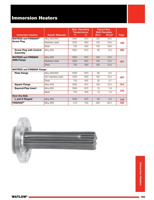
<strong>Immersion</strong> <strong>Heater</strong>sMax. Operating Typical Max.Temperatures Watt Densities<strong>Immersion</strong> <strong>Heater</strong>s Sheath Materials °F °C W/in 2 W/cm 2 PageWATROD and FIREBAR ®Screw PlugScrew Plug with ControlAssemblyWATROD and FIREBARANSI FlangeAlloy 800/840 1600 870 120 18.6Stainless steel 1200 650 120 18.6Steel 750 400 120 18.6Alloy 800 1600 870 60 9.3 235Alloy 800 1600 870 100 15.5Stainless steel 1200 650 100 15.5Steel 750 400 100 15.5WATROD and FIREBAR FlangePlate Flange Alloy 800/840 1600 870 60 9.3304 stainless steel 1200 650 100 15.5 307Steel 750 400 30 4.7Square Flange Alloy 800 1600 870 100 15.5 313Bayonet/Pipe Insert Alloy 800 1600 870 10 1.6Steel 750 400 10 1.6316Over-the-SideL and O Shaped Alloy 800 1600 870 60 9.3 318FIREROD ® Alloy 800 212 100 300 46.5 323165237<strong>Immersion</strong> <strong>Heater</strong>sWATLOW ®163
164 WATLOW ®
<strong>Immersion</strong> <strong>Heater</strong>sWATROD and FIREBAR ® Screw Plug<strong>Immersion</strong> <strong>Heater</strong>sScrew plug immersion heaters are ideal for directimmersion heating of liquids, including all types of oilsand heat transfer solutions.Available in a variety of sizes, <strong>Watlow</strong> ® screw plugimmersion heaters feature both WATROD round andFIREBAR ® flat tubular elements.Heating elements are hairpin bent and either weldedor brazed into the screw plug—depending on elementsheath and plug material compatibility.General purpose terminal enclosures are standard; withoptional moisture resistant, explosion resistant andexplosion/moisture resistant enclosures available tomeet specific application needs.Optional thermostats provide convenient processtemperature regulation.Performance Capabilities• Watt densities up to 120 W/in 2 (18.6 W/cm 2 )• Wattages up to 38 kilowatts• UL ® and CSA component recognition up to 480VACand 600VAC respectively• Alloy 800/840 sheath temperatures up to1600°F (870°C)• Passivated 316 stainless steel sheath temperaturesup to 1200°F (650°C)• 304 stainless steel sheath temperatures up to1200°F (650°C)• Steel sheath temperatures up to 750°F (400°C)WATROD Heating ElementNPTPipeThreadHalfCouplingWeldFIREBARHeatingElementFeatures and BenefitsA variety of element sheath and screw plugmaterials• Meets your application needsIntegral thermowells• Provides convenient temperature sensor insertion andreplacement without draining the fluid being heatedTerminal enclosures• Provides ability to be rotated to simplify connectionwith existing conduitsWelding or brazing WATROD and FIREBARelements to the screw plug• Provides a pressure tight sealWATROD hairpins are repressed (recompacted)• Maintains MgO density, dielectric strength, heattransfer and lifeWATLOW ®2 1 /2 in. (64 mm) NPT screw plug assemblies featureelement support(s)• Ensures proper spacing for maximizing heaterperformance and life• Screw plug and element sizes:1 in. NPT 0.260 and 0.315 in. WATROD1 1 /4 in. NPT 0.260 and 0.315 in. WATROD1 in. FIREBAR2 in. NPT 0.430 and 0.475 in. WATROD2 1 /2 in. NPT 0.430 and 0.475 in. WATROD1 in. FIREBAR• Phase capability:1 in. NPT 1-Phase1 1 /4, 2, 2 1 /2 in., NPT 1- or 3-PhaseUL ® and CSA component recognition under FileE52951 and 31388 respectively, see pages 561 to568 for details.165
<strong>Immersion</strong> <strong>Heater</strong>sWATROD and FIREBAR Screw Plug<strong>Immersion</strong> <strong>Heater</strong>sTypical Applications• Water:DeionizedDemineralizedCleanPotableProcess• Industrial water rinse tanks• Vapor degreasersScrew Plug OrientationCorrect element/thermowell orientation assures properprocess temperature sensing.Correct horizontal mounting of WATROD and FIREBARscrew plugs is shown below. Correct orientationassures optimum performance and maximum heaterlife. Additional mounting information is provided in theInstallation and Maintenance Instructions.FIREBAR Heating Elements1 1 /4 in. (32 mm) NPT–One ElementA• Hydraulic oil, crude, asphalt• Lubricating oils at API specified watt densities• Air and gas flow• Caustic solutions• Chemical baths• Anti-freeze (glycol) solutions• ParaffinWATROD Heating Element1 in. (25 mm) NPT–One ElementElementBundleAAView A-AThermowellA1 1 /4 in. (32 mm) and 2 in. (51 mm) NPT–TwoElementsAElementBundleView A-AThermowell2 1 /2 in. (64 mm) NPT–Three ElementsElementBundleAThermowellAView A-AA2 in. (51 mm) and 2 1 /2 in. (64 mm) NPT–ThreeElementsAElementBundleThermowellAView A-AElementBundleThermowellView A-A166WATLOW ®
<strong>Immersion</strong> <strong>Heater</strong>sWATROD and FIREBAR Screw Plug<strong>Immersion</strong> <strong>Heater</strong>sOptionsTerminal EnclosuresGeneral purpose terminal enclosures, withoutthermostats, are available on all screw plug immersionheaters. To meet specific application requirements,<strong>Watlow</strong> offers the following optional terminal enclosures:• General purpose with single or double pole thermostat• Moisture-resistant or corrosion resistant—available withoptional single or double pole thermostat• Explosion-resistant class 1, groups B, C and Dexplosion resistant—available with optional singleor double-pole thermostat• Explosion and moisture-resistant combination—available with optional single- or double-polethermostatNote: Unless otherwise stated on the accompanyingillustrations, both WATROD and FIREBAR screw plugsare centered on the terminal enclosure. To order, addthe suffix letter(s) to the screw plug heater’s base partnumber. This is depicted on the ordering example onpage 234. Also, specify class and group, if applicable.CSA Certified EnclosuresCSA certified moisture and/or explosion-resistant terminalenclosures protect wiring in hazardous gas environments.These terminal enclosures, covered under CSA Filenumber 61707, are available on all WATROD andFIREBAR screw plug immersion heaters. For additionalinformation, contact your <strong>Watlow</strong> representative.To order, specify CSA certified enclosure, processtemperature (°F), maximum working pressure ofapplication (psig), media being heated and heatermounting orientation (horizontal or vertical) andscrew plug size.Pilot LightThe optional pilot light gives the operator visual indicationof heater on or off power status.The PL10 pilot light is configured to a maximum 250VACand supplied with 6 in. (152 mm) leads.The PL11 pilot light is rated for 480VAC and supplied with4 in. (102 mm) leads.Pilot lights may be attached to either single or doublepole thermostats with general purpose enclosure only.ThermostatsTo provide process temperature control, <strong>Watlow</strong> offersoptional single-pole, single-throw (SPST) and double pole,single throw (DPST) thermostats.Unless otherwise specified, thermostats are mountedinside the terminal enclosure. For details and orderinginformation, refer to Thermostats on pages 534 to 538.Please verify that the thermostat’s sensing bulb O.D. iscompatible with the screw plug’s thermowell I.D.Caution:Explosion-resistant terminal enclosures are intendedto provide explosion containment in the electricaltermination/wiring enclosure only. No portion of theassembly outside of this enclosure is covered underthis enclosure rating. Enclosure rating effectiveness maybe compromised by abuse or misapplication.ASME Pressure Vessel Code WeldingScrew plug assemblies can be provided with an ASME<strong>Section</strong> VIII, Div. I pressure vessel stamp upon request.WATLOW ®167
<strong>Immersion</strong> <strong>Heater</strong>sWATROD and FIREBAR Screw Plug<strong>Immersion</strong> <strong>Heater</strong>sOptions (Continued)ThermocouplesType J or K thermocouples offer extremely accuratesensing of process and/or sheath temperatures.A thermocouple may be inserted into the thermowellor attached to the heater’s sheath.Thermocouples are supplied with 120 in. (3048 mm)leads (longer lead lengths available). Unless otherwisespecified, thermocouples are supplied with temperatureranges detailed on the Thermocouple Types chart.Using a thermocouple requires an appropriatetemperature and power controller and these must bepurchased separately. <strong>Watlow</strong> offers a wide varietyof temperature and power controllers to meet virtually allapplications. Temperature controllers can be configuredto accept process variable inputs, too. Contact your<strong>Watlow</strong> representative for details.To order, specify Type J or K thermocouple and leadlength. Indicate if the thermocouple is for processtemperature sensing or heater sheath high-limitprotection. Please specify if the screw plug will bemounted vertical or horizontal in the tank. If vertical,indicate if the housing is on top or bottom.If the screw plug heater is mounted in an in-line circulationheating application, indicate flow direction relative to theheater’s enclosure.Thermocouple TypesRecommended 1ASTM Conductor Characteristics Temperature RangeType Positive Negative °F (°C)J Iron Constantan 0 to 1000 (-20 to 540)(Magnetic) (Non-Magnetic)K Chromel ® Alumel ® 0 to 2000 (-20 to 1100)(non-magnetic) (Magnetic)1 Type J and Type K thermocouples are rated 32 to 1382°F and32 to 2282°F (0-750°C and 0-1250°C), respectively. <strong>Watlow</strong> doesnot recommend exceeding temperature ranges shown on this chartfor the tubular product line.Sheath MaterialsThe following sheath materials are available on WATRODand FIREBAR heating elements:Standard Sheath MaterialsWATRODFIREBARAlloy 800/840316 SSSteelAlloy 800Exotic Sheath MaterialsContact your <strong>Watlow</strong> representative for detailsand availability.External FinishingPassivationDuring the manufacturing process, particles of iron or toolsteel may become embedded in the stainless steel oralloy sheath. If not removed, these particles may corrode,produce rust spots and/or contaminate the process. Forcritical applications, passivation will remove free iron fromthe sheath. To order, specify passivation.Other FinishesBright annealing available to meet cosmetic demands.Screw Plug MaterialsThe following screw plug materials are available:To order, specify screw plug size and material.Standard Screw Plug MaterialsWATRODFIREBAR304 SS, BrassSteel304 SSMade-to-Order Plug MaterialsFor both WATROD and FIREBAR, contact your <strong>Watlow</strong>representative about details and availability.Wattages and Voltages<strong>Watlow</strong> routinely supplies screw plug immersion heaterswith 120 to 480VAC as well as wattages from250 watts to 38kW.168 WATLOW ®
<strong>Immersion</strong> <strong>Heater</strong>sWATROD and FIREBAR Screw Plug<strong>Immersion</strong> <strong>Heater</strong>sOptions (Continued)Screw Plug SizesIncluding European• NPT– 3 /4, 1, 1 1 /4, 2, 2 1 /2 in.To order, specify size, style (NPT)and material.Screw Plug to Flange AdaptersScrew plug to flange adaptors permit replacing flangeheaters with screw plug heaters. To order, specify theappropriate part number.Screw Plug to Flange AdaptersScrew PlugEstimatedto Flange Shipping Wt. PartAdapter Sizes Material lbs (kg) Delivery Number1 1 /4 to 3 in.-150# Steel 13 (5.9) RS 125X3SA2 1 /2 to 3 in.-150# Steel 11 (5.0) RS 250X3SA2 1 /2 to 4 in.-150# Steel 16 (7.3) RS 250X4SA2 1 /2 to 5 in.-150# Steel 25 (11.3) RS 250X5SA2 1 /2 to 6 in.-150# Steel 33 (15.0) RS 250X6SARAPID SHIP• RS - Next day shipmentup to 3 piecesApplication Hints• Select the recommended sheath material and wattdensity for the substance being heated. Use theSupplemental Applications Chart on pages 555 to 560.If unable to determine the correct heater material andtype, contact your <strong>Watlow</strong> representative.• Extend the element’s no-heat section completely intothe fluid being heated to help prevent premature heaterfailure. See illustration below for proper no-heatsection placement.• Locate screw plug heater low in the tank, but abovethe sludge level.1 in. (25 mm)Min. No-Heat <strong>Section</strong>• Choose a FIREBAR element when the applicationrequires a smaller system package or lower wattdensity.• Ensure wiring integrity by making sure terminalenclosure temperature does not exceed 400°F (205°C).• Keep electrical connections clean, dry and tight.• Size power feeder wires in accordance with NationalElectrical Code guidelines and other applicable codes.• Size power feeder wires in accordance with nationalelectrical code guidelines and other applicable codes.• Minimize problems associated with low liquid levelconditions by using a low liquid level sensor or sheathtemperature high-limit control.• Periodically remove the screw plug assembly forinspection and clean the heating element(s). Thispreventive maintenance will reduce premature failureand optimize heater performance.• Refer to the Installation and Maintenance Instructionsfor correct orientation of FIREBAR elements. Correctelement orientation to flow minimizes pressure drop,increases buoyancy force and heater performance.WATLOW ®169
<strong>Immersion</strong> <strong>Heater</strong>sExtendedCapabilityExtended Capabilities ForWATROD and FIREBAR Screw Plug<strong>Immersion</strong> <strong>Heater</strong>sOptionsPilot LightThe optional pilot light gives the operator visual indicationof heater on or off power status.The PL10 pilot light is configured to a maximum 250VACand supplied with 6 in. (152 mm) leads.The PL11 pilot light is rated for 480VAC and supplied with4 in. (102 mm) leads.Pilot lights may be attached to either single or doublepole thermostats with general purpose enclosure only.For moisture or explosion resistant terminal enclosures,contact your <strong>Watlow</strong> representative.To order, refer to the Ordering Information on page 234.Wattages and Voltages<strong>Watlow</strong> routinely supplies screw plug immersion heaterswith 120 to 480VAC as well as wattages from250 watts to 38kW. If required, <strong>Watlow</strong> may configureheaters with voltages and wattages outside theseparameters. For more information on special voltageand wattage configurations, contact your <strong>Watlow</strong>representative.Screw Plug MaterialsThe following screw plug materials are available:To order, specify screw plug size and material.Extended Screw Plug MaterialsWATROD304, 304H, 316H, 321 SSTitaniumAlloy 400 and 600Hastelloy C276Alloy 800/840Screw Plug SizesIncluding European• Gas (Gas Pipe Standard) – G1 1 /4, G1 1 /2, G2 in.(brass only)• BSP (British Standard Pipe) – 1 1 /2, 2 in.(stainless steel only)Contact your <strong>Watlow</strong> representative for sizes andmaterials not listed.Extended Sheath MaterialsThe following sheath materials are available on WATRODand FIREBAR heating elements:Extended Sheath MaterialsWATRODFIREBAR304 and 321 SSAlloy 400 and 600TitaniumHastelloy C276304 SSAlloy 800170 WATLOW ®
<strong>Immersion</strong> <strong>Heater</strong>sWATROD and FIREBAR Screw Plug<strong>Immersion</strong> <strong>Heater</strong>sOptional Moisture Resistant HousingsSingle-Pole ThermostatDouble-Pole Thermostat1 and 1 1 /4 inch NPT–1 WATROD Element 1 1 /4 inch NPT–2 WATROD Elements1 1 /4 inch NPT–1 FIREBAR ElementAll 2 and 2 1 /2 inch NPT screw plugs(1) 1.093 in.(28 mm) Dia. Hole17⁄16 in.(37 mm)27⁄8 in.(73 mm) Ref.69⁄16 in.(166.7 mm)4¼ in.(108 mm)4¼ in.(114 mm)25⁄8 in.(66.7 mm)15⁄16 in.(33.3 mm)Note: The thermostat is not centered on the WATROD screw plugimmersion heater.69⁄16 in.(166.7 mm)6 in.(152 mm)Single-Pole ThermostatAll 2 and 2 1 /2 inch NPTNote: The thermostat is not centered on the screw plugimmersion heater.69⁄16 in.(166.7 mm)4¼ in.(108 mm)Without Thermostat¾ in.ConduitOpening69⁄16 in.(166.7 mm)6 in.(152 mm)4 in.(100 mm)2 in.(51 mm)2 in.(50 mm)13⁄16 in.(20.6 mm)To order: Reference “W” in the Ordering Informationsection on page 234.WATLOW ®171
<strong>Immersion</strong> <strong>Heater</strong>sWATROD and FIREBAR Screw Plug<strong>Immersion</strong> <strong>Heater</strong>s®®Application: Clean Water• 1 inch NPT screw plug• WATROD elements1" WATROD• With thermostat (SPST)• General purpose enclosure345⁄8 in. Dia.(117.5 mm)57⁄8 in.(149.2 mm)¾ in. NPT KnockoutThermowell(1) 0.315 in. (8 mm) Dia. Element11⁄8 in.(28.6 mm)Bundle1 in. (25 mm) Cold (Ref.)"B"1½ in. NPT HubsType 2 (30 to 250°F)Type 3 (175 to 550°F)Thermowell“B” Dim. Ship Wt.PartPart (1) 0.315 in. (8 mm) Dia. ElementDescription Volts kW Ph in. (mm) lbs (kg) Number Del. Number 2 Del. 11⁄8 in.1" WATROD75⁄8 in. Dia.4General Purpose Enclosure(28.6 mm)(193.7 mm)60 W/in 2120 0.50 1 4 1 Bundle/2 (114.0) 3 (2) BCN4J1S2 RS BCN4J1S3 RSBrass Plug240 0.50 1 41-Alloy 800/2 (114.0) 3 (2) BCN4J10S2 RS 1 in. BCN4J10S3 (25 mm) Cold (Ref.) RSElement 120 0.75 1 6 1 77⁄8 in./2 (165.0) 3 (2) BCN6J1S2 RS BCN6J1S3 "B"(200 mm)RS240 0.75 1 6 1 /2 (165.0) 3 (2) BCN6J10S2 RS BCN6J10S3 RS120 1.00 1 6 5 /8 (168.3) 3 (2) BCN6L1S2 RS BCN6L1S3 RS240 1.00 1 6 5 /8 (168.3) 3 (2) BCN6L10S2 RS BCN6L10S3 RS120 1.25 1 8 (203.0) 4 (2) BCN8A1S2 RS BCN8A1S3 RS240 1.25 1 8 (203.0) 4 (2) BCN8A10S2 RS BCN8A10S3 RS120 1.50 1 10 5 /8 (269.9) 4 (2) BCN10L1S2 RS BCN10L1S3 RS240 1.50 1 10 5 /8 (269.9) 4 (2) BCN10L10S2 RS BCN10L10S3 RS120 2.00 1 12 1 /2 (318.0) 5 (3) BCN12J1S2 RS BCN12J1S3 RS240 2.00 1 12 1 /2 (318.0) 5 (3) BCN12J10S2 RS BCN12J10S3 RS120 2.50 1 14 3 /4 (375.0) 5 (3) BCN14N1S2 RS BCN14N1S3 RS240 2.50 1 14 3 /4 (375.0) 5 (3) BCN14N10S2 RS BCN14N10S3 RS120 3.00 1 16 3 /4 (425.0) 6 (3) BCN16N1S2 RS BCN16N1S3 RS240 3.00 1 16 3 /4 (425.0) 6 (3) BCN16N10S2 RS BCN16N10S3 RS240 4.00 1 21 (533.0) 6 (3) BCN21A10S2 RS BCN21A10S3 RSRAPID SHIP• RS - Next day shipmentup to 5 piecesNote: All screw plug bundles are designed to fit the inside diameter ofthe equivalent mating coupling. They will not fit into the equivalent pipeinside diameter.2 UL ® recognized only172 WATLOW ®
<strong>Immersion</strong> <strong>Heater</strong>sWATROD and FIREBAR Screw Plug<strong>Immersion</strong> <strong>Heater</strong>s®®Application: Clean Water• 1 inch NPT screw plug• WATROD elements• Without thermostat1• General purpose or moisture/explosionresistantenclosure1" WATROD2General Purpose45⁄8 in. Dia.(117.5 mm)53⁄8 in. Dia.(136.5 mm)37⁄8 in.(98.4 mm)Moisture/Explosion-Resistant¾ in. NPT KnockoutThermowell(1) 0.315 in. (8 mm) Dia. Element11⁄8 in.(28.6 mm)Bundle1 in. (25 mm) Cold (Ref.)¾ in. NPT Hubs"B"Thermowell(1) 0.315 in. (8 mm) Dia. Element11⁄8 in.(28.6 mm)Bundle1 in. (25 mm) Cold (Ref.)41⁄8 in.(104.8 mm)"B"“B” Dim. PartShip Wt. PartShip Wt.Description Volts kW Ph in. (mm) Number Del. lbs (kg) Number 7 Del. lbs (kg)General Purpose Enclosure Moisture/Explosion-Resistant Enclosure60 W/in 2120 0.50 1 4 1 /2 (114.0) BCN4J1S RS 3 (2) BCN4J1C RS 6 (3)Brass Plug1-Alloy 800240 0.50 1 4 1 /2 (114.0) BCN4J10S RS 3 (2) BCN4J10C RS 6 (3)Element 120 0.75 1 6 1 /2 (165.0) BCN6J1S RS 3 (2) BCN6J1C RS 6 (3)(9.3 W/cm 2 ) 240 0.75 1 6 1 /2 (165.0) BCN6J10S RS 3 (2) BCN6J10C RS 6 (3)120 1.00 1 6 5 /8 (168.3) BCN6L1S RS 3 (2) BCN6L1C RS 6 (3)240 1.00 1 6 5 /8 (168.3) BCN6L10S RS 3 (2) BCN6L10C RS 6 (3)120 1.25 1 8 (203.0) BCN8A1S RS 4 (2) BCN8A1C RS 7 (4)240 1.25 1 8 (203.0) BCN8A10S RS 4 (2) BCN8A10C RS 7 (4)120 1.50 1 10 5 /8 (269.9) BCN10L1S RS 4 (2) BCN10L1C RS 7 (4)240 1.50 1 10 5 /8 (269.9) BCN10L10S RS 4 (2) BCN10L10C RS 7 (4)120 2.00 1 12 1 /2 (318.0) BCN12J1S RS 5 (3) BCN12J1C RS 8 (4)240 2.00 1 12 1 /2 (318.0) BCN12J10S RS 5 (3) BCN12J10C RS 8 (4)120 2.50 1 14 3 /4 (375.0) BCN14N1S RS 5 (3) BCN14N1C RS 8 (4)240 2.50 1 14 3 /4 (375.0) BCN14N10S RS 5 (3) BCN14N10C RS 8 (4)120 3.00 1 16 3 /4 (425.0) BCN16N1S RS 6 (3) BCN16N1C RS 9 (4)240 3.00 1 16 3 /4 (425.0) BCN16N10S RS 6 (3) BCN16N10C RS 9 (4)240 4.00 1 21 (533.0) BCN21A10S RS 6 (3) BCN21A10C RS 9 (4)RAPID SHIP• RS - Next day shipmentup to 5 piecesNote: All screw plug bundles are designed to fit the inside diameter ofthe equivalent mating coupling. They will not fit into the equivalent pipeinside diameter.7 CSA certified only174 WATLOW ®
<strong>Immersion</strong> <strong>Heater</strong>sWATROD and FIREBAR Screw Plug<strong>Immersion</strong> <strong>Heater</strong>sApplication: Clean 1.25" WATROD Water7• 1 1 /4 inch NPT screw 1.25" plug WATROD7• WATROD elements• With thermostat (SPST)• General purpose or moisture/explosionresistantenclosureGeneral Purpose45⁄8 in. Dia.(117.5 mm)45⁄8 in. Dia.(117.5 mm)6 in.(152 mm)6 in.(152 mm)¾ in. NPT Knockout¾ in. NPT Knockout Thermowell0.315 in. (8 mm) Dia. Element(s)Thermowell0.315 in. (8 mm) Dia. Element(s) 13⁄8 in.(34.9 mm)Bundle13⁄8 in.(34.9 mm)115⁄16 in. (49.2 mm) Cold (Ref.)Bundle115⁄16 in. (49.2 "B" mm) Cold (Ref.)"B"Moisture/Explosion- 1½ in. NPT HubsResistant1½ in. NPT HubsThermowell0.315 in. (8 mm) Dia. Element(s)Thermowell75⁄8 in. Dia.0.315 in. (8 mm) Dia. Element(s) 13⁄8 in.1.25" WATROD8(193.7 mm)(34.9 mm)75⁄8 in. Dia.Bundle13⁄8 in.1.25" WATROD8(193.7 mm)(34.9 mm)Bundle115⁄16 in. (49.2 mm) Cold (Ref.)8 in.115⁄16 in. (49.2 mm) Cold (Ref.)"B"(203 mm)8 in."B"Type (2032 mm) (30 to 250°F) Type 3 (175 to 550°F)“B” Dim. Ship Wt.PartPartDescription Volts kW Ph in. (mm) lbs (kg) NumberDel. Number 5 Del.General Purpose Enclosure60 W/in 2120 0.50 1 4 3 /8 (111.1) 3 (2) BDN4G1S2 RS BDN4G1S3 RSBrass Plug240 0.50 1 4 3 /8 (111.1) 3 (2) BDN4G10S2 RS BDN4G10S3 RS1-Alloy 800120 0.75 1 6Element3 /8 (161.9) 3 (2) BDN6G1S2 RS BDN6G1S3 RS(9.3 W/cm 2 ) 240 0.75 1 6 3 /8 (161.9) 3 (2) BDN6G10S2 RS BDN6G10S3 RS®®60 W/in 2 4Brass Plug2-Alloy 800Elements(9.3 W/cm 2 )120/240 1.00 1 4 3 /8 (111.1) 4 (2) BEN4G6S2 RS BEN4G6S3 RS120/240 1.50 1 6 3 /8 (161.9) 4 (2) BEN6G6S2 RS BEN6G6S3 RS120/240 2.00 1 8 1 /2 (216.0) 5 (3) BEN8J6S2 RS BEN8J6S3 RS120/240 2.50 1 10 3 /4 (273.0) 5 (3) BEN10N6S2 RS BEN10N6S3 RS120/240 3.00 1 15 (381.0) 6 (3) BEN15A6S2 RS BEN15A6S3 RS240 4.00 1 19 (483.0) 7 (4) BEN19A10S2 RS BEN19A10S3 RS240 5.00 1 23 1 /2 (597.0) 8 (4) BEN23J10S2 RS BEN23J10S3 RS240 6.00 1 27 1 /2 (699.0) 9 (4) BEN27J10S2 RS BEN27J10S3 RS60 W/in 2Brass Plug1-Alloy 800Element(9.3 W/cm 2 )Moisture/Explosion-Resistant Enclosure 7120 0.50 1 4 3 /8 (111.1) 7 (4) BDN4G1C2 RS BDN4G1C3 RS240 0.50 1 4 3 /8 (111.1) 7 (4) BDN4G10C2 RS BDN4G10C3 RS120 0.75 1 6 3 /8 (161.9) 7 (4) BDN6G1C2 RS BDN6G1C3 RS240 0.75 1 6 3 /8 (161.9) 7 (4) BDN6G10C2 RS BDN6G10C3 RS60 W/in 2 4Brass Plug2-Alloy 800Elements(9.3 W/cm 2 )WATLOW ®120/240 1.00 1 4 3 /8 (111.1) 8 (4) BEN4G6C2 RS BEN4G6C3 RS120/240 1.50 1 6 3 /8 (161.9) 8 (4) BEN6G6C2 RS BEN6G6C3 RS120/240 2.00 1 8 1 /2 (216.0) 9 (4) BEN8J6C2 RS BEN8J6C3 RS120/240 2.50 1 10 3 /4 (273.0) 9 (4) BEN10N6C2 RS BEN10N6C3 RS120/240 3.00 1 15 (381.0) 10 (5) BEN15A6C2 RS BEN15A6C3 RS240 4.00 1 19 (483.0) 11 (5) BEN19A10C2 RS BEN19A10C3 RS240 5.00 1 23 1 /2 (597.0) 12 (6) BEN23J10C2 RS BEN23J10C3 RS240 6.00 1 27 1 /2 (699.0) 13 (6) BEN27J10C2 RS BEN27J10C3 RSRAPID SHIP• RS - Next day shipmentup to 5 piecesNote: All screw plug bundles are designed to fit the inside diameter ofthe equivalent mating coupling. They will not fit into the equivalent pipeinside diameter.4 Wired for higher voltage 7 CSA certified only5 No third party recognition175
<strong>Immersion</strong> <strong>Heater</strong>sWATROD and FIREBAR Screw Plug<strong>Immersion</strong> <strong>Heater</strong>s®®Application: Clean Water• 1 1 /4 inch NPT screw plug• FIREBAR elements• Without thermostat9• General purpose or moisture/explosionresistantenclosure1.25" FIREBAR10General Purpose45⁄8 in. Dia.(117.5 mm)4 in.(102 mm)Moisture/Explosion-Resistant53⁄8 in. Dia.(136.5 mm)515⁄16 in.(150.8 mm)¾ in. NPT KnockoutThermowell1 in. (25 mm)FIREBAR Element¾ in. NPT Hubs37⁄8 in. (98.4 mm) Cold (Ref.)"B"Thermowell1 in. (25 mm)FIREBAR Element37⁄8 in. (98.4 mm) Cold (Ref.)"B"13⁄8 in.(34.9 mm)Bundle13⁄8 in.(34.9 mm)Bundle“B” Dim. PartShip Wt. PartShip Wt.Description Volts kW Ph in. (mm) Number Del. lbs (kg) Number 7 Del. lbs (kg)General Purpose Enclosure Moisture/Explosion-Resistant Enclosure90 W/in 2 8 240 1.5 1 7 5 /8 (193.7) BDNF7R10S RS 5 (3) BDNF7R10C RS 8 (4)304 SS Plug1-Alloy 800480 1.5 1 7 5 /8 (193.7) BDNF7R11S RS 5 (3) BDNF7R11C RS 8 (4)Element240 3.0 1 11 1 /8 (282.6) BDNF11G10S RS 6 (3) BDNF11G10C RS 9 (4)(9.3 W/cm 2 ) 480 3.0 1 11 1 /8 (282.6) BDNF11G11S RS 6 (3) BDNF11G11C RS 9 (4)240 5.0 3 16 1 /8 (409.6) BDNF16G3S RS 7 (4) BDNF16G3C RS 10 (5)480 5.0 3 16 1 /8 (409.6) BDNF16G5S RS 7 (4) BDNF16G5C RS 10 (5)240 6.5 3 19 1 /8 (485.8) BDNF19G3S RS 8 (4) BDNF19G3C RS 11 (5)480 6.5 3 19 1 /8 (485.8) BDNF19G5S RS 8 (4) BDNF19G5C RS 11 (5)240 8.5 3 24 3 /8 (619.1) BDNF24L3S RS 9 (4) BDNF24L3C RS 12 (6)480 8.5 3 24 3 /8 (619.1) BDNF24L5S RS 9 (4) BDNF24L5C RS 12 (6)240 10.5 3 29 5 /8 (752.5) BDNF29R3S RS 10 (5) BDNF29R3C RS 13 (6)480 10.5 3 29 5 /8 (752.5) BDNF29R5S RS 10 (5) BDNF29R5C RS 13 (6)240 12.7 3 34 5 /8 (879.5) BDNF34R3S RS 11 (5) BDNF34R3C RS 14 (7)480 12.7 3 34 5 /8 (879.5) BDNF34R5S RS 11 (5) BDNF34R5C RS 14 (7)240 17.0 3 45 1 /8 (1146.2) BDNF45G3S RS 13 (6) BDNF45G3C RS 16 (8)480 17.0 3 45 1 /8 (1146.2) BDNF45G5S RS 13 (6) BDNF45G5C RS 16 (8)480 21.5 3 55 5 /8 (1412.9) BDNF55R5S RS 15 (7) BDNF55R5C RS 18 (9)RAPID SHIP• RS - Next day shipmentup to 5 piecesNote: All screw plug bundles are designed to fit the inside diameter ofthe equivalent mating coupling. They will not fit into the equivalent pipeinside diameter.7 CSA certified only8 Can be wired for 1-phase operationWATLOW ®179
<strong>Immersion</strong> <strong>Heater</strong>sWATROD and FIREBAR Screw Plug<strong>Immersion</strong> <strong>Heater</strong>s®®Application: Clean Water• 2 inch NPT screw plug• WATROD elements• Without thermostat• General purpose or moisture/explosionresistantenclosure 2" WATROD1314General Purpose45⁄8 in. Dia.(117.5 mm)Moisture/Explosion-Resistant53⁄8 in. Dia.(136.5 mm)4¼ in. Dia.(108 mm)¾ in. NPT Knockout¾ in. NPT Hubs29⁄16 in. (65.1 mm) Cold (Ref.)"B"0.475 in. (12.1 mm) Dia. ElementsThermowell2¼ in.(57 mm)Bundle0.475 in. (12.1 mm) Dia. ElementsThermowell2¼ in.(57 mm)Bundle47⁄16 in. Dia.(112.7 mm)29⁄16 in. (65.1 mm) Cold (Ref.)"B"“B” Dim.in. (mm)PartNumber Del.Ship Wt.lbs (kg)PartNumber 7 Del.Ship Wt.lbs (kg)Description Volts kW PhGeneral Purpose Enclosure Moisture/Explosion-Resistant Enclosure60 W/in 2 4 120/240 2.0 1 8 1 /8 (206.4) BGN78C6S RS 4 (2) BGN78C6C RS 7 (4)304 SS Plug2-Alloy 800240/480 2.0 1 8 1 /8 (206.4) BGN78C7S RS 4 (2) BGN78C7C RS 7 (4)Elements 120/240 3.0 1 11 1 /8 (282.6) BGN711C6S RS 5 (3) BGN711C6C RS 8 (4)(9.3 W/cm 2 ) 240/480 3.0 1 11 1 /8 (282.6) BGN711C7S RS 5 (3) BGN711C7C RS 8 (4)120/240 4.0 1 15 1 /8 (384.2) BGN715C6S RS 6 (3) BGN715C6C RS 9 (4)240/480 4.0 1 15 1 /8 (384.2) BGN715C7S RS 6 (3) BGN715C7C RS 9 (4)120/240 5.0 1 18 1 /8 (460.4) BGN718C6S RS 6 (3) BGN718C6C RS 9 (4)240/480 5.0 1 18 1 /8 (460.4) BGN718C7S RS 6 (3) BGN718C7C RS 9 (4)240/480 6.0 1 21 1 /8 (536.6) BGN721C7S RS 7 (4) BGN721C7C RS 10 (5)240/480 8.0 1 26 5 /8 (676.3) BGN726L7S RS 7 (4) BGN726L7C RS 10 (5)240/480 10.0 1 32 1 /8 (816.0) BGN732C7S RS 8 (4) BGN732C7C RS 11 (5)60 W/in 2120 3.0 1 8 1 /8 (206.4) BHN78C1S RS 5 (3) BHN78C1C RS 8 (4)304 SS Plug3-Alloy 800240 3.0 3 8 1 /8 (206.4) BHN78C3S RS 5 (3) BHN78C3C RS 8 (4)Elements 480 3.0 3 8 1 /8 (206.4) BHN68C13S RS 5 (3) BHN68C13C RS 8 (4)(9.3 W/cm 2 ) 120 4.5 1 11 1 /8 (282.6) BHN711C1S RS 6 (3) BHN711C1C RS 9 (4)240 4.5 3 11 1 /8 (282.6) BHN711C3S RS 6 (3) BHN711C3C RS 9 (4)480 4.5 3 11 1 /8 (282.6) BHN611C13S RS 6 (3) BHN611C13C RS 9 (4)240 6.0 3 15 1 /8 (384.2) BHN715C3S RS 7 (4) BHN715C3C RS 10 (5)480 6.0 3 15 1 /8 (384.2) BHN715C5S RS 7 (4) BHN715C5C RS 10 (5)240 7.5 3 18 1 /8 (460.4) BHN718C3S RS 7 (4) BHN718C3C RS 10 (5)480 7.5 3 18 1 /8 (460.4) BHN718C5S RS 7 (4) BHN718C5C RS 10 (5)240 9.0 3 21 1 /8 (536.6) BHN721C3S RS 8 (4) BHN721C3C RS 11 (5)480 9.0 3 21 1 /8 (536.6) BHN721C5S RS 8 (4) BHN721C5C RS 11 (5)240 12.0 3 26 5 /8 (676.3) BHN726L3S RS 8 (4) BHN726L3C RS 11 (5)480 12.0 3 26 5 /8 (676.3) BHN726L5S RS 8 (4) BHN726L5C RS 11 (5)240 15.0 3 32 1 /8 (816.0) BHN732C3S RS 9 (4) BHN732C3C RS 12 (6)480 15.0 3 32 1 /8 (816.0) BHN732C5S RS 9 (4) BHN732C5C RS 12 (6)RAPID SHIP• RS - Next day shipmentup to 5 piecesNote: All screw plug bundles are designed to fit the inside diameter ofthe equivalent mating coupling. They will not fit into the equivalent pipeinside diameter.4 Wired for higher voltage7 CSA certified only182 WATLOW ®
<strong>Immersion</strong> <strong>Heater</strong>sWATROD and FIREBAR Screw Plug<strong>Immersion</strong> <strong>Heater</strong>s2.50" WATRODApplication: Clean Water• 2 1 /2 inch NPT screw plug• WATROD elements2.50" WATROD• With thermostat (DPST)19Note: Higher amperage products requirea pilot duty thermostat with separatepower controller. Please see followingpages for available heaters withoutthermostats.• General purpose or moisture/explosionresistantenclosure195½ in. Dia.(140 mm)General Purpose5½ in. Dia.(140 mm)67⁄8 in. Dia.(174.6 mm)67⁄8 in. Dia.(174.6 mm)Moisture/Explosion-Resistant¾ in. NPT Knockout0.475 in. (12.1 mm) Dia. ElementsThermowell2½ in.(64 mm)Bundle¾ in. NPT Knockout23⁄16 in. (55.60.475 mm) in. Cold (12.1 (Ref.) mm) Dia. Elements"B" Thermowell2½ in.(64 mm)Bundle1½ in. NPT Hubs23⁄16 in. (55.6 mm) Cold (Ref.)"B"0.475 in. (12.1 mm) Dia. ElementsThermowell2.50" WATROD202½ in.75⁄8 in. Dia.(64 mm)(193.7 mm)1½ in. NPT HubsBundle0.475 in. (12.1 mm) Dia. Elements23⁄16 in. (55.6 mm) Cold (Ref.)Thermowell85⁄16 in. Dia."B"(211.1 mm)2½ in.2.50" WATROD75⁄8 in. Dia.(64 mm)20(193.7 mm)BundleType 4 (30 to 110°F) Type 5A (60 to 250°F) Type 7A (100 to 550°F)23⁄16 in. (55.6 mm) Cold (Ref.)“B” Dim. Ship Wt. PartPartPart85⁄16 in. Dia.Description Volts kW Ph in. (mm) lbs (kg) Number Del. Number "B"(211.1 mm)Del. Number Del.General Purpose Enclosure60 W/in 2240 3.0 3 7 5 /8 (193.7) 7 (4) BLN77L3S4 RS BLN77L3S5A RS BLN77L3S7A RS304 SS Plug3-Alloy 800480 3.0 3 7 5 /8 (193.7) 7 (4) BLN77L13S4 RS BLN77L13S5A RS BLN77L13S7A RSElements 240 4.5 3 10 5 /8 (269.9) 8 (4) BLN710L3S4 RS BLN710L3S5A RS BLN710L3S7A RS(9.3 W/cm 2 ) 480 4.5 3 10 5 /8 (269.9) 8 (4) BLN610K13S4 RS BLN610K13S5A RS BLN610K13S7A RS240 6.0 3 14 5 /8 (371.5) 10 (5) BLN714L3S4 RS BLN714L3S5A RS BLN714L3S7A RS480 6.0 3 14 5 /8 (371.5) 10 (5) BLN714L5S4 RS BLN714L5S5A RS BLN714L5S7A RS240 7.5 3 17 5 /8 (447.7) 10 (5) BLN717L3S4 RS BLN717L3S5A RS BLN717L3S7A RS240 9.0 3 20 5 /8 (523.9) 12 (6) BLN720L3S4 RS BLN720L3S5A RS BLN720L3S7A RS®®60 W/in 2304 SS Plug3-Alloy 800Elements(9.3 W/cm 2 )RAPID SHIP• RS - Next day shipmentup to 5 piecesMoisture/Explosion-Resistant Enclosure 7240 3.0 3 7 5 /8 (193.7) 10 (5) BLN77L3C4 RS BLN77L3C5A RS BLN77L3C7A RS480 3.0 3 7 5 /8 (193.7) 10 (5) BLN77L13C4 RS BLN77L13C5A RS BLN77L13C7A RS240 4.5 3 10 5 /8 (269.9) 11 (5) BLN710L3C4 RS BLN710L3C5A RS BLN710L3C7A RS480 4.5 3 10 5 /8 (269.9) 11 (5) BLN610K13C4 RS BLN610K13C5A RS BLN610K13C7A RS240 6.0 3 14 5 /8 (371.5) 13 (6) BLN714L3C4 RS BLN714L3C5A RS BLN714L3C7A RS480 6.0 3 14 5 /8 (371.5) 13 (6) BLN714L5C4 RS BLN714L5C5A RS BLN714L5C7A RS240 7.5 3 17 5 /8 (447.7) 13 (6) BLN717L3C4 RS BLN717L3C5A RS BLN717L3C7A RS240 9.0 3 20 5 /8 (523.9) 15 (7) BLN720L3C4 RS BLN720L3C5A RS BLN720L3C7A RSNote: All screw plug bundles are designed to fit the inside diameter ofthe equivalent mating coupling. They will not fit into the equivalent pipeinside diameter.7 CSA certified onlyWATLOW ®183
<strong>Immersion</strong> <strong>Heater</strong>sWATROD and FIREBAR Screw Plug<strong>Immersion</strong> <strong>Heater</strong>s®®Application: Clean Water• 2 1 /2 inch NPT screw plug• WATROD elements• Without thermostat• General purpose or moisture/explosionresistantenclosure2.50" WATROD1718General Purpose45⁄8 in. Dia.(117.5 mm)4½ in. Dia.(114 mm)Moisture/Explosion-Resistant53⁄8 in. Dia.(136.5 mm)¾ in. NPT Knockout0.475 in. (12.1 mm) Dia. ElementsThermowell¾ in. NPT Hubs23⁄16 in. (55.6 mm) Cold (Ref.)"B"0.475 in. (12.1 mm) Dia. ElementsThermowell2½ in.(64 mm)Bundle2½ in.(64 mm)Bundle411⁄16 in. Dia.(119.1 mm)23⁄16 in. (55.6 mm) Cold (Ref.)"B"“B” Dim. PartShip Wt. PartShip Wt.Description Volts kW Ph in. (mm) Number Del. lbs (kg) Number 7 Del. lbs (kg)General Purpose Enclosure Moisture/Explosion-Resistant Enclosure60 W/in 2120 3.0 1 7 5 /8 (193.7) BLN77L1S RS 6 (3) BLN77L1C RS 9 (4)304 SS Plug3-Alloy 800240 3.0 3 7 5 /8 (193.7) BLN77L3S RS 6 (3) BLN77L3C RS 9 (4)Elements480 3.0 3 7 5 /8 (193.7) BLN77L13S RS 6 (3) BLN77L13C RS 9 (4)(9.3 W/cm 2 ) 120 4.5 1 10 5 /8 (269.9) BLN710L1S RS 7 (4) BLN710L1C RS 10 (5)240 4.5 3 10 5 /8 (269.9) BLN710L3S RS 7 (4) BLN710L3C RS 10 (5)480 4.5 3 10 5 /8 (269.9) BLN610K13S RS 7 (4) BLN610K13C RS 10 (5)240 6.0 3 14 5 /8 (371.5) BLN714L3S RS 9 (4) BLN714L3C RS 12 (6)480 6.0 3 14 5 /8 (371.5) BLN714L5S RS 9 (4) BLN714L5C RS 12 (6)240 7.5 3 17 5 /8 (447.7) BLN717L3S RS 9 (4) BLN717L3C RS 12 (6)480 7.5 3 17 5 /8 (447.7) BLN717L5S RS 9 (4) BLN717L5C RS 12 (6)240 9.0 3 20 5 /8 (523.9) BLN720L3S RS 11 (5) BLN720L3C RS 14 (7)480 9.0 3 20 5 /8 (523.9) BLN720L5S RS 11 (5) BLN720L5C RS 14 (7)240 12.0 3 26 1 /8 (663.6) BLN726C3S RS 12 (6) BLN726C3C RS 15 (7)480 12.0 3 26 1 /8 (663.6) BLN726C5S RS 12 (6) BLN726C5C RS 15 (7)240 15.0 3 31 5 /8 (803.3) BLN731L3S RS 14 (7) BLN731L3C RS 17 (8)480 15.0 3 31 5 /8 (803.3) BLN731L5S RS 14 (7) BLN731L5C RS 17 (8)240 18.0 3 37 1 /8 (943.0) BLN737C3S RS 15 (7) BLN737C3C RS 18 (9)480 18.0 3 37 1 /8 (943.0) BLN737C5S RS 15 (7) BLN737C5C RS 18 (9)RAPID SHIP• RS - Next day shipmentup to 5 piecesNote: All screw plug bundles are designed to fit the inside diameter ofthe equivalent mating coupling. They will not fit into the equivalent pipeinside diameter.7 CSA certified only184 WATLOW ®
<strong>Immersion</strong> <strong>Heater</strong>sWATROD and FIREBAR Screw Plug<strong>Immersion</strong> <strong>Heater</strong>s®®Application: Clean Water• 2 1 /2 inch NPT screw plug• FIREBAR elements• Without thermostat• General purpose or moisture/explosionresistantenclosure2.50" FIREBAR21General Purpose45⁄8 in. Dia.(117.5 mm)411⁄16 in. Dia.(119.1 mm)Moisture/Explosion-Resistant¾ in. NPT Knockout(3) 1 in. (25 mm) FIREBAR ElementsThermowell1¼ in. NPT Hubs33⁄8 in. (85.7 mm) Cold (Ref.)"B"2½ in.(64 mm)Bundle(3) 1 in. (25 mm) FIREBAR ElementsThermowell226¼ in. Dia.(159 mm)2½ in.(64 mm)Bundle7¼ in. Dia.(185 mm)33⁄8 in. (85.7 mm) Cold (Ref.)"B"“B” Dim.in. (mm)PartNumber Del.Ship Wt.lbs (kg)PartNumber 7 Del.Ship Wt.lbs (kg)Description Volts kW PhGeneral Purpose Enclosure Moisture/Explosion-Resistant Enclosure90 W/in 2 8 240 15.0 3 15 1 /8 (384.2) BLNF15C3S RS 11 (5) BLNF15C3C RS 14 (7)304 SS Plug3-Alloy 800480 15.0 3 15 1 /8 (384.2) BLNF15C5S RS 11 (5) BLNF15C5C RS 14 (7)Elements 240 20.0 3 18 1 /8 (460.4) BLNF18C3S RS 12 (6) BLNF18C3C RS 15 (7)(14 W/cm 2 ) 480 20.0 3 18 1 /8 (460.4) BLNF18C5S 3 RS 12 (6) BLNF18C5C 3 RS 15 (7)480 25.0 3 23 1 /8 (587.4) BLNF23C5S RS 14 (7) BLNF23C5C RS 17 (8)480 32.0 3 28 5 /8 (727.1) BLNF28L5S RS 17 (8) BLNF28L5C RS 20 (9)480 38.0 3 33 5 /8 (854.1) BLNF33L5S RS 18 (9) BLNF33L5C RS 21 (10)RAPID SHIP• RS - Next day shipmentup to 5 piecesNote: All screw plug bundles are designed to fit the inside diameter ofthe equivalent mating coupling. They will not fit into the equivalent pipeinside diameter.3 Wired for 3-phase operation only7 CSA certified only8 Can be wired for 1-phase operationWATLOW ®185
<strong>Immersion</strong> <strong>Heater</strong>sWATROD and FIREBAR Screw Plug<strong>Immersion</strong> <strong>Heater</strong>s®®Application: Deionized/Demineralized Water• 2 1 /2 inch NPT screw plug2.50" WATROD• WATROD elements• With thermostat (DPST)Note: Higher amperage products requirea pilot duty thermostat with separatepower controller. Please see followingpages for available heaters withoutthermostats.• General purpose enclosure195½ in. Dia.(140 mm)67⁄8 in. Dia.(174.6 mm)¾ in. NPT Knockout0.475 in. (12.1 mm) Dia. ElementsThermowell23⁄16 in. (55.6 mm) Cold (Ref.)"B"2½ in.(64 mm)BundleType 4 (30 to 110°F) Type 5A (60 to 250°F) Type 7A (100 to 550°F)“B” Dim. Ship Wt. PartPartPartDescription Volts kW Ph in. (mm) lbs (kg) Number1½ in. NPT HubsDel. Number Del. Number Del.0.475 in. (12.1 mm) Dia. ElementsGeneral Purpose Enclosure60 W/in 2240 3.0 3 7 5 /8 (193.7) 7 (4) BLR77L3S4 RS BLR77L3S5AThermowellRS BLR77L3S7A RS316 SS Plug480 3.0 3 73-316 SS2½ in.2.50" WATROD/8 (193.7) 7 (4) 75⁄8 BLR77L5S4 in. Dia.RS BLR77L5S5A RS BLR77L5S7A (64 mm) RSElements 240 4.5 3 10 5 20(193.7 mm)/8 (269.9) 8 (4) BLR710L3S4 RS BLR710L3S5A RS BLR710L3S7A Bundle RS(9.3 W/cm 2 ) 480 4.5 3 10 5 /8 (269.9) 8 (4) BLR710L5S4 RS BLR710L5S5A 23⁄16 in. (55.6 mm) RSCold BLR710L5S7A (Ref.)RS(Passivated)240 6.0 3 14 5 /8 (371.5) 10 (5) BLR714L3S485⁄16 in. Dia. RS BLR714L3S5A "B" RS BLR714L3S7A RS480 6.0 3 14 5 (211.1 mm)/8 (371.5) 10 (5) BLR714L5S4 RS BLR714L5S5A RS BLR714L5S7A RS240 7.5 3 17 5 /8 (447.7) 10 (5) BLR717L3S4 RS BLR717L3S5A RS BLR717L3S7A RS240 9.0 3 20 5 /8 (523.9) 12 (6) BLR720L3S4 RS BLR720L3S5A RS BLR720L3S7A RSRAPID SHIP• RS - Next day shipmentup to 5 piecesNote: All screw plug bundles are designed to fit the inside diameter ofthe equivalent mating coupling. They will not fit into the equivalent pipeinside diameter.186 WATLOW ®
Thermowell2.50" WATROD195½ in. Dia.(140 mm)2½ in.(64 mm)Bundle<strong>Immersion</strong> <strong>Heater</strong>s67⁄8 in. Dia.(174.6 mm)23⁄16 in. (55.6 mm) Cold (Ref.)"B"WATROD and FIREBAR Screw Plug<strong>Immersion</strong> <strong>Heater</strong>s®Application: Deionized/Demineralized Water• 2 1 /2 inch NPT screw plug• WATROD elements 2.50" WATROD20• With thermostat (DPST)Note: Higher amperage products requirea pilot duty thermostat with separatepower controller. Please see followingpages for available heaters withoutthermostats.• Moisture/explosion-resistant enclosure75⁄8 in. Dia.(193.7 mm)85⁄16 in. Dia.(211.1 mm)1½ in. NPT Hubs0.475 in. (12.1 mm) Dia. ElementsThermowell23⁄16 in. (55.6 mm) Cold (Ref.)"B"2½ in.(64 mm)BundleDescription Volts kW Ph60 W/in 2316 SS Plug3-316 SSElements(9.3 W/cm 2 )(Passivated)RAPID SHIP• RS - Next day shipmentup to 5 pieces“B” Dim.in. (mm)Ship Wt.lbs (kg)Type 4 (30 to 110°F) Type 5A (60 to 250°F) Type 7A (100 to 550°F)PartPartPartNumber Del. Number Del. Number Del.Moisture/Explosion-Resistant Enclosure240 3.0 3 7 5 /8 (193.7) 10 (5) BLR77L3C4 RS BLR77L3C5A RS BLR77L3C7A RS480 3.0 3 7 5 /8 (193.7) 10 (5) BLR77L5C4 RS BLR77L5C5A RS BLR77L5C7A RS240 4.5 3 10 5 /8 (269.9) 11 (5) BLR710L3C4 RS BLR710L3C5A RS BLR710L3C7A RS480 4.5 3 10 5 /8 (269.9) 11 (5) BLR710L5C4 RS BLR710L5C5A RS BLR710L5C7A RS240 6.0 3 14 5 /8 (371.5) 13 (6) BLR714L3C4 RS BLR714L3C5A RS BLR714L3C7A RS480 6.0 3 14 5 /8 (371.5) 13 (6) BLR714L5C4 RS BLR714L5C5A RS BLR714L5C7A RS240 7.5 3 17 5 /8 (447.7) 13 (6) BLR717L3C4 RS BLR717L3C5A RS BLR717L3C7A RS240 9.0 3 20 5 /8 (523.9) 15 (7) BLR720L3C4 RS BLR720L3C5A RS BLR720L3C7A RSNote: All screw plug bundles are designed to fit the inside diameter ofthe equivalent mating coupling. They will not fit into the equivalent pipeinside diameter.WATLOW ®187
<strong>Immersion</strong> <strong>Heater</strong>sWATROD and FIREBAR Screw Plug<strong>Immersion</strong> <strong>Heater</strong>s®®Application: Deionized/Demineralized Water• 2 1 /2 inch NPT screw plug• WATROD elements• Without thermostat• General purpose or moisture/explosionresistantenclosure2.50" WATROD1718General Purpose45⁄8 in. Dia.(117.5 mm)Moisture/Explosion-Resistant53⁄8 in. Dia.(136.5 mm)4½ in. Dia.(114 mm)¾ in. NPT Knockout0.475 in. (12.1 mm) Dia. ElementsThermowell2½ in.(64 mm)Bundle¾ in. NPT Hubs23⁄16 in. (55.6 mm) Cold (Ref.)"B"0.475 in. (12.1 mm) Dia. ElementsThermowell2½ in.(64 mm)Bundle411⁄16 in. Dia.(119.1 mm)23⁄16 in. (55.6 mm) Cold (Ref.)"B"“B” Dim. PartShip Wt. PartShip Wt.Description Volts kW Ph in. (mm) Number Del. lbs (kg) Number 7 Del. lbs (kg)General Purpose Enclosure Moisture/Explosion-Resistant Enclosure60 W/in 2120 3.0 1 7 5 /8 (193.7) BLR77L1S RS 6 (3) BLR77L1C RS 9 (4)316 SS Plug3-316 SS240 3.0 3 7 5 /8 (193.7) BLR77L3S RS 6 (3) BLR77L3C RS 9 (4)Elements480 3.0 3 7 5 /8 (193.7) BLR77L5S RS 6 (3) BLR77L5C RS 9 (4)(9.3 W/cm 2 ) 120 4.5 1 10 5 /8 (269.9) BLR710L1S RS 7 (4) BLR710L1C RS 10 (5)(Passivated)240 4.5 3 10 5 /8 (269.9) BLR710L3S RS 7 (4) BLR710L3C RS 10 (5)480 4.5 3 10 5 /8 (269.9) BLR710L5S RS 7 (4) BLR710L5C RS 10 (5)240 6.0 3 14 5 /8 (371.5) BLR714L3S RS 9 (4) BLR714L3C RS 12 (6)480 6.0 3 14 5 /8 (371.5) BLR714L5S RS 9 (4) BLR714L5C RS 12 (6)240 7.5 3 17 5 /8 (447.7) BLR717L3S RS 9 (4) BLR717L3C RS 12 (6)480 7.5 3 17 5 /8 (447.7) BLR717L5S RS 9 (4) BLR717L5C RS 12 (6)240 9.0 3 20 5 /8 (523.9) BLR720L3S RS 11 (5) BLR720L3C RS 14 (7)480 9.0 3 20 5 /8 (523.9) BLR720L5S RS 11 (5) BLR720L5C RS 14 (7)240 12.0 3 26 1 /8 (663.6) BLR726C3S RS 12 (6) BLR726C3C RS 15 (7)480 12.0 3 26 1 /8 (663.6) BLR726C5S RS 12 (6) BLR726C5C RS 15 (7)240 15.0 3 31 5 /8 (803.3) BLR731L3S RS 14 (7) BLR731L3C RS 17 (8)480 15.0 3 31 5 /8 (803.3) BLR731L5S RS 14 (7) BLR731L5C RS 17 (8)240 18.0 3 37 1 /8 (943.0) BLR737C3S RS 15 (7) BLR737C3C RS 18 (9)480 18.0 3 37 1 /8 (943.0) BLR737C5S RS 15 (7) BLR737C5C RS 18 (9)RAPID SHIP• RS - Next day shipmentup to 5 piecesNote: All screw plug bundles are designed to fit the inside diameter ofthe equivalent mating coupling. They will not fit into the equivalent pipeinside diameter.7 CSA certified only188 WATLOW ®
<strong>Immersion</strong> <strong>Heater</strong>sWATROD and FIREBAR Screw Plug<strong>Immersion</strong> <strong>Heater</strong>s®®Application: Process Water• 1 1 /4 inch NPT screw plug• FIREBAR elements• With thermostat1.25"(DPST)FIREBAR11Note: Higher amperage products requirea pilot duty thermostat with separatepower controller. Please see followingpages for available heaters withoutthermostats.• General purpose or moisture/explosionresistantenclosure1.25" FIREBAR12General Purpose5½ in. Dia.(140 mm)75⁄8 in. Dia.(193.7 mm)63⁄8 in.(161.9 mm)Moisture/Explosion-Resistant¾ in. NPT KnockoutThermowell1 in. (25 mm)FIREBAR Element1½ in. NPT Hubs37⁄8 in. (98.4 mm) Cold (Ref.)"B"Thermowell1 in. (25 mm)FIREBAR Element13⁄8 in.(34.9 mm)Bundle13⁄8 in.(34.9 mm)Bundle37⁄8 in. (98.4 mm) Cold (Ref.)8 in.(203 mm)"B"Type 5A (60 to 250°F)Type 7A (100 to 550°F)“B” Dim. Ship Wt.PartPartDescription Volts kW Ph in. (mm) lbs (kg) NumberDel.NumberDel.General Purpose Enclosure45 W/in 2 8 240 2.0 3 13 (330) 7 (4) BDNF13A27S5A RS BDNF13A27S7A RS304 SS Plug1-Alloy 800240 2.5 3 15 1 /2 (394) 8 (4) BDNF15J27S5A RS BDNF15J27S7A RSElement 240 3.0 3 18 (457) 9 (4) BDNF18A27S5A RS BDNF18A27S7A RS(7 W/cm 2 ) 240 4.0 3 22 1 /2 (572) 10 (5) BDNF22J27S5A RS BDNF22J27S7A RS480 4.0 3 22 1 /2 (572) 10 (5) BDNF22J28S5A RS BDNF22J28S7A RS240 5.0 3 27 1 /2 (699) 11 (5) BDNF27J27S5A RS BDNF27J27S7A RS480 5.0 3 27 1 /2 (699) 11 (5) BDNF27J28S5A RS BDNF27J28S7A RS240 6.0 3 32 1 /2 (826) 12 (6) BDNF32J27S5A RS BDNF32J27S7A RS480 6.0 3 32 1 /2 (826) 12 (6) BDNF32J28S5A RS BDNF32J28S7A RS240 8.0 3 42 (1067) 14 (7) BDNF42A27S5A RS BDNF42A27S7A RS240 10.0 3 51 1 /2 (1308) 16 (8) BDNF51J27S5A RS BDNF51J27S7A RS45 W/in 2 8304 SS Plug1-Alloy 800Element(7 W/cm 2 )RAPID SHIP• RS - Next day shipmentup to 5 piecesMoisture/Explosion-Resistant Enclosure 7240 2.0 3 13 (330) 10 (5) BDNF13A27C5A RS BDNF13A27C7A RS240 2.5 3 15 1 /2 (394) 11 (5) BDNF15J27C5A RS BDNF15J27C7A RS240 3.0 3 18 (457) 12 (6) BDNF18A27C5A RS BDNF18A27C7A RS240 4.0 3 22 1 /2 (572) 13 (6) BDNF22J27C5A RS BDNF22J27C7A RS480 4.0 3 22 1 /2 (572) 13 (6) BDNF22J28C5A RS BDNF22J28C7A RS240 5.0 3 27 1 /2 (699) 14 (7) BDNF27J27C5A RS BDNF27J27C7A RS480 5.0 3 27 1 /2 (699) 14 (7) BDNF27J28C5A RS BDNF27J28C7A RS240 6.0 3 32 1 /2 (826) 15 (7) BDNF32J27C5A RS BDNF32J27C7A RS480 6.0 3 32 1 /2 (826) 15 (7) BDNF32J28C5A RS BDNF32J28C7A RS240 8.0 3 42 (1067) 17 (8) BDNF42A27C5A RS BDNF42A27C7A RS240 10.0 3 51 1 /2 (1308) 19 (9) BDNF51J27C5A RS BDNF51J27C7A RSNote: All screw plug bundles are designed to fit the inside diameter ofthe equivalent mating coupling. They will not fit into the equivalent pipeinside diameter.7 CSA certified only8 Can be wired for 1-phase operationWATLOW ®189
<strong>Immersion</strong> <strong>Heater</strong>sWATROD and FIREBAR Screw Plug<strong>Immersion</strong> <strong>Heater</strong>s®®Application: Process Water• 1 1 /4 inch NPT screw plug• FIREBAR elements• Without thermostat9• General purpose or moisture/explosionresistantenclosures1.25" FIREBAR10General Purpose45⁄8 in. Dia.(117.5 mm)Moisture/Explosion-Resistant53⁄8 in. Dia.(136.5 mm)4 in.(102 mm)515⁄16 in.(150.8 mm)¾ in. NPT KnockoutThermowell1 in. (25 mm)FIREBAR Element¾ in. NPT Hubs37⁄8 in. (98.4 mm) Cold (Ref.)"B"Thermowell1 in. (25 mm)FIREBAR Element37⁄8 in. (98.4 mm) Cold (Ref.)"B"13⁄8 in.(34.9 mm)Bundle13⁄8 in.(34.9 mm)Bundle“B” Dim. PartShip Wt. PartShip Wt.Description Volts kW Ph in. (mm) Number Del. lbs (kg) Number 7 Del. lbs (kg)General Purpose Enclosure Moisture/Explosion-Resistant Enclosure45 W/in 2 8240 2.0 3 13 (330) BDNF13A27S RS 6 (3) BDNF13A27C RS 9 (4)304 SS Plug1-Alloy 800240 2.5 3 15 1 /2 (394) BDNF15J27S RS 7 (4) BDNF15J27C RS 10 (5)Element240 3.0 3 18 (457) BDNF18A27S RS 8 (4) BDNF18A27C RS 11 (5)(7 W/cm 2 )240 4.0 3 22 1 /2 (572) BDNF22J27S RS 9 (4) BDNF22J27C RS 12 (6)480 4.0 3 22 1 /2 (572) BDNF22J28S RS 9 (4) BDNF22J28C RS 12 (6)240 5.0 3 27 1 /2 (699) BDNF27J27S RS 10 (5) BDNF27J27C RS 13 (6)480 5.0 3 27 1 /2 (699) BDNF27J28S RS 10 (5) BDNF27J28C RS 13 (6)240 6.0 3 32 1 /2 (826) BDNF32J27S RS 11 (5) BDNF32J27C RS 14 (7)480 6.0 3 32 1 /2 (826) BDNF32J28S RS 11 (5) BDNF32J28C RS 14 (7)240 8.0 3 42 (1067) BDNF42A27S RS 13 (6) BDNF42A27C RS 16 (8)480 8.0 3 42 (1067) BDNF42A28S RS 13 (6) BDNF42A28C RS 16 (8)240 10.0 3 51 1 /2 (1308) BDNF51J27S RS 15 (7) BDNF51J27C RS 18 (9)480 10.0 3 51 1 /2 (1308) BDNF51J28S RS 15 (7) BDNF51J28C RS 18 (9)RAPID SHIP• RS - Next day shipmentup to 5 piecesNote: All screw plug bundles are designed to fit the inside diameter ofthe equivalent mating coupling. They will not fit into the equivalent pipeinside diameter.7 CSA certified only8 Can be wired for 1-phase operation190 WATLOW ®
<strong>Immersion</strong> <strong>Heater</strong>sWATROD and FIREBAR Screw Plug<strong>Immersion</strong> <strong>Heater</strong>s®®Application: Process Water¾ in. NPT Knockout0.475 in. (12.1 mm) Dia. Elements• 2 inch NPT screw plugThermowell• WATROD elements2¼ in.2" WATROD5½ in. Dia.(57 mm)• With thermostat (DPST)15(140 mm)BundleNote: Higher amperage products require29⁄16 in. (65.1 mm) Cold (Ref.)a pilot duty thermostat with separate65⁄8 in. Dia."B"(168.3 mm)power controller. Please see followingpages for available heaters withoutthermostats.1½ in. NPT Hubs• General purpose enclosure0.475 in. (12.1 mm) Dia. ElementsThermowellType 4 (30 to 110°F) Type 5A (60 to 250°F) Type 7A (100 to 2¼ 550°F) in.2" WATROD75⁄8 in. Dia.“B” Dim. Ship Wt. PartPartPart (57 mm)16(193.7 mm)BundleDescription Volts kW Ph in. (mm) lbs (kg) Number Del. Number Del. Number Del.General Purpose 29⁄16 in. (65.1 Enclosure mm) Cold (Ref.)48 W/in 2 4 120/240 2.0 1 9 3 /4 (248) 5 (3) BGN79N6S4 81⁄16 in. Dia. RS BGN79N6S5A RS BGN79N6S7 RS"B"304 SS Plug240/480 2.0 1 92-Alloy 800(204.8 mm)/4 (248) 5 (3) BGN79N7S4 RS BGN79N7S5A RS BGN79N7S7A RSElements 120/240 3.0 1 13 1 /4 (337) 6 (3) BGN713E6S4 RS BGN713E6S5A RS BGN713E6S7A RS(7.5 W/cm 2 ) 240/480 3.0 1 13 1 /4 (337) 6 (3) BGN713E7S4 RS BGN713E7S5A RS BGN713E7S7A RS120/240 4.0 1 17 3 /4 (451) 7 (4) BGN717N6S4 RS BGN717N6S5A RS BGN717N6S7A RS120/240 5.0 1 20 1 /4 (514) 8 (4) BGN720E6S4 RS BGN720E6S5A RS BGN720E6S7A RS48 W/in 2240 3.0 3 9 3 /4 (248) 6 (3) BHN79N3S4 RS BHN79N3S5A RS BHN79N3S7A RS304 SS Plug3-Alloy 800480 3.0 3 9 3 /4 (248) 6 (3) BHN79N5S4 RS BHN79N5S5A RS BHN79N5S7A RSElements 240 4.5 3 13 1 /4 (337) 7 (4) BHN713E3S4 RS BHN713E3S5A RS BHN713E3S7A RS(7.5 W/cm 2 ) 480 4.5 3 13 1 /4 (337) 7 (4) BHN713E5S4 RS BHN713E5S5A RS BHN713E5S7A RS240 6.0 3 17 3 /4 (451) 8 (4) BHN717N3S4 RS BHN717N3S5A RS BHN717N3S7A RS480 6.0 3 17 3 /4 (451) 8 (4) BHN717N5S4 RS BHN717N5S5A RS BHN717N5S7A RS240 7.5 3 20 1 /4 (514) 9 (4) BHN720E3S4 RS BHN720E3S5A RS BHN720E3S7A RS240 9.0 3 25 1 /4 (641) 10 (5) BHN725E3S4 RS BHN725E3S5A RS BHN725E3S7A RSRAPID SHIP• RS - Next day shipmentup to 5 piecesNote: All screw plug bundles are designed to fit the inside diameter ofthe equivalent mating coupling. They will not fit into the equivalent pipeinside diameter.4 Wired for higher voltageWATLOW ®191
<strong>Immersion</strong> <strong>Heater</strong>s2" WATRODWATROD and FIREBAR Screw Plug<strong>Immersion</strong> <strong>Heater</strong>s155½ in. Dia.(140 mm)65⁄8 in. Dia.(168.3 mm)¾ in. NPT Knockout29⁄16 in. (65.1 mm) Cold (Ref.)"B"0.475 in. (12.1 mm) Dia. ElementsThermowell2¼ in.(57 mm)Bundle®Application: Process Water• 2 inch NPT screw plug• WATROD elements2" WATROD• With thermostat (DPST)Note: Higher amperage products requirea pilot duty thermostat with separatepower controller. Please see followingpages for available heaters withoutthermostats.• Moisture/explosion-resistant enclosure1675⁄8 in. Dia.(193.7 mm)81⁄16 in. Dia.(204.8 mm)1½ in. NPT Hubs29⁄16 in. (65.1 mm) Cold (Ref.)"B"0.475 in. (12.1 mm) Dia. ElementsThermowell2¼ in.(57 mm)BundleDescription Volts kW Ph48 W/in 2 4304 SS Plug2-Alloy 800Elements(7.5 W/cm 2 )48 W/in 2304 SS Plug3-Alloy 800Elements(7.5 W/cm 2 )RAPID SHIP• RS - Next day shipmentup to 5 pieces“B” Dim.in. (mm)Ship Wt.lbs (kg)Type 4 (30 to 110°F) Type 5A (60 to 250°F) Type 7A (100 to 550°F)PartPartPartNumber Del. Number Del. Number Del.Moisture/Explosion-Resistant Enclosure120/240 2.0 1 9 3 /4 (248) 8 (4) BGN79N6C4 RS BGN79N6C5A RS BGN79N6C7A RS240/480 2.0 1 9 3 /4 (248) 8 (4) BGN79N7C4 RS BGN79N7C5A RS BGN79N7C7A RS120/240 3.0 1 13 1 /4 (337) 9 (4) BGN713E6C4 RS BGN713E6C5A RS BGN713E6C7A RS240/480 3.0 1 13 1 /4 (337) 9 (4) BGN713E7C4 RS BGN713E7C5A RS BGN713E7C7A RS120/240 4.0 1 17 3 /4 (451) 10 (5) BGN717N6C4 RS BGN717N6C5A RS BGN717N6C7A RS120/240 5.0 1 20 1 /4 (514) 11 (5) BGN720E6C4 RS BGN720E6C5A RS BGN720E6C7A RS240 3.0 3 9 3 /4 (248) 9 (4) BHN79N3C4 RS BHN79N3C5A RS BHN79N3C7A RS480 3.0 3 9 3 /4 (248) 9 (4) BHN79N5C4 RS BHN79N5C5A RS BHN79N5C7A RS240 4.5 3 13 1 /4 (337) 10 (5) BHN713E3C4 RS BHN713E3C5A RS BHN713E3C7A RS480 4.5 3 13 1 /4 (337) 10 (5) BHN713E5C4 RS BHN713E5C5A RS BHN713E5C7A RS240 6.0 3 17 3 /4 (451) 11 (5) BHN717N3C4 RS BHN717N3C5A RS BHN717N3C7A RS480 6.0 3 17 3 /4 (451) 11 (5) BHN717N5C4 RS BHN717N5C5A RS BHN717N5C7A RS240 7.5 3 20 1 /4 (514) 12 (6) BHN720E3C4 RS BHN720E3C5A RS BHN720E3C7A RS240 9.0 3 25 1 /4 (641) 13 (6) BHN725E3C4 RS BHN725E3C5A RS BHN725E3C7A RSNote: All screw plug bundles are designed to fit the inside diameter ofthe equivalent mating coupling. They will not fit into the equivalent pipeinside diameter.4 Wired for higher voltage192 WATLOW ®
<strong>Immersion</strong> <strong>Heater</strong>sWATROD and FIREBAR Screw Plug<strong>Immersion</strong> <strong>Heater</strong>sGeneral Purpose¾ in. NPT Knockout0.475 in. (12.1 mm) Dia. ElementsThermowellApplication: Process Water• 2 inch NPT screw plug• WATROD elements• Without thermostat 2" WATROD• General purpose or moisture/explosionresistantenclosure®®131445⁄8 in. Dia.(117.5 mm)53⁄8 in. Dia.(136.5 mm)4¼ in. Dia.(108 mm)Moisture/Explosion-Resistant¾ in. NPT Hubs29⁄16 in. (65.1 mm) Cold (Ref.)"B"2¼ in.(57 mm)Bundle0.475 in. (12.1 mm) Dia. ElementsThermowell2¼ in.(57 mm)Bundle29⁄16 in. (65.1 mm) Cold (Ref.)47⁄16 in. Dia.(112.7 mm)"B"“B” Dim. PartShip Wt. PartShip Wt.Description Volts kW Ph in. (mm) Number Del. lbs (kg) Number 7 Del. lbs (kg)General Purpose Enclosure Moisture/Explosion-Resistant Enclosure48 W/in 2 4 120/240 2.0 1 9 3 /4 (248) BGN79N6S RS 4 (2) BGN79N6C RS 7 (4)304 SS Plug2-Alloy 800240/480 2.0 1 9 3 /4 (248) BGN79N7S RS 4 (2) BGN79N7C RS 7 (4)Elements 120/240 3.0 1 13 1 /4 (337) BGN713E6S RS 5 (3) BGN713E6C RS 8 (4)(7.5 W/cm 2 ) 240/480 3.0 1 13 1 /4 (337) BGN713E7S RS 5 (3) BGN713E7C RS 8 (4)120/240 4.0 1 17 3 /4 (451) BGN717N6S RS 6 (3) BGN717N6C RS 9 (4)240/480 4.0 1 17 3 /4 (451) BGN717N7S RS 6 (3) BGN717N7C RS 9 (4)120/240 5.0 1 20 1 /4 (514) BGN720E6S RS 7 (4) BGN720E6C RS 10 (5)240/480 5.0 1 20 1 /4 (514) BGN720E7S RS 7 (4) BGN720E7C RS 10 (5)240/480 6.0 1 25 1 /4 (641) BGN725E7S RS 7 (4) BGN725E7C RS 10 (5)240/480 8.0 1 32 3 /4 (832) BGN732N7S RS 8 (4) BGN732N7C RS 11 (5)240/480 10.0 1 40 1 /4 (1022) BGN740E7S RS 9 (4) BGN740E7C RS 12 (6)48 W/in 2120 3.0 1 9 3 /4 (248) BHN79N1S RS 5 (3) BHN79N1C RS 8 (4)304 SS Plug3-Alloy 800240 3.0 3 9 3 /4 (248) BHN79N3S RS 5 (3) BHN79N3C RS 8 (4)Element 480 3.0 3 9 3 /4 (248) BHN79N5S RS 5 (3) BHN79N5C RS 8 (4)(7.5 W/cm 2 ) 120 4.5 1 13 1 /4 (337) BHN713E1S RS 6 (3) BHN713E1C RS 9 (4)240 4.5 3 13 1 /4 (337) BHN713E3S RS 6 (3) BHN713E3C RS 9 (4)480 4.5 3 13 1 /4 (337) BHN713E5S RS 6 (3) BHN713E5C RS 9 (4)240 6.0 3 17 3 /4 (451) BHN717N3S RS 7 (4) BHN717N3C RS 10 (5)480 6.0 3 17 3 /4 (451) BHN717N5S RS 7 (4) BHN717N5C RS 10 (5)240 7.5 3 20 1 /4 (514) BHN720E3S RS 8 (4) BHN720E3C RS 11 (5)480 7.5 3 20 1 /4 (514) BHN720E5S RS 8 (4) BHN720E5C RS 11 (5)240 9.0 3 25 1 /4 (641) BHN725E3S RS 9 (4) BHN725E3C RS 12 (6)480 9.0 3 25 1 /4 (641) BHN725E5S RS 9 (4) BHN725E5C RS 12 (6)240 12.0 3 32 3 /4 (832) BHN732N3S RS 9 (4) BHN732N3C RS 12 (6)480 12.0 3 32 3 /4 (832) BHN732N5S RS 9 (4) BHN732N5C RS 12 (6)240 15.0 3 40 1 /4 (1022) BHN740E3S RS 10 (5) BHN740E3C RS 13 (6)480 15.0 3 40 1 /4 (1022) BHN740E5S RS 10 (5) BHN740E5C RS 13 (6)240 18.0 3 47 3 /4 (1213) BHN747N3S RS 11 (5) BHN747N3C RS 14 (7)480 18.0 3 47 3 /4 (1213) BHN747N5S RS 11 (5) BHN747N5C RS 14 (7)RAPID SHIP• RS - Next day shipmentup to 5 piecesNote: All screw plug bundles are designed to fit the inside diameter ofthe equivalent mating coupling. They will not fit into the equivalent pipeinside diameter.4 Wired for higher voltage7 CSA certified onlyWATLOW ®193
<strong>Immersion</strong> <strong>Heater</strong>sWATROD and FIREBAR Screw Plug<strong>Immersion</strong> <strong>Heater</strong>s2.50" WATRODApplication: Process Water• 2 1 /2 inch NPT screw plug• WATROD elements• With thermostat (DPST)2.50" WATRODNote: Higher amperage products requirea pilot duty thermostat with separatepower controller. Please see followingpages for available heaters withoutthermostats.• General purpose or moisture/explosionresistantenclosure2.50" WATROD1919205½ in. Dia.General (140 mm) Purpose5½ in. Dia.(140 mm)67⁄8 in. Dia.(174.6 mm)67⁄8 in. Dia.(174.6 mm)Moisture/Explosion-Resistant75⁄8 in. Dia.(193.7 mm)85⁄16 in. Dia.(211.1 mm)¾ in. NPT Knockout0.475 in. (12.1 mm) Dia. ElementsThermowell¾ in. NPT 23⁄16 Knockout in. (55.6 mm) Cold (Ref.)0.475 in. (12.1 mm) Dia. Elements"B"Thermowell2½ in.(64 mm)Bundle1½ in. NPT Hubs23⁄16 in. (55.6 mm) Cold (Ref.)"B"0.475 in. (12.1 mm) Dia. ElementsThermowell1½ in. NPT Hubs23⁄16 in. (55.60.475 mm) Cold in. (12.1 (Ref.) mm) Dia. Elements"B" Thermowell2½ in.(64 mm)Bundle2½ in.(64 mm)Bundle2.50" WATROD202½ in.75⁄8 in. Dia.(64 mm)(193.7 mm)Type 4 (30 to 110°F) Type 5A (60 to 250°F) Type 7A (100 to Bundle 550°F)Description Volts kW Ph“B” Dim. Ship Wt. PartPartPart23⁄16 in. (55.6 mm) Cold (Ref.)in. (mm) lbs (kg) Number Del. Number Del. Number85⁄16 in. Dia."B"(211.1 mm) General Purpose EnclosureDel.48 W/in 2240 3.0 3 9 3 /8 (238.1) 7 (4) BLN79G3S4 RS BLN79G3S5A RS BLN79G3S7A RS304 SS Plug3-Alloy 800480 3.0 3 9 3 /8 (238.1) 7 (4) BLN79G5S4 RS BLN79G5S5A RS BLN79G5S7A RSElements 240 4.5 3 12 7 /8 (327.0) 8 (4) BLN712R3S4 RS BLN712R3S5A RS BLN712R3S7A RS(7.5 W/cm 2 ) 480 4.5 3 12 7 /8 (327.0) 8 (4) BLN712R5S4 RS BLN712R5S5A RS BLN712R5S7A RS240 6.0 3 17 3 /8 (441.3) 10 (5) BLN717G3S4 RS BLN717G3S5A RS BLN717G3S7A RS480 6.0 3 17 3 /8 (441.3) 10 (5) BLN717G5S4 RS BLN717G5S5A RS BLN717G5S7A RS240 7.5 3 19 7 /8 (504.8) 12 (6) BLN719R3S4 RS BLN719R3S5A RS BLN719R3S7A RS240 9.0 3 24 7 /8 (631.8) 13 (6) BLN724R3S4 RS BLN724R3S5A RS BLN724R3S7A RS®®48 W/in 2304 SS Plug3-Alloy 800Elements(7.5 W/cm 2 )RAPID SHIP• RS - Next day shipmentup to 5 piecesMoisture/Explosion-Resistant Enclosure 7240 3.0 3 9 3 /8 (238.1) 10 (5) BLN79G3C4 RS BLN79G3C5A RS BLN79G3C7A RS480 3.0 3 9 3 /8 (238.1) 10 (5) BLN79G5C4 RS BLN79G5C5A RS BLN79G5C7A RS240 4.5 3 12 7 /8 (327.0) 11 (5) BLN712R3C4 RS BLN712R3C5A RS BLN712R3C7A RS480 4.5 3 12 7 /8 (327.0) 11 (5) BLN712R5C4 RS BLN712R5C5A RS BLN712R5C7A RS240 6.0 3 17 3 /8 (441.3) 13 (6) BLN717G3C4 RS BLN717G3C5A RS BLN717G3C7A RS480 6.0 3 17 3 /8 (441.3) 13 (6) BLN717G5C4 RS BLN717G5C5A RS BLN717G5C7A RS240 7.5 3 19 7 /8 (504.8) 15 (7) BLN719R3C4 RS BLN719R3C5A RS BLN719R3C7A RS240 9.0 3 24 7 /8 (631.8) 16 (8) BLN724R3C4 RS BLN724R3C5A RS BLN724R3C7A RSNote: All screw plug bundles are designed to fit the inside diameter ofthe equivalent mating coupling. They will not fit into the equivalent pipeinside diameter.7 CSA certified only194 WATLOW ®
<strong>Immersion</strong> <strong>Heater</strong>sWATROD and FIREBAR Screw Plug<strong>Immersion</strong> <strong>Heater</strong>s®®Application: Process Water• 2 1 /2 inch NPT screw plug• WATROD elements• Without thermostat• General purpose or moisture/explosionresistantenclosure2.50" WATROD1718General Purpose45⁄8 in. Dia.(117.5 mm)Moisture/Explosion-Resistant53⁄8 in. Dia.(136.5 mm)4½ in. Dia.(114 mm)¾ in. NPT Knockout0.475 in. (12.1 mm) Dia. ElementsThermowell2½ in.(64 mm)Bundle¾ in. NPT Hubs23⁄16 in. (55.6 mm) Cold (Ref.)"B"0.475 in. (12.1 mm) Dia. ElementsThermowell2½ in.(64 mm)Bundle411⁄16 in. Dia.(119.1 mm)23⁄16 in. (55.6 mm) Cold (Ref.)"B"“B” Dim. PartShip Wt. PartShip Wt.Description Volts kW Ph in. (mm) Number Del. lbs (kg) Number 7 Del. lbs (kg)General Purpose Enclosure Moisture/Explosion-Resistant Enclosure48 W/in 2120 3.0 1 9 3 /8 (238.1) BLN79G1S RS 6 (3) BLN79G1C RS 9 (4)304 SS Plug3-Alloy 800240 3.0 3 9 3 /8 (238.1) BLN79G3S RS 6 (3) BLN79G3C RS 9 (4)Elements480 3.0 3 9 3 /8 (238.1) BLN79G5S RS 6 (3) BLN79G5C RS 9 (4)(7.5 W/cm 2 ) 120 4.5 1 12 7 /8 (327.0) BLN712R1S RS 7 (4) BLN712R1C RS 10 (5)240 4.5 3 12 7 /8 (327.0) BLN712R3S RS 7 (4) BLN712R3C RS 10 (5)480 4.5 3 12 7 /8 (327.0) BLN712R5S RS 7 (4) BLN712R5C RS 10 (5)240 6.0 3 17 3 /8 (441.3) BLN717G3S RS 9 (4) BLN717G3C RS 12 (6)480 6.0 3 17 3 /8 (441.3) BLN717G5S RS 9 (4) BLN717G5C RS 12 (6)240 7.5 3 19 7 /8 (504.8) BLN719R3S RS 11 (5) BLN719R3C RS 14 (7)480 7.5 3 19 7 /8 (504.8) BLN719R5S RS 11 (5) BLN719R5C RS 14 (7)240 9.0 3 24 7 /8 (631.8) BLN724R3S RS 12 (6) BLN724R3C RS 15 (7)480 9.0 3 24 7 /8 (631.8) BLN724R5S RS 12 (6) BLN724R5C RS 15 (7)240 12.0 3 32 3 /8 (822.3) BLN732G3S RS 14 (7) BLN732G3C RS 17 (8)480 12.0 3 32 3 /8 (822.3) BLN732G5S RS 14 (7) BLN732G5C RS 17 (8)240 15.0 3 39 7 /8 (1012.8) BLN739R3S RS 15 (7) BLN739R3C RS 18 (9)480 15.0 3 39 7 /8 (1012.8) BLN739R5S RS 15 (7) BLN739R5C RS 18 (9)240 18.0 3 47 3 /8 (1203.3) BLN747G3S RS 17 (8) BLN747G3C RS 20 (9)480 18.0 3 47 3 /8 (1203.3) BLN747G5S RS 17 (8) BLN747G5C RS 20 (9)RAPID SHIP• RS - Next day shipmentup to 5 piecesNote: All screw plug bundles are designed to fit the inside diameter ofthe equivalent mating coupling. They will not fit into the equivalent pipeinside diameter.7 CSA certified onlyWATLOW ®195
<strong>Immersion</strong> <strong>Heater</strong>sWATROD and FIREBAR Screw Plug<strong>Immersion</strong> <strong>Heater</strong>s®®Application: Process Water• 2 1 /2 inch NPT screw plug• FIREBAR elements• With thermostat (DPST)2.50" FIREBARNote: Higher amperage products requirea pilot duty thermostat with separatepower controller. Please see followingpages for available heaters withoutthermostats.• General purpose or moisture/explosionresistantenclosure23General Purpose5½ in. Dia.(140 mm)Moisture/Explosion-Resistant71⁄16 in. Dia.(179.4 mm)¾ in. NPT Knockout(3) 1 in. (25 mm) FIREBAR ElementsThermowell1½ in. NPT Hubs33⁄8 in. (85.7 mm) Cold (Ref.)"B"2½ in.(64 mm)Bundle(3) 1 in. (25 mm) FIREBAR ElementsThermowell2.50" FIREBAR2475⁄8 in. Dia.(193.7 mm)2½ in.(64 mm)Bundle85⁄8 in. Dia.(219.1 mm)33⁄8 in. (85.7 mm) Cold (Ref.)"B"Type 5A (60 to 250°F)Type 7A (100 to 550°F)“B” Dim. Ship Wt.PartPartDescription Volts kW Ph in. (mm) lbs (kg) NumberDel.NumberDel.General Purpose Enclosure45 W/in 2 8 240 6.0 3 12 (305) 12 (6) BLNF12A27S5A RS BLNF12A27S7A RS304 SS Plug 240 7.5 3 14 1 /2 (368) 12 (6) BLNF14J27S5A RS BLNF14J27S7A RS3-Alloy 800Elements 240 9.0 3 17 (432) 13 (6) BLNF17A27S5A RS BLNF17A27S7A RS(7 W/cm 2 ) 240 12.0 3 21 1 /2 (546) 15 (7) BLNF21J27S5A RS BLNF21J27S7A RS45 W/in 2 8304 SS Plug3-Alloy 800Elements(7 W/cm 2 )RAPID SHIP• RS - Next day shipmentup to 5 piecesMoisture/Explosion-Resistant Enclosure 7240 6.0 3 12 (305) 14 (7) BLNF12A27C5A RS BLNF12A27C7A RS240 7.5 3 14 1 /2 (368) 15 (7) BLNF14J27C5A RS BLNF14J27C7A RS240 9.0 3 17 (432) 16 (8) BLNF17A27C5A RS BLNF17A27C7A RS240 12.0 3 21 1 /2 (546) 18 (9) BLNF21J27C5A RS BLNF21J27C7A RSNote: All screw plug bundles are designed to fit the inside diameter ofthe equivalent mating coupling. They will not fit into the equivalent pipeinside diameter.7 CSA certified only8 Can be wired for 1-phase operation196 WATLOW ®
<strong>Immersion</strong> <strong>Heater</strong>sWATROD and FIREBAR Screw Plug<strong>Immersion</strong> <strong>Heater</strong>s®®Application: Process Water• 2 1 /2 inch NPT screw plug• FIREBAR elements• Without thermostat• General purpose or moisture/explosionresistantenclosure2.50" FIREBAR21General Purpose45⁄8 in. Dia.(117.5 mm)411⁄16 in. Dia.(119.1 mm)¾ in. NPT Knockout(3) 1 in. (25 mm) FIREBAR ElementsThermowell33⁄8 in. (85.7 mm) Cold (Ref.)"B"2½ in.(64 mm)BundleMoisture/Explosion-Resistant1¼ in. NPT Hubs(3) 1 in. (25 mm) FIREBAR ElementsThermowell226¼ in. Dia.(159 mm)2½ in.(64 mm)Bundle7¼ in. Dia.(185 mm)33⁄8 in. (85.7 mm) Cold (Ref.)"B"“B” Dim. PartShip Wt. PartShip Wt.Description Volts kW Ph in. (mm) Number Del. lbs (kg) Number 7 Del. lbs (kg)General Purpose Enclosure Moisture/Explosion-Resistant Enclosure45 W/in 2 8 240 6.0 3 12 (305) BLNF12A27S RS 10 (5) BLNF12A27C RS 13 (6)304 SS Plug3-Alloy 800240 7.5 3 14 1 /2 (368) BLNF14J27S RS 11 (5) BLNF14J27C RS 14 (7)Elements 240 9.0 3 17 (432) BLNF17A27S RS 12 (6) BLNF17A27C RS 15 (7)(7 W/cm 2 ) 240 12.0 3 21 1 /2 (546) BLNF21J27S RS 14 (7) BLNF21J27C RS 17 (8)480 12.0 3 21 1 /2 (546) BLNF21J28S RS 14 (7) BLNF21J28C RS 17 (8)240 15.0 3 26 1 /2 (673) BLNF26J27S RS 17 (8) BLNF26J27C RS 20 (9)480 15.0 3 26 1 /2 (673) BLNF26J28S RS 17 (8) BLNF26J28C RS 20 (9)240 18.0 3 31 1 /2 (800) BLNF31J27S RS 18 (9) BLNF31J27C RS 21 (10)480 18.0 3 31 1 /2 (800) BLNF31J28S RS 18 (9) BLNF31J28C RS 21 (10)480 24.0 3 41 (1041) BLNF41A28S RS 20 (9) BLNF41A28C RS 23 (11)480 30.0 3 50 1 /2 (1283) BLNF50J28S RS 22 (10) BLNF50J28C RS 25 (12)RAPID SHIP• RS - Next day shipmentup to 5 piecesNote: All screw plug bundles are designed to fit the inside diameter ofthe equivalent mating coupling. They will not fit into the equivalent pipeinside diameter.7 CSA certified only8 Can be wired for 1-phase operationWATLOW ®197
<strong>Immersion</strong> <strong>Heater</strong>sWATROD and FIREBAR Screw Plug<strong>Immersion</strong> <strong>Heater</strong>s®®Application: Forced Air andCaustic Solutions• 1 1 /4 inch NPT screw plug1.25" WATROD• WATROD elements7• With thermostat (SPST)• General purpose or moisture/explosionresistantenclosure1.25" WATROD8General Purpose45⁄8 in. Dia.(117.5 mm)75⁄8 in. Dia.(193.7 mm)6 in.(152 mm)Moisture/Explosion-Resistant¾ in. NPT Knockout1½ in. NPT HubsThermowell0.315 in. (8 mm) Dia. Element(s)13⁄8 in.(34.9 mm)Bundle115⁄16 in. (49.2 mm) Cold (Ref.)"B"Thermowell0.315 in. (8 mm) Dia. Element(s)13⁄8 in.(34.9 mm)Bundle115⁄16 in. (49.2 mm) Cold (Ref.)8 in.(203 mm)"B"Type 2 (30 to 250°F)Type 3 (175 to 550°F)“B” Dim. Ship Wt.PartPartDescription Volts kW Ph in. (mm) lbs (kg) Number Del. Number Del.General Purpose Enclosure23 W/in 2 4 120/240 1.0 1 13 3 /8 (339.7) 6 (3) BEN13G6S2 RS BEN13G6S3 RS304 SS Plug2-Alloy 800120/240 1.5 1 19 (483.0) 7 (4) BEN19A6S2 RS BEN19A6S3 RSElements(3.6 W/cm 2 )120/240 2.0 1 24 3 /8 (619.1) 8 (4) BEN24G6S2 RS BEN24G6S3 RS23 W/in 2 4304 SS Plug2-Alloy 800Elements(3.6 W/cm 2 )Moisture/Explosion-Resistant Enclosure 7120/240 1.0 1 13 3 /8 (339.7) 10 (5) BEN13G6C2 RS BEN13G6C3 RS120/240 1.5 1 19 (483.0) 11 (5) BEN19A6C2 RS BEN19A6C3 RS120/240 2.0 1 24 3 /8 (619.1) 12 (6) BEN24G6C2 RS BEN24G6C3 RSRAPID SHIP• RS - Next day shipmentup to 5 piecesNote: All screw plug bundles are designed to fit the inside diameter ofthe equivalent mating coupling. They will not fit into the equivalent pipeinside diameter.4 Wired for higher voltage7 CSA certified only198 WATLOW ®
<strong>Immersion</strong> <strong>Heater</strong>sWATROD and FIREBAR Screw Plug<strong>Immersion</strong> <strong>Heater</strong>s®®Application: Forced Air andCaustic Solutions• 1 1 /4 inch NPT screw plug• WATROD elements5• Without thermostat• General purpose or moisture/explosionresistantenclosure1.25" WATROD6General Purpose45⁄8 in. Dia.(117.5 mm)Moisture/Explosion-Resistant53⁄8 in. Dia.(136.5 mm)4 in.(102 mm)4¼ in.(108 mm)¾ in. NPT KnockoutThermowell0.315 in. (8 mm) Dia. Element(s)13⁄8 in.(34.9 mm)Bundle115⁄16 in. (49.2 mm) Cold (Ref.)¾ in. NPT Hubs"B"Thermowell0.315 in. (8 mm) Dia. Element(s)13⁄8 in.(34.9 mm)Bundle115⁄16 in. (49.2 mm) Cold (Ref.)"B"“B” Dim. PartShip Wt. PartShip Wt.Description Volts kW Ph in. (mm) Number Del. lbs (kg) Number 7 Del. lbs (kg)General Purpose Enclosure Moisture Explosion-Resistant Enclosure23 W/in 2 4 120/240 1.0 1 13 3 /8 (339.7) BEN13G6S RS 6 (3) BEN13G6C RS 9 (4)304 SS Plug2-Alloy 800120/240 1.5 1 19 (483.0) BEN19A6S RS 7 (4) BEN19A6C RS 10 (5)Elements(3.6 W/cm 2 )120/240 2.0 1 24 3 /8 (619.1) BEN24G6S RS 8 (4) BEN24G6C RS 11 (5)RAPID SHIP• RS - Next day shipmentup to 5 piecesNote: All screw plug bundles are designed to fit the inside diameter ofthe equivalent mating coupling. They will not fit into the equivalent pipeinside diameter.4 Wired for higher voltage7 CSA certified onlyWATLOW ®199
<strong>Immersion</strong> <strong>Heater</strong>sWATROD and FIREBAR Screw Plug<strong>Immersion</strong> <strong>Heater</strong>s®®Application: Forced Air andCaustic Solutions• 2 inch NPT screw plug2" WATROD• WATROD elements152" WATROD15• With thermostat (DPST)Note: Higher amperage products requirea pilot duty thermostat with separatepower controller. Please see followingpages for available heaters withoutthermostats.• General purpose or moisture/explosionresistantenclosure2" WATROD2" WATROD1616General Purpose5½ in. Dia.5½ (140 in. Dia. mm)(140 mm)75⁄8 in. Dia.75⁄8 (193.7 in. Dia. mm)(193.7 mm)65⁄8 in. Dia.65⁄8 (168.3 in. Dia. mm)(168.3 mm)Moisture/Explosion-Resistant¾ in. NPT Knockout¾ in. NPT Knockout29⁄16 in. (65.1 mm) Cold (Ref.)29⁄16 in. (65.1"B"mm) Cold (Ref.)"B"0.475 in. (12.1 mm) Dia. Elements0.475 in. Thermowell(12.1 mm) Dia. ElementsThermowell2¼ in.2¼ (57 in. mm)(57 Bundle mm)Bundle1½ in. NPT Hubs1½ in. NPT Hubs0.475 in. (12.1 mm) Dia. Elements0.475 in. Thermowell(12.1 mm) Dia. ElementsThermowell2¼ in.2¼ (57 in. mm)(57 Bundle mm)Bundle29⁄16 in. (65.1 mm) Cold (Ref.)81⁄16 in. Dia.29⁄16 in. (65.1 mm) Cold (Ref.)"B"81⁄16 (204.8 in. Dia. mm)"B"(204.8 mm)Type 4 (30 to 110°F) Type 5A (60 to 250°F) Type 7A (100 to 550°F)“B” Dim. Ship Wt. PartPartPartDescription Volts kW Ph in. (mm) lbs (kg) Number Del. Number Del. Number Del.General Purpose Enclosure23 W/in 2 6 240 3.0 3 17 3 /4 (451) 8 (4) BHNA17N3S4 RS BHNA17N3S5A RS BHNA17N3S7A RS304 SS Plug3-Alloy 800480 3.0 3 17 3 /4 (451) 8 (4) BHNA17N5S4 RS BHNA17N5S5A RS BHNA17N5S7A RSElements 240 4.5 3 25 1 /4 (641) 10 (5) BHNA25E3S4 RS BHNA25E3S5A RS BHNA25E3S7A RS(3.6 W/cm 2 ) 480 4.5 3 25 1 /4 (641) 10 (5) BHNA25E5S4 RS BHNA25E5S5A RS BHNA25E5S7A RS240 6.0 3 32 3 /4 (832) 10 (5) BHNA32N3S4 RS BHNA32N3S5A RS BHNA32N3S7A RS480 6.0 3 32 3 /4 (832) 10 (5) BHNA32N5S4 RS BHNA32N5S5A RS BHNA32N5S7A RS240 7.5 3 40 1 /4 (1022) 11 (5) BHNA40E3S4 RS BHNA40E3S5A RS BHNA40E3S7A RS240 9.0 3 47 3 /4 (1213) 12 (6) BHNA47N3S4 RS BHNA47N3S5A RS BHNA47N3S7A RS23 W/in 2 6304 SS Plug3-Alloy 800Elements(3.6 W/cm 2 )RAPID SHIP• RS - Next day shipmentup to 5 piecesMoisture/Explosion-Resistant Enclosure 7240 3.0 3 17 3 /4 (451) 11 (5) BHNA17N3C4 RS BHNA17N3C5A RS BHNA17N3C7A RS480 3.0 3 17 3 /4 (451) 11 (5) BHNA17N5C4 RS BHNA17N5C5A RS BHNA17N5C7A RS240 4.5 3 25 1 /4 (641) 13 (6) BHNA25E3C4 RS BHNA25E3C5A RS BHNA25E3C7A RS480 4.5 3 25 1 /4 (641) 13 (6) BHNA25E5C4 RS BHNA25E5C5A RS BHNA25E5C7A RS240 6.0 3 32 3 /4 (832) 13 (6) BHNA32N3C4 RS BHNA32N3C5A RS BHNA32N3C7A RS480 6.0 3 32 3 /4 (832) 13 (6) BHNA32N5C4 RS BHNA32N5C5A RS BHNA32N5C7A RS240 7.5 3 40 1 /4 (1022) 14 (7) BHNA40E3C4 RS BHNA40E3C5A RS BHNA40E3C7A RS240 9.0 3 47 3 /4 (1213) 15 (7) BHNA47N3C4 RS BHNA47N3C5A RS BHNA47N3C7A RSNote: All screw plug bundles are designed to fit the inside diameter ofthe equivalent mating coupling. They will not fit into the equivalent pipeinside diameter.6 Can be rewired wye to produce 1 ⁄3 of the original kW and watt density(3-phase only)7 CSA certified only200 WATLOW ®
<strong>Immersion</strong> <strong>Heater</strong>sWATROD and FIREBAR Screw Plug<strong>Immersion</strong> <strong>Heater</strong>s®®Application: Forced Air andCaustic Solutions• 2 inch NPT screw plug• WATROD elements• Without thermostat• General purpose or moisture/explosion-2" WATRODresistant enclosure1314General Purpose45⁄8 in. Dia.(117.5 mm)53⁄8 in. Dia.(136.5 mm)4¼ in. Dia.(108 mm)Moisture/Explosion-Resistant¾ in. NPT Knockout¾ in. NPT Hubs29⁄16 in. (65.1 mm) Cold (Ref.)"B"0.475 in. (12.1 mm) Dia. ElementsThermowell2¼ in.(57 mm)Bundle0.475 in. (12.1 mm) Dia. ElementsThermowell2¼ in.(57 mm)Bundle47⁄16 in. Dia.(112.7 mm)29⁄16 in. (65.1 mm) Cold (Ref.)"B"“B” Dim. PartShip Wt. PartShip Wt.Description Volts kW Ph in. (mm) Number Del. lbs (kg) Number 7 Del. lbs (kg)General Purpose Enclosure Moisture/Explosion-Resistant Enclosure23 W/in 2 6 120 3.0 1 17 3 /4 (451) BHNA17N1S RS 7 (4) BHNA17N1C RS 10 (5)304 SS Plug3-Alloy 800240 3.0 3 17 3 /4 (451) BHNA17N3S RS 7 (4) BHNA17N3C RS 10 (5)Elements 480 3.0 3 17 3 /4 (451) BHNA17N5S RS 7 (4) BHNA17N5C RS 10 (5)(3.6 W/cm 2 ) 120 4.5 1 25 1 /4 (641) BHNA25E1S RS 8 (4) BHNA25E1C RS 11 (5)240 4.5 3 25 1 /4 (641) BHNA25E3S RS 8 (4) BHNA25E3C RS 11 (5)480 4.5 3 25 1 /4 (641) BHNA25E5S RS 8 (4) BHNA25E5C RS 11 (5)240 6.0 3 32 3 /4 (832) BHNA32N3S RS 9 (4) BHNA32N3C RS 12 (6)480 6.0 3 32 3 /4 (832) BHNA32N5S RS 9 (4) BHNA32N5C RS 12 (6)240 7.5 3 40 1 /4 (1022) BHNA40E3S RS 10 (5) BHNA40E3C RS 13 (6)480 7.5 3 40 1 /4 (1022) BHNA40E5S RS 10 (5) BHNA40E5C RS 13 (6)240 9.0 3 47 3 /4 (1213) BHNA47N3S RS 11 (5) BHNA47N3C RS 14 (7)480 9.0 3 47 3 /4 (1213) BHNA47N5S RS 11 (5) BHNA47N5C RS 14 (7)240 12.5 3 64 1 /4 (1632) BHNA64E3S RS 15 (7) BHNA64E3C RS 18 (9)480 12.5 3 64 1 /4 (1632) BHNA64E5S RS 15 (7) BHNA64E5C RS 18 (9)240 15.0 3 76 3 /4 (1950) BHNA76E3S RS 18 (9) BHNA76E3C RS 21 (10)480 15.0 3 76 3 /4 (1950) BHNA76E5S RS 18 (9) BHNA76E5C RS 21 (10)RAPID SHIP• RS - Next day shipmentup to 5 piecesNote: All screw plug bundles are designed to fit the inside diameter ofthe equivalent mating coupling. They will not fit into the equivalent pipeinside diameter.6 Can be rewired wye to produce 1 ⁄3 of the original kW and wattdensity (3-phase only)7 CSA certified onlyWATLOW ®201
<strong>Immersion</strong> <strong>Heater</strong>sWATROD and FIREBAR Screw Plug<strong>Immersion</strong> <strong>Heater</strong>s2.50" WATRODApplication: Forced Air andCaustic Solutions• 2 1 /2 inch NPT screw plug• WATROD elements2.50" WATROD• With thermostat (DPST)Note: Higher amperage products requirea pilot duty thermostat with separatepower controller. Please see followingpages for available heaters withoutthermostats.• General purpose or moisture/explosionresistantenclosure2.50" WATROD1919205½ in. Dia.(140 mm)General Purpose67⁄8 in. Dia.(174.6 mm)5½ in. Dia.(140 mm)67⁄8 in. Dia.(174.6 mm)Moisture/Explosion-Resistant75⁄8 in. Dia.(193.7 mm)¾ in. NPT Knockout0.475 in. (12.1 mm) Dia. Elements®Thermowell¾ in. NPT 23⁄16 Knockout in. (55.6 mm) Cold (Ref.)0.475 "B" in. (12.1 mm) Dia. ElementsThermowell1½ in. NPT Hubs23⁄16 in. (55.6 mm) Cold (Ref.)"B"2½ in.(64 mm)Bundle2½ in.(64 mm)Bundle0.475 in. (12.1 mm) Dia. ElementsThermowell2½ in.(64 mm)Bundle1½ in. NPT Hubs23⁄16 in. (55.6 mm) Cold (Ref.)0.475 in. (12.1 mm) Dia. Elements85⁄16 in. Dia."B"(211.1 mm)Thermowell2.50" WATROD202½ in.75⁄8 in. Dia.(64 mm)(193.7 mm)BundleType 4 (30 to 110°F) Type 5A (60 to 250°F) Type 7A (100 to 550°F)Description Volts kW Ph“B” Dim. Ship Wt. PartPartPart23⁄16 in. (55.6 mm) Cold (Ref.)in. (mm) lbs (kg) Number Del. Number Del. Number85⁄16 in. Dia."B"(211.1 mm) General Purpose EnclosureDel.23 W/in 2 6 240 3.0 3 17 3 /8 (441.3) 10 (5) BLNA17G3S4 RS BLNA17G3S5A RS BLNA17G3S7A RS304 SS Plug3-Alloy 800480 3.0 3 17 3 /8 (441.3) 10 (5) BLNA17G5S4 RS BLNA17G5S5A RS BLNA17G5S7A RSElements 240 4.5 3 24 7 /8 (631.8) 13 (6) BLNA24R3S4 RS BLNA24R3S5A RS BLNA24R3S7A RS(3.6 W/cm 2 ) 480 4.5 3 24 7 /8 (631.8) 13 (6) BLNA24R5S4 RS BLNA24R5S5A RS BLNA24R5S7A RS240 6.0 3 32 3 /8 (822.3) 15 (7) BLNA32G3S4 RS BLNA32G3S5A RS BLNA32G3S7A RS480 6.0 3 32 3 /8 (822.3) 15 (7) BLNA32G5S4 RS BLNA32G5S5A RS BLNA32G5S7A RS240 7.5 3 39 7 /8 (1012.8) 16 (8) BLNA39R3S4 RS BLNA39R3S5A RS BLNA39R3S7A RS240 9.0 3 47 3 /8 (1203.3) 18 (9) BLNA47G3S4 RS BLNA47G3S5A RS BLNA47G3S7A RS®23 W/in 2 6304 SS Plug3-Alloy 800Elements(3.6 W/cm 2 )RAPID SHIP• RS - Next day shipmentup to 5 piecesMoisture/Explosion-Resistant Enclosure 7240 3.0 3 17 3 /8 (441.3) 13 (6) BLNA17G3C4 RS BLNA17G3C5A RS BLNA17G3C7A RS480 3.0 3 17 3 /8 (441.3) 13 (6) BLNA17G5C4 RS BLNA17G5C5A RS BLNA17G5C7A RS240 4.5 3 24 7 /8 (631.8) 16 (8) BLNA24R3C4 RS BLNA24R3C5A RS BLNA24R3C7A RS480 4.5 3 24 7 /8 (631.8) 16 (8) BLNA24R5C4 RS BLNA24R5C5A RS BLNA24R5C7A RS240 6.0 3 32 3 /8 (822.3) 18 (9) BLNA32G3C4 RS BLNA32G3C5A RS BLNA32G3C7A RS480 6.0 3 32 3 /8 (822.3) 18 (9) BLNA32G5C4 RS BLNA32G5C5A RS BLNA32G5C7A RS240 7.5 3 39 7 /8 (1012.8) 19 (9) BLNA39R3C4 RS BLNA39R3C5A RS BLNA39R3C7A RS240 9.0 3 47 3 /8 (1203.3) 21 (10) BLNA47G3C4 RS BLNA47G3C5A RS BLNA47G3C7A RSNote: All screw plug bundles are designed to fit the inside diameter ofthe equivalent mating coupling. They will not fit into the equivalent pipeinside diameter.6 Can be rewired wye to produce 1 ⁄3 of the original kW and wattdensity (3-phase only)7 CSA certified only202 WATLOW ®
<strong>Immersion</strong> <strong>Heater</strong>sWATROD and FIREBAR Screw Plug<strong>Immersion</strong> <strong>Heater</strong>s®®Application: Forced Air andCaustic Solutions• 2 1 /2 inch NPT screw plug• WATROD elements• Without thermostat• General purpose or moisture/explosionresistantenclosure 2.50" WATROD1718General Purpose45⁄8 in. Dia.(117.5 mm)Moisture/Explosion-Resistant53⁄8 in. Dia.(136.5 mm)4½ in. Dia.(114 mm)¾ in. NPT Knockout0.475 in. (12.1 mm) Dia. ElementsThermowell2½ in.(64 mm)Bundle¾ in. NPT Hubs23⁄16 in. (55.6 mm) Cold (Ref.)"B"0.475 in. (12.1 mm) Dia. ElementsThermowell2½ in.(64 mm)Bundle411⁄16 in. Dia.(119.1 mm)23⁄16 in. (55.6 mm) Cold (Ref.)"B"“B” Dim.PartShip Wt. PartShip Wt.Description Volts kW Ph in. (mm) Number Del. lbs (kg) Number 7 Del. lbs (kg)General Purpose Enclosure Moisture/Explosion-Resistant Enclosure23 W/in 2 6 120 3.0 1 17 3 /8 (441.3) BLNA17G1S RS 9 (4) BLNA17G1C RS 12 (6)304 SS Plug3-Alloy 800240 3.0 3 17 3 /8 (441.3) BLNA17G3S RS 9 (4) BLNA17G3C RS 12 (6)Elements 480 3.0 3 17 3 /8 (441.3) BLNA17G5S RS 9 (4) BLNA17G5C RS 12 (6)(3.6 W/cm 2 ) 120 4.5 1 24 7 /8 (631.8) BLNA24R1S RS 12 (6) BLNA24R1C RS 15 (7)240 4.5 3 24 7 /8 (631.8) BLNA24R3S RS 12 (6) BLNA24R3C RS 15 (7)480 4.5 3 24 7 /8 (631.8) BLNA24R5S RS 12 (6) BLNA24R5C RS 15 (7)240 6.0 3 32 3 /8 (822.3) BLNA32G3S RS 14 (7) BLNA32G3C RS 17 (8)480 6.0 3 32 3 /8 (822.3) BLNA32G5S RS 14 (7) BLNA32G5C RS 17 (8)240 7.5 3 39 7 /8 (1012.8) BLNA39R3S RS 15 (7) BLNA39R3C RS 18 (9)480 7.5 3 39 7 /8 (1012.8) BLNA39R5S RS 15 (7) BLNA39R5C RS 18 (9)240 9.0 3 47 3 /8 (1203.3) BLNA47G3S RS 17 (8) BLNA47G3C RS 20 (9)480 9.0 3 47 3 /8 (1203.3) BLNA47G5S RS 17 (8) BLNA47G5C RS 20 (9)240 12.5 3 63 7 /8 (1622.4) BLNA63R3S RS 20 (9) BLNA63R3C RS 23 (11)480 12.5 3 63 7 /8 (1622.4) BLNA63R5S RS 20 (9) BLNA63R5C RS 23 (11)240 15.0 3 76 3 /8 (1939.9) BLNA76G3S RS 23 (11) BLNA76G3C RS 26 (12)480 15.0 3 76 3 /8 (1939.9) BLNA76G5S RS 23 (11) BLNA76G5C RS 26 (12)RAPID SHIP• RS - Next day shipmentup to 5 piecesNote: All screw plug bundles are designed to fit the inside diameter ofthe equivalent mating coupling. They will not fit into the equivalent pipeinside diameter.6 Can be rewired wye to produce 1 ⁄3 of the original kW and wattdensity (3-phase only)7 CSA certified onlyWATLOW ®203
<strong>Immersion</strong> <strong>Heater</strong>sWATROD and FIREBAR Screw Plug<strong>Immersion</strong> <strong>Heater</strong>sApplication: Lightweight Oilsand Heat Transfer1" WATRODOils3• 1 inch NPT screw plug• WATROD elements• With thermostat (SPST)• General purpose or moisture/explosionresistantenclosure1" WATROD4General Purpose45⁄8 in. Dia.(117.5 mm)57⁄8 in.(149.2 mm)Moisture/Explosion-Resistant75⁄8 in. Dia.(193.7 mm)¾ in. NPT KnockoutThermowell(1) 0.315 in. (8 mm) Dia. Element11⁄8 in.(28.6 mm)Bundle1 in. (25 mm) Cold (Ref.)1½ in. NPT Hubs"B"Thermowell®(1) 0.315 in. (8 mm) Dia. Element11⁄8 in.(28.6 mm)Bundle®77⁄8 in.(200 mm)1 in. (25 mm) Cold (Ref.)"B"Type 2 (30 to 250°F)Type 3 (175 to 550°F)“B” Dim. Ship Wt.PartPartDescription Volts kW Ph in. (mm) lbs (kg) Number Del.Number Del.General Purpose Enclosure23 W/in 2120 0.25 1 6 1 /2 (165) 3 (2) BCS6J1S2 RS BCS6J1S3 RSSteel Plug1-Steel240 0.25 1 6 1 /2 (165) 3 (2) BCS6J10S2 RS BCS6J10S3 RSElement 120 0.35 1 9 1 /4 (235) 4 (2) BCS9E1S2 RS BCS9E1S3 RS(3.6 W/cm 2 ) 240 0.35 1 9 1 /4 (235) 4 (2) BCS9E10S2 RS BCS9E10S3 RS120 0.50 1 9 3 /8 (238) 4 (2) BCS9G1S2 RS BCS9G1S3 RS240 0.50 1 9 3 /8 (238) 4 (2) BCS9G10S2 RS BCS9G10S3 RS120 0.75 1 13 1 /2 (343) 5 (3) BCS13J1S2 RS BCS13J1S3 RS240 0.75 1 13 1 /2 (343) 5 (3) BCS13J10S2 RS BCS13J10S3 RS120 1.00 1 16 3 /4 (426) 6 (3) BCS16N1S2 RS BCS16N1S3 RS240 1.00 1 16 3 /4 (426) 6 (3) BCS16N10S2 RS BCS16N10S3 RS120 1.50 1 23 3 /4 (603) 7 (4) BCS23N1S2 RS BCS23N1S3 RS240 1.50 1 23 3 /4 (603) 7 (4) BCS23N10S2 RS BCS23N10S3 RS23 W/in 2Steel Plug1-SteelElement(3.6 W/cm 2 )RAPID SHIP• RS - Next day shipmentup to 5 piecesMoisture/Explosion-Resistant Enclosure 7120 0.25 1 6 1 /2 (165) 3 (2) BCS6J1C2 RS BCS6J1C3 RS240 0.25 1 6 1 /2 (165) 3 (2) BCS6J10C2 RS BCS6J10C3 RS120 0.35 1 9 1 /4 (235) 4 (2) BCS9E1C2 RS BCS9E1C3 RS240 0.35 1 9 1 /4 (235) 4 (2) BCS9E10C2 RS BCS9E10C3 RS120 0.50 1 9 3 /8 (238) 4 (2) BCS9G1C2 RS BCS9G1C3 RS240 0.50 1 9 3 /8 (238) 4 (2) BCS9G10C2 RS BCS9G10C3 RS120 0.75 1 13 1 /2 (343) 5 (3) BCS13J1C2 RS BCS13J1C3 RS240 0.75 1 13 1 /2 (343) 5 (3) BCS13J10C2 RS BCS13J10C3 RS120 1.00 1 16 3 /4 (426) 6 (3) BCS16N1C2 RS BCS16N1C3 RS240 1.00 1 16 3 /4 (426) 6 (3) BCS16N10C2 RS BCS16N10C3 RS120 1.50 1 23 3 /4 (603) 7 (4) BCS23N1C2 RS BCS23N1C3 RS240 1.50 1 23 3 /4 (603) 7 (4) BCS23N10C2 RS BCS23N10C3 RSNote: All screw plug bundles are designed to fit the inside diameter ofthe equivalent mating coupling. They will not fit into the equivalent pipeinside diameter.7 CSA certified only204 WATLOW ®
<strong>Immersion</strong> <strong>Heater</strong>sWATROD and FIREBAR Screw Plug<strong>Immersion</strong> <strong>Heater</strong>s®®Application: Lightweight Oilsand Heat Transfer Oils• 1 inch NPT screw plug• WATROD elements1• Without thermostat• General purpose or moisture/explosionresistantenclosure1" WATROD2General Purpose45⁄8 in. Dia.(117.5 mm)37⁄8 in.(98.4 mm)Moisture/Explosion-Resistant53⁄8 in. Dia.(136.5 mm)¾ in. NPT KnockoutThermowell(1) 0.315 in. (8 mm) Dia. Element11⁄8 in.(28.6 mm)Bundle1 in. (25 mm) Cold (Ref.)¾ in. NPT Hubs"B"Thermowell(1) 0.315 in. (8 mm) Dia. Element11⁄8 in.(28.6 mm)Bundle1 in. (25 mm) Cold (Ref.)41⁄8 in.(104.8 mm)"B"“B” Dim. PartShip Wt. PartShip Wt.Description Volts kW Ph in. (mm) Number Del. lbs (kg) Number 7 Del. lbs (kg)General Purpose Enclosure Moisture/Explosion-Resistant Enclosure23 W/in 2120 0.25 1 6 1 /2 (165) BCS6J1S RS 3 (2) BCS6J1C RS 6 (3)Steel Plug1-Steel240 0.25 1 6 1 /2 (165) BCS6J10S RS 3 (2) BCS6J10C RS 6 (3)Element 120 0.35 1 9 1 /4 (235) BCS9E1S RS 4 (2) BCS9E1C RS 7 (4)(3.6 W/cm 2 ) 240 0.35 1 9 1 /4 (235) BCS9E10S RS 4 (2) BCS9E10C RS 7 (4)120 0.50 1 9 3 /8 (238) BCS9G1S RS 4 (2) BCS9G1C RS 7 (4)240 0.50 1 9 3 /8 (238) BCS9G10S RS 4 (2) BCS9G10C RS 7 (4)120 0.75 1 13 1 /2 (343) BCS13J1S RS 5 (3) BCS13J1C RS 8 (4)240 0.75 1 13 1 /2 (343) BCS13J10S RS 5 (3) BCS13J10C RS 8 (4)120 1.00 1 16 3 /4 (426) BCS16N1S RS 6 (3) BCS16N1C RS 9 (4)240 1.00 1 16 3 /4 (426) BCS16N10S RS 6 (3) BCS16N10C RS 9 (4)120 1.50 1 23 3 /4 (603) BCS23N1S RS 7 (4) BCS23N1C RS 10 (5)240 1.50 1 23 3 /4 (603) BCS23N10S RS 7 (4) BCS23N10C RS 10 (5)RAPID SHIP• RS - Next day shipmentup to 5 piecesNote: All screw plug bundles are designed to fit the inside diameter ofthe equivalent mating coupling. They will not fit into the equivalent pipeinside diameter.7 CSA certified onlyWATLOW ®205
<strong>Immersion</strong> <strong>Heater</strong>sWATROD and FIREBAR Screw Plug<strong>Immersion</strong> <strong>Heater</strong>s®®Application: Lightweight Oilsand Heat Transfer Oils• 1 1 /4 inch NPT screw plug1.25" WATROD• WATROD elements• With thermostat (SPST)• General purpose or moisture/explosionresistantenclosure7General Purpose45⁄8 in. Dia.(117.5 mm)6 in.(152 mm)Moisture/Explosion-Resistant¾ in. NPT Knockout1½ in. NPT HubsThermowell0.315 in. (8 mm) Dia. Element(s)13⁄8 in.(34.9 mm)Bundle115⁄16 in. (49.2 mm) Cold (Ref.)"B"1.25" WATROD875⁄8 in. Dia.(193.7 mm)Thermowell0.315 in. (8 mm) Dia. Element(s)13⁄8 in.(34.9 mm)Bundle115⁄16 in. (49.2 mm) Cold (Ref.)8 in.(203 mm)"B"Type 2 (30 to 250°F)Type 3 (175 to 550°F)“B” Dim. Ship Wt.PartPartDescription Volts kW Ph in. (mm) lbs (kg) Number Del. Number Del.General Purpose Enclosure23 W/in 2 4 120/240 0.50 1 6 3 /8 (161.9) 4 (2) BES6G6S2 RS BES6G6S3 RSSteel Plug2-Steel120/240 0.50 1 7 3 /8 (187.3) 4 (2) BES7G6S2 RS BES7G6S3 RSElements 120/240 0.70 1 8 7 /8 (225.4) 5 (3) BES8R6S2 RS BES8R6S3 RS(3.6 W/cm 2 ) 120/240 0.75 1 10 1 /16 (255.6) 5 (3) BES10B6S2 RS BES10B6S3 RS120/240 1.00 1 12 3 /4 (324.0) 6 (3) BES12N6S2 RS BES12N6S3 RS120/240 1.50 1 19 3 /8 (492.1) 7 (4) BES19G6S2 RS BES19G6S3 RS120/240 2.00 1 25 3 /8 (644.5) 8 (4) BES25G6S2 RS BES25G6S3 RS120/240 3.00 1 36 7 /8 (936.6) 9 (4) BES36R6S2 RS BES36R6S3 RS23 W/in 2 4Steel Plug2-SteelElements(3.6 W/cm 2 )Moisture/Explosion-Resistant Enclosure 7120/240 0.50 1 6 3 /8 (161.9) 8 (4) BES6G6C2 RS BES6G6C3 RS120/240 0.50 1 7 3 /8 (187.3) 8 (4) BES7G6C2 RS BES7G6C3 RS120/240 0.70 1 8 7 /8 (225.6) 9 (4) BES8R6C2 RS BES8R6C3 RS120/240 0.75 1 10 1 /16 (256.0) 9 (4) BES10B6C2 RS BES10B6C3 RS120/240 1.00 1 12 3 /4 (324.0) 10 (5) BES12N6C2 RS BES12N6C3 RS120/240 1.50 1 19 3 /8 (492.1) 11 (5) BES19G6C2 RS BES19G6C3 RS120/240 2.00 1 25 3 /8 (644.5) 12 (6) BES25G6C2 RS BES25G6C3 RS120/240 3.00 1 36 7 /8 (936.7) 13 (6) BES36R6C2 RS BES36R6C3 RSRAPID SHIP• RS - Next day shipmentup to 5 piecesNote: All screw plug bundles are designed to fit the inside diameter ofthe equivalent mating coupling. They will not fit into the equivalent pipeinside diameter.4 Wired for higher voltage7 CSA certified only206 WATLOW ®
<strong>Immersion</strong> <strong>Heater</strong>sWATROD and FIREBAR Screw Plug<strong>Immersion</strong> <strong>Heater</strong>s®®Application: Lightweight Oilsand Heat Transfer Oils• 1 1 /4 inch NPT screw plug5• WATROD elements• Without thermostat• General purpose or moisture/explosionresistantenclosure1.25" WATROD6General Purpose45⁄8 in. Dia.(117.5 mm)4 in.(102 mm)Moisture/Explosion-Resistant53⁄8 in. Dia.(136.5 mm)4¼ in.(108 mm)¾ in. NPT KnockoutThermowell0.315 in. (8 mm) Dia. Element(s)13⁄8 in.(34.9 mm)Bundle115⁄16 in. (49.2 mm) Cold (Ref.)¾ in. NPT Hubs"B"Thermowell0.315 in. (8 mm) Dia. Element(s)13⁄8 in.(34.9 mm)Bundle115⁄16 in. (49.2 mm) Cold (Ref.)"B"“B” Dim. PartShip Wt. PartShip Wt.Description Volts kW Ph in. (mm) Number Del. lbs (kg) Number 7 Del. lbs (kg)General Purpose Enclosure Moisture/Explosion-Resistant Enclosure23 W/in 2 4 120/240 0.50 1 6 3 /8 (161.9) BES6G6S RS 4 (2) BES6G6C RS 7 (4)Steel Plug120/240 0.50 1 7 3 /8 (187.3) BES7G6S RS 4 (2) BES7G6C RS 7 (4)2-Steel120/240 0.70 1 8Elements/8 (225.4) BES8R6S RS 5 (3) BES8R6C RS 8 (4)(3.6 W/cm 2 ) 120/240 0.75 1 10 1 /16 (255.6) BES10B6S RS 5 (3) BES10B6C RS 8 (4)120/240 1.00 1 12 3 /4 (324.0) BES12N6S RS 6 (3) BES12N6C RS 9 (4)120/240 1.50 1 19 3 /8 (492.1) BES19G6S RS 7 (4) BES19G6C RS 10 (5)120/240 2.00 1 25 3 /8 (644.5) BES25G6S RS 8 (4) BES25G6C RS 11 (5)120/240 3.00 1 36 7 /8 (936.6) BES36R6S RS 9 (4) BES36R6C RS 12 (6)RAPID SHIP• RS - Next day shipmentup to 5 piecesNote: All screw plug bundles are designed to fit the inside diameter ofthe equivalent mating coupling. They will not fit into the equivalent pipeinside diameter.4 Wired for higher voltage7 CSA certified onlyWATLOW ®207
<strong>Immersion</strong> <strong>Heater</strong>sWATROD and FIREBAR Screw Plug<strong>Immersion</strong> <strong>Heater</strong>s®®Application: Lightweight Oilsand Heat Transfer Oils• 1 1 /4 inch NPT screw plug1.25" FIREBAR• FIREBAR elements• With thermostat (DPST)115½ in. Dia.(140 mm)¾ in. NPT KnockoutThermowell1 in. (25 mm)FIREBAR Element37⁄8 in. (98.4 mm) Cold (Ref.)13⁄8 in.(34.9 mm)BundleNote: Higher amperage products require63⁄8 in."B"(161.9 mm)a pilot duty thermostat with separatepower controller, please see following1½ in. NPT Hubspages for available heaters withoutThermowell1 in. (25 mm)thermostatsFIREBAR Element• General purpose enclosure75⁄8 in. Dia.1.25" FIREBAR12(193.7 mm)Type 5A (60 to 250°F)Type 7A (100 to 550°F)“B” Dim. Ship Wt.Part37⁄8 in. (98.4 mm) Cold (Ref.)PartDescription Volts kW Ph in. (mm) lbs (kg) Number 8 in.Del. "B" NumberDel.(203 mm)General Purpose Enclosure30 W/in 2 3 240 1.70 3 16 1 /8 (409.6) 8 (4) BDNF16G12S5A RS BDNF16G12S7A RS304 SS Plug1-Alloy 800480 1.70 3 16 1 /8 (409.6) 8 (4) BDNF16G13S5A RS BDNF16G13S7A RSElement 240 2.20 3 19 1 /8 (485.8) 9 (4) BDNF19G12S5A RS BDNF19G12S7A RS(4.7 W/cm 2 ) 480 2.20 3 19 1 /8 (485.8) 9 (4) BDNF19G13S5A RS BDNF19G13S7A RS240 2.80 3 24 3 /8 (619.1) 10 (5) BDNF24L12S5A RS BDNF24L12S7A RS480 2.80 3 24 3 /8 (619.1) 10 (5) BDNF24L13S5A RS BDNF24L13S7A RS240 3.50 3 29 5 /8 (752.5) 11 (5) BDNF29R12S5A RS BDNF29R12S7A RS480 3.50 3 29 5 /8 (752.5) 11 (5) BDNF29R13S5A RS BDNF29R13S7A RS240 4.25 3 34 5 /8 (879.5) 12 (6) BDNF34R12S5A RS BDNF34R12S7A RS480 4.25 3 34 5 /8 (879.5) 12 (6) BDNF34R13S5A RS BDNF34R13S7A RS240 5.70 3 45 1 /8 (1146.2) 14 (7) BDNF45G12S5A RS BDNF45G12S7A RS480 5.70 3 45 1 /8 (1146.2) 14 (7) BDNF45G13S5A RS BDNF45G13S7A RS240 7.20 3 55 5 /8 (1412.9) 16 (8) BDNF55R12S5A RS BDNF55R12S7A RS23 W/in 2 8 240 1.25 3 16 1 /8 (409.6) 8 (4) BDNF16G20S5A RS BDNF16G20S7A RS304 SS Plug1-Alloy 800240 1.65 3 19 1 /8 (485.8) 9 (4) BDNF19G20S5A RS BDNF19G20S7A RSElement 240 2.15 3 24 3 /8 (619.1) 10 (5) BDNF24L20S5A RS BDNF24L20S7A RS(3.6 W/cm 2 ) 480 2.15 3 24 3 /8 (619.1) 10 (5) BDNF24L19S5A RS BDNF24L19S7A RS240 2.65 3 29 5 /8 (752.5) 11 (5) BDNF29R20S5A RS BDNF29R20S7A RS480 2.65 3 29 5 /8 (752.5) 11 (5) BDNF29R19S5A RS BDNF29R19S7A RS240 3.20 3 34 5 /8 (879.5) 12 (6) BDNF34R20S5A RS BDNF34R20S7A RS480 3.20 3 34 5 /8 (879.5) 12 (6) BDNF34R19S5A RS BDNF34R19S7A RS240 4.25 3 45 1 /8 (1146.2) 14 (7) BDNF45G20S5A RS BDNF45G20S7A RS480 4.25 3 45 1 /8 (1146.2) 14 (7) BDNF45G19S5A RS BDNF45G19S7A RS240 5.40 3 55 5 /8 (1412.9) 16 (8) BDNF55R20S5A RS BDNF55R20S7A RS480 5.40 3 55 5 /8 (1412.9) 16 (8) BDNF55R19S5A RS BDNF55R19S7A RSRAPID SHIP• RS - Next day shipmentup to 5 pieces13⁄8 in.(34.9 mm)BundleNote: All screw plug bundles are designed to fit the inside diameter ofthe equivalent mating coupling. They will not fit into the equivalent pipeinside diameter.3 Wired for 3-phase operation only8 Can be wired for 1-phase operation208 WATLOW ®
<strong>Immersion</strong> <strong>Heater</strong>s1.25" FIREBAR11WATROD and Screw Plug<strong>Immersion</strong> <strong>Heater</strong>sApplication: Lightweight Oilsand Heat Transfer Oils• 1 1 /4 inch NPT screw plug• FIREBAR elements 1.25" FIREBAR12• With thermostat (DPST)Note: Higher amperage products requirea pilot duty thermostat with separatepower controller. Please see followingpages for available heaters withoutthermostats.• Moisture/explosion-resistant enclosure5½ in. Dia.(140 mm)75⁄8 in. Dia.(193.7 mm)63⁄8 in.(161.9 mm)8 in.(203 mm)¾ in. NPT KnockoutThermowell1 in. (25 mm)FIREBAR Element1½ in. NPT Hubs37⁄8 in. (98.4 mm) Cold (Ref.)"B"Thermowell1 in. (25 mm)FIREBAR Element37⁄8 in. (98.4 mm) Cold (Ref.)"B"13⁄8 in.(34.9 mm)Bundle13⁄8 in.(34.9 mm)Bundle®Type 5A (60 to 250°F)Type 7A (100 to 550°F)“B” Dim. Ship Wt.PartPartDescription Volts kW Ph in. (mm) lbs (kg) NumberDel.NumberDel.Moisture/Explosion-Resistant Enclosure30 W/in 2 3 240 1.70 3 16 1 /8 (409.6) 11 (5) BDNF16G12C5A RS BDNF16G12C7A RS304 SS Plug1-Alloy 800480 1.70 3 16 1 /8 (409.6) 11 (5) BDNF16G13C5A RS BDNF16G13C7A RSElement 240 2.20 3 19 1 /8 (485.8) 12 (6) BDNF19G12C5A RS BDNF19G12C7A RS(4.7 W/cm 2 ) 480 2.20 3 19 1 /8 (485.8) 12 (6) BDNF19G13C5A RS BDNF19G13C7A RS240 2.80 3 24 3 /8 (619.1) 13 (6) BDNF24L12C5A RS BDNF24L12C7A RS480 2.80 3 24 3 /8 (619.1) 13 (6) BDNF24L13C5A RS BDNF24L13C7A RS240 3.50 3 29 5 /8 (752.5) 14 (7) BDNF29R12C5A RS BDNF29R12C7A RS480 3.50 3 29 5 /8 (752.5) 14 (7) BDNF29R13C5A RS BDNF29R13C7A RS240 4.25 3 34 5 /8 (879.5) 15 (7) BDNF34R12C5A RS BDNF34R12C7A RS480 4.25 3 34 5 /8 (879.5) 15 (7) BDNF34R13C5A RS BDNF34R13C7A RS240 5.70 3 45 1 /8 (1146.2) 17 (8) BDNF45G12C5A RS BDNF45G12C7A RS480 5.70 3 45 1 /8 (1146.2) 17 (8) BDNF45G13C5A RS BDNF45G13C7A RS240 7.20 3 55 5 /8 (1412.9) 19 (9) BDNF55R12C5A RS BDNF55R12C7A RS23 W/in 2 8 240 1.25 3 16 1 /8 (409.6) 11 (5) BDNF16G20C5A RS BDNF16G20C7A RS304 SS Plug1-Alloy 800240 1.65 3 19 1 /8 (485.8) 12 (6) BDNF19G20C5A RS BDNF19G20C7A RSElement 240 2.15 3 24 3 /8 (619.1) 13 (6) BDNF24L20C5A RS BDNF24L20C7A RS(3.6 W/cm 2 ) 480 2.15 3 24 3 /8 (619.1) 13 (6) BDNF24L19C5A RS BDNF24L19C7A RS240 2.65 3 29 5 /8 (752.5) 14 (7) BDNF29R20C5A RS BDNF29R20C7A RS480 2.65 3 29 5 /8 (752.5) 14 (7) BDNF29R19C5A RS BDNF29R19C7A RS240 3.20 3 34 5 /8 (879.5) 15 (7) BDNF34R20C5A RS BDNF34R20C7A RS480 3.20 3 34 5 /8 (879.5) 15 (7) BDNF34R19C5A RS BDNF34R19C7A RS240 4.25 3 45 1 /8 (1146.2) 17 (8) BDNF45G20C5A RS BDNF45G20C7A RS480 4.25 3 45 1 /8 (1146.2) 17 (8) BDNF45G19C5A RS BDNF45G19C7A RS240 5.40 3 55 5 /8 (1412.9) 19 (9) BDNF55R20C5A RS BDNF55R20C7A RS480 5.40 3 55 5 /8 (1412.9) 19 (9) BDNF55R19C5A RS BDNF55R19C7A RSRAPID SHIP• RS - Next day shipmentup to 5 piecesNote: All screw plug bundles are designed to fit the inside diameter ofthe equivalent mating coupling. They will not fit into the equivalent pipeinside diameter.3 Wired for 3-phase operation only8 Can be wired for 1-phase operationWATLOW ®209
<strong>Immersion</strong> <strong>Heater</strong>sWATROD and FIREBAR Screw Plug<strong>Immersion</strong> <strong>Heater</strong>s®®Application: Lightweight Oilsand Heat Transfer Oils• 1 1 /4 inch NPT screw plug9• FIREBAR elements• Without thermostat• General purpose or moisture/explosionresistantenclosure 1.25" FIREBAR10General Purpose45⁄8 in. Dia.(117.5 mm)4 in.(102 mm)Moisture/Explosion-Resistant53⁄8 in. Dia.(136.5 mm)¾ in. NPT KnockoutThermowell1 in. (25 mm)FIREBAR Element¾ in. NPT Hubs37⁄8 in. (98.4 mm) Cold (Ref.)"B"Thermowell1 in. (25 mm)FIREBAR Element13⁄8 in.(34.9 mm)Bundle13⁄8 in.(34.9 mm)Bundle37⁄8 in. (98.4 mm) Cold (Ref.)515⁄16 in.(150.8 mm)"B"Description Volts kW Ph“B” Dim. PartShip Wt. PartShip Wt.Del.in. (mm) Numberlbs (kg) Number 7 Del. lbs (kg)General Purpose Enclosure Moisture/Explosion-Resistant Enclosure30 W/in 2 3 240 1.70 3 16 1 /8 (409.6) BDNF16G12S RS 7 (4) BDNF16G12C RS 10 (5)304 SS Plug1-Alloy 800480 1.70 3 16 1 /8 (409.6) BDNF16G13S RS 7 (4) BDNF16G13C RS 10 (5)Element 240 2.20 3 19 1 /8 (485.8) BDNF19G12S RS 8 (4) BDNF19G12C RS 11 (5)(4.7 W/cm 2 ) 480 2.20 3 19 1 /8 (485.8) BDNF19G13S RS 8 (4) BDNF19G13C RS 11 (5)240 2.80 3 24 3 /8 (619.1) BDNF24L12S RS 9 (4) BDNF24L12C RS 12 (6)480 2.80 3 24 3 /8 (619.1) BDNF24L13S RS 9 (4) BDNF24L13C RS 12 (6)240 3.50 3 29 5 /8 (752.5) BDNF29R12S RS 10 (5) BDNF29R12C RS 13 (6)480 3.50 3 29 5 /8 (752.5) BDNF29R13S RS 10 (5) BDNF29R13C RS 13 (6)240 4.25 3 34 5 /8 (879.5) BDNF34R12S RS 11 (5) BDNF34R12C RS 14 (7)480 4.25 3 34 5 /8 (879.5) BDNF34R13S RS 11 (5) BDNF34R13C RS 14 (7)240 5.70 3 45 1 /8 (1146.2) BDNF45G12S RS 13 (6) BDNF45G12C RS 16 (8)480 5.70 3 45 1 /8 (1146.2) BDNF45G13S RS 13 (6) BDNF45G13C RS 16 (8)240 7.20 3 55 5 /8 (1412.9) BDNF55R12S RS 15 (7) BDNF55R12C RS 18 (9)480 7.20 3 55 5 /8 (1412.9) BDNF55R13S RS 15 (7) BDNF55R13C RS 18 (9)23 W/in 2 8 240 1.25 3 16 1 /8 (409.6) BDNF16G20S RS 7 (4) BDNF16G20C RS 10 (5)304 SS Plug1-Alloy 800240 1.65 3 19 1 /8 (485.8) BDNF19G20S RS 8 (4) BDNF19G20C RS 11 (5)Element 240 2.15 3 24 3 /8 (619.1) BDNF24L20S RS 9 (4) BDNF24L20C RS 12 (6)(3.6 W/cm 2 ) 480 2.15 3 24 3 /8 (619.1) BDNF24L19S RS 9 (4) BDNF24L19C RS 12 (6)240 2.65 3 29 5 /8 (752.5) BDNF29R20S RS 10 (5) BDNF29R20C RS 13 (6)480 2.65 3 29 5 /8 (752.5) BDNF29R19S RS 10 (5) BDNF29R19C RS 13 (6)240 3.20 3 34 5 /8 (879.5) BDNF34R20S RS 11 (5) BDNF34R20C RS 14 (7)480 3.20 3 34 5 /8 (879.5) BDNF34R19S RS 11 (5) BDNF34R19C RS 14 (7)240 4.25 3 45 1 /8 (1146.2) BDNF45G20S RS 13 (6) BDNF45G20C RS 16 (8)480 4.25 3 45 1 /8 (1146.2) BDNF45G19S RS 13 (6) BDNF45G19C RS 16 (8)240 5.40 3 55 5 /8 (1412.9) BDNF55R20S RS 15 (7) BDNF55R20C RS 18 (9)480 5.40 3 55 5 /8 (1412.9) BDNF55R19S RS 15 (7) BDNF55R19C RS 18 (9)RAPID SHIP• RS - Next day shipmentup to 5 piecesNote: All screw plug bundles are designed to fit the inside diameter ofthe equivalent mating coupling. They will not fit into the equivalent pipeinside diameter.3 Wired for 3-phase operation only7 CSA certified only8 Can be wired for 1-phase operation210 WATLOW ®
<strong>Immersion</strong> <strong>Heater</strong>sWATROD and FIREBAR Screw Plug<strong>Immersion</strong> <strong>Heater</strong>s®®Application: Lightweight Oilsand Heat Transfer Oils• 2 inch NPT screw plug2" WATROD15• WATROD elements• With thermostat (DPST)Note: Higher amperage products requirea pilot duty thermostat with separatepower controller. Please see followingpages for available heaters withoutthermostats.• General purpose enclosure2" WATROD2¼ in.75⁄8 in. Dia.(57 mm)16(193.7 mm) Type 4 (30 to 110°F) Type 5A (60 to 250°F) Type 7A (100 Bundle to 550°F)“B” Dim. Ship Wt. PartPartPartDescription Volts kW Ph in. (mm) lbs (kg) Number Del. Number 29⁄16 in. (65.1 mm) Del. Cold (Ref.) Number Del.81⁄16 in. Dia. General Purpose Enclosure"B"23 W/in 2 4 120/240 1.0 1 9 1 (204.8 mm)/2 (241) 5 (3) BGS79J6S4 RS BGS79J6S5A RS BGS79J6S7A RSSteel Plug2-Steel240/480 1.0 1 9 1 /2 (241) 5 (3) BGS79J7S4 RS BGS79J7S5A RS BGS79J7S7A RSElements 120/240 1.5 1 13 1 /2 (343) 6 (3) BGS713J6S4 RS BGS713J6S5A RS BGS713J6S7A RS(3.6 W/cm 2 ) 240/480 1.5 1 13 1 /2 (343) 6 (3) BGS713J7S4 RS BGS713J7S5A RS BGS713J7S7A RS120/240 2.0 1 17 1 /2 (445) 7 (4) BGS717J6S4 RS BGS717J6S5A RS BGS717J6S7A RS240/480 2.0 1 17 1 /2 (445) 7 (4) BGS717J7S4 RS BGS717J7S5A RS BGS717J7S7A RS120/240 2.5 1 20 1 /2 (521) 8 (4) BGS720J6S4 RS BGS720J6S5A RS BGS720J6S7A RS240/480 2.5 1 20 1 /2 (521) 8 (4) BGS720J7S4 RS BGS720J7S5A RS BGS720J7S7A RS120/240 3.0 1 25 (635) 8 (4) BGS725A6S4 RS BGS725A6S5A RS BGS725A6S7A RS240/480 3.0 1 25 (635) 8 (4) BGS725A7S4 RS BGS725A7S5A RS BGS725A7S7A RS120/240 4.0 1 32 1 /2 (826) 9 (4) BGS732J6S4 RS BGS732J6S5A RS BGS732J6S7A RS120/240 5.0 1 40 (1016) 10 (5) BGS740A6S4 RS BGS740A6S5A RS BGS740A6S7A RS23 W/in 2Steel Plug3-SteelElements(3.6 W/cm 2 )RAPID SHIP• RS - Next day shipmentup to 5 pieces5½ in. Dia.(140 mm)65⁄8 in. Dia.(168.3 mm)¾ in. NPT Knockout1½ in. NPT Hubs29⁄16 in. (65.1 mm) Cold (Ref.)"B"0.475 in. (12.1 mm) Dia. ElementsThermowell2¼ in.(57 mm)Bundle0.475 in. (12.1 mm) Dia. ElementsThermowell120 1.5 1 9 1 /2 (241) 6 (3) BHS79J1S4 RS BHS79J1S5A RS BHS79J1S7A RS240 1.5 3 9 1 /2 (241) 6 (3) BHS79J3S4 RS BHS79J3S5A RS BHS79J3S7A RS480 1.5 3 9 1 /2 (241) 6 (3) BHS79J13S4 RS BHS79J13S5A RS BHS79J13S7A RS240 3.0 3 17 1 /2 (445) 8 (4) BHS717J3S4 RS BHS717J3S5A RS BHS717J3S7A RS480 3.0 3 17 1 /2 (445) 8 (4) BHS717J5S4 RS BHS717J5S5A RS BHS717J5S7A RS240 4.5 3 25 (635) 10 (5) BHS725A3S4 RS BHS725A3S5A RS BHS725A3S7A RS480 4.5 3 25 (635) 10 (5) BHS725A5S4 RS BHS725A5S5A RS BHS725A5S7A RS240 6.0 3 32 1 /2 (826) 13 (6) BHS732J3S4 RS BHS732J3S5A RS BHS732J3S7A RS480 6.0 3 32 1 /2 (826) 13 (6) BHS732J5S4 RS BHS732J5S5A RS BHS732J5S7A RS240 7.5 3 40 (1016) 14 (7) BHS740A3S4 RS BHS740A3S5A RS BHS740A3S7A RS480 7.5 3 40 (1016) 14 (7) BHS740A5S4 RS BHS740A5S5A RS BHS740A5S7A RS240 9.0 3 47 1 /2 (1207) 14 (7) BHS747J3S4 RS BHS747J3S5A RS BHS747J3S7A RSNote: All screw plug bundles are designed to fit the inside diameter ofthe equivalent mating coupling. They will not fit into the equivalent pipeinside diameter.4 Wired for higher voltageWATLOW ®211
<strong>Immersion</strong> <strong>Heater</strong>s¾ in. NPT Knockout0.475 in. (12.1 mm) Dia. ElementsThermowell2" WATRODWATROD and FIREBAR Screw Plug<strong>Immersion</strong> <strong>Heater</strong>s155½ in. Dia.(140 mm)65⁄8 in. Dia.(168.3 mm)29⁄16 in. (65.1 mm) Cold (Ref.)"B"2¼ in.(57 mm)Bundle®Application: Lightweight Oilsand Heat Transfer Oils• 2 inch NPT screw plug• WATROD elements• With thermostat (DPST)2" WATRODNote: Higher amperage products requirea pilot duty thermostat with separatepower controller. Please see followingpages for available heaters withoutthermostats.• Moisture/explosion-resistant enclosure1675⁄8 in. Dia.(193.7 mm)81⁄16 in. Dia.(204.8 mm)1½ in. NPT Hubs29⁄16 in. (65.1 mm) Cold (Ref.)"B"0.475 in. (12.1 mm) Dia. ElementsThermowell2¼ in.(57 mm)BundleType 4 (30 to 110°F) Type 5A (60 to 250°F) Type 7A (100 to 550°F)Description Volts kW Ph“B” Dim. Ship Wt. PartPartPartDel.in. (mm) lbs (kg) NumberNumber Del. Number Del.Moisture/Explosion-Resistant Enclosure23 W/in 2 4 120/240 1.0 1 9 1 /2 (241) 8 (4) BGS79J6C4 RS BGS79J6C5A RS BGS79J6C7A RSSteel Plug2-Steel240/480 1.0 1 9 1 /2 (241) 8 (4) BGS79J7C4 RS BGS79J7C5A RS BGS79J7C7A RSElements 120/240 1.5 1 13 1 /2 (343) 9 (4) BGS713J6C4 RS BGS713J6C5A RS BGS713J6C7A RS(3.6 W/cm 2 ) 240/480 1.5 1 13 1 /2 (343) 9 (4) BGS713J7C4 RS BGS713J7C5A RS BGS713J7C7A RS120/240 2.0 1 17 1 /2 (445) 10 (5) BGS717J6C4 RS BGS717J6C5A RS BGS717J6C7A RS240/480 2.0 1 17 1 /2 (445) 10 (5) BGS717J7C4 RS BGS717J7C5A RS BGS717J7C7A RS120/240 2.5 1 20 1 /2 (521) 11 (5) BGS720J6C4 RS BGS720J6C5A RS BGS720J6C7A RS240/480 2.5 1 20 1 /2 (521) 11 (5) BGS720J7C4 RS BGS720J7C5A RS BGS720J7C7A RS120/240 3.0 1 25 (635) 11 (5) BGS725A6C4 RS BGS725A6C5A RS BGS725A6C7A RS240/480 3.0 1 25 (635) 11 (5) BGS725A7C4 RS BGS725A7C5A RS BGS725A7C7A RS120/240 4.0 1 32 1 /2 (826) 12 (6) BGS732J6C4 RS BGS732J6C5A RS BGS732J6C7A RS120/240 5.0 1 40 (1016) 13 (6) BGS740A6C4 RS BGS740A6C5A RS BGS740A6C7A RS23 W/in 2120 1.5 1 9 1 /2 (241) 9 (4) BHS79J1C4 RS BHS79J1C5A RS BHS79J1C7A RSSteel Plug3-Steel240 1.5 3 9 1 /2 (241) 9 (4) BHS79J3C4 RS BHS79J3C5A RS BHS79J3C7A RSElements 480 1.5 3 9 1 /2 (241) 9 (4) BHS79J13C4 RS BHS79J13C5A RS BHS79J13C7A RS(3.6 W/cm 2 ) 240 3.0 3 17 1 /2 (445) 11 (5) BHS717J3C4 RS BHS717J3C5A RS BHS717J3C7A RS480 3.0 3 17 1 /2 (445) 11 (5) BHS717J5C4 RS BHS717J5C5A RS BHS717J5C7A RS240 4.5 3 25 (635) 13 (6) BHS725A3C4 RS BHS725A3C5A RS BHS725A3C7A RS480 4.5 3 25 (635) 13 (6) BHS725A5C4 RS BHS725A5C5A RS BHS725A5C7A RS240 6.0 3 32 1 /2 (826) 16 (8) BHS732J3C4 RS BHS732J3C5A RS BHS732J3C7A RS480 6.0 3 32 1 /2 (826) 16 (8) BHS732J5C4 RS BHS732J5C5A RS BHS732J5C7A RS240 7.5 3 40 (1016) 17 (8) BHS740A3C4 RS BHS740A3C5A RS BHS740A3C7A RS480 7.5 3 40 (1016) 17 (8 BHS740A5C4 RS BHS740A5C5A RS BHS740A5C7A RS240 9.0 3 47 1 /2 (1207) 17 (8) BHS747J3C4 RS BHS747J3C5A RS BHS747J3C7A RSRAPID SHIP• RS - Next day shipmentup to 5 piecesNote: All screw plug bundles are designed to fit the inside diameter ofthe equivalent mating coupling. They will not fit into the equivalent pipeinside diameter.4 Wired for higher voltage212 WATLOW ®
<strong>Immersion</strong> <strong>Heater</strong>sWATROD and FIREBAR Screw Plug<strong>Immersion</strong> <strong>Heater</strong>sApplication: Lightweight Oilsand Heat Transfer Oils• 2 inch NPT screw plug• WATROD elements• Without thermostat• General purpose or moisture/explosionresistantenclosureDescription Volts kW Ph23 W/in 2 4Steel Plug2-SteelElements(3.6 W/cm 2 )23 W/in 2Steel Plug3-SteelElements(3.6 W/cm 2 )RAPID SHIP• RS - Next day shipmentup to 5 piecesWATLOW ®2" WATROD1314“B” Dim.in. (mm)General Purpose45⁄8 in. Dia.(117.5 mm)53⁄8 in. Dia.(136.5 mm)4¼ in. Dia.(108 mm)Moisture/Explosion-Resistant47⁄16 in. Dia.(112.7 mm)¾ in. NPT Knockout¾ in. NPT HubsPartNumber Del.Ship Wt.lbs (kg)General Purpose29⁄16 in. (65.1 mm) Cold (Ref.)"B"29⁄16 in. (65.1 mm) Cold (Ref.)"B"0.475 in. (12.1 mm) Dia. ElementsThermowell2¼ in.(57 mm)Bundle0.475 in. (12.1 mm) Dia. ElementsThermowell2¼ in.(57 mm)BundlePartNumber 7 Del.Ship Wt.lbs (kg)Moisture/Explosion-Resistant Enclosures120/240 1.0 1 9 1 /2 (241) BGS79J6S RS 4 (2) BGS79J6C RS 7 (4)240/480 1.0 1 9 1 /2 (241) BGS79J7S RS 4 (2) BGS79J7C RS 7 (4)120/240 1.5 1 13 1 /2 (343) BGS713J6S RS 5 (3) BGS713J6C RS 8 (4)240/480 1.5 1 13 1 /2 (343) BGS713J7S RS 5 (3) BGS713J7C RS 8 (4)120/240 2.0 1 17 1 /2 (445) BGS717J6S RS 6 (3) BGS717J6C RS 9 (4)240/480 2.0 1 17 1 /2 (445) BGS717J7S RS 6 (3) BGS717J7C RS 9 (4)120/240 2.5 1 20 1 /2 (521) BGS720J6S RS 7 (4) BGS720J6C RS 10 (5)240/480 2.5 1 20 1 /2 (521) BGS720J7S RS 7 (4) BGS720J7C RS 10 (5)120/240 3.0 1 25 (635) BGS725A6S RS 7 (4) BGS725A6C RS 10 (5)240/480 3.0 1 25 (635) BGS725A7S RS 7 (4) BGS725A7C RS 10 (5)120/240 4.0 1 32 1 /2 (826) BGS732J6S RS 8 (4) BGS732J6C RS 11 (5)240/480 4.0 1 32 1 /2 (826) BGS732J7S RS 8 (4) BGS732J7C RS 11 (5)120/240 5.0 1 40 (1016) BGS740A6S RS 9 (4) BGS740A6C RS 12 (6)240/480 5.0 1 40 (1016) BGS740A7S RS 9 (4) BGS740A7C RS 12 (6)240/480 6.0 1 47 1 /2 (1207) BGS747J7S RS 10 (5) BGS747J7C RS 13 (6)120 1.5 1 9 1 /2 (241) BHS79J1S RS 5 (3) BHS79J1C RS 8 (4)240 1.5 3 9 1 /2 (241) BHS79J3S RS 5 (3) BHS79J3C RS 8 (4)480 1.5 3 9 1 /2 (241) BHS79J13S RS 5 (3) BHS79J13C RS 8 (4)120 3.0 1 17 1 /2 (445) BHS717J1S RS 7 (4) BHS717J1C RS 10 (5)240 3.0 3 17 1 /2 (445) BHS717J3S RS 7 (4) BHS717J3C RS 10 (5)480 3.0 3 17 1 /2 (445) BHS717J5S RS 7 (4) BHS717J5C RS 10 (5)120 4.5 1 25 (635) BHS725A1S RS 9 (4) BHS725A1C RS 12 (6)240 4.5 3 25 (635) BHS725A3S RS 9 (4) BHS725A3C RS 12 (6)480 4.5 3 25 (635) BHS725A5S RS 9 (4) BHS725A5C RS 12 (6)240 6.0 3 32 1 /2 (826) BHS732J3S RS 12 (6) BHS732J3C RS 15 (7)480 6.0 3 32 1 /2 (826) BHS732J5S RS 12 (6) BHS732J5C RS 15 (7)240 7.5 3 40 (1016) BHS740A3S RS 13 (6) BHS740A3C RS 16 (8)480 7.5 3 40 (1016) BHS740A5S RS 13 (6) BHS740A5C RS 16 (8)240 9.0 3 47 1 /2 (1207) BHS747J3S RS 13 (6) BHS747J3C RS 16 (8)480 9.0 3 47 1 /2 (1207) BHS747J5S RS 13 (6) BHS747J5C RS 16 (8)240 12.5 3 64 (1626) BHS764A3S RS 17 (8) BHS764A3C RS 20 (9)480 12.5 3 64 (1626) BHS764A5S RS 17 (8) BHS764A5C RS 20 (9)Note: All screw plug bundles are designed to fit the inside diameter ofthe equivalent mating coupling. They will not fit into the equivalent pipeinside diameter.4 Wired for higher voltage7 CSA certified only®®213
<strong>Immersion</strong> <strong>Heater</strong>sWATROD and FIREBAR Screw Plug<strong>Immersion</strong> <strong>Heater</strong>sApplication: Lightweight Oilsand Heat Transfer Oils• 2 1 /2 inch NPT screw plug• WATROD elements2.50" WATROD19• With thermostat (DPST)Note: Higher amperage products requirea pilot duty thermostat with separatepower controller. Please see followingpages for available heaters withoutthermostats.• General purpose or moisture/explosionresistantenclosureDescription Volts kW Ph23 W/in 2 6Steel Plug3-SteelElements(3.6 Wcm 2 )2.50" WATROD2.50" WATROD19205½ in. Dia.(140 mm)General Purpose67⁄8 in. Dia.(174.6 mm)5½ in. Dia.(140 mm)67⁄8 in. Dia.(174.6 mm)Moisture/Explosion-Resistant75⁄8 in. Dia.(193.7 mm)¾ in. NPT Knockout0.475 in. (12.1 mm) Dia. Elements®Thermowell¾ in. NPT 23⁄16 Knockout in. (55.6 mm) Cold (Ref.)"B" 0.475 in. (12.1 mm) Dia. ElementsThermowell1½ in. NPT Hubs23⁄16 in. (55.6 mm) Cold (Ref.)"B"2½ in.(64 mm)Bundle0.475 in. (12.1 mm) Dia. ElementsThermowell2½ in.(64 mm)Bundle2½ in.(64 mm)Bundle1½ in. NPT Hubs23⁄16 in. (55.6 mm) Cold (Ref.)0.475 in. (12.1 mm) Dia. Elements85⁄16 in. Dia.(211.1 mm)"B" Thermowell2.50" WATROD2½ in.75⁄8 in. Dia.(64 mm)20(193.7 Type mm) 4 (30 to 110°F) Type 5A (60 to 250°F) Type 7A (100 to Bundle 550°F)“B” Dim. Ship Wt. PartPartPartin. (mm) lbs (kg) Number Del. Number 23⁄16 in. (55.6 Del. mm) Cold (Ref.) Number Del.85⁄16 in. Dia.General Purpose Enclosure"B"(211.1 mm)240 3.0 3 17 1 /4 (438) 10 (5) BLS717E3S4 RS BLS717E3S5A RS BLS717E3S7A RS480 3.0 3 17 1 /4 (438) 10 (5) BLS717E5S4 RS BLS717E5S5A RS BLS717E5S7A RS240 4.5 3 24 3 /4 (629) 13 (6) BLS724N3S4 RS BLS724N3S5A RS BLS724N3S7A RS480 4.5 3 24 3 /4 (629) 13 (6) BLS724N5S4 RS BLS724N5S5A RS BLS724N5S7A RS240 6.0 3 32 1 /4 (819) 15 (7) BLS732E3S4 RS BLS732E3S5A RS BLS732E3S7A RS480 6.0 3 32 1 /4 (819) 15 (7) BLS732E5S4 RS BLS732E5S5A RS BLS732E5S7A RS240 7.5 3 39 3 /4 (1010) 16 (8) BLS739N3S4 RS BLS739N3S5A RS BLS739N3S7A RS480 7.5 3 39 3 /4 (1010) 16 (8) BLS739N5S4 RS BLS739N5S5A RS BLS739N5S7A RS240 9.0 3 47 1 /4 (1200) 18 (9) BLS747E3S4 RS BLS747E3S5A RS BLS747E3S7A RS®23 W/in 2 6Steel Plug3-SteelElements(3.6 Wcm 2 )RAPID SHIP• RS - Next day shipmentup to 5 piecesMoisture/Explosion-Resistant Enclosure 7240 3.0 3 17 1 /4 (438) 13 (6) BLS717E3C4 RS BLS717E3C5A RS BLS717E3C7A RS480 3.0 3 17 1 /4 (438) 13 (6) BLS717E5C4 RS BLS717E5C5A RS BLS717E5C7A RS240 4.5 3 24 3 /4 (629) 16 (8) BLS724N3C4 RS BLS724N3C5A RS BLS724N3C7A RS480 4.5 3 24 3 /4 (629) 16 (8) BLS724N5C4 RS BLS724N5C5A RS BLS724N5C7A RS240 6.0 3 32 1 /4 (819) 18 (9) BLS732E3C4 RS BLS732E3C5A RS BLS732E3C7A RS480 6.0 3 32 1 /4 (819) 18 (9) BLS732E5C4 RS BLS732E5C5A RS BLS732E5C7A RS240 7.5 3 39 3 /4 (1010) 19 (9) BLS739N3C4 RS BLS739N3C5A RS BLS739N3C7A RS480 7.5 3 39 3 /4 (1010) 19 (9) BLS739N5C4 RS BLS739N5C5A RS BLS739N5C7A RS240 9.0 3 47 1 /4 (1200) 21 (10) BLS747E3C4 RS BLS747E3C5A RS BLS747E3C7A RSNote: All screw plug bundles are designed to fit the inside diameter ofthe equivalent mating coupling. They will not fit into the equivalent pipeinside diameter.6 Can be rewired to produce 1 ⁄3 of original kW and watt density(3-phase only)7 CSA certified only214 WATLOW ®
<strong>Immersion</strong> <strong>Heater</strong>sWATROD and FIREBAR Screw Plug<strong>Immersion</strong> <strong>Heater</strong>s®®Application: Lightweight Oilsand Heat Transfer Oils• 2 1 /2 inch NPT screw plug• WATROD elements• Without thermostat• General purpose or moisture/explosionresistantenclosure2.50" WATROD1718General Purpose45⁄8 in. Dia.(117.5 mm)Moisture/Explosion-Resistant53⁄8 in. Dia.(136.5 mm)4½ in. Dia.(114 mm)¾ in. NPT Knockout0.475 in. (12.1 mm) Dia. ElementsThermowell¾ in. NPT Hubs23⁄16 in. (55.6 mm) Cold (Ref.)"B"0.475 in. (12.1 mm) Dia. ElementsThermowell2½ in.(64 mm)Bundle2½ in.(64 mm)Bundle411⁄16 in. Dia.(119.1 mm)23⁄16 in. (55.6 mm) Cold (Ref.)"B"“B” Dim. PartShip Wt.PartShip Wt.Description Volts kW Ph in. (mm) Number Del. lbs (kg) Number 7 Del. lbs (kg)General Purpose Enclosure Moisture /Explosion-Resistant Enclosure23 W/in 2 6 120 3.0 1 17 1 /4 (438) BLS717E1S RS 9 (4) BLS717E1C RS 12 (6)Steel Plug3-Steel240 3.0 3 17 1 /4 (438) BLS717E3S RS 9 (4) BLS717E3C RS 12 (6)Elements 480 3.0 3 17 1 /4 (438) BLS717E5S RS 9 (4) BLS717E5C RS 12 (6)(3.6 Wcm 2 ) 120 4.5 1 24 3 /4 (629) BLS724N1S RS 12 (6) BLS724N1C RS 15 (7)240 4.5 3 24 3 /4 (629) BLS724N3S RS 12 (6) BLS724N3C RS 15 (7)480 4.5 3 24 3 /4 (629) BLS724N5S RS 12 (6) BLS724N5C RS 15 (7)240 6.0 3 32 1 /4 (819) BLS732E3S RS 14 (7) BLS732E3C RS 17 (8)480 6.0 3 32 1 /4 (819) BLS732E5S RS 14 (7) BLS732E5C RS 17 (8)240 7.5 3 39 3 /4 (1010) BLS739N3S RS 15 (7) BLS739N3C RS 18 (9)480 7.5 3 39 3 /4 (1010) BLS739N5S RS 15 (7) BLS739N5C RS 18 (9)240 9.0 3 47 1 /4 (1200) BLS747E3S RS 17 (8) BLS747E3C RS 20 (9)480 9.0 3 47 1 /4 (1200) BLS747E5S RS 17 (8) BLS747E5C RS 20 (9)240 12.5 3 63 3 /4 (1619) BLS763N3S RS 20 (9) BLS763N3C RS 23 (11)480 12.5 3 63 3 /4 (1619) BLS763N5S RS 20 (9) BLS763N5C RS 23 (11)240 15.0 3 76 1 /4 (1937) BLS776E3S RS 23 (11) BLS776E3C RS 26 (12)480 15.0 3 76 1 /4 (1937) BLS776E5S RS 23 (11) BLS776E5C RS 26 (12)RAPID SHIP• RS - Next day shipmentup to 5 piecesNote: All screw plug bundles are designed to fit the inside diameter ofthe equivalent mating coupling. They will not fit into the equivalent pipeinside diameter.6 Can be rewired to produce 1 ⁄3 of original kW and watt density(3-phase only)7 CSA certified onlyWATLOW ®215
<strong>Immersion</strong> <strong>Heater</strong>sWATROD and FIREBAR Screw Plug<strong>Immersion</strong> <strong>Heater</strong>sApplication: Lightweight Oilsand Heat Transfer 2.50" FIREBAR Oils• 2 1 2.50" FIREBAR23/2 inch NPT screw plug• FIREBAR elements• With thermostat (DPST)Note: Higher amperage products requirea pilot duty thermostat with separatepower controller. Please see followingpages for available heaters withoutthermostats.• General purpose or2.50"moisture/explosion-FIREBAR2.50" FIREBAR24resistant enclosure2324General Purpose5½ in. Dia.(140 5½ in. mm) Dia.(140 mm)75⁄8 in. Dia.(193.7 75⁄8 in. mm) Dia.(193.7 mm)71⁄16 in. Dia.(179.4 71⁄16 in. mm) Dia.(179.4 mm)Moisture/Explosion-Resistant85⁄8 in. Dia.(219.1 85⁄8 in. mm) Dia.(219.1 mm)¾ in. NPT Knockout¾ in. NPT Knockout(3) 1 in. (25 mm) FIREBAR Elements(3) 1 in. (25 mm) FIREBAR ElementsThermowellThermowell2½ in.(64 2½ mm) in.Bundle (64 mm)Bundle33⁄8 in. (85.7 mm) Cold (Ref.)33⁄8 in. (85.7 mm) Cold (Ref.)"B""B"1½ in. NPT Hubs1½ in. NPT Hubs(3) 1 in. (25 mm) FIREBAR Elements(3) 1 Thermowell in. (25 mm) FIREBAR ElementsThermowell2½ in.(64 2½ mm) in.Bundle (64 mm)Bundle33⁄8 in. (85.7 mm) Cold (Ref.)33⁄8 in. (85.7 mm) Cold (Ref.)"B""B"Type 5A (60 to 250°F) Type 7A (100 to 550°F)“B” Dim. Ship Wt.PartPartDescription Volts kW Ph in. (mm) lbs (kg) Number Del. Number Del.General Purpose Enclosure30 W/in 2 3 240 5.0 3 15 1 /8 (384.2) 12 (6) BLNF15C12S5A RS BLNF15C12S7A RS304 SS Plug3-Alloy 800480 5.0 3 15 1 /8 (384.2) 12 (6) BLNF15C13S5A RS BLNF15C13S7A RSElements 240 6.5 3 18 1 /8 (460.4) 13 (6) BLNF18C12S5A RS BLNF18C12S7A RS(4.7 W/cm 2 ) 480 6.5 3 18 1 /8 (460.4) 13 (6) BLNF18C13S5A RS BLNF18C13S7A RS240 8.5 3 23 1 /8 (587.4) 15 (7) BLNF23C12S5A RS BLNF23C12S7A RS23 W/in 2 8 240 3.8 3 15 1 /8 (384.2) 12 (6) BLNF15C20S5A RS BLNF15C20S7A RS304 SS Plug3-Alloy 800240 4.9 3 18 1 /8 (460.4) 13 (6) BLNF18C20S5A RS BLNF18C20S7A RSElements 240 6.4 3 23 1 /8 (587.4) 15 (7) BLNF23C20S5A RS BLNF23C20S7A RS(3.6 W/cm 2 ) 480 6.4 3 23 1 /8 (587.4) 15 (7) BLNF23C19S5A RS BLNF23C19S7A RS240 7.9 3 28 5 /8 (727.1) 18 (9) BLNF28L20S5A RS BLNF28L20S7A RS240 9.6 3 33 5 /8 (854.1) 19 (9) BLNF33L20S5A RS BLNF33L20S7A RS®®30 W/in 2 3304 SS Plug3-Alloy 800Elements(4.7 W/cm 2 )23 W/in 2 8304 SS Plug3-Alloy 800Elements(3.6 W/cm 2 )RAPID SHIP• RS - Next day shipmentup to 5 piecesMoisture/Explosion-Resistant Enclosure 7240 5.0 3 15 1 /8 (384.2) 14 (7) BLNF15C12C5A RS BLNF15C12C7A RS480 5.0 3 15 1 /8 (384.2) 14 (7) BLNF15C13C5A RS BLNF15C13C7A RS240 6.5 3 18 1 /8 (460.4) 16 (8) BLNF18C12C5A RS BLNF18C12C7A RS480 6.5 3 18 1 /8 (460.4) 16 (8) BLNF18C13C5A RS BLNF18C13C7A RS240 8.5 3 23 1 /8 (587.4) 18 (9) BLNF23C12C5A RS BLNF23C12C7A RS240 3.8 3 15 1 /8 (384.2) 14 (7) BLNF15C20C5A RS BLNF15C20C7A RS240 4.9 3 18 1 /8 (460.4) 16 (8) BLNF18C20C5A RS BLNF18C20C7A RS240 6.4 3 23 1 /8 (587.4) 18 (9) BLNF23C20C5A RS BLNF23C20C7A RS480 6.4 3 23 1 /8 (587.4) 18 (9) BLNF23C19C5A RS BLNF23C19C7A RS240 7.9 3 28 5 /8 (727.1) 21 (10) BLNF28L20C5A RS BLNF28L20C7A RS240 9.6 3 33 5 /8 (854.1) 22 (10) BLNF33L20C5A RS BLNF33L20C7A RSNote: All screw plug bundles are designed to fit the inside diameter ofthe equivalent mating coupling. They will not fit into the equivalent pipeinside diameter.3 Wired for 3-phase operation only7 CSA certified only8 Can be wired for 1-phase operation216 WATLOW ®
<strong>Immersion</strong> <strong>Heater</strong>sWATROD and FIREBAR Screw Plug<strong>Immersion</strong> <strong>Heater</strong>s®®Application: Lightweight Oilsand Heat Transfer Oils• 2 1 /2 inch NPT screw plug• FIREBAR elements• Without thermostat• General purpose or moisture/explosionresistantenclosure2.50" FIREBAR21General Purpose45⁄8 in. Dia.(117.5 mm)411⁄16 in. Dia.(119.1 mm)¾ in. NPT Knockout(3) 1 in. (25 mm) FIREBAR ElementsThermowell33⁄8 in. (85.7 mm) Cold (Ref.)"B"2½ in.(64 mm)BundleMoisture/Explosion-Resistant1¼ in. NPT Hubs(3) 1 in. (25 mm) FIREBAR ElementsThermowell226¼ in. Dia.(159 mm)2½ in.(64 mm)Bundle7¼ in. Dia.(185 mm)33⁄8 in. (85.7 mm) Cold (Ref.)"B"“B” Dim. PartShip Wt. PartShip Wt.Description Volts kW Ph in. (mm) Number Del. lbs (kg) Number 7 Del. lbs (kg)General Purpose Enclosure Moisture/Explosion-Resistant Enclosure30 W/in 2 3 240 5.0 3 15 1 /8 (384.2) BLNF15C12S RS 11 (5) BLNF15C12C RS 14 (7)304 SS Plug480 5.0 3 15 1 /8 (384.2) BLNF15C13S RS 11 (5) BLNF15C13C RS 14 (7)3-Alloy 800Elements240 6.5 3 18 1 /8 (460.4) BLNF18C12S RS 12 (6) BLNF18C12C RS 15 (7)(4.7 W/cm 2 ) 480 6.5 3 18 1 /8 (460.4) BLNF18C13S RS 12 (6) BLNF18C13C RS 15 (7)240 8.5 3 23 1 /8 (587.4) BLNF23C12S RS 14 (7) BLNF23C12C RS 17 (8)480 8.5 3 23 1 /8 (587.4) BLNF23C13S RS 14 (7) BLNF23C13C RS 17 (8)240 10.5 3 28 5 /8 (727.1) BLNF28L12S RS 17 (8) BLNF28L12C RS 20 (9)480 10.5 3 28 5 /8 (727.1) BLNF28L13S RS 17 (8) BLNF28L13C RS 20 (9)240 12.8 3 33 5 /8 (854.1) BLNF33L12S RS 18 (9) BLNF33L12C RS 21 (10)480 12.8 3 33 5 /8 (854.1) BLNF33L13S RS 18 (9) BLNF33L13C RS 21 (10)240 17.0 3 44 1 /8 (1120.8) BLNF44C12S RS 20 (9) BLNF44C12C RS 23 (11)480 17.0 3 44 1 /8 (1120.8) BLNF44C13S RS 20 (9) BLNF44C13C RS 23 (11)480 21.5 3 54 5 /8 (1387.5) BLNF54L13S RS 22 (10) BLNF54L13C RS 25 (12)23 W/in 2 8 240 3.8 3 15 1 /8 (384.2) BLNF15C20S RS 11 (5) BLNF15C20C RS 14 (7)304 SS Plug240 4.9 3 18 1 /8 (460.4) BLNF18C20S RS 12 (6) BLNF18C20C RS 15 (7)3-Alloy 800Elements240 6.4 3 23 1 /8 (587.4) BLNF23C20S RS 14 (7) BLNF23C20C RS 17 (8)(3.6 W/cm 2 ) 480 6.4 3 23 1 /8 (587.4) BLNF23C19S RS 14 (7) BLNF23C19C RS 17 (8)240 7.9 3 28 5 /8 (727.1) BLNF28L20S RS 17 (8) BLNF28L20C RS 20 (9)480 7.9 3 28 5 /8 (727.1) BLNF28L19S RS 17 (8) BLNF28L19C RS 20 (9)240 9.6 3 33 5 /8 (854.1) BLNF33L20S RS 18 (9) BLNF33L20C RS 21 (10)480 9.6 3 33 5 /8 (854.1) BLNF33L19S RS 18 (9) BLNF33L19C RS 21 (10)240 12.8 3 44 1 /8 (1120.8) BLNF44C20S RS 20 (9) BLNF44C20C RS 23 (11)480 12.8 3 44 1 /8 (1120.8) BLNF44C19S RS 20 (9) BLNF44C19C RS 23 (11)240 16.1 3 54 5 /8 (1387.5) BLNF54L20S RS 22 (10) BLNF54L20C RS 25 (12)480 16.1 3 54 5 /8 (1387.5) BLNF54L19S RS 22 (10) BLNF54L19C RS 25 (12)RAPID SHIP• RS - Next day shipmentup to 5 piecesNote: All screw plug bundles are designed to fit the inside diameter ofthe equivalent mating coupling. They will not fit into the equivalent pipeinside diameter.3 Wired for 3-phase operation only7 CSA certified only8 Can be wired for 1-phase operationWATLOW ®217
<strong>Immersion</strong> <strong>Heater</strong>sWATROD and FIREBAR Screw Plug<strong>Immersion</strong> <strong>Heater</strong>sApplication: Medium1.25" FIREBARWeight Oils 11and Heat Transfer Oils• 1 1 /4 inch NPT screw plug• FIREBAR elements• With thermostat (DPST)• General purpose or moisture/explosionresistantenclosure1.25" FIREBAR12General Purpose5½ in. Dia.(140 mm)75⁄8 in. Dia.(193.7 mm)63⁄8 in.(161.9 mm)Moisture/Explosion-Resistant¾ in. NPT KnockoutThermowell1 in. (25 mm)FIREBAR Element1½ in. NPT Hubs37⁄8 in. (98.4 mm) Cold (Ref.)"B"Thermowell1 in. (25 mm)FIREBAR Element®13⁄8 in.(34.9 mm)Bundle13⁄8 in.(34.9 mm)Bundle®8 in.(203 mm)37⁄8 in. (98.4 mm) Cold (Ref.)"B"Type 5A (60 to 250°F)Type 7A (100 to 550F°)“B” Dim. Ship Wt.PartPartDescription Volts kW Ph in. (mm) lbs (kg) NumberDel.NumberDel.General Purpose Enclosure15 W/in 2 3 240 0.67 3 13 (330) 7 (4) BDNF13A29S5A RS BDNF13A29S7A RS304 SS Plug1-Alloy 800240 0.83 3 15 1 /2 (394) 8 (4) BDNF15J29S5A RS BDNF15J29S7A RSElement 240 1.00 3 18 (457) 9 (4) BDNF18A29S5A RS BDNF18A29S7A RS(2.3 W/cm 2 ) 240 1.33 3 22 1 /2 (572) 10 (5) BDNF22J29S5A RS BDNF22J29S7A RS480 1.33 3 22 1 /2 (572) 10 (5) BDNF22J30S5A RS BDNF22J30S7A RS240 1.67 3 27 1 /2 (699) 11 (5) BDNF27J29S5A RS BDNF27J29S7A RS480 1.67 3 27 1 /2 (699) 11 (5) BDNF27J30S5A RS BDNF27J30S7A RS240 2.00 3 32 1 /2 (826) 12 (6) BDNF32J29S5A RS BDNF32J29S7A RS480 2.00 3 32 1 /2 (826) 12 (6) BDNF32J30S5A RS BDNF32J30S7A RS240 2.67 3 42 (1067) 14 (7) BDNF42A29S5A RS BDNF42A29S7A RS480 2.67 3 42 (1067) 14 (7) BDNF42A30S5A RS BDNF42A30S7A RS240 3.33 3 51 1 /2 (1308) 16 (8) BDNF51J29S5A RS BDNF51J29S7A RS480 3.33 3 51 1 /2 (1308) 16 (8) BDNF51J30S5A RS BDNF51J30S7A RS15 W/in 2 3304 SS Plug1-Alloy 800Element(2.3 W/cm 2 )RAPID SHIP• RS - Next day shipmentup to 5 piecesMoisture/Explosion-Resistant Enclosure 7240 0.67 3 13 (330) 10 (5) BDNF13A29C5A RS BDNF13A29C7A RS240 0.83 3 15 1 /2 (394) 11 (5) BDNF15J29C5A RS BDNF15J29C7A RS240 1.00 3 18 (457) 12 (6) BDNF18A29C5A RS BDNF18A29C7A RS240 1.33 3 22 1 /2 (572) 13 (6) BDNF22J29C5A RS BDNF22J29C7A RS480 1.33 3 22 1 /2 (572) 13 (6) BDNF22J30C5A RS BDNF22J30C7A RS240 1.67 3 27 1 /2 (699) 14 (7) BDNF27J29C5A RS BDNF27J29C7A RS480 1.67 3 27 1 /2 (699) 14 (7) BDNF27J30C5A RS BDNF27J30C7A RS240 2.00 3 32 1 /2 (826) 15 (7) BDNF32J29C5A RS BDNF32J29C7A RS480 2.00 3 32 1 /2 (826) 15 (7) BDNF32J30C5A RS BDNF32J30C7A RS240 2.67 3 42 (1067) 17 (8) BDNF42A29C5A RS BDNF42A29C7A RS480 2.67 3 42 (1067) 17 (8) BDNF42A30C5A RS BDNF42A30C7A RS240 3.33 3 51 1 /2 (1308) 19 (9) BDNF51J29C5A RS BDNF51J29C7A RS480 3.33 3 51 1 /2 (1308) 19 (9) BDNF51J30C5A RS BDNF51J30C7A RSNote: All screw plug bundles are designed to fit the inside diameter ofthe equivalent mating coupling. They will not fit into the equivalent pipeinside diameter.3 Wired for 3-phase operation only7 CSA certified only218 WATLOW ®
<strong>Immersion</strong> <strong>Heater</strong>sWATROD and FIREBAR Screw Plug<strong>Immersion</strong> <strong>Heater</strong>s®®Application: Medium Weight Oilsand Heat Transfer Oils• 1 1 /4 inch NPT screw plug• FIREBAR elements9• Without thermostat• General purpose or moisture/explosionresistantenclosure1.25" FIREBAR10General Purpose45⁄8 in. Dia.(117.5 mm)4 in.(102 mm)Moisture/Explosion-Resistant53⁄8 in. Dia.(136.5 mm)515⁄16 in.(150.8 mm)¾ in. NPT KnockoutThermowell1 in. (25 mm)FIREBAR Element¾ in. NPT Hubs37⁄8 in. (98.4 mm) Cold (Ref.)"B"Thermowell1 in. (25 mm)FIREBAR Element37⁄8 in. (98.4 mm) Cold (Ref.)"B"13⁄8 in.(34.9 mm)Bundle13⁄8 in.(34.9 mm)Bundle“B” Dim. PartShip Wt. PartShip Wt.Description Volts kW Ph in. (mm) Number Del. lbs (kg) Number 7 Del. lbs (kg)General Purpose Enclosure Moisture/Explosion-Resistant Enclosure15 W/in 2 3 240 0.67 3 13 (330) BDNF13A29S RS 6 (3) BDNF13A29C RS 9 (4)304 SS Plug1-Alloy 800240 0.83 3 15 1 /2 (394) BDNF15J29S RS 7 (4) BDNF15J29C RS 10 (5)Element240 1.00 3 18 (457) BDNF18A29S RS 8 (4) BDNF18A29C RS 11 (5)(2.3 W/cm 2 ) 240 1.33 3 22 1 /2 (572) BDNF22J29S RS 9 (4) BDNF22J29C RS 12 (6)480 1.33 3 22 1 /2 (572) BDNF22J30S RS 9 (4) BDNF22J30C RS 12 (6)240 1.67 3 27 1 /2 (699) BDNF27J29S RS 10 (5) BDNF27J29C RS 13 (6)480 1.67 3 27 1 /2 (699) BDNF27J30S RS 10 (5) BDNF27J30C RS 13 (6)240 2.00 3 32 1 /2 (826) BDNF32J29S RS 11 (5) BDNF32J29C RS 14 (7)480 2.00 3 32 1 /2 (826) BDNF32J30S RS 11 (5) BDNF32J30C RS 14 (7)240 2.67 3 42 (1067) BDNF42A29S RS 13 (6) BDNF42A29C RS 16 (8)480 2.67 3 42 (1067) BDNF42A30S RS 13 (6) BDNF42A30C RS 16 (8)240 3.33 3 51 1 /2 (1308) BDNF51J29S RS 15 (7) BDNF51J29C RS 18 9)480 3.33 3 51 1 /2 (1308) BDNF51J30S RS 15 (7) BDNF51J30C RS 18 (9)RAPID SHIP• RS - Next day shipmentup to 5 piecesNote: All screw plug bundles are designed to fit the inside diameter ofthe equivalent mating coupling. They will not fit into the equivalent pipeinside diameter.3 Wired for 3-phase operation only7 CSA certified onlyWATLOW ®219
<strong>Immersion</strong> <strong>Heater</strong>sWATROD and FIREBAR Screw Plug<strong>Immersion</strong> <strong>Heater</strong>s®®Application: Medium Weight Oilsand Heat Transfer Oils• 2 inch NPT screw plug• WATROD elements• With thermostat (DPST)2" WATROD16“B” Dim.Description Volts kW Ph in. (mm)16 W/in 2 3304 SS Plug3-Alloy 800Elements(2.5 W/cm 2 )15 W/in 2Steel Plug3-SteelElements(2.3 W/cm 2 )2" WATRODNote: Higher amperage products requirea pilot duty thermostat with separatepower controller. Please see followingpages for available heaters withoutthermostats.• General purpose enclosureRAPID SHIP• RS - Next day shipmentup to 5 pieces155½ in. Dia.(140 mm)65⁄8 in. Dia.(168.3 mm)¾ in. NPT Knockout1½ in. NPT Hubs29⁄16 in. (65.1 mm) Cold (Ref.)"B"0.475 in. (12.1 mm) Dia. ElementsThermowell2¼ in.(57 mm)Bundle0.475 in. (12.1 mm) Dia. ElementsThermowell2¼ in.75⁄8 in. Dia.(57 mm)(193.7 Type mm) 4 (30-110°F) Type 5A (60 to 250°F) Type 7A (100 to Bundle 550°F)Ship Wt. PartPartPartlbs (kg) Number Del. Number 29⁄16 in. (65.1 mm) Del. Cold (Ref.) Number Del.81⁄16 in. Dia. General Purpose Enclosure240 1.0 3 9 3 "B"/4 (248) 6 (3) BHN79N12S4 (204.8 mm) RS BHN79N12S5A RS BHN79N12S7A RS480 1.0 3 9 3 /4 (248) 6 (3) BHN79N13S4 RS BHN79N13S5A RS BHN79N13S7A RS240 1.5 3 13 1 /4 (337) 7 (4) BHN713E12S4 RS BHN713E12S5A RS BHN713E12S7A RS480 1.5 3 13 1 /4 (337) 7 (4) BHN713E13S4 RS BHN713E13S5A RS BHN713E13S7A RS240 2.0 3 17 3 /4 (451) 8 (4) BHN717N12S4 RS BHN717N12S5A RS BHN717N12S7A RS480 2.0 3 17 3 /4 (451) 8 (4) BHN717N13S4 RS BHN717N13S5A RS BHN717N13S7A RS240 2.5 3 20 1 /4 (514) 9 (4) BHN720E12S4 RS BHN720E12S5A RS BHN720E12S7A RS480 2.5 3 20 1 /4 (514) 9 (4) BHN720E13S4 RS BHN720E13S5A RS BHN720E13S7A RS240 3.0 3 25 1 /4 (641) 10 (5) BHN725E12S4 RS BHN725E12S5A RS BHN725E12S7A RS480 3.0 3 25 1 /4 (641) 10 (5) BHN725E13S4 RS BHN725E13S5A RS BHN725E13S7A RS240 4.0 3 32 3 /4 (832) 10 (5) BHN732N12S4 RS BHN732N12S5A RS BHN732N12S7A RS480 4.0 3 32 3 /4 (832) 10 (5) BHN732N13S4 RS BHN732N13S5A RS BHN732N13S7A RS240 5.0 3 40 1 /4 (1022) 11 (5) BHN740E12S4 RS BHN740E12S5A RS BHN740E12S7A RS480 5.0 3 40 1 /4 (1022) 11 (5) BHN740E13S4 RS BHN740E13S5A RS BHN740E13S7A RS240 6.0 3 47 3 /4 (1213) 12 (6) BHN747N12S4 RS BHN747N12S5A RS BHN747N12S7A RS480 6.0 3 47 3 /4 (1213) 12 (6) BHN747N13S4 RS BHN747N13S5A RS BHN747N13S7A RS240 1.5 3 13 1 /4 (337) 7 (4) BHSS13E3S4 RS BHSS13E3S5A RS BHSS13E3S7A RS480 1.5 3 13 1 /4 (337) 7 (4) BHSS13E13S4 RS BHSS13E13S5A RS BHSS13E13S7A RS240 2.0 3 17 1 /2 (445) 8 (4) BHSS17J3S4 RS BHSS17J3S5A RS BHSS17J3S7A RS480 2.0 3 17 1 /2 (445) 8 (4) BHSS17J5S4 RS BHSS17J5S5A RS BHSS17J5S7A RS240 2.5 3 20 1 /2 (521) 9 (4) BHSS20J3S4 RS BHSS20J3S5A RS BHSS20J3S7A RS480 2.5 3 20 1 /2 (521) 9 (4) BHSS20J5S4 RS BHSS20J5S5A RS BHSS20J5S7A RS240 3.0 3 25 (635) 10 (5) BHSS25A3S4 RS BHSS25A3S5A RS BHSS25A3S7A RS480 3.0 3 25 (635) 10 (5) BHSS25A5S4 RS BHSS25A5S5A RS BHSS25A5S7A RS240 4.0 3 32 1 /2 (826) 13 (6) BHSS32J3S4 RS BHSS32J3S5A RS BHSS32J3S7A RS480 4.0 3 32 1 /2 (826) 13 (6) BHSS32J5S4 RS BHSS32J5S5A RS BHSS32J5S7A RS240 5.0 3 40 (1016) 14 (7) BHSS40A3S4 RS BHSS40A3S5A RS BHSS40A3S7A RS480 5.0 3 40 (1016) 14 (7) BHSS40A5S4 RS BHSS40A5S5A RS BHSS40A5S7A RS240 6.0 3 47 1 /2 (1207) 14 (7) BHSS47J3S4 RS BHSS47J3S5A RS BHSS47J3S7A RS480 6.0 3 47 1 /2 (1207) 14 (7) BHSS47J5S4 RS BHSS47J5S5A RS BHSS47J5S7A RS240 7.5 3 58 1 /2 (1486) 17 (8) BHSS58J3S4 RS BHSS58J3S5A RS BHSS58J3S7A RS240 9.0 3 69 3 /4 (1772) 21 (10) BHSS69N3S4 RS BHSS69N3S5A RS BHSS69N3S7A RSNote: All screw plug bundles are designed to fit the inside diameter ofthe equivalent mating coupling. They will not fit into the equivalent pipeinside diameter.3 Wired for 3-phase operation only220 WATLOW ®
<strong>Immersion</strong> <strong>Heater</strong>s2" WATRODWATROD and FIREBAR Screw Plug<strong>Immersion</strong> <strong>Heater</strong>s155½ in. Dia.(140 mm)65⁄8 in. Dia.(168.3 mm)¾ in. NPT Knockout29⁄16 in. (65.1 mm) Cold (Ref.)"B"0.475 in. (12.1 mm) Dia. ElementsThermowell2¼ in.(57 mm)Bundle®Application: Medium Weight Oilsand Heat Transfer Oils• 2 inch NPT screw plug• WATROD elements• With thermostat (DPST)Description Volts kW Ph16 W/in 2 3304 SS Plug3-Alloy 800Elements(2.5 W/cm 2 )15 W/in 2Steel Plug3-SteelElements(2.3 W/cm 2 )WATLOW ®2" WATRODNote: Higher amperage products requirea pilot duty thermostat with separatepower controller. Please see followingpages for available heaters withoutthermostats.• Moisture/explosion-resistant enclosureRAPID SHIP• RS - Next day shipmentup to 5 pieces16“B” Dim.in. (mm)Ship Wt.lbs (kg)75⁄8 in. Dia.(193.7 mm)81⁄16 in. Dia.(204.8 mm)1½ in. NPT Hubs29⁄16 in. (65.1 mm) Cold (Ref.)0.475 in. (12.1 mm) Dia. ElementsThermowell2¼ in.(57 mm)BundleType 4 (30 to 110°F) Type 5A (60 to 250°F) Type 7A (100 to 550°F)PartPartPartNumber Del. Number Del. Number Del.Moisture/Explosion-Resistant Enclosure240 1.0 3 9 3 /4 (248) 9 (4) BHN79N12C4 RS BHN79N12C5A RS BHN79N12C7A RS480 1.0 3 9 3 /4 (248) 9 (4) BHN79N13C4 RS BHN79N13C5A RS BHN79N13C7A RS240 1.5 3 13 1 /4 (337) 10 (5) BHN713E12C4 RS BHN713E12C5A RS BHN713E12C7A RS480 1.5 3 13 1 /4 (337) 10 (5) BHN713E13C4 RS BHN713E13C5A RS BHN713E13C7A RS240 2.0 3 17 3 /4 (451) 11 (5) BHN717N12C4 RS BHN717N12C5A RS BHN717N12C7A RS480 2.0 3 17 3 /4 (451) 11 (5) BHN717N13C4 RS BHN717N13C5A RS BHN717N13C7A RS240 2.5 3 20 1 /4 (514) 12 (6) BHN720E12C4 RS BHN720E12C5A RS BHN720E12C7A RS480 2.5 3 20 1 /4 (514) 12 (6) BHN720E13C4 RS BHN720E13C5A RS BHN720E13C7A RS240 3.0 3 25 1 /4 (641) 13 (6) BHN725E12C4 RS BHN725E12C5A RS BHN725E12C7A RS480 3.0 3 25 1 /4 (641) 13 (6) BHN725E13C4 RS BHN725E13C5A RS BHN725E13C7A RS240 4.0 3 32 3 /4 (832) 13 (6) BHN732N12C4 RS BHN732N12C5A RS BHN732N12C7A RS480 4.0 3 32 3 /4 (832) 13 (6) BHN732N13C4 RS BHN732N13C5A RS BHN732N13C7A RS240 5.0 3 40 1 /4 (1022) 14 (7) BHN740E12C4 RS BHN740E12C5A RS BHN740E12C7A RS480 5.0 3 40 1 /4 (1022) 14 (7) BHN740E13C4 RS BHN740E13C5A RS BHN740E13C7A RS240 6.0 3 47 3 /4 (1213) 15 (7) BHN747N12C4 RS BHN747N12C5A RS BHN747N12C7A RS480 6.0 3 47 3 /4 (1213) 15 (7) BHN747N13C4 RS BHN747N13C5A RS BHN747N13C7A RS240 1.5 3 13 1 /4 (337) 10 (5) BHSS13E3C4 RS BHSS13E3C5A RS BHSS13E3C7A RS480 1.5 3 13 1 /4 (337) 10 (5) BHSS13E13C4 RS BHSS13E13C5A RS BHSS13E13C7A RS240 2.0 3 17 1 /2 (445) 11 (5) BHSS17J3C4 RS BHSS17J3C5A RS BHSS17J3C7A RS480 2.0 3 17 1 /2 (445) 11 (5) BHSS17J5C4 RS BHSS17J5C5A RS BHSS17J5C7A RS240 2.5 3 20 1 /2 (521) 12 (6) BHSS20J3C4 RS BHSS20J3C5A RS BHSS20J3C7A RS480 2.5 3 20 1 /2 (521) 12 (6) BHSS20J5C4 RS BHSS20J5C5A RS BHSS20J5C7A RS240 3.0 3 25 (635) 13 (6) BHSS25A3C4 RS BHSS25A3C5A RS BHSS25A3C7A RS480 3.0 3 25 (635) 13 (6) BHSS25A5C4 RS BHSS25A5C5A RS BHSS25A5C7A RS240 4.0 3 32 1 /2 (826) 16 (8) BHSS32J3C4 RS BHSS32J3C5A RS BHSS32J3C7A RS480 4.0 3 32 1 /2 (826) 16 (8) BHSS32J5C4 RS BHSS32J5C5A RS BHSS32J5C7A RS240 5.0 3 40 (1016) 17 (8) BHSS40A3C4 RS BHSS40A3C5A RS BHSS40A3C7A RS480 5.0 3 40 (1016) 17 (8) BHSS40A5C4 RS BHSS40A5C5A RS BHSS40A5C7A RS240 6.0 3 47 1 /2 (1207) 17 (8) BHSS47J3C4 RS BHSS47J3C5A RS BHSS47J3C7A RS480 6.0 3 47 1 /2 (1207) 17 (8) BHSS47J5C4 RS BHSS47J5C5A RS BHSS47J5C7A RS240 7.5 3 58 1 /2 (1486) 20 (9) BHSS58J3C4 RS BHSS58J3C5A RS BHSS58J3C7A RS240 9.0 3 69 3 /4 (1772) 24 (11) BHSS69N3C4 RS BHSS69N3C5A RS BHSS69N3C7A RSNote: All screw plug bundles are designed to fit the inside diameter ofthe equivalent mating coupling. They will not fit into the equivalent pipeinside diameter.3 Wired for 3-phase operation only"B"221
<strong>Immersion</strong> <strong>Heater</strong>sWATROD and FIREBAR Screw Plug<strong>Immersion</strong> <strong>Heater</strong>sGeneral PurposeApplication: Medium Weight Oilsand Heat Transfer Oils2" WATROD• 2 inch NPT screw plug2" WATROD• WATROD elements• Without thermostat• General purpose or moisture/explosionresistantenclosure®®1313141445⁄8 in. Dia.(117.5 45⁄8 in. mm) Dia.(117.5 mm)Moisture/Explosion-Resistant53⁄8 in. Dia.(136.5 53⁄8 in. mm) Dia.(136.5 mm)4¼ in. Dia.4¼ (108 in. mm) Dia.(108 mm)¾ in. NPT Knockout¾ in. NPT Knockout29⁄16 in. (65.1 mm) Cold (Ref.)29⁄16 in. (65.1 "B" mm) Cold (Ref.)"B"0.475 in. (12.1 mm) Dia. Elements0.475 in. Thermowell(12.1 mm) Dia. ElementsThermowell2¼ in.2¼ (57 in. mm)(57 Bundle mm)Bundle¾ in. NPT Hubs¾ in. NPT Hubs0.475 in. (12.1 mm) Dia. Elements0.475 in. Thermowell(12.1 mm) Dia. ElementsThermowell2¼ in.2¼ (57 in. mm)(57 Bundle mm)Bundle29⁄16 in. (65.1 mm) Cold (Ref.)47⁄16 in. Dia.29⁄16 in. (65.1 mm) "B" Cold (Ref.)47⁄16 (112.7 in. mm) Dia."B"(112.7 mm)“B” Dim. PartShip Wt. PartShip Wt.Description Volts kW Ph in. (mm) Number Del. lbs (kg) Number 7 Del. lbs (kg)General Purpose Enclosure Moisture/Explosion-Resistant Enclosure16 W/in 2 3 240 1.0 3 9 3 /4 (248) BHN79N12S RS 5 (3) BHN79N12C RS 8 (4)304 SS Plug480 1.0 3 9 3 /4 (248) BHN79N13S RS 5 (3) BHN79N13C RS 8 (4)3-Alloy 800Elements240 1.5 3 13 1 /4 (337) BHN713E12S RS 6 (3) BHN713E12C RS 9 (4)(2.5 W/cm 2 ) 480 1.5 3 13 1 /4 (337) BHN713E13S RS 6 (3) BHN713E13C RS 9 (4)240 2.0 3 17 3 /4 (451) BHN717N12S RS 7 (4) BHN717N12C RS 10 (5)480 2.0 3 17 3 /4 (451) BHN717N13S RS 7 (4) BHN717N13C RS 10 (5)240 2.5 3 20 1 /4 (514) BHN720E12S RS 8 (4) BHN720E12C RS 11 (5)480 2.5 3 20 1 /4 (514) BHN720E13S RS 8 (4) BHN720E13C RS 11 (5)240 3.0 3 25 1 /4 (641) BHN725E12S RS 9 (4) BHN725E12C RS 12 (6)480 3.0 3 25 1 /4 (641) BHN725E13S RS 9 (4) BHN725E13C RS 12 (6)240 4.0 3 32 3 /4 (832) BHN732N12S RS 9 (4) BHN732N12C RS 12 (6)480 4.0 3 32 3 /4 (832) BHN732N13S RS 9 (4) BHN732N13C RS 12 (6)240 5.0 3 40 1 /4 (1022) BHN740E12S RS 10 (5) BHN740E12C RS 13 (6)480 5.0 3 40 1 /4 (1022) BHN740E13S RS 10 (5) BHN740E13C RS 13 (6)240 6.0 3 47 3 /4 (1213) BHN747N12S RS 11 (5) BHN747N12C RS 14 (7)480 6.0 3 47 3 /4 (1213) BHN747N13S RS 11 (5) BHN747N13C RS 14 (7)15 W/in 2240 1.5 3 13 1 /4 (337) BHSS13E3S RS 6 (3) BHSS13E3C RS 9 (4)Steel Plug480 1.5 3 13 1 /4 (337) BHSS13E13S RS 6 (3) BHSS13E13C RS 9 (4)3-SteelElements240 2.0 3 17 1 /2 (445) BHSS17J3S RS 7 (4) BHSS17J3C RS 10 (5)(2.3 W/cm 2 ) 480 2.0 3 17 1 /2 (445) BHSS17J5S RS 7 (4) BHSS17J5C RS 10 (5)240 2.5 3 20 1 /2 (521) BHSS20J3S RS 8 (4) BHSS20J3C RS 11 (5)480 2.5 3 20 1 /2 (521) BHSS20J5S RS 8 (4) BHSS20J5C RS 11 (5)240 3.0 3 25 (635) BHSS25A3S RS 9 (4) BHSS25A3C RS 12 (6)480 3.0 3 25 (635) BHSS25A5S RS 9 (4) BHSS25A5C RS 12 (6)240 4.0 3 32 1 /2 (826) BHSS32J3S RS 9 (4) BHSS32J3C RS 12 (6)480 4.0 3 32 1 /2 (826) BHSS32J5S RS 9 (4) BHSS32J5C RS 12 (6)240 5.0 3 40 (1016) BHSS40A3S RS 10 (5) BHSS40A3C RS 13 (6)480 5.0 3 40 (1016) BHSS40A5S RS 10 (5) BHSS40A5C RS 13 (6)240 6.0 3 47 1 /2 (1207) BHSS47J3S RS 11 (5) BHSS47J3C RS 14 (7)480 6.0 3 47 1 /2 (1207) BHSS47J5S RS 11 (5) BHSS47J5C RS 14 (7)240 7.5 3 58 1 /2 (1486) BHSS58J3S RS 14 (7) BHSS58J3C RS 17 (8)480 7.5 3 58 1 /2 (1486) BHSS58J5S RS 14 (7) BHSS58J5C RS 17 (8)240 9.0 3 69 3 /4 (1772) BHSS69N3S RS 16 (8) BHSS69N3C RS 19 (9)RAPID SHIP• RS - Next day shipmentup to 5 piecesNote: All screw plug bundles are designed to fit the inside diameter ofthe equivalent mating coupling. They will not fit into the equivalent pipeinside diameter.3 Wired for 3-phase operation only7 CSA certified only222 WATLOW ®
<strong>Immersion</strong> <strong>Heater</strong>sWATROD and FIREBAR Screw Plug<strong>Immersion</strong> <strong>Heater</strong>s®®Application: Medium Weight Oilsand Heat Transfer Oils• 2 1 /2 inch NPT screw plug2.50" WATROD• WATROD elements• With thermostat (DPST)• General purpose enclosure195½ in. Dia.(140 mm)67⁄8 in. Dia.(174.6 mm)¾ in. NPT Knockout0.475 in. (12.1 mm) Dia. ElementsThermowell23⁄16 in. (55.6 mm) Cold (Ref.)"B"2½ in.(64 mm)BundleType 4 (30-110°F) Type 5A (60-250°F) Type 7A (100-550°F)“B” Dim. Ship Wt. PartPartPartDescription Volts kW Ph in. (mm) lbs (kg) Number Del. Number Del. Number Del.General Purpose Enclosure16 W/in 2 3 240 1.0 3 9 3 /8 (238.1) 7 (4) BLN79G12S4 RS BLN79G12S5A RS BLN79G12S7A RS304 SS Plug3-Alloy 800480 1.0 3 9 3 /8 (238.1) 7 (4) BLN79G13S4 RS BLN79G13S5A 1½ in. NPT Hubs RS BLN79G13S7A RSElements 240 1.5 3 12 7 /8 (327.0) 8 (4) BLN712R12S4 RS BLN712R12S5A RS0.475 BLN712R12S7A in. (12.1 mm) Dia. Elements RS(2.5 W/cm 2 ) 480 1.5 3 12 7 /8 (327.0) 8 (4) BLN712R13S4 RS BLN712R13S5A RS BLN712R13S7A Thermowell RS240 2.0 3 17 3 /8 (441.3) 10 (5) BLN717G12S4 RS BLN717G12S5A RS BLN717G12S7A RS 2½ in.2.50" WATROD75⁄8 in. Dia.480 2.0 3 17 3 (64 mm)/8 (441.3) 10 20 (5) BLN717G13S4 (193.7 mm) RS BLN717G13S5A RS BLN717G13S7A RS Bundle240 2.5 3 19 7 /8 (504.8) 12 (6) BLN719R12S4 RS BLN719R12S5A RS BLN719R12S7A RS480 2.5 3 19 7 23⁄16 in. (55.6 mm) Cold (Ref.)/8 (504.8) 12 (6) BLN719R13S4 RS BLN719R13S5A RS BLN719R13S7A RS85⁄16 in. Dia.240 3.0 3 24 7 "B"/8 (631.8) 13 (6) BLN724R12S4 (211.1 RS mm) BLN724R12S5A RS BLN724R12S7A RS480 3.0 3 24 7 /8 (631.8) 13 (6) BLN724R13S4 RS BLN724R13S5A RS BLN724R13S7A RS240 4.0 3 32 3 /8 (822.3) 15 (7) BLN732G12S4 RS BLN732G12S5A RS BLN732G12S7A RS480 4.0 3 32 3 /8 (822.3) 15 (7) BLN732G13S4 RS BLN732G13S5A RS BLN732G13S7A RS240 5.0 3 39 7 /8 (1012.8) 16 (8) BLN739R12S4 RS BLN739R12S5A RS BLN739R12S7A RS480 5.0 3 39 7 /8 (1012.8) 16 (8) BLN739R13S4 RS BLN739R13S5A RS BLN739R13S7A RS240 6.0 3 47 3 /8 (1203.3) 18 (9) BLN747G12S4 RS BLN747G12S5A RS BLN747G12S7A RS480 6.0 3 47 3 /8 (1203.3) 18 (9) BLN747G13S4 RS BLN747G13S5A RS BLN747G13S7A RSNote: All screw plug bundles are designed to fit the inside diameter ofRAPID SHIPthe equivalent mating coupling. They will not fit into the equivalent pipe• RS - Next day shipmentinside diameter.up to 5 pieces3 Wired for 3-phase operation only223
Thermowell2.50" WATROD195½ in. Dia.(140 mm)2½ in.(64 mm)Bundle<strong>Immersion</strong> <strong>Heater</strong>s67⁄8 in. Dia.(174.6 mm)23⁄16 in. (55.6 mm) Cold (Ref.)"B"WATROD and FIREBAR Screw Plug<strong>Immersion</strong> <strong>Heater</strong>s®Application: Medium Weight Oilsand Heat Transfer Oils• 2 1 /2 inch NPT screw plug• WATROD elements 2.50" WATROD• With thermostat (DPST)• Moisture/explosion-resistant enclosure2075⁄8 in. Dia.(193.7 mm)85⁄16 in. Dia.(211.1 mm)1½ in. NPT Hubs0.475 in. (12.1 mm) Dia. ElementsThermowell23⁄16 in. (55.6 mm) Cold (Ref.)"B"2½ in.(64 mm)BundleDescription Volts kW Ph16 W/in 2 3304 SS Plug3-Alloy 800Elements(2.5 W/cm 2 )RAPID SHIP• RS - Next day shipmentup to 5 pieces“B” Dim.in. (mm)Ship Wt.lbs (kg)Type 4 (30-110°F) Type 5A (60-250°F) Type 7A (100-550°F)PartPartPartNumber Del. Number Del. Number Del.Moisture/Explosion-Resistant Enclosure240 1.0 3 9 3 /8 (238.1) 10 (5) BLN79G12C4 RS BLN79G12C5A RS BLN79G12C7A RS480 1.0 3 9 3 /8 (238.1) 10 (5) BLN79G13C4 RS BLN79G13C5A RS BLN79G13C7A RS240 1.5 3 12 7 /8 (327.0) 11 (5) BLN712R12C4 RS BLN712R12C5A RS BLN712R12C7A RS480 1.5 3 12 7 /8 (327.0) 11 (5) BLN712R13C4 RS BLN712R13C5A RS BLN712R13C7A RS240 2.0 3 17 3 /8 (441.3) 13 (6) BLN717G12C4 RS BLN717G12C5A RS BLN717G12C7A RS480 2.0 3 17 3 /8 (441.3) 13 (6) BLN717G13C4 RS BLN717G13C5A RS BLN717G13C7A RS240 2.5 3 19 7 /8 (504.8) 15 (7) BLN719R12C4 RS BLN719R12C5A RS BLN719R12C7A RS480 2.5 3 19 7 /8 (504.8) 15 (7) BLN719R13C4 RS BLN719R13C5A RS BLN719R13C7A RS240 3.0 3 24 7 /8 (631.8) 16 (8) BLN724R12C4 RS BLN724R12C5A RS BLN724R12C7A RS480 3.0 3 24 7 /8 (631.8) 16 (8) BLN724R13C4 RS BLN724R13C5A RS BLN724R13C7A RS240 4.0 3 32 3 /8 (822.3) 18 (9) BLN732G12C4 RS BLN732G12C5A RS BLN732G12C7A RS480 4.0 3 32 3 /8 (822.3) 18 (9) BLN732G13C4 RS BLN732G13C5A RS BLN732G13C7A RS240 5.0 3 39 7 /8 (1012.8) 19 (9) BLN739R12C4 RS BLN739R12C5A RS BLN739R12C7A RS480 5.0 3 39 7 /8 (1012.8) 19 (9) BLN739R13C4 RS BLN739R13C5A RS BLN739R13C7A RS240 6.0 3 47 3 /8 (1203.3) 21 (10) BLN747G12C4 RS BLN747G12C5A RS BLN747G12C7A RS480 6.0 3 47 3 /8 (1203.3) 21 (10) BLN747G13C4 RS BLN747G13C5A RS BLN747G13C7A RSNote: All screw plug bundles are designed to fit the inside diameter ofthe equivalent mating coupling. They will not fit into the equivalent pipeinside diameter.3 Wired for 3-phase operation only224 WATLOW ®
<strong>Immersion</strong> <strong>Heater</strong>sWATROD and FIREBAR Screw Plug<strong>Immersion</strong> <strong>Heater</strong>s®®Application: Medium Weight Oilsand Heat Transfer Oils• 2 1 /2 inch NPT screw plug• WATROD elements• Without thermostat• General purpose or moisture/explosionresistantenclosure2.50" WATROD1718General Purpose45⁄8 in. Dia.(117.5 mm)Moisture/Explosion-Resistant53⁄8 in. Dia.(136.5 mm)4½ in. Dia.(114 mm)¾ in. NPT Knockout0.475 in. (12.1 mm) Dia. ElementsThermowell¾ in. NPT Hubs23⁄16 in. (55.6 mm) Cold (Ref.)"B"0.475 in. (12.1 mm) Dia. ElementsThermowell2½ in.(64 mm)Bundle2½ in.(64 mm)Bundle411⁄16 in. Dia.(119.1 mm)23⁄16 in. (55.6 mm) Cold (Ref.)"B"“B” Dim. PartShip Wt. PartShip Wt.Description Volts kW Ph in. (mm) Number Del. lbs (kg) Number 7 Del. lbs (kg)General Purpose Enclosure Moisture/Explosion-Resistant Enclosure16 W/in 2 3 240 1.0 1 9 3 /8 (238.1) BLN79G12S RS 6 (3) BLN79G12C RS 9 (4)304 SS Plug480 1.0 3 9 3 /8 (238.1) BLN79G13S RS 6 (3) BLN79G13C RS 9 (4)3-Alloy 800240 1.5 3 12Elements/8 (327.0) BLN712R12S RS 7 (4) BLN712R12C RS 10 (5)(2.5 W/cm 2 ) 480 1.5 1 12 7 /8 (327.0) BLN712R13S RS 7 (4) BLN712R13C RS 10 (5)240 2.0 3 17 3 /8 (441.3) BLN717G12S RS 9 (4) BLN717G12C RS 12 (6)480 2.0 3 17 3 /8 (441.3) BLN717G13S RS 9 (4) BLN717G13C RS 12 (6)240 2.5 3 19 7 /8 (504.8) BLN719R12S RS 11 (5) BLN719R12C RS 14 (7)480 2.5 3 19 7 /8 (504.8) BLN719R13S RS 11 (5) BLN719R13C RS 14 (7)240 3.0 3 24 7 /8 (631.8) BLN724R12S RS 12 (6) BLN724R12C RS 15 (7)480 3.0 3 24 7 /8 (631.8) BLN724R13S RS 12 (6) BLN724R13C RS 15 (7)240 4.0 3 32 3 /8 (822.3) BLN732G12S RS 14 (7) BLN732G12C RS 17 (8)480 4.0 3 32 3 /8 (822.3) BLN732G13S RS 14 (7) BLN732G13C RS 17 (8)240 5.0 3 39 7 /8 (1012.8) BLN739R12S RS 15 (7) BLN739R12C RS 18 (9)480 5.0 3 39 7 /8 (1012.8) BLN739R13S RS 15 (7) BLN739R13C RS 18 (9)240 6.0 3 47 3 /8 (1203.3) BLN747G12S RS 17 (8) BLN747G12C RS 20 (9)480 6.0 3 47 3 /8 (1203.3) BLN747G13S RS 17 (8) BLN747G13C RS 20 (9)RAPID SHIP• RS - Next day shipmentup to 5 piecesNote: All screw plug bundles are designed to fit the inside diameter ofthe equivalent mating coupling. They will not fit into the equivalent pipeinside diameter.3 Wired for 3-phase operation only7 CSA certified onlyWATLOW ®225
<strong>Immersion</strong> <strong>Heater</strong>sWATROD and FIREBAR Screw Plug<strong>Immersion</strong> <strong>Heater</strong>s®®Application: Medium Weight Oilsand Heat Transfer Oils• 2 1 /2 inch NPT screw plug• FIREBAR elements• With thermostat (DPST)2.50" FIREBARNote: Higher amperage products requirea pilot duty thermostat with separatepower controller. Please see followingpages for available heaters withoutthermostats.• General purpose or moisture/explosionresistantenclosure2.50" FIREBAR2324General Purpose5½ in. Dia.(140 mm)Moisture/Explosion-Resistant75⁄8 in. Dia.(193.7 mm)71⁄16 in. Dia.(179.4 mm)¾ in. NPT Knockout(3) 1 in. (25 mm) FIREBAR ElementsThermowell1½ in. NPT Hubs33⁄8 in. (85.7 mm) Cold (Ref.)"B"2½ in.(64 mm)Bundle(3) 1 in. (25 mm) FIREBAR ElementsThermowell2½ in.(64 mm)Bundle85⁄8 in. Dia.(219.1 mm)33⁄8 in. (85.7 mm) Cold (Ref.)"B"Type 5A (60-250°F)Type 7A (100-550°F)“B” Dim. Ship Wt.PartPartDescription Volts kW Ph in. (mm) lbs (kg) Number Del.NumberDel.General Purpose Enclosure15 W/in 2 3 240 2.0 3 12 (305) 11 (5) BLNF12A29S5A RS BLNF12A29S7A RS304 SS Plug240 2.5 3 14 1 /2 (368) 12 (6) BLNF14J29S5A RS BLNF14J29S7A RS3-Alloy 800240 3.0 3 17 (432) 13 (6) BLNF17A29S5A RS BLNF17A29S7A RSElements(2.3 W/cm 2 ) 240 4.0 3 21 1 /2 (546) 15 (7) BLNF21J29S5A RS BLNF21J29S7A RS480 4.0 3 21 1 /2 (546) 15 (7) BLNF21J30S5A RS BLNF21J30S7A RS240 5.0 3 26 1 /2 (673) 18 (9) BLNF26J29S5A RS BLNF26J29S7A RS480 5.0 3 26 1 /2 (673) 18 (9) BLNF26J30S5A RS BLNF26J30S7A RS240 6.0 3 31 1 /2 (800) 19 (9) BLNF31J29S5A RS BLNF31J29S7A RS480 6.0 3 31 1 /2 (800) 19 (9) BLNF31J30S5A RS BLNF31J30S7A RS240 8.0 3 41 (1041) 21 (10) BLNF41A29S5A RS BLNF41A29S7A RS240 10.0 3 50 1 /2 (1283) 23 (11) BLNF50J29S5A RS BLNF50J29S7A RS15 W/in 2 3304 SS Plug3-Alloy 800Elements(2.3 W/cm 2 )RAPID SHIP• RS - Next day shipmentup to 5 piecesMoisture/Explosion-Resistant Enclosure 7240 2.0 3 12 (305) 14 (7) BLNF12A29C5A RS BLNF12A29C7A RS240 2.5 3 14 1 /2 (368) 15 (7) BLNF14J29C5A RS BLNF14J29C7A RS240 3.0 3 17 (432) 16 (8) BLNF17A29C5A RS BLNF17A29C7A RS240 4.0 3 21 1 /2 (546) 18 (9) BLNF21J29C5A RS BLNF21J29C7A RS480 4.0 3 21 1 /2 (546) 18 (9) BLNF21J30C5A RS BLNF21J30C7A RS240 5.0 3 26 1 /2 (673) 21 (10) BLNF26J29C5A RS BLNF26J29C7A RS480 5.0 3 26 1 /2 (673) 21 (10) BLNF26J30C5A RS BLNF26J30C7A RS240 6.0 3 31 1 /2 (800) 22 (10) BLNF31J29C5A RS BLNF31J29C7A RS480 6.0 3 31 1 /2 (800) 22 (10) BLNF31J30C5A RS BLNF31J30C7A RS240 8.0 3 41 (1041) 24 (11) BLNF41A29C5A RS BLNF41A29C7A RS240 10.0 3 50 1 /2 (1283) 26 (11) BLNF50J29C5A RS BLNF50J29C7A RSNote: All screw plug bundles are designed to fit the inside diameter ofthe equivalent mating coupling. They will not fit into the equivalent pipeinside diameter.3 Wired for 3-phase operation only7 CSA certified only226 WATLOW ®
<strong>Immersion</strong> <strong>Heater</strong>sWATROD and FIREBAR Screw Plug<strong>Immersion</strong> <strong>Heater</strong>s®®Application: Medium Weight Oilsand Heat Transfer Oils• 2 1 /2 inch NPT screw plug• FIREBAR elements• Without thermostat• General purpose or moisture/explosionresistantenclosure2.50" FIREBAR21General Purpose45⁄8 in. Dia.(117.5 mm)Moisture/Explosion-Resistant411⁄16 in. Dia.(119.1 mm)¾ in. NPT Knockout(3) 1 in. (25 mm) FIREBAR Elements1¼ in. NPT HubsThermowell33⁄8 in. (85.7 mm) Cold (Ref.)"B"2½ in.(64 mm)Bundle(3) 1 in. (25 mm) FIREBAR ElementsThermowell226¼ in. Dia.(159 mm)2½ in.(64 mm)Bundle7¼ in. Dia.(185 mm)33⁄8 in. (85.7 mm) Cold (Ref.)"B"“B” Dim. PartShip Wt. PartShip Wt.Description Volts kW Ph In. (mm) Number Del. lbs (kg) Number 7 Del. lbs (kg)General Purpose Enclosure Moisture/Explosion-Resistant Enclosure15 W/in 2 3 240 2.0 3 12 (305) BLNF12A29S RS 10 (5) BLNF12A29C RS 13 (6)304 SS Plug3-Alloy 800240 2.5 3 14 1 /2 (368) BLNF14J29S RS 11 (5) BLNF14J29C RS 14 (7)Elements 240 3.0 3 17 (432) BLNF17A29S RS 12 (6) BLNF17A29C RS 15 (7)(2.3 W/cm 2 ) 240 4.0 3 21 1 /2 (546) BLNF21J29S RS 14 (7) BLNF21J29C RS 17 (8)480 4.0 3 21 1 /2 (546) BLNF21J30S RS 14 (7) BLNF21J30C RS 17 (8)240 5.0 3 26 1 /2 (673) BLNF26J29S RS 17 (8) BLNF26J29C RS 20 (9)480 5.0 3 26 1 /2 (673) BLNF26J30S RS 17 (8) BLNF26J30C RS 20 (9)240 6.0 3 31 1 /2 (800) BLNF31J29S RS 18 (9) BLNF31J29C RS 21 (10)480 6.0 3 31 1 /2 (800) BLNF31J30S RS 18 (9) BLNF31J30C RS 21 (10)240 8.0 3 41 (1041) BLNF41A29S RS 20 (9) BLNF41A29C RS 23 (11)480 8.0 3 41 (1041) BLNF41A30S RS 20 (9) BLNF41A30C RS 23 (11)240 10.0 3 50 1 /2 (1283) BLNF50J29S RS 22 (10) BLNF50J29C RS 25 (12)480 10.0 3 50 1 /2 (1283) BLNF50J30S RS 22 (10) BLNF50J30C RS 25 (12)RAPID SHIP• RS - Next day shipmentup to 5 piecesNote: All screw plug bundles are designed to fit the inside diameter ofthe equivalent mating coupling. They will not fit into the equivalent pipeinside diameter.3 Wired for 3-phase operation only7 CSA certified onlyWATLOW ®227
<strong>Immersion</strong> <strong>Heater</strong>sWATROD and FIREBAR Screw Plug<strong>Immersion</strong> <strong>Heater</strong>sApplication: Bunker C, Asphaltand #6 Fuel Oil 1.25" FIREBAR• 1 1 /4 inch NPT screw plug• FIREBAR elements• With thermostat (DPST)• General purpose or moisture/explosionresistantenclosure1.25" FIREBAR1112General Purpose5½ in. Dia.(140 mm)Moisture/Explosion-Resistant75⁄8 in. Dia.(193.7 mm)63⁄8 in.(161.9 mm)¾ in. NPT KnockoutThermowell1 in. (25 mm)FIREBAR Element1½ in. NPT Hubs37⁄8 in. (98.4 mm) Cold (Ref.)"B"Thermowell1 in. (25 mm)FIREBAR Element®13⁄8 in.(34.9 mm)Bundle13⁄8 in.(34.9 mm)Bundle®8 in.(203 mm)37⁄8 in. (98.4 mm) Cold (Ref.)"B"Type 5A (60-250°F)Type 7A (100-550°F)“B” Dim. Ship Wt.PartPartDescription Volts kW Ph in. (mm) lbs (kg) NumberDel.NumberDel.General Purpose8 W/in 2 3 240 0.43 3 16 1 /8 (409.6) 8 (4) BDNF16G22S5A RS BDNF16G22S7A RS304 SS Plug1-Alloy 800240 0.55 3 19 1 /8 (485.8) 9 (4) BDNF19G22S5A RS BDNF19G22S7A RSElement 240 0.70 3 24 3 /8 (619.1) 10 (5) BDNF24L22S5A RS BDNF24L22S7A RS(1.3 W/cm 2 ) 480 0.70 3 24 3 /8 (619.1) 10 (5) BDNF24L21S5A RS BDNF24L21S7A RS240 0.88 3 29 5 /8 (752.5) 11 (5) BDNF29R22S5A RS BDNF29R22S7A RS480 0.88 3 29 5 /8 (752.5) 11 (5) BDNF29R21S5A RS BDNF29R21S7A RS240 1.08 3 34 5 /8 (879.5) 12 (6) BDNF34R22S5A RS BDNF34R22S7A RS480 1.08 3 34 5 /8 (879.5) 12 (6) BDNF34R21S5A RS BDNF34R21S7A RS240 1.40 3 45 1 /8 (1146.2) 14 (7) BDNF45G22S5A RS BDNF45G22S7A RS480 1.40 3 45 1 /8 (1146.2) 14 (7) BDNF45G21S5A RS BDNF45G21S7A RS240 1.80 3 55 5 /8 (1412.9) 16 (8) BDNF55R22S5A RS BDNF55R22S7A RS480 1.80 3 55 5 /8 (1412.9) 16 (8) BDNF55R21S5A RS BDNF55R21S7A RS8 W/in 2 3304 SS Plug1-Alloy 800Element(1.3 W/cm 2 )RAPID SHIP• RS - Next day shipmentup to 5 piecesMoisture/Explosion-Resistant Enclosure 7240 0.43 3 16 1 /8 (409.6) 11 (5) BDNF16G22C5A RS BDNF16G22C7A RS240 0.55 3 19 1 /8 (485.8) 12 (6) BDNF19G22C5A RS BDNF19G22C7A RS240 0.70 3 24 3 /8 (619.1) 13 (6) BDNF24L22C5A RS BDNF24L22C7A RS480 0.70 3 24 3 /8 (619.1) 13 (6) BDNF24L21C5A RS BDNF24L21C7A RS240 0.88 3 29 5 /8 (752.5) 14 (7) BDNF29R22C5A RS BDNF29R22C7A RS480 0.88 3 29 5 /8 (752.5) 14 (7) BDNF29R21C5A RS BDNF29R21C7A RS240 1.08 3 34 5 /8 (879.5) 15 (7) BDNF34R22C5A RS BDNF34R22C7A RS480 1.08 3 34 5 /8 (879.5) 15 (7) BDNF34R21C5A RS BDNF34R21C7A RS240 1.40 3 45 1 /8 (1146.2) 17 (8) BDNF45G22C5A RS BDNF45G22C7A RS480 1.40 3 45 1 /8 (1146.2) 17 (8) BDNF45G21C5A RS BDNF45G21C7A RS240 1.80 3 55 5 /8 (1412.9) 19 (9) BDNF55R22C5A RS BDNF55R22C7A RS480 1.80 3 55 5 /8 (1412.9) 19 (9) BDNF55R21C5A RS BDNF55R21C7A RSNote: All screw plug bundles are designed to fit the inside diameter ofthe equivalent mating coupling. They will not fit into the equivalent pipeinside diameter.3 Wired for 3-phase operation only7 CSA certified only228 WATLOW ®
<strong>Immersion</strong> <strong>Heater</strong>sWATROD and FIREBAR Screw Plug<strong>Immersion</strong> <strong>Heater</strong>s®®Application: Bunker C, Asphaltand #6 Fuel Oil• 1 1 /4 inch NPT screw plug• FIREBAR elements• Without thermostat• General purpose or moisture/explosionresistantenclosure1.25" FIREBAR1.25" FIREBAR991010General Purpose45⁄8 in. Dia.(117.5 mm)45⁄8 in. Dia.(117.5 mm)Moisture/Explosion-Resistant53⁄8 in. Dia.(136.5 mm)53⁄8 in. Dia.(136.5 mm)¾ in. NPT KnockoutThermowell1 in. (25 mm)FIREBAR Element37⁄8 in. (98.4 mm) Cold (Ref.)4 in."B"(102 mm)37⁄8 in. (98.4 mm) Cold (Ref.)4 in.(102 mm) ¾ in. NPT Hubs"B"Thermowell¾ in. NPT Hubs1 in. (25 mm)Thermowell FIREBAR Element515⁄16 in.(150.8 mm)515⁄16 in.(150.8 mm)¾ in. NPT KnockoutThermowell1 in. (25 mm)FIREBAR Element1 in. (25 mm)FIREBAR Element37⁄8 in. (98.4 mm) Cold (Ref.)"B"37⁄8 in. (98.4 mm) Cold (Ref.)"B"13⁄8 in.(34.9 mm)13⁄8Bundlein.(34.9 mm)Bundle13⁄8 in.(34.9 mm)13⁄8Bundlein.(34.9 mm)Bundle“B” Dim. PartShip Wt. PartShip Wt.Description Volts kW Ph in. (mm) Number Del. lbs (kg) Number 7 Del. lbs (kg)General Purpose Enclosure Moisture/Explosion-Resistant Enclosure8 W/in 2 3 240 0.43 3 16 1 /8 (409.6) BDNF16G22S RS 7 (4) BDNF16G22C RS 10 (5)304 SS Plug1-Alloy 800240 0.55 3 19 1 /8 (485.8) BDNF19G22S RS 8 (4) BDNF19G22C RS 11 (5)Element240 0.70 3 24 3 /8 (619.1) BDNF24L22S RS 9 (4) BDNF24L22C RS 12 (6)(1.3 W/cm 2 ) 480 0.70 3 24 3 /8 (619.1) BDNF24L21S RS 9 (4) BDNF24L21C RS 12 (6)240 0.88 3 29 5 /8 (752.5) BDNF29R22S RS 10 (5) BDNF29R22C RS 13 (6)480 0.88 3 29 5 /8 (752.5) BDNF29R21S RS 10 (5) BDNF29R21C RS 13 (6)240 1.08 3 34 5 /8 (879.5) BDNF34R22S RS 11 (5) BDNF34R22C RS 14 (7)480 1.08 3 34 5 /8 (879.5) BDNF34R21S RS 11 (5) BDNF34R21C RS 14 (7)240 1.40 3 45 1 /8 (1146.2) BDNF45G22S RS 13 (6) BDNF45G22C RS 16 (8)480 1.40 3 45 1 /8 (1146.2) BDNF45G21S RS 13 (6) BDNF45G21C RS 16 (8)240 1.80 3 55 5 /8 (1412.9) BDNF55R22S RS 15 (7) BDNF55R22C RS 18 (9)480 1.80 3 55 5 /8 (1412.9) BDNF55R21S RS 15 (7) BDNF55R21C RS 18 (9)RAPID SHIP• RS - Next day shipmentup to 5 piecesNote: All screw plug bundles are designed to fit the inside diameter ofthe equivalent mating coupling. They will not fit into the equivalent pipeinside diameter.3 Wired for 3-phase operation only7 CSA certified onlyWATLOW ®229
<strong>Immersion</strong> 2.50" <strong>Heater</strong>sWATROD195½ in. Dia.(140 mm)¾ in. NPT Knockout0.475 in. (12.1 mm) Dia. ElementsThermowell2½ in.(64 mm)BundleWATROD and FIREBAR Screw Plug<strong>Immersion</strong> <strong>Heater</strong>sApplication: Bunker C, Asphalt2.50" WATRODand #6 Fuel Oil• 2 1 /2 inch NPT screw plug• WATROD elements• With thermostat (DPST)• General purpose or moisture/explosionresistantenclosure®®2.50" WATROD1920General Purpose5½ in. Dia.(140 mm)Moisture/Explosion-Resistant75⁄8 in. Dia.(193.7 mm)67⁄8 in. Dia.(174.6 mm)23⁄16 in. (55.6 mm) Cold (Ref.)"B"¾ in. NPT Knockout0.475 in. (12.1 mm) Dia. ElementsThermowell23⁄16 in. (55.6 mm) Cold (Ref.)67⁄8 in. Dia."B"(174.6 mm)1½ in. NPT Hubs0.475 in. (12.1 mm) Dia. ElementsThermowell2½ in.(64 mm)Bundle2½ in.(64 mm)Bundle23⁄16 in. (55.6 mm) Cold (Ref.)85⁄16 in. Dia."B"(211.1 mm)1½ in. NPT HubsType 4 (30-110°F) Type 5A (60-250°F) 0.475 in. (12.1 Type mm) 7A Dia. (100-550°F)Elements“B” Dim. Ship Wt. PartPartThermowell PartDescription Volts kW Ph in. (mm) lbs (kg) Number Del. Number Del. Number Del.2½ in.2.50" WATROD75⁄8 in. Dia.General Purpose Enclosure(64 mm)208 W/in 2 3 240 1.0 3 17 1 (193.7 mm)Bundle/4 (438) 10 (5) BLS717E12S4 RS BLS717E12S5A RS BLS717E12S7 RSSteel Plug480 1.0 3 17 1 /4 (438) 10 (5) BLS717E13S4 RS BLS717E13S5A 23⁄16 in. (55.6 RS mm) Cold BLS717E13S7 (Ref.)RS3-SteelElements240 1.5 3 24 3 /4 (629) 13 (6) BLS724N12S4 85⁄16 RS in. Dia. BLS724N12S5A RS "B" BLS724N12S7 RS(1.3 W/cm 2 ) 480 1.5 3 24 3 (211.1 mm)/4 (629) 13 (6) BLS724N13S4 RS BLS724N13S5A RS BLS724N13S7 RS240 2.0 3 32 1 /4 (819) 15 (7) BLS732E12S4 RS BLS732E12S5A RS BLS732E12S7 RS480 2.0 3 32 1 /4 (819) 15 (7) BLS732E13S4 RS BLS732E13S5A RS BLS732E13S7 RS240 2.5 3 39 3 /4 (1010) 16 (8) BLS739N12S4 RS BLS739N12S5A RS BLS739N12S7 RS480 2.5 3 39 3 /4 (1010) 16 (8) BLS739N13S4 RS BLS739N13S5A RS BLS739N13S7 RS240 3.0 3 47 1 /4 (1200) 18 (9) BLS747E12S4 RS BLS747E12S5A RS BLS747E12S7 RS480 3.0 3 47 1 /4 (1200) 18 (9) BLS747E13S4 RS BLS747E13S5A RS BLS747E13S7 RS240 4.0 3 63 3 /4 (1619) 21 (10) BLS763N12S4 RS BLS763N12S5A RS BLS763N12S7 RS480 4.0 3 63 3 /4 (1619) 21 (10) BLS763N13S4 RS BLS763N13S5A RS BLS763N13S7 RS240 5.0 3 76 1 /4 (1937) 24 (11) BLS776E12S4 RS BLS776E12S5A RS BLS776E12S7 RS480 5.0 3 76 1 /4 (1937) 24 (11) BLS776E13S4 RS BLS776E13S5A RS BLS776E13S7 RS8 W/in 2 3Steel Plug3-SteelElements(1.3 W/cm 2 )RAPID SHIP• RS - Next day shipmentup to 5 piecesMoisture/Explosion-Resistant Enclosure 7240 1.0 3 17 1 /4 (438) 13 (6) BLS717E12C4 RS BLS717E12C5A RS BLS717E12C7A RS480 1.0 3 17 1 /4 (438) 13 (6) BLS717E13C4 RS BLS717E13C5A RS BLS717E13C7A RS240 1.5 3 24 3 /4 (629) 16 (8) BLS724N12C4 RS BLS724N12C5A RS BLS724N12C7A RS480 1.5 3 24 3 /4 (629) 16 (8) BLS724N13C4 RS BLS724N13C5A RS BLS724N13C7A RS240 2.0 3 32 1 /4 (819) 18 (9) BLS732E12C4 RS BLS732E12C5A RS BLS732E12C7A RS480 2.0 3 32 1 /4 (819) 18 (9) BLS732E13C4 RS BLS732E13C5A RS BLS732E13C7A RS240 2.5 3 39 3 /4 (1010) 19 (9) BLS739N12C4 RS BLS739N12C5A RS BLS739N12C7A RS480 2.5 3 39 3 /4 (1010) 19 (9) BLS739N13C4 RS BLS739N13C5A RS BLS739N13C7A RS240 3.0 3 47 1 /4 (1200) 21 (10) BLS747E12C4 RS BLS747E12C5A RS BLS747E12C7A RS480 3.0 3 47 1 /4 (1200) 21 (10) BLS747E13C4 RS BLS747E13C5A RS BLS747E13C7A RS240 4.0 3 63 3 /4 (1619) 24 (11) BLS763N12C4 RS BLS763N12C5A RS BLS763N12C7A RS480 4.0 3 63 3 /4 (1619) 24 (11) BLS763N13C4 RS BLS763N13C5A RS BLS763N13C7A RS240 5.0 3 76 1 /4 (1937) 27 (13) BLS776E12C4 RS BLS776E12C5A RS BLS776E12C7A RS480 5.0 3 76 1 /4 (1937) 27 (13) BLS776E13C4 RS BLS776E13C5A RS BLS776E13C7A RSNote: All screw plug bundles are designed to fit the inside diameter ofthe equivalent mating coupling. They will not fit into the equivalent pipeinside diameter.3 Wired for 3-phase operation only7 CSA certified only230 WATLOW ®
<strong>Immersion</strong> <strong>Heater</strong>sWATROD and FIREBAR Screw Plug<strong>Immersion</strong> <strong>Heater</strong>s®®Application: Bunker C, Asphaltand #6 Fuel Oil• 2 1 /2 inch NPT screw plug• WATROD elements• Without thermostat• General purpose or moisture/explosionresistantenclosure2.50" WATROD1718General Purpose45⁄8 in. Dia.(117.5 mm)Moisture/Explosion-Resistant53⁄8 in. Dia.(136.5 mm)4½ in. Dia.(114 mm)¾ in. NPT Knockout0.475 in. (12.1 mm) Dia. ElementsThermowell¾ in. NPT Hubs23⁄16 in. (55.6 mm) Cold (Ref.)"B"0.475 in. (12.1 mm) Dia. ElementsThermowell2½ in.(64 mm)Bundle2½ in.(64 mm)Bundle411⁄16 in. Dia.(119.1 mm)23⁄16 in. (55.6 mm) Cold (Ref.)"B"Description Volts kW Ph8 W/in 2 3Steel Plug3-SteelElements(1.3 W/cm 2 )RAPID SHIP• RS - Next day shipmentup to 5 pieces“B” Dim.in. (mm)PartNumberDel.Ship Wt.lbs (kg)PartNumber 7Del.Ship Wt.lbs (kg)General Purpose Enclosure Moisture/Explosion-Resistant Enclosure240 1.0 1 17 1 /4 (438) BLS717E12S RS 9 (4) BLS717E12C RS 12 (6)480 1.0 3 17 1 /4 (438) BLS717E13S RS 9 (4) BLS717E13C RS 12 (6)240 1.5 3 24 3 /4 (629) BLS724N12S RS 12 (6) BLS724N12C RS 15 (7)480 1.5 1 24 3 /4 (629) BLS724N13S RS 12 (6) BLS724N13C RS 15 (7)240 2.0 3 32 1 /4 (819) BLS732E12S RS 14 (7) BLS732E12C RS 17 (8)480 2.0 3 32 1 /4 (819) BLS732E13S RS 14 (7) BLS732E13C RS 17 (8)240 2.5 3 39 3 /4 (1010) BLS739N12S RS 15 (7) BLS739N12C RS 18 (9)480 2.5 3 39 3 /4 (1010) BLS739N13S RS 15 (7) BLS739N13C RS 18 (9)240 3.0 3 47 1 /4 (1200) BLS747E12S RS 17 (8) BLS747E12C RS 20 (9)480 3.0 3 47 1 /4 (1200) BLS747E13S RS 17 (8) BLS747E13C RS 20 (9)240 4.0 3 63 3 /4 (1619) BLS763N12S RS 20 (9) BLS763N12C RS 23 (11)480 4.0 3 63 3 /4 (1619) BLS763N13S RS 20 (9) BLS763N13C RS 23 (11)240 5.0 3 76 1 /4 (1937) BLS776E12S RS 23 (11) BLS776E12C RS 26 (12)480 5.0 3 76 1 /4 (1937) BLS776E13S RS 23 (11) BLS776E13C RS 26 (12)Note: All screw plug bundles are designed to fit the inside diameter ofthe equivalent mating coupling. They will not fit into the equivalent pipeinside diameter.3 Wired for 3-phase operation only7 CSA certified onlyWATLOW ®231
<strong>Immersion</strong> <strong>Heater</strong>sWATROD and FIREBAR Screw Plug<strong>Immersion</strong> <strong>Heater</strong>sApplication: Bunker C, Asphalt2.50" FIREBARand #6 Fuel Oil• 2 1 2.50" FIREBAR/2 inch NPT screw plug• FIREBAR elements• With thermostat (DPST)• General purpose or moisture/explosionresistantenclosure2323General Purpose5½ in. Dia.5½ (140 in. mm) Dia.(140 mm)71⁄16 in. Dia.(179.4 71⁄16 in. mm) Dia.(179.4 mm)¾ in. NPT Knockout¾ in. NPT Knockout (3) 1 in. (25 mm) FIREBAR Elements(3) 1 in. Thermowell (25 mm) FIREBAR ElementsThermowell2½ in.(64 2½ mm) in.Bundle (64 mm)Bundle33⁄8 in. (85.7 mm) Cold (Ref.)33⁄8 in. (85.7 "B" mm) Cold (Ref.)"B"Moisture/Explosion-1½ in. NPT HubsResistant1½ in. NPT Hubs(3) 1 in. (25 mm) FIREBAR Elements(3) 1 in. Thermowell (25 mm) FIREBAR ElementsThermowell2½ in.75⁄8 in. Dia.2.50" FIREBAR(64 2½ mm)24(193.7 in.75⁄8 in. mm) Dia.Bundle2.50" FIREBAR(64 mm)24(193.7 mm)Bundle33⁄8 in. (85.7 mm) Cold (Ref.)85⁄8 in. Dia.33⁄8 in. (85.7"B"mm) Cold (Ref.)(219.1 85⁄8 in. mm) Dia."B"(219.1 mm)Type 5A (60-250°F)Type 7A (100-550°F)“B” Dim. Ship Wt.PartPartDescription Volts kW Ph in. (mm) lbs (kg) Number Del. Number Del.General Purpose Enclosure8 W/in 2 3 240 1.25 3 15 1 /8 (384.2) 11 (5) BLNF15C22S5A RS BLNF15C22S7A RS304 SS Plug3-Alloy 800240 1.63 3 18 1 /8 (460.4) 13 (6) BLNF18C22S5A RS BLNF18C22S7A RSElements 240 2.13 3 23 1 /8 (587.4) 15 (7) BLNF23C22S5A RS BLNF23C22S7A RS(1.3 W/cm 2 ) 480 2.13 3 23 1 /8 (587.4) 15 (7) BLNF23C21S5A RS BLNF23C21S7A RS240 2.63 3 28 5 /8 (727.1) 18 (9) BLNF28L22S5A RS BLNF28L22S7A RS480 2.63 3 28 5 /8 (727.1) 18 (9) BLNF28L21S5A RS BLNF28L21S7A RS240 3.19 3 33 5 /8 (854.1) 19 (9) BLNF33L22S5A RS BLNF33L22S7A RS480 3.19 3 33 5 /8 (854.1) 19 (9) BLNF33L21S5A RS BLNF33L21S7A RS240 4.25 3 44 1 /8 (1120.8) 21 (10) BLNF44C22S5A RS BLNF44C22S7A RS480 4.25 3 44 1 /8 (1120.8) 21 (10) BLNF44C21S5A RS BLNF44C21S7A RS240 5.38 3 54 5 /8 (1387.5) 23 (11) BLNF54L22S5A RS BLNF54L22S7A RS480 5.38 3 54 5 /8 (1387.5) 23 (11) BLNF54L21S5A RS BLNF54L21S7A RS®®8 W/in 2 3304 SS Plug3-Alloy 800Elements(1.3 W/cm 2 )RAPID SHIP• RS - Next day shipmentup to 5 piecesMoisture/Explosion-Resistant Enclosure 7240 1.25 3 15 1 /8 (384.2) 14 (7) BLNF15C22C5A RS BLNF15C22C7A RS240 1.63 3 18 1 /8 (460.4) 16 (8) BLNF18C22C5A RS BLNF18C22C7A RS240 2.13 3 23 1 /8 (587.4) 18 (9) BLNF23C22C5A RS BLNF23C22C7A RS480 2.13 3 23 1 /8 (587.4) 18 (9) BLNF23C21C5A RS BLNF23C21C7A RS240 2.63 3 28 5 /8 (727.1) 21 (10) BLNF28L22C5A RS BLNF28L22C7A RS480 2.63 3 28 5 /8 (727.1) 21 (10) BLNF28L21C5A RS BLNF28L21C7A RS240 3.19 3 33 5 /8 (854.1) 22 (10) BLNF33L22C5A RS BLNF33L22C7A RS480 3.19 3 33 5 /8 (854.1) 22 (10) BLNF33L21C5A RS BLNF33L21C7A RS240 4.25 3 44 1 /8 (1120.8) 24 (11) BLNF44C22C5A RS BLNF44C22C7A RS480 4.25 3 44 1 /8 (1120.8) 24 (11) BLNF44C21C5A RS BLNF44C21C7A RS240 5.38 3 54 5 /8 (1387.5) 26 (11) BLNF54L22C5A RS BLNF54L22C7A RS480 5.38 3 54 5 /8 (1387.5) 26 (11) BLNF54L21C5A RS BLNF54L21C7A RSNote: All screw plug bundles are designed to fit the inside diameter ofthe equivalent mating coupling. They will not fit into the equivalent pipeinside diameter.3 Wired for 3-phase operation only7 CSA certified only232 WATLOW ®
<strong>Immersion</strong> <strong>Heater</strong>sWATROD and FIREBAR Screw Plug<strong>Immersion</strong> <strong>Heater</strong>s®®Application: Bunker C, Asphaltand #6 Fuel Oil• 2 1 /2 inch NPT screw plug• FIREBAR elements• Without thermostat• General purpose or moisture/explosionresistantenclosure2.50" FIREBAR21General Purpose45⁄8 in. Dia.(117.5 mm)Moisture/Explosion-Resistant411⁄16 in. Dia.(119.1 mm)¾ in. NPT Knockout(3) 1 in. (25 mm) FIREBAR Elements1¼ in. NPT HubsThermowell33⁄8 in. (85.7 mm) Cold (Ref.)"B"2½ in.(64 mm)Bundle(3) 1 in. (25 mm) FIREBAR ElementsThermowell226¼ in. Dia.(159 mm)2½ in.(64 mm)Bundle7¼ in. Dia.(185 mm)33⁄8 in. (85.7 mm) Cold (Ref.)"B"“B” Dim.PartShip Wt. PartShip Wt.Description Volts kW Ph in. (mm) Number Del. lbs (kg) Number 7 Del. lbs (kg)General Purpose Enclosure Moisture/Explosion-Resistant Enclosure8 W/in 2 3 240 1.25 3 15 1 /8 (384.2) BLNF15C22S RS 11 (5) BLNF15C22C RS 14 (7)304 SS Plug3-Alloy 800240 1.63 3 18 1 /8 (460.4) BLNF18C22S RS 12 (6) BLNF18C22C RS 15 (7)Elements 240 2.13 3 23 1 /8 (587.4) BLNF23C22S RS 14 (7) BLNF23C22C RS 17 (8)(1.3 W/cm 2 ) 480 2.13 3 23 1 /8 (587.4) BLNF23C21S RS 14 (7) BLNF23C21C RS 17 (8)240 2.63 3 28 5 /8 (727.1) BLNF28L22S RS 17 (8) BLNF28L22C RS 20 (9)480 2.63 3 28 5 /8 (727.1) BLNF28L21S RS 17 (8) BLNF28L21C RS 20 (9)240 3.19 3 33 5 /8 (854.1) BLNF33L22S RS 18 (9) BLNF33L22C RS 21 (10)480 3.19 3 33 5 /8 (854.1) BLNF33L21S RS 18 (9) BLNF33L21C RS 21 (10)240 4.25 3 44 1 /8 (1120.8) BLNF44C22S RS 20 (9) BLNF44C22C RS 23 (11)480 4.25 3 44 1 /8 (1120.8) BLNF44C21S RS 20 (9) BLNF44C21C RS 23 (11)240 5.38 3 54 5 /8 (1387.5) BLNF54L22S RS 22 (10) BLNF54L22C RS 25 (12)480 5.38 3 54 5 /8 (1387.5) BLNF54L21S RS 22 (10) BLNF54L21C RS 25 (12)RAPID SHIP• RS - Next day shipmentup to 5 piecesNote: All screw plug bundles are designed to fit the inside diameter ofthe equivalent mating coupling. They will not fit into the equivalent pipeinside diameter.3 Wired for 3-phase operation only7 CSA certified onlyWATLOW ®233
<strong>Immersion</strong> <strong>Heater</strong>sWATROD and FIREBAR Screw Plug<strong>Immersion</strong> <strong>Heater</strong>sOrdering InformationPart NumberStock Screw PlugPart NumberOptionalTerminalEnclosuresOptionalProcessSensorsSheathLimitSensorsStock Screw Plug Part NumberNote: <strong>Catalog</strong> part numbers include standard option enclosures andprocess sensors. To order optional enclosures or sensors, substitutethe appropriate suffix.Optional Terminal EnclosuresS = General purpose enclosureW = Moisture-resistant enclosureE = Explosion-resistant enclosureC = Moisture/explosion-resistant enclosureNote: <strong>Catalog</strong> listings include either a general purpose enclosureor moisture/explosion-resistant enclosure. Substitute enclosureoptions are noted.Sheath Limit SensorsHJ = Type J high-limit thermocouple, horizontal mountTJ = Type J high-limit thermocouple, vertical/housing at topBJ = Type J high-limit thermocouple, vertical/housing at bottomHK = Type K high-limit thermocouple, horizontal mountTK = Type K high-limit thermocouple, vertical/housing at topBK = Type K high-limit thermocouple, vertical/housing at bottomNote: <strong>Heater</strong> orientation is critical to accurate sensing of limitconditions. Use the appropriate code to indicate heater mountingorientation.Optional Process Sensors2 = 30 to 250°F, (-1 to 121°C) SPST3 = 175 to 550°F, (79 to 288°C) SPST4 = 30 to 110°F, (-1 to 43°C) DPST5A = 60 to 250°F, (16 to 121°C) DPST (FIREBAR)7A = 100 to 550°F, (38 to 288°C) DPST (FIREBAR)PJ = Type J process thermocouple in thermowellPK = Type K process thermocouple in thermowellNote: Thermostat part numbers are shown in the Thermostat Chart onpage 537.Example Part Number: BHC78C6 S 1 HJ234 WATLOW ®
<strong>Immersion</strong> <strong>Heater</strong>sWATROD and FIREBAR Screw Plug<strong>Immersion</strong> <strong>Heater</strong>sScrew Plug with Control AssemblyConstructed from a WATROD screw plug heater,a moisture resistant terminal enclosure and built-intemperature sensor and power controller, this assemblycomes pre-wired and ready for hook-up to any120VAC control circuit.Optional sheath materials, NPT screw plug sizes andmaterials, wattages, voltages and terminal enclosuresextend application versatility.Performance Capabilities• Watt densities up to 60 W/in 2 (9.3 W/cm 2 )• Wattages up to 20 kilowatts• Voltages up to 600VAC• Alloy 800/840 sheath temperatures up to1600°F (870°C)Features and BenefitsThree 0.475 in. (12 mm) diameter WATROD elementsbrazed to a 2 in. (51 mm) NPT brass screw plug• Produces a pressure-tight sealWATROD hairpins are repressed (recompacted)after bending• Maintains MgO density, dielectric strength, heattransfer and lifeTwo built-in thermostats, one on-off withmanual reset• Helps ensure safe operation by automatically cyclingon and off when process or sheath temperatures reacha predetermined set point selectable from 30° to 250°F(0° to 120°C)Internal mechanical contactor• Works on a 120VAC control circuit to switch highervolts/amps to the heating elementsHinged, moisture resistant terminal enclosurehas two conduit openings• Accommodates 3 /4 in. (19 mm) NPT conduit fittingsTerminal enclosures can be rotated to mate withexisting conduits• Minimal fastener adjustment requiredThermowells allow replacing the thermostat sensingelement without draining the fluid being heated• Labor required to maintain and repair is minimizedWATROD Heating ElementOn-offManualResetThermostat2 in. (51 mm) NPT Pipe ThreadInternalThermostatMechanical ContactorTypical Applications• Water heating• Commercial dishwashers and glass washers• Sterilizing equipmentApplication HintsSame as Screw Plug <strong>Immersion</strong> <strong>Heater</strong>s. See page 169for details.AccessoriesClamping Nut, Gasket and Washers–for mounting tothin-wall tanks, use optional clamping nut, gasket andwashers. To order, specify NGW.WATLOW ®235
<strong>Immersion</strong> <strong>Heater</strong>sWATROD and FIREBAR Screw Plug<strong>Immersion</strong> <strong>Heater</strong>sScrew Plug with Control AssemblyAlloy 800 Sheath2 in. (51 mm) NPT Brass PlugConduit Openingsfor 3 /4 in. (19 mm) NPT10 in.(254 mm)BImmersed Length2 1 /4 in.(57 mm)4 1 /4 in.(108 mm)2 in. (51 mm) NPT Brass Screw Plug With Control Box (Assembly Stock)Immersed Part Number Est. NetWATROD Length 208VAC 240VAC 380VAC 480VAC 575VAC Wt.Desc. kW in. (mm) 3-Phase 3-Phase 3-Phase 3-Phase 3-Phase lbs (kg) Del.50 W/in 2 9 24 3 ⁄4 (629.0) BHNB24N3W2C11 BHNB24N5W2C11 BHNB24N16W2C11 23 (10) MBrass Plug 12 30 (762.0) BHNB30A2W2C11 BHNB30A3W2C11 BHNB30A8W2C11 BHNB30A5W2C11 BHNB30A16W2C11 24 (11) M3-Alloy 800 16 35 5 ⁄8 (904.8) BHNB35L2W2C11 BHNB35L3W2C11 BHNB35L8W2C11 BHNB35L5W2C11 BHNB35L16W2C11 25 (11) M(7.8 W/cm 2 ) 20 45 5 ⁄8 (1158.8) BHNB45L3W2C11 BHNB45L8W2C11 BHNB45L5W2C11 BHNB45L16W2C11 27 (12) M• M - Manufacturing lead timesAlloy 800 Sheath2 in. (51 mm) NPT Brass PlugBImmersed Length2 1 /4 in.(57 mm)2 in. (51 mm) NPT Brass Screw Plug With Control Box (Replacement <strong>Heater</strong> Only)Immersed Part Number Est. NetWATROD Length 208VAC 240VAC 380VAC 480VAC 575VAC Wt.Desc. kW in. (mm) 3-Phase 3-Phase 3-Phase 3-Phase 3-Phase lbs (kg) Del.50 W/in 2 9 24 3 ⁄4 (628.7) BHNB24N3 BHNB24N5 BHNB24N16 21 (9) MBrass Plug 12 30 (762.0) BHNB30A2 BHNB30A3 BHNB30A8 BHNB30A5 BHNB30A16 22 (10) MAlloy 800 16 35 5 ⁄8 (904.8) BHNB35L2 BHNB35L3 BHNB35L8 BHNB35L5 BHNB35L16 23 (10) M(7.8 W/cm 2 ) 20 45 5 ⁄8 (1158.8) BHNB45L3 BHNB45L8 BHNB45L5 BHNB45L16 25 (11) M• M - Manufacturing lead times236WATLOW ®
<strong>Immersion</strong> <strong>Heater</strong>sWATROD and FIREBAR ANSI Flange<strong>Immersion</strong> <strong>Heater</strong>s<strong>Watlow</strong> flange heaters are easy to install and maintain.Designed for heating liquids and gases in tanks andpressure vessels, flange immersion heaters are ideal forapplications requiring higher kilowatts.<strong>Watlow</strong> flange heaters are made with WATROD orFIREBAR tubular elements brazed or welded to a flange.Stock flange heaters are equipped with a general purposeterminal enclosure.Flange heaters, with FIREBAR elements, also answerthe need for liquid immersion applications requiring highkilowatts in small tanks. The FIREBAR element’s uniqueflat surface geometry packs more power in a smallerbundle, with lower watt density, making it especiallywell-suited for petroleum-based liquid heating applications.Performance Capabilities• Watt densities up to 100 W/in 2 (15.5 W/cm 2 )• Wattages up to three megawatts• UL ® and CSA component recognition up to 600VAC• Alloy 800/840 sheath temperatures up to 1600°F(870°C)• Passivated 316 stainless steel sheath temperatures upto 1200°F (650°C)• 304 stainless steel sheath temperatures up to1200°F (650°C)• Steel sheath temperatures up to 750°F (400°C)• FIREBAR flange heaters deliver more kilowatts insmaller bundles• A conventional round tubular 10-inch ANSI flange canbe replaced by a 6-inch ANSI FIREBAR flange withsame immersed lengthFlangeConduit OpeningTerminal EnclosureThermowellFIREBARHeating ElementFeatures and BenefitsANSI and ANSI compatible 2, 2 1 /2, 3 thru 48 inchflanges• Provides appropriate heater size-to-application and fitElement sheath and flange materials• Meets your application needsIntegral thermowells• Provides convenient temperature sensor insertion andreplacement without draining the fluid being heatedStandard, general purpose terminal enclosure• Offers easy access to wiringWATROD Heating ElementElement support(s)• Provides proper element spacing to maximize heaterperformance and lifeAll units are inspected and/or tested• Ensures element-to-flange pressure seals do not leakDrilled and tapped eyebolt holes or lift lugs for eyebolts on 10 inch and larger flange heaters• Facilitates lifting during installationWATROD hairpins are repressed (recompacted)• Provides improved heater life, insulation resistance andheat transferWATLOW ®237
<strong>Immersion</strong> <strong>Heater</strong>sWATROD and FIREBAR ANSI Flange<strong>Immersion</strong> <strong>Heater</strong>sFeatures and Benefits (Continued)FIREBAR flange heaters pack more kilowatts into asmaller bundle• Includes a conventional round tubular 10 in. (254 mm)ANSI flange which can be replaced by a 6 in.(152 mm) ANSI FIREBAR flange with the sameimmersed lengthBranch circuits are designed for 48 amperes percircuit maximum• Reduces risk of failure due to excessive temperaturesgenerated by high amperageUL ® and CSA component recognition under filenumbers E52951 and 31388 respectively• Simplifies obtaining third-party recognition forassemblyTypical Applications• Water:DeionizedDemineralizedCleanPotableProcess• Industrial water rinse tanks• Vapor degreasers• Hydraulic oil, crude, asphalt• Lubricating oils at API specified watt densities• Air and gas flow• Caustic solutions• Chemical baths• Process air equipment• Boiler equipment• Freeze protection of any fluid• Anti-freeze (glycol) solutions• ParaffinOptionsTerminal EnclosuresGeneral purpose terminal enclosures, withoutthermostats, are standard on all flange immersionheaters. Optional terminal enclosures include:• General purpose with a single or double polethermostat.• Moisture resistant. Available with or without a singleor double pole thermostat.• Corrosion resistant. Available with or without a singleor double pole thermostat.• Explosion resistant Class 1, Div. 1 and 2, Groups B, C,D, T1 - T6. Available with or without a single or doublepole thermostat.• Explosion/moisture resistant combinations. Availablewith or without a single or double polethermostat.Prior to ordering, refer to the terminal enclosuredimensions on page 243. Order by adding theappropriate suffix letter(s) to the base flange heaterpart number, as shown on the Ordering information chart.<strong>Heater</strong> part numbers and suffix letters are depicted onthe charts, pages 244 to 305. Specify class and group,if applicable.CautionExplosion-resistant terminal enclosures are intendedto provide explosion containment in the electricaltermination/wiring enclosure only. No portion of theassembly outside of this enclosure is covered underthis rating. Rating effectiveness may be compromisedby abuse or misapplication.238WATLOW ®
Stand-offTerminalEnclosureConduitOpenings<strong>Immersion</strong> <strong>Heater</strong>sWATROD and FIREBAR ANSI Flange<strong>Immersion</strong> <strong>Heater</strong>sOptions (Continued)ANSIFlangeRef. 6 in.(152 mm)Stand-offHeightStand-off Terminal EnclosuresConduitOpeningsStand-offTerminalEnclosureRef. 6 in.(150 mm)Stand-offHeightANSIFlangeThermostatsTo provide process temperature control, <strong>Watlow</strong> offersoptional single pole, single throw (SPST) and double pole,single throw (DPST) thermostats.Unless otherwise specified, thermostats are mountedinside the terminal enclosure. For details and orderinginformation, refer to Thermostats on pages 534 to 537.Please verify that the thermostat’s sensing bulb O.D. iscompatible with the flange heater’s thermowell I.D.Stand-off terminal enclosures provide an air-insulatingbarrier between the flange and terminal enclosure bymounting the terminations and wiring away from theflange. Stand-off terminal enclosures are recommendedwhenever a process operating temperature exceeds210°F (100°C). This helps minimize terminal enclosuretemperatures.To order, specify stand-off terminal enclosure.Certified EnclosuresCSA, ATEX or IECEx certified enclosures protect wiring inhazardous gas environments. These terminal enclosures,covered under CSA file number 61707, ATEX certificate# SIRA 10ATEX1155X or IECEx certificate # IECEx CSA09.0010X are available on WATROD flange heaters. Foradditional information, see page 567 and 568 or contactyour <strong>Watlow</strong> representative.For products that will be installed in hazardous locations,please provide the following information:• Operating conditions• Minimum and maximum ambient temperatures for theinstallation location• Mounting orientation<strong>Watlow</strong> must understand this information so that anappropriate design can be provided.ASME Pressure Vessel Code WeldingFlange assemblies can be provided with an ASME<strong>Section</strong> VIII, Div. I pressure vessel stamp upon request.WATLOW ®ThermocouplesASTM Type J or K thermocouples offer more accuratesensing of process and/or sheath temperatures. Athermocouple may be inserted into the thermowell orattached to the heater’s sheath.Thermocouples are supplied with 120 in. (3050 mm)leads (longer lead lengths available). Unless otherwisespecified, thermocouples are supplied with temperatureranges detailed on the Thermocouple Types chart.Using a thermocouple requires an appropriatetemperature and power controller. These must bepurchased separately. <strong>Watlow</strong> offers a wide variety oftemperature and power controllers to meet virtually allapplications. Temperature controllers can be configuredto accept process variable inputs, too. Contact your<strong>Watlow</strong> representative for details.To order, specify Type J or K thermocouple and leadlength. Indicate if the thermocouple is for processtemperature sensing or heater sheath high-limitprotection. Please specify if the flange heater will bemounted vertical or horizontal in the tank. If vertical,specify if the housing is on top or bottom.If the flange heater is part of an in-line circulation heatingapplication, indicate flow direction relative to the heater’senclosure.Thermocouple TypesRecommended 1ASTM Conductor Characteristics Temperature RangeType Positive Negative °F (°C)J Iron Constantan 0 to 1000 (-20 to 540)(Magnetic) (Non-magnetic)K Chromel ® Alumel ® 0 to 2000 (-20 to 1100)(Non-magnetic) (Magnetic)1 Type J and Type K thermocouples are rated 32 to 1382°F and32 to 2282°F (0-750°C and 0-1250°C), respectively. <strong>Watlow</strong> doesnot recommend exceeding temperature ranges shown on this chartfor the tubular product line.239
<strong>Immersion</strong> <strong>Heater</strong>sWATROD and FIREBAR ANSI Flange<strong>Immersion</strong> <strong>Heater</strong>sOptions (Continued)Wattages and Voltages<strong>Watlow</strong> routinely supplies flange immersion heaters with240 to 480VAC as well as wattages from 150 watts toone megawatt.Sheath MaterialsThe following sheath materials are available on WATRODand FIREBAR flange heaters:Standard Sheath MaterialsWATROD Alloy 800, 840316 SSSteelFIREBAR Alloy 800Exotic Sheath MaterialsContact your <strong>Watlow</strong> representative for details andavailability.External FinishingPassivationDuring the manufacturing process, particles of iron ortool steel may become embedded in the stainless steelor alloy sheath. If not removed, these particles maycorrode, produce rust spots and/or contaminate theprocess. For critical sheath applications, passivationwill remove free iron from the sheath. To order,specify passivation.Other FinishesBright annealing available to meet cosmetic demands.FlangesFlange Sizes and StylesStandard: 2 1 , 2 1 /2 1 , 3 to 48 inch ANSI raised face/blindflanges.Made-to-Order: 16, 18, 20 and 24 inch in anyrecognized configuration, as well as customer specified.Over 48 inch ANSI flange, contact your <strong>Watlow</strong>representative.Flange MaterialsStandardPressure ClassesStandard1 ANSI bolt pattern onlyCarbon steel316 SS304 SS150 lb300 lb600 lbGasketsRubber, asbestos-free and spiral wound gaskets areavailable for all flange sizes. Order by specifying gaskettype, flange size/rating, process operating temperatureand pressure.To make the correct selection, see the Gasket Selectionchart. It provides a recommended gasket type andeffective temperature rating.To use this chart, multiply operating temperature by theoperating pressure to arrive at “Maximum PSIG x °F.”This is listed in the chart’s first column.Gasket SelectionGasketMaximum TemperaturePSIG x °F °F Gasket TypeUp to 15,000 300 RubberOver 250,000 700 Asbestos-FreeOver 250,000 3 Spiral Wound3 Depends on metal gasket material.240 WATLOW ®
Direction of Flow<strong>Immersion</strong> <strong>Heater</strong>sWATROD and FIREBAR ANSI Flange<strong>Immersion</strong> <strong>Heater</strong>sOptions (Continued)BafflesDirection of FlowFor forced circulation applications, 316 stainless steelbaffles can be arranged on the heating element bundleto enhance and/or modify fluid or gas flow for betterheat transfer.For open tank or convection heating applications,standard element supports will be supplied.To order, specify baffles.ANSI Raised Face Blind Flange,150# Class DimensionsPipe SizeDiameterof BoltCircleDiameterof BoltHolesOutsideDiameterFlangeThickness3 7.50 0.94 6.00 0.75 44 9.00 0.94 7.50 0.75 85 10.00 0.94 8.50 0.88 86 11.00 1.00 9.50 0.88 88 13.50 1.12 11.75 0.88 810 16.00 1.19 14.25 1.00 1212 19.00 1.25 17.00 1.00 1214 21.00 1.38 18.75 1.12 1216 23.50 1.44 21.25 1.12 1618 25.00 1.56 22.75 1.25 1620 27.50 1.69 25.00 1.25 2024 32.00 1.88 29.50 1.38 20Number ofBolt HolesApplication Hints• Select the recommended heating element sheathmaterial and watt density for the substance beingheated. Use the Supplemental Applications Chart onpages 555 to 560. If unable to determine the correctheating element sheath material and type, contact your<strong>Watlow</strong> representative.• Extend the element no-heat section completely intothe fluid being heated to help prevent premature heaterfailure. See accompanying illustration for properno-heat section placement.• Locate flange heater low in the tank, but above thesludge level.• Choose a FIREBAR element when your applicationrequires a smaller system package or lower wattdensity.• Ensure wiring integrity by keeping terminal enclosuretemperature below 400°F (205°C).• Size power feeder wires in accordance with NationalElectrical Code guidelines and other applicable codes.• Keep electrical connections clean, dry and tight.• Minimize problems associated with low liquid levelconditions by using low liquid level sensor or sheathtemperature high-limit control.No-Heat<strong>Section</strong>• Periodically remove the flange assembly to inspectand clean the heating element(s). This preventivemaintenance will reduce premature failure and optimizeheater performance.• Refer to the Installation and Maintenance Instructionsfor correct orientation of FIREBAR elements. This isimportant in air applications with customer-suppliedcirculation tanks. Correct element orientation to flowminimizes pressure drop and increases buoyancy forceand heater performance.WATLOW ®241
<strong>Immersion</strong> <strong>Heater</strong>sExtended Capabilities ForWATROD and FIREBAR ANSI Flange<strong>Immersion</strong> <strong>Heater</strong>sOptionsEnclosure Enhancements• Enclosure heater to solve condensation and freezeproblems.• Power distribution blocks to facilitate power feed linewiring.RTDsIf the process requires greater temperature sensingaccuracy than is possible with thermocouples, <strong>Watlow</strong>can also supply RTDs in DIN or JIS calibrations. Contactyour <strong>Watlow</strong> representative for details.FlangesFlange MaterialsExtendedPressure ClassesExtended1 Contact your <strong>Watlow</strong> representativeExotic materials tomeet specificapplication needs 1Over 600 lb 1ExtendedCapabilityWattages and VoltagesIf required, <strong>Watlow</strong> will make heaters with voltage upto 600VAC and wattage beyond one megawatt. Formore information on special voltage and wattageconfigurations, contact your <strong>Watlow</strong> representative.Sheath MaterialsThe following sheath materials are available on WATRODand FIREBAR flange heaters:Extended Sheath MaterialsWATRODFIREBARTitanium304 and 321 SSHastelloy C276Alloy 400 and 600304 SS242 WATLOW ®
7½ in. Ref.(191 mm)75⁄8 in.(193.7 mm)<strong>Immersion</strong> <strong>Heater</strong>s“D”3 in. - 150# ANSI Flange“F”WATROD and FIREBAR ANSI 5¾ Flangein. Ref.(146 mm)<strong>Immersion</strong> <strong>Heater</strong>sOptional Moisture/Explosion ResistantEnclosure Without Thermostat75⁄8 in.(193.7 mm)76“D”3 in. - 150# ANSI FlangeFLANGE HEATER EXPLOSION RESISTANT AND MOISTURE/EXPLOSION RESISTANT ENCLOSURES WITHOUT THERMOSTATTerminal Enclosure DimensionsGeneral Purpose & Moisture Resistant EnclosuresANSI Flange “F” “K” “K”Size Thickness With Without “D”7½ in. “K” Ref.in. in. (mm) Thermostat Thermostat in. (mm)(191 mm)3 15 /16 (23.8) 5 3 /4 (146) See heater dwg. 7'K'1 /2 (191)4 15 /16 (23.8) 5 3 /4 (146) See heater dwg.4" = 797/8(229)5¾ in.Note: 5 thru 12 in. (127 thru 305 mm) flange dimensions are on catalog“F”(146 mm)heater drawings.5" = 8 7/8“D”3 and 4 in. - 150# ANSI FlangeMoisture/Explosion Resistant EnclosuresANSI Flange “F” “K” “K” 6" = 9 7/8Size Thickness With Without “D”in. in. (mm) Thermostat Thermostat 8" = 12 in. 1/8 (mm)3 15 /16 (23.8) N/A N/A 710" = 14 /2 (191)5/83" AND 4" FLANGE4 15 /16 (23.8) N/A 7 7 /8 (200.0) 9 (229)7½ in. Ref.77⁄8 in.(191 mm)5 12" = 17 1/4(200 mm)/16 (23.8) 8 7 /8 (225.4) 8 7 /8 (225.4) 10 (254)FLANGE HEATER EXPLOSION RESISTANT AND MOISTURE/6 1 (25.0) 9 7 /8 (250.8) 9 7 /8 (250.8) 11 (280)EXPLOSION RESISTANT ENCLOSURES WITH THERMOSTAT14" = 19 3/88 1 1 /8 (28.6) 12 1 /8 (308.0) 12 1 /8 (308.0) 13 1 /2 (343)“F”“F” 10 1 3 /16 (30.2) 14 5 /8 (371.5) 14 5 /8 (371.5) 16 (407)“D”124 to 14 in. - 150# ANSI Flange1 1 /4 (32.0) 17 1 /4 (438.0) 17 1 /4 (438.0) 19 (483)14 1 3 /8 (34.9) 19 3 /8 (492.1) 19 3 /8 (492.1) 21 (534)4" TO 14" FLANGEOptional Moisture/Explosion ResistantEnclosure With ThermostatE HEATER EXPLOSION RESISTANT AND MOISTURE/ION RESISTANT ENCLOSURES WITHOUT THERMOSTAT FLANGE HEATER EXPLOSION RESISTANT AND MOISTURE/EXPLOSION RESISTANT ENCLOSURES WITHOUT THERMOSTAT75⁄8 in.“K”(193.7 mm)“K”877⁄8 in.(200 mm)“D”3 and 4 in. - 150# ANSI Flange5¾ in. Ref.(146 mm)7½ in. Ref.(191 mm)“F”“D”5 to 14 in. - 150# ANSI Flange“F”'K'4" = 7 7/85" = 8 7/86" = 9 7/877⁄8 in.(200 mm) 8" = 12 1/8Optional GeneralPurpose/MoistureResistant EnclosureWith Thermostat10" = 14 5/812" = 17 1/414" = 19 3/8'K'5" = 8 7/8“K” “K”6" = 9 7/88" = 12 1/810" = 14 5/812" = 17 1/414" = 19 3/895⁄16 in. 95⁄16 in.(237 mm) (237 mm)Optional MoistureResistant EnclosureWith Thermostat“K”“K”95⁄16 in. 95⁄16 in.(237 mm) (237 mm)4" TO 14" FLANGE“F”“D”to 14 in. - 150# ANSI FlangeMA 3" 1 NEMA or 4 WITH 1 or 4 T'STAT WITH T'STAT 4" NEMA 4" 1 NEMA or 4 W/ 1 or T'STAT 4 W/ T'STAT3" AND 4" FLANGE4" TO 14" FLANGETo order: Reference the Ordering Information on page 306 Note: Dimensions for all 5 to 14 in. flange heaters with General PurposeFLANGE HEATER EXPLOSION RESISTANT AND MOISTURE/or Moisture Resistant Enclosure with thermostats are identical to unitsEXPLOSION RESISTANT ENCLOSURESFLANGEWITHHEATERTHERMOSTATEXPLOSION RESISTANT AND MOISTURE/ supplied without thermostats.3 in.-150# 3 in.-150# ANSI Flange ANSI FlangeEXPLOSION RESISTANT ENCLOSURES WITH THERMOSTATWATLOW ®*Dimensions *Dimensions for all 5"-14" for all Flange 5"-14" <strong>Heater</strong>s Flange <strong>Heater</strong>s with General with General Purpose Purpose243TER EXPLOSION RESISTANT AND MOISTURE/RESISTANT ENCLOSURES WITHOUT THERMOSTAT“D” “D”3 in. - 3150# in. - 150# ANSI ANSI Flange Flange“F”“F”or Moisture or Moisture Resistant Resistant Enclosures Enclosures with Thermostats with Thermostats are identical are identicalto units to supplied units supplied without without Thermostats. Thermostats.“D” “D”4 in. - 4150# in. - 150# ANSI ANSI Flange Flange“F”“F”
<strong>Immersion</strong> <strong>Heater</strong>sWATROD and FIREBAR ANSI Flange<strong>Immersion</strong> <strong>Heater</strong>s®®Application: Clean Water• 3 inch - 150 lb ANSI flange.• WATROD elements• Without thermostat• General purpose ormoisture-resistant enclosures• Single circuit3"-150# FLANGE3"-150# FLANGE11223"-150# FLANGE3"-150# FLANGEGeneral Purpose¾ in. NPT KnockoutThermowell45⁄8¾ in. NPT Knockoutin.(117.5 mm)Thermowell45⁄8 in.(117.5 mm)4 in. (102 mm) Cold (Ref.)“B”35⁄8 in. Dia.(92.1 mm) 4 in. (102 mm) Cold (Ref.)“B”35⁄8 in. Dia. (2) ¾ in. NPT HubsMoisture (92.1 mm) ResistantThermowell(2) 53⁄8 ¾ in. NPT Hubsin.(136.5 mm)Thermowell53⁄8 in.(136.5 mm)4 in. (102 mm) Cold (Ref.)31⁄8 in. Dia.“B”(79.4 mm) 4 in. (102 mm) Cold (Ref.)0.475 in. (12.1 mm)Dia. Element0.475 in. (12.1 mm)Dia. Element0.475 in. (12.1 mm)Dia. Element0.475 in. (12.1 mm)Dia. Element2¾ in. O.D.(70 mm)2¾ in. O.D.(70 mm)2¾ in. O.D.(70 mm)2¾ in. O.D.(70 mm)31⁄8 in. Dia.(79.4 mm)“B”¾ in. (19 mm) NPT Knockout“B” Dim. Ship Wt.PartPartDescription Volts kW Ph in. (mm) lbs (kg) Number ¾ in. (19 mm) Del. NPT Knockout NumberDel.General Purpose Enclosure Moisture-Resistant Enclosure60 W/in 2120 6.0 1 15 1 /2 (394) 22 (10) FMN715J10S RS FMN715J10W RSSteel Flange3-Alloy 800240 6.0 3 15 1 /2 (394) 22 (10) FMN715J3S RS FMN715J3W RSElements480 6.0 1 15 1 /2 (394) 22 (10) FMN715J11S RS FMN715J11W RS(9.3 W/cm 2 )480 6.0 3 15 1 /2 (394) 22 (10) FMN715J5S RS FMN715J5W RS120 9.0 1 21 1 /2 (546) 25 (12) FMN721J10S RS FMN721J10W RS240 9.0 3 21 1 /2 (546) 25 (12) FMN721J3S RS FMN721J3W RS480 9.0 1 21 1 /2 (546) 25 (12) FMN721J11S RS FMN721J11W RS480 9.0 3 21 1 /2 (546) 25 (12) FMN721J5S RS FMN721J5W RS240 12.0 3 27 (686) 27 (13) FMN727A3S RS FMN727A3W RS480 12.0 1 27 (686) 27 (13) FMN727A11S RS FMN727A11W RS480 12.0 3 27 (686) 27 (13) FMN727A5S RS FMN727A5W RS240 15.0 3 32 1 /2 (826) 28 (13) FMN732J3S RS FMN732J3W RS480 15.0 1 32 1 /2 (826) 28 (13) FMN732J11S RS FMN732J11W RS480 15.0 3 32 1 /2 (826) 28 (13) FMN732J5S RS FMN732J5W RS240 18.0 3 38 (965) 30 (14) FMN738A3S RS FMN738A3W RS480 18.0 1 38 (965) 30 (14) FMN738A11S RS FMN738A11W RS480 18.0 3 38 (965) 30 (14) FMN738A5S RS FMN738A5W RS480 25.0 1 51 (1295) 34 (16) FMN751A11S RS FMN751A11W RS480 25.0 3 51 (1295) 34 (16) FMN751A5S RS FMN751A5W RS480 30.0 1 60 1 /2 (1537) 36 (17) FMN760J11S M FMN760J11W RS480 30.0 3 60 1 /2 (1537) 36 (17) FMN760J5S M FMN760J5W RSRAPID SHIP• RS - Next day shipmentup to 5 pieces• M - Manufacturing lead timesNotes: • All flange bundles are designed to fit the inside diameterof the equivalent standard schedule pipe• For ANSI flange dimensions, reference chart on page 241244 WATLOW ®
<strong>Immersion</strong> <strong>Heater</strong>sWATROD and FIREBAR ANSI Flange<strong>Immersion</strong> <strong>Heater</strong>s®®Application: Clean Water• 4 inch - 150 lb ANSI flange• WATROD element• Without thermostat• General purpose ormoisture-resistant enclosures34"-150# FLANGEGeneral Purpose andMoisture Resistant5½ in.(140 mm)Thermowell0.475 in. (12.1 mm) Dia. Element37⁄8 in. O.D.(98.4 mm)8 in.(203 mm)4 in. (102 mm) Cold (Ref.)“B”#Circ.National Electrical Code ® standards.4"-150# FIREBAR FLANGE“B” Dim. Ship Wt.Partin. (mm) lbs (kg) Number Del.ThermowellPartNumber1 in. (25 mm)FIREBAR ElementDescription Volts kW PhDel.General Purpose Enclosure Moisture-Resistant Enclosure240 12.0 1 2 15 1 /24(394)5½31in.(14) FON715J10S RS FON715J10W37⁄8RSin. O.D.240 12.0 3 1 15 1 /2 (394) (140 mm) 31 (14) FON715J3S RS FON715J3W RS (98.4 mm)480 12.0 1 1 15 1 /2 (394) 31 (14) FON715J11S RS FON715J11W RS480 12.0 3 1 15 1 /2 (394) 314 in. (102 mm) Cold (Ref.)(14) FON715J5S RS“B”83⁄8 in.FON715J5W RS240 18.0 1 2 21 1 /2 (546) 34 (212.7 (16) mm) FON721J10S RS FON721J10W RS240 18.0 3 1 21 1 /2 (546) 34 (16) FON721J3S RS FON721J3W RS480 18.0 1 1 21 1 /2 (546) 34 (16) FON721J11S RS FON721J11W RS480 18.0 3 1 21 1 /2 (546) 34 (16) FON721J5S RS FON721J5W RS240 24.0 1 2 27 (686) 36 (17) FON727A10S RS FON727A10W RS240 24.0 3 2 27 (686) 36 (17) FON727A3S RS FON727A3W RS480 24.0 1 1 27 (686) 36 (17) FON727A11S RS FON727A11W RS480 24.0 3 1 27 (686) 36 (17) FON727A5S RS FON727A5W RS240 30.0 3 2 32 1 /2 (826) 39 (18) FON732J3S RS FON732J3W RS480 30.0 1 2 32 1 /2 (826) 39 (18) FON732J11S RS FON732J11W RS480 30.0 3 1 32 1 /2 (826) 39 (18) FON732J5S RS FON732J5W RS240 36.0 3 2 38 (965) 43 (20) FON738A3S RS FON738A3W RS480 36.0 1 2 38 (965) 43 (20) FON738A11S RS FON738A11W RS480 36.0 3 1 38 (965) 43 (20) FON738A5S RS FON738A5W RS480 50.0 3 2 51 (1295) 48 (22) FON751A5S RS FON751A5W RS480 60.0 3 2 60 1 /2 (1537) 52 (24) FON760J5S M FON760J5W M60 W/in 2Steel Flange6-Alloy 800Elements(9.3 W/cm 2 )RAPID SHIP• RS - Next day shipmentup to 5 pieces• M - Manufacturing lead times1 The number and size of the conduit opening will comply with theNotes: • All flange bundles are designed to fit the inside diameterof the equivalent standard schedule pipe• For ANSI flange dimensions, reference chart on page 241WATLOW ®245
<strong>Immersion</strong> <strong>Heater</strong>sWATROD and FIREBAR ANSI Flange<strong>Immersion</strong> <strong>Heater</strong>s®®Application: Clean Water• 5 inch - 150 lb ANSI flange• WATROD element• Without thermostat• General purpose ormoisture-resistant enclosures5"-150# FLANGEGeneral Purpose andMoisture ResistantThermowell0.475 in. (12.1 mm) Dia. Element7 in.4¾ in. O.D.5 (178 mm)(121 mm)4 in. (102 mm) Cold (Ref.)8 in. O.D.(203 mm)“B”1 The number and size of the conduit opening will comply with theNational Electrical Code ® standards.6"-150# FLANGE# “B” Dim. Ship Wt.PartPartDescription Volts kW Ph Circ. in. (mm) lbs (kg) Number Del. Number Del.General Purpose Enclosure Moisture-Resistant 0.475 in. (12.1 mm) EnclosureDia. Element60 W/in 2240 12.0 1 2 15 1 Thermowell/2 (394) 35 (16) FNN715J10S RS FNN715J10W RSSteel Flange6240 12.0 3 1 156-Alloy 800/2 8 (394) in. 35 (16) FNN715J3S RS FNN715J3W 57⁄8 in. O.D. RSElements480 12.0 1 1 15 1 (203 mm)(149.2 mm)/2 (394) 35 (16) FNN715J11S RS FNN715J11W RS(9.3 W/cm 2 )480 12.0 3 1 15 1 /2 (394) 35 (16) FNN715J5S RS FNN715J5W RS240 18.0 1 2 21 1 /2 (546) 384 in. (102 mm) Cold (Ref.)(18) FNN721J10S RS FNN721J10W RS240 18.0 3 1 21 1 “B”/2 (546) 388 in. (18) FNN721J3S RS FNN721J3W RS480 18.0 1 1 21 1 (203 mm)/2 (546) 38 (18) FNN721J11S RS FNN721J11W RS480 18.0 3 1 21 1 /2 (546) 38 (18) FNN721J5S RS FNN721J5W RS240 24.0 1 3 27 (686) 40 (19) FNN727A10S RS FNN727A10W RS240 24.0 3 2 27 (686) 40 (19) FNN727A3S RS FNN727A3W RS480 24.0 1 3 27 (686) 40 (19) FNN727A11S RS FNN727A11W RS480 24.0 3 1 27 (686) 40 (19) FNN727A5S RS FNN727A5W RS240 30.0 3 2 32 1 /2 (826) 43 (20) FNN732J3S RS FNN732J3W RS480 30.0 1 2 32 1 /2 (826) 43 (20) FNN732J11S RS FNN732J11W RS480 30.0 3 1 32 1 /2 (826) 43 (20) FNN732J5S RS FNN732J5W RS240 36.0 3 2 38 (965) 47 (22) FNN738A3S RS FNN738A3W RS480 36.0 1 2 38 (965) 47 (22) FNN738A11S RS FNN738A11W RS480 36.0 3 1 38 (965) 47 (22) FNN738A5S RS FNN738A5W RS480 50.0 3 2 51 (1295) 52 (24) FNN751A5S RS FNN751A5W RS480 60.0 3 2 60 1 /2 (1537) 56 (26) FNN760J5S M FNN760J5W MRAPID SHIP• RS - Next day shipmentup to 5 pieces• M - Manufacturing lead timesNotes: • All flange bundles are designed to fit the inside diameterof the equivalent standard schedule pipe• For ANSI flange dimensions, reference chart on page 241246 WATLOW ®
<strong>Immersion</strong> <strong>Heater</strong>sWATROD and FIREBAR ANSI Flange<strong>Immersion</strong> <strong>Heater</strong>s®®Application: Clean Water• 5 inch - 150 lb ANSI flange• WATROD element• Without thermostat• General purpose ormoisture-resistant enclosures5"-150# FLANGEGeneral Purpose andMoisture ResistantThermowell0.475 in. (12.1 mm) Dia. Element7 in.4¾ in. O.D.5 (178 mm)(121 mm)4 in. (102 mm) Cold (Ref.)8 in. O.D.(203 mm)“B”1 The number and size of the conduit opening will comply with theNational Electrical Code ® standards.6"-150# FLANGE# “B” Dim. Ship Wt.PartPartDescription Volts kW Ph Circ. in. (mm) lbs (kg) Number Del. Number Del.General Purpose Enclosure Moisture-Resistant 0.475 in. (12.1 mm) EnclosureDia. Element60 W/in 2240 18.0 1 3 15 1 Thermowell/2 (394) 38 (18) FNN715J10XS RS FNN715J10XW RSSteel Flange6240 18.0 3 1 159-Alloy 800/2 8 (394) in. 38 (18) FNN715J3XS RS FNN715J3XW 57⁄8 in. O.D. RSElements480 18.0 1 1 15 1 (203 mm)(149.2 mm)/2 (394) 38 (18) FNN715J11XS RS FNN715J11XW RS(9.3 W/cm 2 )480 18.0 3 1 15 1 /2 (394) 38 (18) FNN715J5XS RS FNN715J5XW RS240 27.0 1 3 21 1 /2 (546) 424 in. (102 mm) Cold (Ref.)(19) FNN721J10XS RS FNN721J10XW RS240 27.0 3 3 21 1 /2“B”(546) 428 in. (19) FNN721J3XS(203 mm)RS FNN721J3XW RS480 27.0 1 3 21 1 /2 (546) 42 (19) FNN721J11XS RS FNN721J11XW RS480 27.0 3 1 21 1 /2 (546) 42 (19) FNN721J5XS RS FNN721J5XW RS240 36.0 3 3 27 (686) 45 (21) FNN727A3XS RS FNN727A3XW RS480 36.0 1 3 27 (686) 45 (21) FNN727A11XS RS FNN727A11XW RS480 36.0 3 1 27 (686) 45 (21) FNN727A5XS RS FNN727A5XW RS240 45.0 3 3 32 1 /2 (826) 48 (22) FNN732J3XS RS FNN732J3XW RS480 45.0 1 3 32 1 /2 (826) 48 (22) FNN732J11XS RS FNN732J11XW RS480 45.0 3 3 32 1 /2 (826) 48 (22) FNN732J5XS RS FNN732J5XW RS240 54.0 3 3 38 (965) 53 (24) FNN738A3XS RS FNN738A3XW RS480 54.0 1 3 38 (965) 53 (24) FNN738A11XS RS FNN738A11XW RS480 54.0 3 3 38 (965) 53 (24) FNN738A5XS RS FNN738A5XW RS480 75.0 3 3 51 (1295) 60 (28) FNN751A5XS RS FNN751A5XW RS480 90.0 3 3 60 1 /2 (1537) 66 (30) FNN760J5XS M FNN760J5XW MRAPID SHIP• RS - Next day shipmentup to 5 pieces• M - Manufacturing lead timesNotes: • All flange bundles are designed to fit the inside diameterof the equivalent standard schedule pipe• For ANSI flange dimensions, reference chart on page 241WATLOW ®247
5"-150# FLANGE<strong>Immersion</strong> <strong>Heater</strong>sThermowell0.475 in. (12.1 mm) Dia. Element7 in.4¾ in. O.D.5 (178 mm)(121 mm)WATROD and FIREBAR ANSI Flange<strong>Immersion</strong> <strong>Heater</strong>s8 in. O.D.(203 mm)4 in. (102 mm) Cold (Ref.)“B”®®Application: Clean Water• 6 inch - 150 lb ANSI flange• WATROD element• Without thermostat• General purpose or6moisture-resistant enclosures6"-150# FLANGE8 in.(203 mm)General Purpose andMoisture ResistantThermowell0.475 in. (12.1 mm) Dia. Element57⁄8 in. O.D.(149.2 mm)8 in.(203 mm)4 in. (102 mm) Cold (Ref.)“B”1 The number and size of the conduit opening will comply with theNational Electrical Code ® standards.# “B” Dim. Ship Wt.PartPartDescription Volts kW Ph Circ. in. (mm) lbs (kg) Number Del. Number Del.General Purpose Enclosure Moisture-Resistant Enclosure60 W/in 2240 24.0 1 3 15 3 /8 (390.5) 73 (33) FPN715G10S RS FPN715G10W RSSteel Flange12-Alloy 800240 24.0 3 2 15 3 /8 (390.5) 73 (33) FPN715G3S RS FPN715G3W RSElements480 24.0 1 2 15 3 /8 (390.5) 73 (33) FPN715G11S RS FPN715G11W RS(9.3 W/cm 2 )480 24.0 3 1 15 3 /8 (390.5) 73 (33) FPN715G5S RS FPN715G5W RS240 36.0 1 4 21 3 /8 (542.9) 78 (36) FPN721G10S M FPN721G10W M240 36.0 3 2 21 3 /8 (542.9) 78 (36) FPN721G3S M FPN721G3W M480 36.0 1 2 21 3 /8 (542.9) 78 (36) FPN721G11S M FPN721G11W M480 36.0 3 1 21 3 /8 (542.9) 78 (36) FPN721G5S M FPN721G5W M240 48.0 3 4 26 7 /8 (682.6) 81 (37) FPN726R3S M FPN726R3W M480 48.0 1 3 26 7 /8 (682.6) 81 (37) FPN726R11S M FPN726R11W M480 48.0 3 2 26 7 /8 (682.6) 81 (37) FPN726R5S M FPN726R5W M240 60.0 3 4 32 3 /8 (822.3) 85 (39) FPN732G3S M FPN732G3W M480 60.0 1 3 32 3 /8 (822.3) 85 (39) FPN732G11S M FPN732G11W M480 60.0 3 2 32 3 /8 (822.3) 85 (39) FPN732G5S M FPN732G5W M240 72.0 3 4 37 7 /8 (962.0) 92 (42) FPN737R3S M FPN737R3W M480 72.0 3 2 37 7 /8 (962.0) 92 (42) FPN737R5S M FPN737R5W M480 100.0 3 4 50 7 /8 (1292.2) 100 (45) FPN750R5S M FPN750R5W M480 120.0 3 4 60 3 /8 (1533.5) 110 (50) FPN760G5S M FPN760G5W MRAPID SHIP• RS - Next day shipmentup to 2 pieces• M - Manufacturing lead timesNotes: • All flange bundles are designed to fit the inside diameterof the equivalent standard schedule pipe• For ANSI flange dimensions, reference chart on page 241Truck Shipment only248 WATLOW ®
5"-150# FLANGE<strong>Immersion</strong> <strong>Heater</strong>sThermowell0.475 in. (12.1 mm) Dia. Element7 in.4¾ in. O.D.5 (178 mm)(121 mm)4 in. (102 mm) Cold (Ref.)WATROD and FIREBAR ANSI Flange<strong>Immersion</strong> <strong>Heater</strong>s8 in. O.D.(203 mm)“B”®®Application: Clean Water• 6 inch - 150 lb ANSI flange• WATROD element• Without thermostat• General purpose ormoisture-resistant enclosures66"-150# FLANGE8 in.(203 mm)General Purpose andMoisture ResistantThermowell0.475 in. (12.1 mm) Dia. Element57⁄8 in. O.D.(149.2 mm)Description Volts kW Ph60 W/in 2Steel Flange15-Alloy 800Elements(9.3 W/cm 2 )• M - Manufacturing lead times#Circ.“B” Dim.in. (mm)8 in.(203 mm)Ship Wt.lbs (kg)4 in. (102 mm) Cold (Ref.)“B”1 The number and size of the conduit opening will comply with theNational Electrical Code ® standards.PartNumber Del.General Purpose EnclosurePartNumber Del.Moisture-Resistant Enclosure240 30.0 1 3 15 3 /8 (390.5) 76 (35) FPN715G10XS M FPN715G10XW M240 30.0 3 5 15 3 /8 (390.5) 76 (35) FPN715G3XS M FPN715G3XW M480 30.0 1 3 15 3 /8 (390.5) 76 (35) FPN715G11XS M FPN715G11XW M480 30.0 3 1 15 3 /8 (390.5) 76 (35) FPN715G5XS M FPN715G5XW M240 45.0 1 5 21 3 /8 (542.9) 82 (38) FPN721G10XS M FPN721G10XW M240 45.0 3 5 21 3 /8 (542.9) 82 (38) FPN721G3XS M FPN721G3XW M480 45.0 1 3 21 3 /8 (542.9) 82 (38) FPN721G11XS M FPN721G11XW M480 45.0 3 5 21 3 /8 (542.9) 82 (38) FPN721G5XS M FPN721G5XW M240 60.0 3 5 26 7 /8 (682.6) 85 (39) FPN726R3XS M FPN726R3XW M480 60.0 1 3 26 7 /8 (682.6) 85 (39) FPN726R11XS M FPN726R11XW M480 60.0 3 5 26 7 /8 (682.6) 85 (39) FPN726R5XS M FPN726R5XW M240 75.0 3 5 32 3 /8 (822.3) 90 (41) FPN732G3XS M FPN732G3XW M480 75.0 1 5 32 3 /8 (822.3) 90 (41) FPN732G11XS M FPN732G11XW M480 75.0 3 5 32 3 /8 (822.3) 90 (41) FPN732G5XS M FPN732G5XW M240 90.0 3 5 37 7 /8 (962.0) 98 (45) FPN737R3XS M FPN737R3XW M480 90.0 3 5 37 7 /8 (962.0) 98 (45) FPN737R5XS M FPN737R5XW M480 125.0 3 5 50 7 /8 (1292.2) 108 (49) FPN750R5XS M FPN750R5XW M480 150.0 3 5 60 3 /8 (1533.5) 120 (55) FPN760G5XS M FPN760G5XW MNotes: • All flange bundles are designed to fit the inside diameterof the equivalent standard schedule pipe• For ANSI flange dimensions, reference chart on page 241Truck Shipment onlyWATLOW ®249
<strong>Immersion</strong> <strong>Heater</strong>sWATROD and FIREBAR ANSI Flange<strong>Immersion</strong> <strong>Heater</strong>s®®Application: Deionized orDemineralized Water• 4 inch - 150 lb ANSI flange• WATROD element• Without thermostat• General purpose ormoisture-resistant enclosures34"-150# FLANGEGeneral Purpose andMoisture Resistant5½ in.(140 mm)8 in.(203 mm)Thermowell4 in. (102 mm) Cold (Ref.)“B”0.475 in. (12.1 mm) Dia. Element37⁄8 in. O.D.(98.4 mm)1 The number and size of the conduit opening will comply with theNational Electrical Code ® standards.4"-150# FIREBAR FLANGE# “B” Dim. Ship Wt.PartPartDescription Volts kW Ph Circ. in. (mm) lbs (kg) Number Del. Number Del.ThermowellGeneral Purpose Enclosure Moisture-Resistant 1 in. (25 mm) EnclosureFIREBAR Element60 W/in 2240 12.0 1 2 16 (406) 31 (14) FOR716A10S RS FOR716A10W RS316 SS Flange45½ in.37⁄8 in. O.D.240 12.0 3 1 16 (406) (140 mm) 31 (14) FOR716A3S RS FOR716A3W RS (98.4 mm)6-316 SS Elements(9.3 W/cm 2 ) 480 12.0 1 1 16 (406) 31 (14) FOR716A11S RS FOR716A11W RS4 in. (102 mm) Cold (Ref.)Passivated480 12.0 3 1 16 (406) 31 (14) FOR716A5S RS“B”FOR716A5W RS83⁄8 in.240 18.0 1 2 22 (559) 34 (212.7 (16) mm) FOR722A10S RS FOR722A10W RS240 18.0 3 1 22 (559) 34 (16) FOR722A3S RS FOR722A3W RS480 18.0 1 1 22 (559) 34 (16) FOR722A11S RS FOR722A11W RS480 18.0 3 1 22 (559) 34 (16) FOR722A5S RS FOR722A5W RS240 24.0 1 2 27 1 /2 (699) 36 (17) FOR727J10S RS FOR727J10W RS240 24.0 3 2 27 1 /2 (699) 36 (17) FOR727J3S RS FOR727J3W RS480 24.0 1 1 27 1 /2 (699) 36 (17) FOR727J11S RS FOR727J11W RS480 24.0 3 1 27 1 /2 (699) 36 (17) FOR727J5S RS FOR727J5W RS240 30.0 3 2 33 (838) 39 (18) FOR733A3S RS FOR733A3W RS480 30.0 1 2 33 (838) 39 (18) FOR733A11S RS FOR733A11W RS480 30.0 3 1 33 (838) 39 (18) FOR733A5S RS FOR733A5W RS240 36.0 3 2 38 1 /2 (978) 43 (20) FOR738J3S RS FOR738J3W RS480 36.0 1 2 38 1 /2 (978) 43 (20) FOR738J11S RS FOR738J11W RS480 36.0 3 1 38 1 /2 (978) 43 (20) FOR738J5S RS FOR738J5W RS480 50.0 3 2 51 1 /2 (1308) 48 (22) FOR751J5S RS FOR751J5W RS480 60.0 3 2 61 (1549) 52 (24) FOR761A5S RS FOR761A5W RSRAPID SHIP• RS - Next day shipmentup to 5 piecesNotes: • All flange bundles are designed to fit the inside diameterof the equivalent standard schedule pipe• For ANSI flange dimensions, reference chart on page 241250 WATLOW ®
5"-150# FLANGE<strong>Immersion</strong> <strong>Heater</strong>sThermowell0.475 in. (12.1 mm) Dia. Element7 in.4¾ in. O.D.5 (178 mm)(121 mm)4 in. (102 mm) Cold (Ref.)WATROD and FIREBAR ANSI Flange<strong>Immersion</strong> <strong>Heater</strong>s8 in. O.D.(203 mm)“B”®®Application: Deionized orDemineralized Water• 6 inch - 150 lb ANSI flange• WATROD element• Without thermostat• General purpose ormoisture-resistant enclosures66"-150# FLANGEGeneral Purpose andMoisture Resistant8 in.(203 mm)8 in.(203 mm)Thermowell4 in. (102 mm) Cold (Ref.)“B”0.475 in. (12.1 mm) Dia. Element57⁄8 in. O.D.(149.2 mm)1 The number and size of the conduit opening will comply with theNational Electrical Code ® standards.# “B” Dim. Ship Wt.PartPartDescription Volts kW Ph Circ. in. (mm) lbs (kg) Number Del. Number Del.General Purpose Enclosure Moisture-Resistant Enclosure60 W/in 2240 24.0 1 3 15 3 /4 (400) 73 (33) FPR715N10S RS FPR715N10W RS316 SS Flange12-316 SS Elements240 24.0 3 2 15 3 /4 (400) 73 (33) FPR715N3S RS FPR715N3W RS(9.3 W/cm 2 )480 24.0 1 2 15 3 /4 (400) 73 (33) FPR715N11S RS FPR715N11W RS(Passivated)480 24.0 3 1 15 3 /4 (400) 73 (33) FPR715N5S RS FPR715N5W RS240 36.0 1 4 21 3 /4 (552) 78 (36) FPR721N10S M FPR721N10W M240 36.0 3 2 21 3 /4 (552) 78 (36) FPR721N3S M FPR721N3W M480 36.0 1 2 21 3 /4 (552) 78 (36) FPR721N11S M FPR721N11W M480 36.0 3 1 21 3 /4 (552) 78 (36) FPR721N5S M FPR721N5W M240 48.0 3 4 27 1 /4 (692) 81 (37) FPR727E3S M FPR727E3W M480 48.0 1 3 27 1 /4 (692) 81 (37) FPR727E11S M FPR727E11W M480 48.0 3 2 27 1 /4 (692) 81 (37) FPR727E5S M FPR727E5W M240 60.0 3 4 32 3 /4 (832) 85 (39) FPR732N3S M FPR732N3W M480 60.0 1 3 32 3 /4 (832) 85 (39) FPR732N11S M FPR732N11W M480 60.0 3 2 32 3 /4 (832) 85 (39) FPR732N5S M FPR732N5W M240 72.0 3 4 38 1 /4 (972) 92 (42) FPR738E3S M FPR738E3W M480 72.0 3 2 38 1 /4 (972) 92 (42) FPR738E5S M FPR738E5W M480 100.0 3 4 51 1 /4 (1302) 100 (45) FPR751E5S M FPR751E5W M480 120.0 3 4 60 3 /4 (1543) 110 (50) FPR760N5S M FPR760N5W MRAPID SHIP• RS - Next day shipmentup to 2 pieces• M - Manufacturing lead timesNotes: • All flange bundles are designed to fit the inside diameterof the equivalent standard schedule pipe• For ANSI flange dimensions, reference chart on page 241Truck Shipment onlyWATLOW ®251
5"-150# FLANGE<strong>Immersion</strong> <strong>Heater</strong>sWATROD and FIREBAR ANSI Flange<strong>Immersion</strong> <strong>Heater</strong>s7 in.4¾ in. O.D.5 (178 mm)(121 mm)8 in. O.D.(203 mm)Thermowell0.475 in. (12.1 mm) Dia. Element4 in. (102 mm) Cold (Ref.)“B”®®Application: Deionized orDemineralized Water• 6 inch - 150 lb ANSI flange• WATROD element• Without thermostat• General purpose ormoisture-resistant enclosures66"-150# FLANGE8 in.(203 mm)General Purpose andMoisture ResistantThermowell4 in. (102 mm) Cold (Ref.)0.475 in. (12.1 mm) Dia. Element57⁄8 in. O.D.(149.2 mm)8 in.(203 mm)“B”#Circ.“B” Dim.in. (mm)Ship Wt.lbs (kg)PartNumber Del.PartNumberDescription Volts kW PhDel.General Purpose Enclosure Moisture-Resistant Enclosure240 30.0 1 3 15 3 /4 (400) 76 (35) FPR715N10XS M FPR715N10XW M240 30.0 3 5 15 3 /4 (400) 76 (35) FPR715N3XS M FPR715N3XW M480 30.0 1 3 15 3 /4 (400) 76 (35) FPR715N11XS M FPR715N11XW M480 30.0 3 1 15 3 /4 (400) 76 (35) FPR715N5XS M FPR715N5XW M240 45.0 1 5 21 3 /4 (552) 82 (38) FPR721N10XS M FPR721N10XW M240 45.0 3 5 21 3 /4 (552) 82 (38) FPR721N3XS M FPR721N3XW M480 45.0 1 3 21 3 /4 (552) 82 (38) FPR721N11XS M FPR721N11XW M480 45.0 3 5 21 3 /4 (552) 82 (38) FPR721N5XS M FPR721N5XW M240 60.0 3 5 27 1 /4 (692) 85 (39) FPR727E3XS M FPR727E3XW M480 60.0 1 3 27 1 /4 (692) 85 (39) FPR727E11XS M FPR727E11XW M480 60.0 3 5 27 1 /4 (692) 85 (39) FPR727E5XS M FPR727E5XW M240 75.0 3 5 32 3 /4 (832) 90 (41) FPR732N3XS M FPR732N3XW M480 75.0 1 5 32 3 /4 (832) 90 (41) FPR732N11XS M FPR732N11XW M480 75.0 3 5 32 3 /4 (832) 90 (41) FPR732N5XS M FPR732N5XW M240 90.0 3 5 38 1 /4 (972) 98 (45) FPR738E3XS M FPR738E3XW M480 90.0 3 5 38 1 /4 (972) 98 (45) FPR738E5XS M FPR738E5XW M480 125.0 3 5 51 1 /4 (1302) 108 (49) FPR751E5XS M FPR751E5XW M480 150.0 3 5 60 3 /4 (1543) 120 (55) FPR760N5XS M FPR760N5XW M60 W/in 2316 SS Flange15-316 SS Elements(9.3 W/cm 2 )(Passivated)• M - Manufacturing lead times1 The number and size of the conduit opening will comply with theNational Electrical Code ® standards.Notes: • All flange bundles are designed to fit the inside diameterof the equivalent standard schedule pipe• For ANSI flange dimensions, reference chart on page 241Truck Shipment only252 WATLOW ®
<strong>Immersion</strong> <strong>Heater</strong>sWATROD and FIREBAR ANSI Flange<strong>Immersion</strong> <strong>Heater</strong>s®®Application: Process Water• 3 inch - 150 lb ANSI flange• WATROD elements• Without thermostat• General purpose ormoisture-resistant enclosures• Single circuit3"-150# FLANGE3"-150# FLANGE11223"-150# FLANGE3"-150# FLANGEGeneral Purpose¾ in. NPT KnockoutThermowell¾ in. NPT Knockout45⁄8 in.(117.5 mm)Thermowell45⁄8 in.(117.5 mm)4 in. (102 mm) Cold (Ref.)“B”35⁄8 in. Dia. 4 in. (102 mm) Cold (Ref.)(92.1 mm)“B”35⁄8 in. Dia.Moisture (92.1 Resistantmm) (2) ¾ in. NPT HubsThermowell(2) ¾ in. NPT Hubs53⁄8 in.(136.5 mm)Thermowell53⁄8 in.(136.5 mm)4 in. (102 mm) Cold (Ref.)31⁄8 in. Dia.“B”(79.4 mm) 4 in. (102 mm) Cold (Ref.)31⁄8 in. Dia.“B”(79.4 mm)0.475 in. (12.1 mm)Dia. Element0.475 in. (12.1 mm)Dia. Element0.475 in. (12.1 mm)Dia. Element0.475 in. (12.1 mm)Dia. Element2¾ in. O.D.(70 mm)2¾ in. O.D.(70 mm)2¾ in. O.D.(70 mm)2¾ in. O.D.(70 mm)Description Volts kW Ph48 W/in 2 6Steel Flange3-Alloy 800Elements(7.5 W/cm 2 )RAPID SHIP• RS - Next day shipmentup to 5 piecesWATLOW ®“B” Dim.in. (mm)Ship Wt.lbs (kg)PartNumber¾ in. (19 mm) NPT KnockoutPart¾ in. (19 mm) Del. NPT Knockout NumberDel.General Purpose Enclosure Moisture-Resistant Enclosure240 4.5 1 13 1 /2 (343) 22 (10) FMN713J10S RS FMN713J10W RS240 4.5 3 13 1 /2 (343) 22 (10) FMN713J3S RS FMN713J3W RS480 4.5 1 13 1 /2 (343) 22 (10) FMN713J11S RS FMN713J11W RS480 4.5 3 13 1 /2 (343) 22 (10) FMN713J5S RS FMN713J5W RS240 6.0 1 18 (457) 23 (11) FMN718A10S RS FMN718A10W RS240 6.0 3 18 (457) 23 (11) FMN718A3S RS FMN718A3W RS480 6.0 1 18 (457) 23 (11) FMN718A11S RS FMN718A11W RS480 6.0 3 18 (457) 23 (11) FMN718A5S RS FMN718A5W RS240 7.5 1 20 1 /2 (521) 25 (12) FMN720J10S RS FMN720J10W RS240 7.5 3 20 1 /2 (521) 25 (12) FMN720J3S RS FMN720J3W RS480 7.5 1 20 1 /2 (521) 25 (12) FMN720J11S RS FMN720J11W RS480 7.5 3 20 1 /2 (521) 25 (12) FMN720J5S RS FMN720J5W RS240 9.0 1 25 1 /2 (648) 27 (13) FMN725J10S RS FMN725J10W RS240 9.0 3 25 1 /2 (648) 27 (13) FMN725J3S RS FMN725J3W RS480 9.0 1 25 1 /2 (648) 27 (13) FMN725J11S RS FMN725J11W RS480 9.0 3 25 1 /2 (648) 27 (13) FMN725J5S RS FMN725J5W RS240 12.0 3 33 (838) 28 (13) FMN733A3S RS FMN733A3W RS480 12.0 1 33 (838) 28 (13) FMN733A11S RS FMN733A11W RS480 12.0 3 33 (838) 28 (13) FMN733A5S RS FMN733A5W RS240 15.0 3 40 1 /2 (1029) 30 (14) FMN740J3S RS FMN740J3W RS480 15.0 1 40 1 /2 (1029) 30 (14) FMN740J11S RS FMN740J11W RS480 15.0 3 40 1 /2 (1029) 30 (14) FMN740J5S RS FMN740J5W RS240 18.0 3 48 (1219) 32 (15) FMN748A3S RS FMN748A3W RS480 18.0 1 48 (1219) 32 (15) FMN748A11S RS FMN748A11W RS480 18.0 3 48 (1219) 32 (15) FMN748A5S RS FMN748A5W RSNotes: • All flange bundles are designed to fit the inside diameterof the equivalent standard schedule pipe• For ANSI flange dimensions, reference chart on page 2416 Can be rewired wye to produce 1 /3 of the original kW andwatt density (3-phase only)253
<strong>Immersion</strong> <strong>Heater</strong>sWATROD and FIREBAR ANSI Flange<strong>Immersion</strong> <strong>Heater</strong>s®®Application: Process Water• 4 inch - 150 lb ANSI flange• WATROD elements• Without thermostat• General purpose ormoisture-resistant enclosures34"-150# FLANGEGeneral Purpose andMoisture Resistant5½ in.(140 mm)Thermowell0.475 in. (12.1 mm) Dia. Element37⁄8 in. O.D.(98.4 mm)8 in.(203 mm)4 in. (102 mm) Cold (Ref.)“B”4"-150# FIREBAR FLANGE“B” Dim. Ship Wt.in. (mm) lbs (kg)Description Volts kW Ph#Circ.PartNumber Del.PartNumber Del.ThermowellGeneral Purpose Enclosure Moisture-Resistant 1 in. (25 mm) Enclosure240 9.0 1 1 13 1 FIREBAR Element/2 (343) 29 (14) FON713J10S RS FON713J10W RS45½240 9.0 3 1 13 1 in.37⁄8 in. O.D./2 (343) (14029 mm) (14) FON713J3S RS FON713J3W RS (98.4 mm)480 9.0 1 1 13 1 /2 (343) 29 (14) FON713J11S RS FON713J11W RS480 9.0 3 1 13 1 /2 (343) 29 (14) FON713J5S 4 in. (102 mm) Cold RS (Ref.) FON713J5W RS“B”240 12.0 1 2 18 (457) 32 (15)83⁄8 in.(212.7 mm) FON718A10S RS FON718A10W RS240 12.0 3 1 18 (457) 32 (15) FON718A3S RS FON718A3W RS480 12.0 1 1 18 (457) 32 (15) FON718A11S RS FON718A11W RS480 12.0 3 1 18 (457) 32 (15) FON718A5S RS FON718A5W RS240 15.0 1 2 20 1 /2 (521) 34 (16) FON720J10S RS FON720J10W RS240 15.0 3 1 20 1 /2 (521) 34 (16) FON720J3S RS FON720J3W RS480 15.0 1 1 20 1 /2 (521) 34 (16) FON720J11S RS FON720J11W RS480 15.0 3 1 20 1 /2 (521) 34 (16) FON720J5S RS FON720J5W RS240 18.0 1 2 25 1 /2 (648) 36 (17) FON725J10S RS FON725J10W RS240 18.0 3 1 25 1 /2 (648) 36 (17) FON725J3S RS FON725J3W RS480 18.0 1 1 25 1 /2 (648) 36 (17) FON725J11S RS FON725J11W RS480 18.0 3 1 25 1 /2 (648) 36 (17) FON725J5S RS FON725J5W RS240 24.0 1 2 33 (838) 39 (18) FON733A10S RS FON733A10W RS240 24.0 3 2 33 (838) 39 (18) FON733A3S RS FON733A3W RS480 24.0 1 1 33 (838) 39 (18) FON733A11S RS FON733A11W RS480 24.0 3 1 33 (838) 39 (18) FON733A5S RS FON733A5W RS240 30.0 3 2 40 1 /2 (1029) 43 (20) FON740J3S RS FON740J3W RS480 30.0 1 2 40 1 /2 (1029) 43 (20) FON740J11S RS FON740J11W RS480 30.0 3 1 40 1 /2 (1029) 43 (20) FON740J5S RS FON740J5W RS240 36.0 3 2 48 (1219) 48 (22) FON748A3S RS FON748A3W RS480 36.0 1 2 48 (1219) 48 (22) FON748A11S RS FON748A11W RS480 36.0 3 1 48 (1219) 48 (22) FON748A5S RS FON748A5W RS48 W/in 2 6Steel Flange6-Alloy 800Elements(7.5 W/cm 2 )RAPID SHIP• RS - Next day shipmentup to 5 pieces1 The number and size of the conduit opening will comply with theNational Electrical Code ® standards.Notes: • All flange bundles are designed to fit the inside diameterof the equivalent standard schedule pipe• For ANSI flange dimensions, reference chart on page 2416 Can be rewired wye to produce 1 /3 of the original kW andwatt density (3-phase only)254 WATLOW ®
4"-150# FLANGE<strong>Immersion</strong> <strong>Heater</strong>sWATROD and FIREBAR ANSI Flange<strong>Immersion</strong> <strong>Heater</strong>s35½ in.(140 mm)8 in.(203 mm)Thermowell4 in. (102 mm) Cold (Ref.)“B”0.475 in. (12.1 mm) Dia. Element37⁄8 in. O.D.(98.4 mm)®®Application: Process Water• 4 inch - 150 lb ANSI flange• FIREBAR elements• Without thermostat• General purpose ormoisture-resistant enclosuresGeneral Purpose and4"-150# FIREBAR FLANGEMoisture Resistant45½ in.(140 mm)Thermowell1 in. (25 mm)FIREBAR Element37⁄8 in. O.D.(98.4 mm)83⁄8 in.(212.7 mm)4 in. (102 mm) Cold (Ref.)“B”1 The number and size of the conduit opening will comply with theNational Electrical Code ® standards.# “B” Dim. Ship Wt.PartPartDescription Volts kW Ph Circ. in. (mm) lbs (kg) Number Del. Number Del.General Purpose Enclosure Moisture-Resistant Enclosure45 W/in 2240 12.0 3 1 13 3 /8 (339.7) 32 (15) FONF13G27S RS FONF13G27W RS304 SS Flange240 15.0 3 1 16 (406.0) 35 (16) FONF16A27S RS FONF16A27W RS6-Alloy 800240 18.0 3 1 18Elements/8 (466.7) 38 (17) FONF18G27S RS FONF18G27W RS(7 W/cm 2 )240 24.0 3 2 22 7 /8 (581.0) 41 (19) FONF22R27S RS FONF22R27W RS480 24.0 3 1 22 7 /8 (581.0) 41 (19) FONF22R28S RS FONF22R28W RS240 30.0 3 2 27 7 /8 (708.0) 44 (20) FONF27R27S RS FONF27R27W RS480 30.0 3 1 27 7 /8 (708.0) 44 (20) FONF27R28S RS FONF27R28W RS240 36.0 3 2 32 7 /8 (835.0) 46 (21) FONF32R27S RS FONF32R27W RS480 36.0 3 1 32 7 /8 (835.0) 46 (21) FONF32R28S RS FONF32R28W RS480 48.0 3 2 42 3 /8 (1076.3) 50 (23) FONF42G28S RS FONF42G28W RS480 60.0 3 2 51 7 /8 (1317.6) 54 (25) FONF51R28S RS FONF51R28W RSRAPID SHIP• RS - Next day shipmentup to 5 piecesNotes: • All flange bundles are designed to fit the inside diameterof the equivalent standard schedule pipe• For ANSI flange dimensions, reference chart on page 241WATLOW ®255
<strong>Immersion</strong> <strong>Heater</strong>sWATROD and FIREBAR ANSI Flange<strong>Immersion</strong> <strong>Heater</strong>s®®Application: Process Water• 5 inch - 150 lb ANSI flange• WATROD elements• Without thermostat• General purpose ormoisture-resistant enclosures5"-150# FLANGEGeneral Purpose andMoisture ResistantThermowell0.475 in. (12.1 mm) Dia. Element7 in.4¾ in. O.D.5 (178 mm)(121 mm)4 in. (102 mm) Cold (Ref.)8 in. O.D.(203 mm)“B”Description Volts kW Ph48 W/in 2Steel Flange6-Alloy 800Elements(7.5 W/cm 2 )RAPID SHIP• RS - Next day shipmentup to 5 pieces6"-150# FLANGE# “B” Dim.Circ. in. (mm)1 The number and size of the conduit opening will comply with theNational Electrical Code ® standards.Ship Wt. PartPartlbs (kg) Number Del. Number Del.General Purpose Enclosure Moisture-Resistant 0.475 in. (12.1 mm) Enclosure Dia. ElementThermowell240 9.0 1 1 13 1 /2 (343) 33 (15) FNN713J10S RS FNN713J10W RS240 9.0 63 1 13 1 /2 (343) 33 (15) FNN713J3S RS FNN713J3W RS8 in.57⁄8 in. O.D.480 9.0 1 1 13 1 /2 (203 (343) mm) 33 (15) FNN713J11S RS FNN713J11W (149.2 RS mm)480 9.0 3 1 13 1 /2 (343) 33 (15) FNN713J5S RS FNN713J5W RS240 12.0 1 2 18 (457) 36 (17) FNN718A10S RS4 in. (102 mm) Cold (Ref.)FNN718A10W RS240 12.0 3 1 18 (457) 36 (17) FNN718A3S “B” RS FNN718A3W RS8 in.480 12.0 1 1 18 (457) 36 (203 mm) (17) FNN718A11S RS FNN718A11W RS480 12.0 3 1 18 (457) 36 (17) FNN718A5S RS FNN718A5W RS240 15.0 1 2 20 1 /2 (521) 38 (18) FNN720J10S RS FNN720J10W RS240 15.0 3 1 20 1 /2 (521) 38 (18) FNN720J3S RS FNN720J3W RS480 15.0 1 1 20 1 /2 (521) 38 (18) FNN720J11S RS FNN720J11W RS480 15.0 3 1 20 1 /2 (521) 38 (18) FNN720J5S RS FNN720J5W RS240 18.0 1 2 25 1 /2 (648) 40 (19) FNN725J10S RS FNN725J10W RS240 18.0 3 1 25 1 /2 (648) 40 (19) FNN725J3S RS FNN725J3W RS480 18.0 1 1 25 1 /2 (648) 40 (19) FNN725J11S RS FNN725J11W RS480 18.0 3 1 25 1 /2 (648) 40 (19) FNN725J5S RS FNN725J5W RS240 24.0 1 3 33 (838) 43 (20) FNN733A10S RS FNN733A10W RS240 24.0 3 2 33 (838) 43 (20) FNN733A3S RS FNN733A3W RS480 24.0 1 1 33 (838) 43 (20) FNN733A11S RS FNN733A11W RS480 24.0 3 1 33 (838) 43 (20) FNN733A5S RS FNN733A5W RS240 30.0 3 2 40 1 /2 (1029) 47 (22) FNN740J3S RS FNN740J3W RS480 30.0 1 2 40 1 /2 (1029) 47 (22) FNN740J11S RS FNN740J11W RS480 30.0 3 1 40 1 /2 (1029) 47 (22) FNN740J5S RS FNN740J5W RS240 36.0 3 2 48 (1219) 52 (24) FNN748A3S RS FNN748A3W RS480 36.0 1 2 48 (1219) 52 (24) FNN748A11S RS FNN748A11W RS480 36.0 3 1 48 (1219) 52 (24) FNN748A5S RS FNN748A5W RSNotes: • All flange bundles are designed to fit the inside diameterof the equivalent standard schedule pipe• For ANSI flange dimensions, reference chart on page 241256 WATLOW ®
<strong>Immersion</strong> <strong>Heater</strong>sWATROD and FIREBAR ANSI Flange<strong>Immersion</strong> <strong>Heater</strong>s®®Application: Process Water• 5 inch - 150 lb ANSI flange• WATROD elements• Without thermostat• General purpose ormoisture-resistant enclosures5"-150# FLANGEGeneral Purpose andMoisture ResistantThermowell0.475 in. (12.1 mm) Dia. Element7 in.4¾ in. O.D.5 (178 mm)(121 mm)4 in. (102 mm) Cold (Ref.)8 in. O.D.(203 mm)“B”6"-150# FLANGE# “B” Dim.Circ. in. (mm)Ship Wt. PartPartDescription Volts kW Phlbs (kg) Number Del. Number Del. General Purpose Enclosure Moisture-Resistant Enclosure0.475 in. (12.1 mm) Dia. Element240 14.0 1 3 13 1 /2 (343) 35 (16) FNN713J10XS Thermowell RS FNN713J10XW RS240 14.0 63 1 13 1 /2 (343) 35 (16) FNN713J3XS RS FNN713J3XW RS8 in.57⁄8 in. O.D.480 14.0 1 1 13 1 /2(203(343) mm) 35 (16) FNN713J11XS RS FNN713J11XW (149.2 mm) RS480 14.0 3 1 13 1 /2 (343) 35 (16) FNN713J5XS RS FNN713J5XW RS240 18.0 1 3 18 (457) 39 (18) FNN718A10XS 4 in. (102 mm) Cold (Ref.) RS FNN718A10XW RS240 18.0 3 1 18 (457) 39 (18)8 in.FNN718A3XS “B” RS FNN718A3XW RS480 18.0 1 1 18 (457) (20339 mm) (18) FNN718A11XS RS FNN718A11XW RS480 18.0 3 1 18 (457) 39 (18) FNN718A5XS RS FNN718A5XW RS240 23.0 1 3 20 1 /2 (521) 42 (19) FNN720J10XS RS FNN720J10XW RS240 23.0 3 3 20 1 /2 (521) 42 (19) FNN720J3XS RS FNN720J3XW RS480 23.0 1 1 20 1 /2 (521) 42 (19) FNN720J11XS RS FNN720J11XW RS480 23.0 3 1 20 1 /2 (521) 42 (19) FNN720J5XS RS FNN720J5XW RS240 27.0 1 3 25 1 /2 (648) 45 (21) FNN725J10XS RS FNN725J10XW RS240 27.0 3 3 25 1 /2 (648) 45 (21) FNN725J3XS RS FNN725J3XW RS480 27.0 1 3 25 1 /2 (648) 45 (21) FNN725J11XS RS FNN725J11XW RS480 27.0 3 1 25 1 /2 (648) 45 (21) FNN725J5XS RS FNN725J5XW RS240 36.0 3 3 33 (838) 48 (22) FNN733A3XS RS FNN733A3XW RS480 36.0 1 3 33 (838) 48 (22) FNN733A11XS RS FNN733A11XW RS480 36.0 3 1 33 (838) 48 (22) FNN733A5XS RS FNN733A5XW RS240 45.0 3 3 40 1 /2 (1029) 53 (24) FNN740J3XS RS FNN740J3XW RS480 45.0 1 3 40 1 /2 (1029) 53 (24) FNN740J11XS RS FNN740J11XW RS480 45.0 3 3 40 1 /2 (1029) 53 (24) FNN740J5XS RS FNN740J5XW RS240 54.0 3 3 48 (1219) 60 (28) FNN748A3XS RS FNN748A3XW RS480 54.0 1 3 48 (1219) 60 (28) FNN748A11XS RS FNN748A11XW RS480 54.0 3 3 48 (1219) 60 (28) FNN748A5XS RS FNN748A5XW RS48 W/in 2Steel Flange9-Alloy 800Elements(7.5 W/cm 2 )RAPID SHIP• RS - Next day shipmentup to 5 pieces1 The number and size of the conduit opening will comply with theNational Electrical Code ® standards.Notes: • All flange bundles are designed to fit the inside diameterof the equivalent standard schedule pipe• For ANSI flange dimensions, reference chart on page 241WATLOW ®257
5"-150# FLANGE<strong>Immersion</strong> <strong>Heater</strong>sThermowell0.475 in. (12.1 mm) Dia. Element7 in.4¾ in. O.D.5 (178 mm)(121 mm)WATROD and FIREBAR ANSI Flange<strong>Immersion</strong> <strong>Heater</strong>s8 in. O.D.(203 mm)4 in. (102 mm) Cold (Ref.)“B”®®Application: Process Water• 6 inch - 150 lb ANSI flange• WATROD elements• Without thermostat• General purpose or 6moisture-resistant enclosures6"-150# FLANGE8 in.(203 mm)General Purpose andMoisture ResistantThermowell0.475 in. (12.1 mm) Dia. Element57⁄8 in. O.D.(149.2 mm)8 in.(203 mm)4 in. (102 mm) Cold (Ref.)“B”1 The number and size of the conduit opening will comply with theNational Electrical Code ® standards.# “B” Dim. Ship Wt. PartPartDescription Volts kW Ph Circ. in. (mm) lbs (kg) Number Del. Number Del.General Purpose Enclosure Moisture-Resistant Enclosure48 W/in 2240 18.0 1 2 13 3 /8 (339.7) 73 (33) FPN713G10S RS FPN713G10W RSSteel Flange12-Alloy 800240 18.0 3 1 13 3 /8 (339.7) 73 (33) FPN713G3S RS FPN713G3W RSElements480 18.0 1 1 13 3 /8 (339.7) 73 (33) FPN713G11S RS FPN713G11W RS(7.5 W/cm 2 )480 18.0 3 1 13 3 /8 (339.7) 73 (33) FPN713G5S RS FPN713G5W RS240 24.0 1 3 17 7 /8 (454.0) 75 (34) FPN717R10S M FPN717R10W M240 24.0 3 2 17 7 /8 (454.0) 75 (34) FPN717R3S M FPN717R3W M480 24.0 1 2 17 7 /8 (454.0) 75 (34) FPN717R11S M FPN717R11W M480 24.0 3 1 17 7 /8 (454.0) 75 (34) FPN717R5S M FPN717R5W M240 30.0 1 3 20 3 /8 (517.5) 78 (36) FPN720G10S M FPN720G10W M240 30.0 3 2 20 3 /8 (517.5) 78 (36) FPN720G3S M FPN720G3W M480 30.0 1 2 20 3 /8 (517.5) 78 (36) FPN720G11S M FPN720G11W M480 30.0 3 1 20 3 /8 (517.5) 78 (36) FPN720G5S M FPN720G5W M240 36.0 1 4 25 3 /8 (644.5) 81 (37) FPN725G10S M FPN725G10W M240 36.0 3 2 25 3 /8 (644.5) 81 (37) FPN725G3S M FPN725G3W M480 36.0 1 2 25 3 /8 (644.5) 81 (37) FPN725G11S M FPN725G11W M480 36.0 3 1 25 3 /8 (644.5) 81 (37) FPN725G5S M FPN725G5W M240 48.0 3 4 32 7 /8 (835.0) 85 (39) FPN732R3S M FPN732R3W M480 48.0 1 3 32 7 /8 (835.0) 85 (39) FPN732R11S M FPN732R11W M480 48.0 3 2 32 7 /8 (835.0) 85 (39) FPN732R5S M FPN732R5W M240 60.0 3 4 40 3 /8 (1025.5) 92 (42) FPN740G3S M FPN740G3W M480 60.0 1 3 40 3 /8 (1025.5) 92 (42) FPN740G11S M FPN740G11W M480 60.0 3 2 40 3 /8 (1025.5) 92 (42) FPN740G5S M FPN740G5W M240 72.0 3 4 47 7 /8 (1216.0) 100 (46) FPN747R3S M FPN747R3W M480 72.0 3 2 47 7 /8 (1216.0) 100 (46) FPN747R5S M FPN747R5W MRAPID SHIP• RS - Next day shipmentup to 2 pieces• M - Manufacturing lead timesNotes: • All flange bundles are designed to fit the inside diameterof the equivalent standard schedule pipe• For ANSI flange dimensions, reference chart on page 241Truck Shipment only258 WATLOW ®
5"-150# FLANGE<strong>Immersion</strong> <strong>Heater</strong>sThermowell0.475 in. (12.1 mm) Dia. Element7 in.4¾ in. O.D.5 (178 mm)(121 mm)WATROD and FIREBAR ANSI Flange<strong>Immersion</strong> <strong>Heater</strong>s8 in. O.D.(203 mm)4 in. (102 mm) Cold (Ref.)“B”®®Application: Process Water• 6 inch - 150 lb ANSI flange• WATROD elements• Without thermostat• General purpose or 6moisture-resistant enclosures6"-150# FLANGE8 in.(203 mm)General Purpose andMoisture ResistantThermowell0.475 in. (12.1 mm) Dia. Element57⁄8 in. O.D.(149.2 mm)8 in.(203 mm)4 in. (102 mm) Cold (Ref.)“B”1 The number and size of the conduit opening will comply with theNational Electrical Code ® standards.# “B” Dim. Ship Wt.PartPartDescription Volts kW Ph Circ. in. (mm) lbs (kg) Number Del. Number Del.General Purpose Enclosure Moisture-Resistant Enclosure48 W/in 2240 23.0 1 3 13 3 /8 (339.7) 76 (35) FPN713G10XS M FPN713G10XW MSteel Flange240 23.0 3 5 1315-Alloy 800/8 (339.7) 76 (35) FPN713G3XS M FPN713G3XW MElements480 23.0 1 1 13 3 /8 (339.7) 76 (35) FPN713G11XS M FPN713G11XW M(7.5 W/cm 2 )480 23.0 3 1 13 3 /8 (339.7) 76 (35) FPN713G5XS M FPN713G5XW M240 30.0 1 3 17 7 /8 (441.3) 78 (36) FPN717R10XS M FPN717R10XW M240 30.0 3 5 17 7 /8 (441.3) 78 (36) FPN717R3XS M FPN717R3XW M480 30.0 1 3 17 7 /8 (441.3) 78 (36) FPN717R11XS M FPN717R11XW M480 30.0 3 1 17 7 /8 (441.3) 78 (36) FPN717R5XS M FPN717R5XW M240 38.0 1 5 20 3 /8 (517.5) 82 (38) FPN720G10XS M FPN720G10XW M240 38.0 3 5 20 3 /8 (517.5) 82 (38) FPN720G3XS M FPN720G3XW M480 38.0 1 3 20 3 /8 (517.5) 82 (38) FPN720G11XS M FPN720G11XW M480 38.0 3 1 20 3 /8 (517.5) 82 (38) FPN720G5XS M FPN720G5XW M240 45.0 1 5 25 3 /8 (644.5) 85 (39) FPN725G10XS M FPN725G10XW M240 45.0 3 5 25 3 /8 (644.5) 85 (39) FPN725G3XS M FPN725G3XW M480 45.0 1 3 25 3 /8 (644.5) 85 (39) FPN725G11XS M FPN725G11XW M480 45.0 3 5 25 3 /8 (644.5) 85 (39) FPN725G5XS M FPN725G5XW M240 60.0 3 5 32 7 /8 (835.0) 90 (41) FPN732R3XS M FPN732R3XW M480 60.0 1 3 32 7 /8 (835.0) 90 (41) FPN732R11XS M FPN732R11XW M480 60.0 3 5 32 7 /8 (835.0) 90 (41) FPN732R5XS M FPN732R5XW M240 75.0 3 5 40 3 /8 (1025.5) 98 (45) FPN740G3XS M FPN740G3XW M480 75.0 1 5 40 3 /8 (1025.5) 98 (45) FPN740G11XS M FPN740G11XW M480 75.0 3 5 40 3 /8 (1025.5) 98 (45) FPN740G5XS M FPN740G5XW M240 90.0 3 5 47 7 /8 (1216.0) 108 (49) FPN747R3XS M FPN747R3XW M480 90.0 3 5 47 7 /8 (1216.0) 108 (49) FPN747R5XS M FPN747R5XW M• M - Manufacturing lead timesNotes: • All flange bundles are designed to fit the inside diameterof the equivalent standard schedule pipe• For ANSI flange dimensions, reference chart on page 241Truck Shipment onlyWATLOW ®259
<strong>Immersion</strong> <strong>Heater</strong>sWATROD and FIREBAR ANSI Flange<strong>Immersion</strong> <strong>Heater</strong>s®®Application: Process Water• 6 inch - 150 lb ANSI flange• FIREBAR elements• Without thermostat• General purpose ormoisture-resistant enclosures6"-150# FIREBAR FLANGEGeneral Purpose andMoisture Resistant78 in.(203 mm)Thermowell1 in. (25 mm) FIREBAR Element57⁄8 in. O.D.(149.2 mm)4 in. (102 mm) Cold (Ref.)83⁄8 in.(212.7 mm)“B”Description Volts kW Ph45 W/in 2304 SS Flange15-Alloy 800Elements(7 W/cm 2 )• M - Manufacturing lead times#Circ.1 The number and size of the conduit opening will comply with theNational Electrical Code ® standards.8"-150# FLANGE“B” Dim.in. (mm)Ship Wt.lbs (kg)PartNumber Del.PartNumber 0.475 in. (12.1 mm) Dia. Del. ElementGeneral Purpose Enclosure Moisture-Resistant Enclosure240 30.0 3 5 13 3 /8 (339.7) 78 (36) FPNF13G27S M FPNF13G27W M10 in.7¾ in. O.D.240 37.5 3 5 168(406.0) (254 mm) 81 (37) FPNF16A27S M FPNF16A27W (197 mm) M240 45.0 3 5 18 3 /8 (466.7) 84 (38) FPNF18G27S M FPNF18G27W M240 60.0 3 5 22 7 /8 (581.0) 87 (40) FPNF22R27S M FPNF22R27W M480 60.0 3 5 22 7 /8 (581.0) 876 in. (152 mm) Cold (Ref.)(40) FPNF22R28S M FPNF22R28W M240 75.0 3 5 27 7 /8 (708.0)“B”91 83⁄16 (42) in. FPNF27R27S M(208 mm)FPNF27R27W M480 75.0 3 5 27 7 /8 (708.0) 91 (42) FPNF27R28S M FPNF27R28W M240 90.0 3 5 32 7 /8 (835.0) 95 (43) FPNF32R27S M FPNF32R27W M480 90.0 3 5 32 7 /8 (835.0) 95 (43) FPNF32R28S M FPNF32R28W M480 120.0 3 5 42 3 /8 (1076.3) 106 (48) FPNF42G28S M FPNF42G28W M480 150.0 3 5 51 7 /8 (1317.6) 116 (53) FPNF51R28S M FPNF51R28W MNotes: • All flange bundles are designed to fit the inside diameterof the equivalent standard schedule pipe• For ANSI flange dimensions, reference chart on page 241Truck Shipment only260 WATLOW ®
6"-150# FIREBAR FLANGE<strong>Immersion</strong> <strong>Heater</strong>s78 in.(203 mm)Thermowell1 in. (25 mm) FIREBAR Element57⁄8 in. O.D.(149.2 mm)WATROD and FIREBAR ANSI Flange<strong>Immersion</strong> <strong>Heater</strong>s83⁄8 in.(212.7 mm)4 in. (102 mm) Cold (Ref.)“B”®®Application: Process Water• 8 inch - 150 lb ANSI flange• WATROD elements• Without thermostat• General purpose ormoisture-resistant enclosuresGeneral Purpose and8"-150# FLANGEMoisture Resistant810 in.(254 mm)0.475 in. (12.1 mm) Dia. Element7¾ in. O.D.(197 mm)83⁄16 in.(208 mm)6 in. (152 mm) Cold (Ref.)“B”# “B” Dim. Ship Wt.PartPartDescription Volts kW Ph Circ. in. (mm) lbs (kg) Number Del. Number Del.General Purpose Enclosure Moisture-Resistant Enclosure48 W/in 2240 50.0 3 3 25 3 /4 (654.0) 121 (55) FRN725N3S M FRN725N3W MSteel Flange480 50.0 1 3 25 3 /4 (654.0) 121 (55) FRN725N11S M FRN725N11W M18-Alloy 800480 50.0 3 2 25Elements/4 (654.0) 121 (55) FRN725N5S M FRN725N5W M(7.5 W/cm 2 )240 75.0 3 6 35 3 /4 (908.0) 130 (59) FRN735N3S M FRN735N3W M480 75.0 3 2 35 3 /4 (908.0) 130 (59) FRN735N5S M FRN735N5W M240 100.0 3 6 44 1 /4 (1124.0) 132 (60) FRN744E3S M FRN744E3W M480 100.0 3 3 44 1 /4 (1124.0) 132 (60) FRN744E5S M FRN744E5W M240 125.0 3 6 54 11 /16 (1389.1) 140 (64) FRN754M3S M FRN754M3W M480 125.0 3 6 54 11 /16 (1389.1) 140 (64) FRN754M5S M FRN754M5W M480 150.0 3 6 63 11 /16 (1617.6) 145 (66) FRN763M5S M FRN763M5W M480 175.0 3 6 73 3 /16 (1859.0) 151 (69) FRN773D5S M FRN773D5W M480 200.0 3 6 82 11 /16(2100.3) 157 (72) FRN782M5S M FRN782M5W M48 W/in 2240 67.0 3 4 26 3 /16 (665.2) 129 (59) FRN726D3XS M FRN726D3XW MSteel Flange480 67.0 1 3 26 3 /16 (665.2) 129 (59) FRN726D11XS M FRN726D11XW M24-Alloy 800480 67.0 3 2 26Elements/16 (665.2) 129 (59) FRN726D5XS M FRN726D5XW M(7.5 W/cm 2 )240 100.0 3 8 36 3 /16 (919.2) 142 (65) FRN736D3XS M FRN736D3XW M480 100.0 3 4 36 3 /16 (919.2) 142 (65) FRN736D5XS M FRN736D5XW M240 133.0 3 8 44 11 /16(1135.1) 147 (67) FRN744M3XS M FRN744M3XW M480 133.0 3 4 44 11 /16(1135.1) 147 (67) FRN744M5XS M FRN744M5XW M240 167.0 3 8 54 11 /16(1389.1) 158 (72) FRN754M3XS M FRN754M3XW M480 167.0 3 8 54 11 /16(1389.1) 158 (72) FRN754M5XS M FRN754M5XW M480 200.0 3 8 63 11 /16(1617.6) 166 (76) FRN763M5XS M FRN763M5XW M480 233.0 3 8 73 3 /16 (1859.0) 175 (80) FRN773D5XS M FRN773D5XW M480 267.0 3 8 82 11 /16(2100.3) 184 (84) FRN782M5XS M FRN782M5XW M• M - Manufacturing lead times1 The number and size of the conduit opening will comply with theNational Electrical Code ® standards.Notes: • All flange bundles are designed to fit the inside diameterof the equivalent standard schedule pipe• For ANSI flange dimensions, reference chart on page 241Truck Shipment onlyWATLOW ®261
<strong>Immersion</strong> <strong>Heater</strong>sWATROD and FIREBAR ANSI Flange<strong>Immersion</strong> <strong>Heater</strong>sApplication: Process Water• 10 inch - 150 lb ANSI flange• WATROD elements• Without thermostat• General purpose ormoisture-resistant enclosures9 in.(229 mm)9 in.(229 mm)Ship Wt.lbs (kg)# “B” Dim.PartPartDescription Volts kW Ph Circ. in. (mm)Number Del. Number Del.General Purpose Enclosure Moisture-Resistant Enclosure480 190.0 3 9 54 3 /4 (1391) 240 (109) FSN754N5S M FSN754N5W M480 262.0 3 9 73 1 /4 (1861) 260 (118) FSN773E5SM FSN773E5W M0.475 in. (12.1 mm) Dia. Element48 W/in 2Steel Flange27-Alloy 800Elements(7.5 W/cm 2 )Application: Process Water• 12 inch - 150 lb ANSI flange• WATROD elements• Without thermostat• General purpose ormoisture-resistant enclosures111112"-150# FLANGE1210"-150# FLANGE10"-150# FLANGE910"-150# FLANGE10"-150# FLANGE10101 The number and size of the conduit openingwill comply with the National Electrical Code ®standards.12"-150# FLANGEGeneral Purpose 115⁄8 in.(295.3 mm)115⁄8 in.(295.3 mm)8¼ in.(210 mm)8¼ in.(210 mm)Moisture Resistant13¾ in.(349 mm)13¾ in.(349 mm)13½ in.(343 mm)General Purpose6 in. (152 mm) Cold (Ref.)83⁄8 in.13½ in. (212.7 mm)(343 mm)157⁄8 in.(403.2 mm)83⁄8 in.(212.7 mm)Moisture Resistant6 in. (152 mm) Cold (Ref.)262 WATLOW ®“B”103⁄8 in. O.D.(263.5 mm)1 The number and size of the conduit opening6 in. (152 mm) Cold (Ref.) 0.475 in. (12.1 mm) Dia. Elementwill comply with the National Electrical Code ®9 in.“B”standards.(229 mm)103⁄8 in. O.D.12(263.5 mm)# “B” Dim. Ship Wt.PartPartDescription Volts kW Ph Circ. in. (mm) lbs (kg) Number Del. Number Del.6 in. (152 mm) Cold (Ref.)General Purpose Enclosure Moisture-Resistant Enclosure9 in.“B”48 W/in 2480 250.0 3 6 54 5 /8 (1387.5) 280 (229(127) mm) FTN754L5S M FTN754L5W MSteel Flange480 350.0 3 12 73 1 /8 (1857.4) 291 (132) FTN773C5S M FTN773C5W M36-Alloy 800Elements(7.5 W/cm 2 )• M - Manufacturing lead timesNotes: • All flange bundles are designed to fit the inside diameterof the equivalent standard schedule pipe• For ANSI flange dimensions, reference chart on page 241Truck Shipment only157⁄8 in.(403.2 mm)6 in. (152 mm) Cold (Ref.)6 in. (152 mm) Cold (Ref.) “B”“B”6 in. (152 mm) Cold (Ref.)6 in. (152 mm) Cold (Ref.) “B”“B”“B”®0.475 in. (12.1 mm) Dia. Element0.475 in. (12.1 mm) Dia. Element9¼ in. O.D.(235 mm)9¼ in. O.D.(235 mm)0.475 in. (12.1 mm) Dia. Element0.475 in. (12.1 mm) Dia. Element9¼ in. O.D.(235 mm)9¼ in. O.D.(235 mm)0.475 in. (12.1 mm) Dia. Element0.475 in. (12.1 mm) Dia. Element103⁄8 in. O.D.(263.5 mm)®103⁄8 in. O.D.(263.5 mm)
<strong>Immersion</strong> <strong>Heater</strong>sWATROD and FIREBAR ANSI Flange14"-150# FLANGE<strong>Immersion</strong> <strong>Heater</strong>sApplication: Process Water• 14 inch - 150 lb ANSI flange• WATROD elements• Without thermostat• General purpose ormoisture-resistant enclosures131314"-150# FLANGEGeneral Purpose151⁄8 in.(384.2 mm)151⁄8 in.(384.2 mm)8½ in.(216 mm)8½ in.(216 mm)6 in. (152 mm) Cold (Ref.)“B”6 in. (152 mm) Cold (Ref.)“B”12¼ in. O.D.0.475 in. (12.1 mm) Dia. Element (311 mm)®0.475 in. (12.1 mm) Dia. Element®12¼ in. O.D.(311 mm)141414"-150# FLANGE Moisture Resistant14"-150# FLANGE17¼ in.(438 mm)17¼ in.(438 mm)91⁄8 in.(231.8 mm)6 in. (152 mm) Cold (Ref.)“B”0.475 in. (12.1 mm) Dia. Element12¼ in. O.D.0.475 in. (12.1 mm) Dia. Element (311 mm)12¼ in. O.D.(311 mm)6 in. (152 mm) Cold (Ref.)“B”1 The number 91⁄8 in. and size of the conduit opening will comply with theNational (231.8 mm) Electrical Code ® standards.# “B” Dim. Ship Wt.PartPartDescription Volts kW Ph Circ. in. (mm) lbs (kg) Number Del. Number Del.General Purpose Enclosure Moisture-Resistant Enclosure48 W/in 2480 315.0 3 15 54 1 /2 (1384) 300 (136) FWN754J5S M FWN754J5W MSteel Flange45-Alloy 800Elements(7.5 W/cm 2 )480 375.0 3 15 63 1 /2 (1613) 310 (141) FWN763J5S M FWN763J5W M• M - Manufacturing lead timesNotes: • All flange bundles are designed to fit the inside diameterof the equivalent standard schedule pipe• For ANSI flange dimensions, reference chart on page 241Truck Shipment onlyWATLOW ®263
<strong>Immersion</strong> <strong>Heater</strong>sWATROD and FIREBAR ANSI Flange<strong>Immersion</strong> <strong>Heater</strong>s3"-150# FLANGEGeneral Purpose®®Application: Forced Air andCaustic Solutions• 3 inch - 150 lb ANSI flange• WATROD elements• Without thermostat• General purpose ormoisture-resistant enclosures• Single circuitDescription Volts kW Ph23 W/in 2 6Steel Flange3-Alloy 800Elements(3.6 W/cm 2 )RAPID SHIP• RS - Next day shipmentup to 5 pieces3"-150# FLANGE11223"-150# FLANGE3"-150# FLANGE“B” Dim.in. (mm)45⁄8 in.(117.5 mm)45⁄8 in.(117.5 mm)35⁄8 in. Dia.(92.1 mm)Ship Wt.lbs (kg)¾ in. NPT KnockoutThermowellThermowell4 in. (102 mm) Cold (Ref.)“B”4 in. (102 mm) Cold (Ref.)(2) ¾ in. NPT Hubs“B”35⁄8 in. Dia.Moisture (92.1 mm) ResistantThermowell53⁄8 in.(136.5 mm)(2) ¾ in. NPT Hubs53⁄8 in.(136.5 mm)31⁄8 in. Dia.(79.4 mm)¾ in. NPT KnockoutThermowell4 in. (102 mm) Cold (Ref.)“B”PartNumber Del.General Purpose Enclosure0.475 in. (12.1 mm)Dia. Element0.475 in. (12.1 mm)Dia. Element0.475 in. (12.1 mm)Dia. Element0.475 in. (12.1 mm)Dia. ElementPartNumber Del.Moisture-Resistant Enclosure240 3.0 1 18 (457) 23 (11) FMNA18A10S RS FMNA18A10W RS240 3.0 3 18 (457) 23 (11) FMNA18A3S RS FMNA18A3W RS480 3.0 1 18 (457) 23 (11) FMNA18A11S RS FMNA18A11W RS480 3.0 3 18 (457) 23 (11) FMNA18A5S RS FMNA18A5W RS240 4.5 1 25 1 ⁄2 (648) 27 (13) FMNA25J10S RS FMNA25J10W RS240 4.5 3 25 1 ⁄2 (648) 27 (13) FMNA25J3S RS FMNA25J3W RS480 4.5 1 25 1 ⁄2 (648) 27 (13) FMNA25J11S RS FMNA25J11W RS480 4.5 3 25 1 ⁄2 (648) 27 (13) FMNA25J5S RS FMNA25J5W RS240 6.0 1 33 (838) 28 (13) FMNA33A10S RS FMNA33A10W RS240 6.0 3 33 (838) 28 (13) FMNA33A3S RS FMNA33A3W RS480 6.0 1 33 (838) 28 (13) FMNA33A11S RS FMNA33A11W RS480 6.0 3 33 (838) 28 (13) FMNA33A5S RS FMNA33A5W RS240 7.5 1 40 1 /2 (1029) 30 (14) FMNA40J10S RS FMNA40J10W RS240 7.5 3 40 1 /2 (1029) 30 (14) FMNA40J3S RS FMNA40J3W RS480 7.5 1 40 1 /2 (1029) 30 (14) FMNA40J11S RS FMNA40J11W RS480 7.5 3 40 1 /2 (1029) 30 (14) FMNA40J5S RS FMNA40J5W RS240 9.0 1 48 (1219) 32 (15) FMNA48A10S RS FMNA48A10W RS240 9.0 3 48 (1219) 32 (15) FMNA48A3S RS FMNA48A3W RS480 9.0 1 48 (1219) 32 (15) FMNA48A11S RS FMNA48A11W RS480 9.0 3 48 (1219) 32 (15) FMNA48A5S RS FMNA48A5W RS240 12.5 3 64 1 /2 (1638) 37 (17) FMNA64J3S RS FMNA64J3W RS480 12.5 1 64 1 /2 (1638) 37 (17) FMNA64J11S RS FMNA64J11W RS480 12.5 3 64 1 /2 (1638) 37 (17) FMNA64J5S RS FMNA64J5W RS240 15.0 3 77 (1956) 42 (19) FMNA77A3S RS FMNA77A3W RS480 15.0 1 77 (1956) 42 (19) FMNA77A11S RS FMNA77A11W RS480 15.0 3 77 (1956) 42 (19) FMNA77A5S RS FMNA77A5W RS2¾ in. O.D.(70 mm)2¾ in. O.D.(70 mm)2¾ in. O.D.(70 mm)2¾ in. O.D.(70 mm)4 in. (102 mm) Cold (Ref.)31⁄8 in. Dia.“B”(79.4 mm)¾ in. (19 mm) NPT Knockout1 The number and size of the conduit opening will comply with theNational Electrical Code ® standards.¾ in. (19 mm) NPT KnockoutNotes: • All flange bundles are designed to fit the inside diameterof the equivalent standard schedule pipe• For ANSI flange dimensions, reference chart on page 2416 Can be rewired wye to produce 1 /3 of the original kW andwatt density (3-phase only)264 WATLOW ®
<strong>Immersion</strong> <strong>Heater</strong>sWATROD and FIREBAR ANSI Flange<strong>Immersion</strong> <strong>Heater</strong>s®®Application: Forced Air andCaustic Solutions• 4 inch - 150 lb ANSI flange• WATROD elements• Without thermostat• General purpose ormoisture-resistant enclosures34"-150# FLANGEGeneral Purpose andMoisture Resistant5½ in.(140 mm)8 in.(203 mm)Thermowell4 in. (102 mm) Cold (Ref.)“B”0.475 in. (12.1 mm) Dia. Element37⁄8 in. O.D.(98.4 mm)Description Volts kW Ph23 W/in 2 6Steel Flange6-Alloy 800Elements(3.6 W/cm 2 )RAPID SHIP• RS - Next day shipmentup to 5 pieces#Circ.1 The number and size of the conduit opening will comply with theNational Electrical Code ® standards.4"-150# FIREBAR FLANGE“B” Dim.in. (mm)4Ship Wt.lbs (kg)PartPart Number Del. Number Del.Thermowell1 in. (25 mm)General Purpose Enclosure Moisture-Resistant FIREBAR ElementEnclosure37⁄8 in. O.D.(98.4 mm)240 6.0 1 1 18 (457) 5½ 32 in.(140 mm)(15) FONA18A10S RS FONA18A10W RS240 6.0 3 1 18 (457) 32 (15) FONA18A3S RS FONA18A3W RS480 6.0 1 1 18 (457) 32 (15) FONA18A11S RS FONA18A11W4 in. (102 mm) Cold (Ref.)RS480 6.0 3 1 18 (457) 32 (15) 83⁄8 FONA18A5S in.RS “B” FONA18A5W RS240 9.0 1 1 25 1 /2 (648) 36(212.7 mm)(17) FONA25J10S RS FONA25J10W RS240 9.0 3 1 25 1 /2 (648) 36 (17) FONA25J3S RS FONA25J3W RS480 9.0 1 1 25 1 /2 (648) 36 (17) FONA25J11S RS FONA25J11W RS480 9.0 3 1 25 1 /2 (648) 36 (17) FONA25J5S RS FONA25J5W RS240 12.0 1 2 33 (838) 39 (18) FONA33A10S RS FONA33A10W RS240 12.0 3 1 33 (838) 39 (18) FONA33A3S RS FONA33A3W RS480 12.0 1 1 33 (838) 39 (18) FONA33A11S RS FONA33A11W RS480 12.0 3 1 33 (838) 39 (18) FONA33A5S RS FONA33A5W RS240 15.0 1 2 40 1 /2 (1029) 43 (20) FONA40J10S RS FONA40J10W RS240 15.0 3 1 40 1 /2 (1029) 43 (20) FONA40J3S RS FONA40J3W RS480 15.0 1 1 40 1 /2 (1029) 43 (20) FONA40J11S RS FONA40J11W RS480 15.0 3 1 40 1 /2 (1029) 43 (20) FONA40J5S RS FONA40J5W RS240 18.0 1 2 48 (1219) 48 (22) FONA48A10S RS FONA48A10W RS240 18.0 3 1 48 (1219) 48 (22) FONA48A3S RS FONA48A3W RS480 18.0 1 1 48 (1219) 48 (22) FONA48A11S RS FONA48A11W RS480 18.0 3 1 48 (1219) 48 (22) FONA48A5S RS FONA48A5W RS240 25.0 3 2 64 1 /2 (1638) 53 (24) FONA64J3S RS FONA64J3W RS480 25.0 1 2 64 1 /2 (1638) 53 (24) FONA64J11S RS FONA64J11W RS480 25.0 3 1 64 1 /2 (1638) 53 (24) FONA64J5S RS FONA64J5W RS240 30.0 3 2 77 (1956) 61 (28) FONA77A3S RS FONA77A3W RS480 30.0 1 2 77 (1956) 61 (28) FONA77A11S RS FONA77A11W RS480 30.0 3 1 77 (1956) 61 (28) FONA77A5S RS FONA77A5W RSNotes: • All flange bundles are designed to fit the inside diameterof the equivalent standard schedule pipe• For ANSI flange dimensions, reference chart on page 2416 Can be rewired wye to produce 1 /3 of the original kW andwatt density (3-phase only)WATLOW ®265
<strong>Immersion</strong> <strong>Heater</strong>sWATROD and FIREBAR ANSI Flange<strong>Immersion</strong> <strong>Heater</strong>s®®Application: Forced Air andCaustic Solutions• 5 inch - 150 lb ANSI flange• WATROD elements• Without thermostat• General purpose ormoisture-resistant enclosures6"-150# FLANGE# “B” Dim.Description Volts kW Ph Circ. in. (mm)23 W/in 2 6Steel Flange6-Alloy 800Elements(3.6 W/cm 2 )RAPID SHIP• RS - Next day shipmentup to 5 pieces5"-150# FLANGEGeneral Purpose andMoisture ResistantThermowell0.475 in. (12.1 mm) Dia. Element7 in.4¾ in. O.D.5 (178 mm)(121 mm)8 in. O.D.(203 mm)Ship Wt.lbs (kg)4 in. (102 mm) Cold (Ref.)1 The number and size of the conduit opening will comply with theNational Electrical Code ® standards.PartNumber Del.General Purpose EnclosureThermowellPartNumber Del.Moisture-Resistant Enclosure0.475 in. (12.1 mm) Dia. Element240 6.0 1 1 18 (457) 36 (17) FNNA18A10S RS FNNA18A10W RS240 6.063 1 18 8 (457) in. 36 (17) FNNA18A3S RS FNNA18A3W 57⁄8 in. O.D. RS480 6.0 1 1 18(203 mm)(457) 36 (17) FNNA18A11S RS FNNA18A11W(149.2 mm)RS480 6.0 3 1 18 (457) 36 (17) FNNA18A5S RS FNNA18A5W RS240 9.0 1 1 25 1 /2 (648) 40 (19) FNNA25J10S 4 in. (102 mm) Cold (Ref.) RS FNNA25J10W RS240 9.0 3 1 25 1 /2 (648) 40 8 in. (19) FNNA25J3S “B” RS FNNA25J3W RS480 9.0 1 1 25 1 /2(203 mm)(648) 40 (19) FNNA25J11S RS FNNA25J11W RS480 9.0 3 1 25 1 /2 (648) 40 (19) FNNA25J5S RS FNNA25J5W RS240 12.0 1 2 33 (838) 43 (20) FNNA33A10S RS FNNA33A10W RS240 12.0 3 1 33 (838) 43 (20) FNNA33A3S RS FNNA33A3W RS480 12.0 1 1 33 (838) 43 (20) FNNA33A11S RS FNNA33A11W RS480 12.0 3 1 33 (838) 43 (20) FNNA33A5S RS FNNA33A5W RS240 15.0 1 2 40 1 /2 (1029) 47 (22) FNNA40J10S RS FNNA40J10W RS240 15.0 3 1 40 1 /2 (1029) 47 (22) FNNA40J3S RS FNNA40J3W RS480 15.0 1 1 40 1 /2 (1029) 47 (22) FNNA40J11S RS FNNA40J11W RS480 15.0 3 1 40 1 /2 (1029) 47 (22) FNNA40J5S RS FNNA40J5W RS240 18.0 1 2 48 (1219) 52 (24) FNNA48A10S RS FNNA48A10W RS240 18.0 3 1 48 (1219) 52 (24) FNNA48A3S RS FNNA48A3W RS480 18.0 1 1 48 (1219) 52 (24) FNNA48A11S RS FNNA48A11W RS480 18.0 3 1 48 (1219) 52 (24) FNNA48A5S RS FNNA48A5W RS240 25.0 3 2 64 1 /2 (1638) 57 (26) FNNA64J3S RS FNNA64J3W RS480 25.0 1 2 64 1 /2 (1638) 57 (26) FNNA64J11S RS FNNA64J11W RS480 25.0 3 1 64 1 /2 (1638) 57 (26) FNNA64J5S RS FNNA64J5W RS240 30.0 3 2 77 (1956) 65 (30) FNNA77A3S RS FNNA77A3W RS480 30.0 1 2 77 (1956) 65 (30) FNNA77A11S RS FNNA77A11W RS480 30.0 3 1 77 (1956) 65 (30) FNNA77A5S RS FNNA77A5W RS“B”Notes: • All flange bundles are designed to fit the inside diameterof the equivalent standard schedule pipe• For ANSI flange dimensions, reference chart on page 2416 Can be rewired wye to produce 1 /3 of the original kW andwatt density (3-phase only)266 WATLOW ®
<strong>Immersion</strong> <strong>Heater</strong>sWATROD and FIREBAR ANSI Flange<strong>Immersion</strong> <strong>Heater</strong>s®®Application: Forced Air andCaustic Solutions• 5 inch - 150 lb ANSI flange• WATROD elements• Without thermostat• General purpose ormoisture-resistant enclosures6"-150# FLANGE# “B” Dim.Circ. in. (mm)Ship Wt.PartPartDescription Volts kW Phlbs (kg) Number Del. Number Del.General Purpose Enclosure Moisture-Resistant 0.475 in. (12.1 mm) Enclosure Dia. ElementThermowell240 9.0 1 1 18 (457) 39 (18) FNNA18A10XS RS FNNA18A10XW RS6240 9.0 3 1 18 8 (457) in. 39 (18) FNNA18A3XS RS FNNA18A3XW 57⁄8 in. RS O.D.480 9.0 1 1 18(203 mm)(149.2 mm)(457) 39 (18) FNNA18A11XS RS FNNA18A11XW RS480 9.0 3 1 18 (457) 39 (18) FNNA18A5XS RS FNNA18A5XW RS240 14.0 1 3 25 1 /2 (648) 45 (21) FNNA25J10XS 4 in. (102 mm) Cold (Ref.) RS FNNA25J10XW RS240 14.0 3 1 25 1 /2 (648) 45 8 in. (21) FNNA25J3XS“B”RS FNNA25J3XW RS(203 mm)480 14.0 1 1 25 1 /2 (648) 45 (21) FNNA25J11XS RS FNNA25J11XW RS480 14.0 3 1 25 1 /2 (648) 45 (21) FNNA25J5XS RS FNNA25J5XW RS240 18.0 1 3 33 (838) 48 (22) FNNA33A10XS RS FNNA33A10XW RS240 18.0 3 1 33 (838) 48 (22) FNNA33A3XS RS FNNA33A3XW RS480 18.0 1 1 33 (838) 48 (22) FNNA33A11XS RS FNNA33A11XW RS480 18.0 3 1 33 (838) 48 (22) FNNA33A5XS RS FNNA33A5XW RS240 23.0 1 3 40 1 /2 (1029) 53 (24) FNNA40J10XS RS FNNA40J10XW RS240 23.0 3 3 40 1 /2 (1029) 53 (24) FNNA40J3XS RS FNNA40J3XW RS480 23.0 1 1 40 1 /2 (1029) 53 (24) FNNA40J11XS RS FNNA40J11XW RS480 23.0 3 1 40 1 /2 (1029) 53 (24) FNNA40J5XS RS FNNA40J5XW RS240 27.0 1 3 48 (1219) 60 (28) FNNA48A10XS RS FNNA48A10XW RS240 27.0 3 3 48 (1219) 60 (28) FNNA48A3XS RS FNNA48A3XW RS480 27.0 1 3 48 (1219) 60 (28) FNNA48A11XS RS FNNA48A11XW RS480 27.0 3 1 48 (1219) 60 (28) FNNA48A5XS RS FNNA48A5XW RS240 38.0 3 3 64 1 /2 (1638) 68 (31) FNNA64J3XS RS FNNA64J3XW RS480 38.0 1 3 64 1 /2 (1638) 68 (31) FNNA64J11XS RS FNNA64J11XW RS480 38.0 3 1 64 1 /2 (1638) 68 (31) FNNA64J5XS RS FNNA64J5XW RS240 45.0 3 3 77 (1956) 78 (36) FNNA77A3XS M FNNA77A3XW M480 45.0 1 3 77 (1956) 78 (36) FNNA77A11XS M FNNA77A11XW M480 45.0 3 3 77 (1956) 78 (36) FNNA77A5XS M FNNA77A5XW M23 W/in 2 6Steel Flange9-Alloy 800Elements(3.6 W/cm 2 )RAPID SHIP• RS - Next day shipmentup to 5 pieces• M - Manufacturing lead times5"-150# FLANGEGeneral Purpose andMoisture ResistantThermowell0.475 in. (12.1 mm) Dia. Element7 in.4¾ in. O.D.5 (178 mm)(121 mm)8 in. O.D.(203 mm)4 in. (102 mm) Cold (Ref.)1 The number and size of the conduit opening will comply with theNational Electrical Code ® standards.“B”Notes: • All flange bundles are designed to fit the inside diameterof the equivalent standard schedule pipe• For ANSI flange dimensions, reference chart on page 2416 Can be rewired wye to produce 1 /3 of the original kW andwatt density (3-phase only)Truck Shipment onlyWATLOW ®267
5"-150# FLANGE<strong>Immersion</strong> <strong>Heater</strong>sThermowell0.475 in. (12.1 mm) Dia. Element7 in.4¾ in. O.D.5 (178 mm)(121 mm)WATROD and FIREBAR ANSI Flange<strong>Immersion</strong> <strong>Heater</strong>s8 in. O.D.(203 mm)4 in. (102 mm) Cold (Ref.)“B”®®Application: Forced Air andCaustic Solutions• 6 inch - 150 lb ANSI flange• WATROD elements• Without thermostat6• General purpose ormoisture-resistant enclosures6"-150# FLANGEGeneral Purpose andMoisture Resistant8 in.(203 mm)8 in.(203 mm)Thermowell4 in. (102 mm) Cold (Ref.)“B”0.475 in. (12.1 mm) Dia. Element57⁄8 in. O.D.(149.2 mm)1 The number and size of the conduit opening will comply with theNational Electrical Code ® standards.Description Volts kW Ph23 W/in 2 6Steel Flange12-Alloy 800Elements(3.6 W/cm 2 )#Circ.“B” Dim.in. (mm)Ship Wt.lbs (kg)PartNumber Del.General Purpose EnclosurePartNumber Del.Moisture-Resistant Enclosure240 12.0 1 2 17 7 /8 (454.0) 75 (34) FPNA17R10S M FPNA17R10W M240 12.0 3 1 17 7 /8 (454.0) 75 (34) FPNA17R3S M FPNA17R3W M480 12.0 1 1 17 7 /8 (454.0) 75 (34) FPNA17R11S M FPNA17R11W M480 12.0 3 1 17 7 /8 (454.0) 75 (34) FPNA17R5S M FPNA17R5W M240 18.0 1 2 25 3 /8 (644.5) 81 (37) FPNA25G10S M FPNA25G10W M240 18.0 3 1 25 3 /8 (644.5) 81 (37) FPNA25G3S M FPNA25G3W M480 18.0 1 1 25 3 /8 (644.5) 81 (37) FPNA25G11S M FPNA25G11W M480 18.0 3 1 25 3 /8 (644.5) 81 (37) FPNA25G5S M FPNA25G5W M240 24.0 1 3 32 7 /8 (835.0) 85 (39) FPNA32R10S M FPNA32R10W M240 24.0 3 2 32 7 /8 (835.0) 85 (39) FPNA32R3S M FPNA32R3W M480 24.0 1 2 32 7 /8 (835.0) 85 (39) FPNA32R11S M FPNA32R11W M480 24.0 3 1 32 7 /8 (835.0) 85 (39) FPNA32R5S M FPNA32R5W M240 30.0 1 3 40 3 /8 (1025.5) 92 (42) FPNA40G10S M FPNA40G10W M240 30.0 3 2 40 3 /8 (1025.5) 92 (42) FPNA40G3S M FPNA40G3W M480 30.0 1 2 40 3 /8 (1025.5) 92 (42) FPNA40G11S M FPNA40G11W M480 30.0 3 1 40 3 /8 (1025.5) 92 (42) FPNA40G5S M FPNA40G5W M240 36.0 1 4 47 7 /8 (1216.0) 100 (46) FPNA47R10S M FPNA47R10W M240 36.0 3 2 47 7 /8 (1216.0) 100 (46) FPNA47R3S M FPNA47R3W M480 36.0 1 2 47 7 /8 (1216.0) 100 (46) FPNA47R11S M FPNA47R11W M480 36.0 3 1 47 7 /8 (1216.0) 100 (46) FPNA47R5S M FPNA47R5W M240 50.0 3 4 64 3 /8 (1635.1) 110 (50) FPNA64G3S M FPNA64G3W M480 50.0 1 3 64 3 /8 (1635.1) 110 (50) FPNA64G11S M FPNA64G11W M480 50.0 3 2 64 3 /8 (1635.1) 110 (50) FPNA64G5S M FPNA64G5W M240 60.0 3 4 76 7 /8 (1952.4) 118 (54) FPNA76R3S M FPNA76R3W M480 60.0 1 3 76 7 /8 (1952.4) 118 (54) FPNA76R11S M FPNA76R11W M480 60.0 3 2 76 7 /8 (1952.4) 118 (54) FPNA76R5S M FPNA76R5W M• M - Manufacturing lead timesNotes: • All flange bundles are designed to fit the inside diameterof the equivalent standard schedule pipe• For ANSI flange dimensions, reference chart on page 2416 Can be rewired wye to produce 1 /3 of the original kW andwatt density (3-phase only)Truck Shipment only268 WATLOW ®
5"-150# FLANGE<strong>Immersion</strong> <strong>Heater</strong>sThermowell0.475 in. (12.1 mm) Dia. Element7 in.4¾ in. O.D.5 (178 mm)(121 mm)4 in. (102 mm) Cold (Ref.)WATROD and FIREBAR ANSI Flange<strong>Immersion</strong> <strong>Heater</strong>s8 in. O.D.(203 mm)“B”®®Application: Forced Air andCaustic Solutions• 6 inch - 150 lb ANSI flange• WATROD elements 6• Without thermostat• General purpose ormoisture-resistant enclosures6"-150# FLANGEGeneral Purpose andMoisture Resistant8 in.(203 mm)8 in.(203 mm)Thermowell4 in. (102 mm) Cold (Ref.)“B”0.475 in. (12.1 mm) Dia. Element57⁄8 in. O.D.(149.2 mm)1 The number and size of the conduit opening will comply with theNational Electrical Code ® standards.Description Volts kW Ph23 W/in 2 6Steel Flange15-Alloy 800Elements(3.6 W/cm 2 )• M - Manufacturing lead times#Circ.“B” Dim.in. (mm)Ship Wt.lbs (kg)PartNumber Del.General Purpose EnclosurePartNumber Del.Moisture-Resistant Enclosure240 15.0 1 3 17 7 /8 (454.0) 78 (36) FPNA17R10XS M FPNA17R10XW M240 15.0 3 1 17 7 /8 (454.0) 78 (36) FPNA17R3XS M FPNA17R3XW M480 15.0 1 1 17 7 /8 (454.0) 78 (36) FPNA17R11XS M FPNA17R11XW M480 15.0 3 1 17 7 /8 (454.0) 78 (36) FPNA17R5XS M FPNA17R5XW M240 23.0 1 3 25 3 /8 (644.5) 85 (39) FPNA25G10XS M FPNA25G10XW M240 23.0 3 5 25 3 /8 (644.5) 85 (39) FPNA25G3XS M FPNA25G3XW M480 23.0 1 1 25 3 /8 (644.5) 85 (39) FPNA25G11XS M FPNA25G11XW M480 23.0 3 1 25 3 /8 (644.5) 85 (39) FPNA25G5XS M FPNA25G5XW M240 30.0 1 3 32 7 /8 (835.0) 90 (41) FPNA32R10XS M FPNA32R10XW M240 30.0 3 5 32 7 /8 (835.0) 90 (41) FPNA32R3XS M FPNA32R3XW M480 30.0 1 3 32 7 /8 (835.0) 90 (41) FPNA32R11XS M FPNA32R11XW M480 30.0 3 1 32 7 /8 (835.0) 90 (41) FPNA32R5XS M FPNA32R5XW M240 38.0 1 5 40 3 /8 (1025.5) 98 (45) FPNA40G10XS M FPNA40G10XW M240 38.0 3 5 40 3 /8 (1025.5) 98 (45) FPNA40G3XS M FPNA40G3XW M480 38.0 1 3 40 3 /8 (1025.5) 98 (45) FPNA40G11XS M FPNA40G11XW M480 38.0 3 1 40 3 /8 (1025.5) 98 (45) FPNA40G5XS M FPNA40G5XW M240 45.0 1 5 47 7 /8 (1216.0) 108 (49) FPNA47R10XS M FPNA47R10XW M240 45.0 3 5 47 7 /8 (1216.0) 108 (49) FPNA47R3XS M FPNA47R3XW M480 45.0 1 3 47 7 /8 (1216.0) 108 (49) FPNA47R11XS M FPNA47R11XW M480 45.0 3 5 47 7 /8 (1216.0) 108 (49) FPNA47R5XS M FPNA47R5XW M240 63.0 3 5 64 3 /8 (1635.1) 120 (55) FPNA64G3XS M FPNA64G3XW M480 63.0 1 3 64 3 /8 (1635.1) 120 (55) FPNA64G11XS M FPNA64G11XW M480 63.0 3 5 64 3 /8 (1635.1) 120 (55) FPNA64G5XS M FPNA64G5XW M240 75.0 3 5 76 7 /8 (1952.4) 131 (60) FPNA76R3XS M FPNA76R3XW M480 75.0 1 5 76 7 /8 (1952.4) 131 (60) FPNA76R11XS M FPNA76R11XW M480 75.0 3 5 76 7 /8 (1952.4) 131 (60) FPNA76R5XS M FPNA76R5XW MNotes: • All flange bundles are designed to fit the inside diameterof the equivalent standard schedule pipe• For ANSI flange dimensions, reference chart on page 2416 Can be rewired wye to produce 1 /3 of the original kW andwatt density (3-phase only)Truck Shipment onlyWATLOW ®269
6"-150# FIREBAR FLANGE<strong>Immersion</strong> <strong>Heater</strong>s78 in.(203 mm)Thermowell1 in. (25 mm) FIREBAR Element57⁄8 in. O.D.(149.2 mm)WATROD and FIREBAR ANSI Flange<strong>Immersion</strong> <strong>Heater</strong>s83⁄8 in.(212.7 mm)4 in. (102 mm) Cold (Ref.)“B”®®Application: Forced Air andCaustic Solutions• 8 inch - 150 lb ANSI flange• WATROD elements• Without thermostat• General purpose ormoisture-resistant enclosuresGeneral Purpose and8"-150# FLANGEMoisture Resistant810 in.(254 mm)0.475 in. (12.1 mm) Dia. Element7¾ in. O.D.(197 mm)83⁄16 in.(208 mm)6 in. (152 mm) Cold (Ref.)“B”1 The number and size of the conduit opening will comply with theNational Electrical Code ® standards.# “B” Dim. Ship Wt. PartPartDescription Volts kW Ph Circ. in. (mm) lbs (kg) Number Del. Number Del.General Purpose Enclosure Moisture-Resistant Enclosure240 30.0 1 3 32 3 /4 (832.0) 130 (59) FRNA32N10S M FRNA32N10W M240 30.0 3 2 32 3 /4 (832.0) 130 (59) FRNA32N3S M FRNA32N3W M480 30.0 1 2 32 3 /4 (832.0) 130 (59) FRNA32N11S M FRNA32N11W M480 30.0 3 1 32 3 /4 (832.0) 130 (59) FRNA32N5S M FRNA32N5W M240 40.0 3 3 43 1 /4 (1099.0) 132 (60) FRNA43E3S M FRNA43E3W M480 40.0 1 2 43 1 /4 (1099.0) 132 (60) FRNA43E11S M FRNA43E11W M480 40.0 3 3 43 1 /4 (1099.0) 132 (60) FRNA43E5S M FRNA43E5W M240 50.0 3 3 51 11 /16 (1312.9) 137 (63) FRNA51M3S M FRNA51M3W M480 50.0 1 3 51 11 /16 (1312.9) 137 (63) FRNA51M11S M FRNA51M11W M480 50.0 3 2 51 11 /16 (1312.9) 137 (63) FRNA51M5S M FRNA51M5W M240 40.0 1 4 33 3 /16 (843.0) 142 (65) FRNA33D10XS M FRNA33D10XW M240 40.0 3 4 33 3 /16 (843.0) 142 (65) FRNA33D3XS M FRNA33D3XW M480 40.0 1 2 33 3 /16 (843.0) 142 (65) FRNA33D11XS M FRNA33D11XW M480 40.0 3 2 33 3 /16 (843.0) 142 (65) FRNA33D5XS M FRNA33D5XW M240 53.0 3 4 43 11 /16 (1109.7) 147 (67) FRNA43M3XS M FRNA43M3XW M480 53.0 1 3 43 11 /16 (1109.7) 147 (67) FRNA43M11XS M FRNA43M11XW M480 53.0 3 2 43 11 /16 (1109.7) 147 (67) FRNA43M5XS M FRNA43M5XW M240 67.0 3 4 51 11 /16 (1312.9) 154 (70) FRNA51M3XS M FRNA51M3XW M480 67.0 1 3 51 11 /16 (1312.9) 154 (70) FRNA51M11XS M FRNA51M11XW M480 67.0 3 2 51 11 /16 (1312.9) 154 (70) FRNA51M5XS M FRNA51M5XW M23 W/in 2 6Steel Flange18-Alloy 800Elements(3.6 W/cm 2 )23 W/in 2 6Steel Flange24-Alloy 800Elements(3.6 W/cm 2 )• M - Manufacturing lead timesNotes: • All flange bundles are designed to fit the inside diameterof the equivalent standard schedule pipe• For ANSI flange dimensions, reference chart on page 2416 Can be rewired wye to produce 1 /3 of the original kW andwatt density (3-phase only)Truck Shipment only270 WATLOW ®
<strong>Immersion</strong> <strong>Heater</strong>sWATROD and FIREBAR ANSI Flange<strong>Immersion</strong> <strong>Heater</strong>s®®Application: Forced Air andCaustic Solutions• 10 inch - 150 lb ANSI flange• WATROD elements• Without thermostat• General purpose ormoisture-resistant enclosuresGeneral Purpose10"-150#10"-150#FLANGEFLANGE9115⁄8 in.(295.3 115⁄8 in.mm)(295.3 mm)8¼ in.(210 8¼ mm)in.(210 mm)in. (152 mm) Cold (Ref.)6 in. (152 mm) Cold (Ref.)“B”“B”0.475 in. (12.1 mm) Dia. Element0.475 in. (12.1 mm) Dia. Element9¼ in. O.D.9¼ (235in.mm)O.D.(235 mm)10"-150#10"-150#FLANGEFLANGE10Moisture Resistant13¾ in.(34913¾mm)in.(349 mm)0.475 in. (12.1 mm) Dia. Element0.475 in. (12.1 mm) Dia. Element9¼ in. O.D.9¼ (235in.mm)O.D.(235 mm)in.(2299 in.mm)(229 mm)in. (152 mm) Cold (Ref.)6 in. (152 mm) Cold (Ref.)“B”“B”1 The number and size of the conduit opening will comply with theNational Electrical Code ® standards.Description Volts kW Ph23 W/in 2Steel Flange27-Alloy 800Elements(3.6 W/cm 2 )• M - Manufacturing lead times#Circ.“B” Dim.in. (mm)Ship Wt.lbs (kg)PartNumber Del.General Purpose EnclosurePartNumber Del.Moisture-Resistant Enclosure240 45.0 3 3 33 1 /4 (845) 165 (75) FSNA33E3S M FSNA33E3W M480 45.0 3 3 33 1 /4 (845) 165 (75) FSNA33E5S M FSNA33E5W M240 60.0 3 3 43 3 /4 (1111) 195 (89) FSNA43N3S M FSNA43N3W M480 60.0 3 3 43 3 /4 (1111) 195 (89) FSNA43N5S M FSNA43N5W M240 75.0 3 9 51 3 /4 (1314) 230 (105) FSNA51N3S M FSNA51N3W M480 75.0 3 3 51 3 /4 (1314) 230 (105) FSNA51N5S M FSNA51N5W MNotes: • All flange bundles are designed to fit the inside diameterof the equivalent standard schedule pipe• For ANSI flange dimensions, reference chart on page 241Truck Shipment onlyWATLOW ®271
<strong>Immersion</strong> <strong>Heater</strong>sWATROD and FIREBAR ANSI Flange<strong>Immersion</strong> <strong>Heater</strong>sApplication: Forced Air andCaustic Solutions• 12 inch - 150 lb ANSI flange• WATROD elements• Without thermostat• General purpose ormoisture-resistant enclosures111113½ General in. Purpose(343 mm)13½ in.(343 mm) 83⁄8 in.(212.7 mm)83⁄8 in.(212.7 mm)6 in. (152 mm) Cold (Ref.)“B”6 in. (152 mm) Cold (Ref.)“B”®0.475 in. (12.1 mm) Dia. Element0.475 in. (12.1 mm) Dia. Element®103⁄8 in. O.D.(263.5 mm)103⁄8 in. O.D.(263.5 mm)12"-150# FLANGEMoisture Resistant9 in.(229 mm)Ship Wt.lbs (kg)# “B” Dim.PartPartDescription Volts kW Ph Circ. in. (mm)Number Del. Number Del.General Purpose Enclosure Moisture-Resistant Enclosure480 60.0 3 3 33 1 /8 (841.4) 205 (93) FTNA33C5S M FTNA33C5W M480 80.0 3 3 43 5 /8 (1108.1) 240 (109) FTNA43L5S M FTNA43L5W M480 100.0 3 3 51 5 /8 (1311.3) 280 (127) FTNA51L5S M FTNA51L5W M23 W/in 2Steel Flange36-Alloy 800Elements(3.6 W/cm 2 )• M - Manufacturing lead times12"-150# FLANGE1212157⁄8 in.(403.2 mm)157⁄8 in.(403.2 mm)9 in.(229 mm)6 in. (152 mm) Cold (Ref.)“B”0.475 in. (12.1 mm) Dia. Element0.475 in. (12.1 mm) Dia. Element103⁄8 in. O.D.(263.5 mm)1 The number and size of the conduit opening will comply with theNational Electrical 6 in. Code (152 ® mm) standards. Cold (Ref.)“B”103⁄8 in. O.D.(263.5 mm)Notes: • All flange bundles are designed to fit the inside diameterof the equivalent standard schedule pipe• For ANSI flange dimensions, reference chart on page 241Truck Shipment only272 WATLOW ®
<strong>Immersion</strong> <strong>Heater</strong>sWATROD and FIREBAR ANSI Flange14"-150# FLANGE<strong>Immersion</strong> <strong>Heater</strong>sApplication: Forced Air andCaustic Solutions• 14 inch - 150 lb ANSI flange• WATROD elements• Without thermostat• General purpose ormoisture-resistant enclosures1313141414"-150# FLANGEGeneral Purpose151⁄8 in.(384.2 mm)151⁄8 in.(384.2 mm)8½ in.(216 mm)14"-150# FLANGE17¼ in.(438 mm)8½ in.(216 mm)14"-150# FLANGEMoisture Resistant17¼ in.(438 mm)91⁄8 in.(231.8 mm)6 in. (152 mm) Cold (Ref.)“B”6 in. (152 mm) Cold (Ref.)“B”6 in. (152 mm) Cold (Ref.)“B”0.475 in. (12.1 mm) Dia. Element12¼ in. O.D.(311 mm)0.475 in. (12.1 mm) Dia. Element0.475 in. (12.1 mm) Dia. Element12¼ in. O.D.(311 mm)12¼ in. O.D.(311 mm)0.475 in. (12.1 mm) Dia. Element®®12¼ in. O.D.(311 mm)6 in. (152 mm) Cold (Ref.)1 The number and size of the conduit opening will comply with the“B”National 91⁄8 in. Electrical Code ® standards.(231.8 mm)# “B” Dim. Ship Wt.PartPartDescription Volts kW Ph Circ. in. (mm) lbs (kg) Number Del. Number Del.General Purpose Enclosure Moisture-Resistant Enclosure23 W/in 2480 75.0 3 3 33 (838) 225 (102) FWNA33A5S M FWNA33A5W MSteel Flange45-Alloy 800480 100.0 3 3 43 1 /2 (1105) 255 (116) FWNA43J5S M FWNA43J5W MElements(3.6 W/cm 2 )480 125.0 3 5 51 1 /2 (1308) 300 (136) FWNA51J5S M FWNA51J5W M• M - Manufacturing lead timesNotes: • All flange bundles are designed to fit the inside diameterof the equivalent standard schedule pipe• For ANSI flange dimensions, reference chart on page 241Truck Shipment onlyWATLOW ®273
<strong>Immersion</strong> <strong>Heater</strong>sWATROD and FIREBAR ANSI Flange<strong>Immersion</strong> <strong>Heater</strong>s®®Application: Lightweight Oils andHeat Transfer Oils• 3 inch - 150 lb ANSI flange• WATROD elements• Without thermostat• General purpose ormoisture-resistant enclosures• Single circuit3"-150# FLANGE3"-150# FLANGE11223"-150# FLANGE3"-150# FLANGEGeneral Purpose¾ in. NPT KnockoutThermowell¾ in. NPT Knockout45⁄8 in.(117.5 mm)Thermowell45⁄8 in.(117.5 mm)4 in. (102 mm) Cold (Ref.)“B”35⁄8 in. Dia.4 in. (102 mm) Cold (Ref.)(92.1 mm)“B”35⁄8 in. Dia.Moisture (92.1 mm) Resistant (2) ¾ in. NPT Hubs53⁄8 in.(2) ¾ in. NPT HubsThermowell(136.5 mm)Thermowell53⁄8 in.(136.5 mm)4 in. (102 mm) Cold (Ref.)31⁄8 in. Dia.“B”(79.4 mm) 4 in. (102 mm) Cold (Ref.)0.475 in. (12.1 mm)Dia. Element0.475 in. (12.1 mm)Dia. Element0.475 in. (12.1 mm)Dia. Element0.475 in. (12.1 mm)Dia. Element2¾ in. O.D.(70 mm)2¾ in. O.D.(70 mm)2¾ in. O.D.(70 mm)2¾ in. O.D.(70 mm)31⁄8 in. Dia.(79.4 mm)“B”Description Volts kW Ph23 W/in 2Steel Flange3-Steel Elements(3.6 W/cm 2 )RAPID SHIP• RS - Next day shipmentup to 5 pieces“B” Dim.in. (mm)Ship Wt.lbs (kg)Part¾ in. (19 mm) NPT KnockoutPartNumber Del.NumberDel.¾ in. (19 mm) NPT KnockoutGeneral Purpose Enclosure Moisture-Resistant Enclosure240 3.0 1 18 (457) 23 (11) FMS718A10S RS FMS718A10W RS240 3.0 3 18 (457) 23 (11) FMS718A3S RS FMS718A3W RS480 3.0 1 18 (457) 23 (11) FMS718A11S RS FMS718A11W RS480 3.0 3 18 (457) 23 (11) FMS718A5S RS FMS718A5W RS240 4.5 1 25 1 /2 (648) 27 (13) FMS725J10S RS FMS725J10W RS240 4.5 3 25 1 /2 (648) 27 (13) FMS725J3S RS FMS725J3W RS480 4.5 1 25 1 /2 (648) 27 (13) FMS725J11S RS FMS725J11W RS480 4.5 3 25 1 /2 (648) 27 (13) FMS725J5S RS FMS725J5W RS240 6.0 1 33 (838) 28 (13) FMS733A10S RS FMS733A10W RS240 6.0 3 33 (838) 28 (13) FMS733A3S RS FMS733A3W RS480 6.0 1 33 (838) 28 (13) FMS733A11S RS FMS733A11W RS480 6.0 3 33 (838) 28 (13) FMS733A5S RS FMS733A5W RS240 7.5 1 40 1 /2 (1029) 30 (14) FMS740J10S RS FMS740J10W RS240 7.5 3 40 1 /2 (1029) 30 (14) FMS740J3S RS FMS740J3W RS480 7.5 1 40 1 /2 (1029) 30 (14) FMS740J11S RS FMS740J11W RS480 7.5 3 40 1 /2 (1029) 30 (14) FMS740J5S RS FMS740J5W RS240 9.0 1 48 (1219) 32 (15) FMS748A10S RS FMS748A10W RS240 9.0 3 48 (1219) 32 (15) FMS748A3S RS FMS748A3W RS480 9.0 1 48 (1219) 32 (15) FMS748A11S RS FMS748A11W RS480 9.0 3 48 (1219) 32 (15) FMS748A5S RS FMS748A5W RS240 12.5 3 64 1 /2 (1638) 37 (17) FMS764J3S RS FMS764J3W RS480 12.5 1 64 1 /2 (1638) 37 (17) FMS764J11S RS FMS764J11W RS480 12.5 3 64 1 /2 (1638) 37 (17) FMS764J5S RS FMS764J5W RS240 15.0 3 77 (1956) 42 (19) FMS777A3S RS FMS777A3W RS480 15.0 1 77 (1956) 42 (19) FMS777A11S RS FMS777A11W RS480 15.0 3 77 (1956) 42 (19) FMS777A5S RS FMS777A5W RSNotes: • All flange bundles are designed to fit the inside diameterof the equivalent standard schedule pipe• For ANSI flange dimensions, reference chart on page 241274 WATLOW ®
<strong>Immersion</strong> <strong>Heater</strong>sWATROD and FIREBAR ANSI Flange<strong>Immersion</strong> <strong>Heater</strong>s®®Application: Lightweight Oils andHeat Transfer Oils• 4 inch - 150 lb ANSI flange• WATROD elements• Without thermostat• General purpose ormoisture-resistant enclosures34"-150# FLANGEGeneral Purpose andMoisture Resistant5½ in.(140 mm)8 in.(203 mm)Thermowell4 in. (102 mm) Cold (Ref.)“B”0.475 in. (12.1 mm) Dia. Element37⁄8 in. O.D.(98.4 mm)Description Volts kW Ph23 W/in 2Steel Flange6-Steel Elements(3.6 W/cm 2 )RAPID SHIP• RS - Next day shipmentup to 5 pieces#Circ.1 The number and size of the conduit opening will comply with theNational Electrical Code ® standards.4"-150# FIREBAR FLANGE4“B” Dim.in. (mm)Ship Wt.lbs (kg)PartPart Number Del. Number Del.Thermowell1 in. (25 mm)General Purpose Enclosure Moisture-Resistant FIREBAR ElementEnclosure37⁄8 in. O.D.(98.4 mm)240 6.0 1 1 18 (457) 5½ in. 32(140 mm)(15) FOS718A10S RS FOS718A10W RS240 6.0 3 1 18 (457) 32 (15) FOS718A3S RS FOS718A3W RS480 6.0 1 1 18 (457) 32 (15) FOS718A11S RS FOS718A11W4 in. (102 mm) Cold (Ref.)RS480 6.0 3 1 18 (457) 32 83⁄8 (15) in. FOS718A5S RS“B”FOS718A5W RS240 9.0 1 1 25 1 /2 (648) 36(212.7 mm)(17) FOS725J10S RS FOS725J10W RS240 9.0 3 1 25 1 /2 (648) 36 (17) FOS725J3S RS FOS725J3W RS480 9.0 1 1 25 1 /2 (648) 36 (17) FOS725J11S RS FOS725J11W RS480 9.0 3 1 25 1 /2 (648) 36 (17) FOS725J5S RS FOS725J5W RS240 12.0 1 2 33 (838) 39 (18) FOS733A10S RS FOS733A10W RS240 12.0 3 1 33 (838) 39 (18) FOS733A3S RS FOS733A3W RS480 12.0 1 1 33 (838) 39 (18) FOS733A11S RS FOS733A11W RS480 12.0 3 1 33 (838) 39 (18) FOS733A5S RS FOS733A5W RS240 15.0 1 2 40 1 /2 (1029) 43 (20) FOS740J10S RS FOS740J10W RS240 15.0 3 1 40 1 /2 (1029) 43 (20) FOS740J3S RS FOS740J3W RS480 15.0 1 1 40 1 /2 (1029) 43 (20) FOS740J11S RS FOS740J11W RS480 15.0 3 1 40 1 /2 (1029) 43 (20) FOS740J5S RS FOS740J5W RS240 18.0 1 2 48 (1219) 48 (22) FOS748A10S RS FOS748A10W RS240 18.0 3 1 48 (1219) 48 (22) FOS748A3S RS FOS748A3W RS480 18.0 1 1 48 (1219) 48 (22) FOS748A11S RS FOS748A11W RS480 18.0 3 1 48 (1219) 48 (22) FOS748A5S RS FOS748A5W RS240 25.0 3 2 64 1 /2 (1638) 53 (24) FOS764J3S RS FOS764J3W RS480 25.0 1 2 64 1 /2 (1638) 53 (24) FOS764J11S RS FOS764J11W RS480 25.0 3 1 64 1 /2 (1638) 53 (24) FOS764J5S RS FOS764J5W RS240 30.0 3 2 77 (1956) 61 (28) FOS777A3S RS FOS777A3W RS480 30.0 1 2 77 (1956) 61 (28) FOS777A11S RS FOS777A11W RS480 30.0 3 1 77 (1956) 61 (28) FOS777A5S RS FOS777A5W RSNotes: • All flange bundles are designed to fit the inside diameterof the equivalent standard schedule pipe• For ANSI flange dimensions, reference chart on page 241WATLOW ®275
4"-150# FLANGE<strong>Immersion</strong> <strong>Heater</strong>sWATROD and FIREBAR ANSI Flange<strong>Immersion</strong> <strong>Heater</strong>s35½ in.(140 mm)8 in.(203 mm)Thermowell4 in. (102 mm) Cold (Ref.)“B”0.475 in. (12.1 mm) Dia. Element37⁄8 in. O.D.(98.4 mm)®®Application: Lightweight Oils andHeat Transfer Oils• 4 inch - 150 lb ANSI flange• FIREBAR elements• Without thermostat• General purpose ormoisture-resistant enclosuresGeneral Purpose and4"-150# FIREBAR FLANGEMoisture Resistant45½ in.(140 mm)83⁄8 in.(212.7 mm)Thermowell4 in. (102 mm) Cold (Ref.)“B”1 in. (25 mm)FIREBAR Element37⁄8 in. O.D.(98.4 mm)# “B” Dim. Ship Wt.PartPartDescription Volts kW Ph Circ. in. (mm) lbs (kg) Number Del. Number Del.General Purpose Enclosure Moisture-Resistant Enclosure240 10.0 3 1 16 1 /2 (420) 35 (16) FONF16J12S RS FONF16J12W RS480 10.0 3 1 16 1 /2 (420) 35 (16) FONF16J13S RS FONF16J13W RS240 13.0 3 1 19 1 /2 (495) 38 (17) FONF19J12S RS FONF19J12W RS480 13.0 3 1 19 1 /2 (495) 38 (17) FONF19J13S RS FONF19J13W RS240 17.0 3 1 24 1 /2 (622) 41 (19) FONF24J12S RS FONF24J12W RS480 17.0 3 1 24 1 /2 (622) 41 (19) FONF24J13S RS FONF24J13W RS240 21.0 3 2 30 (762) 44 (20) FONF30A12S RS FONF30A12W RS480 21.0 3 1 30 (762) 44 (20) FONF30A13S RS FONF30A13W RS240 25.5 3 2 35 (889) 46 (21) FONF35A12S RS FONF35A12W RS480 25.5 3 1 35 (889) 46 (21) FONF35A13S RS FONF35A13W RS240 34.0 3 2 45 1 /2 (1156) 50 (23) FONF45J12S RS FONF45J12W RS480 34.0 3 1 45 1 /2 (1156) 50 (23) FONF45J13S RS FONF45J13W RS480 43.0 3 2 56 (1422) 54 (25) FONF56A13S RS FONF56A13W RS240 7.5 3 1 16 1 /2 (420) 35 (16) FONF16J20S RS FONF16J20W RS240 10.0 3 1 19 1 /2 (495) 38 (17) FONF19J20S RS FONF19J20W RS240 12.8 3 1 24 1 /2 (622) 41 (19) FONF24J20S RS FONF24J20W RS480 12.8 3 1 24 1 /2 (622) 41 (19) FONF24J19S RS FONF24J19W RS240 15.8 3 1 30 (762) 44 (20) FONF30A20S RS FONF30A20W RS480 15.8 3 1 30 (762) 44 (20) FONF30A19S RS FONF30A19W RS240 19.0 3 1 35 (889) 46 (21) FONF35A20S RS FONF35A20W RS480 19.0 3 1 35 (889) 46 (21) FONF35A19S RS FONF35A19W RS240 25.0 3 2 45 1 /2 (1156) 50 (23) FONF45J20S RS FONF45J20W RS480 25.0 3 1 45 1 /2 (1156) 50 (23) FONF45J19S RS FONF45J19W RS240 32.3 3 2 56 (1422) 54 (25) FONF56A20S RS FONF56A20W RS480 32.3 3 1 56 (1422) 54 (25) FONF56A19S RS FONF56A19W RS30 W/in 2 3304 SS Flange6-Alloy 800Elements(4.7 W/cm 2 )23 W/in 2 8304 SS Flange6-Alloy 800Elements(3.6 W/cm 2 )RAPID SHIP• RS - Next day shipmentup to 5 pieces1 The number and size of the conduit opening will comply with theNational Electrical Code ® standards.Notes: • All flange bundles are designed to fit the inside diameterof the equivalent standard schedule pipe• For ANSI flange dimensions, reference chart on page 2413 Wired for 3-phase operation only8 Can be rewired for 1-phase276 WATLOW ®
<strong>Immersion</strong> <strong>Heater</strong>sWATROD and FIREBAR ANSI Flange<strong>Immersion</strong> <strong>Heater</strong>s®®Application: Lightweight Oils andHeat Transfer Oils• 5 inch - 150 lb ANSI flange• WATROD elements• Without thermostat• General purpose ormoisture-resistant enclosuresDescription Volts kW Ph23 W/in 2Steel Flange6-Steel Elements(3.6 W/cm 2 )RAPID SHIP• RS - Next day shipmentup to 5 pieces5"-150# FLANGEThermowell0.475 in. (12.1 mm) Dia. Element7 in.4¾ in. O.D.5 (178 mm)(121 mm)6"-150# FLANGE# “B” Dim.Circ. in. (mm)General Purpose andMoisture Resistant8 in. O.D.(203 mm)Ship Wt.lbs (kg)4 in. (102 mm) Cold (Ref.)1 The number and size of the conduit opening will comply with theNational Electrical Code ® standards.PartNumber Del.General Purpose EnclosureThermowellPartNumber Del.Moisture-Resistant 0.475 in. (12.1 mm) EnclosureDia. Element240 6.0 1 1 18 (457) 36 (17) FNS718A10S RS FNS718A10W RS6240 6.0 3 1 18 8 (457) in. 36 (17) FNS718A3S RS FNS718A3W 57⁄8 in. O.D. RS480 6.0 1 1 18(203 mm)(457) 36 (17) FNS718A11S RS FNS718A11W(149.2 mm)RS480 6.0 3 1 18 (457) 36 (17) FNS718A5S RS FNS718A5W RS240 9.0 1 1 25 1 /2 (648) 40 (19) FNS725J10S 4 in. (102 mm) Cold (Ref.) RS FNS725J10W RS240 9.0 3 1 25 1 /2 (648) 408 in. (19) FNS725J3S“B”RS FNS725J3W RS480 9.0 1 1 25 1 /2(203 mm)(648) 40 (19) FNS725J11S RS FNS725J11W RS480 9.0 3 1 25 1 /2 (648) 40 (19) FNS725J5S RS FNS725J5W RS240 12.0 1 2 33 (838) 43 (20) FNS733A10S RS FNS733A10W RS240 12.0 3 1 33 (838) 43 (20) FNS733A3S RS FNS733A3W RS480 12.0 1 1 33 (838) 43 (20) FNS733A11S RS FNS733A11W RS480 12.0 3 1 33 (838) 43 (20) FNS733A5S RS FNS733A5W RS240 15.0 1 2 40 1 /2 (1029) 47 (22) FNS740J10S RS FNS740J10W RS240 15.0 3 1 40 1 /2 (1029) 47 (22) FNS740J3S RS FNS740J3W RS480 15.0 1 1 40 1 /2 (1029) 47 (22) FNS740J11S RS FNS740J11W RS480 15.0 3 1 40 1 /2 (1029) 47 (22) FNS740J5S RS FNS740J5W RS240 18.0 1 2 48 (1219) 52 (24) FNS748A10S RS FNS748A10W RS240 18.0 3 1 48 (1219) 52 (24) FNS748A3S RS FNS748A3W RS480 18.0 1 1 48 (1219) 52 (24) FNS748A11S RS FNS748A11W RS480 18.0 3 1 48 (1219) 52 (24) FNS748A5S RS FNS748A5W RS240 25.0 3 2 64 1 /2 (1638) 57 (26) FNS764J3S RS FNS764J3W RS480 25.0 1 2 64 1 /2 (1638) 57 (26) FNS764J11S RS FNS764J11W RS480 25.0 3 1 64 1 /2 (1638) 57 (26) FNS764J5S RS FNS764J5W RS240 30.0 3 2 77 (1956) 65 (30) FNS777A3S RS FNS777A3W RS480 30.0 1 2 77 (1956) 65 (30) FNS777A11S RS FNS777A11W RS480 30.0 3 1 77 (1956) 65 (30) FNS777A5S RS FNS777A5W RS“B”Notes: • All flange bundles are designed to fit the inside diameterof the equivalent standard schedule pipe• For ANSI flange dimensions, reference chart on page 241WATLOW ®277
<strong>Immersion</strong> <strong>Heater</strong>sWATROD and FIREBAR ANSI Flange<strong>Immersion</strong> <strong>Heater</strong>s®®Application: Lightweight Oils andHeat Transfer Oils• 5 inch - 150 lb ANSI flange• WATROD elements• Without thermostat• General purpose ormoisture-resistant enclosuresDescription Volts kW Ph23 W/in 2Steel Flange9-Steel Elements(3.6 W/cm 2 )RAPID SHIP• RS - Next day shipmentup to 5 pieces• M - Manufacturing lead times65"-150# FLANGEThermowell0.475 in. (12.1 mm) Dia. Element7 in.4¾ in. O.D.5 (178 mm)(121 mm)6"-150# FLANGE#Circ.“B” Dim.in. (mm)General Purpose andMoisture Resistant8 in. O.D.(203 mm)Ship Wt.lbs (kg)4 in. (102 mm) Cold (Ref.)1 The number and size of the conduit opening will comply with theNational Electrical Code ® standards.PartNumber Del.General Purpose EnclosureThermowellPartNumber Del.Moisture-Resistant 0.475 in. (12.1 mm) Enclosure Dia. Element240 9.0 1 1 18 (457) 39 (18) FNS718A10XS RS FNS718A10XW RS240 9.0 3 1 18 8 (457) in. 39 (18) FNS718A3XS RS FNS718A3XW 57⁄8 in. O.D. RS(203 mm)(149.2 mm)480 9.0 1 1 18 (457) 39 (18) FNS718A11XS RS FNS718A11XW RS480 9.0 3 1 18 (457) 39 (18) FNS718A5XS RS FNS718A5XW RS240 14.0 1 3 25 1 /2 (648) 454 in. (102 mm) Cold (Ref.)(21) FNS725J10XS RS FNS725J10XW RS240 14.0 3 1 25 1 /2“B”(648) 45 8 in. (21) FNS725J3XS RS(203 mm)FNS725J3XW RS480 14.0 1 1 25 1 /2 (648) 45 (21) FNS725J11XS RS FNS725J11XW RS480 14.0 3 1 25 1 /2 (648) 45 (21) FNS725J5XS RS FNS725J5XW RS240 18.0 1 3 33 (838) 48 (22) FNS733A10XS RS FNS733A10XW RS240 18.0 3 1 33 (838) 48 (22) FNS733A3XS RS FNS733A3XW RS480 18.0 1 1 33 (838) 48 (22) FNS733A11XS RS FNS733A11XW RS480 18.0 3 1 33 (838) 48 (22) FNS733A5XS RS FNS733A5XW RS240 23.0 1 3 40 1 /2 (1029) 53 (24) FNS740J10XS RS FNS740J10XW RS240 23.0 3 3 40 1 /2 (1029) 53 (24) FNS740J3XS RS FNS740J3XW RS480 23.0 1 1 40 1 /2 (1029) 53 (24) FNS740J11XS RS FNS740J11XW RS480 23.0 3 1 40 1 /2 (1029) 53 (24) FNS740J5XS RS FNS740J5XW RS240 27.0 1 3 48 (1219) 60 (28) FNS748A10XS RS FNS748A10XW RS240 27.0 3 3 48 (1219) 60 (28) FNS748A3XS RS FNS748A3XW RS480 27.0 1 3 48 (1219) 60 (28) FNS748A11XS RS FNS748A11XW RS480 27.0 3 1 48 (1219) 60 (28) FNS748A5XS RS FNS748A5XW RS240 38.0 3 3 64 1 /2 (1638) 68 (31) FNS764J3XS RS FNS764J3XW RS480 38.0 1 3 64 1 /2 (1638) 68 (31) FNS764J11XS RS FNS764J11XW RS480 38.0 3 1 64 1 /2 (1638) 68 (31) FNS764J5XS RS FNS764J5XW RS240 45.0 3 3 77 (1956) 78 (36) FNS777A3XS M FNS777A3XW M480 45.0 1 3 77 (1956) 78 (36) FNS777A11XS M FNS777A11XW M480 45.0 3 3 77 (1956) 78 (36) FNS777A5XS M FNS777A5XW M“B”Notes: • All flange bundles are designed to fit the inside diameterof the equivalent standard schedule pipe• For ANSI flange dimensions, reference chart on page 241Truck Shipment only278 WATLOW ®
5"-150# FLANGE<strong>Immersion</strong> <strong>Heater</strong>sThermowell0.475 in. (12.1 mm) Dia. Element7 in.4¾ in. O.D.5 (178 mm)(121 mm)WATROD and FIREBAR ANSI Flange<strong>Immersion</strong> <strong>Heater</strong>s8 in. O.D.(203 mm)4 in. (102 mm) Cold (Ref.)“B”®®Application: Lightweight Oils andHeat Transfer Oils• 6 inch - 150 lb ANSI flange• WATROD elements• Without thermostat6• General purpose ormoisture-resistant enclosures6"-150# FLANGE8 in.(203 mm)General Purpose andMoisture Resistant8 in.(203 mm)Thermowell4 in. (102 mm) Cold (Ref.)“B”0.475 in. (12.1 mm) Dia. Element57⁄8 in. O.D.(149.2 mm)1 The number and size of the conduit opening will comply with theNational Electrical Code ® standards.# “B” Dim. Ship Wt.PartPartDescription Volts kW Ph Circ. in. (mm) lbs (kg) Number Del. Number Del.General Purpose Enclosure Moisture-Resistant Enclosure23 W/in 2240 12.0 1 2 17 7 /8 (454.0) 75 (34) FPS717R10S M FPS717R10W MSteel Flange12-Steel Elements240 12.0 3 1 17 7 /8 (454.0) 75 (34) FPS717R3S M FPS717R3W M(3.6 W/cm 2 ) 480 12.0 1 1 17 7 /8 (454.0) 75 (34) FPS717R11S M FPS717R11W M480 12.0 3 1 17 7 /8 (454.0) 75 (34) FPS717R5S M FPS717R5W M240 18.0 1 2 25 3 /8 (644.5) 81 (37) FPS725G10S M FPS725G10W M240 18.0 3 1 25 3 /8 (644.5) 81 (37) FPS725G3S M FPS725G3W M480 18.0 1 1 25 3 /8 (644.5) 81 (37) FPS725G11S M FPS725G11W M480 18.0 3 1 25 3 /8 (644.5) 81 (37) FPS725G5S M FPS725G5W M240 24.0 1 3 32 7 /8 (835.0) 85 (39) FPS732R10S M FPS732R10W M240 24.0 3 2 32 7 /8 (835.0) 85 (39) FPS732R3S M FPS732R3W M480 24.0 1 2 32 7 /8 (835.0) 85 (39) FPS732R11S M FPS732R11W M480 24.0 3 1 32 7 /8 (835.0) 85 (39) FPS732R5S M FPS732R5W M240 30.0 1 3 40 3 /8 (1025.5) 92 (42) FPS740G10S M FPS740G10W M240 30.0 3 2 40 3 /8 (1025.5) 92 (42) FPS740G3S M FPS740G3W M480 30.0 1 2 40 3 /8 (1025.5) 92 (42) FPS740G11S M FPS740G11W M480 30.0 3 1 40 3 /8 (1025.5) 92 (42) FPS740G5S M FPS740G5W M240 36.0 1 4 47 7 /8 (1216.0) 100 (46) FPS747R10S M FPS747R10W M240 36.0 3 2 47 7 /8 (1216.0) 100 (46) FPS747R3S M FPS747R3W M480 36.0 1 2 47 7 /8 (1216.0) 100 (46) FPS747R11S M FPS747R11W M480 36.0 3 1 47 7 /8 (1216.0) 100 (46) FPS747R5S M FPS747R5W M240 50.0 3 4 64 3 /8 (1635.1) 110 (50) FPS764G3S M FPS764G3W M480 50.0 1 3 64 3 /8 (1635.1) 110 (50) FPS764G11S M FPS764G11W M480 50.0 3 2 64 3 /8 (1635.1) 110 (50) FPS764G5S M FPS764G5W M240 60.0 3 4 76 7 /8 (1952.4) 118 (54) FPS776R3S M FPS776R3W M480 60.0 1 3 76 7 /8 (1952.4) 118 (54) FPS776R11S M FPS776R11W M480 60.0 3 2 76 7 /8 (1952.4) 118 (54) FPS776R5S M FPS776R5W M• M - Manufacturing lead timesNotes: • All flange bundles are designed to fit the inside diameterof the equivalent standard schedule pipe• For ANSI flange dimensions, reference chart on page 241Truck Shipment onlyWATLOW ®279
5"-150# FLANGE<strong>Immersion</strong> <strong>Heater</strong>sThermowell0.475 in. (12.1 mm) Dia. Element7 in.4¾ in. O.D.5 (178 mm)(121 mm)WATROD and FIREBAR ANSI Flange<strong>Immersion</strong> <strong>Heater</strong>s8 in. O.D.(203 mm)4 in. (102 mm) Cold (Ref.)“B”®®Application: Lightweight Oils andHeat Transfer Oils• 6 inch - 150 lb ANSI flange• WATROD elements• Without thermostat 6• General purpose ormoisture-resistant enclosures6"-150# FLANGE8 in.(203 mm)General Purpose andMoisture Resistant8 in.(203 mm)Thermowell4 in. (102 mm) Cold (Ref.)“B”0.475 in. (12.1 mm) Dia. Element57⁄8 in. O.D.(149.2 mm)1 The number and size of the conduit opening will comply with theNational Electrical Code ® standards.# “B” Dim. Ship Wt.PartPartDescription Volts kW Ph Circ. in. (mm) lbs (kg) Number Del. Number Del.General Purpose Enclosure Moisture-Resistant Enclosure23 W/in 2240 15.0 1 3 17 7 /8 (454.0) 78 (36) FPS717R10XS M FPS717R10XW MSteel Flange240 15.0 3 1 17 7 /8 (454.0) 78 (36) FPS717R3XS M FPS717R3XW M15-Steel Elements480 15.0 1 1 17(3.6 W/cm 2 )/8 (454.0) 78 (36) FPS717R11XS M FPS717R11XW M480 15.0 3 1 17 7 /8 (454.0) 78 (36) FPS717R5XS M FPS717R5XW M240 23.0 1 3 25 3 /8 (644.5) 85 (39) FPS725G10XS M FPS725G10XW M240 23.0 3 5 25 3 /8 (644.5) 85 (39) FPS725G3XS M FPS725G3XW M480 23.0 1 1 25 3 /8 (644.5) 85 (39) FPS725G11XS M FPS725G11XW M480 23.0 3 1 25 3 /8 (644.5) 85 (39) FPS725G5XS M FPS725G5XW M240 30.0 1 3 32 7 /8 (835.0) 90 (41) FPS732R10XS M FPS732R10XW M240 30.0 3 5 32 7 /8 (835.0) 90 (41) FPS732R3XS M FPS732R3XW M480 30.0 1 3 32 7 /8 (835.0) 90 (41) FPS732R11XS M FPS732R11XW M480 30.0 3 1 32 7 /8 (835.0) 90 (41) FPS732R5XS M FPS732R5XW M240 38.0 1 5 40 3 /8 (1025.5) 98 (45) FPS740G10XS M FPS740G10XW M240 38.0 3 5 40 3 /8 (1025.5) 98 (45) FPS740G3XS M FPS740G3XW M480 38.0 1 3 40 3 /8 (1025.5) 98 (45) FPS740G11XS M FPS740G11XW M480 38.0 3 1 40 3 /8 (1025.5) 98 (45) FPS740G5XS M FPS740G5XW M240 45.0 1 5 47 7 /8 (1216.0) 108 (49) FPS747R10XS M FPS747R10XW M240 45.0 3 5 47 7 /8 (1216.0) 108 (49) FPS747R3XS M FPS747R3XW M480 45.0 1 3 47 7 /8 (1216.0) 108 (49) FPS747R11XS M FPS747R11XW M480 45.0 3 5 47 7 /8 (1216.0) 108 (49) FPS747R5XS M FPS747R5XW M240 63.0 3 5 64 3 /8 (1635.1) 120 (55) FPS764G3XS M FPS764G3XW M480 63.0 1 3 64 3 /8 (1635.1) 120 (55) FPS764G11XS M FPS764G11XW M480 63.0 3 5 64 3 /8 (1635.1) 120 (55) FPS764G5XS M FPS764G5XW M240 75.0 3 5 76 7 /8 (1952.4) 131 (60) FPS776R3XS M FPS776R3XW M480 75.0 1 5 76 7 /8 (1952.4) 131 (60) FPS776R11XS M FPS776R11XW M480 75.0 3 5 76 7 /8 (1952.4) 131 (60) FPS776R5XS M FPS776R5XW M• M - Manufacturing lead timesNotes: • All flange bundles are designed to fit the inside diameterof the equivalent standard schedule pipe• For ANSI flange dimensions, reference chart on page 241Truck Shipment only280 WATLOW ®
<strong>Immersion</strong> <strong>Heater</strong>sWATROD and FIREBAR ANSI Flange<strong>Immersion</strong> <strong>Heater</strong>s®®Application: Lightweight Oils andHeat Transfer Oils• 6 inch - 150 lb ANSI flange• FIREBAR elements• Without thermostat• General purpose ormoisture-resistant enclosures6"-150# FIREBAR FLANGEGeneral Purpose andMoisture Resistant78 in.(203 mm)83⁄8 in.(212.7 mm)Thermowell4 in. (102 mm) Cold (Ref.)“B”1 in. (25 mm) FIREBAR Element57⁄8 in. O.D.(149.2 mm)8"-150# FLANGE“B” Dim.in. (mm)#Ship Wt.PartPartDescription Volts kW Ph Circ.lbs (kg)Number Del. Number 0.475 in. (12.1 mm) Dia. Del. ElementGeneral Purpose Enclosure Moisture-Resistant Enclosure240 25.0 3 5 16 1 /2 (419) 81 (37) FPNF16J12S M FPNF16J12W M480 25.0 3 5 16 1 10 in.7¾ in. O.D.8/2 (419) (254 mm) 81 (37) FPNF16J13S M FPNF16J13W (197 mm) M240 32.0 3 5 19 1 /2 (495) 84 (38) FPNF19J12S M FPNF19J12W M480 32.0 3 5 19 1 /2 (495) 84 (38) FPNF19J13S M FPNF19J13W M240 42.0 3 5 24 1 /2 (622) 87 (40) FPNF24J12S 6 in. (152 mm) Cold (Ref.) M FPNF24J12W M480 42.0 3 5 24 1 /2 (622) 87 83⁄16 (40) in. FPNF24J13S“B”M FPNF24J13W M240 52.0 3 5 30 (762)(208 mm)91 (42) FPNF30A12S M FPNF30A12W M480 52.0 3 5 30 (762) 91 (42) FPNF30A13S M FPNF30A13W M240 64.0 3 5 35 (889) 95 (43) FPNF35A12S M FPNF35A12W M480 64.0 3 5 35 (889) 95 (43) FPNF35A13S M FPNF35A13W M240 85.0 3 5 45 1 /2 (1156) 106 (48) FPNF45J12S M FPNF45J12W M480 85.0 3 5 45 1 /2 (1156) 106 (48) FPNF45J13S M FPNF45J13W M480 110.0 3 5 56 (1422) 116 (53) FPNF56A13S M FPNF56A13W M240 19.0 3 5 16 1 /2 (419) 81 (37) FPNF16J20S M FPNF16J20W M240 24.0 3 5 19 1 /2 (495) 84 (38) FPNF19J20S M FPNF19J20W M240 32.0 3 5 24 1 /2 (622) 87 (40) FPNF24J20S M FPNF24J20W M480 32.0 3 5 24 1 /2 (622) 87 (40) FPNF24J19S M FPNF24J19W M240 40.0 3 5 30 (762) 91 (42) FPNF30A20S M FPNF30A20W M480 40.0 3 5 30 (762) 91 (42) FPNF30A19S M FPNF30A19W M240 48.0 3 5 35 (889) 95 (43) FPNF35A20S M FPNF35A20W M480 48.0 3 5 35 (889) 95 (43) FPNF35A19S M FPNF35A19W M240 64.0 3 5 45 1 /2 (1156) 106 (48) FPNF45J20S M FPNF45J20W M480 64.0 3 5 45 1 /2 (1156) 106 (48) FPNF45J19S M FPNF45J19W M240 80.0 3 5 56 (1422) 116 (53) FPNF56A20S M FPNF56A20W M480 80.0 3 5 56 (1422) 116 (53) FPNF56A19S M FPNF56A19W M30 W/in 2 3304 SS Flange15-Alloy 800Elements(4.7 W/cm 2 )23 W/in 2304 SS Flange15-Alloy 800Elements(3.6 W/cm 2 )• M - Manufacturing lead times1 The number and size of the conduit opening will comply with theNational Electrical Code ® standards.Notes: • All flange bundles are designed to fit the inside diameterof the equivalent standard schedule pipe• For ANSI flange dimensions, reference chart on page 2413 Wired for 3-phase operation onlyTruck Shipment onlyWATLOW ®281
6"-150# FIREBAR FLANGE<strong>Immersion</strong> <strong>Heater</strong>s78 in.(203 mm)Thermowell1 in. (25 mm) FIREBAR Element57⁄8 in. O.D.(149.2 mm)WATROD and FIREBAR ANSI Flange<strong>Immersion</strong> <strong>Heater</strong>s83⁄8 in.(212.7 mm)4 in. (102 mm) Cold (Ref.)“B”®®Application: Lightweight Oils andHeat Transfer Oils• 8 inch - 150 lb ANSI flange• WATROD elements• Without thermostat• General purpose ormoisture-resistant enclosuresGeneral Purpose and8"-150# FLANGEMoisture Resistant810 in.(254 mm)0.475 in. (12.1 mm) Dia. Element7¾ in. O.D.(197 mm)1 The number and size of the conduit openingwill comply with the National ElectricalCode ® standards.Description Volts kW Ph23 W/in 2Steel Flange18-Steel Elements(3.6 W/cm 2 )23 W/in 2Steel Flange24-Steel Elements(3.6 W/cm 2 )• M - Manufacturing lead times#Circ.“B” Dim.in. (mm)83⁄16 in.(208 mm)Ship Wt.lbs (kg)6 in. (152 mm) Cold (Ref.)“B”PartNumber Del.PartNumber Del.General Purpose Enclosure Moisture-Resistant Enclosure240 30.0 1 3 32 3 /4 (832.0) 130 (59) FRS732N10S M FRS732N10W M240 30.0 3 2 32 3 /4 (832.0) 130 (59) FRS732N3S M FRS732N3W M480 30.0 1 2 32 3 /4 (832.0) 130 (59) FRS732N11S M FRS732N11W M480 30.0 3 1 32 3 /4 (832.0) 130 (59) FRS732N5S M FRS732N5W M240 40.0 3 3 43 1 /4 (1099.0) 132 (60) FRS743E3S M FRS743E3W M480 40.0 1 2 43 1 /4 (1099.0) 132 (60) FRS743E11S M FRS743E11W M480 40.0 3 2 43 1 /4 (1099.0) 132 (60) FRS743E5S M FRS743E5W M240 50.0 3 3 51 11 /16 (1312.9) 137 (63) FRS751M3S M FRS751M3W M480 50.0 1 3 51 11 /16 (1312.9) 137 (63) FRS751M11S M FRS751M11W M480 50.0 3 2 51 11 /16 (1312.9) 137 (63) FRS751M5S M FRS751M5W M240 60.0 3 6 62 3 /16 (1579.6) 154 (70) FRS762D3S M FRS762D3W M480 60.0 1 3 62 3 /16 (1579.6) 154 (70) FRS762D11S M FRS762D11W M480 60.0 3 2 62 3 /16 (1579.6) 154 (70) FRS762D5S M FRS762D5W M240 70.0 3 6 70 11 /16 (1795.5) 160 (73) FRS770M3S M FRS770M3W M480 70.0 1 6 70 11 /16 (1795.5) 160 (73) FRS770M11S M FRS770M11W M480 70.0 3 2 70 11 /16 (1795.5) 160 (73) FRS770M5S M FRS770M5W M240 80.0 3 6 79 11 /16 (2024.1) 172 (78) FRS779M3S M FRS779M3W M480 80.0 3 3 79 11 /16 (2024.1) 172 (78) FRS779M5S M FRS779M5W M240 40.0 1 4 33 3 /16 (843.0) 142 (65) FRS733D10XS M FRS733D10XW M240 40.0 3 4 33 3 /16 (843.0) 142 (65) FRS733D3XS M FRS733D3XW M480 40.0 1 2 33 3 /16 (843.0) 142 (65) FRS733D11XS M FRS733D11XW M480 40.0 3 2 33 3 /16 (843.0) 142 (65) FRS733D5XS M FRS733D5XW M240 53.0 3 4 43 11 /16 (1109.7) 147 (67) FRS743M3XS M FRS743M3XW M480 53.0 1 3 43 11 /16 (1109.7) 147 (67) FRS743M11XS M FRS743M11XW M480 53.0 3 2 43 11 /16 (1109.7) 147 (67) FRS743M5XS M FRS743M5XW M240 67.0 3 4 51 11 /16 (1312.9) 154 (70) FRS751M3XS M FRS751M3XW M480 67.0 1 3 51 11 /16 (1312.9) 154 (70) FRS751M11XS M FRS751M11XW M480 67.0 3 2 51 11 /16 (1312.9) 154 (70) FRS751M5XS M FRS751M5XW M240 80.0 3 8 62 3 /16 (1579.6) 166 (76) FRS762D3XS M FRS762D3XW M480 80.0 1 4 62 3 /16 (1579.6) 166 (76) FRS762D11XS M FRS762D11XW M480 80.0 3 4 62 3 /16 (1579.6) 166 (76) FRS762D5XS M FRS762D5XW M240 93.0 3 8 70 11 /16 (1795.5) 175 (80) FRS770M3XS M FRS770M3XW M480 93.0 1 6 70 11 /16 (1795.5) 175 (80) FRS770M11XS M FRS770M11XW M480 93.0 3 4 70 11 /16 (1795.5) 175 (80) FRS770M5XS M FRS770M5XW M240 107.0 3 8 79 11 /16 (2024.1) 181 (82) FRS779M3XS M FRS779M3XW M480 107.0 3 4 79 11 /16 (2024.1) 181 (82) FRS779M5XS M FRS779M5XW MTruck Shipment onlyNotes: • All flange bundles are designed to fit the inside diameterof the equivalent standard schedule pipe• For ANSI flange dimensions, reference chart on page 241282 WATLOW ®
<strong>Immersion</strong> <strong>Heater</strong>sWATROD and FIREBAR ANSI Flange<strong>Immersion</strong> <strong>Heater</strong>s®®Application: Light Weight Oils andHeat Transfer Oils• 10 inch - 150 lb ANSI flange• WATROD elements• Without thermostat• General purpose ormoisture-resistant enclosures10"-150# FLANGE10"-150# FLANGE910"-150# FLANGE10"-150# FLANGEGeneral Purpose115⁄8 in.(295.3 115⁄8 mm) in.(295.3 mm)8¼ in.(210 8¼ mm) in.(210 mm)Moisture Resistant6 in. (152 mm) Cold (Ref.)6 in. (152 mm) Cold (Ref.) “B”“B”0.475 in. (12.1 mm) Dia. Element0.475 in. (12.1 mm) Dia. Element9¼ in. O.D.9¼ (235 in. mm) O.D.(235 mm)0.475 in. (12.1 mm) Dia. Element0.475 in. (12.1 mm) Dia. Element101013¾ in.(349 13¾ mm) in.(349 mm)9 in.(2299 mm) in.mm)6 in. (152 mm) Cold (Ref.)6 in. (152 mm) Cold (Ref.)“B”“B”1 The number and size of the conduit opening will comply with theNational Electrical Code ® standards.9¼ in. O.D.9¼ (235 in. mm) O.D.(235 mm)Description Volts kW Ph23 W/in 2Steel Flange27-Steel Elements(3.6 W/cm 2 )• M - Manufacturing lead times#Circ.“B” Dim.in. (mm)Ship Wt.lbs (kg)PartNumber Del.General Purpose EnclosurePartNumber Del.Moisture-Resistant Enclosure240 45.0 3 3 33 1 /4 (845) 165 (75) FSS733E3S M FSS733E3W M480 45.0 3 3 33 1 /4 (845) 165 (75) FSS733E5S M FSS733E5W M240 60.0 3 3 43 3 /4 (1111) 195 (89) FSS743N3S M FSS743N3W M480 60.0 3 3 43 3 /4 (1111) 195 (89) FSS743N5S M FSS743N5W M240 75.0 3 9 51 3 /4 (1314) 230 (105) FSS751N3S M FSS751N3W M480 75.0 3 3 51 3 /4 (1314) 230 (105) FSS751N5S M FSS751N5W M480 90.0 3 3 62 1 /4 (1581) 250 (114) FSS762E5S M FSS762E5W M480 105.0 3 3 70 3 /4 (1797) 258 (117) FSS770N5S M FSS770N5W M480 120.0 3 3 78 3 /4 (2000) 265 (121) FSS778N5S M FSS778N5W MNotes: • All flange bundles are designed to fit the inside diameterof the equivalent standard schedule pipe• For ANSI flange dimensions, reference chart on page 241Truck Shipment onlyWATLOW ®283
<strong>Immersion</strong> <strong>Heater</strong>sWATROD and FIREBAR ANSI Flange<strong>Immersion</strong> <strong>Heater</strong>s11Application: Light Weight Oils andHeat Transfer Oils• 12 inch - 150 lb ANSI flange 11• WATROD elements• Without thermostat• General purpose ormoisture-resistant enclosures12"-150# FLANGE13½ General in. Purpose(343 mm)13½ in. 83⁄8 in.(343 mm) (212.7 mm)83⁄8 in.(212.7 mm)Moisture Resistant6 in. (152 mm) Cold (Ref.)“B”6 in. (152 mm) Cold (Ref.)“B”®0.475 in. (12.1 mm) Dia. Element0.475 in. (12.1 mm) Dia. Element0.475 in. (12.1 mm) Dia. Element®103⁄8 in. O.D.(263.5 mm)103⁄8 in. O.D.(263.5 mm)1212"-150# FLANGE12157⁄8 in.(403.2 mm)157⁄8 in.(403.2 mm)9 in.(229 mm)0.475 in. (12.1 mm) Dia. Element103⁄8 in. O.D.(263.5 mm)1 The number and size of the conduit opening will comply with theNational Electrical 6 in. Code (152 mm) standards. Cold (Ref.)9 in.“B”(229 mm)# “B” Dim. Ship Wt.PartPartDescription Volts kW Ph Circ. in. (mm) lbs (kg) Number Del. Number Del.General Purpose Enclosure Moisture-Resistant Enclosure23 W/in 2480 60.0 3 3 33 1 /8 (841.4) 205 (93) FTS733C5S M FTS733C5W MSteel Flange36-Steel Elements480 80.0 3 3 43 5 /8 (1108.1) 240 (109) FTS743L5S M FTS743L5W M(3.6 W/cm 2 ) 480 100.0 3 3 51 5 /8 (1311.3) 280 (127) FTS751L5S M FTS751L5W M480 120.0 3 3 62 1 /8 (1578.0) 285 (130) FTS762C5S M FTS762C5W M480 140.0 3 4 70 5 /8 (1793.9) 290 (132) FTS770L5S M FTS770L5W M480 160.0 3 4 78 5 /8 (1997.1) 300 (136) FTS778L5S M FTS778L5W M6 in. (152 mm) Cold (Ref.)“B”103⁄8 in. O.D.(263.5 mm)• M - Manufacturing lead timesNotes: • All flange bundles are designed to fit the inside diameterof the equivalent standard schedule pipe• For ANSI flange dimensions, reference chart on page 241Truck Shipment only284 WATLOW ®
<strong>Immersion</strong> <strong>Heater</strong>sWATROD and FIREBAR ANSI Flange14"-150# FLANGE<strong>Immersion</strong> <strong>Heater</strong>sApplication: Light Weight Oils and13Heat Transfer Oils• 14 inch - 150 lb ANSI flange• WATROD elements• Without thermostat• General purpose ormoisture-resistant enclosures131414"-150# FLANGEGeneral Purpose14151⁄8 in.(384.2 mm)151⁄8 in.(384.2 mm)8½ in.(216 mm)14"-150# FLANGE17¼ in.(438 mm)8½ in.(216 mm)14"-150# FLANGE Moisture Resistant17¼ in.(438 mm)91⁄8 in.(231.8 mm)6 in. (152 mm) Cold (Ref.)“B”6 in. (152 mm) Cold (Ref.)“B”6 in. (152 mm) Cold (Ref.)“B”12¼ in. O.D.(311 mm)0.475 in. (12.1 mm) Dia. Element12¼ in. O.D.(311 mm)12¼ in. O.D.(311 mm)0.475 in. (12.1 mm) Dia. Element®0.475 in. (12.1 mm) Dia. Element0.475 in. (12.1 mm) Dia. Element®12¼ in. O.D.(311 mm)Description Volts kW Ph23 W/in 2Steel Flange45-Steel Elements(3.6 W/cm 2 )• M - Manufacturing lead times#Circ.“B” Dim.in. (mm)1 The number and 6 size in. (152 of mm) the Cold conduit (Ref.) opening will comply with the“B”National 91⁄8 in. Electrical Code ® standards.(231.8 mm)Ship Wt.lbs (kg)PartNumber Del.General Purpose EnclosurePartNumber Del.Moisture-Resistant Enclosure480 75.0 3 3 33 (838) 225 (102) FWS733A5S M FWS733A5W M480 100.0 3 3 43 1 /2 (1105) 255 (116) FWS743J5S M FWS743J5W M480 125.0 3 5 51 1 /2 (1308) 300 (136) FWS751J5S M FWS751J5W M480 150.0 3 5 62 (1575) 310 (141) FWS762A5S M FWS762A5W M480 175.0 3 5 70 1 /2 (1791) 318 (145) FWS770J5S M FWS770J5W M480 200.0 3 5 78 1 /2 (1994) 330 (150) FWS778J5S M FWS778J5W MNotes: • All flange bundles are designed to fit the inside diameterof the equivalent standard schedule pipe• For ANSI flange dimensions, reference chart on page 241Truck Shipment onlyWATLOW ®285
<strong>Immersion</strong> <strong>Heater</strong>sWATROD and FIREBAR ANSI Flange<strong>Immersion</strong> <strong>Heater</strong>s®®Application: Medium Weight Oils andHeat Transfer Oils• 3 inch - 150 lb ANSI flange• WATROD elements• Without thermostat• General purpose ormoisture-resistant enclosures• Single circuit3"-150# FLANGE3"-150# FLANGE11223"-150# FLANGE3"-150# FLANGEGeneral Purpose¾ in. NPT KnockoutThermowell45⁄8 in. ¾ in. NPT Knockout(117.5 mm)Thermowell45⁄8 in.(117.5 mm)4 in. (102 mm) Cold (Ref.)“B”35⁄8 in. Dia.(92.1 mm)4 in. (102 mm) Cold (Ref.)“B”Moisture 35⁄8 in. Resistant Dia. (2) ¾ in. NPT Hubs(92.1 mm)Thermowell53⁄8 in. (2) ¾ in. NPT Hubs(136.5 mm)Thermowell53⁄8 in.(136.5 mm)4 in. (102 mm) Cold (Ref.)31⁄8 in. Dia.“B”(79.4 mm)4 in. (102 mm) Cold (Ref.)31⁄8 in. Dia.“B”(79.4 mm)¾ in. (19 mm) NPT Knockout0.475 in. (12.1 mm)Dia. Element0.475 in. (12.1 mm)Dia. Element0.475 in. (12.1 mm)Dia. Element0.475 in. (12.1 mm)Dia. Element2¾ in. O.D.(70 mm)2¾ in. O.D.(70 mm)2¾ in. O.D.(70 mm)“B” Dim. Ship Wt.PartPartDescription Volts kW Ph in. (mm) lbs (kg) Number ¾ in. (19 mm) Del. NPT Knockout Number Del.General Purpose Enclosure Moisture-Resistant Enclosure16 W/in 2 3240 1.5 3 13 1 /2 (343) 22 (10) FMN713J12S RS FMN713J12W RSSteel Flange480 1.5 3 13 1 /2 (343) 22 (10) FMN713J13S RS FMN713J13W RS3-Alloy 800240 2.0 3 18 (457) 23 (11) FMN718A12S RS FMN718A12W RSElements(2.5 W/cm 2 )480 2.0 3 18 (457) 23 (11) FMN718A13S RS FMN718A13W RS240 2.5 3 20 1 /2 (521) 25 (12) FMN720J12S RS FMN720J12W RS480 2.5 3 20 1 /2 (521) 25 (12) FMN720J13S RS FMN720J13W RS240 3.0 3 25 1 /2 (648) 27 (13) FMN725J12S RS FMN725J12W RS480 3.0 3 25 1 /2 (648) 27 (13) FMN725J13S RS FMN725J13W RS240 4.0 3 33 (838) 28 (13) FMN733A12S RS FMN733A12W RS480 4.0 3 33 (838) 28 (13) FMN733A13S RS FMN733A13W RS240 5.0 3 40 1 /2 (1029) 30 (14) FMN740J12S RS FMN740J12W RS480 5.0 3 40 1 /2 (1029) 30 (14) FMN740J13S RS FMN740J13W RS240 6.0 3 48 (1219) 32 (15) FMN748A12S RS FMN748A12W RS480 6.0 3 48 (1219) 32 (15) FMN748A13S RS FMN748A13W RSRAPID SHIP• RS - Next day shipmentup to 5 pieces2¾ in. O.D.(70 mm)Notes: • All flange bundles are designed to fit the inside diameterof the equivalent standard schedule pipe• For ANSI flange dimensions, reference chart on page 2413 Wired for 3-phase operation only286 WATLOW ®
<strong>Immersion</strong> <strong>Heater</strong>sWATROD and FIREBAR ANSI Flange<strong>Immersion</strong> <strong>Heater</strong>s®®Application: Medium Weight Oils andHeat Transfer Oils• 4 inch - 150 lb ANSI flange• WATROD elements• Without thermostat3• General purpose ormoisture-resistant enclosures4"-150# FLANGEGeneral Purpose andMoisture Resistant5½ in.(140 mm)8 in.(203 mm)Thermowell4 in. (102 mm) Cold (Ref.)“B”0.475 in. (12.1 mm) Dia. Element37⁄8 in. O.D.(98.4 mm)16 W/in 2 3Steel Flange6-Alloy 800Elements(2.5 W/cm 2 )4"-150# FIREBAR FLANGE“B” Dim.in. (mm)#Ship Wt. PartPartDescription Volts kW Ph Circ.lbs (kg) Number Del. Number Del.General Purpose EnclosureThermowell Moisture-Resistant 1 in. (25 mm) Enclosure240 3.0 3 1 13 1 FIREBAR Element/2 (343) 29 (14) FON713J12S RS FON713J12W RS45½480 3.0 3 1 13 1 in.37⁄8 in. O.D./2 (140 (343) mm) 29 (14) FON713J13S RS FON713J13W (98.4 RS mm)240 4.0 3 1 18 (457) 32 (15) FON718A12S RS FON718A12W RS480 4.0 3 1 18 (457) 32 (15) FON718A13S 4 in. (102 mm) Cold (Ref.) RS FON718A13W RS“B”240 5.0 3 1 20 1 83⁄8 in./2 (521) 34 (212.7(16) mm) FON720J12S RS FON720J12W RS480 5.0 3 1 20 1 /2 (521) 34 (16) FON720J13S RS FON720J13W RS240 6.0 3 1 25 1 /2 (648) 36 (17) FON725J12S RS FON725J12W RS480 6.0 3 1 25 1 /2 (648) 36 (17) FON725J13S RS FON725J13W RS240 8.0 3 1 33 (838) 39 (18) FON733A12S RS FON733A12W RS480 8.0 3 1 33 (838) 39 (18) FON733A13S RS FON733A13W RS240 10.0 3 1 40 1 /2 (1029) 43 (20) FON740J12S RS FON740J12W RS480 10.0 3 1 40 1 /2 (1029) 43 (20) FON740J13S RS FON740J13W RS240 12.0 3 1 48 (1219) 48 (22) FON748A12S RS FON748A12W RS480 12.0 3 1 48 (1219) 48 (22) FON748A13S RS FON748A13W RSRAPID SHIP• RS - Next day shipmentup to 5 pieces1 The number and size of the conduit opening will comply with theNational Electrical Code ® standards.Notes: • All flange bundles are designed to fit the inside diameterof the equivalent standard schedule pipe• For ANSI flange dimensions, reference chart on page 2413 Wired for 3-phase operation onlyWATLOW ®287
4"-150# FLANGE<strong>Immersion</strong> <strong>Heater</strong>s35½ in.(140 mm)Thermowell0.475 in. (12.1 mm) Dia. Element37⁄8 in. O.D.(98.4 mm)WATROD and FIREBAR ANSI Flange<strong>Immersion</strong> <strong>Heater</strong>s8 in.(203 mm)4 in. (102 mm) Cold (Ref.)“B”®®Application: Medium Weight Oils andHeat Transfer Oils• 4 inch - 150 lb ANSI flange• FIREBAR elements• Without thermostat• General purpose ormoisture-resistant enclosuresGeneral Purpose and4"-150# FIREBAR FLANGEMoisture Resistant45½ in.(140 mm)83⁄8 in.(212.7 mm)Thermowell4 in. (102 mm) Cold (Ref.)“B”1 in. (25 mm)FIREBAR Element37⁄8 in. O.D.(98.4 mm)1 The number and size of the conduit opening will comply with theNational Electrical Code ® standards.# “B” Dim. Ship Wt.PartPartDescription Volts kW Ph Circ. in. (mm) lbs (kg) Number Del. Number Del.General Purpose Enclosure Moisture-Resistant Enclosure15 W/in 2 3240 4.0 3 1 13 3 /8 (339.7) 32 (15) FONF13G29S RS FONF13G29W RS304 SS Flange240 5.0 3 1 16 (406.0) 35 (16) FONF16A29S RS FONF16A29W RS6-Alloy 800240 6.0 3 1 18Elements/8 (466.7) 38 (17) FONF18G29S RS FONF18G29W RS(2.3 W/cm 2 )240 8.0 3 1 22 7 /8 (581.0) 41 (19) FONF22R29S RS FONF22R29W RS480 8.0 3 1 22 7 /8 (581.0) 41 (19) FONF22R30S RS FONF22R30W RS240 10.0 3 1 27 7 /8 (708.0) 44 (20) FONF27R29S RS FONF27R29W RS480 10.0 3 1 27 7 /8 (708.0) 44 (20) FONF27R30S RS FONF27R30W RS240 12.0 3 1 32 7 /8 (835.0) 46 (21) FONF32R29S RS FONF32R29W RS480 12.0 3 1 32 7 /8 (835.0) 46 (21) FONF32R30S RS FONF32R30W RS240 16.0 3 1 42 3 /8 (1076.3) 50 (23) FONF42G29S RS FONF42G29W RS480 16.0 3 1 42 3 /8 (1076.3) 50 (23) FONF42G30S RS FONF42G30W RS240 20.0 3 1 51 7 /8 (1317.6) 54 (25) FONF51R29S RS FONF51R29W RS480 20.0 3 1 51 7 /8 (1317.6) 54 (25) FONF51R30S RS FONF51R30W RSRAPID SHIP• RS - Next day shipmentup to 5 piecesNotes: • All flange bundles are designed to fit the inside diameterof the equivalent standard schedule pipe• For ANSI flange dimensions, reference chart on page 2413 Wired for 3-phase operation only288 WATLOW ®
<strong>Immersion</strong> <strong>Heater</strong>sWATROD and FIREBAR ANSI Flange<strong>Immersion</strong> <strong>Heater</strong>s®®Application: Medium Weight 5"-150# Oils FLANGE andHeat Transfer Oils• 5 inch - 150 lb ANSI flange• WATROD elements• Without thermostat• General purpose ormoisture-resistant enclosures6"-150# FLANGE# “B” Dim.Description Volts kW Ph Circ. in. (mm)16 W/in 2 3Steel Flange6-Alloy 800Elements(2.5 W/cm 2 )16 W/in 2 3Steel Flange9-Alloy 800Elements(2.5 W/cm 2 )RAPID SHIP• RS - Next day shipmentup to 5 pieces• M - Manufacturing lead timesGeneral Purpose andMoisture ResistantThermowell0.475 in. (12.1 mm) Dia. Element7 in.4¾ in. O.D.5 (178 mm)(121 mm)8 in. O.D.(203 mm)Ship Wt.lbs (kg)4 in. (102 mm) Cold (Ref.)1 The number and size of the conduit opening will comply with theNational Electrical Code ® standards.PartNumber Del.General Purpose EnclosureThermowellPartNumber Del.Moisture-Resistant Enclosure0.475 in. (12.1 mm) Dia. Element240 3.0 3 1 13 1 /2 (343) 36 (17) FNN713J12S RS FNN713J12W RS480 3.0 6 3 1 13 1 /2 (343) 36 (17) FNN713J13S RS FNN713J13W RS8 in.57⁄8 in. O.D.240 4.0 3 1 18 (203 mm) (457) 40 (19) FNN718A12S RS FNN718A12W (149.2 mm) RS480 4.0 3 1 18 (457) 40 (19) FNN718A13S RS FNN718A13W RS240 5.0 3 1 20 1 /2 (521) 43 (20) FNN720J12S 4 in. (102 mm) Cold (Ref.) RS FNN720J12W RS480 5.0 3 1 20 1 /2 (521) 438 in. (20) FNN720J13S “B” RS FNN720J13W RS240 6.0 3 1 25 1 /2(203 mm)(648) 47 (22) FNN725J12S RS FNN725J12W RS480 6.0 3 1 25 1 /2 (648) 47 (22) FNN725J13S RS FNN725J13W RS240 8.0 3 1 33 (838) 52 (24) FNN733A12S RS FNN733A12W RS480 8.0 3 1 33 (838) 52 (24) FNN733A13S RS FNN733A13W RS240 10.0 3 1 40 1 /2 (1029) 57 (26) FNN740J12S RS FNN740J12W RS480 10.0 3 1 40 1 /2 (1029) 57 (26) FNN740J13S RS FNN740J13W RS240 12.0 3 1 48 (1219) 65 (30) FNN748A12S RS FNN748A12W RS480 12.0 3 1 48 (1219) 65 (30) FNN748A13S RS FNN748A13W RS240 4.5 3 1 13 1 /2 (343) 39 (18) FNN713J12XS RS FNN713J12XW RS480 4.5 3 1 13 1 /2 (343) 39 (18) FNN713J13XS RS FNN713J13XW RS240 6.0 3 1 18 (457) 45 (21) FNN718A12XS RS FNN718A12XW RS480 6.0 3 1 18 (457) 45 (21) FNN718A13XS RS FNN718A13XW RS240 7.5 3 1 20 1 /2 (521) 48 (22) FNN720J12XS RS FNN720J12XW RS480 7.5 3 1 20 1 /2 (521) 48 (22) FNN720J13XS RS FNN720J13XW RS240 9.0 3 1 25 1 /2 (648) 53 (24) FNN725J12XS RS FNN725J12XW RS480 9.0 3 1 25 1 /2 (648) 53 (24) FNN725J13XS RS FNN725J13XW RS240 12.0 3 1 33 (838) 60 (28) FNN733A12XS RS FNN733A12XW RS480 12.0 3 1 33 (838) 60 (28) FNN733A13XS RS FNN733A13XW RS240 15.0 3 1 40 1 /2 (1029) 68 (31) FNN740J12XS RS FNN740J12XW RS480 15.0 3 1 40 1 /2 (1029) 68 (31) FNN740J13XS RS FNN740J13XW RS240 18.0 3 1 48 (1219) 78 (36) FNN748A12XS M FNN748A12XW M480 18.0 3 1 48 (1219) 78 (36) FNN748A13XS M FNN748A13XW M“B”Notes: • All flange bundles are designed to fit the inside diameterof the equivalent standard schedule pipe• For ANSI flange dimensions, reference chart on page 2413 Wired for 3-phase operation onlyTruck Shipment onlyWATLOW ®289
5"-150# FLANGE<strong>Immersion</strong> <strong>Heater</strong>sThermowell0.475 in. (12.1 mm) Dia. Element7 in.4¾ in. O.D.5 (178 mm)(121 mm)4 in. (102 mm) Cold (Ref.)WATROD and FIREBAR ANSI Flange<strong>Immersion</strong> <strong>Heater</strong>s8 in. O.D.(203 mm)“B”®®Application: Medium Weight Oils andHeat Transfer Oils• 6 inch - 150 lb ANSI flange• WATROD elements• Without thermostat• General purpose ormoisture-resistant enclosuresDescription Volts kW Ph16 W/in 2 3Steel Flange12-Alloy 800Elements(2.5 W/cm 2 )16 W/in 2 3Steel Flange15-Alloy 800Elements(2.5 W/cm 2 )RAPID SHIP• RS - Next day shipmentup to 2 pieces• M - Manufacturing lead times66"-150# FLANGE#Circ.8 in.(203 mm)“B” Dim.in. (mm)General Purpose andMoisture Resistant8 in.(203 mm)Ship Wt.lbs (kg)Thermowell4 in. (102 mm) Cold (Ref.)“B”PartNumber Del.General Purpose Enclosure0.475 in. (12.1 mm) Dia. Element57⁄8 in. O.D.(149.2 mm)1 The number and size of the conduit opening will comply with theNational Electrical Code ® standards.PartNumber Del.Moisture-Resistant Enclosure240 6.0 3 1 13 3 /8 (339.7) 73 (33) FPN713G12S RS FPN713G12W RS480 6.0 3 1 13 3 /8 (339.7) 73 (33) FPN713G13S RS FPN713G13W RS240 8.0 3 1 17 7 /8 (454.0) 75 (34) FPN717R12S M FPN717R12W M480 8.0 3 1 17 7 /8 (454.0) 75 (34) FPN717R13S M FPN717R13W M240 10.0 3 1 20 3 /8 (517.5) 78 (36) FPN720G12S M FPN720G12W M480 10.0 3 1 20 3 /8 (517.5) 78 (36) FPN720G13S M FPN720G13W M240 12.0 3 1 25 3 /8 (644.5) 81 (37) FPN725G12S M FPN725G12W M480 12.0 3 1 25 3 /8 (644.5) 81 (37) FPN725G13S M FPN725G13W M240 16.0 3 1 32 7 /8 (835.0) 85 (39) FPN732R12S M FPN732R12W M480 16.0 3 1 32 7 /8 (835.0) 85 (39) FPN732R13S M FPN732R13W M240 20.0 3 2 40 3 /8 (1025.5) 92 (42) FPN740G12S M FPN740G12W M480 20.0 3 1 40 3 /8 (1025.5) 92 (42) FPN740G13S M FPN740G13W M240 24.0 3 2 47 7 /8 (1216.0) 100 (46) FPN747R12S M FPN747R12W M480 24.0 3 1 47 7 /8 (1216.0) 100 (46) FPN747R13S M FPN747R13W M240 7.5 3 1 13 3 /8 (339.7) 76 (35) FPN713G12XS M FPN713G12XW M480 7.5 3 1 13 3 /8 (339.7) 76 (35) FPN713G13XS M FPN713G13XW M240 10.0 3 1 17 7 /8 (454.0) 78 (36) FPN717R12XS M FPN717R12XW M480 10.0 3 1 17 7 /8 (454.0) 78 (36) FPN717R13XS M FPN717R13XW M240 12.5 3 1 20 3 /8 (517.5) 82 (38) FPN720G12XS M FPN720G12XW M480 12.5 3 1 20 3 /8 (517.5) 82 (38) FPN720G13XS M FPN720G13XW M240 15.0 3 1 25 3 /8 (644.5) 85 (39) FPN725G12XS M FPN725G12XW M480 15.0 3 1 25 3 /8 (644.5) 85 (39) FPN725G13XS M FPN725G13XW M240 20.0 3 5 32 7 /8 (835.0) 90 (41) FPN732R12XS M FPN732R12XW M480 20.0 3 1 32 7 /8 (835.0) 90 (41) FPN732R13XS M FPN732R13XW M240 25.0 3 5 40 3 /8 (1025.5) 98 (45) FPN740G12XS M FPN740G12XW M480 25.0 3 1 40 3 /8 (1025.5) 98 (45) FPN740G13XS M FPN740G13XW M240 30.0 3 5 47 7 /8 (1216.0) 108 (49) FPN747R12XS M FPN747R12XW M480 30.0 3 1 47 7 /8 (1216.0) 108 (49) FPN747R13XS M FPN747R13XW MNotes: • All flange bundles are designed to fit the inside diameterof the equivalent standard schedule pipe• For ANSI flange dimensions, reference chart on page 2413 Wired for 3-phase operation onlyTruck Shipment only290 WATLOW ®
<strong>Immersion</strong> <strong>Heater</strong>sWATROD and FIREBAR ANSI Flange<strong>Immersion</strong> <strong>Heater</strong>s®®Application: Medium Weight Oils andHeat Transfer Oils• 6 inch - 150 lb ANSI flange• FIREBAR elements• Without thermostat• General purpose ormoisture-resistant enclosures6"-150# FIREBAR FLANGEGeneral Purpose andMoisture Resistant78 in.(203 mm)83⁄8 in.(212.7 mm)Thermowell4 in. (102 mm) Cold (Ref.)“B”1 in. (25 mm) FIREBAR Element57⁄8 in. O.D.(149.2 mm)1 The number and size of the conduit opening will comply with theNational Electrical Code ® standards.8"-150# FLANGE# “B” Dim. Ship Wt.PartPartDescription Volts kW Ph Circ. in. (mm) lbs (kg) Number Del. Number 0.475 in. (12.1 mm) Dia. Del. ElementGeneral Purpose Enclosure Moisture-Resistant Enclosure15 W/in 2 3 240 10.0 3 5 13 3 /8 (339.7) 78 (36) FPNF13G29S M FPNF13G29W M304 SS Flange10 in.7¾ in. O.D.240 12.5 3 5 16 8 (406.0) (254 mm) 81 (37) FPNF16A29S M FPNF16A29W (197 mm) M15-Alloy 800Elements240 15.0 3 5 18 3 /8 (466.7) 84 (38) FPNF18G29S M FPNF18G29W M(2.3 W/cm 2 ) 240 20.0 3 5 22 7 /8 (581.0) 87 (40) FPNF22R29S M FPNF22R29W M480 20.0 3 5 22 7 /8 (581.0) 876 in. (152 mm) Cold (Ref.)(40) FPNF22R30S M FPNF22R30W M240 25.0 3 5 27 7 /8 (708.0)“B”91 83⁄16 (42) in. FPNF27R29S M(208 mm)FPNF27R29W M480 25.0 3 5 27 7 /8 (708.0) 91 (42) FPNF27R30S M FPNF27R30W M240 30.0 3 5 32 7 /8 (835.0) 95 (43) FPNF32R29S M FPNF32R29W M480 30.0 3 5 32 7 /8 (835.0) 95 (43) FPNF32R30S M FPNF32R30W M240 40.0 3 5 42 3 /8 (1076.3) 106 (48) FPNF42G29S M FPNF42G29W M480 40.0 3 5 42 3 /8 (1076.3) 106 (48) FPNF42G30S M FPNF42G30W M240 50.0 3 5 51 7 /8 (1317.6) 116 (53) FPNF51R29S M FPNF51R29W M480 50.0 3 5 51 7 /8 (1317.6) 116 (53) FPNF51R30S M FPNF51R30W M• M - Manufacturing lead timesNotes: • All flange bundles are designed to fit the inside diameterof the equivalent standard schedule pipe• For ANSI flange dimensions, reference chart on page 2413 Wired for 3-phase operation onlyTruck Shipment onlyWATLOW ®291
6"-150# FIREBAR FLANGE<strong>Immersion</strong> <strong>Heater</strong>s78 in.(203 mm)Thermowell1 in. (25 mm) FIREBAR Element57⁄8 in. O.D.(149.2 mm)WATROD and FIREBAR ANSI Flange<strong>Immersion</strong> <strong>Heater</strong>s83⁄8 in.(212.7 mm)4 in. (102 mm) Cold (Ref.)“B”®®Application: Medium Weight Oils andHeat Transfer Oils• 8 inch - 150 lb ANSI flange• WATROD elements• Without thermostat• General purpose ormoisture-resistant enclosuresGeneral Purpose and8"-150# FLANGE Moisture Resistant810 in.(254 mm)0.475 in. (12.1 mm) Dia. Element7¾ in. O.D.(197 mm)Description Volts kW Ph16 W/in 2 3Steel Flange18-Alloy 800Elements(2.5 W/cm 2 )16 W/in 2 3Steel Flange24-Alloy 800Elements(2.5 W/cm 2 )#Circ.“B” Dim.in. (mm)83⁄16 in.(208 mm)Ship Wt.lbs (kg)6 in. (152 mm) Cold (Ref.)“B”1 The number and size of the conduit opening will comply with theNational Electrical Code ® standards.PartNumber Del.General Purpose EnclosurePartNumber Del.Moisture-Resistant Enclosure240 17.0 3 1 25 3 ⁄4 (654.0) 121 (55) FRN725N12S M FRN725N12W M480 17.0 3 1 25 3 ⁄4 (654.0) 121 (55) FRN725N13S M FRN725N13W M240 25.0 3 2 35 3 ⁄4 (908.0) 130 (59) FRN735N12S M FRN735N12W M480 25.0 3 1 35 3 ⁄4 (908.0) 130 (59) FRN735N13S M FRN735N13W M240 33.0 3 2 44 1 ⁄4 (1124.0) 132 (60) FRN744E12S M FRN744E12W M480 33.0 3 1 44 1 ⁄4 (1124.0) 132 (60) FRN744E13S M FRN744E13W M240 42.0 3 3 54 11 ⁄16 (1389.1) 140 (64) FRN754M12S M FRN754M12W M480 42.0 3 2 54 11 ⁄16 (1389.1) 140 (64) FRN754M13S M FRN754M13W M480 50.0 3 2 63 11 ⁄16 (1617.6) 145 (66) FRN763M13S M FRN763M13W M480 58.0 3 2 73 3 ⁄16 (1859.0) 151 (69) FRN773D13S M FRN773D13W M480 67.0 3 2 82 11 ⁄16 (2100.3) 157 (72) FRN782M13S M FRN782M13W M240 23.0 3 2 26 3 ⁄16 (665.2) 129 (59) FRN726D12XS M FRN726D12XW M480 23.0 3 1 26 3 ⁄16 (665.2) 129 (59) FRN726D13XS M FRN726D13XW M240 33.0 3 2 36 3 ⁄16 (919.2) 142 (65) FRN736D12XS M FRN736D12XW M480 33.0 3 1 36 3 ⁄16 (919.2) 142 (65) FRN736D13XS M FRN736D13XW M240 44.0 3 4 44 11 ⁄16 (1135.1) 147 (67) FRN744M12XS M FRN744M12XW M480 44.0 3 2 44 11 ⁄16 (1135.1) 147 (67) FRN744M13XS M FRN744M13XW M240 56.0 3 4 54 11 ⁄16 (1389.1) 158 (72) FRN754M12XS M FRN754M12XW M480 56.0 3 2 54 11 ⁄16 (1389.1) 158 (72) FRN754M13XS M FRN754M13XW M480 67.0 3 2 63 11 ⁄16 (1617.6) 166 (76) FRN763M13XS M FRN763M13XW M480 77.0 3 2 73 3 ⁄16 (1859.0) 175 (80) FRN773D13XS M FRN773D13XW M480 89.0 3 4 82 11 ⁄16 (2100.3) 184 (84) FRN782M13XS M FRN782M13XW M• M - Manufacturing lead timesNotes: • All flange bundles are designed to fit the inside diameterof the equivalent standard schedule pipe• For ANSI flange dimensions, reference chart on page 2413 Wired for 3-phase operation onlyTruck Shipment only292 WATLOW ®
<strong>Immersion</strong> <strong>Heater</strong>sWATROD and FIREBAR ANSI Flange<strong>Immersion</strong> <strong>Heater</strong>s®®Application: Medium Weight Oils andHeat Transfer Oils• 10 inch - 150 lb ANSI flange• WATROD elements• Without thermostat• General purpose ormoisture-resistant enclosures10"-150# FLANGE10"-150# FLANGE910"-150# FLANGE10"-150# FLANGEGeneral Purpose115⁄8 in.(295.3 115⁄8 in. mm)(295.3 mm)8¼ in.(210 8¼ mm) in.(210 mm)Moisture Resistant6 in. (152 mm) Cold (Ref.)6 in. (152 mm) Cold (Ref.) “B”“B”0.475 in. (12.1 mm) Dia. Element0.475 in. (12.1 mm) Dia. Element9¼ in. O.D.9¼ (235 in. mm) O.D.(235 mm)0.475 in. (12.1 mm) Dia. Element0.475 in. (12.1 mm) Dia. Element101013¾ in.(349 13¾ mm) in.(349 mm)9 in.(229 9 in. mm)(229 mm)6 in. (152 mm) Cold (Ref.)6 in. (152 mm) Cold (Ref.)“B”“B”1 The number and size of the conduit opening will comply with theNational Electrical Code ® standards.9¼ in. O.D.9¼ (235 in. mm) O.D.(235 mm)# “B” Dim. Ship Wt.PartPartDescription Volts kW Ph Circ. in. (mm) lbs (kg) Number Del. Number Del.General Purpose Enclosure Moisture-Resistant Enclosure16 W/in 2 3480 63.0 3 3 54 3 /4 (1391) 240 (109) FSN754N13S M FSN754N13W MSteel Flange480 75.0 3 3 63 3 /4 (1619) 250 (114) FSN763N13S M FSN763N13W M27-Alloy 800480 87.0 3 3 73Elements1 /4 (1861) 260 (118) FSN773E13S M FSN773E13W M(2.5 W/cm 2 )• M - Manufacturing lead timesNotes: • All flange bundles are designed to fit the inside diameterof the equivalent standard schedule pipe• For ANSI flange dimensions, reference chart on page 2413 Wired for 3-phase operation onlyTruck Shipment onlyWATLOW ®293
<strong>Immersion</strong> <strong>Heater</strong>sWATROD and FIREBAR ANSI Flange<strong>Immersion</strong> <strong>Heater</strong>sApplication: Medium Weight 11 Oils andHeat Transfer Oils• 12 inch - 150 lb ANSI flange11• WATROD elements• Without thermostat• General purpose ormoisture-resistant enclosuresGeneral Purpose13½ in.(343 mm) 13½ in.(343 mm)83⁄8 in.(212.7 mm)83⁄8 in.(212.7 mm)6 in. (152 mm) Cold (Ref.)“B”6 in. (152 mm) Cold (Ref.)“B”103⁄8 in. O.D.(263.5 mm)0.475 in. (12.1 mm) Dia. Element®0.475 in. (12.1 mm) Dia. Element®103⁄8 in. O.D.(263.5 mm)12"-150# FLANGEMoisture Resistant12"-150# FLANGE12157⁄8 in.(403.2 mm)0.475 in. (12.1 mm) Dia. Element103⁄8 in. O.D.(263.5 mm)0.475 in. (12.1 mm) Dia. Element12157⁄8 in.(403.2 mm)9 in.(229 mm)6 in. (152 mm) Cold (Ref.)“B”103⁄8 in. O.D.(263.5 mm)Description Volts kW Ph16 W/in 2 3Steel Flange36-Alloy 800Elements(2.5 W/cm 2 )#Circ.“B” Dim.in. (mm)1 The number and 6 size in. (152 of the mm) conduit Cold (Ref.) opening will comply with theNational 9 in. Electrical Code ® standards. “B”(229 mm)Ship Wt.lbs (kg)PartNumber Del.General Purpose EnclosurePartNumber Del.Moisture-Resistant Enclosure480 83.0 3 3 54 5 /8 (1387.5) 280 (127) FTN754L13S M FTN754L13W M480 117.0 3 3 73 1 /8 (1857.4) 291 (132) FTN773C13S M FTN773C13W M• M - Manufacturing lead timesNotes: • All flange bundles are designed to fit the inside diameterof the equivalent standard schedule pipe• For ANSI flange dimensions, reference chart on page 2413 Wired for 3-phase operation onlyTruck Shipment only294 WATLOW ®
<strong>Immersion</strong> <strong>Heater</strong>sWATROD and FIREBAR ANSI Flange14"-150# FLANGE<strong>Immersion</strong> <strong>Heater</strong>sApplication: Medium Weight Oils13andHeat Transfer Oils• 14 inch - 150 lb ANSI flange• WATROD elements• Without thermostat• General purpose ormoisture-resistant enclosures131414"-150# FLANGEGeneral Purpose14151⁄8 in.(384.2 mm)151⁄8 in.(384.2 mm)8½ in.(216 mm)14"-150# FLANGE17¼ in.(438 mm)8½ in.(216 mm)14"-150# FLANGE Moisture Resistant17¼ in.(438 mm)91⁄8 in.(231.8 mm)6 in. (152 mm) Cold (Ref.)“B”6 in. (152 mm) Cold (Ref.)“B”6 in. (152 mm) Cold (Ref.)“B”12¼ in. O.D.(311 mm)0.475 in. (12.1 mm) Dia. Element12¼ in. O.D.(311 mm)12¼ in. O.D.(311 mm)0.475 in. (12.1 mm) Dia. Element®0.475 in. (12.1 mm) Dia. Element0.475 in. (12.1 mm) Dia. Element12¼ in. O.D.(311 mm)®Description Volts kW Ph16 Win 2 3Steel Flange45-Alloy 800Elements(2.5 W/cm 2 )#Circ.“B” Dim.in. (mm)6 in. (152 mm) Cold (Ref.)1 The number and size of the conduit “B” opening will comply with theNational 91⁄8 in. Electrical Code ® standards.(231.8 mm)Ship Wt.lbs (kg)PartNumber Del.General Purpose EnclosurePartNumber Del.Moisture-Resistant Enclosure480 105.0 3 3 54 1 /2 (1384) 300 (136) FWN754J13S M FWN754J13W M480 125.0 3 5 63 1 /2 (1613) 310 (141) FWN763J13S M FWN763J13W M• M - Manufacturing lead timesNotes: • All flange bundles are designed to fit the inside diameterof the equivalent standard schedule pipe• For ANSI flange dimensions, reference chart on page 2413 Wired for 3-phase operation onlyTruck Shipment onlyWATLOW ®295
<strong>Immersion</strong> <strong>Heater</strong>sWATROD and FIREBAR ANSI Flange<strong>Immersion</strong> <strong>Heater</strong>s®®Application: Bunker C, Asphalt 3"-150# FLANGE and#6 Fuel Oil• 3 inch - 150 lb ANSI flange• WATROD elements• Without thermostat• General purpose ormoisture-resistant enclosures• Single circuit3"-150# FLANGE11223"-150# FLANGE3"-150# FLANGE45⁄8 in.(117.5 mm)45⁄8 in.(117.5 mm)35⁄8 in. Dia.(92.1 mm)53⁄8 in.(136.5 mm)53⁄8 in.(136.5 mm)31⁄8 in. Dia.(79.4 mm)¾ in. NPT Knockout¾ in. NPT KnockoutThermowellThermowell4 in. (102 mm) Cold (Ref.)“B”4 in. (102 mm) Cold (Ref.)(2) ¾ in. NPT Hubs “B”35⁄8 in. Dia.Moisture (92.1 mm) ResistantThermowell(2) ¾ in. NPT HubsThermowell4 in. (102 mm) Cold (Ref.)“B”4 in. (102 mm) Cold (Ref.)0.475 in. (12.1 mm)Dia. Element0.475 in. (12.1 mm)Dia. Element0.475 in. (12.1 mm)Dia. Element0.475 in. (12.1 mm)Dia. Element31⁄8 in. Dia.“B”(79.4 mm)¾ in. (19 mm) NPT Knockout“B” Dim. Ship Wt.PartPartDescription Volts kW Ph in. (mm) lbs (kg) Number¾ in. (19 mm) Del. NPT Knockout Number Del.General Purpose Enclosure Moisture-Resistant Enclosure8 W/in 2 3240 2.0 3 33 (838) 28 (13) FMS733A12S RS FMS733A12W RSSteel Flange480 2.0 3 33 (838) 28 (13) FMS733A13S RS FMS733A13W RS3-Steel Elements240 3.0 3 48 (1219) 32 (15) FMS748A12S RS FMS748A12W RS(1.3 W/cm 2 )480 3.0 3 48 (1219) 32 (15) FMS748A13S RS FMS748A13W RS240 4.0 3 64 1 /2 (1638) 37 (17) FMS764J12S RS FMS764J12W RS480 4.0 3 64 1 /2 (1638) 37 (17) FMS764J13S RS FMS764J13W RS240 5.0 3 77 (1956) 42 (19) FMS777A12S RS FMS777A12W RS480 5.0 3 77 (1956) 42 (19) FMS777A13S RS FMS777A13W RSRAPID SHIP• RS - Next day shipmentup to 5 piecesGeneral Purpose2¾ in. O.D.(70 mm)2¾ in. O.D.(70 mm)2¾ in. O.D.(70 mm)2¾ in. O.D.(70 mm)Notes: • All flange bundles are designed to fit the inside diameterof the equivalent standard schedule pipe• For ANSI flange dimensions, reference chart on page 2413 Wired for 3-phase operation only296 WATLOW ®
<strong>Immersion</strong> <strong>Heater</strong>sWATROD and FIREBAR ANSI Flange<strong>Immersion</strong> <strong>Heater</strong>s®®Application: Bunker C, Asphalt and#6 Fuel Oil• 4 inch - 150 lb ANSI flange• WATROD elements• Without thermostat3• General purpose ormoisture-resistant enclosures4"-150# FLANGEGeneral Purpose andMoisture Resistant5½ in.(140 mm)8 in.(203 mm)Thermowell4 in. (102 mm) Cold (Ref.)“B”0.475 in. (12.1 mm) Dia. Element37⁄8 in. O.D.(98.4 mm)Description Volts kW Ph8 W/in 2 3Steel Flange6-Steel Elements(1.3 W/cm 2 )RAPID SHIP• RS - Next day shipmentup to 5 pieces#Circ.1 The number and size of the conduit opening will comply with theNational Electrical Code ® standards.4"-150# FIREBAR FLANGE“B” Dim.in. (mm)4Ship Wt.lbs (kg)PartPart Number Del. Number Del.Thermowell1 in. (25 mm)General Purpose Enclosure Moisture-Resistant FIREBAR ElementEnclosure37⁄8 in. O.D.(98.4 mm)240 5.0 3 1 40 1 /2 (1029) 5½ 43 in. (20) FOS740J12S RS FOS740J12W RS480 5.0 3 1 40 1 /2(140 mm)(1029) 43 (20) FOS740J13S RS FOS740J13W RS240 6.0 3 1 48 (1219) 48 (22) FOS748A12S RS FOS748A12W4 in. (102 mm) Cold (Ref.)RS480 6.0 3 1 48 (1219) 48 (22) 83⁄8 in. FOS748A13S RS “B” FOS748A13W RS240 8.0 3 1 64 1 /2 (1638) 53(212.7 mm)(24) FOS764J12S RS FOS764J12W RS480 8.0 3 1 64 1 /2 (1638) 53 (24) FOS764J13S RS FOS764J13W RS240 10.0 3 1 77 (1956) 61 (28) FOS777A12S RS FOS777A12W RS480 10.0 3 1 77 (1956) 61 (28) FOS777A13S RS FOS777A13W RSNotes: • All flange bundles are designed to fit the inside diameterof the equivalent standard schedule pipe• For ANSI flange dimensions, reference chart on page 2413 Wired for 3-phase operation onlyWATLOW ®297
4"-150# FLANGE<strong>Immersion</strong> <strong>Heater</strong>s35½ in.(140 mm)Thermowell0.475 in. (12.1 mm) Dia. Element37⁄8 in. O.D.(98.4 mm)WATROD and FIREBAR ANSI Flange<strong>Immersion</strong> <strong>Heater</strong>s8 in.(203 mm)4 in. (102 mm) Cold (Ref.)“B”®®Application: Bunker C, Asphalt and#6 Fuel Oil• 4 inch - 150 lb ANSI flange• FIREBAR elements• Without thermostat• General purpose ormoisture-resistant enclosuresGeneral Purpose and4"-150# FIREBAR FLANGE Moisture Resistant45½ in.(140 mm)83⁄8 in.(212.7 mm)Thermowell4 in. (102 mm) Cold (Ref.)“B”1 in. (25 mm)FIREBAR Element37⁄8 in. O.D.(98.4 mm)Description Volts kW Ph8 W/in 2 3304 SS Flange6-Alloy 800Elements(1.3 W/cm 2 )RAPID SHIP• RS - Next day shipmentup to 5 pieces#Circ.“B” Dim.in. (mm)1 The number and size of the conduit opening will comply with theNational Electrical Code ® standards.Ship Wt.lbs (kg)PartNumber Del.General Purpose EnclosurePartNumber Del.Moisture-Resistant Enclosure240 2.50 3 1 16 1 /2 (420) 35 (16) FONF16J22S RS FONF16J22W RS240 3.25 3 1 19 1 /2 (495) 38 (17) FONF19J22S RS FONF19J22W RS240 4.25 3 1 24 1 /2 (622) 41 (19) FONF24J22S RS FONF24J22W RS480 4.25 3 1 24 1 /2 (622) 41 (19) FONF24J21S RS FONF24J21W RS240 5.25 3 1 30 (762) 44 (20) FONF30A22S RS FONF30A22W RS480 5.25 3 1 30 (762) 44 (20) FONF30A21S RS FONF30A21W RS240 6.38 3 1 35 (889) 46 (21) FONF35A22S RS FONF35A22W RS480 6.38 3 1 35 (889) 46 (21) FONF35A21S RS FONF35A21W RS240 8.50 3 1 45 1 /2 (1156) 50 (23) FONF45J22S RS FONF45J22W RS480 8.50 3 1 45 1 /2 (1156) 50 (23) FONF45J21S RS FONF45J21W RS240 10.75 3 1 56 (1422) 54 (25) FONF56A22S RS FONF56A22W RS480 10.75 3 1 56 (1422) 54 (25) FONF56A21S RS FONF56A21W RSNotes: • All flange bundles are designed to fit the inside diameterof the equivalent standard schedule pipe• For ANSI flange dimensions, reference chart on page 2413 Wired for 3-phase operation only298 WATLOW ®
<strong>Immersion</strong> <strong>Heater</strong>sWATROD and FIREBAR ANSI Flange<strong>Immersion</strong> <strong>Heater</strong>s®®Application: Bunker C, Asphalt 5"-150# FLANGE and#6 Fuel Oil• 5 inch - 150 lb ANSI flange• WATROD elements• Without thermostat• General purpose ormoisture-resistant enclosuresThermowell0.475 in. (12.1 mm) Dia. Element7 in.4¾ in. O.D.5 (178 mm)(121 mm)6"-150# FLANGE8 in. O.D.(203 mm)4 in. (102 mm) Cold (Ref.)# “B” Dim. Ship Wt.PartPartDescription Volts kW Ph Circ. in. (mm) lbs (kg) Number Del. Number Del.General Purpose Enclosure Moisture-Resistant 0.475 in. (12.1 mm) EnclosureDia. Element8 W/in 2 3 240 5.0 3 1 40 1 Thermowell/26(1029) 47 (22) FNS740J12S RS FNS740J12W RSSteel Flange480 5.0 3 1 406-Steel8 in./2 (1029) 47 (22) FNS740J13S RS FNS740J13W57⁄8 in. O.D.(203 mm)(149.2 mm) RSElements 240 6.0 3 1 48 (1219) 52 (24) FNS748A12S RS FNS748A12W RS(1.3 W/cm 2 ) 480 6.0 3 1 48 (1219) 52 (24) FNS748A13S RS FNS748A13W RS240 8.0 3 1 64 1 4 in. (102 mm) Cold (Ref.)/2 (1638) 57 (26) FNS764J12S RS FNS764J12W RS“B”480 8.0 3 1 64 1 8 in./2 (1638) 57 (203 mm) (26) FNS764J13S RS FNS764J13W RS240 10.0 3 1 77 (1956) 65 (28) FNS777A12S RS FNS777A12W RS480 10.0 3 1 77 (1956) 65 (28) FNS777A13S RS FNS777A13W RS8 W/in 2 3 240 7.5 3 1 40 1 /2 (1029) 53 (24) FNS740J12XS RS FNS740J12XW RSSteel Flange9-Steel480 7.5 3 1 40 1 /2 (1029) 53 (24) FNS740J13XS RS FNS740J13XW RSElements 240 9.0 3 1 48 (1219) 60 (28) FNS748A12XS RS FNS748A12XW RS(1.3 W/cm 2 ) 480 9.0 3 1 48 (1219) 60 (28) FNS748A13XS RS FNS748A13XW RS240 12.0 3 1 64 1 /2 (1638) 68 (31) FNS764J12XS RS FNS764J12XW RS480 12.0 3 1 64 1 /2 (1638) 68 (31) FNS764J13XS RS FNS764J13XW RS240 15.0 3 1 77 (1956) 78 (36) FNS777A12XS M FNS777A12XW M480 15.0 3 1 77 (1956) 78 (36) FNS777A13XS M FNS777A13XW MRAPID SHIP• RS - Next day shipmentup to 5 pieces• M - Manufacturing lead timesGeneral Purpose andMoisture Resistant1 The number and size of the conduit opening will comply with theNational Electrical Code ® standards.“B”Notes: • All flange bundles are designed to fit the inside diameterof the equivalent standard schedule pipe• For ANSI flange dimensions, reference chart on page 2413 Wired for 3-phase operation onlyTruck Shipment onlyWATLOW ®299
5"-150# FLANGE<strong>Immersion</strong> <strong>Heater</strong>sThermowell0.475 in. (12.1 mm) Dia. Element7 in.4¾ in. O.D.5 (178 mm)(121 mm)WATROD and FIREBAR ANSI Flange<strong>Immersion</strong> <strong>Heater</strong>s8 in. O.D.(203 mm)4 in. (102 mm) Cold (Ref.)“B”®®Application: Bunker C, Asphalt and#6 Fuel Oil• 6 inch - 150 lb ANSI flange• WATROD elements• Without thermostat6• General purpose ormoisture-resistant enclosures6"-150# FLANGE8 in.(203 mm)General Purpose andMoisture Resistant8 in.(203 mm)Thermowell4 in. (102 mm) Cold (Ref.)“B”0.475 in. (12.1 mm) Dia. Element57⁄8 in. O.D.(149.2 mm)1 The number and size of the conduit opening will comply with theNational Electrical Code ® standards.# “B” Dim. Ship Wt. PartPartDescription Volts kW Ph Circ. in. (mm) lbs (kg) Number Del. Number Del.General Purpose Enclosure Moisture-Resistant Enclosure8 W/in 2 3240 8.0 3 1 32 7 /8 (835.0) 85 (39) FPS732R12S M FPS732R12W MSteel Flange12-Steel Elements480 8.0 3 1 32 7 /8 (835.0) 85 (39) FPS732R13S M FPS732R13W M(1.3 W/cm 2 )240 10.0 3 1 40 3 /8 (1025.5) 92 (42) FPS740G12S M FPS740G12W M480 10.0 3 1 40 3 /8 (1025.5) 92 (42) FPS740G13S M FPS740G13W M240 12.0 3 1 47 7 /8 (1216.0) 100 (46) FPS747R12S M FPS747R12W M480 12.0 3 1 47 7 /8 (1216.0) 100 (46) FPS747R13S M FPS747R13W M240 16.5 3 1 64 3 /8 (1635.1) 110 (50) FPS764G12S M FPS764G12W M480 16.5 3 1 64 3 /8 (1635.1) 110 (50) FPS764G13S M FPS764G13W M240 20.0 3 2 76 7 /8 (1952.4) 118 (54) FPS776R12S M FPS776R12W M480 20.0 3 1 76 7 /8 (1952.4) 118 (54) FPS776R13S M FPS776R13W M8 W/in 2 3240 10.0 3 1 32 7 /8 (835.0) 90 (41) FPS732R12XS M FPS732R12XW MSteel Flange15-Steel Elements480 10.0 3 1 32 7 /8 (835.0) 90 (41) FPS732R13XS M FPS732R13XW M(1.3 W/cm 2 )240 12.5 3 1 40 3 /8 (1025.5) 98 (45) FPS740G12XS M FPS740G12XW M480 12.5 3 1 40 3 /8 (1025.5) 98 (45) FPS740G13XS M FPS740G13XW M240 15.0 3 1 47 7 /8 (1216.0) 108 (49) FPS747R12XS M FPS747R12XW M480 15.0 3 1 47 7 /8 (1216.0) 108 (49) FPS747R13XS M FPS747R13XW M240 21.0 3 5 64 3 /8 (1635.1) 120 (55) FPS764G12XS M FPS764G12XW M480 21.0 3 1 64 3 /8 (1635.1) 120 (55) FPS764G13XS M FPS764G13XW M240 25.0 3 5 76 7 /8 (1952.4) 131 (60) FPS776R12XS M FPS776R12XW M480 25.0 3 1 76 7 /8 (1952.4) 131 (60) FPS776R13XS M FPS776R13XW M• M - Manufacturing lead timesNotes: • All flange bundles are designed to fit the inside diameterof the equivalent standard schedule pipe• For ANSI flange dimensions, reference chart on page 2413 Wired for 3-phase operation onlyTruck Shipment only300 WATLOW ®
<strong>Immersion</strong> <strong>Heater</strong>sWATROD and FIREBAR ANSI Flange<strong>Immersion</strong> <strong>Heater</strong>sApplication: Bunker C, Asphalt and#6 Fuel Oil• 6 inch - 150 lb ANSI flange• FIREBAR elements• Without thermostat• General purpose ormoisture-resistant enclosures6"-150# FIREBAR FLANGEGeneral Purpose andMoisture Resistant78 in.(203 mm)83⁄8 in.(212.7 mm)Thermowell4 in. (102 mm) Cold (Ref.)“B”®1 in. (25 mm) FIREBAR Element57⁄8 in. O.D.(149.2 mm)®8"-150# FLANGE“B” Dim. Ship Wt.in. (mm) lbs (kg)Description Volts kW Ph#Circ.PartNumber Del.PartNumber 0.475 in. (12.1 mm) Dia. Del. ElementGeneral Purpose Enclosure Moisture-Resistant Enclosure240 6.3 3 5 16 1 /2 (419) 81 (37) FPNF16J22S M FPNF16J22W M240 8.1 3 5 19 1 10 in.7¾ in. O.D.8 /2 (254 (495) mm) 84 (38) FPNF19J22S M FPNF19J22W (197 mm) M240 10.6 3 5 24 1 /2 (622) 87 (40) FPNF24J22S M FPNF24J22W M480 10.6 3 5 24 1 /2 (622) 87 (40) FPNF24J21S M FPNF24J21W M240 13.1 3 5 30 (762) 916 in. (152 mm) Cold (Ref.)(42) FPNF30A22S M FPNF30A22W M480 13.1 3 5 30“B”(762) 9183⁄16 (42) in. FPNF30A21S M(208 mm)FPNF30A21W M240 16.0 3 5 35 (889) 95 (43) FPNF35A22S M FPNF35A22W M480 16.0 3 5 35 (889) 95 (43) FPNF35A21S M FPNF35A21W M240 21.3 3 5 45 1 /2 (1156) 106 (48) FPNF45J22S M FPNF45J22W M480 21.3 3 5 45 1 /2 (1156) 106 (48) FPNF45J21S M FPNF45J21W M240 26.0 3 5 56 (1422) 116 (53) FPNF56A22S M FPNF56A22W M480 26.0 3 5 56 (1422) 116 (53) FPNF56A21S M FPNF56A21W M8 W/in 2 3304 SS Flange15-Alloy 800Elements(1.3 W/cm 2 )• M - Manufacturing lead times1 The number and size of the conduit opening will comply with theNational Electrical Code ® standards.Notes: • All flange bundles are designed to fit the inside diameterof the equivalent standard schedule pipe• For ANSI flange dimensions, reference chart on page 2413 Wired for 3-phase operation onlyTruck Shipment onlyWATLOW ®301
6"-150# FIREBAR FLANGE<strong>Immersion</strong> <strong>Heater</strong>s78 in.(203 mm)Thermowell1 in. (25 mm) FIREBAR Element57⁄8 in. O.D.(149.2 mm)WATROD and FIREBAR ANSI Flange<strong>Immersion</strong> <strong>Heater</strong>s83⁄8 in.(212.7 mm)4 in. (102 mm) Cold (Ref.)“B”®®Application: Bunker C, Asphalt and#6 Fuel Oil• 8 inch - 150 lb ANSI flange• WATROD elements• Without thermostat• General purpose ormoisture-resistant enclosuresGeneral Purpose and8"-150# FLANGEMoisture Resistant810 in.(254 mm)0.475 in. (12.1 mm) Dia. Element7¾ in. O.D.(197 mm)83⁄16 in.(208 mm)6 in. (152 mm) Cold (Ref.)“B”1 The number and size of the conduit opening will comply with theNational Electrical Code ® standards.# “B” Dim. Ship Wt. PartPartDescription Volts kW Ph Circ. in. (mm) lbs (kg) Number Del. Number Del.General Purpose Enclosure Moisture-Resistant Enclosure8 W/in 2 3240 12.5 3 1 43 1 /4 (1099.0) 132 (60) FRS743E12S M FRS743E12W MSteel Flange18-Steel Elements480 12.5 3 1 43 1 /4 (1099.0) 132 (60) FRS743E13S M FRS743E13W M(1.3 W/cm 2 )240 16.5 3 1 51 11 /16 (1312.9) 137 (63) FRS751M12S M FRS751M12W M480 16.5 3 1 51 11 /16 (1312.9) 137 (63) FRS751M13S M FRS751M13W M240 20.0 3 2 62 3 /16 (1579.6) 154 (70) FRS762D12S M FRS762D12W M480 20.0 3 1 62 3 /16 (1579.6) 154 (70) FRS762D13S M FRS762D13W M240 24.0 3 2 70 11 /16 (1795.5) 160 (73) FRS770M12S M FRS770M12W M480 24.0 3 1 70 11 /16 (1795.5) 160 (73) FRS770M13S M FRS770M13W M240 27.0 3 2 79 11 /16 (2024.1) 172 (78) FRS779M12S M FRS779M12W M480 27.0 3 1 79 11 /16 (2024.1) 172 (78) FRS779M13S M FRS779M13W M8 W/in 2 3240 17.0 3 1 43 11 /16 (1109.7) 147 (67) FRS743M12XS M FRS743M12XW MSteel Flange24-Steel Elements480 17.0 3 1 43 11 /16 (1109.7) 147 (67) FRS743M13XS M FRS743M13XW M(1.3 W/cm 2 )240 22.0 3 2 51 11 /16 (1312.9) 154 (70) FRS751M12XS M FRS751M12XW M480 22.0 3 1 51 11 /16 (1312.9) 154 (70) FRS751M13XS M FRS751M13XW M240 27.0 3 2 62 3 /16 (1579.6) 166 (76) FRS762D12XS M FRS762D12XW M480 27.0 3 1 62 3 /16 (1579.6) 166 (76) FRS762D13XS M FRS762D13XW M240 32.0 3 2 70 11 /16 (1795.5) 175 (80) FRS770M12XS M FRS770M12XW M480 32.0 3 1 70 11 /16 (1795.5) 175 (80) FRS770M13XS M FRS770M13XW M240 36.0 3 2 79 11 /16 (2024.1) 181 (82) FRS779M12XS M FRS779M12XW M480 36.0 3 1 79 11 /16 (2024.1) 181 (82) FRS779M13XS M FRS779M13XW M• M - Manufacturing lead timesNotes: • All flange bundles are designed to fit the inside diameterof the equivalent standard schedule pipe• For ANSI flange dimensions, reference chart on page 2413 Wired for 3-phase operation onlyTruck Shipment only302 WATLOW ®
<strong>Immersion</strong> <strong>Heater</strong>sWATROD and FIREBAR ANSI Flange<strong>Immersion</strong> <strong>Heater</strong>s®®Application: Bunker C, Asphalt and#6 Fuel Oil• 10 inch - 150 lb ANSI flange• WATROD elements• Without thermostat• General purpose ormoisture-resistant enclosures10"-150# FLANGE10"-150# FLANGE9General Purpose115⁄8 in.(295.3 115⁄8 mm) in.(295.3 mm)8¼ in.(210 8¼ mm) in.(210 mm)Moisture Resistantin. (152 mm) Cold (Ref.)6 in. (152 mm) Cold (Ref.)“B”“B”0.475 in. (12.1 mm) Dia. Element0.475 in. (12.1 mm) Dia. Element9¼ in. O.D.9¼ (235 in. mm) O.D.(235 mm)10"-150# FLANGE10"-150# FLANGE0.475 in. (12.1 mm) Dia. Element0.475 in. (12.1 mm) Dia. Element1013¾ in.(349 13¾ mm) in.(349 mm)9¼ in. O.D.9¼ (235 in. mm) O.D.(235 mm)in.(229 9 in. mm)(229 mm)in. (152 mm) Cold (Ref.)6 in. (152 mm) Cold (Ref.)“B”“B”1 The number and size of the conduit opening will comply with theNational Electrical Code ® standards.Description Volts kW Ph8 W/in 2 3Steel Flange27-Steel Elements(1.3 W/cm 2 )#Circ.“B” Dim.in. (mm)Ship Wt.lbs (kg)PartNumber Del.General Purpose EnclosurePartNumber Del.Moisture-Resistant Enclosure240 25.0 3 3 51 3 /4 (1314) 230 (105) FSS751N12S M FSS751N12W M480 25.0 3 1 51 3 /4 (1314) 230 (105) FSS751N13S M FSS751N13W M240 30.0 3 3 62 1 /4 (1581) 250 (114) FSS762E12S M FSS762E12W M480 30.0 3 1 62 1 /4 (1581) 250 (114) FSS762E13S M FSS762E13W M240 35.0 3 3 70 3 /4 (1797) 258 (117) FSS770N12S M FSS770N12W M480 35.0 3 1 70 3 /4 (1797) 258 (117) FSS770N13S M FSS770N13W M240 40.0 3 3 78 3 /4 (2000) 265 (121) FSS778N12S M FSS778N12W M480 40.0 3 1 78 3 /4 (2000) 265 (121) FSS778N13S M FSS778N13W M• M - Manufacturing lead timesNotes: • All flange bundles are designed to fit the inside diameterof the equivalent standard schedule pipe• For ANSI flange dimensions, reference chart on page 2413 Wired for 3-phase operation onlyTruck Shipment onlyWATLOW ®303
<strong>Immersion</strong> <strong>Heater</strong>sWATROD and FIREBAR ANSI Flange<strong>Immersion</strong> <strong>Heater</strong>s11Application: Bunker C, Asphalt and#6 Fuel Oil• 12 inch - 150 lb ANSI flange 11• WATROD elements• Without thermostat• General purpose ormoisture-resistant enclosures13½ General in. Purpose(343 mm)13½ in.(343 mm) 83⁄8 in.(212.7 mm)83⁄8 in.(212.7 mm)6 in. (152 mm) Cold (Ref.)“B”6 in. (152 mm) Cold (Ref.)“B”0.475 in. (12.1 mm) Dia. Element0.475 in. (12.1 mm) Dia. Element103⁄8 in. O.D.(263.5 mm)103⁄8 in. O.D.(263.5 mm)12"-150# FLANGEMoisture Resistant0.475 in. (12.1 mm) Dia. Element12"-150# FLANGE1212157⁄8 in.(403.2 mm)157⁄8 in.(403.2 mm)9 in.(229 mm)6 in. (152 mm) Cold (Ref.)“B”0.475 in. (12.1 mm) Dia. Element103⁄8 in. O.D.(263.5 mm)103⁄8 in. O.D.(263.5 mm)Description Volts kW Ph8 W/in 2 3Steel Flange27-Steel Elements(1.3 W/cm 2 )• M - Manufacturing lead times#Circ.“B” Dim.in. (mm)1 The number and 6 size in. (152 of mm) the Cold conduit (Ref.) opening will comply with theNational Electrical Code ® standards.9 in.“B”(229 mm)Ship Wt.lbs (kg)PartNumber Del.General Purpose EnclosurePartNumber Del.Moisture-Resistant Enclosure240 34.0 3 2 51 5 /8 (1311.3) 280 (127) FTS751L12S M FTS751L12W M480 34.0 3 1 51 5 /8 (1311.3) 280 (127) FTS751L13S M FTS751L13W M240 40.0 3 2 62 1 /8 (1578.0) 285 (130) FTS762C12S M FTS762C12W M480 40.0 3 1 62 1 /8 (1578.0) 285 (130) FTS762C13S M FTS762C13W M240 47.0 3 3 70 5 /8 (1793.9) 290 (132) FTS770L12S M FTS770L12W M480 47.0 3 2 70 5 /8 (1793.9) 290 (132) FTS770L13S M FTS770L13W M240 54.0 3 3 78 5 /8 (1997.1) 300 (136) FTS778L12S M FTS778L12W M480 54.0 3 2 78 5 /8 (1997.1) 300 (136) FTS778L13S M FTS778L13W MNotes: • All flange bundles are designed to fit the inside diameterof the equivalent standard schedule pipe• For ANSI flange dimensions, reference chart on page 2413 Wired for 3-phase operation onlyTruck Shipment only304 WATLOW ®
<strong>Immersion</strong> <strong>Heater</strong>sWATROD and FIREBAR ANSI Flange14"-150# FLANGE<strong>Immersion</strong> <strong>Heater</strong>sApplication: Bunker C, Asphalt13and#6 Fuel Oil• 14 inch - 150 lb ANSI flange• WATROD elements• Without thermostat• General purpose ormoisture-resistant enclosures131414"-150# FLANGEGeneral Purpose14151⁄8 in.(384.2 mm)151⁄8 in.(384.2 mm)8½ in.(216 mm)14"-150# FLANGE17¼ in.(438 mm)8½ in.(216 mm)14"-150# FLANGE Moisture Resistant17¼ in.(438 mm)91⁄8 in.(231.8 mm)6 in. (152 mm) Cold (Ref.)“B”6 in. (152 mm) Cold (Ref.)“B”6 in. (152 mm) Cold (Ref.)“B”0.475 in. (12.1 mm) Dia. Element12¼ in. O.D.(311 mm)0.475 in. (12.1 mm) Dia. Element12¼ in. O.D.(311 mm)0.475 in. (12.1 mm) Dia. Element12¼ in. O.D.(311 mm)0.475 in. (12.1 mm) Dia. Element®12¼ in. O.D.(311 mm)®6 in. (152 mm) Cold (Ref.)1 The number and size of the conduit opening will comply with the“B”National 91⁄8 in. Electrical Code ® standards.(231.8 mm)# “B” Dim. Ship Wt.PartPartDescription Volts kW Ph Circ. in. (mm) lbs (kg) Number Del. Number Del.General Purpose Enclosure Moisture-Resistant Enclosure8 W/in 2 3240 42.0 3 3 51 1 /2 (1308) 300 (136) FWS751J12S M FWS751J12W MSteel Flange27-Steel Elements480 42.0 3 3 51 1 /2 (1308) 300 (136) FWS751J13S M FWS751J13W M(1.3 W/cm 2 ) 240 50.0 3 3 62 (1575) 310 (141) FWS762A12S M FWS762A12W M480 50.0 3 3 62 (1575) 310 (141) FWS762A13S M FWS762A13W M240 60.0 3 3 70 1 /2 (1791) 318 (145) FWS770J12S M FWS770J12W M480 60.0 3 3 70 1 /2 (1791) 318 (145) FWS770J13S M FWS770J13W M240 67.0 3 5 78 1 /2 (1994) 330 (150) FWS778J12S M FWS778J12W M480 67.0 3 3 78 1 /2 (1994) 330 (150) FWS778J13S M FWS778J13W M• M - Manufacturing lead timesNotes: • All flange bundles are designed to fit the inside diameterof the equivalent standard schedule pipe• For ANSI flange dimensions, reference chart on page 2413 Wired for 3-phase operation onlyTruck Shipment onlyWATLOW ®305
<strong>Immersion</strong> <strong>Heater</strong>sWATROD and FIREBAR ANSI Flange<strong>Immersion</strong> <strong>Heater</strong>sOrdering InformationPart NumberStock ANSI FlangePart NumberOptionalTerminalEnclosuresOptionalProcessSensorsSheathLimitSensorsStock ANSI Flange Part NumberNote: <strong>Catalog</strong> part numbers include optional enclosures andprocess sensors. To order optional enclosures or sensors, substitutethe appropriate suffix.Optional Terminal EnclosuresS = General purpose enclosureW = Moisture-resistant enclosureE = Explosion-resistant enclosureC = Moisture/explosion-resistant enclosureNote: <strong>Catalog</strong> listings include either a general purpose enclosureor moisture/explosion-resistant enclosure. Substitute enclosureoptions are noted.Sheath Limit SensorsHJ = Type J high-limit thermocouple, horizontal mountTJ = Type J high-limit thermocouple, vertical/housing at topBJ = Type J high-limit thermocouple, vertical/housing at bottomHK = Type K high-limit thermocouple, horizontal mountTK = Type K high-limit thermocouple, vertical/housing at topBK = Type K high-limit thermocouple, vertical/housing at bottomNote: <strong>Heater</strong> orientation is critical to accurate sensing of limitconditions. Use the appropriate code to indicate heater mountingorientation.Optional Process Sensors2 = 30 to 250°F, (-1 to 121°C) SPST3 = 175 to 550°F, (79 to 288°C) SPST4 = 30 to 110°F, (-1 to 43°C) DPST5A = 60 to 250°F, (16 to 121°C) DPST (FIREBAR)7A = 100 to 550°F, (38 to 288°C) DPST (FIREBAR)PJ = Type J process thermocouple in thermowellPK = Type K process thermocouple in thermowellNote: Thermostat part numbers are shown in the Thermostat Chart onpage 537.Example Part Number: FPS732R12 S 2 HJ306 WATLOW ®
<strong>Immersion</strong> <strong>Heater</strong>sWATROD and FIREBAR Flange<strong>Immersion</strong> <strong>Heater</strong>sPlate Flange <strong>Immersion</strong> <strong>Heater</strong>s<strong>Watlow</strong> plate flange heaters are easy to install andmaintain. These products are designed for heating heattransfer fluids, medium and lightweight oils and waterin tanks and pressure vessels. Plate flange heaters areideal for applications requiring low to medium wattagerequirements.<strong>Watlow</strong> plate flange heaters are made with WATRODtubular elements that are brazed or welded to the flange.Stock plate flange heaters are supplied with generalpurpose or moisture-resistant terminal enclosures.Performance Capabilities• Watt densities up to 100 W/in 2 (15.5 W/cm 2 )• Wattages up to 18 kilowatts• Alloy 800/840 sheath temperatures up to 1600°F(870°C)• 304 stainless steel sheath temperatures up to 1200°F(650°C)• Steel sheath temperatures up to 750°F (400°C)Features and BenefitsRapid ship program• Minimizes downtimeDirect replacement for many OEM moldtemperature control units• Provides a single source supplier for manyOEM applicationsANSI compatible 2 and 2 1 /2 inch flanges• Provides appropriate heater size-to-application fitStandard general purpose or moisture resistantterminal enclosures• Offers easy access to wiring• Limits accidental contact with termination• Denies access to wiring connection in localenvironmentWATLOW ®307
<strong>Immersion</strong> <strong>Heater</strong>sWATROD and FIREBAR Flange<strong>Immersion</strong> <strong>Heater</strong>sPlate Flange <strong>Immersion</strong> <strong>Heater</strong>sApplication: Clean Water• 2 1 /2 inch plate flange (bolt pattern matches2 1 /2 inch - 150 lb ANSI flange)• WATROD elements• Not available with thermowell or thermostat• General purpose ormoisture-resistant enclosures12 1/2" PLATE FLANGEGeneral Purpose3⁄8 in.(9.5 mm)7 in.(178 mm)4 in. Ref.(102 mm)29⁄16 in. O.D.(65.1 mm)Moisture Resistant3⁄8 in.(9.5 mm)7 in.(178 mm)4 in. Ref.(102 mm)3 in. (76 mm) Cold (Ref.)“B”0.430 in. (10.9 mm) Dia. Elements17⁄8 in. O.D.(47.6 mm)0.430 in. (10.9 mm) Dia. Elements17⁄8 in. O.D.(47.6 mm)27⁄16 in. O.D.(61.9 mm)3 in. (76 mm) Cold (Ref.)“B”Description Volts kW Ph100 W/in 2Steel Flange3-304 SS Elements(15.5 W/cm 2 )80 W/in 2Steel Flange3-304 SS Elements(12.4 W/cm 2 )60 W/in 2Steel Flange3-Alloy 800Elements(9.3 W/cm 2 )RAPID SHIP• RS - Next day shipmentup to 5 pieces• M - Manufacturing lead times#Circ.“B” Dim.in. (mm)Ship Wt.lbs (kg)PartNumber Del.General Purpose EnclosurePartNumber Del.Moisture-Resistant Enclosure240 12.0 1 3 18 (457) 22 (10) FLN18A10S M FLN18A10W M240 12.0 3 1 18 (457) 22 2" PLATE (10) FLANGE FLN18A3S M FLN18A3W M480 12.0 1 1 18 (457) 22 (10) FLN18A11S M FLN18A11W M480 12.0 3 1 18 (457) 22 (10) FLN18A5S9⁄16 in.(14.3 mm)M FLN18A5W M240 9.0 1 1 17 3 /4 (451) 22 (10) FLN17N10S M FLN17N10W 0.430 in. (10.9 mm) Dia. Elements M240 9.0 3 1 17 3 6 in./4 (451) 22 (152(10) mm) FLN17N3S RS FLN17N3W RS480 9.0 1 1 17 3 4 in. Ref.17⁄8 in. O.D./4 (451) 22 (10) (102 FLN17N11S mm)(47.6 mm)M FLN17N11W M480 9.0 3 1 17 3 /4 (451) 22 (10) FLN17N5S M FLN17N5W M2 in. (51 mm) Cold (Ref.)240 18.0 1 3 30 (762) 27 (13) 2¾ in. FLN30A10S O.D.M FLN30A10W M(70 mm)“B”240 18.0 3 1 30 2 (762) 27 (13) FLN30A3S RS FLN30A3W RS480 18.0 1 1 30 (762) 27 (13) FLN30A11S M FLN30A11W M480 18.0 3 1 30 (762) 27 (13) FLN30A5S 9⁄16 in.M FLN30A5W M(14.3 mm)240 4.5 1 1 12 1 /2 (318) 21 (10) FLN12J10S M FLN12J10W 0.430 in. (10.9 mm) Dia. Elements M240 4.5 3 1 12 1 6 in./2 (318) 21 (152 mm) (10) FLN12J3S RS FLN12J3W RS480 4.5 1 1 12 1 4 in. Ref.17⁄8 in. O.D./2 (318) 21 (10) (102 mm) FLN12J11S M FLN12J11W (47.6 mm) M480 4.5 3 1 12 1 /2 (318) 21 (10) FLN12J5S M FLN12J5W M2 in. (51 mm) Cold (Ref.)Note: All flange bundles are designed to fit the inside diameter4½ in. O.D.of the equivalent standard schedule “B”(114 mm)pipe2 1/2" SQUARE PLATE FLANGE W/(3) 0.430 ELEMS308 WATLOW ®
<strong>Immersion</strong> <strong>Heater</strong>sWATROD and FIREBAR Flange<strong>Immersion</strong> <strong>Heater</strong>sPlate Flange <strong>Immersion</strong> <strong>Heater</strong>s13⁄8 in.(9.5 mm)7 in.(178 mm)4 in. Ref.(102 mm)27⁄16 in. O.D.(61.9 mm)3 in. (76 mm) Cold (Ref.)“B”0.430 in. (10.9 mm) Dia. Elements17⁄8 in. O.D.(47.6 mm)Application: Process Water• 2 inch flange (bolt pattern matches2 inch - 150 lb ANSI flange)• WATROD elements• Not available with thermowellor thermostat• General purpose ormoisture-resistant enclosures22" PLATE FLANGEGeneral Purpose9⁄16 in.(14.3 mm)6 in.(152 mm)4 in. Ref.(102 mm)2¾ in. O.D.(70 mm)Moisture Resistant2 in. (51 mm) Cold (Ref.)“B”0.430 in. (10.9 mm) Dia. Elements17⁄8 in. O.D.(47.6 mm)9⁄16 in.(14.3 mm)6 in.(152 mm)4 in. Ref.(102 mm)0.430 in. (10.9 mm) Dia. Elements17⁄8 in. O.D.(47.6 mm)2 in. (51 mm) Cold (Ref.)4½ in. O.D.(114 mm)“B”# “B” Dim. Ship Wt.PartPartDescription Volts kW PH Circ. in. (mm) lbs2 1/2"(kg)SQUARE PLATENumber0.430 ELEMSDel. Number Del.FLANGE W/(3)General Purpose Enclosure Moisture-Resistant Enclosure45 W/in 2240 4.5 1 1 16 (406) 22 (10) FKN16A10S M FKN16A10W MSteel Flange3-Alloy 800240 4.5 3 1 16 (406) 22 (10) FKN16A3S M FKN16A3W MElements480 4.5 1 1 16 (406) 22 (10) FKN16A11S M FKN16A11W M(7 W/cm 2 )480 4.5 3 1 16 (406) 22 (10) FKN16A5S RS FKN16A5W RS240 9.0 1 1 29 (737) 27 (13) FKN29A10S M FKN29A10W M240 9.0 3 1 29 (737) 27 (13) FKN29A3S RS FKN29A3W RS480 9.0 1 1 29 (737) 27 (13) FKN29A11S M FKN29A11W M480 9.0 3 1 29 (737) 27 (13) FKN29A5S RS FKN29A5W RS45 W/in 2240 9.0 1 1 28 (711) 27 (13) FKN28A10S M FKN28A10W MSteel Flange3-Alloy 800240 9.0 3 1 28 (711) 27 (13) FKN28A3S M FKN28A3W MElements480 9.0 1 1 28 (711) 27 (13) FKN28A11S M FKN28A11W M(7 W/cm 2 )480 9.0 3 1 28 (711) 27 (13) FKN28A5S RS FKN28A5W RSRAPID SHIP• RS - Next day shipmentup to 5 pieces• M - Manufacturing lead timesNote: All flange bundles are designed to fit the inside diameterof the equivalent standard schedule pipeWATLOW ®309
<strong>Immersion</strong> <strong>Heater</strong>sWATROD and FIREBAR Flange<strong>Immersion</strong> <strong>Heater</strong>sPlate Flange <strong>Immersion</strong> <strong>Heater</strong>sApplication: Forced Air andCaustic Solutions• 2 1 /2 inch flange (bolt pattern matches2 1 /2 inch - 150 lb ANSI flange)• WATROD elements• Not available with thermowellor thermostat• General purpose ormoisture-resistant enclosures12 1/2" PLATE FLANGEGeneral Purpose7 in.(178 mm)29⁄16 in. O.D.(65.1 mm)3⁄8 in.(9.5 mm)4 in. Ref.(102 mm)Moisture Resistant3⁄8 in.(9.5 mm)7 in.(178 mm)4 in. Ref.(102 mm)3 in. (76 mm) Cold (Ref.)“B”0.430 in. (10.9 mm) Dia. Elements17⁄8 in. O.D.(47.6 mm)0.430 in. (10.9 mm) Dia. Elements17⁄8 in. O.D.(47.6 mm)27⁄16 in. O.D.(61.9 mm)3 in. (76 mm) Cold (Ref.)“B”Description Volts kW Ph30 W/in 2Steel Flange3-Alloy 800Elements(4.7 W/cm 2 )RAPID SHIP• RS - Next day shipmentup to 5 pieces• M - Manufacturing lead times#Circ.“B” Dim.in. (mm)480 4.0 3 1 18 (457) 22 (10) FLN18A13S 9⁄16 in.M FLN18A13W M(14.3 mm)240 6.0 3 1 30 (762) 27 (13) FLN30A12S M FLN30A12W M0.430 in. (10.9 mm) Dia. Elements480 6.0 3 1 30 (762) 27 6 in. (13) FLN30A13S M FLN30A13W M(152 mm)4 in. Ref.17⁄8 in. O.D.Note: (102 mm) All flange bundles are designed to fit the inside diameter (47.6 mm)of the equivalent standard schedule pipe2Ship Wt.lbs (kg)2¾ in. O.D.(70 mm)PartNumber Del.General Purpose Enclosure2 in. (51 mm) Cold (Ref.)“B”PartNumber Del.Moisture-Resistant Enclosure240 3.0 3 1 17 3 /4 (451) 22 (10) FLN17N12S RS FLN17N12W RS480 3.0 3 1 17 3 /4 (451) 22 (10) FLN17N13S RS FLN17N13W RS2" PLATE FLANGE240 4.0 3 1 18 (457) 22 (10) FLN18A12S RS FLN18A12W RS6 in.(152 mm)4 in. Ref.(102 mm)9⁄16 in.(14.3 mm)0.430 in. (10.9 mm) Dia. Elements17⁄8 in. O.D.(47.6 mm)4½ in. O.D.(114 mm)2 in. (51 mm) Cold (Ref.)“B”2 1/2" SQUARE PLATE FLANGE W/(3) 0.430 ELEMS310 WATLOW ®
<strong>Immersion</strong> <strong>Heater</strong>sWATROD and FIREBAR Flange<strong>Immersion</strong> <strong>Heater</strong>sPlate Flange <strong>Immersion</strong> <strong>Heater</strong>s13⁄8 in.(9.5 mm)7 in.(178 mm)4 in. Ref.(102 mm)27⁄16 in. O.D.(61.9 mm)3 in. (76 mm) Cold (Ref.)“B”0.430 in. (10.9 mm) Dia. Elements17⁄8 in. O.D.(47.6 mm)Application: Lightweight Oils andEthylene Glycol (100%)• 2 inch flange (bolt pattern matches2 inch - 150 lb ANSI flange)• WATROD elements• Not available with thermowellor thermostat• General purpose ormoisture-resistant enclosures22" PLATE FLANGEGeneral Purpose9⁄16 in.(14.3 mm)6 in.(152 mm)4 in. Ref.(102 mm)2¾ in. O.D.(70 mm)Moisture Resistant9⁄16 in.(14.3 mm)6 in.(152 mm)4 in. Ref.(102 mm)2 in. (51 mm) Cold (Ref.)“B”0.430 in. (10.9 mm) Dia. Elements17⁄8 in. O.D.(47.6 mm)0.430 in. (10.9 mm) Dia. Elements17⁄8 in. O.D.(47.6 mm)2 in. (51 mm) Cold (Ref.)4½ in. O.D.(114 mm)“B”# “B” Dim. Ship Wt.PartPartDescription Volts kW Ph Circ. in. (mm) lbs (kg) SQUARE PLATE 0.430 NumberELEMSDel. Number Del.2 1/2" FLANGE W/(3)General Purpose Enclosure Moisture-Resistant Enclosure30 W/in 2240 6.0 1 1 29 (737) 27 (13) FKS29A10S RS FKS29A10W RSSteel Flange3-Steel Elements240 6.0 3 1 29 (737) 27 (13) FKS29A3S RS FKS29A3W RS(4.7 W/cm 2 )480 6.0 1 1 29 (737) 27 (13) FKS29A11S RS FKS29A11W RS480 6.0 3 1 29 (737) 27 (13) FKS29A5S M FKS29A5W MRAPID SHIP• RS - Next day shipmentup to 5 pieces• M - Manufacturing lead timesNote: All flange bundles are designed to fit the inside diameterof the equivalent standard schedule pipeWATLOW ®311
<strong>Immersion</strong> <strong>Heater</strong>sWATROD and FIREBAR Flange<strong>Immersion</strong> <strong>Heater</strong>sPlate Flange <strong>Immersion</strong> <strong>Heater</strong>s1Application: Medium Weight Oils andHeat Transfer Oils• 2 inch flange (bolt pattern matches2 inch - 150 lb ANSI flange)• WATROD elements• Not available with thermowellor thermostat• General purpose or2moisture-resistant enclosures2" PLATE FLANGE6 in.(152 mm)4 in. Ref.(102 mm)2¾ in. O.D.(70 mm)3⁄8 in.(9.5 mm)7 in.(178 mm)4 in. Ref.(102 mm)27⁄16 in. O.D.(61.9 mm)General Purpose9⁄16 in.(14.3 mm)Moisture Resistant9⁄16 in.(14.3 mm)6 in.(152 mm)4 in. Ref.(102 mm)3 in. (76 mm) Cold (Ref.)“B”2 in. (51 mm) Cold (Ref.)“B”0.430 in. (10.9 mm) Dia. Elements17⁄8 in. O.D.(47.6 mm)0.430 in. (10.9 mm) Dia. Elements17⁄8 in. O.D.(47.6 mm)0.430 in. (10.9 mm) Dia. Elements17⁄8 in. O.D.(47.6 mm)4½ in. O.D.(114 mm)2 in. (51 mm) Cold (Ref.)“B”# “B” Dim. Ship Wt.PartPartDescription Volts kW Ph Circ. in. (mm) lbs2 1/2" SQUARE(kg)PLATE FLANGE W/(3) 0.430NumberELEMSDel. Number Del.General Purpose Enclosure Moisture-Resistant Enclosure15 W/in 2240 3.0 3 1 28 (711) 27 (13) FKN28A12S M FKN28A12W MSteel Flange480 3.0 3 1 28 (711) 27 (13) FKN28A13S M FKN28A13W M3-Alloy 800 Elements(2.3 W/cm 2 )10 W/in 2Steel Flange3-Steel Elements(1.6 W/cm 2 )240 2.0 3 1 29 (737) 27 (13) FKS29A12S M FKS29A12W M480 2.0 3 1 29 (737) 27 (13) FKS29A13S M FKS29A13W M• M - Manufacturing lead timesNote: All flange bundles are designed to fit the inside diameterof the equivalent standard schedule pipe312 WATLOW ®
<strong>Immersion</strong> <strong>Heater</strong>sWATROD and FIREBAR Flange<strong>Immersion</strong> <strong>Heater</strong>sSquare Flange <strong>Immersion</strong> <strong>Heater</strong>sDesigned for use in boilers and industrial storage tanks,the square flange immersion heater from <strong>Watlow</strong> offersan energy efficient solution to heating water, oils anddegreasing solutions.Consisting of WATROD or FIREBAR elements brazed,staked or welded to a four- or six-bolt flange, theseheaters mount directly to a mating flange that is weldedto a tank wall or nozzle.Installation and maintenance is easy. <strong>Heater</strong> change-outis also simple-unbolt the flange and replace it withanother-without extensive equipment downtime.Performance Capabilities• Watt densities up to 100 W/in 2 (15.5 W/cm 2 )• Wattages up to 24 kilowatts• Voltages up to 480VAC• Alloy 800/840 sheath temperatures up to 1600°F(870°C)Threaded TerminalsPressure TightConstructionWATRODHeating ElementFeatures and Benefits2 1 /2, 3 1 /8 and 4 1 /2 inch square flangesFlange Materials• Adapts easily to application needsAsbestos-free gaskets• Come wire-tied to each flange. SpareavailableEpoxy or silicone resin seals ratedor 390°F (200°C)• Protects elements against moisturecontaminantsWATROD hairpins are repressed (recompacted)• Helps maintain MgO density, dielectricheat transfer and lifeUL ® and CSA component recognitionnumbers E52951 and 31388• Meets industry safety standardsTypical Applications• Water• Boiler equipment• Vapor degreasers• Fuel oils• Heat transfer fluids• Caustic solutionsWATLOW ® WATRODFIREBARAvailableSheath materialsand titaniumFlange materialsFlange sizesExternal finishesand glassOther voltageContact yourSteel304 SSSteelBrass304 andand 316applicationpassivation,ratingsrepresentative forgaskets alsoto 250°F (120°C)on Requestand other• in steel, 316 stainless steel• in titanium stainless steelstrength,• to meet specific needsunder file• such as belt polishingbeading• and wattage<strong>Watlow</strong> detailsMatingFlange313
<strong>Immersion</strong> <strong>Heater</strong>sWATROD and FIREBAR Flange<strong>Immersion</strong> <strong>Heater</strong>sSquare Flange <strong>Immersion</strong> <strong>Heater</strong>sApplication Hints• Determine recommended sheath materials and wattdensities by using the Element and Assembly SelectionGuide on pages 554 to 555. If wattage is not known,contact your <strong>Watlow</strong> representative.• Extend the element’s no-heat section completely inthe fluid at all times to prevent premature heater failure.See the accompanying illustration for properplacement of the no-heat section.• Mount WATROD and FIREBAR square flange heatershorizontally and low in the tank, but above sludge level.• Periodically remove heaters to inspect and clean theelements.• Keep terminations clean, dry and tight.• Minimize problems associated with low liquid levelconditions by using a low liquid level sensor.1 in. (25 mm)Minimum No-Heat <strong>Section</strong>OR<strong>Heater</strong> Dimension in. (mm)A 1 1 /2 (38)C 2 1 /2 (64)D 2 1 /2 (64)E 1 (25)H 1 1 /2 (38)(4) 13 /32 in. Dia.(10 mm)2 1 /2 inch Square Flange—WATROD ElementWatrod Immersed Part Number Est. Ship.Description kW B Dimension 240VAC 240VAC 480VAC 480VAC Wt.in. (mm) 1-Phase 3-Phase 1-Phase 3-Phase lbs (kg)Applications: Clean and Potable Water100 W/in 2 8.0 11 3 /4 (298.0) FHN11N10 b FHN11N3 b FHN11N11 b FHN11N5 1 18 (9)Steel Flange3-Alloy 800(15.5 W/cm 2 )Applications: Forced Air and Gases, Caustic Solutions, Degreasing Solutions30 W/in 2 3.0 18 1 /2 (470.0) FHN18J10 1 ¿ FHN18J3 1 FHN18J11 b ¡ FHN18J5 b ¡ 19 (9)304 SS Flange 3.75 23 1 /16 (585.8) FHN23B10 1 ¿ FHN23B3 1 ¿ FHN23B11 b ¡ FHN23B5 b ¡ 20 (9)3-Alloy 800(4.7 W/cm 2 )25 W/in 2 1.5 12 (305.0) FHN12A10 1 FHN12A3 1 FHN12A11 b ¡ FHN12A5 b ¡ 18 (8)304 SS Flange3-Alloy 800(3.9 W/cm 2 )Applications: Bunker C and #6 Fuel Oils10 W/in 2 1.0 18 1 /2 (470.0) FHN18J12 1 ¿ FHN18J13 b ¡ 19 (9)304 SS Flange 1.25 23 1 /16 (585.8) FHN23B12 1 ¿ FHN23B13 b ¡ 20 (9)3-Alloy 800(1.6 W/cm 2 )8 W/in 2 0.5 12 (305.0) FHN12A12 1 ¿ FHN12A13 b 18 (8)304 SS Flange3-Alloy 800(1.3 W/cm 2 )RAPID SHIP• 1 Next day shipmentup to 5 pieces• b Manufacturing lead times314 WATLOW ®DCEClearance Hole Requirement For:2 1 /2 in. SQ. FLG. = 1 5 /8 in. Dia.3 1 /8 in. SQ. FLG. 0.315 = 2 1 /4in. in. or Dia. 0.430 in.1 (8 or 10.9 mm)/44 in. 1 /2 (6 in. mm) SQ. FLG. = 3 1 /4 in.Dia.WATROD ElementANo-Heat <strong>Section</strong>BImmersed LengthH BundleO.D.
<strong>Immersion</strong> <strong>Heater</strong>sWATROD and FIREBAR Flange<strong>Immersion</strong> <strong>Heater</strong>sSquare Flange <strong>Immersion</strong> <strong>Heater</strong>s<strong>Heater</strong> Dimension in. (mm)A 1 1 /2 (38)C 2 1 /2 (64)D 2 1 /2 (64)E 1 3 /4 (44)H 1 5 /16 (33)(4) 13 /32 in. dia.(10 mm)2 1 /2 inch Square Flange—FIREBAR Elementfirebar Immersed Part Number Est. Ship.Description kW B Dimension 208VAC 240VAC 240VAC 480VAC 480VAC Wt.in. (mm) 3-Phase 1-Phase 3-Phase 1-Phase 3-Phase lbs (kg)Applications: Clean and Potable Water100 W/in 2 5 11 1 /2 (292) FHNFA11J26N b FHNFA11J10N a FHNFA11J3N a FHNFA11J11N b FHNFA11J5N b 5 (3)Steel Flange 8 20 3 /4 (527) FHNFA20N26N b FHNFA20N10N a FHNFA20N3N a FHNFA20N11N b FHNFA20N5N a 7 (4)1-Alloy 800 10 24 3 /8 (619) FHNFA24G26N b FHNFA24G10N a FHNFA24G3N b FHNFA24G11N b FHNFA24G5N a 8 (4)(15.5 W/cm 2 ) 15 33 15 /16(862) FHNFA33S26N b FHNFA33S3N b FHNFA33S11N b FHNFA33S5N a 9 (5)80 W/in 2 16 22 5 /8 (575) FHNFB22L26J b FHNFB22L10J b FHNFB22L3J b FHNFB22L11J b FHNFB22L5J b 10 (5)Steel Flange1-Alloy 800(12.4 W/cm 2 )DC1/4 in.(6 mm)E1 in. (25 mm) FIREBAR ElementANo-Heat <strong>Section</strong>BImmersed LengthH Bundle O.D.<strong>Heater</strong> Dimension in. (mm)A 1 (25.0)C 3 13 /16 (96.8)D 4 1 /2 (114.0)E 2 1 /4 (57.0)H 3 7 /32 (81.8)(6) 3 /8 in. dia. (10 mm) Holes Equally SpacedOn a "C" dia. Bolt CircleANo-Heat 1 in. (25 mm) FIREBAR Element<strong>Section</strong>HBundleD1/4 in.(6 mm)BImmersed Length4 1 /2 inch Square Flange—FIREBAR ElementFIREBAR Immersed Part Number Est. Ship.Description kW B Dimension 208VAC 240VAC 480VAC Wt.in. (mm) 3-Phase 3-Phase 3-Phase lbs (kg)Applications: Clean and Potable Water100 W/in 2 18 10 1 /2 (267) FGNFB10J26N b FGNFB10J3N b FGNFB10J5N a 16 (8)Steel Flange2-Alloy 800(15.5 W/cm 2 )70 W/in 2 12 10 1 /2 (267) FGNFB10J26P a FGNFB10J3P b FGNFB10J5P a 16 (8)Steel Flange2-Alloy 800(10.9 W/cm 2 )RAPID SHIP• 1 Next day shipmentup to 5 piecesWATLOW ®• b Manufacturing lead timesE315
<strong>Immersion</strong> <strong>Heater</strong>sStorage TankExtendedCapabilityWATROD and FIREBAR Flange<strong>Immersion</strong> <strong>Heater</strong>sExtended Capabilities ForBayonet/Pipe Insert <strong>Immersion</strong> <strong>Heater</strong>sBayonet/Pipe insert immersion heaters permit removingand servicing the heater bundle without draining the liquidbeing heated.Heating is accomplished by mounting a flange or screwplug immersion heater inside a pressure-tight bayonetpipe vessel. The pipe vessel then mates to a flangeconnection on a storage tank’s side. Heat transferbetween element(s) and tank contents is accomplishedby heating the air or heat transfer fluid inside the bayonetpipe for conduction to the tank’s contents.Performance Capabilities• Wattages up to 100 kilowatts• Voltages up to 600VAC• Ratings up to 600 lb pressure class• Alloy 800 sheath temperatures up to 1400°F (760°C)• Stainless steel sheath temperatures up to1200°F (650°C)• Steel sheath temperatures up to 750°F (400°C)Features and BenefitsLow watt density screw plug or flange heatersmounted in the bayonet vessel• Provides long lifeCarbon steel, 304 and 316 stainless steelbayonet vessels• Offers compatibility with a wide range of liquidsWelded flange on pipe vessel• Ensures pressure sealHeating elements support(s)• Ensures proper element spacing and maximum heaterperformanceFlange<strong>Heater</strong>No-HeatStorage TankBayonet VesselTypical Applications• Indirect heating of viscous fluids:• Asphalt• Tar• Molasses• Syrup• Glue• Corrosive liquids• Degreasing fluids316 WATLOW ®
<strong>Immersion</strong> <strong>Heater</strong>sExtendedCapabilityWATROD and FIREBAR Flange<strong>Immersion</strong> <strong>Heater</strong>sExtended Capabilities ForBayonet/Pipe Insert <strong>Immersion</strong> <strong>Heater</strong>sOptionsPipe insert heaters can be supplied with a variety ofoptions, including:• Appropriate gasket materials• Passivation cleaning on pipe insert• European screw plug to flange adapters• CSA certified terminal enclosures• Stand-off terminal enclosures• Thermocouple temperature sensors• Thermostats• Customer specified materials, sizes and pressureclass ratingsFor descriptions and ordering information about theseoptions, please refer to Flange <strong>Immersion</strong> <strong>Heater</strong>s, pages237 to 306, or Screw Plug <strong>Immersion</strong> <strong>Heater</strong>s, pages165 to 234.Application Hints• Mount pipe insert heater horizontally• Locate pipe insert heaters low in the tank, but abovethe sludge level• Consider a low liquid level sensor to protect againstlow liquid level conditions• Select a watt density that is compatible with the heattransfer media being used• Insulate the pipe insert heater’s exterior to minimizeheat lossCaution:Do not insulate the terminal enclosure.FlangesFlanges to 24 in. (610 mm) nominal pipe size areavailable in materials compatible with specific applicationneeds. For information on flange materials and ratings,consult your <strong>Watlow</strong> representative.Bayonet VesselsBayonet vessels are available up to 14 in. (356 mm)nominal pipe size and 20 feet long. Vessel size isdependent upon the kilowatt requirement and elementwatt density. For more information, contact your <strong>Watlow</strong>representative.WATLOW ®317
<strong>Immersion</strong> <strong>Heater</strong>sOver-the-Side <strong>Heater</strong>sL and O Shaped <strong>Immersion</strong> <strong>Heater</strong>sOver-the-side heaters are ideal for heating water, oils,solvents, salts and acids. Application versatility isenhanced with optional sheath materials, kilowattratings, terminal enclosures and mounting methods.The L and O shaped “installed-from-the-top” heaters slideeasily into tanks, with the heated portion immersed alongthe side or at the bottom. The drum immersion heatersare designed for direct immersion in a standard 55 gallonsteel drum. <strong>Watlow</strong> vertical loop immersion heaters arewell-suited for open tank applications.L and O Shaped Performance Capabilities• Alloy 800 sheath element watt densities up to60 W/in 2 (9.3 W/cm 2 )• Wattages up to 50 kilowatts• Voltages up to 600VACFeatures and BenefitsRugged, light-weight construction• Resists damage during installation or removal0.475 in. (12 mm) diameter WATRODheating elements• Offers one- or three-phase operationWATROD hairpins are repressed (recompacted)• Maintains MgO density, dielectric strength, heattransfer and heater lifeFour inch (100 mm) sludge legs• Keeps heating elements off the tank’s bottom to helpavoid being covered with sedimentRTV riser seal• Prevents moisture from infiltrating electrical areasStandardized size 1 in. (25 mm) conduit openings• Facilitates wiringSRG insulated flexible lead wires, rated to390°F (200°C)• Allows factory or field wiring for three- or one-phaseoperationRiser materials are compatible with element sheathmaterials such as stainless steel with alloy 800sheath and steel with steel sheath• Meets varying application needs• Ensures ease of useIntegral thermowells• Provides convenient temperature sensor insertion andreplacement without draining the fluid being heated1 in.(25 mm)ConduitOpeningFlexibleLead WiresRiserMoisture ResistantTerminal EnclosureTerminal BlockThermowellWATROD ElementSludge LegsMoisture resistant• Standardizes enclosuresUL ® and CSA component recognition• 480 and 600VAC maximum under file numbersE52951 and 31388 respectivelyTypical Applications• Water heating • Solvents• Freeze protection • Salts• Viscous oils • Caustic solutions• Storage tanks • Paraffin• Degreasing tanks318WATLOW ®
<strong>Immersion</strong> <strong>Heater</strong>sOver-the-Side <strong>Heater</strong>sL and O Shaped <strong>Immersion</strong> <strong>Heater</strong>sOptionsTerminal EnclosuresMoisture resistant terminal enclosures, withoutthermostats, are standard on all <strong>Watlow</strong> L and Oshaped over-the-side heaters. Optional terminalenclosures meet application requirements with:• Corrosion resistant, available with or without asingle- or double-pole thermostat.• Explosion/moisture resistant Class 1, Div. I and II,Groups B, C and D. Available with or without asingle- or double- pole thermostat.ThermostatsOptional single- and double-pole thermostats are alsoavailable separately.For details on thermostats, see Thermostats, pages 534to 537.Wattages and Voltages<strong>Watlow</strong> routinely supplies over-the-side heaters with240 to 480VAC as well as wattages from 3 to 18kilowatts.Multiple ElementsOver-the-side immersion heaters are configured withthree WATROD heating elements.To achieve a specific kilowatt rating, <strong>Watlow</strong> canconfigure units with up to six heating elements.To order, specify multiple elements, the number ofelements, volts, watts, phase and maximum bundleheight and width.RiserA stainless steel or steel riser is supplied to keep terminalenclosures out of the heated solution. Stock heights are39 5 /16 or 51 5 /16 in. (1000 or 1320 mm). Upon request,riser height up to 60 ft (18.3 m) can be provided.To order, specify riser material and height.Right Angle RiserRiser may be right angle formed to move the terminalenclosure away from over the tank.To order, specify right angle riser and dimensions.Sludge LegsFour inch (100 mm) sludge legs are supplied on all stockunits to keep elements above sediments. Shorter orlonger sludge legs are available upon request.To order, specify sludge legs and height.Sheath MaterialStock O and L shaped over-the-side heaters come withalloy 800 or steel sheaths.To order, specify the sheath material.CautionExplosion-resistant terminal enclosures are intendedto provide explosion containment in the electricaltermination/wiring enclosure only. No portion of theassembly outside of this enclosure is covered underthis rating. Rating effectiveness may be compromisedby abuse or misapplication.ThermocouplesASTM Type J or K thermocouples offer more accuratesensing of process and/or sheath temperatures.A thermocouple may be inserted into the thermowellor attached to the heater’s sheath.Thermocouples are supplied with 120 in. (3050 mm) leads(longer lead lengths available). Unless otherwise specified,thermocouples are supplied with temperature rangesdetailed on the Thermocouple Types chart.Thermocouples require an appropriate temperature andpower controller. These must be purchased separately.<strong>Watlow</strong> offers a wide variety of temperature and powercontrollers to meet virtually all applications. Temperaturecontrollers can be configured to accept process variableinputs, too. Contact your <strong>Watlow</strong> representative for details.To order, specify Type J or K thermocouple, leadlength, and indicate if it is for measuring process temperatureor as a high-limit sensing device.Thermocouple TypesRecommendedASTM Conductor Characteristics Temperature RangeType Positive Negative °F (°C) aJ Iron Constantan 0 to 1000 (-20 to 540)(Magnetic) (Non-magnetic)K Chromel ® Alumel ® 0 to 2000 (-20 to 1100)(Non-magnetic) (Magnetic)a Type J and Type K thermocouples are rated 32 to 1382°F and32 to 2282°F (0-750°C and 0-1250°C), respectively. <strong>Watlow</strong> doesnot recommend exceeding temperature ranges shown on this chartfor the tubular product line.WATLOW ®319
<strong>Immersion</strong> <strong>Heater</strong>sExtendedCapabilityOver-the-Side <strong>Heater</strong>sExtended Capabilities ForL and O Shaped <strong>Immersion</strong> <strong>Heater</strong>sOptionsWattages and Voltages<strong>Watlow</strong> routinely supplies over-the-side heaters with240 to 480VAC as well as wattages from 3 to 18kilowatts. If required, <strong>Watlow</strong> can configure heaters withvoltages and wattages outside these parameters.For more information about this option, contact your<strong>Watlow</strong> representative.Sheath MaterialStock O and L shaped over-the-side heaters come withalloy 800 sheaths. 304 or 316 stainless steel and titaniumsheaths are available upon request.For more information about this option, contact your<strong>Watlow</strong> representative.Multiple ElementsOver-the-side immersion heaters are configured withthree WATROD heating elements.To achieve a specific kilowatt rating, <strong>Watlow</strong> canconfigure units with up to 36 heating elements.To order, specify multiple elements, the number ofelements, volts, watts, phase and maximum bundleheight and width.PassivationDuring the manufacturing process, particles of iron or toolsteel may become embedded in the stainless steel oralloy sheath. If not removed, these particles may corrode,produce rust spots and/or contaminate the process.For critical applications, passivation will remove free ironfrom the sheath and other wetted surfaces.To order, specify passivation.Man Hole CoverA man hole cover seals the tank and provides heatermounting. Man hole covers are pre-assembled to theriser. Standard man hole covers are made from steel withother materials available upon request.To order, specify man hole construction, diameterand material.320 WATLOW ®
<strong>Immersion</strong> <strong>Heater</strong>sOver-the-Side <strong>Heater</strong>sL and O Shaped <strong>Immersion</strong><strong>Heater</strong>sOrdering Information4 in.(102 mm)“L” Shaped “O” Shaped 6 in.1 in. (25 mm) Conduit Hole6 in.(152 mm)Moisture ResistantTerminal Enclosure4 in. (102 mm)(150 mm)MoistureResistantTerminalEnclosureAThermowell for0.375 in. (9.52 mm) BulbAThermowellfor 0.375 in.(10 mm) Bulb3 3 /8 in.(85.7 mm)0.475 in. (12.1 mm) Diameter6 1 /4 in.(159 mm)6 1 /4 in.(159 mm)“L” ShapedBWATROD A B Part No. Est. Ship.Description kW Dimension Dimension 240VAC 480VAC Wt.in. (mm) in. (mm) 3-Phase 3-Phase Del. lbs (kg)Applications: Process Water, Mild Caustic Solutions (2% Max), Clean Water48 W/in 2 3 39 5 /16 (998.5) 14 5 /8 (371.5) OLN714L3W OLN714L13W a M 30 (14)Alloy 800 6 39 5 /16 (998.5) 22 5 /8 (574.7) OLN722L3W OLN722L5W M 40 (19)(7.5 W/cm 2 ) 9 39 5 /16 (998.5) 30 1 /8 (765.2) OLN730C3W OLN730C5W M 45 (21)12 51 5 /16 (1303.3) 37 5 /8 (955.7) OLN737L3W OLN737L5W M 50 (23)15 51 5 /16 (1303.3) 45 1 /8 (1146.2) OLN745C3W OLN745C5W M 65 (30)18 51 5 /16 (1303.3) 52 5 /8 (1336.7) OLN752L3W OLN752L5W M 75 (34)Applications: Citric and Phosphoric Acid Solutions, Caustic Solutions, Water Based Solutions23 W/in 2 3 39 5 /16 (998.5) 22 5 /8 (574.7) OLNA22L3W OLNA22L5W M 40 (19)Alloy 800 6 51 5 /16 (1303.3) 37 5 /8 (955.7) OLNA37L3W OLNA37L5W M 50 (23)(3.6 W/cm 2 ) 9 51 5 /16 (1303.3) 52 5 /8 (1336.7) OLNA52L3W OLNA52L5W M 75 (34)B“O” ShapedWATROD A B Part No. Est. Ship.Description kW Dimension Dimension 240VAC 480VAC Wt.in. (mm) in. (mm) 3-Phase 3-Phase Del. lbs (kg)Applications: Process Water, Mild Caustic Solutions (2% Max), Clean Water48 W/in 2 3 39 5 /16 (998.5) 10 3 /4 (273) ORN710N3W ORN710N13W a M 30 (14)Alloy 800 6 39 5 /16 (998.5) 13 1 /2 (343) ORN713J3W ORN713J5W M 40 (19)(7.5 W/cm 2 ) 9 39 5 /16 (998.5) 16 (406) ORN716A3W ORN716A5W M 45 (21)12 51 5 /16 (1303.3) 18 1 /2 (470) ORN718J3W ORN718J5W M 50 (23)15 51 5 /16 (1303.3) 21 1 /2 (546) ORN721E3W ORN721E5W M 65 (30)18 51 5 /16 (1303.3) 23 1 /2 (597) ORN723J3W ORN723J5W M 75 (34)Applications: Citric and Phosphoric Acid Solutions, Caustic Solutions, Water Based Solutions23 W/in 2 3 39 5 /16 (998.5) 13 1 /2 (343) ORNA13J3W ORNA13J5W M 40 (19)Alloy 800 6 51 5 /16 (1303.3) 18 1 /2 (470) ORNA18J3W ORNA18J5W M 50 (23)(3.6 W/cm 2 ) 9 51 5 /16 (1303.3) 23 1 /2 (597) ORNA23J3W ORNA23J5W M 75 (34)• M - Manufacturing lead timesTruck Shipment onlya Must be operated 3-phase only.WATLOW ®321
<strong>Immersion</strong> <strong>Heater</strong>sOver-the-Side <strong>Heater</strong>sL and O Shaped <strong>Immersion</strong> <strong>Heater</strong>sOrdering InformationPart NumberStock Over-the-SidePart NumberOptionalTerminalEnclosuresOptionalProcessSensorsSheathLimitSensorsStock Over-the-Side Part NumberNote: <strong>Catalog</strong> part numbers include optional enclosures andprocess sensors. To order optional enclosures or sensors, substitutethe appropriate suffix.Optional Terminal EnclosuresW = Moisture-resistant enclosureC = Moisture/explosion-resistant enclosureNote: <strong>Catalog</strong> listings include moisture resistant enclosure. Substituteenclosure options are noted.2A =3A =5A =7A =PJ =PK =Optional Process Sensors30 to 250°F, (-1 to 121°C) SPST175 to 550°F, (79 to 288°C) SPST60 to 250°F, (16 to 121°C) DPST100 to 550°F, (38 to 288°C) DPSTType J process thermocouple in thermowellType K process thermocouple in thermowellNote: Thermostat part numbers are shown in the Thermostat Charton page 537.Sheath Limit SensorsTJ = Type J high-limit thermocouple, vertical/housing at topTK = Type K high-limit thermocouple, vertical/housing at topNote: <strong>Heater</strong> orientation is critical to accurate sensing of limitconditions. Use the appropriate code to indicate heater mountingorientation.Example Part Number: OLN714L3 W 2A TK322 WATLOW ®
<strong>Immersion</strong> <strong>Heater</strong>sFIREROD ® <strong>Immersion</strong> <strong>Heater</strong>sFIREROD ® immersion heaters are ideal to replacelarge screw-plug immersion heaters. Packaging up to300 W/in 2 (46.5 W/cm 2 ) in a compact unit, these heatersare versatile when designed into a heating system.FIREROD immersion heaters are complete with astainless steel 3 /4 inch National Pipe Thread Taper (NPT)double-threaded fitting which allows conduit boxes tobe added. They are also sealed at the lead end with asilicone rubber seal.Solid copper leads with silicone rubber sleeves areprovided for unrestricted wiring. These heaters arerecommended for immersion in water of 90+ percentwater soluble solutions.Performance Capabilities• Maximum operating temperature in water up to 212°F(100°C) at atmospheric pressure• Maximum watt density up to 300 W/in 2 (46.5 W/cm 2 )• Maximum voltage up to 480VACFeatures and BenefitsNickel-chromium resistance wire precisely centeredin the unit• Ensures even, efficient distribution of heat to the sheathMagnesium oxide (MgO) insulation compacted tothe proper density• Results in high dielectric strength and contributes tofaster heat-upAlloy 800 sheath• Resists water corrosionMetallurgically-bonded conductor pins• Overlap the resistance wire inside of the coreto ensure trouble-free electrical continuityLead end with silicone rubber seal• Protects the heater against moisture contaminationStainless steel fittings• Offer availability for use in corrosive applicationsHorizontal through the wall tank mounting• Provides faster set-up240 and 480VAC voltage• Allows wiring flexibility for heater use in particularapplications4 in. (102 mm)No-Heat6 in. (152 mm) SolidPins with SiliconeRubber BootsTypical Applications• Plastic reclamation• Food preparation• Lab equipmentAlloy 800SheathNickel-ChromiumResistance WireMgO InsulationDouble Threaded 3 ⁄4 in.NPT 1 3 ⁄8 in. (34.9 mm) longWATLOW ®323
<strong>Immersion</strong> <strong>Heater</strong>sFIREROD <strong>Immersion</strong> <strong>Heater</strong>sApplications and Technical DataThe small size and large capacity of FIRERODimmersion heaters are ideal for use in cramped quarters.When heating liquids of low viscosity, FIREROD heatershave high watt density to pack more heat into tightspots. For water heating applications, a rating of150 to 300 W/in 2 is recommended. Laboratory testsshow that under certain conditions, ratings as high as700 W/in 2 are safe. For longer life at high watt densities,the FIREROD heater:• Should not be contained in the main body of the liquidor in a restricted space• Should be covered with liquid at all times• Should not be allowed to cycle on and off toofrequently• Should not form scale build upWhen heating viscous liquids, such as oils, watt densitiesmust be kept low to prevent carbonization at the heatersheath. FIREROD cartridges offer advantages for heatingviscous materials where long life and high qualityoutweigh usual economic considerations.As in all immersion applications, scale build-up on thesheath and sludge on the bottom of the tank must becarefully controlled to ensure long heater life.Equipped with smaller threaded fittings than conventionalimmersion heaters, FIREROD heaters leave space formore units in the same location. Replacement of singleFIREROD units in multiheater assemblies is fast and easyto avoid discarding the complete assembly.Moisture resistant seals are available for protectionagainst damp atmospheres.Threaded fittings are furnished in either stainless steelor available in brass as an extended offering. FIRERODheaters are designed with alloy 800 sheaths, however,other sheath materials can be provided on made-to-orderFIREROD units.Fittings and sheath material should be appropriate for thespecific liquid material being heated.Sheath Material CompositionsSheathChemical CompositionMaterial Al C Co Cr Cu Fe Mn Mo Ni P S Si Ta Ti V WNickel AlloysAlloy 800 0.15-0.6 0.1 19-23 0.75 Bal 1.5 30-35 0.015 1.0 0.15-0.6Stainless Steels304 0.08 a 18-20 Bal 2 a 8-12 1 a316 0.08 a 16-18 Bal 2 a 2-3 10-14 1 aa Maximum324 WATLOW ®
<strong>Immersion</strong> <strong>Heater</strong>sFIREROD <strong>Immersion</strong> <strong>Heater</strong>s<strong>Heater</strong> Part Numbers With Stainless Steel FittingsDiameterin.Overall Lengthin. (mm) Volts WattsWatt DensityW/in 2 (W/cm 2 )Approx. Net Wt.lbs (kg) Delivery Part Number5 /8 6 1 /4 (159) 120 500 127 (19.7) 0.58 (0.26) RS L6EX12BRAPID SHIP• RS - Next day shipment• M - Manufacturing lead times6 1 /4 (159) 240 500 127 (19.7) 0.58 (0.26) RS L6EX13B6 1 /4 (159) 120 750 191 (29.6) 0.58 (0.26) RS L6EX14B6 1 /4 (159) 240 750 191 (29.6) 0.58 (0.26) RS L6EX15B6 1 /4 (159) 120 1,000 254 (39.4) 0.58 (0.26) RS L6EX16B6 1 /4 (159) 240 1,000 254 (39.4) 0.58 (0.26) RS L6EX17B6 3 /4 (172) 240 1,500 300 (46.5) 0.60 (0.27) RS L6NX7B6 3 /4 (172) 480 1,500 300 (46.5) 0.60 (0.27) M L6NX8B7 3 /4 (197) 240 2,000 291 (45.1) 0.66 (0.30) RS L7NX5B7 3 /4 (197) 480 2,000 291 (45.1) 0.66 (0.30) M L7NX6B8 1 /2 (216) 240 2,500 300 (46.5) 0.68 (0.31) RS L8JX16B8 1 /2 (216) 480 2,500 300 (46.5) 0.68 (0.31) M L8JX17B9 1 /4 (235) 240 3,000 300 (46.5) 0.72 (0.33) RS L9EX11B9 1 /4 (235) 480 3,000 300 (46.5) 0.72 (0.33) RS L9EX12B11 (279) 240 4,000 300 (46.5) 0.80 (0.36) RS L11AX59B11 (279) 480 4,000 300 (46.5) 0.80 (0.36) RS L11AX60B12 3 /4 (324) 240 5,000 300 (46.5) 0.89 (0.41) RS L12NX4B12 3 /4 (324) 480 5,000 300 (46.5) 0.89 (0.41) RS L12NX5B14 1 /2 (368) 240 6,000 300 (46.5) 0.95 (0.43) RS L14JX8B14 1 /2 (368) 480 6,000 300 (46.5) 0.95 (0.43) M L14JX9B18 (457) 240 8,000 295 (45.7) 1.14 (0.52) M L18AX43B18 (457) 480 8,000 295 (45.7) 1.14 (0.52) M L18AX44B21 1 /4 (540) 240 10,000 300 (46.5) 1.30 (0.59) M L21EX1B21 1 /4 (540) 480 10,000 300 (46.5) 1.30 (0.59) M L21EX2B24 3 /4 (629) 480 12,000 300 (46.5) 1.50 (0.68) M L24NX1B29 3 /4 (756) 480 15,000 300 (46.5) 1.80 (0.82) M L29NX5B35 (889) 480 18,000 300 (46.5) 2.00 (0.91) M L35AX5BWATLOW ®325
<strong>Immersion</strong> <strong>Heater</strong>sExtendedCapabilityFIREROD <strong>Immersion</strong> <strong>Heater</strong>s<strong>Heater</strong> Part Numbers With Brass FittingsDiameterin.Overall Lengthin. (mm) Volts WattsWatt DensityW/in 2 (W/cm 2 )Approx. Net Wt.lbs (kg) Delivery Part Number5 /8 6 1 /4 (159) 120 500 127 (19.7) 0.58 (0.26) M L6EX12A• M - Manufacturing lead times6 1 /4 (159) 240 500 127 (19.7) 0.58 (0.26) M L6EX13A6 1 /4 (159) 120 750 191 (29.6) 0.58 (0.26) M L6EX14A6 1 /4 (159) 240 750 191 (29.6) 0.58 (0.26) M L6EX15A6 1 /4 (159) 120 1,000 254 (39.4) 0.58 (0.26) M L6EX16A6 1 /4 (159) 240 1,000 254 (39.4) 0.58 (0.26) M L6EX17A6 3 /4 (172) 240 1,500 300 (46.5) 0.60 (0.27) M L6NX7A6 3 /4 (172) 480 1,500 300 (46.5) 0.60 (0.27) M L6NX8A7 3 /4 (197) 240 2,000 291 (45.1) 0.66 (0.30) M L7NX5A7 3 /4 (197) 480 2,000 291 (45.1) 0.66 (0.30) M L7NX6A8 1 /2 (216) 240 2,500 300 (46.5) 0.68 (0.31) M L8JX16A8 1 /2 (216) 480 2,500 300 (46.5) 0.68 (0.31) M L8JX17A9 1 /4 (235) 240 3,000 300 (46.5) 0.72 (0.33) M L9EX11A9 1 /4 (235) 480 3,000 300 (46.5) 0.72 (0.33) M L9EX12A11 (279) 240 4,000 300 (46.5) 0.80 (0.36) M L11AX59A11 (279) 480 4,000 300 (46.5) 0.80 (0.36) M L11AX60A12 3 /4 (324) 240 5,000 300 (46.5) 0.89 (0.41) M L12NX4A12 3 /4 (324) 480 5,000 300 (46.5) 0.89 (0.41) M L12NX5A14 1 /2 (368) 240 6,000 300 (46.5) 0.95 (0.43) M L14JX8A14 1 /2 (368) 480 6,000 300 (46.5) 0.95 (0.43) M L14JX9A18 (457) 240 8,000 295 (45.7) 1.14 (0.52) M L18AX43A18 (457) 480 8,000 295 (45.7) 1.14 (0.52) M L18AX44A21 1 /4 (540) 240 10,000 300 (46.5) 1.30 (0.59) M L21EX1A21 1 /4 (540) 480 10,000 300 (46.5) 1.30 (0.59) M L21EX2A24 3 /4 (629) 480 12,000 300 (46.5) 1.50 (0.68) M L24NX1A29 3 /4 (756) 480 15,000 300 (46.5) 1.80 (0.82) M L29NX5A35 (889) 480 18,000 300 (46.5) 2.00 (0.91) M L35AX5A326 WATLOW ®