
You also want an ePaper? Increase the reach of your titles
YUMPU automatically turns print PDFs into web optimized ePapers that Google loves.
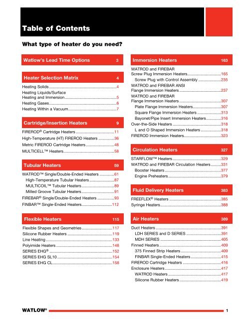
Table of ContentsWhat type of heater do you need?<strong>Watlow</strong>’s Lead Time Options 3<strong>Heater</strong> Selection Matrix 4Heating Solids.............................................................4Heating Liquids/SurfaceHeating and Immersion...............................................5Heating Gases.............................................................6Heating Within a Vacuum............................................7Cartridge/Insertion <strong>Heater</strong>s 9FIREROD ® Cartridge <strong>Heater</strong>s...................................11High-Temperature (HT) FIREROD <strong>Heater</strong>s...............36Metric FIREROD Cartridge <strong>Heater</strong>s..........................48MULTICELL <strong>Heater</strong>s..............................................58Tubular <strong>Heater</strong>s 59WATROD Single/Double-Ended <strong>Heater</strong>s..............61High-Temperature Tubular <strong>Heater</strong>s.......................87MULTICOIL Tubular <strong>Heater</strong>s..............................89Milled Groove Tubular <strong>Heater</strong>s..............................91FIREBAR ® Single/Double-Ended <strong>Heater</strong>s................93FINBAR Single-Ended <strong>Heater</strong>s............................112Immersion <strong>Heater</strong>s 163WATROD and FIREBARScrew Plug Immersion <strong>Heater</strong>s...............................165Screw Plug with Control Assembly.....................235WATROD and FIREBAR ANSIFlange Immersion <strong>Heater</strong>s......................................237WATROD and FIREBARFlange Immersion <strong>Heater</strong>s......................................307Plate Flange Immersion <strong>Heater</strong>s..........................307Square Flange Immersion <strong>Heater</strong>s......................313Bayonet/Pipe Insert Immersion <strong>Heater</strong>s..............316Over-the-Side <strong>Heater</strong>s............................................318L and O Shaped Immersion <strong>Heater</strong>s...................318FIREROD Immersion <strong>Heater</strong>s..................................323Circulation <strong>Heater</strong>s 327STARFLOW <strong>Heater</strong>s............................................329WATROD and FIREBAR Circulation <strong>Heater</strong>s..........331Booster <strong>Heater</strong>s...................................................377Engine Preheaters................................................379Fluid Delivery <strong>Heater</strong>s 383FREEFLEX ® <strong>Heater</strong>s...............................................385Syringe <strong>Heater</strong>s.......................................................388Flexible <strong>Heater</strong>s 115Flexible Shapes and Geometries............................117Silicone Rubber <strong>Heater</strong>s.........................................119Line Heating............................................................133Polyimide <strong>Heater</strong>s...................................................148SERIES EHG ® .........................................................152SERIES EHG SL10..................................................154SERIES EHG CL......................................................158Air <strong>Heater</strong>s 389Duct <strong>Heater</strong>s...........................................................391LDH SERIES and D SERIES................................391MDH SERIES.......................................................405Finned <strong>Heater</strong>s........................................................409375 Finned Strip <strong>Heater</strong>s.....................................409FINBAR Single-Ended <strong>Heater</strong>s............................415FIREROD Cartridge <strong>Heater</strong>s...................................416Enclosure <strong>Heater</strong>s...................................................417WATROD <strong>Heater</strong>s................................................417Silicone Rubber <strong>Heater</strong>s......................................419WATLOW ®1
Table of ContentsHigh-Temperature <strong>Heater</strong>s 423MULTICELL <strong>Heater</strong>s...............................................425High-Temperature FIREROD <strong>Heater</strong>s.....................431High-Temperature Tubular <strong>Heater</strong>s........................432Ceramic Fiber <strong>Heater</strong>s............................................433Specialty <strong>Heater</strong>s 457ULTRAMIC ® Advanced Ceramic <strong>Heater</strong>s...............459Thick Film Conduction <strong>Heater</strong>s...............................463Coil/Cable <strong>Heater</strong>s..................................................467Reference Data 541Power Calculations.................................................543Equations................................................................549Wattage Requirements............................................551Tubular Elements and AssemblySelection Guide.......................................................553Agency Certifications,Recognition and Approvals 561WATROD and FIREBAR Elementand Assemblies.......................................................563Strip/Clamp-On <strong>Heater</strong>s 475Mineral Insulated (MI) Strip <strong>Heater</strong>s........................477375 High-Temperature Strip <strong>Heater</strong>s......................481FIREBAR Clamp-On <strong>Heater</strong>s..................................489Thick Film Conduction <strong>Heater</strong>s...............................490Band/Barrel <strong>Heater</strong>s 491Index 569Product Category Index..........................................571Part Number Index..................................................572Terms and Conditions of Sale 575Terms and Conditions of Sale................................575Mineral Insulated (MI) Band <strong>Heater</strong>s.......................493Nozzle <strong>Heater</strong>s 505Mineral Insulated (MI) Nozzle <strong>Heater</strong>s....................507Pre-Coiled Cable Nozzle <strong>Heater</strong>s...........................509Radiant <strong>Heater</strong>s 511RAYMAX ® Panel <strong>Heater</strong>s........................................513MI Band and Strip Emitters.....................................527Thermostats and Accessories 529ST10 and ST207.....................................................531Bulb and Capillary...................................................534Protective Wells......................................................5392WATLOW ®
<strong>Watlow</strong>’s Lead Time OptionsTo remain competitive in our fast-paced world, you need a supplier that is committed to helping you succeed.<strong>Watlow</strong> ® shows its commitment through multiple options designed to get you what you need quickly.<strong>Watlow</strong> understands that your heating requirements vary from application to application. To help meet your individualneeds, <strong>Watlow</strong> offers several options to ensure you receive your product when you need it.RAPID SHIP and Manufacturing Lead TimesRAPID SHIP<strong>Watlow</strong>’s industry-leading RAPID SHIP offering is available throughout the catalog for various products. RAPID SHIPproducts are noted with “RS” and the RAPID SHIP logo. RAPID SHIP assures that your products will be manufacturedand shipped from the factory the next business day.Products not available as RAPID SHIP will be noted with an “M” which stands for Manufacturing lead times. In manyinstances Manufacturing lead times are just a few days longer than RAPID SHIP due to lower volumes, unique materialsor other manufacturing complexities that must be considered when building your heaters. Contact your local salesrepresentative to check the current lead times offered.FAST TRACK for FIREROD ® <strong>Heater</strong>s<strong>Watlow</strong>’s FAST TRACK program for made-to-order FIREROD ® cartridge heaters allows a range of FIRERODs to beshipped in two or five days.With the FAST TRACK program, you can choose the size, voltage, wattage and termination from a predetermined set ofoptions and choose when you want it – either a two- or five-day lead time.For more information and applicable products, look for the FAST TRACK logo in the cartridge section of this catalog.WATLOW ®3
<strong>Heater</strong> Selection MatrixHeating Solids<strong>Heater</strong>TypeApplication DescriptionSheathMaterialsTypical Max. Max. OperatingWatt Densities TemperaturesW/in 2 W/cm 2 °F °C<strong>Catalog</strong>PageCartridge/Insertion<strong>Heater</strong>sThese heaters are inserted into a close fit hole (i.e. platens,dies and molds).Alloy 800Stainless steelup to 400up to 40062.062.01400100076054011Tubular<strong>Heater</strong>sThese heaters are clamped to the object to be heated,usually exterior surfaces of tanks or other process vessels orfitted into milled grooves in a platen.Flat: Alloy 800Stainless steelRound: Alloy 800Stainless steel404040406.26.26.26.2140012001600120076065087065093936161Flexible<strong>Heater</strong>sThese heaters are bonded or otherwise fastened to the part.Commonly used to heat irregular surfaces and shapes, orapplications requiring distributed wattage or limited space.PolyimideSilicone rubber20103.11.6390500200260148117High- MULTICELL heaters are loosely inserted into the platenTemperature hole for radiant heating. Can also be used in any static or<strong>Heater</strong>s dynamic non-contact application as a radiant heat source.Commonly used for extreme high temperature applications.Ceramic fiber heaters can be formed into an oversizedchamber to surround the object being heated. Using radiantand convection heat transfer, ceramic fiber heaters are usedin ovens and furnaces.Alloy 600Alloy 800Molded ceramic fiber6060309.39.34.6210021002200115011501205425433Specialty<strong>Heater</strong>sULTRAMIC ® advanced ceramic heaters are bonded orclamped to the object being heated.Thick film conduction heaters are clamped to the partbeing heated.Coil/Cable heaters can be formed to heat flat or curvedsurfaces, or wound around the object being heated. Typicalapplications include platen heating and plastic injectionmolding nozzles.Aluminum nitride 1000Dielectric glass on 430 75stainless steel substrateStainless steel orAlloy 600 3015511.64.6111210221200600550650459463467Strip/Clamp-On<strong>Heater</strong>sThese heaters are bolted or clamped to a surface (i.e.dies, molds, ovens). Often used for freeze and moistureprotection.Aluminized steel withrefractory insulationStainless steel withmineral insulation10014015.521.711001400595760481477Band/Barrel<strong>Heater</strong>sThese heaters are clamped to cylindrical surfaces (i.e.extrusion barrels and nozzles).Stainless steel withmineral insulation 100 15.5 1400 760 493Radiant<strong>Heater</strong>sThese heaters are used in any static or dynamic,non-contact application where conduction or convectionheating is not practical. Commonly used in laminatingprocesses, thermoforming and paint drying.Molded ceramic fiberStainless steelemitter strip203034.620002200109512005185144WATLOW ®
<strong>Heater</strong> Selection MatrixHeating Liquids/Surface Heating and Immersion<strong>Heater</strong>TypeCartridge/Insertion<strong>Heater</strong>sTubular<strong>Heater</strong>sApplication DescriptionThese are used as an immersion heater placed eitherdirectly in the liquid, or in a protective well (recommendedfor immersion in water or 90 plus percent water solublesolutions).These heaters are immersed directly in the liquid beingheated. Most commonly used when high kilowatts arerequired. Multiple style mounting adaptors, such as flangesand NPT fittings, provide excellent pressure boundaries.SheathMaterialsAlloy 800 Up to 300in waterFlat: Alloy 800Stainless steelRound: Alloy 800Stainless steelSteelTypical Max. Max. OperatingWatt Densities TemperaturesW/in 2 W/cm 2 °F °C60606060606046.5 212in water9.39.39.39.39.39.31400120035016001200750<strong>Catalog</strong>Page100 11760650180870650400939361616161Flexible<strong>Heater</strong>sImmersion<strong>Heater</strong>sCirculation<strong>Heater</strong>sFluidDelivery<strong>Heater</strong>sHigh-Temperature<strong>Heater</strong>sSpecialty<strong>Heater</strong>sStrip/Clamp-On<strong>Heater</strong>sThese heaters are applied to the surface of a pipe vesselcontaining a liquid (well suited for curved surfacesand irregular shaped objects; frequently used forfreeze protection).FIREBAR ® heaters have multiple elements mounted in a flangeor screw plug fitting. They are immersed directly in a fluid or ina protective well.WATROD heaters have multiple elements mounted in aflange or screw plug fitting. These are immersed directly in afluid or in a protective well.Tubular heaters have multiple elements mounted in a screwplug or ANSI flange fitting and placed in a vessel throughwhich fluid is passed. FIREBAR or WATROD elements maybe utilized.FREEFLEX ® heaters have polymeric heated tubing, used tomaintain temperature in medical applications where heatedflexible tubing is required.Syringe heaters are formed to fit a cylindrical part. Theyare often used in medical applications for heating contrastmedia and often incorporate a sensor and on-board system.Ceramic fiber assembled heaters can be used in a chambersurrounding the tank, vessel, crucible or bath. Radiant andconvection heat transfer heat the load.Coil/Cable heaters that are wrapped or wound around pipeor vessel containing a liquid can be used, or used directlyas an immersion heater. They are often used in applicationswith space limitations (i.e. photo processing equipment,scientific instruments and heat tracing).These heaters are bolted or clamped to the wall of atank or vessel. They are used in food warming and otherapplications offering a flat mounting surface.PolyimideSilicone rubberAlloy 800Alloy 800316 stainless steelSteelRound: Alloy 800Stainless steelSteelPolyimideLexanSilicone rubber2010Up to 100Up to 1006060606072 W/ft233.11.615.515.59.39.39.39.322 W/m0.310.47390500212in water212in water1400in air1600350120075021218542820026010010076087018065040010085220148117Molded ceramic fiber 30 4.6 2200 1205 433Stainless steel orAlloy 600 30 4.6 1200 650 467Aluminized steel withrefractory insulationStainless steel withmineral insulation10014015.521.711001400595760165165331385388481477Band/Barrel<strong>Heater</strong>sThese heaters are clamped to cylindrical surfaces and aremost commonly used to heat liquids flowing through pipesas freeze protection.Stainless steel withmineral insulation 100 15.5 1400 760 493WATLOW ®5
<strong>Heater</strong> Selection MatrixHeating Gases<strong>Heater</strong>TypeApplication DescriptionSheathMaterialsTypical Max. Max. OperatingWatt Densities TemperaturesW/in 2 W/cm 2 °F °C<strong>Catalog</strong>PageCartridge/Insertion<strong>Heater</strong>sThese heaters are mounted in pipes or vessels throughwhich gases pass. They can be placed in protection tubes,making access and wiring easier.Alloy 800 or stainlesssteel100 15.5 Contact <strong>Watlow</strong> 11Tubular<strong>Heater</strong>sThese heaters have multiple elements mounted in an arrayand placed in a duct or vessel through which gases pass.Flat tubular elements can be modified with the addition offins to increase surface area.Flat: Alloy 800Stainless steelRound: Alloy 800Alloy 600303030304.64.64.64.61400120016001800760650870980237Flexible<strong>Heater</strong>sThese heaters are applied to the surface of a pipe or vessel Polyimidecontaining gases. They are well suited for curved surfaces Silicone rubberand irregular shaped objects. Excellent for use in enclosures.550.80.8390500200260148117Circulation<strong>Heater</strong>sAir<strong>Heater</strong>sTubular heaters have multiple elements mounted in a screwplug or ANSI flange fitting and placed in a vessel throughwhich fluid is passed. FIREBAR or WATROD elements maybe utilized.Duct heaters have multiple elements placed in a ductthrough which gases pass.Enclosure heaters prevent freezing and condensation inelectrical and mechanical housings.Finned FIREBAR heaters have aluminized steel fins attachedto a FIREBAR element. They are used for forced air heatingand radiant heating in drivers, ovens and duct work.Finned Strip have aluminized steel fins attached to a375 heater. They are used for air heating, freeze protectionand load bank resistors.High- MULTICELL heaters have multiple elements placed in aTemperature duct or vessel through which gases pass. Designs are also<strong>Heater</strong>s available to heat a pass tube externally to isolate gas fromthe element. Excellent for use in high temperature/highpressure applications.Ceramic fiber heaters are used to construct chambers andfurnaces through which gases are passed. <strong>Heater</strong>s functionas high-temperature radiant heaters surrounding transferpipes or other special vessels.Specialty<strong>Heater</strong>sCoil/Cable heaters are sinuated or wound into coils, whichcan be inserted into a pipe or vessel to heat flowing air orgases. Cable heaters readily lend themselves to applicationswhere space is restricted.Flat: Alloy 800304 stainlesssteelRound: Alloy 800Alloy 600Alloy 800Stainless steelAluminumStainless steelAluminized steelAlloy 600Alloy 800Molded ceramic fiber3030303020 to 30155Up to 50306060304.64.64.64.63 to 4.62.30.87.74.79.39.34.61400120016001800140012001501200110021002100220076065087098076065066650595115011501205331391417419112Stainless steel orAlloy 600 30 4.6 1200 650 4674094254336WATLOW ®
<strong>Heater</strong> Selection MatrixHeating Within a Vacuum<strong>Heater</strong>TypeApplication DescriptionSheathMaterialsTypical Max. Max. OperatingWatt Densities TemperaturesW/in 2 W/cm 2 °F °C<strong>Catalog</strong>PageCartridge/Insertion<strong>Heater</strong>sThese heaters are mounted in a vacuum vessel for radiantenergy transfer.Alloy 800Stainless steelup to 35up to 355.45.41400100076053811Tubular<strong>Heater</strong>sThese heaters are mounted in a vacuum vessel for radiantenergy transfer.Flat: Alloy 800Stainless steelRound: Alloy 800Alloy 600303030304.64.64.64.6140012001600180076065087098093936161Flexible<strong>Heater</strong>sHigh-Temperature<strong>Heater</strong>sThese heaters are applied to the exterior surface of a pipe orvessel. They are well suited for curved surfaces and irregularshaped objects. Note: Polyimide is the only flexible heatertype recommended for use in the vacuum.MULTICELL heaters are mounted in a vacuum vessel forradiant energy transfer.Ceramic fiber heaters surround the exterior surface of avacuum vessel, using radiant energy for heat transfer.Polyimide 7 1.1 390 200 148Alloy 600Alloy 800Molded ceramic fiber6060309.39.34.6225022502200123012301205425433Specialty<strong>Heater</strong>sULTRAMIC advanced ceramic heaters are bonded orclamped to the object being heated.Coil/Cable heaters are wound into a coil or sinuated patternand mounted in a vacuum vessel for radiant energy transfer.Aluminum nitrideAlloy 600 orStainless steel1000201553.111121200600650459467Band/Barrel<strong>Heater</strong>sThese heaters are applied to exterior surface of a pipeor vessel.Stainless steel withmineral insulation 100 15.5 1400 760 493WATLOW ®7
8 WATLOW ®
Cartridge/Insertion <strong>Heater</strong>sMax. Operating Typical Max.Temperatures Watt DensitiesCartridge/Insertion <strong>Heater</strong>s Sheath Materials °F °C W/in 2 W/cm 2 PageFIREROD ® Alloy 800 1400 760 400 62.0Stainless steel 1000 538 400 62.011High-Temperature FIREROD Alloy 800 1800 982 100 15.5 36Metric FIREROD Alloy 800 1400 760 330 50.0 48MULTICELL Alloy 800 2050 1120 30 4.6 58Cartridge/Insertion <strong>Heater</strong>sWATLOW ®9
10 WATLOW ®
Cartridge/Insertion <strong>Heater</strong>sFIREROD ® Cartridge <strong>Heater</strong>sThe <strong>Watlow</strong> ® FIREROD ® cartridge heater incorporatesengineering excellence and is supported by almost60 years of solid industry performance across a broadrange of simple and complex applications. As the premierchoice in swaged cartridge heating, thousands ofindustrial manufacturers continue to choose <strong>Watlow</strong> astheir trusted thermal partner and certified cartridgeheater supplier.Built using premium materials and tight manufacturingcontrols, the FIREROD heater provides superior heattransfer, uniform temperatures, resistance to oxidationand corrosion and a long life even at high temperatures.Every system component that leaves our manufacturingfacilities meets our strict quality assurance specifications,in addition to those set forth by leading standards andregulating industries.To meet our customer’s individual needs, there are manydelivery options available for FIREROD heaters.Performance Capabilities• Part temperatures up to 1400°F (760°C) onalloy 800 sheath• Watt densities up to 400 W/in 2 (62 W/cm 2 )• Maximum voltage up to 480VFeatures and BenefitsNickel-chromium resistance wire• Ensures even and efficient distribution of heat tothe sheathConductor pins• Provide a metallurgical bond to the resistance wire• Ensure a trouble-free electrical connectionMagnesium oxide insulation of specific grain andpurity• Results in high dielectric strength and contributes tofaster heat-upAlloy 800 sheath• Resists oxidation and corrosion from heat, manychemicals and atmospheresMinimal spacing between the element wire andsheath• Results in lower internal temperature• Accommodates a design with fewer or smaller heatersoperating at higher watt densitiesInternational Organization for Standardization (ISO)9001 certified• Provides confidence that quality and reliabilityexpectations are metEnd PieceLead WiresLead WiresMgOInsulationUL ® and CSA approved flexible stranded wires• Lead insulation rated to temperatures up to480°F (250°C)Patented lead adapter (LA) method• Allows same day shipment on more than 150,000configurations of stock FIREROD heaters and leadcombinationsTypical ApplicationsConductorPinsNo HeatSectionSheathResistance Wire• Semiconductor chamber heating• Semiconductor wire and die bonding• Freeze protection and deicing of equipment in coldclimates or applications• Humidity control• Patient comfort heating used in medical devices• Mold die and platen heating• Seal bars used in packaging equipment• Test sample heating in gas chromatography equipmentWATLOW ®11
Cartridge/Insertion <strong>Heater</strong>sFIREROD Cartridge <strong>Heater</strong>sApplications and Technical DataTolerancesDiameter• 1 in. (25 mm) units: ±0.003 in. (±0.08 mm)• All other units: ±0.002 in. (±0.05 mm)Sheath Length• All units up to 4 1 /2 in. (114 mm) long:± 3 /32 in. (±2.4 mm)• 1 /8 in. diameter units over 4 1 /2 in. (114 mm)long: ±3%• All other units over 4 1 /2 in. (114 mm) long: ±2%Length MeasurementsPin Style and Potted FIRERODsPTFE orPotted Seal<strong>Heater</strong> LengthPTFE - Swaged-in Leads FIRERODsWattage• 1 /8 in. units: +10%, -15%• All other units: +5%, -10%Resistance• 1 /8 in. units: +15%, -10%• All other units: +10%, -5%Resistance changes with temperature. There are threecircumstances under which resistance can be measured:1. Room temperature (before use): nominal ohms are90% of Ohm’s law calculation.2. Room temperature (after use): nominal ohms are95% of Ohm’s law calculation.3. At temperature (during use): depending on applicationnominal ohms are approximately 100% of Ohm’s law.Note: Resistance and wattage values are approximatedepending on application conditions.Component Recognition File Numbers• UL ® component rated to 240VAC(file number E52951)• CSA component rated to 240VAC(file number LR7392)• VDE component rated to 240VAC(file number 10062-4911-0006)Note: Not all options or combinations of options arecovered. UL ® , CSA, VDE and CE marking is availableupon request.<strong>Heater</strong> Length (excludes lead end turnover)12WATLOW ®
Cartridge/Insertion <strong>Heater</strong>sFIREROD Cartridge <strong>Heater</strong>sApplications and Technical DataDimensional DataThis table shows minimum/maximum sheath lengths foravailable FIREROD diameters.FIREROD DiameterLengthNominal Actual Min. Max.in. in. (mm) in. (mm) in. (mm)1 /8 0.122 (3.1) 7 /8 (22.2) 12 (305)1 /4 0.246 (6.3) 7 /8 (22.2) 36 (915)3 /8 0.371 (9.4) 7 /8 (22.2) 48 (1220)1 /2 0.496 (12.6) 7 /8 (22.2) 60 (1520)5 /8 0.621 (15.8) 1 1 ⁄4 (25.0) 72 (1830)3 /4 0.746 (18.9) 1 1 ⁄4 (25.0) 72 (1830)1 0.996 (25.3) 1 1 /4 (32.0) 72 (1830)Indicates recommended maximum sheath length; however, longerlengths may be available.CamberCamber is defined as the maximum deviation of theheater’s centerline from straight. FIREROD camberwithin allowable tolerances is verified via passagethrough a cylindrical gauge of specified length anddiameter. Normally, slight camber does not presenta problem since the heater will flex enough to fit intoa straight, close-fit hole.Camber MeasurementCamberAllowable Camber Versus LengthMax. Allowable Camber (in.)0.2000.1800.1600.1400.1200.1000.0800.0600.0400.0200.0000 5 10 15 20 25 30 35 40<strong>Heater</strong> Length (in.)Max. camber = 0.020 in. x (length in feet) 2 or 0.005 in., whichever is greater.WATLOW ®13
Cartridge/Insertion <strong>Heater</strong>sFIREROD Cartridge <strong>Heater</strong>sApplications and Technical Data (Continued)Electrical DataThe table below will assist you in selecting the correctFIREROD heater for your application, accordingto available voltage, amperage and wattage.Please note, some combinations of minimum andmaximum wattages are not available on the same heaterdiameter. If your application exceeds the limitationsshown, contact your <strong>Watlow</strong> representative.Dia.1/4 in. (6 mm)NominalNo-HeatHeated Length1/4 in. (6 mm)NominalNo-Heat12 in. (305 mm)FIRERODDiameterin.Min. Watts @ 120V 3<strong>Heater</strong> LengthMax. WattsVoltsMax.AmpereMax. 11 in.(25 mm)1 1 /2 in.(38 mm)2 in.(50 mm)120V1-phase240V1-phase480V1-phase240V3-phase1 /8 240 3.1 — 8 5 360 720 — — —1 /4 240 4.4 2 100 55 40 525 1050 — — —3 /8 240 6.7 65 35 25 800 1600 — — —1 /2 240 9.7 40 25 20 1160 2320 — — —5 /8 480 23.0 35 20 15 2760 5520 11,000 5 5480V3-phase3 /4 480 23.0 30 15 10 2760 4 5520 11,000 9550 19,1001 7 480 23.0 — 15 10 2760 4 5520 11,000 9550 4 19,100 4Number Of Circuits 6Diameterin. 1-phase 3-phase3 /4 3 11 5 2a Determined by the current carrying capacity of internal parts andlead wire. Alternate material may be available.2 For 1 /4 in. (6 mm) units with thermocouple maximum amperageis 3.1A.3 Determined by the limitation of space for resistance winding.For minimum wattage of 240VAC multiply value by four.4 Higher wattages are available using more than one set of powerleads. Multiply the wattage from the table by the applicable factor.5 Contact your <strong>Watlow</strong> representative for data.6 On 3 /4 in. (19 mm) diameter units, either three single-phase circuitsor one three-phase delta or wye circuit is available. On 1 in. (25 mm)diameter units, either five single-phase or two three-phase deltacircuits are available.7 A minimum charge per line item applies.14 WATLOW ®
Cartridge/Insertion <strong>Heater</strong>sFIREROD Cartridge <strong>Heater</strong>sMaximum Allowable Watt DensityThe following four charts detail maximum allowable wattdensities for applications that use metal, steam, air or gasheating. Please review the charts and applicable data todetermine the correct watt density for your application.Correction FactorsThese graphs depict FIRERODs used in steel parts,therefore, for stainless steel, aluminum or brass, referto applicable correction factors:1. For stainless steel, enter the graph with a fit0.0015 in. (0.04 mm) larger than actual fit.2. For aluminum and brass, enter the graph with atemperature 100°F (38°C) above actual temperature.Heating MetalsThe Maximum Watt Density— Heating Metals chart willdisplay the maximum hole fit or recommended wattdensity of the heater. Enter the chart with either knownvariable, part-fit-in-hole dimension or W/in 2 . Then, find theapplication temperature by reading up or over onthe chart.If the fit of the heater in the hole dimension is not known,it can be easily determined. Subtract the minimumdiameter of the FIREROD (nominal diameter minustolerance) from the maximum hole diameter. For example,the hole fit is 0.006 in. (0.15 mm) for a hole diameter of0.500 in. (13 mm) minus a heater diameter of 0.496 in.(12.6 mm) ±0.002 in. (0.05 mm). For FIREROD heaters insquare holes or grooves, contact your <strong>Watlow</strong>representative for the fit in hole dimension.0.1000.0900.0800.0700.0600.050Maximum Allowable Watt Density—Heating MetalsHoleFit0.040Cartridge <strong>Heater</strong>0.030Fit in Hole—in.0.0200.0100.0090.0080.0070.0060.005Fit in hole = maximum hole I.D. minusminimum heater O.D.200°F (93°C)400°F (204°C)1000°F (538°C)800°F (427°C)600°F (316°C)0.0041200°F (649°C)1400°F (760°C)0.0030.0020.00110 20 30 40 50 60 70 80 100 200 300 400 500 600 800 1000Watt Density—W/in 2WATLOW ®15
Cartridge/Insertion <strong>Heater</strong>sFIREROD Cartridge <strong>Heater</strong>sMaximum Allowable Watt Density (Continued)Watt Density vs. Ambient Air TemperatureThe Watt Density vs. Ambient Air Temperature graphshows the maximum allowable watt density when oneFIREROD is operated in air or similar gas.For FIRERODs grouped in a single row, with no less thanone diameter between elements, multiply value from thegraph by 0.95. When a reflector is placed behind theheaters, multiply the maximum allowable watt densityvalue from the graph by 0.85.Ambient Temperature—°F1600140012001000800600400Maximum Allowable WattDensity vs. Ambient Air20010 20 30 40 50 60Watt Density—W/in 2Sheath Temperature in Ambient AirThe Sheath Temperature in Ambient Air graph indicatesthe watt density required to bring a pre-oxidizedFIREROD to a given sheath temperature whenoperated in 70°F (21°C) ambient air.At 44 W/in 2 (6.8 W/cm 2 ), the sheath temperature is1450°F (784°C). At this temperature, a one-year life isexpected if cycling is not too frequent.Higher temperatures result in reduced heater life.FIREROD Sheath Temperature—°F200015001000500FIRERODSheath Temperature WhenOperated in 70°F Ambient AirNot Pre-oxidizedPre-oxidized10 20 30 40 50 60Watt Density—W/in 2Watt Density in Moving AirThe Watt Density in Moving Air graph shows themaximum allowable watt density of a FIREROD inmoving air.The air movement is expressed in feet per minute (FPM).If the air flow is known in cubic feet per minute (CFM),divide the CFM by the net-free area around the heater(ft 2 ). The net-free area is the total area of the enclosureminus the area occupied by the heater.Air Velocity Past <strong>Heater</strong>—FPM45004000350030002500200015001000Entering AirUp To 200°FMaximum AllowableWatt Density in Moving AirFIREROD–Parallel To Air FlowFIREROD–Perpendicular To Air Flow50020 40 60 80 100 120Watt Density—W/in 216 WATLOW ®140
Cartridge/Insertion <strong>Heater</strong>sFIREROD Cartridge <strong>Heater</strong>sLead and Diameter InformationStandard Lead Specifications<strong>Heater</strong>Diameterin. (mm)Max.VoltageStandardLead GaugeFiberglassSize ToleranceFiberglassStandardLead GaugePTFESizeTolerancePTFEStainless SteelHoseI.D.Stainless SteelBraidI.D.1 /8 (3) 300 24 0.044 - 0.058 24 solid 0.036 - 0.044 1 /8 1 /81 /4 (6) 300 22 0.066 - 0.078 22 0.050 - 0.058 5 /32 1 /83 /8 (10) 300 22 0.076 - 0.088 20 0.056 - 0.064 7 /32 3 /161 /2 (13) 300 18 0.089 - 0.101 20 0.074 - 0.084 9 /32 1 /45 /8 (16) 600 18 0.108 - 0.124 18 0.097 - 0.113 7 /16 3 /83 /4 (19) 600 18 0.108 - 0.124 14 0.097 - 0.113 7 /16 3 /81 (25)1 600 18 0.095 - 0.109 14 0.087 - 0.101 N/A N/ALead length tolerances:1 to 36 in. (25 to 914 mm) = - 1 /2 in. (13 mm), +1 1 /2 in. (38 mm)> 36 to 72 in. (914 to 1829 mm) = -1, +3 in. (-25 + 76 mm) 1Stainless steel hose and braid tolerances: same as lead wire.Units constructed with 480V require MGT or PTFE leads. If connectingheaters in series above 300V, MGT leads are also required.Ratings: GGS, 300V, 482°F (250°C)MGT, 600V, 842°F (450°C)PTFE, 600V, 392°F (200°C)Silicone rubber, 600V, 302°F (150°C)1 A minimum charge per line item applies.Additional Lead SpecificationsLead Gauge Nickel Ampacity N.C.C. Ampacity SPC/NPC26 2.5 4.2 6.024 stranded 3.1 5.2 7.524 solid 3.1 5.2 7.522 4.4 7.2 10.520 N/A N/A 14.018 7.6 12.6 18.016 9.7 16.1 23.014 12.5 21.0 30.012 16.8 28.0 40.010 23.0 38.5 55.0WATLOW ®17
Cartridge/Insertion <strong>Heater</strong>sFIREROD Cartridge <strong>Heater</strong>sLead Adapter (LA)OptionsPatented LA Modification MethodThe lead adapter (LA) modification process is a powerfultool for providing a wide range of finished heaterconfigurations very quickly. The LA process allows thebase FIREROD heater to be modified into a multitudeof configurations. The base FIREROD heater can beselected to meet customers’ individual needs. The baseheater can then be customized by adding various finishingoptions like lead length, lead protection, flanges, locatingrings and right-angle constructions.Right AngleSwaged-in Flexible LeadsNo-Heat ExtensionsPTFE Seal and LeadsSilicone Rubber Seal and LeadsFlangeLocating RingThreaded FittingStainless Steel BraidStainless Steel HoseRight AngleStainlessSteel HoseRight AngleStainlessSteel Braid18 WATLOW ®
Cartridge/Insertion <strong>Heater</strong>sFIREROD Cartridge <strong>Heater</strong>sLead Adapter (LA)OptionsTwo- or Five-Day Lead Times<strong>Watlow</strong>’s FAST TRACK program allows made-to-order FIREROD cartridge heaters to be shipped in two or five days. Youcan design a FIREROD to meet your unique applications. You can choose the size, voltage, wattage, terminationoptions and your preferred lead time. To take advantage of this program contact your <strong>Watlow</strong> representative.Options 1 /4 Inch 3 /8 Inch 1 /2 Inch 5 /8 Inch 3 /4 InchSwaged-in leads 3 3 3 3 3PTFE seal and leads 3 3 3 3Right angle leads 3 3 3 3 3Stainless steel hose 3 3 3 3 3Right angle hose 3 3 3 3Stainless steel braid 3 3 3 3 3Right angle braid 3 3 3 3Straight hose with PTFE seal and leads 3 3 3 3Right angle hose with PTFE seal and leads 3 3 3 3Straight braid with PTFE seal and leads 3 3 3 3Right angle braid with PTFE seal and leads 3 3 3 3Right angle PTFE seal and leads 3 3 3 3Ground lead 3 3 3 3 3FS flange 3 3 3FM flange 3 3 3 3 3FL flange 3 3Single stainless steel fitting 3 3 3 3 3Additional lead end no-heat length 3 3 3 3 3Note: Maximum heater length is 24 inches.WATLOW ®19
Cartridge/Insertion <strong>Heater</strong>sFIREROD Cartridge <strong>Heater</strong>sLATermination OptionsLA Swaged-in Flexible LeadsLA PTFE Seal and LeadsMin. No-Heat1 in.(25 mm)Min. No-Heat1/2in.(13 mm)LA swaged-in flexible leads are used in applicationswhere a high degree of flexing exists or the leads mustbe bent sharply adjacent to the heater without exposingor breaking the conductor. The stranded wire leadsare connected internally and exit through the lead end.The overall length of the heater is extended by1 /4 in. (6 mm). To order, specify length adder code Ebringing the total lead end no-heat to 1 /2 in. (13 mm).This LA option is not available on 1 /8 in. (3 mm) diameterFIRERODs. On 1 /8 in. (3 mm) diameter FIRERODs, leadsare connected externally using a solid conductor leadwire. If stranded wire is desired on 1 /8 in. (3 mm) diameterunits, contact your <strong>Watlow</strong> representative.The LA PTFE seal and leads protect the heater againstmoisture/contamination from lubricating oil, cleaningsolvents, plastic material or fumes and organic tapes.This seal is effective to 392°F (200°C) under continuousoperation.Please note when ordering this option, that a minimumno-heat section is required to allow for construction.Additional no-heat may be required to keep the sealbelow effective temperatures. The minimum lead endno-heat required is 1 in. (25 mm). The LA cap adds3 /4 in. (19 mm) to the overall length of the heater. Toorder, specify option code T.LA Silicone Rubber Seal and LeadsNo-Heat ExtensionsMin. No-Heat1 in.(25 mm)Right Angle (Swaged-in) LeadsSwaged-in LeadsNo-HeatLengthNo-HeatLengthNo-heat extensions are recommended in applicationswhere leads may be exposed to excessive heat andrequire a cooler lead end. They are also used when heatis not required along the entire length of the FIREROD.No-heat extensions are available for most LA options indiameters of 3 /8, 1 /2, 5 /8 and 3 /4 in. (10, 13, 16 and 19mm). These extensions are designed to provide a totalno-heat length of 1, 1 1 /2, 2 or 2 1 /2 in. (25, 38, 51 or 65mm) at the lead end of FIRERODs only. Contact your<strong>Watlow</strong> representative for available LA options.The LA silicone rubber seal and leads protect the heateragainst moisture and contamination from lubricating oil,cleaning solvents, plastic material, fumes and organictapes. This seal is effective to 302°F (150°C) undercontinuous operation.Please note when ordering this option, that a minimumno-heat section is required to allow for construction.Additional no-heat may be required to keep the sealbelow effective temperatures. The minimum lead endno-heat required is 1 in. (25 mm). The LA cap adds3 /4 in. (19 mm) to the overall length. To order, specifyoption code P.20 WATLOW ®
Cartridge/Insertion <strong>Heater</strong>sMin. No-HeatFIREROD Cartridge <strong>Heater</strong>sLATermination Options (Continued)1 in.(25 mm)LA Straight Stainless Steel HoseMin. No-HeatMin. No-HeatMin. No-Heat1 in.(25 mm)LA Straight Stainless Steel BraidMin. No-HeatAn LA straight stainless steel hose provides the bestprotection against abrasion from sharp edges. It alsooffers ease of handling and wiring in abrasiveenvironments. Unless specified a 12 in. (305 mm)hose is supplied. Leads are 2 in. (51 mm) longerthan the hose but, longer leads are available.The minimum lead end no-heat required is 3 /4 in.(19 mm). This option adds 1 /2 in. (13 mm) to the overalllength. To order, specify option code H.Min. No-HeatThe LA straight stainless steel braid is designed to protectleads from abrasion against sharp edges. It is the mostMin. No-Heatflexible <strong>Watlow</strong> protective lead arrangement.Unless specified, a 12 in. (305 mm) braid is supplied.Leads are 2 in. (51 mm) Min. longer No-Heat than the braid, but longerleads are available.The minimum lead end no-heat required is 3 /4 in.(19 mm). This option adds 1 /2 in. (13 mm) to the overalllength. To order, specify option code C.LA Straight Stainless Steel Hose withPTFE Leads and SealLA Straight Stainless Steel Braid withPTFE Leads and SealMin. No-HeatAn LA straight stainless steel hose with PTFE leads andseal is the ultimate combination for providing abrasionprotection and a moisture resistant seal. Unless specified,a standard 12 in. (305 mm) hose is supplied. Leads are2 in. (51 mm) longer than the hose, but longer leads areavailable. This seal is effective up to 392°F (200°C) undercontinuous operation.The minimum lead end no-heat required is 1 in. (25 mm).This option adds 3 /4 in. (19 mm) to the overall length. Toorder, specify option code G.Min. No-HeatThe LA straight stainless steel braid with PTFE leads andseal is <strong>Watlow</strong>’s most flexible lead protection witha moisture resistant seal. Unless specified, a 12 in.(305 mm) braid is supplied. Leads are 2 in. (51 mm)longer than the braid, but longer leads are available.This seal is effective up to 392°F (200°C) undercontinuous operation.The minimum lead end no-heat required is 1 in. (25 mm).This option adds 3 /4 in. (19 mm) to the overall length. Toorder, specify option code F.WATLOW ®21
Cartridge/Insertion <strong>Heater</strong>sFIREROD Cartridge <strong>Heater</strong>sLARight Angle OptionsLA Right Angle LeadsLA Right Angle Stainless Steel Hose withPTFE Leads and SealMin. No-HeatLA right angle leads are used in applications with a highdegree of flexing and when space limitations are critical.Stranded lead wires are connected internally (swaged-in)and exit at a 90 degree angle at the end of the heater.To order, specify option code R.Minimum No-Heat RequiredMin. No-Heat in. (mm)Dia. 1 /4 3 /8 1 /2 5 /8 3 /4In. (mm) 13 /16 (21) 3 /4 (19) 13 /16 (21) 13 /16 (21) 13 /16 (21)Min. No-HeatTo order right angle leads with PTFE leads and seals,specify option code B.LA Right Angle Stainless Steel HoseMin. No-Heat1½ in.(38 mm)An LA right angle stainless steel hose with PTFE leadsand a seal is the ultimate combination for providingabrasion protection and a moisture resistant seal withwiring convenience. Unless specified, a 12 in. (305 mm)hose is supplied. Leads are 2 in. (51 mm) longer than thehose but longer leads are available. This seal is effectiveto 392°F (200°C) under continuous operation.The minimum lead end no-heat required is 1 1 /2 in.(38 mm). This option adds 1 1 /4 in. (32 mm) to overalllength on stock units.To order, specify option code M.Note: This option is not available on 1 /4 in. (6 mm)diameter.Min. No-Heat1 in.(25 mm)An LA right angle stainless steel hose is provided forwiring convenience. Like the LA straight stainless steelhose, it protects leads from abrasion against sharp edges.Unless specified, a 12 in. (305 mm) hose is supplied.Leads are 2 in. (51 mm) longer than the hose, but longerleads are available.Diameter 3 /81 /25 /83 /4Adder length in. (mm) 3 /4 (19) 3 /4 (19) 3 /4 (19) 7 /8 (22)Min. no-heat in. (mm) Min. No-Heat 1 (25) 1 (25) 1 (25) 1 1 /8 (29)To order specify option code W.Note: This option is not available on 1 /4 in. (6 mm)diameter.22 WATLOW ®
Cartridge/Insertion <strong>Heater</strong>sFIREROD Cartridge <strong>Heater</strong>sLARight Angle Options (Continued)LA Right Angle Stainless Steel BraidMounting OptionsLA Stainless Steel Threaded FittingsStandard Fitting LocationAAn LA right angle stainless steel braid is provided forwiring convenience. It protects leads from abrasionagainst sharp edges.Unless specified, a 12 in. (305 mm) braid is supplied.Leads are 2 in. (51 mm) longer than the braid, but longerleads are available.Diameter Min. No-Heat/8 1 /2 5 /8 3 /4Adder length in. (mm) 3 /4 (19) 3 /4 (19) 3 /4 (19) 7 /8 (22)Min. no-heat in. (mm) 1 (25) 1 (25) 1 (25) 1 /8 (3)Min. No-HeatTo order, specify option code Y.Note: This option is not available on 1 /4 in. (6 mm)diameter.Min. No-HeatMin. No-HeatMin. No-Heat1 in.(25 mm)LA Right Angle Stainless Steel Braid withPTFE Leads and Seal1½ in.(38 mm)The LA right angle stainless steel braid with PTFE leadsand seal is <strong>Watlow</strong>’s most flexible lead protection witha moisture resistant PTFE seal and wiring convenience.Unless specified, a 12 in. (305 mm) braid is supplied.Leads are 2 in. (51 mm) longer than the braid, but longerleads are available. This seal is effective up to 392°F(200°C) under continuous operation.The minimum lead end no-heat required is 1 1 /2 in.(38 mm). This option adds 1 1 /4 in. (32 mm) to theoverall length on stock units.To order, specify option code A.Note: This option is not available on 1 /4 in. (6 mm)diameter.Fitting overlaps the unheated section and is silver soldered tothe sheath.Threaded fittings allow fast, water-tight installation ofthe heater into a threaded hole. These fittings are 304stainless steel, other stainless steel alloys are availableupon request. Double threaded fittings are also available.Minimum UnheatedPlease see page 33 for threaded fitting specifications.Provide the location of the fittings if no-heat extensionoption is requested. Specify the location for option B.LeadArrangementCrimped LeadsSwaged-in LeadsSTR SS HoseSTR SS BraidPTFE Seal & LeadsSilicone Seal & LeadsOptional Fitting LocationStandard Fitting 1LocationDimension Ain. (mm)1 /4 (6)5 /16 bd (8)1 /2 c (13)1 /2 (13)7 /8 (22)7 /8 (22)a The location of the threaded fitting from the thread end of the fittingto the lead end of the heater.All optional fitting locations are available only with LA no-heatextensions. Contact your <strong>Watlow</strong> representative for details.b On 1 /4 in. diameter FIREROD only “A” dimension is 7 /16 in. (11.1 mm).c On 1 /4 in. diameter FIREROD only “A” dimension is 5 /8 in. (15.9 mm).4 On 5 /8 in. and 3 /4 in. the fitting is located at 7 /8 in. from the lead endusing a 3 /4 in. no-heat extension. In order to locate at 5 /16 in., thefitting must be epoxied.BWATLOW ®23
Cartridge/Insertion <strong>Heater</strong>sFIREROD Cartridge <strong>Heater</strong>sLAMounting OptionsFlanges1⁄16 in. (1.6 mm)(nominal)Locating Ring0.14 in. (3.6 mm)C DHStainless steel flanges are a convenient mounting methodto position a heater within an application. The flange isstaked on and located 1 /4 in. (6 mm) from the lead end.The flange can be located up to 2 1 /4 in. (57 mm) from thelead end if it is over a no-heat section. Use this option incombination with most LA configurations.To order, specify flange, size and locations.Flange SpecificationsFIRERODin. (mm)Diameter Flangein. Size D C H1 /4, 3 /8, 1 /2 FS 1 (25) 3 /4 (19) 0.144 (4)1 /4, 3 /8, 1 /2/8, 3 /4FM 1 1 /2 (38) 1 1 /8 (29) 0.156 (4)5 /8, 3 /4 FL 2 (51) 1 1 /2 (38) 0.201 (5)A stainless steel locating ring can be used as a retainingcollar to position a FIREROD if mounting requirements arenot critical.For LA, specify the location if the no-heat extensionoption is requested. On FIRERODs with crimped on leadswithout the LA option, the locating ring will be located onthe last 1 /4 in. (6 mm).To order, specify locating ring.Locating Ring SpecificationsDiameter 1 /4 3 /8 1 /2 5 /8 3 /4Ring O.D.in. (mm) 1 /2 (13) 5 /8 (16) 3 /4 (19) 7 /8 (22) 1 (25)24 WATLOW ®
Cartridge/Insertion <strong>Heater</strong>sFIREROD Cartridge <strong>Heater</strong>sLAMineral Insulated (MI) Leads"Metal toMetal Seal"304 SS SheathMineral InsulationNickel ConductorTransitionPTFE LeadsMI leads handle both high temperatures andcontamination, and resist other problems includingabrasion and excessive vibration. The metal seal andswaged-in formable MI cable leads can handletemperatures up to 1500°F (815°C). The lead endseal resists moisture and other forms of contamination,including gases, oils, plastic drool, solvents and water.This LA option is also available as a manufactureditem. Specify MI leads and seal, as well as volts, watts,cable length, lead length and type. Unless specified,6 in. (152 mm) of MI cable and 12 in. (305 mm) of PTFEleads will be supplied. To order, specify option code J.Note: A minimum charge per line item applies.Benefits• Increases heater life• Minimizes down time• Resists moisture contamination• Allows a cartridge heater to be used where it was notpreviously possible• Resists abrasion and vibration• Forms and bends to fit the contours of wiring raceways• Protects against high temperatures without additionalinsulationTypical Applications• Vacuum forming• Plastic molding• Medical device manufacturing• Food handling equipment• Zinc die-castingTechnical DataMax. temp. of cable: 1500°F (815°C)Max. temp. of cable to lead transition: 300°F (149°C)(where flexible leads attach to cable)Cable sheath material: 304 SSConductor material: nickelMax. voltage: 240VLead TypesPTFE 392°F (200°C) – T<strong>Heater</strong> Max. Conductor Cable Transition Cable Length Max.Diameter Current Diameter Diameter Diameter Min. Max. Min. Voltage Lengthin. Amperes in. in. in. in. Bend Radius in. Adder3 /8 7.0 0.044 0.108 0.230 6 72 0.225 240 G ( 3 /8)1 /2 7.0 0.044 0.108 0.230 6 72 0.225 240 K ( 9 /16)5 /8 9.7 0.062 0.138 0.250 6 72 0.280 240 L ( 5 /8)3 /4 9.7 0.062 0.138 0.250 6 72 0.280 240 L ( 5 /8)This information pertains to standard FIREROD heaters.WATLOW ®25
Cartridge/Insertion <strong>Heater</strong>sFIREROD Cartridge <strong>Heater</strong>sLA OptionsMinimum Length Adders Per Diameter Per OptionOptionOption in. (mm) Code<strong>Heater</strong> Diameter 1 /4 (6) 3 /8 (9.5) 1 /2 (13) 5 /8 (15.9) 3 /4 (19)Swaged-in leads E 1 /4 (6) E 1 /4 (6) E 1 /4 (6) E 1 /4 (6) E 1 /4 (6) NoneRight angle leads K 9 /16 (14) J 1 /2 (13) K 9 /16 (14) K 9 /16 (14) K 9 /16 (14) RPTFE seal and leads — — N 3 /4 (19) N 3 /4 (19) N 3 /4 (19) N 3 /4 (19) TRight angle PTFE seal and leads — — N 3 /4 (19) N 3 /4 (19) N 3 /4 (19) N 3 /4 (19) BSilicone seal and leads — — N 3 /4 (19) N 3 /4 (19) N 3 /4 (19) N 3 /4 (19) PStraight hose J 1 /2 (13) J 1 /2 (13) J 1 /2 (13) J 1 /2 (13) J 1 /2 (13) HRight angle hose — — N 3 /4 (19) N 3 /4 (19) N 3 /4 (19) R 7 /8 (22.2) WStraight hose with PTFE seal and leads — — N 3 /4 (19) N 3 /4 (19) N 3 /4 (19) N 3 /4 (19) GStraight braid J 1 /2 (13) J 1 /2 (13) J 1 /2 (13) J 1 /2 (13) J 1 /2 (13) CRight angle braid — — N 3 /4 (19) N 3 /4 (19) N 3 /4 (19) R 7 /8 (22) YRight angle braid with PTFE seal and leads — — 1E 1 1 /4 (32) 1E 1 1 /4 (32) 1E 1 1 /4 (32) 1E 1 1 /4 (32) AStraight braid with PTFE seal and leads — — N 3 /4 (19) N 3 /4 (19) N 3 /4 (19) N 3 /4 (19) FRight angle hose with PTFE seal and leads — — 1E 1 1 /4 (32) 1E 1 1 /4 (32) 1E 1 1 /4 (32) 1E 1 1 /4 (32) MLA options are available for all FIRERODs, except the1 /8 in. diameter size. To order any of these options,please build the order number by specifying the <strong>Watlow</strong>part number, length adder code, option code and leadlength.Ordering Example: The order numberJ12A89-N72W74 indicates an order for a 12 in.(305 mm) FIREROD with 72 in. (1830 mm) right anglestainless steel hose and 74 in. (1880 mm) leads. Theoverall heater length equals 12 3 /4 in. (324 mm).Note: No-heat extensions are available for most LAoptions in diameters of 3 /8, 1 /2, 5 /8 and 3 /4 in. Contactyour <strong>Watlow</strong> representative for available LA options.To order any of these dimensions, please specify theapplicable length adder code shown.No-Heat Length Adder CodesNo-HeatOptionLengthin. (mm) Adder Code1 3 /4 (19) N1 1 /4 (32) 1E1 3 /4 (44) 1N2 1 /4 (56) 2E26 WATLOW ®
Cartridge/Insertion <strong>Heater</strong>sFIREROD Cartridge <strong>Heater</strong>sNon-Lead Adapter (LA)Modification Coding<strong>Watlow</strong> offers heaters in various diameters, lengths andvolt-wattage combinations that are ready for shipping.Basic modifications can be made and heaters are shippedthe same day. Modifications include flanges, threadedfittings, locating rings, ceramic beads and crimped onleads. Following is a list of all available non-LA mountingand pin option codes.Mounting Option CodesBA - Small flange FS (available on 1 /4, 3 /8 and 1 /2 in.)BB - Medium flange FM (available on 1 /4, 3 /8, 1 /2, 5 /8 and3 /4 in.)BC - Large flange FL (available on 5 /8 and 3 /4 in.)BD - Locating ring (available on 1 /4, 3 /8, 1 /2, 5 /8 and3 /4 in.)BG - Single stainless steel fittingBH - Double stainless steel fittingBY - Stainless steel reversedPin Option CodesAA - Short pins 3 /8 in. (10 mm)AB - Medium pins 5 /8 in. (16 mm)AC - Long pins 1 3 /4 in. (45 mm)AD - Stagger pinsAE - Ceramic beads 1 /2 in. (13 mm)AF - Ceramic beads 3 /4 in. (19 mm)AG - Ceramic beads 1 in. (25 mm)AH - Ceramic beads 1 1 /4 in. (32 mm)AJ - Ceramic beads 1 1 /2 in. (38 mm)Crimped-on LeadsCeramic BeadsLocating RingThreaded FittingWATLOW ®27
Cartridge/Insertion <strong>Heater</strong>sFIREROD Cartridge <strong>Heater</strong>sMade-to-OrderStraight OptionsSwaged-in Flexible Leads1 in. (25 mm) Min. No-HeatStraight Stainless Steel Hose1¼ in. (32 mm)Min. No-Heat¼ in. (6 mm)No-Heat12 in. (305 mm)Standard¼ in. (6 mm)No-HeatSwaged-in flexible leads are used in applications wherea high degree of flexing exists or leads must be bentsharply adjacent to the heater without exposing orbreaking the conductor. Stranded wire leads areconnected internally and exit through the lead end.Lead wire type is high temperature fiberglass. Themaximum temperature of the standard fiberglass endpiece is 842°F (450°C). Unless specified, 12 in. (305 mm)leads are supplied.The minimum lead end for no-heat is 1 in. (25 mm) min.or 12 percent of overall heater length. Additional no-heatmay be required to keep the end piece and leads belowthe maximum operating temperatures.PTFE Seal and Leads1 in. (25 mm)Min. No-Heat¼ in. (6 mm) No-HeatA PTFE seal and leads protect the heater againstmoisture and contamination from cleaning solvents,plastic material, fumes and organic tapes. This seal iseffective up to 392°F (200°C) under continuous operation.The PTFE seal and leads have a minimum lead endunheated section of 1 in. (25 mm). Additional no-heat maybe required to keep the seal below its maximum operatingtemperature.A straight stainless steel hose provides the bestprotection against abrasion from sharp edges. Italso offers ease of handling and wiring in abrasiveenvironments.Unless specified, a 12 in. (305 mm) hose is supplied.Leads are 2 in. (51 mm) longer than the hose.Option adds 1 /4 in. (6 mm) to overall length of heater.Note: This option is available with PTFE leads and seal.Minimum no-heats are longer. Contact your <strong>Watlow</strong>representative for details.Straight Stainless Steel Braid1¼ in. (32 mm)Min. No-Heat¼ in. (6 mm)No-HeatA straight stainless braid is designed to protect leadsfrom abrasion against sharp edges and is <strong>Watlow</strong>’s mostflexible protective lead arrangement.Unless specified, a 12 in. (305 mm) braid is supplied.Leads are 2 in. (51 mm) longer than the braid.This option adds 1 /4 in. (6 mm) to overall length of heater.Note: This option is available with PTFE leads and seal.Minimum no-heats are longer. Contact your <strong>Watlow</strong>representative for details.28 WATLOW ®
Cartridge/Insertion <strong>Heater</strong>sFIREROD Cartridge <strong>Heater</strong>sMade-to-OrderRight Angle OptionsRight Angle LeadsAdder LengthMin. No-HeatRight Angle Stainless Steel BraidAdder LengthMin. No-Heat¼ in. (6 mm)No-Heat¼ in. (6 mm)No-HeatRight angle leads are used in applications with a highdegree of flexing and when space limitations are critical.Standard lead wires are connected internally (swaged-in)and exit at a 90° angle at the end of the heater.Diameter 1 /4 3 /8 1 /2 5 /8 3 /4Adder length in. (mm) 1 /4 (6) 1 /4 (6) 5 /16 (8) 7 /16 (11) 7 /16 (11)Min. no-heat in. (mm) 1 1 /4 (32) 1 1 /4 (32) 1 5 /16 (33) 1 7 /16 (37) 1 7 /16 (37)Note: This option is available with PTFE leads and seal.Minimum no-heats are longer. Contact your <strong>Watlow</strong>representative for details.Right Angle Stainless Steel HoseA right angle stainless steel braid is provided for wiringconvenience. It protects leads from abrasion againstsharp edges.Unless specified, a 12 in. (305 mm) hose is supplied.Leads are 2 in. (51 mm) longer than the hose.Diameter 1 /4 3 /8 1 /2 5 /8 3 /4Adder length in. (mm) 5 /16 (8) 3 /8 (10) 9 /16 (14) 11 /16 (17) 13 /16 (21)Min. no-heat in. (mm) 1 5 /16 (33) 1 3 /8 (35) 1 9 /16 (40) 1 11 /16 (43) 1 13 /16 (46)Note: This option is available with PTFE leads and seal.Minimum no-heats are longer. Contact your <strong>Watlow</strong>representative for details.Adder LengthMin. No-Heat¼ in. (6 mm)No-HeatA right angle stainless steel hose is provided for wiringconvenience. It protects leads from abrasion againstsharp edges.Unless specified, a 12 in. (305 mm) hose is supplied.Leads are 2 in. (51 mm) longer than the hose.Diameter 1 /43 /81 /25 /83 /4Adder length in. (mm) 5 /16 (8) 3 /8 (10) 9 /16 (14) 11 /16 (17) 13 /16 (21)Min. no-heat in. (mm) 1 5 /16 (33) 1 3 /8 (35) 1 9 /16 (40) 1 11 /16 (43) 1 13 /16 (46)Note: This option is available with PTFE leads and seal.Minimum no-heats are longer. Contact your <strong>Watlow</strong>representative for details.WATLOW ®29
Cartridge/Insertion <strong>Heater</strong>sFIREROD Cartridge <strong>Heater</strong>sMade-to-OrderTermination OptionsSilicone Rubber Seal and LeadsPost TerminalsMin. No-Heat1 in.(25 mm)Made-to-order silicone rubber seal and leads protectthe heater against moisture and contamination fromlubricating oil, cleaning solvents, plastic material, fumesand organic tapes. This seal is effective up to 302°F(150°C) under continuous operation.Silicone rubber seal and leads for made-to-order unitsgreater than 10 in. (250 mm) long comprise a minimumno-heat section of approximately 12 percent of theoverall length. Longer no-heat sections are availableif required.¾ in.(19 mm)½ in. 5⁄8 in.(13 mm) (15.9 mm)Post terminals provide a quick, secure connectionwith ring or fork connectors or bus bars. Threaded6-32 studs are soldered to the solid power pins.Nuts and washers are provided.Post terminals are available on FIREROD heaters of5 /8, 3 /4 and 1 in. (16, 19 and 25 mm) diameter. On 1 in.(25 mm) diameters, pins are straight. To order, specifypost terminals.Epoxy SealUL ® Listed PlugsMin. No-Heat1 in.(25 mm)Epoxy seals help protect the heater againstmoisture and contamination from lubricating oil, cleaningsolvents, plastic material, fumes and organic tapes.These seals are effective up to 250°F (121°C) undercontinuous operation.Epoxy seals can be ordered only on units greater than1 /8 in. (3 mm) in diameter with crimped on leads. Theminimum no-heat section at the lead end is 1 in. (25 mm).Longer no-heat sections are available upon request.To order, specify epoxy seal.UL ® listed plugs are a safe, convenient installationmethod, especially when frequent connection ordisconnection is required. These plugs have a nylondead front, a molded-in cord grip and straight orTwist-Lock ® blades with or without ground.Use UL ® listed plugs with a stainless steel hose, conduit,braid or lead wires with sleeving. To order, specifyUL ® listed plugs.Ceramic Bead InsulationGround LeadGround leads are a safety feature to protect both workersand equipment. This configuration is not available on alloptions. Contact your <strong>Watlow</strong> representative for additionalinformation. To order, specify ground lead.Ceramic bead insulation protects the leads from highambient temperatures above 842°F (450°C).The beads fit over solid conductors that extend to reacha cooler area where flexible wires can be attached.This option is not available on 1 /8 in. (3 mm) diameterleads. The maximum available length on FIRERODs is12 in. (305 mm). To order, specify ceramic beads andlength, and additional lead length.30 WATLOW ®
Cartridge/Insertion <strong>Heater</strong>sFIREROD Cartridge <strong>Heater</strong>sMade-to-OrderOptionsPassivationDuring the manufacturing and handling of stainless steel,particles of iron or tool steel may embed in the sheath. Ifthey are not removed, particles may corrode and producerust spots. In critical sheath contact applications for themedical industry, passivation will remove free iron fromthe sheath. To order, specify 316L stainless steelsheath and passivation.Note: A minimum charge per line item applies.Thermocouple TypesASTM Conductor Characteristics Temperature RangeCode Positive Negative °F (°C)J Iron Constantan(Magnetic) (Non-Magnetic) 0 to 1400 (-20 to 760)(White)(Red)K Chromel ® Alumel ®(Non-Magnetic) (Magnetic) 0 to 2300 (-20 to 1260)(Yellow) (Red)For other ISA types, contact your <strong>Watlow</strong> representative.Style AStyle BStyle C1/2 in.(13 mm)No-HeatIndividually Controlled Heat ZonesIndividually controlled heat zones offer the flexibility tocontrol temperature by zones, along the length of theFIREROD heater. This is an advantage for heatingrequirements of certain applications, such as seal bars.This internal construction can be ordered on 5 /8, 3 /4 and1 in. (16, 19 and 25 mm) diameter FIREROD heaters.To order, specify individually controlled heat zonesand wattage and length per zone.Note: A minimum charge per line item applies.Internal ThermocoupleStyle A internal thermocouples can be used toevaluate heat transfer efficiency of an application. Thismeasurement can help to cut energy costs and increaseheater life. The ungrounded junction is located in theheater core to monitor the internal temperature ofthe heater.The Style B internal thermocouple provides a goodapproximation of part temperature and is locatedanywhere along the length of the heater. Due to variationsin production, this style may be grounded or ungrounded.This junction is located adjacent to the inside heatersheath in the center of the heated section unlessotherwise specified. A 1 /2 in. (13 mm) unheated sectionis required.A Style C internal thermocouple is useful in applicationswhere material flows past the end of the heater, asin plastic molding. This grounded junction is embedded ina special end disc. Unless requested, the disc end isnot mechanically sealed.To order, specify internal thermocouple, Style A, Bor C and thermocouple ASTM Type J or K.If not specified, 12 in. (305 mm) thermocouple leadsare supplied.AvailabilityAll styles are available on all diameters with the exceptionof 1 /8 in. (3.2 mm) diameter, which is available only withStyle C, and 1 in. (25 mm) which is available only withStyle A and B.WATLOW ®31
Cartridge/Insertion <strong>Heater</strong>sFIREROD Cartridge <strong>Heater</strong>sMade-to-OrderOptionsDistributed Wattage1/4 in. (6 mm)No-HeatDistributed wattage varies the watt density alongthe length of the heater. This construction techniquecompensates for heat losses along the edges of heatedparts and is ideal for seal bar applications.To order, specify distributed wattage and give thelength and wattage for each section.Note: A minimum charge per line item applies.Dual VoltageHeatedLength1/4 in. (6 mm)No-HeatWhen the FIREROD requires the flexibility of operating ontwo voltages, dual voltage internal construction should beused. Dual voltage is not compatible for all lead options.Contact your <strong>Watlow</strong> representative for availability. Toorder, specify dual voltage and voltage requirements.Note: A minimum charge per line item applies.Centerless GrindingCenterless grinding can be used to furnish precisiondiameters to permit closer heater-to-part fit allowinghigher watt densities to be used.For centerless ground heaters, the heater must havePTFE seal and leads (maximum 12 in. (305 mm) leadlength) or crimped on leads. Longer lead lengths areavailable, but require an external connection. Thelength of a FIREROD available for centerless grindingdepends on the construction. Please contact your<strong>Watlow</strong> representative for assistance. To order, specifycenterless grinding.FIRERODActualDiameterPrecision Diameterin.in.1 /4 0.241 ± 0.00053 /8 0.363 ± 0.00051 /2 0.488 ± 0.00055 /8 0.613 ± 0.00053 /4 0.738 ± 0.00051 1 0.984 ± 0.00051 A minimum charge per line item applies.Bolt <strong>Heater</strong>sThe high performance FIREROD can be upgraded with aconduit box and wooden handle.When inserted into a hollow bolt, this heater lengthensthe bolt by heat expansion allowing the nut to be furtherwrench-tightened. The FIREROD bolt is then de-energizedand removed. Upon cooling, the bolt contracts to atight fit.Performance Capabilities• Part temperatures up to 1000°F (540°C)• Maximum watt density up to 100 W/in 2 (15.5 W/cm 2 )5 in. (127 mm)No-HeatWooden HandleNickel-ChromiumResistance Wire4 in. (101 mm) Conduit Boxwith Post Terminals1 in. (25 mm) No-HeatMagnesiumOxide InsulationAlloy 800SheathDiameter ±0.005 in.Maximum VoltsMaximum Amperes120 Maximum Watts240 Maximum Watts1 PH 4803 PH AvailableFIREROD Bolt Specifications0.4962409.71,1602,320——0.621480232,7605,52011,000—Note: Minimum charge per line item applies.0.746480465,52011,00022,000YES0.996480465,52011,00022,000YES32 WATLOW ®
Cartridge/Insertion <strong>Heater</strong>sFIREROD Cartridge <strong>Heater</strong>sMade-to-OrderMounting OptionsThreaded FittingsFlangesLead End Flush WithHex Standard Location1⁄16 in. (1.6 mm)(nominal)0.250 in.Min. No-HeatOptional Location¼ in. (6 mm)Standard LocationOptional FittingLocationOptional FittingLocationCDThreaded fittings allow fast, water-tight heater installationinto a threaded hole. Standard fittings are 304 stainlesssteel and welded to the heater sheath. Other materialsare available upon request. Double threaded fittings arealso available.Unless specified, the fitting hex is located flush with thelead end.Threaded Fittings Specifications<strong>Heater</strong>Diameterin.Pipe ThreadSize (NPTF)in. (mm)Single ThreadFitting Lengthin. (mm)Double ThreadFitting Lengthin. (mm)1 /4 1 /8 (3) 1 /2 (13) 7 /8 (22)3 /8 1 /4 (6) 5 /8 (16) 1 5 /16 (49)1 /2 3 /8 (10) 3 /4 (19) 1 3 /8 (35)5 /81 /2 (13) 7 /8 (22) 1 13 /16 (46)3 /43 /4 (19) 1 (25) 1 13 /16 (46)1 1 (25) 1 (25) 1 1 /2 (38)0.140" (3.6 mm)Locating Rings0.140 in. (3.6 mm)HStainless steel flanges are a convenient mountingmethod and can be used to position a heater withinan application. The standard location is 1 /4 in. (6 mm)from the lead end. However, a specific location maybe requested in any location along the no-heat section.Unless specified, flanges are staked to the sheath.To order, specify flange size and location.Flange SpecificationsFIRERODDiameterin.FlangeSizeDin. (mm)Cin. (mm)Hin.1 /8, 1 /4, 3 /8, 1 /2 FS 1 (25) 3 /4 (19) 0.1441 /4, 3 /8, 1 /2,/8, 3 /4FM 1 1 /2 (38) 1 1 /8 (28) 0.1565 /8, 3 /4, 1 FL 2 (51) 1 1 /2 (38) 0.201A stainless steel locating ring can be used as a retainingcollar to position a FIREROD heater if mountingrequirements are not critical. Standard locating rings arestaked to the heater sheath.To order, specify locating ring and location.Locating Ring SpecificationsOptional LocationFlush With Lead EndStandard LocationDiameter - in. 1 /43 /8 1 /2 5 /8 3 /4Ring O.D.in. (mm) 1 /2 (13) 5 /8 (16) 3 /4 (19) 7 /8 (22) 1 (25)WATLOW ®33
Cartridge/Insertion <strong>Heater</strong>sExtendedCapabilityExtended Capabilities ForCustom Cartridge <strong>Heater</strong>sSpecial cartridge heaters can be engineered and designedto meet the most difficult applications and the highestquality standards. From nuclear power plants to openheart surgeries, <strong>Watlow</strong> cartridge heaters with extendedcapabilities are exceeding customer expectations. Formore than 80 years, emphasis on sound engineering andquality control has established <strong>Watlow</strong> as a preferredsupplier for many high-performance heating requirements.For large opportunities, a solution for you can beengineered to accommodate:• Custom diameters• High watt density applications• Long heater lengths• Low current leakage constructions• Special testing and inspection• Non-destructive testing: x-ray, helium leak tests andstart up verification• Integrated thermostats• Value added integration of the <strong>Watlow</strong> heater into asub-assembly• Complete documentation packages: approvaldrawings, material traceability, inspection traceabilityand other compliance documents.10 ft(3 m)High Performance Cartridge <strong>Heater</strong>s<strong>Watlow</strong> has developed a wide range of heaters and assembliesto meet requirements for the most demanding applications.<strong>Watlow</strong> can engineer and manufacture heaters with low leakageconstructions, integrated temperature controls or limits andunique customer hardware and connectors.Nuclear Pressurizer <strong>Heater</strong>s<strong>Watlow</strong> has provided specialized heaters to the nuclear industryfor more than 40 years. <strong>Watlow</strong> pressurizer heaters are highlyreliable and manufactured to meet the exacting standards of thenuclear industry.34 WATLOW ®
Cartridge/Insertion <strong>Heater</strong>sExtended Capabilities ForFIREROD Cartridge <strong>Heater</strong>sMade-to-OrderTermination OptionsLow Electrical LeakageThis construction technique minimizes current leakageof the heating element. It is especially useful in criticalmedical applications where low set point ground faultinterrupts are used.Low electrical leakage is available on 3 /8, 1 /2, 5 /8 and3 /4 in. (10, 13, 16 and 19 mm) diameter FIRERODheaters.To order, specify low electrical leakage.SJO CordMin. No-Heat1 1 /4 in.(32 mm)SJO cord is used in low temperature applications wherelead wires require protection against moisture or whenUL ® listed plugs are needed. This cord is limited to140°F (60°C) under continuous operation.FIREROD heaters greater than 10 in. (250 mm) have aminimum no-heat section of approximately 12 percent+ 1 /4 in. (6 mm) of the overall length.To order, specify either two conductor or threeconductor as well as overall length.Terminal BoxOptionsBent FIREROD1 /4 in.(6 mm)HeatedBend Radius1 /4 in.(6 mm)1 in.min.(25 mm)UnheatedExtendedCapabilityIn applications where leads must exit at an angle,a bend can be made in the unheated section only.Heated sections may be on either side of the bend.It is recommended that the heater be bent at the<strong>Watlow</strong> factory.A 304 stainless steel sheath is used on bent FIRERODheaters. If the sheath temperature exceeds 1000°F(540°C), contact your <strong>Watlow</strong> representative.See dimensions noted on the chart or contact your<strong>Watlow</strong> representative if application needs exceedlimitations shown.FIREROD Min. Required BendDiameter No-Heat Length Radiusin. in. (mm) in. (mm)1 /4 2 1 /4 (56) 1 /2 (13)3 /8 2 3 /8 (60) 1 /2 (13)1 /2 2 7 /8 (72) 3 /4 (19)5 /8 3 5 /16 (83) 1 (25)3 /4 3 13 /16 (98) 1 1 /4 (32)4 in.(100 mm)Mounting OptionsLA Brass Threaded Fittings1 1 /2 in.(38 mm)1The no-heatsection is thesame as unitswith threadedfittings.1*A 4 in. (100 mm) NEMA 1 octagonal terminal box ismounted on a flange or a threaded fitting. Boxes have1 /2 in. (13 mm) conduit knockouts for electrical connection.Hazardous location (NEMA 4 and NEMA 7) terminal boxesare also available. Contact your <strong>Watlow</strong> representative fordetails. Terminal boxes are available on 1 /2 in. (13 mm)through 1 in. (25 mm) diameter FIREROD heaters.To order, specify terminal box and NEMA type.WATLOW ®Standard Fitting LocationOptional Fitting LocationFitting overlaps the unheated section and is silver soldered tothe sheath.Threaded fittings allow fast, water-tight installation of theheater into a threaded hole. These fittings are brass, otheralloys are available upon request. Double threaded fittingsare also available.Minimum UnheatedPlease see page 33 for threaded fitting specifications.Provide the location of the fittings if no-heat extensionoption is requested. Specify the location for option B.AB35
Cartridge/Insertion <strong>Heater</strong>sExtended Capabilities ForHigh-Temperature (HT) FIREROD ®<strong>Heater</strong>sThe <strong>Watlow</strong> HT FIREROD heater is especially designedfor high temperature platen applications up to 1600°F(871°C). The HT FIREROD heater utilizes the sameindustry leading design principles used on all <strong>Watlow</strong>FIREROD products. Advancing the FIREROD heaterenables it to withstand application temperatures up to400°F (204°C) higher than standard cartridge heaters.HT FIREROD design features, which are important in hightemperature applications, include:• A specially constructed end seal that is virtually airtightto reduce the effects of resistance wire oxidation• A high-temperature sheath that is treated to improveits emissivity for better heat transferPerformance Capabilities• Platen temperatures up to 1600°F (871°C)• Maximum watt density up to 100 W/in 2 (15.5 W/cm 2 )• Maximum voltage up to 277VAC ground• Length tolerance of +0, -4 percent standard diameters;+0, -8 percent for special diameterMade-to-Order AvailabilityNominalActualDiameter Diameter Max.in. in. Amperes1 /2 0.496 ± 0.004 105 /8 0.580 ± 0.004 230.621 ± 0.004 233 /4 0.710 ± 0.004 460.746 ± 0.004 461 0.960 ± 0.004 460.996 ± 0.006 46Contact your <strong>Watlow</strong> representative for special diameter requests.Features and BenefitsHigh-temperature seal• Reduces exposure to the atmosphere, whichminimizes oxidation of the winding wires resulting inlonger element lifeNote: The first 2 in. (51 mm) must be outside of theplaten in free air and less than 1000°F (538°C).Alloy 800 sheath• Transfers heat more efficientlyHigh emissivity sheath• Provides better heat transfer and longer lifeFiberglass InsulatedCrimped-on LeadsInsulationBootsOptionalCeramicBeadsHighTemperatureSeal*ConductorPinsNickel-chromiumResistance Wire* First 2 in. (51 mm) at lead end must be kept below 1000°F (538°C).Typical Applications• Thermo plastic• Super plastic forming of titanium aircraft parts• Diffusion bonding to laminate and shape titaniumExtendedCapabilityMgO InsulationAlloy 800 Sheath3 in. (76 mm)Min. No-Heat Section36 WATLOW ®
Cartridge/Insertion <strong>Heater</strong>sExtendedCapabilityExtended Capabilities ForHigh-Temperature (HT) FIREROD<strong>Heater</strong>sApplications and Technical DataOptions• Thermocouples• Independently controllable heat zones• Distributed wattage0.1000.0900.0800.070Maximum Allowable Watt Density -Heating Metals• Flanges0.060• Post terminals• Conduit NEMA boxes0.050• Bent FIREROD0.040To consider the HT FIREROD for your application, usethe recommended Maximum Watt Density graph shown.Fit in Hole (in.)0.0300.0201600°F1500°F1400°F1200°F1300°F0.0100.0090.0080.0070.0060.00530 40 50 60 70 80 90 100Watt Density—W/in 2WATLOW ®37
Cartridge/Insertion <strong>Heater</strong>sFIREROD Cartridge <strong>Heater</strong>s<strong>Heater</strong> Part NumbersDiameterin.Sheath Lengthin. (mm) Volts WattsWatt DensityW/in 2 (W/cm 2 )Approx. Net Wt.lbs (kg) Part Number1 /8 1 (25.0) 24 20 104 (16) 0.02 (0.009) C1A-9600 11 (25.0) 24 25 130 (20) 0.02 (0.009) C1A-9601 11 (25.0) 24 30 157 (24) 0.02 (0.009) C1A-9602 11 (25.0) 48 20 104 (16) 0.02 (0.009) C1A-9603 11 (25.0) 48 40 208 (32) 0.02 (0.009) C1A-9604 11 (25.0) 50 50 260 (40) 0.02 (0.009) C1A-9605 11 1 /4 (32.0) 120 25 87 (13) 0.02 (0.009) C1E141 1 /4 (32.0) 120 50 174 (18) 0.02 (0.009) C1E131 1 /4 (32.0) 240 35 113 (27) 0.02 (0.009) C1E421 1 /2 (38.0) 120 30 78 (12) 0.02 (0.009) C1J51 1 /2 (38.0) 120 60 156 (24) 0.02 (0.009) C1J62 (51.0) 120 50 87 (13) 0.02 (0.009) C2A42 (51.0) 120 100 174 (27) 0.02 (0.009) C2A51 /4 1 (25.0) 120 80 208 (32) 0.02 (0.009) E1A511 (25.0) 120 100 260 (40) 0.02 (0.009) E1A521 (25.0) 120 150 390 (60) 0.02 (0.009) E1A531 (25.0) 240 100 250 (39) 0.02 (0.009) E1A661 1 /4 (32.0) 120 75 130 (20) 0.02 (0.009) E1E411 1 /4 (32.0) 120 100 173 (27) 0.02 (0.009) E1E421 1 /4 (32.0) 120 150 260 (40) 0.02 (0.009) E1E431 1 /4 (32.0) 240 225 390 (60) 0.02 (0.009) E1E611 1 /2 (38.0) 120 50 65 (10) 0.02 (0.009) E1J391 1 /2 (38.0) 120 100 130 (20) 0.02 (0.009) E1J401 1 /2 (38.0) 120 150 195 (30) 0.02 (0.009) E1J411 1 /2 (38.0) 240 175 228 (35) 0.02 (0.009) E1J491 1 /2 (38.0) 120 200 260 (40) 0.02 (0.009) E1J421 1 /2 (38.0) 240 200 260 (40) 0.02 (0.009) E1J521 1 /2 (38.0) 240 250 325 (50) 0.02 (0.009) E1J352 (51.0) 120 80 68 (11) 0.03 (0.014) E2A1362 (51.0) 120 100 87 (13) 0.03 (0.014) E2A552 (51.0) 240 125 108 (17) 0.03 (0.014) E2A822 (51.0) 120 150 130 (20) 0.03 (0.014) E2A562 (51.0) 240 150 130 (20) 0.03 (0.014) E2A772 (51.0) 120 200 173 (27) 0.03 (0.014) E2A572 (51.0) 240 200 173 (27) 0.03 (0.014) E2A502 (51.0) 120 250 217 (33) 0.03 (0.014) E2A722 (51.0) 240 250 215 (33) 0.03 (0.014) E2A762 (51.0) 240 300 260 (40) 0.03 (0.014) E2A832 1 /2 (64.0) 120 250 159 (25) 0.03 (0.014) E2J802 1 /2 (64.0) 240 250 159 (25) 0.03 (0.014) E2J493 (76.0) 120 100 52 (8) 0.04 (0.018) E3A483 (76.0) 120 200 104 (16) 0.04 (0.018) E3A493 (76.0) 240 200 104 (16) 0.04 (0.018) E3A603 (76.0) 240 250 128 (20) 0.04 (0.018) E3A1243 (76.0) 120 300 156 (24) 0.04 (0.018) E3A503 (76.0) 240 300 156 (24) 0.04 (0.018) E3A514 (102.0) 120 100 37 (6) 0.04 (0.018) E4A284 (102.0) 120 200 74 (11) 0.04 (0.018) E4A294 (102.0) 240 200 74 (11) 0.04 (0.018) E4A324 (102.0) 120 300 111 (17) 0.04 (0.018) E4A304 (102.0) 240 300 111 (17) 0.04 (0.018) E4A6RAPID SHIP heaters are manufactured to standard specifications. 12 inch crimped on GGS Ieadssupplied unless otherwise specified.1 12 inch GGS swaged-in leads, no additional options available.RAPID SHIP• Next day shipmentCONTINUED38 WATLOW ®
Cartridge/Insertion <strong>Heater</strong>sFIREROD Cartridge <strong>Heater</strong>s<strong>Heater</strong> Part NumbersDiameterin.Sheath Lengthin. (mm) Volts WattsWatt DensityW/in 2 (W/cm 2 )Approx. Net Wt.lbs (kg) Part Number1 /4 4 1 /2 (114.0) 120 200 64 (10) 0.05 (0.023) E4J305 (127.0) 240 350 101 (16) 0.05 (0.023) E5A455 (127.0) 120 400 113 (18) 0.05 (0.023) E5A575 (127.0) 240 400 113 (18) 0.05 (0.023) E5A346 (152.0) 240 400 94 (14) 0.06 (0.027) E6A468 (203.0) 240 800 136 (21) 0.08 (0.036) E8A763 /8 1 (25.0) 120 55 95 (15) 0.03 (0.014) G1A711 (25.0) 120 100 172 (26) 0.03 (0.014) G1A291 (25.0) 120 150 259 (40) 0.03 (0.014) G1A381 (25.0) 240 200 344 (53) 0.03 (0.014) G1A831 1 /4 (32.0) 120 100 115 (18) 0.03 (0.014) G1E911 1 /4 (32.0) 120 125 144 (22) 0.03 (0.014) G1E741 1 /4 (32.0) 120 150 172 (27) 0.03 (0.014) G1E921 1 /4 (32.0) 240 150 172 (27) 0.03 (0.014) G1E931 1 /4 (32.0) 120 200 230 (35) 0.03 (0.014) G1E941 1 /4 (32.0) 240 200 230 (35) 0.03 (0.014) G1E951 1 /4 (32.0) 120 400 426 (66) 0.03 (0.014) G1E991 1 /2 (38.0) 120 50 43 (7) 0.04 (0.018) G1J251 1 /2 (38.0) 120 75 65 (10) 0.04 (0.018) G1J701 1 /2 (38.0) 120 80 68 (11) 0.04 (0.018) G1J661 1 /2 (38.0) 120 100 86 (13) 0.04 (0.018) G1J591 1 /2 (38.0) 240 100 86 (13) 0.04 (0.018) G1J1101 1 /2 (38.0) 240 125 106 (16) 0.04 (0.018) G1J1821 1 /2 (38.0) 120 150 129 (20) 0.04 (0.018) G1J311 1 /2 (38.0) 240 150 129 (20) 0.04 (0.018) G1J391 1 /2 (38.0) 120 200 173 (27) 0.04 (0.018) G1J851 1 /2 (38.0) 240 200 173 (27) 0.04 (0.018) G1J731 1 /2 (38.0) 120 250 216 (33) 0.04 (0.018) G1J861 1 /2 (38.0) 240 250 216 (33) 0.04 (0.018) G1J541 3 /4 (45.0) 120 125 86 (13) 0.05 (0.023) G1N451 3 /4 (45.0) 120 175 122 (19) 0.05 (0.023) G1N461 3 /4 (45.0) 120 250 172 (27) 0.05 (0.023) G1N431 3 /4 (45.0) 240 250 172 (27) 0.05 (0.023) G1N322 (51.0) 120 50 29 (5) 0.06 (0.027) G2A532 (51.0) 120 75 42 (7) 0.06 (0.027) G2A1922 (51.0) 120 100 57 (9) 0.06 (0.027) G2A842 (51.0) 240 100 57 (9) 0.06 (0.027) G2A762 (51.0) 120 150 86 (13) 0.06 (0.027) G2A562 (51.0) 240 150 86 (13) 0.06 (0.027) G2A812 (51.0) 120 200 115 (18) 0.06 (0.027) G2A1272 (51.0) 240 200 115 (18) 0.06 (0.027) G2A372 (51.0) 120 250 144 (22) 0.06 (0.027) G2A472 (51.0) 240 250 144 (22) 0.06 (0.027) G2A732 (51.0) 120 300 172 (27) 0.06 (0.027) G2A1392 (51.0) 240 300 172 (27) 0.06 (0.027) G2A982 (51.0) 120 400 230 (36) 0.06 (0.027) G2A1532 (51.0) 240 400 230 (36) 0.06 (0.027) G2A1462 (51.0) 120 500 282 (44) 0.06 (0.027) G2A952 (51.0) 240 500 282 (44) 0.06 (0.027) G2A972 1 /4 (57.0) 120 75 37 (6) 0.07 (0.032) G2E882 1 /4 (57.0) 120 125 62 (10) 0.07 (0.032) G2E89RAPID SHIP heaters are manufactured to standard specifications. 12 inch crimped on GGS Ieadssupplied unless otherwise specified.RAPID SHIP• Next day shipmentCONTINUEDWATLOW ®39
Cartridge/Insertion <strong>Heater</strong>sFIREROD Cartridge <strong>Heater</strong>s<strong>Heater</strong> Part NumbersDiameterin.Sheath Lengthin. (mm) Volts WattsWatt DensityW/in 2 (W/cm 2 )Approx. Net Wt.lbs (kg) Part Number3 /8 2 1 /4 (57.0) 240 125 62 (10) 0.07 (0.032) G2E1382 1 /4 (57.0) 240 150 73 (11) 0.07 (0.032) G2E682 1 /4 (57.0) 120 175 86 (13) 0.07 (0.032) G2E902 1 /4 (57.0) 120 250 123 (19) 0.07 (0.032) G2E22 1 /4 (57.0) 240 250 123 (19) 0.07 (0.032) G2E782 1 /4 (57.0) 120 300 148 (23) 0.07 (0.032) G2E1082 1 /4 (57.0) 240 300 148 (23) 0.07 (0.032) G2E122 1 /4 (57.0) 120 350 173 (27) 0.07 (0.032) G2E912 1 /4 (57.0) 240 350 173 (27) 0.07 (0.032) G2E752 1 /2 (64.0) 120 200 87 (13) 0.07 (0.032) G2J1102 1 /2 (64.0) 240 200 87 (13) 0.07 (0.032) G2J812 1 /2 (64.0) 120 250 108 (17) 0.07 (0.032) G2J462 1 /2 (64.0) 240 250 108 (17) 0.07 (0.032) G2J802 1 /2 (64.0) 120 300 130 (20) 0.07 (0.032) G2J1182 1 /2 (64.0) 240 300 130 (20) 0.07 (0.032) G2J1192 1 /2 (64.0) 120 400 174 (27) 0.07 (0.032) G2J262 1 /2 (64.0) 240 400 174 (27) 0.07 (0.032) G2J1462 1 /2 (64.0) 120 500 216 (33) 0.07 (0.032) G2J1092 1 /2 (64.0) 240 500 216 (33) 0.07 (0.032) G2J523 (76.0) 120 100 34 (5) 0.08 (0.036) G3A553 (76.0) 240 100 34 (5) 0.08 (0.036) G3A1373 (76.0) 120 150 52 (8) 0.08 (0.036) G3A1213 (76.0) 120 200 69 (11) 0.08 (0.036) G3A613 (76.0) 240 200 69 (11) 0.08 (0.036) G3A393 (76.0) 120 250 86 (13) 0.08 (0.036) G3A523 (76.0) 240 250 86 (13) 0.08 (0.036) G3A543 (76.0) 120 300 104 (16) 0.08 (0.036) G3A733 (76.0) 240 300 104 (16) 0.08 (0.036) G3A923 (76.0) 120 400 138 (21) 0.08 (0.036) G3A443 (76.0) 240 400 138 (21) 0.08 (0.036) G3A653 (76.0) 120 500 173 (27) 0.08 (0.036) G3A1193 (76.0) 240 500 173 (27) 0.08 (0.036) G3A1203 (76.0) 240 600 208 (32) 0.08 (0.036) G3A1333 1 /2 (89.0) 120 250 72 (11) 0.09 (0.041) G3J773 1 /2 (89.0) 240 250 72 (11) 0.09 (0.041) G3J653 1 /2 (89.0) 120 300 87 (13) 0.09 (0.041) G3J873 1 /2 (89.0) 240 300 87 (13) 0.09 (0.041) G3J683 1 /2 (89.0) 120 500 144 (22) 0.09 (0.041) G3J223 1 /2 (89.0) 240 500 144 (22) 0.09 (0.041) G3J634 (102.0) 120 125 31 (5) 0.09 (0.041) G4A544 (102.0) 240 125 31 (5) 0.09 (0.041) G4A1634 (102.0) 120 150 37 (6) 0.09 (0.041) G4A784 (102.0) 120 175 43 (7) 0.09 (0.041) G4A1914 (102.0) 120 250 62 (10) 0.09 (0.041) G4A404 (102.0) 240 250 62 (10) 0.09 (0.041) G4A874 (102.0) 120 300 74 (11) 0.09 (0.041) G4A944 (102.0) 240 300 74 (11) 0.09 (0.041) G4A954 (102.0) 120 400 99 (15) 0.09 (0.041) G4A484 (102.0) 240 400 99 (15) 0.09 (0.041) G4A444 (102.0) 240 450 109 (17) 0.09 (0.041) G4A644 (102.0) 120 500 123 (19) 0.09 (0.041) G4A964 (102.0) 240 500 123 (19) 0.09 (0.041) G4A92RAPID SHIP heaters are manufactured to standard specifications. 12 inch crimped on GGS Ieadssupplied unless otherwise specified.RAPID SHIP• Next day shipmentCONTINUED40 WATLOW ®
Cartridge/Insertion <strong>Heater</strong>sFIREROD Cartridge <strong>Heater</strong>s<strong>Heater</strong> Part NumbersDiameterin.Sheath Lengthin. (mm) Volts WattsWatt DensityW/in 2 (W/cm 2 )Approx. Net Wt.lbs (kg) Part Number3 /8 4 (102.0) 120 550 134 (21) 0.09 (0.041) G4A2004 1 /4 (108.0) 240 300 67 (10) 0.09 (0.041) G4E254 1 /4 (108.0) 240 750 167 (26) 0.09 (0.041) G4E154 1 /2 (114.0) 120 300 65 (10) 0.10 (0.045) G4J544 1 /2 (114.0) 240 300 65 (10) 0.10 (0.045) G4J334 1 /2 (114.0) 120 500 108 (17) 0.10 (0.045) G4J554 1 /2 (114.0) 240 500 108 (17) 0.10 (0.045) G4J375 (127.0) 120 150 29 (4) 0.11 (0.050) G5A685 (127.0) 240 150 29 (4) 0.11 (0.050) G5A565 (127.0) 120 300 58 (9) 0.11 (0.050) G5A695 (127.0) 240 300 58 (9) 0.11 (0.050) G5A705 (127.0) 120 500 96 (15) 0.11 (0.050) G5A385 (127.0) 240 500 96 (15) 0.11 (0.050) G5A715 (127.0) 240 750 144 (22) 0.11 (0.050) G5A675 (127.0) 240 1000 192 (30) 0.11 (0.050) G5A1155 1 /4 (133.0) 240 200 45 (7) 0.12 (0.054) G5E165 1 /2 (140.0) 240 600 104 (16) 0.12 (0.054) G5J365 1 /2 (140.0) 240 1000 173 (27) 0.12 (0.054) G5J456 (152.0) 120 200 31 (5) 0.13 (0.059) G6A806 (152.0) 120 250 39 (6) 0.13 (0.059) G6A406 (152.0) 240 250 39 (6) 0.13 (0.059) G6A926 (152.0) 120 400 63 (10) 0.13 (0.059) G6A816 (152.0) 240 400 63 (10) 0.13 (0.059) G6A826 (152.0) 120 500 79 (12) 0.13 (0.059) G6A1256 (152.0) 240 500 79 (12) 0.13 (0.059) G6A596 (152.0) 120 600 94 (15) 0.13 (0.059) G6A566 (152.0) 240 600 94 (15) 0.13 (0.059) G6A516 (152.0) 240 750 117 (18) 0.13 (0.059) G6A466 (152.0) 240 1000 157 (24) 0.13 (0.059) G6A836 1 /2 (165.0) 240 600 86 (13) 0.14 (0.064) G6J236 1 /2 (165.0) 240 1000 144 (22) 0.14 (0.064) G6J337 (178.0) 120 250 33 (5) 0.14 (0.064) G7A407 (178.0) 240 250 33 (5) 0.14 (0.064) G7A327 (178.0) 240 500 65 (10) 0.14 (0.064) G7A307 (178.0) 120 600 80 (12) 0.14 (0.064) G7A417 (178.0) 240 600 80 (12) 0.14 (0.064) G7A427 (178.0) 240 1000 133 (21) 0.14 (0.064) G7A437 1 /2 (191.0) 240 600 74 (11) 0.15 (0.068) G7J277 1 /2 (191.0) 240 1000 124 (19) 0.15 (0.068) G7J288 (203.0) 120 300 34 (5) 0.16 (0.073) G8A548 (203.0) 240 300 34 (5) 0.16 (0.073) G8A478 (203.0) 120 400 45 (7) 0.16 (0.073) G8A1098 (203.0) 120 500 58 (9) 0.16 (0.073) G8A818 (203.0) 240 500 58 (9) 0.16 (0.073) G8A328 (203.0) 120 600 69 (11) 0.16 (0.073) G8A538 (203.0) 240 600 69 (11) 0.16 (0.073) G8A378 (203.0) 240 700 79 (12) 0.16 (0.073) G8A988 (203.0) 240 1000 115 (18) 0.16 (0.073) G8A459 (229.0) 240 1000 100 (16) 0.18 (0.082) G9A379 1 /2 (241.0) 240 600 57 (9) 0.19 (0.086) G9J209 1 /2 (241.0) 240 1000 96 (15) 0.19 (0.086) G9J1210 (254.0) 120 400 36 (6) 0.19 (0.086) G10A48RAPID SHIP heaters are manufactured to standard specifications. 12 inch crimped on GGS Ieadssupplied unless otherwise specified.RAPID SHIP• Next day shipmentCONTINUEDWATLOW ®41
Cartridge/Insertion <strong>Heater</strong>sFIREROD Cartridge <strong>Heater</strong>s<strong>Heater</strong> Part NumbersDiameterin.Sheath Lengthin. (mm) Volts WattsWatt DensityW/in 2 (W/cm 2 )Approx. Net Wt.lbs (kg) Part Number3 /8 10 (254.0) 120 600 54 (8) 0.19 (0.086) G10A3510 (254.0) 240 600 54 (8) 0.19 (0.086) G10A3110 (254.0) 240 1000 91 (14) 0.19 (0.086) G10A3212 (305.0) 120 400 30 (5) 0.22 (0.100) G12A4512 (305.0) 120 600 45 (7) 0.22 (0.100) G12A2912 (305.0) 240 600 45 (7) 0.22 (0.100) G12A4612 (305.0) 240 1000 75 (12) 0.22 (0.100) G12A471 /2 1 (25.0) 120 50 65 (10) 0.06 (0.027) J1A301 (25.0) 120 150 193 (30) 0.06 (0.027) J1A311 1 /4 (32.0) 120 50 43 (7) 0.07 (0.032) J1E501 1 /4 (32.0) 120 125 107 (17) 0.07 (0.032) J1E511 1 /4 (32.0) 240 125 107 (17) 0.07 (0.032) J1E581 1 /4 (32.0) 240 200 172 (27) 0.07 (0.032) J1E521 1 /4 (32.0) 240 250 212 (33) 0.07 (0.032) J1E881 1 /2 (38.0) 120 50 32 (3) 0.08 (0.036) J1J471 1 /2 (38.0) 120 150 97 (15) 0.08 (0.036) J1J481 1 /2 (38.0) 240 150 97 (15) 0.08 (0.036) J1J961 1 /2 (38.0) 120 200 128 (20) 0.08 (0.036) J1J591 1 /2 (38.0) 240 200 128 (20) 0.08 (0.036) J1J382 (51.0) 120 75 32 (5) 0.09 (0.041) J2A802 (51.0) 120 200 86 (13) 0.09 (0.041) J2A492 (51.0) 240 200 86 (13) 0.09 (0.041) J2A752 (51.0) 120 250 108 (17) 0.09 (0.041) J2A852 (51.0) 240 250 108 (17) 0.09 (0.041) J2A712 (51.0) 120 300 128 (20) 0.09 (0.041) J2A952 (51.0) 240 300 128 (20) 0.09 (0.041) J2A962 (51.0) 120 400 171 (27) 0.09 (0.041) J2A812 (51.0) 240 400 171 (27) 0.09 (0.041) J2A822 1 /4 (57.0) 120 75 28 (4) 0.10 (0.045) J2E862 1 /4 (57.0) 120 125 46 (7) 0.10 (0.045) J2E872 1 /4 (57.0) 120 250 92 (14) 0.10 (0.045) J2E562 1 /4 (57.0) 240 250 92 (14) 0.10 (0.045) J2E692 1 /4 (57.0) 120 400 147 (22) 0.10 (0.045) J2E1142 1 /4 (57.0) 240 400 147 (22) 0.10 (0.045) J2E1152 1 /4 (57.0) 120 500 184 (29) 0.10 (0.045) J2E642 1 /4 (57.0) 240 500 184 (29) 0.10 (0.045) J2E882 1 /2 (64.0) 120 100 32 (5) 0.11 (0.050) J2J672 1 /2 (64.0) 240 100 32 (5) 0.11 (0.050) J2J572 1 /2 (64.0) 120 250 81 (13) 0.11 (0.050) J2J682 1 /2 (64.0) 240 250 81 (13) 0.11 (0.050) J2J692 1 /2 (64.0) 120 300 96 (15) 0.11 (0.050) J2J1092 1 /2 (64.0) 240 300 96 (15) 0.11 (0.050) J2J1102 1 /2 (64.0) 120 400 128 (20) 0.11 (0.050) J2J812 1 /2 (64.0) 240 400 128 (20) 0.11 (0.050) J2J822 1 /2 (64.0) 120 500 161 (24) 0.11 (0.050) J2J662 1 /2 (64.0) 240 500 161 (24) 0.11 (0.050) J2J702 3 /4 (70.0) 240 400 115 (18) 0.11 (0.050) J2N432 3 /4 (70.0) 120 400 115 (18) 0.11 (0.050) J2N453 (76.0) 120 125 32 (5) 0.12 (0.054) J3A1083 (76.0) 240 125 32 (5) 0.12 (0.054) J3A1093 (76.0) 120 250 64 (10) 0.12 (0.054) J3A1073 (76.0) 240 250 64 (10) 0.12 (0.054) J3A893 (76.0) 120 300 78 (12) 0.12 (0.054) J3A65RAPID SHIP heaters are manufactured to standard specifications. 12 inch crimped on GGS Ieadssupplied unless otherwise specified.RAPID SHIP• Next day shipmentCONTINUED42 WATLOW ®
Cartridge/Insertion <strong>Heater</strong>sFIREROD Cartridge <strong>Heater</strong>s<strong>Heater</strong> Part NumbersDiameterin.Sheath Lengthin. (mm) Volts WattsWatt DensityW/in 2 (W/cm 2 )Approx. Net Wt.lbs (kg) Part Number1 /2 3 (76.0) 120 350 89 (14) 0.12 (0.054) J3A1733 (76.0) 240 300 78 (12) 0.12 (0.054) J3A733 (76.0) 120 400 104 (16) 0.12 (0.054) J3A1323 (76.0) 240 400 104 (16) 0.12 (0.054) J3A293 (76.0) 120 500 129 (20) 0.12 (0.054) J3A1103 (76.0) 240 500 129 (20) 0.12 (0.054) J3A1113 (76.0) 120 600 154 (24) 0.12 (0.054) J3A513 (76.0) 240 600 154 (24) 0.12 (0.054) J3A1273 (76.0) 120 750 193 (30) 0.12 (0.054) J3A1373 (76.0) 240 750 193 (30) 0.12 (0.054) J3A1123 (76.0) 120 1000 254 (39) 0.12 (0.054) J3A793 1 /2 (89.0) 120 250 54 (8) 0.14 (0.064) J3J443 1 /2 (89.0) 240 250 54 (8) 0.14 (0.064) J3J643 1 /2 (89.0) 240 350 75 (12) 0.14 (0.064) J3J653 1 /2 (89.0) 120 500 107 (17) 0.14 (0.064) J3J453 1 /2 (89.0) 240 500 107 (17) 0.14 (0.064) J3J463 1 /2 (89.0) 240 750 162 (25) 0.14 (0.064) J3J634 (102.0) 120 150 28 (4) 0.15 (0.068) J4A1174 (102.0) 240 150 28 (4) 0.15 (0.068) J4A1224 (102.0) 120 250 46 (7) 0.15 (0.068) J4A1184 (102.0) 240 250 46 (7) 0.15 (0.068) J4A904 (102.0) 120 300 56 (9) 0.15 (0.068) J4A634 (102.0) 240 300 56 (9) 0.15 (0.068) J4A264 (102.0) 120 350 65 (10) 0.15 (0.068) J4A14 (102.0) 240 350 65 (10) 0.15 (0.068) J4A1034 (102.0) 120 400 74 (11) 0.15 (0.068) J4A1394 (102.0) 240 400 74 (11) 0.15 (0.068) J4A684 (102.0) 120 500 92 (14) 0.15 (0.068) J4A164 (102.0) 120 550 100 (16) 0.15 (0.068) J4A2424 (102.0) 240 500 92 (14) 0.15 (0.068) J4A924 (102.0) 120 750 138 (21) 0.15 (0.068) J4A1984 (102.0) 240 750 138 (21) 0.15 (0.068) J4A1194 (102.0) 240 1000 184 (28) 0.15 (0.068) J4A734 1 /2 (114.0) 120 500 80 (12) 0.17 (0.077) J4J694 1 /2 (114.0) 240 500 80 (12) 0.17 (0.077) J4J574 1 /2 (114.0) 120 750 120 (19) 0.17 (0.077) J4J704 1 /2 (114.0) 240 750 120 (19) 0.17 (0.077) J4J325 (127.0) 120 200 29 (4) 0.19 (0.086) J5A855 (127.0) 240 200 29 (4) 0.19 (0.086) J5A745 (127.0) 120 350 50 (8) 0.19 (0.086) J5A865 (127.0) 240 350 50 (8) 0.19 (0.086) J5A635 (127.0) 120 400 58 (9) 0.19 (0.086) J5A985 (127.0) 240 400 58 (9) 0.19 (0.086) J5A465 (127.0) 120 500 72 (11) 0.19 (0.086) J5A525 (127.0) 240 500 72 (11) 0.19 (0.086) J5A455 (127.0) 120 750 108 (17) 0.19 (0.086) J5A1215 (127.0) 240 750 108 (17) 0.19 (0.086) J5A725 (127.0) 240 1000 143 (22) 0.19 (0.086) J5A875 1 /2 (140.0) 240 200 25 (4) 0.20 (0.091) J5J385 1 /2 (140.0) 120 500 64 (10) 0.20 (0.091) J5J435 1 /2 (140.0) 240 500 64 (10) 0.20 (0.091) J5J335 1 /2 (140.0) 240 650 83 (13) 0.20 (0.091) J5J69RAPID SHIP heaters are manufactured to standard specifications. 12 inch crimped on GGS Ieadssupplied unless otherwise specified.RAPID SHIP• Next day shipmentCONTINUEDWATLOW ®43
Cartridge/Insertion <strong>Heater</strong>sFIREROD Cartridge <strong>Heater</strong>s<strong>Heater</strong> Part NumbersDiameterin.Sheath Lengthin. (mm) Volts WattsWatt DensityW/in 2 (W/cm 2 )Approx. Net Wt.lbs (kg) Part Number1 /2 5 1 /2 (140.0) 120 750 97 (15) 0.20 (0.091) J5J445 1 /2 (140.0) 240 750 97 (15) 0.20 (0.091) J5J455 3 /4 (146.0) 120 700 86 (13) 0.20 (0.091) J5N65 3 /4 (146.0) 240 700 86 (13) 0.20 (0.091) J5N86 (152.0) 120 250 29 (4) 0.21 (0.095) J6A1146 (152.0) 240 250 29 (4) 0.21 (0.095) J6A1716 (152.0) 240 300 35 (6) 0.21 (0.095) J6A666 (152.0) 240 350 41 (7) 0.21 (0.095) J6A1196 (152.0) 120 500 59 (9) 0.21 (0.095) J6A1156 (152.0) 240 500 59 (9) 0.21 (0.095) J6A946 (152.0) 120 750 88 (14) 0.21 (0.095) J6A996 (152.0) 240 750 88 (14) 0.21 (0.095) J6A906 (152.0) 120 1000 117 (18) 0.21 (0.095) J6A536 (152.0) 240 1000 117 (18) 0.21 (0.095) J6A366 1 /2 (165.0) 240 500 54 (8) 0.23 (0.104) J6J456 1 /2 (165.0) 240 1000 108 (17) 0.23 (0.104) J6J277 (178.0) 120 250 25 (4) 0.24 (0.109) J7A797 (178.0) 120 500 50 (8) 0.24 (0.109) J7A807 (178.0) 240 500 50 (8) 0.24 (0.109) J7A577 (178.0) 120 600 60 (9) 0.24 (0.109) J7A507 (178.0) 240 600 60 (9) 0.24 (0.109) J7A957 (178.0) 240 1000 99 (15) 0.24 (0.109) J7A817 1 /2 (191.0) 240 500 46 (7) 0.26 (0.118) J7J257 1 /2 (191.0) 240 1000 92 (14) 0.26 (0.118) J7J268 (203.0) 120 300 26 (4) 0.28 (0.127) J8A718 (203.0) 240 300 26 (4) 0.28 (0.127) J8A1118 (203.0) 120 500 43 (7) 0.28 (0.127) J8A648 (203.0) 240 500 43 (7) 0.28 (0.127) J8A668 (203.0) 120 1000 86 (13) 0.28 (0.127) J8A848 (203.0) 240 1000 86 (13) 0.28 (0.127) J8A608 (203.0) 240 1500 129 (20) 0.28 (0.127) J8A1008 (203.0) 240 2000 172 (27) 0.28 (0.127) J8A1018 1 /2 (216.0) 240 300 24 (4) 0.29 (0.132) J8J398 1 /2 (216.0) 240 500 40 (6) 0.29 (0.132) J8J308 1 /2 (216.0) 240 1000 80 (12) 0.29 (0.132) J8J289 (229.0) 240 500 38 (6) 0.30 (0.136) J9A359 (229.0) 240 1000 76 (12) 0.30 (0.136) J9A589 1 /2 (241.0) 240 500 36 (6) 0.32 (0.145) J9J149 1 /2 (241.0) 240 1000 72 (11) 0.32 (0.145) J9J1210 (254.0) 120 500 34 (5) 0.33 (0.150) J10A6110 (254.0) 240 500 34 (5) 0.33 (0.150) J10A6210 (254.0) 120 1000 68 (11) 0.33 (0.150) J10A6310 (254.0) 240 1000 68 (11) 0.33 (0.150) J10A4210 (254.0) 240 1500 102 (16) 0.33 (0.150) J10A3310 (254.0) 240 2000 136 (21) 0.33 (0.150) J10A6411 (279.0) 240 1000 61 (9) 0.36 (0.163) J11A6012 (305.0) 120 500 28 (4) 0.40 (0.181) J12A6312 (305.0) 240 500 28 (4) 0.40 (0.181) J12A7612 (305.0) 120 1000 56 (9) 0.40 (0.181) J12A4012 (305.0) 240 1000 56 (9) 0.40 (0.181) J12A4912 (305.0) 240 1500 84 (13) 0.40 (0.181) J12A3712 (305.0) 240 2000 112 (17) 0.40 (0.181) J12A8914 (356.0) 240 1000 48 (7) 0.48 (0.218) J14A41RAPID SHIP heaters are manufactured to standard specifications. 12 inch crimped on GGS Ieadssupplied unless otherwise specified.RAPID SHIP• Next day shipmentCONTINUED44 WATLOW ®
Cartridge/Insertion <strong>Heater</strong>sFIREROD Cartridge <strong>Heater</strong>s<strong>Heater</strong> Part NumbersDiameterin.Sheath Lengthin. (mm) Volts WattsWatt DensityW/in 2 (W/cm 2 )Approx. Net Wt.lbs (kg) Part Number1 /2 14 (356.0) 240 2300 110 (17) 0.48 (0.218) J14A3915 (381.0) 240 1500 66 (10) 0.50 (0.227) J15A1916 (406.0) 240 1000 41 (7) 0.52 (0.236) J16A1218 (457.0) 240 1500 55 (9) 0.57 (0.259) J18A1918 (457.0) 240 1700 62 (9) 0.57 (0.259) J18A235 /8 1 1 /4 (32.0) 120 50 34 (5) 0.10 (0.045) L1E261 1 /4 (32.0) 120 200 137 (21) 0.10 (0.045) L1E241 1 /4 (32.0) 120 250 171 (27) 0.10 (0.045) L1E271 1 /2 (38.0) 120 250 128 (20) 0.11 (0.050) L1J231 1 /2 (38.0) 240 250 128 (20) 0.11 (0.050) L1J242 (51.0) 120 100 34 (5) 0.13 (0.059) L2A482 (51.0) 120 200 68 (11) 0.13 (0.059) L2A492 (51.0) 240 500 170 (26) 0.13 (0.059) L2A542 1 /4 (57.0) 120 100 29 (4) 0.14 (0.064) L2E492 1 /4 (57.0) 120 250 73 (11) 0.14 (0.064) L2E502 1 /4 (57.0) 240 250 73 (11) 0.14 (0.064) L2E122 1 /4 (57.0) 120 350 103 (16) 0.14 (0.064) L2E402 1 /4 (57.0) 240 350 103 (16) 0.14 (0.064) L2E513 (76.0) 120 150 31 (5) 0.20 (0.091) L3A813 (76.0) 120 250 51 (8) 0.20 (0.091) L3A823 (76.0) 240 250 51 (8) 0.20 (0.091) L3A93 (76.0) 120 400 81 (13) 0.20 (0.091) L3A943 (76.0) 120 500 102 (16) 0.20 (0.091) L3A1133 (76.0) 240 500 103 (16) 0.20 (0.091) L3A333 (76.0) 240 750 154 (24) 0.20 (0.091) L3A713 3 /4 (95.0) 120 525 82 (13) 0.24 (0.109) L3N123 3 /4 (95.0) 240 525 82 (13) 0.24 (0.109) L3N14 (102.0) 120 250 37 (6) 0.26 (0.118) L4A994 (102.0) 240 250 37 (6) 0.26 (0.118) L4A1044 (102.0) 240 400 58 (9) 0.26 (0.118) L4A474 (102.0) 240 500 73 (11) 0.26 (0.118) L4A534 (102.0) 240 600 88 (14) 0.26 (0.118) L4A444 (102.0) 240 750 110 (17) 0.26 (0.118) L4A1004 (102.0) 240 1000 146 (23) 0.26 (0.118) L4A715 (127.0) 120 250 28 (4) 0.29 (0.132) L5A765 (127.0) 240 250 28 (4) 0.29 (0.132) L5A1075 (127.0) 240 500 57 (9) 0.29 (0.132) L5A245 (127.0) 240 750 86 (13) 0.29 (0.132) L5A315 (127.0) 240 1000 114 (18) 0.29 (0.132) L5A776 (152.0) 120 300 28 (4) 0.34 (0.154) L6A286 (152.0) 240 300 28 (4) 0.34 (0.154) L6A646 (152.0) 240 500 47 (7) 0.34 (0.154) L6A736 (152.0) 240 750 70 (11) 0.34 (0.154) L6A706 (152.0) 240 1000 93 (14) 0.34 (0.154) L6A716 (152.0) 120 1500 139 (22) 0.34 (0.154) L6A1636 (152.0) 240 1500 140 (22) 0.34 (0.154) L6A946 1 /2 (165.0) 120 500 43 (7) 0.38 (0.172) L6J436 1 /2 (165.0) 240 500 43 (7) 0.38 (0.172) L6J557 (178.0) 120 500 39 (6) 0.40 (0.181) L7A427 (178.0) 240 500 39 (6) 0.40 (0.181) L7A157 (178.0) 240 1000 79 (12) 0.40 (0.181) L7A377 (178.0) 240 1500 118 (18) 0.40 (0.181) L7A12RAPID SHIP heaters are manufactured to standard specifications. 12 inch crimped on GGS Ieadssupplied unless otherwise specified.CONTINUEDRAPID SHIP• Next day shipmentWATLOW ®45
Cartridge/Insertion <strong>Heater</strong>sFIREROD Cartridge <strong>Heater</strong>s<strong>Heater</strong> Part NumbersDiameterin.Sheath Lengthin. (mm) Volts WattsWatt DensityW/in 2 (W/cm 2 )Approx. Net Wt.lbs (kg) Part Number5 /8 8 (203.0) 120 500 34 (5) 0.47 (0.213) L8A968 (203.0) 240 500 34 (5) 0.47 (0.213) L8A468 (203.0) 240 850 58 (9) 0.47 (0.213) L8A1158 (203.0) 240 1000 68 (10) 0.47 (0.213) L8A108 (203.0) 240 1500 102 (16) 0.47 (0.213) L8A378 (203.0) 240 2000 137 (21) 0.47 (0.213) L8A8010 (254.0) 120 500 27 (4) 0.53 (0.240) L10A5110 (254.0) 240 500 27 (4) 0.53 (0.240) L10A4010 (254.0) 240 750 40 (6) 0.53 (0.240) L10A6910 (254.0) 240 1000 54 (8) 0.53 (0.240) L10A5210 (254.0) 480 1000 54 (8) 0.53 (0.240) L10A19310 (254.0) 240 1500 81 (13) 0.53 (0.240) L10A810 (254.0) 240 2000 108 (17) 0.53 (0.240) L10A5012 (305.0) 120 500 22 (3) 0.66 (0.300) L12A8112 (305.0) 240 500 22 (3) 0.66 (0.300) L12A8012 (305.0) 240 900 40 (6) 0.66 (0.300) L12A10212 (305.0) 120 1000 45 (7) 0.66 (0.300) L12A8212 (305.0) 240 1000 45 (7) 0.66 (0.300) L12A3412 (305.0) 120 1500 66 (10) 0.66 (0.300) L12A14712 (305.0) 240 1500 67 (10) 0.66 (0.300) L12A3912 (305.0) 240 2000 89 (14) 0.66 (0.300) L12A6314 (356.0) 240 3700 140 (22) 0.79 (0.358) L14A2115 (381.0) 240 750 27 (4) 0.84 (0.381) L15A3515 (381.0) 240 2400 84 (13) 0.84 (0.381) L15A2015 (381.0) 480 2500 88 (14) 0.84 (0.381) L15A8815 (381.0) 240 4000 141 (22) 0.84 (0.381) L15A4116 (406.0) 240 2500 82 (13) 0.91 (0.412) L16A3316 (406.0) 240 4500 148 (23) 0.91 (0.412) L16A4018 (457.0) 240 1500 44 (7) 1.03 (0.467) L18A3218 (457.0) 240 3000 87 (13) 1.03 (0.467) L18A3418 (457.0) 240 4700 137 (21) 1.03 (0.467) L18A3620 (508.0) 240 1500 40 (6) 1.25 (0.567) L20A1920 (508.0) 240 3500 92 (14) 1.25 (0.567) L20A1320 (508.0) 480 3500 92 (14) 1.25 (0.567) L20A9620 (508.0) 240 4700 123 (19) 1.25 (0.567) L20A1424 (610.0) 240 2000 44 (7) 1.47 (0.667) L24A1924 (610.0) 240 4700 102 (15) 1.47 (0.667) L24A1436 (914.0) 240 3000 43 (7) 2.30 (1.04) L36A83 /4 2 1 /4 (57.0) 120 200 49 (8) 0.19 (0.086) N2E83 (76.0) 120 250 43 (7) 0.24 (0.109) N3A113 (76.0) 240 500 85 (13) 0.24 (0.109) N3A124 (102.0) 120 250 31 (5) 0.31 (0.141) N4A164 (102.0) 240 500 61 (9) 0.31 (0.141) N4A174 (102.0) 240 1000 122 (19) 0.31 (0.141) N4A155 (127.0) 120 300 28 (4) 0.38 (0.172) N5A195 (127.0) 240 500 47 (7) 0.38 (0.172) N5A125 (127.0) 240 1000 95 (15) 0.38 (0.172) N5A206 (152.0) 120 500 39 (6) 0.44 (0.200) N6A196 (152.0) 240 500 39 (6) 0.44 (0.200) N6A206 (152.0) 240 1000 78 (12) 0.44 (0.200) N6A216 (152.0) 480 1000 78 (12) 0.44 (0.200) N6A225RAPID SHIP heaters are manufactured to standard specifications. 12 inch crimped on GGS Ieadssupplied unless otherwise specified.RAPID SHIP• Next day shipmentCONTINUED46 WATLOW ®
Cartridge/Insertion <strong>Heater</strong>sFIREROD Cartridge <strong>Heater</strong>s<strong>Heater</strong> Part NumbersDiameterin.Sheath Lengthin. (mm) Volts WattsWatt DensityW/in 2 (W/cm 2 )Approx. Net Wt.lbsw (kg) Part Number3 /4 6 (152.0) 240 1500 116 (18) 0.44 (0.200) N6A826 (152.0) 240 2000 155 (24) 0.44 (0.200) N6A227 (178.0) 120 500 33 (5) 0.51 (0.231) N7A157 (178.0) 240 500 33 (5) 0.51 (0.231) N7A17 (178.0) 240 1000 66 (10) 0.51 (0.231) N7A168 (203.0) 120 500 28 (4) 0.58 (0.263) N8A198 (203.0) 240 500 28 (4) 0.58 (0.263) N8A208 (203.0) 240 1000 57 (9) 0.58 (0.263) N8A218 (203.0) 240 2000 114 (17) 0.58 (0.263) N8A2210 (254.0) 240 1000 45 (7) 0.72 (0.327) N10A1510 (254.0) 240 2000 90 (14) 0.72 (0.327) N10A1412 (305.0) 240 1000 37 (6) 0.84 (0.381) N12A1512 (305.0) 240 2000 74 (11) 0.84 (0.381) N12A2412 (305.0) 480 2000 74 (11) 0.84 (0.381) N12A19812 (305.0) 240 4000 148 (23) 0.84 (0.381) N12A2513 (330.0) 240 1000 34 (5) 0.93 (0.422) N13A2614 (356.0) 240 1250 40 (6) 1.03 (0.467) N14A2214 (356.0) 240 2500 79 (12) 1.03 (0.467) N14A2014 (356.0) 240 4500 142 (22) 1.03 (0.467) N14A2115 (381.0) 240 1500 44 (7) 1.09 (0.494) N15A2616 (406.0) 240 1800 49 (8) 1.14 (0.517) N16A2616 (406.0) 240 4700 129 (20) 1.14 (0.517) N16A1818 (457.0) 240 2000 49 (8) 1.25 (0.567) N18A1318 (457.0) 240 5000 122 (19) 1.25 (0.567) N18A1520 (508.0) 240 1150 25 (4) 1.40 (0.635) N20A2120 (508.0) 240 2250 49 (8) 1.40 (0.635) N20A2220 (508.0) 240 5250 115 (18) 1.40 (0.635) N20A1024 (610.0) 240 1375 25 (4) 1.80 (0.816) N24A2424 (610.0) 240 2750 50 (8) 1.80 (0.816) N24A2324 (610.0) 480 2750 50 (8) 1.80 (0.816) N24A7824 (610.0) 240 5500 100 (16) 1.80 (0.816) N24A1336 (914.0) 240 2500 30 (6) 2.50 (1.13) N36A4RAPID SHIP heaters are manufactured to standard specifications. 12 inch crimped on GGS Ieadssupplied unless otherwise specified.RAPID SHIP• Next day shipmentWATLOW ®47
Cartridge/Insertion <strong>Heater</strong>sMetric FIREROD Cartridge <strong>Heater</strong>sThe <strong>Watlow</strong> FIREROD not only sets the industrystandard for cartridge heaters, but continues to makeimprovements in construction and design. Among thoseimprovements is the metric FIREROD, a variation of theFIREROD cartridge heater built to meet the exactspecifications of the global market.Like its counterpart, the metric FIREROD consistentlyoutperforms other cartridge heaters with its designsolutions such as its exclusive resistance wire windingand swaging process. These processes bring theresistance wire closer to the sheath and compacts theMgO insulation to maximize heat transfer. The end resultis longer service life and better efficiency.Performance Capabilities• Part temperatures up to 760°C (1400°F) on alloy 800sheath• Watt densities up to 50 W/cm 2 (330 W/in 2 )Features and BenefitsNickel-chromium resistance wire• Assures even and efficient distribution of heat to thesheath because the wire is precisely wound andcentered in the heaterConductor pins• Ensures a trouble-free electrical connection becauseof the metallurgical bond between the conductor pinsand resistance wireMagnesium oxide insulation of specific grain andpurity• Results in high dielectric strength and contributes tofaster heat-upAlloy 800 sheath• Resists oxidation and corrosion from many chemicals,heat or atmospheresMinimal spacing between the element wire andsheath• Results in lower internal temperature• Accommodates a design with fewer or smaller heatersoperating at higher watt densitiesUL ® and CSA approved flexible stranded wires• Insulates the wires to temperatures of 250°C (480°F)6 mm ( 1 ⁄4 in.)No-HeatHeated LengthNickel-ChromiumResistance WireMgO InsulationFiberglass Insulated Crimpedon Leads6 mm ( 1 ⁄4 in.)No-HeatAlloy 800SheathTypical Applications• Semiconductor chamber heating• Semiconductor wafer lead connection• Semiconductor wire and die bonding• Freeze protection and deicing of equipment in coldclimates or applications• Humidity control• Patient comfort heating used in medical devices• Mold die and platen heating• Seal bars used in packaging equipment• Test sample heating in gas chromatography equipment48 WATLOW ®
Cartridge/Insertion <strong>Heater</strong>sMetric FIREROD Cartridge <strong>Heater</strong>sApplications and Technical DataThe Electrical Data table will assist you in selecting the correct metric FIREROD heater for your application, according toavailable voltage, amperage and wattage.Electrical Data<strong>Heater</strong> Diameter (mm) 6.5 8 10 12.5 16 20Nominal Diameter (in.) 0.256 0.315 0.394 0.492 0.630 0.787Max. Voltage 250 250 250 400 480 480Crimped on LeadsMax. Amperes 7.2 7.2 16.1 16.1 21 21Max. Wattage @ 230V 1650 1650 3700 3700 4830 4830Max. Wattage @ 400V 6440 8400 8400Swaged-in LeadsMax. Amperes 5.2/7.2 a 5.2/7.2 a 12.6 12.6 12.6/21 a 21Max. Wattage @ 230V 1190/1650 1190/1650 2890 2890 2890/4830 4830Max. Wattage @ 400V — — — 5040 5040/8400 8400aOn certain lead constructions, maximum amperes are 5.2 or 12.6. In these instances, amperes are determined by internal construction andcurrent carrying capacity of internal parts to the lead wire. For more information about these amperes restrictions or higher current requirements,please contact your <strong>Watlow</strong> representative.TolerancesDiameter: -0.02 mm, -0.08 mm (-0.0008 in., -0.0031 in.)Length: ±2% with ±2.4 mm (± 3 /32 in.) min.Wattage: +10%, -5%, wattage decreases approximately5% with temperature. Wattage tolerances are for heatersat operating temperature.Resistance: +5%, -10%, resistance is measured at roomtemperature following first heater operation.Camber: 0.25 mm (0.01 in.) max. on any length to300 mm (12 in.). For lengths over 300 mm:[<strong>Heater</strong> Length (mm)] 2182,900WATLOW ®49
Cartridge/Insertion <strong>Heater</strong>s<strong>Heater</strong>sMetric FIREROD Cartridge <strong>Heater</strong>sMaximum Allowable Watt DensityThe following four graphs detail maximum allowable wattdensities for applications involving metal heating or steam,air and gas heating. Please review these respectivegraphs and applicable data to determine the correct wattdensity for the application.Heating MetalsThe Maximum Watt Density—Heating Metals graph willshow either the maximum hole fit or recommended wattdensity of the heater. Enter the chart with either knownvariable, part fit in hole dimension or watt density. Then,find the application temperature by reading up or over onthe chart.If the fit of the heater in the hole dimension is not known,it is easily determined. Subtract the minimum diameter ofthe metric FIREROD (nominal diameter minus tolerance)from the maximum hole diameter. For example, take ahole diameter of 16.1 mm minus a heater diameter of16 mm - 0.08 mm. The hole fit would be 0.18 mm.For metric FIREROD heaters in square holes or grooves,contact your <strong>Watlow</strong> representative for fit in holedimension.Correction Factors:Also note, the Maximum Watt Density—Heating Metalsgraph depicts metric FIRERODs used in steel parts.Therefore, for either stainless steel, aluminum or brass,refer to applicable correction factors a and 2 .2.52.0Maximum Watt Density—Heating Metals1.00.5Fit in Hole (mm)0.250.10800°C700°C600°C500°C400°C300°C200°C100°C0.050a For SS, enter the graph with afit 0.04 mm (0.0015 in.) larger thanactual.2 For aluminum and brass, enterthe graph with a temperature 55°C(100°F) above actual temperature.0.0101 2 3 4 5 6 7 8 9 10 20 30 40 50 607080 100Watt Density—W/cm 250 WATLOW ®
Cartridge/Insertion <strong>Heater</strong>sMetric FIREROD Cartridge <strong>Heater</strong>sMaximum Allowable Watt Density (Continued)Watt Density vs. Ambient AirThe Watt Density vs. Ambient Air Temperature graphshows the maximum allowable watt density when onemetric FIREROD heater is operated in air or similar gas.For metric FIRERODs grouped in a single row, with noless than one diameter between elements, multiply valuefrom graph by 0.95. When a reflector is placed behindthe heaters, multiply the maximum allowable watt densityvalue from the graph by 0.85.Ambient Temperature—°C800600400200Maximum Watt Density vs.Ambient Air Temperature0 2 4 6 8Watt Density—W/cm 2Sheath Temperature in Ambient AirThe Sheath Temperature in Ambient Air graph indicates1200the watt density required to bring a metric FIRERODheater to a given sheath temperature when operated in20°C (70°F) ambient air.1000At 7 W/cm 2 (44 W/in 2 ), the sheath temperature will be800790°C (1450°F). At this temperature, one year of heaterlife would be expected, provided cycling is not toofrequent. Higher temperatures would result in reduced600heater life.4002000Watt DensityóW/cm 2Watt Density in Moving AirMaximum Watt DensityThe Watt Density in Moving Air graph gives the maximumin Moving Airallowable watt density of a metric FIREROD heater in22.5Entering Airmoving air.up to 95°C20.5If the volumetric flow rate of air is known in m 3 /s (or CFM),divide this value by the net free area in m 2 (or ft 2 ) around17.5the heater to determine air flow velocity. The net free area15.0is the total area of the enclosure minus the area occupiedby the heater.12.510.07.55.02.55 10 15Watt Density—W/cm 2FIREROD Sheath Temperatureó °CAir Velocity Past <strong>Heater</strong>—m/sec0Sheath Temperature in 20°C (70°F)Ambient AirNot Pre-OxidizedPre-Oxidized2 4 6 8FIREROD—Parallel to Air FlowFIREROD—Perpendicular to Air Flow2051
Cartridge/Insertion <strong>Heater</strong>sMetric FIREROD Cartridge <strong>Heater</strong>sTermination OptionsSwaged-in Flexible LeadsStainless Steel BraidMin. No-HeatMin. No Heat25 mm(1 in.)Swaged-in flexible leads, with silicone-fiberglassinsulation, are recommended for applications in which theleads must be bent at the exit point from the heater.Unless longer length is specified, 250 mm (10 in.) leadsare supplied.<strong>Heater</strong>s 150 mm (6 in.) or shorter generally have a 6 mm( 1 /4 in.) no-heat section. <strong>Heater</strong>s up to 250 mm (10 in.)require a 25 mm (1 in.) no-heat section. <strong>Heater</strong>s greaterthan 250 mm may require more than a 25 mm no-heatsection. To order, please specify swaged-inflexible leads.Min. No-HeatedA stainless steel braid is designed to protect leads fromabrasion against sharp edges. It is the most flexible of<strong>Watlow</strong>’s protective lead arrangements.When the leads exit straight out, the braid is swagedinto the no-heat section of the heater. When the leadsexit at a right angle, a crimp connector is used to attachthe braids.Unless otherwise specified, leads are 250 mm (10 in.) andthe braid is 200 mm (8 in.) long. To order, specify eitherstraight or right angle stainless steel braid, leadlength and no-heat section.Right Angle LeadsMin. No-HeatMetricMin. No-Heat LengthFIREROD Diameter Straight Right Anglemm mm (in.) mm (in.)6.5 30 (1 1 /8) N/A8.0 30 (1 1 /8) 15 ( 9 /16)10.0 30 (1 1 /8) 17 ( 2 /3)12.5 30 (1 1 /8) 18 ( 11 /16)16.0 30 (1 1 /8) 20 ( 3 /4)20.0 30 (1 1 /8) 21 ( 13 /16)Right angle leads are used in applications with a highdegree of flexing and when space limitations are critical.Lead wires exit at a 90° angle through the side of theheater sheath. Right angle tube may be necessary oncertain constructions. To order, specify right angle leadsand lead length.Metric FIRERODMinDiameterNo-Heat Lengthmmmm (in.)6.5 15 ( 9 /16)8.0 15 ( 9 /16)10.0 17 ( 2 /3)12.5 18 ( 11 /16)16.0 20 ( 3 /4)20.0 21 ( 13 /16)52 WATLOW ®
Cartridge/Insertion <strong>Heater</strong>sMetric FIREROD Cartridge <strong>Heater</strong>sTermination Options (Continued)Stainless Steel HoseGalvanized ConduitMin. No-HeatMin. No HeatAMin. No-HeatMin. No HeatStainless steel hose provides the best protectionagainst abrasion from sharp edges or abrasiveequipment. It also offers ease of handling and wiring inabrasive environments.When the leads exit at a right angle to the heater, thehose is silver soldered to the sheath. Unless otherwisespecified, leads are 250 mm (10 in.) long and the hoseis 200 mm (8 in.) long. To order, specify stainless steelhose, lead length and no-heat section.Metric FIREROD Min. No-Heat Length SS HoseDiameter Straight Right Angle O.D.mm mm (in.) mm (in.) mm (in.)6.5 30 (1 1 /8) N/A 4.7 ( 3 /16)8.0 30 (1 1 /8) 15 ( 9 /16) 5.7 ( 7 /32)10.0 30 (1 1 /8) 17 ( 2 /3) 7.6 ( 3 /10)12.5 30 (1 1 /8) 18 ( 11 /16) 9.5 ( 3 /8)16.0 30 (1 1 /8) 20 ( 3 /4) 12.7 ( 1 /2)20.0 30 (1 1 /8) 21 ( 13 /16) 15.8 ( 5 /8)PTFE Seal and LeadsGalvanized conduit equals stainless steel hose in itsabrasion protection.The conduit is attached with a 90° elbow copper coupler,which overlaps the heater sheath. Unless specified,200 mm (8 in.) conduit is supplied, leads are 50 mmlonger than the conduit. To order, specify galvanizedconduit, lead length and no-heat section.Metric Min. GalvanizedFIREROD No-Heat Dimension Dimension ConduitDiameter Length A B O.D.mm mm (in.) mm (in.) mm (in.) mm (in.)6.5 12 ( 7 /16) 22 ( 7 /8) 29 (1 1 /8) 10 ( 3 /8)8.0 12 ( 7 /16) 22 ( 7 /8) 29 (1 1 /8) 10 ( 3 /8)10.0 12 ( 7 /16) 22 ( 7 /8) 29 (1 1 /8) 10 ( 3 /8)12.5 12 ( 7 /16) 28 (1 1 /8) 30 (1 3 /16) 14 ( 1 /2)16.0 12 ( 7 /16) 28 (1 1 /8) 34 (1 5 /16) 14 ( 1 /2)20.0 12 ( 7 /16) 29 (1 1 /8) 36 (1 7 /16) 16 ( 5 /8)Silicone Rubber Seal and LeadsBMin. No-Heat25 mm(1 in.)PTFE seal and leads protect the heater against moistureand contamination from lubricating oil, cleaning solvents,plastic material or fumes and organic tapes. This seal iseffective to 200°C (400°F) under continuous operation.Please note, when ordering this option, that a 25 mm(1 in.) minimum no-heat section is required to allowconstruction. Additional no-heat area may be requiredto keep the seal below effective temperatures. To order,specify PTFE seal and leads and lead length.Min. No-Heat Length25 mm(1 in.)Silicone rubber seals and leads protect the heater againstmoisture and contamination from lubricating oil, cleaningsolvents, plastic material or fumes and organic tapes.This seal is effective to 230°C (450°F) under continuousoperation. Epoxy potting for up to 260°C (500°F) forcontinuous operation is available upon request.Please note, when ordering this option, a 25 mm (1 in.)minimum no-heat section is required to allow forconstruction. Additional no-heat may be required tokeep the seal below effective temperatures. To order,specify silicone or epoxy seal and leads andlead length.WATLOW ®53
Cartridge/Insertion <strong>Heater</strong>sMetric FIREROD Cartridge <strong>Heater</strong>sTermination Options (Continued)No-Heat SectionCeramic Bead InsulationRight Angle LeadsSwaged in LeadsNo-Heat UnheatedLengthNo-HeatUnheatedLengthCeramic bead insulation protects the leads from hightemperature ambients above 450°C (840°F). The beadsfit over solid conductors and are extended long enoughto reach a cooler area where flexible wires can beattached. To order, specify ceramic beads and length,and additional lead length.No-heat sections are recommended in applications whereleads may be exposed to excessive heat, thus requiring acooler lead end. Also use when heat is not required alongthe entire length of the metric FIREROD. No-heatextensions are available on all diameters with both pinstyle and swaged-in leads. To order, specify no-heatsection and length of no-heat.Post Terminals20 mm( 3 /4 in.)30 mm(1 3 /16 in.)Post terminals provide a quick, secure connectionwith ring or fork connectors or bus bars. ThreadedM4 x 12 mm studs are soldered to the solid powerpins. Nuts and washers are provided. This terminationis available on 16 and 20 mm (0.63 and 0.79 in.)diameter units. To order, specify post terminals.54 WATLOW ®
Cartridge/Insertion <strong>Heater</strong>sMetric FIREROD Cartridge <strong>Heater</strong>sOptionsAccessoriesWATLUBEWATLUBE is an electrically non-conductive lubricantacting as a barrier against high-temperature oxidation,thus making heater removal easier. In addition, it aidsin the transfer of heat from the metric FIREROD to theblock. However, do not use it as a substitute for properhole fit. WATLUBE is packaged in 118 ml (4 oz) bottles.To order, specify WATLUBE.Distributed Wattage6 mm (1/4 in.)No-HeatLengthHeatedLength6 mm (1/4 in.)No-HeatLengthDistributed wattage varies the watt density along thelength of the heater. This construction technique is usedto compensate for heat losses along the edges of heatedparts. To order, specify distributed wattage and givethe length and wattage for each section.Dual VoltageWhen the metric FIREROD requires the flexibility ofoperating on two voltages, use this internal construction.Dual voltage is available on 12.5, 16 and 20 mm(0.5, 0.6 and 0.8 in.) diameter units. If not specified,250 mm (9.8 in.) crimped on leads will be supplied.To order, specify dual voltage, voltage requirements andlength of crimped on leads.Threaded FittingsDIN Thread SizeMetric Min.FIREROD No-Heat Thread Length ofDiameter Length Size A B Threaded*mm mm (in.) DIN 13 mm (in.) mm (in.) SectionOptional Fitting Location B6.5 16 ( 5 /8) M10 X 1.0 10.0 ( 3 /8) 12 ( 7 /16) 6.0 ( 1 /4)8.0 16 ( 5 /8) M12 X 1.0 11.0 ( 7 /16) 14 ( 1 /2) 6.5 ( 1 /4)10.0 18 ( 11 /16) M14 X 1.5 11.5 ( 7 /16) 17 ( 5 /8) 6.5 ( 1 /4)12.5 19 ( 3 /4) M16 X 1.5 12.0 ( 7 /16) 19 ( 3 /4) 6.5 ( 1 /4)16.0 20 ( 3 /4) M20 X 1.5 15.0 ( 3 /5) 24 ( 15 /16) 9.0 ( 3 /8)20.0 22 ( 7 /8) M26 X 1.5 16.0 ( 5 /8) 30 (1 3 ⁄16) 10.0 ( 3 /8)a Swaged-in unit pictured.**Minimum UnheatedANational Pipe Thread (NPT) Thread SizeThreaded fittings allow for fast, water-tight installationof the heater into a threaded hole. These fittings can beordered in either brass or stainless steel. Double threadedfittings are also available. See dimensions noted on theDIN Thread Size and NPT Thread Size charts or contactyour <strong>Watlow</strong> representative if application exceedslimitations shown.To order, specify stainless steel threaded fittings.Metric Min. ThreadFIREROD No-Heat Size Length ofDiameter Length NPT A B Threadedmm mm (in.) (in.) mm (in.) mm (in.) Section6.5 19 ( 3 /4) ( 1 /8) 13.5 ( 11 /20) 11.0 ( 7 /16) 9.5 ( 3 /8)8.0 22 ( 7 /8) ( 1 /4) 17.0 ( 5 /8) 14.0 ( 1 /2) 13.0 ( 1 /2)10.0 22 ( 7 /8) ( 1 /4) 17.0 ( 5 /8) 14.0 ( 1 /2) 13.0 ( 1 /2)12.5 25 (1) ( 3 /8) 20.0 ( 7 /8) 17.5 ( 11 /16) 14.0 ( 11 /20)16.0 28 (1 1 /8) ( 1 /2) 23.0 ( 9 /10) 22.0 ( 15 /16) 16.0 ( 5 /8)20.0 32 (1 1 ⁄4) ( 3 /4) 26.0 (1) 29.0 (1 1 /8) 19.0 ( 3 /4)aBWATLOW ®55
Cartridge/Insertion <strong>Heater</strong>sMetric FIREROD Cartridge <strong>Heater</strong>sOptions (Continued)Flanges1.6 mm (1⁄16 in.)Internal Thermocouple SensorsStyle AStainless steel flanges are a convenient mounting methodas well as a way to position a heater within an application.These flanges can be located in any no-heat section ofthe heater sheath. To order, specify flange, flange sizeand location.¿ aMetricFIRERODDiameter Flange D C Hmm Size mm (in.) mm (in.) mm (in.)HC DStyle BStyle C13 mm ( 1 /2 in.)No-Heat Length6.5, 8, 10,12.5, 16 2 FS 25.4 (1) 19.1 ( 3 /4) 3.7 ( 9 /64)6.5, 8, 10, 12.5, 16, 20 FM 38.1 (1 1 /2) 28.6 (1 1 /8) 4.3 ( 3 /16)16, 20 FL 51.0 (2) 38.1 (1 1 /2) 5.3 ( 13 /64)a Swaged-in unit pictured.2 FS flange for 16 mm diameter is without holes.The Style A internal thermocouple can be used toevaluate heat transfer efficiency of an application, ameasure enabling a customer to cut energy costs andincrease heater life.The Style B internal thermocouple gives a goodapproximation of part temperature. The thermocouplejunction is in contact with the inside of the heater sheath,located in the 13 mm ( 1 /2 in.) no-heat sectionanywhere along the heater length.A Style C internal thermocouple is useful in applicationswhere material flows past the end of the heater, as inplastic molding. This junction is embedded in a specialend disc. Style C is not available on 20 mm (0.8 in.)diameter units. Unless requested, the disc end is notmechanically sealed.To order, specify internal thermocouple Style A, B orC and thermocouple Type J or K. If not specified, 250mm (10 in.) thermocouple leads are supplied.Thermocouple TypesISA Conductor Characteristics Temperature RangeCode Positive Negative °C (°F)J Iron Constantan -20 to 760 (0 to 1400)(Magnetic) (Non-magnetic)K Chromel ® Alumel ® -20 to 1260 (0 to 2300)(Non-magnetic) (Magnetic)For other thermocouple types, contact your <strong>Watlow</strong> representative.56 WATLOW ®
Cartridge/Insertion <strong>Heater</strong>sExtendedCapabilityExtended Capabilities For MetricFIREROD Cartridge <strong>Heater</strong>sOptionsTerminal Boxa The no-heatsection is thesame as unitswith threadedfittings.* a38 mm(1 1 /2 in.)100 mm(4 in.)NEMA 1, NEMA 4 (moisture-proof) and NEMA 7(explosion-proof) octagonal terminal boxes can bemounted to a flange or threaded fitting on the 12.5, 16and 20 mm diameter units. These 100 mm (4 in.) terminalboxes have conduit knockouts to protect electricalconnections.Aluminum and macrolon plastic terminal boxes are alsoavailable in the following sizes:• 50 x 50 x 30 mm nominal size for heaters to 10 mm(0.4 in.) in diameter;• 80 x 80 x 55 mm nominal size for heaters 12.5 mm(9.8 in.) or larger in diameter.To order, specify terminal box, NEMA type and/ormaterial type.Individually Controlled Heat ZonesIndividually controlled heat zones give the flexibility ofcontrolling temperature by zones, along the length ofthe metric FIREROD. This is an advantage for heatingrequirements of certain applications, like seal bars.This internal construction can be ordered on 12.5, 16 and20 mm diameter units. If not specified, 250 mm crimpedon leads will be supplied. To order, specify individuallycontrolled heat zones as well as length and wattageper zone and length of crimped on leads.External Finishing—Centerless GrindingCenterless grinding can be used to furnish precisiondiameters, thus permitting closer heater-to-part fit.Therefore, higher watt densities can be used. Forcenterless ground heaters, the heater must either havePTFE leads and seal (maximum 12 in. (305 mm) leadlength) or have crimped on leads. Longer lead lengthsare available, but require external connection. Thelength of a FIREROD available for centerless grindingis dependent on the construction, please contact your<strong>Watlow</strong> representative for assistance. To order, specifycenterless grinding.WATLOW ®57
Cartridge/Insertion <strong>Heater</strong>sMULTICELL <strong>Heater</strong>sThe advanced design of the MULTICELL insertionheater from <strong>Watlow</strong> offers three major advantages:extreme process temperature capability, independentzone control for precise temperature uniformity andloose fit design for easy insertion and removal.Performance Capabilities• Engineered to achieve sheath temperatures up to2050°F (1120°C)• Up to six independently controllable zonesMultipleZoned Platens235614No-heat Toe EndNo-heat Section Designed forLonger Element LifePotting Cup to SealElectrical TerminationHigh-Temperature Flexible LeadsWide Range of Terminations AvailableFeatures and BenefitsMultiple, independently controllable zones• Allows process temperature uniformity not possiblewith any other single-sheathed heaterRadiant design of heater• Allows for loose insertion in boiling holes andpiping holes• Permits easy removal and replacement with minimaldown time since it will not bind or seize in the holeOxidized sheath• Provides high emissivity and improves the heater’sperformance as oxidation increasesIndividual metal-sheathed coils swaged into alarger, high-temperature alloy outer sheath• Provides maximum protection against elementburnout through the outer sheathCross SectionHigh Grade MgO InsulationResistanceHigh Temperature AlloyWirefor Outer SheathZone 1Zone 3Zone 2For detailed product and technical data,see the full MULTICELL productsection located on pages 425 through 430.58 WATLOW ®
Tubular <strong>Heater</strong>sMax. Operating Typical Max.Temperatures Watt DensitiesTubular <strong>Heater</strong>s Sheath Materials °F °C W/in 2 W/cm 2 PageWATRODAlloy 800/840 1600 870 45 6.9Single-EndedStainless steel 1200 650 60 9.3Double-EndedSteel 750 400 45 6.961Alloy 600 1800 982 45 6.9High-Temperature Alloy 600 1800 982 45 6.9 87MULTICOIL Alloy 800 1400 760 45 6.9304 stainless steel 1200 650 45 6.9 89316 stainless steel 1200 650 45 6.9Milled Groove 304 stainless steel 1200 650 60 9.3Alloy 800 1600 870 60 9.391FIREBAR ®Alloy 800 1400 760 60 9.3Single-Ended304 stainless steel 1200 650 60 9.393Double-EndedFINBARSingle-Ended304 stainless steel 1200 650 50 7.7 112Tubular <strong>Heater</strong>sWATLOW ®59
60 WATLOW ®
Tubular <strong>Heater</strong>sWATROD Single/Double-Ended <strong>Heater</strong>sAvailable in single- or double-ended termination styles,the versatile and economical WATROD tubular heatingelement from <strong>Watlow</strong> ® lends itself to virtually the entirerange of immersion and air heating applications.The single-ended WATROD tubular design has bothterminals at one end. The opposite end is sealed.Flexible lead wires are 12 in. (305 mm) crimp connectedto the terminal pin and have silicone-impregnatedfiberglass oversleeves.The double-ended WATROD, with its roundcross-sectional geometry, is highly adaptable forbending—especially when bending is performed inthe field. <strong>Watlow</strong>’s double-ended MULTICOIL tubularelements offer various combinations of resistor coils andthermocouples inside one sheath. They have the ability tosense the heater’s internal temperature accurately everytime, or offer three-phase capability in one element.Both single- and double-ended WATRODs share manyconstruction features delivering long life—the resistancewire is centered in the heater sheath and electricallyinsulated with compacted, high-grade magnesium oxidefor superior heating performance.WATROD heating elements have a variety ofmounting and termination options making themhighly popular among industrial customers.Single-Ended WATROD PerformanceCapabilities• Watt densities up to 45 W/in 2 (6.9 W/cm 2 )• UL ® and CSA component recognition up to 240VAC• Alloy 800/840 and stainless steel sheath temperaturesup to 1200°F (650°C)Double-Ended WATROD PerformanceCapabilities• Watt densities up to 120 W/in 2 (18.6 W/cm 2 )• UL ® and CSA component recognition up to 600VAC• Alloy 800/840 sheath temperatures up to 1600°F(870°C)• Stainless steel sheath temperatures up to 1200°F(650°C)• Steel sheath temperatures up to 750°F (400°C)• Alloy 800 sheath temperatures up to 1800°F (982°C)WATROD 6Wire to Pin 360˚Fusion WeldNickel-ChromiumResistance WireMetal SheathTerminal PinThreaded StudMgO InsulationFeatures and BenefitsPrecision wound nickel-chromium resistance wire• Distributes heat evenly to the sheath for optimumheater performanceSilicone resin seals• Protects against moisture contamination and is ratedto 221°F (105°C)MgO insulation filled sheath• Maximizes dielectric strength, heat transfer and lifeStandard sheath materials• Steel, 304 and 316 stainless steel, alloy 800/840 andalloy 60053 standard bend formations• Allows forming the heating element to the application.Spirals, compound bends and multi-axis andmulti-plane configurationsStainless steel studs• Fusion welded to terminal pins for mechanical strengthPopular termination, mounting and moisture sealoptions availableWATLOW ®61
1" A1"Tubular <strong>Heater</strong>sWATROD Single/Double-Ended <strong>Heater</strong>sSpecifications1"Double-EndedSingle-EndedApplications Direct immersion Vacuums PlatensHot runner mold (manifold) Semiconductor Forced airForced airDeicing antennasOvensPlastic wrap cuttingRadiantSeal barsClamp-onWatt Density <strong>Catalog</strong> P/N: up to 60 (9.3) <strong>Catalog</strong> P/N: up to 20 (3.1)W/in 2 (W/cm 2 ) Standard: up to 120 (18.6) Standard: up to 45 (6.9)Element Diameters Dia. in 2 Dia. (mm) cm 2 Dia. in 2 Dia. (mm) cm 2in. (mm) 0.210 0.660 (5.33) (4.26) 0.375 1.178 (9.53) (7.600)and Surface Area per Linear 0.260 0.817 (6.60) (5.27) 0.430 1.351 (10.92) (8.717)in 2 (cm 2 ) 0.315 0.990 (8.00) (6.38) 0.475 1.492 (12.07) (9.626)Diameter Tolerance 0.375 1.178 (9.53) (7.60)± 0.005 in. (0.13 mm) 0.430 1.351 (10.92) (8.72)0.475 1.492 (12.07) (9.63)Sheath Materials Standard: Alloy 800/840 1600°F (870°C) Standard: Alloy 800/840 1200°F (650°C)Max. Operating 316 SS 1200°F (650°C) 316 SS 1200°F (650°C)Temperature Steel 750°F (400°C) 304 SS 1200°F (650°C)304 SS 1200°F (650°C)Alloy 600 1800°F (980°C)Sheath Length By Diameter Sheath Sheath Sheath Sheathin. (mm) Dia. Length (in.) Dia. (mm) Length (mm) Dia. Length (in.) Dia. (mm) Length (mm)Standard:Standard:0.210 9 to 130 (5.33) (230 to 3300) 0.375 11 to 125 (9.53) (280 to 3175)0.260 9 to 270 (6.60) (230 to 6858) 0.430 11 to 106 (10.92) (280 to 2690)0.315 9 to 270 (8.00) (230 to 6858) 0.475 11 to 125 (12.07) (280 to 3175)0.375 11 to 360 (9.53) (280 to 9144)0.430 11 to 360 (10.92) (280 to 9144)0.475 11 to 275 (12.07) (280 to 6985)Min. No-Heat Length Sheath No-Heat Sheath No-Heat Sheath No-Heat Sheath No-Heatin. (mm) Length Length Length Length Length Length Length Length11 to 20 1 (280 to 510) (25) 11 to 20 1 1 /2 (280 to 5100) (38)21 to 50 1 1 /4 (535 to 1270) (32) 21 to 50 1 3 /4 (533 to 1270) (44)51 to 80 1 1 /2 (1295 to 2030) (38) 51 to 80 2 1 /8 (1295 to 2030) (54)81 to 110 1 5 /8 (2055 to 2795) (42) 81 to 110 2 3 /8 (2055 to 2795) (60)111 to 140 1 3 /4 (2820 to 3555) (44) 111 to 125 2 5 /8 (2820 to 3175) (67)141 to 170 2 (3580 to 4320) (51)171 to 200 2 1 /4 (4345 to 5080) (57)201 & up 2 1 /2 (5105 & up) (64) 1⁄2 in. (13 mm) No-heat length on all blunt endsMax. Voltage/Amperage Dia. Volts Amperes Dia. Volts AmpereBy Dia. 0.260 (6.6) 250VAC 15 0.375 (9.53) 480VAC 30in. (mm) 0.315 (8.0) 480VAC 30 0.430 (10.92) 480VAC 300.375 (9.53) 480VAC 30 0.475 (12.07) 480VAC 300.430 (10.92) 600VAC 400.475 (12.07) 600VAC 4062WATLOW ®
1" A1"Tubular <strong>Heater</strong>sWATROD Single/Double-Ended <strong>Heater</strong>sSpecifications (Continued)1"Double-EndedSingle-EndedOhms Per Heated Inch Dia. Min. Max. Dia. Min. Max.By Dia. 0.210 0.130Ω 14Ω 0.375 0.150Ω 25Ωin. 0.260 0.080Ω 16Ω 0.430 0.150Ω 24Ω0.315 0.050Ω 25Ω 0.475 0.150Ω 22Ω0.375 0.030Ω 20Ω0.430 0.030Ω 25Ω0.475 0.035Ω 25ΩTerminations Standard: Threaded stud Standard: Flexible lead wiresScrew lug (plate)Rubber overmoldsQuick connect (spade)Flexible lead wiresSeals Standard: Silicone resin 221°F (105°C) Standard: Silicone resin 221°F (105°C)Ceramic base 2800°F (1535°C) Silicone rubber (RTV) 500˚F (260°C)Ceramic-to-metal 482°F (250°C) Epoxy resin 194/356°F (90/180°C)Silicone rubber (RTV) 392°F(200°C)Silicone resin 392°F (200°C)Epoxy resin 194/356°F (90/180°C)Mounting Options Threaded bulkheads Threaded bulkheadMounting bracketsLocator washersLocator washersMounting collarsMounting collarsSurface Finish Options Oxide anneal Oxide annealBright annealBright annealPassivationPassivationAgency Recognition UL ® Component to 480VAC (File # E52951/E56488) UL ® Component to 240VAC (File # E52951)CSA Component to 600VAC (File # 31388)CSA Component to 240VAC (File # 31388) 11 Not applicable to 0.375 inch diameter single-ended WATROD.WATLOW ®63
Tubular <strong>Heater</strong>sWATROD 3CWATROD 3BWATROD Single/Double-Ended <strong>Heater</strong>sOptionsMoisture Resistant SealsCeramic-to-Metal End-SealSheath DiameterBVaries withEnd Seal TypeACWATROD’s MgO insulating material is hygroscopic.To control the rate of moisture entering the heater, anappropriate moisture seal must be used. Choosing thecorrect seal is important to the life and performance ofthe heater. All materials have varying rates of gas vaportransmission. Be sure the maximum continuous usetemperature is not exceeded at the seal location. Mostend seals are applied with a small cavity in the end ofthe heater. The seal will also help prevent arcing at theterminal endsCeramic-to-metal end-seals with threaded studterminations provide an air-tight seal for continuousterminal temperatures up to 500°F (260°C). <strong>Watlow</strong> doesnot recommend this seal if terminations are exposed totemperatures exceeding 500°F (260°C).SheathDiameter A B C Threadin. (mm) in. (mm) in. (mm) in. (mm) Size0.260 (6.6) 1 11 /16 (42.9) 1 /2 (13) 13 /32 (10.32) #8-320.315 (8.0) 1 7 /8 (47.6) 1 /2 (13) 13 /32 (10.32) #10-320.430 (10.9) 2 1 /8 (54.0) 1 /2 (13) 13 /32 (10.32) # 1 ⁄4-28Zoned <strong>Heater</strong>sSingle zone heaters are only available.External FinishesBright AnnealingBright annealing is a process that produces a smooth,metallic finish. It is a special annealed finish created in anon-oxidizing atmosphere. This finish is popular in thepharmaceutical and food and beverage markets.To order, specify bright annealing.PassivationDuring the manufacturing process, particles of iron or toolsteel may become embedded in the stainless steel oralloy sheath. If not removed, these particles may corrode,produce rust spots and/or contaminate the process. Forcritical sheath applications, passivation will remove freeiron from the sheath.To order, specify passivation.64 WATLOW ®
Tubular <strong>Heater</strong>sWATROD Single/Double-Ended <strong>Heater</strong>sOptions (Continued)End-Seal OptionsPart UL ® Max. Cont. UseEnd-Seal Number Color Recognition Temperature Typical or General Usage/ApplicationStandard Epoxy EC Cream Yes 194°F (90°C) Long term stable insulation resistanceIntermediate Epoxy EB Gray Yes 356°F (180°C) Long term stable insulation resistanceHigh-Temp. Epoxy HTE Amber No 450°F (232°C) Long term stable insulation resistanceSilicone Resin SR Clear Yes 221°F (105°C) General usage on tubular products - porousSilicone Fluid SF Clear No 392°F (200°C) Moisture resistance of the MgO, or high temperatureceramic seal (storage only) - porousLavacone LC Dark Brown Yes 221°F (105°C) Porous seal for the FIREBARSilicone Rubber RTV RTV Red-Orange Yes 392°F (200°C) General usage on FIREBAR applications - porousHigh-Temperature HTC White Yes 2800°F (1538°C) Very high-temperature applications - for extremely low vaporCeramictransmission rateWATLOW ®65
Tubular <strong>Heater</strong>sWATROD Single/Double-Ended <strong>Heater</strong>sTerminationsDouble-ended WATROD elements are available with avariety of terminations. Single-ended WATROD elementsare available with only flexible lead wires.The following table and illustrations detail the terminationsavailable with double- or single-ended WATRODs—foreach available sheath diameter.Flexible lead wires are 12 in. (305 mm), Sil-A-Blend390°F (200°C) unless otherwise specified. Insulationoptions include TGGT 480°F (250°C) plus otherSE WATROD 5Atemperature ratings. Contact your <strong>Watlow</strong>representative.Overmolds are available for flexible lead wires only.Available in silicone rubber 390°F (200°C) and neoprene212°F (90°C). Contact your <strong>Watlow</strong> representative.Sheath Threaded Screw Lug Quick Connect FlexibleWATROD Diameter Stud a (Plate) (Spade) Lead WiresElement in. (mm) A B C D E F G HDouble-Ended 0.260 (6.6) #6-32 Yes Yes Yes Yes Yes Yes Yes0.315 (8.0) #10-32 Yes Yes Yes Yes Yes Yes Yes0.335 (8.5) #10-32 Yes Yes Yes Yes Yes Yes Yes0.375 (9.5) #10-32 Yes Yes Yes Yes Yes Yes Yes0.430 (10.9) #10-32 Yes Yes Yes Yes Yes Yes1 1 /2"(38 mm) Yes0.475 (12.1) #10-32 Yes Se Watrod Yes Yes Yes Yes Yes YesSe Watrod 5SE WATROD 30.490 (12.5) SE WATROD #10-32 4 Yes Yes Yes Yes Yes Yes YesSingle-Ended 0.375 (9.53) No No No No No No No Yes0.430 (10.9)SE WATROD SE WATROD No4 4 No No No No No No Yes0.475 (12.1) No No No No No No No Yes0.490 (12.5) No No No No No No No YesAThreaded Stud Screw Lug (Plate) Quick Connect (Spade) Flexible Lead WiresB19 /32 in.(15.1 mm)E11/2 in./2 (13 mm)in.(13 mm)H1919 /32 in./32 in.(15.1 mm)(15.1 mm)5 /16 in.(7.9 mm)11/4 in./4 (6 mm)in.(6 mm)1 in.(25 mm)a Optional #8-32, 1 ⁄4 in. and 4 or 5mm studs available. Consult factoryfor details.C3 /4 in.5 5 /16 in./16 in.(19 mm)(7.9 mm) (7.9 mm)33 /4 in./4 1 in./2 in.(19 (13mm) (19 mm)mm)5 /16 in.(7.9 mm)1 1/2 in. /2 in.(13 mm) (13 mm)5 5/16 in. /16 in.(7.9 mm)(7.9 mm)19 /32 in.(15 mm)F33/4 in./4 in.(19 mm)(19 mm)11/2 in./2 (13 mm)in.(13 mm)19/32 in.19/32 (15.1 mm)in.(15.1 mm)2 in.(51 mm)D19 19/32 in. /32 in.(15 mm) (15 mm)1 /2 in.(13 mm)1 1/2 in. /2 in.(13 mm) (13 mm)1 /2 in.(13 mm)1/2 in. 1/2 in.(13 mm) (13 mm)G11/4 in./4 (6 mm)in.(6 mm)1 /2 in.(13 mm)1 1/2 in. /2 in.(13 mm) (13 mm)1 /2 in.(13 mm)13/32 in.13/32 (10.3 mm)in.(10.3 mm)1/2 in. 1/2 in.(13 mm) (13 mm)11/2 in./2 (13 mm)in.(13 mm)66 WATLOW ®
Tubular <strong>Heater</strong>sWATROD Single/Double-Ended <strong>Heater</strong>sBend FormationsDouble-Ended WATROD Bend FormationsDouble-ended WATROD heating elements can be formedinto spirals, compounds, multi-axis and multi-planes from36 common bend configurations. Custom bending withtighter tolerances can be made to meet specificapplication needs.Formation is limited by the minimum bend radius (R) andthe straight length (F) required beyond the bend. In orderto locate the end of a heated length within a bend, theradius must BEND be 3 in. FORMATION(76 mm) or larger. Additionally, overalllength tolerance (T) must be included in one or more ofthe straight lengths.Minimum radius for various sheath diameters and lengthsare shown in the Bend Formations chart below.Illustrated on pages 67 to 76 are the 51 commonbend configurations available on both stock andmade-to-order WATROD heating elements.WATROD 1- 1WATROD Length Tolerance (T)Sheath LengthLength Tolerancein. (mm) in. (mm)11-50 (280-1270) ± 1 /8 (±3)51-110 (1295-2795) ± 3 /16 (±5)111-170 (2820-4320) ± 1 /4 (±6)171-200 (4345-5080) ± 3 /8 (±10)201 & up (5105 & up) ± 1 /2 (±13)RFSingle-Ended WATROD Bend Formations<strong>Watlow</strong> does not recommend field bending single-endedWATROD elements. Formation is limited by the minimumradius of a bend (R) and the straight length (F) beyondthe bend. The radius must be 3 in. (75 mm) or more forthe heated length’s end to be inside a bend.Additionally, the overall length tolerance (T) must beprovided for in one or more of the specified lengths.The four common bend configurations available forstandard and made-to-order single-ended WATRODelements are Figures 1, 6, 22 and 28.To order a common bend formation, specify the bendfigure number, dimensions and critical tolerances.WATROD Minimum RadiusSheath Diameter Field Bend R a Factory R a F b Dimensionin. (mm) in. (mm) in. (mm) in. (mm)0.260 (6.6) 3 /4 (19.0) 3 /8 (9.5) 1 /2 (13.0)F 0.315 (8.0) 3 /4 (19.0) 1 /2 (13.0) 1 /2 (13.0)0.375 (9.52) 1 (25.0) 1 /2 (13.0) 1 /2 (13.0)0.430 (10.92) 1 (25.0) 1 /2 (13.0) 3 /4 (19.0)0.475 (12.07) 1 (25.0) 5 /8 (15.9) 1 (25.0)0.490 (12.45) 1 (25.0) 5 /8 (15.9) 1 (25.0)a R is theRinside radius of a bend.b F is the distance from the sheath’s end to the start of the firstbend.WATROD 1- 2Figure 1 Figure 2Dia.Dia.R 1HHR 1
WATROD 1- 3Tubular <strong>Heater</strong>sWATROD Single/Double-Ended <strong>Heater</strong>sBend Formations (Continued)WATROD 1- 4BFigure 3Dia.Figure 4Dia.R 3WATROD 1- 5R 1R 2HBHView BBAKR 1R 2View AWATROD 1- 6R 3KCR 3Figure 5SL = 2K - 0.86R 2 - 2.86 Dia. + 2A + 1.14R 1(For pricing, use 3 bends)SL = 2K - 0.86 R 2 - 2.86 DIA + 2A + 1.14 R 1
Tubular <strong>Heater</strong>sWATROD 1- 9WATROD 1-10WATROD Single/Double-Ended <strong>Heater</strong>sBend Formations (Continued)Figure 9Figure 10Dia.Dia.WATROD 1- 11R 1R 1LR 2HWATROD 1- 12R 1R 2HR 1R 3ALKFigure 11WATROD 1- 13Figure 13SL = 2A + 2.28R 1 - 1.29 Dia. + 2L + 1.14R 2SL = 2A + (For 2.28 pricing, R 1 -1.29 use DIA 3 bends) + 2L + 1.14 R 2LDia.R 1R 2 HR 1KR 4BR 3ASL = 2K - 086R 3 - 0.86R 4 - 6.15 Dia. + 2B + 2ASL = 2K-0.86 + 2L + R2.28R 3 -0.86 1R+ 4 1.14R -6.15 2DIA + 2B +2A + 2L +(For2.28pricing,R 1 +1.14use 7Rbends) 2R 1CDia.R 2R 3R 3HKBFigure 12WATROD 1- 14Figure 14LAASL = 2K - 0.86RSL = 2K - 0.86 R 3 - 3.72 Dia. + 2A + 2L3 - 3.72 DIA + 2A +2L + 2.28 + 2.28R R 1 1 + + 1.14 1.14R R 2 2(For pricing, use 5 bends)View AR 1R 1LR 2AR 3Dia.KBHKR 3KR 3View BKView BView View AA: SL = 2K + 2B + 2A + 2L + 2.28R 1+ 1.14R 2 - 1.72R 3 - 6.15 Dia.SL = 2K 2B + 2A + 2L + 2.28 R 1 +View1.14B: SLR 2 -1.72= 2K +R2A3 -6.15+ 2LDIA+ 2.28R 1 + 1.14R 2- 2.28R 3 - 2.15 Dia.View B (For pricing, use 5 bends)SL = 2K + 2A + 2L + 2.28 R 1 +1.14 R 2 -2.28 R 3 -2.15 DIAR 1R 1BWATLOW ®LASL = 2B + 2A + 2L - 6.717 Dia. - 1.717R 1- H - 0.858R 2 - 0.858R 3SL = 2B + 2A + 2L - 6.717 DIA - 1.717 R 1 -H - 0.858(For pricing,R 2 - 0.858use 5Rbends)3R 2R 1 R 3Dia.SL+2K+2A+2L+2.28R 1 +1.14R 2 +2B-6.15 Dia. -0.86R 3 +0.86R 4(For pricing use 7 bends)SL = 2K + 2A + 2L + 2.28 R 1 + 1.14 R 2 +2B - 6.15 DIA - 0.86 R 3 - 0.86 R 4HR 469
WATROD 1- 16Tubular <strong>Heater</strong>sWATROD 1- 15WATROD Single/Double-Ended <strong>Heater</strong>sBend Formations (Continued)Figure 15 Figure 16X HairpinsR 1WATROD 1- 17Figure 17ALR 2R 1R 2R 1 R 3Dia.X = Number X = number of Outside of outside Hairpins hairpinsSL = SL 2K = + 2K 2A + 2A 2L(X + 2K(X - 1) + - 2B 1) + - 2B 0.86 - 0.86R R 3 - 3 -0.86 0.86R R 4 + 1.14RR 1 (X) + 1.14R R 22 (X - 1) -4.86 DIA4.86-Dia.( 2X--(2X1)0.43- 1)DIA0.43 Dia.(For pricing, use 9 bends if X = 3 hairpins)X HairpinsR 1R 2R 1R 1LR 2AX = number of outside hairpinsX = Number of Outside HairpinsSL = 1.14R 2 X - 0.88 Dia. X - 1.14R 2 - 2 Dia.SL = + 1.14R R 1 2 X X-0.88 -0.86RDIA 3 + 2L X-1.14 X - 2L R+ 2 -22A DIA + 2K +(For1.14pricing,R 1 X-0.86use 7Rbends 3 + 2LifX-2LX = 3+hairpins)2A + 2KBDia.R 3HHKR 4KFigure 18X HairpinsR 1WATROD 1- 18R 2R 1R 2R 1LX = number of outside hairpinsSL = 2A + 0.43 Dia. (1 - 2X) + 2L (X - 1) + 1.14R 1+ 1.14R 2 (X - 1)X = (For Number pricing, of use Outside 5 bends Hairpins if X = 3 hairpins)SL = 2A + 0.43 DIA (1-2X) + 2L (X-1) +1.14 R 1 + 1.14 R 2 (X-1)X HairpinsR 1R 2R 1R 2R 1CAADia.LR 3Dia.X = number of outside hairpinsX = Number of Outside HairpinsSL = 2L + 2K + 2B + 2C (X - 1) - 0.86R 3SL = 2L - + 0.86R 2K + 42B - 4.86 + 2C(X Dia. - + 1) 1.14R - 0.86 1 (X) R 3 -0.86+ 1.14RR 4 - 4.86 DIA+ 1.14 R 1 (X) +1.14 R 2 (X 2 (X - 1) - (2X - 1) 0.43 Dia.- 1) - (2X - 1)0.43 DIA(For pricing, use 9 bends if X = 3 hairpins)KR 4BHH70 WATLOW ®
WATROD 1- 19Tubular <strong>Heater</strong>sWATROD Single/Double-Ended <strong>Heater</strong>sBend Formations (Continued)Figure 19XHairpinsALWATROD 1- 21R 2BCWATROD 1- 20Figure 20ALCKR 1R 1R 3R 2R 4HRef.M B HR 1R 5X = number of outside hairpinsSL = 2K + 2A + 2B + 2C + 2L (X - 1) + 1.14R 1(X) + 1.14R 2 (X - 1) - 0.86R 3 - 0.86R 4- 0.86R 5 - 7.29 Dia. - (2X - 1) 0.43 Dia.(For pricing, use 11 bends if X = 3 hairpins)KCWATROD 1- 22R 1 (6 places) R 2R 3Dia.Ref.ESL = 2K + 2C + B + 2A + 2L - 2.58R 1 - 0.86R 2 -0.86R 3 - 12.15 Dia.(For pricing, use 10 bends)Figure 21WATROD 1- 23X = Number of Outside HairpinsSL = 2K + 2A + 2B + 2C + 2L(X - 1) +1.14 R 1 (X) +1.14 R 2 (X - 1) - H 0.86 R 3 - 0.86 R 4 - 0.86 R 5 -7.29 DIA - (2X - 1) 0.43 DIALR 2KR 1 Dia.R 1Figure 22Ref.MC Dia. CWATROD 1- 24R 1Dia.R 1HLAAR 2A BSL = 2A + 2K - H - 2.28R 1 - 0.86R 2- 3.29 Dia.(For pricing, use 4 bends)SL = 2A + 2K-H-2.28 R 1 -0.86 R 2 -3.29 DIAFigure 23Dia.Figure 24SL = 2A - 0.86R KR 1 - 1.43 Dia. + H3(For pricing, use 2 bends)SL = 2A-0.86R-1.43 H DIA + HSL = 2K + 2C + B + 2A + 2L-2.58 R 1 -0.86 R 2 -0.86R 3 -12.15 DIADia.HR 1R 1R 2HR 1R 2KKR 3LASL = 2K - 0.86R 2 - 3.86 Dia. + 2A - 0.86R 1 + H(For pricing, use 4 bends)SL = 2K - 0.86 R 2 - 3.86 DIA + 2A - 0.86 R 1 + HASL = 2K + 2L + H - 0.86R 1 - 0.86R 2 - 0.86R 3SL = 2K + 2L - 7.29 + 2A Dia. + H-0.86 R 1 -(For 0.86 pricing, R 2 -0.86 use R6 3 -7.29 bends) DIAWATLOW ®71
Tubular <strong>Heater</strong>sWATROD Single/Double-Ended <strong>Heater</strong>sBend Formations (Continued)Figure 25Figure 26LR 1 (4 places)KWATROD 1- 28LR 1 (4 places)BAHAHFigure 27WATROD 1- 27Dia.BR 2(2 places)SL = 2K + 2A + 2L - H - 1.72R 1 - 0.86R 2- 6.92 Dia.(For pricing, use 6 bends)SL = 2K + 2A + 2L - H - 1.72 R 1 -0.86 R 2 - 6.92 DIALFigure 28Dia.SL = 2K + 2A + 2L - H - 1.72 R 1 -0.86 R 2 - 6.29 DIAKR 2(2 places)SL = 2K + 2A + 2L - H - 1.72R 1 - 0.86R 2- 6.29 Dia.(For pricing, use 6 bends)AR 1 (4 places)CH
R 2R 2BWATROD 1- 31Tubular <strong>Heater</strong>sWATROD Single/Double-Ended <strong>Heater</strong>sKSL = (G + DIA) 3.14 + 1.14R 1 + 2B +1.14 R 2 + 2K + 3.28 DIA - HHBend Formations (Continued)Figure 31Figure 32Dia.Dia.AR 1GFR 2GR 1 BAGURE 37SL = (G + Dia.) 3.14 + 1.14R 1 + 2FSL = (G + 3.71 + DIA)3.14 Dia. - H + 1.14R +(For pricing, 2F + 3.71 use DIA 4 bends) - HHC H MFIGURE 38Figure 37 Figure 38KSL = (G + Dia.) 3.14 + 1.14R 1 + 2B + 1.14R 2 +2K + 3.28 Dia. - H(For pricing, use 6 bends)SL = (G + DIA) 3.14 + 1.14R 1 + 2B +1.14 R 2 + 2K + 3.28 DIA - HCHHMR 1 (2) PlacesDia.R 1 (4) PlacesLFIGURE 39ASL = (2A - H) + 2pR 1 - 2R 1(For pricing, use 2 bends)ADia.Figure 39Figure 40SL = (2A - H) + 2L + 2pR 1 - 4R 1(For pricing, use 4 bends)R 1 (6) PlacesFigure 40CMHKLDia.CKHADia.LBSL = (2A - H) + 2L + 2K + 3pR 1 - 6R 1(For pricing, use 6 bends)R 1 (4) PlacesASL = (2A - H) + 2B + 2pR 1 - 4R 1(For pricing, use 4 bends)WATLOW ®73
Tubular <strong>Heater</strong>sFigure WATROD 41 Single/Double-Ended <strong>Heater</strong>sBend Formations (Continued)figure 42 newFigure 41 Figure 42MLKCHLR 2 (2) PlacesR 1 (2) PlacesX HairpinsR 1R 2 (4) PlacesCHDia.figure 44 newDia.ASL = 2A + 2C + L - H + 2pR 1 + pR 2 - 2R 1 - 2R 2(For pricing, use 4 bends)Figure 43ASL = 2A + (#)L + 2K + 2C + 2pR 2 + (# of R 1 ) pR 1 - (# of R 1 ) R 1(For pricing, use 7 bends if X = 2)Figure 44HCKCMKX HairpinsHDia.gure 45 newR 1R 2 (4) PlacesDia.LASL = 2A + (#)C + (# of R 1 ) p + 2pR 2 - (# of R 1 ) R 1 - 4R 2(For pricing, use 7 bends if X = 2)Figure 45LFIGURE 46R 1BR 2 (4) PlacesLASL = 2A + 2L + B + 2K + 2pR 2 + 3pR 1 - 4R 2 - 3R 1(For pricing, use 7 bends)Figure 46LDia.KR 2 (1) PlaceR 1HX HairpinsR 1KR 2 (2) PlacesADia.HSL = 2A + 2L + 2K + 3pR 1 + pR 2 - 3R 1 - 2R 2A(For pricing, use 5 bends)SL = 2A + (#)L + K + (# of R 1 ) p + pR 2 - (# ofR 1 ) R 1 - R 22(For pricing, use 6 bends if X = 3)74 WATLOW ®
figure 47 newTubular <strong>Heater</strong>sWATROD Single/Double-Ended <strong>Heater</strong>sfigure 48 newBend Formations (Continued)Figure 47 Figure 48LHR 2 (2) PlacesX HairpinsR 1BGAngleDia.Dia.KASL = 2A + (#)L + B + K + (# of R 1 ) p + pR 2 - (# of R 1 ) R 1 - 2R 2Hfigure 50SL = pG - H(For pricing, use 2 bends)(For pricing, use 7 bends if X = 3)Figure 50Figure 49R 2 (2) PlacesHHKKBR 2 (2) PlacesGGR 1 (2) PlacesDia.Dia.IGURE 51SL = pG - H + 2K + 2pR 2 - 2R 2(For pricing, use 4 bends)FIGURE 52SL = pG - H + 2B + 2K + pR 2 + 2pR 1 - 2R 1 - 2R 2(For pricing, use 6 bends)Figure 51HR 2 (4) PlacesFigure 52BKR 2 (2) PlacesHKBADia.LGDia.SL = pG - H + 2B + 2K + 2pR 2 - 4R 2X HairpinsR 1WATLOW ®(For pricing, use 6 bends) SL = 2A + B + (#)L - H + (# of R 1 ) p + pR 2 - (# of R 1 ) R 1 - 2R 2(For pricing, use 7 bends if X = 3)75
Tubular <strong>Heater</strong>sfigure 54WATROD Single/Double-Ended <strong>Heater</strong>sBend Formations (Continued)ure 53Figure 53 Figure 54Dia.AR 3 (2) PlacesKR 2 (2) PlacesBR 3 (2) PlacesBHKR 1 (1) PlaceR 2 (1) PlacesHDia.ALSL = 2A + 2B + 2K + pR 1 + 2pR 2 - R 1 - 4R 2(For pricing, use 5 bends)R 1X HairpinsSL = 2A + (#)L + B + 2K + (# of R 1 ) p + 2 (pR 3 ) - (# of R 1 ) R 1 - 2R 3 - R 2(For pricing, use 8 bends if X = 3) 2Figure 55Figure 56X HairpinsHR 1Dia.Dia.CBLMAR 2 (2) PlacesSL = A + K - 0.86R 1(For pricing, use 1 bend)SL = A + 2C + 2M + (#)L + (# of R 1 )p + pR 2 - (# of R 1 ) R 1 - 2R 2(For pricing, use 10 bends if X = 4)76 WATLOW ®
WATROD 2BTubular <strong>Heater</strong>sWATROD Single/Double-Ended <strong>Heater</strong>s SE WATROD 2DMounting MethodsBracketsLocator Washers3 1 /4 in.(83 mm)1 1 /2 in.(38 mm)1 3 /8 in.(34.9 mm)1 1 /2 in.(38 mm)(3) 0.25 in.(6 mm)Dia. HolesStainless steel locator washers retain the heated area ofthe sheath in the work zone, while allowing for expansionand contraction during cycling.To order, specify locator washer, along with dimensionfrom the heater’s end.A 0.065 in. (1.7 mm) thick stainless steel bracketprovides element mounting in non-pressurizedapplications. Attached to the heater sheath, thesebrackets are not suited for liquid-tight mountings.The bracket is located 1 /2 in. (13 mm) from the sheath’send, unless otherwise specified.To order, specify mounting bracket.Mounting Collars1/2 in. (13 mm)1 in.(25 mm)Single Leg Bracket+0.250 in. HolePlated steel mounting collars secure the heater sheathwith set screws to serve as adjustable stops forthrough-the-wall mounting. Collars are shipped in bulk.To order, specify mounting collars.1 1 /2 in.(38 mm)3/4 in.(19 mm)+1/2 in.(13 mm)1 in. (25 mm)A 1 1 /2 in. (38 mm) x 1 in. (25 mm) wide x 16 gaugestainless steel bracket with one element hole and onemounting hole 1 /2 in. (13 mm) from end.To order, specify single leg bracket.5 /8"(16 mm)7 /8"(22 mm)7 /8"(22 mm)1 /2"(13 mm)WATLOW ®77
Tubular <strong>Heater</strong>sWATROD Single/Double-Ended <strong>Heater</strong>sMounting Methods (Continued)WATROD SECTThreaded BulkheadsA threaded bushing with flange on the heater sheathprovides rigid, leak-proof mounting through the walls oftanks. A gasket, plated steel washer and hex nut areincluded. The threaded end of the bushing is flush withthe sheath’s end unless otherwise specified. Threadedbulkheads are available in brass, steel or stainless steelas indicated in the table.To order, specify threaded bulkheads and thespecifications from the table.ACGasketWallWasherNutBD bThreaded Bulkhead SpecificationsA a B CElement Flange Threaded OverallDiameter Thread Size/Style Length Lengthin. (mm) Material Size in. (mm) in. (mm) in. (mm)Gasket0.260 (6.6) Brass 1 /2 - 20 UNF 3 /4 Round (19.0) 5 /8 (15.9) Wall/4 (19.0)0.260 (6.6) SS 1 /2 - 20 UNF 3 /4 Round (19.0) 5 /8 (15.9) 3 /4 Washer (19.0)CNut0.315 (8.0) Brass 1 /2 - 20 UNF 3 /4 Round (19.0) 5 /8 (15.9) 3 /4 (19.0)0.315 (8.0) Steel 1 /2 - 20 UNF 3 /4 Hex (19.0) 3 /4 (19.0) 15 /16 (23.8)0.315 (8.0) SS 1 /2 - 20 UNF 3 /4 Round (19.0) 3 /4 (19.0) 27 /32 (21.4)0.375 (9.5) Brass 1 /2 - 20 UNF 3 /4 Round (19.0) 5 /8 (15.9) 3 /4 (19.0)0.375 (9.5) Steel 1 /2 - 20 UNF 3 /4 Hex (19.0) 3 /4 (19.0) 15 /16 (23.8)0.375 (9.5) SS 1 /2 - 20 UNF 3 /4 Round (19.0) 3 /4 (19.0) 27 /32 (21.4)0.430 (10.9) Brass 5 /8 - 18 UNF 7 /8 HexA(22.2) 3 B/4 (19.0) 15 /16 (23.8)0.430 (10.9) Steel 5 /8 - 18 UNF 7 /8 Round (22.2) 3 /4 (19.0) 15 /16 (23.8)0.430 (10.9) SS 5 /8 - 18 UNF 1 Round (25.0) 3 /4 (19.0) 15 /16 (23.8)0.475 (12.1) Brass 5 /8 - 18 UNF 7 /8 Round (22.2) 3 /4 (19.0) 15 /16 (23.8)0.475 (12.1) Steel 5 /8 - 18 UNF 1 Round (25.0) 1 (25.0) 1 1 /8 (28.6)0.475 (12.1) SS 5 /8 - 18 UNF 1 Round (25.0) 3 /4 (19.0) 15 /16 (23.8)a Designates the dimension across flats for hex flange style and outside diameter for round flange style.b Equal to “B” dimension unless otherwise specified.9/16"(14 mm)1 1 /4"(32 mm)2 1 /4"(57mm)15/16" (24 mm)3 /4"(18 mm)Wall0.235"(6 mm)3/16" - 16UNF - 2A78 WATLOW ®
Tubular <strong>Heater</strong>sThreaded Stud Terminal with HardwareCeramic InsulatorsStraight Length Annealed SheathPermits Field or Factory BendingExtendedCapabilityNo-HeatExtended Capabilities For1 in.(25 mm)WATROD Single/Double-Ended <strong>Heater</strong>sHeated LengthBASheath LengthNo-Heat1 in.(25 mm)OptionsTerminal EnclosuresGeneral purpose terminal enclosures, withoutthermostats, are standard on all screw plugThreaded Stud Terminalwith HardwareCeramic Insulatorsimmersion heaters. To meet specific applicationrequirements, <strong>Watlow</strong> offers the following optionalterminal enclosures:• General purpose with single or double pole thermostat• Moisture-resistant or corrosion resistant—available withoptional single or double pole thermostat• Explosion-resistant class 1, groups B, C and Dexplosion resistant—available with optional singleor double-pole thermostat.• Explosion and moisture-resistant combination—available with optional single- or double-polethermostatZoned <strong>Heater</strong>sMultiple zone heaters with up to (5) zones are available.5/8 Straight Length Annealed SheathFeatures and BenefitsStandard sheath materialsPermits Field or Factory Bending• Optional Bmaterials available which includetitanium, alloy 20, Hastelloy C276, 321 SS andalloy 4001" A1"SpecificationsDouble-Ended1"Single-EndedElement Diameters Dia. in 2 Dia. (mm) cm 2 Dia. in 2 Dia. (mm) cm 2in. (mm) 0.490 1.539 (12.45) (9.93) 0.490 1.539 (12.45) (9.930)and Surface Area per Linearin 2 (cm 2 )Diameter Tolerance± 0.005 in. (0.13 mm)Sheath Materials Extended: Alloy 400 Contact <strong>Watlow</strong> Extended: Alloy 600 1800°F (980°C)Max. Operating Titanium Contact <strong>Watlow</strong> Steel 750°F (400°C)TemperatureSheath Length By Diameter Sheath Sheath Sheath Sheathin. (mm) Dia. Length (in.) Dia. (mm) Length (mm) Dia. Length (in.) Dia. (mm) Length (mm)Extended:Extended:0.490 11 to 265 (12.45) (280 to 6731) 0.490 11 to 125 (12.45) (280 to 3175)Max. Voltage/Amperage Dia. Volts Ampere Dia. Volts AmpereBy Dia. 0.490 (12.45) 600VAC 40 0.490 (12.45) 480VAC 30in. (mm)Ohms Per Heated Inch Dia. Min. Max. Dia. Min. Max.By Dia. 0.490 0.035Ω 21Ω 0.490 0.150Ω 24ΩWATLOW ®79
Tubular <strong>Heater</strong>sWATROD 1- 33Extended Capabilities ForWATROD Single/Double-Ended <strong>Heater</strong>sBend FormationsWATROD 1- 34ExtendedCapabilityFigure 33AF 1 L F 2WATROD 1- 35R 1Dia.GFigure 34ALWATROD 1- F 36GFigure 35SL = [(G + Dia.) (3.14) (Number of 360°’s)]SL = [(G + DIA) (3.14)+ F1(Number+ F2of 360∞'S)] +(For pricing, contact <strong>Watlow</strong>)F1 + F2AFigure 36Dia.SL = [(G + Dia.) (3.14) (Number of 360°’s)] + 2FSL = [(G + DIA) (For(3.14) pricing, (Number contact of <strong>Watlow</strong>) 360∞'S)] + 2FALLDia.GFVIEW AHR 1FVIEW BHGGSL = [(GSL+=Dia.)[(G(3.14)+ DIA)(Number(3.14)of 360°’s)](Number + 2F of 360∞'S)] + 2F(For pricing, contact <strong>Watlow</strong>)Dia.SL = [(G + Dia.) (3.14) (Number of 360°’s)]+ (G ÷ 2) + A + F(For pricing, contact <strong>Watlow</strong>)SL = [(G + DIA) (3.14) (Number of 360∞'S)] +(G ∏2) + A + F80 WATLOW ®
Tubular <strong>Heater</strong>sExtendedCapabilityExtended Capabilities ForWATROD Single/Double-Ended <strong>Heater</strong>sMounting MethodsWATROD SECTThreaded BulkheadsA threaded bushing with flange on the heater sheathprovides rigid, leak-proof mounting through the walls oftanks. A gasket, plated steel washer and hex nut areincluded. The threaded end of the bushing is flush withthe sheath’s end unless otherwise specified. Threadedbulkheads are available in brass, steel or stainless steelas indicated in the table.ACGasketWallWasherNutTo order, specify threaded bulkheads and thespecifications from the table.BD bThreaded Bulkhead SpecificationsA a B CElement Flange Threaded OverallDiameter Thread Size/Style Length Lengthin. (mm) Material Size in. (mm) in. (mm) in. (mm)Gasket0.260 (6.6) Steel 1 /2 - 20 UNF 3 /4 Hex (19.0) 5 /8 (15.9)Wall/4 (19.0)0.430 (10.9) Titanium 5 /8 - 18 UNF 1 Round (25.0) 3 /4 (19.0) 15 /16 Washer (23.8)C0.490 (12.5) Brass 3 Nut/4 - 16 UNF 1 Round (25.0) 3 /4 (19.0) 1 (25.0)0.490 (12.5) Steel 3 /4 - 16 UNF 1 Hex (25.0) 3 /4 (19.0) 1 (25.0)0.490 (12.5) SS 3 /4 - 16 UNF 1 Round (25.0) 3 /4 (19.0) 1 (25.0)a Designates the dimension across flats for hex flange style and outside diameter for round flange style.b Equal to “B” dimension unless otherwise specified.9/16"(14 mm)AB1 1 /4"(32 mm)2 1 /4"(57mm)15/16" (24 mm)3 /4"(18 mm)Wall0.235"(6 mm)3/16" - 16UNF - 2AWATLOW ®81
Tubular <strong>Heater</strong>sWATROD Single/Double-Ended <strong>Heater</strong>sDouble-Ended WATRODThreaded Stud Terminal with HardwareCeramic InsulatorsStraight Length Annealed SheathPermits Field or Factory Bending1 in.(25 mm)No-HeatHeated LengthBASheath LengthNo-Heat1 in.(25 mm)watrod Sheath Heated Est. NetDescription A Dimension B Dimension Watts Part Number Wt.in. (mm) in. (mm) 120VAC 240VAC 480VAC lbs (kg)Applications: Medium-Weight, Non-Circulating Oil, Heat-Transfer Oil15 W/in 2 29 7 /8 (758.8) 22 3 /8 (568.4) 500 RGSS29R10S 1.0 (0.5)0.475 in. Dia. 38 3 /8 (974.7) 29 7 Threaded Stud Terminal/8 (758.8) 667 RGSS38G10S RGSS38G11S 1.3 (0.6)Steel 44 3 /4 (1137.0) 37 1 with HardwareStraight Length Annealed Sheath/4 (946.0) 833 RGSS44G10S RGSS44G11S 1.7 (0.8)(2.3 W/cm 2 ) 53 3 /8 (1355.7) 44 3 Ceramic InsulatorsPermits Field or Factory Bending/4 (1137.0) 1000 RGSS53G10S RGSS53G11S 1.9 (0.9)(12 mm) 68 3 /8 (1736.7) 59 5 /8 (1514.4) 1333 RGSS68G10S RGSS68G11S 2.1 (1.0)83 3 /8 (2117.7) 74 1 /2 (1892.0) 1667 RGSS83G10S RGSS83G11S 2.5 (1.1)98 3 /8 (2498.7) 89 1 /2 (2273.0) 2000 RGSS98G10S BRGSS98G11S 3.0 (1.4)120 3 /8 (3057.5) 111 7 /8 (2841.6) 2500 RGSS120G10S 1 RGSS120G11S 1 3.9 (1.8)142 7 /8 (3629.1) 134 1 1" A/4 (3410.0) 3000 RGSS142R10S 1 RGSS142R11S 1 1"4.1 (1.9)Application: Air Heating20 W/in 2 48 3 /4 (1238.0) 38 3 /4 (984.0) 1000 RCN48N10S RCN48N11S 1.0 (0.5)0.430 in. Dia. 58 3 /4 (1492.0) 48 3 /4 (1238.0) 1250 RCN58N10S RCN58N11S 1.1 (0.5)Alloy 840 73 3 /4 (1873.0) 63 3 /4 (1619.0) 1667 RCN73N11S 1.4 (0.7)(3.1 W/cm 2 ) 91 3 /4 (2330.0) 81 3 /4 (2076.0) 2083 RCN91N11S 1.7 (0.8)(10.9 mm)Applications: Caustic Solutions, Air Heating23 W/in 2 29 (737.0) 22 (559.0) 500 RBN291S 0.4 (0.2)0.315 in. Dia. 40 (1016.0) 33 (839.0) 750 RBN401S 0.5 (0.3)Alloy 800 51 (1296.0) 44 (1118.0) 1000 RBN511S 0.7 (0.4)(3.6 W/cm 2 )(8 mm)23 W/in 2 39 (991.0) 27 (686.0) 1000 RGNA391S RGNA3910S RGNA3911S 1.2 (0.6)0.475 in. Dia. 54 (1372.0) 42 (1067.0) 1500 RGNA5410S RGNA5411S 1.6 (0.8)Alloy 800 69 (1753.0) 57 (1448.0) 2000 RGNA6910S RGNA6911S 2.1 (1.0)(3.6 W/cm 2 ) 84 (2134.0) 72 (1829.0) 2500 RGNA8410S RGNA8411S 2.5 (1.2)(12 mm) 99 (2515.0) 87 (2210.0) 3000 RGNA9910S RGNA9911S 3.0 (1.4)106 (2692.0) 94 (2388.0) 2778 RGNA10611S 1 3.2 (1.5)132 (3353.0) 120 (3048.0) 4167 RGNA13210S 1 RGNA13211S 1 4.0 (1.8)157 (3988.0) 145 (3683.0) 5000 RGNA15710S 1 RGNA15711S 1 4.7 (2.2)Applications: Light Oils, Greases, Heat-Transfer Oils23 W/in 2 16 (406.0) 12 (305.0) 250 RBS161S RBS1610S 0.2 (0.1)0.315 in. Dia. 18 (457.0) 14 (356.0) 250 RBS181S 0.3 (0.2)Steel 21 (533.0) 17 (432.0) 350 RBS211S RBS2110S 0.3 (0.2)(3.6 W/cm 2 ) 23 3 /8 (593.7) 19 3 /8 (492.1) 375 RBS23G1S 0.3 (0.2)(8 mm) 28 7 /8 (733.4) 24 7 /8 (631.8) 500 RBS28R1S 0.4 (0.2)RAPID SHIP• Next day shipment up to 15 pieces• 1 - Manufacturing lead times29 (737.0) 24 (610.0) 500 RBS291S RBS2910S 0.4 (0.2)42 (1067.0) 37 (940.0) 750 RBS421S RBS4210S 0.6 (0.3)54 (1372.0) 49 (1245.0) 1000 RBS541S RBS5410S 0.7 (0.4)77 (1956.0) 72 (1829.0) 1500 RBS771S RBS7710S 1.0 (0.5)Truck Shipment onlyCONTINUED82 WATLOW ®
Tubular <strong>Heater</strong>sWATROD Single/Double-Ended <strong>Heater</strong>sDouble-Ended WATROD (Continued)watrod Sheath Heated Est. NetDescription A Dimension B Dimension Watts Part Number Wt.Applications: Light Oils, Greases, Heat-Transfer Oils23 W/in 2 23 (584) 14 (356) 500 RGS231S RGS2310S 0.7 (0.4)0.475 in. Dia. 31 (787) 22 (559) 750 RGS311S RGS3110S 1.0 (0.5)Steel 39 (991) 27 (686) 1000 RGS391S RGS3910S RGS3911S 1.2 (0.6)(3.6 W/cm 2 ) 45 (1143) 36 (914) 1250 RGS451S RGS4510S 1.4 (0.7)(12 mm) 54 (1372) 42 (1067) 1500 RGS541S RGS5410S RGS5411S 1.6 (0.8)69 (1753) 57 (1448) 2000 RGS691S RGS6910S RGS6911S 2.1 (1.0)84 (2134) 72 (1829) 2500 RGS841S RGS8410S RGS8411S 2.5 (1.2)99 (2515) 87 (2210) 3000 RGS9910S RGS9911S 3.0 (1.4)106 (2692) 90 (2286) 2778 RGS10611S 1 3.2 (1.5)132 (3353) 120 (3048) 4167 RGS13210S 1 RGS13211S 1 4.0 (1.8)144 (3658) 128 (3251) 3889 RGS14411S 1 4.3 (2.0)157 (3988) 145 (3683) 5000 RGS15710S 1 RGS15711S 1 4.7 (2.2)Application: Air Heating30 W/in 2 20 (508) 15 (381) 400 RAN2010S 0.2 (0.1)0.260 in. Dia. 25 (635) 20 (508) 500 RAN2510S 0.3 (0.2)Alloy 840 30 (762) 25 (635) 600 RAN3010S 0.3 (0.2)(4.7 W/cm 2 ) 35 (889) 30 (762) 800 RAN3510S 0.4 (0.2)(6.6 mm) 40 (1016) 35 (889) 900 RAN4010S 0.4 (0.2)45 (1143) 40 (1016) 1000 RAN4510S 0.5 (0.3)50 (1270) 45 (1143) 1200 RAN5010S 0.5 (0.3)55 (1397) 50 (1270) 1200 RAN5510S 0.6 (0.3)60 (1524) 55 (1397) 1400 RAN6010S 0.6 (0.3)65 (1651) 60 (1524) 1600 RAN6510S 0.7 (0.4)70 (1778) 65 (1651) 1800 RAN7010S 0.7 (0.4)75 (1905) 70 (1778) 1800 RAN7510S 0.8 (0.4)80 (2032) 75 (1905) 2000 RAN8010S 0.8 (0.4)30 W/in 2 15 (381) 10 (254) 300 RBN1510S 0.2 (0.1)0.315 in. Dia. 20 (508) 15 (381) 400 RBN2010S 0.3 (0.2)Alloy 840 25 (635) 20 (508) 600 RBN2510S 0.4 (0.2)(4.7 W/cm 2 ) 30 (762) 25 (635) 800 RBN3010S 0.4 (0.2)(8 mm) 35 (889) 30 (762) 900 RBN3510S 0.5 (0.3)40 (1016) 35 (889) 1000 RBN4010S 0.5 (0.3)45 (1143) 40 (1016) 1200 RBN4510S 0.6 (0.3)50 (1270) 45 (1143) 1400 RBN5010S 0.7 (0.4)55 (1397) 50 (1270) 1600 RBN5510S 0.7 (0.4)60 (1524) 55 (1397) 1800 RBN6010S 0.8 (0.4)65 (1651) 60 (1524) 1800 RBN6510S 0.8 (0.4)70 (1778) 65 (1651) 2000 RBN7010S 0.9 (0.5)75 (1905) 70 (1778) 2200 RBN7510S 1.0 (0.5)80 (2032) 75 (1905) 2400 RBN8010S 1.0 (0.5)90 (2286) 85 (2159) 2600 RBN9010S 1.2 (0.6)100 (2540) 95 (2413) 3000 RBN10010S 1.3 (0.6)RAPID SHIP• Next day shipment up to 15 pieces• 1 - Manufacturing lead timesin. (mm) in. (mm) 120VAC 240VAC 480VAC lbs (kg)Truck Shipment onlyCONTINUEDWATLOW ®83
Tubular <strong>Heater</strong>sWATROD Single/Double-Ended <strong>Heater</strong>sDouble-Ended WATROD (Continued)Threaded Stud Terminal with HardwareCeramic InsulatorsStraight Length Annealed SheathPermits Field or Factory Bendingwatrod Sheath Heated Est. NetDescription A Dimension B Dimension Watts Part Number Wt.Application: Air Heating1 in.(25 mm)No-HeatHeated LengthBASheath LengthNo-Heat1 in.(25 mm)in. (mm) in. (mm) 120VAC 240VAC 480VAC lbs (kg)30 W/in 2 15 (381.0) 10 (254.0) 400 RCN1510S 0.3 (0.2)0.430 in. Dia. 20 (508.0) 15 (381.0) Threaded 600 Stud Terminal RCN2010S 0.4 (0.2)Alloy 840 25 (635.0) 20 (508.0) with 800 HardwareRCN2510S Straight Length Annealed 0.5 Sheath (0.3)(4.7 W/cm 2 ) 30 (762.0) 25 (635.0) 1000 Ceramic Insulators RCN3010S Permits Field or Factory 0.6 Bending (0.3)(10.9 mm) 35 (889.0) 30 (762.0) 1200 RCN3510S 0.7 (0.4)40 (1016.0) 35 (889.0) 1400 RCN4010S 0.8 (0.4)48 3 /4 (1238.0) 38 3 /4 (984.0) 1500 RCNX48N10S RCNX48N11S 1.0 (0.5)45 (1143.0) 40 (1016.0) 1600 RCN4510S B0.9 (0.5)50 (1270.0) 45 (1143.0) 1800 RCN5010S 1.0 (0.5)58 3 /4 (1492.0) 48 3 1" A1"/4 (1238.0) 1917 RCNX58N10S RCNX58N11S 1.1 (0.5)55 (1397.0) 50 (1270.0) 2000 RCN5510S 1.0 (0.5)60 (1524.0) 55 (1397.0) 2200 RCN6010S 1.1 (0.5)65 (1651.0) 60 (1524.0) 2400 RCN6510S 1.2 (0.6)73 3 /4 (1873.0) 63 3 /4 (1619.0) 2500 RCNX73N11S 1.4 (0.7)70 (1778.0) 65 (1651.0) 2600 RCN7010S 1.3 (0.6)75 (1905.0) 70 (1778.0) 2800 RCN7510S 1.4 (0.7)80 (2032.0) 75 (1905.0) 3000 RCN8010S 1.5 (0.7)91 3 /4 (2331.0) 81 3 /4 (2077.0) 3167 RCNX91N11S 1.7 (0.8)90 (2286.0) 85 (2159.0) 3500 RCN9010S 1.7 (0.8)100 (2540.0) 95 (2413.0) 4000 RCN10010S 1 1.9 (0.9)110 (2794.0) 105 (2667.0) 4500 RCN11010S 1 2.1 (1.0)120 (3048.0) 115 (2921.0) 5000 RCN12010S 1 2.3 (1.1)Application: Radiant Heating40 W/in 2 10 1 /4 (260.0) 7 1 /4 (184.0) 400 RDN10E1S 0.2 (0.1)0.375 in. Dia. 16 5 /8 (422.1) 13 5 /8 (346.1) 650 RDN16L1S 0.3 (0.2)Alloy 800 21 1 /16 (535.0) 16 13 /16 (427.0) 800 RDN21B1S RDN21B10S 0.4 (0.2)(6.2 W/cm 2 ) 27 1 /8 (689.0) 22 7 /8 (581.0) 1100 RDN27C1S RDN27C10S 0.5 (0.3)(9.5 mm) 32 1 /8 (816.0) 27 7 /8 (708.0) 1300 RDN32C10S RDN32C11S 0.6 (0.3)42 7 /8 (1089.0) 38 5 /8 (981.1) 1800 RDN42R10S RDN42R11S 0.8 (0.4)57 1 /2 (1461.0) 53 1 /4 (1353.0) 2500 RDN57J10S RDN57J11S 1.1 (0.5)69 1 /4 (1759.0) 65 (1651.0) 3000 RDN69E10S RDN69E11S 1.3 (0.6)81 1 /4 (2064.0) 77 (1956.0) 3600 RDN81E10S RDN81E11S 1.6 (0.8)109 1 /4 (2775.0) 105 (2667.0) 4000 RDN109E10S 1 2.1 (1.0)134 1 /2 (3416.0) 127 3 /4 (3245.0) 5000 RDN134J10S 1 2.6 (1.2)153 3 /8 (3895.7) 145 7 /8 (3705.2) 5500 RDN153R10S 1 2.9 (1.4)179 1 /4 (4553.0) 171 1 /4 (4350.0) 6500 RDN179E10S 1 3.4 (1.6)RAPID SHIP• Next day shipment up to 15 pieces• 1 - Manufacturing lead timesTruck Shipment onlyCONTINUED84 WATLOW ®
Tubular <strong>Heater</strong>sWATROD Single/Double-Ended <strong>Heater</strong>sDouble-Ended WATROD (Continued)Special 208VAC and 277VAC Voltageswatrod Sheath Heated Est. NetDescription A Dimension B Dimension Watts Part Number Wt.Application: Radiant Heating40 W/in 2 21 1 /16 (535) 16 13 /16 (427) 800 RDN21B2S 1 RDN21B4S 1 0.4 (0.2)0.375 in. Dia. 27 1 /8 (689) 22 7 /8 (581) 1100 RDN27C2S 1 RDN27C4S 1 0.5 (0.3)Alloy 800 42 7 /8 (1089) 38 5 /8 (981) 1800 RDN42R2S 1 RDN42R4S 1 0.8 (0.4)(6.2 W/cm 2 ) 57 1 /2 (1461) 53 1 /4 (1353) 2500 RDN57J2S 1 RDN57J4S 1 1.1 (0.5)(9.5 mm) 69 1 /4 (1759) 65 (1651) 3000 RDN69E2S 1 RDN69E4S 1 1.3 (0.6)81 1 /4 (2064) 77 (1956) 3600 RDN81E2S 1 RDN81E4S 1 1.6 (0.8)Application: Process Waterin. (mm) in. (mm) 208VAC 277VAC lbs (kg)watrod Sheath Heated Est. NetDescription A Dimension B Dimension Watts Part Number Wt.48 W/in 2 23 (584) 14 (356) 1000 RGN231S RGN2310S RGN2311S 0.7 (0.4)0.475 in. Dia. 30 (762) 21 (533) 1500 RGN301S RGN3010S RGN3011S 0.9 (0.5)Alloy 800 39 (991) 27 (686) 2000 RGN391S RGN3910S RGN3911S 1.2 (0.6)(7.4 W/cm 2 ) 44 (1118) 35 (889) 2500 RGN441S RGN4410S RGN4411S 1.3 (0.6)(12 mm) 54 (1372) 42 (1067) 3000 RGN5410S RGN5411S 1.6 (0.8)69 (1753) 57 (1448) 4000 RGN6910S RGN6911S 2.1 (1.0)84 (2134) 72 (1829) 5000 RGN8410S RGN8411S 2.5 (1.2)92 (2337) 76 (1930) 5556 RGN9211S 2.8 (1.3)99 (2515) 87 (2210) 6000 RGN9910S RGN9911S 3.0 (1.4)149 (3785) 133 (3378) 9722 RGN14911S 1 4.5 (2.1)Application: Hot Runner Molds (Manifolds)60 W/in 2 35 (889) 25 (635) 1500 RBR3510S 0.2 (0.1)0.315 in. Dia. 44 (1118) 34 (864) 2000 RBR4410S 0.3 (0.2)316 SS 52 (1321) 42 (1067) 2500 RBR5210S 0.3 (0.2)(9.3 W/cm 2 ) 60 (1524) 50 (1270) 3000 RBR6010S 0.4 (0.2)(8 mm) 69 (1753) 59 (1499) 3500 RBR6910S 0.4 (0.2)77 (1956) 67 (1702) 4000 RBR7710S 0.5 (0.3)85 (2159) 75 (1905) 4500 RBR8510S 0.6 (0.3)Applications: Deionized Water, Demineralized Water60 W/in 2 20 (508) 11 (279) 1000 RGR201S RGR2010S RGR2011S 0.6 (0.3)0.475 in. Dia. 26 (660) 17 (432) 1500 RGR261S RGR2610S RGR2611S 0.8 (0.4)316 SS 34 (864) 22 (559) 2000 RGR3410S RGR3411S 1.0 (0.5)(9.3 W/cm 2 ) 40 (1016) 28 (711) 2500 RGR4010S RGR4011S 1.2 (0.6)(12 mm) 47 (1194) 31 (787) 2778 RGR4711S 1.4 (0.7)RAPID SHIP• Next day shipment up to 15 pieces• 1 - Manufacturing lead timesin. (mm) in. (mm) 120VAC 240VAC 480VAC lbs (kg)46 (1168) 34 (864) 3000 RGR4610S RGR4611S 1.4 (0.7)57 (1448) 45 (1143) 4000 RGR5710S RGR5711S 1.7 (0.8)68 (1727) 56 (1422) 5000 RGR6810S RGR6811S 2.1 (1.0)79 (2007) 67 (1702) 6000 RGR7910S RGR7911S 2.4 (1.1)105 (2667) 93 (2362) 8333 RGR10511S 1 3.2 (1.5)Truck Shipment onlyCONTINUEDWATLOW ®85
Tubular <strong>Heater</strong>sSE WATROD 1WATROD Single/Double-Ended <strong>Heater</strong>sSingle-Ended WATRODApplication HintsThe single-ended WATROD heater’s construction limitsits usefulness in some applications. The following aresome guides to follow when considering a single-endedWATROD.• When single-ended termination simplifies applicationwiring.• The application requires lower wattage or a smallerpackage.• Do not locate the end of the heated length within abend, unless the radius is 3 in. (75 mm) or more. Fieldbending is not recommended.• Bending is limited to bend Figures 1, 6, 22 and 28 (seepages 67 to 72 for details).• Ensure termination temperatures do not exceed 390°F(200°C) or the seal’s maximum rating.• Keep terminations clean, dry and tight.3 /8" (10 mm)Stripped StandardSealed End+0.010 in. (+0.25 mm)-0.005 in. (-0.13 mm)E ± 1% Overall Length1/2 in.B ± 1% Heated Length(13 mm) No-HeatA ± 1% Sheath Length1 1 /2 in. (38 mm)No-HeatMinimum12 in. (305 mm)3/8 in. (9.53 mm)StrippedSealed EndE ± 1% Overall Length10" (250 mm)Lead Wires Standard+0.01" (+0.25)-0.005" (-0.13 mm)1 /2"B ± 1% Heated Length(13 mm) Cold End StandardA ± 1% Sheath Length1 1 /2" (38 mm)Cold EndMinimum3 /8" (10 mm)Stripped Standard86 WATLOW ®
Tubular <strong>Heater</strong>sWATROD Double-Ended <strong>Heater</strong>sHigh-Temperature Tubular <strong>Heater</strong>s<strong>Watlow</strong> manufactures high-temperature tubular heatersto bridge the gap between standard tubular heaters and<strong>Watlow</strong> MULTICELL heaters. This tubular is well suitedfor process air heating applications in excess of 1300°F(704°C), resulting in a maximum sheath temperature of1800°F (983°C). Controlled lab testing between the newdesign and current tubular designs show an increase inlife of approximately 50 percent.The high-temperature tubular consists of an engineeredtubing with an outer sheath of alloy 600 and a specialinternal construction. The outer sheath offers hightemperature capabilities, reduced oxidation as well ascorrosion resistance.The tubular offering is available in 0.430 and 0.375 inchdiameters that are configurable either as formed tubularsor process heaters. The heaters can also be welded toflanges and plates for mounting purposes. Maximumsheath length available is 275 inches for the 0.430 inchand 0.375 inch diameters. The factory should becontacted for longer sheath lengths.Features and BenefitsAlloy 600 sheath material and a special internalconstruction• Assures high temperature performance and corrosionprotection in tough applications0.430 inch diameters*• Allows heater to be configured to existing tubulardesigns that may be experiencing short life*Note: 0.375 diameters are available in <strong>Watlow</strong>’sextended capabilities, contact your <strong>Watlow</strong>representative for details.Dual-ended termination• Installs into flanges and screw plugs similarlyto standard product configurationsBendable in standard formations• Makes the heater easy to apply in a wide varietyof applicationsTypical Applications• High temperature ovens and furnaces• Radiant heating• Drying• Environmental—VOC abatement• Process air heating: duct heaters, circulation heaters• Vacuum applications• Flue gas cleaning (desulphurization)• Fluidized bedsWATLOW ®87
Tubular <strong>Heater</strong>sWATROD Double-Ended <strong>Heater</strong>sHigh-Temperature Tubular <strong>Heater</strong>sSheath Temperature Versus OvenTemperature at Various Watt DensitiesThis chart is used to verify the correct watt densityfor an oven application assuming no air flow. To usethe chart, first select the oven process temperatureon the X axis, using the chosen watt density read thesheath temperature rise above oven temperature fromthe Y axis. This number should then be added to oventemperature. If this number is greater than 1800°F(982°C), a lower watt density should be chosen.Sheath Temperature Rise Above Oven Temperature — °F8007006005004003002001001800°F Maximum Allowable Sheath Temperature(High-Temperature Tubular)0800 900 1000 1100 1200 1300 1400 1500 1600 1700Oven Temperature — °F30 WSI23 WSI16 WSI12 WSI8 WSI<strong>Heater</strong> Life Estimate Service<strong>Watlow</strong> now provides an industry first service with theoffering of the high-temperature tubular. By providingoperating parameters, <strong>Watlow</strong> provides customers withthe estimated life of the heater. To get this information,the following information should be provided:• <strong>Heater</strong> voltage• <strong>Heater</strong> wattage• <strong>Heater</strong> diameter (0.430 or 0.375 in.)• Heated length• Bend configuration and dimensions (number of bendsand radius)• Application including process temperature• Power switching device and cycle time (SCR, etc.)High-Temperature <strong>Heater</strong> Comparisons<strong>Watlow</strong> MULTICELL <strong>Heater</strong>2200°FHigh-Temperature Tubular1800°FTypical Tubular <strong>Heater</strong>1600°F*Assuming normal design practices.88 WATLOW ®
Tubular <strong>Heater</strong>sExtendedCapabilityWATROD Single/Double-Ended <strong>Heater</strong>sExtended Capabilities ForMULTICOIL Tubular <strong>Heater</strong>sThe tubular element with multiple coils and/orthermocouples inside one sheath from <strong>Watlow</strong>answers the need for a versatile, innovative tubularheater. <strong>Watlow</strong>’s patented method of packaginga thermocouple inside of a heater with one or moreresistance coils, gives the ability to sense a heaters’internal temperature accurately, every time.Moreover, this is the first tubular heater in the industrywith three-phase capability. The three coil, three-phaseheater will offer a compact package solution whiledelivering the full power required in a compact heaterpackage. Previously three separate heaters would havebeen required to do the same job; therefore <strong>Watlow</strong>’sMULTICOIL heater capabilities save money.Performance Capabilities• Watt densities up to 60 W/in 2 (9.3 W/cm 2 )• Sheath temperatures up to 1600°F (870°C)• 304 and 316 stainless steel sheath temperatures up to1200°F (650°C)Features and BenefitsThree-phase capability• Results in one element versus three, lower amperage,reduced installation time and lower overall costSingle-ended• Allows for mounting in a 1 /2 inch NPT or 3 /4 inch NPTfitting with three-phase capability• Sensor is not availableMultiple coil operations• Reduces inventory by allowing dual voltage capabilityVersatile forming capabilities• Forms into many configurationsInternal construction with sensor• Allows space savings because drilling and tapping offlange is unnecessary; plus, the interior thermocoupleeliminates contamination buildup around the externalsensing tip, reducing the possibility of false readingsTypical Applications• Foodservice• Process• Medical• Milled groove• Plastics• Plating• Oven heating• SemiconductorWATLOW ®89
Tubular <strong>Heater</strong>sExtendedCapabilityWATROD Single/Double-Ended <strong>Heater</strong>sExtended Capabilities ForMULTICOIL Tubular <strong>Heater</strong>sOptionsOption AOption E3-phase tubular, 0.475 and 0.490 inch diameter.Option C1-phase tubular with three different one phase circuits,0.475 and 0.490 inch diameter.Option F1-phase tubular with one resistance wire and twothermocouples, 0.475 and 0.490 inch diameter.1-phase tubular with two resistance coils, 0.375, 0.430,0.475 and 0.490 inch diameter.Option D1-phase tubular with one resistance coil and onethermocouple, 0.375, 0.430, 0.475 and 0.490 inchdiameter.SpecificationsTermination Styles• Lead wires 392°F (200°C)Sil-A-Blend or 482°F (250°C) GGS.Moisture SealsMoisture seals are required, options include:• Epoxy with temperature rating to 356°F (180°C).Typical applications include water/oil immersion.• Lavacone with temperature rating to 221°F (105°C).Typical application includes air heating.• High-temperature ceramic rated to 2800°F (1537.8°C).• Contact your <strong>Watlow</strong> representative for other moistureseal options.Mounting options• Mounting brackets• Locator washers• Mounting collars• Water-tight bulkheadsMaximum trim length• 237 in. (6020 mm), heater designs with trim lengthgreater than 120 in. (3048 mm) must be reviewedwith your <strong>Watlow</strong> representative.Sheath materials• Alloy 600, 800, 840, 304 and 316 stainless steel,contact your <strong>Watlow</strong> representative for other sheathmaterial options.Internal thermocouple options• Type K is used, contact your <strong>Watlow</strong> representative forType J thermocouple options.90 WATLOW ®
Tubular <strong>Heater</strong>sExtendedCapabilityWATROD Single/Double-Ended <strong>Heater</strong>sExtended Capabilities ForMilled Groove Tubular <strong>Heater</strong>sWATROD milled groove heaters are precision-formedand customized to your hot runner mold application.Even tight radius bends of 0.250 inch maintainingtolerances of ±0.062 to ±0.002 inch are possible. Thiscapability not only allows you freedom to design forthe optimum uniform heating pattern for your plasticsprocess, but also guarantees quick and easy installation.Simply send your groove dimensions in a detaileddrawing or on CAD file. Depending on the formationrequirements, the resulting CAD design will betransferred to either <strong>Watlow</strong>’s CNC bending equipmentor a highly skilled bending operator.A variety of sheath materials are available includingalloy 800, 304 stainless steel and 316 stainless steel;each offering unique advantages of long life in hightemperature molds, rigidity to maintain shape duringshipment and corrosion resistance.<strong>Watlow</strong> not only delivers the heat fast to the process withefficient heat transfer, but guarantees the heater’s fastdelivery, too. While <strong>Watlow</strong> guarantees standard deliverywithin three to four weeks, tough delivery schedules are<strong>Watlow</strong>’s specialty.Features and BenefitsPrecise conformity to customer specifications• Ensures easy installation—bending tolerances as lowas ± 0.002 in.Common element diameters• Includes 0.260, 0.315, 0.375 and 0.430 in.(6.6, 8, 9.5 and 10.9 mm) diametersAlloy 800 sheath material• Corrosion resistant, capable in high-temperatureenvironments304 stainless steel• Excellent pliability, best choice for small bend radiiSuperior resistance coil design• Produces even heatingThreaded stud or lead wire termination as required• Provides robust options for challenging environmentsTypical Applications• Hot runner molds• Precise heat uniformityWATLOW ®91
Tubular <strong>Heater</strong>sExtendedCapabilityWATROD Single/Double-Ended <strong>Heater</strong>sExtended Capabilities ForMilled Groove Tubular <strong>Heater</strong>sUse the Milled Groove Sheath Watt Density andGroove Fit chart to find the recommended watt densityor tightest groove fit. Optimum groove fit, without heattransfer cement, can be determined by plotting theintersect point between the required sheath wattdensity and the Delta temperature (T). If the Delta T isnot known, simply subtract the mold temperature fromthe maximum 1000°F (540°C) sheath temperature.Any combination of watt density and groove fit whichresults in a Delta T below the recommended maximumwill maximize heater life. Conversely, if the Delta T isgreater, less heater life can be expected.Delta Temperature—°F1200110010009008007006005004003002Milled Groove Sheath Watt Density and Groove FitSheath Watt Density—W/cm 24 6 8 10 12 14 16Delta Temperature is Difference BetweenSheath and Steel Block Temperatures0.065 in. (1.65 mm) Groove Fit Without HTC0.007 in. (0.18 mm) Groove Fit Without HTC600500400300200Delta Temperature—°C2001000.065 in. (1.65 mm) Groove Fit With HTC010 20 30 40 50 60 70 80 90 100 110 120Sheath Watt Density—W/in 2100• Recommended maximum watt density = 40 to 70 W/in 2(6.2 to 10.9 W/cm 2 )• Recommended groove = 0.065 inch (1.65 mm) larger in diameterthan sheath diameter and use heat transfer cement.• Recommended heater sheath diameter = 0.315 in. (8 mm)• Recommended maximum Delta T = 400°F (205°C)• Maximum sheath temperature = 1000°F (540°C)• Recommended sheath material = alloy 80092 WATLOW ®
Tubular <strong>Heater</strong>sFIREBAR ® Single/Double-Ended <strong>Heater</strong>sFIREBAR CUTAWAY 5/8 FIREBAR CUTAWAYFIREBAR ® heating elements provide added heatingperformance over standard round tubular heatingelements—especially for immersion applications inpetroleum based liquids requiring high kilowatts.The FIREBAR’s unique flat surface geometry packs morepower in shorter elements and assemblies, along with ahost of other performance improvements. These include:• Minimizing coking and fluid degrading• Enhancing the flow of fluid past the element’s surfaceto carry heat from the sheath• Improving heat transfer with a significantly largerboundary layer allowing much more liquid to flow upand across the sheath’s surfaceFIREBAR elements are available in single- anddouble-ended constructions with one inch or5 /8 inch heights. These two configuration variables makeit possible to use FIREBAR elements instead of roundtubular elements in virtually all applications.FINBAR is a special version of the one inch,single-ended FIREBAR. FINBAR is specially modifiedwith fins to further increase surface area for air andgas heating applications. Details are contained in theFINBAR section, starting on page 112.Double-Ended Performance CapabilitiesOne Inch• Watt densities up to 120 W/in 2 (18.6 W/cm 2 )• Sheath temperatures up to 1400°F (760°C)• 304 stainless steel sheath temperatures up to1200°F (650°C)• Voltages up to 240VAC• Amperages up to 48 amperes per heater or16 amperes per coil5 /8 Inch• Watt densities up to 90 W/in 2 (13.9 W/cm 2 )• Alloy 800 sheath temperatures up to 1400°F (760°C)• Voltages up to 240VAC• Amperages up to 32 amperes per heater or16 amperes per coilNickel-ChromiumResistance WireMgO InsulationWire to Pin 360°Fusion WeldNickel-ChromiumResistance WireMgO InsulationWire to Pin 360˚Fusion WeldMetal SheathFlexible Lead WiresOne Inch Double-Ended FIREBAR Element andLead ConfigurationsMetal SheathFlexible Lead Wires5⁄8 Inch Double-Ended FIREBAR Element andLead ConfigurationsSingle-Ended Performance CapabilitiesOne Inch• Watt densities up to 60 W/in 2 (9.3 W/cm 2 )• Alloy 800 sheath temperatures up to 1400°F (760°C)• 304 stainless steel sheath temperatures up to1200°F (650°C)• Voltages up to 240VAC• Amperages up to 48 amperes per heater or16 amperes per coil5 /8 Inch• Watt densities up to 80 W/in 2 (12.4 W/cm 2 )• Alloy 800 sheath temperatures up to 1400°F (760°C)• Voltages up to 240VAC• Amperages up to 16 amperes per heaterWATLOW ®93
1/2 in.(13 mm)No-HeatHeated LengthBSheath LengthANo-Heat12 in. (305 mm)Standard Leads6 Per ElementSheath LengthATubular <strong>Heater</strong>sFIREBAR Double-Ended <strong>Heater</strong>sSpecificationsOne Inch FIREBARLavacone Seal1/2 in.(13 mm)Straight Length Annealed Incoloy ® Sheath PermitsFactory Bending to Customer RequirementsNo-HeatHeated LengthBSheath LengthA5 ⁄8 Inch FIREBARNo-Heat12 in. (305 mm)Standard Leads4 Per ElementApplications Direct immersion; water, oils, etc. Direct immersion; water, oils, etc.Clamp-on; hoppers, griddlesClamp-on; hoppers, griddlesForced air heating (Also see FINBAR, page 112) Forced air heatingRadiant heatingRadiant heatingWatt Density Stock: up to 90 (13.9) Stock: up to 90 (13.9)W/in 2 (W/cm 2 ) Made-to-Order (M-t-O): up to 120 (18.6) Made-to-Order (M-t-O) up to 90 (13.9)Surface Area Per Linear In. (cm) 2.3 in 2 (14.8 cm 2 ) 1.52 in 2 (9.80 cm 2 )Cross SectionHeight 1.010 (25.7) 0.650 (16.5)± 0.015/0.010 in. (0.381/0.254 mm)Thickness 0.235 (5.9) 0.235 (5.9)± 0.005/0.001 in. (0.127/0.025 mm)Sheath Material—Max. Stock: Alloy 800 1400°F (760°C) Stock: Alloy 800 1400°F (760°C)Operating temperature M-t-O: Alloy 800 1400°F (760°C) M-t-O: Alloy 800 1400°F (760°C)304 SS 1200°F (650°C) 304 SS 1200°F (650°C)Sheath Length Stock: 15 to 114 (381 to 2896) Stock: 15 to 51 (381 to 1295)in. (mm) M-t-O: 11 to 180 (280 to 4572) M-t-O: 11 to 115 (280 to 2920)Straightness ToleranceMajor axis in./ft (cm/m): 0.062 (0.52) 0.062 (0.52)Minor axis in./ft (cm/m): 0.062 (0.52) 0.062 (0.52)No-Heat Length 1 in. min., 12 in. max. (25/305 mm) 1 in. min., 12 in. max. (25/305 mm)Max. Voltage—Amperage 240VAC—48A 240VAC—32AMax. Hipotential 1480VAC 1480VACMax. Current Leakage Per Coil (cold) 3mA 3mAMax. Amperage Per Coil 16A 16APhase(s) 1-ph parallel/series, 3-ph delta/wye 1-ph parallel/seriesResistance Coils 3 or 2 2Ohms/In./Unita 0.270Ω min.—2.833Ω max. 0.040Ω min.—4.250Ω max.Ohms/In./Coila 0.080Ω min.—8.500Ω max. per coil 0.080Ω min.—8.500Ω max. per coilTerminations Flexible lead wires Flexible lead wiresQuick connect (spade)Quick connect (spade)Screw lug (plate)Screw lug (plate)Threaded studThreaded studSeals Stock: Lavacone 221°F (105°C) Stock: Lavacone 221°F (105°C)M-t-O: Ceramic base 2800°F (1535°C) M-t-O: Ceramic base 2800°F (1535°C)Silicone rubber 392°F (200°C) Silicone rubber 392°F (200°C)Lavacone 221°F (105°C) Lavacone 221°F (105°C)Epoxy resin 266/356°F (130/180°C)Epoxy resin 266/356°F (130/180°C)Min. Axis Bending Radius Major: 1 (25) Major: 3⁄4 (19)in. (mm) (Do not field bend) Minor: 1⁄2 (13) 090° bend Minor: 1⁄2 (13) 090° bendMinor: 5⁄32 (4) 180° bend Minor: 5⁄32 (4) 180° bendMounting Options Brackets (Type 1, 2 and 3) Brackets (Type 1, 2 and 3)Threaded bulkhead or fittingThreaded bulkhead or fittingSurface Finish Options Bright anneal, passivation Bright anneal, passivationAgency Recognition UL ® Component recognition to 240VAC UL ® Component recognition to 240VAC(File # E52951) (File # E52951)CSA Component recognition to 240VACCSA Component recognition to 240VAC(File # 31388) (File # 31388)aResistance values valid for three coil 1 in. (25 mm) FIREBAR only.94WATLOW ®
1" 1" (25 (25 mm) mm)Min. Min. No No Heat Heat1" 1" (25 (25 mm) mm)Min. Min. No No Heat HeatBB1 1/4" 1 /4"(32 (32 mm) mm)No No Heat HeatTubular <strong>Heater</strong>sFIREBAR Single-Ended <strong>Heater</strong>sSpecifications (Continued)1" 1"One Inch Single-Ended FIREBAR5/8" 5/8"5 ⁄8 Inch Single-Ended FIREBARApplications Clamp-on; hoppers, griddles Clamp-on; hoppers, griddlesForced or convection air heatingForced or convection air heating(Also see FINBAR, page 112)Watt Density Stock: up to 40 (6.2) Stock: up to 20 (3.1)W/in 2 (W/cm 2 ) M-t-O: up to 60 (9.3) M-t-O: up to 60 (12.4)Surface Area Per Linear In. (cm) 2.3 in 2 (14.8 cm 2 ) 1.52 in 2 (9.80 cm 2 )Cross SectionHeight ± 0.015/0.010 in. (0.381/0.254 mm) 1.010 (25.7) 0.650 (16.5)Thickness ± 0.005/0.001 in. (0.127/0.025 mm) 0.235 (5.9) 0.235 (5.9)Sheath Material—Max. Stock: 304 SS 1200°F (650°C) Stock: Alloy 800 1400°F (760°C)Operating temperature M-t-O: Alloy 800 1400°F (760°C) M-t-O: Alloy 800 1400°F (760°C)304 SS 1200°F (650°C) 304 SS 1200°F (650°C)Sheath Length Stock: 11 to 46 1 ⁄4 (280 to 1175) Stock: 11 1 ⁄2 to 52 (280 to 1321)in. (mm) M-t-O: 11 to 120 (280 to 3048) M-t-O: 11 to 116 (280 to 2946)Straightness ToleranceMajor axis in./foot (cm/m): 0.062 (0.52) 0.062 (0.52)Minor axis in./foot (cm/m): 0.062 (0.52) 0.062 (0.52)No-Heat LengthTop Cold End 1 in. min., 12 in. max. (25/305 mm) 1 in. min., 12 in. max. (25/305 mm)Bottom (blunt end) Cold End 1 ph- 0.5 min., 2 in. max. (13/51 mm) Only available at 1.25 in.3 ph- 0.75 min., 2 in. max. (19/51 mm) N/AMax. Voltage—Amperage 240VAC—48A 240VAC—16AMax. Hipotential 1480VAC 1480VACMax. Current Leakage (cold) 3mA 3mAMax. Amperage Per Coil 16A 16APhase(s) 1-ph, 3-ph wye 1-phResistance Coils 3 or 1 1Ohms/In./Unit 0.200Ω min.—14.00Ω max.¿ a 0.200Ω min.—14.00Ω max. aTerminations Flexible lead wires Threaded stud Flexible lead wiresQuick connect (spade)Quick connect (spade)Screw lug (plate)Screw lug (plate)Seals Stock: Lavacone 221°F (105°C) Stock: Lavacone 221°F (105°C)M-t-O: Ceramic base 2800°F (1535°C) M-t-O: Ceramic base 2800°F (1535°C)Silicone rubber 392°F (200°C) Silicone rubber 392°F (200°C)Lavacone 221°F (105°C) Lavacone 221°F (105°C)Epoxy resin 266/356°F (130/180°C)Epoxy resin 266/356°F (130/180°C)Min. Axis Bending Radius Major: 1 (25) Major: 3⁄4 (19)in. (mm) (Do Not Field Bend) Minor: 1⁄2 (13) 090° bend Minor: 1⁄2 (13) 090° bendMinor: 5⁄32 (4) 180° bend Minor: 5⁄32 (4) 180° bendMounting Options Bracket (Type 2) Bracket (Type 2)Threaded bulkheadThreaded bulkheadSurface Finish Options Bright anneal Bright annealOptional Internal Thermocouple — —Single-end Configuration Stock: Slotted Stock: SlottedM-t-O: Slotted, sealed or welded M-t-O: Slotted, sealed or weldedAgency Recognition UL ® Component recognition to 240VAC UL ® Component recognition to 240VAC(File # E52951) (File # E52951)CSA Component recognition to 240VACCSA Component recognition to 240VAC(File # 31388) (File # 31388)aBased on 1-phase, single voltage heater.WATLOW ®95
Tubular <strong>Heater</strong>sFIREBAR Single/Double-Ended <strong>Heater</strong>sFeatures and BenefitsOne Inch Features and BenefitsDouble-EndedStreamline, 0.235 x 1.010 in. (5.9 x 25.6 mm) normalto flow dimension• Reduces drag70 percent greater surface area per linear inchcompared to a 0.430 in. (11 mm) diameter roundtubular heater• Reduces watt density or packs more kilowatts insmaller bundlesCompacted MgO insulation• Maximizes thermal conductivity and dielectric strengthNickel-chromium resistance wires• Precision wound0.040 in. (1 mm) thick MgO walls• Transfers heat more efficiently away from theresistance wire to the sheath and media—conductsheat out of the element fasterThree resistance coil design• Configurable to either one- or three-phase power,readily adapts to a variety of electrical sources andwattage outputsLavacone seals• Provides protection against humid storage conditions,moisture retardant to 221°F (105°C)Single-EndedSingle-ended termination• Simplifies wiring and installationStreamline, 0.235 x 1.010 in. (5.9 x 25.6 mm) normalto flow dimension• Reduces drag70 percent greater surface area per linear inch• Reduces watt density from that of the 0.430 in.(11 mm) diameter round tubularSlotted end• Provides installation ease in clamp-on applicationsLavacone seals• Provides protection against humid storage conditions,moisture retardant to 221°F (105°C)5 /8 inch Features and BenefitsDouble-EndedSpecial sheath dimensions, 0.235 x 0.650 in.(5.9 x 16.5 mm)• Results in a lower profile heater10 percent greater surface area per linear inch• Reduces watt density from that of the 0.430 in.(11 mm) diameter round tubular heater0.040 in. (1 mm) thick MgO walls• Transfers heat efficiently away from the resistancewire to the heated media—conducts heat out of theelement fasterLavacone seals• Provides protection against humid storage conditions,moisture retardant to 221°F (105°C)Single-EndedSingle-ended termination• Simplifies wiring and installationSpecial sheath dimensions, 0.235 x 0.650 in.(5.9 x 16.5 mm)• Results in a lower profile heater for more wattage ina smaller packageSlotted end• Provides installation ease in clamp-on applicationsLavacone seals• Provides protection against humid storage conditions,moisture retardant to 221°F (105°C)96 WATLOW ®
DDTubular <strong>Heater</strong>sFIREBAR Single/Double-Ended <strong>Heater</strong>sPerformance FeaturesFIREBAR’s flat tubular element geometry producesperformance features and benefits not possible withtraditional round tubular technology. The followingdescribes how and why the FIREBAR is functionallysuperior for many applications—especially thoserequiring large wattage with low watt density.By using the FIREBAR element it will:• Lower the element’s watt density• Reduce element size and keep the same watt density• Increase element life by reducing sheath temperatureFlat Shape Produces Lower Sheath TemperatureThe FIREBAR element operates at a lower sheathtemperature than a round tubular element of equalwatt density because of three factors.1. Flat Surface GeometryFIREBAR’s flat, vertical geometry is streamline. Theliquid’s flow past the heating element’s surface is notimpaired by back eddies inherent in the round tubularshape. The FIREBAR’s streamline shape results in fluidsflowing more freely with more heat carried away fromthe sheath.Comparative WidthsComparate Widths of Flow Resistance0.235 in.0.430 in.Watt Density and Surface Area AdvantagesThe surface area per linear inch of a 1 in. FIREBAR is70 percent greater than the 0.430 in. (11 mm) diameterround tubular element. The 5 /8 in. FIREBAR is nearly10 percent greater.Surface Area PerLinear inch (cm)Element Type in 2 (cm 2 )1 in. FIREBAR 2.30 in 2 (5.84 cm 2 )5 /8 in. FIREBAR 1.52 in 2 (3.86 cm 2 )0.430 in. Round 1.35 in 2 (3.43 cm 2 )2. Normal to the FlowThe element’s width (thickness) of both 1 inch and5 /8 inch FIREBAR elements is just 0.235 in. (5.9 mm).Compared to a 0.430 in. (11 mm) round tubularelement, this relative thinness further reduces dragon liquids or gases flowing past the heater.3. Buoyancy ForceThe FIREBAR element’s boundary layer, or vertical side,is greater than virtually all round tubular elements. Thisis 1.010 and 0.650 in. (25.6 and 16.5 mm) for the oneinch and 5 /8 in. FIREBARs respectively, compared to a0.430 in. (11 mm) diameter on a round tubularelement. The FIREBAR element’s increased height,relative to flow, increases the buoyancy force inviscous liquids. This buoyancy force can be as much as10 times greater depending on the FIREBAR elementand liquid used.WATLOW ®Flat vs. Round Geometry ComparisonsThe unique flat surface geometry of the FIREBARelement offers more versatility in solving heater problemsthan the conventional round tubular element. Thefollowing comparisons show how the FIREBAR elementconsistently outperforms round tubular heaters.FIREBAR elements can:• Reduce coking and fluid degrading• Increase heater power within application spaceparameters• Provide superior heat transfer in clamp-on applicationsresulting from greater surface area contact• Lower watt densityReducing watt density or sheath temperature extends life.The FIREBAR element allows you to do either, withoutsacrificing equipment performance … as is proven by theaccompanying <strong>Heater</strong> Oil Test, Air Flow and Watt Densityvs. Sheath Temperature graphs.97
Tubular <strong>Heater</strong>sFIREBAR Single/Double-Ended <strong>Heater</strong>sTechnical DataThe FIREBAR <strong>Heater</strong> Oil Test graph compares sheathtemperatures of 40 W/in 2 (6.7 W/cm 2 ) flat and roundtubular elements. The FIREBAR element consistentlyoperates at a lower sheath temperature than the roundtubular element, even when light oils are tested atdifferent temperatures. This reduces the chance thatcoking and fluid degradation will occur.In fact, the FIREBAR element’s sheath temperatureat 40 W/in 2 (6.7 W/cm 2 ) is lower than a 30 W/in 2(4.6 W/cm 2 ) round tubular element.Sheath Temperature—°F700650600550500450FIREBAR <strong>Heater</strong> Oil TestOil Temperature—°C75 100 125 150 175 200 225 25040 W/in 2 (6.2 W/cm 2 )30 W/in 2 (4.7 W/cm 2 )40 W/in 2 (6.2 W/cm 2 )30 W/in 2 (4.7 W/cm 2 )350325300275250225Sheath Temperature—°C4003501 Inch FIREBAR <strong>Heater</strong>0.430 Inch Round Tubular200175300150150 200 250 300 350 400 450 500Oil Temperature—°F<strong>Heater</strong> Size and PowerThe <strong>Heater</strong> Size Comparison chart shows, at the samewattage and watt density, the FIREBAR element is38 percent shorter than a 0.430 in. (11 mm) roundtubular element. The FIREBAR element requires lessspace in application and equipment designs.<strong>Heater</strong> Size ComparisonHeated LengthElement in. (mm) Wattage W/in 2 (W/cm 2 )1 in. FIREBAR Element 19 7 /8 (504.8) 1000 23 (3.6)0.430 in. RoundTubular Element 32 1 /4 (819.0) 1000 23 (3.6)The <strong>Heater</strong> Power Comparison chart demonstrates equalwatt density, element length and increased total wattagefor the FIREBAR element. The power in the FIREBARelement is 70 percent greater.<strong>Heater</strong> Power ComparisonHeated LengthElement in. (mm) Wattage W/in 2 (W/cm 2 )1 in. FIREBAR Element 32 1 /4 (819.0) 1700 23 (3.6)0.430 in. RoundTubular Element 32 1 /4 (819.0) 1000 23 (3.6)98 WATLOW ®
Tubular <strong>Heater</strong>sFIREBAR Single/Double-Ended <strong>Heater</strong>sTechnical Data (Continued)Clamp-On ApplicationsDirect immersion in the liquid may not always bepractical. In these instances the FIREBAR element canbe clamped to a tank wall. Heat from the FIREBAR isconducted to the tank wall and into the media.Platen Heating (˚F)FIREBAR elements are also economical platen heaters.The Platen Heating graph shows FIREBAR’s large, flatsurface area allows it to operate at twice the wattdensity of round tubular elements … without sacrificingheater life.Clamps should be placed approximately 6 in. (150 mm)apart and torqued down with 60 in.-lbs (6.8 Newtonmeters).Platen Heating (˚C)Watt Density—W/in 24540353025201510Allowable Watt Densities of FIREBARs in Clamp-on-Application200°F400°F600°F800°F1000°FSubtract 20% of Indicated WattDensity for 2 Element FIREBARSheath TemperatureWatt Density—W/cm 2765432Allowable Watt Densities of FIREBARs in Clamp-on-Application200°C300°C400°C500°CSubtract 20% of Indicated WattDensity for 2 Element FIREBARSheath Temperature51100°C200 400 600 800 1000Platen Temperature—°F100 200 300 400 500Platen Temperature—°C600Watt Density vs. Sheath TemperatureThe Watt Density vs. Sheath Temperature graph featuressheath temperature curves for commonly heatedsubstances. A FIREBAR element’s watt density will resultin the sheath temperature shown at the intersecting pointof its vertical watt density line and substance curve.Sheath Temperature—°F18001600140012001000800600Watt Density vs. Sheath TemperatureWatt Density—W/cm 21 2 3 4 5 6 7 8 9AirSAE 30Cooking Oil1000900800700600500400300Sheath Temperature—°C400200200Water100010 20 30 40 50600Watt Density—W/in 2WATLOW ®99
Tubular <strong>Heater</strong>sFIREBAR Single/Double-Ended <strong>Heater</strong>sTechnical Data (Continued)Air HeatingThe Air Flow/Watt Density/Sheath Temperature graphshows the relationship between air flow, watt density andsheath temperature. Keep in mind that lower sheathtemperature yields longer heater life.To use the Air Flow graph, determine the air flow in feetper second (or meters per second). Then follow the curveto find the recommended sheath temperature andwatt density.Air Flow Normal to Sheath GeometryAir Flow/Watt Density/Sheath Temperature (°F)Air Flow/Watt Density/Sheath Temperature (°C)1800Air Flow1000Air FlowSheath Temperature—°F1600140012001000800600Max. Recommended Sheath Temperature1 FPS4 FPS9 FPS16 FPS20 FPSSheath Temperature—°C900800700600500400300Max. RecommendedSheath Temperature0.3 MPS1.2 MPS2.7 MPS4.9 MPS6.1 MPS4002002001005 10 15 20 25 30 35 40 45 50 55 60Watt Density—W/in 21 2 3 4 5 6 7 8 9 10Watt Density—W/cm 2Moisture Resistant SealsA lavacone seal is provided to prevent moisture andcontaminants from entering the heater. Upon request,optional silicone rubber (RTV) and epoxy resin seals maybe ordered.Silicone Rubber (RTV) SealSilicone rubber RTV seals are 1 /8 in. (3.2 mm) moisturebarriers surrounding the terminal pins at the end of thesheath. Silicone rubber is effective to 392°F (200°C).Epoxy Resin SealEpoxy resin seals are 1 /8 in. (3.2 mm) moisture barrierssurrounding the terminal pins at the end of the sheath.Epoxy resin is effective to 194°F (90°C) or 356°F (180°C),and recommended for water heating applications.Application Hints• Choose a FIREBAR heating element instead of anassembly, when the application requires lowerwattages or smaller system packages.• Keep terminations clean, dry and tight.• Extend the heated section completely into the mediabeing heated at all times to maximize heat transfer andheater life.• Do not locate the end of the heated length within abend, unless the radius is 3 in. (76 mm) or larger.• Ensure termination temperatures do not exceed 392°F(200°C) or the maximum temperature rating of the endseal, whichever is lower.100 WATLOW ®
Tubular <strong>Heater</strong>sFIREBAR Single/Double-Ended <strong>Heater</strong>sTechnical Data (Continued)TerminationsAll FIREBAR heaters are available with a variety oftermination options. Contact your <strong>Watlow</strong> representativefor availability.Part 1 in. FIREBAR 5 /8 in. FIREBARNumber* Termination Phase Wiring Dual-Ended S. End/FINBAR Dual-Ended Single-EndedAl Sil-A-Blend 200°C lead wire 1 Parallel Yes Yes Yes YesA2 Sil-A-Blend 200°C lead wire 1 Series Yes No Yes NoA3 Sil-A-Blend 200°C lead wire 3 Delta Yes No No NoA4 Sil-A-Blend 200°C lead wire 3 Wye Yes Yes No NoB1 TGGT 250°C lead wire 1 Parallel Yes Yes Yes YesB2 TGGT 250°C lead wire 1 Series Yes No Yes NoB3 TGGT 250°C lead wire 3 Delta Yes No No NoB4 TGGT 250°C lead wire 3 Wye Yes Yes No NoC1 1⁄4 in. quick connect (spade) 1 Parallel Yes Yes Yes YesC2 1⁄4 in. quick connect (spade) 1 Series Yes No No NoD1 Screw lug (plate) terminal 1 Parallel Yes Yes Yes YesD2 Screw lug (plate) terminal 1 Series Yes No No NoD3 Screw lug (plate) terminal 3 Delta Yes No No NoE1 #10-32 stud terminal 1 Parallel Yes Yes Yes YesE2 #10-32 stud terminal 1 Series Yes No No NoE3 #10-32 stud terminal 3 Delta Yes No No NoTermination Code Number Legend*D = Nickel-plated steel screw lug with ceramic insulator and platedA = Silicone rubber insulation (Sil-A-Blend) with fiberglass oversleevesRated to 392°F (200°C)B = High-temperature TGGT insulation with fiberglass oversleevesRated to 480°F (250°C)FBAR FBAR D DC = Nickel-plated steel quick connectFBAR ADouble-End/Single-End DOUBLE END 1 1" F THREADED1 in. "DOUBLE FIREBAR a1" DE F THREADED STUD STUD END 5/8"Flexible Lead Wire a Screw Lug (Plate)A, BD1FBAR Hsteel screwFBAR F 3E = #10-32 nickel-plated DOUBLE steel END threaded 1 INCH FIREBAR stud with plated steel nuts andwashers 2 SCREW VIEWElectrical Configuration1 = 1-phase parallel, 2 = 1-phase series, 3 = 3-phase delta,4 = 3-phase wyeSINGLE END 1"FIRE5/8 " DE 5/8 F " THREADED F THREADED STUD STUDScrew Lug (Plate)D3SINGLE END 5/8"FIREThreaded StudE2A• Double-End FBAR B 1 in. FIREBAR• Single-End 1 in. FIREBAR• FINBARQuick Connect (Spade)C1FBAR C• Double-End 1 in. FIREBARQuick Connect (Spade)C2• Double-End 1 in. FIREBARFBAR GFBAR GFBAR G• Double-End 1 in. FIREBARDOUBLE END 1 FIREBAR3-phase deltaFBAR EDOUBLE END 1 INCH FIREBAR wiring example• Double-End 1 & 5 /8 in. FIREBAR• Double-End 1 in. FIREBAR• Double-End 1 & 5 /8 in. FIREBAR"DOUBLE END 5/8"Single-End FIREBAR, Double-End FINBAR 1 5 /8 in. FIREBAR aFlexible Lead Wire aA, BScrew Lug (Plate)D2Quick Connect (Spade)C3Threaded StudE1Screw Lug (Plate)D4FBAR F WIRINGFBAR 1-3• Double-End 1 in. FIREBARDOUBLE END 5/8 FIREBARThreaded StudE3• Double-End 1 in. FIREBAR3-phase deltawiring exampleThreaded StudE4FBAR I WIRINGaFlexible lead wires are 12 in. (305 mm)long unless otherwise specified.• Single-End 1 in. FIREBAR• Double-End 5 /8 in. FIREBAR• Single-End 5 /8 in. FIREBAR• FINBAR• Single-End 1 FIREBAR• FINBAR• Double-End 5 /8 in. FIREBAR• Single-End 5 /8 in. FIREBAR• Single-End 1 in. FIREBAR• FINBAR• Double-End 5 /8 in. FIREBAR• Single-End 5 /8 in. FIREBAR• Single-End 1 in. FIREBAR• FINBARaFlexible lead wires are 12 in. (305 mm)long unless otherwise specified.WATLOW ®101
Tubular <strong>Heater</strong>s1"(25 mm)Minor FIREBAR Axis 1Single/Double-Ended<strong>Heater</strong>sBendingMajor Axis 1Major and Minor Axis Bending ParametersThe following illustrations detail the recommended major Note: <strong>Watlow</strong> does not recommend field bendingand minor Minor axis bend Axis parameters 3 for FIREBARFIREBAR major elements. Axis If the 2 element must be bent in theelements. These illustrations show the relationshipfield, please contact your <strong>Watlow</strong> representative forAbetween the type of bend and the location of heat and assistance.no-heat sections. See the next two pages for the15 common Unheated bend formations. R0.235"(5.9 mm)180° Minor Axis Heated Bend(25 mm)180° Major Axis Heated Bend1 in.Sheath length(25calculationmm)forinside radius to 1 inch (25 mm).Sheath length = A + B - 0.5 inch(13 mm). R = 1 /2 inch (13 mm)minimum.0.235 in.(5.9 mm)1"(25 mm)1" (25 mm) Min.2" (51 mm) Min.No-HeatSheath length calculation for insideradius to 1 in. (25 mm). Sheath length =2A + 0.375 in. (10 mm). R = 1 /2 in.(13 mm) minimum.90° Minor Axis Heated BendA1"0.235"(5.9 mm)1"Unheated1 in.(25(25mm)mm)AA1 in. (25 mm) Min.0.235"0.235" AR (5.91" mm) (25 mm)1" (25 mm) Min.0.235 (5.9 mm) in.No-Heat1" Min.(5.9 mm) 1" (25 mm) Min. R (25 mm)2 in. (51 mm) R Min.BUnheatedB2.5" (64 mm)Sheath length BMin. calculation for insideradius to 1.5 inches (51 mm).Sheath length = A + B - 0.5 inch(13 mm). R = 1 /2 inch (13 mm)minimum.0.235"(5.9 mm)BMinor Axis 2A1" (25 mm) Min.Unheated2.5" (64 mm)Min.RSheath length calculation forinside radius to 1.5 inches (38 mm).Sheath length = A + B - 1.75 inch1 in. (44 mm). R = 1 inch (25 mm)(25 mm) Min. minimum.R1 in.(25 mm)0.235 in.(5.9 mm)BA1 in. (25 mm) Min.ARNo-Heat1 in. (25 mm) Min.Sheath length calculation forinside radius to 1.5 in. (38 mm).Sheath length = 2A + 0.75 in. (19 mm).R = 1 in. (25 mm) minimum.90° Major Axis Heated BendNo-Heat2.5 in. (64 mm)Min.RB3.5 in. (89 mm)Min.No-HeatARB90° Minor Axis Un-Heated Bend1 in.No-Heat(25 mm) A0.235 in.(5.9 mm)1 in. (25 mm) Min.R1 in. (25 mm)Min.B180° Major Axis BendsFIREBAR SizeRadiusin. (mm) in. (mm) Arc Length1 5 /8 (15.9) 1 3 /4 (19.0) 3.1251 5 /8 (15.9) 1 (25.0) 3.9001 5 /8 (15.9) 1 1 /4 (32.0) 4.6201 5 /8 (15.9) 1 1 /2 (38.0) 5.6001 (25.0) 1 (25.0) 4.3351 (25.0) 1 1 /4 (32.0) 5.1211 (25.0) 1 1 /2 (38.0) 5.906102 WATLOW ®
Tubular <strong>Heater</strong>sAFIREBAR Single/Double-Ended <strong>Heater</strong>sBend FormationsR 1HR 2FIREBAR elements can be formed into spirals,The no-heat end junction must be located a minimum ofcompounds, multi-axis and multi-plane configurations 1 in. (25 mm) from any bend. If these parameters are notCfrom 15 common bends. Custom bending L withfollowed, the heater may fail prematurely.tighter tolerances can be made to meet specificAIllustrated below are the common bends that can beAapplication needs.ordered for all FIREBAR heating elements.R 1Formation is limited by bending parameters specified inR 1To order a common bend, specify the figure numberthe illustrations of major and minor axis bendsR 2 on theH and critical dimensions.Hprevious page. On these illustrations, please note theR 1 R 2Note: The alpha characters and symbols are used tono-heat end location.designate specific dimensions within Reach 1 illustration. HCLR 1 RL1 CHALAR R 22HKMinor Axis Major A Axis Minor AxisMajor AxisFigure 1A R 1Figure 1BR 1Figure 2A Figure 2B AR 1HR 1 LRR 2HA 2R 1R H1HRH1 HAR 1 RR 11 HAHCR 2 R 2KR
LLRB 1KBKXirpinsR 2R 2HHTubular <strong>Heater</strong>sR 1R 2R 2FIREBAR 10AFIREBAR Single/Double-Ended <strong>Heater</strong>sR 4R 4R 3 R 1 R 3Bend Formation (Continued)Figure 9AMinor Axis Major Axis Minor AxisMajor AxisFigure 9BFigure 10AKKKKR 4R 4R4R4HHHHBBBBAR 3 R R 3R 3 3L LK KAR AA2 R 2 R 2 R 2 R 1R 2 R 2 R 2 R L2LLRL1 R 1 R 1 R 1 R 1 R 1R 1 R 1 R 1 R 1 R 1 R 1GKBend Figure10BNot AvailableOn Major AxisHairpins1LLR 1R 1R 2X HairpinsBHBFigure 11AR 2HR 2KR 1
Tubular <strong>Heater</strong>sFIREBAR Single/Double-Ended <strong>Heater</strong>sMounting BracketsSteel brackets provide element mounting innon-pressurized applications. In air heating applications,an 18-gauge aluminized steel bracket is press fitted tothe element. A 1 /4 in. (6 mm) thick steel bracket is brazedor welded liquid-tight to the element for liquid heating.Upon request, stainless steel brackets can be provided.Special sizes also available.The bracket is located 1 /2 in. (13 mm) from the sheath’send, 1 /16 in. (1.6 mm) if welded. Available on 5 /8 in.(15.9 mm) FIREBAR as made-to-order only.To order, specify mounting bracket as well as type,location, material and size.Type 12.625 in.(66.7 mm)Water-Tight Double-Leg Threaded FittingA threaded 1 5 /8 in.-10 UNC stainless steel fitting withflange on the heater sheath provides rigid, leak-proofmounting through tank walls. This fitting allows both legsof the heater to pass through the same opening. Agasket, plated steel washer and hex nut are included.The threaded end of the bulkhead is mounted flush withthe sheath’s end, unless otherwise specified. Availableon 1 inch FIREBAR only (brazed only, available).To order, specify water-tight double-leg threadedfitting.0.125 in. Max.No ThreadsGasketWallWasherNut9/16 in.(14.3 mm)1.75 in.(45 mm)2.25 in.(57 mm)(2) 0.25 in.(6 mm) Dia.1.5 in.(38 mm)2.25"(57 mm)3.25 in.(83 mm)0.187 in.(4.8 mm)0.940 in.(23.9 mm)1 5 /8 in. -10 UNC0.753 in.(19 mm)Type 2Type 31.125 in.(28.6 mm)1.75 in.(45 mm)(2) 0.25 in.(6 mm) Dia.0.562"(14 mm)4.875 in.(123.8 mm)1.75 in.(45 mm)1.75 in.(45 mm)Surface FinishBright AnnealingBright annealing is a process that produces a smooth,metallic finish. It is a special annealed finish created in anon-oxidizing atmosphere. This finish is popular in thepharmaceutical and foodservice/beverage markets.To order, specify bright annealing.PassivationDuring manufacturing, particles of iron or tool steel maybe embedded in the stainless steel or alloy sheath. If notremoved, these particles may corrode and produce rustspots. For critical sheath applications, passivation willremove free iron from the sheath.To order, specify passivation.(2) 0.25 in.(6 mm) Dia.3 in.(76 mm)5.5 in.(140 mm)WATLOW ®105
Tubular <strong>Heater</strong>sExtended Capabilities ForFIREBAR Single/Double-Ended <strong>Heater</strong>sInternal ThermocouplesTo provide protection against element over-temperatureconditions, 1 in. (25 mm) double-ended FIREBARelements can be ordered with ASTM Type Kthermocouples. This is accomplished by eliminating thecenter resistance coil and embedding the thermocouplejunction inside the sheath. Thus, thermocouples areavailable only on two resistance coil, 1 in. (25 mm)FIREBAR elements.To order, specify:• Type K thermocouple• Distance the junction is to be located from theelement’s end• Lead lengthThermocouple TypesASTM ConductorType PositiveK Chromel ®(Non-magnetic)CharacteristicsNegativeAlumel ®(Magnetic) 9/16" (14 mm)FBAR NEW BULKHEADSRecommendedTemp. Range°F (°C)0 to 2000(-20 to 1100)aType K thermocouples are rated 32 to 2282°F (0 to 1250°C). <strong>Watlow</strong>does not recommend exceeding the temperature range shown onthis chart.9/16" (14 mm)ExtendedCapabilityOptions for 5 ⁄8-Inch FIREBAR• Electropolished finish• Custom formations• Cordset• Termination overmolds (silicone or neoprene)• Terminal enclosures (general purpose, moistureresistant, moisture/explosion resistant and explosionresistant)• Internal thermocouple (dual end only, single or dual coil• Custom wattage tolerance (±5%)Options for One-Inch FIREBAR• Electropolished finish• Bulkhead, single leg• Custom formations• Cordset• Termination overmolds (silicone or neoprene)• Terminal enclosures (general purpose, moistureresistant, moisture/explosion resistant and explosionresistant)• Internal thermocouple (dual end only, single or dual coil)• Custom wattage tolerance (±5%)Mounting BracketsThreaded BulkheadsA threaded stainless steel bushing with flange on theheater sheath provides rigid, leak-proof mountingthrough tank walls. A gasket, WATROD plated SECT steel washer andhex nut are included (brazed only, available).To order, specify threaded bulkheads.1 1 /4 in.(32 mm)15/16 in. (23.8 mm)3/4 in.(19 mm)GasketWallWasherNut1 1 /4 in.(32 mm)3/16 in.(4.8 mm)Illustration for 1-inch FIREBARrut1 1 /4 in.(32 mm)<strong>Heater</strong> Size Threadin. (mm) Size5 /8 (15.9) 7 /8-14 UNF-2AIllustration for 5 ⁄8-inch FIREBAR1 /8" (3mm) 9/16" (14 mm)No ThreadsGasketWallWasherNut9/16"(14 mm)106 3 /4"(18 mm)WATLOW ®2 1 /4"(57mm)1 (25.0) 3 /4-16 UNF-2A
Tubular <strong>Heater</strong>sFIREBAR Single/Double-Ended <strong>Heater</strong>sSheath LengthAOne-Inch, Double-Ended FIREBARLavacone SealStraight Length Annealed Incoloy ® Sheath PermitsFactory Bending to Customer Requirements½ in.(13 mm)Heated LengthBSheath LengthAFIREBAR Sheath Heated Est. NetDescription A Dimension B Dimension Watts Part Number Wt.in. (mm) in. (mm) 120VAC 240VAC 480VAC lbs (kg)Applications: Asphalt, Paraffin (Solid), Bunker Oil, Clamp-On6 W/in 2 35 (889) 25 (635) 310 FBN351WD 1.3 (0.6)Alloy 800 41 (1041) 31 (787) 410 FBN411WD 1.5 (0.7)(1 W/cm 2 ) 51 (1295) 41 (1041) 530 FBN511WD FBN5110WD 1.9 (0.9)62 (1574) 52 (1320) 650 FBN621WD FBN6210WD 2.3 (1.1)72 (1828) 62 (1574) 800 FBN721WD FBN7210WD 2.6 (1.2)93 (2362) 83 (2108) 1,060 FBN931WD FBN9310WD 3.4 (1.6)114 (2895) 104 (2641) 1,350 FBN1141WD FBN11410WD 4.2 (1.9)• Manufacturing lead timesNo-HeatTruck Shipment onlyNo-Heat12 in. (305 mm)Standard Leads6 Per ElementApplications: Griddles, Fuel Oil, Clamp-On10 W/in 2 25 (635) 22 (558) 500 FBN251WL 0.9 (0.4)Alloy 800 35 (889) 32 (812) 750 FBN351WL FBN3510WL 1.3 (0.6)(1.6 W/cm 2 ) 47 (1193) 43 (1092) 1,000 FBN471WL FBN4710WL 1.7 (0.8)69 (1752) 65 (1651) 1,500 FBN691WL FBN6910WL 2.5 (1.2)90 (2286) 86 (2184) 2,000 FBN901WL FBN9010WL 3.3 (1.5)Applications: Clamp-On, Medium Weight Oils, Liquid Paraffin, Low-Temperature Ovens 400°F (205°C)15 W/in 2 ¿a 29 (736) 19 (482) 670 FBN2910WE 1.1 (0.5)Alloy 800 34 (863) 24 (609) 830 FBN3410WE 1.3 (0.6)(2.3 W/cm 2 ) 39 (990) 29 (736) 1,000 FBN3910WE 1.4 (0.7)48 (1219) 38 (965) 1,330 FBN4810WE FBN4811WE 1.8 (0.9)58 (1473) 48 (1219) 1,670 FBN5810WE FBN5811WE 2.1 (1.0)68 (1727) 58 (1473) 2,000 FBN6810WE FBN6811WE 2.5 (1.2)87 (2209) 77 (1955) 2,670 FBN8710WE FBN8711WE 3.2 (1.5)106 (2692) 96 (2438) 3,330 FBN10610WE FBN10611WE 3.9 (1.8)Applications: Radiant, Platens, Dies, Low-Temperature Ovens 300°F (150°C)20 W/in 2 15 (381) 11 (279) 500 FBN151WM 0.6 (0.3)Alloy 800 20 (508) 16 (406) 750 FBN201WM 0.8 (0.4)(3.1 W/cm 2 ) 26 (660) 22 (558) 1,000 FBN261WM FBN2610WM 1.0 (0.5)36 (914) 32 (812) 1,500 FBN361WM FBN3610WM 1.3 (0.6)48 (1219) 43 (1092) 2,000 FBN481WM FBN4810WM 1.8 (0.9)70 (1778) 65 (1651) 3,000 FBN7010WM FBN7011WM 2.6 (1.2)91 (2311) 85 (2159) 4,000 FBN9110WM FBN9111WM 3.3 (1.5)Applications: Degreasing Solutions, Heat Transfer Oils23 W/in 2 35 (889) 25 (635) 1,250 FBN351WT FBN3510WT 1.3 (0.6)Alloy 800 41 (1041) 31 (787) 1,625 FBN411WT FBN4110WT 1.5 (0.7)(3.6 W/cm 2 ) 51 (1295) 41 (1041) 2,125 FBN511WT FBN5110WT FBN5111WT 1.9 (0.9)62 (1574) 52 (1320) 2,625 FBN621WT FBN6210WT FBN6211WT 2.3 (1.1)72 (1828) 62 (1574) 3,200 FBN721WT FBN7210WT FBN7211WT 2.6 (1.2)93 (2362) 83 (2108) 4,250 FBN931WT FBN9310WT FBN9311WT 3.4 (1.6)114 (2895) 104 (2641) 5,400 FBN1141WT FBN11410WT FBN11411WT 4.2 (1.9)CONTINUEDWATLOW ®107
Tubular <strong>Heater</strong>sFIREBAR Single/Double-Ended <strong>Heater</strong>sOne-Inch, Double-Ended FIREBAR (Continued)Lavacone SealSheath LengthAStraight Length Annealed Incoloy ® Sheath PermitsFactory Bending to Customer Requirements½ in.(13 mm)Applications: Cooking Oils, Mild Caustic Solution, Ethylene Glycol (100%)Heated LengthBSheath LengthAFIREBAR Sheath Heated Est. NetDescription A Dimension B Dimension Watts Part Number Wt.in. (mm) in. (mm) 120VAC 240VAC 480VAC lbs (kg)30 W/in 2 16 (406) 10 (254) 750 FBN161WH 0.6 (0.3)Alloy 800 20 (508) 14 (355) 1000 FBN201WH 0.8 (0.4)(4.7 W/cm 2 ) 27 (685) 21 (533) 1500 FBN271WH FBN2710WH 1.0 (0.5)34 (863) 28 (711) 2000 FBN341WH FBN3410WH 1.3 (0.6)50 (1270) 43 (1092) 3000 FBN5010WH FBN5011WH 1.8 (0.9)64 (1625) 57 (1447) 4000 FBN6410WH FBN6411WH 2.4 (1.1)80 (2032) 72 (1828) 5000 FBN8010WH FBN8011WH 2.9 (1.4)Applications: Process Water, Ethylene Glycol (50%)40 W/in 2 25 (635) 22 (558) 2000 FBN2510WK 0.9 (0.4)Alloy 800 35 (889) 32 (812) 3000 FBN3510WK FBN3511WK 1.3 (0.6)(6.2 W/cm 2 ) 47 (1193) 43 (1092) 4000 FBN4710WK FBN4711WK 1.7 (0.8)69 (1752) 65 (1651) 6000 FBN6910WK FBN6911WK 2.5 (1.2)90 (2286) 86 (2184) 8000 FBN9010WK FBN9011WK 3.3 (1.5)45 W/in 2 29 (736) 19 (482) 2000 FBN2910WP 1.1 (0.5)Alloy 800 34 (863) 24 (609) 2500 FBN3410WP 1.3 (0.6)(7 W/cm 2 ) 39 (990) 29 (736) 3000 FBN3910WP 1.4 (0.7)48 (1219) 38 (965) 4000 FBN4810WP FBN4811WP 1.8 (0.9)58 (1473) 48 (1219) 5000 FBN5810WP FBN5811WP 2.1 (1.0)68 (1727) 58 (1473) 6000 FBN6810WP FBN6811WP 2.5 (1.2)87 (2209) 77 (1955) 8000 FBN8710WP FBN8711WP 3.2 (1.5)106 (2692) 96 (2438) 10,000 FBN10610WP FBN10611WP 3.9 (1.8)Applications: Clean and Potable Water80 W/in 2 15 (381) 11 (279) 2000 FBN1510WJ 0.6 (0.3)Alloy 800 20 (508) 16 (406) 3000 FBN2010WJ 0.8 (0.4)(12.4 W/cm 2 ) 26 (660) 22 (558) 4000 FBN2610WJ FBN2611WJ 1.0 (0.5)36 (914) 32 (812) 6000 FBN3610WJ FBN3611WJ 1.3 (0.6)48 (1219) 43 (1092) 8000 FBN4810WJ FBN4811WJ 1.8 (0.9)70 (1778) 65 (1651) 12,000 FBN7011WJ 2.6 (1.2)91 (2311) 85 (2159) 16,000 FBN9111WJ 3.3 (1.5)90 W/in 2 35 (889) 25 (635) 5000 FBN351WG FBN3510WG FBN3511WG 1.3 (0.6)Alloy 800 41 (1041) 31 (787) 6500 FBN411WG¿ FBN4110WG FBN4111WG 1.5 (0.7)(14 W/cm 2 ) 51 (1295) 41 (1041) 8500 FBN5110WG FBN5111WG 1.9 (0.9)62 (1574) 52 (1320) 10,500 FBN6210WG FBN6211WG 2.3 (1.1)No-HeatNo-Heat12 in. (305 mm)Standard Leads6 Per Element72 (1828) 62 (1574) 12,750 FBN7210WG FBN7211WG 2.6 (1.2)93 (2362) 83 (2108) 17,000 FBN931WG 3.4 (1.6)114 (2895) 104 (2641) 21,500 FBN11411WG 3.4 (1.6)• Manufacturing lead timesTruck Shipment only108 WATLOW ®
Tubular <strong>Heater</strong>sFIREBAR Single/Double-Ended <strong>Heater</strong>s5 /8-Inch Double-Ended FIREBARLavacone Seal5/8Sheath LengthAStraight Length Annealed Incoloy ® Sheath PermitsFactory Bending to Customer Requirements1/2 in.(13 mm)No-HeatHeated LengthBSheath LengthANo-Heat12 in. (305 mm)Standard Leads4 Per ElementFIREBAR Sheath Heated Est. NetDescription A Dimension B Dimension Watts Part Number Wt.in. (mm) in. (mm) 120VAC 240VAC 480VAC lbs (kg)Applications: Degreasing Fluids, Heat Transfer Oils23 W/in 2 a 19 (483) 11 (279) 375 FAN191WT 0.5 (0.3)Alloy 800 22 (559) 14 (356) 500 FAN221WT FAN2210WT 0.5 (0.3)(3.6 W/cm 2 ) 26 (660) 18 (457) 625 FAN261WT FAN2610WT 0.6 (0.3)30 (762) 22 (559) 750 FAN301WT FAN3010WT 0.7 (0.4)37 (940) 29 (737) 1000 FAN371WT FAN3710WT 0.9 (0.5)44 (1118) 36 (914) 1250 FAN441WT FAN4410WT 1.0 (0.5)51 (1295) 43 (1092) 1500 FAN511WT FAN5110WT 1.2 (0.6)Applications: Clean and Potable Water90 W/in 2 15 (381) 7 (178) 1000 FAN151WG¿ FAN1510WG 0.4 (0.2)Alloy 800 19 (483) 11 (279) 1500 FAN191WG FAN1910WG¿ FAN1911WG 0.5 (0.3)(14 W/cm 2 ) 22 (559) 14 (356) 2000 FAN221WG FAN2210WG¿ FAN2211WG 0.5 (0.3)26 (660) 18 (457) 2500 FAN261WG FAN2610WG¿ FAN2611WG 0.6 (0.3)• Manufacturing lead times30 (762) 22 (559) 3000 FAN301WG¿ FAN3010WG¿ FAN3011WG 0.7 (0.4)37 (940) 29 (737) 4000 FAN3710WG¿ FAN3711WG 0.9 (0.5)44 (1118) 36 (914) 5000 FAN4410WG¿ FAN4411WG 1.0 (0.5)51 (1295) 43 (1092) 6000 FAN5110WG¿ FAN5111WG 1.2 (0.6)WATLOW ®109
Tubular <strong>Heater</strong>s5/8 SE FBAR DIMFIREBAR Single/Double-Ended <strong>Heater</strong>sOne-Inch, Single-Ended FIREBAR12 in. (305 mm) Standard Leads2 per ElementSheath LengthA1/4 in.(6 mm)0.235 in.(5.9 mm)1 in. (25 mm)1/2 in.(13 mm)LavaconeSeal1 in. (25 mm)No-HeatHeated LengthB1 1 /4 in. (32 mm)No-Heat5/16 in.(7.9 mm)FIREBAR Sheath Heated Est. NetDescription A Dimension B Dimension Watts Part Number Wt.in. (mm) in. (mm) 120VAC 240VAC lbs (kg)Applications: Radiant, Platens, Dies, Low-Temperature Ovens 300°F (150°C)20 W/in 2 8 3 /4 (222.0) 6 1 /2 (165.0) 300 FSP91WM 0.4 (0.2)304 SS 10 1 /4 (260.0) 7 1 /2 (203.0) 375 FSP101WM 0.4 (0.2)(3.1 W/cm 2 ) 12 1 /4 (311.0) 10 (254.0) 450 FSP121WM 0.5 (0.3)13 1 /2 (343.0) 11 1 /4 (286.0) 500 FSP141WM 0.5 (0.3)16 1 /8 (408.6) 13 7 /8 (352.4) 650 FSP161WM FSP1610WM 0.6 (0.3)17 3 /4 (451.0) 15 1 /2 (393.0) 725 FSP181WM FSP1810WM 0.7 (0.4)19 1 /4 (489.0) 17 (431.0) 800 FSP191WM FSP1910WM 0.7 (0.4)22 (558.0) 19 3 /4 (502.0) 900 FSP221WM FSP2210WM 0.8 (0.4)23 3 /4 (603.0) 21 1 /2 (546.0) 1,000 FSP241WM FSP2410WM 0.9 (0.4)25 (635.0) 22 3 /4 (578.0) 1,050 FSP251WM FSP2510WM 0.9 (0.4)28 5 /8 (727.1) 26 3 /8 (670.0) 1,250 FSP291WM FSP2910WM 1.1 (0.5)31 5 /8 (803.3) 29 3 /8 (746.1) 1,350 FSP321WM FSP3210WM 1.2 (0.6)34 1 /8 (866.8) 31 7 /8 (809.6) 1,500 FSP3410WM 1.3 (0.6)36 7 /8 (936.6) 34 5 /8 (879.5) 1,600 FSP3710WM 1.4 (0.7)40 5 /8 (1031.9) 38 3 /8 (974.7) 1,800 FSP4110WM 1.5 (0.7)46 1 /4 (1175.0) 44 (1117.0) 2,000 FSP4610WM 1.7 (0.8)Applications: Air Heating40 W/in 2 8 3 /4 (222.0) 6 1 /2 (165.0) 600 FSP91WK 0.4 (0.2)304 SS 10 1 /4 (260.0) 7 1 /2 (203.0) 750 FSP101WK 0.4 (0.2)(6.2 W/cm 2 ) 12 1 /4 (311.0) 10 (254.0) 900 FSP121WK FSP1210WK 0.5 (0.3)13 1 /2 (343.0) 11 1 /4 (286.0) 1,000 FSP131WK FSP1310WK 0.5 (0.3)• Manufacturing lead times161/4 (413.0) 13 7 /8 (352.4) 1,300 FSP161WK FSP1610WK 0.6 (0.3)17 3 /4 (451.0) 15 1 /2 (393.0) 1,450 FSP181WK FSP1810WK 0.7 (0.4)19 1 /4 (489.0) 17 (431.0) 1,600 FSP1910WK 0.7 (0.4)22 (558.0) 19 3 /4 (502.0) 1,800 FSP2210WK 0.8 (0.4)23 3 /4 (603.0) 21 1 /2 (546.0) 2,000 FSP2410WK 0.9 (0.4)25 (635.0) 22 3 /4 (578.0) 2,100 FSP2510WK 0.9 (0.4)28 5 /8 (727.1) 26 3 /8 (669.9) 2,500 FSP2910WK 1.1 (0.5)31 5 /8 (803.2) 29 3 /8 (746.1) 2,700 FSP3210WK 1.2 (0.6)34 1 /8 (866.8) 31 7 /8 (809.6) 3,000 FSP3410WK 1.3 (0.6)36 7 /8 (936.6) 34 5 /8 (879.5) 3,200 FSP3710WK 1.4 (0.7)40 5 /8 (1031.9) 38 3 /8 (974.7) 3,600 FSP4110WK 1.5 (0.7)46 1 /4 (1175.0) 44 (1117.0) 4,000 FSP4610WK 1.7 (0.8)110 WATLOW ®
Tubular <strong>Heater</strong>sFIREBAR Single/Double-Ended <strong>Heater</strong>s5 /8-Inch Single-Ended FIREBAR12 in. (305 mm)Standard Leads2 Per Element1/2 in.(13 mm)LavaconeSeal1 in.(25 mm)Min. No-HeatSheath LengthAHeated LengthB1 1 /4 in.(32 mm)No-Heat1/4 in.(6 mm)5/16 in. (7.9 mm)0.235 in.(5.9 mm)5/8 in.(15.9 mm)FIREBAR Sheath Heated Est. NetDescription A Dimension B Dimension Watts Part Number Weightin. (mm) in. (mm) 120VAC 240VAC lbs (kg)Applications: Radiant, Platens, Dies, Low-Temperature Ovens 300°F (150°C)20 W/in 2 11 1 /2 (292) 8 (203) 250 FSA121WM 0.3 (0.2)Alloy 800 15 1 /2 (394) 12 (304) 375 FSA161WM FSA1610WM 0.4 (0.2)(3.1 W/cm 2 ) 19 1 /2 (495) 16 (406) 500 FSA201WM FSA2010WM 0.5 (0.3)28 (711) 24 (609) 750 FSA281WM FSA2810WM 0.6 (0.3)36 (914) 32 (812) 1,000 FSA361WM FSA3610WM 0.8 (0.4)52 (1321) 48 (1219) 1,500 FSA521WM FSA5210WM 1.2 (0.6)• Manufacturing lead timesWATLOW ®111
Tubular <strong>Heater</strong>sFINBAR Single-Ended <strong>Heater</strong>sComposed of aluminized steel fins press fitted to aone-inch single-ended FIREBAR element. The FINBARis designed to improve heat transfer to the air and permitsputting more power in tighter spaces—like forced airducts, dryers, ovens and load bank resistors.Heat transfer, lower sheath temperature and element lifeare all maximized by its finned construction. Installationis simplified by terminations exiting at one end andmounting accommodations on both ends.Performance Capabilities• Watt densities up to 50 W/in 2 (7.7 W/cm 2 )• 304 stainless steel sheath temperatures up to1200°F (650°C)• Voltages up to 480VAC• Amperages up to 48 amperes per heater or16 amperes per coilFeatures and BenefitsRugged aluminized steel fins• Provides an increase in surface area to approximately16 square inches for every linear inch of elementlength. Fins press fitted to the heating elementimprove heat transfer to the airSingle-ended termination• Simplifies wiring and installationStainless steel mounting bracket, welded to theterminal end, supplied with a slotted end• Allows ease of installationLavacone seals• Provides protection against humid storageconditions, moisture retardant to 221°F (105°C)Typical Applications• Forced air heating for dryers, ovens, ducts• Still air heating for ovens, comfort heating• Incubators• Ink drying• Load bank resistorsSlotted EndAluminized Steel FinsFlexible Lead WiresSS Mounting Bracket304 SS SheathConstruction FeaturesWatt Density: Up to 40 W/in 2 (6.2 W/cm 2 )Fin Surface Area: 16 in 2 /linear in. (40.5 cm 2 /linear cm)Fin Cross Section: 2 x 1 in. (50 x 25 mm)Maximum Operating Temperature: Sheath material:304 SS, 1200°F (650°C), Fin material; aluminized steel;1100°F (600°C)<strong>Heater</strong> Length: 11 to 120 in. (280 to 3050 mm)No-Heat Length: 1 in. (25 mm) min.,12 in. (305 mm) max.Voltages: Up to 240VACPhase: 1-phase parallel or 3-phase wyeResistance Coils: 1 or 3Terminations: Flexible lead wires, quick connect(spade), screw lug (plate) and threaded studSeal Material: Lavacone, rated to 221°F (105°C)Single-End Configuration: SlottedAgency Recognition: Refer to FIREBAR UL ®112 WATLOW ®
Tubular <strong>Heater</strong>sFINBAR Single-Ended <strong>Heater</strong>sAir HeatingThe Watt Density, Air Flow and Sheath Temperaturegraph shows the relationship between watt density, airflow velocity and sheath temperature, along with arecommended temperature to avoid deteriorating thefins. Be aware that lower sheath temperature yieldslonger heater life.The graphic representation is based on a single-endedFINBAR, various air velocities (at 68°F/20°C inlettemperature) and different watt densities.Watt Density, Air Flow and Sheath Temperature (°F)To determine, from the graph, the operating temperatureof the FINBAR’s sheath, identify the air velocity curve thatapproximates your application in feet per second (metersper second). Then, look at the vertical line that mostclosely approximates the FINBAR’s watt density. Fromthe intersecting point, read over to the temperaturecolumn to determine the sheath’s operating temperature.Watt Density, Air Flow and Sheath Temperature (°C)1600Air Flow1000Air Flow14001 FPS900Sheath Temperature—°F12001000800600400Max. <strong>Heater</strong> TemperatureMax. <strong>Heater</strong> Temperatureto Avoid Scaling of Fins4 FPS9 FPS16 FPS20 FPSSheath Temperature—°C800700600500400300200Max. <strong>Heater</strong> TemperatureMax. <strong>Heater</strong> Temperatureto Avoid Scaling of Fins0.3 MPS1.2 MPS2.7 MPS4.9 MPS6.1 MPS2001005 10 15 20 25 30 35 40 45 50 55 60Watt Density—W/in 21 2 3 4 5 6 7 8 9 10Watt Density—W/cm 2Dual Ended FINBARFINBAR elements are typically terminated at one end.Upon request, however, dual-ended FINBAR heaterscan be ordered. To order, specify dual-endedFINBAR and lead length.Application Hints• Avoid deteriorating the fins by not exceeding therecommended maximum fin temperature of1100°F (600°C).• Ensure proper air flow to prevent prematureheater failure.• Locate the temperature sensor downstream fromheater(s) for process temperature sensing.The following mounting parameters are recommended:• Air flow over element must be parallel with theflat side. Air Flow Relat Temp• Element center line to element center line spacingmust be a minimum of 1 1 /2 in. (38 mm).TemperatureSensorProper air flow relative to the heater’ssheath is parallel with the longer crosssectional axis.WATLOW ®113
Tubular <strong>Heater</strong>sFINBAR Single-Ended <strong>Heater</strong>s5/16 x 5 /8 in. (8 x 16 mm) Slot Lavacone Seal12 in. (305 mm)Standard Leads2 Per Element2 in.(51 mm)1 in. 1 in.(25 mm) (25 mm)2 in.(51 mm)F ± 1 /4 in. (6 mm)FINBAR Overall Overall Mounting Est. NetDescription A Dimension F Dimension B Dimension Watts Part Number Wt.in. (mm) in. (mm) in. (mm) 120VAC 240VAC lbs (kg)Application: Forced Air20 W/in 2 10 1 /4 (260.0) 6 1 /2 (158.0) 9 1 /2 (241.0) 300 FSP91WMF 1.4 (0.7)304 SS 11 3 /4 (298.0) 8 (203.0) 11 (279.0) 375 FSP101WMF 1.4 (0.7)(3.1 W/cm 2 ) 13 3 /4 (349.0) 10 (254.0) 13 (330.0) 450 FSP121WMF 1.5 (0.7)15 (381.0) 11 1 /4 (285.0) 14 1 /4 (362.0) 500 FSP141WMF 1.5 (0.7)17 5 /8 (447.7) 13 7 /8 (352.4) 16 7 /8 (428.6) 650 FSP161WMF FSP1610WMF 1.6 (0.8)19 1 /4 (489.0) 15 1 /2 (393.0) 18 1 /2 (469.0) 725 FSP181WMF FSP1810WMF 1.7 (0.8)20 3 /4 (527.0) 17 (431.0) 20 (508.0) 800 FSP191WMF FSP1910WMF 1.7 (0.8)23 1 /2 (597.0) 19 3 /4 (501.0) 22 3 /4 (577.0) 900 FSP221WMF FSP2210WMF 1.8 (0.9)25 1 /4 (641.0) 21 1 /2 (546.0) 24 1 /2 (622.0) 1000 FSP241WMF FSP2410WMF 1.9 (0.9)26 1 /2 (673.0) 22 3 /4 (577.0) 25 3 /4 (654.0) 1050 FSP251WMF FSP2510WMF 1.9 (0.9)30 1 /8 (765.2) 26 3 /8 (669.9) 29 3 /8 (746.1) 1250 FSP291WMF FSP2910WMF 2.1 (1.0)33 1 /8 (841.4) 29 3 /8 (746.1) 32 3 /8 (822.3) 1350 FSP321WMF FSP3210WMF 2.2 (1.0)35 5 /8 (904.9) 31 7 ⁄8 (809.6) 34 7 /8 (885.8) 1500 FSP3410WMF 2.3 (1.1)38 3 /8 (974.7) 34 5 /8 (879.5) 37 5 /8 (955.7) 1600 FSP3710WMF 2.4 (1.1)42 1 /8 (1070.0) 38 3 /8 (974.7) 41 3 /8 (1051.0) 1800 FSP4110WMF 2.5 (1.2)47 3 /4 (1213.0) 44 (1117.0) 47 (1193.0) 2000 FSP4610WMF 2.7 (1.3)40 W/in 2 10 1 /4 (260.0) 6 1 /2 (158.0) 9 1 /2 (241.0) 600 FSP91WKF 1.4 (0.7)304 SS 11 3 /4 (298.0) 8 (203.0) 11 (279.0) 750 FSP101WKF 1.4 (0.7)(6.2 W/cm 2 ) 13 3 /4 (349.0) 10 (254.0) 13 (330.0) 900 FSP121WKF FSP1210WKF 1.5 (0.7)15 (381.0) 11 1 /4 (285.0) 14 1 /4 (362.0) 1000 FSP131WKF FSP1310WKF 1.5 (0.7)• M - Manufacturing lead times1/2 in.(13 mm)17 5 /8 (447.7) 13 7 /8 (352.4) 16 7 ⁄8 (428.6) 1300 FSP161WKF FSP1610WKF 1.6 (0.8)19 1 /4 (489.0) 15 1 /2 (393.0) 18 1 /2 (469.0) 1450 FSP181WKF FSP1810WKF 1.7 (0.8)20 3 /4 (527.0) 17 (431.0) 20 (508.0) 1600 FSP1910WKF 1.7 (0.8)23 1 /2 (597.0) 19 3 /4 (501.0) 22 3 /4 (577.0) 1800 FSP2210WKF 1.8 (0.9)25 1 /4 (641.0) 21 1 /2 (546.0) 24 1 /2 (622.0) 2000 FSP2410WKF 1.9 (0.9)26 1 /2 (673.0) 22 3 /4 (577.0) 25 3 /4 (654.0) 2100 FSP2510WKF 1.9 (0.9)30 1 /8 (765.2) 26 3 /8 (669.9) 29 3 /8 (746.1) 2500 FSP2910WKF 2.1 (1.0)33 1 /8 (841.4) 29 3 /8 (746.1) 32 3 /8 (822.3) 2700 FSP3210WKF 2.2 (1.0)35 5 /8 (904.9) 31 7 /8 (809.6) 34 7 /8 (885.8) 3000 FSP3410WKF 2.3 (1.1)38 3 /8 (974.7) 34 5 /8 (879.4) 37 5 /8 (955.7) 3200 FSP3710WKF 2.4 (1.1)42 1 /8 (1070.0) 38 3 /8 (974.7) 41 3 /8 (1050.9) 3600 FSP4110WKF 2.5 (1.2)47 3 /4 (1213.0) 44 (1117.0) 47 (1193.0) 4000 FSP4610WKF 2.7 (1.3)AB1 1 /4 in.(32 mm)1/4 in.(6 mm)3/4 in.(19 mm)1 in.(25 mm)114 WATLOW ®
Flexible <strong>Heater</strong>sMax. Operating Typical Max.Temperatures Watt DensitiesFlexible <strong>Heater</strong>s Sheath Materials °F °C W/in 2 W/cm 2 PageSilicone Rubber Silicone rubber 500 260 80.0 12.50 119Line Heating Silicone rubber 392 200 2.5 0.39 133Polyimide Polyimide 392 200 50.0 7.75 148SERIES EHG ® Controller N/A 158* 70* N/A 152SERIES EHG SL10Controller with LimitN/A 158* 70* N/A 154SERIES EHG CL Controller N/A 158* 70* N/A 158* Ambient environment, not maximum controlling temperature.Flexible <strong>Heater</strong>sWATLOW ®115
116 WATLOW ®
Flexible <strong>Heater</strong>sFlexible Shapes and GeometriesFlexible heaters are thin, bendable and shaped to fitalmost any type of equipment. Heat can be appliedto complex shapes and geometries without sacrificingefficiency or dependability.Excellent heat transfer results from the heater’s thindesign and direct bonding to an application. Flexibleheaters provide fast heat-up and cool-down rates,uniform heat distribution and high watt densities.Features and BenefitsFlat geometry• Permits holes, notches and unusual shapesOption of two material types and two element styles• Allow wider flexibilityLightweight construction and low thermal mass• Permit use in applications with limited space orweight requirementsHeating elements as close as 0.003 in. (0.08 mm)• Creates faster heat-up and cool-down timeUniformly spaced element paths• Distributes heat more evenlyTypical Applications• Medical equipment including blood analyzers,respiratory therapy units and hydrotherapy baths• Semiconductor equipment, including vacuum and gasdelivery lines and wafer processing equipment• Foodservice equipment, including food holding andwarming cabinets• Battery heating• Satellite and communication equipment• Freeze protection for military hardware, aircraftinstrumentation, hydraulic equipment, etc.• Any application requiring a flexible shape or designWire-WoundElementBottom Layer of InsulationSheath MaterialTop Layer of InsulationSheath MaterialEtched FoilElementWATLOW ®117
Flexible <strong>Heater</strong>sFlexible Shapes and GeometriesApplications and Technical DataTwo Material TypesSilicone RubberRugged, moisture- and chemical-resistant material easilycan be bonded to parts for effective heat transfer. <strong>Watlow</strong>silicone rubber heaters handle temperatures up to 500°F(260°C). Many heater styles are available with UR ® , cUR ® ,VDE and CE recognition.PolyimidePolyimide is a thin, lightweight transparent materialdesigned for precise heating requirements ranging from-319 to 392°F (-195 to 200°C). It is ideal for applicationsrequiring low outgassing in a vacuum or resistance toradiation, fungus and chemicals. Many custom heaterscan be UR ® and cUR ® recognized.Two Element Types<strong>Watlow</strong> offers wire-wound and etched foil resistanceelements for silicone rubber heaters. <strong>Watlow</strong> canrecommend the type best suited to your application.Wire-Wound ElementsEtched Foil ElementsThis element style is created by spiraling fine resistancewires around a fiberglass cord. The element is laid out ina pattern designed for a specific application. The benefitsof wire-wound elements include:• Excellent physical strength and flexibility. Repeatedheater flexing has no harmful effects on itsperformance• The ability to conform easily to curved surfaces,including small radius bendsSemiconductor pumpline heaters are typical examplesof applications that use the wire-wound method. Theseheaters are flexed repeatedly during removal andinstallation, but due to their wiring, no internal damageoccurs.This element type is created by acid etching a circuit innickel alloy resistance foil. It is available in silicone rubberand polyimide heater types. The etched foil elementis known for its excellent circuit pattern repeatabilityand superior heat transfer, which results from greatercoverage of the element. Other benefits include:• Delivery of more heat and up to twice the watt densityof a wire-wound element provides longer heater life• Complex heat distribution patternsThe etched foil element style is usually recommended forapplications requiring high temperatures, watt densities,or multiple zoning.118 WATLOW ®
Flexible <strong>Heater</strong>sSilicone Rubber <strong>Heater</strong>sRugged, yet thin, lightweight and flexible—use of<strong>Watlow</strong> ® silicone rubber heaters is limited only by theimagination. Heat can be put exactly where it is neededto improve heat transfer, speed warm ups and decreasewattage requirements in an application process.Fiberglass-reinforced silicone rubber provides dimensionalstability without sacrificing flexibility. Because very littlematerial separates the element from the part, heat transferis rapid and efficient. <strong>Heater</strong>s are constructed with awire-wound element or with an etched foil element. Itsthin construction allows it to fit into applications wherespace is limited.Performance Capabilities• Operating temperatures up to 500°F (260°C)• Watt densities up to 80 W/in 2 (12.5 W/cm 2 ), dependentupon application temperature• Wire-wound element thickness — 0.055 in. (1.4 mm)• Etched foil element — 0.022 in. (0.56 mm)• UR ® , cUR ® , VDE and CE recognitions are available onmany designs up to 428°F (220°C)Features and BenefitsDesigned to the exact shape and size needed• Conforms to component and/or equipmentMore than 80 designs available immediatelyfrom stock• Reduces downtimeConstructed with wire-wound or etched foilelements• Enables a thin, lightweight heater• Provides the desired flexibility for many dynamicapplications• Delivers low mass and easily repeatable distributedwatt densitiesMoisture and chemical-resistant silicone rubbermaterial• Provides longer heater lifeVulcanizing adhesives or fasteners• Allows heaters to be easily bonded to partsTypical Applications• Semiconductor processing equipment• Freeze protection and condensation prevention formany types of instrumentation and equipment• Medical equipment such as blood analyzers and testtube heaters• Computer peripherals such as laser printers• Curing of plastic laminates• Photo processing equipment0.055 in. (1.4 mm)Thick <strong>Heater</strong> withWire-Wound ElementPTFE or SiliconeLeads Available0.022 in. (0.6 mm) Thick <strong>Heater</strong>with Etched Foil ElementElement VulcanizedBetween Two Layers ofSilicone Rubber/FiberglassWATLOW ®119
Flexible <strong>Heater</strong>sSilicone Rubber <strong>Heater</strong>sMounting Methods<strong>Watlow</strong> offers various attachment techniques designed forfast installation.Pressure Sensitive AdhesiveSurface (PSAS)Silicone Contact Cement KitFor speed, convenience and economy of installation,specify PSAS. Simply peel off the protective backingand roll the heater in place for an even bond to a clean,smooth surface. PSAS is not recommended for curvedsurfaces or for heaters rated above 10 W/in 2 (1.5 W/cm 2 ).It should not be used for applications exceeding400°F (205°C) on silicone rubber and 300°F (150°C)on polyimide.Note: PSAS has a maximum six-month storage life at orbelow 86°F (30°C) before heater installation.This two-part adhesive consists of a resin and catalystthat are easily mixed together and applied with apaintbrush. Recommended usage is for field cementingof silicone rubber heaters to customer parts. Availablefor immediate delivery, the cement kit handlestemperatures up to 350°F (175°C). The resin is availablein pint or quart containers. To order, specify siliconecontact cement and the container size.Mechanical FastenersField Applied AdhesiveFor a stronger bond or when long storage is probable,room temperature vulcanizing (RTV) silicone adhesiveworks well. <strong>Watlow</strong> offers red RTV for temperatures upto 500°F (260°C). White RTV is available from adhesivesuppliers for temperatures up to 400°F (205°C). <strong>Watlow</strong>’sone-part RTV is self-priming and can be ordered in either3 oz (90 ml) or 12 oz (355 ml) tubes. For larger heatersrequiring longer adhesive working time, two-part RTVkits can be purchased from adhesive suppliers. Thesekits require primer on the surface prior to adhesiveapplication.Note: Not recommended for polyimide heaters.When a wire-wound flexible heater must be detachable,any type of fastener normally used with fabrics can usuallybe built into the flexible heater’s sheath material. Themost common types are latch fasteners, boot hooks andgrommets. Other styles include snap fasteners, springsand lacing cord. (Hook and loop style fastener strips areonly available as part of the extended capabilities offering.)Grommets and boot hooks are commonly used withtension springs to compensate for slight variations inpart size.120 WATLOW ®
Flexible <strong>Heater</strong>sSilicone Rubber <strong>Heater</strong>sTermination Styles<strong>Watlow</strong> offers many types of leads and terminations.Leads can project from any position along the perimeterof the unit. They are centered on the short side widthof rectangular heaters unless specified.Silicone Insulated LeadsPTFE UL ® 1180 CSALeads Shown ExitingCorner of <strong>Heater</strong><strong>Watlow</strong>’s leads are 12 in. (305 mm) long, white, PTFEinsulated, flexible, plated copper UL ® 1180 CSAwire. Leads are rated for 392°F (200°C)/300V. Leadconnections on or at the heater are insulated with a capof sheath material vulcanized to the heater body.PTFE LeadsLeads Shown Exiting End of<strong>Heater</strong>, Centered on Short SideFor a better moisture seal, specify UL ® silicone insulatedlead wires. This lead type is rated for 302°F (150°C)/600V. Any lead length is available. Note: Siliconerubber heaters are not designed to be waterproof.Excess exposure to moisture may facilitate prematureheater failure.OptionThermal InsulationLeads Shown Exiting Middleof <strong>Heater</strong>.PTFE Type E (MIL-W-16878) and PTFE UL ® 1199 leadsrated for 392°F (200°C)/600V are also available.To increase heating efficiency of your application,silicone rubber heaters can be thermally insulated withsilicone sponge rubber bonded to one side in thefollowing thicknesses: 1 /16, 1 /8, 1 /4, 3 /8 or 1 /2 in. (1.6, 3.2,6, 9.5 or 13 mm).An aluminized surface can be added to the back sideof the heater to reduce radiated heat losses. Thisaluminized surface, called “low loss treatment,” addsvery little to the unit thickness or mass and maintainsa very clean appearance.WATLOW ®121
Wire-wound,on-off controlFlexible <strong>Heater</strong>sSilicone Rubber <strong>Heater</strong>sApplications and Technical DataDetermining Watt DensityThe Maximum Allowable Watt Density graph illustrates themaximum recommended heater watt density at variousmetal parts or ambient air temperatures. However,it does not indicate the watt density necessary to achievea given part temperature. See the Surface Temperaturevs. Time graph on the next page for assistance with thesecalculations. When using this graph, consider:• Part temperature is measured at the point where theheater contacts the metal part.• Thermostats and on-off controllers are typically bimetalor capillary bulb.• Non-cycling controllers are typically solid state,time-proportioning or silicone controlled rectifier (SCR)temperature controllers.• Watt density values should be de-rated by one third ifinsulation is used.• UL ® recognition temperature limits are not detailed.• Contact your <strong>Watlow</strong> representative prior toselecting high watt density etched-foil elements, oroperating heaters with back side insulation ornon-metallic parts which are poor thermal conductors.Example: A wire-wound heater with a non-cyclingcontroller at a part temperature of 250°F (120°C) can berated at 24 W/in 2 (3.7 W/cm 2 ) maximum. An etched foilheater operating under the same conditions can be ratedat 45 W/in 2 (7 W/cm 2 ) maximum.500Maximum Allowable Watt DensityWatt Density–W/cm 21 2 3 4 5 6 7 8 9 10 11 12 13 14 15250Part Temperature–°F40030020010020015010050Part Temperature–°CWire-wound, non-cycling controllerWire-wound, in open airEtched foil non-cycling controller010 20 30 40 50 60 70 80 90 100Watt Density–W/in 20Silicone Rubber SpecificationsMax. width x max. length• Wire wound: 36 x 120 in. (914 mm x 3048 mm)• Etched foil: 18 x 34 in. (457 mm x 863 mm)Thickness• Wire wound: 0.055 in. (1.4 mm)• Etched foil: 0.022 in. (0.6 mm)Weight• Wire wound: 8 oz/ft 2 (0.24 g/cm 2 )• Etched foil: 3 oz/ft 2 (0.09 g/cm 2 )Max. operating temperature: 500°F (260°C)Max. temperature for UL ® recognition: 428°F (220°C)Min. ambient temperature: -80°F (-62°C)Max. voltage: 600VMax. wattage: see watt density graphLead size: sized to loadLead length: 12 +1 1 /2 - 1 /2 in. (305 mm +38 mm -13mm)Wattage tolerance• Wire: ±5%• Foil: +5% -10%Dimensional tolerances• 0 to 6 in. (0 to 152 mm): ± 1 /16 in. (1.59 mm)• 6 to 18 in. (152 to 457 mm): ± 1 /8 in. (3.18 mm)• 18 to 36 in. (457 mm to 914 mm): ± 3 /16 in. (4.76 mm)• Over 36 in. (914 mm): ±1%122 WATLOW ®
Flexible <strong>Heater</strong>sSilicone Rubber <strong>Heater</strong>sApplications and Technical Data (Continued)Surface Temperature vs. TimeThis graph illustrates the surface temperature a siliconerubber heater will reach when uninsulated and suspendedvertically in 70°F (20°C) still air.Data is based on 0.055 in. (1.4 mm) thickconstruction and is offered as a reference tool.Surface Temperature–°F60050040030020010015 W/in 2(2.33 W/cm 2 )8 W/in 2 (1.24 W/cm 2 )Maximum Operating Temperature0 1 2 3 4 5 6 7 8 9 10Time in MinutesUR ® , cUR ® , VDE and CE Recognition forSilicone Rubber <strong>Heater</strong>s<strong>Watlow</strong> frequently works with customers requiring agencyapprovals such as UR ® , cUR ® , VDE and CE. Manysilicone rubber heaters are available with one or morecertifications.6 W/in 2 (0.93 W/cm 2 )5 W/in 2 (0.78 W/cm 2 )4 W/in 2 (0.62 W/cm 2 )3 W/in 2 (0.47 W/cm 2 )2 W/in 2 (0.31 W/cm 2 )1 W/in 2 (0.16 W/cm 2 )1/2 W/in 2 (0.08 W/cm 2 )Options300250200150100500<strong>Watlow</strong> offers options including attachment techniques,thermostats, special leads, holes and cutouts andthree-dimensional shapes as described in the introductionto flexible heaters section.Surface Temperature–°CUL ® Component Recognition (UR ® ) of factory-bondedheaters is available up to 392°F (200°C) and for customerinstalled heaters up to 428°F (220°C) (UL ® File No.E52951).For Canadian recognition, <strong>Watlow</strong> offers cUR ®Recognized silicone rubber heaters under UL ® File#E52951. Several constructions are available withratings to 600V and 428°F (220°C) maximum surfacetemperature. Contact your <strong>Watlow</strong> representative forfurther information.VDE Approval is available on several constructions ofboth wire-wound (File No. 62533) and etched foil (FileNo. 62535) silicone rubber heaters. Maximum ratings are440V and 428°F (220°C) surface temperature. Under VDEguidelines, minimum installed bend radius is 1 /8 in.(3.2 mm) for etched foil and 1 /4 in. (6 mm) for wire wound.VDE states that the user is responsible for the safeapplication, installation and wiring of heaters.Maximum working temperature must be maintained byan appropriate temperature controller.The CE mark is available on UR ® and/or VDErecognized heaters.WATLOW ®123
Flexible <strong>Heater</strong>sExtendedCapabilityExtended Capabilities ForSilicone Rubber <strong>Heater</strong>sMounting MethodsFactory BondingConstructionFormed <strong>Heater</strong>sThis attachment technique provides a strong, void-freebond for excellent heat transfer and extended heaterlife that has proven to be successful. Bonding isrecommended for applications that reach maximumtemperatures of 500°F (260°C) on silicone rubber and300°F (150°C) on polyimide.Termination StylesMany three-dimensional shapes, such as cylinders, conesand boxes, can be factory formed. Semi-rigid shapes canself-grip to the part. Special tooling may be required forsome designs.Holes, Cutouts and NotchesHPN Cord and Plug SetMolded Leads are Shown Exiting Edge of <strong>Heater</strong>;Capped Leads are also Available.For removable heaters, a 6 ft (1.8 m) HPN cord and plugset provides convenience. It is rated for 194°F (90°C)/300V. An HPN cord without a plug is also availablein any length.<strong>Watlow</strong> provides flexible heaters with special holes,cutouts and notches in nearly any position required foryour design. The resistance element can be brought towithin 1 /8 in. (3.2 mm) of all edges. Standard spacing is1 /4 in. (6 mm) from all edges.124 WATLOW ®
Flexible <strong>Heater</strong>sSilicone Rubber <strong>Heater</strong>sWire-Wound Elements — RAPID SHIP OfferingWidth Length 120VAC 120/240VACin. (mm) in. (mm) Watts Part Number Part Number1 (25) 2 (51) 10 010020C1*3 (76) 15 010030C1*4 (102) 20 010040C1*5 (127) 25 010050C1*5 (127) 6.25/25 010050C2*10 (254) 50 010100C110 (254) 12.50/50 010100C2*15 (381) 75 010150C115 (381) 18.75/75 010150C220 (508) 100 010200C120 (508) 25/100 010200C225 (635) 125 010250C130 (762) 150 010300C135 (889) 175 010350C140 (1016) 200 010400C180 (2032) 400 010800C1120 (3048) 600 010F10C12 (51) 2 (51) 20 020020C1*5 (127) 50 020050C15 (127) 12.50/50 020050C2*10 (254) 100 020100C110 (254) 25/100 020100C215 (381) 150 020150C115 (381) 37.50/150 020150C220 (508) 200 020200C120 (508) 50/200 020200C225 (635) 250 020250C130 (762) 300 020300C135 (889) 350 020350C140 (1016) 400 020400C13 (76) 3 (76) 45 030030C15 (127) 75 030050C15 (127) 18.75/75 030050C210 (254) 150 030100C110 (254) 37.50/150 030100C215 (381) 225 030150C115 (381) 56.25/225 030150C220 (508) 300 030200C120 (508) 75/300 030200C225 (635) 375 030250C130 (762) 450 030300C135 (889) 525 030350C140 (1016) 600 030400C1RAPID SHIP• RS - Next day shipment upto 10 pieces for orders withpart number configuration-0001B.CONTINUED* Due to their high resistance, these heaters are not recommended for curved or flexing applications.Notes:• Thickness 0.055 in. (1.4 mm)• <strong>Heater</strong>s have lead length of 12 in. (305 mm) UL ® 1180 PTFE• UL ® component recognition• Silicone rubber wire-wound elements rated at 5 W/in 2 (0.78 W/cm 2 )WATLOW ®125
Flexible <strong>Heater</strong>sSilicone Rubber <strong>Heater</strong>sWire-Wound Elements — RAPID SHIP Offering (Continued)Width Length 120VAC 120/240VACin. (mm) in. (mm) Watts Part Number Part Number4 (102) 4 (102) 80 040040C15 (127) 100 040050C15 (127) 25/100 040050C210 (254) 200 040100C110 (254) 50/200 040100C215 (381) 300 040150C115 (381) 75/300 040150C220 (508) 400 040200C120 (508) 100/400 040200C225 (635) 500 040250C130 (762) 600 040300C135 (889) 700 040350C140 (1016) 800 040400C15 (127) 5 (127) 125 050050C15 (127) 31.25/125 050050C210 (254) 250 050100C110 (254) 62.50/250 050100C215 (381) 375 050150C115 (381) 9.38/375 050150C220 (508) 500 050200C120 (508) 125/500 050200C225 (635) 625 050250C130 (762) 750 050300C135 (889) 875 050350C140 (1016) 1000 050400C16 (152) 5 (127) 150 060050C15 (127) 37.50/150 060050C210 (254) 300 060100C110 (254) 75/300 060100C2RAPID SHIP• RS - Next day shipment upto 10 pieces for orders withpart number configuration-0001B.15 (381) 450 060150C115 (381) 112.50/450 060150C220 (508) 600 060200C120 (508) 150/600 060200C225 (635) 750 060250C130 (762) 900 060300C135 (889) 1050 060350C140 (1016) 1200 060400C1* Due to their high resistance, these heaters are not recommended for curved or flexing applications.Notes:• Thickness 0.055 in. (1.4 mm)• <strong>Heater</strong>s have lead length of 12 in. (305 mm) UL ® 1180 PTFE• UL ® component recognition• Silicone rubber wire-wound elements rated at 5 W/in 2 (0.78 W/cm 2 )126 WATLOW ®
Flexible <strong>Heater</strong>sSilicone Rubber <strong>Heater</strong>sWire-Wound Elements — RAPID SHIP Offering Coding Configured OptionsTo order, complete thepart number with theinformation below:Wire Wound0_______- _ ____Modification Options0 = NoneA = PSAS bottomB = PSAS topE = With plate, heater on sideopposite flangeF = With plate, heater onflange sideG = Flaps + grommetsH = Flaps + boot hooksJ = Flaps + latch fastenersK = PSAS and low lossL = Low lossM = Low loss + flaps +grommetsN = Low loss + flaps +boot hooksP = Low loss + flaps +latch fastenersR = 1 /16 in. spongeS = 1 /8 in. spongeT = 1 /4 in. spongeU = 3 /8 in. spongeV = 1 /2 in. spongeW = PSAS + 1 /16 in. spongeY = PSAS + 1 /8 in. sponge1 = PSAS + 1 /4 in. sponge2 = PSAS + 3 /8 in. sponge3 = PSAS + 1 /2 in. spongeSensorsType LOC WIR0 = NoneL = T10 STD STDM = T10 STD ALTN = T10 ALT STDP = T10 ALT ALTR = T207 STD STDS = T207 STD ALTT = T207 ALT STDU = T207 ALT ALTV = T207E On heater STDW = T207E Remote STD4 = JSTD STD STD6 = JALT STD STD7 = KSTD STD STD• For thermostats,standard location isas shown in catalog;standard wiring isintegral or in series withthe heater, alternatelocation is rotatedparallel with heaterwidth, alternate wiring isseparate leads for pilotcontrol.• For thermocouples,Type J standard isPFA insulation, Type Jalternate is fiberglassinsulation, Type Kstandard is fiberglassinsulation.T10 Set °F*0 = NoneA = 125B = 150E = 175F = 200G = 225H = 250J = 275K = 300T207 Set °F*0 = None1 = 40/552 = 60/753 = 95/1104 = 145/160T/C Length0 = NoneA = 8 in.B = 12 in.E = 18 in.F = 24 in.G = 30 in.H = 36 in.J = 40 in.K = 4 ftL = 5 ftM = 6 ftN = 7 ftP = 8 ftR = 9 ftS = 10 ftT = 12 ftU = 15 ftV = 18 ftW = 20 ftY = 22 ft1 = 25 ft2 = 30 ftLeadInsulation0 = None1 = 1180 UL ® R/C2 = 1180 C-UL ® R/C3 = 3133 22 Ga.6 = 1199 CSA7 = HPN8 = 6 ft HPN set9 = Type E PTFEA = 1180VDE*B = 1199VDE*C = Silicone leadsw/waterproofcapE = SJO cordF = 6 ft SJO set* 1180VDE denotesa C-UL ® heaterplus a VDE stamp.LeadLength*A = 8 in.B = 12 in.E = 18 in.F = 24 in.G = 30 in.H = 36 in.J = 40 in.K = 4 ftL = 5 ftM = 6 ftN = 7 ftP = 8 ftR = 9 ftS = 10 ftT = 12 ftU = 15 ftV = 18 ftW = 20 ftY = 22 ft1 = 25 ft2 = 30 ft* Customer specifiedlength must be noted ininches when ordering.* For all thermostatsthe heater mustbe a 2 in. (51 mm)min. width and5 in. (127 mm)min. length.WATLOW ®127
Flexible <strong>Heater</strong>sSilicone Rubber <strong>Heater</strong>sEtched Foil Elements — RAPID SHIP OfferingWidth Length 120VAC 120/240VACin. (mm) in. (mm) Watts W/in 2 (W/cm 2 ) Part Number Part Number1 (25) 5 (127) 25 5 (0.8) F010050C35 (127) 50 10 (1.6) F010050C75 (127) 12.5/50 2.5/10 (0.4/1.6) F010050C810 (254) 100 10 (1.6) F010100C710 (254) 25/100 2.5/10 (0.4/1.6) F010100C815 (381) 150 10 (1.6) F010150C715 (381) 37.5/150 2.5/10 (0.4/1.6) F010150C820 (508) 200 10 (1.6) F010200C720 (508) 50/200 2.5/10 (0.4/1.6) F010200C82 (51) 5 (127) 100 10 (1.6) F020050C75 (127) 25/100 2.5 /10 (0.4/1.6) F020050C810 (254) 200 10 (1.6) F020100C710 (254) 50/200 2.5 /10 (0.4/1.6) F020100C815 (381) 300 10 (1.6) F020150C715 (381) 75/300 2.5/10 (0.4/1.6) F020150C820 (508) 400 10 (1.6) F020200C720 (508) 100/400 2.5/10 (0.4/1.6) F020200C83 (76) 5 (127) 75 5 (0.8) F030050C35 (127) 150 10 (1.6) F030050C75 (127)) 37.5/150 2.5 /10 (0.4/1.6) F030050C810 (254) 300 10 (1.6) F030100C710 (254) 75/300 2.5 /10 (0.4/1.6) F030100C815 (381) 450 10 (1.6) F030150C715 (381) 112/450 2.5 /10 (0.4/1.6) F030150C820 (508) 600 10 (1.6) F030200C720 (508) 150/600 2.5 /10 (0.4/1.6) F030200C84 (102) 5 (127) 200 10 (1.6) F040050C75 (127) 50/200 2.5 /10 (0.4/1.6) F040050C810 (254) 400 10 (1.6) F040100C710 (254) 100/400 2.5 /10 (0.4/1.6) F040100C815 (381) 600 10 (1.6) F040150C715 (381) 150/600 2.5/10 (0.4/1.6) F040150C820 (508) 800 10 (1.6) F040200C720 (508) 200/800 2.5/10 (0.4/1.6) F040200C85 (127) 5 (127) 250 10 (1.6) F050050C75 (127) 62.5/250 2.5/10 (0.4/1.6) F050050C810 (254) 500 10 (1.6) F050100C710 (254) 125/500 2.5/10 (0.4/1.6) F050100C815 (381) 750 10 (1.6) F050150C715 (381) 187/750 2.5/10 (0.4/1.6) F050150C820 (508) 1000 10 (1.6) F050200C720 (508) 250/1000 2.5/10 (0.4/1.6) F050200C86 (152) 5 (127) 300 10 (1.6) F060050C75 (127) 75/300 2.5/10 (0.4/1.6) F060050C810 (254) 600 10 (1.6) F060100C710 (254) 150/600 2.5 /10 (0.4/1.6) F060100C815 (381) 900 10 (1.6) F060150C715 (381) 225/900 2.5/10 (0.4/1.6) F060150C820 (508) 1200 10 (1.6) F060200C720 (508) 300/1200 2.5/10 (0.4/1.6) F060200C8RAPID SHIP• RS - Next day shipment up to 10 piecesfor orders with part number configuration 0001B.Notes:• Silicone rubber etched foil elements 0.022 in. (0.56 mm) thick• <strong>Heater</strong>s have standard lead length of 12 in. (305 mm) UL ® 1180 PTFE• UL ® component recognition128 WATLOW ®
Flexible <strong>Heater</strong>sSilicone Rubber <strong>Heater</strong>sEtched Foil Elements — RAPID SHIP Offering Coding Configured OptionsTo order, complete thepart number with theinformation below:Etched FoilF0_______- _ ____Options0 = NoneA = PSAS bottomB = PSAS topK = PSAS and low lossL = Low lossR = 1 /16 in. spongeS = 1 /8 in. spongeT = 1 /4 in. spongeU = 3 /8 in. spongeV = 1 /2 in. spongeW = PSAS + 1 /16 in. spongeY = PSAS + 1 /8 in. sponge1 = PSAS + 1 /4 in. sponge2 = PSAS + 3 /8 in. sponge3 = PSAS + 1 /2 in. spongeSensorsType LOC WIR0 = NoneL = T10 STD STDM = T10 STD ALTN = T10 ALT STDP = T10 ALT ALTR = T207 STD STDS = T207 STD ALTT = T207 ALT STDU = T207 ALT ALT4 = JSTD STD STD6 = JALT STD STD7 = KSTD STD STD• For thermostats,standard location isas shown in catalog;standard wiring isintegral or in series withthe heater, alternatelocation is rotatedparallel with heaterwidth, alternate wiring isseparate leads for pilotcontrol.• For thermocouples,Type J offering is PFAinsulation, Type Jalternate is fiberglassinsulation, Type Koffering is fiberglassinsulation.• Etched foil heaters arenot recommended forenclosure heaters.T10 Set °F*0 = NoneA = 125B = 150E = 175F = 200G = 225H = 250J = 275K = 300T207 Set °F*0 = None1 = 40/552 = 60/753 = 95/1104 = 145/160T/C Length0 = NoneA = 8 in.B = 12 in.E = 18 in.F = 24 in.G = 30 in.H = 36 in.J = 40 in.K = 4 ftL = 5 ftM = 6 ftN = 7 ftP = 8 ftR = 9 ftS = 10 ftT = 12 ftU = 15 ftV = 18 ftW = 20 ftY = 22 ft1 = 25 ft2 = 30 ftLeadInsulation0 = None1 = 1180 UL ® R/C2 = 1180 C-UL ® R/C3 = 3133 22 Ga.**6 = 1199 CSA7 = HPN8 = 6 ft HPN set9 = Type E PTFEA = 1180VDE*B = 1199VDE*C = Silicone leadsw/waterproofcapE = SJO cordF = 6 ft SJO set*1180VDE denotesa C-UL ® heaterplus a VDEstamp.**Not availableon compositeheaters due toamperage.LeadLength*A = 8 in.B = 12 in.E = 18 in.F = 24 in.G = 30 in.H = 36 in.J = 40 in.K = 4 ftL = 5 ftM = 6 ftN = 7 ftP = 8 ftR = 9 ftS = 10 ftT = 12 ftU = 15 ftV = 18 ftW = 20 ftY = 22 ft1 = 25 ft2 = 30 ft*Customer specifiedlength must be noted ininches when ordering.* For all thermostats,the heater must bea 2 in. min. widthand a 5 in. min.length.WATLOW ®129
Flexible <strong>Heater</strong>sSilicone Rubber <strong>Heater</strong>sComposite Bonding Applications<strong>Watlow</strong> offers silicone rubber heaters commonly usedfor composite bonding and curing. The design includesequal length circuits and a no-heat tab for temperatureuniformity. The contact surface is made using smoothsilicone to prevent composite surface imperfections.The heaters are fiberglass reinforced to provide lastingfield service durability and life.Performance Capabilities• Watt density up to 5 W/in 2 (0.8 W/cm 2 )• Voltage of 120VAC/240VAC (option) single phase• UL ® recognizedFeatures and BenefitsCustomized leads• Allows up to 30 feet of lead lengthField service ease• Enables on-site repairsEqual length circuits — min. 2 x 2 in. (51 x 51 mm)tab with radius• Creates temperature uniformitySmooth contact surface• Prevents composite surface imperfectionsTypical Applications• Aerospace industry• Repair• Fabrication• Composite bonding processes130 WATLOW ®
Flexible <strong>Heater</strong>sSilicone Rubber <strong>Heater</strong>sWire-Wound Elements — Composite Bonding ApplicationsComposite <strong>Heater</strong>s “L”Width Length 120VAC 120/240VACin. (mm) in. (mm) Watts Part Number Part Number6 (152) 6 (152) 180 L060080C16 (152) 180 L060080C210 (254) 300 L060120C110 (254) 300 L060120C28 (203) 8 (203) 320 L080100C18 (203) 320 L080100C212 (305) 480 L080140C112 (305) 480 L080140C210 (254) 10 (254) 500 L100120C110 (254) 500 L100120C212 (305) 600 L100140C112 (305) 600 L100140C218 (457) 900 L100200C1**18 (457) 900 L100200C212 (305) 12 (305) 720 L120140C1**12 (305) 720 L120140C218 (457) 1080 L120200C1**18 (457) 1080 L120200C2**24 (610) 1440 L120260C1**24 (610) 1440 L120260C2**16 (406) 16 (406) 1280 L160180C1**16 (406) 1280 L160180C2**18 (457) 18 (457) 1620 L180200C1**18 (457) 1620 L180200C2**20 (508) 20 (508) 2000 L200220C1*20 (508) 2000 L200220C2**• M - Manufacturing lead timesNotes:• Thickness 0.055 in. (1.4 mm)• Lead length 12 in. (305 mm) UL ® 1180 PTFE• UL ® component recognition• Silicone rubber wire-wound elements rated at 5 W/in 2• Length does not include 2 in. (51 mm) tab for leads• Smooth surface* Thermostat option is not available for this heater.** Only T207 thermostat option is available.LengthTabSizeWidthWATLOW ®131
Flexible <strong>Heater</strong>sSilicone Rubber <strong>Heater</strong>sEtched Foil Elements — Coding Configured OptionsComposite <strong>Heater</strong>s “L”To order, complete thepart number with theinformation below:Composite Flexible Stock <strong>Heater</strong>sL________- _ ____Modification Options0 = NoneA = PSAS bottomB = PSAS topK = PSAS and low lossL = Low lossR = 1 /16 in. spongeS = 1 /8 in. spongeT = 1 /4 in. spongeU = 3 /8 in. spongeV = 1 /2 in. spongeW = PSAS + 1 /16 in. spongeY = PSAS + 1 /8 in. sponge1 = PSAS + 1 /4 in. sponge2 = PSAS + 3 /8 in. sponge3 = PSAS + 1 /2 in. spongeSensorsType LOC WIR0 = NoneL = T10 STD STDM = T10 STD ALTN = T10 ALT STDP = T10 ALT ALTR = T207 STD STDS = T207 STD ALTT = T207 ALT STDU = T207 ALT ALT4 = JSTD STD STD6 = JALT STD STD7 = KSTD STD ST• For thermostats,standard location isas shown in catalog;standard wiring isintegral or in series withthe heater, alternatelocation is rotatedparallel with heaterwidth, alternate wiring isseparate leads for pilotcontrol.• For thermocouples,Type J offering is PFAinsulation, Type Jalternate is fiberglassinsulation, Type Koffering is fiberglassinsulation.• Etched foil heaters arenot recommended forenclosure heaters.T10 Set °F*0 = NoneA = 125B = 150E = 175F = 200G = 225H = 250J = 275K = 300T207 Set °F*0 = None1 = 40/552 = 60/753 = 95/1104 = 145/160T/C Length0 = NoneA = 8 in.B = 12 in.E = 18 in.F = 24 in.G = 30 in.H = 36 in.J = 40 in.K = 4 ftL = 5 ftM = 6 ftN = 7 ftP = 8 ftR = 9 ftS = 10 ftT = 12 ftU = 15 ftV = 18 ftW = 20 ftY = 22 ft1 = 25 ft2 = 30 ftLeadInsulation0 = None1 = 1180 UL ® R/C2 = 1180 C-UL ® R/C3 = 3133 22 Ga.**6 = 1199 CSA7 = HPN8 = 6 ft HPN set9 = Type E PTFEA = 1180VDE*B = 1199VDE*C = Silicone leadsw/waterproofcapE = SJO cordF = 6 ft SJO set* 1180VDE denotesa cUR ® heaterplus a VDE stamp.**Not available oncomposite heatersdue to amperage.LeadLength*A = 8 in.B = 12 in.E = 18 in.F = 24 in.G = 30 in.H = 36 in.J = 40 in.K = 4 ftL = 5 ftM = 6 ftN = 7 ftP = 8 ftR = 9 ftS = 10 ftT = 12 ftU = 15 ftV = 18 ftW = 20 ftY = 22 ft1 = 25 ft2 = 30 ft* Customer specifiedlength must be noted ininches when ordering.132 WATLOW ®
Flexible <strong>Heater</strong>sLine HeatingModular Gas Line <strong>Heater</strong>sGas DeliveryTetraethyl orthosilicate (TEOS), boron trichloride (BCl 3 ),aluminum chloride (AlCl 3 ), chlorine trifluoride (ClF 3 ) anddichlorosilane (DCS) are gases that condense orliquefy due to a phase shift at low temperatures. Insemiconductor processes, condensation occurs inthe gas line and puddles in the shower head beforebeing injected into the vacuum chamber. A substantialnumber of wafer defects will occur if liquefied gases areinjected into the vacuum chamber. Uniform heating ofthe lines will prevent condensation. TEOS lines aretypically heated above 194°F (90°C) and BCl 3 above86°F (30°C), depending on pressure and flow rate.The optimum line temperature will vary depending onthe process parameters.Specifications• Watt density of 2.5 W/in 2 (0.4 W/cm 2 ) on gas line O.D.• UL ® recognized for U.S. and Canadian safetystandards• <strong>Heater</strong>s and insulators meet UL ® 94-HB flammabilityrequirements• Insulated straight fillers for 100 percent line coverage;elbows and tees are trim-to-fit to proper length• I.D. available: 1 /4, 3 /8, 1 /2, 3 /4 in. (6, 9.5, 13, 19 mm)• 120V standard, other voltages available• Small metal snaps• <strong>Heater</strong>s are insulated with a 3 /8 in. (9.5 mm) wall,silicone rubber, closed cell sponge101 713Upstream Gas Line <strong>Heater</strong> Assembly (Example)19 in. (229 mm) heater with thermocouple. <strong>Heater</strong> leadshave a male plug on one end and a female cap onthe other end. <strong>Heater</strong> materials are UL ® rated to392°F (200°C )26 in. (152 mm) heater, heater leads, see 1982242563Union tee insulator490° union elbow insulator5Male plug, AMP MATE-N-LOK connector part number1-480698-0; with sockets AMP MATE-N-LOK connectorpart number 350689-16Female cap, AMP MATE-N-LOK connector part number1-480699-0; with pins AMP MATE-N-LOK connector partnumber 350690-17Valve or regulator8Y connector: one female cap on one end, two maleplugs on the other end9Dead plug (sealed)0Type J thermocouple w/ male mini-plug (optional)WATLOW ®133
Flexible <strong>Heater</strong>sLine HeatingModular Gas Line <strong>Heater</strong>s (Continued)Gas Line Diameter1 /4 in. (6 mm) O.D. Tubing1 /4 in. (6 mm)<strong>Heater</strong> I.D. x Lengthin. (mm) Description Volts Watts AmperesWithout T/CPart NumberWith Type JT/CWith Type KT/C6 (152) Heated straight 120 12 0.10 008060C1 008060C1A 008060C1K9 (229) Heated straight 120 18 0.15 008090C1 008090C1A 008090C1K12 (305) Heated straight 120 24 0.20 008120C1 008120C1A 008120C1K18 (457) Heated straight 120 36 0.30 008180C1 008180C1A 008180C1K24 (610) Heated straight 120 48 0.40 008240C1 008240C1A 008240C1K36 (914) Heated straight 120 72 0.60 008360C1 008360C1A 008360C1K18 (457) Straight insulator N/A Trim-to-fit Insulator 008180C0* Elbow 90° union elbow insulator N/A Trim-to-fit Insulator 008020C0* Tee Union tee insulator N/A Trim-to-fit Insulator 008030C03 /8 in. (10 mm) O.D. Tubing3 /8 in. (10 mm)<strong>Heater</strong> I.D. x Lengthin. (mm) Description Volts Watts AmperesWithout T/CPart NumberWith Type JT/CWith Type KT/C6 (152) Heated straight 120 18 0.15 012060C1 012060C1A 012060C1K9 (229) Heated straight 120 27 0.23 012090C1 012090C1A 012090C1K12 (305) Heated straight 120 36 0.30 012120C1 012120C1A 012120C1K18 (457) Heated straight 120 54 0.45 012180C1 012180C1A 012180C1K24 (610) Heated straight 120 71 0.60 012240C1 012240C1A 012240C1K36 (914) Heated straight 120 107 0.90 012360C1 012360C1A 012360C1K18 (457) Straight insulator N/A Trim-to-fit Insulator 012180C0* Elbow 90° union elbow insulator N/A Trim-to-fit Insulator 012020C0* Tee Union tee insulator N/A Trim-to-fit Insulator 012030C01 /2 in. (13 mm) O.D. Tubing1 /2 in. (13 mm)<strong>Heater</strong> I.D. x Lengthin. (mm) Description Volts Watts Amperes• M - Manufacturing lead timesWithout T/C* For use on Micro-Fit ® weld fittings.Part NumberWith Type JT/CWith Type KT/C6 (152) Heated straight 120 24 0.20 016060C1 016060C1A 016060C1K9 (229) Heated straight 120 36 0.30 016090C1 016090C1A 016090C1K12 (305) Heated straight 120 48 0.40 016120C1 016120C1A 016120C1K18 (457) Heated straight 120 72 0.60 016180C1 016180C1A 016180C1K24 (610) Heated straight 120 96 0.80 016240C1 016240C1A 016240C1K36 (914) Heated straight 120 144 1.20 016360C1 016360C1A 016360C1K18 (457) Straight insulator N/A Trim-to-fit Insulator 016180C0* Elbow 90° union elbow insulator N/A Trim-to-fit Insulator 016020C0* Tee Union tee insulator N/A Trim-to-fit Insulator 016030C0134 WATLOW ®
Flexible <strong>Heater</strong>sLine HeatingModular Gas Line <strong>Heater</strong>s (Continued)Gas Line Diameter3 /4 in. (19 mm) O.D. Tubing3 /4 in. (19 mm)<strong>Heater</strong> I.D. x Lengthin. (mm) Description Volts Watts AmperesWithout T/C* For use on Micro-Fit ® weld fittings.Part NumberWith Type JT/CWith Type KT/C6 (152) Heated straight 120 36 0.30 024060C1 024060C1A 024060C1K9 (229) Heated straight 120 54 0.45 024090C1 024090C1A 024090C1K12 (305) Heated straight 120 71 0.60 024120C1 024120C1A 024120C1K18 (457) Heated straight 120 107 0.90 024180C1 024180C1A 024180C1K24 (610) Heated straight 120 142 1.19 024240C1 024240C1A 024240C1K36 (914) Heated straight 120 213 1.78 024360C1 024360C1A 024360C1K18 (457) Straight insulator N/A Trim-to-fit Insulator 024180C0* Elbow 90° union elbow insulator N/A Trim-to-fit Insulator 024020C0* Tee Union tee insulator N/A Trim-to-fit Insulator 024030C0• M - Manufacturing lead timesVCR Union <strong>Heater</strong>s/InsulatorsL3⁄8 in. (9.5 mm) nom.1 /4 in. (6 mm)<strong>Heater</strong> I.D. x Lengthin. (mm) Description Volts Watts Amperes• M - Manufacturing lead timesWithout T/CPart NumberWith Type JT/CWith Type KT/C7 /8 x 1 3 /4 (22 x 45) 1 /4 in. (6 mm) VCR union heater 120 10 0.09 01702783 01702783A 01702783K3 /4 x 1 1 /2 (19 x 38) 1 /4 in. (6 mm) VCR union insulator N/A N/A N/A 02401580 N/A N/A1 1 /4 x 1 1 /2 (32 x 38) 1 /2 in. (13 mm) VCR union heater 120 12 0.10 03901581 03901581A 03901581K1 1 /4 x 1 1 /2 (32 x 38) 1 /2 in. (13 mm) VCR union insulator N/A N/A N/A 03901580 N/A N/AWATLOW ®135
Flexible <strong>Heater</strong>sLine HeatingModular Gas Line <strong>Heater</strong>s (Continued)VCR Valve <strong>Heater</strong>s2 in. (51 mm)1.25 in. (32 mm)I.D.2 in. (51 mm)L1.5 in.(38 mm)1.2 in.(30.5 mm)Tube Diameterin. (mm)I.D.in. (mm) Fitting TypeLengthin. (mm) WattsAmperes@ 120VNote: <strong>Heater</strong>s fit Nupro ® BN and BK series valves.Part Number1 /4 (6) 7 /8 (22) Male VCR valve heater 3.00 (76) 18 0.15 031047861 /4 (6) 7 /8 (22) Female VCR valve heater 4.75 (121) 28 0.24 047048931 /2 (13) 1 1 /4 (32) Male VCR valve heater 3.75 (95) 27 0.23 038047821 /2 (13) 1 1 /4 (32) Female VCR valve heater 6.51 (165) 47 0.39 04706690• M - Manufacturing lead timesAccessoriesY connector* Power splitter: 1 female, 2 male Z5303-2Y connector* Power splitter: 2 female, 1 male Z6333Female dead plug* Insulating plug for last connector in chain Z5309-2Male dead plug* Insulating plug for last connector in chain Z6332Type J thermocouple 12 in. (305 mm) 24 Ga. Type J PFA with mini plug Z5786Type J thermocouple extension 10 ft (3048 mm) Type K FEP thermocouplewith mini plug and mini jackZ6271Type K thermocouple 12 in. (305 mm) 24 Ga. Type K TFE tape with mini plug Z5639Adapter* Female to male Z6334Adapter* Male to female Z6335Power extension* 6 in. (152 mm) Z6374Power extension* 3 ft (914 mm) A000136Power extension* 6 ft (1829 mm) A000137Power extension* 10 ft (3048 mm) A000138Strap extension 1 in. (25 mm) long pump line strap extension 010010116Strap extension 2 in. (51 mm) long pump line strap extension 010020113Strap extension 3 in. (76 mm) long pump line strap extension 010030124*All connectors use AMP MATE-N-LOK connectors.• Y-adapters and dead plugs• Sensor pocket thermocouple: 12 in. (305 mm) long, Type J or K, #24 AWG• Two-prong mini-plug connectorPart Description Part Number136WATLOW ®
Flexible <strong>Heater</strong>sLine HeatingSTRETCH-TO-LENGTH ® <strong>Heater</strong>sDuring semiconductor processes, condensation ofmany critical gases occurs due to a phase shift at lowtemperatures. Burning of gases occurs if the deliveryline is too hot. High or low temperature conditions mayresult in undesirable particulates, costly device defectsand tool maintenance.The <strong>Watlow</strong> STRETCH-TO-LENGTH ® (S-T-L) gas lineheater system is an easy-to-assemble temperaturesolution that delivers superior performance comparedto heat tape. The heater’s preformed construction allowsan engineer to easily wrap it around the delivery line. Itprovides consistent heater/gas line contact to improvetemperature uniformity. Due to its flexibility, the S-T-L gasline heater can compensate for variable component sizesto reduce the potential for hot and cold spots.The S-T-L system includes a 2 W/in 2 S-T-L heater andsilicone foam rubber insulation.Features and BenefitsEasy to install two-part system• Conveniently fits most gas line configurationsFlexible heater design• Easily customize the thermal profile for each gasline application• Allows quick prototyping to determine energydistribution requirements for process improvementsFlexible standard system components• Eliminates unnecessary lead times for custom designsAgency Certification, Recognition Compliance andApprovals• Semi S2-93 compatible with a high-limit thermocoupleand controller• UL ® recognized for U.S. safety standardsTypical ApplicationsGas delivery lines• Boron trichloride, BCI3• Chlorine trifluoride, CIF3• Dichlorosilane, (DCS), SiH2CI2• Tetra ethyl orthosilicate, TEOS• Tungsten hexafluoride, WF3• Process gas line qualificationSpecifications• <strong>Heater</strong> material is reinforced silicone rubber fabric• Color:• Insulation and outer jacket – orange• <strong>Heater</strong> – orange• Clean room strap fasteners• Voltage:120 and 240VAC• Max. operating temperature: 392°F (200˚C)• <strong>Heater</strong> watt density: 2 W/in 2 (0.31 W/cm 2 ) – <strong>Watlow</strong>recommends 80% line wrap for optimum performance• Power lead wires: 12 in. (305 mm); #18 AWG UL ®1180 CSA, rated 10A, lead wire pair encapsulated inreinforced silicone rubber sleeving• <strong>Heater</strong> interconnectable up to a 10A circuit• Material rated UL ® 94-HB• <strong>Heater</strong> materials are UL ® rated to 392°F (200˚C)• Insulation:• 3 /8 in. (9.5 mm) wall, silicone rubber, closed cellsponge• Jacket material is reinforced silicone rubber fabricWATLOW ®137
Flexible <strong>Heater</strong>sLine HeatingSTRETCH-TO-LENGTH <strong>Heater</strong>s (Continued)S-T-L heaters are specified by their straight length. Foractual applications, an engineer can wrap the heatersto achieve an optimum temperature profile. Coveragelengths of approximately 60 and 80 percent on 1 ⁄4 in.(6 mm) and 1 ⁄2 in. (13 mm) diameter tubes are providedas a guide to select heater lengths for actual gas linedimensions. A gas line with 100 percent coverage isapproximately 2 W/in 2 , 80 percent coverage 1.6 W/in 2 or60 percent coverage 1.2 W/in 2 .S-T-L <strong>Heater</strong> Ranges - 1 /4 in. (6 mm) O.D. Tubing0.2560%Coverage0.2580%Coverage120V VersionPart NumberS-T-L <strong>Heater</strong> Ranges - 1 /2 in. (13 mm) O.D. TubingAmperes240V VersionPart NumberAmperes10.20 8.04 005120500 1 0.10 N/A N/A14.45 11.39 005170500 2 0.14 N/A N/A18.70 14.74 005220500 2 0.18 005220501 1 0.0923.80 18.76 005280500 1 0.23 005280501 1 0.1230.60 24.12 005360500 2 0.30 005360501 1 0.1539.95 31.49 005470500 2 0.39 005470501 1 0.2051.00 40.20 005600502 2 0.50 005600503 1 0.2563.75 50.25 005750500 2 0.63 005750501 1 0.3176.50 60.30 005900500 2 0.75 005900501 1 0.380.5060%Coverage0.5080%Coverage120V VersionPart NumberAmperes240V VersionPart NumberAmperes10.20 6.63 005170501 2 0.14 N/A N/A15.00 9.75 005250501 2 0.21 N/A N/A21.00 13.65 005350502 2 0.29 005350503 1 0.1529.40 19.11 005490502 2 0.41 005490503 2 0.2038.40 24.96 005640502 2 0.53 005640503 1 0.2747.40 30.81 005790502 2 0.66 005790503 1 0.3359.40 38.61 005990502 2 0.82 005990503 2 0.4173.80 49.97 005F103502 2 1.02 005F103503 2 0.5192.40 60.06 005F128502 2 1.28 005F128503 2 0.641 /4 in. (6 mm) O.D. Tubing Insulators1 /4 in. (6 mm)<strong>Heater</strong> I.D.Partx Length Description Number18 in. (457 mm) Straight insulator 012180500 136 in. (914 mm) Straight insulator 012360500 1Elbow 90° union 012020500 1elbow insulatorTee Union tee insulator 012030500 1VCR VCR fitting 015030500 11 /2 in. (13 mm) O.D. Tubing Insulators1 /2 in. (13 mm)<strong>Heater</strong> I.D.Partx Length Description Number18 in. (457 mm) Straight insulator 024180500 136 in. (914 mm) Straight insulator 024360500 1Elbow 90° union 020024500 1elbow insulatorTee Union tee insulator 024030500 1VCR VCR fitting 015042500 13 /8 in. (9.5 mm) O.D. Tubing Insulators3 /8 in. (9.5 mm)<strong>Heater</strong> I.D.Partx Length Description Number18 in. (457 mm) Straight insulator 016180500 136 in. (914 mm) Straight insulator 016360500 1Elbow 90° union 016020500 2elbow insulatorTee Union tee insulator 016030501 2VCR VCR fitting 015042500 1RAPID SHIP• 1 - Next day shipment up to10 pieces dependingon part number• 2 - Manufacturing lead times138 WATLOW ®
Flexible <strong>Heater</strong>sLine HeatingSTRETCH-TO-LENGTH <strong>Heater</strong>s (Continued)ExtensionsPartDescriptionNumber3 ft (914 mm) A0001366 ft (1829 mm) A00013710 ft (3048 mm) A000138AccessoriesPartDescriptionNumberPower cord 6 ft 18-2 SJ Z5302-2Wiring Y connector – 1F-2M Z5303-2Wiring Y connector – 1M-2FZ6333Female termination plug Z5309-2Male termination plugZ633212 in. 24 Ga. Type J T/C w/mini plug Z578612 in. 24 Ga. Type K T/C w/mini plug Z5639Gender changer – M-FZ6334Gender changer – F-MZ63356 in. power extension Z637410 ft Type J T/C extension Z6271Note: All power connectors use AMP MATE-N-LOK WATLOW ®139
Flexible <strong>Heater</strong>sLine HeatingModular Pump Line <strong>Heater</strong>sThe tight contact fit of <strong>Watlow</strong>’s pump line heatersprovide superior, uniform heating of transfer lines.Agency Certification, RecognitionCompliance and Approvals• Complies with SEMI S2-93 standards• UL ® recognized for U.S. and Canadian safety standards• CE, VDE• National Electrical Code (NEC), Article #427-23• UL ® Listed availableContact your <strong>Watlow</strong> representative for specificapplications and approvals.General Specifications• The heater and jacket material are constructed usingreinforced silicone rubber fabric.• Insulation and outer jacket are gray. The heater isred-orange in color.Silicone RubberOuter JacketSnapFastenerSiliconeSpongeInsulationHeatingElementGround Plane (Optional)Silicone RubberSensor Pocket Built-in to all StraightLength <strong>Heater</strong>s 3 in. (76 mm) Long andGreater; One Per <strong>Heater</strong>• Snap type fasteners are ½ in. (13 mm) with a nominaldiameter metal construction and a nylon cover. Themaximum operating temperature is 392°F (200°C).• Hook and latch fasteners are available.• 120 and 208VAC are standard. Contact your <strong>Watlow</strong>representative for other voltages.• Power lead wires are 3 in. (76 mm) #18 AWG UL ® 1180/CSA PTFE insulated and rated 10A. The lead wire pair isencapsulated in reinforced silicone rubber sleeving.• <strong>Heater</strong>s are interconnectable up to a 10A circuit.• Low watt density:1.5-2 in. (38-51 mm) diameter, 1.5 W/in 2 (0.23 W/cm 2 )3-4 in. (76-102 mm) diameter, 1.25 W/in 2 (0.19 W/cm 2 )140 WATLOW ®
Flexible <strong>Heater</strong>sLine HeatingModular Pump Line <strong>Heater</strong>s (Continued)Tube O.D.in. (mm)Length “L”in. (mm) WattsAmperes@ 120VAmperes@ 208V• M - Manufacturing lead times*To complete the part number, please reference the Ordering Information on page 147.FeaturesBasePart Number*1.5 (38) 2 (51) 15 0.13 0.08 — 020050A1.5 (38) 2T (51T) 8 0.07 N/A Trim-to-fit 020050T1.5 (38) 3 (76) 22 0.19 0.11 Sensor pocket 030050A1.5 (38) 3T (76T) 15 0.13 0.08 Trim-to-fit 030050T1.5 (38) 4 (102) 29 0.25 0.14 Sensor pocket 040050A1.5 (38) 4T (102T) 22 0.19 0.11 Trim-to-fit 040050T1.5 (38) 5 (127) 36 0.30 0.18 Sensor pocket 050050A1.5 (38) 5T (127T) 29 0.25 0.14 Trim-to-fit 050050T1.5 (38) 6 (152) 43 0.36 0.21 Sensor pocket 050060A1.5 (38) 6T (152T) 36 0.30 0.17 Trim-to-fit 050060T1.5 (38) 7 (178) 50 0.42 0.24 Sensor pocket 050070A1.5 (38) 8 (203) 57 0.48 0.27 Sensor pocket 050080A1.5 (38) 9 (229) 64 0.53 0.31 Sensor pocket 050090A1.5 (38) 10 (254) 71 0.59 0.34 Sensor pocket 050100A1.5 (38) 12 (305) 85 0.71 0.41 Sensor pocket 050120A1.5 (38) 18 (457) 128 1.07 0.62 Sensor pocket 050180A1.5 (38) 24 (610) 170 1.42 0.82 Sensor pocket 050240A1.5 (38) 30 (762) 213 1.78 1.03 Sensor pocket 050300A1.5 (38) 36 (914) 255 2.13 1.23 Sensor pocket 050360A1.5 (38) 36 (914) Insulator N/A N/A — 050360B2.0 (51) 2 (51) 19 0.16 0.10 — 020066A2.0 (51) 2T (51T) 10 0.09 N/A Trim-to-fit 020066T2.0 (51) 3 (76) 29 0.25 0.14 Sensor pocket 030066A2.0 (51) 3T (76T) 19 0.16 0.10 Trim-to-fit 030066T2.0 (51) 4 (102) 38 0.32 0.19 Sensor pocket 040066A2.0 (51) 4T (102T) 29 0.25 0.14 Trim-to-fit 040066T2.0 (51) 5 (127) 48 0.40 0.24 Sensor pocket 050066A2.0 (51) 5T (127T) 38 0.32 0.19 Trim-to-fit 050066T2.0 (51) 6 (152) 57 0.48 0.28 Sensor pocket 060066A2.0 (51) 6T (152T) 47 0.39 0.23 Trim-to-fit 060066T2.0 (51) 7 (178) 66 0.55 0.32 Sensor pocket 066070A2.0 (51) 8 (203) 76 0.63 0.37 Sensor pocket 066080A2.0 (51) 9 (229) 85 0.71 0.41 Sensor pocket 066090ACONTINUEDWATLOW ®141
Flexible <strong>Heater</strong>sLine HeatingModular Pump Line <strong>Heater</strong>s (Continued)Tube O.D.in. (mm)Length “L”in. (mm) WattsAmperes@ 120VAmperes@ 208VFeaturesBasePart Number*2.0 (51) 10 (254) 95 0.79 0.46 Sensor pocket 066100A2.0 (51) 12 (305) 114 0.95 0.55 Sensor pocket 066120A2.0 (51) 18 (457) 170 1.42 0.82 Sensor pocket 066180A2.0 (51) 24 (610) 227 1.90 1.10 Sensor pocket 066240A2.0 (51) 30 (762) 283 2.36 1.37 Sensor pocket 066300A2.0 (51) 36 (914) 340 2.84 1.64 Sensor pocket 066360A2.0 (51) 36 (914) Insulator N/A N/A — 066360B3 (76) 2 (51) 24 0.20 0.12 — 020096A3 (76) 2T (51T) 12 0.10 0.06 Trim-to-fit 020096T3 (76) 3 (76) 36 0.30 0.18 Sensor pocket 030096A3 (76) 3T (76T) 24 0.20 0.12 Trim-to-fit 030096T3 (76) 4 (102) 48 0.40 0.24 Sensor pocket 040096A3 (76) 4T (102T) 36 0.30 0.18 Trim-to-fit 040096T3 (76) 5 (127) 59 0.50 0.29 Sensor pocket 050096A3 (76) 5T (127T) 48 0.40 0.24 Trim-to-fit 050096T3 (76) 6 (152) 71 0.60 0.35 Sensor pocket 060096A3 (76) 6T (152T) 59 0.49 0.28 Trim-to-fit 060096T3 (76) 7 (178) 83 0.69 0.4 Sensor pocket 070096A3 (76) 8 (203) 95 0.79 0.46 Sensor pocket 080096A3 (76) 9 (229) 106 0.88 0.51 Sensor pocket 090096A3 (76) 10 (254) 118 0.98 0.57 Sensor pocket 096100A3 (76) 12 (305) 142 1.19 0.69 Sensor pocket 096120A3 (76) 18 (457) 213 1.78 1.03 Sensor pocket 096180A3 (76) 24 (610) 283 2.36 1.37 Sensor pocket 096240A3 (76) 30 (762) 354 2.95 1.71 Sensor pocket 096300A3 (76) 36 (914) 425 3.55 2.05 Sensor pocket 096360A3 (76) 36 (914) Insulator N/A N/A — 096360B• M - Manufacturing lead times*To complete the part number, please reference the Ordering Information on page 147.CONTINUED142 WATLOW ®
Flexible <strong>Heater</strong>sLine HeatingModular Pump Line <strong>Heater</strong>s (Continued)Tube O.D.in. (mm)Length “L”in. (mm) WattsAmperes@ 120VAmperes@ 208VFeaturesBasePart Number*4 (102) 2 (51) 32 0.27 0.16 — 020128A4 (102) 2T (51T) 16 0.14 0.08 Trim-to-fit 020128T4 (102) 3 (76) 48 0.40 0.24 Sensor pocket 030128A4 (102) 3T (76T) 32 0.27 0.16 Trim-to-fit 030128T4 (102) 4 (102) 63 0.53 0.31 Sensor pocket 040128A4 (102) 4T (102T) 48 0.40 0.24 Trim-to-fit 040128T4 (102) 5 (127) 79 0.66 0.38 Sensor pocket 050128A4 (102) 5T (127T) 63 0.53 0.31 Trim-to-fit 050128T4 (102) 6 (152) 95 0.80 0.46 Sensor pocket 060128A4 (102) 6T (152T) 79 0.66 0.38 Trim-to-fit 060128T4 (102) 7 (178) 110 0.92 0.53 Sensor pocket 070128A4 (102) 8 (203) 126 1.05 0.61 Sensor pocket 080128A4 (102) 9 (229) 142 1.18 0.68 Sensor pocket 090128A4 (102) 10 (254) 157 1.31 0.75 Sensor pocket 100128A4 (102) 12 (305) 189 1.58 0.91 Sensor pocket 120128A4 (102) 18 (457) 283 2.36 1.37 Sensor pocket 128180A4 (102) 24 (610) 377 3.15 1.82 Sensor pocket 128240A4 (102) 30 (762) 472 3.94 2.27 Sensor pocket 128300A4 (102) 36 (914) 566 4.72 2.73 Sensor pocket 128360A4 (102) 36 (914) Insulator N/A N/A — 128360B• M - Manufacturing lead times*To complete the part number, please reference the Ordering Information on page 147.WATLOW ® 143
Flexible <strong>Heater</strong>sLine HeatingModular Pump Line <strong>Heater</strong>s (Continued)90° Radius Elbow <strong>Heater</strong>s• 0.25 in. (6 mm) or 0.5 in. (13 mm) silicone rubber spongeinsulation is available• With or without tangents• Will fit both butt-weld and flanged style tubing elbowsOAIAROAIARLWithout TangentLWith TangentRadius Outer Arc Inside ArcTube O.D. Length “L” (R) Length Length Amperes Amperes Basein. (mm) in. (mm) in. (mm) Watts (OA) (IA) @120V @208V Part Number*1.5 (38) 2.00 (51.0) 2.25 (57) 26 4.21 1.85 0.22 0.13 042050A1.5 (38) 2.68 (68.1) 2.25 (57) 36 5.58 3.22 0.30 0.18 050055A2.0 (51) 2.75 (70.0) 3.00 (76) 45 5.78 2.64 0.38 0.22 057066A2.0 (51) 3.81 (96.8) 3.00 (76) 65 7.91 4.77 0.55 0.32 066079A3.0 (76) 4.00 (102.0) 4.50 (114) 84 8.42 3.71 0.70 0.41 089097A3.0 (76) 5.81 (147.6) 4.50 (114) 127 12.05 7.33 1.06 0.62 097125A4.0 (102) 5.50 (140.0) 6.00 (152) 149 11.56 5.28 1.25 0.72 116128A4.0 (102) 7.81 (198.4) 6.00 (152) 222 16.18 9.00 1.85 1.07 128166A45° Radius Elbow <strong>Heater</strong>s• 0.25 in. (6.4 mm) or 0.5 in. (13 mm) silicone rubber spongeinsulation is available• With or without tangents• Will fit both butt-weld and flanged style tubing elbowsOALIAOALIARWith TangentRWithout TangentRadius Outer Arc Inside ArcTube O.D. Length “L” (R) Length Length Amperes Amperes Basein. (mm) in. (mm) in. (mm) Watts (OA) (IA) @120V @208V Part Number*1.5 (38) 0.69 (17.5) 2.25 (57) 14 1.85 0.67 0.12 NA 018050A1.5 (38) 1.38 (35.1) 2.25 (57) 23 3.23 2.04 0.20 0.12 032050A2.0 (51) 1.00 (25.0) 3.00 (76) 23 2.64 1.07 0.20 0.12 026066A2.0 (51) 2.06 (52.3) 3.00 (76) 44 4.77 3.20 0.37 0.22 047066A3.0 (76) 1.37 (34.8) 4.50 (114) 43 3.71 1.35 0.36 0.21 042097A3.0 (76) 3.18 (80.8) 4.50 (114) 85 7.33 4.97 0.71 0.41 078097A4.0 (102) 2.00 (51.0) 6.00 (152) 75 5.28 2.14 0.63 0.37 057128A4.0 (102) 4.31 (109.5) 6.00 (152) 148 9.90 6.76 1.24 0.72 104128A• M - Manufacturing lead times*To complete the part number, please reference the Ordering Information on page 147.144 WATLOW ®
Flexible <strong>Heater</strong>sLine HeatingModular Pump Line <strong>Heater</strong>s (Continued)Tee Section <strong>Heater</strong>s• 0.25 in. (6 mm) or 0.5 in. (13 mm) silicone rubber spongeinsulation is available• Will fit both butt-weld and flanged style tee sectionsLTube O.D. Length “L” Watts Amperes Amperes Basein. (mm) in. (mm) @120V @208V Part Number*1.5 (38) 2.00 (51) 38 0.32 0.19 047064A2.0 (51) 2.75 (70) 69 0.58 0.34 062081A3.0 (76) 3.00 (76) 89 0.75 0.43 095120A4.0 (102) 3.63 (92) 140 1.17 0.69 125155ABellows Section <strong>Heater</strong>s• 0.25 in. (6 mm) or 0.5 in. (13 mm) silicone rubber spongeinsulation is available• Will fit both butt-weld and flanged style flexible sectionsFlexibleSectionO.D.Nom.O.D.LBellowsTube O.D. Section O.D. Length “L” Amperes Amperes Basein. (mm) in. (mm) in. (mm) Watts @120V @208V Part Number*1.5 (38) 1.92 (48.9) 3 (76) 26 0.22 0.13 030056A1.5 (38) 1.92 (48.9) 3T (76T) 18 0.15 0.09 030056T1.5 (38) 1.92 (48.9) 6 (152) 51 0.43 0.25 056060A1.5 (38) 1.92 (48.9) 6T (152T) 44 0.37 0.21 056060T2.0 (51) 2.47 (62.7) 3 (76) 34 0.29 0.17 030077A2.0 (51) 2.47 (62.7) 3T (76T) 24 0.2 0.12 030077T2.0 (51) 2.47 (62.7) 6 (152) 68 0.57 0.33 060077A2.0 (51) 2.47 (62.7) 6T (152T) 59 0.49 0.28 060077T3.0 (76) 3.77 (95.8) 3 (76) 44 0.37 0.22 030117A3.0 (76) 3.77 (95.8) 3T (76T) 30 0.25 0.14 030117T3.0 (76) 3.77 (95.8) 6 (152) 88 0.74 0.43 060117A3.0 (76) 3.77 (95.8) 6T (152T) 74 0.62 0.36 060117T3.0 (76) 3.77 (95.8) 12 (305) 175 1.46 0.85 117120A4.0 (102) 4.75 (121.0) 3 (76) 56 0.47 0.27 030149A4.0 (102) 4.75 (121.0) 3T (76T) 38 0.32 0.18 030149T4.0 (102) 4.75 (121.0) 6 (152) 111 0.93 0.54 060149A4.0 (102) 4.75 (121.0) 6T (152T) 94 0.78 0.45 060149T4.0 (102) 4.75 (121.0) 12 (305) 222 1.85 1.07 120149A• M - Manufacturing lead times*To complete the part number, please reference the Ordering Information on page 147.WATLOW ®145
Flexible <strong>Heater</strong>sLine HeatingModular Pump Line <strong>Heater</strong>s (Continued)ReducersI.D. 2 I.D. 1TubeI.D. 2 to I.D. 1 Length “L” Watts Amperes Amperes Basein. (mm) in. (mm) @120V @208V Part Number*2 (51) to 1.5 (38) 1.38 (35.1) 12 0.10 0.06 020062A3 (76) to 2.0 (51) 2.42 (61.5) 24 0.20 0.12 034090A4 (102) to 2.0 (51) 2.63 (66.8) 31 0.26 0.15 044103A4 (102) to 3.0 (76) 2.60 (66.0) 36 0.30 0.18 040121ALFlange <strong>Heater</strong>s• 0.25 in. (6 mm) or 0.5 in. (13 mm) silicone rubber spongeinsulation is available• For both KF screw flanges and ISO clamp flangesNominalTube O.D. Tube O.D. Watts Amperes Amperes Basein. in. (mm) @120V @120V @ 208V Part Number*KF-40 1.5 (38) 10 0.09 NA 035040AKF-50 2.0 (51) 15 0.13 0.07 045050AISO-80 3.0 (76) 70 0.59 0.34 020176AISO-100 4.0 (102) 82 0.69 0.40 020204ACF 2 3 /4 in. 1.5 (38) 21 0.18 0.10 016089AFlange Insulators• 0.25 in. (6 mm) or 0.5 in. (13 mm) silicone rubber spongeinsulation is available• For both KF screw flanges and ISO clamp flangesNominalTube O.D. Tube O.D. Basein. in. (mm) Part Number*KF-40 1.50 (38) 035040BKF-50 2.00 (51) 045050BISO-80 3.00 (76) 020176BISO-100 4.00 (102) 020204BCF 1 1 /3 in. 0.75 (19) 010044BCF 2 3 /4 in. 1.50 (38) 016089B• M - Manufacturing lead times*To complete the part number, please reference the Ordering Information on page 147.146 WATLOW ®
Flexible <strong>Heater</strong>sLine HeatingModular Pump Line <strong>Heater</strong>s (Continued)Ordering InformationPart Number1 2 3 4 5 6 7 8 9 10 11 12 13 14Base Base Base Base Base Base BaseCode Code Code Code Code Code Code <strong>Heater</strong>Future FutureNbr. Nbr. Nbr. Nbr. Nbr. Nbr. Nbr. Voltage Insulation Connectors Sensors Option OptionXX X X X X X0 O1 2 3 4 5 67 Base Code Number8 9<strong>Heater</strong> VoltageCO = InsulatorC1 = 120VC4 = 208V10InsulationA = 0.25 in. (6 mm) insulation w/UL ® 94-HB jacketB = 0.5 in. (13 mm) insulation w/UL ® 94V-0 jacketC = 0.25 in. (6 mm) insulation w/UL ® 94-HB jacket and ground gridD = 0.5 in. (13 mm) insulation w/UL ® 94V-0 jacket and ground grid11Connectors0 = None (Zero)A = AMP Universal MATE-N-LOK connectorB = AMP CPC connectorNote: All options are not available for every base part number.12Sensors0 = NoneA = Thermal fuse 378°F (192°C)B = Type J thermocoupleC = Type K thermocoupleD = Thermal fuse + Type J thermocoupleE = Thermal fuse + Type K thermocouple13Future Option0 = None (Zero)14Future OptionO = None (Letter O)Description CE SEMI S2-93 UL ® Listing NEC VDE0.25 in. (6 mm) insulation w/HOT marking x x x x0.5 in. (13 mm) insulation o o o oGround grid o o o x oAMP MATE-N-LOK connectors a x x x xAMP CPC connectors b o o o oJacket w/UL ® 94V-0 rating o o o oJacket w/UL ® 94-HB rating x x x xThermal cut-off o x x oxo= Min. requirements= Optional featuresa Male plug: AMP p/n 1-480698-0, w/sockets AMP p/n 350689-1.Female cap: AMP p/n 1-480699-0, w/pins AMP p/n 350690-1.b Plug: AMP p/n 206060-1, w/socket AMP p/n 66101-3.Receptacle: AMP p/n 206153-1, w/pin AMP p/n 66099-3, w/ground pin p/n 164164-2 if ground grid option is chosen.WATLOW ®147
Flexible <strong>Heater</strong>sPolyimide <strong>Heater</strong>sPolyimide is a thin, lightweight organic polymer film thatprovides excellent tensile strength, tear and solventresistance and dimensional stability. The polyimide heateris ideal for applications requiring low outgassing in avacuum or resistance to radiation, fungus and chemicals.Performance Capabilities• For operating environments as low as -319°F (-195°C),heater temperature as high as 392°F (200°C)• Watt densities up to 50 W/in 2 (7.75 W/cm 2 ) a• UR ® and C-UR ® recognitionsFeatures and BenefitsExcellent physical and electrical properties• Results in thermal stability over a wide temperaturerangeTransparent polyimide material• Allows inspection of internal detailsResistance of radiation and fungus• Can be used in a wide range of applicationsTypical Applications• Medical applications that require a clean, sterileenvironment• Laboratory research• Semiconductor processing equipment• Optical equipment• LCD displays• Computer equipment• Photographic equipment• Aerospace/defense, where low outgassing propertiesare requiredPTFE or PolyimideLeads Availablea Watt density limits are application dependent (operatingtemperatures, bonding method and heat sink).Polyimide withFEP AdhesiveSystem0.0065 to 0.008 in. (0.17 to 0.20 mm)Thick <strong>Heater</strong> with Etched Foil Element148 WATLOW ®
Flexible <strong>Heater</strong>sPolyimide <strong>Heater</strong>sTechnical DataSpecificationsThickness• 0.007 in. (0.2 mm)Flexibility (min. radius)• 1 /32 in. (0.8 mm)Weight• 1.5 oz/ft 2 (0.05 g/cm 2 )Operating temperature:• Max.: 392°F (200°C)• Min.: -319°F (-195°C)Watt density rating on stock units• 5 W/in 2 (0.8 W/cm 2 )Dielectric strength• Min. VAC: 1000Flammability rating• Self-extinguishing<strong>Heater</strong> size limitations• 18 x 26 in. (457 mm x 660 mm)Weight loss (outgassing):• 0.51%Lead length• 12 in. (305 mm) PTFE EMaximum Allowable Watt Density Versus TemperatureTo achieve optimum performancewith your <strong>Watlow</strong> polyimide heater,use a proper watt density on thesurface of the heater.500Maximum Allowable Watt DensityWatt Density–W/cm 21 2 3 4 5 6 7 8 9 10 11 12 13 14 15250The graph recommends wattdensities for temperatures using atemperature controller. It does notindicate the watt density needed toachieve a given part temperature.Part Temperature–°F40030020010020015010050Part Temperature–°C010 20 30 40 50 60 70 80 90 100Watt Density–W/in 20Note: The maximum watt density (W/in 2) in open air is 5 W/in 2 . The chart aboveassumes bonding the polyimide heater to a part.WATLOW ®149
Flexible <strong>Heater</strong>sPolyimide <strong>Heater</strong>sRapid Ship OfferingLead length, 12 in. (305 mm) “E” PTFEWidth Length 28V 120Vin. (mm) in. (mm) Watts Part Number Part Number0.5 (13) 2 (51) 5 K005020C5-0009B1 (25) 1 (25) 5 K010010C5-0009B3 (76) 15 K010030C5-0009B5 (127) 25 K010050C3-0009B15 (381) 75 K010150C3-0009B2 (51) 10 (254) 100 K020100C3-0009B3 (76) 5 (127) 75 K030050C3-0009B4 (102) 4 (102) 80 K040040C3-0009B5 (127) 5 (127) 125 K050050C3-0009BRAPID SHIP• RS - Next day shipmentup to 75 piecesdepending onpart number.Option• Pressure sensitive adhesive surface (PSAS). The heaters above can be ordered with theoptional PSAS surface by adding an “A” suffix to the part number and replacing the first “0.”Example K010050C3-A009B150 WATLOW ®
Flexible <strong>Heater</strong>sPolyimide <strong>Heater</strong>sSpecial Product OfferingSizeWatts @Part Number in. (mm) Circuit Resistance Max. Voltage Max. VoltageK05711980-A 1 /2 x 2 1 /8 (13 x 54) A 40 12 4K05711980-B 1 x 2 1 /8 (25 x 54) B 90 48 26K05711980-C 1 1 /2 x 2 1 /8 (38 x 54) C 145 75 39K05711980-D 2 x 2 1 /8 (51 x 54) D 205 105 54K05711980-E 1 /2 x 3 5 /8 (13 x 34.9) E 80 48 29K05711980-F 1 x 3 5 /8 (25 x 92.1) F 165 90 49K05711980-G 1 1 /2 x 3 5 /8 (38 x 92.1) G 275 120 52K05711980-H 2 x 3 5 /8 (51 x 92.1) H 375 120 38K05711980-I 1 /2 x 5 3 /4 (13 x 146) I 130 60 28K05711980-J 1 x 5 3 /4 (25 x 146) J 255 120 56K05711980-K 1 x 1 1 /8 (25 x 28.6) K 28 12 5K05711980-L 1 /2 x 1 1 /8 (13 x 28.6) L 13 6 3K05711980-M 1 in O.D. (25) M 32 12 5K05711980-N 2 in O.D. (51) N 180 105 61K05711980-O 4 in O.D. (102) O 185 120 78K05711980-P 1 x 1 3 /8 (25 x 34.9) P 45 24 13Note: Above heaters are shipped without power leads unless specified, see below.Options• Pressure sensitive adhesive (PSAS) surface• Polyimide Handy <strong>Heater</strong> Kit—For Quick HeatingSolutions• <strong>Watlow</strong> offers a convenient polyimide heaterkit which consists of 16 polyimide heaters—13 rectangular and three circular—in different sizesand resistances. When a small flexible heateris needed quickly, the correct heater that fits theapplication can be used.Notes:• Example: To order the J heater circuit with PSAS,use K05711980A-J.To order the J heater circuit with PSAS and leads, useK05711980AL-J.• Leads are shipped loose, not soldered. Leads are12 in. (305 mm) “E” PTFE.Other Features• The heater sheet can be ordered with or withoutPSAS, depending on requirements. To specify PSASadd A to the part number.• The kit includes instructions for wiring, leadattachment, selection and installation. Pre-tinnedsolder pads are provided for easy lead connections.• Instructions show how to dial in the desired wattageusing a variable voltage transformer.• <strong>Heater</strong>s can be wired individually, in series or inparallel, for hundreds of variations to satisfyspecial applications.WATLOW ®151
Flexible <strong>Heater</strong>sSERIES EHG ®Many applications requiring a fixed temperature set pointrely on a mechanical thermostat for thermal control.Thermostats have proven, however, to be inadequate formany applications due to long-term reliability issues, suchas 100,000 cycle rating and poor temperature control.The SERIES EHG ® thermal solution includes a compacttemperature controller, thermocouple sensor and powerswitching device integrated into the heater’s power cord.The SERIES EHG reduces system costs and lastssubstantially longer than a conventional thermostatsolution.The evolution of miniature microprocessor technology and<strong>Watlow</strong> switching technology fostered development of asmall, versatile temperature controller and thermocouplesensor that is integrated with <strong>Watlow</strong> silicone rubberheater products. This device senses the temperature viainput from a thermocouple strategically placed on theheater mat. The microprocessor is programmed priorto shipment with an application specific set point. Thisresults in quick delivery of a custom, integrated system.The small thermocouple mass provides superior responseto changes in process temperature enabling higher wattdensity silicone rubber heater designs. These featuresoffer an integrated custom set point temperaturecontroller with superior life span, faster heat-up ratesand improved accuracy. The SERIES EHG system hasbeen tested to over four million cycles at rated amperage.Depending on the application, <strong>Watlow</strong>’s power switchingdesign can last up to 40 times longer than a conventionalthermostat.Features and BenefitsLong operational life• Improves system reliabilityTight temperature control• Ensures process accuracySmall sensor footprint• Fits with almost any heater• Responds quickly to temperature changes• Controls high watt densities in low mass applicationsA single EHG controller can be configured withmultiple heaters• Reduces system costPre-wired, in line control• Simplifies installation• Offers two-wire power connectionDurable housing with built-in strain relief• Protects electronics• Provides low risk of mechanical damageManufactured with proven <strong>Watlow</strong> components• Assures reliable system performanceTypical Applications• Semiconductor processing• Aerospace composite repair• Foodservice equipment• Freeze protection• Life sciences• Telecommunications152 WATLOW ®
Flexible <strong>Heater</strong>sSERIES EHGTechnical InformationSpecificationsOperational• SERIES EHG silicone rubber heater UL ® recognized to428°F (220°C) operating temperature• Factory programmed fixed set point• On-off control with 6°F (3°C) switching hysteresis• Temperature band LED indicator ON between-68 and +68°F (–20 and +20°C) of set pointElectrical• Voltage rating: 120 or 240VAC – 30/+10%, 50/60Hz• Silicone rubber heater watt densities up to 80 W/in 2(12.5 W/cm 2 ) dependent on application temperature• SERIES EHG system UL ® recognized to 10A max.Sensor• Type K thermocoupleMechanical• Control dimensions 3.75 in. (95 mm) long by1.75 in. (45 mm) diameter• <strong>Heater</strong> per silicone rubber heater specificationsAgencies• Silicone rubber heater: UL ® recognized File #E52951• SERIES EHG control: TUV File DE 3-3068 toEN 61010-1:2001, UL ® File E43684 to UL ® 873temperature indicating and regulating equipmentEnvironmental• Control operating temperature range 32 to 158°F(0 to 70°C)• Control storage temperature range -40 to 158°F(–40 to 70°C)Contact your <strong>Watlow</strong> representative for customconfigurations.SERIES EHG Versus Thermostat(typical application) EHG versus Thermostat90.0085.0080.0075.0070.0065.0060.0055.0050.000.00 10.00 20.00 30.00 40.00 50.00 60.00 70.00 80.00 90.00Dimensions1.85 in.(47 mm)Elapsed Time (min.)100%3.75 in.(95 mm)ThermostatEHGIntegrated SERIES EHG System Versus Integrated Thermostat SystemIntegrated EHG System Integrated Thermostat System SERIES EHG BenefitLife comparison at Tested to greater than Rated 100,000 cycles Longer product life ofrated amperage 4,000,000 cycles with SERIES EHG system and10A loadhigh application reliabilitySwitch hysteresis 6°F (3°C) 15°F (8°C) Provides superior process controlImproved response time 6°F (3°C) typical 25°F (14°C) typical Responds to temperature changesreduces overshoot onfaster than a thermostatstart-upWarranty 2 years for material 1 year on material Warranty can be extended due toand workmanship and workmanship longer life cycleZero cross switching SERIES EHG has Random switching during Reduces the possibility of electricalzero cross switching sign wave cycle mechanical interference (EMI)WATLOW ®153
Flexible <strong>Heater</strong>sSERIES EHG SL10The SERIES EHG SL10 integrated, multi-functioncontroller is a key component to a powerful system thatintegrates a heater, an adjustable set point temperaturecontroller, a high/low temperature alert, a power switchingdevice and a high temperature safety limit. Its agencyrecognized controller/safety limit meets UL ® 1998 andCE 60730 requirements.An optional display/communications module can beeasily added in the field to provide a digital displayindication, an adjustment of set point, RS485 Modbus ®communications and other Human Machine Interface(HMI) features. As a scalable system, only what is neededcan be purchased.The EHG SL10 controllers’ easy to install, compactdesign, inherent reliability and integrated limit functionsoffer unmatched value. It is designed for easy integrationwith <strong>Watlow</strong> heaters to simplify engineering, reducecomponent count for new equipment and decreaseownership cost. For original equipment manufacturers,(OEMs), CE, Semi-S2 compliance and UL ® recognition,the EHG controller reduces time and costs associatedwith global agency testing and validation.Features and BenefitsProcess controller and safety limit in one package• Meets UL ® 1998 and CE 60730 requirements• Eliminates the need for a thermal fuse on a heater• Eliminates replacement of heater when fuse failsOptional display/communications module• Allows easy upgrade on to base device• Offers low cost field upgrade• Provides easy, snap-on installationAccurate and flexible temperature processcontroller• Replaces problematic bi-metal thermostats withaccurate electronic temperature process controller• Allows easy change of process parametersAmbient operating temperature range 32 to 158°F(0 to 70°C)• Increases reliability when mounting in harshtemperature environments or in close proximityto heatersIntegrated high/low temperature alert signal relay• Provides dry contact output to activate external alarmor process function• Signals control status with three integrated LEDs• Allows a signal of up to two amperes 30VAC/VDC,Form A to alert if process temperature is out ofrange limitsHealth check diagnostics• Monitors maximum heater process temperature,maximum ambient temperature and thermocoupleoperation• Provides health check signal to inform operator thatthe process is working correctlyUniversal power supply• Allows an input of 85 to 264VAC, 50/60Hz• Provides safe control of up to 2400 watts with10 amperes switching in both controller and safety limitCan be switched from on-off and PID algorithm• Increases product life (on-off control is default)• Offers selectable PID control algorithm for tightertemperature uniformityUniversal 1 /8 turn mounting bracket• Allows mounting to most surfaces• Provides flexible mounting—either horizontallyor verticallyTypical ApplicationsFoodservice equipment• Warming and serving equipment• Food holding cabinetsLife sciences• Laboratory equipment• Medical equipmentPackaging• Heat sealing bars• Hot glue application equipmentSemiconductor processing• Gas delivery lines154 WATLOW ®
Flexible <strong>Heater</strong>sSERIES EHG SL10Technical InformationSpecificationsOperational• Two, Type K thermocouple inputs - processtemperature control and safety limit• Process temperature output - 10A NO-ARC relay• Safety limit alarm - 10A relay• High/low temperature alert - 2A 30VAC/VDC, Form A(single pole, normally open contact)• On-off temperature controller algorithm, upgraded viacommunications to PID algorithm (min. cycle time30 seconds)Standard Molex ® connectors• Controllers are integral to the heater and are suppliedby <strong>Watlow</strong>Power• Isolated universal power supply 85 to 264VAC, 50/60Hz• Up to 2400 W with 10A switching capabilityNO-ARC Relay• 10A switching• 4.5 million cyclesEnvironmental• Ambient operating temperature range 32 to 158°F(0 to 70°C)Agency Approvals• UL ® 1998/ C-UL ®• CE 60730• Semi-S2SERIES EHG Versus Thermostat(typical application)90.0085.0080.0075.0070.0065.0060.0055.00Dimensions3.496 in.(88.80 mm)Base UnitEHG versus Thermostat50.000.00 10.00 20.00 30.00 40.00 50.00 60.00 70.00 80.00 90.00Elapsed Time (min.)100%2.196 in.(55.78 mm)ThermostatEHG1.907 in.(48.44 mm)2.486 in.(63.14 mm)Switching Device Comparison Chart1.582 in.(40.18 mm)Without Optional Module2.161 in.(54.89 mm)With Optional ModuleT-Stat Solid State Relay <strong>Watlow</strong> NO-ARC RelayAmperage at 77°F (25°C) 10A 10A 10AAmperage at 158°F (70°C) 10A De-rate significantly and add 10Aheat sink and air coolingOutput device life at 10A Rated 100,000 at 158°F (70°C) Greater than 10 million cycles Greater than 4.5 million cyclesat 77°F (25°C)at 158°F (70°C)WATLOW ®155
Flexible <strong>Heater</strong>sSERIES EHG SL10Technical Information (Continued)EHG SL10 SoftwareWith the addition of an optional communication module,the EHG SL10 can be managed, monitored andmanipulated via software. Change set points, labeldevices, change tuning parameters, check healthstatus and much more all with the click of a key.Reduces System Complexity and CostMounting BracketThe EHG SL10can be“daisy-chained”for gas line andother assemblies.The EHG SL10 mountingenables the controllerto be mounted in fourangles.156 WATLOW ®
Flexible <strong>Heater</strong>sSERIES EHG SL10Technical Information (Continued)Optional Upgrade ModulesThese upgrade modules are easy to install. There is no need to reconfigure, rewire or reorder the base unit.A technician is not needed for the installation, resulting in a seamless, cost-efficient system that can be upgraded.Diagnostics Ability to 3-DigitMemory Change Field 7-Segment User Modbus ®Control Temperature Adjustable LED Display Diagnostic Interface RTUParameters Parameters Set Point Illuminated LED’s Software Communication RS 485BaseUnitOptionalDisplayModuleOptionalCommunicationModuleOptionalDisplayandCommunicationModuleOrdering InformationPart Number1 2 3 4 5 6 7 8 9265 EG27 8 9Modules001 = Base unit007 = Display module008 = Communications module002 = Display and communications moduleWATLOW ®ModulesAdditional cables for wiring parallel heater circuits (daisy-chaining)in gas line and other assemblies4800-0012 - Long cable4800-0022 - Long terminating cable4800-0011 - Short cable4800-0021 - Short terminating cableCompatible AccessoriesOperator Interface Terminals (OIT)Silver Series touchscreenoperator interface terminalsprovide a customizable userinterface and log and graphdata for <strong>Watlow</strong> controllersand other devices. A SilverSeries operator interfaceterminal paired with <strong>Watlow</strong>controllers, is the perfectsolution for industrialprocesses or machinecontrol applications.157
Flexible <strong>Heater</strong>sSERIES EHG CLThe SERIES EHG CL integrated, multi-function controlleris a key component to a powerful system that includesa heater, an adjustable set point temperature controller,a high/low temperature alert, a power switching deviceand a high temperature safety limit. Its agency recognizedcontroller/safety limit meets UL ® 1998 and CE 60730requirements.An optional display/communications module can beeasily added in the field to provide a digital displayindication, an adjustment of set point, RS485 Modbus ®communications and other Human Machine Interface(HMI) features. As a scalable system, only what is neededcan be purchased.The EHG CL controllers’ easy to install, compact design,inherent reliability and integrated limit functions offerunmatched value. It is designed for easy integrationwith <strong>Watlow</strong> heaters to simplify engineering, reducecomponent count for new equipment and decreaseownership cost.For original equipment manufacturers (OEMs), theEHG CL controller’s CE, Semi-S2 compliance andUL ® recognition reduces time and costs associatedwith global agency testing and validation. U.S. PatentNumber 8,044,329Features and BenefitsTemperature range -0.4 to 999°F (-18 to 537°C)• Ideal for high temperature applicationsProcess controller and safety limit in one package• Meets UL ® 1998 and CE 60730 requirements• Eliminates the need for a thermal fuse on a heater• Eliminates replacement of heater when fuse failsOptional display/communications module• Allows easy upgrade on to base device• Offers low cost field upgrade• Provides easy, snap-on installationAccurate and flexible temperature processcontroller• Replaces problematic bi-metal thermostats withaccurate electronic temperature process controller• Allows easy change of process parametersAmbient operating temperature range 32 to 158°F(0 to 70°C)• Increases reliability when mounting in harshtemperature environments or in close proximityto heatersHealth check diagnostics• Monitors maximum heater process temperature,maximum ambient temperature and thermocoupleoperation• Provides health check signal to inform operator thatthe process is working correctlyUniversal power supply• Allows an input of 85 to 264VAC, 50/60Hz• Provides safe control of up to 2400 watts with10 amperes switching in both controller and safety limitCan be switched from on-off and PID algorithm• Increases product life (on-off control is default)• Offers selectable PID control algorithm for tightertemperature uniformityUniversal 1 /8 turn mounting bracket• Allows mounting to most surfaces• Provides flexible mounting—either horizontallyor verticallyTypical ApplicationsSemiconductor processing• Gas delivery lines• Exhaust/pump linesLife sciences• Laboratory equipment• Medical equipment• Pharmaceutical158 WATLOW ®
Flexible <strong>Heater</strong>sSERIES EHG CLTechnical InformationSpecificationsOperational• Two, Type K thermocouple inputs - processtemperature control and safety limit• Process temperature output - 10A NO-ARC relay• Safety limit alarm - 10A relay• On-off temperature controller algorithm, upgraded viacommunications or display module to PID algorithm(min. cycle time 30 seconds)Standard Molex ® connectors• Controllers are integral to the heater and are suppliedby <strong>Watlow</strong>Power• Isolated universal power supply 85 to 264VAC, 50/60Hz• Up to 2400 W with 10A switching capabilityNO-ARC Relay• 10A switching• 4.5 million cyclesEnvironmental• Ambient operating temperature range 32 to 158°F(0 to 70°C)Agency Approvals• UL ® 1998/ C-UL ®• CE 60730• Semi-S2SERIES EHG CL Versus Thermostat(typical application) EHG versus Thermostat90.0085.0080.0075.0070.0065.0060.0055.0050.000.00 10.00 20.00 30.00 40.00 50.00 60.00 70.00 80.00 90.00Elapsed Time (min.)Thermostat ThermostatEHG CL with 3°C EHG hysteresisDimensions3.496 in.(88.80 mm)100%2.196 in.(55.78 mm)Base Unit1.907 in.(48.44 mm)2.486 in.(63.14 mm)1.582 in.(40.18 mm)Without Optional Module2.161 in.(54.89 mm)With Optional ModuleSwitching Device Comparison ChartT-Stat Solid State Relay <strong>Watlow</strong> NO-ARC RelayAmperage at 77°F (25°C) 10A 10A 10AAmperage at 158°F (70°C) 10A De-rate significantly and add 10Aheat sink and air coolingOutput device life at 10A Rated 100,000 at 158°F (70°C) Greater than 10 million cycles Greater than 4.5 million cyclesat 77°F (25°C)at 158°F (70°C)WATLOW ®159
Flexible <strong>Heater</strong>sSERIES EHG CLTechnical Information (Continued)EHG CL SoftwareWith the addition of an optional communicationmodule, the EHG CL can be managed, monitoredand manipulated via software. Change set points, labeldevices, change tuning parameters, check health statusand much more all with the click of a key.Optional Upgrade ModulesThese upgrade modules are easy to install. There is no need to reconfigure, rewire or reorder the base unit.A technician is not needed for the installation, resulting in a seamless, cost-efficient system that can be upgraded.Diagnostics Ability to 3-DigitMemory Change Field 7-Segment User Modbus ®Control Temperature Adjustable LED Display Diagnostic Interface RTUParameters Parameters Set Point Illuminated LED’s Software Communication RS 485BaseUnitOptionalDisplayModuleOptionalCommunicationModuleOptionalDisplayandCommunicationModule160 WATLOW ®
Flexible <strong>Heater</strong>sSERIES EHG CLTechnical Information (Continued)Ordering InformationPart Number1 2 3 4 5 6 7 8 9265 EG3Base/ModuleModules can be upgraded and are easily replaceable.7 8 9Base/Module001 = Base unit (extended temperature range)002 = Display module (extended temperature range)003 = Communications module (extended temperature range)004 = Display with communications module (extended temperaturerange)3.496 in.(88.80 mm)Base Unit2.196 in.(55.78 mm)Additional cables for wiring parallel heater circuits (daisy-chaining)in gas line and other assemblies4800-0012 - Long cable4800-0022 - Long terminating cable4800-0011 - Short cable4800-0021 - Short terminating cableAvailabilityThe EHG CL is available for shipment; please contactyour <strong>Watlow</strong> representative for more information.The EHG CLcan be“daisy-chained”for gas line andother assemblies.Communications Only ModuleMounting BracketDisplay Only ModuleThe EHG CL mountingenables the controllerto be mounted in fourangles.Display and Communications ModuleWATLOW ®161
162 WATLOW ®
Immersion <strong>Heater</strong>sMax. Operating Typical Max.Temperatures Watt DensitiesImmersion <strong>Heater</strong>s Sheath Materials °F °C W/in 2 W/cm 2 PageWATROD and FIREBAR ®Screw PlugScrew Plug with ControlAssemblyWATROD and FIREBARANSI FlangeAlloy 800/840 1600 870 120 18.6Stainless steel 1200 650 120 18.6Steel 750 400 120 18.6Alloy 800 1600 870 60 9.3 235Alloy 800 1600 870 100 15.5Stainless steel 1200 650 100 15.5Steel 750 400 100 15.5WATROD and FIREBAR FlangePlate Flange Alloy 800/840 1600 870 60 9.3304 stainless steel 1200 650 100 15.5 307Steel 750 400 30 4.7Square Flange Alloy 800 1600 870 100 15.5 313Bayonet/Pipe Insert Alloy 800 1600 870 10 1.6Steel 750 400 10 1.6316Over-the-SideL and O Shaped Alloy 800 1600 870 60 9.3 318FIREROD ® Alloy 800 212 100 300 46.5 323165237Immersion <strong>Heater</strong>sWATLOW ®163
164 WATLOW ®
Immersion <strong>Heater</strong>sWATROD and FIREBAR ® Screw PlugImmersion <strong>Heater</strong>sScrew plug immersion heaters are ideal for directimmersion heating of liquids, including all types of oilsand heat transfer solutions.Available in a variety of sizes, <strong>Watlow</strong> ® screw plugimmersion heaters feature both WATROD round andFIREBAR ® flat tubular elements.Heating elements are hairpin bent and either weldedor brazed into the screw plug—depending on elementsheath and plug material compatibility.General purpose terminal enclosures are standard; withoptional moisture resistant, explosion resistant andexplosion/moisture resistant enclosures available tomeet specific application needs.Optional thermostats provide convenient processtemperature regulation.Performance Capabilities• Watt densities up to 120 W/in 2 (18.6 W/cm 2 )• Wattages up to 38 kilowatts• UL ® and CSA component recognition up to 480VACand 600VAC respectively• Alloy 800/840 sheath temperatures up to1600°F (870°C)• Passivated 316 stainless steel sheath temperaturesup to 1200°F (650°C)• 304 stainless steel sheath temperatures up to1200°F (650°C)• Steel sheath temperatures up to 750°F (400°C)WATROD Heating ElementNPTPipeThreadHalfCouplingWeldFIREBARHeatingElementFeatures and BenefitsA variety of element sheath and screw plugmaterials• Meets your application needsIntegral thermowells• Provides convenient temperature sensor insertion andreplacement without draining the fluid being heatedTerminal enclosures• Provides ability to be rotated to simplify connectionwith existing conduitsWelding or brazing WATROD and FIREBARelements to the screw plug• Provides a pressure tight sealWATROD hairpins are repressed (recompacted)• Maintains MgO density, dielectric strength, heattransfer and lifeWATLOW ®2 1 /2 in. (64 mm) NPT screw plug assemblies featureelement support(s)• Ensures proper spacing for maximizing heaterperformance and life• Screw plug and element sizes:1 in. NPT 0.260 and 0.315 in. WATROD1 1 /4 in. NPT 0.260 and 0.315 in. WATROD1 in. FIREBAR2 in. NPT 0.430 and 0.475 in. WATROD2 1 /2 in. NPT 0.430 and 0.475 in. WATROD1 in. FIREBAR• Phase capability:1 in. NPT 1-Phase1 1 /4, 2, 2 1 /2 in., NPT 1- or 3-PhaseUL ® and CSA component recognition under FileE52951 and 31388 respectively, see pages 561 to568 for details.165
Immersion <strong>Heater</strong>sWATROD and FIREBAR Screw PlugImmersion <strong>Heater</strong>sTypical Applications• Water:DeionizedDemineralizedCleanPotableProcess• Industrial water rinse tanks• Vapor degreasersScrew Plug OrientationCorrect element/thermowell orientation assures properprocess temperature sensing.Correct horizontal mounting of WATROD and FIREBARscrew plugs is shown below. Correct orientationassures optimum performance and maximum heaterlife. Additional mounting information is provided in theInstallation and Maintenance Instructions.FIREBAR Heating Elements1 1 /4 in. (32 mm) NPT–One ElementA• Hydraulic oil, crude, asphalt• Lubricating oils at API specified watt densities• Air and gas flow• Caustic solutions• Chemical baths• Anti-freeze (glycol) solutions• ParaffinWATROD Heating Element1 in. (25 mm) NPT–One ElementElementBundleAAView A-AThermowellA1 1 /4 in. (32 mm) and 2 in. (51 mm) NPT–TwoElementsAElementBundleView A-AThermowell2 1 /2 in. (64 mm) NPT–Three ElementsElementBundleAThermowellAView A-AA2 in. (51 mm) and 2 1 /2 in. (64 mm) NPT–ThreeElementsAElementBundleThermowellAView A-AElementBundleThermowellView A-A166WATLOW ®
Immersion <strong>Heater</strong>sWATROD and FIREBAR Screw PlugImmersion <strong>Heater</strong>sOptionsTerminal EnclosuresGeneral purpose terminal enclosures, withoutthermostats, are available on all screw plug immersionheaters. To meet specific application requirements,<strong>Watlow</strong> offers the following optional terminal enclosures:• General purpose with single or double pole thermostat• Moisture-resistant or corrosion resistant—available withoptional single or double pole thermostat• Explosion-resistant class 1, groups B, C and Dexplosion resistant—available with optional singleor double-pole thermostat• Explosion and moisture-resistant combination—available with optional single- or double-polethermostatNote: Unless otherwise stated on the accompanyingillustrations, both WATROD and FIREBAR screw plugsare centered on the terminal enclosure. To order, addthe suffix letter(s) to the screw plug heater’s base partnumber. This is depicted on the ordering example onpage 234. Also, specify class and group, if applicable.CSA Certified EnclosuresCSA certified moisture and/or explosion-resistant terminalenclosures protect wiring in hazardous gas environments.These terminal enclosures, covered under CSA Filenumber 61707, are available on all WATROD andFIREBAR screw plug immersion heaters. For additionalinformation, contact your <strong>Watlow</strong> representative.To order, specify CSA certified enclosure, processtemperature (°F), maximum working pressure ofapplication (psig), media being heated and heatermounting orientation (horizontal or vertical) andscrew plug size.Pilot LightThe optional pilot light gives the operator visual indicationof heater on or off power status.The PL10 pilot light is configured to a maximum 250VACand supplied with 6 in. (152 mm) leads.The PL11 pilot light is rated for 480VAC and supplied with4 in. (102 mm) leads.Pilot lights may be attached to either single or doublepole thermostats with general purpose enclosure only.ThermostatsTo provide process temperature control, <strong>Watlow</strong> offersoptional single-pole, single-throw (SPST) and double pole,single throw (DPST) thermostats.Unless otherwise specified, thermostats are mountedinside the terminal enclosure. For details and orderinginformation, refer to Thermostats on pages 534 to 538.Please verify that the thermostat’s sensing bulb O.D. iscompatible with the screw plug’s thermowell I.D.Caution:Explosion-resistant terminal enclosures are intendedto provide explosion containment in the electricaltermination/wiring enclosure only. No portion of theassembly outside of this enclosure is covered underthis enclosure rating. Enclosure rating effectiveness maybe compromised by abuse or misapplication.ASME Pressure Vessel Code WeldingScrew plug assemblies can be provided with an ASMESection VIII, Div. I pressure vessel stamp upon request.WATLOW ®167
Immersion <strong>Heater</strong>sWATROD and FIREBAR Screw PlugImmersion <strong>Heater</strong>sOptions (Continued)ThermocouplesType J or K thermocouples offer extremely accuratesensing of process and/or sheath temperatures.A thermocouple may be inserted into the thermowellor attached to the heater’s sheath.Thermocouples are supplied with 120 in. (3048 mm)leads (longer lead lengths available). Unless otherwisespecified, thermocouples are supplied with temperatureranges detailed on the Thermocouple Types chart.Using a thermocouple requires an appropriatetemperature and power controller and these must bepurchased separately. <strong>Watlow</strong> offers a wide varietyof temperature and power controllers to meet virtually allapplications. Temperature controllers can be configuredto accept process variable inputs, too. Contact your<strong>Watlow</strong> representative for details.To order, specify Type J or K thermocouple and leadlength. Indicate if the thermocouple is for processtemperature sensing or heater sheath high-limitprotection. Please specify if the screw plug will bemounted vertical or horizontal in the tank. If vertical,indicate if the housing is on top or bottom.If the screw plug heater is mounted in an in-line circulationheating application, indicate flow direction relative to theheater’s enclosure.Thermocouple TypesRecommended 1ASTM Conductor Characteristics Temperature RangeType Positive Negative °F (°C)J Iron Constantan 0 to 1000 (-20 to 540)(Magnetic) (Non-Magnetic)K Chromel ® Alumel ® 0 to 2000 (-20 to 1100)(non-magnetic) (Magnetic)1 Type J and Type K thermocouples are rated 32 to 1382°F and32 to 2282°F (0-750°C and 0-1250°C), respectively. <strong>Watlow</strong> doesnot recommend exceeding temperature ranges shown on this chartfor the tubular product line.Sheath MaterialsThe following sheath materials are available on WATRODand FIREBAR heating elements:Standard Sheath MaterialsWATRODFIREBARAlloy 800/840316 SSSteelAlloy 800Exotic Sheath MaterialsContact your <strong>Watlow</strong> representative for detailsand availability.External FinishingPassivationDuring the manufacturing process, particles of iron or toolsteel may become embedded in the stainless steel oralloy sheath. If not removed, these particles may corrode,produce rust spots and/or contaminate the process. Forcritical applications, passivation will remove free iron fromthe sheath. To order, specify passivation.Other FinishesBright annealing available to meet cosmetic demands.Screw Plug MaterialsThe following screw plug materials are available:To order, specify screw plug size and material.Standard Screw Plug MaterialsWATRODFIREBAR304 SS, BrassSteel304 SSMade-to-Order Plug MaterialsFor both WATROD and FIREBAR, contact your <strong>Watlow</strong>representative about details and availability.Wattages and Voltages<strong>Watlow</strong> routinely supplies screw plug immersion heaterswith 120 to 480VAC as well as wattages from250 watts to 38kW.168 WATLOW ®
Immersion <strong>Heater</strong>sWATROD and FIREBAR Screw PlugImmersion <strong>Heater</strong>sOptions (Continued)Screw Plug SizesIncluding European• NPT– 3 /4, 1, 1 1 /4, 2, 2 1 /2 in.To order, specify size, style (NPT)and material.Screw Plug to Flange AdaptersScrew plug to flange adaptors permit replacing flangeheaters with screw plug heaters. To order, specify theappropriate part number.Screw Plug to Flange AdaptersScrew PlugEstimatedto Flange Shipping Wt. PartAdapter Sizes Material lbs (kg) Delivery Number1 1 /4 to 3 in.-150# Steel 13 (5.9) RS 125X3SA2 1 /2 to 3 in.-150# Steel 11 (5.0) RS 250X3SA2 1 /2 to 4 in.-150# Steel 16 (7.3) RS 250X4SA2 1 /2 to 5 in.-150# Steel 25 (11.3) RS 250X5SA2 1 /2 to 6 in.-150# Steel 33 (15.0) RS 250X6SARAPID SHIP• RS - Next day shipmentup to 3 piecesApplication Hints• Select the recommended sheath material and wattdensity for the substance being heated. Use theSupplemental Applications Chart on pages 555 to 560.If unable to determine the correct heater material andtype, contact your <strong>Watlow</strong> representative.• Extend the element’s no-heat section completely intothe fluid being heated to help prevent premature heaterfailure. See illustration below for proper no-heatsection placement.• Locate screw plug heater low in the tank, but abovethe sludge level.1 in. (25 mm)Min. No-Heat Section• Choose a FIREBAR element when the applicationrequires a smaller system package or lower wattdensity.• Ensure wiring integrity by making sure terminalenclosure temperature does not exceed 400°F (205°C).• Keep electrical connections clean, dry and tight.• Size power feeder wires in accordance with NationalElectrical Code guidelines and other applicable codes.• Size power feeder wires in accordance with nationalelectrical code guidelines and other applicable codes.• Minimize problems associated with low liquid levelconditions by using a low liquid level sensor or sheathtemperature high-limit control.• Periodically remove the screw plug assembly forinspection and clean the heating element(s). Thispreventive maintenance will reduce premature failureand optimize heater performance.• Refer to the Installation and Maintenance Instructionsfor correct orientation of FIREBAR elements. Correctelement orientation to flow minimizes pressure drop,increases buoyancy force and heater performance.WATLOW ®169
Immersion <strong>Heater</strong>sExtendedCapabilityExtended Capabilities ForWATROD and FIREBAR Screw PlugImmersion <strong>Heater</strong>sOptionsPilot LightThe optional pilot light gives the operator visual indicationof heater on or off power status.The PL10 pilot light is configured to a maximum 250VACand supplied with 6 in. (152 mm) leads.The PL11 pilot light is rated for 480VAC and supplied with4 in. (102 mm) leads.Pilot lights may be attached to either single or doublepole thermostats with general purpose enclosure only.For moisture or explosion resistant terminal enclosures,contact your <strong>Watlow</strong> representative.To order, refer to the Ordering Information on page 234.Wattages and Voltages<strong>Watlow</strong> routinely supplies screw plug immersion heaterswith 120 to 480VAC as well as wattages from250 watts to 38kW. If required, <strong>Watlow</strong> may configureheaters with voltages and wattages outside theseparameters. For more information on special voltageand wattage configurations, contact your <strong>Watlow</strong>representative.Screw Plug MaterialsThe following screw plug materials are available:To order, specify screw plug size and material.Extended Screw Plug MaterialsWATROD304, 304H, 316H, 321 SSTitaniumAlloy 400 and 600Hastelloy C276Alloy 800/840Screw Plug SizesIncluding European• Gas (Gas Pipe Standard) – G1 1 /4, G1 1 /2, G2 in.(brass only)• BSP (British Standard Pipe) – 1 1 /2, 2 in.(stainless steel only)Contact your <strong>Watlow</strong> representative for sizes andmaterials not listed.Extended Sheath MaterialsThe following sheath materials are available on WATRODand FIREBAR heating elements:Extended Sheath MaterialsWATRODFIREBAR304 and 321 SSAlloy 400 and 600TitaniumHastelloy C276304 SSAlloy 800170 WATLOW ®
Immersion <strong>Heater</strong>sWATROD and FIREBAR Screw PlugImmersion <strong>Heater</strong>sOptional Moisture Resistant HousingsSingle-Pole ThermostatDouble-Pole Thermostat1 and 1 1 /4 inch NPT–1 WATROD Element 1 1 /4 inch NPT–2 WATROD Elements1 1 /4 inch NPT–1 FIREBAR ElementAll 2 and 2 1 /2 inch NPT screw plugs(1) 1.093 in.(28 mm) Dia. Hole17⁄16 in.(37 mm)27⁄8 in.(73 mm) Ref.69⁄16 in.(166.7 mm)4¼ in.(108 mm)4¼ in.(114 mm)25⁄8 in.(66.7 mm)15⁄16 in.(33.3 mm)Note: The thermostat is not centered on the WATROD screw plugimmersion heater.69⁄16 in.(166.7 mm)6 in.(152 mm)Single-Pole ThermostatAll 2 and 2 1 /2 inch NPTNote: The thermostat is not centered on the screw plugimmersion heater.69⁄16 in.(166.7 mm)4¼ in.(108 mm)Without Thermostat¾ in.ConduitOpening69⁄16 in.(166.7 mm)6 in.(152 mm)4 in.(100 mm)2 in.(51 mm)2 in.(50 mm)13⁄16 in.(20.6 mm)To order: Reference “W” in the Ordering Informationsection on page 234.WATLOW ®171
Immersion <strong>Heater</strong>sWATROD and FIREBAR Screw PlugImmersion <strong>Heater</strong>s®®Application: Clean Water• 1 inch NPT screw plug• WATROD elements1" WATROD• With thermostat (SPST)• General purpose enclosure345⁄8 in. Dia.(117.5 mm)57⁄8 in.(149.2 mm)¾ in. NPT KnockoutThermowell(1) 0.315 in. (8 mm) Dia. Element11⁄8 in.(28.6 mm)Bundle1 in. (25 mm) Cold (Ref.)"B"1½ in. NPT HubsType 2 (30 to 250°F)Type 3 (175 to 550°F)Thermowell“B” Dim. Ship Wt.PartPart (1) 0.315 in. (8 mm) Dia. ElementDescription Volts kW Ph in. (mm) lbs (kg) Number Del. Number 2 Del. 11⁄8 in.1" WATROD75⁄8 in. Dia.4General Purpose Enclosure(28.6 mm)(193.7 mm)60 W/in 2120 0.50 1 4 1 Bundle/2 (114.0) 3 (2) BCN4J1S2 RS BCN4J1S3 RSBrass Plug240 0.50 1 41-Alloy 800/2 (114.0) 3 (2) BCN4J10S2 RS 1 in. BCN4J10S3 (25 mm) Cold (Ref.) RSElement 120 0.75 1 6 1 77⁄8 in./2 (165.0) 3 (2) BCN6J1S2 RS BCN6J1S3 "B"(200 mm)RS240 0.75 1 6 1 /2 (165.0) 3 (2) BCN6J10S2 RS BCN6J10S3 RS120 1.00 1 6 5 /8 (168.3) 3 (2) BCN6L1S2 RS BCN6L1S3 RS240 1.00 1 6 5 /8 (168.3) 3 (2) BCN6L10S2 RS BCN6L10S3 RS120 1.25 1 8 (203.0) 4 (2) BCN8A1S2 RS BCN8A1S3 RS240 1.25 1 8 (203.0) 4 (2) BCN8A10S2 RS BCN8A10S3 RS120 1.50 1 10 5 /8 (269.9) 4 (2) BCN10L1S2 RS BCN10L1S3 RS240 1.50 1 10 5 /8 (269.9) 4 (2) BCN10L10S2 RS BCN10L10S3 RS120 2.00 1 12 1 /2 (318.0) 5 (3) BCN12J1S2 RS BCN12J1S3 RS240 2.00 1 12 1 /2 (318.0) 5 (3) BCN12J10S2 RS BCN12J10S3 RS120 2.50 1 14 3 /4 (375.0) 5 (3) BCN14N1S2 RS BCN14N1S3 RS240 2.50 1 14 3 /4 (375.0) 5 (3) BCN14N10S2 RS BCN14N10S3 RS120 3.00 1 16 3 /4 (425.0) 6 (3) BCN16N1S2 RS BCN16N1S3 RS240 3.00 1 16 3 /4 (425.0) 6 (3) BCN16N10S2 RS BCN16N10S3 RS240 4.00 1 21 (533.0) 6 (3) BCN21A10S2 RS BCN21A10S3 RSRAPID SHIP• RS - Next day shipmentup to 5 piecesNote: All screw plug bundles are designed to fit the inside diameter ofthe equivalent mating coupling. They will not fit into the equivalent pipeinside diameter.2 UL ® recognized only172 WATLOW ®
Immersion <strong>Heater</strong>s1" WATROD45⁄8 in. Dia.(117.5 mm)3WATROD and FIREBAR Screw PlugImmersion <strong>Heater</strong>s57⁄8 in.(149.2 mm)¾ in. NPT KnockoutThermowell1 in. (25 mm) Cold (Ref.)"B"(1) 0.315 in. (8 mm) Dia. Element11⁄8 in.(28.6 mm)Bundle®Application: Clean Water• 1 inch NPT screw plug• WATROD elements• With thermostat (SPST) 1" WATROD4• Moisture/explosion-resistant enclosure75⁄8 in. Dia.(193.7 mm)77⁄8 in.(200 mm)1½ in. NPT HubsThermowell1 in. (25 mm) Cold (Ref.)"B"(1) 0.315 in. (8 mm) Dia. Element11⁄8 in.(28.6 mm)BundleType 2 (30 to 250°F)Type 3 (175 to 550°F)“B” Dim. Ship Wt.PartPartDescription Volts kW Ph in. (mm) lbs (kg) Number Del. Number 5 Del.Moisture/Explosion-Resistant Enclosure60 W/in 2120 0.50 1 4 1 /2 (114.0) 3 (2) BCN4J1C2 RS BCN4J1C3 RSBrass Plug1-Alloy 800240 0.50 1 4 1 /2 (114.0) 3 (2) BCN4J10C2 RS BCN4J10C3 RSElement 120 0.75 1 6 1 /2 (165.0) 3 (2) BCN6J1C2 RS BCN6J1C3 RS(9.3 W/cm 2 ) 240 0.75 1 6 1 /2 (165.0) 3 (2) BCN6J10C2 RS BCN6J10C3 RS120 1.00 1 6 5 /8 (168.3) 3 (2) BCN6L1C2 RS BCN6L1C3 RS240 1.00 1 6 5 /8 (168.3) 3 (2) BCN6L10C2 RS BCN6L10C3 RS120 1.25 1 8 (203.0) 4 (2) BCN8A1C2 RS BCN8A1C3 RS240 1.25 1 8 (203.0) 4 (2) BCN8A10C2 RS BCN8A10C3 RS120 1.50 1 10 5 /8 (269.9) 4 (2) BCN10L1C2 RS BCN10L1C3 RS240 1.50 1 10 5 /8 (269.9) 4 (2) BCN10L10C2 RS BCN10L10C3 RS120 2.00 1 12 1 /2 (318.0) 5 (3) BCN12J1C2 RS BCN12J1C3 RS240 2.00 1 12 1 /2 (318.0) 5 (3) BCN12J10C2 RS BCN12J10C3 RS120 2.50 1 14 3 /4 (375.0) 5 (3) BCN14N1C2 RS BCN14N1C3 RS240 2.50 1 14 3 /4 (375.0) 5 (3) BCN14N10C2 RS BCN14N10C3 RS120 3.00 1 16 3 /4 (425.0) 6 (3) BCN16N1C2 RS BCN16N1C3 RS240 3.00 1 16 3 /4 (425.0) 6 (3) BCN16N10C2 RS BCN16N10C3 RS240 4.00 1 21 (533.0) 6 (3) BCN21A10C2 RS BCN21A10C3 RSRAPID SHIP• RS - Next day shipmentup to 5 piecesNote: All screw plug bundles are designed to fit the inside diameter ofthe equivalent mating coupling. They will not fit into the equivalent pipeinside diameter.5 No third party recognitionWATLOW ®173
Immersion <strong>Heater</strong>sWATROD and FIREBAR Screw PlugImmersion <strong>Heater</strong>s®®Application: Clean Water• 1 inch NPT screw plug• WATROD elements• Without thermostat1• General purpose or moisture/explosionresistantenclosure1" WATROD2General Purpose45⁄8 in. Dia.(117.5 mm)53⁄8 in. Dia.(136.5 mm)37⁄8 in.(98.4 mm)Moisture/Explosion-Resistant¾ in. NPT KnockoutThermowell(1) 0.315 in. (8 mm) Dia. Element11⁄8 in.(28.6 mm)Bundle1 in. (25 mm) Cold (Ref.)¾ in. NPT Hubs"B"Thermowell(1) 0.315 in. (8 mm) Dia. Element11⁄8 in.(28.6 mm)Bundle1 in. (25 mm) Cold (Ref.)41⁄8 in.(104.8 mm)"B"“B” Dim. PartShip Wt. PartShip Wt.Description Volts kW Ph in. (mm) Number Del. lbs (kg) Number 7 Del. lbs (kg)General Purpose Enclosure Moisture/Explosion-Resistant Enclosure60 W/in 2120 0.50 1 4 1 /2 (114.0) BCN4J1S RS 3 (2) BCN4J1C RS 6 (3)Brass Plug1-Alloy 800240 0.50 1 4 1 /2 (114.0) BCN4J10S RS 3 (2) BCN4J10C RS 6 (3)Element 120 0.75 1 6 1 /2 (165.0) BCN6J1S RS 3 (2) BCN6J1C RS 6 (3)(9.3 W/cm 2 ) 240 0.75 1 6 1 /2 (165.0) BCN6J10S RS 3 (2) BCN6J10C RS 6 (3)120 1.00 1 6 5 /8 (168.3) BCN6L1S RS 3 (2) BCN6L1C RS 6 (3)240 1.00 1 6 5 /8 (168.3) BCN6L10S RS 3 (2) BCN6L10C RS 6 (3)120 1.25 1 8 (203.0) BCN8A1S RS 4 (2) BCN8A1C RS 7 (4)240 1.25 1 8 (203.0) BCN8A10S RS 4 (2) BCN8A10C RS 7 (4)120 1.50 1 10 5 /8 (269.9) BCN10L1S RS 4 (2) BCN10L1C RS 7 (4)240 1.50 1 10 5 /8 (269.9) BCN10L10S RS 4 (2) BCN10L10C RS 7 (4)120 2.00 1 12 1 /2 (318.0) BCN12J1S RS 5 (3) BCN12J1C RS 8 (4)240 2.00 1 12 1 /2 (318.0) BCN12J10S RS 5 (3) BCN12J10C RS 8 (4)120 2.50 1 14 3 /4 (375.0) BCN14N1S RS 5 (3) BCN14N1C RS 8 (4)240 2.50 1 14 3 /4 (375.0) BCN14N10S RS 5 (3) BCN14N10C RS 8 (4)120 3.00 1 16 3 /4 (425.0) BCN16N1S RS 6 (3) BCN16N1C RS 9 (4)240 3.00 1 16 3 /4 (425.0) BCN16N10S RS 6 (3) BCN16N10C RS 9 (4)240 4.00 1 21 (533.0) BCN21A10S RS 6 (3) BCN21A10C RS 9 (4)RAPID SHIP• RS - Next day shipmentup to 5 piecesNote: All screw plug bundles are designed to fit the inside diameter ofthe equivalent mating coupling. They will not fit into the equivalent pipeinside diameter.7 CSA certified only174 WATLOW ®
Immersion <strong>Heater</strong>sWATROD and FIREBAR Screw PlugImmersion <strong>Heater</strong>sApplication: Clean 1.25" WATROD Water7• 1 1 /4 inch NPT screw 1.25" plug WATROD7• WATROD elements• With thermostat (SPST)• General purpose or moisture/explosionresistantenclosureGeneral Purpose45⁄8 in. Dia.(117.5 mm)45⁄8 in. Dia.(117.5 mm)6 in.(152 mm)6 in.(152 mm)¾ in. NPT Knockout¾ in. NPT Knockout Thermowell0.315 in. (8 mm) Dia. Element(s)Thermowell0.315 in. (8 mm) Dia. Element(s) 13⁄8 in.(34.9 mm)Bundle13⁄8 in.(34.9 mm)115⁄16 in. (49.2 mm) Cold (Ref.)Bundle115⁄16 in. (49.2 "B" mm) Cold (Ref.)"B"Moisture/Explosion- 1½ in. NPT HubsResistant1½ in. NPT HubsThermowell0.315 in. (8 mm) Dia. Element(s)Thermowell75⁄8 in. Dia.0.315 in. (8 mm) Dia. Element(s) 13⁄8 in.1.25" WATROD8(193.7 mm)(34.9 mm)75⁄8 in. Dia.Bundle13⁄8 in.1.25" WATROD8(193.7 mm)(34.9 mm)Bundle115⁄16 in. (49.2 mm) Cold (Ref.)8 in.115⁄16 in. (49.2 mm) Cold (Ref.)"B"(203 mm)8 in."B"Type (2032 mm) (30 to 250°F) Type 3 (175 to 550°F)“B” Dim. Ship Wt.PartPartDescription Volts kW Ph in. (mm) lbs (kg) NumberDel. Number 5 Del.General Purpose Enclosure60 W/in 2120 0.50 1 4 3 /8 (111.1) 3 (2) BDN4G1S2 RS BDN4G1S3 RSBrass Plug240 0.50 1 4 3 /8 (111.1) 3 (2) BDN4G10S2 RS BDN4G10S3 RS1-Alloy 800120 0.75 1 6Element3 /8 (161.9) 3 (2) BDN6G1S2 RS BDN6G1S3 RS(9.3 W/cm 2 ) 240 0.75 1 6 3 /8 (161.9) 3 (2) BDN6G10S2 RS BDN6G10S3 RS®®60 W/in 2 4Brass Plug2-Alloy 800Elements(9.3 W/cm 2 )120/240 1.00 1 4 3 /8 (111.1) 4 (2) BEN4G6S2 RS BEN4G6S3 RS120/240 1.50 1 6 3 /8 (161.9) 4 (2) BEN6G6S2 RS BEN6G6S3 RS120/240 2.00 1 8 1 /2 (216.0) 5 (3) BEN8J6S2 RS BEN8J6S3 RS120/240 2.50 1 10 3 /4 (273.0) 5 (3) BEN10N6S2 RS BEN10N6S3 RS120/240 3.00 1 15 (381.0) 6 (3) BEN15A6S2 RS BEN15A6S3 RS240 4.00 1 19 (483.0) 7 (4) BEN19A10S2 RS BEN19A10S3 RS240 5.00 1 23 1 /2 (597.0) 8 (4) BEN23J10S2 RS BEN23J10S3 RS240 6.00 1 27 1 /2 (699.0) 9 (4) BEN27J10S2 RS BEN27J10S3 RS60 W/in 2Brass Plug1-Alloy 800Element(9.3 W/cm 2 )Moisture/Explosion-Resistant Enclosure 7120 0.50 1 4 3 /8 (111.1) 7 (4) BDN4G1C2 RS BDN4G1C3 RS240 0.50 1 4 3 /8 (111.1) 7 (4) BDN4G10C2 RS BDN4G10C3 RS120 0.75 1 6 3 /8 (161.9) 7 (4) BDN6G1C2 RS BDN6G1C3 RS240 0.75 1 6 3 /8 (161.9) 7 (4) BDN6G10C2 RS BDN6G10C3 RS60 W/in 2 4Brass Plug2-Alloy 800Elements(9.3 W/cm 2 )WATLOW ®120/240 1.00 1 4 3 /8 (111.1) 8 (4) BEN4G6C2 RS BEN4G6C3 RS120/240 1.50 1 6 3 /8 (161.9) 8 (4) BEN6G6C2 RS BEN6G6C3 RS120/240 2.00 1 8 1 /2 (216.0) 9 (4) BEN8J6C2 RS BEN8J6C3 RS120/240 2.50 1 10 3 /4 (273.0) 9 (4) BEN10N6C2 RS BEN10N6C3 RS120/240 3.00 1 15 (381.0) 10 (5) BEN15A6C2 RS BEN15A6C3 RS240 4.00 1 19 (483.0) 11 (5) BEN19A10C2 RS BEN19A10C3 RS240 5.00 1 23 1 /2 (597.0) 12 (6) BEN23J10C2 RS BEN23J10C3 RS240 6.00 1 27 1 /2 (699.0) 13 (6) BEN27J10C2 RS BEN27J10C3 RSRAPID SHIP• RS - Next day shipmentup to 5 piecesNote: All screw plug bundles are designed to fit the inside diameter ofthe equivalent mating coupling. They will not fit into the equivalent pipeinside diameter.4 Wired for higher voltage 7 CSA certified only5 No third party recognition175
Immersion <strong>Heater</strong>sWATROD and FIREBAR Screw PlugImmersion <strong>Heater</strong>s®®Application: Clean Water• 1 1 /4 inch NPT screw plug• WATROD elements5• Without thermostat• General purpose or moisture/explosionresistantenclosure1.25" WATROD6General Purpose45⁄8 in. Dia.(117.5 mm)53⁄8 in. Dia.(136.5 mm)4 in.(102 mm)Moisture/Explosion-Resistant4¼ in.(108 mm)¾ in. NPT KnockoutThermowell0.315 in. (8 mm) Dia. Element(s)13⁄8 in.(34.9 mm)Bundle115⁄16 in. (49.2 mm) Cold (Ref.)¾ in. NPT Hubs"B"Thermowell0.315 in. (8 mm) Dia. Element(s)13⁄8 in.(34.9 mm)Bundle115⁄16 in. (49.2 mm) Cold (Ref.)"B"“B” Dim.PartShip Wt. PartShip Wt.Description Volts kW Ph in. (mm) Number Del. lbs (kg) Number 7 Del. lbs (kg)General Purpose Enclosure Moisture/Explosion-Resistant Enclosure60 W/in 2120 0.50 1 4 3 /8 (111.1) BDN4G1S RS 3 (2) BDN4G1C RS 6 (3)Brass Plug1-Alloy 800240 0.50 1 4 3 /8 (111.1) BDN4G10S RS 3 (2) BDN4G10C RS 6 (3)Element 120 0.75 1 6 3 /8 (161.9) BDN6G1S RS 3 (2) BDN6G1C RS 6 (3)(9.3 W/cm 2 ) 240 0.75 1 6 3 /8 (161.9) BDN6G10S RS 3 (2) BDN6G10C RS 6 (3)60 W/in 2 4 120/240 1.00 1 4 3 /8 (111.1) BEN4G6S RS 4 (2) BEN4G6C RS 7 (4)Brass Plug120/240 1.50 1 6 3 /8 (161.9) BEN6G6S RS 4 (2) BEN6G6C RS 7 (4)2-Alloy 800Elements 120/240 2.00 1 8 1 /2 (216.0) BEN8J6S RS 5 (3) BEN8J6C RS 8 (4)(9.3 W/cm 2 ) 120/240 2.50 1 10 3 /4 (273.0) BEN10N6S RS 5 (3) BEN10N6C RS 8 (4)120/240 3.00 1 15 (381.0) BEN15A6S RS 6 (3) BEN15A6C RS 9 (4)240 4.00 1 19 (483.0) BEN19A10S RS 7 (4) BEN19A10C RS 10 (5)240 5.00 1 23 1 /2 (597.0) BEN23J10S RS 8 (4) BEN23J10C RS 11 (5)240 6.00 1 27 1 /2 (699.0) BEN27J10S RS 9 (4) BEN27J10C RS 12 (6)RAPID SHIP• RS - Next day shipmentup to 5 piecesNote: All screw plug bundles are designed to fit the inside diameter ofthe equivalent mating coupling. They will not fit into the equivalent pipeinside diameter.4 Wired for higher voltage7 CSA certified only176 WATLOW ®
Immersion <strong>Heater</strong>sWATROD and FIREBAR Screw PlugImmersion <strong>Heater</strong>s®®Application: Clean Water• 1 1 /4 inch NPT screw plug• FIREBAR elements1.25" FIREBAR• With thermostat (DPST)• General purpose enclosure115½ in. Dia.(140 mm)63⁄8 in.(161.9 mm)¾ in. NPT KnockoutThermowell1 in. (25 mm)FIREBAR Element37⁄8 in. (98.4 mm) Cold (Ref.)"B"13⁄8 in.(34.9 mm)Bundle1½ in. NPT HubsType 5A (60 to 250°F) Thermowell Type 7A (100 to 550°F)Description“B” Dim. Ship Wt.Part1 in. (25 Part mm)FIREBAR ElementVolts kW Ph in. (mm) lbs (kg) Number Del.Number 13⁄8 Del. in.75⁄8 in. Dia.1.25" FIREBAR(34.9 mm)12(193.7 mm)General Purpose EnclosureBundle90 W/in 2 8 240 1.5 1 7 5 /8 (193.7) 6 (3) BDNF7R10S5A RS BDNF7R10S7A RS304 SS Plug480 1.5 1 71-Alloy 80037⁄8 in. (98.4 mm) Cold (Ref.)/8 (193.7) 6 (3) BDNF7R11S5A RS BDNF7R11S7A RSElement 240 3.0 1 11 1 8 in."B"/8 (282.6) 7 (4) BDNF11G10S5A (203 mm)RS BDNF11G10S7A RS(14 W/cm 2 ) 480 3.0 1 11 1 /8 (282.6) 7 (4) BDNF11G11S5A RS BDNF11G11S7A RS240 5.0 3 16 1 /8 (409.6) 8 (4) BDNF16G3S5A RS BDNF16G3S7A RS480 5.0 3 16 1 /8 (409.6) 8 (4) BDNF16G5S5A RS BDNF16G5S7A RS240 6.5 3 19 1 /8 (485.8) 9 (4) BDNF19G3S5A RS BDNF19G3S7A RS480 6.5 3 19 1 /8 (485.8) 9 (4) BDNF19G5S5A RS BDNF19G5S7A RS240 8.5 3 24 3 /8 (619.1) 10 (5) BDNF24L3S5A RS BDNF24L3S7A RS480 8.5 3 24 3 /8 (619.1) 10 (5) BDNF24L5S5A RS BDNF24L5S7A RS240 10.5 3 29 5 /8 (752.5) 11 (5) BDNF29R3S5A RS BDNF29R3S7A RSRAPID SHIP• RS - Next day shipmentup to 5 piecesNote: All screw plug bundles are designed to fit the inside diameter ofthe equivalent mating coupling. They will not fit into the equivalent pipeinside diameter.8 Can be wired for 1-phase operationWATLOW ®177
Immersion <strong>Heater</strong>s1.25" FIREBAR11WATROD and FIREBAR Screw PlugImmersion <strong>Heater</strong>sApplication: Clean Water• 1 1 /4 inch NPT screw plug• FIREBAR elements• With thermostat 1.25" (DPST) FIREBAR12Note: Higher amperage products requirea pilot duty thermostat with separatepower controller. Please see followingpages for available heaters withoutthermostats.• Moisture/explosion-resistant enclosure5½ in. Dia.(140 mm)75⁄8 in. Dia.(193.7 mm)63⁄8 in.(161.9 mm)8 in.(203 mm)¾ in. NPT KnockoutThermowell1 in. (25 mm)FIREBAR Element1½ in. NPT Hubs37⁄8 in. (98.4 mm) Cold (Ref.)"B"Thermowell1 in. (25 mm)FIREBAR Element37⁄8 in. (98.4 mm) Cold (Ref.)"B"13⁄8 in.(34.9 mm)Bundle13⁄8 in.(34.9 mm)Bundle®Type 5A (60 to 250°F)Type 7A (100 to 550°F)“B” Dim. Ship Wt.PartPartDescription Volts kW Ph in. (mm) lbs (kg)NumberDel.NumberDel.Moisture/Explosion-Resistant Enclosure90 W/in 2 8 240 1.5 1 7 5 /8 (193.7) 9 (4) BDNF7R10C5A RS BDNF7R10C7A RS304 SS Plug1-Alloy 800480 1.5 1 7 5 /8 (193.7) 9 (4) BDNF7R11C5A RS BDNF7R11C7A RSElement 240 3.0 1 11 1 /8 (282.6) 10 (5) BDNF11G10C5A RS BDNF11G10C7A RS(14 W/cm 2 ) 480 3.0 1 11 1 /8 (282.6) 10 (5) BDNF11G11C5A RS BDNF11G11C7A RS240 5.0 3 16 1 /8 (409.6) 11 (5) BDNF16G3C5A RS BDNF16G3C7A RS480 5.0 3 16 1 /8 (409.6) 11 (5) BDNF16G5C5A RS BDNF16G5C7A RS240 6.5 3 19 1 /8 (485.8) 12 (6) BDNF19G3C5A RS BDNF19G3C7A RS480 6.5 3 19 1 /8 (485.8) 12 (6) BDNF19G5C5A RS BDNF19G5C7A RS240 8.5 3 24 3 /8 (619.1) 13 (6) BDNF24L3C5A RS BDNF24L3C7A RSRAPID SHIP• RS - Next day shipmentup to 5 piecesNote: All screw plug bundles are designed to fit the inside diameter ofthe equivalent mating coupling. They will not fit into the equivalent pipeinside diameter.8 Can be wired for 1-phase operation178 WATLOW ®
Immersion <strong>Heater</strong>sWATROD and FIREBAR Screw PlugImmersion <strong>Heater</strong>s®®Application: Clean Water• 1 1 /4 inch NPT screw plug• FIREBAR elements• Without thermostat9• General purpose or moisture/explosionresistantenclosure1.25" FIREBAR10General Purpose45⁄8 in. Dia.(117.5 mm)4 in.(102 mm)Moisture/Explosion-Resistant53⁄8 in. Dia.(136.5 mm)515⁄16 in.(150.8 mm)¾ in. NPT KnockoutThermowell1 in. (25 mm)FIREBAR Element¾ in. NPT Hubs37⁄8 in. (98.4 mm) Cold (Ref.)"B"Thermowell1 in. (25 mm)FIREBAR Element37⁄8 in. (98.4 mm) Cold (Ref.)"B"13⁄8 in.(34.9 mm)Bundle13⁄8 in.(34.9 mm)Bundle“B” Dim. PartShip Wt. PartShip Wt.Description Volts kW Ph in. (mm) Number Del. lbs (kg) Number 7 Del. lbs (kg)General Purpose Enclosure Moisture/Explosion-Resistant Enclosure90 W/in 2 8 240 1.5 1 7 5 /8 (193.7) BDNF7R10S RS 5 (3) BDNF7R10C RS 8 (4)304 SS Plug1-Alloy 800480 1.5 1 7 5 /8 (193.7) BDNF7R11S RS 5 (3) BDNF7R11C RS 8 (4)Element240 3.0 1 11 1 /8 (282.6) BDNF11G10S RS 6 (3) BDNF11G10C RS 9 (4)(9.3 W/cm 2 ) 480 3.0 1 11 1 /8 (282.6) BDNF11G11S RS 6 (3) BDNF11G11C RS 9 (4)240 5.0 3 16 1 /8 (409.6) BDNF16G3S RS 7 (4) BDNF16G3C RS 10 (5)480 5.0 3 16 1 /8 (409.6) BDNF16G5S RS 7 (4) BDNF16G5C RS 10 (5)240 6.5 3 19 1 /8 (485.8) BDNF19G3S RS 8 (4) BDNF19G3C RS 11 (5)480 6.5 3 19 1 /8 (485.8) BDNF19G5S RS 8 (4) BDNF19G5C RS 11 (5)240 8.5 3 24 3 /8 (619.1) BDNF24L3S RS 9 (4) BDNF24L3C RS 12 (6)480 8.5 3 24 3 /8 (619.1) BDNF24L5S RS 9 (4) BDNF24L5C RS 12 (6)240 10.5 3 29 5 /8 (752.5) BDNF29R3S RS 10 (5) BDNF29R3C RS 13 (6)480 10.5 3 29 5 /8 (752.5) BDNF29R5S RS 10 (5) BDNF29R5C RS 13 (6)240 12.7 3 34 5 /8 (879.5) BDNF34R3S RS 11 (5) BDNF34R3C RS 14 (7)480 12.7 3 34 5 /8 (879.5) BDNF34R5S RS 11 (5) BDNF34R5C RS 14 (7)240 17.0 3 45 1 /8 (1146.2) BDNF45G3S RS 13 (6) BDNF45G3C RS 16 (8)480 17.0 3 45 1 /8 (1146.2) BDNF45G5S RS 13 (6) BDNF45G5C RS 16 (8)480 21.5 3 55 5 /8 (1412.9) BDNF55R5S RS 15 (7) BDNF55R5C RS 18 (9)RAPID SHIP• RS - Next day shipmentup to 5 piecesNote: All screw plug bundles are designed to fit the inside diameter ofthe equivalent mating coupling. They will not fit into the equivalent pipeinside diameter.7 CSA certified only8 Can be wired for 1-phase operationWATLOW ®179
Immersion <strong>Heater</strong>sWATROD and FIREBAR Screw PlugImmersion <strong>Heater</strong>s®®Application: Clean Water• 2 inch NPT screw plug• WATROD elements2" WATROD• With thermostat (DPST)15Note: Higher amperage products requirea pilot duty thermostat with separatepower controller. Please see followingpages for available heaters withoutthermostats.• General purpose enclosure5½ in. Dia.(140 mm)65⁄8 in. Dia.(168.3 mm)¾ in. NPT Knockout1½ in. NPT Hubs29⁄16 in. (65.1 mm) Cold (Ref.)"B"0.475 in. (12.1 mm) Dia. ElementsThermowell2¼ in.(57 mm)Bundle0.475 in. (12.1 mm) Dia. ElementsThermowell2¼ in.2" WATROD75⁄8 in. Dia.(57 mm)16(193.7 Type mm) 4 (30 to 110°F) Type 5A (60 to 250°F) Type 7A (100 to 550°F)Bundle“B” Dim. Ship Wt. PartPartPartDescription Volts kW Ph in. (mm) lbs (kg) Number Del. Number 29⁄16 in. (65.1 mm) Del. Cold (Ref.) Number Del.81⁄16 in. Dia. General Purpose Enclosure60 W/in 2 4 120/240 2.0 1 8 1 "B"/8 (206.4) 5 (3) BGN78C6S4(204.8 mm) RS BGN78C6S5A RS BGN78C6S7A RS304 SS Plug2-Alloy 800240/480 2.0 1 8 1 /8 (206.4) 5 (3) BGN78C7S4 RS BGN78C7S5A RS BGN78C7S7A RSElements 120/240 3.0 1 11 1 /8 (282.6) 6 (3) BGN711C6S4 RS BGN711C6S5A RS BGN711C6S7A RS(9.3 W/cm 2 ) 240/480 3.0 1 11 1 /8 (282.6) 6 (3) BGN711C7S4 RS BGN711C7S5A RS BGN711C7S7A RS120/240 4.0 1 15 1 /8 (384.2) 7 (4) BGN715C6S4 RS BGN715C6S5A RS BGN715C6S7A RS120/240 5.0 1 18 1 /8 (460.4) 7 (4) BGN718C6S4 RS BGN718C6S5A RS BGN718C6S7A RS60 W/in 2240 3.0 3 8 1 /8 (206.4) 6 (3) BHN78C3S4 RS BHN78C3S5A RS BHN78C3S7A RS304 SS Plug3-Alloy 800480 3.0 3 8 1 /8 (206.4) 6 (3) BHN68C13S4 RS BHN68C13S5A RS BHN68C13S7A RSElements 240 4.5 3 11 1 /8 (282.6) 7 (4) BHN711C3S4 RS BHN711C3S5A RS BHN711C3S7A RS(9.3 W/cm 2 ) 480 4.5 3 11 1 /8 (282.6) 7 (4) BHN611C13S4 RS BHN611C13S5A RS BHN611C13S7A RS240 6.0 3 15 1 /8 (384.2) 8 (4) BHN715C3S4 RS BHN715C3S5A RS BHN715C3S7A RS480 6.0 3 15 1 /8 (384.2) 8 (4) BHN715C5S4 RS BHN715C5S5A RS BHN715C5S7A RS240 7.5 3 18 1 /8 (460.4) 8 (4) BHN718C3S4 RS BHN718C3S5A RS BHN718C3S7A RS240 9.0 3 21 1 /8 (536.6) 9 (4) BHN721C3S4 RS BHN721C3S5A RS BHN721C3S7A RSRAPID SHIP• RS - Next day shipmentup to 5 piecesNote: All screw plug bundles are designed to fit the inside diameter ofthe equivalent mating coupling. They will not fit into the equivalent pipeinside diameter.4 Wired for higher voltage180 WATLOW ®
Immersion <strong>Heater</strong>s¾ in. NPT Knockout0.475 in. (12.1 mm) Dia. ElementsThermowell2" WATRODWATROD and FIREBAR Screw PlugImmersion <strong>Heater</strong>s155½ in. Dia.(140 mm)65⁄8 in. Dia.(168.3 mm)29⁄16 in. (65.1 mm) Cold (Ref.)"B"2¼ in.(57 mm)Bundle®Application: Clean Water• 2 inch NPT screw plug• WATROD elements• With thermostat (DPST) 2" WATROD16Note: Higher amperage products requirea pilot duty thermostat with separatepower controller. Please see followingpages for available heaters withoutthermostats.• Moisture/explosion-resistant enclosure75⁄8 in. Dia.(193.7 mm)81⁄16 in. Dia.(204.8 mm)1½ in. NPT Hubs29⁄16 in. (65.1 mm) Cold (Ref.)"B"0.475 in. (12.1 mm) Dia. ElementsThermowell2¼ in.(57 mm)BundleType 4 (30 to 110°F) Type 5A (60 to 250°F) Type 7A (100 to 550°F)“B” Dim. Ship Wt. PartPartPartDescription Volts kW Ph in. (mm) lbs (kg) Number Del. Number Del. Number Del.Moisture/Explosion-Resistant Enclosure60 W/in 2 4 120/240 2.0 1 8 1 /8 (206.4) 8 (4) BGN78C6C4 RS BGN78C6C5A RS BGN78C6C7A RS304 SS Plug2-Alloy 800240/480 2.0 1 8 1 /8 (206.4) 8 (4) BGN78C7C4 RS BGN78C7C5A RS BGN78C7C7A RSElements 120/240 3.0 1 11 1 /8 (282.6) 9 (4) BGN711C6C4 RS BGN711C6C5A RS BGN711C6C7A RS(9.3 W/cm 2 ) 240/480 3.0 1 11 1 /8 (282.6) 9 (4) BGN711C7C4 RS BGN711C7C5A RS BGN711C7C7A RS120/240 4.0 1 15 1 /8 (384.2) 10 (5) BGN715C6C4 RS BGN715C6C5A RS BGN715C6C7A RS120/240 5.0 1 18 1 /8 (460.4) 10 (5) BGN718C6C4 RS BGN718C6C5A RS BGN718C6C7A RS60 W/in 2240 3.0 3 8 1 /8 (206.4) 9 (4) BHN78C3C4 RS BHN78C3C5A RS BHN78C3C7A RS304 SS Plug3-Alloy 800480 3.0 3 8 1 /8 (206.4) 9 (4) BHN68C13C4 RS BHN68C13C5A RS BHN68C13C7A RSElements 240 4.5 3 11 1 /8 (282.6) 10 (5) BHN711C3C4 RS BHN711C3C5A RS BHN711C3C7A RS(9.3 W/cm 2 ) 480 4.5 3 11 1 /8 (282.6) 10 (5) BHN611C13C4 RS BHN611C13C5A RS BHN611C13C7A RS240 6.0 3 15 1 /8 (384.2) 11 (5) BHN715C3C4 RS BHN715C3C5A RS BHN715C3C7A RS480 6.0 3 15 1 /8 (384.2) 11 (5) BHN715C5C4 RS BHN715C5C5A RS BHN715C5C7A RS240 7.5 3 18 1 /8 (460.4) 11 (5) BHN718C3C4 RS BHN718C3C5A RS BHN718C3C7A RS240 9.0 3 21 1 /8 (536.6) 12 (6) BHN721C3C4 RS BHN721C3C5A RS BHN721C3C7A RSNote: All screw plug bundles are designed to fit the inside diameter ofRAPID SHIPthe equivalent mating coupling. They will not fit into the equivalent pipe• RS - Next day shipmentinside diameter.up to 5 pieces4 Wired for higher voltage181
Immersion <strong>Heater</strong>sWATROD and FIREBAR Screw PlugImmersion <strong>Heater</strong>s®®Application: Clean Water• 2 inch NPT screw plug• WATROD elements• Without thermostat• General purpose or moisture/explosionresistantenclosure 2" WATROD1314General Purpose45⁄8 in. Dia.(117.5 mm)Moisture/Explosion-Resistant53⁄8 in. Dia.(136.5 mm)4¼ in. Dia.(108 mm)¾ in. NPT Knockout¾ in. NPT Hubs29⁄16 in. (65.1 mm) Cold (Ref.)"B"0.475 in. (12.1 mm) Dia. ElementsThermowell2¼ in.(57 mm)Bundle0.475 in. (12.1 mm) Dia. ElementsThermowell2¼ in.(57 mm)Bundle47⁄16 in. Dia.(112.7 mm)29⁄16 in. (65.1 mm) Cold (Ref.)"B"“B” Dim.in. (mm)PartNumber Del.Ship Wt.lbs (kg)PartNumber 7 Del.Ship Wt.lbs (kg)Description Volts kW PhGeneral Purpose Enclosure Moisture/Explosion-Resistant Enclosure60 W/in 2 4 120/240 2.0 1 8 1 /8 (206.4) BGN78C6S RS 4 (2) BGN78C6C RS 7 (4)304 SS Plug2-Alloy 800240/480 2.0 1 8 1 /8 (206.4) BGN78C7S RS 4 (2) BGN78C7C RS 7 (4)Elements 120/240 3.0 1 11 1 /8 (282.6) BGN711C6S RS 5 (3) BGN711C6C RS 8 (4)(9.3 W/cm 2 ) 240/480 3.0 1 11 1 /8 (282.6) BGN711C7S RS 5 (3) BGN711C7C RS 8 (4)120/240 4.0 1 15 1 /8 (384.2) BGN715C6S RS 6 (3) BGN715C6C RS 9 (4)240/480 4.0 1 15 1 /8 (384.2) BGN715C7S RS 6 (3) BGN715C7C RS 9 (4)120/240 5.0 1 18 1 /8 (460.4) BGN718C6S RS 6 (3) BGN718C6C RS 9 (4)240/480 5.0 1 18 1 /8 (460.4) BGN718C7S RS 6 (3) BGN718C7C RS 9 (4)240/480 6.0 1 21 1 /8 (536.6) BGN721C7S RS 7 (4) BGN721C7C RS 10 (5)240/480 8.0 1 26 5 /8 (676.3) BGN726L7S RS 7 (4) BGN726L7C RS 10 (5)240/480 10.0 1 32 1 /8 (816.0) BGN732C7S RS 8 (4) BGN732C7C RS 11 (5)60 W/in 2120 3.0 1 8 1 /8 (206.4) BHN78C1S RS 5 (3) BHN78C1C RS 8 (4)304 SS Plug3-Alloy 800240 3.0 3 8 1 /8 (206.4) BHN78C3S RS 5 (3) BHN78C3C RS 8 (4)Elements 480 3.0 3 8 1 /8 (206.4) BHN68C13S RS 5 (3) BHN68C13C RS 8 (4)(9.3 W/cm 2 ) 120 4.5 1 11 1 /8 (282.6) BHN711C1S RS 6 (3) BHN711C1C RS 9 (4)240 4.5 3 11 1 /8 (282.6) BHN711C3S RS 6 (3) BHN711C3C RS 9 (4)480 4.5 3 11 1 /8 (282.6) BHN611C13S RS 6 (3) BHN611C13C RS 9 (4)240 6.0 3 15 1 /8 (384.2) BHN715C3S RS 7 (4) BHN715C3C RS 10 (5)480 6.0 3 15 1 /8 (384.2) BHN715C5S RS 7 (4) BHN715C5C RS 10 (5)240 7.5 3 18 1 /8 (460.4) BHN718C3S RS 7 (4) BHN718C3C RS 10 (5)480 7.5 3 18 1 /8 (460.4) BHN718C5S RS 7 (4) BHN718C5C RS 10 (5)240 9.0 3 21 1 /8 (536.6) BHN721C3S RS 8 (4) BHN721C3C RS 11 (5)480 9.0 3 21 1 /8 (536.6) BHN721C5S RS 8 (4) BHN721C5C RS 11 (5)240 12.0 3 26 5 /8 (676.3) BHN726L3S RS 8 (4) BHN726L3C RS 11 (5)480 12.0 3 26 5 /8 (676.3) BHN726L5S RS 8 (4) BHN726L5C RS 11 (5)240 15.0 3 32 1 /8 (816.0) BHN732C3S RS 9 (4) BHN732C3C RS 12 (6)480 15.0 3 32 1 /8 (816.0) BHN732C5S RS 9 (4) BHN732C5C RS 12 (6)RAPID SHIP• RS - Next day shipmentup to 5 piecesNote: All screw plug bundles are designed to fit the inside diameter ofthe equivalent mating coupling. They will not fit into the equivalent pipeinside diameter.4 Wired for higher voltage7 CSA certified only182 WATLOW ®
Immersion <strong>Heater</strong>sWATROD and FIREBAR Screw PlugImmersion <strong>Heater</strong>s2.50" WATRODApplication: Clean Water• 2 1 /2 inch NPT screw plug• WATROD elements2.50" WATROD• With thermostat (DPST)19Note: Higher amperage products requirea pilot duty thermostat with separatepower controller. Please see followingpages for available heaters withoutthermostats.• General purpose or moisture/explosionresistantenclosure195½ in. Dia.(140 mm)General Purpose5½ in. Dia.(140 mm)67⁄8 in. Dia.(174.6 mm)67⁄8 in. Dia.(174.6 mm)Moisture/Explosion-Resistant¾ in. NPT Knockout0.475 in. (12.1 mm) Dia. ElementsThermowell2½ in.(64 mm)Bundle¾ in. NPT Knockout23⁄16 in. (55.60.475 mm) in. Cold (12.1 (Ref.) mm) Dia. Elements"B" Thermowell2½ in.(64 mm)Bundle1½ in. NPT Hubs23⁄16 in. (55.6 mm) Cold (Ref.)"B"0.475 in. (12.1 mm) Dia. ElementsThermowell2.50" WATROD202½ in.75⁄8 in. Dia.(64 mm)(193.7 mm)1½ in. NPT HubsBundle0.475 in. (12.1 mm) Dia. Elements23⁄16 in. (55.6 mm) Cold (Ref.)Thermowell85⁄16 in. Dia."B"(211.1 mm)2½ in.2.50" WATROD75⁄8 in. Dia.(64 mm)20(193.7 mm)BundleType 4 (30 to 110°F) Type 5A (60 to 250°F) Type 7A (100 to 550°F)23⁄16 in. (55.6 mm) Cold (Ref.)“B” Dim. Ship Wt. PartPartPart85⁄16 in. Dia.Description Volts kW Ph in. (mm) lbs (kg) Number Del. Number "B"(211.1 mm)Del. Number Del.General Purpose Enclosure60 W/in 2240 3.0 3 7 5 /8 (193.7) 7 (4) BLN77L3S4 RS BLN77L3S5A RS BLN77L3S7A RS304 SS Plug3-Alloy 800480 3.0 3 7 5 /8 (193.7) 7 (4) BLN77L13S4 RS BLN77L13S5A RS BLN77L13S7A RSElements 240 4.5 3 10 5 /8 (269.9) 8 (4) BLN710L3S4 RS BLN710L3S5A RS BLN710L3S7A RS(9.3 W/cm 2 ) 480 4.5 3 10 5 /8 (269.9) 8 (4) BLN610K13S4 RS BLN610K13S5A RS BLN610K13S7A RS240 6.0 3 14 5 /8 (371.5) 10 (5) BLN714L3S4 RS BLN714L3S5A RS BLN714L3S7A RS480 6.0 3 14 5 /8 (371.5) 10 (5) BLN714L5S4 RS BLN714L5S5A RS BLN714L5S7A RS240 7.5 3 17 5 /8 (447.7) 10 (5) BLN717L3S4 RS BLN717L3S5A RS BLN717L3S7A RS240 9.0 3 20 5 /8 (523.9) 12 (6) BLN720L3S4 RS BLN720L3S5A RS BLN720L3S7A RS®®60 W/in 2304 SS Plug3-Alloy 800Elements(9.3 W/cm 2 )RAPID SHIP• RS - Next day shipmentup to 5 piecesMoisture/Explosion-Resistant Enclosure 7240 3.0 3 7 5 /8 (193.7) 10 (5) BLN77L3C4 RS BLN77L3C5A RS BLN77L3C7A RS480 3.0 3 7 5 /8 (193.7) 10 (5) BLN77L13C4 RS BLN77L13C5A RS BLN77L13C7A RS240 4.5 3 10 5 /8 (269.9) 11 (5) BLN710L3C4 RS BLN710L3C5A RS BLN710L3C7A RS480 4.5 3 10 5 /8 (269.9) 11 (5) BLN610K13C4 RS BLN610K13C5A RS BLN610K13C7A RS240 6.0 3 14 5 /8 (371.5) 13 (6) BLN714L3C4 RS BLN714L3C5A RS BLN714L3C7A RS480 6.0 3 14 5 /8 (371.5) 13 (6) BLN714L5C4 RS BLN714L5C5A RS BLN714L5C7A RS240 7.5 3 17 5 /8 (447.7) 13 (6) BLN717L3C4 RS BLN717L3C5A RS BLN717L3C7A RS240 9.0 3 20 5 /8 (523.9) 15 (7) BLN720L3C4 RS BLN720L3C5A RS BLN720L3C7A RSNote: All screw plug bundles are designed to fit the inside diameter ofthe equivalent mating coupling. They will not fit into the equivalent pipeinside diameter.7 CSA certified onlyWATLOW ®183
Immersion <strong>Heater</strong>sWATROD and FIREBAR Screw PlugImmersion <strong>Heater</strong>s®®Application: Clean Water• 2 1 /2 inch NPT screw plug• WATROD elements• Without thermostat• General purpose or moisture/explosionresistantenclosure2.50" WATROD1718General Purpose45⁄8 in. Dia.(117.5 mm)4½ in. Dia.(114 mm)Moisture/Explosion-Resistant53⁄8 in. Dia.(136.5 mm)¾ in. NPT Knockout0.475 in. (12.1 mm) Dia. ElementsThermowell¾ in. NPT Hubs23⁄16 in. (55.6 mm) Cold (Ref.)"B"0.475 in. (12.1 mm) Dia. ElementsThermowell2½ in.(64 mm)Bundle2½ in.(64 mm)Bundle411⁄16 in. Dia.(119.1 mm)23⁄16 in. (55.6 mm) Cold (Ref.)"B"“B” Dim. PartShip Wt. PartShip Wt.Description Volts kW Ph in. (mm) Number Del. lbs (kg) Number 7 Del. lbs (kg)General Purpose Enclosure Moisture/Explosion-Resistant Enclosure60 W/in 2120 3.0 1 7 5 /8 (193.7) BLN77L1S RS 6 (3) BLN77L1C RS 9 (4)304 SS Plug3-Alloy 800240 3.0 3 7 5 /8 (193.7) BLN77L3S RS 6 (3) BLN77L3C RS 9 (4)Elements480 3.0 3 7 5 /8 (193.7) BLN77L13S RS 6 (3) BLN77L13C RS 9 (4)(9.3 W/cm 2 ) 120 4.5 1 10 5 /8 (269.9) BLN710L1S RS 7 (4) BLN710L1C RS 10 (5)240 4.5 3 10 5 /8 (269.9) BLN710L3S RS 7 (4) BLN710L3C RS 10 (5)480 4.5 3 10 5 /8 (269.9) BLN610K13S RS 7 (4) BLN610K13C RS 10 (5)240 6.0 3 14 5 /8 (371.5) BLN714L3S RS 9 (4) BLN714L3C RS 12 (6)480 6.0 3 14 5 /8 (371.5) BLN714L5S RS 9 (4) BLN714L5C RS 12 (6)240 7.5 3 17 5 /8 (447.7) BLN717L3S RS 9 (4) BLN717L3C RS 12 (6)480 7.5 3 17 5 /8 (447.7) BLN717L5S RS 9 (4) BLN717L5C RS 12 (6)240 9.0 3 20 5 /8 (523.9) BLN720L3S RS 11 (5) BLN720L3C RS 14 (7)480 9.0 3 20 5 /8 (523.9) BLN720L5S RS 11 (5) BLN720L5C RS 14 (7)240 12.0 3 26 1 /8 (663.6) BLN726C3S RS 12 (6) BLN726C3C RS 15 (7)480 12.0 3 26 1 /8 (663.6) BLN726C5S RS 12 (6) BLN726C5C RS 15 (7)240 15.0 3 31 5 /8 (803.3) BLN731L3S RS 14 (7) BLN731L3C RS 17 (8)480 15.0 3 31 5 /8 (803.3) BLN731L5S RS 14 (7) BLN731L5C RS 17 (8)240 18.0 3 37 1 /8 (943.0) BLN737C3S RS 15 (7) BLN737C3C RS 18 (9)480 18.0 3 37 1 /8 (943.0) BLN737C5S RS 15 (7) BLN737C5C RS 18 (9)RAPID SHIP• RS - Next day shipmentup to 5 piecesNote: All screw plug bundles are designed to fit the inside diameter ofthe equivalent mating coupling. They will not fit into the equivalent pipeinside diameter.7 CSA certified only184 WATLOW ®
Immersion <strong>Heater</strong>sWATROD and FIREBAR Screw PlugImmersion <strong>Heater</strong>s®®Application: Clean Water• 2 1 /2 inch NPT screw plug• FIREBAR elements• Without thermostat• General purpose or moisture/explosionresistantenclosure2.50" FIREBAR21General Purpose45⁄8 in. Dia.(117.5 mm)411⁄16 in. Dia.(119.1 mm)Moisture/Explosion-Resistant¾ in. NPT Knockout(3) 1 in. (25 mm) FIREBAR ElementsThermowell1¼ in. NPT Hubs33⁄8 in. (85.7 mm) Cold (Ref.)"B"2½ in.(64 mm)Bundle(3) 1 in. (25 mm) FIREBAR ElementsThermowell226¼ in. Dia.(159 mm)2½ in.(64 mm)Bundle7¼ in. Dia.(185 mm)33⁄8 in. (85.7 mm) Cold (Ref.)"B"“B” Dim.in. (mm)PartNumber Del.Ship Wt.lbs (kg)PartNumber 7 Del.Ship Wt.lbs (kg)Description Volts kW PhGeneral Purpose Enclosure Moisture/Explosion-Resistant Enclosure90 W/in 2 8 240 15.0 3 15 1 /8 (384.2) BLNF15C3S RS 11 (5) BLNF15C3C RS 14 (7)304 SS Plug3-Alloy 800480 15.0 3 15 1 /8 (384.2) BLNF15C5S RS 11 (5) BLNF15C5C RS 14 (7)Elements 240 20.0 3 18 1 /8 (460.4) BLNF18C3S RS 12 (6) BLNF18C3C RS 15 (7)(14 W/cm 2 ) 480 20.0 3 18 1 /8 (460.4) BLNF18C5S 3 RS 12 (6) BLNF18C5C 3 RS 15 (7)480 25.0 3 23 1 /8 (587.4) BLNF23C5S RS 14 (7) BLNF23C5C RS 17 (8)480 32.0 3 28 5 /8 (727.1) BLNF28L5S RS 17 (8) BLNF28L5C RS 20 (9)480 38.0 3 33 5 /8 (854.1) BLNF33L5S RS 18 (9) BLNF33L5C RS 21 (10)RAPID SHIP• RS - Next day shipmentup to 5 piecesNote: All screw plug bundles are designed to fit the inside diameter ofthe equivalent mating coupling. They will not fit into the equivalent pipeinside diameter.3 Wired for 3-phase operation only7 CSA certified only8 Can be wired for 1-phase operationWATLOW ®185
Immersion <strong>Heater</strong>sWATROD and FIREBAR Screw PlugImmersion <strong>Heater</strong>s®®Application: Deionized/Demineralized Water• 2 1 /2 inch NPT screw plug2.50" WATROD• WATROD elements• With thermostat (DPST)Note: Higher amperage products requirea pilot duty thermostat with separatepower controller. Please see followingpages for available heaters withoutthermostats.• General purpose enclosure195½ in. Dia.(140 mm)67⁄8 in. Dia.(174.6 mm)¾ in. NPT Knockout0.475 in. (12.1 mm) Dia. ElementsThermowell23⁄16 in. (55.6 mm) Cold (Ref.)"B"2½ in.(64 mm)BundleType 4 (30 to 110°F) Type 5A (60 to 250°F) Type 7A (100 to 550°F)“B” Dim. Ship Wt. PartPartPartDescription Volts kW Ph in. (mm) lbs (kg) Number1½ in. NPT HubsDel. Number Del. Number Del.0.475 in. (12.1 mm) Dia. ElementsGeneral Purpose Enclosure60 W/in 2240 3.0 3 7 5 /8 (193.7) 7 (4) BLR77L3S4 RS BLR77L3S5AThermowellRS BLR77L3S7A RS316 SS Plug480 3.0 3 73-316 SS2½ in.2.50" WATROD/8 (193.7) 7 (4) 75⁄8 BLR77L5S4 in. Dia.RS BLR77L5S5A RS BLR77L5S7A (64 mm) RSElements 240 4.5 3 10 5 20(193.7 mm)/8 (269.9) 8 (4) BLR710L3S4 RS BLR710L3S5A RS BLR710L3S7A Bundle RS(9.3 W/cm 2 ) 480 4.5 3 10 5 /8 (269.9) 8 (4) BLR710L5S4 RS BLR710L5S5A 23⁄16 in. (55.6 mm) RSCold BLR710L5S7A (Ref.)RS(Passivated)240 6.0 3 14 5 /8 (371.5) 10 (5) BLR714L3S485⁄16 in. Dia. RS BLR714L3S5A "B" RS BLR714L3S7A RS480 6.0 3 14 5 (211.1 mm)/8 (371.5) 10 (5) BLR714L5S4 RS BLR714L5S5A RS BLR714L5S7A RS240 7.5 3 17 5 /8 (447.7) 10 (5) BLR717L3S4 RS BLR717L3S5A RS BLR717L3S7A RS240 9.0 3 20 5 /8 (523.9) 12 (6) BLR720L3S4 RS BLR720L3S5A RS BLR720L3S7A RSRAPID SHIP• RS - Next day shipmentup to 5 piecesNote: All screw plug bundles are designed to fit the inside diameter ofthe equivalent mating coupling. They will not fit into the equivalent pipeinside diameter.186 WATLOW ®
Thermowell2.50" WATROD195½ in. Dia.(140 mm)2½ in.(64 mm)BundleImmersion <strong>Heater</strong>s67⁄8 in. Dia.(174.6 mm)23⁄16 in. (55.6 mm) Cold (Ref.)"B"WATROD and FIREBAR Screw PlugImmersion <strong>Heater</strong>s®Application: Deionized/Demineralized Water• 2 1 /2 inch NPT screw plug• WATROD elements 2.50" WATROD20• With thermostat (DPST)Note: Higher amperage products requirea pilot duty thermostat with separatepower controller. Please see followingpages for available heaters withoutthermostats.• Moisture/explosion-resistant enclosure75⁄8 in. Dia.(193.7 mm)85⁄16 in. Dia.(211.1 mm)1½ in. NPT Hubs0.475 in. (12.1 mm) Dia. ElementsThermowell23⁄16 in. (55.6 mm) Cold (Ref.)"B"2½ in.(64 mm)BundleDescription Volts kW Ph60 W/in 2316 SS Plug3-316 SSElements(9.3 W/cm 2 )(Passivated)RAPID SHIP• RS - Next day shipmentup to 5 pieces“B” Dim.in. (mm)Ship Wt.lbs (kg)Type 4 (30 to 110°F) Type 5A (60 to 250°F) Type 7A (100 to 550°F)PartPartPartNumber Del. Number Del. Number Del.Moisture/Explosion-Resistant Enclosure240 3.0 3 7 5 /8 (193.7) 10 (5) BLR77L3C4 RS BLR77L3C5A RS BLR77L3C7A RS480 3.0 3 7 5 /8 (193.7) 10 (5) BLR77L5C4 RS BLR77L5C5A RS BLR77L5C7A RS240 4.5 3 10 5 /8 (269.9) 11 (5) BLR710L3C4 RS BLR710L3C5A RS BLR710L3C7A RS480 4.5 3 10 5 /8 (269.9) 11 (5) BLR710L5C4 RS BLR710L5C5A RS BLR710L5C7A RS240 6.0 3 14 5 /8 (371.5) 13 (6) BLR714L3C4 RS BLR714L3C5A RS BLR714L3C7A RS480 6.0 3 14 5 /8 (371.5) 13 (6) BLR714L5C4 RS BLR714L5C5A RS BLR714L5C7A RS240 7.5 3 17 5 /8 (447.7) 13 (6) BLR717L3C4 RS BLR717L3C5A RS BLR717L3C7A RS240 9.0 3 20 5 /8 (523.9) 15 (7) BLR720L3C4 RS BLR720L3C5A RS BLR720L3C7A RSNote: All screw plug bundles are designed to fit the inside diameter ofthe equivalent mating coupling. They will not fit into the equivalent pipeinside diameter.WATLOW ®187
Immersion <strong>Heater</strong>sWATROD and FIREBAR Screw PlugImmersion <strong>Heater</strong>s®®Application: Deionized/Demineralized Water• 2 1 /2 inch NPT screw plug• WATROD elements• Without thermostat• General purpose or moisture/explosionresistantenclosure2.50" WATROD1718General Purpose45⁄8 in. Dia.(117.5 mm)Moisture/Explosion-Resistant53⁄8 in. Dia.(136.5 mm)4½ in. Dia.(114 mm)¾ in. NPT Knockout0.475 in. (12.1 mm) Dia. ElementsThermowell2½ in.(64 mm)Bundle¾ in. NPT Hubs23⁄16 in. (55.6 mm) Cold (Ref.)"B"0.475 in. (12.1 mm) Dia. ElementsThermowell2½ in.(64 mm)Bundle411⁄16 in. Dia.(119.1 mm)23⁄16 in. (55.6 mm) Cold (Ref.)"B"“B” Dim. PartShip Wt. PartShip Wt.Description Volts kW Ph in. (mm) Number Del. lbs (kg) Number 7 Del. lbs (kg)General Purpose Enclosure Moisture/Explosion-Resistant Enclosure60 W/in 2120 3.0 1 7 5 /8 (193.7) BLR77L1S RS 6 (3) BLR77L1C RS 9 (4)316 SS Plug3-316 SS240 3.0 3 7 5 /8 (193.7) BLR77L3S RS 6 (3) BLR77L3C RS 9 (4)Elements480 3.0 3 7 5 /8 (193.7) BLR77L5S RS 6 (3) BLR77L5C RS 9 (4)(9.3 W/cm 2 ) 120 4.5 1 10 5 /8 (269.9) BLR710L1S RS 7 (4) BLR710L1C RS 10 (5)(Passivated)240 4.5 3 10 5 /8 (269.9) BLR710L3S RS 7 (4) BLR710L3C RS 10 (5)480 4.5 3 10 5 /8 (269.9) BLR710L5S RS 7 (4) BLR710L5C RS 10 (5)240 6.0 3 14 5 /8 (371.5) BLR714L3S RS 9 (4) BLR714L3C RS 12 (6)480 6.0 3 14 5 /8 (371.5) BLR714L5S RS 9 (4) BLR714L5C RS 12 (6)240 7.5 3 17 5 /8 (447.7) BLR717L3S RS 9 (4) BLR717L3C RS 12 (6)480 7.5 3 17 5 /8 (447.7) BLR717L5S RS 9 (4) BLR717L5C RS 12 (6)240 9.0 3 20 5 /8 (523.9) BLR720L3S RS 11 (5) BLR720L3C RS 14 (7)480 9.0 3 20 5 /8 (523.9) BLR720L5S RS 11 (5) BLR720L5C RS 14 (7)240 12.0 3 26 1 /8 (663.6) BLR726C3S RS 12 (6) BLR726C3C RS 15 (7)480 12.0 3 26 1 /8 (663.6) BLR726C5S RS 12 (6) BLR726C5C RS 15 (7)240 15.0 3 31 5 /8 (803.3) BLR731L3S RS 14 (7) BLR731L3C RS 17 (8)480 15.0 3 31 5 /8 (803.3) BLR731L5S RS 14 (7) BLR731L5C RS 17 (8)240 18.0 3 37 1 /8 (943.0) BLR737C3S RS 15 (7) BLR737C3C RS 18 (9)480 18.0 3 37 1 /8 (943.0) BLR737C5S RS 15 (7) BLR737C5C RS 18 (9)RAPID SHIP• RS - Next day shipmentup to 5 piecesNote: All screw plug bundles are designed to fit the inside diameter ofthe equivalent mating coupling. They will not fit into the equivalent pipeinside diameter.7 CSA certified only188 WATLOW ®
Immersion <strong>Heater</strong>sWATROD and FIREBAR Screw PlugImmersion <strong>Heater</strong>s®®Application: Process Water• 1 1 /4 inch NPT screw plug• FIREBAR elements• With thermostat1.25"(DPST)FIREBAR11Note: Higher amperage products requirea pilot duty thermostat with separatepower controller. Please see followingpages for available heaters withoutthermostats.• General purpose or moisture/explosionresistantenclosure1.25" FIREBAR12General Purpose5½ in. Dia.(140 mm)75⁄8 in. Dia.(193.7 mm)63⁄8 in.(161.9 mm)Moisture/Explosion-Resistant¾ in. NPT KnockoutThermowell1 in. (25 mm)FIREBAR Element1½ in. NPT Hubs37⁄8 in. (98.4 mm) Cold (Ref.)"B"Thermowell1 in. (25 mm)FIREBAR Element13⁄8 in.(34.9 mm)Bundle13⁄8 in.(34.9 mm)Bundle37⁄8 in. (98.4 mm) Cold (Ref.)8 in.(203 mm)"B"Type 5A (60 to 250°F)Type 7A (100 to 550°F)“B” Dim. Ship Wt.PartPartDescription Volts kW Ph in. (mm) lbs (kg) NumberDel.NumberDel.General Purpose Enclosure45 W/in 2 8 240 2.0 3 13 (330) 7 (4) BDNF13A27S5A RS BDNF13A27S7A RS304 SS Plug1-Alloy 800240 2.5 3 15 1 /2 (394) 8 (4) BDNF15J27S5A RS BDNF15J27S7A RSElement 240 3.0 3 18 (457) 9 (4) BDNF18A27S5A RS BDNF18A27S7A RS(7 W/cm 2 ) 240 4.0 3 22 1 /2 (572) 10 (5) BDNF22J27S5A RS BDNF22J27S7A RS480 4.0 3 22 1 /2 (572) 10 (5) BDNF22J28S5A RS BDNF22J28S7A RS240 5.0 3 27 1 /2 (699) 11 (5) BDNF27J27S5A RS BDNF27J27S7A RS480 5.0 3 27 1 /2 (699) 11 (5) BDNF27J28S5A RS BDNF27J28S7A RS240 6.0 3 32 1 /2 (826) 12 (6) BDNF32J27S5A RS BDNF32J27S7A RS480 6.0 3 32 1 /2 (826) 12 (6) BDNF32J28S5A RS BDNF32J28S7A RS240 8.0 3 42 (1067) 14 (7) BDNF42A27S5A RS BDNF42A27S7A RS240 10.0 3 51 1 /2 (1308) 16 (8) BDNF51J27S5A RS BDNF51J27S7A RS45 W/in 2 8304 SS Plug1-Alloy 800Element(7 W/cm 2 )RAPID SHIP• RS - Next day shipmentup to 5 piecesMoisture/Explosion-Resistant Enclosure 7240 2.0 3 13 (330) 10 (5) BDNF13A27C5A RS BDNF13A27C7A RS240 2.5 3 15 1 /2 (394) 11 (5) BDNF15J27C5A RS BDNF15J27C7A RS240 3.0 3 18 (457) 12 (6) BDNF18A27C5A RS BDNF18A27C7A RS240 4.0 3 22 1 /2 (572) 13 (6) BDNF22J27C5A RS BDNF22J27C7A RS480 4.0 3 22 1 /2 (572) 13 (6) BDNF22J28C5A RS BDNF22J28C7A RS240 5.0 3 27 1 /2 (699) 14 (7) BDNF27J27C5A RS BDNF27J27C7A RS480 5.0 3 27 1 /2 (699) 14 (7) BDNF27J28C5A RS BDNF27J28C7A RS240 6.0 3 32 1 /2 (826) 15 (7) BDNF32J27C5A RS BDNF32J27C7A RS480 6.0 3 32 1 /2 (826) 15 (7) BDNF32J28C5A RS BDNF32J28C7A RS240 8.0 3 42 (1067) 17 (8) BDNF42A27C5A RS BDNF42A27C7A RS240 10.0 3 51 1 /2 (1308) 19 (9) BDNF51J27C5A RS BDNF51J27C7A RSNote: All screw plug bundles are designed to fit the inside diameter ofthe equivalent mating coupling. They will not fit into the equivalent pipeinside diameter.7 CSA certified only8 Can be wired for 1-phase operationWATLOW ®189
Immersion <strong>Heater</strong>sWATROD and FIREBAR Screw PlugImmersion <strong>Heater</strong>s®®Application: Process Water• 1 1 /4 inch NPT screw plug• FIREBAR elements• Without thermostat9• General purpose or moisture/explosionresistantenclosures1.25" FIREBAR10General Purpose45⁄8 in. Dia.(117.5 mm)Moisture/Explosion-Resistant53⁄8 in. Dia.(136.5 mm)4 in.(102 mm)515⁄16 in.(150.8 mm)¾ in. NPT KnockoutThermowell1 in. (25 mm)FIREBAR Element¾ in. NPT Hubs37⁄8 in. (98.4 mm) Cold (Ref.)"B"Thermowell1 in. (25 mm)FIREBAR Element37⁄8 in. (98.4 mm) Cold (Ref.)"B"13⁄8 in.(34.9 mm)Bundle13⁄8 in.(34.9 mm)Bundle“B” Dim. PartShip Wt. PartShip Wt.Description Volts kW Ph in. (mm) Number Del. lbs (kg) Number 7 Del. lbs (kg)General Purpose Enclosure Moisture/Explosion-Resistant Enclosure45 W/in 2 8240 2.0 3 13 (330) BDNF13A27S RS 6 (3) BDNF13A27C RS 9 (4)304 SS Plug1-Alloy 800240 2.5 3 15 1 /2 (394) BDNF15J27S RS 7 (4) BDNF15J27C RS 10 (5)Element240 3.0 3 18 (457) BDNF18A27S RS 8 (4) BDNF18A27C RS 11 (5)(7 W/cm 2 )240 4.0 3 22 1 /2 (572) BDNF22J27S RS 9 (4) BDNF22J27C RS 12 (6)480 4.0 3 22 1 /2 (572) BDNF22J28S RS 9 (4) BDNF22J28C RS 12 (6)240 5.0 3 27 1 /2 (699) BDNF27J27S RS 10 (5) BDNF27J27C RS 13 (6)480 5.0 3 27 1 /2 (699) BDNF27J28S RS 10 (5) BDNF27J28C RS 13 (6)240 6.0 3 32 1 /2 (826) BDNF32J27S RS 11 (5) BDNF32J27C RS 14 (7)480 6.0 3 32 1 /2 (826) BDNF32J28S RS 11 (5) BDNF32J28C RS 14 (7)240 8.0 3 42 (1067) BDNF42A27S RS 13 (6) BDNF42A27C RS 16 (8)480 8.0 3 42 (1067) BDNF42A28S RS 13 (6) BDNF42A28C RS 16 (8)240 10.0 3 51 1 /2 (1308) BDNF51J27S RS 15 (7) BDNF51J27C RS 18 (9)480 10.0 3 51 1 /2 (1308) BDNF51J28S RS 15 (7) BDNF51J28C RS 18 (9)RAPID SHIP• RS - Next day shipmentup to 5 piecesNote: All screw plug bundles are designed to fit the inside diameter ofthe equivalent mating coupling. They will not fit into the equivalent pipeinside diameter.7 CSA certified only8 Can be wired for 1-phase operation190 WATLOW ®
Immersion <strong>Heater</strong>sWATROD and FIREBAR Screw PlugImmersion <strong>Heater</strong>s®®Application: Process Water¾ in. NPT Knockout0.475 in. (12.1 mm) Dia. Elements• 2 inch NPT screw plugThermowell• WATROD elements2¼ in.2" WATROD5½ in. Dia.(57 mm)• With thermostat (DPST)15(140 mm)BundleNote: Higher amperage products require29⁄16 in. (65.1 mm) Cold (Ref.)a pilot duty thermostat with separate65⁄8 in. Dia."B"(168.3 mm)power controller. Please see followingpages for available heaters withoutthermostats.1½ in. NPT Hubs• General purpose enclosure0.475 in. (12.1 mm) Dia. ElementsThermowellType 4 (30 to 110°F) Type 5A (60 to 250°F) Type 7A (100 to 2¼ 550°F) in.2" WATROD75⁄8 in. Dia.“B” Dim. Ship Wt. PartPartPart (57 mm)16(193.7 mm)BundleDescription Volts kW Ph in. (mm) lbs (kg) Number Del. Number Del. Number Del.General Purpose 29⁄16 in. (65.1 Enclosure mm) Cold (Ref.)48 W/in 2 4 120/240 2.0 1 9 3 /4 (248) 5 (3) BGN79N6S4 81⁄16 in. Dia. RS BGN79N6S5A RS BGN79N6S7 RS"B"304 SS Plug240/480 2.0 1 92-Alloy 800(204.8 mm)/4 (248) 5 (3) BGN79N7S4 RS BGN79N7S5A RS BGN79N7S7A RSElements 120/240 3.0 1 13 1 /4 (337) 6 (3) BGN713E6S4 RS BGN713E6S5A RS BGN713E6S7A RS(7.5 W/cm 2 ) 240/480 3.0 1 13 1 /4 (337) 6 (3) BGN713E7S4 RS BGN713E7S5A RS BGN713E7S7A RS120/240 4.0 1 17 3 /4 (451) 7 (4) BGN717N6S4 RS BGN717N6S5A RS BGN717N6S7A RS120/240 5.0 1 20 1 /4 (514) 8 (4) BGN720E6S4 RS BGN720E6S5A RS BGN720E6S7A RS48 W/in 2240 3.0 3 9 3 /4 (248) 6 (3) BHN79N3S4 RS BHN79N3S5A RS BHN79N3S7A RS304 SS Plug3-Alloy 800480 3.0 3 9 3 /4 (248) 6 (3) BHN79N5S4 RS BHN79N5S5A RS BHN79N5S7A RSElements 240 4.5 3 13 1 /4 (337) 7 (4) BHN713E3S4 RS BHN713E3S5A RS BHN713E3S7A RS(7.5 W/cm 2 ) 480 4.5 3 13 1 /4 (337) 7 (4) BHN713E5S4 RS BHN713E5S5A RS BHN713E5S7A RS240 6.0 3 17 3 /4 (451) 8 (4) BHN717N3S4 RS BHN717N3S5A RS BHN717N3S7A RS480 6.0 3 17 3 /4 (451) 8 (4) BHN717N5S4 RS BHN717N5S5A RS BHN717N5S7A RS240 7.5 3 20 1 /4 (514) 9 (4) BHN720E3S4 RS BHN720E3S5A RS BHN720E3S7A RS240 9.0 3 25 1 /4 (641) 10 (5) BHN725E3S4 RS BHN725E3S5A RS BHN725E3S7A RSRAPID SHIP• RS - Next day shipmentup to 5 piecesNote: All screw plug bundles are designed to fit the inside diameter ofthe equivalent mating coupling. They will not fit into the equivalent pipeinside diameter.4 Wired for higher voltageWATLOW ®191
Immersion <strong>Heater</strong>s2" WATRODWATROD and FIREBAR Screw PlugImmersion <strong>Heater</strong>s155½ in. Dia.(140 mm)65⁄8 in. Dia.(168.3 mm)¾ in. NPT Knockout29⁄16 in. (65.1 mm) Cold (Ref.)"B"0.475 in. (12.1 mm) Dia. ElementsThermowell2¼ in.(57 mm)Bundle®Application: Process Water• 2 inch NPT screw plug• WATROD elements2" WATROD• With thermostat (DPST)Note: Higher amperage products requirea pilot duty thermostat with separatepower controller. Please see followingpages for available heaters withoutthermostats.• Moisture/explosion-resistant enclosure1675⁄8 in. Dia.(193.7 mm)81⁄16 in. Dia.(204.8 mm)1½ in. NPT Hubs29⁄16 in. (65.1 mm) Cold (Ref.)"B"0.475 in. (12.1 mm) Dia. ElementsThermowell2¼ in.(57 mm)BundleDescription Volts kW Ph48 W/in 2 4304 SS Plug2-Alloy 800Elements(7.5 W/cm 2 )48 W/in 2304 SS Plug3-Alloy 800Elements(7.5 W/cm 2 )RAPID SHIP• RS - Next day shipmentup to 5 pieces“B” Dim.in. (mm)Ship Wt.lbs (kg)Type 4 (30 to 110°F) Type 5A (60 to 250°F) Type 7A (100 to 550°F)PartPartPartNumber Del. Number Del. Number Del.Moisture/Explosion-Resistant Enclosure120/240 2.0 1 9 3 /4 (248) 8 (4) BGN79N6C4 RS BGN79N6C5A RS BGN79N6C7A RS240/480 2.0 1 9 3 /4 (248) 8 (4) BGN79N7C4 RS BGN79N7C5A RS BGN79N7C7A RS120/240 3.0 1 13 1 /4 (337) 9 (4) BGN713E6C4 RS BGN713E6C5A RS BGN713E6C7A RS240/480 3.0 1 13 1 /4 (337) 9 (4) BGN713E7C4 RS BGN713E7C5A RS BGN713E7C7A RS120/240 4.0 1 17 3 /4 (451) 10 (5) BGN717N6C4 RS BGN717N6C5A RS BGN717N6C7A RS120/240 5.0 1 20 1 /4 (514) 11 (5) BGN720E6C4 RS BGN720E6C5A RS BGN720E6C7A RS240 3.0 3 9 3 /4 (248) 9 (4) BHN79N3C4 RS BHN79N3C5A RS BHN79N3C7A RS480 3.0 3 9 3 /4 (248) 9 (4) BHN79N5C4 RS BHN79N5C5A RS BHN79N5C7A RS240 4.5 3 13 1 /4 (337) 10 (5) BHN713E3C4 RS BHN713E3C5A RS BHN713E3C7A RS480 4.5 3 13 1 /4 (337) 10 (5) BHN713E5C4 RS BHN713E5C5A RS BHN713E5C7A RS240 6.0 3 17 3 /4 (451) 11 (5) BHN717N3C4 RS BHN717N3C5A RS BHN717N3C7A RS480 6.0 3 17 3 /4 (451) 11 (5) BHN717N5C4 RS BHN717N5C5A RS BHN717N5C7A RS240 7.5 3 20 1 /4 (514) 12 (6) BHN720E3C4 RS BHN720E3C5A RS BHN720E3C7A RS240 9.0 3 25 1 /4 (641) 13 (6) BHN725E3C4 RS BHN725E3C5A RS BHN725E3C7A RSNote: All screw plug bundles are designed to fit the inside diameter ofthe equivalent mating coupling. They will not fit into the equivalent pipeinside diameter.4 Wired for higher voltage192 WATLOW ®
Immersion <strong>Heater</strong>sWATROD and FIREBAR Screw PlugImmersion <strong>Heater</strong>sGeneral Purpose¾ in. NPT Knockout0.475 in. (12.1 mm) Dia. ElementsThermowellApplication: Process Water• 2 inch NPT screw plug• WATROD elements• Without thermostat 2" WATROD• General purpose or moisture/explosionresistantenclosure®®131445⁄8 in. Dia.(117.5 mm)53⁄8 in. Dia.(136.5 mm)4¼ in. Dia.(108 mm)Moisture/Explosion-Resistant¾ in. NPT Hubs29⁄16 in. (65.1 mm) Cold (Ref.)"B"2¼ in.(57 mm)Bundle0.475 in. (12.1 mm) Dia. ElementsThermowell2¼ in.(57 mm)Bundle29⁄16 in. (65.1 mm) Cold (Ref.)47⁄16 in. Dia.(112.7 mm)"B"“B” Dim. PartShip Wt. PartShip Wt.Description Volts kW Ph in. (mm) Number Del. lbs (kg) Number 7 Del. lbs (kg)General Purpose Enclosure Moisture/Explosion-Resistant Enclosure48 W/in 2 4 120/240 2.0 1 9 3 /4 (248) BGN79N6S RS 4 (2) BGN79N6C RS 7 (4)304 SS Plug2-Alloy 800240/480 2.0 1 9 3 /4 (248) BGN79N7S RS 4 (2) BGN79N7C RS 7 (4)Elements 120/240 3.0 1 13 1 /4 (337) BGN713E6S RS 5 (3) BGN713E6C RS 8 (4)(7.5 W/cm 2 ) 240/480 3.0 1 13 1 /4 (337) BGN713E7S RS 5 (3) BGN713E7C RS 8 (4)120/240 4.0 1 17 3 /4 (451) BGN717N6S RS 6 (3) BGN717N6C RS 9 (4)240/480 4.0 1 17 3 /4 (451) BGN717N7S RS 6 (3) BGN717N7C RS 9 (4)120/240 5.0 1 20 1 /4 (514) BGN720E6S RS 7 (4) BGN720E6C RS 10 (5)240/480 5.0 1 20 1 /4 (514) BGN720E7S RS 7 (4) BGN720E7C RS 10 (5)240/480 6.0 1 25 1 /4 (641) BGN725E7S RS 7 (4) BGN725E7C RS 10 (5)240/480 8.0 1 32 3 /4 (832) BGN732N7S RS 8 (4) BGN732N7C RS 11 (5)240/480 10.0 1 40 1 /4 (1022) BGN740E7S RS 9 (4) BGN740E7C RS 12 (6)48 W/in 2120 3.0 1 9 3 /4 (248) BHN79N1S RS 5 (3) BHN79N1C RS 8 (4)304 SS Plug3-Alloy 800240 3.0 3 9 3 /4 (248) BHN79N3S RS 5 (3) BHN79N3C RS 8 (4)Element 480 3.0 3 9 3 /4 (248) BHN79N5S RS 5 (3) BHN79N5C RS 8 (4)(7.5 W/cm 2 ) 120 4.5 1 13 1 /4 (337) BHN713E1S RS 6 (3) BHN713E1C RS 9 (4)240 4.5 3 13 1 /4 (337) BHN713E3S RS 6 (3) BHN713E3C RS 9 (4)480 4.5 3 13 1 /4 (337) BHN713E5S RS 6 (3) BHN713E5C RS 9 (4)240 6.0 3 17 3 /4 (451) BHN717N3S RS 7 (4) BHN717N3C RS 10 (5)480 6.0 3 17 3 /4 (451) BHN717N5S RS 7 (4) BHN717N5C RS 10 (5)240 7.5 3 20 1 /4 (514) BHN720E3S RS 8 (4) BHN720E3C RS 11 (5)480 7.5 3 20 1 /4 (514) BHN720E5S RS 8 (4) BHN720E5C RS 11 (5)240 9.0 3 25 1 /4 (641) BHN725E3S RS 9 (4) BHN725E3C RS 12 (6)480 9.0 3 25 1 /4 (641) BHN725E5S RS 9 (4) BHN725E5C RS 12 (6)240 12.0 3 32 3 /4 (832) BHN732N3S RS 9 (4) BHN732N3C RS 12 (6)480 12.0 3 32 3 /4 (832) BHN732N5S RS 9 (4) BHN732N5C RS 12 (6)240 15.0 3 40 1 /4 (1022) BHN740E3S RS 10 (5) BHN740E3C RS 13 (6)480 15.0 3 40 1 /4 (1022) BHN740E5S RS 10 (5) BHN740E5C RS 13 (6)240 18.0 3 47 3 /4 (1213) BHN747N3S RS 11 (5) BHN747N3C RS 14 (7)480 18.0 3 47 3 /4 (1213) BHN747N5S RS 11 (5) BHN747N5C RS 14 (7)RAPID SHIP• RS - Next day shipmentup to 5 piecesNote: All screw plug bundles are designed to fit the inside diameter ofthe equivalent mating coupling. They will not fit into the equivalent pipeinside diameter.4 Wired for higher voltage7 CSA certified onlyWATLOW ®193
Immersion <strong>Heater</strong>sWATROD and FIREBAR Screw PlugImmersion <strong>Heater</strong>s2.50" WATRODApplication: Process Water• 2 1 /2 inch NPT screw plug• WATROD elements• With thermostat (DPST)2.50" WATRODNote: Higher amperage products requirea pilot duty thermostat with separatepower controller. Please see followingpages for available heaters withoutthermostats.• General purpose or moisture/explosionresistantenclosure2.50" WATROD1919205½ in. Dia.General (140 mm) Purpose5½ in. Dia.(140 mm)67⁄8 in. Dia.(174.6 mm)67⁄8 in. Dia.(174.6 mm)Moisture/Explosion-Resistant75⁄8 in. Dia.(193.7 mm)85⁄16 in. Dia.(211.1 mm)¾ in. NPT Knockout0.475 in. (12.1 mm) Dia. ElementsThermowell¾ in. NPT 23⁄16 Knockout in. (55.6 mm) Cold (Ref.)0.475 in. (12.1 mm) Dia. Elements"B"Thermowell2½ in.(64 mm)Bundle1½ in. NPT Hubs23⁄16 in. (55.6 mm) Cold (Ref.)"B"0.475 in. (12.1 mm) Dia. ElementsThermowell1½ in. NPT Hubs23⁄16 in. (55.60.475 mm) Cold in. (12.1 (Ref.) mm) Dia. Elements"B" Thermowell2½ in.(64 mm)Bundle2½ in.(64 mm)Bundle2.50" WATROD202½ in.75⁄8 in. Dia.(64 mm)(193.7 mm)Type 4 (30 to 110°F) Type 5A (60 to 250°F) Type 7A (100 to Bundle 550°F)Description Volts kW Ph“B” Dim. Ship Wt. PartPartPart23⁄16 in. (55.6 mm) Cold (Ref.)in. (mm) lbs (kg) Number Del. Number Del. Number85⁄16 in. Dia."B"(211.1 mm) General Purpose EnclosureDel.48 W/in 2240 3.0 3 9 3 /8 (238.1) 7 (4) BLN79G3S4 RS BLN79G3S5A RS BLN79G3S7A RS304 SS Plug3-Alloy 800480 3.0 3 9 3 /8 (238.1) 7 (4) BLN79G5S4 RS BLN79G5S5A RS BLN79G5S7A RSElements 240 4.5 3 12 7 /8 (327.0) 8 (4) BLN712R3S4 RS BLN712R3S5A RS BLN712R3S7A RS(7.5 W/cm 2 ) 480 4.5 3 12 7 /8 (327.0) 8 (4) BLN712R5S4 RS BLN712R5S5A RS BLN712R5S7A RS240 6.0 3 17 3 /8 (441.3) 10 (5) BLN717G3S4 RS BLN717G3S5A RS BLN717G3S7A RS480 6.0 3 17 3 /8 (441.3) 10 (5) BLN717G5S4 RS BLN717G5S5A RS BLN717G5S7A RS240 7.5 3 19 7 /8 (504.8) 12 (6) BLN719R3S4 RS BLN719R3S5A RS BLN719R3S7A RS240 9.0 3 24 7 /8 (631.8) 13 (6) BLN724R3S4 RS BLN724R3S5A RS BLN724R3S7A RS®®48 W/in 2304 SS Plug3-Alloy 800Elements(7.5 W/cm 2 )RAPID SHIP• RS - Next day shipmentup to 5 piecesMoisture/Explosion-Resistant Enclosure 7240 3.0 3 9 3 /8 (238.1) 10 (5) BLN79G3C4 RS BLN79G3C5A RS BLN79G3C7A RS480 3.0 3 9 3 /8 (238.1) 10 (5) BLN79G5C4 RS BLN79G5C5A RS BLN79G5C7A RS240 4.5 3 12 7 /8 (327.0) 11 (5) BLN712R3C4 RS BLN712R3C5A RS BLN712R3C7A RS480 4.5 3 12 7 /8 (327.0) 11 (5) BLN712R5C4 RS BLN712R5C5A RS BLN712R5C7A RS240 6.0 3 17 3 /8 (441.3) 13 (6) BLN717G3C4 RS BLN717G3C5A RS BLN717G3C7A RS480 6.0 3 17 3 /8 (441.3) 13 (6) BLN717G5C4 RS BLN717G5C5A RS BLN717G5C7A RS240 7.5 3 19 7 /8 (504.8) 15 (7) BLN719R3C4 RS BLN719R3C5A RS BLN719R3C7A RS240 9.0 3 24 7 /8 (631.8) 16 (8) BLN724R3C4 RS BLN724R3C5A RS BLN724R3C7A RSNote: All screw plug bundles are designed to fit the inside diameter ofthe equivalent mating coupling. They will not fit into the equivalent pipeinside diameter.7 CSA certified only194 WATLOW ®
Immersion <strong>Heater</strong>sWATROD and FIREBAR Screw PlugImmersion <strong>Heater</strong>s®®Application: Process Water• 2 1 /2 inch NPT screw plug• WATROD elements• Without thermostat• General purpose or moisture/explosionresistantenclosure2.50" WATROD1718General Purpose45⁄8 in. Dia.(117.5 mm)Moisture/Explosion-Resistant53⁄8 in. Dia.(136.5 mm)4½ in. Dia.(114 mm)¾ in. NPT Knockout0.475 in. (12.1 mm) Dia. ElementsThermowell2½ in.(64 mm)Bundle¾ in. NPT Hubs23⁄16 in. (55.6 mm) Cold (Ref.)"B"0.475 in. (12.1 mm) Dia. ElementsThermowell2½ in.(64 mm)Bundle411⁄16 in. Dia.(119.1 mm)23⁄16 in. (55.6 mm) Cold (Ref.)"B"“B” Dim. PartShip Wt. PartShip Wt.Description Volts kW Ph in. (mm) Number Del. lbs (kg) Number 7 Del. lbs (kg)General Purpose Enclosure Moisture/Explosion-Resistant Enclosure48 W/in 2120 3.0 1 9 3 /8 (238.1) BLN79G1S RS 6 (3) BLN79G1C RS 9 (4)304 SS Plug3-Alloy 800240 3.0 3 9 3 /8 (238.1) BLN79G3S RS 6 (3) BLN79G3C RS 9 (4)Elements480 3.0 3 9 3 /8 (238.1) BLN79G5S RS 6 (3) BLN79G5C RS 9 (4)(7.5 W/cm 2 ) 120 4.5 1 12 7 /8 (327.0) BLN712R1S RS 7 (4) BLN712R1C RS 10 (5)240 4.5 3 12 7 /8 (327.0) BLN712R3S RS 7 (4) BLN712R3C RS 10 (5)480 4.5 3 12 7 /8 (327.0) BLN712R5S RS 7 (4) BLN712R5C RS 10 (5)240 6.0 3 17 3 /8 (441.3) BLN717G3S RS 9 (4) BLN717G3C RS 12 (6)480 6.0 3 17 3 /8 (441.3) BLN717G5S RS 9 (4) BLN717G5C RS 12 (6)240 7.5 3 19 7 /8 (504.8) BLN719R3S RS 11 (5) BLN719R3C RS 14 (7)480 7.5 3 19 7 /8 (504.8) BLN719R5S RS 11 (5) BLN719R5C RS 14 (7)240 9.0 3 24 7 /8 (631.8) BLN724R3S RS 12 (6) BLN724R3C RS 15 (7)480 9.0 3 24 7 /8 (631.8) BLN724R5S RS 12 (6) BLN724R5C RS 15 (7)240 12.0 3 32 3 /8 (822.3) BLN732G3S RS 14 (7) BLN732G3C RS 17 (8)480 12.0 3 32 3 /8 (822.3) BLN732G5S RS 14 (7) BLN732G5C RS 17 (8)240 15.0 3 39 7 /8 (1012.8) BLN739R3S RS 15 (7) BLN739R3C RS 18 (9)480 15.0 3 39 7 /8 (1012.8) BLN739R5S RS 15 (7) BLN739R5C RS 18 (9)240 18.0 3 47 3 /8 (1203.3) BLN747G3S RS 17 (8) BLN747G3C RS 20 (9)480 18.0 3 47 3 /8 (1203.3) BLN747G5S RS 17 (8) BLN747G5C RS 20 (9)RAPID SHIP• RS - Next day shipmentup to 5 piecesNote: All screw plug bundles are designed to fit the inside diameter ofthe equivalent mating coupling. They will not fit into the equivalent pipeinside diameter.7 CSA certified onlyWATLOW ®195
Immersion <strong>Heater</strong>sWATROD and FIREBAR Screw PlugImmersion <strong>Heater</strong>s®®Application: Process Water• 2 1 /2 inch NPT screw plug• FIREBAR elements• With thermostat (DPST)2.50" FIREBARNote: Higher amperage products requirea pilot duty thermostat with separatepower controller. Please see followingpages for available heaters withoutthermostats.• General purpose or moisture/explosionresistantenclosure23General Purpose5½ in. Dia.(140 mm)Moisture/Explosion-Resistant71⁄16 in. Dia.(179.4 mm)¾ in. NPT Knockout(3) 1 in. (25 mm) FIREBAR ElementsThermowell1½ in. NPT Hubs33⁄8 in. (85.7 mm) Cold (Ref.)"B"2½ in.(64 mm)Bundle(3) 1 in. (25 mm) FIREBAR ElementsThermowell2.50" FIREBAR2475⁄8 in. Dia.(193.7 mm)2½ in.(64 mm)Bundle85⁄8 in. Dia.(219.1 mm)33⁄8 in. (85.7 mm) Cold (Ref.)"B"Type 5A (60 to 250°F)Type 7A (100 to 550°F)“B” Dim. Ship Wt.PartPartDescription Volts kW Ph in. (mm) lbs (kg) NumberDel.NumberDel.General Purpose Enclosure45 W/in 2 8 240 6.0 3 12 (305) 12 (6) BLNF12A27S5A RS BLNF12A27S7A RS304 SS Plug 240 7.5 3 14 1 /2 (368) 12 (6) BLNF14J27S5A RS BLNF14J27S7A RS3-Alloy 800Elements 240 9.0 3 17 (432) 13 (6) BLNF17A27S5A RS BLNF17A27S7A RS(7 W/cm 2 ) 240 12.0 3 21 1 /2 (546) 15 (7) BLNF21J27S5A RS BLNF21J27S7A RS45 W/in 2 8304 SS Plug3-Alloy 800Elements(7 W/cm 2 )RAPID SHIP• RS - Next day shipmentup to 5 piecesMoisture/Explosion-Resistant Enclosure 7240 6.0 3 12 (305) 14 (7) BLNF12A27C5A RS BLNF12A27C7A RS240 7.5 3 14 1 /2 (368) 15 (7) BLNF14J27C5A RS BLNF14J27C7A RS240 9.0 3 17 (432) 16 (8) BLNF17A27C5A RS BLNF17A27C7A RS240 12.0 3 21 1 /2 (546) 18 (9) BLNF21J27C5A RS BLNF21J27C7A RSNote: All screw plug bundles are designed to fit the inside diameter ofthe equivalent mating coupling. They will not fit into the equivalent pipeinside diameter.7 CSA certified only8 Can be wired for 1-phase operation196 WATLOW ®
Immersion <strong>Heater</strong>sWATROD and FIREBAR Screw PlugImmersion <strong>Heater</strong>s®®Application: Process Water• 2 1 /2 inch NPT screw plug• FIREBAR elements• Without thermostat• General purpose or moisture/explosionresistantenclosure2.50" FIREBAR21General Purpose45⁄8 in. Dia.(117.5 mm)411⁄16 in. Dia.(119.1 mm)¾ in. NPT Knockout(3) 1 in. (25 mm) FIREBAR ElementsThermowell33⁄8 in. (85.7 mm) Cold (Ref.)"B"2½ in.(64 mm)BundleMoisture/Explosion-Resistant1¼ in. NPT Hubs(3) 1 in. (25 mm) FIREBAR ElementsThermowell226¼ in. Dia.(159 mm)2½ in.(64 mm)Bundle7¼ in. Dia.(185 mm)33⁄8 in. (85.7 mm) Cold (Ref.)"B"“B” Dim. PartShip Wt. PartShip Wt.Description Volts kW Ph in. (mm) Number Del. lbs (kg) Number 7 Del. lbs (kg)General Purpose Enclosure Moisture/Explosion-Resistant Enclosure45 W/in 2 8 240 6.0 3 12 (305) BLNF12A27S RS 10 (5) BLNF12A27C RS 13 (6)304 SS Plug3-Alloy 800240 7.5 3 14 1 /2 (368) BLNF14J27S RS 11 (5) BLNF14J27C RS 14 (7)Elements 240 9.0 3 17 (432) BLNF17A27S RS 12 (6) BLNF17A27C RS 15 (7)(7 W/cm 2 ) 240 12.0 3 21 1 /2 (546) BLNF21J27S RS 14 (7) BLNF21J27C RS 17 (8)480 12.0 3 21 1 /2 (546) BLNF21J28S RS 14 (7) BLNF21J28C RS 17 (8)240 15.0 3 26 1 /2 (673) BLNF26J27S RS 17 (8) BLNF26J27C RS 20 (9)480 15.0 3 26 1 /2 (673) BLNF26J28S RS 17 (8) BLNF26J28C RS 20 (9)240 18.0 3 31 1 /2 (800) BLNF31J27S RS 18 (9) BLNF31J27C RS 21 (10)480 18.0 3 31 1 /2 (800) BLNF31J28S RS 18 (9) BLNF31J28C RS 21 (10)480 24.0 3 41 (1041) BLNF41A28S RS 20 (9) BLNF41A28C RS 23 (11)480 30.0 3 50 1 /2 (1283) BLNF50J28S RS 22 (10) BLNF50J28C RS 25 (12)RAPID SHIP• RS - Next day shipmentup to 5 piecesNote: All screw plug bundles are designed to fit the inside diameter ofthe equivalent mating coupling. They will not fit into the equivalent pipeinside diameter.7 CSA certified only8 Can be wired for 1-phase operationWATLOW ®197
Immersion <strong>Heater</strong>sWATROD and FIREBAR Screw PlugImmersion <strong>Heater</strong>s®®Application: Forced Air andCaustic Solutions• 1 1 /4 inch NPT screw plug1.25" WATROD• WATROD elements7• With thermostat (SPST)• General purpose or moisture/explosionresistantenclosure1.25" WATROD8General Purpose45⁄8 in. Dia.(117.5 mm)75⁄8 in. Dia.(193.7 mm)6 in.(152 mm)Moisture/Explosion-Resistant¾ in. NPT Knockout1½ in. NPT HubsThermowell0.315 in. (8 mm) Dia. Element(s)13⁄8 in.(34.9 mm)Bundle115⁄16 in. (49.2 mm) Cold (Ref.)"B"Thermowell0.315 in. (8 mm) Dia. Element(s)13⁄8 in.(34.9 mm)Bundle115⁄16 in. (49.2 mm) Cold (Ref.)8 in.(203 mm)"B"Type 2 (30 to 250°F)Type 3 (175 to 550°F)“B” Dim. Ship Wt.PartPartDescription Volts kW Ph in. (mm) lbs (kg) Number Del. Number Del.General Purpose Enclosure23 W/in 2 4 120/240 1.0 1 13 3 /8 (339.7) 6 (3) BEN13G6S2 RS BEN13G6S3 RS304 SS Plug2-Alloy 800120/240 1.5 1 19 (483.0) 7 (4) BEN19A6S2 RS BEN19A6S3 RSElements(3.6 W/cm 2 )120/240 2.0 1 24 3 /8 (619.1) 8 (4) BEN24G6S2 RS BEN24G6S3 RS23 W/in 2 4304 SS Plug2-Alloy 800Elements(3.6 W/cm 2 )Moisture/Explosion-Resistant Enclosure 7120/240 1.0 1 13 3 /8 (339.7) 10 (5) BEN13G6C2 RS BEN13G6C3 RS120/240 1.5 1 19 (483.0) 11 (5) BEN19A6C2 RS BEN19A6C3 RS120/240 2.0 1 24 3 /8 (619.1) 12 (6) BEN24G6C2 RS BEN24G6C3 RSRAPID SHIP• RS - Next day shipmentup to 5 piecesNote: All screw plug bundles are designed to fit the inside diameter ofthe equivalent mating coupling. They will not fit into the equivalent pipeinside diameter.4 Wired for higher voltage7 CSA certified only198 WATLOW ®
Immersion <strong>Heater</strong>sWATROD and FIREBAR Screw PlugImmersion <strong>Heater</strong>s®®Application: Forced Air andCaustic Solutions• 1 1 /4 inch NPT screw plug• WATROD elements5• Without thermostat• General purpose or moisture/explosionresistantenclosure1.25" WATROD6General Purpose45⁄8 in. Dia.(117.5 mm)Moisture/Explosion-Resistant53⁄8 in. Dia.(136.5 mm)4 in.(102 mm)4¼ in.(108 mm)¾ in. NPT KnockoutThermowell0.315 in. (8 mm) Dia. Element(s)13⁄8 in.(34.9 mm)Bundle115⁄16 in. (49.2 mm) Cold (Ref.)¾ in. NPT Hubs"B"Thermowell0.315 in. (8 mm) Dia. Element(s)13⁄8 in.(34.9 mm)Bundle115⁄16 in. (49.2 mm) Cold (Ref.)"B"“B” Dim. PartShip Wt. PartShip Wt.Description Volts kW Ph in. (mm) Number Del. lbs (kg) Number 7 Del. lbs (kg)General Purpose Enclosure Moisture Explosion-Resistant Enclosure23 W/in 2 4 120/240 1.0 1 13 3 /8 (339.7) BEN13G6S RS 6 (3) BEN13G6C RS 9 (4)304 SS Plug2-Alloy 800120/240 1.5 1 19 (483.0) BEN19A6S RS 7 (4) BEN19A6C RS 10 (5)Elements(3.6 W/cm 2 )120/240 2.0 1 24 3 /8 (619.1) BEN24G6S RS 8 (4) BEN24G6C RS 11 (5)RAPID SHIP• RS - Next day shipmentup to 5 piecesNote: All screw plug bundles are designed to fit the inside diameter ofthe equivalent mating coupling. They will not fit into the equivalent pipeinside diameter.4 Wired for higher voltage7 CSA certified onlyWATLOW ®199
Immersion <strong>Heater</strong>sWATROD and FIREBAR Screw PlugImmersion <strong>Heater</strong>s®®Application: Forced Air andCaustic Solutions• 2 inch NPT screw plug2" WATROD• WATROD elements152" WATROD15• With thermostat (DPST)Note: Higher amperage products requirea pilot duty thermostat with separatepower controller. Please see followingpages for available heaters withoutthermostats.• General purpose or moisture/explosionresistantenclosure2" WATROD2" WATROD1616General Purpose5½ in. Dia.5½ (140 in. Dia. mm)(140 mm)75⁄8 in. Dia.75⁄8 (193.7 in. Dia. mm)(193.7 mm)65⁄8 in. Dia.65⁄8 (168.3 in. Dia. mm)(168.3 mm)Moisture/Explosion-Resistant¾ in. NPT Knockout¾ in. NPT Knockout29⁄16 in. (65.1 mm) Cold (Ref.)29⁄16 in. (65.1"B"mm) Cold (Ref.)"B"0.475 in. (12.1 mm) Dia. Elements0.475 in. Thermowell(12.1 mm) Dia. ElementsThermowell2¼ in.2¼ (57 in. mm)(57 Bundle mm)Bundle1½ in. NPT Hubs1½ in. NPT Hubs0.475 in. (12.1 mm) Dia. Elements0.475 in. Thermowell(12.1 mm) Dia. ElementsThermowell2¼ in.2¼ (57 in. mm)(57 Bundle mm)Bundle29⁄16 in. (65.1 mm) Cold (Ref.)81⁄16 in. Dia.29⁄16 in. (65.1 mm) Cold (Ref.)"B"81⁄16 (204.8 in. Dia. mm)"B"(204.8 mm)Type 4 (30 to 110°F) Type 5A (60 to 250°F) Type 7A (100 to 550°F)“B” Dim. Ship Wt. PartPartPartDescription Volts kW Ph in. (mm) lbs (kg) Number Del. Number Del. Number Del.General Purpose Enclosure23 W/in 2 6 240 3.0 3 17 3 /4 (451) 8 (4) BHNA17N3S4 RS BHNA17N3S5A RS BHNA17N3S7A RS304 SS Plug3-Alloy 800480 3.0 3 17 3 /4 (451) 8 (4) BHNA17N5S4 RS BHNA17N5S5A RS BHNA17N5S7A RSElements 240 4.5 3 25 1 /4 (641) 10 (5) BHNA25E3S4 RS BHNA25E3S5A RS BHNA25E3S7A RS(3.6 W/cm 2 ) 480 4.5 3 25 1 /4 (641) 10 (5) BHNA25E5S4 RS BHNA25E5S5A RS BHNA25E5S7A RS240 6.0 3 32 3 /4 (832) 10 (5) BHNA32N3S4 RS BHNA32N3S5A RS BHNA32N3S7A RS480 6.0 3 32 3 /4 (832) 10 (5) BHNA32N5S4 RS BHNA32N5S5A RS BHNA32N5S7A RS240 7.5 3 40 1 /4 (1022) 11 (5) BHNA40E3S4 RS BHNA40E3S5A RS BHNA40E3S7A RS240 9.0 3 47 3 /4 (1213) 12 (6) BHNA47N3S4 RS BHNA47N3S5A RS BHNA47N3S7A RS23 W/in 2 6304 SS Plug3-Alloy 800Elements(3.6 W/cm 2 )RAPID SHIP• RS - Next day shipmentup to 5 piecesMoisture/Explosion-Resistant Enclosure 7240 3.0 3 17 3 /4 (451) 11 (5) BHNA17N3C4 RS BHNA17N3C5A RS BHNA17N3C7A RS480 3.0 3 17 3 /4 (451) 11 (5) BHNA17N5C4 RS BHNA17N5C5A RS BHNA17N5C7A RS240 4.5 3 25 1 /4 (641) 13 (6) BHNA25E3C4 RS BHNA25E3C5A RS BHNA25E3C7A RS480 4.5 3 25 1 /4 (641) 13 (6) BHNA25E5C4 RS BHNA25E5C5A RS BHNA25E5C7A RS240 6.0 3 32 3 /4 (832) 13 (6) BHNA32N3C4 RS BHNA32N3C5A RS BHNA32N3C7A RS480 6.0 3 32 3 /4 (832) 13 (6) BHNA32N5C4 RS BHNA32N5C5A RS BHNA32N5C7A RS240 7.5 3 40 1 /4 (1022) 14 (7) BHNA40E3C4 RS BHNA40E3C5A RS BHNA40E3C7A RS240 9.0 3 47 3 /4 (1213) 15 (7) BHNA47N3C4 RS BHNA47N3C5A RS BHNA47N3C7A RSNote: All screw plug bundles are designed to fit the inside diameter ofthe equivalent mating coupling. They will not fit into the equivalent pipeinside diameter.6 Can be rewired wye to produce 1 ⁄3 of the original kW and watt density(3-phase only)7 CSA certified only200 WATLOW ®
Immersion <strong>Heater</strong>sWATROD and FIREBAR Screw PlugImmersion <strong>Heater</strong>s®®Application: Forced Air andCaustic Solutions• 2 inch NPT screw plug• WATROD elements• Without thermostat• General purpose or moisture/explosion-2" WATRODresistant enclosure1314General Purpose45⁄8 in. Dia.(117.5 mm)53⁄8 in. Dia.(136.5 mm)4¼ in. Dia.(108 mm)Moisture/Explosion-Resistant¾ in. NPT Knockout¾ in. NPT Hubs29⁄16 in. (65.1 mm) Cold (Ref.)"B"0.475 in. (12.1 mm) Dia. ElementsThermowell2¼ in.(57 mm)Bundle0.475 in. (12.1 mm) Dia. ElementsThermowell2¼ in.(57 mm)Bundle47⁄16 in. Dia.(112.7 mm)29⁄16 in. (65.1 mm) Cold (Ref.)"B"“B” Dim. PartShip Wt. PartShip Wt.Description Volts kW Ph in. (mm) Number Del. lbs (kg) Number 7 Del. lbs (kg)General Purpose Enclosure Moisture/Explosion-Resistant Enclosure23 W/in 2 6 120 3.0 1 17 3 /4 (451) BHNA17N1S RS 7 (4) BHNA17N1C RS 10 (5)304 SS Plug3-Alloy 800240 3.0 3 17 3 /4 (451) BHNA17N3S RS 7 (4) BHNA17N3C RS 10 (5)Elements 480 3.0 3 17 3 /4 (451) BHNA17N5S RS 7 (4) BHNA17N5C RS 10 (5)(3.6 W/cm 2 ) 120 4.5 1 25 1 /4 (641) BHNA25E1S RS 8 (4) BHNA25E1C RS 11 (5)240 4.5 3 25 1 /4 (641) BHNA25E3S RS 8 (4) BHNA25E3C RS 11 (5)480 4.5 3 25 1 /4 (641) BHNA25E5S RS 8 (4) BHNA25E5C RS 11 (5)240 6.0 3 32 3 /4 (832) BHNA32N3S RS 9 (4) BHNA32N3C RS 12 (6)480 6.0 3 32 3 /4 (832) BHNA32N5S RS 9 (4) BHNA32N5C RS 12 (6)240 7.5 3 40 1 /4 (1022) BHNA40E3S RS 10 (5) BHNA40E3C RS 13 (6)480 7.5 3 40 1 /4 (1022) BHNA40E5S RS 10 (5) BHNA40E5C RS 13 (6)240 9.0 3 47 3 /4 (1213) BHNA47N3S RS 11 (5) BHNA47N3C RS 14 (7)480 9.0 3 47 3 /4 (1213) BHNA47N5S RS 11 (5) BHNA47N5C RS 14 (7)240 12.5 3 64 1 /4 (1632) BHNA64E3S RS 15 (7) BHNA64E3C RS 18 (9)480 12.5 3 64 1 /4 (1632) BHNA64E5S RS 15 (7) BHNA64E5C RS 18 (9)240 15.0 3 76 3 /4 (1950) BHNA76E3S RS 18 (9) BHNA76E3C RS 21 (10)480 15.0 3 76 3 /4 (1950) BHNA76E5S RS 18 (9) BHNA76E5C RS 21 (10)RAPID SHIP• RS - Next day shipmentup to 5 piecesNote: All screw plug bundles are designed to fit the inside diameter ofthe equivalent mating coupling. They will not fit into the equivalent pipeinside diameter.6 Can be rewired wye to produce 1 ⁄3 of the original kW and wattdensity (3-phase only)7 CSA certified onlyWATLOW ®201
Immersion <strong>Heater</strong>sWATROD and FIREBAR Screw PlugImmersion <strong>Heater</strong>s2.50" WATRODApplication: Forced Air andCaustic Solutions• 2 1 /2 inch NPT screw plug• WATROD elements2.50" WATROD• With thermostat (DPST)Note: Higher amperage products requirea pilot duty thermostat with separatepower controller. Please see followingpages for available heaters withoutthermostats.• General purpose or moisture/explosionresistantenclosure2.50" WATROD1919205½ in. Dia.(140 mm)General Purpose67⁄8 in. Dia.(174.6 mm)5½ in. Dia.(140 mm)67⁄8 in. Dia.(174.6 mm)Moisture/Explosion-Resistant75⁄8 in. Dia.(193.7 mm)¾ in. NPT Knockout0.475 in. (12.1 mm) Dia. Elements®Thermowell¾ in. NPT 23⁄16 Knockout in. (55.6 mm) Cold (Ref.)0.475 "B" in. (12.1 mm) Dia. ElementsThermowell1½ in. NPT Hubs23⁄16 in. (55.6 mm) Cold (Ref.)"B"2½ in.(64 mm)Bundle2½ in.(64 mm)Bundle0.475 in. (12.1 mm) Dia. ElementsThermowell2½ in.(64 mm)Bundle1½ in. NPT Hubs23⁄16 in. (55.6 mm) Cold (Ref.)0.475 in. (12.1 mm) Dia. Elements85⁄16 in. Dia."B"(211.1 mm)Thermowell2.50" WATROD202½ in.75⁄8 in. Dia.(64 mm)(193.7 mm)BundleType 4 (30 to 110°F) Type 5A (60 to 250°F) Type 7A (100 to 550°F)Description Volts kW Ph“B” Dim. Ship Wt. PartPartPart23⁄16 in. (55.6 mm) Cold (Ref.)in. (mm) lbs (kg) Number Del. Number Del. Number85⁄16 in. Dia."B"(211.1 mm) General Purpose EnclosureDel.23 W/in 2 6 240 3.0 3 17 3 /8 (441.3) 10 (5) BLNA17G3S4 RS BLNA17G3S5A RS BLNA17G3S7A RS304 SS Plug3-Alloy 800480 3.0 3 17 3 /8 (441.3) 10 (5) BLNA17G5S4 RS BLNA17G5S5A RS BLNA17G5S7A RSElements 240 4.5 3 24 7 /8 (631.8) 13 (6) BLNA24R3S4 RS BLNA24R3S5A RS BLNA24R3S7A RS(3.6 W/cm 2 ) 480 4.5 3 24 7 /8 (631.8) 13 (6) BLNA24R5S4 RS BLNA24R5S5A RS BLNA24R5S7A RS240 6.0 3 32 3 /8 (822.3) 15 (7) BLNA32G3S4 RS BLNA32G3S5A RS BLNA32G3S7A RS480 6.0 3 32 3 /8 (822.3) 15 (7) BLNA32G5S4 RS BLNA32G5S5A RS BLNA32G5S7A RS240 7.5 3 39 7 /8 (1012.8) 16 (8) BLNA39R3S4 RS BLNA39R3S5A RS BLNA39R3S7A RS240 9.0 3 47 3 /8 (1203.3) 18 (9) BLNA47G3S4 RS BLNA47G3S5A RS BLNA47G3S7A RS®23 W/in 2 6304 SS Plug3-Alloy 800Elements(3.6 W/cm 2 )RAPID SHIP• RS - Next day shipmentup to 5 piecesMoisture/Explosion-Resistant Enclosure 7240 3.0 3 17 3 /8 (441.3) 13 (6) BLNA17G3C4 RS BLNA17G3C5A RS BLNA17G3C7A RS480 3.0 3 17 3 /8 (441.3) 13 (6) BLNA17G5C4 RS BLNA17G5C5A RS BLNA17G5C7A RS240 4.5 3 24 7 /8 (631.8) 16 (8) BLNA24R3C4 RS BLNA24R3C5A RS BLNA24R3C7A RS480 4.5 3 24 7 /8 (631.8) 16 (8) BLNA24R5C4 RS BLNA24R5C5A RS BLNA24R5C7A RS240 6.0 3 32 3 /8 (822.3) 18 (9) BLNA32G3C4 RS BLNA32G3C5A RS BLNA32G3C7A RS480 6.0 3 32 3 /8 (822.3) 18 (9) BLNA32G5C4 RS BLNA32G5C5A RS BLNA32G5C7A RS240 7.5 3 39 7 /8 (1012.8) 19 (9) BLNA39R3C4 RS BLNA39R3C5A RS BLNA39R3C7A RS240 9.0 3 47 3 /8 (1203.3) 21 (10) BLNA47G3C4 RS BLNA47G3C5A RS BLNA47G3C7A RSNote: All screw plug bundles are designed to fit the inside diameter ofthe equivalent mating coupling. They will not fit into the equivalent pipeinside diameter.6 Can be rewired wye to produce 1 ⁄3 of the original kW and wattdensity (3-phase only)7 CSA certified only202 WATLOW ®
Immersion <strong>Heater</strong>sWATROD and FIREBAR Screw PlugImmersion <strong>Heater</strong>s®®Application: Forced Air andCaustic Solutions• 2 1 /2 inch NPT screw plug• WATROD elements• Without thermostat• General purpose or moisture/explosionresistantenclosure 2.50" WATROD1718General Purpose45⁄8 in. Dia.(117.5 mm)Moisture/Explosion-Resistant53⁄8 in. Dia.(136.5 mm)4½ in. Dia.(114 mm)¾ in. NPT Knockout0.475 in. (12.1 mm) Dia. ElementsThermowell2½ in.(64 mm)Bundle¾ in. NPT Hubs23⁄16 in. (55.6 mm) Cold (Ref.)"B"0.475 in. (12.1 mm) Dia. ElementsThermowell2½ in.(64 mm)Bundle411⁄16 in. Dia.(119.1 mm)23⁄16 in. (55.6 mm) Cold (Ref.)"B"“B” Dim.PartShip Wt. PartShip Wt.Description Volts kW Ph in. (mm) Number Del. lbs (kg) Number 7 Del. lbs (kg)General Purpose Enclosure Moisture/Explosion-Resistant Enclosure23 W/in 2 6 120 3.0 1 17 3 /8 (441.3) BLNA17G1S RS 9 (4) BLNA17G1C RS 12 (6)304 SS Plug3-Alloy 800240 3.0 3 17 3 /8 (441.3) BLNA17G3S RS 9 (4) BLNA17G3C RS 12 (6)Elements 480 3.0 3 17 3 /8 (441.3) BLNA17G5S RS 9 (4) BLNA17G5C RS 12 (6)(3.6 W/cm 2 ) 120 4.5 1 24 7 /8 (631.8) BLNA24R1S RS 12 (6) BLNA24R1C RS 15 (7)240 4.5 3 24 7 /8 (631.8) BLNA24R3S RS 12 (6) BLNA24R3C RS 15 (7)480 4.5 3 24 7 /8 (631.8) BLNA24R5S RS 12 (6) BLNA24R5C RS 15 (7)240 6.0 3 32 3 /8 (822.3) BLNA32G3S RS 14 (7) BLNA32G3C RS 17 (8)480 6.0 3 32 3 /8 (822.3) BLNA32G5S RS 14 (7) BLNA32G5C RS 17 (8)240 7.5 3 39 7 /8 (1012.8) BLNA39R3S RS 15 (7) BLNA39R3C RS 18 (9)480 7.5 3 39 7 /8 (1012.8) BLNA39R5S RS 15 (7) BLNA39R5C RS 18 (9)240 9.0 3 47 3 /8 (1203.3) BLNA47G3S RS 17 (8) BLNA47G3C RS 20 (9)480 9.0 3 47 3 /8 (1203.3) BLNA47G5S RS 17 (8) BLNA47G5C RS 20 (9)240 12.5 3 63 7 /8 (1622.4) BLNA63R3S RS 20 (9) BLNA63R3C RS 23 (11)480 12.5 3 63 7 /8 (1622.4) BLNA63R5S RS 20 (9) BLNA63R5C RS 23 (11)240 15.0 3 76 3 /8 (1939.9) BLNA76G3S RS 23 (11) BLNA76G3C RS 26 (12)480 15.0 3 76 3 /8 (1939.9) BLNA76G5S RS 23 (11) BLNA76G5C RS 26 (12)RAPID SHIP• RS - Next day shipmentup to 5 piecesNote: All screw plug bundles are designed to fit the inside diameter ofthe equivalent mating coupling. They will not fit into the equivalent pipeinside diameter.6 Can be rewired wye to produce 1 ⁄3 of the original kW and wattdensity (3-phase only)7 CSA certified onlyWATLOW ®203
Immersion <strong>Heater</strong>sWATROD and FIREBAR Screw PlugImmersion <strong>Heater</strong>sApplication: Lightweight Oilsand Heat Transfer1" WATRODOils3• 1 inch NPT screw plug• WATROD elements• With thermostat (SPST)• General purpose or moisture/explosionresistantenclosure1" WATROD4General Purpose45⁄8 in. Dia.(117.5 mm)57⁄8 in.(149.2 mm)Moisture/Explosion-Resistant75⁄8 in. Dia.(193.7 mm)¾ in. NPT KnockoutThermowell(1) 0.315 in. (8 mm) Dia. Element11⁄8 in.(28.6 mm)Bundle1 in. (25 mm) Cold (Ref.)1½ in. NPT Hubs"B"Thermowell®(1) 0.315 in. (8 mm) Dia. Element11⁄8 in.(28.6 mm)Bundle®77⁄8 in.(200 mm)1 in. (25 mm) Cold (Ref.)"B"Type 2 (30 to 250°F)Type 3 (175 to 550°F)“B” Dim. Ship Wt.PartPartDescription Volts kW Ph in. (mm) lbs (kg) Number Del.Number Del.General Purpose Enclosure23 W/in 2120 0.25 1 6 1 /2 (165) 3 (2) BCS6J1S2 RS BCS6J1S3 RSSteel Plug1-Steel240 0.25 1 6 1 /2 (165) 3 (2) BCS6J10S2 RS BCS6J10S3 RSElement 120 0.35 1 9 1 /4 (235) 4 (2) BCS9E1S2 RS BCS9E1S3 RS(3.6 W/cm 2 ) 240 0.35 1 9 1 /4 (235) 4 (2) BCS9E10S2 RS BCS9E10S3 RS120 0.50 1 9 3 /8 (238) 4 (2) BCS9G1S2 RS BCS9G1S3 RS240 0.50 1 9 3 /8 (238) 4 (2) BCS9G10S2 RS BCS9G10S3 RS120 0.75 1 13 1 /2 (343) 5 (3) BCS13J1S2 RS BCS13J1S3 RS240 0.75 1 13 1 /2 (343) 5 (3) BCS13J10S2 RS BCS13J10S3 RS120 1.00 1 16 3 /4 (426) 6 (3) BCS16N1S2 RS BCS16N1S3 RS240 1.00 1 16 3 /4 (426) 6 (3) BCS16N10S2 RS BCS16N10S3 RS120 1.50 1 23 3 /4 (603) 7 (4) BCS23N1S2 RS BCS23N1S3 RS240 1.50 1 23 3 /4 (603) 7 (4) BCS23N10S2 RS BCS23N10S3 RS23 W/in 2Steel Plug1-SteelElement(3.6 W/cm 2 )RAPID SHIP• RS - Next day shipmentup to 5 piecesMoisture/Explosion-Resistant Enclosure 7120 0.25 1 6 1 /2 (165) 3 (2) BCS6J1C2 RS BCS6J1C3 RS240 0.25 1 6 1 /2 (165) 3 (2) BCS6J10C2 RS BCS6J10C3 RS120 0.35 1 9 1 /4 (235) 4 (2) BCS9E1C2 RS BCS9E1C3 RS240 0.35 1 9 1 /4 (235) 4 (2) BCS9E10C2 RS BCS9E10C3 RS120 0.50 1 9 3 /8 (238) 4 (2) BCS9G1C2 RS BCS9G1C3 RS240 0.50 1 9 3 /8 (238) 4 (2) BCS9G10C2 RS BCS9G10C3 RS120 0.75 1 13 1 /2 (343) 5 (3) BCS13J1C2 RS BCS13J1C3 RS240 0.75 1 13 1 /2 (343) 5 (3) BCS13J10C2 RS BCS13J10C3 RS120 1.00 1 16 3 /4 (426) 6 (3) BCS16N1C2 RS BCS16N1C3 RS240 1.00 1 16 3 /4 (426) 6 (3) BCS16N10C2 RS BCS16N10C3 RS120 1.50 1 23 3 /4 (603) 7 (4) BCS23N1C2 RS BCS23N1C3 RS240 1.50 1 23 3 /4 (603) 7 (4) BCS23N10C2 RS BCS23N10C3 RSNote: All screw plug bundles are designed to fit the inside diameter ofthe equivalent mating coupling. They will not fit into the equivalent pipeinside diameter.7 CSA certified only204 WATLOW ®
Immersion <strong>Heater</strong>sWATROD and FIREBAR Screw PlugImmersion <strong>Heater</strong>s®®Application: Lightweight Oilsand Heat Transfer Oils• 1 inch NPT screw plug• WATROD elements1• Without thermostat• General purpose or moisture/explosionresistantenclosure1" WATROD2General Purpose45⁄8 in. Dia.(117.5 mm)37⁄8 in.(98.4 mm)Moisture/Explosion-Resistant53⁄8 in. Dia.(136.5 mm)¾ in. NPT KnockoutThermowell(1) 0.315 in. (8 mm) Dia. Element11⁄8 in.(28.6 mm)Bundle1 in. (25 mm) Cold (Ref.)¾ in. NPT Hubs"B"Thermowell(1) 0.315 in. (8 mm) Dia. Element11⁄8 in.(28.6 mm)Bundle1 in. (25 mm) Cold (Ref.)41⁄8 in.(104.8 mm)"B"“B” Dim. PartShip Wt. PartShip Wt.Description Volts kW Ph in. (mm) Number Del. lbs (kg) Number 7 Del. lbs (kg)General Purpose Enclosure Moisture/Explosion-Resistant Enclosure23 W/in 2120 0.25 1 6 1 /2 (165) BCS6J1S RS 3 (2) BCS6J1C RS 6 (3)Steel Plug1-Steel240 0.25 1 6 1 /2 (165) BCS6J10S RS 3 (2) BCS6J10C RS 6 (3)Element 120 0.35 1 9 1 /4 (235) BCS9E1S RS 4 (2) BCS9E1C RS 7 (4)(3.6 W/cm 2 ) 240 0.35 1 9 1 /4 (235) BCS9E10S RS 4 (2) BCS9E10C RS 7 (4)120 0.50 1 9 3 /8 (238) BCS9G1S RS 4 (2) BCS9G1C RS 7 (4)240 0.50 1 9 3 /8 (238) BCS9G10S RS 4 (2) BCS9G10C RS 7 (4)120 0.75 1 13 1 /2 (343) BCS13J1S RS 5 (3) BCS13J1C RS 8 (4)240 0.75 1 13 1 /2 (343) BCS13J10S RS 5 (3) BCS13J10C RS 8 (4)120 1.00 1 16 3 /4 (426) BCS16N1S RS 6 (3) BCS16N1C RS 9 (4)240 1.00 1 16 3 /4 (426) BCS16N10S RS 6 (3) BCS16N10C RS 9 (4)120 1.50 1 23 3 /4 (603) BCS23N1S RS 7 (4) BCS23N1C RS 10 (5)240 1.50 1 23 3 /4 (603) BCS23N10S RS 7 (4) BCS23N10C RS 10 (5)RAPID SHIP• RS - Next day shipmentup to 5 piecesNote: All screw plug bundles are designed to fit the inside diameter ofthe equivalent mating coupling. They will not fit into the equivalent pipeinside diameter.7 CSA certified onlyWATLOW ®205
Immersion <strong>Heater</strong>sWATROD and FIREBAR Screw PlugImmersion <strong>Heater</strong>s®®Application: Lightweight Oilsand Heat Transfer Oils• 1 1 /4 inch NPT screw plug1.25" WATROD• WATROD elements• With thermostat (SPST)• General purpose or moisture/explosionresistantenclosure7General Purpose45⁄8 in. Dia.(117.5 mm)6 in.(152 mm)Moisture/Explosion-Resistant¾ in. NPT Knockout1½ in. NPT HubsThermowell0.315 in. (8 mm) Dia. Element(s)13⁄8 in.(34.9 mm)Bundle115⁄16 in. (49.2 mm) Cold (Ref.)"B"1.25" WATROD875⁄8 in. Dia.(193.7 mm)Thermowell0.315 in. (8 mm) Dia. Element(s)13⁄8 in.(34.9 mm)Bundle115⁄16 in. (49.2 mm) Cold (Ref.)8 in.(203 mm)"B"Type 2 (30 to 250°F)Type 3 (175 to 550°F)“B” Dim. Ship Wt.PartPartDescription Volts kW Ph in. (mm) lbs (kg) Number Del. Number Del.General Purpose Enclosure23 W/in 2 4 120/240 0.50 1 6 3 /8 (161.9) 4 (2) BES6G6S2 RS BES6G6S3 RSSteel Plug2-Steel120/240 0.50 1 7 3 /8 (187.3) 4 (2) BES7G6S2 RS BES7G6S3 RSElements 120/240 0.70 1 8 7 /8 (225.4) 5 (3) BES8R6S2 RS BES8R6S3 RS(3.6 W/cm 2 ) 120/240 0.75 1 10 1 /16 (255.6) 5 (3) BES10B6S2 RS BES10B6S3 RS120/240 1.00 1 12 3 /4 (324.0) 6 (3) BES12N6S2 RS BES12N6S3 RS120/240 1.50 1 19 3 /8 (492.1) 7 (4) BES19G6S2 RS BES19G6S3 RS120/240 2.00 1 25 3 /8 (644.5) 8 (4) BES25G6S2 RS BES25G6S3 RS120/240 3.00 1 36 7 /8 (936.6) 9 (4) BES36R6S2 RS BES36R6S3 RS23 W/in 2 4Steel Plug2-SteelElements(3.6 W/cm 2 )Moisture/Explosion-Resistant Enclosure 7120/240 0.50 1 6 3 /8 (161.9) 8 (4) BES6G6C2 RS BES6G6C3 RS120/240 0.50 1 7 3 /8 (187.3) 8 (4) BES7G6C2 RS BES7G6C3 RS120/240 0.70 1 8 7 /8 (225.6) 9 (4) BES8R6C2 RS BES8R6C3 RS120/240 0.75 1 10 1 /16 (256.0) 9 (4) BES10B6C2 RS BES10B6C3 RS120/240 1.00 1 12 3 /4 (324.0) 10 (5) BES12N6C2 RS BES12N6C3 RS120/240 1.50 1 19 3 /8 (492.1) 11 (5) BES19G6C2 RS BES19G6C3 RS120/240 2.00 1 25 3 /8 (644.5) 12 (6) BES25G6C2 RS BES25G6C3 RS120/240 3.00 1 36 7 /8 (936.7) 13 (6) BES36R6C2 RS BES36R6C3 RSRAPID SHIP• RS - Next day shipmentup to 5 piecesNote: All screw plug bundles are designed to fit the inside diameter ofthe equivalent mating coupling. They will not fit into the equivalent pipeinside diameter.4 Wired for higher voltage7 CSA certified only206 WATLOW ®
Immersion <strong>Heater</strong>sWATROD and FIREBAR Screw PlugImmersion <strong>Heater</strong>s®®Application: Lightweight Oilsand Heat Transfer Oils• 1 1 /4 inch NPT screw plug5• WATROD elements• Without thermostat• General purpose or moisture/explosionresistantenclosure1.25" WATROD6General Purpose45⁄8 in. Dia.(117.5 mm)4 in.(102 mm)Moisture/Explosion-Resistant53⁄8 in. Dia.(136.5 mm)4¼ in.(108 mm)¾ in. NPT KnockoutThermowell0.315 in. (8 mm) Dia. Element(s)13⁄8 in.(34.9 mm)Bundle115⁄16 in. (49.2 mm) Cold (Ref.)¾ in. NPT Hubs"B"Thermowell0.315 in. (8 mm) Dia. Element(s)13⁄8 in.(34.9 mm)Bundle115⁄16 in. (49.2 mm) Cold (Ref.)"B"“B” Dim. PartShip Wt. PartShip Wt.Description Volts kW Ph in. (mm) Number Del. lbs (kg) Number 7 Del. lbs (kg)General Purpose Enclosure Moisture/Explosion-Resistant Enclosure23 W/in 2 4 120/240 0.50 1 6 3 /8 (161.9) BES6G6S RS 4 (2) BES6G6C RS 7 (4)Steel Plug120/240 0.50 1 7 3 /8 (187.3) BES7G6S RS 4 (2) BES7G6C RS 7 (4)2-Steel120/240 0.70 1 8Elements/8 (225.4) BES8R6S RS 5 (3) BES8R6C RS 8 (4)(3.6 W/cm 2 ) 120/240 0.75 1 10 1 /16 (255.6) BES10B6S RS 5 (3) BES10B6C RS 8 (4)120/240 1.00 1 12 3 /4 (324.0) BES12N6S RS 6 (3) BES12N6C RS 9 (4)120/240 1.50 1 19 3 /8 (492.1) BES19G6S RS 7 (4) BES19G6C RS 10 (5)120/240 2.00 1 25 3 /8 (644.5) BES25G6S RS 8 (4) BES25G6C RS 11 (5)120/240 3.00 1 36 7 /8 (936.6) BES36R6S RS 9 (4) BES36R6C RS 12 (6)RAPID SHIP• RS - Next day shipmentup to 5 piecesNote: All screw plug bundles are designed to fit the inside diameter ofthe equivalent mating coupling. They will not fit into the equivalent pipeinside diameter.4 Wired for higher voltage7 CSA certified onlyWATLOW ®207
Immersion <strong>Heater</strong>sWATROD and FIREBAR Screw PlugImmersion <strong>Heater</strong>s®®Application: Lightweight Oilsand Heat Transfer Oils• 1 1 /4 inch NPT screw plug1.25" FIREBAR• FIREBAR elements• With thermostat (DPST)115½ in. Dia.(140 mm)¾ in. NPT KnockoutThermowell1 in. (25 mm)FIREBAR Element37⁄8 in. (98.4 mm) Cold (Ref.)13⁄8 in.(34.9 mm)BundleNote: Higher amperage products require63⁄8 in."B"(161.9 mm)a pilot duty thermostat with separatepower controller, please see following1½ in. NPT Hubspages for available heaters withoutThermowell1 in. (25 mm)thermostatsFIREBAR Element• General purpose enclosure75⁄8 in. Dia.1.25" FIREBAR12(193.7 mm)Type 5A (60 to 250°F)Type 7A (100 to 550°F)“B” Dim. Ship Wt.Part37⁄8 in. (98.4 mm) Cold (Ref.)PartDescription Volts kW Ph in. (mm) lbs (kg) Number 8 in.Del. "B" NumberDel.(203 mm)General Purpose Enclosure30 W/in 2 3 240 1.70 3 16 1 /8 (409.6) 8 (4) BDNF16G12S5A RS BDNF16G12S7A RS304 SS Plug1-Alloy 800480 1.70 3 16 1 /8 (409.6) 8 (4) BDNF16G13S5A RS BDNF16G13S7A RSElement 240 2.20 3 19 1 /8 (485.8) 9 (4) BDNF19G12S5A RS BDNF19G12S7A RS(4.7 W/cm 2 ) 480 2.20 3 19 1 /8 (485.8) 9 (4) BDNF19G13S5A RS BDNF19G13S7A RS240 2.80 3 24 3 /8 (619.1) 10 (5) BDNF24L12S5A RS BDNF24L12S7A RS480 2.80 3 24 3 /8 (619.1) 10 (5) BDNF24L13S5A RS BDNF24L13S7A RS240 3.50 3 29 5 /8 (752.5) 11 (5) BDNF29R12S5A RS BDNF29R12S7A RS480 3.50 3 29 5 /8 (752.5) 11 (5) BDNF29R13S5A RS BDNF29R13S7A RS240 4.25 3 34 5 /8 (879.5) 12 (6) BDNF34R12S5A RS BDNF34R12S7A RS480 4.25 3 34 5 /8 (879.5) 12 (6) BDNF34R13S5A RS BDNF34R13S7A RS240 5.70 3 45 1 /8 (1146.2) 14 (7) BDNF45G12S5A RS BDNF45G12S7A RS480 5.70 3 45 1 /8 (1146.2) 14 (7) BDNF45G13S5A RS BDNF45G13S7A RS240 7.20 3 55 5 /8 (1412.9) 16 (8) BDNF55R12S5A RS BDNF55R12S7A RS23 W/in 2 8 240 1.25 3 16 1 /8 (409.6) 8 (4) BDNF16G20S5A RS BDNF16G20S7A RS304 SS Plug1-Alloy 800240 1.65 3 19 1 /8 (485.8) 9 (4) BDNF19G20S5A RS BDNF19G20S7A RSElement 240 2.15 3 24 3 /8 (619.1) 10 (5) BDNF24L20S5A RS BDNF24L20S7A RS(3.6 W/cm 2 ) 480 2.15 3 24 3 /8 (619.1) 10 (5) BDNF24L19S5A RS BDNF24L19S7A RS240 2.65 3 29 5 /8 (752.5) 11 (5) BDNF29R20S5A RS BDNF29R20S7A RS480 2.65 3 29 5 /8 (752.5) 11 (5) BDNF29R19S5A RS BDNF29R19S7A RS240 3.20 3 34 5 /8 (879.5) 12 (6) BDNF34R20S5A RS BDNF34R20S7A RS480 3.20 3 34 5 /8 (879.5) 12 (6) BDNF34R19S5A RS BDNF34R19S7A RS240 4.25 3 45 1 /8 (1146.2) 14 (7) BDNF45G20S5A RS BDNF45G20S7A RS480 4.25 3 45 1 /8 (1146.2) 14 (7) BDNF45G19S5A RS BDNF45G19S7A RS240 5.40 3 55 5 /8 (1412.9) 16 (8) BDNF55R20S5A RS BDNF55R20S7A RS480 5.40 3 55 5 /8 (1412.9) 16 (8) BDNF55R19S5A RS BDNF55R19S7A RSRAPID SHIP• RS - Next day shipmentup to 5 pieces13⁄8 in.(34.9 mm)BundleNote: All screw plug bundles are designed to fit the inside diameter ofthe equivalent mating coupling. They will not fit into the equivalent pipeinside diameter.3 Wired for 3-phase operation only8 Can be wired for 1-phase operation208 WATLOW ®
Immersion <strong>Heater</strong>s1.25" FIREBAR11WATROD and Screw PlugImmersion <strong>Heater</strong>sApplication: Lightweight Oilsand Heat Transfer Oils• 1 1 /4 inch NPT screw plug• FIREBAR elements 1.25" FIREBAR12• With thermostat (DPST)Note: Higher amperage products requirea pilot duty thermostat with separatepower controller. Please see followingpages for available heaters withoutthermostats.• Moisture/explosion-resistant enclosure5½ in. Dia.(140 mm)75⁄8 in. Dia.(193.7 mm)63⁄8 in.(161.9 mm)8 in.(203 mm)¾ in. NPT KnockoutThermowell1 in. (25 mm)FIREBAR Element1½ in. NPT Hubs37⁄8 in. (98.4 mm) Cold (Ref.)"B"Thermowell1 in. (25 mm)FIREBAR Element37⁄8 in. (98.4 mm) Cold (Ref.)"B"13⁄8 in.(34.9 mm)Bundle13⁄8 in.(34.9 mm)Bundle®Type 5A (60 to 250°F)Type 7A (100 to 550°F)“B” Dim. Ship Wt.PartPartDescription Volts kW Ph in. (mm) lbs (kg) NumberDel.NumberDel.Moisture/Explosion-Resistant Enclosure30 W/in 2 3 240 1.70 3 16 1 /8 (409.6) 11 (5) BDNF16G12C5A RS BDNF16G12C7A RS304 SS Plug1-Alloy 800480 1.70 3 16 1 /8 (409.6) 11 (5) BDNF16G13C5A RS BDNF16G13C7A RSElement 240 2.20 3 19 1 /8 (485.8) 12 (6) BDNF19G12C5A RS BDNF19G12C7A RS(4.7 W/cm 2 ) 480 2.20 3 19 1 /8 (485.8) 12 (6) BDNF19G13C5A RS BDNF19G13C7A RS240 2.80 3 24 3 /8 (619.1) 13 (6) BDNF24L12C5A RS BDNF24L12C7A RS480 2.80 3 24 3 /8 (619.1) 13 (6) BDNF24L13C5A RS BDNF24L13C7A RS240 3.50 3 29 5 /8 (752.5) 14 (7) BDNF29R12C5A RS BDNF29R12C7A RS480 3.50 3 29 5 /8 (752.5) 14 (7) BDNF29R13C5A RS BDNF29R13C7A RS240 4.25 3 34 5 /8 (879.5) 15 (7) BDNF34R12C5A RS BDNF34R12C7A RS480 4.25 3 34 5 /8 (879.5) 15 (7) BDNF34R13C5A RS BDNF34R13C7A RS240 5.70 3 45 1 /8 (1146.2) 17 (8) BDNF45G12C5A RS BDNF45G12C7A RS480 5.70 3 45 1 /8 (1146.2) 17 (8) BDNF45G13C5A RS BDNF45G13C7A RS240 7.20 3 55 5 /8 (1412.9) 19 (9) BDNF55R12C5A RS BDNF55R12C7A RS23 W/in 2 8 240 1.25 3 16 1 /8 (409.6) 11 (5) BDNF16G20C5A RS BDNF16G20C7A RS304 SS Plug1-Alloy 800240 1.65 3 19 1 /8 (485.8) 12 (6) BDNF19G20C5A RS BDNF19G20C7A RSElement 240 2.15 3 24 3 /8 (619.1) 13 (6) BDNF24L20C5A RS BDNF24L20C7A RS(3.6 W/cm 2 ) 480 2.15 3 24 3 /8 (619.1) 13 (6) BDNF24L19C5A RS BDNF24L19C7A RS240 2.65 3 29 5 /8 (752.5) 14 (7) BDNF29R20C5A RS BDNF29R20C7A RS480 2.65 3 29 5 /8 (752.5) 14 (7) BDNF29R19C5A RS BDNF29R19C7A RS240 3.20 3 34 5 /8 (879.5) 15 (7) BDNF34R20C5A RS BDNF34R20C7A RS480 3.20 3 34 5 /8 (879.5) 15 (7) BDNF34R19C5A RS BDNF34R19C7A RS240 4.25 3 45 1 /8 (1146.2) 17 (8) BDNF45G20C5A RS BDNF45G20C7A RS480 4.25 3 45 1 /8 (1146.2) 17 (8) BDNF45G19C5A RS BDNF45G19C7A RS240 5.40 3 55 5 /8 (1412.9) 19 (9) BDNF55R20C5A RS BDNF55R20C7A RS480 5.40 3 55 5 /8 (1412.9) 19 (9) BDNF55R19C5A RS BDNF55R19C7A RSRAPID SHIP• RS - Next day shipmentup to 5 piecesNote: All screw plug bundles are designed to fit the inside diameter ofthe equivalent mating coupling. They will not fit into the equivalent pipeinside diameter.3 Wired for 3-phase operation only8 Can be wired for 1-phase operationWATLOW ®209
Immersion <strong>Heater</strong>sWATROD and FIREBAR Screw PlugImmersion <strong>Heater</strong>s®®Application: Lightweight Oilsand Heat Transfer Oils• 1 1 /4 inch NPT screw plug9• FIREBAR elements• Without thermostat• General purpose or moisture/explosionresistantenclosure 1.25" FIREBAR10General Purpose45⁄8 in. Dia.(117.5 mm)4 in.(102 mm)Moisture/Explosion-Resistant53⁄8 in. Dia.(136.5 mm)¾ in. NPT KnockoutThermowell1 in. (25 mm)FIREBAR Element¾ in. NPT Hubs37⁄8 in. (98.4 mm) Cold (Ref.)"B"Thermowell1 in. (25 mm)FIREBAR Element13⁄8 in.(34.9 mm)Bundle13⁄8 in.(34.9 mm)Bundle37⁄8 in. (98.4 mm) Cold (Ref.)515⁄16 in.(150.8 mm)"B"Description Volts kW Ph“B” Dim. PartShip Wt. PartShip Wt.Del.in. (mm) Numberlbs (kg) Number 7 Del. lbs (kg)General Purpose Enclosure Moisture/Explosion-Resistant Enclosure30 W/in 2 3 240 1.70 3 16 1 /8 (409.6) BDNF16G12S RS 7 (4) BDNF16G12C RS 10 (5)304 SS Plug1-Alloy 800480 1.70 3 16 1 /8 (409.6) BDNF16G13S RS 7 (4) BDNF16G13C RS 10 (5)Element 240 2.20 3 19 1 /8 (485.8) BDNF19G12S RS 8 (4) BDNF19G12C RS 11 (5)(4.7 W/cm 2 ) 480 2.20 3 19 1 /8 (485.8) BDNF19G13S RS 8 (4) BDNF19G13C RS 11 (5)240 2.80 3 24 3 /8 (619.1) BDNF24L12S RS 9 (4) BDNF24L12C RS 12 (6)480 2.80 3 24 3 /8 (619.1) BDNF24L13S RS 9 (4) BDNF24L13C RS 12 (6)240 3.50 3 29 5 /8 (752.5) BDNF29R12S RS 10 (5) BDNF29R12C RS 13 (6)480 3.50 3 29 5 /8 (752.5) BDNF29R13S RS 10 (5) BDNF29R13C RS 13 (6)240 4.25 3 34 5 /8 (879.5) BDNF34R12S RS 11 (5) BDNF34R12C RS 14 (7)480 4.25 3 34 5 /8 (879.5) BDNF34R13S RS 11 (5) BDNF34R13C RS 14 (7)240 5.70 3 45 1 /8 (1146.2) BDNF45G12S RS 13 (6) BDNF45G12C RS 16 (8)480 5.70 3 45 1 /8 (1146.2) BDNF45G13S RS 13 (6) BDNF45G13C RS 16 (8)240 7.20 3 55 5 /8 (1412.9) BDNF55R12S RS 15 (7) BDNF55R12C RS 18 (9)480 7.20 3 55 5 /8 (1412.9) BDNF55R13S RS 15 (7) BDNF55R13C RS 18 (9)23 W/in 2 8 240 1.25 3 16 1 /8 (409.6) BDNF16G20S RS 7 (4) BDNF16G20C RS 10 (5)304 SS Plug1-Alloy 800240 1.65 3 19 1 /8 (485.8) BDNF19G20S RS 8 (4) BDNF19G20C RS 11 (5)Element 240 2.15 3 24 3 /8 (619.1) BDNF24L20S RS 9 (4) BDNF24L20C RS 12 (6)(3.6 W/cm 2 ) 480 2.15 3 24 3 /8 (619.1) BDNF24L19S RS 9 (4) BDNF24L19C RS 12 (6)240 2.65 3 29 5 /8 (752.5) BDNF29R20S RS 10 (5) BDNF29R20C RS 13 (6)480 2.65 3 29 5 /8 (752.5) BDNF29R19S RS 10 (5) BDNF29R19C RS 13 (6)240 3.20 3 34 5 /8 (879.5) BDNF34R20S RS 11 (5) BDNF34R20C RS 14 (7)480 3.20 3 34 5 /8 (879.5) BDNF34R19S RS 11 (5) BDNF34R19C RS 14 (7)240 4.25 3 45 1 /8 (1146.2) BDNF45G20S RS 13 (6) BDNF45G20C RS 16 (8)480 4.25 3 45 1 /8 (1146.2) BDNF45G19S RS 13 (6) BDNF45G19C RS 16 (8)240 5.40 3 55 5 /8 (1412.9) BDNF55R20S RS 15 (7) BDNF55R20C RS 18 (9)480 5.40 3 55 5 /8 (1412.9) BDNF55R19S RS 15 (7) BDNF55R19C RS 18 (9)RAPID SHIP• RS - Next day shipmentup to 5 piecesNote: All screw plug bundles are designed to fit the inside diameter ofthe equivalent mating coupling. They will not fit into the equivalent pipeinside diameter.3 Wired for 3-phase operation only7 CSA certified only8 Can be wired for 1-phase operation210 WATLOW ®
Immersion <strong>Heater</strong>sWATROD and FIREBAR Screw PlugImmersion <strong>Heater</strong>s®®Application: Lightweight Oilsand Heat Transfer Oils• 2 inch NPT screw plug2" WATROD15• WATROD elements• With thermostat (DPST)Note: Higher amperage products requirea pilot duty thermostat with separatepower controller. Please see followingpages for available heaters withoutthermostats.• General purpose enclosure2" WATROD2¼ in.75⁄8 in. Dia.(57 mm)16(193.7 mm) Type 4 (30 to 110°F) Type 5A (60 to 250°F) Type 7A (100 Bundle to 550°F)“B” Dim. Ship Wt. PartPartPartDescription Volts kW Ph in. (mm) lbs (kg) Number Del. Number 29⁄16 in. (65.1 mm) Del. Cold (Ref.) Number Del.81⁄16 in. Dia. General Purpose Enclosure"B"23 W/in 2 4 120/240 1.0 1 9 1 (204.8 mm)/2 (241) 5 (3) BGS79J6S4 RS BGS79J6S5A RS BGS79J6S7A RSSteel Plug2-Steel240/480 1.0 1 9 1 /2 (241) 5 (3) BGS79J7S4 RS BGS79J7S5A RS BGS79J7S7A RSElements 120/240 1.5 1 13 1 /2 (343) 6 (3) BGS713J6S4 RS BGS713J6S5A RS BGS713J6S7A RS(3.6 W/cm 2 ) 240/480 1.5 1 13 1 /2 (343) 6 (3) BGS713J7S4 RS BGS713J7S5A RS BGS713J7S7A RS120/240 2.0 1 17 1 /2 (445) 7 (4) BGS717J6S4 RS BGS717J6S5A RS BGS717J6S7A RS240/480 2.0 1 17 1 /2 (445) 7 (4) BGS717J7S4 RS BGS717J7S5A RS BGS717J7S7A RS120/240 2.5 1 20 1 /2 (521) 8 (4) BGS720J6S4 RS BGS720J6S5A RS BGS720J6S7A RS240/480 2.5 1 20 1 /2 (521) 8 (4) BGS720J7S4 RS BGS720J7S5A RS BGS720J7S7A RS120/240 3.0 1 25 (635) 8 (4) BGS725A6S4 RS BGS725A6S5A RS BGS725A6S7A RS240/480 3.0 1 25 (635) 8 (4) BGS725A7S4 RS BGS725A7S5A RS BGS725A7S7A RS120/240 4.0 1 32 1 /2 (826) 9 (4) BGS732J6S4 RS BGS732J6S5A RS BGS732J6S7A RS120/240 5.0 1 40 (1016) 10 (5) BGS740A6S4 RS BGS740A6S5A RS BGS740A6S7A RS23 W/in 2Steel Plug3-SteelElements(3.6 W/cm 2 )RAPID SHIP• RS - Next day shipmentup to 5 pieces5½ in. Dia.(140 mm)65⁄8 in. Dia.(168.3 mm)¾ in. NPT Knockout1½ in. NPT Hubs29⁄16 in. (65.1 mm) Cold (Ref.)"B"0.475 in. (12.1 mm) Dia. ElementsThermowell2¼ in.(57 mm)Bundle0.475 in. (12.1 mm) Dia. ElementsThermowell120 1.5 1 9 1 /2 (241) 6 (3) BHS79J1S4 RS BHS79J1S5A RS BHS79J1S7A RS240 1.5 3 9 1 /2 (241) 6 (3) BHS79J3S4 RS BHS79J3S5A RS BHS79J3S7A RS480 1.5 3 9 1 /2 (241) 6 (3) BHS79J13S4 RS BHS79J13S5A RS BHS79J13S7A RS240 3.0 3 17 1 /2 (445) 8 (4) BHS717J3S4 RS BHS717J3S5A RS BHS717J3S7A RS480 3.0 3 17 1 /2 (445) 8 (4) BHS717J5S4 RS BHS717J5S5A RS BHS717J5S7A RS240 4.5 3 25 (635) 10 (5) BHS725A3S4 RS BHS725A3S5A RS BHS725A3S7A RS480 4.5 3 25 (635) 10 (5) BHS725A5S4 RS BHS725A5S5A RS BHS725A5S7A RS240 6.0 3 32 1 /2 (826) 13 (6) BHS732J3S4 RS BHS732J3S5A RS BHS732J3S7A RS480 6.0 3 32 1 /2 (826) 13 (6) BHS732J5S4 RS BHS732J5S5A RS BHS732J5S7A RS240 7.5 3 40 (1016) 14 (7) BHS740A3S4 RS BHS740A3S5A RS BHS740A3S7A RS480 7.5 3 40 (1016) 14 (7) BHS740A5S4 RS BHS740A5S5A RS BHS740A5S7A RS240 9.0 3 47 1 /2 (1207) 14 (7) BHS747J3S4 RS BHS747J3S5A RS BHS747J3S7A RSNote: All screw plug bundles are designed to fit the inside diameter ofthe equivalent mating coupling. They will not fit into the equivalent pipeinside diameter.4 Wired for higher voltageWATLOW ®211
Immersion <strong>Heater</strong>s¾ in. NPT Knockout0.475 in. (12.1 mm) Dia. ElementsThermowell2" WATRODWATROD and FIREBAR Screw PlugImmersion <strong>Heater</strong>s155½ in. Dia.(140 mm)65⁄8 in. Dia.(168.3 mm)29⁄16 in. (65.1 mm) Cold (Ref.)"B"2¼ in.(57 mm)Bundle®Application: Lightweight Oilsand Heat Transfer Oils• 2 inch NPT screw plug• WATROD elements• With thermostat (DPST)2" WATRODNote: Higher amperage products requirea pilot duty thermostat with separatepower controller. Please see followingpages for available heaters withoutthermostats.• Moisture/explosion-resistant enclosure1675⁄8 in. Dia.(193.7 mm)81⁄16 in. Dia.(204.8 mm)1½ in. NPT Hubs29⁄16 in. (65.1 mm) Cold (Ref.)"B"0.475 in. (12.1 mm) Dia. ElementsThermowell2¼ in.(57 mm)BundleType 4 (30 to 110°F) Type 5A (60 to 250°F) Type 7A (100 to 550°F)Description Volts kW Ph“B” Dim. Ship Wt. PartPartPartDel.in. (mm) lbs (kg) NumberNumber Del. Number Del.Moisture/Explosion-Resistant Enclosure23 W/in 2 4 120/240 1.0 1 9 1 /2 (241) 8 (4) BGS79J6C4 RS BGS79J6C5A RS BGS79J6C7A RSSteel Plug2-Steel240/480 1.0 1 9 1 /2 (241) 8 (4) BGS79J7C4 RS BGS79J7C5A RS BGS79J7C7A RSElements 120/240 1.5 1 13 1 /2 (343) 9 (4) BGS713J6C4 RS BGS713J6C5A RS BGS713J6C7A RS(3.6 W/cm 2 ) 240/480 1.5 1 13 1 /2 (343) 9 (4) BGS713J7C4 RS BGS713J7C5A RS BGS713J7C7A RS120/240 2.0 1 17 1 /2 (445) 10 (5) BGS717J6C4 RS BGS717J6C5A RS BGS717J6C7A RS240/480 2.0 1 17 1 /2 (445) 10 (5) BGS717J7C4 RS BGS717J7C5A RS BGS717J7C7A RS120/240 2.5 1 20 1 /2 (521) 11 (5) BGS720J6C4 RS BGS720J6C5A RS BGS720J6C7A RS240/480 2.5 1 20 1 /2 (521) 11 (5) BGS720J7C4 RS BGS720J7C5A RS BGS720J7C7A RS120/240 3.0 1 25 (635) 11 (5) BGS725A6C4 RS BGS725A6C5A RS BGS725A6C7A RS240/480 3.0 1 25 (635) 11 (5) BGS725A7C4 RS BGS725A7C5A RS BGS725A7C7A RS120/240 4.0 1 32 1 /2 (826) 12 (6) BGS732J6C4 RS BGS732J6C5A RS BGS732J6C7A RS120/240 5.0 1 40 (1016) 13 (6) BGS740A6C4 RS BGS740A6C5A RS BGS740A6C7A RS23 W/in 2120 1.5 1 9 1 /2 (241) 9 (4) BHS79J1C4 RS BHS79J1C5A RS BHS79J1C7A RSSteel Plug3-Steel240 1.5 3 9 1 /2 (241) 9 (4) BHS79J3C4 RS BHS79J3C5A RS BHS79J3C7A RSElements 480 1.5 3 9 1 /2 (241) 9 (4) BHS79J13C4 RS BHS79J13C5A RS BHS79J13C7A RS(3.6 W/cm 2 ) 240 3.0 3 17 1 /2 (445) 11 (5) BHS717J3C4 RS BHS717J3C5A RS BHS717J3C7A RS480 3.0 3 17 1 /2 (445) 11 (5) BHS717J5C4 RS BHS717J5C5A RS BHS717J5C7A RS240 4.5 3 25 (635) 13 (6) BHS725A3C4 RS BHS725A3C5A RS BHS725A3C7A RS480 4.5 3 25 (635) 13 (6) BHS725A5C4 RS BHS725A5C5A RS BHS725A5C7A RS240 6.0 3 32 1 /2 (826) 16 (8) BHS732J3C4 RS BHS732J3C5A RS BHS732J3C7A RS480 6.0 3 32 1 /2 (826) 16 (8) BHS732J5C4 RS BHS732J5C5A RS BHS732J5C7A RS240 7.5 3 40 (1016) 17 (8) BHS740A3C4 RS BHS740A3C5A RS BHS740A3C7A RS480 7.5 3 40 (1016) 17 (8 BHS740A5C4 RS BHS740A5C5A RS BHS740A5C7A RS240 9.0 3 47 1 /2 (1207) 17 (8) BHS747J3C4 RS BHS747J3C5A RS BHS747J3C7A RSRAPID SHIP• RS - Next day shipmentup to 5 piecesNote: All screw plug bundles are designed to fit the inside diameter ofthe equivalent mating coupling. They will not fit into the equivalent pipeinside diameter.4 Wired for higher voltage212 WATLOW ®
Immersion <strong>Heater</strong>sWATROD and FIREBAR Screw PlugImmersion <strong>Heater</strong>sApplication: Lightweight Oilsand Heat Transfer Oils• 2 inch NPT screw plug• WATROD elements• Without thermostat• General purpose or moisture/explosionresistantenclosureDescription Volts kW Ph23 W/in 2 4Steel Plug2-SteelElements(3.6 W/cm 2 )23 W/in 2Steel Plug3-SteelElements(3.6 W/cm 2 )RAPID SHIP• RS - Next day shipmentup to 5 piecesWATLOW ®2" WATROD1314“B” Dim.in. (mm)General Purpose45⁄8 in. Dia.(117.5 mm)53⁄8 in. Dia.(136.5 mm)4¼ in. Dia.(108 mm)Moisture/Explosion-Resistant47⁄16 in. Dia.(112.7 mm)¾ in. NPT Knockout¾ in. NPT HubsPartNumber Del.Ship Wt.lbs (kg)General Purpose29⁄16 in. (65.1 mm) Cold (Ref.)"B"29⁄16 in. (65.1 mm) Cold (Ref.)"B"0.475 in. (12.1 mm) Dia. ElementsThermowell2¼ in.(57 mm)Bundle0.475 in. (12.1 mm) Dia. ElementsThermowell2¼ in.(57 mm)BundlePartNumber 7 Del.Ship Wt.lbs (kg)Moisture/Explosion-Resistant Enclosures120/240 1.0 1 9 1 /2 (241) BGS79J6S RS 4 (2) BGS79J6C RS 7 (4)240/480 1.0 1 9 1 /2 (241) BGS79J7S RS 4 (2) BGS79J7C RS 7 (4)120/240 1.5 1 13 1 /2 (343) BGS713J6S RS 5 (3) BGS713J6C RS 8 (4)240/480 1.5 1 13 1 /2 (343) BGS713J7S RS 5 (3) BGS713J7C RS 8 (4)120/240 2.0 1 17 1 /2 (445) BGS717J6S RS 6 (3) BGS717J6C RS 9 (4)240/480 2.0 1 17 1 /2 (445) BGS717J7S RS 6 (3) BGS717J7C RS 9 (4)120/240 2.5 1 20 1 /2 (521) BGS720J6S RS 7 (4) BGS720J6C RS 10 (5)240/480 2.5 1 20 1 /2 (521) BGS720J7S RS 7 (4) BGS720J7C RS 10 (5)120/240 3.0 1 25 (635) BGS725A6S RS 7 (4) BGS725A6C RS 10 (5)240/480 3.0 1 25 (635) BGS725A7S RS 7 (4) BGS725A7C RS 10 (5)120/240 4.0 1 32 1 /2 (826) BGS732J6S RS 8 (4) BGS732J6C RS 11 (5)240/480 4.0 1 32 1 /2 (826) BGS732J7S RS 8 (4) BGS732J7C RS 11 (5)120/240 5.0 1 40 (1016) BGS740A6S RS 9 (4) BGS740A6C RS 12 (6)240/480 5.0 1 40 (1016) BGS740A7S RS 9 (4) BGS740A7C RS 12 (6)240/480 6.0 1 47 1 /2 (1207) BGS747J7S RS 10 (5) BGS747J7C RS 13 (6)120 1.5 1 9 1 /2 (241) BHS79J1S RS 5 (3) BHS79J1C RS 8 (4)240 1.5 3 9 1 /2 (241) BHS79J3S RS 5 (3) BHS79J3C RS 8 (4)480 1.5 3 9 1 /2 (241) BHS79J13S RS 5 (3) BHS79J13C RS 8 (4)120 3.0 1 17 1 /2 (445) BHS717J1S RS 7 (4) BHS717J1C RS 10 (5)240 3.0 3 17 1 /2 (445) BHS717J3S RS 7 (4) BHS717J3C RS 10 (5)480 3.0 3 17 1 /2 (445) BHS717J5S RS 7 (4) BHS717J5C RS 10 (5)120 4.5 1 25 (635) BHS725A1S RS 9 (4) BHS725A1C RS 12 (6)240 4.5 3 25 (635) BHS725A3S RS 9 (4) BHS725A3C RS 12 (6)480 4.5 3 25 (635) BHS725A5S RS 9 (4) BHS725A5C RS 12 (6)240 6.0 3 32 1 /2 (826) BHS732J3S RS 12 (6) BHS732J3C RS 15 (7)480 6.0 3 32 1 /2 (826) BHS732J5S RS 12 (6) BHS732J5C RS 15 (7)240 7.5 3 40 (1016) BHS740A3S RS 13 (6) BHS740A3C RS 16 (8)480 7.5 3 40 (1016) BHS740A5S RS 13 (6) BHS740A5C RS 16 (8)240 9.0 3 47 1 /2 (1207) BHS747J3S RS 13 (6) BHS747J3C RS 16 (8)480 9.0 3 47 1 /2 (1207) BHS747J5S RS 13 (6) BHS747J5C RS 16 (8)240 12.5 3 64 (1626) BHS764A3S RS 17 (8) BHS764A3C RS 20 (9)480 12.5 3 64 (1626) BHS764A5S RS 17 (8) BHS764A5C RS 20 (9)Note: All screw plug bundles are designed to fit the inside diameter ofthe equivalent mating coupling. They will not fit into the equivalent pipeinside diameter.4 Wired for higher voltage7 CSA certified only®®213
Immersion <strong>Heater</strong>sWATROD and FIREBAR Screw PlugImmersion <strong>Heater</strong>sApplication: Lightweight Oilsand Heat Transfer Oils• 2 1 /2 inch NPT screw plug• WATROD elements2.50" WATROD19• With thermostat (DPST)Note: Higher amperage products requirea pilot duty thermostat with separatepower controller. Please see followingpages for available heaters withoutthermostats.• General purpose or moisture/explosionresistantenclosureDescription Volts kW Ph23 W/in 2 6Steel Plug3-SteelElements(3.6 Wcm 2 )2.50" WATROD2.50" WATROD19205½ in. Dia.(140 mm)General Purpose67⁄8 in. Dia.(174.6 mm)5½ in. Dia.(140 mm)67⁄8 in. Dia.(174.6 mm)Moisture/Explosion-Resistant75⁄8 in. Dia.(193.7 mm)¾ in. NPT Knockout0.475 in. (12.1 mm) Dia. Elements®Thermowell¾ in. NPT 23⁄16 Knockout in. (55.6 mm) Cold (Ref.)"B" 0.475 in. (12.1 mm) Dia. ElementsThermowell1½ in. NPT Hubs23⁄16 in. (55.6 mm) Cold (Ref.)"B"2½ in.(64 mm)Bundle0.475 in. (12.1 mm) Dia. ElementsThermowell2½ in.(64 mm)Bundle2½ in.(64 mm)Bundle1½ in. NPT Hubs23⁄16 in. (55.6 mm) Cold (Ref.)0.475 in. (12.1 mm) Dia. Elements85⁄16 in. Dia.(211.1 mm)"B" Thermowell2.50" WATROD2½ in.75⁄8 in. Dia.(64 mm)20(193.7 Type mm) 4 (30 to 110°F) Type 5A (60 to 250°F) Type 7A (100 to Bundle 550°F)“B” Dim. Ship Wt. PartPartPartin. (mm) lbs (kg) Number Del. Number 23⁄16 in. (55.6 Del. mm) Cold (Ref.) Number Del.85⁄16 in. Dia.General Purpose Enclosure"B"(211.1 mm)240 3.0 3 17 1 /4 (438) 10 (5) BLS717E3S4 RS BLS717E3S5A RS BLS717E3S7A RS480 3.0 3 17 1 /4 (438) 10 (5) BLS717E5S4 RS BLS717E5S5A RS BLS717E5S7A RS240 4.5 3 24 3 /4 (629) 13 (6) BLS724N3S4 RS BLS724N3S5A RS BLS724N3S7A RS480 4.5 3 24 3 /4 (629) 13 (6) BLS724N5S4 RS BLS724N5S5A RS BLS724N5S7A RS240 6.0 3 32 1 /4 (819) 15 (7) BLS732E3S4 RS BLS732E3S5A RS BLS732E3S7A RS480 6.0 3 32 1 /4 (819) 15 (7) BLS732E5S4 RS BLS732E5S5A RS BLS732E5S7A RS240 7.5 3 39 3 /4 (1010) 16 (8) BLS739N3S4 RS BLS739N3S5A RS BLS739N3S7A RS480 7.5 3 39 3 /4 (1010) 16 (8) BLS739N5S4 RS BLS739N5S5A RS BLS739N5S7A RS240 9.0 3 47 1 /4 (1200) 18 (9) BLS747E3S4 RS BLS747E3S5A RS BLS747E3S7A RS®23 W/in 2 6Steel Plug3-SteelElements(3.6 Wcm 2 )RAPID SHIP• RS - Next day shipmentup to 5 piecesMoisture/Explosion-Resistant Enclosure 7240 3.0 3 17 1 /4 (438) 13 (6) BLS717E3C4 RS BLS717E3C5A RS BLS717E3C7A RS480 3.0 3 17 1 /4 (438) 13 (6) BLS717E5C4 RS BLS717E5C5A RS BLS717E5C7A RS240 4.5 3 24 3 /4 (629) 16 (8) BLS724N3C4 RS BLS724N3C5A RS BLS724N3C7A RS480 4.5 3 24 3 /4 (629) 16 (8) BLS724N5C4 RS BLS724N5C5A RS BLS724N5C7A RS240 6.0 3 32 1 /4 (819) 18 (9) BLS732E3C4 RS BLS732E3C5A RS BLS732E3C7A RS480 6.0 3 32 1 /4 (819) 18 (9) BLS732E5C4 RS BLS732E5C5A RS BLS732E5C7A RS240 7.5 3 39 3 /4 (1010) 19 (9) BLS739N3C4 RS BLS739N3C5A RS BLS739N3C7A RS480 7.5 3 39 3 /4 (1010) 19 (9) BLS739N5C4 RS BLS739N5C5A RS BLS739N5C7A RS240 9.0 3 47 1 /4 (1200) 21 (10) BLS747E3C4 RS BLS747E3C5A RS BLS747E3C7A RSNote: All screw plug bundles are designed to fit the inside diameter ofthe equivalent mating coupling. They will not fit into the equivalent pipeinside diameter.6 Can be rewired to produce 1 ⁄3 of original kW and watt density(3-phase only)7 CSA certified only214 WATLOW ®
Immersion <strong>Heater</strong>sWATROD and FIREBAR Screw PlugImmersion <strong>Heater</strong>s®®Application: Lightweight Oilsand Heat Transfer Oils• 2 1 /2 inch NPT screw plug• WATROD elements• Without thermostat• General purpose or moisture/explosionresistantenclosure2.50" WATROD1718General Purpose45⁄8 in. Dia.(117.5 mm)Moisture/Explosion-Resistant53⁄8 in. Dia.(136.5 mm)4½ in. Dia.(114 mm)¾ in. NPT Knockout0.475 in. (12.1 mm) Dia. ElementsThermowell¾ in. NPT Hubs23⁄16 in. (55.6 mm) Cold (Ref.)"B"0.475 in. (12.1 mm) Dia. ElementsThermowell2½ in.(64 mm)Bundle2½ in.(64 mm)Bundle411⁄16 in. Dia.(119.1 mm)23⁄16 in. (55.6 mm) Cold (Ref.)"B"“B” Dim. PartShip Wt.PartShip Wt.Description Volts kW Ph in. (mm) Number Del. lbs (kg) Number 7 Del. lbs (kg)General Purpose Enclosure Moisture /Explosion-Resistant Enclosure23 W/in 2 6 120 3.0 1 17 1 /4 (438) BLS717E1S RS 9 (4) BLS717E1C RS 12 (6)Steel Plug3-Steel240 3.0 3 17 1 /4 (438) BLS717E3S RS 9 (4) BLS717E3C RS 12 (6)Elements 480 3.0 3 17 1 /4 (438) BLS717E5S RS 9 (4) BLS717E5C RS 12 (6)(3.6 Wcm 2 ) 120 4.5 1 24 3 /4 (629) BLS724N1S RS 12 (6) BLS724N1C RS 15 (7)240 4.5 3 24 3 /4 (629) BLS724N3S RS 12 (6) BLS724N3C RS 15 (7)480 4.5 3 24 3 /4 (629) BLS724N5S RS 12 (6) BLS724N5C RS 15 (7)240 6.0 3 32 1 /4 (819) BLS732E3S RS 14 (7) BLS732E3C RS 17 (8)480 6.0 3 32 1 /4 (819) BLS732E5S RS 14 (7) BLS732E5C RS 17 (8)240 7.5 3 39 3 /4 (1010) BLS739N3S RS 15 (7) BLS739N3C RS 18 (9)480 7.5 3 39 3 /4 (1010) BLS739N5S RS 15 (7) BLS739N5C RS 18 (9)240 9.0 3 47 1 /4 (1200) BLS747E3S RS 17 (8) BLS747E3C RS 20 (9)480 9.0 3 47 1 /4 (1200) BLS747E5S RS 17 (8) BLS747E5C RS 20 (9)240 12.5 3 63 3 /4 (1619) BLS763N3S RS 20 (9) BLS763N3C RS 23 (11)480 12.5 3 63 3 /4 (1619) BLS763N5S RS 20 (9) BLS763N5C RS 23 (11)240 15.0 3 76 1 /4 (1937) BLS776E3S RS 23 (11) BLS776E3C RS 26 (12)480 15.0 3 76 1 /4 (1937) BLS776E5S RS 23 (11) BLS776E5C RS 26 (12)RAPID SHIP• RS - Next day shipmentup to 5 piecesNote: All screw plug bundles are designed to fit the inside diameter ofthe equivalent mating coupling. They will not fit into the equivalent pipeinside diameter.6 Can be rewired to produce 1 ⁄3 of original kW and watt density(3-phase only)7 CSA certified onlyWATLOW ®215
Immersion <strong>Heater</strong>sWATROD and FIREBAR Screw PlugImmersion <strong>Heater</strong>sApplication: Lightweight Oilsand Heat Transfer 2.50" FIREBAR Oils• 2 1 2.50" FIREBAR23/2 inch NPT screw plug• FIREBAR elements• With thermostat (DPST)Note: Higher amperage products requirea pilot duty thermostat with separatepower controller. Please see followingpages for available heaters withoutthermostats.• General purpose or2.50"moisture/explosion-FIREBAR2.50" FIREBAR24resistant enclosure2324General Purpose5½ in. Dia.(140 5½ in. mm) Dia.(140 mm)75⁄8 in. Dia.(193.7 75⁄8 in. mm) Dia.(193.7 mm)71⁄16 in. Dia.(179.4 71⁄16 in. mm) Dia.(179.4 mm)Moisture/Explosion-Resistant85⁄8 in. Dia.(219.1 85⁄8 in. mm) Dia.(219.1 mm)¾ in. NPT Knockout¾ in. NPT Knockout(3) 1 in. (25 mm) FIREBAR Elements(3) 1 in. (25 mm) FIREBAR ElementsThermowellThermowell2½ in.(64 2½ mm) in.Bundle (64 mm)Bundle33⁄8 in. (85.7 mm) Cold (Ref.)33⁄8 in. (85.7 mm) Cold (Ref.)"B""B"1½ in. NPT Hubs1½ in. NPT Hubs(3) 1 in. (25 mm) FIREBAR Elements(3) 1 Thermowell in. (25 mm) FIREBAR ElementsThermowell2½ in.(64 2½ mm) in.Bundle (64 mm)Bundle33⁄8 in. (85.7 mm) Cold (Ref.)33⁄8 in. (85.7 mm) Cold (Ref.)"B""B"Type 5A (60 to 250°F) Type 7A (100 to 550°F)“B” Dim. Ship Wt.PartPartDescription Volts kW Ph in. (mm) lbs (kg) Number Del. Number Del.General Purpose Enclosure30 W/in 2 3 240 5.0 3 15 1 /8 (384.2) 12 (6) BLNF15C12S5A RS BLNF15C12S7A RS304 SS Plug3-Alloy 800480 5.0 3 15 1 /8 (384.2) 12 (6) BLNF15C13S5A RS BLNF15C13S7A RSElements 240 6.5 3 18 1 /8 (460.4) 13 (6) BLNF18C12S5A RS BLNF18C12S7A RS(4.7 W/cm 2 ) 480 6.5 3 18 1 /8 (460.4) 13 (6) BLNF18C13S5A RS BLNF18C13S7A RS240 8.5 3 23 1 /8 (587.4) 15 (7) BLNF23C12S5A RS BLNF23C12S7A RS23 W/in 2 8 240 3.8 3 15 1 /8 (384.2) 12 (6) BLNF15C20S5A RS BLNF15C20S7A RS304 SS Plug3-Alloy 800240 4.9 3 18 1 /8 (460.4) 13 (6) BLNF18C20S5A RS BLNF18C20S7A RSElements 240 6.4 3 23 1 /8 (587.4) 15 (7) BLNF23C20S5A RS BLNF23C20S7A RS(3.6 W/cm 2 ) 480 6.4 3 23 1 /8 (587.4) 15 (7) BLNF23C19S5A RS BLNF23C19S7A RS240 7.9 3 28 5 /8 (727.1) 18 (9) BLNF28L20S5A RS BLNF28L20S7A RS240 9.6 3 33 5 /8 (854.1) 19 (9) BLNF33L20S5A RS BLNF33L20S7A RS®®30 W/in 2 3304 SS Plug3-Alloy 800Elements(4.7 W/cm 2 )23 W/in 2 8304 SS Plug3-Alloy 800Elements(3.6 W/cm 2 )RAPID SHIP• RS - Next day shipmentup to 5 piecesMoisture/Explosion-Resistant Enclosure 7240 5.0 3 15 1 /8 (384.2) 14 (7) BLNF15C12C5A RS BLNF15C12C7A RS480 5.0 3 15 1 /8 (384.2) 14 (7) BLNF15C13C5A RS BLNF15C13C7A RS240 6.5 3 18 1 /8 (460.4) 16 (8) BLNF18C12C5A RS BLNF18C12C7A RS480 6.5 3 18 1 /8 (460.4) 16 (8) BLNF18C13C5A RS BLNF18C13C7A RS240 8.5 3 23 1 /8 (587.4) 18 (9) BLNF23C12C5A RS BLNF23C12C7A RS240 3.8 3 15 1 /8 (384.2) 14 (7) BLNF15C20C5A RS BLNF15C20C7A RS240 4.9 3 18 1 /8 (460.4) 16 (8) BLNF18C20C5A RS BLNF18C20C7A RS240 6.4 3 23 1 /8 (587.4) 18 (9) BLNF23C20C5A RS BLNF23C20C7A RS480 6.4 3 23 1 /8 (587.4) 18 (9) BLNF23C19C5A RS BLNF23C19C7A RS240 7.9 3 28 5 /8 (727.1) 21 (10) BLNF28L20C5A RS BLNF28L20C7A RS240 9.6 3 33 5 /8 (854.1) 22 (10) BLNF33L20C5A RS BLNF33L20C7A RSNote: All screw plug bundles are designed to fit the inside diameter ofthe equivalent mating coupling. They will not fit into the equivalent pipeinside diameter.3 Wired for 3-phase operation only7 CSA certified only8 Can be wired for 1-phase operation216 WATLOW ®
Immersion <strong>Heater</strong>sWATROD and FIREBAR Screw PlugImmersion <strong>Heater</strong>s®®Application: Lightweight Oilsand Heat Transfer Oils• 2 1 /2 inch NPT screw plug• FIREBAR elements• Without thermostat• General purpose or moisture/explosionresistantenclosure2.50" FIREBAR21General Purpose45⁄8 in. Dia.(117.5 mm)411⁄16 in. Dia.(119.1 mm)¾ in. NPT Knockout(3) 1 in. (25 mm) FIREBAR ElementsThermowell33⁄8 in. (85.7 mm) Cold (Ref.)"B"2½ in.(64 mm)BundleMoisture/Explosion-Resistant1¼ in. NPT Hubs(3) 1 in. (25 mm) FIREBAR ElementsThermowell226¼ in. Dia.(159 mm)2½ in.(64 mm)Bundle7¼ in. Dia.(185 mm)33⁄8 in. (85.7 mm) Cold (Ref.)"B"“B” Dim. PartShip Wt. PartShip Wt.Description Volts kW Ph in. (mm) Number Del. lbs (kg) Number 7 Del. lbs (kg)General Purpose Enclosure Moisture/Explosion-Resistant Enclosure30 W/in 2 3 240 5.0 3 15 1 /8 (384.2) BLNF15C12S RS 11 (5) BLNF15C12C RS 14 (7)304 SS Plug480 5.0 3 15 1 /8 (384.2) BLNF15C13S RS 11 (5) BLNF15C13C RS 14 (7)3-Alloy 800Elements240 6.5 3 18 1 /8 (460.4) BLNF18C12S RS 12 (6) BLNF18C12C RS 15 (7)(4.7 W/cm 2 ) 480 6.5 3 18 1 /8 (460.4) BLNF18C13S RS 12 (6) BLNF18C13C RS 15 (7)240 8.5 3 23 1 /8 (587.4) BLNF23C12S RS 14 (7) BLNF23C12C RS 17 (8)480 8.5 3 23 1 /8 (587.4) BLNF23C13S RS 14 (7) BLNF23C13C RS 17 (8)240 10.5 3 28 5 /8 (727.1) BLNF28L12S RS 17 (8) BLNF28L12C RS 20 (9)480 10.5 3 28 5 /8 (727.1) BLNF28L13S RS 17 (8) BLNF28L13C RS 20 (9)240 12.8 3 33 5 /8 (854.1) BLNF33L12S RS 18 (9) BLNF33L12C RS 21 (10)480 12.8 3 33 5 /8 (854.1) BLNF33L13S RS 18 (9) BLNF33L13C RS 21 (10)240 17.0 3 44 1 /8 (1120.8) BLNF44C12S RS 20 (9) BLNF44C12C RS 23 (11)480 17.0 3 44 1 /8 (1120.8) BLNF44C13S RS 20 (9) BLNF44C13C RS 23 (11)480 21.5 3 54 5 /8 (1387.5) BLNF54L13S RS 22 (10) BLNF54L13C RS 25 (12)23 W/in 2 8 240 3.8 3 15 1 /8 (384.2) BLNF15C20S RS 11 (5) BLNF15C20C RS 14 (7)304 SS Plug240 4.9 3 18 1 /8 (460.4) BLNF18C20S RS 12 (6) BLNF18C20C RS 15 (7)3-Alloy 800Elements240 6.4 3 23 1 /8 (587.4) BLNF23C20S RS 14 (7) BLNF23C20C RS 17 (8)(3.6 W/cm 2 ) 480 6.4 3 23 1 /8 (587.4) BLNF23C19S RS 14 (7) BLNF23C19C RS 17 (8)240 7.9 3 28 5 /8 (727.1) BLNF28L20S RS 17 (8) BLNF28L20C RS 20 (9)480 7.9 3 28 5 /8 (727.1) BLNF28L19S RS 17 (8) BLNF28L19C RS 20 (9)240 9.6 3 33 5 /8 (854.1) BLNF33L20S RS 18 (9) BLNF33L20C RS 21 (10)480 9.6 3 33 5 /8 (854.1) BLNF33L19S RS 18 (9) BLNF33L19C RS 21 (10)240 12.8 3 44 1 /8 (1120.8) BLNF44C20S RS 20 (9) BLNF44C20C RS 23 (11)480 12.8 3 44 1 /8 (1120.8) BLNF44C19S RS 20 (9) BLNF44C19C RS 23 (11)240 16.1 3 54 5 /8 (1387.5) BLNF54L20S RS 22 (10) BLNF54L20C RS 25 (12)480 16.1 3 54 5 /8 (1387.5) BLNF54L19S RS 22 (10) BLNF54L19C RS 25 (12)RAPID SHIP• RS - Next day shipmentup to 5 piecesNote: All screw plug bundles are designed to fit the inside diameter ofthe equivalent mating coupling. They will not fit into the equivalent pipeinside diameter.3 Wired for 3-phase operation only7 CSA certified only8 Can be wired for 1-phase operationWATLOW ®217
Immersion <strong>Heater</strong>sWATROD and FIREBAR Screw PlugImmersion <strong>Heater</strong>sApplication: Medium1.25" FIREBARWeight Oils 11and Heat Transfer Oils• 1 1 /4 inch NPT screw plug• FIREBAR elements• With thermostat (DPST)• General purpose or moisture/explosionresistantenclosure1.25" FIREBAR12General Purpose5½ in. Dia.(140 mm)75⁄8 in. Dia.(193.7 mm)63⁄8 in.(161.9 mm)Moisture/Explosion-Resistant¾ in. NPT KnockoutThermowell1 in. (25 mm)FIREBAR Element1½ in. NPT Hubs37⁄8 in. (98.4 mm) Cold (Ref.)"B"Thermowell1 in. (25 mm)FIREBAR Element®13⁄8 in.(34.9 mm)Bundle13⁄8 in.(34.9 mm)Bundle®8 in.(203 mm)37⁄8 in. (98.4 mm) Cold (Ref.)"B"Type 5A (60 to 250°F)Type 7A (100 to 550F°)“B” Dim. Ship Wt.PartPartDescription Volts kW Ph in. (mm) lbs (kg) NumberDel.NumberDel.General Purpose Enclosure15 W/in 2 3 240 0.67 3 13 (330) 7 (4) BDNF13A29S5A RS BDNF13A29S7A RS304 SS Plug1-Alloy 800240 0.83 3 15 1 /2 (394) 8 (4) BDNF15J29S5A RS BDNF15J29S7A RSElement 240 1.00 3 18 (457) 9 (4) BDNF18A29S5A RS BDNF18A29S7A RS(2.3 W/cm 2 ) 240 1.33 3 22 1 /2 (572) 10 (5) BDNF22J29S5A RS BDNF22J29S7A RS480 1.33 3 22 1 /2 (572) 10 (5) BDNF22J30S5A RS BDNF22J30S7A RS240 1.67 3 27 1 /2 (699) 11 (5) BDNF27J29S5A RS BDNF27J29S7A RS480 1.67 3 27 1 /2 (699) 11 (5) BDNF27J30S5A RS BDNF27J30S7A RS240 2.00 3 32 1 /2 (826) 12 (6) BDNF32J29S5A RS BDNF32J29S7A RS480 2.00 3 32 1 /2 (826) 12 (6) BDNF32J30S5A RS BDNF32J30S7A RS240 2.67 3 42 (1067) 14 (7) BDNF42A29S5A RS BDNF42A29S7A RS480 2.67 3 42 (1067) 14 (7) BDNF42A30S5A RS BDNF42A30S7A RS240 3.33 3 51 1 /2 (1308) 16 (8) BDNF51J29S5A RS BDNF51J29S7A RS480 3.33 3 51 1 /2 (1308) 16 (8) BDNF51J30S5A RS BDNF51J30S7A RS15 W/in 2 3304 SS Plug1-Alloy 800Element(2.3 W/cm 2 )RAPID SHIP• RS - Next day shipmentup to 5 piecesMoisture/Explosion-Resistant Enclosure 7240 0.67 3 13 (330) 10 (5) BDNF13A29C5A RS BDNF13A29C7A RS240 0.83 3 15 1 /2 (394) 11 (5) BDNF15J29C5A RS BDNF15J29C7A RS240 1.00 3 18 (457) 12 (6) BDNF18A29C5A RS BDNF18A29C7A RS240 1.33 3 22 1 /2 (572) 13 (6) BDNF22J29C5A RS BDNF22J29C7A RS480 1.33 3 22 1 /2 (572) 13 (6) BDNF22J30C5A RS BDNF22J30C7A RS240 1.67 3 27 1 /2 (699) 14 (7) BDNF27J29C5A RS BDNF27J29C7A RS480 1.67 3 27 1 /2 (699) 14 (7) BDNF27J30C5A RS BDNF27J30C7A RS240 2.00 3 32 1 /2 (826) 15 (7) BDNF32J29C5A RS BDNF32J29C7A RS480 2.00 3 32 1 /2 (826) 15 (7) BDNF32J30C5A RS BDNF32J30C7A RS240 2.67 3 42 (1067) 17 (8) BDNF42A29C5A RS BDNF42A29C7A RS480 2.67 3 42 (1067) 17 (8) BDNF42A30C5A RS BDNF42A30C7A RS240 3.33 3 51 1 /2 (1308) 19 (9) BDNF51J29C5A RS BDNF51J29C7A RS480 3.33 3 51 1 /2 (1308) 19 (9) BDNF51J30C5A RS BDNF51J30C7A RSNote: All screw plug bundles are designed to fit the inside diameter ofthe equivalent mating coupling. They will not fit into the equivalent pipeinside diameter.3 Wired for 3-phase operation only7 CSA certified only218 WATLOW ®
Immersion <strong>Heater</strong>sWATROD and FIREBAR Screw PlugImmersion <strong>Heater</strong>s®®Application: Medium Weight Oilsand Heat Transfer Oils• 1 1 /4 inch NPT screw plug• FIREBAR elements9• Without thermostat• General purpose or moisture/explosionresistantenclosure1.25" FIREBAR10General Purpose45⁄8 in. Dia.(117.5 mm)4 in.(102 mm)Moisture/Explosion-Resistant53⁄8 in. Dia.(136.5 mm)515⁄16 in.(150.8 mm)¾ in. NPT KnockoutThermowell1 in. (25 mm)FIREBAR Element¾ in. NPT Hubs37⁄8 in. (98.4 mm) Cold (Ref.)"B"Thermowell1 in. (25 mm)FIREBAR Element37⁄8 in. (98.4 mm) Cold (Ref.)"B"13⁄8 in.(34.9 mm)Bundle13⁄8 in.(34.9 mm)Bundle“B” Dim. PartShip Wt. PartShip Wt.Description Volts kW Ph in. (mm) Number Del. lbs (kg) Number 7 Del. lbs (kg)General Purpose Enclosure Moisture/Explosion-Resistant Enclosure15 W/in 2 3 240 0.67 3 13 (330) BDNF13A29S RS 6 (3) BDNF13A29C RS 9 (4)304 SS Plug1-Alloy 800240 0.83 3 15 1 /2 (394) BDNF15J29S RS 7 (4) BDNF15J29C RS 10 (5)Element240 1.00 3 18 (457) BDNF18A29S RS 8 (4) BDNF18A29C RS 11 (5)(2.3 W/cm 2 ) 240 1.33 3 22 1 /2 (572) BDNF22J29S RS 9 (4) BDNF22J29C RS 12 (6)480 1.33 3 22 1 /2 (572) BDNF22J30S RS 9 (4) BDNF22J30C RS 12 (6)240 1.67 3 27 1 /2 (699) BDNF27J29S RS 10 (5) BDNF27J29C RS 13 (6)480 1.67 3 27 1 /2 (699) BDNF27J30S RS 10 (5) BDNF27J30C RS 13 (6)240 2.00 3 32 1 /2 (826) BDNF32J29S RS 11 (5) BDNF32J29C RS 14 (7)480 2.00 3 32 1 /2 (826) BDNF32J30S RS 11 (5) BDNF32J30C RS 14 (7)240 2.67 3 42 (1067) BDNF42A29S RS 13 (6) BDNF42A29C RS 16 (8)480 2.67 3 42 (1067) BDNF42A30S RS 13 (6) BDNF42A30C RS 16 (8)240 3.33 3 51 1 /2 (1308) BDNF51J29S RS 15 (7) BDNF51J29C RS 18 9)480 3.33 3 51 1 /2 (1308) BDNF51J30S RS 15 (7) BDNF51J30C RS 18 (9)RAPID SHIP• RS - Next day shipmentup to 5 piecesNote: All screw plug bundles are designed to fit the inside diameter ofthe equivalent mating coupling. They will not fit into the equivalent pipeinside diameter.3 Wired for 3-phase operation only7 CSA certified onlyWATLOW ®219
Immersion <strong>Heater</strong>sWATROD and FIREBAR Screw PlugImmersion <strong>Heater</strong>s®®Application: Medium Weight Oilsand Heat Transfer Oils• 2 inch NPT screw plug• WATROD elements• With thermostat (DPST)2" WATROD16“B” Dim.Description Volts kW Ph in. (mm)16 W/in 2 3304 SS Plug3-Alloy 800Elements(2.5 W/cm 2 )15 W/in 2Steel Plug3-SteelElements(2.3 W/cm 2 )2" WATRODNote: Higher amperage products requirea pilot duty thermostat with separatepower controller. Please see followingpages for available heaters withoutthermostats.• General purpose enclosureRAPID SHIP• RS - Next day shipmentup to 5 pieces155½ in. Dia.(140 mm)65⁄8 in. Dia.(168.3 mm)¾ in. NPT Knockout1½ in. NPT Hubs29⁄16 in. (65.1 mm) Cold (Ref.)"B"0.475 in. (12.1 mm) Dia. ElementsThermowell2¼ in.(57 mm)Bundle0.475 in. (12.1 mm) Dia. ElementsThermowell2¼ in.75⁄8 in. Dia.(57 mm)(193.7 Type mm) 4 (30-110°F) Type 5A (60 to 250°F) Type 7A (100 to Bundle 550°F)Ship Wt. PartPartPartlbs (kg) Number Del. Number 29⁄16 in. (65.1 mm) Del. Cold (Ref.) Number Del.81⁄16 in. Dia. General Purpose Enclosure240 1.0 3 9 3 "B"/4 (248) 6 (3) BHN79N12S4 (204.8 mm) RS BHN79N12S5A RS BHN79N12S7A RS480 1.0 3 9 3 /4 (248) 6 (3) BHN79N13S4 RS BHN79N13S5A RS BHN79N13S7A RS240 1.5 3 13 1 /4 (337) 7 (4) BHN713E12S4 RS BHN713E12S5A RS BHN713E12S7A RS480 1.5 3 13 1 /4 (337) 7 (4) BHN713E13S4 RS BHN713E13S5A RS BHN713E13S7A RS240 2.0 3 17 3 /4 (451) 8 (4) BHN717N12S4 RS BHN717N12S5A RS BHN717N12S7A RS480 2.0 3 17 3 /4 (451) 8 (4) BHN717N13S4 RS BHN717N13S5A RS BHN717N13S7A RS240 2.5 3 20 1 /4 (514) 9 (4) BHN720E12S4 RS BHN720E12S5A RS BHN720E12S7A RS480 2.5 3 20 1 /4 (514) 9 (4) BHN720E13S4 RS BHN720E13S5A RS BHN720E13S7A RS240 3.0 3 25 1 /4 (641) 10 (5) BHN725E12S4 RS BHN725E12S5A RS BHN725E12S7A RS480 3.0 3 25 1 /4 (641) 10 (5) BHN725E13S4 RS BHN725E13S5A RS BHN725E13S7A RS240 4.0 3 32 3 /4 (832) 10 (5) BHN732N12S4 RS BHN732N12S5A RS BHN732N12S7A RS480 4.0 3 32 3 /4 (832) 10 (5) BHN732N13S4 RS BHN732N13S5A RS BHN732N13S7A RS240 5.0 3 40 1 /4 (1022) 11 (5) BHN740E12S4 RS BHN740E12S5A RS BHN740E12S7A RS480 5.0 3 40 1 /4 (1022) 11 (5) BHN740E13S4 RS BHN740E13S5A RS BHN740E13S7A RS240 6.0 3 47 3 /4 (1213) 12 (6) BHN747N12S4 RS BHN747N12S5A RS BHN747N12S7A RS480 6.0 3 47 3 /4 (1213) 12 (6) BHN747N13S4 RS BHN747N13S5A RS BHN747N13S7A RS240 1.5 3 13 1 /4 (337) 7 (4) BHSS13E3S4 RS BHSS13E3S5A RS BHSS13E3S7A RS480 1.5 3 13 1 /4 (337) 7 (4) BHSS13E13S4 RS BHSS13E13S5A RS BHSS13E13S7A RS240 2.0 3 17 1 /2 (445) 8 (4) BHSS17J3S4 RS BHSS17J3S5A RS BHSS17J3S7A RS480 2.0 3 17 1 /2 (445) 8 (4) BHSS17J5S4 RS BHSS17J5S5A RS BHSS17J5S7A RS240 2.5 3 20 1 /2 (521) 9 (4) BHSS20J3S4 RS BHSS20J3S5A RS BHSS20J3S7A RS480 2.5 3 20 1 /2 (521) 9 (4) BHSS20J5S4 RS BHSS20J5S5A RS BHSS20J5S7A RS240 3.0 3 25 (635) 10 (5) BHSS25A3S4 RS BHSS25A3S5A RS BHSS25A3S7A RS480 3.0 3 25 (635) 10 (5) BHSS25A5S4 RS BHSS25A5S5A RS BHSS25A5S7A RS240 4.0 3 32 1 /2 (826) 13 (6) BHSS32J3S4 RS BHSS32J3S5A RS BHSS32J3S7A RS480 4.0 3 32 1 /2 (826) 13 (6) BHSS32J5S4 RS BHSS32J5S5A RS BHSS32J5S7A RS240 5.0 3 40 (1016) 14 (7) BHSS40A3S4 RS BHSS40A3S5A RS BHSS40A3S7A RS480 5.0 3 40 (1016) 14 (7) BHSS40A5S4 RS BHSS40A5S5A RS BHSS40A5S7A RS240 6.0 3 47 1 /2 (1207) 14 (7) BHSS47J3S4 RS BHSS47J3S5A RS BHSS47J3S7A RS480 6.0 3 47 1 /2 (1207) 14 (7) BHSS47J5S4 RS BHSS47J5S5A RS BHSS47J5S7A RS240 7.5 3 58 1 /2 (1486) 17 (8) BHSS58J3S4 RS BHSS58J3S5A RS BHSS58J3S7A RS240 9.0 3 69 3 /4 (1772) 21 (10) BHSS69N3S4 RS BHSS69N3S5A RS BHSS69N3S7A RSNote: All screw plug bundles are designed to fit the inside diameter ofthe equivalent mating coupling. They will not fit into the equivalent pipeinside diameter.3 Wired for 3-phase operation only220 WATLOW ®
Immersion <strong>Heater</strong>s2" WATRODWATROD and FIREBAR Screw PlugImmersion <strong>Heater</strong>s155½ in. Dia.(140 mm)65⁄8 in. Dia.(168.3 mm)¾ in. NPT Knockout29⁄16 in. (65.1 mm) Cold (Ref.)"B"0.475 in. (12.1 mm) Dia. ElementsThermowell2¼ in.(57 mm)Bundle®Application: Medium Weight Oilsand Heat Transfer Oils• 2 inch NPT screw plug• WATROD elements• With thermostat (DPST)Description Volts kW Ph16 W/in 2 3304 SS Plug3-Alloy 800Elements(2.5 W/cm 2 )15 W/in 2Steel Plug3-SteelElements(2.3 W/cm 2 )WATLOW ®2" WATRODNote: Higher amperage products requirea pilot duty thermostat with separatepower controller. Please see followingpages for available heaters withoutthermostats.• Moisture/explosion-resistant enclosureRAPID SHIP• RS - Next day shipmentup to 5 pieces16“B” Dim.in. (mm)Ship Wt.lbs (kg)75⁄8 in. Dia.(193.7 mm)81⁄16 in. Dia.(204.8 mm)1½ in. NPT Hubs29⁄16 in. (65.1 mm) Cold (Ref.)0.475 in. (12.1 mm) Dia. ElementsThermowell2¼ in.(57 mm)BundleType 4 (30 to 110°F) Type 5A (60 to 250°F) Type 7A (100 to 550°F)PartPartPartNumber Del. Number Del. Number Del.Moisture/Explosion-Resistant Enclosure240 1.0 3 9 3 /4 (248) 9 (4) BHN79N12C4 RS BHN79N12C5A RS BHN79N12C7A RS480 1.0 3 9 3 /4 (248) 9 (4) BHN79N13C4 RS BHN79N13C5A RS BHN79N13C7A RS240 1.5 3 13 1 /4 (337) 10 (5) BHN713E12C4 RS BHN713E12C5A RS BHN713E12C7A RS480 1.5 3 13 1 /4 (337) 10 (5) BHN713E13C4 RS BHN713E13C5A RS BHN713E13C7A RS240 2.0 3 17 3 /4 (451) 11 (5) BHN717N12C4 RS BHN717N12C5A RS BHN717N12C7A RS480 2.0 3 17 3 /4 (451) 11 (5) BHN717N13C4 RS BHN717N13C5A RS BHN717N13C7A RS240 2.5 3 20 1 /4 (514) 12 (6) BHN720E12C4 RS BHN720E12C5A RS BHN720E12C7A RS480 2.5 3 20 1 /4 (514) 12 (6) BHN720E13C4 RS BHN720E13C5A RS BHN720E13C7A RS240 3.0 3 25 1 /4 (641) 13 (6) BHN725E12C4 RS BHN725E12C5A RS BHN725E12C7A RS480 3.0 3 25 1 /4 (641) 13 (6) BHN725E13C4 RS BHN725E13C5A RS BHN725E13C7A RS240 4.0 3 32 3 /4 (832) 13 (6) BHN732N12C4 RS BHN732N12C5A RS BHN732N12C7A RS480 4.0 3 32 3 /4 (832) 13 (6) BHN732N13C4 RS BHN732N13C5A RS BHN732N13C7A RS240 5.0 3 40 1 /4 (1022) 14 (7) BHN740E12C4 RS BHN740E12C5A RS BHN740E12C7A RS480 5.0 3 40 1 /4 (1022) 14 (7) BHN740E13C4 RS BHN740E13C5A RS BHN740E13C7A RS240 6.0 3 47 3 /4 (1213) 15 (7) BHN747N12C4 RS BHN747N12C5A RS BHN747N12C7A RS480 6.0 3 47 3 /4 (1213) 15 (7) BHN747N13C4 RS BHN747N13C5A RS BHN747N13C7A RS240 1.5 3 13 1 /4 (337) 10 (5) BHSS13E3C4 RS BHSS13E3C5A RS BHSS13E3C7A RS480 1.5 3 13 1 /4 (337) 10 (5) BHSS13E13C4 RS BHSS13E13C5A RS BHSS13E13C7A RS240 2.0 3 17 1 /2 (445) 11 (5) BHSS17J3C4 RS BHSS17J3C5A RS BHSS17J3C7A RS480 2.0 3 17 1 /2 (445) 11 (5) BHSS17J5C4 RS BHSS17J5C5A RS BHSS17J5C7A RS240 2.5 3 20 1 /2 (521) 12 (6) BHSS20J3C4 RS BHSS20J3C5A RS BHSS20J3C7A RS480 2.5 3 20 1 /2 (521) 12 (6) BHSS20J5C4 RS BHSS20J5C5A RS BHSS20J5C7A RS240 3.0 3 25 (635) 13 (6) BHSS25A3C4 RS BHSS25A3C5A RS BHSS25A3C7A RS480 3.0 3 25 (635) 13 (6) BHSS25A5C4 RS BHSS25A5C5A RS BHSS25A5C7A RS240 4.0 3 32 1 /2 (826) 16 (8) BHSS32J3C4 RS BHSS32J3C5A RS BHSS32J3C7A RS480 4.0 3 32 1 /2 (826) 16 (8) BHSS32J5C4 RS BHSS32J5C5A RS BHSS32J5C7A RS240 5.0 3 40 (1016) 17 (8) BHSS40A3C4 RS BHSS40A3C5A RS BHSS40A3C7A RS480 5.0 3 40 (1016) 17 (8) BHSS40A5C4 RS BHSS40A5C5A RS BHSS40A5C7A RS240 6.0 3 47 1 /2 (1207) 17 (8) BHSS47J3C4 RS BHSS47J3C5A RS BHSS47J3C7A RS480 6.0 3 47 1 /2 (1207) 17 (8) BHSS47J5C4 RS BHSS47J5C5A RS BHSS47J5C7A RS240 7.5 3 58 1 /2 (1486) 20 (9) BHSS58J3C4 RS BHSS58J3C5A RS BHSS58J3C7A RS240 9.0 3 69 3 /4 (1772) 24 (11) BHSS69N3C4 RS BHSS69N3C5A RS BHSS69N3C7A RSNote: All screw plug bundles are designed to fit the inside diameter ofthe equivalent mating coupling. They will not fit into the equivalent pipeinside diameter.3 Wired for 3-phase operation only"B"221
Immersion <strong>Heater</strong>sWATROD and FIREBAR Screw PlugImmersion <strong>Heater</strong>sGeneral PurposeApplication: Medium Weight Oilsand Heat Transfer Oils2" WATROD• 2 inch NPT screw plug2" WATROD• WATROD elements• Without thermostat• General purpose or moisture/explosionresistantenclosure®®1313141445⁄8 in. Dia.(117.5 45⁄8 in. mm) Dia.(117.5 mm)Moisture/Explosion-Resistant53⁄8 in. Dia.(136.5 53⁄8 in. mm) Dia.(136.5 mm)4¼ in. Dia.4¼ (108 in. mm) Dia.(108 mm)¾ in. NPT Knockout¾ in. NPT Knockout29⁄16 in. (65.1 mm) Cold (Ref.)29⁄16 in. (65.1 "B" mm) Cold (Ref.)"B"0.475 in. (12.1 mm) Dia. Elements0.475 in. Thermowell(12.1 mm) Dia. ElementsThermowell2¼ in.2¼ (57 in. mm)(57 Bundle mm)Bundle¾ in. NPT Hubs¾ in. NPT Hubs0.475 in. (12.1 mm) Dia. Elements0.475 in. Thermowell(12.1 mm) Dia. ElementsThermowell2¼ in.2¼ (57 in. mm)(57 Bundle mm)Bundle29⁄16 in. (65.1 mm) Cold (Ref.)47⁄16 in. Dia.29⁄16 in. (65.1 mm) "B" Cold (Ref.)47⁄16 (112.7 in. mm) Dia."B"(112.7 mm)“B” Dim. PartShip Wt. PartShip Wt.Description Volts kW Ph in. (mm) Number Del. lbs (kg) Number 7 Del. lbs (kg)General Purpose Enclosure Moisture/Explosion-Resistant Enclosure16 W/in 2 3 240 1.0 3 9 3 /4 (248) BHN79N12S RS 5 (3) BHN79N12C RS 8 (4)304 SS Plug480 1.0 3 9 3 /4 (248) BHN79N13S RS 5 (3) BHN79N13C RS 8 (4)3-Alloy 800Elements240 1.5 3 13 1 /4 (337) BHN713E12S RS 6 (3) BHN713E12C RS 9 (4)(2.5 W/cm 2 ) 480 1.5 3 13 1 /4 (337) BHN713E13S RS 6 (3) BHN713E13C RS 9 (4)240 2.0 3 17 3 /4 (451) BHN717N12S RS 7 (4) BHN717N12C RS 10 (5)480 2.0 3 17 3 /4 (451) BHN717N13S RS 7 (4) BHN717N13C RS 10 (5)240 2.5 3 20 1 /4 (514) BHN720E12S RS 8 (4) BHN720E12C RS 11 (5)480 2.5 3 20 1 /4 (514) BHN720E13S RS 8 (4) BHN720E13C RS 11 (5)240 3.0 3 25 1 /4 (641) BHN725E12S RS 9 (4) BHN725E12C RS 12 (6)480 3.0 3 25 1 /4 (641) BHN725E13S RS 9 (4) BHN725E13C RS 12 (6)240 4.0 3 32 3 /4 (832) BHN732N12S RS 9 (4) BHN732N12C RS 12 (6)480 4.0 3 32 3 /4 (832) BHN732N13S RS 9 (4) BHN732N13C RS 12 (6)240 5.0 3 40 1 /4 (1022) BHN740E12S RS 10 (5) BHN740E12C RS 13 (6)480 5.0 3 40 1 /4 (1022) BHN740E13S RS 10 (5) BHN740E13C RS 13 (6)240 6.0 3 47 3 /4 (1213) BHN747N12S RS 11 (5) BHN747N12C RS 14 (7)480 6.0 3 47 3 /4 (1213) BHN747N13S RS 11 (5) BHN747N13C RS 14 (7)15 W/in 2240 1.5 3 13 1 /4 (337) BHSS13E3S RS 6 (3) BHSS13E3C RS 9 (4)Steel Plug480 1.5 3 13 1 /4 (337) BHSS13E13S RS 6 (3) BHSS13E13C RS 9 (4)3-SteelElements240 2.0 3 17 1 /2 (445) BHSS17J3S RS 7 (4) BHSS17J3C RS 10 (5)(2.3 W/cm 2 ) 480 2.0 3 17 1 /2 (445) BHSS17J5S RS 7 (4) BHSS17J5C RS 10 (5)240 2.5 3 20 1 /2 (521) BHSS20J3S RS 8 (4) BHSS20J3C RS 11 (5)480 2.5 3 20 1 /2 (521) BHSS20J5S RS 8 (4) BHSS20J5C RS 11 (5)240 3.0 3 25 (635) BHSS25A3S RS 9 (4) BHSS25A3C RS 12 (6)480 3.0 3 25 (635) BHSS25A5S RS 9 (4) BHSS25A5C RS 12 (6)240 4.0 3 32 1 /2 (826) BHSS32J3S RS 9 (4) BHSS32J3C RS 12 (6)480 4.0 3 32 1 /2 (826) BHSS32J5S RS 9 (4) BHSS32J5C RS 12 (6)240 5.0 3 40 (1016) BHSS40A3S RS 10 (5) BHSS40A3C RS 13 (6)480 5.0 3 40 (1016) BHSS40A5S RS 10 (5) BHSS40A5C RS 13 (6)240 6.0 3 47 1 /2 (1207) BHSS47J3S RS 11 (5) BHSS47J3C RS 14 (7)480 6.0 3 47 1 /2 (1207) BHSS47J5S RS 11 (5) BHSS47J5C RS 14 (7)240 7.5 3 58 1 /2 (1486) BHSS58J3S RS 14 (7) BHSS58J3C RS 17 (8)480 7.5 3 58 1 /2 (1486) BHSS58J5S RS 14 (7) BHSS58J5C RS 17 (8)240 9.0 3 69 3 /4 (1772) BHSS69N3S RS 16 (8) BHSS69N3C RS 19 (9)RAPID SHIP• RS - Next day shipmentup to 5 piecesNote: All screw plug bundles are designed to fit the inside diameter ofthe equivalent mating coupling. They will not fit into the equivalent pipeinside diameter.3 Wired for 3-phase operation only7 CSA certified only222 WATLOW ®
Immersion <strong>Heater</strong>sWATROD and FIREBAR Screw PlugImmersion <strong>Heater</strong>s®®Application: Medium Weight Oilsand Heat Transfer Oils• 2 1 /2 inch NPT screw plug2.50" WATROD• WATROD elements• With thermostat (DPST)• General purpose enclosure195½ in. Dia.(140 mm)67⁄8 in. Dia.(174.6 mm)¾ in. NPT Knockout0.475 in. (12.1 mm) Dia. ElementsThermowell23⁄16 in. (55.6 mm) Cold (Ref.)"B"2½ in.(64 mm)BundleType 4 (30-110°F) Type 5A (60-250°F) Type 7A (100-550°F)“B” Dim. Ship Wt. PartPartPartDescription Volts kW Ph in. (mm) lbs (kg) Number Del. Number Del. Number Del.General Purpose Enclosure16 W/in 2 3 240 1.0 3 9 3 /8 (238.1) 7 (4) BLN79G12S4 RS BLN79G12S5A RS BLN79G12S7A RS304 SS Plug3-Alloy 800480 1.0 3 9 3 /8 (238.1) 7 (4) BLN79G13S4 RS BLN79G13S5A 1½ in. NPT Hubs RS BLN79G13S7A RSElements 240 1.5 3 12 7 /8 (327.0) 8 (4) BLN712R12S4 RS BLN712R12S5A RS0.475 BLN712R12S7A in. (12.1 mm) Dia. Elements RS(2.5 W/cm 2 ) 480 1.5 3 12 7 /8 (327.0) 8 (4) BLN712R13S4 RS BLN712R13S5A RS BLN712R13S7A Thermowell RS240 2.0 3 17 3 /8 (441.3) 10 (5) BLN717G12S4 RS BLN717G12S5A RS BLN717G12S7A RS 2½ in.2.50" WATROD75⁄8 in. Dia.480 2.0 3 17 3 (64 mm)/8 (441.3) 10 20 (5) BLN717G13S4 (193.7 mm) RS BLN717G13S5A RS BLN717G13S7A RS Bundle240 2.5 3 19 7 /8 (504.8) 12 (6) BLN719R12S4 RS BLN719R12S5A RS BLN719R12S7A RS480 2.5 3 19 7 23⁄16 in. (55.6 mm) Cold (Ref.)/8 (504.8) 12 (6) BLN719R13S4 RS BLN719R13S5A RS BLN719R13S7A RS85⁄16 in. Dia.240 3.0 3 24 7 "B"/8 (631.8) 13 (6) BLN724R12S4 (211.1 RS mm) BLN724R12S5A RS BLN724R12S7A RS480 3.0 3 24 7 /8 (631.8) 13 (6) BLN724R13S4 RS BLN724R13S5A RS BLN724R13S7A RS240 4.0 3 32 3 /8 (822.3) 15 (7) BLN732G12S4 RS BLN732G12S5A RS BLN732G12S7A RS480 4.0 3 32 3 /8 (822.3) 15 (7) BLN732G13S4 RS BLN732G13S5A RS BLN732G13S7A RS240 5.0 3 39 7 /8 (1012.8) 16 (8) BLN739R12S4 RS BLN739R12S5A RS BLN739R12S7A RS480 5.0 3 39 7 /8 (1012.8) 16 (8) BLN739R13S4 RS BLN739R13S5A RS BLN739R13S7A RS240 6.0 3 47 3 /8 (1203.3) 18 (9) BLN747G12S4 RS BLN747G12S5A RS BLN747G12S7A RS480 6.0 3 47 3 /8 (1203.3) 18 (9) BLN747G13S4 RS BLN747G13S5A RS BLN747G13S7A RSNote: All screw plug bundles are designed to fit the inside diameter ofRAPID SHIPthe equivalent mating coupling. They will not fit into the equivalent pipe• RS - Next day shipmentinside diameter.up to 5 pieces3 Wired for 3-phase operation only223
Thermowell2.50" WATROD195½ in. Dia.(140 mm)2½ in.(64 mm)BundleImmersion <strong>Heater</strong>s67⁄8 in. Dia.(174.6 mm)23⁄16 in. (55.6 mm) Cold (Ref.)"B"WATROD and FIREBAR Screw PlugImmersion <strong>Heater</strong>s®Application: Medium Weight Oilsand Heat Transfer Oils• 2 1 /2 inch NPT screw plug• WATROD elements 2.50" WATROD• With thermostat (DPST)• Moisture/explosion-resistant enclosure2075⁄8 in. Dia.(193.7 mm)85⁄16 in. Dia.(211.1 mm)1½ in. NPT Hubs0.475 in. (12.1 mm) Dia. ElementsThermowell23⁄16 in. (55.6 mm) Cold (Ref.)"B"2½ in.(64 mm)BundleDescription Volts kW Ph16 W/in 2 3304 SS Plug3-Alloy 800Elements(2.5 W/cm 2 )RAPID SHIP• RS - Next day shipmentup to 5 pieces“B” Dim.in. (mm)Ship Wt.lbs (kg)Type 4 (30-110°F) Type 5A (60-250°F) Type 7A (100-550°F)PartPartPartNumber Del. Number Del. Number Del.Moisture/Explosion-Resistant Enclosure240 1.0 3 9 3 /8 (238.1) 10 (5) BLN79G12C4 RS BLN79G12C5A RS BLN79G12C7A RS480 1.0 3 9 3 /8 (238.1) 10 (5) BLN79G13C4 RS BLN79G13C5A RS BLN79G13C7A RS240 1.5 3 12 7 /8 (327.0) 11 (5) BLN712R12C4 RS BLN712R12C5A RS BLN712R12C7A RS480 1.5 3 12 7 /8 (327.0) 11 (5) BLN712R13C4 RS BLN712R13C5A RS BLN712R13C7A RS240 2.0 3 17 3 /8 (441.3) 13 (6) BLN717G12C4 RS BLN717G12C5A RS BLN717G12C7A RS480 2.0 3 17 3 /8 (441.3) 13 (6) BLN717G13C4 RS BLN717G13C5A RS BLN717G13C7A RS240 2.5 3 19 7 /8 (504.8) 15 (7) BLN719R12C4 RS BLN719R12C5A RS BLN719R12C7A RS480 2.5 3 19 7 /8 (504.8) 15 (7) BLN719R13C4 RS BLN719R13C5A RS BLN719R13C7A RS240 3.0 3 24 7 /8 (631.8) 16 (8) BLN724R12C4 RS BLN724R12C5A RS BLN724R12C7A RS480 3.0 3 24 7 /8 (631.8) 16 (8) BLN724R13C4 RS BLN724R13C5A RS BLN724R13C7A RS240 4.0 3 32 3 /8 (822.3) 18 (9) BLN732G12C4 RS BLN732G12C5A RS BLN732G12C7A RS480 4.0 3 32 3 /8 (822.3) 18 (9) BLN732G13C4 RS BLN732G13C5A RS BLN732G13C7A RS240 5.0 3 39 7 /8 (1012.8) 19 (9) BLN739R12C4 RS BLN739R12C5A RS BLN739R12C7A RS480 5.0 3 39 7 /8 (1012.8) 19 (9) BLN739R13C4 RS BLN739R13C5A RS BLN739R13C7A RS240 6.0 3 47 3 /8 (1203.3) 21 (10) BLN747G12C4 RS BLN747G12C5A RS BLN747G12C7A RS480 6.0 3 47 3 /8 (1203.3) 21 (10) BLN747G13C4 RS BLN747G13C5A RS BLN747G13C7A RSNote: All screw plug bundles are designed to fit the inside diameter ofthe equivalent mating coupling. They will not fit into the equivalent pipeinside diameter.3 Wired for 3-phase operation only224 WATLOW ®
Immersion <strong>Heater</strong>sWATROD and FIREBAR Screw PlugImmersion <strong>Heater</strong>s®®Application: Medium Weight Oilsand Heat Transfer Oils• 2 1 /2 inch NPT screw plug• WATROD elements• Without thermostat• General purpose or moisture/explosionresistantenclosure2.50" WATROD1718General Purpose45⁄8 in. Dia.(117.5 mm)Moisture/Explosion-Resistant53⁄8 in. Dia.(136.5 mm)4½ in. Dia.(114 mm)¾ in. NPT Knockout0.475 in. (12.1 mm) Dia. ElementsThermowell¾ in. NPT Hubs23⁄16 in. (55.6 mm) Cold (Ref.)"B"0.475 in. (12.1 mm) Dia. ElementsThermowell2½ in.(64 mm)Bundle2½ in.(64 mm)Bundle411⁄16 in. Dia.(119.1 mm)23⁄16 in. (55.6 mm) Cold (Ref.)"B"“B” Dim. PartShip Wt. PartShip Wt.Description Volts kW Ph in. (mm) Number Del. lbs (kg) Number 7 Del. lbs (kg)General Purpose Enclosure Moisture/Explosion-Resistant Enclosure16 W/in 2 3 240 1.0 1 9 3 /8 (238.1) BLN79G12S RS 6 (3) BLN79G12C RS 9 (4)304 SS Plug480 1.0 3 9 3 /8 (238.1) BLN79G13S RS 6 (3) BLN79G13C RS 9 (4)3-Alloy 800240 1.5 3 12Elements/8 (327.0) BLN712R12S RS 7 (4) BLN712R12C RS 10 (5)(2.5 W/cm 2 ) 480 1.5 1 12 7 /8 (327.0) BLN712R13S RS 7 (4) BLN712R13C RS 10 (5)240 2.0 3 17 3 /8 (441.3) BLN717G12S RS 9 (4) BLN717G12C RS 12 (6)480 2.0 3 17 3 /8 (441.3) BLN717G13S RS 9 (4) BLN717G13C RS 12 (6)240 2.5 3 19 7 /8 (504.8) BLN719R12S RS 11 (5) BLN719R12C RS 14 (7)480 2.5 3 19 7 /8 (504.8) BLN719R13S RS 11 (5) BLN719R13C RS 14 (7)240 3.0 3 24 7 /8 (631.8) BLN724R12S RS 12 (6) BLN724R12C RS 15 (7)480 3.0 3 24 7 /8 (631.8) BLN724R13S RS 12 (6) BLN724R13C RS 15 (7)240 4.0 3 32 3 /8 (822.3) BLN732G12S RS 14 (7) BLN732G12C RS 17 (8)480 4.0 3 32 3 /8 (822.3) BLN732G13S RS 14 (7) BLN732G13C RS 17 (8)240 5.0 3 39 7 /8 (1012.8) BLN739R12S RS 15 (7) BLN739R12C RS 18 (9)480 5.0 3 39 7 /8 (1012.8) BLN739R13S RS 15 (7) BLN739R13C RS 18 (9)240 6.0 3 47 3 /8 (1203.3) BLN747G12S RS 17 (8) BLN747G12C RS 20 (9)480 6.0 3 47 3 /8 (1203.3) BLN747G13S RS 17 (8) BLN747G13C RS 20 (9)RAPID SHIP• RS - Next day shipmentup to 5 piecesNote: All screw plug bundles are designed to fit the inside diameter ofthe equivalent mating coupling. They will not fit into the equivalent pipeinside diameter.3 Wired for 3-phase operation only7 CSA certified onlyWATLOW ®225
Immersion <strong>Heater</strong>sWATROD and FIREBAR Screw PlugImmersion <strong>Heater</strong>s®®Application: Medium Weight Oilsand Heat Transfer Oils• 2 1 /2 inch NPT screw plug• FIREBAR elements• With thermostat (DPST)2.50" FIREBARNote: Higher amperage products requirea pilot duty thermostat with separatepower controller. Please see followingpages for available heaters withoutthermostats.• General purpose or moisture/explosionresistantenclosure2.50" FIREBAR2324General Purpose5½ in. Dia.(140 mm)Moisture/Explosion-Resistant75⁄8 in. Dia.(193.7 mm)71⁄16 in. Dia.(179.4 mm)¾ in. NPT Knockout(3) 1 in. (25 mm) FIREBAR ElementsThermowell1½ in. NPT Hubs33⁄8 in. (85.7 mm) Cold (Ref.)"B"2½ in.(64 mm)Bundle(3) 1 in. (25 mm) FIREBAR ElementsThermowell2½ in.(64 mm)Bundle85⁄8 in. Dia.(219.1 mm)33⁄8 in. (85.7 mm) Cold (Ref.)"B"Type 5A (60-250°F)Type 7A (100-550°F)“B” Dim. Ship Wt.PartPartDescription Volts kW Ph in. (mm) lbs (kg) Number Del.NumberDel.General Purpose Enclosure15 W/in 2 3 240 2.0 3 12 (305) 11 (5) BLNF12A29S5A RS BLNF12A29S7A RS304 SS Plug240 2.5 3 14 1 /2 (368) 12 (6) BLNF14J29S5A RS BLNF14J29S7A RS3-Alloy 800240 3.0 3 17 (432) 13 (6) BLNF17A29S5A RS BLNF17A29S7A RSElements(2.3 W/cm 2 ) 240 4.0 3 21 1 /2 (546) 15 (7) BLNF21J29S5A RS BLNF21J29S7A RS480 4.0 3 21 1 /2 (546) 15 (7) BLNF21J30S5A RS BLNF21J30S7A RS240 5.0 3 26 1 /2 (673) 18 (9) BLNF26J29S5A RS BLNF26J29S7A RS480 5.0 3 26 1 /2 (673) 18 (9) BLNF26J30S5A RS BLNF26J30S7A RS240 6.0 3 31 1 /2 (800) 19 (9) BLNF31J29S5A RS BLNF31J29S7A RS480 6.0 3 31 1 /2 (800) 19 (9) BLNF31J30S5A RS BLNF31J30S7A RS240 8.0 3 41 (1041) 21 (10) BLNF41A29S5A RS BLNF41A29S7A RS240 10.0 3 50 1 /2 (1283) 23 (11) BLNF50J29S5A RS BLNF50J29S7A RS15 W/in 2 3304 SS Plug3-Alloy 800Elements(2.3 W/cm 2 )RAPID SHIP• RS - Next day shipmentup to 5 piecesMoisture/Explosion-Resistant Enclosure 7240 2.0 3 12 (305) 14 (7) BLNF12A29C5A RS BLNF12A29C7A RS240 2.5 3 14 1 /2 (368) 15 (7) BLNF14J29C5A RS BLNF14J29C7A RS240 3.0 3 17 (432) 16 (8) BLNF17A29C5A RS BLNF17A29C7A RS240 4.0 3 21 1 /2 (546) 18 (9) BLNF21J29C5A RS BLNF21J29C7A RS480 4.0 3 21 1 /2 (546) 18 (9) BLNF21J30C5A RS BLNF21J30C7A RS240 5.0 3 26 1 /2 (673) 21 (10) BLNF26J29C5A RS BLNF26J29C7A RS480 5.0 3 26 1 /2 (673) 21 (10) BLNF26J30C5A RS BLNF26J30C7A RS240 6.0 3 31 1 /2 (800) 22 (10) BLNF31J29C5A RS BLNF31J29C7A RS480 6.0 3 31 1 /2 (800) 22 (10) BLNF31J30C5A RS BLNF31J30C7A RS240 8.0 3 41 (1041) 24 (11) BLNF41A29C5A RS BLNF41A29C7A RS240 10.0 3 50 1 /2 (1283) 26 (11) BLNF50J29C5A RS BLNF50J29C7A RSNote: All screw plug bundles are designed to fit the inside diameter ofthe equivalent mating coupling. They will not fit into the equivalent pipeinside diameter.3 Wired for 3-phase operation only7 CSA certified only226 WATLOW ®
Immersion <strong>Heater</strong>sWATROD and FIREBAR Screw PlugImmersion <strong>Heater</strong>s®®Application: Medium Weight Oilsand Heat Transfer Oils• 2 1 /2 inch NPT screw plug• FIREBAR elements• Without thermostat• General purpose or moisture/explosionresistantenclosure2.50" FIREBAR21General Purpose45⁄8 in. Dia.(117.5 mm)Moisture/Explosion-Resistant411⁄16 in. Dia.(119.1 mm)¾ in. NPT Knockout(3) 1 in. (25 mm) FIREBAR Elements1¼ in. NPT HubsThermowell33⁄8 in. (85.7 mm) Cold (Ref.)"B"2½ in.(64 mm)Bundle(3) 1 in. (25 mm) FIREBAR ElementsThermowell226¼ in. Dia.(159 mm)2½ in.(64 mm)Bundle7¼ in. Dia.(185 mm)33⁄8 in. (85.7 mm) Cold (Ref.)"B"“B” Dim. PartShip Wt. PartShip Wt.Description Volts kW Ph In. (mm) Number Del. lbs (kg) Number 7 Del. lbs (kg)General Purpose Enclosure Moisture/Explosion-Resistant Enclosure15 W/in 2 3 240 2.0 3 12 (305) BLNF12A29S RS 10 (5) BLNF12A29C RS 13 (6)304 SS Plug3-Alloy 800240 2.5 3 14 1 /2 (368) BLNF14J29S RS 11 (5) BLNF14J29C RS 14 (7)Elements 240 3.0 3 17 (432) BLNF17A29S RS 12 (6) BLNF17A29C RS 15 (7)(2.3 W/cm 2 ) 240 4.0 3 21 1 /2 (546) BLNF21J29S RS 14 (7) BLNF21J29C RS 17 (8)480 4.0 3 21 1 /2 (546) BLNF21J30S RS 14 (7) BLNF21J30C RS 17 (8)240 5.0 3 26 1 /2 (673) BLNF26J29S RS 17 (8) BLNF26J29C RS 20 (9)480 5.0 3 26 1 /2 (673) BLNF26J30S RS 17 (8) BLNF26J30C RS 20 (9)240 6.0 3 31 1 /2 (800) BLNF31J29S RS 18 (9) BLNF31J29C RS 21 (10)480 6.0 3 31 1 /2 (800) BLNF31J30S RS 18 (9) BLNF31J30C RS 21 (10)240 8.0 3 41 (1041) BLNF41A29S RS 20 (9) BLNF41A29C RS 23 (11)480 8.0 3 41 (1041) BLNF41A30S RS 20 (9) BLNF41A30C RS 23 (11)240 10.0 3 50 1 /2 (1283) BLNF50J29S RS 22 (10) BLNF50J29C RS 25 (12)480 10.0 3 50 1 /2 (1283) BLNF50J30S RS 22 (10) BLNF50J30C RS 25 (12)RAPID SHIP• RS - Next day shipmentup to 5 piecesNote: All screw plug bundles are designed to fit the inside diameter ofthe equivalent mating coupling. They will not fit into the equivalent pipeinside diameter.3 Wired for 3-phase operation only7 CSA certified onlyWATLOW ®227
Immersion <strong>Heater</strong>sWATROD and FIREBAR Screw PlugImmersion <strong>Heater</strong>sApplication: Bunker C, Asphaltand #6 Fuel Oil 1.25" FIREBAR• 1 1 /4 inch NPT screw plug• FIREBAR elements• With thermostat (DPST)• General purpose or moisture/explosionresistantenclosure1.25" FIREBAR1112General Purpose5½ in. Dia.(140 mm)Moisture/Explosion-Resistant75⁄8 in. Dia.(193.7 mm)63⁄8 in.(161.9 mm)¾ in. NPT KnockoutThermowell1 in. (25 mm)FIREBAR Element1½ in. NPT Hubs37⁄8 in. (98.4 mm) Cold (Ref.)"B"Thermowell1 in. (25 mm)FIREBAR Element®13⁄8 in.(34.9 mm)Bundle13⁄8 in.(34.9 mm)Bundle®8 in.(203 mm)37⁄8 in. (98.4 mm) Cold (Ref.)"B"Type 5A (60-250°F)Type 7A (100-550°F)“B” Dim. Ship Wt.PartPartDescription Volts kW Ph in. (mm) lbs (kg) NumberDel.NumberDel.General Purpose8 W/in 2 3 240 0.43 3 16 1 /8 (409.6) 8 (4) BDNF16G22S5A RS BDNF16G22S7A RS304 SS Plug1-Alloy 800240 0.55 3 19 1 /8 (485.8) 9 (4) BDNF19G22S5A RS BDNF19G22S7A RSElement 240 0.70 3 24 3 /8 (619.1) 10 (5) BDNF24L22S5A RS BDNF24L22S7A RS(1.3 W/cm 2 ) 480 0.70 3 24 3 /8 (619.1) 10 (5) BDNF24L21S5A RS BDNF24L21S7A RS240 0.88 3 29 5 /8 (752.5) 11 (5) BDNF29R22S5A RS BDNF29R22S7A RS480 0.88 3 29 5 /8 (752.5) 11 (5) BDNF29R21S5A RS BDNF29R21S7A RS240 1.08 3 34 5 /8 (879.5) 12 (6) BDNF34R22S5A RS BDNF34R22S7A RS480 1.08 3 34 5 /8 (879.5) 12 (6) BDNF34R21S5A RS BDNF34R21S7A RS240 1.40 3 45 1 /8 (1146.2) 14 (7) BDNF45G22S5A RS BDNF45G22S7A RS480 1.40 3 45 1 /8 (1146.2) 14 (7) BDNF45G21S5A RS BDNF45G21S7A RS240 1.80 3 55 5 /8 (1412.9) 16 (8) BDNF55R22S5A RS BDNF55R22S7A RS480 1.80 3 55 5 /8 (1412.9) 16 (8) BDNF55R21S5A RS BDNF55R21S7A RS8 W/in 2 3304 SS Plug1-Alloy 800Element(1.3 W/cm 2 )RAPID SHIP• RS - Next day shipmentup to 5 piecesMoisture/Explosion-Resistant Enclosure 7240 0.43 3 16 1 /8 (409.6) 11 (5) BDNF16G22C5A RS BDNF16G22C7A RS240 0.55 3 19 1 /8 (485.8) 12 (6) BDNF19G22C5A RS BDNF19G22C7A RS240 0.70 3 24 3 /8 (619.1) 13 (6) BDNF24L22C5A RS BDNF24L22C7A RS480 0.70 3 24 3 /8 (619.1) 13 (6) BDNF24L21C5A RS BDNF24L21C7A RS240 0.88 3 29 5 /8 (752.5) 14 (7) BDNF29R22C5A RS BDNF29R22C7A RS480 0.88 3 29 5 /8 (752.5) 14 (7) BDNF29R21C5A RS BDNF29R21C7A RS240 1.08 3 34 5 /8 (879.5) 15 (7) BDNF34R22C5A RS BDNF34R22C7A RS480 1.08 3 34 5 /8 (879.5) 15 (7) BDNF34R21C5A RS BDNF34R21C7A RS240 1.40 3 45 1 /8 (1146.2) 17 (8) BDNF45G22C5A RS BDNF45G22C7A RS480 1.40 3 45 1 /8 (1146.2) 17 (8) BDNF45G21C5A RS BDNF45G21C7A RS240 1.80 3 55 5 /8 (1412.9) 19 (9) BDNF55R22C5A RS BDNF55R22C7A RS480 1.80 3 55 5 /8 (1412.9) 19 (9) BDNF55R21C5A RS BDNF55R21C7A RSNote: All screw plug bundles are designed to fit the inside diameter ofthe equivalent mating coupling. They will not fit into the equivalent pipeinside diameter.3 Wired for 3-phase operation only7 CSA certified only228 WATLOW ®
Immersion <strong>Heater</strong>sWATROD and FIREBAR Screw PlugImmersion <strong>Heater</strong>s®®Application: Bunker C, Asphaltand #6 Fuel Oil• 1 1 /4 inch NPT screw plug• FIREBAR elements• Without thermostat• General purpose or moisture/explosionresistantenclosure1.25" FIREBAR1.25" FIREBAR991010General Purpose45⁄8 in. Dia.(117.5 mm)45⁄8 in. Dia.(117.5 mm)Moisture/Explosion-Resistant53⁄8 in. Dia.(136.5 mm)53⁄8 in. Dia.(136.5 mm)¾ in. NPT KnockoutThermowell1 in. (25 mm)FIREBAR Element37⁄8 in. (98.4 mm) Cold (Ref.)4 in."B"(102 mm)37⁄8 in. (98.4 mm) Cold (Ref.)4 in.(102 mm) ¾ in. NPT Hubs"B"Thermowell¾ in. NPT Hubs1 in. (25 mm)Thermowell FIREBAR Element515⁄16 in.(150.8 mm)515⁄16 in.(150.8 mm)¾ in. NPT KnockoutThermowell1 in. (25 mm)FIREBAR Element1 in. (25 mm)FIREBAR Element37⁄8 in. (98.4 mm) Cold (Ref.)"B"37⁄8 in. (98.4 mm) Cold (Ref.)"B"13⁄8 in.(34.9 mm)13⁄8Bundlein.(34.9 mm)Bundle13⁄8 in.(34.9 mm)13⁄8Bundlein.(34.9 mm)Bundle“B” Dim. PartShip Wt. PartShip Wt.Description Volts kW Ph in. (mm) Number Del. lbs (kg) Number 7 Del. lbs (kg)General Purpose Enclosure Moisture/Explosion-Resistant Enclosure8 W/in 2 3 240 0.43 3 16 1 /8 (409.6) BDNF16G22S RS 7 (4) BDNF16G22C RS 10 (5)304 SS Plug1-Alloy 800240 0.55 3 19 1 /8 (485.8) BDNF19G22S RS 8 (4) BDNF19G22C RS 11 (5)Element240 0.70 3 24 3 /8 (619.1) BDNF24L22S RS 9 (4) BDNF24L22C RS 12 (6)(1.3 W/cm 2 ) 480 0.70 3 24 3 /8 (619.1) BDNF24L21S RS 9 (4) BDNF24L21C RS 12 (6)240 0.88 3 29 5 /8 (752.5) BDNF29R22S RS 10 (5) BDNF29R22C RS 13 (6)480 0.88 3 29 5 /8 (752.5) BDNF29R21S RS 10 (5) BDNF29R21C RS 13 (6)240 1.08 3 34 5 /8 (879.5) BDNF34R22S RS 11 (5) BDNF34R22C RS 14 (7)480 1.08 3 34 5 /8 (879.5) BDNF34R21S RS 11 (5) BDNF34R21C RS 14 (7)240 1.40 3 45 1 /8 (1146.2) BDNF45G22S RS 13 (6) BDNF45G22C RS 16 (8)480 1.40 3 45 1 /8 (1146.2) BDNF45G21S RS 13 (6) BDNF45G21C RS 16 (8)240 1.80 3 55 5 /8 (1412.9) BDNF55R22S RS 15 (7) BDNF55R22C RS 18 (9)480 1.80 3 55 5 /8 (1412.9) BDNF55R21S RS 15 (7) BDNF55R21C RS 18 (9)RAPID SHIP• RS - Next day shipmentup to 5 piecesNote: All screw plug bundles are designed to fit the inside diameter ofthe equivalent mating coupling. They will not fit into the equivalent pipeinside diameter.3 Wired for 3-phase operation only7 CSA certified onlyWATLOW ®229
Immersion 2.50" <strong>Heater</strong>sWATROD195½ in. Dia.(140 mm)¾ in. NPT Knockout0.475 in. (12.1 mm) Dia. ElementsThermowell2½ in.(64 mm)BundleWATROD and FIREBAR Screw PlugImmersion <strong>Heater</strong>sApplication: Bunker C, Asphalt2.50" WATRODand #6 Fuel Oil• 2 1 /2 inch NPT screw plug• WATROD elements• With thermostat (DPST)• General purpose or moisture/explosionresistantenclosure®®2.50" WATROD1920General Purpose5½ in. Dia.(140 mm)Moisture/Explosion-Resistant75⁄8 in. Dia.(193.7 mm)67⁄8 in. Dia.(174.6 mm)23⁄16 in. (55.6 mm) Cold (Ref.)"B"¾ in. NPT Knockout0.475 in. (12.1 mm) Dia. ElementsThermowell23⁄16 in. (55.6 mm) Cold (Ref.)67⁄8 in. Dia."B"(174.6 mm)1½ in. NPT Hubs0.475 in. (12.1 mm) Dia. ElementsThermowell2½ in.(64 mm)Bundle2½ in.(64 mm)Bundle23⁄16 in. (55.6 mm) Cold (Ref.)85⁄16 in. Dia."B"(211.1 mm)1½ in. NPT HubsType 4 (30-110°F) Type 5A (60-250°F) 0.475 in. (12.1 Type mm) 7A Dia. (100-550°F)Elements“B” Dim. Ship Wt. PartPartThermowell PartDescription Volts kW Ph in. (mm) lbs (kg) Number Del. Number Del. Number Del.2½ in.2.50" WATROD75⁄8 in. Dia.General Purpose Enclosure(64 mm)208 W/in 2 3 240 1.0 3 17 1 (193.7 mm)Bundle/4 (438) 10 (5) BLS717E12S4 RS BLS717E12S5A RS BLS717E12S7 RSSteel Plug480 1.0 3 17 1 /4 (438) 10 (5) BLS717E13S4 RS BLS717E13S5A 23⁄16 in. (55.6 RS mm) Cold BLS717E13S7 (Ref.)RS3-SteelElements240 1.5 3 24 3 /4 (629) 13 (6) BLS724N12S4 85⁄16 RS in. Dia. BLS724N12S5A RS "B" BLS724N12S7 RS(1.3 W/cm 2 ) 480 1.5 3 24 3 (211.1 mm)/4 (629) 13 (6) BLS724N13S4 RS BLS724N13S5A RS BLS724N13S7 RS240 2.0 3 32 1 /4 (819) 15 (7) BLS732E12S4 RS BLS732E12S5A RS BLS732E12S7 RS480 2.0 3 32 1 /4 (819) 15 (7) BLS732E13S4 RS BLS732E13S5A RS BLS732E13S7 RS240 2.5 3 39 3 /4 (1010) 16 (8) BLS739N12S4 RS BLS739N12S5A RS BLS739N12S7 RS480 2.5 3 39 3 /4 (1010) 16 (8) BLS739N13S4 RS BLS739N13S5A RS BLS739N13S7 RS240 3.0 3 47 1 /4 (1200) 18 (9) BLS747E12S4 RS BLS747E12S5A RS BLS747E12S7 RS480 3.0 3 47 1 /4 (1200) 18 (9) BLS747E13S4 RS BLS747E13S5A RS BLS747E13S7 RS240 4.0 3 63 3 /4 (1619) 21 (10) BLS763N12S4 RS BLS763N12S5A RS BLS763N12S7 RS480 4.0 3 63 3 /4 (1619) 21 (10) BLS763N13S4 RS BLS763N13S5A RS BLS763N13S7 RS240 5.0 3 76 1 /4 (1937) 24 (11) BLS776E12S4 RS BLS776E12S5A RS BLS776E12S7 RS480 5.0 3 76 1 /4 (1937) 24 (11) BLS776E13S4 RS BLS776E13S5A RS BLS776E13S7 RS8 W/in 2 3Steel Plug3-SteelElements(1.3 W/cm 2 )RAPID SHIP• RS - Next day shipmentup to 5 piecesMoisture/Explosion-Resistant Enclosure 7240 1.0 3 17 1 /4 (438) 13 (6) BLS717E12C4 RS BLS717E12C5A RS BLS717E12C7A RS480 1.0 3 17 1 /4 (438) 13 (6) BLS717E13C4 RS BLS717E13C5A RS BLS717E13C7A RS240 1.5 3 24 3 /4 (629) 16 (8) BLS724N12C4 RS BLS724N12C5A RS BLS724N12C7A RS480 1.5 3 24 3 /4 (629) 16 (8) BLS724N13C4 RS BLS724N13C5A RS BLS724N13C7A RS240 2.0 3 32 1 /4 (819) 18 (9) BLS732E12C4 RS BLS732E12C5A RS BLS732E12C7A RS480 2.0 3 32 1 /4 (819) 18 (9) BLS732E13C4 RS BLS732E13C5A RS BLS732E13C7A RS240 2.5 3 39 3 /4 (1010) 19 (9) BLS739N12C4 RS BLS739N12C5A RS BLS739N12C7A RS480 2.5 3 39 3 /4 (1010) 19 (9) BLS739N13C4 RS BLS739N13C5A RS BLS739N13C7A RS240 3.0 3 47 1 /4 (1200) 21 (10) BLS747E12C4 RS BLS747E12C5A RS BLS747E12C7A RS480 3.0 3 47 1 /4 (1200) 21 (10) BLS747E13C4 RS BLS747E13C5A RS BLS747E13C7A RS240 4.0 3 63 3 /4 (1619) 24 (11) BLS763N12C4 RS BLS763N12C5A RS BLS763N12C7A RS480 4.0 3 63 3 /4 (1619) 24 (11) BLS763N13C4 RS BLS763N13C5A RS BLS763N13C7A RS240 5.0 3 76 1 /4 (1937) 27 (13) BLS776E12C4 RS BLS776E12C5A RS BLS776E12C7A RS480 5.0 3 76 1 /4 (1937) 27 (13) BLS776E13C4 RS BLS776E13C5A RS BLS776E13C7A RSNote: All screw plug bundles are designed to fit the inside diameter ofthe equivalent mating coupling. They will not fit into the equivalent pipeinside diameter.3 Wired for 3-phase operation only7 CSA certified only230 WATLOW ®
Immersion <strong>Heater</strong>sWATROD and FIREBAR Screw PlugImmersion <strong>Heater</strong>s®®Application: Bunker C, Asphaltand #6 Fuel Oil• 2 1 /2 inch NPT screw plug• WATROD elements• Without thermostat• General purpose or moisture/explosionresistantenclosure2.50" WATROD1718General Purpose45⁄8 in. Dia.(117.5 mm)Moisture/Explosion-Resistant53⁄8 in. Dia.(136.5 mm)4½ in. Dia.(114 mm)¾ in. NPT Knockout0.475 in. (12.1 mm) Dia. ElementsThermowell¾ in. NPT Hubs23⁄16 in. (55.6 mm) Cold (Ref.)"B"0.475 in. (12.1 mm) Dia. ElementsThermowell2½ in.(64 mm)Bundle2½ in.(64 mm)Bundle411⁄16 in. Dia.(119.1 mm)23⁄16 in. (55.6 mm) Cold (Ref.)"B"Description Volts kW Ph8 W/in 2 3Steel Plug3-SteelElements(1.3 W/cm 2 )RAPID SHIP• RS - Next day shipmentup to 5 pieces“B” Dim.in. (mm)PartNumberDel.Ship Wt.lbs (kg)PartNumber 7Del.Ship Wt.lbs (kg)General Purpose Enclosure Moisture/Explosion-Resistant Enclosure240 1.0 1 17 1 /4 (438) BLS717E12S RS 9 (4) BLS717E12C RS 12 (6)480 1.0 3 17 1 /4 (438) BLS717E13S RS 9 (4) BLS717E13C RS 12 (6)240 1.5 3 24 3 /4 (629) BLS724N12S RS 12 (6) BLS724N12C RS 15 (7)480 1.5 1 24 3 /4 (629) BLS724N13S RS 12 (6) BLS724N13C RS 15 (7)240 2.0 3 32 1 /4 (819) BLS732E12S RS 14 (7) BLS732E12C RS 17 (8)480 2.0 3 32 1 /4 (819) BLS732E13S RS 14 (7) BLS732E13C RS 17 (8)240 2.5 3 39 3 /4 (1010) BLS739N12S RS 15 (7) BLS739N12C RS 18 (9)480 2.5 3 39 3 /4 (1010) BLS739N13S RS 15 (7) BLS739N13C RS 18 (9)240 3.0 3 47 1 /4 (1200) BLS747E12S RS 17 (8) BLS747E12C RS 20 (9)480 3.0 3 47 1 /4 (1200) BLS747E13S RS 17 (8) BLS747E13C RS 20 (9)240 4.0 3 63 3 /4 (1619) BLS763N12S RS 20 (9) BLS763N12C RS 23 (11)480 4.0 3 63 3 /4 (1619) BLS763N13S RS 20 (9) BLS763N13C RS 23 (11)240 5.0 3 76 1 /4 (1937) BLS776E12S RS 23 (11) BLS776E12C RS 26 (12)480 5.0 3 76 1 /4 (1937) BLS776E13S RS 23 (11) BLS776E13C RS 26 (12)Note: All screw plug bundles are designed to fit the inside diameter ofthe equivalent mating coupling. They will not fit into the equivalent pipeinside diameter.3 Wired for 3-phase operation only7 CSA certified onlyWATLOW ®231
Immersion <strong>Heater</strong>sWATROD and FIREBAR Screw PlugImmersion <strong>Heater</strong>sApplication: Bunker C, Asphalt2.50" FIREBARand #6 Fuel Oil• 2 1 2.50" FIREBAR/2 inch NPT screw plug• FIREBAR elements• With thermostat (DPST)• General purpose or moisture/explosionresistantenclosure2323General Purpose5½ in. Dia.5½ (140 in. mm) Dia.(140 mm)71⁄16 in. Dia.(179.4 71⁄16 in. mm) Dia.(179.4 mm)¾ in. NPT Knockout¾ in. NPT Knockout (3) 1 in. (25 mm) FIREBAR Elements(3) 1 in. Thermowell (25 mm) FIREBAR ElementsThermowell2½ in.(64 2½ mm) in.Bundle (64 mm)Bundle33⁄8 in. (85.7 mm) Cold (Ref.)33⁄8 in. (85.7 "B" mm) Cold (Ref.)"B"Moisture/Explosion-1½ in. NPT HubsResistant1½ in. NPT Hubs(3) 1 in. (25 mm) FIREBAR Elements(3) 1 in. Thermowell (25 mm) FIREBAR ElementsThermowell2½ in.75⁄8 in. Dia.2.50" FIREBAR(64 2½ mm)24(193.7 in.75⁄8 in. mm) Dia.Bundle2.50" FIREBAR(64 mm)24(193.7 mm)Bundle33⁄8 in. (85.7 mm) Cold (Ref.)85⁄8 in. Dia.33⁄8 in. (85.7"B"mm) Cold (Ref.)(219.1 85⁄8 in. mm) Dia."B"(219.1 mm)Type 5A (60-250°F)Type 7A (100-550°F)“B” Dim. Ship Wt.PartPartDescription Volts kW Ph in. (mm) lbs (kg) Number Del. Number Del.General Purpose Enclosure8 W/in 2 3 240 1.25 3 15 1 /8 (384.2) 11 (5) BLNF15C22S5A RS BLNF15C22S7A RS304 SS Plug3-Alloy 800240 1.63 3 18 1 /8 (460.4) 13 (6) BLNF18C22S5A RS BLNF18C22S7A RSElements 240 2.13 3 23 1 /8 (587.4) 15 (7) BLNF23C22S5A RS BLNF23C22S7A RS(1.3 W/cm 2 ) 480 2.13 3 23 1 /8 (587.4) 15 (7) BLNF23C21S5A RS BLNF23C21S7A RS240 2.63 3 28 5 /8 (727.1) 18 (9) BLNF28L22S5A RS BLNF28L22S7A RS480 2.63 3 28 5 /8 (727.1) 18 (9) BLNF28L21S5A RS BLNF28L21S7A RS240 3.19 3 33 5 /8 (854.1) 19 (9) BLNF33L22S5A RS BLNF33L22S7A RS480 3.19 3 33 5 /8 (854.1) 19 (9) BLNF33L21S5A RS BLNF33L21S7A RS240 4.25 3 44 1 /8 (1120.8) 21 (10) BLNF44C22S5A RS BLNF44C22S7A RS480 4.25 3 44 1 /8 (1120.8) 21 (10) BLNF44C21S5A RS BLNF44C21S7A RS240 5.38 3 54 5 /8 (1387.5) 23 (11) BLNF54L22S5A RS BLNF54L22S7A RS480 5.38 3 54 5 /8 (1387.5) 23 (11) BLNF54L21S5A RS BLNF54L21S7A RS®®8 W/in 2 3304 SS Plug3-Alloy 800Elements(1.3 W/cm 2 )RAPID SHIP• RS - Next day shipmentup to 5 piecesMoisture/Explosion-Resistant Enclosure 7240 1.25 3 15 1 /8 (384.2) 14 (7) BLNF15C22C5A RS BLNF15C22C7A RS240 1.63 3 18 1 /8 (460.4) 16 (8) BLNF18C22C5A RS BLNF18C22C7A RS240 2.13 3 23 1 /8 (587.4) 18 (9) BLNF23C22C5A RS BLNF23C22C7A RS480 2.13 3 23 1 /8 (587.4) 18 (9) BLNF23C21C5A RS BLNF23C21C7A RS240 2.63 3 28 5 /8 (727.1) 21 (10) BLNF28L22C5A RS BLNF28L22C7A RS480 2.63 3 28 5 /8 (727.1) 21 (10) BLNF28L21C5A RS BLNF28L21C7A RS240 3.19 3 33 5 /8 (854.1) 22 (10) BLNF33L22C5A RS BLNF33L22C7A RS480 3.19 3 33 5 /8 (854.1) 22 (10) BLNF33L21C5A RS BLNF33L21C7A RS240 4.25 3 44 1 /8 (1120.8) 24 (11) BLNF44C22C5A RS BLNF44C22C7A RS480 4.25 3 44 1 /8 (1120.8) 24 (11) BLNF44C21C5A RS BLNF44C21C7A RS240 5.38 3 54 5 /8 (1387.5) 26 (11) BLNF54L22C5A RS BLNF54L22C7A RS480 5.38 3 54 5 /8 (1387.5) 26 (11) BLNF54L21C5A RS BLNF54L21C7A RSNote: All screw plug bundles are designed to fit the inside diameter ofthe equivalent mating coupling. They will not fit into the equivalent pipeinside diameter.3 Wired for 3-phase operation only7 CSA certified only232 WATLOW ®
Immersion <strong>Heater</strong>sWATROD and FIREBAR Screw PlugImmersion <strong>Heater</strong>s®®Application: Bunker C, Asphaltand #6 Fuel Oil• 2 1 /2 inch NPT screw plug• FIREBAR elements• Without thermostat• General purpose or moisture/explosionresistantenclosure2.50" FIREBAR21General Purpose45⁄8 in. Dia.(117.5 mm)Moisture/Explosion-Resistant411⁄16 in. Dia.(119.1 mm)¾ in. NPT Knockout(3) 1 in. (25 mm) FIREBAR Elements1¼ in. NPT HubsThermowell33⁄8 in. (85.7 mm) Cold (Ref.)"B"2½ in.(64 mm)Bundle(3) 1 in. (25 mm) FIREBAR ElementsThermowell226¼ in. Dia.(159 mm)2½ in.(64 mm)Bundle7¼ in. Dia.(185 mm)33⁄8 in. (85.7 mm) Cold (Ref.)"B"“B” Dim.PartShip Wt. PartShip Wt.Description Volts kW Ph in. (mm) Number Del. lbs (kg) Number 7 Del. lbs (kg)General Purpose Enclosure Moisture/Explosion-Resistant Enclosure8 W/in 2 3 240 1.25 3 15 1 /8 (384.2) BLNF15C22S RS 11 (5) BLNF15C22C RS 14 (7)304 SS Plug3-Alloy 800240 1.63 3 18 1 /8 (460.4) BLNF18C22S RS 12 (6) BLNF18C22C RS 15 (7)Elements 240 2.13 3 23 1 /8 (587.4) BLNF23C22S RS 14 (7) BLNF23C22C RS 17 (8)(1.3 W/cm 2 ) 480 2.13 3 23 1 /8 (587.4) BLNF23C21S RS 14 (7) BLNF23C21C RS 17 (8)240 2.63 3 28 5 /8 (727.1) BLNF28L22S RS 17 (8) BLNF28L22C RS 20 (9)480 2.63 3 28 5 /8 (727.1) BLNF28L21S RS 17 (8) BLNF28L21C RS 20 (9)240 3.19 3 33 5 /8 (854.1) BLNF33L22S RS 18 (9) BLNF33L22C RS 21 (10)480 3.19 3 33 5 /8 (854.1) BLNF33L21S RS 18 (9) BLNF33L21C RS 21 (10)240 4.25 3 44 1 /8 (1120.8) BLNF44C22S RS 20 (9) BLNF44C22C RS 23 (11)480 4.25 3 44 1 /8 (1120.8) BLNF44C21S RS 20 (9) BLNF44C21C RS 23 (11)240 5.38 3 54 5 /8 (1387.5) BLNF54L22S RS 22 (10) BLNF54L22C RS 25 (12)480 5.38 3 54 5 /8 (1387.5) BLNF54L21S RS 22 (10) BLNF54L21C RS 25 (12)RAPID SHIP• RS - Next day shipmentup to 5 piecesNote: All screw plug bundles are designed to fit the inside diameter ofthe equivalent mating coupling. They will not fit into the equivalent pipeinside diameter.3 Wired for 3-phase operation only7 CSA certified onlyWATLOW ®233
Immersion <strong>Heater</strong>sWATROD and FIREBAR Screw PlugImmersion <strong>Heater</strong>sOrdering InformationPart NumberStock Screw PlugPart NumberOptionalTerminalEnclosuresOptionalProcessSensorsSheathLimitSensorsStock Screw Plug Part NumberNote: <strong>Catalog</strong> part numbers include standard option enclosures andprocess sensors. To order optional enclosures or sensors, substitutethe appropriate suffix.Optional Terminal EnclosuresS = General purpose enclosureW = Moisture-resistant enclosureE = Explosion-resistant enclosureC = Moisture/explosion-resistant enclosureNote: <strong>Catalog</strong> listings include either a general purpose enclosureor moisture/explosion-resistant enclosure. Substitute enclosureoptions are noted.Sheath Limit SensorsHJ = Type J high-limit thermocouple, horizontal mountTJ = Type J high-limit thermocouple, vertical/housing at topBJ = Type J high-limit thermocouple, vertical/housing at bottomHK = Type K high-limit thermocouple, horizontal mountTK = Type K high-limit thermocouple, vertical/housing at topBK = Type K high-limit thermocouple, vertical/housing at bottomNote: <strong>Heater</strong> orientation is critical to accurate sensing of limitconditions. Use the appropriate code to indicate heater mountingorientation.Optional Process Sensors2 = 30 to 250°F, (-1 to 121°C) SPST3 = 175 to 550°F, (79 to 288°C) SPST4 = 30 to 110°F, (-1 to 43°C) DPST5A = 60 to 250°F, (16 to 121°C) DPST (FIREBAR)7A = 100 to 550°F, (38 to 288°C) DPST (FIREBAR)PJ = Type J process thermocouple in thermowellPK = Type K process thermocouple in thermowellNote: Thermostat part numbers are shown in the Thermostat Chart onpage 537.Example Part Number: BHC78C6 S 1 HJ234 WATLOW ®
Immersion <strong>Heater</strong>sWATROD and FIREBAR Screw PlugImmersion <strong>Heater</strong>sScrew Plug with Control AssemblyConstructed from a WATROD screw plug heater,a moisture resistant terminal enclosure and built-intemperature sensor and power controller, this assemblycomes pre-wired and ready for hook-up to any120VAC control circuit.Optional sheath materials, NPT screw plug sizes andmaterials, wattages, voltages and terminal enclosuresextend application versatility.Performance Capabilities• Watt densities up to 60 W/in 2 (9.3 W/cm 2 )• Wattages up to 20 kilowatts• Voltages up to 600VAC• Alloy 800/840 sheath temperatures up to1600°F (870°C)Features and BenefitsThree 0.475 in. (12 mm) diameter WATROD elementsbrazed to a 2 in. (51 mm) NPT brass screw plug• Produces a pressure-tight sealWATROD hairpins are repressed (recompacted)after bending• Maintains MgO density, dielectric strength, heattransfer and lifeTwo built-in thermostats, one on-off withmanual reset• Helps ensure safe operation by automatically cyclingon and off when process or sheath temperatures reacha predetermined set point selectable from 30° to 250°F(0° to 120°C)Internal mechanical contactor• Works on a 120VAC control circuit to switch highervolts/amps to the heating elementsHinged, moisture resistant terminal enclosurehas two conduit openings• Accommodates 3 /4 in. (19 mm) NPT conduit fittingsTerminal enclosures can be rotated to mate withexisting conduits• Minimal fastener adjustment requiredThermowells allow replacing the thermostat sensingelement without draining the fluid being heated• Labor required to maintain and repair is minimizedWATROD Heating ElementOn-offManualResetThermostat2 in. (51 mm) NPT Pipe ThreadInternalThermostatMechanical ContactorTypical Applications• Water heating• Commercial dishwashers and glass washers• Sterilizing equipmentApplication HintsSame as Screw Plug Immersion <strong>Heater</strong>s. See page 169for details.AccessoriesClamping Nut, Gasket and Washers–for mounting tothin-wall tanks, use optional clamping nut, gasket andwashers. To order, specify NGW.WATLOW ®235
Immersion <strong>Heater</strong>sWATROD and FIREBAR Screw PlugImmersion <strong>Heater</strong>sScrew Plug with Control AssemblyAlloy 800 Sheath2 in. (51 mm) NPT Brass PlugConduit Openingsfor 3 /4 in. (19 mm) NPT10 in.(254 mm)BImmersed Length2 1 /4 in.(57 mm)4 1 /4 in.(108 mm)2 in. (51 mm) NPT Brass Screw Plug With Control Box (Assembly Stock)Immersed Part Number Est. NetWATROD Length 208VAC 240VAC 380VAC 480VAC 575VAC Wt.Desc. kW in. (mm) 3-Phase 3-Phase 3-Phase 3-Phase 3-Phase lbs (kg) Del.50 W/in 2 9 24 3 ⁄4 (629.0) BHNB24N3W2C11 BHNB24N5W2C11 BHNB24N16W2C11 23 (10) MBrass Plug 12 30 (762.0) BHNB30A2W2C11 BHNB30A3W2C11 BHNB30A8W2C11 BHNB30A5W2C11 BHNB30A16W2C11 24 (11) M3-Alloy 800 16 35 5 ⁄8 (904.8) BHNB35L2W2C11 BHNB35L3W2C11 BHNB35L8W2C11 BHNB35L5W2C11 BHNB35L16W2C11 25 (11) M(7.8 W/cm 2 ) 20 45 5 ⁄8 (1158.8) BHNB45L3W2C11 BHNB45L8W2C11 BHNB45L5W2C11 BHNB45L16W2C11 27 (12) M• M - Manufacturing lead timesAlloy 800 Sheath2 in. (51 mm) NPT Brass PlugBImmersed Length2 1 /4 in.(57 mm)2 in. (51 mm) NPT Brass Screw Plug With Control Box (Replacement <strong>Heater</strong> Only)Immersed Part Number Est. NetWATROD Length 208VAC 240VAC 380VAC 480VAC 575VAC Wt.Desc. kW in. (mm) 3-Phase 3-Phase 3-Phase 3-Phase 3-Phase lbs (kg) Del.50 W/in 2 9 24 3 ⁄4 (628.7) BHNB24N3 BHNB24N5 BHNB24N16 21 (9) MBrass Plug 12 30 (762.0) BHNB30A2 BHNB30A3 BHNB30A8 BHNB30A5 BHNB30A16 22 (10) MAlloy 800 16 35 5 ⁄8 (904.8) BHNB35L2 BHNB35L3 BHNB35L8 BHNB35L5 BHNB35L16 23 (10) M(7.8 W/cm 2 ) 20 45 5 ⁄8 (1158.8) BHNB45L3 BHNB45L8 BHNB45L5 BHNB45L16 25 (11) M• M - Manufacturing lead times236WATLOW ®
Immersion <strong>Heater</strong>sWATROD and FIREBAR ANSI FlangeImmersion <strong>Heater</strong>s<strong>Watlow</strong> flange heaters are easy to install and maintain.Designed for heating liquids and gases in tanks andpressure vessels, flange immersion heaters are ideal forapplications requiring higher kilowatts.<strong>Watlow</strong> flange heaters are made with WATROD orFIREBAR tubular elements brazed or welded to a flange.Stock flange heaters are equipped with a general purposeterminal enclosure.Flange heaters, with FIREBAR elements, also answerthe need for liquid immersion applications requiring highkilowatts in small tanks. The FIREBAR element’s uniqueflat surface geometry packs more power in a smallerbundle, with lower watt density, making it especiallywell-suited for petroleum-based liquid heating applications.Performance Capabilities• Watt densities up to 100 W/in 2 (15.5 W/cm 2 )• Wattages up to three megawatts• UL ® and CSA component recognition up to 600VAC• Alloy 800/840 sheath temperatures up to 1600°F(870°C)• Passivated 316 stainless steel sheath temperatures upto 1200°F (650°C)• 304 stainless steel sheath temperatures up to1200°F (650°C)• Steel sheath temperatures up to 750°F (400°C)• FIREBAR flange heaters deliver more kilowatts insmaller bundles• A conventional round tubular 10-inch ANSI flange canbe replaced by a 6-inch ANSI FIREBAR flange withsame immersed lengthFlangeConduit OpeningTerminal EnclosureThermowellFIREBARHeating ElementFeatures and BenefitsANSI and ANSI compatible 2, 2 1 /2, 3 thru 48 inchflanges• Provides appropriate heater size-to-application and fitElement sheath and flange materials• Meets your application needsIntegral thermowells• Provides convenient temperature sensor insertion andreplacement without draining the fluid being heatedStandard, general purpose terminal enclosure• Offers easy access to wiringWATROD Heating ElementElement support(s)• Provides proper element spacing to maximize heaterperformance and lifeAll units are inspected and/or tested• Ensures element-to-flange pressure seals do not leakDrilled and tapped eyebolt holes or lift lugs for eyebolts on 10 inch and larger flange heaters• Facilitates lifting during installationWATROD hairpins are repressed (recompacted)• Provides improved heater life, insulation resistance andheat transferWATLOW ®237
Immersion <strong>Heater</strong>sWATROD and FIREBAR ANSI FlangeImmersion <strong>Heater</strong>sFeatures and Benefits (Continued)FIREBAR flange heaters pack more kilowatts into asmaller bundle• Includes a conventional round tubular 10 in. (254 mm)ANSI flange which can be replaced by a 6 in.(152 mm) ANSI FIREBAR flange with the sameimmersed lengthBranch circuits are designed for 48 amperes percircuit maximum• Reduces risk of failure due to excessive temperaturesgenerated by high amperageUL ® and CSA component recognition under filenumbers E52951 and 31388 respectively• Simplifies obtaining third-party recognition forassemblyTypical Applications• Water:DeionizedDemineralizedCleanPotableProcess• Industrial water rinse tanks• Vapor degreasers• Hydraulic oil, crude, asphalt• Lubricating oils at API specified watt densities• Air and gas flow• Caustic solutions• Chemical baths• Process air equipment• Boiler equipment• Freeze protection of any fluid• Anti-freeze (glycol) solutions• ParaffinOptionsTerminal EnclosuresGeneral purpose terminal enclosures, withoutthermostats, are standard on all flange immersionheaters. Optional terminal enclosures include:• General purpose with a single or double polethermostat.• Moisture resistant. Available with or without a singleor double pole thermostat.• Corrosion resistant. Available with or without a singleor double pole thermostat.• Explosion resistant Class 1, Div. 1 and 2, Groups B, C,D, T1 - T6. Available with or without a single or doublepole thermostat.• Explosion/moisture resistant combinations. Availablewith or without a single or double polethermostat.Prior to ordering, refer to the terminal enclosuredimensions on page 243. Order by adding theappropriate suffix letter(s) to the base flange heaterpart number, as shown on the Ordering information chart.<strong>Heater</strong> part numbers and suffix letters are depicted onthe charts, pages 244 to 305. Specify class and group,if applicable.CautionExplosion-resistant terminal enclosures are intendedto provide explosion containment in the electricaltermination/wiring enclosure only. No portion of theassembly outside of this enclosure is covered underthis rating. Rating effectiveness may be compromisedby abuse or misapplication.238WATLOW ®
Stand-offTerminalEnclosureConduitOpeningsImmersion <strong>Heater</strong>sWATROD and FIREBAR ANSI FlangeImmersion <strong>Heater</strong>sOptions (Continued)ANSIFlangeRef. 6 in.(152 mm)Stand-offHeightStand-off Terminal EnclosuresConduitOpeningsStand-offTerminalEnclosureRef. 6 in.(150 mm)Stand-offHeightANSIFlangeThermostatsTo provide process temperature control, <strong>Watlow</strong> offersoptional single pole, single throw (SPST) and double pole,single throw (DPST) thermostats.Unless otherwise specified, thermostats are mountedinside the terminal enclosure. For details and orderinginformation, refer to Thermostats on pages 534 to 537.Please verify that the thermostat’s sensing bulb O.D. iscompatible with the flange heater’s thermowell I.D.Stand-off terminal enclosures provide an air-insulatingbarrier between the flange and terminal enclosure bymounting the terminations and wiring away from theflange. Stand-off terminal enclosures are recommendedwhenever a process operating temperature exceeds210°F (100°C). This helps minimize terminal enclosuretemperatures.To order, specify stand-off terminal enclosure.Certified EnclosuresCSA, ATEX or IECEx certified enclosures protect wiring inhazardous gas environments. These terminal enclosures,covered under CSA file number 61707, ATEX certificate# SIRA 10ATEX1155X or IECEx certificate # IECEx CSA09.0010X are available on WATROD flange heaters. Foradditional information, see page 567 and 568 or contactyour <strong>Watlow</strong> representative.For products that will be installed in hazardous locations,please provide the following information:• Operating conditions• Minimum and maximum ambient temperatures for theinstallation location• Mounting orientation<strong>Watlow</strong> must understand this information so that anappropriate design can be provided.ASME Pressure Vessel Code WeldingFlange assemblies can be provided with an ASMESection VIII, Div. I pressure vessel stamp upon request.WATLOW ®ThermocouplesASTM Type J or K thermocouples offer more accuratesensing of process and/or sheath temperatures. Athermocouple may be inserted into the thermowell orattached to the heater’s sheath.Thermocouples are supplied with 120 in. (3050 mm)leads (longer lead lengths available). Unless otherwisespecified, thermocouples are supplied with temperatureranges detailed on the Thermocouple Types chart.Using a thermocouple requires an appropriatetemperature and power controller. These must bepurchased separately. <strong>Watlow</strong> offers a wide variety oftemperature and power controllers to meet virtually allapplications. Temperature controllers can be configuredto accept process variable inputs, too. Contact your<strong>Watlow</strong> representative for details.To order, specify Type J or K thermocouple and leadlength. Indicate if the thermocouple is for processtemperature sensing or heater sheath high-limitprotection. Please specify if the flange heater will bemounted vertical or horizontal in the tank. If vertical,specify if the housing is on top or bottom.If the flange heater is part of an in-line circulation heatingapplication, indicate flow direction relative to the heater’senclosure.Thermocouple TypesRecommended 1ASTM Conductor Characteristics Temperature RangeType Positive Negative °F (°C)J Iron Constantan 0 to 1000 (-20 to 540)(Magnetic) (Non-magnetic)K Chromel ® Alumel ® 0 to 2000 (-20 to 1100)(Non-magnetic) (Magnetic)1 Type J and Type K thermocouples are rated 32 to 1382°F and32 to 2282°F (0-750°C and 0-1250°C), respectively. <strong>Watlow</strong> doesnot recommend exceeding temperature ranges shown on this chartfor the tubular product line.239
Immersion <strong>Heater</strong>sWATROD and FIREBAR ANSI FlangeImmersion <strong>Heater</strong>sOptions (Continued)Wattages and Voltages<strong>Watlow</strong> routinely supplies flange immersion heaters with240 to 480VAC as well as wattages from 150 watts toone megawatt.Sheath MaterialsThe following sheath materials are available on WATRODand FIREBAR flange heaters:Standard Sheath MaterialsWATROD Alloy 800, 840316 SSSteelFIREBAR Alloy 800Exotic Sheath MaterialsContact your <strong>Watlow</strong> representative for details andavailability.External FinishingPassivationDuring the manufacturing process, particles of iron ortool steel may become embedded in the stainless steelor alloy sheath. If not removed, these particles maycorrode, produce rust spots and/or contaminate theprocess. For critical sheath applications, passivationwill remove free iron from the sheath. To order,specify passivation.Other FinishesBright annealing available to meet cosmetic demands.FlangesFlange Sizes and StylesStandard: 2 1 , 2 1 /2 1 , 3 to 48 inch ANSI raised face/blindflanges.Made-to-Order: 16, 18, 20 and 24 inch in anyrecognized configuration, as well as customer specified.Over 48 inch ANSI flange, contact your <strong>Watlow</strong>representative.Flange MaterialsStandardPressure ClassesStandard1 ANSI bolt pattern onlyCarbon steel316 SS304 SS150 lb300 lb600 lbGasketsRubber, asbestos-free and spiral wound gaskets areavailable for all flange sizes. Order by specifying gaskettype, flange size/rating, process operating temperatureand pressure.To make the correct selection, see the Gasket Selectionchart. It provides a recommended gasket type andeffective temperature rating.To use this chart, multiply operating temperature by theoperating pressure to arrive at “Maximum PSIG x °F.”This is listed in the chart’s first column.Gasket SelectionGasketMaximum TemperaturePSIG x °F °F Gasket TypeUp to 15,000 300 RubberOver 250,000 700 Asbestos-FreeOver 250,000 3 Spiral Wound3 Depends on metal gasket material.240 WATLOW ®
Direction of FlowImmersion <strong>Heater</strong>sWATROD and FIREBAR ANSI FlangeImmersion <strong>Heater</strong>sOptions (Continued)BafflesDirection of FlowFor forced circulation applications, 316 stainless steelbaffles can be arranged on the heating element bundleto enhance and/or modify fluid or gas flow for betterheat transfer.For open tank or convection heating applications,standard element supports will be supplied.To order, specify baffles.ANSI Raised Face Blind Flange,150# Class DimensionsPipe SizeDiameterof BoltCircleDiameterof BoltHolesOutsideDiameterFlangeThickness3 7.50 0.94 6.00 0.75 44 9.00 0.94 7.50 0.75 85 10.00 0.94 8.50 0.88 86 11.00 1.00 9.50 0.88 88 13.50 1.12 11.75 0.88 810 16.00 1.19 14.25 1.00 1212 19.00 1.25 17.00 1.00 1214 21.00 1.38 18.75 1.12 1216 23.50 1.44 21.25 1.12 1618 25.00 1.56 22.75 1.25 1620 27.50 1.69 25.00 1.25 2024 32.00 1.88 29.50 1.38 20Number ofBolt HolesApplication Hints• Select the recommended heating element sheathmaterial and watt density for the substance beingheated. Use the Supplemental Applications Chart onpages 555 to 560. If unable to determine the correctheating element sheath material and type, contact your<strong>Watlow</strong> representative.• Extend the element no-heat section completely intothe fluid being heated to help prevent premature heaterfailure. See accompanying illustration for properno-heat section placement.• Locate flange heater low in the tank, but above thesludge level.• Choose a FIREBAR element when your applicationrequires a smaller system package or lower wattdensity.• Ensure wiring integrity by keeping terminal enclosuretemperature below 400°F (205°C).• Size power feeder wires in accordance with NationalElectrical Code guidelines and other applicable codes.• Keep electrical connections clean, dry and tight.• Minimize problems associated with low liquid levelconditions by using low liquid level sensor or sheathtemperature high-limit control.No-HeatSection• Periodically remove the flange assembly to inspectand clean the heating element(s). This preventivemaintenance will reduce premature failure and optimizeheater performance.• Refer to the Installation and Maintenance Instructionsfor correct orientation of FIREBAR elements. This isimportant in air applications with customer-suppliedcirculation tanks. Correct element orientation to flowminimizes pressure drop and increases buoyancy forceand heater performance.WATLOW ®241
Immersion <strong>Heater</strong>sExtended Capabilities ForWATROD and FIREBAR ANSI FlangeImmersion <strong>Heater</strong>sOptionsEnclosure Enhancements• Enclosure heater to solve condensation and freezeproblems.• Power distribution blocks to facilitate power feed linewiring.RTDsIf the process requires greater temperature sensingaccuracy than is possible with thermocouples, <strong>Watlow</strong>can also supply RTDs in DIN or JIS calibrations. Contactyour <strong>Watlow</strong> representative for details.FlangesFlange MaterialsExtendedPressure ClassesExtended1 Contact your <strong>Watlow</strong> representativeExotic materials tomeet specificapplication needs 1Over 600 lb 1ExtendedCapabilityWattages and VoltagesIf required, <strong>Watlow</strong> will make heaters with voltage upto 600VAC and wattage beyond one megawatt. Formore information on special voltage and wattageconfigurations, contact your <strong>Watlow</strong> representative.Sheath MaterialsThe following sheath materials are available on WATRODand FIREBAR flange heaters:Extended Sheath MaterialsWATRODFIREBARTitanium304 and 321 SSHastelloy C276Alloy 400 and 600304 SS242 WATLOW ®
7½ in. Ref.(191 mm)75⁄8 in.(193.7 mm)Immersion <strong>Heater</strong>s“D”3 in. - 150# ANSI Flange“F”WATROD and FIREBAR ANSI 5¾ Flangein. Ref.(146 mm)Immersion <strong>Heater</strong>sOptional Moisture/Explosion ResistantEnclosure Without Thermostat75⁄8 in.(193.7 mm)76“D”3 in. - 150# ANSI FlangeFLANGE HEATER EXPLOSION RESISTANT AND MOISTURE/EXPLOSION RESISTANT ENCLOSURES WITHOUT THERMOSTATTerminal Enclosure DimensionsGeneral Purpose & Moisture Resistant EnclosuresANSI Flange “F” “K” “K”Size Thickness With Without “D”7½ in. “K” Ref.in. in. (mm) Thermostat Thermostat in. (mm)(191 mm)3 15 /16 (23.8) 5 3 /4 (146) See heater dwg. 7'K'1 /2 (191)4 15 /16 (23.8) 5 3 /4 (146) See heater dwg.4" = 797/8(229)5¾ in.Note: 5 thru 12 in. (127 thru 305 mm) flange dimensions are on catalog“F”(146 mm)heater drawings.5" = 8 7/8“D”3 and 4 in. - 150# ANSI FlangeMoisture/Explosion Resistant EnclosuresANSI Flange “F” “K” “K” 6" = 9 7/8Size Thickness With Without “D”in. in. (mm) Thermostat Thermostat 8" = 12 in. 1/8 (mm)3 15 /16 (23.8) N/A N/A 710" = 14 /2 (191)5/83" AND 4" FLANGE4 15 /16 (23.8) N/A 7 7 /8 (200.0) 9 (229)7½ in. Ref.77⁄8 in.(191 mm)5 12" = 17 1/4(200 mm)/16 (23.8) 8 7 /8 (225.4) 8 7 /8 (225.4) 10 (254)FLANGE HEATER EXPLOSION RESISTANT AND MOISTURE/6 1 (25.0) 9 7 /8 (250.8) 9 7 /8 (250.8) 11 (280)EXPLOSION RESISTANT ENCLOSURES WITH THERMOSTAT14" = 19 3/88 1 1 /8 (28.6) 12 1 /8 (308.0) 12 1 /8 (308.0) 13 1 /2 (343)“F”“F” 10 1 3 /16 (30.2) 14 5 /8 (371.5) 14 5 /8 (371.5) 16 (407)“D”124 to 14 in. - 150# ANSI Flange1 1 /4 (32.0) 17 1 /4 (438.0) 17 1 /4 (438.0) 19 (483)14 1 3 /8 (34.9) 19 3 /8 (492.1) 19 3 /8 (492.1) 21 (534)4" TO 14" FLANGEOptional Moisture/Explosion ResistantEnclosure With ThermostatE HEATER EXPLOSION RESISTANT AND MOISTURE/ION RESISTANT ENCLOSURES WITHOUT THERMOSTAT FLANGE HEATER EXPLOSION RESISTANT AND MOISTURE/EXPLOSION RESISTANT ENCLOSURES WITHOUT THERMOSTAT75⁄8 in.“K”(193.7 mm)“K”877⁄8 in.(200 mm)“D”3 and 4 in. - 150# ANSI Flange5¾ in. Ref.(146 mm)7½ in. Ref.(191 mm)“F”“D”5 to 14 in. - 150# ANSI Flange“F”'K'4" = 7 7/85" = 8 7/86" = 9 7/877⁄8 in.(200 mm) 8" = 12 1/8Optional GeneralPurpose/MoistureResistant EnclosureWith Thermostat10" = 14 5/812" = 17 1/414" = 19 3/8'K'5" = 8 7/8“K” “K”6" = 9 7/88" = 12 1/810" = 14 5/812" = 17 1/414" = 19 3/895⁄16 in. 95⁄16 in.(237 mm) (237 mm)Optional MoistureResistant EnclosureWith Thermostat“K”“K”95⁄16 in. 95⁄16 in.(237 mm) (237 mm)4" TO 14" FLANGE“F”“D”to 14 in. - 150# ANSI FlangeMA 3" 1 NEMA or 4 WITH 1 or 4 T'STAT WITH T'STAT 4" NEMA 4" 1 NEMA or 4 W/ 1 or T'STAT 4 W/ T'STAT3" AND 4" FLANGE4" TO 14" FLANGETo order: Reference the Ordering Information on page 306 Note: Dimensions for all 5 to 14 in. flange heaters with General PurposeFLANGE HEATER EXPLOSION RESISTANT AND MOISTURE/or Moisture Resistant Enclosure with thermostats are identical to unitsEXPLOSION RESISTANT ENCLOSURESFLANGEWITHHEATERTHERMOSTATEXPLOSION RESISTANT AND MOISTURE/ supplied without thermostats.3 in.-150# 3 in.-150# ANSI Flange ANSI FlangeEXPLOSION RESISTANT ENCLOSURES WITH THERMOSTATWATLOW ®*Dimensions *Dimensions for all 5"-14" for all Flange 5"-14" <strong>Heater</strong>s Flange <strong>Heater</strong>s with General with General Purpose Purpose243TER EXPLOSION RESISTANT AND MOISTURE/RESISTANT ENCLOSURES WITHOUT THERMOSTAT“D” “D”3 in. - 3150# in. - 150# ANSI ANSI Flange Flange“F”“F”or Moisture or Moisture Resistant Resistant Enclosures Enclosures with Thermostats with Thermostats are identical are identicalto units to supplied units supplied without without Thermostats. Thermostats.“D” “D”4 in. - 4150# in. - 150# ANSI ANSI Flange Flange“F”“F”
Immersion <strong>Heater</strong>sWATROD and FIREBAR ANSI FlangeImmersion <strong>Heater</strong>s®®Application: Clean Water• 3 inch - 150 lb ANSI flange.• WATROD elements• Without thermostat• General purpose ormoisture-resistant enclosures• Single circuit3"-150# FLANGE3"-150# FLANGE11223"-150# FLANGE3"-150# FLANGEGeneral Purpose¾ in. NPT KnockoutThermowell45⁄8¾ in. NPT Knockoutin.(117.5 mm)Thermowell45⁄8 in.(117.5 mm)4 in. (102 mm) Cold (Ref.)“B”35⁄8 in. Dia.(92.1 mm) 4 in. (102 mm) Cold (Ref.)“B”35⁄8 in. Dia. (2) ¾ in. NPT HubsMoisture (92.1 mm) ResistantThermowell(2) 53⁄8 ¾ in. NPT Hubsin.(136.5 mm)Thermowell53⁄8 in.(136.5 mm)4 in. (102 mm) Cold (Ref.)31⁄8 in. Dia.“B”(79.4 mm) 4 in. (102 mm) Cold (Ref.)0.475 in. (12.1 mm)Dia. Element0.475 in. (12.1 mm)Dia. Element0.475 in. (12.1 mm)Dia. Element0.475 in. (12.1 mm)Dia. Element2¾ in. O.D.(70 mm)2¾ in. O.D.(70 mm)2¾ in. O.D.(70 mm)2¾ in. O.D.(70 mm)31⁄8 in. Dia.(79.4 mm)“B”¾ in. (19 mm) NPT Knockout“B” Dim. Ship Wt.PartPartDescription Volts kW Ph in. (mm) lbs (kg) Number ¾ in. (19 mm) Del. NPT Knockout NumberDel.General Purpose Enclosure Moisture-Resistant Enclosure60 W/in 2120 6.0 1 15 1 /2 (394) 22 (10) FMN715J10S RS FMN715J10W RSSteel Flange3-Alloy 800240 6.0 3 15 1 /2 (394) 22 (10) FMN715J3S RS FMN715J3W RSElements480 6.0 1 15 1 /2 (394) 22 (10) FMN715J11S RS FMN715J11W RS(9.3 W/cm 2 )480 6.0 3 15 1 /2 (394) 22 (10) FMN715J5S RS FMN715J5W RS120 9.0 1 21 1 /2 (546) 25 (12) FMN721J10S RS FMN721J10W RS240 9.0 3 21 1 /2 (546) 25 (12) FMN721J3S RS FMN721J3W RS480 9.0 1 21 1 /2 (546) 25 (12) FMN721J11S RS FMN721J11W RS480 9.0 3 21 1 /2 (546) 25 (12) FMN721J5S RS FMN721J5W RS240 12.0 3 27 (686) 27 (13) FMN727A3S RS FMN727A3W RS480 12.0 1 27 (686) 27 (13) FMN727A11S RS FMN727A11W RS480 12.0 3 27 (686) 27 (13) FMN727A5S RS FMN727A5W RS240 15.0 3 32 1 /2 (826) 28 (13) FMN732J3S RS FMN732J3W RS480 15.0 1 32 1 /2 (826) 28 (13) FMN732J11S RS FMN732J11W RS480 15.0 3 32 1 /2 (826) 28 (13) FMN732J5S RS FMN732J5W RS240 18.0 3 38 (965) 30 (14) FMN738A3S RS FMN738A3W RS480 18.0 1 38 (965) 30 (14) FMN738A11S RS FMN738A11W RS480 18.0 3 38 (965) 30 (14) FMN738A5S RS FMN738A5W RS480 25.0 1 51 (1295) 34 (16) FMN751A11S RS FMN751A11W RS480 25.0 3 51 (1295) 34 (16) FMN751A5S RS FMN751A5W RS480 30.0 1 60 1 /2 (1537) 36 (17) FMN760J11S M FMN760J11W RS480 30.0 3 60 1 /2 (1537) 36 (17) FMN760J5S M FMN760J5W RSRAPID SHIP• RS - Next day shipmentup to 5 pieces• M - Manufacturing lead timesNotes: • All flange bundles are designed to fit the inside diameterof the equivalent standard schedule pipe• For ANSI flange dimensions, reference chart on page 241244 WATLOW ®
Immersion <strong>Heater</strong>sWATROD and FIREBAR ANSI FlangeImmersion <strong>Heater</strong>s®®Application: Clean Water• 4 inch - 150 lb ANSI flange• WATROD element• Without thermostat• General purpose ormoisture-resistant enclosures34"-150# FLANGEGeneral Purpose andMoisture Resistant5½ in.(140 mm)Thermowell0.475 in. (12.1 mm) Dia. Element37⁄8 in. O.D.(98.4 mm)8 in.(203 mm)4 in. (102 mm) Cold (Ref.)“B”#Circ.National Electrical Code ® standards.4"-150# FIREBAR FLANGE“B” Dim. Ship Wt.Partin. (mm) lbs (kg) Number Del.ThermowellPartNumber1 in. (25 mm)FIREBAR ElementDescription Volts kW PhDel.General Purpose Enclosure Moisture-Resistant Enclosure240 12.0 1 2 15 1 /24(394)5½31in.(14) FON715J10S RS FON715J10W37⁄8RSin. O.D.240 12.0 3 1 15 1 /2 (394) (140 mm) 31 (14) FON715J3S RS FON715J3W RS (98.4 mm)480 12.0 1 1 15 1 /2 (394) 31 (14) FON715J11S RS FON715J11W RS480 12.0 3 1 15 1 /2 (394) 314 in. (102 mm) Cold (Ref.)(14) FON715J5S RS“B”83⁄8 in.FON715J5W RS240 18.0 1 2 21 1 /2 (546) 34 (212.7 (16) mm) FON721J10S RS FON721J10W RS240 18.0 3 1 21 1 /2 (546) 34 (16) FON721J3S RS FON721J3W RS480 18.0 1 1 21 1 /2 (546) 34 (16) FON721J11S RS FON721J11W RS480 18.0 3 1 21 1 /2 (546) 34 (16) FON721J5S RS FON721J5W RS240 24.0 1 2 27 (686) 36 (17) FON727A10S RS FON727A10W RS240 24.0 3 2 27 (686) 36 (17) FON727A3S RS FON727A3W RS480 24.0 1 1 27 (686) 36 (17) FON727A11S RS FON727A11W RS480 24.0 3 1 27 (686) 36 (17) FON727A5S RS FON727A5W RS240 30.0 3 2 32 1 /2 (826) 39 (18) FON732J3S RS FON732J3W RS480 30.0 1 2 32 1 /2 (826) 39 (18) FON732J11S RS FON732J11W RS480 30.0 3 1 32 1 /2 (826) 39 (18) FON732J5S RS FON732J5W RS240 36.0 3 2 38 (965) 43 (20) FON738A3S RS FON738A3W RS480 36.0 1 2 38 (965) 43 (20) FON738A11S RS FON738A11W RS480 36.0 3 1 38 (965) 43 (20) FON738A5S RS FON738A5W RS480 50.0 3 2 51 (1295) 48 (22) FON751A5S RS FON751A5W RS480 60.0 3 2 60 1 /2 (1537) 52 (24) FON760J5S M FON760J5W M60 W/in 2Steel Flange6-Alloy 800Elements(9.3 W/cm 2 )RAPID SHIP• RS - Next day shipmentup to 5 pieces• M - Manufacturing lead times1 The number and size of the conduit opening will comply with theNotes: • All flange bundles are designed to fit the inside diameterof the equivalent standard schedule pipe• For ANSI flange dimensions, reference chart on page 241WATLOW ®245
Immersion <strong>Heater</strong>sWATROD and FIREBAR ANSI FlangeImmersion <strong>Heater</strong>s®®Application: Clean Water• 5 inch - 150 lb ANSI flange• WATROD element• Without thermostat• General purpose ormoisture-resistant enclosures5"-150# FLANGEGeneral Purpose andMoisture ResistantThermowell0.475 in. (12.1 mm) Dia. Element7 in.4¾ in. O.D.5 (178 mm)(121 mm)4 in. (102 mm) Cold (Ref.)8 in. O.D.(203 mm)“B”1 The number and size of the conduit opening will comply with theNational Electrical Code ® standards.6"-150# FLANGE# “B” Dim. Ship Wt.PartPartDescription Volts kW Ph Circ. in. (mm) lbs (kg) Number Del. Number Del.General Purpose Enclosure Moisture-Resistant 0.475 in. (12.1 mm) EnclosureDia. Element60 W/in 2240 12.0 1 2 15 1 Thermowell/2 (394) 35 (16) FNN715J10S RS FNN715J10W RSSteel Flange6240 12.0 3 1 156-Alloy 800/2 8 (394) in. 35 (16) FNN715J3S RS FNN715J3W 57⁄8 in. O.D. RSElements480 12.0 1 1 15 1 (203 mm)(149.2 mm)/2 (394) 35 (16) FNN715J11S RS FNN715J11W RS(9.3 W/cm 2 )480 12.0 3 1 15 1 /2 (394) 35 (16) FNN715J5S RS FNN715J5W RS240 18.0 1 2 21 1 /2 (546) 384 in. (102 mm) Cold (Ref.)(18) FNN721J10S RS FNN721J10W RS240 18.0 3 1 21 1 “B”/2 (546) 388 in. (18) FNN721J3S RS FNN721J3W RS480 18.0 1 1 21 1 (203 mm)/2 (546) 38 (18) FNN721J11S RS FNN721J11W RS480 18.0 3 1 21 1 /2 (546) 38 (18) FNN721J5S RS FNN721J5W RS240 24.0 1 3 27 (686) 40 (19) FNN727A10S RS FNN727A10W RS240 24.0 3 2 27 (686) 40 (19) FNN727A3S RS FNN727A3W RS480 24.0 1 3 27 (686) 40 (19) FNN727A11S RS FNN727A11W RS480 24.0 3 1 27 (686) 40 (19) FNN727A5S RS FNN727A5W RS240 30.0 3 2 32 1 /2 (826) 43 (20) FNN732J3S RS FNN732J3W RS480 30.0 1 2 32 1 /2 (826) 43 (20) FNN732J11S RS FNN732J11W RS480 30.0 3 1 32 1 /2 (826) 43 (20) FNN732J5S RS FNN732J5W RS240 36.0 3 2 38 (965) 47 (22) FNN738A3S RS FNN738A3W RS480 36.0 1 2 38 (965) 47 (22) FNN738A11S RS FNN738A11W RS480 36.0 3 1 38 (965) 47 (22) FNN738A5S RS FNN738A5W RS480 50.0 3 2 51 (1295) 52 (24) FNN751A5S RS FNN751A5W RS480 60.0 3 2 60 1 /2 (1537) 56 (26) FNN760J5S M FNN760J5W MRAPID SHIP• RS - Next day shipmentup to 5 pieces• M - Manufacturing lead timesNotes: • All flange bundles are designed to fit the inside diameterof the equivalent standard schedule pipe• For ANSI flange dimensions, reference chart on page 241246 WATLOW ®
Immersion <strong>Heater</strong>sWATROD and FIREBAR ANSI FlangeImmersion <strong>Heater</strong>s®®Application: Clean Water• 5 inch - 150 lb ANSI flange• WATROD element• Without thermostat• General purpose ormoisture-resistant enclosures5"-150# FLANGEGeneral Purpose andMoisture ResistantThermowell0.475 in. (12.1 mm) Dia. Element7 in.4¾ in. O.D.5 (178 mm)(121 mm)4 in. (102 mm) Cold (Ref.)8 in. O.D.(203 mm)“B”1 The number and size of the conduit opening will comply with theNational Electrical Code ® standards.6"-150# FLANGE# “B” Dim. Ship Wt.PartPartDescription Volts kW Ph Circ. in. (mm) lbs (kg) Number Del. Number Del.General Purpose Enclosure Moisture-Resistant 0.475 in. (12.1 mm) EnclosureDia. Element60 W/in 2240 18.0 1 3 15 1 Thermowell/2 (394) 38 (18) FNN715J10XS RS FNN715J10XW RSSteel Flange6240 18.0 3 1 159-Alloy 800/2 8 (394) in. 38 (18) FNN715J3XS RS FNN715J3XW 57⁄8 in. O.D. RSElements480 18.0 1 1 15 1 (203 mm)(149.2 mm)/2 (394) 38 (18) FNN715J11XS RS FNN715J11XW RS(9.3 W/cm 2 )480 18.0 3 1 15 1 /2 (394) 38 (18) FNN715J5XS RS FNN715J5XW RS240 27.0 1 3 21 1 /2 (546) 424 in. (102 mm) Cold (Ref.)(19) FNN721J10XS RS FNN721J10XW RS240 27.0 3 3 21 1 /2“B”(546) 428 in. (19) FNN721J3XS(203 mm)RS FNN721J3XW RS480 27.0 1 3 21 1 /2 (546) 42 (19) FNN721J11XS RS FNN721J11XW RS480 27.0 3 1 21 1 /2 (546) 42 (19) FNN721J5XS RS FNN721J5XW RS240 36.0 3 3 27 (686) 45 (21) FNN727A3XS RS FNN727A3XW RS480 36.0 1 3 27 (686) 45 (21) FNN727A11XS RS FNN727A11XW RS480 36.0 3 1 27 (686) 45 (21) FNN727A5XS RS FNN727A5XW RS240 45.0 3 3 32 1 /2 (826) 48 (22) FNN732J3XS RS FNN732J3XW RS480 45.0 1 3 32 1 /2 (826) 48 (22) FNN732J11XS RS FNN732J11XW RS480 45.0 3 3 32 1 /2 (826) 48 (22) FNN732J5XS RS FNN732J5XW RS240 54.0 3 3 38 (965) 53 (24) FNN738A3XS RS FNN738A3XW RS480 54.0 1 3 38 (965) 53 (24) FNN738A11XS RS FNN738A11XW RS480 54.0 3 3 38 (965) 53 (24) FNN738A5XS RS FNN738A5XW RS480 75.0 3 3 51 (1295) 60 (28) FNN751A5XS RS FNN751A5XW RS480 90.0 3 3 60 1 /2 (1537) 66 (30) FNN760J5XS M FNN760J5XW MRAPID SHIP• RS - Next day shipmentup to 5 pieces• M - Manufacturing lead timesNotes: • All flange bundles are designed to fit the inside diameterof the equivalent standard schedule pipe• For ANSI flange dimensions, reference chart on page 241WATLOW ®247
5"-150# FLANGEImmersion <strong>Heater</strong>sThermowell0.475 in. (12.1 mm) Dia. Element7 in.4¾ in. O.D.5 (178 mm)(121 mm)WATROD and FIREBAR ANSI FlangeImmersion <strong>Heater</strong>s8 in. O.D.(203 mm)4 in. (102 mm) Cold (Ref.)“B”®®Application: Clean Water• 6 inch - 150 lb ANSI flange• WATROD element• Without thermostat• General purpose or6moisture-resistant enclosures6"-150# FLANGE8 in.(203 mm)General Purpose andMoisture ResistantThermowell0.475 in. (12.1 mm) Dia. Element57⁄8 in. O.D.(149.2 mm)8 in.(203 mm)4 in. (102 mm) Cold (Ref.)“B”1 The number and size of the conduit opening will comply with theNational Electrical Code ® standards.# “B” Dim. Ship Wt.PartPartDescription Volts kW Ph Circ. in. (mm) lbs (kg) Number Del. Number Del.General Purpose Enclosure Moisture-Resistant Enclosure60 W/in 2240 24.0 1 3 15 3 /8 (390.5) 73 (33) FPN715G10S RS FPN715G10W RSSteel Flange12-Alloy 800240 24.0 3 2 15 3 /8 (390.5) 73 (33) FPN715G3S RS FPN715G3W RSElements480 24.0 1 2 15 3 /8 (390.5) 73 (33) FPN715G11S RS FPN715G11W RS(9.3 W/cm 2 )480 24.0 3 1 15 3 /8 (390.5) 73 (33) FPN715G5S RS FPN715G5W RS240 36.0 1 4 21 3 /8 (542.9) 78 (36) FPN721G10S M FPN721G10W M240 36.0 3 2 21 3 /8 (542.9) 78 (36) FPN721G3S M FPN721G3W M480 36.0 1 2 21 3 /8 (542.9) 78 (36) FPN721G11S M FPN721G11W M480 36.0 3 1 21 3 /8 (542.9) 78 (36) FPN721G5S M FPN721G5W M240 48.0 3 4 26 7 /8 (682.6) 81 (37) FPN726R3S M FPN726R3W M480 48.0 1 3 26 7 /8 (682.6) 81 (37) FPN726R11S M FPN726R11W M480 48.0 3 2 26 7 /8 (682.6) 81 (37) FPN726R5S M FPN726R5W M240 60.0 3 4 32 3 /8 (822.3) 85 (39) FPN732G3S M FPN732G3W M480 60.0 1 3 32 3 /8 (822.3) 85 (39) FPN732G11S M FPN732G11W M480 60.0 3 2 32 3 /8 (822.3) 85 (39) FPN732G5S M FPN732G5W M240 72.0 3 4 37 7 /8 (962.0) 92 (42) FPN737R3S M FPN737R3W M480 72.0 3 2 37 7 /8 (962.0) 92 (42) FPN737R5S M FPN737R5W M480 100.0 3 4 50 7 /8 (1292.2) 100 (45) FPN750R5S M FPN750R5W M480 120.0 3 4 60 3 /8 (1533.5) 110 (50) FPN760G5S M FPN760G5W MRAPID SHIP• RS - Next day shipmentup to 2 pieces• M - Manufacturing lead timesNotes: • All flange bundles are designed to fit the inside diameterof the equivalent standard schedule pipe• For ANSI flange dimensions, reference chart on page 241Truck Shipment only248 WATLOW ®
5"-150# FLANGEImmersion <strong>Heater</strong>sThermowell0.475 in. (12.1 mm) Dia. Element7 in.4¾ in. O.D.5 (178 mm)(121 mm)4 in. (102 mm) Cold (Ref.)WATROD and FIREBAR ANSI FlangeImmersion <strong>Heater</strong>s8 in. O.D.(203 mm)“B”®®Application: Clean Water• 6 inch - 150 lb ANSI flange• WATROD element• Without thermostat• General purpose ormoisture-resistant enclosures66"-150# FLANGE8 in.(203 mm)General Purpose andMoisture ResistantThermowell0.475 in. (12.1 mm) Dia. Element57⁄8 in. O.D.(149.2 mm)Description Volts kW Ph60 W/in 2Steel Flange15-Alloy 800Elements(9.3 W/cm 2 )• M - Manufacturing lead times#Circ.“B” Dim.in. (mm)8 in.(203 mm)Ship Wt.lbs (kg)4 in. (102 mm) Cold (Ref.)“B”1 The number and size of the conduit opening will comply with theNational Electrical Code ® standards.PartNumber Del.General Purpose EnclosurePartNumber Del.Moisture-Resistant Enclosure240 30.0 1 3 15 3 /8 (390.5) 76 (35) FPN715G10XS M FPN715G10XW M240 30.0 3 5 15 3 /8 (390.5) 76 (35) FPN715G3XS M FPN715G3XW M480 30.0 1 3 15 3 /8 (390.5) 76 (35) FPN715G11XS M FPN715G11XW M480 30.0 3 1 15 3 /8 (390.5) 76 (35) FPN715G5XS M FPN715G5XW M240 45.0 1 5 21 3 /8 (542.9) 82 (38) FPN721G10XS M FPN721G10XW M240 45.0 3 5 21 3 /8 (542.9) 82 (38) FPN721G3XS M FPN721G3XW M480 45.0 1 3 21 3 /8 (542.9) 82 (38) FPN721G11XS M FPN721G11XW M480 45.0 3 5 21 3 /8 (542.9) 82 (38) FPN721G5XS M FPN721G5XW M240 60.0 3 5 26 7 /8 (682.6) 85 (39) FPN726R3XS M FPN726R3XW M480 60.0 1 3 26 7 /8 (682.6) 85 (39) FPN726R11XS M FPN726R11XW M480 60.0 3 5 26 7 /8 (682.6) 85 (39) FPN726R5XS M FPN726R5XW M240 75.0 3 5 32 3 /8 (822.3) 90 (41) FPN732G3XS M FPN732G3XW M480 75.0 1 5 32 3 /8 (822.3) 90 (41) FPN732G11XS M FPN732G11XW M480 75.0 3 5 32 3 /8 (822.3) 90 (41) FPN732G5XS M FPN732G5XW M240 90.0 3 5 37 7 /8 (962.0) 98 (45) FPN737R3XS M FPN737R3XW M480 90.0 3 5 37 7 /8 (962.0) 98 (45) FPN737R5XS M FPN737R5XW M480 125.0 3 5 50 7 /8 (1292.2) 108 (49) FPN750R5XS M FPN750R5XW M480 150.0 3 5 60 3 /8 (1533.5) 120 (55) FPN760G5XS M FPN760G5XW MNotes: • All flange bundles are designed to fit the inside diameterof the equivalent standard schedule pipe• For ANSI flange dimensions, reference chart on page 241Truck Shipment onlyWATLOW ®249
Immersion <strong>Heater</strong>sWATROD and FIREBAR ANSI FlangeImmersion <strong>Heater</strong>s®®Application: Deionized orDemineralized Water• 4 inch - 150 lb ANSI flange• WATROD element• Without thermostat• General purpose ormoisture-resistant enclosures34"-150# FLANGEGeneral Purpose andMoisture Resistant5½ in.(140 mm)8 in.(203 mm)Thermowell4 in. (102 mm) Cold (Ref.)“B”0.475 in. (12.1 mm) Dia. Element37⁄8 in. O.D.(98.4 mm)1 The number and size of the conduit opening will comply with theNational Electrical Code ® standards.4"-150# FIREBAR FLANGE# “B” Dim. Ship Wt.PartPartDescription Volts kW Ph Circ. in. (mm) lbs (kg) Number Del. Number Del.ThermowellGeneral Purpose Enclosure Moisture-Resistant 1 in. (25 mm) EnclosureFIREBAR Element60 W/in 2240 12.0 1 2 16 (406) 31 (14) FOR716A10S RS FOR716A10W RS316 SS Flange45½ in.37⁄8 in. O.D.240 12.0 3 1 16 (406) (140 mm) 31 (14) FOR716A3S RS FOR716A3W RS (98.4 mm)6-316 SS Elements(9.3 W/cm 2 ) 480 12.0 1 1 16 (406) 31 (14) FOR716A11S RS FOR716A11W RS4 in. (102 mm) Cold (Ref.)Passivated480 12.0 3 1 16 (406) 31 (14) FOR716A5S RS“B”FOR716A5W RS83⁄8 in.240 18.0 1 2 22 (559) 34 (212.7 (16) mm) FOR722A10S RS FOR722A10W RS240 18.0 3 1 22 (559) 34 (16) FOR722A3S RS FOR722A3W RS480 18.0 1 1 22 (559) 34 (16) FOR722A11S RS FOR722A11W RS480 18.0 3 1 22 (559) 34 (16) FOR722A5S RS FOR722A5W RS240 24.0 1 2 27 1 /2 (699) 36 (17) FOR727J10S RS FOR727J10W RS240 24.0 3 2 27 1 /2 (699) 36 (17) FOR727J3S RS FOR727J3W RS480 24.0 1 1 27 1 /2 (699) 36 (17) FOR727J11S RS FOR727J11W RS480 24.0 3 1 27 1 /2 (699) 36 (17) FOR727J5S RS FOR727J5W RS240 30.0 3 2 33 (838) 39 (18) FOR733A3S RS FOR733A3W RS480 30.0 1 2 33 (838) 39 (18) FOR733A11S RS FOR733A11W RS480 30.0 3 1 33 (838) 39 (18) FOR733A5S RS FOR733A5W RS240 36.0 3 2 38 1 /2 (978) 43 (20) FOR738J3S RS FOR738J3W RS480 36.0 1 2 38 1 /2 (978) 43 (20) FOR738J11S RS FOR738J11W RS480 36.0 3 1 38 1 /2 (978) 43 (20) FOR738J5S RS FOR738J5W RS480 50.0 3 2 51 1 /2 (1308) 48 (22) FOR751J5S RS FOR751J5W RS480 60.0 3 2 61 (1549) 52 (24) FOR761A5S RS FOR761A5W RSRAPID SHIP• RS - Next day shipmentup to 5 piecesNotes: • All flange bundles are designed to fit the inside diameterof the equivalent standard schedule pipe• For ANSI flange dimensions, reference chart on page 241250 WATLOW ®
5"-150# FLANGEImmersion <strong>Heater</strong>sThermowell0.475 in. (12.1 mm) Dia. Element7 in.4¾ in. O.D.5 (178 mm)(121 mm)4 in. (102 mm) Cold (Ref.)WATROD and FIREBAR ANSI FlangeImmersion <strong>Heater</strong>s8 in. O.D.(203 mm)“B”®®Application: Deionized orDemineralized Water• 6 inch - 150 lb ANSI flange• WATROD element• Without thermostat• General purpose ormoisture-resistant enclosures66"-150# FLANGEGeneral Purpose andMoisture Resistant8 in.(203 mm)8 in.(203 mm)Thermowell4 in. (102 mm) Cold (Ref.)“B”0.475 in. (12.1 mm) Dia. Element57⁄8 in. O.D.(149.2 mm)1 The number and size of the conduit opening will comply with theNational Electrical Code ® standards.# “B” Dim. Ship Wt.PartPartDescription Volts kW Ph Circ. in. (mm) lbs (kg) Number Del. Number Del.General Purpose Enclosure Moisture-Resistant Enclosure60 W/in 2240 24.0 1 3 15 3 /4 (400) 73 (33) FPR715N10S RS FPR715N10W RS316 SS Flange12-316 SS Elements240 24.0 3 2 15 3 /4 (400) 73 (33) FPR715N3S RS FPR715N3W RS(9.3 W/cm 2 )480 24.0 1 2 15 3 /4 (400) 73 (33) FPR715N11S RS FPR715N11W RS(Passivated)480 24.0 3 1 15 3 /4 (400) 73 (33) FPR715N5S RS FPR715N5W RS240 36.0 1 4 21 3 /4 (552) 78 (36) FPR721N10S M FPR721N10W M240 36.0 3 2 21 3 /4 (552) 78 (36) FPR721N3S M FPR721N3W M480 36.0 1 2 21 3 /4 (552) 78 (36) FPR721N11S M FPR721N11W M480 36.0 3 1 21 3 /4 (552) 78 (36) FPR721N5S M FPR721N5W M240 48.0 3 4 27 1 /4 (692) 81 (37) FPR727E3S M FPR727E3W M480 48.0 1 3 27 1 /4 (692) 81 (37) FPR727E11S M FPR727E11W M480 48.0 3 2 27 1 /4 (692) 81 (37) FPR727E5S M FPR727E5W M240 60.0 3 4 32 3 /4 (832) 85 (39) FPR732N3S M FPR732N3W M480 60.0 1 3 32 3 /4 (832) 85 (39) FPR732N11S M FPR732N11W M480 60.0 3 2 32 3 /4 (832) 85 (39) FPR732N5S M FPR732N5W M240 72.0 3 4 38 1 /4 (972) 92 (42) FPR738E3S M FPR738E3W M480 72.0 3 2 38 1 /4 (972) 92 (42) FPR738E5S M FPR738E5W M480 100.0 3 4 51 1 /4 (1302) 100 (45) FPR751E5S M FPR751E5W M480 120.0 3 4 60 3 /4 (1543) 110 (50) FPR760N5S M FPR760N5W MRAPID SHIP• RS - Next day shipmentup to 2 pieces• M - Manufacturing lead timesNotes: • All flange bundles are designed to fit the inside diameterof the equivalent standard schedule pipe• For ANSI flange dimensions, reference chart on page 241Truck Shipment onlyWATLOW ®251
5"-150# FLANGEImmersion <strong>Heater</strong>sWATROD and FIREBAR ANSI FlangeImmersion <strong>Heater</strong>s7 in.4¾ in. O.D.5 (178 mm)(121 mm)8 in. O.D.(203 mm)Thermowell0.475 in. (12.1 mm) Dia. Element4 in. (102 mm) Cold (Ref.)“B”®®Application: Deionized orDemineralized Water• 6 inch - 150 lb ANSI flange• WATROD element• Without thermostat• General purpose ormoisture-resistant enclosures66"-150# FLANGE8 in.(203 mm)General Purpose andMoisture ResistantThermowell4 in. (102 mm) Cold (Ref.)0.475 in. (12.1 mm) Dia. Element57⁄8 in. O.D.(149.2 mm)8 in.(203 mm)“B”#Circ.“B” Dim.in. (mm)Ship Wt.lbs (kg)PartNumber Del.PartNumberDescription Volts kW PhDel.General Purpose Enclosure Moisture-Resistant Enclosure240 30.0 1 3 15 3 /4 (400) 76 (35) FPR715N10XS M FPR715N10XW M240 30.0 3 5 15 3 /4 (400) 76 (35) FPR715N3XS M FPR715N3XW M480 30.0 1 3 15 3 /4 (400) 76 (35) FPR715N11XS M FPR715N11XW M480 30.0 3 1 15 3 /4 (400) 76 (35) FPR715N5XS M FPR715N5XW M240 45.0 1 5 21 3 /4 (552) 82 (38) FPR721N10XS M FPR721N10XW M240 45.0 3 5 21 3 /4 (552) 82 (38) FPR721N3XS M FPR721N3XW M480 45.0 1 3 21 3 /4 (552) 82 (38) FPR721N11XS M FPR721N11XW M480 45.0 3 5 21 3 /4 (552) 82 (38) FPR721N5XS M FPR721N5XW M240 60.0 3 5 27 1 /4 (692) 85 (39) FPR727E3XS M FPR727E3XW M480 60.0 1 3 27 1 /4 (692) 85 (39) FPR727E11XS M FPR727E11XW M480 60.0 3 5 27 1 /4 (692) 85 (39) FPR727E5XS M FPR727E5XW M240 75.0 3 5 32 3 /4 (832) 90 (41) FPR732N3XS M FPR732N3XW M480 75.0 1 5 32 3 /4 (832) 90 (41) FPR732N11XS M FPR732N11XW M480 75.0 3 5 32 3 /4 (832) 90 (41) FPR732N5XS M FPR732N5XW M240 90.0 3 5 38 1 /4 (972) 98 (45) FPR738E3XS M FPR738E3XW M480 90.0 3 5 38 1 /4 (972) 98 (45) FPR738E5XS M FPR738E5XW M480 125.0 3 5 51 1 /4 (1302) 108 (49) FPR751E5XS M FPR751E5XW M480 150.0 3 5 60 3 /4 (1543) 120 (55) FPR760N5XS M FPR760N5XW M60 W/in 2316 SS Flange15-316 SS Elements(9.3 W/cm 2 )(Passivated)• M - Manufacturing lead times1 The number and size of the conduit opening will comply with theNational Electrical Code ® standards.Notes: • All flange bundles are designed to fit the inside diameterof the equivalent standard schedule pipe• For ANSI flange dimensions, reference chart on page 241Truck Shipment only252 WATLOW ®
Immersion <strong>Heater</strong>sWATROD and FIREBAR ANSI FlangeImmersion <strong>Heater</strong>s®®Application: Process Water• 3 inch - 150 lb ANSI flange• WATROD elements• Without thermostat• General purpose ormoisture-resistant enclosures• Single circuit3"-150# FLANGE3"-150# FLANGE11223"-150# FLANGE3"-150# FLANGEGeneral Purpose¾ in. NPT KnockoutThermowell¾ in. NPT Knockout45⁄8 in.(117.5 mm)Thermowell45⁄8 in.(117.5 mm)4 in. (102 mm) Cold (Ref.)“B”35⁄8 in. Dia. 4 in. (102 mm) Cold (Ref.)(92.1 mm)“B”35⁄8 in. Dia.Moisture (92.1 Resistantmm) (2) ¾ in. NPT HubsThermowell(2) ¾ in. NPT Hubs53⁄8 in.(136.5 mm)Thermowell53⁄8 in.(136.5 mm)4 in. (102 mm) Cold (Ref.)31⁄8 in. Dia.“B”(79.4 mm) 4 in. (102 mm) Cold (Ref.)31⁄8 in. Dia.“B”(79.4 mm)0.475 in. (12.1 mm)Dia. Element0.475 in. (12.1 mm)Dia. Element0.475 in. (12.1 mm)Dia. Element0.475 in. (12.1 mm)Dia. Element2¾ in. O.D.(70 mm)2¾ in. O.D.(70 mm)2¾ in. O.D.(70 mm)2¾ in. O.D.(70 mm)Description Volts kW Ph48 W/in 2 6Steel Flange3-Alloy 800Elements(7.5 W/cm 2 )RAPID SHIP• RS - Next day shipmentup to 5 piecesWATLOW ®“B” Dim.in. (mm)Ship Wt.lbs (kg)PartNumber¾ in. (19 mm) NPT KnockoutPart¾ in. (19 mm) Del. NPT Knockout NumberDel.General Purpose Enclosure Moisture-Resistant Enclosure240 4.5 1 13 1 /2 (343) 22 (10) FMN713J10S RS FMN713J10W RS240 4.5 3 13 1 /2 (343) 22 (10) FMN713J3S RS FMN713J3W RS480 4.5 1 13 1 /2 (343) 22 (10) FMN713J11S RS FMN713J11W RS480 4.5 3 13 1 /2 (343) 22 (10) FMN713J5S RS FMN713J5W RS240 6.0 1 18 (457) 23 (11) FMN718A10S RS FMN718A10W RS240 6.0 3 18 (457) 23 (11) FMN718A3S RS FMN718A3W RS480 6.0 1 18 (457) 23 (11) FMN718A11S RS FMN718A11W RS480 6.0 3 18 (457) 23 (11) FMN718A5S RS FMN718A5W RS240 7.5 1 20 1 /2 (521) 25 (12) FMN720J10S RS FMN720J10W RS240 7.5 3 20 1 /2 (521) 25 (12) FMN720J3S RS FMN720J3W RS480 7.5 1 20 1 /2 (521) 25 (12) FMN720J11S RS FMN720J11W RS480 7.5 3 20 1 /2 (521) 25 (12) FMN720J5S RS FMN720J5W RS240 9.0 1 25 1 /2 (648) 27 (13) FMN725J10S RS FMN725J10W RS240 9.0 3 25 1 /2 (648) 27 (13) FMN725J3S RS FMN725J3W RS480 9.0 1 25 1 /2 (648) 27 (13) FMN725J11S RS FMN725J11W RS480 9.0 3 25 1 /2 (648) 27 (13) FMN725J5S RS FMN725J5W RS240 12.0 3 33 (838) 28 (13) FMN733A3S RS FMN733A3W RS480 12.0 1 33 (838) 28 (13) FMN733A11S RS FMN733A11W RS480 12.0 3 33 (838) 28 (13) FMN733A5S RS FMN733A5W RS240 15.0 3 40 1 /2 (1029) 30 (14) FMN740J3S RS FMN740J3W RS480 15.0 1 40 1 /2 (1029) 30 (14) FMN740J11S RS FMN740J11W RS480 15.0 3 40 1 /2 (1029) 30 (14) FMN740J5S RS FMN740J5W RS240 18.0 3 48 (1219) 32 (15) FMN748A3S RS FMN748A3W RS480 18.0 1 48 (1219) 32 (15) FMN748A11S RS FMN748A11W RS480 18.0 3 48 (1219) 32 (15) FMN748A5S RS FMN748A5W RSNotes: • All flange bundles are designed to fit the inside diameterof the equivalent standard schedule pipe• For ANSI flange dimensions, reference chart on page 2416 Can be rewired wye to produce 1 /3 of the original kW andwatt density (3-phase only)253
Immersion <strong>Heater</strong>sWATROD and FIREBAR ANSI FlangeImmersion <strong>Heater</strong>s®®Application: Process Water• 4 inch - 150 lb ANSI flange• WATROD elements• Without thermostat• General purpose ormoisture-resistant enclosures34"-150# FLANGEGeneral Purpose andMoisture Resistant5½ in.(140 mm)Thermowell0.475 in. (12.1 mm) Dia. Element37⁄8 in. O.D.(98.4 mm)8 in.(203 mm)4 in. (102 mm) Cold (Ref.)“B”4"-150# FIREBAR FLANGE“B” Dim. Ship Wt.in. (mm) lbs (kg)Description Volts kW Ph#Circ.PartNumber Del.PartNumber Del.ThermowellGeneral Purpose Enclosure Moisture-Resistant 1 in. (25 mm) Enclosure240 9.0 1 1 13 1 FIREBAR Element/2 (343) 29 (14) FON713J10S RS FON713J10W RS45½240 9.0 3 1 13 1 in.37⁄8 in. O.D./2 (343) (14029 mm) (14) FON713J3S RS FON713J3W RS (98.4 mm)480 9.0 1 1 13 1 /2 (343) 29 (14) FON713J11S RS FON713J11W RS480 9.0 3 1 13 1 /2 (343) 29 (14) FON713J5S 4 in. (102 mm) Cold RS (Ref.) FON713J5W RS“B”240 12.0 1 2 18 (457) 32 (15)83⁄8 in.(212.7 mm) FON718A10S RS FON718A10W RS240 12.0 3 1 18 (457) 32 (15) FON718A3S RS FON718A3W RS480 12.0 1 1 18 (457) 32 (15) FON718A11S RS FON718A11W RS480 12.0 3 1 18 (457) 32 (15) FON718A5S RS FON718A5W RS240 15.0 1 2 20 1 /2 (521) 34 (16) FON720J10S RS FON720J10W RS240 15.0 3 1 20 1 /2 (521) 34 (16) FON720J3S RS FON720J3W RS480 15.0 1 1 20 1 /2 (521) 34 (16) FON720J11S RS FON720J11W RS480 15.0 3 1 20 1 /2 (521) 34 (16) FON720J5S RS FON720J5W RS240 18.0 1 2 25 1 /2 (648) 36 (17) FON725J10S RS FON725J10W RS240 18.0 3 1 25 1 /2 (648) 36 (17) FON725J3S RS FON725J3W RS480 18.0 1 1 25 1 /2 (648) 36 (17) FON725J11S RS FON725J11W RS480 18.0 3 1 25 1 /2 (648) 36 (17) FON725J5S RS FON725J5W RS240 24.0 1 2 33 (838) 39 (18) FON733A10S RS FON733A10W RS240 24.0 3 2 33 (838) 39 (18) FON733A3S RS FON733A3W RS480 24.0 1 1 33 (838) 39 (18) FON733A11S RS FON733A11W RS480 24.0 3 1 33 (838) 39 (18) FON733A5S RS FON733A5W RS240 30.0 3 2 40 1 /2 (1029) 43 (20) FON740J3S RS FON740J3W RS480 30.0 1 2 40 1 /2 (1029) 43 (20) FON740J11S RS FON740J11W RS480 30.0 3 1 40 1 /2 (1029) 43 (20) FON740J5S RS FON740J5W RS240 36.0 3 2 48 (1219) 48 (22) FON748A3S RS FON748A3W RS480 36.0 1 2 48 (1219) 48 (22) FON748A11S RS FON748A11W RS480 36.0 3 1 48 (1219) 48 (22) FON748A5S RS FON748A5W RS48 W/in 2 6Steel Flange6-Alloy 800Elements(7.5 W/cm 2 )RAPID SHIP• RS - Next day shipmentup to 5 pieces1 The number and size of the conduit opening will comply with theNational Electrical Code ® standards.Notes: • All flange bundles are designed to fit the inside diameterof the equivalent standard schedule pipe• For ANSI flange dimensions, reference chart on page 2416 Can be rewired wye to produce 1 /3 of the original kW andwatt density (3-phase only)254 WATLOW ®
4"-150# FLANGEImmersion <strong>Heater</strong>sWATROD and FIREBAR ANSI FlangeImmersion <strong>Heater</strong>s35½ in.(140 mm)8 in.(203 mm)Thermowell4 in. (102 mm) Cold (Ref.)“B”0.475 in. (12.1 mm) Dia. Element37⁄8 in. O.D.(98.4 mm)®®Application: Process Water• 4 inch - 150 lb ANSI flange• FIREBAR elements• Without thermostat• General purpose ormoisture-resistant enclosuresGeneral Purpose and4"-150# FIREBAR FLANGEMoisture Resistant45½ in.(140 mm)Thermowell1 in. (25 mm)FIREBAR Element37⁄8 in. O.D.(98.4 mm)83⁄8 in.(212.7 mm)4 in. (102 mm) Cold (Ref.)“B”1 The number and size of the conduit opening will comply with theNational Electrical Code ® standards.# “B” Dim. Ship Wt.PartPartDescription Volts kW Ph Circ. in. (mm) lbs (kg) Number Del. Number Del.General Purpose Enclosure Moisture-Resistant Enclosure45 W/in 2240 12.0 3 1 13 3 /8 (339.7) 32 (15) FONF13G27S RS FONF13G27W RS304 SS Flange240 15.0 3 1 16 (406.0) 35 (16) FONF16A27S RS FONF16A27W RS6-Alloy 800240 18.0 3 1 18Elements/8 (466.7) 38 (17) FONF18G27S RS FONF18G27W RS(7 W/cm 2 )240 24.0 3 2 22 7 /8 (581.0) 41 (19) FONF22R27S RS FONF22R27W RS480 24.0 3 1 22 7 /8 (581.0) 41 (19) FONF22R28S RS FONF22R28W RS240 30.0 3 2 27 7 /8 (708.0) 44 (20) FONF27R27S RS FONF27R27W RS480 30.0 3 1 27 7 /8 (708.0) 44 (20) FONF27R28S RS FONF27R28W RS240 36.0 3 2 32 7 /8 (835.0) 46 (21) FONF32R27S RS FONF32R27W RS480 36.0 3 1 32 7 /8 (835.0) 46 (21) FONF32R28S RS FONF32R28W RS480 48.0 3 2 42 3 /8 (1076.3) 50 (23) FONF42G28S RS FONF42G28W RS480 60.0 3 2 51 7 /8 (1317.6) 54 (25) FONF51R28S RS FONF51R28W RSRAPID SHIP• RS - Next day shipmentup to 5 piecesNotes: • All flange bundles are designed to fit the inside diameterof the equivalent standard schedule pipe• For ANSI flange dimensions, reference chart on page 241WATLOW ®255
Immersion <strong>Heater</strong>sWATROD and FIREBAR ANSI FlangeImmersion <strong>Heater</strong>s®®Application: Process Water• 5 inch - 150 lb ANSI flange• WATROD elements• Without thermostat• General purpose ormoisture-resistant enclosures5"-150# FLANGEGeneral Purpose andMoisture ResistantThermowell0.475 in. (12.1 mm) Dia. Element7 in.4¾ in. O.D.5 (178 mm)(121 mm)4 in. (102 mm) Cold (Ref.)8 in. O.D.(203 mm)“B”Description Volts kW Ph48 W/in 2Steel Flange6-Alloy 800Elements(7.5 W/cm 2 )RAPID SHIP• RS - Next day shipmentup to 5 pieces6"-150# FLANGE# “B” Dim.Circ. in. (mm)1 The number and size of the conduit opening will comply with theNational Electrical Code ® standards.Ship Wt. PartPartlbs (kg) Number Del. Number Del.General Purpose Enclosure Moisture-Resistant 0.475 in. (12.1 mm) Enclosure Dia. ElementThermowell240 9.0 1 1 13 1 /2 (343) 33 (15) FNN713J10S RS FNN713J10W RS240 9.0 63 1 13 1 /2 (343) 33 (15) FNN713J3S RS FNN713J3W RS8 in.57⁄8 in. O.D.480 9.0 1 1 13 1 /2 (203 (343) mm) 33 (15) FNN713J11S RS FNN713J11W (149.2 RS mm)480 9.0 3 1 13 1 /2 (343) 33 (15) FNN713J5S RS FNN713J5W RS240 12.0 1 2 18 (457) 36 (17) FNN718A10S RS4 in. (102 mm) Cold (Ref.)FNN718A10W RS240 12.0 3 1 18 (457) 36 (17) FNN718A3S “B” RS FNN718A3W RS8 in.480 12.0 1 1 18 (457) 36 (203 mm) (17) FNN718A11S RS FNN718A11W RS480 12.0 3 1 18 (457) 36 (17) FNN718A5S RS FNN718A5W RS240 15.0 1 2 20 1 /2 (521) 38 (18) FNN720J10S RS FNN720J10W RS240 15.0 3 1 20 1 /2 (521) 38 (18) FNN720J3S RS FNN720J3W RS480 15.0 1 1 20 1 /2 (521) 38 (18) FNN720J11S RS FNN720J11W RS480 15.0 3 1 20 1 /2 (521) 38 (18) FNN720J5S RS FNN720J5W RS240 18.0 1 2 25 1 /2 (648) 40 (19) FNN725J10S RS FNN725J10W RS240 18.0 3 1 25 1 /2 (648) 40 (19) FNN725J3S RS FNN725J3W RS480 18.0 1 1 25 1 /2 (648) 40 (19) FNN725J11S RS FNN725J11W RS480 18.0 3 1 25 1 /2 (648) 40 (19) FNN725J5S RS FNN725J5W RS240 24.0 1 3 33 (838) 43 (20) FNN733A10S RS FNN733A10W RS240 24.0 3 2 33 (838) 43 (20) FNN733A3S RS FNN733A3W RS480 24.0 1 1 33 (838) 43 (20) FNN733A11S RS FNN733A11W RS480 24.0 3 1 33 (838) 43 (20) FNN733A5S RS FNN733A5W RS240 30.0 3 2 40 1 /2 (1029) 47 (22) FNN740J3S RS FNN740J3W RS480 30.0 1 2 40 1 /2 (1029) 47 (22) FNN740J11S RS FNN740J11W RS480 30.0 3 1 40 1 /2 (1029) 47 (22) FNN740J5S RS FNN740J5W RS240 36.0 3 2 48 (1219) 52 (24) FNN748A3S RS FNN748A3W RS480 36.0 1 2 48 (1219) 52 (24) FNN748A11S RS FNN748A11W RS480 36.0 3 1 48 (1219) 52 (24) FNN748A5S RS FNN748A5W RSNotes: • All flange bundles are designed to fit the inside diameterof the equivalent standard schedule pipe• For ANSI flange dimensions, reference chart on page 241256 WATLOW ®
Immersion <strong>Heater</strong>sWATROD and FIREBAR ANSI FlangeImmersion <strong>Heater</strong>s®®Application: Process Water• 5 inch - 150 lb ANSI flange• WATROD elements• Without thermostat• General purpose ormoisture-resistant enclosures5"-150# FLANGEGeneral Purpose andMoisture ResistantThermowell0.475 in. (12.1 mm) Dia. Element7 in.4¾ in. O.D.5 (178 mm)(121 mm)4 in. (102 mm) Cold (Ref.)8 in. O.D.(203 mm)“B”6"-150# FLANGE# “B” Dim.Circ. in. (mm)Ship Wt. PartPartDescription Volts kW Phlbs (kg) Number Del. Number Del. General Purpose Enclosure Moisture-Resistant Enclosure0.475 in. (12.1 mm) Dia. Element240 14.0 1 3 13 1 /2 (343) 35 (16) FNN713J10XS Thermowell RS FNN713J10XW RS240 14.0 63 1 13 1 /2 (343) 35 (16) FNN713J3XS RS FNN713J3XW RS8 in.57⁄8 in. O.D.480 14.0 1 1 13 1 /2(203(343) mm) 35 (16) FNN713J11XS RS FNN713J11XW (149.2 mm) RS480 14.0 3 1 13 1 /2 (343) 35 (16) FNN713J5XS RS FNN713J5XW RS240 18.0 1 3 18 (457) 39 (18) FNN718A10XS 4 in. (102 mm) Cold (Ref.) RS FNN718A10XW RS240 18.0 3 1 18 (457) 39 (18)8 in.FNN718A3XS “B” RS FNN718A3XW RS480 18.0 1 1 18 (457) (20339 mm) (18) FNN718A11XS RS FNN718A11XW RS480 18.0 3 1 18 (457) 39 (18) FNN718A5XS RS FNN718A5XW RS240 23.0 1 3 20 1 /2 (521) 42 (19) FNN720J10XS RS FNN720J10XW RS240 23.0 3 3 20 1 /2 (521) 42 (19) FNN720J3XS RS FNN720J3XW RS480 23.0 1 1 20 1 /2 (521) 42 (19) FNN720J11XS RS FNN720J11XW RS480 23.0 3 1 20 1 /2 (521) 42 (19) FNN720J5XS RS FNN720J5XW RS240 27.0 1 3 25 1 /2 (648) 45 (21) FNN725J10XS RS FNN725J10XW RS240 27.0 3 3 25 1 /2 (648) 45 (21) FNN725J3XS RS FNN725J3XW RS480 27.0 1 3 25 1 /2 (648) 45 (21) FNN725J11XS RS FNN725J11XW RS480 27.0 3 1 25 1 /2 (648) 45 (21) FNN725J5XS RS FNN725J5XW RS240 36.0 3 3 33 (838) 48 (22) FNN733A3XS RS FNN733A3XW RS480 36.0 1 3 33 (838) 48 (22) FNN733A11XS RS FNN733A11XW RS480 36.0 3 1 33 (838) 48 (22) FNN733A5XS RS FNN733A5XW RS240 45.0 3 3 40 1 /2 (1029) 53 (24) FNN740J3XS RS FNN740J3XW RS480 45.0 1 3 40 1 /2 (1029) 53 (24) FNN740J11XS RS FNN740J11XW RS480 45.0 3 3 40 1 /2 (1029) 53 (24) FNN740J5XS RS FNN740J5XW RS240 54.0 3 3 48 (1219) 60 (28) FNN748A3XS RS FNN748A3XW RS480 54.0 1 3 48 (1219) 60 (28) FNN748A11XS RS FNN748A11XW RS480 54.0 3 3 48 (1219) 60 (28) FNN748A5XS RS FNN748A5XW RS48 W/in 2Steel Flange9-Alloy 800Elements(7.5 W/cm 2 )RAPID SHIP• RS - Next day shipmentup to 5 pieces1 The number and size of the conduit opening will comply with theNational Electrical Code ® standards.Notes: • All flange bundles are designed to fit the inside diameterof the equivalent standard schedule pipe• For ANSI flange dimensions, reference chart on page 241WATLOW ®257
5"-150# FLANGEImmersion <strong>Heater</strong>sThermowell0.475 in. (12.1 mm) Dia. Element7 in.4¾ in. O.D.5 (178 mm)(121 mm)WATROD and FIREBAR ANSI FlangeImmersion <strong>Heater</strong>s8 in. O.D.(203 mm)4 in. (102 mm) Cold (Ref.)“B”®®Application: Process Water• 6 inch - 150 lb ANSI flange• WATROD elements• Without thermostat• General purpose or 6moisture-resistant enclosures6"-150# FLANGE8 in.(203 mm)General Purpose andMoisture ResistantThermowell0.475 in. (12.1 mm) Dia. Element57⁄8 in. O.D.(149.2 mm)8 in.(203 mm)4 in. (102 mm) Cold (Ref.)“B”1 The number and size of the conduit opening will comply with theNational Electrical Code ® standards.# “B” Dim. Ship Wt. PartPartDescription Volts kW Ph Circ. in. (mm) lbs (kg) Number Del. Number Del.General Purpose Enclosure Moisture-Resistant Enclosure48 W/in 2240 18.0 1 2 13 3 /8 (339.7) 73 (33) FPN713G10S RS FPN713G10W RSSteel Flange12-Alloy 800240 18.0 3 1 13 3 /8 (339.7) 73 (33) FPN713G3S RS FPN713G3W RSElements480 18.0 1 1 13 3 /8 (339.7) 73 (33) FPN713G11S RS FPN713G11W RS(7.5 W/cm 2 )480 18.0 3 1 13 3 /8 (339.7) 73 (33) FPN713G5S RS FPN713G5W RS240 24.0 1 3 17 7 /8 (454.0) 75 (34) FPN717R10S M FPN717R10W M240 24.0 3 2 17 7 /8 (454.0) 75 (34) FPN717R3S M FPN717R3W M480 24.0 1 2 17 7 /8 (454.0) 75 (34) FPN717R11S M FPN717R11W M480 24.0 3 1 17 7 /8 (454.0) 75 (34) FPN717R5S M FPN717R5W M240 30.0 1 3 20 3 /8 (517.5) 78 (36) FPN720G10S M FPN720G10W M240 30.0 3 2 20 3 /8 (517.5) 78 (36) FPN720G3S M FPN720G3W M480 30.0 1 2 20 3 /8 (517.5) 78 (36) FPN720G11S M FPN720G11W M480 30.0 3 1 20 3 /8 (517.5) 78 (36) FPN720G5S M FPN720G5W M240 36.0 1 4 25 3 /8 (644.5) 81 (37) FPN725G10S M FPN725G10W M240 36.0 3 2 25 3 /8 (644.5) 81 (37) FPN725G3S M FPN725G3W M480 36.0 1 2 25 3 /8 (644.5) 81 (37) FPN725G11S M FPN725G11W M480 36.0 3 1 25 3 /8 (644.5) 81 (37) FPN725G5S M FPN725G5W M240 48.0 3 4 32 7 /8 (835.0) 85 (39) FPN732R3S M FPN732R3W M480 48.0 1 3 32 7 /8 (835.0) 85 (39) FPN732R11S M FPN732R11W M480 48.0 3 2 32 7 /8 (835.0) 85 (39) FPN732R5S M FPN732R5W M240 60.0 3 4 40 3 /8 (1025.5) 92 (42) FPN740G3S M FPN740G3W M480 60.0 1 3 40 3 /8 (1025.5) 92 (42) FPN740G11S M FPN740G11W M480 60.0 3 2 40 3 /8 (1025.5) 92 (42) FPN740G5S M FPN740G5W M240 72.0 3 4 47 7 /8 (1216.0) 100 (46) FPN747R3S M FPN747R3W M480 72.0 3 2 47 7 /8 (1216.0) 100 (46) FPN747R5S M FPN747R5W MRAPID SHIP• RS - Next day shipmentup to 2 pieces• M - Manufacturing lead timesNotes: • All flange bundles are designed to fit the inside diameterof the equivalent standard schedule pipe• For ANSI flange dimensions, reference chart on page 241Truck Shipment only258 WATLOW ®
5"-150# FLANGEImmersion <strong>Heater</strong>sThermowell0.475 in. (12.1 mm) Dia. Element7 in.4¾ in. O.D.5 (178 mm)(121 mm)WATROD and FIREBAR ANSI FlangeImmersion <strong>Heater</strong>s8 in. O.D.(203 mm)4 in. (102 mm) Cold (Ref.)“B”®®Application: Process Water• 6 inch - 150 lb ANSI flange• WATROD elements• Without thermostat• General purpose or 6moisture-resistant enclosures6"-150# FLANGE8 in.(203 mm)General Purpose andMoisture ResistantThermowell0.475 in. (12.1 mm) Dia. Element57⁄8 in. O.D.(149.2 mm)8 in.(203 mm)4 in. (102 mm) Cold (Ref.)“B”1 The number and size of the conduit opening will comply with theNational Electrical Code ® standards.# “B” Dim. Ship Wt.PartPartDescription Volts kW Ph Circ. in. (mm) lbs (kg) Number Del. Number Del.General Purpose Enclosure Moisture-Resistant Enclosure48 W/in 2240 23.0 1 3 13 3 /8 (339.7) 76 (35) FPN713G10XS M FPN713G10XW MSteel Flange240 23.0 3 5 1315-Alloy 800/8 (339.7) 76 (35) FPN713G3XS M FPN713G3XW MElements480 23.0 1 1 13 3 /8 (339.7) 76 (35) FPN713G11XS M FPN713G11XW M(7.5 W/cm 2 )480 23.0 3 1 13 3 /8 (339.7) 76 (35) FPN713G5XS M FPN713G5XW M240 30.0 1 3 17 7 /8 (441.3) 78 (36) FPN717R10XS M FPN717R10XW M240 30.0 3 5 17 7 /8 (441.3) 78 (36) FPN717R3XS M FPN717R3XW M480 30.0 1 3 17 7 /8 (441.3) 78 (36) FPN717R11XS M FPN717R11XW M480 30.0 3 1 17 7 /8 (441.3) 78 (36) FPN717R5XS M FPN717R5XW M240 38.0 1 5 20 3 /8 (517.5) 82 (38) FPN720G10XS M FPN720G10XW M240 38.0 3 5 20 3 /8 (517.5) 82 (38) FPN720G3XS M FPN720G3XW M480 38.0 1 3 20 3 /8 (517.5) 82 (38) FPN720G11XS M FPN720G11XW M480 38.0 3 1 20 3 /8 (517.5) 82 (38) FPN720G5XS M FPN720G5XW M240 45.0 1 5 25 3 /8 (644.5) 85 (39) FPN725G10XS M FPN725G10XW M240 45.0 3 5 25 3 /8 (644.5) 85 (39) FPN725G3XS M FPN725G3XW M480 45.0 1 3 25 3 /8 (644.5) 85 (39) FPN725G11XS M FPN725G11XW M480 45.0 3 5 25 3 /8 (644.5) 85 (39) FPN725G5XS M FPN725G5XW M240 60.0 3 5 32 7 /8 (835.0) 90 (41) FPN732R3XS M FPN732R3XW M480 60.0 1 3 32 7 /8 (835.0) 90 (41) FPN732R11XS M FPN732R11XW M480 60.0 3 5 32 7 /8 (835.0) 90 (41) FPN732R5XS M FPN732R5XW M240 75.0 3 5 40 3 /8 (1025.5) 98 (45) FPN740G3XS M FPN740G3XW M480 75.0 1 5 40 3 /8 (1025.5) 98 (45) FPN740G11XS M FPN740G11XW M480 75.0 3 5 40 3 /8 (1025.5) 98 (45) FPN740G5XS M FPN740G5XW M240 90.0 3 5 47 7 /8 (1216.0) 108 (49) FPN747R3XS M FPN747R3XW M480 90.0 3 5 47 7 /8 (1216.0) 108 (49) FPN747R5XS M FPN747R5XW M• M - Manufacturing lead timesNotes: • All flange bundles are designed to fit the inside diameterof the equivalent standard schedule pipe• For ANSI flange dimensions, reference chart on page 241Truck Shipment onlyWATLOW ®259
Immersion <strong>Heater</strong>sWATROD and FIREBAR ANSI FlangeImmersion <strong>Heater</strong>s®®Application: Process Water• 6 inch - 150 lb ANSI flange• FIREBAR elements• Without thermostat• General purpose ormoisture-resistant enclosures6"-150# FIREBAR FLANGEGeneral Purpose andMoisture Resistant78 in.(203 mm)Thermowell1 in. (25 mm) FIREBAR Element57⁄8 in. O.D.(149.2 mm)4 in. (102 mm) Cold (Ref.)83⁄8 in.(212.7 mm)“B”Description Volts kW Ph45 W/in 2304 SS Flange15-Alloy 800Elements(7 W/cm 2 )• M - Manufacturing lead times#Circ.1 The number and size of the conduit opening will comply with theNational Electrical Code ® standards.8"-150# FLANGE“B” Dim.in. (mm)Ship Wt.lbs (kg)PartNumber Del.PartNumber 0.475 in. (12.1 mm) Dia. Del. ElementGeneral Purpose Enclosure Moisture-Resistant Enclosure240 30.0 3 5 13 3 /8 (339.7) 78 (36) FPNF13G27S M FPNF13G27W M10 in.7¾ in. O.D.240 37.5 3 5 168(406.0) (254 mm) 81 (37) FPNF16A27S M FPNF16A27W (197 mm) M240 45.0 3 5 18 3 /8 (466.7) 84 (38) FPNF18G27S M FPNF18G27W M240 60.0 3 5 22 7 /8 (581.0) 87 (40) FPNF22R27S M FPNF22R27W M480 60.0 3 5 22 7 /8 (581.0) 876 in. (152 mm) Cold (Ref.)(40) FPNF22R28S M FPNF22R28W M240 75.0 3 5 27 7 /8 (708.0)“B”91 83⁄16 (42) in. FPNF27R27S M(208 mm)FPNF27R27W M480 75.0 3 5 27 7 /8 (708.0) 91 (42) FPNF27R28S M FPNF27R28W M240 90.0 3 5 32 7 /8 (835.0) 95 (43) FPNF32R27S M FPNF32R27W M480 90.0 3 5 32 7 /8 (835.0) 95 (43) FPNF32R28S M FPNF32R28W M480 120.0 3 5 42 3 /8 (1076.3) 106 (48) FPNF42G28S M FPNF42G28W M480 150.0 3 5 51 7 /8 (1317.6) 116 (53) FPNF51R28S M FPNF51R28W MNotes: • All flange bundles are designed to fit the inside diameterof the equivalent standard schedule pipe• For ANSI flange dimensions, reference chart on page 241Truck Shipment only260 WATLOW ®
6"-150# FIREBAR FLANGEImmersion <strong>Heater</strong>s78 in.(203 mm)Thermowell1 in. (25 mm) FIREBAR Element57⁄8 in. O.D.(149.2 mm)WATROD and FIREBAR ANSI FlangeImmersion <strong>Heater</strong>s83⁄8 in.(212.7 mm)4 in. (102 mm) Cold (Ref.)“B”®®Application: Process Water• 8 inch - 150 lb ANSI flange• WATROD elements• Without thermostat• General purpose ormoisture-resistant enclosuresGeneral Purpose and8"-150# FLANGEMoisture Resistant810 in.(254 mm)0.475 in. (12.1 mm) Dia. Element7¾ in. O.D.(197 mm)83⁄16 in.(208 mm)6 in. (152 mm) Cold (Ref.)“B”# “B” Dim. Ship Wt.PartPartDescription Volts kW Ph Circ. in. (mm) lbs (kg) Number Del. Number Del.General Purpose Enclosure Moisture-Resistant Enclosure48 W/in 2240 50.0 3 3 25 3 /4 (654.0) 121 (55) FRN725N3S M FRN725N3W MSteel Flange480 50.0 1 3 25 3 /4 (654.0) 121 (55) FRN725N11S M FRN725N11W M18-Alloy 800480 50.0 3 2 25Elements/4 (654.0) 121 (55) FRN725N5S M FRN725N5W M(7.5 W/cm 2 )240 75.0 3 6 35 3 /4 (908.0) 130 (59) FRN735N3S M FRN735N3W M480 75.0 3 2 35 3 /4 (908.0) 130 (59) FRN735N5S M FRN735N5W M240 100.0 3 6 44 1 /4 (1124.0) 132 (60) FRN744E3S M FRN744E3W M480 100.0 3 3 44 1 /4 (1124.0) 132 (60) FRN744E5S M FRN744E5W M240 125.0 3 6 54 11 /16 (1389.1) 140 (64) FRN754M3S M FRN754M3W M480 125.0 3 6 54 11 /16 (1389.1) 140 (64) FRN754M5S M FRN754M5W M480 150.0 3 6 63 11 /16 (1617.6) 145 (66) FRN763M5S M FRN763M5W M480 175.0 3 6 73 3 /16 (1859.0) 151 (69) FRN773D5S M FRN773D5W M480 200.0 3 6 82 11 /16(2100.3) 157 (72) FRN782M5S M FRN782M5W M48 W/in 2240 67.0 3 4 26 3 /16 (665.2) 129 (59) FRN726D3XS M FRN726D3XW MSteel Flange480 67.0 1 3 26 3 /16 (665.2) 129 (59) FRN726D11XS M FRN726D11XW M24-Alloy 800480 67.0 3 2 26Elements/16 (665.2) 129 (59) FRN726D5XS M FRN726D5XW M(7.5 W/cm 2 )240 100.0 3 8 36 3 /16 (919.2) 142 (65) FRN736D3XS M FRN736D3XW M480 100.0 3 4 36 3 /16 (919.2) 142 (65) FRN736D5XS M FRN736D5XW M240 133.0 3 8 44 11 /16(1135.1) 147 (67) FRN744M3XS M FRN744M3XW M480 133.0 3 4 44 11 /16(1135.1) 147 (67) FRN744M5XS M FRN744M5XW M240 167.0 3 8 54 11 /16(1389.1) 158 (72) FRN754M3XS M FRN754M3XW M480 167.0 3 8 54 11 /16(1389.1) 158 (72) FRN754M5XS M FRN754M5XW M480 200.0 3 8 63 11 /16(1617.6) 166 (76) FRN763M5XS M FRN763M5XW M480 233.0 3 8 73 3 /16 (1859.0) 175 (80) FRN773D5XS M FRN773D5XW M480 267.0 3 8 82 11 /16(2100.3) 184 (84) FRN782M5XS M FRN782M5XW M• M - Manufacturing lead times1 The number and size of the conduit opening will comply with theNational Electrical Code ® standards.Notes: • All flange bundles are designed to fit the inside diameterof the equivalent standard schedule pipe• For ANSI flange dimensions, reference chart on page 241Truck Shipment onlyWATLOW ®261
Immersion <strong>Heater</strong>sWATROD and FIREBAR ANSI FlangeImmersion <strong>Heater</strong>sApplication: Process Water• 10 inch - 150 lb ANSI flange• WATROD elements• Without thermostat• General purpose ormoisture-resistant enclosures9 in.(229 mm)9 in.(229 mm)Ship Wt.lbs (kg)# “B” Dim.PartPartDescription Volts kW Ph Circ. in. (mm)Number Del. Number Del.General Purpose Enclosure Moisture-Resistant Enclosure480 190.0 3 9 54 3 /4 (1391) 240 (109) FSN754N5S M FSN754N5W M480 262.0 3 9 73 1 /4 (1861) 260 (118) FSN773E5SM FSN773E5W M0.475 in. (12.1 mm) Dia. Element48 W/in 2Steel Flange27-Alloy 800Elements(7.5 W/cm 2 )Application: Process Water• 12 inch - 150 lb ANSI flange• WATROD elements• Without thermostat• General purpose ormoisture-resistant enclosures111112"-150# FLANGE1210"-150# FLANGE10"-150# FLANGE910"-150# FLANGE10"-150# FLANGE10101 The number and size of the conduit openingwill comply with the National Electrical Code ®standards.12"-150# FLANGEGeneral Purpose 115⁄8 in.(295.3 mm)115⁄8 in.(295.3 mm)8¼ in.(210 mm)8¼ in.(210 mm)Moisture Resistant13¾ in.(349 mm)13¾ in.(349 mm)13½ in.(343 mm)General Purpose6 in. (152 mm) Cold (Ref.)83⁄8 in.13½ in. (212.7 mm)(343 mm)157⁄8 in.(403.2 mm)83⁄8 in.(212.7 mm)Moisture Resistant6 in. (152 mm) Cold (Ref.)262 WATLOW ®“B”103⁄8 in. O.D.(263.5 mm)1 The number and size of the conduit opening6 in. (152 mm) Cold (Ref.) 0.475 in. (12.1 mm) Dia. Elementwill comply with the National Electrical Code ®9 in.“B”standards.(229 mm)103⁄8 in. O.D.12(263.5 mm)# “B” Dim. Ship Wt.PartPartDescription Volts kW Ph Circ. in. (mm) lbs (kg) Number Del. Number Del.6 in. (152 mm) Cold (Ref.)General Purpose Enclosure Moisture-Resistant Enclosure9 in.“B”48 W/in 2480 250.0 3 6 54 5 /8 (1387.5) 280 (229(127) mm) FTN754L5S M FTN754L5W MSteel Flange480 350.0 3 12 73 1 /8 (1857.4) 291 (132) FTN773C5S M FTN773C5W M36-Alloy 800Elements(7.5 W/cm 2 )• M - Manufacturing lead timesNotes: • All flange bundles are designed to fit the inside diameterof the equivalent standard schedule pipe• For ANSI flange dimensions, reference chart on page 241Truck Shipment only157⁄8 in.(403.2 mm)6 in. (152 mm) Cold (Ref.)6 in. (152 mm) Cold (Ref.) “B”“B”6 in. (152 mm) Cold (Ref.)6 in. (152 mm) Cold (Ref.) “B”“B”“B”®0.475 in. (12.1 mm) Dia. Element0.475 in. (12.1 mm) Dia. Element9¼ in. O.D.(235 mm)9¼ in. O.D.(235 mm)0.475 in. (12.1 mm) Dia. Element0.475 in. (12.1 mm) Dia. Element9¼ in. O.D.(235 mm)9¼ in. O.D.(235 mm)0.475 in. (12.1 mm) Dia. Element0.475 in. (12.1 mm) Dia. Element103⁄8 in. O.D.(263.5 mm)®103⁄8 in. O.D.(263.5 mm)
Immersion <strong>Heater</strong>sWATROD and FIREBAR ANSI Flange14"-150# FLANGEImmersion <strong>Heater</strong>sApplication: Process Water• 14 inch - 150 lb ANSI flange• WATROD elements• Without thermostat• General purpose ormoisture-resistant enclosures131314"-150# FLANGEGeneral Purpose151⁄8 in.(384.2 mm)151⁄8 in.(384.2 mm)8½ in.(216 mm)8½ in.(216 mm)6 in. (152 mm) Cold (Ref.)“B”6 in. (152 mm) Cold (Ref.)“B”12¼ in. O.D.0.475 in. (12.1 mm) Dia. Element (311 mm)®0.475 in. (12.1 mm) Dia. Element®12¼ in. O.D.(311 mm)141414"-150# FLANGE Moisture Resistant14"-150# FLANGE17¼ in.(438 mm)17¼ in.(438 mm)91⁄8 in.(231.8 mm)6 in. (152 mm) Cold (Ref.)“B”0.475 in. (12.1 mm) Dia. Element12¼ in. O.D.0.475 in. (12.1 mm) Dia. Element (311 mm)12¼ in. O.D.(311 mm)6 in. (152 mm) Cold (Ref.)“B”1 The number 91⁄8 in. and size of the conduit opening will comply with theNational (231.8 mm) Electrical Code ® standards.# “B” Dim. Ship Wt.PartPartDescription Volts kW Ph Circ. in. (mm) lbs (kg) Number Del. Number Del.General Purpose Enclosure Moisture-Resistant Enclosure48 W/in 2480 315.0 3 15 54 1 /2 (1384) 300 (136) FWN754J5S M FWN754J5W MSteel Flange45-Alloy 800Elements(7.5 W/cm 2 )480 375.0 3 15 63 1 /2 (1613) 310 (141) FWN763J5S M FWN763J5W M• M - Manufacturing lead timesNotes: • All flange bundles are designed to fit the inside diameterof the equivalent standard schedule pipe• For ANSI flange dimensions, reference chart on page 241Truck Shipment onlyWATLOW ®263
Immersion <strong>Heater</strong>sWATROD and FIREBAR ANSI FlangeImmersion <strong>Heater</strong>s3"-150# FLANGEGeneral Purpose®®Application: Forced Air andCaustic Solutions• 3 inch - 150 lb ANSI flange• WATROD elements• Without thermostat• General purpose ormoisture-resistant enclosures• Single circuitDescription Volts kW Ph23 W/in 2 6Steel Flange3-Alloy 800Elements(3.6 W/cm 2 )RAPID SHIP• RS - Next day shipmentup to 5 pieces3"-150# FLANGE11223"-150# FLANGE3"-150# FLANGE“B” Dim.in. (mm)45⁄8 in.(117.5 mm)45⁄8 in.(117.5 mm)35⁄8 in. Dia.(92.1 mm)Ship Wt.lbs (kg)¾ in. NPT KnockoutThermowellThermowell4 in. (102 mm) Cold (Ref.)“B”4 in. (102 mm) Cold (Ref.)(2) ¾ in. NPT Hubs“B”35⁄8 in. Dia.Moisture (92.1 mm) ResistantThermowell53⁄8 in.(136.5 mm)(2) ¾ in. NPT Hubs53⁄8 in.(136.5 mm)31⁄8 in. Dia.(79.4 mm)¾ in. NPT KnockoutThermowell4 in. (102 mm) Cold (Ref.)“B”PartNumber Del.General Purpose Enclosure0.475 in. (12.1 mm)Dia. Element0.475 in. (12.1 mm)Dia. Element0.475 in. (12.1 mm)Dia. Element0.475 in. (12.1 mm)Dia. ElementPartNumber Del.Moisture-Resistant Enclosure240 3.0 1 18 (457) 23 (11) FMNA18A10S RS FMNA18A10W RS240 3.0 3 18 (457) 23 (11) FMNA18A3S RS FMNA18A3W RS480 3.0 1 18 (457) 23 (11) FMNA18A11S RS FMNA18A11W RS480 3.0 3 18 (457) 23 (11) FMNA18A5S RS FMNA18A5W RS240 4.5 1 25 1 ⁄2 (648) 27 (13) FMNA25J10S RS FMNA25J10W RS240 4.5 3 25 1 ⁄2 (648) 27 (13) FMNA25J3S RS FMNA25J3W RS480 4.5 1 25 1 ⁄2 (648) 27 (13) FMNA25J11S RS FMNA25J11W RS480 4.5 3 25 1 ⁄2 (648) 27 (13) FMNA25J5S RS FMNA25J5W RS240 6.0 1 33 (838) 28 (13) FMNA33A10S RS FMNA33A10W RS240 6.0 3 33 (838) 28 (13) FMNA33A3S RS FMNA33A3W RS480 6.0 1 33 (838) 28 (13) FMNA33A11S RS FMNA33A11W RS480 6.0 3 33 (838) 28 (13) FMNA33A5S RS FMNA33A5W RS240 7.5 1 40 1 /2 (1029) 30 (14) FMNA40J10S RS FMNA40J10W RS240 7.5 3 40 1 /2 (1029) 30 (14) FMNA40J3S RS FMNA40J3W RS480 7.5 1 40 1 /2 (1029) 30 (14) FMNA40J11S RS FMNA40J11W RS480 7.5 3 40 1 /2 (1029) 30 (14) FMNA40J5S RS FMNA40J5W RS240 9.0 1 48 (1219) 32 (15) FMNA48A10S RS FMNA48A10W RS240 9.0 3 48 (1219) 32 (15) FMNA48A3S RS FMNA48A3W RS480 9.0 1 48 (1219) 32 (15) FMNA48A11S RS FMNA48A11W RS480 9.0 3 48 (1219) 32 (15) FMNA48A5S RS FMNA48A5W RS240 12.5 3 64 1 /2 (1638) 37 (17) FMNA64J3S RS FMNA64J3W RS480 12.5 1 64 1 /2 (1638) 37 (17) FMNA64J11S RS FMNA64J11W RS480 12.5 3 64 1 /2 (1638) 37 (17) FMNA64J5S RS FMNA64J5W RS240 15.0 3 77 (1956) 42 (19) FMNA77A3S RS FMNA77A3W RS480 15.0 1 77 (1956) 42 (19) FMNA77A11S RS FMNA77A11W RS480 15.0 3 77 (1956) 42 (19) FMNA77A5S RS FMNA77A5W RS2¾ in. O.D.(70 mm)2¾ in. O.D.(70 mm)2¾ in. O.D.(70 mm)2¾ in. O.D.(70 mm)4 in. (102 mm) Cold (Ref.)31⁄8 in. Dia.“B”(79.4 mm)¾ in. (19 mm) NPT Knockout1 The number and size of the conduit opening will comply with theNational Electrical Code ® standards.¾ in. (19 mm) NPT KnockoutNotes: • All flange bundles are designed to fit the inside diameterof the equivalent standard schedule pipe• For ANSI flange dimensions, reference chart on page 2416 Can be rewired wye to produce 1 /3 of the original kW andwatt density (3-phase only)264 WATLOW ®
Immersion <strong>Heater</strong>sWATROD and FIREBAR ANSI FlangeImmersion <strong>Heater</strong>s®®Application: Forced Air andCaustic Solutions• 4 inch - 150 lb ANSI flange• WATROD elements• Without thermostat• General purpose ormoisture-resistant enclosures34"-150# FLANGEGeneral Purpose andMoisture Resistant5½ in.(140 mm)8 in.(203 mm)Thermowell4 in. (102 mm) Cold (Ref.)“B”0.475 in. (12.1 mm) Dia. Element37⁄8 in. O.D.(98.4 mm)Description Volts kW Ph23 W/in 2 6Steel Flange6-Alloy 800Elements(3.6 W/cm 2 )RAPID SHIP• RS - Next day shipmentup to 5 pieces#Circ.1 The number and size of the conduit opening will comply with theNational Electrical Code ® standards.4"-150# FIREBAR FLANGE“B” Dim.in. (mm)4Ship Wt.lbs (kg)PartPart Number Del. Number Del.Thermowell1 in. (25 mm)General Purpose Enclosure Moisture-Resistant FIREBAR ElementEnclosure37⁄8 in. O.D.(98.4 mm)240 6.0 1 1 18 (457) 5½ 32 in.(140 mm)(15) FONA18A10S RS FONA18A10W RS240 6.0 3 1 18 (457) 32 (15) FONA18A3S RS FONA18A3W RS480 6.0 1 1 18 (457) 32 (15) FONA18A11S RS FONA18A11W4 in. (102 mm) Cold (Ref.)RS480 6.0 3 1 18 (457) 32 (15) 83⁄8 FONA18A5S in.RS “B” FONA18A5W RS240 9.0 1 1 25 1 /2 (648) 36(212.7 mm)(17) FONA25J10S RS FONA25J10W RS240 9.0 3 1 25 1 /2 (648) 36 (17) FONA25J3S RS FONA25J3W RS480 9.0 1 1 25 1 /2 (648) 36 (17) FONA25J11S RS FONA25J11W RS480 9.0 3 1 25 1 /2 (648) 36 (17) FONA25J5S RS FONA25J5W RS240 12.0 1 2 33 (838) 39 (18) FONA33A10S RS FONA33A10W RS240 12.0 3 1 33 (838) 39 (18) FONA33A3S RS FONA33A3W RS480 12.0 1 1 33 (838) 39 (18) FONA33A11S RS FONA33A11W RS480 12.0 3 1 33 (838) 39 (18) FONA33A5S RS FONA33A5W RS240 15.0 1 2 40 1 /2 (1029) 43 (20) FONA40J10S RS FONA40J10W RS240 15.0 3 1 40 1 /2 (1029) 43 (20) FONA40J3S RS FONA40J3W RS480 15.0 1 1 40 1 /2 (1029) 43 (20) FONA40J11S RS FONA40J11W RS480 15.0 3 1 40 1 /2 (1029) 43 (20) FONA40J5S RS FONA40J5W RS240 18.0 1 2 48 (1219) 48 (22) FONA48A10S RS FONA48A10W RS240 18.0 3 1 48 (1219) 48 (22) FONA48A3S RS FONA48A3W RS480 18.0 1 1 48 (1219) 48 (22) FONA48A11S RS FONA48A11W RS480 18.0 3 1 48 (1219) 48 (22) FONA48A5S RS FONA48A5W RS240 25.0 3 2 64 1 /2 (1638) 53 (24) FONA64J3S RS FONA64J3W RS480 25.0 1 2 64 1 /2 (1638) 53 (24) FONA64J11S RS FONA64J11W RS480 25.0 3 1 64 1 /2 (1638) 53 (24) FONA64J5S RS FONA64J5W RS240 30.0 3 2 77 (1956) 61 (28) FONA77A3S RS FONA77A3W RS480 30.0 1 2 77 (1956) 61 (28) FONA77A11S RS FONA77A11W RS480 30.0 3 1 77 (1956) 61 (28) FONA77A5S RS FONA77A5W RSNotes: • All flange bundles are designed to fit the inside diameterof the equivalent standard schedule pipe• For ANSI flange dimensions, reference chart on page 2416 Can be rewired wye to produce 1 /3 of the original kW andwatt density (3-phase only)WATLOW ®265
Immersion <strong>Heater</strong>sWATROD and FIREBAR ANSI FlangeImmersion <strong>Heater</strong>s®®Application: Forced Air andCaustic Solutions• 5 inch - 150 lb ANSI flange• WATROD elements• Without thermostat• General purpose ormoisture-resistant enclosures6"-150# FLANGE# “B” Dim.Description Volts kW Ph Circ. in. (mm)23 W/in 2 6Steel Flange6-Alloy 800Elements(3.6 W/cm 2 )RAPID SHIP• RS - Next day shipmentup to 5 pieces5"-150# FLANGEGeneral Purpose andMoisture ResistantThermowell0.475 in. (12.1 mm) Dia. Element7 in.4¾ in. O.D.5 (178 mm)(121 mm)8 in. O.D.(203 mm)Ship Wt.lbs (kg)4 in. (102 mm) Cold (Ref.)1 The number and size of the conduit opening will comply with theNational Electrical Code ® standards.PartNumber Del.General Purpose EnclosureThermowellPartNumber Del.Moisture-Resistant Enclosure0.475 in. (12.1 mm) Dia. Element240 6.0 1 1 18 (457) 36 (17) FNNA18A10S RS FNNA18A10W RS240 6.063 1 18 8 (457) in. 36 (17) FNNA18A3S RS FNNA18A3W 57⁄8 in. O.D. RS480 6.0 1 1 18(203 mm)(457) 36 (17) FNNA18A11S RS FNNA18A11W(149.2 mm)RS480 6.0 3 1 18 (457) 36 (17) FNNA18A5S RS FNNA18A5W RS240 9.0 1 1 25 1 /2 (648) 40 (19) FNNA25J10S 4 in. (102 mm) Cold (Ref.) RS FNNA25J10W RS240 9.0 3 1 25 1 /2 (648) 40 8 in. (19) FNNA25J3S “B” RS FNNA25J3W RS480 9.0 1 1 25 1 /2(203 mm)(648) 40 (19) FNNA25J11S RS FNNA25J11W RS480 9.0 3 1 25 1 /2 (648) 40 (19) FNNA25J5S RS FNNA25J5W RS240 12.0 1 2 33 (838) 43 (20) FNNA33A10S RS FNNA33A10W RS240 12.0 3 1 33 (838) 43 (20) FNNA33A3S RS FNNA33A3W RS480 12.0 1 1 33 (838) 43 (20) FNNA33A11S RS FNNA33A11W RS480 12.0 3 1 33 (838) 43 (20) FNNA33A5S RS FNNA33A5W RS240 15.0 1 2 40 1 /2 (1029) 47 (22) FNNA40J10S RS FNNA40J10W RS240 15.0 3 1 40 1 /2 (1029) 47 (22) FNNA40J3S RS FNNA40J3W RS480 15.0 1 1 40 1 /2 (1029) 47 (22) FNNA40J11S RS FNNA40J11W RS480 15.0 3 1 40 1 /2 (1029) 47 (22) FNNA40J5S RS FNNA40J5W RS240 18.0 1 2 48 (1219) 52 (24) FNNA48A10S RS FNNA48A10W RS240 18.0 3 1 48 (1219) 52 (24) FNNA48A3S RS FNNA48A3W RS480 18.0 1 1 48 (1219) 52 (24) FNNA48A11S RS FNNA48A11W RS480 18.0 3 1 48 (1219) 52 (24) FNNA48A5S RS FNNA48A5W RS240 25.0 3 2 64 1 /2 (1638) 57 (26) FNNA64J3S RS FNNA64J3W RS480 25.0 1 2 64 1 /2 (1638) 57 (26) FNNA64J11S RS FNNA64J11W RS480 25.0 3 1 64 1 /2 (1638) 57 (26) FNNA64J5S RS FNNA64J5W RS240 30.0 3 2 77 (1956) 65 (30) FNNA77A3S RS FNNA77A3W RS480 30.0 1 2 77 (1956) 65 (30) FNNA77A11S RS FNNA77A11W RS480 30.0 3 1 77 (1956) 65 (30) FNNA77A5S RS FNNA77A5W RS“B”Notes: • All flange bundles are designed to fit the inside diameterof the equivalent standard schedule pipe• For ANSI flange dimensions, reference chart on page 2416 Can be rewired wye to produce 1 /3 of the original kW andwatt density (3-phase only)266 WATLOW ®
Immersion <strong>Heater</strong>sWATROD and FIREBAR ANSI FlangeImmersion <strong>Heater</strong>s®®Application: Forced Air andCaustic Solutions• 5 inch - 150 lb ANSI flange• WATROD elements• Without thermostat• General purpose ormoisture-resistant enclosures6"-150# FLANGE# “B” Dim.Circ. in. (mm)Ship Wt.PartPartDescription Volts kW Phlbs (kg) Number Del. Number Del.General Purpose Enclosure Moisture-Resistant 0.475 in. (12.1 mm) Enclosure Dia. ElementThermowell240 9.0 1 1 18 (457) 39 (18) FNNA18A10XS RS FNNA18A10XW RS6240 9.0 3 1 18 8 (457) in. 39 (18) FNNA18A3XS RS FNNA18A3XW 57⁄8 in. RS O.D.480 9.0 1 1 18(203 mm)(149.2 mm)(457) 39 (18) FNNA18A11XS RS FNNA18A11XW RS480 9.0 3 1 18 (457) 39 (18) FNNA18A5XS RS FNNA18A5XW RS240 14.0 1 3 25 1 /2 (648) 45 (21) FNNA25J10XS 4 in. (102 mm) Cold (Ref.) RS FNNA25J10XW RS240 14.0 3 1 25 1 /2 (648) 45 8 in. (21) FNNA25J3XS“B”RS FNNA25J3XW RS(203 mm)480 14.0 1 1 25 1 /2 (648) 45 (21) FNNA25J11XS RS FNNA25J11XW RS480 14.0 3 1 25 1 /2 (648) 45 (21) FNNA25J5XS RS FNNA25J5XW RS240 18.0 1 3 33 (838) 48 (22) FNNA33A10XS RS FNNA33A10XW RS240 18.0 3 1 33 (838) 48 (22) FNNA33A3XS RS FNNA33A3XW RS480 18.0 1 1 33 (838) 48 (22) FNNA33A11XS RS FNNA33A11XW RS480 18.0 3 1 33 (838) 48 (22) FNNA33A5XS RS FNNA33A5XW RS240 23.0 1 3 40 1 /2 (1029) 53 (24) FNNA40J10XS RS FNNA40J10XW RS240 23.0 3 3 40 1 /2 (1029) 53 (24) FNNA40J3XS RS FNNA40J3XW RS480 23.0 1 1 40 1 /2 (1029) 53 (24) FNNA40J11XS RS FNNA40J11XW RS480 23.0 3 1 40 1 /2 (1029) 53 (24) FNNA40J5XS RS FNNA40J5XW RS240 27.0 1 3 48 (1219) 60 (28) FNNA48A10XS RS FNNA48A10XW RS240 27.0 3 3 48 (1219) 60 (28) FNNA48A3XS RS FNNA48A3XW RS480 27.0 1 3 48 (1219) 60 (28) FNNA48A11XS RS FNNA48A11XW RS480 27.0 3 1 48 (1219) 60 (28) FNNA48A5XS RS FNNA48A5XW RS240 38.0 3 3 64 1 /2 (1638) 68 (31) FNNA64J3XS RS FNNA64J3XW RS480 38.0 1 3 64 1 /2 (1638) 68 (31) FNNA64J11XS RS FNNA64J11XW RS480 38.0 3 1 64 1 /2 (1638) 68 (31) FNNA64J5XS RS FNNA64J5XW RS240 45.0 3 3 77 (1956) 78 (36) FNNA77A3XS M FNNA77A3XW M480 45.0 1 3 77 (1956) 78 (36) FNNA77A11XS M FNNA77A11XW M480 45.0 3 3 77 (1956) 78 (36) FNNA77A5XS M FNNA77A5XW M23 W/in 2 6Steel Flange9-Alloy 800Elements(3.6 W/cm 2 )RAPID SHIP• RS - Next day shipmentup to 5 pieces• M - Manufacturing lead times5"-150# FLANGEGeneral Purpose andMoisture ResistantThermowell0.475 in. (12.1 mm) Dia. Element7 in.4¾ in. O.D.5 (178 mm)(121 mm)8 in. O.D.(203 mm)4 in. (102 mm) Cold (Ref.)1 The number and size of the conduit opening will comply with theNational Electrical Code ® standards.“B”Notes: • All flange bundles are designed to fit the inside diameterof the equivalent standard schedule pipe• For ANSI flange dimensions, reference chart on page 2416 Can be rewired wye to produce 1 /3 of the original kW andwatt density (3-phase only)Truck Shipment onlyWATLOW ®267
5"-150# FLANGEImmersion <strong>Heater</strong>sThermowell0.475 in. (12.1 mm) Dia. Element7 in.4¾ in. O.D.5 (178 mm)(121 mm)WATROD and FIREBAR ANSI FlangeImmersion <strong>Heater</strong>s8 in. O.D.(203 mm)4 in. (102 mm) Cold (Ref.)“B”®®Application: Forced Air andCaustic Solutions• 6 inch - 150 lb ANSI flange• WATROD elements• Without thermostat6• General purpose ormoisture-resistant enclosures6"-150# FLANGEGeneral Purpose andMoisture Resistant8 in.(203 mm)8 in.(203 mm)Thermowell4 in. (102 mm) Cold (Ref.)“B”0.475 in. (12.1 mm) Dia. Element57⁄8 in. O.D.(149.2 mm)1 The number and size of the conduit opening will comply with theNational Electrical Code ® standards.Description Volts kW Ph23 W/in 2 6Steel Flange12-Alloy 800Elements(3.6 W/cm 2 )#Circ.“B” Dim.in. (mm)Ship Wt.lbs (kg)PartNumber Del.General Purpose EnclosurePartNumber Del.Moisture-Resistant Enclosure240 12.0 1 2 17 7 /8 (454.0) 75 (34) FPNA17R10S M FPNA17R10W M240 12.0 3 1 17 7 /8 (454.0) 75 (34) FPNA17R3S M FPNA17R3W M480 12.0 1 1 17 7 /8 (454.0) 75 (34) FPNA17R11S M FPNA17R11W M480 12.0 3 1 17 7 /8 (454.0) 75 (34) FPNA17R5S M FPNA17R5W M240 18.0 1 2 25 3 /8 (644.5) 81 (37) FPNA25G10S M FPNA25G10W M240 18.0 3 1 25 3 /8 (644.5) 81 (37) FPNA25G3S M FPNA25G3W M480 18.0 1 1 25 3 /8 (644.5) 81 (37) FPNA25G11S M FPNA25G11W M480 18.0 3 1 25 3 /8 (644.5) 81 (37) FPNA25G5S M FPNA25G5W M240 24.0 1 3 32 7 /8 (835.0) 85 (39) FPNA32R10S M FPNA32R10W M240 24.0 3 2 32 7 /8 (835.0) 85 (39) FPNA32R3S M FPNA32R3W M480 24.0 1 2 32 7 /8 (835.0) 85 (39) FPNA32R11S M FPNA32R11W M480 24.0 3 1 32 7 /8 (835.0) 85 (39) FPNA32R5S M FPNA32R5W M240 30.0 1 3 40 3 /8 (1025.5) 92 (42) FPNA40G10S M FPNA40G10W M240 30.0 3 2 40 3 /8 (1025.5) 92 (42) FPNA40G3S M FPNA40G3W M480 30.0 1 2 40 3 /8 (1025.5) 92 (42) FPNA40G11S M FPNA40G11W M480 30.0 3 1 40 3 /8 (1025.5) 92 (42) FPNA40G5S M FPNA40G5W M240 36.0 1 4 47 7 /8 (1216.0) 100 (46) FPNA47R10S M FPNA47R10W M240 36.0 3 2 47 7 /8 (1216.0) 100 (46) FPNA47R3S M FPNA47R3W M480 36.0 1 2 47 7 /8 (1216.0) 100 (46) FPNA47R11S M FPNA47R11W M480 36.0 3 1 47 7 /8 (1216.0) 100 (46) FPNA47R5S M FPNA47R5W M240 50.0 3 4 64 3 /8 (1635.1) 110 (50) FPNA64G3S M FPNA64G3W M480 50.0 1 3 64 3 /8 (1635.1) 110 (50) FPNA64G11S M FPNA64G11W M480 50.0 3 2 64 3 /8 (1635.1) 110 (50) FPNA64G5S M FPNA64G5W M240 60.0 3 4 76 7 /8 (1952.4) 118 (54) FPNA76R3S M FPNA76R3W M480 60.0 1 3 76 7 /8 (1952.4) 118 (54) FPNA76R11S M FPNA76R11W M480 60.0 3 2 76 7 /8 (1952.4) 118 (54) FPNA76R5S M FPNA76R5W M• M - Manufacturing lead timesNotes: • All flange bundles are designed to fit the inside diameterof the equivalent standard schedule pipe• For ANSI flange dimensions, reference chart on page 2416 Can be rewired wye to produce 1 /3 of the original kW andwatt density (3-phase only)Truck Shipment only268 WATLOW ®
5"-150# FLANGEImmersion <strong>Heater</strong>sThermowell0.475 in. (12.1 mm) Dia. Element7 in.4¾ in. O.D.5 (178 mm)(121 mm)4 in. (102 mm) Cold (Ref.)WATROD and FIREBAR ANSI FlangeImmersion <strong>Heater</strong>s8 in. O.D.(203 mm)“B”®®Application: Forced Air andCaustic Solutions• 6 inch - 150 lb ANSI flange• WATROD elements 6• Without thermostat• General purpose ormoisture-resistant enclosures6"-150# FLANGEGeneral Purpose andMoisture Resistant8 in.(203 mm)8 in.(203 mm)Thermowell4 in. (102 mm) Cold (Ref.)“B”0.475 in. (12.1 mm) Dia. Element57⁄8 in. O.D.(149.2 mm)1 The number and size of the conduit opening will comply with theNational Electrical Code ® standards.Description Volts kW Ph23 W/in 2 6Steel Flange15-Alloy 800Elements(3.6 W/cm 2 )• M - Manufacturing lead times#Circ.“B” Dim.in. (mm)Ship Wt.lbs (kg)PartNumber Del.General Purpose EnclosurePartNumber Del.Moisture-Resistant Enclosure240 15.0 1 3 17 7 /8 (454.0) 78 (36) FPNA17R10XS M FPNA17R10XW M240 15.0 3 1 17 7 /8 (454.0) 78 (36) FPNA17R3XS M FPNA17R3XW M480 15.0 1 1 17 7 /8 (454.0) 78 (36) FPNA17R11XS M FPNA17R11XW M480 15.0 3 1 17 7 /8 (454.0) 78 (36) FPNA17R5XS M FPNA17R5XW M240 23.0 1 3 25 3 /8 (644.5) 85 (39) FPNA25G10XS M FPNA25G10XW M240 23.0 3 5 25 3 /8 (644.5) 85 (39) FPNA25G3XS M FPNA25G3XW M480 23.0 1 1 25 3 /8 (644.5) 85 (39) FPNA25G11XS M FPNA25G11XW M480 23.0 3 1 25 3 /8 (644.5) 85 (39) FPNA25G5XS M FPNA25G5XW M240 30.0 1 3 32 7 /8 (835.0) 90 (41) FPNA32R10XS M FPNA32R10XW M240 30.0 3 5 32 7 /8 (835.0) 90 (41) FPNA32R3XS M FPNA32R3XW M480 30.0 1 3 32 7 /8 (835.0) 90 (41) FPNA32R11XS M FPNA32R11XW M480 30.0 3 1 32 7 /8 (835.0) 90 (41) FPNA32R5XS M FPNA32R5XW M240 38.0 1 5 40 3 /8 (1025.5) 98 (45) FPNA40G10XS M FPNA40G10XW M240 38.0 3 5 40 3 /8 (1025.5) 98 (45) FPNA40G3XS M FPNA40G3XW M480 38.0 1 3 40 3 /8 (1025.5) 98 (45) FPNA40G11XS M FPNA40G11XW M480 38.0 3 1 40 3 /8 (1025.5) 98 (45) FPNA40G5XS M FPNA40G5XW M240 45.0 1 5 47 7 /8 (1216.0) 108 (49) FPNA47R10XS M FPNA47R10XW M240 45.0 3 5 47 7 /8 (1216.0) 108 (49) FPNA47R3XS M FPNA47R3XW M480 45.0 1 3 47 7 /8 (1216.0) 108 (49) FPNA47R11XS M FPNA47R11XW M480 45.0 3 5 47 7 /8 (1216.0) 108 (49) FPNA47R5XS M FPNA47R5XW M240 63.0 3 5 64 3 /8 (1635.1) 120 (55) FPNA64G3XS M FPNA64G3XW M480 63.0 1 3 64 3 /8 (1635.1) 120 (55) FPNA64G11XS M FPNA64G11XW M480 63.0 3 5 64 3 /8 (1635.1) 120 (55) FPNA64G5XS M FPNA64G5XW M240 75.0 3 5 76 7 /8 (1952.4) 131 (60) FPNA76R3XS M FPNA76R3XW M480 75.0 1 5 76 7 /8 (1952.4) 131 (60) FPNA76R11XS M FPNA76R11XW M480 75.0 3 5 76 7 /8 (1952.4) 131 (60) FPNA76R5XS M FPNA76R5XW MNotes: • All flange bundles are designed to fit the inside diameterof the equivalent standard schedule pipe• For ANSI flange dimensions, reference chart on page 2416 Can be rewired wye to produce 1 /3 of the original kW andwatt density (3-phase only)Truck Shipment onlyWATLOW ®269
6"-150# FIREBAR FLANGEImmersion <strong>Heater</strong>s78 in.(203 mm)Thermowell1 in. (25 mm) FIREBAR Element57⁄8 in. O.D.(149.2 mm)WATROD and FIREBAR ANSI FlangeImmersion <strong>Heater</strong>s83⁄8 in.(212.7 mm)4 in. (102 mm) Cold (Ref.)“B”®®Application: Forced Air andCaustic Solutions• 8 inch - 150 lb ANSI flange• WATROD elements• Without thermostat• General purpose ormoisture-resistant enclosuresGeneral Purpose and8"-150# FLANGEMoisture Resistant810 in.(254 mm)0.475 in. (12.1 mm) Dia. Element7¾ in. O.D.(197 mm)83⁄16 in.(208 mm)6 in. (152 mm) Cold (Ref.)“B”1 The number and size of the conduit opening will comply with theNational Electrical Code ® standards.# “B” Dim. Ship Wt. PartPartDescription Volts kW Ph Circ. in. (mm) lbs (kg) Number Del. Number Del.General Purpose Enclosure Moisture-Resistant Enclosure240 30.0 1 3 32 3 /4 (832.0) 130 (59) FRNA32N10S M FRNA32N10W M240 30.0 3 2 32 3 /4 (832.0) 130 (59) FRNA32N3S M FRNA32N3W M480 30.0 1 2 32 3 /4 (832.0) 130 (59) FRNA32N11S M FRNA32N11W M480 30.0 3 1 32 3 /4 (832.0) 130 (59) FRNA32N5S M FRNA32N5W M240 40.0 3 3 43 1 /4 (1099.0) 132 (60) FRNA43E3S M FRNA43E3W M480 40.0 1 2 43 1 /4 (1099.0) 132 (60) FRNA43E11S M FRNA43E11W M480 40.0 3 3 43 1 /4 (1099.0) 132 (60) FRNA43E5S M FRNA43E5W M240 50.0 3 3 51 11 /16 (1312.9) 137 (63) FRNA51M3S M FRNA51M3W M480 50.0 1 3 51 11 /16 (1312.9) 137 (63) FRNA51M11S M FRNA51M11W M480 50.0 3 2 51 11 /16 (1312.9) 137 (63) FRNA51M5S M FRNA51M5W M240 40.0 1 4 33 3 /16 (843.0) 142 (65) FRNA33D10XS M FRNA33D10XW M240 40.0 3 4 33 3 /16 (843.0) 142 (65) FRNA33D3XS M FRNA33D3XW M480 40.0 1 2 33 3 /16 (843.0) 142 (65) FRNA33D11XS M FRNA33D11XW M480 40.0 3 2 33 3 /16 (843.0) 142 (65) FRNA33D5XS M FRNA33D5XW M240 53.0 3 4 43 11 /16 (1109.7) 147 (67) FRNA43M3XS M FRNA43M3XW M480 53.0 1 3 43 11 /16 (1109.7) 147 (67) FRNA43M11XS M FRNA43M11XW M480 53.0 3 2 43 11 /16 (1109.7) 147 (67) FRNA43M5XS M FRNA43M5XW M240 67.0 3 4 51 11 /16 (1312.9) 154 (70) FRNA51M3XS M FRNA51M3XW M480 67.0 1 3 51 11 /16 (1312.9) 154 (70) FRNA51M11XS M FRNA51M11XW M480 67.0 3 2 51 11 /16 (1312.9) 154 (70) FRNA51M5XS M FRNA51M5XW M23 W/in 2 6Steel Flange18-Alloy 800Elements(3.6 W/cm 2 )23 W/in 2 6Steel Flange24-Alloy 800Elements(3.6 W/cm 2 )• M - Manufacturing lead timesNotes: • All flange bundles are designed to fit the inside diameterof the equivalent standard schedule pipe• For ANSI flange dimensions, reference chart on page 2416 Can be rewired wye to produce 1 /3 of the original kW andwatt density (3-phase only)Truck Shipment only270 WATLOW ®
Immersion <strong>Heater</strong>sWATROD and FIREBAR ANSI FlangeImmersion <strong>Heater</strong>s®®Application: Forced Air andCaustic Solutions• 10 inch - 150 lb ANSI flange• WATROD elements• Without thermostat• General purpose ormoisture-resistant enclosuresGeneral Purpose10"-150#10"-150#FLANGEFLANGE9115⁄8 in.(295.3 115⁄8 in.mm)(295.3 mm)8¼ in.(210 8¼ mm)in.(210 mm)in. (152 mm) Cold (Ref.)6 in. (152 mm) Cold (Ref.)“B”“B”0.475 in. (12.1 mm) Dia. Element0.475 in. (12.1 mm) Dia. Element9¼ in. O.D.9¼ (235in.mm)O.D.(235 mm)10"-150#10"-150#FLANGEFLANGE10Moisture Resistant13¾ in.(34913¾mm)in.(349 mm)0.475 in. (12.1 mm) Dia. Element0.475 in. (12.1 mm) Dia. Element9¼ in. O.D.9¼ (235in.mm)O.D.(235 mm)in.(2299 in.mm)(229 mm)in. (152 mm) Cold (Ref.)6 in. (152 mm) Cold (Ref.)“B”“B”1 The number and size of the conduit opening will comply with theNational Electrical Code ® standards.Description Volts kW Ph23 W/in 2Steel Flange27-Alloy 800Elements(3.6 W/cm 2 )• M - Manufacturing lead times#Circ.“B” Dim.in. (mm)Ship Wt.lbs (kg)PartNumber Del.General Purpose EnclosurePartNumber Del.Moisture-Resistant Enclosure240 45.0 3 3 33 1 /4 (845) 165 (75) FSNA33E3S M FSNA33E3W M480 45.0 3 3 33 1 /4 (845) 165 (75) FSNA33E5S M FSNA33E5W M240 60.0 3 3 43 3 /4 (1111) 195 (89) FSNA43N3S M FSNA43N3W M480 60.0 3 3 43 3 /4 (1111) 195 (89) FSNA43N5S M FSNA43N5W M240 75.0 3 9 51 3 /4 (1314) 230 (105) FSNA51N3S M FSNA51N3W M480 75.0 3 3 51 3 /4 (1314) 230 (105) FSNA51N5S M FSNA51N5W MNotes: • All flange bundles are designed to fit the inside diameterof the equivalent standard schedule pipe• For ANSI flange dimensions, reference chart on page 241Truck Shipment onlyWATLOW ®271
Immersion <strong>Heater</strong>sWATROD and FIREBAR ANSI FlangeImmersion <strong>Heater</strong>sApplication: Forced Air andCaustic Solutions• 12 inch - 150 lb ANSI flange• WATROD elements• Without thermostat• General purpose ormoisture-resistant enclosures111113½ General in. Purpose(343 mm)13½ in.(343 mm) 83⁄8 in.(212.7 mm)83⁄8 in.(212.7 mm)6 in. (152 mm) Cold (Ref.)“B”6 in. (152 mm) Cold (Ref.)“B”®0.475 in. (12.1 mm) Dia. Element0.475 in. (12.1 mm) Dia. Element®103⁄8 in. O.D.(263.5 mm)103⁄8 in. O.D.(263.5 mm)12"-150# FLANGEMoisture Resistant9 in.(229 mm)Ship Wt.lbs (kg)# “B” Dim.PartPartDescription Volts kW Ph Circ. in. (mm)Number Del. Number Del.General Purpose Enclosure Moisture-Resistant Enclosure480 60.0 3 3 33 1 /8 (841.4) 205 (93) FTNA33C5S M FTNA33C5W M480 80.0 3 3 43 5 /8 (1108.1) 240 (109) FTNA43L5S M FTNA43L5W M480 100.0 3 3 51 5 /8 (1311.3) 280 (127) FTNA51L5S M FTNA51L5W M23 W/in 2Steel Flange36-Alloy 800Elements(3.6 W/cm 2 )• M - Manufacturing lead times12"-150# FLANGE1212157⁄8 in.(403.2 mm)157⁄8 in.(403.2 mm)9 in.(229 mm)6 in. (152 mm) Cold (Ref.)“B”0.475 in. (12.1 mm) Dia. Element0.475 in. (12.1 mm) Dia. Element103⁄8 in. O.D.(263.5 mm)1 The number and size of the conduit opening will comply with theNational Electrical 6 in. Code (152 ® mm) standards. Cold (Ref.)“B”103⁄8 in. O.D.(263.5 mm)Notes: • All flange bundles are designed to fit the inside diameterof the equivalent standard schedule pipe• For ANSI flange dimensions, reference chart on page 241Truck Shipment only272 WATLOW ®
Immersion <strong>Heater</strong>sWATROD and FIREBAR ANSI Flange14"-150# FLANGEImmersion <strong>Heater</strong>sApplication: Forced Air andCaustic Solutions• 14 inch - 150 lb ANSI flange• WATROD elements• Without thermostat• General purpose ormoisture-resistant enclosures1313141414"-150# FLANGEGeneral Purpose151⁄8 in.(384.2 mm)151⁄8 in.(384.2 mm)8½ in.(216 mm)14"-150# FLANGE17¼ in.(438 mm)8½ in.(216 mm)14"-150# FLANGEMoisture Resistant17¼ in.(438 mm)91⁄8 in.(231.8 mm)6 in. (152 mm) Cold (Ref.)“B”6 in. (152 mm) Cold (Ref.)“B”6 in. (152 mm) Cold (Ref.)“B”0.475 in. (12.1 mm) Dia. Element12¼ in. O.D.(311 mm)0.475 in. (12.1 mm) Dia. Element0.475 in. (12.1 mm) Dia. Element12¼ in. O.D.(311 mm)12¼ in. O.D.(311 mm)0.475 in. (12.1 mm) Dia. Element®®12¼ in. O.D.(311 mm)6 in. (152 mm) Cold (Ref.)1 The number and size of the conduit opening will comply with the“B”National 91⁄8 in. Electrical Code ® standards.(231.8 mm)# “B” Dim. Ship Wt.PartPartDescription Volts kW Ph Circ. in. (mm) lbs (kg) Number Del. Number Del.General Purpose Enclosure Moisture-Resistant Enclosure23 W/in 2480 75.0 3 3 33 (838) 225 (102) FWNA33A5S M FWNA33A5W MSteel Flange45-Alloy 800480 100.0 3 3 43 1 /2 (1105) 255 (116) FWNA43J5S M FWNA43J5W MElements(3.6 W/cm 2 )480 125.0 3 5 51 1 /2 (1308) 300 (136) FWNA51J5S M FWNA51J5W M• M - Manufacturing lead timesNotes: • All flange bundles are designed to fit the inside diameterof the equivalent standard schedule pipe• For ANSI flange dimensions, reference chart on page 241Truck Shipment onlyWATLOW ®273
Immersion <strong>Heater</strong>sWATROD and FIREBAR ANSI FlangeImmersion <strong>Heater</strong>s®®Application: Lightweight Oils andHeat Transfer Oils• 3 inch - 150 lb ANSI flange• WATROD elements• Without thermostat• General purpose ormoisture-resistant enclosures• Single circuit3"-150# FLANGE3"-150# FLANGE11223"-150# FLANGE3"-150# FLANGEGeneral Purpose¾ in. NPT KnockoutThermowell¾ in. NPT Knockout45⁄8 in.(117.5 mm)Thermowell45⁄8 in.(117.5 mm)4 in. (102 mm) Cold (Ref.)“B”35⁄8 in. Dia.4 in. (102 mm) Cold (Ref.)(92.1 mm)“B”35⁄8 in. Dia.Moisture (92.1 mm) Resistant (2) ¾ in. NPT Hubs53⁄8 in.(2) ¾ in. NPT HubsThermowell(136.5 mm)Thermowell53⁄8 in.(136.5 mm)4 in. (102 mm) Cold (Ref.)31⁄8 in. Dia.“B”(79.4 mm) 4 in. (102 mm) Cold (Ref.)0.475 in. (12.1 mm)Dia. Element0.475 in. (12.1 mm)Dia. Element0.475 in. (12.1 mm)Dia. Element0.475 in. (12.1 mm)Dia. Element2¾ in. O.D.(70 mm)2¾ in. O.D.(70 mm)2¾ in. O.D.(70 mm)2¾ in. O.D.(70 mm)31⁄8 in. Dia.(79.4 mm)“B”Description Volts kW Ph23 W/in 2Steel Flange3-Steel Elements(3.6 W/cm 2 )RAPID SHIP• RS - Next day shipmentup to 5 pieces“B” Dim.in. (mm)Ship Wt.lbs (kg)Part¾ in. (19 mm) NPT KnockoutPartNumber Del.NumberDel.¾ in. (19 mm) NPT KnockoutGeneral Purpose Enclosure Moisture-Resistant Enclosure240 3.0 1 18 (457) 23 (11) FMS718A10S RS FMS718A10W RS240 3.0 3 18 (457) 23 (11) FMS718A3S RS FMS718A3W RS480 3.0 1 18 (457) 23 (11) FMS718A11S RS FMS718A11W RS480 3.0 3 18 (457) 23 (11) FMS718A5S RS FMS718A5W RS240 4.5 1 25 1 /2 (648) 27 (13) FMS725J10S RS FMS725J10W RS240 4.5 3 25 1 /2 (648) 27 (13) FMS725J3S RS FMS725J3W RS480 4.5 1 25 1 /2 (648) 27 (13) FMS725J11S RS FMS725J11W RS480 4.5 3 25 1 /2 (648) 27 (13) FMS725J5S RS FMS725J5W RS240 6.0 1 33 (838) 28 (13) FMS733A10S RS FMS733A10W RS240 6.0 3 33 (838) 28 (13) FMS733A3S RS FMS733A3W RS480 6.0 1 33 (838) 28 (13) FMS733A11S RS FMS733A11W RS480 6.0 3 33 (838) 28 (13) FMS733A5S RS FMS733A5W RS240 7.5 1 40 1 /2 (1029) 30 (14) FMS740J10S RS FMS740J10W RS240 7.5 3 40 1 /2 (1029) 30 (14) FMS740J3S RS FMS740J3W RS480 7.5 1 40 1 /2 (1029) 30 (14) FMS740J11S RS FMS740J11W RS480 7.5 3 40 1 /2 (1029) 30 (14) FMS740J5S RS FMS740J5W RS240 9.0 1 48 (1219) 32 (15) FMS748A10S RS FMS748A10W RS240 9.0 3 48 (1219) 32 (15) FMS748A3S RS FMS748A3W RS480 9.0 1 48 (1219) 32 (15) FMS748A11S RS FMS748A11W RS480 9.0 3 48 (1219) 32 (15) FMS748A5S RS FMS748A5W RS240 12.5 3 64 1 /2 (1638) 37 (17) FMS764J3S RS FMS764J3W RS480 12.5 1 64 1 /2 (1638) 37 (17) FMS764J11S RS FMS764J11W RS480 12.5 3 64 1 /2 (1638) 37 (17) FMS764J5S RS FMS764J5W RS240 15.0 3 77 (1956) 42 (19) FMS777A3S RS FMS777A3W RS480 15.0 1 77 (1956) 42 (19) FMS777A11S RS FMS777A11W RS480 15.0 3 77 (1956) 42 (19) FMS777A5S RS FMS777A5W RSNotes: • All flange bundles are designed to fit the inside diameterof the equivalent standard schedule pipe• For ANSI flange dimensions, reference chart on page 241274 WATLOW ®
Immersion <strong>Heater</strong>sWATROD and FIREBAR ANSI FlangeImmersion <strong>Heater</strong>s®®Application: Lightweight Oils andHeat Transfer Oils• 4 inch - 150 lb ANSI flange• WATROD elements• Without thermostat• General purpose ormoisture-resistant enclosures34"-150# FLANGEGeneral Purpose andMoisture Resistant5½ in.(140 mm)8 in.(203 mm)Thermowell4 in. (102 mm) Cold (Ref.)“B”0.475 in. (12.1 mm) Dia. Element37⁄8 in. O.D.(98.4 mm)Description Volts kW Ph23 W/in 2Steel Flange6-Steel Elements(3.6 W/cm 2 )RAPID SHIP• RS - Next day shipmentup to 5 pieces#Circ.1 The number and size of the conduit opening will comply with theNational Electrical Code ® standards.4"-150# FIREBAR FLANGE4“B” Dim.in. (mm)Ship Wt.lbs (kg)PartPart Number Del. Number Del.Thermowell1 in. (25 mm)General Purpose Enclosure Moisture-Resistant FIREBAR ElementEnclosure37⁄8 in. O.D.(98.4 mm)240 6.0 1 1 18 (457) 5½ in. 32(140 mm)(15) FOS718A10S RS FOS718A10W RS240 6.0 3 1 18 (457) 32 (15) FOS718A3S RS FOS718A3W RS480 6.0 1 1 18 (457) 32 (15) FOS718A11S RS FOS718A11W4 in. (102 mm) Cold (Ref.)RS480 6.0 3 1 18 (457) 32 83⁄8 (15) in. FOS718A5S RS“B”FOS718A5W RS240 9.0 1 1 25 1 /2 (648) 36(212.7 mm)(17) FOS725J10S RS FOS725J10W RS240 9.0 3 1 25 1 /2 (648) 36 (17) FOS725J3S RS FOS725J3W RS480 9.0 1 1 25 1 /2 (648) 36 (17) FOS725J11S RS FOS725J11W RS480 9.0 3 1 25 1 /2 (648) 36 (17) FOS725J5S RS FOS725J5W RS240 12.0 1 2 33 (838) 39 (18) FOS733A10S RS FOS733A10W RS240 12.0 3 1 33 (838) 39 (18) FOS733A3S RS FOS733A3W RS480 12.0 1 1 33 (838) 39 (18) FOS733A11S RS FOS733A11W RS480 12.0 3 1 33 (838) 39 (18) FOS733A5S RS FOS733A5W RS240 15.0 1 2 40 1 /2 (1029) 43 (20) FOS740J10S RS FOS740J10W RS240 15.0 3 1 40 1 /2 (1029) 43 (20) FOS740J3S RS FOS740J3W RS480 15.0 1 1 40 1 /2 (1029) 43 (20) FOS740J11S RS FOS740J11W RS480 15.0 3 1 40 1 /2 (1029) 43 (20) FOS740J5S RS FOS740J5W RS240 18.0 1 2 48 (1219) 48 (22) FOS748A10S RS FOS748A10W RS240 18.0 3 1 48 (1219) 48 (22) FOS748A3S RS FOS748A3W RS480 18.0 1 1 48 (1219) 48 (22) FOS748A11S RS FOS748A11W RS480 18.0 3 1 48 (1219) 48 (22) FOS748A5S RS FOS748A5W RS240 25.0 3 2 64 1 /2 (1638) 53 (24) FOS764J3S RS FOS764J3W RS480 25.0 1 2 64 1 /2 (1638) 53 (24) FOS764J11S RS FOS764J11W RS480 25.0 3 1 64 1 /2 (1638) 53 (24) FOS764J5S RS FOS764J5W RS240 30.0 3 2 77 (1956) 61 (28) FOS777A3S RS FOS777A3W RS480 30.0 1 2 77 (1956) 61 (28) FOS777A11S RS FOS777A11W RS480 30.0 3 1 77 (1956) 61 (28) FOS777A5S RS FOS777A5W RSNotes: • All flange bundles are designed to fit the inside diameterof the equivalent standard schedule pipe• For ANSI flange dimensions, reference chart on page 241WATLOW ®275
4"-150# FLANGEImmersion <strong>Heater</strong>sWATROD and FIREBAR ANSI FlangeImmersion <strong>Heater</strong>s35½ in.(140 mm)8 in.(203 mm)Thermowell4 in. (102 mm) Cold (Ref.)“B”0.475 in. (12.1 mm) Dia. Element37⁄8 in. O.D.(98.4 mm)®®Application: Lightweight Oils andHeat Transfer Oils• 4 inch - 150 lb ANSI flange• FIREBAR elements• Without thermostat• General purpose ormoisture-resistant enclosuresGeneral Purpose and4"-150# FIREBAR FLANGEMoisture Resistant45½ in.(140 mm)83⁄8 in.(212.7 mm)Thermowell4 in. (102 mm) Cold (Ref.)“B”1 in. (25 mm)FIREBAR Element37⁄8 in. O.D.(98.4 mm)# “B” Dim. Ship Wt.PartPartDescription Volts kW Ph Circ. in. (mm) lbs (kg) Number Del. Number Del.General Purpose Enclosure Moisture-Resistant Enclosure240 10.0 3 1 16 1 /2 (420) 35 (16) FONF16J12S RS FONF16J12W RS480 10.0 3 1 16 1 /2 (420) 35 (16) FONF16J13S RS FONF16J13W RS240 13.0 3 1 19 1 /2 (495) 38 (17) FONF19J12S RS FONF19J12W RS480 13.0 3 1 19 1 /2 (495) 38 (17) FONF19J13S RS FONF19J13W RS240 17.0 3 1 24 1 /2 (622) 41 (19) FONF24J12S RS FONF24J12W RS480 17.0 3 1 24 1 /2 (622) 41 (19) FONF24J13S RS FONF24J13W RS240 21.0 3 2 30 (762) 44 (20) FONF30A12S RS FONF30A12W RS480 21.0 3 1 30 (762) 44 (20) FONF30A13S RS FONF30A13W RS240 25.5 3 2 35 (889) 46 (21) FONF35A12S RS FONF35A12W RS480 25.5 3 1 35 (889) 46 (21) FONF35A13S RS FONF35A13W RS240 34.0 3 2 45 1 /2 (1156) 50 (23) FONF45J12S RS FONF45J12W RS480 34.0 3 1 45 1 /2 (1156) 50 (23) FONF45J13S RS FONF45J13W RS480 43.0 3 2 56 (1422) 54 (25) FONF56A13S RS FONF56A13W RS240 7.5 3 1 16 1 /2 (420) 35 (16) FONF16J20S RS FONF16J20W RS240 10.0 3 1 19 1 /2 (495) 38 (17) FONF19J20S RS FONF19J20W RS240 12.8 3 1 24 1 /2 (622) 41 (19) FONF24J20S RS FONF24J20W RS480 12.8 3 1 24 1 /2 (622) 41 (19) FONF24J19S RS FONF24J19W RS240 15.8 3 1 30 (762) 44 (20) FONF30A20S RS FONF30A20W RS480 15.8 3 1 30 (762) 44 (20) FONF30A19S RS FONF30A19W RS240 19.0 3 1 35 (889) 46 (21) FONF35A20S RS FONF35A20W RS480 19.0 3 1 35 (889) 46 (21) FONF35A19S RS FONF35A19W RS240 25.0 3 2 45 1 /2 (1156) 50 (23) FONF45J20S RS FONF45J20W RS480 25.0 3 1 45 1 /2 (1156) 50 (23) FONF45J19S RS FONF45J19W RS240 32.3 3 2 56 (1422) 54 (25) FONF56A20S RS FONF56A20W RS480 32.3 3 1 56 (1422) 54 (25) FONF56A19S RS FONF56A19W RS30 W/in 2 3304 SS Flange6-Alloy 800Elements(4.7 W/cm 2 )23 W/in 2 8304 SS Flange6-Alloy 800Elements(3.6 W/cm 2 )RAPID SHIP• RS - Next day shipmentup to 5 pieces1 The number and size of the conduit opening will comply with theNational Electrical Code ® standards.Notes: • All flange bundles are designed to fit the inside diameterof the equivalent standard schedule pipe• For ANSI flange dimensions, reference chart on page 2413 Wired for 3-phase operation only8 Can be rewired for 1-phase276 WATLOW ®
Immersion <strong>Heater</strong>sWATROD and FIREBAR ANSI FlangeImmersion <strong>Heater</strong>s®®Application: Lightweight Oils andHeat Transfer Oils• 5 inch - 150 lb ANSI flange• WATROD elements• Without thermostat• General purpose ormoisture-resistant enclosuresDescription Volts kW Ph23 W/in 2Steel Flange6-Steel Elements(3.6 W/cm 2 )RAPID SHIP• RS - Next day shipmentup to 5 pieces5"-150# FLANGEThermowell0.475 in. (12.1 mm) Dia. Element7 in.4¾ in. O.D.5 (178 mm)(121 mm)6"-150# FLANGE# “B” Dim.Circ. in. (mm)General Purpose andMoisture Resistant8 in. O.D.(203 mm)Ship Wt.lbs (kg)4 in. (102 mm) Cold (Ref.)1 The number and size of the conduit opening will comply with theNational Electrical Code ® standards.PartNumber Del.General Purpose EnclosureThermowellPartNumber Del.Moisture-Resistant 0.475 in. (12.1 mm) EnclosureDia. Element240 6.0 1 1 18 (457) 36 (17) FNS718A10S RS FNS718A10W RS6240 6.0 3 1 18 8 (457) in. 36 (17) FNS718A3S RS FNS718A3W 57⁄8 in. O.D. RS480 6.0 1 1 18(203 mm)(457) 36 (17) FNS718A11S RS FNS718A11W(149.2 mm)RS480 6.0 3 1 18 (457) 36 (17) FNS718A5S RS FNS718A5W RS240 9.0 1 1 25 1 /2 (648) 40 (19) FNS725J10S 4 in. (102 mm) Cold (Ref.) RS FNS725J10W RS240 9.0 3 1 25 1 /2 (648) 408 in. (19) FNS725J3S“B”RS FNS725J3W RS480 9.0 1 1 25 1 /2(203 mm)(648) 40 (19) FNS725J11S RS FNS725J11W RS480 9.0 3 1 25 1 /2 (648) 40 (19) FNS725J5S RS FNS725J5W RS240 12.0 1 2 33 (838) 43 (20) FNS733A10S RS FNS733A10W RS240 12.0 3 1 33 (838) 43 (20) FNS733A3S RS FNS733A3W RS480 12.0 1 1 33 (838) 43 (20) FNS733A11S RS FNS733A11W RS480 12.0 3 1 33 (838) 43 (20) FNS733A5S RS FNS733A5W RS240 15.0 1 2 40 1 /2 (1029) 47 (22) FNS740J10S RS FNS740J10W RS240 15.0 3 1 40 1 /2 (1029) 47 (22) FNS740J3S RS FNS740J3W RS480 15.0 1 1 40 1 /2 (1029) 47 (22) FNS740J11S RS FNS740J11W RS480 15.0 3 1 40 1 /2 (1029) 47 (22) FNS740J5S RS FNS740J5W RS240 18.0 1 2 48 (1219) 52 (24) FNS748A10S RS FNS748A10W RS240 18.0 3 1 48 (1219) 52 (24) FNS748A3S RS FNS748A3W RS480 18.0 1 1 48 (1219) 52 (24) FNS748A11S RS FNS748A11W RS480 18.0 3 1 48 (1219) 52 (24) FNS748A5S RS FNS748A5W RS240 25.0 3 2 64 1 /2 (1638) 57 (26) FNS764J3S RS FNS764J3W RS480 25.0 1 2 64 1 /2 (1638) 57 (26) FNS764J11S RS FNS764J11W RS480 25.0 3 1 64 1 /2 (1638) 57 (26) FNS764J5S RS FNS764J5W RS240 30.0 3 2 77 (1956) 65 (30) FNS777A3S RS FNS777A3W RS480 30.0 1 2 77 (1956) 65 (30) FNS777A11S RS FNS777A11W RS480 30.0 3 1 77 (1956) 65 (30) FNS777A5S RS FNS777A5W RS“B”Notes: • All flange bundles are designed to fit the inside diameterof the equivalent standard schedule pipe• For ANSI flange dimensions, reference chart on page 241WATLOW ®277
Immersion <strong>Heater</strong>sWATROD and FIREBAR ANSI FlangeImmersion <strong>Heater</strong>s®®Application: Lightweight Oils andHeat Transfer Oils• 5 inch - 150 lb ANSI flange• WATROD elements• Without thermostat• General purpose ormoisture-resistant enclosuresDescription Volts kW Ph23 W/in 2Steel Flange9-Steel Elements(3.6 W/cm 2 )RAPID SHIP• RS - Next day shipmentup to 5 pieces• M - Manufacturing lead times65"-150# FLANGEThermowell0.475 in. (12.1 mm) Dia. Element7 in.4¾ in. O.D.5 (178 mm)(121 mm)6"-150# FLANGE#Circ.“B” Dim.in. (mm)General Purpose andMoisture Resistant8 in. O.D.(203 mm)Ship Wt.lbs (kg)4 in. (102 mm) Cold (Ref.)1 The number and size of the conduit opening will comply with theNational Electrical Code ® standards.PartNumber Del.General Purpose EnclosureThermowellPartNumber Del.Moisture-Resistant 0.475 in. (12.1 mm) Enclosure Dia. Element240 9.0 1 1 18 (457) 39 (18) FNS718A10XS RS FNS718A10XW RS240 9.0 3 1 18 8 (457) in. 39 (18) FNS718A3XS RS FNS718A3XW 57⁄8 in. O.D. RS(203 mm)(149.2 mm)480 9.0 1 1 18 (457) 39 (18) FNS718A11XS RS FNS718A11XW RS480 9.0 3 1 18 (457) 39 (18) FNS718A5XS RS FNS718A5XW RS240 14.0 1 3 25 1 /2 (648) 454 in. (102 mm) Cold (Ref.)(21) FNS725J10XS RS FNS725J10XW RS240 14.0 3 1 25 1 /2“B”(648) 45 8 in. (21) FNS725J3XS RS(203 mm)FNS725J3XW RS480 14.0 1 1 25 1 /2 (648) 45 (21) FNS725J11XS RS FNS725J11XW RS480 14.0 3 1 25 1 /2 (648) 45 (21) FNS725J5XS RS FNS725J5XW RS240 18.0 1 3 33 (838) 48 (22) FNS733A10XS RS FNS733A10XW RS240 18.0 3 1 33 (838) 48 (22) FNS733A3XS RS FNS733A3XW RS480 18.0 1 1 33 (838) 48 (22) FNS733A11XS RS FNS733A11XW RS480 18.0 3 1 33 (838) 48 (22) FNS733A5XS RS FNS733A5XW RS240 23.0 1 3 40 1 /2 (1029) 53 (24) FNS740J10XS RS FNS740J10XW RS240 23.0 3 3 40 1 /2 (1029) 53 (24) FNS740J3XS RS FNS740J3XW RS480 23.0 1 1 40 1 /2 (1029) 53 (24) FNS740J11XS RS FNS740J11XW RS480 23.0 3 1 40 1 /2 (1029) 53 (24) FNS740J5XS RS FNS740J5XW RS240 27.0 1 3 48 (1219) 60 (28) FNS748A10XS RS FNS748A10XW RS240 27.0 3 3 48 (1219) 60 (28) FNS748A3XS RS FNS748A3XW RS480 27.0 1 3 48 (1219) 60 (28) FNS748A11XS RS FNS748A11XW RS480 27.0 3 1 48 (1219) 60 (28) FNS748A5XS RS FNS748A5XW RS240 38.0 3 3 64 1 /2 (1638) 68 (31) FNS764J3XS RS FNS764J3XW RS480 38.0 1 3 64 1 /2 (1638) 68 (31) FNS764J11XS RS FNS764J11XW RS480 38.0 3 1 64 1 /2 (1638) 68 (31) FNS764J5XS RS FNS764J5XW RS240 45.0 3 3 77 (1956) 78 (36) FNS777A3XS M FNS777A3XW M480 45.0 1 3 77 (1956) 78 (36) FNS777A11XS M FNS777A11XW M480 45.0 3 3 77 (1956) 78 (36) FNS777A5XS M FNS777A5XW M“B”Notes: • All flange bundles are designed to fit the inside diameterof the equivalent standard schedule pipe• For ANSI flange dimensions, reference chart on page 241Truck Shipment only278 WATLOW ®
5"-150# FLANGEImmersion <strong>Heater</strong>sThermowell0.475 in. (12.1 mm) Dia. Element7 in.4¾ in. O.D.5 (178 mm)(121 mm)WATROD and FIREBAR ANSI FlangeImmersion <strong>Heater</strong>s8 in. O.D.(203 mm)4 in. (102 mm) Cold (Ref.)“B”®®Application: Lightweight Oils andHeat Transfer Oils• 6 inch - 150 lb ANSI flange• WATROD elements• Without thermostat6• General purpose ormoisture-resistant enclosures6"-150# FLANGE8 in.(203 mm)General Purpose andMoisture Resistant8 in.(203 mm)Thermowell4 in. (102 mm) Cold (Ref.)“B”0.475 in. (12.1 mm) Dia. Element57⁄8 in. O.D.(149.2 mm)1 The number and size of the conduit opening will comply with theNational Electrical Code ® standards.# “B” Dim. Ship Wt.PartPartDescription Volts kW Ph Circ. in. (mm) lbs (kg) Number Del. Number Del.General Purpose Enclosure Moisture-Resistant Enclosure23 W/in 2240 12.0 1 2 17 7 /8 (454.0) 75 (34) FPS717R10S M FPS717R10W MSteel Flange12-Steel Elements240 12.0 3 1 17 7 /8 (454.0) 75 (34) FPS717R3S M FPS717R3W M(3.6 W/cm 2 ) 480 12.0 1 1 17 7 /8 (454.0) 75 (34) FPS717R11S M FPS717R11W M480 12.0 3 1 17 7 /8 (454.0) 75 (34) FPS717R5S M FPS717R5W M240 18.0 1 2 25 3 /8 (644.5) 81 (37) FPS725G10S M FPS725G10W M240 18.0 3 1 25 3 /8 (644.5) 81 (37) FPS725G3S M FPS725G3W M480 18.0 1 1 25 3 /8 (644.5) 81 (37) FPS725G11S M FPS725G11W M480 18.0 3 1 25 3 /8 (644.5) 81 (37) FPS725G5S M FPS725G5W M240 24.0 1 3 32 7 /8 (835.0) 85 (39) FPS732R10S M FPS732R10W M240 24.0 3 2 32 7 /8 (835.0) 85 (39) FPS732R3S M FPS732R3W M480 24.0 1 2 32 7 /8 (835.0) 85 (39) FPS732R11S M FPS732R11W M480 24.0 3 1 32 7 /8 (835.0) 85 (39) FPS732R5S M FPS732R5W M240 30.0 1 3 40 3 /8 (1025.5) 92 (42) FPS740G10S M FPS740G10W M240 30.0 3 2 40 3 /8 (1025.5) 92 (42) FPS740G3S M FPS740G3W M480 30.0 1 2 40 3 /8 (1025.5) 92 (42) FPS740G11S M FPS740G11W M480 30.0 3 1 40 3 /8 (1025.5) 92 (42) FPS740G5S M FPS740G5W M240 36.0 1 4 47 7 /8 (1216.0) 100 (46) FPS747R10S M FPS747R10W M240 36.0 3 2 47 7 /8 (1216.0) 100 (46) FPS747R3S M FPS747R3W M480 36.0 1 2 47 7 /8 (1216.0) 100 (46) FPS747R11S M FPS747R11W M480 36.0 3 1 47 7 /8 (1216.0) 100 (46) FPS747R5S M FPS747R5W M240 50.0 3 4 64 3 /8 (1635.1) 110 (50) FPS764G3S M FPS764G3W M480 50.0 1 3 64 3 /8 (1635.1) 110 (50) FPS764G11S M FPS764G11W M480 50.0 3 2 64 3 /8 (1635.1) 110 (50) FPS764G5S M FPS764G5W M240 60.0 3 4 76 7 /8 (1952.4) 118 (54) FPS776R3S M FPS776R3W M480 60.0 1 3 76 7 /8 (1952.4) 118 (54) FPS776R11S M FPS776R11W M480 60.0 3 2 76 7 /8 (1952.4) 118 (54) FPS776R5S M FPS776R5W M• M - Manufacturing lead timesNotes: • All flange bundles are designed to fit the inside diameterof the equivalent standard schedule pipe• For ANSI flange dimensions, reference chart on page 241Truck Shipment onlyWATLOW ®279
5"-150# FLANGEImmersion <strong>Heater</strong>sThermowell0.475 in. (12.1 mm) Dia. Element7 in.4¾ in. O.D.5 (178 mm)(121 mm)WATROD and FIREBAR ANSI FlangeImmersion <strong>Heater</strong>s8 in. O.D.(203 mm)4 in. (102 mm) Cold (Ref.)“B”®®Application: Lightweight Oils andHeat Transfer Oils• 6 inch - 150 lb ANSI flange• WATROD elements• Without thermostat 6• General purpose ormoisture-resistant enclosures6"-150# FLANGE8 in.(203 mm)General Purpose andMoisture Resistant8 in.(203 mm)Thermowell4 in. (102 mm) Cold (Ref.)“B”0.475 in. (12.1 mm) Dia. Element57⁄8 in. O.D.(149.2 mm)1 The number and size of the conduit opening will comply with theNational Electrical Code ® standards.# “B” Dim. Ship Wt.PartPartDescription Volts kW Ph Circ. in. (mm) lbs (kg) Number Del. Number Del.General Purpose Enclosure Moisture-Resistant Enclosure23 W/in 2240 15.0 1 3 17 7 /8 (454.0) 78 (36) FPS717R10XS M FPS717R10XW MSteel Flange240 15.0 3 1 17 7 /8 (454.0) 78 (36) FPS717R3XS M FPS717R3XW M15-Steel Elements480 15.0 1 1 17(3.6 W/cm 2 )/8 (454.0) 78 (36) FPS717R11XS M FPS717R11XW M480 15.0 3 1 17 7 /8 (454.0) 78 (36) FPS717R5XS M FPS717R5XW M240 23.0 1 3 25 3 /8 (644.5) 85 (39) FPS725G10XS M FPS725G10XW M240 23.0 3 5 25 3 /8 (644.5) 85 (39) FPS725G3XS M FPS725G3XW M480 23.0 1 1 25 3 /8 (644.5) 85 (39) FPS725G11XS M FPS725G11XW M480 23.0 3 1 25 3 /8 (644.5) 85 (39) FPS725G5XS M FPS725G5XW M240 30.0 1 3 32 7 /8 (835.0) 90 (41) FPS732R10XS M FPS732R10XW M240 30.0 3 5 32 7 /8 (835.0) 90 (41) FPS732R3XS M FPS732R3XW M480 30.0 1 3 32 7 /8 (835.0) 90 (41) FPS732R11XS M FPS732R11XW M480 30.0 3 1 32 7 /8 (835.0) 90 (41) FPS732R5XS M FPS732R5XW M240 38.0 1 5 40 3 /8 (1025.5) 98 (45) FPS740G10XS M FPS740G10XW M240 38.0 3 5 40 3 /8 (1025.5) 98 (45) FPS740G3XS M FPS740G3XW M480 38.0 1 3 40 3 /8 (1025.5) 98 (45) FPS740G11XS M FPS740G11XW M480 38.0 3 1 40 3 /8 (1025.5) 98 (45) FPS740G5XS M FPS740G5XW M240 45.0 1 5 47 7 /8 (1216.0) 108 (49) FPS747R10XS M FPS747R10XW M240 45.0 3 5 47 7 /8 (1216.0) 108 (49) FPS747R3XS M FPS747R3XW M480 45.0 1 3 47 7 /8 (1216.0) 108 (49) FPS747R11XS M FPS747R11XW M480 45.0 3 5 47 7 /8 (1216.0) 108 (49) FPS747R5XS M FPS747R5XW M240 63.0 3 5 64 3 /8 (1635.1) 120 (55) FPS764G3XS M FPS764G3XW M480 63.0 1 3 64 3 /8 (1635.1) 120 (55) FPS764G11XS M FPS764G11XW M480 63.0 3 5 64 3 /8 (1635.1) 120 (55) FPS764G5XS M FPS764G5XW M240 75.0 3 5 76 7 /8 (1952.4) 131 (60) FPS776R3XS M FPS776R3XW M480 75.0 1 5 76 7 /8 (1952.4) 131 (60) FPS776R11XS M FPS776R11XW M480 75.0 3 5 76 7 /8 (1952.4) 131 (60) FPS776R5XS M FPS776R5XW M• M - Manufacturing lead timesNotes: • All flange bundles are designed to fit the inside diameterof the equivalent standard schedule pipe• For ANSI flange dimensions, reference chart on page 241Truck Shipment only280 WATLOW ®
Immersion <strong>Heater</strong>sWATROD and FIREBAR ANSI FlangeImmersion <strong>Heater</strong>s®®Application: Lightweight Oils andHeat Transfer Oils• 6 inch - 150 lb ANSI flange• FIREBAR elements• Without thermostat• General purpose ormoisture-resistant enclosures6"-150# FIREBAR FLANGEGeneral Purpose andMoisture Resistant78 in.(203 mm)83⁄8 in.(212.7 mm)Thermowell4 in. (102 mm) Cold (Ref.)“B”1 in. (25 mm) FIREBAR Element57⁄8 in. O.D.(149.2 mm)8"-150# FLANGE“B” Dim.in. (mm)#Ship Wt.PartPartDescription Volts kW Ph Circ.lbs (kg)Number Del. Number 0.475 in. (12.1 mm) Dia. Del. ElementGeneral Purpose Enclosure Moisture-Resistant Enclosure240 25.0 3 5 16 1 /2 (419) 81 (37) FPNF16J12S M FPNF16J12W M480 25.0 3 5 16 1 10 in.7¾ in. O.D.8/2 (419) (254 mm) 81 (37) FPNF16J13S M FPNF16J13W (197 mm) M240 32.0 3 5 19 1 /2 (495) 84 (38) FPNF19J12S M FPNF19J12W M480 32.0 3 5 19 1 /2 (495) 84 (38) FPNF19J13S M FPNF19J13W M240 42.0 3 5 24 1 /2 (622) 87 (40) FPNF24J12S 6 in. (152 mm) Cold (Ref.) M FPNF24J12W M480 42.0 3 5 24 1 /2 (622) 87 83⁄16 (40) in. FPNF24J13S“B”M FPNF24J13W M240 52.0 3 5 30 (762)(208 mm)91 (42) FPNF30A12S M FPNF30A12W M480 52.0 3 5 30 (762) 91 (42) FPNF30A13S M FPNF30A13W M240 64.0 3 5 35 (889) 95 (43) FPNF35A12S M FPNF35A12W M480 64.0 3 5 35 (889) 95 (43) FPNF35A13S M FPNF35A13W M240 85.0 3 5 45 1 /2 (1156) 106 (48) FPNF45J12S M FPNF45J12W M480 85.0 3 5 45 1 /2 (1156) 106 (48) FPNF45J13S M FPNF45J13W M480 110.0 3 5 56 (1422) 116 (53) FPNF56A13S M FPNF56A13W M240 19.0 3 5 16 1 /2 (419) 81 (37) FPNF16J20S M FPNF16J20W M240 24.0 3 5 19 1 /2 (495) 84 (38) FPNF19J20S M FPNF19J20W M240 32.0 3 5 24 1 /2 (622) 87 (40) FPNF24J20S M FPNF24J20W M480 32.0 3 5 24 1 /2 (622) 87 (40) FPNF24J19S M FPNF24J19W M240 40.0 3 5 30 (762) 91 (42) FPNF30A20S M FPNF30A20W M480 40.0 3 5 30 (762) 91 (42) FPNF30A19S M FPNF30A19W M240 48.0 3 5 35 (889) 95 (43) FPNF35A20S M FPNF35A20W M480 48.0 3 5 35 (889) 95 (43) FPNF35A19S M FPNF35A19W M240 64.0 3 5 45 1 /2 (1156) 106 (48) FPNF45J20S M FPNF45J20W M480 64.0 3 5 45 1 /2 (1156) 106 (48) FPNF45J19S M FPNF45J19W M240 80.0 3 5 56 (1422) 116 (53) FPNF56A20S M FPNF56A20W M480 80.0 3 5 56 (1422) 116 (53) FPNF56A19S M FPNF56A19W M30 W/in 2 3304 SS Flange15-Alloy 800Elements(4.7 W/cm 2 )23 W/in 2304 SS Flange15-Alloy 800Elements(3.6 W/cm 2 )• M - Manufacturing lead times1 The number and size of the conduit opening will comply with theNational Electrical Code ® standards.Notes: • All flange bundles are designed to fit the inside diameterof the equivalent standard schedule pipe• For ANSI flange dimensions, reference chart on page 2413 Wired for 3-phase operation onlyTruck Shipment onlyWATLOW ®281
6"-150# FIREBAR FLANGEImmersion <strong>Heater</strong>s78 in.(203 mm)Thermowell1 in. (25 mm) FIREBAR Element57⁄8 in. O.D.(149.2 mm)WATROD and FIREBAR ANSI FlangeImmersion <strong>Heater</strong>s83⁄8 in.(212.7 mm)4 in. (102 mm) Cold (Ref.)“B”®®Application: Lightweight Oils andHeat Transfer Oils• 8 inch - 150 lb ANSI flange• WATROD elements• Without thermostat• General purpose ormoisture-resistant enclosuresGeneral Purpose and8"-150# FLANGEMoisture Resistant810 in.(254 mm)0.475 in. (12.1 mm) Dia. Element7¾ in. O.D.(197 mm)1 The number and size of the conduit openingwill comply with the National ElectricalCode ® standards.Description Volts kW Ph23 W/in 2Steel Flange18-Steel Elements(3.6 W/cm 2 )23 W/in 2Steel Flange24-Steel Elements(3.6 W/cm 2 )• M - Manufacturing lead times#Circ.“B” Dim.in. (mm)83⁄16 in.(208 mm)Ship Wt.lbs (kg)6 in. (152 mm) Cold (Ref.)“B”PartNumber Del.PartNumber Del.General Purpose Enclosure Moisture-Resistant Enclosure240 30.0 1 3 32 3 /4 (832.0) 130 (59) FRS732N10S M FRS732N10W M240 30.0 3 2 32 3 /4 (832.0) 130 (59) FRS732N3S M FRS732N3W M480 30.0 1 2 32 3 /4 (832.0) 130 (59) FRS732N11S M FRS732N11W M480 30.0 3 1 32 3 /4 (832.0) 130 (59) FRS732N5S M FRS732N5W M240 40.0 3 3 43 1 /4 (1099.0) 132 (60) FRS743E3S M FRS743E3W M480 40.0 1 2 43 1 /4 (1099.0) 132 (60) FRS743E11S M FRS743E11W M480 40.0 3 2 43 1 /4 (1099.0) 132 (60) FRS743E5S M FRS743E5W M240 50.0 3 3 51 11 /16 (1312.9) 137 (63) FRS751M3S M FRS751M3W M480 50.0 1 3 51 11 /16 (1312.9) 137 (63) FRS751M11S M FRS751M11W M480 50.0 3 2 51 11 /16 (1312.9) 137 (63) FRS751M5S M FRS751M5W M240 60.0 3 6 62 3 /16 (1579.6) 154 (70) FRS762D3S M FRS762D3W M480 60.0 1 3 62 3 /16 (1579.6) 154 (70) FRS762D11S M FRS762D11W M480 60.0 3 2 62 3 /16 (1579.6) 154 (70) FRS762D5S M FRS762D5W M240 70.0 3 6 70 11 /16 (1795.5) 160 (73) FRS770M3S M FRS770M3W M480 70.0 1 6 70 11 /16 (1795.5) 160 (73) FRS770M11S M FRS770M11W M480 70.0 3 2 70 11 /16 (1795.5) 160 (73) FRS770M5S M FRS770M5W M240 80.0 3 6 79 11 /16 (2024.1) 172 (78) FRS779M3S M FRS779M3W M480 80.0 3 3 79 11 /16 (2024.1) 172 (78) FRS779M5S M FRS779M5W M240 40.0 1 4 33 3 /16 (843.0) 142 (65) FRS733D10XS M FRS733D10XW M240 40.0 3 4 33 3 /16 (843.0) 142 (65) FRS733D3XS M FRS733D3XW M480 40.0 1 2 33 3 /16 (843.0) 142 (65) FRS733D11XS M FRS733D11XW M480 40.0 3 2 33 3 /16 (843.0) 142 (65) FRS733D5XS M FRS733D5XW M240 53.0 3 4 43 11 /16 (1109.7) 147 (67) FRS743M3XS M FRS743M3XW M480 53.0 1 3 43 11 /16 (1109.7) 147 (67) FRS743M11XS M FRS743M11XW M480 53.0 3 2 43 11 /16 (1109.7) 147 (67) FRS743M5XS M FRS743M5XW M240 67.0 3 4 51 11 /16 (1312.9) 154 (70) FRS751M3XS M FRS751M3XW M480 67.0 1 3 51 11 /16 (1312.9) 154 (70) FRS751M11XS M FRS751M11XW M480 67.0 3 2 51 11 /16 (1312.9) 154 (70) FRS751M5XS M FRS751M5XW M240 80.0 3 8 62 3 /16 (1579.6) 166 (76) FRS762D3XS M FRS762D3XW M480 80.0 1 4 62 3 /16 (1579.6) 166 (76) FRS762D11XS M FRS762D11XW M480 80.0 3 4 62 3 /16 (1579.6) 166 (76) FRS762D5XS M FRS762D5XW M240 93.0 3 8 70 11 /16 (1795.5) 175 (80) FRS770M3XS M FRS770M3XW M480 93.0 1 6 70 11 /16 (1795.5) 175 (80) FRS770M11XS M FRS770M11XW M480 93.0 3 4 70 11 /16 (1795.5) 175 (80) FRS770M5XS M FRS770M5XW M240 107.0 3 8 79 11 /16 (2024.1) 181 (82) FRS779M3XS M FRS779M3XW M480 107.0 3 4 79 11 /16 (2024.1) 181 (82) FRS779M5XS M FRS779M5XW MTruck Shipment onlyNotes: • All flange bundles are designed to fit the inside diameterof the equivalent standard schedule pipe• For ANSI flange dimensions, reference chart on page 241282 WATLOW ®
Immersion <strong>Heater</strong>sWATROD and FIREBAR ANSI FlangeImmersion <strong>Heater</strong>s®®Application: Light Weight Oils andHeat Transfer Oils• 10 inch - 150 lb ANSI flange• WATROD elements• Without thermostat• General purpose ormoisture-resistant enclosures10"-150# FLANGE10"-150# FLANGE910"-150# FLANGE10"-150# FLANGEGeneral Purpose115⁄8 in.(295.3 115⁄8 mm) in.(295.3 mm)8¼ in.(210 8¼ mm) in.(210 mm)Moisture Resistant6 in. (152 mm) Cold (Ref.)6 in. (152 mm) Cold (Ref.) “B”“B”0.475 in. (12.1 mm) Dia. Element0.475 in. (12.1 mm) Dia. Element9¼ in. O.D.9¼ (235 in. mm) O.D.(235 mm)0.475 in. (12.1 mm) Dia. Element0.475 in. (12.1 mm) Dia. Element101013¾ in.(349 13¾ mm) in.(349 mm)9 in.(2299 mm) in.mm)6 in. (152 mm) Cold (Ref.)6 in. (152 mm) Cold (Ref.)“B”“B”1 The number and size of the conduit opening will comply with theNational Electrical Code ® standards.9¼ in. O.D.9¼ (235 in. mm) O.D.(235 mm)Description Volts kW Ph23 W/in 2Steel Flange27-Steel Elements(3.6 W/cm 2 )• M - Manufacturing lead times#Circ.“B” Dim.in. (mm)Ship Wt.lbs (kg)PartNumber Del.General Purpose EnclosurePartNumber Del.Moisture-Resistant Enclosure240 45.0 3 3 33 1 /4 (845) 165 (75) FSS733E3S M FSS733E3W M480 45.0 3 3 33 1 /4 (845) 165 (75) FSS733E5S M FSS733E5W M240 60.0 3 3 43 3 /4 (1111) 195 (89) FSS743N3S M FSS743N3W M480 60.0 3 3 43 3 /4 (1111) 195 (89) FSS743N5S M FSS743N5W M240 75.0 3 9 51 3 /4 (1314) 230 (105) FSS751N3S M FSS751N3W M480 75.0 3 3 51 3 /4 (1314) 230 (105) FSS751N5S M FSS751N5W M480 90.0 3 3 62 1 /4 (1581) 250 (114) FSS762E5S M FSS762E5W M480 105.0 3 3 70 3 /4 (1797) 258 (117) FSS770N5S M FSS770N5W M480 120.0 3 3 78 3 /4 (2000) 265 (121) FSS778N5S M FSS778N5W MNotes: • All flange bundles are designed to fit the inside diameterof the equivalent standard schedule pipe• For ANSI flange dimensions, reference chart on page 241Truck Shipment onlyWATLOW ®283
Immersion <strong>Heater</strong>sWATROD and FIREBAR ANSI FlangeImmersion <strong>Heater</strong>s11Application: Light Weight Oils andHeat Transfer Oils• 12 inch - 150 lb ANSI flange 11• WATROD elements• Without thermostat• General purpose ormoisture-resistant enclosures12"-150# FLANGE13½ General in. Purpose(343 mm)13½ in. 83⁄8 in.(343 mm) (212.7 mm)83⁄8 in.(212.7 mm)Moisture Resistant6 in. (152 mm) Cold (Ref.)“B”6 in. (152 mm) Cold (Ref.)“B”®0.475 in. (12.1 mm) Dia. Element0.475 in. (12.1 mm) Dia. Element0.475 in. (12.1 mm) Dia. Element®103⁄8 in. O.D.(263.5 mm)103⁄8 in. O.D.(263.5 mm)1212"-150# FLANGE12157⁄8 in.(403.2 mm)157⁄8 in.(403.2 mm)9 in.(229 mm)0.475 in. (12.1 mm) Dia. Element103⁄8 in. O.D.(263.5 mm)1 The number and size of the conduit opening will comply with theNational Electrical 6 in. Code (152 mm) standards. Cold (Ref.)9 in.“B”(229 mm)# “B” Dim. Ship Wt.PartPartDescription Volts kW Ph Circ. in. (mm) lbs (kg) Number Del. Number Del.General Purpose Enclosure Moisture-Resistant Enclosure23 W/in 2480 60.0 3 3 33 1 /8 (841.4) 205 (93) FTS733C5S M FTS733C5W MSteel Flange36-Steel Elements480 80.0 3 3 43 5 /8 (1108.1) 240 (109) FTS743L5S M FTS743L5W M(3.6 W/cm 2 ) 480 100.0 3 3 51 5 /8 (1311.3) 280 (127) FTS751L5S M FTS751L5W M480 120.0 3 3 62 1 /8 (1578.0) 285 (130) FTS762C5S M FTS762C5W M480 140.0 3 4 70 5 /8 (1793.9) 290 (132) FTS770L5S M FTS770L5W M480 160.0 3 4 78 5 /8 (1997.1) 300 (136) FTS778L5S M FTS778L5W M6 in. (152 mm) Cold (Ref.)“B”103⁄8 in. O.D.(263.5 mm)• M - Manufacturing lead timesNotes: • All flange bundles are designed to fit the inside diameterof the equivalent standard schedule pipe• For ANSI flange dimensions, reference chart on page 241Truck Shipment only284 WATLOW ®
Immersion <strong>Heater</strong>sWATROD and FIREBAR ANSI Flange14"-150# FLANGEImmersion <strong>Heater</strong>sApplication: Light Weight Oils and13Heat Transfer Oils• 14 inch - 150 lb ANSI flange• WATROD elements• Without thermostat• General purpose ormoisture-resistant enclosures131414"-150# FLANGEGeneral Purpose14151⁄8 in.(384.2 mm)151⁄8 in.(384.2 mm)8½ in.(216 mm)14"-150# FLANGE17¼ in.(438 mm)8½ in.(216 mm)14"-150# FLANGE Moisture Resistant17¼ in.(438 mm)91⁄8 in.(231.8 mm)6 in. (152 mm) Cold (Ref.)“B”6 in. (152 mm) Cold (Ref.)“B”6 in. (152 mm) Cold (Ref.)“B”12¼ in. O.D.(311 mm)0.475 in. (12.1 mm) Dia. Element12¼ in. O.D.(311 mm)12¼ in. O.D.(311 mm)0.475 in. (12.1 mm) Dia. Element®0.475 in. (12.1 mm) Dia. Element0.475 in. (12.1 mm) Dia. Element®12¼ in. O.D.(311 mm)Description Volts kW Ph23 W/in 2Steel Flange45-Steel Elements(3.6 W/cm 2 )• M - Manufacturing lead times#Circ.“B” Dim.in. (mm)1 The number and 6 size in. (152 of mm) the Cold conduit (Ref.) opening will comply with the“B”National 91⁄8 in. Electrical Code ® standards.(231.8 mm)Ship Wt.lbs (kg)PartNumber Del.General Purpose EnclosurePartNumber Del.Moisture-Resistant Enclosure480 75.0 3 3 33 (838) 225 (102) FWS733A5S M FWS733A5W M480 100.0 3 3 43 1 /2 (1105) 255 (116) FWS743J5S M FWS743J5W M480 125.0 3 5 51 1 /2 (1308) 300 (136) FWS751J5S M FWS751J5W M480 150.0 3 5 62 (1575) 310 (141) FWS762A5S M FWS762A5W M480 175.0 3 5 70 1 /2 (1791) 318 (145) FWS770J5S M FWS770J5W M480 200.0 3 5 78 1 /2 (1994) 330 (150) FWS778J5S M FWS778J5W MNotes: • All flange bundles are designed to fit the inside diameterof the equivalent standard schedule pipe• For ANSI flange dimensions, reference chart on page 241Truck Shipment onlyWATLOW ®285
Immersion <strong>Heater</strong>sWATROD and FIREBAR ANSI FlangeImmersion <strong>Heater</strong>s®®Application: Medium Weight Oils andHeat Transfer Oils• 3 inch - 150 lb ANSI flange• WATROD elements• Without thermostat• General purpose ormoisture-resistant enclosures• Single circuit3"-150# FLANGE3"-150# FLANGE11223"-150# FLANGE3"-150# FLANGEGeneral Purpose¾ in. NPT KnockoutThermowell45⁄8 in. ¾ in. NPT Knockout(117.5 mm)Thermowell45⁄8 in.(117.5 mm)4 in. (102 mm) Cold (Ref.)“B”35⁄8 in. Dia.(92.1 mm)4 in. (102 mm) Cold (Ref.)“B”Moisture 35⁄8 in. Resistant Dia. (2) ¾ in. NPT Hubs(92.1 mm)Thermowell53⁄8 in. (2) ¾ in. NPT Hubs(136.5 mm)Thermowell53⁄8 in.(136.5 mm)4 in. (102 mm) Cold (Ref.)31⁄8 in. Dia.“B”(79.4 mm)4 in. (102 mm) Cold (Ref.)31⁄8 in. Dia.“B”(79.4 mm)¾ in. (19 mm) NPT Knockout0.475 in. (12.1 mm)Dia. Element0.475 in. (12.1 mm)Dia. Element0.475 in. (12.1 mm)Dia. Element0.475 in. (12.1 mm)Dia. Element2¾ in. O.D.(70 mm)2¾ in. O.D.(70 mm)2¾ in. O.D.(70 mm)“B” Dim. Ship Wt.PartPartDescription Volts kW Ph in. (mm) lbs (kg) Number ¾ in. (19 mm) Del. NPT Knockout Number Del.General Purpose Enclosure Moisture-Resistant Enclosure16 W/in 2 3240 1.5 3 13 1 /2 (343) 22 (10) FMN713J12S RS FMN713J12W RSSteel Flange480 1.5 3 13 1 /2 (343) 22 (10) FMN713J13S RS FMN713J13W RS3-Alloy 800240 2.0 3 18 (457) 23 (11) FMN718A12S RS FMN718A12W RSElements(2.5 W/cm 2 )480 2.0 3 18 (457) 23 (11) FMN718A13S RS FMN718A13W RS240 2.5 3 20 1 /2 (521) 25 (12) FMN720J12S RS FMN720J12W RS480 2.5 3 20 1 /2 (521) 25 (12) FMN720J13S RS FMN720J13W RS240 3.0 3 25 1 /2 (648) 27 (13) FMN725J12S RS FMN725J12W RS480 3.0 3 25 1 /2 (648) 27 (13) FMN725J13S RS FMN725J13W RS240 4.0 3 33 (838) 28 (13) FMN733A12S RS FMN733A12W RS480 4.0 3 33 (838) 28 (13) FMN733A13S RS FMN733A13W RS240 5.0 3 40 1 /2 (1029) 30 (14) FMN740J12S RS FMN740J12W RS480 5.0 3 40 1 /2 (1029) 30 (14) FMN740J13S RS FMN740J13W RS240 6.0 3 48 (1219) 32 (15) FMN748A12S RS FMN748A12W RS480 6.0 3 48 (1219) 32 (15) FMN748A13S RS FMN748A13W RSRAPID SHIP• RS - Next day shipmentup to 5 pieces2¾ in. O.D.(70 mm)Notes: • All flange bundles are designed to fit the inside diameterof the equivalent standard schedule pipe• For ANSI flange dimensions, reference chart on page 2413 Wired for 3-phase operation only286 WATLOW ®
Immersion <strong>Heater</strong>sWATROD and FIREBAR ANSI FlangeImmersion <strong>Heater</strong>s®®Application: Medium Weight Oils andHeat Transfer Oils• 4 inch - 150 lb ANSI flange• WATROD elements• Without thermostat3• General purpose ormoisture-resistant enclosures4"-150# FLANGEGeneral Purpose andMoisture Resistant5½ in.(140 mm)8 in.(203 mm)Thermowell4 in. (102 mm) Cold (Ref.)“B”0.475 in. (12.1 mm) Dia. Element37⁄8 in. O.D.(98.4 mm)16 W/in 2 3Steel Flange6-Alloy 800Elements(2.5 W/cm 2 )4"-150# FIREBAR FLANGE“B” Dim.in. (mm)#Ship Wt. PartPartDescription Volts kW Ph Circ.lbs (kg) Number Del. Number Del.General Purpose EnclosureThermowell Moisture-Resistant 1 in. (25 mm) Enclosure240 3.0 3 1 13 1 FIREBAR Element/2 (343) 29 (14) FON713J12S RS FON713J12W RS45½480 3.0 3 1 13 1 in.37⁄8 in. O.D./2 (140 (343) mm) 29 (14) FON713J13S RS FON713J13W (98.4 RS mm)240 4.0 3 1 18 (457) 32 (15) FON718A12S RS FON718A12W RS480 4.0 3 1 18 (457) 32 (15) FON718A13S 4 in. (102 mm) Cold (Ref.) RS FON718A13W RS“B”240 5.0 3 1 20 1 83⁄8 in./2 (521) 34 (212.7(16) mm) FON720J12S RS FON720J12W RS480 5.0 3 1 20 1 /2 (521) 34 (16) FON720J13S RS FON720J13W RS240 6.0 3 1 25 1 /2 (648) 36 (17) FON725J12S RS FON725J12W RS480 6.0 3 1 25 1 /2 (648) 36 (17) FON725J13S RS FON725J13W RS240 8.0 3 1 33 (838) 39 (18) FON733A12S RS FON733A12W RS480 8.0 3 1 33 (838) 39 (18) FON733A13S RS FON733A13W RS240 10.0 3 1 40 1 /2 (1029) 43 (20) FON740J12S RS FON740J12W RS480 10.0 3 1 40 1 /2 (1029) 43 (20) FON740J13S RS FON740J13W RS240 12.0 3 1 48 (1219) 48 (22) FON748A12S RS FON748A12W RS480 12.0 3 1 48 (1219) 48 (22) FON748A13S RS FON748A13W RSRAPID SHIP• RS - Next day shipmentup to 5 pieces1 The number and size of the conduit opening will comply with theNational Electrical Code ® standards.Notes: • All flange bundles are designed to fit the inside diameterof the equivalent standard schedule pipe• For ANSI flange dimensions, reference chart on page 2413 Wired for 3-phase operation onlyWATLOW ®287
4"-150# FLANGEImmersion <strong>Heater</strong>s35½ in.(140 mm)Thermowell0.475 in. (12.1 mm) Dia. Element37⁄8 in. O.D.(98.4 mm)WATROD and FIREBAR ANSI FlangeImmersion <strong>Heater</strong>s8 in.(203 mm)4 in. (102 mm) Cold (Ref.)“B”®®Application: Medium Weight Oils andHeat Transfer Oils• 4 inch - 150 lb ANSI flange• FIREBAR elements• Without thermostat• General purpose ormoisture-resistant enclosuresGeneral Purpose and4"-150# FIREBAR FLANGEMoisture Resistant45½ in.(140 mm)83⁄8 in.(212.7 mm)Thermowell4 in. (102 mm) Cold (Ref.)“B”1 in. (25 mm)FIREBAR Element37⁄8 in. O.D.(98.4 mm)1 The number and size of the conduit opening will comply with theNational Electrical Code ® standards.# “B” Dim. Ship Wt.PartPartDescription Volts kW Ph Circ. in. (mm) lbs (kg) Number Del. Number Del.General Purpose Enclosure Moisture-Resistant Enclosure15 W/in 2 3240 4.0 3 1 13 3 /8 (339.7) 32 (15) FONF13G29S RS FONF13G29W RS304 SS Flange240 5.0 3 1 16 (406.0) 35 (16) FONF16A29S RS FONF16A29W RS6-Alloy 800240 6.0 3 1 18Elements/8 (466.7) 38 (17) FONF18G29S RS FONF18G29W RS(2.3 W/cm 2 )240 8.0 3 1 22 7 /8 (581.0) 41 (19) FONF22R29S RS FONF22R29W RS480 8.0 3 1 22 7 /8 (581.0) 41 (19) FONF22R30S RS FONF22R30W RS240 10.0 3 1 27 7 /8 (708.0) 44 (20) FONF27R29S RS FONF27R29W RS480 10.0 3 1 27 7 /8 (708.0) 44 (20) FONF27R30S RS FONF27R30W RS240 12.0 3 1 32 7 /8 (835.0) 46 (21) FONF32R29S RS FONF32R29W RS480 12.0 3 1 32 7 /8 (835.0) 46 (21) FONF32R30S RS FONF32R30W RS240 16.0 3 1 42 3 /8 (1076.3) 50 (23) FONF42G29S RS FONF42G29W RS480 16.0 3 1 42 3 /8 (1076.3) 50 (23) FONF42G30S RS FONF42G30W RS240 20.0 3 1 51 7 /8 (1317.6) 54 (25) FONF51R29S RS FONF51R29W RS480 20.0 3 1 51 7 /8 (1317.6) 54 (25) FONF51R30S RS FONF51R30W RSRAPID SHIP• RS - Next day shipmentup to 5 piecesNotes: • All flange bundles are designed to fit the inside diameterof the equivalent standard schedule pipe• For ANSI flange dimensions, reference chart on page 2413 Wired for 3-phase operation only288 WATLOW ®
Immersion <strong>Heater</strong>sWATROD and FIREBAR ANSI FlangeImmersion <strong>Heater</strong>s®®Application: Medium Weight 5"-150# Oils FLANGE andHeat Transfer Oils• 5 inch - 150 lb ANSI flange• WATROD elements• Without thermostat• General purpose ormoisture-resistant enclosures6"-150# FLANGE# “B” Dim.Description Volts kW Ph Circ. in. (mm)16 W/in 2 3Steel Flange6-Alloy 800Elements(2.5 W/cm 2 )16 W/in 2 3Steel Flange9-Alloy 800Elements(2.5 W/cm 2 )RAPID SHIP• RS - Next day shipmentup to 5 pieces• M - Manufacturing lead timesGeneral Purpose andMoisture ResistantThermowell0.475 in. (12.1 mm) Dia. Element7 in.4¾ in. O.D.5 (178 mm)(121 mm)8 in. O.D.(203 mm)Ship Wt.lbs (kg)4 in. (102 mm) Cold (Ref.)1 The number and size of the conduit opening will comply with theNational Electrical Code ® standards.PartNumber Del.General Purpose EnclosureThermowellPartNumber Del.Moisture-Resistant Enclosure0.475 in. (12.1 mm) Dia. Element240 3.0 3 1 13 1 /2 (343) 36 (17) FNN713J12S RS FNN713J12W RS480 3.0 6 3 1 13 1 /2 (343) 36 (17) FNN713J13S RS FNN713J13W RS8 in.57⁄8 in. O.D.240 4.0 3 1 18 (203 mm) (457) 40 (19) FNN718A12S RS FNN718A12W (149.2 mm) RS480 4.0 3 1 18 (457) 40 (19) FNN718A13S RS FNN718A13W RS240 5.0 3 1 20 1 /2 (521) 43 (20) FNN720J12S 4 in. (102 mm) Cold (Ref.) RS FNN720J12W RS480 5.0 3 1 20 1 /2 (521) 438 in. (20) FNN720J13S “B” RS FNN720J13W RS240 6.0 3 1 25 1 /2(203 mm)(648) 47 (22) FNN725J12S RS FNN725J12W RS480 6.0 3 1 25 1 /2 (648) 47 (22) FNN725J13S RS FNN725J13W RS240 8.0 3 1 33 (838) 52 (24) FNN733A12S RS FNN733A12W RS480 8.0 3 1 33 (838) 52 (24) FNN733A13S RS FNN733A13W RS240 10.0 3 1 40 1 /2 (1029) 57 (26) FNN740J12S RS FNN740J12W RS480 10.0 3 1 40 1 /2 (1029) 57 (26) FNN740J13S RS FNN740J13W RS240 12.0 3 1 48 (1219) 65 (30) FNN748A12S RS FNN748A12W RS480 12.0 3 1 48 (1219) 65 (30) FNN748A13S RS FNN748A13W RS240 4.5 3 1 13 1 /2 (343) 39 (18) FNN713J12XS RS FNN713J12XW RS480 4.5 3 1 13 1 /2 (343) 39 (18) FNN713J13XS RS FNN713J13XW RS240 6.0 3 1 18 (457) 45 (21) FNN718A12XS RS FNN718A12XW RS480 6.0 3 1 18 (457) 45 (21) FNN718A13XS RS FNN718A13XW RS240 7.5 3 1 20 1 /2 (521) 48 (22) FNN720J12XS RS FNN720J12XW RS480 7.5 3 1 20 1 /2 (521) 48 (22) FNN720J13XS RS FNN720J13XW RS240 9.0 3 1 25 1 /2 (648) 53 (24) FNN725J12XS RS FNN725J12XW RS480 9.0 3 1 25 1 /2 (648) 53 (24) FNN725J13XS RS FNN725J13XW RS240 12.0 3 1 33 (838) 60 (28) FNN733A12XS RS FNN733A12XW RS480 12.0 3 1 33 (838) 60 (28) FNN733A13XS RS FNN733A13XW RS240 15.0 3 1 40 1 /2 (1029) 68 (31) FNN740J12XS RS FNN740J12XW RS480 15.0 3 1 40 1 /2 (1029) 68 (31) FNN740J13XS RS FNN740J13XW RS240 18.0 3 1 48 (1219) 78 (36) FNN748A12XS M FNN748A12XW M480 18.0 3 1 48 (1219) 78 (36) FNN748A13XS M FNN748A13XW M“B”Notes: • All flange bundles are designed to fit the inside diameterof the equivalent standard schedule pipe• For ANSI flange dimensions, reference chart on page 2413 Wired for 3-phase operation onlyTruck Shipment onlyWATLOW ®289
5"-150# FLANGEImmersion <strong>Heater</strong>sThermowell0.475 in. (12.1 mm) Dia. Element7 in.4¾ in. O.D.5 (178 mm)(121 mm)4 in. (102 mm) Cold (Ref.)WATROD and FIREBAR ANSI FlangeImmersion <strong>Heater</strong>s8 in. O.D.(203 mm)“B”®®Application: Medium Weight Oils andHeat Transfer Oils• 6 inch - 150 lb ANSI flange• WATROD elements• Without thermostat• General purpose ormoisture-resistant enclosuresDescription Volts kW Ph16 W/in 2 3Steel Flange12-Alloy 800Elements(2.5 W/cm 2 )16 W/in 2 3Steel Flange15-Alloy 800Elements(2.5 W/cm 2 )RAPID SHIP• RS - Next day shipmentup to 2 pieces• M - Manufacturing lead times66"-150# FLANGE#Circ.8 in.(203 mm)“B” Dim.in. (mm)General Purpose andMoisture Resistant8 in.(203 mm)Ship Wt.lbs (kg)Thermowell4 in. (102 mm) Cold (Ref.)“B”PartNumber Del.General Purpose Enclosure0.475 in. (12.1 mm) Dia. Element57⁄8 in. O.D.(149.2 mm)1 The number and size of the conduit opening will comply with theNational Electrical Code ® standards.PartNumber Del.Moisture-Resistant Enclosure240 6.0 3 1 13 3 /8 (339.7) 73 (33) FPN713G12S RS FPN713G12W RS480 6.0 3 1 13 3 /8 (339.7) 73 (33) FPN713G13S RS FPN713G13W RS240 8.0 3 1 17 7 /8 (454.0) 75 (34) FPN717R12S M FPN717R12W M480 8.0 3 1 17 7 /8 (454.0) 75 (34) FPN717R13S M FPN717R13W M240 10.0 3 1 20 3 /8 (517.5) 78 (36) FPN720G12S M FPN720G12W M480 10.0 3 1 20 3 /8 (517.5) 78 (36) FPN720G13S M FPN720G13W M240 12.0 3 1 25 3 /8 (644.5) 81 (37) FPN725G12S M FPN725G12W M480 12.0 3 1 25 3 /8 (644.5) 81 (37) FPN725G13S M FPN725G13W M240 16.0 3 1 32 7 /8 (835.0) 85 (39) FPN732R12S M FPN732R12W M480 16.0 3 1 32 7 /8 (835.0) 85 (39) FPN732R13S M FPN732R13W M240 20.0 3 2 40 3 /8 (1025.5) 92 (42) FPN740G12S M FPN740G12W M480 20.0 3 1 40 3 /8 (1025.5) 92 (42) FPN740G13S M FPN740G13W M240 24.0 3 2 47 7 /8 (1216.0) 100 (46) FPN747R12S M FPN747R12W M480 24.0 3 1 47 7 /8 (1216.0) 100 (46) FPN747R13S M FPN747R13W M240 7.5 3 1 13 3 /8 (339.7) 76 (35) FPN713G12XS M FPN713G12XW M480 7.5 3 1 13 3 /8 (339.7) 76 (35) FPN713G13XS M FPN713G13XW M240 10.0 3 1 17 7 /8 (454.0) 78 (36) FPN717R12XS M FPN717R12XW M480 10.0 3 1 17 7 /8 (454.0) 78 (36) FPN717R13XS M FPN717R13XW M240 12.5 3 1 20 3 /8 (517.5) 82 (38) FPN720G12XS M FPN720G12XW M480 12.5 3 1 20 3 /8 (517.5) 82 (38) FPN720G13XS M FPN720G13XW M240 15.0 3 1 25 3 /8 (644.5) 85 (39) FPN725G12XS M FPN725G12XW M480 15.0 3 1 25 3 /8 (644.5) 85 (39) FPN725G13XS M FPN725G13XW M240 20.0 3 5 32 7 /8 (835.0) 90 (41) FPN732R12XS M FPN732R12XW M480 20.0 3 1 32 7 /8 (835.0) 90 (41) FPN732R13XS M FPN732R13XW M240 25.0 3 5 40 3 /8 (1025.5) 98 (45) FPN740G12XS M FPN740G12XW M480 25.0 3 1 40 3 /8 (1025.5) 98 (45) FPN740G13XS M FPN740G13XW M240 30.0 3 5 47 7 /8 (1216.0) 108 (49) FPN747R12XS M FPN747R12XW M480 30.0 3 1 47 7 /8 (1216.0) 108 (49) FPN747R13XS M FPN747R13XW MNotes: • All flange bundles are designed to fit the inside diameterof the equivalent standard schedule pipe• For ANSI flange dimensions, reference chart on page 2413 Wired for 3-phase operation onlyTruck Shipment only290 WATLOW ®
Immersion <strong>Heater</strong>sWATROD and FIREBAR ANSI FlangeImmersion <strong>Heater</strong>s®®Application: Medium Weight Oils andHeat Transfer Oils• 6 inch - 150 lb ANSI flange• FIREBAR elements• Without thermostat• General purpose ormoisture-resistant enclosures6"-150# FIREBAR FLANGEGeneral Purpose andMoisture Resistant78 in.(203 mm)83⁄8 in.(212.7 mm)Thermowell4 in. (102 mm) Cold (Ref.)“B”1 in. (25 mm) FIREBAR Element57⁄8 in. O.D.(149.2 mm)1 The number and size of the conduit opening will comply with theNational Electrical Code ® standards.8"-150# FLANGE# “B” Dim. Ship Wt.PartPartDescription Volts kW Ph Circ. in. (mm) lbs (kg) Number Del. Number 0.475 in. (12.1 mm) Dia. Del. ElementGeneral Purpose Enclosure Moisture-Resistant Enclosure15 W/in 2 3 240 10.0 3 5 13 3 /8 (339.7) 78 (36) FPNF13G29S M FPNF13G29W M304 SS Flange10 in.7¾ in. O.D.240 12.5 3 5 16 8 (406.0) (254 mm) 81 (37) FPNF16A29S M FPNF16A29W (197 mm) M15-Alloy 800Elements240 15.0 3 5 18 3 /8 (466.7) 84 (38) FPNF18G29S M FPNF18G29W M(2.3 W/cm 2 ) 240 20.0 3 5 22 7 /8 (581.0) 87 (40) FPNF22R29S M FPNF22R29W M480 20.0 3 5 22 7 /8 (581.0) 876 in. (152 mm) Cold (Ref.)(40) FPNF22R30S M FPNF22R30W M240 25.0 3 5 27 7 /8 (708.0)“B”91 83⁄16 (42) in. FPNF27R29S M(208 mm)FPNF27R29W M480 25.0 3 5 27 7 /8 (708.0) 91 (42) FPNF27R30S M FPNF27R30W M240 30.0 3 5 32 7 /8 (835.0) 95 (43) FPNF32R29S M FPNF32R29W M480 30.0 3 5 32 7 /8 (835.0) 95 (43) FPNF32R30S M FPNF32R30W M240 40.0 3 5 42 3 /8 (1076.3) 106 (48) FPNF42G29S M FPNF42G29W M480 40.0 3 5 42 3 /8 (1076.3) 106 (48) FPNF42G30S M FPNF42G30W M240 50.0 3 5 51 7 /8 (1317.6) 116 (53) FPNF51R29S M FPNF51R29W M480 50.0 3 5 51 7 /8 (1317.6) 116 (53) FPNF51R30S M FPNF51R30W M• M - Manufacturing lead timesNotes: • All flange bundles are designed to fit the inside diameterof the equivalent standard schedule pipe• For ANSI flange dimensions, reference chart on page 2413 Wired for 3-phase operation onlyTruck Shipment onlyWATLOW ®291
6"-150# FIREBAR FLANGEImmersion <strong>Heater</strong>s78 in.(203 mm)Thermowell1 in. (25 mm) FIREBAR Element57⁄8 in. O.D.(149.2 mm)WATROD and FIREBAR ANSI FlangeImmersion <strong>Heater</strong>s83⁄8 in.(212.7 mm)4 in. (102 mm) Cold (Ref.)“B”®®Application: Medium Weight Oils andHeat Transfer Oils• 8 inch - 150 lb ANSI flange• WATROD elements• Without thermostat• General purpose ormoisture-resistant enclosuresGeneral Purpose and8"-150# FLANGE Moisture Resistant810 in.(254 mm)0.475 in. (12.1 mm) Dia. Element7¾ in. O.D.(197 mm)Description Volts kW Ph16 W/in 2 3Steel Flange18-Alloy 800Elements(2.5 W/cm 2 )16 W/in 2 3Steel Flange24-Alloy 800Elements(2.5 W/cm 2 )#Circ.“B” Dim.in. (mm)83⁄16 in.(208 mm)Ship Wt.lbs (kg)6 in. (152 mm) Cold (Ref.)“B”1 The number and size of the conduit opening will comply with theNational Electrical Code ® standards.PartNumber Del.General Purpose EnclosurePartNumber Del.Moisture-Resistant Enclosure240 17.0 3 1 25 3 ⁄4 (654.0) 121 (55) FRN725N12S M FRN725N12W M480 17.0 3 1 25 3 ⁄4 (654.0) 121 (55) FRN725N13S M FRN725N13W M240 25.0 3 2 35 3 ⁄4 (908.0) 130 (59) FRN735N12S M FRN735N12W M480 25.0 3 1 35 3 ⁄4 (908.0) 130 (59) FRN735N13S M FRN735N13W M240 33.0 3 2 44 1 ⁄4 (1124.0) 132 (60) FRN744E12S M FRN744E12W M480 33.0 3 1 44 1 ⁄4 (1124.0) 132 (60) FRN744E13S M FRN744E13W M240 42.0 3 3 54 11 ⁄16 (1389.1) 140 (64) FRN754M12S M FRN754M12W M480 42.0 3 2 54 11 ⁄16 (1389.1) 140 (64) FRN754M13S M FRN754M13W M480 50.0 3 2 63 11 ⁄16 (1617.6) 145 (66) FRN763M13S M FRN763M13W M480 58.0 3 2 73 3 ⁄16 (1859.0) 151 (69) FRN773D13S M FRN773D13W M480 67.0 3 2 82 11 ⁄16 (2100.3) 157 (72) FRN782M13S M FRN782M13W M240 23.0 3 2 26 3 ⁄16 (665.2) 129 (59) FRN726D12XS M FRN726D12XW M480 23.0 3 1 26 3 ⁄16 (665.2) 129 (59) FRN726D13XS M FRN726D13XW M240 33.0 3 2 36 3 ⁄16 (919.2) 142 (65) FRN736D12XS M FRN736D12XW M480 33.0 3 1 36 3 ⁄16 (919.2) 142 (65) FRN736D13XS M FRN736D13XW M240 44.0 3 4 44 11 ⁄16 (1135.1) 147 (67) FRN744M12XS M FRN744M12XW M480 44.0 3 2 44 11 ⁄16 (1135.1) 147 (67) FRN744M13XS M FRN744M13XW M240 56.0 3 4 54 11 ⁄16 (1389.1) 158 (72) FRN754M12XS M FRN754M12XW M480 56.0 3 2 54 11 ⁄16 (1389.1) 158 (72) FRN754M13XS M FRN754M13XW M480 67.0 3 2 63 11 ⁄16 (1617.6) 166 (76) FRN763M13XS M FRN763M13XW M480 77.0 3 2 73 3 ⁄16 (1859.0) 175 (80) FRN773D13XS M FRN773D13XW M480 89.0 3 4 82 11 ⁄16 (2100.3) 184 (84) FRN782M13XS M FRN782M13XW M• M - Manufacturing lead timesNotes: • All flange bundles are designed to fit the inside diameterof the equivalent standard schedule pipe• For ANSI flange dimensions, reference chart on page 2413 Wired for 3-phase operation onlyTruck Shipment only292 WATLOW ®
Immersion <strong>Heater</strong>sWATROD and FIREBAR ANSI FlangeImmersion <strong>Heater</strong>s®®Application: Medium Weight Oils andHeat Transfer Oils• 10 inch - 150 lb ANSI flange• WATROD elements• Without thermostat• General purpose ormoisture-resistant enclosures10"-150# FLANGE10"-150# FLANGE910"-150# FLANGE10"-150# FLANGEGeneral Purpose115⁄8 in.(295.3 115⁄8 in. mm)(295.3 mm)8¼ in.(210 8¼ mm) in.(210 mm)Moisture Resistant6 in. (152 mm) Cold (Ref.)6 in. (152 mm) Cold (Ref.) “B”“B”0.475 in. (12.1 mm) Dia. Element0.475 in. (12.1 mm) Dia. Element9¼ in. O.D.9¼ (235 in. mm) O.D.(235 mm)0.475 in. (12.1 mm) Dia. Element0.475 in. (12.1 mm) Dia. Element101013¾ in.(349 13¾ mm) in.(349 mm)9 in.(229 9 in. mm)(229 mm)6 in. (152 mm) Cold (Ref.)6 in. (152 mm) Cold (Ref.)“B”“B”1 The number and size of the conduit opening will comply with theNational Electrical Code ® standards.9¼ in. O.D.9¼ (235 in. mm) O.D.(235 mm)# “B” Dim. Ship Wt.PartPartDescription Volts kW Ph Circ. in. (mm) lbs (kg) Number Del. Number Del.General Purpose Enclosure Moisture-Resistant Enclosure16 W/in 2 3480 63.0 3 3 54 3 /4 (1391) 240 (109) FSN754N13S M FSN754N13W MSteel Flange480 75.0 3 3 63 3 /4 (1619) 250 (114) FSN763N13S M FSN763N13W M27-Alloy 800480 87.0 3 3 73Elements1 /4 (1861) 260 (118) FSN773E13S M FSN773E13W M(2.5 W/cm 2 )• M - Manufacturing lead timesNotes: • All flange bundles are designed to fit the inside diameterof the equivalent standard schedule pipe• For ANSI flange dimensions, reference chart on page 2413 Wired for 3-phase operation onlyTruck Shipment onlyWATLOW ®293
Immersion <strong>Heater</strong>sWATROD and FIREBAR ANSI FlangeImmersion <strong>Heater</strong>sApplication: Medium Weight 11 Oils andHeat Transfer Oils• 12 inch - 150 lb ANSI flange11• WATROD elements• Without thermostat• General purpose ormoisture-resistant enclosuresGeneral Purpose13½ in.(343 mm) 13½ in.(343 mm)83⁄8 in.(212.7 mm)83⁄8 in.(212.7 mm)6 in. (152 mm) Cold (Ref.)“B”6 in. (152 mm) Cold (Ref.)“B”103⁄8 in. O.D.(263.5 mm)0.475 in. (12.1 mm) Dia. Element®0.475 in. (12.1 mm) Dia. Element®103⁄8 in. O.D.(263.5 mm)12"-150# FLANGEMoisture Resistant12"-150# FLANGE12157⁄8 in.(403.2 mm)0.475 in. (12.1 mm) Dia. Element103⁄8 in. O.D.(263.5 mm)0.475 in. (12.1 mm) Dia. Element12157⁄8 in.(403.2 mm)9 in.(229 mm)6 in. (152 mm) Cold (Ref.)“B”103⁄8 in. O.D.(263.5 mm)Description Volts kW Ph16 W/in 2 3Steel Flange36-Alloy 800Elements(2.5 W/cm 2 )#Circ.“B” Dim.in. (mm)1 The number and 6 size in. (152 of the mm) conduit Cold (Ref.) opening will comply with theNational 9 in. Electrical Code ® standards. “B”(229 mm)Ship Wt.lbs (kg)PartNumber Del.General Purpose EnclosurePartNumber Del.Moisture-Resistant Enclosure480 83.0 3 3 54 5 /8 (1387.5) 280 (127) FTN754L13S M FTN754L13W M480 117.0 3 3 73 1 /8 (1857.4) 291 (132) FTN773C13S M FTN773C13W M• M - Manufacturing lead timesNotes: • All flange bundles are designed to fit the inside diameterof the equivalent standard schedule pipe• For ANSI flange dimensions, reference chart on page 2413 Wired for 3-phase operation onlyTruck Shipment only294 WATLOW ®
Immersion <strong>Heater</strong>sWATROD and FIREBAR ANSI Flange14"-150# FLANGEImmersion <strong>Heater</strong>sApplication: Medium Weight Oils13andHeat Transfer Oils• 14 inch - 150 lb ANSI flange• WATROD elements• Without thermostat• General purpose ormoisture-resistant enclosures131414"-150# FLANGEGeneral Purpose14151⁄8 in.(384.2 mm)151⁄8 in.(384.2 mm)8½ in.(216 mm)14"-150# FLANGE17¼ in.(438 mm)8½ in.(216 mm)14"-150# FLANGE Moisture Resistant17¼ in.(438 mm)91⁄8 in.(231.8 mm)6 in. (152 mm) Cold (Ref.)“B”6 in. (152 mm) Cold (Ref.)“B”6 in. (152 mm) Cold (Ref.)“B”12¼ in. O.D.(311 mm)0.475 in. (12.1 mm) Dia. Element12¼ in. O.D.(311 mm)12¼ in. O.D.(311 mm)0.475 in. (12.1 mm) Dia. Element®0.475 in. (12.1 mm) Dia. Element0.475 in. (12.1 mm) Dia. Element12¼ in. O.D.(311 mm)®Description Volts kW Ph16 Win 2 3Steel Flange45-Alloy 800Elements(2.5 W/cm 2 )#Circ.“B” Dim.in. (mm)6 in. (152 mm) Cold (Ref.)1 The number and size of the conduit “B” opening will comply with theNational 91⁄8 in. Electrical Code ® standards.(231.8 mm)Ship Wt.lbs (kg)PartNumber Del.General Purpose EnclosurePartNumber Del.Moisture-Resistant Enclosure480 105.0 3 3 54 1 /2 (1384) 300 (136) FWN754J13S M FWN754J13W M480 125.0 3 5 63 1 /2 (1613) 310 (141) FWN763J13S M FWN763J13W M• M - Manufacturing lead timesNotes: • All flange bundles are designed to fit the inside diameterof the equivalent standard schedule pipe• For ANSI flange dimensions, reference chart on page 2413 Wired for 3-phase operation onlyTruck Shipment onlyWATLOW ®295
Immersion <strong>Heater</strong>sWATROD and FIREBAR ANSI FlangeImmersion <strong>Heater</strong>s®®Application: Bunker C, Asphalt 3"-150# FLANGE and#6 Fuel Oil• 3 inch - 150 lb ANSI flange• WATROD elements• Without thermostat• General purpose ormoisture-resistant enclosures• Single circuit3"-150# FLANGE11223"-150# FLANGE3"-150# FLANGE45⁄8 in.(117.5 mm)45⁄8 in.(117.5 mm)35⁄8 in. Dia.(92.1 mm)53⁄8 in.(136.5 mm)53⁄8 in.(136.5 mm)31⁄8 in. Dia.(79.4 mm)¾ in. NPT Knockout¾ in. NPT KnockoutThermowellThermowell4 in. (102 mm) Cold (Ref.)“B”4 in. (102 mm) Cold (Ref.)(2) ¾ in. NPT Hubs “B”35⁄8 in. Dia.Moisture (92.1 mm) ResistantThermowell(2) ¾ in. NPT HubsThermowell4 in. (102 mm) Cold (Ref.)“B”4 in. (102 mm) Cold (Ref.)0.475 in. (12.1 mm)Dia. Element0.475 in. (12.1 mm)Dia. Element0.475 in. (12.1 mm)Dia. Element0.475 in. (12.1 mm)Dia. Element31⁄8 in. Dia.“B”(79.4 mm)¾ in. (19 mm) NPT Knockout“B” Dim. Ship Wt.PartPartDescription Volts kW Ph in. (mm) lbs (kg) Number¾ in. (19 mm) Del. NPT Knockout Number Del.General Purpose Enclosure Moisture-Resistant Enclosure8 W/in 2 3240 2.0 3 33 (838) 28 (13) FMS733A12S RS FMS733A12W RSSteel Flange480 2.0 3 33 (838) 28 (13) FMS733A13S RS FMS733A13W RS3-Steel Elements240 3.0 3 48 (1219) 32 (15) FMS748A12S RS FMS748A12W RS(1.3 W/cm 2 )480 3.0 3 48 (1219) 32 (15) FMS748A13S RS FMS748A13W RS240 4.0 3 64 1 /2 (1638) 37 (17) FMS764J12S RS FMS764J12W RS480 4.0 3 64 1 /2 (1638) 37 (17) FMS764J13S RS FMS764J13W RS240 5.0 3 77 (1956) 42 (19) FMS777A12S RS FMS777A12W RS480 5.0 3 77 (1956) 42 (19) FMS777A13S RS FMS777A13W RSRAPID SHIP• RS - Next day shipmentup to 5 piecesGeneral Purpose2¾ in. O.D.(70 mm)2¾ in. O.D.(70 mm)2¾ in. O.D.(70 mm)2¾ in. O.D.(70 mm)Notes: • All flange bundles are designed to fit the inside diameterof the equivalent standard schedule pipe• For ANSI flange dimensions, reference chart on page 2413 Wired for 3-phase operation only296 WATLOW ®
Immersion <strong>Heater</strong>sWATROD and FIREBAR ANSI FlangeImmersion <strong>Heater</strong>s®®Application: Bunker C, Asphalt and#6 Fuel Oil• 4 inch - 150 lb ANSI flange• WATROD elements• Without thermostat3• General purpose ormoisture-resistant enclosures4"-150# FLANGEGeneral Purpose andMoisture Resistant5½ in.(140 mm)8 in.(203 mm)Thermowell4 in. (102 mm) Cold (Ref.)“B”0.475 in. (12.1 mm) Dia. Element37⁄8 in. O.D.(98.4 mm)Description Volts kW Ph8 W/in 2 3Steel Flange6-Steel Elements(1.3 W/cm 2 )RAPID SHIP• RS - Next day shipmentup to 5 pieces#Circ.1 The number and size of the conduit opening will comply with theNational Electrical Code ® standards.4"-150# FIREBAR FLANGE“B” Dim.in. (mm)4Ship Wt.lbs (kg)PartPart Number Del. Number Del.Thermowell1 in. (25 mm)General Purpose Enclosure Moisture-Resistant FIREBAR ElementEnclosure37⁄8 in. O.D.(98.4 mm)240 5.0 3 1 40 1 /2 (1029) 5½ 43 in. (20) FOS740J12S RS FOS740J12W RS480 5.0 3 1 40 1 /2(140 mm)(1029) 43 (20) FOS740J13S RS FOS740J13W RS240 6.0 3 1 48 (1219) 48 (22) FOS748A12S RS FOS748A12W4 in. (102 mm) Cold (Ref.)RS480 6.0 3 1 48 (1219) 48 (22) 83⁄8 in. FOS748A13S RS “B” FOS748A13W RS240 8.0 3 1 64 1 /2 (1638) 53(212.7 mm)(24) FOS764J12S RS FOS764J12W RS480 8.0 3 1 64 1 /2 (1638) 53 (24) FOS764J13S RS FOS764J13W RS240 10.0 3 1 77 (1956) 61 (28) FOS777A12S RS FOS777A12W RS480 10.0 3 1 77 (1956) 61 (28) FOS777A13S RS FOS777A13W RSNotes: • All flange bundles are designed to fit the inside diameterof the equivalent standard schedule pipe• For ANSI flange dimensions, reference chart on page 2413 Wired for 3-phase operation onlyWATLOW ®297
4"-150# FLANGEImmersion <strong>Heater</strong>s35½ in.(140 mm)Thermowell0.475 in. (12.1 mm) Dia. Element37⁄8 in. O.D.(98.4 mm)WATROD and FIREBAR ANSI FlangeImmersion <strong>Heater</strong>s8 in.(203 mm)4 in. (102 mm) Cold (Ref.)“B”®®Application: Bunker C, Asphalt and#6 Fuel Oil• 4 inch - 150 lb ANSI flange• FIREBAR elements• Without thermostat• General purpose ormoisture-resistant enclosuresGeneral Purpose and4"-150# FIREBAR FLANGE Moisture Resistant45½ in.(140 mm)83⁄8 in.(212.7 mm)Thermowell4 in. (102 mm) Cold (Ref.)“B”1 in. (25 mm)FIREBAR Element37⁄8 in. O.D.(98.4 mm)Description Volts kW Ph8 W/in 2 3304 SS Flange6-Alloy 800Elements(1.3 W/cm 2 )RAPID SHIP• RS - Next day shipmentup to 5 pieces#Circ.“B” Dim.in. (mm)1 The number and size of the conduit opening will comply with theNational Electrical Code ® standards.Ship Wt.lbs (kg)PartNumber Del.General Purpose EnclosurePartNumber Del.Moisture-Resistant Enclosure240 2.50 3 1 16 1 /2 (420) 35 (16) FONF16J22S RS FONF16J22W RS240 3.25 3 1 19 1 /2 (495) 38 (17) FONF19J22S RS FONF19J22W RS240 4.25 3 1 24 1 /2 (622) 41 (19) FONF24J22S RS FONF24J22W RS480 4.25 3 1 24 1 /2 (622) 41 (19) FONF24J21S RS FONF24J21W RS240 5.25 3 1 30 (762) 44 (20) FONF30A22S RS FONF30A22W RS480 5.25 3 1 30 (762) 44 (20) FONF30A21S RS FONF30A21W RS240 6.38 3 1 35 (889) 46 (21) FONF35A22S RS FONF35A22W RS480 6.38 3 1 35 (889) 46 (21) FONF35A21S RS FONF35A21W RS240 8.50 3 1 45 1 /2 (1156) 50 (23) FONF45J22S RS FONF45J22W RS480 8.50 3 1 45 1 /2 (1156) 50 (23) FONF45J21S RS FONF45J21W RS240 10.75 3 1 56 (1422) 54 (25) FONF56A22S RS FONF56A22W RS480 10.75 3 1 56 (1422) 54 (25) FONF56A21S RS FONF56A21W RSNotes: • All flange bundles are designed to fit the inside diameterof the equivalent standard schedule pipe• For ANSI flange dimensions, reference chart on page 2413 Wired for 3-phase operation only298 WATLOW ®
Immersion <strong>Heater</strong>sWATROD and FIREBAR ANSI FlangeImmersion <strong>Heater</strong>s®®Application: Bunker C, Asphalt 5"-150# FLANGE and#6 Fuel Oil• 5 inch - 150 lb ANSI flange• WATROD elements• Without thermostat• General purpose ormoisture-resistant enclosuresThermowell0.475 in. (12.1 mm) Dia. Element7 in.4¾ in. O.D.5 (178 mm)(121 mm)6"-150# FLANGE8 in. O.D.(203 mm)4 in. (102 mm) Cold (Ref.)# “B” Dim. Ship Wt.PartPartDescription Volts kW Ph Circ. in. (mm) lbs (kg) Number Del. Number Del.General Purpose Enclosure Moisture-Resistant 0.475 in. (12.1 mm) EnclosureDia. Element8 W/in 2 3 240 5.0 3 1 40 1 Thermowell/26(1029) 47 (22) FNS740J12S RS FNS740J12W RSSteel Flange480 5.0 3 1 406-Steel8 in./2 (1029) 47 (22) FNS740J13S RS FNS740J13W57⁄8 in. O.D.(203 mm)(149.2 mm) RSElements 240 6.0 3 1 48 (1219) 52 (24) FNS748A12S RS FNS748A12W RS(1.3 W/cm 2 ) 480 6.0 3 1 48 (1219) 52 (24) FNS748A13S RS FNS748A13W RS240 8.0 3 1 64 1 4 in. (102 mm) Cold (Ref.)/2 (1638) 57 (26) FNS764J12S RS FNS764J12W RS“B”480 8.0 3 1 64 1 8 in./2 (1638) 57 (203 mm) (26) FNS764J13S RS FNS764J13W RS240 10.0 3 1 77 (1956) 65 (28) FNS777A12S RS FNS777A12W RS480 10.0 3 1 77 (1956) 65 (28) FNS777A13S RS FNS777A13W RS8 W/in 2 3 240 7.5 3 1 40 1 /2 (1029) 53 (24) FNS740J12XS RS FNS740J12XW RSSteel Flange9-Steel480 7.5 3 1 40 1 /2 (1029) 53 (24) FNS740J13XS RS FNS740J13XW RSElements 240 9.0 3 1 48 (1219) 60 (28) FNS748A12XS RS FNS748A12XW RS(1.3 W/cm 2 ) 480 9.0 3 1 48 (1219) 60 (28) FNS748A13XS RS FNS748A13XW RS240 12.0 3 1 64 1 /2 (1638) 68 (31) FNS764J12XS RS FNS764J12XW RS480 12.0 3 1 64 1 /2 (1638) 68 (31) FNS764J13XS RS FNS764J13XW RS240 15.0 3 1 77 (1956) 78 (36) FNS777A12XS M FNS777A12XW M480 15.0 3 1 77 (1956) 78 (36) FNS777A13XS M FNS777A13XW MRAPID SHIP• RS - Next day shipmentup to 5 pieces• M - Manufacturing lead timesGeneral Purpose andMoisture Resistant1 The number and size of the conduit opening will comply with theNational Electrical Code ® standards.“B”Notes: • All flange bundles are designed to fit the inside diameterof the equivalent standard schedule pipe• For ANSI flange dimensions, reference chart on page 2413 Wired for 3-phase operation onlyTruck Shipment onlyWATLOW ®299
5"-150# FLANGEImmersion <strong>Heater</strong>sThermowell0.475 in. (12.1 mm) Dia. Element7 in.4¾ in. O.D.5 (178 mm)(121 mm)WATROD and FIREBAR ANSI FlangeImmersion <strong>Heater</strong>s8 in. O.D.(203 mm)4 in. (102 mm) Cold (Ref.)“B”®®Application: Bunker C, Asphalt and#6 Fuel Oil• 6 inch - 150 lb ANSI flange• WATROD elements• Without thermostat6• General purpose ormoisture-resistant enclosures6"-150# FLANGE8 in.(203 mm)General Purpose andMoisture Resistant8 in.(203 mm)Thermowell4 in. (102 mm) Cold (Ref.)“B”0.475 in. (12.1 mm) Dia. Element57⁄8 in. O.D.(149.2 mm)1 The number and size of the conduit opening will comply with theNational Electrical Code ® standards.# “B” Dim. Ship Wt. PartPartDescription Volts kW Ph Circ. in. (mm) lbs (kg) Number Del. Number Del.General Purpose Enclosure Moisture-Resistant Enclosure8 W/in 2 3240 8.0 3 1 32 7 /8 (835.0) 85 (39) FPS732R12S M FPS732R12W MSteel Flange12-Steel Elements480 8.0 3 1 32 7 /8 (835.0) 85 (39) FPS732R13S M FPS732R13W M(1.3 W/cm 2 )240 10.0 3 1 40 3 /8 (1025.5) 92 (42) FPS740G12S M FPS740G12W M480 10.0 3 1 40 3 /8 (1025.5) 92 (42) FPS740G13S M FPS740G13W M240 12.0 3 1 47 7 /8 (1216.0) 100 (46) FPS747R12S M FPS747R12W M480 12.0 3 1 47 7 /8 (1216.0) 100 (46) FPS747R13S M FPS747R13W M240 16.5 3 1 64 3 /8 (1635.1) 110 (50) FPS764G12S M FPS764G12W M480 16.5 3 1 64 3 /8 (1635.1) 110 (50) FPS764G13S M FPS764G13W M240 20.0 3 2 76 7 /8 (1952.4) 118 (54) FPS776R12S M FPS776R12W M480 20.0 3 1 76 7 /8 (1952.4) 118 (54) FPS776R13S M FPS776R13W M8 W/in 2 3240 10.0 3 1 32 7 /8 (835.0) 90 (41) FPS732R12XS M FPS732R12XW MSteel Flange15-Steel Elements480 10.0 3 1 32 7 /8 (835.0) 90 (41) FPS732R13XS M FPS732R13XW M(1.3 W/cm 2 )240 12.5 3 1 40 3 /8 (1025.5) 98 (45) FPS740G12XS M FPS740G12XW M480 12.5 3 1 40 3 /8 (1025.5) 98 (45) FPS740G13XS M FPS740G13XW M240 15.0 3 1 47 7 /8 (1216.0) 108 (49) FPS747R12XS M FPS747R12XW M480 15.0 3 1 47 7 /8 (1216.0) 108 (49) FPS747R13XS M FPS747R13XW M240 21.0 3 5 64 3 /8 (1635.1) 120 (55) FPS764G12XS M FPS764G12XW M480 21.0 3 1 64 3 /8 (1635.1) 120 (55) FPS764G13XS M FPS764G13XW M240 25.0 3 5 76 7 /8 (1952.4) 131 (60) FPS776R12XS M FPS776R12XW M480 25.0 3 1 76 7 /8 (1952.4) 131 (60) FPS776R13XS M FPS776R13XW M• M - Manufacturing lead timesNotes: • All flange bundles are designed to fit the inside diameterof the equivalent standard schedule pipe• For ANSI flange dimensions, reference chart on page 2413 Wired for 3-phase operation onlyTruck Shipment only300 WATLOW ®
Immersion <strong>Heater</strong>sWATROD and FIREBAR ANSI FlangeImmersion <strong>Heater</strong>sApplication: Bunker C, Asphalt and#6 Fuel Oil• 6 inch - 150 lb ANSI flange• FIREBAR elements• Without thermostat• General purpose ormoisture-resistant enclosures6"-150# FIREBAR FLANGEGeneral Purpose andMoisture Resistant78 in.(203 mm)83⁄8 in.(212.7 mm)Thermowell4 in. (102 mm) Cold (Ref.)“B”®1 in. (25 mm) FIREBAR Element57⁄8 in. O.D.(149.2 mm)®8"-150# FLANGE“B” Dim. Ship Wt.in. (mm) lbs (kg)Description Volts kW Ph#Circ.PartNumber Del.PartNumber 0.475 in. (12.1 mm) Dia. Del. ElementGeneral Purpose Enclosure Moisture-Resistant Enclosure240 6.3 3 5 16 1 /2 (419) 81 (37) FPNF16J22S M FPNF16J22W M240 8.1 3 5 19 1 10 in.7¾ in. O.D.8 /2 (254 (495) mm) 84 (38) FPNF19J22S M FPNF19J22W (197 mm) M240 10.6 3 5 24 1 /2 (622) 87 (40) FPNF24J22S M FPNF24J22W M480 10.6 3 5 24 1 /2 (622) 87 (40) FPNF24J21S M FPNF24J21W M240 13.1 3 5 30 (762) 916 in. (152 mm) Cold (Ref.)(42) FPNF30A22S M FPNF30A22W M480 13.1 3 5 30“B”(762) 9183⁄16 (42) in. FPNF30A21S M(208 mm)FPNF30A21W M240 16.0 3 5 35 (889) 95 (43) FPNF35A22S M FPNF35A22W M480 16.0 3 5 35 (889) 95 (43) FPNF35A21S M FPNF35A21W M240 21.3 3 5 45 1 /2 (1156) 106 (48) FPNF45J22S M FPNF45J22W M480 21.3 3 5 45 1 /2 (1156) 106 (48) FPNF45J21S M FPNF45J21W M240 26.0 3 5 56 (1422) 116 (53) FPNF56A22S M FPNF56A22W M480 26.0 3 5 56 (1422) 116 (53) FPNF56A21S M FPNF56A21W M8 W/in 2 3304 SS Flange15-Alloy 800Elements(1.3 W/cm 2 )• M - Manufacturing lead times1 The number and size of the conduit opening will comply with theNational Electrical Code ® standards.Notes: • All flange bundles are designed to fit the inside diameterof the equivalent standard schedule pipe• For ANSI flange dimensions, reference chart on page 2413 Wired for 3-phase operation onlyTruck Shipment onlyWATLOW ®301
6"-150# FIREBAR FLANGEImmersion <strong>Heater</strong>s78 in.(203 mm)Thermowell1 in. (25 mm) FIREBAR Element57⁄8 in. O.D.(149.2 mm)WATROD and FIREBAR ANSI FlangeImmersion <strong>Heater</strong>s83⁄8 in.(212.7 mm)4 in. (102 mm) Cold (Ref.)“B”®®Application: Bunker C, Asphalt and#6 Fuel Oil• 8 inch - 150 lb ANSI flange• WATROD elements• Without thermostat• General purpose ormoisture-resistant enclosuresGeneral Purpose and8"-150# FLANGEMoisture Resistant810 in.(254 mm)0.475 in. (12.1 mm) Dia. Element7¾ in. O.D.(197 mm)83⁄16 in.(208 mm)6 in. (152 mm) Cold (Ref.)“B”1 The number and size of the conduit opening will comply with theNational Electrical Code ® standards.# “B” Dim. Ship Wt. PartPartDescription Volts kW Ph Circ. in. (mm) lbs (kg) Number Del. Number Del.General Purpose Enclosure Moisture-Resistant Enclosure8 W/in 2 3240 12.5 3 1 43 1 /4 (1099.0) 132 (60) FRS743E12S M FRS743E12W MSteel Flange18-Steel Elements480 12.5 3 1 43 1 /4 (1099.0) 132 (60) FRS743E13S M FRS743E13W M(1.3 W/cm 2 )240 16.5 3 1 51 11 /16 (1312.9) 137 (63) FRS751M12S M FRS751M12W M480 16.5 3 1 51 11 /16 (1312.9) 137 (63) FRS751M13S M FRS751M13W M240 20.0 3 2 62 3 /16 (1579.6) 154 (70) FRS762D12S M FRS762D12W M480 20.0 3 1 62 3 /16 (1579.6) 154 (70) FRS762D13S M FRS762D13W M240 24.0 3 2 70 11 /16 (1795.5) 160 (73) FRS770M12S M FRS770M12W M480 24.0 3 1 70 11 /16 (1795.5) 160 (73) FRS770M13S M FRS770M13W M240 27.0 3 2 79 11 /16 (2024.1) 172 (78) FRS779M12S M FRS779M12W M480 27.0 3 1 79 11 /16 (2024.1) 172 (78) FRS779M13S M FRS779M13W M8 W/in 2 3240 17.0 3 1 43 11 /16 (1109.7) 147 (67) FRS743M12XS M FRS743M12XW MSteel Flange24-Steel Elements480 17.0 3 1 43 11 /16 (1109.7) 147 (67) FRS743M13XS M FRS743M13XW M(1.3 W/cm 2 )240 22.0 3 2 51 11 /16 (1312.9) 154 (70) FRS751M12XS M FRS751M12XW M480 22.0 3 1 51 11 /16 (1312.9) 154 (70) FRS751M13XS M FRS751M13XW M240 27.0 3 2 62 3 /16 (1579.6) 166 (76) FRS762D12XS M FRS762D12XW M480 27.0 3 1 62 3 /16 (1579.6) 166 (76) FRS762D13XS M FRS762D13XW M240 32.0 3 2 70 11 /16 (1795.5) 175 (80) FRS770M12XS M FRS770M12XW M480 32.0 3 1 70 11 /16 (1795.5) 175 (80) FRS770M13XS M FRS770M13XW M240 36.0 3 2 79 11 /16 (2024.1) 181 (82) FRS779M12XS M FRS779M12XW M480 36.0 3 1 79 11 /16 (2024.1) 181 (82) FRS779M13XS M FRS779M13XW M• M - Manufacturing lead timesNotes: • All flange bundles are designed to fit the inside diameterof the equivalent standard schedule pipe• For ANSI flange dimensions, reference chart on page 2413 Wired for 3-phase operation onlyTruck Shipment only302 WATLOW ®
Immersion <strong>Heater</strong>sWATROD and FIREBAR ANSI FlangeImmersion <strong>Heater</strong>s®®Application: Bunker C, Asphalt and#6 Fuel Oil• 10 inch - 150 lb ANSI flange• WATROD elements• Without thermostat• General purpose ormoisture-resistant enclosures10"-150# FLANGE10"-150# FLANGE9General Purpose115⁄8 in.(295.3 115⁄8 mm) in.(295.3 mm)8¼ in.(210 8¼ mm) in.(210 mm)Moisture Resistantin. (152 mm) Cold (Ref.)6 in. (152 mm) Cold (Ref.)“B”“B”0.475 in. (12.1 mm) Dia. Element0.475 in. (12.1 mm) Dia. Element9¼ in. O.D.9¼ (235 in. mm) O.D.(235 mm)10"-150# FLANGE10"-150# FLANGE0.475 in. (12.1 mm) Dia. Element0.475 in. (12.1 mm) Dia. Element1013¾ in.(349 13¾ mm) in.(349 mm)9¼ in. O.D.9¼ (235 in. mm) O.D.(235 mm)in.(229 9 in. mm)(229 mm)in. (152 mm) Cold (Ref.)6 in. (152 mm) Cold (Ref.)“B”“B”1 The number and size of the conduit opening will comply with theNational Electrical Code ® standards.Description Volts kW Ph8 W/in 2 3Steel Flange27-Steel Elements(1.3 W/cm 2 )#Circ.“B” Dim.in. (mm)Ship Wt.lbs (kg)PartNumber Del.General Purpose EnclosurePartNumber Del.Moisture-Resistant Enclosure240 25.0 3 3 51 3 /4 (1314) 230 (105) FSS751N12S M FSS751N12W M480 25.0 3 1 51 3 /4 (1314) 230 (105) FSS751N13S M FSS751N13W M240 30.0 3 3 62 1 /4 (1581) 250 (114) FSS762E12S M FSS762E12W M480 30.0 3 1 62 1 /4 (1581) 250 (114) FSS762E13S M FSS762E13W M240 35.0 3 3 70 3 /4 (1797) 258 (117) FSS770N12S M FSS770N12W M480 35.0 3 1 70 3 /4 (1797) 258 (117) FSS770N13S M FSS770N13W M240 40.0 3 3 78 3 /4 (2000) 265 (121) FSS778N12S M FSS778N12W M480 40.0 3 1 78 3 /4 (2000) 265 (121) FSS778N13S M FSS778N13W M• M - Manufacturing lead timesNotes: • All flange bundles are designed to fit the inside diameterof the equivalent standard schedule pipe• For ANSI flange dimensions, reference chart on page 2413 Wired for 3-phase operation onlyTruck Shipment onlyWATLOW ®303
Immersion <strong>Heater</strong>sWATROD and FIREBAR ANSI FlangeImmersion <strong>Heater</strong>s11Application: Bunker C, Asphalt and#6 Fuel Oil• 12 inch - 150 lb ANSI flange 11• WATROD elements• Without thermostat• General purpose ormoisture-resistant enclosures13½ General in. Purpose(343 mm)13½ in.(343 mm) 83⁄8 in.(212.7 mm)83⁄8 in.(212.7 mm)6 in. (152 mm) Cold (Ref.)“B”6 in. (152 mm) Cold (Ref.)“B”0.475 in. (12.1 mm) Dia. Element0.475 in. (12.1 mm) Dia. Element103⁄8 in. O.D.(263.5 mm)103⁄8 in. O.D.(263.5 mm)12"-150# FLANGEMoisture Resistant0.475 in. (12.1 mm) Dia. Element12"-150# FLANGE1212157⁄8 in.(403.2 mm)157⁄8 in.(403.2 mm)9 in.(229 mm)6 in. (152 mm) Cold (Ref.)“B”0.475 in. (12.1 mm) Dia. Element103⁄8 in. O.D.(263.5 mm)103⁄8 in. O.D.(263.5 mm)Description Volts kW Ph8 W/in 2 3Steel Flange27-Steel Elements(1.3 W/cm 2 )• M - Manufacturing lead times#Circ.“B” Dim.in. (mm)1 The number and 6 size in. (152 of mm) the Cold conduit (Ref.) opening will comply with theNational Electrical Code ® standards.9 in.“B”(229 mm)Ship Wt.lbs (kg)PartNumber Del.General Purpose EnclosurePartNumber Del.Moisture-Resistant Enclosure240 34.0 3 2 51 5 /8 (1311.3) 280 (127) FTS751L12S M FTS751L12W M480 34.0 3 1 51 5 /8 (1311.3) 280 (127) FTS751L13S M FTS751L13W M240 40.0 3 2 62 1 /8 (1578.0) 285 (130) FTS762C12S M FTS762C12W M480 40.0 3 1 62 1 /8 (1578.0) 285 (130) FTS762C13S M FTS762C13W M240 47.0 3 3 70 5 /8 (1793.9) 290 (132) FTS770L12S M FTS770L12W M480 47.0 3 2 70 5 /8 (1793.9) 290 (132) FTS770L13S M FTS770L13W M240 54.0 3 3 78 5 /8 (1997.1) 300 (136) FTS778L12S M FTS778L12W M480 54.0 3 2 78 5 /8 (1997.1) 300 (136) FTS778L13S M FTS778L13W MNotes: • All flange bundles are designed to fit the inside diameterof the equivalent standard schedule pipe• For ANSI flange dimensions, reference chart on page 2413 Wired for 3-phase operation onlyTruck Shipment only304 WATLOW ®
Immersion <strong>Heater</strong>sWATROD and FIREBAR ANSI Flange14"-150# FLANGEImmersion <strong>Heater</strong>sApplication: Bunker C, Asphalt13and#6 Fuel Oil• 14 inch - 150 lb ANSI flange• WATROD elements• Without thermostat• General purpose ormoisture-resistant enclosures131414"-150# FLANGEGeneral Purpose14151⁄8 in.(384.2 mm)151⁄8 in.(384.2 mm)8½ in.(216 mm)14"-150# FLANGE17¼ in.(438 mm)8½ in.(216 mm)14"-150# FLANGE Moisture Resistant17¼ in.(438 mm)91⁄8 in.(231.8 mm)6 in. (152 mm) Cold (Ref.)“B”6 in. (152 mm) Cold (Ref.)“B”6 in. (152 mm) Cold (Ref.)“B”0.475 in. (12.1 mm) Dia. Element12¼ in. O.D.(311 mm)0.475 in. (12.1 mm) Dia. Element12¼ in. O.D.(311 mm)0.475 in. (12.1 mm) Dia. Element12¼ in. O.D.(311 mm)0.475 in. (12.1 mm) Dia. Element®12¼ in. O.D.(311 mm)®6 in. (152 mm) Cold (Ref.)1 The number and size of the conduit opening will comply with the“B”National 91⁄8 in. Electrical Code ® standards.(231.8 mm)# “B” Dim. Ship Wt.PartPartDescription Volts kW Ph Circ. in. (mm) lbs (kg) Number Del. Number Del.General Purpose Enclosure Moisture-Resistant Enclosure8 W/in 2 3240 42.0 3 3 51 1 /2 (1308) 300 (136) FWS751J12S M FWS751J12W MSteel Flange27-Steel Elements480 42.0 3 3 51 1 /2 (1308) 300 (136) FWS751J13S M FWS751J13W M(1.3 W/cm 2 ) 240 50.0 3 3 62 (1575) 310 (141) FWS762A12S M FWS762A12W M480 50.0 3 3 62 (1575) 310 (141) FWS762A13S M FWS762A13W M240 60.0 3 3 70 1 /2 (1791) 318 (145) FWS770J12S M FWS770J12W M480 60.0 3 3 70 1 /2 (1791) 318 (145) FWS770J13S M FWS770J13W M240 67.0 3 5 78 1 /2 (1994) 330 (150) FWS778J12S M FWS778J12W M480 67.0 3 3 78 1 /2 (1994) 330 (150) FWS778J13S M FWS778J13W M• M - Manufacturing lead timesNotes: • All flange bundles are designed to fit the inside diameterof the equivalent standard schedule pipe• For ANSI flange dimensions, reference chart on page 2413 Wired for 3-phase operation onlyTruck Shipment onlyWATLOW ®305
Immersion <strong>Heater</strong>sWATROD and FIREBAR ANSI FlangeImmersion <strong>Heater</strong>sOrdering InformationPart NumberStock ANSI FlangePart NumberOptionalTerminalEnclosuresOptionalProcessSensorsSheathLimitSensorsStock ANSI Flange Part NumberNote: <strong>Catalog</strong> part numbers include optional enclosures andprocess sensors. To order optional enclosures or sensors, substitutethe appropriate suffix.Optional Terminal EnclosuresS = General purpose enclosureW = Moisture-resistant enclosureE = Explosion-resistant enclosureC = Moisture/explosion-resistant enclosureNote: <strong>Catalog</strong> listings include either a general purpose enclosureor moisture/explosion-resistant enclosure. Substitute enclosureoptions are noted.Sheath Limit SensorsHJ = Type J high-limit thermocouple, horizontal mountTJ = Type J high-limit thermocouple, vertical/housing at topBJ = Type J high-limit thermocouple, vertical/housing at bottomHK = Type K high-limit thermocouple, horizontal mountTK = Type K high-limit thermocouple, vertical/housing at topBK = Type K high-limit thermocouple, vertical/housing at bottomNote: <strong>Heater</strong> orientation is critical to accurate sensing of limitconditions. Use the appropriate code to indicate heater mountingorientation.Optional Process Sensors2 = 30 to 250°F, (-1 to 121°C) SPST3 = 175 to 550°F, (79 to 288°C) SPST4 = 30 to 110°F, (-1 to 43°C) DPST5A = 60 to 250°F, (16 to 121°C) DPST (FIREBAR)7A = 100 to 550°F, (38 to 288°C) DPST (FIREBAR)PJ = Type J process thermocouple in thermowellPK = Type K process thermocouple in thermowellNote: Thermostat part numbers are shown in the Thermostat Chart onpage 537.Example Part Number: FPS732R12 S 2 HJ306 WATLOW ®
Immersion <strong>Heater</strong>sWATROD and FIREBAR FlangeImmersion <strong>Heater</strong>sPlate Flange Immersion <strong>Heater</strong>s<strong>Watlow</strong> plate flange heaters are easy to install andmaintain. These products are designed for heating heattransfer fluids, medium and lightweight oils and waterin tanks and pressure vessels. Plate flange heaters areideal for applications requiring low to medium wattagerequirements.<strong>Watlow</strong> plate flange heaters are made with WATRODtubular elements that are brazed or welded to the flange.Stock plate flange heaters are supplied with generalpurpose or moisture-resistant terminal enclosures.Performance Capabilities• Watt densities up to 100 W/in 2 (15.5 W/cm 2 )• Wattages up to 18 kilowatts• Alloy 800/840 sheath temperatures up to 1600°F(870°C)• 304 stainless steel sheath temperatures up to 1200°F(650°C)• Steel sheath temperatures up to 750°F (400°C)Features and BenefitsRapid ship program• Minimizes downtimeDirect replacement for many OEM moldtemperature control units• Provides a single source supplier for manyOEM applicationsANSI compatible 2 and 2 1 /2 inch flanges• Provides appropriate heater size-to-application fitStandard general purpose or moisture resistantterminal enclosures• Offers easy access to wiring• Limits accidental contact with termination• Denies access to wiring connection in localenvironmentWATLOW ®307
Immersion <strong>Heater</strong>sWATROD and FIREBAR FlangeImmersion <strong>Heater</strong>sPlate Flange Immersion <strong>Heater</strong>sApplication: Clean Water• 2 1 /2 inch plate flange (bolt pattern matches2 1 /2 inch - 150 lb ANSI flange)• WATROD elements• Not available with thermowell or thermostat• General purpose ormoisture-resistant enclosures12 1/2" PLATE FLANGEGeneral Purpose3⁄8 in.(9.5 mm)7 in.(178 mm)4 in. Ref.(102 mm)29⁄16 in. O.D.(65.1 mm)Moisture Resistant3⁄8 in.(9.5 mm)7 in.(178 mm)4 in. Ref.(102 mm)3 in. (76 mm) Cold (Ref.)“B”0.430 in. (10.9 mm) Dia. Elements17⁄8 in. O.D.(47.6 mm)0.430 in. (10.9 mm) Dia. Elements17⁄8 in. O.D.(47.6 mm)27⁄16 in. O.D.(61.9 mm)3 in. (76 mm) Cold (Ref.)“B”Description Volts kW Ph100 W/in 2Steel Flange3-304 SS Elements(15.5 W/cm 2 )80 W/in 2Steel Flange3-304 SS Elements(12.4 W/cm 2 )60 W/in 2Steel Flange3-Alloy 800Elements(9.3 W/cm 2 )RAPID SHIP• RS - Next day shipmentup to 5 pieces• M - Manufacturing lead times#Circ.“B” Dim.in. (mm)Ship Wt.lbs (kg)PartNumber Del.General Purpose EnclosurePartNumber Del.Moisture-Resistant Enclosure240 12.0 1 3 18 (457) 22 (10) FLN18A10S M FLN18A10W M240 12.0 3 1 18 (457) 22 2" PLATE (10) FLANGE FLN18A3S M FLN18A3W M480 12.0 1 1 18 (457) 22 (10) FLN18A11S M FLN18A11W M480 12.0 3 1 18 (457) 22 (10) FLN18A5S9⁄16 in.(14.3 mm)M FLN18A5W M240 9.0 1 1 17 3 /4 (451) 22 (10) FLN17N10S M FLN17N10W 0.430 in. (10.9 mm) Dia. Elements M240 9.0 3 1 17 3 6 in./4 (451) 22 (152(10) mm) FLN17N3S RS FLN17N3W RS480 9.0 1 1 17 3 4 in. Ref.17⁄8 in. O.D./4 (451) 22 (10) (102 FLN17N11S mm)(47.6 mm)M FLN17N11W M480 9.0 3 1 17 3 /4 (451) 22 (10) FLN17N5S M FLN17N5W M2 in. (51 mm) Cold (Ref.)240 18.0 1 3 30 (762) 27 (13) 2¾ in. FLN30A10S O.D.M FLN30A10W M(70 mm)“B”240 18.0 3 1 30 2 (762) 27 (13) FLN30A3S RS FLN30A3W RS480 18.0 1 1 30 (762) 27 (13) FLN30A11S M FLN30A11W M480 18.0 3 1 30 (762) 27 (13) FLN30A5S 9⁄16 in.M FLN30A5W M(14.3 mm)240 4.5 1 1 12 1 /2 (318) 21 (10) FLN12J10S M FLN12J10W 0.430 in. (10.9 mm) Dia. Elements M240 4.5 3 1 12 1 6 in./2 (318) 21 (152 mm) (10) FLN12J3S RS FLN12J3W RS480 4.5 1 1 12 1 4 in. Ref.17⁄8 in. O.D./2 (318) 21 (10) (102 mm) FLN12J11S M FLN12J11W (47.6 mm) M480 4.5 3 1 12 1 /2 (318) 21 (10) FLN12J5S M FLN12J5W M2 in. (51 mm) Cold (Ref.)Note: All flange bundles are designed to fit the inside diameter4½ in. O.D.of the equivalent standard schedule “B”(114 mm)pipe2 1/2" SQUARE PLATE FLANGE W/(3) 0.430 ELEMS308 WATLOW ®
Immersion <strong>Heater</strong>sWATROD and FIREBAR FlangeImmersion <strong>Heater</strong>sPlate Flange Immersion <strong>Heater</strong>s13⁄8 in.(9.5 mm)7 in.(178 mm)4 in. Ref.(102 mm)27⁄16 in. O.D.(61.9 mm)3 in. (76 mm) Cold (Ref.)“B”0.430 in. (10.9 mm) Dia. Elements17⁄8 in. O.D.(47.6 mm)Application: Process Water• 2 inch flange (bolt pattern matches2 inch - 150 lb ANSI flange)• WATROD elements• Not available with thermowellor thermostat• General purpose ormoisture-resistant enclosures22" PLATE FLANGEGeneral Purpose9⁄16 in.(14.3 mm)6 in.(152 mm)4 in. Ref.(102 mm)2¾ in. O.D.(70 mm)Moisture Resistant2 in. (51 mm) Cold (Ref.)“B”0.430 in. (10.9 mm) Dia. Elements17⁄8 in. O.D.(47.6 mm)9⁄16 in.(14.3 mm)6 in.(152 mm)4 in. Ref.(102 mm)0.430 in. (10.9 mm) Dia. Elements17⁄8 in. O.D.(47.6 mm)2 in. (51 mm) Cold (Ref.)4½ in. O.D.(114 mm)“B”# “B” Dim. Ship Wt.PartPartDescription Volts kW PH Circ. in. (mm) lbs2 1/2"(kg)SQUARE PLATENumber0.430 ELEMSDel. Number Del.FLANGE W/(3)General Purpose Enclosure Moisture-Resistant Enclosure45 W/in 2240 4.5 1 1 16 (406) 22 (10) FKN16A10S M FKN16A10W MSteel Flange3-Alloy 800240 4.5 3 1 16 (406) 22 (10) FKN16A3S M FKN16A3W MElements480 4.5 1 1 16 (406) 22 (10) FKN16A11S M FKN16A11W M(7 W/cm 2 )480 4.5 3 1 16 (406) 22 (10) FKN16A5S RS FKN16A5W RS240 9.0 1 1 29 (737) 27 (13) FKN29A10S M FKN29A10W M240 9.0 3 1 29 (737) 27 (13) FKN29A3S RS FKN29A3W RS480 9.0 1 1 29 (737) 27 (13) FKN29A11S M FKN29A11W M480 9.0 3 1 29 (737) 27 (13) FKN29A5S RS FKN29A5W RS45 W/in 2240 9.0 1 1 28 (711) 27 (13) FKN28A10S M FKN28A10W MSteel Flange3-Alloy 800240 9.0 3 1 28 (711) 27 (13) FKN28A3S M FKN28A3W MElements480 9.0 1 1 28 (711) 27 (13) FKN28A11S M FKN28A11W M(7 W/cm 2 )480 9.0 3 1 28 (711) 27 (13) FKN28A5S RS FKN28A5W RSRAPID SHIP• RS - Next day shipmentup to 5 pieces• M - Manufacturing lead timesNote: All flange bundles are designed to fit the inside diameterof the equivalent standard schedule pipeWATLOW ®309
Immersion <strong>Heater</strong>sWATROD and FIREBAR FlangeImmersion <strong>Heater</strong>sPlate Flange Immersion <strong>Heater</strong>sApplication: Forced Air andCaustic Solutions• 2 1 /2 inch flange (bolt pattern matches2 1 /2 inch - 150 lb ANSI flange)• WATROD elements• Not available with thermowellor thermostat• General purpose ormoisture-resistant enclosures12 1/2" PLATE FLANGEGeneral Purpose7 in.(178 mm)29⁄16 in. O.D.(65.1 mm)3⁄8 in.(9.5 mm)4 in. Ref.(102 mm)Moisture Resistant3⁄8 in.(9.5 mm)7 in.(178 mm)4 in. Ref.(102 mm)3 in. (76 mm) Cold (Ref.)“B”0.430 in. (10.9 mm) Dia. Elements17⁄8 in. O.D.(47.6 mm)0.430 in. (10.9 mm) Dia. Elements17⁄8 in. O.D.(47.6 mm)27⁄16 in. O.D.(61.9 mm)3 in. (76 mm) Cold (Ref.)“B”Description Volts kW Ph30 W/in 2Steel Flange3-Alloy 800Elements(4.7 W/cm 2 )RAPID SHIP• RS - Next day shipmentup to 5 pieces• M - Manufacturing lead times#Circ.“B” Dim.in. (mm)480 4.0 3 1 18 (457) 22 (10) FLN18A13S 9⁄16 in.M FLN18A13W M(14.3 mm)240 6.0 3 1 30 (762) 27 (13) FLN30A12S M FLN30A12W M0.430 in. (10.9 mm) Dia. Elements480 6.0 3 1 30 (762) 27 6 in. (13) FLN30A13S M FLN30A13W M(152 mm)4 in. Ref.17⁄8 in. O.D.Note: (102 mm) All flange bundles are designed to fit the inside diameter (47.6 mm)of the equivalent standard schedule pipe2Ship Wt.lbs (kg)2¾ in. O.D.(70 mm)PartNumber Del.General Purpose Enclosure2 in. (51 mm) Cold (Ref.)“B”PartNumber Del.Moisture-Resistant Enclosure240 3.0 3 1 17 3 /4 (451) 22 (10) FLN17N12S RS FLN17N12W RS480 3.0 3 1 17 3 /4 (451) 22 (10) FLN17N13S RS FLN17N13W RS2" PLATE FLANGE240 4.0 3 1 18 (457) 22 (10) FLN18A12S RS FLN18A12W RS6 in.(152 mm)4 in. Ref.(102 mm)9⁄16 in.(14.3 mm)0.430 in. (10.9 mm) Dia. Elements17⁄8 in. O.D.(47.6 mm)4½ in. O.D.(114 mm)2 in. (51 mm) Cold (Ref.)“B”2 1/2" SQUARE PLATE FLANGE W/(3) 0.430 ELEMS310 WATLOW ®
Immersion <strong>Heater</strong>sWATROD and FIREBAR FlangeImmersion <strong>Heater</strong>sPlate Flange Immersion <strong>Heater</strong>s13⁄8 in.(9.5 mm)7 in.(178 mm)4 in. Ref.(102 mm)27⁄16 in. O.D.(61.9 mm)3 in. (76 mm) Cold (Ref.)“B”0.430 in. (10.9 mm) Dia. Elements17⁄8 in. O.D.(47.6 mm)Application: Lightweight Oils andEthylene Glycol (100%)• 2 inch flange (bolt pattern matches2 inch - 150 lb ANSI flange)• WATROD elements• Not available with thermowellor thermostat• General purpose ormoisture-resistant enclosures22" PLATE FLANGEGeneral Purpose9⁄16 in.(14.3 mm)6 in.(152 mm)4 in. Ref.(102 mm)2¾ in. O.D.(70 mm)Moisture Resistant9⁄16 in.(14.3 mm)6 in.(152 mm)4 in. Ref.(102 mm)2 in. (51 mm) Cold (Ref.)“B”0.430 in. (10.9 mm) Dia. Elements17⁄8 in. O.D.(47.6 mm)0.430 in. (10.9 mm) Dia. Elements17⁄8 in. O.D.(47.6 mm)2 in. (51 mm) Cold (Ref.)4½ in. O.D.(114 mm)“B”# “B” Dim. Ship Wt.PartPartDescription Volts kW Ph Circ. in. (mm) lbs (kg) SQUARE PLATE 0.430 NumberELEMSDel. Number Del.2 1/2" FLANGE W/(3)General Purpose Enclosure Moisture-Resistant Enclosure30 W/in 2240 6.0 1 1 29 (737) 27 (13) FKS29A10S RS FKS29A10W RSSteel Flange3-Steel Elements240 6.0 3 1 29 (737) 27 (13) FKS29A3S RS FKS29A3W RS(4.7 W/cm 2 )480 6.0 1 1 29 (737) 27 (13) FKS29A11S RS FKS29A11W RS480 6.0 3 1 29 (737) 27 (13) FKS29A5S M FKS29A5W MRAPID SHIP• RS - Next day shipmentup to 5 pieces• M - Manufacturing lead timesNote: All flange bundles are designed to fit the inside diameterof the equivalent standard schedule pipeWATLOW ®311
Immersion <strong>Heater</strong>sWATROD and FIREBAR FlangeImmersion <strong>Heater</strong>sPlate Flange Immersion <strong>Heater</strong>s1Application: Medium Weight Oils andHeat Transfer Oils• 2 inch flange (bolt pattern matches2 inch - 150 lb ANSI flange)• WATROD elements• Not available with thermowellor thermostat• General purpose or2moisture-resistant enclosures2" PLATE FLANGE6 in.(152 mm)4 in. Ref.(102 mm)2¾ in. O.D.(70 mm)3⁄8 in.(9.5 mm)7 in.(178 mm)4 in. Ref.(102 mm)27⁄16 in. O.D.(61.9 mm)General Purpose9⁄16 in.(14.3 mm)Moisture Resistant9⁄16 in.(14.3 mm)6 in.(152 mm)4 in. Ref.(102 mm)3 in. (76 mm) Cold (Ref.)“B”2 in. (51 mm) Cold (Ref.)“B”0.430 in. (10.9 mm) Dia. Elements17⁄8 in. O.D.(47.6 mm)0.430 in. (10.9 mm) Dia. Elements17⁄8 in. O.D.(47.6 mm)0.430 in. (10.9 mm) Dia. Elements17⁄8 in. O.D.(47.6 mm)4½ in. O.D.(114 mm)2 in. (51 mm) Cold (Ref.)“B”# “B” Dim. Ship Wt.PartPartDescription Volts kW Ph Circ. in. (mm) lbs2 1/2" SQUARE(kg)PLATE FLANGE W/(3) 0.430NumberELEMSDel. Number Del.General Purpose Enclosure Moisture-Resistant Enclosure15 W/in 2240 3.0 3 1 28 (711) 27 (13) FKN28A12S M FKN28A12W MSteel Flange480 3.0 3 1 28 (711) 27 (13) FKN28A13S M FKN28A13W M3-Alloy 800 Elements(2.3 W/cm 2 )10 W/in 2Steel Flange3-Steel Elements(1.6 W/cm 2 )240 2.0 3 1 29 (737) 27 (13) FKS29A12S M FKS29A12W M480 2.0 3 1 29 (737) 27 (13) FKS29A13S M FKS29A13W M• M - Manufacturing lead timesNote: All flange bundles are designed to fit the inside diameterof the equivalent standard schedule pipe312 WATLOW ®
Immersion <strong>Heater</strong>sWATROD and FIREBAR FlangeImmersion <strong>Heater</strong>sSquare Flange Immersion <strong>Heater</strong>sDesigned for use in boilers and industrial storage tanks,the square flange immersion heater from <strong>Watlow</strong> offersan energy efficient solution to heating water, oils anddegreasing solutions.Consisting of WATROD or FIREBAR elements brazed,staked or welded to a four- or six-bolt flange, theseheaters mount directly to a mating flange that is weldedto a tank wall or nozzle.Installation and maintenance is easy. <strong>Heater</strong> change-outis also simple-unbolt the flange and replace it withanother-without extensive equipment downtime.Performance Capabilities• Watt densities up to 100 W/in 2 (15.5 W/cm 2 )• Wattages up to 24 kilowatts• Voltages up to 480VAC• Alloy 800/840 sheath temperatures up to 1600°F(870°C)Threaded TerminalsPressure TightConstructionWATRODHeating ElementFeatures and Benefits2 1 /2, 3 1 /8 and 4 1 /2 inch square flangesFlange Materials• Adapts easily to application needsAsbestos-free gaskets• Come wire-tied to each flange. SpareavailableEpoxy or silicone resin seals ratedor 390°F (200°C)• Protects elements against moisturecontaminantsWATROD hairpins are repressed (recompacted)• Helps maintain MgO density, dielectricheat transfer and lifeUL ® and CSA component recognitionnumbers E52951 and 31388• Meets industry safety standardsTypical Applications• Water• Boiler equipment• Vapor degreasers• Fuel oils• Heat transfer fluids• Caustic solutionsWATLOW ® WATRODFIREBARAvailableSheath materialsand titaniumFlange materialsFlange sizesExternal finishesand glassOther voltageContact yourSteel304 SSSteelBrass304 andand 316applicationpassivation,ratingsrepresentative forgaskets alsoto 250°F (120°C)on Requestand other• in steel, 316 stainless steel• in titanium stainless steelstrength,• to meet specific needsunder file• such as belt polishingbeading• and wattage<strong>Watlow</strong> detailsMatingFlange313
Immersion <strong>Heater</strong>sWATROD and FIREBAR FlangeImmersion <strong>Heater</strong>sSquare Flange Immersion <strong>Heater</strong>sApplication Hints• Determine recommended sheath materials and wattdensities by using the Element and Assembly SelectionGuide on pages 554 to 555. If wattage is not known,contact your <strong>Watlow</strong> representative.• Extend the element’s no-heat section completely inthe fluid at all times to prevent premature heater failure.See the accompanying illustration for properplacement of the no-heat section.• Mount WATROD and FIREBAR square flange heatershorizontally and low in the tank, but above sludge level.• Periodically remove heaters to inspect and clean theelements.• Keep terminations clean, dry and tight.• Minimize problems associated with low liquid levelconditions by using a low liquid level sensor.1 in. (25 mm)Minimum No-Heat SectionOR<strong>Heater</strong> Dimension in. (mm)A 1 1 /2 (38)C 2 1 /2 (64)D 2 1 /2 (64)E 1 (25)H 1 1 /2 (38)(4) 13 /32 in. Dia.(10 mm)2 1 /2 inch Square Flange—WATROD ElementWatrod Immersed Part Number Est. Ship.Description kW B Dimension 240VAC 240VAC 480VAC 480VAC Wt.in. (mm) 1-Phase 3-Phase 1-Phase 3-Phase lbs (kg)Applications: Clean and Potable Water100 W/in 2 8.0 11 3 /4 (298.0) FHN11N10 b FHN11N3 b FHN11N11 b FHN11N5 1 18 (9)Steel Flange3-Alloy 800(15.5 W/cm 2 )Applications: Forced Air and Gases, Caustic Solutions, Degreasing Solutions30 W/in 2 3.0 18 1 /2 (470.0) FHN18J10 1 ¿ FHN18J3 1 FHN18J11 b ¡ FHN18J5 b ¡ 19 (9)304 SS Flange 3.75 23 1 /16 (585.8) FHN23B10 1 ¿ FHN23B3 1 ¿ FHN23B11 b ¡ FHN23B5 b ¡ 20 (9)3-Alloy 800(4.7 W/cm 2 )25 W/in 2 1.5 12 (305.0) FHN12A10 1 FHN12A3 1 FHN12A11 b ¡ FHN12A5 b ¡ 18 (8)304 SS Flange3-Alloy 800(3.9 W/cm 2 )Applications: Bunker C and #6 Fuel Oils10 W/in 2 1.0 18 1 /2 (470.0) FHN18J12 1 ¿ FHN18J13 b ¡ 19 (9)304 SS Flange 1.25 23 1 /16 (585.8) FHN23B12 1 ¿ FHN23B13 b ¡ 20 (9)3-Alloy 800(1.6 W/cm 2 )8 W/in 2 0.5 12 (305.0) FHN12A12 1 ¿ FHN12A13 b 18 (8)304 SS Flange3-Alloy 800(1.3 W/cm 2 )RAPID SHIP• 1 Next day shipmentup to 5 pieces• b Manufacturing lead times314 WATLOW ®DCEClearance Hole Requirement For:2 1 /2 in. SQ. FLG. = 1 5 /8 in. Dia.3 1 /8 in. SQ. FLG. 0.315 = 2 1 /4in. in. or Dia. 0.430 in.1 (8 or 10.9 mm)/44 in. 1 /2 (6 in. mm) SQ. FLG. = 3 1 /4 in.Dia.WATROD ElementANo-Heat SectionBImmersed LengthH BundleO.D.
Immersion <strong>Heater</strong>sWATROD and FIREBAR FlangeImmersion <strong>Heater</strong>sSquare Flange Immersion <strong>Heater</strong>s<strong>Heater</strong> Dimension in. (mm)A 1 1 /2 (38)C 2 1 /2 (64)D 2 1 /2 (64)E 1 3 /4 (44)H 1 5 /16 (33)(4) 13 /32 in. dia.(10 mm)2 1 /2 inch Square Flange—FIREBAR Elementfirebar Immersed Part Number Est. Ship.Description kW B Dimension 208VAC 240VAC 240VAC 480VAC 480VAC Wt.in. (mm) 3-Phase 1-Phase 3-Phase 1-Phase 3-Phase lbs (kg)Applications: Clean and Potable Water100 W/in 2 5 11 1 /2 (292) FHNFA11J26N b FHNFA11J10N a FHNFA11J3N a FHNFA11J11N b FHNFA11J5N b 5 (3)Steel Flange 8 20 3 /4 (527) FHNFA20N26N b FHNFA20N10N a FHNFA20N3N a FHNFA20N11N b FHNFA20N5N a 7 (4)1-Alloy 800 10 24 3 /8 (619) FHNFA24G26N b FHNFA24G10N a FHNFA24G3N b FHNFA24G11N b FHNFA24G5N a 8 (4)(15.5 W/cm 2 ) 15 33 15 /16(862) FHNFA33S26N b FHNFA33S3N b FHNFA33S11N b FHNFA33S5N a 9 (5)80 W/in 2 16 22 5 /8 (575) FHNFB22L26J b FHNFB22L10J b FHNFB22L3J b FHNFB22L11J b FHNFB22L5J b 10 (5)Steel Flange1-Alloy 800(12.4 W/cm 2 )DC1/4 in.(6 mm)E1 in. (25 mm) FIREBAR ElementANo-Heat SectionBImmersed LengthH Bundle O.D.<strong>Heater</strong> Dimension in. (mm)A 1 (25.0)C 3 13 /16 (96.8)D 4 1 /2 (114.0)E 2 1 /4 (57.0)H 3 7 /32 (81.8)(6) 3 /8 in. dia. (10 mm) Holes Equally SpacedOn a "C" dia. Bolt CircleANo-Heat 1 in. (25 mm) FIREBAR ElementSectionHBundleD1/4 in.(6 mm)BImmersed Length4 1 /2 inch Square Flange—FIREBAR ElementFIREBAR Immersed Part Number Est. Ship.Description kW B Dimension 208VAC 240VAC 480VAC Wt.in. (mm) 3-Phase 3-Phase 3-Phase lbs (kg)Applications: Clean and Potable Water100 W/in 2 18 10 1 /2 (267) FGNFB10J26N b FGNFB10J3N b FGNFB10J5N a 16 (8)Steel Flange2-Alloy 800(15.5 W/cm 2 )70 W/in 2 12 10 1 /2 (267) FGNFB10J26P a FGNFB10J3P b FGNFB10J5P a 16 (8)Steel Flange2-Alloy 800(10.9 W/cm 2 )RAPID SHIP• 1 Next day shipmentup to 5 piecesWATLOW ®• b Manufacturing lead timesE315
Immersion <strong>Heater</strong>sStorage TankExtendedCapabilityWATROD and FIREBAR FlangeImmersion <strong>Heater</strong>sExtended Capabilities ForBayonet/Pipe Insert Immersion <strong>Heater</strong>sBayonet/Pipe insert immersion heaters permit removingand servicing the heater bundle without draining the liquidbeing heated.Heating is accomplished by mounting a flange or screwplug immersion heater inside a pressure-tight bayonetpipe vessel. The pipe vessel then mates to a flangeconnection on a storage tank’s side. Heat transferbetween element(s) and tank contents is accomplishedby heating the air or heat transfer fluid inside the bayonetpipe for conduction to the tank’s contents.Performance Capabilities• Wattages up to 100 kilowatts• Voltages up to 600VAC• Ratings up to 600 lb pressure class• Alloy 800 sheath temperatures up to 1400°F (760°C)• Stainless steel sheath temperatures up to1200°F (650°C)• Steel sheath temperatures up to 750°F (400°C)Features and BenefitsLow watt density screw plug or flange heatersmounted in the bayonet vessel• Provides long lifeCarbon steel, 304 and 316 stainless steelbayonet vessels• Offers compatibility with a wide range of liquidsWelded flange on pipe vessel• Ensures pressure sealHeating elements support(s)• Ensures proper element spacing and maximum heaterperformanceFlange<strong>Heater</strong>No-HeatStorage TankBayonet VesselTypical Applications• Indirect heating of viscous fluids:• Asphalt• Tar• Molasses• Syrup• Glue• Corrosive liquids• Degreasing fluids316 WATLOW ®
Immersion <strong>Heater</strong>sExtendedCapabilityWATROD and FIREBAR FlangeImmersion <strong>Heater</strong>sExtended Capabilities ForBayonet/Pipe Insert Immersion <strong>Heater</strong>sOptionsPipe insert heaters can be supplied with a variety ofoptions, including:• Appropriate gasket materials• Passivation cleaning on pipe insert• European screw plug to flange adapters• CSA certified terminal enclosures• Stand-off terminal enclosures• Thermocouple temperature sensors• Thermostats• Customer specified materials, sizes and pressureclass ratingsFor descriptions and ordering information about theseoptions, please refer to Flange Immersion <strong>Heater</strong>s, pages237 to 306, or Screw Plug Immersion <strong>Heater</strong>s, pages165 to 234.Application Hints• Mount pipe insert heater horizontally• Locate pipe insert heaters low in the tank, but abovethe sludge level• Consider a low liquid level sensor to protect againstlow liquid level conditions• Select a watt density that is compatible with the heattransfer media being used• Insulate the pipe insert heater’s exterior to minimizeheat lossCaution:Do not insulate the terminal enclosure.FlangesFlanges to 24 in. (610 mm) nominal pipe size areavailable in materials compatible with specific applicationneeds. For information on flange materials and ratings,consult your <strong>Watlow</strong> representative.Bayonet VesselsBayonet vessels are available up to 14 in. (356 mm)nominal pipe size and 20 feet long. Vessel size isdependent upon the kilowatt requirement and elementwatt density. For more information, contact your <strong>Watlow</strong>representative.WATLOW ®317
Immersion <strong>Heater</strong>sOver-the-Side <strong>Heater</strong>sL and O Shaped Immersion <strong>Heater</strong>sOver-the-side heaters are ideal for heating water, oils,solvents, salts and acids. Application versatility isenhanced with optional sheath materials, kilowattratings, terminal enclosures and mounting methods.The L and O shaped “installed-from-the-top” heaters slideeasily into tanks, with the heated portion immersed alongthe side or at the bottom. The drum immersion heatersare designed for direct immersion in a standard 55 gallonsteel drum. <strong>Watlow</strong> vertical loop immersion heaters arewell-suited for open tank applications.L and O Shaped Performance Capabilities• Alloy 800 sheath element watt densities up to60 W/in 2 (9.3 W/cm 2 )• Wattages up to 50 kilowatts• Voltages up to 600VACFeatures and BenefitsRugged, light-weight construction• Resists damage during installation or removal0.475 in. (12 mm) diameter WATRODheating elements• Offers one- or three-phase operationWATROD hairpins are repressed (recompacted)• Maintains MgO density, dielectric strength, heattransfer and heater lifeFour inch (100 mm) sludge legs• Keeps heating elements off the tank’s bottom to helpavoid being covered with sedimentRTV riser seal• Prevents moisture from infiltrating electrical areasStandardized size 1 in. (25 mm) conduit openings• Facilitates wiringSRG insulated flexible lead wires, rated to390°F (200°C)• Allows factory or field wiring for three- or one-phaseoperationRiser materials are compatible with element sheathmaterials such as stainless steel with alloy 800sheath and steel with steel sheath• Meets varying application needs• Ensures ease of useIntegral thermowells• Provides convenient temperature sensor insertion andreplacement without draining the fluid being heated1 in.(25 mm)ConduitOpeningFlexibleLead WiresRiserMoisture ResistantTerminal EnclosureTerminal BlockThermowellWATROD ElementSludge LegsMoisture resistant• Standardizes enclosuresUL ® and CSA component recognition• 480 and 600VAC maximum under file numbersE52951 and 31388 respectivelyTypical Applications• Water heating • Solvents• Freeze protection • Salts• Viscous oils • Caustic solutions• Storage tanks • Paraffin• Degreasing tanks318WATLOW ®
Immersion <strong>Heater</strong>sOver-the-Side <strong>Heater</strong>sL and O Shaped Immersion <strong>Heater</strong>sOptionsTerminal EnclosuresMoisture resistant terminal enclosures, withoutthermostats, are standard on all <strong>Watlow</strong> L and Oshaped over-the-side heaters. Optional terminalenclosures meet application requirements with:• Corrosion resistant, available with or without asingle- or double-pole thermostat.• Explosion/moisture resistant Class 1, Div. I and II,Groups B, C and D. Available with or without asingle- or double- pole thermostat.ThermostatsOptional single- and double-pole thermostats are alsoavailable separately.For details on thermostats, see Thermostats, pages 534to 537.Wattages and Voltages<strong>Watlow</strong> routinely supplies over-the-side heaters with240 to 480VAC as well as wattages from 3 to 18kilowatts.Multiple ElementsOver-the-side immersion heaters are configured withthree WATROD heating elements.To achieve a specific kilowatt rating, <strong>Watlow</strong> canconfigure units with up to six heating elements.To order, specify multiple elements, the number ofelements, volts, watts, phase and maximum bundleheight and width.RiserA stainless steel or steel riser is supplied to keep terminalenclosures out of the heated solution. Stock heights are39 5 /16 or 51 5 /16 in. (1000 or 1320 mm). Upon request,riser height up to 60 ft (18.3 m) can be provided.To order, specify riser material and height.Right Angle RiserRiser may be right angle formed to move the terminalenclosure away from over the tank.To order, specify right angle riser and dimensions.Sludge LegsFour inch (100 mm) sludge legs are supplied on all stockunits to keep elements above sediments. Shorter orlonger sludge legs are available upon request.To order, specify sludge legs and height.Sheath MaterialStock O and L shaped over-the-side heaters come withalloy 800 or steel sheaths.To order, specify the sheath material.CautionExplosion-resistant terminal enclosures are intendedto provide explosion containment in the electricaltermination/wiring enclosure only. No portion of theassembly outside of this enclosure is covered underthis rating. Rating effectiveness may be compromisedby abuse or misapplication.ThermocouplesASTM Type J or K thermocouples offer more accuratesensing of process and/or sheath temperatures.A thermocouple may be inserted into the thermowellor attached to the heater’s sheath.Thermocouples are supplied with 120 in. (3050 mm) leads(longer lead lengths available). Unless otherwise specified,thermocouples are supplied with temperature rangesdetailed on the Thermocouple Types chart.Thermocouples require an appropriate temperature andpower controller. These must be purchased separately.<strong>Watlow</strong> offers a wide variety of temperature and powercontrollers to meet virtually all applications. Temperaturecontrollers can be configured to accept process variableinputs, too. Contact your <strong>Watlow</strong> representative for details.To order, specify Type J or K thermocouple, leadlength, and indicate if it is for measuring process temperatureor as a high-limit sensing device.Thermocouple TypesRecommendedASTM Conductor Characteristics Temperature RangeType Positive Negative °F (°C) aJ Iron Constantan 0 to 1000 (-20 to 540)(Magnetic) (Non-magnetic)K Chromel ® Alumel ® 0 to 2000 (-20 to 1100)(Non-magnetic) (Magnetic)a Type J and Type K thermocouples are rated 32 to 1382°F and32 to 2282°F (0-750°C and 0-1250°C), respectively. <strong>Watlow</strong> doesnot recommend exceeding temperature ranges shown on this chartfor the tubular product line.WATLOW ®319
Immersion <strong>Heater</strong>sExtendedCapabilityOver-the-Side <strong>Heater</strong>sExtended Capabilities ForL and O Shaped Immersion <strong>Heater</strong>sOptionsWattages and Voltages<strong>Watlow</strong> routinely supplies over-the-side heaters with240 to 480VAC as well as wattages from 3 to 18kilowatts. If required, <strong>Watlow</strong> can configure heaters withvoltages and wattages outside these parameters.For more information about this option, contact your<strong>Watlow</strong> representative.Sheath MaterialStock O and L shaped over-the-side heaters come withalloy 800 sheaths. 304 or 316 stainless steel and titaniumsheaths are available upon request.For more information about this option, contact your<strong>Watlow</strong> representative.Multiple ElementsOver-the-side immersion heaters are configured withthree WATROD heating elements.To achieve a specific kilowatt rating, <strong>Watlow</strong> canconfigure units with up to 36 heating elements.To order, specify multiple elements, the number ofelements, volts, watts, phase and maximum bundleheight and width.PassivationDuring the manufacturing process, particles of iron or toolsteel may become embedded in the stainless steel oralloy sheath. If not removed, these particles may corrode,produce rust spots and/or contaminate the process.For critical applications, passivation will remove free ironfrom the sheath and other wetted surfaces.To order, specify passivation.Man Hole CoverA man hole cover seals the tank and provides heatermounting. Man hole covers are pre-assembled to theriser. Standard man hole covers are made from steel withother materials available upon request.To order, specify man hole construction, diameterand material.320 WATLOW ®
Immersion <strong>Heater</strong>sOver-the-Side <strong>Heater</strong>sL and O Shaped Immersion<strong>Heater</strong>sOrdering Information4 in.(102 mm)“L” Shaped “O” Shaped 6 in.1 in. (25 mm) Conduit Hole6 in.(152 mm)Moisture ResistantTerminal Enclosure4 in. (102 mm)(150 mm)MoistureResistantTerminalEnclosureAThermowell for0.375 in. (9.52 mm) BulbAThermowellfor 0.375 in.(10 mm) Bulb3 3 /8 in.(85.7 mm)0.475 in. (12.1 mm) Diameter6 1 /4 in.(159 mm)6 1 /4 in.(159 mm)“L” ShapedBWATROD A B Part No. Est. Ship.Description kW Dimension Dimension 240VAC 480VAC Wt.in. (mm) in. (mm) 3-Phase 3-Phase Del. lbs (kg)Applications: Process Water, Mild Caustic Solutions (2% Max), Clean Water48 W/in 2 3 39 5 /16 (998.5) 14 5 /8 (371.5) OLN714L3W OLN714L13W a M 30 (14)Alloy 800 6 39 5 /16 (998.5) 22 5 /8 (574.7) OLN722L3W OLN722L5W M 40 (19)(7.5 W/cm 2 ) 9 39 5 /16 (998.5) 30 1 /8 (765.2) OLN730C3W OLN730C5W M 45 (21)12 51 5 /16 (1303.3) 37 5 /8 (955.7) OLN737L3W OLN737L5W M 50 (23)15 51 5 /16 (1303.3) 45 1 /8 (1146.2) OLN745C3W OLN745C5W M 65 (30)18 51 5 /16 (1303.3) 52 5 /8 (1336.7) OLN752L3W OLN752L5W M 75 (34)Applications: Citric and Phosphoric Acid Solutions, Caustic Solutions, Water Based Solutions23 W/in 2 3 39 5 /16 (998.5) 22 5 /8 (574.7) OLNA22L3W OLNA22L5W M 40 (19)Alloy 800 6 51 5 /16 (1303.3) 37 5 /8 (955.7) OLNA37L3W OLNA37L5W M 50 (23)(3.6 W/cm 2 ) 9 51 5 /16 (1303.3) 52 5 /8 (1336.7) OLNA52L3W OLNA52L5W M 75 (34)B“O” ShapedWATROD A B Part No. Est. Ship.Description kW Dimension Dimension 240VAC 480VAC Wt.in. (mm) in. (mm) 3-Phase 3-Phase Del. lbs (kg)Applications: Process Water, Mild Caustic Solutions (2% Max), Clean Water48 W/in 2 3 39 5 /16 (998.5) 10 3 /4 (273) ORN710N3W ORN710N13W a M 30 (14)Alloy 800 6 39 5 /16 (998.5) 13 1 /2 (343) ORN713J3W ORN713J5W M 40 (19)(7.5 W/cm 2 ) 9 39 5 /16 (998.5) 16 (406) ORN716A3W ORN716A5W M 45 (21)12 51 5 /16 (1303.3) 18 1 /2 (470) ORN718J3W ORN718J5W M 50 (23)15 51 5 /16 (1303.3) 21 1 /2 (546) ORN721E3W ORN721E5W M 65 (30)18 51 5 /16 (1303.3) 23 1 /2 (597) ORN723J3W ORN723J5W M 75 (34)Applications: Citric and Phosphoric Acid Solutions, Caustic Solutions, Water Based Solutions23 W/in 2 3 39 5 /16 (998.5) 13 1 /2 (343) ORNA13J3W ORNA13J5W M 40 (19)Alloy 800 6 51 5 /16 (1303.3) 18 1 /2 (470) ORNA18J3W ORNA18J5W M 50 (23)(3.6 W/cm 2 ) 9 51 5 /16 (1303.3) 23 1 /2 (597) ORNA23J3W ORNA23J5W M 75 (34)• M - Manufacturing lead timesTruck Shipment onlya Must be operated 3-phase only.WATLOW ®321
Immersion <strong>Heater</strong>sOver-the-Side <strong>Heater</strong>sL and O Shaped Immersion <strong>Heater</strong>sOrdering InformationPart NumberStock Over-the-SidePart NumberOptionalTerminalEnclosuresOptionalProcessSensorsSheathLimitSensorsStock Over-the-Side Part NumberNote: <strong>Catalog</strong> part numbers include optional enclosures andprocess sensors. To order optional enclosures or sensors, substitutethe appropriate suffix.Optional Terminal EnclosuresW = Moisture-resistant enclosureC = Moisture/explosion-resistant enclosureNote: <strong>Catalog</strong> listings include moisture resistant enclosure. Substituteenclosure options are noted.2A =3A =5A =7A =PJ =PK =Optional Process Sensors30 to 250°F, (-1 to 121°C) SPST175 to 550°F, (79 to 288°C) SPST60 to 250°F, (16 to 121°C) DPST100 to 550°F, (38 to 288°C) DPSTType J process thermocouple in thermowellType K process thermocouple in thermowellNote: Thermostat part numbers are shown in the Thermostat Charton page 537.Sheath Limit SensorsTJ = Type J high-limit thermocouple, vertical/housing at topTK = Type K high-limit thermocouple, vertical/housing at topNote: <strong>Heater</strong> orientation is critical to accurate sensing of limitconditions. Use the appropriate code to indicate heater mountingorientation.Example Part Number: OLN714L3 W 2A TK322 WATLOW ®
Immersion <strong>Heater</strong>sFIREROD ® Immersion <strong>Heater</strong>sFIREROD ® immersion heaters are ideal to replacelarge screw-plug immersion heaters. Packaging up to300 W/in 2 (46.5 W/cm 2 ) in a compact unit, these heatersare versatile when designed into a heating system.FIREROD immersion heaters are complete with astainless steel 3 /4 inch National Pipe Thread Taper (NPT)double-threaded fitting which allows conduit boxes tobe added. They are also sealed at the lead end with asilicone rubber seal.Solid copper leads with silicone rubber sleeves areprovided for unrestricted wiring. These heaters arerecommended for immersion in water of 90+ percentwater soluble solutions.Performance Capabilities• Maximum operating temperature in water up to 212°F(100°C) at atmospheric pressure• Maximum watt density up to 300 W/in 2 (46.5 W/cm 2 )• Maximum voltage up to 480VACFeatures and BenefitsNickel-chromium resistance wire precisely centeredin the unit• Ensures even, efficient distribution of heat to the sheathMagnesium oxide (MgO) insulation compacted tothe proper density• Results in high dielectric strength and contributes tofaster heat-upAlloy 800 sheath• Resists water corrosionMetallurgically-bonded conductor pins• Overlap the resistance wire inside of the coreto ensure trouble-free electrical continuityLead end with silicone rubber seal• Protects the heater against moisture contaminationStainless steel fittings• Offer availability for use in corrosive applicationsHorizontal through the wall tank mounting• Provides faster set-up240 and 480VAC voltage• Allows wiring flexibility for heater use in particularapplications4 in. (102 mm)No-Heat6 in. (152 mm) SolidPins with SiliconeRubber BootsTypical Applications• Plastic reclamation• Food preparation• Lab equipmentAlloy 800SheathNickel-ChromiumResistance WireMgO InsulationDouble Threaded 3 ⁄4 in.NPT 1 3 ⁄8 in. (34.9 mm) longWATLOW ®323
Immersion <strong>Heater</strong>sFIREROD Immersion <strong>Heater</strong>sApplications and Technical DataThe small size and large capacity of FIRERODimmersion heaters are ideal for use in cramped quarters.When heating liquids of low viscosity, FIREROD heatershave high watt density to pack more heat into tightspots. For water heating applications, a rating of150 to 300 W/in 2 is recommended. Laboratory testsshow that under certain conditions, ratings as high as700 W/in 2 are safe. For longer life at high watt densities,the FIREROD heater:• Should not be contained in the main body of the liquidor in a restricted space• Should be covered with liquid at all times• Should not be allowed to cycle on and off toofrequently• Should not form scale build upWhen heating viscous liquids, such as oils, watt densitiesmust be kept low to prevent carbonization at the heatersheath. FIREROD cartridges offer advantages for heatingviscous materials where long life and high qualityoutweigh usual economic considerations.As in all immersion applications, scale build-up on thesheath and sludge on the bottom of the tank must becarefully controlled to ensure long heater life.Equipped with smaller threaded fittings than conventionalimmersion heaters, FIREROD heaters leave space formore units in the same location. Replacement of singleFIREROD units in multiheater assemblies is fast and easyto avoid discarding the complete assembly.Moisture resistant seals are available for protectionagainst damp atmospheres.Threaded fittings are furnished in either stainless steelor available in brass as an extended offering. FIRERODheaters are designed with alloy 800 sheaths, however,other sheath materials can be provided on made-to-orderFIREROD units.Fittings and sheath material should be appropriate for thespecific liquid material being heated.Sheath Material CompositionsSheathChemical CompositionMaterial Al C Co Cr Cu Fe Mn Mo Ni P S Si Ta Ti V WNickel AlloysAlloy 800 0.15-0.6 0.1 19-23 0.75 Bal 1.5 30-35 0.015 1.0 0.15-0.6Stainless Steels304 0.08 a 18-20 Bal 2 a 8-12 1 a316 0.08 a 16-18 Bal 2 a 2-3 10-14 1 aa Maximum324 WATLOW ®
Immersion <strong>Heater</strong>sFIREROD Immersion <strong>Heater</strong>s<strong>Heater</strong> Part Numbers With Stainless Steel FittingsDiameterin.Overall Lengthin. (mm) Volts WattsWatt DensityW/in 2 (W/cm 2 )Approx. Net Wt.lbs (kg) Delivery Part Number5 /8 6 1 /4 (159) 120 500 127 (19.7) 0.58 (0.26) RS L6EX12BRAPID SHIP• RS - Next day shipment• M - Manufacturing lead times6 1 /4 (159) 240 500 127 (19.7) 0.58 (0.26) RS L6EX13B6 1 /4 (159) 120 750 191 (29.6) 0.58 (0.26) RS L6EX14B6 1 /4 (159) 240 750 191 (29.6) 0.58 (0.26) RS L6EX15B6 1 /4 (159) 120 1,000 254 (39.4) 0.58 (0.26) RS L6EX16B6 1 /4 (159) 240 1,000 254 (39.4) 0.58 (0.26) RS L6EX17B6 3 /4 (172) 240 1,500 300 (46.5) 0.60 (0.27) RS L6NX7B6 3 /4 (172) 480 1,500 300 (46.5) 0.60 (0.27) M L6NX8B7 3 /4 (197) 240 2,000 291 (45.1) 0.66 (0.30) RS L7NX5B7 3 /4 (197) 480 2,000 291 (45.1) 0.66 (0.30) M L7NX6B8 1 /2 (216) 240 2,500 300 (46.5) 0.68 (0.31) RS L8JX16B8 1 /2 (216) 480 2,500 300 (46.5) 0.68 (0.31) M L8JX17B9 1 /4 (235) 240 3,000 300 (46.5) 0.72 (0.33) RS L9EX11B9 1 /4 (235) 480 3,000 300 (46.5) 0.72 (0.33) RS L9EX12B11 (279) 240 4,000 300 (46.5) 0.80 (0.36) RS L11AX59B11 (279) 480 4,000 300 (46.5) 0.80 (0.36) RS L11AX60B12 3 /4 (324) 240 5,000 300 (46.5) 0.89 (0.41) RS L12NX4B12 3 /4 (324) 480 5,000 300 (46.5) 0.89 (0.41) RS L12NX5B14 1 /2 (368) 240 6,000 300 (46.5) 0.95 (0.43) RS L14JX8B14 1 /2 (368) 480 6,000 300 (46.5) 0.95 (0.43) M L14JX9B18 (457) 240 8,000 295 (45.7) 1.14 (0.52) M L18AX43B18 (457) 480 8,000 295 (45.7) 1.14 (0.52) M L18AX44B21 1 /4 (540) 240 10,000 300 (46.5) 1.30 (0.59) M L21EX1B21 1 /4 (540) 480 10,000 300 (46.5) 1.30 (0.59) M L21EX2B24 3 /4 (629) 480 12,000 300 (46.5) 1.50 (0.68) M L24NX1B29 3 /4 (756) 480 15,000 300 (46.5) 1.80 (0.82) M L29NX5B35 (889) 480 18,000 300 (46.5) 2.00 (0.91) M L35AX5BWATLOW ®325
Immersion <strong>Heater</strong>sExtendedCapabilityFIREROD Immersion <strong>Heater</strong>s<strong>Heater</strong> Part Numbers With Brass FittingsDiameterin.Overall Lengthin. (mm) Volts WattsWatt DensityW/in 2 (W/cm 2 )Approx. Net Wt.lbs (kg) Delivery Part Number5 /8 6 1 /4 (159) 120 500 127 (19.7) 0.58 (0.26) M L6EX12A• M - Manufacturing lead times6 1 /4 (159) 240 500 127 (19.7) 0.58 (0.26) M L6EX13A6 1 /4 (159) 120 750 191 (29.6) 0.58 (0.26) M L6EX14A6 1 /4 (159) 240 750 191 (29.6) 0.58 (0.26) M L6EX15A6 1 /4 (159) 120 1,000 254 (39.4) 0.58 (0.26) M L6EX16A6 1 /4 (159) 240 1,000 254 (39.4) 0.58 (0.26) M L6EX17A6 3 /4 (172) 240 1,500 300 (46.5) 0.60 (0.27) M L6NX7A6 3 /4 (172) 480 1,500 300 (46.5) 0.60 (0.27) M L6NX8A7 3 /4 (197) 240 2,000 291 (45.1) 0.66 (0.30) M L7NX5A7 3 /4 (197) 480 2,000 291 (45.1) 0.66 (0.30) M L7NX6A8 1 /2 (216) 240 2,500 300 (46.5) 0.68 (0.31) M L8JX16A8 1 /2 (216) 480 2,500 300 (46.5) 0.68 (0.31) M L8JX17A9 1 /4 (235) 240 3,000 300 (46.5) 0.72 (0.33) M L9EX11A9 1 /4 (235) 480 3,000 300 (46.5) 0.72 (0.33) M L9EX12A11 (279) 240 4,000 300 (46.5) 0.80 (0.36) M L11AX59A11 (279) 480 4,000 300 (46.5) 0.80 (0.36) M L11AX60A12 3 /4 (324) 240 5,000 300 (46.5) 0.89 (0.41) M L12NX4A12 3 /4 (324) 480 5,000 300 (46.5) 0.89 (0.41) M L12NX5A14 1 /2 (368) 240 6,000 300 (46.5) 0.95 (0.43) M L14JX8A14 1 /2 (368) 480 6,000 300 (46.5) 0.95 (0.43) M L14JX9A18 (457) 240 8,000 295 (45.7) 1.14 (0.52) M L18AX43A18 (457) 480 8,000 295 (45.7) 1.14 (0.52) M L18AX44A21 1 /4 (540) 240 10,000 300 (46.5) 1.30 (0.59) M L21EX1A21 1 /4 (540) 480 10,000 300 (46.5) 1.30 (0.59) M L21EX2A24 3 /4 (629) 480 12,000 300 (46.5) 1.50 (0.68) M L24NX1A29 3 /4 (756) 480 15,000 300 (46.5) 1.80 (0.82) M L29NX5A35 (889) 480 18,000 300 (46.5) 2.00 (0.91) M L35AX5A326 WATLOW ®
Circulation <strong>Heater</strong>sMax. Operating Typical Max.Temperatures Watt DensitiesCirculation <strong>Heater</strong>s Sheath Materials °F °C W/in 2 W/cm 2 PageSTARFLOW 316L stainless steel 1000 537 30 4.6 329WATROD and FIREBAR ® Alloy 800/840 1600 870 120 18.6Stainless steel 1200 650 120 18.6Steel 750 400 120 18.6331Alloy 800 350 175 120 18.6Booster <strong>Heater</strong>s Alloy 800 350 175 60 9.3Steel 750 400 23 3.6377Engine Preheaters Alloy 800 1600 870 90 13.9 379Circulation <strong>Heater</strong>sWATLOW ®327
328 WATLOW ®
Circulation <strong>Heater</strong>sSTARFLOW <strong>Heater</strong>sThe STARFLOW circulation heater is engineered toheat a flowing gas stream to 1000°F (537°C). The 316Lstainless steel chamber houses a small diameter sheathedelement, which allows for quick response to both heat-upand cool down cycles.<strong>Watlow</strong>’s starwound, coiled cable heater providesextremely efficient and reliable heating by maximizingthe contact area of the gas or fluid with the element.Because the element is sheathed, the unit can operatein gas streams requiring a clean environment as well asatmospheres containing contaminants and moisture.This provides superior performance compared to unitswith internally exposed or open element wires.Performance Capabilities• Temperatures up to 1000°F (537°C), 316L stainlesssteel sheath• Maximum watt densities up to 30 W/in 2 (4.7 W/cm 2 )• Maximum voltage up to 240VFeatures and BenefitsSmall diameter heater• Allows for quick response timeInternal starwound element• Provides fast, efficient heatingSheathed element• Provides the ability to heat in clean or impure streamsFlexibility in configurations• Allows for adaptability to any process316L stainless steel• Provides a rugged and corrosion resistant constructionElectropolishing available on all wetted surface• Reduces particulate contaminationNote: Contact your <strong>Watlow</strong> representative for ultra-highpurity applicationsLow pressure loss• Minimizes flow restrictionNote: Not suitable for use as a pressure vesselType J or K thermocouples• Provide precise control and high-limit safetyReplaceable heater and thermocouple• Reduces replacement costShipment from stock• Reduces downtimeOutletTubeCableCirculation<strong>Heater</strong>ProcessThermocoupleFittingO-Ring GrooveTypical Applications• Semiconductor processing• Curing and drying• Electronics• Heat shrinking• Thermoforming/sealingInlet Tube<strong>Heater</strong> <strong>Heater</strong> Adapter AdapterExit ExitWATLOW ®329
Circulation <strong>Heater</strong>sSTARFLOW <strong>Heater</strong>s10 in. (254 mm)9.25 in. (235 mm)4 in. (102 mm)ø.3.5 in.(89 mm)ø.2.5 in.(64 mm) 1.26 in. Ref.(32 mm)Process T/C Fitting2 in. (51 mm)Inlet TubeOutlet Tube<strong>Heater</strong> Adapter Exit1.32 in. Ref.(34 mm)0.25 in.(6 mm)O-Ring Grooveø3 in. (76 mm) B.C.(8) : ¼-20 ThreadsOrdering InformationPart Number1 2CH3 4 5 6 7 8 9 10Type ofInletType ofOutlet<strong>Heater</strong>Wattage11Internal T/CCalibration(<strong>Heater</strong>)12Surface Finishof Assemblyand <strong>Heater</strong>13Process T/CCalibration(Assembly)14O-RingMaterial3 4Type of InletET = 1 /4 in. (6 mm) O.D. tubeJT =5 61 /2 in. (13 mm) O.D. tubeType of OutletET = 1 /4 in. (6 mm) O.D. tubeJT = 1 /2 in. (13 mm) O.D. tube12X =E =13J =K =Surface Finish of Assembly and <strong>Heater</strong>UnfinishedElectropolishedProcess Thermocouple Calibration (Assembly)Type JType K7 8 9 100375 = 120V, 375 W0500 = 120V, 500 W0750 = 120V, 750 W1500 = 240V, 1500 W2000 = 240V, 2000 W3000 = 240V, 3000 W<strong>Heater</strong> Wattage14A =M =T =O-Ring MaterialFKM (FPM) 500°F (260°C)Alloy X750 1300°F (704°C)PTFE encapsulated FKM (FPM) 392°F (200°C)11J =K =Internal Thermocouple Calibration (<strong>Heater</strong>)Type JType KRAPID SHIP• Next day shipment330 WATLOW ®
Circulation <strong>Heater</strong>sWATROD and FIREBAR ®Circulation <strong>Heater</strong>sCirculation heaters provide a ready-made means toinstall electric heating with a minimal amount of timeand labor. This is accomplished by combining heatingelements, vessel, insulation, terminal enclosure,mounting brackets and inlet and outlet connectionsinto a complete assembly.Made from NPT screw plug or ANSI flange heaterassemblies mated with a pressure vessel (tank),circulation heaters are designed to heat forced-circulationair, gases or liquids. Ideal for either in-line or side-armoperations, these assemblies direct fluids past FIREBAR ®or WATROD heating elements, to deliver fast responseand even heat distribution.<strong>Watlow</strong> ® meets virtually all your circulation heaterassembly needs with made-to-order units. These unitscan be made from a wide range of heating elementsheath materials, wattages, vessel sizes and materials,pressure ratings, terminal enclosures and controls.Performance Capabilities• Watt densities up to 120 W/in 2 (18.6 W/cm 2 )• Wattages up to three megawatts• UL ® and CSA component recognition up to 690VAC• Ratings up to ANSI Class 600 pressure class• Alloy 800/840 sheath temperatures up to 1600°F(870°C)• Passivated 316 stainless steel sheath temperatures upto 1200°F (650°C)• Steel sheath temperatures up to 750°F (400°C)Features and Benefits<strong>Catalog</strong> screw plug and flange part numbers• Provides a wide selection of WATROD and FIREBARelements to meet specific application requirementsTypeSizes (in.)NPT Screw Plugs 1 1 /4, 2 1 /2ANSI flanges 3, 4, 5, 6, 8, 10, 12, 14FlangeAssemblyThreadedPipe OutletJacket1 in. (25 mm)InsulationThreadedPipe InletGasketMountingLugsPressureVesselFIREBAR assemblies pack more wattage in asmaller heater bundle• Replaces larger flanges with round tubular elements,with a smaller packageCompacted MgO insulation filled elements• Maximizes dielectric strength, heat transfer and life1 inch (25 mm) thermal insulation rated to750°F (400°C)• Reduces heat loss from the vesselHeavy-gauge steel jacket (shroud)• Protects thermal insulation and heating vessel andcomes with protective primer coatingANSI B16.5 Class 150 on 4 or 6 inch FIREBARelement flanges and 3 to 14 inch WATRODelement flanges• Meets recognized agency standardsWATLOW ®331
Circulation <strong>Heater</strong>sWATROD and FIREBARCirculation <strong>Heater</strong>sFeatures and Benefits (Continued)All catalog units rated to ANSI pressure Class 150• Provides pressure vessels (tanks) that are eithercarbon, 304 or 316 stainless steelStandard offering includes units rated for up toand including ANSI pressure class 600 (applicationreview required)• Provides pressure vessels (tanks) available in carbonsteel, 304 or 316 stainless steel materials• Includes schedule 40, standard and 80 pipe used inthe pressure vessel construction<strong>Catalog</strong> units provided with NPT or ANSI Class 150nozzle connection• Makes installation easy. Inlet and outlet nozzleconnections are threaded MNPT on 8 in. (203 mm)and smaller tanks. Class 150 flanged connections on10 in. (254 mm) and larger tanksMounting lugs are welded onto the tank wall of all2 1 /2 in. (64 mm) NPT and larger units• Provides mounting supportGeneral purpose, moisture resistant, enclosuresavailable• Offers easy access to terminal wiringOptionsTerminal EnclosuresGeneral purpose terminal enclosures, withoutthermostats, are supplied on all <strong>Watlow</strong> circulationheaters. Moisture and explosion resistant ratings areavailable to meet specific application needs. For screwplug terminal enclosures, refer to page 171.For flange terminal enclosures, refer to page 243.Stand-off Terminal EnclosuresStand-off terminal enclosures help protect terminalenclosures against excessive temperatures. For details,refer to page 239.ASME Pressure Vessel Code WeldingFlange or screw plug assemblies can be provided withan ASME Section VIII, Div. I pressure vessel stamp uponrequest.Branch CircuitsBranch circuits are designed for 48 amperes per circuitmaximum. Contact your <strong>Watlow</strong> representative for circuitrequirements other than those listed in the stock charts.332Flange mounting holes• Straddles centerline to comply with industry standardsUL ® and CSA component recognition under filenumbers E52951 and 31388 respectively• Meets industry safety standardsTypical ApplicationsWater:• Deionized• Demineralized• Clean• Potable• Process• Industrial water rinse tanks• Hydraulic oil, crude, asphalt• Lubricating oils at API specified watt densities• Heat transfer oil• Paraffin• Caustic cleaners• Nitrogen, hydrogen and other air/gas systems• Superheating steamCertified EnclosuresCSA, ATEX or IECEx certified enclosures protect wiring inhazardous gas environments. These terminal enclosures,covered under CSA file number 61707, ATEX certificate# SIRA 10ATEX 1155X or IECEx certificate # IECEx CSA09.0010 are available on WATROD flange heaters. Foradditional information, see page 567 and 568 or contactyour <strong>Watlow</strong> representative.For products that will be installed in hazardous locations,please provide the following information:• Operating conditions• Minimum and maximum ambient temperatures for theinstallation location• Mounting orientation<strong>Watlow</strong> must understand this information so that anappropriate design can be provided.ThermostatsTo provide process temperature control, <strong>Watlow</strong>offers optional single- and double-pole thermostats.Thermostats are typically mounted in the terminalenclosure. Optional side mounting on vessel alsoavailable.See Screw Plug Immersion <strong>Heater</strong>s, page 167 andFlange Immersion <strong>Heater</strong>s, on page 239 for details.WATLOW ®
Circulation <strong>Heater</strong>sWATROD and FIREBARCirculation <strong>Heater</strong>sOptions (Continued)Direction of FlowDirection of FlowBafflesBaffles mounted on the heating element bundle enhanceand/or modify liquid or gas flow for better heat transfer.For critical sheath temperature and low flow conditions,baffles may be required.Contact your <strong>Watlow</strong> representative for details.ThermocouplesTo sense process or element sheath temperature, ASTMType J or K thermocouples are available.See Screw Plug Immersion <strong>Heater</strong>s, page 168 andFlange Immersion <strong>Heater</strong>s, on page 239 for details.Process Thermocouple in Nozzle(Must specify which nozzle)Direction of FlowSheath MaterialsThe following sheath materials are available on WATRODand FIREBAR heating elements:Standard Sheath MaterialsWATROD Alloy 800/840316 SSSteelFIREBARAlloy 800, 304 SSMade-to-Order Sheath MaterialsWATROD304 SSAlloy 600TitaniumHastelloy C276Wattages and Voltages<strong>Watlow</strong> routinely supplies circulation heaters with120 to 690VAC as well as wattages from 500 wattsto one megawatt. If required, <strong>Watlow</strong> will configurecirculation heaters with voltages and wattages outsidethese parameters.For more information on special voltage and wattageconfigurations, contact your <strong>Watlow</strong> representative.RefTRef. Ref. DimensionTank Size Nozzle Size “A”1 1 /4 3 /4 NPT 8 3 /162 1 /2 1 NPT 8 3 /163 1 NPT 8 3 /164 1 1 /2 NPT 10 3 /85 2 NPT 11 1 /166 2 1 /2 NPT 13 3 /88 2 1 /2 NPT 14 3 /8For 10 in. (254 mm) and larger tanks contact your <strong>Watlow</strong> representativefor dimension.WATLOW ®333
Circulation <strong>Heater</strong>sWATROD and FIREBARCirculation <strong>Heater</strong>sOptions (Continued)Pressure VesselsAll catalog pressure vessel (tank) materials consist ofstandard schedule and 150# class forged fittings and aremade from one of the following materials:• Carbon steel• 316 stainless steelAll catalog pressure vessels (tanks) are steel unlessotherwise noted.316 stainless steel pressure vessels (tanks) arepassivated on all wetted surfaces. Available fromAssembly Stock on 2 1 /2 inch NPT and 4 or 6 inch ANSIflange circulation heaters.Passivated FinishFor critical applications, passivation will remove free ironfrom all wetted surfaces.Contact your <strong>Watlow</strong> representative for details.GasketsRubber, asbestos-free and spiral wound gaskets areavailable for all heater flange, and inlet and outletflange sizes.<strong>Watlow</strong> recommends ordering spares in case replacementbecomes necessary.To order, specify gasket type, flange size/rating andprocess operating temperature.For details on gasket materials and temperature ratings,see page 240.Inlet and Outlet Nozzle ConnectionsAll inlet and outlet materials are compatible with thepressure vessel material and pressure class rating.Vessel sizes from 1 1 /4 to 8 inches are typicallyconfigured with MNPT (Male National Pipe Thread)nozzles. Optional NPT and flange sizes can be suppliedto mate with existing piping.10 inch and larger vessels are supplied with Class 150inlet and outlet flanges. Optional Class 300 or Class 600can be provided to mate with existing piping.To order, specify type, size and pressure class ratingfor both inlet and outlet nozzle/flange connections.Protective Steel Jacket (Shroud)To protect circulation heaters from weather orwash-down conditions, partially welded (standard) outerprotective steel jackets are available. Standard steel, ormade-to-order 304 or 316 stainless steel or aluminumcan be supplied. Jacket diameter is dependent uponthermal insulation thickness.To order, specify protective steel jacket, material typeand weatherproof, if desired.334 WATLOW ®
Circulation <strong>Heater</strong>sWATROD and FIREBARCirculation <strong>Heater</strong>sTechnical DataMaximum VelocitiesThe rate at which a gas or liquid flows through inlet andoutlet pipes is critical to maintaining the desired outputtemperature. Pressure drop through the circulation heatermust be considered to properly size blowers or pumps.The Maximum Velocity to Avoid Excessive Pressure Dropchart gives recommended maximum velocities, in feet persecond and meters per second of gas or liquid beingheated and nominal pipe size.Maximum Velocity to Avoid Excessive Pressure DropNominal Pipe Size Maximum VelocityFluid in. ft/sec (m/sec)Gases All 200 (61.0)Liquid 4 and smaller 10 (3.0)Liquid 6-8 15 (5.0)Liquid 10-12 19 (6.0)Liquid 14-16 21 (6.4)Liquid 18-20 23 (7.0)Liquid 24 24 (7.3)Vessel Orientation GuidelinesCorrectly orienting the heating vessel assures lowerterminal enclosure temperatures and element immersion.Detailed instructions on vessel orientation are containedin the Installation and Maintenance Instructions thataccompanies all circulation heaters.The following are guidelines for vessel orientation in liquidand gas heating applications.LiquidsOrient circulation heater:• Horizontally with inlet and outlet pipes pointing up• Vertically with the terminal enclosure up and the inletpipe on the bottomThese orientations ensure the heating elements will beimmersed at all times and help prevent premature failure.Air or GasesOrient circulation heater:• Horizontally with the inlet nozzle closest to the terminalenclosure• Vertically with terminal enclosure at the bottom of thetank. Use the nozzle nearest the bottom as the inletconnectionIf installation constraints do not allow mounting inaccordance with these guidelines, contact your<strong>Watlow</strong> representative.WATLOW ®Application Hints• Select the recommended heating element sheathmaterial and watt density for the substance beingheated. Use the Supplemental Applications Chart onpages 555 to 558. If unable to determine thecorrect heating element type and material, contactyour <strong>Watlow</strong> representative.• Assure selecting proper vessel by considering thepressure or flow rate, process temperature andcorrosiveness of the media being heated. If assistancewith vessel selection is required, contact your <strong>Watlow</strong>representative.• For maintenance/replacement procedures, retain anarea twice the circulation heater’s overall length topermit easy removal and inspection of screw plugor flange heater assemblies.• Choose a FIREBAR assembly when you require:• A smaller package• More kilowatts or lower watt density in an equallysized WATROD circulation tank• Minimize problems associated with low flow or lowliquid level conditions with a low liquid level sensorand/or sheath high-limit control.• Ensure wiring integrity by making sure terminal enclosuretemperature does not exceed 400°F (205°C).• Size power feeder wires in accordance with nationalelectrical code guidelines and other applicable codes.• Protect against electrical shock by properly groundingthe unit per NEC requirements.• One or more circulation heaters may be connected inseries to achieve the desired total kilowatt ortemperature output.335
Circulation <strong>Heater</strong>sExtendedCapabilityWATROD and FIREBARCirculation <strong>Heater</strong>sPerformance Capabilities• Up to 3000psi design pressureFeatures and BenefitsOffering includes units rated above ANSI pressureclass 600• Pressure vessel tanks are available in “H” seriesstainless steel, Titanium, alloy 800, alloy 600, ChromeMoly, alloy 400, Duplex and 321 stainless steelOptionsExotic Sheath MaterialsContact your <strong>Watlow</strong> representative for details andavailability.Pressure VesselsMade-to-order units can be made in a variety of materials,flange sizes and pressure classes.To order, specify pressure vessel (tank) size, materialand pressure class.Ratings to ANSI class 2500 pressure class are availablefor high-pressure applications.High-Temperature Thermal InsulationTo further minimize heat loss, the pressure vessel’sstandard one inch thermal insulation wrap may bereplaced with thicker or higher temperature insulation.For more information, contact your <strong>Watlow</strong> representative.To order, specify insulation thickness, standard orhigh temperature insulation and temperature rating.Vessels may be supplied with a primer coatingwithout insulation.To order, specify no insulation.Support SaddlesTo mate with an existing installation, customized supportsaddle(s) and/or mounting lugs are available.To order, specify mounting lugs or support saddlesand supply a dimensional drawing.336 WATLOW ®
Circulation <strong>Heater</strong>sWATROD and FIREBARCirculation <strong>Heater</strong>s®®Application: Clean Water 5• WATROD or FIREBAR elements• Without thermostat• General purpose enclosure# PartShip Wt. “A” Dim. “B” Dim. “C” Dim.1 1 /4 inch NPT Screw Plug1 1/4 NPTDescription Volts kW Ph Circ. Number Del. lbs (kg) in. (mm) in. SCREW (mm) PLUG in. (mm)1 1 1 1/4 NPT/4 inch NPT Screw Plug (WATROD)SCREW PLUG67⁄16 in. Ref.60 W/in 2 4 120/240 3.0 1 1 CBEN15A6S RS 23 (11) 24 5 /8 (625.5) 15 (381) 3 1 /8 (79.4) (163.5 mm)67⁄16 in. Ref.Steel Tank240 4.0 1 1 CBEN19A10S RS 29 (14) 242-Alloy 800/8 (625.5) 15 (381) 3 1 /8 (79.4) (163.5 mm)Elements 240 5.0 1 1 CBEN23J10S RS 29 (14) 32 5 /8 (828.7) 23 (584) 3 1 /8 (79.4)¾(9.3 W/cm 2 ) 240 6.0 1 1 CBEN27J10S RS 31 (14) 32 5 /8 (828.7) 23 (584) 3 1 in./8 (79.4)NPT¾ in.InletNPTandInletOutletand OutletA Ref.1 1 /4 inch NPT Screw Plug (FIREBAR)BA Ref.90 W/in 2240 1.5 1 1 CBDNF7R10S M 26 (12) 24 5 /8 (625.5) 15 (381) 3 1 B/8 (79.4)Steel Tank1-Alloy 800480 1.5 1 1 CBDNF7R11S M 26 (12) 24 5 /8 (625.5) 15 (381) 3 1 /8 (79.4)Element 240 3.0 1 1 CBDNF11G10S M 26 (12) 24 5 /8 (625.5) 15 (381) 3 1 /8 (79.4)(14 W/cm 2 ) 480 3.0 1 1 CBDNF11G11S M 26 (12) 24 5 /8 (625.5) 15 (381) 3 1 /8 (79.4)240 5.0 3 1 CBDNF16G3S M 26 (12) 24 5 /8 (625.5) 15 (381) 3 1 /8 (79.4)C Ref.C Ref.480 5.0 3 1 CBDNF16G5S M 26 (12) 24 5 /8 (625.5) 15 (381) 3 1 /8 (79.4)½ in.240 6.5 3 1 CBDNF19G3S M 30 (14) 32 5 /8 (828.7) 23 (584) 3 1 4 in. ½ in./8 (79.4)4NPT(102 in. mm) NPT(102 mm)Drain480 6.5 3 1 CBDNF19G5S M 30 (14) 32 5 /8 (828.7) 23 (584) 3 1 Drain/8 (79.4)240 8.5 3 1 CBDNF24L3S M 31 (14) 32 5 /8 (828.7) 23 (584) 3 1 /8 (79.4)480 8.5 3 1 CBDNF24L5S M 31 (14) 32 5 /8 (828.7) 23 (584) 3 1 /8 (79.4)3¾ 3¾ in. in.240 10.5 3 1 CBDNF29R3S M 43 (20) 42 5 /8 (1082.7) 32 (813) 4 3 /8(111.1)(95 (95 mm) mm)480 10.5 3 1 CBDNF29R5S M 43 (20) 42 5 /8 (1082.7) 32 (813) 4 3 /8(111.1)240 12.7 3 1 CBDNF34R3S M 44 (20) 42 5 /8 (1082.7) 32 (813) 4 3 /8(111.1)2 1 /2 inch NPT Screw Plug480 12.7 3 1 CBDNF34R5S M 44 (20) 42 5 /8 (1082.7) 32 (813) 4 3 /8(111.1)240 17.0 3 1 CBDNF45G3S M 69 (32) 63 5 /8 (1616.1) 53 (1346) 4 3 /8(111.1)73⁄16 73⁄16 in. in. Ref. Ref.2480 17.0 3 1 CBDNF45G5S M 69 (32) 63 5 1/2 NPT/8 (1616.1) 53 (1346) 4 3 (182.6 mm) mm) 113⁄16/8(111.1)113⁄16 in.SCREW PLUGin.(284.2 (284.2 mm) mm)480 21.5 3 1 CBDNF55R5S M 71 (33) 63 5 /8 (1616.1) 53 (1346) 4 3 /8(111.1)1 in. 1 in.NPTNPTInletInletandandOutletOutlet2 1 /2 inch NPT Screw Plug (WATROD)60 W/in 2240 6.0 3 1 CBLN714L3S RS 24 (11) 34 3 /4 (881) 22 1 /2 (572) 16 1 A Ref./2 (419) BA Ref.Steel Tank3-Alloy 800480 6.0 3 1 CBLN714L5S RS 24 (11) 34 3 /4 (881) 22 1 /2 (572) 16 1 BCC/2 (419)Elements 240 7.5 3 1 CBLN717L3S RS 24 (11) 34 3 /4 (881) 22 1 /2 (572) 16 1 /2 (419)1¼ in.(32 mm) 1¼ in.(9.3 W/cm 2 ) 480 7.5 3 1 CBLN717L5S RS 24 (11) 34 3 /4 (881) 22 1 /2 (572) 16 1 /2 (419)(32 mm)240 9.0 3 1 CBLN720L3S RS 26 (12) 34 3 /4 (881) 22 1 /2 (572) 16 1 /2 (419)415⁄16 in.480 9.0 3 1 CBLN720L5S RS 26 (12) 34 3 /4 (881) 22 1 /2 (572) 16 1 /2 (419) (125.4 415⁄16 mm) in.240 12.0 3 1 CBLN726C3S RS 27 (13) 44 3 /4(1135) 32 1 /2 (1129) 26 1 (125.4 mm)Ref./2 (673)Ref.½ in.NPT Drain480 12.0 3 1 CBLN726C5S RS 27 (13) 44 3 /4(1135) 32 1 /2 (1129) 26 1 3⁄8-16 UNC 55⁄8 in. ½ in./2 (673) (Threads (142.955⁄8 mm) in. NPT Drain3⁄8-16 UNC240 15.0 3 1 CBLN731L3S RS 29 (14) 44 3 /4(1135) 32 1 /2 (1129) 26 1 (4/2 (673) (Threads Places)mm)31⁄8 in.480 15.0 3 1 CBLN731L5S RS 29 (14) 44 3 /4(1135) 32 1 /2 (1129) 26 1 (4 Places)(79.4/2 (673)31⁄8mm)in.240 18.0 3 1 CBLN737C3S RS 30 (14) 57 1 (79.4 mm)/4(1453) 45 (1143) 39 (991)43⁄8 in.480 18.0 3 1 CBLN737C5S RS 30 (14) 57 1 /4(1453) 45 (1143) 39 (991)(111.1 mm)43⁄8 in.4 Wired for higher voltage(111.1 mm)RAPID SHIP• RS - Next day shipmentup to 5 pieces• M - Manufacturing lead timesWATLOW ®5 When steel vessel materials are used in thisapplication, some rust may be present in theprocess media3"-150#FLANGE3"-150#FLANGE43⁄8 in.(111.1 mm)43⁄8 in.(111.1 mm)½ in. 337NPT Drain½ in.
SCREW PLUGCirculation <strong>Heater</strong>sBB67⁄16 in. Ref.(163.5 mm)¾ in.NPT Inletand Outlet¾ in.NPT Inletand OutletA Ref.A Ref.WATROD and FIREBARCirculation <strong>Heater</strong>sApplication: Clean Water 5• WATROD or FIREBAR elements• Without thermostat• General purpose enclosure# PartShip Wt. “A” Dim. “B” Dim. “C” Dim.Description Volts kW Ph Circ. Number Del. lbs (kg) in. (mm) in. (mm) in. (mm)2 1 /2 inch NPT Screw Plug (FIREBAR)90 W/in 2 8 240 15.0 3 1 CBLNF15C3S M 22 (10) 34 3 /4 (881) 22 1 2 1/2 NPT/2 (572) 16 1 /2 (419)SCREW PLUG 2 1/2 NPTSteel Tank480 15.0 3 1 CBLNF15C5S M 22 (10) 343-Alloy 800/4 (881) 22 1 /2 (572) SCREW PLUG 16 1 /2 (419)Elements 240 20.0 3 1 CBLNF18C3S M 23 (11) 34 3 /4 (881) 22 1 /2 (572) 16 1 /2 (419)(14 W/cm 2 ) 480 20.0 3 1 CBLNF18C5S 3 M 23 (11) 34 3 /4 (881) 22 1 /2 (572) 16 1 /2 (419)480 25.0 3 1 CBLNF23C5S M 31 (14) 34 3 /4 (881) 22 1 /2 (572) 16 1 /2 (419)480 32.0 3 1 CBLNF28L5S M 34 (16) 44 3 /4 (1135) 32 1 /2 (1129) 26 1 /2 (673)480 38.0 3 1 CBLNF33L5S M 35 (16) 44 3 /4 (1135) 32 1 /2 (1129) 26 1 /2 (673)C Ref.3¾ in.(95 mm)3¾ in.(95 mm)2 1 /2 inch NPT Screw PlugB4 in.(102 mm)½ in.NPTDrain73⁄16 in. Ref.(182.673⁄16mm)in. Ref. 113⁄16 in.(182.6 mm) (284.2 113⁄16 mm) in.1 in.(284.2 mm)NPT Inlet 1 in.and Outlet NPT Inletand Outlet1¼1¼in.in.(32 (32 mm) mm)A Ref.CA Ref.C3 inch - 150 lb ANSI Flange (WATROD)60 W/in 2120 6.0 1 1 CFMN715J10S RS 66 (30) 35 1 /4 (894) 22 1 /2 (573) 16 1 415⁄16/2 (419)415⁄16 in. in.(125.4 (125.4 mm) mm)Steel Tank240 6.0 3 1 CFMN715J3S RS 66 (30) 353-Alloy 8001 /4 (894) 22 1 /2 (573) 16 1 Ref. Ref./2 (419)½ in. ½ in.Elements 480 6.0 1 1 CFMN715J11S RS 66 (30) 35 1 /4 (894) 22 1 /2 (573) 16 1 /2 (419)55⁄8 in. NPT NPT Drain Drain3⁄8-16 3⁄8-16 UNC UNC 55⁄8 in.(9.3 W/cm 2 ) 480 6.0 3 1 CFMN715J5S RS 66 (30) 35 1 /4 (894) 22 1 /2 (573) 16 1 (Threads (Threads (142.9 (142.9 mm) mm)/2 (419) (4 Places) (4 Places)120 9.0 1 1 CFMN721J10S RS 70 (32) 35 1 /4 (894) 22 1 /2 (573) 16 1 31⁄8 31⁄8in.in./2 (419)(79.4 mm)(79.4 mm)240 9.0 3 1 CFMN721J3S RS 70 (32) 35 1 /4 (894) 22 1 /2 (573) 16 1 /2 (419)43⁄8 in.480 9.0 1 1 CFMN721J11S RS 70 (32) 35 1 /4 (894) 22 1 /2 (573) 16 1 43⁄8 (111.1 in. mm)/2 (419)(111.1 mm)480 9.0 3 1 CFMN721J5S RS 70 (32) 35 1 /4 (894) 22 1 /2 (573) 16 1 /2 (419)3 inch - 150 lb ANSI Flange240 12.0 3 1 CFMN727A3S M 80 (37) 45 1 /4 (1148) 32 1 /2 (826) 26 1 /2 (673)43⁄8 in.480 12.0 1 1 CFMN727A11S M 80 (37) 45 1 /4 (1148) 32 1 /2 (826) 26 1 /2 (673)43⁄8 (111.1 in. mm)3"-150#480 12.0 3 1 CFMN727A5S M 80 (37) 45 1 /4 (1148) 32 1 3"-150# FLANGE/2 (826) 26 1 (111.1 mm)/2 (673)FLANGE240 15.0 3 1 CFMN732J3S M 96 (44) 45 1 /4 (1148) 32 1 /2 (826) 26 1 ½ in./2 (673)NPT Drain½480 15.0 1 1 CFMN732J11S M 96 (44) 45 1 /4 (1148) 32 1 /2 (826) 26 1 in./2 (673)NPT Drain480 15.0 3 1 CFMN732J5S M 96 (44) 45 1 /4 (1148) 32 1 /2 (826) 26 1 /2 (673)711⁄16 in. Ref.(195.3 mm)11½ in. Ref.240 18.0 3 1 CFMN738A3S M 98 (45) 57 3 /4 (1465) 45 (1143) 39 (991)711⁄16 in. Ref.(292 mm)(195.3 mm)11½ in. Ref.480 18.0 1 1 CFMN738A11S M 98 (45) 57 3 1 in./4 (1465) 45 (1143) 39 (991)NPT Inlet (292 mm)480 18.0 3 1 CFMN738A5S M 98 (45) 57 3 A Ref. 1 in. & Outlet/4 (1465) 45 (1143) 39 (991) BNPT InletCA Ref. & Outlet3 Wired for 3-phase operation onlyB1¼ C in.RAPID SHIP(32 mm)5 When steel vessel materials are used in this(2 Places)• RS - Next day shipmentapplication, some rust may be present in the1¼ in.up to 5 pieces3⁄8-16 UNC(32 55⁄8 mm) in. Ref.process media(Threads(2(142.9 Places) mm)• M - Manufacturing lead times(4 Places)8 Can be wired for 1-phase operation 3⁄8-16 UNC55⁄8 ½ in. in. Ref.(Threads 31⁄8 in. Dia.(142.9 NPT mm)Truck Shipment only(4 Places) (79.4 mm) Ref.Drain½ in.31⁄8 in. Dia.NPT(79.4 mm) Ref.DrainBC Ref.®4 in.(102 mm)®½ in.NPTDrain338 WATLOW ®
3½ in.Circulation <strong>Heater</strong>sWATROD and FIREBARCirculation <strong>Heater</strong>s®®Application: Clean Water 5• WATROD or FIREBAR elements• Without thermostat• General purpose enclosure# PartShip Wt. “A” Dim. “B” Dim. “C” Dim. 4 inch - 150 lb ANSI FlangeDescription Volts kW Ph Circ. Number Del. lbs (kg) in. (mm) in. (mm) in. (mm)4"-150#513⁄16 in.4 inch - 150 lb ANSI Flange (WATROD)FLANGE(147.6 mm)60 W/in 2240 12.0 1 2 CFON715J10S M 124 (57) 39 (989) 20 1 /2 (521) 17 (432)Steel Tank240 12.0 3 1 CFON715J3S M 124 (57) 39 (989) 20 ½ in.6-Alloy 8001 /2 (521) 17 (432)NPT DrainElements 480 12.0 1 1 CFON715J11S M 124 (57) 39 (989) 20 1 /2 (521) 17 (432)(9.3 W/cm 2 ) 480 12.0 3 1 CFON715J5S M 124 (57) 39 (989) 20 1 /2 (521) 17 (432) 125⁄8 in. Ref.143⁄8 in. Ref.(320.7 mm)240 18.0 1 2 CFON721J10S M 127 (58) 39 (989) 20 1 /2 (521) 17 (432)(365.1 mm)240 18.0 3 1 CFON721J3S M 127 (58) 39 (989) 20 1 /2 (521) 17 (432)1½ in.A Ref. NPT Inlet480 18.0 1 1 CFON721J11S M 127 (58) 39 (989) 20 1 /2 (521) 17 (432)and OutletBC480 18.0 3 1 CFON721J5S M 127 (58) 39 (989) 20 1 /2 (521) 17 (432)240 24.0 1 2 CFON727A10S M 160 (73) 49 1 /2 (1256) 31 (787) 27 1 /2 (699)240 24.0 3 2 CFON727A3S M 160 (73) 49 1 /2 (1256) 31 (787) 27 1 /2 (699)480 24.0 1 1 CFON727A11S M 160 (73) 49 1 /2 (1256) 31 (787) 27 1 /2 (699) 3⁄8-16 UNC(Threads480 24.0 3 1 CFON727A5S M 160 (73) 49 1 /2 (1256) 31 (787) 27 1 /2 (699) (4 Places)311⁄16 in.240 30.0 3 2 CFON732J3S M 163 (74) 49 1 /2 (1256) 31 (787) 27 1 /2 (699) (93.7 mm)480 30.0 1 2 CFON732J11S M 163 (74) 49 1 /2 (1256) 31 (787) 27 1 /2 (699)480 30.0 3 1 CFON732J5S M 163 (74) 49 1 /2 (1256) 31 (787) 27 1 /2 (699)5"-150#240 36.0 3 2 CFON738A3S M 229 (104) 70 1 /2 (1789) 52 (1321) 48 1 /2 (1232)FLANGE480 36.0 1 2 CFON738A11S M 229 (104) 70 1 /2 (1789) 52 (1321) 48 1 /2 (1232)480 36.0 3 1 CFON738A5S M 229 (104) 70 1 /2 (1789) 52 (1321) 48 1 /2 (1232)480 50.0 3 2 CFON751A5S M 234 (107) 70 1 /2 (1789) 52 (1321) 48 1 /2 (1232)480 60.0 3 2 CFON760J5S M 297 (135) 91 1 /2 (2326) 73 (1854) 66 (1676)• M - Manufacturing lead times125⁄8 in. Ref.(320.7 mm)5 When steel vessel materials are used in this2 in.application, some rust may be present in the NPT Inletprocess mediaA Ref. and OutletBTruck Shipment only1¼ in.(32 mm)(2 Places)65⁄8 in.(168.3 mm)½ in.NPTDrain59⁄16 in. Ref.(141.3 mm)½ in.NPT DrainC25 in.(635 mm)1¼ in.(32 mm)(2 Places)3⁄8-16 UNC(Threads(4 Places)75⁄8 in.(193.7 mm)½ in.NPTDrain4¼ in.(108 mm)6"-150#FLANGE65⁄8 in. Ref.(168.3 mm)½ in.NPT Drain1211⁄16 in. Ref.(322.3 mm)147⁄16 in. Ref.(366.7 mm)WATLOW ®A Ref.B2½ in.NPT Inletand OutletC339
513⁄16 in.(147.6 mm)513⁄16 in.(147.6 mm)½ in.NPT Drain½ in.NPT Drain125⁄8 in. Ref.143⁄8 in. Ref.(320.7 mm)(365.1 mm)125⁄8 in. Ref.143⁄8 in. Ref.(320.7 mm)1½ in.(365.1 mm)A Ref. NPT Inletand OutletB1½ in.®CA Ref. NPT Inlet ®and OutletBC1¼ in.(32 mm)1¼ (2 Places) in.3⁄8-16 UNC65⁄8 (32 in. mm)(Threads(168.3 (2 Places) mm)3⁄8-16 (4 Places) UNC65⁄8 in. ½ in.(Threads311⁄16 in.(168.3 mm) NPT(4 Places)(93.7 mm)½ in. Drain311⁄16 in.NPT(93.7 mm)Drain# PartShip Wt. “A” Dim. “B” Dim. “C” Dim. 5 inch - 150 lb ANSI FlangeDescription Volts kW Ph Circ. Number Del lbs (kg) in. (mm) in. (mm) in. (mm)5"-150#59⁄16 in. Ref.5 inch - 150 lb ANSI Flange (WATROD)FLANGE(141.3 mm)5"-150#59⁄16 in. Ref.60 W/in 2 240 24.0 1 3 CFNN727A10S M 140 (64) 49 1 /4 (1249.0) 30 (762) 14 7 /8 (378.8)FLANGE(141.3 mm) ½ in.Steel Tank 240 24.0 3 2 CFNN727A3S M 140 (64) 49 1 /4 (1249.0) 30 (762) 14 7 /8 (378.8)NPT Drain6-Alloy 800 480 24.0 1 3 CFNN727A11S M 140 (64) 49 1 /4 (1249.0) 30 (762) 14 7 /8 (378.8)½ in.ElementsNPT Drain480 24.0 3 1 CFNN727A5S M 140 (64) 49 1 /4 (1249.0) 30 (762) 14 7 /8 (378.8)(9.3 W/cm 2 )125⁄8 in. Ref.240 30.0 3 2 CFNN732J3S M 142 (65) 49 1 /4 (1249.0) 30 (762) 14 7 /8 (378.8) (320.7 mm)125⁄8 in. Ref.C480 30.0 1 2 CFNN732J11S M 142 (65) 49 1 /4 (1249.0) 30 (762) 14 7 /8 (378.8)(320.7 mm)480 30.0 3 1 CFNN732J5S M 142 (65) 49 1 /4 (1249.0) 30 (762) 14 7 /8 (378.8)C2 in.240 36.0 3 2 CFNN738A3S M 160 (73) 56 1 /4 (1427.0) 37 (940) 18 5 /8 (473.1) NPT InletA Ref. and 2 in. Outlet480 36.0 1 2 CFNN738A11S M 160 (73) 56 1 /4 (1427.0) 37 (940) 18 5 /8 (473.1)25 in.BNPT InletA Ref. and Outlet(635 mm)480 36.0 3 1 CFNN738A5S M 160 (73) 56 1 /4 (1427.0) 37 (940) 18 5 /8 (473.1)25 in.B480 50.0 3 2 CFNN751A5S M 180 (82) 67 3 /4 (1719.0) 48 1 /2 (1232) 25 (633.0)(635 mm)1¼ in.480 60.0 3 2 CFNN760J5S M 190 (87) 81 1 /8 (2060.6) 61 7 /8 (1572) 30 7 /8 (784.2)(32 mm)1¼ (2 Places) in.(32 mm)(2 Places)5 inch - 150 lb ANSI Flange (WATROD)3⁄8-16 UNC75⁄8 in.60 W/in 2(Threads(193.7 mm)240 36.0 3 3 CFNN727A3XS M 145 (66) 49 1 /4 (1249.0) 30 (762) 14 7 /8 (378.8)3⁄8-16 (4 Places) UNC75⁄8 in.Steel Tank 480 36.0 1 3 CFNN727A11XS M 145 (66) 49 1 /4 (1249.0) 30 (762) 14 7 /8 (378.8)(Threads(193.7 mm) ½ in.(4 Places)NPT9-Alloy 800½ in. DrainElementsNPTDrain(9.3 W/cm 2 )4"-150#FLANGE4"-150#FLANGECirculation <strong>Heater</strong>sWATROD and FIREBARCirculation <strong>Heater</strong>sApplication: Clean Water 5• WATROD or FIREBAR elements• Without thermostat• General purpose enclosure480 36.0 3 1 CFNN727A5XS M 145 (66) 49 1 /4 (1249.0) 30 (762) 14 7 /8 (378.8)240 45.0 3 3 CFNN732J3XS M 147 (67) 49 1 /4 (1249.0) 30 (762) 14 7 /8 (378.8)4¼ in.480 45.0 1 3 CFNN732J11XS M 147 (67) 49 1 /4 (1249.0) 30 (762) 14 7 /8 (378.8) (108 mm)4¼ in.480 45.0 3 3 CFNN732J5XS M 147 (67) 49 1 /4 (1249.0) 30 (762) 14 7 /8 (378.8) (108 mm)240 54.0 3 3 CFNN738A3XS M 166 (76) 56 1 /4 (1427.0) 37 (940) 18 5 /8 (473.1)480 54.0 1 3 CFNN738A11XS M 166 (76) 56 1 /4 (1427.0) 37 (940) 18 5 /8 (473.1) 6 inch - 150 lb ANSI Flange 65⁄8 in. Ref.6"-150#480 54.0 3 3 CFNN738A5XS M 166 (76) 56 1 /4 (1427.0) 37 (940) 18 5 /8 (473.1)(168.3 mm)FLANGE65⁄8 in. Ref.480 75.0 3 3 CFNN751A5XS M 188 (86) 67 3 /4 (1719.0) 48 1 /26"-150#(1232) 25 (633.0)(168.3 mm)FLANGE480 90.0 3 3 CFNN760J5XS M 200 (91) 81 1 /8 (2060.6) 61 7 /8 (1572) 30 7 /8 (784.2)½ in.NPT Drain½ in.NPT Drain6 inch - 150 lb ANSI Flange (WATROD)1211⁄16 in. Ref.60 W/in 2147⁄16 in. Ref.(322.3 mm)1211⁄16 in. Ref.(366.7 mm)Steel Tank147⁄16 in. Ref.(322.3 mm)(366.7 mm)12-Alloy 8002½ in.ElementsNPT Inlet2½A Ref. and in.(9.3 W/cm 2 )OutletNPT InletBCA Ref. and OutletBC240 24.0 1 3 CFPN715G10S M 212 (97) 40 1 /2 (1027) 20 1 /2 (521) 17 (432)240 24.0 3 2 CFPN715G3S M 212 (97) 40 1 /2 (1027) 20 1 /2 (521) 17 (432)480 24.0 1 2 CFPN715G11S M 212 (97) 40 1 /2 (1027) 20 1 /2 (521) 17 (432)480 24.0 3 1 CFPN715G5S M 212 (97) 40 1 /2 (1027) 20 1 /2 (521) 17 (432)240 36.0 1 4 CFPN721G10S M 217 (99) 40 1 /2 (1027) 20 1 /2 (521) 17 (432)240 36.0 3 2 CFPN721G3S M 217 (99) 40 1 /2 (1027) 20 1 /2 (521) 17 (432)480 36.0 1 2 CFPN721G11S M 217 (99) 40 1 /2 (1027) 20 1 /2 (521) 17 (432)480 36.0 3 1 CFPN721G5S M 217 (99) 40 1 /2 (1027) 20 1 /2 (521) 17 (432)240 48.0 3 4 CFPN726R3S M 222 (101) 51 (1294) 31 (787) 27 1 /2 (699)480 48.0 1 3 CFPN726R11S M 222 (101) 51 (1294) 31 (787) 27 1 /2 (699)480 48.0 3 2 CFPN726R5S M 222 (101) 51 (1294) 31 (787) 27 1 /2 (699)240 60.0 3 4 CFPN732G3S M 288 (131) 51 (1294) 31 (787) 27 1 /2 (699)480 60.0 1 3 CFPN732G11S M 288 (131) 51 (1294) 31 (787) 27 1 /2 (699)480 60.0 3 2 CFPN732G5S M 288 (131) 51 (1294) 31 (787) 27 1 /2 (699)240 72.0 3 4 CFPN737R3S M 290 (132) 72 (1827) 52 (1321) 48 1 /2 (1232)480 72.0 3 2 CFPN737R5S M 290 (132) 72 (1827) 52 (1321) 48 1 /2 (1232)480 100.0 3 4 CFPN750R5S M 298 (136) 72 (1827) 52 (1321) 48 1 /2 (1232)480 120.0 3 4 CFPN760G5S M 360 (164) 93 (2361) 73 (1854) 66 (1676)• M - Manufacturing lead times5 When steel vessel materials are used in thisapplication, some rust may be present in theprocess mediaTruck Shipment only¾-10 UNC 2B(Threads¾-10 UNC 2B(Threads(4 Places)(4 Places)4¾ in.4¾ (121in.mm)(121 mm)3½ in.(89 mm)3½(2 Places)in.(89 mm)(28¾ Places) in.(222 mm)8¾ in.(222 mm)½ in.½ in.NPTNPTDrainDrain340 WATLOW ®
½ in.NPT DrainCirculation <strong>Heater</strong>sWATROD and FIREBARCirculation <strong>Heater</strong>sApplication: Clean Water 5• WATROD or FIREBAR elements• Without thermostat• General purpose enclosure# PartShip Wt. “A” Dim. “B” Dim. “C” Dim.Description Volts kW Ph Circ. Number Del lbs (kg) in. (mm) in. 6"-150# (mm) in. (mm)6 inch - 150 lb ANSI Flange (WATROD)FLANGE60 W/in 2240 30.0 1 3 CFPN715G10XS M 215 (98) 40 1 /2 (1027) 20 1 /2 (521) 17 (432)Steel Tank15-Alloy 800240 30.0 3 5 CFPN715G3XS M 215 (98) 40 1 /2 (1027) 20 1 /2 (521) 17 (432)Elements 480 30.0 1 3 CFPN715G11XS M 215 (98) 40 1 /2 (1027) 20 1 /2 (521) 17 (432)(9.3 W/cm 2 ) 480 30.0 3 1 CFPN715G5XS M 215 (98) 40 1 /2 (1027) 20 1 /2 (521) 17 (432)240 45.0 1 5 CFPN721G10XS M 223 (102) 40 1 /2 (1027) 20 1 /2 (521) 17 (432)240 45.0 3 5 CFPN721G3XS M 223 (102) 40 1 /2 (1027) 20 1 /2 (521) 17 (432)480 45.0 1 3 CFPN721G11XS M 223 (102) 40 1 /2 (1027) 20 1 /2 (521) 17 (432)480 45.0 3 5 CFPN721G5XS M 223 (102) 40 1 /2 (1027) 20 1 /2 (521) 17 (432)240 60.0 3 5 CFPN726R3XS M 226 (103) 51 (1294) 31 (787) 27 1 /2 (699)480 60.0 1 3 CFPN726R11XS M 226 (103) 51 (1294) 31 (787) 27 1 /2 (699)480 60.0 3 5 CFPN726R5XS M 226 (103) 51 (1294) 31 (787) 27 1 /2 (699)240 75.0 3 5 CFPN732G3XS M 288 (131) 51 (1294) 31 (787) 27 1 /2 (699)480 75.0 1 5 CFPN732G11XS M 288 (131) 51 (1294) 31 (787) 27 1 /2 (699)480 75.0 3 5 CFPN732G5XS M 288 (131) 51 (1294) 31 (787) 27 1 /2 (699)240 90.0 3 5 CFPN737R3XS M 296 (134) 72 (1827) 52 (1321) 48 1 /2 (1232)480 90.0 3 5 CFPN737R5XS M 296 (134) 72 (1827) 52 (1321) 48 1 /2 (1232)480 125.0 3 5 CFPN750R5XS M 306 (139) 72 (1827) 52 (1321) 48 1 /2 (1232)480 150.0 3 5 CFPN760G5XS M 370 (168) 93 (2361) 73 (1854) 66 (1676)125⁄8 in. Ref.(320.7 mm)2 in.NPT InletA Ref. and OutletB3⁄8-16 UNC(Threads(4 Places)4¼ in.(108 mm)75⁄8 in.(193.7 mm)½ in.NPTDrain6 inch - 150 lb ANSI FlangeA Ref.B1211⁄16 in. Ref.(322.3 mm)2½ in.NPT Inletand Outlet¾-10 UNC 2B(Threads(4 Places)4¾ in.(121 mm)®8 inch - 150 lb ANSI FlangeC25 in.(635 mm)1¼ in.(32 mm)(2 Places)65⁄8 in. Ref.(168.3 mm)½ in.NPT Drain147⁄16 in. Ref.(366.7 mm)C®3½ in.(89 mm)(2 Places)8¾ in.(222 mm)½ in.NPTDrain8 inch - 150 lb ANSI Flange (WATROD)8"-150#60 W/in 2240 50.0 3 3 CFRN721N3S M 340 (155) 47 1 /4 (1199.0) 24 3 /4FLANGE(627.0) 21 1 /4 (538.0)Steel Tank18-Alloy 800480 50.0 1 3 CFRN721N11S M 340 (155) 47 1 /4 (1199.0) 24 3 /4 (627.0) 21 1 /4 (538.0)Elements 480 50.0 3 2 CFRN721N5S M 340 (155) 47 1 /4 (1199.0) 24 3 /4 (627.0) 21 1 /4 (538.0)(7.5 W/cm 2 ) 240 75.0 3 6 CFRN729N3S M 360 (164) 55 1 /4 (1402.0) 32 3 /4 (830.0) 29 1 /4 (741.0)480 75.0 3 2 CFRN729N5S M 360 (164) 55 1 /4 (1402.0) 32 3 /4 (830.0) 29 1 /4 (741.0)240 100.0 3 6 CFRN737E3S M 385 (175) 62 1 /4 (1580.0) 39 3 /4(1008.0) 36 1 /4 (919.0)480 100.0 3 3 CFRN737E5S M 385 (175) 62 1 /4 (1580.0) 39 3 /4(1008.0) 36 1 /4 (919.0)240 125.0 3 6 CFRN745E3S M 410 (186) 69 7 /8 (1774.8) 47 3 /8(1203.3) 43 7 /8 (1114.4)480 125.0 3 6 CFRN745E5S M 410 (186) 69 7 /8 (1774.8) 47 3 /8(1203.3) 43 7 /8 (1114.4)480 150.0 3 6 CFRN752N5S M 440 (200) 79 3 /8 (2016.1) 56 7 /8(1444.6) 53 3 /8 (1355.7)480 175.0 3 6 CFRN760N5S M 465 (211) 88 3 /8 (2244.7) 65 7 /8(1673.2) 62 3 /8 (1584.3)480 200.0 3 6 CFRN768E5S M 510 (232) 98 3 /8 (2498.7) 75 7 /8(1927.2) 72 3 /8 (1838.3)• M - Manufacturing lead times5 When steel vessel materials are used in thisapplication, some rust may be present in theprocess mediaTruck Shipment onlyA Ref.B1411⁄16 in. Ref.(373.1 mm)¾-10 UNC 2B(Threads(4 Places)2½ in.NPT Inletand Outlet5¾ in.(146 mm)75⁄8 in.(193.7 mm)½ in.NPT Drain14½ in. Ref.(368 mm)C3½ in.(89 mm)(2 Places)10¾ in.(273 mm)½ in.NPTDrainWATLOW ®10"-150#FLANGE3 in.1215⁄16 in.(328.6 mm) 341(2) ¾ -10UNC 2B
(163.5 mm)Circulation <strong>Heater</strong>sB¾ in.NPT Inletand OutletA Ref.WATROD and FIREBARCirculation <strong>Heater</strong>sApplication: Deionized or Demineralized Water• WATROD or FIREBAR elements• Without thermostat• General purpose enclosure# PartShip Wt. “A” Dim. “B” Dim. “C” Dim.Description Volts kW Ph Circ. Number Del. lbs (kg) in. (mm) in. (mm) in. (mm)2 1 /2 inch NPT Screw Plug (WATROD)2 1/2 NPT60 W/in 2240 6.0 3 1 CBLR714L3S RS 24 (11) 34 3 /4 (881) 22 1 /2 (572) 16 1 /2 (419)SCREW PLUG316 SS480 6.0 3 1 CBLR714L5S RS 24 (11) 34Tank/4 (881) 22 1 /2 (572) 16 1 /2 (419)3-316 SS 240 7.5 3 1 CBLR717L3S RS 24 (11) 34 3 /4 (881) 22 1 /2 (572) 16 1 /2 (419)Elements 480 7.5 3 1 CBLR717L5S RS 24 (11) 34 3 /4 (881) 22 1 /2 (572) 16 1 /2 (419)(9.3 W/cm 2 )Passivated240 9.0 3 1 CBLR720L3S RS 26 (12) 34 3 /4 (881) 22 1 /2 (572) 16 1 /2 (419)480 9.0 3 1 CBLR720L5S RS 26 (12) 34 3 /4 (881) 22 1 /2 (572) 16 1 /2 (419)240 12.0 3 1 CBLR726C3S RS 27 (13) 44 3 /4 (1135) 32 1 /2 (1129) 26 1 /2 (673)480 12.0 3 1 CBLR726C5S RS 27 (13) 44 3 /4 (1135) 32 1 /2 (1129) 26 1 /2 (673)240 15.0 3 1 CBLR731L3S RS 29 (14) 44 3 /4 (1135) 32 1 /2 (1129) 26 1 /2 (673)480 15.0 3 1 CBLR731L5S RS 29 (14) 44 3 /4 (1135) 32 1 /2 (1129) 26 1 /2 (673)240 18.0 3 1 CBLR737C3S RS 30 (14) 57 1 /4 (1453) 45 (1143) 39 (991)480 18.0 3 1 CBLR737C5S RS 30 (14) 57 1 /4 (1453) 45 (1143) 39 (991)342 NPT Inlet WATLOW ®BC Ref.½ in.NPTDrain73⁄16 in. Ref.(182.6 mm) 113⁄16 in.(284.2 mm)1 in.NPT Inletand Outlet415⁄16 in.(125.4 mm)3⁄8-16 UNC(Threads(4 Places)4 in.(102 mm)3¾ in.(95 mm)2 1 /2 inch NPT Screw Plug1¼ in.(32 mm)A Ref.CRef.½ in.55⁄8 in. NPT Drain(142.9 mm)4 inch - 150 lb ANSI Flange (WATROD)31⁄8 in.(79.4 mm)60 W/in 2240 12.0 1 2 CFOR716A10S M 124 (57) 39 (989) 20 1 /2 (521) 17 (432)316 SS43⁄8 in.240 12.0 3 1 CFOR716A3S M 124 (57) 39 (989) 20Tank/2 (521) 17 (432)(111.1 mm)6-316 SS 480 12.0 1 1 CFOR716A11S M 124 (57) 39 (989) 20 1 /2 (521) 17 (432)Elements 480 12.0 3 1 CFOR716A5S M 124 (57) 39 (989) 20 1 /2 (521) 17 (432)4 inch - 150 lb ANSI Flange(9.3 W/cm 2 )240 18.0 1 2 CFOR722A10S M 127 (58) 39 (989) 20 4"-150#513⁄16 43⁄8 in.Passivated/2 (521) 17 (432)FLANGE(111.1 (147.6 mm)3"-150#240 18.0 3 1 CFOR722A3S M 127 (58) 39 (989) 20 1 /2 (521) 17 (432)FLANGE480 18.0 1 1 CFOR722A11S M 127 (58) 39 (989) 20 1 /2 (521) 17 (432)½ in.480 18.0 3 1 CFOR722A5S M 127 (58) 39 (989) 20 1 /2 (521) 17 (432)NPT Drain240 24.0 1 2 CFOR727J10S M 160 (73) 49 1 /2 (1256) 31 (787) 27 1 /2 (699)711⁄16 in. 125⁄8 Ref. in. Ref.240 24.0 3 2 CFOR727J3S M 160 (73) 49 1 /2 (1256) 31 (787) 27 1 /2 (699)143⁄8 in. Ref.(195.3 mm) (320.7 mm) 11½ (365.1 in. Ref. mm)480 24.0 1 1 CFOR727J11S M 160 (73) 49 1 /2 (1256) 31 (787) 27 1 /2 (699)(292 mm)11½ in.480 24.0 3 1 CFOR727J5S M 160 (73) 49 1 /2 (1256) 31 (787) 27 1 /2 (699)in.A Ref.NPT NPT Inlet Inlet240 30.0 3 2 CFOR733A3S M 163 (74) 49 1 A Ref. & and Outlet/2 (1256) 31 (787) 27 1 /2 (699)OutletB BCC480 30.0 1 2 CFOR733A11S M 163 (74) 49 1 /2 (1256) 31 (787) 27 1 /2 (699)480 30.0 3 1 CFOR733A5S M 163 (74) 49 1 /2 (1256) 31 (787) 27 1 /2 (699)1¼ 1¼ in. in.(32 (32 mm)240 36.0 3 2 CFOR738J3S M 229 (104) 70 1 /2 (1789) 52 (1321) 48 1 /2 (1232)(2 (2 Places)3⁄8-16 UNC3⁄8-16 (Threads UNC55⁄8 65⁄8 in. in. Ref.480 36.0 1 2 CFOR738J11S M 229 (104) 70 1 /2 (1789) 52 (1321) 48 1 /2 (1232)(168.3(Threads (4 Places)(142.9mm)mm)480 36.0 3 1 CFOR738J5S M 229 (104) 70 1 /2 (1789) 52 (1321) 48 1 /2 (1232)(4 Places)½ in.311⁄16 in.NPT½ in.Drain480 50.0 3 2 CFOR751J5S M 234 (107) 70 1 /2 (1789) 52 (1321) 48 1 /2 (1232) 31⁄8 (93.7in. Dia.mm)NPT480 60.0 3 2 CFOR761A5S M 297 (135) 91 1 /2 (2326) 73 (1854) 66(79.4 mm) Ref.(1676)DrainRAPID SHIP• RS - Next day shipmentup to 5 pieces• M - Manufacturing lead timesTruck Shipment only5"-150#FLANGE125⁄8 in. Ref.(320.7 mm)2 in.A Ref. and OutletB®59⁄16 in. Ref.(141.3 mm)½ in.NPT DrainC®25 in.(635 mm)
½ in.NPT DrainCirculation <strong>Heater</strong>sWATROD and FIREBARCirculation <strong>Heater</strong>sApplication: Deionized or Demineralized Water• WATROD or FIREBAR elements• Without thermostat• General purpose enclosure125⁄8 in. Ref.(320.7 mm)2 in.NPT InletA Ref. and OutletB3⁄8-16 UNC(Threads(4 Places)4¼ in.(108 mm)75⁄8 in.(193.7 mm)½ in.NPTDrain# PartShip Wt. “A” Dim. “B” Dim. “C” Dim. 6 inch - 150 lb ANSI FlangeDescription Volts kW Ph Circ. Number Del. lbs (kg) in. (mm) in. (mm)6"-150#in. (mm)6 inch - 150 lb ANSI Flange (WATROD)FLANGE60 W/in 2240 24.0 1 3 CFPR715N10S M 212 (97) 40 1 /2 (1027) 20 1 /2 (521) 17 (432)316 SS Tank240 24.0 3 2 CFPR715N3S M 212 (97) 40 1 /2 (1027) 20 1 /2 (521) 17 (432)12-316 SSElements480 24.0 1 2 CFPR715N11S M 212 (97) 40 1 /2 (1027) 20 1 /2 (521) 17 (432)(9.3 W/cm 2 ) 480 24.0 3 1 CFPR715N5S M 212 (97) 40 1 /2 (1027) 20 1 1211⁄16 in. Ref./2 (521) 17 (432) (322.3 mm)Passivated 240 36.0 1 4 CFPR721N10S M 217 (99) 40 1 /2 (1027) 20 1 /2 (521) 17 (432)240 36.0 3 2 CFPR721N3S M 217 (99) 40 1 /2 (1027) 20 1 /2 (521) 17 (432)2½ in.480 36.0 1 2 CFPR721N11S M 217 (99) 40 1 /2 (1027) 20 1 NPT Inlet/2 (521) 17 (432) A Ref. and Outlet480 36.0 3 1 CFPR721N5S M 217 (99) 40 1 /2 (1027) 20 1 /2 (521) 17 (432) B240 48.0 3 4 CFPR727E3S M 222 (101) 51 (1294) 31 (787) 27 1 /2 (699)480 48.0 1 3 CFPR727E11S M 222 (101) 51 (1294) 31 (787) 27 1 /2 (699)480 48.0 3 2 CFPR727E5S M 222 (101) 51 (1294) 31 (787) 27 1 /2 (699)240 60.0 3 4 CFPR732N3S M 226 (103) 51 (1294) 31 (787) 27 1 /2 (699)480 60.0 1 3 CFPR732N11S M 226 (103) 51 (1294) 31 (787) 27 1 ¾-10 UNC 2B/2 (699) (Threads480 60.0 3 2 CFPR732N5S M 226 (103) 51 (1294) 31 (787) 27 1 /2 (699)(4 Places)240 72.0 3 4 CFPR738E3S M 290 (132) 72 (1827) 52 (1321) 48 1 /2 (1232)480 72.0 3 2 CFPR738E5S M 290 (132) 72 (1827) 52 (1321) 48 1 /2 (1232)4¾ in.480 100.0 3 4 CFPR751E5S M 298 (136) 72 (1827) 52 (1321) 48 1 (121 mm)/2 (1232)480 120.0 3 4 CFPR760N5S M 360 (164) 93 (2361) 73 (1854) 66 (1676)®C25 in.(635 mm)1¼ in.(32 mm)(2 Places)65⁄8 in. Ref.(168.3 mm)C®½ in.NPT Drain147⁄16 in. Ref.(366.7 mm)3½ in.(89 mm)(2 Places)8¾ in.(222 mm)½ in.NPTDrain6 inch - 150 lb ANSI Flange (WATROD)60 W/in 2240 30.0 1 3 CFPR715N10XS M 215 (98) 40 1 /2 (1027) 20 1 /2 (521) 17 (432)316 SS Tank240 30.0 3 5 CFPR715N3XS M 215 (98) 40 1 /2 (1027) 20 1 /2 (521) 17 (432)15-316 SSElements480 30.0 1 3 CFPR715N11XS M 215 (98) 40 1 /2 (1027) 20 1 /2 (521) 17 (432)(9.3 W/cm 2 ) 480 30.0 3 1 CFPR715N5XS M 215 (98) 40 1 /2 (1027) 20 1 /2 (521) 17 (432)Passivated 240 45.0 1 5 CFPR721N10XS M 223 (102) 40 1 /2 (1027) 20 1 /2 (521) 17 (432)240 45.0 3 5 CFPR721N3XS M 223 (102) 40 1 /2 (1027) 20 1 /2 (521) 17 (432)480 45.0 1 3 CFPR721N11XS M 223 (102) 40 1 /2 (1027) 20 1 /2 (521) 17 (432)480 45.0 3 5 CFPR721N5XS M 223 (102) 40 1 /2 (1027) 20 1 /2 (521) 17 (432)240 60.0 3 5 CFPR727E3XS M 226 (103) 51 (1294) 31 (787) 27 1 /2 (699)480 60.0 1 3 CFPR727E11XS M 226 (103) 51 (1294) 31 (787) 27 1 /2 (699)480 60.0 3 5 CFPR727E5XS M 226 (103) 51 (1294) 31 (787) 27 1 /2 (699)240 75.0 3 5 CFPR732N3XS M 288 (131) 51 (1294) 31 (787) 27 1 /2 (699)480 75.0 1 5 CFPR732N11XS M 288 (131) 51 (1294) 31 (787) 27 1 /2 (699)480 75.0 3 5 CFPR732N5XS M 288 (131) 51 (1294) 31 (787) 27 1 /2 (699)240 90.0 3 5 CFPR738E3XS M 296 (135) 72 (1827) 52 (1321) 48 1 /2 (1232)480 90.0 3 5 CFPR738E5XS M 296 (135) 72 (1827) 52 (1321) 48 1 /2 (1232)480 125.0 3 5 CFPR751E5XS M 306 (139) 72 (1827) 52 (1321) 48 1 /2 (1232)480 150.0 3 5 CFPR760N5XS M 370 (168) 93 (2361) 73 (1854) 66 (1676)• M - Manufacturing lead timesTruck Shipment onlyWATLOW ®343
Circulation <strong>Heater</strong>sWATROD and FIREBARCirculation <strong>Heater</strong>s®®Application: Process Water 5• WATROD or FIREBAR elements• Without thermostat• General purpose enclosure# PartShip Wt. “A” Dim. “B” Dim. 1 1/4 NPT“C” Dim. 1 1 /4 inch NPT Screw PlugDescription Volts kW Ph Circ. Number Del. lbs (kg) in. (mm) in. (mm) SCREW in. PLUG (mm)1 1 /4 inch NPT Screw Plug (FIREBAR)1 1/4 NPT67⁄16 in. Ref.45 W/in 2 8 240 2.0 3 1 CBDNF13A27S M 25 (12) 24 5 SCREW PLUG/8 (625.5) 15 (381) 3 1 /8 (79.4) (163.5 mm)Steel Tank240 2.5 3 1 CBDNF15J27S M 26 (12) 24 5 /8 (625.5) 15 (381) 3 1 67⁄16 in. Ref./8 (79.4) (163.5 mm)1-Alloy 800Element240 3.0 3 1 CBDNF18A27S M 30 (14) 32 5 /8 (828.7) 23 (584) 3 1 /8 (79.4)(7 W/cm 2 ) 240 4.0 3 1 CBDNF22J27S M 31 (14) 32 5 /8 (828.7) 23 (584) 3 1 ¾ in./8 (79.4)NPT Inlet480 4.0 3 1 CBDNF22J28S M 31 (14) 32 5 /8 (828.7) 23 (584) 3 1 /8 (79.4)¾ and in. OutletNPT InletA Ref.240 5.0 3 1 CBDNF27J27S M 43 (20) 42 5 /8 (1082.7) 32 (813) 4 3 /8 (111.1) and OutletB480 5.0 3 1 CBDNF27J28S M 43 (20) 42 5 /8 (1082.7) 32 (813) 4 3 A Ref./8 (111.1)B240 6.0 3 1 CBDNF32J27S M 44 (20) 42 5 /8 (1082.7) 32 (813) 4 3 /8 (111.1)480 6.0 3 1 CBDNF32J28S M 44 (20) 42 5 /8 (1082.7) 32 (813) 4 3 /8 (111.1)240 8.0 3 1 CBDNF42A27S M 69 (32) 63 5 /8 (1616.1) 53 (1346) 4 3 /8 (111.1)480 8.0 3 1 CBDNF42A28S M 69 (32) 63 5 /8 (1616.1) 53 (1346) 4 3 /8 (111.1)C Ref.240 10.0 3 1 CBDNF51J27S M 71 (33) 63 5 /8 (1616.1) 53 (1346) 4 3 /8 (111.1)C Ref.480 10.0 3 1 CBDNF51J28S M 71 (33) 63 5 /8 (1616.1) 53 (1346) 4 3 ½ in./8 (111.1)4 in.½ in. NPT4 (102 in. mm) NPT Drain(102 mm) Drain2 1 /2 inch NPT Screw Plug (WATROD)48 W/in 2 8 240 6.0 3 1 CBLN717G3S RS 24 (11) 34 3 /4 (881) 22 1 /2 (572) 16 1 /2 (419)Steel Tank480 6.0 3 1 CBLN717G5S RS 24 (11) 34 3 /4 (881) 22 1 /2 (572) 16 1 /2 (419)3¾ in.3-Alloy 800Elements240 7.5 3 1 CBLN719R3S RS 26 (12) 34 3 /4 (881) 22 1 /2 (572) 16 1 3¾ (95 in. mm)/2 (419)(95 mm)(7.5 W/cm 2 ) 480 7.5 3 1 CBLN719R5S RS 26 (12) 34 3 /4 (881) 22 1 /2 (572) 16 1 /2 (419)240 9.0 3 1 CBLN724R3S RS 27 (13) 34 3 /4 (881) 22 1 /2 (572) 16 1 /2 (419) 2 1 /2 inch NPT Screw Plug480 9.0 3 1 CBLN724R5S RS 27 (13) 34 3 /4 (881) 22 1 /2 (572) 16 1 /2 (419)240 12.0 3 1 CBLN732G3S RS 29 (14) 44 3 /4 (1135) 32 1 /2 (1129) 26 1 /2 (673)480 12.0 3 1 CBLN732G5S RS 29 (14) 44 3 /4 (1135) 32 1 2 1/2 NPT73⁄16 73⁄16/2 (1129) 26 1 in.in.Ref.Ref.2 1/2 NPT /2 (673) (182.6 (182.6 mm) mm)SCREW PLUG113⁄16 113⁄16 in. in.240 15.0 3 1 CBLN739R3S RS 31 (14) 57 1 SCREW PLUG/4 (1453) 45 (1143) 39 (991)(284.2 (284.2 mm) mm)480 15.0 3 1 CBLN739R5S RS 31 (14) 57 1 1 in. 1 in./4 (1453) 45 (1143) 39 (991) NPT NPT Inlet Inlet240 18.0 3 1 CBLN747G3S RS 32 (15) 57 1 /4 (1453) 45 (1143) 39 (991) and and Outlet Outlet480 18.0 3 1 CBLN747G5S RS 32 (15) 57 1 /4 (1453) 45 (1143) 39 (991)B BA Ref. A Ref.C C2 1 /2 inch NPT Screw Plug (FIREBAR)45 W/in 2 8 240 6.0 3 1 CBLNF12A27S M 21 (10) 34 3 /4 (881) 22 1 /2 (572) 16 1 /2 (419)1¼ in. 1¼ in.Steel Tank240 7.5 3 1 CBLNF14J27S M 22 (10) 34 3 /4 (881) 22 1 /2 (572) 16 1 (32 mm) (32 mm)/2 (419)3-Alloy 800Elements240 9.0 3 1 CBLNF17A27S M 23 (11) 34 3 /4 (881) 22 1 /2 (572) 16 1 /2 (419)(7 W/cm 2 ) 240 12.0 3 1 CBLNF21J27S M 31 (14) 34 3 /4 (881) 22 1 /2 (572) 16 1 415⁄16/2 (419) 415⁄16in.in.(125.4 mm)480 12.0 3 1 CBLNF21J28S M 31 (14) 34 3 /4 (881) 22 1 /2 (572) 16 1 (125.4 mm) Ref./2 (419)Ref.½ in.240 15.0 3 1 CBLNF26J27S M 34 (16) 44 3 /4 (1135) 32 1 /2 (1129) 26 1 NPT Drain ½ in./2 (673) 3⁄8-16 UNC 55⁄8 in.55⁄8 in. NPT Drain480 15.0 3 1 CBLNF26J28S M 34 (16) 44 3 /4 (1135) 32 1 /2 (1129) 26 1 (Threads 3⁄8-16 UNC (142.9 mm)/2 (673)(142.9 mm)(4 Places) (Threads240 18.0 3 1 CBLNF31J27S M 35 (16) 44 3 /4 (1135) 32 1 /2 (1129) 26 1 (4 Places)31⁄8 in./2 (673)(79.4 mm) 31⁄8 in.480 18.0 3 1 CBLNF31J28S M 35 (16) 44 3 /4 (1135) 32 1 /2 (1129) 26 1 (79.4 mm)/2 (673)480 24.0 3 1 CBLNF41A28S M 44 (20) 57 1 /4 (1453) 45 (1143) 39 (991)43⁄8 in.43⁄8480 30.0 3 1 CBLNF50J28S M 52 (24) 63 3 /4 (1618) 51 1 /2 (1308) 46 1 (111.1 mm) in./2 (1181)(111.1 mm)5 When steel vessel materials are used in thisRAPID SHIPapplication, some rust may be present in theprocess media43⁄8 in.• RS - Next day shipment • M - Manufacturing lead times(111.13"-150#43⁄8 mm)up to 5 piecesin.8 Can be wired for 1-phase operationFLANGE(111.1 mm)3"-150#344 WATLOW ®FLANGE½ in.NPT Drain½ in.
Circulation <strong>Heater</strong>s2 1/2 NPTSCREW PLUGB73⁄16 in. Ref.(182.6 mm) 113⁄16 in.(284.2 mm)1 in.NPT Inletand OutletA Ref.CWATROD and FIREBARCirculation <strong>Heater</strong>sApplication: Process Water 5• WATROD or FIREBAR elements• Without thermostat• General purpose enclosure# PartShip Wt. “A” Dim. “B” Dim. “C” Dim.Description Volts kW Ph Circ. Number Del. lbs (kg) in. (mm) in. (mm) in. (mm)3 inch - 150 lb ANSI Flange (WATROD)3"-150#48 W/in 2 240 6.0 1 1 CFMN718A10S RS 68 (31) 35 1 /4 (894) 22 1 /2 (573) 16 1 /2 FLANGE (419)Steel Tank 240 6.0 3 1 CFMN718A3S RS 68 (31) 35 1 /4 (894) 22 1 /2 (573) 16 1 /2 (419)3-Alloy 800 480 6.0 1 1 CFMN718A11S RS 68 (31) 35 1 /4 (894) 22 1 /2 (573) 16 1 /2 (419)Elements 480 6.0 3 1 CFMN718A5S RS 68 (31) 35 1 /4 (894) 22 1 /2 (573) 16 1 /2 (419)(7.5 W/cm 2 ) 240 7.5 1 1 CFMN720J10S RS 70 (32) 35 1 /4 (894) 22 1 /2 (573) 16 1 /2 (419)240 7.5 3 1 CFMN720J3S RS 70 (32) 35 1 /4 (894) 22 1 /2 (573) 16 1 /2 (419)480 7.5 1 1 CFMN720J11S RS 70 (32) 35 1 /4 (894) 22 1 /2 (573) 16 1 /2 (419)480 7.5 3 1 CFMN720J5S RS 70 (32) 35 1 /4 (894) 22 1 /2 (573) 16 1 /2 (419)240 9.0 1 1 CFMN725J10S M 78 (36) 45 1 /4 (1148) 32 1 /2 (826) 26 1 /2 (673)240 9.0 3 1 CFMN725J3S M 78 (36) 45 1 /4 (1148) 32 1 /2 (826) 26 1 /2 (673)480 9.0 1 1 CFMN725J11S M 78 (36) 45 1 /4 (1148) 32 1 /2 (826) 26 1 /2 (673)480 9.0 3 1 CFMN725J5S M 78 (36) 45 1 /4 (1148) 32 1 /2 (826) 26 1 /2 (673)240 12.0 3 1 CFMN733A3S M 96 (44) 45 1 /4 (1148) 32 1 /2 (826) 26 1 /2 (673)480 12.0 1 1 CFMN733A11S M 96 (44) 45 1 /4 (1148) 32 1 /2 (826) 26 1 /2 (673)480 12.0 3 1 CFMN733A5S M 96 (44) 45 1 /4 (1148) 32 1 /2 826) 26 1 /2 (673)240 15.0 3 1 CFMN740J3S M 100 (46) 57 3 /4 (1465) 45 (1143) 39 (991)480 15.0 1 1 CFMN740J11S M 100 (46) 57 3 /4 (1465) 45 (1143) 39 (991)480 15.0 3 1 CFMN740J5S M 100 (46) 57 3 /4 (1465) 45 (1143) 39 (991)240 18.0 3 1 CFMN748A3S M 107 (49) 57 3 /4 (1465) 45 (1143) 39 (991)480 18.0 1 1 CFMN748A11S M 107 (49) 57 3 /4 (1465) 45 (1143) 39 (991)480 18.0 3 1 CFMN748A5S M 107 (49) 57 3 /4 (1465) 45 (1143) 39 (991)4 inch - 150 lb ANSI Flange (WATROD)48 W/in 2 240 9.0 1 1 CFON713J10S M 122 (56) 39 (989) 20 1 /2 (521) 17 (432)Steel Tank 240 9.0 3 1 CFON713J3S M 122 (56) 39 (989) 20 1 4"-150#/2 (521) FLANGE 17 (432)6-Alloy 800 480 9.0 1 1 CFON713J11S M 122 (56) 39 (989) 20 1 /2 (521) 17 (432)Elements 480 9.0 3 1 CFON713J5S M 122 (56) 39 (989) 20 1 /2 (521) 17 (432)(7.5 W/cm 2 ) 240 12.0 1 2 CFON718A10S M 125 (57) 39 (989) 20 1 /2 (521) 17 (432)240 12.0 3 1 CFON718A3S M 125 (57) 39 (989) 20 1 /2 (521) 17 (432)480 12.0 1 1 CFON718A11S M 125 (57) 39 (989) 20 1 /2 (521) 17 (432)480 12.0 3 1 CFON718A5S M 125 (57) 39 (989) 20 1 /2 (521) 17 (432)240 15.0 1 2 CFON720J10S M 127 (58) 39 (989) 20 1 /2 (521) 17 (432)240 15.0 3 1 CFON720J3S M 127 (58) 39 (989) 20 1 /2 (521) 17 (432)480 15.0 1 1 CFON720J11S M 127 (58) 39 (989) 20 1 /2 (521) 17 (432)480 15.0 3 1 CFON720J5S M 127 (58) 39 (989) 20 1 /2 (521) 17 (432)240 18.0 1 2 CFON725J10S M 160 (73) 39 (989) 20 1 /2 (521) 17 (432)240 18.0 3 1 CFON725J3S M 160 (73) 39 (989) 20 1 /2 (521) 17 (432)480 18.0 1 1 CFON725J11S M 160 (73) 39 (989) 20 1 /2 (521) 17 (432)480 18.0 3 1 CFON725J5S M 160 (73) 39 (989) 20 1 /2 (521) 17 (432)240 24.0 1 2 CFON733A10S M 163 (74) 49 1 /2 (1256) 31 (787) 27 1 /2 (699)240 24.0 3 2 CFON733A3S M 163 (74) 49 1 /2 (1256) 31 (787) 27 1 /2 (699)480 24.0 1 1 CFON733A11S M 163 (74) 49 1 /2 (1256) 31 (787) 27 1 /2 (699)480 24.0 3 1 CFON733A5S M 163 (74) 49 1 /2 (1256) 31 (787) 27 1 /2 (699)240 30.0 3 2 CFON740J3S M 229 (104) 70 1 /2 (1789) 52 (1321) 48 1 /2 (1232)480 30.0 1 2 CFON740J11S M 229 (104) 70 1 /2 (1789) 52 (1321) 48 1 /2 (1232)480 30.0 3 1 CFON740J5S M 229 (104) 70 1 5"-150#/2 (1789) 52 (1321) 48 1 FLANGE /2 (1232)240 36.0 3 2 CFON748A3S M 234 (107) 70 1 /2 (1789) 52 (1321) 48 1 /2 (1232)480 36.0 1 2 CFON748A11S M 234 (107) 70 1 /2 (1789) 52 (1321) 48 1 /2 (1232)480 36.0 3 1 CFON748A5S M 234 (107) 70 1 /2 (1789) 52 (1321) 48 1 /2 (1232)RAPID SHIP• RS - Next day shipmentup to 2 piecesWATLOW ®• M - Manufacturing lead times5 When steel vessel materials are used in thisapplication, some rust may be present in theprocess mediaTruck Shipment onlyA Ref.B415⁄16 in.(125.4 mm)3⁄8-16 UNC(Threads(4 Places)711⁄16 in. Ref.(195.3 mm)3⁄8-16 UNC(Threads(4 Places)1¼ in.(32 mm)Ref.½ in.55⁄8 in. NPT Drain(142.9 mm)1 in.NPT Inlet& Outlet31⁄8 in. Dia.(79.4 mm) Ref.43⁄8 in.(111.1 mm)3 inch - 150 lb ANSI Flange31⁄8 in.(79.4 mm)43⁄8 in.(111.1 mm)4 inch - 150 lb ANSI Flange1½ in.A Ref. NPT Inletand OutletB3⁄8-16 UNC(Threads(4 Places)125⁄8 in. Ref.(320.7 mm)311⁄16 in.(93.7 mm)125⁄8 in. Ref.(320.7 mm)2 in.NPT InletA Ref. and OutletB®½ in.NPT Drain11½ in. Ref.(292 mm)1¼ in.(32 mm)(2 Places)55⁄8 in. Ref.(142.9 mm)½ in.NPTDrain513⁄16 in.(147.6 mm)½ in.NPT DrainC½ in.NPT Drain143⁄8 in. Ref.(365.1 mm)C1¼ in.(32 mm)(2 Places)65⁄8 in.(168.3 mm)½ in.NPTDrain59⁄16 in. Ref.(141.3 mm)®C34525 in.(635 mm)
Circulation <strong>Heater</strong>sWATROD and FIREBARCirculation <strong>Heater</strong>s®®Application: Process Water 5• WATROD or FIREBAR elements• Without thermostat• General purpose enclosure# PartShip Wt. “A” Dim. “B” Dim. “C” Dim. 4 inch - 150 lb ANSI FlangeDescription Volts kW Ph Circ. Number Del. lbs (kg) in. (mm) in. (mm) in. (mm)4"-150#513⁄16 in.4 inch - 150 lb ANSI Flange (FIREBAR)FLANGE(147.6 mm)45 W/in 2240 12.0 3 1 CFONF13G27S M 125 (57) 39 (989) 20 1 4"-150#513⁄16 in./2 (521) 17 (432)FLANGE(147.6 mm)Steel Tank240 15.0 3 1 CFONF16A27S M 128 (58) 39 (989) 206-Alloy 8001 /2 (521) 17 (432)½ in.NPT DrainElements 240 18.0 3 1 CFONF18G27S M 130 (59) 39 (989) 20 1 /2 (521) 17 (432)½ in.(7 W/cm 2 ) 240 24.0 3 2 CFONF22R27S M 133 (61) 39 (989) 20 1 /2 (521) 17 (432) 125⁄8 in. Ref.NPT Drain143⁄8 in. Ref.480 24.0 3 1 CFONF22R28S M 133 (61) 39 (989) 20 1 (320.7 mm)(365.1 mm)/2 (521) 17 (432)240 30.0 3 2 CFONF27R27S M 168 (77) 49 1 /2 (1256) 31 (787) 27 1 /2 (699)125⁄8 in. Ref.143⁄8 in. Ref.(320.7 1½ in. mm)480 30.0 3 1 CFONF27R28S M 168 (77) 49 1 /2 (1256) 31 (787) 27 1 A Ref. NPT Inlet(365.1 mm)/2 (699)and Outlet240 36.0 3 2 CFONF32R27S M 170 (78) 49 1 /2 (1256) 31 (787) 27 1 BC/2 (699)1½ in.480 36.0 3 1 CFONF32R28S M 170 (78) 49 1 /2 (1256) 31 (787) 27 1 A Ref. NPT Inlet/2 (699)and Outlet480 48.0 3 2 CFONF42G28S M 236 (107) 70 1 /2 (1789) 52 (1321) 48 1 B1¼ in. C/2 (1232)(32 mm)(2 Places)480 60.0 3 2 CFONF51R28S M 240 (109) 70 1 /2 (1789) 52 (1321) 48 1 3⁄8-16 UNC/2 (1232)65⁄8 in.(Threads(168.3 mm)(4 Places)1¼ in.½ in. (32 mm)311⁄16 in.NPT (2 Places)5 inch - 150 lb ANSI Flange (WATROD)3⁄8-16 (93.7 UNC mm)Drain 65⁄8 in.48 W/in 2240 24.0 1 3 CFNN733A10S M 145 (66) 49 1 /4 (1249) 30 (762) 14 7 (Threads(168.3 mm)/8 (377.8) (4 Places)Steel Tank½240 24.0 3 2 CFNN733A3S M 145 (66) 496-Alloy 8001 /4 (1249) 30 (762) 14 7 in./8 (377.8) 311⁄16 in.NPTElements 480 24.0 1 2 CFNN733A11S M 145 (66) 49 1 5"-150#/4 (1249) 30 (762) 14 7 (93.7 mm) 59⁄16 in. Ref. DrainFLANGE /8 (377.8)(141.3 mm)(7.5 W/cm 2 ) 480 24.0 3 1 CFNN733A5S M 145 (66) 49 1 /4 (1249) 30 (762) 14 7 /8 (377.8) 5 inch - 150 lb ANSI Flange ½ in.240 30.0 3 2 CFNN740J3S M 167 (76) 56 1 /4 (1427) 37 (940) 18 5 NPT Drain/8 (473.1)5"-150#59⁄16 in. Ref.480 30.0 1 2 CFNN740J11S M 167 (76) 56 1 /4 (1427) 37 (940) 18 FLANGE 5 (141.3 mm)/8 (473.1)480 30.0 3 1 CFNN740J5S M 167 (76) 56 1 /4 (1427) 37 (940) 18 5 125⁄8 in. Ref./8 (473.1) (320.7 mm)½ in.240 36.0 3 2 CFNN748A3S M 180 (82) 67 3 /4 (1719) 48 1 NPT DrainC/2 (1232) 25 (633.0)480 36.0 1 2 CFNN748A11S M 180 (82) 67 3 /4 (1719) 48 1 2 in./2 (1232) 25 (633.0) NPT Inlet125⁄8480 36.0 3 1 CFNN748A5S M 180 (82) 67 3 /4 (1719) 48 1 A Ref. and in. Outlet Ref./2 (1232) 25 (633.0) B(320.7 mm)25 in.(635 mm) C5 inch - 150 lb ANSI Flange (WATROD)2 in.NPT Inlet48 W/in 2240 36.0 3 3 CFNN733A3XS M 150 (68) 49 1 /4 (1249) 30 (762) 14 7 /8 (377.8) A Ref. and OutletSteel Tank480 36.0 1 3 CFNN733A11XS M 150 (68) 499-Alloy 800/4 (1249) 30 (762) 14 7 B/8 (377.8) 3⁄8-16 UNCElements 480 36.0 3 1 CFNN733A5XS M 150 (68) 49 1 /4 (1249) 30 (762) 14 7 (Threads/8 (377.8) (4 Places)(7.5 W/cm 2 ) 240 45.0 3 3 CFNN740J3XS M 173 (79) 56 1 /4 (1427) 37 (940) 18 5 /8 (473.1)480 45.0 1 3 CFNN740J11XS M 173 (79) 56 1 /4 (1427) 37 (940) 18 5 /8 (473.1)4¼ in.480 45.0 3 3 CFNN740J5XS M 173 (79) 56 1 /4 (1427) 37 (940) 18 5 3⁄8-16 UNC (108 mm)/8 (473.1) (Threads240 54.0 3 3 CFNN748A3XS M 188 (86) 67 3 /4 (1719) 48 1 /2 (1232) 25 (633.0)(4 Places)480 54.0 1 3 CFNN748A11XS M 188 (86) 67 3 /4 (1719) 48 1 /2 (1232) 25 (633.0)480 54.0 3 3 CFNN748A5XS M 188 (86) 67 3 /4 (1719) 48 1 6"-150#/2 (1232) 25 (633.0)FLANGE4¼ in.(108 mm)• M - Manufacturing lead times5 When steel vessel materials are used in thisapplication, some rust may be present in theprocess mediaTruck Shipment only1211⁄16 in. Ref.6"-150#(322.3 mm)FLANGE1¼ in.(32 mm)(2 Places)25 in.75⁄8 in.(635 mm)(193.7 mm)½ in. 1¼ in.NPT (32 mm)Drain (2 Places)75⁄8 in.(193.7 mm)½ in.NPTDrain65⁄8 in. Ref.(168.3 mm)½ in.NPT Drain147⁄16 65⁄8 in. in. Ref.(168.3 (366.7 mm)2½ in.NPT InletA Ref. and OutletB1211⁄16 in. Ref.(322.3 mm)½ in.NPT DrainC147⁄16 in. Ref.(366.7 mm)346 WATLOW ®
½ in.NPT DrainCirculation <strong>Heater</strong>sWATROD and FIREBARCirculation <strong>Heater</strong>sApplication: Process Water 5• WATROD or FIREBAR elements• Without thermostat• General purpose enclosure# PartDescription Volts kW Ph Circ. Number6 inch - 150 lb ANSI Flange (WATROD)48 W/in 2Steel Tank12-Alloy 800Elements(7.5 W/cm 2 )Del.Ship Wt.lbs (kg)“A” Dim.in. (mm)“B” Dim.in. (mm)6"-150#FLANGE“C” Dim.in. (mm)240 18.0 1 2 CFPN713G10S M 212 (97) 40 1 /2 (1027) 20 1 /2 (521) 17 (432)240 18.0 3 1 CFPN713G3S M 212 (97) 40 1 /2 (1027) 20 1 /2 (521) 17 (432)480 18.0 1 1 CFPN713G11S M 212 (97) 40 1 /2 (1027) 20 1 /2 (521) 17 (432)480 18.0 3 1 CFPN713G5S M 212 (97) 40 1 /2 (1027) 20 1 /2 (521) 17 (432)240 24.0 1 3 CFPN717R10S M 214 (97) 40 1 /2 (1027) 20 1 /2 (521) 17 (432)240 24.0 3 2 CFPN717R3S M 214 (97) 40 1 /2 (1027) 20 1 /2 (521) 17 (432)480 24.0 1 2 CFPN717R11S M 214 (97) 40 1 /2 (1027) 20 1 /2 (521) 17 (432)480 24.0 3 1 CFPN717R5S M 214 (97) 40 1 /2 (1027) 20 1 /2 (521) 17 (432)240 30.0 1 3 CFPN720G10S M 217 (99) 40 1 /2 (1027) 20 1 /2 (521) 17 (432)240 30.0 3 2 CFPN720G3S M 217 (99) 40 1 /2 (1027) 20 1 /2 (521) 17 (432)480 30.0 1 2 CFPN720G11S M 217 (99) 40 1 /2 (1027) 20 1 /2 (521) 17 (432)480 30.0 3 1 CFPN720G5S M 217 (99) 40 1 /2 (1027) 20 1 /2 (521) 17 (432)240 36.0 1 4 CFPN725G10S M 222 (101) 40 1 /2 (1027) 20 1 /2 (521) 17 (432)240 36.0 3 2 CFPN725G3S M 222 (101) 40 1 /2 (1027) 20 1 /2 (521) 17 (432)480 36.0 1 2 CFPN725G11S M 222 (101) 40 1 /2 (1027) 20 1 /2 (521) 17 (432)480 36.0 3 1 CFPN725G5S M 222 (101) 40 1 /2 (1027) 20 1 /2 (521) 17 (432)240 48.0 3 4 CFPN732R3S M 226 (103) 51 (1294) 31 (787) 27 1 /2 (699)480 48.0 1 3 CFPN732R11S M 226 (103) 51 (1294) 31 (787) 27 1 /2 (699)480 48.0 3 2 CFPN732R5S M 226 (103) 51 (1294) 31 (787) 27 1 /2 (699)240 60.0 3 4 CFPN740G3S M 290 (132) 72 (1827) 52 (1321) 48 1 /2 (1232)480 60.0 1 3 CFPN740G11S M 290 (132) 72 (1827) 52 (1321) 48 1 /2 (1232)480 60.0 3 2 CFPN740G5S M 290 (132) 72 (1827) 52 (1321) 48 1 /2 (1232)240 72.0 3 4 CFPN747R3S M 298 (136) 72 (1827) 52 (1321) 48 1 /2 (1232)480 72.0 3 2 CFPN747R5S M 298 (136) 72 (1827) 52 (1321) 48 1 /2 (1232)125⁄8 in. Ref.(320.7 mm)2 in.NPT InletA Ref. and OutletB3⁄8-16 UNC(Threads(4 Places)4¼ in.(108 mm)1¼ in.(32 mm)(2 Places)75⁄8 in.(193.7 mm)½ in.NPTDrain6 inch - 150 lb ANSI Flange65⁄8 in. Ref.(168.3 mm)A Ref.B1211⁄16 in. Ref.(322.3 mm)2½ in.NPT Inletand Outlet¾-10 UNC 2B(Threads(4 Places)4¾ in.(121 mm)®C25 in.(635 mm)½ in.NPT Drain147⁄16 in. Ref.(366.7 mm)C®3½ in.(89 mm)(2 Places)8¾ in.(222 mm)½ in.NPTDrain6 inch - 150 lb ANSI Flange (WATROD)48 W/in 2 240 23.0 1 3 CFPN713G10XS M 215 (98) 40 1 /2 (1027) 20 1 /2 (521) 17 (432)Steel Tank 240 23.0 3 5 CFPN713G3XS M 215 (98) 40 1 /2 (1027) 20 1 /2 (521) 17 (432)15-Alloy 800 480 23.0 1 1 CFPN713G11XS M 215 (98) 40 1 /2 (1027) 20 1 /2 (521) 17 (432)Elements 480 23.0 3 1 CFPN713G5XS M 215 (98) 40 1 /2 (1027) 20 1 /2 (521) 17 (432)(7.5 W/cm 2 ) 240 30.0 1 3 CFPN717R10XS M 217 (99) 40 1 /2 (1027) 20 1 /2 (521) 17 (432)240 30.0 3 5 CFPN717R3XS M 217 (99) 40 1 /2 (1027) 20 1 /2 (521) 17 (432)480 30.0 1 3 CFPN717R11XS M 217 (99) 40 1 /2 (1027) 20 1 /2 (521) 17 (432)480 30.0 3 1 CFPN717R5XS M 217 (99) 40 1 /2 (1027) 20 1 /2 (521) 17 (432)240 38.0 1 5 CFPN720G10XS M 223 (102) 40 1 /2 (1027) 20 1 /2 (521) 17 (432)240 38.0 3 5 CFPN720G3XS M 223 (102) 40 1 /2 (1027) 20 1 /2 (521) 17 (432)480 38.0 1 3 CFPN720G11XS M 223 (102) 40 1 /2 (1027) 20 1 /2 (521) 17 (432)480 38.0 3 1 CFPN720G5XS M 223 (102) 40 1 /2 (1027) 20 1 /2 (521) 17 (432)240 45.0 1 5 CFPN725G10XS M 226 (103) 40 1 /2 (1027) 20 1 /2 (521) 17 (432)240 45.0 3 5 CFPN725G3XS M 226 (103) 40 1 /2 (1027) 20 1 /2 (521) 17 (432)480 45.0 1 3 CFPN725G11XS M 226 (103) 40 1 /2 (1027) 20 1 /2 (521) 17 (432)480 45.0 3 5 CFPN725G5XS M 226 (103) 40 1 /2 (1027) 20 1 /2 (521) 17 (432)240 60.0 3 5 CFPN732R3XS M 288 (131) 51 (1294) 31 (787) 27 1 /2 (699)480 60.0 1 3 CFPN732R11XS M 288 (131) 51 (1294) 31 (787) 27 1 /2 (699)480 60.0 3 5 CFPN732R5XS M 288 (131) 51 (1294) 31 (787) 27 1 /2 (699)240 75.0 3 5 CFPN740G3XS M 296 (135) 72 (1827) 52 (1321) 48 1 /2 (1232)480 75.0 1 5 CFPN740G11XS M 296 (135) 72 (1827) 52 (1321) 48 1 /2 (1232)480 75.0 3 5 CFPN740G5XS M 296 (135) 72 (1827) 52 (1321) 48 1 /2 (1232)240 90.0 3 5 CFPN747R3XS M 306 (139) 72 (1827) 52 (1321) 48 1 /2 (1232)480 90.0 3 5 CFPN747R5XS M 306 (139) 72 (1827) 52 (1321) 48 1 /2 (1232)• M - Manufacturing lead times Truck Shipment only5 When steel vessel materials are used in thisapplication, some rust may be present in theprocess mediaWATLOW ®347
½ in.NPT DrainCirculation <strong>Heater</strong>sWATROD and FIREBARCirculation <strong>Heater</strong>sApplication: Process Water 5• WATROD or FIREBAR elements• Without thermostat• General purpose enclosure# PartShip Wt. “A” Dim. “B” Dim. “C” Dim.6 inch - 150 lb ANSI FlangeDescription Volts kW Ph Circ. Number Del. lbs (kg) in. (mm) in. (mm) in. (mm)6"-150#6 inch - 150 lb ANSI Flange (FIREBAR)FLANGE45 W/in 2240 30.0 3 5 CFPNF13G27S M 217 (99) 40 1 /2 (1027) 20 1 /2 (521) 17 (432)Steel Tank240 37.5 3 5 CFPNF16A27S M 220 (100) 40 1 /2 (1027) 20 1 /2 (521) 17 (432)15-Alloy 800Elements240 45.0 3 5 CFPNF18G27S M 223 (102) 40 1 /2 (1027) 20 1 /2 (521) 17 (432)(7 W/cm 2 ) 240 60.0 3 5 CFPNF22R27S M 226 (103) 40 1 /2 (1027) 20 1 /2 (521) 17 (432) 1211⁄16 in. Ref.480 60.0 3 5 CFPNF22R28S M 226 (103) 40 1 /2 (1027) 20 1 (322.3 mm)/2 (521) 17 (432)240 75.0 3 5 CFPNF27R27S M 232 (106) 51 (1294) 31 (787) 27 1 /2 (699)2½ in.480 75.0 3 5 CFPNF27R28S M 232 (106) 51 (1294) 31 (787) 27 1 /2 (699) NPT Inlet240 90.0 3 5 CFPNF32R27S M 236 (107) 51 (1294) 31 (787) 27 1 A Ref. and Outlet/2 (699) B480 90.0 3 5 CFPNF32R28S M 236 (107) 51 (1294) 31 (787) 27 1 /2 (699)480 120.0 3 5 CFPNF42G28S M 304 (138) 72 (1827) 52 (1321) 48 1 /2(1232)480 150.0 3 5 CFPNF51R28S M 314 (143) 72 (1827) 52 (1321) 48 1 /2(1232)8 inch - 150 lb ANSI Flange (WATROD)48 W/in 2240 67.0 3 4 CFRN726D3XS M 358 (163) 55 1 /4(1402.0) 32 3 /4(830.0) 29 1 /4 (741.0)Steel Tank480 67.0 1 3 CFRN726D11XS M 358 (163) 55 1 /4(1402.0) 32 3 /4(830.0) 29 1 /4 (741.0)24-Alloy 800Elements480 67.0 3 2 CFRN726D5XS M 358 (163) 55 1 /4(1402.0) 32 3 /4(830.0) 29 1 /4 (741.0)(7.5 W/cm 2 ) 240 100.0 3 8 CFRN736D3XS M 392 (178) 62 1 /4(1580.0) 39 3 /4(1008.0) 36 1 /4 (919.0)480 100.0 3 4 CFRN736D5XS M 392 (178) 62 1 /4(1580.0) 39 3 /4(1008.0) 36 1 /4 (919.0)240 133.0 3 8 CFRN744M3XS M 425 (193) 69 7 /8(1774.8) 47 3 ⁄8 (1203.3) 43 7 /8 (1114.4)480 133.0 3 4 CFRN744M5XS M 425 (193) 69 7 /8(1774.8) 47 3 ⁄8 (1203.3) 43 7 /8 (1114.4)240 167.0 3 8 CFRN754M3XS M 463 (210) 79 3 /8(2016.1) 56 7 /8(1444.6) 53 3 /8 (1355.7)480 167.0 3 8 CFRN754M5XS M 463 (210) 79 3 /8(2016.1) 56 7 /8(1444.6) 53 3 /8 (1355.7)480 200.0 3 8 CFRN763M5XS M 511 (232) 88 3 /8(2244.7) 65 7 /8(1673.2) 62 3 /8 (1584.3)480 233.0 3 8 CFRN773D5XS M 554 (252) 98 3 /8(2498.7) 75 7 /8(1927.2) 72 3 /8 (1838.3)480 267.0 3 8 CFRN782M5XS M 587 (267) 98 3 /8(2498.7) 75 7 /8(1927.2) 72 3 /8 (1838.3)125⁄8 in. Ref.(320.7 mm)2 in.NPT InletA Ref. and OutletB3⁄8-16 UNC(Threads(4 Places)4¼ in.(108 mm)1¼ in.(32 mm)(2 Places)75⁄8 in.(193.7 mm)½ in.NPTDrain348FlangeWATLOW Holes ®10"-150#FLANGEC25 in.(635 mm)65⁄8 in. Ref.(168.3 mm)8 inch - 150 lb ANSI Flange (WATROD)¾-10 UNC 2B(Threads48 W/in 2240 50.0 3 3 CFRN725N3S M 350 (159) 55 1 /4(1402.0) 32 3 /4(830.0) 29 1 /4 (741.0)(4 Places)Steel Tank480 50.0 1 3 CFRN725N11S M 350 (159) 55 1 /4(1402.0) 32 3 /4(830.0) 29 1 /4 (741.0)18-Alloy 800Elements480 50.0 3 2 CFRN725N5S M 350 (159) 55 1 /4(1402.0) 32 3 /4(830.0) 29 1 /4 (741.0)4¾ in.(7.5 W/cm 2 ) 240 75.0 3 6 CFRN735N3S M 380 (173) 62 1 /4(1580.0) 39 3 /4(1008.0) 36 1 (121 mm)/4 (919.0)480 75.0 3 2 CFRN735N5S M 380 (173) 62 1 /4(1580.0) 39 3 /4(1008.0) 36 1 /4 (919.0)8 inch - 150 lb ANSI Flange240 100.0 3 6 CFRN744E3S M 410 (186) 69 7 /8(1774.8) 47 3 /8(1203.3) 43 7 /8 (1114.4)480 100.0 3 3 CFRN744E5S M 410 (186) 69 7 /8(1774.8) 47 3 8"-150# /8(1203.3) 43 7 /8 (1114.4)240 125.0 3 6 CFRN754M3S M 445 (202) 79 3 /8(2016.1) 56 7 FLANGE/8(1444.6) 53 3 /8 (1355.7)480 125.0 3 6 CFRN754M5S M 445 (202) 79 3 /8(2016.1) 56 7 /8(1444.6) 53 3 /8 (1355.7)480 150.0 3 6 CFRN763M5S M 490 (223) 88 3 /8(2244.7) 65 7 /8(1673.2) 62 3 /8 (1584.3)480 175.0 3 6 CFRN773D5S M 530 (241) 98 3 /8(2498.7) 75 7 /8(1927.2) 72 3 /8 (1838.3)480 200.0 3 6 CFRN782M5S M 560 (254) 98 3 /8(2498.7) 75 7 /8(1927.2) 72 3 /8 (1838.3) 1411⁄16 in. Ref.(373.1 mm)• M - Manufacturing lead times5 When steel vessel materials are used in thisapplication, some rust may be present in theprocess mediaTruck Shipment onlyA Ref.B¾-10 UNC 2B(Threads(4 Places)3 in.Inlet &Outlet2½ in.NPT Inletand Outlet5¾ in.(146 mm)11½ in.®½ in.NPT Drain147⁄16 in. Ref.(366.7 mm)C3½ in.(89 mm)(2 Places)8¾ in.(222 mm)½ in.NPTDrain75⁄8 in.(193.7 mm)®½ in.NPT Drain14½ in. Ref.(368 mm)C3½ in.(89 mm)(2 Places)10¾ in.(273 mm)½ in.NPTDrain1215⁄16 in.(328.6 mm)(2) ¾ -10UNC 2B
Circulation <strong>Heater</strong>sWATROD and FIREBARCirculation <strong>Heater</strong>s®®"-150#NGEApplication: Process Water 5• WATROD or FIREBAR elements• Without thermostat• General purpose enclosureDescription Volts kW# PartShip Wt. “A” Dim. “B” Dim. “C” 5 Dim. in. FlangeInlet & OutletPh75⁄8Circ. Number Del. lbs (kg) in. (mm) in. (mm) in. (mm)in.10 inch - 150 lb ANSI Flange (193.7(WATROD)mm)48 W/in 2 8Steel Tank480 262.0 3 9½ in.CFSN773E5S M 600 (273) 106 5 /8 (2708.3) 90 7 /8 (2308.2) 97 5 /16(2471.7)163⁄16 in. Ref.(411.2 mm)27-Alloy 800NPT DrainElements(7.5 W/cm 2 )1411⁄16 in. Ref.(373.1 mm)14½ in. Ref.(368 mm)12 inch, 150 lb ANSI Flange (WATROD)2½ in.48 A W/in Ref. 480 350.0 3 12 CFTN773C5S 2NPT InletCSteel Tank B and OutletM 6507(295) 106 1 /2 (2705) 90 3 /8 (2295.5) 97 1 /8 (2467.0)36-Alloy 800Elements(7.5 W/cm 2 )3½ in.147⁄8 in.(89 mm)(377.8 mm)(2 Places)¾-10 UNC 2B10¾ in.14 inch (Threads - 150 lb ANSI Flange (273(WATROD)mm)(4 Places)48 W/in 2 480 315.0 3 15 CFWN754J5S M 600 (273) 83 1 /4 (2115) 67 (1700) 73 11 4½ in./16 (1871.7)Steel TankNPT480 375.0 3 15DrainCFWN763J5S M 650 (295) 90 3 /4 (2305) 74 1 /2 (1891) 81 3 /16 (2062.2)12½ in.45-Alloy 800(318 mm)Elements 5¾ in.(7.5 W/cm(146 2 ) mm)• M - Manufacturing lead times5 When steel vessel materials are used in this application,Truck Shipment onlysome rust may be present in the process media8 Can be wired for 1-phase operation10 inch - 150 lb ANSI Flange12 inch - 150 lb ANSI Flange 14 inch - 150 lb ANSI Flange3 in.FlangeInlet &Outlet11½ in.(292 mm)15¾ in. Ref.(400 mm)A Ref.B14 in.1215⁄16 in.(356 mm)(328.6 mm) 12"-150#14"-150#FLANGE(2) ¾ -10(2) ¾ -10 FLANGEUNC 2BUNC 2BHolesHoles5 in. FlangeInlet & Outlet9 in. Ref.(229 mm)½ in.NPT DrainCA Ref.163⁄16 in. Ref.(411.2 mm)8B12"-150#FLANGE91⁄16 in. Ref.(230.2 mm)½ in.NPT DrainCA Ref.B6 in. FlangeInlet & OutletA Ref.165⁄16 in. Ref.(414.3 mm)B914 in.(356 mm)15 in.(381 mm)11½ in.(292 mm)(2) ¾ -10UNC 2BHoles91⁄16 in. Ref.(230.2 mm)½ in.NPT Drain½ in.(13 mm)C7⁄8 in. (22.2 mm) X2 in. (51 mm) Slot(2) ¾ -10UNC 2BHoles9¼ in. Ref.(235 mm)½ in.NPT DrainC127⁄8 in.(327 mm)½ in.(13 mm)7⁄8 in. (22.2 mm) X2 in. (51 mm) Slot147⁄8 in.(377.8 mm)½ in.(13 mm)7⁄8 in. (22.2 mm) X2 in. (51 mm) Slot3½ in.(89 mm)161⁄8 in.(410 mm)½ in.(13 mm)7⁄8 in. (22.2 mm) X2 in. (51 mm) Slot44412½ in.(318 mm)12½ in.(318 mm)12½ in.(318 mm)WATLOW ®349
Circulation <strong>Heater</strong>sWATROD and FIREBARCirculation <strong>Heater</strong>s®®Application: Forced Air and Caustic Solutions• WATROD or FIREBAR elements• Without thermostat• General purpose enclosure# PartShip Wt. “A” Dim. “B” Dim. “C” Dim.1 1 /4 inch NPT Screw Plug1 1/4 NPTDescription Volts kW Ph Circ. Number Del. lbs (kg) in. (mm) in. 1 (mm) 1/4 NPTin.(mm)1 1 SCREWSCREWPLUGPLUG/4 inch NPT Screw Plug (WATROD)23 W/in 2 4 120/240 1.0 1 1 CBEN13G6S RS 21 (10) 24 5 /8 (625.5) 15 (381) 3 1 /8 (79.4)67⁄16 67⁄16 in. in. Ref. Ref.(163.5 (163.5 mm) mm)Steel Tank120/240 1.5 1 1 CBEN19A6S RS 29 (14) 242-Alloy 800/8 (625.5) 15 (381) 3 1 /8 (79.4)Elements 120/240 2.0 1 1 CBEN24G6S RS 29 (14) 32 5 /8 (828.7) 23 (584) 3 1 /8 (79.4)(3.6 W/cm 2 )¾ in. ¾ in.NPT NPT Inlet Inletand and Outlet OutletA Ref. A Ref.2 1 /2 inch NPT Screw Plug (WATROD)B B23 W/in 2240 3.0 3 1 CBLNA17G3S RS 24 (11) 34 3 /4 (881) 22 1 /2 (572) 16 1 /2 (419)Steel Tank3-Alloy 800480 3.0 3 1 CBLNA17G5S RS 24 (11) 34 3 /4 (881) 22 1 /2 (572) 16 1 /2 (419)Elements 240 4.5 3 1 CBLNA24R3S RS 27 (13) 44 3 /4 (1135) 32 1 /2 (1129) 26 1 /2 (673)(3.6 W/cm 2 ) 480 4.5 3 1 CBLNA24R5S RS 27 (13) 44 3 /4 (1135) 32 1 /2 (1129) 26 1 /2 (673)240 6.0 3 1 CBLNA32G3S RS 29 (14) 44 3 /4 (1135) 32 1 /2 (1129) 26 1 C Ref./2 (673)C Ref.480 6.0 3 1 CBLNA32G5S RS 29 (14) 44 3 /4 (1135) 32 1 /2 (1129) 26 1 /2 (673)½ in.4 in.240 7.5 3 1 CBLNA39R3S RS 31 (14) 57 1 NPT ½ in./4 (1453) 45 (1143) 39 (991)(102 mm) 4 in. Drain NPT(102 mm) Drain480 7.5 3 1 CBLNA39R5S RS 31 (14) 57 1 /4 (1453) 45 (1143) 39 (991)240 9.0 3 1 CBLNA47G3S RS 32 (15) 57 1 /4 (1453) 45 (1143) 39 (991)480 9.0 3 1 CBLNA47G5S RS 32 (15) 57 1 /4 (1453) 45 (1143) 39 (991)3¾ in.(95 mm) 3¾ in.4 Wired for higher voltage(95 mm)RAPID SHIP• RS - Next day shipmentup to 5 pieces2 1/2 NPTSCREW PLUG2 1/2 NPTSCREW PLUG350 WATLOW(111.13"-150#½ in. mm) ®3"-150#FLANGEFLANGE2 1 /2 inch NPT Screw Plug73⁄16 in. Ref.(182.6 mm)73⁄16 in. Ref.113⁄16 in.(182.6 mm) (284.2 mm)113⁄16 in.1 in.(284.2 mm)NPT Inletand Outlet 1 in.NPT Inletand OutletA Ref.BCA Ref.B1¼ in.C(32 mm)1¼ in.(32 mm)415⁄16 in.(125.4 mm)Ref.415⁄16 in.½ in.(125.4 mm)NPT Drain3⁄8-16 UNC Ref. 55⁄8 in.(Threads (142.9 mm)½ in.(4 Places)55⁄8 in. NPT Drain3⁄8-16 UNC31⁄8 in.(Threads (142.9 mm) (79.4 mm)(4 Places)43⁄8 in.(111.1 mm)43⁄8 in.(111.1 mm)43⁄8 in.(111.1 mm)31⁄8 in.(79.4 mm)43⁄8 in.NPT Drain
Circulation <strong>Heater</strong>sWATROD and FIREBARCirculation <strong>Heater</strong>sApplication: Forced Air and Caustic Solutions• WATROD or FIREBAR elements• Without thermostat• General purpose enclosure2 1/2 NPTSCREW PLUGB73⁄16 in. Ref.(182.6 mm) 113⁄16 in.(284.2 mm)1 in.NPT Inletand Outlet415⁄16 in.(125.4 mm)3⁄8-16 UNC(Threads(4 Places)®1¼ in.(32 mm)A Ref.CRef.½ in.55⁄8 in. NPT Drain(142.9 mm)43⁄8 in.(111.1 mm)®31⁄8 in.(79.4 mm)# PartShip Wt. “A” Dim. “B” Dim. “C” Dim.3 inch - 150 lb ANSI FlangeDescription Volts kW Ph Circ. Number Del. lbs (kg) in. (mm) in. (mm) in. (mm)3 inch - 150 lb ANSI Flange (WATROD)3"-150#FLANGE23 W/in 2240 3.0 1 1 CFMNA18A10S RS 68 (31) 35 1 /4 (894) 22 1 /2 (573) 16 1 /2 (419)Steel Tank3-Alloy 800240 3.0 3 1 CFMNA18A3S RS 68 (31) 35 1 /4 (894) 22 1 /2 (573) 16 1 /2 (419)Elements 480 3.0 1 1 CFMNA18A11S RS 68 (31) 35 1 /4 (894) 22 1 /2 (573) 16 1 /2 (419)711⁄16 in. Ref.(3.6 W/cm 2 ) 480 3.0 3 1 CFMNA18A5S RS 68 (31) 35 1 /4 (894) 22 1 /2 (573) 16 1 /2 (419) (195.3 mm)240 4.5 1 1 CFMNA25J10S M 78 (36) 45 1 /4 (1148) 32 1 /2 (826) 26 1 /2 (673)1 in.240 4.5 3 1 CFMNA25J3S M 78 (36) 45 1 /4 (1148) 32 1 /2 (826) 26 1 /2 (673)NPT InletA Ref. & OutletB480 4.5 1 1 CFMNA25J11S M 78 (36) 45 1 /4 (1148) 32 1 /2 (826) 26 1 /2 (673)480 4.5 3 1 CFMNA25J5S M 78 (36) 45 1 /4 (1148) 32 1 /2 (826) 26 1 /2 (673)240 6.0 1 1 CFMNA33A10S M 96 (44) 45 1 /4 (1148) 32 1 /2 (826) 26 1 /2 (673)240 6.0 3 1 CFMNA33A3S M 96 (44) 45 1 /4 (1148) 32 1 /2 (826) 26 1 /2 (673) 3⁄8-16 UNC480 6.0 1 1 CFMNA33A11S M 96 (44) 45 1 /4 (1148) 32 1 /2 (826) 26 1 /2 (673)(Threads(4 Places)480 6.0 3 1 CFMNA33A5S M 96 (44) 45 1 /4 (1148) 32 1 /2 (826) 26 1 /2 (673) 31⁄8 in. Dia.240 7.5 1 1 CFMNA40J10S M 100 (46) 57 3 /4 (1465) 45 (1143) 39 (991)(79.4 mm) Ref.240 7.5 3 1 CFMNA40J3S M 100 (46) 57 3 /4 (1465) 45 (1143) 39 (991)480 7.5 1 1 CFMNA40J11S M 100 (46) 57 3 /4 (1465) 45 (1143) 39 (991)480 7.5 3 1 CFMNA40J5S M 100 (46) 57 3 /4 (1465) 45 (1143) 39 (991)240 9.0 1 1 CFMNA48A10S M 107 (49) 57 3 /4 (1465) 45 (1143) 39 (991)240 9.0 3 1 CFMNA48A3S M 107 (49) 57 3 /4 (1465) 45 (1143) 39 (991)480 9.0 1 1 CFMNA48A11S M 107 (49) 57 3 /4 (1465) 45 (1143) 39 (991)480 9.0 3 1 CFMNA48A5S M 107 (49) 57 3 /4 (1465) 45 (1143) 39 (991)RAPID SHIP• RS - Next day shipmentup to 5 pieces• M - Manufacturing lead timesTruck Shipment only43⁄8 in.(111.1 mm)½ in.NPT Drain11½ in. Ref.(292 mm)1¼ in.(32 mm)(2 Places)55⁄8 in. Ref.(142.9 mm)½ in.NPTDrainCWATLOW ®351
Circulation <strong>Heater</strong>sWATROD and FIREBARCirculation <strong>Heater</strong>s®®Application: Forced Air and Caustic Solutions• WATROD or FIREBAR elements• Without thermostat• General purpose enclosure# PartShip Wt. “A” Dim. “B” Dim. “C” Dim.4 inch - 150 lb ANSI FlangeDescription Volts kW Ph Circ. Number Del. lbs (kg) in. (mm) in.4"-150#(mm) in. (mm)513⁄16 in.4 inch - 150 lb ANSI Flange (WATROD)FLANGE(147.6 mm)23 W/in 2 6 240 6.0 1 1 CFONA18A10S M 125 (57) 39 (989) 20 1 /2 (521) 17 (432)Steel Tank 240 6.0 3 1 CFONA18A3S M 125 (57) 39 (989) 20 1 4"-150#513⁄16 in./2 FLANGE (521) 17 (432)(147.6 mm)½ in.6-Alloy 800NPT DrainElements(3.6 W/cm 2 )½ in.480 6.0 1 1 CFONA18A11S M 125 (57) 39 (989) 20 1 /2 (521) 17 (432)480 6.0 3 1 CFONA18A5S M 125 (57) 39 (989) 20 1 /2 (521) 17 (432)240 9.0 1 1 CFONA25J10S M 160 (73) 39 (989) 20 1 /2 (521) 17 (432)240 9.0 3 1 CFONA25J3S M 160 (73) 39 (989) 20 1 /2 (521) 17 (432)480 9.0 1 1 CFONA25J11S M 160 (73) 39 (989) 20 1 /2 (521) 17 (432)480 9.0 3 1 CFONA25J5S M 160 (73) 39 (989) 20 1 /2 (521) 17 (432)240 12.0 1 2 CFONA33A10S M 163 (74) 49 1 /2 (1256) 31 (787) 27 1 /2 (699)240 12.0 3 1 CFONA33A3S M 163 (74) 49 1 /2 (1256) 31 (787) 27 1 /2 (699)480 12.0 1 1 CFONA33A11S M 163 (74) 49 1 /2 (1256) 31 (787) 27 1 /2 (699)480 12.0 3 1 CFONA33A5S M 163 (74) 49 1 /2 (1256) 31 (787) 27 1 /2 (699)240 15.0 1 2 CFONA40J10S M 229 (104) 70 1 /2 (1789) 52 (1321) 48 1 /2 (1232)240 15.0 3 1 CFONA40J3S M 229 (104) 70 1 /2 (1789) 52 (1321) 48 1 /2 (1232)480 15.0 1 1 CFONA40J11S M 229 (104) 70 1 /2 (1789) 52 (1321) 48 1 /2 (1232)480 15.0 3 1 CFONA40J5S M 229 (104) 70 1 /2 (1789) 52 (1321) 48 1 /2 (1232)240 18.0 1 2 CFONA48A10S M 234 (107) 70 1 /2 (1789) 52 (1321) 48 1 /2 (1232)240 18.0 3 1 CFONA48A3S M 234 (107) 70 1 /2 (1789) 52 (1321) 48 1 /2 (1232)480 18.0 1 1 CFONA48A11S M 234 (107) 70 1 /2 (1789) 52 (1321) 48 1 /2 (1232)480 18.0 3 1 CFONA48A5S M 234 (107) 70 1 /2 (1789) 52 (1321) 48 1 /2 (1232)½ in.311⁄16 in.240 25.0 3 2 CFONA64J3S M 298 (136) 91 1 5"-150#59⁄16 in. Ref.NPT(93.7 mm)Drain/2 (2326) 73 (1854) FLANGE 66 (1676)(141.3 mm)480 25.0 1 2 CFONA64J11S M 298 (136) 91 1 /2 (2326) 73 (1854) 66 (1676) 5 inch - 150 lb ANSI Flange½480 25.0 3 1 CFONA64J5S M 298 (136) 91 1 in./2 (2326) 73 (1854) 66 (1676)NPT Drain240 30.0 3 2 CFONA77A3S M 306 (139) 91 1 /2 (2326) 73 (1854) 5"-150# 66 (1676)59⁄16 in. Ref.480 30.0 1 2 CFONA77A11S M 306 (139) 91 1 /2 (2326) 73 (1854)FLANGE(141.3 mm)66 (1676) 125⁄8480 30.0 3 1 CFONA77A5S M 306 (139) 91 1 in. Ref./2 (2326) 73 (1854) 66 (1676) (320.7 mm)½ in. CNPT Drain5 inch - 150 lb ANSI Flange (WATROD)2 in.23 W/in 2 NPT Inlet6A Ref. 125⁄8 and in. Outlet Ref.25 in.Steel TankB(320.7 mm)(635 mm) C6-Alloy 800Elements2 in.1¼ in.(3.6 W/cm 2 )(32 mm)NPT Inlet240 9.0 1 1 CFNNA25J10S M 140 (64) 49 1 /4(1249.0) 30 (762.0) 14 7 /8(377.8)240 9.0 3 1 CFNNA25J3S M 140 (64) 49 1 /4(1249.0) 30 (762.0) 14 7 /8(377.8)480 9.0 1 1 CFNNA25J11S M 140 (64) 49 1 /4(1249.0) 30 (762.0) 14 7 /8(377.8)480 9.0 3 1 CFNNA25J5S M 140 (64) 49 1 /4(1249.0) 30 (762.0) 14 7 /8(377.8)240 12.0 1 2 CFNNA33A10S M 145 (66) 56 1 /4(1427.0) 37 (940.0) 18 5 /8(473.1)240 12.0 3 1 CFNNA33A3S M 145 (66) 56 1 /4(1427.0) 37 (940.0) 18 5 /8(473.1)480 12.0 1 1 CFNNA33A11S M 145 (66) 56 1 /4(1427.0) 37 (940.0) 18 5 /8(473.1)480 12.0 3 1 CFNNA33A5S M 145 (66) 56 1 /4(1427.0) 37 (940.0) 18 5 /8(473.1)240 15.0 1 2 CFNNA40J10S M 167 (76) 56 1 /4(1427.0) 37 (940.0) 18 5 /8(473.1)240 15.0 3 1 CFNNA40J3S M 167 (76) 56 1 /4(1427.0) 37 (940.0) 18 5 /8(473.1)480 15.0 1 1 CFNNA40J11S M 167 (76) 56 1 /4(1427.0) 37 (940.0) 18 5 /8(473.1)480 15.0 3 1 CFNNA40J5S M 167 (76) 56 1 /4(1427.0) 37 (940.0) 18 5 /8(473.1)240 18.0 1 2 CFNNA48A10S M 180 (82) 67 3 /4(1719.0) 48 1 /2(1232.0) 25 (633.0)240 18.0 3 1 CFNNA48A3S M 180 (82) 67 3 /4(1719.0) 48 1 /2(1232.0) 25 (633.0)480 18.0 1 1 CFNNA48A11S M 180 (82) 67 3 /4(1719.0) 48 1 /2(1232.0) 25 (633.0)480 18.0 3 1 CFNNA48A5S M 180 (82) 67 3 /4(1719.0) 48 1 /2(1232.0) 25 (633.0)240 25.0 3 2 CFNNA64J3S M 195 (89) 81 1 /8(2060.6) 61 7 FLANGE/8(1571.6) 25 (633.0)480 25.0 1 2 CFNNA64J11S M 195 (89) 81 1 /8(2060.6) 61 7 /8(1571.6) 25 (633.0)480 25.0 3 1 CFNNA64J5S M 195 (89) 81 1 /8(2060.6) 61 7 /8(1571.6) 25 (633.0)240 30.0 3 2 CFNNA77A3S M 220 (100) 94 1 /8(2390.8) 75 (1902.0) 25 (633.0)480 30.0 1 2 CFNNA77A11S M 220 (100) 94 1 /8(2390.8) 75 (1902.0) 6"-150# 25 (633.0)480 30.0 3 1 CFNNA77A5S M 220 (100) 94 1 /8(2390.8) 75 (1902.0) FLANGE 25 (633.0)• M - Manufacturing lead times6 Can be wired 3-phase wye to produce1 /3 of the rated kW and watt densityTruck Shipment only352 1211⁄16 in. Ref. WATLOW ®6"-150#125⁄8 1½ in. in. Ref.A Ref.(320.7 NPT Inlet mm)and OutletB1½ in.A Ref. NPT Inletand OutletB3⁄8-16 UNC(Threads(4 Places)B3⁄8-16 UNC(Threads(4 Places)A Ref.B125⁄8 in. Ref.(320.7 mm)311⁄16 in.3⁄8-16 (93.7 UNC mm)(Threads(4 Places)A Ref.and Outlet4¼ in.3⁄8-16 UNC (108 mm)(Threads(4 Places)4¼ in.(108 mm)1211⁄16 in. Ref.(322.3 mm)2½ in.NPT Inletand Outlet(322.3 mm)143⁄8 NPT in. Drain Ref.(365.1 mm)143⁄8 in. Ref.(365.1 mm)C1¼ in.(32 mm) C(2 Places)65⁄8 in.(168.3 mm)1¼ in.½ in. (32 mm)NPT (2 Places)Drain65⁄8 in.(168.3 mm)(2 Places)25 in.75⁄8 in. (635 mm)(193.7 mm)½ in. 1¼ in.NPT (32 mm)Drain (2 Places)75⁄8 in.(193.7 mm)½ in.NPT65⁄8 in.DrainRef.(168.3 mm)½ in.NPT Drain65⁄8 147⁄16 in. in. Ref. Ref.(168.3 (366.7 mm)½ in.NPT DrainC147⁄16 in. Ref.(366.7 mm)
4"-150# 4"-150#FLANGE FLANGE513⁄16 513⁄16 in. in.(147.6 (147.6 mm) mm)½ in. ½ in.NPT NPT Drain DrainCirculation <strong>Heater</strong>s125⁄8 125⁄8 in. in. Ref. Ref.(320.7 (320.7 mm) mm)143⁄8 143⁄8 in. in. Ref. Ref.(365.1 (365.1 mm) mm)WATROD and FIREBARCirculation <strong>Heater</strong>s1½ 1½ in. in.A Ref. NPT InletA Ref. NPT Inletand and OutletB OutletB®®C CApplication: Forced Air and Caustic Solutions• WATROD or FIREBAR elements• Without thermostat• General purpose enclosure# PartDescription Volts kW Ph Circ. Number5 inch - 150 lb ANSI Flange (WATROD)23 W/in 2 6Steel Tank9-Alloy 800Elements(3.6 W/cm 2 )WATLOW ®Del.Ship Wt.lbs (kg)“A” Dim.in. (mm)240 14.0 1 3 CFNNA25J10XS M 145 (66) 49 1 /4(1249.0) 30 (762.0) 14 7 /8 (377.8)240 14.0 3 1 CFNNA25J3XS M 145 (66) 49 1 /4(1249.0) 30 (762.0) 14 7 /8 (377.8)480 14.0 1 1 CFNNA25J11XS M 145 (66) 49 1 /4(1249.0) 30 (762.0) 14 7 /8 (377.8)480 14.0 3 1 CFNNA25J5XS M 145 (66) 49 1 /4(1249.0) 30 (762.0) 14 7 /8 (377.8)240 18.0 1 3 CFNNA33A10XS M 150 (68) 56 1 /4(1427.0) 37 (940.0) 18 5 /8 (473.1)240 18.0 3 1 CFNNA33A3XS M 150 (68) 56 1 /4(1427.0) 37 (940.0) 18 5 /8 (473.1)480 18.0 1 1 CFNNA33A11XS M 150 (68) 56 1 /4(1427.0) 37 (940.0) 18 5 /8 (473.1)480 18.0 3 1 CFNNA33A5XS M 150 (68) 56 1 /4(1427.0) 37 (940.0) 18 5 /8 (473.1)240 23.0 1 3 CFNNA40J10XS M 174 (79) 56 1 /4(1427.0) 37 (940.0) 18 5 /8 (473.1)240 23.0 3 3 CFNNA40J3XS M 174 (79) 56 1 /4(1427.0) 37 (940.0) 18 5 /8 (473.1) B25 in.480 23.0 1 1 CFNNA40J11XS M 174 (79) 56 1 /4(1427.0) 37 (940.0) 18 5 B(635 (635 mm) mm)/8 (473.1)480 23.0 3 1 CFNNA40J5XS M 174 (79) 56 1 /4(1427.0) 37 (940.0) 18 5 /8 (473.1)240 27.0 1 3 CFNNA48A10XS M 189 (86) 67 3 /4(1719.0) 48 1 1¼ 1¼ in. in./2(1232.0) 25 (633.0)(32 (32 mm) mm)240 27.0 3 3 CFNNA48A3XS M 189 (86) 67 3 /4(1719.0) 48 1 /2(1232.0) 25 (633.0)(2 Places) (2 Places)480 27.0 1 3 CFNNA48A11XS M 189 (86) 67 3 /4(1719.0) 48 1 /2(1232.0) 25 (633.0)480 27.0 3 1 CFNNA48A5XS M 189 (86) 67 3 /4(1719.0) 48 1 3⁄8-16 3⁄8-16 UNC UNC75⁄8 75⁄8 in. in./2(1232.0) 25 (633.0)240 38.0 3 3 CFNNA64J3XS M 207 (94) 81 1 /8 (2060.6) 61 7 (Threads (Threads(193.7 (193.7 mm) mm)/8 (1571.6) 25 (633.0) (4 Places) (4 Places)480 38.0 1 3 CFNNA64J11XS M 207 (94) 81 1 /8 (2060.6) 61 7 ½ in. ½ in./8 (1571.6) 25 (633.0)NPT NPT480 38.0 3 1 CFNNA64J5XS M 207 (94) 81 1 /8 (2060.6) 61 7 /8 (1571.6) 25 (633.0)Drain Drain240 45.0 3 3 CFNNA77A3XS M 233 (106) 94 1 /8(2389.0) 75 (1902.0) 25 (633.0) 4¼ 4¼ in. in.480 45.0 1 3 CFNNA77A11XS M 233 (106) 94 1 (108 mm)/8(2389.0) 75 (1902.0) 25 (633.0) (108 mm)480 45.0 3 3 CFNNA77A5XS M 233 (106) 94 1 /8(2389.0) 75 (1902.0) 25 (633.0)6 inch - 150 lb ANSI Flange6 inch - 150 lb ANSI Flange (WATROD)23 W/in 2 6Steel Tank12-Alloy 800Elements(3.6 W/cm 2 )240 12.0 1 2 CFPNA17R10S M 214 (97) 40 1 /2 (1027) 206"-150#1 /2 (521) 17 (432)240 12.0 3 1 CFPNA17R3S M 214 (97) 40 1 FLANGE/2 (1027) 20 1 FLANGE/2 (521) 17 (432)480 12.0 1 1 CFPNA17R11S M 214 (97) 40 1 /2 (1027) 20 1 /2 (521) 17 (432)480 12.0 3 1 CFPNA17R5S M 214 (97) 40 1 /2 (1027) 20 1 /2 (521) 17 (432)240 18.0 1 2 CFPNA25G10S M 222 (101) 40 1 /2 (1027) 20 1 /2 (521) 17 (432)240 18.0 3 1 CFPNA25G3S M 222 (101) 40 1 /2 (1027) 20 1 /2 (521) 17 (432)480 18.0 1 1 CFPNA25G11S M 222 (101) 40 1 /2 (1027) 20 1 /2 (521) 17 (432)480 18.0 3 1 CFPNA25G5S M 222 (101) 40 1 /2 (1027) 20 1 /2 (521) 17 (432)240 24.0 1 3 CFPNA32R10S M 226 (103) 51 (1294) 31 (787) 27 1 /2 (699)240 24.0 3 2 CFPNA32R3S M 226 (103) 51 (1294) 31 (787) 27 1 /2 (699)480 24.0 1 2 CFPNA32R11S M 226 (103) 51 (1294) 31 (787) 27 1 /2 (699)480 24.0 3 1 CFPNA32R5S M 226 (103) 51 (1294) 31 (787) 27 1 /2 (699)240 30.0 1 3 CFPNA40G10S M 290 (132) 72 (1827) 52 (1321) 48 1 /2 (1232)240 30.0 3 2 CFPNA40G3S M 290 (132) 72 (1827) 52 (1321) 48 1 /2 (1232)480 30.0 1 2 CFPNA40G11S M 290 (132) 72 (1827) 52 (1321) 48 1 /2 (1232)480 30.0 3 1 CFPNA40G5S M 290 (132) 72 (1827) 52 (1321) 48 1 /2 (1232)240 36.0 1 4 CFPNA47R10S M 298 (136) 72 (1827) 52 (1321) 48 1 /2 (1232)240 36.0 3 2 CFPNA47R3S M 298 (136) 72 (1827) 52 (1321) 48 1 /2 (1232)480 36.0 1 2 CFPNA47R11S M 298 (136) 72 (1827) 52 (1321) 48 1 /2 (1232)480 36.0 3 1 CFPNA47R5S M 298 (136) 72 (1827) 52 (1321) 48 1 /2 (1232)240 50.0 3 4 CFPNA64G3S M 360 (164) 93 (2361) 73 (1854) 66 (1676)480 50.0 1 3 CFPNA64G11S M 360 (164) 93 (2361) 73 (1854) 66 (1676)480 50.0 3 2 CFPNA64G5S M 360 (164) 93 (2361) 73 (1854) 66 (1676)240 60.0 3 4 CFPNA76R3S M 368 (167) 93 (2361) 73 (1854) 66 (1676)480 60.0 1 3 CFPNA76R11S M 368 (167) 93 (2361) 73 (1854) 66 (1676)480 60.0 3 2 CFPNA76R5S M 368 (167) 93 (2361) 73 (1854) 66 (1676)• M - Manufacturing lead times“B” Dim. “C” Dim. 5 inch - 150 lb ANSI Flangein. (mm) in. (mm)5"-150#59⁄16 in. Ref.5"-150#59⁄16 in. Ref.(141.3 (141.3 mm) mm)6"-150#FLANGE FLANGE6 Can be wired 3-phase wye to produce1 /3 of the rated kW and watt densityTruck Shipment only3⁄8-16 3⁄8-16 UNC UNC(Threads (Threads(4 Places) (4 Places)311⁄16 311⁄16 in. in.(93.7 (93.7 mm) mm)125⁄8 125⁄8 in. in. Ref. Ref.(320.7 (320.7 mm) mm)2 in. 2 in.NPT NPT Inlet InletA Ref. A Ref. and and Outlet Outlet1211⁄16 1211⁄16 in. in. Ref. Ref.(322.3 (322.3 mm) mm)2½ 2½ in. in.NPT NPT Inlet InletA Ref. A Ref. and and Outlet OutletB B¾-10 ¾-10 UNC UNC 2B 2B(Threads (Threads(4 Places) (4 Places)4¾ 4¾ in. in.(121 (121 mm) mm)1¼ 1¼ in. in.(32 (32 mm) mm)(2 Places) (2 Places)65⁄8 65⁄8 in. in.(168.3 (168.3 mm) mm)½ in. ½ in.NPT NPTDrain Drain½ in. ½ in.NPT NPT Drain DrainC C25 in.65⁄8 65⁄8 in. in. Ref. Ref.(168.3 (168.3 mm) mm)½ in. ½ in.NPT NPT Drain Drain147⁄16 147⁄16 in. in. Ref. Ref.(366.7 (366.7 mm) mm)C C3½ 3½ in. in.(89 (89 mm) mm)(2 Places) (2 Places)8¾ 8¾ in. in.(222 (222 mm) mm)½ in. ½ in.NPT NPTDrain Drain353
½ in.NPT DrainCirculation <strong>Heater</strong>sWATROD and FIREBARCirculation <strong>Heater</strong>sApplication: Forced Air and Caustic Solutions• WATROD or FIREBAR elements• Without thermostat• General purpose enclosure# PartDescription Volts kW Ph Circ. Number6 inch - 150 lb ANSI Flange (WATROD)23 W/in 2Steel Tank15-Alloy 800Elements(3.6 W/cm 2 )Del.Ship Wt.lbs (kg)“A” Dim.in. (mm)“B” Dim.in. (mm)“C” Dim.in. (mm)240 15.0 1 3 CFPNA17R10XS M 217 (99) 40 1 /2 (1027) 20 1 /2 (521) 17 (432)240 15.0 3 1 CFPNA17R3XS M 217 (99) 40 1 /2 (1027) 20 1 /2 (521) 17 (432)480 15.0 1 1 CFPNA17R11XS M 217 (99) 40 1 /2 (1027) 20 1 /2 (521) 17 (432)480 15.0 3 1 CFPNA17R5XS M 217 (99) 40 1 /2 (1027) 20 1 /2 (521) 17 (432)240 23.0 1 3 CFPNA25G10XS M 226 (103) 40 1 /2 (1027) 20 1 /2 (521) 17 (432)240 23.0 3 5 CFPNA25G3XS M 226 (103) 40 1 /2 (1027) 20 1 /2 (521) 17 (432)480 23.0 1 1 CFPNA25G11XS M 226 (103) 40 1 /2 (1027) 20 1 /2 (521) 17 (432)480 23.0 3 1 CFPNA25G5XS M 226 (103) 40 1 /2 (1027) 20 1 /2 (521) 17 (432)240 30.0 1 3 CFPNA32R10XS M 288 (131) 51 (1294) 31 (787) 27 1 /2 (699)240 30.0 3 5 CFPNA32R3XS M 288 (131) 51 (1294) 31 (787) 27 1 /2 (699)480 30.0 1 3 CFPNA32R11XS M 288 (131) 51 (1294) 31 (787) 27 1 /2 (699)480 30.0 3 1 CFPNA32R5XS M 288 (131) 51 (1294) 31 (787) 27 1 /2 (699)240 38.0 1 5 CFPNA40G10XS M 296 (135) 72 (1827) 52 (1321) 48 1 /2 (1232)240 38.0 3 5 CFPNA40G3XS M 296 (135) 72 (1827) 52 (1321) 48 1 /2 (1232)480 38.0 1 3 CFPNA40G11XS M 296 (135) 72 (1827) 52 (1321) 48 1 /2 (1232)480 38.0 3 1 CFPNA40G5XS M 296 (135) 72 (1827) 52 (1321) 48 1 /2 (1232)240 45.0 1 5 CFPNA47R10XS M 306 (139) 72 (1827) 52 (1321) 48 1 /2 (1232)240 45.0 3 5 CFPNA47R3XS M 306 (139) 72 (1827) 52 (1321) 48 1 /2 (1232)480 45.0 1 3 CFPNA47R11XS M 306 (139) 72 (1827) 52 (1321) 48 1 /2 (1232)480 45.0 3 5 CFPNA47R5XS M 306 (139) 72 (1827) 52 (1321) 48 1 /2 (1232)240 63.0 3 5 CFPNA64G3XS M 370 (168) 93 (2361) 73 (1854) 66 (1676)480 63.0 1 3 CFPNA64G11XS M 370 (168) 93 (2361) 73 (1854) 66 (1676)480 63.0 3 5 CFPNA64G5XS M 370 (168) 93 (2361) 73 (1854) 66 (1676)240 75.0 3 5 CFPNA76R3XS M 381 (173) 93 (2361) 73 (1854) 66 (1676)480 75.0 1 5 CFPNA76R11XS M 381 (173) 93 (2361) 73 (1854) 66 (1676)FLANGE480 75.0 3 5 CFPNA76R5XS M 381 (173) 93 (2361) 73 (1854) 66 (1676)8 inch - 150 lb ANSI Flange (WATROD)23 W/in 2Steel Tank18-Alloy 800Elements(3.6 W/cm 2 )240 30.0 1 3 CFRNA32N10S M 370 (168) 55 1 /4(1402.0) 32 3 /4 (830.0) 29 1 /4(741.0)240 30.0 3 2 CFRNA32N3S M 370 (168) 55 1 /4(1402.0) 32 3 /4 (830.0) 29 1 /4(741.0)480 30.0 1 2 CFRNA32N11S M 370 (168) 55 1 /4(1402.0) 32 3 /4 (830.0) 29 1 /4(741.0)480 30.0 3 1 CFRNA32N5S M 370 (168) 55 1 /4(1402.0) 32 3 /4 (830.0) 29 1 /4(741.0)240 40.0 3 3 CFRNA43E3S M 410 (186) 62 1 /4(1580.0) 39 3 /4(1008.0) 36 1 /4(919.0)480 40.0 1 2 CFRNA43E11S M 410 (186) 62 1 /4(1580.0) 39 3 /4(1008.0) 36 1 /4(919.0)480 40.0 3 3 CFRNA43E5S M 410 (186) 62 1 /4(1580.0) 39 3 /4(1008.0) 36 1 /4(919.0)240 50.0 3 3 CFRNA51M3S M 440 (200) 69 7 /8(1774.8) 47 3 /8(1203.3) 43 7 /8(1114.4)480 50.0 1 3 CFRNA51M11S M 440 (200) 69 7 /8(1774.8) 47 3 /8(1203.3) 43 7 /8(1114.4)480 50.0 3 2 CFRNA51M5S M 440 (200) 69 7 /8(1774.8) 47 3 /8(1203.3) 43 7 /8(1114.4)8 inch - 150 lb ANSI Flange (WATROD)23 W/in 2Steel Tank24-Alloy 800Elements(3.6 W/cm 2 )240 40.0 1 4 CFRNA33D10XS M 382 (174) 55 1 /4(1402.0) 32 3 /4 (830.0) 29 1 /4(741.0)240 40.0 3 4 CFRNA33D3XS M 382 (174) 55 1 /4(1402.0) 32 3 /4 (830.0) 29 1 /4(741.0)480 40.0 1 2 CFRNA33D11XS M 382 (174) 55 1 /4(1402.0) 32 3 /4 (830.0) 29 1 /4(741.0)480 40.0 3 2 CFRNA33D5XS M 382 (174) 55 1 /4(1402.0) 32 3 /4 (830.0) 29 1 /4(741.0)240 53.0 3 4 CFRNA43M3XS M 425 (193) 62 1 /4(1580.0) 39 3 /4(1008.0) 36 1 /4(919.0)480 53.0 1 3 CFRNA43M11XS M 425 (193) 62 1 /4(1580.0) 39 3 /4(1008.0) 36 1 /4(919.0)480 53.0 3 2 CFRNA43M5XS M 425 (193) 62 1 /4(1580.0) 39 3 /4(1008.0) 36 1 /4(919.0)240 67.0 3 4 CFRNA51M3XS M 457 (207) 69 7 /8 (1774.8) 47 3 /8 (1203.3) 43 7 /8(1114.4)480 67.0 1 3 CFRNA51M11XS M 457 (207) 69 7 /8 (1774.8) 47 3 /8 (1203.3) 43 7 /8(1114.4)480 67.0 3 2 CFRNA51M5XS M 457 (207) 69 7 /8 (1774.8) 47 3 /8 (1203.3) 43 7 /8(1114.4)• M - Manufacturing lead times6 inch - 150 lb ANSI Flange354FlangeWATLOW Holes ®6"-150#FLANGE8"-150#Truck Shipment only10"-150#FLANGE125⁄8 in. Ref.(320.7 mm)2 in.NPT InletA Ref. and OutletB3⁄8-16 UNC(Threads(4 Places)A Ref.B4¼ in.(108 mm)1211⁄16 in. Ref.(322.3 mm)2½ in.NPT Inletand Outlet¾-10 UNC 2B(Threads(4 Places)4¾ in.(121 mm)C25 in.(635 mm)1¼ in.(32 mm)(2 Places)75⁄8 in.(193.7 mm)½ in.NPTDrain65⁄8 in. Ref.(168.3 mm)½ in.NPT Drain8 inch - 150 lb ANSI FlangeA Ref.B1411⁄16 in. Ref.(373.1 mm)¾-10 UNC 2B(Threads(4 Places)3 in.Inlet &Outlet2½ in.NPT Inletand Outlet5¾ in.(146 mm)11½ in.®147⁄16 in. Ref.(366.7 mm)C3½ in.(89 mm)(2 Places)8¾ in.(222 mm)½ in.NPTDrain75⁄8 in.(193.7 mm)®½ in.NPT Drain14½ in. Ref.(368 mm)C3½ in.(89 mm)(2 Places)10¾ in.(273 mm)½ in.NPTDrain1215⁄16 in.(328.6 mm)(2) ¾ -10UNC 2B
Circulation <strong>Heater</strong>sWATROD and FIREBARCirculation <strong>Heater</strong>s®®Application: Forced Air and Caustic Solutions• WATROD or FIREBAR elements12"-150#• Without thermostatFLANGE• General purpose enclosure5 in. Flange75⁄8 in. # PartShip Wt. “A” Dim. “B” Dim. “C” Inlet Dim. & OutletDescription Volts kW (193.7 Ph Circ. mm) Number Del. lbs (kg) in. (mm) in. (mm) in. (mm)10 inch - 150 lb ANSI Flange (WATROD)23 W/in 2240 60.0 3 3 CFSNA43N3S M 515 (234) 76 5 /8(1946.3) 60 7 /8(1546.2) 67 5 /16(1709.7)163⁄16 in. Ref.½ in.Steel Tank480 60.0 3 3 CFSNA43N5S M 515 (234) 76 5 /8(1946.3) 60 7 /8(1546.2) 67 5 (411.2 mm)NPT Drain/16(1709.7)27-Alloy 800Elements240 75.0 3 9 CFSNA51N3S M 530 (241) 84 1 /8(2136.8) 68 3 /8(1736.2) 74 13 /16(1900.2)(3.6 W/cm 1411⁄16 2 in. ) Ref. 480 75.0 314½ in. 3 Ref. CFSNA51N5S M 530 (241) 84 1 /8(2136.8) 68 3 /8(1736.2) 74 13 /16(1900.2)(373.1 mm)(368 mm)A Ref.2½ in.B12 A Ref. inch - NPT 150 Inlet lb ANSI Flange (WATROD) CB23 W/in 2 and Outlet480 80.0 3 3 CFTNA43L5S M 565 (257) 76 7 /8(1952.6) 60 3 /4 (1541) 67 1 /2(1714.0)Steel Tank480 100.0 3 3 CFTNA51L5S M 585 (266) 84 3 /8(2143.1) 68 1 /4 (1732) 75 (1905.0)36-Alloy 8003½ in.Elements(89 mm)(3.6 W/cm 2 )(2 Places)¾-10 UNC 2B10¾ in.(Threads(273 mm)(4 Places)14 inch - 150 lb ANSI Flange (WATROD) ½ in.23 W/in 2 480 100.0 3 3NPTCFWNA43J5S M 570 (259) 75 3 /4 (1924) 59 1 /2 (1510) 66 3 /16(1681.2)DrainSteel Tank 480 125.0 3 5 CFWNA51J5S M 590 (268) 83 1 /4 (2115) 67 (1700) 73 11 /16(1871.7)45-Alloy 800 5¾ in.Elements (146 mm)(3.6 W/cm 2 )• M - Manufacturing lead timesTruck Shipment only7147⁄8 in.(377.8 mm)14 in.(356 mm)12½ in.(318 mm)(2) ¾ -10UNC 2BHoles91⁄16 in. Ref.(230.2 mm)½ in.NPT Drain½ in.(13 mm)C7⁄8 in. (22.2 mm) X2 in. (51 mm) Slot4"-150#NGE10 inch - 150 lb ANSI Flange3 in.FlangeInlet &Outlet11½ in.(292 mm)15¾ in. Ref.(400 mm)A Ref.B127⁄8 in.(327 mm)12½ in.(318 mm)14 in.1215⁄16 in.(356 mm)(328.6 mm) 12"-150#FLANGE (2)(2) ¾¾ -10-1014"-150#UNC 2BUNC 2BFLANGEHolesHoles5 in. FlangeInlet & Outlet9 in. Ref.(229 mm)½ in.NPT Drain½ in.(13 mm)4C7⁄8 in. (22.2 mm) X2 in. (51 mm) Slot12 inch - 150 lb ANSI Flange 14 inch - 150 lb ANSI FlangeA Ref.163⁄16 in. Ref.(411.2 mm)B8147⁄8 in.(377.8 mm)12½ in.(318 mm)91⁄16 in. Ref.(230.2 mm)½ in.NPT Drain½ in.(13 mm)C7⁄8 in. (22.2 mm) X2 in. (51 mm) Slot46 in. FlangeInlet & OutletA Ref.165⁄16 in. Ref.(414.3 mm)B93½ in.(89 mm)161⁄8 in.(410 mm)15 in.(381 mm)11½ in.(292 mm)12½ in.(318 mm)9¼ in. Ref.(235 mm)½ in.NPT Drain½ in.(13 mm)4(2) ¾ -10UNC 2BHolesC7⁄8 in. (22.2 mm) X2 in. (51 mm) SlotWATLOW ®355
Circulation <strong>Heater</strong>sWATROD and FIREBARCirculation <strong>Heater</strong>s®®Application: Lightweight Oils and Heat Transfer Oils• WATROD or FIREBAR elements• Without thermostat• General purpose enclosureDescription Volts kW Ph# PartShip Wt. “A” Dim. “B” Dim. “C” Dim.1 1/4 NPTCirc. Number Del. lbs (kg) in. (mm) in. (mm) in. (mm)SCREW PLUG1 1 /4 inch NPT Screw Plug (WATROD)23 W/in 2 4 120/240 1.5 1 1 CBES19G6S RS 29 (14) 24 5 /8(625.5) 15 (381) 3 1 /8 (79.4)Steel Tank2-SteelElement(3.6 W/cm 2 )120/240 2.0 1 1 CBES25G6S RS 29 (14) 32 5 /8(828.7) 23 (584) 3 (76.0)1 1 /4 inch NPT Screw Plug (FIREBAR)30 W/in 2240 1.7 3 1 CBDNF16G12S M 26 (12) 24 5 /8(625.5) 15 (381) 3 1 /8 (79.4)Steel Tank1-Alloy 800480 1.7 3 1 CBDNF16G13S M 26 (12) 24 5 /8(625.5) 15 (381) 3 1 /8 (79.4)Element 240 2.2 3 1 CBDNF19G12S M 30 (14) 32 5 /8(828.7) 23 (584) 3 1 /8 (79.4)(4.7 W/cm 2 ) 480 2.2 3 1 CBDNF19G13S M 30 (14) 32 5 /8(828.7) 23 (584) 3 1 /8 (79.4)240 2.8 3 1 CBDNF24L12S M 31 (14) 32 5 /8(828.7) 23 (584) 3 1 /8 (79.4)480 2.8 3 1 CBDNF24L13S M 31 (14) 32 5 /8(828.7) 23 (584) 3 1 /8 (79.4)240 3.5 3 1 CBDNF29R12S M 43 (20) 42 5 /8(1082.7) 32 (813) 4 3 /8 (111.1)480 3.5 3 1 CBDNF29R13S M 43 (20) 42 5 /8(1082.7) 32 (813) 4 3 /8 (111.1)240 4.3 3 1 CBDNF34R12S M 44 (20) 42 5 /8(1082.7) 32 (813) 4 3 /8 (111.1)480 4.3 3 1 CBDNF34R13S M 44 (20) 42 5 /8(1082.7) 32 (813) 4 3 /8 (111.1)240 5.7 3 1 CBDNF45G12S M 69 (32) 63 5 /8(1616.1) 53 (1346) 4 3 /8 (111.1)480 5.7 3 1 CBDNF45G13S M 69 (32) 63 5 /8(1616.1) 53 (1346) 4 3 /8 (111.1)240 7.2 3 1 CBDNF55R12S M 71 (33) 63 5 /8(1616.1) 53 (1346) 4 3 /8 (111.1)480 7.2 3 1 CBDNF55R13S M 71 (33) 63 5 /8(1616.1) 53 (1346) 4 3 /8 (111.1)1 1 /4 inch NPT Screw Plug (FIREBAR)2 1/2 NPTSCREW PLUG23 W/in 2240 1.25 3 1 CBDNF16G20S M 26 (12) 24 5 /8 (625.5) 15 (381) 3 1 /8 (79.4)Steel Tank1-Alloy 800240 1.65 3 1 CBDNF19G20S M 30 (14) 32 5 /8 (828.7) 23 (584) 3 1 /8 (79.4)Element 240 2.15 3 1 CBDNF24L20S M 31 (14) 32 5 /8 (828.7) 23 (584) 3 1 /8 (79.4)(3.6 W/cm 2 ) 480 2.15 3 1 CBDNF24L19S M 31 (14) 32 5 /8 (828.7) 23 (584) 3 1 /8 (79.4)240 2.65 3 1 CBDNF29R20S M 43 (20) 42 5 /8(1082.7) 32 (813) 4 3 /8 (111.1)480 2.65 3 1 CBDNF29R19S M 43 (20) 42 5 /8(1082.7) 32 (813) 4 3 /8 (111.1)240 3.20 3 1 CBDNF34R20S M 44 (20) 42 5 /8(1082.7) 32 (813) 4 3 /8 (111.1)480 3.20 3 1 CBDNF34R19S M 44 (20) 42 5 /8 (1082.7) 32 (813) 4 3 /8 (111.1)240 4.25 3 1 CBDNF45G20S M 69 (32) 63 5 /8(1616.1) 53 (1346) 4 3 /8 (111.1)480 4.25 3 1 CBDNF45G19S M 69 (32) 63 5 /8(1616.1) 53 (1346) 4 3 /8 (111.1)240 5.40 3 1 CBDNF55R20S M 71 (33) 63 5 /8(1616.1) 53 (1346) 4 3 /8 (111.1)480 5.40 3 1 CBDNF55R19S M 71 (33) 63 5 /8(1616.1) 53 (1346) 4 3 /8 (111.1)4 Wired for higher voltageRAPID SHIP• RS - Next day shipmentup to 5 pieces• M - Manufacturing lead times1 1 /4 inch NPT Screw PlugBB67⁄16 in. Ref.(163.5 mm)¾ in.NPT Inletand OutletC Ref.A Ref.½ in.NPTDrain73⁄16 in. Ref.(182.6 mm) 113⁄16 in.(284.2 mm)1 in.NPT Inletand Outlet415⁄16 in.(125.4 mm)3⁄8-16 UNC(Threads(4 Places)4 in.(102 mm)3¾ in.(95 mm)1¼ in.(32 mm)A Ref.CRef.½ in.55⁄8 in. NPT Drain(142.9 mm)43⁄8 in.(111.1 mm)31⁄8 in.(79.4 mm)356 3"-150#WATLOW ®FLANGE43⁄8 in.(111.1 mm)
(163.5 mm)Circulation <strong>Heater</strong>sB¾ in.NPT Inletand OutletA Ref.WATROD and FIREBARCirculation <strong>Heater</strong>sApplication: Lightweight Oils and Heat Transfer Oils• WATROD or FIREBAR elements• Without thermostat• General purpose enclosureC Ref.3¾ in.(95 mm)®4 in.(102 mm)½ in.NPTDrain®# PartShip Wt. “A” Dim. “B” Dim. “C” Dim. 2 1 /2 inch NPT Screw PlugDescription Volts kW Ph Circ. Number Del. lbs (kg) in. (mm) in. (mm) in. (mm)2 1 /2 inch NPT Screw Plug (WATROD)73⁄16 in. Ref.23 W/in 2240 3.0 3 1 CBLS717E3S RS 24 (11) 34 3 /4 (881) 22 1 2 1/2 NPT/2 (572) 16 1 /2 (419) (182.6 mm) 113⁄16 in.SCREW PLUGSteel Tank(284.2 mm)3-Steel1 in.(3.6 W/cm 2 )NPT Inletand Outlet480 3.0 3 1 CBLS717E5S RS 24 (11) 34 3 /4 (881) 22 1 /2 (572) 16 1 /2 (419)240 4.5 3 1 CBLS724N3S RS 27 (13) 34 3 /4 (881) 22 1 /2 (572) 16 1 /2 (419)480 4.5 3 1 CBLS724N5S RS 27 (13) 34 3 /4 (881) 22 1 /2 (572) 16 1 /2 (419)240 6.0 3 1 CBLS732E3S RS 29 (14) 44 3 /4 (1135) 32 1 /2 (1129) 26 1 /2 (673)480 6.0 3 1 CBLS732E5S RS 29 (14) 44 3 /4 (1135) 32 1 /2 (1129) 26 1 /2 (673)240 7.5 3 1 CBLS739N3S RS 31 (14) 57 1 /4 (1453) 45 (1143) 39 (991)480 7.5 3 1 CBLS739N5S RS 31 (14) 57 1 /4 (1453) 45 (1143) 39 (991)240 9.0 3 1 CBLS747E3S RS 32 (15) 57 1 /4 (1453) 45 (1143) 39 (991)480 9.0 3 1 CBLS747E5S RS 32 (15) 57 1 /4 (1453) 45 (1143) 39 (991)2 1 /2 inch NPT Screw Plug (FIREBAR)30 W/in 2 3Steel Tank3-Alloy 800Elements(4.7 W/cm 2 )240 5.0 3 1 CBLNF15C12S M 22 (10) 34 3 /4 (881) 22 1 /2 (572) 16 1 /2 (419)480 5.0 3 1 CBLNF15C13S M 22 (10) 34 3 /4 (881) 22 1 /2 (572) 16 1 /2 (419)240 6.5 3 1 CBLNF18C12S M 23 (11) 34 3 /4 (881) 22 1 /2 (572) 16 1 /2 (419)480 6.5 3 1 CBLNF18C13S M 23 (11) 34 3 /4 (881) 22 1 /2 (572) 16 1 /2 (419)240 8.5 3 1 CBLNF23C12S M 31 (14) 34 3 /4 (881) 22 1 /2 (572) 16 1 /2 (419)480 8.5 3 1 CBLNF23C13S M 31 (14) 34 3 /4 (881) 22 1 /2 (572) 16 1 /2 (419)240 10.5 3 1 CBLNF28L12S M 34 (16) 44 3 /4 (1135) 32 1 /2 (1129) 26 1 /2 (673)480 10.5 3 1 CBLNF28L13S M 34 (16) 44 3 /4 (1135) 32 1 /2 (1129) 26 1 /2 (673)240 12.8 3 1 CBLNF33L12S M 35 (16) 44 3 /4 (1135) 32 1 /2 (1129) 26 1 /2 (673)480 12.8 3 1 CBLNF33L13S M 35 (16) 44 3 /4 (1135) 32 1 3"-150#/2 (1129) 26 1 /2 (673)FLANGE240 17.0 3 1 CBLNF44C12S M 44 (20) 57 1 /4 (1453) 45 (1143) 39 (991)480 17.0 3 1 CBLNF44C13S M 44 (20) 57 1 /4 (1453) 45 (1143) 39 (991)480 21.5 3 1 CBLNF54L13S M 52 (24) 63 3 /4 (1618) 51 1 /2 (1308) 46 1 /2 (1181)711⁄16 in. Ref.2 1 /2 inch NPT Screw Plug (FIREBAR)(195.3 mm)23 W/in 2 8 240 3.80 3 1 CBLNF15C20S M 22 (10) 34 3 /4 (881) 22 1 /2 (572) 16 1 /2 (419)Steel Tank 240 4.90 3 1 CBLNF18C20S M 23 (11) 34 3 /4 (881) 22 1 /2 (572) 16 1 /2 (419)3-Alloy 800A Ref.BElements(3.6 W/cm 2 )240 6.40 3 1 CBLNF23C20S M 31 (14) 34 3 /4 (881) 22 1 /2 (572) 16 1 /2 (419)480 6.40 3 1 CBLNF23C19S M 31 (14) 34 3 /4 (881) 22 1 /2 (572) 16 1 /2 (419)240 7.90 3 1 CBLNF28L20S M 34 (16) 44 3 /4 (1135) 32 1 /2 (1129) 26 1 /2 (673)480 7.90 3 1 CBLNF28L19S M 34 (16) 44 3 /4 (1135) 32 1 /2 (1129) 26 1 /2 (673)240 9.60 3 1 CBLNF33L20S M 35 (16) 44 3 /4 (1135) 32 1 /2 (1129) 26 1 /2 (673) 3⁄8-16 UNC(Threads480 9.60 3 1 CBLNF33L19S M 35 (16) 44 3 /4 (1135) 32 1 /2 (1129) 26 1 /2 (673)(4 Places)240 12.80 3 1 CBLNF44C20S M 44 (20) 57 1 /4 (1453) 45 (1143) 39 (991) 31⁄8 in. Dia.480 12.80 3 1 CBLNF44C19S M 44 (20) 57 1 /4 (1453) 45 (1143) 39(79.4 mm) Ref.(991)240 16.10 3 1 CBLNF54L20S M 52 (24) 63 3 /4 (1618) 51 1 /2 (1308) 46 1 /2 (1181)480 16.10 3 1 CBLNF54L19S M 52 (24) 63 3 /4 (1618) 51 1 /2 (1308) 46 1 /2 (1181)RAPID SHIP• RS - Next day shipmentup to 5 pieces• M - Manufacturing lead times3 Wired for 3-phase operation only8 Can be wired for 1-phase operationB415⁄16 in.(125.4 mm)3⁄8-16 UNC(Threads(4 Places)1¼ in.(32 mm)A Ref.CRef.½ in.55⁄8 in. NPT Drain(142.9 mm)1 in.NPT Inlet& Outlet43⁄8 in.(111.1 mm)31⁄8 in.(79.4 mm)43⁄8 in.(111.1 mm)½ in.NPT Drain11½ in. Ref.(292 mm)1¼ in.(32 mm)(2 Places)55⁄8 in. Ref.(142.9 mm)½ in.NPTDrainCWATLOW ®357
Circulation <strong>Heater</strong>s2 1/2 NPTSCREW PLUGB73⁄16 in. Ref.(182.6 mm) 113⁄16 in.(284.2 mm)1 in.NPT Inletand OutletA Ref.CWATROD and FIREBARCirculation <strong>Heater</strong>sApplication: Lightweight Oils and Heat Transfer Oils• WATROD or FIREBAR elements• Without thermostat• General purpose enclosure# PartShip Wt. “A” Dim. “B” Dim. “C” Dim.Description Volts kW Ph Circ. Number Del. lbs (kg) in. (mm) in. (mm) in. (mm)3 inch - 150 lb ANSI Flange (WATROD)23 W/in 2 240 3.0 1 1 CFMS718A10S RS 68 (31) 35 1 /4 (894) 22 1 /2 (573) 16 1 /23"-150#(419)Steel Tank 240 3.0 3 1 CFMS718A3S RS 68 (31) 35 1 /4 (894) 22 1 /2 (573) 16 1 FLANGE/2 (419)3-Steel 480 3.0 1 1 CFMS718A11S RS 68 (31) 35 1 /4 (894) 22 1 /2 (573) 16 1 /2 (419)Elements 480 3.0 3 1 CFMS718A5S RS 68 (31) 35 1 /4 (894) 22 1 /2 (573) 16 1 /2 (419)(3.6 W/cm 2 ) 240 4.5 1 1 CFMS725J10S M 78 (36) 35 1 /4 (894) 22 1 /2 (573) 16 1 /2 (419)240 4.5 3 1 CFMS725J3S M 78 (36) 35 1 /4 (894) 22 1 /2 (573) 16 1 /2 (419)480 4.5 1 1 CFMS725J11S M 78 (36) 35 1 /4 (894) 22 1 /2 (573) 16 1 /2 (419)480 4.5 3 1 CFMS725J5S M 78 (36) 35 1 /4 (894) 22 1 /2 (573) 16 1 /2 (419)240 6.0 1 2 CFMS733A10S M 96 (44) 45 1 /4 (1148) 32 1 /2 (826) 26 1 /2 (673)240 6.0 3 1 CFMS733A3S M 96 (44) 45 1 /4 (1148) 32 1 /2 (826) 26 1 /2 (673)480 6.0 1 1 CFMS733A11S M 96 (44) 45 1 /4 (1148) 32 1 /2 (826) 26 1 /2 (673)480 6.0 3 1 CFMS733A5S M 96 (44) 45 1 /4 (1148) 32 1 /2 (826) 26 1 /2 (673)240 7.5 1 2 CFMS740J10S M 100 (46) 57 3 /4 (1465) 45 (1143) 39 (991)240 7.5 3 1 CFMS740J3S M 100 (46) 57 3 /4 (1465) 45 (1143) 39 (991)480 7.5 1 1 CFMS740J11S M 100 (46) 57 3 /4 (1465) 45 (1143) 39 (991)480 7.5 3 1 CFMS740J5S M 100 (46) 57 3 /4 (1465) 45 (1143) 39 (991)240 9.0 1 2 CFMS748A10S M 107 (49) 57 3 /4 (1465) 45 (1143) 39 (991)240 9.0 3 1 CFMS748A3S M 107 (49) 57 3 /4 (1465) 45 (1143) 39 (991)480 9.0 1 1 CFMS748A11S M 107 (49) 57 3 /4 (1465) 45 (1143) 39 (991)480 9.0 3 1 CFMS748A5S M 107 (49) 57 3 /4 (1465) 45 (1143) 39 (991)4 inch - 150 lb ANSI Flange (WATROD)23 W/in 2 240 6.0 1 1 CFOS718A10S M 125 (57) 39 (989) 20 1 /2 (521) 17 (432)Steel Tank 240 6.0 3 1 CFOS718A3S M 125 (57) 39 (989) 20 1 /2 (521) 17 (432)6-Steel 480 6.0 1 1 CFOS718A11S M 125 (57) 39 (989) 20 1 4"-150#/2 (521) 17FLANGEElements(432)(3.6 W/cm 2 )480 6.0 3 1 CFOS718A5S M 125 (57) 39 (989) 20 1 /2 (521) 17 (432)240 9.0 1 1 CFOS725J10S M 160 (73) 39 (989) 20 1 /2 (521) 17 (432)240 9.0 3 1 CFOS725J3S M 160 (73) 39 (989) 20 1 /2 (521) 17 (432)480 9.0 1 1 CFOS725J11S M 160 (73) 39 (989) 20 1 /2 (521) 17 (432)480 9.0 3 1 CFOS725J5S M 160 (73) 39 (989) 20 1 /2 (521) 17 (432)240 12.0 1 2 CFOS733A10S M 163 (74) 49 1 /2 (1256) 31 (787) 27 1 /2 (699)240 12.0 3 1 CFOS733A3S M 163 (74) 49 1 /2 (1256) 31 (787) 27 1 /2 (699)480 12.0 1 1 CFOS733A11S M 163 (74) 49 1 /2 (1256) 31 (787) 27 1 /2 (699)480 12.0 3 1 CFOS733A5S M 163 (74) 49 1 /2 (1256) 31 (787) 27 1 /2 (699)240 15.0 1 2 CFOS740J10S M 229 (104) 70 1 /2 (1789) 52 (1321) 48 1 /2 (1232)240 15.0 3 1 CFOS740J3S M 229 (104) 70 1 /2 (1789) 52 (1321) 48 1 /2 (1232)480 15.0 1 1 CFOS740J11S M 229 (104) 70 1 /2 (1789) 52 (1321) 48 1 /2 (1232)480 15.0 3 1 CFOS740J5S M 229 (104) 70 1 /2 (1789) 52 (1321) 48 1 /2 (1232)240 18.0 1 2 CFOS748A10S M 234 (107) 70 1 /2 (1789) 52 (1321) 48 1 /2 (1232)240 18.0 3 1 CFOS748A3S M 234 (107) 70 1 /2 (1789) 52 (1321) 48 1 /2 (1232)480 18.0 1 1 CFOS748A11S M 234 (107) 70 1 /2 (1789) 52 (1321) 48 1 /2 (1232)480 18.0 3 1 CFOS748A5S M 234 (107) 70 1 /2 (1789) 52 (1321) 48 1 /2 (1232)240 25.0 3 2 CFOS764J3S M 298 (136) 91 1 /2 (2326) 73 (1854) 66 (1676)480 25.0 1 2 CFOS764J11S M 298 (136) 91 1 /2 (2326) 73 (1854) 66 (1676)480 25.0 3 1 CFOS764J5S M 298 (136) 91 1 /2 (2326) 73 (1854) 66 5"-150# (1676)240 30.0 3 2 CFOS777A3S M 306 (139) 91 1 /2 (2326) 73 (1854) 66 (1676)480 30.0 1 2 CFOS777A11S M 306 (139) 91 1 /2 (2326) 73 (1854) 66 (1676)480 30.0 3 1 CFOS777A5S M 306 (139) 91 1 /2 (2326) 73 (1854) 66 (1676)RAPID SHIP• RS - Next day shipment up to 5 pieces • M - Manufacturing lead times415⁄16 in.(125.4 mm)Ref.½ in.55⁄8 in. NPT Drain(142.9 mm)358 2 in. WATLOW ®FLANGETruck Shipment onlyA Ref.B3⁄8-16 UNC(Threads(4 Places)711⁄16 in. Ref.(195.3 mm)3⁄8-16 UNC(Threads(4 Places)1 in.NPT Inlet& Outlet31⁄8 in. Dia.(79.4 mm) Ref.43⁄8 in.(111.1 mm)1¼ in.(32 mm)3 inch - 150 lb ANSI Flange1½ in.A Ref. NPT Inletand OutletB3⁄8-16 UNC(Threads(4 Places)A Ref.125⁄8 in. Ref.(320.7 mm)311⁄16 in.(93.7 mm)125⁄8 in. Ref.(320.7 mm)NPT Inletand Outlet®31⁄8 in.(79.4 mm)43⁄8 in.(111.1 mm)4 inch - 150 lb ANSI Flange½ in.NPT Drain11½ in. Ref.(292 mm)1¼ in.(32 mm)(2 Places)55⁄8 in. Ref.(142.9 mm)½ in.NPTDrain513⁄16 in.(147.6 mm)½ in.NPT DrainC½ in.NPT Drain143⁄8 in. Ref.(365.1 mm)C1¼ in.(32 mm)(2 Places)65⁄8 in.(168.3 mm)½ in.NPTDrain59⁄16 in. Ref.(141.3 mm)C25 in.®
Circulation <strong>Heater</strong>sWATROD and FIREBARCirculation <strong>Heater</strong>s®®Application: Lightweight Oils and Heat Transfer Oils• WATROD or FIREBAR elements• Without thermostat• General purpose enclosure# PartShip Wt. “A” Dim. “B” Dim. “C” Dim.Description Volts kW Ph Circ. Number Del. lbs (kg) in. (mm) in. (mm) in. (mm)4"-150#4 inch - 150 lb ANSI Flange (FIREBAR)FLANGE30 W/in 2 240 10.0 3 1 CFONF16J12S M 128 (58) 39 (989) 20 1 /24"-150#(521) 17 (432)Steel Tank6-Alloy 800Elements(4.7 W/cm 2 )480 10.0 3 1 CFONF16J13S M 128 (58) 39 (989) 20 1 /2 FLANGE (521) 17 (432)WATLOW ®240 13.0 3 1 CFONF19J12S M 130 (59) 39 (989) 20 1 /2 (521) 17 (432)480 13.0 3 1 CFONF19J13S M 130 (59) 39 (989) 20 1 /2 (521) 17 (432)240 17.0 3 1 CFONF24J12S M 133 (61) 39 (989) 20 1 /2 (521) 17 (432)480 17.0 3 1 CFONF24J13S M 133 (61) 39 (989) 20 1 /2 (521) 17 (432)240 21.0 3 2 CFONF30A12S M 168 (77) 49 1 /2 (1256) 31 (787) 27 1 /2 (699)480 21.0 3 1 CFONF30A13S M 168 (77) 49 1 /2 (1256) 31 (787) 27 1 /2 (699)240 25.5 3 2 CFONF35A12S M 170 (78) 49 1 /2 (1256) 31 (787) 27 1 /2 (699)480 25.5 3 1 CFONF35A13S M 170 (78) 49 1 /2 (1256) 31 (787) 27 1 /2 (699)240 34.0 3 2 CFONF45J12S M 236 (107) 70 1 /2 (1789) 52 (1321) 48 1 /2 (1232)480 34.0 3 1 CFONF45J13S M 236 (107) 70 1 /2 (1789) 52 (1321) 48 1 /2 (1232)480 43.0 3 2 CFONF56A13S M 240 (109) 70 1 /2 (1789) 52 (1321) 48 1 /2 (1232)4 inch - 150 lb ANSI Flange (FIREBAR)23 W/in 2Steel Tank6-Alloy 800Elements(3.6 W/cm 2 )240 7.5 3 1 CFONF16J20S M 128 (58) 39 (989) 20 1 /2 (521) 17 (432)240 10.0 3 1 CFONF19J20S M 130 (59) 39 (989) 20 1 /2 (521) 17 (432)240 12.8 3 1 CFONF24J20S M 133 (61) 39 (989) 20 1 /2 (521) 17 (432)480 12.8 3 1 CFONF24J19S M 133 (61) 39 (989) 20 1 /2 (521) 17 (432)240 15.8 3 1 CFONF30A20S M 168 (77) 49 1 /2 (1256) 31 (787) 27 1 /2 (699)480 15.8 3 1 CFONF30A19S M 168 (77) 49 1 FLANGE/2 (1256) 31 (787) 27 1 /2 (699)240 19.0 3 1 CFONF35A20S M 170 (78) 49 1 /2 (1256) 31 (787) 27 1 /2 (699)480 19.0 3 1 CFONF35A19S M 170 (78) 49 1 /2 (1256) 31 (787) 27 1 /2 (699)5 inch - 150 lb ANSI Flange (WATROD)23 W/in 2Steel Tank6-SteelElements(3.6 W/cm 2 )240 12.00 1 2 CFNS733A10S M 145 (66) 56 1 /4(1427.0) 37 (940.0) 18 5 /8(473.1)240 12.00 3 1 CFNS733A3S M 145 (66) 56 1 /4(1427.0) 37 (940.0) 18 5 /8(473.1)480 12.00 1 1 CFNS733A11S M 145 (66) 56 1 /4(1427.0) 37 (940.0) 18 5 /8(473.1)480 12.00 3 1 CFNS733A5S M 145 (66) 56 1 /4(1427.0) 37 (940.0) 18 5 /8(473.1)240 15.00 1 2 CFNS740J10S M 167 (76) 56 1 /4(1427.0) 37 (940.0) 18 5 /8(473.1)240 15.00 3 1 CFNS740J3S M 167 (76) 56 1 /4(1427.0) 37 (940.0) 18 5 /8(473.1)480 15.00 1 1 CFNS740J11S M 167 (76) 56 1 /4(1427.0) 37 (940.0) 18 5 /8(473.1)480 15.00 3 1 CFNS740J5S M 167 (76) 56 1 /4(1427.0) 37 (940.0) 18 5 /8(473.1)240 18.00 1 2 CFNS748A10S M 180 (82) 67 3 /4(1719.0) 48 1 /2(1232.0) 18 5 /8(473.1)240 18.00 3 1 CFNS748A3S M 180 (82) 67 3 /4(1719.0) 48 1 /2(1232.0) 18 5 /8(473.1)480 18.00 1 1 CFNS748A11S M 180 (82) 67 3 /4(1719.0) 48 1 /2(1232.0) 18 5 /8(473.1)480 18.00 3 1 CFNS748A5S M 180 (82) 67 3 /4(1719.0) 48 1 /2(1232.0) 18 5 /8(473.1)240 25.00 3 2 CFNS764J3S M 195 (89) 81 1 /8(2060.6) 61 7 /8(1571.6) 25 (633.0)480 25.00 1 2 CFNS764J11S M 195 (89) 81 1 /8(2060.6) 61 7 /8(1571.6) FLANGE 25 (633.0)480 25.00 3 1 CFNS764J5S M 195 (89) 81 1 /8(2060.6) 61 7 /8(1571.6) 25 (633.0)240 30.00 3 2 CFNS777A3S M 220 (100) 94 1 /8(2390.8) 75 (1902.0) 25 (633.0)480 30.00 1 2 CFNS777A11S M 220 (100) 94 1 /8(2390.8) 75 (1902.0) 25 (633.0)480 30.00 3 1 CFNS777A5S M 220 (100) 94 1 /8(2390.8) 75 (1902.0) 25 (633.0)6"-150#• M - Manufacturing lead timesTruck FLANGE Shipment only6"-150#5"-150#4 inch - 150 lb ANSI Flange125⁄8 in. Ref.(320.7 mm)125⁄81½in. Ref.in.(320.7A Ref. NPT Inlet mm)and OutletB1½ in.A Ref. NPT Inletand OutletB5"-150#240 25.0 3 2 CFONF45J20S M 236 (107) 70 1 /2 (1789) 52 (1321) FLANGE 48 1 /2 (1232)480 25.0 3 1 CFONF45J19S M 236 (107) 70 1 /2 (1789) 52 (1321) 48 1 /2 (1232)240 32.3 3 2 CFONF56A20S M 240 (109) 70 1 /2 (1789) 52 (1321) 48 1 /2 (1232)480 32.3 3 1 CFONF56A19S M 240 (109) 70 1 /2 (1789) 52 (1321) 48 1 /2 (1232)2 in.NPT InletA Ref. 125⁄8 and in. Outlet Ref.(320.7 B mm)513⁄16 in.(147.6 mm)513⁄16 in.(147.6 mm)½ in.NPT Drain½ in.143⁄8 NPT in. Drain Ref.(365.1 mm)143⁄8 in. Ref.(365.1 mm)C1¼ in.(32 mm) C(2 Places)3⁄8-16 UNC65⁄8 in.(Threads(168.3 mm)(4 Places)1¼ in.½ in. (32 mm)311⁄16 in.NPT (2 Places)3⁄8-16 (93.7 UNC mm)65⁄8 Drainin.(Threads(168.3 mm)(4 Places)½ in.311⁄16 in.NPT(93.7 mm)59⁄16 in. Ref. Drain(141.3 mm)5 inch - 150 lb ANSI Flange½ in.NPT Drain59⁄16 in. Ref.(141.3 mm)125⁄8 in. Ref.(320.7 mm)½ in.A Ref.B3⁄8-16 UNC(Threads(4 Places)4¼ in.3⁄8-16 UNC (108 mm)(Threads(4 Places)A Ref.B2 in.NPT Inletand Outlet4¼ in.(108 mm)1211⁄16 in. Ref.(322.3 mm)2½ in.NPT Inletand Outlet1211⁄16 in. Ref.(322.3 mm)CNPT Drain25 in.(635 mm) C1¼ in.(32 mm)(2 Places)25 in.75⁄8 in. (635 mm)(193.7 mm)½ in. 1¼ in.NPT (32 mm)Drain (2 Places)75⁄8 in.(193.7 mm)½ in.NPTDrain65⁄8 in. Ref.(168.3 mm)½ in.NPT Drain65⁄8 147⁄16 in. in. Ref. Ref.(168.3 (366.7 mm)½ in.NPT DrainC359147⁄16 in. Ref.(366.7 mm)
4"-150# 4"-150#FLANGE FLANGE513⁄16 513⁄16 in. in.(147.6 (147.6 mm) mm)½ in. ½ in.NPT NPT Drain DrainCirculation <strong>Heater</strong>s125⁄8 125⁄8 in. in. Ref. Ref.(320.7 (320.7 mm) mm)143⁄8 143⁄8 in. in. Ref. Ref.(365.1 (365.1 mm) mm)WATROD and FIREBARCirculation <strong>Heater</strong>s1½ 1½ in. in.A Ref. A Ref. NPT NPT Inlet Inletand and Outlet OutletB B®®C CApplication: Lightweight Oils and Heat Transfer Oils• WATROD or FIREBAR elements• Without thermostat• General purpose enclosure# PartDescription Volts kW Ph Circ. Number5 inch - 150 lb ANSI Flange (WATROD)23 W/in 2Steel Tank9-SteelElements(3.6 W/cm 2 )Del.Ship Wt.lbs (kg)“A” Dim.in. (mm)“B” Dim.in. (mm)240 18.0 1 3 CFNS733A10XS M 150 (68) 56 1 /4(1427.0) 37 (940.0) 18 5 /8(471.1)240 18.0 3 1 CFNS733A3XS M 150 (68) 56 1 /4(1427.0) 37 (940.0) 18 5 /8 (471.1480 18.0 1 1 CFNS733A11XS M 150 (68) 56 1 /4(1427.0) 37 (940.0) 18 5 /8 (471.1480 18.0 3 1 CFNS733A5XS M 150 (68) 56 1 /4(1427.0) 37 (940.0) 18 5 /8 (471.1240 23.0 1 3 CFNS740J10XS M 173 (79) 56 1 /4(1427.0) 37 (940.0) 18 5 /8 (471.1240 23.0 3 3 CFNS740J3XS M 173 (79) 56 1 /4(1427.0) 37 (940.0) 18 5 /8 (471.1480 23.0 1 1 CFNS740J11XS M 173 (79) 56 1 /4(1427.0) 37 (940.0) 18 5 /8 (471.1480 23.0 3 1 CFNS740J5XS M 173 (79) 56 1 /4(1427.0) 37 (940.0) 18 5 /8 (471.1240 27.0 1 3 CFNS748A10XS M 188 (86) 67 3 /4(1719.0) 48 1 /2(1232.0) 25 (633.0) A Ref. A Ref.240 27.0 3 3 CFNS748A3XS M 188 (86) 67 3 /4(1719.0) 48 1 B B/2(1232.0) 25 (633.0)480 27.0 1 3 CFNS748A11XS M 188 (86) 67 3 /4(1719.0) 48 1 /2(1232.0) 25 (633.0)480 27.0 3 1 CFNS748A5XS M 188 (86) 67 3 ⁄4 (1719.0) 48 1 /2(1232.0) 25 (633.0)240 38.0 3 3 CFNS764J3XS M 206 (94) 81 1 /8(2060.6) 61 7 /8(1571.6) 25 (633.0)480 38.0 1 3 CFNS764J11XS M 206 (94) 81 1 /8(2060.6) 61 7 /8(1571.6) 25 (633.0)480 38.0 3 1 CFNS764J5XS M 206 (94) 81 1 /8(2060.6) 61 7 3⁄8-16 3⁄8-16 UNC UNC/8(1571.6) 25 (633.0)(Threads240 45.0 3 3 CFNS777A3XS M 233 (106) 94 1 (4 Places) (4 Places)/8(2390.8) 75 (1902.0) 25 (633.0)480 45.0 1 3 CFNS777A11XS M 233 (106) 94 1 /8(2390.8) 75 (1902.0) 25 (633.0)480 45.0 3 3 CFNS777A5XS M 233 (106) 94 1 /8(2390.8) 75 (1902.0) 25 (633.0)6 inch - 150 lb ANSI Flange (WATROD)23 W/in 2Steel Tank12-SteelElements(3.6 W/cm 2 )5"-150# 5"-150#FLANGE FLANGE240 12.0 1 2 CFPS717R10S M 214 (97) 40 1 /2 (1027) 20 1 /2 (521) 17 (432)240 12.0 3 1 CFPS717R3S M 214 (97) 40 1 /2 (1027) 20 1 /2 (521) 17 (432)480 12.0 1 1 CFPS717R11S M 214 (97) 40 1 /2 (1027) 20 1 /26"-150#(521) 17 (432)6"-150#480 12.0 3 1 CFPS717R5S M 214 (97) 40 1 /2 (1027) 20FLANGE1 /2FLANGE(521) 17 (432)240 18.0 1 2 CFPS725G10S M 222 (101) 40 1 /2 (1027) 20 1 /2 (521) 17 (432)240 18.0 3 1 CFPS725G3S M 222 (101) 40 1 /2 (1027) 20 1 /2 (521) 17 (432)480 18.0 1 1 CFPS725G11S M 222 (101) 40 1 /2 (1027) 20 1 /2 (521) 17 (432)480 18.0 3 1 CFPS725G5S M 222 (101) 40 1 /2 (1027) 20 1 /2 (521) 17 (432)240 24.0 1 3 CFPS732R10S M 226 (103) 51 (1294) 31 (787) 27 1 /2 (699)240 24.0 3 2 CFPS732R3S M 226 (103) 51 (1294) 31 (787) 27 1 /2 (699)480 24.0 1 2 CFPS732R11S M 226 (103) 51 (1294) 31 (787) 27 1 /2 (699)480 24.0 3 1 CFPS732R5S M 226 (103) 51 (1294) 31 (787) 27 1 /2 (699)240 30.0 1 3 CFPS740G10S M 290 (132) 72 (1827) 52 (1321) 48 1 /2(1232)240 30.0 3 2 CFPS740G3S M 290 (132) 72 (1827) 52 (1321) 48 1 /2(1232)480 30.0 1 2 CFPS740G11S M 290 (132) 72 (1827) 52 (1321) 48 1 /2(1232)480 30.0 3 1 CFPS740G5S M 290 (132) 72 (1827) 52 (1321) 48 1 /2(1232)240 36.0 1 4 CFPS747R10S M 298 (136) 72 (1827) 52 (1321) 48 1 /2(1232)240 36.0 3 2 CFPS747R3S M 298 (136) 72 (1827) 52 (1321) 48 1 /2(1232)480 36.0 1 2 CFPS747R11S M 298 (136) 72 (1827) 52 (1321) 48 1 /2(1232)480 36.0 3 1 CFPS747R5S M 298 (136) 72 (1827) 52 (1321) 48 1 /2(1232)240 50.0 3 4 CFPS764G3S M 360 (164) 93 (2361) 73 (1854) 66 (1676)480 50.0 1 3 CFPS764G11S M 360 (164) 93 (2361) 73 (1854) 66 (1676)480 50.0 3 2 CFPS764G5S M 360 (164) 93 (2361) 73 (1854) 66 (1676)240 60.0 3 4 CFPS776R3S M 368 (167) 93 (2361) 73 (1854) 66 (1676)480 60.0 1 3 CFPS776R11S M 368 (167) 93 (2361) 73 (1854) 66 (1676)480 60.0 3 2 CFPS776R5S M 368 (167) 93 (2361) 73 (1854) 66 (1676)• M - Manufacturing lead timesTruck Shipment only3⁄8-16 3⁄8-16 UNC UNC(Threads(4 Places) (4 Places)311⁄16 311⁄16 in. in.(93.7 (93.7 mm) mm)125⁄8 125⁄8 in. in. Ref. Ref.(320.7 (320.7 mm) mm)2 in. 2 in.NPT NPT Inlet Inletand and Outlet Outlet4¼ 4¼ in. in.(108 (108 mm) mm)1211⁄16 1211⁄16 in. in. Ref. Ref.(322.3 (322.3 mm) mm)2½ 2½ in. in.NPT NPT Inlet InletA Ref. A Ref. and and Outlet OutletB B¾-10 ¾-10 UNC UNC 2B 2B(Threads(4 Places) (4 Places)4¾ 4¾ in. in.(121 (121 mm) mm)1¼ 1¼ in. in.(32 (32 mm) mm)(2 Places) (2 Places)65⁄8 65⁄8 in. in.(168.3 (168.3 mm) mm)½ in. ½ in.NPT NPTDrain Drain“C” Dim. 5 inch - 150 lb ANSI Flangein. (mm)59⁄16 59⁄16 in. in. Ref. Ref.(141.3 (141.3 mm) mm)½ in. ½ in.NPT NPT Drain DrainC C25 25 in. in.(635 (635 mm) mm)1¼ 1¼ in. in.(32 (32 mm) mm)(2 Places) (2 Places)75⁄8 75⁄8 in. in.(193.7 (193.7 mm) mm)½ in. ½ in.NPT NPTDrain Drain6 inch - 150 lb ANSI Flange65⁄8 65⁄8 in. in. Ref. Ref.(168.3 (168.3 mm) mm)½ in. ½ in.NPT NPT Drain Drain147⁄16 147⁄16 in. in. Ref. Ref.(366.7 (366.7 mm) mm)C C3½ 3½ in. in.(89 (89 mm) mm)(2 Places) (2 Places)8¾ 8¾ in. in.(222 (222 mm) mm)½ in. ½ in.NPT NPTDrain Drain360 WATLOW ®
½ in.NPT DrainCirculation <strong>Heater</strong>sWATROD and FIREBARCirculation <strong>Heater</strong>sApplication: Lightweight Oils and Heat Transfer Oils• WATROD or FIREBAR elements• Without thermostat• General purpose enclosure125⁄8 in. Ref.(320.7 mm)2 in.NPT InletA Ref. and OutletB3⁄8-16 UNC(Threads(4 Places)4¼ in.(108 mm)®C25 in.(635 mm)1¼ in.(32 mm)(2 Places)75⁄8 in.(193.7 mm)½ in.NPTDrain®# PartDescription Volts kW Ph Circ. Number6 inch - 150 lb ANSI Flange (WATROD)23 W/in 2Steel Tank15-SteelElements(3.6 W/cm 2 )Del.Ship Wt.lbs (kg)“A” Dim.in. (mm)“B” Dim.in. (mm)6"-150#FLANGE“C” Dim.in. (mm)240 15.0 1 3 CFPS717R10XS M 217 (99) 40 1 /2 (1027) 20 1 /2 (521) 17 (432)240 15.0 3 1 CFPS717R3XS M 217 (99) 40 1 /2 (1027) 20 1 /2 (521) 17 (432)480 15.0 1 1 CFPS717R11XS M 217 (99) 40 1 /2 (1027) 20 1 /2 (521) 17 (432)480 15.0 3 1 CFPS717R5XS M 217 (99) 40 1 /2 (1027) 20 1 /2 (521) 17 (432)240 23.0 1 3 CFPS725G10XS M 222 (101) 40 1 /2 (1027) 20 1 /2 (521) 17 (432)240 23.0 3 5 CFPS725G3XS M 222 (101) 40 1 /2 (1027) 20 1 /2 (521) 17 (432)480 23.0 1 1 CFPS725G11XS M 222 (101) 40 1 /2 (1027) 20 1 /2 (521) 17 (432)480 23.0 3 1 CFPS725G5XS M 222 (101) 40 1 /2 (1027) 20 1 /2 (521) 17 (432)240 30.0 1 3 CFPS732R10XS M 226 (103) 51 (1294) 31 (787) 27 1 /2 (699)240 30.0 3 5 CFPS732R3XS M 226 (103) 51 (1294) 31 (787) 27 1 /2 (699)480 30.0 1 3 CFPS732R11XS M 226 (103) 51 (1294) 31 (787) 27 1 /2 (699)480 30.0 3 1 CFPS732R5XS M 226 (103) 51 (1294) 31 (787) 27 1 /2 (699)240 38.0 1 5 CFPS740G10XS M 290 (132) 72 (1827) 52 (1321) 48 1 /2 (1232)240 38.0 3 5 CFPS740G3XS M 290 (132) 72 (1827) 52 (1321) 48 1 /2 (1232)480 38.0 1 3 CFPS740G11XS M 290 (132) 72 (1827) 52 (1321) 48 1 /2 (1232)480 38.0 3 1 CFPS740G5XS M 290 (132) 72 (1827) 52 (1321) 48 1 /2 (1232)240 45.0 1 5 CFPS747R10XS M 298 (136) 72 (1827) 52 (1321) 48 1 /2 (1232)240 45.0 3 5 CFPS747R3XS M 298 (136) 72 (1827) 52 (1321) 48 1 /2 (1232)480 45.0 1 3 CFPS747R11XS M 298 (136) 72 (1827) 52 (1321) 48 1 /2 (1232)480 45.0 3 5 CFPS747R5XS M 298 (136) 72 (1827) 52 (1321) 48 1 /2 (1232)240 63.0 3 5 CFPS764G3XS M 360 (164) 93 (2361) 73 (1854) 66 (1676)480 63.0 1 3 CFPS764G11XS M 360 (164) 93 (2361) 73 (1854) 66 (1676)480 63.0 3 5 CFPS764G5XS M 360 (164) 93 (2361) 73 (1854) 66 (1676)240 75.0 3 5 CFPS776R3XS M 368 (167) 93 (2361) 73 (1854) 66 (1676)480 75.0 1 5 CFPS776R11XS M 368 (167) 93 (2361) 73 (1854) 66 (1676)480 75.0 3 5 CFPS776R5XS M 368 (167) 93 (2361) 73 (1854) 66 (1676)6 inch - 150 lb ANSI FlangeA Ref.B1211⁄16 in. Ref.(322.3 mm)2½ in.NPT Inletand Outlet¾-10 UNC 2B(Threads(4 Places)4¾ in.(121 mm)65⁄8 in. Ref.(168.3 mm)½ in.NPT Drain147⁄16 in. Ref.(366.7 mm)C3½ in.(89 mm)(2 Places)8¾ in.(222 mm)½ in.NPTDrain6 inch - 150 lb ANSI Flange (FIREBAR)30 W/in 2 3 240 25.0 3 5 CFPNF16J12S M 220 (100) 40 1 /2 (1027) 20 1 /2 (521) 17 (432)Steel Tank 480 25.0 3 5 CFPNF16J13S M 220 (100) 40 1 /2 (1027) 20 1 /2 (521) 17 (432)15-Alloy 800240 32.0 3 5 CFPNF19J12S M 223 (102) 40Elements/2 (1027) 20 1 /2 (521) 17 (432)(4.7 W/cm 2 ) 480 32.0 3 5 CFPNF19J13S M 223 (102) 40 1 /2 (1027) 20 1 /2 (521) 17 (432)240 42.0 3 5 CFPNF24J12S M 226 (103) 40 1 /2 (1027) 20 1 /2 (521) 17 (432)480 42.0 3 5 CFPNF24J13S M 226 (103) 40 1 /2 (1027) 20 1 /2 (521) 17 (432)240 52.0 3 5 CFPNF30A12S M 232 (106) 51 (1294) 31 (787) 27 1 /2 (699)480 52.0 3 5 CFPNF30A13S M 232 (106) 51 (1294) 31 (787) 27 1 /2 (699)240 64.0 3 5 CFPNF35A12S M 236 (107) 51 (1294) 31 (787) 27 1 /2 (699)480 64.0 3 5 CFPNF35A13S M 236 (107) 51 (1294) 31 (787) 27 1 /2 (699)240 85.0 3 5 CFPNF45J12S M 304 (138) 72 (1827) 52 (1321) 48 1 /2 (1232)480 85.0 3 5 CFPNF45J13S M 304 (138) 72 (1827) 52 (1321) 48 1 /2 (1232)480 110.0 3 5 CFPNF56A13S M 314 (143) 72 (1827) 52 (1321) 48 1 /2 (1232)• M - Manufacturing lead times3 Wired for 3-phase operation onlyTruck Shipment onlyWATLOW ®361
½ in.NPT DrainCirculation <strong>Heater</strong>sWATROD and FIREBARCirculation <strong>Heater</strong>sApplication: Lightweight Oils and Heat Transfer Oils• WATROD or FIREBAR elements• Without thermostat• General purpose enclosure125⁄8 in. Ref.(320.7 mm)2 in.NPT InletA Ref. and OutletB3⁄8-16 UNC(Threads(4 Places)4¼ in.(108 mm)75⁄8 in.(193.7 mm)½ in.NPTDrain# PartShip Wt. “A” Dim. “B” Dim. “C” Dim. 6 inch - 150 lb ANSI FlangeDescription Volts kW Ph Circ. Number Del. lbs (kg) in. (mm) in. (mm) in. (mm)6"-150#6 inch - 150 lb ANSI Flange (FIREBAR)FLANGE23 W/in 2240 19.0 3 5 CFPNF16J20S M 220 (100) 40 1 /2 (1027) 20 1 /2 (521) 17 (432)Steel Tank15-Alloy 800240 24.0 3 5 CFPNF19J20S M 223 (102) 40 1 /2 (1027) 20 1 /2 (521) 17 (432)Elements 240 32.0 3 5 CFPNF24J20S M 226 (103) 40 1 /2 (1027) 20 1 /2 (521) 17 (432)(3.6 W/cm 2 ) 480 32.0 3 5 CFPNF24J19S M 226 (103) 40 1 /2 (1027) 20 1 1211⁄16 in. Ref./2 (521) 17 (432) (322.3 mm)240 40.0 3 5 CFPNF30A20S M 232 (106) 51 (1294) 31 (787) 27 1 /2 (699)480 40.0 3 5 CFPNF30A19S M 232 (106) 51 (1294) 31 (787) 27 1 /2 (699)2½ in.NPT Inlet240 48.0 3 5 CFPNF35A20S M 236 (107) 51 (1294) 31 (787) 27 1 /2 (699) A Ref. and OutletB480 48.0 3 5 CFPNF35A19S M 236 (107) 51 (1294) 31 (787) 27 1 /2 (699)240 64.0 3 5 CFPNF45J20S M 304 (138) 72 (1827) 52 (1321) 48 1 /2 (1232)480 64.0 3 5 CFPNF45J19S M 304 (138) 72 (1827) 52 (1321) 48 1 /2 (1232)240 80.0 3 5 CFPNF56A20S M 314 (143) 72 (1827) 52 (1321) 48 1 /2 (1232)480 80.0 3 5 CFPNF56A19S M 314 (143) 72 (1827) 52 (1321) 48 1 /2 (1232) ¾-10 UNC 2B(Threads(4 Places)8 inch - 150 lb ANSI Flange (WATROD)23 W/in 2240 30.0 1 3 CFRS732N10S M 370 (168) 55 1 /4(1402.0) 32 3 /4 (830.0) 29 1 /4 (741.0)4¾ in.Steel Tank240 30.0 3 2 CFRS732N3S M 370 (168) 5518-Steel/4(1402.0) 32 3 /4 (830.0) 29 1 (121 mm)/4 (741.0)Elements 480 30.0 1 2 CFRS732N11S M 370 (168) 55 1 /4(1402.0) 32 3 /4 (830.0) 29 1 /4 (741.0)(3.6 W/cm 2 ) 480 30.0 3 1 CFRS732N5S M 370 (168) 55 1 /4(1402.0) 32 3 /4 (830.0) 29 1 /4 (741.0)8 inch - 150 lb ANSI Flange240 40.0 3 3 CFRS743E3S M 410 (186) 62 1 /4(1580.0) 39 3 /4(1008.0) 36 1 /4 (919.0)8"-150#480 40.0 1 2 CFRS743E11S M 410 (186) 62 1 /4(1580.0) 39 3 /4 FLANGE (1008.0) 36 1 /4 (919.0)480 40.0 3 2 CFRS743E5S M 410 (186) 62 1 /4(1580.0) 39 3 /4(1008.0) 36 1 /4 (919.0)240 50.0 3 3 CFRS751M3S M 440 (200) 69 7 /8(1774.8) 47 3 /8(1203.3) 43 7 /8(1114.4)480 50.0 1 3 CFRS751M11S M 440 (200) 69 7 /8(1774.8) 47 3 /8(1203.3) 43 7 /8(1114.4)480 50.0 3 2 CFRS751M5S M 440 (200) 69 7 /8(1774.8) 47 3 /8(1203.3) 43 7 /8(1114.4)1411⁄16 in. Ref.240 60.0 3 6 CFRS762D3S M 480 (218) 79 3 /8(2016.1) 56 7 /8(1444.6) 53 3 /8(1355.7)(373.1 mm)480 60.0 1 3 CFRS762D11S M 480 (218) 79 3 /8(2016.1) 56 7 /8(1444.6) 53 3 /8(1355.7)2½ in.480 60.0 3 2 CFRS762D5S M 480 (218) 79 3 /8(2016.1) 56 7 /8(1444.6) 53 3 A Ref./8(1355.7)NPT InletB and Outlet240 70.0 3 6 CFRS770M3S M 530 (241) 88 3 /8(2244.7) 65 7 /8(1673.2) 62 3 /8(1584.3)480 70.0 1 6 CFRS770M11S M 530 (241) 88 3 /8(2244.7) 65 7 /8(1673.2) 62 3 /8(1584.3)480 70.0 3 2 CFRS770M5S M 530 (241) 88 3 /8(2244.7) 65 7 /8(1673.2) 62 3 /8(1584.3)240 80.0 3 6 CFRS779M3S M 610 (277) 98 3 /8(2498.7) 75 7 /8(1927.2) 72 3 /8(1838.3)¾-10 UNC 2B(Threads480 80.0 3 3 CFRS779M5S M 610 (277) 98 3 /8(2498.7) 75 7 /8(1927.2) 72 3 /8(1838.3)(4 Places)• M - Manufacturing lead timesTruck Shipment only5¾ in.(146 mm)®C25 in.(635 mm)1¼ in.(32 mm)(2 Places)65⁄8 in. Ref.(168.3 mm)½ in.NPT Drain147⁄16 in. Ref.(366.7 mm)C3½ in.(89 mm)(2 Places)8¾ in.(222 mm)½ in.NPTDrain75⁄8 in.(193.7 mm)®½ in.NPT Drain14½ in. Ref.(368 mm)C3½ in.(89 mm)(2 Places)10¾ in.(273 mm)½ in.NPTDrainUNC 2B362 WATLOW ®10"-150#FLANGE3 in.FlangeInlet &Outlet1215⁄16 in.(328.6 mm)(2) ¾ -10Holes
Circulation <strong>Heater</strong>sWATROD and FIREBARCirculation <strong>Heater</strong>s®®Application: Lightweight Oils and Heat Transfer Oils• WATROD or FIREBAR elements• Without thermostat• General purpose enclosure# PartShip Wt. “A” Dim. “B” Dim. “C” Dim. 8 inch - 150 lb ANSI FlangeDescription Volts kW Ph Circ. Number Del. lbs (kg) in. (mm) in. (mm) in. (mm)8 inch - 150 lb ANSI Flange (WATROD)8"-150#23 W/in 2240 40.0 1 4 CFRS733D10XS M 382 (174) 55 1 /4(1402.0) 32 3 FLANGE/4 (830.0) 29 1 /4 (741.0)Steel Tank24-Steel240 40.0 3 4 CFRS733D3XS M 382 (174) 55 1 /4(1402.0) 32 3 /4 (830.0) 29 1 /4 (741.0)(3.6 W/cm 2 ) 480 40.0 1 2 CFRS733D11XS M 382 (174) 55 1 /4(1402.0) 32 3 /4 (830.0) 29 1 /4 (741.0)480 40.0 3 2 CFRS733D5XS M 382 (174) 55 1 /4(1402.0) 32 3 /4 (830.0) 29 1 /4 (741.0)240 53.0 3 4 CFRS743M3XS M 425 (193) 62 1 /4(1580.0) 39 3 /4 (1008.0) 36 1 1411⁄16 in. Ref./4 (919.0) (373.1 mm)480 53.0 1 3 CFRS743M11XS M 425 (193) 62 1 /4(1580.0) 39 3 /4 (1008.0) 36 1 /4 (919.0)480 53.0 3 2 CFRS743M5XS M 425 (193) 62 1 /4(1580.0) 39 3 /4 (1008.0) 36 1 /4 (919.0)2½ in.A Ref.240 67.0 3 4 CFRS751M3XS M 457 (208) 69 7 /8(1774.8) 47 3 /8 (1203.3) 43 7 NPT Inlet/8 (1114.4) B and Outlet480 67.0 1 3 CFRS751M11XS M 457 (208) 69 7 /8(1774.8) 47 3 /8 (1203.3) 43 7 /8 (1114.4)480 67.0 3 2 CFRS751M5XS M 457 (208) 69 7 /8(1774.8) 47 3 /8 (1203.3) 43 7 /8 (1114.4)240 80.0 3 8 CFRS762D3XS M 461 (209) 79 3 /8(2016.1) 56 7 /8 (1444.6) 53 3 /8 (1355.7)¾-10 UNC 2B480 80.0 1 4 CFRS762D11XS M 461 (209) 79 3 /8(2016.1) 56 7 /8 (1444.6) 53 3 /8 (1355.7) (Threads(4 Places)480 80.0 3 4 CFRS762D5XS M 461 (209) 79 3 /8(2016.1) 56 7 /8 (1444.6) 53 3 /8 (1355.7)240 93.0 3 8 CFRS770M3XS M 554 (252) 88 3 /8(2244.7) 65 7 /8 (1673.2) 62 3 /8 (1584.3)480 93.0 1 6 CFRS770M11XS M 554 (252) 88 3 /8(2244.7) 65 7 /8 (1673.2) 62 3 /8 (1584.3)480 93.0 3 4 CFRS770M5XS M 554 (252) 88 3 /8(2244.7) 65 7 /8 (1673.2) 62 3 5¾ in./8 (1584.3) (146 mm)240 107.0 3 8 CFRS779M3XS M 636 (289) 98 3 /8(2498.7) 75 7 /8 (1927.2) 72 3 /8 (1838.3)480 107.0 3 4 CFRS779M5XS M 636 (289) 98 3 /8(2498.7) 75 7 /8 (1927.2) 72 3 /8 (1838.3)• M - Manufacturing lead timesTruck Shipment only75⁄8 in.(193.7 mm)½ in.NPT Drain14½ in. Ref.(368 mm)C3½ in.(89 mm)(2 Places)10¾ in.(273 mm)½ in.NPTDrain710"-150#FLANGE3 in.FlangeInlet &Outlet11½ in.(292 mm)15¾ in. Ref.(400 mm)1215⁄16 in.(328.6 mm)(2) ¾ -10UNC 2BHoles9 in. Ref.(229 mm)½ in.NPT DrainA Ref.BC½ in.(13 mm)127⁄8 in.(327 mm)7⁄8 in. (22.2 mm) X2 in. (51 mm) Slot412½ in.(318 mm)WATLOW ®363
Circulation <strong>Heater</strong>sWATROD and FIREBARCirculation <strong>Heater</strong>s®®Application: Lightweight Oils and Heat Transfer Oils• WATROD or FIREBAR elements• Without thermostat• General purpose enclosure5 in. Flange75⁄8 in. # PartShip Wt. “A” Dim. “B” Dim.Inlet & Outlet“C” Dim.Description Volts kW (193.7 Ph mm) Circ. Number Del. lbs (kg) in. (mm) in. (mm) in. (mm)10 inch - 150 lb ANSI Flange (WATROD)163⁄1623 W/in 2480 90.0 3 3 CFSS762E5S M 540 (245) 91 1 /4 (2316.0) 75 1 /2(1916.0) 81 15 in. Ref.½ in./16(2081.2) (411.2 mm)Steel TankNPT Drain480 105.0 3 3 CFSS770N5S M 600 (645) 9927-Steel/8 (2517.8) 83 3 /8(2117.7) 89 13 /16(2281.2)Elements 480 120.0 3 3 CFSS778N5S M 645 (293) 106 5 /8 (2708.3) 90 7 /8(2308.2) 97 5 /16(2471.7)1411⁄16 in. Ref.14½ in. Ref.(3.6 W/cm (373.1 2 ) mm)(368 mm)A Ref.B12 inch - 150 2½ in.A Ref. lb ANSI Flange (WATROD)NPT InletC23 W/inB2 and Outlet 480 140.0 3 4 CFTS770L5S M 650 (295) 99 (2515) 82 7 /8(2105.0) 89 5 /8 (2276.5)Steel Tank480 160.0 3 4 CFTS778L5S M 700 (318) 10636-Steel1 /2(2705) 90 3 /8(2295.5) 97 1 /8 (2467.0)Elements3½ in.(89 mm)(3.6 W/cm 2 )(2 Places)¾-10 UNC 2B10¾ in.(Threads(273 mm)(4 Places)14 inch - 150 lb ANSI Flange (WATROD) ½ in.23 W/in 2480 150.0 3 5NPTCFWS762A5S M 650 (295) 90 3 /4 (2305) 74 1 /2 (1891) 81 3 /16 (2062.2)DrainSteel Tank480 175.0 3 5 CFWS770J5S M 700 (318) 9845-Steel1 /4 (2496) 82 (2081) 88 11 /16 (2252.7)5¾ in.Elements 480 200.0 3 5 CFWS778J5S M 780 (354) 105 3 /4(2686) 89 1 /2 (2272) 96 3 /16 (2443.2)(146 mm)(3.6 W/cm 2 )• M - Manufacturing lead times712"-150#FLANGETruck Shipment only147⁄8 in.(377.8 mm)14 in.(356 mm)12½ in.(318 mm)(2) ¾ -10UNC 2BHoles91⁄16 in. Ref.(230.2 mm)½ in.NPT Drain½ in.(13 mm)C7⁄8 in. (22.2 mm) X2 in. (51 mm) Slot410 inch - 150 lb ANSI Flange3 in.FlangeInlet &Outlet11½ in.(292 mm)15¾ in. Ref.(400 mm)A Ref.B127⁄8 in.(327 mm)12½ in.(318 mm)14 in.1215⁄16 in.(356 mm)(328.6 mm) 12"-150#FLANGE(2) ¾ -10(2) ¾ 14"-150# -10UNC 2BUNC FLANGE 2BHolesHoles5 in. FlangeInlet & Outlet9 in. Ref.(229 mm)½ in.NPT Drain½ in.(13 mm)4C7⁄8 in. (22.2 mm) X2 in. (51 mm) Slot12 inch - 150 lb ANSI Flange 14 inch - 150 lb ANSI FlangeA Ref.163⁄16 in. Ref.(411.2 mm)8B147⁄8 in.(377.8 mm)12½ in.(318 mm)91⁄16 in. Ref.(230.2 mm)½ in.NPT Drain½ in.(13 mm)364 WATLOW ®C7⁄8 in. (22.2 mm) X2 in. (51 mm) Slot46 in. FlangeInlet & OutletA Ref.165⁄16 in. Ref.(414.3 mm)B93½ in.(89 mm)161⁄8 in.(410 mm)15 in.(381 mm)11½ in.(292 mm)12½ in.(318 mm)9¼ in. Ref.(235 mm)½ in.NPT Drain½ in.(13 mm)4(2) ¾ -10UNC 2BHolesC7⁄8 in. (22.2 mm) X2 in. (51 mm) Slot
Circulation <strong>Heater</strong>sWATROD and FIREBARCirculation <strong>Heater</strong>s®®Application: Medium Weight Oils and Heat Transfer Oils• WATROD or FIREBAR elements• Without thermostat• General purpose enclosure#Description Volts kW PhCirc.1 1 /4 inch NPT Screw Plug (FIREBAR)15 W/in 2 3Steel Tank1-Alloy 800Elements(2.3 W/cm 2 )WATLOW ®PartNumber240 0.67 3 1 CBDNF13A29S M 25 (12) 24 5 /8 (625.5) 15 (381) 3 1 /8 (79.4)240 0.83 3 1 CBDNF15J29S M 26 (12) 24 5 /8 (625.5) 15 (381) 3 1 /8 (79.4)240 1.00 3 1 CBDNF18A29S M 30 (14) 32 5 /8 (828.7) 23 (584) 3 1 /8 (79.4)240 1.33 3 1 CBDNF22J29S M 31 (14) 32 5 /8 (828.7) 23 (584) 3 1 /8 (79.4)480 1.33 3 1 CBDNF22J30S M 31 (14) 32 5 /8 (828.7) 23 (584) 3 1 /8 (79.4)240 1.67 3 1 CBDNF27J29S M 43 (20) 42 5 /8 (1082.7) 32 (813) 4 3 /8 (111.1)480 1.67 3 1 CBDNF27J30S M 43 (20) 42 5 /8(1082.7) 32 (813) 4 3 /8 (111.1)240 2.00 3 1 CBDNF32J29S M 44 (20) 42 5 /8(1082.7) 32 (813) 4 3 /8 (111.1)480 2.00 3 1 CBDNF32J30S M 44 (20) 42 5 /8(1082.7) 32 (813) 4 3 /8 (111.1)240 2.67 3 1 CBDNF42A29S M 69 (32) 63 5 /8(1616.1) 53 (1346) 4 3 /8 (111.1)480 2.67 3 1 CBDNF42A30S M 69 (32) 63 5 /8(1616.1) 53 (1346) 4 3 /8 (111.1)240 3.33 3 1 CBDNF51J29S M 71 (33) 63 5 /8(1616.1) 53 (1346) 4 3 /8 (111.1)480 3.33 3 1 CBDNF51J30S M 71 (33) 63 5 /8(1616.1) 53 (1346) 4 3 /8 (111.1)2 1 /2 inch NPT Screw Plug (WATROD)16 W/in 2 3 240 2.0 3 1 CBLN717G12S RS 24 (11) 34 3 /4 (881) 22 1 /2 (572) 16 1 /2 (419)Steel Tank 480 2.0 3 1 CBLN717G13S RS 24 (11) 34 3 /4 (881) 22 1 /2 (572) 16 1 /2 (419)3-Alloy 800240 2.5 3 1 CBLN719R12S RS 26 (12) 34Elements/4 (881) 22 1 /2 (572) 16 1 /2 (419)(2.5 W/cm 2 ) 480 2.5 3 1 CBLN719R13S RS 26 (12) 34 3 /4 (881) 22 1 /2 (572) 16 1 /2 (419)240 3.0 3 1 CBLN724R12S RS 27 (13) 34 3 /4 (881) 22 1 /2 (572) 16 1 /2 (419)480 3.0 3 1 CBLN724R13S RS 27 (13) 34 3 /4 (881) 22 1 /2 (572) 16 1 /2 (419)240 4.0 3 1 CBLN732G12S RS 29 (14) 44 3 /4 (1135) 32 1 /2 (1129) 26 1 /2 (673)480 4.0 3 1 CBLN732G13S RS 29 (14) 44 3 /4 (1135) 32 1 /2 (1129) 26 1 /2 (673)240 5.0 3 1 CBLN739R12S RS 31 (14) 57 1 /4 (1453) 45 2 1/2 (1143) NPT 39 (991)480 5.0 3 1 CBLN739R13S RS 31 (14) 57 1 /4 (1453) 45 SCREW (1143) PLUG 39 (991)240 6.0 3 1 CBLN747G12S RS 32 (15) 57 1 /4 (1453) 45 (1143) 39 (991)480 6.0 3 1 CBLN747G13S RS 32 (15) 57 1 /4 (1453) 45 (1143) 39 (991)2 1 /2 inch NPT Screw Plug (FIREBAR)15 W/in 2 3Steel Tank3-Alloy 800Elements(2.3 W/cm 2 )RAPID SHIP• RS - Next day shipmentup to 5 piecesShip Wt. “A” Dim. “B” Dim. “C” Dim. 1 1 /4 inch NPT Screw PlugDel.lbs (kg) in. (mm) in. (mm) 1 1/4 NPT in. (mm)SCREW PLUG1 1/4 NPTSCREW PLUG240 2.00 3 1 CBLNF12A29S M 21 (10) 34 3 /4 (881) 22 1 /2 (572) 16 1 /2 (419)240 2.50 3 1 CBLNF14J29S M 22 (10) 34 3 /4 (881) 22 1 /2 (572) 16 1 /2 (419)240 3.00 3 1 CBLNF17A29S M 23 (11) 34 3 /4 (881) 22 1 /2 (572) 16 1 /2 (419)240 4.00 3 1 CBLNF21J29S M 31 (14) 34 3 /4 (881) 22 1 /2 (572) 16 1 /2 (419)480 4.00 3 1 CBLNF21J30S M 31 (14) 34 3 /4 (881) 22 1 /2 (572) 16 1 /2 (419)240 5.00 3 1 CBLNF26J29S M 34 (16) 44 3 /4 (1135) 32 1 /2 (1129) 26 1 /2 (673)480 5.00 3 1 CBLNF26J30S M 34 (16) 44 3 /4 (1135) 32 1 /2 (1129) 26 1 /2 (673)240 6.00 3 1 CBLNF31J29S M 35 (16) 44 3 /4 (1135) 32 1 /2 (1129) 26 1 /2 (673)480 6.00 3 1 CBLNF31J30S M 35 (16) 44 3 /4 (1135) 32 1 /2 (1129) 26 1 /2 (673)240 8.00 3 1 CBLNF41A29S M 44 (20) 57 1 /4 (1453) 45 (1143) 39 (991)480 8.00 3 1 CBLNF41A30S M 44 (20) 57 1 /4 (1453) 45 (1143) 39 (991)240 10.00 3 1 CBLNF50J29S M 52 (24) 63 3 /4 (1618) 51 1 /2 (1308) 46 1 /2 (1181)480 10.00 3 CBLNF50J30S M 52 (24) 63 3 /4 (1618) 51 1 /2 (1308) 46 1 /2 (1181)• M - Manufacturing lead times3 Wired for 3-phase operation only3"-150#FLANGE3"-150#FLANGEBB67⁄16 in. Ref.(163.5 mm)67⁄16 in. Ref.(163.5 mm)BB¾ in.NPT Inletand¾ in.OutletNPT Inletand OutletA Ref.A Ref.C Ref.C Ref.½ in.4 in. ½ in. NPT(102 4 in. mm) NPT Drain(102 mm) Drain3¾ 3¾ in. in.(95 (95 mm) mm)2 1 /2 inch NPT Screw Plug73⁄16 in. in. Ref. Ref.(182.6 mm) 113⁄16 113⁄16 in. in.(284.2 (284.2 mm) mm)1 1 in. in.NPT NPT Inlet Inletand and Outlet Outlet1¼ in.(32 mm) 1¼ in.(32 mm)A Ref.A Ref.CC415⁄16 in.(125.4 415⁄16 mm) in.(125.4 mm) Ref.Ref.½ in.NPT Drain3⁄8-16 UNC 55⁄8 in. ½ in.55⁄8 in. NPT Drain3⁄8-16 (Threads (142.9 mm)UNC(4(ThreadsPlaces) (142.9 mm)(4 Places)31⁄8 in.(79.431⁄8 mm) in.(79.4 mm)43⁄8 in.(111.1 mm)43⁄8 in.(111.1 mm)43⁄8 in.(111.1 mm)43⁄8 in.365(111.1 mm)½ in.NPT Drain
Circulation <strong>Heater</strong>s2 1/2 NPTSCREW PLUGB73⁄16 in. Ref.(182.6 mm) 113⁄16 in.(284.2 mm)1 in.NPT Inletand OutletA Ref.CWATROD and FIREBARCirculation <strong>Heater</strong>sApplication: Medium Weight Oils and Heat Transfer Oils• WATROD or FIREBAR elements• Without thermostat• General purpose enclosure# PartShip Wt. “A” Dim. “B” Dim. “C” Dim. 3 inch - 150 lb ANSI FlangeDescription Volts kW Ph Circ. Number Del. lbs (kg) in. (mm) in. (mm) in. (mm)3 inch - 150 lb ANSI Flange (WATROD)3"-150#16 W/in 2 3Steel Tank3-Alloy 800Elements(2.6 W/cm 2 )240 2.00 3 1 CFMN718A12S RS 68 (31) 35 1 /4 (894) 22 1 /2 (573) 16 1 FLANGE/2 (419)480 2.00 3 1 CFMN718A13S RS 68 (31) 35 1 /4 (894) 22 1 /2 (573) 16 1 /2 (419)240 2.50 3 1 CFMN720J12S RS 70 (32) 35 1 /4 (894) 22 1 /2 (573) 16 1 /2 (419)480 2.50 3 1 CFMN720J13S RS 70 (32) 35 1 /4 (894) 22 1 /2 (573) 16 1 /2 (419)240 3.00 3 1 CFMN725J12S M 78 (36) 45 1 /4 (1148) 32 1 /2 (826) 26 1 /2 (673)480 3.00 3 1 CFMN725J13S M 78 (36) 45 1 /4 (1148) 32 1 /2 (826) 26 1 /2 (673)240 4.00 3 1 CFMN733A12S M 96 (44) 45 1 /4 (1148) 32 1 /2 (826) 26 1 /2 (673)480 4.00 3 1 CFMN733A13S M 96 (44) 45 1 /4 (1148) 32 1 /2 (826) 26 1 /2 (673)240 5.00 3 1 CFMN740J12S M 100 (46) 57 3 /4 (1465) 45 (1143) 39 (991)480 5.00 3 1 CFMN740J13S M 100 (46) 57 3 /4 (1465) 45 (1143) 39 (991)240 6.00 3 1 CFMN748A12S M 107 (49) 57 3 /4 (1465) 45 (1143) 39 (991)480 6.00 3 1 CFMN748A13S M 107 (49) 57 3 /4 (1465) 45 (1143) 39 (991)4 inch - 150 lb ANSI Flange (WATROD)16 W/in 2 3 240 3.0 3 1 CFON713J12S M 122 (56) 39 (989) 20 1 /2 (521) 17 (432)Steel Tank 480 3.0 3 1 CFON713J13S M 122 (56) 39 (989) 20 1 /2 (521) 17 (432)6-Alloy 800240 4.0 3 1 CFON718A12S M 125 (57) 39 (989) 20Elements/2 (521) 17 (432)(2.5 W/cm 2 )480 4.0 3 1 CFON718A13S M 125 (57) 39 (989) 20 1 /2 (521) 17 (432)240 5.0 3 1 CFON720J12S M 127 (58) 39 (989) 20 1 /2 (521) 17 (432)480 5.0 3 1 CFON720J13S M 127 (58) 39 (989) 20 1 /2 (521) 17 (432)240 6.0 3 1 CFON725J12S M 160 (73) 39 (989) 20 1 /2 (521) 17 (432)480 6.0 3 1 CFON725J13S M 160 (73) 39 (989) 20 1 4"-150#/2 FLANGE (521) 17 (432)240 8.0 3 1 CFON733A12S M 163 (74) 49 1 /2 (1256) 31 (787) 27 1 /2 (699)480 8.0 3 1 CFON733A13S M 163 (74) 49 1 /2 (1256) 31 (787) 27 1 /2 (699)240 10.0 3 1 CFON740J12S M 229 (104) 70 1 /2 (1789) 52 (1321) 48 1 /2 (1232)480 10.0 3 1 CFON740J13S M 229 (104) 70 1 /2 (1789) 52 (1321) 48 1 /2 (1232)240 12.0 3 1 CFON748A12S M 234 (107) 70 1 /2 (1789) 52 (1321) 48 1 /2 (1232)480 12.0 3 1 CFON748A13S M 234 (107) 70 1 /2 (1789) 52 (1321) 48 1 /2 (1232)4 inch - 150 lb ANSI Flange (FIREBAR)15 W/in 2 3Steel Tank6-Alloy 800Elements(2.3 W/cm 2 )240 4.00 3 1 CFONF13G29S M 125 (57) 39 (989) 20 1 /2 (521) 17 (432)240 5.00 3 1 CFONF16A29S M 128 (58) 39 (989) 20 1 /2 (521) 17 (432)240 6.00 3 1 CFONF18G29S M 130 (59) 39 (989) 20 1 /2 (521) 17 (432)240 8.00 3 1 CFONF22R29S M 133 (61) 39 (989) 20 1 /2 (521) 17 (432)480 8.00 3 1 CFONF22R30S M 133 (61) 39 (989) 20 1 /2 (521) 17 (432)240 10.00 3 1 CFONF27R29S M 168 (77) 49 1 /2 (1256) 31 (787) 27 1 /2 (699)480 10.00 3 1 CFONF27R30S M 168 (77) 49 1 /2 (1256) 31 (787) 27 1 /2 (699)240 12.00 3 1 CFONF32R29S M 170 (77) 49 1 /2 (1256) 31 (787) 27 1 /2 (699)480 12.00 3 1 CFONF32R30S M 170 (77) 49 1 /2 (1256) 31 (787) 27 1 /2 (699)240 16.00 3 1 CFONF42G29S M 236 (107) 70 1 /2 (1789) 52 (1321) 5"-150# 48 1 /2 (1232)480 16.00 3 1 CFONF42G30S M 236 (107) 70 1 /2 (1789) 52 (1321) 48 1 /2 (1232)240 20.00 3 1 CFONF51R29S M 240 (109) 70 1 /2 (1789) 52 (1321) 48 1 /2 (1232)480 20.00 3 1 CFONF51R30S M 240 (109) 70 1 /2 (1789) 52 (1321) 48 1 /2 (1232)RAPID SHIP• RS - Next day shipment up to 5 pieces • M - Manufacturing lead times3 Wired for 3-phase operation onlyTruck Shipment only415⁄16 in.(125.4 mm)Ref.½ in.55⁄8 in. NPT Drain(142.9 mm)366 NPT Inlet WATLOW ®FLANGEA Ref.B3⁄8-16 UNC(Threads(4 Places)711⁄16 in. Ref.(195.3 mm)3⁄8-16 UNC(Threads(4 Places)1 in.NPT Inlet& Outlet31⁄8 in. Dia.(79.4 mm) Ref.1½ in.A Ref. NPT Inletand OutletB3⁄8-16 UNC(Threads(4 Places)125⁄8 in. Ref.(320.7 mm)311⁄16 in.(93.7 mm)125⁄8 in. Ref.(320.7 mm)2 in.A Ref. and OutletB®43⁄8 in.(111.1 mm)1¼ in.(32 mm)31⁄8 in.(79.4 mm)43⁄8 in.(111.1 mm)4 inch - 150 lb ANSI Flange½ in.NPT Drain11½ in. Ref.(292 mm)1¼ in.(32 mm)(2 Places)55⁄8 in. Ref.(142.9 mm)½ in.NPTDrain513⁄16 in.(147.6 mm)C½ in.NPT Drain143⁄8 in. Ref.(365.1 mm)C1¼ in.(32 mm)(2 Places)65⁄8 in.(168.3 mm)½ in.NPTDrain59⁄16 in. Ref.(141.3 mm)½ in.NPT DrainC®25 in.(635 mm)
4"-150# 4"-150#FLANGE FLANGE513⁄16 513⁄16 in. in.(147.6 (147.6 mm) mm)Circulation <strong>Heater</strong>s125⁄8 125⁄8 in. in. Ref. Ref.(320.7 (320.7 mm) mm)½ ½ in. in.NPT NPT Drain Drain143⁄8 143⁄8 in. in. Ref. Ref.(365.1 (365.1 mm) mm)WATROD and FIREBARCirculation <strong>Heater</strong>sApplication: Medium Weight Oils and Heat Transfer Oils• WATROD or FIREBAR elements• Without thermostat• General purpose enclosure# PartDescription Volts kW Ph Circ. Number5 inch - 150 lb ANSI Flange (WATROD)16 W/in 2 3Steel Tank6-Alloy 800Elements(2.6 W/cm 2 )Del.Ship Wt.lbs (kg)“A” Dim.in. (mm)“B” Dim. “C” Dim.in. (mm) in. (mm)240 8.0 3 1 CFNN733A12S M 145 (66) 49 1 /4 (1249) 30 (762) 25 (633.0)480 8.0 3 1 CFNN733A13S M 145 (66) 49 1 /4 (1249) 30 (762) 25 (633.0)240 10.0 3 1 CFNN740J12S M 167 (76) 56 1 /4 (1427) 37 (940) 25 (633.0)480 10.0 3 1 CFNN740J13S M 167 (76) 56 1 /4 (1427) 37 (940) 25 (633.0)240 12.0 3 1 CFNN748A12S M 180 (82) 67 3 /4 (1719) 48 1 /2 (1232) 25 (633.0)480 12.0 3 1 CFNN748A13S M 180 (82) 67 3 /4 (1719) 48 1 /2 (1232) 25 (633.0)2 in. 2 in.5 inch - 150 lb ANSI Flange (WATROD)NPT NPT Inlet Inlet16 W/in 2 3 240 12.0 3 1 CFNN733A12XS M 150 (68) 49 1 A Ref. A Ref. and and Outlet/4 (1249) 30 (762) 25 (633.0) B BSteel Tank 480 12.0 3 1 CFNN733A13XS M 150 (68) 49 1 /4 (1249) 30 (762) 25 (633.0)9-Alloy 800 240 15.0 3 1 CFNN740J12XS M 173 (79) 56 1 /4 (1427) 37 (940) 25 (633.0)Elements480 15.0 3 1 CFNN740J13XS M 173 (79) 56 1 /4 (1427) 37 (940) 25 (633.0)(2.6 W/cm 2 )240 18.0 3 1 CFNN748A12XS M 188 (86) 67 3 /4 (1719) 48 1 /2 (1232) 25 (633.0)480 18.0 3 1 CFNN748A13XS M 188 (86) 67 3 /4 (1719) 48 1 /2 (1232) 25 (633.0) 3⁄8-16 3⁄8-16 UNC UNC(Threads(4 (4 Places)6 inch - 150 lb ANSI Flange (WATROD)16 W/in 2 3Steel Tank12-Alloy 800Elements(2.6 W/cm 2 )5"-150# 5"-150#FLANGE FLANGE240 6.0 3 1 CFPN713G12S M 212 (97) 40 1 /2 (1027) 20 1 /2 (521) 17 (432)480 6.0 3 1 CFPN713G13S M 212 (97) 40 1 /2 (1027) 20 1 /2 (521) 17 (432)240 8.0 3 1 CFPN717R12S M 214 (97) 40 1 /2 (1027) 20 1 /2 (521) 17 (432)480 8.0 3 1 CFPN717R13S M 214 (97) 40 1 /2 (1027) 20 1 /2 (521) 17 (432)240 10.0 3 1 CFPN720G12S M 217 (99) 40 1 /2 (1027) 20 1 /2 (521) 17 (432)480 10.0 3 1 CFPN720G13S M 217 (99) 40 1 /2 (1027) 20 1 /2 (521) 17 (432)240 12.0 3 1 CFPN725G12S M 222 (101) 40 1 /2 (1027) 20 1 6"-150# /26"-150#(521) 17 (432)480 12.0 3 1 CFPN725G13S M 222 (101) 40 1 /2 (1027) 20 1 FLANGE FLANGE/2 (521) 17 (432)240 16.0 3 1 CFPN732R12S M 226 (103) 51 (1294) 31 (787) 27 1 /2 (699)480 16.0 3 1 CFPN732R13S M 226 (103) 51 (1294) 31 (787) 27 1 /2 (699)240 20.0 3 2 CFPN740G12S M 290 (132) 72 (1827) 52 (1321) 48 1 /2 (1232)480 20.0 3 1 CFPN740G13S M 290 (132) 72 (1827) 52 (1321) 48 1 /2 (1232)240 24.0 3 2 CFPN747R12S M 298 (136) 72 (1827) 52 (1321) 48 1 /2 (1232)480 24.0 3 1 CFPN747R13S M 298 (136) 72 (1827) 52 (1321) 48 1 /2 (1232)6 inch - 150 lb ANSI Flange (WATROD)16 W/in 2 3 240 7.50 3 1 CFPN713G12XS M 215 (98) 40 1 /2 (1027) 20 1 /2 (521) 17 (432)Steel Tank 480 7.50 3 1 CFPN713G13XS M 215 (98) 40 1 /2 (1027) 20 1 /2 (521) 17 (432)15-Alloy 800 240 10.0 3 1 CFPN717R12XS M 217 (99) 40 1 /2 (1027) 20 1 /2 (521) 17 (432)Elements480 10.0 3 1 CFPN717R13XS M 217 (99) 40 1 /2 (1027) 20 1 /2 (521) 17 (432)(2.6 W/cm 2 )240 12.5 3 1 CFPN720G12XS M 223 (102) 40 1 /2 (1027) 20 1 /2 (521) 17 (432)480 12.5 3 1 CFPN720G13XS M 223 (102) 40 1 /2 (1027) 20 1 /2 (521) 17 (432)240 15.0 3 1 CFPN725G12XS M 226 (103) 40 1 /2 (1027) 20 1 /2 (521) 17 (432)480 15.0 3 1 CFPN725G13XS M 226 (103) 40 1 /2 (1027) 20 1 /2 (521) 17 (432)240 20.0 3 5 CFPN732R12XS M 288 (131) 51 (1294) 31 (787) 27 1 /2 (699)480 20.0 3 1 CFPN732R13XS M 288 (131) 51 (1294) 31 (787) 27 1 /2 (699)240 25.0 3 5 CFPN740G12XS M 296 (135) 72 (1827) 52 (1321) 48 1 /2 (1232)480 25.0 3 1 CFPN740G13XS M 296 (135) 72 (1827) 52 (1321) 48 1 /2 (1232)240 30.0 3 5 CFPN747R12XS M 306 (139) 72 (1827) 52 (1321) 48 1 /2 (1232)480 30.0 3 1 CFPN747R13XS M 306 (139) 72 (1827) 52 (1321) 48 1 /2 (1232)• M - Manufacturing lead times3 Wired for 3-phase operation onlyTruck Shipment only1½ 1½ in. in.A Ref. A Ref. NPT NPT Inlet Inletand and OutletB B3⁄8-16 3⁄8-16 UNC UNC(Threads(4 (4 Places)311⁄16 311⁄16 in. in.(93.7 (93.7 mm) mm)C C1¼ 1¼ in. in.(32 (32 mm) mm)(2 (2 Places)65⁄8 65⁄8 in. in.(168.3 (168.3 mm) mm)½ ½ in. in.NPT NPTDrain Drain5 inch - 150 lb ANSI Flange59⁄16 59⁄16 in. in. Ref. Ref.(141.3 (141.3 mm) mm)125⁄8 125⁄8 in. in. Ref. Ref.(320.7 (320.7 mm) mm)4¼ 4¼ in. in.(108 (108 mm) mm)1211⁄16 1211⁄16 in. in. Ref. Ref.(322.3 (322.3 mm) mm)2½ 2½ in. in.NPT NPT Inlet InletA Ref. A Ref. and and OutletB B¾-10 ¾-10 UNC UNC 2B 2B(Threads(4 (4 Places)4¾ 4¾ in. in.(121 (121 mm) mm)®½ ½ in. in.NPT NPT Drain DrainC C25 25 in. in.(635 (635 mm) mm)1¼ 1¼ in. in.(32 (32 mm) mm)(2 (2 Places)75⁄8 75⁄8 in. in.(193.7 (193.7 mm) mm)½ ½ in. in.NPT NPTDrain Drain6 inch - 150 lb ANSI Flange®65⁄8 65⁄8 in. in. Ref. Ref.(168.3 (168.3 mm) mm)½ ½ in. in.NPT NPT Drain Drain147⁄16 147⁄16 in. in. Ref. Ref.(366.7 (366.7 mm) mm)C C3½ 3½ in. in.(89 (89 mm) mm)(2 (2 Places)8¾ 8¾ in. in.(222 (222 mm) mm)½ ½ in. in.NPT NPTDrain DrainWATLOW ®367
½ in.NPT DrainCirculation <strong>Heater</strong>sWATROD and FIREBARCirculation <strong>Heater</strong>s125⁄8 in. Ref.(320.7 mm)2 in.NPT InletA Ref. and OutletB®C25 in.(635 mm)1¼ in.(32 mm)(2 Places)®Application: Medium Weight Oils and Heat Transfer Oils• WATROD or FIREBAR elements• Without thermostat• General purpose enclosure3⁄8-16 UNC(Threads(4 Places)4¼ in.(108 mm)75⁄8 in.(193.7 mm)½ in.NPTDrain# PartShip Wt. “A” Dim. “B” Dim. “C” Dim.6 inch - 150 lb ANSI FlangeDescription Volts kW Ph Circ. Number Del. lbs (kg) in. (mm) in. (mm) in. (mm)6"-150#6 inch - 150 lb ANSI Flange (FIREBAR)FLANGE15 W/in 2 3 240 10.00 3 5 CFPNF13G29S M 217 (99) 40 1 /2 (1027) 20 1 /2 (521) 17 (432)Steel Tank240 12.50 3 5 CFPNF16A29S M 220 (100) 40 1 /2 (1027) 20 1 /2 (521) 17 (432)15-Alloy 800Elements240 15.00 3 5 CFPNF18G29S M 223 (102) 40 1 /2 (1027) 20 1 /2 (521) 17 (432)(2.3 W/cm 2 ) 240 20.00 3 5 CFPNF22R29S M 226 (103) 40 1 /2 (1027) 20 1 /2 (521) 17 (432) 1211⁄16 in. Ref.480 20.00 3 5 CFPNF22R30S M 226 (103) 40 1 /2 (1027) 20 1 /2 (521) 17 (432)(322.3 mm)240 25.00 3 5 CFPNF27R29S M 232 (106) 51 (1294) 31 (787) 27 1 /2 (699)2½ in.480 25.00 3 5 CFPNF27R30S M 232 (106) 51 (1294) 31 (787) 27 1 /2 (699) NPT Inlet240 30.00 3 5 CFPNF32R29S M 236 (107) 51 (1294) 31 (787) 27 1 A Ref. and Outlet/2 (699) B480 30.00 3 5 CFPNF32R30S M 236 (107) 51 (1294) 31 (787) 27 1 /2 (699)240 40.00 3 5 CFPNF42G29S M 304 (138) 72 (1827) 52 (1321) 48 1 /2 (1232)480 40.00 3 5 CFPNF42G30S M 304 (138) 72 (1827) 52 (1321) 48 1 /2 (1232)240 50.00 3 5 CFPNF51R29S M 314 (143) 72 (1827) 52 (1321) 48 1 /2 (1232)480 50.00 3 5 CFPNF51R30S M 314 (143) 72 (1827) 52 (1321) 48 1 /2 (1232) ¾-10 UNC 2B(Threads(4 Places)8 inch - 150 lb ANSI Flange (WATROD)16 W/in 2 3 240 17.00 3 1 CFRN725N12S M 350 (159) 55 1 /4(1402.0) 32 3 /4 (830.0) 29 1 /4 (741.0)Steel Tank480 17.00 3 1 CFRN725N13S M 350 (159) 55 1 /4(1402.0) 32 3 /4 (830.0) 29 1 /4 (741.0)18-Alloy 800Elements240 25.00 3 2 CFRN735N12S M 380 (173) 62 1 /4(1580.0) 39 3 /4 (1008.0) 36 1 /4 (919.0)(2.6 W/cm 2 ) 480 25.00 3 1 CFRN735N13S M 380 (173) 62 1 /4(1580.0) 39 3 /4 (1008.0) 36 1 /4 (919.0)240 33.00 3 2 CFRN744E12S M 410 (186) 69 7 /8(1774.8) 47 3 8"-150#/8 (1203.3) 43 7 /8 (1114.4)FLANGE480 33.00 3 1 CFRN744E13S M 410 (186) 69 7 /8(1774.8) 47 3 /8 (1203.3) 43 7 /8 (1114.4)240 42.00 3 3 CFRN754M12S M 445 (202) 79 3 /8(2016.1) 56 7 /8 (1444.6) 53 3 /8 (1355.7)480 42.00 3 2 CFRN754M13S M 445 (202) 79 3 /8(2016.1) 56 7 /8 (1444.6) 53 3 /8 (1355.7)480 50.00 3 2 CFRN763M13S M 490 (223) 88 3 /8(2244.7) 65 7 /8 (1673.2) 62 3 /8 (1584.3)480 58.00 3 2 CFRN773D13S M 530 (241) 98 3 /8(2498.7) 75 7 /8 (1927.2) 72 3 /8 (1838.3)480 67.00 3 2 CFRN782M13S M 560 (254) 98 3 /8(2498.7) 75 7 /8 (1927.2) 72 3 /8 (1838.3)8 inch - 150 lb ANSI Flange (WATROD)16 W/in 2 3 240 23.0 3 2 CFRN726D12XS M 358 (163) 55 1 /4(1402.0) 32 3 /4 (830.0) 29 1 /4 (741.0)Steel Tank480 23.0 3 1 CFRN726D13XS M 358 (163) 55 1 /4(1402.0) 32 3 /4 (830.0) 29 1 /4 (741.0)24-Alloy 800Elements240 33.0 3 2 CFRN736D12XS M 392 (178) 62 1 /4(1580.0) 39 3 /4 (1008.0) 36 1 /4 (919.0)(2.6 W/cm 2 ) 480 33.0 3 1 CFRN736D13XS M 392 (178) 62 1 /4(1580.0) 39 3 /4(1008.0) 36 1 /4 (919.0)240 44.0 3 4 CFRN744M12XS M 425 (193) 69 7 /8(1774.8) 47 3 /8(1203.3) 43 7 /8 (1114.4)480 44.0 3 2 CFRN744M13XS M 425 (193) 69 7 /8(1774.8) 47 3 /8(1203.3) 43 7 /8 (1114.4)240 56.0 3 4 CFRN754M12XS M 463 (210) 79 3 /8(2016.1) 56 7 /8 (1444.6) 53 3 /8 (1355.7)480 56.0 3 2 CFRN754M13XS M 463 (210) 79 3 /8(2016.1) 56 7 /8 (1444.6) 53 3 /8 (1355.7)480 67.0 3 2 CFRN763M13XS M 511 (232) 88 3 /8(2244.7) 65 7 /8 (1673.2) 62 3 /8 (1584.3)480 77.0 3 2 CFRN773D13XS M 554 (252) 98 3 /8(2498.7) 75 7 /8 (1927.2) 72 3 /8 (1838.3)480 89.0 3 4 CFRN782M13XS M 587 (267) 98 3 /8(2498.7) 75 7 /8 (1927.2) 72 3 /8 (1838.3)• M - Manufacturing lead times3 Wired for 3-phase operation onlyTruck Shipment only4¾ in.(121 mm)65⁄8 in. Ref.(168.3 mm)½ in.NPT Drain147⁄16 in. Ref.(366.7 mm)368 Flange WATLOW ®10"-150#FLANGEA Ref.B1411⁄16 in. Ref.(373.1 mm)¾-10 UNC 2B(Threads(4 Places)2½ in.NPT Inletand OutletC3½ in.(89 mm)(2 Places)8¾ in.(222 mm)½ in.NPTDrain8 inch - 150 lb ANSI Flange75⁄8 in.(193.7 mm)3 in.Inlet &Outlet5¾ in.(146 mm)½ in.NPT Drain14½ in. Ref.(368 mm)C3½ in.(89 mm)(2 Places)10¾ in.(273 mm)½ in.NPTDrain1215⁄16 in.(328.6 mm)(2) ¾ -10UNC 2BHoles
Circulation <strong>Heater</strong>sWATROD and FIREBARCirculation <strong>Heater</strong>s®®Application: Medium Weight Oils and Heat Transfer Oils• WATROD or FIREBAR elements• Without thermostat• General purpose enclosure5 in. Flange# PartShip Wt. “A” Dim. “B” Dim. “C” Inlet Dim. & Outlet75⁄8 in.Description Volts kW (193.7 Ph mm) Circ. Number Del. lbs (kg) in. (mm) in. (mm) in. (mm)10 inch - 150 lb ANSI Flange (WATROD)16 W/in 2 3 480 75.0 3 3 CFSN763N13S M 540 (245) 91 3 /16 (2316) 75 7 /16(1916) 81 15 163⁄16 in. Ref.½ in./16(2081)(411.2 mm)Steel TankNPT Drain480 87.0 3 3 CFSN773E13S M 600 (273) 10627-Alloy 8009 /16(2707) 90 13 /16(1037) 97 5 /16(2471)Elements(2.6 W/cm 1411⁄16 2 in. ) Ref.14½ in. Ref.(373.1 mm)(368 mm)A Ref.B12 inch - 150 2½ in. lb ANSI Flange (WATROD)A Ref.16 W/in 2 NPT Inlet3CB and Outlet 480 117.0 3 3 CFTN773C13S M 650 (295) 106 1 /2 (2705) 90 3 /8(2295.5) 97 3 /16 (2468.6)Steel Tank36-Alloy 800Elements3½ in.(2.6 W/cm 2 )(89 mm)(2 Places)¾-10 UNC 2B10¾ in.(Threads(273 mm)14 (4 inch Places) - 150 lb ANSI Flange (WATROD)½ in.16 W/in 2 3 480 105.0 3 3NPTCFWN754J13S M 600 (273) 83 1 /4 (2115) 67 (1700) 73 11 /16(1872)Steel TankDrain480 125.0 3 5 CFWN763J13S M 650 (295) 9045-Alloy 8003 /4 (2305) 74 1 /2 (1891) 81 3 /16(2062)Elements 5¾ in.(146 mm)(2.6 W/cm 2 )712"-150#FLANGE147⁄8 in.(377.8 mm)14 in.(356 mm)12½ in.(318 mm)(2) ¾ -10UNC 2BHoles91⁄16 in. Ref.(230.2 mm)½ in.NPT Drain½ in.(13 mm)C7⁄8 in. (22.2 mm) X2 in. (51 mm) Slot4• M - Manufacturing lead times3 Wired for 3-phase operation onlyTruck Shipment only"-150#NGE10 inch - 150 lb ANSI Flange3 in.FlangeInlet &Outlet11½ in.(292 mm)15¾ in. Ref.(400 mm)A Ref.B127⁄8 in.(327 mm)14 in.1215⁄16 in.(356 mm)(328.6 mm) 12"-150#FLANGE(2) ¾ -10(2) ¾ 14"-150# -10UNC 2BUNC FLANGE 2BHolesHoles5 in. FlangeInlet & Outlet9 in. Ref.(229 mm)½ in.NPT Drain½ in.(13 mm)4C7⁄8 in. (22.2 mm) X2 in. (51 mm) Slot12 inch - 150 lb ANSI Flange 14 inch - 150 lb ANSI FlangeA Ref.163⁄16 in. Ref.(411.2 mm)8B147⁄8 in.(377.8 mm)91⁄16 in. Ref.(230.2 mm)½ in.NPT Drain½ in.(13 mm)C7⁄8 in. (22.2 mm) X2 in. (51 mm) Slot46 in. FlangeInlet & OutletA Ref.165⁄16 in. Ref.(414.3 mm)B93½ in.(89 mm)161⁄8 in.(410 mm)15 in.(381 mm)11½ in.(292 mm)9¼ in. Ref.(235 mm)½ in.NPT Drain½ in.(13 mm)4(2) ¾ -10UNC 2BHolesC7⁄8 in. (22.2 mm) X2 in. (51 mm) Slot12½ in.(318 mm)12½ in.(318 mm)12½ in.(318 mm)WATLOW ®369
Circulation <strong>Heater</strong>sWATROD and FIREBARCirculation <strong>Heater</strong>s®®Application: Bunker C, Asphalt and #6 Fuel Oil• WATROD or FIREBAR elements• Without thermostat• General purpose enclosure# PartShip Wt. “A” Dim. “B” Dim. 1 1/4 NPT “C” Dim. 1 1 /4 inch NPT Screw PlugDescription Volts kW Ph Circ. Number Del. lbs (kg) in. (mm) in. (mm) SCREW PLUG in. (mm)1 1/4 NPT1 1 /4 inch NPT Screw Plug (FIREBAR)SCREW PLUG67⁄16 in. Ref.8 W/in 2 3 240 0.43 3 1 CBDNF16G22S M 26 (12) 24 5 /8 (625.5) 15 (381) 3 1 (163.5 mm)/8 (79.4) 67⁄16 in. Ref.Steel Tank240 0.55 3 1 CBDNF19G22S M 30 (14) 321-Alloy 800/8 (828.7) 23 (584) 3 1 (163.5 mm)/8 (79.4)Element 240 0.70 3 1 CBDNF24L22S M 31 (14) 32 5 /8 (828.7) 23 (584) 3 1 /8 (79.4)¾ in.(1.3 W/cm 2 ) 480 0.70 3 1 CBDNF24L21S M 31 (14) 32 5 /8 (828.7) 23 (584) 3 1 /8 (79.4)NPT Inletand ¾ in.Outlet240 0.88 3 1 CBDNF29R22S M 43 (20) 42 5 /8(1082.7) 32 (813) 4 3 NPT Inlet/8 (111.1) and OutletA Ref.480 0.88 3 1 CBDNF29R21S M 43 (20) 42 5 /8(1082.7) 32 (813) 4 3 /8 (111.1) BA Ref.240 1.08 3 1 CBDNF34R22S M 44 (20) 42 5 /8(1082.7) 32 (813) 4 3 B/8 (111.1)480 1.08 3 1 CBDNF34R21S M 44 (20) 42 5 /8(1082.7) 32 (813) 4 3 /8 (111.1)240 1.40 3 1 CBDNF45G22S M 69 (31) 63 5 /8(1616.1) 53 (1346) 4 3 /8 (111.1)480 1.40 3 1 CBDNF45G21S M 69 (31) 63 5 /8(1616.1) 53 (1346) 4 3 /8 (111.1)C Ref.240 1.80 3 1 CBDNF55R22S M 71 (32) 63 5 /8(1616.1) 53 (1346) 4 3 /8 (111.1)C Ref.480 1.80 3 1 CBDNF55R21S M 71 (32) 63 5 /8(1616.1) 53 (1346) 4 3 /8 (111.1)½ in.4 in. ½ in. NPT4 (102 in. mm) NPT Drain(102 mm) Drain2 1 /2 inch NPT Screw Plug (WATROD)8 W/in 2 3 240 2.0 3 1 CBLS732E12S RS 29 (14) 44 3 /4 (1135) 32 1 /2(1129) 26 1 /2 (673)Steel Tank480 2.0 3 1 CBLS732E13S RS 29 (14) 443-Steel/4 (1135) 32 1 /2(1129) 26 1 /2 (673)3¾ 3¾ in.in.Elements 240 3.0 3 1 CBLS747E12S RS 32 (15) 57 1 /4 (1453) 45 (1143) 39 (991)(95 (95 mm) mm)(1.3 W/cm 2 ) 480 3.0 3 1 CBLS747E13S RS 32 (15) 57 1 /4 (1453) 45 (1143) 39 (991)2 1 /2 inch NPT Screw Plug3 Wired for 3-phase operation onlyRAPID SHIP73⁄16 73⁄16 in. in. Ref. Ref.2 1/2 NPT(182.6 mm) mm)• RS - Next day shipment113⁄16 113⁄16 in. in.SCREW PLUG(284.2 (284.2 mm) mm)up to 5 pieces1 in. 1 in.• M - Manufacturing lead timesNPT NPT Inlet Inletand and Outlet OutletBBA Ref.A Ref.CC1¼ in.(32 mm) 1¼ in.(32 mm)415⁄16 in.(125.4 415⁄16 mm) in.(125.4 mm) Ref.Ref.½ in.NPT Drain3⁄8-16 UNC 55⁄8 in. ½ in.(Threads (142.955⁄8 mm) in. NPT Drain3⁄8-16 UNC(4 (Threads Places)mm)(4 Places)31⁄8 in.(79.4 31⁄8 mm) in.(79.4 mm)43⁄8 in.(111.1 mm)43⁄8 in.(111.1 mm)3"-150#370 WATLOW ®3"-150#FLANGEFLANGE43⁄8 in.(111.1 mm)43⁄8 in.(111.1 mm)½ in.NPT Drain
(163.5 mm)67⁄16 in. Ref.(163.5 mm)Circulation <strong>Heater</strong>sBB¾ in.NPT Inletand Outlet ¾ in.NPT Inletand OutletA Ref.A Ref.WATROD and FIREBARCirculation <strong>Heater</strong>sApplication: Bunker C, Asphalt and #6 Fuel Oil• WATROD or FIREBAR elements• Without thermostat• General purpose enclosureC Ref.C Ref.½ in.4 in. NPT ½ in.(1024 mm) in. Drain NPTmm) Drain3¾ in.(953¾ mm) in.(95 mm)®®# PartShip Wt. “A” Dim. “B” Dim. “C” Dim. 2 1 ⁄2 inch NPT Screw PlugDescription Volts kW Ph Circ. Number Del. lbs (kg) in. (mm) in. (mm) in. (mm)2 1 /2 inch NPT Screw Plug (FIREBAR)73⁄16 in. Ref.8 W/in 2 3 240 1.25 3 1 CBLNF15C22S M 22 (10) 34 3 2/4 (881) 22 1 1/2 NPT/2 (572) 16 1 (182.6 73⁄16 mm) in. Ref.SCREW 2 PLUG 1/2 NPT /2 (419)113⁄16 in.(182.6 mm)Steel Tank240 1.63 3 1 CBLNF18C22S M 23 (10) 34 3 /4 (881) 22 1 /2 (572) 16 1 (284.2 113⁄16 mm) in.SCREW PLUG/2 (419)(284.2 mm)3-Alloy 800Elements240 2.13 3 1 CBLNF23C22S M 31 (14) 34 3 /4 (881) 22 1 /2 (572) 16 1 1 in./2 (419) NPT 1 Inlet in.(1.3 W/cm 2 ) 480 2.13 3 1 CBLNF23C21S M 31 (14) 34 3 /4 (881) 22 1 /2 (572) 16 1 and NPT Outlet Inlet/2 (419)and Outlet240 2.63 3 1 CBLNF28L22S M 34 (15) 44 3 /4 (1135) 32 1 /2(1129) 26 1 /2 (673)A Ref.480 2.63 3 1 CBLNF28L21S M 34 (15) 44 3 /4 (1135) 32 1 /2 (1129) 26 1 B/2 (673)CA Ref.B240 3.19 3 1 CBLNF33L22S M 35 (16) 44 3 /4 (1135) 32 1 /2 (1129) 26 1 C/2 (673)480 3.19 3 1 CBLNF33L21S M 35 (16) 44 3 /4 (1135) 32 1 /2 (1129) 26 1 1¼ in./2 (673)(321¼ mm) in.240 4.25 3 1 CBLNF44C22S M 44 (20) 57 1 (32 mm)/4 (1453) 45 (1143) 39 (991)480 4.25 3 1 CBLNF44C21S M 44 (20) 57 1 /4 (1453) 45 (1143) 39 (991) 415⁄16 in.240 5.38 3 1 CBLNF54L22S M 52 (24) 63 3 /4 (1453) 51 1 /2(1308) 46 1 /2 (1181) (125.4 415⁄16 mm)in.(125.4 mm) Ref.480 5.38 3 1 CBLNF54L21S M 52 (24) 63 3 /4 (1453) 51 1 /2(1308) 46 1 Ref./2 (1181)½ in.NPT½Drainin.3⁄8-16 UNC 55⁄8 in. NPT Drain3⁄8-16 UNC 55⁄8 in.(Threads (142.9 mm)(Threads (142.9 mm)3 inch - 150 lb ANSI Flange (WATROD)(4 Places)(4 Places)31⁄88 W/in 2 3 240 2.0 3 1 CFMS733A12S M 96 (44) 45 1 /4 (1148) 32 1 /2 (826) 26 1 31⁄8 in.in./2 (673)(79.4(79.4mm)mm)Steel Tank 480 2.0 3 1 CFMS733A13S M 96 (44) 45 1 /4 (1148) 32 1 /2 (826) 26 1 /2 (673)3-Steel240 3.0 3 1 CFMS748A12S M 107 (49) 57Elements3 43⁄8 in./4 (1465) 45 (1143) 39 (991)43⁄8 in.(111.1 (111.1 mm) mm)(1.3 W/cm 2 ) 480 3.0 3 1 CFMS748A13S M 107 (49) 57 3 /4 (1465) 45 (1143) 39 (991)3 inch - 150 lb ANSI Flange• M - Manufacturing lead times3 Wired for 3-phase operation only43⁄8 43⁄8 in. in.(111.1 mm)3"-150#(111.1 mm)Truck Shipment 3"-150# onlyFLANGE FLANGE½ ½ in. in.NPT NPT Drain711⁄16 711⁄16 in. in. Ref. Ref.(195.3 (195.3 mm) mm)1 in. 1 in.NPT NPT Inlet InletA Ref. A Ref. & Outlet & OutletB B3⁄8-16 3⁄8-16 UNC UNC(Threads (Threads(4 Places) (4 Places)31⁄8 31⁄8 in. in. Dia. Dia.(79.4 (79.4 mm) mm) Ref. Ref.11½ 11½ in. in. Ref. Ref.(292 (292 mm)CC1¼ 1¼ in. in.(32 (32 mm) mm)(2 (2 Places)55⁄8 55⁄8 in. in. Ref. Ref.(142.9 (142.9 mm) mm)½ ½ in. in.NPT NPTDrain DrainWATLOW ®371
Circulation <strong>Heater</strong>sWATROD and FIREBARCirculation <strong>Heater</strong>s®®Application: Bunker C, Asphalt and #6 Fuel Oil• WATROD or FIREBAR elements• Without thermostat• General purpose enclosure# PartShip Wt. “A” Dim. “B” Dim. “C” Dim.Description Volts kW Ph Circ. Number Del. lbs (kg) in. (mm) in (mm) in. (mm)4 inch - 150 lb ANSI Flange (WATROD)4"-150#FLANGE8 W/in 2 3 240 5.00 3 1 CFOS740J12S M 229 (104) 70 1 /2 (1789) 52 (1321) 48 1 /2 (1232)Steel Tank 480 5.00 3 1 CFOS740J13S M 229 (104) 70 1 /2 (1789) 524"-150#(1321) 48 1 /2 (1232)6-Steel240 6.00 3 1 CFOS748A12S M 234 (106) 70ElementsFLANGE/2 (1789) 52 (1321) 48 1 /2 (1232)(1.3 W/cm 2 )480 6.00 3 1 CFOS748A13S M 234 (106) 70 1 /2 (1789) 52 (1321) 48 1 /2 (1232)240 8.00 3 1 CFOS764J12S M 298 (135) 91 1 /2 (2326) 73 (1854) 66 (1676)480 8.00 3 1 CFOS764J13S M 298 (135) 91 1 /2 (2326) 73 (1854) 66 (1676)240 10.00 3 1 CFOS777A12S M 306 (139) 91 1 /2 2326) 73 (1854) 66 (1676)480 10.00 3 1 CFOS777A13S M 306 (139) 91 1 /2 (2326) 73 (1854) 66 (1676)4 inch - 150 lb ANSI Flange (FIREBAR)8 W/in 2 3Steel Tank6-Alloy 800Elements(1.3 W/cm 2 )240 2.50 3 1 CFONF16J22S M 128 (58) 39 (989) 20 1 /2 (521) 17 (432)240 3.25 3 1 CFONF19J22S M 130 (59) 39 (989) 20 1 /2 (521) 17 (432)240 4.25 3 1 CFONF24J22S M 133 (61) 39 (989) 20 1 /2 (521) 17 (432)480 4.25 3 1 CFONF24J21S M 133 (61) 39 (989) 20 1 /2 (521) 17 (432)240 5.25 3 1 CFONF30A22S M 168 (77) 49 1 /2 (1256) 31 (787) 27 1 /2 (699)480 5.25 3 1 CFONF30A21S M 168 (77) 49 1 /2 (1256) 31 (787) 27 1 /2 (699)240 6.38 3 1 CFONF35A22S M 170 (77) 49 1 /2 (1256) 31 (787) 27 1 /2 (699)480 6.38 3 1 CFONF35A21S M 170 (77) 49 1 /2 (1256) 31 (787) 27 1 /2 (699)5"-150#240 8.50 3 1 CFONF45J22S M 236 (107) 70 1 /2 (1789) 52 (1321) FLANGE 48 1 /2 (1232)480 8.50 3 1 CFONF45J21S M 236 (107) 70 1 /2 (1789) 52 (1321) 48 1 /2 (1232)240 10.75 3 1 CFONF56A22S M 240 (109) 70 1 /2 (1789) 52 (1321)5"-150#48 1 /2 (1232)480 10.75 3 1 CFONF56A21S M 240 (109) 70 1 /2 (1789) 52 (1321) FLANGE 48 1 /2 (1232)5 inch - 150 lb ANSI Flange (WATROD)8 W/in 2 3Steel Tank6-SteelElements(1.3 W/cm 2 )240 5.00 3 1 CFNS740J12S M 167 (76) 56 1 /4(1427.0) 37 (940.0) 25 (633.0)480 5.00 3 1 CFNS740J13S M 167 (76) 56 1 /4(1427.0) 37 (940.0) 25 (633.0)240 6.00 3 1 CFNS748A12S M 180 (82) 67 3 /4(1719.0) 48 1 /2(1232.0) 25 (633.0)480 6.00 3 1 CFNS748A13S M 180 (82) 67 3 /4(1719.0) 48 1 /2 (1232.0) 25 (633.0)240 8.00 3 1 CFNS764J12S M 195 (89) 81 1 /8(2060.6) 61 7 /8(1571.6) 25 (633.0)480 8.00 3 1 CFNS764J13S M 195 (89) 81 1 /8(2060.6) 61 7 /8(1571.6) 25 (633.0)240 10.00 3 1 CFNS777A12S M 220 (100) 94 1 /8(2390.8) 75 (1902.0) 25 (633.0)480 10.00 3 1 CFNS777A13S M 220 (100) 94 1 /8(2390.8) 75 (1902.0) 25 (633.0)5 inch - 150 lb ANSI Flange (WATROD)8 W/in 2 3 240 7.5 3 1 CFNS740J12XS M 173 (79) 56 1 /4(1427.0) 37 (940.0) 25 (633.0)Steel Tank 480 7.5 3 1 CFNS740J13XS M 173 (79) 56 1 /4(1427.0) 37 (940.0) 25 (633.0)9-Steel240 9.0 3 1 CFNS748A12XS M 188 (86) 67Elements/4(1719.0) 48 1 /2(1232.0) 25 (633.0)(1.3 W/cm 2 )480 9.0 3 1 CFNS748A13XS M 188 (86) 67 3 /4(1719.0) 48 1 /2(1232.0) 25 (633.0)240 12.0 3 1 CFNS764J12XS M 206 (94) 81 1 /8(2060.6) 61 7 /8(1571.6) 6"-150# 25 (633.0)480 12.0 3 1 CFNS764J13XS M 206 (94) 81 1 /8(2060.6) 61 7 FLANGE/8(1571.6) 25 (633.0)240 15.0 3 1 CFNS777A12XS M 233 (106) 94 1 /8(2390.8) 75 (1902.0) 25 (633.0)480 15.0 3 1 CFNS777A13XS M 233 (106) 94 1 /8(2390.8) 75 (1902.0) 25 (633.0)• M - Manufacturing lead times6"-150#3 Wired for 3-phase FLANGE operation onlyTruck Shipment only4 inch - 150 lb ANSI Flange125⁄8 in. Ref.(320.7 mm)125⁄8 1½ in. in. Ref.A Ref. (320.7 NPT mm) Inletand OutletB1½ in.A Ref. NPT Inletand OutletB513⁄16 in.(147.6 mm)513⁄16 in.(147.6 ½ mm) in.NPT Drain½ in.NPT 143⁄8 Drain in. Ref.(365.1 mm)143⁄8 in. Ref.(365.1 mm)C1¼ in.(32 mm) C(2 Places)65⁄8 in.3⁄8-16 UNC(Threads(168.3 mm)(4 Places)1¼ in.½ (32 in. mm)311⁄16 in.NPT (2 Places)3⁄8-16 (93.7 UNC mm)65⁄8 Drain in.(Threads(168.3 mm)(4 Places)½ in.311⁄16 in.NPT(93.7 mm)59⁄16 in. Ref. Drain(141.3 mm)5 inch - 150 lb ANSI Flange ½ in.NPT Drain59⁄16 in. Ref.(141.3 mm)125⁄8 in. Ref.½ in.(320.7 mm)NPT Drain C2 in.125⁄8 NPT in. Inlet Ref.A Ref. (320.7 and mm) OutletB2 in.NPT InletA Ref. and OutletB3⁄8-16 UNC(Threads(4 Places)3⁄8-16 UNC(Threads4¼ in.(4 Places) (108 mm)4¼ in.(108 mm)1211⁄16 in. Ref.(322.3 mm)2½ in.NPT Inlet25 in. C(635 mm)1¼ in.(32 mm)(2 Places) 25 in.(635 mm)75⁄8 in.(193.71¼ mm) in.½ (32 in. mm)NPT (2 Places)Drain75⁄8 in.(193.7 mm)½ in.NPTDrain372 A Ref. 1211⁄16andin.OutletRef. WATLOW ®(322.3 B mm)65⁄8 in. Ref.(168.3 mm)½ in.NPT Drain65⁄8 in. Ref.(168.3 mm)147⁄16 in. Ref.(366.7 mm)½ in.NPT Drain147⁄16 Cin. Ref.(366.7 mm)
FLANGE½ in.NPT DrainCirculation <strong>Heater</strong>sWATROD and FIREBARCirculation <strong>Heater</strong>s125⁄8 in. Ref.(320.7 mm)2 in.NPT InletA Ref. and OutletB®C25 in.(635 mm)®1¼ in.(32 mm)(2 Places)Application: Bunker C, Asphalt and #6 Fuel Oil• WATROD or FIREBAR elements• Without thermostat• General purpose enclosure3⁄8-16 UNC(Threads(4 Places)4¼ in.(108 mm)75⁄8 in.(193.7 mm)½ in.NPTDrain# PartShip Wt. “A” Dim. “B” Dim. “C” Dim. 6 inch - 150 lb ANSI FlangeDescription Volts kW Ph Circ. Number Del. lbs (kg) in. (mm) in. (mm) in. (mm)6"-150#6 inch - 150 lb ANSI Flange (WATROD)FLANGE8 W/in 2 3 240 8.00 3 1 CFPS732R12S M 226 (103) 51 (1294) 31 (787) 27 1 /2 (699)Steel Tank12-Steel480 8.00 3 1 CFPS732R13S M 226 (103) 51 (1294) 31 (787) 27 1 /2 (699)Elements 240 10.00 3 1 CFPS740G12S M 290 (132) 72 (1827) 52 (1321) 48 1 /2(1232)(1.3 W/cm 2 ) 480 10.00 3 1 CFPS740G13S M 290 (132) 72 (1827) 52 (1321) 48 1 /2(1232)1211⁄16 in. Ref.(322.3 mm)240 12.00 3 1 CFPS747R12S M 298 (136) 72 (1827) 52 (1321) 48 1 /2(1232)480 12.00 3 1 CFPS747R13S M 298 (136) 72 (1827) 52 (1321) 48 1 /2(1232)2½ in.NPT Inlet240 16.50 3 1 CFPS764G12S M 360 (164) 93 (2361) 73 (1854) 66 (1676) A Ref. and Outlet480 16.50 3 1 CFPS764G13S M 360 (164) 93 (2361) 73 (1854) 66 (1676)B480 20.00 3 1 CFPS776R13S M 368 (167) 93 (2361) 73 (1854) 66 (1676)65⁄8 in. Ref.(168.3 mm)½ in.NPT Drain147⁄16 in. Ref.(366.7 mm)C6 inch - 150 lb ANSI Flange (WATROD)8 W/in 2 3 240 10.00 3 1 CFPS732R12XS M 288 (131) 51 (1294) 31 (787) 27 1 /2 (699)Steel Tank15-Steel480 10.00 3 1 CFPS732R13XS M 288 (131) 51 (1294) 31 (787) 27 1 /2 (699)Elements 240 12.50 3 1 CFPS740G12XS M 296 (135) 72 (1827) 52 (1321) 48 1 /2(1232)(1.3 W/cm 2 ) 480 12.50 3 1 CFPS740G13XS M 296 (135) 72 (1827) 52 (1321) 48 1 /2(1232)240 15.00 3 1 CFPS747R12XS M 306 (139) 72 (1827) 52 (1321) 48 1 /2(1232)480 15.00 3 1 CFPS747R13XS M 306 (139) 72 (1827) 52 (1321) 48 1 /2(1232)240 21.00 3 5 CFPS764G12XS M 370 (168) 93 (2361) 73 (1854) 66 (1676)480 21.00 3 1 CFPS764G13XS M 370 (168) 93 (2361) 73 (1854) 66 (1676)240 25.00 3 5 CFPS776R12XS M 381 (173) 93 (2361) 73 (1854) 66 (1676)480 25.00 3 1 CFPS776R13XS M 381 (173) 93 (2361) 73 (1854) 66 (1676)¾-10 UNC 2B(Threads(4 Places)4¾ in.(121 mm)3½ in.(89 mm)(2 Places)8¾ in.(222 mm)½ in.NPTDrain6 inch - 150 lb ANSI Flange (FIREBAR)8 W/in 2 3 240 6.3 3 5 CFPNF16J22S M 220 (100) 40 1 /2(1027) 20 1 /2 (521) 17 (432)Steel Tank24015-Alloy 8008.1 3 5 CFPNF19J22S M 223 (102) 40 1 /2(1027) 20 1 /2 (521) 17 (432)Elements 240 10.6 3 5 CFPNF24J22S M 226 (103) 40 1 /2(1027) 20 1 /2 (521) 17 (432)(1.3 W/cm 2 ) 480 10.6 3 5 CFPNF24J21S M 226 (103) 40 1 /2(1027) 20 1 /2 (521) 17 (432)240 13.1 3 5 CFPNF30A22S M 232 (106) 51 (1294) 31 (787) 27 1 /2 (699)480 13.1 3 5 CFPNF30A21S M 232 (106) 51 (1294) 31 (787) 27 1 /2 (699)240 16.0 3 5 CFPNF35A22S M 236 (107) 51 (1294) 31 (787) 27 1 /2 (699)480 16.0 3 5 CFPNF35A21S M 236 (107) 51 (1294) 31 (787) 27 1 /2 (699)240 21.3 3 5 CFPNF45J22S M 304 (138) 72 (1827) 52 (1321) 48 1 /2(1232)480 21.3 3 5 CFPNF45J21S M 304 (138) 72 (1827) 52 (1321) 48 1 /2(1232)240 26.0 3 5 CFPNF56A22S M 314 (143) 72 (1827) 52 (1321) 48 1 /2(1232)480 26.0 3 5 CFPNF56A21S M 314 (143) 72 (1827) 52 (1321) 48 1 /2(1232)• M - Manufacturing lead times3 Wired for 3-phase operation onlyTruck Shipment onlyWATLOW ®373
Circulation <strong>Heater</strong>sWATROD and FIREBARCirculation <strong>Heater</strong>s®®Application: Bunker C, Asphalt and #6 Fuel Oil• WATROD or FIREBAR elements• Without thermostat• General purpose enclosure# PartShip Wt. “A” Dim. “B” Dim. “C” Dim. 8 inch - 150 lb ANSI Flange75⁄8 in.8"-150#Description Volts kW Ph Circ. Number Del. lbs (kg) in. (mm) in. (mm) in. (mm)(193.7FLANGE75⁄8 in. mm)8"-150#8 inch - 150 lb ANSI Flange (WATROD)(193.7 mm)FLANGE8 W/in 2 3 240 12.5 3 1 CFRS743E12S M 410 (186) 62 1 /4(1580.0) 39 3 /4(1008.0) 36 1 /4 (919.0)½ in.Steel Tank480 12.5 3 1 CFRS743E13S M 410 (186) 6218-Steel/4(1580.0) 39 3 /4(1008.0) 36 1 NPT ½ Drain in./4 (919.0)NPT DrainElements 240 16.5 3 1 CFRS751M12S M 440 (200) 69 7 /8(1774.8) 47 3 /8(1203.3) 43 7 /8 (1114.4)1411⁄16 in. Ref.14½ in. Ref.(1.3 W/cm 2 ) 480 16.5 3 1 CFRS751M13S M 440 (200) 69 7 /8(1774.8) 47 3 /8(1203.3) 43 7 /8 (1114.4) (373.1 mm)1411⁄16 in. Ref.(368 mm)14½ in. Ref.240 20.0 3 2 CFRS762D12S M 480 (218) 79 3 /8(2016.1) 56 7 /8(1444.6) 53 3 /8 (1355.7)(373.1 mm)(368 mm)480 20.0 3 1 CFRS762D13S M 480 (218) 79 3 /8(2016.1) 56 7 /8(1444.6) 53 3 2½ in./8 (1355.7) A Ref. NPT InletC240 24.0 3 2 CFRS770M12S M 530 (241) 88 3 /8(2244.7) 65 7 /8(1673.2) 62 3 B and2½Outletin.A Ref./8 (1584.3)NPT InletCB and Outlet480 24.0 3 1 CFRS770M13S M 530 (241) 88 3 /8(2244.7) 65 7 /8(1673.2) 62 3 /8 (1584.3)240 27.0 3 2 CFRS779M12S M 610 (277) 98 3 /8(2498.7) 75 7 /8(1927.2) 72 3 3½ in./8 (1838.3)(89 mm)480 27.0 3 1 CFRS779M13S M 610 (277) 98 3 /8(2498.7) 75 7 /8(1927.2) 72 3 (23½Places)in./8 (1838.3) ¾-10 UNC 2B(89 mm)10¾(Threads(2 Places) in.¾-10(4 Places)UNC 2B(27310¾mm)in.(Threads(273 mm)8 inch - 150 lb ANSI Flange (WATROD)(4 Places)½ in.NPT8 W/in 2 3 240 17.0 3 1 CFRS743M12XS M 425 (193) 62 1 /4(1580.0) 39 3 /4(1008.0) 36 1 /4 (919.0)Drain½ in.NPTSteel Tank480 17.0 3 1 CFRS743M13XS M 425 (193) 6224-Steel/4(1580.0) 39 3 /4(1008.0) 36 1 Drain/4 (919.0)5¾ in.Elements 240 22.0 3 2 CFRS751M12XS M 457 (208) 69 7 /8(1774.8) 47 3 /8(1203.3) 43 7 (146 mm)/8 (1114.4)5¾ in.(1.3 W/cm 2 ) 480 22.0 3 1 CFRS751M13XS M 457 (208) 69 7 /8(1774.8) 47 3 /8(1203.3) 43 7 (146 mm)/8 (1114.4)240 27.0 3 2 CFRS762D12XS M 461 (209) 79 3 /8(2016.1) 56 7 /8(1444.6) 53 3 /8 (1355.7)480 27.0 3 1 CFRS762D13XS M 461 (209) 79 3 /8(2016.1) 56 7 /8(1444.6) 53 3 /8 (1355.7) 10 inch - 150 lb ANSI Flange240 32.0 3 2 CFRS770M12XS M 554 (252) 88 3 /8(2244.7) 65 7 /8(1673.2) 62 3 /8 (1584.3)10"-150#1215⁄16 in.480 32.0 3 1 CFRS770M13XS M 554 (252) 88 3 /8(2244.7) 65 7 /8(1673.2) FLANGE62 3 (328.6 mm)10"-150# /8 (1584.3)1215⁄16 in.240 36.0 3 2 CFRS779M12XS M 636 (289) 98 3 /8(2498.7) 75 7 FLANGE/8(1927.2) 72 3 (328.6 mm) (2) ¾ -10/8 (1838.3) 3 in.UNC 2BFlange(2)480 36.0 3 1 CFRS779M13XS M 636 (289) 98 3 /8(2498.7) 75 7 /8(1927.2) 72 3 Holes¾ -10/8 (1838.3) Inlet3 in.&UNC 2BFlangeOutletHolesInlet & 11½ in.Outlet (292 mm)11½ in.10 inch - 150 lb ANSI Flange (WATROD)(292 mm)9 in. Ref.15¾8 W/in 2 3 240 30.0 3 3 CFSS762E12S M 540 (245) 91 1 /4(2316.0) 75 1 /2(1916.0) 82 1 in. Ref.(229/4 (2088.0) (400 mm)9 in. mm) Ref.15¾ in. Ref.(229 mm)Steel Tank480 30.0 3 1 CFSS762E13S M 540 (245) 9127-Steel/4(2316.0) 75 1 /2(1916.0) 82 1 (400 mm)/4 (2088.0)½ in.Elements 240 35.0 3 3 CFSS770N12S M 600 (273) 99 1 /8(2517.8) 83 3 /8(2117.7) 89 13 /16 (2281.2)NPT Drain½ in.(1.3 W/cm 2 ) 480 35.0 3 1 CFSS770N13S M 600 (273) 99 1 /8(2517.8) 83 3 /8(2117.7) 89 13 NPT Drain/16 (2281.2) A Ref.240 40.0 3 3 CFSS778N12S M 645 (293) 106 5 /8(2708.3) 90 7 /8(2308.2) 97 5 A Ref.C/16 (2471.7) BC480 40.0 3 1 CFSS778N13S M 645 (293) 106 5 /8(2708.3) 90 7 /8(2308.2) 97 5 /16 (2471.7)B½ in.• M - Manufacturing lead times3 Wired for 3-phase operation only(13 mm)½ in.Truck Shipment only(13 mm)127⁄8 in.(327 mm)127⁄8 in.(327 mm) 7⁄8 in. (22.2 mm) X2 in. (51 mm) Slot7⁄8 in. (22.2 mm) X2 in. (51 mm) Slot12½ in.(318 mm)12½ in.(318 mm)44374 WATLOW ®
Circulation <strong>Heater</strong>sWATROD and FIREBARCirculation <strong>Heater</strong>s®®(356 mm)Application: Bunker 12"-150# C, Asphalt and #6 Fuel OilFLANGE• WATROD or FIREBAR elements• Without thermostat• General purpose enclosure5 in. FlangeInlet & Outlet14 in.(2) ¾ -10UNC 2BHoles91⁄16 in. Ref.# Part 163⁄16 in. Ref. Ship Wt. “A”(230.2 Dim. mm) “B” Dim. “C” Dim.(411.2 mm)Description Volts kW Ph Circ. Number Del. lbs (kg) in. (mm) in. (mm) in. (mm)12 inch - 150 lb ANSI Flange (WATROD)½ in.8 W/in 2 NPT Drain3 240 47.0 3 3 CFTS770L12S M 700 (318) 99 (2515) 82 7 /8(2105.0) 89 5 /8 (2277)Steel Tank480 47.0 3 2 CFTS770L13SA Ref. M 700 (318) 99 (2515) 8236-Steel7 /8(2105.0) 89 5 /8 (2277)Elements 240 54.0 3 3 CFTS778L12S M 750 (341) 106 1 CB/2(2705) 90 3 /8(2295.5) 97 1 /8 (2467)(1.3 W/cm 2 ) 480 54.0 3 2 CFTS778L13S M 750 (341) 106 1 /2(2705) 90 3 /8(2295.5) 97 1 /8 (2467)½ in.(13 mm)14 inch - 150 lb ANSI Flange (WATROD)147⁄8 in.(377.8 mm)480 60.0 3 3 CFWS770J13S M 700 (318) 9845-Steel/4(2496) 82 (2081) 88 11 /16 (2253)Elements 240 67.0 3 5 CFWS778J12S M 780 (354) 105 3 4/4(2686) 89 1 /2 (2272) 96 3 /16 (2443)8 W/in 2 3Steel Tank240 60.0 3 3 CFWS770J12S M 700 (318) 98 1 7⁄8 /4 in. (2496) (22.2 mm) 82 X (2081) 88 11 /16 (2253)2 in. (51 mm) Slot(1.3 W/cm 2 ) 480 67.0 3 3 CFWS778J13S M 780 12½ in. (354) 105 3 /4(2686) 89 1 /2 (2272) 96 3 /16 (2443)(318 mm)9• M - Manufacturing lead times3 Wired for 3-phase operation onlyTruck Shipment only50#GE12 inch - 150 lb ANSI Flange5 in. FlangeInlet & Outlet14 in.(356 mm)(2) ¾ 14"-150# -10UNC FLANGE 2BHoles14 inch - 150 lb ANSI Flange6 in. FlangeInlet & Outlet15 in.(381 mm)(2) ¾ -10UNC 2BHolesA Ref.163⁄16 in. Ref.(411.2 mm)B91⁄16 in. Ref.(230.2 mm)½ in.NPT DrainCA Ref.165⁄16 in. Ref.(414.3 mm)B11½ in.(292 mm)99¼ in. Ref.(235 mm)½ in.NPT DrainC10147⁄8 in.(377.8 mm)½ in.(13 mm)7⁄8 in. (22.2 mm) X2 in. (51 mm) Slot43½ in.(89 mm)161⁄8 in.(410 mm)½ in.(13 mm)7⁄8 in. (22.2 mm) X2 in. (51 mm) Slot412½ in.(318 mm)12½ in.(318 mm)14"-150#FLANGEWATLOW ®15 in.(381 mm)(2) ¾ -10375
Circulation <strong>Heater</strong>sWATROD and FIREBARCirculation <strong>Heater</strong>sPart NumberStock Plug or ANSI FlangePart NumberOptionalTerminalEnclosuresOptionalProcessSensorsSheathLimitSensorsStock Plug or ANSI Flange Part NumberNote: <strong>Catalog</strong> part numbers include optional enclosures andprocess sensors. To order optonal enclosures or sensors, substitutethe appropriate suffix.Optional Terminal EnclosuresS = General purpose enclosureW = Moisture resistant enclosureE = Explosion resistant enclosureC = Moisture/explosion resistant enclosureNote: <strong>Catalog</strong> listings include either a general purpose enclosureor moisture/explosion resistant enclosure. Substitute enclosureoptions are noted.Sheath Limit SensorsHJ = Type J high-limit thermocouple, horizontal mountTJ = Type J high-limit thermocouple, vertical/housing at topBJ = Type J high-limit thermocouple, vertical/housing at bottomHK = Type K high-limit thermocouple, horizontal mountTK = Type K high-limit thermocouple, vertical/housing at topBK = Type K high-limit thermocouple, vertical/housing at bottomNote: <strong>Heater</strong> orientation is critical to accurate sensing of limitconditions. Use the appropriate code to indicate heater mountingorientation.Optional Process Sensors2 = 30 to 250°F, (-1 to 121°C) SPST3 = 175 to 550°F, (79 to 288°C) SPST4 = 40 to 110°F, (-1 to 43°C) DPST5A = 60 to 250°F, (16 to 121°C) DPST (FIREBAR)7A = 100 to 550°F, (38 to 288°C) DPST (FIREBAR)J = Type J process thermocouple in thermowellK = Type K process thermocouple in thermowellNote: Thermostat part numbers are shown in the Thermostat Chart onpage 537.Example Part Number: CFONA18A10 S 5 HJ376WATLOW ®
Circulation <strong>Heater</strong>sWATROD and FIREBAR <strong>Heater</strong>sBooster <strong>Heater</strong>sBooster heaters are ideal for circulating applicationsrequiring less kilowatts, including engine preheating.Booster heaters are made from a steel or brass1 1 /4 in. (32 mm) NPT screw plug heater and insulatedpressure vessel with 1 in. (25 mm) FNPT inlet and outlet.This assembly also contains an integral thermostat.Performance Capabilities• Watt densities up to 60 W/in 2 (9.3 W/cm 2 )• Wattages up to 3 kilowatts• Voltages up to 480VAC• Steel sheath temperatures up to 750°F (400°C)• Alloy 800 sheath temperatures up to 350°F (175°C)Features and BenefitsDual voltages• Simplifies stocking and wiringCarbon steel, standard pipe wall vessel• Assures compatibility with many applicationsOne inch thick (25 mm) fiberglass thermal insulationrated to 750°F (400°C)• Reduces heat lossSteel jacket (shroud)• Provides a fully welded and painted shroud to protectthermal insulationInlet and outlet nozzle connections• Includes threaded FNPT connections to meetOEM standardsGeneral purpose terminal enclosures• Protects terminals and thermostatIntegral thermostat controls process temperaturesfrom: 60 to 160°F (15 to 70°C) on alloy 800 sheathelements and 175 to 550°F (80 to 290°C) on steelsheath elements• Minimizes the amount of time that the heater operateswhile the engine is runningTypical Applications• Stand by generators• Peak power trimming generators• Mobile generator sets• Earth moving equipment• Water heaters• Lightweight oilsConduitOpening4 in. (100 mm)O.D. JacketInsulation1 in. (25 mm)FNPTInlet PipeGeneralPurposeTerminalEnclosurewith IntegralThermostat1 in. (25 mm)FNPT Outlet PipeVesselWATRODElementWATLOW ®377
Circulation <strong>Heater</strong>sWATROD and FIREBAR <strong>Heater</strong>sBooster <strong>Heater</strong>sOptionsTerminal EnclosureGeneral purpose terminal enclosures with integralthermostats are supplied on all <strong>Watlow</strong> booster heaters.Optional moisture resistant terminal enclosures protectwiring and thermostat from liquid contaminants. To order,request the moisture resistant enclosure option.For explosion resistant and explosion/moisture resistantterminal enclosures, request the explosion/moistureresistant option.Part Est. Ship.Number Wt.Description kW Phase 120/240VAC lbs (kg)Application: Aqueous Solutions60 W/in 2 1.50 1 CBEN8G6 18 (8.2)Brass Plug 2.00 1 CBEN10F6 18 (8.2)2-Alloy 800 2.50 1 CBEN12F6 18 (8.2)(9.3 W/cm 2 ) 3.00 1 CBEN15A6X 18 (8.2)Application: Lightweight Oils23 W/in 2 0.50 1 CBES7G6 18 (8.2)Steel Plug 0.75 1 CBES10B6 18 (8.2)2-Steel 1.00 1 CBES12P6 18 (8.2)(3.6 W/cm 2 )• M - Manufacturing lead times For optional housing adders,use circulation heater adders.¾ in. NPTConduit OpeningRemovableTerminal Cover4 in. (102 mm)Outside Diameter45⁄8 in.(117.5 mm)313⁄16 in.(96.8 mm)615⁄16 in.(176.2 mm)14 in.(356 mm)20 15 ⁄16 in.(531.8 mm)Outlet1 in. (25 mm)FNPTInlet 1 in. (25 mm) FNPT378WATLOW ®
Circulation <strong>Heater</strong>sWATROD and FIREBAR <strong>Heater</strong>sEngine Preheaters<strong>Watlow</strong> engine preheaters help maintain a desiredminimum engine temperature to make starting fast andeasy. They also reduce engine wear caused by coldengine starting.Engine preheaters mount conveniently on an engine orrail. The internal thermostat constantly adjusts to ambienttemperature changes to keep engine coolant warm atall times.An internal tank temperature sensor protects <strong>Watlow</strong>engine preheaters from dry-fire conditions caused by lowcoolant levels or blocked flow.Installation is easy with just two mounting bolts and inletand outlet hose connections.Performance Capabilities• Watt densities from 45 to 90 W/in 2 (7 to 14 W/cm 2 )• Wattages up to 6 kilowatts• UL ® and CSA component recognition up to 480VACand 600VAC respectively• Thermostatically controlled from 60 to 160°F(15 to 70°C)• Alloy 800 sheath temperatures up to 1600°F (870°C)Features and BenefitsAlloy 800 sheath• Minimizes the risk of premature failure in the event of adry-fire conditionIntegral, prewired adjustable thermostat mounted ina general purpose terminal enclosure• Provides a ready to install unitEasy installation with standard 1 in. (25 mm)diameter beaded inlet and outlet nozzles• Provides rubber hose connections eliminating the needfor threaded fittings and adapters120/240VAC or 240/480VAC dual voltages• Makes field wiring flexible• Minimizes stocking multiple voltagesMounting bracket• Isolates harmful engine vibrationHeavy-duty welded carbon steel tank• Resists corrosion and extends lifeOptional oil pressure interconnect switch• Disrupts power during engine operationIntegral check valve• Assures proper coolant flow and correct thermostatoperation. Check valve will not interfere with adequatethermo-siphoning• UL ® and CSA componentRecognition under file numbers E52951 and 31388respectivelyTypical Applications• Stand by generators• Primary power generators• Fire pump enginesOptionsTerminal EnclosureThe following terminal enclosures are available:• Standard, general purpose• Moisture resistant• Explosion resistant Class 1, Division 1 and 2,Groups B, C and D.WATLOW ®379
Circulation <strong>Heater</strong>sWATROD and FIREBAR <strong>Heater</strong>sEngine PreheatersApplication Hints1" (25 mm)2" (51 mm)3 3 /4"(95 mm)• Mount engine preheaters in horizontal position only(as shown in Figures 1, 2 and 3). Contact your <strong>Watlow</strong>representative if vertical mounting is unavoidable.• Mount the heater near or below the lowest point onthe engine block. Keep 4 5 /8" outlet nozzle pointed up, Drain asindicated on the tank. (117 mm)• Estimate kilowatt requirements with the followingformula. First determine the engine displacement,then multiply:Incoloy ® WatrodCheck ValveThermowellEnglishCubic inches X 3 = estimated wattageMetricLiters X 183 = estimated wattage(4) 1 /4-20Bolts, 5 /8" (16 mm)Threaded Length4 5 /8" (117 mDiameterOutlet NozzleSized for1 in. (25 mm)I.D. hose1/4 in.- 20 Mounting BoltsVibrationIsolator BushingsMounting Slots(2) Mounting StudsWATROD Heating Element Check Valve InletThermowellDrainNEMA 1 Terminal EnclosureNozzle Sized for1 in. (25 mm) I.D. hoseFigure 16 3 /8 in.(161.9 mm)(4) Mounting Slots 9 /32 x 3 /4 in.(7.1 X 19 mm)3 1 /8 in. 6 3 /16 in.(79.4 mm) (157.2 mm)2 in. (51 mm)3 3 /4 in.(95 mm)4 5 /8 in.(117.4 mm)UpOutletOverall Length ± 3 /8 in. (9.5 mm)2 3 /16 in. (55.6 mm)2 1 /4 in. (57 mm)Ref. Diameter1 1 /2 in. (38 mm)1 in. (25 mm)(4) 1 /4-20Bolts, 5 /8 in.(15.9 mm) 4 5 /8 in.Threaded (117.5 mm)LengthOverall Part Number Est. Ship.kW Length 120/240VAC 208VAC 240/480VAC Wt.in. (mm) 1-Phase 1-Phase 1-Phase lbs (kg)Application: Ethylene Glycol/Engine Coolant1.13 20 7 /8 (530.2) CPBPL2S12 1 12 (6)1.50 20 7 /8 (530.2) CPBPB6S12 CPBPB2S12 1 12 (6)1.69 20 7 /8 (530.2) CPBPM2S12 1 12 (6)1.88 20 7 /8 (530.2) CPBPN2S12 1 12 (6)2.00 20 7 /8 (530.2) CPBPC6S12 12 (6)2.25 20 7 /8 (530.2) CPBPD6S12 12 (6)2.25 26 11 /16 (677.9) CPBPD2S12 1 15 (7)2.50 20 7 /8 (530.2) CPBPE6S12 12 (6)3.00 26 11 /16 (677.9) CPBPF2S12 1 CPBPF7S12 15 (7)3.75 26 11 /16 (677.9) CPBPG2S12 1 15 (7)4.00 26 11 /16 (677.9) CPBPH7S12 15 (7)5.00 26 11 /16 (677.9) CPBPJ7S12 1 15 (7)RAPID SHIP• Next day shipmentup to 2 pieces• 1 - Manufacturing lead times380WATLOW ®
Circulation <strong>Heater</strong>sWATROD and FIREBAR <strong>Heater</strong>sEngine PreheatersFigure 23 1 /8" (79 mm)6 3 /8" (162 mm)(4) Mounting Slots 9 /32 x 3 /4 in.(7.1 x 19 mm) (4) Mounting Slots 9 /32" X 3 /4"6 3 /8 in. 3 1 /8 in. 6 3 /16 in.(7 mm X 19 mm)(161.9 mm) (79.4 mm) (157.2 mm)2 in. (51 mm)(1) Pair IsolatorBushings &Mounting Studs3 3 /4 in.(95.3 mm)1" (25 mm)(2) 1 /4 - 20 MoBolts“L” MountinBracket4 3 /8"(111 mm)Up Outlet Inlet2 15 /16 in. (74.6 mm)3 1 /2 in. (75 mm)Ref. Diameter4 5 /8 in.(117.5 mm)1 1 /2 in. (38 mm)Overall Length ± 3 /8 in. Drain (9.5 mm)4 5 /8" (117 mm)1 1 /2" (38 mm)Overall Part Number Est. Ship.kW Length 277VAC Overall 480VAC Length ± 3 /8" (10 mm) Wt.in. (mm) 1-Phase 3-Phase lbs (kg)Application: Ethylene Glycol/Engine Coolant1.50 20 7 /8 (530.2) CPCPB4S12 1 CPCPB13S12 1 12 (6)2.00 20 7 /8 (530.2) CPCPC4S12 1 CPCPC13S12 1 12 (6)2.50 20 7 /8 (530.2) CPCPE4S12 1 CPCPE13S12 1 12 (6)3.75 20 7 /8 (530.2) CPCPG4S12 1 CPCPG13S12 1 12 (6)4.00 20 7 /8 (530.2) CPCPH4S12 1 CPCPH13S12 12 (6)5.00 20 7 /8 (530.2) CPCPJ4S12 1 CPCPJ13S12 12 (6)1 in. (25 mm)2" (51 mm)2 1 /4" (57 mm)Ref. Diameter(4) 1 /4-20Bolts, 5 /8 in.(15.9 mm)Threaded Nozzle will acceptLength 1" (25 mm) I.D.4 5 Hose/8 in.(117.5 mm)(4) 1 /4-20Bolts, 5 /8" (16 mm)Threaded LengthRAPID SHIP• Next day shipmentup to 2 pieces• 1 - Manufacturing lead times2 15 /16" (75 mm)Diameter4 5 /8" (117 mDiameterFigure 36 3 /8 in.(161.9 mm)3 1 /8 in.(79.4 mm)(4) Mounting Slots 9 /32 x 3 /4 in.(7.1 x 19 mm)2 in. (51 mm)4 3 /8 in.(111.1 mm)1 1 /2 in.(38 mm)Up OutletInlet2 1 /4 in.(57.2 mm)Ref. Diameter1 in. (25 mm)4 5 /8 in.1 1 /2 in. (38 mm)(117.5 mm)Overall Length ± 3 /8 in. (9.5 mm)(4) 1 /4-20 Bolts,5/8 in. (15.9 mm)Threaded Length4 5 /8 in.(117.5 mm)Overall Part Number Est. Ship.kW Length 120/240VAC 208VAC Wt.in. (mm) 1-Phase 1-Phase lbs (kg)Application: Ethylene Glycol/Engine Coolant0.75 15 5 /8 (396.9) CPBPK2S12 9 (4)1.00 15 5 /8 (396.9) CPBPA6S12 9 (4)• M - Manufacturing lead timesWATLOW ®381
382 WATLOW ®
Fluid Delivery <strong>Heater</strong>sMax. Operating Typical Max.Temperatures Watt DensitiesFluid Delivery <strong>Heater</strong>s Sheath Materials °F °C W/in 2 W/cm 2 PageFREEFLEX ® Polymeric 212 100 10 1.5 385SyringePolycarbonate185 85 2 0.3 388laminateFluid Delivery <strong>Heater</strong>sWATLOW ®383
384 WATLOW ®
Fluid Delivery <strong>Heater</strong>sExtendedCapabilityExtended Capabilities ForFREEFLEX ® <strong>Heater</strong>s<strong>Watlow</strong>’s miniature heated polymeric tubing assembliesprovide a flexible heat-up and transport system formoving fluids within diameters as small as 1 /32 in.(0.8 mm). The FREEFLEX ® heater heats fluids up to212°F (100°C) and maintains temperature during transferfrom a reservoir to a point of use. In some applications,the tubing can actually serve as the reservoir for limitedvolumes of fluid, helping to reduce start-up times.For higher temperatures, contact your <strong>Watlow</strong>representative.<strong>Watlow</strong>’s innovative design places the heating elementand sensor directly in contact with the perimeter of thetubing to produce efficient, responsive heating andtemperature control of the tube contents. The element isevenly wound to ensure reliable, close contact for uniformheating along a portion or the entire length of the line.A flexible, durable jacket covers the wound element to letthe tubing flex and move in a dynamic system. This allowsfor fluid delivery to multiple locations from a single supplysource. In stationary applications, the FREEFLEX heatedtubing is conveniently routed through available space oraround other system components. This saves space andprovides an uncomplicated retrofit in existing systems.The FREEFLEX heater’s efficient heating element designcan incorporate an optional thermocouple, thermistor orresistance temperature detector (RTD) temperaturesensor into the thermal package. Users can select leadsto exit from one or both ends of the assembly. Typicalstandard PTFE tubing is available in 1 /32, 1 /16, 1 /8 or3 /16 in. (0.8, 1.6, 3.2, 4.8 mm) inside diameters. Contactyour <strong>Watlow</strong> representative for other sizes and materials.Features and BenefitsFlexible heat-up and transport system• Eliminates the need for heated reservoir systems inmany applicationsDirect contact between the heating element andtubing• Provides fast, efficient, highly responsive heatingAvailable in three configurations• FREEFLEX design allows tubing to flex, coil or bendaround system components, enabling convenientretrofits• Pre-formed design allows a longer tube length in asmaller volume• Molded design provides a compact heatingassembly for easy installationIntegral sensors• Maintain close control of heater and fluidtemperaturesLow voltage design• Ensures safetyMiniature sizes as small as 1 /32 in. (0.8 mm) insidediameter• Heats and transports fluids within tiny spacesConvenient retrofit• Allows for routing flexible tubing around systemcomponents and using existing control systemUL ® recognition• Available on qualified designs by requestTypical Applications• Medical: automated clinical analyzers, tissueprocessing equipment• Analytical: sample preheating for LC and HPLCsystems, breathalyzers• Semiconductor processing: wafer dryingequipment, DI water heating• Printing: ink jet printers, rapid prototyping systems,photo lithography• General process: wax/paraffin processing andnon-combustible gas heating• Water purification systems• Precision cleaning equipment• Aerospace• MilitaryWATLOW ®385
Fluid Delivery <strong>Heater</strong>sExtendedCapabilityExtended Capabilities ForFREEFLEX <strong>Heater</strong>sTechnical DataWater Temperature Rise/Length Versus Flow Rate Versus Watt DensityWater Temperature Rise(˚F/Foot)9080Water Temperature Rise/Foot vs. Flow Rate vs. Watt Density (1⁄16 in. (1.6 mm) I.D. Tube)7012860W/ft W/m1095050.0 164 914037.5 123 733025.0 82 552012.5 413610180010 20 30 40 50 60 70 80 90 100Flow Rate of Water (mL/Minute)164146Water Temperature Rise(˚C/Meter)Water Temperature Rise °F/FootFlow Rate (mL/minute)W/ft 10 30 50 10050.0 82 29 19 1037.5 64 22 14 725.0 41 16 10 512.5 22 8 5 3Water Temperature Rise °C/MeterFlow Rate (mL/minute)W/m 10 30 50 100164 149 52 35 18123 116 40 26 1382 75 29 18 941 40 15 9 5FREEFLEX Outside Diameter Temperature Versus Watts/LengthO.D. Temperature (˚F)350300250200150100O.D. Temperature vs. Watts/Meter1.5 3.0 4.6 6.1 7.6O.D. Temperature vs. Watts/Unit LengthDry Tube - No Flow177149121936638O.D. Temperature (˚C)W/ft W/m O.D. Temperature°C (°F) (Ambient)0 0 70 (21)5 1.5 140 (60)10 3.0 210 (99)15 4.6 265 (129)20 6.1 310 (154)25 7.6 340 (171)501000 5 10 15 20 25 30O.D. Temperature vs. Watts/Foot386 WATLOW ®
Fluid Delivery <strong>Heater</strong>sExtended Capabilities ForFREEFLEX <strong>Heater</strong>sTypical Application RequirementsWhen requesting a quote please specify:• Fluid Type• Inlet Temperature• Outlet Temperature• Flow Rate• Voltage - Typically less than 36V• Watts/ft - See chart on previous page for typical values• Maximum Allowable Outside SurfaceTemperature• Tube Size• 1 /32 in. (0.8 mm) I.D. x 1 /16 in. (1.6 mm) O.D.• 1 /16 in. (1.6 mm) I.D. x 1 /8 in. (3.2 mm) O.D.• 1 /8 in. (3.2 mm) I.D. x 3 /16 in. (4.8 mm) O.D.• 3 /16 in. (4.8 mm) I.D. x 1 /4 in. (6 mm) O.D.• Other (specify size)• Tube Material• PTFE standard• Silicone rubber• Others upon request• Tube Length - 12 to 120 in. (305 to 3048 mm) typical• Total• Heated• Unheated (specify)• Tube Fittings• No fittings (1 in. [25 mm] bare tubing each end)• Other (specify)• Tube Flexing• Static (to route around components in system)• Dynamic (subject to more continuous flexing)• Occasional, frequent or continuousNote: Min. recommended flexing radius• 1 /32 in. (0.8 mm) I.D. x 1 /16 in. (1.6 mm) O.D. PTFE1 in. (25 mm)• 1 /16 in. (1.6 mm) I.D. x 1 /8 in. (3.2 mm) O.D. PTFE1 1 /2 in. (38 mm)• 1 /8 in. (3.2 mm) I.D. x 3 /16 in. (4.8 mm) O.D. PTFE2 in. (51 mm)• 3 /16 in. (4.8 mm) I.D. x 1 /4 in. (6 mm) O.D. PTFE3 in. (76 mm)• <strong>Heater</strong> Leads• One at each end• Both at one end• Standard lead insulation (UL ® Style 1180 CSAwhite PTFE)• Other insulation (specify)<strong>Heater</strong> Lead Length• Standard 12 in. (305 mm) w/customer endstripped/tinned 1 /2 in. (13 mm)• Other (specify)WATLOW ®<strong>Heater</strong> Lead Exit Direction• Inboard/outboardTemperature Sensor• Thermocouple (#30 Heated AWG Center PFA - Type J)OutboardOutboardLead • Thermistor (specify) 10KΩ at 72°F (25°C) standardDirection• Other { InboardInboardtemperature sensors size/types (specify)• Sense heater element or tube temperatureSensor Lead Exit Direction• Inboard/outboardTemperature Sensor Lead Length• 12 in. (305 mm) Heated Center• Lead Other (specify)DirectionHeated CenterTypical FREEFLEX LayoutLeadDirectionInletLead OrientationLeadDirectionPower Leads{Inlet{Fluid Flow DirectionHeated CenterOutboardPower LeadsFluid Flow Direction OutboardInboardInboardOutsetInlet(Standard)OutboardInboardPower Leads atEnd of <strong>Heater</strong>Power LeadsLead LocationOutboardInboardPower Leads ExitOutletFrom Body of <strong>Heater</strong> Each EndFluid Flow DirectionTyp. SensorPlacement1 in. (25 mm)D in.Bare Tube Typ.InsetOutlet5⁄8 in. (15.9 mm)No Heat Typ.D in.Outset (Standard)InsetPower Leads Fluid at Flow Direction PowerPower LeadsSenseLeadsTubeExitEnd of <strong>Heater</strong>FromSense Jacket(TubeBodyContactof <strong>Heater</strong>in(External to Jacket;Non-Heated Area)InletSeparate Boot)D in.Outset (Standard)Inset{Each End1 in. (25 mm)Bare Tube Typ.5⁄8 in. (15.9 mm)No Heat Typ.1 in. (25 mm)Bare Tube Typ.5⁄8 in. Typ. (15.9 Sensor mm)NoEachHeat Placement EndTyp.1 in. Outlet (25 mm)Bare Tube Typ.{Typ. SensorPlacementOutletInletOutletSense (Under <strong>Heater</strong>Elements Jacket, in Heated BetweenS in.Sensor Location/Mounting DescriptionArea)Inlet{OutboardInboardPower Leads atEnd of <strong>Heater</strong>OutboardInboardPower Leads ExitFrom Body of <strong>Heater</strong>Sense TubeSense Jacket(Tube Contact in(External to Jacket;Non-Heated Area)Separate Boot)Power Leads atPower Leads ExitEnd of <strong>Heater</strong>From Body of <strong>Heater</strong>Sense TubeInletSense Jacket(Tube Contact inSENSOR (External LOCATION/MOUNTINGto Jacket;Non-Heated D Area) in.Outset (Standard) Separate Boot)Sense <strong>Heater</strong>S in.(Under Jacket, BetweenInsetElements in Heated Area)Sense <strong>Heater</strong>(Under Jacket, BetweenElements in Heated Area)ExtendedCapabilityS in.{{Each End5⁄8 in. (15.9 mm)No Heat Typ.Typ. SensorPlacementOutletOutlet387
Fluid Delivery <strong>Heater</strong>sExtendedCapabilityExtended Capabilities forSyringe <strong>Heater</strong>sThe <strong>Watlow</strong> syringe heater was developed to matchthe unique needs of medical injection applications.It produces consistent results by reducing temperatureand viscosity variations. Fluid and drug delivery thatmaintain precise liquid temperatures and reduce fluidviscosity maximize patient comfort and reduce risk.Body temperature injections are more easily introduced,particularly for patients in a frail or distressed condition.The <strong>Watlow</strong> syringe heater is available in twoconfiguration types with an optional, repeatabletemperature sensing controller. The silicone/wireconfiguration accommodates varying syringe sizeneeds. The translucent, high-tech laminate constructionof the polycarbonate/foil design enables fluid levels andair bubbles to be easily viewed and monitored. Bothheater forms are designed to “snap” on to the syringewith one hand and hold firmly during a procedure.An overmold design houses the optional electroniccontroller and/or temperature sensor to allowtrouble-free servicing and extend heater life. Theovermold can be modified and color matched forseamless, integrated appearance.Features and BenefitsLong operational life• Improves system reliability• Reduces equipment down time and minimizes theneed to reschedule proceduresTwo heater configurations provide flexibility andadaptability• Silicon wire enables maximum flexibility toaccommodate various syringe sizes• Polycarbonate/foil provides high tech appearance andfunctionalityCustomizable to most OEM requirements• Allows over-mold to be modified and color matched fora seamless, integrated appearanceOptional precise, repeatable temperature sensingcontrol• Maximizes patient comfort• Minimizes patient risk• Increases the consistency of test results by eliminatingtemperature and viscosity variations• Carries a longer product life than bimetal thermostatsSpecificationsSilicone/Wire and Polycarbonate/Foil• Length: 5 in. (127 mm) max.• Formed heater diameter: formed to fit syringe.Typical diameter is 2 in. (50 mm) to 6 in. (150 mm)*• Voltage: dependent on application, over 48V mayimpact agency approvals• Control accuracy: 5.4°F (±3°C)• Max. operating surface temperature: 185°F (85°C)• Approximate control pod dimensions: 1 x 1 x 2.75 in.(25 x 25 x 70 mm)*• Cord pull strength: Up to 89 N (20 lb F)** Dependent on design requirements.388 WATLOW ®
Air <strong>Heater</strong>sDuct <strong>Heater</strong>sLDH SERIES and D SERIES Alloy 840 1200 650 30 4.7 391MDH SERIES Alloy 840 1200 650 26 4.0 405FinnedMax. Operating Typical Max.Temperatures Watt DensitiesAir <strong>Heater</strong>s Sheath Materials °F °C W/in 2 W/cm 2 Page375 Finned Strip Aluminized steel 1100 595 33 5.1 409FINBAR Single-Ended 304 stainless steel 1200 650 50 7.7 415FIREROD ® Cartridge Alloy 800 Application Specific 100 15.5 416Enclosure <strong>Heater</strong>sWATROD Alloy 840 390 200 15 2.3 417Silicone RubberFiberglass reinforcedsilicone rubber500 260 5 0.8 419Air <strong>Heater</strong>sWATLOW ®389
390 WATLOW ®
Air <strong>Heater</strong>sDuct <strong>Heater</strong>sLDH SERIES and D SERIESConstructed of sturdy 0.430 in. (11 mm) diameterWATROD heating elements mounted to a 1 /4 in.(6 mm) thick steel flange, duct heaters are easilyadapted to many non-pressurized air-heating systems.They are easily installed in applications requiring a widerange of temperature versus air flow combinations.The modular duct heater offers increased reliability. Theindividual modules are removable through the housing ofthe assembly, which eliminates the need to pull thecomplete heater from the duct work. This reducesdowntime costs because the heating elements can bereplaced individually. Performance improvements includequicker response time and reduced infiltration from the airstream being heated into the electrical enclosure.<strong>Watlow</strong> ® duct heaters offer advantages over gas or oilfired and open coil electric units with:• Installation flexibility—no flues or fuel lines• 100 percent energy efficient—no energy loss upthe flue• Universal availability of electricity• Resistance coil in sheath is protected from corrosiveenvironmentsPerformance Capabilities• Watt densities up to 40 W/in 2 (6.2 W/cm 2 )• Recommended process temperatures from-20 to 1200°F (-29 to 650°C)• <strong>Catalog</strong> P/N wattages up to 225kW• Voltages up to 600VACFeatures and BenefitsLong life alloy 840 sheath• Resists corrosion/oxidation while protecting resistancecoils against contaminationMgO insulation filled elements compacted to rockhard density• Maximizes dielectric strength, heat transfer and lifeField replaceable heating elements• Permits easy service and reduces downtime. Elementchange-out is made simple by a single screw clamp(D SERIES only)3 1 /2 in. (90 mm) thick mineral insulation• Keeps wiring cooler and reduces heat lossSilicone resin seals rated to 221°F (105°C)• Protects elements against moisture and othercontaminantsGeneral purpose terminal enclosure• Offers easy access to wiringWATLOW ®D SERIESBussingSingleScrewClampLDH SERIESThreadedHoleMineralInsulation1 /4 in. (6 mm) inside diameter thermowell• Accepts an optional Type J or K thermocouple foraccurate sheath temperature sensing (D SERIES only)Rigid stainless steel supports• Prevents element sagging or deformation in variousmounting positions1 /4 in. (6 mm) thick steel flange with 3 /8 in. (9.5 mm)diameter mounting holes• Easily bolts to the duct wallWATROD hairpins are repressed (recompacted)after bending to assure MgO density• Eliminates hot spots and electrical insulation voidsStock heaters feature from 3 to 60 elements• Meets a wide variety of kilowatt demandsOne or three phase voltages• Meets local power suppliesMaximum 48 amperes per circuit• Complies with National Electrical Code (NEC)Duct heaters with general purpose enclosuresmeet UL ® and CSA component recognition to 480and 600VAC maximum respectively—UL ® and CSAfile numbers are E52951 and 31388391
Air <strong>Heater</strong>sDuct <strong>Heater</strong>sLDH SERIES and D SERIESTypical Applications• Drying ovens• Autoclaves• Furnaces• Load banks• Heat treating• Reheating• HVAC• Paint dryingChoosing a Duct <strong>Heater</strong>The English and metric graphs, shown on the followingpages will help you to select the correct duct heater.These graphs include: Watt Density vs. Air Temperature/Velocity, Watt Density vs. Sheath Temperature andPressure Drop vs. Air Velocity.These graphs, with the quick formulas on this page,along with information specific to your application,will determine the correct duct heater specifications.However, if engineering assistance is needed, contactyour <strong>Watlow</strong> representative.Required Application Information• Desired outlet air temperature• Inlet air temperature• Delta T—the temperature difference between inlet anddesired outlet temperature• Air volume (CFM/CMM) measured at both inlettemperature and pressure• Air velocity in feet per minute (FPM); meters per minute(MPM) which equals:FPM =MPM =EnglishCFM measured at standard conditionsDuct cross section area at heater in ft 2MetricCMM measured at normal conditionsDuct cross section area at heater in m 2• Minimum duct heater wattage (kW). This can bedetermined by:kW =kW =EnglishCFM x Delta T (°F) x 1.1 (safety factor)3000MetricCMM x Delta T (°C) x 1.1 (safety factor)48Note: The duct heater, or combination of duct heaters,used for the process should be equal to or exceed theminimum wattage calculation.392WATLOW ®
Air <strong>Heater</strong>sDuct <strong>Heater</strong>sLDH SERIES and D SERIESWatt Density vs. Air Temperature/VelocityTo decide watt density requirements, first determinethe desired outlet air temperature and velocity in feetper minute. Then, follow the lines on the graph forvelocity and process temperature to the watt densitycurve’s intersecting point. This shows the recommendedwatt density based on a maximum sheath temperatureof 1400°F (760°C). For longer heater life, lower wattdensities should be chosen.1600WATROD Duct <strong>Heater</strong>Watt Density Vs. Air Temperature Velocity500WATROD Duct <strong>Heater</strong>Watt Density Vs. Air Temperature Velocity150014001300120040 W/in 2 30 W/in 223 W/in 220 W/in 216 W/in 28 W/in 24006.2 W/cm 24.65 W/cm 23.5 W/cm 23.1 W/cm 22.5 W/cm 21.25 W/cm 2Air Velocity—FPM11001000900800700600500<strong>Catalog</strong> Duct <strong>Heater</strong>s<strong>Catalog</strong> Duct <strong>Heater</strong>sAir Velocity—MPM300200<strong>Catalog</strong> Duct <strong>Heater</strong>s<strong>Catalog</strong> Duct <strong>Heater</strong>s400300100200100100 200 300 400 500 600 700 800 900 1000 1100 1200Process Temperature—°FEstimated Sheath Temperature = 1400°F100 200 300 400 500 600 700Process Temperature—°CEstimated Sheath Temperature = 760°CWatt Density vs. Sheath TemperatureThe Watt Density vs. Sheath Temperature graph showsthe air velocity (FPM or MPM) required to operate aWATROD duct heater at specific watt densities or sheathtemperatures. Also depicted is the appropriate wattdensity vs. sheath temperature at a specified air flow.1098WATROD Duct <strong>Heater</strong>Watt Density Vs. Sheath TemperatureInlet Temperature at 25°CWatt Density—W/in 2605652484440363228242016128Inlet Temperature at75°FWATROD Duct <strong>Heater</strong>Watt Density Vs. Sheath Temperature1550 FPM1200 FPM760 FPM680 FPM300 FPM60 FPM or Natural ConvectionWatt Density—W/cm 27654321100475 MPM365 MPM235 MPM180 MPM90 MPM18 MPM or Natural Convection200 300 400 500 600 700 800 900 1000Sheath Temperature—°C40100200 300 400 500 600 700 800 900 1000 1100 1200 1300 1400 1500Sheath Temperature—°FWATLOW ®393
Air <strong>Heater</strong>sDuct <strong>Heater</strong>sLDH SERIES and D SERIESPressure Drop vs. Air VelocityThe rate at which pressure drops through the duct heateris critical for properly sizing blowers and pumps. ThePressure Drop vs. Air Velocity graph gives recommendedmaximum velocities in feet per minute and meters perminute according to the air velocity and duct heater size.To determine the pressure drop through the duct heater,follow the air velocity (FPM or MPM) over to theappropriate curve, which identifies the duct heatersize. Then, take the intersecting point down to theapproximate pressure drop value.Air Flow for ≥ 24kWThermowell6kW9kW12kW18kWAir flow for6 to 18kW>18kWNote: Viewing from the element ends—therecommended air flow direction throughelement bundle changes at >18kW.Air Velocity—FPM20001900180017001600150014001300120011001000900800700600500400300200100Round Tubular Duct <strong>Heater</strong> D6Round and FIREBAR Tubular Duct <strong>Heater</strong>sPressure Drop vs. Air VelocityRound Tubular Duct <strong>Heater</strong> D12Round Tubular Duct <strong>Heater</strong> D18Round Tubular Duct <strong>Heater</strong> D24 - D125®FIREBAR Duct <strong>Heater</strong> of Equivalent kW is 30%the Pressure Drop of a Round Tubular Duct <strong>Heater</strong> 1Air Velocity—MPM80075070065060055050045040035030025020015010050Round and FIREBAR Tubular Duct <strong>Heater</strong>sPressure Drop vs. Air VelocityRound Tubular Duct <strong>Heater</strong> D6Round Tubular Duct <strong>Heater</strong> D12Round Tubular Duct <strong>Heater</strong> D18Round Tubular Duct <strong>Heater</strong> D24 - D125®FIREBAR Duct <strong>Heater</strong> of Equivalent kW is 30%the Pressure Drop of a Round Tubular Duct <strong>Heater</strong> 10.020.04 0.06 0.08 0.10 0.12 0.14 0.16 0.18 0.20Approximate Pressure Drop—Inches of Water0.0050.010 0.015 0.020 0.025 0.030 0.035 0.040 0.045 0.050Approximate Pressure Drop—Kilopascals1 FIREBAR ® flat tubular element duct heaters are available as extended capabilities to enhance your application output or performance. Although ductheaters are not normally constructed with FIREBAR elements, the pressure drop reduction using FIREBAR as a distinct advantage is shown above.OptionsWattages/VoltagesTo meet specific application needs, voltage and wattagecombinations outside stock product parametersare available.For more information about this option, contact your<strong>Watlow</strong> representative.394 WATLOW ®
Air <strong>Heater</strong>sDuct <strong>Heater</strong>sLDH SERIES and D SERIESOptions (Continued)Terminal EnclosuresIn addition to the standard, general purpose terminalenclosure, <strong>Watlow</strong> offers a moisture resistant optionalterminal enclosure to meet specific applicationrequirements.ThermocouplesType J or K thermocouples, inserted in the thermowell,accurately sense element sheath temperature forover-temperature conditions.To sense process temperature, the sensing elementshould be located downstream from the duct heater. Thiswill eliminate incorrect sensing caused by radiant heat.Thermocouples are supplied with 120 in. (3050 mm)leads, longer lead lengths are available (this applies to “D”SERIES only). Unless otherwise specified, thermocouplesare supplied with temperature ranges detailed on theThermocouple Types chart.Using a thermocouple requires an appropriatetemperature and power controller. These must bepurchased separately. <strong>Watlow</strong> offers a wide variety oftemperature and power controllers to meet virtually allapplications. Temperature controllers can be configuredto accept process variable inputs, too. Contact your<strong>Watlow</strong> representative for details.To order a thermocouple, add the appropriate suffix letterto the duct heater’s base part number, as indicated onthe Ordering Information chart on page 404.Thermocouple TypesRecommended1ASTM Conductor Characteristics Temperature RangeType Positive Negative °F (°C)J Iron Constantan 0 to 1000 (-20 to 540)(Magnetic) (Non-magnetic)K Chromel ® Alumel ® 0 to 2000 (-20 to 1100)(Non-magnetic) (Magnetic)¿1Type J and Type K thermocouples are rated 32 to 1382°F and 32to 2282°F (0-750°C and 0-1250°C), respectively. <strong>Watlow</strong> does notrecommend exceeding temperature ranges shown on this chart forthe tubular product line.Application Hints• Mount duct heaters horizontally to lower enclosuretemperatures and promote unit life.• Orient heating elements as per the air flow illustrationon page 394.• Promote heater life by keeping sheath temperaturebelow the 1400°F (760°C) maximum.• Measure process temperature in the outlet stream,away from the heater.• Maintain wiring integrity by keeping enclosuretemperature below 400°F (205°C).• Thermal cycling can cause terminations to loosen.Periodically check and tighten all electricalconnections.• Size power feeder wires in accordance with NEC andother applicable codes.• Protect employees against electrical shock by properlygrounding the unit per NEC specifications.ThermowellThermocoupleDuct heater thermowell holds thermocouple for sensingsheath temperature.WATLOW ®395
Air <strong>Heater</strong>sExtendedCapabilityExtended Capabilities For Duct <strong>Heater</strong>sLDH SERIES and D SERIESPerformance Capabilities• Wattages to 2.2 megawattsFeatures and BenefitsCeramic fiber insulation available• Keeps wiring cooler and reduces heat lossGreater than 1 /4 in. (6 mm) with 304 or 316stainless steel flange material• Easily bolts to the duct wall60 plus element designs available• Meets a wide variety of kilowatt demandsOptionsSheath Material<strong>Watlow</strong> duct heaters can be made with the followingsheath materials:• 304, 316, 321 SS• Alloy 800, 840• Laminated alloy 600 (hi-temp)• Hastelloy C276Contact your <strong>Watlow</strong> representative for details andavailability.Terminal EnclosuresIn addition to the standard, general purpose terminalenclosure, <strong>Watlow</strong> offers the following optional terminalenclosures to meet specific applicationrequirements:• Explosion resistant (contact your <strong>Watlow</strong>representative)• High-temperature stand-off enclosures396 WATLOW ®
Air <strong>Heater</strong>sDuct <strong>Heater</strong>sLDH SERIESApplication: High Temperature Air800°F (427°C)• Welded alloy 840 WATROD elements• Without thermostat• General purpose enclosure• Steel flange1 3 and 6 element heaters have (1) 1 inch NPT conduit opening;9, 12 and 15 element heaters have (2) 1 inch NPT conduitopenings; 18 element heaters have (2) 1 1 /2 inch NPT conduitopenings; 21 element (B= 20 1 /4 in.) heaters have (2) 1 1 /2 inchNPT conduit openings; remaining 21 and 24 element heatershave (3) 1 1 /2 inch NPT conduit openings2 All flanges are 12 inches wide• M - Manufacturing lead timesTruck Shipment onlyb10½ in.(267 mm)1FØ 3⁄8 in.(10 mm)DC¼ in.(6 mm)3½ in.(89 mm)Typical8¾ in.(222 mm)3½ in.(89 mm)8 in.(203 mm)# of# PartShip Wt. “A” Dim. “B” Dim. “C” Dim. “D” Dim. “E” Dim. “F” Dim. “G” Dim.Elem Volts kW Ph Circ Number Del. lbs (kg) in. (mm) in. (mm) in. (mm) in. (mm) in. (mm) in. (mm) in. (mm)20 W/in 2 (3.1 W/cm 2 )3 240 9.0 1 1 LDH9S10S M 55 (25) 28 1 /4 (718) 20 1 /4 (514) 3 3 /4 (95) 7 1 /2 (191) 4 (102) 4 5 /8 (117.5) 3 (76)3 240 9.0 3 1 LDH9S3S M 55 (25) 28 1 /4 (718) 20 1 /4 (514) 3 3 /4 (95) 7 1 /2 (191) 4 (102) 4 5 /8 (117.5) 3 (76)3 480 9.0 1 1 LDH9S11S M 55 (25) 28 1 /4 (718) 20 1 /4 (514) 3 3 /4 (95) 7 1 /2 (191) 4 (102) 4 5 /8 (117.5) 3 (76)3 480 9.0 3 1 LDH9S5S M 55 (25) 28 1 /4 (718) 20 1 /4 (514) 3 3 /4 (95) 7 1 /2 (191) 4 (102) 4 5 /8 (117.5) 3 (76)6 240 18.0 1 2 LDH18S10S M 65 (30) 28 1 /4 (718) 20 1 /4 (514) 6 3 /4 (171) 10 1 /2 (267) 7 (178) 7 5 /8 (193.7) 3 (76)6 240 18.0 3 1 LDH18S3S M 65 (30) 28 1 /4 (718) 20 1 /4 (514) 6 3 /4 (171) 10 1 /2 (267) 7 (178) 7 5 /8 (193.7) 3 (76)6 480 18.0 1 1 LDH18S11S M 65 (30) 28 1 /4 (718) 20 1 /4 (514) 6 3 /4 (171) 10 1 /2 (267) 7 (178) 7 5 /8 (193.7) 3 (76)6 480 18.0 3 1 LDH18S5S M 65 (30) 28 1 /4 (718) 20 1 /4 (514) 6 3 /4 (171) 10 1 /2 (267) 7 (178) 7 5 /8 (193.7) 3 (76)9 240 27.0 1 3 LDH27S10S M 120 (55) 28 1 /4 (718) 20 1 /4 (514) 9 3 /4 (248) 13 1 /2 (343) 10 (254) 10 5 /8 (269.9) 3 (76)9 240 27.0 3 3 LDH27S3S M 120 (55) 28 1 /4 (718) 20 1 /4 (514) 9 3 /4 (248) 13 1 /2 (343) 10 (254) 10 5 /8 (269.9) 3 (76)9 480 27.0 1 3 LDH27S11S M 120 (55) 28 1 /4 (718) 20 1 /4 (514) 9 3 /4 (248) 13 1 /2 (343) 10 (254) 10 5 /8 (269.9) 3 (76)9 480 27.0 3 1 LDH27S5S M 120 (55) 28 1 /4 (718) 20 1 /4 (514) 9 3 /4 (248) 13 1 /2 (343) 10 (254) 10 5 /8 (269.9) 3 (76)12 240 36.0 1 4 LDH36S10S M 135 (62) 28 1 /4 (718) 20 1 /4 (514) 12 3 /4 (324) 16 1 /2 (419) 13 (330) 13 5 /8 (346.1) 3 (76)12 240 36.0 3 2 LDH36S3S M 135 (62) 28 1 /4 (718) 20 1 /4 (514) 12 3 /4 (324) 16 1 /2 (419) 13 (330) 13 5 /8 (346.1) 3 (76)12 480 36.0 1 2 LDH36S11S M 135 (62) 28 1 /4 (718) 20 1 /4 (514) 12 3 /4 (324) 16 1 /2 (419) 13 (330) 13 5 /8 (346.1) 3 (76)12 480 36.0 3 1 LDH36S5S M 135 (62) 28 1 /4 (718) 20 1 /4 (514) 12 3 /4 (324) 16 1 /2 (419) 13 (330) 13 5 /8 (346.1) 3 (76)15 240 45.0 3 5 LDH45S3S M 195 (89) 28 1 /4 (718) 20 1 /4 (514) 15 3 /4 (400) 19 1 /2 (495) 16 (406) 17 7 /8 (454.0) 3 (76)15 480 45.0 1 3 LDH45S11S M 195 (89) 28 1 /4 (718) 20 1 /4 (514) 15 3 /4 (400) 19 1 /2 (495) 16 (406) 17 7 /8 (454.0) 3 (76)15 480 45.0 3 5 LDH45S5S M 195 (89) 28 1 /4 (718) 20 1 /4 (514) 15 3 /4 (400) 19 1 /2 (495) 16 (406) 17 7 /8 (454.0) 3 (76)18 240 54.0 3 3 LDH54S3S M 205 (93) 28 1 /4 (718) 20 1 /4 (514) 18 3 /4 (476) 22 1 /2 (572) 19 (483) 20 7 /8 (530.2) 3 (76)18 480 54.0 1 3 LDH54S11S M 205 (93) 28 1 /4 (718) 20 1 /4 (514) 18 3 /4 (476) 22 1 /2 (572) 19 (483) 20 7 /8 (530.2) 3 (76)18 480 54.0 3 2 LDH54S5S M 205 (93) 28 1 /4 (718) 20 1 /4 (514) 18 3 /4 (476) 22 1 /2 (572) 19 (483) 20 7 /8 (530.2) 3 (76)21 240 63.0 3 7 LDH63S3S M 235 (107) 28 1 /4 (718) 20 1 /4 (514) 21 3 /4 (552) 25 1 /2 (848) 22 (559) 23 7 /8 (606.4) 3 (76)21 480 63.0 1 3 LDH63S11S M 235 (107) 28 1 /4 (718) 20 1 /4 (514) 21 3 /4 (552) 25 1 /2 (848) 22 (559) 23 7 /8 (606.4) 3 (76)21 480 63.0 3 7 LDH63S5S M 235 (107) 28 1 /4 (718) 20 1 /4 (514) 21 3 /4 (552) 25 1 /2 (848) 22 (559) 23 7 /8 (606.4) 3 (76)21 240 79.0 3 7 LDH79S3S M 260 (118) 33 (838) 25 (635) 21 3 /4 (552) 25 1 /2 (848) 22 (559) 23 7 /8 (606.4) 3 (76)21 480 79.0 1 7 LDH79S11S M 260 (118) 33 (838) 25 (635) 21 3 /4 (552) 25 1 /2 (848) 22 (559) 23 7 /8 (606.4) 3 (76)21 480 79.0 3 7 LDH79S5S M 260 (118) 33 (838) 25 (635) 21 3 /4 (552) 25 1 /2 (848) 22 (559) 23 7 /8 (606.4) 3 (76)21 240 105.0 3 7 LDH105S3S M 290 (132) 40 1 /2 (1029) 32 1 /2 (826) 21 3 /4 (552) 25 1 /2 (848) 22 (559) 23 7 /8 (606.4) 3 (76)21 480 105.0 1 7 LDH105S11S M 290 (132) 40 1 /2 (1029) 32 1 /2 (826) 21 3 /4 (552) 25 1 /2 (848) 22 (559) 23 7 /8 (606.4) 3 (76)21 480 105.0 3 7 LDH105S5S M 290 (132) 40 1 /2 (1029) 32 1 /2 (826) 21 3 /4 (552) 25 1 /2 (848) 22 (559) 23 7 /8 (606.4) 3 (76)21 480 131.0 3 7 LDH131S5S M 310 (141) 49 1 /2 (1257) 41 1 /2 (1054) 21 3 /4 (552) 25 1 /2 (848) 22 (559) 23 7 /8 (606.4) 3 (76)24 480 150.0 3 4 LDH150S5S M 330 (150) 49 1 /2 (1257) 41 1 /2 (1054) 24 3 /4 (629) 28 1 /2 (724) 25 (635) 26 7 /8 (682.6) 3 (76)GTypicalNotes:• See Watt Density vs. Air Temperature/Velocity charts onpage 393 to confirm suitability in the application.BAE®9 in.(229 mm)10½ in.(267 mm)®WATLOW ®397
Air <strong>Heater</strong>sDuct <strong>Heater</strong>sLDH SERIESApplication: Medium Temperature Air750°F (399°C)• Welded alloy 840 WATROD elements• Without thermostat• General purpose enclosure• Steel flangebDC3½ in.(89 mm)TypicalGTypical®®1 3 and 6 element heaters have (1) 1 inch NPT conduit opening;9, 12 and 15 element heaters have (2) 1 inch NPT conduitopenings; 18 element heaters have (2) 1 1 /2 inch NPT conduitopenings; 21 element (B= 20 1 /4 in.) heaters have (2) 1 1 /2 inchNPT conduit openings; remaining 21 and 24 element heatershave (3) 1 1 /2 inch NPT conduit openings2 All flanges are 12 inches wide10½ in.(267 mm)1FØ 3⁄8 in.(10 mm)¼ in.(6 mm)8¾ in.(222 mm)3½ in.(89 mm)8 in.(203 mm)BAE9 in.(229 mm)10½ in.(267 mm)# of# PartShip Wt. “A” Dim. “B” Dim. “C” Dim. “D” Dim. “E” Dim. “F” Dim. “G” Dim.Elem Volts kW Ph Circ Number Del. lbs. (kg) in. (mm) in. (mm) in. (mm) in. (mm) in. (mm) in. (mm) in. (mm)30 W/in 2 (4.7 W/cm 2 )3 240 14.0 1 3 LDH14SX10S M 55 (25) 28 1 /4 (718) 20 1 /4 (514) 3 3 /4 (95) 7 1 /2 (191) 4 (102) 4 5 /8 (117.5) 3 (76)3 240 14.0 3 1 LDH14SX3S M 55 (25) 28 1 /4 (718) 20 1 /4 (514) 3 3 /4 (95) 7 1 /2 (191) 4 (102) 4 5 /8 (117.5) 3 (76)3 480 14.0 1 1 LDH14SX11S M 55 (25) 28 1 /4 (718) 20 1 /4 (514) 3 3 /4 (95) 7 1 /2 (191) 4 (102) 4 5 /8 (117.5) 3 (76)3 480 14.0 3 1 LDH14SX5S M 55 (25) 28 1 /4 (718) 20 1 /4 (514) 3 3 /4 (95) 7 1 /2 (191) 4 (102) 4 5 /8 (117.5) 3 (76)6 240 27.0 1 3 LDH27SX10S M 65 (30) 28 1 /4 (718) 20 1 /4 (514) 6 3 /4 (171) 10 1 /2 (267) 7 (178) 7 5 /8 (193.7) 3 (76)6 240 27.0 3 2 LDH27SX3X M 65 (30) 28 1 /4 (718) 20 1 /4 (514) 6 3 /4 (171) 10 1 /2 (267) 7 (178) 7 5 /8 (193.7) 3 (76)6 480 27.0 1 2 LDH27SX11S M 65 (30) 28 1 /4 (718) 20 1 /4 (514) 6 3 /4 (171) 10 1 /2 (267) 7 (178) 7 5 /8 (193.7) 3 (76)6 480 27.0 3 1 LDH27SX5S M 65 (30) 28 1 /4 (718) 20 1 /4 (514) 6 3 /4 (171) 10 1 /2 (267) 7 (178) 7 5 /8 (193.7) 3 (76)9 240 41.0 3 3 LDH41SX3S M 120 (55) 28 1 /4 (718) 20 1 /4 (514) 9 3 /4 (248) 13 1 /2 (343) 10 (254) 10 5 /8 (269.9) 3 (76)9 480 41.0 1 3 LDH41SX11S M 120 (55) 28 1 /4 (718) 20 1 /4 (514) 9 3 /4 (248) 13 1 /2 (343) 10 (254) 10 5 /8 (269.9) 3 (76)9 480 41.0 3 3 LDH41SX5S M 120 (55) 28 1 /4 (718) 20 1 /4 (514) 9 3 /4 (248) 13 1 /2 (343) 10 (254) 10 5 /8 (269.9) 3 (76)12 240 54.0 3 4 LDH54SX3S M 135 (62) 28 1 /4 (718) 20 1 /4 (514) 12 3 /4 (324) 16 1 /2 (419) 13 (330) 13 5 /8 (346.1) 3 (76)12 480 54.0 1 3 LDH54SX11S M 135 (62) 28 1 /4 (718) 20 1 /4 (514) 12 3 /4 (324) 16 1 /2 (419) 13 (330) 13 5 /8 (346.1) 3 (76)12 480 54.0 3 2 LDH54SX5S M 135 (62) 28 1 /4 (718) 20 1 /4 (514) 12 3 /4 (324) 16 1 /2 (419) 13 (330) 13 5 /8 (346.1) 3 (76)15 240 68.0 3 5 LDH68SX3S M 195 (89) 28 1 /4 (718) 20 1 /4 (514) 15 3 /4 (400) 19 1 /2 (495) 16 (406) 17 7 /8 (454.0) 3 (76)15 480 68.0 1 3 LDH68SX11S M 195 (89) 28 1 /4 (718) 20 1 /4 (514) 15 3 /4 (400) 19 1 /2 (495) 16 (406) 17 7 /8 (454.0) 3 (76)15 480 68.0 3 5 LDH68SX5S M 195 (89) 28 1 /4 (718) 20 1 /4 (514) 15 3 /4 (400) 19 1 /2 (495) 16 (406) 17 7 /8 (454.0) 3 (76)18 240 80.0 3 6 LDH80SX3S M 205 (93) 28 1 /4 (718) 20 1 /4 (514) 18 3 /4 (476) 22 1 /2 (572) 19 (483) 20 7 /8 (530.2) 3 (76)18 480 80.0 1 6 LDH80SX11S M 205 (93) 28 1 /4 (718) 20 1 /4 (514) 18 3 /4 (476) 22 1 /2 (572) 19 (483) 20 7 /8 (530.2) 3 (76)18 480 80.0 3 3 LDH80SX5S M 205 (93) 28 1 /4 (718) 20 1 /4 (514) 18 3 ⁄4 (476) 22 1 /2 (572) 19 (483) 20 7 /8 (530.2) 3 (76)21 240 95.0 3 7 LDH95SX3S M 235 (107) 28 1 /4 (718) 20 1 /4 (514) 21 3 /4 (552) 25 1 /2 (848) 22 (559) 23 7 /8 (606.4) 3 (76)21 480 95.0 1 7 LDH95SX11S M 235 (107) 28 1 /4 (718) 20 1 /4 (514) 21 3 /4 (552) 25 1 /2 (848) 22 (559) 23 7 /8 (606.4) 3 (76)21 480 95.0 3 7 LDH95SX5S M 235 (107) 28 1 /4 (718) 20 1 /4 (514) 21 3 /4 (552) 25 1 /2 (848) 22 (559) 23 7 /8 (606.4) 3 (76)21 240 120.0 3 7 LDH120SX3S M 260 (118) 33 (838) 25 (635) 21 3 /4 (552) 25 1 /2 (848) 22 (559) 23 7 /8 (606.4) 3 (76)21 480 120.0 1 7 LDH120SX11S M 260 (118) 33 (838) 25 (635) 21 3 /4 (552) 25 1 /2 (848) 22 (559) 23 7 /8 (606.4) 3 (76)21 480 120.0 3 7 LDH120SX5S M 260 (118) 33 (838) 25 (635) 21 3 /4 (552) 25 1 /2 (848) 22 (559) 23 7 /8 (606.4) 3 (76)21 480 160.0 3 7 LDH160SX5S M 290 (132) 40 1 /2 (1029) 32 1 /2 (826) 21 3 /4 (552) 25 1 /2 (848) 22 (559) 23 7 /8 (606.4) 3 (76)21 480 200.0 3 7 LDH200SX5S M 310 (141) 49 1 /2 (1257) 41 1 /2 (1054) 21 3 /4 (552) 25 1 /2 (848) 22 (559) 23 7 /8 (606.4) 3 (76)24 480 225.0 3 8 LDH225SX5S M 330 (150) 49 1 /2 (1257) 41 1 /2 (1054) 24 3 /4 (629) 28 1 /2 (724) 25 (635) 26 7 /8 (682.6) 3 (76)• M - Manufacturing lead timesTruck Shipment onlyNotes:• See Watt Density vs. Air Temperature/Velocity charts onpage 393 to confirm suitability in the application.398 WATLOW ®
Air <strong>Heater</strong>sDuct <strong>Heater</strong>sD SERIES®®Application: High Temperature Air800°F (427°C)• Removable alloy 840 WATROD elements• Without thermostat• General purpose enclosure• Steel flangeabDC3½ in.(89 mm)TypicalGTypical1 6 and 12 element heaters have (1) 1 inch NPT conduitopening; 18, 24, 30 and 42 element heaters have(2) 1 inch NPT conduit openings; 36, 48, 54 and 60element heaters have (2) 1 inch NPT and (2) 1 1 /4 inchconduit openings2 All flanges are 12 inches wide115⁄8 in.(295 mm)F3⁄8 in.(10 mm)Diameter¼ in.(6 mm)8¾ in.(222 mm)3½ in.(89 mm)77⁄8 in. (200 mm)ABE9 in.(229 mm)10½ in.(267 mm)# ofElem. Volts kW Ph#CircPartNumberShip Wt.lbs. (kg)“A” Dim.in. (mm)“B” Dim.in. (mm)“C” Dim.in. (mm)“D” Dim.in. (mm)“E” Dim.in. (mm)“F” Dim.in. (mm)“G” Dim.in. (mm)Del.20 W/in 2 (3.1 W/cm 2 )6 240 6.0 1 1 D6S10S M 50 (23) 27 7 /8 (708) 20 (508) 2 3 /4 (70) 6 1 /2 (165) 3 (76) 5 3 /4 (146) 2 1 /2 (64)6 240 6.0 3 1 D6S3S M 50 (23) 27 7 /8 (708) 20 (508) 2 3 /4 (70) 6 1 /2 (165) 3 (76) 5 3 /4 (146) 2 1 /2 (64)6 480 6.0 1 1 D6S11S M 50 (23) 27 7 /8 (708) 20 (508) 2 3 /4 (70) 6 1 /2 (165) 3 (76) 5 3 /4 (146) 2 1 /2 (64)6 480 6.0 3 1 D6S5S M 50 (23) 27 7 /8 (708) 20 (508) 2 3 /4 (70) 6 1 /2 (165) 3 (76) 5 3 /4 (146) 2 1 /2 (64)12 240 12.0 1 1 D12S10S M 55 (25) 27 7 /8 (708) 20 (508) 4 3 /4 (121) 8 1 /2 (215) 5 (127) 7 3 /4 (197) 3 1 /2 (89)12 240 12.0 3 1 D12S3S M 55 (25) 27 7 /8 (708) 20 (508) 4 3 /4 (121) 8 1 /2 (215) 5 (127) 7 3 /4 (197) 3 1 /2 (89)12 480 12.0 1 1 D12S11S M 55 (25) 27 7 /8 (708) 20 (508) 4 3 /4 (121) 8 1 /2 (215) 5 (127) 7 3 /4 (197) 3 1 /2 (89)12 480 12.0 3 1 D12S5S M 55 (25) 27 7 /8 (708) 20 (508) 4 3 /4 (121) 8 1 /2 (215) 5 (127) 7 3 /4 (197) 3 1 /2 (89)18 240 18.0 1 2 D18S10S M 65 (30) 27 7 /8 (708) 20 (508) 6 3 /4 (171) 10 1 /2 (267) 7 (178) 9 3 /4 (248) 3 (76)18 240 18.0 3 1 D18S3S M 65 (30) 27 7 /8 (708) 20 (508) 6 3 /4 (171) 10 1 /2 (267) 7 (178) 9 3 /4 (248) 3 (76)18 480 18.0 1 1 D18S11S M 65 (30) 27 7 /8 (708) 20 (508) 6 3 /4 (171) 10 1 /2 (267) 7 (178) 9 3 /4 (248) 3 (76)18 480 18.0 3 1 D18S5S M 65 (30) 27 7 /8 (708) 20 (508) 6 3 /4 (171) 10 1 /2 (267) 7 (178) 9 3 /4 (248) 3 (76)24 240 24.0 1 2 D24S10S M 95 (43) 27 7 /8 (708) 20 (508) 8 3 /4 (222) 12 1 /2 (318) 9 (229) 11 3 /4 (298) 2 3 /4 (70)24 240 24.0 3 2 D24S3S M 95 (43) 27 7 /8 (708) 20 (508) 8 3 /4 (222) 12 1 /2 (318) 9 (229) 11 3 /4 (298) 2 3 /4 (70)24 480 24.0 1 1 D24S11S M 95 (43) 27 7 /8 (708) 20 (508) 8 3 /4 (222) 12 1 /2 (318) 9 (229) 11 3 /4 (298) 2 3 /4 (70)24 480 24.0 3 1 D24S5S M 95 (43) 27 7 /8 (708) 20 (508) 8 3 /4 (222) 12 1 /2 (318) 9 (229) 11 3 /4 (298) 2 3 /4 (70)30 240 30.0 3 2 D30S3S M 120 (55) 27 7 /8 (708) 20 (508) 10 3 /4 (273) 14 1 /2 (368) 11 (279) 13 3 /4 (349) 3 1 /4 (83)30 480 30.0 1 2 D30S11S M 120 (55) 27 7 /8 (708) 20 (508) 10 3 /4 (273) 14 1 /2 (368) 11 (279) 13 3 /4 (349) 3 1 /4 (83)30 480 30.0 3 1 D30S5S M 120 (55) 27 7 /8 (708) 20 (508) 10 3 /4 (273) 14 1 /2 (368) 11 (279) 13 3 /4 (349) 3 1 /4 (83)CONTINUED• M - Manufacturing lead timesTruck Shipment onlyNotes:• See Watt Density vs. Air Temperature/Velocity charts on page 393 toconfirm suitability in the application.WATLOW ®399
Air <strong>Heater</strong>sDuct <strong>Heater</strong>sD SERIES®®Application: High Temperature Air800°F (427°C)• Removable alloy 840 WATROD elements• Without thermostat• General purpose enclosure• Steel flange115⁄8 in.(295 mm)abDC3½ in.(89 mm)TypicalGTypicalE9 in.(229 mm)1 6 and 12 element heaters have (1) 1 inch NPT conduitopening; 18, 24, 30 and 42 element heaters have(2) 1 inch NPT conduit openings; 36, 48, 54, and 60element heaters have (2) 1 inch NPT and (2) 1 1 /4 inchconduit openings2 All flanges are 12 inches wideF3⁄8 in.(10 mm)Diameter¼ in.(6 mm)8¾ in.(222 mm)3½ in.(89 mm)77⁄8 in. (200 mm)AB10½ in.(267 mm)# ofElem. Volts kW Ph#CircPartNumberShip Wt.lbs. (kg)“A” Dim.in. (mm)“B” Dim.in. (mm)“C” Dim.in. (mm)“D” Dim.in. (mm)“E” Dim.in. (mm)“F” Dim.in. (mm)“G” Dim.in. (mm)Del.20 W/in 2 (3.1 W/cm 2 )36 240 36.0 3 2 D36S3S M 135 (62) 27 7 /8 (708.0) 20 (508) 12 3 /4 (324) 16 1 /2 (419) 13 (330) 15 3 /4 (400) 3 3 /4 (95)36 480 36.0 1 2 D36S11S M 135 (62) 27 7 /8 (708.0) 20 (508) 12 3 /4 (324) 16 1 /2 (419) 13 (330) 15 3 /4 (400) 3 3 /4 (95)36 480 36.0 3 1 D36S5S M 135 (62) 27 7 /8 (708.0) 20 (508) 12 3 /4 (324) 16 1 /2 (419) 13 (330) 15 3 /4 (400) 3 3 /4 (95)42 240 42.0 3 2 D42S3S M 155 (71) 27 7 /8 (708.0) 20 (508) 14 3 /4 (375) 18 1 /2 (470) 15 (381) 17 3 /4 (451) 4 1 /4 (108)42 480 42.0 1 2 D42S11S M 155 (71) 27 7 /8 (708.0) 20 (508) 14 3 /4 (375) 18 1 /2 (470) 15 (381) 17 3 /4 (451) 4 1 /4 (108)42 480 42.0 3 2 D42S5S M 155 (71) 27 7 /8 (708.0) 20 (508) 14 3 /4 (375) 18 1 /2 (470) 15 (381) 17 3 /4 (451) 4 1 /4 (108)48 240 48.0 3 4 D48S3S M 195 (89) 27 7 /8 (708.0) 20 (508) 16 3 /4 (425) 20 1 /2 (521) 17 (432) 19 3 /4 (502) 4 3 /4 (121)48 480 48.0 1 2 D48S11S M 195 (89) 27 7 /8 (708.0) 20 (508) 16 3 /4 (425) 20 1 /2 (521) 17 (432) 19 3 /4 (502) 4 3 /4 (121)48 480 48.0 3 2 D48S5S M 195 (89) 27 7 /8 (708.0) 20 (508) 16 3 /4 (425) 20 1 /2 (521) 17 (432) 19 3 /4 (502) 4 3 /4 (121)54 240 54.0 3 3 D54S3S M 205 (93) 27 7 /8 (708.0) 20 (508) 18 3 /4 (476) 22 1 /2 (572) 19 (483) 21 3 /4 (552) 5 1 /4 (133)54 480 54.0 1 3 D54S11S M 205 (93) 27 7 /8 (708.0) 20 (508) 18 3 /4 (476) 22 1 /2 (572) 19 (483) 21 3 /4 (552) 5 1 /4 (133)54 480 54.0 3 2 D54S5S M 205 (93) 27 7 /8 (708.0) 20 (508) 18 3 /4 (476) 22 1 /2 (572) 19 (483) 21 3 /4 (552) 5 1 /4 (133)60 240 60.0 3 4 D60S3S M 235 (107) 27 7 /8 (708.0) 20 (508) 20 3 /4 (527) 24 1 /2 (622) 21 (533) 23 3 /4 (603) 5 3 /4 (146)60 480 60.0 1 4 D60S11S M 235 (107) 27 7 /8 (708.0) 20 (508) 20 3 /4 (527) 24 1 /2 (622) 21 (533) 23 3 /4 (603) 5 3 /4 (146)60 480 60.0 3 2 D60S5S M 235 (107) 27 7 /8 (708.0) 20 (508) 20 3 /4 (527) 24 1 /2 (622) 21 (533) 23 3 /4 (603) 5 3 /4 (146)60 240 75.0 3 4 D75S3S M 260 (118) 32 7 /8 (835.0) 25 (635) 20 3 /4 (527) 24 1 /2 (622) 21 (533) 23 3 /4 (603) 5 3 /4 (146)60 480 75.0 1 4 D75S11S M 260 (118) 32 7 /8 (835.0) 25 (635) 20 3 /4 (527) 24 1 /2 (622) 21 (533) 23 3 /4 (603) 5 3 /4 (146)60 480 75.0 3 2 D75S5S M 260 (118) 32 7 /8 (835.0) 25 (635) 20 3 /4 (527) 24 1 /2 (622) 21 (533) 23 3 /4 (603) 5 3 /4 (146)60 480 100.0 3 4 D100S5S M 290 (132) 40 3 /8(1025.5) 32 1 /2 (826) 20 3 /4 (527) 24 1 /2 (622) 21 (533) 23 3 /4 (603) 5 3 /4 (146)60 480 125.0 3 4 D125S5S M 310 (141) 49 3 /8(1254.1) 41 1 /2 (1054) 20 3 /4 (527) 24 1 /2 (622) 21 (533) 23 3 /4 (603) 5 3 /4 (146)• M - Manufacturing lead timesTruck Shipment onlyNotes:• See Watt Density vs. Air Temperature/Velocity charts on page 393 toconfirm suitability in the application.400 WATLOW ®
Air <strong>Heater</strong>sDuct <strong>Heater</strong>sD SERIES®®Application: Medium Temperature Air750°F (399°C)• Removable alloy 840 WATROD elements• Without thermostat• General purpose enclosure• Steel flange115⁄8 in.(295 mm)abDC3½ in.(89 mm)TypicalGTypicalE9 in.(229 mm)10½ in.(267 mm)1 6 and 12 element heaters have (1) 1 inch NPT conduitopening; 18, 24, 30 and 42 element heaters have(2) 1 inch NPT conduit openings; 36, 48, 54, and 60element heaters have (2) 1 inch NPT and (2) 1 1 /4 inchconduit openings2 All flanges are 12 inches wideF3⁄8 in.(10 mm)Diameter¼ in.(6 mm)8¾ in.(222 mm)3½ in.(89 mm)77⁄8 in. (200 mm)AB# of# PartShip Wt. “A” Dim. “B” Dim. “C” Dim. “D” Dim. “E” Dim. “F” Dim. “G” Dim.Elem. Volts kW Ph Circ Number Del. lbs. (kg) in. (mm) in. (mm) in. (mm) in. (mm) in. (mm) in. (mm) in. (mm)30 W/in 2 (4.7 W/cm 2 )6 240 9.0 1 1 D6SX10S M 50 (23) 27 7 /8 (708) 20 (508) 2 3 /4 (70) 6 1 /2 (165) 3 (76) 5 3 /4 (146) 2 1 /2 (64)6 240 9.0 3 1 D6SX3S M 50 (23) 27 7 /8 (708) 20 (508) 2 3 /4 (70) 6 1 /2 (165) 3 (76) 5 3 /4 (146) 2 1 /2 (64)6 480 9.0 1 1 D6SX11S M 50 (23) 27 7 /8 (708) 20 (508) 2 3 /4 (70) 6 1 /2 (165) 3 (76) 5 3 /4 (146) 2 1 /2 (64)6 480 9.0 3 1 D6SX5S M 50 (23) 27 7 /8 (708) 20 (508) 2 3 /4 (70) 6 1 /2 (165) 3 (76) 5 3 /4 (146) 2 1 /2 (64)12 240 18.0 1 2 D12SX10S M 55 (25) 27 7 /8 (708) 20 (508) 4 3 /4 (121) 8 1 /2 (215) 5 (127) 7 3 /4 (197) 3 1 /2 (89)12 240 18.0 3 1 D12SX3S M 55 (25) 27 7 /8 (708) 20 (508) 4 3 /4 (121) 8 1 /2 (215) 5 (127) 7 3 /4 (197) 3 1 /2 (89)12 480 18.0 1 1 D12SX11S M 55 (25) 27 7 /8 (708) 20 (508) 4 3 /4 (121) 8 1 /2 (215) 5 (127) 7 3 /4 (197) 3 1 /2 (89)12 480 18.0 3 1 D12SX5S M 55 (25) 27 7 /8 (708) 20 (508) 4 3 /4 (121) 8 1 /2 (215) 5 (127) 7 3 /4 (197) 3 1 /2 (89)18 240 27.0 1 3 D18SX10S M 65 (30) 27 7 /8 (708) 20 (508) 6 3 /4 (171) 10 1 /2 (267) 7 (178) 9 3 /4 (248) 3 (76)18 240 27.0 3 2 D18SX3S M 65 (30) 27 7 /8 (708) 20 (508) 6 3 /4 (171) 10 1 /2 (267) 7 (178) 9 3 /4 (248) 3 (76)18 480 27.0 1 2 D18SX11S M 65 (30) 27 7 /8 (708) 20 (508) 6 3 /4 (171) 10 1 /2 (267) 7 (178) 9 3 /4 (248) 3 (76)18 480 27.0 3 1 D18SX5S M 65 (30) 27 7 /8 (708) 20 (508) 6 3 /4 (171) 10 1 /2 (267) 7 (178) 9 3 /4 (248) 3 (76)24 240 36.0 1 4 D24SX10S M 95 (43) 27 7 /8 (708) 20 (508) 8 3 /4 (222) 12 1 /2 (318) 9 (229) 11 3 /4 (298) 2 3 /4 (70)24 240 36.0 3 2 D24SX3S M 95 (43) 27 7 /8 (708) 20 (508) 8 3 /4 (222) 12 1 /2 (318) 9 (229) 11 3 /4 (298) 2 3 /4 (70)24 480 36.0 1 2 D24SX11S M 95 (43) 27 7 /8 (708) 20 (508) 8 3 /4 (222) 12 1 /2 (318) 9 (229) 11 3 /4 (298) 2 3 /4 (70)24 480 36.0 3 1 D24SX5S M 95 (43) 27 7 /8 (708) 20 (508) 8 3 /4 (222) 12 1 /2 (318) 9 (229) 11 3 /4 (298) 2 3 /4 (70)30 240 45.0 3 5 D30SX3S M 120 (55) 27 7 /8 (708) 20 (508) 10 3 /4 (273) 14 1 /2 (368) 11 (279) 13 3 /4 (349) 3 1 /4 (83)30 480 45.0 1 2 D30SX11S M 120 (55) 27 7 /8 (708) 20 (508) 10 3 /4 (273) 14 1 /2 (368) 11 (279) 13 3 /4 (349) 3 1 /4 (83)30 480 45.0 3 2 D30SX5S M 120 (55) 27 7 /8 (708) 20 (508) 10 3 /4 (273) 14 1 /2 (368) 11 (279) 13 3 /4 (349) 3 1 /4 (83)CONTINUED• M - Manufacturing lead timesTruck Shipment onlyNotes:• See Watt Density vs. Air Temperature/Velocity charts on page 393 toconfirm suitability in the application.WATLOW ®401
Air <strong>Heater</strong>sDuct <strong>Heater</strong>sD SERIES®®Application: Medium Temperature Air750°F (399°C)• Removable alloy 840 WATROD elements• Without thermostat• General purpose enclosure• Steel flange115⁄8 in.(295 mm)abDC3½ in.(89 mm)TypicalGTypicalE9 in.(229 mm)10½ in.(267 mm)1 6 and 12 element heaters have (1) 1 inch NPT conduitopening; 18, 24, 30 and 42 element heaters have(2) 1 inch NPT conduit openings; 36, 48, 54, and 60element heaters have (2) 1 inch NPT and (2) 1 1 /4 inchconduit openings2 All flanges are 12 inches. wideF3⁄8 in.(10 mm)Diameter¼ in.(6 mm)8¾ in.(222 mm)3½ in.(89 mm)77⁄8 in. (200 mm)AB# of# PartShip Wt. “A” Dim. “B” Dim. “C” Dim. “D” Dim. “E” Dim. “F” Dim. “G” Dim.Elem. Volts kW Ph Circ Number Del. lbs. (kg) in. (mm) in. (mm) in. (mm) in. (mm) in. (mm) in. (mm) in. (mm)30 W/in 2 (4.7 W/cm 2 )36 240 54.0 3 3 D36SX3S M 135 (62) 27 7 /8 (708.0) 20 (508) 12 3 /4 (324) 16 1 /2 (419) 13 (330) 15 3 /4 (400) 3 3 /4 (95)36 480 54.0 1 3 D36SX11S M 135 (62) 27 7 /8 (708.0) 20 (508) 12 3 /4 (324) 16 1 /2 (419) 13 (330) 15 3 /4 (400) 3 3 /4 (95)36 480 54.0 3 2 D36SX5S M 135 (62) 27 7 /8 (708.0) 20 (508) 12 3 /4 (324) 16 1 /2 (419) 13 (330) 15 3 /4 (400) 3 3 /4 (95)42 240 63.0 3 7 D42SX3S M 155 (71) 27 7 /8 (708.0) 20 (508) 14 3 /4 (375) 18 1 /2 (470) 15 (381) 17 3 /4 (451) 4 1 /4 (108)42 480 63.0 1 3 D42SX11S M 155 (71) 27 7 /8 (708.0) 20 (508) 14 3 /4 (375) 18 1 /2 (470) 15 (381) 17 3 /4 (451) 4 1 /4 (108)42 480 63.0 3 2 D42SX5S M 155 (71) 27 7 /8 (708.0) 20 (508) 14 3 /4 (375) 18 1 /2 (470) 15 (381) 17 3 /4 (451) 4 1 /4 (108)48 240 72.0 3 4 D48SX3S M 195 (89) 27 7 /8 (708.0) 20 (508) 16 3 /4 (425) 20 1 /2 (521) 17 (432) 19 3 /4 (502) 4 3 /4 (121)48 480 72.0 1 4 D48SX11S M 195 (89) 27 7 /8 (708.0) 20 (508) 16 3 /4 (425) 20 1 /2 (521) 17 (432) 19 3 /4 (502) 4 3 /4 (121)48 480 72.0 3 2 D48SX5S M 195 (89) 27 7 /8 (708.0) 20 (508) 16 3 /4 (425) 20 1 /2 (521) 17 (432) 19 3 /4 (502) 4 3 /4 (121)54 240 81.0 3 6 D54SX3S M 205 (93) 27 7 /8 (708.0) 20 (508) 18 3 /4 (476) 22 1 /2 (572) 19 (483) 21 3 /4 (552) 5 1 /4 (133)54 480 81.0 1 6 D54SX11S M 205 (93) 27 7 /8 (708.0) 20 (508) 18 3 /4 (476) 22 1 /2 (572) 19 (483) 21 3 /4 (552) 5 1 /4 (133)54 480 81.0 3 3 D54SX5S M 205 (93) 27 7 /8 (708.0) 20 (508) 18 3 /4 (476) 22 1 /2 (572) 19 (483) 21 3 /4 (552) 5 1 /4 (133)60 240 90.0 3 5 D60SX3S M 235 (107) 27 7 /8 (708.0) 20 (508) 20 3 /4 (527) 24 1 /2 (622) 21 (533) 23 3 /4 (603) 5 3 /4 (146)60 480 90.0 1 4 D60SX11S M 235 (107) 27 7 /8 (708.0) 20 (508) 20 3 /4 (527) 24 1 /2 (622) 21 (533) 23 3 /4 (603) 5 3 /4 (146)60 480 90.0 3 4 D60SX5S M 235 (107) 27 7 /8 (708.0) 20 (508) 20 3 /4 (527) 24 1 /2 (622) 21 (533) 23 3 /4 (603) 5 3 /4 (146)60 240 115.0 3 10 D75SX3S M 260 (118) 32 7 /8 (835.0) 25 (635) 20 3 /4 (527) 24 1 /2 (622) 21 (533) 23 3 /4 (603) 5 3 /4 (146)60 480 115.0 1 5 D75SX11S M 260 (118) 32 7 /8 (835.0) 25 (635) 20 3 /4 (527) 24 1 /2 (622) 21 (533) 23 3 /4 (603) 5 3 /4 (146)60 480 115.0 3 4 D75SX5S M 260 (118) 32 7 /8 (835.0) 25 (635) 20 3 /4 (527) 24 1 /2 (622) 21 (533) 23 3 /4 (603) 5 3 /4 (146)60 480 150.0 3 4 D100SX5S M 290 (132) 40 3 /8 (1025.5) 32 1 /2 (826) 20 3 /4 (527) 24 1 /2 (622) 21 (533) 23 3 /4 (603) 5 3 /4 (146)60 480 190.0 3 5 D125SX5S M 310 (141) 49 3 /8 (1254.1) 41 1 /2 (1054) 20 3 /4 (527) 24 1 /2 (622) 21 (533) 23 3 /4 (603) 5 3 /4 (146)• M - Manufacturing lead timesTruck Shipment onlyNotes:• See Watt Density vs. Air Temperature/Velocity charts on page 393 toconfirm suitability in the application.402 WATLOW ®
Air <strong>Heater</strong>sDuct <strong>Heater</strong>sLDH SERIES and D SERIESReplacement ElementsReplaceable heating elements provide easy field serviceand reduce downtime. Element change-out is madesimple by a single screw clamp.To order replacement elements, specify the replacementelement part number (from the table) that correspondsto the original <strong>Watlow</strong> duct heater part number. Then,specify quantity.Replacement ElementsOriginal Replacement A ReplacementDuct <strong>Heater</strong> Element Dimension Element Est. Net Wt.Part Numbers Volts Watts in. (mm) Part Number Delivery lbs (kg)20 W/in 2 (3.1 W/cm 2 )D6S3 to D60S3 240 1000 27 7 /8 (708.0) D6240 M 1.0 (0.5)D6S5 to D60S5 480 1000 27 7 /8 (708.0) D6480 M 1.0 (0.5)D75S3 240 1250 32 7 /8 (835.0) D75240 M 1.0 (0.5)D75S5 480 1250 32 7 /8 (835.0) D75480 M 1.0 (0.5)D100S5 480 1667 40 3 /8 (1025.5) D100480 M 1.4 (0.7)D125S5 480 2083 49 3 /8 (1254.1) D125480 M 1.7 (0.8)30 W/in 2 (4.7 W/cm 2 )D6SX3 to D60SX3 240 1500 27 7 /8 (708.0) D6X240 M 1.0 (0.5)D6SX5 to D60SX5 480 1500 27 7 /8 (708.0) D6X480 M 1.0 (0.5)D75SX3 240 1917 32 7 /8 (835.0) D75X240 M 1.0 (0.5)D75SX5 480 1917 32 7 /8 (835.0) D75X480 M 1.0 (0.5)D100SX5 480 2500 40 3 /8 (1025.5) D100X480 M 1.4 (0.7)D125SX5 480 3167 49 3 /8 (1254.1) D125X480 M 1.7 (0.8)• M - Manufacturing lead timesWATLOW ®403
Air <strong>Heater</strong>sDuct <strong>Heater</strong>sLDH SERIES and D SERIESPart NumberStock DuctPart NumberOptionalTerminalEnclosuresOptionalProcessSensorsSheathLimitSensorsS =W =Optional Terminal EnclosuresGeneral purpose enclosureMoisture resistant enclosureStock Duct Part NumberNote: <strong>Catalog</strong> part numbers include optional enclosures. To orderoptional enclosures or sensors, substitute the appropriate suffix.Note: <strong>Catalog</strong> listing is a general purpose enclosure. Substituteenclosure options are noted.PJ =PK =HJ =HK =Optional Process SensorsType J process thermocouple in thermowellType K process thermocouple in thermowellSheath Limit SensorsType J high-limit thermocoupleType K high-limit thermocoupleExample Part Number: D6SX10 S J HJ404 WATLOW ®
Air <strong>Heater</strong>sDuct <strong>Heater</strong>sMDH SERIES<strong>Watlow</strong> has developed a line of process air heatersoffering improved performance and increased versatilityin medium to low temperature applications.The duct heaters are modular and consist of two parts.The first is a 6 kilowatt heater available in either 240 or480 volts, single- or three-phase.The second part of the heater consists of the electricalhousing protecting each module’s termination area anda main flange that bolts into the user’s ductwork. Theheater modules are installed in the housing and mainflange via rectangular slots in the main flange. The rangeof modules that can be accommodated in various ductheater assemblies, range from 1-10 modules. A rangeof 6 to 60 kilowatts, in 6 kilowatt increments is achieved.The new design of the modular duct heater offersincreased reliability. The individual modules are removablethrough the housing of the assembly, which eliminatesthe need to pull the complete heater from the ductwork.This reduces downtime and costs because the heatingelements can be replaced individually.Performance improvements include quicker responsetime and reduced infiltration from the air stream beingheated into the electrical enclosure.Features and BenefitsIndividual modules removable through housing• Reduces downtime for replacement of moduleSmaller diameter elements (0.315 inch)• Results in a 25 percent lower energy usage oninitial heat-up27 percent reduction in heat-up time as comparedto traditional 0.430 inch diameter duct heaterelements• Results in faster response time31 percent lighter weight than traditional tubularduct heaters• Reduces shipping costs and increases worker safetyGreater free cross sectional area• Results in lower pressure dropImproved seal between element and electricalhousing• Results in lower electrical housing temperatureFlexible module wiring• Allows user to sequentially stage modulesTypical Applications• Low temperature ovens• Parts drying• Semiconductor clean room environmental heating• Plastic curing• Load banks• Heated air knives• Food dehydration• Heat shrink tunnelsWATLOW ®405
Air <strong>Heater</strong>sDuct <strong>Heater</strong>sMDH SERIESVelocity vs. Process TemperatureModular Duct <strong>Heater</strong> – Velocity vs. Process Temperature1600150014001300120040 W/in2 30 W/in2 26 W/in2 23 W/in2 18 W/in2Velocity – Feet/Min110010009008007006005004008 W/in230020010000100 200 300 400 500 600 700 800 900 1000 1100 1200Process Temperature (°F)Based on 70°F InletAir TemperatureWatt Density vs. Sheath TemperatureModular Duct <strong>Heater</strong> – Watt Density vs. Sheath Temperature501550 FPM 1200 FPM 760 FPM 600 FPM40Watt Density-W/in 23020300 FPM60 FPMNaturalConvection100100200 300 400 500 600 700 800 900 1000 1100 1200 1300 1400Sheath Temperature (°F)406WATLOW ®
Air <strong>Heater</strong>sDuct <strong>Heater</strong>sMDH SERIESDTyp.3 1 /2 in.Typ.A®®B11 5 /8 in.8 in.10 1 /2 in.C21 3 /4 in.12 in.1/4 in.26 1 /16 in.3/8 in.DiameterApplication: Air Heating – Maximum outlet temperature – 750°F (399°C)Watt Est. DimensionsDensity No. of No. of Shipping Wt. Part in.W/in 2 kW Volts Phase Circuits Modules lbs Del. Number A B C D26 6 240 1 1 1 35 M MDH6Sl0 6.50 2.50 5.75 2.5026 6 240 3 1 1 35 M MDH6S3 6.50 2.50 5.75 2.5026 6 480 1 1 1 35 M MDH6S11 6.50 2.50 5.75 2.5026 6 480 3 1 1 35 M MDH6S5 6.50 2.50 5.75 2.5026 12 240 1 2 2 39 M MDH12Sl0 8.50 4.75 7.75 3.5026 12 240 3 1 2 39 M MDH12S3 8.50 4.75 7.75 3.5026 12 480 1 1 2 39 M MDH12S11 8.50 4.75 7.75 3.5026 12 480 3 1 2 39 M MDH12S5 8.50 4.75 7.75 3.5026 18 240 1 3 3 46 M MDH18Sl0 10.50 7.00 9.75 3.0026 18 240 3 1 3 46 M MDH18S3 10.50 7.00 9.75 3.0026 18 480 1 1 3 46 M MDH18S11 10.50 7.00 9.75 3.0026 18 480 3 1 3 46 M MDH18S5 10.50 7.00 9.75 3.0026 24 240 1 4 4 67 M MDH24S10 12.50 9.25 11.75 2.7526 24 240 3 2 4 67 M MDH24S3 12.50 9.25 11.75 2.7526 24 480 1 2 4 67 M MDH24S11 12.50 9.25 11.75 2.7526 24 480 3 1 4 67 M MDH24S5 12.50 9.25 11.75 2.7526 30 240 3 2 5 84 M MDH30S3 15.75 11.50 15.00 3.5626 30 480 1 2 5 84 M MDH30S11 15.75 11.50 15.00 3.5626 30 480 3 1 5 84 M MDH30S5 15.75 11.50 15.00 3.5626 36 240 3 2 6 95 M MDH36S3 18.00 13.75 17.25 4.1326 36 480 1 2 6 95 M MDH36S11 18.00 13.75 17.25 4.1326 36 480 3 1 6 95 M MDH36S5 18.00 13.75 17.25 4.1326 42 240 3 3 7 109 M MDH42S3 20.25 16.00 19.50 4.6926 42 480 1 3 7 109 M MDH42S11 20.25 16.00 19.50 4.6926 42 480 3 2 7 109 M MDH42S5 20.25 16.00 19.50 4.6926 48 240 3 4 8 137 M MDH48S3 22.50 18.25 21.75 5.2526 48 480 1 3 8 137 M MDH48S11 22.50 18.25 21.75 5.2526 48 480 3 2 8 137 M MDH48S5 22.50 18.25 21.75 5.2526 54 240 3 3 9 144 M MDH54S3 24.75 20.50 24.00 5.8126 54 480 1 3 9 144 M MDH54S11 24.75 20.50 24.00 5.8126 54 480 3 2 9 144 M MDH54S5 24.75 20.50 24.00 5.8126 60 240 3 4 10 165 M MDH60S3 27.00 22.75 26.25 6.3826 60 480 1 4 10 165 M MDH6OS11 27.00 22.75 26.25 6.3826 60 480 3 2 10 165 M MDH60S5 27.00 22.75 26.25 6.38• M - Manufacturing lead timesTruck Shipment onlyOptions include individual modules with optional general purpose housing, high-temperature thermocouple kit and blank flange modules.Modular duct heaters with 1 and 2 modules have conduit openings for one, 1 inch NPT fitting.Modular duct heaters with 3, 4, 5, and 7 modules have conduit openings for two, 1 inch NPT fittings.Modular duct heaters with 6, 8, 9, and 10 modules have conduit openings for two, 1 1 /4 inch NPT and two, 1 inch NPT fittings.WATLOW ®407
Air <strong>Heater</strong>sDuct <strong>Heater</strong>sMDH SERIESIndividual Module DimensionsSpecifications• Module rating - 240 or 480VAC, 6kW, three-phaseor one-phase• Watt density - 26 W/in 2• Elements - 0.315 inch dia. alloy 840 elements• High-limit thermocouple installed by drillingpremarked hole in flange• 6-60kW range when mounted in duct heaterassemblyApplication Information• Maximum sheath temperature = 1200°F (649°C)• Maximum outlet temperature = 750°F (399°C)8¼ in.(210 mm)7½ in.(191mm)2¼ in.(57 mm)TOP+<strong>Watlow</strong> Modular Duct <strong>Heater</strong>PN XXXXXXXXX6000 W. 480 V, 3PH, XXXX22"OptionsTerminal EnclosuresTerminal enclosures are available in general purpose andmoisture resistant configurations.High-Limit ThermocouplesHigh-limit thermocouples can be supplied on specifiedmodules or shipped as a kit. Available thermocouples areTypes J and K.Blank Module CoversModule covers are available for covering blank slots onthe main flange. This allows for adding heater module ata later time to allow higher wattage outputs.<strong>Watlow</strong>Part NumberDescriptionReplacement ModulesM636kW, 240V, 3 phaseM6106kW, 240V, 1 phaseM656kW, 480V, 3 phaseM6116kW, 480V, 1 phaseHigh Limit Thermocouple KitsMTCJType J (0-1000°F)MTCKType K (0-2000°F)Blank Module CoversMBLKCover slots in main flange408 WATLOW ®
Air <strong>Heater</strong>sFinned <strong>Heater</strong>s375 Finned Strip <strong>Heater</strong>s<strong>Watlow</strong>’s 375 finned strip heater is constructed ofhighly-compacted magnesium oxide (MgO) basedinsulation, which conducts heat efficiently from thenickel chromium element wire to the sheath. Two-inchwide (51 mm) nickel plated fins are attached to maximizesurface contact allowing heat to transfer into the airfaster. Lower sheath temperature and element life aremaximized by this finned construction.Performance Capabilities• Aluminized steel sheath temperatures up to1100°F (595°C)• Watt density up to 33 W/in 2 (5.1 W/cm 2 )• UL ® approved up to 240VAC (File No. E52951)• CSA approved up to 600VAC (File No. LR7392)Features and BenefitsNickel chromium element wire is centered in theheater• Uniformly heats the stripAluminized steel sheath• Operates at higher temperatures• Resists corrosion more effectively than iron-sheathedheatersOptional 430 stainless steel sheath• Provides a durable solution for highly corrosiveenvironmentsWelded post terminals• Produces strong, trouble-free connectionsAvailable lengths from 5 1 /2 to 48 in.(140 to 1220 mm)• Fits a variety of application needsNickel ChromiumResistance WireMgO InsulationTypical Applications• Enclosure heating• Load bank resistors• Shrink tunnels• Duct heaters• Space heaters• Drying ovens• Incubators• Air heating• Heat curing• Ink drying• Food warmers• Moisture protection• Dehumidifiers• Stress relieving ovensAluminized Steel Sheath(Optional 430 SS Sheath)NickelPlated Fins(Optional430 SS Sheath)Welded 10-24Threaded Post TerminalsWATLOW ®409
Air <strong>Heater</strong>sFinned <strong>Heater</strong>s375 Finned Strip <strong>Heater</strong>sApplications and Technical DataCalculating Watt DensityUse the graph and formulas to ensure that themaximum allowable watt density for the heater isnot exceeded in the application.Open air watt density is calculated for the total heatedsurface area.FormulasWattageWatt Density =Heated AreaHeated Area(Offset Terminals) = [Overall Length (A) - 4 in.]x 3.75 in.= [Overall Length (A) - 102 mm]x 95.3 mmHeated Area(Parallel Terminals) = [Overall Length (A) - 3.12 in.]x 3.75 in.= [Overall Length (A) - 79.3 mm]x 95.3 mmHeated Area(One-on-One Terminals) = [Overall Length (A) - 4.25 in.]x 3.75 in.= [Overall Length (A) - 108 mm]x 95.3 mmAmbient Air Temperature—°F6005004003002001000Maximum Allowable Watt DensityWatt Density—W/cm 21 2 34 515 ft/sec (4.6 m/sec) Air Speed10 ft/sec (3.0 m/sec) Air Speed5 ft/sec (1.5 m/sec) Air SpeedStill Air0 5 10 15 20 26Watt Density—W/in 2 30300200100Ambient Air Temperature—°C0 ft/sec (0 m/sec) Air Speed410 WATLOW ®
10-24 Threaded Terminals1.18 in.(30 mm)7 ⁄8 in.(22.2 mm)3⁄8 in.(9.5 mm)AAir <strong>Heater</strong>s3 ⁄8 in.(9.5 mm)11⁄2 in.(38 mm)5⁄16 x 1⁄2 in. (7.9 x 13 mm)Mounting Slots1 ⁄2 in.(13 mm)Finned <strong>Heater</strong>s375 Finned Strip <strong>Heater</strong>sTermination OptionsOffset Terminals11⁄2 in. 3⁄4 in.(38 mm) (19 mm)17⁄8 in.(47.6 mm)One-on-One TerminalsHeated Length11⁄4 in.(32 mm)Typ.10-24 Threaded Terminals10-24 Threaded Terminals1.18 in.(30 mm)1.18 in.(30 mm) 3 ⁄8 in.(9.5 mm)1 1 ⁄2 in. 3⁄4 in.(38 mm) (19 mm)3 ⁄8 in.(9.5 mm)1 1 ⁄2 in. 3⁄4 in.(38 mm) (19 mm)11⁄2 in.(38 mm)7⁄8 in.11⁄2 in. (22.2 mm)(38 mm)23⁄4 in.(70 mm)23⁄4 in.(70 mm)10-24 Threaded TerminalsA7⁄8 in.(22.2 mm)10-24 Threaded Terminals5⁄16 x 1⁄2 in. (7.94 x 13 mm)Mounting SlotsA5⁄16 x 1⁄2 in. (7.94 x 13 mm)Mounting SlotsHeated Length7 ⁄8 in.(22.2 mm)1 ⁄2 in.(13 mm)7 ⁄8 in.(22.2 mm)1 ⁄2 in.(13 mm)11⁄4 in.(32 mm)Typ.11⁄4 in.(32 mm)Typ.3⁄8 in.(9.5 mm)3⁄8 in.(9.5 mm)Two 10-24 threaded post terminals are offset from eachother on the same end. Heated Length1.18 in.(30 mm)3 ⁄8 in.(9.5 mm)1 1 ⁄2 in.(38 mm)11⁄2 in.(38 mm)AHeated Length1 ⁄2 in.(13 mm)7 ⁄8 in.(22.2 mm)0.950 in.(24.1 mm)5⁄16 x 1⁄2 in. (7.9 x 13 mm)Mounting Slots1⁄2 in.(13 mm)Two 10-24 threaded post terminals are placed one oneach end.CB3⁄8 in.(9.5 mm)1.18 in.(30 mm)Parallel Terminals1.18 in.(30 mm) 3 ⁄8 in.(9.5 mm)11⁄2 in. 3⁄4 in.(38 mm) (19 mm)3 ⁄8 in.(9.5 mm)11⁄2 in. 3⁄4 in.(38 mm) (19 mm)11⁄2 in.(38 mm)11⁄2 in.(38 mm)17⁄8 in.(47.6 mm)10-24 Threaded TerminalsA5⁄16 x 1⁄2 in. (7.9 x 13 mm)Mounting SlotsA5⁄16 x 1⁄2 in. (7.9 x 13 mm)Mounting SlotsHeated Length1 ⁄2 in.(13 mm)1 ⁄2 in.(13 mm)7 ⁄8 in.(22.2 mm)7 ⁄8 in.(22.2 mm)11⁄4 in.(32 mm)Typ.3⁄8 in.(9.5 mm)3⁄8 in.(9.5 mm)In-Line Terminals1.18 in.(30 mm)3 ⁄8 in.(9.5 mm)3⁄4 in.(19mm)11⁄2 in.(38 mm)11⁄2 in.(38 mm)7⁄8 in.(22.2 mm)10-24 Threaded Terminals7 ⁄8 in.(22.2 mm)A1 ⁄2 in.(13 mm)5⁄16 in. x 1⁄2 in. (7.94 x 13 mm)Mounting Slots3⁄8 in.(9.5 mm)17⁄8 in.(47.6 mm)Heated Length11⁄4 in.(32 mm)Typ.23⁄4 in.(70 mm)Heated Length11⁄4 in.(32 mm)Typ.10-24 Threaded TerminalsTwo 10-24 threaded post terminals are used; both1.18 in.terminals (30 mm) on one end.7 ⁄8 in.(22.2 mm)3⁄8 in.0.950 in.(9.5 mm)10-24 Threaded Terminals(24.1 mm)A1.18 in. 3 ⁄8 in.Heated Length(9.5 mm)15⁄16 x 1⁄2 in. (7.9 x 13 mm)(30 mm) 11⁄2 in.⁄2 in.Mounting Slots(38 mm) (13 mm)1 1 ⁄2 in.(38 mm)3 ⁄8 in.(9.5 mm)11⁄2 in.(38 mm)AHeated Length1 ⁄2 in.(13 mm)C7 ⁄8 in.(22.2 mm)0.950 in.(24.1 mm)3⁄8 in.(9.5 mm)5⁄16 x 1⁄2 in. (7.9 x 13 mm)Mounting SlotsTwo 10-24 threaded post terminals are in-line with eachother on the same end.1 1 ⁄2 in.(38 mm)B1⁄2 in.(13 mm)CB1⁄2 in.(13 mm)WATLOW ®411
Air <strong>Heater</strong>sFinned <strong>Heater</strong>s375 Finned Strip <strong>Heater</strong>sTermination Options (Continued)Metallic Terminal Boxes - VariationsMetallic terminal boxes are available from stock on offsetterminals. Terminal1 1 /2"boxes7 /8"act as a safety feature by(38.1 mm) (22.2 mm)covering the terminals. A conduit may be attached to the0.020 Tk. 5 Fins Per Inchbox 3 /8" through (9.5 mm) 7 /8 in. (22.2 mm) diameter holes in the ends1 1 /2" 3(38.1ofmm)the /4" box. To order, specify terminal box.(19 mm)2"(50.8 mm)2 in. (51 mm)2½ in. (64 mm)2½ in. (64 mm)5/16" x 1 /2"(7.9 mm x 12.7 mm)Mtg. Holes12 in. (51 mm)/2" (12.7 mm)Typ.2 3 /4"(69.8 mm)2 in. (51 mm)1½ in. (38 mm)Heated LengthA1 1 /4"(31.7 mm)Typ.Available on offset terminals from stockand manufactured.10-24 Threaded Terminals7 /8"(22.2 mm)AccessoriesAvailable on in-line terminals only.7 /8"(22.2 mm)Typ.3 /8"(9.5 mm)1 3 /8"(34.9 mm)Secondary Insulation BushingsCeramic Terminal Covers1 5 /8 in.(41.3 mm)3/8 in. (9.5 mm)1/4 in.-20 x 1 1 /2 in. Threaded Length Screw1/8 in. (3.2 mm)3/8 in. (9.5 mm)Insulators are suitable when air heating and/or voltage toground is a concern. A secondary insulation bushing kit,part number Z-5230, contains one set of bushings forone heater. To accommodate bushings, 17 /32 x 11 /16 inchdiameter mounting holes must be specified whenordering.Ceramic terminal covers offer a convenient andeconomical method to insulate post terminals. A 10-24screw thread is sized for standard length posts and issupplied as an accessory item and shipped separately.Specify Z-4918 and quantity.Note: Number of fins are dependent on length of heater.412 WATLOW ®
Air <strong>Heater</strong>sFinned <strong>Heater</strong>s375 Finned Strip <strong>Heater</strong>s<strong>Heater</strong> Part NumbersWidth Length Power W/in 2 Approx. Net Wt. Partin. (mm) Termination in. (mm) Volts (Watts) (W/cm 2 ) lbs (kg) Delivery Number1 1 /2 (38) Parallel 5 1 /2 (140) 120 125 14 (2.1) 0.5 (0.23) RS SGA1J5JY2Parallel 5 1 /2 (140) 120 250 28 (4.3) 0.5 (0.23) RS SGA1J5JY3Parallel 6 1 ⁄2 (152) 120 150 14 (2.1) 0.5 (0.23) RS SGA1J6AY1Parallel 6 1 ⁄2 (152) 240 150 14 (2.1) 0.5 (0.23) RS SGA1J6AY2Parallel 6 1 ⁄2 (152) 120 300 28 (4.3) 0.5 (0.23) RS SGA1J6AY3Parallel 6 1 ⁄2 (152) 240 300 28 (4.3) 0.5 (0.23) RS SGA1J6AY4Offset 7 1 /2 (191) 120 150 12 (1.8) 0.7 (0.32) M SGA1J7JW1Offset 7 1 /2 (191) 240 150 12 (1.8) 0.7 (0.32) M SGA1J7JW2Offset 7 1 /2 (191) 240 200 15 (2.3) 0.7 (0.32) M SGA1J7JW3Offset 8 1 ⁄2 (203) 120 150 10 (1.5) 0.7 (0.32) RS SGA1J8AW2Offset 8 1 ⁄2 (203) 240 150 10 (1.5) 0.7 (0.32) RS SGA1J8AW3Offset 8 1 ⁄2 (203) 120 175 12 (1.8) 0.7 (0.32) RS SGA1J8AW4Offset 8 1 ⁄2 (203) 240 175 12 (1.8) 0.7 (0.32) M SGA1J8AW5Offset 8 1 ⁄2 (203) 120 250 17 (2.6) 0.7 (0.32) RS SGA1J8AW6Offset 8 1 ⁄2 (203) 240 250 17 (2.6) 0.7 (0.32) RS SGA1J8AW7Offset 8 1 ⁄2 (203) 120 400 27 (4.2) 0.7 (0.32) M SGA1J8AW8Offset 8 1 ⁄2 (203) 240 400 27 (4.2) 0.7 (0.32) M SGA1J8AW9Offset 8 1 ⁄2 (203) 120 500 33 (5.1) 0.7 (0.32) RS SGA1J8AW10Offset 8 1 ⁄2 (203) 240 500 33 (5.1) 0.7 (0.32) RS SGA1J8AW11Offset 10 1 /2 (267) 120 250 10 (1.5) 0.9 (0.40) M SGA1J10JW1Offset 10 1 /2 (267) 240 250 10 (1.5) 0.9 (0.40) M SGA1J10JW2Offset 10 1 /2 (267) 120 350 14 (2.1) 0.9 (0.40) RS SGA1J10JW3Offset 10 1 /2 (267) 240 350 14 (2.1) 0.9 (0.40) M SGA1J10JW4Offset 10 1 /2 (267) 120 400 16 (2.5) 0.9 (0.40) RS SGA1J10JW5Offset 10 1 /2 (267) 240 400 16 (2.5) 0.9 (0.40) RS SGA1J10JW6Offset 12 1 ⁄2 (305) 120 250 8 (1.2) 1.0 (0.45) RS SGA1J12AW1Offset 12 1 ⁄2 (305) 240 250 8 (1.2) 1.0 (0.45) RS SGA1J12AW2Offset 12 1 ⁄2 (305) 120 350 12 (1.8) 1.0 (0.45) RS SGA1J12AW3Offset 12 1 ⁄2 (305) 240 350 12 (1.8) 1.0 (0.45) M SGA1J12AW4Offset 12 1 ⁄2 (305) 120 500 17 (2.6) 1.0 (0.45) RS SGA1J12AW5Offset 12 1 ⁄2 (305) 240 500 17 (2.6) 1.0 (0.45) RS SGA1J12AW6Offset 14 1 ⁄2 (356) 120 300 8 (1.2) 1.2 (0.54) M SGA1J14AW1Offset 14 1 ⁄2 (356) 240 300 8 (1.2) 1.2 (0.54) M SGA1J14AW2Offset 14 1 ⁄2 (356) 120 500 13 (2.0) 1.2 (0.54) M SGA1J14AW3Offset 14 1 ⁄2 (356) 240 500 13 (2.0) 1.2 (0.54) M SGA1J14AW4Offset 15 1 /4 (387) 120 325 8 (1.2) 1.4 (0.64) M SGA1J15EW1Offset 15 1 /4 (387) 240 325 8 (1.2) 1.4 (0.64) M SGA1J15EW2Offset 15 1 /4 (387) 240 500 12 (1.8) 1.4 (0.64) RS SGA1J15EW3CONTINUEDNote: 375 finned strip heaters with one-on-one terminations are available as a manufactured item only. Please contact your <strong>Watlow</strong> representativefor additional information.Note: 5 /16 x 1 /2 in. (7.9 x 13 mm) mounting slots are supplied on all 375 finned strip heaters.RAPID SHIP• RS - Next day shipmentup to 10 pieces• M - Manufacturing lead timesWATLOW ®413
Air <strong>Heater</strong>sFinned <strong>Heater</strong>s375 Finned Strip <strong>Heater</strong>s<strong>Heater</strong> Part Numbers (Continued)Width Length Power W/in 2 Approx. Net Wt. Partin. (mm) Termination in. (mm) Volts (Watts) (W/cm 2 ) lbs (kg) Delivery Number1 1 /2 (38) Offset 17 7 /8 (454) 120 350 8 (1.2) 1.6 (0.73) M SGA1J17RW1Offset 17 7 /8 (454) 240 350 8 (1.2) 1.6 (0.73) M SGA1J17RW2Offset 17 7 /8 (454) 120 375 9 (1.4) 1.6 (0.73) M SGA1J17RW3Offset 17 7 /8 (454) 240 375 9 (1.4) 1.6 (0.73) M SGA1J17RW4Offset 17 7 /8 (454) 120 500 12 (1.8) 1.6 (0.73) M SGA1J17RW5Offset 17 7 /8 (454) 240 500 12 (1.8) 1.6 (0.73) RS SGA1J17RW6Offset 17 7 /8 (454) 120 750 18 (2.8) 1.6 (0.73) RS SGA1J17RW7Offset 17 7 /8 (454) 240 750 18 (2.8) 1.6 (0.73) RS SGA1J17RW8Offset 17 7 /8 (454) 120 1000 24 (3.7) 1.6 (0.73) M SGA1J17RW9Offset 17 7 /8 (454) 240 1000 24 (3.7) 1.6 (0.73) RS SGA1J17RW10Offset 19 1 /2 (495) 240 350 6 (.9) 1.7 (0.77) M SGA1J19JW2Offset 19 1 /2 (495) 120 500 9 (1.4) 1.7 (0.77) M SGA1J19JW3Offset 19 1 /2 (495) 240 500 9 (1.4) 1.7 (0.77) M SGA1J19JW4Offset 19 1 /2 (495) 240 750 13 (2.0) 1.7 (0.77) RS SGA1J19JW5Offset 19 1 /2 (495) 240 1000 17 (2.6) 1.7 (0.77) RS SGA1J19JW6Offset 21 1 ⁄2 (533) 120 500 8 (1.2) 1.9 (0.86) M SGA1J21AW3Offset 21 1 ⁄2 (533) 240 500 8 (1.2) 1.9 (0.86) M SGA1J21AW4Offset 21 1 ⁄2 (533) 120 750 12 (1.8) 1.9 (0.86) M SGA1J21AW5Offset 21 1 ⁄2 (533) 240 750 12 (1.8) 1.9 (0.86) RS SGA1J21AW6Offset 23 3 /4 (603) 240 500 7 (1.0) 2.1 (0.95) M SGA1J23NW3Offset 23 3 /4 (603) 240 750 10 (1.5) 2.1 (0.95) M SGA1J23NW5Offset 23 3 /4 (603) 120 1000 14 (2.1) 2.1 (0.95) M SGA1J23NW6Offset 23 3 /4 (603) 240 1000 14 (2.1) 2.1 (0.95) M SGA1J23NW7Offset 23 3 /4 (603) 240 1500 20 (3.1) 2.1 (0.95) RS SGA1J23NW8Offset 25 1 /2 (648) 120 500 6 (0.9) 2.3 (1.00) M SGA1J25JW2Offset 25 1 /2 (648) 240 500 6 (0.9) 2.3 (1.00) M SGA1J25JW3Offset 25 1 /2 (648) 120 750 9 (1.4) 2.3 (1.00) M SGA1J25JW4Offset 25 1 /2 (648) 240 750 9 (1.4) 2.3 (1.00) RS SGA1J25JW5Offset 25 1 /2 (648) 240 1000 12 (1.8) 2.3 (1.00) RS SGA1J25JW6Offset 26 3 /4 (680) 240 700 8 (1.2) 2.4 (1.10) M SGA1J26NW2Offset 26 3 /4 (680) 240 1000 12 (1.8) 2.4 (1.10) RS SGA1J26NW3Offset 30 1 /2 (775) 120 750 8 (1.2) 2.7 (1.20) M SGA1J30JW1Offset 30 1 /2 (775) 240 750 8 (1.2) 2.7 (1.20) M SGA1J30JW2Offset 33 1 /2 (851) 240 750 7 (1.0) 3.0 (1.40) M SGA1J33JW1Offset 35 7 /8 (911) 120 1000 8 (1.2) 3.2 (1.50) M SGA1J35RW1Offset 35 7 /8 (911) 240 1000 8 (1.2) 3.2 (1.50) M SGA1J35RW2Offset 35 7 /8 (911) 240 1500 13 (2.0) 3.2 (1.50) M SGA1J35RW3Offset 38 1 /2 (978) 120 1000 8 (1.2) 3.4 (1.50) M SGA1J38JW2Offset 38 1 /2 (978) 240 1500 11 (1.7) 3.4 (1.50) M SGA1J38JW3Offset 42 1 /2 (1080) 240 1500 10 (1.5) 3.8 (1.70) RS SGA1J42JW1Offset 47 7 /8 (1216) 240 2250 16 (2.4) 4.3 (2.00) RS SGA1J47RW2Note: 375 finned strip heaters with one-on-one terminations are available as a manufactured item only. Please contact your <strong>Watlow</strong> representativefor additional information.Note: 5 /16 x 1 /2 in. (7.9 x 13 mm) mounting slots are supplied on all 375 finned strip heaters.RAPID SHIP• RS - Next day shipmentup to 10 pieces• M - Manufacturing lead times414 WATLOW ®
Air <strong>Heater</strong>sFinned <strong>Heater</strong>sFINBAR Single-Ended <strong>Heater</strong>sComposed of aluminized steel fins press fitted to aone-inch single-ended FIREBAR element. The FINBARis designed to improve heat transfer to the air and permitsputting more power in tighter spaces—like forced airducts, dryers, ovens and load bank resistors.Heat transfer, lower sheath temperature and element lifeare all maximized by its finned construction. Installationis simplified by terminations exiting at one end andmounting accommodations on both ends.Performance Capabilities• Watt densities up to 50 W/in 2 (7.7 W/cm 2 )• 304 stainless steel sheath temperatures up to1200°F (650°C)• Voltages up to 480VAC• Amperages up to 48 amperes per heater or16 amperes per coilSlotted EndAluminized Steel FinsFlexible Lead WiresSS Mounting Bracket304 SS SheathFeatures and BenefitsRugged aluminized steel fins• Provides an increase in surface area to approximately16 square inches for every linear inch of elementlength. Fins press fitted to the heating elementimprove heat transfer to the airSingle-ended termination• Simplifies wiring and installationStainless steel mounting bracket, welded to theterminal end, supplied with a slotted end• Allows ease of installationLavacone seals• Provides protection against humid storageconditions, moisture retardant to 221°F (105°C)Typical Applications• Forced air heating for dryers, ovens, ducts• Still air heating for ovens, comfort heating• Incubators• Ink drying• Load bank resistorsFor detailed product and technical data,see the full FINBAR productsection located on pages 112 through 114.WATLOW ®415
Air <strong>Heater</strong>sFIREROD ® Cartridge <strong>Heater</strong>sThe <strong>Watlow</strong> ® FIREROD ® cartridge heater incorporates engineeringexcellence and is supported by almost60 years of solid industry performance across a broadrange of simple and complex applications. As the premierchoice in swaged cartridge heating, thousands of industrialmanufacturers continue to choose <strong>Watlow</strong> as theirtrusted thermal partner and certified cartridgeheater supplier.Built using premium materials and tight manufacturingcontrols, the FIREROD heater provides superior heattransfer, uniform temperatures, resistance to oxidation andcorrosion and a long life even at high temperatures. Everysystem component that leaves our manufacturing facilitiesmeets our strict quality assurance specifications, in additionto those set forth by leading standards and regulatingindustries.FIREROD offers many delivery programs to meetyour needs.Performance Capabilities• Part temperatures up to 1400°F (760°C) onalloy 800 sheath• Watt densities up to 400 W/in 2 (62 W/cm 2 )• Maximum voltage up to 480VFeatures and BenefitsNickel-chromium resistance wire• Ensures even and efficient distribution of heat tothe sheathConductor pins• Provide a metallurgical bond to the resistance wire• Ensure a trouble-free electrical connectionMagnesium oxide insulation of specific grain andpurity• Results in high dielectric strength and contributes tofaster heat-upAlloy 800 sheath• Resists oxidation and corrosion from heat, manychemicals and atmospheresMinimal spacing between the element wire andsheath• Results in lower internal temperature• Accommodates a design with fewer or smaller heatersoperating at higher watt densitiesEnd PieceLead WiresLead WiresMgOInsulationConductorPinsNo HeatSectionSheathResistance WireInternational Organization for Standardization (ISO)9001 certified• Provides confidence that quality and reliabilityexpectations are metUL ® and CSA approved flexible stranded wires• Lead insulation rated to temperatures up to480°F (250°C)Patented lead adapter (LA) method• Allows same day shipment on more than 150,000configurations of stock FIREROD heaters and leadcombinationsFor detailed product and technical data,see the full FIREROD productsection located on pages 11 through 47.416WATLOW ®
Air <strong>Heater</strong>sEnclosure <strong>Heater</strong>sWATROD <strong>Heater</strong>sDesigned to prevent freezing and condensation inelectrical and mechanical housings, the WATRODelement is enclosed in a perforated, aluminized-steelbracket.Performance Capabilities• Watt densities up to 15 W/in 2 (2.3 W/cm 2 )• Wattages up to 1000 watts• UL ® and CSA component recognition up to 250VACFeatures and BenefitsStainless steel sheath wall• Resists corrosion and protects the heating coilfrom exposureTUBULAR ENCL 4Silicone resin seal• Provides protection against humid storage conditionsand is effective to 390°F (200°C)Perforated aluminized-steel mounting bracket• Eases installation and helps prevent direct contactwith the heating element0.315 in. (8 mm) Dia.ElementMain BracketStock straight projection Type B #10-32 screw lugterminals• Provides easy electrical connection3½ in.(89 mm)Made-to-order threaded stud• Provides quick connect and flexible lead wiretermination options.Typical Applications• Control panels1 in.(25 mm)1½ in.(38 mm)7⁄16 in.(11.1 mm)7 in.(178 mm)85⁄16 in.(211.1 mm)• Traffic signal boxes• Automated teller machines• Switch gear• Electronic equipmentApplication Hints• Locate heater(s) in the lowest portion of the enclosureto maximize convection heating• Place thermostat(s) in the upper half of the enclosure,away from the heater(s)WATLOW ®417
Air <strong>Heater</strong>sEnclosure <strong>Heater</strong>sWATROD <strong>Heater</strong>sTechnical InformationWattDensity Part Number Est. Net Wt.Watts W/in 2 (W/cm 2 ) 125VAC 250VAC Delivery lbs (kg)95 4 (0.6) EN951 RS 1.5 (0.7)100 4 (0.6) EN10010 RS 1.5 (0.7)250 10 (1.6) EN2501 EN25010 RS 1.5 (0.7)375 15 (2.3) EN3751 EN37510 RS 1.5 (0.7)RAPID SHIP• RS - Next day shipment upto 5 pieces418 WATLOW ®
Air <strong>Heater</strong>sEnclosure <strong>Heater</strong>sSilicone Rubber <strong>Heater</strong>sDesigned for freeze and condensation protection, <strong>Watlow</strong>’senclosure heaters are rugged, reliable and safe tooperate. These rectangular-shaped, wire-wound siliconerubber heaters can be ordered individually with adhesive orvulcanized to an aluminum mounting plate. A thermostatcan be attached to the heater or mounted separatelyas shown.Performance Capabilities• Watt density rating of 5 W/in 2 (0.8 W/cm 2 )• Temperature up to 150°F (66°C)Features and BenefitsPressure-sensitive adhesive mounting to analuminum plate or customer cementing• Reduces installation time• Creates easy installationSeveral standard thermostat set points• Ensures protection against freezing with minimalenergy consumptionVariety of installation options• Provide the option to utilize cement installation toensure permanent heater attachment• The pressure sensitive adhesive installation optionsaves assembly time• Facilitate assembly and disassembly with factoryinstalled aluminum plate mountRemote thermostat option• Provides optimal choice of heater location versustemperature control locationLead options• Allows for a variety of applications• Allows different lead lengths for a variety of wiringrequirementsFactory pre-wired heater and thermostat• Ensures safety and reliability as there are noexposed electrical connectionsElement VulcanizedBetween Two Layers ofSilicone Rubber/FiberglassPTFE, Silicone, orNeoprene-InsulatedLeads Available0.055 in. (1.4 mm)Thick <strong>Heater</strong>With Wire-WoundElementOptional Mounting PlateWith <strong>Heater</strong> On SideOpposite FlangeOptional ThermostatMounted to <strong>Heater</strong>Typical ApplicationsFreeze or condensation prevention in housingscontaining electronic equipment including:• Traffic signal boxes• Automated teller machines• Temperature control panels• Gas or liquid control valve housingsWATLOW ®419
Air <strong>Heater</strong>sEnclosure <strong>Heater</strong>sSilicone Rubber <strong>Heater</strong>sOptions5 in. (127 mm) Typ.See NoteAluminum Mounting PlateBoth vertical and horizontal mounting can beaccomplished with enclosure heaters. Mounting platesare 0.040 in. (1.02 mm) thick, specified as #3003 H14aluminum. The preferred orientation is vertical with athermostat attached at the lower end (as shown in the7drawing)./32 x 1 /2 in.(5.6 For x 13 horizontal mm) mounting, a remote thermostat isSlot Typ.recommended. An enclosure heater can be ordered byitself, with PSAS or vulcanized to an aluminum mountingplate. See the Thermostat section below for moreinformation.0.040 in. (1.02 mm)Aluminum0.065 in. (1.7 mm) 1/2 in. (13 mm)<strong>Heater</strong> 0.53 in. (13.5 mm)0.75 in. (19 mm)<strong>Heater</strong> Length0.75 in.(19 mm)<strong>Heater</strong>Width1.25 in.(32 mm)1/2 in.(13 mm)5 in. (127 mm) Typ.See Note 17/32 x 1 /2 in.(5.6 x 13 mm)Slot Typ.22.5 in.(64 mm) Typ.See Note0.040 in. (1.02 mm)Aluminum0.065 in. (1.7 mm) 1/2<strong>Heater</strong> 0.53 in0.752.5 in.(64 mm) Typ.See Note1/2 in.(13 mm)¿ 1 4 in. (102 mm) on5 in. (127 mm) unit.¡ 2 0.5 in. (13 mm) on5 in. (127 mm) unit.ThermostatsMounted on <strong>Heater</strong>Built-in snap action thermostats from <strong>Watlow</strong> sense airtemperature. See the ordering chart on the followingpage for available settings.Remote From <strong>Heater</strong>For an air sensing thermostat that is separate from theheater, the ST-207E is ideal. It is a modified ST-207mounted on a 1 /32 in. (0.8 mm) thick G-10 circuit boardwith the thermostat’s metal cap exposed to sense airtemperature. The thermostat is placed at the midpointof the lead length. The sensor can be preset at thetemperatures listed for integral sensors.Notes:• On both integral and remote sensors, the thermostat’sexposed metal cap is vulnerable to impact. This coulddefeat the thermostat’s switching action and causeheater malfunction.• T-10 thermostats are not recommended for enclosureheating applications.420WATLOW ®
Air <strong>Heater</strong>sEnclosure <strong>Heater</strong>sSilicone Rubber <strong>Heater</strong>sTechnical DataDetermining Minimum Wattage RequirementsFor EnclosuresThis chart is an excellent guide for determining totalwattage requirements for both insulated and uninsulatedenclosures, assuming the box is relatively airtight.For windy conditions, add an additional 50 percent tothe wattage requirement listed.Total Enclosure Surface Area—Square Feet (Square Meters)2 3 4 5 6 7.5 9 10 15 20 25 30 40 50(0.2) (0.3) (0.4) (0.5) (0.6) (0.7) (0.8) (0.9) (1.4) (1.9) (2.3) (2.8) (3.7) (4.7)Temperature Rise from Ambient °F (°C)20 30 40 55 70 80 100 120 135 205 270 335 405 540 670(11) 10 10 15 20 20 25 30 35 50 65 80 100 130 16040 55 80 110 135 160 200 245 270 405 540 670 805 1075 1340(22) 15 20 30 35 40 50 60 65 100 130 160 195 260 32060 90 120 160 205 245 300 365 405 605 805 1005 1210 1610 2010(33) 20 30 55 50 60 75 90 100 145 195 240 290 385 48080 110 160 215 270 325 400 485 540 805 1075 1340 1610 2145 2680(44) 30 40 55 65 80 100 115 130 195 260 320 385 515 640100 135 200 270 335 405 500 605 670 1005 1340 1675 2010 2680 3350(56) 35 50 65 80 100 125 145 160 240 320 400 480 640 800120 165 240 320 405 485 600 725 805 1210 1610 2010 2415 3220 4020(67) 40 60 80 100 115 150 175 195 290 385 480 580 770 960140 190 280 375 470 565 700 845 940 1410 1880 2345 2815 3755 4690(78) 45 70 90 115 135 175 205 225 340 450 560 675 900 1120Uninsulated boxesInsulated boxesSilicone Rubber Enclosure <strong>Heater</strong>s OfferingFor a complete list of silicone rubber product offeringsavailable for use as an enclosure heater with a thermostat,please refer to the RAPID SHIP offering on page 125.WATLOW ®421
422 WATLOW ®
High-Temperature <strong>Heater</strong>sMax. Operating Typical Max.Temperatures Watt DensitiesHigh-Temperature <strong>Heater</strong>s Sheath Materials °F °C W/in 2 W/cm 2 PageMULTICELL Alloy 800 2050 1120 30 4.6 425High-Temperature FIREROD ® Platen 1800 982 100 15.5 431High-Temperature Tubular Alloy 600 1800 983 30 4.6 432Ceramic Fiber Ceramic fiber 2200 1204 30 4.6 433High-Temperature <strong>Heater</strong>sWATLOW ®423
424 WATLOW ®
High-Temperature <strong>Heater</strong>sMULTICELL <strong>Heater</strong>sThe advanced design of the MULTICELL insertionheater from <strong>Watlow</strong> ® offers three major advantages:extreme process temperature capability, independentzone control for precise temperature uniformity andloose fit design for easy insertion and removal.Performance Capabilities• Engineered to achieve sheath temperatures up to2050°F (1120°C)• Up to six independently controllable zonesMultipleZoned Platens235614No-heat Toe EndNo-heat Section Designed forLonger Element LifePotting Cup to SealElectrical TerminationHigh-Temperature Flexible LeadsWide Range of Terminations AvailableFeatures and BenefitsMultiple, independently controllable zones• Allows process temperature uniformity not possiblewith any other single-sheathed heaterRadiant design of heater• Allows for loose insertion in boiling holes andpiping holes• Permits easy removal and replacement with minimaldown time since it will not bind or seize in the holeOxidized sheath• Provides high emissivity and improves the heater’sperformance as oxidation increasesIndividual metal-sheathed coils swaged into alarger, high-temperature alloy outer sheath• Provides maximum protection against elementburnout through the outer sheathQuick disconnect plug and jack• Permits fast replacement of individual elements whilethe press stays at operating temperatureSpecial bending capabilities• Solves unusual machinery needs and keeps leadsaway from heated zonesFlexible leads up to 842°F (450°C)• Protects termination from high temperature environmentCross SectionHigh Temperature Alloyfor Outer SheathZone 3High Grade MgO InsulationZone 1ResistanceWireIndependently ControllableHeated ZonesTypical Applications• Hot isothermal forming• Soil remediation• Hot forging dies• Heated platens• Super plastic forming• Heated platens (single and multiple zones)• Heat treating processes• Super plastic forming with diffusion bonding• Polysilicon ingots• Hot gas generation• Hazardous waste treatment systemsZone 2WATLOW ®425
High-Temperature <strong>Heater</strong>sMULTICELL <strong>Heater</strong>sApplications and Technical DataDefinition of TermsCold Toe: A physical minimum requirement of1 5 /8 ± 5 /16 inchIndependent Zone: Up to three, separately controlledzones, which can be of varying lengths and wattagesHeated Length: The combined sum of all independentzonesWattage: Ratings are the combined sum of allindependent zonesLeadWireLengthTerminationsNo-HeatSectionIndependentlyControlledZoneSheath LengthHeated Length ±2%IndependentlyControlledZoneIndependentlyControlledZoneMax. W/in 2 On <strong>Heater</strong> Element70605040302010SINGLE Maximum ZONE Allowable MULTICELL Watt Density ELEMENTS*Single Zone aPlaten Or Oven Temperature In Air (°C )200 400 600 800 1000CAB108642Max. W/cm 2 On <strong>Heater</strong> ElementMULTICELL <strong>Heater</strong>s:The High Temperature Choice2050°F(1120°C)1800°F(980°C)1600°F(870°C)1600°F(870°C)ColdToe1.6 ± 5 /16Max. W/in 2 On <strong>Heater</strong> Element70504030200 1 2 3 4 5 6 7 8 9 10 11 12 13 14 15 16 17 18 19 20Process Temperature In Air (°F X 100)ATHREE ZONE MULTICELL ELEMENTS*Maximum Allowable Watt Density Three Zone aPlaten Or Oven Temperature In Air (°C )200 400 600 800 1000B A = 6 cell, 0.935" diameter, 240VÅ(ac), 3-phase60B = 6 cell, 0.685" diameter, 240VÅ(ac), 3-phaseCC = 6 cell, 0.935" diameter, 480VÅ(ac), 3-phase10864Max. W/cm 2 On <strong>Heater</strong> ElementSheath Temperature<strong>Watlow</strong> MULTICELL <strong>Heater</strong>High-Temperature Tubular <strong>Heater</strong>Typical Tubular <strong>Heater</strong>Typical Cartridge <strong>Heater</strong>100 1 2 3 4 5 6 7 8 9 10 11 12 13 14 15 16 17 18 19 20Process Temperature In Air (°F X 100)A = 6 cell, 0.935 in. diameter, 240VAC, 3-phaseB = 6Acell,= 6 cell,0.6850.935"in.diameter,diameter,240VÅ(ac),240VAC,3-phase3-phaseC = 6 B cell, = 6 cell, 0.935 0.685" diameter, in. diameter, 240VÅ(ac), 480VAC, 3-phase 3-phaseC = 6 cell, 0.935" diameter, 480VÅ(ac), 3-phaseNote: Shaded area represents the <strong>Watlow</strong> offering, non-shaded areacontact your <strong>Watlow</strong> representative.a Other designs and voltages with higher temperature capabilities areavailable. Contact your <strong>Watlow</strong> representative.2426WATLOW ®
High-Temperature <strong>Heater</strong>sMULTICELL <strong>Heater</strong>sApplications and Technical Data (Continued)Physical Design ParametersAll bending of a MULTICELL heater is restricted to thecold area of the heater. All bend radii points must be1 in. (25 mm) from the hot/cold junction.“L”Droop90°No-Heat •ElNo-HeatXRStraight LengthHeated Length1 in. (25 mm)Min.•Straight LengthHeated Length0.935 Inch Diameter MULTICELL <strong>Heater</strong>Sheath Min. Total HeatedLength No-Heat LengthDiameter Bending Min./Max. Length Min./Max.in. Style in. (mm) in. (mm) in. (mm)0.935 Straight 14 (356) Contact <strong>Watlow</strong> 6 (152)225 (5715) Contact <strong>Watlow</strong> 160 (4064)0.935 Angle 17 (432) Contact <strong>Watlow</strong> 6 (152)225 (5715) Contact <strong>Watlow</strong> 172 1 /2 (4382)0.935 L 18 (457) Contact <strong>Watlow</strong> 6 (152)225 (5715) Contact <strong>Watlow</strong> 170 1 /4 (4324)0.935 Crank 23 (584) Contact <strong>Watlow</strong> 6 (152)225 (5715) Contact <strong>Watlow</strong> 163 (4140)0.935 Droop 18 (457) Contact <strong>Watlow</strong> 6 (152)225 (5715) Contact <strong>Watlow</strong> 168 (4267)SymbolMin. Lengthin. (mm)E r X R l4 2 1 /2 1 1 /2 2 1 /2 12(102) (38) (38) (38) (305)ErR1 in. (25 mm) Min.ZonesMin. Heatedin. (mm)1 2 36 6 6(152) (152) (152)StraightAngleCranklll4 in.(102 mm)Min. No-HeatNo-Heat1 in.(25 mm)Min.Straight LengthHeated LengthStraight LengthHeated Length0.685 Inch Diameter MULTICELL <strong>Heater</strong>Sheath Min. Total HeatedLength No-Heat LengthDiameter Bending Min./Max. Length Min./Max.in. Style in. (mm) in. (mm) in. (mm)0.685 Straight 14 (356) Contact <strong>Watlow</strong> 6 (152)225 (5715) Contact <strong>Watlow</strong> 178 (4521)0.685 Angle 17 (432) Contact <strong>Watlow</strong> 6 (152)225 (5715) Contact <strong>Watlow</strong> 173 1 /2 (4407)0.685 L 18 (457) Contact <strong>Watlow</strong> 6 (152)225 (5715) Contact <strong>Watlow</strong> 172 (4369)0.685 Crank 18 (457) Contact <strong>Watlow</strong> 6 (152)225 (5715) Contact <strong>Watlow</strong> 163 (4267)0.685 Droop 15 1 ⁄2 (394) Contact <strong>Watlow</strong> 6 (152)225 (5715) Contact <strong>Watlow</strong> 170 (4331)SymbolMin. Lengthin. (mm)E r X R l4 1 1 /2 1 1 /2 1 1 /2 12(102) (38) (38) (38) (305)LrXE•RStraight LengthHeated Length1 in. (25 mm)Min.ZonesMin. Heatedin. (mm)1 2 36 6 6(152) (152) (152)No-HeatWATLOW ®427
High-Temperature <strong>Heater</strong>sMULTICELL <strong>Heater</strong>sApplications and Technical Data (Continued)Tab StylesWeldments to the MULTICELL <strong>Heater</strong> Element1 in.(25 mm)Min.1 in.(25 mm) Min.Full ViewNo-HeatNo-HeatHot ColdJunctionHTD Section5⁄8 in. 5⁄8 in.(15.9 mm) (15.9 mm)5⁄8 in.½ in. (15.9 mm) ½ in.(13 mm) (13 mm)1 in. 1 in.(25 mm) (25 mm)1 in.(25 mm)Slot* Slot*3⁄8 in. R 3⁄8 in. R(9.5 mm) (9.5 mm) 3⁄8 in. R½ in. R ½ in. R(9.5 mm)3⁄8 in. R 3⁄8 in. R(13 mm) (13 mm) ½ in. R* 5⁄16 in. (7.9 * 5⁄16 mm) in. (7.9 x 7⁄16 mm) in. (11.1 x 7⁄16 mm) in. (11.1 mm)(9.5 mm) (9.5 mm) 3⁄8 in. R(13 mm)* 5⁄16 in. (7.9 mm) x 7⁄16 in. (11.1 mm)(9.5 mm)* 5⁄16 in. (7.9 * 5⁄16 mm) in. (7.9 x ¾ in. mm) (19 x mm)* 5⁄16 in. (7.9¾ in.mm)(19xmm)¾ in. (19O.D.mm)Style S1O.D.Style S2O.D. Style S3I.D.I.D.I.D.90° 90° 180° 180°Tabs and rings are used to hold90°the heater in place and keep 180° itfrom creeping. Available 5⁄8 in.1 in.in carbon steel, 304 and 316 SS.(15.9 mm)(25 mm)½ in.5⁄8 in. 5⁄8 in.1 in. 1 in.(15.9 (15.9 mm) mm) (13 mm)(25 mm) (25 mm)Ring Styles½ in. ½ in.¾ in. ¾ in.(19.1 mm) (19.1 mm)¾ in.(19.1 mm)Slot* Slot*15⁄8 in.15⁄8 in.15⁄8 in.15⁄8 in.15⁄8 in.15⁄8 in.(41.3 mm)15⁄8 in.(41.3 mm)15⁄8 in.(41.3 mm)(41.3 mm)(41.3 mm)(41.3 mm)15⁄8 in.(41.3 mm)(41.3 mm) 11⁄8 in.11⁄8 in.11⁄8 in.11⁄8 in.(41.3 mm) 5⁄8 in. 5⁄8 in.(28.6 mm)(28.6 mm)(28.6 mm)11⁄8 in.(28.6 mm)11⁄8 in.(15.88 mm) (15.88 mm)5⁄8 in.(28.6 mm)(28.6 mm)(15.88 mm)1 in. Min.(25 mm)No-HeatNo-Heat1 in.(25 mm) Min.¾ in.(19.1 mm)Slot*¾ in. ¾ in.Slot*(19.1 (19.1 mm) mm)(13 mm) (13 mm)Slot* Slot*Dia.Dia. RRSlot* Slot*Dia.RRR Dia.RDia.Dia.15⁄8 in.15⁄8 in.15⁄8 in.(41.3 mm)(41.3 mm)15⁄8 in. 15⁄8 in.(41.3 mm)15⁄8 in. 15⁄8 QUARTER in. QUARTER WASHER WASHER HALF WASHER HALF WASHER 11⁄8 in. Full Washer 15⁄8 Full in. 15⁄8 in.Washer11⁄8 in.(41.3 (41.3 mm) mm)5⁄8 in.(41.3 (41.3 mm) mm)QUARTER WASHER HALF WASHER(28.6 mm)(28.6 mm)(41.3 (41.3 mm) mm) Full Washer11⁄8 in. 11⁄8 in.5⁄8 in. 5⁄8 in. (15.88 mm)11⁄8 in. 11⁄8 in.(28.6 (28.6 mm) mm)(28.6 (28.6 mm) mm)(15.88 (15.88 mm) mm)3⁄8 in. R(9.5 3⁄8 mm) in. 3⁄8 R in. R(9.5 Full mm) (9.5 View mm)1 in. Min.(25 mm)No-Heat1 in. Min.(25 mm)No-Heat½ in.(13 mm)90° 90° 90° 180°180°Slot*½ in. R½ (13 in. ½ mm) R in. R(13 mm) (13 mm)* 5⁄16 * 5⁄16 * in. 5⁄16 in. (7.9 in. mm) (7.9 mm) x ¾ in. x ¾ (19 in. mm) (19 (19 mm) mm)3⁄8 in. R3⁄8 in. 3⁄8 R in. (9.5 R mm)(9.5 mm) (9.5 mm)* 5⁄16 in. (7.9 mm) x 7⁄16 in. (11.1 mm)* 5⁄16 * in. 5⁄16 (7.9 in. mm) (7.9 mm) x 7⁄16 in. x 7⁄16 (11.1 in. (11.1 mm) mm)O.D. O.D. O.D.I.D. I.D. I.D.Slot*1 in. Min.(25 mm)No-HeatDia. Dia.R RR RDia. Dia.Dia.RRDia.Style S4Style S5Style H1QUARTER QUARTER WASHER WASHER HALF HALF WASHER WASHER Full WasherFull WasherQUARTER WASHER HALF WASHER Full Washer428 WATLOW ®
High-Temperature <strong>Heater</strong>sMULTICELL <strong>Heater</strong>sTermination StandardsPotting SleevesBCeramic Wedge with 10-32 ThreadedTerminalsBAA<strong>Heater</strong> O.D.in.Dimension Ain. (mm)Dimension Bin. (mm) Zone Phase Type No.0.685 3 /4 (19) 1 1 /2 (38) 1 1 61L0.935 1 1 /16 (27) 1 1 /2 (38) 1 1 91L0.935 1 1 /16 (27) 1 1 /2 (38) 1 3AOV-1591L1 3 wire only<strong>Heater</strong> O.D.in.Dimension Ain. (mm)Dimension Bin. (mm) Zone Phase Type No.0.685 1 1 /4 (32) 1 1 /4 (32) 1 1 61T0.935 1 5 /8 (41) 1 5 /8 (41) 1 1 91TAOV-17Potting CupsBPotting Cup for Right Angle ExitBAALead Wires<strong>Heater</strong> O.D.in.Dimension Ain. (mm)Dimension Bin. (mm) Zone Phase Type No.0.685 1 3 /8 (35) 1 3 /8 (35) 2 1 62L0.685 1 3 /8 (35) 1 3 /8 (35) 3 1 62L0.685 1 3 /8 (35) 1 3 /8 (35) 1 3 62L0.685 1 3 /8 (35) 1 3 /8 (35) 2 3 62LAOV-160.935 1 3 /8 (35) 1 3 /8 (35) 2 1 92L0.935 1 3 /8 (35) 1 3 /8 (35) 3 1 92L0.935 1 3 /8 (35) 1 3 /8 (35) 1 3 92L0.935 1 3 /8 (35) 1 3 /8 (35) 2 3 92L<strong>Heater</strong> O.D.in.Dimension Ain. (mm)Dimension Bin. (mm) Zone Phase Type No.0.685 3 /4 (19) 1 1 /2 (38) 1 1 or 3 RAE10.935 1 1 /16 (27) 1 1 /2 (38) 1 AOV-15 1 or 3 RAE2WATLOW ®429
High-Temperature <strong>Heater</strong>sMULTICELL <strong>Heater</strong>sTermination AssembliesAll termination assemblies are available withpotting sleeves or cups, with or withoutarmor flex lead wire protection. Please specifypotting vessel and lead cover optionwhen ordering.OmittedConnectorsRingConnectorSpadeConnectorFemaleFastonMaleFastonTermination illustrations shown with armor flex covering.Twist-Lock ®PlugPlug andSocketConnectorOptionsPlug and Socket and Twist-Lock ® PlugVariationsThree zone heaters requiring a quick disconnect plugwill typically be supplied with a six contact plug andsocket. Twist-Lock ® plug variations are typically suppliedwith single zone MULTICELL heaters. When orderinga Twist-Lock ® plug, please specify the type as shownbelow.For any other plug variations, please contact your <strong>Watlow</strong>representative.Note: Mating connectors are also available for plugterminations listed. Contact your <strong>Watlow</strong> representative.Plug and SocketMale Plug Zones Type Voltage Amperage Blade TypeP406-CCT 3 6 wire 600 30 Straight4570C 1 3 wire 250 15 Twist-Lock ®4720C 1 3 wire 125 15 Twist-Lock ®5266C 1 3 wire 125 15 Straight5666C 1 3 wire 250 15 Straight7102C 1 2 wire 250 20 Twist-Lock ®7545C 1 2 wire 250 15 Twist-Lock ®7567C 1 3 wire 125 10 Twist-Lock ®Twist-Lock ®X YWGF W W WW1 in.(25 mm)4720CStraight4570C7567C7102C7545CWG1.44 in.(36.6 mm)X Y6 ContactsF W W WW5266C5666C430 WATLOW ®
High-Temperature <strong>Heater</strong>sExtended Capabilities ForHigh-Temperature (HT) FIREROD ®<strong>Heater</strong>sThe <strong>Watlow</strong> HT FIREROD heater is especially designedfor high temperature platen applications up to 1600°F(871°C). The HT FIREROD heater utilizes the sameindustry leading design principles used on all <strong>Watlow</strong>FIREROD products. Advancing the FIREROD heaterenables it to withstand application temperatures up to400°F (204°C) higher than standard cartridge heaters.HT FIREROD design features, which are important in hightemperature applications, include:• A specially constructed end seal that is virtually airtightto reduce the effects of resistance wire oxidation• A high-temperature sheath that is treated to improveits emissivity for better heat transferPerformance Capabilities• Platen temperatures up to 1600°F (871°C)• Maximum watt density up to 100 W/in 2 (15.5 W/cm 2 )• Maximum voltage up to 277VAC ground• Length tolerance of +0, -4 percent standard diameters;+0, -8 percent for special diameterMade-to-Order AvailabilityNominalActualDiameter Diameter Max.in. in. Amperes1 /2 0.496 ± 0.004 105 /8 0.580 ± 0.004 230.621 ± 0.004 233 /4 0.710 ± 0.004 460.746 ± 0.004 461 0.960 ± 0.004 460.996 ± 0.006 46Contact your <strong>Watlow</strong> representative for special diameter requests.Features and BenefitsHigh-temperature seal• Reduces exposure to the atmosphere, whichminimizes oxidation of the winding wires resulting inlonger element lifeNote: The first 2 in. (51 mm) must be outside of theplaten in free air and less than 1000°F (538°C).Fiberglass InsulatedCrimped-on LeadsInsulationBootsOptionalCeramicBeadsHighTemperatureSeal*ConductorPinsNickel-chromiumResistance WireExtendedCapabilityMgO InsulationAlloy 800 Sheath3 in. (76 mm)Min. No-Heat Section* First 2 in. (51 mm) at lead end must be kept below 1000°F (538°C).Alloy 800 sheath• Transfers heat more efficientlyHigh emissivity sheath• Provides better heat transfer and longer lifeFor detailed product and technical data,see the full High-Temperature FIREROD productsection located on pages 36 through 37.WATLOW ®431
High-Temperature <strong>Heater</strong>sHigh-Temperature Tubular <strong>Heater</strong>s<strong>Watlow</strong> manufactures high-temperature tubular heatersto bridge the gap between standard tubular heaters and<strong>Watlow</strong> MULTICELL heaters. This tubular is well suitedfor process air heating applications in excess of 1300°F(704°C), resulting in a maximum sheath temperature of1800°F (983°C). Controlled lab testing between the newdesign and current tubular designs show an increase inlife of approximately 50 percent.The high-temperature tubular consists of an engineeredtubing with an outer sheath of alloy 600 and a specialinternal construction. The outer sheath offers hightemperature capabilities, reduced oxidation as well ascorrosion resistance.The tubular offering is available in 0.430 and 0.375 inchdiameters that are configurable either as formed tubularsor process heaters. The heaters can also be welded toflanges and plates for mounting purposes. Maximumsheath length available is 275 inches for the 0.430 inchand 0.375 inch diameters. The factory should becontacted for longer sheath lengths.Features and BenefitsAlloy 600 sheath material and a special internalconstruction• Assures high temperature performance and corrosionprotection in tough applications0.430 inch diameters*• Allows heater to be configured to existing tubulardesigns that may be experiencing short life*Note: 0.375 diameters are available in <strong>Watlow</strong>’sextended capabilities, contact your <strong>Watlow</strong>representative for details.Dual-ended termination• Installs into flanges and screw plugs similarlyto standard product configurationsBendable in standard formations• Makes the heater easy to apply in a wide varietyof applicationsTypical Applications• High temperature ovens and furnaces• Radiant heating• Drying• Environmental—VOC abatement• Process air heating: duct heaters, circulation heaters• Vacuum applications• Flue gas cleaning (desulphurization)• Fluidized bedsFor detailed product and technical data,see the full High-Temperature Tubular productsection located on pages 87 through 88.432 WATLOW ®
High-Temperature <strong>Heater</strong>sCeramic Fiber <strong>Heater</strong>sCeramic fiber heaters offer some of the highesttemperature heating element capabilities available inthe <strong>Watlow</strong> family of heaters. Heating units constructedof ceramic fiber insulation isolate the heating chamberfrom the outside. Ceramic fiber heaters are extremelylow mass, high insulation value units with self-supportedheating elements. Many applications can benefit fromthe convenience of the heating element and insulationcombined into one package. Its lightweight, low-densityproperties are ideally suited for high temperatureapplications requiring low thermal mass.Performance Capabilities• Operating temperatures up to 2200°F (1204°C)• Watt densities from 5 up to 30 W/in 2 (0.8 to 4.6 W/cm 2 )• Uses “radiant” heat transfer exclusivelyFeatures and BenefitsHigh temperature ICA resistance elements• Bounds integrally into required position• Allows five element configurationsLightweight, low-density alumina-silica compositionmolded into shape• Acts as insulation to isolate the heating chamberfrom the outside• Provides low shrinkage fiber and inorganic binder• Ensures a firm, thermal shock resistant, self-supportingunit at all operating temperaturesOperating temperatures up to 2200°F (1204°C)• Provides high temperature performance that is notpossible with many other heater types (See page 436for detailed limits)Low mass ceramic fiber insulation of 10 to 15 lb/ft 3(160 to 240 kg/m 3 )• Allows the heater to reach process temperature quickly• Allows the energy to heat the load instead of wastingenergy on itselfWorks directly off of common power line voltages• Eliminates the need for expensive transformers orcomplex power control systems• Enables compatibility with the full range of <strong>Watlow</strong>temperature controllers and power switching devicesAdditionalCoating forAdded Strengthand SurfaceHardnessTypical Applications• High temperature furnaces• Metal melting, holding and transfer• Semiconductor processing• Glass, ceramic and wire processing• Analytical instrumentationHighTemperatureICA HeatingElementLightweightAlumina-Silica FiberCompositionDuctile AlloyStrip LeadsThin, Tough, High Temperature CeramicCoating over Embedded Elements, plusOptional High Emissivity CoatingWATLOW ®433
High-Temperature <strong>Heater</strong>sCeramic Fiber <strong>Heater</strong>sOptionsEmbedded Sinuated ElementsExposed Sinuated ElementsFlat SinuatedFlat SinuatedV-SinuatedV-Sinuated• Available in either flat or V-sinuated elementconfigurations• Advanced V-sinuated element configuration allowsup to 27 percent additional watt density overembedded flat sinuated elements• Performs best at medium to high temperatures atmedium watt density power requirements• Use in partially enclosed to fully enclosed applications• Especially well suited for large, flat units;semi-cylindrical units above 5 in. (125 mm) I.D.;and full cylinders above 4 in. (100 mm) I.D.• Offers greater effective insulation thickness than coiledelement designs• Enhances “heated insulation” concept of operationaluse• Features high emissivity coating on new high wattdensity series units. When ordering, refer to charts onpages 452 to 454.• Available in either flat or V-sinuated elementconfigurations• Advanced V-sinuated element configuration allowsup to 20 percent additional watt density compared toexposed flat sinuated elements• Offers the lowest possible wire-to-chambertemperature difference for maximum heater life• Provides optimum heat-up/cool-down andrecovery times as well as maximum operationalefficiency• Higher current handling capabilities are possible• Minimizes the number of circuits and connections inlarge furnaces• Especially well suited for large, flat surface area unitsand large I.D. curved units• Exposed elements are available on special order as avariation of the embedded sinuated element normallyprovided on stock and standard units. When ordering,refer to charts on pages 452 to 454.434WATLOW ®
High-Temperature <strong>Heater</strong>sCeramic Fiber <strong>Heater</strong>sApplication HintsApplications• High temperature furnaces• Metal melting, holding and transfer• Semiconductor processing• Glass, ceramicand wireprocessing• Analyticalinstrumentation• Fluidized beds• Laboratory andR&D• Other highEmbedded Coil Elementstemperatureprocess applications• Optimum performance for high temperature, enclosedfurnace chambers• Coiled elements readily conform to complex curvedsurfaces, especially small custom chamber shapes• Coiled element design works best in higher voltage,lower current situations• Use where lower watt density requirements and lowduty cycle operations are expected• Available in stock and standard units of medium wattdensity, rated up to 2000°F (1093°C). When ordering,refer to charts on pages 449 to 451.• Never use ceramic fiber heaters forconduction heating applications. Theseheaters are designed for radiant heattransfer only.• Use appropriate mounting methods including pins,washers, clamping straps, overlapping edge clamps,interlocking edges, etc. Generally, these methodswork better than cementing ceramic fiber heaters, ascementing will not accommodate the expansion andcontraction caused by thermal cycling of surroundingmetal structures.• Keep furnace loads free of oils, lubricants and othercontaminants that can vaporize at high temperatures.Ceramic fiber heaters have a porosity exceeding90 percent and cannot be sealed against contaminationinfiltration and possible damage to the heatingelement wire.• Use low mass thermocouples that are responsive torapidly changing radiant energy transfer conditions.Without proper temperature control, ceramic fiberheaters can generate sufficient heat for self destruction.• Mount a thermocouple junction directly above anelement and within 1 /16 in. (1.6 mm) of the heatedsurface. Embedded ceramic mounting tubes areavailable as an option to position 0.125 in. (3.2 mm)diameter thermocouples inside the fiber, directly behindand between the elements. <strong>Heater</strong> wire operatingtemperatures are critical and wires should be monitoredat the hottest point within the application.• Electrical connections made in heated portions of theapplication must be rated for the appropriate currentsand anticipate ambient temperatures. To ensuregood electrical connections, use compression-typeconnection devices located as far away from thehottest area of the application. This minimizes thepossibility of electrical connection degradation causedby thermal expansion, contraction and high temperatureoxidation.• Ceramic fiber products shrink at high temperatures.During the first 24 hours of operation at temperaturesbetween 1600 and 2200°F (870 to 1204°C), shrinkageof up to 4 percent can occur. Fill all gaps between unitscreated by shrinkage with loose ceramic fiber insulation.<strong>Watlow</strong> offers a “pre-firing” process that pre-shrinksand dimensionally stabilizes units before shipping.Contact your <strong>Watlow</strong> representative for further details.• Use additional back-up insulation for maximum energyefficiency and appropriate safety considerations. Useonly insulation with inorganic fibers and binders to avoidcorrosive fumes that could damage heater elements.• Handle all units and leads with care. Ceramic fiberheaters are very resistant to thermal cycling and thermalshock, but are easily subject to mechanical damagefrom careless handling.• Repair of minor mechanical damage, made withunapproved or unknown cements, could damage thewire elements at high temperatures. If unsure, contactyour <strong>Watlow</strong> representative before making repairs.Several accessory items are available from the factoryfor repair purposes.WATLOW ®435
High-Temperature <strong>Heater</strong>sCeramic Fiber <strong>Heater</strong>sPerformance DataPerformance CapabilitiesThe Performance graph shown below representscapabilities of the five heater element configurations.The curves compare upper temperature limits versuspermissible design watt densities to achieve a standardheater life expectation of 2,000 hours.As with all <strong>Watlow</strong> heaters, the major application concernis the heater’s surface watt density as it relates tothe application temperature, such as with the furnacechamber temperature or the radiant surface temperature.When evaluating an application for temperature andwatt density requirements, it should fall to the left of andbelow the performance limit lines. If the application fallsinto this area, then it is in the safe performance area.The further into this safe performance area, the higher thelife expectancy of the heater. If an application requirestemperatures or watt densities that fall into the area to theright of and above the lines, then the application operatesbeyond the heater’s typical design or performancelimits. Using a heater required to perform in this areaof the graph may result in a shorter life expectancy.For information specific to an application, contactyour <strong>Watlow</strong> representative.General Guidelines: Upper Limit Lines for <strong>Heater</strong> Performancevs. Maximum Application TemperaturesHot Face Surface Watt Density—W/cm 2Furnace Chamber or Load Temperature—°F2400220020001800160014001200100001.0 2.0 3.0 4.0 5.0 6.0Beyond Design/Performance LimitsSTCoilEmbedded SinuatedEmbedded V-SinuatedExposed SinuatedExposed V-SinuatedSafe Performance Area"Black Body" Radiant Temperature2 4 6 8 10 12 14 16 18 20 22 24 26 28 30 32 34 36 381300120011001000900800700600Furnace Chamber or Load Temperature—°CHot Face Surface Watt Density—W/in 2436 WATLOW ®
High-Temperature <strong>Heater</strong>sCeramic Fiber <strong>Heater</strong>sPerformance Data (Continued)The following graphs provide technical data to helpevaluate performance and select the correct ceramic fiberheater for an application.The four graphs shown represent performance data forheat-up/cool-down rates and power requirementsSmall, Full Cylinder, Heated ChambersTest conditions for small, full-cylinder heated chambersare typical of analytical instrumentation furnaces. Severalstock sizes are represented. Units tested were 6 in.(150 mm) long, mounted in a vertical orientation. Bothends were capped with 1 in. (25 mm) of ceramic fiberto maintain furnace temperature. This data averagestest results performed for two typical types of furnacechambers, and should not be used for specificationpurposes.insulation. No additional insulation or metal sheathwas added to the outside diameter. Temperature wasmeasured by a thermocouple located in the geometriccenter of the chamber.Chamber Temperature—°F24002200200018001600140012001000800600400200Heat-Up and Cool-Down Rates—Small Full Cylinders1 3 /4 in. (44 mm) I.D. Full CylinderAverage of 6 Sizes3/4 in. (19 mm) I.D. Full Cylinder02 4 6 8 10 12 14 16 18 20 22 24 26Elapsed Time—Minutes12001000800600400200Chamber Temperature—°CPower RequirementsShown below are percentages of rated power neededto achieve and hold specific temperatures inside the fullcylinder chambers tested.This represents the efficiency of these heaters in thismounting configuration.Chamber Temperature—°F24002200200018001600140012001000800600400200Power Requirements to Hold Temperature—Small Full Cylinders1 3 /4 in. (44 mm) I.D. Full CylinderAverage of 6 Sizes3/4 in. (19 mm) I.D. Full Cylinder010 20 30 40 50 60 70 80 90 100Percent of Rated Power12001000800600400200Chamber Temperature—°CWATLOW ®437
High-Temperature <strong>Heater</strong>sCeramic Fiber <strong>Heater</strong>sPerformance Data (Continued)Medium Sized, Insulated Closed ChambersTest conditions for medium-sized, insulated chambers aretypical of pit and box furnaces, large tube furnaces andpipe and reactor heating. Standard embedded coil units(<strong>Watlow</strong> part number VS412A12S) were used and ratedfor 2000°F (1093°C). The test chamber size was12 in. long and 12 in. I.D. (305 X 305 mm). The volumewas approximately 0.75 ft 3 (0.02 m 3 ).Temperature heat-up rates were measured bythermocouples in three places: at the element, onthe heater surface and at the center-of-chamber. Datafor various additional wall thicknesses is also shown. Thisis typical of how large, flat and semi-cylindrical units areused. The chamber was oriented vertically with top andbottom disks of ceramic fiber insulation equal towall thickness.Temperature—°F24002200200018001600140012001000800600400200Heat-Up and Cool-Down Rates—Medium Sized, Insulated, Closed ChamberControlling BeginsElement<strong>Heater</strong> Hot FaceChamber6 in. (152 mm) Wall4 in. (102 mm) Wall2 in. (51 mm) Wall}Heat Up}Cool Down02 4 6 8 10 12 14 16 18 20 22 24 26Elapsed Time—Minutes12001000800600400200Temperature—°CPower RequirementsShown below are the percentages of rated power neededto achieve and hold specific temperatures inside ofmedium-sized, insulated chambers. This represents theefficiency of these heaters in this mounting configuration.Equilibrium Temperature—°F24002200200018001600140012001000800600400200Power Requirements to Hold Temperature—Medium Sized Insulated, Closed Chamber6 in. (152 mm)4 in. (102 mm)2 in. (51 mm)Element Temperature<strong>Heater</strong> Surface Temperature(3 Wall Thicknesses Shown)05 10 15 20 25 30 35 40Percent of Rated Power—100% = 5000 W12001000800600400200Equilibrium Temperature—°C438 WATLOW ®
High-Temperature <strong>Heater</strong>sCeramic Fiber <strong>Heater</strong>sPerformance Data (Continued)Insulation EffectivenessThe graphs below illustrate the effectiveness of adding6 lb/ft 3 (96 kg/m 3 ) blanket insulation to the backside ofstandard 2 in. (50 mm) thick ceramic fiber heaters. Totalwall thickness of up to 6 in. (152 mm) is shown. Data isfor vertical sides without metal sheathing. Top and bottomsurfaces and surfaces with metal sheaths covering ceramicfiber insulation will vary.External Temperature—°FExternal Temperature—°C4504003503002502001501002252001751501251007550External Surface Temperatures (°F)2200°F Chamber2000°F Chamber1800°F Chamber1600°F Chamber1400°F Chamber1200°F Chamber1050°F Chamber0850°F Chamber1 2 3 4 5 6Total Wall Thickness—inches (Includes Standard 2 in. <strong>Heater</strong> Thickness)External Surface Temperatures (°C)1200°C Chamber1100°C Chamber1000°C Chamber900°C Chamber800°C Chamber700°C Chamber600°C Chamber25 50 75 100 125 150Total Wall Thickness—mm (Includes Standard 50 mm <strong>Heater</strong> Thickness)Heat Loss and Energy TransferFor general calculations of heat loss and energy transfer,the Insulation K-Factors and Emissivity graphs are helpful.The K-Factors graph is for ceramic fiber heaters andthe ceramic fiber insulation blanket typically used withthe heaters. This blanket is offered as an accessory by<strong>Watlow</strong>.Thermal ConductivityThermal ConductivityBTU-inhr-ft 2 -°FW-cmm 2 -C3.02.52.01.51.00.5403530252015Mean Temp. = T Inside + T Outside2Mean Temp. = T Inside + T Outside2Insulation K-FactorsInsulation K-Factors6 lb/ft 3 BlanketTypical Range for <strong>Watlow</strong> Molded Fiber600 800 1000 1200 1400 1600 1800 2000Mean Temperature—°F96 kg/m 3 Blanket105250 300 350 400 450 500 550 600 650 700 750 800 850 900 950 100010501100Mean Temperature—°CTypical Range for <strong>Watlow</strong> Molded FiberApplication HintsFor wall thicknesses (T) in cylindrical situations use the“equivalent thickness” conversion.Tcyl. = rout logeroutrin )Where rout is outer radiusrin is inner radius(Emissivity of <strong>Heater</strong> SurfaceThe Emissivity graph details the normalized emittancevalues for the four surfaces most likely to be encounteredwhen planning <strong>Watlow</strong> ceramic fiber heater applications.WATLOW ®Total Normal Emittance1.00.80.60.40.201000Emissivity ChartSurface Temperature—°C600 700 800 900 1000 1100High Emissivity CoatingOxidized WireCeramic Fiber BlanketStd. Hot Face CoatingUncoated Unit Surfaces1200 1400 1600 1800 2000 2200Surface Temperature—°F439
High-Temperature <strong>Heater</strong>sCeramic Fiber <strong>Heater</strong>sTermination Options<strong>Watlow</strong> offers many variations of electric leads to meetparticular wiring requirements. To understand terminationoptions available, it is necessary to understand thevarious methods for applying electrical leads.Ceramic fiber heater electrical leads are welded tostubs – the metal parts that interface between theheating element wire and the add-on electrical leads.These stubs exit the heater at the lead pockets. Pocketsare small cavities below the cold face plane (outsidesurface) and usually located at or near the corners.<strong>Watlow</strong> ceramic fiber heaters are equipped with eitherstrip leads or double twisted wire leads. Strip leads aremost commonly used, unless otherwise specified.The various lead styles refer to the lead’s exit orientationrelative to the pocket used on a given type of heater. Seeillustrations for specific details.Strip LeadsFlat and semi-cylindrical ceramic fiber heaters areavailable with the termination options shown here.When ordering termination options for catalog units,the specific strip lead Style must be specified. Todetermine the desired style, refer to the followingillustrations. If a style is not specified, Style A leads, 12 in.(305 mm) in length will be provided. Additional lengthsare available using add-on leads which are priced perpair, per inch, for the three different widths. See orderingcharts for which lead width is used on a specific heater.Strip leads are shipped with a 13 /64 in. (5 mm) hole at theend of the lead. Use #10-24 screws, nuts and washers,or other wiring connections. Caution should be exercisedwhen making connections. Leads are susceptible toloosening due to thermal expansion and contraction asthe heater cycles.Flat UnitsStrip Lead(add-on)PocketColdFaceWidthStrip LeadStrip (add-on) Lead(add-on)Style A Lead (Type 5)PocketPocketWidthWidthStyle A (Type 6)Style A (Type 6)Style B (Type 5) Style A Lead Style (Type B 5) (Type 6)Style A Lead (Type 5)Style C (Type 5)PocketColdFaceLengthStubStyle B (Type 5)Style B (Type 5)Style A (Type 6)ColdCold FaceFaceStubStubLength LengthSemi-Cylindrical UnitsStyle C (Type 6)Style C (Type 5)Style Stub C (Type 5)ColdCold Face PocketFace PocketStubStubStyle B (Type 6)Style B (Type 6)Style C (Type 6)Style C (Type 6)Strip LeadStyle AVestibule(add-on)(Type 3 or 4)Strip LeadStyle AVestibule(add-on)(Type Style 3 Aor 4)Style A LeadStrip LeadVestibule(add-on)(Type 3 or 4)(Type 1 or 2 Unit) Style A Lead(Type Style A 1 Lead or 2 Unit)(Type 1 or 2 Unit)Style A (Type 8)Style A (Type 8)Style A (Type 8)Style B (Type 8)Style B (Type 8)Style B (Type 8)Style C (Type 8)Style C (Type 8)Style C (Type 8)ImportantInspect the carton and its contents for damage prior todiscarding packaging material. If there is any damage,contact your <strong>Watlow</strong> representative immediately for aReturned Material Authorization (RMA) number.All damaged goods are to be returned in the originalpackaging to reduce the possibility of further damageto the product.Style B Lead(Type 1 or 2)Style B Lead Style BStyle (Type B Lead 1 or 2) (Type Style 3 Bor 4)(Type 1 or 2) Style B(Type 3 or 4)(Type 3 or 4)440 WATLOW ®
High-Temperature <strong>Heater</strong>sCeramic Fiber <strong>Heater</strong>sTermination Options (Continued)Special Lead OrientationIf the various standard strip lead orientations and pocketconfigurations are not suitable, special designs areavailable. When ordering, please include drawings thatshow proposed locations.Leads Bent 90 DegreesThe double twisted leads of full cylinder heaters can bend90 degrees to lay into slots and exit to the sides of theunit.Special Add-On Lead ConfigurationsThe two options illustrated can be welded onto the stubat the heater pocket, or for a better installation, weldedto the end of a specified length of the regular strip lead.The strip lead length can vary from zero to the valuenecessary to distance it from the hot zone. The length ofthe add-on lead option eliminates the need for a customproduct and satisfies a greater range of wiringrequirements. Contact your <strong>Watlow</strong> representativefor technical details and price.Stub on<strong>Heater</strong>in Pocket(Typ.)FlexibleStrandedMGT InsulatedNickel Lead Wire(450°C Rated)Solid NiCrWireL Total = L S + L LAccessoriesCeramic fiber heater orders can include the accessoryitems described in this section. Please specify the <strong>Watlow</strong>part number when ordering.RigidizerRigidizer is primarily used to recoat soft, cut edges ofceramic fiber heaters and ceramic fiber insulation panels.Various degrees of hardening can be achieved withadditional applications. Rigidizer can be ordered bythe pint (0.47 l) by specifying part number CFRGDPTor gallon (3.78 l), part number CFRGDGAL.B.T.E. Closed-End Thermocouple TubesA horizontal thermocouple tube between the elements isavailable in two sizes: 0.140 in. (3.6 mm) and 0.265 in.(6.7 mm), both 6 in. (152 mm) long with closed end.Black Surface CoatBlack high emissivity coating is used to raise emissivity closerto 1.0. The container size is 4 ounces. Order CFBSC.Ceramic TubesCeramic tubes are available in four nominal sizes: 1 /8, 1 /4,3 /8 and 1 /2 in. (3.2, 6, 9.5 and 13 mm) I.D. and lengthsincluding 0.9 in. (22 mm) and 1.9 in. (48 mm) long.Ceramic tubes have several uses, including thermocouplemounting holes, mounting pin sleeves and lead coverings.The table below lists part numbers and exact sizes.Inside Diameter Length Partin. (mm) in. (mm) Number0.140 (3.6) 0.90 (22) CC405-10.265 (6.7) 0.90 (22) CC405-20.390 (9.9) 0.74 (19) CC405-30.515 (13.1) 0.90 (22) CC405-90.140 (3.6) 1.90 (48) CC405-40.265 (6.7) 1.90 (48) CC405-50.390 (9.9) 1.60 (41) CC405-60.515 (13.1) 1.90 (48) CC405-8WATLOW ®441
High-Temperature <strong>Heater</strong>sCeramic Fiber <strong>Heater</strong>sAccessories (Continued)Dry Heating Surface MixDry heating surface mix is used to make the hot face of allheaters, including those with the high emissivity coating.It can also be used with rigidizer to make a very hightemperature paste for touch ups of the hot face area.Order by the pint (0.47 l), part number CFHTGSURMX,or gallon (3.78 l), part number CFHTGMXGAL.Patch KitTo easily repair small breaks or cracks, the patch kit containsone pint (0.47 L) of powdered ceramic fiber and four ounces(0.118 L) of black surface coat. Order CFPATCHKIT.Ceramic Fiber Insulation BlanketAdditional insulation value for ceramic fiber heaters isavailable with ceramic fiber insulation blanket. This 6 lb/ft 3(96 kg/m 3 ) ceramic fiber blanket contains no organic binders.It is suitable for applications up to 2300°F (1260°C) andsold in full rolls or cut by the square foot. These blankets areavailable in the following sizes:Size (U.S.) Size (metric) Part No.24 in. X 25 ft X 1 /4 in. 610 mm X 7.6 m X 6 mm CFBLKT1/4 124 in. X 25 ft X 1 /2 in. 610 mm X 7.6 m X 13 mm CFBLKT1/2 124 in. X 25 ft X 1 in. 610 mm X 7.6 m X 25 mm CFBLKT-1 11 Add ...R to end of part number for full roll.Powdered Ceramic FiberPowdered ceramic fiber is used primarily to improve surfacefinish in critical areas. It can also be used to fill voids, cracksand broken corners in damaged units. Use powderedceramic fiber with rigidizer to make an easy to apply paste.A standard container size is one pint (0.47 l).Order part number CFPDRFPT.High Temperature Coating and ElectricalPotting CementTwo different high purity, high temperature cements can beused to mount thermocouple tubes, provide extra surfacehardening, bond ceramic fiber gaskets and affix lightweightceramic fiber insulation blanket to panels, as well asattach edge-spacer blocks and custom vestibules. Pottingcement is packaged in a 1 /4 pint (116 mL) jar, and may beordered by specifying part number CFPTGCMT. The hightemperature coating cement is available in pints orgallons, and can be ordered by using part numbersCFCTGCMTPT and CFCTGCMTGAL.Strip Lead Porcelain BushingsStrip lead porcelain bushings are primarily used to protectheater power leads when passing through metal wallsand furnace structures. Bushings are available with insidediameters listed below for use with double twisted leadsand the three standard strip lead widths. To select theappropriate inside diameter lead bushing, reference theheater selection tables on pages 449 through 454.The strip lead width for each heater is listed therein.Overall O.D. HeadInt.Ext.ShankOverallLengthWire Dia. = (See Table)Strip Leads Double Twistedand Flexible LeadsInsideOutsideMetal Wallor ShroudPorcelain Bushings SpecificationsConduit Shank Dia. without Wire Nut Wire Nut Shank Overall Overall HeadK.O. Size Int. Ext. Dia. Length Length O.D. (Ref.) Partin. (mm) in. (mm) in. (mm) in. (mm) in. (mm) in. (mm) in. (mm) Use With: Number3 /8 (9.5) 3 /8 (9.5) 21 /32 (16.7) 0.080 (2.032) 9 /16 (14.3) 7 /8 (22.2) 7 /8 (22.2) All double twist CS45-111 /2 (13.0) 7 /16 (11.1) 13 /16 (20.6) 0.080 (2.032) 3 /4 (19.0) 1 1 /8 (28.6) 1 1 /8 (28.6) 3 /8 (9.5 mm) Strip CS45-203 /4 (19.0) 9 /16 (14.3) 1 (25.0) 0.106 (2.692) 7 /8 (22.2) 1 5 /16 (33.3) 1 5 /16 (33.3) 1 /2 (13.0 mm) Strip CS45-30442 WATLOW ®
High-Temperature <strong>Heater</strong>sCeramic Fiber <strong>Heater</strong>sMounting MethodsThe <strong>Watlow</strong> ceramic fiber heater is available in a widerange of heater shapes and configurations to solve hightemperature process applications. The modularity andrange of sizes and wattages provide the greatest possibleflexibility. <strong>Watlow</strong> has developed and can recommendmany appropriate specific and generalized mountingsystems for mounting heaters. Ceramic fiber heaters havebeen organized into seven major mounting categories orheater system configurations as shown in the followingillustrations.1. Full Cylinder <strong>Heater</strong>s4. Flat Panels, with One Panel on Each Side5. Flat Wall Array with MinimumTwo-by-Two Units per Wall2. Semi-Cylindrical (180° section) <strong>Heater</strong>s6. Made-to-Order Molded Shapes with up toFive Sides of a Box Molded as One Piece,Including Complex Curves3. Arc-Section Arrays of <strong>Heater</strong>s (3 or moreunits of 120° or less each)WATLOW ®443
High-Temperature <strong>Heater</strong>sCeramic Fiber <strong>Heater</strong>sMolded Ceramic Fiber Insulation ModulesFor heating applications requiring insulation panels,<strong>Watlow</strong> offers many shapes and sizes of molded ceramicfiber insulation modules. These insulation modulesare constructed using the same high quality, hightemperature, low mass ceramic fiber material usedin our heaters.As a complement to the overall product line, thesemodules offer additional solutions for high temperatureindustrial insulation problems. Without heating elements,molded ceramic fiber insulation modules are available incomplex shapes to conform to application requirements.Molded-to-shape insulation modules also make handlingand installation easier compared to other insulationmethods. Since they are molded to shape, sanding,cutting and grinding of blocks to achieve the desiredconfiguration is not required.Highly resistant to thermal shock and chemical attack,except for hydrofluoric and phosphoric acids and strongalkalies, insulation modules are unaffected by oil andwater. If the insulation becomes wet, physical and thermalproperties can be fully restored when dried.Note: If using molded ceramic fiber insulation modulesalong with other <strong>Watlow</strong> ceramic fiber heaters, oil, waterand other contaminants will negatively affect the heatingelement portion of the ceramic fiber heater.Molded insulation modules are rated for up to 2300°F(1260°C) continuous duty. The inorganic binder eliminatessmoke or combustion during initial heating to 300°F(150°C) and higher. Vacuum molded density is10 to 15 lbs/ft 3 (160 to 240 kg/m 3 ), the same as theceramic fiber heaters.Size Limits: Maximum flat size is 34 x 52 in.(860 x 1320 mm) with a molded thickness of morethan 4 in. (102 mm). Maximum inside diameter forsemi-cylindrical modules is 24 in. (610 mm). Forapplications requiring curved insulation pieces in excessof 180 degrees, consider using multiple arc-sectionmodules or an array system of multiple flat units.Application and Technical DataThe same insulation performance and technical data forceramic fiber heaters applies to molded ceramic fiberinsulation modules. For specific information on insulationperformance properties, see the Heat Loss and EnergyTransfer portion of the ceramic fiber heaters section onpage 439.AccessoriesWhere appropriate, many of the same accessoriesavailable for ceramic fiber heaters are available foruse with molded ceramic fiber insulation modules.Accessories can be used to modify, provide mountingoptions and for minor repairs and maintenance.Ordering InformationMolded ceramic fiber insulation modules are available inexactly the same sizes and shapes as the ceramic fiberheaters listed in the ordering tables. In general, theordering part numbers are derived by replacing thesecond alpha character in the heater part number(i.e., F, S, C, R, etc.) with N to designate no-element.Extended Capabilities: <strong>Watlow</strong> representatives canwork with your customers to design and manufacturemodules to meet specific insulation needs.444 WATLOW ®
High-Temperature <strong>Heater</strong>sCeramic Fiber <strong>Heater</strong>sMolded Ceramic Fiber Insulation ModulesOrdering InformationVN - No-Heat PanelsPart Number1 2 3 4 5 6 7 8 9 10 11 12 13 14BaseCodeNbr.VBaseCodeNbr.BaseCodeNbr.BaseCodeNbr.BaseCodeNbr.BaseCodeNbr.BaseCodeNbr.BaseCodeNbr.10Modification Options0 = NoneA = 0.430 thermocouple tube I.D. center on unitB = 0.265 thermocouple tube I.D. center on unitE = Black surface coat one sideF = Black surface coat 0.140 thermocouple tube I.D. center on unitG = Black surface coat 0.265 thermocouple tube I.D. center on unitBaseCodeNbr.ModificationOptionsN 5 1 2 A 1 2 A 0 0 0 01 2 3 4 5 678 9 Base Code NumberWATLOW ®445
High-Temperature <strong>Heater</strong>sCeramic Fiber <strong>Heater</strong>sModificationsIt is possible to order certain special modifications forcatalog units prior to shipment. Some of these are listedbelow, with a brief description.Beveled and trimmed edges: The unheated edges ofType 6, 7 and 8 units can be factory modified to providein-between overall sizes, and can be angle cut to formregular polygon shapes around objects. Angles betweenzero degrees and 45 degrees can be accommodated.Black surface coating: Improves the emissivity ofthe heater’s hotface. See the graph on page 439 foremissivity values, contact the factory for pricing adders.Leads: See page 441 for other “Special Add-On Lead”configurations.Thermocouple holes: Ceramic tubes on page 441 areused to make electrically isolated holes through heaters.To order, the inside diameter and location must bespecified. A special “behind-the-element” horizontalthermocouple tube is available to very closely trackelement temperature for over-temperature protection andimproved heater life.Notches or long slots in no-heat areas ofunits: Rectangular and semi-circular notches can be cutinto no-heat areas and vestibules on most units. Usually,a sketch or drawing that specifies exact location must beincluded with your order. Fax numbers to send drawingsto are available.Shortened vestibule lengths: Modified vestibulelengths require retention of at least 1 /2 in. (13 mm) ofinsulation for adequate strength or complete removal(“0” length) to make Type 1 units into left vestibule(i.e., Type 2) or right vestibule (i.e., Type 3) units.Lead TimesRAPID SHIP: Same or next working day shipmentis subject to current inventory (contact your <strong>Watlow</strong>representative for latest status). No set up charges.Orders must be placed before 11:00 a.m. CST/CDT,USA.RAPID SHIP with modifications: Two-to-three workingdays shipment. Nominal set up charges only for specificmodifications, not for the basic heater.Standard delivery: Shipment is usually within threeweeks. Check with the factory for the latest lead timestatus. No set up charges.WarningThis product contains refractory ceramicfibers (RCF) which have been identified by theInternational Agency for Research on Cancer(IRAC) as a possible human carcinogen (class 2B). Beforeusing these products, read the material data safetysheet (MSDS) which includes the detailed precautionarymeasures and handling instructions.446 WATLOW ®
High-Temperature <strong>Heater</strong>sCeramic Fiber <strong>Heater</strong>sBCFull Cylinder UnitsAFull CylinderDouble-Twisted LeadsDimensions, in. (mm)Heated Area Overall Electrical RatingsI.D. (A) Length (B) O.D. (C) Power Surface Approx.in. (mm) in. (mm) in. (mm) (Watts) Loading 1 Net Wt. Part± 1 /16 (±1.6) ± 1 /16 (±1.6) ± 1 /8 (±3.2) Volts ±5% W/in 2 (W/cm 2 ) Lead Width oz (kg) Delivery Number 21 /2 (13) 6 (152) 2 (51) 60 175 18.6 (2.9) 5 (0.14) RS VC400J06A1 /2 (13) 12 (305) 2 (51) 120 350 18.6 (2.9) 10 (0.28) RS VC400J12A3 /4 (19) 6 (152) 3 (76) 60 200 14.2 B (2.2) 8 (0.23) RS VC400N06A3 /4 (19) 12 (305) 3 (76) 120 400 14.2 (2.2) 13 (0.37) RS VC400N12A1 (25) 6 (152) 3 (76) C 60 220 11.7 (1.8) 9 (0.26) RS VC401A06AB1 (25) 12 (305) 3 (76) 120 440 A 11.7 (1.8) 13 (0.37) RS VC401A12A1 1 /4 (32) 6 (152) 3 1 Full Cylinders/2 (89) 60 275 Full 11.7 Cylinder(1.8) Double 11 C (0.31) RS (“Round VC401E06A Radiants”)1 1 /4 (32) 12 (305) 3 1 Double-Twisted Leads/2 (89) 120 550 11.7 (1.8) Twisted 18 (0.51) RS Style VC401E12AA Leads Illustrated1 1 /2 (38) 6 (152) 3 1 A (Default Lead Style)/2 (89) 60 300 10.6 (1.6) Leads 12 (0.34) RS VC401J06A1 1 /2 (38) 12 (305) 3 1 /2 (89) 120 600 10.6 (1.6) 20 (0.57) RS VC401J12A1 3 /4 (45) 6 (152) 4 (102) 120 350 10.6 (1.6) 12 (0.34) RS VC401N06A1 3 /4 (45) 12 (305) 4 (102) 120 700 10.6 (1.6) 23 (0.65) RS VC401N12A2 (51) 6 (152) 4 (102) 120 425 11.3 (1.8) 13 (0.37) RS VC402A06A2 (51) 12 (305) 4 (102) 120 850 11.3 (1.8) 25 (0.71) RS VC402A12ACFull Cylinder UnitsDimensions, in. (mm)Heated Area Overall Electrical RatingsI.D. (A) Length (B) O.D. (C) Power Surface Approx.in. (mm) in. (mm) in. (mm) (Watts) Loading 1 Lead Width Net Wt. Part± 1 /16 (±1.6) ± 1 /16 (±1.6) ± 1 /8 (±3.2) Volts ±5% W/in 2 (W/cm 2 ) in. (mm) lbs (kg) Delivery Number 23 (76) 6 (152) 7 (178) 120 650 11.5 (1.8) 3 /8 (10) 2.5 (1.1) RS VC403A06A4 (102) 6 (152) 8 (203) 120 900 11.9 (1.8) 1 /2 (13) 3.1 (1.4) RS VC404A06A4 (102) 6 (152) 8 (203) 120 1100 14.6 (2.3) 3 /8 (10) 3.1 (1.4) RS VC404A06T5 (127) 6 (152) 9 (229) 120 1250 13.7 (2.1) 1 /2 (13) 3.5 (1.6) RS VC405A06A5 (127) 6 (152) 9 (229) 120 1400 14.9 (2.3) 3 /8 (10) 3.6 (1.6) RS VC405A06T6 1 /2 (165) 6 (152) 10 1 /2 (267) 120 1500 12.2 (1.9) 3 /4 (19) 4.9 (2.2) RS VC406J06A6 1 /2 (165) 6 (152) 10 1 /2 (267) 120 2000 16.3 (2.5) 1 /2 (13) 4.9 (2.2) RS VC406J06T8 (203) 6 (152) 12 (305) 120 1800 11.9 (1.8) 3 /4 (19) 5.7 (2.6) RS VC408A06A8 (203) 6 (152) 12 (305) 120 2600 17.2 (2.7) 3 /4 (19) 5.8 (2.6) RS VC408A06TRAPID SHIPWATLOW ®C• RS - Next day shipment up to 2 piecesfor orders with part numberconfiguration -0000R or 0001R.BFull Cylinders(“Round Radiants”)Style A Leads IllustratedA (Default Lead Style)• All modifications to RAPID SHIPare manufacturing lead times.CBFull Cylinders(“Round Radiants”)Style B Leads IllustratedA1 Units with part numbers ending in ...0A, watt densities between 10.6 to 14.2 W/in 2 (1.6 to 2.2 W/cm 2 ), are coil designs suitable for use up to2000°F (1093°C) maximum surface temperature. Units with part numbers ending in ...T, watt densities between 14.6 to 17.2 W/in 2(2.3 to 2.7 W/cm 2 ) are “round radiants” with sinuated element designs and high emissivity coating that are suitable for use up to 1800°F (982°C)maximum surface temperature.2 For unheated insulation tubes, substitute “VN” for “VC” in the part number of the appropriate size unit. No heats are manufacturing lead times.447
High-Temperature <strong>Heater</strong>sCeramic Fiber <strong>Heater</strong>sOrdering InformationVC - Full CylindricalPart Number1 2 3 4 5 6 7 8 9 10 11 12 13 14BaseCodeNbr.VBaseCodeNbr.BaseCodeNbr.BaseCodeNbr.BaseCodeNbr.BaseCodeNbr.BaseCodeNbr.BaseCodeNbr.BaseCodeNbr.ModificationOptionsC 4 0 5 A 0 6 A 0 0LeadOptionsLeadLength1 2 3 4 5 678 9 Base Code Number10Modification Options0 = NoneA = 0.140 thermocouple tube I.D. opposite leads, centered onheightB = 0.140 thermocouple tube I.D. lead side, centered on heightE = Black surface coatF = Black surface coat 0.140 thermocouple tube I.D. opposite leads,centered on heightG =Black surface coat 0.140 thermocouple tube I.D. lead side,centered on height13Lead Options0 = Fixed (built-in) standard double-twisted1 = 601 Alloy 600 strip A style2 = 601 Alloy 600 strip B style9 = Flex NI, MGT A styleA = Flex NI, MGT B styleE = Chromel ® A / NI, A styleF = Chromel ® A / NI, B style14Lead LengthA = 0 in. T = 14 in.B = 1 in. U = 15 in.E = 2 in. V = 16 in.F = 3 in. W = 17 in.G = 4 in. X = 18 in.H = 5 in. Y = 19 in.J = 6 in. 1 = 20 in.K = 7 in. 2 = 21 in.L = 8 in. 3 = 22 in.M = 9 in. 4 = 23 in.N = 10 in. 6 = 24 in.P = 11 in. 7 = 30 in.R = 12 in. 8 = 36 in.S = 13 in. 9 = 42 in.Notes:• If the order is placed before 11:00 AM CST, heaters with standard leads (...0R) ship the same day. <strong>Heater</strong>s with non-standard leadsship the next day.• The BTE (between-the-element) is NOT covered in this system yet. Please contact your <strong>Watlow</strong> representative for availability.448 WATLOW ®
High-Temperature <strong>Heater</strong>sCeramic Fiber <strong>Heater</strong>sAACACAAll units: T =2 ± 1 ⁄4 inches(51 ±6 mm)TBTBTLBTLBFlat Units — Embedded Coiled Elements (see page 435)Dimensions, in. (mm)Heated Size Type 6 & 8 Type 7 & 8 Electrical Rating Strip Approximate Net Wt.Width (A) Length (B) Width (C) Length (L) Power Surface Lead Type Type Typein. (mm) in. (mm) in. (mm) in. (mm) (Watts) Loading Width 5 6 & 7 8 Part+ 1 /16 - 1 /8 (1.6-3.2) + 1 /16 - 1 /8 (1.6-3.2) + 1 /16 - 1 /8 (1.6-3.2) + 1 /16 - 1 /8 (1.6-3.2) Volts ±5% W/in 2 (W/cm 2 ) in. (mm) lbs (kg) lbs (kg) lbs (kg) Delivery Number4 (102) 6 (152) 8 (203) 10 (254) 60 275 11.5 (1.8) 3 /8 (10) 0.6 (0.3) 1.1 (0.5) 1.7 (0.8) RS VF a 04A06S12 (305) 8 (203) 16 (406) 60 550 11.5 (1.8) 1 /2 (13) 1.2 (0.5) 2.2 (1.0) 2.8 (1.3) RS VF a 04A12S18 (457) 8 (203) 22 (559) 120 750 10.4 (1.6) 3 /8 (10) 1.9 (0.9) 3.4 (1.5) 4.5 (2.0) M VF a 04A18S24 (610) 8 (203) 28 (711) 120 1100 11.5 (1.8) 1 /2 (13) 2.4 (1.1) 4.4 (2.0) 5.6 (2.5) RS VF a 04A24S6 (152) 6 (152) 10 (254) 10 (254) 60 375 10.4 (1.6) 3 /8 (10) 0.9 (0.4) 1.5 (0.7) 2.4 (1.1) RS VF a 06A06S12 (305) 10 (254) 16 (406) 120 750 10.4 (1.6) 3 /8 (10) 1.8 (0.8) 2.8 (1.3) 3.7 (1.7) RS VF a 06A12S18 (457) 10 (254) 22 (559) 120 1250 11.6 (1.8) 1 /2 (13) 3.0 (1.4) 4.1 (1.9) 5.0 (2.3) RS VF a 06A18S24 (610) 10 (254) 28 (711) 240 1500 10.4 (1.6) 3 /8 (10) 3.5 (1.6) 5.3 (2.4) 6.2 (2.8) RS VF a 06A24S30 (762) 10 (254) 34 (864) 240 2000 11.2 (1.7) 1 /2 (13) 4.5 (2.0) 6.6 (3.0) 8.4 (3.8) M VF a 06A30S36 (914) 10 (254) 40 (1016) 240 2500 11.6 (1.8) 1 /2 (13) 6.1 (2.8) 8.3 (3.8) 10.2 (4.6) M VF a 06A36S8 (203) 12 (305) 12 (305) 16 (406) 120 1100 11.5 (1.8) 1 /2 (13) 2.5 (1.1) 3.2 (1.5) 4.1 (1.9) RS VF a 08A12S18 (457) 12 (305) 22 (559) 240 1500 10.4 (1.6) 3 /8 (10) 3.6 (1.6) 4.7 (2.1) 5.6 (2.5) M VF a 08A18S24 (610) 12 (305) 28 (711) 240 2200 11.5 (1.8) 1 /2 (13) 4.8 (2.2) 6.5 (2.9) 7.4 (3.4) RS VF a 08A24S30 (762) 12 (305) 34 (864) 240 2500 10.4 (1.6) 1 /2 (13) 6.2 (2.8) 8.0 (3.6) 9.7 (4.4) M VF a 08A30S36 (914) 12 (305) 40 (1016) 240 3000 10.4 (1.6) 3 /4 (19) 7.8 (3.5) 10.0 (4.5) 11.8 (5.4) M VF a 08A36S10 (254) 12 (305) 14 (356) 16 (406) 240 1250 10.4 (1.6) 3 /8 (10) 2.6 (1.2) 3.9 (1.8) 5.0 (2.3) RS VF a 10A12S18 (457) 14 (356) 22 (559) 240 1800 10.0 (1.6) 1 /2 (13) 4.2 (1.9) 5.4 (2.4) 6.5 (2.9) RS VF a 10A18S24 (610) 14 (356) 28 (711) 240 2500 10.4 (1.6) 1 /2 (13) 5.2 (2.4) 7.7 (3.5) 8.8 (4.0) M VF a 10A24S30 (762) 14 (356) 34 (864) 240 3000 10.0 (1.6) 3 /4 (19) 7.0 (3.2) 9.5 (4.3) 11.7 (5.3) M VF a 10A30S36 (914) 14 (356) 40 (1016) 240 3600 10.0 (1.6) 3 /4 (19) 9.1 (4.1) 11.5 (5.2) 13.7 (6.2) M VF a 10A36S12 (305) 12 (305) 16 (406) 16 (406) 240 1500 10.4 (1.6) 3 /8 (10) 3.2 (1.5) 4.6 (2.1) 5.8 (2.6) RS VF a 12A12S18 (457) 16 (406) 22 (559) 240 2200 10.2 (1.6) 1 /2 (13) 4.9 (2.2) 6.5 (2.9) 7.7 (3.5) M VF a 12A18S24 (610) 16 (406) 28 (711) 240 3000 10.4 (1.6) 3 /4 (19) 7.5 (3.4) 9.5 (4.3) 10.7 (4.9) RS VF a 12A24S30 (762) 16 (406) 34 (864) 240 3600 10.0 (1.6) 3 /4 (19) 9.1 (4.1) 11.7 (5.3) 12.9 (5.9) M VF a 12A30S36 (914) 16 (406) 40 (1016) 240 4400 10.2 (1.6) 3 /4 (19) 12.4 (5.6) 15.5 (7.0) 16.7 (7.6) M VF a 12A36S14 (356) 12 (305) 18 (457) 16 (406) 240 1750 10.4 (1.6) 1 /2 (13) 4.7 (2.1) 6.1 (2.8) 7.6 (3.4) M VF a 14A12S18 (457) 18 (457) 22 (559) 240 2550 10.6 (1.6) 1 /2 (13) 6.8 (3.1) 8.5 (3.9) 10.0 (4.5) M VF a 14A18S24 (610) 18 (457) 28 (711) 240 3500 10.4 (1.6) 3 /4 (19) 10.0 (4.5) 11.9 (5.4) 13.4 (6.1) M VF a 14A24S30 (762) 18 (457) 34 (864) 240 4300 10.2 (1.6) 3 /4 (19) 12.5 (5.7) 15.0 (6.8) 16.5 (7.5) M VF a 14A30S36 (914) 18 (457) 40 (1016) 240/240 5200 10.3 (1.6) 1 /2 (13) 14.2 (6.4) 17.2 (7.8) 18.7 (8.5) M VF a 14A36S b16 (406) 12 (305) 20 (508) 16 (406) 240 2100 10.9 (1.7) 1 /2 (13) 5.2 (2.4) 6.7 (3.0) 8.4 (3.8) M VF a 16A12S18 (457) 20 (508) 22 (559) 240 3000 10.4 (1.6) 3 /4 (19) 8.2 (3.7) 9.9 (4.5) 11.6 (5.3) M VF a 16A18S24 (610) 20 (508) 28 (711) 240 4200 10.9 (1.7) 3 /4 (19) 11.9 (5.4) 13.8 (6.3) 15.5 (7.0) M VF a 16A24S30 (762) 20 (508) 34 (864) 240/240 5000 10.4 (1.6) 1 /2 (13) 15.2 (6.9) 17.7 (8.0) 19.4 (8.8) M VF a 16A30S b36 (914) 20 (508) 40 (1016) 240/240 6000 10.4 (1.6) 3 /4 (19) 17.9 (8.1) 20.9 (9.5) 22.6 (10.3) M VF a 16A36S bWATLOW ®Type 5Fully Heated(Style A Leads Illustrated)(Default Lead Style)RAPID SHIP• RS - Next day shipment up to 2 piecesfor orders with part numberconfiguration -0001R.• All modifications to RAPID SHIPare manufacturing lead times.Type 6Insulated Sides(Style B Leads Illustrated)Type 7Insulated Ends(Style C Leads Illustrated)(Style A, B or C leads available on any type unit. Please specify.)• M - Manufacturing lead timesType 8Insulated All Edges(Style C Leads Illustrated)All units in this table are suitable for use up to 2000°F (1093°C) maximum surface temperature.1 Add Type number (Type 5 - 8) in the blank position in the part number. Example: VS704A06S.For unheated units, see catalog page 444.2 These units have dual elements to use in “parallel” for 240V usage. Alternate designs are availablefor 480V, 277V and three-phase (internally wired). Contact your <strong>Watlow</strong> representative.449
High-Temperature <strong>Heater</strong>sCeramic Fiber <strong>Heater</strong>sECCED CCLBADBADBABAEEType 1Full Vestibule(Style A Leads Illustrated)(Default Lead Style)Type 2Left Vestibule(Style B Leads Illustrated)Type 3Right Vestibule(Style A Leads Illustrated)(Style A or B leads available on any type unit. Please specify.)Type 4No Vestibule(Style B Leads Illustrated)Semi-Cylindrical Units — Embedded Coiled Elements (see page 435)Dimensions, in. (mm)Heated Size Type 1, 2, & 3 Sizes Electrical Ratings Approx. Net Wt.Vestibule SizesI.D. (A) Length (B) O.D. (C) Length (L) Dia. (D) Length (E) Power Surface Strip Type 1 Type 4in. (mm) in. (mm) in. (mm) in. (mm) in. (mm) in. (mm) (Watts) Loading Lead Full No± 1 /8 (+3.2) + 1 /16 - 1 /8 (Ref) + 1 /16 - 1 /8 ± 1 /8 (+3.2) + 1 /16 - 1 /8 ±5% W/in 2 (W/cm 2 ) Width Vest. Vest. Part(+1.6 - 3.2) (+1.6 - 3.2) (+1.6 - 3.2) Volts in. (mm) lbs (kg) lbs (kg) Delivery Number2 (51) 6 (152) 6 (152) 8 (203) 1 (25) 1 (25) 60 275 14.6 (2.3) 3 /8 (10) 1.1 (0.5) 1.1 (0.5) RS VS a 02A06S12 (305) 6 (152) 14 (356) 1 (25) 1 (25) 120 550 14.6 (2.3) 3 /8 (10) 1.8 (0.8) 1.8 (0.8) RS VS a 02A12S18 (457) 6 (152) 20 (508) 1 (25) 1 (25) 120 750 13.3 (2.1) 3 /8 (10) 2.3 (1.0) 2.3 (1.0) RS VS a 02A18S24 (610) 6 (152) 26 (660) 1 (25) 1 (25) 240 1100 14.6 (2.3) 3 /8 (10) 3.5 (1.6) 3.5 (1.6) RS VS a 02A24S3 1 /2 (89) 6 (152) 7 1 /2 (191) 9 1 /2 (241) 2 (51) 1 3 /4 (45) 60 450 13.6 (2.1) 1 /2 (13) 2.0 (0.9) 1.5 (0.7) RS VS a 03J06S12 (305) 7 1 /2 (191) 15 1 /2 (394) 2 (51) 1 3 /4 (45) 120 900 13.6 (2.1) 1 /2 (13) 3.1 (1.4) 2.6 (1.2) RS VS a 03J12S18 (457) 7 1 /2 (191) 21 1 /2 (546) 2 (51) 1 3 /4 (45) 120 1250 12.6 (2.0) 1 /2 (13) 4.5 (2.0) 4.0 (1.8) RS VS a 03J18S24 (610) 7 1 /2 (191) 27 1 /2 (699) 2 (51) 1 3 /4 (45) 240 1800 13.6 (2.1) 1 /2 (13) 5.4 (2.4) 4.9 (2.2) RS VS a 03J24S5 (127) 6 (152) 9 (229) 11 (279) 3 1 /2 (89) 2 1 /2 (64) 60 625 13.3 (2.1) 1 /2 (13) 3.4 (1.5) 2.5 (1.1) RS VS a 05A06S12 (305) 9 (229) 17 (432) 3 1 /2 (89) 2 1 /2 (64) 120 1250 13.3 (2.1) 1 /2 (13) 4.9 (2.2) 4.0 (1.8) RS VS a 05A12S18 (457) 9 (229) 23 (584) 3 1 /2 (89) 2 1 /2 (64) 240 1775 12.6 (2.0) 1 /2 (13) 5.7 (2.6) 4.8 (2.2) RS VS a 05A18S24 (610) 9 (229) 29 (737) 3 1 /2 (89) 2 1 /2 (64) 240 2500 13.3 (2.1) 1 /2 (13) 7.9 (3.6) 6.9 (3.1) RS VS a 05A24S30 (762) 9 (229) 35 (889) 3 1 /2 (89) 2 1 /2 (64) 240 3100 13.2 (2.0) 3 /4 (19) 10.9 (4.9) 9.2 (4.2) RS VS a 05A30S36 (914) 9 (229) 41 (1041) 3 1 /2 (89) 2 1 /2 (64) 240 3550 12.6 (2.0) 3 /4 (19) 13.2 (6.0) 11.5 (5.2) M VS a 05A36S6 1 /2 (165) 6 (152) 10 1 /2 (267) 12 (305) 5 (127) 3 (76) 120 750 12.2 (1.9) 3 /8 (10) 3.8 (1.7) 2.6 (1.2) RS VS a 06J06S12 (305) 10 1 /2 (267) 18 (457) 5 (127) 3 (76) 240 1500 12.2 (1.9) 3 /8 (10) 5.4 (2.4) 4.2 (1.9) RS VS a 06J12S18 (457) 101 /2 (267) 24 (610) 5 (127) 3 (76) 240 2100 11.4 (1.8) 1 /2 (13) 7.5 (3.4) 6.2 (2.8) RS VSa06J18S24 (610) 101 /2 (267) 30 (762) 5 (127) 3 (76) 240 3000 12.2 (1.9) 3 /4 (19) 10.9 (4.9) 8.9 (4.0) RS VSa06J24S30 (762) 101 /2 (267) 36 (914) 5 (127) 3 (76) 240 3750 12.2 (1.9) 3 /4 (19) 13.5 (6.1) 11.4 (5.2) M VSa06J30S36 (914) 101 /2 (267) 42 (1067) 5 (127) 3 (76) 240 4200 11.4 (1.8) 3 /4 (19) 16.4 (7.4) 14.3 (6.5) M VSa06J36S8 (203) 6 (152) 12 (305) 12 (305) 61 /2 (165) 3 (76) 120 900 11.6 (1.8) 1 /2 (13) 5.0 (2.3) 2.8 (1.3) M VSa08A06S12 (305) 12 (305) 18 (457) 61 /2 (165) 3 (76) 240 1800 11.6 (1.8) 1 /2 (13) 7.6 (3.4) 5.0 (2.3) RS VSa08A12S18 (457) 12 (305) 24 (610) 61 /2 (165) 3 (76) 240 2500 11.1 (1.7) 1 /2 (13) 10.5 (4.8) 8.1 (3.7) RS VSa08A18S24 (610) 12 (305) 30 (762) 61 /2 (165) 3 (76) 240 3500 11.6 (1.8) 3 /4 (19) 13.9 (6.3) 12.4 (5.6) M VSa08A24S30 (762) 12 (305) 36 (914) 61 /2 (165) 3 (76) 240 4200 11.1 (1.7) 3 /4 (19) 16.6 (7.5) 14.1 (6.4) M VSa08A30S36 (914) 12 (305) 42 (1067) 61 /2 (165) 3 (76) 240/240 5000 11.1 (1.7) 1 /2 (13) 18.0 (8.2) 15.6 (7.1) M VSa08A36SbRAPID SHIP• RS - Next day shipment up to2 pieces for orders withpart number configuration -0001R.• All modifications to RAPID SHIPare manufacturing lead times.• M - Manufacturing lead timesCONTINUEDAll units have 2 ± 1 /4 inch thick walls.All units in this table are suitable for use up to 2000°F (1093°C) maximum surface temperature.1 Add Type number (Type 1 - 4) in the blank position in the part number. Example: VS102A06S.For unheated units, see catalog page 444.Overall length applies only to the full vestibule (Type 1) units. Types 2 and 3 are shorter byone vestibule length. Type 4 length equals (B).Type 2 (left vestibule) and Type 3 (right vestibule) style units are not stocked. They are,however, still standard units and designs are kept on file.2 These units have dual elements to use in “parallel” for 240V usage. Alternate designs are availablefor 480V, 277V and three-phase (internally wired). Contact your <strong>Watlow</strong> representative.450 WATLOW ®
High-Temperature <strong>Heater</strong>sCeramic Fiber <strong>Heater</strong>sECCED CCLBADBADBABAEEType 1Full Vestibule(Style A Leads Illustrated)(Default Lead Style)Type 2Left Vestibule(Style B Leads Illustrated)Type 3Right Vestibule(Style A Leads Illustrated)Type 4No Vestibule(Style B Leads Illustrated)(Style A or B leads available on any type unit. Please specify.)Semi-Cylindrical Units — Embedded Coiled Elements (see page 435)Dimensions, in. (mm)Heated Size Type 1, 2, & 3 Sizes Electrical Ratings Approx. Net Wt.Vestibule SizesI.D. (A) Length (B) O.D. (C) Length (L) Dia. (D) Length (E) Power Surface Strip Type 1 Type 4in. (mm) in. (mm) in. (mm) in. (mm) in. (mm) in. (mm) (Watts) Loading Lead Full No± 1 /8 (+3.2) + 1 /16 - 1 /8 (Ref) + 1 /16 - 1 /8 ± 1 /8 (+3.2) + 1 /16 - 1 /8 ±5% W/in 2 (W/cm 2 ) Width Vest. Vest. Part(+1.6 - 3.2) (+1.6 - 3.2) (+1.6 - 3.2) Volts in. (mm) lbs (kg) lbs (kg) Delivery Number10 (254) 12 (305) 14 (356) 18 (457) 18 (203) 3 (76) 240 2100 11.1 (1.7) 1 /2 (13) 9.2 (4.2) 6.5 (2.9) M VSa10A12S18 (457) 14 (356) 24 (610) 18 (203) 3 (76) 240 3000 10.6 (1.6) 3 /4 (19) 13.3 (6.0) 10.6 (4.8) M VSa10A18S24 (610) 14 (356) 30 (762) 18 (203) 3 (76) 240 4200 11.1 (1.7) 3 /4 (19) 15.5 (7.0) 12.8 (5.8) M VSa10A24S30 (762) 14 (356) 36 (914) 18 (203) 3 (76) 240/240 5000 10.6 (1.6) 1 /2 (13) 18.7 (8.5) 15.4 (7.0) M VSa10A30Sb36 (914) 14 (356) 42 (1067) 18 (203) 3 (76) 240/240 6000 10.6 (1.6) 3 /4 (19) 22.6 (10.3) 19.3 (8.8) M VSa10A36Sb12 (305) 12 (305) 16 (406) 18 (457) 10 (254) 3 (76) 240 2500 11.1 (1.7) 1 /2 (13) 9.9 (4.5) 6.8 (3.1) RS VSa12A12S18 (457) 16 (406) 24 (610) 10 (254) 3 (76) 240 3500 10.3 (1.6) 3 /4 (19) 13.0 (5.9) 9.9 (4.5) RS VSa12A18S24 (610) 16 (406) 30 (762) 10 (254) 3 (76) 240 4200 9.3 (1.4) 3 /4 (19) 18.5 (8.4) 15.4 (7.0) RS VSa12A24S30 (762) 16 (406) 36 (914) 10 (254) 3 (76) 240/240 6000 10.6 (1.6) 3 /4 (19) 22.5 (10.2) 18.6 (8.4) M VSa12A30Sb36 (914) 16 (406) 42 (1067) 10 (254) 3 (76) 240/240 7000 10.3 (1.6) 3 /4 (19) 26.9 (12.2) 23.1 (10.5) M VSa12A36Sb14 (356) 12 (305) 18 (457) 18 (457) 12 (305) 3 (76) 240 3000 11.4 (1.8) 3 /4 (19) 12.6 (5.7) 9.0 (4.1) M VSa14A12S18 (457) 18 (457) 24 (610) 12 (305) 3 (76) 240 4200 10.6 (1.6) 3 /4 (19) 15.3 (6.9) 11.7 (5.3) M VSa14A18S24 (610) 18 (457) 30 (762) 12 (305) 3 (76) 240/240 6000 11.4 (1.8) 3 /4 (19) 18.8 (8.5) 15.2 (6.9) M VSa14A24Sb30 (762) 18 (457) 36 (914) 12 (305) 3 (76) 240/240 7000 10.6 (1.6) 3 /4 (19) 26.7 (12.1) 22.2 (10.1) M VSa14A30Sb36 (914) 18 (457) 42 (1067) 12 (305) 3 (76) 240/240 8400 10.6 (1.6) 3 /4 (19) 31.8 (14.4) 27.3 (12.4) M VSa14A36Sb16 (406) 12 (305) 20 (508) 18 (457) 14 (356) 3 (76) 240 3500 11.6 (1.8) 3 /4 (19) 14.0 (6.4) 10.2 (4.6) M VSa16A12S18 (457) 20 (508) 24 (610) 14 (356) 3 (76) 240 4200 9.3 (1.4) 3 /4 (19) 16.9 (7.7) 13.1 (5.9) M VSa16A18S24 (610) 20 (508) 30 (762) 14 (356) 3 (76) 240/240 7000 11.6 (1.8) 3 /4 (19) 20.8 (9.4) 17.0 (7.7) M VSa16A24Sb30 (762) 20 (508) 36 (914) 14 (356) 3 (76) 240/240 7600 10.1 (1.6) 3 /4 (19) 30.1 (13.7) 24.2 (11.0) M VSa16A30Sb36 (914) 20 (508) 42 (1067) 14 (356) 3 (76) 240/240 9000 9.9 (1.5) 3 /4 (19) 34.4 (15.6) 28.5 (12.9) M VSa16A36SbRAPID SHIP• RS - Next day shipment up to2 pieces for orders withpart number configuration -0001R.• All modifications to RAPID SHIPare manufacturing lead times.• M - Manufacturing lead timesAll units in this table have 2 ± 1 /4 inch thick walls.All units in this table are suitable for use up to 2000°F (1093°C) maximum surface temperature.1 Add Type number (Type 1 - 4) in the blank position in the part number. Example: VS102A06S.For unheated units, see catalog page 444.Overall length applies only to the full vestibule (Type 1) Units. Types 2 and 3 are shorter byone vestibule length. Type 4 length equals (B).Type 2 (left vestibule) and Type 3 (right vestibule) style units are not stocked. They are, however,still standard units and designs are kept on file.2 These units have dual elements to use in “parallel” for 240V usage. Alternate designs areavailable for 480V, 277V and three-phase (internally wired). Contact your <strong>Watlow</strong> representative.WATLOW ®451
High-Temperature <strong>Heater</strong>sCeramic Fiber <strong>Heater</strong>sAll units: T =2 ± 1 ⁄4 inches(51 ±6 mm)TBATBACTLABTLCABType 5Fully Heated(Style A Leads Illustrated)(Default Lead Style)Type 6Insulated Sides(Style B Leads Illustrated)Type 7Insulated Ends(Style C Leads Illustrated)(Style A, B or C leads available on any type unit. Please specify.)Type 8Insulated All Edges(Style C Leads Illustrated)Flat Units—High Watt Density Sinuated Elements (see page 434)Dimensions, in. (mm)Heated Size Type 6 & 8 Type 7 & 8 Electrical Rating Strip Approximate Net Wt.Width (A) Length (B) Width (C) Length (L) Power Surface Lead Type Type Typein. (mm) in. (mm) in. (mm) in. (mm) (Watts) Loading Width 5 6 & 7 8+ 1 /16 - 1 /8 (1.6-3.2) + 1 /16 - 1 /8 (1.6-3.2) + 1 /16 - 1 /8 (1.6-3.2) + 1 /16 - 1 /8 (1.6-3.2) Volts ±5% W/in 2 (W/cm 2 ) in. (mm) lbs (kg) lbs (kg) lbs (kg) Delivery Part No.6 (152) 12 (305) 10 (254) 16 (406) 60 1250 17.4 (2.7) 1 /2 (13) 1.7 (0.8) 2.7 (1.6) 3.6 (1.2) M VF a 06A12T18 (457) 10 (254) 22 (559) 120 2000 18.5 (2.9) 1 /2 (13) 2.6 (1.2) 3.7 (2.1) 4.6 (1.7) M VF a 06A18T24 (610) 10 (254) 28 (711) 120 2500 17.4 (2.7) 1 /2 (13) 3.2 (1.5) 5.0 (2.7) 5.9 (2.3) M VF a 06A24T24 (610) 10 (254) 28 (711) 240 2500 17.4 (2.7) 1 /2 (13) 3.2 (1.5) 5.0 (2.7) 5.9 (2.3) M VF a 06A24U30 (762) 10 (254) 34 (864) 240 3400 18.9 (2.9) 1 /2 (13) 4.5 (2.0) 7.1 (3.6) 7.9 (3.2) M VF a 06A30T36 (914) 10 (254) 40 (1016) 240 4000 18.5 (2.9) 1 /2 (13) 5.5 (2.5) 8.5 (4.2) 9.3 (3.9) M VF a 06A36T8 (203) 12 (305) 12 (305) 16 (406) 60 1800 18.7 (2.9) 3 /4 (19) 2.3 (1.0) 3.0 (1.8) 3.9 (1.4) M VF a 08A12T18 (457) 12 (305) 22 (559) 120 3000 20.8 (3.2) 3 /4 (19) 3.5 (1.6) 4.6 (2.5) 5.5 (2.1) M VF a 08A18T24 (610) 12 (305) 28 (711) 120 3600 18.7 (2.9) 3 /4 (19) 4.4 (2.0) 6.1 (3.2) 7.0 (2.8) M VF a 08A24T30 (762) 12 (305) 34 (864) 240 5000 20.8 (3.2) 1 /2 (13) 6.1 (2.8) 8.7 (4.4) 9.7 (4.0) M VF a 08A30T36 (914) 12 (305) 40 (1016) 240 6000 20.8 (3.2) 3 /4 (19) 7.0 (3.2) 10.0 (5.0) 11.0 (4.5) M VF a 08A36T10 (254) 12 (305) 14 (356) 16 (406) 120 2000 16.7 (2.6) 1 /2 (13) 2.4 (1.1) 3.7 (2.2) 4.8 (1.7) M VF a 10A12T18 (457) 14 (356) 22 (559) 120 3600 20.0 (3.1) 3 /4 (19) 4.0 (1.8) 5.2 (2.9) 6.3 (2.4) M VF a 10A18T24 (610) 14 (356) 28 (711) 240 4500 17.9 (2.8) 3 /4 (19) 4.7 (2.1) 7.2 (3.8) 8.3 (3.3) M VF a 10A24T30 (762) 14 (356) 34 (864) 240 6000 20.0 (3.1) 3 /4 (19) 6.7 (3.0) 9.3 (4.8) 10.5 (4.2) M VF a 10A30T36 (914) 14 (356) 40 (1016) 240 7200 20.0 (3.1) 3 /4 (19) 8.5 (3.9) 11.5 (5.8) 12.7 (5.2) M VF a 10A36T12 (305) 12 (305) 16 (406) 16 (406) 120 2500 17.4 (2.7) 1 /2 (13) 2.9 (1.3) 4.3 (2.5) 5.5 (2.0) M VF a 12A12T12 (305) 16 (406) 16 (406) 240 2500 17.4 (2.7) 3 /8 (10) 2.9 (1.3) 4.3 (2.5) 5.5 (2.0) M VF a 12A12U18 (457) 16 (406) 22 (559) 240 4000 18.5 (2.9) 1 /2 (13) 4.5 (2.0) 6.1 (3.3) 7.3 (2.8) M VF a 12A18T24 (610) 16 (406) 28 (711) 240 6000 20.8 (3.2) 3 /4 (19) 6.6 (3.0) 8.6 (4.4) 9.8 (3.9) M VF a 12A24T30 (762) 16 (406) 34 (864) 240 7200 20.0 (3.1) 3 /4 (19) 8.6 (3.9) 11.2 (5.7) 12.6 (5.1) M VF a 12A30T36 (914) 16 (406) 40 (1016) 240/240 8400 19.4 (3.0) 3 /4 (19) 10.2 (4.6) 13.2 (6.6) 14.6 (6.0) M VF a 12A36T b14 (356) 12 (305) 18 (457) 16 (406) 120 3500 20.8 (3.2) 3 /4 (19) 4.2 (1.9) 5.3 (3.0) 6.7 (2.4) M VF a 14A12T18 (457) 18 (457) 22 (559) 240 4900 19.4 (3.0) 1 /2 (13) 6.1 (2.8) 7.6 (4.1) 9.1 (3.4) M VF a 14A18T24 (610) 18 (457) 28 (711) 240 7000 20.8 (3.2) 3 /4 (19) 8.5 (3.9) 10.5 (5.4) 11.9 (4.8) M VF a 14A24T30 (762) 18 (457) 34 (864) 240/240 8400 20.0 (3.1) 3 /4 (19) 10.7 (4.9) 13.2 (6.6) 14.6 (6.0) M VF a 14A30T b36 (914) 18 (457) 40 (1016) 240/240 9800 19.4 (3.0) 1 /2 (13) 12.2 (5.5) 15.2 (7.5) 16.6 (6.9) M VF a 14A36T b16 (406) 12 (305) 20 (508) 16 (406) 120 3550 18.5 (2.9) 3 /4 (19) 4.7 (2.1) 5.7 (3.4) 7.4 (2.6) M VF a 16A12T18 (457) 20 (508) 22 (559) 240 5750 20.0 (3.1) 3 /4 (19) 7.1 (3.2) 8.6 (4.7) 10.3 (3.9) M VF a 16A18T24 (610) 20 (508) 28 (711) 240 7100 18.5 (2.9) 3 /4 (19) 9.5 (4.3) 11.5 (6.0) 13.2 (5.2) M VF a 16A24T30 (762) 20 (508) 34 (864) 240/240 9600 20.0 (3.1) 1 /2 (13) 11.7 (5.3) 14.2 (7.2) 15.9 (6.4) M VF a 16A30T b36 (914) 20 (508) 40 (1016) 240/240 11,500 20.0 (3.1) 3 /4 (19) 14.2 (6.4) 17.2 (8.6) 18.9 (7.8) M VF a 16A36T b• M - Manufacturing lead timesAll units in this table are suitable for use up to 1800°F (982°C) maximum surface temperature.1 Add Type number (Type 5 - 8) in the blank position in the part number. Example: VF806A12T. For unheatedunits, see catalog page 444.Sinuated wire, high watt density units are provided with embedded sinuated elements and high emissivitycoating unless exposed sinuated is specified when manufactured. (These are not stocked.) Contact your<strong>Watlow</strong> representative.2 These units have dual elements to use in “parallel” for 240V usage. Alternate designs are available for 480V,277V and three-phase (internally wired). Contact your <strong>Watlow</strong> representative.452 WATLOW ®
High-Temperature <strong>Heater</strong>sCeramic Fiber <strong>Heater</strong>sECCECDCLBABABABADDEEType 1Full Vestibule(Style A Leads Illustrated)(Default Lead Style)Type 2Left Vestibule(Style A Leads Illustrated)Type 3Right Vestibule(Style A Leads Illustrated)Type 4No Vestibule(Style A Leads Illustrated)Semi-Cylindrical Units—High Watt Density Sinuated Elements (see page 434)Dimensions, in. (mm)Heated Size Type 1, 2, & 3 Sizes Electrical Ratings Approx. Net Wt.Vestibule SizesI.D. (A) Length (B) O.D. (C) Length (L) Dia. (D) Length (E) Power Surface Strip Type 1 Type 4in. (mm) in. (mm) in. (mm) in. (mm) in. (mm) in. (mm) (Watts) Loading Lead Full No± 1 /8 (±3.2) + 1 /16 - 1 /8 (Ref) + 1 /16 - 1 /8 ± 1 /8 (±3.2) + 1 /16 - 1 /8 ±5% W/in 2 (W/cm 2 ) Width Vest. Vest. Part(+1.6 - 3.2) (+1.6 - 3.2) (+1.6 - 3.2) Volts in. (mm) lbs (kg) lbs (kg) Delivery Number5 (127) 6 (152) 19 (229) 11 (279) 3 1 /2 (89) 2 1 /2 (64) 60 750 15.9 (2.5) 3 /8 (10) 3.1 (1.4) 2.3 (1.0) M VS a 05A06T12 (305) 19 (229) 17 (432) 3 1 /2 (89) 2 1 /2 (64) 60 1400 14.9 (2.3) 3 /4 (19) 4.5 (2.0) 3.6 (1.6) M VS a 05A12T18 (457) 19 (229) 23 (584) 3 1 /2 (89) 2 1 /2 (64) 120 2100 14.9 (2.3) 1 /2 (13) 5.2 (2.4) 4.3 (2.0) M VS a 05A18T24 (610) 19 (229) 29 (737) 3 1 /2 (89) 2 1 /2 (64) 120 2800 14.9 (2.3) 3 /4 (19) 6.9 (3.1) 6.0 (2.7) M VS a 05A24T30 (762) 19 (229) 35 (889) 3 1 /2 (89) 2 1 /2 (64) 240 3500 14.9 (2.3) 1 /2 (13) 8.3 (3.8) 7.4 (3.4) M VS a 05A30T36 (914) 19 (229) 41 (102) 3 1 /2 (89) 2 1 /2 (64) 240 4200 14.9 (2.3) 1 /2 (13) 9.6 (4.4) 8.7 (3.9) M VS a 05A36T6 1 /2 (165) 6 (152) 10 1 /2 (267) 12 (305) 5 (127) 3 (76) 60 1000 16.3 (2.5) 1 /2 (13) 3.6 (1.6) 2.4 (1.1) M VS a 06J06T12 (305) 10 1 /2 (267) 18 (457) 5 (127) 3 (76) 120 2000 16.3 (2.5) 1 /2 (13) 5.1 (2.3) 3.9 (1.8) M VS a 06J12T18 (457) 10 1 /2 (267) 24 (610) 5 (127) 3 (76) 120 3000 16.3 (2.5) 3 /4 (19) 6.8 (3.1) 5.6 (2.5) M VS a 06J18T24 (610) 10 1 /2 (267) 30 (762) 5 (127) 3 (76) 240 4000 16.3 (2.5) 1 /2 (13) 9.5 (4.3) 7.4 (3.4) M VS a 06J24T30 (762) 10 1 /2 (267) 36 (914) 5 (127) 3 (76) 240 5000 16.3 (2.5) 1 /2 (13) 11.0 (5.0) 9.3 (4.2) M VS a 06J30T36 (914) 10 1 /2 (267) 42 (1067) 5 (127) 3 (76) 240 6000 16.3 (2.5) 3 /4 (19) 12.4 (5.6) 11.2 (5.1) M VS a 06J36T8 (203) 6 (152) 12 (305) 12 (305) 6 1 /2 (165) 3 (76) 60 1300 17.2 (2.7) 1 /2 (13) 4.1 (1.9) 2.6 (1.2) M VS a 08A06T12 (305) 12 (305) 18 (457) 6 1 /2 (165) 3 (76) 120 2600 17.2 (2.7) 1 /2 (13) 6.9 (3.1) 5.4 (2.4) M VS a 08A12T18 (457) 12 (305) 24 (610) 6 1 /2 (165) 3 (76) 240 3900 17.2 (2.7) 1 /2 (13) 8.5 (3.9) 7.0 (3.2) M VS a 08A18T24 (610) 12 (305) 30 (762) 6 1 /2 (165) 3 (76) 240 5200 17.2 (2.7) 1 /2 (13) 12.0 (5.4) 10.5 (4.8) M VS a 08A24T30 (762) 12 (305) 36 (914) 6 1 /2 (165) 3 (76) 240 6250 16.7 (2.6) 3 /4 (19) 13.8 (6.3) 12.3 (5.6) M VS a 08A30T36 (914) 12 (305) 42 (1067) 6 1 /2 (165) 3 (76) 240/240 7800 17.2 (2.7) 3 /4 (19) 15.6 (7.1) 14.1 (6.4) M VS a 08A36T bCONTINUED• M - Manufacturing lead timesAll units in this table have 2 ± 1 /4 inch thick walls.All units in this table are suitable for use up to 1800°F (982°C) maximum surface temperature.1 Add Type number (Type 1 - 4) in the blank position in the part number. Example: VS106J06T. For unheatedunits, see catalog page 444.Sinuated wire, high watt density units are provided with embedded sinuated elements and high emissivitycoating unless exposed sinuated is specified when manufactured. (These are not stocked.) Contact your<strong>Watlow</strong> representative.Overall length applies only to the full vestibule (Type 1) units. Types 2 and 3 are shorter by one vestibulelength. Type 4 length equals (B).Type 2 (left vestibule) and Type 3 (right vestibule) style units are not stocked. They are, however, still standardunits and designs are kept on file.2 These units have dual elements to use in “parallel” for 240V usage. Alternate designs are available for 480V,277V and three-phase (internally wired). Contact your <strong>Watlow</strong> representative.WATLOW ®453
High-Temperature <strong>Heater</strong>sCeramic Fiber <strong>Heater</strong>sECCECDCELBDAEBDABABA240V 240VLeads on dualcircuit unitsonly. Seeratings below.Type 1Full Vestibule(Style A Leads Illustrated)(Default Lead Style)Type 2Left Vestibule(Style A Leads Illustrated)Type 3Right Vestibule(Style A Leads Illustrated)Type 4No Vestibule(Style A Leads Illustrated)Semi-Cylindrical Units—High Watt Density Sinuated Elements (see page 434)Dimensions, in. (mm)Heated Size Type 1, 2, & 3 Sizes Electrical Ratings Approx. Net Wt.Vestibule SizesI.D. (A) Length (B) O.D. (C) Length (L) Dia. (D) Length (E) Power Surface Strip Type 1 Type 4in. (mm) in. (mm) in. (mm) in. (mm) in. (mm) in. (mm) (Watts) Loading Lead Full No± 1 /8 (±3.2) + 1 /16 - 1 /8 (Ref) + 1 /16 - 1 /8 ± 1 /8 (±3.2) + 1 /16 - 1 /8 ±5% W/in 2 (W/cm 2 ) Width Vest. Vest. Part(+1.6 - 3.2) (+1.6 - 3.2) (+1.6 - 3.2) Volts in. (mm) lbs (kg) lbs (kg) Delivery Number10 (254) 12 (305) 14 (356) 18 (457) 18 (203) 3 (76) 240 3200 17.0 (2.6) 1 /2 (13) 8.5 (3.9) 5.8 (2.6) M VS a 10A12T18 (457) 14 (356) 24 (610) 18 (203) 3 (76) 240 4800 17.0 (2.6) 1 /2 (13) 12.0 (5.4) 9.3 (4.2) M VS a 10A18T24 (610) 14 (356) 30 (762) 18 (203) 3 (76) 240 6400 17.0 (2.6) 3 /4 (19) 13.8 (6.3) 11.1 (5.0) M VS a 10A24T30 (762) 14 (356) 36 (914) 18 (203) 3 (76) 240/240 8000 17.0 (2.6) 3 /4 (19) 17.6 (8.0) 14.9 (6.8) M VS a 10A30T b36 (914) 14 (356) 42 (1067) 18 (203) 3 (76) 240/240 9600 17.0 (2.6) 1 /2 (13) 21.3 (9.7) 18.6 (8.4) M VS a 10A36T b12 (305) 12 (305) 16 (406) 18 (457) 10 (254) 3 (76) 240 3800 16.8 (2.6) 1 /2 (13) 8.9 (4.0) 5.9 (2.7) M VS a 12A12T18 (457) 16 (406) 24 (610) 10 (254) 3 (76) 240 5700 16.8 (2.6) 3 /4 (19) 11.2 (5.1) 8.1 (3.7) M VS a 12A18T24 (610) 16 (406) 30 (762) 10 (254) 3 (76) 240 7600 16.8 (2.6) 3 /4 (19) 16.7 (7.6) 13.6 (6.2) M VS a 12A24T30 (762) 16 (406) 36 (914) 10 (254) 3 (76) 240/240 9600 17.0 (2.6) 1 /2 (13) 18.0 (8.2) 14.9 (6.8) M VS a 12A30T b36 (914) 16 (406) 42 (1067) 10 (254) 3 (76) 240/240 11400 16.8 (2.6) 3 /4 (19) 19.2 (8.7) 16.1 (7.3) M VS a 12A36T b14 (356) 12 (305) 18 (457) 18 (457) 12 (305) 3 (76) 240 4400 16.7 (2.6) 1 /2 (13) 11.4 (5.2) 7.7 (3.5) M VS a 14A12T18 (457) 18 (457) 24 (610) 12 (305) 3 (76) 240 6600 16.7 (2.6) 3 /4 (19) 12.9 (5.9) 9.4 (4.3) M VS a 14A18T24 (610) 18 (457) 30 (762) 12 (305) 3 (76) 240/240 8800 16.7 (2.6) 1 /2 (13) 16.3 (7.4) 12.7 (5.8) M VS a 14A24T b30 (762) 18 (457) 36 (914) 12 (305) 3 (76) 240/240 11400 17.3 (2.7) 3 /4 (19) 19.4 (8.8) 15.8 (7.2) M VS a 14A30T b36 (914) 18 (457) 42 (1067) 12 (305) 3 (76) 240/240 13200 16.7 (2.6) 3 /4 (19) 22.4 (10.2) 18.8 (8.5) M VS a 14A36T b16 (406) 12 (305) 20 (508) 18 (457) 14 (356) 3 (76) 240 5000 16.6 (2.6) 1 /2 (13) 11.8 (5.4) 8.0 (3.6) M VS a 16A12T18 (457) 20 (508) 24 (610) 14 (356) 3 (76) 240/240 7500 16.6 (2.6) 3 /4 (19) 15.1 (6.8) 11.3 (5.1) M VS a 16A18T24 (610) 20 (508) 30 (762) 14 (356) 3 (76) 240/240 10,000 16.6 (2.6) 1 /2 (13) 18.1 (8.2) 14.3 (6.5) M VS a 16A24T b30 (762) 20 (508) 36 (914) 14 (356) 3 (76) 240/240 12,800 16.8 (2.6) 3 /4 (19) 22.3 (10.1) 18.5 (8.4) M VS a 16A30T b36 (914) 20 (508) 42 (1067) 14 (356) 3 (76) 240/240 15,000 16.6 (2.6) 3 /4 (19) 26.4 (12.0) 22.6 (10.3) M VS a 16A36T b• M - Manufacturing lead timesAll units in this table have 2 ± 1 /4 inch thick walls.All units in this table are suitable for use up to 1800°F (982°C) maximum surface temperature.1 Add Type number (Type 1 through 4) in the blank position in the part number. Example VS106J06T.For unheated units, see catalog page 444.Sinuated wire, high watt density units are provided with embedded sinuated elements and high emissivitycoating unless exposed sinuated is specified when manufactured. (These are not stocked.) Contact your<strong>Watlow</strong> representative.Overall length applies only to the full vestibule (Type 1) units. Types 2 and 3 are shorter by one Vestibulelength. Type 4 length equals (B).Type 2 (left vestibule) and Type 3 (right vestibule) style units are not stocked. They are, however, stillstandard units and designs are kept on file.2 These units have dual elements to use in “parallel” for 240V usage. Alternate designs are available for480V, 277V and three-phase (internally wired). Contact your <strong>Watlow</strong> representative.454 WATLOW ®
High-Temperature <strong>Heater</strong>sCeramic Fiber <strong>Heater</strong>sOrdering InformationVF - FlatVS - Semi-CylindricalPart Number1 2 3 4 5 6 7 8 9 10 11 12 13 14Base Base Base Base Base Base Base Base BaseCode Code Code Code Code Code Code Code Code ModificationLead LeadNbr. Nbr. Nbr. Nbr. Nbr. Nbr. Nbr. Nbr. Nbr. OptionsOptions LengthV10Modification Options0 = NoneA = 0.140 thermocouple tube I.D. center of heated length of unitB = 0.265 thermocouple tube I.D. center of heated length of unitE = Black surface coatF = Black surface coat 0.140 thermocouple tube I.D. center ofheated length of unitG =F 5 1 2 A 1 2 S 0 01 2 3 4 5 678 9 Base Code NumberBlack surface coat 0.265 thermocouple tube I.D. center ofheated length of unit13Lead Options0 = None1 = 601 Alloy 600 strip A style2 = 601 Alloy 600 strip B style3 = 601 Alloy 600 strip C style9 = Flex NI, MGT A styleA = Flex NI, MGT B styleB = Flex NI, MGT C styleE = Chromel ® -A / NI, A styleF = Chromel ® -A / NI, B styleG = Chromel ® -A / NI, C style14Lead LengthA = 0 in. T = 14 in.B = 1 in. U = 15 in.E = 2 in. V = 16 in.F = 3 in. W = 17 in.G = 4 in. X = 18 in.H = 5 in. Y = 19 in.J = 6 in. 1 = 20 in.K = 7 in. 2 = 21 in.L = 8 in. 3 = 22 in.M = 9 in. 4 = 23 in.N = 10 in. 6 = 24 in.P = 11 in. 7 = 30 in.R = 12 in. 8 = 36 in.S = 13 in. 9 = 42 in.Notes:• If the order is placed before 11:00 AM CST, heaters with standard leads (...1R or ...2R) ship the same day. <strong>Heater</strong>s with non-standard leadsship the next day.• The BTE (between-the-element) is NOT covered in this system yet. Please contact your <strong>Watlow</strong> representative for availability.WATLOW ®455
High-Temperature <strong>Heater</strong>sCeramic Fiber <strong>Heater</strong>sHow to OrderMade-to-Order UnitsOrdering InformationQuantity: When ordering, specify quantity of unitsdesired. Semi-cylindrical units are sold as “each half.”Two halves to make a pair are usually required. Pleaseinclude the number of desired spares or extras in the totalquantity.Part number: Use the part number if an exact re-orderof a previously designed made-to-order unit is needed.Please reconfirm volts and watts, lead orientation andlength. Most heaters allow selection of several stockmodifications (see page 446) and termination options(see pages 440 and 441).Dimensions for made-to-order units: Include adrawing if possible. Specify the heated area, widthand length, overall width/length, thickness, electricalratings, etc.Wattage: 6.5 to 25 W/in 2 (1.0 - 3.9 W/cm 2 ) on theheating surface is the recommended watt density rangefor operation in the 1500 to 2200°F (815 - 1204°C)range. (Note: At the higher temperatures, lower wattdensities must be employed.) Please provide operatingtemperatures and conditions. Contact your <strong>Watlow</strong>representative for higher watt densities at othertemperatures. Generally, for higher operating temperaturelimits, lower watt densities must be used.Voltage: 60, 120 and 240VAC are offered on units.However, up to 600 volts is possible with extendedcapabilities. Internally connected three-lead, three-phaseunits are also available on made-to-order units (these arenormally internally wye-connected). Contact your <strong>Watlow</strong>representative on special voltage requirements.Leads: Lead length and orientation (i.e. Style A, Bor C). Lead Style A, 12 in. (305 mm) long.Shipping weight: The product listing tables show netweights per unit. To estimate gross shipping weight,add 30 percent to the total. Additional shipping/packaging charges may be incurred for certain largeorders. Due to the light weight but large size of theseheaters, dimensional box weighting may occur onexpedited air shipments.Ordering HintsOrdering ceramic fiber heaters is easy. However, it is veryimportant to pay attention to part numbers and specialmodifications details.• Always fill in the “..._...” (blank) code position with thecorrect Type number (see illustrations above the charts).• Always provide the correct Lead Style letter.(See suggested illustrations above the charts, butStyle A-12 will be the default lead if not otherwisespecified.)• Supply a drawing or sketch whenever possible toeliminate confusion.• When ordering Type 6, 7, 8 units, be certain of theheated area and no-heat area orientations desired.• When planning to order Type 2 and/or Type 3 units(left or right vestibule), there are three options toconsider—two of which could be used on the Type 1items:1. Order the appropriate full vestibule unit. The customercan carefully remove the unneeded vestibule.2. Order the full vestibule unit. Prior to shipping <strong>Watlow</strong>will remove the unneeded vestibule as a stockmodification. There is a small additional charge forthis.3. Special order the desired Type 2 or 3 unit. Thisrequires extended manufacturing of the heater andincreases delivery time, but will minimize costs.456WATLOW ®
Specialty <strong>Heater</strong>sMax. Operating Typical Max.Temperatures Watt DensitiesSpecialty <strong>Heater</strong>s Sheath Materials °F °C W/in 2 W/cm 2 PageULTRAMIC ® AdvancedCeramicAluminum nitride 1112 600 1000 155 459Thick Film Conduction 430 stainless steel 1022 550 75 11.6 463Coil/Cable304 stainless steel or 1200 650 30 4.6 467alloy 600Specialty <strong>Heater</strong>sWATLOW ®457
458 WATLOW ®
Specialty <strong>Heater</strong>sULTRAMIC ® Advanced Ceramic <strong>Heater</strong>s<strong>Watlow</strong>’s high performance ULTRAMIC ® advancedceramic heaters are designed for thermal applicationsthat require optimal effectiveness of equipment andprocesses.Constructed with aluminum nitride (AIN), ULTRAMICheaters’ thermally matched proprietary heatingelement provides maximum performance in challengingapplications. AIN is especially suitable for applicationsthat require a clean, non-contaminating heat source.Its excellent geometric stability ensures consistentpart-to-part thermal contact during heating cycles.<strong>Watlow</strong> AIN heaters operate up to 400°C (752°F) 1with an ultra-fast ramp rate of up to 150°C (270°F) persecond depending on the application, heater design andprocess parameters. In addition to its excellent thermalcharacteristics, the ULTRAMIC provides high electricalisolation and typically provides superior chemicalresistance compared to traditional metal heaters.Performance Capabilities• Standard operating temperature up to 400°C (752°F) 1• Watt densities up to 155 W/cm 2 (1000 W/in 2 )• Temperature ramp rate up to 150°C (270°F)per second (depending on application parameters)Features and BenefitsRobust AIN ceramic• Creates a homogeneous assembly for atmosphericand vacuum applications• Provides durable heater construction and thermaltransfer necessary for high temperature and longheater life• Supports the design of a high watt density, fastresponding heater in a very small package• Ensures geometric stability due to low coefficient ofthermal expansionSuperior electrical performance• Assures low leakage current• Enables high breakdown voltageHigh thermal conductivity• Makes for an ultra-fast temperature ramp rate of up to150°C (270°F) per second (depending on applicationparameters)• Allows for quick cool-down• Provides extremely uniform temperatures over theheater’s surfaceType K thermocouple integrated into assembly• Ensures reliable heater/sensor interface• Improves accuracy with optimized temperature sensing• Provides ramping applications with a high response rateUL ® and CE agency compliance• Meets global safety standards• Includes RoHS complianceTypical Applications• Wire and die bonding• Integrated circuit (IC) chip testing• Mass spectrometry• Medical devices• Plastic welding/sealing• Respiratory therapy equipment1 400°C (752°F) operating temperature is standard.High temperature terminations between 400 and 600°C(752 and 1112°F) are available as an extended capability.Contact your <strong>Watlow</strong> representative for information.WATLOW ®459
Specialty <strong>Heater</strong>sULTRAMIC Advanced Ceramic <strong>Heater</strong>sTechnical DataMounting Guidelines• Temperature
Specialty <strong>Heater</strong>sExtendedCapabilityExtended Capabilities ForULTRAMIC Advanced Ceramic <strong>Heater</strong>sFeatures and BenefitsRapid prototyping with finite element analysis (FEA)• Provides rapid “virtual prototyping” of heaterperformance prior to the manufacturing process• Allows custom prototype delivery in weeks rather thanmonths with innovative design and manufacturingpracticesMounting Guidelines 1• In addition to the options listed on the previous page,a screw hole can be provided on custom designs(recommend insulation buffer such as mica spacer)Optional Sensors• In addition to, or in place of the standard bondedthermocouple, a drilled hole or slot can be providedfor installing an externally mounted sensorConfigurations and DimensionsMaximum Area 4032 mm 2 (6.25 in 2 )Length Width Thickness Aspect RatioFlat SquareMin: 10 mm (0.393 in.)Max: 63.5 mm (2.5 in.)Min: 2.5 mm (0.098 in.)Max: 5 mm (0.196 in.)1Rectangular Max: 100 mm (3.94 in.) Min: 8 mm (0.315 in.)Inside DiameterI.D.Outside DiameterO.D.Ring Min: 0 Max: O.D. 77.5 mm (3.05 in.)Min: 2.5 mm (0.098 in.)Max: 5 mm (0.196 in.)ThicknessMin: 2.5 mm (0.098 in.)Max: 5 mm (0.196 in.)
Specialty <strong>Heater</strong>sULTRAMIC Advanced Ceramic <strong>Heater</strong>sTechnical DataProduct Ordering InformationPart NumberSquareCER-1-01-00002CER-1-01-00374CER-1-01-00093CER-1-01-00097CER-1-01-00333CER-1-01-00334CER-1-01-00335<strong>Heater</strong>s With HolesCER-1-01-00540CER-1-01-00541CER-1-01-00542RectangularCER-1-01-00001CER-1-01-00003CER-1-01-00004CER-1-01-00005CER-1-01-00007CER-1-01-00098CER-1-01-00105RingCER-1-02-00001CER-1-02-00002CER-1-02-00074RAPID SHIP• RS - Next day shipmentDimensionsmm (in.)25 mm x 25 mm(0.98 in. x 0.98 in.)50 mm x 50 mm(1.97 in. x 1.97 in.)25 mm x 25 mm(0.98 in. x 0.98 in.)19 mm x 19 mm(0.75 in. x 0.75 in.)15 mm x 15 mm(0.59 in. x 0.59 in.)12 mm x 12 mm(0.47 in. x 0.47 in.)8 mm x 8 mm(0.31 in. x 0.31 in.)12 mm x 12 mm 1(0.47 in. x 0.47 in.)25 mm x 25 mm 2(0.98 in. x 0.98 in.)50 mm x 50 mm 2(1.97 in. x 1.97 in.)25 mm x 15 mm(0.98 in. x 0.6 in.)50 mm x 10 mm(1.97 in. x 0.39 in.)50 mm x 10 mm(1.97 in. x 0.39 in.)50 mm x 25 mm(1.97 in. x 0.98 in.)75 mm x 25 mm(2.95 in. x 0.98 in.)25 mm x 15 mm(0.98 in. x 0.6 in.)50 mm x 25 mm(1.97 in. x 0.98 in.)38 mm x 29 mm(1.50 in. x 1.14 in.)77.5 mm x 59 mm(3.05 in. x 2.32 in.)25.4 mm solid disk(1 in.)Thicknessmm (in.) Watt Density Watts Volts Lead Exit2.5 mm(0.10 in.)3.0 mm(0.12 in.)2.5 mm(0.10 in.)2.5 mm(0.10 in.)2.5 mm(0.10 in.)2.5 mm(0.10 in.)3.0 mm(0.12 in.)2.5 mm(0.10 in.)2.5 mm(0.10 in.)3.0 mm(0.12 in.)2.5 mm(0.10 in.)2.5 mm(0.10 in.)2.5 mm(0.10 in.)2.5 mm(0.10 in.)2.5 mm(0.10 in.)2.5 mm(0.10 in.)2.5 mm(0.10 in.)3.0 mm(0.12 in.)3.0 mm(0.12 in.)2.5 mm(0.10 in.)High 967 240 SideMedium 1938 240 SideLow 150 120 SideLow 200 120 SideMedium 150 48 SideHigh 200 48 SideLow 21.5 12 TopMedium 100 24 SideHigh 800 120 SideMedium 1500 240 SideHigh 580 120 SideMedium 582 120 SideHigh 770 240 SideMedium 1453 240 SideMedium 1455 240 SideLow 180 120 SideLow 100 120 SideHigh 733 120 TopMedium 770 240 TopMedium 300 120 Side1 3 mm (0.12 in.) hole in center of heater2 5 mm (0.19 in.) hole in center of heaterSee page 460 for lead exit details (full drawings and current list of standard designs available at www.watlow.com/ultramic)Configurations include:• Power lead wires with 305 mm (12 in.) of PTFE insulation• Bonded Type K thermocouple with 305 mm (12 in.) PTFE insulated lead wiresNote: Maximum temperature is 400°C (752°F). Lead wires are rated to 205°C (401°F).If ceramic beads are required, please contact your <strong>Watlow</strong> representative for a quote.462 WATLOW ®
Specialty <strong>Heater</strong>sThick Film Conduction <strong>Heater</strong>sThe <strong>Watlow</strong> 430 stainless steel thick film conductionheater is ideal for many applications where fast responseand uniformity are essential. A clamp-on, thick film heaterprovides the best possible combination of heat transfer,thermal efficiency, temperature response and uniformity ina low profile package.This high-performance heater can be used in areaswhere space is limited or where conventional heaterscannot be used due to limited voltage and wattagecombinations.Thick film conduction heaters provide a low profilein a variety of shapes including two-dimensional circularand rectangular forms. Direct contact of thick film heatersto surfaces ensures efficient heat transfer throughthermally stable substrates and precise resistancetrace patterns.Performance Capabilities• Maximum substrate temperature up to 1022°F (550°C).Contact your <strong>Watlow</strong> representative for applicationsover 842°F (450°C)• Watt densities up to 75 W/in 2 (11.6 W/cm 2 )• Voltages up to 240VFeatures and BenefitsWatt densities up to 75 W/in 2 (11.6 W/cm 2 ) forclamp-on applications• Allows precise, repeatable wattage distribution anduniform temperature profileThreaded stud termination• Produces strong, trouble-free connections, seeTermination Assembly drawing on page 464Agency approvals• UL ® component recognition available upon requestDielectricGlassLayersResistor Circuit TraceTypical Applications• Food warming cabinets• Load dump resistors• Seal bars• Deposition chamber lids430 SSSubstrateWATLOW ®463
Specialty <strong>Heater</strong>sThick Film Conduction <strong>Heater</strong>sTechnical InformationSpecificationsMin. Length: 2.25 in. (57 mm)Max. Length: 24 in. (610 mm)Max. Voltage: 240VACMax. Amperage: 25ATerminations: Stud terminalsSubstrate: 14 ga. typicalFeatures: Holes/slots up to 15% of areaTermination Assembly0.487 in.(12.4 mm)18 in.(457 mm)Clamping Plate2.6 mm (12 Ga.)To install, mount the heater to the surface beingheated and assemble mounting hardware. Standardmeasurements of assembly hardware are illustratedin the Termination Assembly drawing above. Pleaserefer to the Installation and Maintenance Manual(316-42-32-1) that is supplied with the heater forproper mounting instructions.MicaInsulator0.040 in.(1 mm)<strong>Heater</strong>1.9 mm(14 Ga.)ConstructionMica InsulatorClamping PlateMating Part<strong>Heater</strong> (Trace)Thick film conduction heaters, designed for clamp-onapplications, are supplied as a multi-part assembly:heater, mica insulator, clamping plate and mountinghardware.The mica insulator acts as a thermal barrier to effectivelyforce heat into the part being heated and as anadditional protective layer for the heater.The clamping plate distributes pressure evenly acrossthe entire surface of the heater to promote close contactbetween the thick film heater and the part to be heated.The mounting hardware is designed to effectively clampto the part requiring heat, based on the heater size.464 WATLOW ®
Specialty <strong>Heater</strong>sExtendedCapabilityExtended Capabilities ForThick Film Conduction <strong>Heater</strong>sTechnical InformationSpecificationsMin. Length: 2.25 in. (57 mm)Max. Length: 24 in. (610 mm)Max. Voltage: 240VACMax. Amperage: 25ATerminations: Stud terminalsSoldered leads 480°F (250°C)Rubber molded flexible leads 480°F (250°C)Substrate: 10 to 18 ga. 430 SS, AluminaFeatures: Holes/slots up to 15% of areaSensor: Bolted ring-style thermocoupleWATLOW ®465
Specialty <strong>Heater</strong>sThick Film Conduction <strong>Heater</strong>sTechnical Information<strong>Heater</strong> Part NumbersRound<strong>Heater</strong> Sizein. (mm) Voltage Wattage 1 W/in 2 (W/cm 2 )ApproximateAssembly Weightlbs (kg)<strong>Watlow</strong>Part Number 24.5 dia. (114) 120 325 20.4 (3.2) 1.10 (0.50) TFA004JA03EL18B 36.0 dia. (152) 120 850 30.1 (4.7) 2.74 (1.24) TFA006AA08KL18C6.0 dia. (152) 240 1125 39.8 (6.2) 2.74 (1.24) TFA006AE11EL18C 38.0 dia. (203) 240 2000 39.8 (6.2) 4.91 (2.23) TFA008AE200L18C 310.0 dia. (254) 240 3000 38.2 (5.9) 7.24 (3.28) TFA010AE300L18CSquare2.25 x 2.25 (57 x 57) 120 100 19.8 (3.1) 0.27 (0.12) TFA2E2EA010L18B 33.00 x 3.00 (76 x 76) 120 225 25.0 (3.8) 0.50 (0.23) TFA3A3AA02EL18B 34.00 x 4.00 (102 x 102) 120 400 25.0 (3.8) 1.61 (0.73) TFA4A4AA040L18C6.00 x 6.00 (152 x 152) 120 1250 34.7 (5.4) 3.74 (1.70) TFA6A6AA12KL18C6.00 x 6.00 (152 x152) 240 1450 40.3 (6.3) 3.74 (1.70) TFA6A6AE14KL18C8.00 x 8.00 (203 x 203) 240 2500 39.1 (6.1) 6.36 (2.88) TFA8A8AE250L18CRectangle2.0 X 4.0 (51 x 102) 120 240 30.0 (4.6) 0.47 (0.21) TFA2A4AA02HL18B4.0 X 6.0 (102 x 152) 120 725 30.2 (4.7) 2.46 (1.12) TFA4A6AA07EL18C6.0 X 8.0 (152 x 203) 240 1920 40.0 (6.2) 5.01 (2.27) TFA6A8AE19DL18C 31 Wattage output at 77°F (25°C).2 Includes clamping plate, mica insulator and mounting hardware. Replace the last letter of the part number with “O” for heater only.3 Delivery 1 to 3 working days466 WATLOW ®
Specialty <strong>Heater</strong>sCoil/Cable <strong>Heater</strong>sThe versatile <strong>Watlow</strong> coil/cable heater can beformed into a variety of shapes. Small diameter,high performing cable heaters are fully annealedand readily bent to a multitude of configurations.The heater can be formed into a compact, coilednozzle heater supplying a full 360 degrees of heat withoptional distributed wattage. A straight cable heater cansnake through an equipment application. Flat, spiralconfigurations can be used in high-tech manufacturingwhile a star wound cable can be used for air andgas heating.Different applications require different constructionmethods, including one, two or four resistance wires;parallel coil or straight wire; drawn or swaged sheaths;with or without internal thermocouples; leads exiting fromone or both ends, and round, rectangular or square cablecross sectionals.Whatever the application requirement, a <strong>Watlow</strong>coil/cable heater can be shaped to fit.Performance Capabilities• Continuous operating temperatures up to 1200°F(650°C) with intermittent operating periods achievingup to 1500°F (815°C) dependent on the type ofelement wire used• Sheath watt densities on the cable up to 30 W/in 2(4.65 W/cm 2 ), and as high as 75 W/in 2 (11.62 W/cm 2 )subject to factory approval• Maximum voltage up to 240VFeatures and BenefitsHigh ductility• Allows the heater to be cold-formed into almostany shapeLow mass• Allows quick response in both heating and coolingConstructed with no open seams• Capable of operating in unusual environments,including cryogenic and sub-freezingtemperatures, high vacuum, gaseous andliquid immersion heaters• Decreases opportunity for corrosionConstructed of standard 304 stainless steel,optional 316 stainless steel or alloy 600• Provides high temperature corrosion and oxidationresistance along with ideal expansion properties<strong>Heater</strong> sheath can be brazed• Allows the permanent attachment of mounted fittingsto the heater, contact your <strong>Watlow</strong> representativeWATLOW ®Straight Resistance WireORWeldedEnd CapParallel CoiledResistance WireSheathCompacted MgO bySwaging or DrawingWith or Without a No-Heat Tail SectionSwaged AdapterCrimp RingOptional SS Hose orBraid Lead ProtectionLead WiresSizes range from 0.040 in. (1.02 mm) to 0.188 in.(4.8 mm) diameter• Delivers a high volume of heat into a tiny spaceInternal construction options• Allows for internal thermocouples and no-heat sections(not available in all sizes)467
Specialty <strong>Heater</strong>sCoil/Cable <strong>Heater</strong>sTypical Applications• Plastic injection molding nozzles• Semiconductor manufacturing and wafer processing• Hot metal forming dies and punches• Sealing and cutting bars• Medical, analytical and scientific instruments• Restaurant and food processing equipment• Cast-in heaters• Laminating and printing presses• Air heating• Textile manufacturing• Heating in a vacuum environmentElectrical Data and Coiling LimitsSheath Surface Area Per Min. Bend Min. CoiledDiameter Max. Linear Foot Radius Inside Diameterin. (mm) Voltage in. (cm) in. (mm) in. (mm)0.040 ± 0.002 (1.016 ± 0.051) 48 1.51 (9.740) 1 /16 (1.6) 1 /8 (3.2)0.062 ± 0.002 (1.575 ± 0.051) 120 2.34 (15.098) 1 /8 (3.2) 1 /4 (6.0)0.094 + 0.002 - 0.003 (2.388 + 0.051 - 0.076) 240 3.54 (22.840) 3 /16 (4.8) 3 /8 (9.5)0.102 square ± 0.003 (2.591 ± 0.076) 240 4.90 (31.615) 1 /4 (6.0) 1 /2 (13.0)0.102 ± 0.003 x (2.591 ± 0.076) x0.156 ± 0.005 rectangular (3.962 ± 0.127) 240 6.19 (39.938) 1 /4 (6.0) 1 /2 (13.0)0.125 ± 0.003 (3.175 ± 0.076) 240 4.71 (30.389) 1 /4 (6.0) 1 /2 (13.0)0.157 ± 0.004 (3.988 ± 0.102) 240 5.92 (38.196) 5 /16 (7.9) 5 /8 (15.9)0.188 + 0.003 - 0.006 (4.775 + 0.076 - 0.152) 240 7.09 (45.745) 3 /8 (9.5) 3 /4 (19.0)0.128 square ± 0.003 (3.251 ± 0.076) 240 6.31 (40.712) 1 /4 (6.0) 1 /2 (13.0)In most cases 30 W/in 2 (4.65 W/cm 2 ) is the safe allowable limit for cable watt density. Please contact your <strong>Watlow</strong> representative prior toordering >30 W/in 2 cables.Resistance/Wattage Tolerance ±10%.Cable heaters can run on both ac and dc. Contact your <strong>Watlow</strong> representative for amperage limitations.Coiling TolerancesCoiled Width TolerancesCoiled I.D. TolerancesCable Coiled Width Tolerances Coil I.D. Range TolerancesDiameters in. (mm) in. (mm) in. (mm) in. (mm)All Diameters Below 6 (152) + 0 - 1 /8 (+0.00 - 3.18) Below 0.625 (Below 15.88) +0.000 - 0.015 (+0 - 0.38)6 to 10 (152 to 254) + 1 /8 - 3 /8 (+3.18 - 9.53) 0.625 to 0.999 (15.88 to 25.38) +0.000 - 0.030 (+0 - 0.76)Over 10 (Over 254) + 1 /4 - 1 /4(+6.35 - 6.35) 1.000 to 1.999 (25 to 50.78) +0.000 - 0.062 (+0 - 1.58)2.000 to 2.999 (51 to 76.18) +0.000 - 0.125 (+0 - 3.18)3.000 to 3.999 (76 to 101.58) +0.000 - 0.250 (+0 - 6.35)4.000 to 4.999 (102 to 126.98) +0.000 - 0.375 (+0 - 9.53)5.000 and Over (127 and Over) +0.000 - 0.500 (+0 - 13.00)When the O.D. of the coil is required as the critical dimension, it must be specified at the time of ordering so that proper coiling procedures can bedetermined. I.D. and O.D. dimensions cannot be held on the same unit. Please contact your <strong>Watlow</strong> representative prior to ordering coiled cableheaters requiring other than standard tolerances.Cable Straight Length TolerancesLengthTolerance≤ 24 in. >24 in. ≤ 60 in. >60 in. ≤ 100 in. >100 in.± 3 /8 in. ± 1 /2 in. ±1 in. ±1%468 WATLOW ®
Specialty <strong>Heater</strong>sCoil/Cable <strong>Heater</strong>sFormation OptionsCoil <strong>Heater</strong>sThe coil heater can be tight wound or open pitch.Lead Orientation Options for Coiled Cable <strong>Heater</strong>sClosed Coil without Distributed WattageWidthWidthWidth/8 in.mm)I.D.I.D.Tail SectionTail Section90°1/8 ± 1 /8 in.(3 ± 3 mm)1 ± 1 /8 in.(25 ± 3 mm)I.D.90°Closed Coil with Distributed WattageTail Section1 ± 1 /8 in.(25 ± 3 mm)Nom. 3 /8 in.(9.5 mm) O.D.Option 2CFlat SpiralOption 2COption 2AOption 2AWidthWidthWidth90°n. (6 mm) R3/8 ± 1 /8 in.(10 ± 3 mm)TailSectionI.D.I.D.TailWidth Section45°90°1 ± 1 /8 in.(25 ± 3 mm)1/4 in. (6 mm) R3/8 ± 1 /8 in.(10 ± 3 mm)TailSectionI.D.Flat, spiral formations are used to heat flat circular45°surfaces. This formation is often used in semiconductorand medical applications.TailWidthSection1 ± 1 /8 in.(25 ± 3 mm)I.D.Option 2BOption 2BI.D.90°Option 2Bption 2AWidthI.D. Tail SectionNom. 3 /8 in.(9.5 mm) O.D.Tail Section1/8 ± 1 /8 in.(3 ± 3 mm)90°1 ± 1 /8 in.(25 ± 3 mm)Tail SectionFlat Spiral with2A Type LeadOrientation1 ± 1 /8 in.(25 ± 3 mm)Option 2CFlat Spiral with 2CType Lead OrientationFlat Spiral Inside Diameter StandardsCable Diameter—in.Flat Spiral with2F Type LeadOrientationm) R3/8 ± 1 /8 in.(10 ± 3 mm)TailSectionI.D.I.D.TailSectionWidthWidthOption 2COption 2C90°1/4 in. (6 mm) R45°Option 2F1 ± 1 /8 in.(25 ± 3 mm)3/8 ± 1 /8 in.(10 ± 3 mm)TailSectionI.D.TailSectionWidthSpiral Inside Diameter—in.145°(1.0) 3 3 31 ± 1 /8 in.(25 ± 3 mm)1 /16(0.062)3 /32(0.094)1 /8(0.125)2Option 1 /2 2B (2.5) 35 /32(0.156)3 /16(0.188)5 /8 (0.625) 3 3 33 /4 (0.75) 3 3 3 37 /8 (0.875) 3 31 3 /16 (1.187) 31 1 /4 (1.25) 31 1 /2 (1.5) 3 3 32 (2.0) 33 (3.0) 3 3 3Note: Maximum outside diameter is 6 inches.WATLOW ®Option 2B469
Specialty <strong>Heater</strong>sCoil/Cable <strong>Heater</strong>sFormation Options (Continued)Star WoundStar wound formations are usually inserted into pipes orducts and used to heat moving air or liquids. The offsetcoils increase and induce turbulent flow. This allows theflowing material to have better contact with the heatersurface to provide efficient heat transfer.Internal ConstructionSheath with Coiled InternalResistance WireSheath with Straight (Uncoiled)Resistance WireSheath Swaged to SizeHigh DensityMgO OxideNo Junction in theResistance WireEnd Disk WeldedPrior to Swaging72 in. (1829 mm) Maximum LengthHeatedSectionCoiled Resistance WireNo-HeatSectionSheathNo-Heat PinsMate withAdapterHeated LengthSheath Drawn to SizeResistance Wires Junctionedafter Sheath is Drawn to SizeEnd Disk Welded afterResistance Wires are JunctionedCompacted MgO Oxidefrom Drawing ProcessStraight Resistance Wirefrom End to EndSheathMate withAdapterResistance wire wound into a small coil is loadedinto insulating cores, then into metal tubing andswaged to final size. This construction method iscalled coil wire or parallel coil.The coil method allows for a no-heat section in thesheath. The length of either the heated section orthe no-heat section is variable as long as the combinedlength does not exceed 72 in. (1829 mm). Other featuresof this construction method include:• Variable ohms/foot within a minimum andmaximum range• Variable location of the thermocouple junction• Grounded or ungrounded thermocouple junction• No-heat sections• 304 stainless steel• A variety of diameters and shapes:0.094 in. (2.4 mm) round0.125 in. (3.2 mm) round (minimum diameter withinternal thermocouple)0.102 in. (2.6 mm) square0.128 in. (3.3 mm) square0.102 in. X 0.156 in. (2.6 mm X 4 mm)rectangularStraight resistance wires are positioned inside a largediameter metal tube. The tube assembly is repeatedlypulled through draw dies until the desired diameter isachieved. Though limited to fixed incremental ohms/footand without no-heat sections, this straight wire ordrawn cable construction method allows:• Essentially no limit on cable length• Thermocouple junction only at the disk end of thesheath• Grounded or ungrounded thermocouple junction• Full length of the sheath is heated• 304 stainless steel• A variety of diameters and shapes:0.040 in. (1.0 mm) round0.062 in. (1.6 mm) round0.094 in. (2.4 mm) round0.125 in. (3.2 mm) round (minimum diameter withinternal thermocouple)0.157 in. (4.0 mm) round0.188 in. (4.8 mm) round0.128 in. (3.3 mm) square*0.102 in. X 0.156 in.* (2.6 mm X 4 mm)rectangular* Maximum length is 140 in. (3556 mm)470 WATLOW ®
Specialty <strong>Heater</strong>sCoil/Cable <strong>Heater</strong>sInternal Construction (Continued)Disk End of SheathNo Wire Junction in theResistance Wire—Madefrom One Continuous Length ofResistance WireEnd Disk WeldedPrior to SwagingJunction Cavity is Backfilledwith MgO after ResistanceWires are JunctionedEnd Disk Welded AfterResistance Wires are JunctionedSheathCoiled ResistanceWireResistance Wires Junctionedafter Sheath is Drawn to SizeSheathStraight ResistanceWireHigh DensityMgO from theSwaging ProcessCompacted MgO fromthe Drawing ProcessCoiled InternalResistance WireThe end of the heater sheath opposite from the leadexit end is called the disk end.With coil construction methods, the internal resistancewires form a 180° bend inside the sheath and do notrequire a junction. After the end cap has been weldedin place, the entire area at the end of the sheath isswaged to provide maximum density of the magnesiumoxide (MgO).Straight (Uncoiled)Resistance WireWith straight construction, the internal wires—whetherresistance or thermocouple—must be junctioned beforethe heater sheath can be finished. MgO is removed fromthe tip of the sheath to expose the wires which arejunctioned by welding. MgO powder is backfilled intothe cavity surrounding the junctioned wires and lightlycompacted. The end cap is inserted and weldedinto place.ThermocouplesInternal thermocouples are available in ASTM Type Jor K calibration with both the coil or straight constructionmethods.Coil:0.125 in. (3.2 mm) round0.128 x 0.128 in. (3.3 x 3.3 mm) square0.102 x 0.156 in. (2.6 x 4.0 mm) rectangularStraight:0.125 in. (3.2 mm) round0.157 in. (4.0 mm) round0.188 in. (4.8 mm) round0.128 x 0.128 in. (3.3 x 3.3 mm) square0.102 x 0.156 in. (2.6 x 4.0 mm) rectangularWATLOW ®471
Specialty <strong>Heater</strong>sCoil/Cable <strong>Heater</strong>sOptions—Internal ConstructionAdaptersAdapters are transition sections where lead wires areattached and connected with the internal wires from theheater sheath.The positive connection lap joint brazes or weldsthe wire lap joint before the adapter is compacted.Positive connection is used in all standard applicationsand adds protection in high temperature environments.An extended length adapter collar, or high temperaturecollar, is used as a heat sink enabling the heater tooperate in high temperature, demanding applications.The positive connection and collar are used in conjunctionwith both power leads and thermocouple leads.Compacted MgOSheathCollar Welded/Brazed toAdapter CaseCollar Welded to SheathLead WirePositive Connection LapJoint Welded/BrazedHigh Density MgOHigh Temperature Adaptor CollarExternal ConstructionLead Wire100 percent nickel, copper, nickel plated copper or silverplated copper.InsulationPTFE, fiberglass or a high temperature variety suchas MGT or MGE.Lead ProtectionStainless steel hose, stainless steel braid orfiberglass braid.Contact your <strong>Watlow</strong> representative for details.472 WATLOW ®
Specialty <strong>Heater</strong>sCoil/Cable <strong>Heater</strong>sCable <strong>Heater</strong> Units (Internal thermocouple is not available)Straight CableLengthin. (mm) Volts WattsWatt DensityW/in 2 (W/cm 2 )No-HeatLengthin. (mm)Lead Wire0.062 in. (1.6 mm) Diameter Round (with ±10% wattage tolerance) 0.250 in. x 1.125 in. adapter24 (610) 120 240 51 (7.9) 0 (0)PartNumber62H24A6X-113836 (914) 120 400 57 (8.8) 0 (0) 36 in. (914) mm 62H36A5X-101556 (1422) 120 330 30 (4.7) 0 (0) swaged-in fiberglass 62H56A4X-94265 (1651) 120 500 39 (6.0) 0 (0) 62H65A3X-11110.094 in. (2.4 mm) Diameter Round (with ±5% wattage tolerance) 0.132 in. x 1.250 in. adapter— Lead protection not available30 (762) 230 125 17 (2.6) 5 (127) 48 in. (1219) mm 94PC30A1Xswaged-in PTFE30 (762) 230 250 34 (5.3) 5 (127) leads only94PC30A2X0.125 in. (3.2 mm) Diameter Round (with ±10% wattage tolerance) 0.250 in. x 1.125 in. adapter, *0.375 in. x 2.000 in. adapter18 (457) 240 250 35 (5.4) 1.5 (38)125CH18A4X-106619 (483) 120 165 21 (3.3) 1.5 (38) 125CH19A1X-87924 (610) 120 275 29 (4.5) 1.5 (38) 125CH24A1X-104924 (610) 240 275 29 (4.5) 1.5 (38) 125CH24A14X-80638 (965) 240 325 21 (3.3) 1.5 (38) 125CH38A1X-63138 (965) 120 175 12 (1.9) 1.5 (38) 125CH38A2X-24647 (1194) 240 260 14 (2.2) 1.5 (38)36 in. (914) mmswaged-in fiberglass125CH47A1X-10847 (1194) 120 235 12 (1.9) 1.5 (38) 125CH47A2X-18247 (1194) 120 375 20 (3.1) 1.5 (38) 125CH47A3X-98647 (1194) 240 345 19 (2.9) 1.5 (38) 125CH47A4X-108165 (1651) 240 420 16 (2.5) 1.5 (38) 125CH65A1X-94065 (1651) 240 675 27 (4.2) 1.5 (38) 125CH65A2X-111595 (2413) 240 1000 28 (4.3) 0 (0) 125CH93A1X-1154126 (3200) 240 1500 30 (4.7) 0 (0)125H126A4A-969150 (3810) 240 2000 34 (5.3) 0 (0)48 in. (1219) mmswaged-in fiberglass125H150A3A-1168*223 (5664) 240 3000 34 (5.3) 0 (0) 125H223A1A-1057*0.128 in. (3.3 mm) Square Cross-Section (with ±10% wattage tolerance) 0.250 in. x 1.125 in. adapter12 (305) 120 200 36 (5.6) 1.5 (38)125PS12A24A-64712 (305) 240 200 36 (5.6) 1.5 (38) 125PS12A23A-15520 (508) 120 300 31 (4.8) 1.5 (38) 125PS20A37A-53720 (508) 240 300 31 (4.8) 1.5 (38)36 in. (914) mmswaged-in fiberglass125PS20A38A-14230 (762) 120 450 30 (4.7) 1.5 (38) 125PS30A47A-15930 (762) 240 450 30 (4.7) 1.5 (38) 125PS30A48A101938 (965) 240 600 31 (4.8) 1.5 (38) 125PS38A23A-562Note: Lead protection is available upon request.RAPID SHIP• RS - Next day shipmentup to 5 piecesWATLOW ®473
Specialty <strong>Heater</strong>sCoil/Cable <strong>Heater</strong>sCable <strong>Heater</strong> Units (Type J internal thermocouple)Straight CableLengthin. (mm) Volts WattsWatt DensityW/in 2 (W/cm 2 )No-HeatLengthin. (mm)Lead WirePartNumber0.125 in. (3.2 mm) Diameter Round (with ±10% wattage tolerance), thermocouple located in center of heated section,0.250 in. x 1.125 in. adapter24 (610) 120 275 29 (4.5) 1.5 (38)125CH24A13X38 (965) 120 175 12 (1.9) 1.5 (38) 48 in. (1219) mm 125CH38A18X47 (1194) 120 235 13 (2.0) 1.5 (38) swaged-in fiberglass 125CH47A21X65 (1651) 240 675 26 (4.0) 1.5 (38) 125CH65A26X0.157 in. (4 mm) Diameter Round (with ±10% wattage tolerance), thermocouple located at the disk end of the cable,0.375 in. x 2.000 in. adapter124 (3150) 240 1500 25 (3.9) 0 (0)157CH124AX150 (3810) 240 2000 27 (4.2) 0 (0)48 in. (1219) mmswaged-in fiberglass157CH150AX220 (5588) 240 3000 28 (4.3) 0 (0) 157CH220AX0.128 in. (3.3 mm) Square Cross-Section (with ±10% wattage tolerance), thermocouple located in center of heated section,0.250 in. x 1.125 in. adapter12 (305) 240 200 36 (5.6) 1.5 (38)125PS12A22A20 (508) 120 300 31 (4.8) 1.5 (38) 125PS20A35A20 (508) 240 300 31 (4.8) 1.5 (38)48 in. (1219) mmswaged-in fiberglass125PS20A36A30 (762) 240 450 30 (4.7) 1.5 (38) 125PS30A46A38 (965) 240 600 31 (4.8) 1.5 (38) 125PS38A24ANote: Lead protection is available upon request.RAPID SHIP• RS - Next day shipmentup to 5 pieces474 WATLOW ®
Strip/Clamp-On <strong>Heater</strong>sMax. Operating Typical Max.Temperatures Watt DensitiesStrip/Clamp-On <strong>Heater</strong>s Sheath Materials °F °C W/in 2 W/cm 2 PageMineral Insulated (MI) 304 stainless steel 1400 760 140 21.7 477375 High-Temperature Aluminized steel 1100 595 100 15.5 481FIREBAR ® Clamp-On Alloy 800 1400 760 120 18.6304 stainless steel 1200 650 120 18.6489Thick Film Conduction 430 stainless steel 1025 550 75 11.6 490Strip/Clamp-On <strong>Heater</strong>sWATLOW ®475
476 WATLOW ®
Strip/Clamp-On <strong>Heater</strong>sMineral Insulated (MI) Strip <strong>Heater</strong>sThe MI strip heater is a thin, responsive heater that usesthe most advanced heater construction techniques.A nickel-chromium element wire is embedded in <strong>Watlow</strong>’sexclusive mineral insulation material, which has a muchhigher thermal conductivity than the mica and hardceramic insulators used in conventional heaters. This thinlayer of insulation brings the element wire closer to theheater sheath. The result is heat flows easily from theelement wire to the sheath allowing the wire to run coolerthan conventional heaters and increasing heater life.Performance Capabilities• Sheath temperatures up to 1400°F (760°C)• Watt densities up to 140 W/in 2 (21.7 W/cm 2 )• Maximum voltage up to 480VAC• UL ® component recognition for most 240VAC or lessdesigns (UL ® File #E52951)Features and BenefitsHigher watt densities than any other strip heater• Provides faster heat upExclusive mineral insulation• Combines dielectric strength and superior thermalconductivity• Transfers heat rapidly to the sheath304 stainless steel sheath• Maintains the high compaction of mineral insulation• Produces a rigid heaterTypical Applications• Solder pots• Zinc die-casting equipment• Die and mold heating• High-temperature resins• Tank and platen heating• Ovens• Packaging equipment0.36 in. (9 mm) Dia.Optional Mounting HolesMineral InsulationWelded 10-24 ThreadedPost Terminals304 Stainless Steel SheathNickel ChromiumElement WireRAPID SHIP• Next day shipmentWATLOW ®477
Strip/Clamp-On <strong>Heater</strong>sMineral Insulated (MI) Strip <strong>Heater</strong>sApplications and Technical DataCalculating Watt DensityWatt density is the amount of wattage per square inch ofheated area. To determine watt density, divide the totalwattage by the heated area.Watt Density =WattageHeated AreaTo apply this equation, the heated area is the totalcontact surface of the heater less areas of no-heatfound around terminals, mounting holes, etc.Heated Area = Total Contact Area - No-Heat AreaTo calculate the heated area:1. Using the chart below, locate the no-heat factorcorresponding to the type of heater being considered.2. To use the formula below, insert the no-heat factors,length and width (in inches).Heated Area = (Overall Length - No-Heat Factor)x WidthNo-Heat FactorType(in.)1 in. Wide1 in. wide post terminal 1 on 1 1.751 in. wide post terminal 1 on 1with mounting holes 3.00For all other widths2 on 1 post terminal 1.182 on 1 with mounting holes 3.18The drawings on the next page and the graph on thispage will help in selecting the correct watt density fora particular application. First, refer to the drawings todetermine the heated area of the heater. Then, use thewatt density formula and graph to ensure that themaximum watt density of the heater does not exceedthe specific application requirements.Watt Density =WattageHeated AreaMaximum Allowable Watt DensityWatt Density - W/cm 25 10 15 20 2530Part Temperature — °F12001000800600400200MI strip clamped to a good heat sink,operating in 70°F (21°C) ambient airMI strip clamped to a good heat sink,operating in insulated or enclosedenvironments600500400300200100Part Temperature — °C40 80 120 160 200Watt Density—W/in 2478 WATLOW ®
½ in.(13 mm) 10-24 Screw Thread¾ in. (19 mm)7⁄8 in.Heated Length5⁄16 in.Strip/Clamp-On <strong>Heater</strong>s(7.9 mm)(22.2 mm)½ in.(13 mm)Mineral Insulated (MI) Strip <strong>Heater</strong>s¾ in. (19 mm)(13 mm)Applications (38 mm) and Technical Data (Continued)Specifications½ in.Width(13 mm)• 1, 1 1 /2 and 2 in. (25, 38, 51 mm), tolerance ± 1 /32Length7⁄8 in. Heated Length7⁄8 in.• 8 to (22.2 30 mm) in. (203 to 762 mm), tolerance (22.2 mm) ± 1 /8½ in.(13 mm)Terminations• 1 in. (25 mm) wide—post terminals one-on-one1 1 /2 to 2 in. (38 to 51 mm)—post terminals two-on-one17⁄8 in.All Widths0.715 in.(18.2 mm)1½ in.17⁄8 in.(47.6 mm)1½ in.(38 mm)(47.6 mm)0.36 (9 mm) D, 2 PlacesHeated Length10-24 Screw Thread0.36 in. (9 mm) D, 2 PlacesHeated Length10-24 Screw Thread15⁄16 in.(33.3 mm)1½ in.(38 mm)17⁄8 in.(47.6 mm)5⁄32 in.(3 mm)½ in.½ in.(13 mm)½ in.(13 mm)Note: In most applications, mounting holes alone do notprovide adequate clamping. A clamp bar should be usedfor each 4 in. (102 mm) of heater length.½ in.(13 mm) 10-24 Screw Thread¾ in. (19 mm)7⁄8 in.(22.2 mm)½ in.(13 mm)¾ in. (19 mm)1½ in.(38 mm)1 in. (25 mm) Wide 17⁄8 in.½ in.(13 mm)(47.6 mm)7⁄8 in.(22.2 mm)½ in.(13 mm)0.715 in.(18.2 mm)1½ in.(38 mm)17⁄8 in.(47.6 mm)Heated Length0.36 (9 mm) D, 2 PlacesHeated LengthTYPE 110-24 Screw ThreadHeated LengthTYPE 20.36 in. (9 mm) D, 2 PlacesHeated Length10-24 Screw Thread1 1 /2 in. – 2 in. (38 – 51 mm) WideTYPE 3½ in.(13 mm) 10-24 Screw Thread15⁄16 in.(33.3 mm)7⁄8 in.(22.2 mm)1½ in.(38 mm)17⁄8 in.(47.6 mm)5⁄32 in.(3 mm)5⁄16 in.(7.9 mm)½ in.(13 mm)½ in.(13 mm)½ in.(13 mm)¾ in. (19 mm)7⁄8 in.(22.2 mm)½ in.(13 mm)Heated LengthTYPE 40.36 (9 mm) D, 2 Places5⁄16 in.(7.9 mm)¾ in. (19 mm)1½ in.(38 mm)17⁄8 in.(47.6 mm)Heated Length15⁄16 in.(33.3 mm)½ in.(13 mm)½ in.(13 mm)10-24 Screw Thread½ in.(13 mm)7⁄8 in.(22.2 mm)½ in.(13 mm)Heated Length0.36 in. (9 mm) D, 2 Places7⁄8 in.(22.2 mm)½ in.(13 mm)1½ in.(38 mm)17⁄8 in.(47.6 mm)Heated Length1½ in.(38 mm)17⁄8 in.(47.6 mm)0.715 in.(18.2 mm)10-24 Screw Thread5⁄32 in.(3 mm)WATLOW ®479
Strip/Clamp-On <strong>Heater</strong>sMineral Insulated (MI) Strip <strong>Heater</strong>sApplications and Technical Data (Continued)OptionsThermocouple PocketAccessoriesCeramic Terminal CoversA thermocouple pocket welded to the back surfaceaccepts a 0.063 in. (1.6 mm) diameter thermocouple.This option provides accurate temperature sensing andeasy thermocouple replacement. Thermocouple notincluded.Ceramic terminal covers offer a convenient and economicmethod to insulate post terminals. They are sized forstandard length posts with 10-24 screw thread size,supplied as an accessory item and shipped separately.Specify Z4918 and quantity.Parallel Terminals Part Numbers—Type 3 and 4Approx.Width Length Power Watt Density Net Wt. Partin. (mm) in. (mm) Volts (Watts) W/in 2 (W/cm 2 ) lbs. (kg) Type Number1 1 /2 (38) 8 (203) 240 500 50 (7.8) 0.3 (0.15) 3 MS1J8AS31 1 /2 (38) 12 (305) 120 350 26 (4.0) 0.5 (0.2) 4 MS1J12AV2 11 1 /2 (38) 12 (305) 240 350 26 (4.0) 0.5 (0.2) 4 MS1J12AV3 11 1 /2 (38) 12 (305) 240 800 49 (7.6) 0.5 (0.2) 3 MS1J12AS21 1 /2 (38) 18 (457) 120 1000 40 (6.2) 0.8 (0.3) 3 MS1J18AS11 1 /2 (38) 18 (457) 240 1000 40 (6.2) 0.8 (0.3) 3 MS1J18AS21 Denotes units with mounting holes. Mounting holes are 0.36 in. (9 mm) in diameter and are intended foruse with 1 /4 in. (6 mm) bolts.Centers of mounting holes are located 1 /2 in. (13 mm) from the ends of the heater.RAPID SHIP• Next day shipmentup to 5 pieces480 WATLOW ®
Strip/Clamp-On <strong>Heater</strong>s375 High-Temperature Strip <strong>Heater</strong>sNamed for its 0.375 in. (9.5 mm) thickness, the rugged<strong>Watlow</strong> ® 375 strip heater is capable of both hightemperatures and high watt densities.<strong>Watlow</strong> begins construction by accurately placing acoiled, nickel-chromium element wire in the centerof the heater. The element wire is then embedded inmagnesium oxide (MgO)-based insulation compactedinto a solid mass creating excellent heat conductivityand high dielectric strength. The heater is then enclosedin aluminized steel or 430 stainless steel sheathing.Performance Capabilities• Aluminized steel sheath temperatures up to1100°F (595°C)• 430 stainless steel sheath temperatures up to1200°F (650°C)• Watt densities up to 100 W/in 2 (15.5 W/cm 2 )• UL ® approved up to 240VAC (File No. E52951)• CSA approved up to 600VAC (File No. LR7392)Features and BenefitsNickel-chromium element wire is centered inthe heater• Assures uniform heatAluminized steel sheath• Operates at higher temperatures and resists corrosionbetter than iron-sheathed heaters• Minimizes heat-up timeOptional 430 stainless steel sheath• Meets temperature requirements that reach up to1200°F (650°C)Post terminals, welded to the element wire• Produces strong, trouble-free connectionsRigid 3 /8 in. (9.5 mm) thick design• Enables the heater to fit into many existing applicationsOver 100 in-stock models in popular sizes andratings• Allows next day shipmentAvailable dimensions are 1 1 /2 in. (38 mm) wide and5 1 /2 to 48 in. (140 to 1219 mm) long• Fits a variety of application needsMineral InsulationNickel-ChromiumResistance WireTypical Applications• Food warming• Freeze and moisture protection• Tank and platen heating• Packaging• Dies and mold heating• Autoclaves• Ovens• TelecomRAPID SHIP• Next day shipmentAluminizedSteel SheathMountingSlotsWelded 10-24 ThreadedPost TerminalsWATLOW ®481
Strip/Clamp-On <strong>Heater</strong>s375 High-Temperature Strip <strong>Heater</strong>sApplications and Technical DataCalculating Watt DensityUse the Maximum Allowable Watt Density graphs andformulas to ensure the allowable watt density for theheater does not exceed the specific applicationrequirements. Watt density is calculated for one sideof the heater only.Part Temperature — °FPart Temperature — °F1200100080060040020012001000800600400200Watt Density =Heated Area(Offset Terminals) = [Overall Length (A) x 1.5 in.] - 6 in 2= [Overall Length (A) x 38 mm] - 38.7 cm 2Heated Area(Parallel Terminals) = [Overall Length (A) x 1.5 in.] - 4.7 in 2= [Overall Length (A) x 38 mm] - 30.3 cm 2600Heated AreaWatt Density — W/cm 22 4 6 8 10 12375 Strip < 24 in. (610 mm) O.A.L.; bar clampedoperating in 70°F (21°C) ambient air(One-on-One Terminals) = [Overall Length 500 (A) x 1.5 in.] - 6 in 2= [Overall Length (A) x 38 mm] - 38.7 cm 2375 Strip < 24 in. (610 mm) O.A.L.; bar clampedoperating in insulated or enclosedenvironmentsMaximum Allowable Watt Density ClampedUnits 24 in. (610 mm) and longerConsult Factory Watt Density — W/cm 22 4 6 8 10 12375 Strip < 24 in. (610 mm) O.A.L.; bar clampedoperating in 70°F (21°C) ambient air20 40 60 80 100375 Strip < 24 in.Watt Density — W/in 2 (610 mm) O.A.L.; bar clampedoperating in insulated or enclosedenvironmentsUnits 24 in. (610 mm) and longerConsult FactoryFormulasWattageHeated Area400300200100600500400300200100Part Temperature — °CPart Temperature — °C20 40 60 80 100Watt Density — W/in 2Sheath Temperature — °Fath Temperature — °F1200100080060040020012001000800600Maximum Allowable Watt Density in AirWatt Density — W/cm 22 4 6 8 10Sheath TemperatureWatt Density — W/cm(SS)22 4 6 8 10Sheath Temperature(Aluminized Steel)70°F (21°C) ambientoperating in still air20 40 Sheath 60 Temperature 80 100Watt Density —(Aluminized W/in 2 Steel)482 WATLOW ®400Sheath Temperature(SS)70°F (21°C) ambientoperating in still air600500400300200100600500400300200Sheath Temperature — °CSheath Temperature — °
(30 mm)A7 ⁄8 in.(22.2 mm)3⁄8 in.(9.5 mm)Strip/Clamp-On <strong>Heater</strong>s3 ⁄8 in.(9.5 mm)11⁄2 in. 3⁄4 in.(38 mm) (19 mm)11⁄2 in.(38 mm)1 ⁄2 in.(13 mm)5⁄16 in. x 1⁄2 in. (7.9 x 13 mm)Mounting Slots375 High-Temperature Strip <strong>Heater</strong>s17⁄8 in.(47.6 mm)Heated Length11⁄4 in.(32 mm)Typ.Termination OptionsOffset TerminalsOne-on-One Terminals1.18 in.(30 mm)1.18 in.(30 mm)3 ⁄8 in.(9.5 mm)11⁄2 in.(38 mm)7⁄8 in.(22.2 mm)10-24 Threaded Terminals10-24 Threaded TerminalsA7 ⁄8 in.(22.2 mm)1 ⁄2 in.(13 mm)5⁄16 in. x 1⁄2 in. (7.94 x 13 mm) 7 ⁄8 in.Mounting Slots (22.2 mm)A3⁄8 in.(9.5 mm)3⁄8 in.(9.5 mm)1.18 in.(30 mm)3 ⁄8 in.(9.5 mm)11⁄2 in.(38 mm)10-24 Threaded TerminalsAHeated Length1 ⁄2 in.(13 mm)7 ⁄8 in.(22.2 mm)0.950 in.(24.1 mm)3⁄8 in.(9.5 mm)5⁄16 in. x 1⁄2 in. (7.9 x 13 mm)Mounting Slots1 1 ⁄2 in. 3⁄4 in.(38 mm) (193 ⁄8 mm) in.(9.5 mm)1 1 ⁄2 in. 3⁄4 in.(38 mm) (19 mm)11⁄2 in.(38 mm)7⁄8 in.(22.2 mm)23⁄4 in.(70 mm)1 ⁄2 in.(13 mm)5⁄16 in. x 1⁄2 in. (7.94 x 13 mm)Mounting SlotsHeated Length11⁄4 in.(32 mm)Typ.Two 10-24 threaded 23⁄4 in. post terminals are offset from eachHeated Length(70 mm)other on the same end.11⁄4 in.(32 mm)Typ.1 1 ⁄2 in.(38 mm)1⁄2 in.(13 mm)Two 10-24 threaded post terminals are placed one oneach end.CB10-24 Threaded Terminals1.18 in.Parallel Terminals(30 mm)In-Line Terminals1.18 in.(30 mm)3 ⁄8 in.(9.5 mm)11⁄2 in. 3⁄4 in.(38 mm) (193 ⁄8 mm) in.(9.5 mm)11⁄2 in. 3⁄4 in.(38 mm) (19 mm)11⁄2 in.(38 mm)11⁄2 in.(38 mm)17⁄8 in.(47.6 mm)10-24 Threaded Terminals7 ⁄8 in.(22.2 mm)A1 ⁄2 in.(13 mm)5⁄16 in. x 1⁄2 in. (7.9 x 13 mm) 7 ⁄8 in.Mounting Slots (22.2 mm)A1 ⁄2 in.(13 mm)5⁄16 in. x 1⁄2 in. (7.9 x 13 mm)Mounting Slots11⁄4 in.Heated Length(32 mm)Typ.3⁄8 in.(9.5 mm)3⁄8 in.(9.5 mm)1.18 in.(30 mm)3 ⁄8 in.(9.5 mm)3⁄4 in.(19mm)11⁄2 in.(38 mm)11⁄2 in.(38 mm)7⁄8 in.(22.2 mm)10-24 Threaded Terminals7 ⁄8 in.(22.2 mm)A1 ⁄2 in.(13 mm)5⁄16 in. x 1⁄2 in. (7.94 x 13 mm)Mounting Slots3⁄8 in.(9.5 mm)17⁄8 in.(47.6 mm)Heated LengthTwo 10-24 threaded post terminals are used; bothterminals on one end.10-24 Threaded Terminals11⁄4 in.(32 mm)Typ.23⁄4 in.(70 mm)Heated Length11⁄4 in.(32 mm)Typ.Two 10-24 threaded post terminals are in-line with eachother on the same end.1.18 in.(30 mm)1.18 in.(30 mm)3 ⁄8 in.(9.5 mm)1 1 ⁄2 in.(38 mm) 3 ⁄8 in.(9.5 mm)11⁄2 in.(38 mm)11⁄2 in.(38 mm)10-24 Threaded TerminalsAHeated Length1 ⁄2 in.(13 mm)AHeated Length1 ⁄2 in.(13 mm)7 ⁄8 in.(22.2 mm)0.950 in.(24.1 mm)3⁄8 in.(9.5 mm)5⁄16 7 in. x 1⁄2 in. (7.9 x 13 mm)⁄8 in.(22.2Mountingmm)Slots 3⁄8 in.0.950 in.(9.5 mm)(24.1 mm)5⁄16 in. x 1⁄2 in. (7.9 x 13 mm)Mounting SlotsC1 1 ⁄2 in.(38 mm)B1⁄2 in.(13 mm)CB1⁄2 in.(13 mm)WATLOW ®483
Strip/Clamp-On <strong>Heater</strong>s375 High-Temperature Strip <strong>Heater</strong>sTermination Options (Continued)Metallic Terminal Boxes - VariationsAccessoriesCeramic3 /8" (9.5 mm)Terminal Covers1 1 /2" 3(38.1 mm)/4"(19 mm)1 1 /2"(38.1 mm)7 /8"(22.2 mm)0.020 Tk. 5 Fins Per Inch2"(50.8 mm)2 in. (51 mm)2 in. (51 mm)1½ in. (38 mm)5/16" x 1 /2"(7.9 mm x 12.7 mm)Mtg. Holes1 /2" (12.7 mm)Typ.2 3 /4"(69.8 mm)Heated LengthA1 1 /4"(31.7 mm)Typ.Available on in-line terminals only.Ceramic terminal covers offer a convenient and economicmethod7 /8"to insulate post terminals. They are sized for(22.2 mm)standard length posts with 10-24 screw thread size,supplied as an 7 /8" accessory item and shipped separately.(22.2 mm)Specify Z4918 and quantity.Typ.10-24 Threaded Terminals3 /8"(9.5 mm)1 3 /8"(34.9 mm)2½ in. (64 mm)2½ in. (64 mm)Secondary Insulation Bushings2 in. (51 mm)1 5 /8 in.(41.3 mm)3/8 in. (9.5 mm)1/4 in.-20 x 1 1 /2 in. Threaded Length Screw1/8 in. (3.2 mm)Available on offset terminals from stockand manufactured.Metallic terminal boxes are available from stock on offsetterminals. Terminal boxes act as a safety feature bycovering the terminals. A conduit may be attached to thebox through 7 /8 in. (22.2 mm) diameter holes in the endsof the box. To order, specify terminal box.3/8 in. (9.5 mm)Insulators are suitable when air heating and/or voltageto ground is a concern. A secondary insulation bushingkit, part number Z5230, contains one set of bushings forone heater. To accommodate bushings, 17 /32 x 11 /16 inchdiameter mounting holes must be specified whenordering the heater.484 WATLOW ®
Strip/Clamp-On <strong>Heater</strong>sExtendedCapabilityExtended Capabilities For375 High-Temperature Strip <strong>Heater</strong>sOptionsTab RemovalMoisture ProtectionImproved Insulation Resistance Value (IIRV)Treatment—This process coats the MgO insulation.The treated insulation fends off moisture when unheatedfor long periods of time. It is also ideal for heaters thatare exported to customers around the world, where highhumidity may be a problem.Tab removal is available from stock or manufacturedproducts. Length without tabs equals total lengthincluding tabs minus 1 1 /2 in. (38 mm).Ground Studs and Mounting StudsStandard 1 /4-20 x 1 1 /2 in. (38 mm) or M6-1 x 40 steelstuds are welded to the heater. Contact your <strong>Watlow</strong>representative for exact locations on specific heaters.Flat TabsMounting tabs can be formed flat to allow bar clamping.WATLOW ®485
Strip/Clamp-On <strong>Heater</strong>s375 High-Temperature Strip <strong>Heater</strong>s<strong>Heater</strong> Part NumbersWatt Approx. Chromalox ® Part No. 1 Wellman ® Part No. 1Width Length Power Density Net Wt . Part Rust Resist. Chrome Stl. Aluminized Chrome Stl.in. (mm) in. (mm) Term. Volts (Watts) W/in 2 (W/cm 2 ) lbs (kg) Delivery Number Iron Sheath Sheath Steel Sheath Sheath1 1 /2 (38) 5 1 /2 (140) Parallel 120 125 35 (5.4) 0.4 (0.18) RS SGA1J5JP1 PT-512 — — —5 1 /2 (140) Parallel 120 250 70 (10.8) 0.4 (0.18) RS SGA1J5JP2 — PT-502 — —6 1 ⁄2 (152) Parallel 120 150 35 (5.4) 0.4 (0.18) RS SGA1J6AP2 PT-615 — — —6 1 ⁄2 (152) Parallel 240 150 35 (5.4) 0.4 (0.18) RS SGA1J6AP3 PT-615 — — —6 1 ⁄2 (152) Parallel 120 300 70 (10.8) 0.4 (0.18) RS SGA1J6AP4 — PT-603 — —6 1 ⁄2 (152) Parallel 240 300 70 (10.8) 0.4 (0.18) RS SGA1J6AP5 — PT-603 — —7 1 /2 (191) Offset 120 150 29 (4.5) 0.5 (0.23) RS SGA1J7JO1 OT-715 — SS1041 —7 1 /2 (191) Offset 240 150 29 (4.5) 0.5 (0.23) M SGA1J7JO2 OT-715 — SS1052 —7 1 /2 (191) Offset 240 200 38 (5.9) 0.5 (0.23) RS SGA1J7JO3 — OT-702 — SS20528 1 ⁄2 (203) Offset 120 150 25 (3.9) 0.5 (0.23) RS SGA1J8AO1 OT-815 — SS1061 —8 1 ⁄2 (203) Offset 240 150 25 (3.9) 0.5 (0.23) RS SGA1J8AO5 OT-815 — SS1072 —8 1 ⁄2 (203) Offset 120 175 29 (4.5) 0.5 (0.23) RS SGA1J8AO6 OT-817 — SS1081 —8 1 ⁄2 (203) Offset 240 175 29 (4.5) 0.5 (0.23) M SGA1J8AO7 OT-817 — SS1092 —8 1 ⁄2 (203) Offset 120 250 42 (6.5) 0.5 (0.23) RS SGA1J8AO2 — OT-802 — SS20618 1 ⁄2 (203) Offset 240 250 42 (6.5) 0.5 (0.23) RS SGA1J8AO8 — OT-802 — SS20728 1 ⁄2 (203) Offset 120 400 67 (10.4) 0.5 (0.23) RS SGA1J8AO9 — OT-804 — SS20818 1 ⁄2 (203) Offset 240 400 67 (10.4) 0.5 (0.23) RS SGA1J8AO10 — OT-804 — SS20928 1 ⁄2 (203) Offset 120 500 83 (12.9) 0.5 (0.23) RS SGA1J8AO3 — — — —8 1 ⁄2 (203) Offset 240 500 83 (12.9) 0.5 (0.23) RS SGA1J8AO4 — — — —8 1 ⁄2 (203) 1-on-1 120 150 24 (3.7) 0.5 (0.23) RS SGA1J8AT1 S-815 — SD1021 —8 1 ⁄2 (203) 1-on-1 240 150 24 (3.7) 0.5 (0.23) M SGA1J8AT2 S-815 — SD1032 —9 1 /2 1 ⁄2 (241) 1-on-1 120 200 23 (3.6) 0.6 (0.27) M SGA1J9JT1 S-920 — SD1041 —10 1 /2 (267) Offset 120 250 26 (4.0) 0.7 (0.32) RS SGA1J10JO1 OT-1025 — SS1101 —10 1 /2 (267) Offset 240 250 26 (4.0) 0.7 (0.32) RS SGA1J10JO2 OT-1025 — SS1102 —10 1 /2 (267) Offset 120 350 36 (5.6) 0.7 (0.32) RS SGA1J10JO8 — OT-1003 — SS210110 1 /2 (267) Offset 240 350 36 (5.6) 0.7 (0.32) RS SGA1J10JO5 — OT-1003 — SS211210 1 /2 (267) Offset 120 400 41 (6.4) 0.7 (0.32) RS SGA1J10JO6 — OT-1004 — SS213110 1 /2 (267) Offset 240 400 41 (6.4) 0.7 (0.32) RS SGA1J10JO7 — OT-1004 — SS213212 1 ⁄2 (305) Offset 120 250 21 (3.3) 0.8 (0.32) RS SGA1J12AO1 OT-1225 OT-1202 SS1141 —12 1 ⁄2 (305) Offset 240 250 21 (3.3) 0.8 (0.32) RS SGA1J12AO2 OT-1225 OT-1202 SS1152 —12 1 ⁄2 (305) Offset 120 350 29 (4.5) 0.8 (0.36) RS SGA1J12AO5 — OT-1203 — SS214112 1 ⁄2 (305) Offset 240 350 29 (4.5) 0.8 (0.36) RS SGA1J12AO6 — OT-1203 — SS215212 1 ⁄2 (305) Offset 120 500 42 (6.5) 0.8 (0.36) RS SGA1J12AO3 — OT-1205 — SS216112 1 ⁄2 (305) Offset 240 500 42 (6.5) 0.8 (0.36) RS SGA1J12AO4 — OT-1205 — SS217212 1 ⁄2 (305) 1-on-1 120 250 20 (3.1) 0.8 (0.36) M SGA1J12AT1 S-1225 S-1202 SD1061 SD207112 1 ⁄2 (305) 1-on-1 240 250 20 (3.1) 0.8 (0.36) RS SGA1J12AT2 S-1225 S-1202 SD1072 SD208212 1 ⁄2 (305) 1-on-1 240 500 40 (6.2) 0.8 (0.36) RS SGA1J12AT3 — S-1205 — SD212214 1 ⁄2 (356) Offset 120 300 20 (3.1) 0.9 (0.41) RS SGA1J14AO2 OT-1430 — SS1181 —14 1 ⁄2 (356) Offset 240 300 20 (3.1) 0.9 (0.41) RS SGA1J14AO1 OT-1430 — SS1192 —14 1 ⁄2 (356) Offset 120 500 33 (5.1) 0.9 (0.41) RS SGA1J14AO3 — OT-1405 — SS218114 1 ⁄2 (356) Offset 240 500 33 (5.1) 0.9 (0.41) RS SGA1J14AO4 — OT-1405 — SS219214 1 ⁄2 (356) 1-on-1 120 300 20 (3.1) 0.9 (0.41) M SGA1J14AT1 S-1430 — SD1131 —15 1 /4 (387) Offset 120 325 19 (2.9) 1.0 (0.45) M SGA1J15EO2 OT-1532 — SS1201 —15 1 /4 (387) Offset 240 325 19 (2.9) 1.0 (0.45) M SGA1J15EO3 OT-1532 — SS1212 —15 1 /4 (387) Offset 240 500 30 (4.6) 1.0 (0.45) RS SGA1J15EO4 — OT-1505 — SS22121Chromalox ® and Wellman ® part numbers are used as a cross reference to help select theequivalent <strong>Watlow</strong> part number. Chromalox ® sizes 27 in. (686 mm) and longer, and allWellman ® sizes have mounting slot center to center distances 1 /8 in. (3.2 mm) less than<strong>Watlow</strong> spacing.RAPID SHIP• RS - Next day shipmentCONTINUED• M - Manufacturing lead times486 WATLOW ®
Strip/Clamp-On <strong>Heater</strong>s375 High-Temperature Strip <strong>Heater</strong>s<strong>Heater</strong> Part Numbers (Continued)Watt Approx. Chromalox ® Part No. 1 Wellman ® Part No. 1Width Length Power Density Net Wt. Part Rust Resist. Chrome Stl. Aluminized Chrome Stl.in. (mm) in. (mm) Term. Volts (Watts) W/in 2 (W/cm 2 ) lbs (kg) Delivery Number Iron Sheath Sheath Steel Sheath Sheath1 1 /2 (38) 17 7 /8 (454) Offset 120 350 17 (2.6) 1.2 (0.54) RS SGA1J17RO4 OT-1835 — SS1221 SS222117 7 /8 (454) Offset 240 350 17 (2.6) 1.2 (0.54) M SGA1J17RO5 OT-1835 — SS1232 SS223217 7 /8 (454) Offset 120 375 18 (2.8) 1.2 (0.54) RS SGA1J17RO6 OT-1837 —SS1261 SS2241 —17 7 /8 (454) Offset 240 375 18 (2.8) 1.2 (0.54) M SGA1J17RO7 OT-1837 — SS1252 —17 7 /8 (454) Offset 120 500 24 (3.7) 1.2 (0.54) RS SGA1J17RO1 OT-1850 — SS1261 SS224117 7 /8 (454) Offset 240 500 24 (3.7) 1.2 (0.54) RS SGA1J17RO2 OT-1850 — SS1272 SS225217 7 /8 (454) Offset 120 750 36 (5.6) 1.2 (0.54) RS SGA1J17RO9 — OT-1807 — SS226117 7 /8 (454) Offset 240 750 36 (5.6) 1.2 (0.54) RS SGA1J17RO8 — OT-1807 — SS227217 7 /8 (454) Offset 120 1000 48 (7.4) 1.2 (0.54) RS SGA1J17RO10 — OT-1801 — SS228117 7 /8 (454) Offset 240 1000 48 (7.4) 1.2 (0.54) RS SGA1J17RO3 — OT-1801 — SS229217 7 /8 (454) 1-on-1 120 500 24 (3.7) 1.2 (0.54) M SGA1J17RT1 S-1850 S-1805 SD1211 SD217117 7 /8 (454) 1-on-1 240 500 24 (3.7) 1.2 (0.54) RS SGA1J17RT2 S-1850 S-1805 SD1222 SD218217 7 /8 (454) 1-on-1 240 750 35 (5.4) 1.2 (0.54) M SGA1J17RT3 — S-1807 — SD220217 7 /8 (454) 1-on-1 120 1000 47 (7.3) 1.2 (0.54) M SGA1J17RT4 — S-1801 — SD221117 7 /8 (454) 1-on-1 240 1000 47 (7.3) 1.2 (0.54) M SGA1J17RT5 — S-1801 — SD222219 1 /2 (496) Offset 240 350 15 (2.3) 1.3 (0.59) M SGA1J19JO6 OT-1935 — SS1301 —19 1 /2 (496) Offset 120 500 22 (3.4) 1.3 (0.59) M SGA1J19JO7 OT-1950 OT-1905 — SS230119 1 /2 (496) Offset 240 500 22 (3.4) 1.3 (0.59) RS SGA1J19JO4 OT-1950 OT-1905 — SS231219 1 /2 (496) Offset 240 750 32 (5.0) 1.3 (0.59) RS SGA1J19JO8 — OT-1907 — —19 1 /2 (496) Offset 240 1000 43 (6.7) 1.3 (0.59) RS SGA1J19JO1 — OT-1901 — SS233219 1 /2 (496) 1-on-1 240 750 32 (5.0) 1.3 (0.59) M SGA1J19JT1 — S-1907 — SD226221 1 ⁄2 (533) Offset 120 500 20 (3.1) 1.4 (0.64) M SGA1J21AO1 OT-2150 — SS1341 —21 1 ⁄2 (533) Offset 240 500 20 (3.1) 1.4 (0.64) RS SGA1J21AO2 OT-2150 — SS1352 —21 1 ⁄2 (533) Offset 120 750 29 (4.5) 1.4 (0.64) M SGA1J21AO3 — OT-2107 — SS234121 1 ⁄2 (533) Offset 240 750 29 (4.5) 1.4 (0.64) RS SGA1J21AO4 — OT-2107 — SS235221 1 ⁄2 (533) 1-on-1 120 500 19 (2.9) 1.4 (0.64) M SGA1J21AT1 S-2050 S-2005 SD1291 SD229123 3 /4 (603) Offset 120 500 17 (2.6) 1.5 (0.68) RS SGA1J23NO5 OT-2450 OT-2405 SS1361 SS236123 3 /4 (603) Offset 240 500 17 (2.6) 1.5 (0.68) RS SGA1J23NO6 OT-2450 OT-2405 SS1372 SS237223 3 /4 (603) Offset 120 750 25 (3.9) 1.5 (0.68) M SGA1J23NO1 OT-2475 OT-2407 SS1391 SS238123 3 /4 (603) Offset 240 750 25 (3.9) 1.5 (0.68) RS SGA1J23NO2 OT-2475 OT-2407 SS1402 SS239223 3 /4 (603) Offset 120 1000 34 (5.3) 1.5 (0.68) RS SGA1J23NO7 — OT-2401 — SS240123 3 /4 (603) Offset 240 1000 34 (5.3) 1.5 (0.68) RS SGA1J23NO3 — OT-2401 — SS241223 3 /4 (603) Offset 240 1500 51 (7.9) 1.5 (0.68) RS SGA1J23NO4 — OT-2415 — —23 3 /4 (603) 1-on-1 240 250 8 (1.2) 1.5 (0.68) M SGA1J23NT1 S-2425 — SD1322 —23 3 /4 (603) 1-on-1 240 500 17 (2.6) 1.5 (0.68) M SGA1J23NT3 S-2450 S-2404 SD1342 SD232223 3 /4 (603) 1-on-1 240 750 25 (3.9) 1.5 (0.68) RS SGA1J23NT5 — S-2407 — SD235223 3 /4 (603) 1-on-1 120 1000 33 (5.1) 1.5 (0.68) M SGA1J23NT6 — S-2401 — SD236123 3 /4 (603) 1-on-1 240 1000 33 (5.1) 1.5 (0.68) M SGA1J23NT7 — S-2401 — SD237223 3 /4 (603) 1-on-1 240 1500 50 (7.8) 1.5 (0.68) M SGA1J23NT8 — S-2415 — —25 1 /2 (648) Offset 120 500 16 (2.5) 1.7 (0.77) RS SGA1J25JO1 OT-2550 — SS1421 —25 1 /2 (648) Offset 240 500 16 (2.5) 1.7 (0.77) RS SGA1J25JO2 OT-2550 — SS1432 —25 1 /2 (648) Offset 120 750 23 (3.6) 1.7 (0.77) M SGA1J25JO3 OT-2575 OT2507 SS1441 SS242125 1 /2 (648) Offset 240 750 23 (3.6) 1.7 (0.77) RS SGA1J25JO4 OT-2575 OT-2507 SS1452 SS243225 1 /2 (648) Offset 240 1000 31 (4.8) 1.7 (0.77) RS SGA1J25JO5 — OT-2501 — SS24521Chromalox ® and Wellman ® part numbers are used as a cross reference to help select theequivalent <strong>Watlow</strong> part number. Chromalox ® sizes 27 in. (686 mm) and longer, and all Wellman ®sizes have mounting slot center to center distances 1 /8 in. (3.2 mm) less than <strong>Watlow</strong> spacing.RAPID SHIP• RS - Next day shipmentCONTINUED• M - Manufacturing lead timesWATLOW ®487
Strip/Clamp-On <strong>Heater</strong>s375 High-Temperature Strip <strong>Heater</strong>s<strong>Heater</strong> Part Numbers (Continued)Watt Approx. Chromalox ® Part No. 1 Wellman ® Part No. 1Width Length Power Density Net Wt. Part Rust Resist. Chrome Stl. Aluminized Chrome Stl.in. (mm) in. (mm) Term. Volts (Watts) W/in 2 (W/cm 2 ) lbs (kg) Delivery Number Iron Sheath Sheath Steel Sheath Sheath1 1 /2 (38) 26 3 /4 (680) Offset 240 700 21 (3.3) 1.7 (0.77) RS SGA1J26NO1 OT-2670 — SS1472 —26 3 /4 (680) Offset 240 1000 29 (4.5) 1.7 (0.77) RS SGA1J26NO2 — OT-2601 — SS247230 1 /2 (775) Offset 120 750 19 (2.9) 2.0 (0.91) M SGA1J30JO2 OT-3075 OT-3007 SS1481 —30 1 /2 (775) Offset 240 750 19 (2.9) 2.0 (0.91) RS SGA1J30JO3 OT-3075 OT-3007 SS1492 SS248230 1 /2 (775) 1-on-1 240 750 19 (2.9) 2.0 (0.91) RS SGA1J30JT1 S-3075 S-3007 SD1452 —33 1 /2 (851) Offset 240 750 17 (2.6) 2.2 (1.0) RS SGA1J33JO1 OT-3375 OT-3307 SS1522 SS252233 1 /2 (851) 1-on-1 240 1000 22 (3.4) 2.2 (1.0) M SGA1J33JT1 — S-3301 — SD247235 7 /8 (911) Offset 120 1000 21 (3.3) 2.3 (1.0) M SGA1J35RO4 OT-3610 — SS1531 —35 7 /8 (911) Offset 240 1000 21 (3.3) 2.3 (1.0) RS SGA1J35RO3 OT-3610 — SS1542 SS253235 7 /8 (911) Offset 240 1500 31 (4.8) 2.3 (1.0) RS SGA1J35RO1 — OT-3601 SS2552 —35 7 /8 (911) 1-on-1 240 1000 21 (3.3) 2.3 (1.0) RS SGA1J35RT1 S-3610 S-3601 SD1492 SD249238 1 /2 (978) Offset 120 1000 19 (2.9) 2.5 (1.1) M SGA1J38JO2 OT-3810 OT-3801 SS1581 SS256138 1 /2 (978) Offset 240 1500 29 (4.5) 2.5 (1.1) RS SGA1J38JO3 — OT-3815 — —42 1 /2 (1080) Offset 240 1500 26 (4.0) 2.8 (1.3) RS SGA1J42JO1 — OT-4315 SS1632 SS263247 7 /8 (1216) Offset 240 2250 34 (5.3) 3.1 (1.4) RS SGA1J47RO1 — OT-4822 — —1Chromalox ® and Wellman ® part numbers are used as a cross reference to help select theequivalent <strong>Watlow</strong> part number. Chromalox ® sizes 27 in. (686 mm) and longer, and all Wellman ®sizes have mounting slot center to center distances 1 /8 in. (3.2 mm) less than <strong>Watlow</strong> spacing.Note: 5 /16 in. x 1 /2 in. (7.9 mm x 13 mm) mounting slots are supplied on all 375 strip heaters.Note that the <strong>Watlow</strong> part number specifies that the 375 strip heater includes an aluminizedsteel sheath. If a special sheath material is required, such as stainless steel, please contactyour <strong>Watlow</strong> representative for material availability.RAPID SHIP• RS - Next day shipment• M - Manufacturing lead times488 WATLOW ®
Strip/Clamp-On <strong>Heater</strong>sFIREBAR ® Clamp-On <strong>Heater</strong>sFIREBAR CUTAWAYFIREBAR ® heating elements provide added heatingperformance over standard round tubular heatingelements—especially for immersion applications inpetroleum based liquids requiring high kilowatts.The FIREBAR’s unique flat surface geometry packs morepower in shorter elements and assemblies, along with ahost of other performance improvements. These include:• Minimizing coking and fluid degrading• Enhancing the flow of fluid past the element’s surfaceto carry heat from the sheath• Improving heat transfer with a significantly largerboundary layer allowing much more liquid to flow upand across the sheath’s surfaceFIREBAR elements are available in single- anddouble-ended constructions with one inch or5 /8 inch heights. These two configuration variables makeit possible to use FIREBAR elements instead of roundtubular elements in virtually all applications.5/8 FIREBAR CUTAWAYNickel-ChromiumResistance WireMgO InsulationWire to Pin 360˚Fusion WeldMetal SheathFlexible Lead WiresOne-Inch Double-Ended FIREBAR Element andLead ConfigurationsNickel-ChromiumResistance WireMgO InsulationMetal SheathWire to Pin 360°Fusion WeldFlexible Lead Wires5⁄8-Inch Double-Ended FIREBAR Element andLead ConfigurationsFor detailed product and technical data,see the full FIREBAR productsection located on pages 93 through 111.WATLOW ®489
Strip/Clamp-On <strong>Heater</strong>sThick Film Conduction <strong>Heater</strong>sThe <strong>Watlow</strong> 430 stainless steel thick film conductionheater is ideal for many applications where fast responseand uniformity are essential. A clamp-on, thick film heaterprovides the best possible combination of heat transfer,thermal efficiency, temperature response and uniformity ina low profile package.This high-performance heater can be used in areaswhere space is limited or where conventional heaterscannot be used due to limited voltage and wattagecombinations.Thick film conduction heaters provide a low profilein a variety of shapes including two-dimensional circularand rectangular forms. Direct contact of thick film heatersto surfaces ensures efficient heat transfer throughthermally stable substrates and precise resistancetrace patterns.Performance Capabilities• Maximum substrate temperature up to 1022°F (550°C).Contact your <strong>Watlow</strong> representative for applicationsover 842°F (450°C)• Watt densities up to 75 W/in 2 (11.6 W/cm 2 )• Voltages up to 240VFeatures and BenefitsWatt densities up to 75 W/in 2 (11.6 W/cm 2 ) forclamp-on applications• Allows precise, repeatable wattage distribution anduniform temperature profileThreaded stud termination• Produces strong, trouble-free connections, seeTermination Assembly drawing on page 464Agency approvals• UL ® component recognition available upon requestDielectricGlassLayersResistor Circuit TraceTypical Applications• Food warming cabinets• Load dump resistors• Seal bars• Deposition chamber lids430 SSSubstrateFor detailed product and technical data,see the full Thick Film Conductionproduct section located on pages 463 through 46.490 WATLOW ®
Band/Barrel <strong>Heater</strong>sMax. Operating Typical Max.Temperatures Watt DensitiesBand/Barrel <strong>Heater</strong>s Sheath Materials °F °C W/in 2 W/cm 2 PageMineral Insulated (MI) Stainless steel 1400 760 100 15.5 493Band/Barrel <strong>Heater</strong>sWATLOW ®491
492 WATLOW ®
Band/Barrel <strong>Heater</strong>sMineral Insulated (MI) Band <strong>Heater</strong>sThe mineral insulated (MI) band heater from <strong>Watlow</strong> ® isa high-performance heater that incorporates <strong>Watlow</strong>’sexclusive mineral insulation. This material offers muchhigher thermal conductivity than mica and hard ceramicinsulators that are used in conventional heaters.A thin layer of the “high” thermally conductive MI materialelectrically insulates the element wire from the insidediameter of the heater sheath. A thicker, low thermallyconductivity layer backs up the element wire directing theheat inward toward the part being heated. The result ismore efficient heat transfer, which lowers element wiretemperatures and increases heater life.Performance Capabilities• <strong>Heater</strong> operating temperatures up to 1400°F (760°C)• Watt densities up to 100 W/in 2 (15.5 W/cm 2 ) availableon large diameter barrel bands• Maximum voltage to 480VFeatures and BenefitsHigh thermal conductivity of MI and low massconstruction• Provides an almost instant response to temperaturecontrol• Eliminates thermal lag and temperature overshootassociated with ceramic insulated heatersOperating temperatures up to 1400°F (760°C)• Allows safe melting of resins such as PEEK,Teflon ® , Ultem ® and Zytel ®Higher watt densities• Contributes to faster heat-up and throughput forincreased productivityStainless steel cover and side fold design• Resists contamination from overflow of plastic or otherfree-flowing materialsAttached clamp bars• Eliminates cumbersome clamping straps to easeinstallationTypical Applications• Extruders• Blown film dies• Injection molding machines• Other cylinder heating applicationsThick LowConductivityMI BackingThin HighConductivityMI Insulation430 StainlessSteel SheathElement Wire inMineral InsulationCoiled or SinuatedWire ElementWATLOW ®493
Band/Barrel <strong>Heater</strong>sMineral Insulated (MI) Band <strong>Heater</strong>sApplications and Technical DataThe Physical Limitations of Variations table shows theavailability of widths, inside diameters and terminationsfor <strong>Watlow</strong>’s MI band, barrel and nozzle heaters. Toensure available terminations meet application needs,refer to the termination variation illustrations in thissection.If the application requires a heater exceeding limitationsshown, contact your <strong>Watlow</strong> representative.Physical Limitations of VariationsI.D. Available—in. (mm)1 pc. Construction Expandable 2 pc. ConstructionWidth Min. Max. Min. Max. Min. Max.in. (mm) in. (mm) in. (mm) in. (mm) in. (mm) in. (mm) in. (mm) Available Terminations1 (25) 1 (25) – 6 (152) 3 (76) – 12 (305) 3 (76) – 12 (305) All1 3 /8 (35) 1 (25) – 3 (76) 3 (76) – 6 (152) 3 (76) – 6 (152) All - Except SLE1 1 /2 (38) 1 (25) – 14 (356) 3 (76) – 14 (356) 3 (76) – 28 (711) All2 (51) 1 1 /4 (32) – 14 (356) 3 (76) – 14 (356) 3 (76) – 28 (711) All2 1 /2 (64) 1 1 /4 (32) – 14 (356) 3 (76) – 14 (356) 3 (76) – 28 (711) All3 (76) 1 1 /2 (38) – 14 (356) 3 (76) – 14 (356) 3 (76) – 28 (711) All3 1 /2 (89) 1 3 /4 (45) – 14 (356) 3 (76) – 14 (356) 3 (76) – 28 (711) All - Except 90° “B” Leads4 (102) 2 (51) – 14 (356) 3 (76) – 14 (356) 3 (76) – 28 (711) All4 1 /2 (114) 2 1 /4 (57) – 14 (356) 3 (76) – 14 (356) 3 (76) – 28 (711) All5 (127) 2 1 /2 (64) – 14 (356) 3 (76) – 14 (356) 4 (102) – 28 (711) All - Except 90° “B” Leads5 1 /2 (140) 2 3 /4 (70) – 14 (356) 3 (76) – 14 (356) 4 (102) – 28 (711) Post Terminals, SLE only6 (152) 3 (76) – 14 (356) 3 (76) – 14 (356) 4 (102) – 28 (711) All7 (178) 4 (102) – 14 (356) Post Terminals, SLE onlyGeneral Limitations• Maximum width of 1 in. (25 mm) diameter heater:1 1 /2 in. (38 mm)• Maximum heater width: 2x heater diameter• Minimum I.D. for Type B, C, E and H leads:1 in. (25 mm)• Minimum I.D. for Type B—90° leads: 1 1 /8 in. (29 mm)• Maximum lead amperes: 12.5A per pair• SLE maximum: 17.0A• Maximum amperes (post terminals): 30A per pair• Minimum diameter and width for SLE: 4 in. x 1 1 /2 in.(102 mm x 38 mm) width• 90° leads not available over 250VAC• Minimum I.D. for post terminals: 1 1 /4 in. (32 mm)• Actual width for 7 in. (178 mm) wide heater:6 7 /8 in. (175 mm)Gaps• ≤ 3 in. = 1 /8 in. nomin al• 3 in. ≤ 6 in. = 1 /4 in. nominal ± 1 /8 in.• 6 in. ≤14 in. = 3 /8 in. nominal ± 1 /8 in.• >14 in. = 1 /2 in. nominal ± 1 /4 in.494 WATLOW ®
Band/Barrel <strong>Heater</strong>sMineral Insulated (MI) Band <strong>Heater</strong>sApplications and Technical Data (Continued)Calculating Watt DensityWatt density is the amount of wattage per square inch ofheated area. To determine watt density, divide the totalwattage by the heated area.Total WattsWatt Density =Heated AreaTo apply this equation, the term “heated area” must bedefined. Heated area is the total contact surface of theheater less the areas of no-heat found around terminals,mounting holes, etc.Heated Area = Total Contact Area - No-Heat AreaTo calculate the heated area:1. Locate the no-heat factor from the chart below thatcorresponds to the type of heater being considered.TypeNo-Heat Factorin.1 pc. lead unit Type B, C, H, Eor 90°B1.371 pc. post terminal 1.601 pc. expandable post term 3.181 pc. expandable lead unit 3.00True 2 pc. post term 3.20True 2 pc. leads 2.74SLE 3.682. To use the formula below, insert the no-heat factors,diameter and width (in inches).Heated Area =(3.14 x Diameter - No-Heat Factor) x WidthMaximum Allowable Watt DensityThe following derating factors apply to the MaximumAllowable Watt Density chart, which are displayed in bothinches and millimeters. Review these factors and thechart to determine the correct watt density curve forthe application.Derating Factors:• For units over 2 in. (51 mm) in width, multiply the wattdensity by 0.80.• For applications where unusual operating conditionsare present, such as irregular mounting surfaces,contact your <strong>Watlow</strong> representative for watt densitylimitations.• For two-piece units used in vertical applications, referto Clamping Matrix Application Guide on page 496.• For applications where insulating blankets are used,multiply watt density by 0.75.Maximum Allowable Watt DensityWatt Density - W/cm 25 10 15 20 25 30 35Part Temperature — °F130012001100100090080070060050040030014 in. (356 mm) I.D. & 2 Piece6 in. (152 mm) I.D.10 in. (254 mm) I.D.12 in. (305 mm) I.D.3 in. (76 mm) I.D.Allowable watt density for 1 1 ⁄2 in. (38 mm) wideMI band heaters:• Moderate cycling• <strong>Heater</strong>s properly clamped• <strong>Heater</strong>s mounted on a smooth cylinder1 1 /2 in. (38 mm) I.D.700600500400300200Part Temperature — °C20010010 20 30 40 50 60 70 80 90 100 110 120 130 140 150 160 170 180 190 200 210 220 230Watt Density — W/in 2WATLOW ®495
Band/Barrel <strong>Heater</strong>sMineral Insulated (MI) Band <strong>Heater</strong>sApplications and Technical Data (Continued)• Review the Watt Density chart to ensure theapplication does not exceed the maximum wattdensity at operating temperature after applyingderating factors.• Locate clamping guideline for unit diameter, width andwatt density.• Description of guideline letters are at the bottom ofthe MI Band Clamping Matrix Application Guide.• Note: Upward arrows are up to and not includingspecified watt density. Downward arrows are greaterthan or equal to specified watt density.Watt Density–W/in 2MI Band Clamping Matrix Application GuideDia. 8 ≥ 10 10 ≥ 12 12 ≥ 14 14 ≥ 16 16 ≥ 18 18 ≥ 20 20 ≥ 22 22 ≥ 24 24 ≥ 26 26 ≥ 28Width1 1 /2 to4 in.(38 to102mm)4 1 /2 to7 in.(114to 178mm)1 1 /2 to4 in.(38 to102mm)4 1 /2 to7 in.(114to 178mm)1 1 /2 to4 in.(38 to102mm)4 1 /2 to7 in.(114to 178mm)1 1 /2 to4 in.(38 to102mm)4 1 /2 to7 in.(114to 178mm)1 1 /2 to4 in.(38 to102mm)8075706560BAbove Recommended Watt DensitiesContact your <strong>Watlow</strong> Representative55B50B4540B B35B DD D D D D D30 AD D D D D D D25AA20A ACAC C C C C C15C C C C C C C100A = Clamp bars, expandable or one piece construction Width Clamp Points at Each GapB = Spring clamps, expandable or one piece construction ≥ 5 in. (127 mm) 3C = Spring clamps, at one gap, welded barrel nuts at other gap ≥ 3 in. (76 mm) 2D = Spring clamps, spring clamps at both gaps < 3 in. (76 mm) 1Note: 1 in. (25 mm) wide heaters use welded barrel nuts rather than clamp bars.4 1 /2 to7 in.(114to 178mm)1 1 /2 to4 in.(38 to102mm)4 1 /2 to7 in.(114to 178mm)1 1 /2 to4 in.(38 to102mm)4 1 /2 to7 in.(114to 178mm)1 1 /2 to4 in.(38 to102mm)4 1 /2 to7 in.(114to 178mm)1 1 /2 to4 in.(38 to102mm)4 1 /2 to7 in.(114to 178mm)1 1 /2 to4 in.(38 to102mm)4 1 /2 to7 in.(114to 178mm)496 WATLOW ®
Band/Barrel <strong>Heater</strong>sMineral Insulated (MI) Band <strong>Heater</strong>sTermination VariationsPost TerminalsStock0.75 in.(19 mm)0.16 in.(4.1 mm)0.625 in. (15.9 mm)Nom.Post terminals provide optimum connections. Screwthread is 10-24. To order, specify post terminals(metric threads available).1.25 in.(32 mm)Width ±0.0625 in.(1.6 mm)I.D.Leads Type B, Type B - 90° rotation, Type B - 180°rotation or Type C: Two fiberglass-insulated lead wiresexit in a single metal braid for good abrasion protection,0.50 in.lead flexibility and wiring convenience. (13 mm) Leads are 2 in.(51 mm) longer than braid. Shipped with 12 in. (305 mm)leads, unless longer length is specified. To order, specifytype and length.Type BStock0.36 in.(9 mm)12 in.(305 mm)0.81 in.(21 mm)termination types(64A,B,C)Lead Wire<strong>Heater</strong>s rated at less than 250VAC use UL ® approvedlead insulation for operations to 480°F (250°C) asstandard. Lead insulation UL ® rated for operation to 840°F(450°C) is available for high-temperature applicationswhere the leads are shrouded or enclosed with theheater. These leads are available in any of the TypeB with loose braid as well as Types E, F and H leadconfigurations. All heaters rated at more than 250VACuse this wire. When ordering, specify 850°F (450˚C) wire.0.625 in.(16 mm)Nom.Type B - 90° RotationNon-Stock0.36 in.(9 mm)1.25 in.(32 mm)Type B - 180° RotationStockI.D.0.16 in.(4.1 mm)0.625 in.(15.9 mm)Nom.Width ±0.0625 in.(1.6 mm)I.D.0.16 in.(4.1 mm)1.25 in.(32 mm)Width ±0.0625 in.(1.6 mm)1.25 in.(32 mm)Width ±0.0625 in.(1.6 mm)WATLOW ®497
Band/Barrel <strong>Heater</strong>sMineral Insulated (MI) Band <strong>Heater</strong>sTermination Variations (Continued)Lead Wire (Continued)Type CStockType FStock0.191 in.(4.9 mm)0.656 in.(16.7 mm) Dia.0.557 in.(14.1 mm)0.75 in.(19 mm) Nom.0.191 in.(4.9 mm)I.D.0.656 in.(16.7 mm) Dia.0.635 in.(16.1 mm)0.75 in.(19 mm) Dia.I.D.1.25 in.(32 mm)Width ±0.0625 in.(1.6 mm)Type EStock1.25 in.(32 mm)Width ±0.0625 in.(1.6 mm)Type F: Loose fiberglass sleeving encloses two fiberglassleads for additional insulation protection where hightemperature or minor abrasion is present. Leads are2 in. (51 mm) longer than the sleeving. To order, specifyType F and length.0.44 in.(11.2 mm) Dia.Type HStock0.191 in.(4.9 mm)I.D.0.656 in.(16.7 mm) Dia.0.635 in.(16.1 mm)0.75 in.(19 mm) Nom.0.191 in.(4.9 mm)0.656 in.(16.7 mm) Dia.0.635 in.(16.1 mm)0.75 in.(19 mm) Nom.I.D.1.25 in.(32 mm)Width ±0.0625 in.(1.6 mm)Type E: Loose metal braid encloses two fiberglass leadsfor good abrasion protection, lead flexibility and wiringconvenience. Leads are 2 in. (51 mm) longer than thebraid. Shipped with 12 in. (305 mm) leads, unless longerlength is specified. To order, specify Type E and length.1.25 in.(32 mm)Width ±0.0625 in.(1.6 mm)Type H: A flexible steel hose encloses the leads formaximum abrasion protection. Leads are 2 in. (51 mm)longer than hose. Shipped with 12 in. (305 mm) leads,unless longer length is specified. To order, specifyType H and length.498 WATLOW ®
Band/Barrel <strong>Heater</strong>sMineral Insulated (MI) Band <strong>Heater</strong>sTermination Variations (Continued)Lead Wire (Continued)Type KStockType SLE0.4375 in.(11.1 mm)Strain Relief0.191 in.(4.9 mm)0.656 in.(16.7 mm) Dia.0.557 in.(14.1 mm)0.75 in.(19 mm) Nom.I.D.1.25 in.(32 mm)Width ±0.0625 in.(1.6 mm)Type K: Flexible lead wires exit vertically from the heater.These leads can be bent adjacent to the heaterfor a quick and easy connection. To order, specifyType K and length.Two fiberglass lead wires exit a single, tightly woven metalbraid at a right angle on the expandable construction vs.two sets of leads. The minimum diameter capability is4 in. (102 mm). Minimum width capability is 1 1 /2 in.(38 mm). To order, specify Type SLE and length.VariationsThermocoupleHeavy Duty Strain Relief0.25 in.(6 mm)Spot Welded to<strong>Heater</strong> SheathASTM Type J or K thermocouples are available on leadType B with loose braid and fiberglass sleeving. They arealso available on E, F and H leads. The thermocouplejunction, spot-welded to the heater sheath, provides asignal for measuring relative heater temperature.A separate thermocouple is available.Heavy duty strain relief is recommended for applicationswhere there is great stress or continued flexing of theleads. The strain relief is available on Type B,Type B - 90° and Type B - 180° leads only. To order,specify heavy-duty strain relief. Note: not availablewith loose braid or fiberglass sleeving.WATLOW ®499
Band/Barrel <strong>Heater</strong>sMineral Insulated (MI) Band <strong>Heater</strong>sVariations (Continued)Expandable <strong>Heater</strong>s With Post Terminalsor LeadsMetallic Terminal Box3½ in. for 3½-515⁄16 in. I.D.4 in. for 6-28 in. I.D.17⁄16 in.(36.5 mm)113⁄16 in.(46 mm)and greaterExpandable heaters are two-piece units with a commontop metal allowing the heater to expand open to thefull diameter of the barrel. On expandable bands, eachhalf will be one half of the total wattage. Plus, on bothexpandable and two-piece bands, each half will be ratedat full operating voltage, unless otherwise specified.MI band heaters 1 1 /2 1½ in. (38 mm) mm) wide wide or greater haveand greaterpost terminals located next to the expansion joint. Leadsmay be located anywhere along the circumference exceptnear the gap and at the expansion joint. Two sets of leadsrequired.On 1 in. (25 mm) wide MI band heaters, post terminalswill be located 90° from the expansion joint. Leads may1½ in. (38 mm) wideand greaterbe located anywhere along the circumference exceptnear the gap and at the expansion joint. Two sets ofleads are required. To order, specify expandable.Expandable heaters are designed to be opened fornew installation only.Ceramic Terminal Cover1½ in. (38 mm) wideCeramic covers, with openings for leads, are screwedon to post terminals, providing a convenient, economicalinsulator. To order, specify part number Z-4918 andquantity. For metric sizes specify thread needed.Note: Ceramic terminal covers will not fit on some stockexpandable MI bands or nozzles. Contact your <strong>Watlow</strong>representative for more information.Metallic terminal boxes are available from stock on 3 1 /2 in.inside diameter x 1 1 /2 in. wide (89 mm x 38 mm) or largerheaters. Terminal boxes, which attach directly to the heater,act as a safety feature by covering the terminals. Conduitmay be attached to the box through 7 /8 in. (22 mm)diameter holes in the ends of the box. Two-piece heatersrequire two boxes. To order, specify terminal box.MI Band <strong>Heater</strong> with HolesMI band heaters with holes are available on all widthsexcept 1 in. (25 mm) wide. Contact your <strong>Watlow</strong>representative for hole sizes and location constraints.To order, specify hole size and location. The insidediameter minimum is 3 in. (76 mm). Note: a minimumcharge per line item applies.500 WATLOW ®
Band/Barrel <strong>Heater</strong>sMineral Insulated (MI) Band <strong>Heater</strong>sClamping VariationsTig-Welded Barrel Nuts with SpringLoaded ClampingTig-Welded Barrel Nuts¼ in. 2 Screw5⁄16 in. 18 Screw5.8 in. (147 mm)0.75 in.(19 mm)Tig Welded0.563 in.(14.3 mm)Welded barrel nuts with spring loaded clamping areused to maintain a tight heater fit on large barrels duringstart-up. This clamping variation is recommended for allMI band heaters greater than 14 in. (356 mm) in diameterand 1 1 /2 in. (38 mm) or greater in width. Refer to MI BandClamping Matrix Application Guide. For smaller diameterheaters, it is an option and must be ordered separately.To order, specify spring loaded clamping.Low-Profile Tig-Welded Barrel NutsLow-profile barrel nuts are available on all widths andprovide a clearance of 0.470 in. (12 mm). However, thisvalue can be higher depending on how far the clampscrew extends past the barrel nut. To order, specifylow-profile tig-welded barrel nuts.Tig-welded barrel nuts can function like a hinge to allowtwo-piece heaters to be more easily installed. If a largegap is specified to provide access for instrumentation,tig-welded barrel nuts can be situated in such a waythat the clamp screws do not interfere with the sensor.To order, specify gap size and sensor location.Note: a gap greater than 1 in. (25 mm) wide isconsidered extended capability.OptionsThermocouple PocketLow-Profile Clamp BarsI.D.A thermocouple pocket welded to the surface accepts a0.063 in. (2 mm) diameter thermocouple (not included).This option provides accurate temperature sensing of theheater and easy thermocouple replacement.0.45 in.(11.4 mm)8-32 ScrewLow-profile clamp bars are available on both1 in. (25 mm) and 1 1 /2 in. (38 mm) wide heaters, forwider widths contact your <strong>Watlow</strong> representative. <strong>Watlow</strong>recommends not using low-profile clamping on diametersand widths greater than 3 in. (76 mm). The bars are1 /4 in. (6 mm) diameter with an 8-32 screw. To order,specify low-profile clamp bars.WATLOW ®501
Band/Barrel <strong>Heater</strong>sExtendedCapabilityExtended Capabilities ForMineral Insulated (MI) Band <strong>Heater</strong>sVariationsHigh Temperature “Quick Disconnect”European Style Plugs4 in. 2 in.(102 mm) (51 mm)Outside Diameter <strong>Heater</strong>3 in. (76 mm) min. O.D,14 in. (356 mm) max.15⁄8 in.(41.3 mm) 0.420 in.2 7⁄8 in.(10.7 mm)(73 mm)2 ¼ in.(57 mm)0.875 in.(22.2 mm)15⁄16 in.(33.3 mm)VerticalHorizontalThey provide the simplest and safest way to apply powerto band heaters. The combination of high-temperaturemale and female “quick disconnect” plug assemblieseliminates all live exposed terminals and electrical wiringthat can be a potential hazard to employees or machine.Maximum 15 amperes at 240VAC, maximum 240V.To order, specify vertical or horizontal European plug.Two fiberglass-insulated lead wires rated to 840°F (450°C)exit a metal braid 180° opposite from gap, Type B outsidediameter designed and constructed to mate with insidediameter of cylinders. Maximum width for outsidediameter heaters is 6 in. (152 mm). To order, specifyoutside diameter and width of heater.Ground WireInsulated ground wire is available, contact your <strong>Watlow</strong>representative.502 WATLOW ®
wwBand/Barrel <strong>Heater</strong>sMineral Insulated (MI) Band <strong>Heater</strong>s<strong>Heater</strong> Part NumbersWattApprox.I.D. Width Density Net Wt. Partin. (mm) in. (mm) Construction Volts Watts W/in 2 (W/cm 2 ) Termination lbs (kg) Delivery Number1 (25) 1 (25) 1 pc 120 150 92 (14.2) Type B,C,E, F or H 0.1 (0.05) RS MB1A1AN11 (25) 1 pc 120 100 61 (9.4) Type B,C,E, F or H 0.1 (0.05) RS MB1A1AN21 (25) 1 pc 120 200 122 (18.9) Type B,C,E, F or H 0.1 (0.05) RS MB1A1AN31 (25) 1 pc 240 200 122 (18.9) Type B,C,E, F or H 0.1 (0.05) RS MB1A1AN41 1 /2 (38) 1 pc 240 300 106 (16.4) Type B,C,E, F or H 0.1 (0.05) RS MB1A1JN11 1 /2 (38) 1 pc 120 300 106 (16.4) Type B,C,E, F or H 0.1 (0.05) RS MB1A1JN21 1 /2 (38) 1 pc 240 200 70 (10.8) Type B,C,E, F or H 0.1 (0.05) RS MB1A1JN31 1 /2 (38) 1 pc 120 200 70 (10.8) Type B,C,E, F or H 0.1 (0.05) M MB1A1JN41 1 /2 (38) 1 pc 240 400 141 (21.8) Type B,C,E, F or H 0.1 (0.05) RS MB1A1JN51 1 /4 (32) 1 (25) 1 pc 240 250 104 (16.1) Type B,C,E, F or H 0.1 (0.05) RS MB1E1AN11 (25) 1 pc 120 250 104 (16.1) Type B,C,E, F or H 0.1 (0.05) RS MB1E1AN21 (25) 1 pc 240 300 124 (19.2) Type B,C,E, F or H 0.1 (0.05) M MB1E1AN31 1 /2 (38) 1 pc 240 350 87 (13.5) Type B,C,E, F or H 0.2 (0.09) RS MB1E1JN11 1 /2 (38) 1 pc 120 350 87 (13.5) Type B,C,E, F or H 0.2 (0.09) RS MB1E1JN21 1 /2 (38) 1 pc 240 450 112 (17.3) Type B,C,E, F or H 0.2 (0.09) M MB1E1JN31 1 /2 (38) 1 (25) 1 pc 240 300 93 (14.4) Type B,C,E, F or H 0.1 (0.05) M MB1J1AN11 (25) 1 pc 120 300 93 (14.4) Type B,C,E, F or H 0.1 (0.05) RS MB1J1AN21 (25) 1 pc 240 200 62 (9.6) Type B,C,E, F or H 0.1 (0.05) RS MB1J1AN31 (25) 1 pc 120 200 62 (9.6) Type B,C,E, F or H 0.1 (0.05) RS MB1J1AN41 (25) 1 pc 240 400 125 (19.3) Type B,C,E, F or H 0.1 (0.05) RS MB1J1AN51 1 /2 (38) 1 pc 120 300 62 (9.6) Type B,C,E, F or H 0.2 (0.09) RS MB1J1JN11 1 /2 (38) 1 pc 240 450 87 (13.5) Type B,C,E, F or H 0.2 (0.09) RS MB1J1JN21 1 /2 (38) 1 pc 240 300 62 (9.6) Type B,C,E, F or H 0.2 (0.09) RS MB1J1JN31 1 /2 (38) 1 pc 240 600 116 (17.9) Type B,C,E, F or H 0.2 (0.09) M MB1J1JN41 1 /2 (38) 1 pc 240 300 62 (9.6) Post 0.2 (0.09) M MB1J1JP41 1 /2 (38) 1 pc 240 450 96 (14.8) Post 0.2 (0.09) RS MB1J1JP62 (51) 1 pc 240 450 57 (8.8) Type B,C,E, F or H 0.3 (0.14) RS MB1J2AN12 (51) 1 pc 240 300 42 (6.5) Type B,C,E, F or H 0.3 (0.14) RS MB1J2AN22 (51) 1 pc 240 900 125 (19.3) Type B,C,E, F or H 0.3 (0.14) RS MB1J2AN33 (76) 1 pc 240 500 45 (7.0) Type B,C,E, F or H 0.4 (0.18) RS MB1J3AN13 (76) 1 pc 240 350 31 (4.8) Type B,C,E, F or H 0.4 (0.18) M MB1J3AN23 (76) 1 pc 240 1000 104 (16.1) Type B,C,E, F or H 0.4 (0.18) M MB1J3AN31 3 /4 (45) 1 3 /8 (35) 1 pc 240 450 83 (12.9) 36 in. 90° Type B 0.2 (0.09) RS MB1N1GX3Abraid w/HD strainrelief1 1 /2 (38) 1 pc 240 300 47 (7.3) Type B,C,E, F or H 0.2 (0.09) RS MB1N1JN11 1 /2 (38) 1 pc 120 300 50 (7.7) Type B,C,E, F or H 0.2 (0.09) RS MB1N1JN21 1 /2 (38) 1 pc 240 700 110 (17.0) Type B,C,E, F or H 0.2 (0.09) RS MB1N1JN32 (51) 1 pc 240 750 86 (13.3) Type B,C,E, F or H 0.3 (0.14) M MB1N2AN12 (51) 1 (25) 1 pc 240 350 73 (11.3) Type B,C,E, F or H 0.2 (0.09) RS MB2A1AN11 (25) 1 pc 120 350 73 (11.3) Type B,C,E, F or H 0.2 (0.09) RS MB2A1AN21 (25) 1 pc 240 450 94 (14.5) Type B,C,E, F or H 0.2 (0.09) RS MB2A1AN31 (25) 1 pc 240 350 73 (10.3) 36 in. 90° Type B 0.2 (0.09) RS MB2A1AX6Bbraid w/HD strainreliefRAPID SHIP• RS - Next day shipment• M - Manufacturing lead timesCONTINUEDNotes:All lead units are available with any length Type B, C, E, F or Type H leads.Type B 90° rotation not available as RAPID SHIP.WATLOW ®503
Band/Barrel <strong>Heater</strong>sMineral Insulated (MI) Band <strong>Heater</strong>s<strong>Heater</strong> Part Numbers (Continued)WattApprox.I.D. Width Density Net Wt. Partin. (mm) in. (mm) Construction Volts Watts W/in 2 (W/cm 2 ) Termination lbs (kg) Delivery Number2 (51) 1 1 /2 (38) 1pc 240 400 53 (8.2) Type B,C,E, F or H 0.3 (0.14) RS MB2A1JN11 1 /2 (38) 1pc 240 1000 132 (20.4) Type B,C,E, F or H 0.3 (0.14) M MB2A1JN22 (51) 1pc 240 750 75 (11.6) Type B,C,E, F or H 0.4 (0.18) M MB2A2AN12 (51) 1pc 240 1200 125 (19.3) Type B,C,E, F or H 0.4 (0.18) RS MB2A2AN22 (51) 1pc 240 750 75 (11.6) 36 in. 90° Type B 0.2 (0.09) RS MB2A2AX2Abraid w/HD strainrelief2 1 /4 (57) 2 (51) 1pc 240 750 63 (9.7) 120 in. 180° Type B 0.2 (0.09) RS MB2E2AX7braid w/HD strainrelief2 1 /2 (64) 1 pc 240 1000 72 (11.2) Type B,C,E, F or H 0.5 (0.23) RS MB2E2JN12 1 /2 (64) 1 (25) 1 pc 240 400 63 (9.7) Type B,C,E, F or H 0.2 (0.09) RS MB2J1AN11 1 /2 (38) 1 pc 240 500 50 (7.7) Type B,C,E, F or H 0.4 (0.18) RS MB2J1JN13 (76) 1 (25) 1 pc 240 400 54 (8.4) Post 0.3 (0.14) M MB3A1AP11 1 /2 (38) 1 pc 240 500 40 (6.2) Post 0.4 (0.18) RS MB3A1JP11 1 /2 (38) 2 pc exp 230/460 525 53 (8.2) Post 0.4 (0.18) M ME3A1JP103 1 /2 (89) 2 (51) 1 pc 240 800 42 (6.5) Post 0.7 (0.32) RS MB3J2AP23 5 /8 (92) 1 1 /2 (38) 2 pc exp 230/460 650 51 (7.9) Post 0.5 (0.23) M ME3L1JP54 (102) 1 (25) 1 pc 240 700 62 (9.6) Post 0.4 (0.18) RS MB4A1AP11 1 /2 (38) 1 pc 240 800 48 (7.4) Post 0.6 (0.27) RS MB4A1JP21 1 /2 (38) 2 pc exp 230/460 625 43 (6.7) Post 0.6 (0.27) RS ME4A1JP111 1 /2 (38) 2 pc exp 230/460 725 50 (7.8) Post 0.6 (0.27) RS ME4A1JP124 1 /2 (114) 2 1 /2 (64) 1pc 240 1250 40 (6.2) Post 1.0 (0.45) RS MB4J2JP15 (127) 1 1 /2 (38) 2 pc exp 240/480 1000 52 (8.1) Post 0.8 (0.36) RS ME5A1JP85 1 /4 (133) 1 1 /2 (38) 2 pc exp 240/480 1000 48 (7.4) Post 0.8 (0.36) M ME5E1JP11 1 /2 (38) 2 pc exp 230/460 600 29 (4.5) Post 0.7 (0.32) M ME5E1JP93 (76) 2 pc exp 230/460 1700 40 (6.2) Post 1.5 (0.68) RS ME5E3AP54 1 /2 (114) 2 pc exp 230/460 2400 38 (5.9) Post 2.2 (1.00) RS ME5E4JP24 1 /2 (114) 2 pc exp 230/460 2700 43 (6.6) Post 2.2 (1.00) M ME5E4JP35 1 /2 (140) 1 1 /2 (38) 2 pc exp 240/480 1000 46 (7.1) Post 0.9 (0.40) RS ME5J1JP16 (152) 1 1 /2 (38) 2 pc exp 240/480 1000 41 (6.4) Post 0.9 (0.40) M ME6A1JP26 1 /2 (165) 1 1 /2 (38) 2 pc exp 240/480 1250 47 (7.3) Post 1.0 (0.45) RS ME6J1JP56 3 /4 (171) 1 1 /2 (38) 2 pc exp 230/460 815 29 (4.5) Post 0.9 (0.40) M ME6N1JP61 1 /2 (38) 2 pc exp 230/460 1000 36 (5.6) Post 0.9 (0.40) M ME6N1JP74 (102) 2 pc exp 230/460 2600 35 (5.4) Post 2.5 (1.10) M ME6N4AP25 (127) 2 pc exp 230/460 3700 40 (6.2) Post 3.2 (1.50) M ME6N5AP36 (152) 2 pc exp 230/460 3750 33 (5.1) Post 3.8 (1.70) M ME6N6AP57 (178) 1 1 /2 (38) 2 pc exp 240/480 1250 43 (6.6) Post 1.1 (0.50) M ME7A1JP47 1 /2 (191) 1 1 /2 (38) 2 pc exp 240/480 1500 47 (7.3) Post 1.1 (0.50) M ME7J1JP47 5 /8 (194) 3 (76) 2 pc exp 230/460 1800 28 (4.3) Post 2.2 (1.00) M ME7L3AP18 (203) 1 1 /2 (38) 2 pc exp 240/480 1250 37 (5.7) Post 1.2 (0.54) M ME8A1JP49 (229) 1 1 /2 (38) 2 pc exp 240/480 1500 39 (6.0) Post 1.4 (0.64) M ME9A1JP19 1 /2 (241) 3 (76) 2 pc exp 230/460 3000 37 (5.7) Post 2.6 (1.20) M ME9J3AP211 1 /4 (286) 3 (76) 2 pc exp 230/460 2400 24 (3.7) Post 3.2 (1.50) M ME11E3AP25 (127) 2 pc exp 230/460 5100 31 (4.8) Post 5.2 (2.40) M ME11E5AP1RAPID SHIP• RS - Next day shipment• M - Manufacturing lead timesNotes:All lead units are available with any length Type B, C, E, F or Type H leads.Type B 90° rotation not available as RAPID SHIP.504 WATLOW ®
Nozzle <strong>Heater</strong>sMax. Operating Typical Max.Temperatures Watt DensitiesNozzle <strong>Heater</strong>s Sheath Materials °F °C W/in 2 W/cm 2 PageMineral Insulated (MI) Stainless steel 1400 760 230 35.6 507Pre-Coiled Cable Stainless steel 1200 650 152 23.5 509Nozzle <strong>Heater</strong>sWATLOW ®505
506 WATLOW ®
Nozzle <strong>Heater</strong>sMineral Insulated (MI) Nozzle <strong>Heater</strong>sThe mineral insulated (MI) nozzle heater is ahigh-performance heater that incorporates <strong>Watlow</strong>’sexclusive mineral insulation technology. This materialoffers much higher thermal conductivity than mica andhard ceramic insulators used in conventional heaters.A thin layer of the high thermal conductive MI materialelectrically insulates the element wire from the insidediameter of the heater sheath. A thicker, low thermalconductivity layer backs up the element wire, directingthe heat inward toward the heated part. The result ismore efficient heat transfer—a performance solutionthat lowers element wire temperatures and increasesheater life.Performance Capabilities• <strong>Heater</strong> operating temperatures up to 1400°F (760°C)• Watt densities up to 230 W/in 2 (35.6 W/cm 2 ) areavailable on small diameter nozzle• Maximum voltage up to 240VFeatures and BenefitsOperating temperatures up to 1400°F (760°C)• Melts resins such as PEEK ® , Teflon ® , Ultem ®and Zytel ® safelyHigher watt densities• Contributes to faster heat-up and throughput forincreased productivityHigh thermal conductivity of MI and low massconstruction• Provides an almost instant response to temperaturecontrol• Eliminates thermal lag and temperature overshootStainless steel cover and side fold design• Resists contamination by overflow of plastic or otherfree-flowing materialsPermanently attached clamp bars• Eliminates cumbersome clamping straps to easeinstallationTypical Applications• Extruders• Blown film dies• Injection molding machines• Other cylinder heating applicationsFor MI nozzle heater part numbers see next page.For detailed product and technical data,see the full MI Band <strong>Heater</strong> productsection located on pages 493 through 502.WATLOW ®507
Nozzle <strong>Heater</strong>sMineral Insulated (MI) Nozzle <strong>Heater</strong>s<strong>Heater</strong> Part NumbersI.D.in. (mm)Widthin. (mm) Construction Volts WattsRAPID SHIP• RS - Next day shipment• M - Manufacturing lead timesWatt DensityW/in 2 (W/cm 2 ) TerminationApprox. Net Wt.lbs. (kg) Del.PartNumber1 (25) 1 (25) 1 pc 120 150 92 (14) Type B, C, E, F or H 0.1 (0.05) RS MB1A1AN11 (25) 1 pc 120 100 61 (9) Type B, C, E, F or H 0.1 (0.05) RS MB1A1AN21 (25) 1 pc 120 200 122 (19) Type B, C, E, F or H 0.1 (0.05) RS MB1A1AN31 (25) 1 pc 240 200 122 (19) Type B, C, E, F or H 0.1 (0.05) RS MB1A1AN41 1 /2 (38) 1 pc 240 300 106 (16) Type B, C, E, F or H 0.1 (0.05) RS MB1A1JN11 1 /2 (38) 1 pc 120 300 106 (16) Type B, C, E, F or H 0.1 (0.05) RS MB1A1JN21 1 /2 (38) 1 pc 240 200 70 (11) Type B, C, E, F or H 0.1 (0.05) RS MB1A1JN31 1 /2 (38) 1 pc 120 200 70 (11) Type B, C, E, F or H 0.1 (0.05) M MB1A1JN41 1 /2 (38) 1 pc 240 400 141 (22) Type B, C, E, F or H 0.1 (0.05) RS MB1A1JN51 1 /4 (32) 1 (25) 1 pc 240 250 104 (16) Type B, C, E, F or H 0.1 (0.05) RS MB1E1AN11 (25) 1 pc 120 250 104 (16) Type B, C, E, F or H 0.1 (0.05) RS MB1E1AN21 (25) 1 pc 240 300 124 (19) Type B, C, E, F or H 0.1 (0.05) M MB1E1AN31 1 /2 (38) 1 pc 240 350 87 (13) Type B, C, E, F or H 0.2 (0.09) RS MB1E1JN11 1 /2 (38) 1 pc 120 350 87 (13) Type B, C, E, F or H 0.2 (0.09) RS MB1E1JN21 1 /2 (38) 1 pc 240 450 112 (17) Type B, C, E, F or H 0.2 (0.09) M MB1E1JN31 1 /2 (38) 1 (25) 1 pc 240 300 93 (14) Type B, C, E, F or H 0.1 (0.05) M MB1J1AN11 (25) 1 pc 120 300 93 (14) Type B, C, E, F or H 0.1 (0.05) RS MB1J1AN21 (25) 1 pc 240 200 62 (10) Type B, C, E, F or H 0.1 (0.05) RS MB1J1AN31 (25) 1 pc 120 200 62 (10) Type B, C, E, F or H 0.1 (0.05) RS MB1J1AN41 (25) 1 pc 240 400 125 (19) Type B, C, E, F or H 0.1 (0.05) RS MB1J1AN51 1 /2 (38) 1 pc 120 300 58 (9) Type B, C, E, F or H 0.2 (0.09) RS MB1J1JN11 1 /2 (38) 1 pc 240 450 87 (14) Type B, C, E, F or H 0.2 (0.09) RS MB1J1JN21 1 /2 (38) 1 pc 240 300 58 (9.0) Type B, C, E, F or H 0.2 (0.09) RS MB1J1JN31 1 /2 (38) 1 pc 240 600 116 (18) Type B, C, E, F or H 0.2 (0.09) M MB1J1JN41 1 /2 (38) 1 pc 240 300 64 (10) Post 0.2 (0.09) M MB1J1JP41 1 /2 (38) 1 pc 240 450 96 (15) Post 0.2 (0.09) RS MB1J1JP62 (51) 1 pc 240 450 57 (9) Type B, C, E, F or H 0.3 (0.14) RS MB1J2AN12 (51) 1 pc 240 300 42 (7) Type B, C, E, F or H 0.3 (0.14) RS MB1J2AN22 (51) 1 pc 240 900 125 (19) Type B, C, E, F or H 0.3 (0.14) RS MB1J2AN33 (76) 1 pc 240 500 45 (7) Type B, C, E, F or H 0.4 (0.18) RS MB1J3AN13 (76) 1 pc 240 350 31 (5) Type B, C, E, F or H 0.4 (0.18) M MB1J3AN23 (76) 1 pc 240 1000 104 (16) Type B, C, E, F or H 0.4 (0.18) M MB1J3AN31 3 /4 (45)1 3 36 in. 90° Type B braid/8 (35) 1 pc 240 450 83 (13)w/HD strain relief0.2 (0.09) RS MB1N1GX3A1 1 /2 (38) 1 pc 240 300 47 (7) Type B, C, E, F or H 0.2 (0.09) RS MB1N1JN11 1 /2 (38) 1 pc 120 300 50 (8) Type B, C, E, F or H 0.2 (0.09) RS MB1N1JN21 1 /2 (38) 1 pc 240 700 110 (17) Type B, C, E, F or H 0.2 (0.09) RS MB1N1JN32 (51) 1 pc 240 750 86 (13) Type B, C, E, F or H 0.3 (0.14) M MB1N2AN12 (51) 1 (25) 1 pc 240 350 73 (11) Type B, C, E, F or H 0.2 (0.09) RS MB2A1AN11 (25) 1 pc 120 350 73 (11) Type B, C, E, F or H 0.2 (0.09) RS MB2A1AN21 (25) 1 pc 240 450 94 (15) Type B, C, E, F or H 0.2 (0.09) RS MB2A1AN32 1 /4 (57)1 (25) 1 pc 240 350 79 (12)36 in. 90° Type B braidw/HD strain relief0.2 (0.09) RS MB2A1AX6B1 1 /2 (38) 1 pc 240 400 53 (8) Type B, C, E, F or H 0.3 (0.14) RS MB2A1JN11 1 /2 (38) 1 pc 240 1000 132 (21) Type B, C, E, F or H 0.3 (0.14) M MB2A1JN22 (51) 1 pc 240 750 73 (11) Type B, C, E, F or H 0.4 (0.18) M MB2A2AN12 (51) 1 pc 240 1200 125 (19) Type B, C, E, F or H 0.4 (0.18) RS MB2A2AN22 (51) 1 pc 240 750 75 (12)36 in. 90° Type B braidw/HD strain relief0.2 (0.09) RS MB2A2AX2A2 (51) 1 pc 240 750 63 (10)120 in. 180° Type Bbraid w/HD strain relief0.2 (0.09) RS MB2E2AX72 1 /2 (64) 1 pc 240 1000 72 (11) Type B, C, E, F or H 0.5 (0.23) RS MB2E2JN12 1 /2 (64) 1 (25) 1 pc 240 400 63 (10) Type B, C, E, F or H 0.2 (0.09) RS MB2J1AN11 1 /2 (38) 1 pc 240 500 50 (8) Type B, C, E, F or H 0.4 (0.18) RS MB2J1JN1508 WATLOW ®
Nozzle <strong>Heater</strong>sPre-Coiled Cable Nozzle <strong>Heater</strong>sThe <strong>Watlow</strong> pre-coiled, cable nozzle heater has beenformed into a compact, tightly wound coil to supply360 degrees of heat. This heater features a 5 in.(127 mm) long, no-heat tail section, which eliminatesfailures in the adapter area due to overheating.This cable nozzle heater is manufactured with <strong>Watlow</strong>’sswaged compaction process. This process provides agreater compaction of the MgO insulation than thecompetitor’s rolling process. Compacting MgO insulationinto a solid mass results in excellent heat conductivity andhigh dielectric strength.Performance Capabilities• Watt density up to 100 W/in 2 (15.5 W/cm 2 )• Possible operating temperature up to 1200°F (650°C)(Dependent on type of element wire used)• 230 and 240V constructionsFeatures and BenefitsLow-profile construction• Provides easy installation in the tight environment ofmultiple-gate moldsNo-heat tail section• Reduces temperature at the adapter eliminatingfailures due to overheatingSingle tail with dual lead• Occupies less space in the wire raceway360° circumference heat• Provides even heatingOptional externally welded thermocouple to thesheath• Provides temperature measurement capabilitiesTypical Applications• Plastic injection molding equipment• Hot runner moldsRound orSquare CableNo-Heat Section2F Style Lead Orientation430 SS Band Clamp with EndRollover to Retain CoilSingle Tailwith Dual LeadWATLOW ®509
Nozzle <strong>Heater</strong>sPre-Coiled Cable Nozzle <strong>Heater</strong>sTechnical Data5 in. (127 mm)No-Heat Section3/16 in. (4.67 mm) Dia.1.25 in.(32 mm)1 in.(25 mm)0.28 in. (7.1 mm)0.094 in. (2.39 mm)Dia. 304 SS SheathB"A"Coiled Nozzle <strong>Heater</strong>s Mounted on a64 Cavity Plastic Injection Mold#6-32 SS SocketHead Cap Screws22 Ga. Type “E”Teflon ® LeadsCable <strong>Heater</strong> Units (Coiled nozzle with clamp strap)Lead WireCoil I.D. Clamp O.D. Clamp Width (Swaged-in)Volts Watts in. (mm) in. (mm) in. (mm) No-Heat PTFE Only Part Number0.094 in. Diameter Round (with ±5% wattage tolerance), no lead protection available.230 125 0.75 (19.0) 0.98 (24.9) 1.25 (32) 5 in. (127 mm) 36 in. (914 mm) 94PC30A1A230 125 0.75 (19.0) 0.98 (24.9) 1.25 (32) only 72 in. (1829 mm) 94PC30A1D230 250 0.75 (19.0) 0.98 (24.9) 1.25 (32) 36 in. (914 mm) 94PC30A2A230 250 0.75 (19.0) 0.98 (24.9) 1.25 (32) 72 in. (1829 mm) 94PC30A2D230 250 0.75 (19.0) 0.98 (24.9) 1.25 (32) 36 in. (914 mm) 94PC30A4A a0.102 in. Square Cross-Section (with ±5% wattage tolerance), no lead protection available.230 125 0.75 (19.0) 1 (25.0) 1.25 (32) 5 in. (127 mm) 36 in. (914 mm) 102PS28A2B230 125 0.75 (19.0) 1 (25.0) 1.25 (32) only 72 in. (1829 mm) 102PS28A2A230 250 0.75 (19.0) 1 (25.0) 1.25 (32) 36 in. (914 mm) 102PS28A1B230 250 0.75 (19.0) 1 (25.0) 1.25 (32) 72 in. (1829 mm) 102PS28A4A a230 250 0.875 (22.2) 1.12 (28.5) 1.25 (32) 36 in. (914 mm) 102PS32A1A• Delivery, 1 to 3 working daysaUnits have a 36 in. (914 mm) fiberglass insulated Type J thermocouple externally brazed to the heater sheath O.D.0.058 in. Diameter Round Mini-Cable Nozzle <strong>Heater</strong>(Coiled nozzle with axial clamp)(with ±5% wattage tolerance)No-Heat Tail SectionAxial Access Clamp0.058 in.Round CableCoil I.D. Lead Length Clamp Widthin. (mm) Volts Watts in. (mm) in. (mm) Cable Type Part No.0.75 (19) 240 268 72 (1829) 1.25 (32) Round Z59690.75 (19) 240 149 72 (1829) 1.25 (32) Round Z5968• Delivery, 1 to 3 working daysNote: An optional Type J or Type K thermocouple can be externally brazed to the sheath O.D.510 WATLOW ®
Radiant <strong>Heater</strong>sMax. Operating Typical Max.Temperatures Watt DensitiesRadiant <strong>Heater</strong>s Sheath Materials °F °C W/in 2 W/cm 2 PageRAYMAX ® PanelStainless steel/2000 1095 30 4.7 513Alumized steelMineral Insulated (MI) Bandand Strip EmittersStainless steel 1300 700 30 4.7 527Radiant <strong>Heater</strong>sWATLOW ®511
512 WATLOW ®
Radiant <strong>Heater</strong>sRAYMAX ® Panel <strong>Heater</strong>sThe RAYMAX ® radiant panel heater product line from<strong>Watlow</strong> ® solves virtually any application requiringradiant heat from contamination-resistant surfaces tofast responding high-temperature panels.<strong>Watlow</strong>’s engineering staff has the training andexpertise required to meet the most complicatedapplication requirements. Technical support includescalculating watt density and temperature requirementsand recommending system components such as sensorsand controllers.Performance Capabilities• Maximum face temperature up to 2000°F (1095°C)• Maximum watt densities up to 30 W/in 2 (4.7 W/cm 2 )Features and BenefitsVariety of styles• Match the ideal temperature and watt densityrequirements of the application<strong>Watlow</strong> engineering and application support• Assures projects run smoothlyCustom designs• Adapts to specific needs<strong>Watlow</strong> sensors and controllers are compatible withRAYMAX heaters• Offers a single-source thermal system that is reliableand designed for your applicationTypical Applications• Thermoforming• Food warming• Paint and epoxy curing• Heat treating• High-temperature furnaces• Tempering and annealing processesCaution: Fire HazardRadiant heaters must not be operatedin the presence of flammable vapors,gases or combustible materialswithout proper ventilation and safetyprecautions. Radiant heaters mustbe properly wired and controlled tocomply with all applicable electricalcodes.WATLOW ®513
Radiant <strong>Heater</strong>sRAYMAX Panel <strong>Heater</strong>sRAYMAX 1010Designed to resist contamination, the RAYMAX 1010 isideal for use in screen printing, food warming and otherlow-heat applications. The heater’s “sealed face” keepscontaminants away from the heating element, and themetal surface can be easily wiped or brushed cleanwhenever needed.Rugged, all-metal construction creates a shock-proof,shatter-proof heater, which is durable and long lasting.Performance Capabilities• Face temperature: 1000°F (540°C) maximum• Watt densities: 10 W/in 2 (1.5 W/cm 2 ) maximum• 50 amperes maximum• Maximum voltage up to 480VFeatures and BenefitsUniform full-surface heat source• Provides more even heatConvenient ready-to-use package• Makes installation easierOne-inch thick backside insulation• Reduces lossesTotally sealed version available• Suitable for hose down applicationsRepeatable temperature sensing options• Increases accuracyUL ® component recognized versions are availableThermal Insulation BlanketOptional Mounting StudsTypical Applications• Drying screen-printed textiles• Curing process coatings on circuit boards• Food warming/cooking• Epoxy curing• ThermoformingHigh-TemperatureMicaSinuatedElementWireContinuous Stainless Steel FaceWith High Emissivity Coating514 WATLOW ®
Radiant <strong>Heater</strong>sRAYMAX Panel <strong>Heater</strong>sRAYMAX 1010Applications and Technical DataSizes and RatingsThickness: 1 3 /4 in. (45 mm)Voltage: Customer specified up to 480V.Note: Small heaters may not be able to be built athigh voltages. Contact your <strong>Watlow</strong> representative forspecific application requirements.Watt density: Up to 10 W/in 2 (1.5 W/cm 2 ), 50A max.Face temperature: Up to 1000°F (540°C)Typical peak energy wavelength: 3.5-4 micronsSpecifications<strong>Heater</strong> Dimensions Min. Max. IncrementsWidth: in. (mm) 4 (102) 20 (508) 2 (50.8)Length: in. (mm) 10 (254) 68 (1727) 0.06 (1.6)Area: in 2 (cm 2 ) 864 (5574) AnyNote: Less than maximum length x width may exceed themaximum area.Note: New designs require a minimum charge per design.Overall Width =Heated Width1¾ in. (45 mm)1½ in.(38 mm)Overall Length =Heated Length½ in. (13 mm)1½ in.(38 mm)Options• Terminal box• Thermowell (VAT style thermocouple required)• Thermocouple pocket (thermocouple required)• Thermocouple welded to hot face• Mounting studs• Zoning• Totally sealed construction• Food-safe surface treatmentWATLOW ®515
Radiant <strong>Heater</strong>sRAYMAX Panel <strong>Heater</strong>sRAYMAX 1120The RAYMAX 1120 radiant heater panel is lightweight, yetsturdy and durable. The emitter sheath is stainless steelwith a black coating providing a highly efficient radiatingsurface. The heater’s low mass allows rapid start-up andfast response to controllers.The patented RAYMAX heater features 1 in. (25 mm) wideemitter strips which are individually replaceable for lowermaintenance costs. Weighing only 5.5 lbs/ft 2 (26.8 kg/m 2 ),the heater is easy to mount.Performance Capabilities• Face temperature: 1100°F (595°C) maximum• Watt density: 20 W/in 2 (3 W/cm 2 ) maximum• Maximum voltage up to 480V• UL ® component recognized versions are availableFeatures and BenefitsReplaceable emitters• Reduces costHigh temperature mica• Insulates nickel chromium resistance wire, permittinglonger heater lifeHigh emissivity coating on emitter strips• Improves radiant heating efficiency7 /8 in. (22.2 mm) thick thermal insulation• Backs the emitter strips to reduce backside lossesUniform full surface heat source• Provides better, more even heatSpecial requirements are easily met• Ensures availability of custom sizes and ratingsNext day shipment on RAPID SHIP heaters• Provides quick delivery to meet customer’s needsTypical Applications• Thermoforming• Textile drying• Paint curing• Powder coating fusing• Shrink wrapping• Circuit board solderingHigh-Temperature MicaSinuated Element WireAluminized Steel CaseThermalInsulationBlanket1 in. (25 mm) Wide Replaceable SSEmitter With High Emissivity Coating516 WATLOW ®
Radiant <strong>Heater</strong>sRAYMAX Panel <strong>Heater</strong>sRAYMAX 1120Applications and Technical DataSizes and RatingsFace Temperature: 1100°F (595°C) max.Wattage: Watt densities up to 20 W/in 2 (3 W/cm 2 )Voltage: Customer specified up to 480V. Balanced3-phase available on unit widths divisible by three.Note: Small heaters may not be able to be built athigh voltages. Contact your <strong>Watlow</strong> representative todiscuss specific application requirements.Terminals: Non-standard locations are available.Please specify.Tolerance: ± 1 /16 in. (1.6 mm)Typical Peak Energy Wavelength: 3-3.5 micronsNote: New designs require a minimum charge per design.Specifications<strong>Heater</strong> Dimensions Min. Max. IncrementsWidth: in. (mm) 1 (25) 24 (610) 1 (25.0)Length: in. (mm) 6 (152) 72 (1829) 0.06 (1.5)Area: in 2 (cm 2 ) 6 (39) 864 (5574) AnyNote: Less than maximum length x width may exceed themaximum area.Options• Terminal box• Thermowell• Thermocouple welded to hot face• Thermocouple pocket• Mounting studsOverall Width =Heated Width+ ½ in. (13 mm)19⁄16 in. (39.7 mm)ABOverall Length =Heated Length+ 1¼ in. (32 mm)7⁄8 in. (22.2 mm)1½ in.(38 mm)1½ in.(38 mm)13⁄16 in.(30.2 mm)Panel Panel Approx.Overall Size in. (mm) Heated Size in. (mm) Watt Density Net Wt. PartWidth Length Width Length Volts Watts W/in 2 (W/cm 2 ) lbs (kg) Delivery Number6 1 /2 (165) 25 1 /4 (641) 6 (152) 24 (610) 240 2880 20 (3.1) 6 (2.7) RS P0624AX05012 1 /2 (318) 13 1 /4 (337) 12 (305) 12 (305) 240 2880 20 (3.1) 6 (2.7) RS P1212AX03012 1 /2 (318) 25 1 /4 (641) 12 (305) 24 (610) 240 5760 20 (3.1) 12 (5.4) RS P1224AX06212 1 /2 (318) 49 1 /4 (1251) 12 (305) 48 (1219) 480 3-phase 11,520 20 (3.1) 24 (10.8) RS P1248AX073RAPID SHIP• RS - Next day shipmentNotes: • Panels are equipped with a terminal box, a thermocouple well with bayonet adapter and mounting studs.• Radiant panels must be properly applied for safe operation.• Please contact your <strong>Watlow</strong> representative with the application before ordering.WATLOW ®517
Radiant <strong>Heater</strong>sRAYMAX Panel <strong>Heater</strong>sRAYMAX 1220 and 2030Easy to install and capable of high surface temperatures,the RAYMAX 1220 and 2030 panel heaters are ideal formany process heating applications requiring “hot-face”temperatures above 1000°F (540°C).Each unit consists of a ceramic fiber heater mounted ina 2 1 /2 in. (64 mm) deep sheet metal case providingthermal insulation. The case includes post terminals forelectrical connections and a mounting system that canbe used with virtually any flat ceramic fiber unit. Sinceany flat unit heating element configuration can be used—exposed sinuated, embedded coil or foil elements—wattdensity and temperature capabilities can be tailored tomeet a specific radiant application.Performance Capabilities• RAYMAX 2030 (uses sinuated or coil elements):temperatures up to 2000°F (1095°C); watt densitiesup to 30 W/in 2 (4.7 W/cm 2 )• RAYMAX 1220 (uses an etched foil element):temperatures up to 1200°F (650°C); watt densitiesup to 20 W/in 2 (3 W/cm 2 )• Maximum voltage up to 600VFeatures and BenefitsLightweight, low mass design• Allows fast response to controllersSelf insulation with 2 1 /2 in. (64 mm) thickmounting case• Provides high efficiencyThermocouple mounting clamp• Makes process system control easierAluminized steel case• Handles temperatures up to 1100°F (595°C)Special hot-face heating patterns• Provides a design made specifically for an applicationusing an etched foil RAYMAX 1220Typical Applications• Conveyor furnaces• High-temperature vessel heating• Tempering and annealing processes for glass, wire,ceramics and metals• Coating, curing and drying of inks, paints, plasticsand filmsHeating Element(Sinuated Wire Shown)1 /2 in. (13 mm)Ceramic FiberInsulation2 in. (51 mm)Thick CeramicFiber <strong>Heater</strong>MountingLegsThermocoupleMountingClamp518 WATLOW ®
Radiant <strong>Heater</strong>sRAYMAX Panel <strong>Heater</strong>sRAYMAX 1220 and 2030Applications and Technical DataApplication HintsA thermocouple mounting clamp is provided on oneend of the case, with holes on both ends for alternatelocations. The clamp can be used with 1 /8 in. (3.2 mm)outside diameter sheath thermocouples. The clamp is3 /16 in. (4.8 mm) high, but can be removed for flushmounting*.The heater’s maximum recommended surfacetemperature is based on the rating of the ceramic fiberheater module. This can vary from 2000°F (1095°C) atlower watt densities, to higher watt densities at reducedsurface temperatures.Note: Maximum wattages cannot be achieved at themaximum temperatures simultaneously.* 13 /16 in. (4.8 mm) and 1 /4 in. (6 mm) are available upon request.SpecificationsWeight: Under 6.5 lbs/ft 2 (31.75 kg/m 2 )Voltage and Wattage: Ratings are based on theceramic fiber heater module mounted inside of the case.Up to 600VAC is possible.Terminals: Terminals are 1 /4-20 threaded studs.Two terminals plus ground for single-phase, and threeterminals plus ground for 3-phase. These are located onthe center line of the length unless otherwise specified.Terminals can be located anywhere along lines A and B(see illustration below), but not closer than 2 in. (51 mm)to the case ends.Mounting Legs: Mounting legs are available in either1 in. (25 mm) or 3 in. (76 mm) length options. Formade-to-order units, mounting legs can be suppliedin any incremental length L from 1 /2 in. (13 mm) to3 in. (76 mm). Slots are not provided in legs less than1 in. (25 mm) long.<strong>Heater</strong> Dimensions Min. Max. IncrementsWidth: in. (mm) 2 (51) 30 (762) AnyLength: in. (mm) 6 (152) 52 (1320) AnyNote: Units are 1 /4 in. (6 mm) wider than the nominal size of the ceramicfiber heater. Overall length is equal to heater length, but a thermocoupleclamp is not included in the length.1⁄8 in. (3.2 mm)* T/C Clamp¼ in. (6 mm)Overall Width =Heated Width +¼ in. (6 mm)+1⁄16 in. (1.6 mm)-1⁄8 in. (3.2 mm)9⁄32 in. x ½ in. Slot (7.1 mm X 13 mm)3⁄8 in.(9.5 mm)2½ in.(64 mm)L3⁄8 in. (9.5 mm)13⁄16 in.(30.2 mm)3⁄8 in.(9.5 mm)Overall Length =Heated Length-1⁄16 in. (1.6 mm)7⁄8 in.(22.2 mm)1½ in.(38 mm)A B1½ in.(38 mm)13⁄16 in.(30.2 mm)OptionsSeveral options are available with RAYMAX 1220 and2030 models. Contact your <strong>Watlow</strong> representative formore information on options.• Single-phase, non-standard location power terminals• Terminal box• Zoning• Mounting studs and legs• 3-phase construction• Thermocouple mounting tubes• Alternate case materialsWATLOW ®519
Radiant <strong>Heater</strong>sRAYMAX Panel <strong>Heater</strong>sRAYMAX 1220Ceramic Fiber with Foil ElementPanel Overall Size Panel Approx.± 1 /16 in. (1.5 mm) Nominal Heated Size in. (mm) Watt Density Net Wt. PartWidth Length Width Length Volts Watts W/in2 (W/cm 2 ) lbs (kg) Delivery Number4 1 /4 (108) 12 (305) 4 (102) 12 (305) 120 950 19.8 (3.1) 2.8 (1.3) M VP504A12F4 1 /4 (108) 24 (610) 4 (102) 24 (610) 240 1900 19.8 (3.1) 4.8 (2.2) M VP504A24F8 1 /4 (210) 12 (305) 8 (203) 12 (305) 240 1900 19.8 (3.1) 4.5 (2.1) M VP508A12F 18 1 /4 (210) 24 (610) 8 (203) 24 (610) 240 3800 19.8 (3.1) 7.7 (3.5) M VP508A24F• M - Manufacturing lead timesAll units in this table are suitable for use up to 1200°F (650°C) maximum surface temperature.1 Thermocouple clasp is not included in the length.RAYMAX 2030Ceramic Fiber with Sinuated ElementNominal NominalHeated Heated Approx.Width Length Watt Density Net Wt. Partin. (mm) in. (mm) Volts Watts W/in 2 (W/cm 2 ) lbs (kg) Delivery Number4 (102) 6 (152) 30 500 20.8 (3.2) 1.9 (0.9) M VP504A06T12 (305) 120 925 19.3 (3.0) 3.1 (1.4) M VP504A12T 118 (457) 120 1400 19.4 (3.0) 4.1 (1.9) M VP504A18T 124 (610) 240 1850 19.5 (3.0) 5.2 (2.4) M VP504A24T 130 (762) 240 2250 19.6 (3.1) 6.3 (2.9) M VP504A30T 136 (914) 240 3200 22.2 (3.4) 7.4 (3.3) M VP504A36T 16 (152) 6 (152) 60 650 18.1 (2.8) 2.4 (1.1) M VP506A06T 112 (305) 120 1250 17.4 (2.7) 4.1 (1.9) M VP506A12T18 (457) 240 2000 18.5 (2.9) 5.8 (2.6) M VP506A18T24 (610) 120 2500 17.4 (2.7) 7.4 (3.3) M VP506A24T24 (610) 240 2500 17.4 (2.7) 7.4 (3.3) M VP506A24U30 (762) 240 3400 18.9 (2.9) 9.0 (4.1) M VP506A30T36 (914) 240 4000 18.5 (2.9) 10.6 (4.8) M VP506A36T8 (203) 12 (305) 120 1800 18.8 (2.9) 4.7 (2.4) M VP508A12T18 (457) 240 3000 20.8 (3.2) 7.4 (3.3) M VP508A18U 124 (610) 240 3600 18.8 (2.9) 9.5 (4.3) M VP508A24T30 (762) 240 5000 20.8 (3.2) 11.7 (5.3) M VP508A30T36 (914) 240 6000 20.8 (3.2) 13.9 (6.3) M VP508A36T10 (254) 12 (305) 120 2000 16.7 (2.6) 6.3 (2.9) M VP510A12T18 (457) 120 3600 20.0 (3.1) 9.0 (4.1) M VP510A18T24 (610) 240 4500 17.9 (2.8) 11.7 (5.3) M VP510A24T30 (762) 240 6000 20.0 (3.1) 14.4 (6.5) M VP510A30T36 (914) 240 7200 19.4 (3.0) 17.1 (7.8) M VP510A36T• M - Manufacturing lead timesAll units in this table are suitable for use up to 1800°F (982°C) maximum surface temperature.1 Vee sinuatedCONTINUED520 WATLOW ®
Radiant <strong>Heater</strong>sRAYMAX Panel <strong>Heater</strong>sRAYMAX 2030 (Continued)Ceramic Fiber with Sinuated ElementNominal NominalHeated Heated Approx.Width Length Watt Density Net Wt. Partin. (mm) in. (mm) Volts Watts W/in 2 (W/cm 2 ) lbs (kg) Delivery Number12 (305) 12 (305) 120 2500 17.4 (2.7) 7.4 (3.3) M VP512A12T12 (305) 240 2500 17.4 (2.7) 7.4 (3.3) M VP512A12U 118 (457) 240 4000 18.5 (2.9) 10.6 (4.8) M VP512A18T24 (610) 240 6000 20.8 (3.2) 13.9 (6.3) M VP512A24T30 (762) 240 7200 20.0 (3.1) 17.1 (7.8) M VP512A30T36 (914) 240 8400 19.4 (3.0) 20.3 (9.2) M VP512A36T 114 (356) 12 (305) 240 3500 20.8 (3.2) 8.5 (3.8) M VP514A12T18 (457) 240 4900 19.4 (3.0) 12.2 (5.5) M VP514A18T24 (610) 240 7000 20.8 (3.2) 16.0 (7.3) M VP514A24T30 (762) 240 8400 20.0 (3.1) 19.8 (9.0) M VP514A30T 136 (914) 240/240 9800 19.4 (3.0) 23.6 (10.7) M VP514A36T16 (406) 12 (305) 240 3600 18.8 (2.9) 9.5 (4.3) M VP516A12T18 (457) 240 5700 19.8 (3.1) 13.9 (6.3) M VP516A18T24 (610) 240 7100 18.5 (2.9) 18.2 (8.2) M VP516A24T30 (762) 240/240 9600 20.0 (3.1) 22.5 (10.2) M VP516A30T36 (914) 240/240 11500 20.0 (3.1) 26.8 (12.2) M VP516A36T• M - Manufacturing lead timesAll units in this table are suitable for use up to 1800°F (982°C) maximum surface temperature.1 Vee sinuatedPart Number12 3 4 5 6 7 8 9 10 11 12 1314ModificationOptionsV P 5 0 8 A 1 2 T 0 0 0 01 2 3 4 5 6 7 8 9Base Part NumberVP508A12T10Modification Options1 = 3 in. (76 mm) leg height and terminal box4 = 1 /4 / 20 mounting studs5 = 1 /4 / 20 mounting studs and terminal boxM = 1 in. (25 mm) leg heightR = 1 in. (25 mm) leg height and terminal boxW = Terminal box in standard locationY = 3 in. (76 mm) leg heightWATLOW ®521
Radiant <strong>Heater</strong>sRAYMAX Panel <strong>Heater</strong>sRAYMAX 1330The RAYMAX 1330 is the only radiant heater featuringspecially insulated heater emitter strips for higherperformance. <strong>Watlow</strong>’s unique compacted mineralinsulation electrically insulates the element wire, creatingsuperior heat transfer and higher operating capabilities.The RAYMAX 1330 lasts longer due to its ruggedstainless steel construction. It features a highemissivity black coating and a uniform, full-surfaceheat source for better efficiency.Performance Capabilities• Maximum face temperature: 1300°F (700°C)• Maximum watt density: 30 W/in 2 (4.7 W/cm 2 )• Typical peak energy wavelength: 3-3.6 microns• Maximum voltage up to 480VFeatures and BenefitsField replaceable emitter strips• Eliminates the cost to buy a whole new radiant heaterRugged metal construction• Protects the heater from contaminantsNo reflectors• Eliminates cleaning and replacementNo fragile glass or ceramic elements• Prevents possible safety hazardsBackside insulation• Results in better heating efficiencyResponsive face temperature sensing options• Increases accuracyTypical Applications• Thermoforming plastics and composites• Circuit board soldering• Heat shrinking of plasticHigh-PerformanceMineral InsulationSinuatedElementWireHigh EmissivityCoatingStainless Steel Insulation CapWith Thermal Insulation BlanketSS Case3 in. (76 mm) WideReplaceable StainlessSteel Emitter522 WATLOW ®
Radiant <strong>Heater</strong>sRAYMAX Panel <strong>Heater</strong>sRAYMAX 1330Applications and Technical DataSizes and RatingsThickness: 2.46 in. (62.5 mm)Voltage: Customer specified up to 480V. Balanced3-phase is available on units with three or six emitters.Note: Small heaters may not be able to be built at highvoltages. Contact your <strong>Watlow</strong> representative todiscuss specific application requirements.Maximum Watt Density: 30 W/in 2 (4.7 W/cm 2 )Maximum Face Temperature: 1300°F (700°C)Typical Peak Energy Wavelength: 3 micronsStandard Tolerances: ± 1 /16 in. (1.6 mm)Specifications<strong>Heater</strong> Dimensions Min. Max. IncrementsLength: in. (mm) 12 (305) 30.5 (775) 0.06 (1.5)Number ofEmittersHeated Widthin. (mm)Overall Widthin. (mm)1 2.95 (75) 3.36 (85)2 6.14 (156) 6.54 (166)3 9.33 (237) 9.73 (247)4 12.51 (318) 12.92 (328)5 15.70 (399) 16.11 (409)6 18.89 (480) 19.29 (490)Options• Terminal box• Thermowell• Thermocouple welded to hot face• Thermocouple pocket• Mounting studsSee Chart Above2.464 in. (62.6 mm)Overall Length =Heated Length+ 1.86 in. (47.2 mm)7⁄8 in. (22.2 mm)1 in.(25 mm)WATLOW ®523
Radiant <strong>Heater</strong>sRAYMAX Panel <strong>Heater</strong>sMounting AccessoriesMounting StudsStandard 1 /4-20 x 1 1 /2 in. (38 mm) or (M6-1 x 40) steelstuds are welded to the case. For best support, studsshould be approximately located on 12 in. (305 mm)centers. Contact your <strong>Watlow</strong> representative for exactlocations on specific heaters.Available with RAYMAX 1010, 1120, 1220, 1330and 2030.Terminal AccessoriesTerminal Box1¾ in.(45 mm)12 in.(305 mm)Max12 in.(305 mm)MaxMounting LegsMounting legs are extensions of the steel end capswith mounting slots for bolting directly to field supportmembers. There is no extra charge for legs. They canbe supplied in half inch increments from 0.5 in. (13 mm)to 3 in. (76 mm). Slots are not provided in legs less than1 in. (25 mm) long.For panels over 24 in. (610 mm) long, mounting studsare recommended for the best panel support.Available with RAYMAX 1120, 1220 and 2030(Available as an extended capability for RAYMAX1010 and 1330.)To protect electrical connections, a standard NEMAoctagon terminal box is available. The standard size is3 9 /16 x 3 9 /16 x 1 1 /2 in. (90.5 x 90.5 x 38 mm) withknockouts for 1 /2 in. (13 mm) conduit. Other NEMAsizes are available as an extended capability.Care should be taken to use lead wire capable ofwithstanding the ambient temperatures.Available with RAYMAX 1010, 1120, 1220, 1330and 2030.Zoning9⁄32 in. x ½ in. Slot(7.1 x 13 mm)3⁄8 in.(9.5 mm)13⁄16 in.(30.2 mm)9⁄16 in.(14.3 mm)LegHeightApplication note: Allow for some thermal expansion ofthe heater case during operation. An expansion of up toone percent can occur when the case reaches its normalmaximum limit of 1100°F (595°C). If the equipment hasmounting screws to connect to the slots in the mountinglegs, allow for a small amount of extra length. If mountingholes are used to interface with the mounting studson the back of the RAYMAX case, make sure that theholes are oversized. Use washers and avoidovertightening the screws.Watt densities can be varied across the entire widthof RAYMAX heaters. If desired, each zone can havean individually controlled power supply.Zoning can be very valuable when part of the productrequires more heat, or when it must compensate forheat losses at the edges. Separately turning off partof the heated width enables the heater to adjust forvarious widths of material.Available with RAYMAX 1010, 1120 and 1330.(Available as an extended capability for RAYMAX 1220and 2030.)524 WATLOW ®
Radiant <strong>Heater</strong>sRAYMAX Panel <strong>Heater</strong>sTemperature ControlThermowellsWelded Thermocouple1¼ in. (32 mm)A thermowell allows a thermocouple to be used witha bayonet fitting to monitor heater temperature. Thethermowell is located on the back of the panel to alloweasy access for thermocouple replacement. A springtension holds the tip of the thermocouple in contact forclose control of the heater temperature. A thermocoupleis not included.Available with RAYMAX 1010, 1120 and 1330.A thermocouple junction is welded to the emitting surfaceto provide optimum temperature sensing accuracy andresponsiveness. This option permits the actual radiatingface temperature to be precisely monitored andcontrolled. The standard length of the thermocouplewire is 12 in. (305 mm).Available with RAYMAX 1330.Thermocouple ClampsThermocouple PocketA thermocouple mounting clamp can be provided on theend of the heater case. The clamp is suitable for 1 /8 in.(3.2 mm) and 1 /4 in. (6 mm) outside diameter sheaththermocouples bent to 90° so that the sensing tip isjust above and lightly touching the hot face at anelement location.Available with RAYMAX 1220 and 2030.A thermocouple pocket welded to the emitting surfaceaccepts a 0.063 in. (1.6 mm) diameter thermocouple(not included). This option provides accurate temperaturesensing and easy thermocouple replacement.Available with RAYMAX 1010, 1120 and 1330.WATLOW ®525
Radiant <strong>Heater</strong>sExtendedCapabilityExtended Capability ForRAYMAX Panel <strong>Heater</strong>sSpecificationsRAYMAX 1120Zoning<strong>Heater</strong> Dimensions Min. Max. IncrementsWidth: in. (mm) 24 (610) 36 (914) 1 (25.0)Length: in. (mm) 6 (152) 94 (2388) 0.06 (1.5)Area: in 2 (cm 2 ) 6 (38.7) 864 (5574.2) AnyNote: Less than maximum length x width may exceed themaximum area.RAYMAX 1330Number ofEmittersHeated Widthin. (mm)Overall Widthin. (mm)7 22.08 (560.8) 22.48 (570.9)8 25.26 (641.6) 25.67 (652.0)Mounting LegsMounting legs are extensions of the steel end capswith mounting slots for bolting directly to field supportmembers. They can be supplied in half inch incrementsfrom 0.5 in. (13 mm) to 3 in. (76 mm). Slots are notprovided in legs less than 1 in. (25 mm) long.For panels over 24 in. (610 mm) long, mounting studsare recommended for the best panel support.Available as an extended capability for RAYMAX1010 and 1330.Watt densities can be varied across the entire widthof RAYMAX heaters. If desired, each zone can havean individually controlled power supply.Zoning can be very valuable when part of the productrequires more heat, or when it must compensate forheat losses at the edges. Separately turning off partof the heated width enables the heater to adjust forvarious widths of material.Available as an extended capability for RAYMAX1220 and 2030.Wiring Raceway9⁄32 in. x ½ in. Slot(7.1 x 13 mm)3 in.(76 mm)13⁄16 in.(30.2 mm)9⁄16 in.(14.3 mm)LegHeight1¾ in.(45 mm)3⁄8 in.(9.5 mm)Application note: Allow for some thermal expansion ofthe heater case during operation. An expansion of up toone percent can occur when the case reaches its normalmaximum limit of 1100°F (595°C). If the equipment hasmounting screws to connect to the slots in the mountinglegs, allow for a small amount of extra length. If mountingholes are used to interface with the mounting studson the back of the RAYMAX case, make sure that theholes are oversized. Use washers and avoidovertightening the screws.A steel raceway provides electrical and physicalprotection for all terminal connections. This can beparticularly useful for multi-zone panels.Available as an extended capability for RAYMAX1010, 1120, 1220, 1330 and 2030.526 WATLOW ®
2 15 /16 in. (74.6 mm)Radiant <strong>Heater</strong>sExtendedCapabilityExtended Capabilities ForMineral Insulated (MI) Bandand Strip EmittersThese heaters are constructed using <strong>Watlow</strong>’sexclusive mineral insulation, which features highthermal conductivity. The band and strip emitters areconstructed of rugged stainless steel sheath and ahigh emissivity coating.Performance Capabilities• Maximum operating temperature up to 1300°F (704°C)• Maximum watt densities up to 30 W/in 2 (4.7 W/cm 2 )SizesStrip EmittersWidth: 2 in. (51 mm), 3 in. (76 mm)Length: 6 in. (152 mm) minimum,31 in. (787 mm) maximumBand EmittersWidth: 1 in. (25 mm), 2 in. (51 mm),3 in. (76 mm) maximum• Segment length: 6 in. (152 mm) minimum to42 in. (1067 mm) maximum• Contact your <strong>Watlow</strong> representative for partial arcs upto full 360° coverage• High emissivity coating on inside is standard. For highemissivity coating on the outside, contact your<strong>Watlow</strong> representative.• Post terminals are standard. High-temperature leadsare available on bands only.Options• Mounting studs• Mounting clips for 3 in. (76 mm) wide emitter strips,part #MM6063• Thermocouple welded to sheath• Thermocouple pocket welded to sheathFeatures and BenefitsExclusive mineral insulation• Combines dielectric strength and superior thermalconductivity• Transfers heat rapidly to the sheathHigh thermal conductivity of MI• Provides an almost instant response to temperaturecontrol• Eliminates thermal lag and temperature overshootassociated with other heaters9/16 in.(14.3 mm)1/4 in.(6 mm)5/32 in. (4 mm)1/2 in. (13 mm)3/4 in. (19 mm)Overall = Heated + 1 3 /16 in. (30.2 mm)LOptionalType KT/CMounting Clip (Part # MM6063)(For 3 in. (76 mm) wide strip heater)Typical Applications• Heating rotating drums and rollers• Tube ovens• Small spot heating• Heat shrinking and curing wire coatings• Heat laminating wheelsWATLOW ®527
528 WATLOW ®
Thermostats and AccessoriesThermostatsand Accessories Description PageST10 and ST207Bulb and CapillaryProtective WellsPre-set thermostats used with flexible heaters are available mounted tothe heater or as a separate device used to control process.Regulates temperature in non-critical applications within a preset rangeand cycles heaters on and off.Provides protection for thermostat bulbs and other sensors whiledirectly immersed in process fluids.531534539Thermostats and AccessoriesWATLOW ®529
530 WATLOW ®
Thermostats and AccessoriesST10 and ST207Temperature Sensors<strong>Watlow</strong> ® offers several styles of sensors for use withflexible heaters. These sensors are available aspreset or adjustable thermostats, thermocouples,thermistors, RTDs or thermal fuses. They can beintegrally mounted (encapsulated in silicone rubber) tosense the temperature of either the part or the heatersheath. The thermostats can also be ordered separatefrom the heater, allowing direct control of your processtemperature, if desired.Pre-Set ThermostatsSeveral styles of non-adjustable, pre-set thermostats areavailable from <strong>Watlow</strong>. Thermostats separate from theheater are encapsulated in silicone rubber, and areavailable with standard 12 in. (305 mm) leads unlessotherwise specified.Thermocouples, thermistors, RTDs and thermal fusesare usually mounted to the heater under a vulcanizedprotective cap of silicone rubber sheath material.This drawing shows a typical mounting style for athermocouple.Note: Precise part temperature control with preset thermostatsrequires prototyping and field testing.ST-207EST-10ST-207Ref.3/8 in.(9.5 mm)Ref.11/16 in.(17.5 mm)3/16 in.(4.8 mm)3/4 in.(19 mm)1 3 /4 in.(45 mm)3/4 in.(19 mm)1 1 /4 in.(32 mm)3/4 in.(19 mm)2 1 /2 in.(64 mm)1 1 /2 in.(38 mm)T-10Pre-Set Thermostats (Non-Adjustable)1 1 /2 in.(38 mm)T-207ThermocoupleThermostat Maximum Volts Temperature Settings Agency ApprovalsModel Watts AC Available °F (°C) UR cUR VDET-10 600/960 120/240 *125-300±10 (50-149±5) yes yes yesT-207 1500 120/240 40/55±8 (4/13±4.4) yes yes yes1500 120/240 60/75±8 (16/24±4.4) yes yes yes1500 120/240 95/110±8 (35/43±4.4) yes yes yes1500 120/240 145/160±8 (63/71±4.4) yes yes yesNotes:• When ordering a pre-set thermostat separate from the heater,simply add the prefix S to the model number. (Example: ST-10)See next page.• Snap action preset temperatures on the T-207 are close/open settings.WATLOW ®• T-10 thermostats are manufactured for specific preset temperatures.Available in 25°F increments.• Other temperature ranges and voltages are available on special order.Minimum quantities apply, contact your <strong>Watlow</strong> representativebefore ordering.531
Thermostats and AccessoriesST10 and ST207Temperature Sensors (Continued)Separate <strong>Heater</strong> Accessories Available —Pre-Set Thermostats Separate From <strong>Heater</strong>These are offered to allow direct control of your processtemperature, so you’re not limited to controlling only theheater temperature when using catalog heaters. Pre-setthermostats are encapsulated in silicone rubber withstandard 12 inch leads.The same temperature ranges, ratings and sizes areavailable on these thermostats. When ordering, add “S”prefix to the model number to indicate “separate” item.(Examples: ST-10 and ST-207)Standard leads are 12 in. (305 mm) 18 gauge UL ® 1180black leads.0.50 in. (13 mm)0.34 in. (8.6 mm)0.50 in.(13 mm)Ref.2.25 in. (57 mm)1.75 in. (45 mm)1.25 in. (32 mm)0.50 in. (13 mm)1 in. (25 mm)0.218 in. (5.5 mm)Dia. Typ.Note: For direct control of air temperature as is required in enclosureheating applications, specify thermostat model number ST-207E. Thisis a modified ST-207 mounted on 1 /32 inch thick G-10 circuit board withthe thermostat’s metal cap exposed to sense air temperature.532 WATLOW ®
Thermostats and AccessoriesST10 and ST207Thermostat Ordering InformationTo order, complete thepart number with theinformation below:Tstat Part #- 0 0 _ _ _Tstat Part #ST10ST207ST207E (sense air)Options0 = NoneSensors0 = NoneT10 Set °FA = 125B = 150E = 175F = 200G = 225H = 250J = 275K = 300T207 Set °F1 = 40/552 = 60/753 = 95/1104 = 145/160LeadInsulation1 = 1180 UL ® R/C2 = 1180 C-UL ® R/C4 = 3134 18 Ga.6 = 1199 CSA9 = Type E PTFEA = 1180 VDEB = 1199 VDEStandard lead for T207is 16 Ga. black.Standard lead for T10is 22 Ga.. black.LeadLength*A = 8 inB = 12 inE = 18 inF = 24 inG = 30 inH = 36 inJ = 40 inK = 4 ftL = 5 ftM = 6 ftN = 7 ftP = 8 ftR = 9 ftS = 10 ftT = 12 ftU = 15 ftV = 18 ftW = 20 ftY = 22 ft1 = 25 ft2 = 30 ft* Customer specifiedlength must be notedin inches whenordering.WATLOW ®533
Thermostats and AccessoriesBulb and CapillaryThermostats regulate temperature in non-criticalapplications. They sense temperature, within a presetrange and cycle heaters on and off to maintain theset point.Thermostats may be mounted inside a terminal enclosureor remote mounted (separate from the heater assembly).If using a remote mounted thermostat, be sure to orderthe sufficient capillary tube length to permit installation.All <strong>Watlow</strong> thermostats are normally closed circuit andeither single-pole, single-throw (SPST) or double pole,single-throw (DPST). They can be used with or withoutan enclosure.Thermostat selection should be based on temperaturerange, capillary tube length and sensor bulb size(diameter/length).Remote Mount Thermostat AssembliesRemote mounted thermostat assemblies can be suppliedwith the following enclosures:• General purpose• Moisture resistant• Dust resistantPilot LightAn optional pilot light gives visual indication whether thepower supplied to the heating element(s) is on or off.To order, please specify suffix part PL11.Thermostat Conversion KitsKits are available to convert a heater’s generalpurpose terminal enclosure to accept either asingle- or double-pole thermostat. The kit contains allthe necessary parts to change out the existing terminalenclosure cover and mount the thermostat inside.These are hardware and wiring kits only.Single-pole conversion kit covers 1, 1 1 /4 , 2 and 2 1 /2inch NPT screw plugs. To order, specify partK492-000-35-(thermostat type).Double-pole conversion kit covers 2 and 2 1 /2 inchNPT screw plugs. To order, specify partK492-000-34-(thermostat type).Thermostat Dial ScalesThermostats ship standard with Fahrenheit (°F) dialscales. If your application requires a Celsius (°C) scale,order the optional dial face.All new single-pole thermostats, as well as dual-polethermostats (4, 5A and 7A) will be provided with dualscale (both °C and °F). All other dual pole thermostatsship standard with Fahrenheit (°F) scales. If yourapplication requires a Celsius (°C) scale, order optionaldial face.To order, specify code CD. Scale will match thermostattemperature range.WarningDo not use thermostats for high-limit sheath protection.Thermostats fail in a closed circuit mode and will not cutpower to the heaters. Limit control should be provided byan isolated, redundant sensor and control system of theappropriate type, design and installation.Thermostats are pre calibrated at the factory. Noadjustment, other than selecting the desired operatingtemperature, is required. All wiring should be performedby qualified personnel and comply with the NationalElectrical Code and other applicable state andlocal codes.To help assure the correct thermostat is selected as wellas installed and wired properly, here are a few helpfulhints. Schematics are provided for interconnectingthermostats to single- and three-phase heaters.534 WATLOW ®
SPSTP1 L1Thermostats and AccessoriesBulb and CapillaryTechnical InformationSingle Phase - InterconnectedSingle Phase - InterconnectedSPST1 L11 L2P1 L2Single Phase - Pilot DutyThree Phase Delta - InterconnectedDPSTThree Phase 1 L1Delta - InterconnectedP DPST1 L11 L2P1 L3 1 L21 L3Three Phase Delta - Pilot DutyApplication HintsSingle Phase - Pilot Duty1 L1• Locate the thermostat where ambient temperaturesdo not exceed 150°F (65°C).1 L11 L2• Mount the thermostat in an enclosure that iscompatible with the surrounding environment.SPST• Immerse the entire sensing 1 L2 bulb in the media beingheated.120VÅ(ac)• Make sure the sensing bulb is mounted SPST away from theheating element(s) to negate any undue influence onthe sensing bulb’s temperature 120VÅ(ac) “reading.”P• Keep the capillary tube insulated from electricalconnections.Single Phase - Interconnected• Do not use a thermostat for high-accuracytemperature sensing. Use an appropriateDPST1 L1thermocouple, RTD or thermistor and temperaturePcontrol.Single Phase - Interconnected• Do not use thermostats as a primary power switchingDPST1 L1device. Use a disconnect switch or circuit breaker to1 L2cut power when servicing.P• Interconnect the thermostat to the heater only if:- The heater has one circuit1 L2- The heater’s ampere draw is lower than thethermostat’s rated ampacity at prescribed voltage.• Interconnect either aSinglesingle-Phaseor-double-poleInterconnectedthermostatwith a single-phase heater when the supply voltagedoes not exceed 250VAC for SPST SPST or 480VAC1 L1for DPST.• Only interconnect three-phase P delta heaters to DPSTthermostats.1 L2• Use a single-pole thermostat for pilot duty where thethermostat is not interconnected with the heater, orheater exceeds the volt/amp rating.Pilot Duty WiringSPST, 1-phase1 L1Single Phase - Pilot Duty1 L1PThree Phase Delta - InterconnectedSingle 120VÅ(ac) Phase120VÅ(ac)- Interconnected PDPST1 L11 L3Pilot Duty Three Wiring 1 L1 Phase Delta (Continued)- Pilot DutySPST, 3-phase delta1 L31 L11 L31 L31 L11 L21 L1P1 L1Three Phase Delta - Pilot 1 L1 Duty1 L2120VÅ(ac)SPSTThree Phase Wye - Pilot Duty1 L21 L3SPST, 3-phase wye1 L2120VÅ(ac)SPSTSPSTThree Phase Wye - Pilot Duty1 L11 L21 L2120VÅ(ac)Interconnected WiringSPST, 1-phaseDPST, 1-phasePSPSTSPST1 L2Single Phase - InterconnectedSingle Phase - Pilot DutySingle Phase - Interconnected1 L11 L2PSingle Phase - Pilot DutyPSPSTPPPDPSTPSPSTThree Phase1 L11 L31 L11Three Phase1 L21 L31 L2120VÅ(ac)1 L3Single Phase - InterconnectedSPSTSPST1 L1PP1 L21 L1 Three Phase Delta - InterconnectedDPST, 3-phase deltaDPST1 L1 SPST1 L2120VÅ(ac)PP 1 L21 L11 L31 L21 L3SPSTWATLOW ®Single Phase - Interconnected120VÅ(ac)Three Phase Wye - Pilot DutyP535120V
(73 mm) (22 mm)8(22Thermostats and AccessoriesBulb and Capillary5 13 /16"(148 mm)1 7 /16"(37 mm)2 7 /8"(73 mm)3 1 /4"(83 mm)4 5 /8"(117 mm)5 1 /2"(140 mm)4 5 /8"(117 mm)7 /8"(22 mm)Technical Information (Continued)Thermostats with EnclosuresGeneral Purpose Single- and Double-Pole3¼ in.(83 mm)25⁄32 in.(54.8 mm)35⁄16 in.(84.1 mm)2 3 /16"(56 mm)3"(76 mm)2 7 /8"(73 mm)5 5 /16"17 (135 mm) /32"6 3 /8"(13 mm)(162 mm)Moisture Resistant Double-Pole7 /8"(22 mm)69⁄16 in.(166.7 mm)1/2" (13 mm) Dia.2 Places7 3 /4"(197 mm)513⁄16 in.(147.6 mm)Moisture Resistant Single-Pole33⁄16 33⁄16 in. in.2¾ 2¾ in. in.(70 (70 mm) mm)(81 (81 mm) mm)43⁄8 43⁄8 in. in.(111.1 mm) mm)View Above Shown Without CoverView Above Shown Without Cover7⁄16 7⁄16 in. in.(88 (88 mm) mm)(2) (2) 0.218 0.218 in. in.(5.5 (5.5 mm) mm) Dia. Dia. Holes215⁄16 215⁄16 in. in.(74.6 (74.6 mm) mm)(2) ½ in.(13 mm)1 7 /16"(37 mm)2 7 /8"(73 mm)23⁄16 in.(55.6 mm)3 in.(76 mm)3¼ in.(83 mm)4 5 /8"(117 mm)5 1 /2"(140 mm)45⁄8 in.(117.5 mm)55⁄16 in.(134.9 mm)6 in.63⁄8 in.(161.9(152 mm) mm)Cross-Reference ForReplacement Thermostat6 9 /16"202-0-96-5(167 mm)2A202-0-96-3 3202-0-94-1 (small knob) 202-0-21-8M 1/2" (13 mm) Dia.202-0-96-66 9 /16"3A2 Places202-0-4-2 (167 mm) 4202-0-4-17 5A202-0-4-16 7A202-0-3-1 8202-0-3-3 9202-0-29-2 11202-0-41-2 (small knob)4 1 /4"12AIf you only have the thermostat part (108 number, mm) use the cross-referencechart above.6"(152 mm)69⁄16 in.(166.7 mm)4¼ in.(108 mm)Order With BelowPart Number202-0-96-2 (small knob) 202-0-21-2MB202-0-96-4 23/8" (10 mm)6 9 /16"(167 mm)8 13 /16"(224 mm)(193/8"6(16536 WATLOW ®
Thermostats and AccessoriesBulb and CapillaryTechnical Information (Continued)ThermostatsControl Temperature Ampacity @ Bulb Bulb Capillary Terminal Part Est. NetMode Type Range Differential Line Voltage Diameter Length Length Type No. Wt.°F (°C) ˚F (˚C) 120 240 277 480 in. (mm) in. (mm) in. (mm) lbs (kg)On-off Single- 30-250 (0-120) 13 (7) 25 25 22 — 0.250 (6) 3 1 /2 (89) 18 (455) #12 AWG 2 1 (0.4)Temp Pole 30-250 (0-120) 13 (7) 25 25 22 — 0.250 (6) 3 1 /4 (85) 84 (2135) Stranded 2A 1 (0.4)Control Single- 175-550 (80-290) 23 (13) 25 25 22 — 0.250 (6) 2 3 /4 (70) 18 (455) Leads or 3 1 (0.4)Throw 175-550 (80-290) 23 (13) 25 25 22 — 0.250 (6) 2 3 /4 (70) 84 (2135) #8-32 3A 1 (0.4)(SPST)screw lug60-160 (15-70) 19 (10) 30 30 30 20 0.250 (6) 4 3 /8 (110) 14 (355) #8-32 12A 1 (0.4)Double- 30-110 (0-40) 12 (7) 30 30 30 10 0.375 (10) 6 9 /16 (167) 36 (915) 4 2 (0.9)Pole 60-250 (15-120) 12 (7) 30 30 30 10 0.250 (6) 6 1 /2 (165) 48 (1220) Screw Lug 5A 2 (0.9)Single- 100-550 (40-290) 22 (12) 30 30 30 10 0.250 (6) 7 1 /16 (179) 48 (1220) 7A 2 (0.9)Throw(DPST)On-off (DPST) 60-250 (15-120) 12 (7) 30 30 30 — 0.250 (6) 6 1 /2 (165) 48 (1220) #10-32 8 2 (0.9)with 100-550 (40-290) 22 (12) 30 30 30 — 0.188 (5) 12 (305) 48 (1220) Screw Lug 9 2 (0.9)Manual (SPST) 350 9 (180) — 30 30 20 — 0.250 (6) 3 1 /2 (90) 36 (915) #10-32 11 1 (0.4)ResetScrew LugRAPID SHIP• RS - Next day shipmentup to 15 pieces9Fixed temperature ratingNote: All thermostats certified by UL ® and/or CSA for use in the United Statesand Canada.WATLOW ®537
Thermostats and AccessoriesBulb and CapillaryOrdering InformationPart NumberThermostatPartNumberEnclosure(RemoteMount Only)OptionsNote: See chart on previous page.Thermostat Part NumberS =W =D =CD =CB =LTB =PL11 =Enclosure (Remote Mount Only)General purposeMoisture resistantDust resistantOptionsCelsius dial scale (Double pole only)Chrome bezel (Double pole only)Liquid-tight brass fitting ( 3 /8 in. - 18 NPT)Pilot light, 120V only available on moisture/explosionresistant and explosion resistant enclosuresExample Part Number: 2 W LTB538 WATLOW ®
Thermostats and AccessoriesInternal 3 /8" - 18 NPTProtective WellsProtective wells isolate and protect thermostat bulbs andother temperature sensors (thermocouples, RTDs orthermistors). They allow inserting the sensing elementsufficiently into the media being heated without beingdamaged.Steel or stainless steel protective wells are availablein three lengths. They are supplied with 1 /2 inch NPTmounting and 3 /8 inch-18 NPT internal thread for matingto a liquid-tight bushing (LTB).To order, specify the appropriate part number from thetable below.Protective Wells1 /2" (12.7 mm) NPTInternal 3 /8" - 18 NPT1 /2" NPTImmersed LengthB ± 1 /4" (6 mm)Immersed LengthB ± 1 /4" (6 mm)Plug and Immersed Est. Ship.Thermowell B Dimension Part Wt.Material in. (mm) Number lb (kg)12 (305) PWS12 1 (0.5)Steel 24 (610) PWS24 2 (1.0)36 (915) PWS36 2 (1.0)Stainless 12 (305) PWSS12 1 (0.5)Steel 24 (610) PWSS24 2 (1.0)36 (915) PWSS36 2 (1.0)1/2 in. NPTInternal 3 /8 in. NPTImmersed LengthB ± 1 /4 in. (6 mm)0.500 in. O.D.WATLOW ®539
540 WATLOW ®
Reference DataReference DataPower Calculations.........................................................................................................................543Equations.........................................................................................................................................549Wattage Requirements...................................................................................................................551Tubular Elements and AssemblySelection Guide...............................................................................................................................553Reference DataWATLOW ®541
542 WATLOW ®
Reference DataPower CalculationsCalculations for Required Heat EnergyThe total heat energy (kWH or BTU) required to satisfythe system needs will be either of the two values shownbelow depending on which calculated result is larger.A. Heat required for start upB. Heat required to maintain the desired temperatureThe power required (kW) will be the heat energy value(kWH) divided by the required start up or working cycletime. The kW rating of the heater will be the greater ofthese values plus a safety factor.The calculation of start up and operating requirementsconsist of several distinct parts that are best handledseparately. However, a short method can also be used fora quick estimate of heat energy required. Both methodsare defined and then evaluated using the followingformulas and methods:Short MethodStart-up watts = A + C + 2 /3 L + safety factorOperating watts = B + D + L + safety factorSafety factor is normally 10 to 35 percent based onapplication.A = Watts required to raise the temperature of materialand equipment to the operating point, within thetime desiredB = Watts required to maintain temperature of thematerial during the working cycleC = Watts required to melt or vaporize load materialduring start-up periodD = Watts required to melt or vaporize load materialduring working cycleEquation for A and B(Absorbed watts-raising temperature)lbs x C p x °Fhrs x 3.412• lbs = weight of material• C p = specific heat of material (BTU/lb x °F)• °F = temperature rise• hrs = start-up or cycle timeEquation for C and D(Absorbed watts-melting or vaporizing)lbs x BTU/lbhrs x 3.412• lbs = weight of material• BTU/lb = heat of fusion or vaporization• hrs = start-up or cycle timeEquation for L(Lost conducted watts)k x ft 2 x °Fin. x 3.412• k = thermal conductivity (BTU x in./[ft 2 x °F x hr])• ft 2 = surface area• °F = temperature differential to ambient• in. = thickness of material (inches)L = Watts lost from surfaces by:• Conduction-use equation to the right• Radiation-use heat loss curves• Convection-use heat loss curvesWATLOW ®543
Reference DataPower CalculationsConduction and Convection HeatingAbsorbed Energy, Heat Required to Raisethe Temperature of a MaterialBecause substances all heat differently, different amountsof heat are required in making a temperature change.The specific heat capacity of a substance is the quantityof heat needed to raise the temperature of a unit quantityof the substance by one degree. Calling the amountof heat added Q, which will cause a change intemperature ∆T to a weight of substance W, at aspecific heat of material C p , then Q =w x C p x ∆T.Since all calculations are in watts, an additionalconversion of 3.412 BTU = 1 Wh is introduced yielding:Equation 1Q A or Q B = w x C p x ∆T3.412Q A = heat required to raise temperature of materialsduring heat-up (Wh)Q B = heat required to raise temperature of materialsprocessed in working cycle (Wh)w = weight of material (lb)C P = specific heat of material (BTU/Ib x °F)∆T = temperature rise of material (TFinal - TInitial)(°F)This equation should be applied to all materials absorbingheat in the application. Heated media, work being processed,vessels, racks, belts and ventilation airshould be included.Example: How much heat energy is needed to changethe temperature of 50 lbs of copper from 10 to 70°F?Q = w x C p x ∆T= (50 lbs) x (0.10 BTU/[lb x °F]) x (60°F) = 88 (Wh)3.412Heat Required to Melt or Vaporize aMaterialIn considering adding heat to a substance, it is alsonecessary to anticipate changes in state that might occurduring this heating such as melting and vaporizing. Theheat needed to melt a material is known as the latent heatof fusion and represented by H f . Another state change isinvolved in vaporization and condensation. The latent heatof vaporization H v of the substance is the energy requiredto change a substance from a liquid to a vapor. Thissame amount of energy is released as the vaporcondenses back to a liquid.Equation 2Q C or Q D =Q CQ DwH fH Vw x H fw x Horv3.412 3.412= heat required to melt/vaporize materials duringheat-up (Wh)= heat required to melt/vaporize materialsprocessed in working cycle (Wh)= weight of material (lb)= latent heat of fusion (BTU/Ib)= latent heat of vaporization (BTU/lb)Example: How much energy is required to melt 50 lbsof lead?Q = w x H f= (50 lbs) x (9.8 BTU/Ib) = 144 (Wh)3.412 BTU/(Wh)Changing state (melting and vaporizing) is a constanttemperature process. The C p value (from Equation 1) ofa material also changes with a change in state. Separatecalculations are thus required using Equation 1 for thematerial below and above the phase change temperature.544WATLOW ®
Reference DataPower CalculationsConduction and Convection HeatingConduction Heat LossesHeat transfer by conduction is the contact exchange ofheat from one body at a higher temperature to anotherbody at a lower temperature, or between portions of thesame body at different temperatures.Equation 3A—Heat Required to Replace ConductionLossesQ L1 = k x A x ∆T x t e3.412 x LQ L1 = conduction heat losses (Wh)k = thermal conductivity(BTU x in./[ft 2 x °F x hour])A = heat transfer surface area (ft 2 )L = thickness of material (in.)∆T = temperature difference across material(T 2 -T 1 ) °F= exposure time (hr)t eThis expression can be used to calculate losses throughinsulated walls of containers or other plane surfaceswhere the temperature of both surfaces can bedetermined or estimated.Convection Heat LossesConvection is a special case of conduction. Convectionis defined as the transfer of heat from a high temperatureregion in a gas or liquid as a result of movement of themasses of the fluid.Equation 3B—Convection LossesQ L2 = A x F SL x C FQ L2 = convection heat losses (Wh)A = surface area (in 2 )F SL = vertical surface convection loss factor(W/in 2 ) evaluated at surface temperatureC F = surface orientation factorheated surface faces up horizontally = 1.29vertical = 1.00heated surface faces down horizontally = 0.63Radiation Heat LossesRadiation losses are not dependent on orientation of thesurface. Emissivity is used to adjust for a material’s abilityto radiate heat energy.Equation 3C—Radiation LossesQ L3= A x F SL x eQ L3 = radiation heat losses (Wh)A = surface area (in 2 )F SL = blackbody radiation loss factor at surfacetemperature (W/in 2 )e = emissivity correction factor of material surfaceExample:We find that a blackbody radiator (perfect radiator) at500°F, has heat losses of 2.5 W/in 2 . Polished aluminum,in contrast, (e = 0.09) only has heat losses of 0.22 W/in 2at the same temperature (2.5 W/in 2 0.09 = 0.22 W/in • 2 ).Combined Convection and RadiationHeat LossesSome curves combine both radiation and convectionlosses. This saves you from having to use both Equations3B and 3C. If only the convection component is required,then the radiation component must be determinedseparately and subtracted from the combined curve.Equation 3D—Combined Convection and RadiationHeat LossesQ L4 = A x F SLQ L4 = surface heat losses combined convection andradiation (Wh)A = surface area (in 2 )F SL = combined surface loss factor at surfacetemperature (W/in 2 )This equation assumes a constant surface temperature.WATLOW ®545
Reference DataPower CalculationsConduction and Convection HeatingTotal Heat LossesThe total conduction, convection and radiation heatlosses are summed together to allow for all losses in thepower equations. Depending on the application, heatlosses may make up only a small fraction of total powerrequired or it may be the largest portion of the total.Therefore, do not ignore heat losses unless previousexperience tells you it is alright to do.Equation 3E—Total LossesQ L = Q L1 + Q L2 + Q L3 If convection and radiation lossesare calculated separately.(Surfaces are not uniformlyinsulated and losses must becalculated separately.)ORQ L = Q L1 + Q L4 If combined radiation andconvection curves are used.(Pipes, ducts, uniformly insulatedbodies.)Start-Up and Operating Power RequiredBoth of these equations estimate required energy andconvert it to power. Since power (watts) specifies anenergy rate, we can use power to select electric heaterrequirements. Both the start-up power and the operatingpower must be analyzed before heater selection can takeplace.Equation 4—Start-Up Power (Watts)PS = Q A + Q C 2t S 3(QL) x (1 + S.F.)Q A = heat absorbed by materials during heat-up (Wh)Q C = latent heat absorbed during heat-up (Wh)Q L = conduction, convection, radiation losses (Wh)S.F. = safety factort S = start-up (heat-up) time required (hr)During start up of a system the losses are zero, andrise to 100 percent at process temperature. A goodapproximation of actual losses is obtained when heatlosses (Q L ) are multiplied by 2 /3.Equation 5—Operating Power (Watts)Po = Q B + Q D+ (QL ) x (1 + S.F.)t CQ B = heat absorbed by processed materials in workingcycle (Wh)Q D = latent heat absorbed by materials heated inworking cycle (Wh)Q L = conduction, convection, radiation losses (Wh)S.F. = safety factort C = cycle time required (hr)546 WATLOW ®
Reference DataPower CalculationsConduction and Convection HeatingRadiant HeatingWhen the primary mode of heat transfer is radiation, weadd a step after Equation 5.Equation 6 is used to calculate the net radiant heattransfer between two bodies. We use this to calculateeither the radiant heater temperature required or (if weknow the heater temperature, but not the power required)the maximum power which can be transfered to the load.Equation 6—Radiation Heat TransferBetween Infinite Size Parallel SurfacesP RA=S (T 4 1 - T 4 2)( 1 ef)(144 in 2 /ft 2 ) (3.412 BTU/Wh)ffFEmissivity Correction Factor (e f )e 1 1f = +e S e - 1 Le1 f = +e SD SD L1- 1( e L )( )1 De f = + S - 1e 1S D xe L Lplane surfacesconcentric cylindersinner radiating outwardconcentric cylindersouter radiating inwarde S = heater emissivity (from material emissivity tables)e L = load emissivity (from material emissivity tables)D S = heater diameterD L = load diameterP R = power absorbed by the load (watts) - fromequation 4 or 5A = area of heater (in 2 ) - known or assumedS = Stephan Boltzman constant= 0.1714 10 • -8 (BTU/hr. sq. ft. °R 4 )T 1 (°R) = emitter temperature (°F + 460)T 2 (°R) = load temperature (°F + 460)e F = emissivity correction factor - see EmissivityCorrection Factor information to the rightF = shape factor (0 to 1.0) - see Shape Factor forRadiant Application graph to the rightShape Factor FShape Factor for Radiant Application1.00.70.50.40.30.2Shape Factor for Radiant Application10.04.00.10.20.070.050.10.040.030.020.010.1 0.2 0.3 0.4 0.5 1 2 3 4 5 10 20M2.01.00.60.4NFor Two Facing Panels:N =(Heated LengthDistance to Material)M =(Heated WidthDistance to Material)WATLOW ®547
Reference DataPower CalculationsConduction and Convection HeatingPower EvaluationAfter calculating the start up and operating powerrequirements, a comparison must be made and variousoptions evaluated.Shown in the graph below are the start up and operatingwatts displayed in a graphic format to help you see howpower requirements add up.With this graphic aid in mind, the following evaluationsare possible:• Compare start up watts to operating watts.• Evaluate effects of lengthening start-up time such thatstart-up watts equals operating watts (use timer tostart system before shift).• Recognize that more heating capacity exists than isbeing utilized. (A short start-up time requirement needsmore wattage than the process in wattage.)• Identify where most energy is going and redesign oradd insulation to reduce wattage requirements.Having considered the entire system, a reevaluation ofstart-up time, production capacity and insulating methodsshould be made.Comparison of Start Up and Operating Power Requirements109810% Safety FactorLosses Conduction2/3 of Convection{ Radiation10% Safety FactorS.F.7(Q L )Power (Watts)654Initial Heat toMelt or VaporizeOperating LossesConductionConvectionRadiation(Q L )321Initial Heat toRaise Equipmentand Materials(Q C )(Q A )Process Heat—Melting or VaporizingOperating Process Heat toRaise Product from T 1 to T 2(Q D )(Q B )Start-UpTime (Hours)Process548 WATLOW ®
Reference DataEquationsOhm’s LawVolts =Volts =Volts =VoltsWatts x OhmsWattsAmperesAmperes x OhmsIRWIWRV(Volts)VRI(Amps)WRWVAmperesAmperes = VoltsOhmsAmperes =Amperes =WattsVoltsWattsOhmsVIWI2OhmsOhms = VoltsAmperesOhms = Volts 2WattsOhms =WattsAmperes 2(Ohms)R2V 2W(Watts)W2V 2RI 2 RVIWattsWatts = Volts2OhmsWatts = Amperes 2 x OhmsWatts = Volts x AmperesWattage varies directly as ratio ofvoltages squaredW 2= W 1x)V 2 2(V 13 Phase Amperes = Total WattsVolts x 1.732WATLOW ®549
Reference DataEquationsTypical 3-Phase Wiring Diagrams andEquations for Resistive <strong>Heater</strong>sDefinitionsFor Both Wye and Delta(Balanced Loads)V p = Phase voltageV L = Line voltageI p = Phase currentI L = Line currentR = R 1 = R 2 = R 3 == Resistance of each branchW = WattageWye and Delta EquivalentsW DELTA = 3 W WYEW ODELTA = 2 /3 W DELTA3-Phase Delta (Balanced Load)R 1R 3I LI LR 2I PV PV LEquations For Delta OnlyI P = I L /1.73V P = V LW DELTA = 3(V L 2 )/RW DELTA = 1.73 V L I LW OWYE= 1 /2 W WYE3-Phase Wye (Balanced Load)R 1R 2I PV PR 3V L3-Phase Open DeltaI L01I P03V LI P01I LI L02Equations For Wye OnlyI P = I LV P = V L/1.73W WYE = V L2 /R = 3(V P2 )/RW WYE = 1.73 V LI L3-Phase Open Wye (No Neutral)Equations For Open Delta OnlyV P = V LI PO1 = I PO3 = I LO2I LO3 = 1.73 I PO1W 0DELTA = 2 (V L 2 /R)R 1R 2I POV POV LI LOEquations For Open Wye OnlyI PO = I LOV PO = V L/2W 0WYE = 1 /2 (V L2 /R)W 0WYE = 2 (V PO2 /R)W 0WYE = V LI LO550WATLOW ®
Reference DataWattage RequirementsThe following equations can be used to make quick estimates of wattage requirements.For SteelUse equation:kW = pounds x temperature rise (°F)20,000 x heat-up time (hrs.)ORkW = kilograms x temperature rise (°C)5040 x heat-up time (hrs.)For OilUse equation:kW = gallons x temperature rise (°F)800 x heat-up time (hrs.)ORkW = liters x temperature rise (°C)1680 x heat-up time (hrs.)1 cu. ft. = 7.49 gallonsFor Heating Water in TanksUse equation:kW = gallons x temperature rise (°F)375 x heat-up time (hrs)ORkW = liters x temperature rise (°C)790 x heat-up time (hrs)For Heating Flowing WaterUse equation:kW = GPM* x temperature rise (°F) x 0.16ORkW = liters/min. x temperature rise (°C) x 0.0761 cu. ft. = 7.49 gallonsFor Compressed AirFor AirUse equation:kW = CFM** 1 x temperature rise (°F)3000ORUse equation:kW = CFM** 2 x density 2 x temperature rise (°F)228ORkW = cubic meters/min 2 x temperature rise (°C) x density (kg/m 3 ) 257.5kW = cubic meters/min 1 x temperature rise (°C)47** Gallons per minute*** Cubic feet per minute1 Measured at normal temperature and pressure2 Measured at heater system inlet temperature and pressureWATLOW ®551
Reference DataWattage RequirementsKilowatt-Hours to Superheat Steam1. Plot points on lines P, Q and S. P represents the inlettemperature (and saturation pressure) of thesystem.Q represents the liquid content of the water vapor.S indicates the outlet temperature minus the saturatedtemperature.W indicates the heat content of the water vapor.2. Draw a straight line from P through Q to W. Read W 1 .3. Draw a straight line from P through S to W. Read W 2 .4. Required watts = Weight (lbs) of steam/hour x (W 2 -W 1 )Watt density is critical. Review temperature and velocityprior to heater selection.Example Shown:Q = 90% quality (% R.H.)P = 75 psigS = 320°FSuperheat SteamSaturated Temperature—°F450400350300250210P4003001501005025100Gauge Pressure—lbs/in 2Q859095100100200300400500600700800Quality—% R.h.Degrees of Superheat—°F9000102030405060708090100110120130140150160170180190SW200Heat Content—Watt–hour/lbNote: Reference is based on >80% steamquality at >20 psig.552WATLOW ®
Reference DataTubular Elements and AssemblySelection Guide<strong>Watlow</strong> ® tubular elements and assemblies are primarilyused for direct immersion in water, oils, viscous materials,solvents, process solutions and molten materials as wellas air and gases.Additionally, round and flat surface tubular elements(WATROD and FIREBAR ® heaters respectively) can beused for surface heating.WATROD and FIREBAR heating elements may bepurchased separately, or fabricated into process heatingassemblies, including:• Screw plug• Flange• Circulation• Booster• Engine preheater• Over-the-side• Vertical loop• Drum• DuctBoth elements and assemblies are available from stock.They can be configured with a variety of watt and voltratings, terminations, sheath materials and mountingoptions to satisfy the most demanding applications.If our stock products do not meet your application needs,<strong>Watlow</strong> can custom engineer the optimum heater.Performance Capabilities• Sheath temperatures up to 1800°F (983°C)• Assembly wattages to 3 megawatts• Process assembly ratings up to 3000psi• Watt densities up to 120 W/in 2 (18.6 W/cm 2 )• Enhanced performance beyond these specificationsis available upon request• <strong>Watlow</strong> can design thermal systems to meet specificperformance criteria. Contact your local <strong>Watlow</strong>representative for assistance.Features and Benefits53 standard bend formations• Enables designing of the heating element aroundavailable space to maximize heating efficiencyFIREBAR flat surface geometry• Enhances heat transfer in both immersion and airapplications and also surface heating• Increases surface area per linear inch allowing heatersto run cooler in viscous materialsWattages from 95 watts to 3 megawatts (onindividual elements and assemblies respectively)• Makes tubular heaters one of the most versatileelectric heating sources availableTypical Applications• Liquids• Air• Gases• Molten materials• Contact surface heating• Radiant surface heatingWATLOW ®553
Reference DataTubular Elements and AssemblySelection GuideThe following two charts will help you select anappropriate heater based on your application and wattdensity restrictions. These charts are application driven.The total wattage required by your application shouldbe known before selecting a specific heater type(s) fromthe stock tables. If your required wattage is not known,please contact your <strong>Watlow</strong> representative.Once the heater type has been identified, turn to theappropriate product section for information on theelement or assembly.Element and Assembly Selection GuideTo identify the tubular heater type best suited to yourapplication, consult the Element and AssemblySelection Guide.In most cases <strong>Watlow</strong> recommends using single tubularheating elements for low kilowatt applications.Liquids:Assemblies are better suited for large kilowatt applicationsto heat liquids, air or gases.When selecting a heater according to watt density, besure to consider the following:• Liquid viscosity at start up and at process temperature• Operating temperature• Chemical compositionUnder the “Heating Method” column in the Elementand Assembly Selection Guide locate the method thatapplies to your application to find the recommended“<strong>Heater</strong> Type.”After identifying the heater type(s) suitable for yourapplication, refer to the Supplemental Applications Chartfor further application data. This chart will assist you inselecting the appropriate watt density and sheath materialfor your specific application. It also presents theperformance characteristics for both WATROD andFIREBAR elements.Element and Assembly Selection GuideApplication Heating Method <strong>Heater</strong> TypeAcids Direct immersion (circulating/non-circulating) FIREBAR, WATROD, screw plug, flange, over-the-side,vertical loop and pipe insertCaustic soda Direct immersion (circulating/non-circulating) WATROD, screw plug, square flange, flange,12% concentrate over-the-side, vertical loop, circulation and pipe insert10% concentrate75% concentrateDegreasing solutions Direct immersion (circulating/non-circulating) FIREBAR, WATROD, screw plug, square flange, flange,over-the-side and pipe insertElectroplating Direct immersion (circulating/non-circulating) FIREBAR, WATROD, screw plug, square flange, flange,over-the-side, drum, vertical loop and pipe insertEthylene glycol Direct immersion (circulating/non-circulating) FIREBAR, WATROD, screw plug, flange, over-the-side,50% concentrate circulation, booster and engine preheater100% concentrateOils Direct immersion (circulating/non-circulating) FIREBAR, WATROD, screw plug, square flange,Asphaltflange, over-the-side, drum, vertical loop, circulation,Fuel oilsbooster and pipe insertLight grades 1 and 2Medium grades 4 and 5Heavy grade 6 and Bunker CHeat transferLubricatingSAE 10, 20, 30SAE 40, 50API STD 614Vegetable (cooking)Paraffin or wax Direct immersion (circulating/non-circulating) FIREBAR, WATROD, screw plug, square flange, flange,over-the-side, drum and pipe insertCONTINUED554WATLOW ®
Reference DataTubular Elements and AssemblySelection GuideElement and Assembly Selection Guide (Continued)WaterClean Direct immersion (circulating/non-circulating) FIREBAR (non-process water only)DeionizedWATROD, screw plug, screw plug with control assembly,Demineralizedsquare flange, flange, over-the-side, drum, vertical loop,Potablecirculation, booster, engine preheater and pipe insertProcessAir: Direct (forced or natural convection) FIREBAR, WATROD, FINBAR, WATROD enclosure heater,screw plug, flange, circulation and ductGas: Direct (forced convection) FIREBAR, WATROD, screw plug, flange and circulationHydrocarbons, Nitrogen, OxygenOzone, SteamMolten Materials:Aluminum Indirect (radiant) WATRODLead Direct (non-circulating) FIREBAR and WATRODSalt Direct (non-circulating) FIREBAR and WATRODSolder Direct (non-circulating) FIREBAR and WATRODSurface Heating:Application Heating Method <strong>Heater</strong> TypeDies, griddles, molds, platens Direct FIREBAR and WATRODSupplemental Applications ChartThis Supplemental Applications Chart is provided inaddition to the Element and Assembly Selection Guide.This chart will help you select watt density and sheathmaterials for either WATROD or FIREBAR heatingelements according to the specific media being heated.For example, if you are heating vegetable oil, eitherWATROD or FIREBAR elements at 30 and 40 W/in 2respectively (4.6 and 6.2 W/cm 2 ) with 304 stainless steel,sheath can be used.Supplemental Applications ChartWATROD ElementFIREBAR ElementMax. Max. Max.Operating Watt WattHeated Material Temperature Density Sheath Material Density Sheath Material°F (°C) W/in 2 (W/cm 2 ) W/in 2 (W/cm 2 )Acid Solutions (Mild)Acetic 180 (82) 40 (6.2) 316 SS 40 (6.2) Alloy 800Boric (30% max.) 257 (125) 40 (6.2) Titanium 40 (6.2) 304 SSCarbonic 180 (82) 40 (6.2) Alloy 600 40 (6.2) 304 SSChromic 180 (82) 40 (6.2) Titanium N/A N/A N/ACitric 180 (82) 23 (3.6) Alloy 800 30 (4.6) Alloy 800Fatty Acids 150 (65) 20 (3.1) 316 SS 30 (4.6) Alloy 800Lactic 122 (50) 10 (1.6) 316 SS N/A N/A N/ALevulinic 180 (82) 40 (6.2) Alloy 600 40 (6.2) 304 SSMalic 122 (50) 10 (1.6) 316 SS 16 (2.5) Alloy 800Nitric (30% max.) 167 (75) 20 (3.1) 316 SS 30 (4.6) Alloy 800Phenol—2-4Disulfonic 180 (82) 40 (6.2) 316 SS 40 (6.2) Alloy 800Phosphoric 180 (82) 23 (3.6) Alloy 800 30 (4.6) Alloy 800Phosphoric (Aerated) 180 (82) 23 (3.6) 304 SS 30 (4.6) 304 SSCONTINUEDWATLOW ®555
Reference DataTubular Elements and AssemblySelection GuideSupplemental Applications Chart (Continued)WATROD ElementFIREBAR ElementMax. Max. Max.Operating Watt WattHeated Material Temperature Density Sheath Material Density Sheath Material°F (°C) W/in 2 (W/cm 2 ) W/in 2 (W/cm 2 )Proponic (10% max.) 180 (82) 40 (6.2) Alloy 800 40 (6.2) 304 SSTannic 167/180 (75/82) 23/40 (3.6/6.2) Steel/304 SS 40 (6.2) 304 SSTartaric 180 (82) 40 (6.2) 316 SS 40 (6.2) Alloy 800Acetaldehyde 180 (82) 10 (1.6) Alloy 800 16 (2.4) Alloy 800Acetone 130 (54) 10 (1.6) 304 SS 16 (2.4) 304 SSAir ¿ ¿ a a Alloy 800 a a Alloy 800Alcyl alcohol 200 (93) 10 (1.6) Alloy 800 16 (2.4) Alloy 800Alkaline solutions 212 (100) 40 (6.2) Steel 48 (7.4) 304 SSAluminum acetate 122 (50) 10 (1.6) 316 SS 16 (2.5) Alloy 800Aluminum potassiumsulfate 212 (100) 40 (6.2) Alloy 800 N/A N/A N/AAmmonia gas a a a a Steel a a 304 SSAmmonium acetate 167 (75) 23 (3.6) Alloy 800 30 (4.6) Alloy 800Amyl acetate 240 (115) 23 (3.6) Alloy 800 30 (4.6) Alloy 800Amyl alcohol 212 (100) 20 (3.1) 304 SS 30 (4.6) 304 SSAniline 350 (176) 23 (3.6) 304 SS 30 (4.6) 304 SSAsphalt 200-500 (93-260) 4-10 (0.6 - 1.6) Steel 6-12 (0.9 - 1.8) 304 SSBarium hydroxide 212 (100) 40 (6.2) 316 SS 40 (6.2) Alloy 800Benzene, liquid 150 (65) 10 (1.6) Alloy 800 16 (2.5) 304 SSButyl acetate 225 (107) 10 (1.6) 316 SS 16 (2.5) Alloy 800Calcium bisulfate 400 (204) 20 (3.1) 316 SS N/A N/A N/ACalcium chloride 200 (93) 5-8 (0.8 - 1.2) Alloy 600 N/A N/A N/ACarbon monoxide — — a a Alloy 800 a a Alloy 800Carbon tetrachloride 160 (71) 23 (3.6) Alloy 800 30 (4.6) Alloy 800Caustic soda:2% 210 (98) 48 (7.4) Alloy 800 — — Contact <strong>Watlow</strong>10% concentrate 210 (98) 23 (3.6) Alloy 800 — — Contact <strong>Watlow</strong>75% 180 (82) 23 (3.6) Alloy 800 — — Contact <strong>Watlow</strong>Citric juices 185 (85) 23 (3.6) Alloy 800 30 (4.6) Alloy 800Degreasing solution 275 (135) 23 (3.6) Steel 30 (4.6) 304 SSDextrose 212 (100) 20 (3.1) 304 SS 30 (4.6) 304 SSDyes and pigments 212 (100) 23 (3.6) 304 SS 30 (4.6) 304 SSElectroplating Baths:Cadmium 180 (82) 40 (6.2) 304 SS 40 (6.2) 304 SSAlloy 800 180 (82) 40 (6.2) 316 SS N/A N/A N/ADilute cyanide 180 (82) 40 (6.2) 316 SS N/A N/A N/ARochelle cyanide 180 (82) 40 (6.2) 316 SS N/A N/A N/ASodium cyanide 180 (82) 40 (6.2) 316 SS N/A N/A N/APotassium cyanide 180 (82) 40 (6.2) 316 SS 40 (6.2) 304 SSEthylene glycol 300 (148) 30 (4.6) Steel 40 (6.2) 304 SSFormaldehyde 180 (82) 10 (1.6) 304 SS 16 (2.5) 304 SSFreon ® gas 300 (148) 2-5 (0.3 - 0.8) Steel ¿ ¿ 304 SSGasoline 300 (148) 23 (3.6) Steel 30 (4.6) 304 SSa Contact your <strong>Watlow</strong> representative.CONTINUED556 WATLOW ®
Reference DataTubular Elements and AssemblySelection GuideSupplemental Applications Chart (Continued)WATROD ElementFIREBAR ElementMax. Max. Max.Operating Watt WattHeated Material Temperature Density Sheath Material Density Sheath Material°F (°C) W/in 2 (W/cm 2 ) W/in 2 (W/cm 2 )Gelatin liquid 150 (65) 23 (3.6) 304 SS 30 (4.6) 304 SSGelatin solid 150 (65) 5 (0.8) 304 SS 7 (1.0) 304 SSGlycerin 500 (260) 10 (1.6) Alloy 800 12 (1.9) 304 SSGlycerol 212 (100) 23 (3.6) Alloy 800 30 (4.6) 304 SSGrease:Liquid — — 23 (3.6) Steel 30 (4.6) 304 SSSolid — — 5 (0.8) Steel 7 (1.0) 304 SSHydrazine 212 (100) 16 (2.5) 304 SS 20 (3.1) 304 SSHydrogen a a — — Alloy 800 a a Alloy 800Hydrogen chloride a a — — Alloy 600 a a N/AHydrogen sulfide a a — — 316 SS(heavy wall) a a N/AMagnesium chloride 212 (100) 40 (6.2) Alloy 600 40 (6.2) Alloy 800Magnesium sulfate 212 (100) 40 (6.2) 304 SS 40 (6.2) 304 SSMagnesium sulfate 212 (100) 40 (6.2) 316 SS 40 (6.2) 304 SSMethanol gas a a — — 304 SS a a 304 SSMethylamine 180 (82) 20 (3.1) Alloy 600 30 (4.6) 304 SSMethychloride 180 (82) 20 (3.1) Alloy 800 N/A N/A N/AMolasses 100 (37) 4-5 (0.6 - 0.8) 304 SS 5-8 (0.8 - 1.2) 304 SSMolten salt bath 800-900 (426-482) 25-30 (3.8 - 4.6) Alloy 400 N/A N/A N/ANaphtha 212 (100) 10 (1.6) Steel 16 (2.5) 304 SSOilsFuel oils:Grades 1 and 2(distillate) 200 (93) 23 (3.6) Steel 30 (4.6) 304 SSGrades 4 and 5(residual) 200 (93) 13 (2.0) Steel 16 (2.5) 304 SSGrades 6 and Bunker C(residual) 160 (71) 8 (1.2) Steel 10 (1.6) 304 SSHeat transfer oils: bStatic 500 (260) 16 (2.5) Steel 23 (3.6) 304 SS600 (315) 10 (1.6) Steel 16 (2.5) 304 SSCirculating 500 (260) 23 (3.6) Steel 30 (4.6) 304 SS600 (315) 15 (2.3) Steel 20 (3.1) 304 SSLubrication oils:SAE 10, 90-100SSU @ 130°F 250 (121) 23 (3.6) Steel 30 (4.6) 304 SSSAE 20, 120-185SSU @ 130°F 250 (121) 23 (3.6) Steel 30 (4.6) 304 SSSAE 30, 185-255SSU @ 130°F 250 (121) 23 (3.6) Steel 30 (4.6) 304 SSSAE 40, -80SSU @ 210°F 250 (121) 13 (2.0) Steel 18 (2.7) 304 SSSAE 50, 80-105SSU @ 210°F 250 (121) 13 (2.0) Steel 18 (2.7) 304 SSa Contact your <strong>Watlow</strong> representative.b Maximum operating temperatures and watt densities are detailed in Heat Transfer Oil charts on page 560.CONTINUEDWATLOW ®557
Reference DataTubular Elements and AssemblySelection GuideSupplemental Applications Chart (Continued)WATROD ElementFIREBAR ElementMax. Max. Max.Operating Watt WattHeated Material Temperature Density Sheath Material Density Sheath Material°F (°C) W/in 2 (W/cm 2 ) W/in 2 (W/cm 2 )Miscellaneous oils:Draw bath 600 (315) 23 (3.6) Steel 30 (4.6) 304 SSHydraulic — — 15 3 (2.3) Steel 15 3 (2.3) 304 SSLinseed 150 (65) 50 (7.7) Steel 60 (9.3) 304 SSMineral 200 (93) 23 (3.6) Steel 30 (4.6) 304 SS400 (204) 16 (2.5) Steel 23 (3.6) 304 SSVegetable/shortening 400 (204) 30 (4.6) 304 SS 40 (6.2) 304 SSParaffin or wax (liquid) 150 (65) 16 (2.4) Steel 20 (3.1) 304 SSPerchloroethylene 200 (93) 23 (3.6) Steel 30 (4.6) 304 SSPotassium chlorate 212 (100) 40 (6.2) 316 SS N/A N/A N/APotassium chloride 212 (100) 40 (6.2) 316 SS N/A N/A N/APotassium hydroxide 160 (71) 23 (3.6) Alloy 400 N/A N/A N/ASoap, liquid 212 (100) 20 (3.1) 304 SS 30 (4.6) 304 SSSodium acetate 212 (100) 40 (6.2) Steel 50 (7.7) 304 SSSodium cyanide 140 (60) 40 (6.2) Alloy 800 50 (7.7) Alloy 800Sodium hydride 720 (382) 28 (4.3) Alloy 800 36 (5.5) Alloy 800Sodium hydroxide — — — — See Caustic Soda — — —Sodium phosphate 212 (100) 40 (6.2) Alloy 800 50 (7.7) 304 SSSteam, flowing 300 (148) 10 (1.6) Alloy 800 a a Alloy 800500 (260) 5-10 (0.8-1.6) Alloy 800 a a Alloy 800700 (371) 5 (0.8) Alloy 800 a a Alloy 800Sulfur, molten 600 (315) 10 (1.6) Alloy 800 12 (1.8) Alloy 800Toluene 212 (100) 23 (3.6) Steel 30 (4.6) 304 SSTrichlorethylene 150 (65) 23 (3.6) Steel 30 (4.6) 304 SSTurpentine 300 (148) 20 (3.1) 304 SS 25 (3.8) 304 SSWaterClean 212 (100) 60 (9.3) Alloy 800 45 (7) Alloy 800Deionized 212 (100) 60 (9.3) 316 SS (passivated) 90 (14) Alloy 800Demineralized 212 (100) 60 (9.3) 316 SS (passivated) 90 (14) Alloy 800Potable 212 (100) 60 (9.3) Alloy 800 45 (7) Alloy 800Process 212 (100) 48 (9.3) Alloy 800 Contact <strong>Watlow</strong>a Contact your <strong>Watlow</strong> representative.c Per API standards.558 WATLOW ®
Reference DataTubular Elements and AssemblySelection GuideFree Cross Sectional Area of WATROD andFIREBAR Circulation <strong>Heater</strong>sFree cross sectional areas from the chart are in squarefeet. Calculations are based on:• Flange 12 inches and under, pipes are schedule 40• Flanges 14 inches and above, pipes are standard wallthickness 0.375 in. (9.5 mm)• All WATROD heating elements are 0.475 in. (12 mm)diameterCirculation<strong>Heater</strong> Sizein.WATROD2 1 /2 NPT 0.044 (3)3 Flange 0.044 (3) 0.037 (6)4 Flange 0.074 (6)5 Flange 0.124 (6) 0.117 (9)6 Flange 0.172 (12) 0.164 (15)8 Flange 0.303 (18) 0.296 (21) 0.288 (24)10 Flange 0.481 (27) 0.460 (36)12 Flange 0.697 (36) 0.652 (54)14 Flange 0.848 (45) 0.781 (72)16 Flange 1.091 (72) 1.054 (87) 1.017 (102)18 Flange 1.372 (102) 1.357 (108) 1.342 (114)20 Flange 1.748 (108) 1.733 (114) 1.704 (126)FIREBAR2 1 /2 NPT 0.0417 (3)4 Flange 0.0692 (6)6 Flange 0.1540 (15)Free Cross Sectional Area in Square Feet(Number of Elements in Parenthesis)WATLOW ®559
Reference DataTubular Elements and AssemblySelection GuideHeat Transfer Oil ChartRecommendedMin. Velocity Thru <strong>Heater</strong>Max. Temperature °F (°C) Flammability Data °F (°C) in Feet/second at W/in 2 (M/second at W/cm 2 )Heat Transfer Process Sheath Flash Point Fire Point Autoignition 8 (1.2) 16 (2.8) 23 (3.6) 30 (4.7)Fluid F (˚C) ˚F (˚C) ˚F (˚C) ˚F (˚C) ˚F (˚C) W/in 2 (W/cm 2 ) W/in 2 (W/cm 2 ) W/in 2 (W/cm 2 ) W/in 2 (W/cm 2 )Calflo HTF 600 (316) 650 (343) 414 (212) 462 (239) 670 (354) 1.5 (0.5) 3.0 (0.9) 5.0 (1.52) 7.0 (2.1)Calflo AF 550 (288) 600 (316) 400 (204) 437 (225) 650 (343) 1.5 (0.5) 3.0 (0.9) 5.0 (1.52) 7.0 (2.1)Dow Therm ® A 750 (399) 835 (446) 255 (124) 275 (135) 1150 (621) 0.5 (0.15) 1.0 (0.3) 2.0 (0.61) 3.0 (0.9)Dow Therm ® G 700 (371) 775 (413) 305 (152) 315 (157) 1150 (621) 0.7 (0.2) 1.5 (0.5) 2.5 (0.75) 3.5 (1.1)Dow Therm ® J 575 (302) 650 (343) 145 (63) 155 (68) 806 (430) 1.0 (0.3) 2.0 (0.61) 3.0 (0.9) 4.5 (1.37)Dow Therm ® LF 600 (316) 675 (357) 260 (127) 280 (138) 1020 (549) 0.7 (0.2) 1.5 (0.5) 2.5 (1.75) 3.5 (1.1)Dow Therm ® HT 650 (343) 700 (371) no data no data no data no data no data no data 1.5 (0.5) 2.5 (0.75) 3.5 (1.1) 5.0 (1.52)Dow Therm ® Q 625 (329) 700 (371) no data no data no data no data 773 (412) 0.7 (0.2) 1.5 (0.5) 2.5 (0.75) 3.5 (1.1)Marlotherm S 662 (350) 698 (370) 374 (190) no data no data 932 (500) 1.5 (0.5) 3.0 (0.9) 5.0 (1.52) 7.0 (2.1)Mobiltherm 603 590 (310) 625 (329) 380 (193) no data no data no data no data 1.5 (0.5) 3.0 (0.9) 5.0 (1.52) 7.0 (2.1)Multitherm IG-2 600 (316) 650 (343) 440 (227) 500 (260) 700 (371) 0.8 (0.24) 1.7 (0.52) 2.3 (0.7) 3.0 (0.9)Multitherm PG-1 600 (316) 640 (338) 340 (171) 385 (196) 690 (368) 1.0 (0.3) 2.0 (0.61) 3.0 (0.9) 4.0 (1.22)Para Cymene 600 (316) 650 (343) 117 (47) 152 (72) 817 (438) 0.7 (0.2) 1.5 (0.5) 2.5 (0.75) 3.5 (1.1)Syltherm 800 750 (399) 800 (427) 350 (177) 380 (193) 725 (385) 1.5 (0.5) 3.0 (0.9) 5.0 (1.52) 7.0 (2.1)Syltherm XLT 500 (260) 550 (288) 116 (47) 130 (54) 662 (350) 1.5 (0.5) 2.5 (0.75) 4.0 (1.22) 5.0 (1.52)Texatherm 600 (316) 640 (338) 430 (221) no data no data no data no data 2.0 (0.61) 4.0 (1.22) 6.0 (1.83) 8.0 (2.4)Thermia 33 600 (316) 650 (343) 455 (235) 495 (257) no data no data 1.5 (0.5) 3.0 (0.9) 5.0 (1.52) 7.0 (2.1)Therminol 44 400 (204) 475 (246) 405 (207) 438 (228) 705 (374) 1.0 (0.3) 2.0 (0.61) 3.0 (0.9) 4.0 (1.22)Therminol 55 550 (288) 605 (318) 350 (177) 410 (210) 675 (357) 1.5 (0.5) 2.5 (0.75) 3.5 (1.1) 5.0 (1.52)Therminol 59 600 (316) 650 (343) 302 (150) 335 (168) 770 (410) 1.5 (0.5) 2.5 (0.75) 3.5 (1.1) 5.0 (1.52)Therminol 60 620 (327) 655 (346) 310 (154) 320 (160) 835 (448) 1.5 (0.5) 3.0 (0.9) 5.0 (1.52) 7.0 (2.1)Therminol 68 650 (343) 705 (374) 350 (177) 380 (183) 705 (374) 1.5 (0.5) 2.5 (0.75) 3.0 (0.9) 4.5 (1.37)Therminol 75 750 (399) 805 (429) 390 (199) 440 (227) 1000 (538) 1.0 (0.3) 2.0 (0.61) 3.0 (0.9) 4.0 (1.22)Therminol LT 600 (316) 650 (343) 134 (57) 150 (66) 805 (429) 1.5 (0.5) 2.5 (0.75) 4.0 (1.22) 5.0 (1.52)Therminol VP-1 750 (399) 800 (427) 255 (124) 280 (127) 1150 (621) 1.0 (0.3) 2.0 (0.61) 3.0 (0.9) 4.0 (1.22)U-Con 500 500 (260) 550 (288) 540 (282) 600 (316) 750 (399) 1.0 (0.3) 2.0 (0.61) 3.0 (0.9) 4.0 (1.22)560 WATLOW ®
Agency Certifications, Recognition and ApprovalsAgency Certifications, Recognition and ApprovalsWATROD and FIREBAR ® Element and Assemblies.................................................................563Agency Certifications,Recognition and ApprovalsWATLOW ®561
562 WATLOW ®
Agency Certifications, Recognition and ApprovalsWATROD and FIREBAR ® Elementand AssembliesAgency RecognitionUL ® and CSA recognition information charts are providedto ensure:• Safety parameters in relationship to stated voltage andamperage• Approved sheath materials, end seals and assemblyelectrical enclosures<strong>Watlow</strong> believes that UL ® and CSA recognitioninformation is necessary to confirm the reliability of ourheating products in relationship to your application. Assuch, the accompanying Agency Recognition chartsillustrate the extent of coverage each heater typeprovides. Specific end use application information isrequired for each agency marking. Some products carryU.S. and Canada approvals.®®UL ® Recognition and ListingFile Number E52951 (UL ® 499) — Component RecognitionAll information for UL ® File #E52951 can be found in the UL ® Directory, Volume 2 under “<strong>Heater</strong>s Miscellaneous”(Classification KSOT2).Elements (Volume 2, Section 1)WATROD Allowable Max. Watt Min. Bend Allowable EndDiameter Part Max. Max. Density Radius Sheath Sealin. (mm) Numbers Volts Amps W/in 2 W/cm 2 in. (mm) Materials Types0.210 (6.0) RK series U0-xx 250 15 N/A N/A 1 /16 (1.6) Nickel alloy 400, Epoxy resin,0.260 (6.6) RA series U1-xx 250 15 N/A N/A 1 /16 (1.6) 600, 800, 840, Lavacone,0.315 (8.0) RB series U3-xx 480 30 N/A N/A 1 /16 (1.6) 800H, Silicone resin,0.375 (9.5) RD, RS series U5-xx 480 30 N/A N/A 3 /16 (4.8) 304, 316 SS, Silicone rubber,0.430 (10.9) RC series U6-xx 600 40 a N/A N/A 5 /32 (4.0) Steel, Titanium, ULTRAGARD,0.475 (12.0) RG series U7-xx 600 40 N/A N/A 3 /16 (4.8) Copper coated SF-99,0.490 (12.4) RJ series U8-xx 600 40 N/A N/A 3 /16 (4.8) steel Ceramic pottingHastelloy C22, C2761a45 in water applications only.Note: All end seal types apply to all diameter heaters.Elements (Volume 2, Section 6)MULTICOIL Allowable Max. Watt Min. Bend Allowable EndDiameter Part Max. Max. Density 2 2 Radius Sheath Sealin. (mm) Numbers Volts Amps W/in 2 W/cm 2 in. (mm) Materials Types0.430 (10.9) U6M series 480 33 N/A N/A N/A 1 /2 (13.0) Nickel alloy 800, Epoxy resin ,0.475 (12.0) U7M series 480 N/A N/A N/A 5 /8 (15.9) 840, Silicone resin,0.490 (12.4) U8M series 480 N/A N/A N/A 5 /8 (15.9) 304, 316 SS, Silicone rubber,Steel, Titanium Lavacone, SF-99,Ceramic potting2Maximum sheath temperatures apply, contact your <strong>Watlow</strong> representative3 U6M2 series up to 250VNote: All end seal types apply to all diameter heatersWATLOW ®563
Agency Certifications, Recognition and ApprovalsWATROD and FIREBAR Elementand AssembliesUL ® Recognition and Listing (Continued)Elements (Volume 2, Section 4)FIREBAR Allowable Max. Watt Min. Bend Radius Allowable EndHeight Part Max. Max. Density Major Axis Minor Axis Sheath Sealin. (mm) Numbers Volts Amps W/in 2 (W/cm 2 ) in. (mm) in. (mm) Materials TypesAir or Immersion Heating5 /8 (15.9) FA, FS series A-xx 480 N/A 50 (5.1) 1 (25) 1 /2 (13) 3 Nickel alloy 800, Epoxy resin,1 (25.0) FB, FS series 480 N/A 50 (5.1) 1 (25) 1 /2 (13) 3 840, Lavacone,304 SS Silicone resin,Silicone rubber,SF-99,Ceramic pottingLiquid Immersion Heating Only5 /8 (16) FA, FS series U-xx 480 N/A 160 (24.7) 1 (25) 1 /16 (1.6) Nickel alloy 800, Epoxy resin,1 (25) FB, FS series 480 N/A 160 (24.7) 1 (25) 1 /16 (1.6) 840, Lavacone,304 SS Silicone resin,Silicone rubber,SF-99,Ceramic potting31 if >33 W/in 2 .Notes: UL ® and CSA must be requested at the time the order is placed. All sheath materials and end seal types apply to all diameter heaters.AssembliesRefer to applicable WATROD and FIREBAR elements for maximum voltage, watt density and sheath materials.<strong>Heater</strong> Type Allowable Part Numbers Electrical Enclosure OptionsScrew Plug All catalog models B General purpose or moisture resistant with or without thermostatSeries U1 to U9 (Type “3” thermostat excluded)Flange All catalog models FE, FG, FH, FK, FL, FM, FN, FO, FP General purpose or moisture resistant with or without thermostatFR, FS, FT, FW—Series U1 to U9(Type “3” thermostat excluded)Circulation All catalog models CB, CF, CP General purpose or moisture resistant with or without thermostatSeries U1 to U9(Type “3” thermostat excluded)Over-the-Side All catalog models OL, OR and VL Moisture resistant with or without thermostatSeries U1 to U9, except U2 and U4Duct All catalog models D6 to D125, MDH6 to MDH60, General purpose enclosure onlyLDH9 to LDH225Series U1 to U9 and U0, UE564 WATLOW ®
Agency Certifications, Recognition and ApprovalsWATROD and FIREBAR Elementand AssembliesFile Number E56488 (UL ® 1030)—Water Immersion Only (Classification UBJY2) — Component RecognitionElementsWATROD Allowable Max. Max. Watt Min. Bend Allowable EndDiameter Part Max. # of Density Radius Sheath Sealin. (mm) Numbers Volts Bends W/in 2 (W/cm 2 ) in. (mm) Materials Types0.315 (8.0) 480 7 18.5 (120) 1 /8 (3.2) Nickel alloy 800, 840, Epoxy,0.375 (9.5) 480 7 18.5 (120) 1 /8 (3.2) 304, 316 SS Silicone rubber,0.430 (10.9) T series 575 7 18.5 (120) 5 /16 (7.9) Silicone resin0.475 (12.0) Example: T085CN3S 575 7 18.5 (120) 5 /16 (7.9)0.490 (12.4) 575 7 18.5 (120) 5 /16 (7.9)FIREBAR ® Allowable Max. Max. Watt Min. Bend Allowable EndHeight Part Max. # of Density Major Axis Minor Axis Sheath Sealin. (mm) Numbers Volts Bends W/in 2 (W/cm 2 ) in. (mm) in. (mm) Materials Types1 (25) T series 250 N/A 80 (12.4) 1 (25) 5 /32 (4) Nickel alloy 800, Epoxy,Example: T085HN3W 304 SS Silicone rubber,Silicone resinNote: All sheath materials and end seal types apply to all diameter heaters.AssembliesRefer to applicable WATROD and FIREBAR elements for maximum voltage, watt density and sheath materials.<strong>Heater</strong> Type Allowable Part Numbers Electrical Enclosure OptionsScrew Plug Models T3, T5, T6, T7, T8, T9 General purpose without thermostatExample: T336xxxxFlange Models T3, T5, T6, T7, T8, T9 General purpose without thermostatExample: T621xxxxNote: UL ® and CSA must be requested at the time the order is placed.File Number MH26554 (UL ® 574)—Electric Oil <strong>Heater</strong>s (Classification MDST2) — Component Recognition orListing (Contact factory if UL ® Listed marking is desired)ElementsFor reference only, marking applies only to assemblies noted below.WATROD Allowable Max. Watt Min. Bend Allowable EndDiameter Part Max. Max. Density Radius Sheath Sealin. (mm) Numbers Volts Amps W/in 2 (W/cm 2 ) in. (mm) Materials Types0.260 (6.6) Series 1-xx 250 15 23 (3.56) 1 /16 (1.6) Steel, Epoxy resin,0.315 (8.0) Series 3-xx 480 30 23 (3.56) 1 /16 (1.6) Nickel alloy 400, Silicone resin,0.375 (9.5) Series 5-xx 480 30 23 (3.56) 3 /16 (4.8) 600, 800, 840, Silicone rubber,0.430 (10.9) Series 6-xx 600 40 23 (3.56) 5 /32 (4.0) 304, 316 SS, Lavacone0.475 (12.0) Series 7-xx 600 40 23 (3.56) 3 /16 (4.8) Titanium0.490 (12.4) Series 8-xx 600 40 23 (3.56) 3 /16 (4.8)Note: All sheath materials and end seal types apply to all diameter heaters.AssembliesRefer to applicable WATROD elements for maximum voltage, watt density and sheath materials.<strong>Heater</strong> Type Allowable Part Numbers Electrical Enclosure OptionsScrew Plug Models BCS and BGS Enclosure Types 1 or 4, with or without thermostat.Series 1-xx thru 9-xx, excluding series 2-xx and 4-xx Thermostat shall be <strong>Watlow</strong> Type 2, 2A, 4, 5A, 7A, 12, 12ANote: UL ® and CSA must be requested at the time the order is placed.WATLOW ®565
Agency Certifications, Recognition and ApprovalsWATROD and FIREBAR Elementand AssembliesDeclaration of ConformityThe Low Voltage Directive (LVD) (73/23/EEC) statesthat electrical and electronic equipment placed on themarket in the European Union (EU) must be safe. TheCE Marketing Directive (93/68/EEC) for the LVD cameinto force on January 1, 1995, subject to a two-yeartransition period. All heaters operating on a supplyvoltage of between 50 and 1000VAC and between75 and 1500VDC fall within the scope of the LVD.The Self Declaration of Conformity shown on the right,backed by our risk assessment and technical file, assurethat the product series shown on the Declaration meetthe EU requirements. The declaration is not applicableto any of our heaters intended for use in an explosiveatmosphere, or for radiological and medical purposes.For heaters intended for use in an explosive environment,see the ATEX section of page 568.566 WATLOW ®
Agency Certifications, Recognition and ApprovalsWATROD and FIREBAR Elementand AssembliesCSA CertificationFile Number LR 31388All information for CSA file LR 31388 can be found in the CSA List of Certified Electrical Equipment catalog,Volume II, under <strong>Heater</strong>s—Miscellaneous.Elements<strong>Heater</strong> Type— Allowable Max. Max. Watt Allowable End SealDiameter/Height Part Volts Density Sheath Typein. (mm) Numbers W/in 2 (W/cm 2 ) Materials 4 (All Diameters)WATROD:0.260 (6.6) All catalog models, 1-xx 250 120 (18.5) Nickel alloy 400, Epoxy resin,0.315 (8.0) All catalog models, 3-xx 480 120 (18.5) 600, 800, 840, Lavacone,0.375 (9.5) All catalog models, 5-xx 600 120 (18.5) 304, 316 SS, Silicone resin,0.430 (10.9) All catalog models, 6-xx 600 120 (18.5) Steel, Silicone rubber,0.475 (12.0) All catalog models, 7-xx 600 120 (18.5) Copper coated ULTRAGARD,0.490 (12.4) All catalog models, 8-xx 600 120 (18.5) steel Ceramic,Silicone fluidFIREBAR:5 /8 (15.9) FA, FS models, 4-xx 480 120 (18.5) Nickel alloy 800, 840 Epoxy resin,1 (25.0) FB, FS models, 2-xx 480 120 (18.5) 304 SS Lavacone,Silicone resin,Silicone rubberCeramic,Silicone fluidMULTICELL:Contact <strong>Watlow</strong>4Some sheath materials not available on all diameters. Contact your <strong>Watlow</strong> representative.Note: Heating elements are certified only for use in equipment where the acceptability of the construction combination is determinedby the Canadian Standards Association.Note: All sheath materials and end seal types apply to all diameter heaters.Assemblies<strong>Heater</strong> Type Allowable Part Numbers Electrical Enclosure OptionsScrew Plug <strong>Catalog</strong> series “B” General purpose with or without thermostatSeries 1-xx to 9-xxEnclosure 4 with or without thermostatFlange <strong>Catalog</strong> series “F” General purpose with or without thermostatSeries 1-xx to 9-xx Enclosure 4 with or without thermostat 5Circulation <strong>Catalog</strong> series “C” General purpose with or without thermostatSeries 1-10 to 9-10 Enclosure 4 with or without thermostat 5Over-the-Side <strong>Catalog</strong> series “OL” and “OR” Enclosure 4 with or without thermostatSeries 1-30 to 9-30Duct <strong>Catalog</strong> series “D”, “LDH” and “MDH” General purpose enclosure onlySeries 1-1 to 9-154, 5, 6 and 8 inch flange size only.File Number LR 61707—<strong>Heater</strong> Assemblies–Miscellaneous–For Hazardous Locations<strong>Heater</strong> Type Allowable Part Numbers Electrical Enclosure OptionsScrew Plug <strong>Catalog</strong> series “B” Class 1, Div. 1 and 2, Groups B, C and D andSeries 1-xx to 9-xxenclosure 4 with or without thermostatFlange <strong>Catalog</strong> series “F” Class 1, Div. 1 and 2, Groups B, C and D andSeries 1-xx to 9-xx, 700, 701, 702, 703, 704, 713, 714enclosure 4 with or without thermostatCirculation <strong>Catalog</strong> series “C” Class 1, Div. 1 and 2, Groups B, C and D andSeries 1-10 to 9-10enclosure 4 with or without thermostatNote: UL ® and CSA must be requested at the time the order is placed.WATLOW ®567
Agency Certifications, Recognition and ApprovalsWATROD and FIREBAR Elementand AssembliesATEX CertificationCertificate Number KEMA 07ATEX0172XAssemblies<strong>Heater</strong>TypePart NumberDesignationElectrical EnclosureOptionsFlange Series FX EX II 2G Ex d IIB + H2 T6....T1Note: ATEX must be requested at the time that the order is placed.IECEx CertificationCertificate Number IECEx CSA 09.0010Assemblies<strong>Heater</strong>TypePart NumberDesignationElectrical EnclosureOptionsFlange Series FX Ex d 11B + H2 T1....T6 Gb;-40°C
IndexIndexProduct Category Index..................................................................................................................571Part Number Index..........................................................................................................................572IndexWATLOW ®569
570 WATLOW ®
IndexProduct Category Index375 Finned Strip <strong>Heater</strong>s...........................................409375 High-Temperature Strip <strong>Heater</strong>s.........................481Agency Certifications, Recognition and Approvals.....561Band and Strip Emitters............................................527Bayonet/Pipe Insert Immersion <strong>Heater</strong>s.....................316Booster <strong>Heater</strong>s........................................................377Bulb and Capillary.....................................................534Ceramic Fiber <strong>Heater</strong>s...............................................433Coil/Cable <strong>Heater</strong>s....................................................467Duct <strong>Heater</strong>s.............................................................391Enclosure <strong>Heater</strong>s.....................................................417Engine Preheaters.....................................................379FINBAR Single-Ended <strong>Heater</strong>s...............................112Finned <strong>Heater</strong>s..........................................................409FIREBAR ® Clamp-On <strong>Heater</strong>s...................................489FIREBAR Single/Double-Ended <strong>Heater</strong>s......................93FIREROD ® Cartridge <strong>Heater</strong>s.......................................11FIREROD Immersion <strong>Heater</strong>s....................................323Flexible Shapes and Geometries...............................117FREEFLEX ® <strong>Heater</strong>s..................................................385<strong>Heater</strong> Selection Matrix.................................................4High-Temperature FIREROD <strong>Heater</strong>s..........................36High-Temperature Tubular <strong>Heater</strong>s.............................87L and O Shaped Immersion <strong>Heater</strong>s.........................318LDH SERIES and D SERIES......................................391Line Heating..............................................................133MDH SERIES............................................................405Metric FIREROD Cartridge <strong>Heater</strong>s.............................48Milled Groove Tubular <strong>Heater</strong>s....................................91Mineral Insulated (MI) Band <strong>Heater</strong>s..........................493Mineral Insulated (MI) Band and Strip Emitters..........527Mineral Insulated (MI) Nozzle <strong>Heater</strong>s........................507Mineral Insulated (MI) Strip <strong>Heater</strong>s...........................477MULTICELL <strong>Heater</strong>s..............................................425MULTICOIL Tubular <strong>Heater</strong>s....................................89Over-the-Side <strong>Heater</strong>s...............................................318Plate Flange Immersion <strong>Heater</strong>s................................307Polyimide <strong>Heater</strong>s.....................................................148Pre-Coiled Cable Nozzle <strong>Heater</strong>s..............................509Protective Wells.........................................................539RAYMAX Panel <strong>Heater</strong>s............................................513Reference Data.........................................................541Screw Plug with Control Assembly............................235SERIES EHG ® CL......................................................158SERIES EHG.............................................................152SERIES EHG SL10....................................................154Silicone Rubber <strong>Heater</strong>s............................................119Square Flange Immersion <strong>Heater</strong>s.............................313ST10 and ST207.......................................................531STARFLOW <strong>Heater</strong>s..............................................329Syringe <strong>Heater</strong>s.........................................................388Terms and Conditions of Sale...................................575Thick Film Conduction <strong>Heater</strong>s..................................463ULTRAMIC ® Advanced Ceramic <strong>Heater</strong>s...................459WATROD and FIREBAR ANSI FlangeImmersion <strong>Heater</strong>s.................................................237WATROD and FIREBAR Circulation <strong>Heater</strong>s.............331WATROD and FIREBAR FlangeImmersion <strong>Heater</strong>s.................................................307WATROD and FIREBAR Screw PlugImmersion <strong>Heater</strong>s.................................................165WATROD Single/Double-Ended <strong>Heater</strong>s.....................61WATLOW ®571
IndexPart Number IndexHow To Use This IndexThis easy cross reference contains the alpha or numeric prefixes for all <strong>Watlow</strong> product part numbers contained inthis catalog. The spaces (_) shown in some of the following prefixes indicate additional characters.Note: Some part numbers include a suffix alpha character. This is the last alpha character that appears in the productpart number.PartPageNumber Description Number005_ STRETCH-TO-LENGTH line heaters 139008_ Modular gas line heaters 135010_ Silicone rubber wire-wound elements 125020_ Silicone rubber wire-wound elements 125030_ Silicone rubber wire-wound elements 12501202_ STRETCH-TO-LENGTH line heaters 13901203_ STRETCH-TO-LENGTH line heaters 13901206_ Modular gas line heaters 13501209_ Modular gas line heaters 13501212_ Modular gas line heaters 1350121805_ STRETCH-TO-LENGTH line heaters 139012180C_ Modular gas line heaters 1350122_ Modular gas line heaters 1350123_ Modular gas line heaters 135015_ STRETCH-TO-LENGTH line heaters 1390160205_ STRETCH-TO-LENGTH line heaters 139016020C_ Modular gas line heaters 13501603_ Modular gas line heaters 13501606_ Modular gas line heaters 13501609_ Modular gas line heaters 13501612_ Modular gas line heaters 1350161805_ STRETCH-TO-LENGTH line heaters 139016180C_ Modular gas line heaters 1350162_ Modular gas line heaters 1350163_ Modular gas line heaters 135017_ Modular gas line heaters 136018_ Modular pump line heaters 14402002_ Silicone rubber wire-wound elements 12502005_ Silicone rubber wire-wound elements 12502006_ Modular pump line heaters 1460201_ Modular pump line heaters 1460202_ Modular pump line heaters 146024_ Modular gas line heaters 1360260_ Modular pump line heaters 14403003_ Silicone rubber wire-wound elements 125030050_ Silicone rubber wire-wound elements 125030056_ Modular pump line heaters 1450301_ Modular pump line heaters 145031_ Modular gas line heaters 137032_ Modular pump line heaters 144034_ Modular pump line heaters 146035_ Modular pump line heaters 146038_ Modular gas line heaters 13704004_ Silicone rubber wire-wound elements 12604005_ Silicone rubber wire-wound elements 12604009_ Modular pump line heaters 1430401_ Modular pump line heaters 146042_ Modular pump line heaters 144044_ Modular pump line heaters 146PartPageNumber Description Number045_ Modular pump line heaters 1460470_ Modular pump line heaters 14404704_ Modular gas line heaters 13704706_ Modular gas line heaters 137050050_ Silicone rubber wire-wound elements 126050055_ Modular pump line heaters 144050100A_ Modular pump line heaters 142050100C_ Silicone rubber wire-wound elements 12605015_ Silicone rubber wire-wound elements 1260502_ Modular pump line heaters 1420503_ Modular pump line heaters 1420570_ Modular pump line heaters 144057128A Modular pump line heaters 14406_ Modular pump line heaters 144062_ Coil/Cable heaters 47307_ Modular pump line heaters 14408_ Modular pump line heaters 14409_ Modular pump line heaters 145094_ Coil/Cable heaters 473100_ Modular pump line heaters 143104_ Modular pump line heaters 14411 Thermostats 53711_ Modular pump line heaters 144120_ Modular pump line heaters 145125_ Coil/Cable heaters (ex: 125CH38A18X) 4731281_ Modular pump line heaters 144157_ Coil/Cable heaters (ex: 157CH124AX) 4742 Thermostats 5372A Thermostats 5373 Thermostats 5373A Thermostats 5374 Thermostats 5375A Thermostats 53762H_ Stock coil/cable heaters (ex: 62H36A5X) 4737A Thermostats 5378 Thermostats 5379 Thermostats 53794PC_ Pre-coiled cable nozzle heaters(ex: 94PC30A1X)510BCN_ WATROD - screw plug immersion heaters 172-174BCS_ WATROD - screw plug immersion heaters 204-205BDN_ WATROD - screw plug immersion heaters 175-176BDNF_ FIREBAR ® - screw plug immersion heaters 177-179,189-190,208-210,218-219,228-229BEN_ WATROD - screw plug immersion heaters 175-176,198-199BES_ WATROD - screw plug immersion heaters 206-207572WATLOW ®
IndexPart Number IndexPartPageNumber Description NumberBGN_ WATROD - screw plug immersion heaters180-182,191-193BGS_ WATROD - screw plug immersion heaters 211-213BHN_ WATROD - screw plug immersion heaters 180-182,191-193,220-222BHNA_ WATROD - screw plug immersion heaters 200-201BHNB_ WATROD - screw plug immersion heaters 236BHS_ WATROD - screw plug immersion heaters 211-213BHSS_ WATROD - screw plug immersion heaters 220-222BLN_ WATROD - screw plug immersion heaters 183-185,194-195,223-225BLNA_ WATROD - screw plug immersion heaters 202-203BLNF_ FIREBAR - screw plug immersion heaters 196-197,216-217,226-227,232-233BLR_ WATROD - screw plug immersion heaters 186-188BLS_ WATROD - screw plug immersion heaters 214-215,230-231C_ 1⁄8 in. FIREROD heaters (ex: C1E-921) 11CBDNF_ FIREBAR - screw plug circulation heaters 337, 344,356, 365,370CBE Booster heaters 378CBEN_ WATROD - screw plug circulation heaters 337, 350CBES_ WATROD - screw plug circulation heaters 356CBLN_ WATROD - screw plug circulation heaters 337, 344CBLNA_ WATROD - screw plug circulation heaters 350CBLNF_ FIREBAR - screw plug circulation heaters 338, 344,357, 365,371CBLR_ WATROD - screw plug circulation heaters 342CBLS_ WATROD - screw plug circulation heaters 370CER_ ULTRAMIC ® heaters (ex: CER-1-01-00002) 462CFBLKT_ Ceramic fiber insulation blanket 442CFMN_ WATROD - ANSI flange circulation heaters 338, 345,366CFMNA_ WATROD - ANSI flange circulation heaters 351CFMS_ WATROD - ANSI flange circulation heaters 358, 371CFNN_ WATROD - ANSI flange circulation heaters 340, 346,367CFNNA_ WATROD - ANSI flange circulation heaters 352-353CFNS_ WATROD - ANSI flange circulation heaters 359-360,372CFON_ WATROD - ANSI flange circulation heaters 339, 345,366CFONA_ WATROD - ANSI flange circulation heaters 352CFONF_ FIREBAR - ANSI flange circulation heaters 346, 359,366, 372CFOR_ WATROD - ANSI flange circulation heaters 342CFOS_ WATROD - ANSI flange circulation heaters 358, 372CFPN_ WATROD - ANSI flange circulation heaters 340-341,347, 367CFPNA_ WATROD - ANSI flange circulation heaters 353-354CFPNF_ FIREBAR - ANSI flange circulation heaters 348, 361,362, 368,373CFPR_ WATROD - ANSI flange circulation heaters 343PartPageNumber Description NumberCFPS_ WATROD - ANSI flange circulation heaters 360-361,373CFRN_ WATROD - ANSI flange circulation heaters341, 348,368CFRNA_ WATROD - ANSI flange circulation heaters 354CFRS_ WATROD - ANSI flange circulation heaters 362,363, 374CFSN_ WATROD - ANSI flange circulation heaters 349, 369CFSNA_ WATROD - ANSI flange circulation heaters 355CFSS_ WATROD - ANSI flange circulation heaters 364, 374CFTN_ WATROD - ANSI flange circulation heaters 349, 369CFTNA_ WATROD - ANSI flange circulation heaters 355CFTS_ WATROD - ANSI flange circulation heaters 364, 375CFWN_ WATROD - ANSI flange circulation heaters 349, 369CFWNA_ WATROD - ANSI flange circulation heaters 355CFWS_ WATROD - ANSI flange circulation heaters 364, 375CH_ STARFLOW circulation heaters330(ex: CHJTJT3000JXJA)CPBP_ WATROD - engine preheaters 380-381CPCP_ WATROD - engine preheaters 381D_ WATROD - duct heaters 399-403E_ 1⁄4 in. FIREROD ® heaters (ex: E3A-12003) 11EN_ WATROD - enclosure heaters 418F01_ Silicone rubber etched foil elements 129F02_ Silicone rubber etched foil elements 129F03_ Silicone rubber etched foil elements 129F04_ Silicone rubber etched foil elements 129F05_ Silicone rubber etched foil elements 129F06_ Silicone rubber etched foil elements 129FAN_ FIREBAR heaters 109FBN_ FIREBAR heaters 107-108FGNFB_ FIREBAR - square flange immersion heaters 315FHN_ WATROD - square flange immersion heaters 314FHNFA_ FIREBAR - square flange immersion heaters 315FHNFB_ FIREBAR - square flange immersion heaters 315FKN_ WATROD - plate flange immersion heaters 309, 312FKS_ WATROD - plate flange immersion heaters 311-312FLN_ WATROD - plate flange immersion heaters 308, 310FMN_ WATROD - ANSI flange immersion heaters244,253, 286FMNA_ WATROD - ANSI flange immersion heaters 264FMS_ WATROD - ANSI flange immersion heaters 274, 296FNN_ WATROD - ANSI flange immersion heaters 246-247,256-257,289FNNA_ WATROD - ANSI flange immersion heaters 266-267FNS_ WATROD - ANSI flange immersion heaters 277-278FON_ WATROD - ANSI flange immersion heaters 245,254,287FONA_ WATROD - ANSI flange immersion heaters 265FONF_ FIREBAR - ANSI flange immersion heaters 255, 276,288, 298FOR_ WATROD - ANSI flange immersion heaters 250FOS_ WATROD - ANSI flange immersion heaters 275, 297FPN_ WATROD - ANSI flange immersion heaters 248-249,258-259,290WATLOW ®573
IndexPart Number IndexPartPageNumber Description NumberFPNA_ WATROD - ANSI flange immersion heaters 268-269FPNF_ FIREBAR - ANSI flange immersion heaters 260, 281,291, 301FPR_ WATROD - ANSI flange immersion heaters 251-252FPS_ WATROD - ANSI flange immersion heaters 279-280,300FRN_ WATROD - ANSI flange immersion heaters 261, 292FRNA_ WATROD - ANSI flange immersion heaters 270FRS WATROD - ANSI flange immersion heaters 282, 302FSA_ FIREBAR heaters 111FSN_ WATROD - ANSI flange immersion heaters 262, 293FSNA_ WATROD - ANSI flange immersion heaters 271FSP_ FIREBAR heaters 110, 114FSS_ WATROD - ANSI flange immersion heaters 283, 303FTN_ WATROD - ANSI flange immersion heaters 262, 294FTNA_ WATROD - ANSI flange immersion heaters 272FTS_ WATROD - ANSI flange immersion heaters 284, 304FWN_ WATROD - ANSI flange immersion heaters 263, 295FWNA_ WATROD - ANSI flange immersion heaters 273FWS_ WATROD - ANSI flange immersion heaters 285, 305G_ 3⁄8 in. FIREROD heaters (ex: G2N-4950) 11J_ 1⁄2 in. FIREROD heaters (ex: J10J-10145) 11K0_ Polyimide heaters 150-151L_ 5⁄8 in. FIREROD heaters (ex: L12A-6489) 11L0_ Silicone rubber wire-wound elements 132L10_ Silicone rubber wire-wound elements 132L12_ Silicone rubber wire-wound elements 132L16_ Silicone rubber wire-wound elements 132L18_ Silicone rubber wire-wound elements 132L20_ Silicone rubber wire-wound elements 132LDH_ WATROD - duct heaters 397-398M6_ WATROD - duct replacement modules 408MB_ MI band heaters (ex: MB2A1JN3) 503MBLK_ Duct blank module cover 408MDH_ WATROD - duct heaters 407ME_ Expandable MI band heaters 504MS_ MI strip heaters (ex: MS1J8AS1) 480MTC_ Duct thermocouple replacement kits 408N_ 3⁄4 in. FIREROD heaters (ex: N8E-3912) 11OLN_ WATROD - L-shaped immersion heaters 321ORN_ WATROD - O-shaped immersion heaters 321P_ RAYMAX 1120 panel heaters (ex: P1224AX062) 517PWS_ Thermowells 539RAN_ WATROD heaters 83RBN_ WATROD heaters 83RBR_ WATROD heaters 85RBS_ WATROD heaters 82RCN_ WATROD heaters 82, 84RDN_ WATROD heaters 84-85RGN_ WATROD heaters 82, 85RGNA_ WATROD heaters 82RGS_ WATROD heaters 83RGR_ WATROD heaters 85RGSS_ WATROD heaters 82SGA1J_ 375 strip heaters 413-414,486PartPageNumber Description NumberST_ 1 in. FIREROD heaters (ex: ST20A-1234) 11TFA_ Thick film - conduction heaters 466T_ Pre-set thermostats 531VC_ Ceramic fiber heaters 447VF_S Ceramic fiber heaters 449VF_T Ceramic fiber heaters 452VP504_F RAYMAX 1220 heaters 520VP504_T RAYMAX 2030 heaters 520VS_S Ceramic fiber heaters 450-451VS_T Ceramic fiber heaters 453-454574WATLOW ®
Terms and Conditions of SaleQuantity and Weights:Products purchased and sold hereunder shall be those forwhich buyer submits an order which is accepted by <strong>Watlow</strong> ® .<strong>Watlow</strong>’s quantities shall govern unless proved to be in error.On orders for products carried in stock, <strong>Watlow</strong> will deliver theordered quantity specified. However, in the manufacture ofproducts it is agreed that <strong>Watlow</strong> will be allowed productionlosses. <strong>Watlow</strong> shall have the right to manufacture, deliver andinvoice for partial deliveries of products as stated below:Quantity Ordered Delivery Variation1-4 No variation5-24 ± 1 unit25-74 ± 2 units75-99 ± 3 units100+ ± 3 percentSERV-RITE ® InsulatedWire and Cable± 10 percentXACTPAK ® Sheathed Wire ± 10 percentNote: <strong>Watlow</strong> will deliver exact quantities on products witha net price of $100.00 or more. If buyer expressly requestsno variation in delivered quantity of products with a totalnet price under $100.00, a ten percent (10%) surcharge willbe added to the net billing on the invoice for such order.Delivery:FCA (Incoterms ® 2010) - <strong>Watlow</strong>’s Pickup Plant. Risk of lossand title transfer pass to buyer on delivery at the FCA point.<strong>Watlow</strong> shall prepay freight, assure the shipment and selectthe means of transportation unless buyer provides specificwritten instructions otherwise with buyer’s order. <strong>Watlow</strong> shallnot be bound to tender delivery of any quantities for whichbuyer has not given shipping instructions. <strong>Watlow</strong> shall beentitled to designate from time to time the locations from whichbuyer may receive or pick up products.Payment Terms:Terms are net 30 days from date of invoice with approvedcredit. Prices and discounts are subject to change withoutnotice. All quotations are valid for 30 days unless otherwisestated.Restocking Charges:Stock heaters, controllers, sensors and accessories which havenot been used or modified may be returned to the relevant<strong>Watlow</strong> plant for a twenty percent (20%) restocking charge.For <strong>Watlow</strong>’s Hannibal plant products only, modified-stockproducts may be returned if not permanently modified, for aminimum thirty percent (30%) restocking charge. All stock andmodified-stock products require <strong>Watlow</strong>’s prior authorization tobe returned and must be returned within one hundred twenty(120) days from the date of delivery. Controllers may not bereturned if the packaging seal is broken. Non-stock (custom)heaters, controls, sensors and accessories are not returnable.Price Revision:Prices are subject to change without advance notice. If <strong>Watlow</strong>desires to revise the discounts, prices, points of delivery,service allowances or terms of payment but is restricted to anyextent against so doing by reason of any governmental request,law, regulation, order or action, or if the discounts, prices,points of delivery, service allowances or terms of payment thenin effect are altered by reason of governmental request, law,regulation, order or action, <strong>Watlow</strong> shall have the right (i) toterminate this order by notice to buyer, (ii) to suspend deliveriesfor the duration of such restriction or alteration or (iii) to haveapplied to this order (as of the effective date of such restrictionor alteration) any discounts, prices, points of delivery, serviceallowances or terms of payment governmentally acceptable.Any delivery suspended under this section may be canceledwithout liability.Return Policy:Prior approval must be obtained from the relevant <strong>Watlow</strong>plant to return any product. <strong>Watlow</strong> will assign a returnauthorization number and record the reason for the return.<strong>Watlow</strong> will examine returned product to determine the actualcause, if any, leading to buyer’s return. If product has amanufacturing defect, <strong>Watlow</strong>, in its sole discretion, may issuea credit for the returned product or repair or replace with likeproduct. If returned product is not subject to <strong>Watlow</strong>’swarranty, buyer will be notified of the estimated cost of repair, ifpossible. Thereafter, buyer must advise <strong>Watlow</strong> whether or notbuyer chooses to have product repaired at buyer’s expense.Order Changes:Buyer must notify <strong>Watlow</strong> in writing of requested changes in thequantity, drawings, designs or specifications for products whichare ordered but not yet in the process of manufacture. Afterreceipt of such notice, <strong>Watlow</strong> will inform buyer of anyadjustments to be made in price, delivery schedules, etc.resulting from buyer’s requested changes prior to incorporatingrequested changes into manufactured products. Controllerproducts require written notice of requested changes not lessthan sixty (60) days prior to last scheduled shipping date.Freight and Taxes:Prices do not include prepaid freight, federal, state or localtaxes. Any increase in freight rates paid by <strong>Watlow</strong> ondeliveries covered by this order and hereafter becomingeffective and any tax or governmental charge or increase insame (excluding any franchise or income tax or other tax orcharge based on income) (i) increasing the cost to <strong>Watlow</strong> ofproducing, selling or delivering products or of procuringproducts used therein or, (ii) payable by <strong>Watlow</strong> because of theproduction, sale or delivery of products, such as Sales Tax, UseTax, Retailer’s Occupational Tax, Gross Receipts Tax, ValueAdded Tax (VAT), and Ways Fees may, at <strong>Watlow</strong>’s option, beadded to the prices herein specified and be added to invoices.Engineering Charge:On complex products, systems or controller softwaremodifications, an engineering charge shall be applied orincluded in the price of prototypes. This charge is not subjectto discounts.Tooling:All tooling and fixtures are the property of <strong>Watlow</strong>. <strong>Watlow</strong> willaccept buyer’s special tooling if sent freight prepaid. <strong>Watlow</strong>will maintain this tooling, exercising reasonable care, in order toproduce buyer’s products. Permanent molds for aluminumcast-in and polymer products shall be the property andresponsibility of buyer.Cancellation Charges:There will be no cancellation charge for non-modified stockproducts. Non-stock and modified-stock products may besubject to a cancellation charge to be determined by <strong>Watlow</strong>depending upon the portion of product completed at the timeof such cancellation.WATLOW ®575
Terms and Conditions of SaleExcuse of Performance:(A) Deliveries may be suspended by either party in the event of:Act of God, war, riot, fire, explosion, accident, flood, sabotage;lack of adequate fuel, power, raw materials, labor, containersor transportation facilities; compliance with governmentalrequirements (as hereinafter defined); breakage or failure ofmachinery or apparatus; national defense requirements or anyother event, whether or not of the class or kind enumeratedherein, beyond the reasonable control of such party; or in theevent of labor trouble, strike, lockout or injunction (providedthat neither party shall be required to settle a labor disputeagainst its own best judgment); which event makesimpracticable the manufacture, transportation, sale, purchase,acceptance, use or resale of products or a material upon whichthe manufacture of products is dependent. (B) If <strong>Watlow</strong>determines that its ability to supply the total demand forproducts, or obtain any or a sufficient quantity of any materialused directly or indirectly in the manufacture of products, ishindered, limited or made impracticable, <strong>Watlow</strong> may allocateits available supply of products or such material (withoutobligation to acquire other supplies of any such products ormaterial) among itself and its purchasers on such basis as<strong>Watlow</strong> determines to be equitable without liability for anyfailure of performance which may result therefrom.(C) Deliveries suspended or not made by reason of this Sectionshall be canceled without liability, but this agreement and/ororder shall otherwise remain unaffected.Prototypes:If buyer orders and/or <strong>Watlow</strong> delivers a product designated asa “prototype”, no guarantees, warranties or representations asto fitness for a particular purpose or merchantability are madewith respect to such prototype. Buyer shall have the duty andsole responsibility to test a prototype prior to acceptance and/or incorporation into end-use applications. Further, aproduction product based on a prototype design may differ inassembly methods and materials from the prototype. Buyer,therefore, shall have the duty and sole responsibility for testingand acceptance of production products which are based onprototype designs.Warranty and Limitation of Liability:<strong>Watlow</strong> warrants its products against defects in material andworkmanship for at least one (1) year (three (3) years on somecontrols) from the date of delivery, provided such product isproperly applied, used and maintained. Refer to the expresswritten warranty time period for each individual product orcontact the relevant <strong>Watlow</strong> plant for such warranty timeperiod information. <strong>Watlow</strong> does not warrant any productagainst damage from corrosion, contamination, misapplication,improper specification or wear and tear and operationalconditions beyond <strong>Watlow</strong>’s control. The terms of this warrantyare the exclusive terms available to buyer and to any otherperson or entity to whom products are transferred during theperiod of this warranty. No person has authority to bind <strong>Watlow</strong>to a representation or warranty other than this expresswarranty. <strong>Watlow</strong> shall not be liable for incidental orconsequential damages resulting from the use of productswhether a claim for such damages is based upon warranty,contract, negligence or other cause of action. Should anyproduct fail while subject to this warranty, such product shall berepaired or a substitute product shall be provided, at <strong>Watlow</strong>’soption, at no charge to buyer or to any other person or entity towhom product is transferred during the period of this warranty.<strong>Watlow</strong> must be notified of the alleged failure of product withinthirty (30) days of such event and advanced authorization forrepair or replacement must be obtained in writing from<strong>Watlow</strong>. THIS WARRANTY IS MADE EXPRESSLY IN LIEUOF ALL OTHER WARRANTIES, EXPRESS OR IMPLIED,INCLUDING WITHOUT LIMITATION, ANY WARRANTYARISING FROM A COURSE OF DEALING OR USAGEOF TRADE, AND ALL OTHER SUCH WARRANTIES ARESPECIFICALLY EXCLUDED. THE CORRECTION OF ANYDEFECT IN OR FAILURE OF PRODUCTS BY REPAIR ORREPLACEMENT TO THE EXTENT SET FORTH ABOVE,SHALL BE WATLOW’S LIMIT OF LIABILITY AND THEEXCLUSIVE REMEDY FOR ANY AND ALL LOSSES, DELAYSOR DAMAGES RESULTING FROM THE PURCHASE ORUSE OF THE PRODUCTS. IN NO EVENT SHALL WATLOWBE LIABLE FOR SPECIAL, INDIRECT, INCIDENTAL ORCONSEQUENTIAL DAMAGES. WATLOW SHALL NOT BELIABLE FOR, AND BUYER AND ANY OTHER PERSONOR ENTITY TO WHOM PRODUCTS ARE TRANSFERREDDURING THE PERIOD OF THIS WARRANTY ASSUMESRESPONSIBILITY FOR, ALL PERSONAL INJURY ANDPROPERTY DAMAGE RESULTING FROM OR RELATED TOTHE HANDLING, POSSESSION OR USE OF PRODUCTSAND PRODUCTS MANUFACTURED AND SOLD BYWATLOW HEREUNDER.Miscellaneous:THE VALIDITY, INTERPRETATION AND PERFORMANCE OFTHIS AGREEMENT AND/OR ORDER AND ANY DISPUTECONNECTED HEREWITH SHALL BE GOVERNED ANDCONSTRUED IN ACCORDANCE WITH THE LAWS OF THESTATE OF MISSOURI. These Terms and Conditionsconstitute the full understanding of the parties, a completeallocation of risks between them and a complete andexclusive statement of the terms and conditions of theiragreement and/or order relating to the subject matter herein.Except as otherwise expressly provided herein, no conditions,usage of trade, course of dealing or performance,understanding or agreement and/or order purporting tomodify, vary, explain or supplement the terms or conditionsof this agreement and/or order shall be binding unlesshereafter made in writing and signed by the party to be bound,and no modification shall be effected by the acknowledgmentor acceptance of any purchase order or shipping instructionforms containing terms or conditions at variance with or inaddition to those set forth herein. No waiver by either party withrespect to any breach or default or of any right or remedy andno course of dealing or performance shall be deemed toconstitute a continuing waiver of any other breach or default orof any other right or remedy, unless such waiver be expressedin writing signed by the party to be bound. If any term,condition or provision of this agreement and/or order or theapplication thereof is judicially or otherwise determined to beinvalid or unenforceable, or if the parties mutually agree inwriting to any revision of this agreement and/or order, theremainder of this agreement and/or order and the applicationthereof shall not be affected, and this agreement and/or ordershall otherwise remain in full force and effect.Rev. 11/07/11576 WATLOW ®