E-SAFE® II Hybrid Power Switch User Manual Rev C June ... - Watlow
E-SAFE® II Hybrid Power Switch User Manual Rev C June ... - Watlow
E-SAFE® II Hybrid Power Switch User Manual Rev C June ... - Watlow

You also want an ePaper? Increase the reach of your titles
YUMPU automatically turns print PDFs into web optimized ePapers that Google loves.
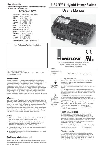
L3240VÅ L2L1FuseBreakerSeries SDSD3_-_K_ _-_ _RG1 2 3 4 5 68 9 1011ResetFuseSeries LVLVC6KW-4542500A12673849510Fuse240VÅ120VÅFuseFuseFuseCR1A1 Input A2T1 T2 T3120VÅ 2 4 6CR1Coil7L11L23L35ControlThermocoupleHigh LimitThermocoupleE-SAFE ® <strong>II</strong><strong>Hybrid</strong> <strong>Power</strong><strong>Switch</strong>ES2X-2XX0-0000DeltaConnectedHeaterT3T3NT2T14-Wire WyeConnected HeaterWyeT2T1ConnectedHeaterNeutralL3480VÅ L2L1FuseResetBreaker120VÅSeries SDSD3_-_K_ _-_ _RG1 2 3 4 5 68 9 101112345FuseFuseSeries LVLVC6KW-4542500A678910480VÅFuseFuseFuseCR1A1 Input A2T1120VÅ 2CR1Coil7L11L23T24L35T36ControlThermocoupleE-SAFE ® <strong>II</strong><strong>Hybrid</strong> <strong>Power</strong><strong>Switch</strong>ES2X-3XX0-00004-Wire WyeConnected HeaterHigh LimitThermocoupleSystem Wiring Example 240 volt, 3-phase, 3 polewith ac input controlNote:ES2X-2XX0-0000 is powered via L1, L2System Wiring Example 277/480 volt, 3-phase, 3pole with ac input control, 4-wire Wye connectedheater onlyNote:ES2X-3XX0-0000 is powered via terminal (7) and L1N120VÅ L1FuseBreakerSeries SDSD3_-_K_ _-_ _RG1 2 3 4 5 6Fuse8 9 10117CR1L11InputA1 A2T1120VÅ 2L23T24L35T36E-SAFE ® <strong>II</strong><strong>Hybrid</strong> <strong>Power</strong><strong>Switch</strong>ES21-1HV0-0000240VÅ L2L1FuseBreakerSeries SDSD3_-_K_ _-_ _RG1 2 3 4 5 6891011FuseFuse240VÅ120VÅFuseCR1Input120VÅ7L11L23L35A1 A2T1 T2 T32 4 6E-SAFE ® <strong>II</strong><strong>Hybrid</strong> <strong>Power</strong><strong>Switch</strong>ES22-2HV0-0000ResetSeries LVLVC6KW-4542500A12345678910FuseFuseCR1CoilControlThermocoupleHigh LimitThermocoupleResetSeries LVLVC6KW-4542500A12345678910FuseFuseCR1CoilControlThermocoupleHigh LimitThermocoupleSystem Wiring Example 120 volt, single-phase, 1pole with ac input controlSystem Wiring Example 240 volt, single-phase, 2pole with ac input controlç∫WARNING:Wiring must conform to National Electric Code (NEC) safety standards, as well as locally applicable codes. Failure to do so could result inpersonal injury or loss of life. See the product rating curve for wire gauge selection, ambient temperature and current restrictions.∫WARNING:Only authorized and qualified personnel should install and service the E-SAFE <strong>II</strong> <strong>Hybrid</strong> <strong>Power</strong> <strong>Switch</strong>. Failure to comply with these recommendationsmay result in damage to equipment and property and injury to personnel.Torque Guidelines:Properly torque line and load terminals to 2.25 nm (20 in-lbs).NOTE:Do not use an RC snubber on the temperature control command signal output. The leakage current througha snubber circuit can turn the E-SAFE <strong>II</strong> relay on, even when the command signal is off.SnubbersSnubbers Snubbers
U.L. Conditions of AcceptabilityApplications must be tested as described below for specificwire insulation or specific wire gauge sizes. Testsshall be performed in the end application under worstcaseoperating conditions.Test ProcedureA. Monitor the temperature of terminals, usingthermocouples between the ring terminal andconnectors L1, L2 or L3. The temperature mustnot exceed 95°C.B. Monitor the temperatures of wire insulation,using a thermocouple located 3 inches from theconnector. The temperature must not exceed theinsulation rating of the wire.ç∫WARNING: Thermocouples attached to terminals will be at loadvoltage potential, measurements need to be taken with isolatedequipment or isolate the sensor from the terminal with suitableinsulation.These ratings apply to 3-phase units with cycle times of 30 secondsor more. Consult the factory for 1- and 2-phase unit ratings.ç∫WARNING: Wiring must conform to National Electric Code (NEC)safety standards, as well as locally applicable codes. Failure to doso could result in personal injury or loss of life.See the product rating curve for wire gauge selection, ambient temperatureand current restrictions.∫WARNING: Only authorized and qualified personnel should installand service the E-SAFE <strong>II</strong> <strong>Hybrid</strong> <strong>Power</strong> <strong>Switch</strong>. Failure to complywith these recommendations may result in damage to equipmentand property and injury to personnel.ç∫WARNING: Do not use an ungrounded wye- or delta-wired heaterconfiguration at 400 or 480VÅ (ac).Failure to follow all specifications and wiring instructions may resultin property damage, personal injury and/or loss of life.çCAUTION: Provide proper enclosure ventilation to maintain an operatingenvironment less than 70°C (158°F) maximum ambient rating.Failure to do so could cause damage to equipment and property.Torque Guidelines:Properly torque line and load terminals to 2.25 nm (20in-lbs).Unit DimensionsSide6.35 mm(0.25 in)Top46.99 mm(1.85 in)23.88 mm(0.94 in)82.55 mm(3.25 in)97.03 mm(3.82 in)14.88 mm(0.586 in)48.51 mm(1.910 in)140.72 mm(5.54 in)#10-32 (7x)1/4 x 0.032male Q.D. (2x)holes and slots for fitwith #10 screws
SpecificationsOutput voltage• 100/120VÅ (ac) +10/-15 percent, 50/60Hz• 200/240VÅ (ac) +10/-15 percent, 50/60Hz• 230/277VÅ (ac) +10/-15 percent, 50/60HzOutput amperage• Up to 35 amperes single, dual and three-phase• 30 A @ 277VÅ (ac)Operating environment• 0 to 70°C (32 to 158°F) operating temperature• 0 to 90 percent RH, non-condensing• Operational life: Four million switching cycles• Installation category <strong>II</strong>I, Pollution degree 2Control mode• “No-arc” hybrid contactorInput command signal• 3 to 32VÎ (dc), 24VÅ (ac) +20/-20 percent• 100 to 240VÅ (ac) +10/-15 percent, [85 to 264VÅ (ac)]Input command signal terminals• 1⁄4 inch fast on applianceLine and load terminals• No. 10 screw will accept ring terminals, locking fork terminals or blockfork terminals, 1⁄4 in. (6.35 mm) by 10-32• Wire insulation temperature can be determined through testingdescribed in the U.L. Conditions of Acceptability.Ordering InformationE S 2 _ - _ _ _ 0 - 0 _ _ _Number of Poles1 1 pole2 2 poles controlled3 3 poles controlledLoad Voltage1 100 to 120VÅ (ac)2 200 to 240VÅ (ac)3 230/277VÅ (ac) (400/480VÅ (ac) withwye/star, neutral connected to centerrequired)Command Signal VoltageLV Low voltage 3 to 24VÎ (dc) or 24VÅ (ac)HV High voltage 100 to 240VÅ (ac) +10/-15percent, [85 to 264VÅ (ac)]Future OptionFuture OptionCustom Parameters000 Standard productMounting• Back panel mount• Horizontal or vertical mounting options with equal productperformanceNOTE:Do not use an RC snubber on the temperature controlcommand signal output. The leakage current througha snubber circuit can turn the E-SAFE <strong>II</strong> relay on, evenwhen the command signal is off.SnubbersDeclaration of ConformitySeries Esafe <strong>II</strong> Relay<strong>Watlow</strong> Winona, Inc.1241 Bundy Blvd.Winona, MN 55987 USADeclares that the following product:Designation:Model Numbers:Classification:Rated Voltage and Frequency:Rated <strong>Power</strong> Consumption:Series Esafe <strong>II</strong> RelayES2 (1, 2 or 3) – (1, 2 or 3)(LV or HV)0 – 0 (any three letters or numbers)AC51 Semiconductor Direct-on-line contactor,Installation Category <strong>II</strong>I, Pollution degree 2, IP00100-120 Vac, 200-240 Vac, 230-277 Vac**Star or Wye with Center connected Neutral required.35A Resistive Load MaximumMeets the essential requirements of the following European Union Directives by using the relevant standards showbelow to indicate compliance.EN 60947-4-1EN 60947-4-32004/108/EC Electromagnetic Compatibility Directive2004 CRGD, Low-Voltage switchgear and controlgear Part 4-3: Contactors and2000 2005 motor-starters AC semiconductor controllers and contactors fornon-motor loads. Class B EmissionsEN 61000-4-2 1996 A2, 2001 Electrostatic Discharge ImmunityEN 61000-4-3 2002 Radiated Field ImmunityEN 61000-4-4 2004 Electrical Fast-Transient / Burst ImmunityEN 61000-4-5 1995 A2, 2001 Surge ImmunityEN 61000-4-6 1996 A3, 2005 Conducted ImmunityEN 61000-4-8 1994 A1, 2001 Magnetic Field ImmunityEN 61000-4-11 2004 Voltage Dips, Short Interruptions and Voltage Variations ImmunityIEC 61000-3-12 2004 Harmonic Current Emissions > 16A < 75AIEC 61000-3-11 2 2000 Voltage Fluctuations and Flicker > 16A < 75A2 NOTE 1: To comply with flicker requirements cycle time may need to be greater than 12 seconds if Load<strong>Power</strong> is = 16A to comply with standard, or the maximum source impedance needs to be determined. Sourceimpedance shall meet EN 61000-3-11 requirements for load currents > 16A.EN 60947-1EN 60947-4-320042000CRGD,20052006-95-EC Low-Voltage DirectiveLow-Voltage switchgear and controlgear Part 4-3: Contactors andmotor-starters AC semiconductor controllers and contactors fornon-motor loads.Compliant with 2002/95/EC RoHS Directive2002/96/EC WEEE DirectiveEquipment Requires RecyclingRaymond D. Feller <strong>II</strong>IName of Authorized RepresentativeWinona, Minnesota, USAPlace of IssueGeneral Manager February 2008Title of Authorized RepresentativeDate of IssueSignature of Authorized Representative