Time/Temperature Control Series 733/734 - Watlow
Time/Temperature Control Series 733/734 - Watlow
Time/Temperature Control Series 733/734 - Watlow

Create successful ePaper yourself
Turn your PDF publications into a flip-book with our unique Google optimized e-Paper software.
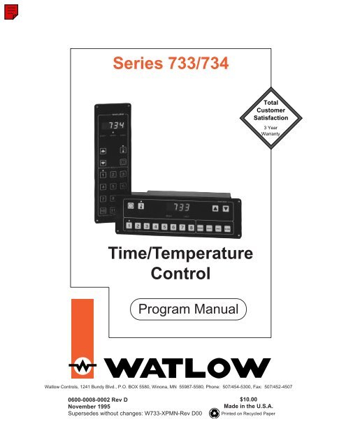
<strong>Series</strong> <strong>733</strong>/<strong>734</strong>TotalCustomerSatisfaction3 YearWarranty<strong>Time</strong>/<strong>Temperature</strong><strong>Control</strong>Program Manual<strong>Watlow</strong> <strong>Control</strong>s, 1241 Bundy Blvd., P.O. BOX 5580, Winona, MN 55987-5580, Phone: 507/454-5300, Fax: 507/452-45070600-0008-0002 Rev DNovember 1995Supersedes without changes: W<strong>733</strong>-XPMN-Rev D00$10.00Made in the U.S.A.Printed on Recycled Paper
Chapter 1Starting Out<strong>Series</strong> <strong>734</strong>WATL WStarting Out With The <strong>Watlow</strong> <strong>Series</strong> <strong>733</strong>/<strong>734</strong>,A Menu Driven <strong>Time</strong>/<strong>Temperature</strong> <strong>Control</strong>EVENT READY LOAD 1MENUS123456Single or Dual (custom units only) Input -Type J, K or E thermocouple, RTD orProcessDual EventInputDual Output -PID or ON/OFF710SERIES <strong>734</strong>Output 2 -Heat,Auto-tune811912Output 1 -Heat,Auto-tuneSingleAlarmFour Event OutputsGeneral DescriptionRS-422A, RS-423A (RS-232Ccompatible), or EIA-485Optional Computer InterfaceThe <strong>Watlow</strong> <strong>Series</strong> <strong>733</strong>/<strong>734</strong> is a microprocessor-based, menu driven time/temperature control. <strong>Control</strong> orientation is available in horizontal or verticalversions with single or dual zones. The <strong>Series</strong> <strong>733</strong>/<strong>734</strong> has single or dual inputand single or dual control outputs. Optional event input/output, alarms andcommunications are also available. The <strong>733</strong>/<strong>734</strong> offers a wide range of inputsand outputs. The <strong>733</strong>/<strong>734</strong> is a smart control which is easy to program and hasoperator friendly prompts. Auto-tune is also available with PID parameters.Standard features may include control melt cycle, WatCurve temperaturecompensation, calibration offset, a menu selection of time and temperature, andfield changeable menus. In addition, <strong>Watlow</strong> offers customization services tomeet special customer needs.Figure 1 -<strong>Series</strong> <strong>733</strong>/<strong>734</strong> Inputand Output Overview.<strong>Watlow</strong> <strong>Control</strong>s provides an industry leading 3 year warranty on the <strong>Series</strong><strong>733</strong>/<strong>734</strong>. The <strong>Series</strong> <strong>733</strong>/<strong>734</strong> has electrical noise immunity which meets orexceeds major restaurant chain specificatons. An additional feature is the highambient rating of 176°F/80°C.Operator-friendly features include automatic LED indicators to aid in monitoringand setup. The <strong>Watlow</strong> <strong>Series</strong> <strong>733</strong>/<strong>734</strong> automatically stores all information in anon-volatile memory.Starting Out, Chapter 1WATLOW <strong>Series</strong> <strong>733</strong>/<strong>734</strong> Program Manual3
WATL WKeys & DisplaysSERIES <strong>733</strong>EVENT READY LOAD 1MENUS1 2 3 4 5 6 7 8 9 10 11 12Chapter 2 Keys & DisplaysWATL WEVENT READY LOAD 114710SERIES <strong>734</strong>MENUS2581136912ZONE 1 ZONE 2EVENT READY LOAD 1ZONE LED'sOn a single zone control:• Neither LED is displayed.On a dual zone control:• The LED is lit when the correspondingzone is active. The LED flashes whenviewing or programming data in the Programmode.Diagnostic LED'sEvent• Lit when an event is ON.Ready• Lit when the process temperature ofeach zone is within the guard band andno program is running.Load 1• Lit when Load 1 is energized.<strong>Time</strong>With the <strong>Time</strong> key you can:• View time;• Scroll 12 menus in the Program mode;• Exit the Program mode;• In the Review mode, it scrollsprogrammed menu parameters;• Activates the Monitor mode;• In the Monitor mode, it scrolls currentdata.<strong>Temperature</strong>With the <strong>Temperature</strong> key you can:• View temperature;• Activate the Review mode;• Snooze alarm or error codes, and theauto-tune display for 30 seconds. Formore information see Pages 19 - 23 ofthe <strong>Series</strong> <strong>733</strong>/<strong>734</strong> Service Manual;• Energizes the alarm output if alarm silenceis active.Up and DownWith the Up/Down keys you can:• Activate the Program mode;• Scroll up and down through theparameter data.Digital Display [0)º0]Displays the countdown time, target menutemperature, menu parameters and securitylockout codes. Consists of four red,seven segment LEDs.147102581136912Menu KeysWith the Menu keys you can:• Select a menu;• Start and stop a menu;• Silence the audible alarm;• In the Program mode, you can scrollthrough the programmed data;• Return to the Operation mode from theMonitor or Review mode.4 WATLOW <strong>Series</strong> <strong>733</strong>/<strong>734</strong> Program Manual Keys & Displays, Chapter 2
ProgramChapter 3 The Program ModeEntering the Program ModeThe Program mode configures the <strong>Series</strong> <strong>733</strong>/<strong>734</strong> menus.Press the UP/DOWN keys simultaneously for 5 seconds. Both LED'sabove these keys are lit while in the Program mode. If there are no keyactivations within 1 minute, the control automatically exits the Program mode.Press the appropriate menu key to program.The display shows the SP1 (Step 1 set point) parameter [SP`1], while theMenu LED is lit, and Zone LED (if applicable) is flashing.The SP1 parameter alternately flashes with its current menu status. Use theUP/DOWN keys to select the desired value for the parameter. Pressthe menu key to advance to the next parameter.You can reach the Program mode only from the Operation mode. If you arerunning a menu, the unit quits running and beeps for 15 seconds, alerting youthe program stopped. Not all parameters are visible in this menu, depending onthe control configuration and model number.= Parameter may not appear dependingon control configuration andmodel number.Figure 2 -The Program ModeSERIES <strong>733</strong>EVENT READY LOAD 1MENUSWATL W1 2 3 4 5 6 7 8 9 10 11 12˜NOTE:A dash "_", representsa menu stepnumber. This canbe a 1, 2, or 3.Press any menu key212SP _SP _t _E _EcAcLOC( )( )( )( )( )( )( )Zone 1 set point, Step 1, 2 orZone 2 set point, Step 1, 2 or<strong>Time</strong>EventsError clearAlarm clearUser lock out˜NOTE:On dual zone units,pay close attentionto the LED's on the<strong>733</strong>/<strong>734</strong>. The SP _parameter isdisplayed twice, butrefers to Zone 1 orZone 2 dependingon which LED isflashing.00 : 00Operation MenuProgramming, Chapter 3WATLOW <strong>Series</strong> <strong>733</strong>/<strong>734</strong> Program Manual5
ProgramTo Advance To The Next Menu• Press the TIME (clock) key .The unit scrolls to the next menu and the corresponding menu LED is lit.After menu 12, the unit exits the Program mode.142536Entering A Specific MenuOR710811912Press the appropriate menu key and the program is displayed. Continuepressing the same menu key to advance to the next parameter in that menu.For more information, see the following for the parameter listings.Select Or Change Program Data Within A MenuUse the UP/DOWN keys .Exiting The Program Mode• Press the last menu key (12) 12 .• Press the TIME keySelect either:. The display goes to the LOC parameter.0 All parameters can be changed.1 Menu parameters can only be viewed, not changed.• Press the TIME key again. You are back to the Operation mode [0)º0].Clearing Alarm or Error Codes• Press the last menu key (12) 12 .• Press the <strong>Time</strong> key. The display goes to the Ec or Ac parameter.• Press the <strong>Temperature</strong> key to clear the error or alarm.An error or alarm can only be cleared if the condition has been corrected.6 WATLOW <strong>Series</strong> <strong>733</strong>/<strong>734</strong> Program Manual Programming, Chapter 3
Program(S P _ ) Zone 1 <strong>Temperature</strong> Set Point: Press any menu key and theS P _ parameter is displayed and alternately flashes with the current set pointfor Zone 1. On dual zone units, pay close attention to the LED's on the<strong>733</strong>/<strong>734</strong>. The SP _ parameter is displayed twice, but refers to Zone 1 orZone 2 depending on which LED is flashing. The appropriate menu LED isalso lit. Range: Range low to range high Default: 75°F/24°CDisplay alternatesbetween parameterand programmed data.SP _325(S P _ ) Zone 2 <strong>Temperature</strong> Set Point: Press the same menu key and theS P _ parameter is displayed and alternately flashes with the current set pointfor Zone 2. On dual zone units, pay close attention to the LED's on the<strong>733</strong>/<strong>734</strong>. The SP _ parameter is displayed twice, but refers to Zone 1 orZone 2 depending on which LED is flashing. The appropriate menu LED isalso lit. This parameter only appears if you have a dual zone unit.Range: Range low to range highDefault: 75°F/24°C/0 unitsSP _350<strong>Time</strong> (t _ ): Press the same menu key and the t _ parameter is displayedand alternately flashes with the current program menu time. The appropriatemenu LED is lit. Expressed in either hours/minutes, or minutes/seconds.Range: 0 to 23:59 OR 0 to 59:59 Default: 0t_02:45Events (E _ ): Press the same menu key and the E _ parameter is displayedand alternately flashes with the event status.E _This parameter determines the binary state of the Event Outputs. This parameteronly appears if your unit has events. See the inside back cover for themodel number breakdown. Each step in a menu can have up to 4 events.Press the UP or DOWN key to cycle through the binary options until you reachthe appropriate combination. Events 1 through 4 are read from right to left.1 = ON 0 = OFF Range: 0000 = All OFF to 1111 = All ON Default: 04321Example: If you want Events 1 & 2 ON, and Events 3 & 4 OFF, press the UPor DOWN key to cycle through the binary options until you reach 0011. Rememberthat 1 = ON and 0 = OFF.Press the menu key to advance to the next step. To exit the Program mode,press and the <strong>Time</strong> key 12 .Error Clear: This parameter only appears if errors exist. Pressing the temperaturekey clears any system errors appearing in the display. The displaystops alternating, and the alarm output is enabled.Alarm Clear: This parameter only appears if alarms exist, and your unit isconfigured for alarms. Pressing the temperature key clears any alarm conditionsif the condition is corrected. The display stops alternating the alarmmessage, and the alarm output is enabled.Lock: Selects the level of operator lockout.LOC 0: All menu parameters may be viewed or changed.EcAcLOCLOC 1: All menu parameters may be viewed, but none can be changed.Range: 0 - 1 Default: 01Programming, Chapter 3WATLOW <strong>Series</strong> <strong>733</strong>/<strong>734</strong> Program Manual7
Program ChartTable 1 -Program ModeMaster Step ChartMenu # Step # Zone 1 Zone 2 <strong>Time</strong> EventSet Point Set Point HR:MN or MN:SEC°F/°C°F/°C1 :1 2 :3 :1 :2 2 :3 :1 :3 2 :3 :1 :4 2 :3 :1 :5 2 :3 :1 :6 2 :3 :1 :7 2 :3 :1 :8 2 :3 :1 :9 2 :3 :1 :10 2 :3 :1 :11 2 :3 :1 :12 2 :3 :8 WATLOW <strong>Series</strong> <strong>733</strong>/<strong>734</strong> Program Manual Programming, Chapter 3
Chapter 4 The Operation ModeOperationFrom the Operation mode, you can start a menu by pressing the appropriatenumber (menu) key, provided you are within the guard band (READY LED lit).Refer to the Seires <strong>733</strong>/<strong>734</strong> Service Manual for more information on the guardband. You can also view the process time and temperature of the last menu used.Menu 1, Step 1 is the default. Once a menu is initiated, the time remaining is alsovisible here.From the Operation mode, you can also enter the Monitor or Review mode. Formore information, see the following page.= Parameter may not appear dependingon control configuration andmodel number.EVENT READY LOAD 1MENUSWATL WFigure 3 -The Operation Mode1 2 3 4 5 6 7 8 9 10 11 12SERIES <strong>733</strong>( ) : ( )( )( )<strong>Time</strong> remainingZone 1 actual processZone 2 actual process00 : 00Operation Parameters<strong>Time</strong> Remaining: Represents the running time left in the selected menu. Displayedin hours/minutes OR minutes/seconds. This is the total menu time.Zone 1 Actual Process <strong>Temperature</strong>: Press the <strong>Temperature</strong> key once todisplay the current value of the process variable for Zone 1. The appropriate zoneLED will be lit if you have a dual zone control. Displayed in °F or °C.Zone 2 Actual Process <strong>Temperature</strong> Press the <strong>Temperature</strong> key again andthe current value of the process variable for Zone 2. The appropriate zone LED willbe lit if you have a dual zone control. This parameter only appears if your unit isdual-zone. Displayed in °F, °C, or units.( ) : ( )( )( )Operation, Chapter 4 WATLOW <strong>Series</strong> <strong>733</strong>/<strong>734</strong> Program Manual 9
OperationRunning a MenuPress the appropriate menu key 6 , that menu is activated. The LED's above the<strong>Time</strong> key and menu key are lit. The time programmed for each step in the menu isadded together and begins counting down. Once the combined menu time iscomplete, the audible alarm sounds and the menu LED flashes. Press the menukey again to stop the audible alarm. If not, the alarm will sound for 15 seconds.Before a menu can be started, menu time must be programmed.Viewing <strong>Temperature</strong> While Running a Menu• To view a menu's process temperature while executing a program, press thetemperature key .• The display shows the temperature for Zone 1 [``80].• Press the <strong>Temperature</strong> keydisplayed.again and the Zone 2 process temperature is• Press the <strong>Time</strong> keyto return to your menu countdown time.Stopping a Menu• To stop a running menu, press the active menu key.• The display reverts back to [0)º0].• The <strong>733</strong>/<strong>734</strong> now controls at the temperature [``80].Entering The Review Mode• Press the <strong>Temperature</strong> key for 5 seconds. You are in the Review mode.When a menu is running, you will not effect the menus program status.• The [nEnU] prompt is displayed. Press the menu to review.• Press the <strong>Time</strong> key to cycle through the selected menu.• To exit the Review mode, press any menu key. The control reverts to the lastactive menu and/or step. To review more than one menu, exit the Review modeand re-enter.• After 1 minute with no key activations, the unit reverts to the Operation mode.10 WATLOW <strong>Series</strong> <strong>733</strong>/<strong>734</strong> Program ManualOperation, Chapter 4
OperationEntering the Monitor ModeThe Monitor Mode displays the current set point(s), time, and events of an activemenu without interrupting the menu operation. If no menu is active, it displaysinfromation from the last menu step which was running, or defaults toMenu 1, Step 1.• Press the<strong>Time</strong> key for 5 seconds.• The display reads the current step [StP_].• Press the <strong>Time</strong> key, the display reads Zone 1's current set point [`325].• The <strong>Temperature</strong> key LED is lit. The Zone 1 LED is also lit if you havea dual zone control.• Press the <strong>Time</strong> key to advance to the next parameter. If you have adual zone unit, the Zone 2 LED is lit and the display reads the current setpoint [`350].• Press the <strong>Time</strong> key and the current step time is displayed [1!º6].• Press the <strong>Time</strong> key again and the event status is displayed [1010].• You can enter the Monitor mode whenever you are running a menu.• To exit the Monitor mode, press any key.Operation, Chapter 4 WATLOW <strong>Series</strong> <strong>733</strong>/<strong>734</strong> Program Manual 11
AlarmsChapter 5 Alarm & Error CodesUsing AlarmsThe <strong>Series</strong> <strong>733</strong>/<strong>734</strong> has two alarm types, Process or Deviation. A Process alarmsets an absolute temperature. When the process exceeds that absolute temperaturelimit an alarm occurs. The Process alarm set points may be independently sethigh and low.A Deviation alarm alerts the operator when the process strays too far from setpoint. The operator can enter independent high and low alarm settings. The setpoint is the reference for the deviation alarm. Any change in set point causes acorresponding shift in the deviation alarm. Example: If your set point is 100°F,and a deviation alarm set at +7°F as the high limit, and -5°F as the low limit, thehigh alarm trips at 107°F, and the low alarm at 95°F. If you change the set point to130°F, the alarms follow the set point and trip at 137°F and 125°F.˜NOTE:A dash "_" can beeither a 1 or 2 whichrepresents Zone 1or Zone 2 respectively.˜NOTE:An alarm displaywill be masked byan error conditionor when the controlis in the Setup,Service or Calibrationmenus.Both process and deviation alarms can be latching or non-latching. When thealarm condition is removed a non-latching alarm automatically clears the alarmoutput. You must manually clear a latching alarm. See below.Flashing "LO _" or "HI _" in the display indicates an alarm. The display alternatelyshows information from the current parameter and the "LO _" or "HI _" alarmmessage at one second intervals. If an alarm condition exists, the alarm output isde-energized. An alarm condition does not effect the control output.To clear an alarm…• First correct the alarm condition, then…• If the alarm is latching…Clear it manually as soon as the process temperature is inside the alarm band(below A_HI and above A_LO).Enter the Program mode by pressing the keys simultaneously for 3seconds.Press the Menu 12 12 key once. Next, press the <strong>Time</strong> key . The Ac (AlarmClear) prompt is displayed. Press the <strong>Temperature</strong> key and the alarm iscleared. Pressing the <strong>Time</strong> key twice, takes you back to the Operationmode [0)º0].• If the alarm is non-latching…The alarm clears itself automatically as soon as the process temperature is 3°Finside the fixed alarm limit.Alarm Silencing is available with either the process or deviation alarm in latchingand non-latching mode. On initial power up, alarm silencing disables the alarmmessage and the alarm output relay. Once the process value crosses into the"safe" region, the latching or non-latching alarm is enabled. Any future deviationoutside this safe band triggers an alarm message and the alarm output relay deenergizes.On dual zone controls, both process values must cross into the saferegion before either the latching or non-latching alarm is enabled.12 WATLOW <strong>Series</strong> <strong>733</strong>/<strong>734</strong> Program ManualAlarms & Error Codes, Chapter 5
To mask an alarm …• When the SIL parameter is ON…• Press the <strong>Temperature</strong> key . This masks or "snoozes" the alarm messagefor 30 seconds, and energizes the alarm output relay.Error Codes• When the SIL parameter is OFF…• Press the <strong>Temperature</strong> key . This masks or "snoozes" the alarm messagefor 30 seconds, but does not energize the alarm relay.Error Code MessagesThe error code is visible in the display and alternates with the current display at a3 second rate. The list below outlines the standard error codes associated withthe <strong>Series</strong> <strong>733</strong>/<strong>734</strong>. They are designed to isolate specific problem areas and aidin troubleshooting your control. If the problem persists, consult the factory.ProblemEr01 -ROM (Read OnlyMemory) checksum errorEr02 -RAM (Random AccessMemory) checksum errorProbable CauseInternal ROM isdefective.Internal RAM is defective.Solution• Cycle power• Cycle powerçWARNING:Electrical noise or anoise event, excessenvironmentalmoisture or temperature,or vibrationmay cause<strong>Series</strong> <strong>733</strong>/<strong>734</strong>errors to occur. Ifthe cause of anerror is not otherwiseapparent,check for these.Er03 -Ambient sensor errorAmbient temperature isbelow 32°F/0°CFactory calibrationparameters have beenaltered.• Check ambient temperatureat the control.• Restore factorycalibration parameters.See Calibration section.Table 2 -Error CodeTroubleshootingEr04 -Configuration errorDefective microprocessor• Cycle powerEr05 -EEprom errorPower loss while storingdata.• Cycle powerEr06 -Zone 1 A/D (Analog toDigital Converter) UnderflowerrorEr07 -Zone 1 A/D overflow errorEr08 -Zone 2 A/D (Analog toDigital Converter) Underflowerror• Incorrect sensor type• Measuring temperatureoutside the sensorrange• Reversed sensor leadsOpen sensor• Incorrect sensor type• Measuring temperatureoutside the sensorrange• Check the InP1 parameter.Verify itmatches your sensor.• Check the InP1 parameter.Verify itmatches your sensor.• Check the InP2 parameter.Verify itmatches your sensor.˜NOTE:For Er06 throughEr09, always checkthe sensor andconnections for areversed or opensensor beforetrying the solutionlisted.Er09 -Zone 2 A/D overflow errorOpen sensor• Check the InP2 parameter.Verify itmatches your sensor.Alarms & Error Codes, Chapter 5 WATLOW <strong>Series</strong> <strong>733</strong>/<strong>734</strong> Program Manual 13
Error CodesProblem Probable Cause SolutionEr10 -Stack overflow errorMicroprocessor error• Cycle powerTable 2 -ContinuedEr11 -Zone 1 open sensor errorOpen sensor• Check the InP1 parameter.Verify itmatches your sensor.˜NOTE:For Er10 throughEr14, first checkthe sensor andconnections for areversed or opensensor beforetrying the solutionlisted.˜NOTE:Er06 through Er09,and Er11 throughEr14 are selfclearing errors ifthe condition thatcaused the alarmhas been takencare of.Er12 -Zone 1 shorted sensorEr13 -Zone 2 Open sensorEr14 -Zone 2 shorted sensorEr15 -Zone 1 loop error• Incorrect sensor type• Measuring temperatureoutside the sensorrangeOpen sensor• Incorrect sensor type• Measuring temperatureoutside the sensorrange• Reversed sensor leads• Faulty heater or gasvalve• Shorted sensor• Faulty output switchingdevice• Blown fuse to heater• Incorrect Pb1 valuefor thermal system• Check the InP1 parameter.Verify itmatches your sensor.• Check the InP2 parameter.Verify itmatches your sensor.• Check the InP2 parameter.Verify itmatches your sensor.• Check heater or gasvalve• Check sensor• Check output switchingdevice• Check fuse to heater• Auto-tune the controlEr16 -Zone 2 loop errorError Code ActionsSee Er15 ProbableCause above.• Incorrect Pb2 value forthermal systemSee Er15 Solution above.• Auto-tune the control• Error codes will result in these conditons:• The alarm outputs are in their alarm state (de-energized).• The display alternately flashes the process value and error code.• All keys are inactive except for the <strong>Temperature</strong> key . This key snoozes theerror code and display for 30 seconds.• The above conditions occur regardless of the LOC value, or the presence of theSetup, Service or Calibration Menus.• To clear a corrected error…• Cycle power to the control. OR• Enter the Program mode by pressing the keys simultaneously for3 seconds.• Press the Menu 12 key 12 once.• Press the <strong>Time</strong> key . The EC (Error Clear) prompt is displayed.• Press the <strong>Temperature</strong> key , and the error is cleared. Press the <strong>Time</strong> keytwice, and you're back to the Operation mode [0)º0].14 WATLOW <strong>Series</strong> <strong>733</strong>/<strong>734</strong> Program ManualAlarms & Error Codes, Chapter 5
IndexA, BActual <strong>Temperature</strong>, 9Advancing to the Next Menu, 6Alarm Clear, 5 - 7Alarm, Masking, 4, 13Ac Parameter, 7CChanging Data, 6DDiagnostic LED's, 4Displays, Digital, 4Down key, 4EE _, 7Ec Parameter, 7Entering,a Menu, 6the Monitor Mode, 6Event,LED, 4Parameter, 7Exit the Program Mode, 6Error Clear, 5 - 7Events, 7F, GGeneral Description, 3Guard Band, 4KKeys, 4LLED's, 4LOAD 1 LED, 4LOC parameter, 7MMenu Keys, 4Monitor Mode, 4, 11Masking Alarms, 4, 13Model Number, 19NnEnU prompt, 10OOrdering Information, 19Overview, 3OperationMode, 9Parameters, 9PProgram,Chart, 8Mode, 5,6Parameters, 7Process <strong>Temperature</strong>, 9Q, RREADY LED, 4Review Mode, 10Running a Menu, 10SSnooze, 4, 13SP_ parameter, 5, 7Scrolling Menus, 6Selecting Data, 6Specifications, 18Stopping a Menu, 10Tt _, 7<strong>Time</strong> Remaining, 9<strong>Time</strong> Key, 4, 6, 9<strong>Temperature</strong> Key, 4<strong>Time</strong> Parameter, 7UUp Key, 4V, W, X, YViewing <strong>Temperature</strong>, 10Viewing Program Status, 10ZZone 1, 4, 7, 9Zone 2, 4, 7, 9Zone LED's, 4Appendix WATLOW <strong>Series</strong> <strong>733</strong>/<strong>734</strong> Program Manual 15
Notes16 WATLOW <strong>Series</strong> <strong>733</strong>/<strong>734</strong> Program Manual Appendix
Declaration of ConformityDeclares that the following product:WATLOW CONTROLS124 1 Bundy BoulevardWinona, Minnesota 55987USADesignation:Model Number:Classification:Rated Voltage:Rated Current:Rated Frequency:Maximum Power Input:<strong>Series</strong> <strong>733</strong> I<strong>734</strong><strong>733</strong>A-4BB l-AAAGElectronic Incorporated Class III temperature controller,Type 2C action, for use in light industrial environment24V- (VAC)0.25OA50/60 Hz15 WattsMeets the essential requirements of the following European Union Directive(s) using therelevant section(s) of the normalized standards and related documents shown:89/336ZEEC Electromagnetic Compatibility DirectiveEN 50082-1:1992 EMC Generic immunity standard, Part I: Residential, commercial, and light industryIEC 801-3: 1984 Radiated immunityIEC 801-5: 1991 Surge immunityEN 50082-2:1995 EMC Generic immunity standard, Part 2: Industrial environmentEN 6 1000-4-2: 1995 Electrostatic dischargeEN 6 1000-4-4: 1995 Electrical fast transientsENV 50141: 1993 Conducted immunityEN 50081-2:1994 EMC Generic emission standard, Part 2: Industrial environmentEN 55011: 1991 Limits and methods of measurement of radio disturbance characteristicsof industrial, scientitic and medical radio-frequency equipment (Class B)73/23/EEC Low- Voltage DirectiveEN 60730-1:1993 Automatic electrical controls for household and similar use, Part 1: General requirementsWinona. Minnd. USAPlace of IssueOctober 26. 1995Date of IssueNkIName of Authorized RepresentativeASS_Title of Authorized RepresentativeW73X-ECEN-0000 Rev A00of Authorized RepresentativeAppendix WATLOW <strong>Series</strong> <strong>733</strong>/<strong>734</strong> Program Manual 17
Specifications<strong>Control</strong> Mode• Single or dual input, single or dual output, single alarm.• EIA/TIA-422A, EIA/TIA-423A, or EIA/TIA-485 datacommunications.• ON/OFF: Determined by the HYSX parameter forOutputs 1 and 2.• PID Parameters:• Proportional band: 0 to 999°F/0 to 555°C/0 to 999units.• Reset: 0.00 to 9.99 repeats per minute.• Rate: 0.00 to 9.99 minutes.• Cycle time: 1 to 60 seconds.Operator Interface• Membrane front panel.• Single, four-digit 0.56" (14 mm) LED displays.• TIME, TEMPERATURE, UP/DOWN & 1-12 menukeys.Input• Thermocouple, RTD and electrical process input.• Automatic cold junction compensation for thermocouple.• RTD input, 2- or 3-wire, platinum, 100 @ 0°C, solfwareselectable: JIS curve #3916 (0.003916 / °C) or DINcurve #3850 (0.003850 / /°C).• Sensor break protection de-energizes control outputs toprotect system.• Grounded or ungrounded sensors. (Dual input requiresat least one ungrounded t/c. See Chapter 1 of the<strong>Series</strong> <strong>733</strong>/<strong>734</strong> Service Manual.)• °F, °C or process variable units are user selectable.• Operating ranges user selectable.J t/c: 32 to 1382°F or 0 to 750°CK t/c: 32 to 2282°F or 0 to 1250°CE t/c: 32 to 1220°F or 0 to 660°CRTD: 32 to 1112°F or 0 to 600°CProcess: -500 to 3500 unitsPrimary Output (Zone 1)• Solid-state Relay, Form A, 0.4A @ 120/208/240VÅ(VAC), 30VA pilot duty @ 120/208/240VÅ (VAC), optoisolated,zero-cross switching. Off state impedance is20K minimum with contact suppression, 31M withoutcontact suppression.• Electromechanical Relay, Form A, 1A @ 24/120/208/240VÅ (VAC), 1/8 hp. @ 120/240VÅ (VAC), 125VA pilotduty @ 24/120/208/240VÅ (VAC). Off state impedance is20K minimum. 200m contact resistance, maximum.• Switched DC, 500 minimum load resistance, 1K load,9mA minimum, 22mA maximum, non-isolated.• 0-20mA/4-20mA reverse or direct into a 600 maximumload impedance, non-isolated.• 0-5VÎ (VDC)/0-10VÎ (VDC) reverse or direct into a10K minimum load impedance, non-isolated.Secondary Output (Zone 2)• Solid-state Relay, Form A, 0.4A @ 120/208/240VÅ(VAC), 30VA pilot duty @ 120/208/240VÅ (VAC),opto-isolated, zero-cross switching. Off state impedanceis 20K minimum with contact suppression,31M without contact suppression.• Electromechanical Relay, Form A, 1A @ 24/120/208/240VÅ (VAC), 1/8 hp. @ 120/240VÅ (VAC), 125VApilot duty @ 24/120/208/240VÅ (VAC). Off stateimpedance is 20K minimum. 200m contactresistance, maximum.• Switched DC, 500 minimum load resistance, 1Kload, 9mA minimum, 22mA maximum, non-isolated.• 0-20mA/4-20mA reverse or direct into a 600 maximumload impedance, non-isolated.• 0-5VÎ (VDC)/0-10VÎ (VDC) reverse or direct into a10K minimum load impedance, non-isolated.Alarms• Electromechanical Relay, Form A, 1A @ 24/120/208/240VÅ (VAC), 1/8 hp. @ 120/240VÅ (VAC), 125VApilot duty @ 24/120/208/240VÅ (VAC). Off stateimpedance is 20K minimum. 200m contact resistance,maximum.• Latching or non-latching.• Process or deviation.• Separate high and low values.• Alarm silencing (inhibit) on power up for alarm.Event Outputs• Switched DC, non-isolated, 5VÎ (VDC), 5mA maximum.Accuracy• Calibration Accuracy & Sensor Conformity: ± 0.1% ofspan, ± 1LSD, 77°F ± 5°F(25°C ±3°C) minimum.• Accuracy Span: Normally 1000° minimum span.• <strong>Temperature</strong> Stability: < 0.2°F/°F (0.2°C/°C) changein ambient.• Voltage Stability: ± 0.01% of span / % of rated linevoltage.Communications• Serial data communications.• EIA/TIA-422A or EIA/TIA-423A (EIA/TIA-232Ccompatible) or EIA/TIA-485.• ANSI X3.28 protocol, or XON/XOFF protocol.• Isolated.Agency Approvals• UL® 873, File #E43684.• CSA Certified, File #LR30586, C22.2.• Select models CE approved. Consult factory for details.Electronic Incorporated Class III <strong>Control</strong>, Type 2 action.Connectors• Compression type screw terminals and universalMate-n-Lok.Power• 24VÅ (VAC) +10%, - 15%.• 50 to 60 Hz ± 3%.• Consumption 6 - 10VA.• For CE-approved models, input power limited to 15watts maximum. All components are rated for amaximum of 15 watts.Operating Environment• 32 to 176°F/0 to 80°C.• 0 to 90% RH, non-condensing.Dimensions<strong>733</strong>A-xxxx-xxxx (horizontal) models:• Height: 3.28" 83 mm• Width: 10.66" 271 mm• Depth: 2.00" 51 mm<strong>734</strong>A-xxxx-xxxx (vertical) models:• Height: 10.66" 271 mm• Width: 3.28" 83 mm• Depth: 2.00" 51 mmSpecific18 WATLOW <strong>Series</strong> <strong>733</strong>/<strong>734</strong> Program Manual Appendix
<strong>733</strong>/<strong>734</strong> = One or two channel microprocessor-based, time andtemperature control; 24VÅ (VAC) power input.*Order power supply and connector kit(s) separately below.Model Number7 3 _ A - _ _ _ _ - _ _ A ADisplay Orientation3 = Horizontal4 = VerticalDisplay LocationA = Integral (local)Input Type1 = Single thermocouple (type J, K E)2 = Single RTD 1°, curve selectable4 = Dual thermocouple (type J, K, E); Order output types 1 & 25 = Dual RTD 1°, curve selectable; Order output types 1 & 26 = Dual Input: Channel 1 thermocouple (type J, K, E); and Channel 2process (0-5VÎ (VDC), 0-10VÎ (VDC), 0-20mA, 4-20mA), Order output types 1 & 2Dual-zone units must use ungrounded thermocouples.Output 1 TypeB = Solid-state relay with RC suppression, form A, 0.4AC = Switched DC, open collector, non-isolatedD = Mechanical relay, form A, 1A, with suppressionE = Mechanical relay, form A, 1A, without suppressionF = Process, 4-20mA, non-isolatedH = Process, 0-5VÎ (VDC), non-isolatedK = Solid-state relay without RC suppression, form A, 0.4AOutput 2 TypeA = NoneB = Solid-state relay with RC suppression, form A, 0.4AC = Switched DC, open collector, non-isolatedD = Mechanical relay, form A, 1A, with suppressionE = Mechanical relay, form A, 1A, without suppressionF = Process, 4-20mA, non-isolatedH = Process, 0-5VÎ (VDC), non-isolatedK = Solid-state relay without RC suppression, form A, 0.4AEvent Inputs/Outputs0 = None1 = 4 Event outputs, switched DC, non-isolated (custom only)AlarmA = NoneD = Single mechanical relay, form A, 1A, with suppressionCommunications (Isolated)A = NoneB = EIA/TIA-422 or EIA/TIA-423D = EIA/TIA-485OptionsAA = Standard Single DisplayPower Supply, Power Connector and Event Input/Output Accessory Kits (Order separately here.)Part No.DescriptionA001-0249-0001 = 120VÅ (VAC) - 24VÅ (VAC), stepdown transformer, Class 2, quick connect terminals included.A001-0249-0002 = 208/240VÅ (VAC) - 24VÅ (VAC), stepdown transformer, Class 2, quick connect terminals included.A001-0250-0012 = Power input connector kit, 12-pin connector assembly, wire not included.A001-0250-0009 = Event input/output connector kit, 9-pin connector assembly, wire not included.Appendix WATLOW <strong>Series</strong> <strong>733</strong>/<strong>734</strong> Program Manual 19
<strong>Watlow</strong> <strong>Series</strong> <strong>733</strong>/<strong>734</strong> User's Manual<strong>Watlow</strong> <strong>Control</strong>s, 1241 Bundy Blvd., P.O. Box 5580, Winona, MN 55987-5580, 507/454-5300, Fax: 507/452-450720 WATLOW <strong>Series</strong> <strong>733</strong>/<strong>734</strong> Program Manual Appendix