download 13.8 MB pdf
download 13.8 MB pdf
download 13.8 MB pdf

You also want an ePaper? Increase the reach of your titles
YUMPU automatically turns print PDFs into web optimized ePapers that Google loves.
SECTION 9 OF 10NAVSHI PS 94200.1Dl RECTORYCOMMUNICATIONEQUI PMENT(CONTI NUED)PREPARED BYU.S. NAVYELECTRON IGS SUPPLY OFFICEGREAT LAKES, ILLINOIS
UNCLASSIFIEOApril 1958RADIO SET AND RADIO RELAY SETRadio-TransceiversAN/TRC-1,AN/TRC4Radio Set AN/ZRC-:UNCLASSIFIED 1.7 AN/TRC-1: 1
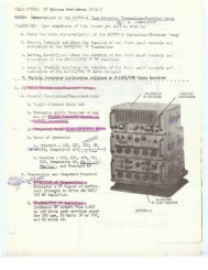
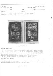
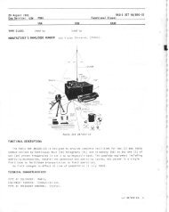
Radio-TransceiversRADIO SET AND RADIO RELAY SETUNCLASSIFIEDApril 1958FUNCTIONAL DESCRIPTIONAbDIO INPUT IMPEDANCEHIGH FIDELITY CHANNEL: 500 ohms.The AN/TRC-I is a ground transportableMICROPHONE CHANNEL: 30 to 50 ohmstransmitting and receiving equipment whichcan beused for point-to-point communication,or for radio-relay application as a terminal(single-button carbon).POWER INP~?: 115 r, 50 to 60 cps. 250 W.RECEIVERor repeater. It provides single channel com- TYPE: Double conversion superheterodyne.munication in both directions simultaneously,FREQUENCY RANGE: 70 to 99.9 mc (300or single channel communication in one di-channels).rection at a time. It may be used for multi-TYPE MODULATION RECEIVED: FM (k30 kc:hannel communication when continuous ser-deviation).vice is not required. This radio set is not FREQUENCY CCNTROL: Cr ys ta 1.intended for 24 hours service, but for inter- INTERMEDIATE FREQUENCYnittent use only.1ST IF: 32.5 to 47.5 mc, variable.The AN/TRC-4 is a ground relay station of2ND IF: 5 mc fixed.a single or multi-channel radio-relay com-CRYSTAL FFEOUENCY RANGE: 7,300 to 8741.7nunieation system designed for continuousoperation.kc.OUTPUT IMPEDANCEThe AN/TRC-I and AN/TRC-4 have the sameHIGH FIDELITY: 500 ohms.basic components, differing only in the a-SPEAKER CA HEADSET: 6 ohms.mount of components, and maintenance equip- OUTFUI LEVEL: 0 dbm normal, t20 dbm max.ment. They may generally beused for the same AUDIO RESPONSEpurpose.HIGH FIDELITY CHANNEL: fl db, 200, toNo field changes in effect et time of12.000 cps.>reparation (31 March 1958).SPEAKER OUTPUT: +I db, 200 to 2,500cps; -30 db. 3.000 cps and above.iLECTRlCAL AND MECHANICAL CHARACTERISTICSANTENNA: ~orizontall~ polariied directionalarray consistinr of 1/2 wave di~ole. . . director,and reflector, spaced 1/4 waveTRANSMITTERlength apart.FREQUENCY RAVGE: 70 to 99.9 mc (300 chan- POWER REQUIREMENTSneIs.1. AN/TRC-1: 115 v, 60 cps, 1 ph, 370 W.TYPE: Crystal controlled FM, multiplies AN/TRC-4: 115 v, 60 cps, 1 ph, 740 W.96 times.SI(NAL TYPE: Broad band audio.TRANSMISSION TYPE: A3,multichannel tele- MANUFACTURER'S OR CONTRACTOR'S DATAphone, telegraph, facsimile, or a combinationof these. Approximate Cost: $2.500.00 with e-MODULATION: FM, phase modulator. quipment Spares (AN/TRC-l).POWER OUTPUT: 50 W ma.; 10 W an low power.FREQUENCY DEVIATION: f30 kc max. TUBE AND/OR CRYSTAL COMPLEMENTOPERATING RANGE: Line of sight (150 mimax). AN/TFC- 1 AN/TRC-4CRYSTAL FREQUENCY RANGE: 729.167 to 1040. (2) 5R4WGB (12) 6AC7WA625 kc.OUTPUT IMPEDANCE: 50 to 100 ohms intocoaxial cable.AUDIO RESPONSEHIGH FIDELITY CHANNEL: k1 db, 500 to12.000 cPs: +O to -2 db, 250 to 500cps.MICROPHONE CHANNEL: +3 db, 250 to12.000 cps.AUDIO LEVEL INPL.. 0 to -12 db for 9 kcdeviation.Total Tubes: (28) Total Tubes: (78)No Crystals Available.UNCLASSIFIED
April 1958RELATION TO OTHER EQUIPMENTTM-11-2601: Technice! Menos! fnr Radi~ SetAN/TRC-I, Series and Radio Relay Set AN/TRC-4. Series.Radio-TransceiversRADIO SET AND RADIO RELAY SET AN/TRC-1 ,AN/TRC-4TYPE CLASSIFICATIONDESIGN COGNIZANCE TASS4PROCUREMENT COGNIZANCE SPEC NO. 271-1010STOCK NO.EQUIPMENT SUPPLIEDDATAQUANTITYPEEEQUIPTNAME AND NOMENCLATUREOVERALL DIMENSIONS(inches)WEIGHT(1bs.jPNITRC-1117111211214376u1371123313112211111I iRadio Receiver R-19ITRC-1Radio Transmitter T-1UlTUC-14ntenna System AS-191T~C-1Antenna Extension Kit MX-~UIITRC-1Power unit PE-75Crystal KitJunction Box ~e-110Cord CC-318Cord CC-87UElectric amp (115 v 50 w)Set of ~aintenance Equipmnt MK-~ITRC-1Contrcl Box C-ZIITRC-1Test Osci 1 lator TS-721TRC-1Hand Set K-231~. TS-13Telephone EE-8Junction Box J-85lG41 ignment ToolTube PullerMaintenance Kit MK-~ITRC-UCord CC-711Cord CWROOCord CX-8ITRC-1Kriife TL-29Pliers TL-107Solder Iron Ti-117Flash1 lqht TL-123Pliers TL-125I PI iers TL-i26or TS-15or CX-IOUITRC-18 X 12-3/U X 19-11810-31U X 12-314 X 19-11819-112 x 26-112 x 767 X 5 X 12-11284 lg78 lg2-118 X 3-114 X U-718U X U-7/U X 77-112 X 7-11/16 X 9-9/164-118 X 4-718 X 5-i!26-5!8 lg7-118 lg600 lg40 lg120 lg436614730I7.5.579.758.I.210.71.5UNCLASSIFIED
UNCUIIlFlEDApril 1959RADIO SETRadio-TransceiversAN/TRC-13FUNCTIONAL DESCRIPTIONThe AN/lRC-13 is a combination radio transmitterand receiver with facilities forproviding two-way voice channels between twopoints over an unobstructed line-of-sightradio transmission path. The AN/TRC-13 willbe utilized as a connecting link in a wirecommunication network where the terranfeatures are such that the laying of wirefacilities isnot feasible. The over-all wirecommunications network may include suchfacilities as sections of wire lines orcarrier telephone or telegraph systems.No field changes in effect at time ofpreparation (18 July 1958).ELECTRICAL AND MECHANICAL CHARACTERISTICSOPERATING FREQUENCYTRANSMITm AM) RECEIVER: 30 to 40 mc.OPERATING POWER RM: 115 v AC. 60 cps, 470W.TUBE AND/OR CRYSTAL COMPLEMENTElectron Tube andcrystal Data not Available.REFERENCE DATA AND LITERATURENomenclature.Card AN/TRC-13Set.TYPE CLASSIFICATIONDESIGN COGNIZANCE OC SIG 0PROCUREMENT COGNIZANCESTOCK NO.for the RadioQUANTITYPEPEQUlPTNAME AND NOMENCLATURE1 I Transmitter FMTSO-BW. PA-8029I1Receiver FMR-138.Antenna P-8250PA-80751 Cont rol ~ead P-8022EQUIPMENT SUPPLIED DATAOVERALL DIMENSIONS(inrhea)WEIGHT(Ibs.)UNCLASSIFIED
RADIO SETRadio-TransceiversAN /TRC-271' llll,/-% ;Rndto Set ANlTRC-27FUNCTIONAL DESCRIPTIONThe AVITRC-27 is designed as a small lightweight,portable radio communication systemwhicli provides one (1) to eight (8) duplexcommunication channels and is primarily foruse in forward operation areas. Facilitiesare provided for net operations with RadioSet ANIGRC-27. It provides two-way microwaveradio transmission for eight telephone channels.No field changes in effect st time ofpreparation (24 April 1959).RELATION TO OTHER EQUIPMENTThe 4N/TRC-27 iy similar in operation asthe AN/MRC-59 and AN/MRC-60 except that itdiffers in equipment supplied.installation area as required.ELECTRICAL AND MECHANICAL CHARACTERISTICSTYPE OF WIISSION: P3f type of emission.TYPE OF FREaJEPCY CONTH)LTRANSMITTER: variable frequency triodeoscillator.RECEIVER: Variable frequency klystronlocal oscillator.TYPE OF RECEIVW: Su~erheterodvne. 60 mc IF.RAh'GE DATAATTENII.4TION: Max allowable attenuationis 158 db.SPACE ATUDUATIOPI: For various ranges at4700 mc shorn below:RANGE ATTENUATIIX FADE(M1I.ES) (Dn) MARGIN (LIR)1 110 48EQUIPMENT REQUIRED BUT NOT SUPPLIED(5) Packboard Standard Army FII-8465-262-5201. ! Sledge Aam-er ( 5 lb!. (1) Telephonetype EE-8 or equivalent. (1) Telephone Line(Three ft or suitable length), (1) Fuel Can,(1) Compass, (1) Protraeter. Set of maps, ofUNCLASSIFIED1.7 AN/TRC-27:
Radio-TransceiversAN/TRC-27 .RADIO SETUNCLASSIFIEDApril 1959TEhlPERAnrRE RANGE: - 54' C to +65'MULTIPLEX CHARACTERISTICSC.NU<strong>MB</strong>ER OF CHANNELS: 4 duplex (8 per terminal).CNANNEL TERMINATIMV: 2- wire. 600- ohm.TYPE OF Ml!LTIPLEXING: Time Division.TYPE OF MODC'LATION: Pulse-position.AUDIO BANDWIMH: 300 to 3500 cos.RINGING FREWENCY: 25 cps.FRAME FREWENCY: 8 kc.PULSE WIDTH: 0.45 k0.05 microsecond.ANTmNA TYF'E: Paraboloid reflector with offcenterdiplexing horn, vertical and horizontalpolarization.POWER SUPPLIES: Self contained in receivertransmitterand multiplexer units.PRIMARY POWER SOURCES: 400 cycle GasolineEngine Generatqr PU-278/TRC-27 (2-supplied)FREQUENCY RANGE: 4400 to 5000 mc.(1) 2K22, (3) 6AU6WA(2) 6X4W (12) 12Al7WA(13) 5654/6AK5W (1) 5670(2) 5726/6AL5W (3) 5727/2D21W(1) 5814A (1) 5933WA(2) 6005/6AQ5W (20) 6021(1) 6280Total Tubes: (67)Total Crystals: (85)REFERENCE DATA AND LITERATURENAVSHIPS 93098(A): Technical Manual forRadio Sets AN/TRC-27, AN/MRC-59. AN/MRC-60.MANUFACTURER'S OR CONTRACTOR'S DATARaytheon Mfg Co., Waltham. Mass.Type No. LM103.Contract NObsr-71035, dated 28 September1955.TUBE AND/OR CRYSTAL COMPLEMENTTYPE CLASSIFICATIONDESIGN COGNIZANCE BUS11 I PSPROCUREMENT COGNIZANCE MI ~-~-15378(SH I Ps)STOCK NO.R.D.B. IDENT. NO.(4) OA2WA (1) SV-9QUANTITYPEREQUIPT121NAME AND NOMENCUNREIEQUIPMENT SUPPLIED DATAReceiver-Transmitter ~T-252/TRc-27Mu1 t i plexer TC-iOl/TRc-27Antenna Group OA-1378IGRC Including:1-Antenna AS-682/TRC-271-Mast AB-357ITRC-271-Antenna case CY-Z~Z~~GRCGasoline Engine Generator Pu-z~~/TRc-z~22 ft coaxial Antenna Cable (included withRT-252ITRC-27)5 ft Coaxial Cable (included with ~~-252/TRc-27)5 ft Power Cable (included with Tc-101/T~c-27)50 ft Power Cable (included with OA-1378IGRCOVERALLDIMENSIONSI(inches)WEIGM[Ibs.)1.7 AN/TRC-27: 2 UNCLASSIFIED
UNCLASSIFIEDmril 1959RADIO SETRadio-TransceiversAN/TRC-27EQUIPMENT SUPPLIED DATAQUANTITYPEEEGGll:NAME AND NOMENCUNREIOVERALL DIMENSIONS!inches1WElGMIIbs.!112Winterization KitSet of Equipment SparesTechnical Manual NAVSH I PS 93098 (A) 1 x 9-I/U x 11-112UNCLASSIFIED
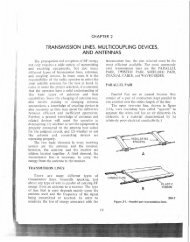
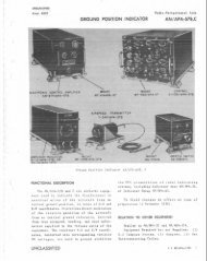
UNCLASSlFI€DFebruary 1960RADIO SETRadio-TransceiverAN/TRC-27AANTENNA A$-682lTRC-27TO-IOlAlTRC-27MULTIPLEXEI I$LAVLl8 TRUNK LINESTO INOIVIOUALTELEPHONES ORSWITCHBOARDSTO-lOlA/TRC-27MULTIPLEXER IMASTEMAST A8-357lTRC-27RT-252/TRC-27RECEIVER-TRANSMITTERPU-278A/TRC-27GASOLINE ENGINE-GENERATORRadio Sdt 1N PRC-27.4FUNCTIONAL DESCRIPTIONRadio Set AN/TRC-27A provides two-waymico-wave radio transmission for eight telephonechannels. Designed primarily for operationina forward area, it will operate witha 28 db fade margin over. a 10 mile line-ofsightpath, or with a 12 db fade margin overa 60 mile line-of-sight path.No field changes in effect at time ofpreparation (13 October 1959).ELECTRKAL AND MECHANICAL CHARACTERISTICSFREWENCY RANGE: 4400 to 5000 mc (SHF).TYPE OF FREQUENCY CONTROLTRANSMITTER: Variable frequency triodeoscillator.RECEIVER: Variable frequency klyatronlocal oscillator.NORMAL CARRIER WTPUT: 1.5 W, peak.TYPE OF RECEIVER: Superheterodyne, 60 mc IF.TEMPERATURE RANGE: -54' C to +65' C.UNCLASSIFIED 1.7 ANITRC-27.4: 1
Radio-TransceiverAN/TRC-27ARADIO SETUNCLASSIFIEDFebruary 1960MULTIPLEXERNU<strong>MB</strong>ER OF CHANNELS: 4 duplex (8 per terminal).CHANNEL TERMINATION: 2-wire, 600 ohm.TYPE OF MULTIPLEXING: Time division.TYPE OF MODULATION: Pulse-position.AUDIO BANDWIDTH: 300 to 3500 cps.RINGING FREQUENCY: 25 cps.FmAME FRE@JFNCY: R kc.PULSE WIDTH: 0.45 f0.05 usec.ANTENNA: 30 in. paraboloid reflector withoff-center duplexing horn, vertical andhorizontal polarization.POWER SUPPLIES: Self-contained in receivertransmitterand moltiflex units.PRIMARY POWER SOURCE: 400 cycle GasolineEngine Generator PU-278A/TRC-27.(41) SG215 or IN460(8) SG216 or 1N458(1) SG2li or IN459(8) 1N67 or lN198(2) IN252 .or IN251(3) 1N482 or 1N457(13) 5654/6AK5W(1) 5726/6AL5W(3) 5727!2n21w(2) 6005/6AQ5W(20) 6021(1) 6280Total Tubes (148)No .Crystals used.REFERENCE DATA AND LITERATUREMANUFACTURER'S OR CONTRACTOR'S DATA NAVSHIPS 93098(A): Technical Manual forRADIO SETS AN/TRC-27, AN/TRC-27A, AN/MRC-Raytheon Mfg., Waltham. Mass.59, AN/MRC-60.1Contract NObsr-75107, dated 15 JanuaryTYPE CLASSIFICATION (NAVY),1958.DESIGN COGNIZANCE USN, BUSH! PSTUBE AND/OR CRYSTAL COMPLEMENTPROCUREMENT COGNIZANCE SPECS: MI L-R-211145AND SH I PS-R-1947Anocr NO.(4) QA2WA (1) SG211 or 1N659R.D.B.!DENT. NO.EQUIPMENT SUPPLIED DATAQUANTITYPEREQUIKNAME 'AND NOMENCLATUREOVERALL DIMENSIONS(incher)WEIGHT(Ibs.111Radio Set AH/TRC-27Aincluding:Receiver-Transmitter AT-252ITRC-27i2Mu1 t i pl exer TC-1OlAlTRC-271 Antenna Group OA-l378/GRc includes:1Antenna AS-682/TRC-271Mast AB-357/TRC-271Antenna case cY-~~~~/GRc2Gasoline Engine Generator Pu-278A/TRC-27coaxial Antenna Cable (included WIR-25211TRC-27)coaxial Cable (included w/~T-252/~~~-27)power Cable (included ~/Tc-IO~AITRC)21 I Power Cabi e (inci uded w/On-1378iGRCj~ i ~ ? ~ ~ i ~ '(cperillt j ~ " ; cse2 02?.,3 I ISet Equiwnent Spare Parts2 Technical Manual NAvsfi IPS 93098(A)11-318 X 14-5/16 X 25-5/155-718 X 14-5/15 X 25-5/159 X 17 X 2712-518 X 13-111 X 17-5/15264 lg60 lg50 lgI 6OC igI615458511.7 AN/TRC-Z~A: z UNCLASSIFIED
UNCLASSIFIEDADril 1959RADIO SETRadio-TransceiversAN/TRC5 (XC-3Radio Set AXIPRC-SfPC-31FUNCTIONAL DESCRIPTIONPacilities is not feasible.No field changes in effect at time of'The AN/TRC-S(XC-3) is designed as corn- preparation (9 April 1959).binedradio transmitter and radio receiverwith facilities far providing eight (8) twowayvoice-frequency channels between two ELECTRICAL AND MECHANICAL CHARACTERISTICSpoints over an unobstructed line-of sighttransmission path. In general, the radio set TYPE OF kMISSION: Short pulses.will be utilized as a connecting link in a TYPE OF MODULATION: Pulse-time.wire communications network where the terrain NI<strong>MB</strong>ER OF MULTIPLEX V-F CHANNELS: Eight.features are such that the laying of wire TWE OF MULTIPLEXING: Time division.UNCLASSIFIED 1.7 AN/TRC-S(XC-3): 1
Radio-TransceiversAN/TRCd (XC-3RADIO SETUNCLASSIFIEDApril 1959TRANSMITTER POWER AVERAGE: 200 watts.TRANSMITTER POWER PEAK: 400 watts.-E OF PU"!T?T!Nk Dippole radietcr, parahaiicreflector.NET GAIN IN BEAM DIRECTION: 14 db.ANTENNA BEAM WIm: 15' at half pourer.AVERAGE RANGE OF SINGLE RADIO LINK: 25 to50 miles.RECEIVER INTERUEDIATE FREQUENCY: 16 me.CHAVNEL PLILSE LMG?H: 0.4 microseconds.SYNCHRONIZING PLILSE LENGTH: 2.0 micro-TUBE AND/OR CRYSTAL COMPLEMENTTotal Tubes: (63)secuuds.REPETITION RATE: 10 kc.NET DUTY,FACTOR: 5.2%.ANTMNA Sl..PPORT HEIGHT: 50 ft.REFERENCE DATA AND LITERATUREVOICE FRE~ENCY RAR'GE: 300 to 3,000 cycles.VOICE FREQIMCY INPUT IMPEDANCE: 600 ohms. TMll-626: Technical Manual for Radio SetVOICE FREQVEVCY INPUT CONNECTIONS: 2-wire AN/TRC-S(XC-3)or 4-wire.RINGING INPUT: 20 or 60 cycles.TYPE CUSSIFICATIONRINGING OUTPUT: 20 cycles.DESIGN COGNIZANCE BUSH l PSPOWERDRAIN: 1,500 watts.PROCUREMENT COGNIZANCEFRE(WF3CY FXNGE: 1.350 to 1, 500 mc.STOCK NO.R.D.B. IDENT. NO.OPERATING POWER RWT: 115 or 230 T. 50 to60 cpa.SHIPPING DATANU<strong>MB</strong>EROFBOXESCONTENTS AND IDENTIFICATIONVOLUME(Cu.Ft.)OVERALL DIMENSIONS(inches)WEIGHTPACKED(Ibs.)1~adio Set AN~TRC-~(xc-3) Including:Chest CY-262lTRC-5 (XC-3)Chest CY-u~O/TRC-~(XC-~)Chest CY-308lTRC-5(XC-3)Chest CY-U81ITRC-5(XC-3)Chest CY-4831~~~-~(xc-3)cbest CY-~~~ITRc-~(xc-~)chest CY-263lTRC-5(XC-3)Chest CY-2741TRC-5(XC-3)chest cv-uasl~~c-~ (XC-3)Chest CY-466ITRC-5 [xC-3)Chest CY-4671~~~-~(xc-9)Chest CY-6UChest CY-983/TRC-S(XC-9)Chest (ie:egr;lDh ~dajierjChest cY-u68/TRC-5(~~-3)Chest (Test ~qui went)'1.7 AN/TRC-SIXC-31: 2 UNCLASSIFIED
UNCLASSIFIEDApril 1959RADIO SETRadio-TransceiversAN/TRCJ (XC-3)SHIPPING DATANU<strong>MB</strong>EROFBOXESCONTENTS AND IDENTIFICATIONVOLUME1Cu.R)OVERALL DIMENSIONS(inches)WEIGHTPACKED(Ibs.)t -Chest (~utotransformer)11 Chest CY-~~U~TRC-5 (XC-3)1 . Pioneer Tool KitEQUIPMENT SUPPLIED DATAQUANTITYPEREQUIPTNAME AND NOMENCLATUREOVERALL DIMENSIONS(inches)WEIGHT(Ibr)12112111122222218111118iRadio Set ANITRC-~(xc-3) Including:Antenna Ass'y AS-~~~/TRC-~(XC-~)Antenna support AB-741~~~-~(xc-3)Autotransformer TF-~OIITRC-S(XC-3)Chest CY-~~~/TRC-~(XC-~) (~ransmi tter)Chest cY-274/TRC-5(~~-3) (Mu1 t ipl exer)Distribution Box J-~OIITRC-S(XC-~)Junction Box J-1001~~~-~(xc-3)Osci 1 loscope TS-~B~/TRC-S(XC-~)Power Unit PE-197Radio Receiver R-~~~/TRc-~(XC-~)Radio Transmitter T-I~~/TRc-~(xc'-~)Rectifier Power Unit PP-~~~/TRC-~(XC-~)Rectifier Power unit PP-~~~IT~!C-S(XC-~)Rectifier Power unit PP-~~~/TRC-~ (XC-3)Receiving Multiplex Comon UnitMX-429/TRC-S(xC-3)Receiving Mu1 t iplex Channel UnitMX-431ITRC-5 (XC-3)Telegraph Adapter TH-U/UTerminal unit TA-~I/TRC-~(XC-~)Test Panel TS-~~~/TRc-s(xc-~)Test Set I-56-KTransmitting Mult i Pl ex Comnon UnitMx-~~~/TRC-S(XC-~)Transmitting Multiplex Channel UnitMX-430/TRC-5 (XC-3)Tuning Meter TS-~~~/TRC-~(XC-~)3-1/113351607692136-11234-112770396394556543-11224782348-11243-1121-112UNCLASSIFIED 1.7 ~/F~Ic-SIAC-31: 3
UNCUSSIREDOctober 1957RADIO SITRadio-TransceiversAN/TRC-61FIJNCnONAl DESQlmONTUBE AND/OR QYSTAl COMPLEMENTThe AN/TRC-6lissnairtransportable radio Tubes and Crystals: Not Arailsblc.set that provides facilities for receivingand transmitting multichannel voice (12 voiceplus 1 order wire) telegraph. teletype, and DATA mD UraATUIEor facsimile inconjunction with multichannelsub-carrier telephone carrier equipment. TheNomenclature Card for Radio Set AN/TRC-61dated 29 November 1956.eaui~mcnt . . is intended for use by CommandGroups and Wing Command Squadrons.No field changes in effect at time ofpreparation (7 June 1957).ELECTRICAL AND MECHANICAL CHARAmBISTICSEMISSION AND RECEPTICN: F9.FREWENCY RANGE: 100 to 400 mc.NU<strong>MB</strong>ER OF BANDS: 2.NU<strong>MB</strong>ER OF CHANNELS: 425.MAX TRANSMITTER POWER W'IPUT: 100 x.POWER SOURCE REWIRED: 115 or 230 v, 50 to60 cps, single ph.QUANTITYPEEEQUIP1NAME AND NOMENCLATUREEQUIPMENT SUPPLIED DATAFTYPE CLASSIFIC*TIONDESIGN COGNIZANCE BUSH IPSPROCUREMENT COGNIZANCESTOCK NO.OVERALL DIMENSIONS(inches)-WEIGHTIlbs.111142111Electrical Equipment Shelter S-13BITRRadio Set ANITRC-35ChairTelegraph-Telephone Signal Converter TA-lB21UDoublet Antenna K i tRadio Set~ utiplexer l Set.Antenna Coupler and Filter UnitUNCLASSIFIED1.7 AN/TRC-61: 1
31 July I962 RADIO SET ANITRC-68Cog Service: SuWeps FSN:Functional Class:USA USN USAFTYPE CLASS: Used by Used oy Used byMANUFACTURER'S NAHE/CODE NU<strong>MB</strong>ER: Collins ?adio Co.. (13~99)FUNCTIO3AL DESCRIPTIOH:Raiio Set AAr/TPC-56The Radio Set ANITRC-68 is oesilned as s Fixed Xtatton Ultra-High-Frequenzy (UHF) groundto-?iF*EJ;C C ~ P T U " ~ Z ~ ~ ~ ? It " C sr~vid*~.for !r3nc71iss;~n ?no rirrotiin of brno:itdde-Moaul ited (AV) rsdio-releohone signal 5 for ground-to-3.i r 1 iaison. This set may also be usedto transmit ana receive encoaea voice si?nais.NO field chsnges in effect at time of preoaration (26 Januarv 1962).TECHNICAL CHARACTERISTICS:TYPE OF INST4LLATION:TYPE OF HODULATION:AM.T)?E OF ? ? 4 ~ 2 " ! s S l 0 ~ :vo;c?.NUMfiE? OF 6AWOS: 1 b-nd.Stationary (fixfa-type).SU%@ER O F CHANMELS: 1750 channels.
AM/TRC-68RADIO SETNU<strong>MB</strong>ER OF PQESET CHANNELS: 19 preset channels.OPERATING FREQUENCY RANGE: 225.0 to 399.9 mc.OPERATING POWER RQMT: 115 or 230 v ac. 50 to 60 cps. single oh; 300 v dc.RELATIOH TO OTHER EQUIPL'ENT:The ANITRC-68 is similar to Radio Set ANlvRC-2u exceot that i: is desipned for fixed sta-tionary installation and the equioment supplied differs: and the operjting ooaer-source isdifferent also.EQUIPMENT REQUIRED BUT HJT SUPPLIED:None.QTY l TEM STOCK N3h:BERS DIMENSIONS WEi GHT(INCHES)(LB.;)1 Receiver-Transmi tter OA-26n9:TilC-68 12 x 18-1iu x 20 155-112Includes:1 ?eceiver-Transrri tter 9-1'2 x 10 x 11-1;2 US-31URT-u41IT7C-581 Centrifugal Fan H&790/U 3-1!2 x 3-112 x 0-1:2 51 Receiver-Transni t ter Case 12-112 x 19-114 x 20 553CY-27 12 {TRC-681 Oower juoply PP-IusuiU 7-:I8 x 12 x 18-31" 57-1121 Mounting KT-2297iTRC-581 ?adio Set Control i-lu39lU 2-71a x 5-112 x 5-1:2 51 Accessory Case C~-2713/TSc-6@ 2? x 2u x 25-li2 93-1121 Electric31 Power Ca3le Ass'y 300 lg 2.3CX-U881/U1 Electrical Specisl Purpose Caole 230-112 1;Ass'y CX-u882iU1 Electrical Soecial Purpose Caole 36 I?Ass'y1 Electricsl Soecial purnose Caole 35 13~ss'y CX-U~~~IU1 Electric31 Sgeci3l Puroose Cable 35 igAss'y CX-u88u,'U1 Connect2r Adapter gG565AiU1 Antenna A5s.y AT-197/Gn1 Control Grouo AbI1G1A-6 Including:1 Remate Control C-u'33/G2C1 Local Cgntrol C-u3ulGRC1 Handset H-33iP~1 Bag CW-189IGR1 Electrical Hesdset H-113'~1 Headset Cord CX-13.341~1 Dynamic Loudspeaker LS-166!U1 Micropnone '4-29~1~1 SDOOl 32-8-6 1 Wire wD-l/TT
RADIO SET ANITRC-68QTI ITEM STOCK NU<strong>MB</strong>ERS DIMENSIONS WEIGHT(INCHES)(LflS)1 Set of Equipment Spares2 Technical Hanual T~11-5820-222-102 Technical Manual rn11-5820-222-20REFERENCE DATA AND LITERATURE:TMll-5820-222-10 6 TO 31R2-2TRC68-1: Technical Manual for Radio Sets AN/vRC-ZU and AN/TRC-68TUBE, CRYSTAL AND/OR SEMI-CMIOUCTOR DATA:TUBES: (9) 565416A~5W (6) 5670 (1) 5769 (1) UX150D (1) 6uu2 (5) 6JuWA (1) 75511CRYSTALS:None used.SEMI-CONDUCTORS: (2) IN457 (2) IN458SH IPP ING DATAPKGS VOLUME (CU FT) WEIGHT (LBS)PROCUREMENT DATAPROCURING SERVICE:BuWepsDESIGN COG:TASSA h USAFSPEC &/ORDWG:COIITRACTOR LOCATI ON CONTRACT OR APPROX.ORDER NO.UNIT COSTCollins Radio Co. Cedar Rapids, Iowa 14276-PC58-41-51Pt no. 522-2275-00
UNCUSSIFIEDAugust 1957RADIO SETRadio-TrsnsceircrsAN/TRG7ARELATION TO OTHER EQUIPMENTSimilar to Radio Set AN/TRC-7.ELECTRICAL AND MECHANICAL CHARACTERISTICSFREQUENCY WWGE: 100 to 156 me.POWER OVTPUT: 0.4 to 1.5 W.EMISSION AND RECEF'TICU: A3.FREQUENCY CCWROL: Crystal eontrolledoseillator.TYPE RECEIVER: Superheterodyne.POWER SOURCE: Battery BA-70. GeneratorG-3/TRC-7.ANTENNA ..- -. DATATfPE: Whip or ground plane conical.POLARIZATICU: Vertical.IMPEDANCE: 50 ohms.MANUFACTURER'S OR CONTRACTOR'S DATAAndrea Radio Corp. Long Island City, N.Y.TUBE AND/OR CRYSTAL COMPLEMENTTotal Tubes: (16)Radio Set ANITRC-7A Total Crystals: (4)FUNCTIONAL DESCRIPTIONThe AN/TRC-7A is a portable, low-power,receiver-transmitter, operated by battery,hand eeneratar. or a combination of both. Itis designed for AM eommunicstion over shortdistances in the VHF range and is intendedprimarily to provide communication betweenground troops and aircraft.No field changes in effect at time ofpreparation ( 5 February 1957).REFERENCE DATA AND LITERATURETMll-617: Technical Manual for Radio SetAN/TIIC-7A.TYPE CUSIFICATIONDESIGN COGNIZANCEPROCUREMENT COGNIZANCESTOCK NO.EQUIPMENT SUPPLIED DATAQUANTITYPEEEQUIP1NAME AND NOMENCLATUREOVERALL DIMENSIONS(inrhe.1WElGM(lbr)11I122Antenna AT-59lTRC-7Antenna Assy. AS-lIOA/TRC-7Antenna Base AB-?7/TRC-7Battery BA-70Bag CW-u7/TRC-7Bag CW-U8ITRC-70.145 dia X 27-11/164-112 X 7-518 X 10&5/B X 14-115 X 1610 X 1U X 37UNCLASSIFIED-- 1.7 AN/TRC-7A: 1
Radio-TranaccireraAN/TRG7ARADIO SETUNCLASSIFIEDAugust 1967UNCLASSIFIED
UNCLASSIFIEDOctober 1957RADIO RANGING SETRadio-TranaeeireraAN/TRQ-9NNCllONAL DESCRIPTIONMANUFACWRB'S OR CONlRAClOR'S DATAThe AN/TRQ-9 consists of one transmitterend tvo receivers end o.c power source andSeismograph Service Corp.,Tulsa. Oklahoma.is used forgiving accurate position locationsof the AN/URQ-6 equipments. It operates as atvoe ..11 - Reference Section.TUBE AND/OR CRYSTAL COMPLE<strong>MB</strong>JlNo field changer in effect at time ofpreparation (16 April 1957). Tubes and Crystals: Not Available.RELATION TO OTHER EQUIPMENT REFERENCE DATA M D LITERATUREused in conjunction with 3 or 4 Radio ~~~~~~l~~~~~ card for ~ ~ ~~~~i~~ d i set ~Ranging Sets AN/TRQ-8 sndany number of Radio AN/TRQ-9 amended 11 February 1952.Ranging Sets AN/URQ-6.ELEClRlCAL AND MECHANICAL CHARAClERISTICSEMISSION: Al.TRANSMITER OUTPm: 25 W.FREQUENCY RANGE: I. 8 to 3 mc.NU<strong>MB</strong>ER OF BANDS: single.S(LIRCE REWIRR): 110 v, 60 cp. sin& ph.TYPE CUSSIFICATIONDESIGN COGNIZANCErRocunurElrr COGNIZANCESTOCK NO.BUSH I PSn I L-E-1591s (SHIPS)EQUIPMENT SUPPLIED DATAQUANTITYPEEEQUIP1NAME AND NOMENCUNIEOMULL DIM ENSIONSWElUn(inches) Ilk)/ Radio Ranging set nnlr~p-9 I IUNCLASSIFIED
UNCLASSIFIEDJune 1961RADIO SETRadio-TranceiversAN/URC-10FUNCTIONAL DESCRIPTIONRadio Set AN/URC- 10 is a transistorizedair-sea rescue receiver-transmitter. The receireris superheterodyne, using single conversion.Injection current at 240 to 260 mcis obtained from a transistor quedruplerdriven by a crystal controlled 60 to 65 mcoscillator. A crystal diode mixer convertsthe incoming frequency to 475 kc, the intermediatefrequency. After three stages oftransformer coupled I-F amplification, thesignal is detected. The transmitter outputstages consist of two 2N537 transistors inparallel, driven by a 60 to 65 mc crystalcontrolled oscillator followed by two transistordoubler stages.No field changes in effect at time ofpreparation (22 July 1960).RELATION TO OTHER EQUIPMENTThis equipment is to replace Radio SetAN/URC- 4.ELECTRICAL AND MECHANICAL CHARACTRlmCSPOWER REWIREMENTS:Self-contained batterysource.FREWET'4CY RANGE: 240 to 260 me.TYPE OF FREQUENCY CONTROL:, Crystal.TYPE OF FMISSICN: Al. A3.POWER OU'IPUT: 75 to 100 mw.ANTENNA: Telescoping whip.MANUFACTURER'S OR CONTRACTOR'S DATAMotorola Inc, Chicago, Ill.TUBE AND/OR QYSTAL COMPLEMENTNo electron tube or crystal data available.REFERENCE DATA AND UTERATLIRENAVSHIPS 93400: Preliminary data sheet forRadio Set AN/URC-10.TYPE CUSSIFICATION (NAVY)DESIGN COGNIZANCE USAFPROCUREMENT COGNIZANCESTOCK NO.R.D.B. IDEM. NO.EQUIPMENT SUPPLIED DATAQUANTITYPEEEQUIPTI1 Radio Set ANIURC-10 including:Transceiver1 BatteryNAME AND NOMENCLATUREOVERALL DIMENSIONS(inrhrs)1-118 x 3-118 x 5-3181-112 x 3-114 x 4-718WEIGHT(Ibs.11-3/162-1/16UNCLASSIFIED
~~ --UNCLASSIFIEDPgril 1959RADIO SETRadio-TransceiversAN/URC-11FUNCTIONAL DESCRIPTIONFQUW OZPIPLT 200 ma.The .AN/LFC-11 is designed a small light-OPERATING FREQUENCY RANGE: 238 to 263 mc.C ? ~ A ~ NPOW, G R()>T: 2.5 W DC.weight radic, set intefided as =n emeraencyitem used to facilitate search and rescueoperations. The AN/URC-11 may be cerried onthe person of air crew members or stowed inTUBE AND/OR CRYSTAL COMPLEMENTlift rafts and survioal kits. Power is Electron TubeandCrystal data not availahle.delivered to the AN/uRC-11 by means of aSpecial Purpose Cable Assembly (CX-1093A/U).A battery supplies all the power necessary REFERENCE D.4TA AND LITERATUREfor operation of the radio transceiver. TheAN/URC-11 has an approximate operating lifeof twenty-four (24) hours without batteryNomenclature Card AN/UR.C-11 Radio Set.rep1 acement.No field changes in effect at time ofpreparation (3 July 1958).ELECTRKAL AND MECHANICAL CHARACTERISTICSTYPE OF EMISSION: Al, A2 and A3 type ofemission.NU<strong>MB</strong>ER OF BANDS: 1 band.TYPE CLASSIFICATIONDESIGN COGNIZANCE BUSH IPSPROCUREMENT COGNIZANCESTOCK NO.QUANTITYPER IEQUIPTINAMEEQUIPMENT SUPPI "" "'I' .....IAND NOMENCLATURE OVERALL DIMENSIONS(inches)WEIGHT(Ibs.)1Radio set AN~URC-11 including:(I) ~eceiver-~ransmitter RT-~BSIURC-11(2) special Purpose Cable Assemblycx-109gnlu (-?+in)UNCLASSIFIED
UNCLASSIFIEDJune 1957RADIO SETRadio-TransceiversAN/URC-16,16X,16Y,17,17X,17Y,18,18X,18YRadio Set ANfORC-16, !BY, IBT, 17. 17X, 171, 18, 18X. 181.FUNCTIONAL DESCRIPTIONThe AN/URC-16, 16X,16Y, 1 17X, 17Y, 18,18X, 18Y are portable radio sets designedfor F3 type of emission within the frequencyrange of 20.0 to 54.9 mc.Data an this sheet reflects the followingfield changes, F/C No.2 (17 September 1956).RELATION TO OTHER EQUIPMENTThe AN/URC-16, 16X, 16Y, 17, 17X, 17Y, 18,18X, 18Y are similar to the AN/SRC-10, LOX,lOY, 11. 11Y. 116. 12. 12X. 12Y, 13, 13X.13Y. 14. 14X. 14Y. 15. 15X. 15Y exceut forsome of the components used.ELECTRICAL AND MECHANICAL CHARACTERISTICSTYPE OF TRANSMISSION AND RECEPTION: Voiceand 1600 cpa F'M signals.FREQUENCY FIANGEAN/URC-16. 16X. 16Y: 20 to 27.9 mc.AN/UHC-17, 17X, 17Y: 27 to 38.9 mc.ANIURC-18, 18X, 18Y: 38 to 54.9 mc.TYPE OF TUNING: Choice of channels or continuoustuning.RANGE: 10 to 15 mi.UNCLASSIFIEDTRANSMITTER POWER OUTPUTAN/URC-16. 16X, 17. 17X, 18, 18X: 16 Won high and 2 W on low.AN/URC-16Y. 17Y. 18Y: 13 W.RECEIVER OUTPUT: Approx. 1 W at speaker and50 mwatphones. A third output of approx.30 ma at fixed-level output is not used.MICROPHONE INPUT IMPEDANCE: 150 ohms.AUDIO OUTPUT IMPEDANCE: 600 ohms at allaudio output terminals.RECEIVER SENSITIVITY: 30 dv signal-plusnoiseto noise ratio with 0.5 uv inputsipnal. -~~~W ~ REQUIREMENTSRAN/URC-16. 17, 18: 25.2 v LC.AN/URC-16X, l7X, 18X: 12.6 v DC.ANIUHC-16Y, 17Y. 18Y: Hand cranked Eerieretorand dry batteries (5) BA-403/U.(1) BA-419/U.MANUFACTURER'S OR CONTRACTOR'S DATA18X, 18YContract MIPR 800-29092, 29094, 29500.AN/URC-16Y, 17Y, 18Y,Contract MIPR-800-39406.Approximate Cost: S1500.00 with equipmentspares each.1.7 AN/URC-16: 1
Radio-TransceiversAN/URC-16,16X,16Y,17,17X,17Y,18,18X,18YRADIO SETUNCUSSlFlEDJune 1957TUBE AND/OR CRYSTAL COMPLEMENT AN/URC-16, 16X. 16Y, AN/L!C-17, 17X. 17Y9 Crystals 13 GystalsAN/URC-16, 16X, 17, 17X, 18, 1BX Total Crystals: (9) Total Crystals: (13)(2) 1.43 (2) 1AE4(2) IL4 (4) iR5 ANi'iC-is, 18x ANPiC- lay(1) 1S5 (4) 1U4 18 Crystals 16 Crystals(1) 6626/OA2WA (1) 6627/OB2WA Total Crystals: (18) Total Crystals: (16)(1) 2E24 (1) 3A4(3) 3A5 (2) 3B4(4) 304 (2) 1007 REFERENCE DATA AND LITERATURE(1) 5654/6AKSWTotal Tubes: (31)TMll-286: Technical Manual for Radio Sets.AN/URC-16, 16X, 16Y, 17, 17X, l7Y, 18,AN/URC-16Y, 17Y. 1BY lax, 18Y (AN/VRC-8, -9, -10)(2) 1A3 (2) 1AE4 BUSHIPS LTR S67/1-7 Ser 881E-1-3528, dated(2) 114 (4) 1R5 1 September 1955.(1) 155 (4) 1U4TYPE CLASSIFICATION(1) 2E24 (1) 3A4DESIGN COGNIZANCE(3) 3.45 (2) 3B4TASSA(4) 304 1 5654/6AK5WPROCUREMENT COGNIZANCETotal Tubes: (27) 0STOCK NO.EQUIPMENT SUPPLIEDDATAQUANTITYPEPEQUIPTNAME AND NOMENCLATUREOVERALL DIMENSIONS(inches)WEIGHT(Ibs.)ANlURC16 116~ 116~1 1 i Receiver-Transmitter RT46lGRC1Power Supply PP-112IGR ~UVDC)1 Power Supply PP-109lGR I 12 VDC)1 1 Mounting MT-299/GR1 1 Mast Base AB-15IGR1 1 Mast Sect ion MS-116A1 1 Mast Sect ion MS-117A1 1 Mast Section MS-ll8A1 1 Control Box G375lVRC1 ModificationKit MX-898/GR1 1 1 Loudspeaker LS-166lU1 1 1 Bag CUC206lGR2 2 Handset H-33( ) /PT1 1 Coaxial Adapter UG273IU1 15Coaxial Adapter UG306/UDry Battery BkU03/U1 1 Antenna Cable CG56BIU1 Dry Battery BA-4191U1 1 Cable Assembly CX-1211IU2 2 2 Technical Manual TM11-2669 X 11-1lU X 138 ~ 9 x 1 38 x 9 1 94 X 13 X 2099-112 in. lg39-112 in. 1g39-112 in. 19u X 7 X 73X5XUO2-1/16 X 9 X 350 in. lg9593332U1.61.40.59.53.520.340.760.5O.UANIURC-17117X 117Yi i11:: IMounting.4 .AReceiver-7ranmitterR:-67/GRCPower Supply PP-112IGRPower Supply ??-109lGR35I :..1.7 ILY/L'RC-16: 2 UNCLASSlFlEDI9 x ;;-:In x ;j8 X9X 138 X 9 X 134 X 13 X 20MT-299lGRMast Base A&15/GR1 1 Mast Section MS-116A39-112 in. lg1 1 I Mast Section MS-ll7A19-112 in. "-5: s~~tio:: "ri:zi 1 >?-:!z i?. 1~ . J1 1 control lox G~~IVRC 4 x 1 x 733
UNCLASSIFIEDJune 1957RADIO SETEQUIPMENT SUPPLIED DATARadio-TransceiversAN/URC-16,16X,16Y,17,17X,17Y,18,18X,18YQUANTITYPEPEQUIP1NAME AND NOMENCLANREOVERALL DIMENSIONS(inches)WEIGHTIIbs.150 in. lg3.520.30.360.50.u1 1 Mounting MT-299lGRMast Base A&IS/GR1 1 Mast Sect ion MS117A1- 1 -1 ~ ~- ast Sect -~~ ion~AB--2UlGR1 111 1 11 1 12 21 11 11 1511 12 2 2control sox ~ 3 7 5 1 ~ ~ ~Modification K i t MX-898/GRLoudspeakerLS166/UBaa CW-206lGRmaidset &33( ) PTCoaxial Adapter UG273lUCoaxial Adapter UG306/UAntenna Cable C&53U/UDry Battery 8A-uO~IUDry Battery BPrU19/UCable Assembly CX-1211/UTechnical Manual TM11-28639-112 in. 1g2~112 in. 1gu x 7 x 750 in. lg353333241.40.13 .3.5 -3.520.340.360.50.9UNCLASSIFIED
RADIO SETRadio-TransceiversAN/URC-2FUNCTIONAL DESCRIPTIONEATERY IhTW"6" BATTERY: +90 v, 1.44 W.The AN/URC-2 is designed as a Very High 'A" BAlTERY: t1.3 v, 624 W.Frequency (VHF) transceiver which may be TOTAL POWER OUlPUT: 2.064 W.used wherever a lightweight portable transceiveris required. It is used essentiallyfor emergency "Air-Sea" and 'Air-Land" ope- TUBE AND/OR CRYSTAL COMPLEMENTrations. Completely water-tight.YI,u-I.slv r.trrer- - - - in ' .f:D"r------ Zt time nfNo Electron Tribe ar crystal data avail-preparation (28 July 1958).able.RELATION TO OTHER EQUIPMENTREFERENCE DATA AND LITERATUREThe AN/URC-2 is used with but not part Nomenclature Card AN/URC-2 forthe Radio Set.of Radio Set SCR.522A, Radio Set AN/ARC-3and Homing Adapter AN/ARA-8.TYPE CLASSIFICATIONELECTRICAL AND MECHANICAL CHARACTERISTICSTYPE OF VOICE: AM. CW and MCW.OUIPm PWIER: 30 mw.FREQUENCY RANGE: 131.5 to 142 mc.DeSlGN COGP8zANCE USAFPROCUREMENT COGNIZANCESTMK NOI ~ : ~ ~ ~ NO, l ~ & .EQUIPMENT SUPPLIED DATAQUANTITYPEREQUIPTNAME AND NOMENCLATUREOVERALL DIMENSIONS(inchertWEIGHT(Ibs.11Radio set ANiuRC-2 incl:(1) Receiver-Transmitter RT-148() URC-2(1) Mast ~T-6090iU(1) Special Purpose Cable Ass'y CX-10931U(1) Maintenance K i t YK-E.S ()/URC IUNCLASSIFIED
28 August 1962 RADIO SET ANIURC-20Cog Service: FSN: Functional Class:TYPE CLASS:MANUFACTURER'S NAMElCODE NU<strong>MB</strong>ER:USA USN USAF(Yo I 1 lustsation Available1FUNCTIONAL DESCRIPTION:The Radio Set AN/URc-20is used as a general purpose, portable. ground installation and inTruck, 1/11 ton, Input power requirements are direct current (OC), furnished by GeneratorG-B/GRC. The AN/URC-20 combines Radio set AN/VRC-8 and Modification Kit MX-898/~~.NO field changes in effect at time of preparation (25 April 1961).TECHNICAL CHARACTERISTICS:TYPE OF INSTALLATION: Portable, ground and vehicular.TYPE OF EMISSION: F3 type.NU<strong>MB</strong>ER OF BANDS: 1 band.NU<strong>MB</strong>ER OF CHANNELS: 80 channels.FREQUENCY RANGE: 20 10 27.9 mC.POWER OUTPUT: 16 W.POWER SUPPLY: DC Generator G-B/GRC.RELATION TO OTHER EQUIPMENT:The AN/URC-20 is similar to Radio Set AN/URc-167 except it includes different mountingprovisions.EQUIPMENT REQUIRED BUT NOT SUPPLIED:None.MAJOR COMPONENTSQTY i TEM STOCK NU<strong>MB</strong>ERS DIMENSIONS WEIGHT( INCHES) (LBS)Radio Set AN/URC-20 consists of:1 Receiver-Transmi t ter RT-66/GRC 9 x 11-3/16 x 12-13/161 Mast Base A&~S/GRC1 Case CY-68U/GR 3-1/B x 4-1/2 X 9-7/81 Power Supply PP-112/GR 7-5/16 x 9-1/11 x 12-7/81 Control Box C-375/vRC 3-1/11 X 6-13/16 X 71 ~ocal control C-U~U/GRC2 Mast. Sect ion MS-116-AG 0.393 oia x 39-1/22 mast Section MS-117-AG 0.373 dia x 39-1/22 ~ast Sect ion MS-118-AG 0.296 dia x 39-1/21 Mounting MT-299/GR 3-7/16 x 12-l/2 x 19-3/11
AWIURC-20RADIO SETQTY ITEM STOCK NU<strong>MB</strong>ERS DIMENSIONS WEIGHT( INCHES) (LBS)I Remote Control C-433/GRC 3-9/16 x 6-7/16 x 8-9/161 Handset H-33/PT1 Generator G8/GRC 6-I/Z x 8-7/8 x 101 Case CY-590/GR 5-3/8 x 7-1/4 x 15-5/81 uast sect ion AB-ZZ/GR 11/32 d ia x 2r1/23 Mast sect ion AB-Z~/GR 7/32 d i a x 23-1/21 Mast sect ion AB-z4/eR 7/32 d i a x 23-1/21 Mounting MT-652/GR 3/8 dia x ~5/16REFERENCE DATA AND LITERATURE:Nomenclature Card for Radio Set AN/URC-20.TUBE, CRYSTAL AND/OR SEMI-CONDUCTOR DATA:TUBES:Data not available.CRYSTALS:Data not available.SEMI-CONDUCTORS:Data not available.SH l PP l WGOATAPKGS VOLUME (CU FT) WEIGHT (L~s)PROCUREMENT OATAPROCURING SERVICE:SPEC &/OR DWG:DESIGN COG: USN. BushipsCONTRACTOR LOCAT l OW CONTRACT OR APPROX.ORDER NO.UNIT COST
26 August 1962 RADIO SET ANIURC-21Cog Service: FSN: Functional Class:USA USll USAFTYPE CUSS:MANUFACTURER 'S NAMEICOOE NU<strong>MB</strong>ER:(lo Illustration Available)FUNCTIONAL DESCRIPTION:he AN/uRc-21 is used as a general purpose. portable, ground installation and in Truck.1/4 ton. Input power requirements are direct current (DC), furnished by,Generator G-8/GRC.Channel separation is one channel for every 10 kilocycles (KC) of tuning range.A~/uRc-21 combines Radio Set AN/VRC-9 and Modification K i t MX-898/GR.NO field changes in effect at time of preparation (24 April 1961).Radio SetTECHNICAL CHARACTERISTICS:TYPE OF INSTALLATION: Portable, ground and vehicular.TYPE OF EMISSION: F3 type.NU<strong>MB</strong>ER OF BANDS: 1 band.NU<strong>MB</strong>ER OF CHANNELS: 120 channels.FREQUENCY RANGE: 27 to 38.9 mc.POWER OUTPUT: 16 W.POWER SUPPLY: DC Generator G-8/GRC.RELATION TO OTHER EQUIPMENT:The AN/URC-21 is similar to Radio Set AN/URC-17Y except it includes different mountingDrovisions.EQUIPMENT REQUIRED BUT NOT SUPPLIED:None.MAJOR COMPONENTSQTY ITEM STOCK NU<strong>MB</strong>ERS DIMENSIONS(INCHES)WE I GHT(LBS)Radio Set AN/URC-21consists of:1 Receiver-Transmi tier RT-67/GRC 9 x 11-3/16 x 12-13/161 uast Base AEIS/GR1 Case CY-684/GR 3-1/8 X 4-1/2 X +7/81 Power Supply PP-112/GR 7-5/16 x +1/4 x 12-7/8I Control BOX C-~~S/VRC 3-1/4 x 6-13/16 x 71 Local Control C-434/~Rc2 Mast sect ion MS-116-AG 0.393 dia x 39-1/22 ~ast sect ion US-II~-AG 0.373 dia x 39-1/2z Mast sect ion US-118-AG 0.246 dia x 3+1/2
ANlURC-21RADIO SETQTY ITEM STOCK NU<strong>MB</strong>ERS DIMENSIONS(INCHES)WEIGHT(LBS)Mounting MT-299/GRPemote Control c-u~~/GRCHandset n-33/PTGenerator G8/GRCCase CY-590/GRMast Section A&22/GRMast Sect ion AEZYGRMast sect ion AE28/GRMounting MT+SZ/GR6-112 x 8-7/8 x 105-3/8 x 7-118 x 1>5/811/32 dia x 23-1/27/72 dia x 2>1/27/12 dia x 23-1123/8 dia x 55/16REFERENCE DATA AND LITERATURE:Nomenclature Card for Radio Set AN/uRC-21.TUBE, CRYSTAL AND/OR SEMI-CONDUCTOR DATA:TUBES:Data not available.CRYSTALS:Data not available.SEMI-CONDUCTORS:Data not available.SHIPPING DATAPKGS VOLUME (CU FT) WEIGHT (LBS)PROCUREMENT DATAPROCURiNG SERVICE:SPEC &/OR DWG:DESIGN COG: USN, BuShipsCONTRACTOR LOCATION CONTRACT OR APPROX .ORDER NO.UNIT COST
UNCLASSIFIEDAugust 1957RADIO SETRadio-TransceiversAN/URC-22FUNCTIONAL DESCRIPTION OPERATING POWER: Supplied by Hand GeneratorG-8/GHCThe AN/URC-22 is designed for generalpurpose use, for vehicular and ground use.No fieldchanges ineffect at time of TUBEAND/ORCRYSTALCOMPLEMENTpreparation (17 December 1956).RELATION TO OTHER KIUIPMENTSimiiar to Radio Set AN/URC-18Yincludes different mtg provisions.exceptELECTRICAL AND MECHANICAL CHARACTERlmCSNo Electron Tubes.REFERENCE DATA AND LITERATURENomenclature card.FREQUENCY RANGE: 38 to 54.9 mc. 1 bandTYPE EMISSION: F3.FREGUENCY CHANNELS: 170 channels. one everyioo kc.TYPE CLASSIFICATIONDESIGN COGNIZANCEPROCUREMENT COGNIZANCESTOCK NO.QUANTITYPEEECIUIPTNAME AND NOMENCLATUREMUIPMENT SUPPLIED DATAMast Sect ion A&2u/GRCable, Special Purpose, Assy CX-~ZII/UMounting MT-299/GRRemote Control c-U~~/GRCConnector and Bond Nut (Appleton no. 61007)and BL-50Handset H-33/PTGenerator G-8IGRCCase CY-5901GRMast Sect ion AB-22/GRMast Sect ion 40-23/GRMast Sect ion 48-25/GRPower Cable Assy CX-1209/UPower Cable Assy CX-1210/UReceiver-Transmitter RT-68/GRCMast Base 4&15/GRCase CX-68U/GRRF Cable Assenk3ly CG-53OIUAdaoter UG-106/U.1 sag CW-ZO~I~RI cable, special purpose UM-461U1 Control Box C-77ulVRC1 Bag CW-189lGRAdapter UG-273/U1 Local Control C43UlGRC2 Mast sect ion Ms-117-A1 I Mount ina HT-65z/GRI1 ~eadset-n-331~~1 Bag CW-187/GR1 Bag CW-188/GROVERALL DIMENSIONS(inrhes)WEIGHTIIbs.1UNCLASSIFIED 1.7 UI/URC-22: 1
30 July 1962 RADIO SET AM/URC-2'4Cog Service: USN FSN: Functional Class:USA USN USAFTYPE CLASS: Used by Used byMAWUFACTURER'S WAMEICODE NU<strong>MB</strong>ER: Teksun. Inc., (88831).Radio Set AR/URC-2UFUNCTl OMAL DESCRIPTION:The Radio Set ANIuRC-24is designed to provide two-way voice communications by means ofhigh frequency radio on shipboard or shore stations, and it is adaptable to craft having anyof several standard electrical power supply voltages available, as well as to stations hav-ing 115 volt. 60-cycle power.Radio Set ANIURC-24 is a compact radio telephone transmitter-receiver system, which iscapable of operating indeoendently of any other electronic equipment.No field changes in effect at time of preparation (22 January 1962).TECHNICAL CHARACTERISTICS:TYPE OF INSTALLATION:TYPE OF EMISSION:A? tyoe.i ~ i E OF RECEI vER: Supernersrodync.Shipboard or shore station.
A N / u ~ C - RADIO ~ ~ SETTYPE OF LOAD:Loudspeaker and handset.EQUIPMENT PURPOSE: Two-way communications for ship to shore use.TYPE OF FREQUENCY CONTROL: Piezo-electric crystal.POWER OUTPUT: 10 W into 24-ohm antenna.ANTENNA CHARACTERISTICS: Impedance between 5 6 25 ohms.RECEIVER AUDIO OUTPUT: 3 W into 600 ohm load, less than 78 total harmonic distortion.FREQUENCY RANGECHANNELS 1 THRU u: 2.0 to 7.8 mc.CHANNELS 5 and 6: 3.8 to 7.0 mc.OPERATING POWER RQMTVOLTAGES: 6, 12, or 24 v dc; 115 v ac, 60 cps.POWER DRAIN, RECEIVER ONLY: 84 W.POWER DRAIN. TRANSMITTER AND RECEIVER: 192 W.RELATION TO OTHER EQUIPMENT:None.EQUl PMENT REQUIRED BUT NOT SUPPLIED:(1) Cable Type MFHA O r equivalent; (6) Crystal Type HC-6lU (For Transmission frequencycontrol); (6) Crystal Type HC-6Iu (For Receiver frequency control); (1) Vibrator (PowerSupoly dc to ac conversion); (1) Auto-Transformer (Reduce 115 v ac power to power Supplyinout).MAJOR COMPONENTSQTY l TEM STOCK NU<strong>MB</strong>ERS DIMENSIONS WEIGHT(INCHES)(LBS)1 Transmitter, Receiver, PowerSupply ANIURC-241 Remote Control UnitC-2165lURC-241 Set of Equipment SparesREFERENCE DATA AND LITERATURE:CG-273-47:Technical Manual for Radio Set ANIuRC-24.TUBE, CRYSTAL AND/OR SEMI-CONDUCTOR DATA:TUBES: (1) 5654 (1) 5750 (2) 5763 (1) 5814 (1) 6176 (1) 6146 (1) 6661(4) 6662 (1) 6680 (1) 6AQ6 (1) 12BH7 (2) 2E26CRYSTALS:(12) HC-6/USEYI-CONDUCTORS:None used.
RADIO SET AH/URC-24SHlPPlHG DATAPKGS VOLUME (CU FT) WEIGHT (LBS)PROCUREMENT DATAPROCURING SERVICE: U.S.C.G. DESIGN COG: U.S.C.G.SPEC hlOR DWG:.----..CONTRACTOR LOCATI ON CONTRACT U8 arrnuA.ORDER no.un I T COSTTeksun. Inc. Los Angeles. Cal if.T,.P,,,-39420Model no. CG-1
~...~UNCLASSIFIEDdpril imnRADIO SETFUNCTIONAL DESCRIPTION.-.The AN/UFlC-30 is a single-sideband, two(2) way communication transmitter-receiver;designed for general porpose use. The circuitryis partially transistorized.No field changes in effect at time ofpreparation (22 January 1959).ELECTRICAL AND MECHANICAL CHARACTERISTICSTPE OF FECEIVER AND V3ANSMITTER: Singlesideband.PEAK ENVELOPE POWERRECEIVER AM) TRANSMIITER: 200 a.OPWATING FREOUENCYRECEIVER AND TRANSMIlTER: 2 to 30 mc.OPERATING POWER REQUIREMENTRECEIVER AND TRANSMITTER: 115 v, 60 cps,single ph.MANUFACTURER'S OR CONTRACTOR'S DATARadio Corporstion of America, Camden, N. J.Contract NObsr-72738, dated 26 June1957.sb.Appfoximate Cost: f475.544.00 with e.quipment spares.TUBE AND/OR CRYSTAL COMPLEMENTElectron Tube andcrystal Data not Available.REFERENCE DATA AND LITERATURENAVSHIPS 4457 (Rev. 11-56) for the Radio SetAN/URC-30.TYPE CLASSIFICATIONDESIGN COGNIZANCEBUSH IPSPROCUREMENT COGNIZANCE SHI PS-R-2673STOCK NO.-EQUIPMENT SUPPLIED DATANAME AND NOMENCLATUREEQUIPT 1----- . ~~ . ~~~1 Receiver-Transmitter1 Receiver Exciter1 Transmitter Power Supply1 Antenna. TunerQUANTITY I 1 -. . -- . . .UICIALL -" YIMEN -"SIONS(inrher)~~.WEIGHT. ~UNCLASSIFIED
UNCLASSIFIEDJ*e-1961 .-RADIO SETRadio-TransceiversAN/URC-3 2FUNCTIONAL DESalPTlONRadio Set AN/URC-32i.a manoally operatedradio communications transceiver for operationin the 2 to 30 ac high-frequency rangewith a transmit peak-envelope-power outpotof 500 W. The AN/URC-32 is primarilydesibcdfor single-sideband transmission and receptionon upper sideband, lower sideband ortwo independent sidebands with separate audioand IF channels for each sideband. In additionto single-sideband operation, proriaionsart included for compatible AM (carrierreinatrted). CW or FSK operation. The frequencyrange of 2 to 30 mc is covered infour bands, the desired operating frequencybeing set to one-kilocycle increments on sdirect-reading frequency counter. Frequencyaccuracy and stability are controlled by aself-contained frequency standard. Prorisionaare prorided for using on externalfrequency standard such as the AN/URQ-9.Data on this sheet reflects the followingfield changes: F.C. fl.RELATION TO omn EQUIPMENTThia equipment is,a military version ofthe Collins KUT-6 Type 8 Transceiver.EQUIPMENT REQUIRED BUT NOT SUPPLIEDThia equipment is a complete radio communicationstransceiver requiring only an antenna.an sntenna feed system with s transmittertermination of 50 ohms onbslanced.ELECTRICAL AN0 MECHANICAL CHMACTRIITICSRodio Set N/URC-32FREQUENCY RANGE: 2.0 to 30.0 mc.TYPE OF RECEPTION AND TRANSMISSION: CWtelcgraphy(Al); double sideband full carrier(A3) on reeeirc; single sidebtnd, rtd~cedcarrier (A3.j; two independent sidebands.d u d csrzitr (A3b); composite trans-
RADIO SETUNCLASSIFIEDJune 1961mission (A9); single sideband, full carrier(A9a) on transmit; frequency-shifttelegraphy (Fl).TRANSMIT POWER OUTPUT: (Al) 500 W. (A3) 125W carrier porer, (A3a) 500 W PEP, (A3b)500 W PEP total, (A9) 500 W PEP total.(A9a) 125 W carrier power. (Fl) 500 W.OUTPUT SIGNAL CHARACTERISTICS FOR AUDIO OUT-PUTSUSB LINE: P14 to M34 dbm (adjustable)into 600 ohms balanced.LSB LINE: P14 to M34 dbm (adjustable)into 600 ohms balanced.PHONES: Standard 600 ohm headphones.SPEAKER: 3 W max into 3-4 ohm or 600 ohmspeaker.FREQUENCY STABILITY: 1 part in lo6 per monthand 1 part in 10' per day under allambientconditions, using the equipment'sinternalfrequency standard.POWER SOURCE REQUIRED: 115 or 230 r. 50 to60 cyc. single pb, 1700 W.RECEIVER RF INPUT IMPEDANCE: 50 ohms unbalanced.TRANSMIlTER RF OUTPUT IMPEDANCE: 50 ohma unbalanced.AUDIO INPUTSUSB LINE: P14 to M34 dbm into 600 ohmsbalanced.LSB LINE: P14 to M34 dbm into 600 ohmsbalanced.MICROPHONE: Standard high impedance dvnamiemicrophone.RECEIVER SENSITIVITY: 1 uv for 10 db signalplus noise-to-noise ratio.RECEIVER SELECTIVIIY: 3 kc bandwidth on eithersideband, 6 kc bandwidth on AM.RF,CEIVER AUDIO DISTORTION: Less than 5%.DISTORTION CN 'IRANSUIT: 50 db below PEP autput(3rd order dimtortion).CARRIER SUPPRESSICN: 45 db belowPEP output.UNDESIRED SIDEBAND SUPPRESSICN: 35 db belowPEP output.HOW INSTALLED: Mounted on a atd 19 in. rackwhich ia bolted to floor.FLOOR SPACE REQUIRED: 3.3 sq ft.NU<strong>MB</strong>ER OF OPERATORS REQUIRED: 1.MANUFACTURER'S OR CONTRACTOR'S DATACollins 4adio Co..Cedar Rapids, Iowa.Part No. 522-1298-00.Contract NObsr-75279.Contract NObsr-81220.TUBE AND/OR CRYSTAL COMPLEMENT(1) OBZ (1) 6BE6 (3) 6CL6(1) 12AT7 (1) 12AU7 (9) 5636(3) 5654 (1) 5670 (6) 5749(1) 5750 (3) 5814A (2) 5840(14) 5899 (2) 6021 (2) 7580Total Tubes: (50)No Crystals used.SEMI-CONDUCTORS(3) m45(7) 2N117(8) 2~128(5) 2N158A(DTA-17)(6) 211243(1) 2N274(1) 2N5_27(1) 2N537(3) 2N540(5) 2~lj50(~1904)(10) 5-2i3(3) 1N67A(2) IN91(5) lNl98(1) HD2!60(1) SllS9Total Semi-Conductors:REFERENCE DATA AND UIEUWRENAVSHIPS 93285(A): Technical Manual forRidio Set AN/URC-32.NAVSHIPS 93285(A)-1: Supplement to TcchnicalManual for Rddio Set AN/URC-32.NAVSHIPS 93285.21: Operating Instructionsfor Redio Set AN/URC-32.NAVSHIPS 93285.32: Performance StandardsSheet for Radio Set AN/URC-32.NAVSHIPS 93285.42(A): Maintenance StandardsBook .for Radio Set AN/URC-32.TVi? ClA$$lflCATlON(NAVY)OCSlON COONIZANCE USN, BUSH 1 psPIOCUIlMCWI COOC(IZANCISTOCK NO.I.D.B. IDM. NO.UNCLASSIFIED
UNCLASSIFIEDJune l961RADIO SETSHIPPING DATAI VOLUME I OVERALL DIMENSIONS WEIGHIR I..-.~..limrk.slCONTEN'S AND lDENNAOITlON I I ~ UBOXES I , (ID,.,1 I Radio Set ANIURC-32 ] U8.7 32 x 32 X 82 1 800EQUIPMENTSUPPLIEDDATAQUANTITYPEREOUIPTNAME AND NOMENCLATUIEOVERALL DIMENSIONS(inrharlWEIGHT1Ibs.I1111I111111111122111~adio sex ANIURC-32 includes:R.F. ~mpl if ier AM-2061lURTconverter-Oscillator CV-7311URC~mpl if ier-converter-Modulator A+206U/URCamp1 if ier-control ~+2062/URCPower supply PP-21531Upower supply PP-2154IUCooler, Air, Electronic Equipnent Hk347IUcontrol-Pover supply C-26911URCsigml Comparator CPel26lURconverter-Monitor CV-~~O/URCRack, Electrical Equipmnt MT-20921~interconnecting BOX t10071~~ i~uctr KitCable Kit2 mpere FuseTechnical Manual NAVSHIPS 93285(~)Haintenance Standards BookOperator's Chart. nandset Hr169/U and Cord cx-l8u6( )/u6-718 X 8-112 X 197 x 15-5/83 x 196-718 x 7 x 196-718 x 7 x 198-112 x 15-518 x 196-718 x 7 x 198-718 x 11-119 x 193-112 x 7 x 193-112 x 7 X 193-112 x 7 x 1917-112 x 21-112 x 733-112 x 7 x 194702143.514.515.2593.033.022.012.05.757.5200*** weight incltded with weight of Rack MT-~0921~UNCLASSIFIED
UNCLASSIFIEDFebruary 1960RADIO SETRadio-TransceiversANAJRC-34, AN/URC34XRECEIVER-TRANSMITTER, RADIOR T-452/URC,!/i /CONTROL. RADIO SETRadio Set AN/URC-34, ANIURC-341UNCLASSIFIED1.7 AN/URC-34: 1
Radio-TransceiversAN/URC34, AN/URC34XRADIO SETEUNCLASSIFIEDFebruary 1980FUNCTIONAL DESCRIPTIONRadio Set AN/URC-34 provides transmissionand recepticn cf tclsphonc signals throughthe frequency range of 2.0 to 4.0 megacycles.The radio set is suitable for two wayvoice communication for shipboard or shorestation use. Automatic channel selection ofsix (6) pertuned frequency channels is provided.The radio set includes a remote controlunit which contains all necessary controlsfor operating all functions of the radio set.Included in the remote control unit arethe transmitting and receiving handset and aloudspeaker for the reception of incomingcalls.No field changes in effect at time ofpreparation (27 October 1959).RELATION TO OTHER EQUIPMENTRadio Set AN/URC-34 is a complete operatingradio telephone system with the exceptionof the antenna. it is capabie ofoperating independently of any other electronicequipment.EQUIPMENT REOUIRED BUT NOT SUPPLIEDRadio Set AN/URC-34is designed to operateinto antenna systems having resistance of 10to 30 ohms and a capacitance of 200 micrarnicrofar.de.ELECTRKAL AND MECHANICAL CHARACTERISTICS.RECEIVER SENSITIVITY: 3 micravolts - 30%modulation (6 db signal to noise ratio)for 100 ma audio output.POWER REQUIREMWTS: 250 Wacts Receiver; 500Watts Receiver.INSTALLATION: Holes are provided in cabinetfor deck, table or bulkhead mounting.REMOTE CONTROL (C-2521/URC-34): Equippedfor bulkhead mounting.POWER SUPPLY !K-337/URC-3?X): lnput 115vdc. contains modulator.POWER SUPPLY (MO-336/URC-34): Input 115 vac.single phese, 60 cycles, contains modulator.MANUFACTURER'S OR CONTRACTOR'S DATAMunston Manufacturing R Service, Inc.,Beech Street, Islip, N. Y.Radio Set, AC, AN/URC-34, Munston PartNo. MRT- 135-MOD.Radio Set, DC, AN/URC-34X, UunstcnPart No. MRT-135-MOD.Receiver-transmitter, radio. RT-452,'URC. Munston Part No. MRT- 135-MOD.Control, Radio Set, C-2521/URC, MunstonPart No. 596-150.Modulation, Power Supply, MD-336/URC-34. Munston Part No. 596-152.Modulator. Power Supply, MD-337/URC-34X. Munston Part No. 596-151.Contract. Tcg 40480 (CG-39,755-A), dated29 April 1957.TYPE OF TRANSMISSION AND RECEPTION: A3 telephony.6 kc band width.FREQUENCY RANGE (BOTH TRANSMITTING AND RE-CEIVING).ALL SIX CHA4'ELS: 2.0 ta 9.0 megacycles.ALTERYATE ARRANGrnlWTSTWO CHANUELS: 2-4 megacycle band.FOUR CilA\NELS: 4-7 megacycle, land.FOUR CHANVFLS: 2-4 megacycle band.TWO CHANNELS: 7-9 megacycle band.TRWSMITTER WWER: 75 watts.MODULATION: The transmitter is capable ofprovlding at ieast 95% moduiation.ncrcrxrco -woo nvrnnrr. r, .* r. --... ..; rh,",L,,L.>,, .-...,., "u..uL.-less than 10% distortion.""".- -aTUBE AND/OR CRYSTAL COMPLEMENT(2) 12AX7 (1) 6C4 (2) 6CL6(3) 6146 (3) 6BA6 (1) 6BE6(1) 6CR6 (3) 6AL5 (1) 12AQ5(2) 6146 (2) OR2 (1) 5Y3(2) 866 (2) OB?Total Tubes (26)Type CR-18:U crystals are required f o ~bcth the transmitter and receiver to coverthe 2-9 megacycle frequency range. The cry.stals are not furnished with the equipment,UNCLASSIFIED
UNCLASSIFIEDFebruary 1960RADIO SETRadio-TransceiversAN/URC34, AN/URC34XREFERENCE DATA AND LITERATURETYPE CLASSIFICATION(NAVY)DESIGN COGNIZANCE U.S. COAST GUARDNAVSHIPS 93349: Technical Manual for RadioSet AN/URC-34 and AN/URC- 34X, PublicationNo. CG273-46.Schematic diagram for Radio Set AN/URC- 34.-SHIPPING DATA-PROCUREMENT COGNIZANCESTOCK NO.E.D.B. IDENT. NO.NU<strong>MB</strong>EROFBOXESCONTENTS AND IDENTIAWIONVOLUMElCu.Fl.)OVERALL DIMENSIONS(inches)WEIGHTPACKED[Ibs.)1111~eceiver-TransmitterReceiver Spares, Handsets, Remote Control,BooksPower SupplySpares for Power Supply3.11.11.21.115X22X1620X10X810 x 19 x 1110X15XliQUANTITYPEREQUIPT1II'1'.INote:Submission of the manuscript shall not be withheld for lack of the shipping data.EQUIPMENT SUPPLIED DATANAME AND NOMENCLATURE~eceiver-~ransmitter, RT-4521URCcontrol, Radio set, C-25211URC~odul atiowpower supply. MM361URC-34~adulatar-Power supply, MC-)~~/URC-~~X. Note: only one power supply will be suppliedfor each complete equipment, dependingupon the power requirements.IOVERALLDIMENSIONSI(inches)14 x 15 X 2110 x 8 x 7-1129 x 10 x 189 x 10 x 18WEIGHT[lbr.)3457043UNCLASSIFIED 1.1 AN/URC-34: 3
28 August 1962 RADIO SET ANIURC-35Cog Service: USN FSW: Functional Class:USA usw USAFTYPE CLASS: PlnlStd PlnlStdMANUFACTURER'S NAME/CDDE NU<strong>MB</strong>ER: Stromberg-car1 son Co., (58189).Radio Set dY/URC-35FUNCTIONAL DESCRIPTION:The Radio Set ANIURC-35 is designed primarily for mobile operation. It consists of asingle sideband receiver-exciter, a power amplifier-powsr supply, a semi-automatic antennacoupler, and a remote control unit. This equipment operates over a frequency range of 2 to30 megacycles (MC) and provides three (71 modes of operation. Operating nodes include:Upper Sideband (USE), Lower Side3and (~58). and Amplitude Modulation (AH) compatible. Foreither sideband operation, the transmitter power output is 100 watts peak envelope power(PEP); for AM compatible operation, the available output power is 25 watts carrier power.No field changes in effect at time of preparation (24 May 1962).TECHNICAL CHARACTER I STICS:TYPE O i EViSSiOR: BAji, GAjb. 4A9a, A:, i?.FREP1EKCY RAWS:: 2 tz ;O z: in : l; ;ncie,%en;s.
ANlURC-35RADIO SETFREQUENCY STABILITY: 1 part in 107 per week.MODES OF OPERATION: Upper Sideband. Lower Sideband and AH (compatible).RECEIVER IF REJECTION:RECEIVER IMAGE REJECTION:RECEIVER AUDIO OUTPUTME0 db.M80 db.BALANCED LOAD: 60 mw into 600 ohm.UNBALANCED LOAD: 15 mw into 600 ohm.EXTERNAL SPEAKER: 3 W max.RECEIVER AUDIO DISTORTION:RECEIVER NOISE BLANKER:Less than IS.RECEIVER SENSITIVITY: I uv for 10 db-.RECEIVER BANDWI DTHSSB: 3.2 kc.AM-CW: 6 kc.TRANSMITTER POWER OUTPUTSSB: 100 W PEP.AM: 25 W carrier.CW: 50 W.FSK: P50 W.Reduces pulse type interference.POWER AMPLIFIER OUTPUT TERHINATION: 52 ohms.POWER INPUT: External 24 v dc; Internal 24 v dc silver zinc battery.RECEI VER-EXCITER POWER CONSUMPTION: 43 W.POWER AMPLIFIER POWER CONSUMPTION: 180 W.SEMI-AUTOMATIC ANTENNA COUPLER SYSTEM, FREQUENCY RANGE: 2 to 30 mc.SEMI-AUTOYATIC ANTENNA COUPLER SYSTEM VSWR: 1.5:1 max.SEMI-AUTOMATIC ANTENNA COUPLER SYSTEM INPUT IMPEDANCE:52 ohms.RELATION TO OTHER EQUIPMENT:None.EQUIPMENT REQUIRED BUT NOT SUPPLIED:(1) Interconnecting Cable (Designat ion W2); (1) Interconnecting Cable (Designation w5);(1) 25 ft Center fed whip antenna (optional); (1) 35 ft Whip type antenna (optional).MAJOR COMPONENTSQTY ITEM STOCK NU<strong>MB</strong>ERS DIMENSIONS WEIGHT(INCHES)(LBS)1 Receiver-Exciter RT-61BlURC1 Power Amol i f ier AM-3OOB/uRT1 Remote Control Unit C-3697lURC1 Shock Mount1 Semi-Automatic Antenna CouplerIHandset CU-9371URsetofcables1 Bag of Hardware
RADIO SET ANIURC-35REFERENCE DATA AND LITERATURE:NAVSHIPS 9u254:Technical Manual for Radio Set ANIURC-35.TUBE, CRYSTAL AND/OR SEMI-CONDUCTOR OATA:TUBES: (1) 6CD6 (1) 7377 (1) 7733 (1) DX195CRYSTALS:None used.SEMI-CONDUCTORS: (4) 11904 (1) IN1202 (1) 111594 (u) IN2357 (1) 1130048(1) 1130208 (1) IN30318 (2) IN3070 (1) HD6730 (2) 11198(2) 11252 (30) 1N270 (2) 11538 (7) 11625 (1) IN628 (2) 11645(1) 11646 (4) IN648 (6) 11649 (4) IN714 (1) 11718 (6) 11816TRANSISTORS: (1) 2N102 (1) 2N328A (1) 21336 (5) 21338 (3) 21502A (2) 215118(4) 2N5U2 (2) 21600 (12) 2N652 (1) 21656 (2) 2N695 (42) ZN700(4) 21705 (3) 2N1012 (1) 211132 (13) 2N1224 (2) 211225 (12) 211301(1) 3185SHIPPING OATAPKGS VOLUME (CU FT) WEIGHT (LBS)PROCUREMENT DATAPROCURING SERVICE: US1 DESIGN COG: USN, BushipsSPEC &/OR DWG: SHIPS-R-3304CONTRACTOR LOCATION CONTRACT OR APPROX.ORDER NO.UNIT COSTStromberg-Carl son Co. Rochester. N. Y. NObsr-77628.18 June 1959
UNCLASSIFIEDFebruary 1960RADIO SETRadio-TransceiversAN/URC37FUNCTIONAL DESCRIPTION Model 350-CRadio Set AN/URC-37 is an ampli tude-modulatedradio telephone equipment which operateswith 10 watt radio-frequency output on4 pretuned crystal controlled channels overa frequency of 2 to 6 me.No field changes in effect at time ofpreparatiom (4 November 1959).Contract Tcg-40795(CG-42,TUBE AND/OR CRYSTAL COMPLEMENT173-A).Nq Electron Tube or Crystal Data Available.REFERENCE DATA AND LITERATUREELECTRICAL AND MECHANICAL CHARACTERISTICS NAVSHIPS 93400: Preliminary Data Sheet forRADIO SFT AN/URC- 37.POWER REWIREMENTS: 12 or 24 v DC.FRECUMCY RANGE: 2 to 6 mc. 4 channels.TYPE OF INISSION: A3.TYPE OF FREWMCY CONTROL: Crystal.POWER OmT: 10 W.WE CUSSlFlCATlON (NAVY)DESIGN COGNIZANCE U.S.C.G.MANUFACTURER'S OR CONTRACTOR'S DATACommunications Co.. Inc., Coral Gables,Florida.PIOCUIIEMENT COGNIZANCESTOCK NO.I.D.I. IDENl NO.QUANTITY IPEPEQUIP1NAME AND NOMWCUNPERadio Set AN/URC-37 consists of:Transmitter, Radio T-~~z~uRc-)~coupler, Antenna CU-73aIu~C-37Control,Radio Set C-2798lURC-77control, Radio set C-27971~~~-37Radio Receiver R-9331~~~-77EQUIPMENT SUPPLIED DATAPower supply PP-2285/U~C-37Cabinet, Electrical Equipment CY-2578/URC-37WEIGHT(Ibr.)UNCLASSIFIED
~ -~ ~~ ~UNCLASSIFIEDJune 1961RADIO SETFUNCTIONAL DESCRIPTION Type No. 3248-1.Contract PR623A.Ihe AN/URC-38 is a semi-transistorized,aingle-sideharid transceiver for special (30coo-uniisti--5 ;eqi;iremests. It is fir specie! TUBE AND!OR CRYSTAL COMPLEMENTpurpose use, transportable, fixed, and semiportable.Electron Tobe and/or Crystal data not arail-No field changes in effect at time of a61 e.preparation (6 December 1960).REFERENCE DATA AND UTERATIJREELECTRICAL AND MECHANICAL CHARACImIS?lCSNAVSHIPS 93400: Prelzmznary Uata Form iorTYPE OF INSTALLATION: Transportable, fixed Aadio Set AN/URC-38.and semi-partable.TYPE OF ANn'NA: Whip type antenna.TYPE OF FMISSION: A3A Lower sidebend.TYPE OF FRECgiFNCY CONTROL: CrystalNll<strong>MB</strong>ER ~- OF . MANNE1.S:~A channels.OPERATING FREWENCY RANGE: 2 to 1s me.TYPE CWJIIICATION (NAVY)OPERATIhG POWER RQMT: 115/230 v ac. 12u de and 28 v dc.DESIGN COGHIUINCE COMMERC I ALPOWER OUTPUT: 100 W PEP.PI0CUI)EMEM COC.NIUINCESTOCK NO.R.D.C. IDENT. NO.MANUFACTURER'S OR CONTRACTOR'S DATACollins Radio Co., Cedar Rapids. Iowa.K)UIPMENT SUPPLIED DATAQUANTITYPEREQUlPTNAME AND NOMENCLATUREOVERALL DIMENSIONSlinrhss)WEIGHTIlbs.11111111111111111111IRadio set ANIURC-38 consists of:Radio. Transceiverpower supply (SIS/Z~O v ac)Power supply (28 v dc)Antenna iunerFiberglass Whip Antenna 6 MountTransceiver Shock MountDynamic MicrophoneAntenna Tuner Shock Mount~eadsetSpeakerSet of Interconnecting CablesSet of Equipment Sparesset of Four Channel CrystalsSet of ilnused Channel Coilsset of (2) High Stabil ityCrystal OvensDirectional WattmeterEquipment Carrying CaseK i t for Field Conversion toUpper Sideband useUNCLASSIFIED
umcmsslnmOctober 1957RADIO SETRadio Set Af/URC-4FUNCTIONAL DESCRlPllONand depending upon the crystal in use. willtransmit on any preset frequency within theThe Radio Set AN/URC-4 is a portable. VHF of 120 to 130 mc, or in the UHF band ofhand operated unit designed to furnish two- 240 to260 megacycles. The following variableway voice and Keyed tone communication be- components rill besupplied when required fortmeen distressed personnel and searchingair- a particular application. A rest. Radiocraft. The transmitter is crystal controlled, Carrier AN/URC-4 is au~plied when the eqip-UNCLASSIFIED 1.7 AN~~C-4: 1
Radio-TransceiversAN/URC-4RADIO SETUNClASSlnEDOctober 1957ment is to be carried on the person of airmenduring flight missions; and DroppahleKit AN/URC-4 when ncrial delivery of theradio equipment to survivors oi aircrsitcrashes and forced I andings.No field changes in effect at time ofpreparation (7 February 1957).Hoffman Laboratories, Inc., Los Angeles,California.Contract-AF33(038)5603.Contract-AF33(038)10107.Contract-AF33(038)17439.Approximate Cost: $90.00 with equipmentspares.TUBE AND/OR CRYSTAL COMPLEMENTELECTRICAL AND MECHANICAL CHARACTERlmCS (1) 2E31(4) . ~ 6050~ . ~FREQUENCY RANGE: 120 to 130 mc and 240 to Tots1 Tubes: (8)260 mt.POWR OUFUT: 85 ma max.(1) CR-24/UEMISSION: AO, A2 and A9.Total Crystals: (1,RECEIVER TYPE: Super-regenerative type.POWER SOURCE REQUIRED: 125 v DC at 45 ma and1.25 v DC at 520 ma.REFERENCE DATA AND LITERATURETMll-510: Technical Manual for Radio SetMANUFACTURER'S OR LACTOR'S DATAAN/URC-4.Philharmonic Realo and Television Cbrp.,New Brunswiek, N.J.Contract-AF33(600)21243.Gntract-AF33(600)16654.Contract-AF33(600)24751, dated 23 May1953.TYPE CLASSIFICATIONDESIGN COGNIZANCE~ROCUIIEMENT COGNIZANCESTOCK NO.EQUIPMENT SUPPLIED DATAQUANTITYPER=n,,,s,NAME AND NOMENCLATUREOVERALL DIMENSIONS[inches)WEIGHTIlbs.1i iver-Transmi tter: RT-159IURC-u50AiilPi-n59B/UQC-LIBattery BA-126niuSpecill Purpo:.? Cat!? Assy: C~-1!?93/~VPS!,or cx-lo93iuor cx-lo9jAIuwadi0 CsrricrFour sizes - EX. Large - 8700-978-500Large - R300-97R-510HeCiurn - 8330-970-520Smnll - $?on-979-5305roppatii itii, A1.l~iol %-ii~?r~ r,;~si.ii!?.~; LLParachute, CarqoContainer, Aerial Deliverybil/uRC-;G-7 [modified)t-iO1.i AL/UHC-I: 2 UNCLASSIFIED
UNCLASSIFIEDAnril 19.58RAD 0 SETRadio-TransceiversAN /URC-7,-7X,-7Y,-nSETRadio Set AK/URC-7UNCLASSIFIED 1.7 AN/IIRC-7: 1
Radio-TransceiversUNCLASSIFIEDANIURC-7,-7X,-7Yt-7Z RADIO SET .wril 1958FUNCTIONAL DESCRIPTION RECEPTION: A3.OUTPUT: 2 W to speaker.The AN/URC-7 series isdesigned for medium IF: 455 kc.and short distance voice communication and SVbJLCH: Opens with input signal of3 ur.provides all facilities far both transmission A<strong>MB</strong>IENT TEMPEHATUHE RANGE: -10 to +50 deg C.and reception of voice modulated signals POWER REQUIREMENTS: 115 v , 60 cps, singlewithin its frequency range. They have six ph or 24 u DC or 32 v CC or 115 v DC.pretuned crystal controlled channels in the HEAT DISSIPATIW2000 to 7000 kilocycle frequency range. As AN/URC-7: 343 W.shipped from the factory, they have been set PU-222/LRC-7: 244 W.up to tune from 2000 to 3800 kilocycles, hutby madifyina some "1 she svitih eafcz coxnectionsand jumpers, channels five and six MANUFACTURER'S OR CONTRACTOR'S DATAcan be made to tunein the 3800 to 6000 kilocycleband or 6000 to 7000 kilocycle band. Radiomarine Gorp of America, New York,Equipment furnished under contract Tcg-38557New York.is shipped modified for high frequency.Contract Tcg-37988, dated 26 OctoberThey are intended for use and installation1949 (AN/URC-7).on Coast Guard ressels as well as for use atContract Tcg-38301, dated 8 Decembervarious type shore stations.1950 (AN/URC-7).They are similar in function, differing Contract Tcg-38557, dated 26 June 1951only in components required for operation(AN/URC-7).from different power sources.The/LV/URC-7 isContract Tcg-38807, dated 20 Februaryfor operation from a 115 volt alternating-1952 (AN/LflC-7).current power source, the AN/URC-7X from 24Contract Tcg-39362 (AN/URC-7X, -7Y,volts direct-current, the AN/URC-7Y from 32 -72).volts direct-current, and the AN/W-7Z from115 volts direct current. TUBE AND/OR CRYSTAL COMPLEMENTData on this sheet reflects the followingfield changes: FC-1 (9 May 1958). (5) 1624 (2) 6005/6A05WEquipment Required but not Supplied: (1) (2) 5R4WGB (1) 6X4WAAntenna, Cables and Leads as Required. (4) 5749/6BA6W (2) 6AV6( 1) 5750/6BE6WTotal Tubes: (17)ELECTRICAL AND MECHANICAL CHARACTERISTICS ( 2) IN54 (12) HC-6/uTotal Crystals: (14)FRE!)UENCY RANGE: 2000 to 7000 kc.BAM) DATABAND 1: 2000 to 3800 kc.REFERENCE DATA AND LITERATUREBAND 2: 3800 to 6000 kc or 6000 to 7000kc.NAVSHIPS 91931: Technical Manual for RadioCHANNELS: 6 in 2000 to 3800 kc band. 2 may Set AX/IJC-7.be modified for 3800 to 6000 kr or 6000 Nomenclature Cerds for Radio Spt AN/lIRC-7X,to 7000 kc. 7 AN/URC-7Z.POWER OUTPLT: 25 W "om.EMISSTOX: A3.TRE~1:EYCY COYTTROL: Crystal orrillatnr.TYPE CLASSIFICATIONMCHII'LATIO'U DhTADESIGN COGNIZANCE 15cSTYPE: hmplitude.PROCUREMENT COGNIZANCE hT2C-35 1-2CAPARILIlT: 95%.RECEIV~R DATASTOCK NO.TYF't.: Superheterodyne.NU<strong>MB</strong>EROFBOXESCONTENTS AND IDENIIFICAT1ON1 ~ " ~ c ~ oI K3O IC :E: Ccnr:ciI Ternin:,l inrrc !;\ in, 18,,~) i,,::Set of iluiament SaaresSHIPPING DATAVOLUME(Cu.Ft)OVERALL DIMENSIONSlinthe.)Sit ~ ~ C ~ J C ~ R G : 1 31.2 1 5:: , 37 Y 43 ,1.7 ANII,RC-7: 2 UNCLASSIFIEDIi' 8I1 71 i 22 : ? LIWEIGHTPACKED(Ib'.)-a&:,I :?3
April 19.58RADIO SETRadio-TransceiversAN/URC-7,-7X,-7Y,-nEQUIPMENT SUPPLIED DATAQUANTITYPERNAME AND NOMENCLATUREEQUIPTIAh/-RC-71 Cabinet CY-1027lLQC-7 ircluding:Radio Trans~itter T-298/URC-7Radio Receiver R-41J/URC-7~odulator-P~wer Supoly Y1E-1u51URC-7Radio Set Confrol C-87e/URC-7Terminal Box J-4OlIURC-7Terminal Box J-uuZ/URC-7Handset NT-51012ANIURC-7XCabinet CY-1027lURC-7 including:Rad io Transmitter T-2981uRC-7Radio Receiver R-413/URC-7Modulator-Power Supply ME-221/URC-7XRadio Set Control C-878/URC-7Terminal Box J-612/URC-7Terminal Rox J-442/URC-7~indset N?-51032ANIURC-7YCabinet cY-1027/uRC-7 including:Radio Transmitter T-298/URC-7Radio Receiver R-413iURC-7Modulator-Power supply ME-222/URC-7YRadio Set Control C-878/URC-7Terminal Box J-612,'URC-7Terminal Box J-u421URC-7Handset NT-51032ANIuRC-72Cabinet ~~-1027/u~C-7 including:Radio Transmitter T-298/URC-7Radio Receiver R-413/URC-7Modulator-Power Supply MD-223/URC-72Radio Set Control C-878iURC-7Terminal Box J-612/URC-7Terminal Box J-442/URC-7dsndsr: NT-51232OVERALL DIMENSIONS(inches)20-112 x 23-25/32 x 27-318 165WEIGHT(Ibr.)UNCLASSIFIED
27 July 1962 RADIO SET ANIURC-8(XN-I)Cog Service: USN FSN: 5820-302-9532 Functional Class:USA USN USAFTYPE CLASS: Used by Used byMANUFACTURER'S NAHE~CODE NU<strong>MB</strong>ER: Col 1 ins Radio Co.. (13999).Radio Set AX/G.PC-B(XX-11FUNCTIONAL DESCRIPTION:The Radio Set AN/URC-~(XN-1) is designed for radiwtelegraph ( ~ 1 ) and radio telephone(bj) communications In the 2 to 30 megacycle (HC) range. The radio set is especially suitablefor shipboard,mobile and fixed station Operation where a rugged, easily operated and easllymaiqtained installation is required.NO fteld changes in effect at time of preparation (22 January 1962).TECHNICAL CHARACTERISTICS:TYPE OF INSTALLATION: Shipb~ard mobile and fixed-s:a:ion.TRANSMITTER DATATYPE OF EMISSION: AI A A? type.F9EQUEYCI RANGE: 2 to 30 mc.NU<strong>MB</strong>ER OF BANDS: a bands.
BAND ONE FREQUENCY:2 to 4 mc.BAND TWO FREQUENCY: 4 to 8 mc.BAND THREE FREQUENCY:BAND FOUR FREQUENCY:8 tO 16 mc.16 to 30 mc.NU<strong>MB</strong>ER OF PRESET FREQUENCIES: 16.TYPE OF FREQUENCY CONTROL: Choice of premeability-tuned oscillator for continuous tuningor crystal oscillator (four crystals) for preset frequencies.POWER OUTPUTNOMINAL: U2 W.MINIMUM: 32 W.DUTY CYCLE: Continuous duty w/100% sine-wave modulation under any conditions.KEYING RATE:Up to 40 words per minute.FREQUENCY STABILITY: Porm 0.03% w/permeability-tuned oscillator; porm 0.015% usingnearest 100 kc check point.AUDIO FREQUENCY RESPONSE:300 to 3500 cps porm 2 db.DISTORTION: Less than 7% with 90% modulation.SPURIOUS OUTPUT: Greater than 50 db below fundamental.HUM AN0 NOISE:Greater than 40 db below 100% modulation.OPERATING TEMPERATURE RANGE: M30 deg to P65 deg C.RECEIVER DATATYPE OF EMISSION: A1. A2, A3 type.TYPE OF RECEIVER: Dual-conversion superheterodyne.FREQUENCY RANGE:NU<strong>MB</strong>ER OF BANDS:2 to 30 mc.4 bands.BAND ONE FREQUENCY:2 to 4 mc.BAND TWO FREQUENCY: 4 to 8 mc.BAND THREE FREQUENCY:BAND FOUR FREQUENCY:8 to 16 mc.16 to 30 mc.NU<strong>MB</strong>ER OF PRESET FREQUENCIES: 16.TYPE OF FREQUENCY CONTROL:Choice of permeability-tuned master oscillator for continuoustuning or crystal oscillator (four crystals) for preset frequencies.RECEIVE OUTPUT: 1-1/2 w into 600 ohm load.INTERMEDIATE FREQUENCY:455 kc.FREQUENCY STABILITY: Porm 0.040% or 2 kc using master oscillator; porm 0.009% or 1 kcusing crystal oscillator.IMAGE AND IF REJECTION: Greater than 60 db.AUDIO FREQUENCY RESPONSE:300 to 3500 Cps porm 2 db.AUDIO DISTORTION: Less than 5% at 1 kc with I-i/2 watts into 600 ohm load.SELECTIVITYNARROW BAND: ~t least 2 kc at 6 db down and less than 5.4 kc at 60 db down.BROAD BAND: kt least 8.4kc at 6 db down and less than 20 kc at 60 db.OPERATING POWER RQHT: 115/230 v at. 50 to 60 or 400 cps, single ph. 650 W.RELATION TO OTHER EQUIPMENT:None.EQUIPMEWT REQUIRED BUT NOT SUPPLIED:(1) Radio Frequency Cable Type RG-10/u; (1) Antenna (Emission h Reception); (a) CrystalUnit CR-lB/U (for Transmitter Frequency control); (4) Crystal Unit CR-1B/U (for Receiver
RADIO SET AN/URC-8(XW-I)Frequency Control); (1) Handset Type H-51/U; (1) Telegraph Key; (1) Headphone (600 ohmimpedance); (1) to (a) Radio Phone Unit Type 23500; (1) Loudspeaker (600 ohm impedance);(1) Motor-Generator PU-~UO(XN-~)/U; (1) Motor-Generator PU-341 (XN-I) /u; (1) Motor-GeneratorPU-~U~(XN-~)/U; (1) Electrical Power Cable Ass'y ~~-3202/~.MAJOR COMPONENTSQTY ITEM STOCK NU<strong>MB</strong>ERS OlMENSlONS WE 1 GHT(INCHES)(LBsI1 Pedic Transmi!!er r/cover 10-15/32 r 17-1/11 r 17-7/n R 6T-U~U(XN-~)/uRc-81 Radio Receiver 10-15/32 x 17-1/U x 18-5/16 91~-627(x~-l)/~RC-81 Power supply w/cover 10-15/32 x 17-1/4 x 17-25/32 122PP-~~~O(XN-~)/URC-~1 Mounting MT-~~~~(xN-~)/uRC-~ 1-7/8 x 15 x 18 162 Mounting MT-~~~~(xN-~)/uRC-~ 1-7/8 x 15 x 18 16 ea1 R. F. Cable Ass'y 96 lgCG-1108A/U1 Electrical Power Cable Assay 96 lgCX-32Ol/U1 Electrical Special Power 96 lgCable Ass'y CX-3203/U1 bC Power Cable 96 lgW/AN-)lO6~-20-7sConnector1 AC Power Cable 120 lgW/AN-31064-28-17SConnector1 Audio Cable 96 lg1 connector for Antenna Cableiransmi tter UG-59A/U1 Connector for Antenna Cable,Receiver UG-573A/U2 Technical Manual NAVSHIPS 3/4 x 8-1,': x 1192831REFERENCE DATA AND LITERATURE:NAYSHIPS 92831: Technical Manual :or Eadio Set AN/URC-~(xN-1).TUBE, CRYSTAL AND/OR SEMI-CONDUCTOR DATA:TUaES: (2) OA2WA (2) 3E28 (2) SRUWCB (3) 6AU6WA (1) 5686 !?) 5726 (10) 5749(1) 5751 (9) 581UA (4) 5933 (2) 6005.CRYSTALS: (R) 2R-18/U.
ANlURC-8(XM-I)RADIO SETSEMI-CONDUCTORS:None used.SHIPPING DATAPKGS VOLUME (CU FT) WEIGHT (LBS)PROCUREMENT DATAPROCURING SERVICE:USNSPEC &/OR DWG: MIL-R-17165CONTRACTOR LOCAT l ON CONTRACT OR APPROX.ORDER NO.UN l T COSTCollins Radio Co. Cedar Rapids, Iowa NObsr-63161.23 December 1952
UNCLASSIFIEDApril 1959RADIO SETRadio-TransceiversAN/URC-9 (XN-1)FUNCTIONAL DESCRIPTIONThe AN/URC-9(XN-1) is designed to providetwo-way UHF communication fsci!ities for mobile,amphibious craft, and fixed inatalletions.It may be mounted on the floor of avehicle or rack mounted and it provides 1750crystal-controlled channels in the 225 to399.9 megacycle frequency range for the recepti.?nand transmission of amplitude modulatedradiotelephone signals. Any 20 of thefrequency channels are available atone time.No field changes in effect at time ofpreparation (10 June 1958).MANUFACTURER'S OR CONTRACTOR'S DATACollins Radio Co., Cedar Rapids, Iowa.Conerect NCbar-63356, dated 27 uarch1953.TUBE AND/OR CRYSTAL COMPLEMENTi loi 5654j6~~5~ iii 4XisOn(6) 5670 (4) 5763(6) 6J4WA (1) 6442/21911Total Tubes: (28)No Crystal Data Available.ELECTRICAL AND MECHANICAL CHARACTERISTICSREFERENCE DATA AND LITERATUREFRE@EVCY RANGE: 225 to 399.9 mc. NAVSHIPS 4457: Electronic Equipment-Prelim-CHANNELS: 1750. inary Data for Radio Set AN/URC-9(XN-1).POWW OUTPUT. 20 W.Nomenclature Card for Radio Set ANjURC-9(XN-EMISSION: A3. 1).FREWEYCY SEPARATION: 100 kc between channels.FREWENCY CONIROL: Crystal .DESIGN COGNIZANCE BUSH I PSIMPEDANCE: 52 ohms.POWFR REWIREMENTS: 105. 115, or 125 v, 50to 60 cps, single ph or 28 v DC.PROCUREMENT COGNIZANCE SHI PSd-9808EQUIPMENT SUPPLIED DATAQUANTITYPER~UIPTNAME AND NOMENCLATUREOVERALL DIMENSIONS(inches)WEIGHT(Ibs.)111111111Transmitter-Receiver unit 1Power supply unit 2Radio Set Group Case Unit 3Radio Set Control Unit 4Radio set control unit 5Mounting Accessory K i t unit 6ACslower for caseAC power Cable Assembly unit 7DC P~wer Ceble Assenbly Unit e9-112 x 9-29/32 x 16-7/117-5/32 x 12 x 19-7/1612-7/72 X 18 X 18-1144-5 116 X 5 X 8-1144-11/32 x 5 x 8-1\111-11/16 x 15-11/16 X 16-llu4-1/22 x 6-114 x 7120 lg120 lgu75 64 7U55II II I iUNCLASSIFIED 1.7 ANIURC-~(xN-I): 1
UNCLASSIFIEDJune 1961RADIO SETRadio-TransceiversAN/URC-9XFUNCTIONAL DESCRIPTIONThe AN/URC-9X is a self-contained transmittingand receiving set capable of A3transmission and reception on any one of 1750channels. It provides Ultra High Frequency(UHF) communication facilities for mobile.amphibious craft, and fixed installations.The 1750 crystal-controlled channels in thefrequency range of 225.0 to 399.9 megacycle(MC) are provided for the reception andtransmission af amplitude modulated (AM)radio-telephone signals.No field changes in effect at time ofpreparation (12 December 1960).RELATION TO OTHER EQUIPMENTThe AN/URC-9X is similar to the AN/URC-9except far power supply.MANUFACTURER'S OR CONTRACTOR'S DATACollins Radio Company. Cedar Rapids, Iowa.Outline Dwg Nos. 2625-4'. 5, 6.Contract NObsr-63366. dated 27 March1953.TUBE AND/OR CRYSTAL COMPLEMENI(1) 4X150D (10) 5654-6AK5W(6) 5670 (4) 5673(6) 6J4WA (1) 6442-21911~otal Tubes: (28)No Crystals used.REFERENCE DATA AND UTERAWRENAVSHIPS 93400: Preliminary Data Form forRadio Set AN/URC-9X.ELECTRICAL AND MECHANICAL CHARACTERISTICSTYPE OF EMISSION: A3 type.TYPE OF FREQUENCY CONTROL: Crystal controlled(synthesizer).NU<strong>MB</strong>ER OF BANDS: 1 band.NU<strong>MB</strong>ER OF CHANNELS: 1750 channels.OPERATING FREQUENCY RANGE: 225.0 to 399.9mc.IMPEDANCE: 52 ohms.POWER OUTPUT: Approx 15 W.OPERATING POWER RQMT: 115 or 230 v ac, 60.cps, single ph.TYPE CUSSIIICATION (NAVY)DESIGN COGNIZANCE NAVY BUSH IPSPROCUREMEW COGNIZANCESTOCK NO.EQUIPMENT SUPPLIED DATAQUANTITYPEREQUIPTNAME AND NOMENCLATUREOVERALL DIMENSIONS(inches)WEIGHTtlbr.)I111111AN/URC-9x ~eceiver-~ransmi tterunit a of AN/URC-9 control, Radio setunit 5 of AN/URC-9 control, Radio setunit 6 of AN/URC-9 Accessory it Mountingunit 7 of AN/URC-9 AC power Cable ~ss'yunit 8 of AN/URC-9 DC power Cable ~ss'yAC Blower for Case13-13/16 x 17-1/2 x 19-I/Z4-5/16 x 5 x 8-1/44-11/32 x 5 x 8-l/a1-11/16 x 15-11/16 x 16-1/4120 19120 lg4-1/22 x 6-1/11 x 715745UNCLASSIFIED
UNCLASSIFIEDJune 1957RADIO SETRadio-TransceiversAN/VRC-1Radio Set INIFRC-1UNCLASSIFIED
Radio-TransceiversAN/VRC-1RADIO SETUNCLASSIFIEDJune 1957FUNCTIONAL DESCRIPTIONThe AN/VR~-1 is designed for use by AirForce ground organizations in the controlof tactical aircraft. The H-F section isnormally used for communication within aground point-to-point net, although use as abeacon for compass-equipped aircraft and forcommunication with HF equipped aircraft isalso practicable. The VHF section is normallyused for ground-air communication with aircraftfitted with VHF equipment.No field changes in effect at time ofpreparation (22 October 1956).INPUl': 12 r, 40 amp.OUl'FVT: 1000 v, 350 maDhlYAMOToR CM- 21INPW: 12 v, 2.7 amp.OUl'PUT: 230 v, 82 ma.VHF SECTION ---.- -.DYNAMOTOR PE-98NPUT: 12 v. 23 amp.OUTPUT: 300 v. 260 mcma: 13 v, 3.9 amp.PWR OUTPUTHF SECTION: 40 to 75 W.VHF SECTION: 8 to 9 W.TUBE AND/OR CRYSTAL COMPLEMENTELECTRICAL AND MECHANICAL CHARACTERISTICS(2) 6C5 (2) 6SK7WA (3) 12SG7YFREWENCY RANGE: 3000 kc to 156 mc. (1) 6F6 (1) 1OY (4) 211WH-F SECTION (1) 6G6G (3) 12A6 (2) 832RADIO TRANSMITTER BC-191: 3000 kc to (4) 6K7 (1) 12AH7GT (1) 90024500 kc using TU-6 and 4500 to 6200 (1) 6L7 (1) 12C8 (3) 9003kc using TU-7. (1) 6R7 11) 12J5GTRADIO TRANSMITTER BC-312: 1500 to ~~~~l ~ ~ (32) b ~ ~18000 kc.:VHF SECTIMVRADIO TRANSMITTER RC-625: 100 to 156(8) ~C-ll/cR-lTotal Crystals: (8)mc.RADIO RECEIVER BC-624: 100 to 156 mc.TYPE MODULATION : Amp1 i tude.REFERENCE DATA AND UTERAWRETYPE SIGNALS TRANSMITTED AND RECEIVEDHF SECTION TM-11 277: Technical Manual for Radio SetRADIO SET SCR-193: CW. tone voice. AN/VRC- 1.%?IF SECTICNRADIO SET SCR-542: Voice.POWER SUPPLY: 12 v vehicular storage battery DESIGN COGNIZANCE TASSAand dynamotors.PROCUREMENT COGNIZANCEHF SECTIONSTOCK NO.DYNAMOTOR BD-77EQUIPMENT SUPPLIED DATAQUANTITYPEEEQUIPTNAME AND NOMENCLATUREOVERALL DIMENSIONS(inches)WElGHI[Ibs.)112411111111111112Radio Tranvnitter,BC-191 consists of:Mounting FT-151-8Technical Manual ~'1~11-800Set Screw WrenchMounting FT-172wounting FT-178Radio Receiver EC-912Technical Manual Wll-850Oynmtor BE-77Antenna At+211--AAntenna A-27Box EX-8BOX EX-9BOX EX-21Case CS-118Mast Base UP-57Mast Bracket MP-67Mast Section MS49UNCLASSIFIED
UNCLASSIFIEDJune 1957RADIO SETRadio-TransceiversAN/VRC-IEQUIPMENT SUPPLIED DATAQUANTITYPEREQCI!PTNAME AND NOMENCLANREOVERALL DIMENSIONS(inrher)WEIGHT(Ibs.)222211i2222111Mast Section MS-50Mast section MS-51Mast Sect ion MS-52Mast Section MS-53Roll BG56-ATerrni nal Bl ock TW183Terminai 6oxClamp MC-421Clamp MC-422c1mp MGU23Cl jnp MC-424Cord CC-237Cord CC-358Cord Ct~u11Cord ~iU24Cord CD-165-ACover 8667-ACover BG57-ACover BG78-ACover 8G79-Alnsul ator I N-06Insulator IH-104Insulator IN-121Radio Transmitter BC-625Crystals Units DC-11 or CR-1Radio Receiver BG62UCrystal Unit nC-11 or CR-1Dynmtor Unit PE-90Radio Control Box BC-602I nterphone Control Box BG606Junction Box J-33/VRC-1Mast Base MP-48-AMast Section MS-53Coaxi a1 Cable WC-547 or WG5U9Case CS-BOCord Ck689Cord CX-SBIVRC-1Cord CX-591VRC-1Cord CX-60lVRG1Cord CX-61IVRG1Cord CX-63IVRC-1Cordage CO-211Cover 86108Microphone Adapter M-299Mounting Bracket FT-475Plug PL-173Rack FT-2UUTentative TMll-509Headset HS-70Microphone T-USMicrophone T-17Microphone Cover n-367Cord CO-SOFACord CC-604C3Td CC-260Cord C-&ji&ACabinet ~ ~ 2 1 7Rope RP-5i rest Equipment IE-361 Test set l-139-AUNCLASSIFIED
UNCUSSIFIEDApril 1958RADIO SETRadio-TransceiversAN/VRC-12FUNCTIONAL DESCRIPTIONTUBE AND/OR CRYSTAL COMPLEMENTThe Signal Corps revised the equipment Electron Tube andcrystal Data not available.characteristics. The AN/VRC-12 is being revisedto include the range of 20 to 70 mcand circuitry is to be transistorized where REFERENCE DATA AND LITERATUREpossible. The AN/VRC-12 has a broadbandcoverage vehicular radio 20 to 70 me. NAVSHIPS 4457 (Rev. 11-56) Preliminary DataNo field changes in effect at time ofForm for AN/VRC-12 Radio Set.preparation (11 June 1958). Nomenclature Card for AN/VRC-12 for RadioSet.ELECTRICAL AND MECHANICAL CHARACTERISTICSNU<strong>MB</strong>ER OF CHANNELS: 10 preset.TYPE OF EMISSION: F3 type of emission.OPERATING FREQUENCY RANGE: 20 to 70 mc.MILEAGE RANGE: 3 to 30 miles.OPERATING POWER REQMT: 115 v, 60 cps. 1 ph.24 v DC.TYPE CLASSIFICATIONDESIGN COGNIZANCEBUSH IPSMANUFACTURER'S OR CONTRACTOR'S DATAPROCUREMENT COGNIZANCESTOCK NO.Signal Corps,UNCLASSIFIED
UNCUISlFlEDApril 1959Radio-TransceiversRADIO SET AN/VRC-16,17 AND -18Ra3io Set A4/VRC-16FUNCTIONAL DESCRIPTIONThe AN/VRC-16. 17 and 18 are designed toprovide frequency-modulated (R.4) radiotelephonefacilities within the frequency rangeof 20 to 54 megacycles (mc). The frequencycoverage of each radio set is that of itsrespective receiver-transmitter and is duplicatedby the auxiliary receiver, Radio ReceiverR-lOB/GRC. R-109/GRC, or R- llO/GRCreapectively.The radio sets can be -installed and operatedin trucks, personnel carriers, armoredutility vehicles, weapons carriers, andotherauthorized vehicles. The sets are designedprimarily for short-range operation (10 to15 miles) within and between armored, srtiliery,and infantry units. Specificaily, RadioSeta AN/VRC-16, 17, and 18 are intendedfor use by armored, artillery, and infantryunirs, respectiveiy. A 900 kiiocyeic (kc)n..-ri.n i. frrq.rtnc. .*...regt betyttn */VRC-16, and 17 provides for liaison betweenarmored and artillery unite; B similar 900kilocycle overlap between AN/VRC-17 and 18provides for liaison between artillery andinfantry units.The AN/VRC-16, 17 and 18 art identicalexcept that the AN/VRC-16 has a frequencyrange of 20 to 27.9 mc and uses Reeeivcr-Transmitter RT-66/GRC.The AN/VAC-17 hae a frequency range of 27to 38.9 mc and uses Receiver-Transmitter RT-67/9C.The AN/VRC-18 haa a frequency range . of38 to 54.9 mc and uses Receirer-TransmitterRT-68/GRC.No field changes in effect st time ofpreparation (22 July 1958).ELECTRKAL AND MECHANICAL CHARACTERISTICS.TYPE OF TRANSMISSION AND RECEPTION: Voiceend i.600 cycie FM siplais.T"F*L POIYZO D?vh.IN: ?! t~ 215 IY.INP'UT VOLTAGERECEIVER AND TflANSMITIER: 12.6 or 25.2 v.UNCLASSIFIED 1.7 AN/VRC-16: 1
.Radio-TransceiversAN/VRC-16,17 AND -1 8RADIO SETUNCLASSIFIEDApril 1959AUXILIARY RECEIVER: 12.6 or 25.2 v. (2) 384 (9) 3Q4 (4) 082INPUT AMPERAGE (4) OA2 (2) 1007 (1) 114RECEIVER AND IRANSMITTERSTAND-BY: 1.5 or 2.3 ampa. rota1 Tubes:. (61)TRANSMISSION: 1.3 or 11.0 amps.AUXILIARY RECEIVERNo Crystala used.STAND-BY: 1.5 or 2.3 ampa.RECEIVER AUDIO FREQUENCY OUTPUTMICROPHONE INPUT IMPEDANCE: 150 ohms. !REFERENCE DATA AND. LITERATUREAUDIO OUTPUT IMPEDANCE: 600 ohms.RECEIVER SENSITIVITY TMll-611: Technical Manual AN/VRC-16, 17RECEIVER AND TRANSMITTER: 30 db signal- and 18 for-the Radio Sets.~ ~plus noise to noise ratio with 1/2 uvinput signal.AUXILIARY RECEIVER: 30 db signal-plusnoise to noise ratio with 1/2 uv inputsignal.TYPE CLASSIFICATIONTUBE AND/OR CRYSTAL COMPLEMENTDESIGN COGNIZANCETASSAPROCUREMENT COGNIZANCE(3) 1A3 (2) .1AE4 (2) 1L4(4) 1R5 (3) Is5 (12) 1U4(3) 2E24 (1) 3A4 (9) 3A5STOCK NO.1 R.D.B. IDENT. NO.IQUANTITYPEREOUIPTC-NAME AND NOMENCLATUREI3.Receiver Transmitter RT-661~~~Receiver Transmitter RT-671~~~1 Receiver Transmitter RT-681~~~11 Radio Receiver R-IIO/GRC1 Power Supply PP-281/GRc O r PW282/GRC1 control BOX C-3751~~~1 Mounting MT-~~~/GRCControl Group AN~GRA-6 including:iIPower supply PP-~O~/GR or PP-IZ/GRRadio Receiver R-1081~~~Radio Receiver R-~~~/GRc(1) Local control C-U~~/GRC(1) Remote control C-4331~~~1 (1) Handset H-331~~1 (1) Bag Clt189/GRMast sect ion Ms-116-A2 Mast section HS-~I~-AMast sect ion MS-~I~-A2 Mast Section AB-Z&/GRI Special Purp_ose..C&le Ass'y.c.x~12ll~uEQUIPMENT SUPPLIED DATAOVERALLDIMENSIONSI(inchar)WEIGHT(Ibr.)UNCLASSIFIED
UNCLASSIFIEDApril 1959Radio-TransceiversRADIO SET AN/VRG16,17 AND -18EQUIPMENT SUPPLIED DATAEQiiiPT (NAME AND NOMENCLATUREOVERALL DIMENSIONS(inches)WEIGHT(Ibs.1112111111121111111211R.F.Cable ASS'Y CG-560/~R.F. Cable ASS'Y CG-~?~/UAdapter u~-706/ui 'adapter UG-2731~1IBag CWZO~/GRwire w-iuzTechnical Manual TM11-611Special Purpose Cable wkt46IuConnector and Bondnut Nos. 61007 and EL-50Case CY-~~U/GRMast Base AB-1st~~UNCLASSIFIED
UNCLASSIFIEDApril 1958RADIO SETRadio-TransceiversAN/VRC-2, -2XThe completion of Field Change No. 1changes the frequency range from 30 to 40 mcto 32 to 42 mc and the type designation fromAN/VRC-2 and AN/VRC-2X to AN/VRC-26 and AN/VRC-26X respectively.The AN/VRC-2 operate on a power source of6 volts while the AN/VRC-2X needs 24 voltsotherwise the equipments are identical.Data on this sheet reflects the fallowingfield changes: F.C. No. 1 dated June 1955.-- -ELECTRICAL AND MECHANICAL CHARACTERISTICSRadio Set AX/ VRC-2, 21FUNCTIONAL DESCRIPTIONThe AN/M(C-2 and AN/VRC-2X are completeradio sets, less primary power source, designedfor vehicular operation. It providestwo-way voice communication withsimilar fixedor mobile equipment operating at the samefrequency. The radio sets are preset for asingle output frequency (crystal controlled)in the range between 30 and 40 megacycles.Frequency modulation (FM) is used. Reliablecommunications up to a distance of 15 milesmay be obtained in open terrain.The communication circuit is of singlefrequency(receiver and transmitter tunedto same frequency), push-to-talk type. Thereceiver and transmitter are crystal-controlled,and other crystals must be substitutedinorder to change frequency. Thetransmittermust be retuned before signals at anotherfrequency can be received or transmitted.Operation of a push-ta-talk buttondisables the receiver and turns onthe transmitter.Conversation can proceed in one directionat a time. A single antenna is usedfor transmitting and receiving and it isswitched by an antenna relay located in thetransmitter. Control of the relay and of thepower to the transmitter and receiver isaccomplished at the control head which islocated at the operators position.The complete radio set consists of a receiver,a transmitter, a control head, andassociated operating and installation components.FREQUENCY RANGE: 30 to 40 me.FREQUENCY CONTROL: Crystal.TYPE OF SIGNAL: F-M voice.TYPE OF RECEIVER: Double conversion superheterodyne.TRANSMITTER POWER CUl'PmAN/VRC-2: 25 W.AN/VRC-2X: 30 W.POWER SOURCE REQUIREDAN/VRC-2: 6 v DC.AN/VRC-2X: 24 v DC.ANTENNA TYPE: Whip.MANUFACTURER'S OR CONTRACTOR'S DATAApproximate Cost: $820.00, with equipmentspares (AN/VRC-2x1.TUBE AND/OR CRYSTAL COMPLEMENTAN/VRC-2(4) 6SD7GT (3) 7C7(2) 6H6GT (1) 807(1) 6K8GT (2) 7A8(1) 6K6GT (2) OZ4A/1003(1) 6C8G ( 1) 6V6GTY(2) 6X5WGTTotal Tubes: (20)AN/VRC-2X(1) 6C8G (3) 7C7(2) 6H6GT (2) 7A8(1) 6K8GT (1) 6V6GTY(8) 6SG7Y (1) 807(2) 6X5WGT ( 1) 6K6GTTotal Tubes: (22)(3) 4755KCTotal Crystals: (3)UNCLASSIFIED 1.7 AN/VRC-2: 1
Radio-TransceiversAN/VRC-2, -2XRADIO SETUNCLASSIFIED.April 1958REFERENCE DATA AND LITERATURETM11-607, T016-30WC2-5, Technical Mcnual forRadio Sets AN/VRC-2, -2A, -2B, -2C and AN/VRC-2X.TYPE CLASSIFICATIONDESIGN COGNIZANCE TASSAPROCUREMENT COGNIZANCESHIPPING DATANU<strong>MB</strong>EROFBOXESCONTENTS AND IDEMIFICATIONRadio Set ANiVRC-2 or ANIVRC-2~ wlallcomponents and accessories orTransmitter, Receiver and accrssoriesAntennaVOLUME(G.H.)12.771OVERALL DIMENSIONS(inches)WEIGHTPACKED(1br.lIEQUIPMENT SUPPLIED DATAQUANTITY OVERALL DIMENSIONS WEIGHTPER NAME AND NOMENCLATURE (inchor) 1Ibs.lEQUIPTIRadio Transmitter T-197iVRc-2 or T-322lVRC-2X10 X 11-112 X 15Radio Set Control C493IVRC-2Microphone M-38/uor C-1060/VRC-2XCable Groupset of Transmitter Plate Coils (set of 3)Box of installat ion componentsRadio Receiver R-237/VRDynamic Loudspeaker LS-158lUFuse BOX J-498/VRC-2XSpitCh Guards Mx-1368!VRC-2xSet of Repair PartsTechni tal Manuals TM 11-607Antenna AT-129lVRor R4?5/VRC-2X2-114 x ?-l/n x 7-1143-112 X 3-314 X 55 X I I X 1 11-:/2 X 2-114 X 43 X 4 X 4-11210 X 11-112 X 154-114 X 9-112 dia2-?I16 X 2-112 X 6-118?-71u x u-1/11 x lu-7ia5 X 6 X B112 X 8 X 10-1121-112 X 1-112 X 75UNCLASSIFIED
28 August 1962 5820-669-7019 W/O RAD I0 SET ANIVRC-2CCog Service: FSN: 5820-665-3876 WIS Functional Class:-,USA USN USAFTYPE CLASS:MANUFACTURER'S NAME/CODE NU<strong>MB</strong>ER:capehart-~arnsworth corporation.Radio Set IN/VRC-ZCFUNCTIONAL DESCRIPTION:The AN/vRC-2Coperation. it provides two-wayoperating at the same frequency.is a complete radio set, less primary power source, designed for vehicularvoice communication with similar fixed or mobile equipmentThe radio set is preset for a single output frequency (cry-stal controlled) in the range between 30 and UO megacycles (MC). Frequency Modulation (FM)is used. Communication is reliable up to a distance of fifteen (15) miles, obtained in openterrain.NO field changes in effect at time of preparation (20 January 1961).TECHllICAL CHARACTERISTICS:TYPE OF INSTALLATION: vehicular.TYPE OF RECEIVER: Dual conversion superheterodyne with two crystal oscillator circuits.TYPE OF CONTROL: Crystal.
TYPE OF ANTENNA: I/&-wave telescopic whip.TYPE OF EMISSION: F3 type.TYPE OF MODULATION: FM resulting from phase modulation.FREQUENCY DEVIATION: Porm 15 kc for full modulation.NU<strong>MB</strong>ER OF BANDS: 1 band.GFERA~ING FREQUENCY RANGE: 30 to 40 mc.POWER OUTPUT: 30 watts.OPERATING POWER RQMT: 6.3 V dC.RELATION TO OTHER EOUIPMENT:The AN/VRC-LC is in!erchangeahle with AN/VRC-2, AN/VRC-?A, and bN/VRC-28. but differs iqcomponents.EQUIPMENT REQUIRED BUT NOT SUPPLIED:None.MAJOR COMPONENTSQTY l TEM STOCK NU<strong>MB</strong>ERS DIMENSIONS WEIGHTRadio Transmitter T-19?C/VRC-2Radio set control C-~O~O/VRC-~C~icrophone u-38/UCable CroupTransmitter Plate Coils (Set of 3)Installation Components (box)Radio Receiver R-435/VRC-2CDynamic Loudspeaker Ls-158/~Fuse BOX J-u~B/vRC-~CSW i tCh Guard MX-~~~B/VRC-ZXset of Equipment SparesTechnical ManualAntenna10 X 11-1/2 X 152-1/11 X 3-1/4 X 7-1/113-1/2 X 3-3/11 X 55 x 11 x 111-1/2 X 2-1/4 X 113 x 4 x 11-11210 X 11-1/2 X 15a-I/& x 9-1/2 dia2-3/16 x 2-1/2 x 6-1/83-?/4 x 4-1/11 x 14-7/85 X 6 X Bl/Z X 8 X 10⁻¹/21-1/2 X 1-1/2 X 78REFERENCE DATA AND LITERATURE:TMI-607 TO 16-~OVRCZ-5: Technical Manual for Radio Sets AN/VRC-2, -2A. -28. -2C AndAN/VRC-2x.TUBE, CRYSTAL AND/OR SEMI-CONDUCTORDATA:CRYSTALS:NOne used.SEMI-CONDUCTORS:NOne used.
RADIO SET ANIVRC-2CSHIPPING DATAPKGS VOLUME (CU FT) WEIGHT (LBS)PROCURING SERVICE:SPEC &/OR DWG:MIL-R-11782DESIGN COG:TASSACONTRACTOR LOCATION CONTRACT OR APPROX.ORDER NO.UNIT COSTCapehart-Farnsworth ~ t wayne, . Indiana 33U9-Ph i la-52-06(51)Corporation
30 July 1962 RADIO SET AWIVRC-24Cog Service:FSN:Functional Class:nuneosUSA USW USAFTYPE CLASS: used by used by Used byMANUFACTURER'S WAMEICODE NU<strong>MB</strong>ER: ioll ins Radio Co.. (13~99).FUNCTIONAL DESCRIPTION:Radio Set AX/VRC-24The Radio Set ANIVRC-24 is designed as a vehicular dc powered Ul t ra-High-Frequency (UHF]ground-to-air radio communications set. it ~rovides for transmission and reception ofAmplitude-Modulated (AM) radio-telephone signals for ground-to-air liaison. This set may alsobe used to transmit and rece'rve encoded voice signals.NO field changes in effect at time of preparation (25 January 1962).TECHNICAL CHARACTERISTICS:TI?! Efl FITALLATION: Vehicular.TYPE OF MODULATION: AM.TYPE OF TRANSMISSION: voice.NUYBE2 OF BANDS: 1 bana.hudBiR OF ini.nEiS: i750 cnanneis.
Atl/VRC-24RADIO SETNU<strong>MB</strong>ER OF PRESET CHANNELS: 19 preset channels.OPERATING FREQUENCY RANGE: 225.0 to 399.9 mc.OPERATING POWER RQMT: 26.U v dc (Battery).RELATION TO OTHER EQUIPMENT:-The ANIVRC-24 is designed to be used witn, but not Part of C-lU39/u, AT-803/VR, CX-u630lUand Radio Sets ANIGRC-3thru ANIGRC-8.EQ3lPMENT REQUIRED BUT NOT SUPPLIED: None.MAJOR COMPONENTSQTY l TEM STOCK NU<strong>MB</strong>ERS DIMENSIONS(INCHES)WEIGHT(~85)1 Receiver-Transmi tter Group 10 X 12 x 15 62OA-26uB/VRC-2uIncludes:1 Receiver-Transmitter 9-112 x 10 x 15-112 U8RT-323lVRC-2U1 Dynamotor DY-ISIU 3-112 x 3-112 x 10 6-1121 Receiver-Transmitter Case 10-518 x 12 x 16-112 8CY-2557iVRC-2~1 Mounting MT-lU36IU 5-g/U x 10-112 x 18 201 Radio Set Control C-l499/U 2-718 x 6-112 x 6-112 51 Antenna AT-803IVR 2-31'1 x 3 x 111 R. F. Cable Ass'y CG1650/U 72 lg1 Electrical Power Cable Ass'y 96 lgCX-4629/U1 Electrical Special Purpose Cable 120 lgAss'y CX-u6301 Electrical Soecial Purpose Cable 36 l YAss'y CX-U88u/u1 Dynamic Loudspeaker LS-166lU 3-112 x 5 x 5-112 11 Microphone M-29AlU1 Set of Equipment Spares2 Technical Manual TH11-5820-222-10 1-111 x 8 x 10-1122 Technical Manual TMll-5820-222-20 1-114 x 8 x 10-112REFERENCE DATA AND LITERATURE:TM11-5820-222-10 d TO 31R2-2TRC68-1: Technical Manual For Radio Sets AY/VRC-24 and ANITRC-68.TUBE, CRYSTAL AND/OR SEMI-C3NDUCTOR DATA:CRYSTALS:None used.SEMI-CONOUClORS: (2) lNU57 (2) lNU58
RADIO SET AHIYRC-24SHIPPING DATAPKGS VOLUME (CU FT) WEIGHT (LBS)PROCUREMENT DATAPROCURING SERVICE:SPEC &/OR DWG:BuwepsDESIGN COG:TASSA b USAFCOiriTitbClOR LOCATI ON CONTRACT OR APPROX.ORDER NO.UNIT COSTCollins Radio Co. Cedar Rapids, Iowa 19275-PC-60-A1Pt no. 522-2232-00
UNCUSSIFIEOApril 1959RADIO ... SETRadio-TransceiversAN/VRC-26FUNCTIONAL DESCRIPTIONThe AN/VRC-26 is designed as a completeradio set, lesa primary power aource, designedfor vehicular operation. It providestwo-way voice communication with similarfixed or mobile equipment operating at thesame frequency. The radio eet is preset fors single output frequency range between 32and 42 megacycles (me): frequency modulation(fm) is used. The AN/VRC-26 has reliablecommunications facilities up to 15 miles inopen terrain.N~ field changes in effect at time ofpreparation (29 July 1958).MANUFACTURER'S OR CONTRACTOR'S DATAGalvin Mfg Co., Chicago, Illinoia.Contract BuAer 40746-54.TUBE-AND/OR CRYSTAL COMPLEMENT(1) 6V6Total Tubes: (24)(3) ,Operating CrystalsRELATION TO OTHER EQUIPMENT Total Crystals: (3)The AN/VRC-26 is the same as the AN/VRC-2except for frequency change.REFERENCE DATA AND LITERATUREELECTRKAL AND MECHANICAL CHARACTERISTICSFREWFNCY ODNTAOL: Crystal.TYPE OF SIOYAL: F3.TYPE OF RECEIVER: Double superheterodyne.RECEIVER INTERMEDIATE FREQUFNCY: 4.3 mc.,POWER OVIPUT: 25 W.TYPE OF ANTENNA: 1/4 wave telescopic whip.FREWEXCY RANGE: 32 to 42 me.POWER SOURCE REWIRED.RECEIVER: 6.3 v. 14. 5 ampa; 250 v. 80 ma(6 v DC vehicular battery and selfcontainedvibrator).TRANSMITTER: 6.3 v, 25 amps: 540 v, 150ma.Nomenclature Cafd AN/VRC-26Set.TYPE CLASSIFICATIONDESIGN COGNIZANCE BUAERPROCUREMENT COGNIZANCESTOCK NO.R.D.B. IDENT. NO.for the RadioNU<strong>MB</strong>EROFBOXESSHIPPING DATA1 I Transmitter Receiver and Operating I?.o 1 1156~ccessories I I I1AntennaCONTENTS AND IDENTIFICATIONVOLUME(cu.Fr.)OVERALL DIMENSIONS(inches)WEIGHTPACKED(Ibr.)UNCLASSIFIED 1.7 AN/VRC-2.5: I
Radio-TransceiversAN/VRC-26RADIO SETUNCLASSIFIEDApril 1959EQUIPMENT SUPPLIED DATAQUANTITY I i OVERALI/ DIMENSIONS i WEIGHTPEE NAME AND NOMENCUNRE (inche%t (IbrlEQUlPtRadio Transmitter T-193 (")IvRc-2Radio Receiver ~-297(")IvRRadio Set Control C-a93 (") IVRC-2Antenna AT-129 ('*I IVRC-2MicrophoneCable K i tGenerator FilterAntenna Loading CoilBOX of Installation ComponentsSpeakerSet of Equipment Spares10 X 11-112 X 1510 X 11-112 X 152-112 X 9-1/11 X 7-1/u7R lg7-112 x p31u x 55 X 11 X 112-1lU X 5 X 61-112 X 2-1/11 X ug x u x u-1129-112 dia X a-114 WUNCLASSIFIED
UNCLASSIFIEDOctober 1960RADIO SETRadio-TranaceirersAN/VRC-26XFUNCTIONAL DESCRIPTION OPERATING PORER RQMT: 24 Y dc. 3 amp receiver;10 amp transmitter.The AN/VRC-26X is designed as a completeradio set, less primary power source. It isdesigned for vehicular operation. It provides MANUFACTURER'S OR CONTRACTOR'S DATAtwo-ray roice communication with similarfixed or mobile equipment operating at the Utility Ebectronics Corp., Newark, N. J.same frequency. The Radio Set is preset forSig Corps Order 16816-P-51-01.a sineleoutout "freouencv (crvstalcontrolled)in the range of 32 to 42 megacycles (MC).Frequency Modulation (I%) is used. The Radio TUBE AND/OR CRYSTAL COMPLEMENTSet maintains reliable communications up toa distance of 15 miles may be obtained in (1) 6C8G (2) 6H6GT (1) 6K6GTopen terrain. (1) 6K8GT (8) 6SG7Y ( 1) 6V6GTYNo field changes in effect at time of (2) 6X5WGT (2) 7A8 (3) 7C7preparation (11 March 1960). (1) 807 (4) 12ATTWA (1) 6AB4(2) 5654-6AK5W (1) 5726-6A15W (1) 6CB6RELATION TO OTHER EOUIPMENTTotal Tubes: (44)The AN/VRC-26X is the same as the AN/VRC- crv.tal ~ ~ not t available. a2X except it differs in the frequency rangeand equipment supplied.REFERENCE DATA AND LITERATUREELECnlCAL AND MECHANICAL CHARACTERISTICSTYPE OF EMISSIONTRANSMITTER AND RECEIVER: €3 type ofemission.NU<strong>MB</strong>ER OF BANDS: 1 band.NU<strong>MB</strong>ER OF WELS: 1 channel.TYPE OF SIGVAL RECEIVED: FM voice.TYPE OF CONTROL: Crystal controlled FM.POWER OUTPUT: 30 watts.TYPE OF INSTALLATION: Vehicular.FREQUENCY RANGE: 39 ta 42 mc.Nomenclature Card AN/VRC-26X for Radio Set.TYPE CLASSIFICATION (NAVY)DESIGN COGNIZANCE TASSAPROCUREMENT COGNIZANCESTOCK NO.R.D.B. IDENT. NO.QUANTITYPEREQUIPTINAMEAND NOMENCLATUREEQUIPMENT SUPPLIED DATAOVERALL DIMENSIONS(inches)WEIGHT(Ibr.)Radio Transmitter T-54OlVRC-26XRadio Receiver R-4351VRC-2Xcontrol ~-1060/~~~-2XMicrophone W38/Uspeaker LS-158lUFuse BOX J-498/VRC-2XModulator Subassembly MX-13861~~~-zxAntenna ~~-1291vRSet of Equipment Spares10 X 11-112 X 159-114 X 12-112 X 14-3142-114 X 3-114 X 7-3182 X 2-112 X 4UNCLASSIFIED
~~ -r-~.UNCLASSIFIEDnerember 1956RADIO SETRadio TransceiverAN/VRC-27Control Head and hlicrophoae TU124. (1) SpeakerTU125, (1) Cable Kit TK280, (1) AntennaP-1253-A. (1) Installation Kit K-9055.Pransmittec-Receiver A X/VRC-27ELECTRICAL AND MECHANICAL CHARACTERISTICSFREWENCY RANGE: 30 to 42 mc.TRknlSMITTER OUTPUT: 25 to 30 8.TRANSMITTER MOUULATIOX: i15 kc for 100% at-- 1000 cps..- . -- .-.. ---- .--..nr,.vr,t~ I I I I : Less than 6.25 uv iar20 dh, quieting.RECEIVER SELECTIVITY: -100 db at f30 kc.RECEIVER MODULATION ACCEPTANCE: 115 kc ormore at -6.POWER INPUTSTANORY: 10.0 amp at 6.3 v DC.RANSMIT: 25.0 amp at 6.3 v DC.MANUFACTURER'S OR CONTRACTOR'S DATAMotorola Communications and ElectronicsDiv., Chicago, Ill.The AN/VRC-27 is a FM two-way radio e- Contract: NObsr-64259quipment consisting essentially of a transmitter,a receiver and a power supply chassisassembled in a drawer-type mobile radio TUBE AND/OR CRYSTAL COMPLEMENThousing. The transmitter and receiver operateon fixed, crystal-controlled frequencies. (2) 6AK5 (1) 6AL5 (2) 6C4The power supply furnishes all the voltage* (4) 12ATl (1) 6146 (2) 6AQ5required for operation of both the trans- (1) hAH4 (5) 6HH6 (2) 6AK6mitter and the receiver. When installed with (1) 6816 (1) 6E.5the appropriate cable kit the radio set will Total Tubes: (22)operate from either 6 v DC or 12 v DC. The (1) D34 (1) 834 (1) B28equipment is designed for installation in (1) D35 (2) Go4 (1) D28the trunk of a passenger vehicle. Total Crystals: (7)When~~orooerlv , installed and operated thisequipment w i l l provide dependable two-wayradio communication with any land and/or REFERENCEDATAAND LITERATUREmobile station within range and on the samespecific frequencies.Technical Manual for RADIO SET AN/mC-2:.No field changesineffect at time of preparation(28 ~un; 1956).RELATION TO OTHER EQUIPMENTEquipment required but not supplied: (1) IsToc~TYPE CLASSIFICATIONDESIGN COGNIZANCEPROCUREMENT COGNIZANCEQUANTITYPEREQUIPTNAME AND NOMENCLATUREEQUIPMENT SUPPLIED DATAIOVERALL DIMENSIONS(inches)WEIGHTIlbs.1Radio So: A~ihRi-2i consists of:Transmitter TA-179Receiver TA-180O^. ufbr, S U P P ~ TU-: ~Chassis Mtg. Plate Kit TK-167Front Panel Kit K-902-bMobile Housing K-9045UNCLASSIFIED 1.7 ANIVRC-27: 1
UNCLASSIFIEDJune 1957RADIO SETRadio-ReceiversANNRC-3RELATION TO OTHER EQUIPMENTSimilar to Radio Set SCR-300, with edditionof special mounting brackets.ELECTRICAL AND MECHANICAL CHARACTERISTICS/7RANSMIITERFREWENCY RANGE: 40 to 48 mc.POWER OUTPUT: 0.3 ( r f ).-7 ., >>RECEIVERFREOUENCY RANGE: 40 to 48 mcPOWER OUlPUT: 2 mw (AF).TYPE MODULATION: Frequency.FREWENCY CONTROL: Master Oscill stor.RANGE: 3 mi.! OPERATING POWER: Power Supp] y PP- 114/VRC- 3,BA-7 on loaded Battery Case CS-139.TUBE AND/OR CRYSTAL COMPLEMENT(1) 1A3 (5) 1L4(1) 1R5 (3) 1S5(6) 1T4 (2) 3A4Total Tubes: (18).Total Crystals: (2).REFERENCE DATA AND LITERATURERndio Set AF/VRC-3FUNCTIONAL DESCRIPTIONTMll-487A: Technical Manual for RadioCommunication Equipment.The AN/VRC-3 is designed for FM, two-wayeommunucation aver short distances. It isprimarily intended for installation in lightand medium tanks to provide communicationbetween tank and supporting infantry, thisTYPE CLASSIFICATIONset is now used in vehicles only. DESIGN COGNIZANCE TASSAPROCUREMENT COGNIZANCENo field changes in effect at time ofpreparation (22 October 1956).QUANTITYPEEEQUIPT. 1111NAME AND NOMENCLATURERadio Receiver and Transmitter BC-1000-4Mast Section MS--117Mast Section MS-118Mast Base 48-I~/GREQUIPMENT SUPPLIED DATA-OVERALL DIMENSIONS(inches)5-518 X 7-110 X 11-5/16WEIGHTiIbl.113UNCLASSIFIED 1.7 AN/VRC-3: I
RADIO SETRadio TransceiversANNRC-32FUNCTIONAL DESCRIPTIONFREOUUYCY STABILITYLNIfEATED CRYSTAL: *.002%.TheAN/VRC-32 is a compact rupesdly eon-UEP.EL? cRCP.TAL2 M .OOO5%.atructed equipment desianed for vehicularAUDIO FRECNJENCY: Within M to -8 db of aapplication to provide dependable two-wayradio communication with land-mobile equip-6 db/octere de-emphasis curve from 300ment operatina on fixed frequencies withinto 3000 cps (1000 cps reference).the 30 to 42 mtaacycle ranae.CHANNEL SEPARATION(MbJ0: 0.4% operatinaNo field chanaes in effect at time offreauency (160 kc approx).preparation (21 June 1956).CONTROL: Crystal.INERMEDIATE FRECUENCIES: 3.2 me and 290ELECTRICAL AND MECHANICAL CHARACTERISTICSkc.OWUT: F3 phase modulationTRANSMIlTERPOWER REQUIREMENTS: 6, 12, or 24 v DC.FREOUENCY RANGE: 30 to 42 mc.battery operated.POWER OVTPUT: 30 W (nominal)ANTENNA DATAMODULATION: fi kc (narrow band) or *I5 kc(wide band) swin$rith instantaneousTYPE: Vertical whip.modulation limitina.CRYSTAL MULTIPLICATION: 12 tiaes.A<strong>MB</strong>IENT TEMPERATURE: -30'~ to +60°c. MANUFACTURER'S OR CONTRACTOR'S DATAFREOUENCY STAEILITYUNHEATED CRYSTAL: *. 002%.General Electric, Electronics Park.HEATIT) CRYSTAL: f0. @0&5X.AUDIO FREWMCY: Between fl to -3 db of s Syraeuae. New 6ork.6 dbloctare pre-emphasis from 300 to Contract NObsr 64749. dated 6 June 1955.3000 cps (1000 cps reference). Approximate Cost 1372.00 with Equip-SPURIOUS AND HARMONIC RADIATION: At least ment spares80 db below rated power output at anyfrequency.HUM ANDNOISE LEVEL: -40 db (below *I0 kcswine).TUBE AND/OR CRYSTAL COMPLEMENTCHANNEL SEPARATION (MAX) : 0.4% of overatinafrcquency(160 kc approx.) for 2, (8) 6BH6 (1) 6UB (1) 6CL63 or 4 channel operation.(1) 6146 (2) 12AU7 (2) 12AT7CONTROL: Crystal(2) 6AL5 (1) 12AX7 (1) 6A05OUTPUT: F3 phase modulation.Total Tubes: (19)RECEIVERTYPE: Wide band, double conversion superheterodyne.FREWENCY RANGE: 30 to 54 mc.AUDIO OUTPUT: 1.5 W (less than 10% dis-REFERENCE DATA AND LITERATUREtortion).NAVSHIPS 92652: Technical Manual for RadioSENSITIVITY: 0.4 uv (20 db auietioam.f.hnA). -~. . .Set A"I/VRC- 32.SOUELCH: Adiustable, will open at lessthan 0.15 uv at critical settina.SELECTIVITY: 100 db i30 kc (20 db quietinnmethod). i-BAND WIDTH: +I5 kc st the 6 db points I .,,, r,rccamr.rlou,,,- -.,.-...-.. .-..(spin* method of measurement). 1 DESIGN COGNIZANCF , PSSPC%IOG'S RES??ISE: At least iO0 db down. I COGNIZANCEAMRTENT TFMPFRA.Tl_I!!L?: -?(iOc t, +l;!?"~ 1 STOCK NO.... . -.(outside of cabinet that houses I il.D,B. ,DENT. NO,chassis).I 1UNCLASSIFIED
Radio-TransceiversUNCLASSIFIEDANNRC-32RADIO SETSeptenher 1956EQUIPMENT SUPPLIED DATAQUANTIWPEREQUIPTNAME AND NOMENCLATUREOVERALL DIMENSIONS(inches)WEIGHTIlbr.)1Cabinet CY-l908/VRC-72~eceiver-Transmitter-Power Supply~T-767/~RC-32control unit C-18U7/VRC-72Loudspeaker LS-25s /UAntenna AT-671 /vRc-~~Fuse Box Assembly J-775/VRC-72Power Cable CX-3658/UControl Cable CX-3659/UUNCLASSIFIED
UNCLASSIFIEDFebruary 1960RADIO SETRadio-TransceiversANNRC-33Radio Set RX/TRC-33FUNCTIONAL DESCRIPTIONThe AN/VRC-33 is designed as a universal6. 12 or 24 volt mobile unit expecially forPalice (Public Safety), Industrial RadioServices and Land Transportation radio serricessuch as highway trucks, railroads endtaxi-cabs. The unit is interchengeable betweenvehicles having a 6, 12 or 24 voltsystem without making any modifications. Thetransmitter has an output of 25 to 35 wattsin the 30 to 42 megacycle (MC) range.No field changes in effect at time ofpreparation (17 July 1959).RELATION TO OTHER EOUIPMENTThe AN/VRC-33 is similar to the AN/VRC-33A except that it differs in equipmentsupplied.FREWENCY STABILITY: 0.002%.AMRImT TEhPERAllJRE RANGE: -30°C to t60° C.SEVSITIVITY: 0.4 microvolt for 20 db noisequieting.SQUELCH SEBSITIVITY: 0.2 microvolt or less.SPURIOUS RESPONSE: -100 db or better.AUDIO OUTPUT: 1.5 W with less than 10%distortion.AIiDIO FREWENCY RESPONSE: Within +1 db to-3 db of a 6 db per octave de-emphasiscurse over the rangeaf 300 to 3000 cycles(1000 cps reference). This response canbe altered far special requirements.INPUT IMPEDANCE ANTENNA: 52 ohms.AUDIO OUTPUT IMPEDANCE: 4 and 500 ohms.OPERATING FREWENCY RANGE: 30 to 42 mc.OPERATING P0W.R RWT: 6, 12 or 24 v, 25 to35 watts.MANUFACTURER'S OR CONTRACTOR'S DATACommunication Company Inc.. Coral Gables,ELECTRICAL AND MECHANICAL CHARACTERISTICSFlorida.Model 400-AB-6/12/24-2.TiPE OF EMISSION: F3 type. Contract NObsr-71359, dated 26 JuneNLWB!?? OF CBANNELS FOR TRANSMITTER ANDRECEIVER 1 channel.1956.cELECTIVITYI1ROADRANn: 2X down ( - 6 db ) 215 kc; TUBE AND/OR CRYSTAL COMPLEMENTlG@,C08X down :-lGD db) *25 ki.,.\
Radio-TransceiversANNRC-33RADIO SETUNCLASSIFIEDFebruary 1980(1) 6146Total Tubes: (21)Radio Sets AN/VRC-33, 33A.Total Crystals: (3)TYPE CLASSIFICATIONDESIGN COGNIZANCEBUSHI PSPROCUREMENT COGNIZANCE MI L-k19fl6 (sH I Ps)REFERENCE DATA AND LITERATURENAVSHIPS 92922CA):Technical Manual forSTOCK NO.R.D.B.IDENT. NO.QUANTITYPEREQUIP1NAME AND NOMENCLATUREEQUIPMENT SUPPLIED DATARadio Set ANIVRC-33 1 ncl uding:Receiver Transmitter RT-~O~/VRC-~~Cablnet Electrical Equipment CY-2108/VRC-33control Radio Set C-2110/~~~-39Loudspeaker Dynamic LS-425/~Voltage Selector Plug and Battery Cablecomnerical Model 624-ZH-201~ (Rev. A)Fuse, Holder BracketComrical Model 624-3H-201X (~ev. A)Antenna AssemblyMicrophone comrical Model CBl2ZOVERALL DIMENSIONS(inches)UNCLASSIFIED
UNCLASSIFIEDFebruary 1060RADIO SET-Radio-TransceiversAN/VRC33ARadio Set dU/VRC-33RFUNCTIONAL DESCRIPTIONThe AN/WC-33A is designed as a universal6, 12 or 24 volt mobile unit especially forPolice (Public Safety), Industrial RadioServices and Land Transportation radio serricessuch as highway trucks, railroads andtaxi-cabs. The unit is interchangeable betweenvehicles having a 6, 12 ar 24 voltsystem without making any modifications. Thetransmitter has an output of 25 to 35 wattsin the 30 to 42 megacycle (MC) range.No field changes in effect at time ofpreparation (17 July 1959).RELATION TO OTHER EQUIPMENTThe AN/VRC-33A is similar to the AV/VRC-33 except that it differs in the equipmentsupplied.100.000X down (-100 db) f14 kc.FHEOUENCY STABILITY: 0.002%.A<strong>MB</strong>IENT TEMPERATURE RANGE: -30' C to f60°c.SENSITIVITY: 0.4 microvolt for 20 db noisequieting.SQUELCH SENSITIVITY: 0.2 microvolt or less.SPURIOUS RESPONSE: -100 db or better.ALQIO OUTPLT: 1.5 W with less than 10% distortion.AUDIO FREOUENCY RESPONSE: Within +I db to-3 db of a 6 db per octave de-em~hasiscurve over the range of 300 to 3000 cycles(1000 cps reference). This response canbe altered for special requirements.INPUT IMPEDANCE ANTEmA: 52 ohms.OPERATING FREQUENCY RANGE: 30 to 42 mc.OPERATING POWER RQWT: 6, 12 or 24 Y, 25 to35 watts.MANUFACTURER'S OR CONTRACTOR'S DATACommunication Company Inc., Coral Gables,ELECTRICAL AND MECHANICAL CHARACTERISTICSFlorida.Model 400-AB-6/12/24-2 (Modified).TYPE OF EMISSON: F3 type. Contract NObsr-75322, dated 12 JuneNl<strong>MB</strong>ER OF CHANNELS FOR TRANSMITTER AND RE- 1958.CEIVER: 1 channel.SELECTIVITYREOADBAND: 2X down (-6 db) f15 Lr; TURF. AND/OR CRYSTAL COMPLEMENT100,000X down (-iuu abj ii6 kc.NARROWBAND: 2X down (-6 db.) f6 kc; (3) 6AL5 (1) 6A05 (11) 6BH6UNCLASSIFIED
Radio-TransceiversAN/VRC-33ARADIO SETUNCLASSIFIEDFebruary 1960(2) 12AT7 (2) 12AX7 (1) 5763 Radio Sets AN/VRC-33. 33A.(1) 6146Total Tubes: (21)(1.) CR-18/U (1) 3450KC (1) 30 to 40 MCTotal Crystals: (3)REFERENCE DATA AND LITERATURENAVSHIPS 92922(A): Technical Manual forTYPE CLASSIFICATIONDESIGN COGNIZANCE BUSH IPSPROCUREMENT COGNIZANCE M l L-R19116 (sHI PS)STOCK NO.R.D.B. IDENT. NO.QUANTITYPEREQUIPTIEQUIPMENT SUPPLIED DATAIOVERALLNAME AND NOMENCLATURERadio Set AN/VRC-33A Including:Receiver-Transmi t ter RT-~O~A/YRC-~~ACabinet Electrical Equipment CY-2108A/VRC-??AControl Rad io Set C-211o/vRC-33Loudspeaker Dynamic LS-UZs/UVoltage Selector Plug Battery Cable CommercialModel 624-2H-201X[ReV. 6)Fuse Holder Bracket Commercial Model624-3~-201~[Rev. A)Antenna Ass'yMicrophone Comnercial Model CR4WIDIMENSIONS(inBellWEIGHT(Ibs.)UNCLASSIFIED
31 July 1962 RADIO SET ANIVRC-36Cog Service: USN FSN: 5820-6 15-9848 Functional Class:USA USW USAFTYPE CLASS: Used by Used byYAWUFACiURER'S NAMEICODE %LI<strong>MB</strong>ER: Motor01 a 1 nc., '(81223).Radio Set AX/VRC-36FUNCTIONAL DESCRIPTION:The Radio Set AN/VRC-36 is designed as a mobile two-way communications radio set. It operatesin the frequency range of 30 to 42 mepacycle (MC) band and is capable of 25 wattsRadio Frequency (AT) power output.The ANIVRC-36 is specifically designed for vehicular trunk mounting; and operates from aprimary source of 6. 12. or 24 volt dc.NO field changes in effect at time of preparation (29 January 1962).TECHNICAL CHARACTERISTICS:TYPE OF INSTALLATION: Vehicular.TYPE OF MOUNTING: Trunk mounted.TYPE 3: EMlSS!OC F? type.PGWFE OilTPiiT: 25 W.
ANIVRC-36RADIO SETTRANSMITTER MODULATIONuOF3:Porm 15 kc for 100% at 1000 cps.16F3: Porm 5 kc for 100% at 1000 cps.RECEIVER SENSITIVITY:Less than 0.3 microvolt for 20 db quieting; 50 ohms rf input impedance.RECEIVER SELECTIVITY20 KC CHANNEL SPACING: MlOO db at porm 18 kc.U0 KC CHANNEL SPACING:RECEIVER MODULATION ACCEPTANCE20 KC CHANNEL SPACING: Porm 5 kc.40 KC CHANNEL SPACING: Porm 15 kc.FREQUENCY RANGERECEIVER AND TRANSMITTER:TYPE OF FREQUENCY CONTROL:NU<strong>MB</strong>ER OF CHANNELSRECEIVER AND TRANSMITTER:OPERATING POWER RQMT:MI00 db at porm 32 kc.30 to 42 mc.Crystal.1 channel.6 v dc. 12 v dC or 2U v dc.RELATION TO OTHER EQUIPMENT:The AN/VRC-36 is designed to be used with, but not part of C-24os/VRC.EQUIPMENT REQUIRED BUT NOT SUPPLIED:None.MAJOR COMPONENTSQTY ITEM STOCK NU<strong>MB</strong>ERS DIMENSIONS WEIGHTAdapter Motorola Pt no. TK206Cabinet Electrical EquipmentMotorola Pt no. TKU24-NPanel Blank Motorola Pt no.TK12IIPanel Blank Motorola Pt no.TK-365NAccessory Group Motorola NAV-1Receiver-Transmitter RT-439/v~c-36consists of:Power Supply Motorola Pt no.TU581-HRadio-Transmitter TA104-NRadio. Receiver TAI~CW-NREFERENCE DATA AND LITERATURE:NAVSHIPS 93197:Technical Manual for Radio Set AN~VRC-36.
RADIO SET ANIVRC-36TUBE, CRYSTAL AND/OR SEMI-CONDUCTOR DATA:TUBES: (2) 6AK6 (1) 6AK5 (1) 66811 (8) 6BH6 (3) 12AT7 (4) 6CB6 (1) 6BJ6(2) 6AL5 (1) 6CU (1) 6.495 (1) 6146CRYSTALS: (1) 211.5-36.5 mc (1) 5955 kcSEMI-CONDUCTORS:None used.SHIPPING DATAPKGS VOLUME (CU FT) WEIGHT (ies)PROCUREMENT DATAPROCURING SERVICE: USN DESIGN COG: USN. BuShipsSPEC &/OR DWG:CONTRACTOR LDCATI ON CONTRACT OR APPROX.ORDER NO.UNIT COSTMotorola Inc. Chicago, Illinois NObSr-71897, 6717.77pt no. XUlGGV-4 20 May 1957
tiNtLASSlFl EDJune 1961RADIO SETRadio-TransceiversANNRC-37MULTI- WNWCTORCONTROL CABLE[BLACK) 2OFI(ALWAYS USED1WTOn CARE NO10IRE01 $7 FT.I10aP4YOC USES THISWRE,DILY. I~REOI ~ F T(REDIWFTSVOC USES THISCABLE a W.10 &I).BATTERY OROUNO CABLE 4t-su-m, " .m=",9"rTTO -ANTENNAOR INSIDE COVER OF JUNCTlON BOX.Radio Set AN/VRC-37FUNCTIONAL DESCRIPTIONcontrolled frequency in the 132 to 152 mega-The AN/VRC-37 is a mobile radio set de- cycle (MC) range.signed to provide Frequency Modulation (FM)No field changes in effect at time oftwo-way communications on a fixed preparation (3 February 1961).UNCLASS l F l ED 1.7 IW/VRC-37: 1
Radio-TransceiversANNRC-37RADIO SETUNCtASSlflEDJune 1961RELATION TO OTHER EQUIPMENT (2) 5726-6AL5W (1) 6AB4(1) 6AK6 (4) 6BH6The AN/VRC-37 is designed to bq used (1) 6856 (6) 6CB6with but not part of C-2405/VRC. (1) 6C4WA (1) 6005-6AQ5W(1) 6146~otsl Tubes: (24)ELECTRICAL AND MECHANICAL CHARACTERISTICS NO Crystals used..TWE OF INSTALLATION: Mobile-transportable.SPECIFIC FUNCTION: FM tro-aa; communication.TYPE OF EMISSION: F3 tvm. ..OPERATING FREQUENCYTRANSMI'ITER AND RECEIVER FREQUENCY: 132to 152 mc.OPERATING POWER RQMT: 6.3 v , 12.6 v, 24v dc.REFERENCE DATA AND LITERATURENAVSHIPS 93302: Technical Manual for RadioSet AN/VRC-37.MANUCACIURCR'S OR CONIIUCIOR'S DATAMotorola Ine.. Chicago, Ill.Model No. X43GGV-3.Contract NObsr-71897, dated 20 May1957.TUBE AND/OR CRYSTAL COMPLEMENTIrv~tcr*ulnc*rloN (NAVY)DESIGN COONIZANCE NAVY BUSH IPSP8OCURtYINl COONIZANCtSTOCK NO.R.D.1. IDINT. NO.QUANTITYPEENAME AND NOMENCLATUREFOUtPT1I' Adapter Motorola No. TK2061 1 cabinet, Electrical EquiprentMotorola NO. TKUZU-N1111Panel Blank Motorola No. TK-12uPanel Blank Motorola No. TK-j6E-iiRadio Receiver Motorola No. TAluOBW-NPower Supply Motoro?a No. TU581EQUIPMEM SUPPLIED DATA1 Iglnic ~ransmitter Mnternla No. T~~?QLN !1 I Accessory Group Motorola NO. NAV-2 iOVERALL DIMENSIONSIinrher)WEIGHT(1bs.l1.7 AN/VRC-37: 2 UNCLASSIFIED
UNCLASSIFIEDJune 1961RADIO SETRadio-TransceiversANNRC-39FUNCTIONAL DESCRIPTIONNll<strong>MB</strong>ER OF CNANNELS: 28,000 channels.FREOUENCY RANGE: 2 to 30 mc.The AN/VRC-39 is e Vehicular System for OPERATING POWER RQMT: 115 r ac. 380 to 420voice and teletype communications. It is usedc~s. 3 ~h (line to ncutrsll.for point-to-point, tro-ray-eommunicationain the frequency range of 2 to 30 megacycle(MC).MANUFACTURER'S OR CONTRACTOR'S DATANo field chanaes - in effect at time ofpreparation (6 January 1961).Collins Radio Co., Cedar Rapids, Iowa.Contract NOm-70500, dated 19 May 1958.RELATION TO OTHER EQUIPMENTThe AN/VRC-39 is the vehicular version ofRadio Set AN/ARC-58.ELECTRICAL AND MECHANICAL CHARACTRlmQTYPE OF INSTALLATION: Mounted in Jeep M38A1(1/4 ton, 4 x 4).TYPE OF SYSTFA!: Vehicular for voice 81 teletypecommunication.TRANSMI7TER DATATYPE OF RECEPTION: AM, SSB and DSB.NU<strong>MB</strong>ER OF BANDS: 1 band.NU<strong>MB</strong>ER OF MMELS: 28,000 channels.FREQUENCY RANGE: 2 to 30 mc.POWER OUIPUT: 1 kw.RECEIVER DATATYPE OF RECEPTION: AM, SSB, DSB and CW.NU<strong>MB</strong>ER OF BANDS: 1 hand.Electron Tube and/or Crystal data not arailable.REFERENCE DATA AND LITNTURI!NAVSiIPS 93400: Preliminary Data Form forRadio Set AN/VRC-39.-nrc cuu~nc*tlO~(NAVY)DESIGN COGNIZANCE TASSAPIOCUIEMENT COGNIZANCESTOCK NO.I.D.B. IDENT. NO.EQUIPMENT SUPPLIED DATAQUAMITYPEEMulnNAME AM) NOMWCUNIEOVEIALL DIMENSIONS(inches)WEIW(Ibs.1Radio Set ANIVRC-39 consists of:Radio ReceiverRadio TransmitterRadio controlAntenna AdapterRadio TeletypeMountingsInverter-ConverterUNCLASSIFIED
UNCUSSlFlEDOctober 1957RADIO SETRadio-TransceiversANNRC-4FUNCTIONAL DESCRIPTIONThe AN/I%C-4 is a 25-watt vehicular radiostation providing two-way voice and continuoussave (CY) communication from fixed ormobile positions with other stations usingthe same or similar equipment.Addenda of April 7-1945.Xo field chances in effect at t i m e ofprsparation (6 Feb 1957).ELECTRICAL AND MECHANICAL CHARACTERISTICSTRAKSMIITER ~-9l/WC-4.FREWIENCY RAWF: 1.7 mc to 8.7 mc; 4 presetchannels, crystal controlled (channels1, 2. 3 and 4); 4mc to R mc in onetunable channel (channel no. 5)WPF: Master nscillatnr-nnusr smpli fier."... -. .~otl.saiulri: C" and C'oice.MODI!lATIO"i: Amplitude.POWER INPUT.6-Volt Input.RECFIVER ONLY: 6-1/2 amp.STAND-DY RECEIVE AT! TRANSMIT: 10amp.TRANSMIT: 42 amp., 110 r. 50 to 60cps.RFCEIVER AND TRANSM17TFR (r( (STA.W-BY): 148 W.RECFIVFR nvn TPAYSMTITER ON (TRANS-MIT): 340 W.POWER OITPLT.CW 0PERATIO"J: 25 W.VOTCE OPERATTOY: 25 W.AMFWA: Whip and 35 ft single wire.RECEIVER R-114;VRC-4FREQUENCY RANGE.BANDS 1. 2, 3 and 4 (Crystal): 1.7 meto 8.7 nc.Mhn 5 (Tunab!e): 190 to 510 kc.TYPE: Superheterodynenr.i.r.k'lIU4. CW, Tone and Voice.I.F.: h25 kc.C4I.IRRATION: Crystal control led.UNCLASSIFIED
Radio-TransceiversANNRC-4RADIO S€TUNCUSSIFIEDOctober 1957TUBE AND/OR CRYSTAL COMPLEMENTREFRlENCE DATA AND LITERATURE(4) 6SK7GT/G (1) 6V6GT/G (1) 5Y3G TMll-829: Technical Manual for Radio Set( 1) 6K8GT/G (2) 6L6 (1) 024AN/VRC-4 and Transmitter ~ype TS25-E and(2) 6SQ7GT/G (1) 6X5GT/G (1)Receiver Types - RS25-3 and RS25-4.(1) 6K6GT/G (2) 5U4GTotal Tubes: (17)(8) Type Not Available.Total Crystals: (8)TYPE CUSSIFICATIONDESIGN COGNIZANCE T4SSAPROCUREMEMI COGNIZANCESTOCK NO.QUANTITYPEEEQUIP1. .11111I111-1a 111'Notes:NAME AND NOMENCLATUREEQUIPMENT SUPPLIED DATAAntenna Assy. - AS17OIVRC-4Cord BKN-2Cord PC-1Cord PRS-6Cord PST-8Cord RA-1Cord TA-1Cord TFS-2Power Unit PU-491VRC-UPower unit (110-VAC for Receiver)Power unit (110-Vac tor ~ransmi tter)Receiver R-114/VRC-UTransmitter T-91lVRC-4When SpecifiedIOVERALL DIMENSIONS(inches)WEIGHI10.750.1250.04715.0u7.59u. 5UNCLASSIFIED
UNCLASSIFIEDOctober 1980RADIO SETRadio Set AN/VRC-UZFUNCTIONAL DESCRIPTION TRANSMITTER AND RECEIVER: 132 to 152 mc.OPER4TING POWER RMT: 6. 12 or 24 v DC.The AN/W-42 is designed as a vehicularRadio Transmitter and receiver. It is s fixedtuned, crystal controlled unit, of a preset, MANUFACTURER'S OR CONTRACTOR'S DATAsingle channel Very High Frequency (WFItype deslgned for reception and transmissionCon~tnunications Company Inc., Coral Gables,of FR (Frequency Modulated (FMI) emission.Florida.No field changes in effect at time of!lode1 No. A3CA6.preparation (5 May 1960).Contract NOhsr-75322.RELATION TO OTHER EQUIPMENTTUBE AND/OR WSTN COMPLEMENTThe AN/VRC-42 is Communications Company (1) 1245; (11 6AL5Incorporated's Model A3F7A6. 2 6AK6 (3) 68116(1) 6CL6 (1) 6146ELECTRICAL AND MECHANICAL CHARACTERISTICS Total Tubes: (9)TYPE O? ENISSION: F3 tvpe.Nl%!BER OF CHANNELS: 1 channelFREWOVCY DATAi ! i c8- !e:oTotal Crystals: (1)UNCLASSIFIED 1.7 AN/VRC-42: I
Radio-TransceiversAN/VRC42RADIO SETUNCLASSIFIEDOctober 1960REFERENCE DATA AND -MENAVSHIPS 93557: Technical Manual for RadioSet AN/VRC-42.TYPE CLASSIFICATION (NAVY)DESIGN COGNIZANCE NAVY BUSH l PSPROCUREMENT COGNIZANCE M l L-R-19116B (SH I Ps)STOCK NO.R.D.B. IDENT. NO.NU<strong>MB</strong>ERBOXESCONTENTS AND IDENTIFICATIONVOLUMEICu.Ft.1OVERALL DIMENSIONSlinrh.~)1 I Radio Set AN/VRC-42 I I I 4sWEIGHTPACKEDIlb*.)1QUANTITYPE1EQUIPTEQUIPMENT SUPPLIED DATAIOVEPALLNAME AND NOMENCLATURERadio Set AN/VRC-42 Consisting of:Receiver-~ransmi t ter RT-597/v~c-42Cabinet Electrical Equipment CY-2108~/~~~-33Radio Control Set C-2110/v~c-93Loudspeaker Dynamic LS-U25-UVoltage Selector Plug h Battery CablePart NO. 6211-2n-201x(Rev B)Fuse Holder, Bracket and Soare FusePart NO.Antenna Ass'y624-9~-201xMicrophone Model CRUWIDIMENSIONSlinrhss)WEIGHTIlbs.)UNCLASSIFIED
UNCLASSIFIEDJune 1961RADIO SETRadio-TransceiversANNRC-50FUNCTIONAL DESCRIPTIONThe AN/YRC-50 is designed for generalpurpose useas an FM transceiver. It performsthe functionof transmission and reception ofradio frequency electromagnetic wares throughspace.No field changes in effect at time ofpreparation (20 December 1960).ELECTRICAL AND MECHANICAL CHARACTERlSTlCfTYPE OF EMISSION: F3 type.TWE OF ATTTEWA: Whip type.TYPE OF FREQUENCY CONTROL: Crystal.TRWSMImER DATANWER OF BANDS: 1 band.NL<strong>MB</strong>ER OF CHANNELS: 1 channel.FRECUEhCY RANGE: 132 to 152 mc.RECEIVER DATANU<strong>MB</strong>ER OF Hh'iOS: I band.NL%!BER OF CHAhNELS: 1 channel.FREQUENCY RANGE: 132 to 152 mc.I&lPED.&VCE: 50 ohms.POItER OUTPUT: 25 W max.OPERATING POHER RQhlT: 6 v dc, 12 v dc and24 Y dc.MANUFACTURER'S OR CONTRACIOR'S DATAIndustrial Redip Gorp.. Chicago. I11Model No. TM25H.Contract NObsr-75942.TUBE AND/OR CRYSTAL COMPLEMENTElectron Tube andLor Crystal data not available.REFERENCE DATA AND U-TURENAVSHIPS 93400: Preliminary Data Form forRsdio Set AN/VRC-50.TYPE CLASSIFICATION (NAVY)DESIGN COGNIZANCE NAVY BUSH l PSPROCUREMENT COGNIZANCE MI i-R-191168STOCK NO.R.D.I. #DM. NO.QUANTITY /PEREQUIPT11111111NAME AND NOMENCLATURERadio Set AN~VRC-50 consists of:Radio Deceiver R-966/8>?Rad io Transmitter T-776/VRC-50Poner Supply PP-261a/VRC-50Radio Control Set C-3256iVaC-50Magnetic Microphone M-107iUAntenna ~T-9631vRCBracket-Cable Ass'y MX-3026IVRC-50Fuse Block Ass'yEQUIPMENT SUPPLIED DATA1 ! czbinet. Electrical Equipr~nt CY-?S7U/\flDC-50OVERALL DIMENSIONS(inches)WEIGHT(Ibs.)-UHCLASS IF lED FOR OFFICIAL USE ONLY 1.7 AN/VAC-so: I
16 August 1962 RADIO SET ANIVRC-51Cog Service: USN FSN: 5820-893-0050 Functional Class:USA USW USAFTYPE CLASS: Used by Used byMAIUFACTURER'S RAMEICODE NU<strong>MB</strong>ER: communications co.. I nc., (178~8).Rodio Set ARlVRC-51FUNCTIONAL DESCRIPTION:The Radio Set AY/VRC-51single channel type;is designed as a fixed tuned, crystal controlled unit of thefor Frequency Modulated ( FM) type emission.The AN/VRC-~~ is a mobile radio-telephone unit designed especially for Government Ser-vice, Police (Public safety) Industrial Radio Service and Land Transportation Radio Ser-vices. I t operates in the frequency range of 132 to 152 megacycles (MC) with an R.F. Poweroutput of 25 watts.NO field changes in effect at time of preparation (20 July 1960).TECHNICAL CHARACTERISTICS:TYPE OF INSTALLATION: Vehicular.TYPE OF MODULATION: F3 (FM) type emission
ANIvRC-51-RADIO SETTYPE OF ~REQUEYCY CONTROL: crystal.NU<strong>MB</strong>ER OF CHANNELS: One (1).FRE'J!:ESlCl R4NGE: 132 to 152 mC.A<strong>MB</strong>IENT TEMPERATUQE RANGE: H3O deg C to P60 deg C ( ~ 2 2 deg F lo PlUO deg F)OPERATING POWER QQMTVOLTAGE: i3.6 v dc.STAND-BY DRAIY: 6.20 amps.TOTAL DRAIN WHILE TRANSMITTING:VOLTAGE:26. U v dc.STAND-BY DRAIN: 3.10 amps.12.31 amps.TOTAL DRAIN WHILE TPAVSMITTIYG: 7.19 anps.RELATI ON TO OTHER EQUIPMENT:me au/vnc-jl is the same 2s cfimmunicaiion Co. lnc.': comrercial rode? no. A932'7L0.EQUIPMENT REQUIRED BUT NOT SUPPLIED:None.MAJOR COHPONENTSQTY l TEM STOCK NUMSERS DIMENSIONS WEIGHT( I VCHES) (LBS)1 Radio Set AN/YRC-51consists of:1 ~eceiver-Transmi tterAT-6 16/VRC-511 Control-Power SupplyC-369 l/VRC-511 Antenna1 MicrophoneREFERENCE DATA AND LITERATURE:QAvSHIPS 9ul21: Technica? Yanual :or Oadio Set AY/VPC-51TUBE, CRYSTAL AND/OR SEMI-CONDUCTOR DATA:CRYSTALS:None used.SEMI-CON OUCTORS: None usea.S!!l??!!!GDATAPKGS VOLUME (CU FTI WEIGHT (LBS)
RADIO SET ANIVRC-5 lPROCUREMENT DATAPROCURING SERVICE: USNSPEC &/OR D'6G: SH I PS-R-3603DESIGN COG: USN. BuShipsCONTRACTOR LOCAT I ON CONTRACT OR APPROX.ORDER NO.UNIT COSTCommunications CO. Inc. Coral Gables. Fla. NObsr-81600.Model no. 6832F7A6 13 June 1961
.UNCLASSIFIEDApril 1958RADIO SETRadio-TransceiversAN/VRC-8, -9, -10Radio Set AN/VRC-~, -9, -10FUNCTIONAL DESCRIPTIONRELATION TO OTHER EQUIPMENTThe AN/VRC-8, -9, and -10 are frequency Equipment Required but not Supplied: Conmodulatedradio telephone transmitter-re- trol Group AN/GRA-6requires (4) 1-1/2 v Batceiversfor installation and operation in tries RA-30, (1) 45 v Rattery BA-414/U.trucks, personnel carriers, armored utilityvehicles, weapons carriers, and other authorizedvehicles. The sets are designed for ELECTRICAL AND MECHANICAL CHARACTERISTICSshort-range operation within and betweenarmored, artillery and infantry units. D1ST:YYCE RNGE: 10 to 15 mi.These equipments may be interconnected FREQUmCY RhVGEwith the standard Navy 12-wire control system ASi'C71C-8: 20.0 to 27.9 mc.upon completion of Field Change No. 1 dated AH/VRC-9: 27.0 to 38.9 mc.October 1954. AN/\RC-10: 38.0 to 54.9 mc.These sets are identical except for dif- EMISSIOS AND RECEPTICN: F3.ferent operating frequencies. TUNING: Continuous, or channel selection.NUkBER OF AVAILABLE CHANNELS FOR PRESETTING:NOTES: *Fa represent equipmentdeaigned for AN/VRC-8: 80.24 volt power sources. The AN/VRC-IO AN/VRC-9: 120.is furnished wispares: the others AN/VRC-10: 170.w/out spares. NVWBER OF PRESET CHAhmELS: 2. ail modeis.nata on this sheet reflects the ioiiowing Fi\CiiiTiES: i:,,i,sc"r;zg; szsh-!c-*=l . ~ .~ b ~ 7 -field changes: 1 and 2 eration from local or remote controlUNCLASSIFIED 1.7 AN/VRC-8: I
Radio-TransceiversAN/VRC-8, -9, -10RADIO SETUNCLASSIFIEDApril 1958stations; full duplex telephone circuitbetween local and remote control units;ringer circuit: sidetone; AFC, adaptionfor interconnection with standard Navy12-wire control system.POWER OWPUTTRANSMIITER: High, 16 W; low, 2 W.RECEIVER: 1 W into 600 ohm-speaker; 50mw into 600 ohm phone.RECEIVER TYPE: Double conversion superheterodyne.RECEIVER SENSITIVITY: 30 db signal plusnoise-to-noise ratio with 1/2 uv. inputsignal.(2) 3B4(3) 3A5(4) 304(4) 1U4Tatal Tubes: (31)(2) CR-18/UTotal Crystals: (2)REFERENCE DATA AND LITERATURETMll-286: Technical Manual for Radio SetsAN/VRC-8, AN/VRC-9, and ANfVRC- 10.TUBE AND/OR CRYSTAL COMPLEMENTTYPE CLASSIFICATIONDESIGN COGNIZANCE BUSH IPSPROCUREMENT COGNIZANCESTOCK NO.SHIPPING DATANOTES: "Not suppl ied with Radio Set 4NIvRC-10:*'Supplied with Radio Set ~NIvRc-10only with Radio Set 4NIVRC-8Not SUPPI ied with Radio Set 4NIvRC-8ttt~uppl ied with Fueld Change No. 1UNCLASSIFIED
UNCLASSIFIEDNAVY STOCK LIST OF THE ELECTRONICS SUPPLY OFFICERadio-TransceiversApril 1958 RADIO SET AN/VRC-8, -9, -1 0EQUIPMENT SUPPLIEDQUANTITYEOUlPTNAME AND NOMENCLATURE1 Receiver-Transmitter RT~~~IGRC"or1 Receiver-Transmitter RT-67/GRC"*orReceiver-Transmitter RTd81GRCPower supply PP-II~/GR~~ orP P - ~ C ~ ~ G R ~Control Box C-?75/VRCMounting MT-299/GRControl Group ANiGRA-6 incl(1) Local Control C-434/GRC(1) Remote Control C-4331~~~(1) Handset H-33/PT(2) Mast Sect ion MS-116-Attt(2) MaSt Sect ion MS-117-4(2) Mast Section ~s-lle-bftt(2) Mast Sect ion 48-2u/GR*'"(1) Special Purpose Cable AssemblyCX-1211/U(1) RF Cable Assembly CG-5681U"(1) RF Cable 4ssembly ~~-530Iutttt(1) Adapter UG-j06/U1 Bag CuC206/GRTechnical Manual TM 11-286Special Purpose Cable WW6iUAdapter UG-2731UCase CY484/GRMast Base 4B-15/GRcontrol Adapter MX-1583 ISRC~OVERALL DIMENSIONS(inehesl9 X 11-11u X 13WEIGHT(1br.t-35NOTES: 'For the basic equipment which in itself does not constitute an operating system. A seperateinstallation unit must be supplied also :or each vehicular installation..'4N/VRC--8. "'ANIVRC-9, "*'4~/vRC-10, t12 v batt, tt24 v batt, ~~~ANIVRC-8 and 9 only,+ ~ ~ ~ A N / V R Cand - ~ 10 only Isuppi ied with Field changeio. 1.UNCLASSIFIED
RADIO SETRadio-TransceiversANNRQ-3Radio Set AN/PRQ-3FUNCTIONAL DESCRIPTIONThe AN/VRQ-3 provides frequency-modulatedradiotelephone facilities within the frequencyrange of 38.0 to 54.9 mc. It can beinstalled and operated in trucks, personnelcarriers, armored utility vehicles, weaponcarriers, and other authorized vehicles. Itis designed primarily for short range operatian(10 to 15 miles).No field changes in effect at time ofpreparation (7 February 1958).RELATION TO OTHER EQUIPMENTThe use of different Receiver-Transmittersto cover particular frequency ranges constitutesthe major difference among the RadioSeta AN/VFlQ-1, AN/VRQ-2, and AN/VRQ-3.Equipment Required but not Supplied: (1)Inatallation Unit as required, (4) 1.5 v Battery84-30, (1) 45 v Battery BA-414/U.CLECTRICAL AND MECHANICAL CHARACTERISTICSTYPE OF TRANSMISSION AND RECEPTION: Voiceand 1600-cycle FM signals.FREQUENCY RANGE: 38.0 to 54.9 mc.TYPE OF TUNING: (SET ONE OR SET TWO) 170channels, detented at every 100 kc of thetuning range. Provisions are also madefor presenting any two of the detentedchannels, and for continuous tuning.OPERATIONAL FACILITIESMCNITORING:Push-to-talk operation from Local orRemote Control Station. AutomaticRetransmission of received signals.Full Duplex Radio Operation.Full Duplex Telephone Circuit betweenLocal and Remote Control Units.Remote (as well as local) control ofpower.CCMMUNICATION RANGE: 10 mi. for vehicles inmotion and 15 mi. for stationary vehicles.TOTAL POWER CMYSU&!ll'ION: 30 to 215 W, Dependingon aode of operation.POSER OLTPUTRANSMITTER RF: (Set one or Set 2) 16 WUNCLASSIFIED 1.7 AN/VRQ-~: 1
UNCLASSIFIEDRadio-TransceiversAN/VRQ-3 RADIO SET kril 1958on HIGH, 2 W or LOW. (1) lN34AllY43RECEIVE8 AF: (Set one or Set 2) 1 W and (17) 6091.666 and 8887.50050 mw at speaker and phone output terminals;30 m s at fixed level autpu~ Total Crystals: (18)terminals.MICROPHONE 1NPL.T IMPEDANCE: 150 ohms.AUDIO OUTPUT IMPEDANCE: 600 ohms at all REFERENCE DATA AND LITERATUREaudio output terminals.RECEIVER SENSITIVITY (Set 1 or Set 2): 30 TMll-287: Technical Manual for Radio Setsdb signal plus noise to noise ratio with AN/VRQ-1, AN/VRQ-2, and AN/VRQ-3.0.5 uv input signals.POWER SQURCF RFQUlRFn 12 v DC or 24 v DCdepending on type of vehicle.TUBE AND/OR CRYSTAL COMPLEMENT(2) 1AE4 (2) 1L4 (2) 1A3(4) lR5(2) 1007(1) 1S5(1) 2E24(4) lL4(1) 3A4(3) 3A5 (2) 304 (5) 344(1) 6A!5TYPE CLASSIFICATIONDESIGN COGNIZANCEPROCUPEMENT COGNIZANCESTOCK NO.Total Tubes: (30)SHIPPING DATANU<strong>MB</strong>EROFBOXESCONTENTS AND IDENTIFICATIONVOLUMEICu.Ft.1OVERALL DIMENSIONS(inches)WEIGHTPACKED(Ibc.)111Receiver-Transmitter RT-68/GRCPO#er Supply PP-109/SR or PP-112/~4Mast Base AB-:S/GR*st Sect ion KS-117-4YaSt Sect ion AB-24/GRControl Group AN/G?A-6Adapter uG-273/UAdapter uG-706iuCable ~ssy Cr-i?::/uBaj Cw-Z06/GRCase cY-6a~iG~Technical ManualsSpecial Purpose Cable wN-G~/uControl sox C-?~~/VRCControl C-'~~IGRCHount ing V-Z~RIGRCasle Assy CG-SlOi:Connector and bond nut4.2031.227011087QUANTITYPEPEQUIPTNAME AND NOMENCkATUREEQUIPMENT SUPPLIED DATAOVEIAl1 DIMENSIONS(inches)WEIGHT2 Peceiver-Transmitter ~T-~@/GRc9 1 11-:/n x 13352 p3;3r -c U ..-- ~ w 7.. , : PP-~C?!CR or ~p-:~2!~~ B x O x l ?.9 >,1 ; Control sox c-j75/qi.i l i x i x i 1 3.5Mounting MT-298IGRCon:rcl Group AK/GRA-6 consists of:IlZ41.7 ANjVRQ-3: 2 VNCLASSlFlEDIlbs.1
UNCLASSIFIED?April mwRADIO SETRadio-TransceiversANNRQ-3EQUIPMENT SUPPLIED DATAOUANTITYPEEEOUIPTNAME AND NOMENCLATURE1Lmal Control C-U?U/GAC1Remote Control CY~~/GRC1Headset H-331PT1Bag CW-1891~~1 Control C-I~~~/GRC2 Case CY-68~1~~2 1 ~astMast Sect ion MS-117-A~ast Sect ion AB-~~/GRSpecial Purpose Cable Assy CX-12111UR.F. Cable Assy CG-5301~Adapter UG-7061~Baq CW-206/GRAdapter UG-2731~Technical Manual TMll-287Special Purpose Cable WW6/uBase AB-ISIGR I I 'I79.5 lg27.5 lg50 lg7X5XUOilu x 8 x lo6 dia x 120OYERAL) DIMENSIONS(inchel,)WEIGHTIIbs.1UNCLASSIFIED
10 August 1962 RADIO SET AN~WRC-ICog Service: FSN: Functional Class:USA USN USAFTYPE CLASS: Std StdMANUFACTURER'S NAMEICODE NU<strong>MB</strong>ER: General Dynamics Electronics, (95~03).Radio Set AX/YRC-IFUNCTIONAL DESCRIPTION:The Radio Set AN/WRC-1 is designed as a communication transmitting and receiving system,requiring an automatic antenna tuning system for proper operat ion. The system consists of areceiver. a single sideband exciter, a junction box, and a power amplifier. The systemcovers the frequency rsnge of 2 to 30 megacycles [VC), and is capable of producing an outputof 100 watts peak envelope power (PEP). Transmission and reception on upper sideband (USE),lower sideband (LSB), continuous wave (cw). amplitude modulation (AM) and independent sideband(ISR) are provided. IqR allows the transmission and reception of different informat ion on USRand LSB simultaneously. Frequency shift keying (FSK) operat ion is obtained using suitableauxiliary equipment (not supplied).NO field changes in effect at time of preparation (31 May 1962).
AWIWRC-IRADIO SETTECHNICAL CHARACTERISTICS:MODES OF OPERATION: AM, CW, FSK, USB, LSB & ISB.FREQUENCY RANGE: 2 to 70 mc in 1 kc increments.FREQUENCY STABILITY: 1 part in lo7 per week.RECEIVER IF REJECTION: M80 db.RECEIVER IMAGE REJECTION: Me0 db.RECEIVER AUDIO OUTPUT600-OHM BALANCE LOAD: 60 mw.600-OHM UNBALANCED LOAD: 15 mw.RECEIVER AUDIO DISTORTION: Less than 1%.RECEIVER NOISE BLANKER: Reduces pulse interference.RECEIVER SENSITIVITY: 1 av for 10 db signal plus noiselnoise.RECEIVER BANDWIDTHSSB: 7.2 kc.AM, CW: 6 kc.TRANSMITTER POWER OUTPUTSSB: 100 W PEP.AM: 25 W carrier.CW: 50 W.FSK: 50 W.POWER AMPLIFIER OUTPUT IMPEDANCE: 52 ohms.RECEIVER POWER CONSUMPTION: 47 W.EXCITER POWER CONSUMPTION: 40 W.POWER AMPLlF IER CONSUMPTIONSSB: 130 W.AM. FSK: 150 W.OPERATING POWER RQMT: 115 v ac, 48 to 1.000 cps. single ph.RELATION TO OTHER EQUIPMENT:The ANIWRC-1 is designed to be used with, but not part of ANIURA-38, CU-937lUR andAT-lO471U.EQUIPMENT REQUIRED BUT NOT SUPPLIED:(2) Interconnecting cables (for use between Junction BOX and Antenna Tuner).MAJOR COMPONENTSQTY ITEM STOCK NU<strong>MB</strong>ERS DIMENSIONS WEIGHT1 Radio Set ANIWRC-1 consists of:1 Receiver R-lOSI/URR1 Exciter T-827lURT1 Power Amp1 ifierAM-7007lURT1 Automatic Antenna CouplerControl CU-3698IURA-78
RADIO SET ANlWRC-IQTY 1 TFM STOCK NU<strong>MB</strong>ERS DIMENSIONS WEIGHT1 Automatic Antenna TunerCU-138lORA-391 Junction Box J-1265/U1 Shock Mount1 Stabil izer1 Microphone1 Set of Casles1 Bag of Hardware8-5/32 x 33-114 dia 33REFERENCE DATA AND LITERATURE:NAVSHIPS 94255:Technical Manual for Radio Set ANIWRC-I.TUBE, CRYSTAL AND/OR SEMI-CONDUCTOR DATA:TUBES: (3) 6CD6 (1) 7377 (1) 7733 (1) OX195 (6) 17'42337 (1) SV1035 (2) ZZlOCRYSTALS:None used.SEMI-CONDUCTORS: (4) IN251 (4) 11252 (61) IN270 (18) IN538 (4) IN540 (16) IN615(14) IN625 (2) IN628 (9) lU6U5 (4) 1#6U6 (1) IN662 (6) IN718(4) IN7550 (2) 1N758A (16) IN816 (8) IN904 (2) 1N967B (4) IN2357(u) 1N2161 (8) H06730TRANSISTORS: (1) 2N327A (2) 211332 (2) 2N333 (2) 2N336 (12) 2N338 (2) 2N542(11) 2N652 (1) 211656 (4) 211695 (74) 2N700 (8) 2N706 (3) 2N1012(2) 2N1183A (23) 2N1224 (16) 2N1225 (23) 2N1301 (8) 2N1602 (8) 246524(2) 2N1117ASHIPPING DATAPKGS v o ~ u n (CU ~ FT)WEIGHT (LBS)PROCUREMENT DATAPROCURING SESVICE: USN DESIGN COG: USN, euShipsSPEC &/OR DWG: SH IPS-R-3304CONTRACTOR LOCAT l ON CONTRACT OR APPROX.ORDER NO.UNIT COSTGeneral Dynamics Rochester, N. Y.ElectronicsModel no. SC-910NObSr-77628,16 June 1959