GROUND POSITION INDICATOR AN /APA-57B,C
GROUND POSITION INDICATOR AN /APA-57B,C
GROUND POSITION INDICATOR AN /APA-57B,C
- No tags were found...

Create successful ePaper yourself
Turn your PDF publications into a flip-book with our unique Google optimized e-Paper software.
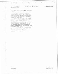
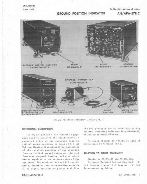
UNCLASSIFIEDJune 1957<strong>GROUND</strong> <strong>POSITION</strong> <strong>INDICATOR</strong>Rsdio-Navigational Aids<strong>AN</strong> /<strong>APA</strong>-<strong>57B</strong>,CELECTRONIC:r HFUNCTIONAL DESCRIPTIONThe Atd/<strong>APA</strong>-<strong>57B</strong> and C ere airborne equipmentused to indicste the diaplscement innautical nilea of the aircraft from aninitial ground position, in terms of N-S andE-W coordinates. It provides direct indicetionof the relative position of the aircraftirom an initiai ground reference, derivedfrom true airapced, heading, and wind informationsupplied to the various unit# of thetquipaent. 'ke reaultaet N-S r ~ ~ dnatea, converted into corresponding variableDC voltages, are used to ground stabilizethe PPI preaentatian of radar indicatingsystems, including Indicator Assy <strong>AN</strong>/<strong>APA</strong>-56,or Indicator Group <strong>AN</strong>/<strong>APA</strong>-81.No field changea in effect at time ofprepsration (2 November 1956).Simil nr to .<strong>AN</strong>/.<strong>APA</strong>-57 and <strong>AN</strong>/.<strong>APA</strong>- S7A.E-l c ~ ~ ~ d i - Equipgc~t Required hot. not Sunp1ird: (1)G-2 Compass System, (1) Adapter, (I) SetInterconnecting Cables.UNCLASSIFIED 1.3 <strong>AN</strong>/<strong>APA</strong>-570: I
UNCLASSIFIEDRadio-Navipational Aids June 1957<strong>AN</strong>/<strong>APA</strong>-57~,~ <strong>GROUND</strong> <strong>POSITION</strong> <strong>INDICATOR</strong>ELECTRICAL <strong>AN</strong>D MECH<strong>AN</strong>ICAL CHARACTERlSTlCSTUBE. <strong>AN</strong>D/OR CRYSTAL'-COMPLEMENTF!EADING SIGNAL: 0 to 3 v, single phase, 400 (8) 12AU7 (3) l2AT7cps: or 0 to 9 v, single phase, 400 cps. (2) 6AQ5 (3) 6X4WAIRSPEED SIGYAL: 0 to 65 v, 3 phase, 40 to (1) 6AX5 (1) 6J6W160 cps; or 0 to 12 v, single phase, 400 Total Tubes: (18)eps.WIND SIGNAL: 0 to 1.5 v, single phase, 400cps.REFERENCE DATA <strong>AN</strong>D LITERATUREOUTPUT HEADING SIGNAL: 0 to 12 v. 3 phase,400 cps. <strong>AN</strong> 16-30<strong>APA</strong>57-3: Technical Manual for GroundOUTPU <strong>GROUND</strong> <strong>POSITION</strong> COORDINATES Position Indicator <strong>AN</strong>/<strong>APA</strong>-57~, <strong>AN</strong>/<strong>APA</strong>-5 B,P(ITWTI0METBR: -150 to f150 v DC. <strong>AN</strong>/<strong>APA</strong>- 57C, <strong>AN</strong>/<strong>APA</strong>- 57.SYNCHRO: 0 to 12 v, 3 phase, 400 cps.ALTITUDE: 30,000 ft.TEMPERATURE R<strong>AN</strong>GE: -55 deg to f55 deg C.POWER REQUIREMENTS: 115 v or 208 v i5%, 3 TYPE CLASSIFICATIONDESIGN COGNIZ<strong>AN</strong>CE BUAER~hase, 400 cps +5% and 115 v f5%, phaseA, 400 cps, +5%; phase A 70 va, phase B62 ve, phese C 78 va, and 28 v DC f5%,lamp.PROCUREMENT COGNIZ<strong>AN</strong>CESTOCK NO.QU<strong>AN</strong>TITYPEr!EQUIPTNAME <strong>AN</strong>D NOMENCLATUREEQUIPMENT SUPPLIED DATAOVERALL DIMENSIONS[inthu)IWEIGHT(Ibr.1Computer-Indicator CP-l31/AP&578 or CP-132/APP,57CMounting MT-1098/AP&578Electronic Control Amp1 if i er ~M-674/APk-578Mounting MT-617/<strong>APA</strong>-57Contrcl ~-1061/~PP<strong>57B</strong>Mounting MT-620l<strong>APA</strong>-57Airspeed Transmitter T-3U9/AP&578MountingInertia Switch S&275/APPr57Mounting MT-9S5lASet AccessoriesUNCLASSIFIED
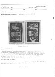
L-~- ~ &HOMING ADAPTERRadio-Navigational Aids<strong>AN</strong>/ARA-8<strong>AN</strong>TENNARELAV-13/4R4.j.* ..PLL'G'. L -. 3 $2-!CSL-'SADAPTER b?.fiz -:. PL Jh ,. CA3L EM -358 y.. =Lo 'r, .. 4 4DAPTEPI* 4N 3057-4UNCLASSIFIED 1.3 AA/A~.A-L: I
Radio-Navigational Aids<strong>AN</strong>/ARA-8FUNCTIONAL DESCRIPTIONHOMING ADAPTERELECTRICAL <strong>AN</strong>D MECH<strong>AN</strong>ICAL CHARACTERISTICSThe <strong>AN</strong>/ARA-8 is to be used with a W F receiver,such as Radio Set SCR-522 or RadioSet <strong>AN</strong>/ARC-3, to provide a fighter aircraftwith means to home on any transmitted carrierwithin the frequency range of 120 to 140megacycles. It enables lost pilots to homeon ground communication stations and thusreach the vicinity of the landing field, andcan beused for air-to-air homing forpurposesof rendezvous and gathering of scatteredcombat planes. flaming can be accomplished oneither CW. MCW, or audio pulse signals.No field changes in effect at time Ofpreparation (31 January 1957).RELATION TO OTHER EQUIPMENTEquipment Required But Not Supplied: (1)Ol~mmeter 1-56 or IS-189, (1) 28 V lamp, (1)Toggle Switch <strong>AN</strong>-3023-1. (1) Toggle Switch<strong>AN</strong>-3022-2, ( 1) Set Antenna Mtg. Clamps, (1)Signal Generator I-130-A, (1) Noise GeneratorTS-274/AR.FREQUENCY R<strong>AN</strong>GE: 120 to 140 mc.RECEPTION: CW, MCW, audio pulsea.POWER REQUIREMENTS: 28 v DC, 1 amp.TUBE <strong>AN</strong>D/OR CRYSTAL COMPLEMENTNo Electron Tubes.REFERENCE DATA <strong>AN</strong>D LITERATURE<strong>AN</strong>16-30ARA8-3: Technical Manual far HomingAdapter <strong>AN</strong>/ARA-8.TYPE CLASSIFICATIONPROCUREMENT COGNIZ<strong>AN</strong>CESTOCK NO.IEQUIPMENT SUPPLIED DATA'OU<strong>AN</strong>TITYOVERALL DIMENSIONSWEIGHTPEENAME <strong>AN</strong>D NOMENCL<strong>AN</strong>REEOUIPT(inches)(Ib'.)NOTES: Qty 2 to 7 depending on type of aircraft in which equipment is installed... Length depends on type of aircraft in which equipment is installed.Modulator Keying Unit MC-%U/ARA-~Mounting Bracket MT-~B~/ARA-~Antenna Relay RE-17IARA-8Mounting MT-288/~RA-8Antenna Assembly AS-148iARA-82-315Cable Adapter <strong>AN</strong>7057-4capacitor CA275Adapter M-758Adapter W59Cord CC-BOO or CG~O~/UCord CC-800 or CG-~O~/UEscutcheon, wlswitch Guard Mx-769/~~~--8Plug <strong>AN</strong>7106-1OSL-7SPlug <strong>AN</strong>310&lOSL-USPlug PL-259Cable R.F. RG-8/u or RG-31/~UNCLASSIFIED
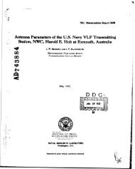
UNCLASSIFIEDJune 1957-. -RADIO RECEIVING SETRadioNmvigationaI Aid.<strong>AN</strong>IARN-14Radio Receiving Set <strong>AN</strong>/ARN-14UNCLASSIFIED 1.3 M/ARII-I& 1
Radio-Navigational Aids<strong>AN</strong>/ARN-14FUNCTIONAL DESCRIPTIONRADIO RECEIVING SETThe <strong>AN</strong>/ARN-14 is en airborne equipmentdesigned to provide the pilot or other membersof an air crew with all the rsdio sida tonavigation now available in the very highfrequency range of 108.0 to 135.9 megacycles.inclusive. The reception range includes bothmilitary and commercial AM communicationchannels, Omnidirectional Range Channels,Tone (90 or 150 cycle) and Phssc CamparisonLocalizer Channels, and Two-Gurae VHY VisualRange Navigational Channels are avsilsblewhen the Radio Receiving Set has aa a pertof its aystcm, Radio Receiver R-252/ARN-14and Gntrol Box C-512/ARN-14. 'he Radio Receiviagsetwhich uses Radio Receiver R-252B/ARN-14 does not provide Phase ComparisonLocalizer Chsnncl facilities. In any receivingsystem which utilizes Control PanelC-760A/A, Phase Comparison Localizer Channelsare not available.No licld changes in effect at time ofpreparation (8 November 1956).RELATION TO OTHW MUIPMMTUNCLASS!FIEDJune 1957GENERAL COMMUNICATION RECEPTION: 122.0to 135.9 mc.FREWENCY STABILIP: M.OO?%.AilDiO POWER OL'WUT: 300 mw into 500 ohmload.AUDIO OUWL'T IMPED<strong>AN</strong>CE: 500 ohma.<strong>AN</strong>TENNA INPUT IMPED<strong>AN</strong>CE: 52 ohms with lessthan 2: 1 SWR.AUTOMATIC GAIN CONTROL: Maintains audiooutput within 3 db for variation of RFinput from 5 to 100000 uv.TEMPERA'ILIRE R<strong>AN</strong>GE: -55 to 471 deg C (67 to+I60 deg F).HUMIDITY: Up to 95% at +50 deg C (f122 degF) .PRESSURE: Altitude up to 50000 ft.R<strong>AN</strong>GE: 4 mi at 10 ft altitude to 300 m i at50000 ft altitude.POWER REWIREMNTS: 26.5 v DC, 7 anpa normal,20 amps starting and channel selection;26 V. 400 cps. 0.43 amps for automaticindicators.TUBE <strong>AN</strong>D/OR CRYSTAL COMPLEMENTEquipment Required but not Supplied: (1)(11) 567014) 5749/6BA6W( 4) 57 2 6 / 6 ~ ~ 5 ~(1) 57 50/6BE6WFlight Path Deviation Indicator ID-48A, (1) (3) 5751Antenna Chsnaeover - Relay. ..(1) Gvro Flux GateCompass Transmitter and Amplifier Unit or Total Tubes: (33)other remote indicating magnetic compass, (1)Antenna Coaxial Connector UG-21B/U, Antenna (2) 1N34A (34) Hc-6/UCoaxial Cable RG-8/U, Headsets. Cords. InterphoneJack Boxes, Interconnecting wires as Total Crystals: (36)Re+i red, Test Equipment as Required.ELECTRICAL <strong>AN</strong>D MECH<strong>AN</strong>ICAL CHARACTBISTICSFREWMCY R<strong>AN</strong>GE: 108.0 to 135.9 mc.MAWEL DAT.4NLMBER: 280.SPACING: 100 kc.(iSN'IROL: Cryatal.SERVICE FREWENCY R<strong>AN</strong>GESlDNE TYPE RUNWAY LOCALIZER: 108.0 to111. 9 me.PHASE TYPE RUNWAY LOCALIZER: 108.0 to111.9 mc.OMNIDIRECTIONAL R<strong>AN</strong>GE: 112.0 to 117.9mc.WiF 7WO-UJURSE R<strong>AN</strong>GE: 108.3 to 110. 3 me.WEAEER EPOADCAST RECEPTIW: 111.0 toiii.0 mc.'IDWER RECEPTION: 118.0 to 121.9 mc.REFERENCE DATA <strong>AN</strong>D U-TURET.O. 12RS-2AIW 14-2: Technical Manual lorRadio Receiving Set &'/Am-14.TYPE CLASSIFICATIONDESIGN COGNIZ<strong>AN</strong>CEUSAFPROCUREMENT COGNIZ<strong>AN</strong>CE----" ..-.,I"Ln I.".1.3 <strong>AN</strong>/ARN-14: 2 UNCLASSIFIED
UNCUSSIFIEDJune 1957RADIO RECEIVING SETRadio-Navigational Aids<strong>AN</strong>/ARN-14QU<strong>AN</strong>TITYPEPEQUIP1NAME <strong>AN</strong>D NOMENCUTVIEEQUIPMENT SUPPLIED DATAOVERALL DIMENSIONS(inches)Radio Receiver ~-252/ARN-14 or R-252BtARN-1U including:RF HeadIF and Audio ChassisNavigation ChassisMonitor ChassisControl Panel C-512/ARN-14control Panel ~-760~1ADynmtor Unit DY-66/ARN-14or:Mounting, Dynamtor MT-627tARN-14course Indicator lC-249/~RN or I C - ~ ~ ~ A ~ A R NCourse Indicator 1~-250/AR~Radio-I ndicator Control 10-251lARNAntenna AT-172/AR~-145 X 7.62 X 25.413.775 X 5 X 5.377.775 X s.5 X 5.755 X 7.75 X lU.745.87 X 5.93 X 24.757.25 dia X 6.217.25 dia X 6.257.25 dia X 4.3612.125 X 17.25 X 26.5UNCLASSIFIED
UNCLASSIFIEDAqust 1957RADIO RECEIVING SETRadio-Navigational Aids<strong>AN</strong>/ARN-14A1---.. 1 ..7i u ;!A 94E -;-*.- - ;L-..- - ;i-' i - 1a&&\/- . - . .- .' C v s?! ~-sRadio Receiving Set AK/ARX-iYA1 Course Indicator ID-249A/ARN 7 Mounting MT-627A/ARV-142 Course Indicator ID-250/ARN 8 Control Panel C-760A/A3 Radio indicator-Control iD-2SI/AXN 7 Antenna AT-??2/A?N-14-4 "..----.L'y 5 L,/*?"y- ?1~ ~zezctcr ~'-UA/AUN.~AA5 Mounting MT-628/ARN-14 11 Mounting MT-962/ARN-l4A6 Radio Receiver R-252C/ARN-14UNCLASSIFIED 1.3 <strong>AN</strong>/UIN-I~A: I
Radio-Navigational Aids<strong>AN</strong>/ARN-14ARADIO RECEIVING SETFUNCTIONAL DESCRIPTIONThe <strong>AN</strong>/ARN-14A is an airborne navigationalradio receiving equipment providing 280 communication-navigationchannels covering afrequency range of 108-0 through 135.9 megecycles.Primarily the equipment is designedto provide the pilotandsir crew with visualindications of the lateral positional deviationof the aircraft from e selected omnidirectionalrange station radial or from aparticular leg of a WF visual-aural rangeon an airway, or from the correct localizerpath to an airport runway. Provision is alsomade for the reception and detection ofamplitude modulated communication signals.including weather and tower broadcasts,general communications on the military andcommercial frequency bands and coded identificationletter groups associated with navigationalsignals.No field changes in effect at time ofpreparation (10 December 1956).TOWER COMMLTNICATIONS: 118.0 to 121.9 mc.GENERAL COMMUNICATIONS: 122.0 to 135.9mc.FREWENCY DRIFT: 0.01%.RECEIVER SYSTEM: Triple conversion super.heterodyne.FREWENCI CCNlROL: Crystal.EFFECTIVE RECEIVING R<strong>AN</strong>GETONE LOCALIZER SERVICE: Approx 20 mi.OMNIDIRECTIONAL R<strong>AN</strong>GE: Approx 175 mi.V.H.F. VISUAL-AWL-R<strong>AN</strong>GE: Approx159mi.AMBIENT TEMPERATURE R<strong>AN</strong>GE: -55'C to +7l0 C.MINIMUM BAROMETFiIC PRESSURE: 3.4 in. mercury(50,000 ft altitude).POWER SOURCE REWIRED: 26.5 V DC and 26 V,400 cps AC.TUBE <strong>AN</strong>D/OR CRYSTAL COMPLEMENTRELATION TO OTHER EQUIPMENTEquipment Required but not Supplied: (1)Antenna Changeover Relay, (1) Set of Powerand R.F. Cebles, (1) Remote Indicating Compassand (1) Headset.Total Tubes: (30)REFERENCE DATA <strong>AN</strong>D UTER<strong>AN</strong>RE<strong>AN</strong>16-30ARN14-11: Technical Manual for RadioReceiving Set <strong>AN</strong>/ARN-14A.ELECTRICAL <strong>AN</strong>D MECH<strong>AN</strong>I~L CHARACTERISTICSFREOWCY R<strong>AN</strong>GE: 108.0 to 135.9 me.TWES OF SERVICE AM) FREQUENCY BAM)S.TONE LOCALIZER (Runway location): 108.8to 111.9V.H.F. VISUAL-AURAL-R<strong>AN</strong>GE (Airway location):108.3 to 110.3 mc.WEA-R BROADCASTS: 111.0 to 111.9 mc.OMNIDIRECTIONAL R<strong>AN</strong>GE (Radial location):112.0 to 117.9 mc.TYPE CLASSIFICATIONDESIGN COGNIZ<strong>AN</strong>CEUSAFPROCUREMENT COGNIZ<strong>AN</strong>CESTOCK NO.EQUIPMENT SUPPLIED DATAQU<strong>AN</strong>TITYPEEEQUIPTNAME <strong>AN</strong>D NOMENCLATUREOVERALL DIMENSIONS(inth.11WElGMIlbs.1111Radio Receiver R-252C/ ARM-lUControl Panel C760AIADynamotor CY-8ulARN-l4Aor CY-66lARN-luUNCLASSIFIED
UNCUSSIFIEDAugust 1957RADIO RECEIVING SETRadio-Nsrigetionel Aids<strong>AN</strong>/ARN-14AEQUIPMENT SUPPLIED DATAQU<strong>AN</strong>TITYPER I NAME <strong>AN</strong>D NOMENCLATUREMounting MT-962/ARN-luAMounting MT-627A/ARN-14Course Indicator I b2U9AlARNCourse Indicator I It2SOlARNiioJio :ndiihioi Ci.ii:r~l iL!-:5:,'AR:IAntenna AT-1721ARN- 19or Mi-62813RN-14OVERALL DIMENSIONSWEIGHTEQUIP1 I I(inches! I [lbs.)UNCLASSIFIED
I0 August 1962RADIO RECEIVING SET <strong>AN</strong>/ARN-IPCCog Service: BuWeps FSN: Functional Class:USA USN USAFTYPE CUSS: Used by Used byM<strong>AN</strong>UFACTURER'S NAME/CODE NUMBER: coll ins Radio CO., (13499) .FUNCTIONAL DESCRIPTION:Radio Receiving Set AR/ARR-IYCThe Radio Receiving Set <strong>AN</strong>~ARN-14c is an airborne navigational radio receiving equipmentproviding 280 communicat ion-navigat ion channels covering a frequency range of 108.0 to135.9 megacycles (MC).NO field changes in effect at time of preparation (5 March 1962).TECHN lCAL CHARACTER I ST ICS:TYPE OF INSTALLATION: Airborne. FREQUENCY R<strong>AN</strong>GE: 108.0 to 135.9 mc.TYPE OF INDICATATION:visual. NUMBER OF CH<strong>AN</strong>NELS: 280.TYPE OF RECEPTION: A9 type. CH<strong>AN</strong>NEL SPACING: 100 kc.TYPE OF RECEIVER: Superheterodyne. OPERATING POWER RQMT: 115 v ac, 400 cps,TYPE OF FREQUENCY CONTROL: crystal. single ph, 25 W; 26.5 v dc, 159 W.EQUIPMENT PURPOSE:Navigation.
RADIO RECEIVING SET <strong>AN</strong>lARN-IUCSHIPPING DATAPKGS VOLUME (CU FT) WEIGHT (LBS)PROCUREMENT DATAPROCURING SERVICE:BuWepsSPEC &/OR DWG: MCREE-329-0DESIGN COG:BuWepsCONTRACTOR LOCATION CONTRACT OR APPROX.ORDER NO.UNIT COSTCollins Radio Co. Cedar Rapids, Iowa ~~33(038)-20917~~33(038)-30015
IV August 1962Cog Service: BuWeps FSN:RADIO RECEIVING SET <strong>AN</strong>/ARN-IVDFunctional Class:USA USW USAFTYPE CLASS: %ed by Used byM<strong>AN</strong>UFACTURER'S NAMEICODE NUMBER: Bendix Aviation Corp., Bendi x Radio Division, (06845).FUNCTIONAL DESCRIPTION:Radio Receiving Set <strong>AN</strong>/RRN-IYDThe Radio Receiving Set <strong>AN</strong>/ARN-IUDis an airborne navigational radio receiving equipmentprovldlng 280 communication-naviation channels covering a frequency range of 108.0 to135.9 megacycles (MC).No field changes in effect at time of preparation (2 March 1962).TECHNICAL CHARACTERISTICS:TYPE OF INSTALLATION: Airborne. CH<strong>AN</strong>NEL SPACING: 100 kC.TYPE OF INDICATION: Visual. OPERATING POWER RQMT: 115 V ac, 400 cps, Sin-TYPE OF RECEPTION: A9 type. gle ph, 25 W; 26.5 v dc.EQUIPXEN: PURPOSE: Naviga: ion.CDE?nENCY R<strong>AN</strong>GE: 1nR.n lo l ? S G mr.NUMBER OF CH<strong>AN</strong>NELS:280 channels.
<strong>AN</strong>/ARN-l4DRADIO RECEIVING SETRELATION TO OTHER EQUIPMENT:The <strong>AN</strong>/ARN-140 is functionally the same as Radio Receiving Set <strong>AN</strong>/ARN-IUA except the tonelocalizer functions are deleted from the even tenth megacycles position in the range 108megacycles to 119.9 megacycles and VOR function SubstitUted on these frequencies.EQUIPMENT REQUIRED BUT NOT SUPPLIED:(1) Power Supply lor Dynamotor OY-66/ARN-l& or (I) Power Supply for Dynamotor DY-~u/ARN-~~A;(I) Power Supply for Indicators (26 v, 400 cps, 0.5 amps); (I) Remote lndlcatlng MagneticCompass NT 12013; (1) Headset; (3) Antenna Cwaxlal Cables RG-B/U; (6) Antenna Coaxial Connector(to match W/UG-58/U Receptacle or uG-2181~); (I) Vertical Antenna Type <strong>AN</strong>-iOuB or equivalent.MAJOR COMPONENTSQTY l TEM STOCK NUMBERS DIMENSIONS WEIGHT(INCHES)(LBS)Radio Receiving Set <strong>AN</strong>IARN-1x1consists of:Rad I0 Reca lver R-SUl/ARN-140Receiver control C-5121~~~-laDynamotor DY-66/ARN-14Mount ing Base MT-627A/ARN-14Mounting Base ~T-628/A~N-14Antenna AT-172/~~~-14control Panel C-~~OA/ADynamotor DY-84/ARN-l4AMounting 68% MT-~~~/ARN-~~AREFERENCE DATA <strong>AN</strong>D LITERATURE:<strong>AN</strong>X-35~541-1:Technical Manual for Radio Receiving set <strong>AN</strong>/ARN-I&D.TUBE, CRYSTAL <strong>AN</strong>D/OR SEMI-CONDUCTOR DATA:TUBES: (7) 5654 (5) 5670 (4) 5749 (1) 5750 (4) 5726 (5) 5751 (1) 082CRYSTALS:None used.SEMI-CNOOUCTORS:None used.SHIPPING DATAPKGS VOLUME (CU FT) WEIGHT (LBS)
RADIO RECEIVING SET <strong>AN</strong>~ARN-IUDPROCUREMENT DATAPROCURING SERVICE: BUWePS DESIGN COG: BUWeDSSPEC &/OR DWG: HCREE-329-8CONTRACTOR LOCAT l ON CONTRACT OR APPROX.ORDER NO.UNIT COSTBendix Aviation Corp..Bendix Radio DivisionBaltimore. Maryland
21 August 1962 RADIO RECEIV ING SET <strong>AN</strong>/ARN-19~Cog Service: USAF FSN: Functional Class:USA usn USAFTYPE CLASS:used byM<strong>AN</strong>UFACTURER~S nAME/CODE NUMBER: coil ins Radio CO., (131199).(No Illustration Available)FUNCTIONAL DESCRIPTION:The Radio Receiving Set <strong>AN</strong>/ARN-1UE is an airborne navigational radio receiving equipmentproviding 280 communication-navigation channels covering a frequency range of 108.0 through135.9 megacycles (MC).The <strong>AN</strong>/ARN-l4E is primarily designed to provide the pilot and air crew with visual indicationsof the lateral positional deviation of the aircraft from a selected omnidirectionalrange station radial, or from a particular leg of a very High Frequency (VHF) visual-auralrange on an airway, or from the correct localizer path to an airport runway. Provision isalso made for the reception and detection of amplitude modulated communication signals, includingtower broadcasts, general communications on the military and commerical frequencybands, and coded identification letter groups associated with navigational signals.NO field changes in effect at time of preparation (3 January 1962).TECHNICAL CHARACTERISTICS:TYPE OF INSTALLATION: Aircraf 1 installed.TYPE OF RECEIVER: Double superheterodyne.TYPE OF FREQUENCY CONTROL: Crystal.CH<strong>AN</strong>NEL DAT<strong>AN</strong>UMBER OF CH<strong>AN</strong>NELS: 280.CH<strong>AN</strong>NEL SPACING: 100 kc.TYPE OF CONTROL: Crystal.SERVICE FREQUENCY R<strong>AN</strong>GESTONE TYPE RUNWAY LOCALIZER: 108 to 111.9 mc.PHASE TYPE RUNWAY LOCALIZER: 108 to 111.9 mc.OMNIDIRECTIONAL R<strong>AN</strong>GE: 112.0 to 117.9 mc.VHF TWO-CORSE R<strong>AN</strong>GE: 108.3 to 110.3 mc.WEATHER BROADCAST RECEPTION: 110.0 to 112.0 mc.TOWER RECEPTION: 118.0 10 121.9 mc.GENERAL COMMUNICATION RECEPTION: 122.0 to 135.9 mc.TYPE OF RECEPTION: A9 type.OPERATING FREQUENCY R<strong>AN</strong>GE: 108 to 135.9 mc.OPERATING POWER RQMT: 26.5 dc, 2.5 amps; 250 V dc, 150 ma.RELATION TO OTHER EQUIPMENT:The <strong>AN</strong>/ARN-1uE is similar to but not the same as <strong>AN</strong>/ARN-~u.-~uA,-~~B,-~~~c and <strong>AN</strong>/ARN-140.
<strong>AN</strong>/ARN-l4ERADIO RECEIVING SETEQUIPMENT REQUIRED BUT NOT SUPPLIED:None.MAJOR COMPONENTSQTY 1 TEM STOCK NIJWBERS CllMENSlClhlS WEIGHT1 Radio Receiving Set <strong>AN</strong>/ARN-14Econsists of:1 Radio Receiver R-SUO/ARN-IUC1 !tcga:)n2 !!~-~~~~/~~f;&;;1 Dynamotor DY-84/ARN-1UA1 Mounting MT-962/ARN-IUA5X8X21SXBX 10REFERENCE DATA <strong>AN</strong>D LITERATURE:~~16-35~541-I: Technical Manual for Radio Receiving set <strong>AN</strong>~ARU-I~.-~~~A.-~~B,-I~C.-I~D and<strong>AN</strong>/ARN-lUE.TUBE, CRYSTAL <strong>AN</strong>D/OR SEMI-CONDUCTOR DATA:TUBES: (1) OA2WA (10) 6AKSW (1) 5687WA (1) 6AL5W (3) 5751 (10) 5814ACRYSTALS:(94) HC-6/USEMI-CONDUCTORS:(2) 1N34ASHlPPlaG DATAPKGS VOLUME (CU FT) WEIGHT (LBS)PROCUREMENT DATAPROCURING SERVICE: USAF, USN DESIGN COG: USAFSPEC &/OR DWG: MCREE-729B(USAF)CONTRACTOR LOCAT l ON CONTRACT OR APPROX.ORDER NO.UNIT COSTCollins Radio Company Cedar Rapids. Iowa MIPR2776-53
UNCLASSIFIEDOctober 1957RADIO RECEIVING SETRadio-Navigational Aids<strong>AN</strong>/ARN-18Radio Receiving Set <strong>AN</strong>/ARN-I~FUNCTIONAL DESCRIPTION'ha <strong>AN</strong>/ARN-18 is a part of the instrumentlanding mystem which provides for both rerticaland lateral guidanca whan landing anaircraft. Lateral guidance is supplied bya separate receiver. The oignals received bythe guide slope receiver are radiated by anultra high frequency glide elope tranamitterlocated in proximity to the touchdorn pointon the airfield landing strip or runway.These signnla are used to operate the horizontalpointer of one to three cross-pointerinstruments to provide a continuous siaunlindication of tho position of the aircraftwith iempect to the aatablished glide rlope.No fiald changes in effact at time ofpreparation (6 March 1957).REUTION TO OTHER MUIPMENTEquipment Required but not Supplied: (1)Antenna, bs required) Trnnsminsion Line, (1)Power Cable (26.5 V DC) (1) Power Cable (115V AC) (1) Set Interconnectin Wire, (1) ControlPanel C-760/A or C-9967~. (1 to 3) IndicatorID-48/ARN or ID-249/ARN or ID-249A/UNCLASSIFIED 1.3 A N A N 1
UNCLASSIFIEDJune 1957RADIO SETRadio-Navigational Aids<strong>AN</strong>/ARN-21RADIORECEIVER - TR<strong>AN</strong>SMITTERRT-220/ARN-21PHASE DETECTING NETWORKPtl227//A011IR<strong>AN</strong>GE IND1D-310,'AKNRADIO SET CONTRlC-866/ARN-21Radio Set <strong>AN</strong>/ARN-21UNCLASSlFlED 1.3 <strong>AN</strong>~ARN-21: 1
Radio-Navigational Aids<strong>AN</strong>/ARN-21RADIO SETUNCLASSIFIEDJune 1857FUNCTIONAL DESCRIPTIONThe &V/ARN-21 is an airborne navigationinterrogator-responsor designed to operatein conjunction with a surface navigationbeacon such as Radio Set <strong>AN</strong>/LRN-3. The airborneand surface equipment8 form s radionavipation system which enables an equippedaircraft to obtain continuous indications ofits distance and bearing from any selectedsurface beacon located within a line-of-sightdistance from the aircraft up to 195 nauticalmiles. The bearing information and diatanceinformation are displayed on two separateindicators.No field changes in effect at time ofpreparation (6 November 1956).RELATION TO OTHER MUIPMENTEquipment Required but not Supplied: (1)Antenna AS-572/ARN-21 or ~s-l33/APX or AT-234/APX, (1) Cable, Antenna RG-8/U, Plugsand Cable Clamps as required, Test Equipmentas required. (1) Course Indicator ID-249(A)/ARN, (1) Course Indicator ID-250/ARN, (1)Fluxgate Compass G-2, and Plugs and CableClamps ere Accessory Equipment aa required.ELECTRICAL <strong>AN</strong>D MECH<strong>AN</strong>ICAL CHARAClERlSllCSRECEIVER DATAFREQUENCY R<strong>AN</strong>GELOW B<strong>AN</strong>D: 962 to 1024 mc in 1 mcsteps.HIGH B<strong>AN</strong>D: 1151 to 1213 mc in 1 mcsteps.INTERMEDIATE FREQUENCY: 63 mc.NOISE FIGURE: 13 db.IMAGE RATIO: 60 db min.TRAVSMITTER DATAFREQUENCY R<strong>AN</strong>GE: 1025 to 1150 me in 1 mcsteps.PEAK PULSE POWER OLTPUT: 1 kw min.PULSE PAIR TR<strong>AN</strong>SMISSION RATE: 150 and30 pps.SIMAL DATATR<strong>AN</strong>SMIrnPJLSE PAIR SPACING: 12 usee.UiSF TIME: 2.5 osrr (10 to 90% amplitude).DURATION: 3.5 usec (50% amplitude).DECAY TIME: 1 usec max (90 to 10%amplitude).RECEIVEDPULSE PAIR SPACING: 12 usec.RISE TIME: 2.5 usec (10 to 90% amplitude).DURATION: 3.5 usec (50% amplitude).DECAY TIME: 2.5usec (90 to 10% amplitude).PULSE WDULATION: Amplitude modulated15 :35 .-"..-I' -.'-p a . USpL" 0. "I"""-lation is 15 to 30% for each frequency.15 CYCLE REFERENCE BEARING SIMAL: 15pulse groups per second, each groupconsisting of 12 pulse pairs spaced30 usec apart.135 CYCLE REFERENCE BEARING SIMAL:135 pulse groups per second, eachgroup consistin6 of 6 pulse pairsspaced 24 usec apart.POWER REQUIREMENTS: 115 v, 380 to 420 cps,single phase, 80 va; 115 v, 320 to 1000cpa, single phase, 400 ra; 28 v DC, 0.7amps.M<strong>AN</strong>UFACTURER'S OR CONTRACTOR'S DATAHoffman Laboratories, Inc., Los Angeles,California.Contract NOas 52-445, dated 6 December1951.Stramberg Carlson Company, Rocheater,N.Y.,Contract NOas 52-446, dated 21 November1951.Collins Radiocompany. Cedar Rapids. Iowa.Contract NOas 51-1155-i, dated 30 June1951.International Telephone and TrlegraphCorp (Federal Telephone and RadioCompany Div). Clifton, New Jersey.Contract Noes 51-1227, dated 19 June1951.Approximate Cost: 19500.00 withequipment spares.TUBE <strong>AN</strong>D/OR CRYSTAL COMPLEMENTUNCLASSIFIED
UNCUSSIFIEDJune 1957RADIO SETRsdio-Navigational Aids<strong>AN</strong>/ARNdl(1) OA2 (2) 5670 REFERENCE DATA <strong>AN</strong>D UTBUTUIIE(6) 5654 (3) 5656(1) 3D21A (2) 5517 <strong>AN</strong>16-3DARN21-3: Technical Manual for ~adiaTotal Tubes: (75) Set <strong>AN</strong>/ARN-21.Total Crystals: (46)DESIGN COGNIZ<strong>AN</strong>CE BUSH IPSPROCUREMENl COGNIZ<strong>AN</strong>CESTOCK NO.EQUIPMENT SUPPLIED DATAQU<strong>AN</strong>TITYPEEFCslllVT- ~NAME <strong>AN</strong>D NOMENCL<strong>AN</strong>REOVERALL DIMENSIONS(inches)WEIGH?(Ibt.)Radio Receiver-Transmi tter RT-220lARN-21Mounting MT-92BIARN-21Azimuth Indicator IP9O'IIARNRange Indicator I P31OIARNRadio Set Control C866IARH-21Phase Detecting Netwrk CY-2791ARN3-118 dia x 6-5183-110 dia X 7-1142-114 X W/U X 5-3142-23/32 X 9 X &7/8.. .,UNCLASSIFIED
13 August 1962 RADIO SET <strong>AN</strong>IARN-26(XN-2)Cog Service: USN FSW: Functional Class:USA USN USAFTYPE CLASS: Used by Used byMAWUFACTURER'S RAMEICODE NUMBER: ITT Laboratories, (903~8).Radio Set dX/ARR-26(XB-21FUNCTIONAL DESCRIPTION:The Radio Set <strong>AN</strong>IARN-26(x~-2) is designed as a radio receiving set operating between 90kilocycles and 110 kilocycles on seventy-f ive (75) preset channels, automatically obtains abearing and a course to fly to the Navaglobe Station selected, up to a distance of 1500 nauticalmiles.The <strong>AN</strong>IARN-26(xN-2) is an airborne data 1 ink equipment operated in conjunct ion with airborneRadio Set <strong>AN</strong>/ARN-ZI(XN-3) to perform the following functions: ( It displays actualbearing. heading, air speed and al!itude information; (2) It encodes and reeds ?o Radio Set<strong>AN</strong>~ARN-2l(XN-3) for transmission to the surface act iv'ity the above fl ight data, acknowledgementsof received orders, any one of 31 discrete messages, and any one of six modes of oper-ation: (3) It decodes and displays ordered instructions received from the surface activity inthe same categories.No field changes in effect at t;me oi preparation (1 Harch 1962).
LNlARN-26(XN-2)RADIO SETTECHNICAL CHARACTERISTICS:TYPE OF INSTALLATION: Airborne. RECEIVER FREQUENCY: 1087.5 to 1215 mc.TYPE OF EQUIPMENT: Radio. CH<strong>AN</strong>NEL SPACING: 2.5 mc.EQUl PMENT PURPOSE: Navigation. NUMBER OF PRESET CH<strong>AN</strong>NELS: 75.EFFECTIVE R<strong>AN</strong>GE: Up to 1500 nautical miles. OPERATING POWER RQMT: 28 V dc. 2 amps; 110 VFREQUENCY R<strong>AN</strong>GE ac, 320 to 1760 cps, 400 va; 115 v ac, 380TR<strong>AN</strong>SMITTER FREQUENCY: 960 to 1087.5 mc. to 420 cps, single ph, 30 va.CH<strong>AN</strong>NEL SPACING:2.5 mc.RELATION TO OTHER EQUIPMENT:The <strong>AN</strong>/ARN-26 (XN-2) is designed to be used in conjunct ion with Radio Sets <strong>AN</strong>/ARN-21 (XN-3).<strong>AN</strong>/URN-3; <strong>AN</strong>IGRN-9. 9A. 98, 9C or <strong>AN</strong>ISRN-6.EQUl PMENT REQUIRED BUT NOT SUPPLIED:(1) Radio Set <strong>AN</strong>IARN-ZI(XN-~); (1) Cross Pointer Instrument ID-249; (1) ILS and MarkerGenerator; (1) Altitude Sensing Cell; (1) Throttle Potentiometer; (1) Flux-Gate Compass; (I)Set of Cables.MAJOR COMPONENTSQTY ITEM STOCK NUMBER DIMENSIONS WEIGHT(INCHES)( LBS)1 Radio Set <strong>AN</strong>/ARN-26(xN-2)consists of:I Data Coding Unit 9-ljli6 x 11-118 x 241 control Panel 5-13/32 x 5-314 x 7-1181 Airspeed Indicator 3-114 x 3-114 x 8-11/161 Altitude Indicator 3-1/11 x 3-114 x 7-31/321 Radio Magnetic (~eading) 3-114 x 3-flu x 7-17/16lndicator1 Bearing lnd icator 3-114 x 3-114 x 8-7/321 Distance Indicator 3-114 x 3-114 x 8-21/321 Discrete Data Indicator 3-1/4 x 3-114 x 10-518I Junction Box 4-17/64 x 10-9/16 x 12-1121 Set of ConnectorsREFERENCE DATA <strong>AN</strong>D LITERATURE:NAVSH l PS 93501:--Technical Manual for Radio Set <strong>AN</strong>/ARN-26 (XN-2).TUBE, CRYSTAL <strong>AN</strong>D/OR SEMI -CONDUCTOR DATA:
RADIO SET <strong>AN</strong>IARN-26(XN-2)CRYSTALS:None used.SEMI-CONDUCTORS: (168) IN274 (119) IN278 (6) IN343 (6) IN344 (15) 11352 (1) IN429SHIPPING DATAPKGS VOLUME (CU FT) WEIGHT (LBS)PROCUREMENT DATACONTRACTOR LOCAT ION CONTRACT OR APPROX.ORDER NO.UN l T COSTITT Laboratories Nutley. New Jersey NObsr-64655,30 November 1959
UNCUSSIFIEDJune 1857RADIO RECEIVING SETRadio-Navigational Aids<strong>AN</strong>/ARN30,30AMOTORARN-30IRADIO REMOUNT1MT-I 174/ARiu-~unSIGNAL DATA C ONVERT ERCV- .265/AR14-30A. ARADIO SET (C-984/AFSET C(254/ARbCOURSE <strong>INDICATOR</strong>ID-322/ARN-30MN I rlulumAS-580A/ARN-30Radio Receiuing Set <strong>AN</strong>/ARN-30,30A<strong>INDICATOR</strong>ID-48/ARNUNCLASSIFIED 1.3 *W/ARN-~O: 1
Radio-Navigational Aids<strong>AN</strong>/ARN30,30ARADIO RECEIVING SETUNCLASSIFIEDJune 1957FUNCTIONAL DESCRIPTIONThe <strong>AN</strong>/ARN-30 and <strong>AN</strong>iARN-30A are airbornenavigation-communication receiving ayatemadesigned for uae in the frequency range of108 to 135 megacycles for use in aircraftcquipped with a 28 volt direct-current powersource,They provide for VI1F omnidirectional radiorange (VOR), visual-aural range (VAR), 90 to150 cps runway tone localiaera (AMP LOCI,and voice reception on all frequenciaa covaredby the receiver, simultanaously with thenavigation facilitiea, if desired.The approximate distance range of theequipment isdepandant on height and surrouningterrain.The <strong>AN</strong>/ARN-30 end <strong>AN</strong>/ARN-3OA are functionallyinterchangeable, but differ slightlyin the major components provided.No field changes in effect at time ofpreparation (9 November 1956).RELATION, TO OTHER EQUIPMENTThe <strong>AN</strong>/ARN-30 is AircraftRadioCcrporationVHF Navigational Receiving Equipment Type15C, while the <strong>AN</strong>/ARN-30A is Aircraft RadioCorporation Type 15D.Equipment Required but not Supplied:CableasRequired, Test Equipmentas Required.ELECTRICAL <strong>AN</strong>D MECH<strong>AN</strong>ICAL CHARAClERlSllCSFREOWNCY R<strong>AN</strong>GE: 108 to 135 mc.TUNING: Continuous.FREWENCY STABILITY: 0.04% max.TYPE RECEIVER: Superheterodyne.Am10 OUTPVT: 170 mu at AVC knee (at approx6 ur input), 360 mw at 100.000 uv inputrith 30% modnlation et 400 cps, into a300 ohm load.SENSITIVITY: 2 uv or better throughout fre-quency range (for 10 mr with 30% madulationat 400 cva, into a 300 ohm load).SELECTIVITY: ~otdl bandwidth 100 kc for 6db, 350 kc for 60 db.INTERMEDIATE FREQUENCY: 15 mc.TWING ACCURACY: Better then 0.2%.POWER RECUIREMENTS: 28 v DC.<strong>AN</strong>TENNA TYPE: Ramshorn type comprising twoL___, L__1 ..---..-Y. "."-".I." .llrDllll...M<strong>AN</strong>UFACTURER'S OR CONTRACTOR'S DATAAircraft Radio Corporation, Boonton, NewJsracy.Approximate Cost: $846.00 with equipment.pares.TUBE <strong>AN</strong>D/OR CRYSfAL COMPLEMENT(1) 12A6 (3) I2AT7WA( 1) 12AX7 (1) 14F7(2) 14R7 (1) 6189(1) 9002 (3) 9003( 1) 14A7/12B7Total Tubes: (14) (<strong>AN</strong>/ARN-30. 30A)<strong>AN</strong>/ARN-30<strong>AN</strong>/ARN- 30A(8) 1N34A (8) 1N34A(2) 15910Total Crystals: (8) <strong>AN</strong>/ARN-30. (10) 30AREFERENCE DATA <strong>AN</strong>D UTWATURE<strong>AN</strong> 16-45-132: Technical Manual for RadioReceiving Set <strong>AN</strong>/ARN-30.<strong>AN</strong> 16-30ARN30-1: Technical Manuel for RadioReceiving Set <strong>AN</strong>/ARN-30A.ITYPE CLASSIFICATIONDESIGN COGNIZ<strong>AN</strong>CEBUAERI PROCUREMENT CCJCNIZ<strong>AN</strong>CE COXUERCI ALI TD~Y NO.R.D.8. IDENT. NO.IUNCLASSIFIED
UNCLASSIFIEDJune 1957RADIO RECEIVING SETRadio-Navigational Aids<strong>AN</strong>/ARN-30,30AEQUIPMENT SUPPLIEDDATAQU<strong>AN</strong>TITYPEEEQUIPTNAME <strong>AN</strong>D NOMENCLATUREOVERALL DIMENSIONSlinrhes)WEIGHT1Ibs.l<strong>AN</strong>lARN-301111Radio Receiver R-UU5/ARN-30Signal Data Converter CV-217/AR+30Filter-Amp1 if ier AM-609/ARN-30Mounting MT- 1047/ARN-30,Dynamotor DY-86/ARN-3011111111Radio Set Control C-98UlARN-30Antenna A?A~OA/ARN-30Indicator ICLc8IARNCourse indicator ID-322IARN-30Mounting MT-10UUlARN-30Mounting MT-10U5/ARN-30Mounting ~T-lOU6tARk30set of Accessories<strong>AN</strong>IARN-30 A1111Antenna AS-580AlARN-30Radio Receiver R-U45/ARN-30signal Data Converter CV-265/ARN-30 AMounting ~T-l175/ARN-30A1 Mounzing ~T-1174/ARN-30A. oynmtor DY-86/ARN-301 ~ ~ Set dControl i ~ C-98UlARN-30 including:(1) Mounting MT-IOII~/ARN-~O orRadio Set Control C-125U/ARN-?O1 Indicator lkU81ARN1 course Indicator 15322/ARN-301 Set of Accessories- Includes Dynamotor DY-~~/ARN-~O+ - Includes Mounting MT-iOu6/ARN-304-13/16 X 5-112 X 11-1124-13/16 X 5-112 X 11-112"13116 X 5-112 X 6-13/163-518 X 11 X 13-1/162-9/11 dia X U-27/322-15/16 X 3-118 X 4-9/16lo-l/U X 21-119 X 28>l/U X 3-114 X 4-13/163-114 X +l/U X 5-5/161-518 X 10-23/32 X 11-5181-5/16 X 4-15/16 X 6-11/165/16 x 3-118 x 11-19/32lo-l/U X 21-114 X 284-27/32 X 5-518 X 11-1124-27/12 X 5-518 X 11-1123-718 X 9-11/16 X 12-1121-112 X 10-23112 X 11-5182-1/11 dia X U-27/322-15/16 X 3-118 X U-9/165/16 X 3-118 X 4-19/322-9/32 X 3-5/16 X %3/u3-l/U X 7-1/11 X 4-13/16>l/U X 3-l/U X 5-5/168.64.5u2.82.80.623.61.91.50.750.350.083.68.6'5.82.30.7 ,0.7t '0.81.81.5UNCLASSIFIED
UNCLASSIFIEDApril 1959RADIO RECEIVING SET. ..Radio-Navigational Aids<strong>AN</strong>/ARN30B- orwuarqz...66,As, ;* WY.!T,IT_ 'TI<strong>AN</strong>/ARN-308 by Radio Set Cantrol C-1254/ARN-30.ELECTRICAL <strong>AN</strong>D MECH<strong>AN</strong>ICAL CHARACTERISTICS\f 1-.N.,WWAIS 5li"*,l*N 30Radio Receivin Set <strong>AN</strong>/lRN-308Radio Set Control f-125U/ARN-30 OmittedFUNCTIONAL DESCRIPTIONThe <strong>AN</strong>LARN-308 is an airborne .navigationcommunicationreceiving system designed foruse in the frequency range of 108 to 135megacycles an the following very high frequency(vhf) facilities:Very high frequency (vhf) omnidirectionalrange (VOR)Visual-aural range (VAR)90 to 150 cycles per second runway tonelocalizer (AMP LOCIVoice reception on the complete band offrequencies covered by the equipment's receiver;simultaneously with the navigationfacilities, if desired.No field changes in affect at t i m e ofpreparation (10 September 1958).FREWENCY R<strong>AN</strong>GE: 108 to 135 mc.FRE&!ENCY STABILITY: 0.!4% max :or temperaturechanges from -55 C (-67 F) to f5s0C (+131° F).AI;DIO OUTPCT: 170 mw with approximately6 uvinput. 360 ma at 100,000uvinput with30% modulation at 400 cpa, into a 300 ohmload.SMSITIVITY: 2 uv or better throughout thefrequency range for 10 ma with 30% modulationat 400 cps, into e 300 ohm load.SELECTIVITY: Total bandwidth 100 kc for 6db, 350 kc for 60 db.INTERMEDIATE FREWENCY: 15 mc.INPUT VOLTAGE: 28 v de.FILAMENT alRRMT REWIRENMT: 600 ma.TUNING ACCURACY: Better than 0.02%.DYNAMO'IOR DY-86/ARN- 30 CHARACTER1 SICS.RATED IWUT VOLTAGE: 25 v dc.RATED IWUT CURRENT: 1.7 amp.RATED OUTPUT VOLTAGE: 250 v dc.RATED OUTPUT CURRENT: 8 5 ma.AMSIENT TMPERAIIIRE: - 55' C (-67' F) to+71° C (t1~9.8~~).TI3WERAllU7E RISE: 55O C (67O F) .RATED SPEED: 7000 rpm.ALTITUDE RATING: 40,000 ft max.LIIST<strong>AN</strong>CE R<strong>AN</strong>GE: D=l.Z%arhere D=di stanc~in miles and hZheight in feet.M<strong>AN</strong>UFACTURER'S OR CONTRACTORS DATAAircraft Radio Corporation. Roonton, N.J.Contract 21312-PHILA-56-55( 31).TUBE <strong>AN</strong>D/OR CRYSTAL COMPLEMENTRELATION TO OTHER EOUlPMENlI~terchan~eabi e with <strong>AN</strong>/Ak3-30A eiectri-Differs. .mec'nanicaiiy, and i~,~~i;~~~.::j.in that Radio Set Control C-984/ARN-30A inthe <strong>AN</strong>/ARN-30A equipment is replaced in(2) 1N34ATotal Crystals: (2)UNCLASSIFIED 1.3 <strong>AN</strong>/ARI-~OB: 1
Radio-Navigational Aids<strong>AN</strong>/ARN30BRADIO RECEIVING SETUNCLASSIFIEDApril 1959REFERENCE DATA <strong>AN</strong>D LITERATURENomenclature Card for Radio Receiving Set<strong>AN</strong>/ARN- JOB.Technical Manual for Radio Receiving Set<strong>AN</strong>/ARN- 30A.TYPE CLASSIFICATIONDESIGN COGNIZ<strong>AN</strong>CE TASSAPROCUREMENT COGNIZ<strong>AN</strong>CESTOCK NO.EQUIPMENT SUPPLIEDDATAQU<strong>AN</strong>TITYPEREQUIKNAME <strong>AN</strong>D NOMENCLAlVREOVERALL DIMENSIONS(Inchas1WElOHT(Ibs.111I11111I112I1I2112122Antenna AS-580A/ARN-30Radio Recelver R-UUSIARN-90signal Data converterCV-265lARN-3OAMount lng MT-1175/ARN-3OAMount Ing MT-1174IARN-3OADynMlOtOr DY-86IARN-30Radio Set Control C1254/ARN-30Indicator IC-~BIARNCourse Indicator ID-~Z/ARN+OClamp ~N3057-10Connector <strong>AN</strong>9106A-18-1SConnector ARC-14050Connector ARC-14321Connector ARC-15911Connector ARC-15912Connector UG-80/uCab1 e RG-58/uShafting ARC-1174Nut ARC-1167 or ARC-11095Casing ARC-3406 or ARC-8601Sleeve ARC-6585 or ARC-1103SP~ i ne ARC-678810-1{4 x 21-11u x 284-27/32 A 5-518 X 11-1124-27/32 X 5-518 X 11-1123-718 X 9-11/16 X 12-1121-112 X 10-21132 X 11-5182-314 x 4-27/922-1/11 X 4-112 X 5-9143-114 x 3-1/11 x 4-13/163-114 X ~ 1 1 x 4 5-5/161-118 X 1-3/161-5/16 X 21-114 x 1-5/161-1/32 x 1-1/16I-11s x 1-5/161-114 x 1-5/1627/64 x 31/329.68.65.82.30.70.71.81.50.050.10.070.0~0.070.070.02UNCLASSIFIED
RADIO RECEIVING SETRadio-Navigational Aid<strong>AN</strong>/ARN32c-.!)LED IN! STALLATIONRodto Recelvlng Set <strong>AN</strong>IARR-32FUNCTIONAL DESCRlPTlONThe <strong>AN</strong>/ARN-32 ia designed as an airbornemarker beacon receiving equipment. It receivesand indicates the reception of 75-megacycle (MC) Amplitude Modulated (AM) sipnals from marker beacon transmitters for thepurpose of determining the position of anaircraft. It also gives the pilot s visualand aural indication denoting distance torunway when aircraft is approaching underinstrument guidance.No field changes in effect at time ofpreparation (23 April 1959).EOUIPMENT REQUIRED BUT NOT SUPPLIED(1) Audio Output Meter General Radio Cotype 583A. (1) Signal Generator <strong>AN</strong>/USM-44 orHewlett-Packard type 608D, (1) Test QscillatorBC-376, (1) Electronic Tube Tenter N-77/U or Hickok 540 or 570, (1) Vacuum TubeVoltmeter (RCA Voltohmyst or equivslent),(1) VHF impedance and phase measurementbridge Uer!ert-Packard type 803, (1) \?IF DetectorHealett-Peckard type 417A.ELECTRICAL <strong>AN</strong>b MErUaN!CA? Cursrt?Ep!:T:t:TYPE OF RECEPTION:AM type.
Radio-Navigational Aids<strong>AN</strong>/ARN-32RADIO RECEIVING SETUNCLASSIFIEDApril 1959OPEBATING FREQUENCY: 75 mc.OPERATING POWER R W : 27.5 v DC.No Crystals used.M<strong>AN</strong>UFACTURER'S OR CONTRACTOR'S DATAStromberg-Carlson. Division of GeneralDynamics Corp., Rochester, N. Y.Contract No. AF33(600)-31550.Crosley Corp., Divisionof Avca Mfg Corp..Cincinnati, Ohio.Contract No. AF33(600)-22078.TUBE <strong>AN</strong>D/OR CRYSTAL COMPLEMENTREFERENCE DATA <strong>AN</strong>D LITERATURETMl1-5826-205-50: Technical Manual forRadioReceiving Set <strong>AN</strong>/ARN-32.TYPE CLASSIFICATIONDESIGN COGNIZ<strong>AN</strong>CE BUAERPROCUREMENT COGNIZ<strong>AN</strong>CE EXH l Bl T WC IN-10111STOCK NO.R.D.0. !DENT. NO.Total Tubes: (9)EQUIPMENT SUPPLIED DATAQU<strong>AN</strong>TITYPEREQUIPTNAME <strong>AN</strong>D NOMENCLATUREOVERALL DIMENSIONS(inches)WEIGHT(Ibr.)11111Radio Receiving Set <strong>AN</strong>/ARN-72 Including:Radio Receiver R-666/~~~-32Antenna AT-516/ARNMounting MT-1546/ARN-32Angle Bracket MT-15U7/ARN-726 X 7 X 82-1/8 x 5-I/& X 7-5/84X8X121-1/2 X 7 X 86-1/21 4 4UNCLASSIFIED
UNCLASSIFIEDApril 1959RADIO RECEIVING SETRadio-Navigational Aids<strong>AN</strong>/ARNJ and<strong>AN</strong>/ARN-SARadio Receiving Equiwent <strong>AN</strong>/ARN-5fAIRELATION TO OTHER EQUIPMENTRadio Receiving Eqvi@ent <strong>AN</strong>/AKN-5The <strong>AN</strong>/ARN- 5 uses Radio Receiver R-57/ARN-5 whereas <strong>AN</strong>/ARN-5A uses Radio ReceiverR-89/AFN-SA.EOUIPMENT REQUIRED BUT NOT SUPPLIEDFUNCTIONAL DESCRIPTIONThe AV/ARN-5 and hN/ARN-5A is airborneequi~ments designed to give vertical guidanceto a pilot during aircraft landing operations.This equipment is part of an instrementapproach system which provides bothlateral and vertical guidence, Izterzl giiidancebeing supplied by Radio Receiving EquipmentRC-103A.The .<strong>AN</strong>/.A!?."i-5 end .A.N,IA!lN-5A sre similar inoperation, but differ in equipment supplied.No field changes in effecr st tine ofpreparation (14 April 1959).UNCLASSIFIED(2) Plug type PL-P257 or PL-190. (1 ar 2)Cable, Aircraft Low Tension per Spec <strong>AN</strong>-J-C-48 as requited, (1) Connector Panel. (1)Mounting Plate FT-292-A. (1) Radio ControlBox BC-732-A, (1) Headset W/Plug PL-55.ELECTRICAL <strong>AN</strong>D MECH<strong>AN</strong>ICAL CHARACTERISTICSRADIO RECEIVER CHARA(TrER1STICSTYPERECEI\'ER: Super-regenerative, glidepat11receiver.NL114%ROF *..4YNEI.S: 1 channel.UYtKKilNti FHLWEWY H<strong>AN</strong>tiEb: 332.6, 333.8or 335.0 mc.OPERATING POWER RWT: 24 v K.1. 3 <strong>AN</strong>/ARN-5:
Radio-Navigational Aids<strong>AN</strong>/ARNr5 andRADIO RECEIVING SET<strong>AN</strong>/ARN5AM<strong>AN</strong>UFACTURER'S OR CONTRACTOR'S DAT<strong>AN</strong>o.Crystals Used.UNCLASSIFIEDApril 1959Crosley Carp., Cincinnati, Ohio.Contract Order No. 613-DAY-44 (<strong>AN</strong>/AW-51. -.Contract Order No. 825-DAY-44 (<strong>AN</strong>/A<strong>AN</strong>-5A).TUBE <strong>AN</strong>D/OR CRYSTAL COMPLEMENTREFERENCE DATA <strong>AN</strong>D LITERATURE<strong>AN</strong>16-30ARN5-3: Technical Manual for RadicReceiving Equiprnents <strong>AN</strong>/A<strong>AN</strong>-5 and <strong>AN</strong>/ARN-5A.Total Tubes: (5)TYPE CUSSIACATIONDESIGN COGNIZ<strong>AN</strong>CE USAFPROCUREMENT COGNIZ<strong>AN</strong>CESTOCK NO.R.D.B. IDENT. NO.Total Tubes: (18)QU<strong>AN</strong>TITYMUlnEQUIPMENT SUPPLIED DATA1OVERALLNAME <strong>AN</strong>D NOMENCLATUREIDIMENSIONS(Inches)WEIGHT(Ibs.)Antenna ~ss'y AS-~~IARN-~orI Antenna system AS-~~/ARN-~Resistor RS-125Adapter ~~3057-10Mounting MT-28/ARN-5Capacitor ~wg NO. SC-D-zzu6Pl Ug Type PL-275Plug Type PL-284'Plug Type <strong>AN</strong>9108-18-1s orPlug Type <strong>AN</strong>9106-18-1sRadio Frequency Cable Tyoe ~~-221U (10 ft)or Cab1 e WC-5514Adapter Type PL-29Radio Receiver R571ARN-5 Including:g Crystal Holders FT-243, tubes andAdapter U-19IARN MiRadio Receiver R-891ARN-5A orR-89AIARN-5A or R-898lARN-5A15/16 dia x 1-516u1-112 X 6 X 11UNCLASSIFIED
April 1959NOTE:RADIO RECEIVING SETRadio-Navigational Aids<strong>AN</strong>/ARNd and<strong>AN</strong>/ARNJA'Antenna ~ s s AS-~~IARN-~~ yis issued only when the installation plan of the aircraftthat Radio Receiving Equipment <strong>AN</strong>IARN-5 or <strong>AN</strong>IARN-5~ and RC-109-A use the same antenna.Wnen two Indicators (Indicator I-101-c or 1-101-0) are used, omit Resistor RS-125.. . Used only in pressurized-cabin installations, or special installat ions, Radio FrequencyCable R0221U or Cable WC-55-Bmay have to be cut and interconnected through Plug typePL-275. In such installations, two additional plugs type PL-284 must be used.fused Only in pressurized-Cabin installation.xSince most Aircraft will have installation that includes a ic-Prong Plug for connectionto the receiver, Radio Receiver w-57IbRN-C. i9 elrlin?~d with Arlsp??r !I-lO/bRU Mi;UNCLASSIFIED
UNCLASSIFIEDApril 1959RADIO RECEIVING SETRadio-Navigational Aids<strong>AN</strong>IARNJBindicators end receiver used are different.EQUIPMENT REQUIRED BUT NOT SUPPLIED(1 o r 2) Indicator ID-48/ARN, ( 1) ControlC-512/ATW-14 or C-760A/A or C-996/A, (1 or 2)Aircraft Cable Low Tension MIL-W-5086.ELECTRICAL <strong>AN</strong>D MECH<strong>AN</strong>ICAL CHARACTERISTICSRADIO RECEIVES CRARACTERISTICSTWE RECEIVER: Super-regeneratire, glidepathreceiver.NUMBER OF CH<strong>AN</strong>NELS: 1 channel.OPERATING FXEQJENCY R<strong>AN</strong>GE: 332.6, 333.8 or335.0 mc.OPERATING POWER RWT: 24 v DC.M<strong>AN</strong>UFACTURER'S OR CONTRACTOR'S DATAThe Crosley Corp., Cincinnati, OhioRadio Receiving Equipment <strong>AN</strong>/ARX-5BFUNCTIONAL DESCRIPTIONThe <strong>AN</strong>/ARN-SR is designed to provide apilot with visual indication of the positionof the aircraft with respect to a glidepathtransmitting equipment. Output af thereceiver is fed into a cross pointer meterposition of the horizontal pointer of themeter with respect to center of meter facegives a pilot an indication of whether tofly up or down, to remain on a predetermineddescent path to ground. It may be operatedat 332.6, 333.8 or 335.0 megacycles (MC)with crystal changes controlled from thepilots compartment.No field changes in effect at time ofpreparation (14 April 1959).The <strong>AN</strong>/ARN-SB is similar in operation tothat of the <strong>AN</strong>/ARN-5 and 5A except that theTUBE <strong>AN</strong>D/OR CRYSTAL COMPLEMENT(7) 6AJ5 (1) 12SR7(2) 12SN7 (1) 28D7Total Tubes: (11)No Crystals used.REFERENCE DATA <strong>AN</strong>D LITERATURET.O. 12R5-2ARN5-2: Technical Manual forRadio Receiving Equipment <strong>AN</strong>/APN-5( >.TYPE CLASSIFICATIONDESIGN COGNIZ<strong>AN</strong>CEUSAFPROCUREMENT COGNIZ<strong>AN</strong>CESTOCK NO.R.D.B.IDENT. NO.UNCLASSlFlED 1.3 <strong>AN</strong>/ARN- SB: 1
Radio-Navisational Aids<strong>AN</strong>/ARN-5BRADIO RECEIVING SETEQUIPMENT SUPPLIED DATAQU<strong>AN</strong>TITYNAME <strong>AN</strong>D NOMENCLATUREOVERALL DIMENSIONS(inches!WEIGHTIIbs.)NOTE:Antenna Ass'y AWlIARN-5 orAntenna System AS-27-ARN-5Antenna System <strong>AN</strong>IARN-50Mounting MT-281ARN-5Plug Type PL-275Pl Ug Type PL-284Plug Type <strong>AN</strong>3108-18-1sPl Ug Type <strong>AN</strong>3 106-18-1sorRadio Frequency Cable RG-221~ (10 ft) orCable Type wC-551-~Adapter Type PL-253Radio Receiver R-268/ARN-50R-268AlARN-58or R-~~~BIARN-~B'Antenna Ass'y AS-Z~/ARN-~ is used only when the installation plan of the aircraftrequires that Radio Receiving Equipnent <strong>AN</strong>IARN-5A and RC-103-4, use same antenna.'**Used only in pressurized-cabin installations.'"'Inpressurized-cabin installations, or other special installations, Radio FrequencyCable ~ 0 2 2 or 1 ~ cable wc-551-~ may have to be cut and interconnected through plugPL-275. In such installations, two additional plugs, Plug PL-284, must be use.UNCLASSIFIED
UNCUSSIAEDOctober 1957RADIO COMPASSRadio-Navigational Aids<strong>AN</strong>/ARN-6Radio ComDass AX/ARN-6UNCLASSIFIED 1.3 #WARN-6:
Radio-Navigational Aids<strong>AN</strong>/ARN-6RADIO COMPASSVWCUSSlREDOctober 1957FUNCTIONAL DESCRIPTIONThe <strong>AN</strong>/ARN-6 is an airborne navigationalinstrument designed to cover the frequencyrange of 100 to 1750 kilocycles and is capableof providing automatic visual bearing indicationof the direction of arrival of RFencreg end aimultencous aural reception ofmodulated RF energy, aural reception ofmodulated RF energy using a non-directionalor a loop antenna, andaural-null directionalindications of the arrival of modulated RFenergy using a loop antenna.It has been designed smaller and lighterthan other automatic radio compass equipmentfor the purpose of using it in small aircraft.No field changes in effect at time ofpreparation (22 April 1957).combined noise and modulation output is50 mw.NORMAL PERFORM<strong>AN</strong>CE CHARACTERISTICSCOMPASS DATAACCURACY: k1 deg at all frequenciesand field ecrengtha from 25 uv permeter up.SENSITIVITY: 25 uvper meter or better.BEARINGS SPEED: 4 to 7 aec for 175 deg.HUNTING: 0 deg to i1 deg.POWR REWIREMENTS: 26: 5 v DC, 4 ampa.M<strong>AN</strong>UFACTURER'S OR CONTRACTOR'S DATAApproximate Cost:ment spares.$2400.00 with equip-TUBE <strong>AN</strong>D/OR CRYSTAL COMPLEMENTRELATION TO QTHER EQUIPMENT(6) 12SK7 (1) 12SH'iEquipment Required but not Supplied: (4) 12SX7GT (2) 26A7GTQty Per Installation (1) 12SYi (2) 2050Total Tubes: (16)Headset HS-33 or US-38 or HS-1 Covpliag Unit CU-65,fARN-61 1 Loop AS-313/ARN-6 or AS-313A/ARN-6 or AS-3135/ARN-61 Antenna, Non-directional3 Tunin. Shaft MC-1241 Coupling MC-203A1 Plug kQ-3106-16s-IS2 PluK <strong>AN</strong>-3106-14s-2s2 Cable Clamp <strong>AN</strong>-305i-61 Cable Clamp 4Y-305'-8* Receptacle MRE-345-GTuning Meter EA-112NOTE:.-Indicates quantities as requiredfor installation.REFERENCE DATA <strong>AN</strong>D LITERATURETMll-5125: Technical Manual for Radio Compass<strong>AN</strong>/ARq-6.E:EC?X!CAL <strong>AN</strong>D HECII<strong>AN</strong>!C4L CHPSbCTERISTICS IIDESIGN COGNIZ<strong>AN</strong>CE USAFPROCUREMENT COGNIZ<strong>AN</strong>CEFREQUENCY R<strong>AN</strong>GE: 100 to 1750 kc.OLTpLT: ji; mw irti.8 ?Rl: oh,? !cad.IXT:L'T :!.TF:!:?:cx: ?clbnhmcISI(;NAL-TO-NOISE RATIO: 4: 1 in power, 2: 1in voltage. Noise output is 12.5 rnw when
UNCUSSlFlEDOctober 1957RADIO COMPASSRadio-Navigational Aids<strong>AN</strong>/ARN-6H)UIPMENT SUPPLIED DATAQU<strong>AN</strong>TITYPEEEQUIP1NAME <strong>AN</strong>D NOMENCUNREOVERALL DIMENSIONS[inches)WElGHlIlbs.)S 0Radio CCmPaSS Unit R-IOlIARN-6or R1018/ARN-6or RlOlA/ARN-6Mounting MT-z~~A/ARN-~ or MT-273BIARN-6 orMT-2730/bRN-6 or MT-273E/ARN-6Mounting MT-274/ARN-6 or M T - ~ ~ ~ A ~ A RorN - ~MT-2748/ARN-6or MT-~~uC/ARN-~Control BOX C-149/ARN-6 or C-149AlARN-6control Panel C-403~ or C-UO~A/AControl Panel C-758/Acontrol Panel C-15141~Mounting MT-275/ARN-6Indicator, Pilots ID-90lARN-6 or ID-90A/ARN-6orIndicator, Pilots or Night Fighter IC-~~/ARN-~or I WlAIARN-6 O r I W~B/ARN-~orIndicator. 90 oeg ~ t of g LOOP Ib231/ARN-6 orIC-231A/ARN-6Or ID-2310/~~~-6 O r IC-Z~~EIARN.orIndicator, Navigator IC-~Z~ARN-~ orI W2AlARN-6Coup1 ing unit. Antenna CU-~~IARN-~coup1 ing unit Antenna CW~~A/ARN-~Cord. One Right Angle Connector CG-131/&~~-6orCord. Two Right Angle Connectors CG-132/ARN-6orCord. One Right Angle Connector CG-1331ARN-6orCord, Two Right Angle Connectors CG-134lARN-6Cord, Antenna CG-405/ARN-6CG-320/ARN-6Loop (incl Cover CW-~UI/ARN-~) AS-313IARN-6 orAS-313AIARN-6orOr AS-3138IARN-6NOTE:*-Indicates quantities as required for installation.t-indicates required but not supplied in some installations.U S-Single Installation.D-Dual Installat ion.UNCLASSIFIED
UNCUSSlFlEDApril 1958RADIO COMPASSRadio-Nsrigationsl Aids<strong>AN</strong>/ARN-7Radio Comaass ARIARx-7.4\FUNCTIONAL DESCRIPTIONThe <strong>AN</strong>/ARN-7 is designed primarily to beused as an airborne navigational instrumentand is capable of providing automatic visualbearing indication of the direction of arrivalof radio-frequency energy snd simultaneousaural reception of modulated radiofrequencyenergy using s non-directionalantenna or a loop antenna. In addition, itprovides aural-null directional indicationsof the arriva! of medulated radio-freqn~nryenergy using s loop antenna.It is operated from a slngie controi box,but two controls permit operation from eitherof two separate positions on the aircraft.No field changes in effect st time ofpreparation (4 October 1957).RELATION TO OTHER EQUIPMENTThe <strong>AN</strong> ARN 7 was formerly known as RadioCompass A-264-A thru G.Equipment, Xequired but not Supp!ied:WITH R-5/ARN-7(1) Nos-Directional Antenna, (1) TuningShaft,(1) 'Rectifier Unit RA-59-A, Wiring as Rcquired.NOTE:*-For use only when 12 to 14 v DCpower supply is used.UNCLASSIFIED ~.J<strong>AN</strong>/ARW.T: 1
Radio-Navigational Aids<strong>AN</strong>/ARN-7RADIO COMPASSUNCUSSIflEDApril 1958WITH R-SA/AFIN-7 POWER REWIREMENTS: 115 v, 400 cps and 14( 1) Mounting FT-213-A. (*) Mounting FT-224-A, or 28 v DC.(+) Loop LP-21-A or LP-21-AM or LP-31-A orLP-31-AM, (1) Cord CD-365 or CD-365-A orCD-365-B, (1) Coupling MC-203-A, (1) Indica- M<strong>AN</strong>UFACTURER'S OR CONTRACTOR'S DATAtor I-82-A. (1) Relay BK-22-K. (1) "RelaySW-172-A o; SW-~~Z-A.. (1) plug. PL-112. (*j Bendix Radio Diviaion. Bendix AviationPlug PL-118, (1) Plug PL-122, (1) AlignmentCorp., Baltimore, Maryland.Tool TL-138-B.NOTE: 1 or 2 required tor single or TUBE <strong>AN</strong>D/OR CRYSTAL COMPLEMENTdual installation reapeetively.+ - 1 required for dual inatalla- (1) 5Z4 (1) 6L7tion only. (2) 688 (1) 6N7- Not used in dual inatallation. (2) 6F6 (1) 6SCI(1) 655 (2) 2051(4) 6K7ELECTRICAL <strong>AN</strong>D MECH<strong>AN</strong>ICAL CHARACTERISTICS Total Tubes: (15)FREWCY R<strong>AN</strong>CE: 100 to 1750 kc.B<strong>AN</strong>0 FREWNCIESB<strong>AN</strong>D 1: 100 to 200 kc.REFERENCE DATA <strong>AN</strong>D LITERATUREB<strong>AN</strong>D 2: 200 to 410 kc. <strong>AN</strong>16-30ARN7-3: Technical Manual for RadioB<strong>AN</strong>D 3: 410 to 850 kc. Compass <strong>AN</strong>/AIW-'I.B<strong>AN</strong>D 4: 850 to 1750 kc.POWER OVTPUT(PEAK): 1500 mr.OUTPUT IMPED<strong>AN</strong>CELOW: 300 ohms for 4 headsets.HIGK: 4000 ohma for <strong>AN</strong>/AFIN-7.TYPE CUSSIFICATIONINTERMEDIATE FREWCIESDESIGN COGNIZ<strong>AN</strong>CE USAFPROCUREMENT COGNIZ<strong>AN</strong>CECH<strong>AN</strong>NEL 1: 243.5 kc.CH<strong>AN</strong>NEL 2: 142.5 kc.STOCK NO.71-1719BEARING ACCURACY: Within e.5 deg.EQUIPMENT SUPPLIED DATAQU<strong>AN</strong>TITYPEREOUIPTNAME <strong>AN</strong>D NOMENCUNREOVERALL DIMENSIONS(inches1Radio Compass Unit R-5/4RN-7 orR-5414RN-7 including:Mount i ng FT-213-4Radio Control Box G~I~RN-7 including:Mounting FT-224-4Loop LP-21-4 orLP-21-AM OrLP-21-LM orLP-31-4 OrLP-3 1-4MLoop Dehydratorcord CC-365 orCW65-4 orCC-365-0Coup1 ing HC-203-49 X 15-114 X 25+/89 X 15-114 X 25-3189 X 15-114 X 25-3186-3/92 X 11-5/16 X 14-23/926-3/32 X 11-15/16 X 14-29/921-518 X 1-13/16 X 12-1/16112 dia X 721.3 ~/m-7: 2 UNCLASSIFIED
UNCUSSIFIEDApril 1958. ..RADIO COMPASSRadio-Navigational Aids<strong>AN</strong>/ARN-7QU<strong>AN</strong>TITY?€kEQUlPTEQUIPMENT SUPPLIED DAT<strong>AN</strong>AME <strong>AN</strong>D NOMENCL<strong>AN</strong>IEI OYEIALL DfMENSlONS 1 WEIGHT1 (inches) I (Ibr.1Pilots Indicator 1-81-4 orI-81-L or1-31-11Navigator's Indicator ID-&S/ARNNavigator's Indicator 1-82-6,Relay BK-22-K Includlng:Auto?rans?omrRelay SW-172-4, C, or F orSW-182-A, C, Or Fplug PL-112plug PL-118plug PL-122Chart for Radio Compass 4N/4~~-7314 X 3-114 X 3-11/16:,3-518 X 5-3/16 X 5-3/104-3/32 X 5-118 X 5-1183 X 7 X 11-3141-318 x 1-718 x 2-31415/32 x 1-3/32 dia1-3/32 dia x 1-15/321-23/32 d ia x 2-1181/32 X 4-112 X 7-118NOTE: .-Not suppl ied by contractor with Radio Compass unit R-54/4R~-7.UNCLASSIFIED
RADIO BEACON TRAINING SETRadio-Navigational Aids<strong>AN</strong>/ARN-TIFUNCllONAL DESCRIPTIONThe <strong>AN</strong>/ARN-T1 is used to simulate on LinkTrainer radio direction finding of signalsand homing beacon signals of Radio ReceivingEquipment <strong>AN</strong>/ARR-1 (Navy Model ZB-2 series)and <strong>AN</strong>/ARR-2 (Navy Model ZBX series) fortrainins - . purDoses. .No field changes in effect at time ofpreparation (18 March 1957).TUBE <strong>AN</strong>D/OR CRYSTAL COMPLEMENTNo Electron Tubes.REFERENCE DATA <strong>AN</strong>D LITERAIURENomenclature Card for Radio Beacon TrainingSet <strong>AN</strong>/ARN-TI Amended 8 September 1945.RELATION TO OTHER EQUIPMENTUsed with Standard Link Trainer.ELECTRICAL <strong>AN</strong>D MECH<strong>AN</strong>ICAL CHARACTERISTICSPWER SOURCE REWIRED:120 v, 60 cps.M<strong>AN</strong>UFACTURER'S OR CONTRACTOR'S DATADeVry Coyp.Contract NOas-176.fTYPE CLASSIFICATIONDESIGN COGNIZ<strong>AN</strong>CE B"&ERPROCUREMENT COGNIZ<strong>AN</strong>CESTOCK NO.EQUIPMENT SUPPLIED DATAQU<strong>AN</strong>TITYPEREQUIP1NAME <strong>AN</strong>D NOMENCLATUREOVERALL OI#AENSIONS(inrheslWEIGH7I1bs.lPhot o xel I Assembly CY-~IARN-TIDirection Finder Simulator CY-S/ARN-TIRadio Beacon Simulator CY-~~~RN-T~Mounting Frame MT-~UZIARN-T~Loop Drive Assemly MX-uSIARN-T1Transmitter-Rece iver RT-7114RN-T1UNCLASSIFIED
UNCLASSIFIEDApril 1958RADIO SETRadio-Navigational Aids<strong>AN</strong>/CPN-2ARadio SetThe <strong>AN</strong>/CPN-2A is a ground station in theShoran (Short Range Navigation) system ofradio narii~stion. .The Shoren ayatem ensblesn iv?r-f+ -qai?ped Uadio 5-t <strong>AN</strong>/AD-J-?Aprecision Shoran airborne equipment, to datermineits position and navigate withouttaking observations on the atsra or the aur-faceefthe earth. ??le airborne equipment indicates,on individual counters, the distance-: aircraft from two Shoran ground station.ot in,. . 'neations and thereby fixesthe aircraft position. ibc Shoran svstem maye!sc he ~ r c 2 fnr eariz! ==;ping e-d rtconnaisanceby photography.The <strong>AN</strong>/CPN-2A is interrogated by a pulsedradio frequency signal from the airborneUNCLASSIFIED 1.3 <strong>AN</strong>/CPN-ZA: 1
Radio-Naviga tional Aids<strong>AN</strong>/CPN9ARADIO SETUNCLASSIFIEDMril ms8Shoran equipment, and in reply aendsa pulsedtor Selector).radio frequency signal back to the aircraft. 850 WAITS: Nominal AC demand (selec-The entire operation of the ground Shoran e- tor in 'Calibrate' position).quipment, except for starting, monitoring 310 WAITS: Max DC demand.the receiver output level, and stopping, is 70 TO 280 W: Power demand of crystalautomatic and requires no attention from theoven, wattage depending upon ovenoperator.and ambient temperature.No field changes in effect at time ofpreparation (21 February 1958).M<strong>AN</strong>UFACTURER'S OR CONTRACTOR'S DATARELATION TO OTHER EQUIPMENTEquipment Required but not Supplied: (1)Screwdriver, 1/4in. wide blade with standardlength handle, (1) compaaa for orienting antennaassembly and (1) Power Plant C-25.ELECTRICAL <strong>AN</strong>D MECH<strong>AN</strong>ICAL CHARACTERISTICS-.- -TYPE OF EMISSION: Pul ee.RADIO FREQJENCY R<strong>AN</strong>GE: 290 to 330 mc.PULSE WIDTH: 0.8 usec.PULSE REPETITION FREQ: 930 cps.PEAU WWER OUTPm: 25 kw min.AVERAGE POWER C~~PUT: 60 W min.OUTPUI IMPED<strong>AN</strong>CE: 52 ohms.RFCFTVTNC . .. .. . -RADIO FREQUENCY R<strong>AN</strong>GE: 210 to 330 mc.R.\I)IO FRFOWNCY BAJRTMH: 10 mc min.I\ITRWPI%TF FRFO('FIYCY: 30 mc.INTERMEnIATE FREO B<strong>AN</strong>DWIDTH: 7 me.INPLII. IMPED<strong>AN</strong>CE: ' 52 ohms.RECEIVER TYPE: Superheterodyne.MONITORING: 3 in. CRT.TEMPERATURE R<strong>AN</strong>GE: -55 deg C to + 50 deg C.<strong>AN</strong>TENNA AT-176/AP: Two antennas (receivinaand transmitting) aremounted within "corner"type reflectors at the top of themast. ~.POWER REWIREMENTSAC: 115 v, 400 cps, 12 amps peak approx.WWER FACTOR: 90 to 95%.DC: 27 v, 11.5 amp (approx).POWER CONSUMPTION ( approx)1020 W: Max AC demand (Control-Moni-Radio Corp of America, Camden, N.J.Contract: AF33(635)926, dated 15 June-.--. 1953.C ontrnct MIPR 800-29289-52 dated 31October 1951.TUBE <strong>AN</strong>D/OR CRYSTAL COMPLEMENTi7j X51(7) 5726/6AL5W(1) 6H6Total Tubes: (76)No Crystals.REFERENCE DATA <strong>AN</strong>D LITERATURENAV~IPS 9,999, ~ ~ ~ ~~~~~l h for ~ ~~di,, i ~ ~ lSet <strong>AN</strong>/CPN- 2A.DESIGN COGNIZ<strong>AN</strong>CE BUSH IPSPROCUREMENT COGNIZ<strong>AN</strong>CENUMBEROFBOXESNOTE:11'AICONTENTS <strong>AN</strong>D IDENTIFICATIONSHIPPING DATATransmitter (in carrying case CY-I?UA/CPN-2)Control- oni it or (in carryi ng caseCY-195AICPN-2)Set of Accessories (in carrying caseCY-136AlCPN-2)Mast Bundle No. 1(11 mast section)four inches on both sides to permit free usVOLUME OVERALL DIMENSIONS(Cu.Ft.) I(inches) I-of handWEIGHTPACKED(Ib,.)-2701.3 <strong>AN</strong>/CPN-ZA: 2 UNCLASSIFIED
RADIO SETRadio-Navigational Aids<strong>AN</strong>/CPN-2A. . . . . . - - . . . . .NUMBEROFIICIES1CONTENTS <strong>AN</strong>D IDENTIFICATION- 1Mast Bundle No. 2 (7 mast sectionsand accessories)Mast Bundle No. 7 (antenna reflectors)Mast Bundle No. 4 (antenna baseassembly and struts):;as: niie5sor;es in iianspori inesiIVOLUME(0.111OVERALL DIMENSIONS:inch.i:WEIGHTI PACKEDI (1bs.lEQUIPMENT SUPPLIED DATAQU<strong>AN</strong>TITYPEEEQUIPTNAME <strong>AN</strong>D NOMENCLATUREOVERALL DIMENSIONSlinrheslWEIGHTIlbs.)1Mast &&168/CPN-2~ C/O(1) Mast and Bwm incl Transit conponents(1) set of Mast Accessories incl Transport Case(1) Set of 2 reflectors(1) Base Assembly lncl 2 strut assyTransport Case CY-~~~AICPN-~ incl(1) Set of accessories(2) antenna AT-~?~/AP(1) Set of Spare Tubes(I) set of RF Cable. Power Cable and Test Cable(1) visor M787(2) adapters UG559lU(I) Cable Trimner MX-10~1~Cont rol-~oni tor I P-68lC~~-ZA incl(I) Transport case CY-I?SA/~PN-~Radar Transmitter T-~~O/CPN-~A incl(I) Transprt case CY-~~~AICPN-~995UNCLASSIFIED
UNCLASSIFIEDApril 1959RADIO DIRECTION FINDERRadio-Navigational Aids<strong>AN</strong>/CRD-6I~4--&*WwTR-2so,~~~ NUMBER OF CH<strong>AN</strong>NELS: 1751.SPACING PER CH<strong>AN</strong>NEL: 100 kc apart..TYPE OF CCNIROL: Crystal.OPERATING FREQUENCY R<strong>AN</strong>GE: 225 to 400 mc. ,.OPERATING POWER RQhV: 110 v, 50 to 60 cps,single ph.TUBE <strong>AN</strong>D/OR CRYSTAL COMPLEMENT(1) a42 (1) 2BP1(1) 2D21 (4) 5Y3GT(12) 6AK6 (1) 6AL5W(2) 6AU6 (2) 12AU7(10) 12AX7 (5) 6SN7GTTotal Tubes: (39)-No Crystals Used.REFERENCE DATA <strong>AN</strong>D LITERATURENomenclature Card <strong>AN</strong>/CRD-6 for Radio Direc-Radio Direction Pinder AX/CRD-6 tion Finder.T.O. 31R4-2CRD6-4 Technical Manual and PartsFUNCTIONAL DESCRIPTION Breakdown for <strong>AN</strong>/CRD-6 Radio DirectionFinder.The <strong>AN</strong>/CRD-6 is a ground radio directionfinder far determining azimuth of aircrafttransmitting an B UHF channel such as RadioSet <strong>AN</strong>/ARC-27 or Radio Set <strong>AN</strong>/ARC-33 in aircraft.Operates on any of 1751 channels, 100kc spacing, ten of rhieh may be present.Employs a diversity type reception using 2coaxial type dipole antennas with rotatingreflectors. Employ aphase meter type bearingindicator to give automatic indication ofTYPE CLASSIFICATIONDESIGN COGNIZ<strong>AN</strong>CEUSAFPROCUREMENT COGNIZ<strong>AN</strong>CESTOCK NO.R.D.B. !DENT. NO.ENG-211CIQU<strong>AN</strong>TITYPER NAMEEQUIP1<strong>AN</strong>D NOMENCLATUREEQUIPMENT SUPPLIED DATA1 1 Radio Direction Finder <strong>AN</strong>tCRD-5 Includinq:I(I) Radio Receiver R-278CiGR(2) Azimuth Indicator ID-260lGRD(1) Radio Transmitter T-216lGR 1OVERALL DIMENSIONS(inches)IWEIGHT(1br.lUNCLASSIFIED 1.3 <strong>AN</strong>/CRD-6: 1
Radio-Navigational Aids<strong>AN</strong>/CRD-6RADIO DIRECTION FINDERUNCLASSIFIEDApril 1959EQUIPMENT SUPPLIED DATAIQU<strong>AN</strong>TITYPER NA?C.EEQUIPT (inches) I IIbr.1(I) Direct ion Finder control C-568/GRD(1) Rack Mount 686/GR<strong>AN</strong>D SOMWC!ATC!EE IOVERALL DIMENSIONS 1 WElGHT(I) Direct ion Finder Control CS~~/GRD(1) Shelter S-571~~(1) Corparator C,+Z~Z~/GR(1) Power Distribution Panel SB-~~/CRD-~(1) Antenna AT-368/CRD-6(1) Mast AB-2771CRD-6(1) Junction BOX J+76/CRC-6(I) case CY-~ZZ/GR(1) Case CY-894/GR(2) Antenna case CY-I~~~/CRD+(2) control case c~-1175/c~D-6(2) case ~ndicator C~-1177/cRD-6(1) case signal comparator c Y - ~ ~ ~ u I c R D - ~(1) Aircraft clock (8 day) ~~5743-z(1) Desk Shelf MX-105B/~(1) Headset CW-495~7(1) Obstruct ion Light and Cable ~~-69787-1b(2) Ground Rod, Hubbard 9426(2) Telephone EE-8-A(1) Transit MX-UO~/U(1). Power unit PE-75UNCLASSIFIED
Radio-Navigation AidsRADIO SET <strong>AN</strong>/CRN-1 0FUNCTIONAL DESCRIPTIONRadio Set AR/CRR-10controlled.<strong>AN</strong>TENNAThe <strong>AN</strong>/CRN-10 is designed to Radiate two TYPE: Broad band dipole.modulated overlapping field patterns. The BEAM PATTERN: Cardioid type.intersectionof these field patterns provides IMPED<strong>AN</strong>CE: 55 ohms.s regionof characteristic sound which can bereceivedbyaircraft radio equipment and usedas the localizer beam far an airport runway.No field changes in effect at time ofTUBE <strong>AN</strong>D/OR CRYSTAL COMPLEMENTpreparation (14 June 1956). (5) 807 (4) 836 (3) 4E27(1) 5U4G (2) 6H6 (1) 9002(1) 2051 (1) 2050 (1) 6K6GTRELATION TO OTHER EQUIPMENT(1) 6X5GT (1) 957 (1) 1R5(2) 1LN5 (1) 1S5 (1) 354Equipment Required but not Supplied: (1) Total Tubes: (26)Power Unit PU-25/CRN, (1) Converter Unit PU-15/CRN-2. (1) Weston Multi-meter 665, (1) (6) DC-17-ARCA Oscilloscope 152. Total Crystals: (6)ELECTRICAL <strong>AN</strong>D MECH<strong>AN</strong>ICAL CHARACTERISTICS RE~MCE DATA <strong>AN</strong>D 1 1 ~ ~ ~ p . m ~FREQUENCY R<strong>AN</strong>GE: 108.3 to 110.3 mc.R<strong>AN</strong>GE OF EOUIPMENT<strong>AN</strong> 16-30CRN10-3: Technical Manual for Radio40 MILES: 2500 ft.Set <strong>AN</strong>/CRN- 10.60 MILES: 6000 ft.J75 MILES: 10000 ft.TYPE CLASSIFICATIONPOWER SOURCE: 110 to 120 v, 60 cps, sin~lephase.DESIGN COGNIZ<strong>AN</strong>CETR<strong>AN</strong>SMIITER OLTPUT: 110 W. PROCUREMENT COGNIZ<strong>AN</strong>CEPOWER FACTOR: 93% STOCK NO.MODULATION: Mechanical and electronicallyEQUIPMENT SUPPLIED DATAQU<strong>AN</strong>TITYPEREQUIPTNAME <strong>AN</strong>D NOMENCLATUREOVERALL DIMENSIONS(Inches)WEIGHT(Ibr.)Antenna System AS-156lCRN-10 consisting of:Antenna Tuning Unit TN-7I/CRN-IOMast SAntenna Assemoly AS-155 ICRN-10Mount ing Fram MT-2801CRN-10Cord CG-157/CRN-1010-7116 X 811-3111 X 108 X 111'11-118 x 17-114 x 72-15/161-9/16 X 3-518 X 10-718 X 122-114 X 70 X 3784-314 X 118-7116 X 41'73-13/16 lgUNCLASSIFIED1.3 <strong>AN</strong>/CRN-10: 1
Radio-Navigation Aids<strong>AN</strong>/CRN-1 oRADIO SETUNCLASSIFIEDSeptember 1858QU<strong>AN</strong>TITYPEREQUIPTINAME <strong>AN</strong>D NOMENCLATURE1122211211111111111I11I11111111111111112I 1 iersiElectrician's iooi KitVoltmter 15-1891 .Screw DriverCord CG-~~U/CRN-IOcord CG-15UICRN-10Cord CG-152 ICRN-loCord CG-152/CRN-10Cord CG-~ j~ / i~"-ioCord CG-152/CRN-10AxhorsCourse Detector TS-179/CR~-10 consist in9 of:Leg LG-16-8Mount ing MT-229/CRN-10Course Monitor TS-180/CRN-10 consist ing of:Cord CX-ZUUICRN-10Mounting MI-226/CRN-10Tr i p d LG-27-8Radio Transmitter T-~~/CRN-IO consisting of:Cord (junction box to indicator)Cord (junction box to obstacle 1 ights)Cord (12 volts DC to junction box)Cord (115 volk A-C to jumt ion box)Cord (junction box to transmitter)Cord (transmitter to Modulator)Crystal Unit (6016.66kc) DC-17-ACrystal Unit (648.88kc) DC-17-ACrystal Unit (6061.11kc) DC-17-ACrystal Unit (6083.33kc) DC-17-ACrystal Unit (6105.55kc) DC-17-Acrystal Unit (6127.77kc) DC-17-AMcdulator and Bridge MD-~u/CRN-IO consisting of:Cord CX-3U51CRN-10Cord CX-3U6/CRN-10Chest CY-~UZ/CRN-10Indicator Box ID-70/CRN-10Voltneter 13-176-8Trailer V-6/CRN-10 consist lnq of:Chest CY-18U/CRN-10Cable Case CY-291/CRN-IDReel ~ssemly RL-107/CRN-10Obstacle Light MX-217/CRN-10Obstacle Light conbat HodsSet of tools consisting of:EQUIPMENT SUPPLIED DATAIIOVERALL DIMENSIONS(inches)-U7' 9" 19.47' 11" lg.28' 3" lg.19' 9" 19.3" 2:: iy.2U' 7" lg.3-518 X 188-718 X 11-114 X 711-3/16 X 1-3/16 X 721-112 X 7-518 X 109-918 x 10-718 x 19-15/16225 lg1-112 X &5/8 X 12u-118 X +1/2 X 21125-7/11 X 26 X 9131 1912' 6" lg20' 1" 1g20' 2" lg39-112 lg85 lg20-518 X 23-11? X 43-71810' 2-112'' lg10' 2-112" Ip7 x 11-l/u x 24-1121-7/8 X 1-13/16 X 18-9/16a-1 /a X u-3 la x 1662 X 63 X 798 X 12 X 15-3/115 X 22-3/11 X 511-7188-9/16 X 12-3/11 X 15-9/4axlux93I 6 141.3 <strong>AN</strong>/CRN-IO: 2 UNCLASS l F l ED1 WEIGHTiIbs.1127.50.50.5326.2552.61722.32.66.31111.50.91.053.S3.251l.U1519.5772.2587.997.9
UNCLASS l F IEDSeptedr 1838RADIO SETRadio Navigation Aids<strong>AN</strong>/CRN-10EQUIPMENT SUPPLIED DATAQU<strong>AN</strong>TITYPEREQUIP11 1 .Screw Driver 15-112 lg1111I111111111Soldering IronNAME <strong>AN</strong>D NOMENCLATURERoll Rasin Core Solder~ o l Black l Friction TapeElectrician'sMetal TapeHamr HM-1"Shovel"MattockLC-19Fire ExtinguisherKnife"Ground RodMetal Tapewad io set SCR-610-0Chart (operating Instruct ions)Right Side Antenna Stavage Rack(loaded)(unloaded)1 Left Side Antenna Stowage Rack(Loaded)(unloaded)'Item mounted in the transmitter cabinet."Item mounted external on trailer.OVERALL DIMENSIONS(inches)WEIGHT1Ibr.I-UNCLASSIFIED
UNCLASSIFIEDAugust 1957RADIO SETRsdio-Navigational Aids<strong>AN</strong>KRN-2fLEFT SIDE.i ;81 :J J *UNCLASSIFIED
~~~ ~~ -Radio-Navigational Aida<strong>AN</strong>/CRN-2RADIO SETWNCTIONAL DESCRIPTIONThe <strong>AN</strong>/CRN-2 is an instrument landingglide patb trsnsmitting equipment operatingin the frequency range of 329 to 335 megacycles.The transmitting component8 are installedin an air transportable trailer V-l/CRN-2 whichisa part of the set. The antennais mounted on a 30 foot mast and is a foldeddipole rith reflectox'. The function of RadioSet <strong>AN</strong>/CRN-2 is to provide rcrtieal guidanceto an airplane coming in for a landing on alocelizer courac.No field changes in effect at time ofpreparation (6 February 1957).RELATION TO OTHER EQUIPMENTThis equipment is a part of the Army AirForces Instrument Approach System (formerlycalled the SCS-51 System).ELECTRICAL <strong>AN</strong>D MECH<strong>AN</strong>ICAL CHARACTERISTICSFREQUENCY R<strong>AN</strong>GE: 332.6, 333.8 and 335 MC.DIST<strong>AN</strong>CE R<strong>AN</strong>GE: 15 mi at elevation of glidepath.FREWENCY CONTROL: CrystalTR<strong>AN</strong>SMITER POWER OUTPUT: 20 W man at 335mc.AUDIO FREQUENCIES: 90 cps and 150 cps simnl-taneously by means of a divided output.AFPIWNA:UPPER: broad band half loop with reflector.LOWER: two-fold stack of broad band, endfed type 'V' rith dipole reflectors.<strong>AN</strong>GLE OF GLIIE PATH: 2" to 5'.TUBE <strong>AN</strong>D/OR fXYSTAL COMPLEMENT(4) 8025 (1) 957Total Tubes: (21)(2) DC-17BTotal Crystals: (2)REFERENCE DATA <strong>AN</strong>D LITERATURE<strong>AN</strong>08-30CRNZ-3: Handbook of Maintenance Instructionsfor Radio Set - <strong>AN</strong>/CRN-2.TYPE CLASSIFICATIONI DESIGN COGNIZ<strong>AN</strong>CE USAFPROCUREMENT COGNIZ<strong>AN</strong>CE1 STOCK NO.NUMBEROFBOXESCONTENTS <strong>AN</strong>D IDENTIFICATIONSHIPPING DATAIWith hitch 60 x 62 x 123Without hitch 60 X 62 X 781 Trailer holds complete equipmnt - <strong>AN</strong>ICRN-2VOLUME(tu.Ft.1IOVERALL DIMENSIONS(inches)WEIGHTPACKED(Ibr.)2190EQUIPMENT SUPPLIED DATAQU<strong>AN</strong>TITYPEEEQUIPTNAME <strong>AN</strong>D NOMENCLATUREOVERALL DIMENSIONS(inrh.11WEIGHT(Ibr.1Ii1Radio Transmitter T-3/CRn-2Rectifier Power unit P P - ~ ~ I C R N - ~Antenna System AS-2/CRN-2 including( 1 ~ntenna-hT-?3/C~~-2with Antenna Cover CW--IOO/CRN-224 X 25 X 3922-918 X 24-318 X 26-3189 X 11 X 203/16 X 11-112 X 232 2725 u671.3 <strong>AN</strong>/CRN-2: 2 UNCLASSIFIED
RADIO SETRadio-Nerigstionsl Aids<strong>AN</strong>/CRN-2OU<strong>AN</strong>TITYPEEEOUIPTNAME <strong>AN</strong>D NOMENCLATUREEQUIPMENT SUPPLIED DATAIOVEllALL DIMENSIONS1 WEIGHTI linrh.sl 1 ilbs.1(1) Antenna - AT-~u~CRN-2with Antenna Cover - CWIOI/CRtt2Antenna Cover - CW-109ICRN-2(1) Antenna Ref1 ector - AT-~~/CRN-~Cord CG22/CRtt2Cord CG-~~/CRN-~Cord CG19ICRN-2Cord CGZO/CRN-2Guy Sect ion A@-10 IICRN-2Guy Sect ion A&lI/CRN-2Mast Assembly - including:(I) Mast Section AB-12ICRN-2(I) Mast section A8-13/CR~-2(1) Mast Sect ion A&lu/CRN-2~ight unit MX-~Z/CRN-~With CordPower Unit PL)-IICRN-2Battery 88-57Motor Generator Plb15/CRN-2Auto Transformer MX-~~/CRN-ZRadio Set SCN-6l0AVoltmeter TWIOICRN-2Chest CY-~~/CR&~363 611-1 /a11-112311215142 12 05-1/111-3142266 248702-914Full -77Empty-Trailer V-IICRN-2 - With hitchWithout hitchTarpaul inConpass (Pi r Cow ~ype) 8-16Fire Extinguisher k-7Shovel LC-19Kerosene LanternTest Set 1-77 ()Battery Bb47NOTES:' Suppl ied only with 50 cycle power'. Any production is applicableUNCLASSIFIED
UNCLASSIFIEDDecember 1956RADIO SETRadio Navigational Aids<strong>AN</strong>/CRNaELECTRICAL <strong>AN</strong>D MECH<strong>AN</strong>ICAL CHARACTERISTICSFREQUENCY R<strong>AN</strong>GE: 108.3 to 110.3 mc.PRESET FREQUENCIES: 108.3, 108.7, 109.1,109.5, 105.9, 110.3.<strong>AN</strong>TENNA: 5 Alford Loops in same horizontalplane.TYPE OF SIGNAL: CW, blCW, VOICE.R<strong>AN</strong>GE: 75 mi.TIMING: (MO or xtal) xtal.POWER SOURCE: Power Unit PE-141 or 110 v60 cpsPOWER OUTPUT: 25 W.TUBE <strong>AN</strong>D/OR CRYSTAL COMPLEMENT(1) 6SN7GT (2) VR-150-30 (1) 957(1) 5V4G (4) 836 (2) 1LN5(1) 6F6 (1) 6SF5 (1) 3S4(2) 6H6 (1) 6K6GT (2) 6SC7(3) HK257 (1) 6X5GT (3) 1S5(4) 807W (1) 1R5 (1) 9002Total Tubes: (32)REFERENCE DATA <strong>AN</strong>D LITERATURERadio Set <strong>AN</strong>/CRN-3FUNCTIONAL DESCRIPTIONTM-11-227 War Department Technical Manualfor Signal CommunicationEquipmentDireetoryof Radio Communication Equipment.The <strong>AN</strong>/CRN-3 is designed for temporaryfield installation for use as a ground localizertransmitter to provide azimuth guidanceof aircraft for blind approach or instrumentlanding over a range of 75 miles. It replacesin part the Army A-1 Instrument LandingSystem.No field changes in effect at time ofpreparation (20 June 1556).RELATION TO OTHER EQUIPMENTSimilar tothe<strong>AN</strong>/MRN-1 except for installation.TYPE CLASSIFICATIONDESIGN COGNIZ<strong>AN</strong>CEEAFPROCUREMENT COGNIZ<strong>AN</strong>CE WCEG-P395 (USAF)STOCK NO.UNCLASSIFIED 1.3 <strong>AN</strong>ICRN-3: 1
. .- ~-.Radio Navigational AidsRADIO SETUNCUSSIFIEDQU<strong>AN</strong>TITYPEREQUIP1IINAME <strong>AN</strong>D NOMENCLATUr(EEQUIPMENT SUPPLIED DATAOVERALL DIMENSIONS(inches)(Ibs.1Radio Transmitter Equip. RC-107Local izer Transmitter Equip.consists of :Control Box-BC-915Radio Transmitter-6C-751Mcdulator and Bridges-BC-752Course Detector-BC-757 (~ixed)Course Detector-BC-7511(~ortable)Field Intensity Meter-BC-755ind icator-BC-777(~larm)Antenna Equip.-RC-109Radio Set-SCR-510Heater-h+?21Maintenance Parts and ToolsUNCLASSIFIED
UNCLASSIFIEDApril 1958TR<strong>AN</strong>SMITTER GROUPRadio-Navigational Aids<strong>AN</strong>/FRA-31ELECTRICAL DUMMY L(DA-IBI/Urvvrc"STEP-UP TR5NSF,AUDIO FRIRADIO FRIAMPLirrrnAM-IR17/FRA-31ILOW PASS FILTEF-39Z/UBOX. . - .. .' L . . .I L - -0 0 0AUDIO FREOUENCY-RADIO FREQUENCYAMPLIFIERAUDIO FREOUENCY-RADIO FREQUENCYAMPLIFIER - -AM-I802/FRA-311POWER SUPPLYASSEMBLY4/FRA-31PWEp SWITCHBOARDSB-839/U.JTRIFUGAL F<strong>AN</strong><strong>AN</strong>DALTERNDTiNG CURRENT MOTORPD-62/UTransmitter Group A K/PRA-~~UNCLASSIFIED 1.3 <strong>AN</strong>IFRA-31: I
Radio-Navigational Aids<strong>AN</strong>/FRA-31TR<strong>AN</strong>SMITTER GROUPUNCLASSIFIEDApril 1958FUNCTIONAL DESCRIPTIONThe &'/?PA-31 is s very lor frequency,high power radio trmnsmitter deaigned foruaein m long range navigation ayatem underwidely varying climatic conditions. It iscapablsof receiving aignals from an externalsource in the 9 to 40 kilocycle frequencyrange and emitting continuous-ware signalsbetween the frequency ranges of 9 to 14 kilocyclesand 34 to 40 kilocycles at the maximumoutputs of 20 kilowatts and 100 kilowattsrs~pectively. It is houaed in aluminum subaasemblieaand bolted together in the finalassembly.No field changsa in effect at time ofpreparation (7 July 1958).INPUT: 1100 s for 100 kw output fromAM-1801/FRA-31.OUT?L!T: 100 kr across 300 ohms to RFTransformer.AMBIMT TEMPERATURE R<strong>AN</strong>GE: 0 to 50 deg C.POWER REQUIREMENTSLIGHT BUS: 120 v, 5 amps per line, 0.6kva, 97% pf.POWER BUS: 480 v, 320 amps per line, 266kva, 65% pi.M<strong>AN</strong>UFACTURER'S OR CONTRACTOR'S DATAWcstinahouas Electric Corp, Washington,D.C-Contract NObsr-72581, dated 21 August1956.EQUIPMENT REQUIRED BUT NOT SUPPLIEDTUBE <strong>AN</strong>D/OR CRYSTAL COMPLEMENT(1) Antenna, (1) Antenna Tuner, (1). AntennaCoupler, ( 1) Circuit Breaker, Test Equipment (4) 5933WA (2) ML6425 (6) ML6697as Required. (7) 8578Total Tubea: (19)(2) 1N38AELECTRICAL <strong>AN</strong>D MECH<strong>AN</strong>ICAL CHARACTERISTICS Total Crystals: (2)FREQUENCY R<strong>AN</strong>GE: 9 to 40 kc.POWER OUTFVT (NOMINAL)REFERENCE DATA <strong>AN</strong>D LITERATURE9 TO 14 KC: 10. 15. and 20 kw.34 TO 40 KC: 50, 75, mnd 100 kw. NAVSHIPS 93077: Manuacript Copy of TechnicalEMISSION: CW. Manual for Transmitter Group <strong>AN</strong>/E+A-31.INPUT <strong>AN</strong>D OUTPUT DATAAM- 1801/FRA-31INPUT: 2 v across 70 ohms from externalTYPE CLASSIFICATIONsignal generators.DESIGN COGNIZ<strong>AN</strong>CE BUSHI PSOUTPUT: 2200 W across 500 ohms to AM-PROCUREMENT COGNIZ<strong>AN</strong>CE SH I PS-N-22521802/fRA-31.STOCK NO.AM-1802/FRA- 31NLIMBEROFBOXESAF-RF Awl if ier AM-1801iFRd-31.Miscell aneous Parts for AM-IROI/FRA-~~AF-RFAmp1 if ier AM-1802/~~~-~1SHIPPINGMiscellaneous Parts for AM-1802/~~~-31POWT SUPP!~ b55errSIy PF-~Bu!FRA-?~Powr switchhoard SA-A?9/11Switch Box SA-5741~AF-RFCONTENTS <strong>AN</strong>D lDENTlFICAllONTransformer TF-2651~IVOLUME(Cv.H.1OVERALL DIMENSIONS(inches1tWEIGHTPACKED(Ibr.),1500119noI200I401.3 <strong>AN</strong>/PRA-31: 2 UNCLASSIFIED
UNCUSSIFIEDApril 1958TR<strong>AN</strong>SMITER GROUPRadio-Navigational Aids<strong>AN</strong>/FRA-31NUMBEROFBOXESCONTENTS <strong>AN</strong>D IDENTlFlCATlONSHIPPINGDATAVOLUME(CU.RIOVERALL DIMENSIONS(inaes)WEIGWPACKED(Ibs.)3111Power Distribution Transformer TF-257/upower Distribution Transformer TF-2561~Power step-up Transformer TF-~~S~FRA-~ICentrifugal Fan Hw300/u including:AC Motor Pk62/~4.01.8208.3173.018X19X2012xluX1850 x 80 x 9058 X 60 X 66285105560088511Reactor ~x-229u/uLine Capacitors (7)12.510.020 X 2U X us2u X 2u X 305 707701 Capacitor Rack10.3 19 X 2u X 39UO1 Motor starter SA-S~~/UElectrical Dummy Load DA-1811~ consisting of:1.7 1 0 x 1 ~ ~ ~ ~ 53555U6.00.75.023 X 40 X 866X10X2012X18XUO250UO75Direct current Power Filter F-3711~consisting of:2125.01.424 X 70 X 9010 X 12 X 2016004011.3 10 X 15 X 15RO110.76U:ORX12X1223X65X7U50200Low-Pass Filter and Enclosure ~-392/uconsisting of:714U.0 2U X 48 X 72600 -2270.0UU.O38 XU0 XU025 X 78 X 404003007198.0 24 X UU X 1082700Enclosure consisting of:I45.0 70 X 76 X 725601 SO.0 70X76XRO 6301 I1 1 6 . I 211 X 65 X 75 800IEQUIPMENT SUPPLIED DATAQU<strong>AN</strong>TITYOVERALL DIMENSIONSWEIGHTIE. NAME <strong>AN</strong>D NOMENCLATUREEQUIPT(inrhcr)Ilbr.)11111111Power Supply Assembly PP-~~uu/FRA-~~$1-112 X 66 X 84Centrifugal Fan Hk?OO!U including:52 X 53-9/16 X 54-112AC Motor PC-621~Motor starter SA-~S~/UPower Switchboard SB-R?9/u20 X 50-5/R X 90-318Power Distribution Transformer TF-2561~Power step-up Transformer TF-Z~SIFRA-~IAF-RF Transformer TF-26sfu21 X 2U X 35LOWP~SS Filter and Enclosure F-?~z!u7-118 x 8-15/16 x 22-5/169-112 x 10-3/16 x 14-7/16uu x 77-314 x 7798 x 99 x 108120066575130075.550009503095UNCLASSIFIED 1.3 <strong>AN</strong>/FRA-31: 3
UNCLASSIFIEDRadio-Navigational Aids April 1958<strong>AN</strong>/FRA31QU<strong>AN</strong>TITYTR<strong>AN</strong>SMITTER GROUPEQUIPMENT SUPPLIED DATAPER N4ME <strong>AN</strong>D NOMENCLATURE IOVERALL DIMENSIONS 1 WEIGHTEQUlPT 1 (inches)I(Ibs.)511?i122111Electrical oumy Load OA-I~I/UReactor M X - ~ ~ ~ U / UDC Power Filter ~-371/uPower Distribution Transformer TF-z~?/uAF-iii hispi i iiar d+iRl7/~~~-liAF-RFAmp1 if ier At.t1401/~~~-31AF-RF Amp1 if ier AW~BO~IFRA-31Technical Manual NAVSHIPS 93077~ilament contactorEnclosureSwitch Box SA-57uj~19 x 36-l/u x 97-13/1616-518 x 19 x 77-11419 x 66 x 781u-314 x 15-?lu x 22-11812 x 13-liu x 27-liuU8-1/& X49-l/u66 X 8UX 66 X RU7 x 11 x 18-11268 X 76 X 26U17 X 24 X 91275U9015110239110129013271700160UNCLASSIFIED
13 August 1962 AIRPORT CONTROL TOWER CONSOLE <strong>AN</strong>IFRG-I9ACog Service: USW FSW: 5895-665-1980 WIS Functional Class:USA usn USAFTYPE CLASS: Used by Used by Used byM<strong>AN</strong>UFACTURER'S MAMElCODE NUMBER: Wlckes Engineering 6 Construct ion Co., (74451).AirPort Control Tower Console <strong>AN</strong>/FRC-19AFUNCTIONAL DESCRIPTION:The Airport Control Tower Console <strong>AN</strong>/FRC-19A is an airport traffic control system designedto provide unified control of aircraft traffic from an airfield control tower. Facilitiesincorporated in the equipment provide for complete coordination of visual aid operat ion.radio telephone transmission, radio telephone reception, message recording, crash-alarm em-ergency. and intercommukication. Operating personnel can quickly obtain information such asflight progress, weather and fleld conditions, wind direction and speed, altimeter readings.and time. Two operating positions, "A" and "Em, are provided for controlling the radio telephonetransmitting system. The conkrols and indicators for.other console facilities arewithin easy reach of el ther operator.NO field changes in effect at time of preparation (19 April 1962).
AIRPORT CONTROL TOWER CONSOLE <strong>AN</strong>!FRC-I9AEQUIPMENT REQUIRED BUT NOT SUPPLIED:(1) Tube Tester TV-2/U; (1) Multimeter TX-Z~~/U; (1) Multitester TS-3521~; (I) ~udioOscillator TS-382A/U; (1) Output Meter TS-585/U; (1) Distortion Meter GE Model no. 1932~.MAJOR COMPONENTSQTY l TEM STOCK NUMBERS DIMENSIONS WEIGHT(INCHES)(LBS)1 Control Tower Console CY-888/CRC 36 x 40 x 94 929I Field Lighting Control Group 19-1/11 x 36 x 40 215OA-228/CRC consists Of:1 Cabinet CY-889/CRC 19-1/4 x 36 x 40 1421 Control Panel ~-796/c~C 7 x 8-3/4 x 18 171 Power Supply PP-523/CRC 8-3/4 x 11 x 18 473 Dynamic Speaker LS-173/CRC 3-5/8 x 5 dia 3I Meteorological Indicator Group 19-1/4 x 36 x 40 200OA-I~~/CRC consists of:1 Cabinet c~-884/CRC 19-l/a x 36 x 40 1161 Aerological Indicator IO-296/CRC 6 x 7 ~ 1 9 131 control Panel C-792/CRC 5-1/u x 17 x 17-I/Z 18i Indicator control C-791/CRC 3-l/a x 17-i/2 x 20 401 Panel Light ~X-l133/CRc 3-1/2 x 5 x 19 43 Dynamic Speaker LS-173/CRC 3-5/8 x 5 di a 31 Flight Data Indicator Group 17 x 38 x 40 90OA-117ICRC consists of:1 Cabinet CY-885/CRC 17 x 36 x 40 671 ~1 i ght Data Board PT-IOZ/U 2 x 17 x 95 231 Comnun icat i ons Group OA-119/CRC 19-1/4 x 36 x 40 18 4consists of:1 Cabinet CY-887/CRC 19-l/4 x 36 x 40 1171 In terphone Control C-794/CRC 5-1/U x 17-1/2 x 20 441 AF ~mpl i f ier AM-365/CRC 5-1/4 x 8-1/u x 18 143 Dynamic Speaker LS-173/~~~ 3-5/8 x 5 dia 3I control-hloni tor Group OA-115/CRC 19-l/& x 36 x 40 210consists of:1 Cabinet CY-886/CRC 19-1/4 x 36 x 40 1871 AF Monitor i C-297/CRC 4 x 5-1/4 x 19 62 AF Amp1 If ier AM-365/CRC 5-1/4 x 8-1/U x 18 141 Transmitter Control C-793/CRC 5-l/~ x 17-1/2 x 18 323 Dynamic Speakers LS-173/CRC 3-5/8 x 5 di a 3i storage Battery BE245/U 12 x 21-I/Z x 26-1/2 3 1210 A1 arm Telephone BZ-24A/CRC 6-7/16 x 7-5/16 x 12-3/4 132 Bell BZ-26/U U-1/4 x 12-1/4 x 13 88 Control Unit' C-388/CRC 6-1/2 x 9 x 28 221 Field Condition Indicator 5 x 20 x 24 21I D-203/CRC1 Field Condition Indicator &-I/& x 20 x 24 22
<strong>AN</strong>/FRC-IBAAl RPORT CONTROL TOWER CONSOLEPTY ITEM STOCK NUMBERS DIMENSIONS(INCHES)WEIGHT(LBS)1 &298/CRCRelay RE-821CRCAlternate Wind PanelStorage Battery Maintenance K i tWind Panel Installation K i tMaintenance Parts K i tSet of Interconnecting Cab1 esronsi-tq of:P w r Cable Ass'y CX-1311/UPower Cable ~ss'y CX-~?I/UPaver Cable Ass'y CX-13111~Power Cable ~ss'y CX-~~II/USpecial Purpose Cable Ass'ycx-13lO/USpecial Purpose Cable Ass'yCX-1309/USpecial Purpose Cable Ass'ycx-13oe/uspecial Purpose Cable Ass'yCX-1907/USpecial. Purpose Cable Ass'ycx-~goa/uSpecial Purpose Cable Ass'yCX-l?OS/U1 Special Purpose Cable Ass'y 73 19CX-130U/U1 Spec la1 Purpose Cable Ass'y 126 lgc~-l3og/uI Specla1 Purpose Cable Ass'y 71 1gCX-1302/UREFERENCE DATA <strong>AN</strong>D LITERATURENAVSHIPS 91679(~): Technical Manual for Airport control Tower console <strong>AN</strong>/FRC-I~A.'Ub, CRYSTAL <strong>AN</strong>D/OR SEMI-CONDUCTOR DATA:CRYSTIL:None used.SEMI-CONDUCTORS:None used.SHIPPING DATAPKGS VOLUME (CU FT) WEIGHT (LBS)
PKGS VOLUME (CU FT) WEIGHT ~LBS)PROCUREMENT DATAPROCURING SERVICE: USN, USAF DESIGN COG: USN. BushipsSPEC &/OR DWG: USAF Exhibit WLENG-144ACONTRACTOR LOCATION CONTRACT OR APPROX.ORDER NO.UNIT COSTWickes Engineering 6 Camden. New Jersey AF33 (038)-25926,Construction Co. 10 May 1951DWg ro. 4500024
UNCUSSIFIEDAugust 1957DIRECTION FINDER SETRadio-Navigational Aids<strong>AN</strong>/FRD-5FUNCTIONAL DESCRIPTIONTUBE <strong>AN</strong>D/OR CRYSTAL COMPLEMENTThe <strong>AN</strong>/FRD-5 is a ground UHF equipment forNo Electron Tubesaround . communications and aircraft control.it is used ior deterrninina azimuth oi aircrafttransmitting on a uhi channel such asRadio Set <strong>AN</strong>/ARC-27 or Radio Set <strong>AN</strong>/ARC-33 REFERENCE DATA <strong>AN</strong>D U ~ T U R Ein aircraft. It emolovs . , s ohasemeter tvne ,.bearing indicator to give automatic indica- ~~~~~~l~~~~~ card for ~ i pinder set ~ ~tian of azimuth of received signals..<strong>AN</strong>IPRn-
UNCLASSIFIEDSeptenher 1956RADIO BEACONRadio Navigational Aids<strong>AN</strong>/FRN-17W N A AT-3BYFRM-R,NEWA KIT MK-dFRN.1
Radio Navigational Aids<strong>AN</strong>/FRN-17RADIO BEACONUNCLASSIFIEDSeptenber 1956FUNCTIONAL DESCRIPTIONThe h"l/FRN-17 is used as an air-navigationalaid. I:the fnnetiln ef providing apositive indicatian of position at a pointalong anairaay by radiatingan identificationsignal which is broad in a perpendicular tothe airway end narrow in a plane along theairway.The radiated signal may be either voicemodulated or modulated by a 3000 cps identification tone.Data onthissheet reflects the following;Field Change No. 1 (14 June 1956).ELECTRICAL <strong>AN</strong>D MECH<strong>AN</strong>ICAL CHARACTERISTICSRIEQUENCY: 75 me.FREQUENCY CWIROL: Crystal.TYPE OF EMISSION: A2, A3.CARRIER OWLT: lOOW into a balanced 70 ohmloadFREQUENCY STABILITY: 0.01%.OWPUT IMPED<strong>AN</strong>CE: 70 ohms, balanced.MICROPHCNE INPVT IMPED<strong>AN</strong>CE: 500 ohms.-. POWR -- INPW: - 115~. single ph, 50 to 60 cps.INPUT POWER FACTCAI 0.945.HEAT DISSIPATION: 940W.M<strong>AN</strong>UFACTURER'S OR CONTRACTOR'S DATAMaryland Electronic Mfg. Corp., CollegePark. MarylandContract NObsr-52631, dated 30 June 1956Cost $22960.00TUBE <strong>AN</strong>D/OR CRYSTAL COMPLEMENT(3) OA2 (3) 6AU6WA (2) 5687,..\ ,."" ( 7 ,
UNCLASSIFIEDSeptenber 1956RADIO BEACONRadio Navigational Aids<strong>AN</strong>/FRN-17QU<strong>AN</strong>TITYEOUlPTEQUIPMENT SUPPLIED DATAINAME <strong>AN</strong>D NOMENCLATURERadio Transmitter T-?871FR~-17 consists of:Modulator and RFMonitor and Control Unitldent if icat ion Reproducer and KeyerHigh Voltage Power SupplyTransformr, Power, voltage Regulating Tf-181/UAntenna K i t MK-98lFRN-17 consist ing of:Antenna AT-389tFRN-17Antenna Coupler CU-722/FRN-17CounterpoiseBuilding, Prefabricated, Sectional S-79/FIOVERALL DIMENSIONS(inchss)~-WEIGHTIlbs.1UNCLASSIFIED
27 July 1962 RADIO BEACON TR<strong>AN</strong>SMITTER ARIFRN-I8Cog Service: FSN: Functional Class:USA USN USAFTYPE CLASS:M<strong>AN</strong>UFACTURER'S NAMElCODE NUMBER:Erco Radio Laboratories Incorporated.Radio Beacon T?-ansnilter AX/PRR-18FUNCTIONAL DESCRIPTION:The Radio Beacon Transmitter <strong>AN</strong>IFRN-18 is a rack mcunted radio beacon transmitter for thepropsgation of signals for Msrine rsdio direction finder service. It is primarily designedfor use on ships and other stations of the U. S. Coast Guard as a radio aid to navigation.NO field changes in effect at time of preparation (24 May 1961).TECHNICAL CHARACTERISTICS:TYPE OF INSTALLATION:TYPE OF EYISSION: AI h ~2 type.TYPE OF FREOUENCY CONTROL:Ship or Shore station.Crystal and master oscillator.FREQUENCY STASI LITY: 0.008%.<strong>AN</strong>TENNA CH4P4CTEG'lSTiCS: 10 ohm C.Goi rnfds to 35 Ohm 0.0004 mfdS.NUMBER OF B<strong>AN</strong>DS:1 band.
<strong>AN</strong>IFRN-18RADIO SEACON TR<strong>AN</strong>SMITTERFREQUENCY R<strong>AN</strong>GE: 275 to 325 kc.POWER OUTPUT OF EACH EMISSIONA1 TYPE OF EMISSION: 25 W.A2 TYPE OF EMISSION: 25 W.POWER SUPPLY CHARACTERISTICSTYPE: MD-162/FRN-18.INPUT POWER: 115 v ac. 60 CpS, single Ph.CURRENT <strong>AN</strong>D POWER FACTORST<strong>AN</strong>D-BY: 1.2 amps at 95% pf.KEY LOCKED CW: 1.8 amps at 92% pf.KEY LOCKED MCW: 2.6 amps at 901 pf.RELATION TO OTHER EQUIPMENT:None.EQUIPHENT REQUl RED BUT NOT SUPPLIED:(2) Quartz Crystal Unit CG Type T-4 (285-UIOKC).MAJOR COMPONENTSQTY l TEM STOCK NUMBERS DIMENSIONS(INCHES)WEIGHT(LBS)2 Amp-Oscillator UnitAM-629lFRN-182 Mod-Power Supply UnitMD-162/FRN-182 Dust Cover4 Set of Tubes1 Set of Equipment SparesREFERENCE DATA <strong>AN</strong>D LITERATURE:U. S. Coast Guard Technical Manual for Radio Beacon Transmitter <strong>AN</strong>/FRN-18.TUBE, CRYSTAL <strong>AN</strong>D/OR SEMI-CONDUCTOR DATA:CRYSTALS:None used.SEMI-CONDUCTORS:None used.SHIPPING DATAPKGS VOLUME (CU FT) WEIGHT (LBS)
RADIO BEACON TR<strong>AN</strong>SMITTER <strong>AN</strong>lFRN- I8PROCUREMENT DATAPROCURING SERVICE: DESIGN COG: U. S. Coast GuardSPEC &/OR DWG: U. S. C. G. TRB-362CONTRACTOR LOCATION CONTRACT OR APPROX.ORDER NO.UNIT COSTErco Radio Laboratories Garden City, New York, Tcg-38262.Incorporated N. Y. 3 October 1950
26 July 1962 RADIO BEACON SET <strong>AN</strong>IFRN-2~Cog Service: FSN: Functional Claas:TYPE CLASS:M<strong>AN</strong>UFACTURER'S IAMEICOOE NUMBER:RCA service Company. Systems Engineering Faci 1 i ty.Radio Beacon Set lB/PRI-24FUNCTIONAL DESCRI PTION:The Radio Beacon Set <strong>AN</strong>IFRN-24 is intended for installation at naval air stations. Itprovides for the radiation of an ident ified Modulated Continuous Wave (MCW) signal for airstation location and voice modulation for ground to aircraft communication. It also providesremote cant rol and standby unattended Ul t ra-High-Frequency (UHF) Radio Beacon and RadioTelephone communications (one-way) to high altitude aircraft for navigational purposes.NO field changes in effect at t ime of preparation (15 August 1961).TECHN ICAL CHARACTERISTICS:TR<strong>AN</strong>SMITTER DATA MODEL TED SERIESFREQUENCY R<strong>AN</strong>GE: 225 to 400 mc.TYPE OF FREQUENCY CONTROL: Crystal.TYPE OF EMISSION: A2 (MCW); A3 (phone).
<strong>AN</strong>/FRN-29 RADIO BEACON SETNOMINAL CARRIER OUPUT: 22 to 25 watts.FREQUENCY STABILITY: Porn 0.0079 under any conditions or combinat ion of conditions.IMPED<strong>AN</strong>CEINPUT: 600 ohms.OUTPUT: 50 ohms.AUDIO INPUT VOLTAGE: M25 db to P5 db from a 0.006 W reference level (0.1 to 3.9 volts).AUDIO FREQUENCY RESPONSE CHARACTERISTICS: Flat within plus or minus 3 db from 1,000 cpsresponse level, from 300 to 9.500 cps.-HEAT DISSIPATION: 725 W.POWER SUPPLY: 115 v ac, 50 to 60 CPS, single ph, 900 W.AUDIO AMPLIFILR AM-41) A ~ GFREQUENCY RESPONSE: Porm 1 db from 200 to 5000 CPS.INPUT IMPED<strong>AN</strong>CE: 600 ohms porm 105.INPUT LEVEL: 0.0001 to 6 rnilliwatts.OUTPUT: 6 mw, 600 ohms balanced.COMPRESSION R<strong>AN</strong>GE: 0.001 to 6 mi.DISTORTION: 7% max.POWER SUPPLY: 115 v ac, 50 to 60 cps, single ph. 50 w.<strong>AN</strong>TENNA TYPE AS-768/GR or AS-505A (NOT SUPPLIED)FREQUENCY R<strong>AN</strong>GE: 225 to U00 mc.PATTERN: Omni-di rect ional.IMPED<strong>AN</strong>CE: 50 ohms.MAXIMUM ST<strong>AN</strong>DING WAVE RATIO: 2 to 1.TYPE OF <strong>AN</strong>TENNA: a-bay vertically stacked array.GAIN: U db at 225 mc; 5 db at YO0 mc.HORIZONTAL BEAM WIDTH: Omni-directional.VERTICAL BEAM WIDTH: 20 deg at 225 mc, 12 deg at 400 mc.FRONT TO BACK RATIO: Omni-directional.MAXIMUM POWER TR<strong>AN</strong>SMITTED: 1 kw.POLARIZATIOH: Vertical.RELATION TO OTHER EQUIPMENT:The <strong>AN</strong>IFRN-2U is similar to, but not interchangeable with <strong>AN</strong>/URN-12.The <strong>AN</strong>IFRN-24 is designed to be used with, but not part of AY~ARA-25 and <strong>AN</strong>~ARC-27(Receiver Port ion).EQUIPMENT REQUIRED BUT NOT SUPPLIED:(1) Antenna ~s-768/GR or AS-505AIGR; (2) Technical Manual NAVSHIPS 97177A for Antenna~~-768j~R (or AS-505~1~~); (2) Crystal Unit CR-2~1~.MAJOR COMPONENTSQTY l TEM STOCK NUMBERS DIMENSIONS WE1 GHTLocal Control Unit consisting of:: Casi net CI-597A/G".>.. -....-.... 0.. 77" ,..>i "a"," (1 allalll, L llLY a=, tLL-(P,"U,C C A & S Z ~ ~ ~ )-~\
-RADIO BEACON SET <strong>AN</strong>~FRN-z~,Keyer Unit K Y - ~ ~ ~ / u R NElectronic Equipment A i r CoolerHD-926/UTransmitter Control UnitC-Z516/FR~-24Beacon Transfer Control UnitG2515/F~N-24Technical Manual for RadioTransmitt in9 Set TEc-(~od)Technical Manual for KeyerKY-IZ?/URN NAVSH I PS 92007Remote Control Unit consisting of:Cabinet CY-2u11IUTransmitter emote) ControlUnit C-2517lFRN-24Audio Frequency Ampl if ierA+~I~A/GTechnical Manual for A. F.Ampl if ier AFCII~SAIGNAVSHIPS 91905Technical Manual for RadioBeacon Set <strong>AN</strong>IFRN-24NAVSHl PS 97291REFERENCE DATA <strong>AN</strong>D LITERATURE:NAVSHIPS 97291:Technical Manual for Radio Beacon Set <strong>AN</strong>IFRN-24.TUBE, CRYSTAL <strong>AN</strong>D/OR SEMI-CONDUCTOR DATA:TUBES: (4) 9828 (6) 4x1501 (2) 5Y9WGTB (2) 6AT6 (I) 6J6 (11) 12AT7WA (1) 12AX7(1) 6005 (4) 807 (4) 5726/6~L5~ (2) 5749/6BA6W (8) 5814/12AU7CRYSTALS:None used.SEMI-CONDUCTORS:None used.SH IPPlNG DATAPKGS VOLUME (CU FT) WEIGHT (LBS)
<strong>AN</strong>~FRN-24 RADIO BEACON SETPKGS VOLUME (CU FT) WEIGHT (LBS)PROCUREMENT DATAPROCURING SERVICE:SPEC &/ORDWG:DESIGN COG: USN. BuShipsCONTRACTOR LOCATION CONTRACT OR APPROX.ORDER NO.UNIT COSTRCA Service CompanySystems EngineeringFacilityAlexandria, VirginiaNobsr-81015,11 December 1959
October 1957RADIO SETRadio-Receivers<strong>AN</strong>/FRRdlFUNCTIONAL DESCRIPTIONlUBE <strong>AN</strong>Dp QmAL COMPLEMenThe <strong>AN</strong>/FRR-51 is a receiving aet which Tube. and Crystals: Not Avsilable.provides for dual direraity reception offrequency shift radio teletype signals infrequency ranw - 0.5 to 32 mc. This equipment .W C E DATA <strong>AN</strong>D UIBUTWE~employs a 10 channel auto-turn system.field in effect .t tirne of Nomenclmture Card for Receiving Set, Radiopreparation (3 May 1957). <strong>AN</strong>/FRFl-51 dated 21 September 1956.RECEPTICN: AO. Al, A2, A3, A9.FREQUENCY R<strong>AN</strong>GE: 0.5 to 32 mc.NUMBER Of CH<strong>AN</strong>NELS: 10.PRESENTATIW: Audio.POWER SOURCE REQUIRED: 115 v. or 230 v. 48to 62 cps, single ph.TYPE CUSSIfIC*71ONDESIGN COGNIZ<strong>AN</strong>CE BUSH IPSPROCUREMENT COGNIUINC*nocr NO.OU<strong>AN</strong>TITY~~ ~PEREOUIPTNAME <strong>AN</strong>D NOMENCLAWREEQUIPMENT SUPPLIED DATARadio Receiver R-792/URRAntenna Coupler CU-560lURRReceiver Control C-2087tURERemote Switching control C-2086IURRFrequency snift converter Cv-116/URRElectrical Equipment Cabinet CY-1119/Usignal Data Converter CV-395/UOVEULL DIMENSIONS(inches)UNCLASSIFIED
UNCUSSIFIEDOctober 1957AIR CONTROL CENTRALRadio-Nsvigetionsl Aid<strong>AN</strong>/GRN-10NNCnONAL DESCR!PT?ONTUBE <strong>AN</strong>D/OR CRYSAL COMPLEMENTThe <strong>AN</strong>/GRN-10 ia used in monitoring, in- Tubes and Crystais: Not Avaiiable.structing. auperviaing and advising studenttraffic at Air Trainina . Command baaes concerningtheir take-offs, approaches, and REFERMCE DATA <strong>AN</strong>D LlTERATURElandings. May be mounted on and operatedfrom a 1.1/2 ton 4 2 .take snd Nomenclature Card for Air Traffic Control~latform truck. Central <strong>AN</strong>/GRN-10 dated 7 December 1957.No fie!* ch=age= in sffzit mi iime uipreparation (6 June 1957).REIATION TO OTHR EOUIPMMTFormerly nomenclstured as Trainer. AirTraffic Control Central <strong>AN</strong>/m-TI.TYPE CUSSIFICATIONDESIGN COGNIZ<strong>AN</strong>CE BUAERPROCUREMENT COGNIZ<strong>AN</strong>CESTOCK NO.EQUIPMENT SUPPLIED DATAOU<strong>AN</strong>TINPEEEQUlPlNAME <strong>AN</strong>D NOMENCUNIEOVERALL DIMENSIONS(inches)WEIGHTIlbr.)1112I1111112UU212Electrical Equipment She1 terAltimeter Type 12CClock <strong>AN</strong>574f l APyrotechnic Pistol <strong>AN</strong>-M8Air type Traffic Control Light a2Air Conditioner and HeaterChairsControl PanelRmte Control UnitMu1 timeter <strong>AN</strong>/PS&6Wind Direction and Speed Indicator IC-~l~/GMCbllMicrophone ECIS/URLoudspeaker LS-11Headset HS-SfAGround Rod GP-26Wind Direction and Speed Tranvnitter T-a20/GMp11Binocular 7 x 50UNCLASSIFIED
UNCLASSlFltDJune 1981RADIO SETRadio-Navigational ACds<strong>AN</strong>/GRN-9III POWER SUPPLYiASSEMBLY1 OA-1536/GRN-9 RECEIVERORTR<strong>AN</strong>SMITTERI OA-l537/GRN-9A GROUP04-1533/GRN-9OR0A-1534/GRN-9AII1 RADIO SET<strong>AN</strong>/GRN-9 OR<strong>AN</strong>IGRN-9AI ----------------------Radio Beacon (Shore-based),using Radio Set Al/GRR-9FUNCTIONAL DESCRIPTIONRadio Set <strong>AN</strong>/GRN-9, its associated an+tenna groups and accessories, and Radio Set<strong>AN</strong>/ARN-21 make up an air navigation systemthrough which an aircraft (equipped withRadio Set <strong>AN</strong>JAW-21) can accurately determineits position. As many as one hundred aircraftmay simultaneously obtain navigationalinformation in conjunction with a singleinstallation of Radio Set <strong>AN</strong>/GW-9.Radio Set <strong>AN</strong>/GR'i-9 is capable of receivingon any one of 126 frequencies in the rangeof 1025 to 1150 megacycles. This set cantransmit on any one of 126 frequencies inUNCLASSIFIEDths ranges of 962 to 1024 megacycles and 1151co 1213 megacycles. Two types of antennas areavailable far use. Each antenna can operateon 63 channels, either in a low band of frequenciesor in a high band of frequencies.Low band installations transmit at frequenciesbetween 962 and 1024 megacycles and recei~eat frequencies between 1025 and 1087 megacycles.High band installations transmit atfrequencies between 1151 and 1213 megacyclesand receive at frequencies between 1088 and1150 megacycles. Two frequencies are used ineach channel, one for receiving and one fortransmitting. In low band installations, thefrequency used for receivine is 63 megacycles1.3 WORN-9: I
Radio-Navigational Aids<strong>AN</strong>/GRN-9RADIO SETUNCLASSIFIEDJune 1961abpve the frequency used for transmitting inthe same channel. In high band installations,the receiving frequency is 63 megacycles belowthe transmitting frequency.No field changes in effect at time ofpreparation (26 Jansury 1960).RELATION TO OTHER EQUIPMENTThis equipment is similar to Radio Set<strong>AN</strong>/IIRN-3 except modified for improved performance,ease in maintenance and change inpower requirements.EQUIPMENT REQUIRED BUT NOT SUPPUED(1) Power Meter-Pulae Counter TS-891/URN-3; (1) Skiteh-Test Adapter SA-420/URN-3(Technical Manual NAVSHIPS 92809); (1) 0scilloscope0s-54/URN-3 (Technical ManualNAVSHIPS 92778); (1) Pulse Analyzer-SignalGenerator TS-890/URN-3 (Technical ManuallJAVSHIPS 92819); (1) Pulse Sweep GeneratorSG-121A/URN-3 (Technical Manual NAVSHIPS92145)._RATE: 3.600 pulse-paira per sec.PULSE-PAIR SPACING: 12 usec.PULSE SHAPEDURATION: 3.5 usec.RISE TIME: 2.5 usec.DECAY TIME: 2.5 usec.POWER OUTPUT: 120 W (arg); 5 kw (peak).<strong>AN</strong>TENNA IMPED<strong>AN</strong>CE: 50 ohms.POWER REQUIREMENTS: 208 v. 60 cy, 3 ph.M<strong>AN</strong>UFACTURER'S OR CONTRACTOR'S DATAFederal Telephone and Radio Co, Div ofInternational Telephone and TelegraphCorp, Clifton, New Jersey.Part/hg No. NLS959.Contract NObsr-71385, dated 1 July1956.TUBE <strong>AN</strong>D/OR CRYSTAL COMPLEMENTELECTRKAL <strong>AN</strong>D MECH<strong>AN</strong>ICAL CHARACTERISTICSFREWENCl R<strong>AN</strong>GE~CEIVIKG: 1025 to 1150 me.TR<strong>AN</strong>SMITCING: 962 to 1024 mc, and 1151 to1213 mc.FREWCY STABILITYTotal Tubes: (122).TRAWIITER: f2.5 kc.RECEIVER: f50 kc.126) CH-32/URECEIVER DATASELECTIVITY: Rejects properly coded in- Total Crystals: (126).terrogations on adjacent channels 80db.TRIGGERING LEVEL: 125 db below 1 W (noload): 124 db below 1 W (full load).REFERENCE DATA <strong>AN</strong>D LITERATUREB<strong>AN</strong>DWIDTH: Trigger level does not de- NAVS'SHIPS 92986(A): Technical Manual farteriorate by more than 3 db.RADIO SETS <strong>AN</strong>/GmS-9, <strong>AN</strong>/GRN-9A8 <strong>AN</strong>/SRN-6.RECOVERY TIME: 20 to 65 usec.IINTERMEDIATE FREQUENCY: 63 mc.iRESPONSE DELAY: 50 f0.25 uaec.INTERROGATION PULSE REPETITION IREwa:TYPE CLASSIFICATION (NAVY)24 cps from each95interrogating sourcesDESIGN COGNIZ<strong>AN</strong>CE USN, RUSH l PSand 150 cps from each of 5 other sourcesPOOCUOEHENT COGN!Z<strong>AN</strong>Cf SPEC: M: L-Q-;9340 IfHAFFlC C<strong>APA</strong>CITY: 100 aircraft. ) STOCl: NO.isei?~, IUODIZNUTAL ,C?TLY%l F'l*TE?>!; SS~~::V~SJ isi-P.D.B. IDEM. NO.dioid.PULSE TYPE lR<strong>AN</strong>SMISSICNUNCLASSIFIED
RADIO SETRadio-Navigitional Aids<strong>AN</strong>/GRN-9SHIPPING DAT<strong>AN</strong>UMBEROFBOXESCONTEMS <strong>AN</strong>D IDRnlFlCATlONVOLUME(Cu.Ft.1OVERALL DIMENSIONS(inches)WEIGHTPACKED(Ibs.11Receiver-Transmitter Group OA-1533lGRN-9 ..105Power Supply Assembly OA-1536lGRN-9105Tube. Klystron SAL-39A7.0Electronic Control Amp1 if ier AM-17201URN 48.0LowBand Antenna C/O133Antenna AS-891/URNAntenna Pedestal AB-SIIIURNHigh-Band Antenna C/O120Antenna AS-8921~~~Antenna Pedestal A&S~IIURNEquipment Spares44 X 46 X 901935' Either low-band or high-band antenna isshipped.QU<strong>AN</strong>TITYPEREOUIPT1--NAME <strong>AN</strong>D NOMENCLATUREEQUIPMENT SUPPLIED DATAOVERALL DIMENSIONS(inches)Radio Set <strong>AN</strong>IGRN-9 includes:~eceiver-~ransrnitter Group 0A-15931GRN-9 CIOCoder-Indicator KY-~~~/URNRadio Receiver R-8241~~~control-~uplexer C-22261GRN-9Ampl if ier-Modul ator AM-1702tGRN-9Frequency-Mu1 t i pl ier-Oscil lator CV-590tGRN-9~l ect rical ~qui pment Cabinet CY-21851GRN-9Power Supply Assembly OA-1536/GRN-9 C/OPower Supply PP-1764/URNPower Supply PP-17651U~NPower Supply PP-17661URNElectrical Equipment Cabinet CY-2188lGRN-9.Antenna Group (Low-l and) 0~-1547/u~N C/OAntenna AS-8911~~~4p1/2 dia x 65-518Antenna Pedestal A&541tU~~Electronic Control Ampl ifier AM-1720lURN12-112 X 90-718 X 70Antenna Group (High-Band) OA-1548lURN-C/OAntenna AS-8921URN49-112 dia X 59-114Antenna Pedestal AB-SUIIURNElectronic control Ampl i f ier AM-17201URNTechnical Manual NAVSHI PS 92986 (A)Performance Standards Book NAVSHlPS 92986.71Maintenance Check-Off Book NAVSHIPS 92986.91WEIGHTIIbr.1,-* Either the lowband or the high-band group isoppl ied.UNCLASSIFIED
RADIO SETRadio-Navigational Aids<strong>AN</strong>/GRN-9A,ELECTRONICI -IInI<strong>AN</strong>TENNA GROUP OA-1547lURN (HIGH B<strong>AN</strong>D)OR OA-1548/URN (LOW B<strong>AN</strong>D)IIIIII2-c ,, ..,: . .. IPOWER SUPPLY/ ASSEMBLYOA-536lGRN-9RECEIVERORTR<strong>AN</strong>SMITTER! CA-1537,GRN-9A GROUP0A-1533/GRN-9OROA-1534/GRN-9AIIRADIO SET<strong>AN</strong>/GRN-9 OR<strong>AN</strong>IGRN-94-----FUNCTIONAL DESCItIPTIONRadio Set <strong>AN</strong>/GRN-9A, its associated antennagroups end accessories, and Radio Set<strong>AN</strong>/ARN-21 make up an air navigation systemthrough which an aircraft (equipped withRadio Set <strong>AN</strong>/ARN-21) can accurately determineits position. As many as one hundred aircraftmay aimultansausly obtain navigationalinformation in conjunction with a singleinstallation of Radio Set <strong>AN</strong>/GRN-9A.Radio Set <strong>AN</strong>/G'A'-9R is capable of receivingon my one of 126 frequencies in therange of 1025 to 1150 megacycles. Thia setRadio Beacon [Shose-based) , d ing Radio Set AR/GRR-01csn transmit on any one of 126 frequenciesin the ranges of 962 to 1024 megacycles and1151 to 1213 megacycles. TWO types of antennasare available for use. Each antennacan operate on 63 channels, either in a lowband of frequencies or in a high band offrequencies. Lor band installations transmitat frequencies between 962 and 1024 megacyclesand receive at frequencies between1025 and 1087 megacycles. High band inatallationstransmit at frequencies between 1151and 1213mcgacycles and receive at frequsncicabecween iOBB and iiSD megacycios. Two fiequenciesare used in each channel. one forUNCLASSIFIED 1.3 AHIGRN-9~: 1
Radio-Navigational Aids<strong>AN</strong>/GRN-9ARADIO SETUNCLASSIFIEDJune 1961receiving and one for transmitting. In lorband installationa, the frequency used forreceiving is 63 megacycles above the frequencyused for transmitting in the samechannel. In high band installations, thereceiving frequency is 63 megacycles belowthe transmitting frequency.No field changes in effect nt time ofpreparation (26 January 1960).RELATION TO OTHER EQUIPMENTThis equipment is similar to Radio Set<strong>AN</strong>/URN-3 except modified for improved performance,ease in maintenanca and change inpower requirements.EQUIPMENT REQUIRED BUT NOT SUPPLIED(1) Power Meter-Pulse Counter TS-891/U<strong>AN</strong>-3; (1) Switch-Test Adapter SA-420/URN-3(Technical Manual NAVSHIPS 92809); (1) OscilloacopeOS-54/URN-3 (Technical ManualNAVSHIPS 92778); (1) Pulse Analyzer-SignalGenerator TS-890/URN-3 (Technical ManualNAVSHIPS 92819); (1) Pulse Sweep GeneratorSG121A/URN-3 (Technical Manual NAVSHIPS92745).ELECTRICAL <strong>AN</strong>D MECH<strong>AN</strong>ICAL CHARACTERISTICSFREQUWCY R<strong>AN</strong>GERECEIVING: 1025 to 1150 mc.TR<strong>AN</strong>SMITTING: 962 to 1024 mc and 1151 to1213 me.FREWFNCY STABILITY'TR<strong>AN</strong>SMITTER: f25 kc.RECEIVER: *SO kc.RIXXIVER DATASELECTIVITY: Rejects properly coded interrogationson adjacent channels 80dh.TRIGGERING LEVEL: 125 db below 1 W (noload); 124 db below 1 W (full load).B<strong>AN</strong>DWIDTH: Trigger level doea not deteriorateby more than 3 db.RECOVERY TIME: 20 to 65 usec.IMERMEDIATE FREQUWCY: 63 me.RESPCNSE DELAY: 50 i0.25 usec.INTERROGATION - --PULSE REPETITION FREQUWICY:24 cpr from each of 95 interrogatingsources, and 150 cpa from each of 5 othersources.lRAFFIC C<strong>APA</strong>CITY: 100 aircraft.HORIZONTAL <strong>AN</strong>TENNA PATTERN: Scalloped cardibi'd.WGE TYPE TR<strong>AN</strong>SMISSIONRATE: 3.600 pulse-pairs per sec.PULSE PAIR SPACING: 12 uaec.PULSE SHAPEDURATION: 3.5 usec.RISE TIME: 2.5 usec.DECAY TIME: 2.5 usec.POWER OWUT: 180 W (avg), 7.5 kr (peak).<strong>AN</strong>TMNA IMPED<strong>AN</strong>CE: 50 ohms.POWER REQUIREMENTS: 208 v, 60 cy. 3 ph, 4wire.M<strong>AN</strong>UFACTURER'S OR CONTRACTOR'S DATAFederal Telephone and Radio Co, Div ofInternational Telephone and TelegraphCorp. Clifton, New Jersey.Contract NObar-71385, dated 1 July1956.TUBE <strong>AN</strong>D/OR CRYSTAL COMPLEMENT(2) 836(3) 5651WA(2) 6080WA(10) 5670(8) 5687WA(2) 5725/6AS6W572616A 5W~ot(?)Tubes: k121)?126) CR-32/UTotal Crystsla: (126)REFERENCE DATA <strong>AN</strong>D UTER<strong>AN</strong>RENAVSHIPS 92986(A): Technical Manual forRadio Seta <strong>AN</strong>/GRN-9, <strong>AN</strong>/GFN-gA, <strong>AN</strong>/SRN-6.TYPE CLASSIFICATIONDESIGN COGNIZ<strong>AN</strong>CE(NAVY)PROCUREMENT COGNIZ<strong>AN</strong>CESTMK NO.1.D.L low. NO.-USY. BUSH IPSSPEC: MlL-R19390(SHlP~)1UNCLASSIFIED
UNCLASSIFIEDJune 1961RADIO SETRadio-Navigational Aids<strong>AN</strong>/GRN-9ASHIPPING DAT<strong>AN</strong>UMSEROFSCXESCONTENTS <strong>AN</strong>D IDENTIFICATIONVOLUME(CU.~.)OVERALL DIMENSIONS(inch..)WEIGHTPACKED! 1lbn.l11I11.1'Receiver-Transmitter Group 04-15971GRN-9APower Supply Assembly OA-l5341GR~-9ATube, Klystron SAL-89Electronic Control Amp1 if ierLorBand Antenna c/oAntenna AS-891IURNAntenna Pgdestal AB-541/URNH igh-Band ~ntenna c/oAntenna AS-8921~~~Antenna Pedestal AB-~U~/URNEquipment Spares1051057.048.019912044 X 46 X 9044 X 46 X 9020 X 20 X 9022 X 45 X 8654 x 54 x 8754 X 54 X 711935165578784850846EQUIPMENT SUPPLIEDQUAMINPEREQUIPTNMIE <strong>AN</strong>D NOMENCLATUREOVERALL DIMENSIONS(1nrh.s)WEIGHT(lbs.11111i111111111'1I1I'11121Rad,io Set <strong>AN</strong>IGRN-9A .includes:~eceiver-~ransmitter Group O A - ~ ~ ~ ~ / G R Nc/o- ~ ACoder-Indicator KV-2951~~~Radio Receiver R-82u/URNcontrol-~uplexer ~-2226/~R~-9~mpl if ier Modulator AM-I~O~/URNFrequency Mu1 t ipl ier-Osc il lator CV-589/URN~l ectrical Equipment Cabinet cY-2186/GRN-9APower Supply Assembly OA-15971GRN-9APower Supply PP-1763/URNPower supply PP-17651~~11Power Supply PP-17661~~~C/OElectrical Equipment Cabinet cY-2189/~~~-9~Antenna Group (LOW-8and)Antenna AS-8911~~~OA-l547/uR~ c/oAntenna Pedestal ~8-541IuR~Electronic Control Amp1 ifi~r bW172O/UQNAntenna Group (~igh- and) OA-~~U~/URN c/oAntenna AS-892/URNAntenna Pedeqtal AB-~uIIURNElectronic Control Amp1 if ier AM-172OIURNTechnical Manual NAVSH l PS 92986(~)Performance Standards Book NAVSHIPS 92986.91Maintenance Check-Off Book NAVSHIPS 92986.4143-112 dia X 59-119'Either the lowband or the high-band group is suppl ied.UNCLASSlFlED 1.3 <strong>AN</strong>/GRN-9~: 3
RADIO SETAavigational Aid<strong>AN</strong>/GRN-9BFUNCTIONAL DESCRIPTIONRadio SetRadio Set <strong>AN</strong>/GRN-9B, its associatedantenna groups and acceasoriea, and RadioSet <strong>AN</strong>/ARN-21 make up an air navigation systemthrough which an aircraft (equipped withRadio Set <strong>AN</strong>/ARN-21) can accurately determineits position. As many as one hundred aircraftmay simultaneously obtain navigationalinformation in conjunction with a singleinstallation of Radio Set <strong>AN</strong>/G<strong>AN</strong>-9B.Radio Set <strong>AN</strong>/GRN-9B is capable of receivingon any one of 126 frequencies in therange of 1025 to 1150 megacycles. The setcan transmit on any one of 126 frequenciesin the range of 962 to 1024 megacycles and1151to1213 megacycles. Two types of antennaare available for use. Each antenna can operateon 63 channels, either in a lowband offrequencies or in a high band of frequencies.Low band installations transmit st frequenciesbetween 962 and 1024 megacycles andreceive at frequencies between 1025 and 1087megacycles. High band installations transmitat frequencies between 1151 and 1213 megacyclesand receive at frequencies between1088 and 1150 megacycles. Two frequenciesare used in each channel, one for receivingand one for transmitting. In lowband installations,the frequeqcy used for receiving is63 megacycles above the frequency used fortransmitting in the same channel. In highband installations, the receiving frequencyis 63 megacycles below the transmitting frequency.No field changes in effect at time ofpreparation (26 January 1960).RELATION TO OTHER EQUIPMENTThis equipment is similar to Radio Set<strong>AN</strong>/URN-3 except it is improved in performance,has mare ease of maintenance, and hasa different power requi-rementi.UNCLASSIFIED 1.3 <strong>AN</strong>/GRN-98: 1
Radio-Navigational Aid<strong>AN</strong>/GRN-9BRADIO SETUNCLASSIFIEDJune is61EQUIPMENT REQUIRED BUT NOT SUPPLIED(1) Antenna Group (Lor Band) OA-1547/GRN-9; (1) Antenna Group (High Band) 0A-1548/GIW-9; (1) Power Meter-Pulse Counter TS-891/URN-3; (1) Switch-Test Adapter SA-420/UIW-3;(2) Technical Manual NAVSHIPS 92809; (1) Os-=i!!=tor QS-54/UU-N-3; (2) Technic.! MenvalNAVSHIPS 92778; (1) Pulse Analyzer SignalGenerator TS-890/UFW-3; (2) Technical ManualNAVSHIPS 92819; (1) Pulse Sweep GeneratorSG-121A/UFN-3; (2) Technical Manual NAVSHIPS92745; (1) Control Monitor Group <strong>AN</strong>/GRA-34;(1) Remote Switching Control C-2234/GRA-34;(2) Technical Manual NAVSHIPS 93121(A).ELECTRICAL <strong>AN</strong>D MECH<strong>AN</strong>ICAL CHARACTERISIICSa standard signal strength of 50 db.INTERROGATION PULSE REPETITION FREOUENCY:24 cps from each 95 sourcc and 150 cpsfrom each of 5 other sources.PULSE DATA (TR<strong>AN</strong>SMITIING)RATE: 3600 pulse-pairs per see.PULSE-PAIR SPACING: 12 usec.PULSE SHAPEWRATION: 3.5 usec.RISE TIME: 2.5 usec.DECAY TIME: 2.5 usec.INSTALLATION: Share.POWERREQUIREMENTS: 208v,60 cy, 3 ph, fourwire, 10 KVA, 0.95 pf, 30 amp per phase.M<strong>AN</strong>UFACTURER'S OR CONTRACTOR'S DATA-Stromberp-Carlson, Div of General DynamicsGorp. Rochester. N. Y.Contract NObsr-71717.TYPE OF RECEPTION <strong>AN</strong>D TR<strong>AN</strong>SMISSION: Codedpulses.TUBE <strong>AN</strong>D/OR CRYSTAL COMPLEMENTFREWENCY R<strong>AN</strong>GE(2) m21c (2) IN25 (8) IN69LOW B<strong>AN</strong>D: 962 mc to 1024 mc for trans-(5) IN126 (2) IN256 (6) 2C39Amitting. (5) 5R4WGB (1) 6AH6 (3) 6J4WA1025 mc to 1087 mc for receiv- (2) 6X4W (1) 6V3A (13) 12AT7WAing. (1) SAL-89 (8) 829B (2) 836HIGH B<strong>AN</strong>D: 1151 mc to 1213 for trans- (3) 5651WA (11) 5670 (8) 5687WAmitting.(10) 5654/6AK5W (2) 5725/6AS6W (3) 5726/6ALSW(1) 5814A (1) 6005/6AQSW (2) 6080WA1088 mc to 1150 mc for receiv- (5) 6293 (5) 6626/OA2WA (6) 8020(3) 6627/OB2WATotal Tubes: (121)(126) CR-32/UTotal Crystals: (i26)ing.POWER OUTWT: 187.5 W (avg); 7.0 kw (peak).FREQUENCY STABILITYTR<strong>AN</strong>SMITER: 125 kc.RECEIVER: 150 kc.RECEIVER DATASELECTIVITY: Rejects properly coded interrogationson adjacent channels 80db.TRIGGERING LEVEL: 125 db below 1 W (noload); 124 db below 1 W (full load).B<strong>AN</strong>DWIDTH: Trigger level does not deterioratemore than 3 dh.ECHO SUPPRESSION: Properly spaced pulaepairsdo not trigger the tranami ttermore then 20% of the time far any signai.INTERMEDIATE FREQUENCI: 63 mc.RESPONSE DELAY: 50 10.025 usec msasured atREFERENCE DATA <strong>AN</strong>D UTERATURENAVSHIPS 93177(A): Technical Manual fo:RADIO SETS <strong>AN</strong>/GRN-98 and <strong>AN</strong>/SRN-6A.ITYPE CUSSlflCATtON(NAVY)DESIGN COGNIZ<strong>AN</strong>CE USN, BUSHI PSI PlOiillEYhT COGNIZ<strong>AN</strong>CE S?iC: Mi L-F19390(SHl?S) 1iUNCLASSIFIED
UNCLASSlFlEOJune 19131RADIO SETRadio-Navigational Aid<strong>AN</strong>/GRN-99SHIPPING DAT<strong>AN</strong>UMBEROFBOXESi1IVOLUME OVERALL DIMENSIONS WEIGHTCONTENTS <strong>AN</strong>D IDENTlFiCATlONPACKED(CU.RI[inches)(Ibs.)~eceiver-~ransmitter Group OA-1803lGRN-90 105 43 X 44 x 901850Power Supply Assembly 0A-1804/~~N-90 I 105 I 43 X 44 X 90Tube, Klyst rOn SAL-89 I 17j0EQUIPMENT SUPPLIED DATAQU<strong>AN</strong>TITYPEREOUIPTNAME <strong>AN</strong>D NOMENCLATUREOVERALL DIMENSIONS(inches)WEIGHTIIbs.1Radio Set <strong>AN</strong>IGRN-90includes:~eceiver-Transmitter Group O A - ~ ~ O ~ ~ G R NC/O- ~ BCoder-l nd i cator KY-248/GRN-98Radio Receiver R-8651GRN-90COnt rol-Dupl exer C-24121~RN-90Amp1 if ier-Modulator AhC1872/GRN-90Frequency ~ u lipl t ier-Oscillator CV-6501GRN-98Electrical Equipment Cabinet CY-Z~~~/GRN-~Power Supply Assembly OA-1804/GRN-90Power Supply PP-1927/GR~-90Power Supply PP-19281GRN-90Power supply PP-~~Z~/GRN-~BC/OElectrical Equipment Cabinet CY-23741G~N-9Technical Manual NAvSH l PS 93177Maintenance Standards Book NAVSH I PS 93177.42Operating Instruct ions chart NAVSHI PS 93177.32UNCLASSIFIED
UNCLASSIFIEDFebruary 1960RADIO SETRadio-Navigational Aids<strong>AN</strong>/GRN-9C<strong>AN</strong>TENNA(GFH)<strong>AN</strong>TENNA!UNCLASSIFIED
Radio-Navigational Aids<strong>AN</strong>/GRNdCRADIO SETUNCLASSIFIEDFebruary 1960<strong>AN</strong>TENNACONTROLTO<strong>AN</strong>TENNARadio Set <strong>AN</strong>IGRN-90, 2 of liUNCLASSIFIED
UNCLASSlFltDFebruary 1960RADIO SETRadio-Navigational Aids<strong>AN</strong>/GRN-9CUNCLASSIFIED
UNCLASSIFIEDRadio-Navigat<strong>AN</strong>/GRN-9C' AidsRADIO SETFebruary 196004-1916lGRN-9CPOWER SUPPLYGROUPTS-890lURN-3PULSE <strong>AN</strong>ALYZER-SIGNAL GENERATORIGFMI50-121A1URN-3GENERATOR-PULSE SWEEPI GFM I0s-54 /URN-3OSCILLOSCOPEIGFMITS-8911URN-3POWER METER -PULSE COUNTER(GFMIPP-1929AlGRN-98MEDIUM-VOLTAGEPOWER SUPPLYPP-1928AIGRN-98LOW -VOLTAGEPOWER SUPPLYPP-2044lGRN-9CH IGH-VOLTAGEPOWER SUPPLYRadio Set RN/GRN-SC, 4 of 41.3 ILVICRN-9c: 4 UNCLASSIFIED
~pUNCLASSIFIEDFebruary 1WiORADIO SETRadio-Pavigational Aids<strong>AN</strong>/GRN-9CFUNCTlONAL DESCRIPTIONRadio Set <strong>AN</strong>/GRN-9C is e tactical airnavigation system known as TAC<strong>AN</strong>. The systemprovides radio navigation information (bearing,identification, and distance) by meansof rf energy radiated from an antenna to asmany as 95 aircraft simultaneously.An important feature of the <strong>AN</strong>/GRN-9C isthe use of a SAL-89 klystron in the transmitteroutput stage.No field changes in effect at time ofpreparation (2 September 1959).M<strong>AN</strong>UFACTURER'S OR CONTRACTOR'S DATARaytheon Mfg. Ca., Waltham, Massachusetts.Contract NObsr-71769.TUBE <strong>AN</strong>D/OR CRYSTAL COMPLEMENTELECTRICAL <strong>AN</strong>D MECH<strong>AN</strong>ICAL CHARACTERISTICSFREQUENCY RkUGERECEIVING: 1025 to 1150 mc.TRAFISMITTING: 962 to 1024 mc and 1151 to Total Tubes: (102)1213 mc.FREWENCY STABILITY (2) 1N21C (3) IN25 (5) 1N126RECEIVER: *50 kc. (2) 1N256 (11) IN457TFI<strong>AN</strong>.38lITTR: t25 kc (0.002% of ths channelfrequency). Total Crystals: (23)RECEIVER SELECTIVITY: -- - 80 db.RECEIVER R<strong>AN</strong>DWIDTF: 3 db when its totalfrequency drift is t70 kc.REFERENCE DATA <strong>AN</strong>D LITERATURERECEIVER IF: 63 me.RESWNSE DELAY: 50 k0.25 usec. NAVSHIPS 93208(A): Technical Manual forTRhFFIC C<strong>APA</strong>CITY: 100 aircraft (max). RADIO SET <strong>AN</strong>/GRN- 9C.TR<strong>AN</strong>SMITTER PULSE COUNT: Within *2.5% ofits nominal value.TYPE CLASSIFICATION (NAVY)PULSE TYPE TR<strong>AN</strong>SMISSION: 3600 pulse-pairsDESIGN COGNIZ<strong>AN</strong>CE USN, ausn i PSper sec.TR<strong>AN</strong>ShqITTER POWER OUTPUT: 7.0 kw peak,using SAL-89 klystron.DllTY CYCLF: 3600 pulse-pairs per sec i2.5%.POiIER REQUIREVENT: 208 v, four-wire, 3 ph,60 cy; 10 kva. 0.95 pf, 30 amp per phase.PROCUREMENT COGNIZ<strong>AN</strong>CESTOCK NO.R.D.B. IDENT. NO.SHIPPING - DAT<strong>AN</strong>UMBEROFBOXESCONTENTS <strong>AN</strong>D IDENTIFICATIONVOLUMEfCu.FI.1OVERALL DIMENSIONS(inches)WEIGHTPACKED(Ibr.)Receiver-Transmitrer Group 04-1917/GRN-9Cc/o:(1) ~molifier-klodulator At+1915/GRN-9C(11 Ca"ile:, E1ectri:il E;uipaect CY-:,73A/$?N-:EL,,,,I; co,~e~~-l~~~~ic~L~vKY-/~L~A/I;GN-?F/ . . - .~uri, u 5-.L, srs i-iuiik;;En-9oI>_: css 2 c,jnntctar j(1) Frequency Mcltiplier-Orcillz!~ Cv-677/GRhi-9CUNCLASSIFIED 1.3 ~Y/GRV. 9c. 5
, , .- '.;3visational Aids<strong>AN</strong>/GRN-9CRADIO SETUNCLASSIFIEDFebruary 1960NUMBERBOXES OF11 (dl1.1"1(carton)"1(carton)"1(drunjICONTENTS <strong>AN</strong>D IDENTIFICATIONSHIPPING DATA(1) Radio Receiver R-865A/GRN-99 (lesstube 5RU packed in box XU)(2) Technical Manual NAVSH I PS 93208jii(1) Performance Standards Book NAVSH IPS93208.31(1) Maintenar.ce Checkoff Book NAVShl PS93208.81(I) operator's Instruction Chart NAb-SH l PS 93208.21(I) Extra Cavity Assy 6003-500961 br L:/I) Tube (~lystron) SAL-89Power Supply Group OA-1916/GRN-9C C/O:(1) Cabinet, Electrical Equipment CY-237UA/GRN-98(1) Power Supply PP-l928A/G~~-98 (less2 tubes 836)(1) Power Supply PP-~~Z~A/GRN-~B (less3 tubes SRU)(I) Power Supply PP-2044/GRN-9C (less6 tubes 8020)Wiring Harness CX-3958/URN-31 Set Equipment Maintenance PartsVOLUME(Cu.Ft.)OVERALL DIMENSIONS(inchor)YEIGHT'ACKED(Ib*.)-617 8968'Furnished to BuAer"Furnished to USAFEQUIPMENT SUPPLIED DATAQU<strong>AN</strong>TITYPEREQUiPTNAME <strong>AN</strong>D NOMENCLATUREOVERALL DIMENSIONS[inches)WEIGHT(Ibr.)Radio Set <strong>AN</strong>/GPN-9C Including:~eceiver-~ransrni t ter Group 0~-1917/~~~-9c C/O:Coder-Indicator KY-2U8A/GRN-98Radio Receiver R-865AlGRi4-98Control-Duplexer C-2412A/GRN-9BAmp1 i f ier-Modulator AM-1915/GRN-PCFrequency ~ ut l ipl ier-Osci llator CV-t7?/GRN-9(Cabinet, Electrical Equipment CY-23iiA/GRN-98Power Supply Group 0A-1916/GRN-9C C/O:Povier Supply PP-1929A/GRN-98Power Supply PP-1928A/GRN-90Power Supply PP-7044/GRN-9CCabinet, Electrical Equipment CY-237UA/GRY-9EUNCLASSIFIED
February 1960RADIO SETRadio-Navigational Aids<strong>AN</strong>/GRN-9CEQUIPMENT SUPPLIED DATAQU<strong>AN</strong>TITYPEREQiiiPl1'1'1.1'111~ow:rNAME <strong>AN</strong>D NOMENCLATURE~i;ter-Pul5.r iaurltei IS-~rl/uh~-jOscilloscope 0s-Sn/URN-3Pulse Analyzer Si~nal Generator TS-890/URN-3Pulse sweep icneratc: St-~~IPIU'JN-?i r ~ i t r i i ~ i l*idilun:i3~iCiii: :? :::63j~)Approved Manuscript Performance Sta~darCsBock NAYSHIPS 43208.31Ayprwed M'inor;rin\@oOk NAVSHIPS 93208.41operator's51208.21Maintenance Cl?eckoftIrstructior, Chart NaVSHlPSOVERALL DIMENSIONS WEIGHTI (inches) (Ibr.)3-I/Z Y 14-13/12 X 26-J/u 11.513-1/2 X 14-15/32 X 26-1/2 87l?-1/2 X 14-5/8 Y 24 959-1/2 x ln-19/32 x 76-25/32 45'Government-furnishedequipmentUNCLASSIFIED
UNCUSSIFIEDOctober 1957AIR TRAFFIC CONTROL CENTRALRadio-Navipational Aids<strong>AN</strong>/GSN-7FUNCTIONAL DESCRIPTIONELECTRICAL <strong>AN</strong>D MECH<strong>AN</strong>ICAL CHAW-ISTICSThe <strong>AN</strong>/GSN-7 has two uses (1) as a sub- LINEAR R<strong>AN</strong>GE: 200 mi.stitute for the <strong>AN</strong>/GSN-3 when lesa precisecontrol is permisaable and (2) as an inputacquisition unit for the <strong>AN</strong>/GSN-3 at ranges TUBE <strong>AN</strong>D/OR CRYSTAL COMPLEMMTin excess of the 60 mi ranpe of the <strong>AN</strong>/GSN-3.The equipment features analog trackinp Tubes and Cryatals: Not Available.radial velocity, timeofarriral cornputstion.PPI end time of srrival displays. Facilitiesare provided for automatically tracking REFERENCE DATA <strong>AN</strong>D UTER<strong>AN</strong>REa target, computinp its velocity end time ofarrival and displaying position and time of Nomenclature Card for Air Traffic Controlarrival. These functions are necessary for Central <strong>AN</strong>/GSN-7 dated 1 Nor 1956.course air traffic control. Thia equipmenthas operational utility independent of itauae with the <strong>AN</strong>/GSN-3. Maximum useful ranpeia 200 miles.No field changes in effect st tine ofpreparation (19 June 1957).RELATION TO OTHER EQUIPMENTPart of <strong>AN</strong>/GSN-3.TYPE CLASSIFICATIONDESIGN COGNIZ<strong>AN</strong>CE BUAERPROCUREMENT COGNIZ<strong>AN</strong>CESTOCK NO.EQUIPMENT SUPPLIED DATAQU<strong>AN</strong>TITYPEPEQUIPTNAME <strong>AN</strong>D NOMENCLATUREOVERALL DIMENSIONSlinrhor)WElGHIIIbt.1202011111111Polar Coordimte Tracking ChannelTime of Arrival Computer ChannelRange Reference Saw-ToothGeneratorAzimuth Reference Voltage GeneratorRange Mark GeneratorVideo MixerTarget Acquisition Device Power SuppliesSelf Contained Test FacilityControl Console w/PPISet of lntercornect inq
UNCLASSIFIEDJune 1961DIRECTION FINDER SETladio-Navigatlonsl Aids<strong>AN</strong>/MRD-15FUNCTIONAL DCSCRlnlONThe Direction Finder Set <strong>AN</strong>/MRD-15 is amabile installation mounted in a Cargo TruckModel M-35. It is a ground equipment used forground communications, aircraft control andfor determining azimuth of aircraft.No field changes in effect at time ofpreparation (11 April 1961).ELECTRICAL <strong>AN</strong>D MECH<strong>AN</strong>ICAL CHARACTERISTICSTYPEOF INSTALLATION: Ground, mobile, truckmounted.TYPE OF PRESENTATION: Visual (cathode raytube).TYPEOF EMISSION: Al, A2, A3, A4, B, FO, F1,F2, F3 and F4 types.NUMBER OF B4NDS: 4 bands.OPERATING FREQUENCY R<strong>AN</strong>GE: 0.54 to 30 mc.OPERATING POWER RQhfT: 110 v ac, 60 cpa, singleph.M<strong>AN</strong>UFACTURER'S OR CONTRACTOR'S DATAServo-Corporation of America, New HydePark, L. I., New York.TUBE <strong>AN</strong>D/OR CRYSTAL COMPLEMENTElectron Tube, Crystal and/or Semi-ConductorDevice data not available.REFERENCE DATA <strong>AN</strong>D LITERATURENAvSHIPS 93400: Preliminary Data Form forDirection Finder Set <strong>AN</strong>/MRD-15.TYPE CLASSIFICATIONDESIGN COGNIZ<strong>AN</strong>CEPROCUREMENT COGNIZ<strong>AN</strong>CE L-R-10697 (S IG C )STOCK NO.EQUIPMENT SUPPLIED DATAQU<strong>AN</strong>TITYPEREQUIPTNAME <strong>AN</strong>D NOMENCLATUREOVERALL DIMENSIONS(Inches)WEIGHTIIbs.111s31z11121Direction Finder Set <strong>AN</strong>IMRD-15 includina:Truck t+35Shelter Electrical Equipment S-s6( )IGAntenna 4ss.y bS-593( )/URRadio Receiver R-390( )/URRlndicator. Azimuth 1p-137i )/URDGoniareter, Electrical GC-~(Goniometer, Electrical Gc--6( I/GRDGoniometer, Drive Mx-1170( )/URDAmp1 if ier. Radio Frequercy 4+~96( )/TRD-~Power Unit P+58( ~IuTransmitter. Radio 7-?79( ~/UR2-11? ton (6 xt)75 x 76112 x 19810-112 x 1b112 x 1910-112 x 17 x 19IGRD 5-11? x 5 x 7-114s x 5-112 x 7-l/u10-112 x 12 x 19+I/? x 5112 x 37-11?7-7/16 x 9-11? x 162079UNCLASSIFIED
June 1957RADIO SETRadio-Navigational Aids<strong>AN</strong>/MRD-8'-7 ...~ ~ ofthe frcqvency ran* of 100 to 156 mc on anyitsnine fixed, crystal-controlled channelsand one crystal-controlled guard channelwhich is fixed and within a restricted band.When operating on one of the other channels,the equipment can be monitored on the guardchannel of the receiver.No field changes in effect at time of(29 October 1956).ELECTRICAL <strong>AN</strong>D MECH<strong>AN</strong>ICAL CHARACralmCSRadio Set R!!/.YRC-8-'FUNCTIONAL DESCRIPTIONThe <strong>AN</strong>/MRD-8 consists of a portable RadioDirection Finding Equipment DAZ, PortableRadio Transmitting and Receiving EquipmentMAX, Generator and all necessary spare partsand accessories mounted in a truck andtrailer.'Ihe DAZ operates in the frequency rangeof 100 to 156 mc to provide when used withthe associated equipment, instantaneousindication of the direction of arrival ofreceived radio waves andpanoramic indicationof any radio waves in the range of 1.5 mc oneach side of the received signal frequency.The MAX is designed to provide reliable,long range, two way, amplitude modulatedradio telephone communication between aircraftand ground station as well as otherground stations. The equipment operatea inRADIO DIRECTION FINDER DAZFREWWCY R<strong>AN</strong>GE: 100 to 156 mc, 1 band.TYPE <strong>INDICATOR</strong>: (IR tube.TYPE RECEIVER: Superheterodyne.TiPE RECEPTION: Unmodulated, frequency.modulated, phase modul ated, or mpli tudemodulated.INPUT POWER: 24 v DC. 14 amp.RECEIVER OUTPUT: 200 mw to phones.RADIO SET MAXFRECJJMCY R<strong>AN</strong>GE: 100 to 156 me, 10 crystalcontrolled operating frequencies.FREWMCY STABILITY: 0.0 2 5%,POWER SOURCE REWIRED: 28 v, 18 amp, 504w.TR<strong>AN</strong>SMIrnRPOWPOWER INPUT: 28 v, 10 amp.POWER OUTPUT: 8 W.PLATE MOWLATION: Up to 100%.OUTPUT IMPED<strong>AN</strong>CE: 50 ohms.SELECTIVITY: 25 db down at 100 kcfrom resonance.RECEI WRPOWER INPUT: 28 v, 7 amp.POWER OUIPUT: 400 ma into 300 or 4000ohm load.SENSITIVITY: 3 to 5 uv upon DC vsupply.OPERATING POWER:by generator.24 v DC, 25 amp furnishedM<strong>AN</strong>UFACTURER'S OR CONTRACTOR'S DATABendix Radio Division, Bendix AviationCorporation, Baltimore, Maryland.Contract NXsr 86345, dated 30 August1945.Approximate &st: $8000.00 with equipmentapares.LUNCLASSIFIED 1.3 ~IYRD-a: 1
Rhdio-Navigational Aids<strong>AN</strong>IMRD-8TUBE <strong>AN</strong>D/OR CRYnAL COMPLEMENTRADIO SETREFERENCE DATA <strong>AN</strong>D LITERATUREUNCLASSIFIEDJune 1987( i) \?150-30 ,., --...1.1 YJO'I(6) 6AG5 NAVSHIPS 900,939(A): Technical Manual for(1) 6RA6 Radio Set <strong>AN</strong>/MRD-8.(1) 637W(2) 6N7(1) 581I(1) lASGT/G (2) 832A TYPE CUSSIFICATION(2) 6V6GT/G(2) 656 DESIGN COGNIZ<strong>AN</strong>CE BUSH I PSPROCUREMENT COGNIZ<strong>AN</strong>CE(1) 12SL.7GT (1) 12A6STOCK NO.Total Tubes: (60) 0IEQUIPMENT SUPPLIED DATAQU<strong>AN</strong>TITYPEPNAME <strong>AN</strong>D NOMENCLATUREEQUIPTTruck NT-IGU65i 1 Tral ler v-25/MRD-8: I P?dic 9i rection Findin? Eguipqen! PA?consists of:Badio Receiver Indicator NT-46291Converter PU-118IUAntenna Assembly NT-661118-ARadio Tranmi tter NT-52358-ACompass NT-10666Tripod NT-10610-4Carrying Case NT-10507-ACase CY-56u/MRD-aCarrying Case NT-10588Case CY-57I/MRMMast-Antenna Suppar: AB--I~Z/MR&RVHF Rzdio Trsnsmi tiin? and Receiv;ngEauiment MAX consists of:~adib Tranvniiter Receiver RT-IBIARC-1Mounting Base MT-100/ARC-IA;:erna AS--?:9!MPbF-RJack Sox NT-G::??Roll Field Wire2 MI crophone, Face Harness NT-510711 I Hiaclst? Assemtlv NT-ii9507Cord, ~i crophonk NT-49561Cord. tieadsei ixttns;an h7-~9574Test Meter TS-80!rPhantom Antenna, iranmi tler TS-7B/dPhantom Antenna, kecei ver TS-79iU---.# " " #i3ji i Case cy-568iMRr-81 I CSSe CY-570IMR&81 Generator NT-Zluln1 i +pi fiQ-7; - .,.~7 .~,II518OVERALL DIMENSIONS(inrhrs)9-518 X 15-13/32 X 211-112F~!u X 9-?/8 X 13-11216 X 16 X 264-518 X 8-718 X 9-1181-15/16 X 5-118 X +ll/l64 dia X 6011 X 13 X 1716-I/U X 19 X 32IS X 19-1!2 X 282?-1ln x n-11u x 266 X 6 X 2UOx 8-112 x 117-71~ X 2-314 X 7-11?118 dia X 1lOOI. 3 <strong>AN</strong>IYRD-8: 2UNCLASSIFIED
UNCLASSIFIEDFebruary 1960RADIO SETRadio-Navigational Aid<strong>AN</strong>/MRN-16Radio Set <strong>AN</strong>IMRN-16FUNCTIONAL DESCRIPTIONTUBE <strong>AN</strong>D/OR CRYSTAL COMPLEMENTRadio Set <strong>AN</strong>/MRN-16 is a ground based Electron Tube andcrystal Data not Available.navigational aid which supplier informationto an aircraft equipped with Radio Set <strong>AN</strong>/ARN-21 as to the azimuth and distance to goREFERENCE DATA <strong>AN</strong>D LITERATUREto the subject equipment.No changes in effect at time of NAVSHIPS 92707: Technical Manual for RADIOpreparation (2 October 1959). SET <strong>AN</strong>/MRN- 16.ELECTRKAL <strong>AN</strong>D MECH<strong>AN</strong>ICAL CHARACTERISTICSPOWER REQUIREMENTS: 208 v, 60 cy, 3 ph.FREWENCY R<strong>AN</strong>GE: 962 to 1024 mc.TYPE OF EMISSION: P9d.POWER OUTPUT: 5 kw.TYPE CLASSIFICATIONDESIGN COGNIZ<strong>AN</strong>CE(NAVY)USN, BUSH~PSM<strong>AN</strong>UFACTURER'S OR CONTRACTOR'S DATAPROCUREMENT COGNIZ<strong>AN</strong>CESTOCK NO.Philalelphia Naval Shipyard, Philadelphia,Pennsylvania.EQUIPMENT SUPPLIED DATAQU<strong>AN</strong>TITYPEtEQUIPTNAME <strong>AN</strong>D NOMENCLATUREOVERALL DIMENSIONS[inches)WEIGHT(Ibs.)1111Radio Set <strong>AN</strong>/MRN-16 Including:Antenna Group OA-592/URN-3uu X u4 X 78UlOAntenna Control C-13u9/UUN-312-1/2 X 30-7/8 X 70Power Supply-Test Group OA-SOO/URN-3 , X 72 1,051UNCLASSlFlED 1.3 <strong>AN</strong>/MRN- 16: 1
Radio-Navigational Aid<strong>AN</strong>/MRN-16RADIO SETUNCLASSIFIEDFehruary 1960QU<strong>AN</strong>TITYPEEEQUIP?1'111111111111111111111111111u1u111111EQUIPMENT SUPPLIED DATAP?.4UE <strong>AN</strong>D NO&!ENCIA.TCIEEIReceiver-Transmitter Group OA-u99/URN-3Fan. ventilating, Propeller H[t.ZU5/UDehumidifierHeater, Electriccontactor. ~ea!erPanel, Power DictributionHoisting Mechanism, Antenna E-251Cantr~ller. HoistTube Checker TV-3C/UMu1 t imeter <strong>AN</strong>/USt+3UOscilloscope TS-3UA/PTool Set <strong>AN</strong>/USb+15oumny Load RS-ZI/UShe1 ter. Electrical Equipment S-122/MRN-16Generator Diesel Engine PU-2398/G2-1/2 Ton Truck M-35Cable Assy, Dehumidifier PowerCase I, Mag. Ampfr. Conponents/Misc. capacitorsCase 2, Mag. Ampfr.Case 3. Chain Hoist, SlingCase u, Vent Motor. Hoist MotorCase 5, TransformerCase 6. TransformerCase 7. Vacuum TubesCase 8, Capacitor and ResistorsCase 9, Two V-1302 TubesCase 10, Coil, Relays. Misc. PartsCase 11, Switches, Connectors, Misc. PartsChain Hoists, One ToneTwo Pulleys w/Sling. Wire ?ope8% A" Frame,,A 8,;r?me Cross MemoerFire Extinguisher C02 TypeGrease LunWrench Lug, AntennaGallon. Paint qadomeAslru iornp65sTripod and SextantIOVEULL DIMENSIONS 7(incher) (Ibr.)25 X 3'1-1/8 X 7222-3/11 dia x 16-I/Z76-1/2 X 846-7/8 X lo-?/@ X 16-3/u6-5/8 X 8-7/8 X 9-3/u8 X 9 X 20-3/U7-1/2 X 8-7/8 X lU-1/887-3/u X 95-1/U X 15II-1/USO X 88-1/2 X 16U88 X 107 X 2711-3/U12 X 23-1/2 X 31-1/211 X 13 X 23-1/211-1/2 X IU X 30-1/211-1/2 X lU X 30-1/211 X 13 X 2213 X 23-1/2 X 3013 X 23-1/2 X 3013 X 22 X 2213 X 22 X 2213 X 15 X 2211 x i5 x 303-l/U X 10-7/8 X 13-3/82-:/2 X U36-1/2 X i X 1365-1/2 X 161* 173191329205,10811,775I3086632-1/27851:2 01.3 <strong>AN</strong>/MRN-16: 2 UNCLASSIFIED
UNCLASSlPlEDFebruary 1880RADIO SETRadio-Navigational Aid<strong>AN</strong>/MRN-I 6ARadio Set <strong>AN</strong>/MRN-16AFUNCTIONAL DESCRIPTIONPhiladglphiaHadio Set <strong>AN</strong>/MPN-16A is a ground basednavigational aid which supplies informationto an aircraft equipped with Radio Set <strong>AN</strong>/ARN-21 as to the azimuth and distance to goto the subject equipment.No field changes in effect at time ofpreparation (2 October 1959).TUBE <strong>AN</strong>D/OR CRYSTAL COMPLEMENTElectron Tube andcrystal Data not Available.REFERENCE DATA <strong>AN</strong>D LITERATURENAVSIIIPS 92707: Technical hlanual for RADIOELECTRKAL <strong>AN</strong>D MECH<strong>AN</strong>ICAL CHARACTERISTICS SET <strong>AN</strong>/MRN- 16.NAVSHIPS 93400: Preliminary Data Sheet forPOWER REQUIREMDITS: 120/208 v, 60 cy, 3 ph,MDIO SET <strong>AN</strong>/MRN- 16A.112 kw.rvpE CLASSIPICATION (NAVY)FREQUENCY R<strong>AN</strong>GE: 962 to 1024 mc.TYPE OF EVISSICN: P9d.DESIGN COGNIZ<strong>AN</strong>CE USN. BUSH 1 PSPOWER OWPUT: 5 kw.1 PROCUREMENT COGNIZ<strong>AN</strong>CEISTOCK NO.M<strong>AN</strong>UFACTURER'S OR CONTRACTOR'S DATAIR.D.B. IDENT. NO.. ~hiladel~hisNava1 Shipyard, Philadelphia, 1QU<strong>AN</strong>TINPERFOIIIPT111!NAME <strong>AN</strong>D NOMENCLATUREIRadio Set <strong>AN</strong>IMRN-16A including:Antenna Group 04-592tURN-7Antenna Control C-l3491URN-3Power Supply Assy OA-1536/GRN-9EQUIPMENT SUPPLIED DATAOVERALLDIMENSIONSI(inches144 X 44 X 7812-112 X 70-718 X 7022 X 34-118 X 72WEIGHTflbr.1UNCLASSIFIED 1.3 <strong>AN</strong>/MRN-16A: 1
Radio-Navigational Aid<strong>AN</strong>/MRN-16ARADIO SETUNCLASSIFIEDFebruary lSWQU<strong>AN</strong>TITYPEREOUlPTiI1111111111111I111i111ii111141u2111-,11NAME <strong>AN</strong>D NOMENCUTUREEQUIPMENT SUPPLIED DATAI~eceiver-Tran~aitter Group OA-15331~~~-9Fan, ventilating. Propeller HD-2451~M0ni tor, RF MX-1627IURN-3Dehumidifierdadtai, i1eiii;icontactor, c eaterPanel. Power DistributionHoisting Mechanism, Antenna E-25/MR~-16controller, HoistTube Checker TV-3C/Uuul t imeter <strong>AN</strong>IUSX-34oscilloscope TS-~UA~PTool Set <strong>AN</strong>IUSM-15Dumny Load R621/UShelter, Electrical Equipment S-1221MRN-16Generator, Diesel Engine PW239BIG2-112 Ton Truck M-35Cable Assy, Dehumidifier Powercase 1, Mag. Amplfr.case 2, Mag. mpfr.Case 3, Chain Hoist, Sl ingCornponentslHisc. Capacitor:case 4, vent Motor, Hoist MotorCase 5. Transformercase 6, Transformercase 7, vacuum Tubescase 8, Capacitors and ~esistorscase 9, TWO V-1302 tubecase 10, Coil, Relays. Misc. PartsCase 11, Switches, Connectors. Hi sc.chain Hoist. one ToneTWO Pulleys wlSl ing, Wire Rope'A. Frame.A. Frme cross MemberFire Extinguisher C02 Type~rease GunWrench Lug, AntennaGallon, Paint Radmenstro CompassTripod and SextantPartsIIOVERALL DIMENSIONSiinrh.~)22 x 34-118 x 7222-3/11 dia x 16-11215-112 X 19-112 X 24-51876-112 X 846-718 X 10-718 X 16-9146-518 x 8-718 x 9-3148 x 9 x 20-3147-112 X 0-718 X 111-11883-314 x 95-1lu x 154-11480 x 88-112 X 16988 X 107 X 274-911112 X 23-112 X 31-112il x 19 x 29-11211-112 X 14 X 90-11211-112 X 14 X 30-11211 X I3 X 2213 x 23-112 x 3019 x 23-112 X 3013 x 22 x 2213 X 22 X 2213 X 15 X 2211 X 15 X 303-114 x IC-718 x 13-3182-112 X 433 x 6-112 X 1365-112 X 16WEIGHTI (lbr.1I1,173191329205.10811,7753 086632-112785420UNCLASSIFIED
UNCUSSlHAlJune 1957RADIO SETRadio-Navigational Aids<strong>AN</strong>/MRN-18FUNCTIONAL DESCRIPTION OPERATING POWER: 115 or 208, 60 cps, 3 ph.The <strong>AN</strong>/MRN-18 is a mobile tactical airnavigation aid consisting of a modified K-78trailer in which are mounted two Radio Set<strong>AN</strong>/URN-3, Antenna (c ither HI or Lor Band)with an automatic transfer panel (only one<strong>AN</strong>/URN-3 issued, the other is standby) oneor two KW engine generators with automaticchange over facilities, trailer mounted.No field changes in effect at time ofpreparation (14 December 1956).TUBE <strong>AN</strong>D/OR CRYSTAL COMPLEMENTNo Electron Tubes.REFERENCE DATA <strong>AN</strong>D LITERATURENomenclature Card for Radio Set <strong>AN</strong>/MRN-18.ELECTRICAL <strong>AN</strong>D MECH<strong>AN</strong>ICAL CHARACTWlmCSFREQUENCY R<strong>AN</strong>GE: 962 to 1024 mc.TYPE EMISSION: P9d.POWER 0UTPt.T: 5 kw.TYPE CUSSIFICATIONDESIGN COGNIZ<strong>AN</strong>CE BUSH I p~PROCUREMENT COGNIZ<strong>AN</strong>CESTOCK NO.QU<strong>AN</strong>TITYPEI!EQUIPT111EQUIPMENT SUPPLIED DATAOVERALLNAME <strong>AN</strong>D NOMENCL<strong>AN</strong>REIReceiver-Transmitter Group OA-UU~/URN-~ Consist ICoder - Indicator KY-IOIIURN-3Radio Receiver R~u~/uRH-~Control - Duplexer C-l236/uRtt3Amp1 if ier - Modulator AM-u87/URH-7Frequency Multipl ier-Oscillator cU-Z~~/URN-~Electrical Equipmnt Cabinet CY-13721uRtt3Power Supply - Test Set Group OA-~OOIURN-3Consists of:Power Supply PP-95uIURN-3Power Supply PP-955IuRtt3Power Supply PP-9561URkgAntenna Group consists or:Antenna AS-6851uRH-7 or AS-6861~Rtt3Antenna AE+361Antenna Control C-13u9/URH-9DIMENSIONS(inrhan)UNCLASSIFIED
UNCLASSIFIEDOctober 1957AIR TRAFFIC CONTROL SETRadio-Navigational Aids<strong>AN</strong>/MRN-20FUNCTIONAL DESCRIPTION ELECTRICAL <strong>AN</strong>D MECH<strong>AN</strong>ICAL CHARACTBIISTlCS 1The &Y/MRN-20 provide* mohi!e rnntrol Nn Electron Tubes.tower f seilities, performing all functionsof a fixed control tower, and monitoring atforward aresa when fixed control towers arenonexiatant or out of operation. It providesdirection finder facilities when telephoneREFERENCE DATA <strong>AN</strong>D LlTWATUREfscilitiee are maintained with other simiiar sc <strong>AN</strong>/uE?:-~~.units. It is designed for all weather oper-ations, and is transportable in C-47 aircraft.No field changes in effect at time ofpreparation (2 May 1957).Nomenclature Card for Air Traffic Control.M<strong>AN</strong>UFACIURER'S OR CONTRACIOR'S DATACraig Systems, Denvera, Mass.Contract AF30(635)-7052.TYPE CLASSIFICATIONDESIGN COGNIZ<strong>AN</strong>CE USPFPROCUREMENT COGNIZ<strong>AN</strong>CESTOCK NO.QU<strong>AN</strong>TITYPEREQUlKShelter, Electrical Equipment including:(I) Trziler. ChassisReceiving Set, Radio <strong>AN</strong>IURR-35Receiving Set. Radio <strong>AN</strong>IURR-27Transmitting Set. Radio AHIURT-74Transmitt ins Set Model TED-6Receiver. Rnd io BC-3u2Ra6io Beacon Monitor Type Rlwwind [quipmen:NAME <strong>AN</strong>D NOMENCL<strong>AN</strong>IE<strong>AN</strong>,%M>:A i r Traffic Control ~ i ~ h tEQUIPMENT SUPPLIED DATASet of Altimeters, Micro~hones, Loudspeakers.Antennas, Masts, FlaresIOVERALL DIMENSIONSiinrk.~)WEIGHTIlbr)IUNCLASSIFIED
UNCUSSlFlEDJune 1957MARKER BEACON SETRadio-Navigational Aide<strong>AN</strong>fMRN-3-- -~ --Marker Beacon Set RN/MRN-3
Radio-Navigational Aids<strong>AN</strong>/MRN3MARKER BEACON SETUNCLASSIFIEDJune 1957FUNCTIONAL DESCRIPTIONThe <strong>AN</strong>/illRN-3 is a mobile ground-transmittingequipment which transmits verticaiiyeither a keyed or continuous tone-modulatedsignal in e fen-shaped pattern. Thissienal,when received by a 75 mc beacon receiverinstalled in an aircraft, provides the pilotwith visual indication of his horizontaloasition alonp a preset line of flieht withrespect to the landine field.Three complete sets of Marker Beacon Set<strong>AN</strong>/MRN-3 are used to aid in the landing ofaircraft. On set isused e "hnundarv" marker,one so a "middle" marker, and one as an"outer" marker. Inter-communication is providedbetween these marker beacon sets and acentral control point.No field changes in effect at time ofpreparation (8 November 1956).RAnlO SETFREOITYCY RI\NGE: 27. fl 7.0 32. o , .~~ -OPFR41'IhlG PO!?lR: 6 or 12 m.POWER lYJTOPFRATTNG POWR: 12 r at 100 amp.TUBE <strong>AN</strong>D/OR CRYSTAL COMPLEMENT11) 7Fh 1A:l 170012) 7F7 (5) IINS(1) 7N7 (1) 1K6(5) 7C5 (1) 12R4(2) C93,'VRlSO (1) I!$(1) 524 (1) 1005(2) 1291 (1) lOTl(1) OB3/VR90Total Tubes: (29)RELATION TO OTHER EQUIPMENTREFERENCE DATA <strong>AN</strong>D LITERATURESimilar tn Mark-T Reacon Set. <strong>AN</strong>/MRN-3A.TM16-30MRN3-6: Technical Manual for Marke~De-co- Set <strong>AN</strong>U:iXVr'-3. 3A.ELECTRICAL <strong>AN</strong>D MECH<strong>AN</strong>ICAL CHARACTERISTICS I IRADIO TR<strong>AN</strong>SMITTERFREQUEVCY: 75 mc.MOUIATION: 400, 1300 or 3000 cps.OPERATING POWER: 105 to 135 v. 50 to 70cps.ITYPE CLASSIFICATIONDESIGN COGNIZ<strong>AN</strong>CEUSAFPROCUREMENT COGNIZ<strong>AN</strong>CESTOCK NO.EQUIPMENT SUPPLIED DATAQU<strong>AN</strong>TITYPEPEOUIPTNAME <strong>AN</strong>D NOMENCLATUREOVERALL DIMENSIONS(inches)!iWEIGHTl~irtct iun Sox J-i?iMK+3 2-1/11 x a-7111 x a-?/a 1.5Marker Beacon Transmittinq EquipmcPt RC-115-A 18 x 21-l!u x 22 ! 5FIndicst-r 131~i!rnu-:,:-I!> x :-i:2 x :i. ' 8Powr Jni t PE-ee17-112 x 18 x 2:81.. 5Padio Set SCR-SIC-ai? k i3 x i7137Shelter S-Z/M'IN--J21 x 31-112 x 57-11260Trllrk l!a Tnn u u ii 56 x 'C l 129Drum. 5 gal. 6-112 X 13-?/a X 18-112Ilbs.)UNCLASSIFIED
UNCLASSIFIEDApril 1958RADIO TR<strong>AN</strong>SMITTING SETRadio-NarigatioaaI Aida<strong>AN</strong>/MRN-9EYER-OSCILL4TOR 4MPLIFIER-OSCILLATOR PH4SERGROUP GROUP CV-290lU04-535)MRH-9OA-5341MRN-9\OUP9PMENT1 BENCHEquifiment Arrangeme +. Starjoard Side of TrailerMAINSWITCHMLAILI1SWITCHSPARE PARTSLOCrERSTR<strong>AN</strong>SMITTER GROUPOh-533,MRN-9CONTROL-MONITORAMPLIFIER-OSCILLATORGROUP0A-5341MRN-9Equiplent Arrangement, Port Side of TrailerUNCLASSIFIED
Radio-Navigational Aids<strong>AN</strong>/MRN-9RADIO TR<strong>AN</strong>SMITTING SETFUNCTIONAL DESCRIPTIONThe <strong>AN</strong>/MlW-9 is an unattended, remotelycontrolled ground station designed toprovideaircraft with indication of bearing with referencetothestation and track guidance betweenthe station and any point within theline of sight without limitation as to azimuth.Transmitting on an asaigned carrier inthe 112 to 118 mc band, the <strong>AN</strong>/m-9 radiatestwo fields. One field. rotating 30 times persec., develops in the receiver a 30 cyclesignal withaphase that varies directly withazimuthal position around the station. Theother field carriers a 30 cycle referencesignal whichis received in the same phase atall points in azimuth. The difference inphase between the received signals indicatesthe position of the aircraft in azimuth.Course orientation is under control of thepilot, a theoretically infinite number ofradial visual courses being open to him.A 1020 cps code identification and a voiceidentification signel modulate the carriercontinuously except when emergency or otherinformation is being broadcast over the ststion.To permit periodic inspection and maintenancewhile maintaining continuous yearroundservice. duplicate transmitting equipmentis provided for alternate operation.A monitoring system checks the station outputcontinuously and automaticslly. In theevent of transmitter trouble it actuateswarning alarms at the remote control location.Remote controiisaccom~lished by meansof a telephone-type dial via a single paircontrol line from a position up to 30 milesfrom the range. Two-way communication is alsoFM (SUBCARRIER): 30 cps.NOMINAL CARRIER OUIPUT: 200 W.<strong>AN</strong>TONN.4TYPE: Undergrounded, ha1 anced, four slot.NUMBER SECTIONS: 4.IMPED<strong>AN</strong>CE: 52 ohms.POWR SUPPLY CHARACTERISTICSTYPE: Engine-Generator PU- 292/U (furnished)or alternate power source ofsingie ph, ?-wire, 2% r, 60 ips.CURRENT <strong>AN</strong>D POWER FACTQRMAX STARTING: 2R amp, 90% pf.ST<strong>AN</strong>DING: 6 amp. 90% pf.ONE TR<strong>AN</strong>SMITTER ON, OTHER AT ST<strong>AN</strong>DBY:20 amp, 90% pf.VOICE TR<strong>AN</strong>SMISSION: 29 amp, 3% pffor 85% modulation.POWER OFF: 2.7 amp, 90% pf.HEAT DISSIPATIONTRAILER, ONE TRAWSHITTER ON: 12,520 BTUper hr.TR<strong>AN</strong>SMITTER GROUP OA- 533/MRN-9: 7300 BTUper hr.AMPLIFIER-OSCILLATOR GROUP OA-534/MRN-9:2440 RTU per hr.KEYER-OSCILLATORGROUPOA-535/mN-9: 1025BTU per hr.CONTROL-M)NITOR GROUP OA-569/MRN-9: 1385BTU per hr.TR<strong>AN</strong>SMITTER CONTROL GROUP OA-57 l/MRN- 9:360 BTU per hr.AMPLIFIER-MONITOR GROUP OA-571/MRN-9:360 BTU per hr.ENGINE-GENERATOR PU-292/U: 200,000 BTUper hr.M<strong>AN</strong>UFACTURER'S OR CONTRACTOR'S DATAafforded over the control line by meana of Lavoie Laboratories. Morganville, N.J.sound powered hand sets. Contract: NObsr-52692, dated 26 JuneNo field changes in effect at time of 1951.preparation (24 February 1958).TUBE <strong>AN</strong>D/OR CRYSTAL COMPLEMENTELECTRICAL <strong>AN</strong>D MECH<strong>AN</strong>ICAL CHARACTWISTICS(4) ML-322 (2) OA2 (1) OA3FREWNCY R<strong>AN</strong>GF; 112.1 to 117.9 mc. (2) OR2 (8) OC3 (12) OD3TYPE FREQUENCY Q)hlROL: Quartz crystal (2) 1P40 (2) 2E26 (4) 3825MODULATION C<strong>APA</strong>BILI'N(12) 3328 (121 4D21 (11) 5R4GYAMPLITUDE MODULATION: 85%.(2) 5U4G (S) 5Y3 (12) 6AG5FM DEVIATION RATIO: 16:l for 9960/30 ihl hAl< 191 &.in< /?I L ~ E ~ Ccps audio sxgnei only.h!uuuLAiIuF( FREWTNC~ESAM (SIDEB<strong>AN</strong>D): 30 cps.AM (SUBCARRIER): 9960 Cps.UNCLASSIFIED
UNCLASSIFIEDApril 19%RADIO TR<strong>AN</strong>SMITTING SETRadio-Navigational Aids<strong>AN</strong>/MRN-9(2) 815 (4) 5763Total Tubes: (175)(1) CR-19/UTotal Crystals: (1)REFERENCE DATA <strong>AN</strong>D UTERATURENAVSHIPS 92411(A): Technical Manual for RadioTransmitting Set <strong>AN</strong>/MRN-9.TYPE CLASSIFICATIONDESIGN COGNIZ<strong>AN</strong>CEPROCUREMENT COGNIZ<strong>AN</strong>CESTOCK NO.QU<strong>AN</strong>TITYPEEEQUIPT11111121I111121111I22111111IIiI1111iI11111222NAME <strong>AN</strong>D NOMENCLATUREEQUIPMENT SUPPLIEDTruck Tractor V-u6/GTrailer consist of:Antenna AS-664lMRN-9CounterpoiseEng i ne-~enerator PU-2921~voltage Regulator cn-97/~Transmitter Group0~-577/MR~-9 consists of:Cabinet. Electrical ~~-1499/~~~-998 X 108 X 266RF mpl i fier AW?Z~/FRN-~Z16 x 27 x 26RF mpl ifier-oscillator O-~~IFRN-IZTransmitter-control C-~I~/FRN-I~2-518 x 7 x 8-112Radio Modulator M&112/FRN-1214 X 25 X 26Power SU lply PP-470lFRN-1225 X 26 X 26mpl ifier-oscillator Group0~-57U/MRN-9 c/o: 27-112 x 27 52477Cabinet. Electrical Equipment CY-~~~~IMRN-~27-112 x 27 x 52150if~mpl ier-osci 1 lator AM-~O~~MRN-~Modulator Eliminator Bridqe ~x-1175/FRN-lZAKeyer-oscil lator Group OA-S~S~MRN-~c/o:Cabinet, Electrical Equipment cY-1462/MRN-9Keyer-Sound Reproducer KY-~~~/MRN-~nudio Oscillator 0--211/MRN-9Transmitter Control Group 0~-571/MR~-9 c/o:Cabinet. Electrical Equipment cY-1494/MRN-9Transmitter control c-579/FRN-12Power supply PP-u~~IFRN-~~Goniometer Group 0~-120/FRN-12DATAOVERALL DIMENSIONS[inches)95 X 177 X 288 .27 dia X 95700 dia X 2499 x 48 x 7420 X 27 X u?-11272 x 32-718 x 7672 x 72-718 x 766 x 6112 x 15-1121~-1/2 X 19 X 2713-112 X 14 X 1923-112 x 24 x 6623-1/2 x 24 x 6611 X 19 X 255-112 X 10 X 1927-114 x 24 x 7623-1/11 x 24 x 7611 x 17-112 x 2710-112 X 17 X 17-11215 X 17-112 X 28-112WEIGHT(Ibs.)111500176760270074610452629 51s519 8470Control-Moni tor Group0~-569/~~~-9 C/O:27-119 X 24 X 76440Cabinet, Electrical Equipment CY-IU~~IMRN-~23-1/11 x 24 x 76180Monitor Receiver ~282/~~~-1210-518 x 17 x 27120AF Amp1 ifier AM-~~~/FRN-~~65/16 x 10-518 x 1778AF Amp1 ifier AW?24/FRN-126-5/16 X 10-518 x 1727Goniometer Group OA-~~O/FRN-~~15 x 17-112 x 28-11267Line Loss Equalizer C~-107/FRN-122-3/11 x 5 x 11-1128Amp1 i fier-Moni tor Group OA-~~O/MRN-~c/o: 18 x 22 x 70251Cabinet, Electrical Equipment CY-~u~~IMRN-~18 x 22 x 70154Monitor Panel S&742/MRfi-93 x 7-714 x 178AF mpl if ier AM-~Z~/FRN-IZ8-112 x 10-518 x 1778Power Supply PP-5291FRN-124-114 X 7-718 X 1715Dial Switch SA-760lMRN-95X5X199AF amp1 ifier AM-~~u~FRN-~~65/16 X 10-518 X 1727Phaser CV-290/UHandset H-SU/U7X7X101Antenna-Detector AT-unOIMRtt-99XPX5815Tripod (For nntenna-detector)u x u x 39-112IUcase (For ~ntenna-detector)10 x 10-112 x 584725627910i406218415208568467UNCLASSIFIED
Radio-Nari-ptionml<strong>AN</strong>/MRN-9AidaRADIO TR<strong>AN</strong>SMITTING SETEQUIPMENT SUPPLIEDDATAQU<strong>AN</strong>TITYPEREQUIPT?88111222i112111111112I11IITechnicalNAME <strong>AN</strong>D NOMENCLATUREstepladderGuy. Nylon RopeStake, Guy ~ncnorGround RodMast. FixedMast, AdjustableJack Plate, steel~ooters, Landing Gear, Steeliab:e Reel (;oi ;n:enn;-dctccto:)Carriage (For Antenna stowage)Lockernir neater uP6oluset, cable dssyTube Tester Hickok Model 6001MUI timeter ME-a8IuMultimeter ME-zS/URadio Receiving Set <strong>AN</strong>IFRR-27signal Generator TS-?RZ/UTest-To01 Set <strong>AN</strong>IUSM-15oscilloscope Ts-239lUDirectional CouplerTest ~quipment Bench and Rack AssyTechnical Manual NAVSH l PS 91898 (~ntennaAS-~~U/MRN-~)Technical Manual T.O. if-350A120-9OVERALL DIMENSIONS(inrh.8)15X 29 X967/16 dia X ZUO lg2X2X36314 dia X 601-112 dia X 961-112 dia X 96u x 2u x 2U9 X 16 X 16?? dia Y 1312 X 29 X 10018-112 x 45-112 X 7416 x 16 x 167-112 X 11-?/U X 16-31910 x ~z-?/u x 18-31913-112 x 16-112 x 21-11251-119 X 36-1/2 X 47-112112 X 8-112 X 11114 n +?I? x 11(coniometer ~ioup 01-:20/r~n-:2)IManual [~ngine-~eneiatorPU-2921~) 112 X 8-112 X 11WEIGHT(Ibs.12 11.588a16792177.520106uo15uo90318UNCLASSIFIED
UNCLASSIFIEDOctober 1957RADIO BEACON RECEIVERRadio-Navigational Aids<strong>AN</strong>/PRN-1FUNCTIONAL DESCRIPTIONThe <strong>AN</strong>/PFlN-1 is s man-pack radio receiverweighing not more than 15 lbs. with selfcontainedbatteries. It is used rith RadioBeacon Transmitter <strong>AN</strong>/TRN-1.No field chsngea in effect at time ofpreparation (27 March 1957).TUBE <strong>AN</strong>D/OR CllYSTAl COMPLEMENTTubes and Crystals: Not Available.mENCE DATA <strong>AN</strong>D UTWAlllRENomenclatare Card for Radio Beacon Receiver<strong>AN</strong>/PFlN-I.REIATION TO OTHER EQUIPMENTUsed rith Radio Beacon Transmitter A N/m-l.DESIGN COGNIZ<strong>AN</strong>CE TASSAPROCUREMENT COGNIZ<strong>AN</strong>CESTOCK NO.QU<strong>AN</strong>TITYPEEMUlnNAME <strong>AN</strong>D NOMENCLATUREEQUIPMENT SUPPLIED DATAOVEULL DIMENSIONSlinther)1 I Radio Beacon Receiver <strong>AN</strong>/PRN-1I IWEIGHTIlbs.)UNCLASSIFIED
UNCUSSIAEDDecember 1956RADAR RECEIVING SETRadio Narigetionml Aids<strong>AN</strong>/SPNJ;IARECLIVORBPOWER SUPPLYInTERCONNECTlNGEA8LE <strong>AN</strong>D -CO*YECTOmPOWER INPUTCABLECONNECTORWNCTIONAL DESCRIPTIONRadar Receiving Set AB/SPX-7.4RELATION TO OTHER EQUIPMENTThe <strong>AN</strong>/SPN-7. or <strong>AN</strong>/SPN-7A is a shipborneLoren Receiver used to receive and indicateloran signals to determine a position at seaunder all conditions of weather. The receivermay be used to obtain either a single loranline of position (LOP) or a fix, A fix may beobtained by croasing a loran lineof positionwith other loran lines, sun lines, soundinglines, stmr lines, radar range circles, orbeacon bearings. The two sets are similarexcept for a fer minor electrical and mechanicalchanaes.No field changes in effect at time ofpreparation (21 June 1956).Equipment Required but not SuppliedInstalletion material as required.ELECTRICAL <strong>AN</strong>D MECH<strong>AN</strong>ICAL CHARACTERISTICSFREWETCY RAPI'GE. 1750 to 1950 kc.CRYSTAL-CONTROLLED FREWENCY: 4 channel a.CH<strong>AN</strong>NEL 1: 1950 kc.CH<strong>AN</strong>NEL 2: 1850 kc.CH4hWEL. 3: lqnn kc.MA?INEL 4: 1750 kc.FREQJENCY DRIFT: f5 kc.RECEIVER TYPF: Superheterodyne.UNCLASSlFlED 1.3 <strong>AN</strong>/SPN-7: I
R.dioNavigation a1 Aids<strong>AN</strong>/SPN-7,7ARADAR RECEIVING SETUNCUSSlFlEDDecember 1956TYPE OF SIGNALS RECEIVED: Pulsed.PULSE RECURR<strong>AN</strong>CE RATESBASIC RECURR<strong>AN</strong>CE RATES (selected by BASICP.R.R. switch).<strong>POSITION</strong> S: 20 pps.<strong>POSITION</strong> L: 25 ppa.<strong>POSITION</strong> H: 33-1/3 pps.SPECIFIC RECURR<strong>AN</strong>CE RATES (selected bySPECIFIC P.R.R. switch):8 different soecific rates for eachbasic rate.TOTAL DIFFERFNT PULSE RECURR<strong>AN</strong>CE RATES:24.R<strong>AN</strong>GE: 600 to 90 miles by day, and 1400miles at night.TUBE <strong>AN</strong>D/OR CRYSTAL COMPLEMEHl<strong>AN</strong>/SPN-7(1) OA3/VR-75 (4) 6AL5 (9) 656(1) OC3/VR-105 (1) 6AS6 (1) 6SH7(1) 122 (3) 6BA6 (1) 6X5GT(1) 3KP1 (1) .6BE6 (1) 6Y6G(1) 5V46 (5) 6D4 (14) 12AW(2) 6AK5 (1) 655Total Tubes: (48)(1) VC-5K (4) NT 40125Total Crystals: (5)TYPE: Vertical wire.--., .(1) OA3/VR-75 (1) 6AL5 (1) 6SH7LENGTH: 35 to 100 ft. (1) OC3/M1-105 (1) 6AS6 (1) 6X5GTRESISTIVE COMPONENT: 75 to 1000 ohms at (1) 122 (3) 6BA6 (1) 6Y6G1850 kc. ilj 2 ~ 1 (1) 6BE6 (2) 12AnTYPES OF 1M)ICATORS (1) 5V4G (1) 655 (21) 12AU7PULSE MATCHING: 3 inc. CR tube. IV\,-,LAKC"...."I&),-,616v-.TIME DIFFERFNCE MEASUREMENT: Read directly tal Tubes: ( 46)in number on TIME DIFFERENCE indicator.POWER SOURCE REQUIRED: 105, 115 or 125 v, 50 (1) VC-5K (4) NT 40125to 60 cps. single ph, 250 W. Total Crystals: (5)M<strong>AN</strong>UFACTURER'S OR CONTRACTOR'S DATAREFERENCE DATA <strong>AN</strong>D LITERATURETMll-1502: Technical Manual for Radar Rc-(<strong>AN</strong>/SPN-I) noneceiving Set <strong>AN</strong>ISPN-7.Approximate Cost: $4350.00. NAVSHIPS 91862: Technical Manual for Radar(<strong>AN</strong>ISPM-7A) Sperry Gyroscope Co., GreatReceiving Set <strong>AN</strong>/SPN-7A.Neck, N.Y.Contract NObsr-57171, dated 4 March1952.Approximate Cost: $4000.00.DESIGN COGNIZ<strong>AN</strong>CE BUSH IPSPROCUREMENT COGNIZ<strong>AN</strong>CESTOCK NO.SHIPPING DATAI INUMBER VOLUME OVERALL DIMENSIONSCONTENTS <strong>AN</strong>D IDEMIFICATIONBOXES(inch.*)OF1 Radar Receiving Set <strong>AN</strong>ISPN-71 Ind icator-fteceiver IP-hllSPN-71 Power supply PP-UUZ/SPN-7 consisting of:Antenna Coupler CU-18OlSPN-7Interconnecting Cable and PlugPlug PL-259Input Power Pluginterconnecting Cable Plug1 Set Running Spare Parts1 Radar Receiving set <strong>AN</strong>ISPN-7AWEIGHTPACKEDIlbr.11.3 AP/SPN-I: 2 UNCLASSIFIED
UNCUSSl~EnDecember 1958RADAR RECENING SETRadio Navigational Aids<strong>AN</strong>JSPN-7,7<strong>AN</strong>UMBEROF I CONTENTS <strong>AN</strong>p IDENTIAC*TION 1 (Cc.Y)BOXES 111 Power supply PP-UU~A/SPN-~ consisting of: 23-112 x 24 x 34-11220 X 25 X 41I iAntenna CouDler CU-180/SPN-7Accessoriesspare partsVOLUME OVERALL DIMENSIONS WEIGHT(:nth.i;]PACKED1 fibs.)Indicator-Receiver IPdlAISPI+7 15.2 25-112 X 26 X 39-112225'13 24 X 24 X 39191'Processed equipment has been especially packed in moisture free moisture-prooflcng Storage periods without deterioration of the equipment.containers to permitEQUIPMENT SUPPLIED DATAQU<strong>AN</strong>TITYPERCOIIIPTNAME <strong>AN</strong>D NOMENCLATUREOVERALL DIMENSIONS(inches)WElGM1lb1.JRadar Receiving Set <strong>AN</strong>ISPN-7 consists of:I nd icator-Receiver IPdl/SPN--7Power Supply PP-442lSPN-7Antenna Coupler Ckl8OISPN-7Set Running Spare PartsInterconnecting Cable and P1 ugPlug PL-259Input Power PlugInterconnecting Cable PlugEquipment Preformance Check1 ist CardRadar Receiving Set <strong>AN</strong>ISPN-7A consists of:Indicator-Receiver IP-6lAlSPN-7Power supply PP-u~~A/SPN-~Antenna Coupler CU-18OISPN-7Control Panel Dust CoverInterconnecting Cable and SocketCoaxial ConnectorAI ignmnt Chart (plastic)~l ignrrent Adjustrent Recordset Equipmnt Spares Parts14 X 22 X 22I1 X 15 X 166X6X1218 X 18 X 2915 rt. (1g)318 X 31.9 X 1-3141 x 1-112 x 21X2X91132 X 8 X 815 X 15-112 X 24-91810-114 X 13-518 X 17-146-1/16 X 7-118 X 12-1182-718 X 14-518 X 15-11215 rt. (1g).314 X 914 X 1-1121/32 X 8-118 X &I188-112 X 119X9X18UNCLASSIFIED
UNCUSSlFlEDApril 1959DIRECTION FINDER SETRadio-Navigational Aids<strong>AN</strong>/SRD-12FUNCTIONAL DESCRIPTIONThe <strong>AN</strong>/SRD-12 is designed as a twenty-onetube superheterodyne radio receiver, used ada navigational aid in fixing positions;checking wind, current, end tide drift atsea; and making landfalls on the coast inall kinds of weather. The <strong>AN</strong>/SRD-12 operatesin the low frequency (275 kc to 510 kc) radiobeacon band. Accurate radio bearing determinationcan be made up to more than onehundred (100) miles from a radio-beacon station.No field changes in effect at time ofpreparation (15 July 1958).Contract Tcg-39798.TUBE <strong>AN</strong>D/OR CRYSTAL COMPLEMENTTotal Tubes: (15)Total Crystals: (6)ELECTRICAL <strong>AN</strong>D MECH<strong>AN</strong>ICAL CHARACTERISTICSREFERENCE DATA <strong>AN</strong>D LITERATURETYP? OF RECEPTION: AO, Al, A2 and A3.TYPE OF INDICATION: Visual.NUMBER OF B<strong>AN</strong>DS: 2 bands.AZIMVRi SCALE CALIBRATION: 0' to 360'.TYPE OF PRESEWATION: Dial and pointer.FREQUENCY R<strong>AN</strong>GE: 275 to 510 kc, 2 to 3.5 mc.OPERATING POWER REQUIREMEWS: 110 v AC. 60Nomenclature Card <strong>AN</strong>/SRD-12 for the DirectionFinder Set.TYPE CLASSIFICATIONcps, 1 ph. DESIGN COGNIZ<strong>AN</strong>CE U.S. Coast GuardPROCUREMENT COGNIZ<strong>AN</strong>CE RDF-319M<strong>AN</strong>UFACTURER'S OR CONTRACTOR'S DATA 1 STOCK NO.IR.D.B. IDENT. NO.Raytheon Mfg Co., Waltham, Mass.IEQUIPMENT SUPPLIED DATAQU<strong>AN</strong>TITYPEREQUIPTNAME <strong>AN</strong>D NOMENCLATUREOVERALL DIMENSIONS(inches)WEIGHT(Ibr.)1 Antenna AT-628/SRC-121 Antenna AT-627lSRC-121 Radio Receiver R-715/SRC+12UNCLASSIFIED
UNCLASSIFIEDJune 1961DIRECTION FINDER SETRadio-Navigational ~ i d k<strong>AN</strong>/SRD-13FUNCTIONAL DESCRIPTION?he <strong>AN</strong>/SRD-13 i~ a navigational aid to ohtainrelative bcaringa on distant radio transmitters quidrly and automatically. Manual operationis provided when interference preventsautomatic operation. To obtain the positionof the veaael on which the direction finderis inafaiisd. two or more bearings are takenon shore station transmittera at widely separatedpoints. This aet determines the relativebearing of another ship and the positionof a ship at aea by direction finder bearingsfrom two o r more widely separated shore directionfinder inatallationa.No field changea in effect at time ofpreparation (13 October 1960).OPER4TING FREWENCY R<strong>AN</strong>GE: 215 to 510 kc, and2 to 3.5 mc frequency rank=.OPERATING POWER RQMT: 115 v ac. 60 cpa,single ph.M<strong>AN</strong>UFACTURER'S OR CONTRACTOR'S DATACe-rrol Electronics CG., Inc., ::,,,,iingion,New York.Cantract Tog-40709(CG42, 102-A), dated10 October 1958.TUBE <strong>AN</strong>D/OR CRYSTAL COMPLEMENTElectron Tube and/or Crystal data not available.RELATION TO OTHER EQUIPMENTREFERENCE DATA <strong>AN</strong>D UlERAWREThe <strong>AN</strong>/SRD- 13 ia similar to and a replacementfor Direction Finder Set <strong>AN</strong>ISRD-12. NAVSHIPS 93400: Preliminnry Data Form forDirection Finder Set <strong>AN</strong>/SFQ-13.ELECTRICAL <strong>AN</strong>D MECH<strong>AN</strong>ICAL CHARA-ISTICS 1 iTYPE OF EMISSION: AO, Al. A2, A3 types ofmiesion.TYPE OF PRESENTATION: Audio end electricmeter type presentations.TYPE OF <strong>AN</strong>IENNA: Loop an tenna.TYPE cusslnunm (NAVY )DESIGN COGNIZ<strong>AN</strong>CE TASSAPIOCUIEMEW COGNIZ<strong>AN</strong>CESTOCK NO.R.D.O. IDM. NO.NUMBER OF B<strong>AN</strong>DS: 2 banda. 1 IQUAWINPEPwulnNAME <strong>AN</strong>D NOMRKUNE1 Direction Finder Set W/%0-13 consists ok11 Receiver-IndicatorIIOVEULL DlMWSlONS(inrk.)WElGHlLlbs.1UNCLASSIFIED
UNCLASSIFIIDApril 1958DIRECTION FINDER SETRadio-Navigational Aids<strong>AN</strong>/SRD-7the radio activity within the limits of 50kc above and 50 kc below this frequency isdisplayed on the face of the five inch catbode-raytube.Data on this sheet reflects the followingfield changes: FC No. 1 (18 arch 1958).RELATION TO OTHER EQUIPMENTThe <strong>AN</strong>/SRD was developed as a replacementequipment for the DAK end DAU sets. It providesgreater flexibility inantenna setting,simpler operation and improved performance.Equipment Required hut not Supplied: (1)Headset, (1) Flange or mtg plate in aeeordaneew/installing Activity Plans, (8) AntennaMtg Bolts, intr mnecting cable and assoeiated hardware.ELEClRICAL <strong>AN</strong>D MECH<strong>AN</strong>ICAL CHARACTWlSTlCSDirection Pinde~ Set AX/SRD-?NNCllONAL DESCRlPllONThe <strong>AN</strong>/SRD-7 is a general purpose shipboarddirection finding equipment coveringthe frequency range of 250 kc to 32.0 mc.This range is divided into seven hands. Directionfinding information is displayed onthe screen of a five inch cathode-ray tubeand the associated bearing is readable fromconcentric azimuth rings. In addition, panoramictype (frequency scanning) operation,not simultaneous with the Direction Findingfunction, enables the operator to visuallymonitor a band of frequencies. This hand,100 kc wide. is centered on the frequency towhich the receiver tuning dial is set, andFREQ R<strong>AN</strong>GE: 250 kc to 32 mc in 7 bands.TYPE OF RECEF'TICN: AO, Al, A2 and A3.SFNSITIVITY: For 20 dh signal plus noise tonoise: min approx 3 uv; max better thanone uv.OUTPUT: Demodulated (audio) signals avail-.able at front panel headset connector.Radio hearing, true ar relative readablefrom azimuth dials located around the faceof the cathode-ray tube.TYF'E OF RECEIVER: Superheterodyne.INTERMEDIA'IE FfEQ: 175kc for the lower frequencvbands (250 kc to 4.0 mc) and doubleconversion: 175 kc/2.0 mc for the higherfrequency bands (4.0 mc to 32.0 me).POWER SWRCE REQUIRED: 115 v. 50 cps, singleph, 250 W approx.MOUNTING: Normally, table or pedestal mountedin locations where the developed informationmay hare tactical or navigationalutility. Mounting requires pedestal ortable space 22 inches wide and 27-5/8 inchesdeep, with additional clearance of 3inches min to rear bulkhead and 22 inchesin frontof receiver for drawer extension.A r n ATYPE: Self-contained, continuously-rota-. .ting loop.MOUNTING: Preferred location indicates amasthead mounting above and clear ofall ships structures. Unit is securedto a special masthead mounting flangeby eight 3/4-16 bolts.UNCLASSIFIED
Radio-Navigational Aids<strong>AN</strong>/S RD-7 DIRECTION FINDER SET April 1958M<strong>AN</strong>UFACTURER'S OR CONTRACTOR'S DATA .Stewart-Warner Electronics, Division of Total Tubea: (46)Stewart Warner Corp, Chicago, Ill.Part No. G-165000. No Crystals Used.Contract NObsr-52218, dated 18 January1951.Contract Nobar-63065, dated 30 September1952.Approximate Casi: f?4,8??.3? rith c- urxrcurnc n-,lrotr\.quipment spares.reetion Finder Set <strong>AN</strong>/SRD-7.TUBE <strong>AN</strong>D/OR CRYSTAL COMPLEMENT(1) C62WA (1) 5696(3) 5750/6BE6W (1) SCPlA(2) 5725/6AS6W (11) 5751(7) 5654/6AK5W (5) 5726/6AL5WSHIPPING DATAREFERENCE DATA <strong>AN</strong>D UTBUTURE,-.,.., ,-,. T--~-:--II TYPE CLASSIFICATIONDESIGN COGNIZ<strong>AN</strong>CE BUSH IPSPROCUREMEMI COGNIZ<strong>AN</strong>CESTOCK NO..=. uAb... u --..- 1 ci-NUMBEROFBOXESCONTENTS <strong>AN</strong>D IDENTIRCATIONVOLUME[Cu.ft.)OVERALL DIMENSIONS(inches)WEIGMPACKED(Ibr.)111IRad lo Receiver R-6271~~0-7Antenna AS-714lSRO-7AccessoriesSpare parte16.09.00.771.827X28X3622.5 X 21.0 X 29.06.75 X 13.75 X 14.514.25 X 14.25 X 15.252201001525QU<strong>AN</strong>TITYPEREQUlPl1I11112276221111 lNAME <strong>AN</strong>D NOMENCL<strong>AN</strong>REEQUIPMENT SUPPLIED DATAOVERALL DIMENSIONS(inrh.~)19.0 dia X 20.019.5 x 22.0 x 27.152 dia X 2.252.25 dia x 32.25 dia X 2.752.5 dia X 1.751.5 x 1.5 x 71.75 dia X 2.751.5 x 1.5 x 30.8 X 9.75 X 480.8 X 2.25 X 480.8 X 2.25 X 180.05 X 0.72 X 1.890.067 X 0.72 X 1.90WElMAntenna, AS-7141SRD-7Radio Receiver R-6231sRD-7clamp (H-1527)Clamp (H-1528)connector, <strong>AN</strong>-3106C-32-8sConnector. PN-jl06C-j6-15Pclampconnector uG-4211~Connector uG-2181~Test cableTest cableTest CableAllen Head WrenchAllen Head wrenchAllen Head Wr~nch0.08U X 0.84 X 2.05I IAllen Head Wrench0.11 X 0.8U X 2.19 0.1A1 igmnt Tool 8.0 X 0.16 dian1 Ygniien: iool 1 0.19 dia x 12.0 I 0.51 ~llenead wrench 0.15 x 1.09 x 2.75Technical Manual NAYSHIPS 92349(AI 1.5 ea x 8.75 x 11.5IIbr)75.0195.00.250.250.250.50.2 ea0.2 ea3.25 ea1.250.50.50.020.030.05:::Technical Manual NAVS~IPS 92349 i 0.2 ea x 8.5 x 11.0Technical Manual NAVSHIPS 92349 1 0.75 ea x 8.5 x 11.03 13.0 eaUNCLASSIFIED
RADIO R<strong>AN</strong>GING SETRadio-Narigatioaal Aids<strong>AN</strong>/SRN-1 (XN-1)Raio Ranging Set <strong>AN</strong>/SRN-1 (IN-1)UNCLASSIFIED 1.3 <strong>AN</strong>/SRN-I(XN-1): 1
Radio-Navigational Aids<strong>AN</strong>/SRN-1 (XN-1) RADIO R<strong>AN</strong>GING SET April lm.3NNCllONAL DESCRIPTION<strong>AN</strong>TENNALF: 35 ft whip.The <strong>AN</strong>/SRN-1(XN-1) in a shipboard radio HF: Broadband folded dipole.designed for ose .s the !XlX DATA: Fifteen units are mounted in astation in a precision automatic radio rsng- master station and foor onits are deck oring system. It ia used in conjonction with relay-rack mounted.two Radio Ranging Sets <strong>AN</strong>/URN-~(XN-~) forobtaining continuous range-only informationbv means of vhsse comparison.M<strong>AN</strong>UFACTURER'S OR CONTRACTOR'S DATA' The compl;te systeb is installed on threenaval vessels, two employing the <strong>AN</strong>/URN-4 Hestings v:- Instrument Co, Inc, Hsmpton.(XN-1) with all phase information elther.-.g*..--.originating at, or being relayed to, theContract NObsr-49020, dated 13 January1950.vessel containina the <strong>AN</strong>/SRN-1(XN-I). Thesvnchroaof the ceiter station equipment givecontinuous range information concerning each TUBE <strong>AN</strong>D/OR CRYSTAL COMPLEMENTehip with respect to the other two ships.The information may bestored by photographicallyrecording the synchro dials, and/or by(lo) (24) 6H6 (1) 6K6(6) VR150 (10) 6A15 (2) 082using a multichannel recorder. (2) 654 (6) 6AU6 (9) 6BE6No field ehsngea in effect st time of(6) 6X5 (1) 6V6 (8)(Y\2preparation (3 December 1957). (22) 6&46 (6) W105 (2) 12AW(2) 807W (42) 6SM (3) 5Y3ELEORICAL <strong>AN</strong>D MECH<strong>AN</strong>ICAL CHAlUClRlSllCS (iii gy (2) 5WG (7) 6SL7(6) 12AX7 (4) 6AG7DUAL LF-CW 'IR<strong>AN</strong>SMImR (2) €aFREQR<strong>AN</strong>GE: 2.0 to 5.0 mc. Total Tubes: (209)WERATIHG FREQ: 2130 to 2l?O kc.FREQ CONTROL: Crystal. No Crystals:EMISSION: Al.POWER OmPUT: 25 W.DUAL HF-AM RECEIVER (2)FFEQ R<strong>AN</strong>GE: 36 to 42 me.REFERENCE DATA <strong>AN</strong>D UTaAlUllOPERATING FREQRECVR NO 1: 36.510 end 36.490 me.NAVSHIPS 91671: Technical Msnusl for RadioRanging Sets <strong>AN</strong>/SRN-1(XN-1) and <strong>AN</strong>/URN-4HECVR NO 2: 38.470 and 38.450 mc. (XN- I).TYPE: Double superheterodyne.DUAL LF-AM RECEIVERFFEQ R<strong>AN</strong>GE: 2.0 to 5.0 me.OPERATING ITiEQ: 2.130 and 2.170 me.TYPE: Double superheterodyne.RECORDER: Hot-stylus, strip-chart type r/six channels and a timer.POWER SOURCE REQUIRED: 115 r, 60 cps, singlepi,.TYPE CLASSIFICATIONDESIGN COGNIZ<strong>AN</strong>CE BUSH l PSPIOCUREMMT COGNIZ<strong>AN</strong>CESTOCK NO.QU<strong>AN</strong>TITYPEREQUIPTNAME <strong>AN</strong>D NOMENCL<strong>AN</strong>REEQUIPMENT SUPPLIED DATAOVERALL DIMENSIONSinch.^)W E l MIlbr)1 Dual Channel CW Transnitter 12-1/8 x 17-318 x 2s-114 192Antenna Loading Coil Unit 12 X 12 X 18 14.01 Master Station 13-15/16 x 65-112 x 69-318 18001 Six Channel Strip Recorder 7 x 8 ~ 1 520.0Antennas and Base l nsulators' I NT-660&7 glU dia x 781 I HF Folaea Unipole inienna w/Uf attar+,w+ntsNOTES: 'One (1) furnished as a spareI! I1.3 <strong>AN</strong>ISRN-~(XN-I): 2 UNCLASSIFIED
UNCUS SIFIEDRsdio-Navigational Aids~pl.11 1sxi RADIO RECEIVING SET <strong>AN</strong>ISRN-2 IXN-1) and<strong>AN</strong>/SRN9Radio Receiving Set Ab/SRN-2(XN-11FUNCllONAL DESCRIPTIONThe <strong>AN</strong>/SRN-2(XN-1) and <strong>AN</strong>/SRN-2 are mediom-frequencyshipboard receivers designed foruse as the receiving equipment in a LORAC(Long Range Accuracy) hyperbolic phase-comparisonnavigation system. It receives signalsfrom fixed-station LORAC transmittersand provides highly accurate position informationin the form of dial reedings whichare related tothe hyperbolic coordinate system.No field changes in effect at time ofpreparation (4 December 1957).RELATION TO OTHER MUIPMENTThe <strong>AN</strong>/SRN-2(XN-1) is designed to be usedin conjunction with one Radio TransmittingSet <strong>AN</strong>fTRN-2(XN-1) and two Radio Sets <strong>AN</strong>m-3(XN-1).Equipment Required but not Supplied: For<strong>AN</strong>/SRN-2(XN-1); Vacuum Tube voltmeter. AFSignal Generator, RF Signal Generator and aninverter for primary power source.For <strong>AN</strong>/SRN-2; (1) Audio OscillatorTS-382A/U, (1) Multimeter ME-25A/U, (1) RFSignal Generator <strong>AN</strong>/URM-25, (1) Tube TesterTV-3A/U.ELECTRICAL <strong>AN</strong>D MECH<strong>AN</strong>ICAL CHARACTERISTICSFREQUENCY R<strong>AN</strong>GE: 1.7 to 2.5 mc.FREQUENCY CONTROL: Xtal.IF<strong>AN</strong>/SRN-2(XN-1): 262 kc.<strong>AN</strong>/SRN-2: 455 kc.TYPE RECEIVER: Superheterodyne.TYPE RECEPTION: A2, AO.RECEIVER INPUT IMPED<strong>AN</strong>CE (<strong>AN</strong>/SRN-2): 52ohms.FILTERS: 135 end 315 cycle filters.NOISE LIMITING: Automatic in eech detectoramplifierchannel.PRESENTATION<strong>AN</strong>/SRN-2: 2 dial type meters.<strong>AN</strong>/SRN-2(XN-1): 4 dial type meters.TEMPERATURE R<strong>AN</strong>GE<strong>AN</strong>/SRN-2(XN-1): -20 deg to +50 deg C.<strong>AN</strong>/SRN-2: 0 to 50 deg C.UNCLASSlFlED 1.3 <strong>AN</strong>/SRN-~(xN-1): 1
Radio-Navigational Aids<strong>AN</strong>/SRN-2 (XN-11 and<strong>AN</strong>/SRN4RADIO RECEIVING SETUNCLASSIFIEDApril 1%8POWER SOURCE REQUIRED: 115 v. 60 to 400 cps,<strong>AN</strong>/SR-~(~-~)single ph 300 W. (5) a72 (2) 5R4W (17) 5749<strong>AN</strong>TENNA: 15 to 100 ft verc whip type. (3) 6Rn7 !SO! 5814(15) 5726(1) 6X4W (2) 6AS7G (2) 6AU6M<strong>AN</strong>UFACTURER'S OR CONTRACTOR'S DATATotal Tubes: (97)No Crystals.Seismograph Service Carp, Tulsa, Oklahoma.Contract NObsr-52614, dated 15 September,1951 L<strong>AN</strong>/sRV-~(XN-~)].REFERENCE DATA <strong>AN</strong>D LITERATUREContract NObsr-64651, dated 1 March1956 (<strong>AN</strong>/SFlN-2). NAVSHIPS 91775(A), Technical Manuel for RadioReceiving Set <strong>AN</strong>/SRN-2(XN-1).NAVSHIPS 92804, Technical Manual for RadioTUBE <strong>AN</strong>D/OR CRYSTAL COMPLEMENTReceiving Set A~j~rn-2.<strong>AN</strong>/SRv-2(2) 12AT7WA (1) 6626/OA2WA (2) 6627/(aZWA(2) 5750/6BE6N (4) 5814A (8) 5749/6B46H(1) 60WWA (4) 5726/6AL5W (3) 6072(1) 5MWm (1) 6X4W.TYPE CLASSIFICATIONTotal Tubes: (29) DESIGN COGNIZ<strong>AN</strong>CE BUSHI PSPROCUREMENT COGNIZ<strong>AN</strong>CE(2) 1N38A STOCK NO.Total Crystals: (2)SHIPPING DAT<strong>AN</strong>UMBEROFBOXESCONTENTS <strong>AN</strong>D IDENTIFICATIONVOLUMElCu.F?.lOVERALL DIMENSIONS(incher)WEIGHTPACKED(lbr.1111<strong>AN</strong>/SRN-ZRadio Receiver R-736/SRN-2Indicator I0-540/S~N-2Antenna Coupler CU-h98/SRN-29.63.70.721 x 25 x 2512 x 19 X 259 X 11 X 1223 0859EQUIPMENT SUPPLIED DATAQU<strong>AN</strong>TITYPELEQUIPT1111111NAME <strong>AN</strong>D NOMENCLATURE,<strong>AN</strong>JSRN-Z(XN-1)Receiver UnitPower Sup~ly UnitIndicator Unit.Int~n-a Cnuo!rrA!!!SRN-2Antenna Coupler C'+498i5kN-Lina icator i+54O/SRN-2Radio Receiver R-736/SRN-2OVERALL DIMENSIONS1inrh.s)WEIGHTIlbs.):Z x 20-112 x $6-l!?158.009-112 x 21-112 x 22-112153.0010-7/11 x 12-112 x 24-11452.006 x 7-518 x 7-17/16/10.25II ::!3 x 5-7!P x 9 57-9/16 x 15-3/16 x 20-518l ~ i x a 20-518 x 21-314 1101.3 <strong>AN</strong>ISRN-~(xN-11: 2 UNCLASSIFIED
SEXT<strong>AN</strong>T, ELECTRONICRadlo-Narl~atlonal Aid<strong>AN</strong>/SRN-5FUNCTIONAL DESCRIPTIONThe <strong>AN</strong>/SRN-5 is a high precisian trackerfar radio stars; to be used as navigationalaid in conjunction with shipboard inertialnavigation system.No field changes in effect st time ofpreparation (6 June 1958).ELECTRICAL <strong>AN</strong>D MECH<strong>AN</strong>ICAL CHARACTERISTICSTYPE OF RECEPTION: A0 type of reception.NUMBER OF B<strong>AN</strong>DS: 1 band.NUMBER CH<strong>AN</strong>NELS: 1 channel.OPERATING FaEQUENCY: 7.5 to 18 kmc.OPERATING POWER RQMT: 115 v, 400 cps, 3 ph.M<strong>AN</strong>UFACTURER'S OR CONTRACTOR'S DATADetroit Controls Corp, Norwood, Mass.Contract NObsr-72556, dated 30 MarchTUBE <strong>AN</strong>D/OR CRYSTAL COMPLEMENTElectron Tubes andcrystal data not available.REFERENCE DATA <strong>AN</strong>D LITERATURENAVSHIPS 4457 (Rer. 11-56) Preliminary Dataform for <strong>AN</strong>/SRN-5 Sextant, Electronic.Nomenclature Card for <strong>AN</strong>/SRN-5 for Sextant,Electronic.0TYPE CLASSIFICATIONDESIGN COGNIZ<strong>AN</strong>CE BUSH IPSPROCUREMENT COGNIZ<strong>AN</strong>CE SH I PS-2725STOCK NO.R.D.B. IDENT. NO.IQU<strong>AN</strong>TITYPEREQUIPTNAME<strong>AN</strong>D NOMENCLATUREEQUIPMENT SUPPLIED DATAOVERALL DIMENSIONS(inches)WEIGHT(lbs.)sextant, Electronic <strong>AN</strong>ISRN-~1 Antenna Console Power SupplyIUNCLASSIFIED
UNCLASSIFIEDJune 1961Radi4-Navigational Aid.RADIO SET<strong>AN</strong>/SRN-6<strong>AN</strong>TENNAAS-889/SRN-6 (LCW B<strong>AN</strong>D)n R<strong>AN</strong>TENNA GROUPOA-1545/SRN-6 (LOW B<strong>AN</strong>D)nD0 ~ - 1 5 4 6 / (HIGH ~ ~ ~ B<strong>AN</strong>D) ~ 6RADIO SET<strong>AN</strong>/SRN-6i-Radio Beacon (Shipboard), using Radio Set AWISRR-6UNCLASSIFIED
Badin-Navigational Aids<strong>AN</strong>/SRN4RADIO SETUNCLASSIFIEDJune 1961FUNCTIONAL DESCRIPTIONRadio Set <strong>AN</strong>/SRN-6, its associated antennagroups and accessories, andRadio Set <strong>AN</strong>/A<strong>AN</strong>-21 make up an air navigation system throughwhich an aircraft (equipped with RADIO SET<strong>AN</strong>/ARN-21) can accurately determine itsposition. As many as one hundred aircraftmay simultaneously obtain navigational informationin conjunction with a single installationof Radio Set <strong>AN</strong>/SRN-6.Radio Set <strong>AN</strong>/SRN-6iscapable of receivingon any one of 126 frequencies in the rangeof 1025 to 1150 megacycles. The set cantransmit on any one of 126 frequencies inthe ranges of 962 to 1024 megacycles and1151 to 1213 megacycles. Two types of antennaare available for use. Each antenna canoperate on 63 channels, either in a low bandof frequencies or in a high band of frequencies.Low band installations transmit atfrequencies between 962 and 1024 megacyclesand receive st frequencies between 1025 and1087 megacycles. High band installations,transmit at frequencies between 1151 and 1213megacycles and receive at frequencies between1088 and 1150 megacycles. Two frequenciesare used in each channel, one forreceiving and one for transmitting. In lowband installations, the frequency used forreceiving is 63 megacycles above the frequencyused for transmitting in the samechannel. In high band installations, thereceiving frequency is 63 megacycles belowthe transmitting frequency.This set em~loys . . a SAL-89 Klystron in thetransmitter output stage, but is designedfor shipboard installation. Theantenna groupused includes facilities required to compensateon shipboard, for roll, pitch and bearingvariations.No field changes in effect at time ofpreparation (26 January 1960).RELATION TO OTHER EQUIPMENTThis equipmentis similar to Radio Set <strong>AN</strong>/URN-3 except it is improved in performance,has more ease of maintenance, and has a differentpower requirement.EQUIPMENT REQUIRED BUT NOT SUPPLIED(1) Power Meter-Pulse Counter TS-891/LRN-3: (1) Switch-Test Adapters SA-420/URN-3(Technical Manual NAVSHIPS 92809): (1) Oscilloscope0s-54/URN-3 (Technical ManualNAVSHIPS 92778): (1) Pulse Analyzer-SignalGenerator TS-890/URN-3 (Technical ManualNAVSHIPS 92819): (1) Pulse Sweep GeneratorSG-121A/URN-3 (Technical Manual NAVSHIPS92745).ELECTRICAL <strong>AN</strong>D MECH<strong>AN</strong>ICAL CHARACTERISTICSFAEWENCY R<strong>AN</strong>GERECEIVING: 1,025 to 1150 mc.TR<strong>AN</strong>SMITTING: 962 to 1.024 mc and 1.151to 1,213 mc.FREOUENCY CONTROL: Directlv controlled - bvone of 126 different crystals.FREW!ZNCY STABILITYTR<strong>AN</strong>SMITTER: *25 kc (over the operatingrange).RECEIVER: t50 kc (over the operatingrange).EMISSIMY: 3600 f2.5% pulse-pairs per sec.PULSE-PAIR SPACING: 12 usec.PULSE SHAPEPULSE DURATION: 3.5 usec.PULSE RISE TIME: 2.5 usec.PULSE DECAY TIME: 2.5 usec.POWER OUTPUTPEAK: 7.5 kw.AVERAGE: 180 W.RECEIVERSELECTIVITY: 80 db.TRIGGER LEVEL: 125 db below 1 W.B<strong>AN</strong>DWIDTH: Trigger level does not deteriorateby more than 3 db.INTERMEDIATE FREWNCY: 9.3 me.RESPONSEDELAY: 50 f0.25 usec.INTERROGATION PULSE REPETITION FREQUENCY:24 cps from each of 95 interrogatingsources.TRAFFIC C<strong>APA</strong>CITY: 100 aircraft.TEMPERAlVRE R<strong>AN</strong>GE: -55 to +75' C.POWER REQUIREMENTS: 440 v, 60 cy, three ph,9.5 KVA, 0.95 pf. 20 amp per phase.M<strong>AN</strong>UFACTURER'S OR CONTRACTOR'S DATAFederal Telephone and Radio Co., Div ofInternational Telephone and TelegraphCorp, Clifton, New Jersey.Part/Dwg No. NLS958.Contrsct NObsr-71385, dated 1 July1956.
UNCLASSIFIEDJune 1961RADIO SET, Radio-Navi.g.Ci-onal AidsTUBE <strong>AN</strong>D/OR CRYSTAL COMPLEMENTREFERENCE DATA <strong>AN</strong>D LITERATURE(2) 1N21C (2) IN25 (1) 6005/6AQ5W(8) 1N69 (1) 6V3A (2) 5725/6AS6W MAVSHIPS 92986(A): Technical Manual for(5) IN126 (2) IN256 (3) 5726/6AL5W(6) 2C39A (5) 5R4WGB (11) 5654/6AK5WRadio Sets <strong>AN</strong>/GRN-9, <strong>AN</strong>/GRN-9A, <strong>AN</strong>/SlW-6.(1) 6AH6 (3) 6J4WA (5) 6626/OA2WA(2) 6X4W (1) SAL-89 (3) 6627/OB2WA(8) 8298 (13) 12AT7WA (2) 836rrrr CLASSIFICATION (NAVY)(3) 5651WA (10) 5670 (8) 5687WA(1) 5814A (2) 6080WA (5) 6293DESIGN COGNIZ<strong>AN</strong>CE usn, BUSH IPS,
UNCLASSIFIEDRadio-Narigational Aids June 1961<strong>AN</strong>/SRN-6RADIO SETEQUIPMENT SUPPLIEDDATAQU<strong>AN</strong>TITYPEREQUIPTNAME <strong>AN</strong>D NOMENCLATUREOVERALL DIMENSIONS(inches)WEIGHTIlbs.)1111111'111111'1111112111Electrical Equipment Cabinet CY-2184/~~~-6.power Supply Assembly 0~-1535/S~~-6 C/OPower Supply PP-1763/URNPower Supply PP-1765/URNPower Supply PP-1766/URNElectrical Equipment Cabinet CY-2187/SRN-625 X 34-1/8 X 72Antenna Group (~Ow-~and) OA-1545/~~~-6 c/oAntenna AS-~~~/SRN-€43-1/2 dia x 76-718Antenna Pedestal A8-54O/SRN-6Electronic Control Amp1 if ier A I C ~ ~ ~ ~ / S R N - ~ 11-13/16 x 29-1/4 x 49-1/2Electronic Control Amp1 ifier AM-1719/SRN-615-1/2 X 30-1/11 X 56-1/2Radome CW-441/SRN-689-1/2 dia x 80-1/2Antenna Group (High- and) OA-1546/SRN-6 c/oAntenna AS-890/SRN-6Antenna Pedestal AB-540/SRN-6Electronic Control Amp1 if ier AM-1718/SRN-611-13/16 X 29-1/4 X 49-1/2Electronic Control Amplifier ~ ~ - 1 7 1 9 / ~ ~ ~ -15-1/2 6 X 38-1/4 X 56-1/2Radome CW-441/SRN-689-1/2 dia X 80-1/2power ~istribution lransformer TF-235/URN-310-7/8 x 11-7/16 x 14-3/8Technical Manual NAYSHIPS 92986(~)Performance Standards Book NAVSHIPS 92986.31&1/28-1/2X 11X 11Maintenance Check-Off Book NAVSHIPS 92986.418-1/2 X 11986750450733200450733200110Either the low band or the high band group issupplied.UNCLASSIFIED
UNCLASSIFIEDJune 1961RADIO SETRadio-Navigational Aid<strong>AN</strong>/SRN-6ARadio Set AX/SRX-6AFUNCTIONAL DESCRIPTIONRadio Set <strong>AN</strong>/SFU-6A, its associated antennagroups and accessories and Radio Set<strong>AN</strong>/ARN-21 make up an air navigation systemthrough which an aircraft (equipped withRadio Set <strong>AN</strong>/AW-21) can accurately determineits position. As many as one hundred aircraftmay simultaneously obtain navigationalinformation in conjunction with a singleinstallation of Radio Set <strong>AN</strong>/SRN-6A.Radio Set <strong>AN</strong>/SRN-6A is capable of reeeivingon any one of 126 frequencies in therange of 1025 to 1150 megacycles. The setcan transmit on any one of 126 frequenciesin the ranges of 962 to 1024 megacycles and1151to 1213 megacycles. Two types of antennaare areilable foruse. Each antenna cen operateon 63 channels, either in a lowband offrequencies or in a high band of frequcneies.Lorband installations transmit atfrequencies between 962 and 1024 megacycleaUNCLASSIFIED-and receive at frequencies between 1025 and1087 megacycles. High band installationstransmit st frequencies between 1151 and 1213megacycles and receive at frequencies between1088 and 11'50 megacycles. Two frequenciesare used in each channel, one for receivingand one for transmitting. In low bend installations,the frequency used for receivingis63 megacycles above the frequency usedfor transmitting in the same channel. In highbend instsllstians, the receiving frequencyis 63 megacycles below the transmittingfrequency.Thia act employs a S.&-89 Klystron in thetransmitter output stage, but is designedfor ahipboard installations. Th. antennagroup used includes facilities reqoired tbcompcnaate on .hipboard. for roil. itchand bearing variations.No field changes in effect at time ofprepara-tion (26 January 1969).1.3MISR)I-W: 1I
Radio-Navigational Aid<strong>AN</strong>/SRN-6ARADIO SETUNCLASSIFIEDJune 1961RELATION TO OTHER EQUIPMENTThis equipment is similar to Radio Set<strong>AN</strong>/W-3 except it is improved in performance,has more ease of maintenance, and hasa different power requirements.EQUIPMENT REQUIRED BUT NOT SUPPUEDU) Antenna Group (Low-Band) OA-1545/=-6; (1) Antenna Group (High-Hand) OA-1546/SN-6; (1) Power Meter Pulse Counter TS-891/W-3; (1) Switch-Test Adapters SA-420/URN-3(Technical Manuel NAVSHIPS 92809); (1) OscillatorOS-54/URN-3 (Technical ManualNAVSHIPS 92778); (1) Pulse Analyzer SignalGenerator TS-890/URN-3 (Technical ManualNAVSHIPS 92819) ; ( 1) Pulse Sweep GeneratorSG-121A/URN-3 (Technical Manual NAVSHIPS92745); (1) Radio Frequency Monitor MX-1627/URN-3; (1) Antenna AT-592/URN-3 (TechnicatManual NAVSHIPS 92975(A)); (1) ElectricalDummy Load DA-177/U (Inatructlon SheetNAVgiIPS 93065).,PULSE SHAWDURATION: 3.5 usec.RISE TIME: 2.5 usec.DEW TIME: 2.5 usec.INSTALLATION: Shipboard.POWER REQUIREMMTS: 440 v, 60 cy, 3 ph, 9.5Kt4 0.95 power factor. 20 amp per phase.M<strong>AN</strong>UFACTURER'S OR CONTRACTOR'S DATAStrsmberg-Carlson, Div of General DynamicsCorp, Rochester, New York.Coptract NObsr-71717.TUBE <strong>AN</strong>D/OR CRYSTAL COMPLEMENTELECTRICAL <strong>AN</strong>D MECH<strong>AN</strong>ICAL CHARACTERISTICS(3) 6J4WA(5) 5R4WGB (1) 6AH6(2) 6X4W (1) 6V3A (13) 12AT7WATYPE OF RECEPTION <strong>AN</strong>D TR<strong>AN</strong>SMISSION: Coded (1) SAL-89 (8) 829B (2) 5725/6AS6Wpulses.FREQUENCY R<strong>AN</strong>GE(3) 5651WA (11) 5670 (8) 5687WALOW B<strong>AN</strong>D: 962 mc to 1024 mc for trans- (6) 8020 ( 10) 5654/6AK5W ( 5) 6626/OAZWAmitting. (2) 836 (1) 5814A ( 3) 6627/OB2WAHIGH B<strong>AN</strong>D:1025 to 1087 mc for receiving1151 me to 1213 mc for trans-(2) 6080W~ (5) 6293 ( 1) 6005/6AQ5Wmitting(3) 5726/6AL5W1088 mc to ll50mc for receivingTotal Tubes: (121)POWER OUlPUT: 187.5 W (avg); 7.0 kw (peak).FFEQUMCY STABILITYTR<strong>AN</strong>SMITTER: f25 kc. (126) CR-32/URECEIVER: f50 kc.REEIVER DATASELECTIVITY: Rejects properly coded interrogationson adjacent channels 80Total Crvstals: 4126)db.TRIGGERING LEVEL: 125 db below 1 W (noload); 124 db below 1 W (full load). REFERENCE DATA <strong>AN</strong>D LITERATUREB<strong>AN</strong>DWIDTH: Trigger level does not deterioratemore than 3 db.EolO SUPPRESSION: Properly spaced pulse-NAVSHIPS 93177(A): Technical Manual forpairs do not trigger the transmitterRMIO SETS <strong>AN</strong>/GRh'-9B and <strong>AN</strong>/SW-6A.more than 20% of the time for any sig--nal.INT~%~IATE FREQUMCY: 63 mc.TYPE CLASSIFICATION (NAVY)RESPONSE DELAY: 50 f0.25 usec measured atastandard signal strength of 50 db.DESIGN COGNIZ<strong>AN</strong>CE USN. BUSH 1 PSINTERROGATION PULSE REPETITION FREQUENCY:24 cps from each 95 source and I50 cpsPPOCUUEMENT COGNIZ<strong>AN</strong>CE SPEC: MIL-R-19390from each of 5 other sources.(SHIPS)STOCK NO.PULSE DATA (IR<strong>AN</strong>SMITI'ING)RATE;' 3600 pulse-pairs per sec.U.D.5. IDENT. NO.PULSFPAIR SPACING: 12 usec.1.3 *N/SRN-6~: 2 UNCLASSIFIED
UNCLASSIFIEDJune 1961RADIO SETRadio-Navigltional Aid<strong>AN</strong>/SRN-6ASHIPPING DAT<strong>AN</strong>UMBEROFBOXESCONTENTS <strong>AN</strong>D IDENTIFICATIONVOLUMEI (CC.~?.;OVERALL DIMENSIONS1inch.s)WEIGHTPACKED(Ibz.111Recqiver-Transmi tter Group OA-~~~~A/SRN-~ 105Power Supply Assembly10543 X 44 x 9043 X 44 X 9018501720EQUIPMENT SUPPLIED DATAQU<strong>AN</strong>TITYPEREQUIPTNAME <strong>AN</strong>D NOMENCLATUREOVERALL DIMENSIONS(inches)WEIGHT1Ibr.J1111I111111119221Radio Set <strong>AN</strong>/SRN-6A includes:Receiver-~ravsrnitter Group OA-15?2A/s~~-6 C/O:Coder-Indicator KY-235tuRNRadio Receiver R-8241~~~Control-Duplexer ~-2225~/~~~-6bmpl i tier-Modulator AM-I701/uRNFrequency Mult ipl ier-oscillator CV-589~1~~~Electrical Equipment Cabinet CY-2184/SRN-6Power Supply Assembly 0A-1535lSRN-6 C/O:Power Supply PP-1763lURNPower Supply PP-1765/URNPower Supply PP-1766/URNElectrical Equi went Cabinet ~~-2187Iu~NPower Distribution Transfonner TF-Z~~~URN-~Technical Manual NAVSHI PS 99177Maintenance Standards Book NAVSHIPS 93177.42Operating Instructions Charts NAVSHIPS 93177.3225 x 34-118 x 7225 X 34-118 X 7210-718 X 11-7/16 x 14-3188-112 x 1111731051110UNCLASSIFIED
UNCUSSIFIEDJune 1961TARGET CONTROL SYSTEMRadio-Navigational Aids<strong>AN</strong>ARW-4WNCTIONAL DESCRIPTIONM<strong>AN</strong>UFACTURER'S OR CONTRACTOR'S DATAThe kN/SIiw-4ip.designed to provide remote Babcock,Rsdio Engineering Inc., Costa:ontrol of aircraft targets when installedMesa, California.aboard a ship or at shore installations. ItContract NOas 59-8018r.provides for two remote control stations;:IC for out-of-sight control and ADS for insightcontrol. 100% backup equipment is pro- BE <strong>AN</strong>D/OR COMPLEMENTrided with ,manual switching system designedfor inatallation on TERRIER andTARTARGuided Electron Tube and/or Crystal data not avail-Miaaile Shipa.'able.No field changea in effect at time ofpreparation (31 August 1960).REmENCI DATA <strong>AN</strong>D UTERAmIREC~ICAL <strong>AN</strong>D ME~<strong>AN</strong>ICAL CHARA-lmCS~W'UT: F9; 100 W or more.CYPE OF FREQUENCY CONTROL: Crystal and masteroscillator.POWER: 1400 W max, 700 W stand-by; 9 powerfactor.FREQUENCY R<strong>AN</strong>GE: 406 to 549 mc; 1 band.OPERATING POWER RQMT: 102 to 106 v ac, 53to 65 cps, single ph.~omenelature Card for Target Control System<strong>AN</strong>/SRW-4.TYPE CLAsslFIunON (NAVY)DESIGN COGNIZ<strong>AN</strong>CE NAYI BUAERPROCUREMENT COGNIZ<strong>AN</strong>CE MI L-T-21010STOCK NO.R.D.B. IDENT. NO.EQUIPMENT SUPPLIED DATAQU<strong>AN</strong>TITVPEREQUIP7NAME <strong>AN</strong>D NOMENCLATUREOVERALL DIMENSIONSlinchaslWEIGHTIIbs.)12211111121122Target control System <strong>AN</strong>/SRW-4 Incl:control Transmitter C-2803/S~W-4control Transmitter C-2802/SRW-4Control Transmitter C-2801/SRW-4control Transml t ter C-2804/SRW-~Interconnecting Box J-1039/SRW-4interconnectlog BOX J-1038/SRW-4Relay ASSy RE-434/SRW-4Power Supply PP-2288/SRW-4Transml tter set, Radlo <strong>AN</strong>/uRW-14lnterconnectlng Box J-lO52/SRW-4Test Harness Transmitting set <strong>AN</strong>/URM-I~IR.F. ~ransmisslon ~ l n switch e ~A-631/~~+4Antenna ~ss'y AT-781A/u3 x 8 x 8-7/83-7/16 x 8-11/16 x 9-3/85-7/8 x 6-1/2 x 8-3/43-I/Z x 7-5/8 x 9-1/44 x 10-3/8 x 115-1/4 x 10-3/4 x 11-3/87-9/16 x 24-5/8 X 33-3/1612-5/8 x 1C5/8 X 27-1/85-1/4 x 10-3/U X 11-3/813-9/32 x 22-5/16 x 25-3/410 x 10 x 2425-1/2 dla x 80 lg9 1UNCLASSIFIED
UNCLASSIFIEDJune 1981DIRECTION FINDER SETRadio-Nrrigational AiFm<strong>AN</strong>/TRD-12\FUNCTIONAL DESCRIPTIONThe Direction Finder Set <strong>AN</strong>/'lRD-12 is designedto proride instantaneous rianal directionfinding information from radio fraquencyargnala In tne frequency range trom225.0 megacycles to 399.9 megacycles rMC).No field changes in effect at tlmc ofpreparation (18 April 1961).0. S. M. C. Supply Forwarding Annex, SanFrancisco, California.TUBE <strong>AN</strong>D/OR CRYSTAL COMPLEMENTRELATIONS TO OTHER EQUIPMENTThe <strong>AN</strong>/TRD-12 ia a Direction Finder Set<strong>AN</strong>IURD-4 --., modified into a transit-case honsed~equipment that can be readily transported.-cted and disa.aemhlcd. Tntal Tube.: (64)(1) c~-ie/u (1) c~-ze/u (17) CR-~/UELECTRICAL <strong>AN</strong>D MECH<strong>AN</strong>ICAL CHARACTERISTICSTntsl Crystals: (19)-PW OF RECEPTION: AM. PM, (A9, F9).(IYPE OF FREWWCY CONTROL: Crystal. Na Semi-Conductor Devices used.~YPE OF RECEIVER: Superheterodyne.SENSITIVITY: 10 microrolts for 10 dhsignal to noise ratio.REFERENCE DATA <strong>AN</strong>D LITERATURE~ I 50 kc minimum ~ for : 6 db attcnuat~on.Nomenclature Card far Direction Finder SetNUMBER OF TUNING B<strong>AN</strong>DS: 1 band. <strong>AN</strong>/TRD- 12.WUMBER OF PRESET FREQUENCIES: 20. NAVSHIPS 93400: Preliminary Data Form forINTERMEDIATE FREQUENCIES: 15.325 mc & 2.8072 Direction Finder Set <strong>AN</strong>/TRD-12.me. NAVSHIPS 91912(A): Technical Manual forRECEIVER AUDIO OUTPUT: 100 mv into 600 ohm Direction Finder Set <strong>AN</strong>/URD-4.impedance headphones.IIPED<strong>AN</strong>Ce<strong>AN</strong>TENNA: 52 ohms.R.F. INPUT: 52 ohms.HEACPHONES: 600 ohms.AUMBER OF CH<strong>AN</strong>NELS: 1750.TYPE CLASSIFICATION(NAVY)blMEL SPACING: 0.1 mc apmrt.DESIGN COGNIZ<strong>AN</strong>CE NAVY USHCTYPE OF INDICATION: Visual (5 inch CRT). . PROCUREMENT COGNIZ<strong>AN</strong>CEOPERATING FREQUENCY R<strong>AN</strong>GE: 225.0 to 399.9STOCK NO.mc.E.D.B. IDENT. NO.QPERATING POWER RQMT: 115 r ac. 55 to 65cpa. single ph.EQUIPMENT SUPPLIED DATAQU<strong>AN</strong>TITYPEIEQUIP?~irection/~inder Set LNITRC-12 consists of:1 I Receiver Radio fi-357iURC-U Ii ;74ii6:o;, ~;imu:"?--::!n?sl! I I1 /NAME <strong>AN</strong>D NOMENCLATUREOVERALL DIMENSIONS(inches)Power Supply PP-55tiWC-I 1 10.11 Y 20.5 x 21.0 IWEIGHT(Ibs.)UNCLASSIFIED
Radio-Navigational Aids<strong>AN</strong>/TRD-12DIRECTION FINDER SETUNCLASSIFIEDJune 1961QU<strong>AN</strong>TITYPEREOUIPTNAME <strong>AN</strong>D NOMENCLATUREEQUIPMENT SUPPLIEDDATAOVERALL DIMENSIONSlinthe')WEIGHT(Ibs.)11111112111111422111Antenna AS-SIUIURWUJunction Box J-306/GRCabinet, Electrical Equipment CY-1881lTRD-12USMC Case, Receiver Dwg No. SFA, SF (Elect)101Ul&?lu dia x 77-1182 ~ 5 x 1 01g21-11? x 23-718 x 26-116Cabinet. Electrical Equipment ~~-1882/~~&12 13-3/u x 21 x 28-118USMC case, Indicator Dwg No. SFA, SF (Elect)1015Chest type BC-5USMC Reel, Cable Dwg No. SFA, SF (Elect)1016Mast AB-UUOIGRSupport, Antenna AB-UULIGR 9-114 dia x 58 lgTest Set. Radio TS-777lIJRF47-112 x 6-112 x 8llSMC Headset Type No. MHS-7llSMC Cable Ass'y, Power, Electrical Dwg No.SFA, SF (Elect) 1021USMC Cable Ass'y, Power, Electrical Dwg No.SFA. SF (Elect) 1021 Sheet 5 item 13'Cable Ass'y, R. F. CG1068/U0.206 dia x 18 lgCable ASS'Y, K.F. ~ ~ 1 0 6 8 1 ~0.206 dia x 36 lgCable Ass'y, Special Purpose, ElectricalCX-2356lUCable Ass'y, Special Purpose, Electricalcx-2757lUCable Ass'y Special Purpose. ElectricalCX-23581U4UNCLASSIFIED
DIRECTION FINDER SETRadio-Navigational Aids<strong>AN</strong>/TRD3Direction Pindt ?r Set RK/PRD-3FUNCTIONAL DESCRIPTIONThe <strong>AN</strong>/TRD-3 consists of an assembly ofequipments for use in the detection, identification,frequency measurement, and determinationof bearing (azimuth) of radio frequency(RF) transmissions from fixed, mobile,or portable radio sets operating in the frequencyrange of 100 to 1500 kilocycles (KC).The direction finder set will give bearingson signals from continuous save (CW), amplitudemodulated(AM), radioteletype, facsimile,or other types of radio frequency transmission.(Azimuth bearings of static andjamming signals can also be determined).When usedin conjunction with other directionfinder sets, positions of stations, calledfixes, can be determined by triangulation.The <strong>AN</strong>/TRD-3 is designed as a semifixedinstallation with an easily erected and disassembledantenna system, which will permita =hang= of site with a minimum of delay.Accessory items furnished with the direcrionfinder set aid in the proper orientation ofthe antenna system. Two (2) methods of obtainingbearings are the visual rne~hod andthe aurai-nuii merhod.No field changes in effect at time ofpreparation (10 April 1959).ELECTRICAL <strong>AN</strong>D MECH<strong>AN</strong>ICAL CHARACTERISTICS<strong>AN</strong>TENNA SYSTEM<strong>AN</strong>TENNA TYPE: Crossed Adcock array ofvertical monopoles.<strong>AN</strong>TENNA MOVOPOLE HEIGFIT: 64 ft.ARRAY DIAGON4l. DIST<strong>AN</strong>CE: 180 f t.TYPE OF SIGNALS: CW. AM, radioteletype, andfacsimile.BEARING PRESENTATIONAURAL-NC'LL: Null on headset or loudspeaker,bearing read from graduated scale.VISUAL: Display on cathode-ray tubescreen: bearing read from graduatedscale around screen.\'ISLIAL PRFSEYTATIOUNORIIAL RECEPTION WrTHOUT SENSE APPLIED:Propeller-shaped pattern.NORMAL SENSE INDICATIOY: Arrowhead-shanedpattern.INSPRGhlENTAL ACCIJRACY: i2 O.POWER fIXSEi1PTTOX: 400 watts..FETJENCY R4NGEDIRECTION FIiiDIW SYSTE11: 100 to 1, 500kc.MEIO RECEIIr5R: I C tc 1, 5" kc.TAHGET TRAVSI!ITl'ER: I09 to 2.099 kc.OPERATING POWER RQMT: 115 v or 230 v AC,50 to 60 cps line frequency.UNCLASSIFIED I.~<strong>AN</strong>/TRD-3: 1
Radio-Narig6tional Aids<strong>AN</strong>/TRD3DIRECTION FINDER SETUNCLASSIFIED&pi1 1959M<strong>AN</strong>UFACTURER'S OR CONTRACTOR'S DATA .- REFERENCE DATA <strong>AN</strong>D LITERATURERaytheon Mfg., Co., Chicago. Illinois TM11-629/TO31R4-2TRD3-21: Technical ManualContract 11674-PH-52-93.for Direction Finder Set <strong>AN</strong>/TFD-3.rUBE <strong>AN</strong>D/OR CRYSTAL COMPLEMENT(1) 5CPlB (1) 5R4WGY (1) 123(1) 6AS7 (1) 5750 (1) 5693(1) 6005/6AQSW (1) 082 (1) 5749(2) 6AK6 (1) 5Y3aTotal Tubes: (13)(4) IN69Total Crystals: (4)TYPE CWSlFlCATlONDESIGN COGNIZ<strong>AN</strong>CE TASSAPROCUREMN COGNIZ<strong>AN</strong>CE MI L-R-IU78STOCK NO.-EQUIPMENT SUPPLIED DATAQU<strong>AN</strong>TINPEREQUIPTNAME <strong>AN</strong>D NOMENCLATUREOVERALL DIMENSIONS(inches)WEIGHT(Ibr.)Antenna AS-S~~( )/GRAzimuth Indicator IP-197( )/GRDGenerator set Gas01 ine Engine Pu-236(Radio Transmitter T-39( )/TRC-?shelter S-44( )GGoniometer Electrical GO+( )ITRt-3Goniometer Electrical GC-~( )/GRORadio Receiver R-389( )/URR)/GUNCLASSIFIED
UNCLASSIFIEDJuns 1967 Radio-N.rig.tiona1 AidsRADIO TR<strong>AN</strong>SMITTING SET <strong>AN</strong>DRADIO SET<strong>AN</strong>/TRN-237f\ 5 ,>'I//;I .!\,P iii .iI-+kdRadto Transmitting Set and Radio Set <strong>AN</strong>/TRN-2,<strong>AN</strong>/?RN-3RJNnlONAL DESCRIPTIONELECTRICAL <strong>AN</strong>D MECH<strong>AN</strong>ICAL CHARACXRISTITICSThe <strong>AN</strong>/TRN-2 and <strong>AN</strong>/TRN-3 ia a LORACmethod of radionavigation of the UIRAC type FREaUMCY DATA"A" system, compriaed of one Radio Trana- R<strong>AN</strong>GE: 1.7 to 2.5 mc.mitting Set <strong>AN</strong>/TRN-2 and two Radio Sets <strong>AN</strong>/ CH<strong>AN</strong>NELS: 2 separated by 20 kc sin.TRN-3, each conaiating of a receiver and a B4NDWIDTH: 1.5 kc max for any channel.transmitter. The equipment is tran~portable FREQLFXCY CONlROL DATATYPE: Cryetal (enclosedincrystal oven).but it is operated at fixed sites.FREQUENCY VARIATICN: Lena than 1 cps perThe radio frequency energy radiated from mc per deg C st 75 fl deg C.the fixed stations catahliahes a radiorave EMISSION DATAinterference pattern, hyperbolic in nature. <strong>AN</strong>/TRN-2: AO, Al, A3.from the vicinity of the stations outward, <strong>AN</strong>/'IRN-3: AO, Al, A3, A9.covering an area of thousands of square miles WDmaTICN (<strong>AN</strong>/rn.S)A9: Capable of at leaat 90% modulation,of the earth'a surface. Any ship or vehiclewith leas than 10% hormonic distortiolr.in thia area equipped witha receiver employ- INPUT POWER (DC PLATE) : 500 W at each RFing phase-measuring equipment, such as Radio amplifier.Receiving Set <strong>AN</strong>/SRN-2, can navigate with a INPUT IMPED<strong>AN</strong>CEhigh degree of accuracy under conditions un- WDUL4TSf: 600 ohms.favorable to other means of navigation.RF AMPLIFIER: 50 ohms microphone inputNo field changes in effect at time ofat apeech amplifier.REFERENCE RECEIVER DATApreparation ( 15 November 1956).lYF'E: Superheterodyne.TIPE RECETTION: Heterodyne (2 or mare CWsignals).RELATION TO OTHER EQUIPMENTFREQUENCY BAM): 1.7 to 2.5 mc. semifixedtunable.Similar to <strong>AN</strong>/'lRN-2. 3, 4, 5 (XN-1's). INTERMEDIATE FRECUENCY: 455 kc.Equipment ~ ~ hut not ~ ~,,~,,li~d: ~ (3) i FREWNCY ~ CONIROL: ~ d Crystal controls electronC3..- IAntenna AS-769/TRN, (1) Audio Oscillator-,.ed :eel! osci!!ator.B<strong>AN</strong>DWIDTH: 3000 eps at 3 db points.TS-382A/U, (1) Frequency Meter and Calibrator SENSITIVITY: 5 ur.Equipment Model LR. (1) Multimeter K?-25A/L!, AYC DATA(2) Oscilloscope OS-8/ii, (3) Radio Set. RF-IF LEVEL: Delayed AVC voltassCosmuu;ch;iuili, "' "." . I... P.. .I ,"D.. rl11, 1t'Y.U is.. us.. N.,rru.r-.. ! h . .t ... din .mi; -(1) RF Signal Generator <strong>AN</strong>/WM-25, (1) Tube fier Loatrols gain of RF snd-IFTester TV-3A/U.amplifier..UNCLASSIFIED 1. s urrnw. 2: 1
Radio-Navigational Aids<strong>AN</strong>/TRN9,3RADIO TR<strong>AN</strong>SMITTING SET <strong>AN</strong>DRADIO SETUNCLASSIFIEDJune 1957AF LESL: Audio AVC circuit maintains <strong>AN</strong>/'IRN-3conatant-amplitude output signal to (2) OA2WA(1) 6BA7transmitter.(4) OB2WA (2) 6B96GTNOISE LIMITING: Automatic noiae (1) 2X2A (1) 6X4WAlimiter in detector amplifier. (4) 3828(1) 807OUlPUT IMPED<strong>AN</strong>CE: 600 ohm output to (1) 3RP1 (21 811Amodulator. (2) 4D21/4-125A (4) 5726<strong>AN</strong>TENNA: 3 ft shielded loop type. (4) 5R4WGB(3) 5749suadripod mounted, conneeta to re- (2) 6AG7 (16) 5814ceiver through 52ohm coaxial cable. (2) 6AS7G(4) 6005/6AQ5WOPERATING CONDITICNS(6) 6AU6TEMPERA7URER<strong>AN</strong>GE (AMBIENT): -20 tot50 TotalTubes: (62)deg C.RELATIVE HUMIDITY: 95% mdx.<strong>AN</strong>/lRN- 2ELEVATICN: 5000 ft max.POWER REQUIREMENTS: 115(2) IN35(4) CR-27/Ur *lo%, 50 to 60 Total (6)cps or 400 cpa. aingle phase.POWER CONSUMPTICN<strong>AN</strong>/'IRN- 3<strong>AN</strong>/lRN-2: 1100 W.(2) 1N35 (2) CR-27/U<strong>AN</strong>/TRnl-3: 2000 W.(4) 1N54A r(2) CR/180<strong>AN</strong>TENNA AS-769/m.TYPE: 100 ft sectional tower. Total Cryatala: (10)INPUT IMPED<strong>AN</strong>CE: 35 ohms matched to 52ohm transmission line by antennacoupler.REFERENCE DATA <strong>AN</strong>D LITERATUREM<strong>AN</strong>UFACTURER'S OR CONTRACTOR'S DATASeismograph Service Corporation, Tulsa,Oklahoma.Contract NObar 64651, dated25February1955TUBE <strong>AN</strong>D/OR CRYSTAL COMPLEMENIiz) 6 ~ ~(1) 6AS7G7 (3) 5814(1) 6005/6AQ5W(5) 6AU6Total Tubes: (25)NAVSHIPS 92643(A): Technical Manual forRadio Trsnamitting Set <strong>AN</strong>/'IRN-2 and RadioSet <strong>AN</strong>/'IRN-3.rTYPE CUSSIFICATIONDESIGN COGNIZ<strong>AN</strong>CE BUSH IPSPROCUREMENT COGNIZ<strong>AN</strong>CE SH I PS-T-1867,STOCK NO.SH I PS-A-1858SHIPPING DAT<strong>AN</strong>UMBEROFBOXESCONTENTS <strong>AN</strong>D lDENTlFtCATlONVOLUMEfCo.Fl.]OVERALL DIMENSIONS(inches)WEIGHTPACKED(Ibs.1323232223Power Supply PP-IUUO/TRNRadio Modulator MD-267/TRN-7Radio Frequency Ampl if ier Ak!-lj78/TR~0s: i 1 loscope OS-60/TRU-3 including:Radio Frequency 0s: illator 0-3981TRNAntenna Coupler CbU9OtTRNRadio Receiver R-7331TRN-3Antenna AT-6uS/TRN-3 (Loop Only)Stand, AntennaStanding Wave Ratio Indicator ID-538/U6.36.36.36.38.56.38.89.60.817 X 25 X 2617 X 25 K 2617 x 25 x 2617 X 25 X 2621 x 26 x 2817 X 25 X 269 X Ul X 4114 X 15 X 807.5 X 9.5 X 19290710150200109150771602U1.3 <strong>AN</strong>/TRN-2: 2 UNCLASSIFIED
UNCUSSIFIEDJune 1957NUMBEROFBOXES3223I i 1 CableQU<strong>AN</strong>TITYPEEEQUIPTRADIO TR<strong>AN</strong>SMITTING SET <strong>AN</strong>DRADIO SET --SH1PP:NG DATACONTENTS <strong>AN</strong>D IDEMIFICATIONVOLUME(Cv.!!.]Radio-Navigational Aids<strong>AN</strong>/TRN-2.3Electrical Durnny Load DA-1ZSIU1.2 10 X 12 X 18 26Reel, with CablesCable ~arness W-370413.51.624 X 30 X 325 X 13 X 4550545Technical Manuals0.6 7 X 10 X 12 14Radio Frequency Oscillator 0-4021TRN-2I6.7 17 X 25 X 261iuoReel, with Cable X 23 X 23Harness W-7701 5 X 13 X 3UNAME <strong>AN</strong>D NOMENCLATURE::: I1UEQUIPMENT SUPPLIED DATAOVERALL DIMENSIONS!inches!OVERALL DIMENSIONS(inches)WEIGHTI PACKEDI (Ibs.)I::WEIGHT(Ibs.1<strong>AN</strong>ITRU-2 31 11 . 1I1 11 11 1111111Power Supply PP-144O/TRNRad ic-Frequency Amp1 if ier AM-13781TRNRad io-Frequency Oscillator 0-u02/TRN-2Antenna Coupler CM901TRNStanding Wave Indicator ID-5.381UElectrical ~urriny Lmd DA-125/uCable narness W-3701Cable Harness W-3704Radio Mdulator MO-267lTRN-3~scilloscope OS-~O~TRN-~ including:(1) Radio-Frequency Oscillator W9B/TRNRadio Receiver R-7331TRK-7Loop Antenna AT-648/TRN-315 X 23 X 24 18015 X 23 X 24 9015 X 27 X 24 8015 x 23 x 23 495.5 X 6.5 X 15.5 86X9Xli 557.515X 23 X 24 25015 X 23 X 24 14015 X 23 X 24 100125UNCLASSIFIED
RADIO TR<strong>AN</strong>SMITTING SET"Radio-Navigational Aid.<strong>AN</strong>/TRN4X,<strong>AN</strong>/TRN3X<strong>AN</strong>TENN!(NOT SUPPcJr L<strong>INDICATOR</strong>wHOF (2 4CTI\W2103Radio Transmitting Set AR/l'RX-2X,31FUNCTIONAL DESCRIPTIONThe <strong>AN</strong>/TRN-2X and <strong>AN</strong>/TRN-3X is a LaRACmethod of radionavigation of the LORAC type"A" system, comprised of one Radio TransmittingSet <strong>AN</strong>/TRN-2X and two Radio Sets <strong>AN</strong>/TRN-3X. The Radio frequency energy radiatedby these transmitters cover a large area atthe earth's surface. The radiation patternmay be plotted on a geographical map as agrid composed of interesting hyperbolic lines.Any ship, or other carrier, using phasemeasuringequipment such as Radio ReceivingSet <strong>AN</strong>/SRN.7 can navigate with a high degreeof accuracy within an trea covered by theLORAC grid. Fixing a posltion at the receivingset consists only in reading two positionindicator dials and in locating these readingsas map coordinates. Each indicator dialUNCLASSIFIEDshows a lane number and the position withinthat lane.No field changes in effect at time ofpreparation (15 May 1958).RELATION TO OTHER EQUIPMENTThe <strong>AN</strong>/TRN-ZX is directly interchangeablewith the Radio Transmitting Set <strong>AN</strong>/TRN-2.However, the individual units which mke up the<strong>AN</strong>/TRN-2X are not directly interchangeablewith the units which make up the <strong>AN</strong>/TRN-2.The <strong>AN</strong>/IRN-3X is directly interchangeablewith Radio Set <strong>AN</strong>/lR*I-3. However, the individualunits which make up the <strong>AN</strong>/'lW4-3X arenot directly interchangeable with the unitswhich make up the <strong>AN</strong>/IR"I-3.l.~uc/nns-zx: I
--Radio-Navigational Aids<strong>AN</strong>/TRN-2X,<strong>AN</strong>/TRN3XRADIO TR<strong>AN</strong>SMITTING SETUNCLASSIFIEDApril 1958Equipment Required but not Supplied: AntennaA5769/Ta, Audio Oscillator TS-382/U,Combined Heterodyne Frequency Meter and CrystalControlled Calibrator Equipment LR.Multimeter ME- 25A/U, Oscilloscope OS-8/U, RFSignal Generator <strong>AN</strong>/URM-25, Tube Tester TV-3A/U, Radio Test Set <strong>AN</strong>/PRM-1, and Radio Set.ELECTRICAL <strong>AN</strong>D MECH<strong>AN</strong>iCAi CiARACiERiSTiCSR-F and I-F amplifiers.AF LFWL: Audio AGC circuit maintainsconstant emplitudr output rienat tomodulator.OUTPUT IMPED<strong>AN</strong>CE: 600 ohm output tomodulator.<strong>AN</strong>1FFINA: Three foot diameter shieldedloop, quadripod mounted. Connectsto receiver through a 52 ohm coaxialcable.RADIO lMN%ImNG SET <strong>AN</strong>/TRN- 2XFREWbXCY DATAM<strong>AN</strong>UFACTURER'S OR CONTRACTOR'S DATAR<strong>AN</strong>GE: 1.7 to 2. 5 mc.CH<strong>AN</strong>NELS: 2 separated by 20 kc min. Seismograph Service Corp; Tulsa. Oklahoma.B<strong>AN</strong>DWIDTH: 1.5 kc max for any channel. Contract NObsr-71572 dated 8 OctoberR1FOIlENCY mNlROL DATA 1957.~.-~ - ~WE: Crystal (Enclosed in crystaloven).FREOUENCY VARIATION: Less than 1 cps TUBE <strong>AN</strong>D/OR CRYSTAL COMPLEMENTper mc per deg C at 75 +deg C. .., ,-.<strong>AN</strong>/ ItW-Zhme OF EMISSICN: AO.(1) OA2WA (2) 3B28POWER INPUT TO FINAL AMJ'LIqEP: 500 W.POWER REQUIRED: 115 v ?lo%, 50 to 60 (2) 4D21 (2) 5R4PrGB(3) 6AG7(4) fiAU6WAcpa, 1 ph,(2) 5726 (1) 5751POWER CCNSINPTION: 1100 W.POWER OUTPUT: 300 W across 52 ohm load.(1) 5814A (2) 5933WARAnIC! SET <strong>AN</strong>/TRN-3X(1) 6336m0~mrV ..,-y- ". .-. nATA -.....Total Tubes: (21)R<strong>AN</strong>GE: . ~1.7 to 2. 5 me. <strong>AN</strong>/TRN- 3XCt!.4NNELS: 2 separated by 20 LC min.B<strong>AN</strong>nWIDTH: 1.5 kc max for any channel.FFEWDCY (DNTROL DATATYPE: Crystal (Enclosed in crystaloven).FREQUENCY VARIATION: Less than 1 cpsper mc per deg C at 75 +deg C.IWF OF EMISSION: AO, A9.(13) 5814A (2) 5933WAPOWER INPUT F'INAI. AWI.TFIEP: 500 W.(3) 6005 (2) 6336POWER REWIRED: 115 *lo%, sn to 60 C ~ S , Total Tubes: (5R)1 ph.Crystal data not available.. . POWER CONSUMPTICN: 2000 W.POWFR OUlPUT: 300 W across 52 ohm load.RA11IO RFCEIVERREFERENCE DATA <strong>AN</strong>D LITERATURETYPE RECEIVER: Superheterodyne.FREWENCY R<strong>AN</strong>GE: 1.7 to 2.5 me.KAVSIPS 93068: Technical Manual for Trans-INTERMEDIATE %FmCY: 455 LC.mitting Set <strong>AN</strong>ITRN-7X and <strong>AN</strong>I'JPN-3Y.FRSWENCY CONTPOL: AT-cut crystals,controls e!ect;on-coupled local oscillator.B<strong>AN</strong>DWIDTH: 300 cps at 6 db voltage I TYPE CLASSIFICATIONpoints, ROO9 eps e t 6F db roltageDESICW COGNIZ<strong>AN</strong>CE RIISH I PS~olnts.PROCUREMENT COGYIZ<strong>AN</strong>CESENSITIVITY: 5 mv.STOCK NO.RF-IF LEVEL: AVC voltage derel oped byR.D.B. IDENT. NO.signal at detector controls gain onUNCLASSIFIED
UNCLASSIFIEDApril 1958 Radio-Narigationd Aids ;NUMBEROFBOXESCONTENTS <strong>AN</strong>D IDENTIFICATIONRADIO TR<strong>AN</strong>SMITTING SET- - . . . . .OLUME(CIU.H.I<strong>AN</strong>/TRN-2X,<strong>AN</strong>/TRN3XOVERALL DIMENSIONS1inrh.s)-WElGMPACKED(Ib,.)-Power Supply PP-18271T~Nuodulator-Power supply MG-~IUITRN-3xRadio Frequency Amp1 ifi er Aht1761/TRNOSC illoscope OS-80/TRN-3XRadio Frequency oscillator C-SIOITRN-3Antenna coupler CLb49OA/TRNRadio Receiver R~~~/TRN-~xAntenna [LOOP) AT-648Al~RN-9Antenna (stand)Standing Wave Ratio Indicator 1 ~ 5 3 8 ~ 1 ~Electrical Dumny Load DA-l25AIUInterconnecting Cab1 escomplete ~quipment <strong>AN</strong>ITRN-zxComplete Equipment <strong>AN</strong>/TRN-3x19 X 26 X 3219 X 26 X 3219 X 26 X 3219 X 26 X 32lncluded with Oscilloscope18 X 26 X 2719 X 26 X 929 X 41 X 4114 X 15 X 808X8X158 X 12 X 13On reels and boxed as reau i rEQUIPMENT SUPPLIED DATAQU<strong>AN</strong>TITYPEREQUIPTNAME <strong>AN</strong>D NOMENCLATUREOVERALL DIMENSIONS(inches)WEIGHT(Ibr.)<strong>AN</strong>/TRN-2X<strong>AN</strong>ITRN-3x1111I1111111111111Radio Frequency Amp1 i fier At+1761/TRNRadio Frequency Osci 11 ator +~O~/TRN-~XRadio Frequency Oscillator C-510/TRN-3XPower Supply PP-l8271TRNModulator-Power supply MG-~~~/TRN-~xOSC~ 1 loscope OS-~O/TRN-~XRadio Receiver R~~~/TRN-~xLOOP ~ntenna AT-B~~AITRN-~Antenna Coupler CU-490AlTRNElectrical Dumny Load DA--125~1~standing Wave Ratio Indicator IW5g8A/UCable Harness W2101Cable Harness ~210215 X 22 X 28Included with oscelloscopeIncluded with Oscilloscope15 X 22 X 2815 X 22 X 2815 X 22 X 2815 X 22 X 2815 X 22 X 235-llu x 9-1/16 x 10-3144-114 X 5-1/11 X 12-1147517820813487994991344\IUNCLASSIFIED
UNCUSSlflEDApril 1858RADIO SETRADIO TR<strong>AN</strong>SMITTING SETRadio-Navigational Aid?-Radio ~ansmi ttinp 3e t kfi/lRiV-i;XK-iiUNCLASSIFIED1.3 <strong>AN</strong>/TRN-3(m-l): 1
Radio-Navigational Aids<strong>AN</strong>ITRN-3 (XN-1)<strong>AN</strong>/TRN-2 (XN-1)PRADIO SETRADIO TR<strong>AN</strong>SMITTING SETUNCUSSlFlEDApril 1958Radio Set <strong>AN</strong>/PRN-3(XN-1 I1.3 <strong>AN</strong>/TRN-3o(N-1): 2UNCLASSIFIED
UNCUSSlFlEDApril IS58RADIO SETRADIO TR<strong>AN</strong>SMITTING SETRadio-Navigational AidsFUNCITONAL DESCRIPTIONThe kV/TRN-2(XN-I) is a mcdium-frequency,transportable, fixed site transmittez dtsignedto be used ss the center station ofthree transmitter stations in a LORAC, orhyperbolic phase cornpariaon navigation system.It includes a transmitter, antennacoupler, and transmitting antenna.The <strong>AN</strong>/'IRN-3(XN-1) is s medium-frequency.transportable, fixed aite transmitter designedto be used as an end station of threetransmitter stations in a LORAC. or hyperbolicphase comparison navigation system. Itis comprised of the transmitter, antennacoupler, transmitting antenna, reference receiver,and loop antenna.When used as part of a LORAC system the<strong>AN</strong>/TRN-2(YN-1) and <strong>AN</strong>/TRN-3(XN-1) are eachinstrumental in establishing a radio-wave'nterference pattern of hyperbolic nature inthe vicinity of the stations, and outward,covering an area of thouaanda of square milesat the earth's surface. Any ship or vehiclein this areaequipped rith a suitable receiverand phase-measuring equipment can navigaterith a high degree of precision under conditionsunfavorable to other means of naviaation.Telephone communication is possible betweenthe three transmitter aites.No field changes in effect at time of ber 1951.8 preparation (17 December 1957).TWVSMIITERFREQ<strong>AN</strong>/TRN-2(XN-I): 1722.0 and 1797.4 kc..<strong>AN</strong>/P,?!-3(XN-l): l771.685 or 1797.265kc.FREQ CONTROL: AT cut xtal.FREQ VARIATION: Less than 1 cycle/mc/degC at 50 deg C i1 dcg C.POWER OUTPUT: 500 W approx.INPUT IMPED<strong>AN</strong>CE: 50 ohm microphone input.OUTPLJT IMPED<strong>AN</strong>CE: 52 ohm at RF ampliiier.EMISSION: CW type AOandAhl type A2 automaticallyswitched by received carrier.RECEIVER [<strong>AN</strong>/TRN- 3(XN- I)]TWE: Superheterodyne.RECEPTION: AV types AO. A2.FREQ B<strong>AN</strong>D: 1.7 to 2.5 mc semifixed tunable.RF INPUT TUNING: 1797.265 kcand1771.685kc.FREQ CONTROL: AT cut xtals.IF: 262 kc.OUTPTJI IMPED<strong>AN</strong>CE: 600 ohm outputtomodulator.M<strong>AN</strong>UFACTURER'S OR CONTRACXOR'S DATASeismograph ServiceCorp, Tulsa, Oklahoma.Contract NObar-52614 dated 15 Septem-RELATION TO OTHER EQUIPMENTTUBE <strong>AN</strong>D/OR CRYSTAL COMPLEMENT(<strong>AN</strong>/TRN-2(XN- I)The receiving equipment designed for use (2) 5R4WGY (2) 4D21in this system is the Radio Receiving Set (5) 6AU6 (1) 6005/6AQ5W<strong>AN</strong>/SRN-2(XN- 1). (2) 3828 (1) 507Equpment Required but not Supplied: Va- (1) 2X2A (1) 082cuum-tube voltmeter, AF Signal Generator. RF (1) 6AS7G (4) 5814Signal Generator and gasoline engine gene- (2) 6BQ6GT (2) 6AG7rator. (2) 5726Total Tubes: (26)ELECTRICAL <strong>AN</strong>D MECH<strong>AN</strong>ICAL CHARACTERISTICSGENERALOPERATING CCNnITIONSAMBIENT TEMP R<strong>AN</strong>GE: 7 0 to +50 deg C.RELATIVE HUMIDITY: 95% max.ELEVATION: 5000 ft msx.POWER SOURCE REQUIRED: 115 v *lo%. 50 to400 cps, single ph (blowers must bechanged for other than 50 to 60 cpsoperation).RECOMMENDED POWER EQUIP: Power Unit PF-75.<strong>AN</strong>Th~/ll\~-2(~~-1!: 100 ft sectional tower.i;
Radio-Navigational Aids<strong>AN</strong>/TRN3 (XN-I 1<strong>AN</strong>/TRN-2 (XN-INo Crystals.REFERENCE DATA <strong>AN</strong>D LITERATURERADIO SETRADIO TR<strong>AN</strong>SMITTING SETNAVSHIPS 91774(A): Technical Manual for RadioTransmitting Set <strong>AN</strong>/TFN-2(XN-1) RadioSet <strong>AN</strong>/TRN-3(XN-I), RadioTransmitting Set<strong>AN</strong>/TRN-.((XN-1). Radio Set <strong>AN</strong>/TRN-S(XN-1). iTYPE CWSIFIUTIONDESIGN COGNIZ<strong>AN</strong>CE BUSH I PSPROCUREMENT COGNIZ<strong>AN</strong>CESTOCK NO.UNCLASSIFIEDApril 1958QU<strong>AN</strong>TITYFOUIPT11I11.NAME <strong>AN</strong>D NOMENCUTURETransmitterI'incl1 Power supply1 oscillator-Switcher1) RF AmplifierStanding wave IndicatorAnt couplerAntReference Receiver incl*1) ~etector-~mpl if ierEQUIPMENT SUPPLIED DATAIOVERALL DIMENSIONS(inches)20 x 21-112 5 111-11813-314 x 20 x 21-11213-314 x 20 x 21-11213-3/11 x 20 X 21-112'4-118 X 5-114 X 14-1/119-118 x 12-~Iu x 13IWEIGM(Ibs.12081171107.7518.5I (1) LOOP AntennaNOTES:*Supplied WI<strong>AN</strong>ITRN-~(xN-I) only.UNCLASSIFIED
April IsWRadio-Nmrigational AidaRADIO TR<strong>AN</strong>SMITTING SET <strong>AN</strong>A'RN-4 IXN-11,<strong>AN</strong>D RADIO SET <strong>AN</strong>/TRN-5 (XN-I 1,Radio Set ll/rRl-5(1H-IIFUNCTIONAL DESCRIPTIONNo field changes in effect at time ofpreparation (12 June 1'358).One <strong>AN</strong>/l?7N-4(XN-l) and two <strong>AN</strong>/IRN-5(XN-1)comprise a LORAC type 'D" radionavigationsystem that is transportable and used at RELATION 10 OTHER EQUIPMENTfixed shore stations. The type "D" LORAC~ ~system operates with the navigational re- The <strong>AN</strong>/TRN-4(XN-1) and <strong>AN</strong>/TpFI-S(XN-1)ceiver, Radio Receiving Set <strong>AN</strong>/SRN-2(XN-1)type "Dm LORAC system is similar to the <strong>AN</strong>/to form a high-accuracy, mu1 tiuaer system TRN-2(XN-I) and <strong>AN</strong>/TRY-3fXN-I) type "A" LORACfeaturing lane identification.system except that the type "D" system feat-The radio frequency energy radiated from ures lane identification while the type "A"the fixed stations eatabliahes a radio-wave system locates a position relative to twointerference pattern, hyperbolic in nature, intersecting hyperbolic lines, but does notfrom the vicinity of the stations outward, identify the exact lanes to which the readcoveringan area of thousands of square milesings are related.at the earth's surface. Any ship or vehiclein this area equipped witha receiver employingphase-neasuring cqzipnen t. 3uch PS the EQ!JIpMEgT gEQ!J!DEp S!JT NOT SIJDDL!EpA N / N ~ ) can . nari~ate with a high d raree of accuracy under conditions unfarorable (3) Communication Radio Set, Test Equiptoother means of navigation.nt as Pequired.UNCLASSlFlED 1.3 <strong>AN</strong>/TR?I-4(XN-I): 1
Radio-Navigational Aids<strong>AN</strong>/TRN-4 (XN-11, RADIO TR<strong>AN</strong>SMITTING SET<strong>AN</strong>/TRNd (XN-1)<strong>AN</strong>D RADIO SETELECTRICAL <strong>AN</strong>D MECH<strong>AN</strong>ICAL CHARACTERISTICS ~~~~l Tubea: (63)UNCUSSIAEDApril lotieFREWmCY R<strong>AN</strong>GE: 1.7 to 2.5 mc.CX<strong>AN</strong>NEL DATAQU<strong>AN</strong>TITY: 3.(3) OA2WASP<strong>APA</strong>TIW: 20 kc min.(1) M2AB<strong>AN</strong>DWIDTM: 1.5 kc max.(1) 3RP1EMISSION(6) 5R4WGBCFNTER STATICN: AO, Al, A3.END STATIONS: AO, Al, A3. A9.(6) 5749/6BA6WMODULATION C<strong>APA</strong>BILITY (A9): 90% min rith (3) 6AG7Yless than 10% harmonic distortion.(9) 6AU6WAINPUT IMPED<strong>AN</strong>CE: 50 and 600 ohms.(4) 6BQ6GTREERENCE PECEIV!?F DATA(7) 6005/6AQ5WFFEQUENCY R<strong>AN</strong>GE: 1.7 to 2. 5 mc.(4) RllATYPE: Superheterodyne.RECEPTICN: Heterodyne (2 or more CW sig- Total Tubes: (110)nals).I?: 262 kc.<strong>AN</strong>/lW-4(XN-l)FFWMCY CWmL: Crystal controls elec- (2) IN35(3) HC-6/Utron-coupled local oscillator.B<strong>AN</strong>DWIDTH: 3000 cps at 3 db points. Total Crystals: (5).!SFNSITIVITY: 5 uv. .OUll'UT IMPED<strong>AN</strong>CE: 600 ohms.<strong>AN</strong>/'IRN- 5(XN-1)OPERATING R<strong>AN</strong>GES (8) 1N54A (4) HC-6/UAMPIFNT TEMPFRAIIIRE: -20 to +50 deg C.(4) MIL-C-3098APELATJVE HUMIDITI: 95% max.ELEVATION: 5000 ft.POnER RECUIREMENTS: 115 v *lo%, 50 to 60 orTotal Crystals: (16)400 cps, single ph.HPAT DISSIPATICN: 3200 W at each station.AMENNA DATAREFERENCE DATA <strong>AN</strong>D LITERATURETR<strong>AN</strong>SMITIERTYPE: 100 ft sectional tower.NAVSHIPS 91774(A): Technical Manual for Ra-INPm IMPED<strong>AN</strong>CE: 35 ohms matched to dio Transmitting Set <strong>AN</strong>/'IRN-2(XN-1). Ra-52 ohm transmission line.dio Set <strong>AN</strong>/TFEI-3(!Uf-1), Radio Transmit-RECEIVER. ting Set <strong>AN</strong>/TPN-4(XN-l), Radio Set <strong>AN</strong>/TYPE: 3 ft dia shielded loop.TRP-S(XN-1).M<strong>AN</strong>UFACTURER'S OR CONTRACTOR'S DATASeismograph Service Corp. Tulsa, Okla.Contract NObsr-6465l.dated 25 February1955.TUBE <strong>AN</strong>D/OR CRYSTAL COMPLEMENTTYPE CLASSIFICATIONDESIGN COGNIZ<strong>AN</strong>CE BUSH IPSPROCUREMENT COGNIZ<strong>AN</strong>CE SH I PFT-1867,STOCK NO.SH I PS-Rl858I. A N T - 4 2-,~~.UNCLASSIFIED
UNCUSSIFIEDApril 1958Radio-Nerigational AidsRADIO TR<strong>AN</strong>SMITTING SET <strong>AN</strong>/TRN-4 (XN-I),<strong>AN</strong>D RADIO SET ' <strong>AN</strong>/TRN-5 (XN-1)SHIPPING DAT<strong>AN</strong>UMBER I I VOLUME I OVERALL D~MENSIONS !WEIGHT0: CDNTEKS <strong>AN</strong>D IDENTIFICATIONBOXES(Cu.Ft.)[inches)PACKED(Ibs.)TYPE '0" SYSTEMTechnical Manuals NAVSH l PS 91779 (A)Antenna Base Plate including:accessoriesAntenna Tower Sect ionsGuy-wi re Reel including:IGUYSGround wireGUY and Ground Stakes including:Sledqe HamnerGin Pole StakesGin PoleAntenna Base InsulatorPower supplyPower supplyOscillator-SwitcherOscillator-swi tcherRF mplifierTransmitter IsolatorTransmitter IsolatorTransmitter IsolatorTransnitter IsolatorJunction Boxoumy Load including:Standing-wave IndicatorAntenna Coupler~umy Load including:standinp-wave IndicatorAntenna couplerCable Hamesscable HarnessCable HarnessCable HarnessCab1 e HarnessInterconnecting CablesInterconnecting Cables including:Patch Cablescrystals including:Mi crophonesLoop Antenna StandLoop AntennaPower supplyOsiillator-Swi tcherOscill ator-Swi tcherRF mpl ifierRF mpl ifier~odul atoruodu: atorOsrilloscnpe including:Gated T-R SwitchRadio ReceiverI.II5xmxr3UNCLASSIFIED I. - 4 -1 : 3
Radio-Navigational Aids<strong>AN</strong>/TRN-4 (XN-11,<strong>AN</strong>/TRNJ (XN-1)NUMBEROFBOXESCONTENTS <strong>AN</strong>D IDENTIFICATIONRADIO TR<strong>AN</strong>SMITTING SET<strong>AN</strong>D RADIO SETSHIPPING DATA'VOLUME(Cu.Ft.)OVERALL DIMENSIONS(inches)UNCLASSIFIED~pril 1998WEIGHTPACKED(Ibs.)Radio ReceiverJunction BoxCab1 e HarnessInterconnecting Cablesinterconnecting Cablescrystals . includinq: -MicrophonesPower supplyPower SupplyOscillator-Swi tcherRF mpl ifierRF mplifier~odulatorOsci 1 loscope including:Gated T-R switchoscilloscope including:Gated T-R SwitchRadio ReceiverTransnitter l solatorTransni tter IsolatorJunction BOXCable HarnessEQUIPMENT SUPPLIED DATAQU<strong>AN</strong>TINPEREQUIPTNAME <strong>AN</strong>D NOMENCLATUREOVERALL DIMENSIONS(inches)WEIGHT(Ibs.1<strong>AN</strong>ITRN-4 (XN-I)Transmitting Set <strong>AN</strong>~TRN-~(xN-1)consisting of:(a) Power supply(u) RF mpl ifier(3) Oscillator-switcher(5) Transmitter OscillatorAntenna couplerStanding wave IndicatorDumny LoadTransmitting Antenna<strong>AN</strong>ITRN-~(xN-1)'Transmitting set <strong>AN</strong>ITRN-~(xN-1)consisting of:jl) power SUPP~Y2) Modulator?I RF mol ifierI2) T-R3) SwitchTransmitter Isolator210.0110.0220.07.85.0- UNCLASSIFIED
UNCUSSIFIEDApril 1958RADIO TR<strong>AN</strong>SMITTING SET<strong>AN</strong>D RADIO SETRadio-Narigatianal Aids<strong>AN</strong>/TRN4 (XN-11,<strong>AN</strong>/TRN-5 IXN-1)EQUIPMENT SUPPLIED DATAQU<strong>AN</strong>TITY ( I OVERALL DIMENSIONSPEREQUIPT2372NAME <strong>AN</strong>D NOMENCLATURE~ntenna couplerStanding Wave Indicator~umy LoadReference ReceiverLOOP ~ntenna22 I rrznsritting Antema' NOTE: '-Indicates tw(2) Radio Sets SUPPIied per "D" system.Quantities of all components include one (1) spareSuppl iedI(inches)1 IWEIGHT1lbs.lUNCLASSIFIED
12 July 1962 AIR TRAFFIC CONTROL GROUP <strong>AN</strong>~TSA-11Cog Service: USN FSN: 5840-503-3100 w/S Functicmal Class:USA US W USAFTYPE CLASS: Used by Used byM<strong>AN</strong>UFACTURER'S NAME/CODE NUMBER: W ickes Engineering 6 Construct ion Co.. (74451).FUNCTIONAL DESCRIPTION:Air Traffic Contro 1 Group AI/2SA-I1The A i r Traffic Control Group <strong>AN</strong>ITSA-11 is a complete airport control system, designed toprovide unified control of aircraft traffic. It provides complete coordination of visual aidoperation, radic-telephone transmission, radio-telephone reception, and telephone intercommunications. Operating personnel can quickly obtain informat ion such as direct ion findingdata, wind direct ion. and wind velocity. Two (2) operating positions are provided for controlling the rad io-telephone transmitting and receiving systems and the telephone system.Each operator has access to a UHF radio set for emergency radio-telephone communications.Message recording fac il it ies are also provided.No field changes in effect at time of preparation (13 December 1961).TECHN l CAL CHARACTERISTICS:TYPE OFINSTALLATI ON : Ground transportable.
<strong>AN</strong>~TSA-I l AIR TRAFFIC CONTROL GROUPEQUIPMENT PURPOSE:INPUT <strong>AN</strong>D OUTPUT IMPED<strong>AN</strong>CEA . AMPLIFIER ALA-5INPUT:OUTPUT:501600 ohms.600 ohms.Complete air traffic control tower system.TR<strong>AN</strong>SMITTER LlNE TERMISAL UNIT TMU-4NUMBER OF OUTPUTS:10; 6001200150 ohms each.RECEIVER LlNE TERMINAL UNIT TMU-5NUMBER OF INPUTS: 10; 600 ohms each.DYNAMIC MICROPHONE IMPED<strong>AN</strong>CE:POWER SUPPLY CHARACTERISTICS30 ohms.AC POWER SOUQCE: 1201208 v, 60 cps, four-wire, 3 pn; power consumprion aoorox i6 Kw.DCPOWER SOURCE28 V DC POWER SUPPLY: 95-130 v, 60 cycle, single ph ac input at 20 amps max. DC Output24-32 volts at 30 amps max.24 V DC POWER SUPPLY: 100-130 v 50160 cycles, single ph ac input. DC output 24 v atu amps max.REUTION TO OTHER EQUIPMENT:None.EQUIPMENT REQUIRED BUT NOT SUPPLIED:None.WJOR COMPONENTSQTY ITEM STOCK NUMBERS DIMENSIOVS(INCHES)WE I GHT(LBS)1 Air Traffic Control Group<strong>AN</strong>ITSA-11 consists of:1 Console-Shelter GroupOA-I~~~~T~A-II consists of:1 Mobile Shelter, Wickes TypeMS-154 Transit Cover, Wickes no.8750081-501ILadder Assy, Wickes no.8750069-5011 Hoistinq Riq. Wickes no.8750071-5011 Stowage Rack, Wickes no.8700086-0011 He1 icopter Lifting Sling1 Davit Support Assy, Wickesno. 8750101-5011 Airport Control Console,Wickes Type ACC-108consists of:2 Equiprent Rack, Wirk~5TvOe ER-1
QTY-ITEM STOCK NUMBERS DIMENSIONS( INCHES)WEIGHT(LBs)1Equiprent Rack, ~ickeh TypeER-2Writing Shelf, Wickes no.8750040-501Light PanelSpeaker-TelephoneControlPanel, Wickes Type STGlControl Panel, Wickes TypeTRC-3Control Input Unit, WickesType ICU-1Line Relay Unit, WickesA.F.Type LRU-6Amplifier, Wickes TypeA LA-5Line Relay Unit, WicksType LRU-7Mating Relay Unit, WickesType MRlJ-3Line Terminal Unit, WickesType TMU-ULine Terminal Unit, WickesType TMU-5l ndicator Amp1 if ier Assy,Wickes Type ASA-324 v dc Power Supply, SolaElectric Co.28177Pt no.Telephone Handset, W.E.pt no. FLAW-20Handset Mtg, W.E..Co. ~tno. G1Co.Dynamic Microphone. WickesPt no. 8500210-501Accessories Cons i StS of:Meteorological Panel,Wickes Type MP-4consists of:Windial, Bendix-Fr iezMOdel no. 4766Altimeter, Kollsman Ins.Pt no. 671CPX-I-038Clock, Chelsea Co. TypeA, Pt no. P-642Ringing Generator. LorainPrOdUctS Corp.BC-3OXPt no.5 dia x 8-I/&
<strong>AN</strong>ITSA-I I AIR TRAFFIC CONTROL GROUPQTY ITEM STOCK NUMBERS DIMENSIONS WEIGHT(INCHES)(LBS)1 28 v dc Power Supply, Perkin 15 x 19x 21 160Engineering Corp. Mrdelno. 28-30 WXM1 Air Traffic Signal Light, 9 x 14-112 x 14-13/16 6-1 12Crouse-Hinds Co. Type 0-21 Siren, Spert i-Faraday Co. 10-318 dia x 12-15/16 12Pt. r,o. 1501 Mounting Bracket, Wickes Pt 5-112 x 5-112 x 22 5-1 12no. 7750056-5012 Mounting Bracket, Wickes Pt 5-112 x 5-112 x 22 5-112no. 7750056-5u24 Guard Rail, Wickes Type 1 ~ 6 x 4 8no. 7700077-5011 Antenna Mast, Wickes Type 1-1/11 dia x 5u 4-314no. 5750073-5021 Windial Mast. Wickes Type 1.66 dia x 54 3-112no. 4700101-5011 Antenna Mast Assy consists of:1 Bottom Mast Section Wickes 1-1/4 dia x 55-314 4-1 12Pt no. 7750057-0061 Center.Mast Section. Wickes 2-1/11 x 2-114 x 44-314 7-1 14no. 8750064-5011 Top Section w/lights. 4Wickes no. 7750057-5016 Mast Extensions, Wickes 3no. 8700074-5016 Antenna Adapter, Wickes 1 /ano. 4750015-5011 Wind Transmitter, pio 7-1 I2Bendix-Friez Model no.1176-61 Wind Transmitter Tripod, 15p/o Bendix-Friez Model476-61 Antenna Adapter, Wickes no. 1 dia x 81 I44750015-6011 Headset, N.T. 49507, hO0ohms1 Ground Rcd1 Ground Wire. Wickes no.5790006-0012 Connector Plug. Crouse-Hinds P! no. WP7211 Connect Plug, Crouse-H inds?! "I, APJ-3273S?t of Cables Includes:
AIR TRAFFIC CONTROL GR.OUP <strong>AN</strong>ITSA-IIOTY l TEM STOCK NUMBERS DiMENSiONS WEIGHT( INCHES) ( LBS)1 R.F. Cable Assy, Wickes no. 192 lg7790015-5021 Special Purpose Cable. 432 lgWickes no. 8930131-5011 Special Purpose Cable. 432 lgWickes no. 8930131-5021 Electrical Equipment Shelter 75-3/8 x 75-318 x 82S-129/TSAconsisting of:1 Mobile She1 ter, Wickes 75-3/8 x 75-3/8 x 82iy pe MS-161 Mounting Bracket. Wickes 2 x 6-1/2 x 7no. 7750069-5021 Antenna Support, Wickes 2-3/U x 3-7/16 x 24no. 7750081-5011 H.F. Whip Antenna 180 lg(+sect ions)1 R.F. Cable Assy. Wickes 864 lgno. 7790015-5011 Set of Interconnecting Cablesincludes:6 R.F. Cable Assy. Wickes no. 1020 lg7790015-5041 R.F. Cable Assy. Wickes no. 1020 lg7790015-5011 Special Purpose Cable Assy. 1020 lgWickes no. 8930131-5051 R.F. Cable Assy, Wickes no. 1020 lg7790015-5031 Power Cable Assy. Wickes 1200 lgno. 4790008-502b1 Special Purpose Cable, 900 lgWickes no. 8930131-5031 Special Purpose Cable, 900 lgWickes no. 8930131-5041 Special Purpose Cable. 900 lgWickes no. 8930131-5061 Power Cable Assy, Wickes 600 lgno. 479008-5011 Tower AB-~~~/TSA consists of: 118 x 72 x 2884 Base Plate, Wickes no. 4-1/2 x 12 x 124500294-008 (AB-206/~)1 Base Tower Section 118 x 72 x 72AB-208/U3 Upper Tower Section 48 x 72 x 72~&207/~
-- - - -<strong>AN</strong>lTSA-IIAIR TRAFFIC CONTROL GROUP156 ITEM STOCK NUMBERS DIMENSIONS WE l GHT( INCHES) (LBS)1 Outboard Platform, Wickesno. 4500294-0031 Outboard Platform, Wickesno. 8750065-501 (MOO)1 Platform ~ t Assy. g Wickesno. 7750073-5011 Platform Mtg Assy. Wickesno. 7750073-5021 Stairway w/locking Hooks.Wickes no. 4500294-6021 Hoist Line Assy. Wickesno. 4500294-0121 Davit Assy. Wickes no.450029U-011 (~~-1215/U)uTag Line, Wickes no.4500294-0132 Guard Rail. Wickes no.7750051-5011 Set of Hardware1 Guy Accessory K i t consisting of:ilGuy Anchor, Wickes no.4200495-0011 Tensiometer. Wickes no.4500294-0018 Guy Winch, Wickes no.9500294-0058 Guy. Nylon Covered. Wickesno. 4500294-0048 Insulator Clevio, Wickesno. 4500294-0064 Guy. Winch Spacer. Wickesno. U500?94-0071 GFM Equipment includes:7 Antenna Assy 4~-390/SRC1 Direct ion Finder Set <strong>AN</strong>/URD-u1 Radio Set <strong>AN</strong>/FRC-42 includes:1 Antenna Assy AS-759/~~~-361 Radio set <strong>AN</strong>/ARC-276 Radio Receiving Set <strong>AN</strong>/URR-356 Radio Transmitting Set TED1 Radio Telephone 6 TelegraphTransmit!in:Equ i pmen t TCS-12Receiving2 Sound Recorder-ReproducerED-~~s(A)/uNi O dia x 66
AIR TRAFFIC CONTROL GROUP <strong>AN</strong>~TsA-I IREFERENCE DATA <strong>AN</strong>D LITERATURE:NAYSHIPS 92947:Technical Manual for Air Traffic Control Group <strong>AN</strong>ITSA-11.TUBE, CRYSTAL <strong>AN</strong>D/OR SEMI-COWDUCTOR DATA:TUBES: (10) 5670 (5) 6SK7W (5) 6SJ7 (5) 6H6 (5) SY3GT (5) 6V6GTCRYSTALS:None used.SEMI-CONDUCTORS:None used.SHIPPING DATA-PKGS VOLUME (CU FT) WEIGHT (LBS)PROCUREMENT DATAPROCURING SERVICE:SPEC &/OR DWG:USNDESIGN COG: USN, Buships
<strong>AN</strong>ITSA-I.-I AIR TRAFFIC CONTROL GROUPCONTRACTOR CONTRACT OR APPROX.ORDER NO.UN l T COSTWickes Engineering 6 Camden, New Jersey ~Obsr-71088,Construction Co. 28 November 1955
UNCLASSIFIEDJune 1961 Radio-~ati#.tioliel AldnL<strong>AN</strong>DING CONTROL CENTER<strong>AN</strong>/TSN-1ELECTRICAL I W P -MIHT SHEiTt" -~,9~,/T$x->Landtng Control Central A.Q/fSR-1WNCTlONAL DESCRIPTION 39. (1.) Video Amplifier AM-1578/FPN-33, (1)Power Supply PP-1633/FPN-33. ( 1) Radar SetThe <strong>AN</strong>/TSN-1 is comprised of two (2) sets Group OA-1913/FPN-36, (1) Antenna Group OAofremotely located, integrated electronic 1368/F'~~-53. (2) Power Supply PU-348/G.equipments designed of search, presentationof aircraft approach data, and transmissionand reception of voice communications for the ELECTRICAL <strong>AN</strong>D MECH<strong>AN</strong>ICAL CHARACTERISTICSguidance of aircraft during landings. Facilitiesare also provided for recording the OPERATING POWER REQUIREMENTS: 208 v ac, 3voice communications and for interphone cam- ph, 60 cps.munications between each area.The <strong>AN</strong>/TSN-1 canbeused in any area whereground control approach facilities muat be M<strong>AN</strong>UFACTURER'S OR CONTRACTOR'S DATAquickly set up and operated. The equipmentis easily transportable and can be moved to Wickes Engineering & Construction Company,another location in the event that an emer-Cemden, New Jersey.gency arises. hg. No. SK-6280.No field changes in effect at time ofContract NObsr-75291.preperatio'n (27 October 1960).TUBE <strong>AN</strong>D/OR CRYSTAL COMPLEMENTEQUIPMENT REQUIRED BUT NOT SUPPLIEDElectron Tube and/or Crystal data not avail-(1) Control-Indicator Group OA-1313/FPN- able.UNCLASSIFIED r 1. 3 I N - 1: 1
-B.dio~vigatbonal Aida<strong>AN</strong>/TSN-1L<strong>AN</strong>DING CONTROL CENTERJune 1961REFERENCE DATA <strong>AN</strong>D LITERATURENNSWPS 93641: Technical Manual for LandingControl Central <strong>AN</strong>/TSN-1.TVPC C~~I~ICATION (NAVY)t:b:ON :=DXIZ<strong>AN</strong>CC HAvY 6usili PSPROCURIMtNT COONIZ<strong>AN</strong>CISTOCK NO.R.0.b. IDLNT. NO.NUMBERI BOXES OFCONTENTS<strong>AN</strong>D IDENTIflUllONSHIPPING DATAI 1 (in
UNCLASSIFIEDJune 1861L<strong>AN</strong>DING CONTROL CENTERRadio-NaVigdtion.1Aih<strong>AN</strong>/TSN-1EQUIPMENT SUPPLIED DATAQU<strong>AN</strong>TIWPEEEQUlPlNAME <strong>AN</strong>D NOMENCLATURECable Ass'y Wickes Type No. 7790089-502Cable Ass'y Wickes Type No. 7790088-502Cable Ass'y Wickes Type No. 779009k503Cable Ass'y Wickes Type No. 7790009-503Cable ASS'Y Wickes ~ype NO. 7790088-503Cable Reels Wickes Type No. 7750136501Cable Reels Wickes Type No. 7750136502Cable Reels Wickes Type No. 5790021-501Cable Ass'y Wickes Type No. 7780077-501Cable Assay Wickes Type No. 7790077-502Cable Ass'y Wickes Type No. 7790075-501Cable Ass'y Wickes Type No. 7790075-502Cable Ass'y wickes Type No. 5790027-501Cable Ass'y Wickes Type No. 579003U-501Cable Ass'y Wickes Type No. 5790034-502Cable Ass'y Wickes Type No. 5790036Receiver-Transmitter RT-1781~~~-27Mounting MT-822lARC-27Control BOX C-6261~~~-27Antenna AS-~~O/SRCTechnical Manual NavAer <strong>AN</strong>IARC-27Technical Manual NAVSHIPS 91338Mounting MT-8211~~~-27X-Band Echo Box IS-U88AIUMu1 t imeter <strong>AN</strong>/PSM-4~Oscilloscope <strong>AN</strong>/USM-38Tube Tester TV-IOIUvacuum Tube voltmeter <strong>AN</strong>/us~?-~~X-Band Test Set T+147/UPOVEIALL DIMENSIONS(inchar)216 lg216 lg276 lg216 lg216 lg15-318 x 24 dia6318 x 24 dia300 iq6000 lg1800 lg6000 lg1800 lg1200 lg192 lg258 lg180 lg11-114 x 12-318 x 27-7182-318 x 11-118 x 19-3/115-112 x 6-318 x 9-9/168 x 22 x 22318 x 3 h x 9-1/169 x 11-112 x 17-3144-718 x 6314 X 7-51810-318 x 14-112 x 17-1127-114 x 11 x 153/85-112 x 9-318 x 11-71812 x 12-718 x 19-112UNCLASSIFIED
UNcuislnEDOctober 1867AIR TRAFFIC CONTROL SETRadio-Navigational Aids<strong>AN</strong>/TSW-1FUNCTIONAL DESCRIPTIONThe <strong>AN</strong>/TSW-1 in -eel forcontrolling aircrafttraffic in and around an airport andprovides complete control tower facilities.It ia readily transportable by 2-1/2 toncargo truck, cargo type helicopter, and cargotype aircraft.No field changes in effect st time ofpreparation (2 May 1957).IBFFRENCE DATA <strong>AN</strong>D UTERAWRENomenclature Card forAir Traffic Control SetAU/TSlF- 1.TYPE CUSIIFICATIONDESIGN COGNIZ<strong>AN</strong>CE'PROCUREMEMa8w.- ,.-. COGNIZ<strong>AN</strong>CE*-a*" .,,.QU<strong>AN</strong>TITYPEEEQUlPlNAME <strong>AN</strong>D NOMENCUNlEEQUIPMENT SUPPLIED DATAShelter, Electrical Equipment S-116tTSWConsole. Airport control TowerSignal Lightwind Measuring Set <strong>AN</strong>IGMQ-11Radio Set <strong>AN</strong>IFRc-15Receiving set, Radio <strong>AN</strong>IURR-27Receiving set, Radio <strong>AN</strong>IURR-35rransmittingset. Radio <strong>AN</strong>IURT-7Transmitting Set, Radio Model TEDBarometric dl t imeterBinocularsClockLoudspeaker LS-11OVERALL DIMENSIONS[inches)UNCLASSIFIED
UNCUSSlFlEDJune 1957LOR<strong>AN</strong> RECEIVING SETRadio-Navigation<strong>AN</strong>/UPN-12 (XN-1)<strong>AN</strong>TCivnaCOUPLERLoran Receiving Set AR/UPN-12IXN-1 INNCrlONAL DESCRIPTIONData on this sheet reflects the followingfield changes, FC-1 (26 October 1956).The <strong>AN</strong>/UPN-12 (XN-1) is a navigationalaid which gives a direct reading, in microseconds,of the time difference in arrival RELATION TO OTHER EQUIPMENTof signal pulses from the msster and slavetranemitters of a Loran transmitting group.lhe receiving set is basically an instru-Equipment Required but not Supplied:Cable. Power DSGA-3, (1) Interconnecting(1)ment for measuring the very small periods oftime that elapse between the arrival ofCable RG-1O/U, (1) Terminal Tube.signals from the two stations of a LoranTrnnsmi tting pair. To accomplish this, a ELECTRICAL <strong>AN</strong>D MECH<strong>AN</strong>ICAL C H ~ ~ I S T I C Svariable, timed interval is generated withinthe receiving aet and displayedon the acreen FREWMCY R<strong>AN</strong>GE: 1700 to 2000 kc.of a CR tube. When the received signals arepositioned at the beginning and end of theNUMBER PRESET FRECUMCIES:'IYF'E ON'lR3L: Crystal.4 channels.timed-period, the time difference between TYPE RECEIVER: Superheterodyne.arrival of the signals at the location of INTEWEDIATE FREWMCI: 1100 kc.the receiving set may be read from s revo- TYPE RECEPTION: Pulse.lutian type counter and with a second read- FREWE"IC( STABILITYing obtained in the same manner from a diff- HETERODYNE OSCILLA'DR: f300 cpa.erent transmitting pair uaed to determine RECEIVER OVERALL: i3 kc.geographical location from Loran charts and OPERATING POWER: 105, 115, or 125 v, 60 ctables. 400 cps, single phase, 335 W.UNCLASSIFIED1.3 r~/m~-12 (m-1): I
Rmdio-Navigation<strong>AN</strong>/UPN-12 (XN-1 ILOR<strong>AN</strong> RECEMNG SETUNCLASSIFIEDJune 1957M<strong>AN</strong>UFACTURER'S OR CONTRACTOR'S DATA (4) C?I-l8/U (1) CR-1S/URCA Victor Division Radio Corporetion ot Tot.1 %'stnls: (5)America. Camden, New Jersey.Contract NObsr 57556, dated 18 June1952. REFERENCE DATA <strong>AN</strong>D UTERAWREApproximate Cost: S12000.00 vithequipment apnren. NAVSHIPS 91964: Technical Manual for LoranRecs;ring Set &?,'LTU-i2 (%-I).(1) OBZWA (2) 122 (1) 3JP1(1) 5R4WCYA (1) SY3WW (4) 6AU6WA(1) 6X4W (43) 5670 (2) 5696(3) 5725 (3) 5726 (3) 5744(1) 5750 (1) 5814 (11 6072(2) 6080WATotal Tubes: (70)TYPE CUSSlFICAnONDESIGN COGNIZ<strong>AN</strong>CEPROCUREMENT COGNIZ<strong>AN</strong>CESTOCK NO.BUSH l PSNUMBEROFCONTENTS <strong>AN</strong>D IDEN71FICATIONBOXES1 Loran Receiving Set <strong>AN</strong>IUPN-12 (XN-1)1IMaintenance Spare Parts'PING DATA1VOLUME OVERALL DIMENSIONS WEIGHT(CU.~.) (inches) PACKED(Ib,.)' 8.2 I 20 x 22 x 72 1170EQUIPMENT SUPPLIED DATAQU<strong>AN</strong>TITYPEEEQUIPTNAME <strong>AN</strong>D NOMENCUNREIndicator-Receiver Unit cnnsists of:Loran Receiver Unit IPower Supply Uni t 2bmpl ete Tube Canpl ementCmplete Crystal ComplementAntenna Coupler unit 3Technical Manuals NAVSH l PS 91964OVERALL DIMENSIONS(inches)15-518 X 17-21/32 X 20-11611 b33WEIGHT(Ibs.)1.3 <strong>AN</strong>/UPN-IZ (m-I): 2 UNCLASSIFIED
LOR<strong>AN</strong> RECEIVING SETRadio-Navigational Aid<strong>AN</strong>/UPN-12RCCEV!".SET .-kLoran Recetving Set AX/UPR-12NNCTlONAL DESCRIPTIONa CR tube. When the received signals are positionedatthe beainnina - " and end of the timeperiod, the time difference may be read fromThe <strong>AN</strong>/UPN-12 is a navigational aid whicha revolution type counter and with a secondpermits the navigator to determine the ship'sreading obtained from a different transmittingposition when weather conditions or extreme pair, the geographical loeation canbe deterdistancefrom shore prevent the use of stan- mined by the use of the Loran charts and tadardmethods such as celesta1 navigation or bles.radio direction finding.No field changes in effect at time ofThe receiving set is basically an instru- preparation (6 March 1958)-ment far measuring the very small periods oftime that elapse between the arrival of signalsfrom the two stations of a Loran trans-RELATION TO OTHER EQUIPMENTmitting pair. To accomplish this, a variable Equipment Required but not Supplied: (1)time interval is generated within the receivingset and is displayed on the screen ofPower Cable DSG4-3. (1) Interconnecting CablrRG-1O/U.UNCLASSIFIED 1.3 <strong>AN</strong>/UPN- 12: I
Radio-Navigational Aid<strong>AN</strong>/UPN-12LOR<strong>AN</strong> RECEMNG SETUNCUSSIREOApril 1958ELECTRICAL <strong>AN</strong>D MECH<strong>AN</strong>ICAL CHARACTBIISTICSCity, N.Y.Contract NObsr-71148.FREWE"ICY R<strong>AN</strong>GE: 1700 to 2000 kc. Approximate Coat: $12,000.00 with +-NUMBER PRESET FREQJENCIES: Four channei s quipmcnt spares.(1750. 1850. 1900 and 1950 kc).TYPE FRECUMCY- IDNTFDL: Crystal.TYPE RECEIVER: Superheterodyne. TUBE <strong>AN</strong>D/OR CflYSTAL COMPLEMENTINTERMEDIATE FREWENCY: 1100 kc.TYPE OF RECEPTIDN: Pulse (Loran Signals). (1) OB2WA (24) IN69CRYSTALS (2) 122 (1) 3JP1CR-IS!": 8? kc. (1) 5R4WGB (2) 6AU6WACR-18/U: 2850. 2950. 3000 and 3050 kc. (1) 6X4F (38) 5670FREO~JENCY STABILITY (2) 5696 (3) 5725RECEIVER OSCILLATOR: E100 cps. (3) 5726 (3) 5739/6BA6WARECEIVER OVERALL: f3 kc. (1) 5750/6BE6W (3) 5751TIMER CIRCUITS: i1 part per million dur- (1) 5814A (1) 6005/6AQ5Wing 4 min. operating period. (1) 6072 (1) 608OWA<strong>AN</strong>TENNA COUPLER: Accommodate antennaswithin (1) 6098/6AR6WArange of 25-j75 to 2j1000 ohms.SENSITIVITY: 4 uv peak pulse input for 1Total Tubes: (90)(4) CR-18/U (1) CR-15/Uin. deflection on indicator tube, at 3:lsignal plus noise to internally generatedTotal Crystals: (5)noise ratio.PWER SOURCE REQUIRED: 105. 115, or 125 v f REFERENCE DATA <strong>AN</strong>D UTRUTuRE10%. 60 or 400 cps i5%, single ph.CURRENT (at 115 v):STARTING: 3.85 amp max.NAVSHIPS.92988: Technical Manual for LoranReceiving Set <strong>AN</strong>/UPN- 12.ST.4NDPY: 1.95 amp.OPERATING: 3.0 amp.M<strong>AN</strong>UFACTURER'S OR CONTRACTOR'S DATAPolaroid Electronics Corp, Long IslandTYPE CUSSIFIUTIONDESIGN COGNIZ<strong>AN</strong>CE BUSH I PSPROCUREMENT COGNIZ<strong>AN</strong>CESHIPPING DAT<strong>AN</strong>UMBEROFBOXESCONlENTS <strong>AN</strong>D IDENTlFlCATlONVOLUME1Cu.Fr.)OVERALL DIMENSIONS(inrher)WElGlilPACKED(Ib$.i111Loran Receiving set <strong>AN</strong>/UPN-12Antenna coupler CU-532/uPN-12Maintenance spare Parts9.40.13.422 x 24-314 x 29-3/115 ~ 5 x 718 X 18 X 18193925EQUIPMENT SUPPLIED DATAQU<strong>AN</strong>TITYPEEEQUIPTNAME <strong>AN</strong>D NOMENCLATURELoran Receiving Set <strong>AN</strong>IuPN-12 consists of: 17-liz x la-~/u x 22-9/16AmDl ifier-Detector-Power SuDPly AM-1500/UPN-12 I 7-3\11 X 18-118 X 20-1148-112 x 18-118 x 20-114Indicator, Loran I P-365/uPN-12Cabinet, Loran Receiving Set CY-1989iUPN-12"'wup:er, *nie,-, ,no - ~ "" u-3,~) LIT+-12---*--+-- uu ,.,,-- "-, , p?zg, E!ecfric?' ~OL\ vC-?'"~l\.,, ,connector, P:ug, Electrical (Power)<strong>AN</strong>3106A-1051-35clamp. clect rical ~~3057-48OVERALL DIMENSIONSlin
UNCLASSIFIEDJune 1961RECEIVINGSET, LOR<strong>AN</strong>Radio-Navigational Aids<strong>AN</strong>/UPN-12BTYPE OF PRESENTATION: Rotating Counter presentation.NUMBER OF REPETITION RATES: 24 aelected repetitionrates.TYPE OF EMISSION: Continuous Wave (CW).NUMBER OF CH<strong>AN</strong>NELS: 4 channels.OPERATING FREWWCY R<strong>AN</strong>GE: 1700 to 2000 kc.OPERATING POWER RQMT: 115 v ac. 600 cps,single ph.M<strong>AN</strong>UFACTURER'S OR CONTKACTOR'S DATAWaterman Products Co., Philadelphia, Pa.Contract NObsr-75357, dated 17 June1958.Loran Receiving Set Ab'/UPU-IOBTUBE <strong>AN</strong>D/OR CRYSTAL COMPLEMENTFUNCTIONAL DESCRIPTIONIhe <strong>AN</strong>/WN-12B is a general purpose, seaborneinstallation, designed for surface andsub-surface vessels. Time difference ia ohtainedfrom rotating counter presentation.One reading is required to obtain the timedifference.No field changes in effect at time ofpreparation (17 October 1960).RELATION TO OTHER EQUIPMENTThe <strong>AN</strong>/UPN-128 is electrically, mechanicallyand functionally interchangeable withthe <strong>AN</strong>/UPN-12A and <strong>AN</strong>/UPN-12 except for differentmanufacturer and pa,rts changes.EQUIPMENT REQUIRED BUT NOT SUPPLIED(I) Power Cable type DSGA-3.cannecting Cable RG- 1O/U.(1) Inter-ELECTRICAL <strong>AN</strong>D MECH<strong>AN</strong>ICAL CH~CTERlmCfTYPEOF INSTALLATION:Seahorne installation.Total Tubes: (70)No Crystals used.REFERENCE DATA <strong>AN</strong>D LITERATURENAVSHIPS 92988: Technical Manual for LoranReceiving Set <strong>AN</strong>/UPN-12, -12A.NAVSHIPS 93400: Preliminary Data Form forLoran Receiving Set <strong>AN</strong>/UPN-12B.TYPE CUJIIIICATION (NAVY)DESIGN COGNIZ<strong>AN</strong>CE NAVY BUSH IPSPROCUREMEM COGNIZ<strong>AN</strong>CE MI ~-~-19977(~~ I PS)nocr NO.R.D.B. IDMI. NO.AUNCLASSIFIED
UNCLASSIFIEDRndxo-Navigatlonsl AldsJune 1961A N/UPN-128RECEIVING SET, -LOR<strong>AN</strong>-SHIPPING DATA1 I IOVERALL DIMENSIONS4TNUMBER OF I CONTENTS <strong>AN</strong>D IDENTIFICATIONl ~ A ? ~ ~ D[Cu.Fl.]1 1 (inches)BOXES 1 ] (Ib..!1 I Receiving Set, Loran <strong>AN</strong>/UPN--128 (less 9.4 1 22 x 24-314 x 29-3/U 193IAntenna coupler)1 Antenna Coupler ~b532/UPN-121 Set of Equipment SparesEQUIPMENT SUPPLIED DATA.QU<strong>AN</strong>TITYPEEEQUIP1NAME <strong>AN</strong>D NOMENCLATUREOVERALL DIMENSIONS(inchel)WEIGHl(Ibs.11 Receiving Set. Loran <strong>AN</strong>IUPN-128 consists of: 17-112 x l&l/u x 22-9/161amp1 i f ier-Detector-Power Supplyi7-3/U x 1&1/8 x 20-1/4~M-2427/UPN-1281Cabinet, Loran Receiving Set CY-2752/UPN-128 17-1/2 x 1&1/4 x 22-9/161Indicator, Loran I P-365BIUPN-12 &1/2 x 1e-118 x 20-1/41Coupler, Antenna CU-532/UPN-12 3-11/16 x 6-1/16 x H2Connector. Plug, Electrical UG~~D/U1 Connector, ~1";. Electrical <strong>AN</strong>-3106A-10SL-3S 11 Clamp, Electrical <strong>AN</strong>-3057-48 1I1084 733285UNCLASSIFIED
UNCUSSIREOAugust 1957RADIO SETRadio-Navigational Aids<strong>AN</strong>/URD-1FUNCTIONAL DESCRIPTIONThe <strong>AN</strong>/URD-1 is a radio direction finderfor marine or land station use. It is designedfor the reception of amplitude modulatedradio frequency aignals over the frequencyrange from 255 to 550 kilocycles. Itis supplied with a loop antenna, a batterybox, a six volt storage battery, a batterycharger and a gyro repeater. The equipmentuses but doesnot include a 45 v dry battery.It is designed for suspension mounting fromcoiling by pedestal shaft.No field changes in effect at time ofpreparation (13 March 1957).RELATION TO OTHER EQUIPMENTM<strong>AN</strong>UFACTURER'S OR CONTRACTOR'S DATAFederal Telephone And Radio Corp.TUBE <strong>AN</strong>D/OR CRYSTAL COMPLEMENT(4) 655 (4) 6SK7WATotal Tubes: (8)REFERENCE DATA <strong>AN</strong>D LITERATURENomenclaturecard for RadioSet <strong>AN</strong>JURD-1 dated21 May 1946.Equipment Required But Not Supplied: 45volt dry battery.ELECTRICAL <strong>AN</strong>D MECH<strong>AN</strong>ICAL CHARACTERISTICSFREQUENCY R<strong>AN</strong>GE: 255 to 550 kc.SIGXAL RECEIVED: AM.SENSITIVITY: 0.25 uv.POWER ObTPW: 6 miliaatt.PaWER SOURCE REWIRED: 6 v DCat 3.845 v DC at Irma.MWVTING: susoension mountina fromby pedestal' shaft.amp andcoilingTYPE CLASSIFICATIONDESIGN COGNIZ<strong>AN</strong>CEPROCUREMENT COGNIZ<strong>AN</strong>CESTOCK NO.PSEQUIPMENT SUPPLIED DATAQU<strong>AN</strong>TITYPEEEQUIPTNAME <strong>AN</strong>D NOMENCUNUEOVEULL DIMENSIONS(i"Q..lWEIGHT(Ib..)Radio Set 4NlURD-1 c/o(1) Battery Box(1) 6 volt storage Battery(I) Headset(1) Battery Charger(1) Gyro RepeaterUNCLASSIFIED
UNCLASSIFIEDRadio-Navigational AidsApril 1958 DIRECTION FINDER SET <strong>AN</strong>/URD-2,-2AMAGYEDirection Finder Set AX/URD-2, -2.4UNCLASSIFIED~.~<strong>AN</strong>/URD-2: 1
Radio-Navigations1 Aids<strong>AN</strong>/URD-2,-2ADIRECTIONUNCUSSIFIEDFINDER SET ~prn 1958FUNCTIONAL DESCRIPTIONThe <strong>AN</strong>/URD-2 and -2A are VHF directionfinders for either ship or shore use, toprovide instantaneous visual directionfindinginformation for Al,AM,FM, or phasemodulatedsignals, aswell as aural receptionof any of these types of modulation. Theywere designed for use onvertically polarizedsignals hut may be used on signals which arepolarized aa far as 45 degrees from thevertical. A fixed antenna assembly is used.employing a rotating goniometer. The truedirection of transmission is obtained throughuse of a sense element in the antenna.A radio Transmitter is employedtoprovidetest signals for calibrationafthe direction4finding system. A magnetic compass is usedto position the transmitter at a location ofknown magnetic direction.Data on this sheet reflects the followingfield changes. No. 1.2.3.4 dated 18 December1957.RELATION TO OTHER EOUlPMENlThe <strong>AN</strong>/URD-2 and 2A are similar to VHFRadio Direction Finder Equipment DBF-lexceptfor improvement in design.Equipment Required but not Supplied: (1)Headset NT-49016 or equivalent, end 4 guysfor antenna mast.AUDIBLE: Phones.POWER SOURCE REQUIRED: 115 v ?lo%, 55 to 65cpa single ph. 126 W.AhTTYPE: 1/2 rave dipole array (Adcock,cross connected).PATTERN: Figure-eight rotating aroundgeometrical center of array synchronoualywith goiometer rotation.IMPED<strong>AN</strong>CE: 50 ohms.Mn: DATARECVR: Shock-mounted for table or shelfinstallation, and not more than 100 ftfrom ant.: Must be mounted high enough to clearall neighboring obstruetiona.M<strong>AN</strong>UFACTURER'S OR COMTUACIOR'S DATABendix Radio Div of &ndix Aviation CorpsBaltimore, Md.Contr NObsr-39237 dated 12 June 1947(<strong>AN</strong>/URD-2).Contr NObsr-52081 dated 28 November1950 (<strong>AN</strong>/URD-2A).WeE <strong>AN</strong>D/OR CRYSTAL COMPlEMENTELECTRICAL <strong>AN</strong>D MECH<strong>AN</strong>ICAL CHARACTBISIICSRECVR TYPE: Superheterodyne.RECEPTION: AlSA2,A3,A4, F, F2, F3.F4, phasemodulation.FREQ R<strong>AN</strong>GE: 100 to 156 mc continuouslyvariable.IF: 12 mc.OUPW: 200 mv into 600 ohm headset.BEARING ACCURACY: ?5 degon aig polarized toas far as 45 deg iron vert.INDICATIOWVISUAL: 5 in. CRT.Total Tubes: (30)<strong>AN</strong>/URD-2A(10) 5725/6AS6W (1) 6Y6G(1) 3A5 (1) 1B3a(1) a43 (1) 5R4WGB(1) CC3W (10) 2C51(1) SCPlA (2) 5651WATotal Tubes: (29)No Crystals.UNCLASSIFIED
~~ -UNCUSSIFIEDRadio-Navigational AidsApril 1958 DIRECTION FINDER SET <strong>AN</strong>/URD9,9AREFERENCE DATA <strong>AN</strong>D UTaA1UETYPE CLASSIFICATIONNAVSHIPS 91198, Technical Manual for Direction I DES!GN COGNIZ<strong>AN</strong>CE BUSH I PSPROCUREMENT COGNIZ<strong>AN</strong>CEFinder Set <strong>AN</strong>/URD-2.STOCK NO.NAVSHIPS 91521, Technical Manual forDirectionFinder Set <strong>AN</strong>/URD-2A. I ISHIPPING . ~~DAT<strong>AN</strong>UMBEROFBOXESi Receivers and Accessories1 Ant AsSyCONTENTS <strong>AN</strong>D 1DENTIF1CATION1 Radio Xmt r and AccessoriesI1 Mast Ant Support and Tripcd3 Equiprent SparesVOLUMEICu.Ff.1OVERALL DIMENSIONS(inch..)7 eWEIGHTPACKED(1bn.jQU<strong>AN</strong>TITYPEREQUIPTINAME <strong>AN</strong>D NOMENCLATUREEQUIPMENT SUPPLIED DATAIOVERALL DIMENSIONS(in&.$)IWEIGH71Ibs.lRadio Receiver R-256/URD-2'R-256AlURD-2.'Antenna Assembly AS-UIO/URD-~Radio Transmitter T-207/URk?'T-207AlURD-2"Antenna Support Mast CRR-10662Tripod - 10610Magnetic Compass - 10666Ligbt ShieldCord CG-92A/UC/O(2) RF Plug UG-ZIB/U(1) DF Cable D+9/UCable Assy Power -62U45 c/o(2) Plug <strong>AN</strong>7106A-224sororjij Cable -a91697S ~ ui L EquivrwriL SvaieSNOTES 'Supplied w/<strong>AN</strong>/uRD-2 only"Supplied w/<strong>AN</strong>/uRD-zA only6-15/16 x 9 x 121-9/10 dia x 3-31s x 120a-l/U x U-114 x 605-318 x 5-11116 d i a10-718 dia25/32 dia x 1-3/111200 lg1-112 dia x 13/16UNCLASSIFIED 1.3 <strong>AN</strong>/URD-2: 3
UNCLASSIFIED.April W8SPECIAL PURPOSE CABLE ASSY - -7CX-1526/U ( 300'-0")CORD CG-92A/U (100'-0")DIRECTION FINDER SET<strong>AN</strong>TENNA -AS-514(XN-I)/URRadio-Navigational Aids<strong>AN</strong>/URD4 (XN-1)7IDi~ection Finder Set IR/ORD-Y(YR-I)UNCLASSIFIED 1.3 <strong>AN</strong>/URD-~(XN-1): I
Radio-Navigational Aida<strong>AN</strong>/URD4 (XN-1)DIRECTION FINDER SETUNCLASSIFIEDApril 1958FUNCTIONAL DESCRlPTlON<strong>AN</strong>TENNA: Rotable Adcock Array, two dip~lesvertically mounted, rotating capacitanceThe <strong>AN</strong>/URD-4 (XN-1) is deaiped for in- joint.sts1la:i;n far either shore or ship board toprovide inatantaneoua viausl direction findinginformation from radio frequency signals. M<strong>AN</strong>UFACTURER'S OR CONTRACTOR'S DATAThe antenna system is designed to acceptonly vertically ~olarized signals. Accurate Bendix Radio Div of Bendix Avaition Corp,direction finding information is provided.Baltimore, Md.however, from signals polarized as far as 45 Contract: NObsr-42385, dated 10 Junedeg from vert~eal. Tuning is accompiisItr4 hy 1945.means of a remotely-controlled device whichselects any one of 20 pre-set frequencies.1750 of which are available. TUBE <strong>AN</strong>D/OR CRYSTAL COMPLEMENTNo field changes in effect at time ofpreparation (13 February 1958). (2) 122 (11) 2C51(1) 5W12 (1) 5R4GY(1) 5V4 (4) 6AK5(5) 6AL5 (18) 6AS6RELATION TO OTHER MUlPMENT(1) 6AS7G (3) 6F4Equipment Required but not Supplied: (1) (1) 6X4W (2) 6Y6GHeadset NT-49016, (4) Guy Wires, (1) Target (1) 5651 (6) 5670Transmitter. (1) 5686 (2) OA2/VR150(1) OA3/VR75 (1) CC3/VR105Total Tubes: (62)ELECTRICAL <strong>AN</strong>D MECH<strong>AN</strong>ICAL CHARACTERISTICS(1) CR-1R/U (17) CR-27/U,.REQUENCY R<strong>AN</strong>GE: 225.0 to 399.9 mc. spaced (1) CR-28/U0.1 mc. Total Cryatels: (19)NUMBER OF B<strong>AN</strong>DS: 1.PRE-SET FREQUENCIES: 20.TYPE RECEIVER: S~~erhetrodyne. REFERENCE DATA <strong>AN</strong>D LITERATUREINTERMEDIATE FREWENCY: 15.325 mc and 2.8072mc. ElAVSHIPS 91482: Technical Manual far Dirsc-RECEIVW AUDIO OUTPUT: 500 mw into 200 ohm tion Finder Set <strong>AN</strong>/URD-4 (XN-1).impedance headphones.TYPE RECEPTION: AO, Al, A2, A3, F1, F2, F3.SQUELCH LEVEL: 7 to 22 uv.IMPED<strong>AN</strong>CE<strong>AN</strong>TENNA: 52 ohms.RF INPUT: 52 ohms.HEADPHONES: 200 ohms (audio output impedance).TYPE CLASSIFICATIONiPOWER SOURCE RECUIRED: 115 v. 55 to 65 cps,DESIGN COGNIZ<strong>AN</strong>CE BUSH IPSsingle ph, 370 W.PROCUREMENT COGNIZ<strong>AN</strong>CEIIHEAT nISSIPATIONSTOCK NO.R-353 (XN-l)/URD-4: 105 W.TP-93 (XN-l)/URD-4: 130 W.AS-514(XN-l)/URD-4: 135 Q.SHIPPING DAT<strong>AN</strong>UMBER 1OF 1 CCNTZNTS <strong>AN</strong>D !DENT!AS.T!ONI F .BOXES !! tinchcr)I (Ik. I
UNCLASSIFIEDApril 1958DIRECTION FINDER SETRadio-Navigational Aida<strong>AN</strong>/URD4 (XN-1)EQUIPMENT SUPPLIED DATAQU<strong>AN</strong>TITYPEEEQUlPlNAME <strong>AN</strong>D NOMENCL<strong>AN</strong>REOVERALL DIMENSIONS(inches)WEIGHT(Ibs.1Antenna ASSIU(XN-I)/UR~UMast (two 10-foot sections) A&198(XN-l)/UCabinet CY-890 (XN-1) IURtL4 consists of:Radio Receiver R353 (XN-1) /URtL4Power supply PP-556 (XN-I)IURD-Uazimuth Indicator IP-~~(xN-~)/UR~+UPower Cable ~ssy CX-1525IUPower Cable Assy CX-152UlUSpecial Purpose Cable Assy CX-1526/UCord CG92AIUIspare Parts Box15 diax 72240 lg20-1116 X 22-118 X 25-11470.5150UNCLASSIFIED