
You also want an ePaper? Increase the reach of your titles
YUMPU automatically turns print PDFs into web optimized ePapers that Google loves.
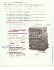
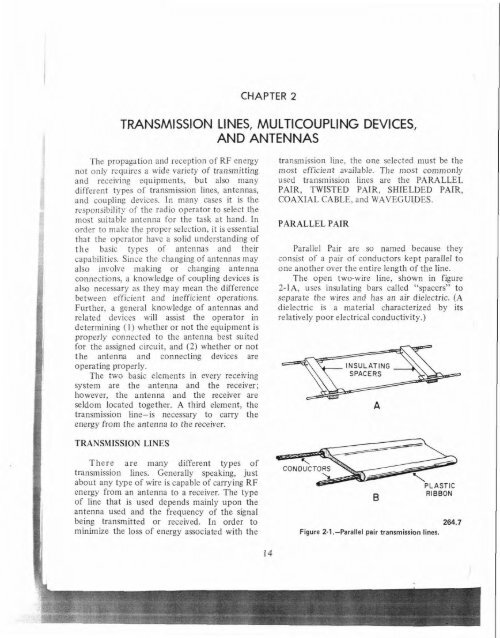
~ ~CHAPTER 2TRANSMISSION LINES, MULTICOUPLING DEVICES,AND ANTENNASThe propagation and reception of RF energynot only requires a wide variety of transmittingand receiving equipments, but also manydifferent types of transmission lines, antennas,and coupling devices. In many cases it is theresponsibility of the radio operator to select themost suitable antenna for the task at hand. Inorder to make the proper selection, it is essentialthat the operator have a solid understanding ofthe basic types of antennas and theircapabilities. Since the changing of antennas mayalso involve making or changing antennaconnections, a knowledge of coupling devices isalso necessary as they may mean the differencebetween efficient and inefficient operations.Further, a general knowledge of antennas andrelated devices will assist the operator indetermining (I) whether or not the equipment isproperly connected to the antenna best suitedfor the assigned circuit, and (2) whether or notthe antenna and connecting devices areoperating properly.The two basic elements in every receivingsystem are the antenna and the receiver;however, the antenna and the receiver areseldom located together. A third element, thetransmission fine-is necessary to carry theenergy from the antenna to the receiver.transmission line, the one selected must be themost efficient available. The most commonlyused transmission lines are the PARALLELPAIR, TWISTED PAIR, SHIELDED PAIR,COAXIAL CABLE, and WAVEGULDES.PARALLEL PAIRParallel Pair are so named because theyconsist of a pair of conductors kept parallel toone another over the entire length of the line.The open two-wire line, shown in figure2-lA, uses insulating bars called "spacers" toseparate the wires and has an air dielectric. (Adielectric is a material characterized by itsrelatively poor electrical conductivity.)TRANSMISSION LINESThere are many different types oftransmission lines. Generally speaking, justabout any type of wire is capable of carrying RFPLASTICenergy from an antenna to a receiver. The tyve . RIBBONof line that is used depends mainly upon thetiantenna used and the frequency of the signalbeing transmitted or received. In order to 264.7minimize the loss of energy associated with theFigure 2-1.-Parallel pair transmission lines.
Chapter 2-TRANSMISSIONLINES, MULTICOUPLING DEVICES, AND ANTENNASThe insulated twewire line, shown in figureINSULATION2-IB, uses a solid plastic dielectric to separatethe two wires and maintain a set distancebetween them. This is the type of transmissionline commonly used to connect a televisionreceiving antenna to a television set.A parallel pair transmission line has theCONDUCTORSadvantages of low cost, ease of installation, andgood operating efficiency up into thc mid-UHFrange. At higher frequencies, however, a parallel 13.46pair may suffer high radiation losses, particularlyFigure 2-3.-Shielded pair transmission line.when placed in the vicinity of metal objects.The . twisted pair. as the name implies,consists of two insulated wires twisted to form aflexible line. As can be seen in figure 2-2, thetwisted pair does not use spacers. This type oftransmission line is limited to low frequencyapplications below 15 MHz, and over very shortdistances. At frequencies above 15 MHz highenergy losses are incurred. Its ~dvanta_ees are thatit is easy to construct, it is economical, and itmay be used where more efficient lines wouldnot be feasible because of mechanicalconsiderations.SHIELDED PAIRA shielded pair (figure 2-3) consists of twoparallel conductors, separated from each otherand surrounded by an insulating dielectricmaterial. The conductors and dielectric materialare contained within a metal braid tubing whichacts as a shield. The entire assembly is thencontained within a weatherproof coating madeof rubber or some other flexible composition.This type of line is normally used forapplications in the IIF band and below. Theprincipal advantage of the shielded pair overother types of two-wire lines is its low radiationInss. It alsn prevents interference from undesiredradiations.COAXIAL LINESIt is possible to place one conductor INSIDEanother conductor to form a transmission line.Such a line is called a COAXIAL line. There aretwo types of coaxial lines: AIR COAXIAL andSOLID COAXIAL.AIR COAXIAL.-The air coaxial, shown infigure 2-4A, consists of a wire inner conductorDIELECTRICMATERIALAIR COAXIALINNERCONDUCTOROUTERCONDUCTORINNERCONDUCTORSOLID COAXIAL13.46 13.46Figiire 2-2.-Twisted pair iransmission !he.Figure 24.-Cozxia! transmlsion !ines.15
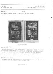
CRYPTOLOGIC COLLECTION EQUIPMENTSlaced within a metal tube which serves as thebuter conductor. The inner conductor isseparated from the outer conductor byinsulating spacers placed at regular intervals.Air coaxial lines are very efficient foroperation up to the mid-UHF band.The principje advantage of air coaxial line isits ability to minimize radiation losses. Theouter conductor provides perfectshielding-there is no radiation from the line andno noise is picked up from external sources. The 264.8major disadvantage is its high expense. The area Figure 2-5.-Cylindrical and rectangular waveguides,between the inner and outer conductors must bekept pressurized to keep out moisture, therebypreventing power losses and supressing RFenergy arcs between conductors.frequency range for waveguides is in the UHFband and above.. ,!i I%:I. ,.SOLID COAXIAL.-The solid coaxial line(figure 2-48) is probably the most commonlyused type of transmission line. It consists of awire inner conductor surrounded by a soliddielectric material, and an outer conductor ofmetal braid. One disadvantage in the solidcoaxial line is that some of the energytransmitted through the inner conductor isabsorbed by the dielectric material and,therefore, is lost. The amount of energy lost inthis manner increases with frequency. Thereforethe suitability of solid coaxial lines is limited tofrequencies up to the lower portion of the UHFband.WaveguidesBecause of their extremely shortwavelengths, frequencies above 1000 MHz arereferred to as MICROWAVE frequencies.Excessive energy losses from radiation occurwhenever standard transmission lines are used atmicrowave frequencies. Therefore, a special typeof transmission line known as a WAVEGUIDE isused.Waveguides are round or rectangular metaltubes (figure 2-5). They channel the signal fromthe input end with a much lower energy lossthan that which would occur through the use ofother types of transmission lines. Sincewaveguides can also effectively handle highpower transmissions, they are ideal for radarapplications where high levels of power aretransmitted at microwave frequencies. TheMULTICOUPLERSMulticouplers are devices that permit severalreceivers to operate simultaneously from oneantenna. They are designed to provide the bestpossible coupling between antennas andreceivers while isolating the receivers from eachother. Unfortunately, some loss of signal qualitywill occur when multicouplers are used.Multicouplers are designed to operate efficientlyover a fixed frequency spectrum only. A sh~,drop in efficiency will occur for frequent.outside the spectrum of the multicouplers. Inorder to use multicouplers efficiently, it isextremely important for the operator to ensurethat the receiving frequency is within the rangefor which the multicoupler was designed.ANTENNASAn antenna is a device which either radiates(transmits) or receives energy in the form ofelectromagnetic waves. In its most elementaryform, an antenna may be simply a single lengthof wire to which a transmission line isconnected.When such an antenna is used to transmit,waves of RF energy travel from the transmitter,through the transmission line, and on outtoward the end of the antenna. Anelectromagnetic field expands around the
Chapter 2-TRANSMISSIONLINES, MULTICOUPLING DEVICES, AND ANTENNASantenna wire and then collapses with each For example, to compute the length of a fullalternation of the waves. During the first half of wave antenna for use on 10,000 kHz proceed asthe alternation, (while the current is swinging follows:from zero to its maximum positive or negativevalue), the electromagnetic field expands 30 meters, or, sinceoutward from the antenna. During the last half 300,000,000 = 1 meter = 3.28 feetof the alternation, (while the current is swinging 10,000,000 30 x 3.28 = 98.4 feetfrom its maximum positive or negative valueback to zero) that portion of the In half-wave or quarter-wave antenna valueselectromagnetic field that is still near the are desired, simply divide the result by 2 or 4.antenna collapses and returns to the antenna,while that portion that is away from the antenna ANTENNA POLARIZATION!continues to travel outward into space.If a receiving antenna is placed in the path of The polarization of radio waves is dependentan electromagnetic wave that is traveling upon the position of ihe Lransmittiilg antennathrough space, RF (signal) current will be with respect to the plane of the earth. Aninduced in the antenna. This induced current is antenna that is mounted in a horizontal positionthen transported to the receiving system via a radiates horizontally polarized waves, whereas atransmission line.vertically mounted antenna will radiate verticallyCT T, R, & I personnel may seldom have an polarized waves.occasion to work with transmitting antennas. Accordingly, a receiving antenna willHowever, operators should become familiar with generally receive radio waves most efficiently ifIthe characteristics of transmitting antennas so it is configured in the SAME polarization as thatthat they can better select a receiving antenna, of the transmitting antenna. A compromise ofshould the need arise.sorts may be achieved with receiving antennasby mounting them at 45' with respect to theIWAVELENGTH earth's plane. Thus, both horizontally andvertically polarized signals can be received withThe physical length of an antenna is often acceptable efficiency. A receiving antenna withIreferred to in wavelengths. Such terms as its polarity opposite to that of the transmittingquarter-wave, half-wave, and full-wave are used antenna may be used for reception, however aIextensively. Wavelength is usually expressed in substantial loss of signal energy will occur.meters and is defined as the velocity of a radiowave in free space divided by the frequency of FIELD INTENSITYthe wave. The symbol for wavelength isA (lambda). The field intensity of a radiated radio wave1Since the velocity of an electromagnetic is the strength of the wave at any given distance1wave in free space is considered to be 300 from the transmitting antenna, Field intensity ismillion meters per second, the formula- for usually expressed in MICROVOLTS-PER-5 computing wavelength is expressed as: METER and is measured by special300,000,000instruments after the antenna is installedWavelength in meters =and while it is beinp test-operated. On thefrequency in basis of these measurements, changes may becycles per second made in the design - or installation of the antennaIf wavelenzth in meters is known, freauency in order to improve its radiation pattern.,-iq cycles per ~econd can be determined by theIANTENNA RADIATION PATTERNSI following formula:Frequency in cycles per second = 300,000,000wavelengthin metersThe total radiation from an antenna is, ineffect, comprised of two components: onecomponent is rzdiated dkectly from the antenna
1ICRYPTOLOGIC COLLECTION EQUIPMENTSfi7Rinto space; the other component is a groundreflection that appears to originate a mirrorimage of the antenna, as shown in figure 2-6.The amount of energy reflected by theground may vary greatly. Some terrains reflectvirtually all of the energy that strikes it, whileothers reflect very little. Therefore, the ground MINOR LOBESreflection may be uniform or patchy, dependingupon the composition of the terrain near theantenna.Depending upon their amplitude and phaserelationships, the direct and reflectedcomponents may reinforce or cancel oneanother. If the terrain near the antenna is a goodconductor, with very little absorption of energyoccurring during the reflection process, thereflected wave has the same amplitude as thedirect wave. If two equal amplitude waves arriveat the receiving site in phase, the signal strengthis much greater than that from the direct wavealone. On the other hand, if the direct andreflected waves arrive 180° out of phase, thesignal strength will be zero. Intermediate valuesof signal strength occur with intermediateamplitude and phase relationships between the RADIATION ANGLEdirect and reflected waves.Because of ground reflections, the radiationpattern of an antenna is broken up into a seriesof gaps and lobes as shown in figure 2-7. A gapin the radiation pattern occurs in any directionwherein the two components cancel each other.DIRECTLOBEFigure 2-7.-Radiation lobes and gaps.264.9A MINOR LOBE of radiation is formed wherethey partially cancel, and a MAJOR LOBE ofradiation is formed where they reinforce eachother.The angle between the horizontal plane ofthe earth and the axis of the antenna lobe iscalled the RADIATION ANGLE (figure 2-8).The radiation angle of an antenna can vgreatly and is dependent upon several factors:the type of antenna; the height of theantenna above ground; the length of theantenna in number of wavelengths; and;the frequency at which the antenna isoperated.END VIEW OF IHORIZONTAL IANTENNAI/ /IMAGE I /ANTENNA I ,/11,//GROUND PLANE25.197$I/:: 1Figure 2-6.-Direct and ground reflected rays.' IAnte~as made up of long wires radiate at alow angle when the height or size of the antennais large in terms of wavelength. These are designconsiderations that do not change once theantenna is installed. Of more importance inday-to-day operations, since it is a factor thatcan be controlled, is the frequency at which theantenna is operated-the higher the frequency,the lower the radiation angle.Neither highly directional beam formingantennas, nor antenna arrays made of tubing,exhibit the changes in radiation angle thatcharacterize wire antennas.
Chapter 2-TRANSMISSION LINES, MULTICOUPLING DEVICES, AND ANTENNASIII 4 PLANEIIIFigure 2-8.-Antenna radiation angle.25.201,IANTENNA BEAMWIDTHIA lobe of energy radiated from an antenna isreferred to as a "beam". The width of a beam isII expressed in degrees and, not too surprisingly, isreferred to as the antenna BEAMWIDTH.iNarrow beamwidths are used extensively atmicrowave frequencies, particularly for radar1 systems. Radars may have beamwidths as narrowas one or two degrees, depending upon theirI application.ANTENNA DIRECTIVITYMost practical antennas are directional tosome extent. This means that an antenna usedfor transmitting will radiate most of its energy incertain directions. The more an antennaconcentrates its energy in a particular direction,the greater will be the field intensity producedin that direction for a given amount of totalradiated power. Likewise, an antenna that isused for receiving will receive best if it isoriented in the direction of the radiation.The directional characteristics of an antennaare determined to a great extent by its designand the position in which it is installed. Thus,certain directional qualities are associated witheach type of antenna. The following terms areused to describe general directional qualities ofan antenna:0MNIDIRECTIONAL.-Receives or radiatesapproximateiy equal amounts of energyAL-..~.... ~Ariuuuguuur a I'uii 360 dcgree paiiem.DIRECTIONAL.-Receivesor radiatesenergyonly in certain directions. Directional antennascan be further classified as follows:Bidirectional.-Receives or radiatesefficiently in two directions: for example, Northand South or East and West.Unidirectional.-Receivesefficiently in only one direction.BASIC TYPES OFANTENNASor radiatesIn the following discussion of basic types ofantennas, reception rather than transmission ofradio waves will be emphasized. Generallyspeaking, any antenna designed to transmit radiowaves on a particular frequency can receiveradio waves of the same frequency equally well.The greatest differences between transmittingand receiving antennas are the greaterpower-handling capability of transmittingantennas and the types of transmission lines thatare used.HALF-WAVE ANTENNAThe most basic type of antenna is a one-halfwavelength antenna known as DIPOLE orHERTZ antenna. It consists of two one quarterwavelength conductors p!aced end to end.Normaiiy, rne rransmission iine is connecrea ro
CRYPTOLOGIC COLLECTION EQUIPMENTSplaced within a metal tube which serves as theouter conductor. The inner conductor isseparated from the outer conductor byinsulating spacers placed at regular intervals.Air coaxial lines are very efficient foroperation up to the mid-UHF band.The principle advantage of air coaxial line isits ability to minimize radiation losses. Theouter conductor provides perfectshielding-there is no radiation from the line andno noise is picked up from external sources. The 264.8major disadvantage is its high expense. The area Figure 2-5.-Cylindrical and rectangular waveguides.between the inner and outer conductors must bekept pressurized to keep out moisture, therebypreventing power losses and supressing RF frequency range for waveguides is in the UHFenergy arcs between conductors.band and above.SOLID COAXIAL.-The solid coaxial line(figure 2-4B) is probably the most commonlyused type of transmission line. It consists of awire inner conductor surrounded by a soliddielectric material, and an outer conductor ofmetal braid. One disadvantage in the solidcoaxial line is that some of the energytransmitted through the inner conductor isabsorbed by the dielectric material and,therefore, is lost. The amount of energy lost inthis manner increases with frequency. Thereforethe suitability of solid coaxial lines is limited tofrequencies up to the lower portion of the UHFband.WaveguidesBecause of their extremely shortwavelengths, frequencies above 1000 MHz arereferred to as MICROWAVE frequencies.Excessive energy losses from radiation occurwhenever standard transmission lines are used atmicrowave frequencies. Therefore, a special typeof transmission line known as a WAVEGUIDE isused.Waveguides are round or rectangular metaltubes (figure 2-5). They channel the signal fromthe input end with a much lower energv lossthan that which would occur through the-ise ofMULTICOUPLERSMulticouplers are devices that permit severalreceivers to operate simultaneously from oneantenna. They are designed to provide the bestpossible coupling between antennas andreceivers while isolating the receivers from eachother. Unfortunately, some loss of signal qualitywill occur when multicouplers are used.Multicouplers are designed to operate efficientlyover a fixed frequency spectrum only. A shardrop in efficiency will occur for frequencie..outside the spectrum of the multicouplers. Inorder to use multicouplers efficiently, it isextremely important for the operator to ensurethat the receiving frequency is within the rangefor which the multicoupier was designed.ANTENNASAn antenna is a device which either radiates(transmits) or receives energy in the form ofelectromagnetic waves. In its most elementaryform, an antenna may be simply a single lengthof wire to which a transmission line isconnected.other types of transmission lines. Since When such an antenna is used to transmit,waveguides can also effectively handle high waves of RF energy travel from the transmitter,power transmissions, they are ideal for radar through the transmission line, and on outapplications where high levels of power are toward the end of the antenna. Antransmitted at microwave frequencies. The electromagnetic field expands around the
Chapter 2-TRANSMISSIONLINES, MULTICOUPLING DEVICES, AND ANTENNASantenna wire and then collapses with each For example, to compute the length of a fullalternation of the waves. During the first half of wave antenna for use on 10,000 kHz proceed asthe alternation, (while the current is swinging follows:from zero to its maximum positive or negativevalue), the electromagnetic field expands 30 meters, or, sinceoutward from the antenna. During the last half 300,000,000 = 1 meter = 3.28 feetof the alternation, (while the current is swinging 10,000,000 30 x 3.28 = 98.4 feetfrom its maximum positive or negative valueback to zero) that portion of the In half-wave or quarter-wave antenna valueselectromagnetic field that is still near the are desired, simply divide the result by 2 or 4.antenna collapses and returns to the antenna,while that portion that is away from the antenna .ANTENNA POLARIZATIONcontinues to travel outward into space.. .!fa rccc;ving untcnna is placed in the path of The po!arizztion of radio waves is dependentan electromagnetic wave that is traveling upon the position of the transmitting antennathrough space, RF (signal) current will, beinduced in the antenna. This induced current iswith respect to the plane of the earth. Anantenna that is mounted in a horizontal positionthen transported to the receiving system via a radiates horizontally polarized waves, whereas atransmission line.vertically mounted antenna will radiate verticallyCT T, R, & 1 personnel may seldom have an polarized waves.occasion to work with transmitting antennas.Howcvcr, operators should become familiar withAccordingly, a receiving antenna willgenerally receive radio waves most efficiently ifthe characteristics of transmitting antennas so it is configured in the SAME polarization as thatthat they can better select a receiving antenna, of the transmitting antenna. A compromise ofshould the need arise.sorts may be achieved with receiving antennasby mounting them at 45" with respect to theWAVELENGTH earth's plane. Thus, both horizontally andverticalty polarized signals can be received withThe physical length of an antenna is often acceptable efficiency. A receiving antenna withreferred to in wavelengths. Such terms asquarter-wave, half-wave, and full-wave are usedits polarity opposite to that of the transmittingantenna may be used for reception, however aextensively. Wavelength is usually expressed in substantial loss of signal energy will occur.meters and is defined as the velocity of a radiowave in free space divided by the frequency of FIELD INTENSITYthe wave. The symbol for wavelength isX (lambda).The field intensity of a radiated radio waveSince the velocity of an electromagnetic is the strength of the wave at any given distancewave in free space is considered to be 300 from the transmitting antenna. Field intensity ismillion meters per second, the formula for usually expressed in MICROVOLTS-PERcomputingwavelength is expressed as: METER and is measured by special300,000,000instruments after the antenna is installedWavelength in meters =and while it is being test-operated. On thefrequency in basis of these measurements, changes may hccycles per second made in the design or installation of the antennaIf wavelength in meters is known, frequencyin order to improve its radiation pattern.in cycles per second can be determined by thefollowing formula:ANTENNA RADIATION PATTERNSFrequency in cycles per second = 300,000,000wavelengthin metersThe total radiation from an antenna is, ineffect, comprised of two components: onecomponent is radiated directly from the antezx
1CRYPTOLOGICthe inside ends of the conductor as shown infigure 2-9.COLLECTION EQUIPMENTSMaximum efficiency is obtained from adipole antenna only when it is operated at thefrequency for which it is designed, or a multipleof that frequency. As we move away from thedesign frequency, efficiency drops off, becomingunacceptable at frequencies approximately fivepercent higher or lower than the designfrequency. Therefore, this antenna is not DOWNsuitable when a wide range of frequencies is tobe used.A dipole antenna is more or lessomnidirectional, radiating energy in alldirections from the surface of its conductors,but little, if any, from their ends. However, theeffective radiation pattem of a dipole dependsupon whether it is mounted in a horizontal or ina vertical position. A vertical dipole radiates in afull 360 degrees pattern resembling a doughnutlying on its side, as shown in figure 2-10. Adipole mounted horizontally also radiates in adoughnut-shaped pattem, but since energyradiated from the underside of the antenna iseither absorbed or reflected by the ground, theeffective radiation pattern is shaped more like ahalf-doughnut in the upright position. Figure2-1 1 shows the radiation pattern of a horizontaldipole.264.1 1Figure 2-10.-Radiation pattern of a vertical dipoleantenna.MINIMUMRADIATION264.12Figure 2-11.-Radiation pattern of a horizontal dipoleantenna.EQUARTER-WAVE ANTENNAFigure 2-9.-Dipole antenna.264.1 0If the ground plane of an antenna is a fairlygood conductor, it will act as a mirror for thereflection of energy that is radiated downwardfrom an antenna. Using this characteristic, anantenna that is only a quarter-wavelength longcan be made into the equivalent of a half-waveantenna. The antenna itself provides onequarter-wavelength, and the ground reflectionserves as another quarter-wavelength antenna,known as the image antenna, as shown in figure2-1 2.The quarter-wave antenna (also known asthe MARCONI or "grounded antenna") iswidely used where available space is limited,
Chapter 2-TRANSMISSIONLINES, MULTICOUPLING DEVICES, AND ANTENNASANTENNATRANSMISSIONLINETRANSMISSIONGROUND =? ii'FEED 4
CRYPTOLOGIC COLLECTION EQUIPMENTSRHO<strong>MB</strong>IC antenna. It consists of four long-wireantennas connected in the shape of a rhombus(or diamond), with a transmission Line attachedto one end as shown in figure 2-1 5.Two advantages of the rhombic antenna arethat it has a broad frequency range and it is easyand inexpensive to CO~S~NC~.The rhombic antenna is not without itsdisadvantages, the principal one being that afairly large antenna site is required for itserection. Each leg must be at least twowavelengths long at the lowest operatingfrequency, and when increased gain anddirectivity are required, legs of from 8 to 12wavelengths are used.A rhombic antenna that is designedprimarily for reception will receive best whenoriented toward the transmitting terminal. Anoperator, in selecting one of several rhombicantennas to receive a desired signal, or toattenuate an interfering signal, must oftenexperiment with several antennas. The bestmethod for choosing the proper antenna is tolisten to the received signal while changingantennas, and use the one with the best signalquality.MULTI-WIRE RHO<strong>MB</strong>ICA rhombic antenna will improve inperformance if more than a single wire is usec'form each leg. By using three wires to form eh. ..leg and connecting all of them at both ends to acommon point, but spacing them vertically 5 to7 feet apart at the side poles, an improvedantenna known as a multi-wire or curtainrhombic is formed.Advantages of the multi-wire rhombicinclude an improved signal-tenoise ratio, aslight increase in signal gain, and a reduction ininterference caused by rain (precipitation static).BROADBAND ANTENNASConcial MonopoleThe Conical monopole antenna wasdeveloped to fulfill a need for a broad-bandantenna in the HF range. It is omnidirectional inradiation and may be operated over a frequencyrange ratio of approximately 3 to 1, i.e., 5-20MHz.Conical monopoles are in the shape of twocones with the ends cut off and connected baseto base as shown in figure 2-16. The ba~:Figure 2-15.-A rhombic antenna.
CRYPTOLOGIC. COLLECTION EQUIPMENTSHF Whip AntennaHF Whip antennas, widely used by CB(Citizen Band) radio operators, are used by theNavy for ship/shore/ship communications, fortransportable systems, and for laboratory andshop installations.HF whip antennas are vertically polarizedand are omnidirectional. They are normallymade of sections of tubular metal orfi berglass-covered metal. Electrical tuningdevices are used to alter the effective wavelengthof the whip antenna and enable it to operateover a broad band of frequencies.Of all commonly used vertical antennas,whips are the least efficient. The reasons thatthey are so widely used are that they areinexpensive; require minimal space, and; theyare simple to install. (They may be installed onpoles, tops or sides of buildings, on decks orsuperstructures of ships, or on vehicles of mostany type.)Log Periodic AntennaThe LOG PERIODIC ANTENNA (LPA) is aunidirectional broadband antenna with up to a10 to 1 frequency range ratio. A typicalfrequency range for an LPA would be 30 to 300MHz. As shown in figure 2-18, it consists of along piece of tubing bent in such a manner as toform a series of progressively longer parallelcross elements, each connected to the crosselement next to it. Only these cross elementsradiate or receive energy; the tubing in betweenthem serves only to connect the cross elementsand space them the correct distance apart.For some- applications, ROTATABLE LOGPERIODIC ANTENNAS (RLPA's) are used.Regardless of type, however, size limitationsrestrict the use of LPA's to the upper portion ofthe HF band and above.to as the RADIATOR and is connected directlyto the transmission line. The remaining elementsconsist of a REFLECTOR, which is 1ocatp.ldirectly behind the driven element, and onemore DIRECTORS, located in front of thedriven element. The reflector and directorelements are called PARASITIC elementsbecause they are not connected to thetransmission line, but derive their energy fromthe driven element. The complete antennaassembly, because it has these parasitic elements,is known as a PARASITIC ARRAY.The two main advantages of a parasitic arrayare increased gain and unidirectivity. There is areduction of transmitted energy in all but thedesired direction. This makes the 'parasitic arrayparticularly useful in antenna systems that canbe rotated to a given direction. Thedisadvantages of these arrays are that theiradjustment is critical and they do not operateover a wide frequency range.When three or more nondriven elements areused in conjunction with a driven element, theparasitic array is commonly known as a YAGIarray or YAGI antenna.MICROWAVE ANTENNASThe basic principles of antennas operatingthe microwave region (1000-30,000 MHz) arethe same as those of antennas operating at thelower frequencies. However, because of theshort wavelength involved at these frequencies,microwave antennas can be more readilydesigned to have higher gain and directivity. Theproperties of microwaves approach those of lightwaves. They may be beamed or brought to afocus by the use of parabolic reflectors; likewise,their direction can be readily changed by placinga suitable reflecting surface in their path.Horn RadiatorsPARASITIC ARRAYSHorn radiators are used to obtain directiveradiation at microwave frequencies. They arePARASITIC ARRAYS represent another constructed in a variety of shapes, as shown inmethod of achieving high antenna gains. They figure 2-20.are made up of tubular aluminum elements The operation of a horn radiator as amounted parallel to each other as shown in directing device can be compared to an acousticfigure 2-19. The DRIVEN ELEMENT is referred horn. However, the throat of an acoustic horn is
Chapter 2-TRANSMISSIONLINES, MULTICOWLING DEVICES. AND ANTENNASiqFigure 2-18.-Log-periodic antenna. , ,much smalier than the wavelengths of audio Parabolic Reflectorsfrequencies, while the throat size of a horn used .1for electromagnetic radiation is compatible with Parabolic reflectors, commonly referred tothe wavelength of the operating frequency. as "Dish Antennas" (figure 2-21) are highly , j +directional antennas that are widely used forEven though they may be fed by other types microwave communications and radar '%Yof transmission lines, horns are most readily applications. Basically, parabolic reflectors .,%adaptable for use with waveguides because they focus the radiated energy into a narrow '2"-serve as impedance rnatchi~~g devices as well as beam, much like the fight Seam from a.-.I&rct;ve...-.li2tcrs cf ecerg,. ---coorrhlinht .. -:1
CRYPTOLOGIC COLLECTION EQUIPMENTSREFLECTORIVEN ELEMENTRECTORSFigure 2-19.-Parasitic array.264.14(1) (2) (3)RECTANGULAR PYRAMIDAL CONICAL76.58Figure 2-21.-Mobile parabolic reflector 30-foot scatterantenna.Figure 2-20.-Horn antennas.WULLENWEBER ANTENNAARRAY13.41The WULLENWEBER ANTENNA ARRAY,named after its designer, is a receiving syStemcapable of providing coverage from 2 to 30MHz. This is accomplished through the use oftwo separate arrays of antenna elements, one ofwhich provides coverage from 2 to 8 MHz (lowband), the other from 8 to 30 MHz (high band).The system is capable of providingomnidirectional coverage, coverage of a givensector of rather broad bandwidth, or highlydirectional beams.The Wullenweber was initially developed forhigh frequency direction finding applications;however, it has been accepted for service in theNavy's HF point-to-point communications. It iswidely used within the Naval Security Group asboth a receiving antenna and a direction findingantenna.A typical Wullenweber array, also commonlyknown as a Circularly Disposed Antenna Array(CDAA), is shown in figure 2-22. It consists oftwo arrays of receiving antenna elements andtwo reflecting screens, arranged in fourconcentric circles. The extreme outer circle isthe high band antenna array (figure 2-22A). It isapproximately 875 feet in diameter and consistsof 120 equally spaced antenna elements, one foreach 3 degrees of azimuth. Each of theseelements is a sleeve monopole of the properlength to permit reception of signals in the 8 to30 MHz range.The next circle is the high band reflectorscreen (figure 2-22B) composed of vertical wires
Chapter 2-TRANSMISSION LINES, MULTICOUPLING DEVICES, AND ANTENNASrR(A) High-band receiving elements. (C) Low-band receiving elements.(6) High-band reflector saeen. (D) Lowband reflector screen.Figure 2-22.-Wullenweber antenna array.25.117which are suspended from pole supportedhorizontal braces. The reflector screen does notreceive signals but does contribute to thedirectional characteristics of the CDAA byshielding the receiving elements from thosesignals amving from any direction other thanthe outer perimeter of the array.Inside the high hand reflector screen, lies thethird circle which is the low band receiving array(figure 2-220. It consists of 40 equally spacedfolded monopoles: one for each 9 degrees ofazimuth. These elements are longer than thoseof the high band since the frequencies received(2 to 8 MHz) by the low band elements havelonger wavelengths.The low hand refl.cc:or scrccn (figuic 2-22D)cn"?~ricer --fier rr).~\s! cir-!e. is +;lzroperation to the high band screen, but thevertical wires are longer and correspond to thelengths of the low band receiving elements.The high band and low band antennaelements are connected to buried coaxialtransmission lines that terminate inside theoperations building which is normally located atthe center of the array. The transmission linesare electrically equal in length to ensure that thetime delay in each line is the same. That is, thetime required for a sienal to travel from theinput end of a line to its output end is exactlyequal for all lines. This makes it possible for anelectronic sampling device to determine whichreceiving element was the first to be struck byan incoming signal. That, in turn, indicates fromwhich direction the signal arrived, since the fustieceiving clement to he struck by a signal is thee-e -exes! the tr~nsmittk?:: sktinfi.
CRYPTOLOGIC COLLECTION EQUIPMENTSANTENNA PATCH PANELSIn addition to antennas, transmission lines,and coupling devices, an operator will also beconcerned with antenna patch panels. This is thepoint at which the equipment is actuallyconnected to the desired antenna. Because thereare various types of patch boards in use, it is notpractical to provide detailed operatingprocedures herein. It is well to remember thatconnections should be made with care and thatcomecting cords (usually solid coaxial lines)should be handled very carefully. Cautionshould also be taken not to bend or b :connecting plugs or damage the insulation onconnecting cords.If there are indications of poorcommunication signals, one of the fustprocedures should be to check the antennapatch panel and associated connections.