communications navsea 0967-lp-000-0010 original ... - VIR History
communications navsea 0967-lp-000-0010 original ... - VIR History
communications navsea 0967-lp-000-0010 original ... - VIR History
- No tags were found...

You also want an ePaper? Increase the reach of your titles
YUMPU automatically turns print PDFs into web optimized ePapers that Google loves.
during the day, to fly after that for at least 30 minutes.Section 91.203(a) prohibits, in pertinent part, any person from operating a civil aircraftunless it has within it (1) an appropriate and current airworthiness certificate; and (2) aneffective U.S. registration certificate issued to its owner or, for operation within the UnitedStates, the second copy of the Aircraft Registration Application as provided for in 14 CFR47.31(c).Section 91.203(b) prescribes, in pertinent part, that no person may operate a civil aircraftunless the airworthiness certificate or a special flight authorization issued under 14 CFR91.715 is displayed at the cabin or cockpit entrance so that it is legible to passengers or crew.Section 91.405(a) requires, in pertinent part, that an aircraft operator or owner shall havethat aircraft inspected as prescribed in Subpart E of the same part and shall, betweenrequired inspections, except as provided in paragraph (c) of the same section, havediscrepancies repaired as prescribed in part 43 of the chapter.Section 91.407(a)(1) prohibits, in pertinent part, any person from operating an aircraft thathas undergone maintenance, preventive maintenance, rebuilding, or alteration unless it hasbeen approved for return to service by a person authorized under § 43.7 of the same chapter.Section 91.409(a)(2) prescribes, in pertinent part, that no person may operate an aircraftunless, within the preceding 12 calendar months, it has had an inspection for the issuance ofan airworthiness certificate in accordance with part 21 of this chapter.Section 91.417(a) and (b) prescribes, in pertinent part, that—(a) Each registered owner or operator shall keep the following records for the periodsspecified in paragraph (b) of this section:(1) Records of the maintenance, preventive maintenance, and alteration and recordsof the 100-hour, annual, progressive, and other required or approved inspections,as appropriate, for each aircraft (including the airframe) and each engine,propeller, rotor, and appliance of an aircraft. The records must include—(i) A description (or reference to data acceptable to the Administrator) of thework performed; and(ii) The date of completion of the work performed; and(iii) The signature, and certificate number of the person approving the aircraftfor return to service.(2) Records containing the following information:4
COMMUNICATIONSNAVSEA <strong>0967</strong>-LP-<strong>000</strong>-<strong>0010</strong>SERVICE NOTESAN/F RA-501, AN/F RA-19(V), AN/FR R-502, AN/F RR-49(V), CV-~~~/URR, CV-SPIA/URR, AND TECHNICAL MA-TERIAL CORPORATION COMMERCIAL MODEL MSR-5 -USE OF AUTO-TRANSFORMER TO REDUCE EXCESSIVELINE VOLTAGESee article in AN/FRA-19 section under the sametitle.ORIGINAL
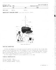
SERVICE HOTESAN/FRT-15, -15A RADIO TRANSMITTERSWhen using the AN/FRT- 15, - 15A Transmitters modifiedby kit RM-193 to feed the unbalanced 70-ohm transmissionline, improved operation will result by opening the strapbetween output terminals E-3002 and E-3003. The revisedcircuit is as follows:Correct the diagram in EIB 467, page 3, and Figures2-9A and 7-95B of Modification Kit RM-193, NAVSHIPS91690(A)-1 to aqree with figure 1.Cut 4AFigure 1AN/FRT-ISHAZARD TO SAFETY OF MAINTENANCEPERSONNELIt has recently come to light that some AN/FRT-15Radio Transmitters have not been modified with High-VolageInterlock Sw~tch Kit RM-194.Recently a maintenance technician was seriously burnedwhile making preventive maintenance checks on M AN/FRT-15 Rad~o Transmitter which had not been equippedwith a H. V. Interlock Kit RM-194.Installation of the H.V. Interlock Switch Kit RM-194provides additional protection for personnel by shorting theDC output of the high-voltage rectifiers to ground when thetransmitter doors are opened, or when the rectifier tubeprotective screen is removed.Users of AN/FRT-15 Radio Transmitters are directed toascertain if H.V. Interlock Switch hts RM-194 have beeninstalled. AN/FRT-15 Radio Transmitters no: equippedwith H.V. Interlock Switch Kit RM-194 should be so equipped at the earliest opportunity. H.V. Interlock Switch htsRM-194 are available in stock under FSN F5820-503-4849.Use of Spectrum Analyzer to Eliminate the Couses ofSpurious Rodiotions from High Frequency Rodio TronsmittersHadjo transmitters equipped w~th master oscillatorsynthesizers are more prone to radiate spurlous sidebandsthan crystal controlled transmltters, and this is understandableconsidering the numerous mixing processes and balancesmodulators associated with this type of oscillator.The Ar.I/FI
COMMUNICATIONSNAYSEA (j96j-iP-(j(j&u0i(jAN/FRT-17, RESISTOR FAILUREThe following information was forwarded by the AssistantIndustrial Manager, USN, Seattle.In two instances, AN/FRT-17 transmitters could not bemade to operate with the Cal-Line-Opemte Switch in theOPERATE position. Relay K-809 fuctioned as if a platevoltage overload existed. Investigation of the relay circuitryrevealed a defective (open) potentimeter R-801 (see schematic,figure 2-30, NAVSHIPS 91963, the AN/FRT-17 InstructionBook). Opening of this shunt resistor permittedexcessive current flow through the relay coil, although allother conditions were normal. It shald be noted in theschematic that a false indication could also be induced byfailure of the other associated shunt resistor, R-847.Two other overload relays, K-810 and K-808, figures2-30 and 2-32, NAVSHIPS 91963, also have associatedshunt resistors, R-803, R-802, and R-848, failure of whichcould falsely indicate "Screen Overload" ar "MediumVoltage Overload".The foregoing information should be entered in theInstruction Book, NAVSHIPS 91963, Table 7-1, TroubleShooting Chart.ORIGINAL
COMMUNICATIONS NAVSEA <strong>0967</strong>-LP-<strong>000</strong>-<strong>0010</strong> SERVICE NOTESAN/FRTd5 TRANSMITTER MODIFICATIONSeveral naval shore-type transmitters, presently in usewith an unbalanced cooxial output, do not incorporate facilitiesfor frequency measurements of the actual output energy.The Naval Ship Repair Facility, Guam, has devised a circuitfor the ANffRT-25 which has the Bureau of Shipsapproval. A small induction loop, Figure 1, is placed nearthe IPA-plate tank coil - the first point where the outputfrequency is assured regardless of multiplication factorsemployed in the transmitter. RF sampling at any of the previousstages would result in measurement of a subharmonicof the output frequency and lesser frequency spread whenthe transmitter is operated in F1 or F4 modes of emission.This method of RF Sampling may be applicable to othershore type transmitters, provided consideration is given tothe power involved which would necessitate a constructionchange of the induction loop, such as number of turns andspacing from IPA-plate tank coil.DETAIL- INOTES:RF COUPUNG L p P EXPLODED VIEW. I2 AWGI. COUPLING LOOP 10 OC PLACED UO LLP THAN 2" FROM COIL ' 301aAWLOCAILD SQ THlT IPA CHASSIS CAN E OllLLEO FOR(2I TWOMOUNTING METAL SCREW WITH OUT INTERFCRCNCE WITH OTHERCOMPO*L*l PARTS.z COUPLINO LOOP m o r PLACED UI NO~IZOWTAL ~ A N C .Figure 1RF OSCILLATOR 0-14OJ/FRT-TEST PROCEDURE?he following procedure is recanmended for use:The AN/USM-26 frequency meter is an extremely usefulinstrument in quickly locating a trouble in the RF oscillator0-140B/FRT-15 utilized in AN/FRT-25 equipments.Advantages of this procedure are speed and accuracy in locatingtroubles. Reference to specific pges of the instructionmonual is avoided, since more than one equipmentis involved. Reference to dials "A," "B," "C," I'D," and"G" in this procedure are those of 0-140B/FRT-15equipmen ts.Procedure:1. The 200 kc oscillator, the hsic oscilla!or of theunit, should be checked first. The frequency countermay be connected to J-3501. The frequency countedshould be close to 200 kc.2. The output of the 101-100 kc oscillator shouldbe checked at J-3702. Setting dial I'D" to zero on thewhite scale should result in a frequency of 101 kc. Adjustdial "D" for exactly 100 kc.3. The multivibrators should be checked next. The1CO kc output is available at P-3501, the 10 kc at P-3502, and the 1 kc at P-3503. Remember that anyerror in the 200 kc oscillator will result in an error inthe multivibrator checks. As an example, a locycleerror in the 200 kc osclllator will result in a 5-cycleerror in the 100 kc, a O.hycle error in the 10 kc, andno readable error in the 1 kc. Every effort should bemade, however, to remove all error in the 200 kc oscillator.Any count other than that described above indicatesneed to adjust the multivibrator. If the multivibratorneeds adjustment, the procedure outlined inSect~on 7 of the instruction book should be followed,except that the AN/USM-26 may be used in place of theoscilloscope and the audio osclllator.4. The 29-20 kc output may be ckecked at 1-3302.The setting of dial "C" should be 9 for 20 kc output, andzero for 29 kc. Check the output at each setting ofdial "C."5. The 130-120 output may be checked at F-3602.If the 101-100 kc osclllator is set at exactly 100 kc,this check will be easler. There 1s no need to rotatedial "C" again, since this check only shows that thereis an output at the correct frequency. This frequencyis affected by both dials "C" and "D."6. The 500-400 kc output appears at P-3402. Rotatingdial "B" should change this autput in 10 kcsteps. The 500-400 kc signal is affected by dials "B,""C,Ii and "D," and by rmnipulating these controls, theentire range of 500-400 kc may be observed.7. There are no further quick checks of the 0-140B/FRT-15 there the AN/USM-26 is useful. It is not pssibleto check the RF output at 5-3153, since both the sumand difference frequency outputs of the balanced modulatorappmr here. If no trouble was found in the abovechecks and the RF output at 5-3153 still is not correct,assume that the trouble lies in the frequency selectormixerCV-276/FRT-15A. If it is necessary to checkthe 2300-4500 kc input to the balanced modulator, aconvenient point to connect the AN/USM-26 is acrossL-3155. Should strong RF fields from nearby transmittersinterfere with this check, requiring better shielding,an alternate procedure is to connect the frequencyORIGINAL
COMMUNICATIONSNAVSEA <strong>0967</strong>-LP-<strong>000</strong>-<strong>0010</strong>SERVICE NOTEScounter to the RF output jack J-3153. Remove the500-400 kc input at J-3152, and rotate R-3171 until areadng can be obtained on the counter. Note, however,that thls pocedure unbalances the balancedmodulator, and it must again be blanced out followingthe procedure described in Secticn 7 of the instructionmacual.8. A final check of the RF Osciliator 0-140B/FRT-15 may be made by rotating the mixer tuning dial"G," and observing the multiplier cathode currents.ORIGINAL
COMMUNICATIONS NAVSEA <strong>0967</strong>-LP-<strong>000</strong>-<strong>0010</strong> SERVICE NOTESNOISE LEVEL RECEIVED FROM ANfFRT-3909 1 : : :MILLS-- -- . Figures 1, 2, 3, and 4 show the received noise versusdistance in miles from the transmitting antenna for a typica,Naval Air Station located in the Southeastern United States.fTypical expected man-made and atmospheric noise curves,corrected to 3 kc bandwidth, are shown for different timesof the day. These qaphs assume conical monopole antennasfor both transmitting and receiving. Oniy the ground wavecase is considered and good earth conductivity is assumed.Information for the curves in figures 1 through 4 wasobtained from the following:1. National Bureau of Standards Report 5692, page 2.2. Signal Corps Propagation Agency, Fort Monmouth, N.J.Technical Report No. 3, Gound Wave Intensities, figure13, page 29.3. International Telecommunication Union Report No. 65,Revision of Atmospheric Radio Noise Data.In the past, several Field Technical Authorities havedevised keyers to reduce the noise generated by the AN/FRT-39( ). In order to standardize installations and toprovide simplex RTTY operation, a keyer is being developedfor the Bureau of Ships by the Industrial Manager, EighthNaval District. It is anticipated that a complete shopdrawing package for the keyer will be forwarded to allField Technical Authorities prior to 31 December 1963.The Field Technical Authorities will disseminate thekeyer design information to the using activities. Thispackage will include sufficient information to locallyfabricate or procure the keyer by contract. All futureand existing AN/FRT-~~( ) installations, not exclusivelyutilized on point-to point circuits, should be backfittedwith these keyers as soon as possible after receipt of thedesign information.ORIGINAL
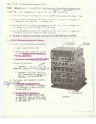
COMMUNICATIONSAN/FRT-39 SERIES TRANSMITTER; IPA BLOWER MOTORBEARING FAILUREBearing failures in the IPA blower motor (B201) of theAN/FRT-39 series radio transmitters after approximately10,<strong>000</strong> operating hours have been attributed to the loss offactory lubricant caused by overheating. Tne bearing whichtypically fails is located in the motor end bell opposite thecage end of the blower. Location of this bearinq, close tothe equipment side panel, contributes to its overheatinqwith consequent liquification and drainage of the factorylubricant from the sealed bearinq raceway.Users of the AN/FRT-39 series transmitter are requestedto check the bearings in the IPA blower motor at the end of8,<strong>000</strong> operating hours and replace any flat bearings as a preventativemaintenance item. Such replocement may preventlater trouble because of bearing seizure. (10s)AN/FRT-39/40/62WARDSERIES TRANSMITTERS-SAFETYThe Naval Ship Repair Facility, Guam, and others havecited the hiqh voltaqe warninq liqht on subject transmittersas being an extreme safety hazard to personnel enqaqed inreplacing the enclosed 230 VAC lamp.As a result of various sugqestions for correctinq thehazard, arrangements have been made with the manufacturerfor the following production change to the light assemblyAX-124 on transmitter procured for the Navy:a. Install metallic stud bolts with removable cap nutsin lieu of the existinq removable cap bolts.b. Install a round bakelite plate drilled for clearanceholes for the two (2) stud bolts and socket neck to cover the230 volt socket terminals. A nut, flat-washer and lockwasher to be used in each stud bolt to secure the bakeliteplate as well as secure the stud bolt.c. The installation of a four (4) terminal barrier stripin !ieu of the existing two (2) terminal barrier strip, (E-3003),to which the h~gh voltage warninq liqht is currently connected,to permit installation of a type IN-547 diode in serieswith the lamp to improve lamp llfe.The production change is also available from the rncmufactureras RylC Modification Kit No. 284 for transmitterspreviously delivered and not modified on the productionline. The kits are available at a budqetary unit cost estimateof $12.50, list price, in quantities of 1 to 10; and$11.85, list price, in quantities of 10 to 100.Naval Communications System Headquarters messaqe0314442 of May 1966 and Bureau of Weapons rnessaqe2315332 of April 1966 applies to field activities underrespective mcnagement office control. (17s)AU/FRT-39, AN/FRT-40 AND AN/FRT-62 RADIO TRANS-MITTER SILICON RECTIFIERS-MAINTENANCE INFOR-MATION1. The purpose of this article is to promulqote informationon maintenance and warranty return procedures for theNAVSEA <strong>0967</strong>-LP-<strong>000</strong>-<strong>0010</strong>SERVICE NOTES2. Determination of ageing or deteriorotion of siliconWestinghouse solid state rectifier stacks installed in theAN/FRT-39, 40 and 60 radio transmitters.rectifiers.-Unlike tubes, there are but two conditions possiblein silicon rectifiers, operable or inoperable. No requirementexists for, nor is anythinq gained by measurinqfront-to-back ratios of the individual diodes in the stack.In addition, fron t-tehack ratios of diodes v a somewhat ~from lot to lot and are shunted by a resistor which furthertends to make such measures meaninqless. In qeneral, ifhigh voltage of the correct maqnitude is present at the outputof the rectifier, the rectifler is qood and requires noattention. Rectifier stacks will operate satisfactorily withas many as 2(! percent of the diodes shorted.3. Shunting resistors.- The appearance of two differentsize shunting resistors 68K ohm and 470K ohm on similarstacks is not an error on the part of the manufacturer. Thosecards containing 68K resistors were so made up for previouslyused alloy junction diodes which have a lower backresistance than the currently used double hffused diodesand, accordingly, require a lower value of shunting resistorto insure equal inverse voltage distribution. A higher valueof shunting resistor is permissible across the double diffuseddiode but is not necessary for proper operation.4. Soldering of components to rivets on cords.- Severalstations have reported what appears to be cold solder jointswhere components are connected to rivets on the componentcards. In other instances, arcs have occured at these pointsresulting in an open circuit. These conditions are knownto occur only in the rect~fier stacks for the AN/FRT62 transmitters. The condition is caused by the inadvertent use ofsome unplated rivets which have resulted in faulty soldering.The manufacturer will, and in fact, desires to replace allstacks found to contain faulty rivets. Procedures for temporarycorrective maintenance and return/replacement of thestacks will be contained in subsequent paragraphs.5. Worronty . . provisiona. The manufacturer of the rectifier stacks providesa five-ywr warranty on all stacks. Warranty provisions havebeen extended to cover rectifiers when certaln substitutionof stacks are effected and when a percentage of cards withinstacks are shunted out of the circuit. Details of these correctivemaintenance steps are provided in later paragraphsand figures 1 and 2. In addition to the warranty providedby the rectifier manufacturer. Westinghouse, a similarwarranty for the rectifler klts is provided by their manufacturer,TMC. Neither warranty negates the other, but ingeneral, the provisions of the Westinqhouse warranty will beexercised where failures of anything less than the entiremodification kit is involved.b. Return of Defective Stocks.- Defective stacksshould be carefully packed and returned directly to WestinghouseElectric Corporation, Semi Conductor Division,Youngswood, Pennsylvania, 15597. In addltion, a letteradvisinq of sh~pment of o defective stack should be preparedand mailed to same address as above with copies to COM-NAVCOMM and NAVELECSYSCOM. Westinqhouse willORIGINAL
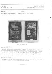
COMMUNICATIONSNAVSEA <strong>0967</strong>-LP-<strong>000</strong>-<strong>0010</strong>SERVICE NOTESship warranty replucement stacks upon receipt of defectivestack.6. Corrective Maintenonce Procedures. -Correctivemaintenance involving anything other than replacementof a complete rectifier stack will be considered atemporary repair and will be effected only to avertequipment outage. Details of temporary corrective maintenancepermissible by the terms of the warranty agreementare as follows:a. ldentificotion of rectifier stocks. -The followinsnumbers are used by TMC and Westinghouse to identifystacks:Equip. Contained TMC Westinghousein TMC Port Part NO.Mod KitNo.No.Observe standard safety precautionsb. lnterchongeoblility of stocks. -The followinqsubstitution of stacks to effect temporary repair ispermissible:Defective StackTemporary ReplacementNOTE(1) Observe polarity of stack and remove fromequipment.(2) Strip one-half inch of insulation from oneend of wire and tin.(3) Wrap tinned end one complete turn aroundstack bus wire where it leaves nearest good card atpoint marked "A" or "A", on photo of figure 2 and solder.(4) Carefully dress wire at least one-half inchfrom all components and secure other end of wire atpoint "B" or "B" on figure 2, following procedure ofsteps 2 and 3 above.(5) Remove all foreign material from work area.Sharp , protruding ends of wire should be avoided toprevent corona discharge.(6) Bridging faulty cards located at the extremeends of the stack will require connecting a new wire frompoint "C" or ''(3'' to point "D" or "D" an figure 2.(7) To bridge faulty cards located at the centerof the stack, connect as in (3) above from point "E"(cathode of the diode) to point "F" which shunts out card11 X 11 or from point "E" to polnt "GI1 which shunts outcard IIY1'.(8) Reinstall repaired stack observing samepolarity as noted in step (1) above. Up to twenty perctof the cards of any stack may be shunted in the above mannerwithout reducing the effectiveness of the stack.DD-116(320C018GlO)DD117(320C018G-09)DD-118(320C018G08)DD-117(320C018G-09) orDD-1 18(320C018G-O8)One DD-118(320C018G08) or two DD116(32&C018G10)Two DD117(320C018G09)in series or two DD-116(320C318G10) in seriesWhen connecting stacks in series, polarity must becarefully observed, i.e., positive terminal of one stackto negative terminal of other. Individual stack centerconnection (AC) will not be used. AC connection will bemade to junction of series pair. Substitution of stacks,in series, or a stack differing in physical size, willinvolve drilling additional holes in the insulated baseplate for temporary stack placement. Stacks shouldbe placed in such a manner as to insure maximum separationbetween individual stacks and between stacks andchass~s panels. For details see sketch in figure 1.c. Temporary repair to stack. -Where measurements,both front and back, indicate an open card in a stack(condition usually caused by faulty rlvet as previously noted),emergency repalr may be effected by bridging the faulty cardwith No. 16AWG solid copper, 600V insulated wire, inin accordance with the following procedure:ORIGINAL
I .-. . .b . b . b . ..COMMUNICATIONS NAVSEA <strong>0967</strong>-LP-<strong>000</strong>-<strong>0010</strong> SERVICE NOTES-;?-n0 0 8SINGLE STACK-?:I +NCne0-AC-0- 0 8 8 8 -& +0 ' '0CONNECTION OF TWO SMALLER STACKS AS SUBSTITUTION FOR ONE LARGE STACKFigure 1. A C Connections to Single and Series Stacks.NC!+zgure 2. Mcthod o/ Bridging Faulty Cards.ORIGINAL
COMMUNICATIONS NAVSEA <strong>0967</strong>-LP-<strong>000</strong>-<strong>0010</strong> SERVICE NOTESAN/FRT-39 Transmitter: Excessive Failure of Components inCMO Unit-Maintenance HintIt has been brought to the attention ofthe Naval Electronic Systems Command thatexcessive failures have been encountered inthe CMO unit sync indicator circuit of theAN/F'RT-39D. Analysis of the failures isthat the Keyer KY-S~L/URT opens the cathodeof V305 in the CMO unit which causes V305to be in a non-conducting state. Thisincreases the voltage on V310 thus causingit to conduct heavily with consequent overheatingof R339 and failure of V310.Activities which experience excessivefailure of V310 and R339 in the CMO unit ofAN/FRT-~~ series are requested to adviseNaval Electronic Systems Command via the"User Activity Technical Manual CommentSheet" normally provided by ED or othermeans as appropriate. ,(788)AN/FRT-39, AN/FRT-40 Transmitters, BandSwitch Detent Mechanism Repair--Maintena~ceHintThe indexing mechanism on the rear of IPABand Switch 5-202 in the AN/FRT-39/40 has ateflurr wheel which engages a star gear forindexing. The shaft of this wheel has beenfound to be a high failure rate item and thewheel is not stocked as a discrete part, theentire band switch must be replaced uponfailure of the- teflon wheel.r rDETAIL "A-'USUAL FAYWIE IS PLISTK AXLEMAKNG WFAT TI€ WMXLA method of repair of this item is outlinedas follows. Refer to figure 1 fordetails. Steps to be followed in repair are:1. Remove spring and arm assembly andseparate the teflon wheel from the arm byspreading the fork.2. Drill a 0.125" hole through thecenter of the teflon wheel.3. Cut a piece of 0.125 dia. brassrod to slightly more than the width of thefork.4. Insert the wheel into the fork andpress the brass rod through holes in forkand wheel.5. Peen both ends of the brass rod tohold it in position.6. Reassemble spring and arm assembly.This method of repair can be adopted toother switch assemblies which are constructedin a similar manner .:(732)ANIFRT-39, AN/FRT-40, ANIFRT-62 Radio TransmittingSet-IPA (AM,-2103lURT) Meter Interpretationand Incorrect Resistor ValueSome activities have experienced lowreadings of the IPA RF grid voltage while thetransmitter appears to be operating normallyin other respects.Aside from circuit malfunctions, thisproblem may be due to:a. Improper meter readinginterpretation--Position 6 of the Multimeterswitch (5204) may be labeled eirher "IPA Egxi"or "IPA Egx2." This multiplication factormust be included in interpreting the meterreading.b. Improper value of "multiplier resistorF233 in the mltimeter circuit ofAM-~~o~/uRT--I~ has been found that in someequipments, the value of R233 is 120 K o!lmsvice its proper value of 20 K ohms (for I'IPAEgxl") or 39 K ohms (for "IPA Egx2").Those activities experiencing low 1YA gridvoltage readings are advised to inspect R233and, if necessary, replace it with the valuescited above. Appropriate replacement resistorsare:20h ohm 112 watt FSN 5905-192-064939K ohm 112 watt FSN 5905-279-3497This article does not pertain to plannedor preventive maintenance . i\iirTOP VEWFigure 1.Switch S-202 Index Assmb1.y.ORIGINAL
COMMUNICATIONS NAVSEA <strong>0967</strong>-LP-<strong>000</strong>-<strong>0010</strong> SERVICE NOTESANIFRT-39, ANIFRT-40, ANIFRT-62 Radio Transmitter,Announcement of Availability of Replacement BallBearings for Blower Assemblies-Maintenance HintIn the past, Naval Activities which usethese equipments have replaced the lrariouscomponent blw~er motors with new units asfailure has occurred. Experience with theseequi~ments has shown that motors with wornoutbearings may be repaired prior to motorseizure/burnout with substantial savings tothe Navv. For example, the power amplifiermain blower for the AN/FRT-40 transmitter,circuit symbol B-7102, FSN9G4140-6g6-8656,costs $732.00 to replace. This mo:or can befitted with replacement bearings as they becomeworn-out at a cost of $8.44 per unitplus labor, and thus failure can be avoidedif the bearings are replaced when thev firstbecome "noisy".Accordinglv, Naval Activities desiringto replace the subject bearings rather thanthe motors, are advised to procure bearingpullers and replacement bearings as requiredOrdering information for replacementbearings is as shown in Table I.TABLE IBlowerNumberBlower Motor of Ball Bearings FSN for BallMotor Circuit Required Bearings Price perDescription Symbol per Assembly Assemblies AssemblyAN/ FRT-62 B-5001 1 ea 923110-144-8637 $1.24P. A. Main Blower 1 ea 923110-927-7919 $2.48AN/ FRT-62PSA, PSB Frame B-6001 2 ea 923110-554-0020 $1.20Top Fan B-6601AN/FRT-40 B-7102 1 ea 923110-144-8637 $1.24P.A. Main Blower 1 ea 923110-144-8622 $ .86AN/FRT-40 B-7301 2 ea *923110-554-6033 $ .63Top FanP.A. SectionAN/ FRT-40 B-8102 2 ea "923110-554-6033 $ .63Top FanP.S. FrameAN/FRT-39 B-800 2 ea 923110-144-8589 $ .69P.A. ?in Blower 923110-776-0643 $1.00AN/FRT-39 B-201 2 ea "92.3110-554-6033 $ .63IPA Main BlowerAN/FRT-39/40/62 B-3001 2 ea "923110-554-6033 $ .63Rear FanAssembly FrameAN/FRT-39/40/62 B-3<strong>000</strong>Front FanAux. Frame*If blower motor is manufactured by Eastern Air Devices, Inc. use 923110-158-8230.price per assembly - $.88(EIB 852/881)ORIGINAL
COMMUNICATIONSNAVSEA <strong>0967</strong>-LP-<strong>000</strong>-<strong>0010</strong>SERVICE NOTESANIURT-19( ), ANIFRT-39( 1, AN/FRT-40( 1. and AN1FRT-62( ), Radio Transmitters, Improved AlignmentProcedure for Side-Band Exciter Model CBE-1, -2The following improved alignment procedureis hereby provided for the sideband exciter,Model CBE-1, 2 units. This proceduresupersedes tables 6-1 & 6-2, section 6, pages6-1,2,3 of Technical Manual for Sideboard ExciterModel CBE-1,2(0-714/UR).A. Equipment Required1. Audio signal generator (ZTG orTlS-3 may be used).2. 70 OHM dumy load Tektronix 011-055 or equal.3. AN/USM-140 or equivalent oscilloscope.B. Modulator, Carrier Balance, andTrans former Tuning1. Remove CBE-1, 2 unit from theauxiliary frame using the CHG unit as asupport.2. Turn the sideband selectorswitches and carrier level control to OFF ancextreme CCW position respectively.3. Insure that the 250 kHz inputfrom the CHG is at least 1.3 volts RMS (3.68v p to p) normal indication is 4.1 to 4.5 vP to P.4. Connect oscilloscope probe tothe junction of C-209 and R-209, (near pin 1of V-204).5. Turn R-213 (Carrier Balance,USB) to maximum CW position to provide maximum250 kHz injection signal at T-203.6. Adjust the top and bottom slugsof transformer T-203 for a maximum indicationon the oscilloscope. Normal indication is1.5-2.0 v p to p.7. Adjust R-213 (Carrier Balance,USB) and C-216 (Carrier Balance, USB) forminimum indication on the oscilloscope. The250 kHz leakage signal should not, exceed .2v p to p.8. Connect oscilloscope probe tothe junction of C-226 and R-240 (near pin 5of V-208).9. Turn R-244 (Carrier Balance,LSB) to maximum CW position to provide maximum250 kHz injection signal at T-206.10. Adjust the top and bottom slugsof transformer T-206 for a maximum indicationon the oscilloscope. Normal indication is1.5-2.0 v p to p.11. Adjust R-244 (Carrier Balance,LS3) and C-233 (Carrier Balance, LSB) forminimum indication on the oscilloscope.C. Balance of Combining Network1. Apply a 1 kHz signal at -30 Dbm(.025 VRMS) at terminals 2 and 4 of E-201(Channel 1). This signal may be suppliedfrom the TlS-3 in the CW mode with the testswitch in the MARK position, or from the TTGor audio generator. The level of this injectedsignal may be verified by measuringthe level at the control grids (pin 6) ofV-203 (USB) or V-207 (LSB) with the USB gainor LSB gain controls (R-219 or R-222) in thefully CW positions. The level at pin 6 ofV-203 or V-207 should then be .2 v p to p.2. Connect the oscilloscope probeto the OUT terminal of 2-201.3. Set the USB channel selectorswitch to CHANNEL 1. Adjust the USB gaincontrol for a .2 v p to p signal on thescope. Switch the USB channel selectorswitch to OFF. Do not touch the USB gaincontrol.4. Connect the oscilloscope probeto the OUT terminal of 2-203.5. Set the LSB channel selectorswitch to CHANNEL 1. Adjust the LSB gaincontrol for a .2 v p to p signal on thescope.6. Connect the oscilloscope probeto the IN terminal of 2-202.7. Note and record the signallevel displayed on the oscilloscope. Switchthe LSB channel selector switch OFF and theUSB channel selector switch ON. Compare thelevel with the LSB level noted.8. Adjust the combining networkpotentiometer R-237 until the levels notedin step 7 are equal.D. Adjustment of Carrier Level1. Set the USB and LSB selector 'switches in the OFF position.2. Attach the 7C OHM dumj load to5-202.3. Connect the oscilloscope probeto the 70 OHM load.4. Set the carrier level control to0 DB position.5. Adjust the carrier insert potentiometerR-236 for .34 v p to p on thescope.E. Adjustment of USB and LSB PowerIndicator Ileters1. Set the carrier level control tothe extreme MIN position.2. Turn the USB channel selectorswitch to select the 1 kHz input (Channel 1).3. Advance the USB gain controluntil the oscilloscope indicates .34 v pto p.4. Adjust R-216 until the USB meterindicates 100%.5. Turn USB channel selector switchto the OFF position.6. Turn the LSB channel selectorswitch to select the 1 kHz input (Channel 1).ORIGINAL
COMMUNICATIONS NAVSEA <strong>0967</strong>-LP-<strong>000</strong>-<strong>0010</strong> SERVICE NOTES7. Advance the LSB gain controluntil the oscilloscope indicates .34 v pto p.8. Adjust R-247 until the LSBmeter indicates 100%.9. Correct level alignment may beverified as follows :a. Set-up the CBE-1, 2 sidebandexciter for normal operation.b. Set-up the exciter frame forany desired frequency of operation.c. Observe the M. F. tuning andR. F. output meters on the CHG-2 frequencyamplifier .d. These meters should provideidentical indications of 0 DB carrier insertion,or 100% modulation USB or LSB (usingthe 1 kHz test tone)ORIGINAL
COMMUNICATIONS NAVSEA <strong>0967</strong>-LP-<strong>000</strong>-<strong>0010</strong> SERVICE NOTESAN/F RT-40 AND AN/FRT-54 SERIES TRANSMITTERS-TUNING HINT FOR TMC MODEL GPT-40KIt has been determined that the output balance controlof the 10-ktv driver that is used to excite the 40-kilowatttransmitter has effect on the operation of the 40-kilowatttransmitter to the extent of minimizing the reactive componentof jrivs to the final. The VSWR indication circuitryin the newer loand 40-kilowatt transmitters can be used togreat advantage by tuning the "Output Balmce" control(C916) to minimize the VSWR drlve to the final.In tuning those transmitters that do not contain theVSWR circuitry, it is suqgested that the curve illustratedin figure 1 of this article be used to preposition the outputbalance control. This curve is an idealized curve derivedas an average curve taken from readings on several transmittersand will enhance the operation of the transmitterover the total frequency range.I---I ' 3 10 2 4 6 8 10 12 14 16 18 20 22 24 26 28 30FREQUENCY IN MEGACYCLESFigure 1. Typical Tuning CurveAN/FRT-39( ) AND AN/FRT-40( )- MISALIGNMENT OFPLUG AND JACK, CORRECTION OFSee article in AN/FRi'-40(ritle.) section under sameTIME DELAY FAILURES IN AN/FRT-39 AND AN/FRT-40 SERIES TRANSMITTERSRefer to article in AN/FRT-39 section under the sametitle.RF THERMOCOUPLE FAILURES IN AN/FRT-39( ) andAN/FRT-40( ) RADIO TRANSMITTERSRefer to article in AN/FRT-39 section under the sametitle.Pl;lse Transformer T-8105, a component part of the 10 KVpower supply In the ANiFRT-40( ) radio transrr,i tter. Hi$voltaqe orc-over between terminal No. 1 and the transformer'srnount~nq bracket appecrs to be a prlne co:~tr~butingcause of all failure> reprted.As a preventive and corrective measure, Naval FiuciioStation ('T) hiare lislan? haa Seen eniarginc; the teri':n31 clearancehoit- I:] tne traniiorncr mol;nting bracket by !/4 1n2h ~n?iur.eterC tr.ert.by In..-r >in:: ::.r ~rc-p.:t!: tic!:ve?n !rnnsfnr::!~.rterm~nal No. 1 and the ::ount~rli brackpt. Re!erral oi titismatter to the manufacturer ha- resuited In t,e !ollo':.~lq~niorrnat~ori for disse;. ~r~otlon to I'Javai shore activities:I. Enlarjement ol terminal ileararice hole in tronsformer:nountinq bracket IS snt1s!2ctory foi G;I ANiFR'T-4O( )trartsrnitters up to and ~nclujinq Ser131 Nc. 13226.2. AN/FRT--1OC trunsrnitters beqinn~nr; 'ivith SelialNo. 14227, and all ;ili/FRT-ij?( ) trcmsmltters, are eqzippi :v;ith a redcs~,dqed trart.ifor:cer ~,~L,III.; i?pro,~e.i t~rmir,a1insulilt~on.3. Appropr~ate chilnqes were ~ncorporateil as anaddendum to technical ir~unuols zccornpar~;.::io equ<strong>lp</strong>rnentsso moci~f~ed on the pro,iuctiort I~ne. The !',)i, FRT-!iOC :riaintenancemanual ..?as SII~:C~~IIC:,~~~~UF. :iltecl and re,nrittei. ondbears un issuc Jate cf 15 Szp:::;!!btr 196.1.4. The manufacturer'. port No. 1'F'-126 on? FSII-N59506452946 iderit~fies ihe or1 ~II;'JI iu~lure-pronc tro::;-former. Ti~s item 1:- :,L l ~n-j~r :i!i>~ilr.! J., J .P-I~C LJrt I.:the manufacturer.5. fie redesljnej tran~fc:r:ier bears the eq'iipn,entmclnufacturer'a part iJo. '1-i -:if, .I:;: ii- eIt.,:tricail:; a: :mecna:iicili!y intc-rcn-r. !satl! ::II', thi for.:li;r Ti'-126. '71 ten1 has been a~zi 4:)s- : .:!GCK r~u:~:,?; j %rd-l:J-.;J5&75 \-.'.'ti ;.Modif~cat~o:~ oi the T-ti1E pulse tr ir;::!',~r~~+; nountir,:bracket In )\.Nit FIT'-.I& j I; ~;p;sv~~ J:- J :irl: c!.::? ;Lpend~nq class~f~s,zt~on arl!! Jssl'n :r!e:!t i! c! cu;..i,r.r.This rnodlficut~on 1s c~prc.vc.d and rcrc::;:li;t.n3e:i fcir ecrlyoc~ornp!ishmerlt, c~tir. 1 ti.15 Hln jtk-k (ilt'!L':;lIIFS 93171,<strong>000</strong>. 1)os outhc:) ~ y .(659;AN/FRT-40B-AM-115 Power Amplifier Meter PanelAssemblyThe technical manl~ll issuei! 1 111ne 1962 for the i:'/FRT-408 radio transmitter .lid not ~mr~ta~n o srarr psrtslist for the syn;bol 7200 scrie.; itiil.is. Thi~ .;erie:; ;lertt:inl;to the /!?%!-I 15 Power iiirplif~er !.lrter Pnriel sec.::on of tit'transmitter.The following parts list for ti.? 7?OC serl,:s 1:f.r' !:taken from tile lila~ntenance I.:anuill for 4i!/i7i'T-;OK, T!.:CEJG. 1?!0313, Volume Ill, tiati.2 15 Septi,rr'ber 1964, cnt! maybe of some assistance 1r: :ii:rit~fy~rltl parts 111 t11i. A!.:-115panel asse~hly.MODIFICATION OF AN/FRT-40( ) SERIES TRANSMITTERSNaval Cornmunlcation Stat~ons Sun Francisco and Guamhave reported r.urr;erous failures b~tnq ex-ppri~nre-i ivlti-ORIGINAL
COMMUNICATIONSNAVSEA <strong>0967</strong>-LP-<strong>000</strong>-<strong>0010</strong>SERVICE NOTESAM-115 POWER AMPLIFIER METER PANEL ASSEMBLYDescriptionCAPACITOR, fixed: mica; .Ol uF,- + lo%, 500 wVdc.Same as C7201.Same as C7201.Same as C7201.Same as C7201. -NOT USEDNOT USEDCAPACITOR, fixed mica; 1<strong>000</strong>pF , + 10%C7209 Same as C7208thruC721117201 LAMP, fluorescent: standardcool, 112" dia. x 11-114" lg.Same as 17201LAMP, incandescent: frosted;2301250 V, 25 W; standardscrew base; 4" x 1-718'' o/a.LAMP, incandescent: red; 110/115 V, 25 W; standard screwbase; 4" x 1-718'' o/a.CONNECTOR, receptacle: coaxial.Same as 57201COIL, R.F. : fixed; 2.5 mH100 mA molded case.Same as L7201.METER, filament primary: AC; 500 wVdc .voltmeter, 0-300 V, red markerat 230 V; 4-1/2" square case.METER, kilovolts, R.F.: 0-1 kV4-112" rectangular case.MmER: amperes: 0-10 A; 4-112''rectangular case.METER, kilovolts, R.F. : 0-10 kVRF scale, 200 & DC movement,4-1/2" square case.NOT USEDMETER, kilowatts, R .F. : 0-60 kW200 WA DC movement.RESISTOR, fixed: wirewound; 500ohms, 25 w.STARTER, fluorescent lamp; 8 W;13/16" dia. x 1-1/2" lg.Same as S7201.BALLAST, fluorescent lamp; 8 W;118 v, 0.17 A, 60 HZFunctionFilament Primary MeterBypassDrive Meter 2j~assPlate Current MeterBypassPlate RF Meter BypassOutput Meter BypassSWR BypassSWR BypassMeter IlluminatingMeter IlluminatingPA Deck IlluminatingHV ON LightSWR ConnectorSWR ConnectorSWR FilterSWR FilterFilament PrimaryDrivePlate CurrcntPlate, R .F.Unbalanced OutputHV ON Light VoltageDropping ResistorLamp StarterLamp StarterLamp BallastTMCPart No.CM35B103KORIGINAL
COMMUNICATIONSNAVSEA <strong>0967</strong>-LP-<strong>000</strong>-<strong>0010</strong>SERVICE NOTESSyrn Descript~on FunctionSame as T7201.SOCKET, fluor~scent lamp: 75watts, 250 volts.Same as X17201ASame as X17201ASame as X17201ASOCKET, bulb head mounting:ceramic; lor standard base incandescentlamp; rated for 660watts, 250 volts.Sme os y17203.SOCKET, starter: Iluorescent;60 watts, 250 volts.Same as XSIB I.Lamp BallastLmp SocketLamp SocketLamp SocketLamp SocketPA Deck Lqht SocketHV ON Lqht SocketStarter SocketStarter SocketT MCPort No.TS-141AN/FRT-39, ANIFRT-40 AND AN/FRTdZ RADIOTRANSMITTER SILICON RECTIFIERSMAINTENANCEINF0RMAT:ON.See arucle under AN/FRT-33 wth the sane title(EIB 723)AN/FRT-39,AN/FRT-40,AN/FRT-62 RadioTransmitter, Announcement of Availabilitv of Re~lacement Ball Bear-ings fir lower Assembl ies--MaintenanceHintSee article under AN/FRT-39 withAN/FRT-40 Transposed Leods on PlQk Transformer-MaintenonceHintsame title. (EIB 852/881)AN/URT-19( ), AN/FRT-39( ), AN/FRT-40( ), and AN/The Field Technical Authority (FTA) atFRT-62( ), Radio Transmitters, Improved AlignmentNAVRADSTA (TI Annapolis has noted that the Procedure for Side-Band Exciter Model CBE-1, -2replacement for the AN/FRT-40 late Dowertrinsformers T8101, T8102, and' ~8103' (FSN9~6120-774-8584), manufactured by Prec'ision See article in AN/FRT-39 sectionElectronics, Incorporated, may have the under the same title. (EIB 887)start and ending leads ef one windingreversed. These transformers are paintedgrey instead of black. When the transformerwith the transposed leads is installed inaccordance with instructions and the wirescon~ected to the same numbers as the failedunit, the supply fails to deliver correctvoltage.In case a new transformer is installedand the supply malfunctions, reverse theleads to the primary winding of the newlyinstalled transfomer. Tag the primaryleads for information to the next maintenanceman. This vill prevent inadvertent"correction" of the connections at a laterinspection.,(78 jAN/F RT-39, AN/FRT-40 Transmitters, Band SwitchDetent Mechanism Repair - Maintenance Hint.See Article under P.N./FRT-39 ,with some title.(EIB 792)ORIGINAL
COMMUNICATIONS NAVSEA <strong>0967</strong>-LP-<strong>000</strong>-<strong>0010</strong> SERVICE NOTESAN/FRTJO AND AN/FRT-54 SERIES TRANSMITTERS -TUNING HINT FOR TMC MODEL GPT-40KSee article in AN/FRT-40 secticn under the sametitle.OR1 G I NAL
COMMUNICATIONSNAVSEA <strong>0967</strong>-LP-<strong>000</strong>-<strong>0010</strong>SERVICE NOTESANhRT-39/40/62 brier T mnraittersJohty HazardSee article ANffRT-39 section under the sane title (17s)AN/FRT-39, AN/FRTJO AND AN/FRT42 RADIOTRANSMITTERS SILICON RECT IFJERSMAINTENANCEINFORMATIONSee article under AN/FRT-39 with the some title.(EIB 723)AN/FRT-62, AN/FRT-62A, AN/FRT42B, IN/FRTlXAND AN/FRTIZD4ADIO TRANSMIT T ERSREPLACEMENT PARTHolders of subject equipment are requested to Includethe following information in correspondence and requestsmceming replacement parts:a. Transmitter model (AN/FRT62B, etc.)b. Assembly where replacment part Is locatedc. Name of partd. Circuit symbole. Manufacturer's part numberf. Federal stock numberEXAMPLE: AN/FRT62B, 200 KW PA, Capacitor,C5327, TMCl CB 167-2,FSN 9N5910-9047330Compliance with the foregoing will geatly enhmceefforts to fill replaernent put requests.(EIB 723)AN/FRT-39,ANlFRT-40,AN/FRT-62 RadioTransmi tter , Announcement of Avai 1 -ability of Replacement Ball Bearingsfor Blower Assemblies--MaintenanceHintSee article under ANjFRT-39 w ithsame title. (EIB 852/881)4N/URT-19( ), AN/FRT-39( ), AN/FRT-40( ), and AN/FRT-62( ), Radio Transmitters, Improved AlignmentProcedure for Side-Bond Exciter Model CBE-1, -2See article in AN/FRT-39 sectionunder the same title. (EIB 887)ORIGINAL
COMMUNICATIONSNAVSEA <strong>0967</strong>-LP-<strong>000</strong>-<strong>0010</strong>SERVICE NOTESAN/FRT-83 Series Transmitter "4G" ModulesRequest for Care in HandlingThe purpose of this article is to callattention to the large number of modules receivedat the repair depot which have sufferedphysical damage due to mishandling.During the period from 15 December 1974 to 15June 1975, 183 of 1124 or 16.3% of the partsreplaced were damaged due to mishandling.Some of the causes of this damage are asfollows: attempting to insert modules withoutsufficient care in aligning pins first;failure to tighten modules down, causingdamage to hold down screws when drawers areclosed; attempting to tighten nuts too faron some of the larger transformers, thusstripping threads, breaking lugs, etc; anddropping modules causing breakage of fragileparts and bending of chassis.In addition to the damaged modules, 50of 422 modules processed or 11.9% were foundto be non-defective and another 38 or 9%required alignment only.The net result of the foregoing problemsis shown in increased turn around time andmore inefficient use of depot resources. Ifall personnel would take more care in theirdiagnostic and handling procedures, theywould enjoy better sup~ort from the modulerepair depot.(EIB 919)AN/FRT-83(V) and AN/FRT-84, Frequency Transmitters- Potential Shock HazardThe purpose of this article is to advise*\/FRT-83(V) and AN/FRT-84(V) maintenancepersonnel of a potential shock hazard and toinform them of the availability of DANGERlabels that will alert the technician tothis hazard.IJhen the 1 KIJ power amplifier, RF AmplifierAM-6046/FRT, is withdrawn from its cabinet, 220VAC is present at relay lAlKl terminals 3, 4, and5 even though the equipment is in standby andinterlocks 1A2S1 and 1A2S2 are open. This conditionexists when circuit breaker XAlCB1 is shut(See Technical Manual for ANIFRT-83(V), NAVELEX<strong>0967</strong>-LP-292-9010, figure 4-49 or TechnicalManual for ANf FRT-84 (V) , NAVELEX <strong>0967</strong>-LP-293-<strong>0010</strong>, figure 4-49.) Although a protective plasticcover is installed over relay 1AlK1, this coveris not foo<strong>lp</strong>roof and its removal may be requiredduring maintenance.As an added precautior against the potentialshock hazard described in foregoing paragraph,self adhesive DANGER labels are available fordistribution by NAVELEXSYSENGCEN, San Diego.This label may be affixed to the protection coverover relay lAlKl to remind the technician of thepotential hazard. Stations that have not receivedtheir DANGER label(~) may acquire sameby writing to NAVELEXSYSENGCEN, Code 4311, 4297Pacific Highway, P.O. Box 80337, San Diego, CA,?2138, referencing this EIB (925), and statingt!ie quantity of labels (1 per equipment) reo~iired.Field Change 7-AN/FRT-83/84 Radio TransmittingSet - Installation DifficultyThe purpose of this article is to recommendremedial alternatives to correct thedifficulties experienced in the installationof Field Change 7-ANIFRT-83/64.Installing personnel have reported thatthe 1-114 inch flex hose (Item 23 of fieldchange bulletins PJAVELEX <strong>0967</strong>-LP-292-9170 andNAVELEX <strong>0967</strong>-LP-293-9170) provided with thefield change kit is too stiff to ensure areasonably easy 90' bend where the hoseleaves the blower plenum. In some instances.the hose has collapsed at the 90' bend,thereby cutting off air flow to Power SupplyPP-6067IFRT.A procedural 1JOTE in the field changebulletin (page 7 of iJAVELEX <strong>0967</strong>-LP-292-9170and page 6 of NAVELEX <strong>0967</strong>-LP-293-9170) mentionedthat portions of the procedure had alreadybeen accomplished on some transmittersas is indicated by the presence of flex hosebetween the blower plenum and Power SupplyPP-6067lFRT. This hose is much more flexiblethan that provided in the field change list.A procedural CAUTION stated that those Dortionsalready accomplished should be removedand replaced with the parts and materialsupplied with the field change kit.As a solution to the difficult 90' bendusing the hose provided with the field changekit, those activities that have retained theolder more flexible hose may leave it installedor re-install it if it has beenremoved.Those activities that did not have thenore flexible hose previously installed or11ave since discarded it, may alter the fieldchange as prescribed below.Elaterial required: Schedule 40, 1" PVC;1. Elbow, 90° , ? each2. Pipe, 3" long, 1 each3. Pipe, 5-112" long, 1 eachORIGINAL
SERVICE NOTES NAVSEA <strong>0967</strong>-LP-<strong>000</strong>-007 9Procedures1. P.emove the hose from the hose adapterat the blower plenum wall.2. Install a PVC 90' elbow onto thelose adapter in place of the hose. Plount theelbow so that it is pointing straignr up.3. I~stal? the 5-1/2 inch lozg ?!'Cpipe into the elbow.4. Add the second elbow to the 5--112inch long pipe so that it is pointing towardthe front of the transmitter.5. Install the 3" long IYC gipeinto the elbow.6. Shorten the flex hose by an amountnecessary to install it on the 3" pipe andclamp the hose in place.Platerial required: Schedule 40, 1" PVC;1. Elbow 90" , 1 each16 2. Pipe, 3" long, 1 eachProcedures1. Remove the hose from the hose adap--ter at the blower plenum wall.2. Install a PVC 90° elbow onto thetiose adapter in place of the hose. Plount theelbow so that it is pointing straight down.3. Install the 3" long pipe into theelbow.4. Shorten the flex hose by an amountnecessary to install it on the 3" pipe andclamp the hose in place.'AN/FRT-83(V) and AN/FRT-84(V) FrequencyTransmitters-Lubricant Substitution and PublicationsRevisionsThe lubricant called for in the PMS requirementson the AN/FRT-83(V) and AN/FRT-84(v),.- nr transmitters known as "Airo iubriplate",NSN 9W9150-00-030-0451, is no longer carriedin the Navy Supply system. Any general purposelubricant is acceptable. One readily obtainablesubstitute is Aircraft and InstrumentGrease, MIL-(;-23827 (A), NSN 91'9150-00-985-7244.The cost is $1.14 per 4 oz. tube.Pen and ink revisions should be made tothe following publications reflecting thissubstitution:Maintenance Standards Book AN/FRT-83(V)NAVSHIPS <strong>0967</strong>-292-8090 pg viii and pg 13Maintenance Standards Book AN/FRT-84(V)NAVSHIPS <strong>0967</strong>-292-0050 pg viii and p: 16PMS Cards AN/FRT-83(V) MRC Code C-877cards BJH9, pg 1 and pg 4 ACP6 pg 1and pg 3PMS Cards ANIFRT-84(V) MRC Code C-868cards BJJ4 pg 1 and pg 4 ACLl pg 1and pg 4(EIB 943)lhe material required may be procuredthrough local supply activities or preparedassemblies may be obtained by writing toNAVELEXSYSEPiGCICN, Code 4311, 4297 PacificHighway, P.O. Box 80337, San Diego, CA 92138,referencing this EIB article, and statingthe number of assemblies required and forwhich model, (A?I/FRT-83 or AN/FRT-84) transmitters.(EIB 937)
COMMUNICATIONSNAVSEA <strong>0967</strong>-LP-<strong>000</strong>-<strong>0010</strong>SERVICE NOTESAN/FRT-85 Radio Transmitting Set-BlowerMotor Cable Harness Damage PreventionThere have been some reported incidents ofdamage to the AN/FRT-85 blower motor cable harnessas a result of fan belt breakage; afterthe fan belts break, the frayed belt partsstrike the harness. Inspection of 25 AN/FRT-85transmitters has revealed that their blowermotor cable harnesses were routed incorrectly:the harnesses were dressed to the rear of Shield"C" vice to the front as illustrated in theTechnical Manual, NAVSEA <strong>0967</strong>-293-1010, Section2, Figure 2-17. Dressing the cable harness tothe rear of the shield exposes the harness todamage from frayed and broken belt parts.Dressing the cable harness to the front of theshield affords harness protection in the eventof belt fraying and/or breakage.The following procedure pertains to boththe inspection and correct ro~ting of theAN/FRT-85 blower motor cable harness:1. De-energize the equipment; tag appropriateswitches and circuit breakers.2. Unlatch and open the right-front doorat the power amplifier cabinet.WARNINGENSURE HIGH VOLTAGE, HIGH CAPACITANCECOMPONENTS ARE DISCHARGED TO GROUND.3. Refer to NAVSEA <strong>0967</strong>-293-1010, Section2, Figure 2-17.4. Inspect equipment for correct blowermotor cable harness routing as illustrated inFigure 2-17, i.e., to the front of Shield "C".5. If cable harness is routed correctly:a. Close and latch the right-frontdoor of the power amplifier cabinet.b. Return the equipment to itsnormal operating condition.6. If cable harness is dressed to therear of Shield "C":a. Remove the cable clamp(s) "B"from the rear of Shield "C".b. Remove the cable clamp securingthe harness to the right side of the poweramplifier cabinet behind Shield "C"; removethe clamp from the harness and discard.c. Reroute and dress the cable harnessto the front of Shield "C" as illustratedin Figure 2-17.d. Install the cable harness clarnp(s)"B" on the front of Shield "C"; use <strong>original</strong>screw holes.e. Close and latch the right-frontdoor of the power amplifier cabinet.f. Return the equipment to itsnormal operating condition.(ELB 971)iIORIGINAL
COMMUNICATIONSNAVSEA <strong>0967</strong>-LP-<strong>000</strong>-<strong>0010</strong>SERVICE NOTEAN/FSH-7 (V) Recorder-Reproducer--Si gnal DataSet-Storage Bin Access Door RepairVarious activities using the AN/FSH-7 (V)equipment have reported breakage and deteriorationof the storage bin access door(~9MP51) hinges because of the absence ofdoor stops. Since the door assembly was notconsidered to be a failure item during initia<strong>lp</strong>rovisioning, logistic support was not provided.Some activities have reported the use ofwire rope or metal chain to support the binaccess door. Although the adequacy of suchfixes is not known, the use of the anglebar support shown in figure 1, appears tooffer a worthwile solution to the storagebin access door problem. The stainlesssteel angle bar can readily replace theedsting hinge cover strap on the tapestorage bin door and is recommended forimplementation where the basic problemexists. The plastic piece, shown in figure1, should be attached along the topedge of the angle bar to act as a stop andprevent scratching the storage bin accessdoor when open and resting on the stop. (799)*41 (.096) DRILL, 8 HOLESSPACED3" APART
SERVICE NOTES NAVSEA <strong>0967</strong>-LP-<strong>000</strong>-<strong>0010</strong> COMMUNICATIONSAN/FSH-7(V) Dust Cover Door Hinge Repair -Maintenance HintThis article provides a single, inexpensivemethod of repair for broken dust coverdoor hinges in the AN/FSH-7(V) equipment. Thehinge, an integral part of the cast aluminumdust cover door, is frequently broken requiringreplacement of the entire door. Theexpense of a new door is avoided by replacingthe broken hinge.1 6641E-247 7-17-75 {EIB 913)7 6641E1-237 5-8-7511 6641E1-553 9-29-753 6641E1-69 2-16-736 664161-286 5-8-741 Rec. rlAVSECrJORDIV 6-22-758 6641E1-319 7-15-753. Refer to EIMB Reference Book (NAVSEA<strong>0967</strong>-LP-<strong>000</strong>-0140) Screw, Drill and Tap Data.Drill and tap the holes for the 10-24 mountingscrews in the brass stock.4. Drill two holes in the door for thescrews. Final alignment of the hinge may beachieved by filing the bearing surface of thehinge for equal weight distribution.5. M i l l off the peak of hex point togive clearance for the door to swing open.6. Place flat washers as necessarybnder the mounting screw head to prevent scre3.rom contacting hinge pin.7. Re-adjust door latch if necessary.Parts Needed :Allen Head Screw 10-24 X 1-114" (twoper hinge) 92305-00-978-93595/8" Brass Hex Rod 1-718" per hinge/in ft.\A'- a ~ ~ i ~ iorder) 9Z530-00-232-5618Repairs are accomplished as listed in thesteps below:1. Remove all but 1/16 inch of existingtinge with hacksaw and file. The remaining portionwill serve as a guide for alignment of thenew hinge piece.2. Cut off 1-7/8 inch brass stock anddrfll the 17/64 inch hole as shown in figure 1.DRILL 8 TAP FOR 10/24fi/ L~~~~ DIAMETER 17/64"L ~ OFF l PEAK ~ OF ~ HEX POINTTG APPiiOx I/~'AcROSS FLATSTO GIVE CLEARANCE AS DOORSWINGS OPENFigure 1. Replacement Hinge Dimensions/1 AN/FSH-7 (V) : 2
COMMUNICATIONSNAVSEA <strong>0967</strong>-LP-<strong>000</strong>-<strong>0010</strong>SERVICE NOTESAN/GMt?-13 Cloud Height Set-HeaterInformationPower SupplyThe DC voltclge level applied to the heaters of thefirst and second amplifier stages of the detector amplifierof Cloud Height Set AN/GMQ-13 (all models)has been found to have considerable effect on the amplifiernoise level and signal-to-noise ratio. Thisvoltage level should be 4.8V DC, measured at the outputof the heater supply (point "B", figure 7-4, ofNAVAIR 50-30GMQ13-1). The D.C. output voltagemay be made variable by replacing resistor R239 withan adjustable, lkhm, 10-watt resistor (IRC 1-3/4AAor equal).This modification should be made in all installationswhere higher than normal noise is experienced atthe detector amplifier output. An accurately calibratedvacuum-tube voltmeter must be used when makingthe adjustment to 4.8V DC.If difficulty is encountered in obtaining bridge rectifierCR-201, utilized in the 4.8V heater power supply,a replacement such as Motorola PA4 MDA 952-1,or equivalent, may be utilized. (751)ORIGINAL
COMMUNICATIONSNAVSEA <strong>0967</strong>-LP-<strong>000</strong>-<strong>0010</strong>SERVICE NOTESInstollation Notes On AN/GRA-47 and AN/GRA-48 ShoreTACAN AntennasAn excessive number of failures has been experiencedin these types of antennas due to bearlng [allures, openantenna array, and vibrationk total of 20 were purchased for the Bureau of JeaponsGround Electronics Program, and no further procurement ofthis type wlll be authorized. In order to insure the longestservice-life wsslble, ~t 1s recommended that the followingsteps be taken durlng installations.(a) The tower antenna-base plate should be machlnedflat if posslble If not, set the antenna on the base plateand Insert shlms where necessary to correct for an unlevelor warped base plate.(b) Llghten the mounting bolts ufter all shims are Inplace, to prevent daniaglng stress to the antenna base(c) Ascertain that all screws holdlng tne access coversare tight Jhen the rragnetlc deviation has to be set duringa flight check, be sure to replace the access cover 3s soonas posslble It has been found that antenna vibriltionincreases with these access covers removed (534)ORIGINAL
COMMUNICATIONSNAVSEA <strong>0967</strong>-LP-<strong>000</strong>-<strong>0010</strong>SERVICE NOTESAN/GRC-27, Preventing Down TimeA number of AN/GRC-27 equipments have been immobilizedby broken contact pins on thespecial socketsfor the two 4X150A tubes (V-601, V-602) in the RF poweramplifier. This can result when the tube is replaced andthe key on the tube stem is not alined w~th theguide inthe socket. Pushing the tube "home" results in breakingthe contacts. Specla1 attention to this situat~on when replacingtubes is suggested.to obtain relay closure at 90-volts line voltage. If thespring tens~on is decreased too much, then the relay contactsare sure to open under mechanicnl shock and shutdown Radio Set AN/GRC-27.Rad~o-Set Controls, Serral 1 through 115, will be fieldchanged to use the new, properly adjusted relay. Stockmaintenance relays of the old type will be replaced wlththe new type.AN/GRC-27 LUBRICATE HELIPOT R601Proper lubr~cation can plevent theHelipot (R601) shaftfrom freezing in its bearing. This type of mechanical failurehas occurred, andresults In breakage of the associatedflexible shaft coupling (to the tunlng drive motor). If sucha failure occurs before preventive maintenance can be effected,repair can be made by carefully disassembling the hel<strong>lp</strong>ot,reflnlshing the shaft and tearing w~th corcus cloth, andlubr~cating the bearing area ofter reassembly. Replace theshaft coupling ~f ~t has broken.During routine preventive-maintenance pocedures, puta drop or two of oil (MIL-L664) on the shaft bearing ofHel<strong>lp</strong>ot R601. Helipot R601 1s now oorried as a stockmaintenance Item.IM-89/U R CH ECKlNG AN/GRC-27 TRANSMISSION LINEThe Standing Wave Indicator IM439/UR can be used inchecklng the transmission 11ne of AN/GRC-27 by operatingthe transmitter-receiver at 60 watts and using the "prcentreflected power" indication as a measure of the transmissionline condit~on.ADJUST ARMC-1180/GRC-27 START-STOP RELAY ADJUSTMENTArmature chatter In start-stop relay K-105 In Rad~oSet Control C-!!80/I;RC-27 has been reported Th~s relaywas changed to a shock-res~stantype (Prlce Electr~c CompanyType 2107) , start~ng wlth Serlal No. 116. The armaturereturn splngs are adjusted by the manufacturer so that thereloy would close at 100-volts line voltage. When the co~lheats up after a short per~d of operation, the ampere-turnsratlo decreases somewhat. This results In a tendency forthe springs to open the relay, causing armoture chattersl~ght decrease In the spring tension, permlttlng closure on90-volts llne voltage, will correct this cond~tion.Radlo Set Controls C-1180/GRC-27, Ser~al 116 through315, can be adjusted In the f~eld by bendln~ the armoturereturn spring arms (see flgilre 1) upward slightly. A variabletransformer (Var~ac or slmllar) should be used when marklngthis adjustment ofter the relay has cooled for several hours,Figure 1.Relay K-105, Armature Return Spring Arm AdjustmeatBROKEN END PLATES ON RF TUNERS ON THEANIGRC-27AReports have been received of numerous cases of brokenend plates on RF Tuners 7,501, 7502, and 2503 in thedriver unit of T-217A/GR. Tne broken end plates are apparently a result of extraction or insertion of 2C39A tubeswithout paying heed to the warning, 'Caution-loosen clampand use twisting motion to extract or replace tubes,"stamped on the unit cover plate. It is suggested thatstrict adherence to this procedure be followed to avoidunnecessory damage to the tuners.ORIGINAL
COMMUNICATIONS NAVSEA <strong>0967</strong>AN/GRC-27A-WIRE CODE LEGENDIt has been pointed out that there are difficulties inidentifying internal leads in the AN/GRC-27A because ofomission of a wire code legend in NAVSHIPS 92774. Thislegend is published herewith (flgure 1.) for use by allactivities concerned with servicing the AN/GRC-27A:wire designation: D A S 9 2 3 5AN/GRC-27 and AN/GRC-27A Radio Sets,Adiustable Tuning CoresMany electronic techicians are ordering transformersfor the AN/GRC-27 and AN/GRC-27A when the tuning corefails. The tuning cores are not packaged with the transformeras an assembly, and, therefore, must be orderedseparately. Listed below are symbols of the transformer,coils, and cores with the respective Federal Stock Numberof each core:Receiver (R-278/GR, R-278A/GR, R-?78B/GR)Transformer Coil Core Core Stork No.letter 's* indicates shieldingbody colorfirst tracer colorI Isecond tracer colorIthird tracer color IFigure 1. Wire Code LegendTransmitter (T-217/GR and T-2 17A/GR)AN-J-C40 wireBusbar, round, tinned copperJAN Type WL (600 volts)Miniature JAN wire (Prodelin)JAN Type SPIR (1<strong>000</strong> volts)JAN Type SRHV (2500 volts)Wire Sizet.10. 22 AWGNo. 20 AVIGNo. 18 A1?GNo. 16 AWGNo. 14 AWG!lo. 12 AWGNo. 10 AVdGNo. 8 AWGColorBlackBrownRedOrangeYellowGreenBlueViolet or PurpleGrayVhiteNOTE:This informtion was assembled from NAV-SIIIPS 92774, Section 7, and Allowance PartsList for AN/GRC-27 NOMENCLATURE CODE55376100, dated Dec. 1960, and Allouance PartsList for AN/GRC-27A NOMENCLATURE CODE55376101, dated Jan. 1962.AN/GRC-27 Radio Sets -Maintenance IntormationTuning (parallel) lines of the grid and plate circuits inthe power amplifier of Radio Transmit!er T-217A/GR aresubject todamage that destroys the effectivness of theircoin-silver contact surfaces. When such damage occurs,the shorting bars no longer make the positive contact requiredto ensure power output and reset accuracy. Thefollowing prccedwe for rehabilitating these lines was submittedby the Long Beach Naval Shipyard.While the information contained herein is directed tofield activities which have facilities for silver platingoperations, it also should be of interest to field activitiesresponsible for the maintenance and repair of theseequipments.ORIGINAL
COMMUNICATIONS NAVSEA <strong>0967</strong>-LP-<strong>000</strong>-<strong>0010</strong> SERVICE NOTESA. REMOVAL AND DISASSEMBLYThe following removal and disassembly pocedures mustbe performed before silver plating operations are begun.NOTE: Figures a d paragraphs referenced herein arefound in NAVSHIPS 92774.1. Remove power amplifier subassembly from transmitterchassis (paragraph 6-3b (10)).2. Remove plate side cover (figure 6-19).3. Remove blower housing and blower from grid side(figure 6-19). Remove two screws securing motor supportto power amplifier subassembly and two screws securingfaward end of blower housing to allow motor blower assemblyto be lifted from side without damage to the motorwiring.4. Remove two screws securing plate on whichresistors R608, R609, and R613 (figure 6-19) are mounted.5. Remove two screws securing capacitor C615 toplate A601 (figure 6-22).6. Remove two screws securing resistors R605 andR605 (figure 6-22).7. Remove all screws securing plate A601 to poweramplifier chassis.8. Unsolder lead at L603 which connects to 2602(figure 6-20).9. Remove nuts, washers, and screws securingteflon insulator located between tuning lines and screen.10. Remove two retaining rings from shaft 0643(plate line) and retain for reuse.NOTECare should be taken in removing retainingrings as they will be difficultto obtain through supply channe!~.11. Unsolder brass strap E625, wch end of whichis soldered toeach half of tuning lines.12. Loosen coupler (figure 6-22).13. Remove side plate A644(figure 6-19) and, atsame time, remove 2602 (figure 6-20) as an assemblyfrom power amplifier.B. INSTRUCTIONS FOR SILVER PLATING1. Remove side plates from tuning line 2602.2. Machine tuning line to a smooth finish, removingas little metal as possible.3. Flash with copper (paragraph D) from 1-1.5 minutesat 1.5 volts with tank temperature at 100-110 degreesFahrenheit.4. Coat with 1 Mil of silver (paragraph D) for oneholfhour at 1 volt.5. At completion of plating, buff bright with aBristol brush.C. REASSEMBLY AND ALIGNMENT1. Reassemble tuning lines by performing, in reverseorder, disassembly procedures.ORIGINAL2. Use the following procedure to reload the springlmdedgears:a. Located on left side of Power Amplifier arefour studs which are in line withplate lmding gears0619 and 0621. Fit apertures in 0619 and 0621 tothese studs; loosen lock nut and slide loading geartoward side plate of power amplifier. Studs willnow fit in apertures, locking 0619 so that it cannotmove.b. Using a flat blade screwdriver, press 0607until it slips between 0619 and 0621.c. Load 0621 by turning it clockwise.d. Release tension on 0607. This locks 0619and 0621.e. Slide 0619 and 0621 inplace and tighten locknut.Care should be taken to ensure that studs fit inapertures, locking 0619 so that it cannot move.Equipment does not have to be disassembledto accomplish the above work.3. Align power amplifier and servo system trackingin accordance with instructions in paragraphs 6-2c (8)(a) through 6-2c (8) (f).D. INSTRUCTION FOR SILVER PLATINGWARNINGCyanide poisoning can result from improperhandling of thechemicals thatcomprise the plating solutions. This platingprocess is to be undertaken onlyby a Naval Shipyard or Repair Facilitywhere a chemist is available to supervisethe prepation of these solutions.The plating solutions are prepared as follows:Copper solution -Copper Cyanide - 3.5 oz. per gal. of waterSodium Cyanide - 4.6 oz. per gal. of waterSodium Carbonate - 4.0 oz. per gal. of waterRochelle Salt - 6.0 oz. per gal. of waterCopper Metal - 2.5 oz. per gal. of waterFree NaCN -0.75 oz. per ql. of waterpH adjusted withCaustic Soda -12.5 oz. per gal. of waterCurrent Density 40-50 amp per sq. ft.**Silver Solution -Silver Cyanide - 10-15 av. oz. per gal. of waterPotassiumCyanide - 12-18 av. oz. per gal. of waterPotassiumCarbonate (min) 2 - av. oz. per gal. of waterPotassiumHydroxide - 0-4 av. oz. per gal. of waterMetallic Silver - 7.511.5 tr oz. per gal. ofwaterFree Cyanide - 7-12 av. oz. per. gal. of waterTemperature 100-12pFCurrent Density 50-100 amp per sq. ft.AN/GRC-27:3
COMMUNICATIONSNAVSEA <strong>0967</strong>-LP-<strong>000</strong>-<strong>0010</strong>SERVICE NOTESAN/GRC-27, -27A RADIO SET - TRANSMITTER IFALINEMENT.The purpose of this article is to provide a detailedalinement procedure of 1F strip in the T-217A/GRC-27ATransmitter.Information gained from Performance and OperationalReports and CASREPTS received by the ElectronicsMaintenance Engineering Center (EMEC) has shorn thatalinemmt of tke 1F strip L: the T-217AlGRC-27A transmitterhas been a cause of prolonged equipment downtime.Alinement as outlined in the Technical Manual, NAVSHIPS92774, page 6-24, paragraph (5), although a reliablealinement procedure, is presupposing that the "sumfrequency" of the 1 and 0.1 mc oscillators will be the onlyavailable signal at J-403. ?his definitely is not hue, andunless T-401, T-402, and T-403 are actually tuned to the"sum frequency" of the 1 and 0.1 mc oscillators, alinementis impossible to accomplish.IF ond Oscillator Alinement:1. Before attempting to dine the 1F amplifiers andoscillators, proceed with the following preliminary steps.Step a. Set the frequency selector unit to 399.9 mc.The cam followers will be on the first step of the cams.Step b. Adjust the slugs in each of the amplifiersand the oscillator (T-401, T-402, T-403, and 2-401) toapproximately 1-7/32 inches dDrn from the surface of theshielding can.Step c. Disconnect the B+ to tube V-406 at feedthroughinsulator E-429 (junction of C-456 and L-414).Step d. Remove tubes V-305 and V-101.Step e. Put the brass end of the tuning wand in theplate side (primary) of transformer T-401. Leave the wandin place until Tuner 2-401 is tracked.2. To tune the 1 mc oscillator, proceed as follows.Step a. Set the frequency selector unit to 390.0.Step b. Connect dc VTVM AN/USM-116, orequivalent, to Jack J-402.Step c. Key transmitter and adjust coil L-405 fora peak indication on the VTVM.Step d. Set the frequency selector to 393.9 mc.Step e. Adjust trimmer C-433 for a peak indicationon the VTVM.Step f. Repeat steps a. through e. until adjustmentof either capacitance or inductance no longer causes anincrease of negative voltage at jack J-402.Step g. Unkey transmitter, and remove tuning wandfrom pimary of T-401.NOTE: It is possible for the mixer to 0scillateas a tuned plate-tuned grid oscillatorif Tuner 2-401 is tuned to the IF frequencyinstead of the crystal frequency.This situation may occur, since these twofrequencies are separated by only 2.0 mc.An oscillating mixer will cause a readingof approximately - 5.0 volts at 5-402.The reading will be approximately -3.0volts dc a! the mrrect operating frequency.When a Frequency Counter (CAQI-524 or equivalent)is available, frequency of the 1 and 0.1 nc oscillatorORIGINALshould be checked. This my be accamplished by removingV-401, inserting tube socket adapter, replacing V-401,and taking signal from pin 7 of V-401. The 1 and 0.1 mcoscillator signals are present at this pin.The frequency of the 1 and 0.1 mc oscillators shouldbe checked in each of their incremental steps.After completing bequency check, remove tube socketadapter and replace V-401.3. To check the 0. l mc oscillat~r, proceed as follows:Step a. Ccnnect the dc VTVM to Jack J-401.Step b. Key the transmitter and check the voltageat J-401 with dc VTVM. The voltage should range between-12.0 md -20.0 wlts dc.Step c. Unkey trmsmitter.4 Tuning the IF:Step a. Set the frequency selector unit to 390.0 mc.Step b Adjust capacitors C-408, C-417, C-424,C-436, and C-443 for approximately one-half capacity(silvered portion up).Step. c. Remove tube V-403 and place rf probe orac probe on pin 1 of V-403 socket.NOTE: Correct voltage will be approximately0.1 volts rms. Incorrect voltagecould be as much as 3 volts rms.Step d Key transmitter and tune powdered iron coresin T-401 primary and secondary for peak on VTVM.Step e. Remove V-402. Voltage at pin 1 of V-403should drop to ZERO.NOTE: If the output drops to ZERO, T-401has been properly tuned and you may continuewith alinement procedures as given inthis article. If the output does not drop toZERO, T-401 has been tuned to 18 mc, whichis the O ~ ~ Iof J ! the L mc oscillator only:Tnis is the part of the alinement procedurethat has been causing the difficulty, andmaking IF strip alinement almost impossible.Step f.Replace V-402.NOTE: If T-401 has been tuned to the1 mc oscillator only, it is tuned toolow in frequency. To tune to a higherfrequency, it will, therefore, be necessaryto decrease inductance by turningthe powdered iron cores in the primaryand seconda~y of T-401 clockwisewhile looking for a second peak on theVTVM. The second peak will be veryslight and can be easily overlooked.As a general rule, 3 or 3 1/2 turns of thepowdered iron cores is all that isrequired.\:'hen T-401 is tuned to the second peak, remove V-462and the out?ut will drop to zero.Step g. Unkey transmitter and change frequencyselector to 399.0 mc.
COMMUNICATIONS NAVSEA <strong>0967</strong>-LP-<strong>000</strong>-<strong>0010</strong> SERVICE NOTESStep h. Key transmitter and tune trimmer capacitorsC-417 and C-408 of T-401 for a peak on VTVM.Step i. Repeat steps a, d, g, and h until output ispeaked on both the inductors and capacitors.Step j. Remove tube V-402 and make sure outputstill drops to ZERO.Step k. Unkey trrmsmitter and replace V-402 andv-403.Step 1. Remove tube U-405 and perform steps a, d,g, and h to tune T-402, using capacitors C-424, 436, andinductors L405 and L407.Step m. Unkey transmitter and replace V-405.Step n. Remove tube V-406 and place ac or rf probeon pin 7 of V-406 tube socket.Step o. Repeat steps a, d, g, and h to tune T-403,using capacitors C-443, C-447 and inductors L-408 andL-409.Step p. Unkey transmitter and replace V-406.Step q. Set VTVM to - 10 volt dc scale and connectto Jack J-403.Step r. Repeat steps a, d, g, and h, trimming allcapacitors and inductors in T-401, T-402, and T-403slightly for maximum voltage at jack 5-403.NOTE: Step r. in a final touchup. Uponcompletion, V-402 should be removed toassure that the IF strip is still tuned tothe sum frequencies of the 1 and 0.1 mcoscillators.Step s. Reconnect B+ to tube V-406 at feedthroughinsulator E-429 (junction of C-456 and L-414).5. Replace tubes V-305 and V-101; IF strip tuningis completed.AN/GRC-27 AND AN/GRC-27A - FEDERAL STOCKNUMBERS OF MAJOR UNITSThe stock numbers of subassemblies for the AN/GRC-27 and AN/GRC-27A are not listed in the allowance partslist. The following list of stock numbers is provided in theevent that replacement subassemblies are required. Allsubxsemblies listed with stock numbers are available inthe supply system.ReferenceFederolDesignation Stock NumberItem Name101-199 1N 5820-503-3383 Receiver RF Amp.201-299 IN 5820-765-4525 Receiver RF Osc.301-399 IN 5820-3 19-2089 Receiver RF Amp.401-499 2N 5820-642-7666 Receiver IF Amp.501-399 2N 5820642-7648 Receiver IF Amp.601-699 No FSN Receiver IF Amp.801-899 NoFSN Receiver AF Amp.901-999 NoFSN Receiver P Supply1001-1099 NO FSN Receiver DC Filt.1101-1199 2N 5820-378-4807 Receiver Freq. Sel.101-199 2N 5820-665-0683 Transmitter RF Amp.201-299 2N 5820-6 42-6904 Transmitter RF Osc.ReferenceFederolDesignation Stock Number Item Name301-399 2N 5820-3 18-4439 Transmitter RF Amp.401-499 2N 5820-301-0917 Transmitter IF Amp.501-599 2N 5820665-0684 Transmitter RF Amp.601699 2N 5820-665-1 110 Transmitter RF Amp.701-799 NoFSN Transmitter Servo Amp.1101-1199 2N 5820-378-4807 Transmitter Freq. Sel.1301-1399 No FSN Transmitter AF Amp.AN/GRC-27 AND AN/GRC-27A - MAINTENANCE HINTTO OBTAIN INCREASED LIFE OF DRIVER ANDAMPLIFIER TUBESThe purpose of this article is to disseminate proceduresfor extending the service life of the Driver and PowerAmplifier tubes in the AN/GRC-27 and the AN/GRC-27A.The Electronic Maintenance Engineering Center hasdetermined that extended service life of the Driver andPower Amplifier tubes (V-501, V-502, V-503, V-601, andV-602) can be obtained by adjusting the filament voltageapplied to these tubes for a value between 5.4 and 6.0volts ac. The upper limit of 6.0 volts ac should neverbe exceeded.In a three-month trial period conducted at U.S. FAAWTC,Dam Neck, the tubes were opefated at the proper filamentvoltage, as set forth herein. During this trial period, tubeusage has been on the order of one tube per week.The filament voltage supply to these tubes is controlledby the FILVOLT ADJ switch (S-1204) which is locatedon the left side panel of the transmitter chassis. 'Ihisswitch should, for most installations, be set at the 118-voltposition.The filament voltage supply to these tubes should bemeasured with m ANPSM-4 multimeter or equivalent andcan be accomplished as follows:1. Remove the servo amplifier sub-assembly.2. For tubes V-501, V-502, and V-503, connect themultimeter between Terminal 12 of transformer T-1201and q~ound. Multimeter should indicate from 5.4 to 6.0volts ac.3. For tubes V-601 and V-602, connect the ANPSM-4 multimeter between Terminal 10 of transformer T-1201 and ground. Multimeter should indicate from 5.4 to6.0 volts ac.If the filament voltages at these points exceed theupper limit of 6.0 volts ac, set the FIL VOLT ADJ switch(S-1204) to the 123-volt position and measure voltage atthe ahove points. Multimeter should then indicate from5.4 to 6.0 volts ac.NOTE: It should be noted that, by setting theprimary input, voltage will be reduced accordingly.Upon completion of above voltage measurements, replaceservo amplifier sub-assembly and return equipment to normdoperation.ORIGINALAN /GRC-27:s
COMMUNICATIONSNAVSEA <strong>0967</strong>-LP-<strong>000</strong>-<strong>0010</strong>SERVICE NOTESAN/GRC-27A,Power Amplifier, Maintenance HintOne of the existing problems of AN/GtiC-27A PowerAmplifier Assemblies has been the poor contract betweenthe plate of the 4x150 and the plate socket connectingfingers. If all fingers are not touching, the circuit 3 is loweredand the high plate current at point of contact causesburnt spots on the plate of the 4x150's. This car! be ohserved by looking down on the power amplifier tubes, and/or by spots on the plate of the 4x150 when removed fromXV602.This can be remedied by the:a. Removal of 4x150 from the socket.b. Bending the fingers toward the center of the tubesocket using a tool in the form of a hook, such as a dentist'sscaler.c. Care must be exercised to prevent breakage offingers and the possibility of the fingers falling into thegrid tank.d. Replace tubes (V601 and V602) and visuallycheck contact to the tubes.'ilith the proper contact of all fingers on the plates of4X1501s, proper alignment will be easier to accomplish, andtube life (4x150) will be extended. (629)ORIGINAL
I. .. ,. - *. b . *.Z *- .- .-COMMUNICATIONS NAVSEA <strong>0967</strong>-LP-<strong>000</strong>-<strong>0010</strong> SERVICE NOTESRADIO SET AN/GRC-165( )-INFORMATIONCONCERNINGThe U. S. Army has procured Radio Set AN/GRC-165.?he AN/GRC-165 1s an equivalent equipment to the U. S.Navy Radio Set AN/U!?C-58. The prime differences betweenthe equipmenis are in color (the AN/GRC-165 is standardArmy olive drab), the manual antenna coupler ismounted on a shock and vibration separated from thethe receiver-transmitter unit (the ANAJRC-58 has bothunits mounted on one single mounting), and adifference in case design for more rugged environment.Other than those differences, the equipment circuit desiqnand components are the same as for the AN/URC-58.The AN/GRC-165 has a primary power input capabilityof 115/230 VAC, 24 VDC; the AN/GRC-165X is 115/230VAC, 12 VDC; and the AN/2RC-165Y is for 115/230 VAC only.The above lnformat~on is furnished for reference inequipment similarity to that used by the U. S. Navy and isprovided for possible local emergency support assistancepurposes. (EIB 721)ORIGINAL
COMMUNICATIONS NAVSEA <strong>0967</strong>-LP-<strong>000</strong>-<strong>0010</strong> SERVICE NOTESFederal Stock Number Assigned for Solid State Replacementfor E-4901 Now Used in the PP-1186/GRDd Power SupplyESO recently assigned 1N 613C-069-9851 as the FSNfor the Chicago Condenser Company Mdel 551-NR SolidState High Voltage Power Supply Replacement for the E-4901 unit now used in the PP-1186/GRDd. Using activitiesshould order E-4901 replacements by the new number as ESOhas been requested todeplete all stccks of the E-4901, andto issue only the new 551-NR units. Using activities mustfabricate mounting brackets locally, as shown in figure 1,to install the 551-NR in the same spce from which theE-4901 unit was removed.Figure 1.Figure I.TOP VlEWSIDE VlEWPP -1 186/GRD-6 CHASSIS0EXISTINGE-49010ORIGINAL
COMMUNICATIONS NAVSEA <strong>0967</strong>-LP-<strong>000</strong>-<strong>0010</strong> SERVICE NOTESTube Type USN-SAL-89 -Determination of RestorationFeasibilityTube Type USN-SAL-89 (FSN N5960-844-8284) is usedin radio transmitter applications AN/GRN-9A, -9B, -9C, -9D;AN/SRNB, BA, BB; and AN/URN3A. ESO Instruction4440.100A requires that spent USN-SAL-89 tubes be returnedto NSC Euyonne for determination of restoration.All personnel concerned with equipment maintenanceare requested toenswe that tubes are turned in with leads,ground screw, output coupling plug, and cathode protectivecover (cup). In addition, personnel will assure that equipment malfunction is in reality a result of fatigue of theUSNSAL-89 prior toremoval and return of same to NSCBayonne. Tubes meeting specifications and having additionaluseful life are being discarded. Considering thehigh unit cost, substantial TYCOM funds are being utilizedfor the erroneous replacement of nondefective tubes.?he new nomenclatwe for the SAL-89 (FSN IN5960-844-8284) is the type 8493 (FSN IN5960-0794043). Turninof this peferred version also should be accomplished inaccordance with ESO Instruction 4440.100A. (634)UNDESIRABLE OSCILLATIONS IN ANAJRN-JA, AN/SRNd(SERIES), AND AN/GRN3 (SERIES) TACANSee article in AN/URN-3 section under the same title.General Tuning Procedure for Sperry SAL-89 KlystronIntroduction-Th~s tunlng procedure descr~bes theappllcatlon of the SAL-89 klystron to theAN/GRN-9A,AN/GRN-9B, AN/GRN-9C, AN/SRN6, and AN/SRNGATACAN system. The procedure describes the means bywhich rated klystron output power and best spectrum canbe ach~eved w~thout creatlng dangerous voltages alongthe rf transmisslon IIIIC. Urilebs this procedure IS followedcarefully, damage can result In the SAL-89 klystron outputconnector and consequently rum the tube.SAL-89 Aglng Procedure-Th~s prwedure to be followedfor all new tubes and tubes whlch have not been operutedfor a per~od of more than 3 months.1. Reduce the grid drlve voltage to zero. (Do notchange the blos voltage from its normal -125 v setting.)2. Disconnect the rf drive at the Input BNC jackon the klystron.3. Apply rated filament voltage for 15 minutes.4. Rearrange the maln power transformer TI001 orT1002 prlmary from delta to wye.5. Apply the resulting beam voltage (Approximately7 kv. from step 4 above) for 15 mlnutes.6. Increase theqr~d dr~ve from zero to a valuewhlch gives 10 ma. of average beam current.7. Increase the grid drive for an add~t~onal 10 ma.of average beam current every 5 mlnutes unt~l 50 ma ofbeam current is reached.8. Reduce thebeam voltage to zero and reconnectthe power transformer In its or~glnal delta setting.9. Apply the rated beam voltage and continue toIncrease thegr~d drive tovalues which pov~de 10 ma.beam current Increases every 5 mlnutes until the currentreaches 90 ma.The tube now is cons~dered to be properly aged andready tobe placed into servlce.SAL-89 Tuning Procedure-The prop tuning pocedureas outlined contalns three baslc steps (conditions A,B, and C):A. Create a matched rf transmlsslon llne wh~leoperating at reduced klystron output pwer levels.(Follow steps 1 through 8 below.)B. Apply rated klystron output power to thismatched llne by tunlng the klystron to dellver maxlmumpower at rated operating voltage. (Follow steps 9 through12 below.C. Without retuning the klystron output cavity,adlust the matchlng transformer, filter cavltles, andklystron input and middle cav~ty for best shape and spectrumw~th rated antenna power. (Follow step 13.)When the follow~ngs steps are applied, these cond~t~onswlll be fulfilled, and no damage will occur to the SAL-89klystron output connector from high transmisslon llnevoltages and rf arclng.Cond~t~on A-Steos to follow.1. To a tube whlch has been preset to the desiredoperating frequency range by the manufacturer's tunlngcurves, and properly aged as described above, turn g ~ddrive control to mlni mum drive and reconnect the BNClnpt jack on the klystron.2. Apply rf drive and Increase the gr~d drive to avalue corresponding to 30 ma. of average beam current.3. Alternately tune the Input cavlty of the klystronand the rf exclter for max~mum absorption of power fromthe exciter at the tlme in the rf pulse when the grid drlvepuke IS at 1:s peak. !his 1s nbservd c!t the :eflec:edcoupler on the rf drlve Ilne.4. While vlewlng the center cavlty monltor of theklystron (uslng a crystal detector and osc~lloscope), adjustthe center cavlty of the klystron for rmxlmum ampl~tudeof the detected pulse.5. Adjust the output cavlty of the klystron forrnaxlmum detected voltage on the first lncldent couplerof the output transmlsslon Ilne.6. Tune the first f~lter cavlty for a rnlnlmum at thepeak of the pulse when vlewed at the reflected coupler.7. Tune the second filter cavity for rnaxlrnum onthe second incident coupler.8. Because some f~lter lnteractlon may cccur, repeatsteps 6 and 7. On models where only one filter cavltyexlsts, adjust it for the maximum signal cn the Incidentcoupler and ininlmum s~gnal on the second reflectedcoupler.ORIGINAL
SERVICE NOTES NAVSEA <strong>0967</strong>-LP-<strong>000</strong>-<strong>0010</strong> COMMUNICATIONSCondition B-Steps to follow: SAL-39A Klystrons-Modified Procedure for Aging9. Adjust the shape of the grld drive voltage tothat recommended by the manufacturer and lncreose 11samplitude to a polnt lust below the saturation level of thetube as Indicated by a flattening of the pulse observed atthe f irst incident coupler. (Co not operate with a pulsewhlch appears to be saturating at the peak.)10. Repea: step 3.11. Adjust the center cavlty of the klystron for maximumslgnal at theflrst incldent coupler (taking cure tomalntaln a smooth pulse on the center cavity monitor in theinterest of god spectrum). The center cavity wlll now beslightly detuned to the high frequency side.12. Alternately adjust the output cavlty of theklystron and the matchlng transformer for maximum slgnalat the flrst incident coupler. Condltlon B has now beenmet, and the output cavlty of the klystron must not beretuned.Conditlon C.13. Repeat steps 6 and 7 and make minor adjustmentsIn the matchlng transformer and the klystron inputand center cavltles whlle vlewing the second lncldentcoupler for speclfled power and best pulse shape forspectrum.The above SAL-89 klystron tuning procedures wlllreplace the present SAL-89 klystron tunlng procedures asoutl~ned in these TACAN manuals: ANCRN-YA,NAVSHIPS <strong>0967</strong>-073-5010; AN/SRN6, NAVSHIPS <strong>0967</strong>-M3-5010; AN/GRN-9B, NAVSHIPS <strong>0967</strong>4736010;AN/SRN&A, NAVSHIPS <strong>0967</strong>-0736010; AN/GRNYC,NAVSHIPS <strong>0967</strong>-109-1010.AN/URN-2O(V)l, ANARN-20(V)2, AN/GRN-9B,AN/SRN-6A, and AN/URN-3A - Gases for TacanSpectrum Filters Applicable to Pressurized Filters.See Article under AN/UHN-20(V)1 with sametitle. (EIB788)TACANS AN/GRN-9 and AN/URN-3--Increased AgingTimes for Klystron SAL-39A.The following increased aging times arerecommended for the SAL-39A klystrons whichhave been in storage for one or more years:1. Ef = 5.0VIPd = O.OW Ageeb = O.OKV2.IEf = 5.0VPd = O.OW Ageeb - 3.0 KV3. Ef = 5.0 VPd = 20.0Web = 3.0 KVI4. Ef = 5.0VPd = 20.0Web = 6.0KV5. Ef = 5.0VPd = 20.0Web = 1i.OKVI6. Ef = 5.0VPd = 40.0W Ageeb = 11.OKVEf = filament voltagePd = FMO RF driveeb = beam pulse voltagefor 20 minutesfor 30 minutesAge for 30 minutesAge for 30 minutesAge for 30 minutesfor 60 minutes(840)AN/URN-3A, AN/GRN-9, and AN/SRN4( ) -Requisitioning of 2C39WA Tubes.See Article under AN/URN3A with same title.(EIB 791)New Planar Triodes for AN/URN-3A,AN/SRN-6 (Series), and AN/GRN-9(Series) TACANS--Avai labi 1 i ty ofSee article under AN/URN-3 withthe same title. (EIB 922)TACAN Maintenance Hint for KlystronTube, ITT Type 8493 for AN/SRN-6( ) , AN/GRN-9( ) , and AN/URN-3ATACANsSee article under AN/SRN-6Section with the same title.(EIB 958)ORIGINAL
COMMUNICATIONSNAVSEA <strong>0967</strong>-LP-<strong>000</strong>-<strong>0010</strong>SERVICE NOTESMODIFICATION OF TUNING PROCEDURE in UHFTRANSMITTERS AN/GRT3When tuning Tmsmftter AN/C;RT-3 in acccrdoncewith Technical Manual NAVSHIPS 93336, the transmittercurrent meter and meter fuse are subjected to undue stress.In order to save "wear and tear" on these two components,it is recommended that the tuning procedure bemodified asfollows:Instead of initially peaking he grid drive to the"drive stage" (refer to tuning steps 17, 18, and 19) andthen tuning the driver plate, first, tune the grid to indicatea small value of grid current. Next, tune the plate for aminimum indication, and then tune the grid circuit for therated drive.This modified procedure will decrease the number of timesthe current fuse opens, thus protecting both the fuse andcurrent meter. It should be noted that by alternately tuningthe grid and plate circuits, over-rating of the 4X150A driveris eliminated, and driver tube life is extended.ORIGINAL
COMMUNICATIONSNAVSEA <strong>0967</strong>-LP-<strong>000</strong>-<strong>0010</strong>SERVICE NOTESAN/GRT-20 Radio Transmitter-Maintenance HintThe Naval Electronic Systems Commandhas been advised that some activities areexperiencing an abnormal number of failuresto the 4CX250 PA tube and component partsin the immediate area of the PA cavitityof the AN/GRT-20 transmitter .Investigation reveals that the blowermotor (Bl) only operates when the transmitteris keyed, resulting in an extremelyhigh heat build up which causes componentfailure.Pending the promulgation of an officialfield change to correct this situation,activities experiencing high failures as aresult of this heat build up are authorizedto solder a jumper wire between pins 2 and3 of relay K2 on the relay bracket chassisA7. This minor modification will permitblower motor B1 to run continuously as longas plate switch S3 is in the ON positionand reduce failures due to heat.Activities making this modificationshall ensure that suitable notation is madein associated technical documentation citingthis EIB (834) as authority. (~j+)ORIGINAL
COMMUNICATIONS NAVSEA <strong>0967</strong>-LP-<strong>000</strong>-<strong>0010</strong> SERVICE NOTES'AN/GRT-21, AN/GRT-22 Transmitting Sets;10 Watt Operation - Information ConcerningThis article clarifies the proper methodof operating the AN/GRT-21 or AN/GRT-22transmitting sets in the exciter only mode.The AN/GRT-21 and AN/GRT-22 transmitterspresently being placed in service for groundto air utilization at Air Traffic ControlFacilities are configured for use in the 50watt output mode, with the T-1108ICRT-21(EXCITER) connected to an associated AM-6154/GRT-21 (LPA) or the T-1109/GRT-22 (EXCITER)connected to an associated hiY-6155/GRT-22(LPA) with interconnecting cables 14-3, IJ-4,and W-5 and the antenna connected to ui_l onthe EXCITER.To operate in a 10 watt "EXCITER ONLY"mode, interconnectirlg cables W-3, 15-4, andW-5, must be disconnected from the T-1108/GRT-21 or T-1109/GRT-22 and the antennacoaxial cable connected to K1J3 on theEXCITER.At ~irst'~iance, it would appear thatthe easy way to provide 10 watt operationwould be to secure the high voltage on theLPA's. This will provide 10 watt operation,but causes a 200 millisecond delay frominitial keying until RF power radiation.This delay "chops off" the first words ofthe controller's transmission and is notoperationally acceptable. The delay in thestart of RF transmission is immediatelyIt is also essential that the unkeyedplate current of the tube be kept withinacceptable limits. Excessive unkeyed platecurrent will deteriorate the life expectancyof the tube.Another contributing factor to shortlife of the tube is improper adjustment ofthe AM-hl5b!C-RT-E1 or A>!-6155/GRT-22. Thisis usually dlie to confr~sion about the propermethod of adjusting the OUTPUT TUNING andOUTPUT COUPLING controls. It is absolutelyessential that the OUTPUT TUNING control beadjusted for mirtinlum plate current. Theactual value of plate current which existswhen the OUTPUT TL'NING control is adji~stedfor minimum plate current is determined bythe position of the OUTPUT COUPLING control.But ALWAYS ad just t iie OUTPUT TUNING controlfor minimum plate current as the last adjustmentin the tuning procedure.The output power of the AN/GRT-21 (whenoperated with the LPAj should.be 50 watts.Note that even considerable rnistuning of theLPA will not reduce the power output dire t:!the APC (Automatic Power Control) featureof the equipment. It the power output is [>
SERVICE NOTES NAVSEA <strong>0967</strong>-LP-<strong>000</strong>-<strong>0010</strong> COMMUNICATIONSneed for steps 2, 3, 4, part of 11 that prepared epoxy, reseal the joint. See notementions epoxy, and 12. Be sure the following step 2; a good mechanical joint is atip is small enough so the corner where must.the solderwill lay will bewell heated.12. Wrap a rubber band around the unit andallow the epoxy to cure before re-installing3. With the same tool held approximatelythe unit in the transmitter. If quick-curing15O froinvertica1,again scrape carefully aroundepoxy is used, the unit need only be held tothesolder joint (a /I8 dental tool is idealgether hand until the glue firms up.here) .4. With any small blunt object tap allfour sides of the upper housing until a smallNOTEcrack appears at the joint.If an excessive amount of solder exists5. Firmly tap the upper housing on one on the repaired pins, especially KlJ1,side and lift the housing.the relay willnot seat properly on the6. Remove the bail from around the relay PC board and may cause operationalarmature assembly, and lift thewholemechanism problems as well.out of the lower housing.Testing Repaired Relay. Test the unit as7. Remove solder and scrape J-4's centerfollows before reinstalling in radio.conductor until bright.1. Set-up equipment as shown in Figure 1.8. Re-solder the joint using standard2. Adjust output level of Signal Generatorsoldering techniques.CAQI-608 to establish a reference on Receiver9. Clean off all excess solder where theAN/URR-35 or AN/URR-27 input meter. It is besttwo housings join.to test relay 1K1 at the frequency at which it10. Re-install the relay armatureandbail.will operate.NOTE 3. Close switch S1 to energize relay 1K1.Check all solder joints beforeresealing unit.11. Set the upper housing back into placeafter checking that no metallic particles remainin the unit, and with a small amount ofIf meter reading varies appreciably, it is anindication of poor solder connections.NOTEA slight variation can be expectedwhen S1 is closed.IUHF/ VHFCAQI-608II POWER I1 SOURCE IFigi-re 1. RF Transmission Line Switch, Test Setup.ORIGINAI..
COMMUNICATIONSNAVSEA <strong>0967</strong>-LP-<strong>000</strong>-<strong>0010</strong>SERVICE NOTESAN/GRT-21, AN/GRT-22 Tronsmitting Sets;10 Watt operation-Information ConcerningSee article in AN/GRT-21 sectionunder the same title. (EIB 908)AN/GRT-21, AN/GRT-22 Tronsmitting Sets-Reduction of Power Amplifier Tube FailuresSee article in AN/GRT-21 sectionunder the same title. (EIB 908)AN/GRT-21, AN/GRT-22 Radio TransmittingSets--Repair of RF TransmissionLine Switch--MaintenanceHintSee article in AN/GRT-21 Sectionunder the same title. (EIB 978)ORIGINAL