download 9 MB pdf
download 9 MB pdf
download 9 MB pdf
- No tags were found...

Create successful ePaper yourself
Turn your PDF publications into a flip-book with our unique Google optimized e-Paper software.
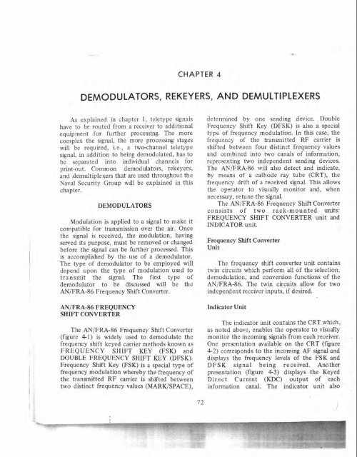
CHAPTER 4DEMODULATORS, REKEY ERS, AND DEMULTIPLEXERSAs explained in chapter 1, teletype signalshave to be routed from a receiver to additionalequipment for further processing. The morecomplex the signal, the more processing stageswill be required, i.e., a twechannel teletypesignal, in addition to being demodulated, has tobe separated into individual channels forprint-out. Common demodulators, rekeyers,and ,demultiplexers that are used throughout theNaval Security Group will be explained in thischapter.DEMODULATORSModulation is applied to a signal to make itcompatible for transmission over the air. Oncethe signal is received, the modulation, havingserved its purpose, must be removed or changedbefore the signal can be further processed. Thisis accomplished by the use of a demodulator.The type of demodulator to be employed willdepend upon the type of modulation used totransmit the signal. The fist type ofdemodulator to be discussed will be theANIFRA-86 Frequency Shift Converter.ANIFRA-86 FREQUENCYSHIFT CONVERTERThe ANIFRA-86 Frequency Shift Converter(figure 4-1) is widely used to demodulate thefrequency shift keyed carrier methods known asFREQUENCY SHIFT KEY (FSK) andDOUBLE FREQUENCY SHIFT KEY (DFSK).Frequency Shift Key (FSK) is a special type offrequency modulation whereby the frequency ofthe transmitted RF carrier is shifted betweentwo distinct frequency values (MARKISPACE),determined by one sending device. DoubleFrequency Shift Key (DFSK) is also a specialtype of frequency modulation. In this case, thefrequency of the transmitted RF carrier isshifted between four distinct frequency valuesand combined into two canals of information,representing two independent sending devices.The AN/FRA-86 will also detect and indicate,by means of a cathode ray tube (CRT), thefrequency drift of a received signal. This allowsthe operator to visually monitor and, whennecessary, retune the signal.The ANIFRA-86 Frequency Shift Converterconsists of two rack-mounted units:FREQUENCY SHIFT CONVERTER unit andINDICATOR unit.Frequency Shift ConverterUnitThe frequency shift converter unit containstwin circuits which perform all of the selection,demodulation, and conversion functions of theAN/FRA-86. The twin circuits allow for twoindependent receiver inputs, if desired.Indicator UnitThe indicator unit contains the CRT which,as noted above, enables the operator to visuallymonitor the incoming signals from each receiver.One presentation available on the CRT (figure4-2) corresponds to the incoming AF signal anddisplays the frequency levels of the FSK andDFSK signal being received. Anotherpresentation (figure 4-3) displays the KeyedDirect Current (KDC) output of eachinformation canal. The indicator unit also
Chapter 4-DEMODULATOR%,REKEYERS, AND DEMULTIPLEXERSFigure 4-1.-ANIFRA-86 frequenw shift Converter.264.27contains the power supplies for all voltages used Outputsin the AEiFRA-86.The AN/FRA-86 is dosigned to provide aInputtotal of siy sisnal outputs. The tVpeS of 0utplltSarr ;is follows:IThe AN/FRA-86 will accept two input KEYED DIRECT CURRENT (KDC)-lbsignals. either in the form of audio frequencyPKDC output for each canal,(AF), FSK, or DFSK, or a cornbination of bothi type
CRYPTOLOGIC COLLECTION EOUIPMENTSF Iincoming signal level. The signal then passes tothe LIMITER stage whose function is tomaintain a nearly constant output level ex-.though the input level may fluctuate. ',output of the limiter is fed to aDISCRIMINATOR network. TheDISCRIMINATOR responds to each of thefrequencies of the DFSK signal as they appearand converts them to KDC pulses.The four outputs of the discriminator arecoupled to the DIVERSITY CO<strong>MB</strong>INER andF 4the indicator (CRT) unit. When theNORMALIDUAL switch is in the NORMAL264.28 position, the diversity combiner selects theFigure 42.-ANIFRA-86 CRT display of frequency Stronger of the two input signals and allows1 ~ ~ 1 6 . them to pass to the outputs for follow-onprocessing. When the NORMALIDUAL switchis in the DUAL position, the diversity combineris bypassed and the two input signals are feddirectly to the output stages.F4264.29Figure 4-3.-ANIFRA-86 CRT display of keyed directcurrent (KDC).LIMITER (AF output)- 1 limiter output foreach AF input.Theory of OperationAs shown in figure 4-4, the incoming audiofrequency signals are fed to two separate, butfunctionally identical, circuits. Within eachcircuit, the AF signal first passes through aBANDPASS FILTER where unwantedfrequencies are eliminated. Immediatelyfollowing the BANDPASS FILTER, an INPUTLEVEL METER is used to monitor theThe CANAL OUTPUT stage, by means of apatching network which enables it todemodulate any combination of marks andspaces, i.e., Fl=MM, F2=MS, F3=SM, F4=SS,routes each arm of the DFSK signal to itsappropriate information canal in the form of KTand KDC. This condition assumes that tSPACE frequency is lower than the transmittedMARK frequency. Because of the two-canaloutput limitation of the AN/FRA-86, onlyone canal of each DFSK signal can beoutputted at any given time when the dualmode is used.Cathode Ray Tube (CRT)PresentationsA knowledge of the various conditionsin which FSK and DFSK signals mayappear is necessary to determine an existingsignal condition and the proper tuning ofa FSK or DFSK signal with a knownsignal condition. In order to best understandand interpret the various keying conditions,refer to table 4-1 and compare the fourfrequencies of a DFSK signal to thefour outputs of the discriminator stage ofthe AN/FRA-86.
Chapter 4-DEMODULATORS,REKEYERS, AND DEMULTIPLEXERSNORMALTWOFILTERnllTDl ITLx.xLKDCl N PUTLEVELLIMITEROUTPUTFigure 4-4.-ANIFRA-86block diagram.264.30Table 4-1.-DFSKSignal Keying Condition(1000Hz Shift)R-390A INPUT CANAL "A" CANAL "B"DISCRIMINATOROUTPUTFREQUENCY CONDITION CONDITION FREQUENCY4kHz I MARKSkHzMARK6kHzSPACE7kHzSPACEMARK F 1SPACE F2MARK F3SPACE F4Controls and FunctionsThe AN/FRA-86 FREQUENCY SHIFTCONVERTER is used to receive various types ofFrequency Shift Key signals. It is important forthe operator to know the controls and theirfunctions in order to properly hlne anddetermine existing signal conditions. TheCONVERTER unit controls and indicators arelisted in Table 4-2 and the INDICATORunit controls and indicators arc listed in T&!e4-3. (Refer to figure 4-1 while studying thesetables.)As explained in the discussion of DFSKmodulation, when the MARK or SPACEelements in a CANAL change, a correspondingchange is made in the DFSK frequency levelkeyed. These changes will appear on the CRT.For example, a DFSK signal with both canalsactively transmitting (MARKISPACE transitionsoccurring) would appear on the CRT as a"cross". If canal A stops transmitting and holdson its MARK irequency. only the frequencies
CRYPTOLOGIC COLLECTION EQUIPMENTTable 4-2.-ANIFRA-86Converter Unit Operating Controls, Indicators and FunctionsCONTROL OR INDICATORMONITOR SwitchFUNCTIONA four-position switch that selects one of four signalsto be monitored at the phone jack.RCVR 1 or 2 Position -The output of the selectedreceiver can be monitored.CANAL 1 or 2 - The KT output from the selectedcanal can be monitored.IPHONES JackSHIFT Switchlevel metersINPUT BANDWIDTHSwitchA receptacle which accepts the headset plug formonitoring the signal selected by the monitor switch.A six-position switch (250, 400, 500, 850, 1000, andone spare position) that is used to select thefrequency shift characteristics of the discriminator.A DFSK signal with a frequency excursion of 1500Hzwould require a setting of 500. A FSK signal shifting500Hz would also require a setting of 500.VU (volume unit) meters used to indicate the level ofthe output signals from receiver No. 1 or receiver No.-A four-position switch (1, 2, 4, and one spareposition) used to select a pair of bandpass filtersthrough which the receiver input signals must pass.For FSK signals, set this switch to match thefrequency shift/excursion of the incoming signal. ForDFSK signals, set this switch at four (4) times thefrequency shift of the incoming signal.1 KC - The selected bandpass filters enable onlyfrequencies that are within 500Hz of the centerfrequency to pass.2 KC - The selected bandpass filters enable onlyfrequencies that are within 1 kHz of the centerfrequency to pass.4 KC -The selected bandpass filters enable onlyfrequencies that are within 2kHz of the centerfrequency to pass.SPARE - Normally not used, however, an additionalsetting may be installed.
Chapter 4-DEMODULATORS,REKEYERS, AND DEMULTIPLEXERSTable 4-2.-ANIFRA-86 Converter Unit Operating Controls, Indicators and Functions-Continued! ' i!,-0NTROL OR INDICATORRECEIVER 1 /RECEIVER 2CANAL selectorsNORMALIDUAL switchFUNCTIONA two-position miniature toggle switch that allowsfor the selection of either canal 1 or canal 2 forprocessing.A two-position mode switchINORMAL - When the RECEIVER 1 and 2 CANALSELECT Switches are in the CANAL 1 and CANAL2 positions respectively, the AN/FRA-86 will accepta single FSK or DFSK signal and allows for diversityreception if desired. : 1!I /DUAL - The AN/FRA-86 will accept two separate, .FSK or DFSK signals (one canal of each) or one FSKI1' !and one DFSK (one canal only) signal. Selection ofthe desired DFSK canal is made by placing theRECEIVER 1 or 2 CANAL selector switch in theCANAL 1 or CANAL 2 posjtion.CONTROL OR INDICATORTable 4-3.-ANIFRA-86 Indicator Unit Operating Controls, Indicators and FunctionsFUNCTIONAC POWER switch A two-position switch (ON-OFF) used to supplyi ,.power to both units.AC POWER indicatorA red lamp which lights when a.c. power is applied tothe power supply and is extinguished when the poweris disconnected from the power supply.i' I..CRT DISPLAY A four-position switch used to select one of the four ioutputs for display on the CRT screen. I.il/c:.?!!RECEIVER 1 TUNING -The output frequencies F1, ... .,.F?, F3, and F4 of receiver No. 1 are displayed on theCRT screen.I !.,I'lj . ,! '> ~ >1..:/ i. ..l.~,, ,.,, .,: I*,, ~: .!..: i1 j:!*... .:.", ,., .. ,! iiRECEIVER 2 TUNING - the output frequencies F1,, t,cjF2, F3, and F4 of receiver No. 2 are displayed on theCRT screen.,:z!'*CANAL 1 OUTPUT - The KDC output of canal No. '1I&1 is displayed on CRT screen.CANAL 2 OUTPUT - The KDC output of canal No.2 is displayed on CRT screen. rn:atili h
CRYPTOLOGIC COLLECTION EQUIPMENTSTable 4-3.-ANIFRA-86 Indicator Unit Operating Controls, Indicators and Functions-ContinuedCONTROL OR INDICATORDEFL GAIN(Deflection Gain)INTENSITYSWEEP FREQUENCYFUNCTIONFour sets of two-knob controls which control theamplitude of the F1, F2, F3, and2F4 ' ages on theCRT screen when the CRT DISPL switch is in theRECEIVER 1 TUNING or RECEIVER 2 TUNINGposition. The outer (smaller) knobs control theamplitude of receiver number 1 and the inner (larger)knobs control the amplitude of receiver No. 2. F1,F2, F3, and F4 correspond to the four frequenciesof a DFSK signal; an FSK signal will use only F2and F3.Controls the brightness of the imageon the CRTscreen. KEEP IT AS LOW AS POSSIBLE FOR EYECOMFORT AND TO PREVENT BURNING OF THESCOPE FACE.Controls the sweep duration when the CRT DISPLAYswitch is in the CANAL 1 or 2 OUTPUT position. Itcontrols how fast the MARKISPACE format of thesignal is displayed on the CRT DISPLAY screen. Youcan slow down or speed up this presentation byadjusting the SWEEP FREQUENCY control.F1 (MM) and F2 (MS) will appear on the CRT.(Refer to figure 4-5 through 4-9 for DFSK CRTdisplays.)When the input signal is an FSK signal,properly tuned, the higher frequency willcorrespond to F2 (M) and the lower frequencyto F3 (S). (Refer to figure 4-1 0.)F2 (MS)Operating ProceduresI1 I I /The operating procedures for theANIFRA-86 FREQUENCY SHIFTCONVERTER include: Preliminary OperatingRocedures; Calibration procedures; NORMALmode Operating Procedures; DUAL modeOperating Procedures, and Signal Re-tuningProcedures. The R-390AlURR receiver with amodified BFO microdial is used to supply inputsF 4(SS)to the ANIFRA-86; therefore, it is imperative 264.31that an operator know the operating and Figure 4-5.-DFSK signal condition with both canalscalibrating procedures of the R-390A/URRactive.
Chapter 4-DEMODULATORS,REKE ;YERS, AND DEMULTIPLEXERSFigure 4-6.-DFSK signal conditionCanal A-Holding on a Mark FrequencyCanal 6-Transmitting~i~~~~ 4.8.-DFSKsignal condition.Canal A-TransmittingCanal 6-Holding on a Mark Frequency264.34Figure 4-7.-DFSK signal condition.Canal A-Holding on a Space FrequencyCanal B-TransmittingFigure ~-~.-DFSK signal condition.Canal A-TransmittingCanal 6-Holding on a Space Frequency264.35'IIiwhen operating the AN/FRA-86 FREQUENCYSHIFT CONVERTER.PRELIMINARY OPERATINGPROCEDURES.-The preliminary AN/FRA-86operating procedure steps are listed below:! a. Turn the AC POWER switch to ON. The- : * 1 h l lred a.c. p w c ~li"1,t ,,?;uLulrarvr ,u,.,,, ....-...- ~indicating that power has been applied to theAN/FKA-~~. ~llow a minimum warmup intervalof 15 minutes before continuing.b. Rotate all the DEFL GAIN controlsfullcounterclockwise.c Set the CRT DISPLAY switch to theRECEIVER TUNING ! positicn.
CRYPTOLOGIC COLLECTION EQUIPMENTS264.36Figure 4-10.-FSK signal condition transmitting.d. Rotate the INTENSITY controiclockwise until a clear round dot appears in thecenter of the CRT screen.e. Set the NORMAL /DUAL switch to theNORMAL position.f. Set the RECEIVER 1 CANALSELECTOR miniature toggle switch to CANAL1.g. Set the RECEIVER 2 CANALSELECTOR miniature toggle switch to CANAL2.CALIBRATION OF ANIFRA-86RECEIVER 1 .-The calibration procedures forRECEIVER 1 are as follows:g. Set the R-390A LINE GAIN control tomaximum.h. Rotate counterclockwise the R-3FBFO MICRODIAL until the fust maxim^,,^deflection for F4 is noted on the CRT.i. Adjust the R-390A LINE GAIN to~rovide a 0 VU indication on the ANIFRA-86input level meter for receiver 1.j. Using the R-390A BFO MICRODIAL ,and the F4 DEFL GAIN control, position thedot on the CRT between the bottom horizontallines printed on the plastic overlay on the CRT(see figure 4-1 1). (This is a crucial step and mustbe understood thoroughly if proper calibrationis to be accomplished.) The dot can be moved Iby either the BFO MICRODIAL 01 the F4DEFL GAIN; however, the object is to positionthe dot so that it is at its maximum peaking'point. In other words, PEAK it with the BFOMICRODIAL and POSITION it with the DEFLGAIN. When the dot is peaked, the inputfrequency from the R-390A is exactly 7kHz andis represented as such on the ANIFRA-86 by thedot being between the bottom horizontal lines.k. Rotate the BFO MICRODIAL counterclockwiseuntil the dot returns to the center ofthe CRT. Now rotate the F3 DEFL GAIN clrwise until the dot is slightly off the center of ...;CRT. Adjust the BFO MICRODIAL and F3DEFL GAIN until the dot is between the verticallines on the right side of the CRT display(see figure 4-12). Note the BFO MICRODIALa. Calibrate Receiver 1 (R-390A/URR)using normal R-390A calibration procedures.b. -~ Set~the R-390A BANDWIDTH KCselector to 8.c. Set the INPUT BANDWIDTH switch onthe ANIFRA-86 to 4 KC.d. Set the ANIFRA-86 SHIFT switch tothe frequency shift of the signal to be copied.e. Rotate the BFO MICRODIAL on theR-390A in a clockwise direction while observingthe AN/FRA-86 INPUT LEVEL meter.Continue turning the MICRODIAL until themeter peaks and starts dropping.f. Rotate clockwise the outer (smaller)DEFL GAIN control for F4 until the dot isslightly off the center of the CRT.F IFigure 4-11.-F4 Peaked.
Chapter 4-DEMODULATORS,REKEYERS, AND DEMULTIPLEXERSGAIN clockwise until the dot is slightly off thecenter of the CRT. Adjust the BFOMICRODIAL and F1 DEFL GAIN until the dotis between the vertical lines of the CRTDISPLAY (see figure 4-14). This represents aninput frequency of 4kHz.n. Determine the BFO MICRODIALcalibration point. Subtract the F2 BFOMICRODIAL reading obtained in (1) abovefrom the F3 BFO MICRODIAL readingobtained in (k) above and HALVE thereading at the F3 peak. This represents an inputfrequency of 6 kHz.PEAKS AT F1, F2, F3, and F4 WILL CHANGEWHEN THE S W IS SET ~ TO ~ A ~ ~POSITION OTHER THAN THAT OF ITSRo ta te the BFO CALIBRATED POSITION; THEREFORE, THEcounterclockwise until the dot returns to the AN,FRA-86 SHOULD BE CALIBRATEDcenter of the CRT. NOW rotate the F2 DEFL WHEN EVE^ THE FREQUENCY SHIFTGAIN clockwise until the dot is slightly off theCHANGES.center of the CRT. Adjust the MICRODIAL andI F2 DEFL GAIN until the dot is between the CALIBRATION OF ANIFRA-86upper horizontal lines of the CRT DISPLAY RECEIVER :.-The procedures for calibrating(see figure 4-13). Note the BFO MICRODIAL RECEIVER 2 are the same as those forreading at the F2 peak point. This represents an RECEIVER 1, except that the CRT DISPLAYinput frequency of 5kHz.switch should be set to RECEIVER 2 TUNINGm. Rotate the BFO MICRODIAL position and the inner (larger) DEFL GAINcounterclockwise until the dot returns to the knobs must be used to position the dot at F4,center of the CRT. Now rotate the F1 DEFL F3, F2, and F1.Figure bi3.-i2 ;died.264.39Fiaure 4-14.-F1 Peaked.! 81I- -
CRYPTOLOGIC COLLECTION EQUIPMENTNORMAL MODE OPERATING j. The procedure for tuning the secondPROCEDURES.-The following procedures are R-390A is the same as that for the first;based on a 3000Hz DFSK sisal input with both however, set the CRT DISPLAY switch to -canals active:RECENER 2 TUNING position. DO h- idisturb the RECEIVER 1 settings.a. Set the ANIFRA-86 NORMALIDUALswitch to NORMAL. DUAL MODE OPERATINGb. Set the SHIFT switch to the position PROCEDURES.-The DUAL mode can be usedwhich corresponds to the shift between adjacent to demodulate two FSK signals, one FSK signalfrequencies of the DFSK signal to be and one DFSK signal, or two DFSK signals.demodulated-in this case, 1000 Hz.When demodulating DFSK signals in the DUALc. Set the INPUT BANDWIDTH switch to mode, only one canal (either A or B) of a DFSK4 KC (for DFSK signals, a bandwidth setting signal can be selected for output.equal to four times the shift between adjacentfrequencies is required). Under NOcircumstances should a bandwidth setting beused that is as narrow as, or more narrow than,the input signal's total excursion. If possible, theR-390A BANDWIDTH setting should be thesame as that of the AN/FRA-86 INPUTBANDWIDTH setting.d. Set the ANIFRA-86 CRT DISPLAYswitch to the RECEIVER 1 TUNING position.e. Set the AN/FRA-86 RECEIVER 1CANAL selector to CANAL 1, and RECEIVER2 CANAL selector to CANAL 2.f. Set the R-390A FUNCTION switch to of the DFSK signal.the AGC vosition.g. Using the R-390A KILOCYCLECHANGE control, tune to the desired signal.Adjust the KILOCYCLE CHANGE control untildots/rays appear at F1, F2, F3, and F4 on theCRT DISPLAY tube. All four dots/rays shouldappear to reach their peak simultaneously. Toaccomplish this, slow movement of theKILOCYCLE CHANGE control is necessary.The CRT DISPLAY should appear as a "cross"as shown in figure 45.h. Adjust the R-390A LINE GAIN controluntil a ZERO (0) VU reading is obtained on theANIFRA-86 RECENER 1 input level meter onthe CONVERTER unit. At this point, the signalin the fmt R-390A is properly tuned.i. The procedures for tuning FSK signalsare the same as those for DFSK signals, with theexception of the INPUT BANDWIDTH settingand the CRT DISPLAY presentation. A properlytuned FSK signal should appear as depicted infgure 4- 10.a. Set the ANIFRA-86 NORMALIDUALswitch to DUAL.b. Set the ANIFRA-86 SHIFT switch asfollows:TWO FSK Signals-If the frequency shiftsare not the same, set the SHIFT switch to matchthe lower of the two shifts.TWO DFSK Signals-The frequency shift ofthe two signals must be equal.ONE FSK and ONE DFSK Signal-Set theSHIFT switch to the frequency shift of theDFSK signal. The freauencv shift of the FSKsignal must be either equal to or twice the - 'ftc. Set the INPUT BANDWIDTH switch asfollows:TWO FSK Signals-Use the setting thatcorresponds to the highest frequency excursion(shift) of the two signals.TWO DFSK Signals-Use the setting thatcorresponds to four (4) times the frequency shift.ONE DFSK and ONE FSK Signal-Use thesetting that corresponds to four (4) times thefrequency shift of the DFSK signal.d. Use the R-390A KILOCYCLE CHANGEcontrol to tune to the desired signals. Adjust thecontrol until the proper CRT presentations areobtained for the type of signal being tuned(figures 4-5 and 4-10).e. Adjust the receiver R-390A LINE GAINcontrol until a ZERO (g) VU reading is obtained ,on the input level meter on the CONVERTERunit.
Chapter 4-DEMODULATORS.REKEYERS, AND DEMULTIPLEXERSf. Set the ANIFRA-8h RECEIVER l andRECEIVER 2 CANAL szlector s\vitcl~es to thethe appropriate position to ,>bt:iln proper outputwhen receiving two FSK signals (either canalmay be selected).g. Select either CANAL I 01- CANAL 2 byusing the appropriate RECEIVER 112 andCANAL 112 switches wlicn receiving two DFSKsiznals or a combination of onc FSK and oneDFSK signal.SIGNAL RE-TIJNINC. The CKT DISPLAYshould be checked periodically to ensure thatthe sign;ri is properly iu~led iRECE:VT.RTUNING 1/21. Whenever- the legs of thedots/rays fail to lie just outside of the inncrscreen ~ect;lnglc, the r~cci~cr nlust bc re-tuned.Use the KILOCYCLE CHANGE control tore-tune the signal. DO NOT ADJUST THE BFOMICRODIAL SETTING OR ADJUST THEDOTS/RAYS BY MEANS OF THE DEFL GAINCONTROLS.CV-1627/URR TWO-CHANNELREKEYERThe CV-1627lURR (AFSAV 39-C)two-channel rekeyer (figure 4-15) 1s used toconvert Keyed Tone (KT) signal5 received fromthe AN/FRA-86, or similar terminal equipment,into d.i. pulscs to operate teleprinters for one ortwo independent single-channel teletypesystems. The input is Keyed Tone with aminunum element length of 5 MS.Controls and FunctionsThe operator controls and functionsexplained in Table 4-4 below, can be found onthe front panel on thc CV/1627/URR (seefieure 4-15).Operating ProceduresTlie followine operatins proccdurec arehased on a single-channel teletype signal:a. Place the POWER ON-OFF switch in the,ON position. The POWER INDICATOR lampshould glow.b. Place the CHANNEL 1NORMAL-REVERSE switch in the NORMALposition.c. Patch the channel 1 signal rromANIFRA-86 Keyed Tone output to tile channelI input of the CV-I 627JURR.d. Place the PRINTER CURRFNT meterswitch in the Channel 1 position.Figure 4-1 5.-CV- 1627iURR two-channei rekeyer.83
CRYPTOLOGIC COLLECTION EOUIPMENTSTable 4-4.-CV-1627lURRCONTROL OR INDICATORPOWER ON-OFFSwitchPOWER INDICATORNORMAL-REVERSEFUSEOperating Controls, Indicators and FunctionsFUNCTIONSupplies filament and plate power to alltubes when in the ON position.Visual Indicator that lights up when thea.c. power is on.Two switches, one for each channel,used to select the proper polarity tomatch the polarity of the incomingsignal.Line fuse to protect the equipment.PRINTER CURRENTMeasures the direct current pulse out-Meter puts to printers (channel 1 or 2).EQUIPMENT JacksEQUIPMENT SPAREUsed to supply d.c. pulses to printersfrom front panel patching. It should benoted that the terminal patch on therear of the chassis will automatically bedisconnected when the EQUIPMENTJack is used.Same as the EQUIPMENT Jack, butpermits the rear terminal patch toremain operative.e. Check the printer. If it is garbling, place ~~&.~~CAVE#S$';NCH?/CMVNHAKSJDM-63the Channel 1 NORMAL-REVERSE switch in &FJDHJGKZMXNHSG"I,"the REVERSE position and recheck the printer.Figure 4-17.-Garbled telelype 'bansmission.NOTE: GARBLE IS A TERM USED INRADIO COMMUNICATIONS TO DENOTE ANERROR IN TRANSMISSION OR RECEPTION Safety PrecautionsTHAT RENDERS INCORRECT ORUNINTELLIGIBLE A PART OR ALL OF THE It is extremely important for you to observeTRANSMISSION. Figure 4-16 shows a standard the safety precautions related to this piece ofteletype test transmission, while figure 4-17 equipment. (Failure to do so may result inshows a garbled transmission.serious electrical shock.) IN PARTICULAR, DONOT PLUG HEADPHONES INTO EQUIPMENTJACKSISPARES AND DO NOT POKE ANYTHE QUICKBROWN FOX mPED OVERTHELAZY OBJECT INTO OPENINGS AROUNDDOG'S BACK 1234567890 TIMES RYRYRYRYRYRY EQUIPMENT USE ONLYRYRYRYRYRYRYRYRYRYRYRYRYRYRYRYRYPROPER PLUG OR JACK PATCHES. WheneverRYRYRYRYRYRYRYRYyou use front panel jacks, the Drover procedureis to plug into-your equipment; and THEN intoFigure 4-16.-Standard teletype test.the CV-1627/URR.
to~ theChapter 4-DEMODULATORS,REKEYERS, AND DEMULTIPLEXERSCV-157/URR SINGLE SIDEBAND CARRIER Set to the level of theCONVERTER COMPENSATOR desired signal carrier;6.5 (20 db reducedThe CV-157/URR single sideband convertercarrier), 3.0 (10 db re-(figure 4-18) is used to separate and demodulateduced carrier), 10.0 (nothe intelligence contained in a single sideband orreduction in carrier).in onc sideband of an independent sideband DRIFT 0 kHztransmission. The sideband transmission can be INDICATORvoice, teletype, or a combination of the two. Itcan also be used as an aid in the reception of MONITOR Switch Set ~ oppositeamplitude modulated double sidebandposition of the sidetransmissionsunder extreme atmosphericband containing theconditions of fading. The R-390AlURR receiverKeyed-Tones:is normally used to provide an input to theA-If the Keyed-toneCV-157/URR. The CV-157/URR has an audiointelligence is inoutput in the frequency range of 125 Hz tothe upper side-6kHz. An Automatic Frequency Control (AFC)band.circuit holds the converter IF at exactly 100kHz and assures that accurate audio frequenciesB-If the Keyed-toneare delivered from the converter to terminalintelligence is inequipment.the lower sideband.Controls and FunctionsVU SELECTSwitchSet to the sameposition as theMONITOR SwitchThe front-panel controls of theCV - 157/URR are explained in table 4-5 below:(Refer to figure 4-18.)Operating ProceduresThe following operating procedures for theCV-157/URR Siligli Sideband Converter coverthe reception of single sideband or independentsideband signals containing multitones:1. Set the CV-I 57/URR controls asfollows:MONITOR GAIN 5SB SELECTVU RANGELSB-A USB-B+IOdhSQUELCHOFFAFCOFFAGC SELECTRECCARRIER SELECT LCSB AGC 7.5AGC TIMESLOWVE?>
264.42Figure 4-1 8.-CV-157lURR single sideband converter.8. Set thc AFC swjtcli of the converter to I I. Set the AGC TIME switch of theON.ct1iiva-tci- to FAST.9. Set tllc SQUELCI-I switch ot the i3.St5t the MONITOR switch of thecoiivertcr to ON.coilvcrtcr to tlic appropriate channel.10. Set the A(;(: SELI'CT s\vitcll of theconve1.t.r lo the positio!~ corr~spondine to the VOTF : WHEN CHANGING FREQUENCY,tones contnined in the sidchai~d. I'L.ACE Ti 1L CV-157 AFC SWITCH TO THE
Chapter 4-DEMODULATORS,REKEYERS, AND DEMULTIPLEXERSiCONTROL OR INDICATORONIOFF SwitchMONITOR SwitchTable 4-5.-CV-157lURROperating Controls. Indicators, and FunctionsFUNCTIONApplies filament and plate voltages to the equipmentwhen in the ON position. It is also a circuit breakerthat serves as a protective device by automaticallytripping to the OFF position if faulty circuits causeexcessive current drain from the power source.In the A position, the audio intelligence in theconverter A channel may be monitored. In the Bposition, the audio intelligence in the converter Bchannel may be monitored.I MONITOR GAIN Control Varies the volume of the monitored signalIfSB SELECT SwitchA-VCBVCIn the counterclockwise position, (A-LSB, B-USB),the intelligence contained in the lower transmittedsideband is fed to channel A output and theintelligence contained in the transmitted uppersideband is fed to channel B output. In theclockwise position (B-LSB, A-USB), the outputsare reversed with the transmitted lower sidebandappearing at channel B output and the uppersideband appearing at channel A.Controls the volume of channel A audio outputto terminal equipment. It is adjusted with ascrewdriver.Controls the volume of channel B audio outputto terminal equipment. It is adjusted with ascrewdriver.-VU-SELECT SwitchVU RANGE SwitchSQUELCH SwitchAFC SwitchIn A position, selects channel A audio output levelto be measured by the VU METER. In the Bposition, selects channel B audio output level to bemeasured by the VU METER.Changes the range of the VU METER (+lo, 0, and-10). It is similar in operation to the R-390A/URRLINE METER switch.Turns the squelch circuit ON and OFFActivates the automatic frequency control circuitsThis switch should be OFF when any tuningis done.
ICRYPTOLOGIC COLLECTION EQUIPMENTSTable 4-5.-CV-157lURRCONTROL OR INDICATOROperating Controls, Indicators, and Functions-ContinuedFUNCTIONarc SELECT Switch Five-Position automatic gain control function swi' :' - - - - - - -1. REC - The associated receiver uses its own AL,voltage. The converter has no control of theradio receiver's RF gain.2. CAR - The 100 kHz IF converter carrier, withthe modulation removed, is selected as thesource of AGC voltage developed to control RFgain of the receiver (recommended for most uses).3. LSB - The intelligence contained in the lowersideband is selected as the source of AGC voltagedeveloped by the converter to control the RFgain of the associated receiver.4. USB - The intelligence contained in the uppersideband is selected as the source of AGC voltagedeveloped by the converter to control the RFgain of the associated receiver.5. TSB - (Twin sideband and double sideband) thelOOkHz converted IF carrier plus the sidebandsare selected as the source of AGC voltagedeveloped by the converter to control the RFgain of the associated receiver.CARRIER SELECTSwitchSB AGC ControlAGC TIME SwitchVERNIER ControlCARRIER COMPENSATORControlTwo-position switch which selects a 100kHz outputto demodulate the intelligence present in sideban 'frequencies.LC - 100 kHz output is from the local oscillator.RC - 100 kHz output is reconditioned from thereceived signal.The SIDEBAND AUTOMATIC GAIN CONTROL(SB AGC) varies the amount of voltage developed bythe converter when the AGC SELECT switch is inthe TSB, USB, or LSB positions.Varies the time constant of the AGC voltagedeveloped by the converter. ,Tunes the converter heterodyne oscillator over arange of + or -2 kHz.Varies the gain of the converter carrier section toadjust for various levels of carrier suppression at thetransmitter.
Chapter 4-DEMODULATORS,REKEYERS, AND DEMULTIPLEXERS-Table 4.5.-CV.157IURR' CONTROL OR INDICATOROperating Controls, Indicators, and Functions-ContinuedFUNCTIONISQUELCH ALARMThe SQUELCH ALARM lights when the AGC circuithas been disabled because of the signal to noise ratiobeing too low for proper operation. This alarm operatesonly when the squelch control is in the ON position.IDRIFT ALARMThe DRIFT alarm lights to indicate that thesignal has drifted + or -2 kHz, necessitating retuningof the signal.AFC INDICATORThe AFC INDICATOR lamp gives the vinla!indication that the AFC motor is on.DRIFT INDICATOR When the AFC is ON, the DRIFT INDICATOR givesa visual indication of the amount of signal drift.LOW-PASS FILTERSwitchThis two-position switch is internally located andnormally is preset by maintenance.iIN - The output of the converter's AF band pass islimited to 3.5 kHz.OUT - The output of the converter's AF band passi , may go up to 6 kIIz.CARRIER LEVEL meterIndicates the level of the reconditioned carrier.OFF POSITION. FAILURE TO DO SO MAY If a signal is "multiplexed" at the transmittingRESULT IN DAMAGE TO THE AFC MOTOR terminal, it must be "demultiplexed" at theDRIVE ASSE<strong>MB</strong>LY.receiving terminal before it can be put into anintelligible form. The most commonFREQUENCY DIVISION demultiplexer used inDEMULTIPLEXERSthe Naval Security Group is the ANIFGC-78SUBCARRIER TELEGRAPH CHANNELRadio stations throughout the world are SELECTOR.prevented from interfering with each otherprimarily by being assigncd different carrier ANIFGC-78 SUBCARRIERTELEGRAPHfrequencies and by being limited to CHANNEL SELECTORprescribed bandwidths around these carrierIfrequencies. The term "multiplexing" describes The ANIFGC-78 (AFSAV-129) Subcarriermethods which allow two or more channels or Telegraph Channel Selector (figure 4-19) isusedcanals of information to be transmitted on one to extract individual teletype signals from multicarrier,thereby permitting each station to tone (FDM) systems. The input is normally antransmit more inforxation withi? its allotcd audio frequency from a sing!e sideband converterportion of the RF spectrum. The two general such as the CV-157lURR. The keyed d.c. (KDC)methods of multiplexing are FREQUENCY output is used to drive terminal teletypeI DiViSlON (FDMI and TIME UIVISIOK (TDM). equi~men!, or it czn be used for input into thei 89
CRYPTOLOGIC COLLECTION EQUIPMENTSFigure 4-19.-ANIFGC-78 Subcarrier telegraph channel selector.264.43SN-398 Dual Digitizer for FLEXSCOP operations.In the operation of the AN/FGC-78, theoperator tunes the Channel Selector through itsranges of multitones to select individual channelswhich may be narrowly or widely spaced infrequency. The unit will accomodate signals ofnarrow shifts, (60-120 Hz), or wideband shifts,(170-360 Hz). The AN/FGC-78 is designed forfixed station operation and not for mobile use.Controls and FunctionsThe ANIFGC-78 is comprised of two units:CHANNEL SELECTOR Unit and FILTER Unit.90The controls and functions of each individualunit are listed in Tables 4-6 and 4-7. (Refer tofigures 4-20 & 4-2 1 .)Operating ProceduresThe operating procedures described beloware to be used when extracting individualchannels from multitone (FDM) signals:FILTER UNIT..1. Shift SELECTOR-Set this control tothe setting that is equal to the frequency shift ofthe selected tone.
Chapter 4-DEMODULATORS,REKEYERS, AND DEMULTIPLEXERS'ITable 46.-Channel Selector C-4895lFGC-78 Controls and Functions,CHANNEL TUNINGControls the variable oscillator frequencyKnob:5from 16 to 28 kHz.8INPUT LEVEL Knob Controls the input amplitude. I:. , ,.'ER FUNCTIONConnects the meter to various checkPOWER SwitchSwitches power ON or OFF.Table 47.-Filter F-846lFGC-78 Controls and FunctionsSHlFT SELECTOR Selects the filter to be used on thel.1 1Switch translated signal. There are eight , .!positions: 60, 85, : 20, 170, 240, 361and two spares. The position used will be1j idetermined by the frequency shift of thesignal.IDISCRIMINATORSelects the ~ ro~er discriminator trans-; ,!OUTPUT LEVELKnobAdjusts the output level of the filteredsignal displayed on the meter..;1,: 1,. .. ,PRINTER OUTPUT NORMALIREVERSE positions for .. .Switch control of the polarity of the output toi; ithe printers.2. DISCRIMINATOR-Set to NARROW CHANNEL SELECTOR UNIT.- I:for tone shifts of less than 170 HZ;WIDE for tone shifts of greater than 1. METER FUNC170Hz. follows: 4 .,;....'?,3. PRINTER OUTPUT-Set as determined a. I~~OSCillator should indicate ...by signal polarity. $$dB.;i; :, ,FJ91:..I ,.-I!2 1:' I:" 3:3R
CRYPTOLOGIC COLLECTION EQUIPMENTS-, -,. ,#,.,,."x. mOY17YT. .2"OINPUT LEVEL METER FUNCTION Or'Figure 4.20.-Channelselector unit C-4895lFGC-78 front panel.264.44@DISCRIMINATOR....,. @.,8PRINTER OUTPUT"O"".L @"EVC",ESHIFT SELECTOR8 370 % NO- OUTPUT YWITOR OUTPUT YONITOR OUTPUT LEVELFILTERTONE KEYER. IIllE I8Figure 4-21.-Filter unit F-846lFGC-78 front panel.264.45b. 2ND OSC i 11 a t o r should indicate 3. METER FUNCTION Switch-Set to0 dB. INPUT position.4. Adjust the CHANNEL TUNING dial forNOTE: NOTIFY MAINTENANCE IF maximum deflection on the meter-if levelsABOVE OSCILLATOR OUTPUTS INDICATE exceed 0dB, lower the RF GAIN on theOTHER THAN THE ABOVE LEVELS.R-390AlURR receiver.5. Adjust the INPUT GAIN for near @dB2. CHANNEL TUNING dial-Set to the (for fading multitone signals, adjust slightlydesired frequency.above pdB).
Chapter 4-DEMODULATORS,REKEYERS, AND DEMULTIPLEXERS6. Set METER FUNCTION switch toOUTPUT-adjust output to0 dB.7. Set METER FUNCTION switch to 2NDAOD (second modulator)-meter shouldindicate -10 dB8. While monitoring the FILTER OUTPUT,locate an active tone channel.9. Monitor the tone keyer output andadjust the TUNING dial for the best audibleoutput or visual indication on an oscilloscope.10. Perform the METER check again andmake necessary adjustments for proper inputand output levels.ANlTCA-4 DIGITAL CONVERTERPROGRAMMING GROUP (KINDER)The AN/TCA-4 (Cigure 4-22) is anothercommon demultiplexer. This equipment is usedprimarily to separate time division multiplex(TDM) signals into individual channels and toperform signal translation functions.Demultiplexing, in this case, is the separation ofchannels contained in a time division multiplex(TDM) signal. Translation is the conversion ofany unit code to another standard unit code,i.e., changiqg a 7 unit code to a 5 unit code. TheAN/TCA-4 has the capability of processing onesignal with a maximum of 56 equal lengthelements per cycle or, with the Appliquesection, two signals with a maximum of 28 equallength elements per cycle for each signal. (TheApplique section will be discussed later in thischapter.) Input signals may be in the form ofkeyed tone (KT) or keyed direct current (KDC)within an element length range of 1 to 40milliseconds. The ANITCA-4 provides amaximum of ten output channels, in standard 5-unit teletype form, and a printing rate of 50to 175 words per minute (U'PM).Theory of OperationFunctionally, the AN/TCA-4 is divided intoseven sections (figure 4-23). These are: theSynchronizer; Storage and Demultiplexer;Translation; Output; Control; Error Detection,and; Applique Section.SYNCHRONIZER SECTION.-The inputdata signal is first applied to the synchronizerFigure264.464-22.-ANJTCA-4 digital converter programminggroup IKINDERI.
CRYPTOLOGIC COLLECTION EQUlPMENTSINPUT SIGNALwm3aYr---------------- ---ICONTROL SIGNALI1I SYNCHRONIZER CLOCK PULSE CONTROLISECTIONSECTIONI0 /-\I W+ / / I \I2 2 +bL/I W Z 59'-IIIIIIIIIz w:ti,W G! /[L,IANDDEMULTIPLEXSECTIONnAWI I 2 2I :*IW(LIL*- APPLIOUESECTION--A' q%ob/DEMULTIPLEXSIGNALTRANSLATIONSECTIONCONTROL SIGNALALARM SIGNALTRANSLATEDSIGNALERRORDETECTIONOUTPUTSECTIONTObPRINTERSFigure 4-23.-ANITCA-4 block diagram.2w 47where it is regenerated into digital level signals.The synchronizer generates a clock pulse signalthat provides synchronization of the equipmentto the speed of the incoming signal. The clockpulse is then routed to the control section. Theregenerated signal is passed to the storage anddimultiplexing section.OUTPUT SECTION.-The individualchannels of the demultiplexed signal are storedin the output storage registers. Teleprinter startand stop elements are added to the five unitteleprinter signal and the composite signal isapplied to the teleprinters.CONTROL SECTION.-The clock pulseSTORAGE AND DEMULTIPLEXING signal is used by the control section as a base toSECTION.-The regenerated data signal is stored provide timing and control signals to all otherin the input storage register for one complete sections of the equipment. The control sectioncycle and then demultiplexed and routed to the provides phasing of the equipment to the timetranslation section.division multiplex signal. The control signalsproduced by this section initiate the translationTRANSLATION SECTION.-The function and output phases of operation.of this section is to convert the incoming signalto the standard five-unit teleprinter code. The ERROR DETECTION SECTION.-Thissignal, in converted form, is then applied to the section operates in conjunction with the controloutput section.section. Its function is the detection of
-Chapter 4-DEMODULATORS,REKEYERS, AND DEMULTIPLEXERSerroneous or prohibited signals (incorrectly in a separate equipment rack. There are eightkeyed characters, static characters, etc.1. It major assemblies contained in the AN/TcA-~.; ctivates alarm circuitry upon detection of an Figure 4-22 shows the AN/TCA-4 as it ismoneous or prohibited signal and routes a normally installed with the Applique section andsignal to the control section. The control section ANIUGC-33X paper tape printers.then sends a "checked" pulse to the translationI section. The character is either confirmed as POWER SUPPLY.-This unit is mounted in) being erroneous and routed to ground, or proved the topmost portion of the cabinet and suppliesand routed on through the equipment. The four separate d.c. operating voltages for thecontrol section then reactivates the translation cabinet-mounted equipment. These voltages areand output phases of operation and normal adjustable from the front of the power supplyoperation continues.by means of screwdriver controls (adjustmentsare performed by maintenance personnel). AllC .APPLIQUE SECT!nN.-The firnction of the fuses are mounted at the front of the power1 applique section is to increase the capability of supply to facilitate replacement. The powerthe ANITCA-4. It provides the capability of nrpply is obst~cted~from view by an air filterthandlin~ two independent input signals placed on the front of the equipment.1simultaneously. This section contains anapplique converter section and synchronizer DATA DISPLAY PANEL.-The data displaysection. The applique synchronizer is panel is mounted directly below the powerfunctionally identical to the synchronizer supply and contains two rows of lamps, 28section, providing synchronization, input data lamps in each row. The indicator lamps are used,L regeneration, and a baud-clock signal generation. to provide a visual indication of the input dataThe applique converter counts and stores the bits stored at the beginning of each cycle ofinput digital bits and transfers them to the operation. The indicator lamps are illuminatedstorage and demultiplexing section upon receipt to show the presence of an energized data bitof a control (checked) pulse from the control after the signal has bcer, dcrnu!tip!exed. See~ection. Once the two input signals are in the figure 4-24.mput storage register of the storage anddemultiplexing section, they are treated as one OSCILLOSCOPE.-The Tektronix Modelsignal having as many channels as the original RM-504 is the oscilloscope used with the11signals combined.ANITCA-4 (figure 4-25). This unit provides theoperator with a means for monitoring the signal1 Major Assemblies at various points throughout the equipment and, s.2aids in equipment set-up. It is also used by thek The ANITCA-4 is mounted in a single maintenance force when performing equipment! equipment rack The Applique section is housed maintenance.CisC?r; 0 0BB
CRYPTOLOGlC COLLECTION EQUIPMENTSFigure 4-25.-ANITCA-4 oscilloscope unit.264.49SYNCHRONIZER.-The Synchronizer ismounted below the oscilloscope unit andprovides all the functions of the synchronizersection. The synchronizer is the heart of theAN/TCA-4. See figure 4-26.LEFT DRAWER.-The left drawer (figure4-27) is a slide mounted unit to permit itswithdrawal for operational and maintenancefunctions. It contains all printed circuit moduleboards of the plug-in type. They are easilyremoved for maintenance and replacementpurposes. These boards comprise the storage anddemultiplexing output, error detection, andcontrol circuitry. The REORDER plugboard isalso contained in the left drawer. This is alocally prepared patched plugboard thatprovides the signal program for the AN/TCA-4.The REORDER plugboard is prewired todemultiplex the incoming signal. Programs fordifferent signals are prewired on separateREORDER plugboards. Rapid changeover fromone program to another is accomplished byremoval of the REORDER plugboard from theleft drawer and inserting the one programmedfor the desired signal.RIGHT DRAWER.-The right drawer (figure4-28) is also slide mounted and contains 74printed circuit module boards of the plug-intype. These boards provide individual c' lelsub-division and phasing of sub-divided c h .... 61s.The TRANSLATOR plugboard is contained inthis drawer. It is locally pre-patched for theoperator and translates or converts codes to thestandard five unit teleprinter code. Separate 1TRANSLATOR plugboards are required foreach specific code.B LO WERIFILTER UNIT.-Theblowerlfilter panel circulates cooling airthroughout the cabinet mounted assemblies. Amain circuit breaker is located directly belowthe blower/filter panel at the bottom of thecabinet.APPLIQUE UNIT.-This unit (figure 4-29),containing the applique synchronizer andapplique converter, is mounted in a separatecabinet and enables the AN/TCA-4 to handletwo, 28element signals simultaneously. Theapplique synchronizer contains a separate power
IChapter 4-DEMODULATORS, REKEYERS, AND DEMULTIPLEXERSFigure 4-26.-ANlTCA.4 synchronizer unit.supply, which is the only difference between itand the cabinet mounted synchronizer. Theapplique unit CANNOT process any signal thatis employing channel subdivision.AN/UGC-33X PRINTER CONSOLE.-Thedata from the AN/TCA-4 is reproduced on theAN/UGC-33X (figure 4-30), a special printerconfiguration designed for use with theAN/TCA-4. It contains nine reperforatorprinters that reproduce a signal on five-levelpaper tape. Contamed within the consoleis a vacuum system that collects the chadpunched from the tape. Each printer has Fourseparate inputs from each channel of theANITCA-4.Controls, and FunctionsPreliminary OperatingProceduresFor preliminary operating procedures, thecontrols should be set as follows: .OSCILLOSCOPE UnitPOWER SwitchVERTICAL POSITIONControlONCenter Presentationon CRTVERTICAL SENSITIVITY 2 Volts!CMSwitchVERTICAL SENSITIVITY Fully ClockwiseVariableACIDC Toggle SwitchDCThe controls, indicators, and their functions SWEEPTIMEICM Switch 1 MSECare presented unit by unit, from topto the bottom of the cabinet in tables HORIZONTALPOSITION Mid-Scale48 thru 4- 1 2. Controi
CRYPTOLOGIC COLLECTION EQUIPMENTS264.52264.51 Figure 4-28.-ANITCA-4 right-hand drawer.Figure 4-27.-ANITCA-4 left-hand drawer.
~~ ~~ ~ --~~~~~ ~ ~-~~ ~-~ ~--p~-~~~~-~ ~ ~ ~~~~ - ~ ~IChapter 4-DEMODULATORS, REKEYERS, AND DEMULTIPLEXERSFigure 4-29.-ANITCA.4 applique unit.264.53iIHORIZONTAL SWEEP Fully clockwise TRIGGER LEVEL Free RunTIME/CM VARIABLE/FOCUS and INTENSITY Adjust to obtain a! Controls clear and concise! TRIGGER SOURCE EXTpresentation.SwitchIi i TRIGGER COUPLING DCSCALE ILLUI1fINATION Fully counterclockhitchControlwiseSYNCHRONIZER UNITTRIGGER SLOPE +' 1 S\v:?c!: B!AS Control Mid-scaleIII1! I a9 il~mif'I-A~- ~~~~~~~~~~~- ~- ~ - - ~ ~ -
CRYPTOLOGIC COLLECTION EQUIPMENTSFigre 430.-ANIUGC-33X printer console.100
IChapter 4-DEMODULATORS, REKEYERS, AND DEMULTIPLEXERSTable 4-8.-ANITCA-4 Oscilloscope Unit Operating Controls, Indicators. and FunctionsIiCONTROL OR INDICATORFUNCTIONFOCUS ControlAdjusts focus of spot image on CRT screen.1 INTENSITY Control Adjusts image of intensity on CRT screen'ISCALE ILLUMINATION ControlAdjusts graticule (vertical and horizontal lines)illumination.i TF.!GGER. LEVEL ControlAdjusts operating point of trigger for synchronizingimage on CRT scrcen. Whcn set to FREE RUN,sweep is not synchronized with vertical input signal;when set to AUTO, sweep is automaticallysyncluonized with vertical input sigual.1! TRIGGER SLOPE3!ITRIGGER COUPLING SwitchSelects synchronization with positive-going (+) ornegative-going (-) signal.Selectr external trigger signal coupling to triggeramplifier.1 TRIGGER SOURCE SwitchSelects source of trigger signal; INT from verticalamp!ifiers, EXT from external trigger input.1 HORIZONTAL POSITION control Permits horizontal positioning of image on the screenI SWEEP TlMEiCM Switch Selects sweep rates for horizontal sweep.1 SWEEP TlMEICM Variable Control Adjusts for intermediate values of sweep time.1PWRION SwitchWhcn set to ON, applies line power to theoscilloscope.INDICATOR LIGHTWhen lit, indicates line power to oscilliscope hasbeen turned on.IACIDC SwitchSelects signal coupling to vertical amplifiers: AC fo~coupling AC signal, DC for coupling DC signals.I/ VERTICAL SENSITIVITY Control Selects vertical amplifier gain for CRT scale.VERTICAL SENSITIVITYVariable Control,\djusts vertical amp!ifier gain for intermediatevalues.I IVERTICAL POSITION control Adjusts vertical positioning of image on CRTscrcen.i
~ ~~ ~CRYPTOLOGIC COLLECTION EQUIPMENTSTable 49.-ANlTCA.4CONTROL OR INDICATORSynchronizer Unit Operating Controls, Indicators. and FunctionsFUNCTION ' ' '-MANUAL FREQUENCY X 128SwitchChanges baud clock output by 128 bits per secondper increment.Changes baud clock output by 16 bits per second pelincrement.Changes baud clock output by 2 bits per second perincrement.INTERPOLATION FREQUENCYMeterMONITOR SwitchProvides a visual indication of synchronizationbetween clock signal and input signal.Permits selection of internal signal and sync outputsto be applied to the oscilloscope unit as follows:POSITION SYNC SIGNAL SELECTED SIGNAL DISPLAYED ON OSCILLOSCOPE1 Baud Clock Baud Clock2 Baud Clock Input data to filter3 Baud Clock Input data to filter4 Baud Clock Transition data signal5 Input Data Squared Transition data signal andBaud Clock Signal6 Baud Clock Regenerated data signal.SQUELCH ON LampINCREASEIDECREASE SwitchCORRECTION SwitchRESET COUNTER SwitchDATA SwitchBIAS ControlLights when squelching exists.Functions only when Correction switch is in themanual position. Permits manual increasing anddecreasing of interpolation frequency for initialsynchronization of the baud clock and input signal.In the Manual position, disconnects automaticcorrection voltage. In Auto positions 1, 2, or 3,applies correction voltage to synchronizer forautomatic synchronization.Presets the interpolation frequency to its centerposition when the Correction is in the Manualposition.Selects normal or inverted polarity for regenerated 1data.Permits the elimination of any mark or space bias onthe input signal.
Chapter 4-DEMODULATORS,REKEYERS, AND DEMULTIPLEXERSITable 4-10.-ANITCA-4Left-Hand Drawer Operating Controls, Ind~cators, and FunctionsCONTROL OR INDICATOR FUNCTION .- !IPOWER ON Switch Applies main power to the unit.IPOWER ON LampLights when main power is applicd.POWER OFF SwitchRemoves main power from unit.CIRClTIT BREAKER LampLights when clrcult breaker is on.LOW AIR FLOW LampLishts when cabinet air circulation is low.IIXBLOWN FUSE LampsLights when BLOWER, POWER SUPPLY, orOSCILLOSCOPE fuses are open.IMONITOR SwitchCYCLE LENGTH SwitchesPermits printout of channels 1 tliroi~gh 10 011 themonitor printer.TENS-Selects tens-order of elements per cycle.. ,UNITS-Selects the Crn~tq-order of elements percycle.ALARM SwitchControls error alarm. In the OFF position, remove?ialarm circuitry from equipment; RESET positionsilences audio alarni and resets alarm circuitry. !IERROR SEQUENTIAL LampIndicates that the preset number of sequential errorshas occurred.: I'ERROR SINGLE Lamp Indicates that a signal error has occ.~rred I!'I PHASIYC Switches ADVANCE/KETARD-Selects nran~ral phasing nlede ..: 1to be used. ::.[i ALITO-Indicates autoniaric phasine cvcle. 'iI: i VOLTAGE Mor,itor Selects operating vnlt;~seVoltage Monitor Meter.. .t j ito be monitored bv , ,.,I :!'!.:'I
CRYPTOLOGIC COLLECTION EQUIPMENTSTable 4-10.-ANlTCA.4Left-Hand Drawer Operating Controls, Indicators, and Functions-ContinuedCONTROL OR INDICATOR FUNCTION,^^ ,,,. .-. ,OSCILLOSCOPE VERTICAL SwitchSelects signal for vertical input of 'the oscilloscope asfollows:POSITIONOFFSIGNAL SELECTEDGroundedSynchronizer nionitor signalNormal end cycle pulse50kHz delayed clock pulseSerial oscillator output signalInverted parallel commandsenerator outputChannel monitor outputChannel pulsesApplique synchronizer monitorSelected input from REORDERplugboardSignal from external vertical jackon left drawerIIOSCILLOSCOPE TRIGGER SwitchSelects trigger source for oscilloscope as follows:POSITIONOFF123456789SIGNAL SELECTEDGroundedSynchronizer Sync signalNormal end cycle pulseSokHz delayed clock pulseSerial oscillator start signalOpenChannel Monitor OutputChannel pulsesApplique synchronizer sync signalSelected input from REORDERplugboardSignal from external trigger jack ,on left drawerINPUT JACK (Vertical)External input jack to oscilloscope trigger throughoscilloscope vertical switch.IINPUT JACK (Trigger)External input jack for oscilloscope trigger throughoscilloscope trigger switch.
~IChapter 4-DEMODULATORS, REKEYERS, AND DEMULTIPLEXERSTable 4-11.-ANITCA.4R~ght-Hand Drawer Operating Controls, Ind~cators, and FunctionsCONTROL OR INDICATOR FUNCTION .- ,,.1 :IDATA MODE Switch Selects data hold or sample functions., ,i 1iCYCLE SAMPLE SwitchSelects which cycle data is sampled by Data ModeSwitch action., 1 PRINTERS Switch Controls output of equipment to external channel8 5 printers (ANIUGC-33x1.? PRINTER SELECT Switch &id> iiie p~-i~-~ter io w-lii~:i the ribdivided dais isapplied for each sub-cycle of time for channels 1,2,3, and 4.I1INVINORM SwitchesPHASE Sw~tchERROR LampsSelects the wb-cycle of the channel that will uselnverted or normal polarity.Controls phaslng of the channel sub-cycles.lnd~cates error characters in respectlve channelIIIEli1Table 4-12-ANITCA-4 Applique Unit Operating Controls. Indicators, and FunctionsCONTROL OR INDICATORFUNCTIONPOWER SwitchAppl~es power to the Apphque synchronuer andi Applique converter \* I! 18ii POWER Indicator Lamp Indicates that power to the Applique unit is being' sapplied.!ERROR LampsIndicates an error character in the respective channel.NOTE: THE ADDITIONAL CONTROLS OF THE APPLIQUE SYNCHRONIZER ARE IDENTICALCI$, : .. IN FTJNCTTON WJTH .....- THE ~- CONTROLS -. -~ ~ - OF - THE CABINET SYNCHRONIZER. THE CYCLE i :, iILENGTH, TENS, UNITS, AND PHASING SWITCHES OF THE APPLIQUE CONVERTER UNITP! ARE IDENTICAL IN FUNCTION TO THE RESPECTIVE CONTROLS ON THE LEFT DRAWERItDATA SwitchNormal MANUAL FREQUENCY 0XI28i;CORRECTION Switch Manual a .l ,:INTERPOLATION Mid-scale (PressLi1 1 MANUAL FREQUENCY x2 0 FREQUENCY METER RESET counter)I L!:..M.4-NUAL FREQT_lFNcY X I6 0 MONiTOR Swiicli !ii8:i; ! ~:.c. .:.,:
ICRYPTOLOGIC COLLECTION EQUIPMENTSRIGHT-HAND DRAWERDATA MODE SwitchCYCLE SAMPLE SwitchPRINTERS SwitchPRINTER SELECTSwitchesacross the face of the screen. (See waveform Aof fieure 4-31 .)NORM (u3) ~djusi the MANUAL FREQU -7YX 128, X 16, and X2 switches on the1 Synchronizer unit so that two clock cycles areOFF1INV/NORM SwitchesLEFT-HAND DRAWERNORMA. FILTER INPUT: VOLTAGE MONITOR OFFSwitchMONITOR SwitchALARM Switch1 OSCILLOSCOPEVERTICAL SwitchOFFOFFEl. BAUD CLOCKOSCILLOSCOPE 1TRIGGER SwitchCYCLE LENGTH TENSCYCLE LENGTH UNITS 8fjC.TRANSlTlONS a CLOCKOperating ProceduresThe following paragraphs describe thefunctional operation of the AN/TCA-4equipments. In general, these proceduresdescribe the sequence of events which occurwhen a particular control is operated, as well asits relationship with the overall operation of theequipment.D. TRANSITIONS(INCORRECT BIAS)OSCILLOSCOPE AND SYNCHRONIZERPHASING.-Adjust the Oscilloscope andSynchronizer phasing as follows:(1) Adjust the TRIGGER LEVEL controlon the Oscilloscope counterclockwise until thetrace begins to trigger on the face of the screen.(2) Adjust the SWEEP TIME/CM switch and 264.55control so that two signal bauds are displayed Fisure4-31.-ANITCA-4oscilloscopephasingwaveforms.II106
Chapter 4-DEMODULATORS,REKEYERS, AND DEMULTIPLEXERSdisplayed across the face of the Oscilloscope channels operate with inverted input datascreen. (See waveform B of figure 4-31.) If no signals.trace appears, momentarily depress the RESETCOUNTER'siiif6h on the Synchronizer unit.In operations using sub-channeling, control(4) Set the MONITOR switch on the of the channel inverters is accomplished bySynchronizer unit to position 5 and adjust the means of the INVINORM Switches (for eachMANUAL FREQUENCY X2 switch to the cycle of each channel) located on the frontposition at which the clock trace on the panel of the RIGHT drawer. When it is desiredOscilloscope screen most nearly stops drifting. that a specific sub-channel operate with inverted(See waveform C of figure 4-31 .)input data, the INVINORM switch for that cycle' f (5) Adjust the INCREASEJDECREASE (subchannel) is set to INV. Suppose, for' E switch on the Synchronizer unit to stop the example, that all of the four PRINTER SELECTi clock trace from drifting. If the trace drifts switches for main channel 1 were in position 1i toward the left, operate the switch to (this, in effect, eliminates any', . DECREASE; if the trace drifts toward the right, sub-channelization for this main channel). Now,operate the switch to INCREASE.if it is desired that the main channel operate(6) Set the CORRECTION switch on the with inverted input data, all four of the1Synchronizer unit to position 1. When the INVINORM switches for the channel 1 cyclesINTERPOLATION FREQUENCY METER must be placed in the INV position so that inputindication stops drifting (5 to 15 minutes), set data inversion occurs for all successive channel 1the CORRECTION switch to position 3.scan times. Otherwise, when the equipment was(7) Set the MONITOR switch on the actually processing channel 1 data during a cycleSynchronizer unit to position 4 and adjust the time that was not selected for inversion, theBIAS control so that the positive and negative input data would not be correctly inverted, andspikes displayed on the Oscilloscope screen the channel output data would consist of partlyC. appear at the same horizontal positions. (See erroneous data.waveforms D and E of figure 4-3 1 .)L(8) Set the MONITOR switch on the SUBCHANNEL CYCLE AND PRINTERSynchronizer unit to position 6 to see that a SELECTION.-When processing signalssignal is present. containing sub-channeling, the PRINTERt: SELECT switches on the front panel of theCYCLE LENGTH CONTROL.-The RIGHT drawer permit selection of which printer[ equipment may handle up to 56 input data bits shall receive the main channel output data forof information at one time. To select the each cycle (sub-channel) time. It is possible tonumber of input bits which will actually be set these switches (for a particular main channel)processed during one cycle, the CYCLE so that only one printer receives the channelLENGTH switches must be placed in the output data at all times, or so that each of theappropriate positions. Assume that the four printers kceives the channel data forequipment is to process a train of 28 input bits successive cycles of operation. If all of the fouric per cycle. The CYCLE LENGTH switchesmust, cycle switches for a particular channel are inthen, be set for an input cycle length of 28. To position 1, then the output data for that channel1 accomplish this, the TENS switch is set to will always be fed to the same printer (for that' ILposition 2, and the UNITS switch set to position channel) during successive cycles. If eachi 8. If the desired cycle length were 35, the TENS PRWTER SELECT switch is placed in theswitch would have to be set to position 3, and position corresponding to its CYCLE, (that is,[the UNITS switch to position 5. the cycle I switch is in position 1, the cycle 2Bswitch is in position 2, etc.) then four separate- CHANNELSELECTION.-ForINVERTER CONTROLsome modes of equipmentoutputs will provide distribution of the channel1 data to four separate output jacks. Actually,noperation, principally when processing a signal each of the four printers receives output datai having a sync pattern, it is desirabie ihai all GG:~ cxicf~: czc!: fez' OLCC~SS~? cycles.EFIi 2 07f .. .
Setting PRINTER SELECT switches permitsdistribution of a main channel output data to asmany as four printers, or to two, three, or one.Suppose, for example, that the CYCLE 1 andCYCLE 2 switches were placed in position 1 andthat CYCLE 3 and CYCLE 4 switches wereplaced in position 2; then the printer connectedto the cycle 1 output connector would receivethe channel output data during the cycle 1 and 2scan times and the printer connected to thecycle 2 output connector would receive thechannel output data during the cycle 3 and 4scan times. The exact positioning of these cyclePRINTER SELECT Switches will depend uponthe multiplexing plan used for the input dataand the demultiplexing plan desired.DATA HOLD AND CYCLE SAMPLEOPERATION.-For some conditions ofequipment operation, it is desirable to hold thedata display indications in the lamps of the DataDisplay Panel. This is done by placing the DATAMODE switch, on the front panel of the RIGHTDrawer, in either the HOLD or SAMPLEposition. The HOLD position may be used inany type of operation. The SAMPLE positionwill normally be used only with sub-channeleddata.When the DATA MODE switch is set toHOLD, the lamps of the Data Display Panel willshow steady indications after the next occurringend cycle pulse. They will display the data forthat input multiplex cycle until the switch isagain returned to its NORM position. Placing theswitch in the SAMPLE position causes the lampsto display the data status of one of the fourpossible sub-channels (cycle) for four successivecycles of operation. The lamps will then changetheir condition to suit the next input data setfor that sub-channel. For example, suppose thedata for cycle 2 of the four main channels is tobe displayed. The DATA MODE switch is set toSAMPLE and the CYCLE SAMPLE switch is setto position 2. The lamps will then display thedata input present during cycle 2 and willchange for each successive occurrence of cycle 2.CRYPTOLOGIC COLLECTlON EQUIPMENTSperformed, as well as phasing of the entireequipment. This sub-channel phasing isaccomplished by use of the PHASE switc' >reach channel on the front panel of the RIL ..TDrawer. Each time the PHASE switch isdepressed, the subchannels are displaced onecycle time with respect to the main channelinput. Observe the output data being fed to eachprinter from a particular main channel andoperate the PHASE switch for that channel untilthe data being printed out is correct for each ofthe printers attached.M O N I T O R C H A N N E LSELECTION.-Provision is made to monitor theoutput of any of the 10 channels by means ofthe MONITOR switch. For monitoring by anauxiliary teleprinter, the printer is connected tothe MONITOR connector on the Blower/FilterPanel and the MONITOR switch is set to thechannel to be monitored. Oscilloscopemonitoring of the output can be accomplishedwith the same switch. In this case, theOSCILLOSCOPE VERTICAL switch is set toposition 6 (channel monitor output) and thefinal output signal of the selected channel willbe observed.ERROR AND ALARM CONTROL.-\' 1automatic error alarm operation is being ~-;dwith the equipment, selection must be made ofthe number of sequential errors which mustoccur before the alarm will sound. This is doneby opening the LEFT drawer and setting theSEQUENTIAL ERROR THRESHOLD switch tothe desired position. For example, with thisswitch set to position 6, six sequential errorsmust occur before the alarm will sound. Afterthe alarm threshold has been set, place theALARM switch on the front panel of the LEFTdrawer in the ON position; then, when the alarmsounds, it may be reset by setting the switchmomentarily to its RESET position. With theALARM switch in the OFF position, thesequential error alarm may be detected by thelighting of the ERROR SEQ lamp on the frontpanel of the left drawer.SUB-CHANNEL PHASING OSCILLOSCOPE AND CHANNELOPERATION.-When using sub-channels, it is MONITOR SWITCHES.-For monitoring andnecessary that phasing of the individual checking the presence and waveforms of varioussub-channel for each main channel (1 thm 4) be signals within and external to the equipment,
ia"IChapter 4-DEMODULATORS, REKEYERS, AND DEMULTIPLEXERSE dthe OSCILLOSCOPE VERTICAL andTRIGGER switches and the MONITOR switchare provided on the front panel of the LEFTdrawer. The MONITOR switch selects theindividual inverted channel pulse signal when the--- --- ---- ---OSCILLOSCOPE VERTICAL and TRIGGERswitches are set to position 7. By rotating the --- ---IMONITOR switch through all its positions, I I II Iwhile the OSCILLOSCOPE VERTICAL andTRIGGER switches are set to position 7, each SIGNAL DISPLAY CLOCK OISPLPYinverted channel pulse signal may be checked onthe oscilloscope to see that it is occurring 264.56correctlv in time and is of the correct waveform.Figure 4-32.-Data signal/clock pulses.By placing the OSClLLOSCOPE VERTiCAiand TRIGGER switches in position 6, eachoutput selected by the MONITOR switch maybe observed on the OSCILLOSCOPE. The otherpositions of OSCILLOSCOPE VERTICAL and1 TRIGGER switches permit connection of otheri signals into the Oscilloscope for viewing.OSCILLOSCOPE OPERATION.-TheOscilloscope operating procedures are givenbelow: (These procedures are general in natureand provide the operator with an idea of howthe Oscil!oscope controls may be used to obtaina proper display and how the signalcharacteristics may be determined.)a. Check to see that the Oscilloscopecontrols are set to the proper preliminarypositions.b. Select the signal to be displayed on theOscilloscope by means of the OSCILLOSCOPEVERTICAL switch on the LEFT drawer (fornormal operations both switches are set atposition 1).c. Adjust SWEEP TIME/CM switch to asuitable sweep ;ate so that a practical time baseis obtained for the signal to be observed.Generally, the rate is selected to provide one ormore complete waveforms across the face of theOscilloscope screen when the SynchronizerMONITOR switch is set to position 2. Aftercentering the presentation. the MONITORsw~tch may be changed to position 1 for settingup the clock signal. The clock signal is adjustedby use of the MANUAL FREQUENCY X128,X16, and X2 switches, in that order. The clockpuises should occur at twice the rate of the data*i",.o+ZZ,).-:--"I ,"..,.O'h". \*L ..bYL'd. Observe the waveform on theOscilloscope screen for the required signalcharacteristics. Adjust the VERTICALSENSITIVITY control and SWEEP TIME/CMswitch, as required, and reposition the imagewith the VERTICAL and HORIZONTALPOSITION controls. NOTE: WITH THEVERTICAL SENSITIVITY VARIABLECONTROL AND THE SWEEP/CM CONTROLSSET TO THEIR CALIBRATED POSITIONS,THE GRATICULE ON THE OSCILLOSCOPESCREEN MAY BE USED FOR MEASURINGTHE AMPLITUDE AND DURATIONCHARACTERISTICS OF THE OBSERVEDSIGNAL.PRINTERS SWITCH.-In normal usage, theequipment feeds its output channel data toexternal teleprinting equipment connected tothe CHANNEL connectors on the Blower/Filterpanel. Control of the printers, as far as receipt ofoutput data from the equipment is concerned, isby means of the PRINTERS switch on the frontpanel of the RIGHT drawer. When the switch isplaced in the OFF position, the output data forall output channels is disabled simultaneously.PHASING (FIVE-UNIT CODESIGNALS).-While observing the top row ofindicator lamps on the Data Display panel, setthe DATA MODE switch to NORM to obtainthe normal polarity of the signal as displayed onthe indicator lamps.Determine the position of signal element NO.1 as displayed on the top row of indicatoriamps. Operate thc PH,\S!I\!C
CRYPTOLOGIC COLLECTION EQUIPMENTSADVANCEIRETARD switch on the LEFTdrawer a sufficient number of times to causeelement No. 1 of the signal to appear in lamp 1of the upper row of the Data Display panel.Operating the switch to the ADVANCE positionwill cause the displayed signal to move to theright, while operation of the RETARD positionwill cause the displayed signal to move to theleft. Set the PRINTERS switch on the RIGHTdrawer to the ON position for print-out.PHASING (SEVEN-UNIT CODESIGNALS).-While observing ERROR lamps onthe front panel of the RIGHT drawer, operatethe PHASING ADVANCEIRETARD switch onthe LEFT drawer a sufficient number of timesto cause all errdr lamps to extinguish. Alsoobserve sync or idle patterns on the DataDisplay panel.When subchannel operation is employed ona particular channel, every fourth cycle of thatchannel will normally be inverted. Tocompensate for this, set INVINORM CYCLE 1switch for the affected channel to INV andoperate the PHASE switch for that channel untilthe ERROR lamp is extinguished.in sub-channel operation, one or more of thefour subcycles may be used to give sub-channeloperating speeds of normally 15, 30, and 45words per minute. To compensate for this, theequipment provides four printer output lines foreach of the first four main channels, togetherwith switches to select which of the foursubcycles is to be routed out on any given line.To determine what conbination ofsubchanneling is being employed, set thePRINTERS switch to ON. During traffic in thesubdividing channel, observe the printer for thatchannel as follows:(1) If valid traffic is being printed at a speedslower than 60 words per minute, switch thePRINTER SELECT CYCLE i, 2, 3, and 4switches for that channel to position 2 until, bythe process of elimination, it is known which ofthe subcycles is being employed.(2) Garbled traffic indicates that more anone sub-channel is active. In this case, switchPRINTER SELECT CYCLE 1, 2, 3, and 4switches to position 2 until, by the process ofelimination, it is known which of the subcyclesis beine used for each stream of traffic.(3r~djust PRINTER SELECT CYCLE 1,2, 3, and 4 switches so that each stream oftraffic is routed out on a different line. Forexample, if it is found that a30 word-per-minute subchannel is employingcycles 1 and 3, the CYCLE 1 and 3 switcheswould be set to position 1. Cycles 2 and 4switches would be set to positions other than 1.If four, 15 wpm sub-channels were employed,each PRINTER SELECT CYCLE switch wouldbe set to positions I, 2, 3, and 4.APPLIQUE SYNCHRONIZEROPERATION.-The operation of the AppliqueSynchronizer is identical to the operation of theAN/TCA4 Synchronizer, except that thePOWER switch on the front panel is used forapplying power to the Applique synchronizer.APPLIQUE CONVERTL..OPERATION.-Set the CYCLE LENGTHswitches on the front panel of the AppliqueConverter to the cycle length to be employed.Phase the input signal with the AN/TCA-4equipment. Observe the ERROR indicator lampson the Applique Converter and operate thePHASING ADVANCEIRETARD switch until allthe ERROR lamps are extinguished.EQUIPMENT SHUTDOWN.-To shut downthe equipment, it is necessary to onlymomentarily depress the POWER OFF switchon the LEFT drawer and place the POWERswitch on the Applique Synchronizer to theOFF position.