EIMB - General (NAVSEA SE000-00-EIM-100)
EIMB - General (NAVSEA SE000-00-EIM-100)
EIMB - General (NAVSEA SE000-00-EIM-100)

You also want an ePaper? Increase the reach of your titles
YUMPU automatically turns print PDFs into web optimized ePapers that Google loves.
-<strong>NAVSEA</strong> SEOOO-OO-EI M-1<strong>00</strong>ELECTRONICSINSTALLATIONANDMAINTENANCE BOOK,..LPublished by direction ofCOMMANDER, NAVAL SEA SYSTEMS COMMANDAPRIL IW3FOR OFFICIAL USE ONLY
FRONT MAITER <strong>NAVSEA</strong> SEOCW)O-<strong>EIM</strong>-l(KI GENERALeI LIST OF EFFECTIVE PAGES IDatas of issue for original and changed pages ara:Original .. 0.. darauwJKfB3YTOTAL NUMBER OF PAGES IN THIS PUBLICATION IS CONSISTING OF THE FOLLOWING:~Page ● Changa Page ● ChangaNo. No. No. No.Title . . . . . . . . . . . . . . . . . . . . . . . . . . . . . . . . . . . o .14-**. . . . . . . . . . . . . . . . . . . . . . . . . . . . . . . . . . . . .A .??6 . . . . . . . . . . . . . . . . . . . . . . . . . . . . . . . . o 414 . . . +-$~, . . . . . . . . . . . . . . . . . . . . . . . . . ,,,,;i . . . . . . . . . . . . . . . . . . . . . . . . . . . . . . . . . . . . . . .0 &l.*.$-!& . . . . . . . . . . . . . . . . . . . . . . . . . .0iiBlank . . . . . . . . . . . . . . . . . . . . . . . . ........0iii — xi;...... . . . . . . . . . . . .... . . . . ........0. .A-1 - +69’ b. . . . . . . . . . . . . . . . . . . . . . .0 3 - I - P-Y o. . . . . . . . . . . . . . . . . . . . . . .0●AORIGINAL
mz:IJ mum
GENERAL<strong>NAVSEA</strong> SEOOO-OO-<strong>EIM</strong>-lOOFRONT MAITERGENERALBOX SCORE<strong>NAVSEA</strong> 0967-LP-Ooo-ol~EDITIONBasicPuBLICATION STOCK LATEST EIBDATE NUMBER cOVERED(I)()$)67 -LP-()()()-O1OO-4xMChange 9(2)(2) (2)NOTES(1) The number listed in this column indicates that this handbook issue incorporates informationfrom EIB issues up to and including the one show.(2) This change reserved for Tab Separator Package.ORIGINALi/(ii Blank)
d44
GENERAL<strong>NAVSEA</strong> SEOOO-m<strong>EIM</strong>-l~cONTENTSLbLParagraph1-11-21-31-41-51-61-71-82-12-2SECTION 1 – INTRODUCTIONTABLE OF CONTENTSPagePurpose . . . . . . . . . . . . . . 1-1Scope . . . . . . . . . . . . . . . . . . 1-1UseandApplication . . . . . . . . . . . . . . . . 1-1<strong><strong>EIM</strong>B</strong>SeriesH~dbook . . . . . . . . . . 1-11-4.1 <strong>General</strong> Information Hmdbwks 1-11-4.2 Equipment Oriented Handbooks 1-2Distribution . . . . . . . . . . . . . . . . . . . . . . 1-2Changes . . . . . . . . . . . . . . 1-2Address for Correspondence . . . . . . . . . . 1-2Requisitions for Addition~ Copies orBinders of the <strong><strong>EIM</strong>B</strong> ... , . . . . . . . . . . . . 1-3SECTION 2 – ADMINISTRATIONIntroduction. . . . . . . . . . . . . . . . . . . . . . .2-1Electronics Organization and n,Responsibihties . . . . . . . . . . . . . . . . . . . . z-~2.3 *urity ... , . . . . . . . . . . . . . . . . . . . . . . 2-12.3.1 Responsibility . . . . . . . . . . . . ~ 2-12-3.2 security Classification Categories 2-22-3.3 Access to Classified Material . . . 2-32.3.4 Inspections . . . . . . . . . . . . . . . . 2-32-3.5 Downgr*g andlkl~sification 2-42-3.5.1 Originally Cl~sifiedDocuments 2-42-3.5.2 Previously Marked Documents 2-42.3.6 Clmsification Marking . . . . . . . . . 2-42-3.6.1 Categories of InformationConsidered for Classification . . 2-42-3.6.2 Classification Designations . . . . 2-42-3.6.3 Original Classificatio n Authorit y 2-52-3.6.4 Derivative Classification . . . . . . 2-52-3.6.5 DuratiOnof C)nginalClassification. . . . . . . . . . . . . . . . . 2-52-3.6.6 Subject and Tkle Marking . . . . . 2-52-3.6.7 position Marking . . . . . . . . . . . . 2-52-3.6.8 Transmittal Documents . . . . . . . 2-52-3.6.9 Addition~ Warning Notes . . . . . 2-52-3.7 Security Publications andInstructions ... . . . . . . . . . . . . . . 2-62-3.7.1 Naval Sea Systems Comm~dShore Activities St~dmds . . . . 2-6paragraphPage2-3.7.2 Security Classification andCogniz~t Activity of ElectronicEquipment . . . . . . . . . . . . . . . . . 2-62-4 Training . . . . . . . . . . . . . . . . . . . . . . . . . . . . 2-62.4.1 Fleet Trrunlng . . . . . . . . . . . . . 2-62-4.1.1 Types of Training Exercises. . 2-72-4.1.2 Shakedown and RefresherTraining. . . . . . . . ~ . . . . . . . . . . . . 2-72-4.1.2.1 The Fleet Trammg Group . . . 2-82-4.1.2.2 Operation~ ReadinessInspection . . . . . . . . . . . . . . . . 2-82-4.2 ShipboardTraining Program . . 2-82-4.2.1 Training org~ization . . . . . . . . 2-92-4.2.1.1 Planning Board for Training 2-92-4.2.1.2 Education~ Services Officer. 2-102-4.2.1.3 Division Training Officer. . . . 2-102-4.2.1.4 Inst~ctors ~ . . . . . . . . . . . . . . . .;:;!2-4.3 Electronics Traunng . . . . . . . . . . .2-4.3.1 Electronics Material officer . . 2-112-4.3.1.1 What the EMO Dcw . . . . . . . . 2-122-4.3.2 The Instructors. . . . . . . . . . . . . . 2-122-4.3.3 Navy Service Schools . . . . . . . . . 2-122-4.3.3.1 Enlisted Service Schools . . . . . 2-132-4.3.3.2 Fleet Team Training Schools. . 2-132-4.3.4 Shipboard Classes andOn-The-Job Training . . . . . . . . . 2-132-4.3.5 Correspondence Courses. . . . . . . 2-132-4.3.6 Training of Operator Personnel 2-142-4.4 <strong>NAVSEA</strong> Miniature andMicrominiature (2M) ElectronicRepair Pfogram . . . . . . . . . . . . . . . 2-142-4.4.1 Deflonltlons ., . . . . . . . . . . . . . . . . 2-142-4.4.1.1 Mlcroelectronlcs. . . . . . . . . . . . 2.142-4.4.1.2 Miniature Electronics . . . . . . . 2-142-4.4.1.3 2M Repah. . . . . . . . . . . . . . . . . 2-152-4.4.1.4 Miniature Electronic Repair 2-142-4.4.1.5 Microminiature ElectronicRepair . . . . . . . . . . . . . . . . . . . . 2-152-4.4.1.6 2M Repair Limitations . . . . . . 2-152-4.4.2 Certification . . . . . . . . . . . . . . 2-152-4.4.2.1 Station Certificatio~Recertification Requirements 2-152-4.4 .2.1.1 Equipment Requirements 2-152-4.4 .2.1.2 Facility Requirements . . . . . 2-152-4.4.2.2 Technici~ Certification/Recertification Requirements 2-162-4.4 .2.2.12-4.4 .2.2.22-4.4 .2.2.32-4.4 .2.2.4Initial Certification . . . . . . . . 2-16Recertification. . . . . . . . . . . . 2-16Performmce Tests . . . . . . . . 2-162M Miniature ElectronicRepair Technici~ . . . . . . . . . 2-16ORIGINAL. . .Ill
CONTENTS<strong>NAVSEA</strong> SEOOO-<strong>00</strong>-<strong>EIM</strong>-lUlGENERALTABLE OF CONTENTS (Continued)ParagraphPageParagraphPaged2-4.4 .2.2.5 2M MicrominiatureElectronic RepairTechnician . . . . . . . . . . . . . . .2-4.4.2.3 Issuance of IdentificationCards . . . . . . . . . . . . . . . . . . . .2-4.4.2.4 Inspector Recertification.2-4.4.3 2M Training . . . . . . . . . . . . . . . .2-4.4.4 Supply &lppOrt . . . . . . . . . . . . .2-4.5 Technical Assistance forElectronics Training . . . . . . . . . . .2-4.5.1 Electronic Field Engineers.2-4.5.2 Mobile Technical Units (MOTU)2-4.6 Sources of Training Information.2-172-172-172-172-172-172-182-182-182-5 Levels of Equipment Maintenance. . . . 2-192-5.1 Organizational Maintenance . . . . 2-192-5.2 Intermediate Maintenance . . . . . . 2-192-5.3 Depot Maintsnauce . . . . . . . . . . . . 2-192-6 Preventive Maintenance . . . . . . . . . . . . . 2-202-6.1 Routine Maintenance . . . . . . . . . . 2-202-6.2 Testing . . . . . . . . . . . . . . . . . . . . . . 2-202-6.3 Adjusting. . . . . . . . . . . . . . . . . . . . 2-202-7 Preventive Maintenance Programs . . . 2-212-7.1 Maintenance and MaterialManagement System . . . . . 2-212-7.1.1 3M Systems Description . . . . . . 2-212-7.1.2 PMS (Planned Mtinten~ceSystem) . . . . . . . . . . . . . . . . . . . . 2-222-7.1.2.1 IEM (Inactive EquipmentMaintenance) . . . . . . . . . . . . . . 2-232-7.1.3 MDS (Maintenance DataSystem) . . . . . . . . . . . . . . . . . . . . 2-242-7.1.3.1 AMS (Alteration MaintenanceSystem). . . . . . . . . . . . . . . . . . . 2-242-7.1.3.2 IMMS (IntermediateMaintenance ActivityMaintenance ManagementSystem). . . . . . . . . . . . . . . . . . . 2-242-7.2 POMSEE Program . . . . . . . . . . . . 2-242-7.3 Reliability Centered Maintenance(RCM) . . . . . . . . . . . . . . . . . . . . . . . 2-252-7.3.1 RCM Application . . . . . . . . . . . . 2-242-7.3.2 Analyst and Staff Training 2-252-8 Corrective Maintenance . . . . . . . . . . . . . 2-252-8.1 Symptom Recognition. . . . . . . . 2-252-8.2 Malfunction Location . . . . . . . . 2-262-8.2.1 Identifying the Symptom. . . . . . 2-262-8.2.2 Identifying the Malfunction. . . . 2-262-8.2.3 Localizing the Malfunction 2-262-8.2.4 Locating the Cause ofMalfunction. . . . . . . . . . . . . 2-262-8.2.5 Failure Analysis . . . . . . . . . . 2-262-8.3 Repair at the OrganizationalLevel (Ships Force Repair). . . . . 2-262-8.4 Repair at the Intermediate andDepot Level . . . . . . . . . . . . . . . . . . 2-272-8.4.1 Ship Availabilities . . . . . . . . . 2-272-8.4.1.1 RestrictedAvailability . . . . . . 2-272-8.4.1,2 Technical Availability ., . . . . 2-272-8.4.1.3 Regular Overhaul. . . . . . . . . . . 2-282-8.4.1.4 Voyage Repairs . . . . . . 2-282-8.4.1.5 Regular Tender Availability . 2-282-8.4.1.6 Upkeep Period . . . . . . . . . . . . . 2-282-8.4.1.7 Supply Availability . . . . . . . . 2-282-8.4.2 Repair Activities. . . . . . . . . 2-282-8.4.2.1 Repair Ships and Tenders 2-282-8.4.2.2 Ship Repair Facilities . . . . . . 2-292-8.4.2.3 Naval Shipyards . . . . . . . . . . . 2-292-9 Classes of Overhaul Work . . . . . . . . . 2-302-9.1 Class “A” Overhaul. . . . . . . . . . 2-302-9.2 Class “B” Overhaul . . . . . . . 2-302-9.3 Class “C” Overhaul . . . . . . . . . . 2-312-9.4 Class “D” Overhaul. . . . . . . . . 2-312-9.5 Claes “E” Overhaul. . . . . . . . . . . . 2-312-10 Alterations to Ships and Equipment . . 2-312-10.1 Categories of Alterations. . . . . . 2-312-10.1.1 Military Alteration . . . . . . . . . . 2-312-10.1.2 Technical Alteration . . . . . . . . . 2-312-10.1.3 Alteration-Equivalent-T&Repair . . . . . . . . . . . . . . . . . . . . 2-312-10.2 Authority for the Approval andAuthorization of Alterations . . . 2-322-10.3 Unauthorized Modifications ... 2-322-10.4 Emergency Alterations . . . . . . . 2-322-10.5 Requesting the Approval ofNon-Authorized Alterations . . . . 2-322-10.6 Ship Alterations (SHIPALTS) 2-322-10.7 Electronic Equipment FieldChanges . . . . . . . . . . . . . . . . 2-332-10.7.1 Types of Field Changes . . . . . 2-332-10.7.2 Classes of Field Changes . . . . 2-332-10.7.3 Operational Categories ofField Changes . . . . . . . . . . . 2-342-10.7.4 Accomplishment Priorities ofField Changes . . . . . . . . . . . . . . 2-34dddivORIGINAL
GENERAL<strong>NAVSEA</strong> SECKXJ-O<strong>EIM</strong>-lWcONTENTSLLLparagraphTABLE OF CONTENTS (Continued)Page2.10.7.4.1 Emergency . . . . . . . . . . . . . . . 2-34 ---2-10.7.4.2 Urgent . . . . . . . . . . . . . . . . . . 2-342.10.7.4.3 Routine . . . . . . . . . . . . . . . . . . 2-342-10.7.5 Approval of Field Changes . . . . 2-342-10.7.6 Authority for AccomplishingField Changes ., . . . . . . . . . . . . 2-352-10.7.7 Recording ~heAccomplishment of FieldChanges ., . . . . . . . . . . . . . . . . . 2-352-10.7.8 Reporting the Accomplishmentof Field Changes . . . . . . . . . . . . 2-352.11 Regular Overhaul Procedures. . . . . . . . . 2-352-11.1 Procedures PrecedingOverhaul ., . . . . . . . . . . . . . . . . . 2-352.11.1.1 Work Requests . . . . . . . . . . . . . 2-352-11.1.1.1 Review by AuthoritYAllotting Funds . . . . . . . . . . . 2-362-11.1.1.2 Review by Repair Activity . . 2-362-11.1.2 Work to be Accomplishedby Ships Force . . . . . . . . . . . . 2-362-11.1.3 Preamival Inspection . . . . . . . . 2-372-11.2 Procedures During Overhaul . . . 2-372-11.2.1 Arrival Conference . . . . . . . . . . 2-372-11.2.2 Use of Shipyard Facilities - . .by Ships Force . . . . . . . . . . . . . z-3’I2-11.2.3 Information Furnished theShiP . . . . . . . . . . . . . . . . . . . . . . 2-37 - .-2-11.2.4 Inspections . . . . . . . . . . . . . . . . Z-3’(2-11.2.5 Weekly Conferences . . . . . . . . . 2-382-11.2.6 Progress Report . . . . . . . . . . . . 2-382.11.2.7 Unsatisfactory Work . . . . . . . . 2-382-11.3 Procedures Upon Completionof Overhaul . . . . . . . 2-382-11.3.1 Completion Report . . . . . . . . . . 2-382.11.3.2 Uncompleted Work . . . . . . . . . 2-382-11.3.3 Preparation for Sea. . . . . . . . . . 2-382-122-13Inspections of Ships and Equipment . . . 2-382-12.1 Administrative Inspection . . . . . 2-392-12.2 Operation~ ReadinessInspection . . . . . . . . . . . . . . . . .2-12.3 Material Inspection . . . . . . . . . . . 2-392-12.4 Insurv Inspection . . . . . . . . . . . . 2-392.12.5 Mval Inspection . . . . . . . . . . . . 2-402-12.6 Post Overhaul Inspection . . . . . . 2-40MAnten~Ce Reports . . . . . . . . . . . . . . . 2-402-13.1 Reports progr~ ~. ~ 2-40paragraph2-142-15Page2.13.2 Survey Reports . . . . . . . . . . . . . . 2-402-13.2.1 Expenditure of MaterialWithout Survey . . . . . . . . . . . . 2-412-13.2.2 Other Survey Exceptions . . . . . 2-412-13.2.3 Government Property Lost,Damaged, or Destroyed(GPLD) Survey Certifica@(DDForm 2090)” . . . . . . . . . . . . 2-412.13.2.4 Report of &wveY (DD 2<strong>00</strong> . . . . 2-41 . .-2.13.3 3M Reports . . . . . . . . . . . . . . . . . 2-422-13.4 Reporting of QualitY DeficientMaterials Obtained Through theSUpply System. . . . . . . . . . . . . . . 2-422-13.4.1 Quality Deficient MaterialReports (QDRs). . . . . . . . . . . . . 2-422-13.5 Ad&tlond Reports . . . . . . . . . . . 2-42Technical and Mainten~ce, Overhaul~d Repfi Standmds (TRS) . . . . . . . . . 2-45Ship Equipment ConfigurationAccounting SYstem (SECAS) ., . . . . . . . 2-452-15.1 Organization Responsibilities . . . 2-452.15.2 SECAS program Manual . . . . . . 2-462-15.3 SECAS Configuration Data . . . . 2-462-15.3.1 Configuration ChangeReporting . . . . . . . . . . . . . . . . . 2-472-15.4 $jECASValidations . . . . . . . . . . . 2-472.15.4.1 Types of Validation. . . . . . . . . . 2-482-15.4.2 Validation Schedule . . . . . . . . . 2-482.15.4.3 Pre-Validation . . . . . . . . . . . . . . 2-482-15.4.3.1 SECASValidation Team. . . . 2-492-15.4.3.2 ShipS Force Responsibilities 2-492-15.4.4 Post-Validation . . . . . . . . . . . . . 2-492.15.5 SECAS Reports . . . . . . . . . . . . . . 2-502-15.5.1 Uses of SECAS Reports . . . . . . 2-502-15.5.1.1 COSAL . . . . . . . . . . . . . . . . . . 2-502-15.5.1.2 SPETERL . . . . . . . . . . . . . . . 2-502-15.5.1.3 PAL . . . . . . . . . . . . . . . . . . . 2-502-15.5.1.4 MIps . . . . . . . . . . . . . . . . . . . 2-512-15.5.2 Reference Document. . . . . . . . . 2-512-15.5.3 SECAS Reports Provided toshipS . . . . . . . . . . . . . . . . . . . . 2-512-15.5.3.1 HM&E Report . . . . . . . . . . . . 2-512-15.5.3.2 ELEX Reports . . . . . . . . . . . . 2-512-15.5.3.3 Ordnance Report . . . . . . . . . . 2-522-15.5.4 Other SECAS Reports . . . . . . . 2-522-15.6 Distribution of SECAS Reports 2-52ORIGINALv
CONTENTS<strong>NAVSEA</strong> SEWO-<strong>00</strong>-<strong>EIM</strong>-ICN)GENERALTABLE OF CONTENTS (Continued)ParagraphPageParagraph2-16 Allowance Lists and Repair Parts%ppOrt . . . . . . . . . . . . . . . . . . . . . . . . . . 2-522-16.1 Coordinated ShipboardAllowance List (COSAL) . . . . . . . 2-522-16.1.1 COSAL Part I . . . . . . . . . . . . . . 2-522-16.1.2 COSAL Part II . . . . . . . . . . . . . 2-522-16.1.3 COSAL Part III . . . . . . . . . 2-532-16.1.4 COSAL Feedback Program 2-532-16.2 Finding a National StockNumber (NSN) . . . . . . . . . . . . . . . 2-532-16.3 Workshop Stores of Repairparts . . . . . . . . . . . . . . . . . . . . . . . . . . . 2-532-17 Equipment Nomenclature. . . . . . . . . . . . 2-542-17.1 Joint Electronic TypeDesignating System (JETDS). . 2-542-17.2 MK-MOD Nomenclature . . . . . . . 2-542-17.3 Commercial Nomenclature . . . . . 2-54SECTION 3 – SAFETY AND ACCIDENTPREVENTION3-1 Introduction. . . . . . . . . . . . . . . . . . . . . . . 3-13-1.1 Cause and Effect of Accidents . . . 3-13-1.2 Responsibility . . . . . . . . . . . . . . . . 3-13-2 Electric Shock . . . . . . . . . . . . . . . . . . . . 3-23-2.1 Symptoms of Electric Shock . . . 3-23-2.2 Rescue of Victims . . . . . . . . . . . 3-23-3 Shipboard Ungrounded ElectricalDistribution Systems are Deadly . . . . . 3-33-3.1 Reason for Using an UngroundedSystem . . . . . . . . . . . . . . . . . . . . 3-33-3.2 Misconceptions of a ShipboardUngrounded System . . . . . . . . . . 3-33-3.3 Resistance Versus Capacitance. 3-53-3.4 Isolated Receptacle Circuits . . . 3-63-4 <strong>General</strong> Safety Precautions andPolicies . ................3-73-4.1 Intentional Shocks are Forbidden. 3-73-4.2 Never Work Alone . . . . . . . . . . . . . 3-73-4.3 Authorized Personnel Only 3-73-4.4 Energized Electronic Equipment 3-73-4.4.1 Loose Metal Parts, Tools andLiquids . . . . . . . . . . . . . . . . . . . . 3-83-4.4.2 Established Safety Precautions. 3-83-4.5 Repsirof Energized Circuits . . . . 3-83-4.6 Measuring Voltages Over 3<strong>00</strong>Volts . . . . . . . . . . . . . . . . . . . . . . . . 3-83-4.7 Operating Circuit Breakers . . . . . . 3-93-4.8 Operating Power Switches . . . . . 3-93-4.9 Tag Out Procedures. . . . . . . . . . . . 3-93-4.10 Discharging De-energizedCircuits. . . . . . . . . . . . . . . . . . . . . 3-103-4.11 Working Aloft on ShipboardAntennas . . . . . . . . . . . . . . . . . . . 3-103-4.12 High-Speed Rotating Antennas 3-103-4.13 Whip Antennaa . . . . . . . . . . . . . . 3-103-4.14 Submarine Antennaa . . . . . . . . . 3-113-4.15 Power Line Grounds . . . . . . . . . . 3-113-4.16 Fuses . . . . . . . . . . . . . . . . . . . . 3-11 ~3-4.17 Protective Enclosures . . . . . . 3-113-4.18 Interlocks. . . . . . . . . . . . . . . . . . . 3-113-4.19 Replacing Electron Tubes . . . 3-113-4.20 Replacing Cathode Ray Tubes 3-113-4.21 Use of Steel Wool and Emery 3-123-4.22 Insulating Hand Tools . . . . . 3-123-4.23 Measuring UngroundedElectrical Power Sources 3-123-4.23.1 Shorting Bar Method . . . . . . 3-123-4.23.2 Isolation Transformer Method. 3-133-5 Additional Safety Precautions WhileShip is in Port . . . . . . . . . . . . . . . 3-133-5.1 <strong>General</strong> Safety Precautions. . . . 3-133-5.2 Transmitting Equipment . . . . . . 3-133-6 Precautions in the Handling andCharging of Batteries . . . . . . . . . . . . . . 3-133-6.1 Nickel-Cadmium Batteries . . . . . 3-133-6.2 Mercury Batteries . . . . . . . . . . . 3-143-6.3 Lithium Batteries . . . . . . . . . . . . 3-153-7 Grounding of Non-Portable Power Toolsand Equipment . . . . . . . . . . . . . . . . . . . . 3-153-7.1 Maintenance of GroundConnections . . . . . . . . . . . . 3-15 43-7.2 Tagging of Temporary ProtectiveGrounds . . . . . . . . . . . . . . . . . . . . 3-163-7.3 Grounding of Whip Antennae . . . 3-163-7.4 Grounding of Equipment andMetal Fittings on Non-MetallicHu~ Ships . . . . . . . . . . . . . . . 3-163-8 Grounding of Portable Electronic Toolsand Equipment . . . . . 3-163-8.1 Portable Cables, Plugs, andOutlets . . . . . . . . . . . . . . 3-163-8.2 Plastic Cased Portable Tools. . . 3-163-8.3 Portable Cable Assemblies . . . . . 3-17dviORIGINAL
GENERAL<strong>NAVSEA</strong> SEOOO-w<strong>EIM</strong>-l~CONTENTSLLLparagraphTABLE OF CONTENTS (Continued)Page3-8.4 Privately Owned PortableEquipment . . . . . . . . . ~ . . . . . . . . . . ?J:3~3-8.5 Portable Extension Lights . . . . . .3-8.6 Voltage Testers . . . . . . . . . . . . . . . 3-173-8.7 Fuse Pullers . . . . . . . . . . . . . . . . . .3-183-9 Portable Power Tool Precautions . . . . . . 3-183-10 soldering Iron Precautions . . . . . . . . . . . 3-183-11 Hazardous Equipment and Materials. 3-193-11.1 Transforrnerless Commerci~Equipment . . . . . . . . . . . . . . . . . . 3-193-11.2 Cleamng Solvents . . . . . . . . . . . . 3-193.11.3 Aerosol Dispensers . . . . . . . . . . . 3 - 203-11.4 Fungus-proofed and Fiberglass -InsulatedWires . . . . . . . . . . . . . . 3-203-11.5 Cathode-RaY Tubes . . . . . . . . . . . ~-~~3-11.63-11.73-11.7.1 Dielectric Propefiies ofG~es . . . . . . . . . . . . . . . . . . . . . . . 3 - 2 23-11.7.2 Recommended SafetyPrecautions . . . . . . . . . . . . . . . . 3-233-11.8 Radioactive Electron Tubes . . . . 3-243-11.9 Radioactive Sources for RadiacEquipment ., . . . . . . . . . ~ . . . . . . . 3-253-11.10 Dlspos~ of Items ContmnmgRadioactive Material . . . . . . . . . 3-253-11.11 Radiohnninescent Materials . 3-253-11.12 Instruction for CleaningResidues from Leaks in SmallCapacitors . . . . . . . . . . . . . . . . 3-263.12 Electrom~etiC Radiation . . . . . . 3 -273-12.1 Biological Effects of MicrowaveElectromagnetic Energy . . . . . . . 3-273-12.2 Exposure Limits toElectrom@l&iC Radiation . . . 3-283-12.3 Radiation Hazmd Zones . . . . . . . 3-283-12.4 R.F ----- Bum Hazards . . . . . . . . . . . . 3-293-12.5 Fuel and Explosive VaporHazards ... , . . . . . . . . . . . . . . . . 3-303-12.5.1 Precautions During Handlingof Ammunition, Volatile Liquidso r G a s e s 3-303-12.5.2 Examples of RF VoltagesEncountered . . . . . . . . . . . . . . 3-303-12.5.3 Precautions At ShoreInstallations . . . . . 3-30paragraph3-133-143-153-163-173-183-193-12.6PageHazards of ElectromagneticRadiation to Ordnance (HERO) 3-31x-Rays ... , . . . . . . . . . . . . . . . . . . . . . . X&3-13.1 Effects-of X-Rays. . . . . . . . . . . . .3-13.2 ProtectIon Against X-Rays . . . . . 3-323-13.3 Detectors . . . . . . . . . . . .....3-32L,ightmng ~ ~3-323-14.1 Llghtmng ProtectIon . . . . . . . . . . 3-323;-14.2 Lightning Arresters. . . . . . . . . . . 3-32. .llectncd Fwes ~3-33)-15.1 The Four Classes of Fwe . . . . . . . 3-33)-15.1.1 Class A F~res . . . . . . . . . . . . . . . 3-331-15.1.2 Class B F!res . . . . . . . . . . . . . . . 3-33]-15.1.3 Claes C Flores . . . . . . . . . . . . . . . 3-34]-15.1.4 Class D Fwes . . . . . . . . . . . . . . . 3-343-15.2 Fire Extmgulshing Agents . . . . . 3-343-15.2.1 Carbon Dioxide Gas . . . . . . . . . 3-343-15.2.2 Dry Chemical Powder . . . . . . . . 3-353-15.2.3 water. . . . . . . . . . . . . . . . . . . . . 3-353-15.2.4 Light Wa@r (AFFF) . . . . . . . . . 3-353-15.3 Controlling Combustion ofElectrical Fires. . . . . . . . . . . . . . . 3-363-15.3.1 Removal of Fuel . . . . . . . . . . . . 3-363-15.3.2 Removal of Heat . . . . . . . . . . . . 3-363-15.3.3 Control of Air . . . . . . . . . . . . . . 3-363-15.4 Application of Carbon Dioxide 3-363-15.5 Application of PKP . . . . . . . . . . . 3-373-15.6 Procedure for CombattingElectrical Fires. . . . . . . . . . . . . . 3-37Reporting Unstie Conditions . . 3 - 3 8Reporting Accidents, Near Accidents,and Death, . . . . . . . . . . . . . . . . . . . . . . . 3-383-17.1 Personnel Accident~Injury/Death Report (5102/1) . . . 3-383-17.2 Materi~ (proPefiY) D~WeReport (5102/2) . . . . . . . . . . . . . . . 3-39Reporting Hazardous DefectiveMaterial . . . . . . . . . . . . . . . . . . . . . . . . . 3-39Safety Equipment . . . . . . . . . . . . ~ . . . . . 3-393-19.1 Electric Grade Deck Covering. . 3-393-19.2 Slip-Resist~t Deck Covering . . 3-403-19.2.1 Deck Preparation . . . . . . . . . . . 3-403-19.2.2 Installation . . . . . . . . . . . . . . . . 3-403-19.3 Safety Shorting Probe . . . . . . . . . 3-40oRIGINALvii
CONTENTS<strong>NAVSEA</strong> SE0(N140-<strong>EIM</strong>-lMlTABLE OF CONTENTS (Continued)ParagraphPageParagraph Page 43-19.4 Safety Harnesses and Fall-Prevention Devices . . . . . . . . . . . 3-403-19.5 Rubber Gloves . . . . . . . . . . . . . . . 3-423-19.6 Safety Goggles. . . . . . . . . . . . . . . 3-423-19.7 Respiratory Equipment. . . . . . . . 3-423-19.8 Equipment Built-in SafetyDevices. . . . . . . . . . . . . . . . . . . . . 3-423-19.8.1 Guards and Barriers . . . . . . . . 3-423-19:8.2 WarningMarkers . . . . . . . . . . 3-423-19.8.3 High Voltage Monitoring . . . . 3-423-19.8.4 Interlocks . . . . . . . . . . . . . . . . . 3-423-19.8.5 Battle Short Switches. . . . . . . 3-423-20 Warning Signs aud Posters. . . . . . . . . . . 3-433-20.1 High Voltage and ShockHazard Warning Signs . . . . . . . 3-433-20.2 Stack Gas Warning Sign . . . . . . 3-433-20.3 Radio Frequency RadiationHazard Warning Signs . . . . . . . . 3-433-20.4 Explosive Vapors Warning Sign. 3-433-20.5 Additional Signs and Posters . . . 3-453-21 Cardiopulmonary Resuscitation andArtificial Respiration. . . . . . . . . . . . . . . . 3-453-22 Cold Weather Safety Precautions . . . . . . 3-45SECTION 4 – PUBLICATIONS AND THEIRHANDLING4-1 Introduction. . . . . . . . . . . . . . . . . . . . . 4-14-2 <strong>NAVSEA</strong> Technical ManualManagement Program. . . . . . . . . . . . . . . 4-14-2.1 Program Management andPurpose . . . . . . . . . . . . . . . . . . . . 4-14-2.2 Requisitioning Management audControl . . . . . . . . . . . . . . . . . . . . 4-14-2.3 Initial Procurement andDistribution . . . . . . . . . . . . . . . . . . 4-14-2.4 Disposition of Surplus Manuals . . 4-14-3 Definitions . . . . . . . . . . . . . 4-24-4 Publications Applicability List. . . . . . . . 4-34-4.1 Content. . . . . . . . . . . . . . . . . . . . . 4-34-4.2 Format of Listings. . . . . . . . . . . . . 4-34-4.3 Format of Volumes . . . . . . . . . . 4-44-4.4 PAL Maintenance . . . . . . . . . . . 4-44-4.5 PAL Requisitions . . . . . . . . . . 4-54-5 Requisitioning of <strong>NAVSEA</strong> TechnicalManuals . . . . . . . . . . . . . . . . . . . . . . . . . 4-54-5.1 <strong>General</strong> . . . . . . . . . . . . . . . . . . . . . . 4-54-5.2 Hard Copy <strong>NAVSEA</strong> TechnicalManuals . . . . . . . . . . . . . . . . . . . . 4-54-5.3 Microfiche Form <strong>NAVSEA</strong>Technical Manuals. . . . . . . . . . . . . 4-74-5.4 Microfilm Form <strong>NAVSEA</strong>Technical Manuds . . . . . . . . . . . . . 4-74-5.5 Automatic DistributionLimitations . . . . . . . . . . . . . . . . . . 4-74-6 Reporting Technical Manual Deficiencies 4-74-6.1 Deficiency Identification. 4-74-6.2 Priority Assignment . . . . . . . . . . 4-84-6.3 Method of Reporting Deficiencies. 4-84-6.4 <strong>NAVSEA</strong> Technical ManualDeficiency/Evaluation Report 4-84-6.5 Naval Messages and SpeedLetters . . . . . . . . . . . . . . . . . . . . . . 4-94-6.6 <strong>NAVSEA</strong> Responses. . . . . . . . . 4-94-6.7 Other Reporting Methods . . . . . . 4-124-7 <strong>NAVSEA</strong> Technical MauualMaintenance . . . . . . . . . . . . . . . . . . . . . 4-124-7.1 Advance Change Notices. 4-124-7.2 Permanent Changes. . . . . . . . . . . 4-134-7.3 Revisions . . . . . . . . . . . . . . . . . . . . 4-134-8 User Technical Manual Maintenance . . 4-144-8.1 Advance Change Notice . . . . . 4-144-8.2 Permanent Change . . . . . . . . . . . . 4-144-8.3 Revisions . . . . . . . . . . . . . . . . . . 4-154-9 Technical Manual IdentificationNumbering System (TMINS) . . . . . . 4-154-9.1 PI Composition . . . . . . . . . . . . . 4-164-9.2 Suffix . . . . . . . . . . . . . . . . . . . . . . 4-164-9.3 TMINSAssembly 4-164-9.4 Hyphenation . . . . . . . . . . . . . . . 4-164-9.5 Coding Information . . . . . . . . . . 4-164-10 <strong>NAVSEA</strong> DECKPLATE . . . . . . . . . . 4-224dd. . .VlllORIGINAL
GENERAL<strong>NAVSEA</strong> SEOOO-<strong>00</strong>-<strong>EIM</strong>-lmCONTENTSTABLE OF CONTENTS (Continued)Paragraph Page Paragraph Page4-11Electronic Information Bulletin (EIB) 4-224-11.1 Special Instructions Pertainingtothe EIB, CEIB and <strong><strong>EIM</strong>B</strong> . 4-224-11.2 Automatic Distribution of EIBand <strong><strong>EIM</strong>B</strong> . . . . . . . . . . . . . . . . . 4-224-11.3 Requisitioning Copies . . . . . . . . . 4-234-11.4 Comment Sheets . . . . . . . . . . . . . 4-234-16 Electronics-Oriented Publications . . 4-254-17 Catalogs, Lists, Indexes andDirectories . . . . . . . . . . . . . . . . . . . . . . 4-26SECTION 5 – EIB/<strong><strong>EIM</strong>B</strong> INDEXES5-1 Introduction. . . . . . . . . . . . . . . . . . . . . . . 5-1L4-124-134-144-15Naval Ships Technical Manual . . . . . . . . 4-23Safety-Oriented Publications . . . . . . . . . 4-24Security-Oriented Publications. . . . . . 4-25Commercial Manuals. . . . . . . . . . . . . . . . 4-255-2 EIB Indexes . . . . . . . . . . . . . . . . . . . . 5-15-2.1 Distribution . . . . . . . . . . . . . 5-15-2.2 Updating . . . . . . . . . . . . . . . . . . . . 5-15-3 <strong><strong>EIM</strong>B</strong> Index . . . . . . . . . . . . . . . . . 5-15-3.1 Distribution . . . . . . . . . . . . . . . . . .5-3.2 Updating . . . . . . . . . . . . . . . . . .L
ILLUSTRATIONS<strong>NAVSEA</strong> SEWMM-<strong>EIM</strong>-lMIGENERALLIST OF ILLUSTRATIONSFigure Page Figure Page +2-12-22-32-42-52-62-72-8SECTION 2 – ADMINISTRATIONSources of Information ConcerningShipboard Organization . . . . . . . . 2-2A Fleet Type Organization . . . . . . . . . 2-7Shipboard Training Organization(Destroyer Type) . . . . . . . . . . . . . . . 2-9Shop Group Organization of theProduction Department . . . . . . . . . 2-30Sample DD Form 2090, GPLD(Government Property Lost orDamaged) Survey Certificate . . . . . 2-43Basic Structure of JETDSNomenclature Assignment 2-45Basic Structure of MK-MODNomenclature Assignment . . . . . . . 2-46Basic Structure of Commercial3-3 Capacitance of Cables . . . . . . . . . . . . 3-53-4 Ground (Ships Hull or Bulkhead) . . . . . . 3-63-5 Cathode-Ray Tube Base Structure. 3-213-6 Safetygram . . . . . . . . . . . . . . . . . . 3-383-7 Safety Shorting Probe. . . . . . . . . . . . 3-413-8 High Voltage Warning Sign . . . . . . . 3-443-9 Stack Gas Warning Sign. . . . . . . . . . . 3-443-10 Explosive Vapors Warning Sign 3-453-11 Radio Frequency Radiation HazardWarning Sign. . . . . . . . . . . . . . . . 3-47SECTION 4 – PUBLICATIONS AND THEIR 4HANDLING4-1 Technical Manual Deficiency/Evaluation Report (TMDER) . . . . . . . 4-104-2 Sample Deficiency Report (TMDER) . . . 4-11Nomenclature Assignment . . . . . 2-47 4-3 TMINS Assembly . . . . . . . . . . . . . 4-17SECTION 3 – SAFETY AND ACCIDENTPREVENTION3-1 Perfect Ungrounded System 3-33-2 Typical Shipboard “Real” UngroundedSystem . . . . . . . . . . . . . . . . 3-444xORIGINAL
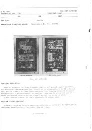
GENERAL<strong>NAVSEA</strong> SELIM-<strong>00</strong>-<strong>EIM</strong>-lWPREFACEPREFACELLbPOLICY AND PURPOSEThe Electronics Installation andMaintenance Book (<strong><strong>EIM</strong>B</strong>) was established as themedium for collecting, publishing, anddistributing, in one convenient source document,those subordinate maintenance and repair policies,installation practices, and overall electronic equipmentand material-handling procedures required toimplement the major policies set forth in Chapter4<strong>00</strong> of the Naval Ships’ Technical Manual. All datacontained within the <strong><strong>EIM</strong>B</strong> derive their authorityfrom Chapter 4<strong>00</strong> of the Naval Ships’ TechnicalMauual, as established in accordance with Article1201, U. S. Navy Regulations.Since its inception the <strong><strong>EIM</strong>B</strong> hasbeen expanded to include selected information ofgeneral interest to electronic installation andmaintenance personnel. These items are such aswould generally be contained in textbooks,periodicals, or technical papers, and form (alongwith the information cited above) a comprehensivereference document. In application, the <strong><strong>EIM</strong>B</strong> isto be used for information and guidance by allmilitary and civilian personnel involved in theinstallation, maintenance, and repair of electronicequipment under cognizance, or technical control,of the Naval Sea Systems Command (<strong>NAVSEA</strong>).The information, instructions, and prceedures, inthe <strong><strong>EIM</strong>B</strong> supplement instructions and data suppliedin equipment technicaI manuals and otherapproved maintenance publications.INFORMATION SOURCESPeriodic revisions are made to providethe best current data in the <strong><strong>EIM</strong>B</strong> and keepabreast of new developments. In doing this, manysource documents are researched to obtain pertinentinformation. Some of these sources includethe Electronics Information Bulletin (EIB), the<strong>NAVSEA</strong> Deckplate, electronics and other textbooks,industry magazines and periodicals, andvarious military installation and maintenancerelatedpublications.ORGANIZATIONThe <strong><strong>EIM</strong>B</strong> is organized into a seriesof handbooks to afford maximum flexibility andease in handling. The handbooks are stocked andissued as separate items so that individual handbooksmay be obtained as needed.The handbooks fall within two categories:general information handbooks, andequipment-oriented hondbooks. The general informationhandbooks contain data which are ofinterest to all personnel involved in installationand maintenance, regardless of their equipmentspecialty. The titles of the various general informationhandbooks give an overall idea of their datacontent; the <strong>General</strong> Handbook includes morecomplete descriptions of each handbook.The equipment handbooks are devotedtQ information about particular classes of equipment.They include general test procedures,adjustments, general servicing information, andfield change identification data.All handbooks of the series are Iistedbelow with their <strong>NAVSEA</strong> numbers.HANDBOOK TITLE<strong>NAVSEA</strong> NUMBER<strong><strong>EIM</strong>B</strong> <strong>General</strong> Information Handbooks<strong>General</strong>SEOOO-OO-<strong>EIM</strong>-1OOInstallation Standards SEOOO-OO-<strong>EIM</strong>-11OElectronic CircuitsSEOOO-OO-<strong>EIM</strong>-120Test Methods & Practices SEOOO-OO-<strong>EIM</strong>-130Reference DataSEOOO-OO-<strong>EIM</strong>-140EMI ReductionSEOOO-OO-<strong>EIM</strong>-150<strong>General</strong> MaintenanceSEOOO-OO-<strong>EIM</strong>-160, !:. / i . ~ ? ~,.,< }., ,( : : ~ -,:.,-. ,, .-. . , .: )/‘ -/ ‘1’{’/ 1“/’( j L : i : 1. f I J“.:t. ,( {’ :zf~’? )<strong><strong>EIM</strong>B</strong> Equipment-Oriented HandbooksCommunicationsSEOOO-OO-<strong>EIM</strong>-O1ORadarSEOOO-OO-<strong>EIM</strong>-020SonarSEOOO-OO-<strong>EIM</strong>-030Test EquipmentSEOOO-OO-<strong>EIM</strong>-040RadiacSEOOO-OO-<strong>EIM</strong>-050Countermeasures SEOOO-<strong>00</strong>-<strong>EIM</strong>+%O~’ / :DISTRIBUTIONInitial Set: An “AF” Restriction Codehas been assigned to <strong>NAVSEA</strong> SEOOO-OO-<strong>EIM</strong>-OOOto control the over-requisitioning of the <strong><strong>EIM</strong>B</strong>ORIGINALxi
PREFACE<strong>NAVSEA</strong> SEOOO-OO-<strong>EIM</strong>-1OOGENERALPREFACESeries. Fleet and shore activities requiring aninitial set of the <strong><strong>EIM</strong>B</strong> Series (13 handbooks withall changes and heavy-duty binders) should submittheir requisition (DD Form 1348 with writtenjustification) through their Supply Officer or area,for issue approval to:Individual Handbooks: To orderindividual handbooks and changes, use the stocknumbers listed in the Box Score on page i. Usingthe stock number for the “BASIC” provides thehandbook (with vinyl cover) and all applicablechanges.dCommanderNaval Sea Systems Command<strong>NAVSEA</strong> 552412Washington, D.C. 20362Use the following data on the DD-1348,Block A -288 NAVPUBFORMCENPHILAStock No. - 0967-LP-OOO-OOO0Unit of Issue - SEFund -<strong>00</strong>All other blocks are to be filled in as normally doneby the requisitioner when ordering publications.Changes and Revisions: The <strong><strong>EIM</strong>B</strong> iscontinuously being updated. For efficiency thesechanges and revisions are automaticallydistributed to using activities who are on theAutomatic Distribution List for the <strong><strong>EIM</strong>B</strong>.Requests and/or changes to the<strong><strong>EIM</strong>B</strong> Automatic Distribution List and anyproblems in requisitioning should be directed to:SUGGESTIONS /CORRECTl ONS<strong>NAVSEA</strong> recognizes that users ofthe <strong><strong>EIM</strong>B</strong> will have occasion to offer corrections orsuggestions. To encourage more active participation,a pre-addressed comment sheet is provided in 4the back of each handbook change. Complete informationshould be given when preparing suggestions.Suggesters are encouraged to include theirname and address so that clarifying correspondencecan be initiated when necessary. Such correspondencewill be by letter directly to theindividual concerned.If a comment sheet is not available, orif correspondence is lengthy, corrections or suggestionsshould be directed to the following:CommanderNaval Sea Systems Command<strong>NAVSEA</strong> 552412Washington, D.C. 20362CommanderNaval Sea Systems Command<strong>NAVSEA</strong> 55Z412Washington, D.C. 20362dxiiORIGINAL
GENERAL<strong>NAVSEA</strong> SEOOO-W-<strong>EIM</strong>-1OOINTRODUCTIONSECTION 1INTRODUCTION1-1 PURPOSEThe purpose of the <strong>General</strong> handbookis to provide policies and instructions pertinent tothe proper use of the Electronics Installation andMaintenance Handbook (<strong><strong>EIM</strong>B</strong>) series. The handbookis published for the guidance of all personnelin the naval establishment responsible for orengaged in the installation, maintenance; adrepair of electronic equipment.L 1-2 SCOPELThe information contained in the<strong>General</strong> handbook has been carefully selected andarranged so that it is easily identified andretrieved.The handbook consists of the following:Section 1 – Introduction.Section 2 — Administration.Section 3 – Safety and AccidentPrevention.Section 4 – Publications and theirHandling.Section 5 – EIBI<strong><strong>EIM</strong>B</strong> Indexes.1-3 USE AND APPLICATIONWhen properly used, the <strong>General</strong>handbook is a quick source of information forinstallation and maintenance personnel. Valuabledata pertaining to administration, supply, publications,and safety matters that couId be foundpreviously only after considerable research in morethan one <strong><strong>EIM</strong>B</strong> handbook have been collected andcarefully arranged in a logical sequence within the<strong>General</strong> handbook. In addition, the <strong><strong>EIM</strong>B</strong> SubjectIndex (Index C), located in Section 5 of this handbook,provides another handy reference for identifyingthe <strong><strong>EIM</strong>B</strong> handbook(s) in which all informationof a particular subject is located.1-4 <strong><strong>EIM</strong>B</strong> SERIES HANDBOOKSThe <strong><strong>EIM</strong>B</strong> series handbooks aredivided into two main categories: general informationhandbooks and equipment-oriented handbooks.The handbooks belonging to the first\ category contain data which are of interest to allpersonnel involved in installation and maintenanceactivities, regardless of equipment specialty.The handbooks of the second categorycontain data on equipment of a particukwclass, such as general test procedures, adjustments,general servicing information, and fieldchange identification.1-4.1 GENERAL INFORMATIONHANDBOOKSThere are seven generaJ informationhandbooks of the <strong><strong>EIM</strong>B</strong> series. These handbooksare discussed in the following paragraphs:a. <strong>General</strong> <strong><strong>EIM</strong>B</strong> handbook,<strong>NAVSEA</strong> SEOOO-OO-<strong>EIM</strong>-1OO. The function of the<strong>General</strong> handbook is discussed in Subsections 1-1,1-2, and 1-3.b. Installation Standards <strong><strong>EIM</strong>B</strong>handbook, <strong>NAVSEA</strong> SEOOO-OO-<strong>EIM</strong>-11O. Thishandbook promulgates approved shipboardinstallation standards, techniques, and practicesof NAVSHIPS electronic equipment. The informationcontained in this handbook had beenextracted from numerous publications, instructions,and pamphlets obtained from military andcommercial sources. It represents the best currentknowIedge in the electronic installation andmaintenance field. The handbook has beenarranged so that material is presented as nearly aspossible in the chronological order of installationevents, starting with receipt of equipment fromsource of supply, to standard installation practicespreliminary ta pIacing the equipment into service.Periodic revisions and additions will be made toensure that the handbook always reflects the bestcurrent techniques and keeps abreast of newdevelopments. This handbook is intended forinstallation personnel.c. Electronic Circuits <strong><strong>EIM</strong>B</strong> handbook,<strong>NAVSEA</strong> SEOOO-OO-<strong>EIM</strong>-120. This handbookprovides electronic circuitry theory anddescriptions for basic vacuum tube and semiconductorcircuits. The contents of the handbook werecarefully selected and prepared to serve therequirements of naval personnel in the electronicsfield. The handbook, as sectionalized, permits theaddition of new circuits to keep the handbookabreast of current electronic developments. Thismethod permits the addition of new electron-tube,semiconductor, and allied circuits, as well as therevision of existing circuits. Each circuit descrip-ORIGINAL 1-1
INTRODUCTION <strong>NAVSEA</strong> SEOOO-OO-<strong>EIM</strong>-1OO GENERALtion includes information on the circuit application,its important characteristics, an analysis ofcircuit theory and operation, and failure analysisbased upon output signal indications. This handbookis intended primarily for shipboard electronictraining personnel and as electronic referencematerial.d. Test Methods and Practices<strong><strong>EIM</strong>B</strong> handbook, <strong>NAVSEA</strong> SEOOO-OO-<strong>EIM</strong>-130.This handbook urovides electronic technicianswith reference in f~rrnation on the fundamentals oftest methods and basic measurements, step-bystepprocedures for testing typical electronicequipments and circuits, and functional descriptionsof the theory of operation of the test equipmentused and circuits tested.e. Reference Data <strong><strong>EIM</strong>B</strong> handbook,<strong>NAVSEA</strong> SEOOO-OO-<strong>EIM</strong>-140. This handbookcontains an encyclopedic arrangement of usefuland informative references of pertinent definitions,abbreviations, formulas, and other generaldata related to electronic installations andmaintenance. This handbook of reference data isintended for use by all Navy electronics personnel.f. EMI Reduction <strong><strong>EIM</strong>B</strong> handbook,<strong>NAVSEA</strong> SEOOO-OO-<strong>EIM</strong>-150. This handbook containsNAVSHIPS—approved techniques and procedures for the elimination or reduction of electromagneticinterference created by own-forceselectromagnetic radiating devices. This handbookis intended for electronic technicians involved inthe installation and maintenance of electronic andelectrical systems and equipment.g. <strong>General</strong> Maintenance <strong><strong>EIM</strong>B</strong>handbook, <strong>NAVSEA</strong> SEOOO-OO-<strong>EIM</strong>-160. Thishandbook contains routine maintenance concepts,techniques, and procedures common to all electronicand electrical equipment. Preventivemaintenance programs, equipment-level andsystem-level maintenance philosophies, andmaintenance of subsystems and repair parts arediscussed. This handbook is intended for use by alltechnicians involved in the maintenance of electronicand electrical equipment.1-4.2 EQUIPMENT-ORIENTEDHANDBOOKSThere are six equipment-orientedhandbooks of the <strong><strong>EIM</strong>B</strong> series. Each of thesehandbooks contain general servicing informationfor the basic equipment category (i.e., radar),general servicing information for specificequipments (i.e., ANISPS-1OD), the Field ChangeIdentification Guide (FCIG) which provides fieldchange information for all equipments of the basicequipment category, and circuit functionaldescriptions common to the equipment of the basicequipment category. The six equipment-orientedhandbooks are:Communications <strong>NAVSEA</strong> SEOOO-OO-<strong>EIM</strong>-O1O<strong><strong>EIM</strong>B</strong>Radar <strong><strong>EIM</strong>B</strong> <strong>NAVSEA</strong> SEOOO-<strong>00</strong>-<strong>EIM</strong>-020Sonar <strong><strong>EIM</strong>B</strong> <strong>NAVSEA</strong> SEOOO-OO-<strong>EIM</strong>-030Test Equipment <strong>NAVSEA</strong> SEOOO-OO-<strong>EIM</strong>-040<strong><strong>EIM</strong>B</strong>Radiac <strong><strong>EIM</strong>B</strong> <strong>NAVSEA</strong> SEOOO-OO-<strong>EIM</strong>-050Countermeasures <strong>NAVSEA</strong> SEOOO-<strong>00</strong>-<strong>EIM</strong>-0$0<strong><strong>EIM</strong>B</strong>f1-5 DISTRIBUTIONThe distribution of the <strong><strong>EIM</strong>B</strong> handbooksand handbook changes is a joint effort bythe Naval Sea Systems Command, SEA 05L3 andthe Naval Publications and Forms Center (NPFC),Philadelphia. Requests for changes or additions tothe distribution list are processed by <strong>NAVSEA</strong>and are forwarded to NPFC, Philadelphia, to incorporatethe changes or additions into the masterdistribution file. Periodic revisions to this file aremade so that it complies with changes to theStandard Navy Distribution List (SNDL).Activities not already on the <strong><strong>EIM</strong>B</strong>distribution list and those requiring changes to thelist should submit correspondence to <strong>NAVSEA</strong> inaccordance with Subsection 4-6 of this handbook.1-6 CHANGESTo be an effective publication, the<strong><strong>EIM</strong>B</strong> handbooks must be continually updated.<strong>General</strong>ly, they are updated by adding applicableinformation obtained from EIB articles, new andrevised specifications, field change bulletins, andpertinent <strong>NAVSEA</strong> or NAVSHIPS instructions.Also, new data are extracted from technical journalsand periodicals. From time to time, fleet personnelwill be required to determine what kind ofinformation is desired in the <strong><strong>EIM</strong>B</strong>. Regardless ofdata source, all new articles to be included in the<strong><strong>EIM</strong>B</strong> publications should be of a permanentnature that will serve as an aid to personnelengaged in electronics maintenance and repairactivities. It also should not duplicate any informationthat is already available in existingtechnical Navy publications.1-7 ADDRESS FORCORRESPONDENCEdThe Naval Sea Systems Commandrecognizes that users of the <strong><strong>EIM</strong>B</strong> will have /AJ1-2 ORIGINAL
GENERAL<strong>NAVSEA</strong> SEOOO-OO-<strong>EIM</strong>-1OOINTRODUCTIONLoccasion to offer comments or suggestions. Toencourage more active participation, a selfaddressedcomment sheet is provided in the backof each handbook. Complete information should begiven when preparing suggestions. It is mostdesirable that the suggestor includes his full nameand mailing address on the comment sheet tofacilitate direct correspondence in the event thatfurther information or clarification is required by<strong>NAVSEA</strong>. Instructions for submitting commentsheets are included in Subsection 4-8 of this handbook.Whenever a comment sheet is notavailable or correspondence is lengthy, suggestionsshould be directed as follows:CommanderNaval Sea Systems CommandSEA 552412Washington DC 203621-8 REQUISITIONS FORADDITIONAL COPIES ORBINDERS OF THE <strong><strong>EIM</strong>B</strong>Activities desiring additional copiesor binders of the <strong><strong>EIM</strong>B</strong> handbooks should submittheir requisitions directly to NPFC, Philadelphia,in accordance with Subsection 4-6 of this handbook.LLORIGINAL1-3/( 1-4 Blank)
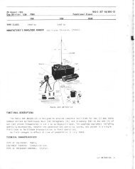
GENERAL<strong>NAVSEA</strong> SEOOO-<strong>00</strong>-<strong>EIM</strong>-lmAD MinistrationSECTION 2ADMINISTRATloNLLL2-1 INTRO DUCTloNThe maintenance of electronic equipmentinvolves more than just correcting malfunctionsor performing preventive mtinten~ce.Although these tasks are essential, someone mustfirst determine what should be done, train andassign the personnel to do it, and then supervisethem as they do it. In addition, sufficient spareparts must be stocked, publications kept up todate, records kept, reports made, and so on. All ofthese tasks are part of the electronics administration,without which there can be no effective electronicsmaintenance.The purpose of this section is toacquaint Navy electronics personnel with administrativeresponsibilities and procedures. Orgmiza”tions, procedures, and facilities for supplyingnaval electronic material are addressed since anunderstanding of these phases of support is importantfor personnel whose duties are concerned withelectronic material. This section and the sources ofadditional information referenced in the text furnishmost of the information necessary for properadministration of a Navy electronic division orinstallation.2-2 ELECTRON I= OrganizationAND RESPONSIBILITIESThe ship’s organization manual fullydescribes the ship’s org~ization, outlines theduties and responsibilities of the various departmentsand divisions, gives the procedures for accomplishingthe various tasks and duties, and liststhe ship’s regulations. In addition, most ships willhave department organization manuals; and someships may have division organization manu~s.The U.S. Navy Regulations prescribes the functionalorganization for ships and is the authorityfor these publications. The following di~~(Figure 2-1) shows the various sources of informationconcerning shipboard organization.Within the organization for electronics,the assignment of operation~ ~dmaterial responsibilities is as follows:a. Operational responsibilities (i.e.,operational use,maintenance, andmaintenance notaccomplishment)manipulation, operationalthose portions of preventiverequiring realignment afterare assigned to personnelcharged with operating electronic equipment andassociated equipment. Very often, a competentequipment operator can detect a malfunction in anequipment, which he can correct without the aid ofa technician. He is qualified to make someadjustments and minor repair, provided that theydo not require a high degree of technical skill.b. Material responsibilities includethe general upkeep and maintenance of all assignedelectronic equipment. Such responsibilitiesinclude those portions of routine and preventivemaintenance which require alignment after accomplishment,installation of Class A field changes,corrective maintenance, and maintenance ofrecords, reports, technical manuals, and othermaintenance documents.2-3 SECURITYThe security of the United States ingeneral, and of naval operations in particular,depends in part upon the success attained in thesafeguarding of classified information. It is ofparamount importance that all who engage inadministering security preserve a balanced andcommon sense outlook toward the subject. Theideal to be sought is the indoctrination of all personnelto the point that they automatically exerciseproper discretion in the discharge of theirduties and do not think of security of informationas something separate and apart from otherthings. In this way, security of classified informationbecomes a natural element of every task andnot an additionally imposed burden. The attainmentof the desired objective requires sound directionfrom competent authority and full alertnessand cooperativeness of the part of all subordinates.2-3-1 RESPONS16iLi~The Chief of Naval Operations isresponsible to the Secretary of the Navy for allpolicies relating to the maintenance of the securityof all classified information within the navalestablishment. Owing to the close relationship ofcounterintelligence and the presemation of security,the Director of Naval Intelligence has beendesignated as the officer primarily responsible tothe Chief of Naval Operations for the protection ofclassified information. Therefore, the office ofNaval Intelligence formulates and promulgatesORIGINAL2-1
ADMINISTRATION <strong>NAVSEA</strong> SEO(M-(K)-<strong>EIM</strong>-l(Kl GENERALIvU. S.NAVYREGULATIONSI1Io8ATTLEBILLFLEET TYPE COMMANDERSSTANDARD ORGANIZATIONMANUALIISHIP’S ORGANIZATION MANUAL (EACH SHIP)SHIP’S WATCH ORGANIZATIONAL SHIP’SORGANIZATION ORGANIZATION SILLS REGULATIONSCHART(underway snd (admin - op -(down coinport)etnerg)divisionlevel) Chapter 2 Chaptar 3 Chaptaf 4 IIIOEPARTFIENT ORGANIZATIONMANUALIIAPPENDIXESIII4FiiF=-1Figure 2-1. Sources of Information Concerning Shipboard OrganizationNavy policies which relate to the security of &dlclassified information.Chapter 15 of the Navy Regulationsspecifies that commanding officers are directlyresponsible for safeguarding all classified informationwithin their commands and are responsible forinstructing their personnel in security practicesand procedures. The electronics material officer isresponsible to the commanding officer for seeingthat security is the responsibility of all electronicspersonnel, and that each of his personnel complieswith the regulations pertaining to the security ofelectronic equipment, spaces, and printed matter.The Department of the Navy SeCurityManual for classified information,OPNAVINST 5510,1, is the basic security document.The purpose of this document is to provideall naval activities and personnel with detailedregulations and guidance for classifying, marking,and handling classified information. A thoroughknowledge of this security document and of alllocally established security procedures arerequired for all electronics personnel.2-3.2 SECURITY CLASSIFICATIONCATEGORIESOfficial information or material whichrequires protection against unauthorizeddisclosure in the interest of the national defense orforeign relations of the United States are classifiedin one of three categories, namely “Top Secret,”“Secret,” or “Confidential” depending upon thedegree of its significance to national security.4-2-2 ORIGINAL
<strong>NAVSEA</strong> SEMIO-(Xl-<strong>EIM</strong>-l(MlADMINISTRATIONThese classification categories are defined asfollows:a. TOD Secret. “TOD Secret” refersto that national security inform~tion or materialwhich requires the highest degree of protection.The test for assigning “Top Secret” classificationshall be whether its unauthorized disclosure couldreasonably be expected to cause exceptionallygrave damage to the national security. Examplesof “exceptionally grave damage”, may include, butis not limited to, armed hostilities against theUnited States or its allies; disruption of foreignrelations virtually affecting the national security;the compromise of vital national defense plans orcomplex cryptologic and communications intelligencesvstems: the revelation of sensitive intelli-~ence operations; and the disclosure of scientific ortechnological developments vital to nationalsecurity, This classification shall be used with theutmost restraint.b. Secret. “Secret” refers to thatnational security information or material whichrequires a substantial degree of protection. Thetest for assigning “Secret” classification shall bewhether its unauthorized disclosure could reasonablybe expected to cause serious damage to thenational security. Examples of “serious damage”may include, but is not limited to, dismption offoreign relations significantly affecting thenational security; significant impairment of a program or policy directly related to the nationalsecurity; revelation of significant military plans orintelligence operations; compromise of significantmilitary plans or intelligence operations; and compromiseof significant scientific or technologicaldevelopments relating to national security. Theclassification “Secret” shall be sparingly used.c. Confidential. “Confidential”refers to that national security information ormaterial which requires protection. The test forassigning “Confidential” classification shall bewhether its unauthorized disclosure couldreasonably be expected to cause damage to thenational security. Examples of “damage” mayinclude, but is not limited to, the compromise ofinformation that indicates strength of ground, airand naval forces in the United States and overseasareas; disclosure of technical information used fortraining, maintenance, and inspection of classifiedmunitions of war; revelation of performancecharacteristics, test data, design and productiondata on munitions of war.2-3.3 ACCESS TO CLASSIFIEDMATERIALThe availability of classified materialis restricted to those persons who have the propersecurity clearance and a “need-bknow”. The“need-to-know” term means that the disseminationof classified information is available ordy tothose persons whose official military or othergovernmental duties require knowledge or possessionthereof. Reaponsibility for determiningwhether a person’s duties require that he possessor have access to classified information andwhether he is authorized to receive it rests uponeach individual who has possession, knowledge, orcommand control of the information involved andnot upon the prospective recipient. This principleis applicable whether the prospective recipient isan individual, a command, a defense contractor,another federal agency, or a foreign government. A“need-teknow” is recognized as established when(1) the disclosure is necessary in the interests ofnational defense; (2) there clearly appears from theposition, status, duties, and responsibilities of theapplicant that he haa a legitimate requirement foraccess to the classified information in order tocarry out his assigned duties and responsibilities;(3) there is no other equal or ready source of thesame classified information available to him; and(4) the applicant is or can be appropriately clearedfor access to the degree of classified informationinvolved and is capable both physically and mentallyof providing the degree of protection whichthat information requires.2-3.4 INSPECTIONSCommanding officers establish arequirement for review and inspection proceduresto determine and evaluate the effectiveness of thesecurity indoctrination. These inspections inquireinto the security procedures and practices, andincludes, but is not limited to: classification,dissemination, transmission, control and accounting,atowage, downgrading and declassificationprocedures, security orientation, education andtraining. Such inspections may be conducted as anintegral part of existing inspections, provided theresults are readily identifiable so as to provide abasis for m-evaluation of the objectives of thesecurity program. (Refer to the current edition ofOPNAVINST 5040.70)ORIGINAL 2-3
ADMINISTRATION <strong>NAVSEA</strong> SEOOO-W-<strong>EIM</strong>-lW GENERAL2-3.5 DOWNGRADING ANDDECLASSIFICATIONEffective 1 August 1982, theprevious limitations on the duration of classificationsare removed (e.g., original Secret and Confidentialclassification authorities could classifyinformation up to six years and original Top Secretclassification authorities could classify informationup to 20 years). With the 6 and 20 yeardeclassification/review time limits of E.O. 12065eliminated, the original classification authoritieswill now classify information for as long asrequired by national security considerations.2-3.5.1 Originally Classified DocumentsEffective 1 August 1982, originallyclassified documents, classified by a securityclassification guide, shall be marked fordeclassification as folIows:“Declassify on:,,(If known or appropriate, insert the specific date orevent which is certain to occur. Otherwise, insertthe notation “Originating Agency’s DeterminationRequired” or “OADR.”)2-3.5.2 Previously Marked DocumentsThere is no need to re-markdocuments marked under E.O. 12065 or predecessororders. Those documents already markedwith a specific date or event for downgrading ordeclassification shall be downgraded ordeclassified accordingly. Documents not markedfor automatic downgrading or declassification on aspecific date or event shall not be downgraded ordeclassified without authorization of an originalclassification authority from the originating agency.Information extracted from such documentsshall be marked “Declassify on: OADR.”However, when conversion of previous ExecutiveOrder markings are required, the following applies:a. If a source document contains aspecific date or event for deckssification and theinformation remains unchanged, then that date isCtltli$d forward.b. If a source document contains areview for declassification date, then the date isconverted to the notation “OADR.”The mandatory 20-yem systematicreview program of E.O. 12065 has been eliminated.The Archivist of the United States will, under E.O.12356, systematically review for declassificationall permanently valuable 30-year old Navy recordsaccessioned into the Archives pursuant toguidance provided by CNO (OP-<strong>00</strong>9DX).Mandatory declassification review requestswill be accepted by Department of theNavy (DON) components only if received fromU.S. citizens or permanent resident aliens or froma federal agency or state or local government.DON components need not accept requests for 4mandatory declassification review from foreignaddresses or from persons whose citizenship orstatus is not known. It is the intent of the DON,however, to demonstrate flexibility in the treatmentof such requests and to effect declassificationreviews whenever feasible with availableresources.DON components may not automaticallydeclassify information because of itsunofficial publication or its inadvertent orunauthorized disclosure in the United States orelsewhere or because of the open publication orrelease of identical or similar information. Infor- 4mation may be declassified by the “OADR,”original classification authority only, when its continuedclassification is no longer warranted.2-3.6 CLASSIFICATION MARKING:Some of the basic changes to thesecurity classification and marking system, effective1 August 1982, are set forth below:2-3.6.1 Categories of InformationConsidered for ClassificationThere are four categories of informationwhich may be considered for classification:a. Vulnerabilities or capabilities ofsystems, installations, projects, or plans relatingto the national securityb. Intelligence activities includingspecial activities, or intelligence sources ormethodsc. cryptologyd. A confidential sourceOriginaI classification authoritiesmust elect to classify when doubt exists as towhether or not classification is appropriate. Thehigher classification level must be selected whendoubt exists as to which level of classificationshould be appiied.Information and material may beclassified under E.O. 12356 when, taken togetherwith other information, the same can causedamage to the national security if released withoutauthorization. Original classification authoritiesshall now, as part of the classification process, considerall information in light of previousdisclosures, or in context with other informationclassified or unclassified, as to whether or not theinformation should be classified.2-3.6.2 Classification DesignationsInformation or material that requiresprotection against unauthorized disclosure in thedd2-4 ORIGINAL
GENERAL <strong>NAVSEA</strong> SEtN10-tX)-<strong>EIM</strong>-l(N) ADMINISTRATIONLLLinterest of the national security shall be classifiedin one of three designations, “TOP SECRET,”“SECRET,” or “CONFIDENTIAL.” The marking“FOR OFFICIAL USE ONLY” shall not beused to identify classified information or material.No other term(s) (e.g., “Sensitive,” “Conference,”or “Agency”) shall be used in conjunction with theauthorized classification designations to identifyclassified information or material. The tbeeclassification designators are defined in paragraph2-3.2.2-3.6.3 Original Classification Authority“Original classification” is defined asan initial determination that information ormaterial requires, in the interest of the nationalsecurity, protection against unauthorizeddisclosure together with a classification designationsignifying the level of protection required.When the information or material is originallyclassified, only the original classificationauthorities shall be cited in the “classified by”line. Further, only an original classificationauthority shall upgrade, downgrade, or declassifyinformation or material. If a classification guide isnot available or an originator of classified informationis not a designated classification authority,the information shall be marked by the originatorwith the highest classification believed to bewarranted.2-3.6.4 Derivative Classification.Derivative Classification is defined as,a detemnination that information or material is insubstance the same as information or materialthat is currently classified and assigned a designationof the same level of classification. The“Classified by” line on derivatively classifieddocuments shall reflect the identity of theapplicable classification guide, source document orother authority for the classification. If more thanone such source is applicable, insert the phrase“Multiple Sources.” When “Multiple Sources” iscited in the “classified by” line, it is the responsibilityof the originator to maintain with the fileor record copy of the document the identificationof the source material (e.g., classification guides,documents, etc.) used.2-3.6.5 Duration of OriginalClassificationAt the time a determination is madeby an official with authority to originally classifyinformation and material as “TOP SECRET,”“SECRET,” or “CONFIDENTIAL,” such officialmust also determine how long the classificationshall remain in effect.Original classification authoritiesmay not be able to predetermine a date or event forautomatic declassification, in which case, theyshall provide for the indefinite duration ofclassification. The “Declassify on” line shall read“Originating Agency’s Determination Required”or “OADR.”2-3.6.6 Subject and Title MarkingSubjects and Titles of ClassifiedDocuments shall be marked with the appropriatesymbol, “(TS),” “(S),” “(C),” or “(U)” placedimmediately following and to the right of the item.When applicable, other appropriate symbols (e.g.,“(RD),” “(FRD),” “(WNINTEL)”) shall be added.2-3.6.7 Position MarkingEach section, part, paragraph, subparagraph,or similar portion of a classified documentshall be marked to show the level of classificationof the information contained therein orrevealed by it or that it is Unclassified. Portions ofdocuments shall be marked in a manner that eliminatesdoubt as to which of its portions contain orreveal classified information. Classification levelsof portions of a document shall be shown by theappropriate classification symbol placed immediatelyfollowing the portion’s letter or number, orin the absence of letters or numbers, immediatelybefore the beginning of the portion.2-3.6.8 Transmittal DocumentsA transmittal document, includingendorsements and comments, when such endorsementsand comments are added to the basic communication,shall carry on its face a prominentnotation as to the highest classification of theinformation or material transmitted by it, and alegend showing the classification, if any, of thetransmittal document, endorsement or commentstanding alone. For example, an Unclassified documentthat transmits as an attachment a classifieddocument, shall be marked with a notationsubstantially as follows:“Unclassified upon removal of classifiedenclosure(s)”Transmittal documents shall also be marked withany additional applicable warning notices describedin paragraph 2-3.6.9 below.2-3.6.9 Additional Warning NoticesIn addition to the marking requirementsprescribed the following warningnotices, when applicable, shall be prominentlydisplayed on classified documents and materials.ORIGINAL 2-5
ADMINISTRATION <strong>NAVSEA</strong> SEMKI-<strong>00</strong>-<strong>EIM</strong>-lW GENERAL“RESTRICTED DATA” –“This mate% contains “Restricted Data” asdefined in the Atomic Energy Act of 1954.Unauthorized disclosure subject to administrativeand criminal sanctions.” Portion mark “RD.”b. “FORMERLY RESTRICTEDDATA” – “Unauthorized disclosure subject toadministrative and criminal sanctions. Handle as“Restricted Data” in foreign dissemination.Section 144.b, Atomic Energy Act, 1954.” Portionmark as “FRD.”“WARNING NOTICE – IN-TELLIGENCE SOURCES AND METHODSINVOLVED.” Portion mark as “WNINTEL” or“WN.”d. “NOT RELEASABLE TOFOREIGN NATIONALS”. Portion mark as“NOFORN” or “NF”. “NOFORN” markings areauthorized for use only on the following categoriesof information and material:(1) Naval Nuclear PropulsionInformation (NNPI)(2) Intelligence data, other thanWNINTEL(3) Communications informationand material (COMSEC)(4) Cryptographic informationand material (CRYPTO)2-3.7 SECURITY PUBLICATIONSAND INSTRUCTIONSBasic security regulations andcriteria for safeguarding classified information arecovered in detail in OPNAV Instruction 5510.1,Department of the Navy Security Manual forClassified Information. The purpose of this documentis to provide all Naval activities and personnelwith detailed regulations and guidance forclassifying, marking, and the handling of classifiedinformation.The following documents are listedfor specific guidance in safeguarding classifiedinformation. A more comprehensive listing ofsecurity-oriented documents is contained inOPNAV Instruction 5510.1.2-3.7.1 Naval See Systems CommandShore Activities Standards;<strong>NAVSEA</strong> Instruction 5610.2.The purpose of this instruction is toprovide an updated security guide for the protectionof classified information and materials in thecustody of or under the cognizance of the NavalSea Systems Command. The policies and procedures contained in this instruction are based onthe Department of the Navy Security Manual forClassified Information (OPNAVINST 5510.1) andother security regulations interpreted to meetspecific needs of the <strong>NAVSEA</strong> Command.2-3.7.2 Security Classification andCognizant Activity of ElectronicEquipment, MIL-HDBK-140.This handbook is the Department ofDefense’s document which provides the officialsecurity classification and cognizance data of AirForce, &my, and Navy electronic equipments. Itlists the official nomenclature, current securityclassification, engineering cognizance, procurementcognizance, and automatic time-phaseddowngrading information of equipments covered.2-4 TRAININGThe principal objective of Navy trainingis to maintain a naval force in an optimumstate of readiness for the defense of the UnitedStates. Navy training consists of fleet training,shipboard training, and naval school training.<strong>General</strong> policies for fleet training are stated inShip Exercises, FXP-3-B, and (except forshakedown and refresher training) are discussedonly briefly in this section. Shipboard training andnaval school training, however, are discussed inconsiderable detail, especially as they pertain tothe ship’s electronics department. All three phasesof Navy training are closely allied and contributeto the development of highly trained and fullyqualified individuals who man the ships of ourmodem Navy.2-4.1 FLEET TRAININGFleet training of ships is the responsibilityof the Deputy Chief of Naval Operationsfor Fleet Operations and Readiness, and is controlledand supervised by the Commander in Chief,Atlantic Fleet, and the Commander in Chief,Pacific Fleet. The Fleet Commanders in Chief exercisetheir training responsibilities through theirtype commanders. This delegation of authorityprovides for battle readiness at every level ofadministrative command while assuring unity ofpurpose and uniformity of standards. Fleet typeorganization is illustrated in Figure 2-2. The fleettraining command (Commander, Training Command)of each fleet assists the other type commandersby supplying services for programs andconducting training programs (shakedown andrefresher training) as directed by the fleet commanders.d42-6 ORIGINAL
GENERAL <strong>NAVSEA</strong> SEOOO-<strong>00</strong>-<strong>EIM</strong>-lUI ADMINISTRATIONLLI 1IFLEET*AMDERI~ANOIMG GEXERALl+COW4AMOERFLEET MARINE FORCE NAVAL AIR FORCE If ,COWANOER~OERCRUISER-OESTROYER , AnPwEmJsFORCEFORCE4COW4ANOERSUMARINE 1 ~ANOERfORCEMM FORCECCWWIOERSERVICE IWRCE.~MOER- YRAuMGd * comAllobFigure 2-2. A Fleet Type OrganizationThe training cycle for each ship correspondsto the period between regularly scheduledshipyard overhauls. The most importantfeature of the training cycle is that it furnishes abasis for scheduling inspections and trials. Theintratype competitive period corresponds to thefiscal year regardless of the training cycle. Fleetoperating schedules are issued on both a quarterlyand an annual basis, and govern many factorswhich must be taken into consideration in theplanning of maintenance and training.2-4.1.1 Types of Training ExercisesType commanders prescribe thetraining exercises to be conducted by ships of thetype during the intratype competitive period. Thetactical commander of ships in a task forcerequires that ships of the force perform, eitherseparately or in company with other ships, theexercises required by the type commanders.Each type commander is responsible,under the fleet commander, for the administrationand control of the training program of each shipIbassigned to his administrative command. In thedischarge of his training responsibilities, the typecommander (1) designates the required exercisesand establishes minimum exercise requirements,(2) reallocates ammunition allotted to him by thefleet commander, (3) selects exercises to meetspecific training requirements, (4) divides shipsinto competitive groups, (5) provides for observationof certain exercises by qualified obsemers, (6)appraises the performance of each ship, and (7)evaluates and maintains records of the overall performanceof each ship. When awarding a finalgrade for performance, the type commander hasbroad authority and may weigh separate exercisesand other performances, at his own discretion, toallow realistic evaluation of the ship’s organization,discipline, and opportunities for training. Thetype commander may delegate his authority forfleet training (except for policy guidance) to subordinatecommanders of units operating outside hissupervision and observation.Maximum benefit is derived from anytraining exercise when the performance of theexercise is properly observed and analyzed. If theexercise is to be graded, formal observation ismandatory. When the importance of the exercisejustifies such assignment, the observation will befrom the outside of the observed ship. The analysisof the exercise, in the form of a critique, is held assoon as practicable after the completion of theexercise to determine errors committed, deficienciesin material or procedures, and recommendationsfor improvement.Exercise appraisal is based on thereadiness of the ship to deal effectively with thesituation simulated by the exercise. The effect offactors over which the ship has no control,however, is taken into consideration. The observingcommand submits a recommended grade alongwith the report of the exercises observed; however,the award of a final grade is the responsibility ofthe type commander (or a designated subordinate)and is aimed at establishing uniformity within thetype. In the evaluation of readiness, considerationis given to the performance of basic exercises, theperformance of prescribed exercises, and thehandling of actual casualties which occur.2-4.1.2 Shakedown and RefresherTrainingAfter a ship has been commissionedand has completed fitting out, she undergoesshakedown training. A newly activated ship or aship leaving a shipyard after regulm overhaulundergoes refresher training. In either case, theship is put through an intensive combat readinessORIGINAL 2-7
. . - . . . . . . . . . . - . -- . . . . . .--— - ----- -- ---- ---.-— - --— ----- -- . . . . . ---. -- ---- . . .training period by a designated Fleet TrainingGroup, under the direction of the Commander,Training Command, U. S. Atlantic or Pacific Fleet,as applicable. It is during this period which theOperational Readiness Inspection (ORI) is conducted.Ships reporting for refresher trainingreceive a training readiness evaluation inspectionprior to the ORI. The purpose of this inspection isto determine the organizational and materialreadiness of the shiD . to commence refresher training.The inspection checkoff lists are based uponstandards prescribed by Battle Control (U), NWIP50-1( ), Naval Ships Technical Manual, and directivesof the fleet commander and type commanders.Immediately following the trainingreadiness evaluation inspection, a critique is heldand a complete written report of the discrepanciesnoted is left with the executive officer of the ship.A formal report is submitted to the Commander,Training Command, with a copy to the type commander.Those deficiencies which will affectrefresher training should be corrected as soon aspossible. It is expected that all deficiencies will becorrected prior to the ORI.2-4.1.2.1 The Fleet Treining GroupThe primary function of a Fleet TrainingGroup (FTG) is to help ships train themselves.In implementation of this, training groups havebeen delegated authority to control and assignmentof operating areas, to coordinate andregulate the conduct of training exercises, and tosupply training services in their assignedoperating areas.A Fleet Training Group is generallydivided into two sections–au administrativesection and an afloat training section. Theadministrative section performs the work of schedulingthe activities of ships undergoing training; itcorrelates such activities as target towingservices, camera services, and dmd ship exercises.The afloat training section is organizedinto departments in the general pattern ofshipboard organization. Their instructors also actas observers, advisors, and inspectors. In thesecapacities, they may offer constructive criticism orrecommended improvements. At times they mayassist with impromptu instruction, lectures, anddemonstrations.During battle problems, FTG personnelare observers both by title and function. Theyimpose damage by setting up, as realistically aspossible, various exercises and then observingaction taken by ship’s personnel to combat theimposed damage. They do not operate any equipment,but will endeavor to stop an evolution thatmay result in damage to equipment or injury topersonnel. 4FTG shipboard instructors haveobserved many ships in training; they know whichmethods work and have picked up many pointersboth in training techniques and administrativeprocedures. When conditions following the day’sexercises permit, the instructors conduct a critiquewith the ship’s personnel involved in the training.During the critique, the instructors call attentionto errors observed during drills, make recommendationsfor improvement, and answer questionsconcerning the training.2-4.1.2.2 Operational ReadinessInspection4The purpose of the OperationalReadiness Inspection is to evaluati the ability ofthe ship to perform her assigned mission. (See also,Subsection 2-12.2 Operational Readiness Inspection.)In addition to the final battle problem, ORIincludes evaluation of the ability of the ship’s ConditionIII Watch Organization to conduct a fullpower run, fight fires, rescue a man overboard, andrender assistance to another ship. These drills andthe full power run are usually conducted prior tothe day of the final battle problem.The final battle problem serves tofamiliarize the personnel of the ship with a fullscale battle problem and the manner in which it isconducted. Insofar as practicable, the battleproblem approximates wartime operations expectedof the type ship involved.2-4.2 SHIPBOARD TRAININGPROGRAMShipboard training and the maintenanceof material are two of the major factors contributingto battle readiness. Neither can be saidto be more important than the other except thattraining is a prerequisite to proper maintenance.The shipboard training programmust consider the organizational framework andoperating schedules of the ship. The applicationphase of the training program involves the actualteaching of personnel and the evaluation ofindividual progress as well as the ability to functionas a team. Analysis of the results of shipboardtraining entails (1) observation of team (group) andindividual performance, (2) comparison of performancewith standard criteria, and (3) recognitionof methods for improvements. The effective sbipboardtraining program has as its objective thedevelopment of optimum individual and team efficiency.dd2-8 ORIGINAL
GENERAL <strong>NAVSEA</strong> SEOOO-<strong>00</strong>-<strong>EIM</strong>-lW ADMINISTRATIONLLThe basis of all training is the developmentof skills in the individual. The individual istrained to fill successfully his billet aboard shipand to prepare for advancement in rating and foracceptance of more responsibilities. Team training,or training of a ship as a whole, can only beaccomplished with a successful individual trainingprogram as a base.2-4.2.1 Training OrganizationThe commanding officer heads theshipboard organization for training, as shown inFigure 2-3. The organization is responsible forphmning, coordinating, and conducting drills,classes, and instruction designed to increas eth especialized and general professional knowledge ofthe personnel of the command. The organization isgoverned in its actions by the policies and plans ofhigher authority-principally those of the typecommander.Close attention must be given to thetraining potentialities of the individual ship, andto the elimination of all but essential paperwork inthe program. Training methods will vary from shipto ship, depending on the size, design, and personnelallowance; and each ship’s training time mustbe carefully balanced with the time allotted formaintenance. The proper time apportionmentmust be made by officers who know existing shipboardtraining and maintenance conditions. Once abalance is established, programs for training andfor maintenance should be carefully planned,executed, and controlled. The executive officerexercises overall supervision of the trainingprogram under the direction of the commandingofficer.2-4.2.1.1 Planning Board for TrainingThe ship’s planning board for training is generallycomposed of the executive officer as chairman, theheads of departments, the training officer, and theeducational services officer. (See Figure 2-3) Theboard performs the following generaf functions:a. Advises and assists the commandingofficer in the formulation of trainingpolicies.b. Establishes the training programfor the ship and periodically evaluates the trainingprogram by reviewing the schedules within theprogram.c. Establishes a training syllabusfor the training of junior officers and one forenlisted men.The planning board meets periodicallyto evaluate progress, coordinate action, andpropose changes to improve the training programIMvmloa ofRcERIFigure 2-3. Shipboard Training Organization(Destroyer Type)and future requirements. The personal knowIedgeof members, the reports of the educational servicesofficer, and the use of various control devices, allserve to indicate areas needing improvement.Regardless of the care exercised inthe development of the original training program,the need for changes will occur often. The followingitems should be examined periodically for theirpossible effect on the training program:1. Changes in the nature of scheduleof the ship’s operations.2. Installation of new or improvedequipment.3. Changes in the qualifications foradvancement in rating.4. Changes in person nelassignments.5. Change in regulations or procedures under which the ship is operating.ORIGINAL 2-9
ADMINISTRATION <strong>NAVSEA</strong> SE(XKI-OO-<strong>EIM</strong>-1OO GENERAL6. Completion of any phase of thetraining program.7. Increases or decreases in facilitiesor avadability of fleet and bureau controlled trainingestablishments.2-4.2.1.2 Educational Services OfficerThe Educational Services Officer(ESO) assists the executive officer in theadministration of the training, information, andeducation programs of the ship. (See Figure 2-3.)In large ships it may be possible to assign theduties of the educational services officer to anofficer as primary duty. In smaller ships, theduties may be assigned an officer as collateralduty or the executive officer may elect to performthe duties himself. The educational services officerperforms the following duties:a. Supervises the administrationand operation of the training office and of theship’s training aids.b. Serves as a member of the ship’splanning board for training.c. Maintains contact with fleet andbureau controlled training activities and advisesthe planning board for training and other ship’spersonnel of the use of facilities for training.d. Secures quotas, as recommendedby heads of departments, for personnel attendingfl-~t or functional schools.e. Assists examining boards by providingmaterial and personnel as requested.f. Schedules orientation and indoctrinationcourses for officer and enlisted personnel.g. Directs the educational servicesprogram inccuding the interviewing and counsel-;mg of personnel; processing of applications forofficer, enlisted, and correspondence courses;administration of special and end-of-course tests;and assisting personnel in obtaining high school,college, business, and military education credits.h. Processes applications and makesnecessary interviews and tests for limited dutyofficer, Naval Academy Preparatory School,Officer Candidate School, and Naval ReserveOfficer’s Training Corps.i. Prepares, maintains, and submitsrequired training records and reports.The ESO reports to the executiveofficer in the performance of assigned duties. TheESO collaborates with and advises departmenttraining officers and division training officers concerningthe overall training program and theimplementation of special training programs.2-4.2.1.3 Division Training OfficerThe duties of the division trainingofficer are generally assigned as collateral duty forthe junior division officer or are performed by thedivision officer. (See Figure 2-3.) As the assistantto the division officer for the administration andcoordination of the division training program, thedivision training officer performs the followingduties:a. Plans, develops, and ensures thepreparation of division training schedules, andobtains the training space and materials necessaryto support the schedules.b. Selects and trains instructors forthe division.c. Supervises the preparation oftraining material and reviews curriculums,courses, and lesson plans for the division.d. Obtains, maintains custody of,and issues required training aids and devices.e. Evaluates all instruction withinthe division.f. Prepares, maintains, and submitstraining records and reports required of the division.g. Initiates requisitions for trainingsupplies and materials for the division.h. Encourages division personnel touse available naval schools.i. Encourages division personnel tofurther the advancement of their careers throughuse of Navy and Defense Activity for Non-Traditional Education Support (DANTES) correspondencecourses.The division training officer reportsto the division officer for the performance ofassigned duties. The division training officer consultswith the electronics training officer and theeducational services officer, as appropriate, intraining matters affecting the division. Theinstructors of the division report to the divisiontraining officer.2-4.2.1.4 Instructors 4Every officer and petty officer musttake an active part in the training program, andeach is expected to be a competent instructor. (SeeFigure 2-3.) There is no better method for juniorofficers or petty officers to attain definite positionsas leaders than by demonstrating ability asan instructor. Each instructor must be capable inhis specialty and display a potential teaching abilitythat can be developed through training andexperience.2-1o ORIGINAL
GENERAL <strong>NAVSEA</strong> SEOOO-(W<strong>EIM</strong>-1OO ADMINISTRATIONL\The job of instructing is twofold. Aninstructor not only must pass on knowledge, butthe instructor must develop certain attitudes inthe personnel, The most effective method ofteaching these attitudes is by example. Theinstructor must possess and constantly displaythese attitudes if the instructor is to be a goodinstructor.Pride in the Navy is one of the majordesirable attitudes the instructor must foster. Tobe proud of the Navy you must first be proud ofyour part in the Navy, and proud of those parts ofit with which you come in contact. The instructor,because of being an immediate contact with theindividual, is a symbol of the Navy. Everythingthat the instructor says and does should becalculated to foster pride in the Navy.Respect for authority is anotherdesirable attitude which the instructor mustdevelop in the personnel. The instructor as arepresentative of authority, must be someone thatthe personnel can respect. In the matter of beingcorrect in relationships with personnel, theinstructor must be fair, firm, and friendly.Many times in a career a sailor iscalled upon to exercise ingenuity. In order todevelop a willingness to exercise ingenuity, the instructormust (by example or otherwise) show theperson what ingenuity is and then give that personthe technical knowledge with which to work. Oneway to do this is to encourage the individual todiscuss makeshift or substitute materials ormethods which may be used to accomplish tasksencountered on the job.Enthusiasm plays an important rolein teaching. The instructor who approaches a jobwith pride and vigor will find that the class willrespond in a like manner. No one can be enthusiasticabout anything which is felt is not importantor useful. The wise instructor will always show thevalue of the things taught, An enthusiasticapproach by the instructor, helps to develop (1) thedesire to advance professionally, (2) pride in doingany job well, and (3) pride in doing more than isexpected.2-4.3 ELECTRONICS TRAININGThe primary purpose of the electronicstraining program must be to ensure thatthe personnel assigned to the electronics divisionknow how to maintain the electronic equipment toensure its peak performance. The electronicsmaterial officer (E MO) is responsible forestablishing and supervising the training program.In addition, the EMO may be responsiblefor training equipment operators since the effectivenessof electronic equipment is also dependenton the operation of the equipment. The quantityand kinds of electronic equipment, the number andcapabilities of the personnel on board, and themission of the ship dictate the training needs.2-4.3.1 ELECTRONICS MATERIALOFFICERThe electronics material officer(EMO) is responsible, under the operations officer,for the readiness of all assigned electronic equipment;and for the administration of the electronicsmaterial maintenance, technical maintenance, andrepair of all shipboard electronic equipment otherthan weapons control radar and equipment specificallyassigned to another division. In ships havinga combat systems department, the above generalduties and the following special duties will beassumed by the Electronic Coordination Officer(ECO). The electronics coordination officer reportsdirectly to the combat systems officer. The specificduties of the EMO are:a. Be responsible for the maintenanceand repair of all electronic equipment,excluding weapons control radar and equipmentspecifically assigned to another division.b. Prepare and supervise the electronicspreventive maintenance program.c. Provide for maximum operationalreadiness of electronic equipment by means ofoperational tests and established maintenanceprocedures.d. Provide for correct use, manipulation,maintenance, and repair of assigned electronicrepair equipment.e. Direct equipment modificationsrequired by authorized field changes.f. Establish and maintain a reportingand record system which wilJ provide, to allpersonnel concerned, current information regardingthe material status of all electronic equipmentunder his cognizance.g. Assist and advise operating personnelas requested by cognizant officers,including the CIC and communications officers, inthe proper operational procedures and characteristicsof electronic equipment, including performancecapabilities and limitations.h. Prepare, for forwarding throughthe engineer officer, work lists for shipyardavailability repairs; and provide detailed specificationsand information requests for shipyard work.Follow up work, in close liaison with shipyardofficials, keeping informed of work progress; andcarry out inspection of completed work.ORIGINAL 2-11
ADMINISTRATION <strong>NAVSEA</strong> SEOOO-<strong>00</strong>-<strong>EIM</strong>-lW GENERALi. Keep informed concerning theship’s current electronic equipment allowance, andensure the requisitioning and procurement ofauthorized equipment; and, when necessary,supervise the installation of such equipment, subjectto the approval of the operations officer, inorder to maintain these allowances.j. Act in an advisory capacity to thesupply officer to ensure the proper requisitioningof electronic spare parts in accordance with theminimum requirements of the appropriate allowancelists, and ensure the ready availability of suchspare parts.k. Ensure the maintenance of accuraterecords of equipment changes, installations,repairs, and expenditure of repair funds in accordancewith current instructions.1. Ensure the preparation and submissionof electronic material reports as requiredby <strong>NAVSEA</strong>SYSCOM and the type commander.m. Maintain a technical library includingone or more copies of instruction books foreach type of equipment under his cognizance andother related Navy manuals and commercialpublications.n. Establish and maintain a programfor the training, supervision, and effectiveemployment of assigned personnel.o. Be responsible for the cleanlinessand preservation of spaces assigned.p. Keep informed of current developmentsin electronic equipment, maintenance andrepair techniques, and so forth, especially thatinformation which may effect the ship’s electronicinstallation.2-4.3.1.1 What the EMO DoesWhen new electronics personnelreport aboard, their service records are examinedby the electronics material officer. The EMO alsointerviews each person to get an idea of anyprevious experience, or interest in electronics, andto let the person know what is expected-as amember of the electronics division. Strikers arefirst assigned to work along with experienced personnel,and rated technicians newly reporting areassigned in accordance with their previousexperience.The EMO is ready and eager to talkwith any of the personnel about their problems,either professional or personal. The EMO will findthat from these talks can be learned additionaldetails about the electronics installation rmd abouthow the division is working as a team as well ashow a particular person is developing. The EMOfinds, too, that these talks afford an opportunityto build toward team work through instilling aright attitude in the personnel as well as furtheringtheir technical knowledge by discussingspecific problems.The EMO also explains to the person-4nel that before they can be considered eligible foradvancement they must satisfactorily completecertain rate training manuals and fulfill both themilitary and practical requirements for advancement.These latter include satisfactory completionof the applicable practical factors listed in theManpower and Personnel Classifications andOccupational Standards, NAVEDTRA 18068.They must also pass a Navy-wide competitiveexamination.In addition they must complete anyrequired formal schooling. The EMO makes itclear that completion of all of the above does not 4mean that they will be advanced immediately;they must await openings in the next higher paygrade in accordance with quotas and complementsestablished by the Bureau of Naval Personnel. TheEMO may do none of the actual instructing, but isresponsible for the effectiveness of the trainingprogram. The EMO must know what suitabletexts and training aids are available. To get thisinformation, the EMO examines the latest editionof the List of Training Manuals and CorrespondenceCourses, NAVEDTRA 1<strong>00</strong>61, thelatest DANTES Catalog DoD 1322.8, and the U.S.Navy Film Catalog, OPNAVINST 3157.1.In planning a training program, theEMO keeps in mind the other shipboard trainingprograms and cooperates with the officers incharge of these in order that the personnel mayreceive proper training in the subjects required ofall hands, such as damage controI and seamanship.2-4.3.2 The InstructorsIn many ships, the leading technician,under the guidance of the EMO, administersthe electronics training program; in other ships,one of the division petty officers may be assignedthe collateral duty of training petty officer. Allpetty officers, however, participate in the training 4program. For example, one person may be assignedthe task of presenting a lecture on safetyprecautions, another person to conduct a course onthe use of test equipment, and still another toteach some other subject. Each person in the divisionis usually assigned responsibility for somearea of training. All technicians have the addedresponsibility of training operators in the performanceof their maintenance duties.2-4.3.3 Navy Service SchoolsThe Navy provides through itsvarious training activities, instruction and train- /2-12 ORIGINAL
<strong>NAVSEA</strong> SEWO-M)-<strong>EIM</strong>-lMIADMINISTRATIONLLing in electronics to assist the forces afloat. Navyschools fall into the following types:2-4.3.3.1 Enlisted Service SchoolsSchools are designated as Class “A”or “C” to classify the level and type of trainingoffered. Class-A schools offer the basic technicalknowledge and skills required to prepare personnelfor job entry level performance and furtherspecialized training. Class-C schools offer theadvanced knowledge, skills and techniques for personnelto perform a particular job in a billet. Class-C schools include the courses formerly identifiedas Class “B”.2-4.3.3.2 Fleet Team Training SchoolsFleet team training schools (Class“F”) provide team training and refresher trainingto fleet enlisted personnel and officers. The teamtraining courses are normally offered to membersof ships’ companies or to those enroute to duty asships’ companies. Refresher training offersoperator and technical courses on a specific pieceof equipment by a specialist in the field. The electronicequipment concerned is usually used forinstruction and thus, provides on-the-job training.The courses are short and the knowledge gainedfor exceeds the loss of the person’s time to theship. The specific courses offered, their subjectmatter smd the frequency with which they aregiven, are governed by the requirements of thefleet. The information concerning courses is promulgated locally and ships of a command areusually aware of them. If an electronics materialofficer desires that the rated technicians beinstructed on a particular equipment for which acourse does not presently exist, these needs shouldbe made known and a special course requested.Ships can also request, through the type commander,that a mobile technical unit (MOTU) comeaboard to provide instruction. (Refer to subsection2-4.5.2), Mobile Technical Units, following.)2-4.3.4 Shipboard Classes andOn-The-Job TrainingThe EMO establishes classes in thefundamentals of electronics and electricity for thepersonnel who have not attended Class-A school.The purpose of classes in these subjects is to helpthe personnel understand the theory behind thepractical work they are learning on the job, toincrease their judgment of what practices are safein working with equipment, and to give them sufficientbackground to obtain greater benefit fromthe studying they will do when sent to navalschool for further training.It is emphasized that the sailorsmajor shipboard training is received on the job.Since the ultimate purpose of classes is to supplementon-the-job training, class work must be tiedin as closely as possible with the sailors jobs.To make the training as useful aspossible, practical as well as theoretical problemsare considered. One of the first practic~ thingstaught the personnel is the correct use and care ofthe tools they will use in their work. They aretaught this both on the job and in classes throughdiscussion, demonstration, and practice. They ~etaught also the purposes of the various electronicstesting equipments and how to use and care forthem.The personnel are encouraged tobring to class problems they have had on the job.They explain the symptoms of an equipmentfailure and tell what they did to discover the causeof and to remedy the trouble. The technicalmanual, the service notes section of theequipment-oriented <strong><strong>EIM</strong>B</strong> handbooks, and issuesof the EIB for the equipment in question arebrought out. Frequently the group goes to theequipment itself in order to understand just whatcaused the failure and the action taken to diagnoseand remedy it. In this way, the personnel as agroup learn from each other’s individual experienceson the job.In order that the personnel willappreciate the necessity for conservingmaintenance parts and for timely requisitioning ofreplacements, the electronics material officer givesthem a brief discussion of the fundamentals ofelectronics suppIy. The EMO indicates thepublications that assist in identifying material,and the importance of submitting correctly completedrequisitions.The EMO explains electronics allowancesand points out the routine establishedaboard his ship for stowing, accounting for, andrequisitioning parts.The electronics material officer takesadvantage of visits of repair teams and contractfield technicians (such as provided by MOTU) toarrange for as many of his personnel as possible toobsenre the work accomplished under the supervisionof these skilled people and to talk with themabout problems which have arisen on the job.2-4.3.5 Correspondence CoursesCorrespondence courses are stillanother method of training. The EMO shouldencourage the rated technicians to enroll in allapplicable training courses. When they completethe required courses, they should be encouraged totake others that will help them when they taketheir examinations for promotion. Applications forORIGINAL 2-13
ADMINISTRATION<strong>NAVSEA</strong> SEOOO-(M-<strong>EIM</strong>-1OOcorrespondence courses are handled by the educationalservices officer.2-4.3.6 Training of Operator PersonnelIt will be the responsibility of thesenior electronics petty officer to train or ensurethe training of operator personnel to properly performthe preventive maintenance procedures asoutlined in the Planned Maintenance Sub-System(PMS) program, or as assigned by the EMO. Theoperator’s duties should be limited to nontechnicalprocedures or to the performance of simplemaintenance operations for which adequate trainingand supervision has been received. Improper orinadequate training of any of the personnel for theperformance of the maintenance operations mayresult in unnecessary equipment breakdownandJor prove hazardous to personnel.An operator should be trained to performpreventive maintenance only on thoseequipments to which assigned or may be assigned.The technician designated to train the operatorshould be the one that is assigned to maintain thatspecific equipment.When qualified by the senior pettyofficer the operator should carry out authorizedperformance standards tests on electronic equipmentto which assigned.2-4.4 <strong>NAVSEA</strong> MINIATURE ANDMICROMINIATURE (2M)ELECTRONIC REPAIRPROGRAMThis program is sponsored by theChief of Naval Material, Washington, DC.<strong>NAVSEA</strong> 06C1 is the program manager.The 2M program objective is to provide the Fleet with a miniature electronic repaircapability at all maintenance levels afloat andashore and a microminiature repair capability onselected ships, Intermediate MaintenanceActivities (IMAs) and shore facilities. At eachrespective activity, repairs shall be made to thosecomponents that are Source, Maintenance andRecoverability (SM&R) coded on the ~low~ceParts List (APL) for that maintenance level, Additionally,the program is intended to provideorganizational and intermediate maintenance levelactivities with the capability to repair, on anemergency baais only, components coded fordiscard or depot maintenance. The 2M program isapplicable to all systems containingminiaturehnicrominiature electronic components.2-4.4.1 Definitions2-4.4.1.1 MicroelectronicsMicroelectronics is that area of electronictechnology associated with or applied to therealization of electronic systems from extremelysmall electronic parts or elements. Microelectronicsincludes extremely small circuits having ahigh equivalent circuit-element density, which isdconsidered as a single part composed of interconnectedelements on or within a single substrate toperform an electronic-circuit function. Includedare all types of flatpacks, dual-in-line packages(DIPs), and other microelectronic packages.<strong>General</strong>ly, only external, bent, or broken connectionscan be repaired outside a laboratory. (Thisexcludes, for example, printed wiring boards,circuit
GENERAL<strong>NAVSEA</strong> SEWO-OO-<strong>EIM</strong>-1OOADMINISTRATIONLLmicrosoldenng, the use of a stereo microscope, orthe complete rebuilding of all or part of a PCB orother miniature electronic assembly. Authorizedrepairs to optical encoders and edge-lighted panelsare included in microminiature electronic repair.2-4.4.1,6 2M Repair LimitationsInternal repair to microelectronicpackages is not authorized under the 2M program.Similarly, internal repairs to special componentsand miniature assemblies which may be criticallysensitive to frequency, voltage, temperature, etc.,(such as miniature radio frequencylbalancedmixers) and require the use of special calibrationequipment, are not authorized at the “O” and “I”level of maintenance under the 2M program.Normal 2M repair is limited to the levels and typesof repair taught in the approved 2M trainingcourses.2-4.4.2 CertificationThe primary means of ensuring qualityassurance of the 2M program is annual certificationof personnel and repair sites includingequipment, tools and consumables. The only<strong>NAVSEA</strong> approved Allowance Equipage List(AEL) for the 2M miniature electronic repairtechnician is AEL No. 2-67<strong>00</strong>34022. The only<strong>NAVSEA</strong> approved microminiature electronicrepair technical AEL is No. 2-67<strong>00</strong>34035. MobileTechnical Unit (MOTU) 2M trained inspectorsdesignated by <strong>NAVSEA</strong> annually inspect andrecertify 2M technicians and sites, To be certifieda site must have on board two 2M technicians certifiedat the appropriate skill level for each 2Mstation installed.2-4.4.2.1 Station Certification/Recertification RequirementsEach authorized 2M repair station must maintaincurrent certification status. The recertificationprocess will consist of: Inspection to ensure equipmentis available and in proper condition, inspectionto ensure compliance with facility requirements,and ascertain that activity has on boardtwo 2M technicians certified at the appropriateskill level.2-4.4.2.1.1 Equipment RequirementsMiniature electronic repair stationsshall be equipped with all items listed in AllowanceEquipage List (AEL) No. 2-67<strong>00</strong>34022 (Tools/Equipment Miniature Electronic Repair).Microminiature electronic repair stationsshall be equipped with all items in AEL No.2-67<strong>00</strong>34035 (Tools/Equipment-Microminiatur eElectronic Repair).NOTESince the skill levelsacquired during trainingand initial certificationwere developed using thisequipment, substitutionsof required items must bekept to a minimum. When aquestion exists as towhether other equipmentmay be substituted forrequired items (i.e., theapplicable AEL), 2Minspectors may providetechnical advice. Questionsunresolved by the 2Minspectors will be referredto <strong>NAVSEA</strong> 06 C12).2-4.4.2.1.2 Facility requirementsAdequate facilities generally includeconsideration of lighting, ventilation, physicalaccommodations, security, and noise levels foreach activity or work station. With the exceptionof requirements imposed by the Naval EnvironmentalHealth Center and other appropriateauthorities for ship and shore work conditions,requirements will be tailored by each activity tooptimize the effectiveness of this repair capabilityas dictated by local conditions.The lighting requirement is to provide1<strong>00</strong> footcandles, measured at the work surface,from a direct lighting source. Light-colored(i.e., white or off-white) ceilings, walls, andworkbench tops will be used to complement thelighting provided.Adequate ventilation is required dueto toxic fumes given off by solder, coating,materials, grinding dust, and plating materials.Use of toxic and flammable substances, solvents,and especially coating compounds dictates theneed for a ventilation system ducted to the outsideto prevent contamination of normal closed ventilationsystems. This is particularly importantonboard ship. Vented hoods, ducts, or laminar flowinstallations exhausting outside must meet theminimum standards set by the Naval EnvironmentalHealth Center, e.g., when usingtnchloroethane 1.1.1, there shall be no more than350 parts per million of solvent in the atmosphereduring any given eight-hour period.ORIGINAL 2-15
ADMINISTRATION<strong>NAVSEA</strong> SE(lXMM-<strong>EIM</strong>-lWNoise levels in the work area must beacceptable for exposure of personnel for normalwork periods as approved for each activityinvolved (i.e., ship, IMA). Due to the tedious andtiring nature of this type of work, the noise levelswill be as low as possible. Ear protectors may beused if necessary.Work stations will be a minimumwork surface 60 inches wide and 30 inches deep.Standard Navy desks are excelIent, but standardshipboard workbenches are acceptable. Chairs,with backs and without arms, should be comfortablypadded and of the proper, standard height tobe compatible with work surfaces. The work surfaceshould be white, heat resistant (formica orsimilar material), and have drawers or tool storagefacilities.A 2M work station shall be capable ofbecoming a static-free work station as specified in<strong>NAVSEA</strong> OD 46363, “Requirements for the ElectrostaticDischarge Protection of Electronic Componentsand Assemblies”. When so equipped, nowork on energized circuits will be performedwithin three feet of the 2M work station.No special power or equipmentmounting is required. The repair equipmentoperates on 115 VAC, 60Hz power. A 15 amperecircuit is sufficient and should have six individualpower receptacles.2-4.4.2.2 Technician Certification/Recertification RequirementsKnowledge, skills, and tasks whichmust be demonstrated to a satisfactory degree ofproficiency in the certification and recertificationprocess are specified below. Certification willnormally be valid for a period of one year. $ Recertificationof technicians should be obtained priorto extended deployments if current certificationwill lapse during that deployment. The appr~pnate inspector should be contacted by thoserequiring recertification to establish date and timeof recertification inspection.2-4.4 .2.2.1 Initial CertificationInitial certification wilI normally beaccomplished through successful completion oftraining specified in <strong>NAVSEA</strong>INST 4790.17A.2-4.4.2.2.2 RecertificationThe recertification process for repairtechnicians consists of an evaluation ofcapabilities by a 2M inspector and includes:a. Practical demonstration of repsirtechnician proficiency which, consists ofdemonstration of the knowledge and skillsspecified.b. Evaluation of past repair work.Recertification usually will be conducted at thetechnician’s activity but may be accomplished at aMOTU. If required, on-the-job training may beprovided by 2M inspectors to ensure techniciansmaintain current capability.2-4.4.2.2.4 2M Miniature ElectronicRepair TechnicianA technician qualified to performminiature electronic repairs will havedemonstrated knowledge and skills. He must showhis ability to perform consistently reliable repairson miniature circuits to receive and maintain certificationas a qualified miniature componentrepair technician. The knowledge and skills hemust master and demonstrate include all of thefollowing:a. InstaUing and soldering componentson printed circuit boards.b. Removing conformal coating andpotting compounds.c. Resoldering and removing bothminiature and microminiature components.d. Repairing damaged circuitboards.e. Hand soldering turret terminals.f. Hand soldering hook and tabterminals.g. Hand soldering bifurcated ter- ~minds.h. Using solderable connector pins.i. Maintaining the repair station.j. Observing safety precautions astaught in the 2M miniature repair course.k. Making high reliability microminiature solder connections on single- anddouble-sided PCBS.1. Performing a valid analysis of therepair tasks required and the procedures necessaryto accomplish repair.d2-4.4.2.2.3 Performance TestsPerformance tests for recertification of individualtechnicians wiU require demonstration of acceptableknowledge and skill levels through accomplishmentof certain representative repair tasksincluded below. Minor training and practice maybe included if required for the technician to reachacceptable levels. By obsewing the processes andfinished workplaces from these tasks, a qualified2M inspector can accurately determine the techni-cian’s recertification (performance) level.d2-16 ORIGINAL
GENERAL <strong>NAVSEA</strong> SEOOO-@<strong>EIM</strong>-lW ADMINISTRATIONkLk2-4.4 .2.2.5 2M Microminiature ElectronicRepair TechnicianTechnicians qualified to conductmicrominiature component repairs will havedemonstrated knowledge and skills superior tothose of the average miniature component repairtechnician in performing the same types of repair.In addition, the microminiature technician willhave mastered repair tasks that are beyond thecapability of the miniature repair technician.Characteristics of component construction thatnecessitate a higher degree of skill and knowledgeinclude: microminiature size of components; hardto-removeconforma.1 coatings; susceptibility todamage; complexity of laminates; multilayer construction;high density package for discrete components;and extent of damage to the componentundergoing repair. This type of repair alsonecessitates use of special tools. In addition to theskills listed above, the knowledge and skills themicrominiature technician must master anddemonstrate include ail of the following:a. Desoldenng and removing componentsin microminiature circuits.b. Repairing microminiature andmultilayer circuit board laminates and conductors.c. Consistently making high reliability,microelectronic solder connections.d. Splicing electrical wire.e. R~pairi~g microminiature solderabIeconnectors.f. Correcting disassembly, repairing,cleaning, and reassembling of digital enc~ers.g. Repairing plastic edge-lightedpanels and their conductors.h. Electroplating electronic circuits,including edge connectors.i. Maintaining and repairing themicrominiature repair station and its components.j. Demonstrating the ability to inspectmicroelectronic repairs and identifyingdefects in workmanship affecting reliability.2-4.4.2.3 Issuance of Identification CardsUpon successful completion of theapplicable performance tests by the candidate, the2M Inspector (i.e., MOTU, 2M school) will issuethe appropriate card, record its issuance, andforward a completed <strong>NAVSEA</strong> 2M Program Certification/RecertificationCard to <strong>NAVSEA</strong>06C12. These cards are provided to inspectors by<strong>NAVSEA</strong>SYSCOM (N AVSEA 06 C12),Washington, DC 20362.2-4.4.2.4 Inspector RecertificationRequirementsEach inspector will qualify for recertificationannually by returning to Fleet TrainingCenter, Norfolk, VA, or Advanced ElectronicsSchool Department, Service schools Command,San Diego, CA, for a three-day evaluationlupdateconducted by an instructor. Any changes to trainingcourse content, AELs, or techniques will bediscussed at this time. The school will then make arecertification recommendation to <strong>NAVSEA</strong>.Inspector recertification will be provided by<strong>NAVSEA</strong> or its designated representative.2-4.4.3 2M TrainingTraining courses are provided at<strong>NAVSEA</strong> sponsored schools at the following locations:Norfolk, VA; Charleston, SC; San Diego,CA; Mayport, FL (proposed) and Pearl Harbor, HI(proposed). Training is also available at 12 NavalAir Maintenance Training Detachments. The 2Mminiature electronic repair course lasts 4 weeksand Microminiature course adds an additional 2weeks.2-4.4.4 supply supportInitial outfitting for ships (excludingnew construction) is provided by <strong>NAVSEA</strong> 06C1.Other users such as new construction shouldobtain the initial equipments through <strong>NAVSEA</strong>06C1, 2M Acquisition Engineering Agent, NavalUndersea Warfare Engineering Station (Code2640) Keyport, WA. Consumable items are obtainedvia MILSTRIP by requesting activity.Applicable documents include thefollowing:a. <strong>NAVSEA</strong>INST 4790.17Miniature/Microminiature 2M Electronic RepairProgram; responsibilities and procedures forb. <strong>NAVSEA</strong> TEOOO-AA-HBK-010/2M, Repair Handbookc. <strong>NAVSEA</strong> TEOOO-AA-HBK-02012M, Workmanship Standardsd. <strong>NAVSEA</strong> TEOOO-AA-HBK-030/2M, Reference Data2-4.5 TECHNICAL ASSISTANCE FORELECTRONICS TRAININGShips may request assistance fromelectronic field engineers and Mobile TechnicalUnits for the purpose of training shipboard electronicspersonnel in certain installation,maintenance, and operation philosophies.LORIGINAL 2-17
ADMINISTRATION <strong>NAVSEA</strong> SEOOO-W-<strong>EIM</strong>-l(X) GENERAL2-4.5.1 Electronic Field EngineersElectronic field engineers are civilianelectronics personnel from commercial firms whichare under contract with the Naval Sea SystemsCommand or Naval Electronic Systems Command.Their services are obtained by request to theappropriate operational or type commander. Oncallengineering services are arranged by theappropriate systems command if the requestedservices are not already available through theMobile Technical Units under Service ForceCommand.Ordinarily, electronics work assignedto or undertaken by the field activities of thesystems commands (i.e.) <strong>NAVSEA</strong>, NAVAIR, orNAVELEX is accomplished by naval miIitary andcivilian personnel. However, when necessary,<strong>NAVSEA</strong> or NAVELEX will provide the professionalservices of electronic field engineers. Asdirected by the appropriate systems command,electronic field engineers are assigned by contractorsto shipyards, maintenance yards, and fleetservice commands requiring their services.They provide technical information tonaval military and civilian personnel on unusualdesign, planning, installation, and maintenanceproblems associated with the introduction of newequipment. The major justification for their use,however, is their contribution in helping naval personnelto perform their duties more efficientlythrough training. At naval shipyards, for instance,they train and instruct shipyard personnel in theinstallation, checkout, and adjustment of equipment.Shop personiiel are given detailed informationon the fine points of equipment, maintenance,and techniques. On board ships, electronic fieldengineers familiarize the ship’s force with the adjustment,maintenance, and operation of installedelectronic equipment.In addition, electronic field engineerstrain naval personnel at regularly establishedschools. These schools provide continuous trainingon such systems as ASW equipment, fire controlradar, certain communication equipment, andother electronic equipment in use by the Navy.2-4.5.2 Mobile Technical Units (MOTU)Mobile Technical Units (MOTU) consistsof civilian contract engineers, civil serviceand senior technical enlisted personnel. MOTU’Sfunction is to promote the achievement oftechnical self-sufficiency of the operating forcesprimarily through on-the-job training inmaintenance or operation of electronics andweapons equipments and through responsivetechnical assistance.The responsibilities of MOTU include:training of fleet personnel; engineering andtechnical assistance of installations; electronicspretraining checkouts; recommending fieldchanges or modifications; through the properauthorized engineering field service activity, toimprove operation and reliability of equipment.The services of MOTU can be obtainedby contacting MOTU or the cognizant commanddirectly, unless intermediate procedures arerequired by the type or operational commander,The following priorities will be utilized in schedulingtechnical assistance:a. Casualty correction involvingCASREPS.b. Non-CASREPS casualty correction.c. On-the-job training not related toimmediate casualties.d. Dedicated assistance programssuch as AN/ULM-4 range, TEMPE ST,Miniature/Microminiature (2M) electronic repairprogram, EMI/WCAP.e. Technical reviews.f. Exercise ship radar not specificallyrelated to casualties.CO MN AVMATINST 4350.13establishes MOTU as the primary contact pointfor weapons/electronics assistance and information.Type Commander Instructions establishedMOTU’S as info addees for CASREPS andSITREPS on all electronic or ordnance relatedequipments, and provides additional informationfor MOTU utilization. Use of these instructionswill simplify and accelerate requests for assistanceand result in faster response time.At the time services are provided, itis essential that equipment qualified technicians,preferably those regularly assigned to the equipment,be present when MOTU personnel are onboard. Ship’s Technicians are to perform the work -required, advised and assisted by MOTU personnel.It is desired that a cognizant officer also bedesignated to coordinate details. The ship mustprovide test equipment in working condition,technical manuals, repair parts, and adequateworking facilities so that MOTU personnel maycarry out their assignment promptly and efficiently.2-4.6 SOURCES OF TRAININGINFORMATIONThe following sources of informationwill be useful in establishing and administering ad2-18 ORIGINAL
GENERAL <strong>NAVSEA</strong> SEOOO-<strong>00</strong>-<strong>EIM</strong>-IW ADMINISTRATIONLLtraining program aboard ship:a. NWP 50 (A), Chapter 10, ShipboardProcedures-Provides the basic policy andrequirements as set forth by OPNAV.b. NAVEDTRA 1<strong>00</strong>52, Bibliographyfor Advancement E xaminationStudy—Lists the training courses and otherpublications prescribed for use by all personnelconcerned with advancement in rating, training;and examinations. It is revised annually.c. NAVEDTRA 1<strong>00</strong>61—Lists trainingmanuals and correspondence courses. It isrevised semiannually and lists the latest availabletraining manuals and correspondence courses.d. NAVEDTRA 105<strong>00</strong>–Catalog ofNavy Training Courses–Presents a compilation ofgeneral information concerning courses conductedat training activities under the management controlof the Chief of Naval Personnel. In addition,information has been included concerning theJoint Colleges, Foreign Staff Colleges and schoolsof other branches of the Armed Services in whichthe Chief of Naval Personnel is granted a studentquota. The catalog contains such information ascourse location, and convening schedule; a scope ofinstruction; and information concerning quotarequests and the eligibility of personnel.e. Catalogs of Training Courses—Prepared and distributed by various type commanders;and presented in the form of apublication-type instruction, a listing of all thecourses under their management control for whichthey have quota control. Also include informationfor quota requests.f. Fleet Training Command Publicationsand Directives.g. DANTES Catalog; DoD 1322.8-Ch. NAVEDTRA 18068; Manpowerand Personnel Classifications and OccupationalStandardsi. U.S. Navy Film Catalog;OPNAVINST 3157-1j. NAVEDTRA 1<strong>00</strong>56 Military Requirementsfor Petty Officer 3 & 2k. NAVEDTRA 1<strong>00</strong>57 Military Requirementsfor Petty Officer 1 & C.2-5 LEVELS OF EQUIPMENTMAINTENANCEThree levels (or echelons) of equipmentmaintenance that will be performed withinthe Navy are prescribed by NAVMATINST47<strong>00</strong>.4. The definitions of these three levels ofequipment maintenance are included in the followingsubsections.2-5.1 ORGANIZ ATIONALMAINTENANCEOrganizational maintenance is thatmaintenance which is the responsibilit yof and performedby using organizations on its assignedequipment. Its phases normally consist of inspecting,servicing, lubricating, adjusting and thereplacing of parts, minor assemblies and subassemblies.This normally includes shipboardmaintenance of its own equipment, mobile or portable(van), unit or aircraft squadron maintenance,including scheduled preventive maintenance, andin the case of Civil Engineering Support Equipment(CESE) this is service station or fieldservicing.2-5.2 INTERMEDIATEMAINTENANCEIntermediate maintenance is thatmaintenance which is the responsibility of and performedby designated maintenance activities fordirect support of using organizations. Its phasesnormally consist of calibration, repair or replacementof damaged or unserviceable parts, components,or assemblies; the emergency manufactureof non-available parts; and providingtechnical assistance to using organizations. Thisnormally includes maintenance performed by aircraftcarriers, by tenders in support of other ships,airwing/group maintenance departments, aircraftmaintenance departments, public works centers,public works departments, public works transportationcenters, and shore activities officiallydesignated as such,2-5.3 DEPOT MAINTENANcEDepot maintenance is thatmaintenance performed on material requiringmajor overhaul or a complete rebuild of parts,assemblies, subassemblies, and end items,including the manufacture of parts, modifications,testing and reclamation as required. Depotmaintenance serves to support lower categories ofmaintenance by providing technical assistanceand performing that maintenance beyond theirresponsibility. Depot maintenance provides stocksof serviceable equipment by using more extensivefacilities for repair than are available in lower levelmaintenance activities. This is normally thatmaintenance performed by the Naval Air ReworkORIGINAL2-19
ADMINISTRATION <strong>NAVSEA</strong> SE(XNMIO-<strong>EIM</strong>-lW GENERALFacilities, Depot Field Teams, Naval AmmunitionDepots, Naval Ordnance Stations, Naval WeaponsStations, Naval Torpedo Stations, Naval ConstructionBattalion Centers, Polaris MissileFacilities, contractor depot level rework activitiesand at commercial facilities or Navy Shipyards(including Ship Repair Facilities) duringavailabilities designated “voyage repairs, ”restricted, technical, regular overhauls and thelike.2-6 PREVENTIVE MAINTENANCEPreventive maintenance is thesystematic accomplishment of actions deemednecessary to reduce or eliminate the occurance offailures, and prolong the useful life of the equipment.All preventive maintenance actions aregrouped into three basic categories: routinemaintenance, testing, and adjusting. Thesecategories are discussed briefly in the followingsubsections, however, a more useful knowledge ofpreventive maintenance can be acquired byunderstanding the programs which plan andschedule the routine maintenance, testing, andadjusting of equipment. These programs, thePerformance Operation and Maintenance Systemfor Electronics Equipment (POMSEE); thePlanned Maintenance Sub-System (PMS); and theReliability Centered Maintenance (RCM) programare discussed in Subsection 2-7.2-6.1 ROUTINE MAINTENANCERoutine maintenance is the applicationof special procedures of inspection, cleaning,and lubrication of equipment. They are special proceduresin that approved and standard methodsare employed whenever such maintenance actionsare performed. For example, certain approvedmethods have been developed for the cleaning andlubrication of ball bearings. Whenever a ball bearingrequires lubrication, it must first be cleanedusing approved methods and solvents, and mustthen be lubricated with the proper lubricant.Included with the lubricating instructions arelubrication charts which specify approvedlubricants and their general usage. Such approvedmethods are routine in that they apply wheneverball bearings are lubricated and must beaccomplished periwlically.Routine inspections include suchactions as checking equipment ground straps forloose connections and broken or frayed straps,checking tightness of screws, bolts, and nuts,checking oil reservoirs for the proper quantity ofoil, checking front panel indicators and illuminationfor burned-out bulbs, etc. Inspections of suchrequire direct analysis and judgement by theperson performing the check.A source of routine inspection, cleaning,and lubrication procedures is contained inSection 3 of the <strong>General</strong> Maintenance <strong><strong>EIM</strong>B</strong>,<strong>NAVSEA</strong> SEOOO-OO-<strong>EIM</strong>-160.2-6.2 TESTINGTesting of electronic equipmentinvolves the use of calibrated instruments tomonitor or record the electrical, mechanical, andchemical properties of functions of theequipment’s circuits and other devices for comparisonwith established standards. By observingthe responses and indications of the testinstruments, and by comparing the informationpresented with established standards, it can bedetermined if the circuit or device is functioning asit should.The difference between a test, asexplained here, and on inspection, as explained inthe preceding subsection, is that a test involvesthe use of an instrument to present informationrepresenting a form or function of energy notperceivable by the human senses or which could behazardous to health. With the informationpresented by the instrument, a person can thenmake an examination and analysis. Inspectionsrequire direct examination by human senses,normally sight and touch.2-6.3 ADJUSTINGAdjusting of electronic equipment isa broad term which encompasses all phases of (1)adjustments to rearrange or change a function orcharacteristic, (2) circuit alignment which adjuststwo or more sections of a circuit or system so theirfunctions are properly synchronized, and (3) circuit 4calibration by which circuits or instruments of agiven accuracy standard are checked against standardsof higher accuracy ad then aligned oradjusted accordingly. Sometimes other terms (e.g.,collimation) are used to indicate special adjustingtechniques. Collimation is the precise alignment ofthe mechanical system of a radar antenna, by comparisonwith an optical device aligned on knownpoints in azimuth and elevation. It also applies tothe process of making light rays or the paths ofelectrons or other particles in a beam parallel to orconcentric with, each other.d42-20 ORIGINAL
GENERAL<strong>NAVSEA</strong> SECUK)-(M-<strong>EIM</strong>-lIX)ADMINISTRATIONLL2-7 PREVENTIVEPROGRAMSMAINTENANCEAn electronics preventivemaintenance program consists of a schedule ofinspections, tests, adjustments, and routinemaintenance procedures and a system of checkofflists to ensure that the schedule is carried out. Theadministration of such a program aboard shiprequires that the preventive maintenance needs ofevery equipment be recognized, planned for,accomplished, and recorded.The preventive maintenance program,developed to accomplish these tasks: is thePlanned Maintenance Sub-System (PMS). Thisprogram, however, does not provide an efficientmeans for technicians to report certainmaintenance problems. Such a system employingautomatic data processing was then developed.This system, the Maintenance Data CollectionSub-System (MDCS), complements the PMS toform the basic Maintenance and Material Management(3-M) System.2-7.1 MAINTENANCE ANDMATERIAL MANAGEMENT(3-M) SYSTEMThe Maintenance and MaterialManagement (3-M) System is an integratedmanagement system which, when properly used,provides for orderly scheduling and accomplishmentof maintenance and for reporting anddisseminating significant maintenance relatedinformation. It is composed of two sub-systems,the PMS (Planned Maintenance Sub-System) andthe MDCS (Maintenance Data Collection Sub-System); and it forms the nucleus of a shipboardmaintenance program which can contributesignificantly toward achieving improved fleetreadiness with reduced expenditure of resources.The 3-M System is not envisioned asa cure for all equipment problems and attendantmaintenance resource demands, nor does iteliminate the urgent need for good leadership andsupervision based on experience and reasonedjudgment. The system will, however, produce alogical and efficient approach to the solution ofmaintenance problems, and a large reservoir ofknowledge about maintenance. Proper applicationof these system products will result in improvedequipment performance with less maintenanceeffort and will lead to meaningful improvements inequipment design and logistic support.The primary objective of the Ship’sMaintenance and Material Management System isto provide for managing maintenance andmaintenance support in a manner which willensure maximum equipment operationalreadiness. To this end, the intermediate objectivesof the 3-M Systems are as follows:a. Achievement of uniform maintenancestandards and criteria.b. Effective use of available manpowerand material resources in maintenance andmaintenance support efforts.c. Documenting information relatingto maintenance and maintenance supportactions.d. Improvement of maintainabilityand reliability of systems and equipment throughanalysis of documented maintenance information.e. Provision of the means for reportingship configuration changes.f. Identification and reduction of thecost of maintenance and maintenance support interms of manpower and material resources.g. Reduction of the cost of accidentalmaterial damage by means of accurate identificationand analysis of the cost.The 3-M Systems is fully applicableto all ships, service craft, small boats, nonaviationfleet support equipment and equipment usedashore which is identical to shipboard equipment(in so far as the Planned Maintenance System isconcerned). A separate OPNAV Installation willbe issued for all other shore-based equipment.The Ship’s 3-M Systems include alfequipments installed in ships except fleet ballisticmissile weapon systems, nuclear power plants andassociated test equipment. Ships, service craft andsmall boats that are operated and maintained bycivilian crews (Naval Stations, shipyards, repairfacilities, etc.) me also excepted from therequirements of the 3-M Systems.2-7.1.1 3-M SYSTEMS DESCRIPTIONThe 3-M Systems are the nucleus formanaging maintenance aboard all ships andselected shore stations of the Navy. They provideall maintenance and material managers throughoutthe Navy with the means to plan, acquire,organize, direct, control, and evaluate manpowerand material resources expended or planned forexpenditure in support of maintenance. Thus, it isessential that all hands recognize the importanceof the Systems, and understand the role they playin assisting management to improve the materialreadiness of equipment in the Fleet. In referring to“management,” the term is used in its broadestsense, including the work center on the ship as wellas Navy Headquarters in Washington.2-21
ADMINISTRATION <strong>NAVSEA</strong> SEOOO-<strong>00</strong>-<strong>EIM</strong>-l(X) GENERALThe Ships’ 3-M Systems consist ofthose systems designed for maintenance management:a. PMS (Planned MaintenanceSystem)(1) Inactive Equipment Maintenance(IEM)b. MDS (Maintenance Data System)(1) AMS (Alteration ManagementSystem)(2) IMMS (Intermediate MaintenanceActivity Maintenance ManagementSystem). The scope of these systems is as describedbelow.2-7.1.2 PMS (Planned MaintenanceSystem)PMS provides each user with a simpleand standard means for planning, scheduling, controlling,and performing planned maintenance ofall equipment. PMS is the most efficient meansdeveloped to date for using available maintenanceresources.PMS maintenance actions are theminimum required to maintain the equipment in afully operable condition, within qualifications. Ifperformed according to schedule, these maintenanceactions will provide the means to identifyparts requiring replacement prior to failure. PMSprocedures are, therefore, preventive in nature inthat they are designed to prevent future equipmentfailures which might otherwise result inrepeated corrective maintenance actions.These PMS procedures and the periodicitiesin which they are to be accomplished aredeveloped for each piece of equipment baaed ongood engineering practice, practical experience,and technical standards. These procedures are containedon cards designated Maintenance RequirementCards (MRCS). MRCS provide the detailedprocedures for performing the preventivemaintenance and state who, what, when, how andwith what resources a specific requirement is to beaccomplished. Some MRCS have EquipmentGuide Lists (EGLs) accompanying them to serveos location guides for identical equipments; suchaa, motors, controllers, valves, life rafts, deck fittings,C02, bottles, etc., which are impractical toschedule individually for routine, periodic preventivemaintenance.PMS procedures me developed by theactivities and offices of the Naval Material Commandthat are responsible for the development andprocurement of the systems equipments for active,new construction, major conversion and activationships, boats, and craft. PMS documentation[Maintenance Index Pages (MIPs) and MaintenanceRequirements Cards (MRCS)] me developedas part of the Integrated Logistics Support (ILS) 4effort for all new procurements, reprocurements,alterations, and modifications of systems andequipments.A MIP (Maintenance Index Page)contains a brief description of the requirements onthe MRC(S) for each item of equipment, includingthe periodicity code, the estimated manhoursinvolved, the recommended rates and, ifapplicable, the related maintenance requirements.The MIPs for all equipment for which a departmentis assigned the maintenance responsibilityare contained in a departmental master PMSmanual. This manual also contains an index of the 4effective MIPs, called a LOEP (List of EffectivePages). Report PMS 5. The Department MasterPMS Manual is used by the department head as ascheduling tool when scheduling maintenance onthe PMS schedule forms, and also as a cross--reference guide. Additionally, each work centerhas a Work Center PMS Record which is identicalto the Departmental Master PMS Record, exceptthat it contains only those MIPs and LOEPSapplicable to the work center. The division officers,work center supervisors, and maintenance personneluse these records for cross-reference purposes.The planning and scheduling of maintenancerequirements are accomplished on thecycle, quarterly, and weekly schedules. Transferringmaintenance requirements from the MIPs foreach work center contained in the DepartmentalMaster PMS Manual and scheduling them on theCycle Schedule creates the ship’s overhaul tooverhaul planned maintenance schedule. Quarterlyand Weekly Schedules are prepared, using theCycle Schedule as a guide. Maintenance requirementsindicated on the Weekly Schedule areassigned to specific personnel for accomplishment.Scheduled maintenance actions are crossed overwith an “X” when they are completed, and actions dnot completed are circled and arrowed to a newscheduled date or left where it is if it is known thatthe action cannot be completed or if it is not knownwhen it cau be completed. The c symbol is used tomark those requirements which have beensatisfied by the successful completion of its parentsystem test. Quarterly Schedules are updated inthe same manner.Changes to PMS are issued by the<strong>NAVSEA</strong>CEN (Naval Sea Support Center).(Atlantic and Pacific).The PMS FBR Form (OPNAV Form4790 7B) provides Fleet maintenance personneld2-22 ORIGINAL
GENERAL <strong>NAVSEA</strong> SE(MLM10-<strong>EIM</strong>-1<strong>00</strong> ADMINISTRATIONwith the means to report discrepancies, problems,PSDA (Partial Source Data Automation) requirements,and to request PMS software. All PMSFBRs are sent to <strong>NAVSEA</strong>CENS or TYCOMS(Type Commanders). based on the category of theFBR.The procedures and tools of the PMSare discussed in detail in the Ship’s 3-M Manual,Volume 1, OPNAVINST 4790.4.2-7.1.2.1 IEM (Inactive EquipmentMaintenance)IEM provides PMS proceduresmodified and reduced for maintenance of systemsand equipment during overhaul, availabilities, andother extended periods during which equipment isL not operatid.a. IEM development commenced in1974. This is an improved concept for modificationof PMS during extended periods of equipmentinactivation or nonoperation. IEM does notrequire separate PMS material and assistancefrom TYCOM teams to implement. Modified procedures to institute during appropriate periods areincluded on regular PMS documents.2-7.1.3 MDS (Maintenance Date System)MDS is the means by which maintenancepersonnel report corrective maintenanceactions on specific categories of equipments(except for submarines who report correctivemaintenance on all equipments). Information isretrievable from the TYCOM and the NAMSO(Navy Maintenance Support Office) data banks foranalyzing maintenance and logistic supportproblems, for the development of the CSMP, andfor generation of automated work requests formaintenance actions deferred for outsideassistance.It is a basic premise of the MDS thatmaintenance data will be recorded once and onlyonce by fleet personnel and that the MDS databank (not the maintenance activity) will thereafterLprovide information to all who have need for it insuch form as may be required. In this connection,the NAMSO data bank is designed to be the focalpoint for receipt and distribution of maintenanceand material data. Direct requests to the fleet fordata which is available from the NAMSO imposesan unnecessary burden on the operating forces. Itis the policy of the CNM (Chief of Naval Material)that the Naval Material Command minimize requeststo the fleet for special data. However, ifsome such requests are deemed essential. Specialrequests for data will include a phrase “TheNAMSO data bank has been queried and the dataL is not available. ”From the 3-M Systems central databank maintained at NAMSO, numerous reportsare already programmed and available uponrequest by any command. These reports yield dataconcerning equipment maintainabilit yandreliability, manhour usage, equipment alterationstatus, material usage and costs, and fleet materialcondition. Many reports are produced periodicallyfor users in both the Navy Shore Establishment~d Operating Forces. Gener~ infom,ationconcerning NAMSO products is contained inChapter 4 of this manual. Detailed information iscontained in NAMSOINST 4790.2. “An Outlineand Guide for use in the Selection of Ships 3-MInformation Reports.”From the deferred maintenance thatis reported, a CSMP file is developed by the ADP(Automated Data Processing) facility designatedby the TYCOM. From the CSMP file a series ofcomputer reports is provided the ship andlor unitcommander. These reports are also used by theTYCOM. The reports provide either a detailed orsummary listing of deferred maintenance informationin various format options. By-products of theCSMP include automated work packages, PRE-INSURV packages, etc. A package of AWRS(Automated Work Requests) is generated by theADP facility for each ship prior to overhaul andavailability periods. These packages contain workrequests for CSMP items appropriate to thedesignated repair activity as well as standardwork requests for routine jobs performed duringIntermediate Maintenance Activity (IMA) andshipyard availabilities.Prior to an inspection by the Board ofInspection and Survey, a package of automatedINSURV items is generated by the TYCOM fromall deferrals listed in a CSMP file. These items arein a format similar to AWRS. After the INSURVboard has screened these items and assignedpriority numbers, if appropriate, the package isused to update the CSMP.The usefulness of MDS is dependentupon the accuracy, adequacy and timeliness of theinformation reported into the system. It is asystem in which potential benefits are directly proportional to the efforts applied. Present programsfor improving reliability, maintainability, amdlogistic support of Fleet equipment are dependentupon conscientious adherence to reporting procedures.Much of the Fleet support effortresulting from use of 3-M Systems data is notalways visible immediatel yto the Fleet because ofthe time span required to test, evaluate, and imple-ORIGINAL 2-23
ADMINISTRATION <strong>NAVSEA</strong> SEOOO-(K)-<strong>EIM</strong>-lW GENERALment engineering and design changes. Correctionof malfunctioning equipments through improvementin design often occur subsequent to reassignmentof personnel who provided the informationwhich precipitated the corrective action.2-7.1.3.1 AMS (Alteration ManagementSystem)The AMS is an automated accountingprocedure designed to assist the Type Commanderin fulfilling responsibilities toward monitoring andcontrolling the configuration of attached units andin satisfying the requirements of the FleetModernization Program (FMP). The AMS computerprograms produce reports of the aIterationin convenient formats so that the Type Commandermay properly advise the Chief of NavalOperations concerning the structure of the FMP.Procedures and tools of the MDCSare discussed in detail in the Ship’s 3-M Manual,Volume 2, OPNAVINST 4790.4.2-7.1.3.2 IMMS (IntermediateMaintenance ActivityMaintenance ManagementSystem)IMMS is comprised of computerizedprocedures used aboard tenders, repair ships, andrepair bases’ activities. These mechanized precedures are used to manage the planning, scheduling,production, and monitoring of themaintenance workloads of tended ships. Proceduresand tools of the IMMS are discussed indetail in The Ships 3-M Manual, Volume 3,OPNAVINST 4790.4.2-7.2 POMSEE PROGRAMThe Performance Operation andMaintenance Standards for Electronic Equipment(POMSEE) program was designed to help operationaland maintenance personneI determine proper performance of electronic equipment.Specifically, the POMSEE program was designedto: (1) provide procedures for determining thesestandards on an equipment basis following initialinstallation (2) utilize these standards for referencepurposes when checking equipment’s performanceduring scheduled maintenance, and (3) provide abasis for check-out validation after repair adorreinstallation of the equipment.The requirement for establishingreference standards for electronic equipment afterinstallation, and for using the reference standardsprocedures as a basis for equipment check-outafter overhaul or restoration, continues in effect.In this respect, there has been no change in thePOMSEE program since its initiation in 1956.(Refer to NAVSHIPSINST 9670.86, ShipboardPOMSEE Program, Implementation of. )POMSEE is a valid test document for an electronicsequipment after installation or reinstallationin a ship, and after all steps have beentaken to ensure that the equipment is properlyinstalled aud operating satisfactorily.2-7.3 “RELIABILITY CENTEREDMAINTENANCE (RCM)”.RCM is a methodology intended foruse in developing the preventive maintenancetasks which, together, comprise the preventivemaintenance program for a ship.2-7.3.1 RCM ApplicationRCM provides an opportunity toapply reason—not dogma—to preventivemaintenance program design. Well used, it willprovide significant benefits. Where data arelimited, unstructured judgment will always beoffered as an alternative to analysis. Whatever thelevel of data available, a structured decision logicwill provide better decisions. RCM is not a cure-all,but it is a logical way to attack important preventivemaintenance task needs using the available informationand knowledge that can be brought tothe problem. Obviously, judgment has a role inthis process. RCM is used after collecting thefacts, not instead of collecting them. RCM doesnot presume that hardware needs preventivemaintenance but uses knowledge about systems,their functions, and their failures to identifyapplicable and effective preventive maintenancetasks.Applying RCM requires an understandingof each ship system, its failures, and theimpact of these failures.RCM is reliability-centered. Its objectiveis to maintain the inherent reliability of thedesign, recognizing that changes in inherentreliability are the province of design.Rather than focusing immediately onsubsystems or equipments RCM starts from thetop by:a. Partitioning the ships intosystems and subsystems that require analysis;b. Identifying functionally significantitems;c. Determining the maintenancerequirements (tasks) for each significant item basedon analysis of its functions, both evident andhidden, and its likely failures;d. Determining when, how, and bywhom each task will be done, and identifyingneeds for design change when safety is threatened442-24 ORIGINAL
GENERAL <strong>NAVSEA</strong> SEOOO-<strong>00</strong>-<strong>EIM</strong>-lfX) ADMINISTRATIONLLLby a fadure for which there is no applicable andeffective task; ande, Using information obtained fromoperations and appropriate analytical techniquesto adjust these intervals and revise task content.RCM is intended to consider the totalpreventive maintenance program for a ship,irrespective of the level of the maintenanceresources assigned to perform the required tasks.Therefore, it intends to include all echelons ofpreventive maintenance. Its ability to do thiseffectively requires an integrated organizationalstructure totally responsible for maintenance pr~gram planning and management.2-7.3.2 Analyst and Staff TrainingPreparing an RCM-based preventivemaintenance program requires general training inRCM concepts and in use of the documentationspecified in MIL-P-24534 (Navy), Appendix F. It isalso important that you, as an analyst, be veryfamiliar with the design, operating characteristics,and operating experience of the systems assigned.A team approach that includes participation ofship work center supervisors having currentoperating experience is a particularly useful way ofacquiring knowledge about failures and failuremodes that will ensure high quality analysis.Preparing an RCM-based program isintended to be an innovative, creative search forapplicable and effective tasks. You will do a betterjob by thinking about what should be done, ratherthan by reviewing the PM tasks that are beingdone on the system to which you are assigned.Further information on the RCM system may beobtained in <strong>NAVSEA</strong> 59081 -AB-GIB-010/MAINT.2-8 CORRECTIVE MAINTENANCECorrective maintenance of electronicequipment consists of the actions and operationsneeded to restore an inoperative equipment, or anequipment operating at reduced capability, to afully operative condition. Corrective maintenanceactions may be those needed to repair an equipmentafter a fire, to locate and then replace a defectivecomponent, or to locate a faulty function andthen adjust its circuit for an output which iswithin specification. Common to each of theseexamples of corrective maintenance actions, andto all other corrective maintenance actions, is asequence of three basic operations which arealways performed. These actions, listed below, arediscussed in the subsections which follow.a. Symptom recognitionb. Malfunction location @troubleshooting)c. Repair (organizational, intermediate,and depot levels)2-8.1 SYMPTOM RECOGNITIONSymptom recognition is, perhaps, theweakest link of the three basic operations.Numerous incidents have occurred where malfunctioningequipment were operated for hours, days,and even months without any symptom ofmalfunction being recognized by anyone. Ofcourse, repair was not affected and the equipmentcontinued to operate, but in a status of reducedcapability. How hazardous! The symptoms ofmany malfunctions are quite subtle and may notbe easily recognized, even by highly skilled andexperienced operators and technicians. Consequently,the need for trained operators and techniciansin the methods of symptom recognition isvery important. A good training aid is the equipmentwith which the operators and technicians areresponsible. They must know proper equipmentoperation, they must know what function eachoperating control performs, and they must knowthe function of each operating mode even of thoserarely used.Symptom recognition may be difficultunder electronic countermeasures (ECM)attack, but consider the probable consequences ifcorrective action is not taken, because the symptomwas not reported to a technician, In manycases, a mode change or the adjustment of anoperator’s control is all that is needed.Very often, a competent equipmentoperator can see or sense a malfunction in anequipment, which the operator can correct withoutthe aid of a technician. The operator is qualified tomake some adjustments and changes to an equipment,provided they do not require a high degreeof technical skill. Operators who are not technicallyqualified technicians on the equipmentthey operate are still responsible for reporting amalfunction or a probable symptom of malfunctionto the electronic technician.Not all equipments produce symptomsthat are easily recognized and may bediscovered while performing preventivemaintenance. It is important that the “not soapparent” as well as the apparent troubles berecognized.ORIGINAL 2-25
ADMINISTRATION <strong>NAVSEA</strong> SE(XX)-OO-<strong>EIM</strong>-1OO GENERAL2-8.2 MALFUNCTION LOCATIONThe process of malfunction location,or more appropriately stated—troubleshooting,begins after a symptom of malfunction has beenrecognized and terminates when the cause of themalfunction has been located and verified. But,what else can be said about troubleshooting?Technicians, operators, and others who haveworked with electronic equipment or with anyother type of equipment consisting of two or morerepairable or replaceable parts, know whattroubleshooting is. But, then, why does so muchdown-time occur?Modern electronic equipment is extremelycomplex because there is so much interfacingand interacting circuitry, and to troubleshootsuch equipment can be exasperating. It should beapparent that troubleshooting efficiency dependson the knowledge that one has of the operation ofthe equipment as well as the technical aspects.This is very important. You must know what theequipment does before you cam determine what itis not doing or is doing incorrectly. Totroubleshoot efficiently, five logictd operationsmust be performed. These operations are listedbelow and are discussed subsequently:a. Identifying the symptomb. Identifying the malfunctionc. Localizing the malfunctiond. Locating the cause of malfunctione. Failure analysis2-8.2.1 Identifying the SymptomAfter an equipment trouble has beenrecognized, all the available aids designed into theequipment should be used to further elaborate onthe symptom. Use of front panel controls andother built-in indicating and testing aids shouldprovide better identification of the symptom. Theequipment operation section of technical manualsmay serve as a guide.2-8.2.2 Identifying the MalfunctionThe next step in troubleshooting is toformulate a number of logical choices as to thebasic cause of the symptom, or what function is atfault. The logicaI choices should be mentaJ decisionsbased on knowledge of equipment operation,a full identification of the symptom, and informationcontained in technical manuals. The overallfunctional description with associated blockdiagrams of technical manuals can help the electronicstechnician formulate logical choices.2-8.2.3 Localizing the MalfunctionNow, that the malfunction is identified,its basic source must be localized to a circuit,group of circuits, unit, or equipment. Localizingthe malfunction is normally accomplished byusing the servicing block diagrams in technicalmanuals. The logical choices should be tested byfollowing the signal flow of a function believed tobe at fault through the diagrams in an order thatwill require the least time. If one test does notprove that a particular function is at fault, thenext choice should be tested, and so on, until thefaulty function or basic cause of the symptom islocalized.2-8.2.4 Locating the Cause ofMalfunctionOnce the malfunction is localized, itmay be necessary to make additional choices as towhich circuit, or group of circuits is at fault.Again, the servicing block diagrams supportedwith these parameters are used, along withschematics and other test location informationthat may be helpful in bracketing the faulty circuit.If the trouble is not immediately apparent,test methods are then necessw to further isolatethe fault. Of the most common test methods arewaveform analysis, voltage checks, resistancechecks, tube testing, semiconductor testing, andmodule testing. This process continues until thespecific cause is located. Examples of specificcauses are defective components, improper wiringand soldering of components and terminations,loose connectors and shielding, covers left off ofcircuits and equipment cabinets, circuits not inproper electrical alignment, and dirty air filters.2-8.2.5 Failure AnalysisAfter the faulty component, misalignment,etc., has been located, but prior to makingthe repair, the procedures followed up to this pointshould be reviewed to determine exactly why thefault affected the equipment in the manner it did.This review is usually necessary to make certainthat the fault discovered is actually the cause ofthe malfunction, and not just the result of themalfunction. For example, a defective transistormay have caused the loss of a certain function.Upon analysis, it may be determined that insuffi- -cient cooling of the transistor caused it to fail. Thereal culprit could be merely a dirty air filter or animproperly installed heat sink. In addition toreplacing the faulty transistor, the cause ofoverheating must also be corrected.2-8.3 REPAIR AT THEORGANIZATIONAL LEVEL(SHIPS FORCE REPAIR)Regardless which preventive maintenanceprogram is employed or how effective theprogram is, electronic equipment will continue tod2-28 ORIGINAL
<strong>NAVSEA</strong> SEOOO-O<strong>EIM</strong>-lWADMINISTRATIONLmalfunction and be deranged by battle, foulweather, accidents, etc. Most equipment malfunctionsand minor darnage can be repaired by theship’s force, but the more severe casualties maynecessitate repair at the intermediate or depotlevel.Each ship should, insofar as practicable,be self-sustaining with regard to normalrepairs. Each ship should be well supplied withmaterials, repair parts, and tools test equipmentso that much of its own repair work can be accomplishedby ship’s force. Repairs should be undertakenunder the supervision of the most competentand experienced personnel. Personnel not familiarwith specific repairs and tests should be instructedto take advantage of shipyard or repsir shipavailabilities or tender assignments to observehow such work is undertaken.An interdepartment routine requestfor work requiring assistance by another shipboarddepartment is referred to as a ship’s workrequest. Such a form enforces proper channeling ofwork request between departments, and permitsthe settings up of priorities of available manpowerand facilities, The work request form, the 4790-2KMaintenance Data Form, should be utilized torequest interdepartment work.2-8.4 REPAIR AT THE INTERMEDIATEAND DEPOT LEVELSShips can operate only a certainlength of time without repairs. To keep a ship inprime condition, constant attention must be givento the material uDkeeD and definite intervals oftime must be a.llo~ted-for overhaul work, repairs,and alterations.The control and disposition of a shipis at all times a function of certain operating commands.A commanding officer, therefore, may not,informally take a ship to a shipyard or alongside atender or repair ship for repairs. Instead, whenthere is a need for assistance at the intermediate ordepot level, the commanding officer informs thetype commander, or in some cases, the operationalcommander, who assigns an availability at a repairactivity.2-8.4.1 Ship AvailabilitiesAs it applies to work on naval ships,an availability is a period of time assigned a shipby competent authority for the accomplishment ofcorrective maintenance at a repair activity. Duringcertain availabilities a ship may be incapable ofengaging in fleet operations and the operatingschedule is adjusted accordingly. Only the authoritygranting the availability can alter or extend theperiod of the availability; however, a repair activitymay request that the ship’s availability beextended so that work can be completed or recommenda completion date to the authority grantingthe availability.The following paragraphs describethe types of availabilities for U.S. Naval ships.These availabilities vary with the purpose of theirassignments.2-8.4.1.1 Restricted AvailabilityA restricted availability is anavailability for the accomplishment of specificitems of work by a repsir activity, normally withthe ship present, during which period the ship isrendered incapable of fully performing its assignedmission and tasks due to the nature of the repsirwork. (This availability applies to shipyards only.)For example. Assume that a leak is discovered inthe sonar dome, Since it is necessary that the shipbe in dry dock for the repair of the dome, the commandingofficer would request restricted availabilityfor the repair of the specific item. If additionalurgent repairs of a kind requiring shipyardaccomplishment are discovered after the ship is inthe yard, accomplishment must be requested fromthe type commander. Additional repairs may beundertaken during a restricted availability, provialed that they can be accomplished within thetime required to repair the specific items for whichavailability was requested, and provided thatfunds are available. Routine shipyard repsirs,however will not be accomplished during arestricted availability. They will be deferred untilthe ship’s regular overhaul period.2-8,4.1.2 Technical AvailabilityA technical availability is anavailability for the accomplishment of specificitems of work by a repair activity, normally withthe ship not present, during which period theship’s ability of fully performing its assigned missionand tasks is not affected by the nature of therepair work. (This availability applies to shipyardsonly.) For example, should a component of anequipment require repair and the component, suchas an amplidyne motor, can be removed andrepaired without the ship being present, atechnical availability would be requested. The itemto be repaired would be removed, repaired, andthen returned to the ship. The request for atechnical availability must be approved by thetype commander. If the type commander approvesthe request, he makes the arrangements and provides funds for the availability.ORIGINAL 2-27
ADMINISTRATION <strong>NAVSEA</strong> SEO(XM10-<strong>EIM</strong>-l(Kl GENERAL2-8.4.1.3 Regular OverhaulA regular overhaul is an availabilityfor the accomplishment of general repairs andalterations at a naval shipyard or other shorebasedrepair activity, normally scheduled in advanceand in accordance with au established cycle.2-8.4.1.4 Voyage RepairsVoyage repairs, which apply toshipyards work only, are emergency repairsnecessary to enable a ship to continue on itsassigned mission and can be accomplished withoutrequiring a change in the ship’s operating scheduleor the general steaming notice in effect. Forexample, a ship may be scheduled to be in port fora week, at which time emergency repairs may beaccomplished by such repair facilities as areavailable.2-8.4,1.5 Regular Tender AvailabilityA regular tender availability is anavailability for the accomplishment of generalrepairs and authorized alterations which arebeyond the capacity of the ship’s force alongside atender of repair ship. It is normally scheduled inadvance.2-8.4.1.6 Upkeep PeriodAn upkeep period is a period of timeassigned a ship, while moored or anchored, by competentauthority for the uninterrupted accomplishmentof work by the ship’s force or other forcesafloat.2-8.4.1.7 Supply AvailabilityA supply availability is a period oftime assigned a ship for the uninterrupted accomplishmentof a supply overhaul. (A supply overhaulis the work involved in the purification andadjustment of on-board stocks and records tobring them into conformity with prescribed allowancesor other stockage objective criteria.) Asupply availability is normally scheduled to coincidewith a regular overhaul.2-8.4.2 Repair ActivitiesRepair activities afloat include repairships and tenders. Repair activities ashore includenaval shipyards, private shipyards under contractwith the Navy, and naval ship repair facilities(usually located outside the continental limits ofthe United States). The repairs and alterationsthat are within the capacity of a ship’s force areaccomplished by the ship’s force. Repairs andalterations that are beyond the capacity of a ship’sforce may be accomplished by repair activitiesafloat or ashore as directed by the cognizant typecommander or other authority assigning the availability.Repair ships and tenders are normallyavailable to fleet and type commanders forthe accomplishment of regular tender availabilities,emergency tender availabilities, parenttendedautomatic availabilities, and concurrentavailabilities. Work that is beyond the capacity ofthe repair ships and tenders may be accomplishedby repair activities ashore. In addition to the typeof work requesti, the availability of funds and theworkload of available repair activities govern theassignment of repair work that is beyond thecapacity of the ship’s force.The placement and administration ofcontracts for the repair or overhaul of naval shipsat private shipyards are functions of an Office ofthe Supervisor of Shipbuilding (SUPSHIP) of thenaval district in which the shipyard is located.2-8.4.2.1 Repair Ships and TendersIn order to provide adequate facilitiesfor unusual repair requirements and to meet varyingoperational commitments, particularly of shipsdeployed outside the continental United States,the ship assignments to the various repair activitiesafloat are flexible. The final assignment isusually made by message, designating the activityand the period and type of availability. Theseassignments are made by either the fleet or typecommander.Ships are scheduled for a regulartender availability or an upkeep period alongsiderepair ships or tenders at certain intervals of timewhich vary with different types of ships. Theavailability periods, which are usually planned farin advance, depend upon the quarterly employmentschedule of the ship concerned.When a ship receives its employmentschedule, or is otherwise notified, it can begin toprepare the necessary paperwork in advance of thescheduled availability period. The requirement formaintenance assistance (work request) is accomplishedon the Ship’s Maintenance Action Form(2-KILO) (OPNAV 4790-2 K).The work requests, with the requirednumber of copies, are sent with a forwarding letterto the type commander or an authorized representative.The staff officer handling material andmaintenance screens the work requests. Most ofthe ship’s availability work list items are approvedand authorized. Also, the ship may have to furnishmore detailed information on certain work requests.The amount of corrective action taken bythe reviewing staff officer will depend upon howwell the work requests are written and the extentto which they follow established policies and proddd42-28 ORIGINAL
GENERAL <strong>NAVSEA</strong> SEO(K)-OO-<strong>EIM</strong>-1OO ADMINISTRATIONLLcedures. Upon the completion of this screening,the ship’s work requests are forwarded to therepair ship or tender. This is done well in advanceof the assigned period of availability so that therepair department personnel can schedule thework and make any necessary preparations.2-8.4.2.2 Ship Repair FacilitiesShip repair facilities (SRF) are locatedoutside the continental limits of the United States.employ civilian personnel indigenous to thecountry in which they are located, and are supervisedby naval officers assisted by enlisted andcivil service personnel. An SRF has dry docks andshops capable of accomplishing nearly all shiprepair work. Typical utilization includes voyagerepairs, restricted availabilities, and overhaul ofships whose home ports are not in the area.An SRF is a component of a fleetactivity or a shore-based naval activity which exercisesmilitary area coordination. The mission of anSRF is as follows:a. Provide logistic support, includingdrydocking, overhaul, repair, alteration, andconversion of naval ships and service craft andships of other Government departments, asassigned.b. Perform voyage repairs and relatedwork, including drydocking of naval ships.c. Install and maintain shore-basedelectronic equipment and provide technicalguidance to assigned naval activities.d. Perform additional related functionsrequested by competent authority.2-8.4.2.3 Naval ShipyardsNaval shipyards are under the commandof the Chief of Naval Material; primary supportis provided by the Naval Ship Systems Command.Naval shipyards perform the followingtasks and functions:a. Provide logistic support to activitiesand units of the active fleet of the U.S. Navyand the naval shore establishment.b. Perform authorized shipwork inconnection with the new construction, conversion,overhaul, repair, alteration, activation, inactivation,and outfitting of naval ships and servicecraft.c. Design naval ships.d. Operate as planning yards forship alterations and prepare allowance lists forships under construction and conversion.e. Perform research, development,test, and evaluation work as assigned.f. Serve as primary and secondarystock points for designated material controlled bysystems commands and offices of the NavyDepartment.g. Provide accounting civil payroll,public works, industrial relations, medical, dental,berthing, messing, fire protection, security, andother services to naval activities and other governmentalagencies as assigned.h. Perform work for other U.S.Government departments, private parties, andforeign governments, as directed by competentauthority.A shop in a naval shipyard is assignedcertain specific work, usually by trades,and manned with specifically trained and qualifiedpersonnel adept in the type of work assigned. Theshop usually performs its peculiar type of work forthe entire yard. Most of the shops are assigned tothe production department. All production departmentshops are under the supervision of the production officer. Each shop group is under the controlof a civilian group master.A typical production departmentshop group organization is shown in Figure 2-4.Each shop is assigned a number and a name. Certainshops are not located in some shipyards; someshops, however, are common to all shipyards. Atsome shipyards, certain shops may be combinedwith another shop.To ensure that service is rendered tothe fleet more effectively, each ship in the activefleet is assigned a home yard by the Chief of NavalOperations. Two naval shipyards (one on the eastcoast, and one on the west coast) are designated asplanning shipyards for each of the various shiptypes. A home shipyard is the naval shipyard towhich a ship is usually assigned for regularoverhaul. The concept of home shipyards, withregularity in repetition of overhauling and dealingwith the same ship, promotes a stability in relationshipsbetween the ship and the naval shipyard.The yard forces gain a familiarity with thematerial condition of the ship and with the ship’spersonnel; the ship’s force learns the physicallayout of the shipyard and its capabilities andgains an acquaintance ship with key yard personnel.Regularity in assignment of work permitsa better analysis and uniformity of workload.Home shipyards maintain certain basic records onassigned ships which serve as a continual source ofreference. Records are maintained on outstandingjob orders with the status of both physical completionand material deliveries. Finished plans andallowance lists, consisting of hull, machinery,navigation, and ordnance items, are filed andORIGINAL 2-28
ADMINISTRATION <strong>NAVSEA</strong> SEOOO-(Xl-<strong>EIM</strong>-10fl GENERALPRODUCTION DEPARTMENTIPROOUCTION OFFICERI4F+=lhIEEElFigure 2-4. Shop Group Organization of the Production Departmentmaintained current. Thus, for each item of work,the time required for famiIiarization and investigationof details is held to a minimum, permittingmore time to be devoted to actual work accomplished.As a further expansion on permanencyof relationship between ships and navalshipyards, each class of ship has been assigned aplanning shipyard. A planning shipyard undertakesthe design work for the class of shipassigned it and, when authorized, procuresmaterial required by other overhauling yards forthe accomplishment of work affecting all the shipsof the class. It can readily be seen that with severalshipyards overhauling the same class ofdestroyers on the east coast, an economy in the useof design manpower is gained if this work is performedin only one yard and the developed planssupplied to the others.2-9 CLASSES OF OVERHAUL WORKFive classes of overhaul (A, B, C, D,and E) define the type of overhaul work to be performed,and should not be confused with the term“regular overhaul.” A regular overhaul, as definedearlier, is a scheduled availability for a ship duringwhich time needed maintenance is performed andequipment improvements are made. The classes ofoverhaul describe the type and scope of workwhich is required of each equipment.2-9.1 CLASS “A” OVERHAULA class “a” overhaul includes thatwork which requires such overhaul, repairs, ormodifications (e.g., field changes, ORDALTS,SPALTS, or SHIPALTS) as will sustain orimprove the operating and performancecharacteristics of the system, sub-system or componentto meet its most recent design andtechnical specifications. The end product shouldbe in a “like-new” condition in appearance, operation,and performance. All manufacturers’ andtechnical manual performance standards andspecifications, unless superseded by properauthority, will be met as will all technicafdocumentation. The repair activity willdemonstrate that the end product successfullymeets all performance criteria specified by thegoverning specifications. Defining an overhaul asClass “A” means that all actions required to meetthe definition are authorized. The definition isapplicable to all components, sub-systems andsystems whether machinery/electrical/hull, electronicsor weapons, without regard to equipmentcost, size or complexity. Thus, a Class “A”overhaul of a IO-horsepower motor is just as muchClass “A” as that of a radar set or a boiler;although the demands on resources differ greatly.2-9.2 CLASS “B” OVERHAULA Class “B” overhaul includes thatwork which requires such overhaul or repairs asdd2-30 ORIGINAL
GENERAL <strong>NAVSEA</strong> SEOOO-CU)-<strong>EIM</strong>-l(XI ADMINISTRATIONwill restore the operating and performancecharacteristics of a system, sub-system or componentto its “original” design and technicalspecifications. If it is required to restore theoperating and performance characteristics of anitem to meet its service application, it must be sospecified and the performance criteria defined.SHIPALTS, ORDALTS, SPALTS, field changes,and other modifications, even if applicable, are notto be accomplished unless specified by thecustomer. Maintenance adjustment and calibrationroutines specified by the applicable instructionmanual, unless superseded by authority, arerequired. The repair activity will demonstrate thatthe end product successfully meets all performancecriteria specified by the governingspecifications.2-9.3 CLASS “C” OVERHAULA Class “C” overhaul includes repairwork on a system, sub-system or componentspecified by the work request or that workrequired to correct the particular deficient conditionsor malfunctions specified by the customer.The repair activity must demonstrate that thework requested has been accomplished or that theconditionslmalfunctions described have been corrected,but the repairing activity has no responsibilityfor the repair or proper operation of theassociated components of the equipment or for theoperation of the systemlsub-system equipment asa whole.2-9.4 CLASS “D” OVERHAULA Class “D” overhaul includes thatwork associated with the “open, inspect andreport” type of work request where the customercannot be specific about what is or may be wrongwith the item. This class of work is intended to bediagnostic in nature and thus depending on thetype of equipment, may require various tests,followed by inspection to assist in a completediagnosis. The repair activity will report findings,recommendations and cost estimates to thecustomer for authorization prior to any repairwork being accomplished. When requested by thecustomer, minor repairs and adjustments may beaccomplished without prior authorization to theextent specified.2-9.5 CLASS “E” OVERHAULA Class “E” overhaul includes thatwork required to incorporate all alterations andmodifications specified for a designated system,sub-system, or component. The repair activity willdemonstrate the successful checkout of the workaccomplished to assure compliance with the performancestandards established for the modificationonly to the extent of the work performed.When required by the customer, the repair activitywill conduct system tests to prove systemoperability through affected interfaces. Repairs, ifany, are minor in nature.2-1o ALTERATIONS TO SHIPS ANDEQUIPMENTAn alteration to a naval ship isdefined as any change in the hull, machinery,equipment, or fittings that involves a change indesign, materials, number, location, or relationshipof the component parts of an assembly regardlessof whether it is undertaken separately from, identicalto, or in conjunction with, repairs.2-10.1 CATEGORIES OF ALTERATIONSAlterations to navaJ ships, whetherthey be promulgated as Ship Alterations(S HIPALTS) or Ordnance Alterations(ORDALTS) by the Naval Sea Systems Command(<strong>NAVSEA</strong>), Special Project Alterations (SPALTS)by the Project Offices of the systems commands oras designated by the Chief of Naval Material, or asany other systems command controlled alterationor modification (except electronic equipment fieldchanges) are categorized by one of the followingthree terms:2-10.1.1 Military AlterationA military alteration is one whichchanges or improves the operational or militarycharacteristics of a ship.2-10.1.2 Technical AlterationA technical alteration is one whichdoes not affect the operational or militarycharacteristics of a ship. In general, technicalalterations concern matters of safety of personneland equipment and effectiveness of equipment performance.2-10.1.3 Alteration-Equivalent-to-Repair.An alteration-equivalent-to-repair(AER) is an alteration which meets one of thefollowing conditions:a. The substitution, without changein design, of different materials which have priorapproval of the cognizant systems command forsimilar use and which are available from standardstcwk.b. The replacement of worn ordamaged parts, assemblies, or equipments requiringrenewal by those of later and more efficientORIGINAL 2-31
ADMINISTRATION <strong>NAVSEA</strong> SE(XM-<strong>00</strong>-<strong>EIM</strong>-lW GENERALdesign previously approved by the cognizantsystems command.c. The strengthening of parts whichrequire repair or replacement in order to improvereliability of the parts and of the unit, provided noother change in design is involved.d. Minor modifications involving nosignificant changes in design or functioning ofequipment, but considered essential to eliminaterecurrence of unsatisfactory conditions.2-10.2 AUTHORITY FOR THEAPPROVAL ANDAUTHORIZATION OFALTERATIONSThe word “approve” used in correctionwith an alteration indicates an action ofapproval of a proposed change. Promulgation of anapproved alteration constitutes authority toexpend design resources to plan for theaccomplishment, but does not constitute authorityto procure material or accomplish the alteration.The word “authorize” is used to signify permissionto proceed with the installation and the grantingof funds for a particular ship during a particularavailability.Al&rations affecting the militarycharacteristics of a ship (i.e., military alterations)may be approved only by the Chief of Naval Operationswho shall establish the priority for theaccomplishment of such alterations by thesystems commands concerned.Alterations not affecting the militarycharacteristics of a ship (i.e., technical alterations)may be approved and authorized for accomplishmentby the systems command concerned withoutreference to the Chief of Naval Operations.Alterations-equivalent-to-repairsmay be approved and authorized for accomplishmentby fleet type commanders to the extent thatsuch authority has been delegated to them by thesystems commands concerned.2-10.3 UNAUTHORIZEDMODIFICATIONSAlterations shall not be made unlesspreviously approved and authorized for accomplishmentby competent authority or unlessaccomplished for emergency purposes.Unauthorized alterations to electronic equipment,or to cabling and wiring which affect existingsystems or approved plans, must be reported to<strong>NAVSEA</strong> and to any other applicable cognizancesystems command, upon their determination.Appropriate action should then be taken to correctthem or to obtain approval for them. Annualinspections and other inspections and tests performedmust be carried out with a view to revealingunauthorized alterations.2-10.4 EMERGENCY ALTERATIONSAlterations accomplished foremergency purposes, where advance authorizationis impossible, must be reported to <strong>NAVSEA</strong> andto other cognizance hardware systems commands(if applicable) at the earliest practical time, andauthorization requested. (See Subsection 2-10.5following.)When circumstances warrant emergencyalterations, adequate consideration shouldbe given to the safety of personnel and equipmentand to the basic equipment performance requirements.2-10.5 REQUESTING THE APPROVALOF NON-AUTHORIZEDALTERATIONSRequests for the approval of alterationsto the ship or ship’s equipment or systemsshall be forwarded to <strong>NAVSEA</strong> via the applicabletype commander (with an information copy to thetype commander of the opposite fleet.) The twotype commanders will then forward to <strong>NAVSEA</strong>their recommendations concerning the proposed(or emergency) alteration and a list of shipsaffected.2-10.6 SHIP ALTERATIONS(SHIPALTS)A ship alteration (SHIPALT) is analteration as defined in Subsection 2-10, Alterationsto Ships and Equipment, but which involvesmaterial under the technical cognizance of<strong>NAVSEA</strong>. Alterations which affect shipbomesystems and equipment under the technicalcognizance of other systems commands (e.g.,ORDALTS, Air Alterations, and SPALTS) are not +SHIPALTS, but may require concurrentSHIPALTS where system interface changes areinvolved.SHIPALTS are assigned categories(or “Titles”) as follows:a. Title “A” is assigned to alterationsrequired for certain ships under construction,in which authorization is anticipated during theobligation period under construction funds. Title“A” SHIPALTS are authorized by <strong>NAVSEA</strong>.b. Title “D” is assigned toalterations-equivalent-to-repairs. Title “D’SHIPALTS are authorized by type commanders. &d42-32 ORIGINAL
GENERAL <strong>NAVSEA</strong> SEO(MO-<strong>EIM</strong>-lW ADMINISTRATIONLLLc. Title “F” is assigned to alterationsthat are capable of being accomplished byforces afloat and do not require Special ProgramMaterial. (Special Program Material is thatmaterial which is procured specifically to supportaccomplishment of approved SHIPALTS and isprovided to the installing activity on a nonreimburseablebasis.) Title “F” SHIPALTS areauthorized by type commanders and no industrialassistance is required.d. Title “K” is assigned to all othertypes of SHIPALTS authorized by <strong>NAVSEA</strong>.2-10.7 ELECTRONIC EQUIPMENTFIELD CHANGESAlterations to electronic equipmentare issued as field changes in accordance with the<strong>General</strong> Specification for Field Changes and FieldChange Kits, MIL-F-17655 (currently MIL-F-17655C(NAVY), 4 February 1969). A field changeis any modification or alteration made to an electronicequipment after delivery to the government.Recommendations for field changes may originatefrom any of several sources including the fleet,Naval shipyards, contractors, project managers,and equipment engineers.Field Changes are developed for thepurpose of improving performance, operationalcharacteristics, maintenance, reliability, adsafety features of equipment. They may be of anature which require minor wiring or mechanicalchanges to an item of equipment and consist onlyof instructions for making the change. Other fieldchanges may be more extensive, requiring circuitchanges and the removal and/or substitution ofparts. The nature of each field change issued isidentified by a type and class designation operationalcategory and an accomplishment priority.2-10.7.1 Types of Field ChengesField Changes are designated as TypeI, Type II, Type III, or Type IV. These typedesignations afford an abbreviated method ofindicating the material (including the publicationspackage) which is contained in the field change kitandlor furnished by the installing activity. Thepublications package consists of the ElectronicField Change Bulletin, and changes to technicalmanuals, reference standards books, and other<strong>NAVSEA</strong>/NAVELEX-suPPlied equipmentmanuals. Planned Maintenance System (PMS)documentation, Allowance Parts List (APL)documentation, or other documentation not controlledby <strong>NAVSEA</strong> or NAVELEX are not includedin the publications package. Correctionsand revisions to these documents, as a result offield changes, will be issued by the activities whichhave cognizance of them, Definition by type is asfollows:a. Type 1. A Type I field change requiresparts, all of which are included in a kit. Thekit consists of a publications package, all parts,materials, and special tools required to accomplishthe change to one equipment and to revise existingequipment nameplates, publications, and charts.b. Type Il. A Type 11 field change requiresparts, none of which are included with thefield change. The Type II field change may beeither a kit consisting of only the publicationspackage, or instructions which are published in theElectronics Information Bulletin (EIB) or otherofficial instruction or letter. When published in theEIB, complete instructions for accomplishing thefield change and for correcting related publicationsare included. The parts, tooks, and test equipmentrequired to accomplish a Type II field change areeither standard shipboard items (e.g., wire, terminallugs, soldering irons, etc,) or readilyavailable from stock supplies (e.g., repair partsstucked for the equipment).c. Type III. A Type III field changerequires parts, of which some, but not all, are includedin a kit. The kit consists of a publicationspackage and some of the parts, materials, andspecial tools required to accomplish the fieldchange to one equipment and revise existingequipment nameplates, publications, and charts.The parts, tools, and test equipment not includedin the kit are either standard shipboard items (e.g.,wire, terminal lugs, soldering irons, etc.) or readilyavailable from stock supplies (e.g., repair partsstocked for the equipment).d. Type IV. A Type IV field changedoes not require parts or use of special tools. Thistype of field change maybe either a kit consistingof only the publications package, or instructionswhich are published in the EIB or other officialinstruction or letter. When published in the EIB,complete instructions for accomplishing the fieldchange and for correcting related publications areincluded.2-10.7.2 Classes of Field ChangesThere are three class designations (A,B, and C) for field changes, one of which is assignedto each field change. They provide anabbreviated method of indicating the funding andinstallation responsibility. Definition by class is asfollows:a. Class A. A Clsss A field changedesignates that the field change is approved foraccomplishment by forces afloat or station personnel,and no installation funding is required.ORIGINAL 2-33
ADMINISTRATION <strong>NAVSEA</strong> SEOOO-OO<strong>EIM</strong>-ltNl GENERALb. Class B. A Class B field changerequires fleet installation funding. Class B fieldchanges to shipboard equipment are approved foraccomplishment by Naval Shipyards, tenders, orrepair facilities under the conditions stated in thefield charige bulletin, when authorized by typecommanders. Class B field changes to equipmentat training activities are approved for accomplishmentand funded by the appropriate systems command.EXCEPT FOR CLASS B FIELDCHANGES PRESENTLY UNDER PROCURE-MENT, IN THE SUPPLY SYSTEM, OR IN THEFLEET INSTALLATION PLANNING STAGE,THIS TYPE OF FIELD CHANGE WILL NOLONGER BE ISSUED.c. Class C. A Class C field changenormally requires industrial assistance for installationand requires the appropriate systemscommand installation funding.2-10.7.3 Operational Categories of FieldChangesTwo operational categories areassigned to field changes which describe the effectof the change on the operating characteristics ofthe equipment. These categories are: Operationaland Non-Operational. An Operational changeeffects the military characteristics of the equipment(e.g., a range increase of a radar, the additionof electronic countermeasures equipment to aradar, etc.). A Non-Operational change does noteffect the military characteristics of the equipment.They concern matters of equipment maintenanceand reliability improvements, safety of personneland equipment, and effectiveness of equipmentperformance.2-10.7.4 Accomplishment Priorities ofField ChangesAn accomplishment priority (i.e.,Emergency, Urgent, or Routine) is assigned toeach field change to indicate the urgency of theaccomplishment.2-10.7.4.1 EmergencyThis priority is assigned to field changes for eitherof the following reasons:a. To effect a change in operationalcharacteristics which if not accomplished withoutdelay, may seriously compromise the nationalsecurity.b. To correct a hazardous conditionwhich may result in fatal or serious injury to personnel,extensive damage, or destruction of equipment.2-10.7.4.2 UrgentThis priority is assigned to changes for the followingreasons:a. To effect a change in operationalcharacteristics which if not accomplishedexpeditiously, may seriously compromise the dmission effectiveness of deployed equipment.b. To correct a potentially hazardouscondition which may result in serious injury topersonnel or in damage to equipment. A potentiallyhazardous condition compromises safety andembodies risk, but within reasonable limits, permitscontinued use of the affected equipment, providedthe operator has been informed of the hazardand appropriate precautions have been definedand distributed to the user.c. To meet certain significant contractualrequirements.d. To effect an interface change _which if delayed, will cause a schedule slippage orincreased cost.e. To effect through value engineeringor other cost reduction efforts substantial lifecycle cost savings to the Government.2-10.7.4.3 RoutineThis priority is assigned to proposed changeswhere “emergency” or “urgent” is not applicable.2-10.7.5 Approval of Field ChangesField changes to electronic equipmentare developed for the purpose of improving theequipment’s performance and operational characteristicsand maintenance, reliability, and safetyfeatures. Therefore, field changes are approvedonly after it has been determined that the effortand cost involved is warranted by the improvedresults achieved. Approval of field changes isgiven by the systems commands having cognizanceof the equipment to be modified. Thecognizant systems commands for shipboard electronicequipment are <strong>NAVSEA</strong>, and NAVELEX.2-10.7.6 Authority for AccomplishingField ChengesAn approved field change is the _authority for accomplishment, but only on thoseinstallations, systems, and equipments asspecified by the approving activity—the cognizantsystems command. The applicability of fieldchanges to specified installations, systems, andequipments is presented in each Electronic FieldChange Bulletin andior promulgated in advance bypublication in the EIB or, in special cases, byletter or message from the cognizant systems commandor project office.Accomplishment of approved andapplicable field changes is mandatory when theyare available, and shall be performed at the earliestd2-34 ORIGINAL
GENERAL <strong>NAVSEA</strong> SEOOO-<strong>00</strong>-<strong>EIM</strong>-I(X) ADMINISTRATIONLLLLopportunity in accordance with the accomplishmentpriorities assigned. (See Subsection 2-10.7.4,Accomplishment Priorities of Field Changes.2-10.7.7 Recording the Accomplishmentof Field ChangesThe final procedure in the accomplishmentof a field change is an important one,and must be performed even if it was not includedin the field change bulletin. This procedure includesthe following two steps:a. Record the accomplishment of thefield change on the 4790.2K Form (3 M).b. Stamp the field change number(e.g., 4) on the Field Change Accomplishment Plateattached to the equipment or unit of which thefield change bulletin is promulgated against. Theplate should belong to the equipment or unitwhose type designation matches, exactly, the typedesignation (e.g., AN/SPS-10D) of the field changebulletin (e.g., 4-AN/SPS-10D). If the equipment orunit does not have a Field Change AccomplishmentPlate, put one on! They can be requisitionedusing stock number 010264 -LP-085-<strong>00</strong><strong>00</strong> in accordancewith Subsection 4-5, Requisitioning ofCognizance “I” Material.2-10.7.8 Reporting the Accomplishmentof Field ChangesThe accomplishment of a field changeis considered complete only when the actions listedbelow have been performed, at which time itsaccomplishment must then be reported to certaincognizant activities.a. The field change has been installedin the equipment in accordance with the fieldchange instructions, and installation accuracy andcompletion has been verified.b. The equipment has been tested forproper operation in accordance with the fieldchange instructions, and proper operation hasbeen verified.c. The field change number has beenstamped on the Field Change AccomplishmentPlate in accordance with subsection 2-10.7.7.2.d. The field change must be reportedon the Ship’s Maintenance Action Form (2-KILO),OPNAV Form 4790/2K, in accordance withVolume 2 of the Ship’s 3-M Manual, OPNAVINST4790.4.2-11 REGULATOR OVERHAULPROCEDURESAll ships of the fleet are assignedregular overhaul periods for maintenance andimprovement. These periods usually vary from 1month for small ships to 3 months or more for thelarger ships. During the overhaul period, work pertainingto repairing, docking, and altering ships isperformed by the shipyard force. The interval oftime between regular overhauls, varies from a yearto five years, the interval being the maximumperiod consistent with keeping the ships infighting trim.An analysis of the problems ofbuilding, overhauling, or converting ships revealsthat for all three periods, the following factors playessential roles:a. The ship must be available for theuninterrupted accomplishment of yard work. Shipavailabilities are explained in Subsection 2-8.4.1.b. The contemplated work must bedecided upon, arranged in order of priority ofaccomplishment, and actually authorized to beperformed.c. Funds must be available in sufficientamount to cover the cost of the work.d. Material must be available.e. Men to perform the work must beavailable.2-11.1 PROCEDURES PRECEDINGOVERHAULIn order that the best use may bemade of the time and funds available for anoverhaul, planning for the repairs to beaccomplished during the overhaul must be done inadvance of the ship’s arrival at the repair activity.Advance planning is required of both the ship andthe repair activity.About 60 days prior to the data setfor entering the repair activity, the ship mustsubmit to the repair activity, via the type commandera work list showing the repairs and alterationsto be accomplished during the overhaul. Thetime for submitting the work list is designated bythe fleet and type commander and must be such asto allow time for planning by the shipyard. TheType Commander’s Administrative Manualsshould be consulted.The type commander, upon receipt ofthe work list, screens it for undesirable items andallots funds to cover the items to be accomplished.The approved list is then forwarded by the typecommander to the repair activity. Work lists aresubmitted in two parts: (1) Naval shipyard work, and(2) ship’s force work. In many cases, these lists containitems which can and should be accomplished bythe technicians rather than yard personnel.2-11.1.1 Work RequestsShips submit work requests to shipyards,repair ships, and tenders in accordance withORIGINAL 2-35
ADMINISTRATION <strong>NAVSEA</strong> SE(XXMX)-<strong>EIM</strong>-1OO GENERALcurrent directives of the cognizant type commander.The Ship’s Maintenance Action Form(2-KILO), OPNAV 4790-2K, is used to requestassistance from naval shipyards, repair ships, andtenders. A copy of the work request becomes partof a work booklet prepared by the repair activity.The work request should be carefullyworded to enable the repair activity to conductadvance planning and estimating. The requestshould accurately describe existing conditions andsymptoms which can be used to analyze the faultand determine the general extent of repair partsand work required. Such generalities as “requirescomplete overhaul” or “inspect and repair asnecessary” are insufficient for proper analysis.Nameplate data and status, if known, of materialrequired for the repairs should be included inappropriate spaces on the work request form.Approved alterations equivalent to repairs exceptthose designated for accomplishment forces afloat,are included in the work requests.The commanding officer (or the commmdingofficers representative) reviews andapproves each work request before it is forwardedto the type commander. The heads of departmentssubmit their work requests (in the rough) to theengineering officer, who must review them, ensurethat they are in proper form, and arrange them in atentative order of priority of accomplishment.Next, the commanding officer and executiveofficer meet with the heads of departments, andresign the ship’s classification and prioritynumber to each work request according to theoverall relative importance of the work item.The work requests are typed, signedby the commanding officer (or the commandingofficer’s representative), and submitted to the typecommander (or other authority granting the funds)for approval. The work requests for an overhaulare accompanied by a work item list of work forshipyard accomplishment, arranged in order of thepriority of work requested, and a work item list ofwork for ship’s force accomplishment, arranged bydepartments.The type commander or the type commander’sdesignated representative may modifyand approve or disapprove the work requests asdeemed necessary, depending upon the importanceof the work and the availability of the funds required.Following his screening action, the typecommander forwards the approved requests to theappropriate repairing activity.2-11.1.1.1 Review by Authority AllottingFundsPreliminary determination of thenature and extent of the repair work to be performedon a ship during a regular overhaul is made bythe authority allotting the funds to cover the costof such work. This authority is usually the typecommander who is in a position to consider thecost of your work requests in relation to thenumber of overhauls that must be funded duringthe fiscal year.2-11.1.1.2 Review by Repair ActivityUpon receipt of a ship’s workrequests the naval shipyard or the Supervisor ofShipbuilding (SUPSHIP) investigates the work requested.If at this time, or during the course of theoverhaul, conditions develop which render it inadvisableto do the work requested, the shipyardcommander or SUPSHIP so informs both the commandingofficer of the ship and the authority allottingthe funds. If the scope of the work is greaterthan that originally determined, the shipyard commanderor SUPSHIP may request additionalfunds from the allotting authority.When a work request is approved anda job order is issued by the planning department ofthe shipyard or SUPSHIP, they may not agree inevery detail. Modifications may be dictated byfunds or nonavailability of plans and materials. Inview of this, all job orders should be reviewedwhen they are received from the yard. Any uncertaintiesshould be investigated so that the intentionof the yard is known. .2-11.1.2 Work to be Accomplished byShip’s ForceIn addition to the work list forwardedvia appropriate channels to the shipyard, the commandingofficer of the ship prepares a list of workto be accomplished by the ship’s force during theavailability. Normally this list also is forwarded tothe shipyard commander to ensure proper schedulingof all work to be accomplished.During an overhaul period (and certainrestricted availabilities) a portion of the repairfunds may be designated as an assist-ship’s forcefund. The fund, under the local control of the commandingofficer, provides a means for shipsundergoing overhaul to obtain minor shipyardassistance for accomplishing ship’s force workwhich is beyond the technical capabilities of theship’s force. These jobs must be limited to those indAdd2-36ORIGINAL
.— ----- . . . . -. -.-..-—- - —. ..-... —-... — ..-— — . . . . . ___%0LLwhich the ship’s force participates. Also, specialtools may be borrowed from the shipyard’s centraltoolroom; these tools can increase the capability ofpersonnel and make jobs possible that could nototherwise be accomplished.2-11.1.3 Prearrival InspectionA prearrival inspection is heId,whenever possible, by appropriate personnel fromthe shipyard (naval or private) to determine (1) ifavailable plans are applicable; (2) what designservices, specifications, or other changes arenecessary; (3) consonance between actual workrequired and preliminary estimates. This inspectionis followed by a prearrival conference with theship’s force officers and the type commander’srepresentative.At the prearrival inspection, the personnelof the planning department gain an overallview of the work scheduled for accomplishment.Such knowledge is valuable, for it permits them toundertake necessary preliminary work. Theyassemble plans and materials required for theauthorized work and, upon receipt of an approvedwork request from the appropriate authority,begin the prefabrication of needed materials.2-11.2 PROCEDURES DURINGOVERHAULDuring an overhaul the ship continuesto have responsibility for the items scheduledfor repair. Such responsibility includes a finalreview, jointly with repair activity personnel, ofthe repairs requested and inspections of therepairs during accomplishment and upon completion.The commanding officers of the ship and therepair activity also have certain responsibilities toeach other, to the grantor of the availability, andto the authority allotting the overhaul funds.The ship superintendent is the liaisonbetween the ship and the naval shipyard, and coordinatesall authorized work on a ship during itsavailability in the shipyard. During an overhaulthe ship superintendent will be in daily contactwith yard workers, civilian supervisors, and yardand ship officer personnel.Electronics work is under the technicalcognizance of the electronics superintendent.However, it is the responsibility of the shipsuperintendent to see that such jobs are satisfactorilycompleted, and therefore close cooperationwith the specialists in the various phases isrequired.2-11.2.1 Arrival ConferenceThe first important step of the actualoverhaul is the arrival conference. When the shiparrives in the shipyard the ship superintendentwill notify the commanding officer of the time andplace of the arrival conference. New work is reviewedby the type commander and, if approved, istaken by the planning department for incorporationin the work schedule. One important subjectat the arrival conference is the sequence in whichvarious jobs should be undertaken. Some, by theirvery nature, shouki be undertaken first. For example,if a section of the ship’s interior is to be sandblasted,this would have to be completed beforeother work in that area is begun.2-11.2.2 Use of Shipyard Facilities byShip’s ForceIn order to expedite the repairs andimprovements to be undertaken by the ship’sforce, the commanding officer of the repair activityis responsible for seeing that, insofar as is practicable,the facilities of the shipyard are madeavailable to the ship’s crew.2-11.2,3 Information Furnished the ShipThe commanding officer of the repairactivity is responsible for keeping the commandingofficer of the ship appropriately informed ofthe repair activity’s action on all items of work; thecosts thereof when determined; and the issue, closing,cancellation, or other changes in status, of joborders affecting the ship.By copy of official communication tothe authority allotting the funds or the grantor ofthe availability, the commanding officer of therepair activity informs the commanding officer ofthe ship when work cannot be accomplished withinthe funds allotted or witbin the time of theassigned availability.If repairs to an article of equipagecannot be completed during the availability of theship and the article is required for military efficiencyor for the health and comfort of the crew,the commanding officer of the repair activity soadvises the commanding officer of the ship inorder that the latter may have the article surveyedand replaced.2-11.2.4 InspectionsThe commanding officer of the ship isresponsible for inspecting the work accomplishedby the repair activity for the ship. The commandingofficer makes such inspections as may benecessarv to determine that the work is satisfactory,bo~h during its progress and when completed.To this end the commanding officerappoints such additional ship’s inspectors as maybe necessary to assist and act as the commandingofficer’s representative. The commanding officerand assistants confer frequently with theappropriate officials of the repair activity.ORIGINAL 2-37
ADMINISTRATION <strong>NAVSEA</strong> SEOOO-(N)-<strong>EIM</strong>-l(K) GENERAL2-11.2.5 Weekly ConferencesThe ship superintendent normaIIyholds a weekly meeting attended by key ship’sofficers to discuss progress of the overhaul m-idproblems related to the work.The shipyard Commander’s Conferenceis usually attended by the commandingofficers of ships in the yard. At this meeting theshipyard commander invites each commandingofficer to speak of problems encountered.2-11.2.6 Progress ReportDuring an overhaul period, thedepartment heads must submit weekly progressreports to the commanding officer. These shouldinclude ship’s force work as well as shipyard work.In order to submit these reports, as well as to keepthemselves informed, ship’s supervisory personnelmust check on the status of work at all times. Oneof the best methods of keeping track of thenumerous repair jobs is by means of a progresschart which can be obtained through the NavySupply System. These charts have columns toshow the percentage of completion for each joblisted.2-11.2.7 Unsatisfactory WorkIn the event the commanding officerof the ship considers unsatisfactory any work doneby the repair activity, and satisfactory adjustmentcannot be obtained locally, when the circumstanceswarrant it, the commanding officerreports the facts directly to the Chief of NavalOperations, with copies to the type commander,the grantor of the availability, and the commandingofficer of the repair activity. The commandingofficer of the repair activity then immediately submitshis recommendations in the matter to theChief of Naval Operations.2-11.3 PROCEDURES UPONCOMPLETION OF OVERHAULCompleting an overhaul requires areport on the completion status of all authorizeditems, plans for the cancellation or later accomplishmentof uncompleted work, and readyingthe ship for its initial voyage after the overhaul.2-11.3.1 Completion ReportInsofar as its material condition isconcerned, a ship leaving a repair activity uponcompletion of its overhaul normally is ready forwar service.Upon completion of the overhaul, thecommanding officer of the repair activity submitsto the authorities concerned a report showing thecompletion status of each item of repair or alteration.This report includes a list of all items whichwere authorized but not undertaken.2-11.3.2 Uncompleted WorkExcept in unusual circumstances, joborders for uncompleted repair work are closed or dcanceled upon the ship’s departure from the repairactivity. Job orders for authorized alterations,however, are held open until the work is latercompleted or canceled by the systems commandconcerned.In case of the departure of the shipwhen unfinished work is to be completed atanother activity, all outstanding job orders aretransferred to the latter activity together with allpertinent information and such material as hasbeen assembled for the work.ShouId work be desired later on joborders which have been closed or canceled, new4requests must be made by the commanding officerof the ship.2-11.3.3 Preparation for SeaReadying a ship for sea, including itsinitial voyage after an overhaul, involvesmeticulous planning, persistent work, and determinedfollowup to make certain that necessaryactions or material are not omitted. The electronicsmaterial officer (EMO) must see that the divisionis in order and that allowances of equipment, tools,and repair parts are on board and property stowed.The reason for this is obvious, as negligence canmake the ship a liability during crucial action. TheEMO must impress the technicians and theoperators with the importance of reporting toproper authority all defects, regardless of theirapparent insignificance. When the division isreported ready for sea, or for getting underway,the commanding officer assumes that each equipmentis in condition to give the performance requiredof it. The commanding officer can act accordinglyif advised of the exact condition of theequipment on board, and to what extent the shipcan or cannot meet its commitments.2-12 INSPECTIONS OF SHIPS ANDEQUIPMENTType commanders must ensure thatthe ships under their command are informed of andkept up to prescribed standards of maintenanceand readiness. These standards are found invarious directives stemming from fleet commanders,technical commands, and the Chief ofNaval Operations (CNO). These directives may bein the form of regulations, letters, directives, ormanuals. Most of these sources get fleetwidedissemination, but the material is so voluminousthat it is not readily effective except for detailedreference. Consequently, type commanders issue4+2-36 ORIGINAL
GENERAL <strong>NAVSEA</strong> SE~-<strong>00</strong>-<strong>EIM</strong>-l(Nl ADMINISTRATIONLLtype instructions and type lettsrs in which pertinentmaterial is quoted or summarized, thus reducingthe general instructions to specific instructionspeculiar to the type.Not only must type commandersissue data aa to the standards required for theirships, they must also enforce these standards bymeans of inspections. The number and kinds ofinspections are specified in Navy Regulations andCNO directives. Three types of inspections aremandatory–Administrative, OperationalReadiness, and Material. The scheduling of inspectionsis baaed upon the operating cycles of theships; that is, the periods between regularlyscheduled shipyard overhauls.Inspections of ships and aircraftsquadrons are under the control of the fleet commanderswho delegate this responsibility to thetype commanders. The commanders of task forcesor groups conduct, or direct the conduct of, suchinspections aa are recommended by the type commandersand submit to the latter the appropriatereports. When requested, fleet training commandsassist the type commanders in the conduct ofadministrative and operational readiness inspections.(Refer to Subsection 2-4.1.2), Shakedownand Refresher Training.)The grade a ship receives on an inspectionis baaed upon the readiness of its personneland material to carry out its missions.OPNAVINST 5040.7 establishes objectivesof, assigns responsibility for, andprescribes procedures for conducting and reportingon the Naval Command Inspection Program.2-12.1 ADMINISTRATIVE INSPECTIONAn administrative inspection is aninspection of all the administrative methods andprocedures normally employed by a ship to determinewhether or not the ship is being administeredin an intelligent and efficient manner, and whetherthe organization, methods, and procedures aredirected toward keeping the ship prepared to performits wartime mission. At least one administrativeinspection is conducted in each trainingcycle and is divided into two categories, the ship asa whole and each department.2-12.2 OPERATIONAL READINESSINSPECTIONAn operational readiness inspection(ORI) consists of a demonstration on the part of aship of its readiness and ability to perform theoperations which might be required during war.Normally two such inspections are conducted duringa training cycle.As with administrative inspections,the conduct of an operational readiness inspectionis the responsibility of the type commander whonormally requests the assistance of the fleet trainingcommand. The inspection includes a battle problemprepared, conducted, and observed asspecified by CNO in the publication, “Preparation,Conduct and Analysis of a Battle Problem,FXP3-2(B)”. In addition, other operational exercisesare prescribed by the type commander,including gunnery, damage control, engineering,CIC, communications, seamanship, and aviation.The inspection is conducted underway except for those portions which are tasksnormally conducted at anchor, or in getting underway and coming to anchor. The inspection lasts fora period of 24 hours during which the ship is riggedfor battle to the maximum extent possible. Thecriteria for performance are (1) whether the ship aaa whole can carry out its operational functions and(2) whether the ship’s company is well trained andcompetent in all phases of the evolutions.2-12.3 MATERIAL INSPECTIONThe purpose of a material inspectionis to determine the actual material condition of aship and its equipment in respect to ability to performall functions for which the items wereseparately and interrelatedly designed, and torecommend repairs, alterations, changes, ordevelopments that will ensure the materialreadiness of the ship to carry out the mission forwhich it was designed. Material readiness impliesthat the ship haa established routines for ownforce inspections, tests, and preventive maintenance;that there is effective utilization of facilitiesfor repair and preservation; and that outstandingitems of work have been correctly determined aswithin the capacity of the ship’s force, repairshipskenders, or naval shipyards, respectively.The scope of material inspections issimilar to that of inspections made by the Board ofInspection and Survey (InSurv). Since an InSurvinspection is required every 3 years, and since inmost cases the period between overhauls is 18months, the scheduling of a material and anInSurv inspection is alternated. One of the aboveinspections should be conducted a minimum of 3months prior to a shipyard overhaul.2-12.4 INSURV INSPECTIONEvery three years, a material inspectionis conducted by the Board of Inspection andSurvey (INSURV) to determine the materialreadiness of electronic equipments and systemsORIGINAL 2-39
ADMINISTRATION <strong>NAVSEA</strong> SEOM)-CK)-<strong>EIM</strong>-l(X) GENERALand to establish work requests covering deficiencies.(See Article 2016-Navy Regulations.)Whenever practical the INSURV inspection isheld in advance of the regular overhaul and in lieuof the material inspection.2-12.5 ARRIVAL INSPECTIONArrival inspections for electronicequipments and systems are conducted upon orbefore the arrival of a ship for overhaul. Thisinspection is authorized by the type commanderand includes the determination of the condition ofthe equipment and system, and the preparation ofa list of the repairs required to ensure effectiveelectrical and mechanical operation.2-12.6 POST OVERHAUL INSPECTIONPost overhaul inspections are for thepurpose of furnishing the commanding officer of aship a report on the condition, capabilities, andlimitations of electronic equipment and systems.This inspection is normally made at a test andcalibration facility and shall include new installationsof equipment and systems, and thoseequipments and systems which were included inoverhaul job orders. (Refer to the Naval Ships’Technical Manual, Chapter 094.)2-13 MAINTENANCE REPORTSEfficient administration requiresexact and current knowledge of all matters underthe cognizance of the administrator. In the case ofthe electronics material officer, this includesknowledge of the current operating status of allelectronic equipment and systems for which theEMO has maintenance responsibility. It includesmaintaining g proper records and compiling and forwardingto the applicable authority variousreports necessary to logistically support navalelectronic installations.2-13.1 REPORTS PROGRAMTo increase the effectiveness of recurringreports and to avoid duplication, a programknown as the Reports Program has been put intoeffect. The major objectives of this program are:(1) to develop effective new reports and reportingprocedures; (2) to improve existing reports andrelated procedures in the light of current needs; (3)to ensure economy in paperwork, man-hours, andother costs by analyzing and simplifying reportsand reporting procedures; and (4) to eliminate andprevent unnecessary of duplicate reporting.The Reports Program is installed inthe various Naval commands, in the Marine Corps,in each continental Naval district, and in selectedmajor field activities. Direct responsibility for theprogram is vested in the Chief of Naval Operations.Periodically, the commands furnish thisoffice with current listings of their required recurringreports. These listings are published in thefollowing documents.a. Consolidated List of RecurnngReports Required by the Navy Department Fromthe Naval Shore Activities.b. OPNAVINST 5214.1, ConsolidatedList of Recurring Reports Required byWashington Navy Headquarters Organizationsfrom the Operating Forces of the Navy.The foregoing instructions are revisedperiodically to reflect changes made by the commandsand the Chief of Naval Operations in theirrequirements for recurring reports. The commandswill furnish reports information to individuals andother offices upon request.The latest list should be used, asapplicable, by the operating forces and shoreactivities to commre the reDorts reauired withthose actually being submit~d. To c~mply withexisting directives and to ensure the elimination ofunnecessary reporting, any requests for reportsnot listed in the instructions should be brought tothe attention of the office or command making therequest.2-13.2 SURVEY REPORTSA survey is the procedure requiredwhen Navy property is lost, damaged ordestroyed, except in incoming shipments. The purposeof a survey is to determine responsibility forsuch property and to fix the actual loss to theGovernment. To make a true determination, thefacts surrounding the loss or damage must bethoroughly researched. The survey should not belimited to verifying the statements of interestedparties, but should be broad enough to ensure thatthe interests of the Government as well as therights of the individual(s) or Navy activities concernedare fully protected. A thorough review ofthe facts collected is required to prove or refutestatements of interested persons and is necessaryto place responsibility where it belongs. As anEMO you will become involved with surveys involvingequipment for which you have cognizanceor involving equipment under the cognizance ofsome other department.ddd2-40 ORIGINAL
GENERAL<strong>NAVSEA</strong> SE~-<strong>00</strong>-<strong>EIM</strong>-1<strong>00</strong>ADMINISTRATIONLLLL2-13.2.1 Expenditure of MaterialWithout SurveyMaterial will be expended withoutsurvey on a Requisition and Invoice/ShippingDocument (DD Form 1149) or DOD Single LineItem Release/Receipt Document (DD Form1348-1), which will be annotated “Loss by survey”and will indicate the circumstances of the loss ordarnages or the disposition authority, as applicable,under the following conditions:a. Items determined to be scrap byan inventory managerb. Losses of liquid oxygen (LOX)because of evaporationc. Material cannibalized or otherwiseunaccounted for in an overhaul and repairdepartmentd. Residue of material cannibalizedin an overhaul and repair department consideredto have scrap value onlye. Samples of petroleum productssent to a laboratory for examination and test andnot returned to storesf. Medical material determined to bedefective by the Field Branch, Bureau of Medicineand Surgery, and destruction of the material hasbeen directed; also potency-dated material onwhich potency has expired and no additional approvalor action is required by the Bureau ofMedicine and Surgeryg. Material lost in transit due toenemy actionh. Discrepancies in material quantitiestransferred to disposal, provided that thevalue of the loss or shortage is less than $50.<strong>00</strong> perline item and does not involve sensitive items2-13.2.2 Other Survey ExceptionsA survey research action is notrequired when it is the opinion of the commandingofficer or a designated representative thatnegligence is not indicated in the loss, damage ordestruction of government property; or that, forreasons known to the commanding officer,negligence or responsibility cannot be determinedand that research under those conditions wouldconstitute an unnecessary administrative burden.Research action is not usually required when an individwdaccepts responsibility for loss, damage, ordestruction of government property. At the discretionof the commanding officer or a designatedrepresentative, investigative reports required byother appropriate DOD component regulationsmay be used in lieu of the research when:a. There is no death or injuryb. The total property damage doesnot exceed $2<strong>00</strong>.<strong>00</strong>c. There is no possible claim againstthe Government2-13.2.3 Government Property Lost,Damaged, or Destroyed (GPLD)Survey Certificate(DD Form 20WlThe Government Property Lost,Damaged, or Destroyed (GPLD) Survey Certificate(DD Form 2090) is used if no personalresponsibility is evident. The DD Form 2090 willnormally be prepared by the person who conductedfurther research. A copy of the DD Form is shownin figure 2-5. Instructions for preparation,distribution and approval levels of DD Form 2090are contained in Chapter Five, Part A, Section IIIof NAVSUP P-485 Afloat Supply Procedures.2-13.2.4 Report of Survey (DD 2<strong>00</strong>)DD Form 2<strong>00</strong>, Report of Survey,should be used if personal responsibility is evident,if the reviewing authority does not approve DD2090, and if the commanding officer or higherauthority so directs. If further research developsevidence of personal responsibility or criminalwrongdoing, a Report of Survey should be used tosubstantiate adjusting the stock record and pr~vide relief from property accountability.The criteria for performing furtherresearch on unresolved discrepancies are:a. Sensitive items, e.g., drugs,precious metals-when any discrepancy occurs,regardless of dollar valueb. Classified items regardless ofdollar valuec. Pilferable items–when discrepancyis $5<strong>00</strong> or mored. Any discrepancy when there is anindication or suspicion of fraud, theft, ornegligencee. Arms/Ammunition—mandatorvfor all personal arms, whether or not pecunitiresponsibility is admittedf. Repetitive losses and the dollarvalue of the adjustment equals or exceeds projectedcosts or report of investigationg. Bulk petroleum—loss exceedingstated allowanceh. Mandatory-Turn-in Repairable,including items that have been invoiced andshipped but not received.i. Discrepancies over $50,<strong>00</strong>0 (allitems)ORIGINAL 2-41
ADMINISTRATION <strong>NAVSEA</strong> SEOOO-<strong>00</strong>-<strong>EIM</strong>-l(K) GENERALj. When requested by the accountableofficerk, Shortage in receipts from fleetissue ships when the value of the shortage is $1<strong>00</strong>or more per UNREP1. Missing controlled equipage, includingitems that have been invoiced and shippedbut not received; and all unserviceable controlledequipage that is beyond economical repair exceptchronometersm. Presentation silver and othervaluable gifts missing or destroyedInstructions for DD Form 2<strong>00</strong>,Report of Survey, preparation, distribution, andapproval levels are contained in NAVSUP P-485,Afloat Supply Procedures, Chapter Five, Part A,Section III.2-13.3 3-M REPORTSReports required in the maintenanceand Material Management (3-M) System areexplained in Subsections 2-7.1.2-13.4 REPORTING OF QUALITYDEFICIENT MATERIALSOBTAINED THROUGH THESUPPLY SYSTEMThe reporting procedures for qualitydeficient Navy Stock Account (NSA) andAppropriations Purchases Account (APA)materials, including warranty period failures andshort life defects or failures, which are assigned tothe Naval Supply Systems Command (NAVSUP)and are stored or used at Navy activities can befound in NAVSUPINST 4440.120E. This instructionnornxdly applies to materials which have beenaccepted into the supply system; however, in casesof danger to Navy personnel, those proceduresmay be applied to locally purchased non-standardmaterials. Reports to defective inventory controlpoint (ICP) purchased non-standard material willbe sent to the Fleet Material Support Office(FMSO) for forwarding to the cognizant technicalICP for a determination of the need for, and extentof, action to be taken. This also applies to qualitydeficient items reported through theALERT/SAFE-ALERT portion of the GovernmentIndustqy Date Exchange Program (GIDEP)which will be forwarded by FMSO, if appropriate,to the cognizant item managedinventory controlpoint for corrective action. In addition, this appliesto quality deficient items discovered duringGovernment acceptance inspection at the receivingactivity which will be reported in accordance<strong>NAVSEA</strong>INST 4855.7 and NAVMATINST4355.73.2-13.4.1 Quality Deficient MaterialReports (QDRs)Quality Deficient Reports (QDRs) SF368, are used for reporting material not suitablefor its intended use due to a deficiency in design,material, or procurement. These deficiencies caninclude chemical, electrical, functional or physicaldiscrepancies noted in material, attributable tononconformance to contractual or specificationrequirements. Also, it may include deficienciesattributable to ambiguous, improper, incorrect oromitted contractual requirements, including theprocurement document or its referenceddocuments, that describe the technical requirementsof the material. For more completeinformation refer to NAVSUPINST 4440.120E.The following discrepancies are not tobe reported via a QDR:a. Discrepancies in preservation,packing, packaging, and marking.b. Discrepancies in shipments attributableto or the responsibility of shippingactivities such as shortages, unacceptable overshipments,unacceptable substitutes, materialshipped in error, unacceptable duplicateshipments and shipment of the wrong item, andmissing or improperly prepared supply documentation.Also included are shelf-life items whichwere overage at time of issue or were issued withinsufficient shelf life remaining.c. Transportation type discrepanciesin shipments received by a military installationor activity from any source, via all modes oftransportation.These discrepancies will be reportedin accordance with NAVMATINST 4355.73 orNAVSUPINST 461 O.33B.2-13.5 ADDITIONAL REPORTSType commanders and otherauthorities may require reports in addition tothose required by the Navy Department. Instructionsconcerning such reports may be promulgatedvia letter, message, or other official means. Theelectronics material officer therefore must examineall official correspondence regarding electronicsreceived in order to keep abreast of currentinstructions. Additional requirements for reportsare contained in Chapter 090 of the Naval Ships’Technical Manual.ddd2-42 ORIGINAL
<strong>NAVSEA</strong> SEOOO-<strong>00</strong>-<strong>EIM</strong>-lMIADMINISTRATIONGPLD (GOVERNMENT PROPERTY LOST OR DAMAGED) SURVEYCERTIFICATETO (N-* -d Ad&.** .1 R**l*W1.# Authorllv)$ 2. FR03d (NM. -d 4.,, .1 A !he ctrcum~tmncedescrtbed htre, n.6. 10.“ NATIONAL STOCK NO. OR 7 ’NOMENCLATURE :Nbr or ‘ ‘. ExTE?40EDCWANTITYUN(TMANuFACTURERS PART NO.ISSUE COST COST2.TOTAL COST of LISTE D 176A153 C! RCUMST ANCES OF LOSS OR OA14AGE>t. ;W:CDE; AME h GRAOE OF ACCOUNT AOL E/ RESPONSIUL E tam. SIGN AT” RE !ti. ObTETHIS PORTION TO SE COMPLETEO BY REVIEWING AUTHORITY ANO RETURNEO TO ACTIVITY INOICATEO IN ITEM NO. 2Li. I h.. e rev, ewed the evkdence pertatntnv to the 10s$ or dam.ae ● nd ~ wee ~ d. not .Kree that !h. [.ss or d.mace tothe property was “ot due to = stmplefollow, n~ .fito” ,S .uthortzed:”O &o%s neglt~cn.. c, willful rnt.. end. c!. or deltbcr. te .n.. thortz. d use. l%.J . . An mv.n!ory .djustment for the property which w.. not lost lhr.uuh D slmPle = Kr.ss .eglhcc..e. WIllfUlmisconduct, or delther. te .n. uthottzed use.~ b Rep.&r the dam.ged p,operty ● nd ch.rce to O&Mls[ock fu”d .s f.,r wear .nd tr.r .$ dmmage was not c..sed bv trussne~ltge. ce, WI II(UI misconduct, or deliberate “nmutho?iaerl use.~ . . The CIrc.mslances s.rroundlng Ihe loss or d.m.Rc wmm.nt !h. processtn~ of ● reporl of ..?xey, DD Form 2<strong>00</strong> t. bet. be i.ttt. ted ,mmedwtely.~ d. Othe, mcljon (SpeclfY):, TYPED Nb” E b GRADE OF REVIEWING OFFICER 16.. SIGNATURE 16b DATEFigure 2-5. Sample DD Form 2090, GPLD (Government Property Lost or Damaged) Survey Certificate.ORIGINAL 2-43 t
1ADMINISTRATION <strong>NAVSEA</strong> SELXUMX1-<strong>EIM</strong>-lW GENERALd<strong>NAVSEA</strong> (USER) TECHNICAL MANUAL DEFICIENCY/EVALUATION REPORT (TMDER)NAvSEA 4160/1 (3-S2) (FRONTI(Fommrlv tbAVSEA 5SOWn(REA0 INSTRUCTIONS 8F. FORE FlLLl14a IN PO RM. I{ U,. ol..ti 8w’ , I*,. II - ,oac. r-rod.,INSTRUCTIONS7. us. m,.
<strong>NAVSEA</strong> SEOOO-<strong>00</strong>-<strong>EIM</strong>-l(MADMINISTRATIONL2-14 TECHNICAL ANDMAINTENANCE, OVERHAULAND REPAIR STANDARDS(TRS)2-15SHIP EQUIPMENTCONFIGURATIONACCOUNTING SYSTEM(SECAS)LThe Chief of Naval Material establishedthe TRS program and requires that all newweapon-system and equipment acquisition programs provide for the development and publicationof TRSS as a specific part of the documentationprovided by the Integrated Logistic Support(ILS) effort.<strong>NAVSEA</strong> implemented the TRS program for surface warfare systems and for submarinenon-nuclear systems, equipment, andcomponents.TRSS were developed to provide standardrequirements for the intermediate and depotlevel support of <strong>NAVSEA</strong> systems and equipmentrequiring overhaul or repair procedures that arenot addressed in an approved <strong>NAVSEA</strong> technicalmanual. Information, procedures, and datadeveloped for TRSS complement data published incorresponding technical manuals.TRSS are to be used as a nondeviationstandard in all appropriate cases whereclass B overhaul of <strong>NAVSEA</strong>*ognizant equipmentis specified. (Reference <strong>NAVSEA</strong>INST4160.2)In addition to defining equipmentrepair standards, TRSS are important in standardizingestimates and improving overhaul communicationsand planning. TRS acceptancecriteria and TRS shop test requirements are thesole acceptance or rejection standards used byoverhaul, repair, and conversion activities foroverhaul, repair, and restoration work authorizedby the cognizant activity. No deviation from a certifiedTRS is allowable under Class B overhaul proceduresunless a specific waiver is granted by<strong>NAVSEA</strong> or by the delegated authority of a<strong>NAVSEA</strong> field activity.A NAVMAT standard TechnicalManual Identification Number (TMIN) is assignedto each TRS, change, or revision.A central <strong>NAVSEA</strong> library andarchive for all <strong>NAVSEA</strong> TRSS was established bySEA 05L3 and is maintained by the Naval SeaData Support Activity (NSDSA). The NSDSAcompiles, consolidates, revises, and publishes asemiannual computer listing of TRSS, distributedas <strong>NAVSEA</strong> publication TOO IO-AA- IDX-<strong>00</strong>0/TRS.The ability to accurately define theconfiguration of a ship and its systems is a criticalfactor in maintaining proper shipboard support.The Ship Equipment Configuration AccountingSystem (SECAS) was established to provide asingle, standard source of accurate ship configurationdata, and reduce Fleet reporting to a singlerequirement. The objectives of SECAS are asfollows:a. Collect, maintain and report thecurrent configuration status of ships (i.e., thestatus of shipboard systemslequipment, includingall changes to the systems/equipment);b. Operate as a management informationsystem to provide current shipboardsystendequipment configuration data tA all Navyplanners and managers to perform their functionsrelating to ship life cycle management; andc. Provide the standards, requirementsand policies for the collection, maintenance,and reporting of projected/actual ship configurationdata prior to and during availabilities forgeneration of logistic support.SECAS is an important part of theoverall system for Fleet logistic and maintenancesupport. As the central, integrated source of shipconfiguration data, SECAS has the capability toeliminate the data inconsistencies common toindependent systems. SECAS provides the accurateand current ship configuration datanecessary for life cycle management of logistic andmaintenance support for the ship.2-15.1 ORGANIZATIONRESPONSIBILITIESThe following responsibilities havebeen assigned for SECAS:a Naval Sea Systems Command.The Commander, Naval Sea Systems Command(<strong>NAVSEA</strong>SYSCOM) has been designated as theNaval Material Command coordinating authorityfor SECAS.b. Naval Sea Support CenterDetachments (<strong>NAVSEA</strong>CEN DETs). The fieldoffices of the <strong>NAVSEA</strong>SYSCOM. <strong>NAVSEA</strong>CENDETs (Atlantic and Pacific), execute the majorityof <strong>NAVSEA</strong>’S SECAS operational functions.Maintenance of the SECAS data base by theORIGINAL 2-45
ADMINISTRATION <strong>NAVSEA</strong> SEOMM)O-<strong>EIM</strong>-1<strong>00</strong> GENERAL<strong>NAVSEA</strong>CEN DETs includes update of the centralfile through onsite total ship validationsperformed by the <strong>NAVSEA</strong>CEN DETs and theprocessing of configuration change informationsubmitted by Ship”s Force personnel to the<strong>NAVSEA</strong>CEN DETs during the ship’s operatingperiod. <strong>NAVSEA</strong>CEN DETs also providestechnical expertise in the accurate maintenance ofthe configuration data in the WSF.c. Naval Supply Systems Command.The Commander, Naval Supply Systems Command(NAVSUPSYSCOM) has been designatedby the Chief of Naval Material (CHNAVMAT) toprovide a central repository for the SECAS data.This central repository is the Weapon SystemsFile (WSF) located at the Navy Ships PartsControl Center (SPCC), Mechanicsburg, PA. TheWSF contains the total ship configuration status,(i.e., HM&E, Electronics and Ordnance). As thecentral ship configuration status file, the WSF producesall configuration status reports provided tousers. It is also the file from which the COSAL isproduced; therefore, it also contains data concerningsupply support. Consequently, the accuracy ofthe WSF directly impacts the accuracy of theCOSAL, as well as, all other documents thatdepend on the WSF configuration status products.d. FIeet and Type Commander. TheType Commanders (TYCOMS), under the directionof the Fleet Commanders, have primary responsibilityfor the support and utilization of SECASin the Fleet.e. Ship’s Force. Each ship is responsiblefor the accurate maintenance of its own configurationstatus in SECAS. To achieve this,Ship’s Force is responsible for:(1) Reporting all configurationchanges as they occur;(2) Reviewing <strong>NAVSEA</strong>CENDET feedback on configuration change forms.Errors listed in the feedback shall be correctedpromptly;(3) Responding to <strong>NAVSEA</strong>CENDET questions on configuration change forms;and(4) Providing assistance and supportto SECAS Validation Teams during the performanceof a validation on the ship.2-15.2 SECAS PROGRAM MANUALThe SECAS Program Manual consistsof eight separate volumes, each a stand-alonedocument tailored to specific areas of interest orfunctions within the SECAS Program. Ships willbe required to utilize only one volume, <strong>NAVSEA</strong>T0752-AA-MAN-0401 SECAS; which addressesthe SECAS Program and the operation thereof, asit affects the individual ship.This volume has been written forboth supervisory and working level personnel. Itprovides step-by-step instructions, includingdetailed illustrations of the various forms andreports involved.2-15,3 SECAS CONFIGURATION DATASECAS is a key ingredient in theoverall fleet logistic and maintenance support pr~gram. Ship configuration data available fromSECAS is the basic element used by shoreactivities to determine the types and degree oflogistic and maintenance support required by a 4ship for its complex systems/equipment. Accurateand current ship configuration data is necessaryfor the onboard availability of all applicabletechnical manuals, repair parts, and other logisticsupport to perform required maintenance andrepair actions. SECAS provides ship configurationdata to, and interacts with, the other elements ofthe overall systems. Through this interaction, andas the central, integrated source of ship configurationstatus data, SECAS directly impacts:a. Onboard repair part support toinstalled/in-use equipment and, therefore, COSALaccuracy and comprehensiveness;b. Planned Maintenance System(PMS) and technical manual [TM) support;c. Ships Portable Electronic TestEquipment Requirements List (SPETERL);d. Budget planning;e. Maintenance and overhaul planning;f. Operational planning; andg. Special improvement and interestprograms.The individual ship is the ultimate recipient of theenhanced logistic and maintenance support thatSECAS makes possible.The individual ship is also the prime -contributor to the maintenance of SECAS; and,therefore, it is in great part a master of its ownlogistic and maintenance support destiny. Ship’sForce personnel contribute significantly to thesuccess of a SECAS validation through theassistance they provide to Validation Teams. Byreporting configuration changes during operatingperiods, Ship’s Force personnel ensure that theWSF continuously reflects accurate and currentship configuration status data. Only through suchdedicated involvement by the ship can the validityof the configuration data base be ensured.dd2-45 ORIGINAL
GENERAL<strong>NAVSEA</strong> SEO(M)-<strong>00</strong>-<strong>EIM</strong>-lMIADMINISTRATIONLLL2-15.3.1 CONFIGURATION CHANGEREPORTINGConfiguration change reporting iseven more crucial to the success of the SECASProgram than is the validation effort. Properreporting of configuration changes is the primarymethod of maintaining an accurate, up-t~date configurationdata file.A central configuration file withoutan adequate and efficient means for update,as changes occur, results in a stagnant file withlittle useful purpose. The configuration changereporting system haa been designed to accomplishthis updating requirement.A configuration change occurs wheneverany system, equipment, component or unit isinstalled, removed, modified, or relocated. Theaccomplishment of any action prescribed by analteration directive (e.g., Ordnance Alteration(ORDALT), Ship Alteration (SHIPALT), FieldChange (FC), Engineering Change, etc.) thatresults in a configuration change.Incident to the review of a SECASreport an error or omission in the configurationdata for an equipment may be detected in theship’s COSAL (including Indexes), or any othersuch document baaed on the ship’s configurationfile. Such errors and omissions must immediatelybe corrected if the ship is to be provided properlogistic and maintenance support for the applicableequipment.A single form (OPNAV Form4790/CK) provides all the required configurationchange data. This form significantly reduces theFleet workload in the reporting of configurationchanges and obtaining logistics support. Forexample, a separate Ship’s Maintenance ActionForm (OPNAV 4790/2K) is no longer appropriateto report the accomplishment of a maintenanceaction that results in a configuration change.Separate Planned Maintenance System FeedbackReports (OPNAV 4790/7Bs), Technical ManualDeficiency/Evaluation Reports (<strong>NAVSEA</strong> 56<strong>00</strong>/2s)and Configuration Change Reports (NAVSUP122<strong>00</strong>1s) are no longer to be used ti obtain updatedPMS, technical manual and supply support, respectively,incident to a configuration change. However,it should be noted that the OPNAV Forms 4790/2K,4790/7B, NAVSUP Form 1220-2 and <strong>NAVSEA</strong>Form 56<strong>00</strong>/2 are still used for other technical actions.Only that data that is available on theship has to be reported; data that is available in theshore systems, (i.e., SCAT), does not have to bereported.The importance of reporting configurationchanges cannot be overemphasized. The qualityand currency of information recorded in the database directly determines the quality of support to theFleet. If configuration changes am not reported, vitalsupport elemente such as repair parta, TechnicalManuals, PMS requirements and related allowancedocumente will not be on hand when needed.Without such support, the material readiness of aship is adversely affected. Furthermore, the NavalManpower and Material Analysis Center (NAV-MAC) requires reliable configuration informationupon which to base personnel and training requirement. Considering their impact on shipboard supportsystems, all configuration changes must be aspromptly and accurately reported as possible.Therefore, the responsibility for identifying anddocumenting configuration changes must rest at@levels of the ship’s internal command, from the CommandingOfficer on down.2-15.4 SECAS VALIDATIONSThe SECAS validation updates theship’s configuration baseline in the Weapon SystemsFile (WSF) through visual inspection, Configurationdata existing in the WSF is periodically verifiedagainst the actual configuration of onboardsystems/equipment. Since logistic (e.g., the CoordinatedShipboard Allowance List (COSAL)) andmaintenance support for the ship is based upon configurationdata in the WSF, validations are conductedto ensure that the WSF contains current andaccurate data for all onboard systernslequipment. Ashipboard validation is currently performed prior toan overhaul to provide an accurate configurationbaseline for overhaul planning.Validation is a systematic method ofverifying or recording the configuration of the shipthrough onsite, detailed visual inspection of systems,equipment, and components (to the lowest unit level);precisely locating the identified items; verifyingaccomplishment of specific equipment alterations(e.g., Field Changes (FC), SHIPALTS, ORDALTS)and confirmṁg or documenting descriptive, characteristicinformation for verification and entry l-o theSECAS data base. The ship validation includesHM&E, ORD and ELEX systems and equipmentsas follows:a Hull, Mechanical and Electrical(HM&E) Validations. The onsite verification ofselected hull, mechanical and electrical systems andequipment including any special purpose test equipment not covered in ELEX or ORD validations;ORIGINAL 2-47.
. — - -.-..-—- . . . . . .. . . . . . . . . . . . . . . . . . — .b. Ordnance (ORD) Validations. Theonsite verification of nonexpendable ordnance andrelated fire control systems and equipment, includingassociated ordnance electronic equipment, ordnancespecial purpose test equipment and applicableOrdnance Alteration (ORDALT) status: andc. Electronics (ELEX)” Validation.The onsite verification of electronics swtems andequipment (less ordnance electronics); general andspecial purpose electronic test equipment; andequipment alteration status such as applicablefield change, crypto equipment modification andengineering change.2-15.4.1 TYPES OF VALIDATIONFull Team Validation, Directed Validationand Self-Help Validation are the descriptivetitles assigned to the three methods of validationwhich may be employed in the SECAS Program.Although the same functions occur in each type ofvalidation, the source of personnel for theiraccomplishment varies. The three types are asfollows:a FULL TEAM VALIDATION. FullTeam Validations are managed by a <strong>NAVSEA</strong>CENDET Representative and are accomplished by atrained Validation Team consisting of<strong>NAVSEA</strong>CEN DET and Validation Agentmembers. Assistance by Ship’s Force personnelduring the validation will be limited to opening/operatingequipment and providing access tospaces and/or equipment located in security or hazardousareas; and to provision of necessary escortservice, technical documentation, and other supportefforts. To ensure that the validation is completed ina timely manner, it is essential that assigned Ship’sForce personnel provide dedicated assistance, asrequested, until released by the <strong>NAVSEA</strong>CEN DETRepresentative.b. DIRECTED VALIDATION.Directed Validations are conducted by Ship’s ValidationTeams under the direction of SECA%minedvalidat.ors providwl by the Validation Agent anddirected by a <strong>NAVSEA</strong>CEN DET Representative.Depending on the availability of SECAS validationpersonnel and level of validation effort, the ratio of<strong>NAVSEA</strong>CEN DET validators to ship’s validatorswill range from 1:1 to 1:4. The applicable ratios ofpersonnel required and work centers involved will bedetermined by systemlequipmentlcomponentpopulation and the validation time frame. Eachmember of the Ship’s Validation Team, as directedby the Ship’s Liaison Officer, will wport to the<strong>NAVSEA</strong>CEN DET validator to whom he is assigned.It is essential that the assigned Ship’sValidation Team be dedicated to the validation effortuntil completion of individual assignments andrelease by the <strong>NAVSEA</strong>CEN DET Representative.c. SELF-HELP VALIDATION. Self-Help Validations are conducted by Ship’s Force personnelunder the direction of a Ship’s Validation ControlOfficer designated by the CO. A <strong>NAVSEA</strong>CENDET Representative will review the validation aidsand other materials required for accomplishing thevalidation and ensure their delivery tQ the shiprequesting the validation. Dependent upon availabilityof <strong>NAVSEA</strong>CEN DET manpower resources,<strong>NAVSEA</strong>CEN DET will provide one or more personneIto act as the <strong>NAVSEA</strong>CEN DET Representativeand provide procedural training and guidance to theShip’s Validation Team. The <strong>NAVSEA</strong>CEN DETRepresentative may personally deliver the validationpackage and, prior to commencement of the validation,give a presentation to the Validation ControlOfficer and Validation Team describing validationprocedures and techniques. Completion of the validationwithin the required time, and return of the completedvalidation package to the applicable<strong>NAVSEA</strong>CEN DET by the date specified, are thenxqxmsibility of the ship’s CO.2-15.4.2 VALIDATION SCHEDULEThe <strong>NAVSEA</strong>CEN DETs are responsiblefor coordinating with the appropriate Type Commandersand the ships to establish ship validationschedules. The current objective is to conduct avalidation 15-21 months prior to the start of overhaul(sOH) to allow timely input of configuration changedata tm the WSF. This will ensure that updated configurationaccounting status data is available to allactivities involved in the overhaul process in sufficienttime (not later than 12 months prior to theSOH) to provide accurate configuration data supportfor overhaul and logistic plarming efforts. Attainmentof this scheduling objective is a critical factor inestablishing adequate post-overhaul logistic supportof the ship.2-15.4.3 PRE-VALIDATIONPrior to performance of the validation,Ship’s Force persomel shall assist in the preparationefforts by:a. Coordinating with the ValidationScheduler tQ deterrnine the schedule for performance;b. Identifying Ship’s Force personnelti assist in the validation on a dedicatd basis.Although the number and types of personnelrequired will vary with the type of validation beingperformed, the following will always be required:(1) Liaison Officer, to be the singlepoint of contact for the ship,d442-48 ORIGINAL
GENERAL <strong>NAVSEA</strong> SEOOO-<strong>00</strong>-<strong>EIM</strong>-lW ADMINISTRATION(2) Certifying Officer, who may bethe same individual as the Liaison Officer, to reviewand approve for the ship, all proposed “deletes” forwhich there is no replacement equipment;c. Designating working space for useby the Validation Team;d. Providing to the Validation Teamall configuration change forms (CCF) for which<strong>NAVSEA</strong>CEN DET response has not been received,or which have not been included in previous SECASreports; ande. Participating in the F%Validationbriefing which outlines the validation process,ensures common understanding of all elements by allparticipants, and provides or schedules any requiredtraining of the Ship’s Force personnel.2-15.4.3.1 SECAS VALIDATION TEAMThe SECAS Validation Team is madeup of technical specialists who have been trained andare experienced in configuration validations on certainbroad categories of shipboard equipments. Theaccuracy of the validation of the systemslequipmentsis based on this technical expertise, not merely therwading and recording of nameplate data. Thevalidators also utilize technical data which allowsthem to assess the true configuration of the onboardequipments. For example, for each EquipmentAlteration validated, a “Key Checkpoint Sheet” isused to deterrnine the status of the EquipmentAlteration accomplishment. This data is importantbecause the installation of a certain EquipmentAlteration may result in a change to the TypeDesignation of the Equipment on which it has beeninstalled. In some cases, the nameplate on the equipmenthas not been updated to reflect this situation.2-15.4.3.2 SHIP’S FORCERESPONSIBILITIESDuring the actual performance of thevalidation, Ship’s Force persormel will contribute tothe efforts by:a Providing tQ the Validation Team,upon their arrival, a copy of the ship’s most recentMetrology Automated System for Uniform Recalland Reporting (MEASURE) inventory and a list ofall equipment “off-ship” (e.g., being repaired at atender, being calibratd at a cal lab);b. Providing any requested technicaldocumentation;c. Providing escort services, access tospaces and/or equipment located in security orhazadous areas, operation of equipment, opening ofequipment for Equipment Alteration status verification;d. Providing tQ the Validation Teamall CCFS prepared during the validation (Note: Theship will continue tQ forward a copy of each to the3-M System);e. Providing ship’s existing configurationdata as requested, for equipments that cannot bevalidated for some reason; i.e., equipment operating,spaces secured, safety hazard, etc.;f. Alerting the Validation Team ofany equipment that they observe within a space thathas been validated without a SECAS validationmarker. This procedure is particularly necessary toassure validation of portable equipment, such as testequipment, that may be moved during the validation.Any equipment that is stQred in a location thatthe validation team would not normally validate,should also be brought to the attention of the team.Occasionally, it may be impossible tovalidate equipment which is operating (on-line), offshipfor repair, temporarily inaccessible, etc. Formstodocument the validation of such equipment maybe left onboard tQ be completed by Ship’s Force personneland returned ti the <strong>NAVSEA</strong>CEN DETwithin 30 days.2-15.4.4 POST-VALIDATIONUpon conclusion of the validation, the<strong>NAVSEA</strong>CEN DET Representative will conducta briefing to apprise the ship of the preliminaryresults of the validation. Subsequent to the validation,the ship will also receive official notificationof all equipment “adds” (equipment onboard butnot in the existing configuration file) or “deletes”(equipment in the existing configuration file butnot found onboard by the Validation Team and forwhich no replacement can be found). Action shouldbe taken by the ship to obtain immediate repairpart support for each “add.” Procedures for doingso are provided in the COSAL Use andMaintenance Manual (SPCCINST 4441.170),Chapter 5 and additionally, for ships only, in theAfloat Supply Procedures (NAVSUP Pub 485)paragraph 2104, and Chapter 4. It is n~t necessaryfor the ship to submit CCFS for these changes. Theexisting ship’s COSAL, annotated in accordancewith these procedures, will be used until an updatedCOSAL is received from SPCC approximatelyfour months after the overhaul. The CertifyingOfficer, in conjunction with the appropriateDepartment Head, will be allowed thirty days toofficially comment to the <strong>NAVSEA</strong>CEN DET onequipment “deletes.” Within approximately tendays, a letter will be forwarded to the ship with thecopies of validation aids for all “adds” and2-49
ADMINISTRATION <strong>NAVSEA</strong> SEOMJ-(11-<strong>EIM</strong>-lMl GENERAL“deletes” (without replacement). The ship is requestedto review these items and certify their accuracyor update the “valaids” with the correct informationand respond to the <strong>NAVSEA</strong>CEN DET.In this way, the ship maintains control over itsconfiguration status file.2-15.5 SECAS REPORTSAn explanation of the standard summaryand informational SECAS reports preparedfor the use of commands throughout the Navy canbe found in <strong>NAVSEA</strong> TO 752-AA-MANo40/sEcAs.2-15.5.1 USES OF SECAS REPORTSAs the documents which provide theconfiguration of the ship, the SECAS reportsshould be used for various purposes. All systemslequipments identified in SECAS reports as onboardship should be reflected in the CoordinatedShipboard Allowance List (COSAL), the Ships PortableElectronic Test Equipment RequirementsList (SPETERL), the Publications Allowance List(PAL), and the Maintenance Index Page (MIP) Index.Each systemlequipment should be adequatelysupported by ships personnel with the proper expertiseto operate and maintain the equipment.2-15.5.1.1 COSALAll systems/equipments requiringsupply support must be included in the COSAL. Itis equally important that the COSAL no longersupports systems/equipment which have beenremoved from the ship. The COSAL is a dynamicdocument that must be continuously updated bythe ship to reflect changing configuration of onboardequipment. Errors in data contained in theWSF will result in errors in the COSAL and otherlogistic support. These can be detected and correctedat the shipboard level and are the respomsibility of both technical and supply personnel. Toensure that the ship’s COSAL reflects the ship’sconfiguration, a determination is made that thesysternlequipment configuration data common toboth the COSAL and the reports are the same. Itshould be noted that configuration records containedin SCAS reports are not always included inthe COSAL and vice versa. Examples of inconsistenciesthat may occur when comparing COSALto the SECAS report are:a. Some electronics equipment willbe identified in the WSF by a series of ten nines(9s) in the APL field. SECAS reports will includethese items with 9s, whereas the COSAL will n@include these items. When the 9s are in the APLfield, it is because the equipment was notmechanically matched to an APL/RIC. The itemswith 9s require manual research by SPCCtechnical personnel to assign the proper APL/RICor develop a new APL for the item. The COSAL donly contains items with an APL/RIC assigned.b. Both the COSAL and SECASreports will include “Supply Support Only” (SS0)configuration records. However, SS0 items are“non-hardware.” Therefore, there will be no actualonboard equipment against which the configurationdata in the COSAL/SECAS reports can beverified. The SECAS report will identify theseitems with an “L” or “M” Installation StatusCode.c. Unaccomplished Field Changes(FCS) will be reflected in SECAS reports, but not inthe COSAL.d. HM&E equipment onboard may -not be in either the SECAS reports or the COSAL,if no APL/RIC has been assigned by SPCC.e. Occasionally, equipments arechanged from one type of support to another, i.e.,HM&E to Electronics, or vice versa. Therefore, ifan equipment is not found in one section of theCOSAL, it may be found in another section.f. The CNO has directed that the useof Manufacturer’s Designating Symbols (MDS),i.e., CAQI, be discontinued in favor of the FederalSupply Code for Manufacturers (FSCM).Therefore, equipment nameplates may include anMDS, but SECAS reports and the COSAL maynot contain them. To differentiate between modelnumbers that appear the same, the FSCM must beidentified. FSCMS for commercial equipment arelisted in Index C of the COSAL. During the transitionperiod, the MDS may continue to appear inthe nomenclature fields of SECAS reports and theCOSAL. It is not necessary for the ship to takeany corrective action in this situation.2-15,5.1.2 SPETERLAll electronics general purpose testequipment requirements are listed in theSPETERL and are based on the prime equipments4contained in the WSF. Therefore, an error in theWSF prime equipment configuration data canadversely affect the test equipment allowance. Inaddition, test equipment is maintained in theWSF. Inaccuracies in the test equipment configurationwill impact excesses and deficiencies oftest equipment based on the allowance for theship. The test equipment should therefore beverified as accurate in the SECAS reports (502.lBand 502.lC) by matching SCAT codes.2-15.5.1.3 PALEach onboard equipment should havean applicable Technical Manual (TM) available;42-50 ORIGINAL
GENERAL <strong>NAVSEA</strong> SEOOO-<strong>00</strong>-<strong>EIM</strong>-lW ADMINISTRATIONtherefore, the PAL should include the necessaryTMs for each equipment in the SECAS reports.2-15.5.1.4 MIPsEach equipmentlsystem onboardshould also be covered by a MIP for performanceof planned maintenance, if applicable.2-15.5.2 REFERENCE DOCUMENTSECAS reports are ready referencedocuments for:a. Identification elements such asEIC, APL/AEL, equipment nomenclature, etc.,which serve to simplify generation of futureOPNAV Form 4790/CK, 4790/2K and otherreports requiring configuration data;b. Shipboard training aids andLreference documents for the orientation of newship’s personnel;c. Determination of equipmentalteration status (those requiring installation aswell as those previously installed);d. Comparison with the ship’sMetrology Automated System for Uniform Recalland Reporting (MEASURE) reports to ensure consistencybetween systems and to ensure that alltest equipment is included in the MEASUREsystem. However, it is to be noted that not allequipment in the MEASURE system is configurationworthy. SECAS Reports 502.lB and 502.lCshould be used for this comparison;e. Comparison with local shipboardconfiguration related documents to ensure consistencyand complete coverage of all systemslequipment;f. The true configuration status ofthe ship (nameplate data is not always accurate);g. Test equipment configurationstatus when advised by the TYCOM to redistributeexcesses, and for identifying and requisitioningshortages; and/orh. Availability of test equipmentlisted on Bills of Material required to performPMS.L 2-15.5.3 SECAS REPORTS PROVIDEDTO SHIPSSECAS reports are grouped by Hull,Mechanical and Electrical (HM&E) Reports; Electronics(ELEX) Reports; and Ordnance (ORD)Reports.2-15.5.3.1 HM&E REPORTThe Ship Integrated ConfigurationReport, SECAS Report V02-CAIL, is a Ship WorkAuthorization Boundary (SWAB) oriented configurationreport which lists a ship’s onboard hull,mechanical and electrical equipment in SWAB\-sequence.Since the structure of the V02-CAILis based on the SWAB, the listing of an onboardHM&E system will also include each of its majorsubsystems, equipment and components. Thereport provides technical HM&E equipment identificationdata such as the Service ApplicationCode (SAC), APL/AEL, equipment nomenclature,the quantity of such equipment onboard the ship,the EIC, location, etc.2-15.5.3.2 ELEX REPORTSEach of the 502, 503 and 506 seriesSECAS reports contain essentially the same informationbut in different sequences and for differentcategories of electronic equipment. These reports,collectively, were designed as a ready referenceand management tool for identification of both thehardware itself and its applicable major supportelements such as category (CAT) and subcategory(SCAT) codes, equipment identification codes, WCcodes and APL numbers. A brief description ofeach report follows:REPORT NR.502.lA502.lB502.lC502.lR503.1DESCRIPTIONLists all of a ship’s onboardELEX equipment less testequipment. The report alsoprovides Field Change (FC)Status.Lists all of a ship’s onboardELEX/electrical generalpurpose test equipment.Same as the 502.lB exceptthe items are sorted in Sub-Category (SCAT) sequenceto mat.xh the Ships PortableElectronic Test EquipmentRequirements List(SPETERL).Lists all of a ship’s onboardELEX equipment with itsapplicable EquipmentAlteration Status. Thereport is available onmicrofiche only.Lists all of a ship’s onboardELEX equipment. Immediately,following eachlisted location, the reportitemizes, in type designationsequence, all theELEX equipment containedin that location(LOC).ORIGINAL 2-51
ADMINISTRATION<strong>NAVSEA</strong> SE(JM4)0-<strong>EIM</strong>-lWGENERAL506.1Lists all of a ship’s onboardELEX equipment structuredin systems as theyare configured on the ship.The report also providesEquipment AlterationStatus, where applicable forequipment listed.506.2Lists all of a ship’s onboardprime ELEX equipment inalphanumeric sort bycategory code.2-15.5.3.3 ORDNANCE REPORTThe Ship Armament Insttdlation List(SAIL), SECAS Report EOO1O, provides the configurationstatus of all nonexpendable ordnance(ORD) systems/equipment onboard a ship andincludes the applicable Ordnance Alterations(ORDALTS). The ORD equipment is listed in ConfigurationAccounting Number (CAN) sequence.The report provides technical ORD systems/equipmentidentification data such as the CAN,nomenclature, the MARK and MOD, location, thestatus of applicable ORDALTS, etc.2-15.5,4 OTHER SECAS REPORTSOther available SECAS reports areFleet, rather than ship, oriented. The versatility ofthe SECAS retrieval program provides for the production of tailored reports to meet specificcustomer needs. If a desired report format is notavailable, it can be obtained (within the confines ofthe data elements currently maintained in the file)by request from <strong>NAVSEA</strong> 0411. The request/recommendation shall be forwarded via the chainof command.2-15.6 DISTRIBUTION OF SECASREPORTSThe above listed reports will beautomatically sent to validatxxi ships. If morecopies, other reports, or copies on other reportmediums such as microfiche are required, make asmcial reauest to one of the following SECAS~alidation”Field Offices:Commanding OfficerNaval Sea Support Center,P.O. BOX 80548San Diego, CA 92138Officer-in-ChargeNaval Sea Support CenterAtlantic Detachment CodeSt. Juliens Creek Annex,Portsmouth, VA 23702Pacific9332-16 ALLOWANCE LISTS ANDREPAIR PARTS SUPPORTThe kinds, amounts and parts of ~equipment to be carried by naval operating forcesare established by allowance lists developed inaccordance with the concept that naval ships mustbe self-sufficient to the maximum possible extentand that a ships own storeroom is its first echelonof supply support. These allowance lists itemizethe operating equipment of each ship and therepair parts and equipage necessary to support theequipment.2-16.1 COORDINATED SHIPBOARDALLOWANCE LIST (COSAL)The Coordinated ShipboardAllowance List (COSAL) is the heart of the shipboardsupply system in that it consolidates allrepair parts required to support all shipboardequipment. It establishes quantities of on-boardrepair parts, equipage, and material for direct supportof all departments. Each ship has a COSALtailored specifically for the equipment installed.The COSAL is comprised of an Introduction,Part I, Part II, and Part III. Competentusage of the COSAL requires careful review of theIntroduction. Parts I, II, and III are brieflydiscussed following.2-16.1.1 COSAL PART IThe Summary of Effective AllowanceParts/Equipage Lists (SOEAPLS) list shows thedocument rmmber only of all Allowance PartsLists (APLs) and Allowance Equipage Lists(AELs) included in the COSAL compilation. PartI, Section A is an alphanumeric name to APL/AELnumber list and Part I, Section B is enalphanumeric name to APL/AEL number withinservice application of all equipments support bythe COSAL.An individual APL, AEL, or PreliminaryAPL exists for each equipment listed in PartI of the COSAL when the last two digits of theAllowance Support Code in Part I are “AA” or“AB”.2-16.1.2 COSAL PART IIPart II includes, in APL number sequence,Section A of the APLs included in theCOSAL computation. The APL Section A is across-reference from part number to National ItemIdentification Number (NIIN) or Activity ControlNumber (ACN) of repair parts which are candidatesfor allowance.Certain equipments (e.g., electronictest equipment) and special tools are considered&d42-52 ORIGINAL
GENERAL <strong>NAVSEA</strong> SEOOO-CK)-<strong>EIM</strong>-l(Xl ADMINISTRATIONLLequipage-non-consumable articles that are portableand not altered by use. These may be itemizedin an AEL. Section C of Part II of the COSALconsists of applicable AELS, in AEL numbersequence.2-16.1.3 COSAL PART IllPart III of the COSAL, the StockNumber Sequence List (SNSL), is a consolidatedlisting in NIIN sequence of allowance repairparts/items. The SNSL actually consists of twolists-one for Store-room Items (Section A) andone for Operating Space Items (Section B).Repair parts allowed onboard arenecessarily limited by space, weight, and cost.Allowances are computed by a complex processwhich considers failure rate, criticality, etc. to provide optimum repair parts within specified constraints.2-16.1.4 COSAL Feedback ProgramThe COSAL Use and MaintenanceManual (SPCCINST 4441.170) supplied to allships contains instmctions for use and submissionof FCFBR (Fleet COSAL Feedback Report) forms.These forms provide a direct, informal channelfor shipboard technicians to notifyNAVSSESDETMECH of technical problems encounteredin using any equipment APLs(Allowance Parts Lists).2-16.2 FINDING A NATIONAL STOCKNUMBER (NSN)Usually we are concerned only withthe NSN when it is necessary to obtain a part fromsupply to effect a repair. The method used toobtain the correct NSN for the part needed is bestexplained by way of example.In working on the ANISPS-<strong>00</strong>, it wasdiscovered that R21 was defective. The first stepwould be to look in Section B of the AN/SPS-<strong>00</strong>APL, which lists the repair parts in ReferenceSymbol Number (RSN) sequence to identify thepart number of R21. The second step would be tolook in Section A to obtain the National StockNumber (NSN) of R21. The final step would be toorder the part from supply using the DD1150form.NOTEAPL Section B is not partof the COSAL but isavailable by hard copy ormicrofiche. Section B is inRSN sequence and crossesto part number. Section Ais part of the COSAL butmay also be available byhard copy or microfiche.There will be aboard, occasionally, anitem of equipment for which there is no APL; ormore rarely, which is not supported by theCOSAL. In either case, the procedure for obtainingthe correct NSN is a little more involved. Thefirst step would be to check the parts list of theequipment technical manual for a manufacturer’sidentification. The identification number can thenbe cross-referenced to an NSN in The Master CrossReference List, Part I.There are several other avenues openwhich are more involved and used so seldom that itis not necessary to go into them here. The numberof times that a part cannot be referenced to anNSN are actually very few. It is during such rareoccurrences, however, that a good working relationshipwith the supply department pays off.Supply personnel have all the latest supplypublications readily available; they are experiencedin their use; and they can be of great assistancein obtaining the necessary information.2-16.3 WORKSHOP STORES OFREPAIR PARTSCertain parts may require replacementso often that there may be a tendency to considerthem as a part of shop stores. In such a case,an improvement of design may leave the shopstore with a 6-year stock of obsolete parts ratherthan a 90day supply of improved parts. For thisreason alone it is desirable to keep shop stores to aminimum. Furthermore, if a large quantity of aparticular item is built up in shop stores, requisitionsfor this item are likely to be forwarded to theLORIGINAL 2-63
ADMINISTRATION <strong>NAVSEA</strong> SEOOO-<strong>00</strong>-<strong>EIM</strong>-lMl GENERALsupporting supply officer for electronics on only anannual or semiannual basis rather than on amonthly basis. The supply officer for electronics,however, determines the future requirements onthe baais of quarterly or monthly demand. Since,for a long period of time, no requisitions have beenforthcoming for this particular item, the supplyofficer naturally assumes that the demand is notgreat. This information is transmitted to higherechelons of supply by means of a quarterly requisitionor a transaction report. When the quantity ofthis item in the shop store finally becomes low anda requisition is submitted, the supply officer maynot have a sufficient quantity on hand to fill therequest and must submit an emergency requisitionfor action.Often, excess stocks are built up toensure that sufficient material will be available atall times without immediate recourse to the supplysystem. The electronics distribution system is soorganized that it can supply the material in aminimum of time only when (1) no more than a3-month supply is maintained in ship loads, (2)requisitions for material are submitted at monthlyintervals, and (3) planned future requirements aresubmitted in sufficient time and detail to permitthe supply officer for electronics to obtainmateriaIs from a higher echelon of supply.2-17 EQUIPMENT NOMENCLATURENomenclature for an electronic equipmentis assigned by one of three systems: the JointElectronic Type Designating System (JETDS) inaccordance with MIL-STD-196, the Mk-Modnomenclature system in accordance with MIL-STD-1661, or commercial nomenclature system.2-17.1 JOINT ELECTRONIC TYPEDESIGNATING SYSTEM(JETDS)Electronic material are identified inthe Joint Electronics Type Designation System(JETDS), formerly the Joint Army-Navy (or“AN”) Nomenclature System, which isadministered by the U.S. Army ElectronicsCommand. The “type designation” is that part ofnomenclature consisting of a combination ofletters and numerals arranged in a specificsequence to provide a short significant method ofidentification. The other part of a completinomenclature assignment is the “item name”. SeeFigure 2-6 for examples of the basic structure ofnomenclature assignment.2-17.2 MK-MOD NOMENCLATUREdThe Mk-Mod nomenclature consistsof the item name of the equipment and sequence of“Mk-Mod” numbers and letters as shown in the -example contained in Figure 2-7. Unlike theJETDS type designating system, the item namemust always be included with the Mk-Moddesignation to specifically identify an item ofequipment. The Mk-Mod designations are assignedin alpha-numeric sequence within eachequipment type. The item name may be spelledout, but the accepted letter-group abbreviations(e.g., SINS, DRAI, SAISAC, MSR, WDE, WDS,etc.) are preferred for lengthy item names.2-17.3 COMMERCIALNOMENCLATURECommercial nomenclature assignedto an item of electronic equipment consists of themanufacturer assigned name or the DefenseSupply Agency assigned Federal Supply Code forManufacturers (FSCM) and the manufacturerassigned model number. (See Figure 2-8.) Commercialnomenclatures are assigned only to commerciallymanufactured “off-the-shelf” items of electronicequipment which have not been assignedeither JETDS or MK-Mod identification.The FSCM consists of five characters,generally all numeric.d2-54 ORIGINAL
<strong>NAVSEA</strong> SEOOO-W-<strong>EIM</strong>-lWADMINISTRATIONJETDS NOMENCLATUREMIL-STD-196ITEM NAMETYPE DESIGNATION●I 1Lt 1/ RAOiR SET \I EQUIPWENT I GROUP OR UNIT& ?Figure 2-6. Basic Structure of JETDS Nomenclature Assignment&MK - MOD NOMENCLATUREITEM NAMEMK - MOO DESIGNATIONORSINSLFigure 2-7. Basic Structure of Mk-Mod Nomenclature Assignment2-55
ADMINISTRATION<strong>NAVSEA</strong> SEOOO-(W<strong>EIM</strong>-lWv4COMMERCIAL EQUIPMENTNOT ASSIGNED J ETDSTYPE DESIGNATION ORMK - MOD DESIGNATIONITEM NAMEMANUFACTURERd/ \ /PoWER METER MODEL 431A HEWLETT ANO PACKARD CO.\ / \ /COMMERCIAL NOMENCLATURE ASSIGNMENT’ITEM FCSM MODELNAFIE ASSIGNMENT NUMBER/ POWER METER \/ \ / \28480 43 I AFigure 2-8. Basic Structure of Commercial Nomenclature Assignment 4
GENERAL<strong>NAVSEA</strong> SEOOO-<strong>00</strong>-<strong>EIM</strong>-lWSAFETYSECTION 3LSAFETY AND ACCIDENT PREVENTION3-1 INTRODUCTIONBecause safety is one of those subjectsabout which many volumes can be written,and since the purpose of the <strong><strong>EIM</strong>B</strong> series handbooksis to cover subjects that are of interest toelectronics and maintenance personnel, the safetyand accident prevention information containedherein is limited to material dealing with the safetyof personnel aboard ships and ashore. However,every effort has been made to cover the differentpossible types of hazards that could endanger lifeor damage equipment, and to recommend practicesfor prevention and elimination of such hazards andthus reduce the cost of accidents.3-1.1 CAUSE AND EFFECT OFACCIDENTSMost accidents are preventable.However, through ignorance or misunderstanding,there is a common belief that they are the inevitableresult of unchangeable circumstances orfate. This belief is untrue because it fails to considerthe basic law of “cause and effect” to whichaccidents are subject. In other words, accidents donot occur without a cause; most accidents are thedirect result of some deviation from prescribedsafe operating procedures.A preventable accident maybe tracedto causes as basic as the heredity and earlyenvironment of the individual. These causes maybe revealed in the form of personal characteristicswhich permit the individual to perform an unsafeact or permit a hazardous condition to exist; whenan accident results, the “cause and effect”sequence is completed.One purpose of safety rules is to remindthe individual of the dangers inherent in thework. Training in the observance of safety precautionscan be instrumental in avoiding preventableaccidents and in maintaining a work environmentwhich is conducive to accident-free operation.Operating procedures and work methods adoptedwith hazard prevention as a specific criteria do notexpose personnel unnecessarily to injury or occupationalhealth hazards. Accidents which areabout to happen can be prevented if the “cause” isdetected and appropriate remedial action is taken.3-1.2 RESPONSIBILITYResponsibility for the safety of personnelis vested in the commanding officer. Thecommanding officer may delegate authority to thesafety officer and other subordinates to ensurethat all prescribed safety precautions areunderstood and strictly enforced. The commandingofficer ensures that the personnel are instructedand drilled in applicable safety precaution;requires that adequate warning signs beposted in dangerous areas; and establishes a forceto see that such precautions are being observed. Itis the responsibility of supervisory personnel tosee that precautions are strictly adhered to in theirown work area, since they are responsible to thecommanding officer. Furthermore, individualsconcerned should strictly observe all safetyprecautions applicable to their work or duty. Thus,it is obvious that accident prevention is thebusiness of every individual–not just a delegatedfew.As an individual, you have a responsibilityto yourself and to your shipmates to doyour part in preventing accidents. You mustalways be alert to detect and report unsafe workpractices and unsafe conditions so that they maybe corrected before they cause accidents.Each individual must:a. Observe all posted operating instructionsand safety precautions.b. Report any condition, equipment,or material which is considered to be unsafe. (SeeSubsection 3-16, Reporting Unsafe Conditions.)c. Warn others whom are believed tobe endangered by known hazards or by theirfailure to observe safety precautions.d. Wear protective clothing or useprotective equipment of the type approved for thesafe performance of their work or duty. (SeeSubsection 3-19, Safety Equipment.)e. Report to their supervisor any injuryor evidence of impaired health occurring inthe course of their work or duty.f. Exercise reasonable caution as appropriateto the situation in the event of anemergency or other unforeseen hazardous condition.Post-accident investigations haverevealed that the majority of accidents result fromORIGINAL 3-1
SAFETY<strong>NAVSEA</strong> SEOOO-<strong>00</strong>-<strong>EIM</strong>-l(XIGENERALunsafe practices or acts, most of which are knownbeforehand to be unsafe and in violation of safetypractices, rules, regulations, or directives. Otherhuman factors found to be the cause of accidentsinclude fatigue, monotony, preoccupation at acritical moment (inattention), mental and/orphysical problems, improper supervision, lack ofmotivation and such. Because of various factors,individuals do not always act (or react) as theywere trained, instructed, or directed to act. Resultsof this condition, most probably, will be an accidentbecause of “human error”.Human error includes all the actionsor inactions of an individual having a bearing onan accident or on an unsafe practice that can leadto an accident. To reduce human error as apredominant cause of accidents, it is the responsibilityof all individuals to acquaint themselveswith the environmental hazards surrounding themand they should condition themselves to be alert,both mentally and physically, so that they can protectthemselves and others by not foolishly or unnecessarilyexposing themselves to hazards.Accidents do not happen without acause; when each individual can be made aware ofthe hazards involved with his work, fewer accidentswill result. Accident prevention must be acontinuous effort in which each individual gainsexperience and knowledge through day-to-dayassociation with coworkers who are aware of thehazards of their environment.Remember! As an individual, youhave a responsibility to yourself and to your sbipmates.You must always be alert to detect andreport hazardous work practices and conditions sothat they can be corrected before they cause accidents.In all cases, when working on or near electricalor electronic equipment, learn to respectyour equipment’s potential for accidental damageand injury.3-2 ELECTRIC SHOCKFundamentally, current rather thanvoltage is the criterion of shock intensity. Thepassage of even a very small current through avital part of the human body will cause death. Thevoltage necessary to produce the fatal current isdependent upon the resistance of the body, contactconditions, the path through the body, etc.It is imperative to recognize that theresistance of the human body cannot be reliedupon to prevent a fatal shock from 115 volts oreven lower voltages—fatalities from as low as 30volts have been recorded. Tests have shown thatbody resistance under unfavorable conditions maybe as low as 3<strong>00</strong> ohms and possibly as low as 1<strong>00</strong>ohms from temple to temple if the skin is broken.Volt for volt, DC potentials are normally not asdangerous as AC as evidenced from the fact thatreasonable safe “let-go currents” for 60 hertz alternatingcurrent is 9.0 milliamperes for men and 6.0milliamperes for women while the correspondingvalues for direct current are 62.0 milliamperes formen and 41.0 milliamperes for women.3.2.1 SYMPTOMS OF ELECTRICSHOCKIn the event of severe electric shock,the victim is usually very white or blue. The pulseis extremely weak or entirely absent, unconsciousnessis complete, and bums are usuallypresent. The victim’s body may become rigid orstiff in a few minutes. This condition can be causedby muscular reaction to shock, and it shall not,necessarily, be considered as rigor mortis.Therefore, artificial respiration shall be administeredimmediately, regardless of body stiffness,as recovery from such a state has beenreported. Consequently, the appearance of rigormortis should not be accepted as a positive sign ofdeath.3-2.2 RESCUE OF VICTIMSThe rescue of electric shock victims isdependent upon prompt administration of firstaid.WARNINGDo not attempt to administerfirst aid or come inphysical contact with anelectric shock victim beforethe power is shut off, or, ifthe power cannot be shutoff immediately, before thevictim has been removedfrom the live conductor.When attempting to administer firstaid to an electric shock victim, proceed as follows:a. Shut off the power.b. If the power cannot be deactivated,per Step a, remove the victim immediately,observing the following precautions.(1) Protect yourself with dry insulatingmaterial.(2) Use a dry board, belt, dryclothing, or other available non-conductivematerial to free the victim (by pulling, pushing, orrolling) from the power-carrying object. DO NOTTOUCH the victim.dddORIGINAL
GENERAL<strong>NAVSEA</strong> SEOW-W-<strong>EIM</strong>-lMI&LLc. Immediately after removal of thevictim from the power-carrying object, administerartificial respiration, as described in Subsection3-21, Resuscitation and Artificial Respiration.3-3 SHIPBOARD UNGROUNDEDELECTRICAL DISTRIBUTIONSYSTEMS ARE DEADLYThe following article appeared in theNaval Sea Systems Command Technical News, ofMarch 1970, Volume 19, Number 3, <strong>NAVSEA</strong>09<strong>00</strong> -LP-OOO-2060, and was written by G.C.Janzen of the Naval Sea Systems Command.For reasons given in the followingparagraphs, all electrical systems can be potentialkillers. Shipboard ‘(ungrounded” electricalsysteme are actually capacitively grounded to theextent that lethal currente can flow through a personsbody if a live conductor is touched while incontact with ship’s ground. The capacitance whichcauses this electrical ground leakage current toflow is inherent in the design of equipment andcable, and can not be eliminated by practicaltechnical means. All personnel should be aware ofthe potential hazards; those who work on electricalequipment or systeme should be completelyknowledgeable of the hazards, precautions, firstaidtechniques, and theory of electric shock.3-3.1 REASON FOR USING ANUNGROUNDED SYSTEMUngrounded electrical distributionsystems of both 450 and 120 volts AC are providedon naval ships to achieve maximum systemreliability and continuity of electrical power undercombat conditions. If one line of the distributionsystem is grounded, due to battle damage ordeterioration of system insulation resistance, thecircuit protective devices (circuit breakers, fusee,etc.) will not de-energize the circuit having theground and electrical power will continue to bedelivered to vital load equipment without furtherdamage to the system. Frequent and proper use ofthe system ground detectors provided on the shipserviceswitchboards and certain power panels willallow maintenance personnel to locate the groundand make repairs to remove the ground from thesystems as operating conditions permit. Theprimary advantage of an ungrounded system isthat power can be maintained to a piece of vitalload equipment (such as fire control equipment)during a battle condition, even when a groundoccurs on one line of the electrical circuit supplyingpower to the equipment. If the system wasdesigned as a grounded system, the abovementionedground on one power line would result in immediatetripping of the circuit protective devices,possible de-energizing a piece of vital equipmentwhen it is most needed.3-3.2 MISCONCEPTIONS OF ASHIPBOARD UNGROUNDEDSYSTEMMany personnel believe that since theelectrical syetem is supposed to be ungrounded, itis possible to touch one bare conductor withoutdanger, since there will be no electrical path forcurrent to flow and, therefore, no electrical shockhazard. This can be a very deadly belief. Themisconception arises when we consider the question;what is an ungrounded system? How do wemeasure or determine that an electrical system isungrounded? How much electrical current does ittake to kill a person? For purposes of discussion, aperfectly ungrounded single-phase, two-wiredistribution system is shown in Figure 3-1. Thesystem consists of a generator, distribution cable,and load equipment.GENERATORGROUN D SHIP’S HULL OR fWLKMEAD ~Figure 3-1. Perfect Ungrounded System=LOAO EQuIPMENTBy a perfect ungrounded system wemean one in which the insulation is perfect on allcables, switchboard, circuit breakers, generators,and load equipment; that no Radio Frequency Interference(RFI) filter capacitors are connectedfrom ground to any of the conductors, and thatnone of the system’s equipment or cables have anyinherent capacitance-to-ground. If all these conditionswere met, there would not be a path for elec.trical current to flow to ground from any of thesystem conductors. Figure 3-1 shows that if a persontouches a live conductor at point A whilestanding on the deck or ground at point B, there isno completed path for current to flow from conductorA to conductor C through the persons body,and thus there is no danger for electrical shock.However, shipboard electrical power distributionORIGINAL 3-3
SAFETY <strong>NAVSEA</strong> SEOOO-<strong>00</strong>-<strong>EIM</strong>-l(X) GENERALsystems do not and can not meet the above definitionof a perfect ungrounded system. If we examinea typical shipboard “real” ungroundedsystem (see Figure 3-2) there are additional factorswhich must be considered, some of which are notvisible.These additional factors can begrouped into two categories: resistance andcapacitance. The resistance consists of R~ which isthe generator insulation resistance, RC which is theelectric cable insulation resistance, and R 1which isthe load insulation resistance. These resistances,when combined in parallel, form the insulationresistance of the system. Insulation resistance isperiodically measured by the crew using a 5<strong>00</strong> voltDC megger. The reading obtained is an indicationof the integrity or quality of the insulation. Theseresistors, (Rg, R C, R l) can not be seen as physicalcomponents, but are representative of small currentpaths through equipment and cable electricalinsulation. The values of these resistances aremeasured in ohms; the higher the resistance, thebetter the system insulation and consequently,less current flow between conductor and ground.Typical values would be,Rg = 5<strong>00</strong>,<strong>00</strong>0 ohms*R C= 50,<strong>00</strong>0 ohms* for large systemR 1= 1,<strong>00</strong>0,<strong>00</strong>0 ohms* or greaterThe capacitance, shown in Figure 3-2consists of Cg which is the capacitance of thegenerator to ground, C Cwhich is the capacitance ofrIIIIGENE RATORthe distribution cable to ground, and C lwhich isthe capacitance of the load equipment to ground.As mentioned before, these capacitances can notbe seen, since they are not actually physical components,but are inherent in the design of electricalequipment and cable. As an example, if we consideran electrical conductor surrounded by insulation,mounted on a metal bulkhead, we have twopieces of metal separated by an insulatingmaterial. Then, since on shipboard systems apotential difference (voltage) will exist between theconductor and the metal bulkhead or ground, wehave established, in effect, a capacitor as shown inFigure 3-3.The value of the capacitance thusgenerated between the conductor and ground isdetermined by the radius of the conductor, thedistance between the conductor and the bulkhead,the dielectric constant of the material between thetwo, and the length of the cable. Similarcapacitance exists between the generator windingand ground, and between various pieces of loadequipment and ground. Since capacitors ideallyhave an infinite impedance to DC current, theirpresence can not be detected by a megger or insulationresistance test.* These values are typical of a large operatingsystem but can vary widely depending on thesize of the ship and the number of electricalcircuits connected together.LOAD EQUIPMENTddI I I Ih A A AGROUNO (SHIP’ S HULL OR WL Kii EAO) -L =Figure 3-2. Typical Shipboard “Real” Ungrounded SystemFigure 3-2. Typical Shipboard “Real” Ungrounded System3-4 ORIGINAL
GENERAL <strong>NAVSEA</strong> SE(XM-Ml-<strong>EIM</strong>-l@ SAFETYL-lMETAL BULKHEADt-I~ POTENTIAL DIFFERENCEIk1CON OUCTORCABLE+
SAFETY<strong>NAVSEA</strong>SECUKM)O-<strong>EIM</strong>-lWGENERAL(R) (Xc) (50,<strong>00</strong>0) (1,<strong>00</strong>0)z = =tiR2+x2c ~50,<strong>00</strong>0)z+(l,<strong>00</strong>0)2= Approximately 1,<strong>00</strong>0 ohms\ ,.yJ@J, L yJYaOHM;mov.+ -cA CA8L EB LOAOFigure 3-4. Ground (Ship’s Hull or Bulkhead)If the person touches conductor B, the current willflOW through the body (6<strong>00</strong> ohms) to ground? thenthrough the system impedance Z (1,<strong>00</strong>0) ohms, andback to conductor A completing the electrical circuit.The total opposition to this current flow is thesquare root of the quantity 1<strong>00</strong>02 + 6<strong>00</strong>2, or 1166ohms. The amount of shock current which wouldflow is given by Ohm’s Law;450 volts 450 voltsIs = = = .386 ampsz~ 1166 ohmsHow much current does it take to kill a person?The following general guidelines are taken from<strong>NAVSEA</strong> O9OO-LP-OO7-9O1O “Electric Shock-ItsCauses and Its Prevention”.a. At 1.0 mA, shock is felt.b. At 10 mA, a person may beunable to let go.c. At 1<strong>00</strong> mA, shock is fatal if itlasts for one second or more.Thus, even if no RFI filters were connected to thesystem, even if a megger test showed the systemto be ungrounded, a current of almost fo~r timesthe current required to kill a person would flowthrough the body, and death would result. Theaforementioned system capacitance (Cg, % Cl)can not be eliminated since it results from inherentlaws of electrical theory associated with the practicaldesign of electrical equipment and cable. Thiscondition existed on all previous ships constructedwith AC distribution systems, exists on all presentships, and will exist on all future ships. However,unlike the system insulation resistance, thesystem capacitance will not change with time(unless equipments containing capacitors con- ~nected to ground are added) since it is a function ofequipment and cable design. Therefore, no needexists to periodically measure capacitance as wemeasure the insulation resistance.The addition or elimination of RFIfilter capacitors connected to the system makes nodifference from a safety standpoint. It only makesno difference from a safety standpoint. It onlytakes so much current to kill you, and there is morethan enough without RFI filters. Remember:a. Never touch a live conductor of anelectrical circuit, “ungrounded” or grounded.b. High system insulation readingsfrom a megger test do not make the system safe to -touch–nothing does.c. Insulation resistance tests aremade to ensure that the system will operateproperly, not to make the system safe.d. Know and follow the electricalsafety instructions contained in Naval ShipsTechnical Manual Chapter 3<strong>00</strong>.3-3.4 ISOLATED RECEPTACLECIRCUITSTo reduce the inherent hazard ofthese leakage currents on receptacle circuits whereportable tools or applicants are plugged in and out,and personnel are more likely to receive an electricshock, isolated receptacle circuits are installed onall new-construction ships. These circuits are individuallyisolated from the main power distributionpystem by transformers and each circuit islimited to 1,5<strong>00</strong> feet in length to reduce thecapacitance to an acceptable level. This design isintended to limit ground leakage currents to 10mA which produces a non-lethal shock. To maintainthis low level of leakage current and providepersonnel safety, it is extremely important thatthe isolated receptacle circuits be maintained freeof all resistance grounds. 4Ships already in the fleet were providedinformation for installation of either fixed orportable isolation transformers in the receptaclecircuits in 1960.The use of isolated receptacle circuits,and equipment design improvements, havematerially reduced the hazards encountered whenusing portable tools and appliances. However, thebest safety device is respect for the deadly hazardspresent in all electrical systems, grounded orungrounded, low or high-voltage, AC or DC; forthey all are potential killers of the careless or theinexperienced. Each crewmember should be ~3-6 ORIGINAL
GENERAL <strong>NAVSEA</strong> SE(NXM10-<strong>EIM</strong>-l(Xl SAFETYLLLfamiliar with the electrical safety precautions containedin the following publications.a. Naval Ships Technical Manual,<strong>NAVSEA</strong> S9086-KC-5TM-<strong>00</strong>0 /CH-3<strong>00</strong> RIChapter 3<strong>00</strong>b. Electric Shock-Its Causes and ItsPrevention, <strong>NAVSEA</strong> O9OO-LP-OO7-9O1O (formerlyNAVSHIPS 250, 660-42)3-4 GENERAL SAFETYPRECAUTIONS AND POLICIESElectronic equipment in the Fleettoday has become exceedingly complex andsophisticated. It includes such areas as radars,sonars, radios, power amplifiers, antennas,satellite communications and navigation equipment,electronic warfare equipment, missile andfire control equipment, computers and associatedcontrol equipments.Safety from the viewpoint of thetechnician requires a full appreciation of thevarious factors and hazards involved in themaintenance of these equipments. Adequate safetyfeatures, such as the use of suitable enclosures,provision for grounding, protective interlocks,etc., are required for electronic equipments. Electronicinstallations require similar protectivefeatures or additional features such as the installationof approved insulating deck covering on deckareas adjacent to electronic equipments.Regardless of efforts made duringdesign and installation, however, safety dependson the user being continually aware of hazards andbeing alert to guard against them.Personnel must always rememberthat the removal of a unit or part from the normallocation and the energizing of the unit or part,while it is outside the normal enclosure, removesthe protective features such as interlocks, groundsand enclosures. Since these safety features then nolonger exists, special precautions and safetymeasures must be taken.Some of these basic, but vital safetyprecautions pertaining to the proper handling ofelectronic equipment circuits, are compiled in thissubsection. These safety precautions, togetherwith those contained in equipment technicalmanuals and Maintenance Requirement Cards,comprise a nucleus for the promulgation of detailedinstructions for accident-free installation,maintenance, and operation of electronic equipmentand facilities ashore and afloat.3-4.1 INTENTIONAL SHOCKS AREFORBIDDENIntentionally taking a shock at anyvoltage is always dangerous and is STRICTLYFORBIDDEN. Whenever is becomes necessary tocheck a circuit to see if it is alive, a test lamp, avoltmeter, or some other appropriate indicatingdevice shall be used. The indicating deviceemployed shall be suitable for obtaining thedesired check without jeopardizing personnel, andif necessary, it should be used in conjunction withauthorized safety devices. (See subsection 3-19,Safety Equipment.) Never implicitly trust insulationmaterial: treat all wiring as though it werebare of insulation. Insulating material has failedbefore and may fail again-be on the alert!3-4.2 NEVER WORK ALONENever work on electronic equipmentby yourself; have another person (safety observer)qualified in first aid for electrical shock present atall times. The safety observer should also knowwhich circuits and switches control the equipment,and should be given instructions to pull the switchimmediately if anything unforeseen happens.3-4.3 AUTHORIZED PERSONNELONLYBecause of the danger of fire, damageto material, and injury to personnel, no personshould be assigned to operate, repair, or adjust anyelectronic equipment unless that person hasdemonstrated a practical knowledge of its operationand repair and of all applicable safety regulations,and then only when duly authorized by thehead of department having cognizance over suchequipment.3-4,4 ENERGIZED ELECTRONICEQUIPMENTPersonnel should not reach within orenter energized electronic equipment enclosuresfor the purpose of servicing or adjusting exceptwhen such servicing or adjusting is prescribed byofficial applicable technical manuals (instructionbooks) and then only with the immediate assistanceof another person capable of rendering adequateaid in the event of an emergency. Personnelshall be warned to exercise extreme caution whenreaching into the enclosures of equipment havinginternal exposed high voltage points. The metalshielding shell of some capacitors, kylstrons,cathode-ray tubes, and other components are athigh potentials above ground.ORIGINAL 3-7
SAFETY <strong>NAVSEA</strong> SE(KU)-<strong>00</strong>-<strong>EIM</strong>-l(XI GENERAL3-4.4.1 Loose Metal Parts, Tools, andLiquidsIn addition, be careful with loosemetal parts, tools, and liquids. No person shalltake loose metal parts, tools or liquids near orabove a starter box or above open electric or electronicequipment. No person shall be permittedabove open electric or electronics apparatus withloose metal objects attached to clothing. Stowageor insertion of tools or other foreign articles in ornear swit.chgear, control appliances, panels, etc., isstrictly forbidden.%4.4.2 ESTABLISHED SAFETYPRECAUTIONSRecords indicate that most of thefatalities caused by electric shock have been theresult of working on energized circuits andequipments. Post-accident investigations havealso shown that these accidents could usually havebeen prevented by adherence to established safetyprecautions and procedures. Among the establishedsafety precautions are the following:a. If it is necessary to work onenergized circuits, such works shall be performedonly with the specific permission of the CommandingOfficer.b. Electrical equipment is a greatsource of danger. The Commanding Officer isresponsible for electrical safety, a responsibilitywhich can not be delegated. Energized electricalequipment shall not be disassembled or have anycorrective maintenance performed on it withoutfirst obtaining the approval of the CommandingOfficer. The only exception to this policy is whereapproved instructions issued by higher authoritypermit opening or inspecting equipments coincidentto performing preventive maintenance,routine testing, measurements and adjustmentsfor which the equipment is required to be energized.(See subsection 3-4.5 Repsir of Energizedcircuits.)c. Carefully study the schematicand wiring diagrams of the entire circuit, notingwhich circuits must be de-energized in addition tothe main power supply.d. When making measurements ortests, always keep one hand out of reach of circuitry.In addition, when measuring voltages over3<strong>00</strong> volts, follow the procedures outlined inSubsection 3-4.6 Measuring Voltages Over 3<strong>00</strong>volts.e. When working on energized circuitsor equipments, follow those additional safetyprecautions outlined in Subsection 3-4.5 Repair ofEnergized Circuits.d3-4.5 REPAIR OF ENERGIZEDCIRCUITSCorrective maintenance, or any othertype of repair work, shall not be performed onenergized circuits except under emergency conditionswhich are considered essential by the commandingofficer. (See also, Subsection 3-4.9 TagOut Procedures.) In such an emergency, the correctivemaintenance of energized circuits shall beaccomplished under the supervision of an experiencedelectronic technician or officer, and everycare shsll be taken to observe the following safetyprecautions:4a. Provide ample light of illumination.b. Remove loose clothing and metallicobjects such as bracelets, rings, etc., from theworker.c. Insulate the worker from groundwith sheets of phenolic insulating material or asuitable rubber mat, depending upon conditionsinvolved.d. Cover metal tools with insulatingrubber tape as directed in Subsection 3-4.22Insulating Hand Tools.e. Use only one hand, if practical, inaccomplishing the work.f. Rubber gloves shall be worn onboth hands if at all possible. If not possible, arubber glove shall be worn, at least, on the handnot used for handling tools. (See also, Subsection3-19.5, Rubber Gloves.)g. Have personnel stationed by circuitbreakers or switches so that the circuit orswitchboard can be de-energized immediately incase of emergency.h. A person qualified in first aid forelectric shock shall be present during the entireperiod of repairs. 4i. If equipment must be energizedafter removal from its normal rack or mounting,make certain that all parts, normally at groundpotentiaI, such as chassis-t~frame ground terminals,are securely grounded.3-4.6 MEASURING VOLTAGESOVER ~ VOLTVoltages in excess of 3<strong>00</strong> volts shallnot be measured by probing or holding the testprobe in the hands. Whenever measurements are3-8 ORIGINAL
GENERAL <strong>NAVSEA</strong> SEO(M-<strong>00</strong>-<strong>EIM</strong>-lW SAFETYLLLnecessary on equipment employing potentials inexcess of 3<strong>00</strong> volts or where rubber gloves cannotbe worn, the following precautions and proceduresshall be observed:a The equipment (or circuit) shallfirst be deenergized.b. High voltage capacitors shall bedischarged with a suitably insulated shorting orgrounding bar. (Refer to Subswtion 3-19”3 StietyShorting Probe.) Since capacitors may not be completelydischarged when first shorted, this oPerationshould be repeated several times to make surecapacitor is discharged.c. Technicians shall ascertain thattest equipment controls are set corr~tlY fortesting high voltage.d. Test leads capable of carryinghigh voltage shall be secured on the desired testpoints by the technician.e. Technicians shall withdraw fromthe equipment under test making sure they arefree from leads and are in a good position formaking correct meter readings.f. Equipment shall be energized byan assistant standing by the power switch.g. After the necessary reading ismade, and prior to removing the test leads, theequipment shall be de-energized and the highvoltagecapacitms shall be discharged, as in thepreceding Step b.h. For each measurement, Steps athrough g shall be repeated as applicable.3-4.7 OPERATING CIRCUITBREAKERSWhile opening or closing circuitbreakers:a Use only one hand.b. Keep your hands clear of partsother than operating handles.c. Touch only one breaker handle ata time.d. In cases where positive andnegative breakers have two handles, close onebreaker at a time.e. Cloee the breaker first and thenclose the switches.f. Trip circuit breakers before openingswitches.g. Never disable a circuit breaker.h. Keep your face turned away whileclosing circuit breakers. Wearing of safety gogglesis recommended while opening or closing nonenclosedtypes of circuit breakers and switches.(See Subsection 3-19.6, Safety Goggles.)i. Never stand over a circuit breakerwhile power is on.34.8 OPERATING POWERSWITCHESAs a general rule, use only one handfor switching. Keep the other hand clear. Only oneswitch should be touched at one time by oneperson. Before closing a switch, make sure that:a The circuit is ready and all partsare free.b. Personnel near moving parts arenotified that the circuit is to be energized. This isparticularly important in cases where rotatingantennaa are energized.c. Proper fuses are installed for pret.ection of the circuit.d. Circuit breakers are closed.When opening and closing switches,ease the lever or knob to a position where safe andquick action can be made, and then make the finalmotion positive and rapid. For switches carryinghigh current, the break must be poeitive and rapid.For switches enclosed in watertightcases, such as snap switches and multiple rotaryswitches, it is important to make sure that theswitch has been operated to the position actuallyintended. Reports have been received indicatingthat switch handles were not moved far enoughwhen transferring circuits from one station toanother. Consequently, the switch contacts wereleft in an “in-between” position and the circuit wasactually open, leading h possible casualty. Thecause was traced to excessively tightened glandrings on the switch shafts which prevented theaction of the switch detent mechanisms from beingreadily felt by the operators.Maintenance personnel should checkall watertight rotary switches used as “safety”switches on rotating and transmitting devices toensure that each is operated to its proper positionsand that none are sticking in an “in-between” position.3-4.9 TAG OUT PROCEDURESA tag-out procedure is necessarybecause of the complexity of modem ships and thecost, delays and hazards to personnel which couldresults from improper operation of equipments.The Ship’s Organization and Regulation Manual(OPNAVINST 3120.32) article 630.17 providesprocedures to be used to prevent improper operationwhen a component, equipment, system, orportion of a system is isolated or in an abnormalcondition. Type Commander Directives furtherORIGINAL 3-9
SAFETY <strong>NAVSEA</strong> SE(UIO-(W<strong>EIM</strong>-l(Ul GENERALamplify the provisions of this procedure. Tag-outprocedures are mandatory.3-4.10 DISCHARGINGDE-ENERGIZED CIRCUITSThe electrical charge retained by electricalmachinery and electronic circuits when deenergizedis, in most cases, sufficient to cause alethal shock. This hazard shall be consideredbefore performing any type of maintenance on anyelectric or electronic circuit or before making connectionsto a seemingly dead circuit or machine.Be safe-discharge and ground all high-voltagecapacitors and exposed high-voltage terminals,leads, and the like by using only an authorizedshorting probe as directed in Subsection 3-19-3.Repeat discharge operations several times to makesure that all high-voltage terminations are completelydischarged.Extreme caution shall be used priorto working on or near de-energized circuits whichemploy large capacitors and pulse-forming networks.Short circuit the terminals to ground usingonly au authorized safety shorting probe or builtingrounding bar for this purpose.3-4.11 WORKING ALOIT ONSHIPBOARD ANTENNASThere is potential danger to personnelworking aloft near energized antennae. Only whenrotating antennas have been de-energized andwhen it has been definitely determined that RFdangers do not exist, shall personnel be allowed togo aloft. This will prevent casualty due toinvoluntary relaxation of the hands which mightoccur if a small spark is drawn from a chargedpiece of metal or section of rigging. The sparkitself may be quite harmless, but the “surprise”may set up a dangerous reflex action. The sparkmay result in RF bums which can be quite painfuland slow healing. (Refer to Subsection 3-12, ElectromagneticRadiation, for information concerningRF bums.) RF voltages induced in a ship’s structureor section of rigging, can cause RF bums topersonnel or produce open sparks when contact isbroken between metallic objects. Personnel of thedeck force or others working on rigging shall bewarned regarding the hazards which may exist andthe precautions to be obsemsd. Safety harnessesshall be employed when working aloft to guardagainst falls. (See Subsection 3-19.4, SafetyHarnesses and Fall Prevention Devices.)The above precautions should beobserved also when “other” antennae in the immediatevicinity are energized by electronic 4transmitters unless it is definitely known thatthere is no danger. “Other” antennas maybe interpretedto mean those aboard another ship mooredalongside, or those across a pier or at a nearbyshore station.There is serious danger to personnelaloft from falls caused by radar or other antennaswhich rotate or swing through horizontal or verticalarcs. Motor switches controlling the motionof radar antennas shall be tagged open before personnelare allowed aloft within dangerous proximityto such antennas. Detailed Safety Precautionsfor personnel working aloft are contained in the ~Ship’s Organization and Regulation Manual(OPNAVINST 3120-32) Article 720.16.3-4.12 HIGH-SPEED ROTATINGANTENNASHigh-speed rotating antennas such asthose used for TACAN, shall not be brakedmanually. Such antennae, which do not have builtindynamic braking features, require considerabletime to stop rotating because of the very high inertiacreated by the antenna elements revolving at ahigh rate of speed. Manual braking of the antennaiby applying handforce or hoMing objects againstthe moving m revolving elements, cau causeserious or fatal injuries to personnel and can resultin costly equipment darnage.Once the antenna has coasted to acomplete stop, make sure that the “safety” switchon the pedestal or the “power” switch at the controlstation is positioned so as to prevent accidentalenergizing of the antenna servo system. If a“safety” switch is not installed on or adjacent tothe antenna pedestal, all remote switches that canenergize the antenna servos shall be de-energizedand tagged in accordance with OPNAVINST3120.32 Article 630.17.3-4.13 WHIP ANTENNASNo portion of an MF/HF transmittingwhip antenna shall be within a person’s reach.Operating stations, guard rails, and normalpersonnel thoroughfares shall be designed to provide at least a 4 foot horizontal and 8 foot verticalclearance from MF/HF transmitting antennas.Wherever conformance with this design requirementis impractical, a protective screen shall be installedto prevent personnel from physical contactwith any portion of the antenna.43-1o ORIGINAL
GENERAL <strong>NAVSEA</strong> SE(NIO-W-<strong>EIM</strong>-lW SAFETYLb&L3-4.14 SUBMARINE ANTENNASThe following precautions are necessaryto avoid certain hazards on submarines:a. Do not raise or lower antennamasts until assured that all personnel are clear.b. When work is being performed onretractable and/or trainable electronic masts, tagor lock open controlling electric switches and/orhydraulic manifolds.Complete and detailed safety precautionsregarding submarines antenna installationare contained in Naval Ships Technical Manual,Chapter 022 and Chapter 585.3-4.15 POWER LINE GROUNDSPower shall be immediately removedfrom an equipment when the power line shows aground, except in installations where local powerconditions require a grounded line for normaloperating conditions. Power shall not be re-applieduntil the ground is cleared. Keep all electrical circuitswhich are not intentionally grounded, freefrom grounds. Refer to Subsection 3-3 concerningthe hazards of shipboard ungrounded electricaldistribution systems and the reasons why shipboardpower lines must not be grounded.3-4.16 FUSESCAUTIONNever Bypass a BlownFuse By Shorting It Out.Fuses should be removed and replacedordy after their associated circuits have beencompletly de-energized. A burned-out fuse shall bereplaced with a fuse of the same amperage andvoltage rating. Do not use replaceable link-typefuses. When practical, a circuit should be checkedbefore replacing a burned-out fuse as such troubleis usually indicative of a circuit fault. Nonconductingfuse pullers shall be used when removingknife or cartridge-type fuses from fuse holders.Refer, also to the Naval Ships Technical Manual,Chapter 3<strong>00</strong>, Electric Plant-<strong>General</strong>.3-4.17 PROTECTIVE ENCLOSURESAll fuse boxes, junction boxes, levertypeboxes, and wiring accessories shall behabitually kept closed, except when necessary tobe opened for service. Care shall be exercised toground effectively and to maintain such protectivegrounds on all metal enclosures for electrical andelectronic equipment in accordance with Subsection3-7 Grounding of Non-Portable Power Toolsand Equipment.3-4.18 INTERLOCKSAlmost all modern electronicequipments are provided with various built-in safetydevices (such as interlock switches) to preventtechnical and maintenance personnel from accidentlycoming into contact with electrical potentialsin excess of 70 volts RMS or DC. (See also,Subsection 3-19.8, Equipment Built-in SafetyDevices.) However, some of these protectivedevices are removed or destroyed by personnelwho tamper with, block open, or otherwise “override”them. The foregoing practices are actionswhich must n@ be performed, unless the commandingofficer has directed as such for operationalreasons amd, as a result, the equipment isproperly tagged to notify personnel of the condition.Interlocks, and other safety devicessuch as overload relays and fuses, shall not bealtered or disconnected, except for replacement;also, safeguard circuits shall not be modifiedwithout specific authority from the cognizantsystems commend. Periodic test and inspectionsshall be made to ensure that the above safetydevices are functioning properly.3-4.19 REPLACING ELECTRONTUBESWhenever replacing electron tubes,the following precautions shall be observed:a. Do not use bare hands to removehot tubes from their sockets; use a tube puller.b. Before replacing high voltagetubes, ensure that the plate cap (anode) has beenproperly discharged.c. When replacing, or working closeto, radioactive tubes, ensure that snecial mecautionsare observed. (Refer to Subs”wtion -3-11.8,Radioactive Electron Tubes, for details.)3-4.20 REPLACING CATHODE-RAY TUBESCathode-ray tubes (CTRS) arebiddy --evacuated and shall be handled with extreme care,because they can implode. (Refer to Subsection3-11.5 Cathode-Ray Tubes, for associatedhazards.) The face of a CRT, particularly the rim,shall not be struck, scratched or subjected to morethan moderate pressure.ORIGINAL 3-11
SAFETY <strong>NAVSEA</strong> SEOOO-<strong>00</strong>-<strong>EIM</strong>-1~ GENERALWhenever replacing CRTs the followingprecautions shall be taken:a Always wear safety glasses (goggles)and protective gloves when handling a CRT.b. Avoid scratching or striking theface.c. DO NOT use excessive force whenremoving the CRT from or replacing it in its deflectionyoke or its socket.d. DO NOT try to remove anelectromagnetic type CRT from its yoke until youmake sure that the high voltage has been dischargedfrom its anode connector (hole).e. Never hold the CRT by its neck.f. Always set a CRT with its facedown on a thick piece of felt, rubber, or smoothcloth.g. Always handle the CRT gently.Rough handling or a sharp blow on the servicebench may cause the tube to implode or the electrodeswithin to be displaced resulting in faultyoperation.3-4.21 USE OF STEEL WOOLAND EMERYThe use of steel wool or emery forcleaning within electronic equipment spaces isharmful to the normal operation of electronicequipment. Steel wool or emery, in any form, shallnot be used on or near electronic equipment. InChapter 430 of the Naval Ships Technical Manual,comments on the maintenance of electronic contactsare as follows: “Emery paper or cloth or steelwool must never be used to clean contacts. ” Tbissame paragraph then makes the followingstatements, indicating that steel wool particles area menace: “Ventilation currents distribute themwhere they do the most harm.” and, “Magneticmaterials, often being present, will collect ferrousparticles.”Another publication considering theharmful effects of using steel wool in electronicequipment spaces is the Handbook of CleaningPractices, <strong>NAVSEA</strong> O936-LP-OO3-7O1O. InChapter 5, under the paragraph entitled “SoilRemoval from Aluminum,” the handbook states:“The use of steel wool on electronic equipment isnot permitted, since residual particles of steel maycause a short circuit.” Additionally, in Chapter 7of the same handbook, the paragraph entitled“Electrical Contacts” directs: “clean with silverpolish, fine sandpaper, or burnishing tools. Do notuse emery or steel wool. Use vacuum to removedust.”The above statements are clear and tothe point: When cleaning electronic parts, DONOT USE STEEL WOOL OR EMERY.3-4.2? INSULATING HAND TOOLSCover working, metal, hand-held toolswith an electrical insulating material. TapingMethod: Cover the handle and as much of the shaftof the tool as practical. Use two layers of rubber orvinyl plastic tape, half lapped. Coating Method:Coat tools with plastisol; see instructions in NavalShips Technical Manual, Chapter 631.3-4.23 MEASURING UNGROUNDEDELECTRICAL POWERSOURCESInstances have been reported ofmaintenance personnel removing the power cord’ssafety ground pin or using a power cord adapterwhen it is necessary to adapt certain test instrumentsfor measuring voltages of ungroundedelectrical power sources. These methods of adaptationare not only unauthorized, but they are alsopotential killers. Subsection 3-8.1 PortableCables, Plugs, and Convenience Outlets, states thepolicy concerning safety ground connections ofportable power cables for the test instruments.Shipboard electrical distributionpower sources, synchro and resolver powersources, and any other alternating current powersource originating from the ship’s generators are“ungrounded” for the reasons explained in Subsection3-3, Shipboard Ungrounded ElectricalDistribution Systems are Deadly. Electricalmeasurements of such “floating” or “aboveground” power sources require that both test leadsof the test instrument be isolated from ground.This isolation shall be achieved only by one of twomethods: by use of a shorting bar, but only withthose test instruments provided with this feature;or by use of an isolation transformer between thetest instrument signal-input test terminals and thepower source to be measured. Both of thesemethods are explained in the following subsections.3-4.23.1 Shotiing Bar MethodThe chassis of some electronic testinstruments are electrically connected to theinstruments’ metallic cases with shorting bars(removable ground straps), and the cases aregrounded to the ship’s hull through the portablepower cables. The shorting bar is connectedbetween the “common” signal-input test terminalsdd3-12 ORIGINAL
GENERAL <strong>NAVSEA</strong> SEOfXM10-<strong>EIM</strong>-1<strong>00</strong> SAFETYLLLLand the instmment case. Disconnecting the shortingbar will then isolate both the chassis and thesignal-input test lead terminals from ground, butwill not remove the required safety ground connectedto the instrument’s case. The shorting barfeature will permit the test instrument to be usedfor the measurement of “floating” or “above--ground” power sources without jeopardizing personnelsafety.An example in the use of a shortingbar is contained in the Test Equipment <strong><strong>EIM</strong>B</strong>Handbook, <strong>NAVSEA</strong> SEOOO-OO-<strong>EIM</strong>-0403-4.23.2 Isolation Transformer MethodIn instruments where the chassis andmetallic cases are electrically and permanentlyconnected together, it will be necessary to use anisolation transformer in the test-lead circuitry toachieve the desired location. The isolationtransformer will prevent the grounded test leadfrom influencing a ground on the “floating” electricalpower source being measured. One suchisolation transformer is the CCAP-ST-213 (or theCCAP-ST-2<strong>00</strong>F). Federal Stock Number4G6625-916-3122. The specifications of the CCAP-ST-213 model are as follows: (EIB 846)a. Turns Rati~l:lb. Frequency Range-50 Hz to IOkHzc. Input Voltage-O.35f (350 V max)d. Input Impedance-Greater than250,<strong>00</strong>0 ohms at 4<strong>00</strong> Hz (with secondary circuitopen)e. Open Circuit Ratio Accuracy-0.<strong>00</strong>5% at 4<strong>00</strong> Hzf. DC Resistance-10 ohms (approximate)g. Insulation-5<strong>00</strong>-V testh. Open Circuit Phase Error-Lessthan 0.30 milliradians at 4<strong>00</strong> Hzi. Terminations-Binding Postsj. Potting Material-Epoxyk. Shielding-Electrostatic1. Intershield Capacitance-350 pF(approximate)3-5 ADDITIONAL SAFETYPRECAUTIONS WHILESHIP IS IN PORT3-5.1 GENERAL SAFETYPRECAUTIONSDuring overhaul and repair, localsafety officials of a Navy yard or repair facility willnormally notify the commanding officers of shipswhen electronic safety measures are required.Among the standard safety measures are theprecautions listed below. These general safetyprecautions shall be observed, and adhered to,while a ship is in drydock, yard, or repair facility.a. The electronic equipment of aship may be energized only with the express permissionof the docking officer, and then, only whenthe ship’s hull is adequately grounded.b. Excitation is not to be applied tosonzu- transducers unless properly immersed.c. Sonar hoist mechanisms are to beoperated only after it has been definitely ascertainedthat adequate clearance exists for the movingelements within their full limit of travel, andthat mechanical damage will not be incurred bysuch operation. This determination is to be madeas soon as practical after the dock is dewatered; ifinsufficient clearance exists, positive action shallbe taken to prevent accidental lowering of thetransducer by gravity, manual operation, or poweroperation.3-5.2 TRANSMITTING EQUIPMENTDuring any in port period the ship’selectronic transmitting equipment shall be securedwhenever:a. Overhead cranes are operating inclose proximity of the transmitting antennas.b. Personnel are installing/removingrigging or structures aloft.c. Transporting, loading, or unloadingoperations (of aircraft, ammunition, volatileliquids, or explosive gases) are in progress on theadjacent dock or on other ship’s barges nearby.3-6 PRECAUTIONS IN THEHANDLING AND CHARGINGOF BATTERIESThe safety precautions contained inthis subsection involving the handling, storage,maintenance and charging of batteries shall beobserved.3-6.1 NICKEL-CADMIUMWARNINGNickel-Cadmium Batteriesor Cells Must be Chargedonly in Series, Never inParallel. Cell ImbalancesCause Different ResistancesWhich Vary theCharging Rates of the Cellswhen Charged in Parallel.This May Cause a “ThermalRunaway”.BATTERIESORIGINAL 3-13
SAFETY<strong>NAVSEA</strong> SEOOO-<strong>00</strong>-<strong>EIM</strong>-lWGENERALNickel-cadmium batteries haveexploded while being charged, resulting in injuryto personnel. This was probably due to not usingthe proper precautions when charging the battery,rather than a defective battery.WARNINGHigher Than RecommendedCharging Rates orVoltages May Result inG as E volu tion ofHydrogen and Oxygen-AnExplosive Mixture which isEasily Ignited.The manual charging rate for a nickelcadmiumbattery is cI1O, where “c” is the arnpemhour capacity of the battery. This is the recommendedconstant current charging rate at the tenhourrate. For example: the charging rate for a4.0-ampere-hour nickeladrnium battery or cellwould be 0.4 amperes at a maximum voltage of 1.5volts per cell. A completely discharged battery requiree14 to 16 hours of charging. With properlydesigned batteries, gassing due to over~hsrging ispractically nil under these conditions. Constantvoltage charging is not recommended.All nickel-cadmium sealed cells canbe “floated” or “trickle-charged” to maintain afully charged condition in standby for emergencypower applications. The usual trickkcharge rate isc/1<strong>00</strong> unless the manufacturer recommends otherwise.To obtain optimum life and performance,care should be taken to maintain a nickel
GENERAL <strong>NAVSEA</strong> SEWO-<strong>00</strong>-<strong>EIM</strong>-lCKI SAFETYLLLe. Store the batteries in an adequatelyventilated, preferably cool, fireproof area.3-6.3 LITHIUM BAITERIESWARNINGLithium Batteries or Cellsare Potential Hazards ifMisused, Tampered withBefore, During or AfterDischarge. Lithium Batterieshave Exploded whileRapidly Discharging andup to 30 Minutes After Discharge.Whether Fresh orDischarged, Lithium Batteriesshall not be Pierced,Crushed, Burned, IntentionallyDropped, Cannibalized,Dismantled,Modified or OtherwiseCarelessly Handled norshall They be Short Circuited,Charged or Used inany Other Equipment thanSpecified.The number of safety incidents dictatesthat caution must be exercised in all areasconcerned with the handling of lithium batteries.Only lithium batteries which have been approvedas safe for a specific use shall be procured and thensolely for that application.Lithium cells and batteries shall bestored in their original shipping containers in acool, well ventilated shelter. The storage area is tobe isolated from other hazardous and combustiblematerial.Since most of the documented safetyincidents have occurred with partially or fullydischarged lithium batteries, these shall beremoved from their associated equipment uponcompletion of their useful life. The exposed terminalsshall be insulated to prevent short circuitsand batteries turned in for appropriate disposal.When possible, agencies licensed to dispose ofhazardous materials should be utilized; if this isnot possible then:a. At sea — discharge overboard inwater over 5<strong>00</strong> feet deep outside of the 50 milelimit. Do not store for shore disposal.b. Shore – batteries shall be buriedin a controlled hazardous waste land fill. See NavalEnvironmental Support Office NESO 20.2-011Hazardous waste disposal Guide.Additional Guidelines for designacquisition, packaging, use, transport and disposalof Lithium Batteries are outlined in <strong>NAVSEA</strong>INSTRUCTION 931O.1A3-7 GROUNDING OFNON-PORTABLEPOWER TOOLS ANDEQUIPMENTThe possibility of electrical shock canbe reduced by ensuring that all motor andgenerator frames, cases, metal bases, and otherstructural parts of electrical and electronic equipmentare at ground potential. Normally, on steelhullvessels, such grounds are inherently providedbecause the metal cases or frames of the equipmentare in contact with one another and with themetal structure of the vessel. In some instanceswhere such inherent grounding is not provided bythe mounting arrangements, such as equipmentsupported on shock mounts, suitable ground connectionsmust be provided. The conductorsemployed for this purpose are generally composedof flexible material (copper and aluminum) thatprovides sufficient current-carrying capacity to ensurean effective ground. In this manner, equipmentcases and frames which are not intended tobe above ground potential are effectively grounded,and the possibility of electncaI shock to personnelcoming in contact with metal parts of theequipment is minimized.3-7.1 MAINTENANCE OFGROUND CONNECTIONSh important function of grounds isthe maintenance of service continuity betweenseparately mounted equipments that have a commonground return, as well as improvement ofoperation. Faulty ground returns are detrimentalto normal operation and can cause interruption ofservice, intermodulation and noise, excessivevoltage build-up, false signals, signal distortion,and other undesirable effects that may result inequipment damage.A satisfactory ground connection,regardless of the application, must meet certainrequirements as described in MIL-STD-131O, inChapter 3<strong>00</strong> of the Naval Ships Technical Manual,and in MIL-E-164<strong>00</strong>. Their requirements aretested by the manufacturer of the equipment or byNaval development laboratones, and therefore,maintenance of ground conductors and connectorsis primarily, preventive.ORIGINAL 3-15
SAFETY <strong>NAVSEA</strong> SEOW-(N)-<strong>EIM</strong>-lUI GENERALIn all instances, where equipmentgrounding is provided, certain general precautionsand preventive maintenance measures must betaken to ensure that all bonding surfaces (connectionpoints or metallic junctions) are securelyfastened and free of paint, grease, or other foreignmatter that could interfere with the positive metaltu-metalcontact at the ground connection point. Afew of these precautions are given below:a. Periodically, clean all strap andclamp-type connectors to ensure that all directmetal-timetal contacts are free from foreignmatter.b. Check all mounting hardware formechanical failure or loose connections.c. Replace any faulty, rusted, orotherwise unfit grounding strap, clamp, connection,or component between the equipment and theground to the ship’s hull.d. When replacing a part of theground connection, make certain that the metalliccontact surfaces are clean, and that electrical continuityis m-established.e. After the foregoing steps havebeen completed, recheck to ensure that the connectionis securely fastened with the correct mountinghardware, and then paint the ground strap andhardware in accordance with MIL-STD-131O.3-7.2 TAGGING OF TEMPORARYPROTECTIVE GROUNDSAll circuits over 750 volts shall begrounded, for protection of personnel engaged inrepair work. Such grounding points should belocated in the vicinity of the working party andshall be properly secured to prevent accidentalremoval. However, if the grounding points can notbe located in the immediate vicinity of the workingparty, the tagging procedure indicated in Subsection3-4.9 shall be followed with the working of thetags suitably revised to cover the applicable conditions.3-7.3 GROUNDING OFWHIP ANTENNASWhip antennas shall be groundedbefore any maintenance is performed on them. Theground shall be attached to the ship’s structurefirst and then to the antenna.3-7.4 GROUNDING OF EQUIPMENTAND METAL FITTINGS ONNON-METALLIC HULL SHIPSAU metal fittings and electronicequipment installed on non-metallic hull shipsshall be grounded in accordance with MIL-STD-131O, Shipboarding Bonding, Grounding,and Other Techniques for Electronic Compatibilityand Safety. Mating surfaces of metal fittingsand ground straps must be cleaned to remove dirtand paint. After fittings are secured in place, thegrounding contacts shall be sealed against theentrance of moisture to prevent corrosion.3-8 GROUNDING OFPORTABLE ELECTRICALTOOLS AND EQUIPMENTImproperly wired electrical tools,portable electrical and electronic equipment, testequipment, etc. are extremely hazardous: especiallywhen they are powered by the ship’s115-volt, 60-hertz, single-phase power. The safetyprecautions involving the use of portable electricaltools and equipment and the policies regarding certainwiring procedures are contained in the subsectionswhich follow. These safety procedures andpolicies shall be practiced by all personnel.3-8.1 PORTABLE CABLES, PLUGS,AND OUTLETSWARNINGNever use any metal-casedportable equipment, appliance,or power tool, or anycable or extension cordunless you are absolutelysure that it is equippedwith a properly connectedgrounding conductor.Portable cables, plugs, and convenienceoutlets used to supply 115 volts 60 hertzsingle-phase power to portable equipment, testequipment, power tools, and appliances must havea safety ground conductor when used aboard Navyvessels. For shipboard application, it is obviousthat a safety ground conductor is imperative forpersonnel safety since neither side of the 115-volt60-hertz single-phase power source is at ground (orhull) potential. (Refer to Subsection 3-3. ShipboardUngrounded Electrical Distribution Systems areDeadly.)3-8.2 PLASTIC CASEDPORTABLE TOOLSCertain portable tools and equipmentare exempt from the requirement that they be444d3-16 ORIGINAL
GENERAL <strong>NAVSEA</strong> SEOW-<strong>00</strong>-<strong>EIM</strong>-1<strong>00</strong> SAFETYLLLLequipped with a properly connected safety groundconductor. One exemption applies to plastic-cased(sometimes referred to as “double insulated”) portableelectric tools, which do not require a safetyground conductor. With these tools, the tweprongplugs and cords are authorized for use aboard shipand may be inserted in bladed type receptacleseven though they are labeled “WARNING: IN-SERT 3-PRONG GROUNDED PLUGS ONLY”.Other exemptions involve privately-owned portableequipment which are explained in Subsection3-8.4, Privately-Owned Portable Equipment.3-8.3 PORTABLE CABLEASSEMBLIESPortable cable assemblies used withportable electronic test equipment shall be aneight-foot, 3-conductor flexible cord conforming toMIL-L-28777 (EC). The wires of this type of cablehave insulations which are color-coded white,green, and black.To ensure that the safety factorsincorporated in cables and connectors are in serviceablecondition and safe for use, the followingprecautions and inspections must be performed.a. Inspect the phenolic pin-guideinsert of the receptacle to see that it is held firmlyin place ~d that the guide pin is not bent ordamaged.b. Check the wiring terminals andconnections of the plug. Loose connections andfrayed wires on the plug surface must be correctedand all foreign matter removed before the plug isinserted into the receptacle.c. Check for spliced cables. Splicedportable cables are extremely dangerous and shallnot be used.Do not attempt to insert a groundedtypeplug into a grounded receptacle without firstaligning it properly. For MS/AN connectors,always rotate the plug so that its groove is alignedwith the polarity pin or notch inside the receptacle.3-8.4 PRIVATELY-OWNEDPORTABLE EQUIPMENTShipboard 115-volt 60-Hz lightingand receptacle circuits are ungrounded. In s-nungrounded system both conductors of the115-volt system are above ground potential andare a shock hazard. For this reason personal electricalequipments, which are normally designed tooperate on 115-volt 60-Hz grounded systems (thenormal residential system), are discouraged frombeing used aboard ship. In much of this equip-ment, the chassis forms a part of the circuit andthe exposed metal parts are energized therebycreating the danger of shock to personnel touchingthem. Moreover, grounding these metal parts tothe ship structure would place a ground on the115-volt system jeopardizing continuity of power.OPNAVIST 3120.32 and 51<strong>00</strong>.19plus Naval Ships Technical Manual Chapter 3<strong>00</strong>provide detailed guidance and establishes requirementsfor administrative control of privatelyowned portable equipment programs.3-8.5 PORTABLE EXTENSIONLIGHTSOnly those portable extension lightswhich conform to Military Specification MIL-F-16377 are authorized for use aboard Navyvessels. These authorized types of portable extensionlights are listed in the following chart:Mil Spec &Description Symbol NSNIncandescent, MIL-F-16377/52A 9G6230-OO-1<strong>00</strong> watts, Symbol 286 701-2947120 voltsFluorescent, MIL-F-16377/49 9G6230-OO-8 watts, Symbol 306.2 244-3996115 volts,60 hertzFluorescent MIL-F-16377/684 watts, Symbol 163120 volts,60 hertzMaintenance and operation instructionfor portable extension lights are contained inChapter 330, Lighting, of the Naval ShipsTechnical Manual.3-8.6 VOLTAGE TESTERSThe following voltage tester isauthorized for shipboard use where a hand-heldvisual indicator is required.Voltage TesterNSN Description FunctionlN6625-OO- MIL-I-23830B 28 to 440 VAC,132-1196 28 to 5<strong>00</strong> VDC,DC polarity, and60 and 4<strong>00</strong> HzORIGINAL 3-17
SAFETY<strong>NAVSEA</strong> SE(KIO-W-<strong>EIM</strong>-l(X)GENERAL3-8.7 FUSE PULLERSCertain hazardous fuse pullers andvoltage testers remain in use in the fleet. Only thefollowing fuse pullers are authorized for shipboarduse; all others should be destroyed. (EIB 799)Diameter ofFuse Puller NSN Description Fuse (in)9Q5120-OO-224- W-P-796, class A, 0.25 to 0.509453 Size 19Q512<strong>00</strong>0-224- W-P-796, ChMs A, 0.35 to 1.<strong>00</strong>9456 Size 29Q5120-OO-243- W-P-796, class A, 1.40 to 2.502776 Size 3Fuse pullers in frequent use maybecome contaminated with dirt and perspirationfrom handling. This may accumulate on the edgesof the material and may eventually cause arcing ortracking. Periodic inspection, and if necessary,replacement with a new puller will prevent anyshock hazard from occurring.3-9 PORTABLE POWER TOOLPRECAUTIONSThe hazards associated with the useof portable power tools are electrical shock,bruises, cuts, particles in the eye, falls, explosions,and such. Safe practice in the use of these tools willreduce or eliminate such accidents. Listed beloware some of the general safety precautions thatshalI be observed when your work requires the useof portable power tools.a. Ensure that all metakaaed portablepower tools are grounded in accordance withSubsection 3-8.1 Portable Cables, Plugs, and ConvenienceOutlets.b. Do not use spliced cables unlessan emergency warrants the risk involved.c. Inspect the cord and plug forproper comection. Do not use any power tool thathas a frayed cord or broken or damaged plug.d. Make sure that the ordoff switchis in the off position before inserting or removingthe plug from the receptacle.e. Always connect the cord of a portablepower tool into the extension cord before theextension cord is inserted into a live receptacle.f. Always unplug the extension cordfrom the receptacle before the cord of the portablepower tool is unplugged from the extension cord.g. See that all cables are positionedso that they will not constitute a tripping hazard.h. Wear eye protection when workingwhere particles may strike the eyes. (Refer toSubsection 3-19.6 Safety Goggles.)i. Wear hearing protection (earplugs or circumaural type muffs which cover theentire outer ear) when working with noise producingtools or in the area of such work.j. After completing the task requiringthe use of a portable power tool, disconnect thepower cord as described in Steps d and g and stowthe tool in its assigned location.3-1o SOLDERING IRONPRECAUTIONSCAUTIONTransformer Type SolderingGuns Shall not be UsedWhen using a soldering iron, alwaysremember the following:a. To avoid bums, always assumethat a soldering iron is hot.b. Never rest a heated ironanywhere but on a metal surface or rack providedfor this purpose. Faulty action on your part couldresult in fire, extensive equipment damage, adlorserious injuries.c. Never use an excessive amount ofsolder, because drippings may cause serious skinor eye bums and/or short circuits.d. Do not swing an iron to removeexcess solder. Bits of hot solder that are removedin this manner can cause serious skin or eye bums,or bits of hot solder may ignite combustiblematerial in the work area,e. When cleaning an iron, use acleaning cloth but DO NOT hold the cleaning clothin your hand. Always place the cloth on a suitablesurface and wipe the iron across it to prevent bumingyour hand.f. Hold small soldering jobs withpliers or a suitable clamping device to avoid bums.Never hold the work in your hand.g. Do not use an iron that has afrayed cord or damaged plug.h. Do not solder electronic equipmentunless the equipment is electronically disconnectedfrom the power supply circuit.i. After completing the task requiringthe use of a soldering iron, disconnect its powercord from the receptacle and, when the iron hascooled off, stow it in its assigned storage areadAd3-18 ORIGINAL
GENERAL<strong>NAVSEA</strong> SE(X)O-<strong>00</strong>-<strong>EIM</strong>-1~SAFETYLkL3-11HAZARDOUS EQUIPMENTAND MATERIALSThis subsection provides informationpertaining to hazards and hazardous items ofequipment that may cause injury and, in severecases, death. It is the purpose of this subsection tosupply electronic and maintenance personnel withinformation pertaining to these hazards and toprovide sufficient safety practices which, whenfaithfully enforced, will aid in the elimination ofaccidents.3-11.1 TRANSFORM ERLESSCOMMERCIAL EQUIPMENTMany of the “transformerless” typetelevision and radio sets that have been manufacturedcommercidy are the “hot chmsis” type.That is, one side of the 115-volt, 60-hertz, singlephaseinput power line is connected to the chassisfor series tube filament and “B” SUPPIY return.Aboard ship, this arrangement creates a DEAD-LY shock hazard; in addition, it presents anundesirable source of RF radiation. Moreover,grounding of the chassis to the ship’s structureplaces a ground on the 115-voh power system,jeopardizing the continuity of power. Why is thecontinuity of power jeopardized? Refer to Subsection3-3.1, Reason for Using an Ungroundedsystem, and learn why.Privately-wned portable equipment,such as television receivers, radio receivers, recordplayers, wire or tape recorders, electric shavers!lights, fans, power tooIs, and hobby equipmentshall not be used aboard ship unless they satisfythe conditions stated in Subsection 3-8.4,Privately-Owned Portable Equipment.3-11.2 CLEANING SOLVENTSThe technician who smokes whileusing a volatile cletig solvent is invitingdisaster. Unfortunately, many such disasters haveoccurred. For this reason, the Navy does not permitthe use of gasoline, benzine, ether, or likesolvents for cleaning purposes, since they presentpotential fire or explosion hazards. Ordy, nonvolatilesolvents shall be used to clean electrical orelectronic apparatus.In addition to the potential hazard ofaccidental fire or explosion, most cleaning solventscan darnage the human respiratory system, in caseof prolonged inhalation. The following list of “DONOT’s” will serve as an effective reminder totechnical personnel who must use cleaningsolvents:a. DO NOT work alone in a poorlyventilated compartment.b. DO NOT use carbon tetrachloride.This is a highly toxic compound.c. DO NOT breathe directly over thevapor of any cleaning solvent for prolongedperiods.d. DO NOT spray cleaning solventson electrical windings or insulation.e. DO NOT apply solvents to warmor hot equipment since this increases the toxicityhazard.The following steps are positive safetyprecautions which shall be followed when cleaningoperations are underway.a Use a blower or a canvas windchute to blow air into a compartment in which acleaning solvent is being used.b. Open all usable port holes andplace wind scoops in them.c. Place a fire extinguisher close by,ready for use.d. If feasibIe, use water compoundsinstiad of other solvents.e. Wear rubber gloves to preventdirect contact with solvents.f. Use goggles when a solvent is beingsprayed on permissible surfaces.g. Hold the nozzle close to the objectbeing sprayed.Where water compounds are notfeasible, inhibited methyl chloroform (1,1,1,Trichloroethane) shall be used instead of thedangerous carbon tetrachloride. Methylchloroform is an effective cleaner and as a safe ascan be expected when reasonable care, such as adequateventilation and obsenmnce of fire precautions,is exercised. When using inhibited methylchloroform, avoid direct inhalation of the vapor.The Chief of Naval Material, by ItrMAT 0413.JM of 22 June 1970, prohibited the useof natural (pure) ethanol as a shipboard cleaningand decreasing agent ~d approved the use Ofisopropyl alcohol as a replacement. Isopropylalcohol may be requisitioned in the following quantitiesusing the Federal Stock Numbers listed.Quantity8-ounce containerlquart containerl-gallon can5-gallon canNSN9G681O-OO-753-49939G681O-OO-983-85519G68104O-286-54359G681O-OO-855-6I6OFor additional information on thesafety precautions to be observed when usingORIGINAL3-19
SAFETY <strong>NAVSEA</strong> SEOOO-W-<strong>EIM</strong>-1~ GENERALsolvents, see Articles 3<strong>00</strong>-2.30 thru 33;3<strong>00</strong> -4.29thru 34 of the Naval Ships Technical Manual,Chapter 3<strong>00</strong>. In addition, refer to Chapter 670 ofthe Naval Ships Technical Manual for informationpertaining to the handling and storage of cleaningcompounds.3-11.3 AEROSOL DISPENSERSNOTEAerosol dispenserspermitted aboardsubmarines. Referare notnuclearto theNuclear Powered SubmarineAtmosphere ControlManual, <strong>NAVSEA</strong>O938-LP-O11-4O1O.Deviation from prescribed proceduresregarding the selection, application, storage, ordisposal of aerosol dispensers containing industrialsprays can result in serious injury to personnelbecause of toxic effects, fire, explosion, andso on. Specific instructions concerning the precautionsand procedures that must be obsenmd to preventphysical injury cannot be given in this articlebecause of the multiplicity of available industrialsprays. However, all personnel concerned with thehandling of aerosol dispensers containing voIatilesubstances should clearly understand the hazardsinvolved and the importance of exercising protectivemeasures to prevent personal injury. Strictcompliance with the instructions printed on theaerosol dispensers will prevent many of theaccidents which result from misapplication, orimproper storage of industrial sprays.The basic rules which must be observedto ensure safety in the use of aerosoldispensers are:a. Carefully read and comply withthe instructions printed on the container.b. Do not use any dispenser that iscapable of producing dangerous gases or othertQxic effects in an enclosed area urdess the area isadequately ventilated.c. If a protective coating must besprayed in an inadequately ventilated space, eitheran air-line respirator or self-contained breathingapparatus should be provided. However, fresh airsupplied from outside the enclosure by use ofexhaust fans or portable blowers is preferred. Suchequipment will prevent inhalation of toxic vapors.d. Do not spray protective coatingson warm or energized equipment, because to do socreates a fire hazard.e. Avoid contact of your skin withthe liquid contained in the dispenser. Contact withsome of the liquids being used may result in bums, 4while milder exposures may cause only rashes.f. Do not puncture the dispenser,because it is pressurized. Injury can result fromthis practice.g. Do not discard used dispensers inwastebaskets that are to be emptied into an incinerator;an explosion of the dispenser may result.h. Keep dispensers away from directsunlight, heaters, and other sources of heat.i. Do not store dispensers in anenvironment where the temperature is above thetemperature limits printed on the dispenser case.Exposure to high kmperature may cause the containerto burst.3-11.4 FUNGUS-PROOFED ANDFIBERGLASS-INSULATEDWIRESHandling fungus-proofed, fiberglassinsulatedwire requires certain precautions to preventskin irritation. Insulation stripped from thistype of wire should be placed in containers to keepit off floors, benches, and clothing. Insulation“dust” (small particles of insulation shed duringstripping or flexing of the wire) should be collectedwith a vacuum cleaner. Compressed air shall neverbe used to remove “dust” from benches, equipment,or floors.After stripping or handling fi.mgusproofedwire, the hands and arms should bewashed thoroughly with soap and water. If anitching sensation is experienced, a good handcleaner should be used tA remove the remainingparticles of fiberglass. Scratching of the affectedarea shall be avoided. If skin irritation persists,medical advice shall then be sought.3-11.5 CATHODE-RAY TUBESCathode-ray tubes (CRTs) are, potentially,extremely hazardous items. the phosporcoating on their internal faces is toxic and thelarge physical size of their glass envelopes cancreate violent implosions, if broken. Their glassenvelopes are highly evacuated and, consequently,their large surface areas are subjected to considerableforce by atmospheric pressure. For example,the total force exerted on the overall surface ofa 10-inch CRT is nearly 2,<strong>00</strong>0 pounds, of which1,<strong>00</strong>0 pounds is exerted on the face alone. When aCRT breaks, the high external pressure causes thetube to implode (burst inwards) and, as a result,the inner metal parts, glees fragments, and toxicphospors are violently expelled.4d3-2Q ORIGINAL
------ . . . ---. . . . . . . --------- . . .- --- ------------- ---LThe precautions which are to befollowed when replacing CRTs are contained inSubsection 3-4.20, Replacing CathodeRay Tubes.Extreme care shall also be takenwhenever disposal of CRTs is necessary. All defectivetubes shall be stored in such away that injuryto personnel will be avoided. When a CRT isremoved from a unit, it should not be allowed toremain exposed to damage or shock on workbenches, etc., but should be immediately placed inthe container provided for that purpose or in thecontainer that held the replacement tube, untildisposal.WARNINGThe Phospor Coating onthe Internal Face of the Crtis Extremely Toxic. WhenDisposing of a BrokenTube be Careful not toCome into Contact withthis Compound. If Contactis Made, Consult a MedicalOfficer Immediately.Before a CRT is discarded, it shouldbe made harmless by breaking the vacuum glassseal. To accomplish this, proceed as follows:a Place the tube that is to bediscarded in an empty carton, with its face down.b. Make sure that goggles are worn.c. Carefully brake off the locatingpin from its base. (See Figure 3-5.)d. With a small screwdriver orprobe, break off the tip of the glass vacuum seal.LOCATIPINFigure 3-5. Cathode-Ray Tube Base Structure3-11.6 MERCURYCAUTIONPersonal hygiene is ofutmost importance inworking with and handlingmercury. Since mercurycan be absorbed throughthe skin, extreme care shallbe taken not to handle mercuryor mercury contaminatedcomponentsdirectly. Exposed skinshall be thoroughly washedwith soap and water orsuitable hand cleanerfollowing clean-up procedures.Persons coming incontact with mercury shallnot smoke until hands arewashed. Clothing on whichmercury has been spilledshall be cleaned of visiblemercury, then removed,double bagged, and disposedof as a mercurywaste.The proper handling of mercury isessential for personnel safety. Mercury is anextremely toxic material and should be handledwith great care. It is much more volatile than isgenerally supposed, and is especially dangeroussince its presence is not easily detected by thehuman senses. The vapor concentration atequilibrium and normal room temperature is 2<strong>00</strong>times the safe amount. When mercury is spilled, itbecomes finely divided, lodges in tiny pores andcrevices in the floor, and gives off vapor morereadily because of the large area exposed. It is absorbedinto the body in three ways; by inhalationof vapor, by ingestion from contaminated handswhen eating or smoking, aud by direct absorptionthrough the skin when finely divided.Mercury and many mercury compoundsare particularly hazardous when heateddue to the production of toxic vapors.BUMEDINST 6270.3 establishes a thresholdlimiting value of 0.05 milligrams per cubic meter(mg/m3) over an eight (8) hour period. Unprotectedexposure exceeding this value may lead to acute orchronic physiological changes, depending upon theexposure pattern. Therefore extreme care is requiredwhenever mercury or mercury compoundsare handled.ORIGINAL 3-21
SAFETY <strong>NAVSEA</strong> SE(NM4X)-<strong>EIM</strong>-1OO GENERALMercury may be damaging tomaterials and equipment. Mercury and its compoundsare especially corrosive to certain nonferrousmetals and their alloys, e.g., silver, copper,aud ahuninum.Mercury is a severely damagingenvironmental pollutant and is toxic to fresh andsalt water marine organisms. OPNAVINST6240.3 prohibits overboard discharge of mercuryor mercury compounds and requires disposalashore. Mercury has been found to be toxic at alevel of 0.05 parts per million (ppm) for some formsof sea life, and any amount in the marine life foodchain may subsequently be toxic to man. DetailedGuidance for the handling of mercury is found in<strong>NAVSEA</strong>INST 51<strong>00</strong>.3.3-11.7 GASEOUS DIELECTRIC FORWAVEGUIDESThe development of high-powermicrowave transmitting equipment haa reachedthe point where the power levels available forradiation exceed the power-handling capabilities ofordinary waveguide transmission lines. Therefore,it is necessary to develop means by which thepower-handling capability of waveguides can beincreased.Waveguides for use with moderatepowerequipments enploy dry air as the dielectricmedium. Since the power-handling capability of atypical air-dielectric waveguide can be increasedapproximately as the square of the pressure, thepower-handling capability of this type ofwaveguide can be increased by increasing thepressure of the gas (air) within the waveguide.However, there is a practical limit to this approach,because the increased internal pressure ofa waveguide may require considerable strengtheningof the guide, and the use of pressurized seals,and windows. Consequently, when thick, soliddielectric materials are used to withstand the increasedpressure in the waveguide, problems of impedancematching, possible dielectric losses, andnarrowed transmission bandwidths are encountered.Therefore, an increase of the pressure inthe waveguide system is not always the answer toan increase of the power-handling capabilities ofthe transmission line.One solution to the problem has beenthe use of a gas, other than dry air, having a dielectricstrength greater than air. However, the dielectricstrength of a gas is influenced by its nature,purity, and density, and is subjected to large variationscaused by the introduction of impurities inthe form of small amounts of foreign gases. Theseimpurities may either decrease or increase thedielectric strength of the predominant gas by asmuch as 50 percent.3-11.7.1 Dielectric Properties of GassesNitrogen, which has a relative dielectricstrength slightly greater than that of dry air,and Freon, which has a relative dielectric strengthseveral times that of dry air, have been used as gasdielectric media in waveguides. Although Freonhas a greater relative dielectric strength than dryair or nitrogen, its vapor pressure varies considerablywith changes in temperature. For thisreason, if an arc-over or a breakdown occurs in thewaveguide, Freon decomposition products arehighly corrosive and deposit undesirable carbonparticles on the waveguide inner surfaces.Presently, a gas used with much successas a dielectric medium in waveguides, isSulfur Hexafluonde (SF6). This gas has a highdielectric strength; chemically, it is essentiallyinert; biologically, it possesses a wide operatingtemperature range and does not leave carbontracks on waveguide surfaces after breakdown.Additionally, it permits ahnost 8 to 10 timesgreater power to be transmitted through thewaveguides, at microwave frequencies, as comparedto the power permitted to travel throughsimilar dry-air filled waveguides.In many applications, microwavetransmission lines are quite long and are subject toleak when pressurized. Present standards forwaveguides used in ground radar equipmentsspecify that the leakage rate for a 30-psig systemmust not exceed 1.25 psi per hour. The waveguide,originating at a transmitter, usually passesthrough areas accessible to, and possibly occupiedby, personnel. Therefore, the toxicity factor of agas used to pressurize the waveguide must beknown, especially when a leak occurs in a closedspace, to safeguard personnel against toxic effectsfrom leeks in the waveguide. Adequate ventilation,provided by exhaust fans, maybe required tokeep the concentration of escaping gas well belowa tolerable percentage in closed spaces occupied bypersonnel.The use of either Freon or Sulfur Hexafluorideas a dielectric medium for pressurizingwaveguide systems, does not permit an increase ofthe power-handling capability of the waveguidesystem; in the event of an arc-over or a chemicalbreakdown, both gases will be subjected to decomposition.Freon is not likely to be used in lowtemperatureapplications because of its comparativelyhigh condensation temperature (a Freonfilledsystem operated under low-temperature con-dd>3-22 ORIGINAL
GENERAL <strong>NAVSEA</strong> SEOW-<strong>00</strong>-<strong>EIM</strong>-lW SAFETYLLLLditions special treatment to keep the temperatureof the gas above the condensation temperature.)However, it is important to note that afterchemical breakdown, one of the decomposition products of Freon is Phosgene, which is a highly toxicgas and extremely dangerous to personnel.Sulfur Hexafluoride, in its pure state,is essentially inert and nontoxic and has found usein medical applications as a therapeutic agent forrehabilitation of damaged lungs. In tests onhumans, the gas in its pure state has been found bbe non-toxic when inhaled in gaa-Oxygen mixturescontaining es much as 80-percent Sulfur Hexafluonde.However, when arc-over occurs in awaveguide filled with this gas, the decompositionproducts that are produced constitute a dangerouspersonnel hazard in the form of several toxic gases,including Fluorine. These toxic gases are colorless,cannot be detected by odor, and may not irritatethe skin. When inhaled, however, they will causesevere lung irritation and hemorrhaging. In animalexperiments, conducted in the laboratory, samplesof Sulfur Hexafluoride and its decompositionproducts produced by arcing proved fatal to miceand rats when small percentages of the gaseouscompounds were introduce into the air chambercontaining the experimental animals. Autopsyrevealed extensive hemorrhaging in the lungs ofthe animals.3-11.7.2 Recommended SafetyPrecautionsThe effects of a short exposure to ahigh concentration of Sulfur Hexa.fluonde, whichhas been subject to arcing, are not fully known atthis time. Tests are being conducted to determinethe most practical means of maintaining the concentrationof toxic products in operational equipmentbelow a hazardous level, and to devise asystem which is completely safe, foolproof, andpractical for field use.When a breakdown occurs witbin awaveguide system, the voltage-standing-waveratio in the transmission line will, likely, increase.Depending upon the individual radar system, anincrease in the voltage-standing-wave ratio maycause arcing in the magnetron transmitter, andthis in turn may actuate power “rundown” controlcircuits to stop the transmitter until the arc isextinguished. However, arcing may take placeperiodically until the system fails completely, or atleast until the system performance drops below anacceptable minimum. Therefore, should amaintenance technician open the waveguide whilerepairing the system, highly toxic gases (resultingfrom dielectric breakdown) would be released intothe area in which the work is taking place.The possibility of inhaling a concentratedmixture when the pressure in the system isreleased, by opening the system, represents aserious hazard to personnel, especially in closedwork spaces. Since results of tests have indicatedthat the decomposition products of Sulfur Hexafluondeare definitely haaardous to personnel, thefoIlowing safety precautions are recommended ininstallations where this gas is used to pressurizewaveguide systems:a. The portion of the waveguidesystem which originates at the transmitter andpasses through confined areas shell be well sealedand made as gas-tight as is possible.b. A room ventilation system shellbe provided in confined areaa where leakage fromthe waveguide is possible. The room exhaust fanshell provide a complete change of air everyseveral minutes to pervent concentration of toxicgases.c. Consideration shall be given tathe incorporation of an escape valve in thewaveguide system, at a point external to any closedarea or equipment shelter, to allow continuousleaking of the gas to the open atmosphere. Thepurpose of such a pressure leak is to keep the gasesmoving through the system which expels decompositionproducts, resulting from electricalbreakdown, to the open atmosphere where thegases will be diluted and dissipated harmlessly.The rate of flow through the escape valve shallrequire adjustment to a rate which is economicallyfeasible. A flow rate of 2.25 liters per hour has beensuggested; at this rate, a 1<strong>00</strong> pound tank of SulhrHexafluoride connected to a typical waveguidesystem should maintain system pressurizationcontinuously for approximately 5 months.d. An alternate to the recommendationgiven in the previous paragraph (Paragraph 3)is to provide a gas recirculating system, to circulatethe gases from the waveguide through ascrubbing column of soda-lime, for absorption ofthe toxic gases, and to return the purified gas backto the waveguide. (If necessary, an absorption columncontaining activated alumina may be used inseries with the soda-lime scrubber.) However, thescmbbing agent would require replacement afterlosing its effectiveness; therefore, the scrubbingcolumns of such a system should be openedperiodically for removal of the spent absorbingagent and replacement.e. Infraxed spectrograms have beenmade to obtain information on the nature of thetoxic by-products resulting from the decompositionof Sulfur Hexafluoride. Baaed upon thesedatq respiratory protective devices are recom-ORIGINAL 3-23
SAFETY <strong>NAVSEA</strong> SEOW-<strong>00</strong>-<strong>EIM</strong>-lW GENERALmended for maintenance personnel working onpressurized waveguides employing Sulfur Hexafluoride.However, the use of such respiratorydevices shall be confined to emergency or intermittentexposure conditions and shall not be reliedupon as the sole safety measure for controlling thepersonnel toxicity hazard.3-11.8 RADIOACTIVEELECTRON TUBESElectron tubes containing radioactivematerial are commonly used in microwave andradar systems. These tubes are known as TR,ATR,PRE-TR, spark-gap, voltage-regulator, gasswitching,cold-cathode gas-recifier tubes andsuch. Some of these tubes have dangerous radioactive intensity levels and, therefore, are labeled inaccordance with MIL-STD-1458. The majority ofthese tubes contain radioactive cobalt (C060),radium (Ra-226), or carbon (C-14); several containnickel (ni-63); and relatively few contain cesiumbarium(Cs Ba-137). A complete listing of radioactiveelectron tubes is contained in the ConsolidatedHazardous Item List (CHIL), NAVSUPPublication 45<strong>00</strong>.As long as an electron tube, containingany of the previously listed radioactivematerials, remains intact end is not broken, thedanger from radioactivity is negligible. However,when the tube breaks, allowing the radioactivematerial to be exposed or to escape, a potentialhazard exists. The concentration of radioactivity,in an average collection of electron tubes atmaintenance shops, does not approach a dangerouslevel and, therefore, the hazards of injury fromthe exposure are slight. However, at major supplypoints, the storage of large quantities of radioactiveelectron tubes, in a relatively small area, mayconstitute a potential hazard. For this reason, allpersonnel working with equipments employingelectron tubes containing radioactive material, orwho are in areas where a large quantity of radioactivetubes are stored, should read, and becomethoroughly familiar with, the safety practices containedin the Radiation Health and ProtectionManual, NAVMEDP-5055. Strict compliance withthe prescribed safety precautions end proceduresof this manual will help avoid accidents, end helpmaintain a work environment conducive to goodhealth. Some important instructions and precautionspertaining to proper handling of radioactivetubes are provided below:a Radioactive tubes shall not beremoved from their cartons until immediatelyprior to actual installation.b. When a tube containing a radioactive material is removed from an equipment, itshould be placed immediately in an appropriatecarton to prevent possible breakage.c. A radioactive tube shall never becarried in a manner that may cause it to break.d. If a radioactive electron tubebreaks, immediately notify the cognizant authorityand obtain the services of qualified radiologicalpersonnel.e. The immediate affected area shallbe promptly isolati to prevent other personnelfrom possible contamination and exposure.f. Follow the established proceduresset forth in NAVMED P-5055.g. Do not expose any part of yourbody to contaminated material.h. Avoid breathing any vapor ordust released by tube breakage.i. Wear rubber or plastic gloves duringcleanup and decontamination procedures.j. Use forceps to handle the largerfragments of a broken radioactive tube. Theremaining small particles can then be removedwith a vacuum cleaner, using an approved disposalcollection bag. If a vacuum cleaner is not available,use a wet cloth to wipe off the affected area. In thiscase, be sure to make one stroke at a time; Do notuse a back-and-forth motion. After each stroke,fold the cloth in half, always using the clean side ofthe new stroke. Dispose of the cloth in the mannerstated in Subsection 3-11.10, Disposal of ItemsContaining Radioactive Material.k. No food or drink shall be broughtinto the contaminated area or near any radioactivematerial.1. Immediately, after leaving a contaminatedereai personnel who have handledradioactive materials in any way shall, first,remove all contaminated clothing and, then,thoroughly wash their hands and arms, or anyother pert of their body that may have come incontact with radioactive materials, with soap andwater followed with a thorough rinse with cleanwater.m. If a wound is sustained by asharp radioactive object, a medical officer shall benotified immediately. If a medical officer cannotreach the scene immediately, mild bleeding shouldbe stimulated by pressure about the wound and byused of suction bulbs. Do not use the mouth.n. When cleaning a contaminatedare% all debris, cleaning cloths, end collectionbags, shall be sealed in a container such as plasticbag, heavy wax paper, or glass jar, and placed in addd_/3-2A ORIGINAL
GENERAL <strong>NAVSEA</strong> SEOOO-<strong>00</strong>-<strong>EIM</strong>-lLll SAFETYLLLLsteel can until disposed of in accordance withexisting instructions.o. Decontaminate all tools andimplements used to remove a radioactivesubstance by use of soap and water and thoroughrinsing. Monitor the tools and implements forradiation with an AN/PDR-27( ) Radiac Set, or anyother such instrument with equivalent sensitivity;they should emit less than 0.1 mR/hr at thesurface.3-11.9 RADIOACTIVE SOURCESFOR RADIAC EQUIPMENTThere is a large variety of types andsizes of radioactive material used in calibrating orchecking radiac equipments. The use of largeradioactive sources is restricted to authorizedradiac repsir facilities. Prior to using a new sourceassigned ta such a facility, the individual in chargeof the facility, shall review its installation andoperational procedures with local cognizant healthardor safety personnel and receive their permissionto install and use the new source. Areas wherethese sources are used shall be restricted toauthorized persomel only and shall be adequatelymarked. Smaller radioactive sources, althoughalso of possible danger, are supplied with Radiacequipments for the purpose of fieldzhecking theequipments. Normally, the instructions for theproper use and handling of these sources are containedin the technical manuals for the equipmentswith which they are supplied. If these instructions,however, do not cover the proposed use of thesource under consideration, 10CSI health ardorsafety authorities should be consulted. Radbactive materials, even in storage, may harm personneland may expose unprocessed photographicand radiographic films and papers. Precautionsmust, therefore, be exercised constantly to protectpersonnel and vulnerable materials from theseradiations. More detailed information on thehandling and storage of radioactive material andthe safety mecautions to be obse~ed is cont~nedin secti~n- 1 of the Radiac <strong><strong>EIM</strong>B</strong> handbook,<strong>NAVSEA</strong>-SEOOO-OO-<strong>EIM</strong>-050, and in NAVMATP-51OO, Navy Safety Precautions for Shore Activities.3-11.10 DISPOSAL OF ITEMSCONTAINING RADIO-ACTIVE MATERIALThe Radiation Health ProtectionManual, NAVMED P-5055, requires disposal ofradio-active waste by transfer to an activity licensedby the Nuclear Regulatory Commission (NRC).A number of experienced commercial organizationswhich meet these requirements are licensedby the NRC or by certain states to dispose radioactivewastes. NAVSUPINST 5101.9B detsds procedures for disposal of these wastes.Military commodities which containradioactive material (including electron tubes) aremarked with the standard radiation symbol, in accordancewith MIL-STD-129. Items which aremarked as containing radioactive material, andwhich are to be disposed of, shall be sealed in asturdy leakproof container. The container shallthen be marked to indicate the radioactive contentof the material sealed within.NAVSUPINST 5101.6 contains procedures for requisitioning, labeling, handling,storage, and disposal of certain items which containradioactive by-product material. The itemscovered by this instructions are:a. Submersible wrist compass,NSN1H6605-OO-079-OO07b. Submersible wrist watch,NSN2H6645-OO-752-8638c. Wrist depth gauge, NSN 2H4220-<strong>00</strong>-639-8999d. Lensatic compass, NSN IH6605-<strong>00</strong>-846-7618e. Lensatic compass, NSN IH6605-<strong>00</strong>-151-5337f. Gas and smoke detector, NSN 2H6605-<strong>00</strong>-937-3143g. Gas and smoke detector, NSN 2H6605-<strong>00</strong>-937-3144h. Tritium water standard, NSN IH6665-<strong>00</strong>-878-04903-11.11 RADIOLUMINESCENTMATERIALSRadiohuninescent material is thatmaterial which Iuminesces (emits light) while beingbombarded by nuclear radiation if, and only if, thesource of nuclear radiation (radioactive material) iscontained within the material. Devices, such asclocks, compasses, depth-gauges, and wrist watches,which contain radioluminescent material constitutea potential health hazard. Although thedirect radiation from this material is of little consequence,its radioactive particles may constitute aserious radiation hazard if taken into the body.Another potential hazard is the inhalation of“radon daughtter” products, when a radioactiveluminescent material is displaced in an enclosed atmosphere.For example, experience on submarineshas indicated that a watch with an unbrokencrystal and with a radium dial and radium handsORIGINAL$25
SAFETY <strong>NAVSEA</strong> SEOOO-<strong>00</strong>-<strong>EIM</strong>-lW GENERALcan produce airborne particulate radioactivitylevels greatm than the permissible limit, becauseof radon-222 decay. Continuous exposure to thereleased radon gas will result in personnel radiationexposure greater than the safety limit of 0.5remlyear. Damaged or deteriorated radioh.uninescentmaterials or devices containing this radonmaterial may contaminate local areas with radioactive particles which can then circulate air or begathered on the hands and clothing of personnel.Also, ventilation filters and electrostaticprecipitators will collect, and concentrate, theseparticles which may become radiological hazard.The above conditions can lead to the ingestion orinhalation of radioactive particles. These hazards,however, are frequently ignored because thephysiological effects of unsafe exposure to smallamounts of radioactivity are not immediatelyapparent; they may take months, or even years, toappear and they may never be traced to the initialcause.In order to guard against the hazardsof radioluminescent materials, the precautionslisted in the following paragraphs shall beimplemented. These precautions apply to allradioluminescent material whether governmentproperty or privately owned.a Take appropriate action to informall hands of all hazards associated withradiohuninescent materials.b. Make visual inspections and conductmonitoring to detect the presence ofradioluminescent materials. Monitoring shouldinclude periodic checks of areas where the workmight involve the handling of components containingthese materials. Any material exhibiting aradiation level of more than one tenth of onemilliroentgen per hour (0.1 mR/hr) abovebackground at a distance of approximately oneinch from the material should be treated asradioactive. (Radiac Set AN/PDR-27( ), or an imstrumentof equivalent sensitivity, with the detectorend window open is a suitable radiacmeter fordetecting this radioactivity.)c. Remove all radioluminescentdevices, including repair parts, which are notoperationally essential.d. Insure that modification or repairof all items or components containing radioluminescent material is performed only byorganizations qualified for such work, in accordancewith NAVELEXINST 51<strong>00</strong>.2 RadioluminescentMaterial, Control of. A statement by therepair facility that is so qualified shall be sufficientevidence thereof.e. Do not handle components bearingradioluminescent material any longer thannecessary. When handling is necessary, wear rubberor plastic gloves to prevent contamination of
GENERAL <strong>NAVSEA</strong> SEOOO-<strong>00</strong>-<strong>EIM</strong>-1<strong>00</strong> SAFETYLL20.2~28, “PCB Compliance, Assessment, andSpill Control Guide.”WARNINGDielectric fluids containingpolychlorinated biphenylsare suspected of causingcancer and other diseasesafter prolonged exposure.Gloves shall be worn whenhandling leaking capacitorsand their residues.Avoid getting dielectricfluid on the skin or in theeyes. Rinse from the eyeswith water and obtainmedical as sistancepromptly. Wash from skinpromptly with soap andhot water.a. Labels, technical manual information,or local methcds of testing for PCB may beused to determine if the dielectric fluid containsmore than 50 parts per million of PCB. If a concentrationof less than 50 part per million cannot beverified, treat the dielectric fluid as PCB. Dielecticfluids that are free of PCB may be treated as oilywaste.b. Locate and remove the capacitorwhich is leaking and place it in a metal containersuch as empty paint can, food container, or anyother sealable metal container.c. Using a clean, dry cloth dampenedwith kerosene, Freon PCA (Freon 113 orFreon FT) or other suitable solvent, wipe clean thePCB from all surfaces on to which it has leaked.Observe the precautions associated with cleaningwith a solvent, section 3-10.d. Place the used cleaning clothsand gloves in the container with the capacitor,securely seal the container, and discard it as solidwaste.3-12 ELECTROMAGNETICRADIATIONElectromagnetic radiation (alsoreferred to as RF radiation) can be neither seen noreasily sensed. Therefore, its presence must bemeasured by use of special sensitive instruments,or by theoretical calculations, so that the safety ofpersonnel involved in various activities within theelectromagnetic environment will be assured. Adiscussion of the various methods used to sensethe presence of electromagnetic energy is beyondthe scope of this section. However, the importanceof remaining alert to the danger of overexposure toelectromagnetic radiation as well as to the dangersof other radiation hazards is emphasized.3-12.1 BIOLOGICAL EFFECTS OFMICROWAVE ELECTRO-MAGNETIC ENERGYThe energy impinging on an object inan electromagnetic field may be reflected orabsorbed. Only the absorbed energy constitutes abiological hazard. The amount of penetration ofenergy into the body and its absorption dependsupon the physical dimensions of the body, the electricalproperties of the tissues, and the wavelengthof the electromagnetic energy.For any significant effect to occur,the physical size of the object must be equivalentto at least one tenth the wavelength of the radiatedenergy. Neglecting other physical measurementsof the human body, a man’s height determines atwhat wavelength the electromagnetic energy willbe most hazardous to him. As the wavelengthdecreases, the man’s height represents an increasinglygreater number of electrical wavelengths.Inversely, as the wavelength increases, the man,therefore, becomes a less significant object in theradiation field. Consequently, the likelihood of theoccurrence of biological effects on human bodyincreases as the wavelength decreases (or frequencyincreases). Additionally, as the wavelengthbecomes progressively shorter, the dimensions ofparts and appendages of the human body becomeincreasingly more significant in terms of thenumber of equivalent electrical wavelengths.Briefly, the effects from microwave electmmagnetic radiation on the human body increase inproportion to frequency of the radiated energy.The higher the frequency the greater the absorptionby the human body and, consequently, thegreatir the danger from exposure to electromagneticradiation.When electromagnetic energy isabsorbed by tissues of the body, heat is producedin the tissues. If the organism cannot dissipatethis heat energy as fast as it is produced, the internaltemperature of the body will rise, resulting indamage to the tissue and, if the rise is sufficientlyhigh, in destruction of the organism. The body’sability to dissipate heat successfully depends uponmany related factors, such as environmental aircirculation rate, humidity, air temperature, bodymetabolic rate, clothing, power density of theORIGINAL 3-27
SAFETY <strong>NAVSEA</strong> SEOOO-<strong>00</strong>-<strong>EIM</strong>-MKI GENERALradiation field, amount of energy absorbed, andduration of exposure.Certain organs of the body are consideredto be more susceptible than others to theeffects of RF radiation. Organs, such as the lungs,the eyes, the testicles, the gall bladder, and portionsof the gastrointestinal tract, are not cooledby an abundant flow of blood through the vascularsystem. Therefore, these organs are more likely tobe damaged by heat resulting from excessiveexposure to radiation. Information presentlyavailable and experience indicate that, of theorgaus just mentioned, the eye and testicles arethe moat vulnerable to microwave radiation.Therefore, the possibility of becoming partiallyblind or temporarily sterile is most likely.3-12.2 EXPOSURE LIMITS TOELECTROMAGNETICRADIATIONThe Bureau of Medicine and Surgeryhas established safe exposure limits of humans inan electromagnetic field based on the power densityof the radiation beam and the time of exposurein the radiation field, as follows:Personnel shall not be exposed to apower density which, when averaged over any 0,1hour period, exceeds 10 mWlcm2 in the frequencydomain of 10 MHz - 1<strong>00</strong> GHz. Neither the rootmean squared electric field strength (E) nor theroot mean squared magnetic field strength (H)may exceed the following values when averagedover any 0.1 hour period:E = 2<strong>00</strong> VoltsMeterH = 0.5 Amper~tumsMeter(These are the electric and magnetic fieldstrengths roughly corresponding to electrwmagnetic waves in free space to which a value ofpower density of 10 mW/em2 may be assigned).For a condition where exposure is not regular intime or continuous in level over the 0.1 hourperiod, the equivalent energy fluence level of 1mW-hrlem2 may be used as the limit of exposurefor auy 0.1 hour period. In situations wheremeasurement of two or more quantities are availablethe most restrictive shall be used as thelimiting factor.All areas, in which the RF~nergylevels exceed the safe limits, shall be consideredhazardous.3-12.3 RADIATION HAZARD ZONESDuring early applications of radar in 4the Navy, the danger of injury to personnel fromelectromagnetic radiation was generally negligible,because the power densities (expressed inwatte/square centimeter) were relatively low andthe radiation patterns were generally directedabove personnel work areas. However, with themore powerful “high performance” radars in use intoday’s Navy, extremely high power densities areachieved, through the use of high values ofaverage power and more concentrated radiationpatterns. When such concentrated radiation patternscan be positioned in elevation as well as inazimuth, as are fire control radars in aircraft andaboard ships, extreme caution is required to keep 4the beams directed away from personnel.Shipboard radar antennae are normallylocated high on the superstructure and arewell removed from general working areas, and,under most circumstances, RF radiation fromtheir beams do not present a serious hazard.However, care must be exercised against hazardsintroduced by energized antennae on nearby ships,which, because of differences in ship types, mayviolate the minimum safe clearance distances.The Naval Sea Systems Command isresponsible for deternum “ “ng hazardous shipboardareas and ensuring that the possibility ofbiological injury to personnel from electr~magnetic radiation is minimized or nonexistent.Theoretical calculations and power densitymeasurements are used to establish the distancesfrom radar antennae within which it is notbiologically safe for personnel to enter, This information,together with additional power densitymeasurements, if necessary, is then used to determineif and where RF radiation hazard zones exist.Specific RF radiation hazard zones of radars andthe maximum exposure times allowed for personnelto remain in these zones, are listed in the RadiationHazards Manual, <strong>NAVSEA</strong> 09<strong>00</strong>-LP-<strong>00</strong>5-8<strong>00</strong>0.While every effort must be made toprotect personnel from harmful exposure to RFradiation, it is not considered necessary ordesirable that blanket restrictions on ship antennaradiation be imposed to achieve safety. The existenceof such policy will tend to restrictmaintenance and checkout procedures, which canotherwise be carried out safely, providing certainprecautions are taken to keep personnel clear ofd
GENERAL<strong>NAVSEA</strong> SEOOO-W<strong>EIM</strong>-l~SAFETYhumdO~s meas. These pr~autions ‘ nclude ‘hefollowing:n— vigu~ -— inspection of feed homs~oPn ends of waveguides-or ~Y other o~”gemitting electrom~etic energy shall not be madeu~ess the ~uipments are definitely secured forthe purpose of such an insP~tion.b. Make sure that all radar antennqwhich norndy rotate, are rota~ con -tinuously or are trained (and/or elevated) ti aknown safe position while radiating.c. Train and elevate non-rotatingantenn~ away from inhabited areas, ships, piers,@ d~ks, pier cranes, and such, while radiating.d. Aircraft, employing high-powerrad~s, shall be parked (or their ~tennm sh~ beoriented) so that the beams are directed away frompersonnel work areas.e. Where the possibility of accident~exposure might exist, mainten~ce Perso~elme ~~ ~ have a man stationed topside!within view of the antenna (but well out of thebeam ), and in communication with the operatir,while the antenna is radiating.f. Ensure that radiation h~~dwfig signs are properly posted. (Refer tiSubsection 3-20-3, Radio FrequencY Ra&ationHazard Warning Signs.)g. when operating or servicing ashipbo~ radar, operation and maintenance personnelshall observe all RF radiation hazard signsposted in the operating area to ensure that ther~m is operating in such a manner that personnelon deck or in the superst~cture of the ship as wellas personnel working on nearby pier or personneloperating pier or deck cranes tws not subj~ted ~hazardous levels of RF radiation.h. All personnel shall observe RFhm~d Wfig signs which point out the ex -istence of RF radiation in a specific location orarea3-12.4 RF BURN HAZARDSAn RF bum occurs when a personcomes into contact with a source of RF voltage in amanner that allows RF current to flow through thearea of contwt. Resist~ce of the skiII to the currentflow at the area of contact causes heat. Theeffect of the heat on a person at the point of contactranges from a noticeable warmth to a painfulbum. The sensations of RF bums are solely aresult of concentrated heating of the skin; sh~kand lod muscle spasm normally associated withcontacting 60-hertz AC or high DC power-sourcevoltage are not present.Mild Rf bums are usually accompaniedby small white spots on the skin; the odorof scorched skin may also be detected. More severeburns, while not necessdY large in ~~ maypenetrate deeply into the flesh ~d produce P~fil~d slow-he~g injuries.Numerous fleet reports on RFvoltages being present on crane hooks have been~eived. These voltages, of sufficient po~nti~ insome instances to cause RF bums, are induced incrane structws and wire ropes by transmittingantennas operating in the vicinity of the ship’scrane.Some crane/~@nna problems can beeliminatd by relocation of antenn~, but eachinstallation requires special considerations. TheIWations of ship’s antennas are determined byoptimizing the desired radiation patterns with theimpOSed by other featuresphysical limitationsdictated by the ship’s function. Often, the relocationof antenn~, although physically permissible,is not feasible because of the location of theassocia~ transmitters.RF voltages have been measuredaboard shiPs indicating reson~ce eff~ts betw~n2 and 30 MHz. By carefully frequency utilization,it has been found that it is Possible ~ ~ucecoupling of RF voltages induced in crane structures~d figfig. This method should beconsidered.A better approach, however, is theuse of RF High Voltage Insulator Links which prctide protection for personnel against RF burns.(Refer to MIL-L-2441O (SHIPS), Link RF Highvoltage Insulator for Ship Cranes). The requ~edhigh el~trical resistance, low capwit~cet ~ghtensile strength, mggedness and fail-safe featuresof the ~stiator links are provided by means of twoseparate bands of fibergl~s filament wound ontwo zinc-coated stsel saddles. The inner band carfiesthe fill working load; the outer band is capableof carrying the full working load should the innerb~d break.Refer to the Radio Frequency BumHazards manual, <strong>NAVSEA</strong> 0967-Lp-317-7010, fortypes and stock number of insulator links.when proper precaution- measures~ t~en, the operation of ek?ctronic trSnsInitting~~prnent at any frequency having a raw outputnot greater than 250 watts,average, has beenORIGINAL3-29
---- . . . . . . . . . . . . . ------ . . . ----- . . . . .= ----- -. .proven safe while handling rigging. HOWEVER,PERSONNEL SHOULD BE CONSTANTLYALERT TO THE FACT THAT EVEN UNDERTHE ABOVE OPERATIONAL LIMITS, ELEC-TRONIC TRANSMI’M’ING EQUIPMENT CANCAUSE HAZARDOUS VOLTAGES TO BE IN-DUCED IN THE STANDING RIGGING ANDOTHER PORTIONS OF A SHIP’S STRUC-TURE, PARTICULARLY THOSE STRUC-TURES AND OBJECTS (i.e., AIRPLANES ANDHELICOPTERS) WHICH PROTRUDE FROMTHE SHIP IN THE SAME PLANE AS THERADIATING SOURCE. The RF voltages inducedin a ship’s structures, rigging, or other objects willcause bums to personnel when contact is madewith conductive objects. The bum hazard problem,ita causes and remedial techniques, are discussedin <strong>NAVSEA</strong> O967-LP-317-7O1O, Technical Mamd,Radio Frequency Bum Hazards Reduction.3-12.5 FUEL AND EXPLOSIVEVAPOR HAZARDSThe operation of electronic transmittersused for radio and radar, or the operation ofany other electronic device emitting electromagneticenergy, will induce RF voltages in thestanding rigging, parts of the superstructure,other transmitting and receiving antennas, cables,crane structures, or other objects whose electricallengths are resonant at the transmitted frequency(or a harmonic thereof which approaches the resonantcondition). The presence of RF voltages onsuch objects may arc between closelyspaced(usually 0.02 inches or less) conductive objects orcause sparks when contact is made or broken bypersonnel or other conductive media If the RFvoltage contains sufficient energy, the heat of thespark (or arc) may be sufficient to ignite fuelvapors aud other explosive mixtures. At areaswhere gasoline vapors are present and during fuelingand arming of aircraft, or handling of ammunition,volatile liquids, or gases (particularly duringfueling operations involving the delivery ofgasoline from hoses, spouts, cans, and the mixingof gasoline aud napalm), adequate precautionarymeasures must, therefore, be taken to nullify thehazards of explosions and fires.3-12.5.1 Precautions During Handling ofAmmunition, Volatile Liquids orGasesDuring the handling of ammunition,volatile liquids, or gases in areas where booms,cranes or burtoning wires are operated, the followingprecautions shall be obsenwd:a Alert the deck-force or others asto the hazards involved.b. Use an insulated steering hook
GENERAL <strong>NAVSEA</strong> SEOOO-<strong>00</strong>-<strong>EIM</strong>-lW SAFETYLLLLlocated, the following precautions and proceduresshall be observed.a. Isolated metal parts, whereverfessible, shall be grounded. However, wheregrounding is not feasible, the metal parts shell bebonded together. Metal used in building structures,and particularly in wood structures, shall begrounded.b. The fueling of gasoline poweredmotor vehicles, equipment or aircraft, in proximityto antennas and antenna down leads, shall beavoided or shall be conducted under specialprecautions. An ungrounded automobile, tmck,etc., and ungrounded filling nozzle, coupled withthe attendant’s body capacity will produce sparkssufficient to ignite gasoline vapor when the nozzlecontacts the tank opening. Pump nozzles shall begrounded at all times, and motor vehicles andother gasoline-driven equipment or aircraft shallalso be grounded when fueling and before openingthe tank. (See Chapter 542 of the Nav~ ShiPSTechnical Manual). Similar precautions must betaken prior to delivery of gasoline, or otherexplosive liquids, or gases. The application ofhighly volatile and flammable coatings (saran,vinyls, etc.) in the affected area shall be avoided.3-12.6 HAZARDS OF ELECTRO-MAGNETIC RADIATION TOORDNANCE (HERO)The uses of electrically initiatedexplosive devices are increasing greatly, i.e., forinitiating booster rocket igniters end warheaddetonators, for stage separation in multistagerockets, for reliable high-speed operation ofswitches and valves, and for many other purposes.Some weapons continuous development efforts aredirected toward reducing weight and space, loweringpower requirements, assuring positiveresponse, and increasing reliability and safety.However, these are not always complementarygoals.At the same time, the power of communicationsand radar transmitting equipment isbeing constantly increased end the frequencyspectrum broadened.These trends produce incompatiblesituations. Transmitters and their antemss haveonly one purposeto radiate electromagneticenergy, whereas the initiating elements of ordnanceitems need only to be supplied with theproper amount of electrical ener~ for an explosiont-o take place. Several shipboard incidents involvingordnance items have been attributed to initiationto their EEDs by electromagnetic radiationfrom the ship’s transmitting equipment. Each incidentoccurred during shipboard operation whilethe ordnance item was handled normally. Therefore,with many explosive ordnance items, constraintsare required for safety and to ensurereliable performance.To meet the growing need for newshipboard procedures to reduce the hazard to ordnanceequipment from RF radiation, the Naval SeaSystem Command (<strong>NAVSEA</strong>) has sponsored testswhich, coordinated with studies by other agencies,have enabled the formation of new guidelines andrestrictions for handling electrically initiated ordnanceequipment. The basic problem in determiningan ordnance system’s susceptibility to RFradiation lies in the evaluation of the antenna-likecouplings exist between illuminating fields and thevarious EEDs employed in the system. RF energymay enter a weapon as wave radiated through ahole or crack in the weapon skin. RF energy mayalso be conducted into the weapon by the firingleads or other wires that penetrate the weaponenclosure. The precise probabilities of EED actuationare relatively unpredictable, being dependentupon variables of frequency, field strength,geometric orientation, environment, and metallicor personnel contacts with ordnance and aircraft.Actuation of EED is often undetectable withoutdisassembly of weapons. The most susceptibleperiods are during assembly, disassembly, loading,unloading, or testing in electromagnetic fields. Themost likely effects of premature actuation aredudding, reduction of reliability, or propellant ignition.In the very worst environments there is alow, but finite probability of warhead detonation.Detailed restrictions and thenecessary general and theoretical analysis taenable the reader to make intelligent assessmentsof the hazard present in tactical use of ordnancemay be found in the Radio Frequency Hazards toOrdnance, Persomel, and Fuel manual. NAVORDOP 3565/NAVAIR 16-1-529.3-13 X-RAYSThe use of high-power radar and communicationequipments have created new radiationhazards. Modem electron tubes, such asklystrons, magnetrons, thyratrons, cathode-raytubes, and high-voltage rectifiers, when operatedwith electric potentials in excess of 16,<strong>00</strong>0 volts,may generate X-rays. These rays may emanatefrom the tube, if satisfactory shielding is not provialed. The ability of X-rays to penetrate solidmatter and alter, damage, or destroy living tissue,ORIGINAL 3-31
SAFETY <strong>NAVSEA</strong> SE(KM-<strong>00</strong>-<strong>EIM</strong>-lW GENERALmakes this energy extremely useful for medicaltreatments when controlled. However, it makes ita veqy serious hazard when not controlled.3-13.1 EFFECTS OF X-RAYSAU X-rays, except those of very lowenergy, will penetrate human tissues and formpositive and negative ions. These ions cause tissuedamage which may be either temporary or permanent.Unless the dosage is extremely high, therewill be no noticeable effects for days, weeks, or insome cases, years after the exposure. In effect, thisdelay is, no doubt, the most important factor incases of overdose of X-rays, since by the time thesymptoms are evident, the damage has been done.Some of the known effects of overexposure toX-rays are:a. An increase in the number ofwhite blood cells (leukemia), a decrease in thenumber of white blood cells (leucopenia), andincrease of blood clotting time, and anemia Theseeffects on the blood lower the resistance of thebody to bacteria which is a secondary hazard toover-exposure.b. Bone damage–Most of thedamage is done to the marrow which produces theblood cells; occasionally, the bones themselves aredamaged.c. Skin cancer, skin inflammation,and loss of hair. Reddening of the skin is one of thefirst symptoms of overexposure.d. Mutations-Ulcers, sterility, orcataracts which may not appear until the second orthird generation.3-13.2 PROTECTIONAGAINST X-RAYSWhen working with high-voltage electrontubes, or on auy other device capable of producing X-rays, you should make certain that theradiation has been checked at all possible points ofemission. Under normal operating conditions,there will probably be protective shielding (forradiation control). However, you must be aware ofthe possible increase in radiation under unusualconditions. Areas exposed to radiation must bechecked to determine the radiation strength and, ifnecessary, to set some exposure time-limits forworkers in the area The recommended maximumintensity levels in controlled radiation areas is 1<strong>00</strong>rnilliroetgens per week or 2.5 ndliroentgens perhour. Although these limits are considered safe, noone shall be exposed to X-ray radiation longer thanit is absolutely necessary.3-13.3 D=ECTORSDetectors, such as film badges orpocket meters, shall be worn in all radiation areas. ~However, these detectors should be used with theunderstanding that radiation may be concentratedon other portions of the body where the detectorsare not carried. Several other types of portableradiation detectors are also available. Theseinclude ionization chambers, proportionalcounters. Geiger-Muller counters. scintillationdetectors, and electroscopes.3-14 LIGHTNINGLightning poses a serious hazard topersonnel who work with communications as wellas other electronic equipment. To help cope withthis hazard the information contained in the -following subsections must be taken into considerationduring operation, maintenance, and installationof electronic equipment.3-14.1 LIGHTNING PROTECTIONWhenever antennas or transmissionlines are installed, careful attention must be paidto appropriate safety measures. Protection can beobtained by using a number of devices, such aslightning arresters, capacitors, protector tubes,spark gaps, and ground wires. Although thesedevices are very effective, additional precautionsmust be exercised during the conduct of the workschedule. For example, work must not be performedon antennas, towers, or transmission linesduring an electrical storm or whenever such astorm is imminent. The combination of lightningprotection devices and common sense will providea secure basis for life saving as well as for preventionof darnage to equipment.3-14.2 LIGHTNING ARRESTERSAntenna or transmission line lead-inconductors shall be protected by lightningarresters, unless the transmission line itself is protected by a continuous grounded metal sheath.The arresters shall be placed in the most direct linebetween the lead-in conductor and the point wherethe grounding connection is made; they may belocated either outside or inside the equipmentsheltm.Arresters shall not be installed in theimmediate vicinity of inflamrnable material, nor ata location which is exposed to dust or inflemmablegases.If lightning arresters with auxiliariesare installed inside a building, they shall be keptdd3-32ORIGINAL
GENERAL<strong>NAVSEA</strong> SEOOO-(Nl-<strong>EIM</strong>-1~SAFETY&LLLaway from all other equipment, passageways. andcombustible materials or parts of the building. Airbreaktype arresters employed in circuits of morethan 75<strong>00</strong> volts shall be arranged, isolated andequipped so that they maybe readily disconnectedfrom conductors by means of disconnects or clampingdevices accessible from a safe distance. Suchdisconnecting devices shell be installed sufficientlyfar from all parts of the arrester equipmentso that maintenance aud inspection work, requiredfor any part of the arrester, can be performedsafely. In addition, those disconnectors which areneither controlled nor operated remotely shall besituated in adequa~ working sP=esv = sP~ifi4~for disconnectors in general, in the National SafetyCode.oil-type . . lightning mresters mesubject to the same precautions as oil switches, circuitbreakers, and the like, and must, therefore, beseparated from other apparatus by adequate fireresistantbarriers or otherwise adequately isolated.With outdoors installations, a me~s to quickdrain away to a safe distance any spilled oil shallbe provided. One method of providing oil draim%eis the use of ditches or drains. Another, is the useof cinders or other absorbent material, paved to adepth of several inches in order to absorb the oiland eliminate any danger of its spreading. Withindoor installation% floor drains shall be providedand arranged so that spilled oil will quickly collectin a suitable drainage or storage system providedfor the purpose. If a large quantity of oil is involved,a separate fireproof compartment, suitablyventilated, is recommended.The grounding wires of the arrestersshall be of low impedance and of ample currentcapacity, and shall be run as directly as possible.Kinks and coils in the wire are undesirable. Metalparts of arresters must be grounded, even if theparts are not designed to CW current, u~essthey are elevated above the reach of personnel, orare satisfaCh3flY guarded from making contactwith live circuits.All currentarrying parts of ~-restere, on cirtits involving more th~ 70 volts!unless effectively isolated by elevation, shall haveguards or barriers for the protection of personnel.Lightning arresters, unless provided with disconnectorswhich are always opened before work ispreformed on the arresters, shall be arranged sothat the necessary adjustments can be m~ewithout danger of conating Current-cmingparts. When adjustments must be performed onlive ~est,ars, either permanently groundedmechanisms or suitable insulatkg devices shall beused. Choke coils, gap electrodes, or otherattachments inherent in the lightning-prowtiveequipment, shw have ~ insulation) ~m ‘heground end other conductors, equal at least to theinsulation required by other points of the circuitinvolved.3-15 ELECTRICAL FIRESAn electrical fire aboard a Navyvessel can be more fatal and damaging to both personnelend ship than that resulting from battle. Itis extremely important that all personnel knowand understand shipbo~d fire-fighting proceduresfor electrical fires. Part of this knowledge is thelearning of the types and locations of all Claes Cfire= fighting equipment and apparatus iu the immediateworking and berthing spaces, as well asthroughout the ship. It is too late to try to learnduring the course of a fire. The time is before; thetime is now.Detailed information pertaining togeneral shipboard fire-fighting procedures, firehazards, and precautions is contained in Chapter555, Fire Fighting, of the Naval Ships TechnicalManuel.3-15.1 THE FOUR CLASSESOF FIREThe four classes of fire (A, B, C, andD) are dictated by the types of combustiblematerial (or fuel) involved and by the methods andagents used in extinguishing them.3-15.1.1 Class A FiresClass A fires involve combustiblematerials that leave embers of wood, paper, cot~nand wool fabrics, cork, etc. Although naval shipsare constructed of steel, the equipment necessaryfor their operation includes a large quantity ofClass A combustibles, which maybe ignited eitherdirectly or indirectly, as a result of heat transmittedfrom other fires. The main characteristic ofClass A combustibles, the fact that they leaveembers, deterrnines the method of extinguishment.Surface extinguishment is not sufficientfor Class A fires, except in the incipientstage. Therfore, these fires cannot be extinguishedby smothering, since the entire mess of the embersmust be cooled thoroughly. Water is the indicatedextinguishing agent.3-15.1.2 Class B FiresClass B fires include combustibleliquids which do not leave embers as in Class AORIGINAL3-33
SAFETY <strong>NAVSEA</strong> SE(XM-W<strong>EIM</strong>-l(XI GENERALfires, such as cooking and fuel oils, grease,gasoline, jet fuels, kerosene, paint, turpentine, etc.Fires in paint lockers, machinery and fire rooms,and in oil and gasoline tanks constitute thegreatest hazards. Another combustible materialtheinsulating oil of electric transformers used inelectric and electronic equipment- is also considereda Class B fuel. However, the method ofextinguishing burning insulating oil is considerablydifferent from that used in machineryrooms, paint locker, etc. (See next Subsection3-15.1.3, Class C Fires.)Class B fires are usually extinguishedby smothering, because vapor is emitted from thesurface and bums when Class B combustibles areignited. However, when the supply of oxygen isremoved from the surface, the fire goes out. Whilethe fire is burning over the surface, only the toplayer of the oil under it is heated to its ignitiontemperature. For this reason, the rate of heatpenetration in fuel and lubricating oils is low. Fueloil burning for 10 to 15 minutes may have only aninchdeep layer of oil heated to its ignitiontemperature. Therefore, extinguishing such a fireis less difficult in its early stages. Foam,Iightwater, water fog, and dry chemical powder arethe recommended extinguishing agents for ClassB Fires.3-15.1.3 Class C FiresClass C fires are not categorizedaccording to the types of fuels involved. These areelectrical fires and may involve fuels belonging tothe CISSS A category (i.e., electrical insulatingmaterial, plastics, etc.); to the Class B category(i.e., insulating oil of electric transformers, someelectrolytic substances, etc.); and possibly to theClaas D category (i.e., special metal alloys ofmagnesium, titanium, zinc, etc.); since any one orany combination of these fuels may ignite duringan electrical fire. Claas C fires are a special situationin that an additiontd hazard of electric shockis involved, and that the fire must be extinguishedwithout further damage to the delicate componentsof electric and electronic equipment. Thissituation requires specialized methods and specislextinguishing agents.Carbon dioxide (C02) is the preferredagent in extinguishing electrical fires, because itneither conducts electricity nor damages theequipment. Another choice is a dry chemical agentknown as “PurpleK-Powder” (PKP). Carbondioxide and PKP extinguishing agents are discussedin Subsection 3-15.2, Fire ExtinguishingAgents.3-15.1.4 Class D FiresClass D fires include certain combustiblemetals such as magnesium, sodium, 4titanium, zinc, zirconium, and potassium. Thesemetals are used in the manufacture of certain partsof aircraft, missiles, engines, electronic equipment,etc. Some of these metals do not require flame fortheir ignition; heat from radiation, conduction orconvection, would be sufficient.3-15.2 FIRE EXTINGUISHINGAGENTSThe principal fire extinguishingagents used aboard ship are carbon dioxide gas,dry chemical powders, water, foam, and lightwater. These agents are discussed following.3-15.2.1 Carbon Dioxide GasA method for extinguishing fires by asmothering action is the use of the inert gas, carbondioxide, to “starve” the fire by diluting orremoving its oxygen content. If gaseous carbondioxide is directed into a fire, the flames will subsideand, finally will cease. Depending on the fuel,this action will take place when the 21-percent contentof oxygen in sir is diluted with carbon dioxidewhich will reduce the oxygen content to 15 percent,or even lower. Some Class A fuels requirereduction of oxygen content to less than 6 percentfor extinguishment of the glowing ember combustion.The smothering action of carbon dioxide gasis a tempormy one, however, and it must beremembered that a smothered fire may quicklyrekindle if the oxygen must be kept away or thetemperature of the burning substance and its surroundingsmust be lowered below its ignitiontemperature.Carbon dioxide is a dry, non-corrosivegas, which is inert when in contact with mostsubstances, and will not damage electronic equipmentor other machinery. It is a nonconductor ofelectricity and can be safely used in fighting firesthat involve an electrical shock hazard.Carbon dioxide gas is generallystored in steel cylinders at a high pressure ofapproximately 850 psi at normal room temperatures.Under this pressure, about twcAhirds ofthe volume of the carbon dioxide is in liquid form;but when discharged, it has the appearance ofsnow. The cooling effect of the low temperature“snow” (-llO” F) is of rather small consequencealthough it increases the effective dilution period.However, the snow will blister the skin and causebums if it is allowed to remain on the skin.d3-34
GENERAL <strong>NAVSEA</strong> SEOOO-<strong>00</strong>-<strong>EIM</strong>-l@ SAFETYLLbLPersonnel must be aware of the factthat the very qualities which make carbon dioxidea valuable extinguishing agent, make it, ako,dangerous to life. Certainly, when it replacesoxygen in the air, to the extent that combustioncannot be sustained, respiration cannot be sustainedeither. Prolonged inhalation in an atmosphereof high concentration of carbon dioxidewill cause suffocation. This gas is odorless and colorlessand, therefore, it gives no evidence of itspresence. Since carbon dioxide is heavier than air,it does not rise, but remains close to the surface.A portable carbon dioxide extinguisherconsists of a forged-steel container fittedwith a “squeez~grip” control, and contains 15pounds of carbon dioxide.Normally-encountered freezingtemperatures do not affect the operation of carbondioxide extinguishers. However, extinguishersexposed to arctic temperatures for prolongedperiods will fail tQ operate.3-15.2.2 Dry Chemical PowderSince all fires are results of chemicalreactions, certain extinguishing agents operate ona purely chemical reaction basis for quenchingflames. These agents are dry chemical powderswhich are blown onto the fire by a charge ofexpellant gas, such as carbon dioxide, nitrogen orhigh plWJSUrS ti.The chemical reaction and extinguishingmechanism of dry chemical agents is avery complicated one. It involves neither inertness,like carbon dioxide gas, nor cooling, likewater fog. In general, it may be said that drychemical agents hak the chemical reaction in afire,in the same manner as shields would if they wereplaced between the heat, the fuel and the oxygen.In the “fire triangle” of fuel, heat, and oxygen,application of dry chemical powder will halt theunion of these three elements just long enough tocause the flames to cease.The dry chemical agent used in theNavy is a purple-colored powder composed ofpotassium bicarbonate and is called “PurPIs-K-Powder” commonly called PKP.Although PKP is provided primarilyfor use on Class B fires, it is also safe and effectivefor Claes C fires. However, it should not be usedinstead of carbon dioxide, unless absolutelynecessary, because it leaves a residue that is difficultto remove from electronic components.3-15.2.3 WaterWater being the most economicalcooling and diluting agent, is far superior to otheragents. Cooling or removal of heat, is the mostcommon method of fire extinguishment. Aboardship, water is applied to a fire with a single piece ofequipment-the all-purpose nozzle-in three differentforms:a. As a straight solid stream ofwater with a long reach and penetrating power;b. As a “high velocity” water-fogwith some reach or throw of the umbrda-shawd .pattern of small water particles; andc. As a “low velocity” water-fog(when using an applicator) with little reach ofexceedingly fine water particles in a wideumbrella-shaped “cloud” pattern. This pattern isvery easily blown about by wind currents.It must be remembered, that aboardship, every gallon of water put on a fhe, which doesnot actually cool the fire or remove the fuel, mustbe pumped overboard or disposed of in some othermanner. For this reason the straight solid streamof water is seldom used unless its capabilities oflong reach or deep penetration are needed. Solidstreams of water are onlv used to reach intosmoke-filled spaces or into remote areas which requirecooling or washing-down to preventor extinguish a fire.Water-fog is perhaps the most usefulheat removing agent. Water, in the form of eitherhigh or low velocity fog, is the most economicalwater usage. However, the fog must be applieddirectly to the area requiring cooling if its benefitsare to be realized.When water is broken UD into smallparticles, as in water-fog, there is ‘little or nodanger of carrying electric current, provided thatthe nozzle used for the application is operated atits designed pressure to produce a fine spray:Therefore, the all-purpose nozzle, or its applicat.m,constitutes a shock hazard because of possibleaccidental shifting from the water-fog position tothe solid-stream position or of accidental contactof its applicator with electrical equipment. It mustbe remembered that even after electric power isshutoff, particularly in electronic equipment, adangerous potential may remain in circuit until aneffective ground is established. Water-fog is,therefore, not recommended as an extinguishingagent for electrical fires, except as a last resort. Ifit is necessary to apply water fog, the nozzleshould not be brought any closer to the powersource than is absolu@ly necessary for ultimateutilization of the fog pattern.3-15.2.4 Light Water (AFFF)Light Water was developed for combatingClass B fires. It is a clear, amber+oloredliquid, which has the ability of floating on the sur-ORIGINAL 3-35
SAFETY<strong>NAVSEA</strong> SE(XXWI)-<strong>EIM</strong>-1OOGENERALface of hydrocarbon fuels creating a film whichprevents the escape of vapors and consequentlyprevente ignition. The Light Water is applied tothe burning fuel surface, as a foam. As the LightWater solution drains from the foam, it forms thevapor-tight film on top of the fuel.Although Light Water can be usedseparately, it is generally used in conjunction withPKP.The shelf life of the concentratedLight Water or the mixed solution is infinite.There is no deterioration of the products withrespect to time.3-15.3 CONTROLLING COMBUSTIONOF ELECTRICAL FIRESThe three methods of controllingcombustion of electrical fires-the removal of fuel,the removal of heat, and the control of air(oxygen)–are discussed in the followingparagraphs.3-15.3.1 Removal of FuelWhen fighting a fire, combustiblematerials must, if at all possible, be removed fromthe area to prevent them from getting in contactwith, or being heated by, the fire. In an electricalfire, this is done primarily to prevent the fire fromspreading. Since it is not practical to remove combustiblesubstances from the source of fire withinelectrical or electronic equipment, either theremoval of heat or the control of air (or both) is themost practical approach in combatting an electricalfire.3-15.3.2 Removal of HeatHeat is transferred by radiation, conduction,and convection. In radiation, heatradiates in all directions from the fire, thus raisingthe temperature of nearby substances ormateriels. In conduction, heat is transferredthrough a material, such as metal work benchesand compartment decks and walls, when suchmateriel comes in direct contact with fire. In turn,the material gives off heat along its length andmass. In convection, heated air and gases rise froma fire ta contact and transfer heat to othersubstances or materials nearby. Water or waterfogshould be used only to remove heat fromsubstances or materiels surrounding an electricalE5.3.3 Control of AirAir, which is composed of approximately21 percent oxygen and 79 percent nitrogenand other gases, is difficult tQ be controlled,because it is impossible to remove air from the atmospheresurrouriding the fire. However, the aircan be diluted with a non-combustible gas, such ascarbon dioxide, which will reduce the oxygen content.The reduction of the oxygen content in air ~will prevent its combustion even though thetemperature of the fuel is sufficiently high to igniteit. Carbon dioxide, a nonco~osive gas, is oneand one-half times heavier than air and, therefore,remains close to the surface of the deck or floor.3-15.4 APPLICATION OF CARBONDIOXIDEWARNINGThe very qualities whichmake carbon dioxide avaluable extinguishingagent make it alsodangerous to life. Whencarbon dioxide dilutes andreplaces the oxygen in theair to the extent that combustioncannot be sustained.Respiration cannotbe sustained either.Personnel should be aware that prolonged exposure to an atmosphere heavily ladenwith carbon dioxide will cause suffocation, unlessspecial breathing apparatus is used. Carbon dioxidecannot be seen or smelled and its presencegives no evidence that can be recognized by thehuman senses. In the event of prolonged exposureto carbon dioxide, artificial respiration or oxygenmust be administered and the victims must bekept warm and quiet. However, in the use of the15-pound portable carbon dioxide extinguishers,the possibility of suffocation is negligible, becausethe quantity of gas released from one or several ofthese cylinders is not usually sufficient to reducethe total oxygen content of the air in a compartmentbelow a dangerous minimum. 4If carbon dioxide is applied to a ClaesC fire on time, the fire will cease immediately.When properly directed and applied to the fire,there is no danger of an electrical shock since carbondioxide is a non-conductor of electricity.However, if the discharge horn of a portable carbondioxide extinguisher has accumulated ice,and it accidentally touches an energized circuit,the “iced” horn may transmit a shock to the personhandling the extinguisher. The squeeze-griptype extinguisher may be turned off during its useand it will hold the unexpended carbon dioxideindefinitely without leakage. In continuous opera- 43-36 ORIGINAL
GENERAL <strong>NAVSEA</strong> SE(MX)-<strong>00</strong>-<strong>EIM</strong>-lW SAFETYLLLLtion, the 15 pound cylinder will expend its contentsin about 40 seconds. Carbon dioxidecylinders should be recharged to capacity as soonas practical after use. A discharged cylinder mustnever be returned to its place of stowage.The carbon dioxide extinguisher issimilar in appearance to the PKP extinguisher.Therefore, make absolutely sure that it is the extinguisherdesired before using it. READ THEIDENTIFICATION LABEL ON THEEXTINGUISHER.3-15.5 APPLICATION OF PKPA drjwhemical type extinguishingagent, known as Purple-K-Powder (PKP) issuitable for electrical fires because it is nonconductiveend is very effective for extinguishingClass B combustible materials. However, damageto electrical or electronic parts of equipment mayresult from the use of this agent.The PKP is neither toxic nor asphyxiating,like C02. However, in a closed compartment,its dense white discharge induces coughingwhen ingested inln the lungs.The dry-chemical extinguisher issimilar in appearance to the carbon dioxideextinguisher; therefore, it must not be mistakenfor and used in place of a carbon dioxide extinguisher.Prior to use, READ THE IDEN-TIFICATION LABEL ON THE EX-TINGUISHER.PKP fire extinguishers are carried tothe fire scene and then the activation plunger ispushed to pressurize it. When the hose nozzle issqueezed, a dense cloud of fire-killing powder willbe discharged. This discharge shall be applied atthe base of the flame to “cut off” the fuel from itsflame and then “wig-wagged” across the burningsurface. The flames will immediately subside.Afterwards, the discharge shall be advanced to thefarther edge of the fire and up into the flamingcloud to fully extinguish the fire.3-15.6 PROCEDURE FORCOMBAITING ELECTRICALFIRESThe following general proceduresshall be used for combatting electrical fires:a. Promptly de-energize the powercircuit or equipment affected. Shift the operationto a stand-by circuit or equipment, if possible.b. Sound an alarm in accordancewith the station regulations or the ship’s fire bill.When ashore, notify the fire department; if afloat,notify the officer of the deck. Give the fire locationand state what is burning. If possible, report theextent of the fire, that is, what are its effects uponthe surrounding areac. Secure ventilation by closing compartmentair vents or windows.d. Attack the fire with equipmentavailable in the immediate vicinity, such as portable15-pound carbon dioxide (C02) extinguishers,proceed as follows:(1) Carry the extinguisher in anupright position and approach the fire as close asthe heat permits.(2) Remove the locking pin from thevalve.(3) Gr=p the horn handle. (It isinsulated to protect against frostbite.)(4) Squeeze the release lever; thiswill open the valve and will release the carbondioxide.(5) Direct the discharge at the baseof the fire. (The maximum effective range for15-pound extinguishers is 5 feet from the outer endof the horn.) If practical, attack the fire from thewindward side, so that the wind will blow the heataway from you and at the same time will carry thecarbon dioxide over the fire.(6) In fighting a fire in electricalequipments or on bulkheads, direct the dischargeof the carbon dioxide at the bottom of the flamingarea Move the horn slowly from side to side andfollow the flames upward as they recede.(7) As soon as conditions permit,release the lever to close the valve and continue toopen end close it as necessary. (It can be openedand closed repeatedly without 10ss from leakage.)(8) When continuous operation isdesired or when the valve is to remain open forrecharge, depress the operating haudle and slip theD-yoke ring over the handle. (The D-yoke permitscontinuous operation by keeping the handle down,constantly.) Replace the D-yoke ring to its originalposition to resume intermittent operation.e. Avoid prolonged exposure to highconcentrations of carbon dioxide in confinedspaces, since there is danger of suffocation, unlessspecial breathing apparatus is available.f. Administer artificial respirationor oxygen to any personnel overcome by carbondioxide fumes and keep the victim warm.When extinguishing an electrical fire,remember that quick action is required to reenergizethe affected circuit. When this has beenORIGINAL 3-37
SAFETY <strong>NAVSEA</strong> SEtMO-<strong>00</strong>-<strong>EIM</strong>-lW GENERALdone-STOP! LOOK! THINK! The use of a C02fire extinguisher directed at the base of the flameis always best for all electrical fires.3-16 REPORTING UNSAFECONDITIONSTo provide Navy. personnel with aninformal means of reporting haaardous conditionsor practices, the Surface Ship Safetygram andSubmarine Safetygram forms are available. Whena person observes a hazardous material conditionor practice or has an accident prevention suggestion,that person may describe it on a Safetygramform and submit it to the Naval Safety Centerwith copies as appropriate.The Safetygram (OPNAV Form5102/4) illustrated in Figure 3-6 can be preparedlocally or ordered from the supply system.The Safetygram shall not be used as asubstitute for either the Accidental Death/InjuryReport (OPNAV 5102/1) or Material (Property)Damage Report (OPNAV 5102/2). The purpose ofthe Safetygram is to provide an informal methodof reporting hazard-related suggestions or commentsto the Naval Safety Center., ;:,:::.........!..
GENERAL <strong>NAVSEA</strong> SE(M04M-<strong>EIM</strong>-1~ SAFETYLLLLe. Chemical or toxic exposure or oxygendeficiency cases requiring medical examination.f. All injuries which result from anexplosive mishap.3-17.2 MATERIAL (PROPERTY)DAMAGE REPORT (5102/2)AU cases of accidental material (preperty) damage involving a repaidreplacement costof $250 or more will be investigated and reportedusing OPNAV FORM 5102/2. In addition thefollowing types of accidents will be reportedregardless of the cost involved:a Fire. All cases except small trashor similar fires in which no persomel injuries aresustained and material (property) damage islimited to the container in which the fire started.b. Flooding.c. Collision.d. Grounding.e. Explosions.3-18 REPORTING HAZARDOUSDEFECTIVE MATERIALThe reporting of defective materialobtained through the supply system is of primeimportance, especially when the use of thismaterial could endanger personnel. NAV-SUPINST 4440.120 outlines mmxh.ms andassigns responsibilities for the reporting of defectivematerials, and it applies to all ships and stations.Commanding officers, ships safety officers,and department heads should make all personnelaware of these responsibilities and reportingcriteria as outlined in NAVSUPINST 4440.120.Remember, proper reporting of defective materialmay save a life.3-19 SAFtFl_Y EQUIPMENTArticles of clothing, equipment, floorand deck coverings, and other devices andmaterials which are designed exclusively for theprotection of persomel working with or near electricaland electronic equipment are discussed inthis subsection.3-19.1 ELECTRIC GRADEDECK COVERINGTo eliminate likely causes ofaccidents and to afford maximum protection topersomel from the hazards associated with electicshock, only the approved floor matting forelectric and electronic spaces shall be used. Inmauy instances, after accidents had occurred,investigations showed the operating locations andareas around electric and electronic equipmentwere covered with only general-purpose floormatting. This type of matting should not be usedbecause its electrical characteristics do not pr~vide adequate insulating properties to protect personnelfrom the possibility of electric shock; also,the material used in the manufacture of this mattingis not fire-retardant.For the protection of personnel, whenwork is being performed on electric and electronicequipment, steps should be taken to ensure thatonly the approved rubber floor matting (currentlyspecified in Military Specification MIL-M-15562)is used. The approved matting is made of fireretardantmaterial, some with a diamond-shapedsurface. Use of this matting will serve as a safetymeasure around electric and electronic equipmentswhere electrical potentials up to but not exceeding3<strong>00</strong>0 volts may be encountered.NOTERefer to Section 3 of theNaval Ships TechnicalManual, Chapter 634, forinformation pertaining todeck preparation, installationinstructions, andcleaning of this robbermatting.The careful design and fabrication ofthe floor matting material minimizes the possibilityof accidents. However, to ensure that thesafety factors which were incorporated in themanufacture of the material are effective, and thatthe matting is completely safe for use, operationand maintenance personnel must make certainthat all foreign substances that could possibly contaminateor impair the dielectric properties of thematting material are promptly removed from itssurface areas. For this reason, scheduled periodicvisual inspection and cleaning practice proceduresshould be established. During visual inspections,personnel should make certain that the dielectricproperties of the matting have not been impairedor destroyed by oil impregnation, piercing bymetal chips, cracking, or other causes. If it isapparent that a section or the entire length ofmatting is defective for any reason, it should beremoved, and replaced immediately by new mattingmaterial.ORIGINAL 3-39
SAFETY <strong>NAVSEA</strong> SEOOO-<strong>00</strong>-<strong>EIM</strong>-1~ GENERAL3-19.2 SLIP-RESISTANTDECK COVERINGFor the safety of personnel workingaloft or at any other topside location exposed tothe weather, deck areas such as platforms,elevated walkways, and ladders should be treatedwith a slip-resistant material. There are a numberof materials approved for shipboard use asspecified in Chapter 634, Deck Coverings, of theNaval Ships Technical Manual. Perhaps the mostpractical slip-resistant deck covering for use onelevated platforms of radar antennas and othersimilar outside working spaces is the siliconcarbidcwoated fabric which conforms to MilitarySpecification MIL-D-17951. This deck covering isblack in color, can be cut to size and shape, has apressure-sensitive adhesive backing, and can beinstalled satisfactorily over bare steel, wood, welldriedpaint or primer, linoleum, deck tile, and allother deck coverings that are well adhered to thedeck. This matting may be requisitioned using thefollowing National Stock Numbers.a. 9Q7220-OO-205-0389: Treads, 6inches by 24 inches, 0.08 inches thickb. 9Q7220-<strong>00</strong>-205-0390: Roll, 96 feetlong, 24 inches wide, 0.08 inches thick3-19.2.1 Deck PreparationPrior to the application of pressuresensitive deck covering, all rust, grease, oil, anddirt must be removed from the deck surface. Decktile and linoleum must be cleaned free of residualwax by using a good cleaning agent or solvent. If asolvent is used for cleaning, it must be allowed toevaporate before applying the deck covering.3-19.2.2 InstallationThe pressure-sensitive adhesive backingof this deck covering is protected by a plasticliner. To facilitate removal of the liner, rub theedge of the liner in the direction of removal usingthe rough surface of another piece of deck covering.This will lift the edge and the liner can then beremoved easily. Apply the deck covering to thedeck and roll with a weighter roller. All edgesshould be sealed with beading sealer (sealing compound,NSN 9Q8030-OO-264-3886) to waterproof.When installing sheet material, leave a l/16-inchspace between sheets and bulkheads or coamings,because of expansion. Traffic can be permittedover the area after the sealer has dried hard.Three treads with no space betweenshould be installed at head and foot of ladders andon each side of doors used for continuous traffic(install over deck tile or linoleum, if present). Thiswill protect the deck tile or linoleum from excessivewear on either side of doors. Slip-resistantcloth should not be painted or waxed as this willdrastically reduce its slip-resistant properties.3-19.3 SAFETY SHORTING PROBEIt is of the utmost importance thattechnical and maintenance personnel engaged inrepairs of circuits which employ large capacitors,pulse forming networks, and the like, use only anauthorized safety shorting probe to discharge thecircuits. Figure 3-7 shows an authorized probe,NSN 9N-592041-029-4176.Certain electronic equipments areprovided with built-in special-purpose safetyshorting probes. These probes are not considered“general-purpose”, and are to be used only withthe equipment with which they are provided andonly in a manner as directed by the technicalmanuals for the equipment. THEY SHALL NOTBE REMOVED AND USED ELSEWHERE.When using the general-purposesafety shorting probe, always be sure first to connectthe grounding clip to a good ground connection(if necessary, scrape the paint of the groundingmetal to make a good contact). Then, whileholding the safety shorting probe by the handlebehind the protective shield, touch the end ofmetal rod to the point to be shorted-out. Toucheach point to be shorted-out several times to makesure that the circuit is completely discharged.Always be extremely careful andmake absolutely sure that you do not touch any ofthe metal parts of the safety shorting probe whiletouching the probe to the exposed “hot” terminal.It pays to be safe; use the safety shorting probewith C-.d&3-19.4 SAFETY HARNESSES ANDFALL-PREVENTION DEVICESIn the realm of safety, when importanceof function is taken into consideration, beltsand harnesses might be place in the same category 4with parachutes, because they do not compromise;they either save the falling person, usually fromdeath, or they do not.The only authorized safety harnessfor naval service application is the parachute-typesafety harness (NSN 9G-4240410-022-2522).The parachute-type safety harness iscompatible with both the kapok life jacket and thesubmarine safety track follower assembly. It isalso useful in all submarine deck applications andcontains enough D-rings to attach a bridge tendingline for additional recovery protection whilegaining access to the safety track. d3-4a ORIGINAL
GENERAL<strong>NAVSEA</strong> SEOOO-w<strong>EIM</strong>-l~SAFETYLFigure 3-7.Safety Shorting ProbeORIGINAL3-41
SAFETY <strong>NAVSEA</strong> SEOOO-<strong>00</strong>-<strong>EIM</strong>-lMI GENERAL“When working at elevated locationsor over the side, the parachute-type safety harnessshall be used with the Safety Lanyard (NSN 9G4240-<strong>00</strong>-022-2521 ).”“<strong>General</strong> Specifications for Ships ofthe U.S. Navy, Section 622, requires that a climbersafety device be installed in accordance with<strong>NAVSEA</strong> Drawing No. 804-4563125 on permanentlyinstalled topside ladders on masts,kingposts, and other similar topside structure providingaccess to a hazardous location and where aperson is expected to wear a safety harness.” Oneof these devices consists of a sleeve which slides ona rail attached to the ladder. The sleeve movesfreely up and down with normal ascent or descent,but locks within six inches when the wearer slipsor falls from the ladder. These rails should not bepainted or lubricated, but, should corrosion buildup, be wire-brushed. (Where rigid-rail type installationis not practical (i.e. for ladders less than 12”wide or peg-rung ladders on polemaats) aRetractable-Wire type installation is to be used.)3-19.5 RUBBER GLOVESElectrician’s lineman rubber gloves,Federal Specification ZZG-402B, are available insizes 10 and 11, and may be requisitioned usingNSN 9D8415-<strong>00</strong>-266-8691 and 8692. These rubbergloves are rated at 5,<strong>00</strong>0 volts, Detailed informationfor the recommended safe practices in the careand inspection of rubber insulating gloves is containedin the Naval Ships Technical Manual,Chapter 3<strong>00</strong>.3-19.6 SAFETY GOGGLESRefer to the Safety EquipmentManuaI, NAVMAT P-1047O, for approved types ofsafety goggles and other eye and face protectiondevices.3-19.7 RESPIRATORY EQUIPMENTRefer to the Safety EquipmentManual, NAVMAT P-1047O for approvedrespiratory equipment.3-19.8 EQUIPMENT BUILT-INSAF~ DEVICESBecause of the hazards which confrontelectronic technicians in the performance oftheir duties, each person concerned should make ittheir responsibility to read, and thoroughlyunderstand, the safety practices and procedurescontained in applicable technicaI publications,before attempting to repair or adjust electronicequipment. Technicians should never endanger 4their life or the lives of their associates bydisregarding or taking too lightly the built-indevices that are provided for their safety. (Seealso, Subsection 3-4.18, Interlocks.) The primarybuilt-in safety devices of electronic equipment arediscussed in the following paragraphs.3-19.8.1 Guards and BarriersAll contacts, terminals, and likedevices having potentials in excess of 70 voltsRMS or DC, with respect to ground, have barriersor guards to prevent personnel from accidentalcontact with such voltage. The bamiers or guardsshall be marked so as to indicate the approximate &highest voltage which may be encountered uponremoval.3-19.8.2 Warning MarkingsAU contacts, terminals, and likedevices having potentials in excess of 5<strong>00</strong> voltsRMS or DC are clearly marked “DANGER HIGHVOLTAGE (maximum voltage applicable)VOLTS,” in addition to having guards and barriersas specified in the preceding paragraph.These high voltage markings are posted conspicuouslyas close to the point of danger aspossible.3-19.8.3 High Voltage MonitoringEquipments employing potentials inexcess of 3<strong>00</strong> volts peak, which require measurement,have either a monitoring test point or asafety-type panel meter connected via a voltagedivider network. The voltage divider networks arecalibrated so that high voltages can be measuredat relatively low potentials, but in no case above3<strong>00</strong> volts peak.3-19.8.4 InterlocksMajor units which have doors, coversor plates and where access into these units isrequired for maintenance during normal operation- provided with interlocks which remove d dpotentials in excess of 70 volts RMS or DC.Bypass devices are sometimes used withinterlocks, providing that the potentials are not inexcess of 5<strong>00</strong> volts RMS or DC.3-19.8.5 Battle Short SwitchesWhen battle short switches are provided,they are normally located on the mainoperating console or assembly, and they functionto by-pass all safety interlocks. Their usage shallbe restricted to emergency operating conditionsonly.3-42 ORIGINAL
GENERAL<strong>NAVSEA</strong> SE(K)O-@-<strong>EIM</strong>-1~SAFETY3-20 WARNING SIGNSAND POSTERSWarning signs and suitable guardsshall be provided for preventing persomel fromaccidentally coming in contact with dangerousvoltages, for warning personnel of possiblepresence of explosive vapors and RF radiation, forwarning personnel working aloft of poisonouseffects of stack gases, and for warning of otherdangers which may cause injuries to personnel.Equipment installations should not be consideredcomplete until appropriate warning signs havebeen conspicuously posted.& 3-20.1 HIGH VOLTAGE AND SHOCKHAZARD WARNING SIGNSHigh voltage and shock hazard warningsigns shall be installed on or in the vicinity ofequipments or accessories having exposed conductorsat potentials of 30 volts (RMS or DC) orabove. Exposed conductors include those in whichpersonnel may receive a shock by physical contactor by voltage are over. The signs shall be posted sothat they are obvious and can be clearly read uponentrance.LCompartments or walk-in enclosurescontaining equipment with exposed conductorspresenting shock hazards in excess of 5<strong>00</strong> voltsRMS or DC shall have a “Danger High Voltage”sign posted conspicuously within each entrance.Compartments or walk-in enclosurescontaining equipment with exposed COndUCtOrSpresenting shock hazards between 30 volts RMSor DC and 5<strong>00</strong> volts RMS or DC shall have either a“Danger High Voltage” sign or a “Dager ShockHazard” sign posted conspicuously within eachentrance.The above requirements areminimum requirements, and are in agreement withthose specified in the <strong>General</strong> Specifications forShips of the United States Navy, <strong>NAVSEA</strong>S9AA0-AA-SPN-010/GEN-SpEC Although therequirements direct the posting of these signswithin the entrances of compartments and walk-inenclosures, additional signs may also be posted ator near the exposed conductors within the space.“Danger High Voltage” signs may bemanufactured in accordance with <strong>NAVSEA</strong> DrawingNumber 807-2680621. This sign, shown inFigure 3-8 is 7 inches by 10 inches in size and madeof 18-gauge sheet steel. “Dmger High Voltw”1aminated placards may be requisitioned using thefollowing cognizant-I stock numbers. (Refer toSection 4 of this handbook for requisitioninginstructions.)Size (inches) Stock Number (Cog 1)2%x4 0177-LF-225-28<strong>00</strong>5%X7 O177-LF-225-21OO4 x8 0177-LF-225-67<strong>00</strong>“Danger Shock Hazard” signs maybe manufactured in accordance with <strong>NAVSEA</strong>Drawing Number 807-2699757. This sign is madeof 18-gauge sheet steel and is available in twosizes: 7 inches by 10 inches and 3% inches by 5inches.3-20.2 STACK GAS WARNING SIGNA warning sign to alert personnelworking aloft in way of smoke pipe (stack) gases(<strong>NAVSEA</strong> Drawing Number 807-2680542) isshown in Figure 3-9. One sign should be mountednear the bottom of each access ladder leading aloftand another sign should be locatad at the top ofeach ladder, but mounted on the outside of theantenna pedestal. This sign (8-Y4 inches by 10 inches)may be requisitioned using stock number0177-LF-226 29<strong>00</strong>. (Refer to Section 4 of this handbookfor requisitioning instructions.)3-20.3 RADIO FREQUENCYRADIATION HAZARDWARNING SIGNSThere are six radio frequency radiationhazard warning signs as shown in Figure 3-11.All six signs are included in <strong>NAVSEA</strong> DrawingNumber 807-2681228 (Revision J, Sheets 1 and 2).Requisitioning <strong>NAVSEA</strong> number (cog I) andinstructions as to where these signs are to beposted are included in the illustration of each sign.3-20.4 EXPLOSIVE VAPORSWARNING SIGNThis sign (NAVSHIPS Drawing,807-2680602) is a warning against the energizingof electronic equipment installed in spaces whereexplosive vapors may accumulate until the spaceis adequately ventilated. (See Figure 3-10.)Although this Warning plate is to be specificallyinstalled in small craft, it may also be displayed inother spaces where explosive vapors mayaccumulate.ORIGINAL
SAFETY<strong>NAVSEA</strong> SE(HK)-OO-<strong>EIM</strong>-1OOGENERAL4Figure 3-8. High Voltage Warning SignPERSONNEL ARE CAUTIONED TO GUARDAGAINST POISONOUS EFFECTS OF SMOKE PIPEGASES WHILE SERVICING EQUIPMENT ALOFT.WHEN SERVICING EQUIPMENT IN THE WAYOF SMOKE PIPE GASES USE OXYGEN BREATHINGAPPARATuS AND A TELEPHONE CHEST ORTHROAT MICROPHONE SET FOR COMMUNICATIONWITH OTHERS IN WORKING PARTY.OBTAIN NECESSARY EQUIPMENT BEFORE0 GOING ALOFT.o4Figure 3-9. Stack Gas Warning SignORIGINAL
GENERAL<strong>NAVSEA</strong> SEOOO-@-<strong>EIM</strong>-1~SAFETYTitle of Placard or PosterStock NumberLLIDONOT ENERGIZE ELECTRONIC EQUIPMENTUNTi L VENTILATION BLOWERS HAVE BEENOPERATING A MINIMUM OF FIVE MINUTESTO EXPEL EXPLOSIVE VAPORS.Figure 3-10. Explosive Vapors Warning Si~3-20.5 ADDITIONAL SIGNSAND POSTERSThe following is a list of laminatedplacards and posters which may be requisitionedusing the corresponding stock numbers. (Refer toSection 4 of this handbook for requisitioningprocedures.)Title of Placard or PosterStock NumberElectrical Safety Precautions O177-LF-225-11OO<strong>General</strong> Electrical SafetyPrecautions0177 -LF-211-85<strong>00</strong>Electrical Safety (RadioRoom)O177-LF-214-31OOSafety Precautions when menare Going Aloft (RadioRoom)0177-LF-214-33<strong>00</strong>Safety precautions for menworking aloft0177-LF-224-45<strong>00</strong>Battery Storage SafetyPrecautions0177-LF-225-13<strong>00</strong>Danger No Smoking–Battery on charge0177-LF-225-68<strong>00</strong>Mouth to mouthResuscitation0177 -LF-226-34<strong>00</strong>Electric Shock and itsPrevention0283-LP-236-OOO0Low Voltage can Kill you 0283-LP-236-2<strong>00</strong>0Never use an ExtensionLight Without a Guard 0283-LP-236-3<strong>00</strong>0Don’t Monkey withElectrical Equipment 0283-LP-236-4<strong>00</strong>0Be Careful when RemovingBroken Bulbs0283-LP-236-5<strong>00</strong>0Repair Equipment that givesa Shock0283-LP-236-6<strong>00</strong>0Beware of Switchboards 0283-LP-236-7<strong>00</strong>0Pliers are not forFuse Pullers0283-LP-236-8<strong>00</strong>0IDon’t try ta Fixit Yourself—Take itto the Electrical ShopStudy Electrical ShockPreventionDon’t be a Shock AbsorberRubber Gloves are Stockedto Prevent Electric Shock0283-LP-236-9<strong>00</strong><strong>00</strong>283-LP-237-OOO0O283-LP-237-1OOO0283-LP-237-2<strong>00</strong>03-21 CARDIO-PULMONARYRESUSCITATION ANDARTIFICIAL RESPIRATIONAt least quarterly, the electronicsofficer shall require that all personnel, who engagein the operation and maintenance of electronicequipment, demonstrate their practical knowledgein the application of cardbpuhnonary resuscitationand artificial respiration procedures. The ElectronicsOfficer shall arrange for additional trainingif it is deemed necessary, so that all personnel willmaintain proficiency in resuscitation techniques.For further detailed guidance see NAVSHIPTECH Manual Chapter 3<strong>00</strong>.3-22 COLD WEATHERSAFETY PRECAUTIONSCareful instruction and indoc&inationof aU personnel are necessary to ensure thatsafety precautions, peculiar to cold weather andarctic operations afloat and ashore, are obsewed.Subjects for consideration are listed below:a. Wear loose clothing: Tightclothing and foot gear restrict blood circulationand invite frostbiti or trench foot.b. Wear dry clothing: Outer layersof clothing should be water repellent and imperviousto rain, snow, and sleet.c. Wear several layers of thinclothing. Individual layers of clothing can beremoved as body heat rises.d. Wear eye protection. Sun glassesor goggles with tinted lenses should be worn toprotect the eyes from snow blindness and preventeye strain.e. Avoid overheating. Excessivesweating darnpens clothing, resulting in poorinsulation. Perspiration cools the body even more,as it evaporates. It is better to feel slightly chillythan to perspire excessively.ORIGINAL 3-45
SAFETY <strong>NAVSEA</strong> SE(XWOO-<strong>EIM</strong>-lCNI GENERALf. Avoid overexposure. Use windshields or screens whenever working on exposedequipments.g. Avoid overexertion. Frequentrest, hot drinks, and food are necessary for efficiencyof personnel working on exposed equipment.h. Work in pairs. Check each otherfor frostbite, since a person can become frostbittenwithout realizing it. Frostbite skin becomeswhitish or grayish, and the parts feel numb ratherthan painful.i. Do not touch metal objects. Never 4touch metal objects with bare hands. Although theskin may seem dry, it will freeze to very cold metal.j. Do not touch fuels - or voIatileliquids. Be very careful when working with fuelsand volatile liquids. Gasoline, for example, willfreeze flesh in a matter of seconds.3-46 ORIGINAL
( ( (RAOIO FREOJENCY RALW kllON HAZAROI . . . . , . . . , . , ., c ! . . . . . . , . .“ . . ! ,,!., .,. . . . . . . . ., . . . . . . ..,. . , c !.. . . . . . . . . . i .., ....,’ ..“ . . ., ..,:. . . . . . ., ,, .....’ , . . . . .10CATION 0?4 RAOAR ANTENNA PEDE$TAL 5REW$I IION NAVSN!PS 09tJ 11~ 1010SIZE b’i’” X b’:”LOCATION IN A SUITABLE LOCATION IN VIEW OFOECK FORCE PERQNNELRf@J154T10N NAV5NWS 096131$2010SIZE 6’~” X 6’]”LOCAIION AI FUEL HANOLING AREAS WNJCH ARESUBJECTEO TO RF RAOIATICNREWISITILM4 NAVSMPS 096)31$ JO IO.SJZE d)”x 6’1”RAOIO FRf OUENCY l/AWAIION MAZ ARO,. ...,.. , ,4 .> . , . . ! !., ! . . ! I -.., ... . ! .., ,,1 ,., ! . . . ,. . . $ ! k ,., ., .,.! . ! ! .,. ?t ,., . .,., . . . . . ,, . , , ., .., . . . .. . . . .,. > . . , . . . . .RAOIO FREWENCY RADIATION HAZARO. . . . ., ,”. .. .:.,.,. . . “’. ,.. ?.., ‘ ., .,. !,,,,., .. !,.?.. .+ AM of .., ’. .0., ..”.,, .’, . ,. IIA2AR0. “., ..” ,0 .,. sO.. ,. L .,*, ,,. ,,$, ., .“ or .,’. .0.. .,0 “.0..,. . . . . I ., ’4,.,,.., ... ,.. D##. , o ... ” ,0 .1, . 0, “..,... . . ...,,0. .“O$, !O. . . !.,0 ,,. . . . . . . . . . . . . . . . . .,<strong>00</strong>10CAIION IN II AOIO 1RAN9411 (EFI RGON$ INNJITAEi E LOCATION FOR FuLL VIEWBi OPEA’AIION PERSONNELJFIOIJI$IIJON NAVSNlp$ OWJ 090 K)IOLOCATION AT EYE LEVEL AI IHE FOD1 OF ALLLAODERS OR OIHER ACCESSES TOALL IOWLRS, MA51S ANO *PER$TRuCIURES wHICH ARE 54J8JECTE0TO HAZARW3US LEVELS OF RACMAllONREQu154110N NAVSNlpS 0967 15180J0S(ZE 6S)” ” X b,’”LOCAIION ON, OR AO)ACENT TO, RAOAR SElCONTROLREWISITION NAVSNIP50W LWbJ)10SLZE 3“’X 6“NOTE REFER 10 RF RAC4ATION HAZAROS MANUAL,NAV$Nlp$ 09<strong>00</strong>~Mw FOR INSIRUCT!ON$10 IN TERPERT OR INSER? DATA ON THISSIGN.Figure 3-11. Radio Frequency Radiation Hazard Warning Signs
GENERAL<strong>NAVSEA</strong> SE(NM-<strong>00</strong>-<strong>EIM</strong>-lWPUBLICATIONSSECTION 4PUBLICATIONS AND THEIR HANDLINGLLL4-1 INTRODUCTIONThis section provides Fleet personneland other users of <strong>NAVSEA</strong> technical manuals (includingthose manuals identified by NAVORD andNAVSHIPS publications numbers) with informationrequired to properly maintain publicationsand publication libraries. Additional informationand procedures are outlined in <strong>NAVSEA</strong>SOO05-AA-GYD-030/TMMp, Guide For UserMaintenance of <strong>NAVSEA</strong> Technical, promulgatedas part of the <strong>NAVSEA</strong> Technical ManualManagement Program (TMMP).The purpose of this section and theusers guide is to assist technical manual userswith specific information related to:(a) The determining of which technicalmanuals are required.(b) Requesting of technical manuals.(c) Reporting of technical manualdeficiencies.(d) The maintaining of technicalmanuals.4-2 <strong>NAVSEA</strong> TECHNICAL MANUALMANAGEMENT PROGRAM4-2.1 PROGRAM MANAGEMENTAND PURPOSEThe Naval Sea Systems Command(<strong>NAVSEA</strong>) Technical Manual Management Program(TMMP) was developed to ensure the availabilityof adequate and satisfactory technicalinformation of fleet personnel and other technicalmanual users when they need it. The <strong>NAVSEA</strong>TMMP is managed by the Technical Publicationsand Engineering Drawings Branch (SEA 5524),4-2.2 REQUISITIONINGMANAGEMENT AND CONTROLThe Naval Sea Systems Command(<strong>NAVSEA</strong>) has designated the Naval Sea DataSupport Activity (NSDSA), Port Hueneme, CA,Code 5711 as the single point of contact for all<strong>NAVSEA</strong> technical manual support functions.AU technical manual requisitioningoffices requesting <strong>NAVSEA</strong> assistance with problems such as issue restrictions, quantity exceptions,publication identification assistance,MILSTRIP assistance, back orders, follow-upresistance, etc., should contact NSDSA Code5711.ORIGINAL4-1The address of the NSDSA office provialing this support function is: CommandingOfficer, Naval Ship Weapon Systems EngineeringStation, Code 5711, Naval Sea Data SupportActivity, Port Hueneme, CA 93043. Phone:Autovon 360-5172/4425 or Commercial (805)982-5172/4425.4-2.3 INITIAL PROCUREMENTAND DISTRIBUTIONAll technical and maintenancemanuals procured in bulk quantities by the NAVYare stocked as Cognizance “I” material at NpFC,Philadelphia. Initial distribution of equipmentmanuals is specified by the equipment procurementcontract. Currently, two copies are shippedwith each new equipment. Additional distributionincludes installation, maintenance, and operationaland logistic support activities. Whenevermanuals are not received with new equipment, areport of incomplete shipment shall be madepromptly to the shipping activity. A copy of thisreport shall be sent to the Naval Sea SystemsCommand, and action will be taken to obtain themissing publications.One copy of each publicationapplicable to shipboard equipments is required tobe maintained onboard. Only one publication isrequired for any number of identical equipments.Publications applicable to shipboard equipmentsare listed in the Publications Allowance List(PAL). All manuals retained onboard shall be keptup-to-date. The basic publications allowance foreach ship provides: a) two copies of the maintenancemanual for each equipment (no more thanfive identical manuals are outfitted regardless ofthe quantity of identical equipments onboard), b)two copies of each systems manual, and c) onecopy of each general-type publication. Surpluscopies shall be shipped to the Naval Publicationsand Forms Center (NPFC). 5801 Tabor Avenue,Philadelphia, PA 19120 and marked “Returned forStock.”4-2.4 DISPOSITION OF SURPLUSMANUALSExcessive copies of manuals ormanuals with multiple changes shall be disposedof locally rather than returned to NPFC,Philadelphia, if their value is less than theadministrative costs involved in returning them to
PUBLICATIONS <strong>NAVSEA</strong> SEOOO-<strong>00</strong>-<strong>EIM</strong>.1(11 GENERALthe supply system. If classified, disposal shall bein accordance with the Department of the NavySecurity Manual for Classified Information,OPNAVINST 5510.1. In instances where somedoubt may exist as to whether material should beturned-in or disposed of locally, a listing of thematerial and quantities involved shall be submittedto NPFC, Philadelphia, for review. Proceduresfor turning-in material are contained in theIntroduction to Navy Stock List of Publicationsand Forms (hard copy), NAVSUP Publication2<strong>00</strong>2, stock number 0535-LP-<strong>00</strong>4-<strong>00</strong>01.Preliminary manuals are to bedestroyed upon receipt of final manuals, asindicated in the promulgating letter in the finalbooks. If the manuals to be destroyed are classified,disposal must be in accordance withOPNAVINST 5510.1 (series).The instructions which accompanychanges to manuals indicate the desired dispositionof material removed from the manuals.43 DEFINITIONS.The following definitions areapplicable to this document and the users guide<strong>NAVSEA</strong> SOO05-AA-GYD-030/TMMP.4-3.1 HARDCOPY.Hardcopy is a descriptive term usedin reference to technical manuals printed on paperand bound in book form.43.2 MICROFICHE.Microfiche is a descriptive term referringto a sheet of film containing multiple microimagesof technical manual pages in a grid pattern.It contains a heading or title which can be readwithout ramification.4-3.3 MICROFILM.A fine-grain, high resolution film containingone or more images greatly reduced in sizefrom the original. As used in this document, microfilm describes a strip of processed microfilmwound on a reel (roll microfilm) or enclosed in acontainer (cartridge microfilm).4-3.4 TECHNICAL MANUAL USERS.The term technical manual user isany person, military or civilian, who is required touse <strong>NAVSEA</strong> technical publications. It includespersonnel assigned to shore activities, ships, boatsand craft, personnel within the Naval Sea SystemsCommand, personnel within other commands ofthe U.S. Navy, and personnel within other DoD orGovernment agencies.4-3.5 TECHNICAL MANUAL.A publication containing a descriptionof equipment, weapons, or weapon systems,with instructions for effective use, including one ormore of the following sections, as required: instructionscovering initial preparation for use; operationalinstructions; maintenance instructions;overhaul instructions; modification instructions;inspection procedures; parts lists, or partsbreakdown; and related technical information orprocedures, exclusive of those of an administrativenature.4-3.6 TECHNICAL MANUALMAINTENANCE.Technical mamd maintenance is alltechnical and administrative actions taken tomaintain technical manuals at an up-to-date levelof technical accuracy and adequacy and to providethese technical manuals in the quantity, quality,and usable form required by users.dd4-3.7 TECHNICAL MANUALCHANGES AND REVISIONS.A technical manual change or revisionis a modification made to a technical manualor volume of a technical manual to ensure that it istechnically accurate and adequate for its intendeduse. Authorized changes and revisions t.<strong>NAVSEA</strong> technical manuals are limited to advancechange notices (ACNS), permanent changesand revisions.4-3.7.1 Advance Change Notice (ACN).An ACN is an advance change to atechnical manual which is issued when a deficiencyor problem with the manual requires immediatecorrection, and time does not permit issuance of apermanent change or revision.4-3.7.2 Permanent Change.A permanent change to a hardcopytechnical manual is issued as a package containingone or more complete page replacements or additionsand instructions for integrating the changeinto the affected technical manual. A permanentchange to a microfiche technical manual is issued das a complete replacement of the microfichetechnical manual or volume thereof.4-3.7.3 Revision.A revision is issued as a completetechnical manual or volume thereof and supersedesall previous issues and changes to thatmanual or volume. A revision may be either of twotypes:a. Complete Revision. A completerevision is a rewrite or reorganization of thetechnical manual to meet the [ontent, style, andformat requirements of current military specifications(e.g., MIL-M-15071H, MIL-M-241OOB with 44-2 ORIGINAL
GENERAL <strong>NAVSEA</strong> SECUK)-<strong>00</strong>-<strong>EIM</strong>-IW PUBLICATIONSLamendment 1, etc.). It incorporates all previouschanges and new data. In a complete revision, allpages, paragraphs, illustrations and tables arerenumbered, as necessary, eliminating all numbersuffixes and establishing correct sequence.b. Update Revision. An updaterevision incorporates all previous changes and newdata into applicable portions of the basic manualwithout rewriting or reorganizing the technicalcontent of the material. It is prepared in the style,format, level of specificity and comprehension ofthe basic manual. In an update revision, suffixedparagraph, illustration and table numbers areretained whenever possible.L 4-4 PUBLICATIONSAPPLICABILITY LISTLLThe Publication Applicability List(PAL) is a document that 1ists technical manualsrequired for operating and maintaining <strong>NAVSEA</strong>and NAVELEX systems and equipment on aspecific ship. PAL combines and replaces thevarious documentation listings such as TechnicalDocumentation Indexes (TDIs), PublicationRequirement Lists (FW.JS), and Indexes ofTechnical Manuals (ITMs).PAL indicates to a ship the total<strong>NAVSEA</strong> and NAVELEX technical publicationsrequired to be on board and also the systmdequipmentlsubject application of listed publications.4-4.1 CONTENT<strong>General</strong> publications; electronicsequipment and electronic test equipment publications;hull, mechanical and electrical (HM&E)equipment technical manuals; and ordnmcesystems md equipment publications are listed andcross-referenced in the PAL. The information is inseparate volumes according to subject matter.This permits the separation of the volumes bythose who maintain technical manuals in the areasof electronics, HM&E and ordnance.44.2 FORMAT OF LISTINGSThe publications are listed in twomajor sequences: (1) by equipment (except forgeneral publications), and (2) by publicationnumber.4-4,2.1 Equipment Sequence.Electronics equipment and electronictest equipment are listed alphanumerically byGovernment Type Designation. All other system/equipment listings are alphabetical by equipmentnoun name.4-4.2.2 Publication Number Sequence.The publication number sequences inthe PAL include numbers assigned under severaldifferent systems according to the issuing authorityand the age of the publication.a. The most common publicationnumbers in PAL listings are publications issuedby <strong>NAVSEA</strong> (including any of its predecessors)and NAVELEX. These numbers will appear in oneof the following forms:Issuing Authority<strong>NAVSEA</strong> (NavalOrdnance SystemsCommand)<strong>NAVSEA</strong> (Bureauof ships)<strong>NAVSEA</strong> (Naval ShipSystems Command)NAVELEX (NavalElectronicSystems Command)<strong>NAVSEA</strong> (NavalSea SystemsCommand)Publication NumberFormsOD15315OP208235104351-<strong>00</strong>480358-042-6<strong>00</strong><strong>00</strong>361-182-01030947-LP-018-7<strong>00</strong>20285-048-1<strong>00</strong>10967-LPr038-<strong>00</strong>6<strong>00</strong>338.LP-051-4013SE211-AB-MMI-O1O(See paragraph 4-4.2.3)b. In addition to publications issuedby <strong>NAVSEA</strong> and NAVELEX, the PAL may listpublications and their corresponding identificationnumbers issued by other Navy Commands orDepartment of Defense agencies. For example:Issuing Commandor AgencyNaval AirSystems Command(NAVAIR)Depmtment ofthe Army (DA)Department ofthe Air Force (AF)Publication NumberForm<strong>00</strong>-25-6<strong>00</strong>FM 23-08(Field Manual)TM9-1095-2O(Technical Manual)T.O. 14 DI-2-1(Technical Order)AFM 281-2 (AirForce Manual)ORIGINAL 4-3
PUBLICATIONS<strong>NAVSEA</strong> SEOOO-W-<strong>EIM</strong>-la)GENERAL4-4.2.3 REPLACEMENT OFPUBLICATIONS NUMBER BYTMINS NUMBER<strong>NAVSEA</strong> Standard TechnicalManual Identification Numbering System(TMINS) publication numbers of the form“SE211-AB-MMI-O1O” are currently being assignedby <strong>NAVSEA</strong> to all new and revised technicalmanuals. These TMINS numbers will ultimatelyreplace all previous <strong>NAVSEA</strong>, <strong>NAVSEA</strong>predecessor,and NAVELEX publication numbersand forms.4-4.3 FORMAT OF VOLUMESa. Volume 1 - <strong>General</strong> publications(not identified to specific hardware). Publicationslisted in this volume are not repeated in any othervolume.(1) Part 1 - <strong>General</strong> electronics,safety, transportation, Naval Ship’s TechnicalManual (NSTM), and miscellaneous publications.(a) Publication number sequence(b) Additions/deletions sinceprevious PAL(2) Part 2 - <strong>General</strong> ordnancepublications.(a) Publication number sequence(b) Additions/deletions sinceprevious PALb. Volume 2- Electronics equipmentpublications.(1) Part 1- Equipment sequence(2) Part 2- Publication number sequence(3) Part 3 - Additions/deletionssince previous PAL.c. Volume 3 - HM&E equipmentpublications.(1) Part 1- Equipment sequence(2) Part 2- Publication number sequence(3) Part 3 - Additions/deletionssince previous PALd. Volume 4 - Ordnance equipmentpublications.(1) Part 1- Equipment sequence(2) Part 2- Publication number sequence(3) Part 3 - Additions/deletionssince previous PALNOTEIf you cannot locate thepublication in Parts 1 or 2of the appropriate volumes,check Part 3 of the specificvolume to determine if ithas been deleted from thePAL.4-4.4 PAL MAINTENANCESome errors in the publications listedmay be caused by differences between the actualsystemlequipment configurations aboard ship orcraft and the configurations reported to <strong>NAVSEA</strong>.Electronics and ordnance systems and equipmentlisted in the PAL are those reported for the ship orcraft during construction or by the Ship EquipmentConfiguration Accounting System (SECAS).HM&E equipment listings are based on configurationdata maintained by the Naval Ship WeaponSystems Engineering Station (NSWSES), Code57<strong>00</strong>. All changes or corrections to system/equipmentconfigurations should be reported in accordancewith OPNAVINST 479o.4 CH 1 of April1974 (Ships 3-M Manual, Volume II). In addition,all changes or corrections to HM&E configurations,as well as any identified publication listingerrors, should be reported to the Naval Sea DataSupport Activity (NSWSES Code 57<strong>00</strong>). Correctionsmay be submitted by marking up copies ofPAL pages on which there are errors with the correctedinformation. If the PAL is on microfiche,reproduce copies of the affected pages onmicrofiche readerlprinter and mark-up thosecopies. Send the marked-up copies, via theappropriate Type Commander (TYCOM) to:Commanding OfficerNaval Ship Weapon System EngineeringStationNaval Sea Data Support Activity (NSDSA)Port Hueneme, CA 93043Attention: NSWSES Code 57<strong>00</strong>The data files will be corrected andthe next issue of PAL will reflect the reportedchanges. PALs for active ships will be updatedand distributed semiannually. For additional informationon PALs, call AUTOVON 360-5047 or commercial(805) 982-5047.d4-4 ORIGINAL
GENERAL<strong>NAVSEA</strong> SEWO-@-<strong>EIM</strong>-lWPUBLICATIONS&L4-4.5 PAL REQUISITIONSPALs are produced in hardcopy and48:1 microfiche. If a hardcopy of PAL or additiondmicrofiche copies are needed send a request directlyto the address listed in paragraph 4-4.4. Send acopy of the request to the TYCOM. If you needindividual publications listed in the PAL, referparagraph 4-5 of this document.4-5 REQUISITIONING OF <strong>NAVSEA</strong>TECHNICAL MANUALS4-5.1 GENERALTechnical manuals are normally requisitionedfor one of the following reasons:(a) They are authorized but not onhand(b) They are required to support anewly assigned mission.(c) They are needed to replacedamaged manuals (including normal wear andtear).<strong>NAVSEA</strong> technical manuals areavailable in one or more of the following forms:(a) Hardcopy(b) Microfiche(c) Microfilm rolls(d) Microfilm Cartridges4-5.2 HARDCOPY <strong>NAVSEA</strong>TECHNICAL MANUALS.<strong>NAVSEA</strong> technical manuals aregenerally available in hardcopy form. Most hmdcopy<strong>NAVSEA</strong> technical manuals are stocked bythe Naval Supply System at the Navy Publicationsand Forms Center (NPFC), Philadelphia, PA,and can be obtained through the use of theMILSTRIP requisition DD Form 1348. Refer toNAVSUP Publication 2<strong>00</strong>2 for the listing oftechnical manuals stocked at NPFC. The informationin the following paragraphs will assist you inobtaining these manuals.4-5.2.1 NORMAL REQUISITIONS.The MILSTRIP requisition, DDForm 1348, is the means by which COG I (NPFCstocked)technical manuals are obtained. Detailedinstructions for the use of MILSTRIP are previaled in NAVSUP Publication 437. Simplifiedinstructions for the use of MILSTRIP by shipboardpersonnel may be found in enclosure (1) toNAVSUPINST 4235.3A, Fleet Use ofMILSTRIP. Send requisitions to:Naval Publications and Forms Center(NPFC)5801 Tabor AvenuePhiladelphia, PA 191204-5.2.2 Urgent RequisitionsIf the need for a hardcopy technicalmanual is urgent, contact the Customer ServiceBranch of NPFC, telephone AUTOVON 442-3321or Commercitd (213) 692-3321, to submit therequest. Requests must be submitted inMILSTRIP format, so have a properly completedDD Form 1348 that can be read to the NPFCcustomer service representative. The duty hoursat NPFC are 08<strong>00</strong> to 1630 hours EST, Mondaythrough Friday; offduty requests are serviced byan automated answering service, seven days aweek.4-5.2.3 Requisition Restrictions.Certain <strong>NAVSEA</strong> technical manualswithin the COG I category (for example, technicalmanuals dealing with nuclear propulsion) haverequisition restrictions (column RR in the NAV-SUP 2<strong>00</strong>2 listings) placed on their issue. The Introductionto NAVSUP 2<strong>00</strong>2 (SIN 0535-LP-044-<strong>00</strong>01) provides information as to how theDD Form 1348 should be coded and to whom suchrequisitions should be submitted.4-5.2.4 Requisition Reply–Backorderedor Out of Stock.After requisitioning a <strong>NAVSEA</strong>technical manual, a reply maybe received from thesupply point, particularly NPFC, that the manualis backordered or out of stock. Due to a lack offunds, <strong>NAVSEA</strong> is unable to replenish the stocksof many manuals and, in all probability, an out-ofstockmanual will remain out of stock. If the lackof the technical manual will adversely affect theoperation or mission capabilities of the ship,system or equipment, use the proper channels toadvise the Type Commander of the problem.4-5.2.5 Special Requisitions.Some <strong>NAVSEA</strong> technical manualsare not stocked by NPFC. If the technical manualis not listed in NAVSUP 2<strong>00</strong>2, help can be obtainedin identifying the stock point, and in obtainingthe mamml, by contacting the Naval Sea DataSupport Activity [NSDSA), Naval Ship WeaponSystems Engineering Station, Port Hueneme, CA.ORIGINAL 4-5
PUBLICATIONS <strong>NAVSEA</strong> SE(#XM10-<strong>EIM</strong>-lW GENERAL4-5.2.5.1 Non-COG I Technical Manuals.Some <strong>NAVSEA</strong> technical manuals(non-COG I) are not stocked by NPFC. If the neededtechnical manual is not listed in NAVSUPPublication 2<strong>00</strong>2, submit a request for thetechnical manual to the NSDSA. Send a messageor letter justifying the need and provide as muchinformation as possible to help identify the manual(e.g., subject of equipment application, equipmentmanufacturer’s name or FSCM code, type oftechnical manual, publication identificationnumber or numbers, etc.). Provide a point of contactin your activity, including the telephonenumber, to be contacted should NSDSA need additionalinformation.The NSDSA address for a message is:NAVSHIPWPNSYSENGSTAPort Hueneme, CA(Add to the message:NAVSHIPWPNSYSENGSTA-PASS TO CODE 57<strong>00</strong>)The NSDA address for a letter is:Commanding OfficerNaval Ship Weapon SystemsEngineering StationNaval Sea Data SupportActivity (NSDSA)Port Hueneme, CA 93043Attention: NSWSES Code 57<strong>00</strong>45.2.5.2 Naval Ship’s Technical Manual(NSTM) Requisitions.Chapters of the NSTM are publishedin both hardcopy and microfiche form. Hardcopiesof chapters are available in stock at NPFC;microfiche chapters are available at NSDSA.If additional hardcopies are requiredof one or more required chapter, together with acovering letter which justifies the need for thechapter or chapters, to the NSDSA. The justificationmust include the following:a. Designate current number ofNSTM chapter(s) now being received.b. Indicate whether documentationrequested is needed to fill current allowance or toincrease allowance.c. Provide statement that all NSTMdocumentation held is being maintained current.d. Provide statement that allworking-level personnel in the activity have accessto the NSTM.de. Furnish justificatiordreason forthe requested increase in NSTM chapter(s).NSDSA will validate the need andforward the requisition to NPFC if the need isjustified. Requisitions submitted directly toNPFC without NSDSA endorsement shall bereturned to the originator with appropriate directionfor resubmittal.Activities desiring modification oftheir status on the NSTM distribution lists shallsubmit their requirements to the NSDSA togetherwith appropriate justification. Activities areencouraged to request a change of their distnbu- +tion from hardcopy to microfiche when that formis compatible with their needs.4-5.2.5.3 Obtaining PreliminaryTechnical Manuals.Some technical manuals aredistributed to the Fleet in preliminary form forinterim use while the final manual is beingprepared and printed. Small quantities of thesepreliminary manuals are also provided to NPFCfor issue under controlled circumstances. If youneed a copy of a preliminary technical manual,your request for the manual will have to be approvedby the cognizant <strong>NAVSEA</strong> activity beforeNPFC will issue the manual to you. Send yourrequest, along with a statement justifying yourneed, directly to the cognizant activity. If yourrequest is approved, the cognizant activity willdirect NPFC to issure the manual. If you cannotidentify the cognizant activity, contact theNSDSA for assistance.4-5.2.6 Low Stock Levelsand Replacement PagesPrior to requisitioning a new<strong>NAVSEA</strong> technical manual, determine if it isreally needed. Stock levels of <strong>NAVSEA</strong> manualsare being drawn down faster than they can be 4replaced (because of a lack of funds). Somemanuals are already out of stock and the stocklevel for many other manuals soon will be exhausted.If a manual is really needed, then order it;but do not order a new manual to replace a worn,dirty or dog-eared but otherwise usable andreadable one. If most of the manual is usableexcept for a few pages that are unreadable (ormissing), do not requisition a new manual toreplace it. Contact the Naval Sea Data Support Activity(NSDSA) to see if it is feasible for them to4-6
GENERAL <strong>NAVSEA</strong> SEOOO-<strong>00</strong>-<strong>EIM</strong>-1~ PUBLICATIONS&forward copies of replacement pages. Identify themanual by title and identification number and indicatethe page or pages that are missing byvolume, chapter and page number. Be sure to includeyour address and, if possible, a telephonenumber to be contacted should the NSDSA needadditional information. Whenever possible, theNSDSA will make copies of the missing pages andmail them as quickly as possible.4-5.3 MICROFICHE FORM <strong>NAVSEA</strong>TECHNICAL MANUALS.Under the OPNAV and CNMTechnical Manual Shipboard Microfiche Program,selected technical manuals have been and arebeing converted to microfiche form. In the future,L many more technical manuals will be available onmicrofiche. Ships and shore activities equippedwith microfiche viewers and viewerlprinters areencouraged to obtain required m~u~s inmicrofiche form, subject to availability, wheneverthat form is compatible with user requirements.Microfiche copies of <strong>NAVSEA</strong> technical manualsare stocked by the NSDSA.4-5.3.1 NPFC-LISTED (COG 1)MANUALS.Since not all <strong>NAVSEA</strong> technicalmanuals have been or will be converted tomicrofiche form, check the listings in NAVSUP2<strong>00</strong>2 before trying to requisition a manual in thisform. If the manual is a COG I manual available onmicrofiche, the stock number listing in NAVSUPzooz will display an “XD” in the RequisitionRestriction (RR) column. Send your DD Form1348 directly to the NSDSA.45.3.2 NON-COG I MANUALS.Some non-COG I technical manuals,principally in the ordnance field, are available onmicrofiche from the NSDSA. To learn if the neededmanual is available on microfiche, call the NSDSA,AUTOVON 360-5094 or commercial (805)982-5094, or write to the address referenced inL paragraph 4-5.2.5.14-5.4 MICROFILM FORM <strong>NAVSEA</strong>TECHNICAL MANUALS.Some <strong>NAVSEA</strong> technical manualshave been produced in microfilm roll and microfilmcartridge forms. Distribution of these forms oftechnical manual have not been widespread andthese microfilm manuals are not stocked by theSUpply system. However, such manuals areavailable from the cognizant technical activity orinservice engineering activity for the applicableequipment. If a microfilm roll or cartridge manualis needed, the request should be sent directly tothe cognizant activity. If the cognizant activitycannot be identified, call or write the NSDSA forassistance. Include as much information (publicationidentification number, system or equipment,manual title, etc.) as possible to help the NSDSAidentify the manual and the cognizant activity.4-5.5 AUTOMATIC DISTRIBUTIONLIMITATIONS.Publications requisitioned fromNPFC or obtained from NSDSA do not place therequestor on automatic distribution. Therefore,subsequent changes and revisions to such publicationswill not be automatically distributed to therequester. To be placed on automatic distributionfor any <strong>NAVSEA</strong> technical manual, other thanNSTM chapters, a letter must be submitted to theNSDSA that identifies the manual (by identificationnumber, title, systemlequipment applicability,etc.) and justifies the need for automaticdistribution. Include a point of contact andtelephone number in case additional information isneeded by the NSDSA.4-6 REPORTING TECHNICALMANUAL DEFICIENCIESWhen reporting technical manualdeficiencies, first identify the deficiency as to itscharacteristics and determine the priority (importance)for correcting the deficiency. The prioritydetermines the method of reporting the deficiencyand the type of response it will receive at theNSDSA.4-6.1 DEFICIENCY IDENTIFICATIONTechnical manual deficienciesadversely affect one or more of the followingcharacteristics: accuracy, adequacy, and usability.The following paragraphs list some of the deficienciesthat may be found in technical manuals:4-6.1.1 ACCURACY DEFICIENCIES.Deficiencies in technical manualaccuracy usually fall into one of the followingcategories.a. Measurement or value errorsb. Procedural errorsc. Theory or descriptive errorsd. Errors in listingse. Incorrect component or component identificationORIGINAL 4-7
PUBLICATIONS <strong>NAVSEA</strong> SE(N)O-<strong>00</strong>-<strong>EIM</strong>-l(KI GENERAL4-6.1.2 Adequacy Deficiencies.The adequacy of a technical manualcan be affected by many things, particularly omissions.Typical adequacy deficiencies are:a. Specific configuration notcoveredb. Missing or incomplete informationc. Lack of detaild. Ambiguous data4-6.1.3 Usability Deficiencies.Usability deficiencies, although notnormally as critical as accuracy or adequacy deficiencies,reduce the value of the technical manualand should be corrected. Typical usability de ficienciesare:a. Poorly reproduced text or illustra-tionsmaterialb.c.Incorrect referencesConfusing presentation of46.2 PRIORl~ ASSIGNMENTCarefully consider the seriousness ofthe deficiency to be reported and determine itsappropriate priority from one of the following:4-6.2.1 Emergency.Requires immediate correction. Involvesconditions which, if not corrected, mayresult in injury to personnel, extensive damage ordestruction of equipment or property, or inabilityto achieve or maintain operational status.4-6.2.2 Urgent.Requires prompt correction. Involvesconditions which, if not corrected, could result indamage to equipment or property, reduction inoperational efficiency, or jeopardy to success ofthe mission.4-6.2.3 Routine.Requires correction. Involves conditionswhich, if not corrected, may result in: hazardousconditions through prolonged use, negative effectson operation or maintenance efficiency,reduced operatiomd life or serviceability of equipment.4-6.3 METHOD OF REPORTINGDEFICIENCIESIf more than one deficiency is beingreported for a single technical manual, the highestpriority for an individual deficiency establishes theoveraU priority of the subsequent report. After theoverall priority has been determined, select the appropriatereporting method from one of the following:a. Emergency deficiencies must be dreported by naval message, or if no electricalmeans of transmission is available, by speedletter(paragraph ). Assign a PRIORITY precedenceto the message.b. Urgent deficiencies must bereported by naval message or speedletter. Assign aROUTINE precedence to the message(paragraph ).c. Routine deficiencies should bereported by mail using a Technical Manual Deficiency/EvaluationReport (TMDER) form(paragraph ).d4-6.4 <strong>NAVSEA</strong> TECHNiCAL MANUALDEFICIENCY/EVALUATIONREPORT (TMDER) FORM.The method of reporting routine deficienciesin <strong>NAVSEA</strong> technical manuals uses thepreaddressed <strong>NAVSEA</strong> TMDER (form <strong>NAVSEA</strong>56<strong>00</strong>/2 - see figure 4-l).Current hardcopy <strong>NAVSEA</strong> technicalmanuals normally contain three TMDERforms, located at the end of the manual andimmediately before the rear cover. Microfichecopies of <strong>NAVSEA</strong> technical manuals have oneTMDER positioned on the frame immediatelypreceding the index on the last sheet of fiche in theset. When using Microfiche, a copy of the TMDERmay be printed and using a separate envelopeaddress it to the NSDSA.<strong>NAVSEA</strong> technical manuals inmicrofiche cartridges do not include a TMDERform. Additional TMDER forms (Stock numberO116-LF-O56-OO1O) are available in your supplyoffice or can be ordered from the Naval Publicationsand Forms Center (NPFC), 5801 TaborAvenue, Philadelphia, PA 19120 in accordancewith the instructions in NAVSUP Publications2<strong>00</strong>2 and 437. dSome previous issues of <strong>NAVSEA</strong>technical manuals (particularly those bearing aNAVSHIPS publication identification number)had a User Activity TM Comment Sheet (formNAVSHIPS 56<strong>00</strong>/2) bound into the rear of themanual. This form has been superseded by theTMDER form and should no longer be used.4-6.4.1 Completing the TMDERThe following guidance will help infilling out the TMDER form. An example of a completedTMDER form is shown in figure 4-2.ORIGINAL
GENERAL <strong>NAVSEA</strong> SE(XUMX)-<strong>EIM</strong>-lW PUBLICATIONSLLLa. If the TMDER being used is fromthe technical manual, blocks 1 through 4 will havebeen completed. If not, furnish the appropriateinformation.b. If the deficiency is being reportedon a microfiche or cartridge manual, fill in theappropriate information for blocks 5 through 8.c. Enter the system or equipmentnoun name in block 9 and the nameplatenomenclature (MK/MOD/AN) in block 10. Do notenter the name and nomenclature data printed onthe technical manual.d. Enter the word “Routine” inblock 11.e. Check the applicable box in block12. Enter any supporting information for yourevaluation under “RELATED REMARKS”.f. Check the applicable box in block13. Use the available space in block 13 to explainany problem, ask a question, or make a suggestionor comments.NOTEIf more space is needed,use the space in block 14 (ifspecific changes are notbeing recommended), orcontinue on a blank sheetof paper. If a blank sheet isused, indicate the blocknumber, i.e., “Block 13,continued”.g. Use block 14 to identify specificdeficiencies or make specific change recommendations.Indicate, in the appropriate columns, thepage number (or frame number on microfiche andmicrofilm), paragraph number, line number, figurenumber or table number where the deficiencyappears and explain the problem or recommendedchange in the large column to the right. Use additionalblank sheets as necessary but identify thecontinuing portion by the same block and columninformation.h. Enter the appropriate informationin blocks 15, 16, 17 and 19. Enter the workcenter supervisor’s name and rate in block 18 andobtain his signature.i. Do not enter anything in the partsof block 20.j. Enter the date in the appropriateapace to the right of block 16.k. Fold the TMDER form along thedotted lines on the reverse side of the form, sealthe form and mail it. If the TMDER was repr~duced from microfiche, put the completed form inan envelope, seal it, and mail to :Commanding OfficerNaval Ship Weapon SystemsEngineering StationNaval Sea Data Support Activity(NSDSA)Port Hueneme, CA 93043Attention: NSWSES Code 57<strong>00</strong>4-6.5 NAVAL MESSAGES ANDSPEEDLEITERSThe primary methods for the reportingof Emergency or Urgent priority technicidmanual deficiencies are the Naval Message (JointMessage form, DD Form 173) and the NavalSpeedletter (OPNAV Form 5216/145). Althoughthere is no set format for reporting technicalmanual deficiencies by these methods, the followingguidance may be used:a. The addressee will always be theNSDSA.b. The subject will be: TechnicalManual Deficiency Report.c. The balance of the information inthe message or speedletter should be equivalent tothat reflected in the TMDER form (paragraph4-6.4). As a minimum, the message should:(1) Clearly identify the deficiencytechnical manual by title, volume number and<strong>NAVSEA</strong> identification number;(2) State the priority assigned tothe report;(3) Identify the specific deficiency,referencing the page, paragraph, figure or tablenumber; or(4) Explain the problem.d. Include a point of contact andtelephone number for use should NSDSA requireadditional information.4-6.6 <strong>NAVSEA</strong> RESPONSESNSDSA, upon receipt, will analyzethe deficiency and forward the report to theresponsible technical activity.a. If an Emergency priority deficiencyreport is submitted the originator will benotified of the action being taken within threeworking days after receipt by the responsibletechnical activity.b. If an Urgent priority deficiencyreport is submittad the originator will be notifiedORIGINAL 4-9
PUBLICATIONS <strong>NAVSEA</strong> SEOOO-<strong>00</strong>-<strong>EIM</strong>-l(X) GENERAL<strong>NAVSEA</strong> (USER I TECHNICAL MANUAL Deficiency/EVALUATION REPORT (TMDER)Check Appropriate Blwk)~ UNCLASSIFIED c1 c:;:’iyo(If CLASSIFIED, this report mu~r he marked andmailed in accordance wi[h OPNAVINS r 5510.1 E.)Use this report to indicate deficiencies, u*r remark$ and recommendation relating to the trublication.INSTRUCTIONS: 1.2. ● T. be filled in by Contractor before printing.3. Fold on dotted line, staple and mait to: Commanding Officer, Naval Ship weapon Systems Engineering Station, NSOSA(Code S7<strong>00</strong>). Dept. of the Navy, port Hueneme, CA. 93043.● 1. <strong>NAVSEA</strong> NO.● 3. TITLE INomonclaturol4t3. TITLE INomorm=latur*l ICont’d) 4. REv. OATH(TM, CHG)MICROFILM/5. C4RT1FK2NE * 6. 12ART/FK21+E OATE1S. SVSTEM/EOUIPMENT 10. IDENTIF IC ATION (M KfMOD/AN)12. USER EVALUATION {Manual Is?) (Chtck On-)tlCROFICHE7. FRAME NO. 8. OTHER 1.0. NO.11. PRIORITY4❑ EXCELLENT O Gooo ❑ FAIR D POOR DCOfktPLETE ❑ NCOfAPLETE ~RELATEO REMARKS:13. OTHg R USER INFO (Chock Ona ● nd Brlcflv DlscussJ❑ pR08LEfA DQUESTION ❑ Suggestion ❑ COMMENT14. REcoMMENDED CHANGE(S) 10 PUBLICATION- PAGE G LINE ‘IGURE rABLENO. ;RAPH NO. NO. No.RECOMMENCED CHANGES AND REASONSI16. ORIGINATOR6. RAN KIRATE OR S3RADE ANO TITLE417. WORK CENTER18. SUPERVISOR10. SHIP MULL NO. ANOIOR STATION AOORESS20. NSDSA USE ONLYa. CONTROL b. COG OATE I f. I s. 1 h. I i. [ j. I PRIORITYNO. ISEA c. f REC. --1 d. -. Fwn I .1 . DUE - - - 1 i i t I fk NSIISA . . . . . Il. . . . .FI N ALI I I I 1 I 1 I 1 1 1 1 1 I 1 1 I I I I 1 I 1111I111111111111111111111111111111 I +<strong>NAVSEA</strong> _—. 5S<strong>00</strong>/7! _ (~W. 678) (BACKISIN 0116.LF.0%<strong>00</strong>1 1Figure 4-1. <strong>NAVSEA</strong> Technical Deficiency/Evaluation Report (Form <strong>NAVSEA</strong>4-1o56<strong>00</strong>/2).ORIGINALd
GENERAL <strong>NAVSEA</strong> SE(XKMXI-<strong>EIM</strong>-lLN) PUBLICATIONS<strong>NAVSEA</strong> (USERI TECI+NICAL MANUAL DE FICIENCVIEVALUAT ION REPORT ITMOER)II I!*.L APPMIP. S... W...,❑ UHCLASSIFIEO❑ CL!::!::’,* f CI.AII*8?8ED. tht. v.p. rt ...1 b •..~.d ..4.,, ,.a ,. .,..,-”,. .1 u. O? II AV1*ll IISlo. lF. IINSTRUCTIONS 1 u,. m,, *aesf, ,0 ,“a,,,l. d81,cb*”c,.*, .,.. ,... !.,,, ● “Q .Ocomm.. a.t,o. s .,l. cma 10 w- Dubg-.l,on2 “ Te B9 l,tl.d m b, CO.*,..,.. M* O- De,nt,.e3 Fmd .“ ae,,.a ,, ”., ,,.p,, ,.0 In.,o ,0 Cm-”. me.am, Ott,
PUBLICATIONS<strong>NAVSEA</strong> SEOOO-<strong>00</strong>-<strong>EIM</strong>-lWGENERALof the action being taken within ten working daysafter receipt by the responsible technical activity.NOTEBased on the judgment ofthe technical activity, actionneeded to correct thedeficiency normally will besent in the form of anAdvance Change Notice(ACN) by the fastest meansappropriate.c. If a Routine priority deficiencyreport, the originator will receive acknowledgementof receipt and be advised of the intendedaction to be taken within ten working days afterreceipt by the responsible technical activity. Theoriginator will be notified of the corrective actiontaken by the responsible technical activity withinninety days after receipt by that activity. Formost routine deficiency reports of a non-technicalnature, correction of the deficiency will be incorporatedinto the next change or revision to thetechnical manual.4-6.7 OTHER REPORTING METHODS<strong>NAVSEA</strong> technical activities monitorthe various maintenance data reports fortechnical-manual-related problems and forwardidentified technical manual deficiencies to theNSDSA. The NSDSA, in concert with the appropriatetechnical activity, analyzes the affectedtechnical manual, and, if required, a change or revisionis prepared and distributed. However, thismethod requires more time to correct deficienciesthan the method utilizing the preferred <strong>NAVSEA</strong>TMDER.4-7 <strong>NAVSEA</strong> TECHNICALMANUAL MAINTENANCEModification to technical manuals arerequired to maintain their accuracy, adequacy andusability in a current status.Technical manual modifications maybe required as a result of any of the following:hardware or ship alterations and improvements(e.g., engineering changes, field changes, ordnancealterations, ship alterations, etc.); changes inpolicy and requirements (e.g., safety, medicalhazard, environmental protection, etc.); and deficiencies(Section 4) reported by the Fleet and otherusers.NOTEModifications to technicalmanuals are described inrelation to completemanuals. However, individualvolumes of multivolumetechnical manuals(and chapters of the NavalShip’s Technical Manual orNSTM) are often modifiedindependent of the overallmanual. The process ofmodification remains thesame,As previously discussed in paragraph4-3.7 <strong>NAVSEA</strong> technical manuals are maintainedcurrent by the issuance of one of the following:a. Advance Change Notices (ACNS),b. Permanent changes, andc. Revisions.d4-7.1 ADVANCE CHANGE NOTICESAn ACN is originated by the cognizant<strong>NAVSEA</strong> technical activity to modify thecontents of a technical manual or Naval Ship’sTechnical Manual chapter in response to an urgentneed for corrected or expanded information.ACNS are prepared in either navalmessage or letter form. The form selected dependsupon the urgency, the amount of information required,and the number of technical manualholders who require the information. ACNS areprepared for pen-and-ink or cut-and-tape insertioninto the technical manual. The information to beinserted is maintained at a level of specificity andcomprehension equivalent to the existing material.The ACN directs the user to a specific chapter, section,part, page, paragraph, sentence, figure and/ortable, as applicable, and provides the exact informationto be added, substituted or deleted.The issuance of ACNS is strictly con- -trolled. ACNS are assigned an identification or controlnumber that provides dual information:specifically, the serial number of the ACN as itapplies to a specific technical manual or NSTMchapter, followed by the number of the permanentchange to the technical manual or NSTM chapterinto which the ACN is to be incorporated. Theserial number and change number are separated bya slant line. Numbering of ACNS after issuance ofa permanent change begins over again with serialnumber 1 followed by the next permanent changenumber to be assigned. The NSDSA utilizes thisd412 ORIGINAL
GENERAL <strong>NAVSEA</strong> SE(XNM10-<strong>EIM</strong>-lMl PUBLICATIONSnumber to track the conversion of ACNS to permanenttion of the change sheet. Changed lines or symbolsused, such as a number sign “#”, plus “+”, etc.,L its meaning is explained in the introductory por- technical activity).changes. ACN data will be incorporated into are not used when material is relocated,L and superseded by a permanent change or revisionwithin sixty days for NSTM chapters or within sixmonths for other manuals.ACNS may be distributed in any ofparagraphs are renumbered, a complete ptwt,chapter or section is replaced or added, or aneditorial error having no technical significance iscorrected.the three mediums: Naval Message, Speedletter,A miniature pointing hand may beor regular letter. The distribution of ACNS is used to highlight the area containing the changelimited to holders of the technical manual thathave immediate need for the information. However,on a photograph or line drawing. Changes todiagrams and schematics may be highlighted by aACN data for Type II and Type IV field screen or shaded border around the affected area.changes may be promulgated via Electronic InformationAdded paragraphs, illustrationsBulletins (EIBs).(including index numbers), tables and pages are47.2 PERMANENT CHANGESnumbered by adding either a decimal (e.g., 2-4.1) oralphabetical (e.g., 2-4A) sequence to the preceding&Permanent changes are originated or paragraphlillustrationkablelpage, except whenprocured by the cognizant <strong>NAVSEA</strong> technical activityhaving the technical manual maintenance or chapter), in which case the next consecutivematerial is added at the end of a sequence (sectionresponsibility. For permanent changes to correct number is used.technical manual deficiencies or to incorporateWhere a change deletes a paragraph,ACNS, the NSDSA may also originate or procure illustration or table without substituting another,the change after coordination with the cognizant the space formerly occupied by the paragraph,technical activity.illustration or table is noted with a statement,Permanent changes to <strong>NAVSEA</strong> such as “Paragraph 4-2 deleted.” The Table oftechnical manuals are prepared os change page Contents, List of Illustrations, List of Tables andpackages, consisting of: a change (instruction) Alphabetic Index me changed accordingly. Whensheet, replacement (changed) pages for those in the a complete page is deleted, a statement indicatingexisting manual, and, if necessary, additional the deletion is placed in the bottom margin of thepages to be included in the manual. The changed preceding page or in the top margin of the succeedingpage. For example, “AU data on page 2-4,pages replace the correspondingly numberedpages in the manual and may involve changed including figure 2-1, deleted. ” When the deletedmaterial, additional material, or the deletion of page is the reverse side of another page (which willexisting material. Material that cannot be included remain), the deletion statement is pIaced on thein its entirety on a replacement page is prepared as blank page.an additional page for insertion between or afterthe affected pages. The material comprising a permanentchange is prepared in the same format,and on the same level of specificity and comprehensionas the material in the existing manual.Each permanent change includes (asreplacement pages) a new title page and List ofEach page containing changed, addedor deleted materiaI bears the words “change...”placed at the bottom of the page. Each permanentchange to a technical manual is numbered insequence. The assignment of all permanentchanges is controlled by the NSDSA. Numberingof permanent changes after issuance of eachLEffective Pages. The new title page indicates the technical manual revision begins again withchange level and change date of the material in the number 1.package. The new List of Effective Pages reflectsthe change status of all pages in the manual, includingany pages added or deleted by incorporationof the change page package.Changes to the text and tables(including new material or added pages) are indicatedby a vertical line or symbol in the marginPermanent changes are issued only tothe holders of the technical manual on record. Forthose technical manuals issued in microfiche ormicrofilm cartridge form, the permanent changesare incorporated into the manual, the changedmanuals refihned and then issued as a completemicrofiche set or microfilm cartridge.extending close to the entire area of the materialaffected (outer margin for double-columnedmaterial, margin opposite binding edge for singlecolumned4-7.3 REVISIONSRevisions are prepared or procuredmaterial). When a change symbol is by the cognizant <strong>NAVSEA</strong> technical activityorORIGINAL 4-13
PUBLICATIONS <strong>NAVSEA</strong> SEtMO-(N)-<strong>EIM</strong>-l(M GENERALA revision is a second or subsequentedition of an existing technical manual. A revisionis developed whenever a hardware modification(e.g., ECP, SHIPALT, or ORDALT) or technicalmanual deficiency is of sufficient magnitude torequire changing the majority of the pages in theexisting manual. A revision also may be developedwhen an existing manual already has several permanentchanges issued against it and the issuanceof an additional change would substantially reducethe usability of the manual.Revisions, applicable to <strong>NAVSEA</strong>technical manuals, are of two types: complete revisionsand update revisions (see paragraph 4-3.7.3).Change symbols are used only in updaterevisions to identify new or altered materialthat differs in the revision from that contained inthe latest previous edition.When a <strong>NAVSEA</strong> technical manualis revised, all change numbers (if any) are removedfrom the pages and the last change number andchange date are removed from the title page andreplaced by the revision date. In a complete revision,all pages, paragraphs, illustrations and tablesare numbered to eliminate all number suffixes andto establish correct sequence. In an update revision,suffixed paragraph, illustration and tablenumbers are often retained when the usability ofthe manual will not be substantially improved byrenumbering.Comple& and update revisions areissued to all holders of the technical manual onrecord.4-8 USER TECHNICAL MANUALMAINTENANCEThe initial action to be taken whenany technical manual modification material (ACN,permanent change or revision) is received is todetermine the applicability of the material to aspecific ship, system or equipment. For ACNS,check that the technical manual title and numbershown in the “A” line (message format) orparagraph 1 (letter form) matches the manual.ACNS for the NSTM will indicate an NSTMchapter number in those locations. For permanentchanges, compare the publication number on thenew title page to the manual and check the generalinstructions (if any) on the change (instruction)sheet to determine any hardware configuration differencescovered by the change. Also, inspect thechange package for a new Foreword or ReferenceData Table (Chapter 1) that may limit the applicabilityof the change to specific ship, system orequipment applications. For revisions, check theForeword or introductory chapter for hardwareapplicability and compare the configuration (or 4configurations) covered to your hardware. Do notincorporate an ACN or permanent change ordestroy an existing manual until it is positive thenew material is applicable to your requirements.4-8.1 ADVANCE CHANGE NOTICE(ACN)Upon receipt of an ACN, incorporatethe data into the technical manuals as specified inthe ACN. Some data in an ACN maybe formattedfor insertion as pen-and-ink corrections, some datamay be formatted for cut-and-tape insertion, andother data may be formatted for direct page insertion.After entering the ACN into the manual,record the entry on the Record of Changes pagelocated in the front of the manual. Holders of thetechnical manual in a microfiche envelope or localindex and file the ACN where it will be readilyavailable.An ACN is effective upon receipt;however, issuance of an ACN does not authorizemodification of existing project orders, workrequests or allotments.Authorization and necessary fundingto accomplish efforts required by the ACN fromthe cognizant authority.An ACN will be incorporated into thenext permanent change or publication revision, asappropriate, within six months (sixty days forNSTM chapters) after issuance of the ACN. TheACN is automatically cancelled after issuance ofthe permanent change or revision incorporating itscontents.4-8.2 PERMANENT CHANGE4-8.2.1 CHANGES TO HARDCOPYTECHNICAL MANUALS.Each permanent change to a hardcopytechnical manual includes a new title page, 4list of effective pages, replacements pages, and achange sheet. Inspect the set of pages for completenessagainst the list of effective pages. Followthe instructions on the change sheet for actualremoval of superseded pages and insertion ofreplacement pages. In addition to other instructions,the change sheet instruction page will identifythe reason for the change and those ACNSincluded in the permanent change. Be sure thechange is applicable to the ship, system or equipmentbefore entering it in the manual. After incorporatingthe permanent change pages, record the4d4-14 ORIGINAL
GENERAL <strong>NAVSEA</strong> SE(KN)-<strong>00</strong>-<strong>EIM</strong>-lM PUBLICATIONSL&LLentry on the Record of Change page and draw aline through any superseded ACNS. Destroy theremoved pages in accordance with local disposalinstructions.4-8.2.2 Changes to MicroficheTechnical Manuals.Microfiche technical manual holderswill be supplied with a complete microfiche ormicrofiche set, aa appropriate, that incorporatesthe changed pages. Microfiche technical manualsthat are intended for shipboard use and that incorporatepermanent changes are tailored to specifichull configurations. Thus, not all changes to atechnical manual will be reflected in all replacementmicrofiche sets. The header at the top of themicrofiche will indicate the inclusion of thechange. Verify the hardware configuration coveredby the replacement microfiche (or set) against yourhardware. If it is different, contact the NSDSA(see paragraph ). Ensure the configurationsmatch, then destroy any superseded microfiche inaccordance with local disposal instructions.4-8.3 REVISIONS4-8.3.1 REVISIONS TO HARDCOPYTECHNICAL MANUALSUpon receipt of a revised technicalmanual, verify its applicability to the specific ship,system or equipment configuration prior to thereplacement of the superseded edition. All super.sealed editions and changes should be destroyed inaccordance with local disposal instructions.4-8.3.2 REVISIONS TO MICROFICHETECHNICAL MANUALSMicrofiche technical manual holderswili be supplied with a complete set of microfichefor the revised technical manual. Verify theapplicability of the revised manual to the specificship, system or equipment prior to the replacementof the superseded set of microfiche. Allsuperseded microfiche should be destroyed inaccordance with local disposal instructions.4-8.3.3 IDENTIFICATION NUMBERSFOR REVISIONSAll new and revised <strong>NAVSEA</strong>technical manuals issued after 17 May 1977 will beidentified by a publication number assigned inaccordance with <strong>NAVSEA</strong> Standard TechnicalManual Identification Numbering System(TMINS - see paragraph 4.4.2.3). A revision to anexisting manual will indicate, on the cover andtitle page, both the TMINS number and formerpublication number. The former publicationnumber will be indicated in the supersedure notice.Upon receipt of a technical manual bearing one ofthe new identification numbers, check the cover ortitle page to see if it supersedes a manual in yourinventory.4-9 TECHNICAL MANUALIDENTIFICATION NUMBERINGSYSTEM (TMINS)The Standard Technical ManualIdentification Numbering System (TMINS)<strong>NAVSEA</strong> MOOOO-<strong>00</strong>-IDX-<strong>00</strong>0/TMINS, establishesa standard method of assigning a uniqueand significant Technical Manual (TM) identificationnumber to each individual technical documentand separately-bound portion of a technical docu.ment. The assigned TM identification number maybe composed of either one or two distinct parts.Use of the first part is mandatory under all conditions;use of the second part is mandatory only forclassified documents and separately boundunclassified portions of classified documents.The first part of the standardized TMidentification number is a publication identifier(pi) patterned to have precisely thirteencharacters, the same quantity aa the NationalStock Number (NSN) for publications, i.e.,OOOO-LP-OOO-OOOO, and is all that is required toprovide unique identification to a document. Thesignificant aspects of the assigned number arebaaed on the classification of the technical documentby its subject or related commodity.The second part of the TM identificationnumber is a variable-length suffix of up to 17characters which may be added to publicationidentifier. This suffix is added to provide securityinformation for classified documents and toprovide user-oriented information such aa theapplicable equipment designator, nomenclature,hull number, etc., when such information providesbetter configuration identification. Except forclassified documents, use of the suffix is not amandatory requirement.The two parts of the TM identificationnumber are always separated by virgule (slashmark).Standard assignment of the TM identificationnumber permits ADP selection of informationand preparation of selected listings (e.g.,lists can be created to index all communicationreceiver manuals, all flight manuals, allNAVELEX Confidential manuals, all manuals pertainingto the SSN 688, etc).ORIGINAL 4-15
PUBLICATIONS <strong>NAVSEA</strong> SE(XNMK)-<strong>EIM</strong>-lW GENERAL4-9.1 PI COMPOSITION.The publication identifier (PI) is madeup of the Hardware/Subject Identifier, and the TMIdentifier.4-9.1.1 Hardware/Subject IdentifierThe first seven characters of the PI iscalled the “Hardware/Subject Identifier”, since itis a code assigned to represent a given subject or aspecific item of hardware. Once assigned to aspecific equipment model, the Hardware/SubjectIdentifier should never change. Therefore, theTMINS of all TMs relating to the same item ofhardware will normally have an identical firstseven characters and will index as a group.These seven characters are composedof three code groups: (1) cogniz~t comm~d(COG COMM), (2) standard subject classificationcode (SSCC), and (3) the subject serial identitynumber (SUBJECT SERIAL #).4-9.1.2 TM IdentifierThe TM Identifier consists of sixcharacters. It indicates by a 3-character abbreviationor acronym, the type of TM to which theTMIN is assigned, and by a unique 3-characterserial, the separately bound volumes, parts, andchanges pertaining to that TM.49.2 SUFFIX COMPOSITION.The TMIN suffix is a variable lengthfield that is separated from the PI by a virgule (/).The suffix is used to indicate the security classificationof classified TMs and provide user-recognizableinformation, such as equipment nomenclature,ship class or hull number, for easy associationbetween TM number and subject.4-9.2,1 Classified Manuals.The Suffix is always used with classifiedmanuals. In such cases, the security classificationindicator always forms the first component ofthe suffix. The security classification indicator isalways a letter representing the level of classificationand is always enclosed in parentheses. Thesecond component in the suffix for a classifiedmanual is the amplifying information.4-9.2.2 Unclassified Manuals.For unclassified manuals, the Suffixwill contain onIy amplifying information. In suchcases, the first alphanumeric character of theamplifying information will be positioned immediatelyfollowing the virgule and will not be enclosedin parentheses.4-9.2.3 Maximum Length, 4In order to conform to a standardADP data field, the suffix is limited to 17 alphanumericand symboI characters, including thevirgule and spaces. Thus, the amplifying informationcomponent for classified manuals will have asuffix limit of 13 characters while the same comp~nent for unclassified manuals will have a limit of16 characters. It is intended that amplifying informationwill be of minimum length necessary toconvey understanding, and will rarely reach itslimit.4-9.3 TM INS ASSEMBLYThe preceding paragraphs havedescribed the components and individual codedgroups that are included in the TMINS. Figure 4-3illustrates the entire TMINS as an assemblage ofall component parts.49.4 HYPHENATIONHyphenation of components or codegroups is not necessary for TMINS significance orfor automatic data processing manipulation.However, for use as the identifying manual coveror page headings, the TMINS will normally behyphenated as follows:NAVMAT: MXXXX-XX-XXX-XXW(X)NAVAIR: AX-XXXXX-XXX-XXX/(X)NAVELEX: EXXXX-XX-XXX-XXX/(X)<strong>NAVSEA</strong>: SXXXX-XX-XXX-XXW(X)4-9.5 CODING INFORMATIONAlthough TMINS appear differentfrom other identification numbers, they incorporatecoding features of the Navy Standard SubjectIdentification Code (SSIC), the Ships WorkBreakdown Structure (SWBS), and the Nawd AirSystems Command TM identification number.Specifically, the code that relates the TMIN to thesubject or type of hardware covered by TM istermed the “Standard Subject Classification Code(Sscc).”The command designator codes, theSSCC categories and the categories “E” and “T”codes are listed in the following paragraphs. For acomplete listing of all codes see <strong>NAVSEA</strong>MOOOO-OO-IDX-OOO/TMINS.dd&16 ORIGINAL
GENERAL<strong>NAVSEA</strong> SE(NIO-(XJ-<strong>EIM</strong>-l(XlLLEXAMPLETMINLTECHNICAL MANUAL IDENTIFICATION NUMBER ‘ITMIN]S E 2 13- V A - M M I -<strong>00</strong>0 / (C)S P S -52 A?::::: I :;: 1: “ “ ‘ “WBLIC4TION IDENTIFIER (Pi)m(13ctNARDWARE/SLfBJEflhIDENTIFIER(7 chamcters)CDONIZAWcohuuND{$- NAV5AA) ‘~-. 3W8JftTCA7W3R7([- UKTRONK5) 211-wmiwlIAMnlfw40lNFDRMAt10t4(5P5-52A-AN/SPSS2A)vWwAclSSRISS(213- 4ADAR.30)i!l
PUBLICATIONS<strong>NAVSEA</strong> SEOOMO-<strong>EIM</strong>-l(K)GENERAL4-9.5.1 Naval Command DesignatorCodesThe first digit of the TMINS numberis a single alphabetical character that identifiesthe cognizant Naval Command. The following arecurrently assigned Command Designator Codes:CODE COMMANDA Air Systems CommandB Air Systems Command (NAVAIRmanuals not under NATSF cognizance)c Reserved for Marine CorpsE Electronic Systems CommandF Reserved for Facilities EngineeringCommandH Reserved for Bureau of MedicineJ Reserved for Training CommandM Material CommandP Reserved for Bureau of Personnels Sea Systems CommandT <strong>NAVSEA</strong> documents not subject toreplenishment by <strong>NAVSEA</strong> 55241 zx Supply Systems CommandGHLMNPsTNo123456789Ground/Ship Support/Semice/HandlingEquipmentHedth/Medicine/Dentistry/f%nitationLogisticsMeteorological EquipmentInstrumentsPhotographic/Audiovisu~ EquipmentPersonnel Survival/Safety EquipmentTest Equipment/ATE (<strong>General</strong>Purpose-GPETE)Weapons/ArmamentlOrdnance<strong>General</strong>AircraftlAviationTelecommunicationMissiles (less Ordnance)Vehicles/Construction EquipmentAshore/Ground Station and ShoreFacilities<strong>General</strong> MaterialUnassignedTraining (<strong>General</strong>)Ships/Craft.d4-9.5.2 Subject Category CodesThe second digit of the TMINSnumber is a single alpha or numeric charactersrepresenting the major category to which the subjectbelongs. The currently assigned subjectcategories are:DEDeck/Hanger/Flying Field Equipment.Electronics Equipment/Systems4-9.5.3 Subject Series CodesThe third, fourth and fifth digits ofthe TMINS number classifies the subject to adistinct series within the assigned major or subjectcategory. Categories “E” and “T” Series arelisted in this paragraph. See <strong>NAVSEA</strong>MOOOO-<strong>00</strong>-IDX-<strong>00</strong>0/’l’MINS, Table 2-2 for a completelisting of subject series codes.CATEGORY E - ELECTRONICS[Less Fire Control (CAT. W) and <strong>General</strong> Purpose TestEquipment (CAT. T))SERIESSERIESE-<strong>00</strong>0E-<strong>00</strong>1E-<strong>00</strong>2E-<strong>00</strong>3E-<strong>00</strong>4E-<strong>00</strong>5E-O1OE-015E-020E-025<strong>General</strong>Electronic Circuit Theory/Analysis/DesignInstallation Practices andStandardsElectronic Maintenance/PracticesCircuit Boards/MiniaturemicrominiatureCircuits/Integrated CircuitsControlsPower SuppliesMountsAmplifiersFiltersE-looE-101E-105E-106E-11OE-IllE-120E-125E-140E-150E-160E-161Communications (except Sonar) –<strong>General</strong>Announcing/Public AddresslEntertainmentSystems (orig. E-120)Intercommunication SystemsTelephone, Secure VoiceAntennaeAntenna Couplerll’unersAuxiliary SystemsReceiversTransmittersTransceiversTerminal EquipmentsTeletype418
GENERAL<strong>NAVSEA</strong> SEOOO-<strong>00</strong>-<strong>EIM</strong>-1~PUBLICATIONSCATEGORY E - ELECTRONICS (Cent’d)SERIESSERIESE-162E-163E-164E-165E-166E-167E-168E-169L E-170E-171E-172E-173E-174E-175E-176E-177E-178E-179E-180E-181LE-185E-187E-190E-195E-199E-2<strong>00</strong>E-21OE-211E-212E-213E-214E-215E-216E-217E-218E-219E-220E-230E-235E-240E-245E-250E-251E-255E-256L E-257ConvertersMultiplexerProcessorsTelephone Systems/EquiPmentTelemetrySwitchboards/p~els (See alsoE-670 Series)Alarm, Safety, and WarningEquipmentMisc/CompositiNavigationid AidsLoranTacanOmegaSatNavBeaconsDirection FindersAltimetersSpeedi_Velocity IndicatorsMisc/CompositSCr@xWecurity EquipmentInterior Intrusion DetectionT~c~~c~m~ata (* ~so E - 68 5 )Digital DataCommunications Test SetsStudio EquipmentMisc/CompositeRadar — <strong>General</strong> (eItCePt firecontrol, see also W-2<strong>00</strong> Series)Detection (Composite)Surface SearchM search (2D)M Search (3D)AirborneBombingAircraft Control Approac~Instrument Landing SystemNavigation/BeaconSpace Vehicle, Electronic TrackingMultiple NodeHeight FindingIFF-Identification and RecognitionIFF Test SetsData Relay and DistributionSwitchbowds (See also E-678)Display/IndicatorsPPIRangeHeightData Display GroupsE-258E-259E-260E-265E-270E-280E-285E-290E-299E-3<strong>00</strong>E-305E-31OE-312E-315E-316E-317E-320E-321E-322E-325E-326E-330E-335E-340E-350E-355E-360E-365E-370E-375E-380E-390E-391E-392E-393E-395E-396E-398E-399E-4<strong>00</strong>E-41OE-411E-412E-413Target Designation IndicatorsMisc/CompositiMoving Target Indicator (MTI)Video Clutter SuppressorMissile Guidance (See also W-262,W-272)Trainers/SimulatorsVideo ProcessorsRadar Test setsMisc/CompositS~nm – <strong>General</strong>Airborne Active; ActivelPassiveSubmsrine Active; ActivelPassive(E-31O and E-311)Surface Ship Active; Active/Passive(E-312 thru E-314)Mine Detection; SurfaceMine Detection; SubmarineMine Detection: AirbornePagsive-Listening; SurfacePmsive-List.ening; SubmarinePmsiveListening; AirborneSonobuoysBuoys; TransponderFire ControlBottom MappingCommunication (E-340 thru E-345)Navigation (E-350 thru E-354)BeaconDepth Determining/Fathome~rs/Sounders (E-360 thm E-362)BathythermograPhHarbor DefenseCountermeasures (E-375 thE-377)Trainers (E-380 and E-381)Auxiliary and SpecialIndicators and Data DisplayEquipmentRecorders, Recorder/ComPu~rs*Recorder/ReproducerAnalyzersTransducersHoists (Use G-820 Series)Test setsMisc/CompositSCountermemures – <strong>General</strong>JammersCommunicationRadarSonarORIGINAL4-19
PUBLICATIONS<strong>NAVSEA</strong> SEOCN)-fM-<strong>EIM</strong>-1~GENERALSERIESCATEGORY E - ELECTRONICS (Cent’d)SERIESE-420E-430E-440E-450E-460E-461E-462E-465E-470E-480E-490E-491E-492E-495E-5<strong>00</strong>E-51OE-520E-530E-540E-550E-560E-565E-570E-580E-590E-6<strong>00</strong>E-61OE-620E-630E-640E-650E-660E-670E-671DetectionAllteMOSPanoramic AdaptorsPulse AnalyzersReceiversTransmittersTransceivers/TranspondersTest SetsRecordersDeception EquipmentAuxiliary/Deception DevicesMine DetectorsChaffMiscTelevision – <strong>General</strong>Special PurposeReceiversCamerasVideo Recorders, Players, PlayedRecordersTransmittersStudio EquipmentMonitorsAntennaeAccessoriesMisc/CompositeData Processing – <strong>General</strong>Computers – <strong>General</strong> PurposeInput Peripheral EquipmentOutput Peripheral EquipmentInput/Output DevicesSignal Data ConvertersComputer ProgrammingSwitchboards, <strong>General</strong>Integral Fire ControlE-672E-673E-674E-675E-676E-677E-678E-679E-680E-681E-682E-683E-685E-686E-687E-688E-690E-7<strong>00</strong>E-71OE-720E-730E-740E-8<strong>00</strong>E-81OE-820E-830E-840E-9<strong>00</strong>E-920E-930E-940E-990Missile Fire ControlGun Fire ControlUnderwater Battery Fire ControlDigitalCommand/ControlInterior CommunicationsVideo (Radar)CommunicationsTimingShips ServiceAnalogCombat SystemTactical Data System Equipment –<strong>General</strong>Data DisplayData ProcessingTest SetsInterfaceRadiac – <strong>General</strong>SuweysDosimeters (including chargersand readers)MonitorsLaboratory EquipmentInfrared – <strong>General</strong>CommunicationSearchNavigationLaboratory EquipmentIndustrial – <strong>General</strong>Plant and Machinery InstrumentationWarning and Safety DevicesProduct Development InstrumentsSpecial, Limited Purposed4ORIGINAL
GENERAL<strong>NAVSEA</strong> SEOOO-<strong>00</strong>-<strong>EIM</strong>-lWPUBLICATIONSSERIEST-<strong>00</strong>0T-1OOT-11OT-115T-120T-121T-122T-123T-125T.130T-140T-141T-142L T-143T-144T-145T-150T-2<strong>00</strong>T-21OT-220T-230T-250T-3<strong>00</strong>T-31OT-315LT-320T-330T-350T-360T-4<strong>00</strong>T-41OT-420T-421T-422T-423T-424T-430T-431T-432T-440T-450T-460T-461T-5<strong>00</strong>T-51OT-520T-525T-530T-540. T-550CATEGORy T - TEST EQUlpMENT/ATE (GENERAL PURPOSE-G pETE)SERIEST-6<strong>00</strong><strong>General</strong>Test Equipment – BasicMeasurementMultimetersElectronicVoltmetersDCAC (<strong>General</strong>)AC (RF)Special PurposeOhmmeters, Megohmmet$rsBridges (Multipurpose)ResistanceImpedanceCapacitanceInductanceSpecial PurposeAmmetersFrequency Measuring – Gener~Absorption TypeHeterodyne TypeDirect ReadingTime Base MeasuringWaveform Measuring – Gener~OscilloscopesOscilloscope Subassemblies/AccessoriesSpectrum hdyzer/panoramicAdaptersWave AnalyzersFrequency Deviation MeterSpecial PurposeSignal Generator – Gener~Audio FrequencyRadio FrequencyRadio Frequency (AM)Radio Frequency (CW)Radio Frequency (FM)Radio Frequency (PM)pulse GeneratingTrigger PUb3eTime Markersquare WavesweepSpecial PurposeInterfaceField Intensity and NoiseMemuring – <strong>General</strong>Field IntensityNoise Field IntensityNoise Analyzer/RecorderNoise Figure MetersNoise GeneratingSpecial purposeT-61OT-620T-630T-640T-641T-642T-643T-7<strong>00</strong>T-705T-71OT-720T-750T-8<strong>00</strong>T-81OT-820T-82*T-821T-822T-830T-840T-850T-851T-852T-853T-860T-870T-890T-9<strong>00</strong>T-901T-902T-903T-904T-905T-906T-907T-909T-91OT-920T-930T-940T-950T-990T-995Power, Dissipation Measuring –<strong>General</strong>power MetersDummy LoadsNuclear Energy MeasurementStanding Wave RatioMeasurements – <strong>General</strong>Ratio MeterReflectometerSlotted LinesCalibrationProceduresStandardsR~ge CalibratorsSpecial PurposeTester and Performance Test SetsElectron Tube and SemiconductorTransistor TestersAutomatic Test Sets (ATE) andSemi-automatic Test Sets ModuleTestersMajor Automatic Test (ATE)Module TestersPerformance Monitoring/FaultLocationRadar Test setsRadio Test setsTeletype and Terminal Test SetsDistortion GeneratorsDistortion AnalyzersRelay Test setssystem SensitivitySonar Test SetSpecial PurposeMiscell~eous Items and TestDevicesAdaptorsAttenuatorsDecade Boxes, Potentiome~rsFiltersVoltage DividersAmplifiersTransformer% Variable Transforms,VariacsComponentsDirectional Couplers/(loaxialWaveguides and ComponentsBattery TesterFluxme~rs, Stroboscopespower Supplies, Modula~rsRecordersSpecial PurposeMultipurpose* Alpha CharacterORIGINAL4-21
PUBLICATIONS <strong>NAVSEA</strong> SEOOO-<strong>00</strong>-<strong>EIM</strong>-lW GENERAL4-9.5.4 Subject Serial CodeThe sixth and seventh digits of theTMINS numbers is a nonsignificant two-charactercode used to differentiate among items assigned toa standard subject classification code (SSCC). Formore detailed information see Table 2-3 of<strong>NAVSEA</strong> MOOOO~O-IDX-<strong>00</strong>0/TMINS49.5.5 Technical Manual Type CodesThe three character acronym (digits8, 9 and 10) identifies the technical manual type.The acronym or work unit identification code wasselected from or determined by the guidelines ofMOOOO-OO-IDX-OOO/TMINS, Table 2-4.4-9.5.6 TM Serial/TM Issue CodesThe two character TM serial (digits11 and 12) and the single character TM issue (digit13) are used to identify different volumes, partsand changes to specific technical manuals.4-1o <strong>NAVSEA</strong> DECKPLATEThe <strong>NAVSEA</strong> DE CKPLATE(formerly the <strong>NAVSEA</strong> JOURNAL) is a technicalperiodical published monthly by the Naval SeaSystems Command (<strong>NAVSEA</strong>) for the informationof personnel in the naval establishment. Thisperiodical contains information on the design, construction,conversion, operation, maintenance, andrepair of Navy vessels and their equipment, on programs under the cognizance of <strong>NAVSEA</strong>, as wellas on personnel safety, service hints, and adoptedbeneficial suggestions.The contents of the <strong>NAVSEA</strong>DECKPLATE are for information only, andshould not be regarded as authority for altering orsuperseding official regulations, orders, or directives.4-11 ELECTRONICS INFORMATIONBULLETIN (EIB)The Electronics Information Bulletin(EIB), is an authoritative publication, publishedbiweekly, and is forwarded to all naval ships andnaval electronics installation and maintenanceactivities.The EIB contains advance informationof field changes, installation techniques,maintenance hints, safety notices, beneficial suggestionsadopted by various yards and bases, andnotification of the availability of changes and revisionsto technical manuals and the <strong><strong>EIM</strong>B</strong>. Allarticles, including those under the cognizance ofNaval Electronic Systems Command(NAVELEX), have been authenticated and areauthoritative in nature. Accordingly, reference dmay be made to a particular EIB issue as theauthority for adoption of ideaa and accomplishmentof field changes appearing therein, except forinterface changes between equipment and systemsor between equipment and ship.Unless otherwise indicated, themaintenance requirements prescribed in thevarious issues of the EIB are consistent with thosecontained in the Planned Maintenance System.Articles of lasting interest are latertranscribed into the <strong><strong>EIM</strong>B</strong> except for fieldchanges and corrections to publications.As issues are received, they are to be ~filed in a folder or notebook in consecutive order.An EIB index, located in Section 5 of this handbook,is provided as a ready reference to all articlescontained in the EIB’s. The index is arranged intwo sections: one section lists general informationarticles and the other section lists equipmentrelatedarticles in equipment type number sequence.Confidential issues of the EIB, calledthe CEIB, are published when sufficient datajustify their issue.4-11.1 SPECIAL INSTRUCTIONSPERTAINING TO THEEIB, CEIB, AND <strong><strong>EIM</strong>B</strong>The Naval Sea Systems Command<strong>NAVSEA</strong> 05L31 is the preparing activity for theElectronics Information Bulletin (EIB), the ConfidentialEIB (CEIB), and the Electronics Installationand Maintenance Books (<strong><strong>EIM</strong>B</strong>) and is themain control point concerning additions, deletions,or changes to the Automatic Distribution List forthese publications.The EIB and <strong><strong>EIM</strong>B</strong> are “For OfficialUse Only” documents. The designation “ForOfficial Use Only” signifies that tb EIB and<strong><strong>EIM</strong>B</strong> may not be further released to the public or 4to sources outside the U.S. Government withoutthe permission of the Commander, Naval SeaSystems Command.4-11.2 AUTOMATIC DISTRIBUTIONOF EIB AND <strong><strong>EIM</strong>B</strong>Automatic Distributions Lists aremaintained by <strong>NAVSEA</strong> 05L31 for the EIB, and<strong><strong>EIM</strong>B</strong> as well as for MIL-HDBK-140 “securityClassification and Cognizant Activity of ElectronicEquipment”. Naval, Coast Guard, and DODactivities can be included in this computerized4-22 ORIGINAL
GENERAL <strong>NAVSEA</strong> SEO(X)-<strong>00</strong>-<strong>EIM</strong>-l(Nl PUBLICATIONSLLLdistribution system by submitting a letter, memo,or “Comment Sheet” to:CommanderNaval Sea Systems CommandSea 552412Washington DC 20362Activities outside the Department ofDefense (i.e., commercial companies) desiring to beplaced on automatic distribution for the EIB,<strong><strong>EIM</strong>B</strong>, and MIL-HDBK-140 are required to processwritten requests through their military liaisonor contracting officer or through the nearestDefense Contract Administration Services Office(DCAS), These commerical requests shall includethe Navy contract number(s) and contract completiondate(s). Automatic distribution of thesedocuments will terminate upon completion of thecontract and, therefore, a new request is requiredwhenever a contract is extended or a new contractis awarded. These requirements are also applicablefor requests regarding additions, deletions, changeof address, or quantity.Naval, Coast Guard, and DODactivities need only to notify <strong>NAVSEA</strong> 05131 bycomment sheet, memo, letter, or telephone (202)692-1060 or (AUTOVON) 222-1060 regarding additions,deletions, change of address, or quantity.Correspondence should be explicit in the needs ofthe activity-state the publication and the numberof copies involved, the action required, and the activity’scompleti unabbreviated mailing address.However, these activities should check their internaldistribution lists to verify that the requesteddocuments are being routed to the actual requestore,and to ensure that only the copies actually requiredare being requested, to avoid waste orunnecessary correspondence. Check with the mailroomto verify that the received copies were distributedproperly, and make sure that there is anactual need for additional copies, before requestingextra copies.Foreign distribution was discontinued1 June 1972 as a result of implementing thepolicy of NAVSHIPINST 55<strong>00</strong>.llA of 18February 1972. This NAVSHIPS Instructionestablishes criteria for the control of “For OfficialUse Only” documents. However, foreign governmentsmay request information concerningspecific equipments in their possession by contactingtheir assisting technical activity or U.S.Military Advisory Group.Distribution of a CEIB is only to thecommand holding the particular equipment forwhich the article is written.4-11.3 REQUISITIONING COPIESThe EIB, CEIB, and the <strong><strong>EIM</strong>B</strong> seriesare not stocked at <strong>NAVSEA</strong> S!5Z41. They arestocked at NPFC, Philadelphia, and must be requisitionedas Cognizance I material from NPFCin accordance with paragraph 4-5 of this section.When requisitioning the EIB, CEIB,or <strong><strong>EIM</strong>B</strong>, or when requisitioning back issues, additionalcopies, or changes to these documents, usethe thirteendigit TMINS number of the particulardocument or change and place it in the “StockNumber” block of DD Form 1348 (or 1348m).EIB issues up to and including EIB844 of DEC 72 have been cancelled and are nolonger stocked for requisitioning purposes.4-11.4 COMMENT SHEETSTwo types of Comment Sheets areavailable for the purpose of submitting equipmentand publications-type comments, problems, questions,suggestions, and other voluntary information:the <strong>NAVSEA</strong> (user) Technical Manual Defi.ciency/Evaluation Report (TMDER) <strong>NAVSEA</strong>416011 (Figure 4-1) and the Electronics InformationBulletin (EIB) Comment Sheet.The TMDER is attached to the backof technical manuals and other electronics publications,and the EIB Comment Sheet is found inperiodic issues of the EIB. Both are used for thesame purpose, and both are pre-addressed. Theirdifference is the address to which they will beforwarded. EIB Comment sheets are addressed to<strong>NAVSEA</strong> SsZqonly.The Comment Sheets which arereceived by <strong>NAVSEA</strong> 5524 are either processed“in-house” and answered directly, or are forwardedto the responsible technical supporting activityor code for processing. All EIB CommentSheets are answered, unless, of course, the senderhas not included his mailing address.4-12NAVAL SHIP’S TECHNICALMANUALThe Naval Ship’s Technical Manual isa complete and authoritative reference availableon <strong>NAVSEA</strong> cognizant material. This manual containsadministrative and technical instructions notincluded in the U.S. Navy Regulations or otherpublications of higher authority but which aredeemed necessary for a clear understanding of therequirements of the technical work and equipmentORIGINAL 4-23
PUBLICATIONS <strong>NAVSEA</strong> SE(XXMX)-<strong>EIM</strong>-I(M GENERALunder the cognizance of the Naval Sea SystemsCommand.Each chaptir of the manual isprepared as a separate pamphlet so that individualchapters may be issued to naval vessels or othernaval activities for use in the instruction of navalpersonnel. Copies of individual chapters maybe requisitioneddirectly from the Naval Publicationsand Forms Center as directed in Subsection 4-5 ofthis section.Chapter 4<strong>00</strong> “Electronics” of thismanual, should be read by electronics personnel.This chapter provides major policies and instructionspertaining to electronics work and electronicmaterial under the cognizance or technical controlof the Naval Sea Systems Command. In addition,this chapter refers to other cbapters containingrelative information valuable to electronics personnel.In addition to the information containedin Chapter 4<strong>00</strong> the foUowing chapters of theNaval Ship’s Technical Manual may be of interestto electronics personnel.ChapterTitleChapter4<strong>00</strong>4304344915105325425555565856136316346707<strong>00</strong>TitleElectronicsInterior Communication InstaUationsMotion Picture EquipmentElectrical Measuring and TestInstrumentsVentilating, Heating, Cooling, andAir Conditioning Systems forSurface ShipsLiquid Cooling Systems forElectronic EquipmentGasoline and JP-5 Fuel SystemsFirefighting-ShipsHydraulic EquipmentSubmarine Antennas and MastsWire, Fiber Rope, and RiggingPreservation of Ships in Service(Cathodic Protection)Deck CoveringsStowage, Handling and Disposal ofHazardous <strong>General</strong> UseConsumablesShip Ammunition Handling andStowaged4<strong>00</strong>102203<strong>00</strong>3404105<strong>00</strong>7<strong>00</strong>7808309<strong>00</strong>940962623<strong>00</strong>302310313320330<strong>General</strong>SubmarinesPublications and DrawingsService CraftAdministration of FundsReadiness and Care of InactiveshipsRadiological Recovery of ShipsAfter Nuclear Weapons ExplosionsGaskets, Packings, and SealsAUowances, Issues, and Expendituresof Material and Repair PartsInspection, Tests, Records, andReportsTrialsWeights and StabilityLubricating Oils, Greases, andHydraulic Fluids and LubricatingSystemsElectric Plant-<strong>General</strong>Electric Motors and ControUersElectric Power Generators andConversion EquipmentPortable Storage and Dry BatteriesElectric Power Distribution SystemsLightingTwo preventive maintenance systemsare in use in the Navy-the Planned MaintenanceSub-system (PMS) and the Maintenance Data CollectionSub-s3 stem (MDCS) which complementsthe PMS to form the basic Maintenance andMaterial Management (3-M) System.The Ship’s Maintenance and MaterialManagement (3-M) Manual, OPNAVINST 4790.4,prescribes policy guidance, organization, and procedures for the installation and operation of the3-M System. This manual provides the managementtools required for efficient and economicalutilization of personnel and material resources inthe performance of improved maintenance and thereporting of expenditure of resources. The proceduresand tools of the two principle subsystemsof the 3-M system, the Planned Maintenance Sub-System (PMS) and the Maintenance Data CoUectionSub-System (MDCS), are discussed inVolumes 1 and 2 of this manual.4-13 SAFETY-ORIENTEDPUBLICATIONSRefer to Section 3 of this handbookfor a listing of safety-oriented publications.44-24 ORIGINAL
GENERAL<strong>NAVSEA</strong> SE(KK1-LXl-<strong>EIM</strong>-1~PUBLICATIONS%_L414SECURITY-ORIENTEDPUBLICATIONSRefer to Section 2 of this handbookfor a listing of security-oriented publications.4-15 COMMERCIAL MANUALSCommercial manuals (sometimescalled “off-the-shelf” manuals) are manufacturer’sexisting manuals which contain technical informationcovering assembly, installation, operation,servicing, overhaul, and parts identification. Thistechnical information is normally furnished bymanufacturers to their customers. However, Navycontractors are required to provide supplements tothe commercial manuals to supply any requiredtechnical data which is not included in the “off-theshelf”issues.Commercial manuals are normallyassigned publications numbers and, therefore,stocked as Cognizance “I” material at NPFC,Philadelphia.4-16 ELECTRONICS-ORIENTEDPUBLICATIONS OF INTERESTVarious publications, some of whichare discussed in the following paragraphs, areavailahle for guidance in the maintenance of electronicequipment tmd for reference and study byelectronics personnel.a. Shipboard Antenna Systems.The Shipboard Antenna Systemsserves as a source of information for those concernedwith the installation and maintenance ofshipboard antennas. Information contained in thism~urd supplements, but does not supersede,existing specifications. It consists of the followingfive volumes (or chapters), formerly known as theL Shipboard Antenna Details, NAVSHIPS 9<strong>00</strong>, 121(A), Chapters 1 through 8.(1) Volume 1, CommunicationsAntenna Fundamentals, <strong>NAVSEA</strong> 0967-LP-77-301O(2) Volume 2, Antenna InstallationDetails. <strong>NAVSEA</strong> 0967 -LP-177-3020.(3) Volume 3, Antenna CouplerSystems, <strong>NAVSEA</strong> 0967 -LP-177-3030.(4) Volume 4, Testing andMaintenance <strong>NAVSEA</strong> 0967 -LP-177-3040.(5) Volume 5, Antenna DataSheets, <strong>NAVSEA</strong> 0967-LP-177-3050b. Emissions and Bandwidth Hand-Lbook <strong>NAVSEA</strong> O967-LP-3O8-OO1OThis handbook is concerned with theemissions and bandwidths of radio signals used forcommunications purposes in the U.S. Navy. Itdiscusses and describes communications signals,various other emissions, both natural and manmade,frequency allocation and assignment,electromagnetic interference, and methods andspecific techniques used to suppress electr~magnetic interference. This publication is writtenfor electronic technicians, and is highly recommended.c. Single Sideband Communications<strong>NAVSEA</strong> O967-LP-3O7-7O1OThis handbook highlights the important conceptsof single sideband (SSB) to aid shipboardoperators in getting the best communications fromany of the SSB and associated equipments. Thehandbook identifies and clarifies the areas whereoperators have had difficulty in developing anunderstanding of SSB. It is recommended forreading by all technicians and operatorsassociated with SSB equipment.d. Principles of MODEMS<strong>NAVSEA</strong> O967-LP-291-6O1O. This documentexplains, in a basic non-technical language, thevarious methods by which modulation anddemodulation of signal-carrying electric currentsare accomplished, and some of the characteristicsof the methods that determine their applicabilityto various system designs. A glossary of termscommonly used in conjunction with modulatordemodulator(MODEM) application is included, aswell os a bibliography to assist those who desire amore thorough technical treatment of the subject.e. Principles of Telegraphy(Teletypewriter)<strong>NAVSEA</strong> O967-LP-255-OO1O. Thishandbook is devoted to the principles and practicesof telegraphy as applied to the teletypewriter.It is designed as an introductory text for studentsand engineers who are concerned with practicalsystems and equipments within the military service,and is recommended reading for Navy electronictechnicians and operaturs associated withtelegraphy.f. Miniature lMicrominiatureEl~tronic Repair Program <strong>NAVSEA</strong> TEOOO-AA-HBK-010/2M, and <strong>NAVSEA</strong> TEOOO-AASHBK-02012M, and <strong>NAVSEA</strong> TEOOO-AA-HBK-03012MThe primary purpose of this document is toestabfish uniform procedures and techniques forrepairing high-reliability electronic assemblies toensure the continuance of the original quality andreliability of the electronic component, and, at thesame time, to afford a basis for developing theskills of new personnel and controlling the endresults of their repair actions.ORIGINAL 4-26
PUBLICATIONS <strong>NAVSEA</strong> SE(KIO-<strong>00</strong>-<strong>EIM</strong>-l(XI GENERALg. Military Communication SystemTechnical Standards. MIL-STD-188( ). Thisstandard provides technical design standards formilitary communication systems. The standardsare intended for guidance in research and developmentof new equipment as well as in preparation ofoperating standards and engineering installationstandards for communication systems. The objectiveof this standard is to enable engineering,installation, and operation of military communicationsystems to be accomplished without unduedifficulty from equipment interface problems andproblems of incompatibility between systems andequipments.h. Shipboard Bonding, Groundingand Other Technicmes for ElectromameticCompatibility and ‘Safety, MIL-STD-1~10( )(SHIPS). The requirements of this standard amdv~ all new shipb~ard installations and to that ~“~of existing installations that are being modified. Itis not the intent of this standard to retrofit existinginstallations that are not programmed formodification or to retrofit work accomplished accordingto previous requirements. The proceduresand methods srwcified in this standard shall beutilized only ~henever it is required to bond,ground, insulate, or use nonmetallic materials soas to provide electromagnetic compatibility, personnelsafety from electrical shock hazards,safeguard electrical transmissions of classifiedinformation, and a DC reference ground.i. Electronic Material OfficerNAVEDTRA 10473(A). This publicationacquaints line officers of the Navy and NavyReserve with the administrative responsibilitiesand procedures with which they should be familiarwhen assigned to billets concerned with electronicmaterial. Organizations, procedures, and facilitiesfor supplying naval electronic material aredescribed.4-17 CATALOGS, LISTS, INDEXES,AND DIRECTORIESCatalogs, lists, indexes, and directoriesof electronic equipment are discussed in thefollowing paragraphs.a. Equipment Identification Code(EIC) Master Index. This index provides a listingof Equipment Identification Codes (EICS) in twosections. Section 1 is a listing of EIC numbers innumerical sequence and identifies the equipmentnomenclature assigned to each EIC number. SectionII is just the opposite. It lists nomenclature inalphabetical-numerical sequence and identifies theEIC numbers assigned to equipment. The EICMaster Index is published by the Maintenance dSupport Office, Mechanicsburg, Pennsylvaniaand is usually located in the ship’s maintenanceoffice.b. Electronic Test EauiDmentStowage Guide, <strong>NAVSEA</strong> 0969-LP-019-~OOb. Thispublication has been prepared as a guide to assistship installation and design activites in determiningadequate storage facilities for electronictest equipment. The nomenclature of the generalpurposetest equipment presently in use aboardships for the operation, maintenance, and repair ofelectronic equipments and systems is arranged inthis publication so as to include military test Lequipment by manufacturer’s designating —symbols. The nomenclature, name, functionaldescription, dimensions, weight, and volume ofeach general-purpose test equipment is listed.c. Electronic Test Equipment, MIL-HDBK-172 ( ). This publication consists of twovolumes: Volume 1, UNCLASSIFIED; Volume 2,CONFIDENTIAL. It presents data and informationon the technical, physical, and operationalcharacteristics as well as lotistics information ofelectronic test equipment used in the Departmentof Defense. It is intended primarily for use bystandardization, design, development, and precurement activities of the Department of Defense,and by technical planning and coordinatinglogistics personnel involved in supply and maintenanceof military technical equipment operations.d. United States Radar Equipment(U), MIL-HDBK-162( ). This handbook is a confidentialpublication which contains technical andfunctional descriptions, logistical information, installationconsiderations. and reference data onradar equipments used in the Department ofDefense. Ground, airborne, and shipboard radarequipments are included. The book provides, inconcise and convenient form, factual data tofamiliarize maintenance and engineering military -personnel as well as government contractors, withtechnical and physical characteristics of radarequipments. It is designed to supplement departmentalmanuals and directives and is intended foruse, to the greatest extent possible, in the standardizationof the design, development, procurement,and application of military radar equipment.e. Electronic Test EquipmentApplication Guide. <strong>NAVSEA</strong> 0969-LP-019-7<strong>00</strong>0.The primary purpose of this publication is to supplymanufacturers of major electronic equipmentwith technical information of electronic test equip-&4-26 ORIGINAL
GENERAL <strong>NAVSEA</strong> SE(XUMW<strong>EIM</strong>-l(M PUBLICATIONSLment currently used in the Navy. It is a guide forthe selection and application of test equipmentwhich is to be used in conjunction with primeequipment. It includes descriptions of the primaryfunction of individual equipments, electrical andmechanical characteristics, mounting methods, accessoriessupplied, and shipping data.f. Handbook of Miniature Parts andIntegrated Circuit Devices for Electronic Equipment,<strong>NAVSEA</strong> O967-LP-O31-1OOO. This hsndbooklists and describes commercial miniatureelectronic parts and integrated circuit devices thatare available from suppliers. The handbook is intendedprimarily for industry and governmentdesign personnel.g. Index of Teletype and Facsimileand Associated Equipment, <strong>NAVSEA</strong>O967-LP-1O4-OO1O. This index contains brief functionaldescriptions of facsimile and associatedequipments, and a cross-reference between commericalend JAN nomenclatures. The book is intendedprimarily for design personnel as a sourceof reference data.h. Coordinated Shipboard AllowanceList (COSAL). Refer to Section 2 of thishandbook.i. Electrical/Electronic Test EquipmentIndex For SuPPort Requirements of ShipboardElectronic, Electrical, IC, Weapons, andReactor Systems; <strong>NAVSEA</strong> STOOO-AA-IDX-010/PEETE. This Index has been prepsred as aguide to assist Fleet personnel in identifying portableelectrical/electronic test equipment (PEETE)required for support of prime electronic, electrical,IC, weapons, and reactor instrumentationsystems. It may also be used as an aid to establishpriorities for the calibration of PEETE.In general, this Index should be usedin conjunction with the Ships Portable Electrical/Electronic Test Equipment Requirements List(SPETERL). Data in this Index is subject to revisionperiodically as new equipmentlsystemsbecome available, and new requirements aregenerated. Hence, incongruities may exist betweendata in this Index and the SPETERL,depending upon issue date of the latter. Under presentprocedures, these incongruities will beeliminated automatically in subsequent issues ofthe SPETERL. This Index does NOT, in any way,supersede or modify the SPETERL, nor does itauthorize procurement of, or requisition of, itemsnot listed on the SPETERL. This Index is publishedon an annual basis in the spring of eachyear.ORIGINAL4-27/(4-28 Blank)
GENERAL<strong>NAVSEA</strong> SE(XM4K)-<strong>EIM</strong>-l(X)INDEXSECTION 5EIB/<strong><strong>EIM</strong>B</strong> INDEXESL5-1 INTRODUCTIONThe indexes identify the location ofdata contained in the Electronic InformationBulletin (EIB) and in the thirteen handbooks ofthe <strong><strong>EIM</strong>B</strong> series. Three indexes are provided; twoindexes for the EIB, and one index for the <strong><strong>EIM</strong>B</strong>handbooks. These indexes are identified below andtheir page numbers are listed for their laationwitbin this section.Index Title ~A EIB Equipment IndexB EIB <strong>General</strong> Index B-1c <strong><strong>EIM</strong>B</strong> Subject Index c-15-2 EIB INDEXESThe EIB indexes (A and B) provide acomprehensive listing of articles published in theEIB and identify the EIB in which each article appears.Index A lists, by equipment type numberandior name, articles pertaining to specificequipments (i.e., AN/SPS-10, LS-458/SIC, MK 23MOD 3 GYRO COMPASS, TACAN, TED-1,TEKTRONIX TYPE 316 OSCILLOSCOpE,etc.).This index is prepared using an automatic dataprocessing system with a basic columnar sort sequence,and, therefore, many entries are not intheir true numeric sequence. For exmple:R-1051 )/u RR precedes R-390/URR andANISPA-33 precedes ANISPA-4. Field changesare identified by “FC” following the equipmenttype numbers, i.e., R-390A/URR-FC-5.Index B lists, by subject, all articlesof general information not pertaining to specificequipment (i.e., Coxial Lines-Prevention of CorrosionDue to Salt Spray on).5-2.1 DISTRIBUTIONThe EIB indexes (A and B) aredistributed automatically as a change to the<strong>General</strong> <strong><strong>EIM</strong>B</strong> handbook, <strong>NAVSEA</strong> SEOOO-OO-<strong>EIM</strong>-1OO. Activities desiring extra copies of theEIB indexes should requisition them directly fromthe Naval Publications and Forms Center (NPFC),Philadelphia. Complete instructions for requisitioningpublications are contained in NAVSUPPublication 2<strong>00</strong>2 and in Section 4 of this handbook.5-2.2 UPDATINGsupplements to the EIB indexes willbe published periodically in the EIB. Revised indexeswill be published in future changes to theGeneraI <strong><strong>EIM</strong>B</strong> handbook, <strong>NAVSEA</strong> SEOOO-OO-<strong>EIM</strong>-1OO. The current status of EIB Indexes Aand B is stated on pages A-1 and B-1.5-3 <strong><strong>EIM</strong>B</strong> INDEXThe <strong><strong>EIM</strong>B</strong> Subject Index, Index C,will be issued at a later date as a change to thisdocument.ORIGINAL5-1/(5-2 Blank)
T/TLE:ELECTRONlcs INSTALLATION and MAINTENANCE BOOK (<strong><strong>EIM</strong>B</strong>) Comment sheetfold en dotted Iin* on reverse side, stoplc, ond mai I to thePUBLICATION NO.:NAVAL SEA SYSTEMS COMMANDPROBLEM O QUESTION O SUGCESTfON n COMMENT D (*eck one)SUBJECT:LNAMERANK/RATE/TITLEMAILING ADDRESS‘%’TELEPHONE (A UTOVONIFOR OFFICAL USE ONLY(COMMERCIAL)(P4) ASS Deviations PLEASE)
FOLO- - — — — . — — — — — — — . . — — — — — — — — — — — — — — — — — — — — — — — —DEPARTMENT OF THE NAVY111111NAVAL SEA SYSTEMS COMMANDWASHINGTON, D. C.OFFICIAL BUSINESSPENAI.w FOR PRIVATE USE $3<strong>00</strong>-————————-nNO POSTAGENECESSARYIF MAILEDIN rHEUNITED STATES—/rBUSINESS REPLY MAILFIRST CLASS PERMIT NO 12543 WASHINGTON, D CPOSTAGE WILL BE PAID BY: DEPARTMENT OF TIN! NAWCOMMANDERNAVAL SEA SYSTEMS COWSEA 552412WASHINGTON, DC 20362- — — — — — — — — — - - — — — — — — — — — — — — — — — — — — — — — — — — — — — — — — — — — --FOLO— —————../
.GENERAL SEOOO-<strong>00</strong>-<strong>EIM</strong>-1<strong>00</strong> EN INDEX8 PERISCOpE: FC-1, Installation of RCSR Kits --Availability... . . . . . . . . . . . . . . . . . . . . . . . . . . . . . . . . . . . . . . . . . . . . . . . . . . . . . . . . . . . . . . . . .. 011OA-87%/SR: TM, Change 1, 0967-583-8011 -- Availabil-L ity . . . . . . . .. . . . . . . . . . . . . . . . . . . . . . . . . . . . . . . . . . . . . . . . . . . . . . . . . . . . . . . . . . . . . . . . . . . . . . . . . . . . . . . . . . 087 . .OE-213AJ: TM, Change 2, NE0967-572-8012 -- Availability. . . . . . . . . . . . . . . . . . . . . . . . . . . . . . . . . . . . . . . . . . . . . . . . . . . . . . . . . . . . . . . . . . . . . . . . . . . . . . . . . . . . . .. . . . 085 .15 PERISCOpE: FC-1, Installation of RCSR Kits --Availability... . . . . . . . . . . . . . . . . . . . . . . . . . . . . . . . . . . . . . . . . . . . . . . . . . . . . . . . . . . . . . . . . . . . . . . . . 01118 PERISCOPE: ACN 1/1 to 0924-LP-062-3120 . . . . . . . . . . . . . . . <strong>00</strong>718 PERISCOPE: FC-2, Installation of RCSR Kits --Availability . . . . . . . . . . . . . . . . . . . . . . . . . . . . . . . . . . . . . . . . . . . . . . . . . . . . . . . .. . . . . . . . . . . . . . . .. 0115KW STATIC INVERTER: Load Resistors -- Avallablhty o73AB-1080iSMQ-6G9: Retrofit Replacement Cwacitor-..-.. 084AB-1235/SMQ-6BG’k Retrofit Replacement of CaPaCitOr o84AFLOAT COMMUN1CATIONS CRITERIA HAND-BOOK: Availability . . . . . . . . . . . . . . . . . . . . . . . . . . . . . . . . . . . . . . . . . . . . . . . . . . .. 811AIMS IFP: Mode Enable Multiplex System -- Availability. . . . . . . . . . . . . . . . . . . . . . . . . . . . . . . . . . . . . . . . . . . . . . . . . . . . . . . . . . . . . . . . . . . . . . . . . . . . . . . . . . .. 826L AIMS IPF: Update Information to EIB 826.. . . . . . . . . . . . . . . . . . . . . . . 893AIRCRA~ INERTIAL ALIGNMENT SYSTEM(AL4s): Pigtail Replacement..............................”..”. 059AIRCRA~ INERTIAL ALIGNMENT SYSTEM: PigtailAssembly -- Salvage of Paris.....................,.............,.. 902AM-215/U: Change 1, 0967-150-6031, to MSB -- Available............. . . . . . . . . . . . . . . . . . . . . . . . . . . . . . . . . . . . . . . . . . . . . . . . . . . . . . . .. . . . . . . . . . . . . 069AM-215AJ: Correction to MSB 0967 -150-6030 . . . . . . . . . . . . . . . . . . . 865AM-215A/U: Change 1, 0967-150-6031, to MSB -- Avail-.,abdlty . . . . . . . . . . . . . . . . . . . . . . . . . . . . . . . . . . . . . . . . . . . . . . . . . . . . . . . . . . . . . . . . . . . . . . . . . . . . . . . . . . . 069AM-215A/U: Correction to MSB 0967 -150-6030 . . . . . . . . . . . . . . . . 865AW215BAJ: Change 1, 0967-150-6031, to MSB -- Availability. . . . . . . . . . . . . . . . . . . . . . . . . . . . . . . . . . . . . . . . . . . . . . . . . . . . . . . . . . . . . . . . . . . . . . . . . . . . . . . . . . . . . . 069AM-215D/U: Change 1, 0967-150-6031, to MSB -- Availability.. . . . . . . . . . . . . . . . . . . . . . . . . . . . . . . . . . . . . . . . . . . . . . . . . . . . . . . . . . . . . . . . . . . . . . . . . . . . . . . . . . . . .069AM-4740/Gl’N: Nomenclature Clarification . . . . . . . . . . . . . . . . . . . . . . . 987AM-1017/SLR: FC-2, Correction to... . . . . . . . . . . . . . . . . . . . . . . . . . . . . . . . . . . 795AM-1017/SLR: FC-2, Replace Amplifier and PowerSupply with Solid State Devices -- Availability . . . . . . . . . . . . . . . . ..805AM-1017/SLR: FC-2, Revised Bulletin -- Availability . . . . . . . 853AM-1017AASLR: FC-1, Correction to... . . . . . . . . . . . . . . . . . . . . . . . . . . . . . . . 795AM-1017A/SLR: FC-1, Replace Amplifier and PowerSupply with Solid State Devices -- Availability . . . . . . . . . . . . . . . . . . 805AM-1017A/SLR: FC-1, Revised Bulletin -- Availability . . . . 853AM-1017B/SLR: TM, Correction to 0967 -286-901 HI... . . . . . . . . 794AM.1022flQS: Installation of Shielded Conductors ------ 862AM-19130flP: RSB, Correction to 0967 -149 -9020 . . . . . . . . . . . . 806AM.1914A/Up: Printed Circuit NSN Information . . . . . . . . . . . . . 961AM-1914B/UP: Printed Circuit NSN Information . . . . . . . . . . . . . 961L AM.1914cwP: Printed Circuit NSN Information =----- 961AM.2123(v)~: RF Amplifiers) OutPut Signal Levels -,.- 8 <strong>00</strong>AM-2123fl: RF Amplifiers) OutPut Signal Levels ---= 8NAM.21230/U: 5MHz Output Levels Lowered to MeetAN/WRC-l Requirements . . . . . . . . . . . . . . . . . . . . . . . . . . . . . . . . . . . . . . . . . . . . . . . . . . . . 907AM-2123/U: Correction to TM 0967 -136-1010 . . . . . . . . . . . . . . . . . . . 907AM-2123A(WU: RF Amplifiers, Output Signal Levels 8(!0AM-2123A(WU: FC-1, Lowering of 5MHz Output . . . . . . . . . . 907AM-2123A(V)~: Correction to TM 0967-225 -9010. . . . . . . . . . . . 907AM.2197NRT-1: Standoff Insulators -- Replacements---- 8 85AM-2316D/SIA: Suspended Use of... . . . . . . . . . . . . . . . . . . . . . . . . . . . . . . . . . . 078AM-3<strong>00</strong>7AJRT: Check PA Tube Type 8116. . . . . . . . . . . . . . . . . . . . . . . <strong>00</strong>2AM-3<strong>00</strong>7wRT: TM, Correction to 0967-878-@10......”” 8MAM-3<strong>00</strong>7AJRT: Identification of Installation.............’..”’” 865AM-3<strong>00</strong>7/URT: Correction to EIB 840 . . . . . . . . . . . . . . . . . . . . . .. 943LAM-3051NIH: Correction to TM 0365-274-5~..........AM-3051A/wIH: Correction to TM 0365 -284-7~......AM-3637/FRA-M: Fan Motor B-8101 Replacement . . . . . . . . . .AM-3712/SRC-16: FC-2, Voltmeter Terminal Covers --Availability . . . . . . . . . . . . . . . . . . . . . . . . . . . . . . . . . . . . . . . . . . . . . . . . . . . .. . . . . . . . . . . . . . . . .AM-3729/SR: TM, Change 2 to O967-LP-1O5-8O1O --Availability . . . . . . . . . . . . . . . . . . . . . . . . . . . . . . . . . . . . . . . . . . . . . . . . . . . . . . . . ..... . . . . . . . . . . . . . . . . . 078AM-3729/SR: Correction to EIB 078.. . . . . . . . . . . . . . . . . . . . . . . . . . . . . . . . . . 081AM-3729/SR: Correction to TM 0967-105 -8010 . . . . . . . . . . . . . . . . . 974AM-379!VSRC-23(W: FC-2, Incorporate Factory ModBulletins .............................................................: . . . . . . . . . . . . . . . . . . 863AM-379!VSRC-23W): Fe-l, Voltmeter Termmal Covers-- Availability . . . . . . . . . . . . . . . . . . . . . . . . . . . . . . . . . . . . . . . . . . . . . . . . . . . . . . . . . . . . . . . . . . . . . . . . . 875AM-3924(P)/URT: Mod to Metal Cover Plate -- FC-9 toANflRT.23(V)... . . . . . . . . . . . . . . . . . . . . . . . . . . . . . . . . . . . . . . . . . . . . . . . . . .. . . . . . . . . 842AM-3924(P)/URT: Addition of Fuse and Relay -- FC-7t. ANflRT-23(V) . . . . . . . . . . . . . . . . . . . . . . . . . . . . . . . . . . . . . . . . . . . . . . . . . . . . . . . . . . . . . . .AM-3924(P)/URT: Proper Bias Adjustment . . . . . . . . . . . . . . . . . . . . . . . .AM-3924(P)/URT: Proper Procedure for Removal ofFixed Capacitor 1A1C4 . . . . . . . . . . . . . . . . . . . . . . . . . . . . . . . . . . . . . . . . . . . . . . . . . . . . . . . .AM-3924(P)/URT: Remove Primary Voltage when Interlocksare Open -- FC-10 to ANflRT-23(V)... . . . . . . . . . . . . . . . . . . . .AM-3924(P)/URT: Cooling of -- FC-12 to AN/URT-23(V) . . . . . . . . . . . . . . . . . . . . . . . . . . . . . . . . . . . . . . . . . . . . . . . . . . . . . . . . . . . . . . . . . . . .AM-39240(P)/URT: Improve Filter Action by UsingFilter Adhesive . . . . . . . . . . . . . . . . . . . . . . . . . . . . . . . . . . . . . . . . . . . . . . . . . . . . . . . . . . . . . . . . . . . . . .AM-3924(PVURT: FC-12, Correction to EIB 887.. . . . . . . . . . . . .AM-3924A(P)/URT: FC-4 to ANAJRT-23A(V), Replacementand Relocation of Interlock Switch and Additionof High Voltage Filter Capacitor -- Availability . . . . . . . . .AM-4130A/ULQ-6B: High Voltage problems . . . . . . . . . . . . . . . . . . .AM-4131 A/ULQ-6B: Prevent High Voltage Arcs. . . . . . . . . . . . . .AM-4385/uYA-l(W: FC-1, Implement TACSflADSDisplay Features -- Availability . . . . . . . . . . . . . . . . . . . . . . . . . . . . . . . . . . . . . . . . . . . .AM-4453/U: FC-1, Prevent Failure of Dummy Load ResistorR-1 15................:. . . . . . . . . . . . . . . . . . . . . . . . . . . . . . . . . . . . . . . . . . . . . . . . . . . . . . .AM-4453/U: CorrectIon to 0965-<strong>00</strong>8-4<strong>00</strong>0 . . . . . . . . . . . . . . . . . . . . . . . . . . .AM-4530/ULQ-6A: FC-4, Relocate RF Test Jack --Availability . . . . . . . . . . . . . . . . . . . . . . . . . . . . . . . . . . . . . . . . . . . . . . . . . . . . . . . . . . . . . . . . . . . . .AM.4530/ULQ-6A: TM, Correction to 0967-267-5010.. . . . . .AM-4530AWLQ-6A: TM, Correction to 0967 -312-9010.-AM.4534/uYA-4(V): FC-13, Mod to Overtemp Test Cir-Cmt . . . . . . . . . . . . . . . . . . . . . . . . . . . . . . . . . . . . . . . . . . . . . . . . . . . . . . . . . . . . . . . . . . . . . . . . . . . . . . . . . . . . . . . .AM-4534/UYA-4(W: FC-14, Improve Regulation of39<strong>00</strong>34 Power Supply . . . . . . . . . . . . . . . . . . . . . . . . . . . . . . . . . . . ..AM-4534/uYA-4(v): ApL, Correction to 523534<strong>00</strong> -----AM-4534/uYA-4W): FC-3, Correct Timing of UnblinkingSignal............................................:.:......... . . . . . . . . . . . . . . . . . .AM.4534/uYA-4(W: FC-7, Capablllty to GenerateDashed Lines -- Availability . . . . . . . . . . . . . . . . . . . . . . . . . . . . . . . . . . . . . . . . ..AM-4534/UYA-4W): FC-8, Standardization of powerSupplies -- Availability . . . . . . . . . . . . . . . . . . . . . . . . . . . . . . . . . . . . . . . . . . . ..AM-4534/UYA-4(V): FC-4, LVPS Change -- Availability.AM-4534/uYA-4(v): Correction to ApL 52353~..---=AM.4534/uYA-4(V): FC-5, Resistor Change to IsolatorLogic Gate Card -- Availability . . . . . . . . . . . . . . . . . . . . . . . . . . . . . . . . . . ..AM-4534/uYA-4(V): FC-9, Correct Counter EnableReset . . . . . . . . . . . . . . . . . . . . . . . . . . . . . . . . . . . . . . . . . . . . . . . . . . . . . . . . . . . . . . . . . . . . . . .. . . . . . . . .AM-4534/UYA-4(V): Correction to TM 0967 -238-7040 . . . . . .AM-4534/UYA-4(V): Correction to EIB 854.. . . . . . . . . . . . . . . . . . . . . .AM-45M/Ul’A-4(V): Correction to EIB 861 . . . . . . . . . . . . . . . . . . . . . . .AM-4534/UYA-4(V): FC-10, Elimination of Double PulseOutput From 1537642 Card -- Availability . . . . . . . . . . . . . . . . . . . . . . . . .86086784587584785988188488793595101995486290689389382985085<strong>00</strong>11036838842845854854855855861861861871882ORIGINAL A-1
GENERA1 SEOOO-OO-<strong>EIM</strong>-1OO EIB INDEXAM-4534AJYA-4(V): FC-6, TACWTADS HardwareChanges -- Availability . . . . . . . . . . . . . . . . . . . . . . . . . . . . . . . . . . . . . . . . . . . . . . . . . . . . . . . . . . . 894AM-4534AJYA-4(V): FC-10, Correction to EIB 882.. . . . . . . . . 922AM-4534/UYA-4(V): FC-12, Reset Counter Enable withP15 . . . . . . . . . . . . . . . . . . . . . . . . . . . . . . . . . . . . . . . . . . . . . . . . . . . . . . . . . . . . . . . . . . . . . . . . . . . . . . . . . . . . . . . . . . 965 .AM-4823/U: Grounding, Power Cable . . . . . . . . . . . . . . . . . . . . . . . . . . . . . . . . 046AM-4823/U: Change 2, 0967-285-3013, to TM -- Availability. . . . . . . . . . . . . . . . . . 069AM-4823/U: Correction to TM 0967-285 -3010 . . . . . . . . . . . . . . . . . . . 970AM-4823AJ: Correction to TM 0967 -285 -3010 . . . . . . . . . . . . . . . . . . . 977AM-4968/UYA-4(Vk FC-6, Mod to Overtemp Test Circuit. . . . . . . . . . . . . . . . . . . . . . . . . . . . . . . . . . . . . . . . . . . . . . . . . . . . . . . . . . . . . . . . . . . . . . . . . . . . . . . . . . . . . . . . . . 011 .AM-496WUYA-4(V): Correction to APL 52504668 . . . . . . . . . . . . 855AM-496WUYA-4(V): FC-2, Resistor Change to IsolatorLogic Gate Card -- Availability . . . . . . . . . . . . . . . . . . . . . . . . . . . . . . . . . . . . . . . . . . . . 855AM-496WUYA-4(V): FC-3, Correct Counter EnableReset . . . . . . . . . . . . . . . . . . . . . . . . . . . . . . . . . . . . . . . . . . . . . . . . . . . . . . . . . . . . . . . . . . . . . . . . . . . . . . . . . . . 861 .AM-4968AJYA-4(V): Correction to TM 0967-238 -7040 . . . . . .AM-496WUYA-4(V): Correction to EIB 861 . . .AM-49WUYA-4(V): FC-4, Elimination of Double PulseOutput from 1537642 Card -- Availability . . . . .AM-4968/UYA-44V): FC-4, Correction to EIB 882.. . . . . . . . . . .AM-4968AJYA-4(V): FC-5, Reset Counter Enable withP15 . . . . . . . . . . . . . . . . . . . . . . . . . . . . . . . . . . . . . . . . . . . . . . . . . . . . . . . . . . . . . . . . . . . . . . . . . . . . . . . . . . . . . . . .AM-6034/SRN-9: Addition of Flat Gasket to Filter Assembly-- FC-1 to AN/SRN.9. . . . . . . . . . . . . . . . . . . . . . . . . . . . . . . . . . . . . . . . . . . . . . . 883AM-6047/FBT-84(V): Capacitor 9A1C1O of Power Amplifier-- Information . . . . . . . . . . . . . . . . . . . . . . . . . . . . . . . . . . . . . . . . . . . . . . . . . . . . . . . . . . . . . 825AM-6130~LR-6A(V): Elapsed Time Meter Failures . . . . . . . . 887AM-6148/ARC-138(V): Change 1 to TM 0967-471 -<strong>00</strong>10--Availability . . . . . . . . . . . . . . . . . . . . . . . . . . . . . . . . . . . . . . . . . . . . . . . . . . . . . . . . . . . . . . . 053 .AM-614WARC-138(V): Replacement of Power AmplifierTube. . . . . . . . . . . . . . . . . . . . . . . . . . . . . . . . . . . . . . . . . . . . . . . . . . . . . . . . . . . . . . . . . . . . . . . . . . . . . . . . . . . . . . . . 054 .AM-6154/GRT-21: Air Filters -- Cleaning . . . . . . . . . . . . . . . . . . . . . . . . . . .AM-6155/GRT-22: Air Filters -- Cleaning . . . . . . . . . . . . . . . . . . . . . . . . . . .AM-6230/SLA-16: Tube Loop Assembly . . . . . . . . . . . . . . . . . . . . . . . . . . . . .AM-6382/UYA-4W): FC-8, Mod to Overtemp Test Cir-861871882922011AM-6382AJYA-4(V): FC-9, Addition of Safety GroundStraps -- Availability . . . . . . . . . . . . . . . . . . . . . . . . . . . . . . . . . . . . . . . . . . . . . . . . . . . . . . . . . . . . . . 036AM-6382AJYA-4(V): FC-10, PA/SG 4CH, 5.75V Preloadand Meter Centering -- Availability . . . . . . . . . . . . . . . . . . . . . . . . . . . . . 081AM-6382/UYA-4(V): FC-1, Implement TACS/TADSDisplay Features -- Availability . . . . . . . . . . . . . . . . . . . . . . . . . . . . . . . . . . . . . . . . . . . . 906AM-6382AJYA-4(V): FC-2, Width Change and AddressStacking -- Availability . . . . . . . . . . . . . . . . . . . . . . . . . . . . . . . . . . . . . . . . . . . . . . . . . . . . . . . . . . 950AM-6382AJYA-4(V): FC-5, Correct 1/0 Cable Noise --Availability . . . . . . . . . . . . . . . . . . . . . . . . . . . . . . . . . . . . . . . . . . . . . . . . . . . . . . . . . . . . 957AM-6382/UYA-4(V): FC-7, Reduce Power supply OvervoltageSensitivity -- Availability . . . . . . . . . . . . . . . . . . . . . . . . . . . . . . . . . . . . . . . . . . 983AM-6382AJYA-4(V): FC-4, CPA/SYM GEN Clock Synchronization-- Availability . . . . . . . . . . . . . . . . . . . . . . . . . . . . . . . . . . . . . . . . . . . . . . . . 988AM-6675/URT: FC 1, Operation and Safety Improvements-- Availability . . . . . . . . . . . . . . . . . . . . . . . . . . . . . . . . . . . . . . . . . . . . . . . . . . . . . . . . . . . . . . . 014AM-6675/URT: Replacement Assemblies for APL52!356705 . . . . . . . . . . . . . . . . . . . . . . . . . . . . . . . . . . . . . . . . . . . . . . . . . . . . . . . . . . . . . . . . . . . . . . . . . . . . . . . . . 068AM-6675/URT: Operation During Antenna TransferRelay Failure . . . . . . . . . . . . . . . . . . . . . . . . . . . . . . . . . . . . . . . . . . . . . . . . . . . . . . . . . . . . . . . . . . . . . . . 077AM-6675/URT: Correction to TM 0967-578-2010 . . . . . . . . . . . . . . 962AM-6675/URT: Correction to TM 0967-578-2010 . . . . . . . . . . . . . . 974AM-6691A/WSC-l(V): FC-1, Installation of Air LeakproofConnector Adaptors -- Availability . . . . . . . . . . . . . . . . . . . . . . . . . . . . 047965891891828AM-6714/FSA-52(V): TM 0967-<strong>00</strong>5 -9030-- Availability . . 954AN/ALM-139: Safety Hazard -- Dangerous Voltages onChassis of Oscillator when not Installed (PositiveGround) . . . . . . . . . . . . . . . . . . . . . . . . . . . . . . . . . . . . . . . . . . . . . . . . . . . . . . . . . . . . . . . . . . . . . . . . . . . . . . . . . . . 035AN/APS-80: Magnetron Type 8855 -- Warning for.. . . . . . . . . . . 813AN/APX-72: Correction to EIB 754 . . . . . . . . . . . . . . . . . . . . . . . . . . . . . . . . . . . . 8<strong>00</strong>AN/ART-50: Avoiding Lost Time in Calibration . . . . . . . . . . . . . . . 924AN/BLA-2A: FC-5, Installation of Fuse for 48V Powersupply . . . . . . . . . . . . . . . . . . . . . . . . . . . . . . . . . . . . . . . . . . . . . . . . . . . . . . . . . . . . . . . . . . . . . . . . . . . . . . . . . . . . . . 9<strong>00</strong>AN/BLA-2A: Correction to TM 0967-063 -7010 . . . . . . . . . . . . . . . . . . 9<strong>00</strong>AN/BLA-2A: FC-6, Wiring Change for Interface withIP.929/BLR.10A . . . . . . . . . . . . . . . . . . . . . . . . . . . . . . . . . . . . . . . . . . . . . . . . . . . . . . . . . . . . . . . . . . . . 939AN/BLA-2A: Correction to TM 0967-063 -7010 . . . . . . . . . . . . . . . . . . 939AN/BLA-2B: FC-6, Wiring change for Interface with IP-929/BLR-10A . . . . . . . . . . . . . . . . . . . . . . . . . . . . . . . . . . . . . . . . . . . . . . . . . . . . . . . . . . . . . . . . . . . . . . . . . 939AN/BLA-2B: Correction to TM 0967-908-5010 . . . . . . . . . . . . . . . . . . 939AN/BLA-2C: FC-6, Wiring Change for Interface withIP.929/BLR.10A . . . . . . . . . . . . . . . . . . . . . . . . . . . . . . . . . . . . . . . . . . . . . . . . . . . . . . . . . . . . . . . . . . . . 939AN/BLA-2C: Correction to TM 0967-908-4010 . . . . . . . . . . . . . . . . . . 939AN/BLA-4: FC-1, Installation of Radar Camouflage Unit-- Availability . . . . . . . . . . . . . . . . . . . . . . . . . . . . . . . . . . . . . . . . . . . . . . . . . . . . . . . . . . . . . . . . . . . . . . . . . . 018AN/BLM-1: Calibration Interval Extension . . . . . . . . . . . . . . . . . . . . . . . . 867AN/BLR-10: FC-3, Install Solid-state and ‘Universal’TWT’S -- Availability . . . . . . . . . . . . . . . . . . . . . . . . . . . . . . . . . . . . . . . . . . . . . . . . . . . . . . . . . . . . . 903AN/BLR-10A: FC-3, Install Solid-state and ‘Universal
GENERAL SEOOO-OO-<strong>EIM</strong>-1OO EIE INDEXAN/BPS-9A: TM, Correctio to 0967-088 -1020 . . . . . . . . . . . . . . . . . . . . 848AN/BPS-9A: Correction to MSB 0967-088-1060.. . . . . . . . . . . . . . . . 891AN/BPS-9B: FC-5, Eliminate Safety Hazard in PowerL Distribution Unit. . . . . . . . . . . . . . . . . . . . . . . . . . . . . . . . . . . . . . . . . . . . . . . . . . . . . . . . . . . . . . . . . . . . . 848AN/BPS-9B: TM, Correction to 0967 -088 -1020 . . . . . . . . . . . . . . . . . . 848AN/BPS-9B: Correction to MSB 0967-088-1060.. . . . . . . . . . . . . . . . 891AN/BPS-9C: RSB, Correction to 0967-088-1060.. . . . . . . . . . . . . . . . 805AN/BPS-9C: FC-4, Eliminate Safety Hazard in PowerDistribution Unit. . . . . . . . . . . . . . . . . . . . . . . . . . . . . . . . . . . . . . . . . . . . . . . . . . . . . . . . . . . . . . . . . . . ..848AN/BPS-9C: TM, Correction to 0967 -088 -1020 . . . . . . . . . . . . . . . . . . 848AN/BPS-9C: Correction to MSB 0967 -088-1060 . . . . . . . . . . . . . . . . . 891AN/BPS-9C: Secure Pedestal for Rotary Coupler Maintenancy......... . . . . . . . . . . . . . . . . . . . . . . . . . . . . . . . . . . . . . . . . . . . . . . . . . . . . . . . . . . . . . . . . . . . . . . . . . . 923AN/BPS-n: FC-1, Eliminate Safety Hazard in PowerDistribution Unit. . . . . . . . . . . . . . . . . . . . . . . . . . . . . . . . . . . . . . . . . . . . . . . . . . . . . . . . . . . . . . . . . . . ..848AN/BPS-n: TM, Correction to 0967 -135 -1010 . . . . . . . . . . . . . . . . . . . 848AN/BPS-n: Correction to TM 0967-135 -2020 . . . . . . . . . . . . . . . . . . . . 876AN/BPS-n: ACN 1/3 to 0967-LP-135-201 O.... . . . . . . . . . . . . . . . . . . . 985L AN/BPS-llA: FC-1, Eliminate Safety Hazard in PowerDistribution Unit. . . . . . . . . . . . . . . . . . . . . . . . . . . . . . . . . . . . . . . . . . . . . . . . . . . . . . . . . . . . . . . . . . . ..848AN/BPS-llA: TM, Correction to 0967-135 -1010 . . . . . . . . . . . . . . . . 848AN/BPS-llA: Correction to TM 0967- 135-2020 . . . . . . . . . . . . . . . . . 876AN/BPS-llA: ACN 1/3 to 0967-LP-135-201 O.... . . . . . . . . . . . . . . . . 985AN/BPS-12: ACN 1/3 to TM 0967-477-6020 . . . . . . . . . . . . . . . . . . . . . . 070AN/BPS-12: Modulator Replacement . . . . . . . . . . . . . . . . . . . . . . . . . . . . . . . . . . 811AN/BPS-12: FC-6, Range Drive Mod.. . . . . . . . . . . . . . . . . . . . . . . . . . . . . . . . 825AN/BPS-12: TM, Correction to 0967-037-5010 and 5030.. 825AN/BPS-12: APL’s, Revised . . . . . . . . . . . . . . . . . . . . . . . . . . . . . . . . . . . . . . . . . . . . . . . . . 850AN/BPS-12: TM, O967-477-6O1O, 6020, and 6030 -- Availability. . . . . . . . . . . . . . . . . . . . . . . . . . . . . . . . . . . . . . . . . . . . . . . . . . . . . . . . . . . . . .. . . . . . . . . . . . . . . . . . . . . . . 850AN/BPS-12: FC-7, Cover Terminal Boards With InsulatingBoards -- Availability . . . . . . . . . . . . . . . . . . . . . . . . . . . . . . . . . . . . . . . . . . . . . . . . . ... . . 855AN/BPS-12: Receiver Mixer Crystal Holder -- Installationand Removal . . . . . . . . . . . . . . . . . . . . . . . . . . . . . . . . . . . . . . . . . . . . . . . . . . . . . . . . . . . . . . . . . ..860AN/BPS-12: Correction to TM 0967-477-6010. . . . . . . . . . . . . . . . . . . . 886AN/BPS-12: Correction to TM 0967-477-6030. . . . . . . . . . . . . . . . . . . . 920AN/BPS-12: ACN 1/2 to 0967-037-5070 . . . . . . . . . . . . . . . . . . . . . . . . . . . . . 936AN/BPS-12: ACN 1/2 to 0967-477-6020 . . . . . . . . . . . . . . . . . . . . . . . . . . . . . 950AN/BPS-13: ACN 1/3 to TM 0967-477 -6020 . . . . . . . . . . . . . . . . . . . . . . 070AN/BPS-13: Modulator Replacement . . . . . . . . . . . . . . . . . . . . . . . . . . . . . . . . 811 .AN/BPS-13: FC-4, Range Drive Mod . . . . . . . . . . . . . . . . . . . . . . . . . . . . . . . . . 825AN/BPS-13: TM, Correction to 0967-037-5010 and 5030.. 825AN/BPS-13: APL’s, Revised . . . . . . . . . . . . . . . . . . . . . . . . . . . . . . . . . . . . . . . . . . . . . . . . . 850AN/BPS-13: TM, O967-477-6O1O, 6020, and 6030 -- Availability. . . . . . . . . . . . . . . . . . . . . . . . . . . . . . . . . . . . . . . . . . . . . . . . . . . . . . . . . . . . . . . . . . . . . . . . . . . . . . . . . . . . 850AN/BPS-13: FC-5, Cover Terminal Boards with InsulatingBoards -- Availability . . . . . . . . . . . . . . . . . . . . . . . . . . . . . . . . . . . . . . . . . . . . . . . . . . . 855L AN/BPS-13: Receiver Mixer Crystal Holder -- Installationand Removal . . . . . . . . . . . . . . . . . . . . . . . . . . . . . . . . . . . . . . . . . . . . . . . . . . . . . . . . . . . . . . . . . ..860AN/BPS-13: Correction to TM 0967 -477 -6010 . . . . . . . . . . . . . . . . . . . . 886AN/BPS-13: Correction to TM 0967 -477 -6030 . . . . . . . . . . . . . . . . . . . . 920AN/BPS-13: ACN 1/2 to 0967-037-5070 . . . . . . . . . . . . . . . . . . . . . . . . . . . . . 936AN/BPS-13: ACN 1/2 to 0967-477-6020 . . . . . . . . . . . . . . . . . . . . . . . . . . . . . 950AN/BPS-14: ACN 1/3 to TM 0967 -477 -6020. . . . . . . . . . . . . . . . . . . . . . 070AN/BPS-14: Modulator Replacement . . . . . . . . . . . . . . . . . . . . . . . . . . . . . . . . . . 811AN/BPS-14: FC-6, Range Drive Mod . . . . . . . . . . . . . . . . . . . . . . . . . . . . . . . . . 825AN/BPS-14: TM, Correction to 0967-037-5010 and 5030.. 825AN/BPS-14: APL’s, Revised . . . . . . . . . . . . . . . . . . . . . . . . . . . . . . . . . . . . . . . . . . . . . . . . . 850AN/BPS-14: TM, 0967-477-6010, 6020, and 6030 -- Availability. . . . . . . . . . . . . . . . . . . . . . . . . . . . . . . . . . . . . . . . . . . . . . . . . . . . . . . . . . . . . . . . . . . . . . . . . . . . . . . . . . . . . 850AN/BPS-14: FC-7, Cover Terminal Boards With Insulat-L ing Boards -- Availability . . . . . . . . . . . . . . . . . . . . . . . . . . . . . . . . . . . . . . . . . . . . . . . . . . . . .. 855 .AN/BPS-14: Receiver Mixer Crystal Holder -- Installationand Removal . . . . . . . . . . . . . . . . . . . . . . . . . . . . . . . . . . . . . . . . . . . . . . . . . . . . . . . . . . . . . . . . . . . 860AN/BPS-14: Correction to TM 0967 -477 -6010 . . . . . . . . . . . . . . . . . . . . 886AN/BPS-14: Correction to TM 0967 -477 -6030 . . . . . . . . . . . . . . . . . . . . 920ANIBPS-14: ACN 1/2 to 0967-037-5070 . . . . . . . . . . . . . . . . . . . . . . . . . . 936AN/BPS-14: ACN 1/2 to 0967-477-6020 . . . . . . . . . . . . . . . . . . . . . . . . . . . . . 950AN/BPS-15: FC-2, Replace Blower Assembly -- Availability. . . . . . . . . . . . . . . . . . . . . . . . . . . . . . . . . . . . . . . . . . . . . . . . . . . . . . . . . . . . . . . . . . . . . . . . . . . . . . . . . . . . <strong>00</strong>4AN/BPS-15: FC-1, Correction of Inadequate Insulationon High Voltage Wire . . . . . . . . . . . . . . . . . . . . . . . . . . . . . . . . . . . . . . . . . . . . . . . . . . . . . . . . 928 . .ANIBPS-15: ACN 1/1 to 0967-442-9060 . . . . . . . . . . . . . . . . . . . . . . . . . . . . . 935AN/BPS-15: FC-1, Correction to EIB 928.. . . . . . . . . . . . . . . . . . . . . . . . . 940AN/BPS-15A: ACN 1/2, to 0967 -LP-585-7020... . . . . . . . . . . . . . . . . 023AN/BPS-15A: Change 1, 0967-585-7071, of 1 May 81Distributed Prematurely . . . . . . . . . . . . . . . . . . . . . . . . . . . . . . . . . . . . . . . . . . . . . . . . . . . . . . . . 069AN/BPS-15B: ACN 1/2, to 0967 -LP-585-7020 . . . . . . . . . . . . . . . . . . . 023AN/BPs-15B: FC-2, Wiring Change to True-RelativeBearing Switching Unit. . . . . . . . . . . . . . . . . . . . . . . . . . . . . . . . . . . . . . . . . . . . . . . . . . . . . . .. 030 . .AN/BPS-15B: ACN 2/2 to 0967 -585 -7020 . . . . . . . . . . . . . . . . . . . . . . . . . . . 030AN/BPS-lSB: Change 1, 0967-585-7071 of 1 May 81 DistributedPrematurely . . . . . . . . . . . . . . . . . . . . . . . . . . . . . . . . . . . . . . . . . . . . . . . . . . . . . . . . . . . . . 069AN/BPS-15C: Change 1, 0967-585-7071 of 1 May 81 DistributedPrematurely . . . . . . . . . . . . . . . . . . . . . . . . . . . . . . . . . . . . . . . . . . . . . . . . . . . . . . . . . . . . . 069AN/BPS-15D: ACN 1/2, to 0967 -LP-585-7020... . . . . . . . . . . . . . . . . 023AN/BQA-3A: FC-3, Information on... . . . . . . . . . . . . . . . . . . . . . . . . . . . . . . . . . . 873AN/BQA-3A: Correction to TM 0967 -177 -4010 . . . . . . . . . . . . . . . . . . 873AN/BQA-3B: Correction to TM 0967 -<strong>00</strong>0-7010 . . . . . . . . . . . . . . . . . . 873AN/BQA-8: TM, Correction to 0967 -080-4030 . . . . . . . . . . . . . . . . . . . 805AN/BQA-8: TM, Correction to 0967 -080-4010 . . . . . . . . . . . . . . . . . . . 853AN/BQA-8: FC-3, Noise Generator Mod -- Availability . . . 853AN/BQA-80: Damage to Hydrophores using Megohmmeters. . . . . . . . . . . . . . . . . . . . . . . . . . . . . . . . . . . . . . . . . . . . . . . . . . . . . . . . . . . . . . . . . . . . . . . . . . . . . . . . . . . 946AN/BQA-8A: FC-3, Correction to 780 . . . . . . . . . . . . . . . . . . . . . . . . . . . . . . . . 799AN/BQA-8A: TM, Correction to EIB 780 . . . . . . . . . . . . . . . . . . . . . . . . . . 799AN/BQA-8A: PSS, Correction to 0967-283 -2020 . . . . . . . . . . . . . . . . 801AN/BQA-8A: PSS, 0967 -283-2020-- Availability . . . . . . . . . . . . . . . 803AN/BQA-8A: FC-2, Correction to EIB 780.. . . . . . . . . . . . . . . . . . . . . . . 823AN/BQA-8A: Master Regulator PCB -- Correction to . . . 834AN/BQA-8A: TM, Correction to 0967-283 -2010 . . . . . . . . . . . . . . . . . 841AN/BQA-8A: TM, Correction to 0967-283 -2010 . . . . . . . . . . . . . . . . . 850AN/BQA-8A: FC-4, Wiring Change to Master Sub-RegulatorBoard Socket . . . . . . . . . . . . . . . . . . . . . . . . . . . . . . . . . . . . . . . . . . . . . . . . . . . . . . . . . . . . . . . . ..854AN/BQA-8A: Correction to TM 0967-283 -2010 . . . . . . . . . . . . . . . . . . 854AN/BQA-8A: ACN 1/4 to 0967-283-2010 . . . . . . . . . . . . . . . . . . . . . . . . . . . 952AN/BQA-8B: ACN 1/1 to 0967-LP-447-401 O.... . . . . . . . . . . . . . . . . . <strong>00</strong>8AN/BQA-8B: ACN 2/1 to 0967-LP-447-401 O.... . . . . . . . . . . . . . . . . . 015AN/BQA-8B: Correction to APL 54059903 . . . . . . . . . . . . . . . . . . . . . . . . 015AN/BQA-8B: ACN 3/1 to 0967 -447-4010. . . . . . . . . . . . . . . . . . . . . . . . . . . . 063AN/BQA-8B: FC-1, Power Supply Fuse Addition --Availability . . . . . . . . . . . . . . . . . . . . . . . . . . . . . . . . . . . . . . . . . . . . . . . . . . . . . . . . . . . . . . . . . . . . . . . . . 919AN/BQA-8B: FC-2, Lamp Intensity Adjustments; IrrdividualB Decoupling; Additional Attenuation in CavitationChannel . . . . . . . . . . . . . . . . . . . . . . . . . . . . . . . . . . . . . . . . . . . . . . . . . . . . . . . . . . . . . . . . . . . . . . . . . . . . 953AN/BQC-1: FC-1, Installation of a Stop On the ModeSwitch -- Availability . . . . . . . . . . . . . . . . . . . . . . . . . . . . . . . . . . . . . . . . . . . . . . . . . . . . . . . . . . . . 868AN/BQC-1: Correction to RSB 0967-1 14-5030 . . . . . . . . . . . . . . . . . . . 933AN/BQC-lo: Transducer Junction BOX Wring Error . . . . . . . 935AN/BQC-1: FC-1, Installation of Stop on Mode Switch --Availability . . . . . . . . . . . . . . . . . . . . . . . . . . . . . . . . . . . . . . . . . . . . . . . . . . . . . . . . . . . . . . 948AN/BQC-lA: ACN 1/2 to 0967-1 14-5010 . . . . . . . . . . . . . . . . . . . . . . . . . . . . 048AN/BQC-lA: FC-1, Installation of a Stop On the ModeSwitch -- Availability . . . . . . . . . . . . . . . . . . . . . . . . . . . . . . . . . . . . . . . . . . . . . . . . . . . . . . . . . . . . 868ORIGINAL A-3
GENERAL SEOOO-OO-<strong>EIM</strong>-1OO EIB INDEXAN/BQC-lA: Correction to RSB 0967-114-5030 . . . . . . . . . . . . . . . . 933AN/BQC-lB: FC-1, Installation of a Stop on the ModeSwitch -- Availability... . . . . . . . . . . . . . . . . . . . . . . . . . . . . . . . . . . . . . . . . . . . . . . . . . . . . . . . . . . 868ANVBQC-lC: FC-1, Installation of a Stop on the ModeSwitch -- Availability... . . . . . . . . . . . . . . . . . . . . . . . . . . . . . . . . . . . . . . . . . . . . . . . . . . . . . . . . . . 868AN/BQG2B: Increasing Cooling . . . . . . . . . . . . . . . . . . . . . . . . . . . . . . . . . . . . . . . . . 899AN/BQG2B: Improperly Manufactured 5V PowerSupply -- Turn-in Procedures . . . . . . . . . . . . . . . . . . . . . . . . . . . . . . . . . . . . . . . . . . . . . . . . 902AN/BQG4: TM, Correction to 0967 -214-2030 . . . . . . . . . . . . . . . . . . . 798ANVBQG-4: TM, Correction to 0967-214-2050 . . . . . . . . . . . . . . . . . . . 821AN/BQG4A: Increasing Cooling . . . . . . . . . . . . . . . . . . . . . . . . . . . . . . . . . . . . . . . . . 899AWBQG-4A: Improperly Manufactured 5V PowerSupply -- Turn-in Procedures . . . . . . . . . . . . . . . . . . . . . . . . . . . . . . . . . . . . . . . . . . . . . . . . 902AIVBQH-lA: ACN 2/3 to TM 0967-932-<strong>00</strong>10 . . . . . . . . . . . . . . . . . . . 041AN/BQH-lA: TM, Correction to 0967-932-<strong>00</strong>10 . . . . . . . . . . . . . . . . 820AN/BQH-lA: TM, Correction to 0967-932-<strong>00</strong>10 . . . . . . . . . . . . . . . . 827AN/BQH-lA: FC-2, Correction to... . . . . . . . . . . . . . . . . . . . . . . . . . . . . . . . . . . . . 835AN/BQH-lA: TM, Correction to 0967 -932-<strong>00</strong>10 . . . . . . . . . . . . . . . . 835AN/BQH-lA: ACN 1/2 to 0967-932-<strong>00</strong>10 . . . . . . . . . . . . . . . . . . . . . . . . . . . 929AN/BQH.lA: ACN 1/3 to 0967-932-<strong>00</strong>10 . . . . . . . . . . . . . . . . . . . . . . . . . . . 953AIVBQH-lA: ACN 1/3 to 0967-932-<strong>00</strong>10 . . . . . . . . . . . . . . . . . . . . . . . . . . . 968ANVBQH-lB: TM, Correction to 0967-932-<strong>00</strong>10 . . . . . . . . . . . . . . . . 820AN/BQH-lB: TM, Correction to 0967-932-<strong>00</strong>10 . . . . . . . . . . . . . . . . 827AN/BQH-lB: FC-2, Correction to... . . . . . . . . . . . . . . . . . . . . . . . . . . . . . . . . . . . . 835AN/BQH-lB: TM, Correction to 0967-932-<strong>00</strong>10 . . . . . . . . . . . . . . . . 835AN/BQH-lB: ACN 1/2 to TM 0967-932-<strong>00</strong>10 . . . . . . . . . . . . . . . . . . . 929AN/BQH-lB: ACN 1/3 to 0967-932-<strong>00</strong>10 . . . . . . . . . . . . . . . . . . . . . . . . . . . 953AN/BQH.lB: ACN 1/3 to 0967-932-<strong>00</strong>10 . . . . . . . . . . . . . . . . . . . . . . . . . . . 968AN/BQH-2C: ACN 2/5 to 0967-LP-931-701 O.... . . . . . . . . . . . . . . . . . 025AN/BQH-2D: FC-1, Provides Proper Impedance Matchingfor Inputs -- Availability.. . . . . . . . . . . . . . . . . . . . . . . . . . . . . . . . . . . . . . . . . . . . . . . . . 818AN/BQH-2D: FC-1, Suspend Installation . . . . . . . . . . . . . . . . . . . . . . . . . . . . 852AN/BQH-2D: FC-1, Proper Impedance Matching . . . . . . . . . . . . . 864AN/BQH-2D: FC-3, Band Expander -- Availability . . . . . . . . . . . 951AN/BQH-2E: ACN 1/5 to 0967-LP-227-7010. . . . . . . . . . . . . . . . . . . . . 025AN/BQH-2E: FC-1, Provides Proper Impedance Matchingfor Inputs -- Availability . . . . . . . . . . . . . . . . . . . . . . . . . . . . . . . . . . . . . . . . . . . . . . . . . . 818AN/BQH-2E: FC-1, Suspend Installation . . . . . . . . . . . . . . . . . . . . . . . . . . . . 852AN/BQH-2E: FC-1, Proper Impedance Matching . . . . . . . . . . . . . 864AN/BQH-2E: FC-3, Band Expander -- Availability . . . . . . . . . . . 951AN/BQH-2H: FC-2, Additional Information . . . . . . . . . . . . . . . . . . . . . . 880AN/BQH-7: Cable Shield for W1 Cable Terminations Incorrect. . . . . . . . . . . . . . . . . . . . . . . . . . . . . . . . . . . . . . . . . . . . . . . . . . . . . . . . . . . . . . . . . . . . . . . . . . . . . . . . . . . . . 074AN/BQN-4: FC-1, Provide Safety Interlock and HighVoltage Bleeder -- Availability . . . . . . . . . . . . . . . . . . . . . . . . . . . . . . . . . . . . . . . . . . . . . 868AN/BQN-4A: FC-2, Provide Interlock Switch and HighVoltage Power Supply Bleeder -- Availability . . . . . . . . . . . . . . . . . . . . 868AN/BQN-4A: Correction to MSB 0967-931-5040 and TMW67.931.5010... . . . . . . . . . . . . . . . . . . . . . . . . . . . . . . . . . . . . . . . . . . . . . . . . . . . . . . . . . . . . . . . . . . . . . . . 905AN/BQN-13: FC-2, Interchange Fuse Wires in Test Set... 075AWBQN-13: FC-1, Connect Input Ground Wire to Case-- Availability . . . . . . . . . . . . . . . . . . . . . . . . . . . . . . . . . . . . . . . . . . . . . . . . . . . . . . . . . . . . . . . . . . . . . . . . . . 952AN/BQQ.30: Serial Number Modification..........., . . . . . . . . . . . . . . 022AN/BQQ.3: TM, correction to 0967-064-3030 . . . . . . . . . . . . . . . . . . . 796AN/BQQ.3: Deltic Modulator Assembly -- Turn-in ofDefective Assemblies . . . . . . . . . . . . . . . . . . . . . . . . . . . . . . . . . . . . . . . . . . . . . . . . . . . . . . . . . . . . . 848AN/BQQ.30: Correction to EIB 848.. . . . . . . . . . . . . . . . . . . . . . . . . . . . . . . . . . 863AN/BQQ.3 :periodic Evaluation and Groom -- Availability. . . . . . . . . . . . . . . . . . . . . . . . . . . . . . . . . . . . . . . . . . . . . . . . . . . . . . . . . . . . . . . . . . . . . . . . . . . . . . . . . . . . . . . . . . . . . 876AN/BQQ.30: Recorder Assembly Maintenance Kit --Availability . . . . . . . . . . . . . . . . . . . . . . . . . . . . . . . . . . . . . . . . . . . . . . . . . . . . . . . . . . . . . . . . . . . . . . . . . . . . . . 878AN/B~.30: FC-3, correction to . . . . . . . . . . . . . . . . . . . . . . . . . . . . . . . . . . . . . . . 878AN/BQQ.30: Correction to TM 0967-370.3010.. . . . . . . . . . . . . . . . . 879AN/BQQ-3: FC.5, configuration Mod......, . . . . . . . . . . . . . . . . . . . . . . . . . 881AN/BQQ.3: Periodic Evaluation and Groom Program --Discontinuation . . . . . . . . . . . . . . . . . . . . . . . . . . . . . . . . . . . . . . . . . . . . . . . . . . . . . . . . . . . . . . . . . . . . . . . 899AN/BQQ.3A: TM, Correction to 0967-064-3030 . . . . . . . . . . . . . . . . 796AN/BQQ.3A: FC-5, configuration Mod . . . . . . . . . . . . . . . . . . . . . . . . . . . . . 881AN/BQQ.3A(V) :EC-4, Deltic Replacement -- Availability. . . . . . . . . . . . . . . . . . . . . . . . . . . . . . . . . . . . . . . . . . . . . . . . . . . . . . . . . . . . . . . . . . . . . . . . . . . . . . . . . . . . . . . . . . . . . 073AN/BQQ-3A(V): Change 3-- Availability . . . . . . . . . . . . . . . . . . . . . . . . . . . 930AN/BQQ-3B(): Correction to Field Change Bulletin0967-303-7870 and TM 0967-303 -7880 . . . . . . . . . . . . . . . . . . . . . . . . . . . . . . . . . . 879AN/BQQ.3B(): Correction to TM..................,...............,..... 888AN/BQQ.3B(V)l: EC-4, Deltic Replacement -- Availability. . . . . . . . . . . . . . . . . . . . . . . . . . . . . . . . . . . . . . . . . . . . . . . . . . . . . . . . . . . . . . . . . . . . . . . . . . . . . . . . . . . . . . . . . . . . . 073AN/BQQ.3B(v)l: FC-2, Engineering Improvements . . . . . . . . . 888AN/BQQ-3B(v)l: FC-3, Band Expander . . . . . . . . . . . . . . . . . . . . . . . . . . . . . 943AN/BQQ.3B(V)l: Change 2-- Remove Classified (Blank)Page . . . . . . . . . . . . . . . . . . . . . . . . . . . . . . . . . . . . . . . . . . . . . . . . . . . . . . . . . . . . . . . . . . . . . . . . . . . . . . . . . . . . . . . . 986ANflQQ.3B(M2: FC-2, configuration Mod . . . . . . . . . . . . . . . . . . . . . . 881AN/BQQ.3BW)2: FC-3, Engineering Improvements . . . . . . . . . 888AN/BQQ-3B(v)2: Change 2-- Remove Classified (Blank)Page . . . . . . . . . . . . . . . . . . . . . . . . . . . . . . . . . . . . . . . . . . . . . . . . . . . . . . . . . . . . . . . . . . . . . . . . . . . . . . . . . . . . . . . . 986AN/BQR-20: Compensator Brush Grinding and Smoothing. . . . . . . . . . . . . . . . . . . . . . . . . . . . . . . . . . . . . . . . . . . . . . . . . . . . . . . . . . . . . . . . . . . . . . . . . . . . . . . . . . . . . . . . . . . . 813AN/BQR-2: Handwheel Drive Mechanism -- CautionNotice . . . . . . . . . . . . . . . . . . . . . . . . . . . . . . . . . . . . . . . . . . . . . . . . . . . . . . . . . . . . . . . . . . . . . . . . . . . . . . . . . . . . . . 835AN/BQR-2: Mixing of DT-168A and B Hydrophores inSame Array . . . . . . . . . . . . . . . . . . . . . . . . . . . . . . . . . . . . . . . . . . . . . . . . . . . . . . . . . . . . . . . . . . . . . . . . . . . . . 848AN/BQR-2: 60Hz Tonal Reduction . . . . . . . . . . . . . . . . . . . . . . . . . . . . . . . . . . . . . 904AN/BQR-20: Reduce Gear Failures . . . . . . . . . . . . . . . . . . . . . . . . . . . . . . . . . . . . 934AN/BQR-20: Cleaning Compensator Switches, TWILL-JEAN Cloth NOT Recommended for Use.. . . . . . . . . . . . . . . . . . . . . . . . . 938AN/BQR-20: Ultasonic Cleaning -- Cancellation of EIB719............ . . . . . . . . . . . . . . . . . . . . . . . . . . . . . . . . . . . . . . . . . . . . . . . . . . . . . . . . . . . . . . . . . . . . . . . . . . . . . . . . 957AN/BQR-2B: Correction to EIB 791 . . . . . . . . . . . . . . . . . . . . . . . . . . . . . . . . . . . 8<strong>00</strong>AN/BQR-2B: TM, Correction to 0967-183 -3010 . . . . . . . . . . . . . . . . . 802AN/BQR-2B: MSB, Correction to 0967-051 -1060. . . . . . . . . . . . . . . 806AN/BQR-2B: Upgrade TM’s -- Distribution . . . . . . . . . . . . . . . . . . . . . . . 928AN/BQR-2B: ACN 1/1 to 0967-183 -3020 . . . . . . . . . . . . . . . . . . . . . . . . . . . . 955AN/BQR-2B: Correction to EIB 955.. . . . . . . . . . . . . . . . . . . . . . . . . . . . . . . . . . 964AN/BQR-2B: ACN 2/1 to 0967 -LP-183-3020... . . . . . . . . . . . . . . . . . . 986AN/BQR-2B: Test Cable Replacement . . . . . . . . . . . . . . . . . . . . . . . . . . . . . . . . 986AN/BQR-2C: Correction to EIB 791 . . . . . . . . . . . . . . . . . . . . . . . . . . . . . . . . . . . 8<strong>00</strong>AN/BQR-2C: TM, Correction to 0967-183 -3010 . . . . . . . . . . . . . . . . . 802AN/BQR-2C: MSB, Correction to 0967-051 -1060. . . . . . . . . . . . . . . 806AN/BQR-2C: Upgrade TM’s -- Distribution . . . . . . . . . . . . . . . . . . . . . . . 928AN/BQR-2C: ACN 1/1 to 0967-183 -3020. . . . . . . . . . . . . . . . . . . . . . . . . . . . 955AN/BQR-2C: Correction to EIB 955.. . . . . . . . . . . . . . . . . . . . . . . . . . . . . . . . . . 964AN/BQR-2C: ACN 2/1 to 0967-LP-183-3020 . . . . . . . . . . . . . . . . . . . . . 986AN/BQR-2C: Test Cable Replacement . . . . . . . . . . . . . . . . . . . . . . . . . . . . . . . . 986AN/BQR-2D: Test Cable Replacement . . . . . . . . . . . . . . . . . . . . . . . . . . . . . . . . 986AN/BQR-70: Compensator Brushes -- Information . . . . . . . . . . . . 012AN/BQR-7: ACN 1/7 to 0967-LP-064-101 O.... . . . . . . . . . . . . . . . . . . . . 012AN/BQR-7: CU-1961(V)2 Nomenclature Changed toCU.22M/BQR.7 . . . . . . . . . . . . . . . . . . . . . . . . . . . . . . . . . . . . . . . . . . . . . . . . . . . . . . . . . . . . . . . . . . . . . 012AN/BQR-7: ACN 2/7 to 0967-064-LP-101 O.... . . . . . . . . . . . . . . . . . . . . 016AN/BQR-70: Cleaning Compensator Switches, TWILL-JEAN Cloth NOT Recommended for Use.. . . . . . . . . . . . . . . . . . . . . . . . . 938AN/BQR-7(V): Bearing Shift Correction . . . . . . . . . . . . . . . . . . . . . . . . . . . . . 880AN/BQR-7A: ACN 1/7 to 0967-LP-064-101 O.... . . . . . . . . . . . . . . . . . 012AN/BQR-7A: ACN 2/7 to 0967-064-LP-101 O.... . . . . . . . . . . . . . . . . . 016AN/BQR-7A: ACN 3/7 to 0967-064-1010 . . . . . . . . . . . . . . . . . . . . . . . . . . . 062ddddORIGINAL A-4
GENERAL SEOOO-OO-<strong>EIM</strong>-1OO EIB INDEXAN/BQR-7A: FC-13, Correction to . . . . . . . . . . . . . . . . . . . . . . . . . . . . . . . . . ...852AN/BQR-7B: ACN 1/9 to 0967-LP-065410. . . . . . . . . . . . . . . . . . .. 012AN/BQR-7B: ACN 1/7 to 0967 -065 -M30........... . . . . . . . . . . . . . . . .. 016‘L AN/BQR-7B: TM, Correction to W67-065W20..... . . . . . . . . . . . . 847AN/BQR-7B: FC-8, Correction to . . . . . . . . . . . . . . . . . . . . . . . . . . . . . . . . . . . .. 852AN/BQR-7C: ACN 1/7 to 0967-LP-332-WI0 . . . . . . . . . . . . . . . . . . . . 012AWBQR-7C: ACN 1/9 to 0967 -LP-332-W30..... . . . . . . . . . . . . . . . . 012ANA3QR-7C: FC-5, Correction to . . . . . . . . . . . . . . . . . . . . . . . . . . . . . . . . . . . . . . 852ANflQR-7c: ACN 1/1 TO 0967 -332-OOIQ @32Q and<strong>00</strong>30. . . . . . . . . . . . . . . .. . . . . . . . . . . . . . . . . . . . . . . . . . . . . . . . . . . . . . . . . . . . . . . . . . . . . . . . . . . . . . . . . . . . . .990AN/BQR-7C: ACN 1/1 TO 0967-Lp-332-W30. . . . . . . . . . . . . .. 990AN/BQR-7D: ACN 1/2 to 0967LP-332-@@.. . . . . . . . . . . . . . . . . . . . 012AN/BQR-20A: 30dB Fixed Attenuator . . . . . . . . . . . . . . . . . . . . . . . . . . . . . . . . 086AN/BQR-20A: Navy Supply Support . . . . . . . . . . . . . . . . . . . . . . . . . . . . . . . . . 878AN/BQR-20A: Onboard Repair Parts and Ready ServiceSpares . . . . . . . . . . . . . . . . . . . . . . . . . . . . . . . . . . . . . . . . . . . . . . . . . . . . . . . . . . . . . . . . . . . . . . . . . . . . . . . . . . . . . . .879AN/BQR-20A: FC-2, Power Cord Replacement -- Availability. . . . . . . . . . . . . . . . . . . . . . . . . . . . . . . . . . . . . . . . . . . . . . . . . . . . . . . . . . . . . . . . . . . . . . . . . . . . . . . . . 926L AN/BQR-20A: FC-2, Correction to EIB 926..............., . . . . . . 937AN/BQR-20A: ACN 1/1 to 0967-448-5010 . . . . . . . . . . . . . . . . . . . . . . . . . 976AN/BQR-21: Air Filter Cleaning . . . . . . . . . . . . . . . . . . . . . . . . . . . . . . . . . . . . . . . . . 057AN/BQR-2W’): Freeze-up . . . . . ..,.. . . . . . . . . . . . . . . . . . . . . . . . . . . . . . . . . . . . . . . . . 046AN/BQR-21W): Hydrophore Insulation MeasurementsInfomation..... . . . . . . . . . . . . . . . . . . . . . . . . . . . . . . . . . . . . . . . . . . . . . . . . . . . .......... -..;... 046AN~QR.21(v): Cathode Ray Tube Replacement Cnterra. . . . . . . . . . . . . . . . . . . . . . . . . . . . . . . . . . . . . . . . . . . . . . . . . . . . . . . . . . . . . . . . . . . . . . . . . . . . . . . . . . . . . . . . . . . 055 . .AN~QR.21(v): Return of BQR-21 Material . . . . . . . . . . . . . . . . . . . . . . 057AN/BQR-21(v): Correction to EIB 055...............”.”” 061AN/BQR-21(V): Failure Reports ...............,..... ””.””””.””.””.”””. 061AN/BQR-21(v): Synchro Torque Receiver TransmitterAssemblies -- Return of... . . . . . . . . . . . . . . . . . . . . . . . . . . . . . . . . . . . . . . . . . . . . . . . . . . . . .. 062 .AN/BQR-2UW: Repair of Material . . . . . . . . . . . . . . . . . . . . . . . . . . . . . . . . . . . . . . 074AN/BQR-21(V): Troubleshooting Aid . . . . . . . . . . . . . . . . . . . . . . . . . . . . . . . . . 074AN/lIQR-21(v): Display Reference SOUTH -- DiscrepancyNotice . . . . . . . . . . . . . . . . . . . . . . . . . . . . . . . . . . . . . . . . . . . . . . . . . . . . . . . . . . . . . . . . . . . . . . . . 083AN/BQR-21(v): TM, Binders -- NSN for................ ”..””.”” 091AN/BQR-23: APL 54066898 and 54067588 -- Additionsto . . . . . . . . . . . . . . . . . . . . . . . . . . . . . . . . . . . . . . . . . . . . . . . . . . . . . . . . . . . . . . . . . . . . . . . . . . . . . . . . . . . . . . . . . . . . . 062AN/BQR-23: Use of Extender Boards . . . . . . . . . . . . . . . . . . . . . . . . . . . . . . . . . 913AN/BQS-4(BQR-2): Upgrade Program . . . . . . . . . . . . . . . . . . . . . . . . . . . . . . . . 887AN/BQS-4: 60Hz Tonal Reduction . . . . . . . . . . . . . . . . . . . . . . . . . . . . . . . . . . . . . . 904AN/BQS-4B: ECO-13, Eliminate Radiated Energy inTest Mode . . . . . . . . . . . . . . . . . . . . . . . . . . . . . . . . . . . . . . . . . . . . . . . . . . . . . . . . . . . . . . . . . . . . . . . . . . . . . <strong>00</strong>5AN/BQS-4B: ACN 1/2 to W67-LP-560-9W.. . . . . . . . . . . . . . . . . . . . <strong>00</strong>9AN/BQS-4B: ECO 10, Correction to EIB <strong>00</strong>5.. . . . . . . . . . . . . . . . . . . 033AN/BQS-4B: MSB, Correction to 0967 -051 -1060 . . . . . . . . . . . . . . . 806AN/BQS-4B: Transmitting in Water when in DummyL Load. . . . . . . . . . . . . . . . . . . . . . . . . . . . . . . . . . . . . . . . . . . . . . . . . . . . . . . . . . . . . . . . . . . . . . .. . . . . . . . . . . . 860AN/BQS-4B: Upgrade TM’s -- Distribution . . . . . . . . . . . . . . . . . . . . . . . 928AN/BQS-4B: ANC 1/2 to 0967 -LP-560-9030.... . . . . . . . . . . . . . . . . . 986AN/BQS-4C: ECO-13, Eliminate Radiated Energy inTest Mode . . . . . . . . . . . . . . . . . . . . . . . . . . . . . . . . . . . . . . . . . . . . . . . . . . . . . . . . . . . . . . . . . . . . . . . . . . . . . <strong>00</strong>5AN/BQS-4C: ACN 1/2 to @67-LP-5~-9~... . . . . . . . . . . . . . . . . . . <strong>00</strong>9AN/BQS-4C: ECO 10, Correction to EIB <strong>00</strong>5.. . . . . . . . . . . . . . . . . . . 033AN/BQS-4C: MSB, Correction to W67-051-loa.... . . . . . . . . . . . 806AN/BQS-4C: Transmitting in Water when in DummyLoad. . . . . . . . . . . . . . . . . . . . . . . . . . . . . . . . . . . . . . . . . . . . . . . . . . . . . . . . . . . . . . . . . . . . . . . . . . . . . . . . . . . . . . . 860AN/BQS-4C: Upgrade TM’s -- Availability . . . . . . . . . . . . . . . . . . . . . . . 928AN/’BQS-4C: ACN 1/2 to 0967-LP-5@-9030. . . . . . . . . . . . . . . . . . . . . 986AN/BQS-4D: ECO-9, Eliminate Radiated Energy in TestMode. . . . . . . . . . . . . . . . . . . . . . . . . . . . . . . . . . . . . . . . . . . . . . . . . . . . . . . . . . . . . . . . . . . . .. . . . . . . . . . . . . <strong>00</strong>5AN/BQS-4D: ACN 1/2 to 0967 -LP-560-9040 . . . . . . . . . . . . . . . . . . . . . <strong>00</strong>9LAN/BQS-4D: ECO 10, Correction to EIB <strong>00</strong>5.. . . . . . . . . . . . . . . . . . 033AN/BQS-4D: TM, Correction to 0967-051-1010 and 1020. 802AN/BQS-4D: MSB, Correction to 0967-051 -1060 . . . . . . . . . . . . . . . 806AN/BQS-4D: Transmitting in Water when in DummyLoad.. . . . . . . . . . . . . . . . . . . . . . . . . . . . . . . . . . . . . . . . . . . . . . . . . . . . . . . . . . . . . . . . . . . . . . . . . . . . . . . . . . . .. . . . 860AN/BQS-4D: Upgrade TM’s -- Distribution . . . . . . . . . . . . . . . . . . . . . . . . 928AN/BQS-4D: ACN 1/2 to 0967-LP-560-9030 . . . . . . . . . . . . . . . . . . . . . 986AN/BQS-6B: TM, Correction to 0967-032-3030 . . . . . . . . . . . . . . . . . 822AN/BQS-6B: TM, Correction to 0967-032-3040, 3080,and 3090... . . . . . . . . . . . . . . . . . . . . . . . . . . . . . . . . . . . . . . . . . . . . . . . . . . . . . . . . . . . . . . . . . . . . . . . . . . . . . . . . 839AN/BQS-6B: TM, Correction to EIB 839.. . . . . . . . . . . . . . . . . . . . . . . . . . 842AN/BQS-8: FC-2, Rapid Switching to Passive Mode andEliminate Emission of Unwanted Signals . . . . . . . . . . . . . . . . . . . . . . . . . . . 916AN/BQS-8: FC-3, Interface with ANflQN-lK providingVisual Depth Info . . . . . . . . . . . . . . . . . . . . . . . . . . . . . . . . . . . . . . . . . . . . . . . . . . . . . . . . . . . . 917AN/BQS-8: FC-4, Install Protective Stylus Covers . . . . . . . . . . . . 917AN/BQS-8: FC-1, Improve Performance -- Availability.... 923ANnQS-80: pressure Switches -- Inspection and Replacement. . . . . . . . . . . . . . . . . . . . . . . . . . . . . . . . . . . . . . . . . . . . . . . . . . . . . . . . . . . . ------------ 928AN/BQS-8: ACN 1/5 to 0967-233-<strong>00</strong>10 and ACN 1/5 towho............ . . . . . . . . . . . . . . . . . . . . . . . . . . . . . . . . . . . . . . . . . . . . . . . . . . . . . . . . . . . . . . . . . . . . . . . 964AN/BQS-8: ACN 2/5 to 0967 -233 -W30........... . . . . . . . . . . . . . . . . . . . . 972ANflQS-8A: FC-1, Improve perform~ce -- Availability. 902AN/BQS-8A: Correction to TM 0967 -369-9080 . . . . . . . . . . . . . . . . . . 926AN/BQS-8B: FC-1, Install a Protective Cover for CoolingFan. . . . . . . . . . . . . . . . . . . . .. . . . . . . . . . . . . . . . . . . . . . . . . . . . . . . . . . . . . . . . . . . . . . . . . . . . . . . . . . . . . . . .917AN/BQS-8B: TM 0967 -369-9080-- Availability . . . . . . . . . . . . . . . . . . 918AN/BQS-8B: Repair Parts -- Requisitioning . . . . . . . . . . . . . . . . . . . . . . . . 926AN/BQS-8B: FC-2, Present Visual Depth and RangeScale Information . . . . . . . . . . . . . . . . . . . . . . . . . . . . . . . . . . . . . . . . . . . . . . . . . . . . . . . . . . . . . . . . . ..927AN/BQS-8B: APL Corrections . . . . . . . . . . . . . . . . . . . . . . . . . . . . . . . . . . . . . . . . . . . . 954AN/BQS-8B: Overhaul and Repair TM for Scan SwitchAssembly, O967-6OO-3O1O -- Availability . . . . . . . . . . . . . . . . . . . . . . . . . . . . . . . 968AN/BQS-8B: FC-3, Replace Power Supply 4A8 -- Availability. . . . . . . . . . . . . . . . . . . . . . . . . . . . . . . . . . . . . . . . . . . . . . . . . . . . . . . . . . . . . . . . . . . . . . . . . . . . . . . . . . . . . . .96897AN/BQS-8B: ACN 1/2 to MpL @67-369 -9080 . . . . . . . . . . . . . . . . 3AN/BQS-8B: APL for FC-3 -- Availability . . . . . . . . . . . . . . . . . . . . . . . . . 985AN/BQS-10: FC-1, Improve Performance -- Availability.. 902AN/BQS-10(): Pressure Switches -- Inspection and Replacement. . . . . . . . . . . . . . . . . . . . . . . . . . . . . . . . . . . . . . . . . . . . . . . . . . . . . . . . . . . . . . . . . . . . . . . . . . . . . . . . .928AN/BQS-10A: FC-1, Install Protective Cover for CoolingFan.. . . . . . . . . . . . . . . . . . . . . . . . . . . . . . . . . . . . . . . . . . . . . . . . . . . . . . . . . . . . . . . . . . . . . . . . . . . . . . . . . . . 917AN/BQS-10A: TM 0967 -369-9080-- Availability . . . . . . . . . . . . . . . . 918AN/BQS-10A: Correction to TM 0967-369-9080 . . . . . . . . . . . . . . . . 926AN/BQS-10A: Repair Parts -- Requisitioning . . . . . . . . . . . . . . . . . . . . . 926AN/BQS-10A: FC-2, Present Visual Depth and RangeScale Information . . . . . . . . . . . . . . . . . . . . . . . . . . . . . . . . . . . . . . . . . . . . . . . . . . . . . . . . . . . . . . .. 927AN/BQS-10A: Overhaul and Repair TM for Scan SwitchAssembly, O967-6CO-3O1O -- Availability . . . . . . . . . . . . . . . . . . . . . . . . . . . . .. 968AN/BQS-10A: FC-3, Replace Power SUPPIY 4A8 --Availability . . . . . . . . . . . . . . . . . . . . . . . . . . . . . . .. . . . . . . . . . . . . . . . . . . . . . . . . . . . . . . . . . . . . . . . . . . . . 968AN/BQS-10A: ACN 1/2 to MPL 0967-369 -9080. . . . . . . . . . . . . . . . 973AN/BQS-11: Replacement of Slip-Ring Assembly . . . . . . . . . . . . . 888AN/BQS-12: Replacement of Slip-Ring Assembly . . . . . . . . . . . . . 888AN/BQS-13: APL, Correction to 54068813 . . . . . . . . . . . . . . . . . . . . . . . . 852AN/BQS-13: Safety Hazard, ON/OFF Switch can beActuated when Main Power is Off.. . . . . . . . . . . . . . . . . . . . . . . . . . . . . . . . . . . . . . 856AN/BQS-13: Replacement of Slip-Ring Assembly . . . . . . . . . . . . . 888AN/BQS-14: FC-1, Improve Performance -- Availability.. 902AN/BQs-140: pressure Swithes -- Inspection and Replacement. . . . . . . . . . . . . . . . . . . . . . . . . . . . . . . . . . . . . . . . . . . . . . . . . . . . . . . . . . . . . . . . . . . . . . . . . . . . . . . 928AN/BQS-14A: FC-1, Install Protective Cover for CoolingFan.. . . . . . . . . . . . . . . . . . . . . . . . . . . . . . . . . . . . . . . . . . . . . . . . . . . . . . . . ..... . . . . . . . . . . . . . . . . . . . . . . . 917ORIGINAL A-5
GENERAL SEOOO-OO-<strong>EIM</strong>-1OO EIB INDEXAN/BQS-14A: TM 0967 -369-9080-- Availability . . . . . . . . . . . . . . . . 918AN/BQS-14A: Correction to TM 0967-369 -9080 . . . . . . . . . . . . . . . . 926AN/BQS-14A: Repair Parts -- Requisitioning . . . . . . . . . . . . . . . . . . . . . . 926AN/BQS-14A: FC-2, Present Visual Depth and RangeScale Information . . . . . . . . . . . . . . . . . . . . . . . . . . . . . . . . . . . . . . . . . . . . . . . . . . . . . . . . . . . . . . . . . . . 927AN/BQS-14A: APL Corrections . . . . . . . . . . . . . . . . . . . . . . . . . . . . . . . . . . . . . . . . 954AN/BQS-14A: Overhaul and Repair TM for Scan SwitchAssembly, 0967-6G0-3010 -- Availability . . . . . . . . . . . . . . . . . . . . . . . . . . . . . . . 968AN/BQS-14A: FC-3, Replace Power Supply 4A8 --Availability . . . . . . . . . . . . . . . . . . . . . . . . . . . . . . . . . . . . . . . . . . . . . . . . . . . . . . . . . . . . . . . . . . . . . . . . . . . . . . 968AN/BQS-14A: ACN 1/2 to MPL 0967-369-9080 . . . . . . . . . . . . . . . . 973AN/BQS-14A: APL for FC-3 -- Availability . . . . . . . . . . . . . . . . . . . . . . . 985AN/BQS-15: PCB Failure Due to Spread Pins of EdgeConnectors . . . . . . . . . . . . . . . . . . . . . . . . . . . . . . . . . . . . . . . . . . . . . . . . . . . . . . . . . . . . . . . . . . . . . . . . . . . . . . 055AN/BQS-20: FC-1, Rapid Switching and Eliminate Emissionof Unwanted Signals -- Availability . . . . . . . . . . . . . . . . . . . . . . . . . . . . . . 916AN/BQS-20: FC-2, Interface with UQN-IK to ProvideVisual Depth Info. . . . . . . . . . . . . . . . . . . . . . . . . . . . . . . . . . . . . . . . . . . . . . . . . . . . . . . . . . . . . . . . . ..917AN/BQS-20: FC-3, Install Protective Stylus Covers . . . . . . . . . . 917AN/BQS-20: Pressure Switches -- Inspection and Replacement. . . . . . . . . . . . . . . . . . . . . . . . . . . . . . . . . . . . . . . . . . . . . . . . . . . . . . . . . . . . . . . . . . . . . . . . . . . . . . 928AN/BQS-20: ACN 1/5 to 0967-233-<strong>00</strong>10 and ACN 1/5to OQ30 . . . . . . . . . . . . . . . . . . . . . . . . . . . . . . . . . . . . . . . . . . . . . . . . . . . . . . . . . . . 964AN/BQS.20: ACN 2/5 to 0967-233 -<strong>00</strong>30 . . . . . . . . . . . . . . . . . . . . . . . . . . . . . 972AN/BRA-6: TM, Correction to 0967 -064-6010 . . . . . . . . . . . . . . . . . . . . 838AN/BRA-6: MSB, Correction to 0967 -064-6040 . . . . . . . . . . . . . . . . . . 838AN/BRA-6: Correction to MSB 0967-064-6040 and EIB838.. . . . . . . . . . . . . . . . . . . . . . . . . . . . . . . . . . . . . . . . . . . . . . . . . . . . . . . . . . . . . . . . . . . . . . . . . . . . . . . . . . . . . . 892AN/BRA-6: Correction to TM 0967 -064-6010 . . . . . . . . . . . . . . . . . . . . . 892AN/BRA-8: Replacement Components and Subassemblies 894AN/BRA-8B: FC-1, Auxiliary Floating Wire Modification-- Availability . . . . . . . . . . . . . . . . . . . . . . . . . . . . . . . . . . . . . . . . . . . . . . . . . . . . 945AN/BRA-13: ACN 1/1 to 0967 -316-<strong>00</strong>30 . . . . . . . . . . . . . . . . . . . . . . . . . . . . . 943AN/BRA-15: TM 0967-064-8010 -- Security Declassification. . . . . . . . . . . . . . . . . . . . . . . . . . . . . . . . . . . . . . . . . . . . . . . . . . . . . . . . . . . . . . . . . . . . . . . . . . . 060AN/BRA-15: Antenna Resistance Readings........................, 856AN/BRA-15(XN-l): TM 0967-064-8010 -- Security Declassification. . . . . . . . . . . . . . . . . . . . . . . . . . . . . . . . . . . . . . . . . . . . . . . . . . . . . . . . 060AN/BRA-16: Exposed Power Supply Transistors andRegulator Diodes . . . . . . . . . . . . . . . . . . . . . . . . . . . . . . . . . . . . . . . . . . . . . . . . . . . . . . . . . . . . . . . . . . ..89]AN/BRA-17: ACN 1/1 to 0967-316-IX130...................,......... 943AN/BRA-18: Antenna Transfer Mechanism Ball CheckValves -- Inspection of... . . . . . . . . . . . . . . . . . . . . . . . . . . . . . . . . . . . . . . . . . . . . . . . . . . . . . .. 796 .AN/BRA-18: FC-1, Additional Information . . . . . . . . . . . . . . . . . . . . . . . . 808AN/BRA-180: Antenna Seal Valve Operation . . . . . . . . . . . . . . . . . . . . 813AN/BRA-18: FC-1, Correction to EIB 808 . . . . . . . . . . . . . . . . . . . . . 832AN/BRA-18A: Antenna Transfer Mechanism Ball checkValves -- Inspection . . . . . . . . . . . . . . . . . . . . . . . . . . . . . . . . . . . . . . . . . . . . . . . . . . . . . . . . . . . . . . ..796AN/BRA-18A: TM, Corretion to 0967-982-9020 and0967.325.8010.. . . . . . . . . . . . . . . . . . . . . . . . . . . . . . . . . . . . . . . . . . . . . . . . . . . . . . . . . . . .. . . . . . . . . . 813AN/BRA-18C: Antenna Transfer Mechanism Ball CheckValves -- Inspcetion..... . . . . . . . . . . . . . . . . . . . . . . . . . . . . . . . . . . . . . . . . . . . . . . . . . . . . . . . . . ..796AN/BRA-18C: TM, Correction to 0967-982-9020 and0967.325.8010.. . . . . . . . . . . . . . . . . . . . . . . . . . . . . . . . . . . . . . . . . . . . . . . . . . . . . . . . . . . . . . . . . . . . . . . 813AN/BRA-21: Antenna Resistance Readings . . . . . . . . . . . . . . . . . . . . . . . . . 856AN/BRA-25: ACN 1/1 to 0967 -316-<strong>00</strong>30 . . . . . . . . . . . . . . . . . . . . . . . . . . . . . 943AN/BRA-26: ACN 1/1 to 0967-316-<strong>00</strong>30 ...,............,..,......,.. 943AN/BRD-60: TM, Correction to 0967 -158 -2030 . . . . . . . . . . . . . . . . . 794AN/BRD-60: MSB, Correction 0967 -158 -1040 . . . . . . . . . . . . . . . . . . . . 809AN/BRD-6B: Correction to TM 0967 -158 -2010 . . . . . . . . . . . . . . . . . . 892AN/BRD-7: LF/MF Capability Range . . . . . . . . . . . . . . . . . . . . . . . . . . . . . . . . 014AN/BRD-7: TM, EE46OBA-OP1-O1O -- Availability . . . . . . . . . 092AN/BRD-7: Connector Maintenance . . . . . . . . . . . . . . . . . . . . . . . . . . . . . . . . . . . . 904AN/BRD-7: Correction to APL 54073660 . . . . . . . . . . . . . . . . . . . . . . . . . . . 960AN/BRM-2: Correction to TM 0969 -122-2010 . . . . . . . . . . . . . . . . . . . . 871AN/BRN-7: Change 1 to 0967-467-6010 -- Availability . . . . . . 049 dAN/BRN-7: TM Change 20967-467-6012 -- Availability . . . 059AN/BRN-7: Increase Reliability . . . . . . . . . . . . . . . . . . . . . . . . . . . . . . . . . . . . . . . . . . 925AN/BRN-7: Computer Program -- Update . . . . . . . . . . . . . . . . . . . . . . . . . . 984AN/BRN-7: Cable Ground Shield Breakage -- SafetyPrecaution . . . . . . . . . . . . . . . . . . . . . . . . . . . . . . . . . . . . . . . . . . . . . . . . . . . . . . . . . . . . . . . . . . . . . . . . . . . . . 987AN/BRR-3: FC-3, Installation of Three-Wire PowerConnector For Chassis Grounding through the LineCord. . . . . . . . . . . . . . . . . . . . . . . . . . . . . . . . . . . . . . . . . . . . . . . . . . . . . . . . . . . . . . . . . . . . . . . . . . . . . . . . . . . . . . . . . 826AN/BRR-3: FC-4, Resistor R-626 Replacement . . . . . . . . . . . . . . . . . 881AN/BRR-3: Correction to TM 0967-063 -6010 . . . . . . . . . . . . . . . . . . . . . 881AN/BRR-3: Shock Hazard -- Frayed InterconnectingCables . . . . . . . . . . . . . . . . . . . . . . . . . . . . . . . . . . . . . . . . . . . . . . . . . . . . . . . . . . . . . . . . . . . . . . . . . . . . . . . . . . . . . . . 914AN/BRR-3: Cancellation of Prototype Field Change 5..... 950AN/BRR-3: FC-5, FC-6 -- Availability . . . . . . . . . . . . . . . . . . . . . . . . . . . . . . . . 950AN/BRR-3A: FC-2, Resistor R-626 Replacement . . . . . . . . . . . . . . . 881 dAN/BRR-3A: Cancellation of Prototype Field Change 5.. 950AN/BRR-3A: FC-3, FC-4, Availability . . . . . . . . . . . . . . . . . . . . . . . . . . . . . . . . 950AN/BST-1: FC-1 thru 7, Distribution of... . . . . . . . . . . . . . . . . . . . . . . . . . . . 834AN/BST-1: FC-8, Remove Safepins, Safepin MonitorSwitches, and Cables and Associated Circuitry and Indicators-- Availability . . . . . . . . . . . . . . . . . . . . . . . . . . . . . . . . . . . . . . . . . . . . . . . . . . . . . . . . . . . . . . . 853AN/BST-1: FC-9, Modify Detonator Resistance Test SetMark 532 Mod O to Measure Greater Range of Resistance-- Availability . . . . . . . . . . . . . . . . . . . . . . . . . . . . . . . . . . . . . . . . . . . . . . . . . . . . . . . . . . . . . . . . . 854AN/BST-1: FC-4, Correction to . . . . . . . . . . . . . . . . . . . . . . . . . . . . . . . . . . . . . . . . . . . 905AN/BST-1: Publications Status . . . . . . . . . . . . . . . . . . . . . . . . . . . . . . . . . . . . . . . . . . . . . 909AN/BST-1: FC-10, Mod to Hull Penetrator Cable W3 --Availability . . . . . . . . . . . . . . . . . . . . . . . . . . . . . . . . . . . . . . . . . . . . . . . . . . . . . . . . . . . . . . . . . . . . . . . . . . . . . . 918AN/BST-1: FC-11, Addition of MK 8 Test Band Guageof Pressure Switch Test Set MK 526 MOD O -- Availability. . . . . . . . . . . . . . . . . . . . . . . . . . . . . . . . . . . . . . . . . . . . . . . . . . . . . . . . . . . . . . . . . . . . . . . . . . . . . . . . . . . . 927AN/CPN-4: FC-1-C-872/GPN -- Part of AN/CPN-4........ 838AN/CPN-4: TM, Correction to NAVWEPS 16-30CPN4-4.... . . . . . . . . . . . . . . . . . . . . . . . . . . . . . . . . . . . . . . . . . . . . . . . . . . . . . . . . . . . . . . . . . . . . . . . . . . . .. . . . . . . . . . . . . 838AN/CPN-4: TM, Correction to NAVWEPS 16-30CPN4-5.... . . . . . . . . . . . . . . . . . . . . . . . . . . . . . . . . . . . . . . . . . . . . . . . . . . . . . . . . . . . . . . . . . . . . . . . . . . . . . . . . . . . . . . . . 838AN/CPN-4: TM, Correction to T.O. 31P5-2 MPN1 1-4..... 838AN/CPN-4: Inspection of Socket XV6608 in TransmitterT-289A/GPN and T.8670/MPN..... . . . . . . . . . . . . . . . . . . . . . . . . . . . . . . . . . . . . . 899AN/CPN-4A: TM, Correction to NAVWEPS 16-CPN4-8 838AN/CRT-3: Shortage and Issue Control of Balloons . . . . . . . . . . 943AN/CRT-3A: Shortage and Issue Control of Balloons . . . . . . . 943AN/FCC-66: FC-1, Pilot Light Addition to Panel Front . . . 873AN/FCC-66: Correction to TM 0967-279-4010 . . . . . . . . . . . . . . . . . . . 873 4AN/FCC-66: Back-to-Back Testing of Individual Channels. . . . . . . . . . . . . . . . . . . . . . . . . . . . . . . . . . . . . . . . . . . . . . . . . . . . . . . . . . . . . . . . . . . . . . . . . . . . . . . . . . . . . . . . 887AN/FCC-69: FC-1, Pilot Light Addition to Panel Front . . . 873AN/FCC-69: Correction to TM 0967 -292-5010 . . . . . . . . . . . . . . . . . . . 873AN/FCC-70: FC-1, Pilot Light Addition to Panel Front . . . 873AN/FCC-70: Correction to TM 0967 -292-5010 . . . . . . . . . . . . . . . . . . . 873AN/FGC-60(V): TM, Correction to 0967 -193 -6010 . . . . . . . . . . . . . 836AN/FGC-730: Tape Flow Monitor Capability -- Information. . . . . . . . . . . . . . . . . . . . . . . . . . . . . . . . . . . . . . . . . . . . . . . . . . . . . . . . . . . . . . . . . . . . . . . . . . . . . . . . . . . . . . . 843AN/FGC-73B(V): FC-1, Address Counter PCB Mod.. . . . . . . . 805AN/FGC-73B(V): TM, 0967-327-9010, 0967-871-5560, and5570 -- Availability . . . . . . . . . . . . . . . . . . . . . . . . . . . . . . . . . . . . . . . . . . . . . . . . . . . . . . . . . . . . . . . ..805AN/FGC-73B(V): FC-1, Correction to EIB 805,...............,. 835AN/FGC-73B(V): FC-1, Correction to EIB 805.....,.......,.... 884.ORIGINAL A-6
.GENERAL 5EOOO-OO-<strong>EIM</strong>-1OO EIB INDEXAN/FGc-73C(V): FC-1, Address Counter PCB Mod.. . . . . . . . 805AN@CC-73C(V): TM, O967-327-9O1O, 0967-871-5560, and5570 -- Availability . . . . . . . . . . . . . . . . . . . . . . . . . . . . . . . . . . . . . . . . . . . . . . . . . . . . . . . . . . . . . . . ..805AN/FGC-73C(V): FC-1, Correction to EIB 805.. . . . . . . . . . . . . . . . . 835AN/FGC-73C(V): FC-1, Correction to EIB 805.. . . . . . . . . . . . . . . . . 884ANAWC-73D(V): FC-1, Address Counter PCB Mod . . . . . . . . 805AN/FCC-73D(V): TM, 0967-327-9010, 0967-871-5560, and5570 -- Availability . . . . . . . . . . . . . . . . . . . . . . . . . . . . . . . . . . . . . . . . . . . . . . . . . . . . . . . . . . . . . . . . . 8135AN/FCC-73D(V): FC-1, Correction to EIB 805.. . . . . . . . . . . . . . . . 835AN/FCC-73D(V): FC-1, Correction to EIB 8135 . . . . . . . . . . . . . . . . . 884AN/FGC.740: Produce a ‘Mark’ Output on Not-in-UseLines . . . . . . . . . . . . . . . . . . . . . . . . . . . . . . . . . . . . . . . . . . . . . . . . . . . . . . . . . . . . . . . . . . . . . . . . . . . . . . . . . . . . . WAN/FCC-740: Prevent Damage to Crypto EquipmentComponents When Operating in Low Level Mode . . . . . . . . . . . 040AN/FGC-790: produce a ‘Mark’ output on Not-in-useLines . . . . . . . . . . . . . . . . . . . . . . . . . . . . . . . . . . . . . . . . . . . . . . . . . . . . . . . . . . . . . . . . . . . . . . . . . . . . . . . . . . . . . 040AN/FGC-790: Prevent Damage to Crypto EquipmentComponents When Operating in Low Level Mode . . . . . . . . . . . 040AN/FGT-8: Changes 1,2, and 3 to TM 0967-286-4010 --Availability..... . . . . . . . . . . . . . . . . . . . . . . . . . . . . . . . . . . . . . . . . . . . . . . . . . . . . . . . . . . . . . . . . . . . . . . . . . 862AN/FLR-llW): Correction to TM 0967-046-3010 . . . . . . . . . . . . . . 867AN/FLR-ll(V): FC-21, Wiring Change to FacilitateMonitoring Multiplexer . . . . . . . . . . . . . . . . . . . . . . . . . . . . . . . . . . . . . . . . . . . . . . . . . . . . . . . . . . 872AN/FLR-ll(V): FC-22, Removal of Storage Batteries andPower SelcectOr Unit. . . . . . . . . . . . . . . . . . . . . . . . . . . . . . . . . . . . . . . . . . . . . . . . . . . . . . . . . . . . 886AN/FLR-ll(V): Correction to TM 0967-387-5010 . . . . . . . . . . . . . . 886AN/FLR-ll(V): FC-22, Correction to EIB 886.. . . . . . . . . . . . . . . . . . 895AN/FLR-ll(V): Correction to EIB 867 . . . . . . . . . . . . . . . . . . . . . . . . . . . . . . . 904AN/FLR-llA(Vk FC-4, Wiring Change to FacilitateMonitoring Multiplexer . . . . . . . . . . . . . . . . . . . . . . . . . . . . . . . . . . . . . . . . . . . . . . . . . . . . . . . . . 872AN/FLR-llA(V): FC-5, Removal of Storage Batteriesand Power Selector Unit . . . . . . . . . . . . . . . . . . . . . . . . . . . . . . . . . . . . . . . . . . . . . . . . . . . . . . . 886AN/FLR-llA(V): FC-5, Correction to EIB 886.. . . . . . . . . . . . . . . . 895AN/FLR-llA(V): FC-6, Eliminate Compromising Emanationsfrom the R.1694fi....... . . . . . . . . . . . . . . . . . . . . . . . . . . . . . . . . . . . . . . . . . . . . . . . . . 904AN/FLR-llA(V): Correction to TM 0967 -Lp-381-7010..... 984AN/FLR-15: FC-4, Word O Observation Modification . . . . . . . <strong>00</strong>4AN/FLR-15: FC-5, Tracker Lock-on Modification . . . . . . . . . . . . <strong>00</strong>4AN/FLR-15: FC-1, Improve Antenna Band Change Resolution-- Availability . . . . . . . . . . . . . . . . . . . . . . . . . . . . . . . . . . . . . . . . . . . . . . . . . . . . . . . . . . . . . 884AN/FLR-15: FC-2, Broken Tape Loop Alarm . . . . . . . . . . . . . . . . . . . 891AN/FLR-15: Correction to Bell and Howell Operationand Maintenance Manual 992573-<strong>00</strong>16 . . . . . . . . . . . . . . . . . . . . . . . . . . . . . . . . . 891AN/FLR-15: FC-1, Correction to EIB 891.. . . . . . . . . . . . . . . . . . . . . . . . . 892AN/FLR-15: FC-3, Positive Shut Down of the Recording(DUB) Process . . . . . . . . . . . . . . . . . . . . . . . . . . . . . . . . . . . . . . . . . . . . . . . . . . . . . . . . . . . . . . . . . 894AN/FLR-15: Correction to OMI 0967 -421 -8040 . . . . . . . . . . . . . . . . . 894AN/FLR-15: Correction to OMI 0967 -421 -81<strong>00</strong> . . . . . . . . . . . . . . . . . 894AN/FPN-28A: Correction to EIB 785.. . . . . . . . . . . . . . . . . . . . . . . . . . . . . . . . . 795AN/FPP!-28A: Correction to EIB 785.. . . . . . . . . . . . . . . . . . . . . . . . . . . . . . . . . 797AN/FPN-36: FC-2, Cancelled . . . . . . . . . . . . . . . . . . . . . . . . . . . . . . . . . . . . . . . . . . . . . . . 885AN/FPN-36: Simplified Trigger Synchronization Procedare............ . . . . . . . . . . . . . . . . . . . . . . . . . . . . . . . . . . . . . . . . . . . . . . . . . . . . . . . . . . . . . . . . . . . . . . . . . . . . . . 951AN/FPN-36: Temporary Fix for Stress Failure of AzimuthBeam Casting . . . . . . . . . . . . . . . . . . . . . . . . . . . . . . . . . . . . . . . . . . . . . . . . . . . . . . . . . . . . . . . . 952AN/FPN-63: Blanker Switch Contact Cleaner . . . . . . . . . . . . . . . . . . . . 068AN/FPN-63: Gear Box Oil.. . . . . . . . . . . . . . . . . . . . . . . . . . . . . . . . . . . . . . . . . . . . . . . . . . . 068AN/FPN-63: Power Supply Availability . . . . . . . . . . . . . . . . . . . . . . . . . . . . . 068AN/FPN-63: TM, Correction to 0967-615-1020 . . . . . . . . . . . . . . . . . . 075AN/FPN-63: Signal Mixer Diode Replacement . . . . . . . . . . . . . . . . . . 094AN/FPN-63: Nomenclature Clarification . . . . . . . . . . . . . . . . . . . . . . . . . . . . . 987AN/FPT-1: Initial Factory Training . . . . . . . . . . . . . . . . . . . . . . . . . . . . . . . . . . . . . 871AN/FQA-14: Correction to TM 0967 -544-1130 . . . . . . . . . . . . . . . . . . .AN/FRA-11: FC-15, Correction to EIB 780 and FieldChange Bulletin . . . . . . . . . . . . . . . . . . . . . . . . . . . . . . . . . . . . . . . . . . . . . . . . . . . . . . . . . . . . . . . . . . . . . .AN/FRA-11: Errata Data for Instruction Book . . . . . . . . . . . . . . . . . .AN/FRA-11: FC-12, Correction to EIB 780.. . . . . . . . . . . . . . . . . . . . . . .AN/FRA-54: FC-36, Wiring Change to Facilitate MonitoringMultiplexer . . . . . . . . . . . . . . . . . . . . . . . . . . . . . . . . . . . . . . . . . . . . . . . . . . . . . . . . . . . . . . . . . . .AN/FRA-54W): FC-37, Removal of Storage Batteriesand Power Selector Unit . . . . . . . . . . . . . . . . . . . . . . . . . . . . . . . . . . . . . . . . . . . . . . . . . . . . . . .AN/FRA-54W): Correction to TM 0967-388 -2010 . . . . . . . . . . . . . . 886AN/FRA-54W): FC-37, Correction to EIB 886.. . . . . . . . . . . . . . . . . 895AN/FRA-54W): Correction to EIB 867 . . . . . . . . . . . . . . . . . . . . . . . . . . . . . . . 904AN/FRA-54W): FC-38, Time Code Signal Modification . . . 941AN/FRA-54A: FC-4, Wiring Change to Facilitate MonitoringMultiplexer . . . . . . . . . . . . . . . . . . . . . . . . . . . . . . . . . . . . . . . . . . . . . . . . . . . . . . . . . . . . . . . . . . . 872AN/FRA-54A(V): FC-5, Removal of Storage Batteriesand Power Selector Unit . . . . . . . . . . . . . . . . . . . . . . . . . . . . . . . . . . . . . . . . . . . . . . . . . . . . . . . 886AN/FRA-54A(V): FC-5, Correction to EIB 886.. . . . . . . . . . . . . . . . . 895AN/FRA-54A(V): FC-6, Eliminate Compromising Emanationsfrom R.1694/F....... . . . . . . . . . . . . . . . . . . . . . . . . . . . . . . . . . . . . . . . . . . . . . . . . . . . . . . . . 904AN/FRC-37: Replacement of Gas Rectifier Tubes withSolid State Devices . . . . . . . . . . . . . . . . . . . . . . . . . . . . . . . . . . . . . . . . . . . . . . . . . . . . . . . . . . . . . . . . 837AN/FRC-37: Replacement of Gas Rectifier Tubes --Clarification of EIB 837.. . . . . . . . . . . . . . . . . . . . . . . . . . . . . . . . . . . . . . . . . . . . . . . . . . . . . . . . 853AN/FRC-37: Replacement of Gas Rectifier Tubes withSolid State Devices . . . . . . . . . . . . . . . . . . . . . . . . . . . . . . . . . . . . . . . . . . . . . . . . . . . . . . . . . . . . . . . . 895AN/FRC-37: Filament Power Supply -- Wiring Error . . . . . . . 909AN/FRD-10: Method to Stop Oil Leaks in ElectronicGoniometer . . . . . . . . . . . . . . . . . . . . . . . . . . . . . . . . . . . . . . . . . . . . . . . . . . . . . . . . . . . . . . . . . . . . . . . . . . . . . 942AN/FRD.10(V): Correction to TM 0967-141-3020, 3030,and 3W... . . . . . . . . . . . . . . . . . . . . . . . . . . . . . . . . . . . . . . . . . . . . . . . . . . . . . . . . . . . . . . . . . . . . . . . . . . . . . . . . 870AN/FRD-10(XN-2): Correction to TM 0967-141-4020,4030 and W.... . . . . . . . . . . . . . . . . . . . . . . . . . . . . . . . . . . . . . . . . . . . . . . . . . . . . . . . . . . . . . . . . . . . . . . 870AN/FRD-10A(V): Correction to TM 95744 . . . . . . . . . . . . . . . . . . . . . . . . . 927AN/FRN-24: Correction to TM 0967 -154-8010 . . . . . . . . . . . . . . . . . . . 874AN/FRQ-15(V): TM, Correction to 0967-281 -6010 . . . . . . . . . . . . . 844AN/FRR-59: FC-3, Relocation of Test Points . . . . . . . . . . . . . . . . . . . . . 859AN/FRR-59: Relocation of Test Points in IF Amplifier . . . . 935AN/FRR-59A: Frequent Replacement of V-805 -- MakstenanceHint . . . . . . . . . . . . . . . . . . . . . . . . . . . . . . . . . . . . . . . . . . . . . . . . . . . . . . . . . . . . . . . . . . . . . . . . . . . .AN/FRR-59A: Correction to EIB 820.. . . . . . . . . . . . . . . . . . . . . . . . . . . . . . . . .AN/FRR-59A: FC-2, Relocate Test Points . . . . . . . . . . . . . . . . . . . . . . . . . .AN/FRR-59A: Correction to TM 0967-137 -3010 . . . . . . . . . . . . . . . .AN/FRR-59A: FC-3, Power Supply Fuse Changes . . . . . . . . . . . .AN/FRR-59A: Correction to TM 0967-137-3010 . . . . . . . . . . . . . . . .AN/FRR-59A: Relocation of Test Points in IF Amplifier.AN/FRR-59B: Frequent Replacement of V805 -- MaintenanceHint . . . . . . . . . . . . . . . . . . . . . . . . . . . . . . . . . . . . . . . . . . . . . . . . . . . . . . . . . . . . . . . . . . . . . . . . . . . . . . .AN/FRR-59B: Correction to EIB 820.. . . . . . . . . . . . . . . . . . . . . . . . . . . . . . . . .AN/FRR-59B: FC-2, Relocate Test Points . . . . . . . . . . . . . . . . . . . . . . . . . .AN/FRR-59B: Relocation of Test Points in IF Amplifier .AN/FRT-39: Damaged Capacitor Screws . . . . . . . . . . . . . . . . . . . . . . . . . . . .971894931940872886820834859859877877935820834859935071AN/FRT-390: TM, Corrections to 0967-377-3010. . . . . . . . . . . . . . . 797AN/FRT-39: Repair of PA Tube Socket . . . . . . . . . . . . . . . . . . . . . . . . . . . . . 8<strong>00</strong>AN/FRT-39: PA Tube Socket Repair . . . . . . . . . . . . . . . . . . . . . . . . . . . . . . . . . . 846AN/FRT-390: TM, Correction to 0967-377-3010 . . . . . . . . . . . . . . . . 846AN/FRT-39: Meter Interpretation and Incorrect ResistorValue . . . . . . . . . . . . . . . . . . . . . . . . . . . . . . . . . . . . . . . . . . . . . . . . . . . . . . . . . . . . . . . . . . . . . . . . . . . . . . . . . . . . . . . 851 .AN/FRT-39: Ball Bearings for Blower -- Repair Prior toMotor Burnout . . . . . . . . . . . . . . . . . . . . . . . . . . . . . . . . . . . . . . . . . . . . . . . . . . . . . . . . . . . . . . . . . . . . . . . . 852AN/FRT-39: Adjustable Core for L-914 Coil -- Availability. . . . . . . . . . . . . . . . . . . . . . . . . . . . . . . . . . . . . . . . . . . . . . . . . . . . . . . . . . . . . . . . . . . . . . . . . . . . . . . . . . . . . . . . . . . . 872ORIGINAL A-7
GENERAL SEOOO-OO-<strong>EIM</strong>-1OO EIB INDEXAN/FRT-39: Correction to EIB 852.. . . . . . . . . . . . . . . . . . . . . . . . . . . . . . . . . . . . 881AN/FRT-39: Correction to TM . . . . . . . . . . . . . . . . . . . . . . . . . . . . . . . . . . . . . . . . . . . . 884AN/FRT-390: Correction to TM per EIB 846.. . . . . . . . . . . . . . . . . . . 886AN/FRT-390: Improved Alignment Procedure for Side-Band Exciter Model CBE-1 , 2. . . . . . . . . . . . . . . . . . . . . . . . . . . . . . . . . . . . . . . . . . . . . . 887AN/FRT-39D: Correction to TM . . . . . . . . . . . . . . . . . . . . . . . . . . . . . . . . . . . . . . . . . 884AN/FRT-39N: FC-1, Replace R-108 and Fuse F-103 onStanding Wave Control Unit. . . . . . . . . . . . . . . . . . . . . . . . . . . . . . . . . . . . . . . . . . . . . . . . . 797AN/FRT-40: Faulty Power Cable Connections . . . . . . . . . . . . . . . . . . . 058AN/FRT-40: Damaged Capacitor Screws . . . . . . . . . . . . . . . . . . . . . . . . . . . . 071AN/FRT-40(): TM, Correction to 0967-377 -4010 . . . . . . . . . . . . . . . . 797AN/FI?T-M: Repair of PA Tube Socket . . . . . . . . . . . . . . . . . . . . . . . . . . . . . 8<strong>00</strong>AN/FRT-40: Component Parts List for Main BandswitchAssembly . . . . . . . . . . . . . . . . . . . . . . . . . . . . . . . . . . . . . . . . . . . . . . . . . . . . . . . . . . . . . . . . . . . . . . . . . . . . . . . . 844AN/FRT-40: PA Tube Socket Repair . . . . . . . . . . . . . . . . . . . . . . . . . . . . . . . . . . 846AN/FRT-4t30: TM, Correction to 0967 -377-4010 . . . . . . . . . . . . . . . . 846AN/FRT-40: Meter Interpretation and Incorrect ResistorValue . . . . . . . . . . . . . . . . . . . . . . . . . . . . . . . . . . . . . . . . . . . . . . . . . . . . . . . . . . . . . . . . . . . . . . . . . . . . . . . . . . . . . . . . 851AN/FRT-4t3: Replacement Ball Bearings -- Repair Priorto Motor Burnout . . . . . . . . . . . . . . . . . . . . . . . . . . . . . . . . . . . . . . . . . . . . . . . . . . . . . . . . . . . . . . . . . . . 852AN/FRT-40(): PA Type 6679A, Cooling Glass Chimney-- Availabilhy . . . . . . . . . . . . . . . . . . . . . . . . . . . . . . . . . . . . . . . . . . . . . . . . . . . . . . . . . . . . . . . . . . . . . . . . . . 872AN/FRT-40: Correction to EIB 852.. . . . . . . . . . . . . . . . . . . . . . . . . . . . . . . . . . . . 881AN/FRT-40(): Correction to TM per EIB 846.. . . . . . . . . . . . . . . . . . . 886AN/FRT-40(): Improved Alignment Procedure for Side-Band Exciter Model CBE.l.2........ . . . . . . . . . . . . . . . . . . . . . . . . . . . . . . . . . . . . . . . . 887AN/FRT-40J: FC-1, Replace R-108 and Fuse F-103 onthe Standing Wave Control Unit . . . . . . . . . . . . . . . . . . . . . . . . . . . . . . . . . . . . . . . . . . 797AN/FRT-62: Repair of PA Tube Socket . . . . . . . . . . . . . . . . . . . . . . . . . . . . . 8<strong>00</strong>AN/FRT-62: Component Parts List of HV Contractors . . . . 835AN/FRT-62: PA Tube Socket Repair . . . . . . . . . . . . . . . . . . . . . . . . . . . . . . . . . . 846AN/FRT-62: Meter Interpretation and Incorrect ResistorValue . . . . . . . . . . . . . . . . . . . . . . . . . . . . . . . . . . . . . . . . . . . . . . . . . . . . . . . . . . . . . . . . . . . . . . . . . . . . . . . . . . . . . . . . 851AN/FRT-62: Ball Bearings Replacement Prior to MotorBum Out.. . . . . . . . . . . . . . . . . . . . . . . . . . . . . . . . . . . . . . . . . . . . . . . . . . . . . . . . . . . . . . . . . . . . . . . . . . . . . . 852AN/FRT-62: Correction to EIB 852.. . . . . . . . . . . . . . . . . . . . . . . . . . . . . . . . . . . . 881AN/FRT-620: Improved Alignment Procedure for Side-Band Exciter Model CBE.l.2........ . . . . . . . . . . . . . . . . . . . . . . . . . . . . . . . . . . . . . . . . 887AN/FRT-70: Damaged Capacitor Screws . . . . . . . . . . . . . . . . . . . . . . . . . . . . 071AN/FRT-72(U): Change 4 to EE140-EA-INM-04D --Availability . . . . . . . . . . . . . . . . . . . . . . . . . . . . . . . . . . . . . . . . . . . . . . . . . . . . . . . . . . . . . . . . . . . . . . . . . . . . . 064AN/FRT-72B: FC-3, Provide Failure Alarm . . . . . . . . . . . . . . . . . . . . . . . 896AN/FRT-72B: Correction to TM 0967 -238 -9010 . . . . . . . . . . . . . . . . . 896AN/FRT-74: Damaged Capacitor Screws............, . . . . . . . . . . . . . . . 071AN/FRT-80: TM’s -- Availability . . . . . . . . . . . . . . . . . . . . . . . . . . . . . . . . . . . . . . . . . 885AN/FRT-830: ‘4G’ Modules -- Care in Handling . . . . . . . . . . . . . . . 919AN/FRT-83: FC-7, Installation Information . . . . . . . . . . . . . . . . . . . . . . . . 937AN/FRT-83(V): FC-1, Replace Side Carrier Generator --Availability . . . . . . . . . . . . . . . . . . . . . . . . . . . . . . . . . . . . . . . . . . . . . . . . . . . . . . . . . . . . . . . . . . . . . . . . . . . . 806AN/FRT-83(V): FC-3, Mod of KY-655 /FAT........... . . . . . . . . . . . 818AN/PRT-83(V): FC-3, Correction to EIB 818.. . . . . . . . . . . . . . . . . . . . 826AN/FRT-83(V): FC-2, Provide Independent Protectionand Control of the 115VAC Supply to Outlet Strip 8A3-- Available . . . . . . . . . . . . . . . . . . . . . . . . . . . . . . . . . . . . . . . . . . . . . . . . . . . . . . . . . . . . . . . . . . . . . . . . . . . . . . 844AN/FRT-83(V): FC-4, Automatic Switching to ExternalFrequency Standard -- Availability . . . . . . . . . . . . . . . . . . . . . . . . . . . . . . . . . . . . . . 867AN/FRT-83(V): FC-5, Allow Changing Antennas withEquipment Remaining in a Standby Condition -- Availability. . . . . . . . . . . . . . . . . . . . . . . . . . . . . . . . . . . . . . . . . . . . . . . . . . . . . . . . . . . . . . . . . . . . . . . . . . . . . . . . . . . . . . . 888AN/FRT-83(V): FC-6, Replacement of Bridge Rectifier --Availability . . . . . . . . . . . . . . . . . . . . . . . . . . . . . . . . . . . . . . . . . . . . . . . . . . . . . . . . . . . . . . . . . . . . . . . . . . . . 889AN/FRT-83(V); Potential Shock Hazard . . . . . . . . . . . . . . . . . . . . . . . . . . . . . 925AN/FRT-83(V): TM Corrections to Note LubricationSubstitution . . . . . . . . . . . . . . . . . . . . . . . . . . . . . . . . . . . . . . . . . . . . . . . . . . . . . . . . . . . . . . . . . . . . . . . . . . . . . . 943AN/FRT-84: Potential Shock Hazard . . . . . . . . . . . . . . . . . . . . . . . . . . . . . . . . . . . 925AN/FRT-84: FC-7, Installation Information . . . . . . . . . . . . . . . . . . . . . . . . 937 JAN/FRT-84W): PA Plate Capacitor Tuning Drive AssemblyAlignmnet. . . . . . . . . . . . . . . . . . . . . . . . . . . . . . . . . . . . . . . . . . . . . . . . . . . . . . . . . . . . . . . . . . . 049AN/FRT-84W): Fabrication of RF Coil 9A1L12......... . . . . . . . 049AN/FRT-84(V): Fabrication of RF Coil 9A1L13......... . . . . . . . 049AN/FRT-84(V): PA Tube Outgassing Procedure . . . . . . . . . . . . . . . . 052AN/FRT-84(V): Correction To EIB 049.. . . . . . . . . . . . . . . . . . . . . . . . . . . . . 069AN/FRT-84(V): Tuning Capacitors -- Replacement andAlignment . . . . . . . . . . . . . . . . . . . . . . . . . . . . . . . . . . . . . . . . . . . . . . . . . . . . . . . . . . . . . . . . . . . . . . . . . . . . . . . . 070AN/FRT-84(V): PA Screen Grid and Control GridBypass Capacitors, Replacement Procedures . . . . . . . . . . . . . . . . . . . . . . 073AN/FRT-84(V): FC-1, Replace Side Carrier Generator --Availability . . . . . . . . . . . . . . . . . . . . . . . . . . . . . . . . . . . . . . . . . . . . . . . . . . . . . . . . . . . . . . . . . . . . . . . . . . . . . . 806AN/FRT-84(V): FC-2, Mod of KY-655/FRT..... . . . . . . . . . . . . . . . . . 818AN/FRT-84(V): FC-2, Correction to EIB 818.. . . . . . . . . . . . . . . . . . . . 826AN/FRT-84(V): FC-3, Provide Independent Protection 4and Control of 115VAC Supply to Outlet Strip 8A3 --Availability . . . . . . . . . . . . . . . . . . . . . . . . . . . . . . . . . . . . . . . . . . . . . . . . . . . . . . . . . . . . . . . . . . . . . . . . . . . . . . 837AN/FRT-84(V): FC-4, Automatic Switching to ExternalFrequency Standard -- Availability . . . . . . . . . . . . . . . . . . . . . . . . . . . . . . . . . . . . . . 867AN/FRT-84(V): FC-5, Allow changing Antennas withEquipment Remaining in Standby -- Availability . . . . . . . . . . . . . . . . 888AN/FRT-84(V): FC-6, Replacement of Bridge Rectifier --Availability . . . . . . . . . . . . . . . . . . . . . . . . . . . . . . . . . . . . . . . . . . . . . . . . . . . . . . . . . . . . . . . . . . . . . . . . . . . . . . 889AN/FRT-84(V): TM Corrections to Note LubricationSubstitutions . . . . . . . . . . . . . . . . . . . . . . . . . . . . . . . . . . . . . . . . . . . . . . . . . . . . . . . . . . . . . . . . . . . . . . . . . . . . 943AN/FRT-84A(V): Fabrication of RF Coil 9A1L12............. 049AN/FRT-84A(V): Fabrication of RF Coil 9A1L13............. 049AN/FRT-84A(V): PA Tube Outgassing Procedure . . . . . . . . . . . . . 052AN/FRT-84A(V): Tuning Capacitors -- Replacement andAlignment . . . . . . . . . . . . . . . . . . . . . . . . . . . . . . . . . . . . . . . . . . . . . . . . . . . . . . . . . . . . . . . . . . . . . . . . . . . . . . . . 070AN/FRT-84A(V): PA Screen Grid and Control GridBypass Capacitors, Replacement Procedures . . . . . . . . . . . . . . . . . . . . . . 073AN/FRT-85: Blower Motor Cable Harness Damage Prevention. . . . . . . . . . . . . . . . . . . . . . . . . . . . . . . . . . . . . . . . . . . . . . . . . . . . . . . . . . . . . . . . . . . . . . . . . . . . . . . . . . . . . 971AN/FRT-85(V): Alignment of PA Plate CapacitorTuning Drive Assembly (3 A2)............ . . . . . . . . . . . . . . . . . . . . . . . . . . . . . . . . . . 045AN/FRT-85(V): PA Tube Outgassing Porcedure...... . . . . . . . . . . 052AN/FRT-85(V): High Voltage Arcing of PA Tube --Availability . . . . . . . . . . . . . . . . . . . . . . . . . . . . . . . . . . . . . . . . . . . . . . . . . . . . . . . . . . . . . . . . . . . . . . . . . . . . . . 071AN/FRT-85(V): FC-1, Mod of KY-655/FRT..... . . . . . . . . . . . . . . . . . 818AN/FRT-85(V): FC-1, Correction to EIB 818.. . . . . . . . . . . . . . . . . . . . 826AN/FRT-85(V): Changes 0967-293-1012, 1022, 1072, and1061 -- Availability . . . . . . . . . . . . . . . . . . . . . . . . . . . . . . . . . . . . . . . . . . . . . . . . . . . . . . . . . . . . . . . . . 857AN/FRT-85(V): FC-2, Automatic Switching to External dFrequency Standard -- Availability . . . . . . . . . . . . . . . . . . . . . . . . . . . . . . . . . . . . . . 867AN/FRT-86: TM’s -- Availability . . . . . . . . . . . . . . . . . . . . . . . . . . . . . . . . . . . . . . . . . 885AN/FRT-86(V): FC-1, Replace Side Carrier Generator --Availability . . . . . . . . . . . . . . . . . . . . . . . . . . . . . . . . . . . . . . . . . . . . . . . . . . . . . . . . . . . . . . . . . . . . . . . . . . . . . . 806AN/FRT-86(V): FC-2, Mod of KY-655/FRT..... . . . . . . . . . . . . . . . . . 818AN/FRT-86(V): FC-2, Correction to EIB 818.. . . . . . . . . . . . . . . . . . . . 826AN/FRT-86(V): Changes 0967-293-2012, 2022, 2072, and2061 -- Availability . . . . . . . . . . . . . . . . . . . . . . . . . . . . . . . . . . . . . . . . . . . . . . . . . . . . . . . . . . . . . . . . . 857AN/FRT-86(V): FC-3, Automatic Switching to ExternalFrequency Standard -- Availability . . . . . . . . . . . . . . . . . . . . . . . . . . . . . . . . . . . . . . 867AN/FSA-32: TM, Correction to 0967-874-4110 . . . . . . . . . . . . . . . . . . . 844AN/FSH-5: FC-1, Change in Value of Fuse to ImproveProtection for Secondary . . . . . . . . . . . . . . . . . . . . . . . . . . . . . . . . . . . . . . . . . . . . . . . . . . . . . . . 854AN/FSH-5: Correction to APL 54925825 . . . . . . . . . . . . . . . . . . . . . . . . . . . 854 dORIGINAL A-8
..GENERAL SEOGO-OO-<strong>EIM</strong>-1OO EIB INDEXAN/PSH-5: Correction to TM W67-226-7010... . . . . . . . . . . . . . . . . . .AN/PSH-5: FC-2, Capacitor Change to Decrease Attenuationof the 8.4 kHz Signal . . . . . . . . . . . . . . . . . . . . . . . . . . . . . . . . . . . . . . . . . . . . . . . . . . . .& AN/PSH-5: Correction to TM W67-226-7010... . . . . . . . . . . . . . . . . .AN/FSH-5: FC-1, Correction to EIB 854.. . . . . . . . . . . . . . . . . . . . . . . . . . .AN/PSH-5: Correction to APL 54925825 -- Correctionto EIB 854.. . . . . . . . . . . . . . . . . . . . . . . . . . . . . . . . . . . . . . . . . . . . . . . . . . . . . . . . . . . . . . . . . . . . . . . . . . . . .AN/FSH-5: FC-1, Correction to EIB 884.. . . . . . . . . . . . . . . . . . . . . . . . . . .AN/FSH-S: Correction to EIB 854 . . . . . . . . . . . . . . . . . . . . . . . . . . . . . . . . . . . . . .AN/FSH-7: Correction to TM W67-266-5010... . . . . . . . . . . . . . . . . AN/FSH-7: FC-14, Provide Switch to defeat the ReproduceCapstan Status during Maintenance -- Availability....AN/PSH-70: Supplementary TM 0967-266-5150 -- Availability.... . . . . . . . . . . . . . . . . . . . . . . . . . . . . . . . . . . . . . . . . . . . . . . . . . . . . . . . . . . . . . . . . . . . . . . . . . . . . . . . . . . .AN/PSH-7: FC-18, Correction to EIB 895.. . . . . . . . . . . . . . . . . . . . . . . . .AN~H.7(v): Storage Bin Access door Repair . . . . . . . . . . . . . . . . .AN/I?3H-7(V): FC-15, Component Change to ImProveTime Following Error.. . . . . . . . . . . . . . . . . . . . . . . . . . . . . . . . . . . . . . . . . . . . . . . . . . . . . . . . . .L AN/FSH-7(V): Correction to TM 0967-266-5010”””””.””””.AN~H.7(v): FC-16, Mod to XDS3 Lamp SocketMounting Plate . . . . . . . . . . . . . . . . . . . . . . . . . . . . . . . . . . . . . . . . . . . . . . . . . . . . . . . . . . . . . . . . . . . . . . . 863AN~H-7(v): FC-16 Correction to EIB 863 ------”- 867,4N~H.7(v): FC.17, Mod of Reel Knobs A9MP25 --AvailabilitY.................................................""..."."""" . . . . . . . . . . . . . 867AN~H-7(v): correction to TM 0967-26~5010”.”””””””” 867AN~H-7(vh FC-16, correction to EIB 867/863 ----- 883AN~H-7w: TCOR #12 0967-266-5205 -- Availability- 895AN~H-7(v): FC-18, hnprove Response of Tape @ntrolSignal . . . . . . . . . . . . . . . . . . . . . . . . . . . . . . . . . . . . . . . . . . . . . . . . . . . . . . . . . . . . . . . . . . . . . . . . . . . . . . 895AN/Ft3H-7(v): correction to TM @67-266-5010 ........”””.” 895AN/FSH-7Wk Correction to APL 54925827 . . . . . . . . . . . . . . . . . . . . . . 895AN~I-I.7(V): Dust cover Door Hinge Repair . . . . . . . . . . . . . . . . . 913AN~Q-59(vh correction to TM 0967-269-2140------ 864AN~Q-59(Vk FC-5, Add Audible Alarm -- Availability 933AN/ETA-2fJ: TM, Correction to 0967 -292-8010 . . . . . . . . . . . . . . . . . . 830AN/FYA-71: Station Covers -- Source of... . . . . . . . . . . . . . . . . . . . . . . . . . 936AN/FYA-71(v): Improvement for printed Circuit CardA52668-<strong>00</strong>1 in R0.313/G....... . . . . . . . . . . . . . . . . . . . . . . . . . . . . . . . . . . . . ..948AN/FYA.71(v): Minor Change to Eliminate Physical andEquipment Hazard -- RO-314/G . . . . . . . . . . . . . . . . . . . . . . . . . . . . . . . . . . . . . . . . . 948AN/FYC-12: Change 1 to Illustrated Parts BreakdownAppendix . . . . . . . . . . . . . . . . . . . . . . . . . . . . . . . . . . . . . . . . . . . . . . . . . . . . . . . . . . . . . . . . . . . . . . . . . . . . . . . . <strong>00</strong>1 .L85488488488888889396<strong>00</strong>35AN/GCA-4: TM Changes -- Availability . . . . . . . . . . . . . . . . . . . . . . . . . . ..AN/GCA-5: TM Changes -- Availability . . . . . . . . . . . . . . . . . . . . . . . . . . . .AN/GcA.6: TM Changes -- Availability . . . . . . . . . . . . . . . . . . . . . . . . . . . . .AN/GCA-7: TM Changes -- Availability . . . . . . . . . . . . . . . . . . . . . . . . . . . . .AN/GCA-37: TM Changes -- Availability . . . . . . . . . . . . . . . . . . . . . . . . . . . .L AN/GCA-38: TM Changes -- Availability . . . . . . . . . . . . . . . . . . . . . . . ..AN/GCA-39: TM Changes -- Availability . . . . . . . . . . . . . . . . . . . . . . . ..AN/GCC-11: TM Changes -- Availability . . . . . . . . . . . . . . . . . . . . . . . . . . .AN/GCC-12: TM Changes -- Availability . . . . . . . . . . . . . . . . . . . . . . . . . . . .AN/GCC-13: TM Changes -- Availability . . . . . . . . . . . . . . . . . . . . . . . . . . . .AN/GGC-55: TM, Correction to TO-31 W-4-4-3M-1 . . . . . . . . . .AN/GIC-17(W: TM, Correction to W61-169-8010... . . . . . . . . . . .AN/GPA-91: FC-3, Video Mapper Potentiometers Relocation. . . . . . . . . . . . . . . . . . . . . . . . . . . . . . . . . . . . . . . . . . . . . . . . . . . . . . . . . . . . . . . . . . . . . . . . . . . . . . . . . . . 865 .AN/GPA-l136W): TYP@ 2 and 3-- TM Availability........,.. 013AN/GPA-107~: Types 2, 4, and 7-- TM Availability . . . . . . 013AN/GPA-130: FC-1, Video Mapper Potentiometers Relocation. . . . . . . . . . . . . . . . . . . . . . . . . . . . . . . . . . . . . . . . . . . . . . . . . . . . . . . . . . . . . . . . . . . . . . . . . . . . . . . . . . . 865AN/GPM-15: Out of Tolerance Rise Time and Pulse Duration. . . . . . . . . . . . . . . . . . . . . . . . . . . . . . . . . . . . . . . . . . . . . . . . . . . . . . . . . . . . . . . . . . . . . . . . . . . . . . . . . . . . . 8088718729047998618618978978978978978378978978978970428<strong>00</strong>AN/GPM-15: Revised TM O969-O94-2O1O -- Availability . . . 975AN/GPM-15A: Revised TM 0969-094-2010 -- Availability 975AN/GRC-164: Maintenance Gncept......... . . . . . . . . . . . . . . . . . . . . . . . .. 825AN/GRC-175: FC-1, Wiring Change to Radio Set Local/Remote Switch . . . . . . . . . . . . . . . . . . . . . . . . . . . . . . . . . . . . . . . . . . . . . . . . . . . . . . . . . . . . . . . ..‘5AN/GRC-175: TM, Correction to W67-589~10..... . . . . . . . . . . . 045AN/GRC-17SAG’): FC-1, Wiring Change to Radio SetLocal/Remote Switch . . . . . . . . . . . . . . . . . . . . . . . . . . . . . . . . . . . . . . . . . . . . . . . . . . . . . . . . . . . . 045AN/GRN-90: Care, Handling, and Tuning Hints forType 8493 Klystron . . . . . . . . . . . . . . . . . . . . . . . . . . . . . . . . . . . . . . . . . . . . . . . . . . . . . . . . . . . . . . . .023AN/GRN-9: SAL-39A KLYSTRON -- Modified Procedurefor Aging . . . . . . . . . . . . . . . . . . . . . . . . . . . . . . . . . . . . . . . . . . . . . . . . . . . . . . . . . . . . . . . . . . . . . . . .840AN/GRN-9: FC-4, Secure Wiring Harness in ControlDuplexes . . . . ... ... . . . . . . . . . . . . . . . . . . . . . . . . . . . . . . . . . . . . . . . . . . . . . . . . . . . . . . . . . . . . .. 851AN/GRN-9: Correction to TM 0967-073-5010 . . . . . . . . . . . . . . . . . . . . 922AN/GRN-90: New Planar Triodes -- Availability . . . . . . . . . . . . . . 922AN/GRN-90: Systems Performance Test Procedures --Availability . . . . . . . . . . . . . . . . . . . . . . . . . . . . . . . . . . . . . . . . . . . . . . . . . . . . . . . . . . . . . . . . . . . .. 935AN/GRN-90: KLYSTRON -- Aging to prevent HighFailure Rate. . . . . . . . . . . . . . . . . . . . . . . . . . . . . . . . . . . . . . . . . . . . . . . . . . . . . . . . . . . . . . . . . . . . . 958AN/GRN-9A: FC-5, Secure Wiring Harness in ControlDuplexer . . . . . . . . . . . . . . . . . . . . . . . . . . . . . . . . . . . . . . . . . . . . . . . . . . . . . . . . . . . . . . . . . . . . . .. 851AN/GRN-9A: Correction to TM 0967 -073 -5010 . . . . . . . . . . . . . . . . . 922AN/GRN-9B: Corrections to TM W67-073-W10.... . . . . . . . . . . . . 022AN/GRN-9B: FC-10, Secure Wiring Harness in ControlDuplexes . . . . . . . . . . . . . . . . . . . . . . . . . . . . . . . . . . . . . . . . . . . . . . . . . . . . . . . . . . . . . . . . . . . . . . . . . . 851AN/GRN-9B: FC-11, Correct Wiring Deficiency in Loasof Phase Relay Circuitry . . . . . . . . . . . . . . . . . . . . . . . . . . . . . . . . . . . . . . . . . . . . . . . . . . . . . 851 . .ANIGRN-9B: Correction to TM @67Q73-@10..... . . . . . . . . . . . . . 860AN/GRN-9B: FC-11, Correctuib to EIB 851 . . . . . . . . . . . . . . . . . . . . . . 862AN/GRN-91k Correction to TM W67-073-W10.... . . . . . . . . . . . . . . 922AN/GRN-9C: Correction to TM ~67-lW-1010.... . . . . . . . . . . . . . . 922AN/GRN-9C: Correction to APL5543fJ915 . . . . . . . . . . . . . . . . . . . . . . . . . 987AN/GRR-23: Tunable Filter Repair . . . . . . . . . . . . . . . . . . . . . . . . . . . . . . . . . . . . . 077AN/GRR-23: Mounting Brackets . . . . . . . . . . . . . . . . . . . . . . . . . . . . . . . . . . . . . . . . 837AN/GRR-23: FC-1, Wiring Change to Crystal ControlledOscillator Assembly Heater . . . . .. . . . . . . . . . . . . . . . . . . . . . . . . . . . . . . . . . . . . . . . . 931AN/GRR-23: Correction to TM @67~28-1010.... . . . . . . . . . . .. 931AN/GRR-23(Vh FC-2, Replace CrYs@f ~i~ator; provide25 kHz Channel Separation - Avdlability.... . . . . . . . . . . . . . . 086AN/GRR-24: Tunable Filter Repair . . . . . . . . . . . . . . . . . . . . . . . . . . . . . . . . . . . . 077ANIGRR-24: Mounting Brackets..................,.....,.,............ 837ANIGRR-24: FC-1, Wiring Change to Crystal ControlledOscillator Assembly Heater . . . . . . . . . . . . . . . . . . . . . . . . . . . . . . . . . . . . . . . . . . . . . .. 931AN/GRR-24: Corrections to TM o967-428-1C110. . . . . . . . . . . . . . . . . 931AN/GRR-24(V): FC-2, Replace Crystal Oscillator; Provide25 kHz Channel Separation -- Availability . . . . . . . . . . . . . . . . . . 086AN/GRT-213: Component Failures in PA -- Mod toBlower Motor Circuit . . . . . . . . . . . . . . . . . . . . . . . . . . . . . . . . . . . . . . . . . . . . . . . . . . . . . . . . . .. . 834AN/GRT-20: FC-1, PA Plate Circuit Mod.. . . . . . . . . . . . . . . . . . . . . . . . . 899AN/GRT-20: Correction to TM @67-3+-1010 . . . . . . . . . . . . . . . . . . . 899AN/GRT-20: FC-2, Keying Relay Replacement . . . . . . . . . . . . . . . . . 904AN/GRT-20: Correction to TM............................o....,..0.<strong>00</strong>.0.. ~AN/GRT-20: FC-2, Correction to EIB 904 . . . . . . . . . . . . . . . . . . . . . . . . . 917AN/GRT-20: FC-2, Correction to EIB 904 . . . . . . . . . . . . . . . . . . . . . . . . 921AN\GRT-20: TM Changes, Correction to EIB 904.. . . . . . . . . . . 921AN/GRT-20: FC-2, Correction to EIB 904 . . . . . . . . . . . . . . . . . . . . . . . . . 930AN/GRT-21: TM, 0967-428-1010 and 1020 -- Availability. 827AN/GRT-21: Mounting Brackets . . . . . . . . . . . . . . . . . . . . . . . . . . . . . . . . . . . . . . . . . . 837AN/GRT-21: Reduction of PA Tube Failures . . . . . . . . . . . . . . . . . . . . . 908AN/GRT-2k tO watt operation -- xnfo~ation................ 9013AN/GRT-2k FC-1, Wiring Change to Crystal ControlledOscillator Assembly Heater.... . . . . . . . . . . . . . . . . . . . . . . . . . . . . . . . . . . . . . . . . . . . . . 931A-9
GENERAL SEOOO-OO-<strong>EIM</strong>-1OO EIB INDEXAN/GRT-21: Correction to TM 0967-429-5010 . . . . . . . . . . . . . . . . . . . 931AN/GRT-21: Corrections to TM 0967-429-5010 . . . . . . . . . . . . . . . . . 944AN/GRT-21: Repair of RF Transmission Line Switch . . 978AN/GRT-21: Potential Shock Hazard -- Close Proximityof FL2-C2 and S6 (20V).......... . . . . . . . . . . . . . . . . . . . . . . . . . . . . . . . . . . . . . . . . . . . . . . 989AN/GRT.21(v): FC.2, Replace Crystal oscillator --Availability . . . . . . . . . . . . . . . . . . . . . . . . . . . . . . . . . . . . . . . . . . . . . . . . . . . . . . . . . . . . . . . . . . . . . . . . . . . . . . 091AN/GRT-22: TM, 0967-428-1010 and 1020 -- Availability. 827AN/GRT-22: Mounting Brackets . . . . . . . . . . . . . . . . . . . . . . . . . . . . . . . . . . . . . . . . . . 837AN/GRT-22: Reduction of PA Tube Failures . . . . . . . . . . . . . . . . . . . . . 908AN/GRT-22: 10 Watt Operation -- Information . . . . . . . . . . . . . . . . . . 908AN/GRT-22: FC-2, Wiring Change to Crystal ControlledOscillator Assembly Heater . . . . . . . . . . . . . . . . . . . . . . . . . . . . . . . . . . . . . . . . . . . . . . . . . . . 931AN/GRT-22: Correction to TM 0967-429-5010 . . . . . . . . . . . . . . . . . . . 931AN/GRT-22: Corrections to TM 0967-429-5010 . . . . . . . . . . . . . . . . . 944AN/GRT-22: Repair of RF Transmission Line Switch . . . . . . 978AN/GRT-22: Potential Shock Hazard -- Close Proximityof FL2-C2 and S6 (20V).......... . . . . . . . . . . . . . . . . . . . . . . . . . . . . . . . . . . . . . . . . . . . . . . 989AN/GRT-22(V): FC-3, Replace Crystal Oscillaor --Availability . . . . . . . . . . . . . . . . . . . . . . . . . . . . . . . . . . . . . . . . . . . . . . . . . . . . . . . . . . . . . . . . . . . . . . . . . . . . . . 091AN/GRT-23: TM, 0967-429-5010 and 5020 -- Availability. 827AN/GRT-24: TM, 0967-429-5010 and 5020 -- Availability. 827AN/GSM-110: Correction to TM 96059 . . . . . . . . . . . . . . . . . . . . . . . . . . . . . . 856AN/GYK-3: Correction to TM 0967-436-5010 . . . . . . . . . . . . . . . . . . . . 856AN/GYK-3(V): TM, Correction to Change 3, 0967-220-~23............ . . . . . . . . . . . . . . . . . . . . . . . . . . . . . . . . . . . . . . . . . . . . . . . . . . . . . . . . . . . . . . . . . . . . . . . . . . . . . . 829AN/GYK-3(V): FC-2, Installation of Bleeder Resistor inRD.278/GYK.3... . . . . . . . . . . . . . . . . . . . . . . . . . . . . . . . . . . . . . . . . . . . . . . . . . . . . . . . . . . . . . . . . . . . 870AN/MPN-5(A): Correction to EIB 785.. . . . . . . . . . . . . . . . . . . . . . . . . . . . . . . 797AN/MPN-5A: Correction to EIB 785 . . . . . . . . . . . . . . . . . . . . . . . . . . . . . . . . . . 795AN/MPN-11: Blanker Switch Contact Cleaner . . . . . . . . . . . . . . . . . . 068AN/MPN-11: TM, Correction to NAVWEPS 16-30CPN4-5 . . . . . . . . . . . . . . . . . . . . . . . . . . . . . . . . . . . . . . . . . . . . . . . . . . . . . . . . . . . . . . . . . . . . . . . . . . . . . . . . 838AN/MPN-11: TM, Correction to T.O. 31P5-2 MPN1l-4.. 838AN/MPN-llB: Inspection of Socket XV6608 in TransmitterT.8670~PN. . . . . . . . . . . . . . . . . . . . . . . . . . . . . . . . . . . . . . . . . . . . . . . . . . . . ... . . . . . . . . 8$Y3AN/MPN-llD: TM, Correction to NAVWEPS 16-3KPN4.8........ . . . . . . . . . . . . . . . . . . . . . . . . . . . . . . . . . . . . . . . . . . . . . . . . . . . . . . . . . . . . . . . . 838AN/MPN-llE: TM, Correction to NAVWEPS 16-3~PN4.8........ . . . . . . . . . . . . . . . . . . . . . . . . . . . . . . . . . . . . . . . . . . . . . . . . . . . . . . . . . . . . . . . . . . . . . . . . 838AN/MPN-23: Blanker Switch Contact Cleaner . . . . . . . . . . . . . . . . . . 068AN/MPN-23: Gear Box Oil . . . . . . . . . . . . . . . . . . . . . . . . . . . . . . . . . . . . . . . . . . . . . . . . . . 068AN/MPN-23: Power Supply -- Availability . . . . . . . . . . . . . . . . . . . . . . . . 068AN/MPN-23: TM, Correction to 0967 -615 -1020 . . . . . . . . . . . . . . . . . 075AN/MPN-23: Signal Mixer Diode Replacement . . . . . . . . . . . . . . . . . 094ANA4PN-23: Nomenclature Clarification . . . . . . . . . . . . . . . . . . . . . . . . . . . 987AN/MRC-131(V): TM, Correction to 0967 -384-7010 . . . . . . . . . . 836AN/PDR-27CXX: FC-1, Correction to . . . . . . . . . . . . . . . . . . . . . . . . . . . . . . . . 807AN/PDR-27EX: FC-1, Correction to... . . . . . . . . . . . . . . . . . . . . . . . . . . . . . . . . 807AN/PDR-27FX: FC-1, Correction to . . . . . . . . . . . . . . . . . . . . . . . . . . . . . . . . . . . 807AN/PDR-27GX: FC-1, Correction to... . . . . . . . . . . . . . . . . . . . . . . . . . . . . . . . . 807AN/PDR-27HX: FC-1, Correction to . . . . . . . . . . . . . . . . . . . . . . . . . . . . . . . . . . 807AN/PDR-27R: TM Revision EE71O-BA-OMI-O1O --Availability . . . . . . . . . . . . . . . . . . . . . . . . . . . . . . . . . . . . . . . . . . . . . . . . . . . . . . . . . . . . . . . . . . . . . . . . . . . . . . 070AN/PDR-66A: Change 1, 0967-595-9011, to TM -- Availability. . . . . . . . . . . . . . . . . . . . . . . . . . . . . . . . . . . . . . . . . . . . . . . . . . . . . . . . . . . . . . . . . . . . . . . . . . . . . . . . . . . . . . . 069AN/PRC-25: FC-1, Install a One Way Valve to VentHydrogen Gas from Battery Compartment . . . . . . . . . . . . . . . . . . . . . . . . . 850AN/PRC-41: FC-5, Replace 2 Wire Power Cord . . . . . . . . . . . . . . . 044AN/PRC-41: TM, Correction to 0967 -166-5010 . . . . . . . . . . . . . . . . . . 044AN/PRC-41: FC-2, Cancellation . . . . . . . . . . . . . . . . . . . . . . . . . . . . . . . . . . . . . . . . . . . 056AN/PRC-41: FC-5, Correction to EIB 044 ,,,,,,,,,,,,,.,,,,,,,,,., 056AN/PRC-41: Ceramic Screw Replacement in RF and PAAmplifier Module . . . . . . . . . . . . . . . . . . . . . . . . . . . . . . . . . . . . . . . . . . . . . . . . . . . . . . . . . . . . . . . . . . . 836AN/PRC-41: FC-3, Preclude Shorting of Electrical Contacts... . . . . . . . . . . . . . . . . . . . . . . . . . . . . . . . . . . . . . . . . . . . . . . . . . . . . . . . . . . . . . . . . . . . . . . 864 dAN/PRC-41: Correction to TM 0967-165 -5010 . . . . . . . . . . . . . . . . . . . 864AN/PRC-41: FC-3, Cancellation of -- Correction to EIB8~............. . . . . . . . . . . . . . . . . . . . . . . . . . . . . . . . . . . . . . . . . . . . . . . . . . . . . . . . . . . . . . . . . . . . . . . . . . 929AN/PRC-41: TM, Correction to 0967-166-5010 in EIB864 Superseded . . . . . . . . . . . . . . . . . . . . . . . . . . . . . . . . . . . . . . . . . . . . . . . . . . . . . . . . . . . . . . . . . . . . . . . 929AN/PRC-41: FC-4, Improved Modification to PrechrdeShorting of Electrical Contacts. EIB 864 Cancelled . . 929AN/PRC-41: Corrections to TM 0967-166-5010. . . . . . . . . . . . . . . . . . 929AN/PRC-41: Charging of Batteries . . . . . . . . . . . . . . . . . . . . . . . . . . . . . . . . . . . . . . 959AN/PRC-41: Correction to TM 0967-166-5010 . . . . . . . . . . . . . . . . . . . 978AN/PRC-41A: FC-1, Replace 2 Wire Power Cord . . 044AN/PRC-41A: TM, Correction to 0967 -166-5010 . . . . . . . . . . . . . . . 044AN/PRC-41A: FC-1, Correction to EIB 044.. . . . . . . . . . . . . . . . . . . . . . 056AN/PRC-68: TM, EE15O-SL-MMO-O1O -- Availability . . . . . 094AN/PRC-77: FC-1, Install a One Way Valve to Vent 4Gas from Battery Compartment . . . . . . . . . . . . . . . . . . . . . . . . . . . . . . . . . . . . . . . . . . . . 850AN/PRC-96: FC-1, Replacement of Lithium Battery Unit-- Availability . . . . . . . . . . . . . . . . . . . . . . . . . . . . . . . . . . . . . . . . . . . . . . . . . . . . . . . . . . . . . . . . . . . . . . . . . . (X39AN/PRC.96: FC-1, Replacement of Lithium Battery Unit-- Correction to EIB We............. . . . . . . . . . . . . . . . . . . . . . . . . . . . . . . . . . . . . . . . . . . . 011AN/PRC-96: FC-2, Battery Voltage Indicator -- Availability. . . . . . . . . . . . . . . . . . . . . . . . . . . . . . . . . . . . . . . . . . . . . . . . . . . . . . . . . . . . . . . . . . . . . . . . . . . . . . . . . . . . . . . 057AN/PRC-96: FC-3, Alkaline Battery Power Source --Availability . . . . . . . . . . . . . . . . . . . . . . . . . . . . . . . . . . . . . . . . . . . . . . . . . . . . . . . . . . . . . . . 057AN/PRC-96: Lithium Batter i es . . . . . . . . . . . . . . . . . . . . . . . . . . . . . . . . . . . . . . . . . . . . . 086AN/PRC-96: Lithium Battery Safety Precautions . . . . . . . . . . . . . . . 975AN/PSM.4: Meter Replacement Problems . . . . . . . . . . . . . . . . . . . . . . . . . . 917AN/PSM-40: Meter Movement Protection Kit -- Availability. . . . . . . . . . . . . . . . . . . . . . . . . . . . . . . . . . . . . . . . . . . . . . . . . . . . . . . . . . . . . . . . . . . . . . . . . . . . . . . . . . . . . . . 942AN/PSM-4D: Replacement of Meter Movements . . . . . . . . . . . . . . 810AN/PSM-4F: FC-1, Fuse F101 Change . . . . . . . . . . . . . . . . . . . . . . . . . . . . . . . 906AN/PSM-4F: Correction to TM 0969-125 -<strong>00</strong>90 . . . . . . . . . . . . . . . . . . 906AN/SGC-1: Proper Input Level . . . . . . . . . . . . . . . . . . . . . . . . . . . . . . . . . . . . . . . . . . . . 946AN/SIA-l14A: Correction to TM 0365 -283 -5<strong>00</strong>0 . . . . . . . . . . . . . . . . 908AN/SIA-l14B: FC-1, Correct Wiring Error in <strong>General</strong>Alarm Circuit . . . . . . . . . . . . . . . . . . . . . . . . . . . . . . . . . . . . . . . . . . . . . . . . . . . . . . . . . . . . . . . . . . . . . . . . . . 852AN/SIA-l14B: TM, Correction to 0365 -287-9<strong>00</strong>0 . . . . . . . . . . . . . . . 852AN/SIA-l14B: Correction to EIB 852.. . . . . . . . . . . . . . . . . . . . . . . . . . . . . . . . 899AN/SIA-115: FC-1, Correct Wiring Error in <strong>General</strong>Alarm Circuit . . . . . . . . . . . . . . . . . . . . . . . . . . . . . . . . . . . . . . . . . . . . . . . . . . . . . . . . . . . . . . . . . . . . . . . . . 852AN/SIA-115: TM, Correction to 0965 -050-7010 . . . . . . . . . . . . . . . . . . 852AN/SIA-l15A: ACN 1/1 to SE1O1-NO-MMO-O1 O.... . . . . . . . . 054AN/SIA-116: FC-1, Correct Wiring Error in <strong>General</strong>Alarm Circuit . . . . . . . . . . . . . . . . . . . . . . . . . . . . . . . . . . . . . . . . . . . . . . . . . . . . . . . . . . . . . . . . . . . . . . . . . . 852 4AN/SIA-116: TM, Correction to 0965-023 -9010 . . . . . . . . . . . . . . . . . . 852AN/SIA-l17B: ACN 1/1 to SE1O1-QB-MMO-O1 O.... . . . . . . . . . 054AN/SIA-l17B: FC-1, Correct Wiring Error in <strong>General</strong>Alarm Circuit . . . . . . . . . . . . . . . . . . . . . . . . . . . . . . . . . . . . . . . . . . . . . . . . . . . . . . . . . . . . . . . . . . . . . . . . . . 852AN/SIA-l17B: TM, Correction to 0965 -068 -1010 . . . . . . . . . . . . . . . 852AN/SIA-l18A: ACN 1/1 to SE1O1-QB-MMO-O1 O.... . . . . . . . . . 054AN/SIA-125A: FC-1, Eliminate Squeal in Output Circuit. 873AN/SIA-125A: Correction to TM 0965 -101 -3010 . . . . . . . . . . . . . . . . 873AN/SIA-125A: FC-1, Correction to EIB 873 . . . . . . . . . . . . . . . . . . . . . . 879AN/SIH-7: ACN 1/2 to 0965-078 -4010 . . . . . . . . . . . . . . . . . . . . . . . . . . . . . . . . 963AN/SIH-7: Verification of Missing Pages in 0965 -078-Who............ . . . . . . . . . . . . . . . . . . . . . . . . . . . . . . . . . . . . . . . . . . . . . . . . . . . . . . . . . . . . . . . . . . . . . . . . . . . . . . 972AN/SKR-4: Change 2 to TM 0967-595 -6010-- Availability,,, ,,, ,!, ,,, ,,, !,, !,, ,,, ,0, !0,0!40, ,!, !!4!, ,!,O. ,0, !$,0 !,O,O!< 0,!!, ,, < 0, ,0 ,<strong>00</strong>,<strong>00</strong>.0, !o#!o#!o#o 053dORIGINAL A-10
.....GENERAL SEOOG-GG-<strong>EIM</strong>-lGO EIB INDEXAN/SKR-4: TM, Correction to 0967-595-@ 10... . . . . . . . . . . . . . . . . .AN/SKR-4: TM Availability . . . . . . . . . . . . . . . . . . . . . . . . . . . . . . . . . . . . . . . . . . . . . . . .AN/SKR-4A: Change 2 to TM 0967-595-6010 -- Availability. . . . . . . . . . . . . . . . . . . . . . . . . . . . . . . . . . . . . . . . . . . . . . . . . . . . . . . . . . . . . . . . . . . . . . . . . . . . . . . . . . . . . 053AN/SKR-4A: TM, Correction to 0967 -595 -6010 . . . . . . . . . . . . . . . . . 075AN/SKR-4A: TM Availability . . . . . . . . . . . . . . . . . . . . . . . . . . . . . . . . . . . . . . . . . . . . . . 980AN/SKR-6: CV-ASWM, Discriminator Output SignalField Trouble-shooting Procedures . . . . . . . . . . . . . . . . . . . . . . . . . . . . . . . . . . . . . . 017AN/SKR-6: P/O CV-ASWM. Discriminator Mod. No.2255 -- Availability . . . . . . . . . . . . . . . . . . . . . . . . . . . . . . . . . . . . . . . . . . . . . . . . . . . . . . . . . . . . . . . . 019AN/SKR-6: P/O CV-ASWM, Temperature Warning andBlower Drawer Mod. No. 22M............ . . . . . . . . . . . . . . . . . . . . . . . . . . . . . . . 019AN/SKR-6: CV-ASWM Modification; Power SUPPIYRegulator Drawer Installation in AN/SKR-6 -- Availability. . . . . . . . . . . . . . . . . . . . . . . . . . . . . . . . . . . . . . . . . . . . . . . . . . . . . . . . . . . . . . . . . . . . . . . . . . . . . . . . . . . . . . 027AN/SKR-6: Audio Defeat Switch -- Safety Hazard . . . . . . . . . . . 038AN/SKR-6: Analog Circuit Timing Change . . . . . . . . . . . . . . . . . . . . . . . . 041AN/SKR-6: Audio Visual Alarm Panel Mod. AvionicsL Change 2470 -- Availability . . . . . . . . . . . . . . . . . . . . . . . . . . . . . . . . . . . . . . . . . . . . . . . . . . 048AN/SKR-6: Amendment 1 to Avionics Change No. 2453. 053AN/SLA-1<strong>00</strong>: Interface with AN/SPS-l@...... . . . . . . . . . . . . . . . . . . . 068AN/SLA-10: Heat Problem -- Information . . . . . . . . . . . . . . . . . . . . . . . . . . 842AN/SLA-10A: FC-2, Information Concerning . . . . . . . . . . . . . . . . . . . . . 014AN/SLA-10A: Correction to RSB 0967-234-<strong>00</strong>20 . . . . . . . . . . . . . . . 950AN/SLA-12A: TM, 0967-031 -7<strong>00</strong>0-- Availability . . . . . . . . . . . . . . . 828AN/SLA-15: FC-2, Allows for Extinguishing of ShipsHeading Light When Own Ships Course Input is Lost. . . . . . 802AN/SLA-15: FC-2, This Article Contains Informationfrom EIB 702 . . . . . . . . . . . . . . . . . . . . . . . . . . . . . . . . . . . . . . . . . . . . . . . . . . . . . . . . . . . . . . . . . . . . . . . 802AN/SLA-15: TM, Correction to o967-312-5010.. . . . . . . . . . . . . . . . . . 802AN/SLA-15: Correction to EIB 802.. . . . . . . . . . . . . . . . . . . . . . . . . . . . . . . . . . . . 806AN/SLA-15: FC-2, Correction to EIB 802.. . . . . . . . . . . . . . . . . . . . . . . . . 808AN/SLA-15: FC-1, Replace TWT with Universal TWTA.- Availability.. . . . . . . . . . . . . . . . . . . . . . . . . . . . . . . . . . . . . . . . . . . . . . . . . . . . . . . . . . . . . . . . . . . . . . . . 825AN/SLA-17: Correction to TM o967-317-9010.. . . . . . . . . . . . . . . . . . . 883AN/SLD-1: TM, Correction to 0967-323-8020 . . . . . . . . . . . . . . . . . . . .AN/SLD-1: Troubleshooting Procedure . . . . . . . . . . . . . . . . . . . . . . . . . . . . . .AN/SLD-1: RSB, Correction to 0967-323 -8040 . . . . . . . . . . . . . . . . . . .AN/SLD-1: FC-1, Correction to... . . . . . . . . . . . . . . . . . . . . . . . . . . . . . . . . . . . . . . . .AN/SLM-1: FC-1, Prevent Bum-Out of Varactor Diode.- Availability . . . . . . . . . . . . . . . . . . . . . . . . . . . . . . . . . . . . . . . . . . . . . . . . . . . . . . . . . . . . . . . . . . . . . . . .AN/SLM.2A: Correction to TM 0969-1 19-9010 . . . . . . . . . . . . . . . . . .AN/SLQ-25: Power Levels for Towed Bodies andDummy Loads . . . . . . . . . . . . . . . . . . . . . . . . . . . . . . . . . . . . . . . . . . . . . . . . . . . . . . . . . . . . . . . . . . . . . .L AN/SLQ-25: Tow Cable Connector Inspection . . . . . . . . . . . . . . . . . .AN/SLQ-25: TM O967-49O-3O1O -- Availability . . . . . . . . . . . . . . . . . . .AN/SLQ-25: FC-1, Overload Protection for SwitchingUnit and Winch Controls -- Availability . . . . . . . . . . . . . . . . . . . . . . . . . . . . . .LAN/SLQ-25: Installation Information . . . . . . . . . . . . . . . . . . . . . . . . . . . . . . . . .AN/SLQ-25: Correction to EIB 924 . . . . . . . . . . . . . . . . . . . . . . . . . . . . . . . . . . . .AN/SLQ-25: ACN 1/2 to 0967-490-3010 . . . . . . . . . . . . . . . . . . . . . . . . . . . . .AN/SLQ-25: Deterioration of the Six Steel Shear Pins. . . . . .AN/sLQ-25 (NIXIE): Installation Information and pre -cautions . . . . . . . . . . . . . . . . . . . . . . . . . . . . . . . . . . . . . . . . . . . . . . ... . . . . . . . . . . . . . . . . . . . . . . . . . . . . . . . . .AN/SLQ-26 (v5-V1O): System Stand-Alone Capability ----AN/SLQ-26: Training Course A-102-O192 Deferred . . . . . . . . . .AN/SLR-12: Correction to TM 0967-010-@@ . . . . . . . . . . . . . . . . . . .AN/SLR-12A: TM, O967-3O6-5O1O and RSB, 0967 -306-0759808<strong>00</strong>804821841873865AN/SLM-2A: TM O969-119-9O1O, 9020, 9030, and 9040 --Availability . . . . . . . . . . . . . . . . . . . . . . . . . . . . . . . . . . . . . . . . . . . . . . . . . . . . . . . . .. . . . . . . . . . . . . . . . 865AN/SLQ-25: Potential Safety Hazard while closingDrawer 2A1 ..........................!................................................ 0230550560809039249289309549608839288595040 -- Availability . . . . . . . . . . . . . . . . . . . . . . . . . . . . . . . . . . . . . . . . . . . . . . . . . . . . . . . . . . . . . . . . . 807AN/SMQ-10: Interim Shipping Instructions . . . . . . . . . . . . . . . . . . . . . . . 070AN/SPA(): Cancellation of Article in EIB 789----------- 796AN/SPA-40: Indicators Modified to SpA-4D Configuration-- Reporting Information . . . . . . . . . . . . . . . . . . . . . . . . . . . . . . . . . . . . . . . . . . . . . . . . 8<strong>00</strong>AN/SPA.40: TM, Correction to T-15 0967-087 -9019 . . . . . . . . 825AN/SPA-4: NSN for Reflection Plotter and RubberViewer. . . . . . . . . . . . . . . . . . . . . . . . . . . . . . . . . . . . . . . . . . . . . . . . . . . . . . . . . . . . . . . . . . . . . . . . . . . . . . . . . . . .840AN/SPA-4: Correction to TM 0967-087-9010 . . . . . . . . . . . . . . . . . . . . . 863AN/SPA-40: Extension of Applicability of TM Changes.. 933AN/SPA-4: Low Voltage Power supply PC Boards E501Drawn from Supply may have Repairable Defects . . . . . . . . . . . . 952AN/SPA40: ACN 1/2 to 0967-087-9010 . . . . . . . . . . . . . . . . . . . . . . . . . .. 972AN/SPA-4: Video and Cursor Sweep Yoke Brush Holder-- Information . . . . . . . . . . . . . . . . . . . . . . . . . . . . . . . . . . . . . . . . . . . . . . . . . . . . . . . . . . . . . . . . . . . . . . . . . .982AN/SPA-40: ACN l/1 to W67-Lp-087-9010 . . . . . . . . . . . . . . . . . .. 986AN/SPA-4B: TM, Correction to 0967-087-9010.. . . . . . . . . . . . . . . . . 833AN/SPA-4B: TM O967-O87-9O1O (31 March 73) -- Availability. . . . . . . . . . . . . . . . . . . . . . . . . . . . . . . . . . . . . . . . . . . . . . . . . . . . . . . . . . . . . . . . . . . . . . . . . . . . . . . . . . . . . 872AN/SPA-4B: Correction to TM 0967-087-9010 . . . . . . . . . . . . . . . . . . . 896AN/SPA-4B: FC-18, Move Air Filter -- Availability . . . . . . . . . 929AN/SPA-4B: Correction to EIB 896.. . . . . . . . . . . . . . . . . . . . . . . . . . . . . . . . . . . 94)AN/SPA-4C: TM O967-O87-9O1O (31 March 73) -- Availability. . . . . . . . . . . . . . . . . . . . . . . . . . . . . . . . . . . . . . . . . . . . . . . . . . . . . . . . . . . . . . . . . . . . . . . . . . . . . . . . . . . . . . 872AN/SPA-4C: Correction to TM o967-087-9010.. . . . . . . . . . . . . . . . . . 896AN/SPA-4C: FC-16, Move Air Filter --Availability . . . . . . . . . . . 929AN/SPA-4C: Correction to EIB 928 . . . . . . . . . . . . . . . . . . . . . . . . . . . . . . . . . . . . 940AN/SPA-4D: FC-14, Resistor Change in Sweep-Timer-Chassis . . . . . . . . . . . . . . . . . . . . . . . . . . . . . . . . . . . . . . . . . . . . . . . . . . . . . . . . . . . . . . . . . . . . . . . . . . . . . . . . . . . . .833AN/SPA-4D: TM, Correction 0967 -087-9010 . . . . . . . . . . . . . . . . . . . . . . 833AN/SPA-4D: TM 0967-087-9010 (31 March 73) -- Availability. . . . . . . . . . . . . . . . . . . . . . . . . . . . . . . . . . . . . . . . . . . . . . . . . . . . . . . . . . . . . . . . . . . . . . . . . . . . . . . . . . . . 872AN/SPA-4D: Correction to TM 0967-087 -9010 . . . . . . . . . . . . . . . . . . 896AN/SPA-4D: FC-17, Move Air Filter -- Availability . . . . . . . . . 929AN/SPA-4D: Correction to EIB 896.. . . . . . . . . . . . . . . . . . . . . . . . . . . . . . . . . . . 940AN/SPA-4E: FC-10, Presence of Light Emitting DiodeRange Readout Indicator -- Availability . . . . . . . . . . . . . . . . . . . . . . . . . . . . . . 809AN/SPA-4E: FC-11, Presence of an External ConnectorIJ1 on Side of Indicator -- Availability . . . . . . . . . . . . . . . . . . . . . . . . . . . . . . . . 809AN/SPA-4E: FC-10, Correction to... . . . . . . . . . . . . . . . . . . . . . . . . . . . . . . . . . . 821 .AN\SPA-4E: TM, Correction to 0967 -087-901 (3... . . . . . . . . . . . . . . . 833AN/SPA-4E: TM, Correction to 0967-098 -801 HI............. . . . . . 853AN/SPA-4E: FC-12, Power Supply Foldback Mod --Availability . . . . . . . . . . . . . . . . . . . . . . . . . . . . . . . . . . . . . . . . . . . . . . . . . . . . . . . . . . . . . . . . . . . . . . . . . . . 853AN/SPA-4E: Correct APL for FC-lO.......... . . . . . . . . . . . . . . . . . . . . . . . . 861AN/SPA-4E: Maintenance Hint for Variable RangeStrobe Control Potentiometer. . . . . . . . . . . . . . . . . . . . . . . . . . . . . . . . . . . . . . . . . . . . . . . 865AN/SPA-4E: TM OO967-O87-9O1O (31 March 73) -- Availability. . . . . . . . . . . . . . . .. . . . . . . . . . . . . . . . . . . . . . . . . . . . . . . . . . . . . . . . . . . . . . . . . . . . . . . . . . . . . . . . . . . . . . . 872AN/SPA-4E: Correction to TM 0967-087-9010. . . . . . . . . . . . . . . . . . . 896AN/SPA-4E: FC-14, Move Air Filter -- Availability . . . . . . . . . 929AN/SPA-4E: Correction to EIB 896.. . . . . . . . . . . . . . . . . . . . . . . . . . . . . . . . . . . 940AN/SPA-4F: FC-7, Presence of a LED Range ReadoutIndicator -- Availability . . . . . . . . . . . . . . . . . . . . . . . . . . . . . . . . . . . . . . . . . . . . . . . . . . . . .. 809 .AN/SPA-4F: FC-8, Presence of an External ConnectorIJ1 on Indicator -- Availability . . . . . . . . . . . . . . . . . . . . . . . . . . . . . . . . . . . . . . . . . . . . . 809AN/SPA-4F: FC-7, Correction to... . . . . . . . . . . . . . . . . . . . . . . . . . . . . . . . . . . . 821 .AN/SPA-4F: TM, Correction to 0967 -087-9010. . . . . . . . . . . . . . . . . . 833AN/SPA-4F: TM, Correction to 0967 -098-8010 . . . . . . . . . . . . . . . . . . 853AN/SPA-4F: FC-9, Power Supply Foldback Mod --Availability . . . . . . . . . . . . . . . . . . . . . . . . . . . . . . . . . . . . . . . . . . . . . . . . . . . . . . . . . . . . . . . . . . . . . . . . . . . . 853AN/SPA-4F: Maintenance Hint for Variable RangeStrobe Control Potentiomenter . . . . . . . . . . . . . . . . . . . . . . . . . . . . . . . . . . . . . . . . . . . . . 865ORIGINALA-n
GENERAL SEOOO-OO-<strong>EIM</strong>-1OO EIB INDEXANASPA-4F: TM 0967-087-9010 (31 March 73) -- Availability. . . . . . . . . . . . . . . . . . . . . . . . . . . . . . . . . . . . . . . . . . . . . . . . . . . . . . . . . . . . . . . . . . . . . . . . . . . . . . . . . . . . . . 872AN/SPA-4F: Correction to TM 0967-087-9010 . . . . . . . . . . . . . . . . . . . 896ANVSPA-4F: FC-11, Move Air Filter -- Availability . . . . . . . . . . 929ANVSPA-4F: Correction to EIB 896.. . . . . . . . . . . . . . . . . . . . . . . . . . . . . . . . . . . 940AN/SPA-8B: Instruction Book, T-23 -- Availability . . . . . . . . . . . 837AN/SPA-18: FC-3, Cancellation . . . . . . . . . . . . . . . . . . . . . . . . . . . . . . . . . . . . . . . . . . . 986AN/SPA-250: Range Strobe Gear Adjustment procedure ~5AN/SPA-25: Maintenance Training Course . . . . . . . . . . . . . . . . . . . . . . . . . 070AN/SPA-25: Power Amplifier Failure . . . . . . . . . . . . . . . . . . . . . . . . . . . . . . . . . 806AN/SPA-25: FC-5, Suppress Transients due to Arcing atthe 9,<strong>00</strong>0 Volt Regulator Tube -- Availability . . . . . . . . . . . . . . . . . . . . . 808AN/SPA-25: TM, Correction to 0967-221 -3010 . . . . . . . . . . . . . . . . . . 837AN/SPA-25: Correction to TM 0967-221 -3010 . . . . . . . . . . . . . . . . . . . 872AN/SPA-250: Publications -- Availability . . . . . . . . . . . . . . . . . . . . . . . . . . . 962AN/SPA-25: FC-6, Improve Target Definition at MinimumRange, Maintainability, and Reliability -- Availability. . . . . . . . . . . . . . . . . . . . . . . . . . . . . . . . . . . . . . . . . . . . . . . . . . . . . . . . . . . . . . . . . . . . . . . . . . . . . . . . . . . . . . . . . . . . . 962AN/SPA-25: FC-6, Corrections to -- ACN 1/1 to FCBW67.221.31 lo............. . . . . . . . . . . . . . . . . . . . . . . . . . . . . . . . . . . . . . . . . . . . . . . . . . . . . . . . . . . . . . 962AN/SPA-25: FC-6, Revised Field Change Bulletin --Availability... . . . . . . . . . . . . . . . . . . . . . . . . . . . . . . . . . . . . . . . . . . . . . . . . . . . . . . . . . . . . . . . . . . . . . . . . . . . 976AN/SPA-25A: Proper Return of... . . . . . . . . . . . . . . . . . . . . . . . . . . . . . . . . . . . . . . . . 094AN\SPA-25A: Power Amplifier Failure . . . . . . . . . . . . . . . . . . . . . . . . . . . . . . 806AN/SPA-25A: FC-1, Suppress Transients due to Arcingat the 9KV Regulator Tube -- Availability . . . . . . . . . . . . . . . . . . . . . . . . . . 808AN/SPA-25A: TM, Correction to 0967-221 -3010 . . . . . . . . . . . . . . . . 837ANASPA-25A: Correction to TM 0967-221 -3010 . . . . . . . . . . . . . . . . . 872AN/SPA.25A: FC-4, Replacement of Radar SelectorSwitch 1S2 for Compatibility with SB-1109/SP and SB-1505 -- Availability . . . . . . . . . . . . . . . . . . . . . . . . . . . . . . . . . . . . . . . . . . . . . . . . . . . . . . . . . . . . . . . . . 962AN\SPA-25B: Proper Return of... . . . . . . . . . . . . . . . . . . . . . . . . . . . . . . . . . . . . . . . . 094ANVSPA-25B: Identification Nameplate . . . . . . . . . . . . . . . . . . . . . . . . . . . . . . . 845ANVSPA-25B: FC-3, Change Resistors 1A11R23 andlA12R23........ . . . . . . . . . . . . . . . . . . . . . . . . . . . . . . . . . . . . . . . . . . . . . . . . . . . . . . . . . . . . . . . . . . . . . . . . . . 898AN/SPA-25B: Correction to APL 56982418 . . . . . . . . . . . . . . . . . . . . . . . 905AIVSPA-25B: FC-4, Replacement of Radar SelectorSwitch 1S2 for Compatibility with SB-1109A3P and SB-1505/SP -- Availability . . . . . . . . . . . . . . . . . . . . . . . . . . . . . . . . . . . . . . . . . . . . . . . . . . . . . . . . . . 962AN/SPA-25C: Proper Return of... . . . . . . . . . . . . . . . . . . . . . . . . . . . . . . . . . . . . . . . . 094AN/SPA-25C: FC-3, Replacement of Radar SelectorSwitch 1S2 for Compatibility with SB-1109/SP and SB-1505/SP -- Availability . . . . . . . . . . . . . . . . . . . . . . . . . . . . . . . . . . . . . . . . . . . . . . . . . . . . . . . . . . 962. AN/SPA-25D: Proper Return of... . . . . . . . . . . . . . . . . . . . . . . . . . . . . . . . . . . . . . . . . 094AIWSPA-25D: FC-1, Replacement of Radar SelectorSwitch 1S2 for Compatibility with SB-1109/SP and SB-1505/SP -- Availability . . . . . . . . . . . . . . . . . . . . . . . . . . . . . . . . . . . . . . . . . . . . . . . . . . . . . . . . . . 962AN/SPA-25E: Proper Return of... . . . . . . . . . . . . . . . . . . . . . . . . . . . . . . . . . . . . . . . . 094ANK3PA-25F: Proper Return of... . . . . . . . . . . . . . . . . . . . . . . . . . . . . . . . . . . . . . . . . 094AN/SPA-330: TM, Correction to 0967-085 -4010 . . . . . . . . . . . . . . . . 839AN/SPA-34: APL, Correction to 569834<strong>00</strong> . . . . . . . . . . . . . . . . . . . . . . . . . 817AN/SPA-34(XN-l): MSB, Correction to 0967 -145 -5040 . . . . . 817AN/SPA-34B: MSB, Correction to 0967-145-5040 . . . . . . . . . . . . . . 817AN/SPA-34B: FC-1, Modify Range Strobe and SweepCircuitry of All Operational Indicators -- Availability . . . . . . . 831AN/SPA-34B: TM, Correction to T-4 0967-145 -5016 . . . . . . . . . 837AN/SPA-34B: FC-2, Mod of Range Azimuth Indicators-- Availability . . . . . . . . . . . . . . . . . . . . . . . . . . . . . . . . . . . . . . . . . . . . . . . . . . . . . . . . . . . . . . . . . . . . . . . . . . 861AN/SPA-34B: FC-3, Mod to Range Azimuth Indicators-- Availability . . . . . . . . . . . . . . . . . . . . . . . . . . . . . . . . . . . . . . . . . . . . . . . . . . . . . . . . . . . . . . . . . . . . . . . . . . 861AN/SPA-50: Document Declassification . . . . . . . . . . . . . . . . . . . . . . . . . . . . . . 029AN/SPA-50: FC-4, Information . . . . . . . . . . . . . . . . . . . . . . . . . . . . . . . . . . . . . . . . . . . . 795AN/SPA-50: MSB, Correction to 0967-091 -5050 . . . . . . . . . . . . . . . . 8<strong>00</strong>AN/SPA-50: MSB, Correction to 0967-091 -5050 . . . . . . . . . . . . . . . . 812AN/SPA-50: Overheating . . . . . . . . . . . . . . . . . . . . . . . . . . . . . . . . . . . . . . . . . . . . . . . . . . . . . . 862AN/SPA-50: HV Arcing . . . . . . . . . . . . . . . . . . . . . . . . . . . . . . . . . . . . . . . . . . . . . . . . . . . . . . . . 862AN/SPA-50: High Voltage Arcing . . . . . . . . . . . . . . . . . . . . . . . . . . . . . . . . . . . . . . . 864AN/SPA-50: High Voltage Power Supply Repair . . . . . . . . . . . . . . 887AN/SPA-50: Replacement Stud Terminals -- Availability. 908AN/SPA-50: Minimize Parts Failure . . . . . . . . . . . . . . . . . . . . . . . . . . . . . . . . . . . . 925AN/SPA-50: CRT Shock Hazard . . . . . . . . . . . . . . . . . . . . . . . . . . . . . . . . . . . . . . . . . 962ANLSPA-50A: Document Declassification . . . . . . . . . . . . . . . . . . . . . . . . . . . 029AN/SPA-50A: MSB, Correction to 0967-205 -1050. . . . . . . . . . . . . . 8<strong>00</strong>AN/SPA-50A: RSB, Correction to 0967 -205 -1050 . . . . . . . . . . . . . . 808AN/SPA-50A: RSB, Correction to 0967-205 -1050 . . . . . . . . . . . . . . 812AN/SPA-50A: FC-7, Availability . . . . . . . . . . . . . . . . . . . . . . . . . . . . . . . . . . . . . . . . . . 861AN/SPA-50A: Overheating . . . . . . . . . . . . . . . . . . . . . . . . . . . . . . . . . . . . . . . . . . . . . . . . . . . 862AN/SPA-50A: HV Arcing . . . . . . . . . . . . . . . . . . . . . . . . . . . . . . . . . . . . . . . . . . . . . . . . . . . . . 862AN/SPA-50A: FC-7, Availability . . . . . . . . . . . . . . . . . . . . . . . . . . . . . . . . . . . . . . . . . . 863AN/SPA-50A: High Voltage Arcing . . . . . . . . . . . . . . . . . . . . . . . . . . . . . . . . . . . . 864AN/SPA-50A: TM 0967-205-1010 and 1020 -- Availability 868AN/SPA-50A: High Voltage Power Supply Repair . . . . . . . . . . . 887AN/SPA-50A: Correction to APL 56985<strong>00</strong>5 . . . . . . . . . . . . . . . . . . . . . . . 887AN/SPA-50A: Replacement Stud Terminals -- Availability. . . . . . . . . . . . . . . . . . . . . . . . . . . . . . . . . . . . . . . . . . . . . . . . . . . . . . . . . . . . . . . . . . . . . . . . . . 908AN/SPA-50A: Minimize Parts Failure . . . . . . . . . . 925ANLSPA-50A: CRT Shock Hazard . . . . . . . . . . . . . . . . . . . . . . . . . . . . . . . . . . . . . . 962AN/SPA-50C: ACN 1/1 to SE251-AB-MMA-01 O.... . . . . . . . . . . 081AN/SPA-62: FC-3, Circuit Change in Control Gate Generatorand Trigger Amplifier . . . . . . . . . . . . . . . . . . . . . . . . . . . . . . . . . . . . . . . . . . . . . . . . . 945AN\SPA.62: ACN 1/1 to 0281-071-23<strong>00</strong> and ACN to0281.071.2310.. . . . . . . . . . . . . . . . . . . . . . . . . . . . . . . . . . . . . . . . . . . . . . . . . . . . . . . . . . . . . . . . . . . . . . . . . 945AN/SPA-63: TM, Correction to 0967-947-3010 . . . . . . . . . . . . . . . . . . 844AN/SPA-63: FC-3, Circuit Change in 1A1A2, IA1A6,and 2A2 . . . . . . . . . . . . . . . . . . . . . . . . . . . . . . . . . . . . . . . . . . . . . . . . . . . . . . . . . . . . . . . . . . . . . . . . . . . . . . . . . . . 945AN/SPA-63: ACN 1/1 to 0281-071-24<strong>00</strong> and ACN 1/1 to02811.071.2410. . . . . . . . . . . . . . . . . . . . . . . . . . . . . . . . . . . . . . . . . . . . . . . . . . . . . . . . . . . . . . . . . . . . . . . . 945AN/SPA-66: FC-8, Incorporation of Digital RangeStrobe and Radar Timing Mod to Improve Indicator Reliability-- Availability . . . . . . . . . . . . . . . . . . . . . . . . . . . . . . . . . . . . . . . . . . . . . . . . . . . . . . . . . . . . 026AN/SPA-66: ACN 1/1 to 0967-620-3010 . . . . . . . . . . . . . . . . . . . . . . . . . . . . . 052AN/SPA-66: ACN 2/1 to 0967 -620-3010 . . . . . . . . . . . . . . . . . . . . . . . . . . . . . 055AN/SPA-66: Instruction for Repairing Oil Leaks in HVTransformers . . . . . . . . . . . . . . . . . . . . . . . . . . . . . . . . . . . . . . . . . . . . . . . . . . . . . . . . . . . . . . . . . . . . . . . . . . . 809AN/SPA-66: Reduce Radiation Between Range StrobeGenerator and E-W Generator . . . . . . . . . . . . . . . . . . . . . . . . . . . . . . . . . . . . . . . . . . . . . 817AN/SPA-66: Nomenclature Change . . . . . . . . . . . . . . . . . . . . . . . . . . . . . . . . . . . . . 839A.N/SPA-66: Correction to TM O967-OO8-(KI1O . . . . . . . . . . . . . . . . . . . 884AN/SPA-660: Range Strobe Gear Assembly TechnicalBulletin -- Availability . . . . . . . . . . . . . . . . . . . . . . . . . . . . . . . . . . . . . . . . . . . . . . . . . . . . . . . . . . . . 896AN/SPA-66: Replacing Cathode Ray Tube. . . . . . . . . . . . . . . . . . . . . . . . . 913AN/SPA-66: Correction to TM 0967-<strong>00</strong>8-6010 . . . . . . . . . . . . . . . . . . . 913AN/SPA-66: Adjustment of Range Selector Unit . . . . . . . . . . . . . . . 934AN/SPA-66A: FC-1, Incorporation of Digital RangeStrobe and Radar Timing Mod to Improve Indicator Reliability-- Availability . . . . . . . . . . . . . . . . . . . . . . . . . . . . . . . . . . . . . . . . . . . . . . . . . . . . . . . . . . . . 026AN/SPA-66A: ACN 1/1 to 0967-620-3010. . . . . . . . . . . . . . . . . . . . . . . . . . . 052AN/SPA-66A: ACN 2/1 to 0967-620-3010. . . . . . . . . . . . . . . . . . . . . . . . . . . 055ANASPA-66A: Replacing CRT.. . . . . . . . . . . . . . . . . . . . . . . . . . . . . . . . . . . . . . . . . . . . . 913ANLSPA-66A: Correction to TM 0967-444-3010 . . . . . . . . . . . . . . . . . 913ANASPA-66A: Adjustment of Range Selector Unit . . . . . . . . . . . . 934AN/SPA-66B: FC-3, Incorporation of Digital RangeStrobe and Radar Timing Mod to Improve Indicator Reliability-- Availability . . . . . . . . . . . . . . . . . . . . . . . . . . . . . . . . . . . . . . . . . . . . . . . . . . . . . . . . . . . 026ddd- /ORIGINAL A-12
GENERAL SEOOO-OO-<strong>EIM</strong>-1OO EIB INDEXAN/SPA-66B: ACN 1/1 to 0967 -620-3010 . . . . . . . . . . . . . . . . . . . . . . . . . . . 052AN/SPA-66B: ACN 2/1 to 0967-620-3010 . . . . . . . . . . . . . . . . . . . . . . . . . . . 055AN/SPA-66B: Correction to TM 0967-443 -1010 . . . . . . . . . . . . . . . . . 884AN/SPA-66B: Correction to RSB 0967-443-1040 . . . . . . . . . . . . . . . 884AN/SPA-66B: Replacing CRT.. . . . . . . . . . . . . . . . . . . . . . . . . . . . . . . . . . . . . . . . . . . .. 913AN/SPA-66B: Correction to TM o967-443-1010.. . . . . . . . . . . . . . . . 913AN/SPA-66B: Adjustment of Range Selector Unit . . . . . . . . . . . . 934AN/SPA-71: TM, Correction to T-4 0967-145 -5016 . . . . . . . . . . . 837AN/SPA-72: Antenna Bull Gear Lubrication Instruction.. 817AN/SPA-72: ACN 1/5 to 0967-LP-O04-101 O.... . . . . . . . . . . . . . . . . . . . 984AN/SPA-72A: ACN 1/5 to 0967-LP-W-1010. . . . . . . . . . . . . . . . . . . . 984AN/SPA-72B: ACN 1/6 to 0967 -<strong>00</strong>4-1010 . . . . . . . . . . . . . . . . . . . . . . . . . . . 074AN/SPA-72B: ACN 1/5 to W67-LP-W-1010 . . . . . . . . . . . . . . . . . . . . 984AN/SPA-74: Document Declassification . . . . . . . . . . . . . . . . . . . . . . . . . . . . . . 029AN/SPA-74: MSB, Correction to 0967-091 -5050 . . . . . . . . . . . . . . . . 8fXlAN/SPA-74: Overheating . . . . . . . . . . . . . . . . . . . . . . . . . . . . . . . . . . . . . . . . . . . . . . . . . . . . . 862AN/SPA-74: HV Arcing... . . . . . . . . . . . . . . . . . . . . . . . . . . . . . . . . . . . . . . . . . . . . . . . . . . . . . 862AN/SPA-74: High Voltage Arcing . . . . . . . . . . . . . . . . . . . . . . . . . . . . . . . . . . . . . . . 864L AN/sPA-740: High Voltage Power SUPPIY Repair . . . . . . . . . . 887AN/SPA-74: Replacement Stud Terminals -- Availability. 908AN/SPA-74: Minimize Parts Failures . . . . . . . . . . . . . . . . . . . . . . . . . . . . . . . . . . . 925AN/SPA-74: CRT Shock Hazard . . . . . . . . . . . . . . . . . . . . . . . . . . . . . . . . . . . . . . . . . 962AN/SPG-51: Interface with AN/SPS-lO().... . . . . . . . . . . . . . . . . . . . . . . . 068AN/SPG-51: Klystrons VA-828 and 825 -- High FailureRate. . . . . . . . . . . . . . . . . . . . . . . . . . . . . . . . . . . . . . . . . . . . . . . . . . . . . . . . . . . . . . . . . . . . . . . . . . . . . . . . . . . . . . 863AN/SPG-55: Interface with AN/SPS-lO().... . . . . . . . . . . . . . . . . . . . . . . . 068AN/SPH-2: Training Course A-102-O193 Deferred . . . . . . . . . . . . 928AN/SPM-19: ACN 1/1 to 0967-270-9010 . . . . . . . . . . . . . . . . . . . . . . . . . . . . 934AN/SPM-19: Correction to EIB 934.. . . . . . . . . . . . . . . . . . . . . . . . . . . . . . . . . . . 936AN/SPM-21: Permanent Installation Instructions . . . . . . . . . . . . . . . 902AN/SPN-6: Addition to Overhaul Procedures on AzimuthMotor Cap Assembly . . . . . . . . . . . . . . . . . . . . . . . . . . . . . . . . . . . . . . . . . . . . . . . . . . . 885ANASPN-6: Replacement of Relay K-1203 . . . . . . . . . . . . . . . . . . . . . . . . . . 897ANASPN-10: Standardized Shipboard Alignment ComerReflector -- Availability . . . . . . . . . . . . . . . . . . . . . . . . . . . . . . . . . . . . . . . . . . . . . . . . . . . . . . . . . 797AN/SPN-10: Eliminate Potentiometer Shaft Damage onControl Console Shelf . . . . . . . . . . . . . . . . . . . . . . . . . . . . . . . . . . . . . . . . . . . . . . . . . . . . . . . . . . . 803AN/SPN-10: Operational Amplifier Checkout . . . . . . . . . . . . . . . . . . . . 810AN/SPN-10: FC-16, Elimination of Glide Slope Variationfor Ship’s Pitch Motion and Trim . . . . . . . . . . . . . . . . . . . . . . . . . . . . . . . 817AN/SPN-10: TM, Correction to 0967-057-3060 . . . . . . . . . . . . . . . . . . 817AN/SPN-32: FC-3, Installation of Protective cover OverExposed Voltages . . . . . . . . . . . . . . . . . . . . . . . . . . . . . . . . . . . . . . . . . . . . . . . . . . . . . . . . . . . . . . . . . ..802AN/SPN-32: Correction to EIB 802.. . . . . . . . . . . . . . . . . . . . . . . . . . . . . . . . . . . . 806AN/SPN-32: APL, Correction to 570185<strong>00</strong> . . . . . . . . . . . . . . . . . . . . . . . . 816AN/SPN-32: TM, Correction to 0967 -060-1020 . . . . . . . . . . . . . . . . . . 816AN/SPN-32: Distribution of Erroneous Field Change . . . . . . . 837b AN/SPN-32: FC-4, Correction to... . . . . . . . . . . . . . . . . . . . . . . . . . . . . . . . . . . . . . . 855AN/SPN-32: Correction to TM 0967-099-<strong>00</strong>10, <strong>00</strong>20,<strong>00</strong>30, <strong>00</strong>50, <strong>00</strong>70, and MOO............ . . . . . . . . . . . . . . . . . . . . . . . . . . . . . . . . . . . . . . . . . 855AN/SPN-32: FC-5, Sky Lamp Enabling . . . . . . . . . . . . . . . . . . . . . . . . . . . . . . 871AN/SPN-32: Correction to TM 0967-099-<strong>00</strong>30 . . . . . . . . . . . . . . . . . . . 871AN/SPN-32: Coaxial Connector Marking to EliminateBreaking . . . . . . . . . . . . . . . . . . . . . . . . . . . . . . . . . . . . . . . . . . . . . . . . . . . . . . . . . . . . . . . . . . . . . . . . .. . . . . . . . . 881AN/SPN-32: Correction to EIB 871.. . . . . . . . . . . . . . . . . . . . . . . . . . . . . . . . . . . . 931AN/SPN-32: FC-6, Faster Lock-On in Search Mode. . . . . . . . . 931AN/SPN-32: Correction to TM 0967-060-1010, 1020, and0967-099-<strong>00</strong>20, <strong>00</strong>30, ~.... . . . . . . . . . . . . . . . . . . . . . . . . . . . . . . . . . . . . . . . . . . . . . . . . . . 931AN/SPN-35: FC-8, Improve Thyratron Reliability . . . . . . . . . . . . 805AN/SPN-35: TM, Correction to 0967 -946-8010 . . . . . . . . . . . . . . . . . . 805AN/SPN-35: TM, Correction to 0967 -946-8010 . . . . . . . . . . . . . . . . . . 814ANISPN-35: Correction to EIB 814.. . . . . . . . . . . . . . . . . . . . . . . . . . . . . . . . . . . . 820LAN/SPN-35: Azimuth Antenna Yoke and Drive Assemblies-- Failure of . . . . . . . . . . . . . . . . . . . . . . . . . . . . . . . . . . . . . . . . . . . . . . . . . . . . . . . . . . . . . . . . . . . . 834AN/SPN-35: Correction to RSB 0967 -254-6040 . . . . . . . . . . . . . . . . . . 913AN/SPN-35A: FC-1, Improve Thyratron Reliability . . . . . . . . . 805AN/SPN-35A: TM, Correction to 0967 -254-6010 . . . . . . . . . . . . . . . 805AN/SPN-35A: FC-2, Change One Diode and One Transistorin Pulse Generator -- Availability . . . . . . . . . . . . . . . . . . . . . . . . . . . . . . . 862AN/SPN-38: FC-3, Prevent Magnetic Interference toCRT -- Availability . . . . . . . . . . . . . . . . . . . . . . . . . . . . . . . . . . . . . . . . . . . . . . . . . . . . . . . . . . . . . . ..795AN/SPN-38: FC-3, Installation of CRT Magnetic Shield-- Availability . . . . . . . . . . . . . . . . . . . . . . . . . . . . . . . . . . . . . . . . . . . . . . . . . . . . . . . . . . . . . . . . . . . . . . . . . . 835AN/SPN-38: FC-1, Installation of Filtered Power Switch.- Availability . . .. . . . . . . . . . . . . . . . . . . . . . . . . . . . . . . . . . . . . . . . . . . . . . . . . . . . . . . . . . . . . . . . . . . . . . .839AN/SPN-38: FC-4, Correction to Constant Alarm Condition. . . . . . . . . . . . . . . . . . . . . . . . . . . . . . . . . . . . . . . . . . . . . . . . . . . . . . . . . . . . . . . . . . . . . . . . . . . . . . . . . . . . . . . . . . . 858AN/SPN-38: Correction to TM 0967-048 -5010 . . . . . . . . . . . . . . . . . . . 858AN/SPN-38: Correction to TM 0967 -048-5030 . . . . . . . . . . . . . . . . . . . 865AN/SPN-38: FC-4, Correction to EIB 858.. . . . . . . . . . . . . . . . . . . . . . . . . 9<strong>00</strong>AN/SPN-38: Publication Baseline Data . . . . . . . . . . . . . . . . . . . . . . . . . . . . . . . 944AN/SPN-40: TM, Change 2 to 0967-287-3040. . . . . . . . . . . . . . . . . . . . . 072AN/SPN-40: FC-2, Prevent Loss of Automatic FrequencyControl when the DRIFl_ andlor SLAVE Controlsare Positioned to their Limits -- Availability . . . . . . . . . . . . . . . . . . . . . . . 829AN/SPN-40: MSB, Correction to 0967-287-3040 . . . . . . . . . . . . . . . . 835AN/SPN-40: FC-3, Provide a Sampled Video Display toAid in Matching Loran-C Master and Slave Pulses --Addability..... . . . . . . . . . . . . . . . . . . . . . . . . . . . . . . . . . . . . . . . . . . . . . . . . . . . . . . . ... . . . . . . . . . . . . . . . 863AN/SPN-40: Correction to TM 0967 -287 -3010 . . . . . . . . . . . . . . . . . . . 877AN/SPN-40: Marking Test Jacks on Circuit Boards . . . . . . . . . . 877AN/SPN-40: FC-4, Protective Cover for PCB -- Availability. . . . . . . . . . . . . . . . . . . . . . . . . . . . . . . . . . . . . . . . . . . . . . . . . . . . . . . . . . . . . . . . . . . . . . . . . . . . . . . . . . . . . . . 903AN/SPN-40: FC-5, Improvement of Drift/AFC . . . . . . . . . . . . . . . . 937AN/SPN-40: Correction to TM 0967-287-3010 . . . . . . . . . . . . . . . . . . . 937AN/SPN-40: Corrections to TM 0967 -287-3010 . . . . . . . . . . . . . . . . . . 954AN/SPN-441: FC-3, Correction to EIB 863.. . . . . . . . . . . . . . . . . . . . . . . . . 974AN/SPN-40: FC-3, Corrections to Field Change Bulletin0967.287.3070.. . . . . . . . . . . . . . . . . . . . . . . . . . . . . . . . . . . . . . . . . . . . . . . . . . . . . . . . . . . . . . . . . . . . . . . 975AN/SPN-41: Stabilizer Platform -- High Voltage Presentafter Breaker Off.. . . . . . . . . . . . . . . . . . . . . . . . . . . . . . . . . . . . . . . . . . . . . . . . . . . . . . . . . . . . . . . . . . ..881AN/SPN-41: Replacement Blower Motor . . . . . . . . . . . . . . . . . . . . . . . . . . . 927ANASPN-41: Importance of PUS.. . . . . . . . . . . . . . . . . . . . . . . . . . . . . . . . . . . . . 952AN/SPN-42: Depot Receiver Alignment . . . . . . . . . . . . . . . . . . . . . . . . . . . . . 033AN/SPN-42: Standardized Shipboard Alignment ComerReflector -- Availability . . . . . . . . . . . . . . . . . . . . . . . . . . . . . . . . . . . . . . . . . . . . . . . . . . . . . . . . . 797AN/SPN-42: Eliminate Potentiometer Shaft Damage onControl Console Shelf . . . . . . . . . . . . . . . . . . . . . . . . . . . . . . . . . . . . . . . . . . . . . . . . . . . . . . . . . . . 803AN/SPN-42: FC-3, Give LSO an Easily Identifiable Indicationthat the 42 has Sent Waveoff...... . . . . . . . . . . . . . . . . . . . . . . . . . . . . . . . 833AN/SPN-42: FC-4, Resistor Change in 1<strong>00</strong>Hz Spin ErrorAmplifier . . . . . . . . . . . . . . . . . . . . . . . . . . . . . . . . . . . . . . . . . . . . . . . . . . . . . . . . . . . . . . . . . . . . . . . . . . . . . . . . . 842AN/SPN-42: TM, Correction to 0967-304-4070 . . . . . . . . . . . . . . . . . . 842AN/SPN-42: FC-5, Improve the Frequency Response ofthe Coincidence Discriminator Mixer -- Availability . . . . . . . . . . 856AN/SPN-42: Revised TM’s -- Availability . . . . . . . . . . . . . . . . . . . . . . . . . . 859AN/SPN-420: Prevent Sense Amplifier Failures . . . . . . . . . . . . . . . . 887AN/SPN-42: Integrator Cards Collection and OverhaulPoint . . . . . . . . . . . . . . . . . . . . . . . . . . . . . . . . . . . . . . . . . . . . . . . . . . . . . . . . . . . . . . . . . . . . . . . . . . . . . . . . . . . . . . . . . 898AN/SPN-42: Alignment...... . . . . . . . . . . . . . . . . . . . . . . . . . . . . . . . . . . . . . . . . . . . . . . . . . . . 925AN/SPN-42: Alternate Method of Adjusting CP-848/UYK Computter Memory Currents . . . . . . . . . . . . . . . . . . . . . . . . . . . . . . . . . . . . . 935AN/SPN-42A: Operational Logistics Support Summary --Availability . . . . . . . . . . . . . . . . . . . . . . . . . . . . . . . . . . . . . . . . . . . . . . . . . . . . . . . . . . . . . . . . . . . . . . . . . . . . . . 020ORIGINAL A-13
GENERAL SEOOO-<strong>00</strong>-<strong>EIM</strong>-lGO EIB INDEXAN/SPN-42A: Klystron -- Availability . . . . . . . . . . . . . . . . . . . . . . . . . . . . . . . . 023AN/SPN-42A: Thyratron HY-6<strong>00</strong>3 -- Availability . . . . . . . . . . . . . . 053AN/SPN-42A: Replacement of CRT Plug (lAIAIXV1)... 054ANVSPN-42A: FC-1, Resistor Change in 1<strong>00</strong>Hz SpinError Amplifier . . . . . . . . . . . . . . . . . . . . . . . . . . . . . . . . . . . . . . . . . . . . . . . . . . . . . . . . . . . . . . . . . . . . . . . 842AN/SPN-42A: Minimization of Side Lobe Lock-On inBeacon Mode . . . . . . . . . . . . . . . . . . . . . . . . . . . . . . . . . . . . . . . . . . . . . . . . . . . . . . . . . . . . . . . . . . . . . . . . . . 845AN/SPN-42A: TM 0967-455-2010 for TS-3098/SPN --Addability..... . . . . . . . . . . . . . . . . . . . . . . . . . . . . . . . . . . . . . . . . . . . . . . . . . . . . . . . . . . . . . . . . . . . . . . . . . 865AN/SPN-42A: Recognition and Prevention of ACLSBeacon Interference . . . . . . . . . . . . . . . . . . . . . . . . . . . . . . . . . . . . . . . . . . . . . . . . . . . . . . . . . . . . . . . 895AN/SPN-42A: Quick Disconnect Waveguide Joiners --Lubrication Procedure . . . . . . . . . . . . . . . . . . . . . . . . . . . . . . . . . . . . . . . . . . . . . . . . . . . . . . . . . . . 910AN/SPN-42A: NSN for Direct Current Motor 20A9B902 942AN/SPN-42A: Compressor Overhaul Kit Information . . . . . . . 950AFVSPN-42A: Part Change Verification of 3<strong>00</strong>VDCPower Supply Protection Fuses . . . . . . . . . . . . . . . . . . . . . . . . . . . . . . . . . . . . . . . . . . . . 988ANVSPN-42A-T4: Operational Logistics Support Summary-- Availability . . . . . . . . . . . . . . . . . . . . . . . . . . . . . . . . . . . . . . . . . . . . . . . . . . . . . . . . . . . . . . . . 020AN/SPN-42ATl: FC-1, Resistor Change in 1<strong>00</strong>Hz SpinError Amplifier . . . . . . . . . . . . . . . . . . . . . . . . . . . . . . . . . . . . . . . . . . . . . . . . . . . . . . . . . . . . . . . . . . . . . . . 842AN/SPN-42Tl: Eliminate Potentiometer Shaft Damageon Control Console Shelf . . . . . . . . . . . . . . . . . . . . . . . . . . . . . . . . . . . . . . . . . . . . . . . . . . . . . . 803AN/SPN-42Tl: FC-1, Resistor Change in 1<strong>00</strong>Hz SpinError Amplifier . . . . . . . . . . . . . . . . . . . . . . . . . . . . . . . . . . . . . . . . . . . . . . . . . . . . . . . . . . . . . . . . . . . . . . . 842AN/SPN-42Tl: FC-2, Improve the Frequency Responseof the Coincidence Discriminator Mixer -- Availability . . . . . 856AN/SPN-42T2: FC-1, Improve Frequency Response ofthe Coincidence Discriminator Mixer -- Availability . . . . . . . . . . 856AN/SPN-42T4: Depot Receiver Alignment . . . . . . . . . . . . . . . . . . . . . . . . 033AN/SPN-43: Receiver Card Extender -- Availability . . . . . . . . . 799AN/SPN-43: TM, Correction to 0967-177 -1010 . . . . . . . . . . . . . . . . . . 8<strong>00</strong>AN/SPN-43: FC-5, Correction to.........., . . . . . . . . . . . . . . . . . . . . . . . . . . . . . . 850AN/SPN-42: Addition to Overhaul Procedures on AzimuthMotor Cap Assembly . . . . . . . . . . . . . . . . . . . . . . . . . . . . . . . . . . . . . . . . . . . . . . . . . . . 885AN/SPN-43: Repalcement of Relay K-1203 . . . . . . . . . . . . . . . . . . . . . . . . 897AN/SPN-43A: Solution for High Voltage Arcing Problam............. . . . . . . . . . . . . . . . . . . . . . . . . . . . . . . . . . . . . . . . . . . . . . . . . . . . . . . . . . . . . . . . . . . . . . . . . . . . . . . . <strong>00</strong>9AN/SPN-42A: Gearbox Wear Reduction . . . . . . . . . . . . . . . . . . . . . . . . . . . . 069AN/SPN-43A: Correction to TM 0967-436-3010 . . . . . . . . . . . . . . . . 887AN/SPN-42A: Correction to TM 0967-436-3010 . . . . . . . . . . . . . . . . 897AN/SPN-43A: Correction to TM 0967-436-3010 . . . . . . . . . . . . . . . . 903AN/SPN-43A: Corrections to TM 0967 -436-3010 . . . . . . . . . . . . . . . 929AN/SPF&44: RSB, Correction to 0967 -318-1040 . . . . . . . . . . . . . . . . . 826AN/SPN-44: Failure of Diode 1A4CR1 During Maintenance-- Caution . . . . . . . . . . . . . . . . . . . . . . . . . . . . . . . . . . . . . . . . . . . . . . . . . . . . . . . . . . . . . . . . . . . . . . 835AN/SPN-44: Correction to RSB 0967-318-1040 . . . . . . . . . . . . . . . . . . 899AN/SPN-44: Correction to TM 0967-318-1010 and RE-F-2698342 . . . . . . . . . . . . . . . . . . . . . . . . . . . . . . . . . . . . . . . . . . . . . . . . . . . . . . . . . . . . . . . . . . . . . . . . . . . . . . . . . . . . 903AN/SPN-44: Change to Repairable Items . . . . . . . . . . . . . . . . . . . . . . . . . . . . 910AN/SPN-44: Elastomer Sealed Type CL65 Capacitors --Replacement . . . . . . . . . . . . . . . . . . . . . . . . . . . . . . . . . . . . . . . . . . . . . . . . . . . . . . . . . . . . . . . . . . . . . . . . . . . . 928AN/SPS-50: APL, Correction to 57036110 and 57036115. 825AN/SPS-5C: FC-7, Solid State Replacement for 5R4Diodes . . . . . . . . . . . . . . . . . . . . . . . . . . . . . . . . . . . . . . . . . . . . . . . . . . . . . . . . . . . . . . . . . . . . . . . . . . . . . . . . . . . . . . 825AN/SPS-5C: TM, Correction to 0967-032-6<strong>00</strong>0 . . . . . . . . . . . . . . . . . . 825AN/SPS-5D: FC-7, Solid State Replacement for 5R4........ 825AN/SPS-5D: TM, Correction to 0967 -032-6<strong>00</strong>0 . . . . . . . . . . . . . . . . . . 825AN/SPS-5D: APL, Correction to 57036115 . . . . . . . . . . . . . . . . . . . . . . . . 828AN/SPS-5D: TM, Correction to 0967-032-7<strong>00</strong>0 . . . . . . . . . . . . . . . . . . 828AN/SPS-10: Video Clutter Suppressor (VCS) MaintenanceCourse . . . . . . . . . . . . . . . . . . . . . . . . . . . . . . . . . . . . . . . . . . . . . . . . . . . . . . . . . . . . . . . . . . . . . . . . . . . 010ANLSPS-10(): Matrix of Field Changes . . . . . . . . . . . . . . . . . . . . . . . . . . . . . . . . 012AN/SPS-10(): ACN 1/1 to 0967-071-5060 . . . . . . . . . . . . . . . . . . . . . . . . . . . 034AN/SPS-10(): Interface with MK XII AIMS IFF, AN/SLA-10(), AN/SPG-55, AN/SPG-51 . . . . . . . . . . . . . . . . . . . . . . . . . . . . . . . . . . 0684AN/SPS-10: Radiation Hazard -- Safe Distance . . . . . . . . . . . . . . . . . . 083AN/SPS-10: FC-20, Rectifiers Replaced with Solid State-- Availability . . . . . . . . . . . . . . . . . . . . . . . . . . . . . . . . . . . . . . . . . . . . . . . . . . . . . . . . . . . . . . . . . . . . . . . . . . 798AN/SPS-1<strong>00</strong>: Defective Pulse Transformers . . . . . . . . . . . . . . . . . . . . . . . 798AN/SPS-1<strong>00</strong>: Use of CBVT-1 107 for Maintenance . . . . . . . . . . . . 815AN/SPS-10: <strong><strong>EIM</strong>B</strong> Correction . . . . . . . . . . . . . . . . . . . . . . . . . . . . . . . . . . . . . . . . . . . . . 827AN/SPS-10: APL, Correction to 570366(X) . . . . . . . . . . . . . . . . . . . . . . . . . 838AN/SPS-lt3@ Diode Type 845-1<strong>00</strong> -- FSN for . . . . . . . . . . . . . . . . . . . 840AN/SPS-1<strong>00</strong>: APL, Correction to EIB 838 . . . . . . . . . . . . . . . . . . . . . . . . 843AN/SPS-10: FC-27, Replacement of V3<strong>00</strong>2 TR Tube5865 With TR Limiter MD 80C17 . . . . . . . . . . . . . . . . . . . . . . . . . . . . . . . . . . . . . . . 852AN/SPS-10: TM, Correction to 0967-071 -5010 . . . . . . . . . . . . . . . . . . . 852AN/SPS-1<strong>00</strong>: Correction to EIB 838.. . . . . . . . . . . . . . . . . . . . . . . . . . . . . . . . . . 861AN/SPS-10: FC-11, Cancelled...... . . . . . . . . . . . . . . . . . . . . . . . . . . . . . . . . . . . . . . . . 864AN/SPS-10: FC-28, Disabling of Thyratron Filament dPreheat Cycle . . . . . . . . . . . . . . . . . . . . . . . . . . . . . . . . . . . . . . . . . . . . . . . . . . . . . . . . . . . . . . . . . . . . . . . . . . 874AN/SPS-10: Correction to TM 0967-071 -5010 . . . . . . . . . . . . . . . . . . . . 874AN/SPS-10: FC-29, STC Mod.. . . . . . . . . . . . . . . . . . . . . . . . . . . . . . . . . . . . . . . . . . . . . 874AN/SPS-10: Correction to TM 0967-071 -5010 . . . . . . . . . . . . . . . . . . . . 874AN/SPS-10(): Correction to APL 570366<strong>00</strong> . . . . . . . . . . . . . . . . . . . . . . . . 882AN/SPS-10(): Video Integrator Removal Procedures --Availability... . . . . . . . . . . . . . . . . . . . . . . . . . . . . . . . . . . . . . . . . . . . . . . . . . . . . . . . . . . . . . . . . . . . . . . . . . . . 885AN/SPS-10: 6344A Magnetron Filament Voltage Adjustment. . . . . . . . . . . . . . . . . . . . . . . . . . . . . . . . . . . . . . . . . . . . . . . . . . . . . . . . . . . . . . . . . . . . . . . . . . . . . . . . . . . . . . . . . 9(XIAN/SPS-10: EMI............ . . . . . . . . . . . . . . . . . . . . . . . . . . . . . . . . . . . . . . . . . . . . . . . . . . . . . . . . 919AN/SPS-10: Training, Maintenance Course A-104-0170 --Availability . . . . . . . . . . . . . . . . . . . . . . . . . . . . . . . . . . . . . . . . . . . . . . . . . . . . . . . . . . . . . . . . . . . . . . . . . . . . . . 925ANASPS-10: FC-31, Incorporates VCS............ . . . . . . . . . . . . . . . . . . . . 925AN\SPS-10: Correction to EIB 925 . . . . . . . . . . . . . . . . . . . . . . . . . . . . . . . . . . . . . 930AN/SPS-10: ACN 1/5 to 0967-071 -5010 . . . . . . . . . . . . . . . . . . . . . . . . . . . . . . 935AN/SPS-10: Magnetron Life. . . . . . . . . . . . . . . . . . . . . . . . . . . . . . . . . . . . . . . . . . . . . . . . . 965ANK3PS-10: FC-32, Pretrigger Capability for Mark XIIAIMS IF... . . . . . . . . . . . . . . . . . . . . . . . . . . . . . . . . . . . . . . . . . . . . . . . . . . . . . . . . . . . . . . . . . . . . . . . . . . . 965AN/SPS-10B: FC-14, Replace Rectifiers with Solid State-- Availability ..........................................................................' 798AN/SPS-10B: APL, Correction to 57036610 . . . . . . . . . . . . . . . . . . . . . . . 838AN/SPS-10B: FC-21, Replacement of V3<strong>00</strong>2 TR Tube5865 with TR Limiter MD 80C17.......... . . . . . . . . . . . . . . . . . . . . . . . . . . . . . . 852AN/SPS-10B: TM, Correction to 0967-071 -5010 . . . . . . . . . . . . . . . . 852AN/SPS-10B: FC-3, Cancelled . . . . . . . . . . . . . . . . . . . . . . . . . . . . . . . . . . . . . . . . . . . . . 864AN/SPS-10B: FC-22, Disabling of Thyratron FilamentPreheat Cycle . . . . . . . . . . . . . . . . . . . . . . . . . . . . . . . . . . . . . . . . . . . . . . . . . . . . . . . . . . . . . . . . . . . . . . . . . 874AN/SPS-10B: ?Correction to TM 0967-071 -5010 . . . . . . . . . . . . . . . . 874AN/SPS-10B: Correction to TM 0967-071 -5010 . . . . . . . . . . . . . . . . . 874 _ANASPS-1OB: Correction to APL 57036610 . . . . . . . . . . . . . . . . . . . . . . . . 882AN/SPS-10B: FC-26, Pretrigger Capability for MARKXII AIMS IFF............ . . . . . . . . . . . . . . . . . . . . . . . . . . . . . . . . . . . . . . . . . . . . . . . . . . . . . . . . . . . . 965AN/SPS-10C: FC-13, Replace Rectifiers with Solid State-- Availability . . . . . . . . . . . . . . . . . . . . . . . . . . . . . . . . . . . . . . . . . . . . . . . . . . . . . . . . . . . . . . . . . . . . . . . . . . 798ANVSPS-1OC: APL, Correction to 57036615 . . . . . . . . . . . . . . . . . . . . . . . 838AN/SPS-10C: FC-20, Replacement of V3<strong>00</strong>2 TR Tube5865 with TR Limiter MD 80C17.......... . . . . . . . . . . . . . . . . . . . . . . . . . . . . . . 852AN/SPS-10C: TM, Correction to 0967-071 -5010 . . . . . . . . . . . . . . . . 852AN/SPS-10C: FC-2, Cancelled . . . . . . . . . . . . . . . . . . . . . . . . . . . . . . . . . . . . . . . . . . . . . 864AN/SPS-10C: FC-21, Disabling of Thyratron FilamentPreheat Cycle . . . . . . . . . . . . . . . . . . . . . . . . . . . . . . . . . . . . . . . . . . . . . . . . . . . . . . . . . . . . . . . . . . . . . . . . . 874AN/SPS-10C: Correction to TM 0967-071 -5010 . . . . . . . . . . . . . . . . . 874AN/SPS-10C: FC-22, STC Mod . . . . . . . . . . . . . . . . . . . . . . . . . . . . . . . . . . . . . . . . . . . 8744ORIGINAL A-14
GENERAL SEOOO-OO-<strong>EIM</strong>-1OO EIB INDEXAN/SPS-10C: Correction to TM 0967 -071 -5010 . . . . . . . . . . . . . . . . . 874AN/SPS-10C: Correction to APL 57036615 . . . . . . . . . . . . . . . . . . . . . . . . 882AN/SPS-10C: ACN 1/5 to 0967-071 -5010 . . . . . . . . . . . . . . . . . . . . . . . . . . . 935L AN/SPS-10C: FC-25, Pretrig~-- Capability for MARKXII AIMS IFF............ . . . . . . . . . . . . . . . . . . . . . . . . . . . . . . . . . . . . . . . . . . . . . . . . . . . . . . . 965AN/SPS-10D: FC-13, Replace Rectifiers with Solid State-- Availability. . . . . . . . . . . . . . . . . . . . . . . . . . . . . . . . . . . . . . . . . . . . . . . . . . . . . . . . . . . . . . . . . . . . . . . . . 798AN/SPS-10D: APL, Correction to 57036620 . . . . . . . . . . . . . . . . . . . . . . 838AN/SPS-10D: FC-20, Replacement of TR Tube V3<strong>00</strong>25865 with TR Limiter MD 80C17.......... . . . . . . . . . . . . . . . . . . . . . . . . . . . . . . 852AN/SPS-10D: TM, Correction to 0967-103-8010 . . . . . . . . . . . . . . . . 852AN/SPS-10D: TM, Correction to 0967-103-81320. . . . . . . . . . . . . . . . 852AN/SPS-10D: FC-2, Cancelled . . . . . . . . . . . . . . . . . . . . . . . . . . . . . . . . . . . . . . . . . . . . . 864AN/SPS-10D: FC-21, Disabling of Thyratron FilamentPreheat Cycle . . . . . . . . . . . . . . . . . . . . . . . . . . . . . . . . . . . . . . . . . . . . . . . . . . . . . . . . . . . . . . . . . . . . . . . . . 874AN/SPS-10D: Correction to TM 0967-103-8010 . . . . . . . . . . . . . . . . . 874AN/SPS-10D: FC-22, STC Mod.. . . . . . . . . . . . . . . . . . . . . . . . . . . . . . . . . . . . . . . . . . 874AN/SPS.10D: Correction to TM 0967-103 -8010 . . . . . . . . . . . . . . . . . 874L ANASPS-1OD: Correction to TM 0967-103 -8020 . . . . . . . . . . . . . . . . . 874AN/SPS-10D: Correction to APL 57036620 . . . . . . . . . . . . . . . . . . . . . . . 882AN/SPS-10D: Correction to TM 0967-103-8020.. . . . . . . . . . . . . . . . 913AN/SPS-10D: FC-25, Pretrigger Capability for MARKXII AIMS IFF............ . . . . . . . . . . . . . . . . . . . . . . . . . . . . . . . . . . . . . . . . . . . . . . . . . . . . . .. 965AN/SPS.10E: FC-11, Replace Rectifiers with Solid State-- Availability . . . . . . . . . . . . . . . . . . . . . . . . . . . . . . . . . . . . . . . . . . . . . . . . . . . . . . . . . . . . . . . . . . . . . . . . . . 798AN/SPS-10E: APL, Correction to 57036625 . . . . . . . . . . . . . . . . . . . . . . . 838AN/SPS-10E: FC-18, Replacement of V3<strong>00</strong>2 TR Tube5865 with TR Limiter MD 80C17.......... . . . . . . . . . . . . . . . . . . . . . . . . . . . . . . 852ANLSPS-1OE: TM, Correction to 0967-071 -5010 . . . . . . . . . . . . . . . . 852AN/SPS-10E: FC-1, Cancelled . . . . . . . . . . . . . . . . . . . . . . . . . . . . . . . . . . . . . . . . . . . . . 864AN/SPS-10E: FC-19, Disabling of Thyratron FilamentPreheat Cycle . . . . . . . . . . . . . . . . . . . . . . . . . . . . . . . . . . . . . . . . . . . . . . . . . . . . . . . . . . . . . . . . . . . .. 874AN/SPS-10E: Correction to TM 0967 -071 -5010 . . . . . . . . . . . . . . . . . 874AN/SPS-10E: FC-20, STC Mod.. . . . . . . . . . . . . . . . . . . . . . . . . . . . . . . . . . . . . . . . . . 874ANA3PS-1OE: Correction to TM O967-O7I-5O1O . . . . . . . . . . . . . . . . . 874AN/SPS-10E: Correction to APL 57036625 . . . . . . . . . . . . . . . . . . . . . . . . 882ANASPS-1OE: FC-23, Pretrigger Capability for MARKXII AIMS IFF............ . . . . . . . . . . . . . . . . . . . . . . . . . . . . . . . . . . . . . . . . . . . . . . . . . . . . . . . .. 965 .AN/SPS-10F: FC-15, Repalce Rectifiers with Solid State-- Availability . . . . . . . . . . . . . . . . . . . . . . . . . . . . . . . . . . . . . . . . . . . . . . . . . . . . . . . . . . . . . . . . . . . . . . . . . 798AN/SPS-10F: APL, Correction to 57036630 . . . . . . . . . . . . . . . . . . . . . . . 838AN/SPS.10F: FC-21, Replacement of V3<strong>00</strong>2 TR Tubewith TR Limiter MD 80C17 . . . . . . . . . . . . . . . . . . . . . . . . . . . . . . . . . . . . . . . . . . . . . . . . . 852AN/SPS-10F: TM, Correction to o967-103-8010.. . . . . . . . . . . . . . . . 852AN/SPS-10F: TM, Correction to 0967-103-802CI. . . . . . . . . . . . . . . . . 852ANASPS-1OF: FC-1, Cancelled...... . . . . . . . . . . . . . . . . . . . . . . . . . . . . . . . . . . . . . . .. 864AN/SPS-10F: FC-22, Disabling of Thyratron Filamentb Preheat Cycle . . . . . . . . . . . . . . . . . . . . . . . . . . . . . . . . . . . . . . . . . . . . . . . . . . . . . . . . . . . . . . . . . . . . .. 874AN/SPS-10F: Correction to TM 0967-103-8010.. . . . . . . . . . . . . . . . . 874AN/SPS-10F: FC-23, STC Mod . . . . . . . . . . . . . . . . . . . . . . . . . . . . . . . . . . . . . . . . . . . 874AN/SPS-10F: Correction to TM 0967-103-8010.. . . . . . . . . . . . . . . . . 874AN/SPS-10F: Correction to TM 0967 -103 -8020 . . . . . . . . . . . . . . . . . . 874AN/SPS-10F: Correction to APL 57036630 . . . . . . . . . . . . . . . . . . . . . . . . 882AN/SPS-10F: Correction to TM 0967-103-8010.. . . . . . . . . . . . . . . . . 913AN/SPS-10F: FC-26, Pretrigger Capability for MARKXII AIMS IFF............ . . . . . . . . . . . . . . . . . . . . . . . . . . . . . . . . . . . . . . . . . . . . . . . . . . . . . . . . . . ..965AN/SPS-12: FC-14, Emission Status Monitoring Modification-- Availability . . . . . . . . . . . . . . . . . . . . . . . . . . . . . . . . . . . . . . . . . . . . . . . . . . . . . . . . . . . . . . 795AN/SPS-12C: FC-1, Emission Status Monitoring Modification-- Availability . . . . . . . . . . . . . . . . . . . . . . . . . . . . . . . . . . . . . . . . . . . . . . . . . . . . . . . . . . . . . 795AN/SPS-23E: ACN 1/4 to Supplemental TechnicalLHandbook for LORA........... . . . . . . . . . . . . . . . . . . . . . . . . . . . . . . . . . . . . . . . . . . . . .. 953AN/SPS-290: APL, Correction to 57038515 . . . . . . . . . . . . . . . . . . . . . . . 796AN/SPS-290: APL, Correction to EIB 796.. . . . . . . . . . . . . . . . . . . . . . . 798ANASPS-290: Distilled Water System, Caution AgainstUsing Sealing Tape. . . . . . . . . . . . . . . . . . . . . . . . . . . . . . . . . . . . . . . . . . . . . . . . . . . . . . . . . . . . . . . ..803ANISPS-290: Correction to TM to be Incorporated ----- 864AN/SPS-290: Tube Socket Identification Data. . . . . . . . . . . . . . . . . . . 876AN/SPS-290: Demineralization System C-501D -- PotentialShock Hazard . . . . . . . . . . . . . . . . . . . . . . . . . . . . . . . . . . . . . . . . . . . . . . . . . . . . . . . . . . . . . . . . . . 988AN/SPS-29C: Correction to TM 0967 -086-<strong>00</strong>20 . . . . . . . . . . . . . . . . . 913AN/SPS-30: TM, Correction to 0967-057-8030 . . . . . . . . . . . . . . . . . . . 794AN/SPS-30: FC-41, Improce Reliability and Operation ofthe Printed Wiring Boards -- Availability . . . . . . . . . . . . . . . . . . . . . . . . . . . . 794AN/SPS-30: TM, Correction to EIB 794.. . . . . . . . . . . . . . . . . . . . . . . . . . . . 8<strong>00</strong>AN/SPS-30: Scanner Commutator 12A17A1A1 -- WiringCorrection . . . . . . . . . . . . . . . . . . . . . . . . . . . . . . . . . . . . . . . . . . . . . . . . . . . . . . . . . . . . . . . . . . . . . . . . . . . . . . .8<strong>00</strong>AN/SPS-30: FC-37, Provides Means of Testing andTroubleshooting Servo System -- Availability . . . . . . . . . . . . . . . . . . . . 802AN/SPS-30: FC-43, Improve Operation of the OutputVideo Limiter in the Receiver Video Amplifier 9A29 --Availability . . . . . . . . . . . . . . . . . . . . . . . . . . . . . . . . . . . . . . . . . . . . . . . . . . . . . . . . . . . . . . . . . . . . . . . . . . . . . . 804AN/SPS-30: FC-44, Prevent Train Drive Power Prior toBrake Release In Emergency -- Availability . . . . . . . . . . . . . . . . . . . . . . . 806AN/SPS-30: FC-45, Improve Operation of SynchronizerUnit 3A9 -- Availability . . . . . . . . . . . . . . . . . . . . . . . . . . . . . . . . . . . . . . . . . . . . . . . . . . . . . . . 806 .AN/SPS-30: FC-34, Correction to... . . . . . . . . . . . . . . . . . . . . . . . . . . . . . . . . . . . . . 811AN/SPS-30: Procedures for Making Transmitter FrequencyMeasurements . . . . . . . . . . . . . . . . . . . . . . . . . . . . . . . . . . . . . . . . . . . . . . . . . . . . . . . . . . . 841AN/SPS-30: Correction to EIB 841 . . . . . . . . . . . . . . . . . . . . . . . . . . . . . . . . . . . . . 844AN/SPS-30: APL, Correction to 570386<strong>00</strong> . . . . . . . . . . . . . . . . . . . . . . . . . 850AN/SPS-30: TM, Correction to 0967 -057 -8050 . . . . . . . . . . . . . . . . . . . 850AN/SPS-30: TM’S -- Availability . . . . . . . . . . . . . . . . . . . . . . . . . . . . . . . . . . . . . . . . . 852AN/SPS-30: Change 10967 -445-2010-- Availability . . . . . . . . . . 861AN/SPS-30: FC-40, Correction to... . . . . . . . . . . . . . . . . . . . . . . . . . . . . . . . . . . . . . 864AN/SPS-35: Replacement Meter Information . . . . . . . . . . . . . . . . . . . . . 875AN/SPS-35A: Replacement Meter Information . . . . . . . . . . . . . . . . . . 875AN/SPS-37: Exciter Alignment Procedure . . . . . . . . . . . . . . . . . . . . . . . . . 072AN/sPS.370: Distilled Water System, Caution AgainstUsing Sealing Tape. . . . . . . . . . . . . . . . . . . . . . . . . . . . . . . . . . . . . . . . . . . . . . . . . . . . . . . . . . . . . . . . .803AN/SPS-37: Safety Hazard, 150 VDC PCB 6A6A5 onMounting Bracket of Pot 6A6A5R13....... . . . . . . . . . . . . . . . . . . . . . . . . . . . . 844AN/SPS-37A: Exciter Alignment Procedure . . . . . . . . . . . . . . . . . . . . . . . 072ANISPS-37A: Safety Hazard, 150 VDC on PCB 6A6A5Mounting Bracket of Pot 6A6A5R13....... . . . . . . . . . . . . . . . . . . . . . . . . . . . . 844ANASPS-39: Correction to EIB 791 . . . . . . . . . . . . . . . . . . . . . . . . . . . . . . . . . . . . . 795AN/SPS-39: FC-29, Provide Reliable Thyratron and ImproveTrigger Stability -- Availability . . . . . . . . . . . . . . . . . . . . . . . . . . . . . . . . . . 799AN/SPS-39: Method to Insert External Triggers for ProgrammerTroubleshooting . . . . . . . . . . . . . . . . . . . . . . . . . . . . . . . . . . . . . . . . . . . . . . . . . . . . 8<strong>00</strong>AN/SPS-39: TM, Correction to 0967-074-4060 . . . . . . . . . . . . . . . . . . . 809AN/SPS-39: TM, Correction to 0967-074-4060. . . . . . . . . . . . . . . . . . . 810AN/SPS-39: Correction to EIB 809 . . . . . . . . . . . . . . . . . . . . . . . . . . . . . . . . . . . . . 813AN/SPS-39: TM, Correction to 0967-074-4150 . . . . . . . . . . . . . . . . . . . 826AN\SPS-39: TM, Correction to 0967 -074-4060 . . . . . . . . . . . . . . . . . . . 842AN/SPS-39: FC-27 and FC-37, Cancellation of... . . . . . . . . . . . . . . . 856AN/SPS-39A: JAN Designation and NSN for Klystron.... 072ANLSPS-39A: Thyratron Installation . . . . . . . . . . . . . . . . . . . . . . . . . . . . . . . . . . . 076AN/SPS-39A: FC-27, Provide More Reliable Thyratronand Improve Trigger Stability -- Availability . . . . . . . . . . . . . . . . . . . . . . 799AN/SPS-39A: Reduce Failures of 334-H TAT.. . . . . . . . . . . . . . . . . . 8<strong>00</strong>AN/SPS-39A: TM, Correction to 0967-074-5120 . . . . . . . . . . . . . . . . 816ANISPS-39A: FC-27, Correction to... . . . . . . . . . . . . . . . . . . . . . . . . . . . . . . . . . . 818AN/SPS-39A: Correction to EIB 816.. . . . . . . . . . . . . . . . . . . . . . . . . . . . . . . . . . 820ORIGINAL A-15
GENERAL SEOOO-<strong>00</strong>-<strong>EIM</strong>-1<strong>00</strong> EIB INDEXAN/SPS-39A: APL, Correction to 88477601 . . . . . . . . . . . . . . . . . . . . . . . 823AN/SPS-39A: TM, Correction to W67-31 1-2023 . . . . . . . . . . . . . . . . 824AN/SPS-39A: TM, Correction to 0967-074-5120 . . . . . . . . . . . . . . . . 826AN/SPS-39A: TM’S -- Availability . . . . . . . . . . . . . . . . . . . . . . . . . . . . . . . . . . . . . . 828ANASPS-39A: FC-34, Wiring Change for S3 Logic Gate.. 839AN/SPS-39A: TM, Correction to 0967-311-2090 andW67.0745120.... . . . . . . . . . . . . . . . . . . . . . . . . . . . . . . . . . . . . . . . . . . . . . . . . . . . . . . . . . . . . . . . . . . . . . . 839AN/SPS-39A: TM, Correction to 0967-311 -2090 . . . . . . . . . . . . . . . . 842AN/SPS-39A: Proper Installation of Heater-CathodeLeads -- Additional Info to EIB 8<strong>00</strong> . . . . . . . . . . . . . . . . . . . . . . . . . . . . . . . . . . . . 852AN/SPS-39A: Correction to TM 0967-311 -2130 . . . . . . . . . . . . . . . . . 874AN/SPS-39A: Wire Deletion . . . . . . . . . . . . . . . . . . . . . . . . . . . . . . . . . . . . . . . . . . . . . . . . . 874AN/SPS-39A: Availability of Parts . . . . . . . . . . . . . . . . . . . . . . . . . . . . . . . . . . . . . . . 892AN/SPS-40: Electromagnetic Interference Prevention . . . . . . 020AN/SPS-40(): Liquid Cooling System -- Availability of0948-LP-1 15-5010, Maintenance Information . . . . . . . . . . . . . . . . . . . . . . . 021AN/SPS-40(): New NSN for Water Trap. . . . . . . . . . . . . . . . . . . . . . . . . . . . 039AN/SPS-40: MSB, Correction to 0967-056-2180 . . . . . . . . . . . . . . . . . 848AN/SPS-40: Module 5A76 NSN Change . . . . . . . . . . . . . . . . . . . . . . . . . . . . . 913AN/SPS-40(): Low PA Filament Voltage -- FilamentStrap Inshllation.... . . . . . . . . . . . . . . . . . . . . . . . . . . . . . . . . . . . . . . . . . . . . . . . . . . . . . . . . . . . . . . 991AN/SPS-40A: TM, Correction to 0967-255 -1180 . . . . . . . . . . . . . . . . 836AN/SPS-40A: MSB, Correction to 0967-255 -1090 . . . . . . . . . . . . . . 848AN/SPS-40A: Correction to MSB 0967-255 -1090 . . . . . . . . . . . . . . . 861AN/SPS-40A: Dehydrator Water Trap Maintenance . . . . . . . . . 885AN/SPS-40A: Safety Precautions in Handling and Storageof Lower Tank Assemblies . . . . . . . . . . . . . . . . . . . . . . . . . . . . . . . . . . . . . . . . . . . . . 948AN/SPS-40B: Revised TM’s -- Availability . . . . . . . . . . . . . . . . . . . . . . . <strong>00</strong>9AN/SPS-40B: Electromagnetic Interference Prevention.... 020AN/SPS-40B: Overhaul and Repair TM -- Canceled . . . . . . . . 064AN/SPS-40B: O-Ring Kit for Power Amplifier Tube. . . . . . . . 861AN/SPS-4t3B: Dehydrator Water Trap Maintenance Hint 885AN/SPS-40B: Sagety Precautions in Handling and storageof Lower Tank Assembliies... . . . . . . . . . . . . . . . . . . . . . . . . . . . . . . . . . . . . . . . . . 948AN/SPS40C: Revised TM’s -- Availability . . . . . . . . . . . . . . . . . . . . . . . . . <strong>00</strong>9AN/SPS-40C: Electromagnetic Interference Prevention.... 020AN/SPS-40C: Overhaul and Repair TM Canceled . . . . . . . . . . . . 064AN/SPS-40C: O-Ring Kit for Power Amplifier Tube. . . . . . . . 861AN/SPS-40C: Dehydrator Water Trap Maintenance . . . . . . . . . 885AN/SPS-40C: Safety Precautions in Handling and Storageof Lower Assemblies . . . . . . . . . . . . . . . . . . . . . . . . . . . . . . . . . . . . . . . . . . . . . . . . . . . . . . . 948AN/SPS-40D: Revised TM’s -- Availability . . . . . . . . . . . . . . . . . . . . . . . . <strong>00</strong>9AN/SPS-40D: Electromagnetic Interference Prevention 020AN/SPS-40D: Overhaul and Repair TM Cancelled . . . . . . . . . . . 064AN/SPS-40D: O-Ring Kit for Power Amplifier Tube . . . . . . . 861AN/SPS-40D: Dehydrator Water Trap Maintenance . . . . . . . . . 885ANASPS-40D: Safety Precautions in Handlinng and Storageof Lower Tank Assemblies . . . . . . . . . . . . . . . . . . . . . . . . . . . . . . . . . . . . . . . . . . . . . 948AN/SPS-42: Method of Inserting External Triggers forProgrammer Troubleshooting . . . . . . . . . . . . . . . . . . . . . . . . . . . . . . . . . . . . . . . . . . . . . . . 8<strong>00</strong>AN/SPS-43: FC-18, Circuit Change in Duplexer Assembly1A6 to Improve Alignment . . . . . . . . . . . . . . . . . . . . . . . . . . . . . . . . . . . . . . . . . . . . . 029ANASPS-43: ACN 1/3 to 0967-LP-052-8020 . . . . . . . . . . . . . . . . . . . . . . . 029AN/SPS-43: ACN 2/3 to 0967-LP-052-8040 . . . . . . . . . . . . . . . . . . . . . . . 029AN/SPS-43: Exciter Alignment Procedure . . . . . . . . . . . . . . . . . . . . . . . . . 072AN/SPS-43: TM, 0967-052-8010, 8020, 8030, 8040, and8290........... . . . . . . . . . . . . . . . . . . . . . . . . . . . . . . . . . . . . . . . . . . . . . . . . . . . . . . . . . . . . . . . . . . . . . . . . . . . . . . . 802AN/SPS-430: Distilled Water System, Caution AgainstUsing Sealing Tape. . . . . . . . . . . . . . . . . . . . . . . . . . . . . . . . . . . . . . . . . . . . . . . . . . . . . . . . . . . . . . . . . 803AN/SPS-43: FC-17, Circuit Change in AM-2653 . . . . . . . . . . . . . . . . 975AN/SPS-43: ACN 1/3 to 0967-052 -8040 . . . . . . . . . . . . . . . . . . . . . . . . . . . . . . 975AN/SPS-43: ACN 1/3 to 0967 -052-8020 . . . . . . . . . . . . . . . . . . . . . . . . . . . . . . 979AN/SPS-43A: FC-20, Circuit Change in Duplexer Assembly1A6 to Improve Alignment . . . . . . . . . . . . . . . . . . . . . . . . . . . . . . . . . . . . . . 029AN/SPS.43A: ACN 1/3 to 0967-LP-052-8020 . . . . . . . . . . . . . . . . . . . . . 029AN/SPS-43A: ACN 2/3 to 0967-LP-052-8040 . . . . . . . . . . . . . . . . . . . . . 029dAN/SPS-43A: Exciter Alignment Procedure . . . . . . . . . . . . . . . . . . . . . . . 072AN/SPS-43A: TM, 0967-052-8010,8020,8030,8040, and8290........... . . . . . . . . . . . . . . . . . . . . . . . . . . . . . . . . . . . . . . . . . . . . . . . . . . . . . . . . . . . . . . . . . . . . . . . . . . . . . . . 802AN/SPS-43A: FC-19, Circuit Changes in AM-2653 . . . . . . . . . . . 975AN/SPS-43A: ACN 1/3 to 0967-052-8040 . . . . . . . . . . . . . . . . . . . . . . . . . . . 975AN/SPS.43A: ACN 1/3 to 0967-052-8020 . . . . . . . . . . . . . . . . . . . . . . . . . . . 979AN/SPS-48: Technical Bulletin -- Correction to... . . . . . . . . . . . . . . 801AN/SPS-480: Verification and Corrections of BO-23 Polarity.......... . . . . . . . . . . . . . . . . . . . . . . . . . . . . . . . . . . . . . . . . . . . . . . . . . . . . . . . . . . . . . . . . . . . . . . . . . . . . . . . 978AN/SPS-48(V): TM, Correction to 96042 VOI 7.... . . . . . . . . . . . . . . 799AN/SPS-48(V): MSB, Correction to 96042 .42.. . . . . . . . . . . . . . . . . . . . 802AN/SPS-48(V): TM, Correction to 96042 . . . . . . . . . . . . . . . . . . . . . . . . . . . . 802AN/SPS-48(V): Provisions for Electrical Alignment andInterim Change . . . . . . . . . . . . . . . . . . . . . . . . . . . . . . . . . . . . . . . . . . . . . . . . . . . . . . . . . . . . . . . . . . . . . . . 808AN/SPS-48(V): TM, Correction to 96042 . . . . . . . . . . . . . . . . . . . . . . . . . . . . 818 aAN/SPS-48(V): Test Equipment Allowance . . . . . . . . . . . . . . . . . . . . . . . . 819AN/SPS-48(V): FC-9, Provide Protection from Contactwith 43WV in AM-4181 /SPS-48(V) -- Availability . . . . . . . . . . . . 825ANASPS-48(V): MSB, Correction to 96042 .42.. . . . . . . . . . . . . . . . . . . . 827AN/SPS-48(V): Replacement Transformer Circuit Symbols-- Discrepancies . . . . . . . . . . . . . . . . . . . . . . . . . . . . . . . . . . . . . . . . . . . . . . . . . . . . . . . . . . . . . . . 839AN/SPS-48(V): Amplitron/Puk.e Transformer InsulatingOil -- Information . . . . . . . . . . . . . . . . . . . . . . . . . . . . . . . . . . . . . . . . . . . . . . . . . . . . . . . . . . . . . . . . . . . 842AN/SPS-48(V): O&R TM, Correction to 0967-186-1170.... 842AN/SPS-48(V): TM, Correction to 0967 -186-1050 . . . . . . . . . . . . . . 842AN/SPS-48(V): TM, Correction to 0967 -186-1050 . . . . . . . . . . . . . . 844AN/SPS-48(V): TM, Correction to 0967-186-1050, andlogo........... . . . . . . . . . . . . . . . . . . . . . . . . . . . . . . . . . . . . . . . . . . . . . . . . . . . . . . . . . . . . . . . . . . . . . . . . . . . . . . . 845AN/SPS-48(V): TM, Correction to 0967 -186-11<strong>00</strong> . . . . . . . . . . . . . . 848AN/SPS-48(V): TM, Correction to 0967-186-1050 . . . . . . . . . . . . . . 852AN/SPS-48(V): TM, Correction to 0967-186-1120 . . . . . . . . . . . . . . 852AN/SPS-48(V): Correction to TM 96042, 0967-186-1080,and 1090. . . . . . . . . . . . . . . . . . . . . . . . . . . . . . . . . . . . . . . . . . . . . . . . . . . . . . . . . . . . . . . . . . . . . . . . . . . . . . . . . . . 854AN/SPS-48(V): Correction to EIB 845 . . . . . . . . . . . . . . . . . . . . . . . . . . . . . . . . 855AN/SPS-48(V): Technicians Handbook 0967-186-1260 --Availability . . . . . . . . . . . . . . . . . . . . . . . . . . . . . . . . . . . . . . . . . . . . . . . . . . . . . . . . . . . . . . . . . . . . . . . . . . . . . . 855AN/SPS-48(V): Correction to TM 0967-186-1260 . . . . . . . . . . . . . . . 861AN/SPS-48(V): Correction to TM 0967-186-11<strong>00</strong> . . . . . . . . . . . . . . . 865AN/SPS-48(V): Correction to TM 96042 . . . . . . . . . . . . . . . . . . . . . . . . . . . . . 865AN/SPS-48(V): Amplitron/Pulse Transformer InsulatingOil, Fed Spec VV-I-530A, Class 2-- Availability . . . . . . . . . . . . . . . 876AN/SPS-48(V): TM Applicability . . . . . . . . . . . . . . . . . . . . . . . . . . . . . . . . . . . . . . . . . 884AN/SPS-48(V): Correction to RSB 0967-186-1190 . . . . . . . . . . . . . . 911AN/SPS-48(V): Correction to TM 0967-186- 1050. . . . . . . . . . . . . . . 911 +AN/SPS-48(V): Tunnel Dilde Amplifier Applicability . . . . . . . 913AN/SPS-48(V): Correction to EIB 884 . . . . . . . . . . . . . . . . . . . . . . . . . . . . . . . . 923AN/SPS-48A(V): Amplitron/Pulse Transformer InsulatingOil, Fed Spec VV-I-530A, Class 2-- Availability . . . . . . . . . . 876AN/SPS-48A(V): TM Applicability . . . . . . . . . . . . . . . . . . . . . . . . . . . . . . . . . . . . . . 884AN/SPS-48A(V): Correction to APL 57040405 . . . . . . . . . . . . . . . . . . 894AN/SPS-48A(V): TM, Correction to 0967-443 -2140 . . . . . . . . . . . 894AN/SPS-48A(V): Correction to RSB 0967-186-1190 . . . . . . . . . . . 911AN/SPS-48A(V): Correction to EIB 884 . . . . . . . . . . . . . . . . . . . . . . . . . . . . . 923AN/SPS-49(V): Troubleshooting With Circuit Card Assembly5A3A21..... . . . . . . . . . . . . . . . . . . . . . . . . . . . . . . . . . . . . . . . . . . . . . . . . . . . . . . . . . . . . . . . . . . 035AN/SPS-49(V): Antenna Control Test B Function,Proper use of... . . . . . . . . . . . . . . . . . . . . . . . . . . . . . . . . . . . . . . . . . . . . . . . . . . . . . . . . . . . . . . . . . . . . . . . . 055AN/SPS-49(V): Cooling System Flush Information . . . . . . . . . . . . 055ORIGINAL A-16
GENERAL SEOOO-OO-<strong>EIM</strong>-1OO EIB INDEXANmPs-4909: Torque Requirements ‘or ‘ n t e n n aAccess Cover Bolts ...........................................................'."055AN/sPS-49(V): Downgrading of................. ””.”.”.””. 072AN/sPs-49Wk Test Equipment Turn-in ........””””””.”.”””.””.. 072AN/SPS-5oB: ACN 1/1 to SE251-AB-MM*-01 O.... . . . . . . . . 081AN/SPS-52: Reduce Failures in 334-H TAT.. . . . . . . . . . . . . . . . . . . . . 8<strong>00</strong>AN/SPS-52: Proper Installation of Heater-Cathode Leads. . Additional Info to EIB 8~............. . . . . . . . . . . . . . . . . . . . . . . . . . . . . . . . . .. . 852AN/SPS-52A: JAN Designation and NSN for Klystron.... 072AN/SPS-52A: Thyratron Installation . . . . . . . . . . . . . . . . . . . . . . . . . . . . . . . ..076AN/SPS-52B: JAN Designation and NSN for Klystron.... 072AN/SPS-52B: Thyratron Installation................................” 076AN/SPS.530: E,xposed HV on Modulator Deck . . . . . . . . . . . . . . . . 864ANASPS-53: FC-1, Provides Covers for HV in TransceiverCabinet . . . . . . . . . . . . . . . . . . . . . . . . . . . . . . . . . . . . . . . . . . . . . . . . . . . . . . . . . . . . . . . . . . . . . . . . .940AN/sps.s30: Interlock Switches Bypass Condition . . . . . . . . . ~~AN/sPs-530: New TM *available........... ”.’”.”””””....”””””..”””AN/SPS-53A: External Mounting of Air Filter . . . . . . . . . . . . . . . . . 896L AN/SPS-53A: Correction to EIB 896.. . . . . . . . . . . . . . . . . . . . . . . . . . . . . . . . . 898AN/SPS-53A: FC-1, Protective Cover for HV in Transceiver. . . . . . . . . . . . . . . . . . . . . . . . . . . . . . . . . . . . . . . . . . . . . . . . . . . . . . . . . . . . . . . . . . . . . . . . . . . . . . . . . . . . 940AN/SPS.53B: ACN 2/1 to 0967-603-8020 and *CN 1/1to 8030 ......................................................".."..""""""""""""""""""" 964AN/SPS-53D: FC-1, Protective Cover for HV in Transcewer. . . . . . . . . . . . . . . . . . . . . . . . . . . . . . . . . . . . . . . . . . . . . . . . . . . . . . . . . . . . . . . . . . . . . . . . . . . . . . . . . . . . . . .940AN/SPS.53D: ACN 2/1 to 0967-603-8020 and *CN 1/1to 8030 ....................................;..................................."."`"."""""" . 964AN/SPS-53E: FC-1, Protectwe Cover for HV m Transceiver. . . . . . . . . . . . . . . . . . . . . . . . . . . . . . . . . . . . . . . . . . . . . . . . . . . . . . . . . . . . . . . . . . . . . . . . . . . . . . . . . . . . . . 940AN/SPS-53E: ACN 2/1 to 0967-603-8020 and ACN 1/1to 8030 ......................................................................""...""""'" . 964AN/sps.53F: ACN 2/1 to 0967-603-8020 and *CN 1/1to 8030 . . . . . . . . . . . . . . . . . . . . . . . . . . . . . . . . . . . . . . . . . . . . . . . . . . . . . . . . . . . . . . . . . . . . . . . . . . . . . . . . . . . . .964AN/SPS-53G: ACN 2/1 to 0967-603-8020 and ACN 1/1to 8030 . . . . . . . . . . . . . . . . . . . . . . . . . . . . . . . . . . . . . . . . . . . . . . . . . . . . . . . . . . . . . . . . . . . . . . . . . . . . . . . . . . . . . 964AN/SPS-53H: FC-1, Protective Cover for HV in Transceiver. . . . . . . . . . . . . . . . . . . . . . . . . . . . . . . . . . . . . . . . . . . . . . . . . . . . . . . . . . . . . . . . . . . . . . . . . . .. 940AN/sps.53H: ACN 2/1 to 0967-603-8020 and *CN 1/1to 8030 ...................................................................."..""."." . . . . . 964AN/SPS-53J: FC-1, Protective Cover for HV in Transceiver. . . . . . . . . . . . . . . . . . . . . . . . . . . . . . . . . . . . . . . . . . . . . . . . . . . . . . . . . . . . . . . . . . . . . . . . . . . . . . . . . . . .. . . 940AN/sPs-53J: *CN 2/1 to 0967-603-8020 and *CN 1 / 1to 8O3O............................................................."....."""`. . . . . . . . . . 964AN/SPS-53K: FC-1, Protective Cover for HV Transcewer. . . . . . . . . . . . . . . . . . . . . . . . . . . . . . . . . . . . . . . . . . . . . . . . . . . . . . . . . . . . . . . . . . . . . . . . . . . . . . . . . . . . . . 940AN/SPS-53K: ACN 2/1 to 0967-tW3-8020 and ACN 1/1to 8030 . . . . . . . . . . . . . . . . . . . . . . . . . . . . . . . . . . . . . . . . . . . . . . . . . . . . ..... . . . . . . . . . . . . . . . . . . . . . . . . . . . . 964L AN/SPS-53L: FC-1, Protective Cover for HV in Transcewer. . . . . . . . . . . . . . . . . . . . . . . . . . . . . . . . . . . . . . . . . . . . . . . . . . . . . . ... . . . . . . . . . . . . . . . . . . . . . . . . . . . . 940AN/sps-53L: ACN 2/1 to 0967-603-8020 and *CN I/1to 8030 . . . . . . . . . . . . . . . . . . . . . . . . . . . . . . . . . . . . . . . . . . . . . . . . . . . . . . . . . . . . . . . . . . . . . . . . . . . . . . . . . .. . . 964AN/SPS-53M: ACN 2/1 to 0967-603-8020 and ACN 1/1to 8O3O...............................................................""."" . . . . . . . . . 964AN/SPS-55: Modulator Lanyard Safety Hazard . . . . . . . . . . . . . . . . . <strong>00</strong>4ANASPS-55: ACN 2/2 to @67-531 -5010 . . . . . . . . . . . . . . . . . . . . . . . . . . . . 030AN/SPS-55: ACN 3/2 to W67-531-5010... . . . . . . . . . . . . . . . . . . . . . . . .. 035AN/SPS-5S: Magnetron Replacement Guidelines . . . . . . . . . . . . . . . 035AN/SPS-55: Antenna Assemblies Shipped for Restoration-- Missing Part. . . . . . . . . . . . . . . . . . . . . . . . . . . . . . . . . . . . . . . . . . . . . . . . . . . . . . . . . . . . . . . . . . . . . . . . 042AN/SPS-55: Slip Ring Fouling . . . . . . . . . . . . . . . . . . . . . . . . . . . . . . . . . . . . . . . . . . .. 043AN/SPS-55: ACN 1/3 to W67-531-5010... . . . . . . . . . . . . . . . . . . . . . . . . . . 052L AN/SPS-55: Magnetron Replacement and Turn-in . . . . . . . . . . . . . 053AN/SPS-55: Video Blanking Circuit Alignment . . . . . . . . . . . . . . . . 053AN/SPS-55: ACN 1/1 to @67-531 -5310 . . . . . . . . . . . . . . . . . . . . . . . . . . . . . . 059AN/SPS-55: Magnetron PMS . . . . . . . . . . . . . . . . . . . . . . . . . . . . . . . . . . . . . . . . . . . . .. 063AN/SPS-55: ACN 2/3 to 0967-531 -5010 . . . . . . . . . . . . . . . . . . . . . . . . . . . . . 064AN/SPS-55: ACN 1/1 to 0967-531 -5080 . . . . . . . . . . . . . . . . . . . . . . . . . . . . . . 064AN/SPS-55: Correction to EIB 059 . . . . . . . . . . . . . . . . . . . . . . . . . . . . . . . . . . . . . 064AN/SPS-55: Front Panel RF PowerflSWR Meters, Useof.. . . . . . . . . . . . . . . . . . . . . . . . . . . . . . . . . . . . . . . . . . . . . . . . . . . . . . . . . . . . . . . . . . . . . . . . . . . . . . . . . . . . . . . . . . 067AN/SPS-55: Wiring Error . . . . . . . . . . . . . . . . . . . . . . . . . . . . . . . . . . . . . . . . . . . . . . . . . . . . . 068AN/SPS.55: ACN 1/3 to TM 0967-531 -5030 . . . . . . . . . . . . . . . . . . . . . . 070AN/SPS-55: AFC Circuitry -- Improper Connection . . . . . . . . . 077AN/SPS-55: Trapped Water in Waveguide...... . . . . . . . . . . . . . . . .. 082AN/SPS-55: Disablement of Transmitter Interrupt --Hazard ................................................................."...."""..". 085AN/SPS-55: Replacement of RF Rotary Coupler . . . . . . . . . . . . . . 085AN/SPS-55: TM 0967-531-5010, 5020, 5030 -- Availability 940AN/SPS-55: Magnetron Mishandling and Bake-in . . . . . . . . . . . . . . 963AN/SPS-55: Antenna Brake Alignment . . . . . . . . . . . . . . . . . . . . . . . . . . . . . . . 978AN/sPS-55: *CN 1/2 to W67-Lp-531-5010 ................”” 985AN/SPS-55: Correct Cable Clamp Mounting . . . . . . . . . . . . . . . . . . . . . . 985AN/SPS-55: High Voltage Overloads -- TroubleshootingHints..................l ..:........................................."...."". . . . . . . . . . . . . . . . . 985AN/SPS-58: Imtla] Turn-ON Procedure for KlystronTubes ...................................1........................................'.':'. . . . 044AN/SPS-58: Military Serwce Data Letters by Westinghouse-- Updating of TAMS. . . . . . . . . . . . . . . . . . . . . . . . . . . . . . . . . . . . . . . . . . . . . . . . . . . . 953AN/SPS-58: Potential Shock Hazard in Unit 6 and 8.... . . . . . 961AN/SPS-58A: Initial Turn-On Procedure for KlystronTubes ....................:................:.....................................""".". 044AN/SPS-58A: Mihtary Service Data Letters by Westinghouse-- Updating of TMs..... . . . . . . . . . . . . . . . . . . . . . . . . . . . . . . . . . . . . .. 953AN/SPS.58A: Potential Shock Hazard in Unit 6 and 8...... 961AN/SPS-62: Initial Turn-on Procedure for KlystronTubes . . . . . . . . . . . . . . . . . . . . . . . . . . . . . . . . . . . . . . . . . . . . . . . . . . . . . . . . . . . . . . . . . . . . . . . . . . . . . . . . . . . . . . .044AN/SPS-62: Military Service Data Letters by Westinghouse-- Updating TMs . . . . . . . . . . . . . . . . . . . . . . . . . . . . . . . . . . . . . . . . . . . . . . . . . . . . . . . 953 . .AN/SPS-62: Potential Shock Hazard in Unit 6 and 8.... . . . . . 961AN/sps.fj5(v): Initial Turn-On Procedure for KlystronTubes .........................................................................""."" . . . 044AN/SPS-72: ACN 2/5 to O967-LP-OO4-IO1O . . . . . . . . . . . . . . . . . . . . . . . ~ANISPS-72: Correction to EIB 984 . . . . . . . . . . . . . . . . . . . . . . . . . . . . . . . . . . . . 990ANISPS-72A ACN 2/5 to 0967 -LP-m-lO1O..... . . . . . . . . . . . . .. <strong>00</strong>9AN/SPS-72A: Correction to EIB 984.. . . . . . . . . . . . . . . . . . . . . . . . . . . . . . . . 990ANISPS-72B: ACN 2/5 to 0967 -LP-w-lO1O..... . . . . . . . . . . . . .. <strong>00</strong>9AN/SPS-721k Correction to EIB 984.. . . . . . . . . . . . . . . . . . . . . . . . . . . . . . . 990AN/SPS-T3A RSB, Correction to 0967 -290-2040 . . . . . . . . . . . . . . 820AN/SPS-T3A Correction to APL 57035886 . . . . . . . . . . . . . . . . . . . . . . . 971AN/SQA-13: Waterproofing Exposed surfaces . . . . . . . . . . . . . . . . . . . . 856AN/SQA.13: Correction to TM 0967-370-2310 . . . . . . . . . . . . . . . . 856AIUISQA.13(V): Spare Drum Drive Motor Backup . . . . . . . . . . . 034ANIsQA-13(v): Interim Locking of Nosepiece and TailpieceScrews Until a Swaged Ring Equipped Towlinewith Self Locking Screws Has Been Installed . . . . . . . . . . . . . . . . . . . . . 861AN/sQA-13(Vh IVDS Hoist Hydraulic FIUid --.-.”--’-”- 902MNIsQA-13(v): parts List, correction to TM C1967-370-23W............................................................"""""""". . . . . . . . 907AN/sQ.4.13(v): use proper Type Shear Pin (13rass).......... 929AN/,sQA.13(v): Compromised safety Features . . . . . . . . . . . . . . . . . . 936ANISQM-5: Overhaul and Repair Facility for . . . . . . . . . . . . . . . . . . . <strong>00</strong>3AN/SQM-5: Overhaul and Repair Facility . . . . . . . . . . . . . . . . . . . . . . . . 889ANAQM-5: Overhaul and Repair Facility . . . . . . . . . . . . . . . . . . . . . . . . . . 903AN/SQQ-14: Waterblock Potting Procedure . . . . . . . . . . . . . . . . . . . . . . 085ORIGINAL A-17
GENERAL SEOOO-OO-<strong>EIM</strong>-1OO EIB INDEXAN/SQQ-14: Method of Correction of Bearing DeviationBetween Hull Mounted and VDS Positions . . . . . . . . . . . . . . . . . . . . . . . . 798AN/SQQ-14: Azimuth and Tilt Pinion Shaft Seals Information. . . . . . . . . . . . . . . . . . . . . . . . . . . . . . . . . . . . . . . . . . . . . . . . . . . . . . . . . . . . . . . . . . . . . . . . . . . . . . . . . . . . . . 801AN/SQQ-14: APL, Correction to 570764<strong>00</strong> . . . . . . . . . . . . . . . . . . . . . . . . 802AN/SQQ-14: TM, Correction to 0967-103 -4040. . . . . . . . . . . . . . . . . . 803AN/SQQ-14: Revision of Towed Body Leak Test Procedares........... . . . . . . . . . . . . . . . . . . . . . . . . . . . . . . . . . . . . . . . . . . . . . . . . . . . . . . . . . . . . . . . . . . . . . . . . . . . . . . 805AN/SQQ-14: Temporary Operation with Open Circuitsin Towline Cable 10A2W1 . . . . . . . . . . . . . . . . . . . . . . . . . . . . . . . . . . . . . . . . . . . . . . . . . . . . 805AN/SQQ-14: MSB, Correction to 0967 -103 -4070 . . . . . . . . . . . . . . . 813AN/SQQ-14: TM, Correction to 0967-103 -4030 . . . . . . . . . . . . . . . . . . 824AN/SQQ-14: FC-1, Mod to Azimuth Amplifier Bias Circuit. . . . . . . . . . . . . . . . . . . . . . . . . . . . . . . . . . . . . . . . . . . . . . . . . . . . . . . . . . . . . . . . . . . . . . . . . . . . . . . . . . . . . . . . . . . 854AN/SQQ.14: Correction to TM 0967-103-4030, 4040, andMOO............ . . . . . . . . . . . . . . . . . . . . . . . . . . . . . . . . . . . . . . . . . . . . . . . . . . . . . . . . . . . . . . . . . . . . . . . . . . . . . . 854AN/SQQ-14: Correction to EIB 813.. . . . . . . . . . . . . . . . . . . . . . . . . . . . . . . . . . . 9<strong>00</strong>AN/SQQ-14: Correction to TM 0967-103 -4030 . . . . . . . . . . . . . . . . . . . 901AN/SQQ-14: Correction to TM 0967-103 -4030. . . . . . . . . . . . . . . . . . . 902ANASQQ-14: Defective Material in Unit 4 . . . . . . . . . . . . . . . . . . . . . . . . . . 912AN/SQQ-14: Correction to TM 0967 -103 -4070 . . . . . . . . . . . . . . . . . . . 916AN/SQQ-14: Correction to EIB 912.. . . . . . . . . . . . . . . . . . . . . . . . . . . . . . . . . . . 919AN/SQQ-230: Two Types of Pressure and TempSwitches Used in Water Cooling System -- Hazard . . . . . . . . . . . 812AN/sQQ.23: Polarity Markings on power &@YModule A208 . . . . . . . . . . . . . . . . . . . . . . . . . . . . . . . . . . . . . . . . . . . . . . . . . . . . . . . . . . . . . . . . . . . . . . . . . . 899AN/SQQ-23: Pre-Overhaul Transducer Test Data. . . . . . . . . . . . . 932AN/SQQ-23: Maintenance of Performance MonitorEquipment Recorders . . . . . . . . . . . . . . . . . . . . . . . . . . . . . . . . . . . . . . . . . . . . . . . . . . . . . . . . . . . . . 977AN/SQQ-23A: Sonar Dome Alarm Panel in ForwardEngine Room not Interlocked -- Safety Hazard . . . . . . . . . . . . . . . . . . 038AN/SQQ-23A: Circuit Card Type A103 Maintenance . . . . . . . 057AN/SQR-17: ACN 1/1 to 0967-LP-561-O050 -- Correctionto EIB 978 . . . . . . . . . . . . . . . . . . . . . . . . . . . . . . . . . . . . . . . . . . . . . . . . . . . . . . . . . . . . . . . . . . . . . . . <strong>00</strong>3AN/SQR-17: ACN 2/1 to 0967-LP-561-<strong>00</strong>50 . . . . . . . . . . . . . . . . . . . . . . 012AN/SQR-17: ACN 1/1 to 0967 -LP-561-<strong>00</strong>30 . . . . . . . . . . . . . . . . . . . . . . 021AN/SQR-17: ACN 3/1 to 0967-LP-561-<strong>00</strong>50 . . . . . . . . . . . . . . . . . . . . . . 021AN/SQR-17: Correction to EIB 983 . . . . . . . . . . . . . . . . . . . . . . . . . . . . . . . . . . . . 041AN/SQR-17: ACN 1/1 to 0967-561 -<strong>00</strong>60 . . . . . . . . . . . . . . . . . . . . . . . . . . . . . 042AN/SQR-17: FC-1, Discontinuation . . . . . . . . . . . . . . . . . . . . . . . . . . . . . . . . . . . . . 043AN/SQR-17: ACN 1/3 to 0967-561 -05<strong>00</strong> . . . . . . . . . . . . . . . . . . . . . . . . . . . . . 048AN/SQR-17: ACN 1/3 Correction to EIB 048.. . . . . . . . . . . . . . . . . . 052AN/SQR-17: Repair Parts Ordering Procedure . . . . . . . . . . . . . . . . . . 057AN/SQR-17: Installation Instructions for Power Supply3034.2......... . . . . . . . . . . . . . . . . . . . . . . . . . . . . . . . . . . . . . . . . . . . . . . . . . . . . . . . . . . . . . . . . . . . . . . . . . . . . . . 080AN/SQR-17: Repair Parts Ordering Procedure . . . . . . . . . . . . . . . . . . 951AN/SQR-17: Changes of Test Equipment . . . . . . . . . . . . . . . . . . . . . . . . . . . 961AN/SQR-17: ACN 1/1 to 0967-561 -<strong>00</strong>50 . . . . . . . . . . . . . . . . . . . . . . . . . . . . . 978AN/SQR-17: FC-1, Power Mod for Recorder VentValve -- Availability . . . . . . . . . . . . . . . . . . . . . . . . . . . . . . . . . . . . . . . . . . . . . . . . . . . . . . . . . . . . . . . 981AN/SQR-17: ACN 1/1 TO 0967-LP-561-O01 O.... . . . . . . . . . . . . . . . . 982AN/SQR-17: Repair Parts Ordering Procedure. CorrectionEIB 041 . . . . . . . . . . . . . . . . . . . . . . . . . . . . . . . . . . . . . . . . . . . . . . . . . . . . . . . . . . . . . . . . . . . . . . . . . . . . 983AN/SQR-17: Power Supply Type 3034-2 -- Installation . . . . 991AN/SQR-17(V): Minimize Apparent Failures . . . . . . . . . . . . . . . . . . . . . . <strong>00</strong>4AN/SQR-17(V): ACN 1/1 to 0967-561 -<strong>00</strong>40 . . . . . . . . . . . . . . . . . . . . . . . . 059AN/SQR-17(V): ACN Corrections . . . . . . . . . . . . . . . . . . . . . . . . . . . . . . . . . . . . . . . 060AN/SQR-17(V): ACN 3/3 to 0967 -561 -<strong>00</strong>50. . . . . . . . . . . . . . . . . . . . . . . . 060AN/SQR-17(V): ACN 2/1 to 0967-561 -<strong>00</strong>60 . . . . . . . . . . . . . . . . . . . . . . . . 063AN/SQR-17(V): Minimize System Noise . . . . . . . . . . . . . . . . . . . . . . . . . . . . . 070AN/SQR-17(V)l: Certification Inspection Manual --Availability... . . . . . . . . . . . . . . . . . . . . . . . . . . . . . . . . . . . . . . . . . . . . . . . . . . . . . . . . . . . . . . . . . . . . . . . . . . . <strong>00</strong>8AN/SQR-17(V)2: Check to Minimize Downtime...........,.... 057AN/SQR-17(V)2: DMED Playback Problem . . . . . . . . . . . . . . . . . . . . . . 083AN/SQR-18A: Display Replacement . . . . . . . . . . . . . . . . . . . . . . . . . . . . . . . . . . . . 081AN/SQR-18A: Array Fluid Personnel Protection . . . . . . . . . . . . . . . 085 4AN/SQR-18A: Array Tow Bolt Adjustment . . . . . . . . . . . . . . . . . . . . . . . 086AN/SQS-230: Cooling System Maintenance . . . . . . . . . . . . . . . . . . . . . . . 794AN/SQS-23: Performance Monitor Equipment TapeTransport Panel Assembly -- Repair Facilities . . . . . . . . . . . . . . . . . . . . 801AN/SQS-230: Correction to EIB 794 . . . . . . . . . . . . . . . . . . . . . . . . . . . . . . . . . . 805AN/SQS-23: Interim Repair Part Support for.. . . . . . . . . . . . . . . . . . . . 809AN/SQS-230: Pressure and Temp Switches Used inWater Cooling System -- Hazard . . . . . . . . . . . . . . . . . . . . . . . . . . . . . . . . . . . . . . . . . . 812AN/SQS-23: Correction to EIB 809.. . . . . . . . . . . . . . . . . . . . . . . . . . . . . . . . . . . . 824AN/SQS-230: Accurate Locating Index Marks on PulseScanner . . . . . . . . . . . . . . . . . . . . . . . . . . . . . . . . . . . . . . . . . . . . . . . . . . . . . . . . . . . . . . . . . . . . . . . . . . . . . . . . . . . . 825AN/SQS-23: Degausing System Interference to . . . . . . . . . . . . . . . . . 827AN/SQS-23: Correction to EIB 809.. . . . . . . . . . . . . . . . . . . . . . . . . . . . . . . . . . . . 836AN/SQS-23: Modest Improvement Program, InterimRepair Part Support for -- Cancellation . . . . . . . . . . . . . . . . . . . . . . . . . . . . . . . 846 dAN/SQS-230: Correction to EIB 856 . . . . . . . . . . . . . . . . . . . . . . . . . . . . . . . . . . 871AN/SQS-23: Pre-Overhaul Transducer Test Data. . . . . . . . . . . . . . 932AN/SQS.23: Maintenance of Performance MonitorEquipment Recorders . . . . . . . . . . . . . . . . . . . . . . . . . . . . . . . . . . . . . . . . . . . . . . . . . . . . . . . . . . . 977AN/SQS-23D: TM, Correction to 0967-232-3020 . . . . . . . . . . . . . . . . 802AN/SQS-23D: Publications -- Availability . . . . . . . . . . . . . . . . . . . . . . . . . . . 807AN/SQS-23D: TM, 0967-412-8020 -- Availability . . . . . . . . . . . . . . . 812AN/SQS-23D: Correction to EIB 807.. . . . . . . . . . . . . . . . . . . . . . . . . . . . . . . . . 823AN/SQS-23D: TM, 0967-412-8010 and 0967-370-5011 . . . . . . . . 824AN/SQS-23D: Possible Wiring Short . . . . . . . . . . . . . . . . . . . . . . . . . . . . . . . . . . . 824AN/SQS-23D: MSB, Correction to 0967-232-3120 . . . . . . . . . . . . . 826AN/SQS-23D: TM, Correction to 0967 -232-31<strong>00</strong>. . . . . . . . . . . . . . . . 833AN/SQS-23D: FC-2, Prevent Random FM/CW Sequencingin SEARCH ANALYZE and ATTACK SDTModes . . . . . . . . . . . . . . . . . . . . . . . . . . . . . . . . . . . . . . . . . . . . . . . . . . . . . . . . . . . . . . . . . . . . . . . . . . . . . . . . . . . . . . 841AN/SQS-23D: TM, Correction to 0967-232-3060, 3090,and 31 IO.... . . . . . . . . . . . . . . . . . . . . . . . . . . . . . . . . . . . . . . . . . . . . . . . . . . . . . . . . . . . . . . . . . . . . . . . . . . . . . . . 841AN/SQS-23D: FC-1, MIP -- Information on... . . . . . . . . . . . . . . . . . . . . 842AN/SQS-23D: TM, Correction to 0967-232-3110. . . . . . . . . . . . . . . . 842AN/SQS-23D: TM, Correction to 0967-232-3070, 3090,and 31 IO.. . . . . . . . . . . . . . . . . . . . . . . . . . . . . . . . . . . . . . . . . . . . . . . . . . . . . . . . . . . . . . . . . . . . . . . . . . . . . . . . . . 843AN/SQS-23D: Correction to TM 0967-232-3060 . . . . . . . . . . . . . . . . . 856AN/SQS-23D: Correction to TM 0967-232-3070, 3090,and 31 lo............. . . . . . . . . . . . . . . . . . . . . . . . . . . . . . . . . . . . . . . . . . . . . . . . . . . . . . . . . . . . . . . . . . . . . . . 856AN/SQS-23D: Correction to APL 57091316 . . . . . . . . . . . . . . . . . . . . . . . 861AN/SQS-23D: TM 0967-411-4010, 4011, and 4020 --Availability . . . . . . . . . . . . . . . . . . . . . . . . . . . . . . . . . . . . . . . . . . . . . . . . . . . . . . . . . . . . . . . . . . . . . . . . . . . . . . 862AN/SQS-23D: High Voltage Operating Levels with TR-208A Transducer . . . . . . . . . . . . . . . . . . . . . . . . . . . . . . . . . . . . . . . . . . . . . . . . . . . . . . . . . . . . . . . . . . . . 865 dAN/SQS-23D: Correction to DATOM Manuals . . . . . . . . . . . . . . . . . 865AN/SQS-23D: Correction to APL 57091316 . . . . . . . . . . . . . . . . . . . . . . . 868AN/SQS-23D: Correction to RSB 0967-411 -4010 . . . . . . . . . . . . . . . 868AN/SQS-23D: Correction to APL 57091316 . . . . . . . . . . . . . . . . . . . . . . 871AN/SQS-23D: ACN 1/2 to 0967-370-5010 . . . . . . . . . . . . . . . . . . . . . . . . . . 933AN/SQS-23D: ACN 1/4 to Supplemental TechnicalHandbook for LORA........... . . . . . . . . . . . . . . . . . . . . . . . . . . . . . . . . . . . . . . . . . . . . . . . . . . 953AN/SQS.23D: ACN 1/3 to 0967-411-4010 . . . . . . . . . . . . . . . . . . . . . . . . . . 953AN/SQS-23D: ACN 1/4 to 0967-232-3020 . . . . . . . . . . . . . . . . . . . . . . . . . . 954AN/SQS-23E: TM, Correction to 0967 -232-4020 . . . . . . . . . . . . . . . . 802AN/SQS-23E: Publications -- Availability . . . . . . . . . . . . . . . . . . . . . . . . . . . 807AN/SQS-23E: Correction to EIB 807 . . . . . . . . . . . . . . . . . . . . . . . . . . . . . . . . . . 823AN/SQS-23E: TM, 0967-412-8010 and 0967-370-5011 --Availability . . . . . . . . . . . . . . . . . . . . . . . . . . . . . . . . . . . . . . . . . . . . . . . . . . . . . . . . . . . . . . . . . . . . . . . . . . . . . . 824 &ORIGINAL A-18
...GENERAL SEOOO-OO-<strong>EIM</strong>-1OO EIB INDEXLLAN/SQS-23E: Possible Wiring Short . . . . . . . . . . . . . . . . . . . . . . . . . . . . . . . . . . . 824AN/SQS-23E: MSB, Correction to 0967 -232-4120 . . . . . . . . . . . . . . 826AN/SQS-23E: TM, Correction to 0967 -232-41<strong>00</strong> . . . . . . . . . . . . . . . . 833AN/SQS-23E: FC-2, Prevent Random FM/CW Sequencingin SEARCH ANALYZE and ATTACK SDTModes . . . . . . . . . . . . . . . . . . . . . . . . . . . . . . . . . . . . . . . . . . . . . . . . . . . . . . . . . . . . . . . . . . . . . . . . . . . . . . . . . . . . . 841AN/SQS-23E: TM, Correction to 0967 -232-406Q 4090,and 41 lo............. . . . . . . . . . . . . . . . . . . . . . . . . . . . . . . . . . . . . . . . . . . . . . . . . . . . . . . . . . . . . . . . . . . . 841AN/SQS-23E: FC-1, MIP -- Information on . . . . . . . . . . . . . . . . . . . . . . . 842AN/SQS-23E: TM, Correction to 0967-232-4110 . . . . . . . . . . . . . . . . 842ANISQS-23E: TM, Correction to 0967-232-4070, 4090,and 4110. . . . . . . . . . . . . . . . . . . . . . . . . . . . . . . . . . . . . . . . . . . . . . . . . . . . . . . . . . . . . . . . . . . . . . . . . . . . . . . . . . 843AN/SQS-23E: Correction to TM 0967-232 -4060 . . . . . . . . . . . . . . . . . 856AN/SQS-23E: Correction to TM 0967-232-4070, 4090,and 41 IO.. . . . . . . . . . . . . . . . . . . . . . . . . . . . . . . . . . . . . . . . . . . . . . . . . . . . . . . . . . . . . . . . . .. . . . . . . . . . .AN/SQS-23E: Correction to APL 57091317 . . . . . . . . . . . . . . . . . . . . . . .AN/SQS-23E: TM 0967-411-4010, 4011, and 4020 --Availability . . . . . . . . . . . . . . . . . . . . . . . . . . . . . . . . . . . . . . . . . . . . . . . . . . . . . . .. . . . . . . . . . . . . . . . . . . .AN/SQS-23E: High Voltage Operating Levels with TR-208A Transducer . . . . . . . . . . . . . . . . . . . . . . . . . . . . . . . . . . . . . . . . . . . . . . . . . . . . . . . . . . . . . . ..AN/SQS-23E: Correction to DATOM Manuals . . . . . . . . . . . . . . . . .AN/SQS-23E: Correction to APL 57091317 . . . . . . . . . . . . . . . . . . . . . . .AN/SQS-23E: Correction to RSB 0967-41 1-4010 . . . . . . . . . . . . . . . .AN/SQS-23E: Correction to APL 57091317 . . . . . . . . . . . . . . . . . . . . . . .AN/SQS-23E: LORA Modification . . . . . . . . . . . . . . . . . . . . . . . . . . . . . . . . . . . . . .AN/SQS-23E: ACN 1/2 to W67-370-5010... . . . . . . . . . . . . . . . . . . . . . . .AN/SQS-23E: ACN 1/4 to W67-232-W20.... . . . . . . . . . . . . . . . . . . . . . . .AN/SQS-23F: Correction to EIB 786 . . . . . . . . . . . . . . . . . . . . . . . . . . . . . . . . . .AN/SQS-23F: TM, Correction to EIB 786 and 797 . . . . . . . . . . .AN/SQS-23F: TM, Correction to 0967 -232-5020 . . . . . . . . . . . . . . . .AN/SQS-23F: Publications -- Availability . . . . . . . . . . . . . . . . . . . . . . . . . . .AN/SQS-23F: Correction to EIB 807 . . . . . . . . . . . . . . . . . . . . . . . . . . . . . . . . . .AN/SQS-23F: TM, 0967-412-8010 and 0967-370-5011 --Availability . . . . . . . . . . . . . . . . . . . . . . . . . . . . . . . . . . . . . . . . . . . . . . . . . . . . . .. . . . . . . . . . . . . . . . . . . .AN/SQS-23F: Possbile Wiring Short . . . . . . . . . . . . . . . . . . . . . . . . . . . . . . . . . . .AN/SQS-23F: MSB, Correction to 0967 -232-5120 . . . . . . . . . . . . . .AN/SQS-23F: TM, Correction to 0967 -232-51<strong>00</strong> . . . . . . . . . . . . . . . .AN/SQS-23F: FC-2, Prevent Random FM/CW Sequencingin SEARCH ANALYZE and ATTACK SDTModes . . . . . . . . . . . . . . . . . . . . . . . . . . . . . . . . . . . . . . . . . . . . . . . . . . . . . . . . . . . . . . . . . . . . . . . . . . ..AN/SQS-23F: TM, Correction to 0967-232-5060, 5090,and 5llO................................................................., . . . . . . . . . . . . .AN/SQS-23F: FC-1, MIP -- Information on... . . . . . . . . . . . . . . . . . . . . .ANASQS-23F: TM, Correction to 0967 -232-5110 . . . . . . . . . . . . . . . .AN/SQS-23F: TM, Correction to 0967-232-5070, 5090,and 51 IO.. . . . . . . . . . . . . . . . . . . . . . . . . . . . . . . . . . . . . . . . . . . . . . . . . . . . . . . . . . . . . . . . . . . . . . . . . . . . . . .AN/SQS-23F: Correction to TM 0967-232-5060 . . . . . . . . . . . . . . . . .L AN/SQS-23F: Correction to TM 0967-232-5070, 5090,and 51 lO....................................................................., . . . . . . . . . . . . .AN/SQS-23F: Correction to APL 57091318 . . . . . . . . . . . . . . . . . . . . . . .AN/SQS-23F: TM O967-411-4O1O, 4011, and 4020 --LHandbook for LORA........... . . . . . . . . . . . . . . . . . . . . . . . . . . . . . . . . . . . . . . . . . . . . . . . . .AN/SQS-23F: ACN 1/4 to 0967-232 -5020 . . . . . . . . . . . . . . . . . . . . . . . . . . .856861862865865868868871896933954797799803807823824824826833841841842842843856856861Availability . . . . . . . . . . . . . . . . . . . . . . . . . . . . . . . . . . . . . . . . . . . . . . . . . . . . . . . . ..... . . . . . . . . . . . . . . . . . 862AN/SQS-23F: High voltage Operating Levels with TR-208A Transducer . . . . . . . . . . . . . . . . . . . . . . . . . . . . . . . . . . . . . . . . . . . . . . . . . . . . . . . . . . . . . . . . . . . . 865AN/SQS-23F: Correction to DATOM Manuals . . . . . . . . . . . . . . . . . 865AN/SQS-23F: Correction to APL 57091318 . . . . . . . . . . . . . . . . . . . . . . . 868AN/SQS-23F: Correction to RSB 0967-41 1-4010 . . . . . . . . . . . . . . . . 868ANL9QS-23F: Correction to APL 57091318 . . . . . . . . . . . . . . . . . . . . . . . 871AN/SQS-23F: ACN 1/2 to 0967 -370-5010 . . . . . . . . . . . . . . . . . . . . . . . . . . . 933AN/SQS-23F: ACN 1/4 to Supplemental Technical953954AN/SQS-23G: TM, Correction to 0967-232-6020. . . . . . . . . . . . . . . . 803AN/SQS-23G: Publications -- Availability . . . . . . . . . . . . . . . . . . . . . . . . . . . 807AN/SQS-23G: TM, 0967-412-8020 -- Availability . . . . . . . . . . . . . . . 812AN/SQS-23G: Correction to EIB 807 . . . . . . . . . . . . . . . . . . . . . . . . . . . . . . . . . . 823AN/SQS-23G: TM, 0967-412-8010 and 0967-370-5011 --Availability . . . . . . . . . . . . . . . . . . . . . . . . . . . . . . . . . . . . . . . . . . . . . . . . . . . . . . . . ..... . . . . . . . . . . . . . . . . . 824AN/SQS-23G: Possible Wiring Short . . . . . . . . . . . . . . . . . . . . . . . . . . . . . . . . . . . 824AN/SQS-23G: MSB, Correction to 0967-232-6120 . . . . . . . . . . . . . 826ANLSQS-23G: TM, Correction to 0967 -232-61<strong>00</strong> . . . . . . . . . . . . . . . . 833ANISQS-23G: FC-2, Prevent Random FM/CW Sequencingin SEARCH ANALYZE and ATTACK SDTModes . . . . . . . . . . . . . . . . . . . . . . . . . . . . . . . . . . . . . . . . . . . . . . . . . . . . . . . . . . . . . . . . . . . . . . . . . . . . . . . . . . .AN/SQS-23G: TM, Correction to 0967-232-6060, 6090,and 61 IO... . . . . . . . . . . . . . . . . . . . . . . . . . . . . . . . . . . . . . . . . . . . . . . . . . . . . . . . . . . . . . . . . . . . . . . . . . . . . .AN/SQS-23G: FC-1, MIP -- Information on... . . . . . . . . . . . . . . . . . . . .AN/SQS-23G: TM, Correction to 0967 -232-6110 . . . . . . . . . . . . . . . .AN/SQS-23G: TM, Correction to 0967-232-6070, 6090,and 61 IO... . . . . . . . . . . . . . . . . . . . . . . . . . . . . . . . . . . . . . . . . . . . . . . . . . . . . . . . . . . . . . . . . . . . ..... . . . . . . .AN/SQS-23G: Correction to TM 0967 -232-6060 . . . . . . . . . . . . . . . . .AN/SQS-23G: Correction to TM 0967-232-6070, 6090,and 61 IO.. . . . . . . . . . . . . . . . . . . . . . . . . . . . . . . . . . . . . . . . . . . . . . . . . . . . . . . . . . . . . . . . . . . . . . . . . . . . . . .AN/SQS-23G: Correction to APL 57091319 . . . . . . . . . . . . . . . . . . . . . . .AN/SQS-23G: TM 0967-411-4010, 4011, and 4020 --Availability . . . . . . . . . . . . . . . . . . . . . . . . . . . . . . . . . . . . . . . . . . . . . . . . . . . . . . . . . . . . ... . . . . . . . . . . . . . .AN/SQS-23G: High Voltage Operating Levels with TR-208A Transducer . . . . . . . . . . . . . . . . . . . . . . . . . . . . . . . . . . . . . . . . . . . . . . . . . . . . . . . . . . . . . . . . . . . .AN/SQS-23G: Correction to DATOM Manuals . . . . . . . . . . . . . . . . .AN/SQS-23G: Correction to APL 57091319 . . . . . . . . . . . . . . . . . . . . . . .AN/SQS-23G: Correction to RSB 0967-41 1-4010 . . . . . . . . . . . . . . .AN/SQS-23G: Correction to APL 57091319 . . . . . . . . . . . . . . . . . . . . . . .AN\SQS-23G: ACN 1/2 to 0967 -370-50t0 . . . . . . . . . . . . . . . . . . . . . . . . . .AN/SQS-23G: ACN 114 to supplemental ‘Technic~Handbook for LORA........... . . . . . . . . . . . . . . . . . . . . . . . . . . . . . . . . . . . . . . . . . . . . . . . . . .ANASQS-23G: ACN 1/4 to 0967-232-6020 . . . . . . . . . . . . . . . . . . . . . . . . . .AN/SQS-23H: Chg 1 to Certification Inspection Manual..AN/SQS-23H: ACN 1(1 to 0967-LP-561-8r321J . . . . . . . . . . . . . . . . . . . .AN/SQS-23J: Chg 1 to Certification Inspection Manual . . .AN/SQS-23J: ACN VI to 0967 -Lp-561-8020... . . . . . . . . . . . ..AN/SQS-23K: Chg 1 to Certification Inspection Manual..AN/SQS-23K: ACN 1/1 to 0967-LP-561-8020 . . . . . . . . . . . . . . . . . . . .AN/SQS-23L: Chg 1 to Certification Inspection Manual...AN/SQS-23L: ACN 1/1 to 0967 -LP-561-8020 . . . . . . . . . . . . . . . . . . . .ANLSQS-260: ACN 2/1 to 0967-LP-415-8010 . . . . . . . . . . . . . . . . . . . .AN/SQS-26: Sonar Dome Rubber Window <strong>General</strong> Information;TM, Drawings, Supply, Modifications . . . . . . . . . . . . . .AN/SQS-260: Identification fo F Cog Equipment byFAN............ . . . . . . . . . . . . . . . . . . . . . . . . . . . . . . . . . . . . . . . . . . . . . . . . . . . . . . . . . . . . . . .. . . . . . . . . . . . .AN/sQS-260: CL65 Replacement . . . . . . . . . . . . . . . . . . . . . . . . . . . . . . . . . . . . . . . .AN/sQS-260: Configuration Status 0967-411-3010 --Availability . . . . . . . . . . . . . . . . . . . . . . . . . . . . . . . . . . . . . . . . . . . . . . . . . . . . . . . . . . . . . . . . . . . . . . . . . . . .AN/sQS-260: Unauthorized Marking of Repairable Material.. . . . . . . . . . . . . . . . . . . . . . . . . . . . . . . . . . . . . . . . . . . . . . . . . . . . . . . . . . . . . . . . . . . . . . . . . . . . . . . . . . . .AN/SQS-26: Air Filter Mod . . . . . . . . . . . . . . . . . . . . . . . . . . . . . . . . . . . . . . . . . . . . . . . . .AN/SQS-26: Failure Due to High Input Voltage . . . . . . . . . . . . . . .AN/SQS-26: MG Bearing Replacement . . . . . . . . . . . . . . . . . . . . . . . . . . . . . . .AN/SQS-26: Water Pressure Switch 4S3............ . . . . . . . . . . . . . . . . .AN/SQS-260: Configuration Status Publication -- Availability. . . . . . . . . . . . . . . . . . . . . . . . . . . . . . . . . . . . . . . . . . . . . . . . . . . . . . . . . . . . . . . . . . . . . . . . . . . . . . . . . . . .AN/sQS-260: Sonar Dome Fill Tanks -- Water Level ----AN/SQS-26: MG Inner and Outer Bearing Cap GasketReplacement . . . . . . . . . . . . . . . . . . . . . . . . . . . . . . . . . . . . . . . . . . . . . . . . . . . . . . . . . . . . . . . . . . . . . . . . . .ANISQS-26: Correction to APL 32523<strong>00</strong>0 and 325231201..84184184284284385685686186286586586886887193395395498198398198398198398198301608179579881YI803804804804804808912924930ORIGINAL A-19
GENERAL $EOOO-OO-<strong>EIM</strong>-1OO EIB INDEXAN/SQS-260: Monitoring of... . . . . . . . . . . . . . . . . . . . . . . . . . . . . . . . . . . . . . . . . . . . . . . 936AN/SQS-26: Transmitter Power Supply Fuses -- Availability. . . . . . . . . . . . . . . . . . . . . . . . . . . . . . . . . . . . . . . . . . . . . . . . . . . . . . . . . . . . . . . . . . . . . . . . . . . . . . . . . . . . . . . 944AN/SQS-26: CL65 Capacitor Replacement . . . . . . . . . . . . . . . . . . . . . . . . . 958AN/SQS-260: ACN 1/1 to 0967-415-8010 (Cancelled byACN 2/1 per EIB Old)........... . . . . . . . . . . . . . . . . . . . . . . . . . . . . . . . . . . . . . . . . . . . . . . . 976AN/SQS-26AX: SCR -- Availability . . . . . . . . . . . . . . . . . . . . . . . . . . . . . . . . . . . . . 796AN/SQS-26AX(R): Post Overhaul Test Manual -- Availability. . . . . . . . . . . . . . . . . . . . . . . . . . . . . . . . . . . . . . . . . . . . . . . . . . . . . . . . . . . . . . . . . . . . . . . . . . . . . . . . . . . . . . . 853AN/SQS-26AX(R): Correction to TM 0967-409-1030 . . . . . . . . . 879AN/SQS-26AX(R): Procedure for Start-up of a ColdSystem . . . . . . . . . . . . . . . . . . . . . . . . . . . . . . . . . . . . . . . . . . . . . . . . . . . . . . . . . . . . . . . . . . . . . . . . . . . . . . . . . . . . . 879AN/SQS-26AXR: Doppler Amplifier -- Information . . . . . . . . . . 795ANISQS-26AXR: SCR -- Availability . . . . . . . . . . . . . . . . . . . . . . . . . . . . . . . . . . 796AN/SQS-26AXR: TM, Correction to 0967-409-1070 . . . . . . . . . . 801AN/SQS-26AXR: TM, Correction to 0967-409-1060 . . . . . . . . . . 806AN/SQS-26AXR: TM, Correction to 0967-409-1160 . . . . . . . . . . 829AN/SQS-26AXR: TM, Correction to 0967-409-1090 . . . . . . . . . . 832AN/SQS-26AXR: Correction to EIB 829 . . . . . . . . . . . . . . . . . . . . . . . . . . . . 832AN/SQS-26AXR: Scan Converter Tubes . . . . . . . . . . . . . . . . . . . . . . . . . . . . . 840AN/SQS-26AXR: Correction EIB 840.. . . . . . . . . . . . . . . . . . . . . . . . . . . . . . . . 845AN/SQS-26AXR: Scan Converter Tube -- BAKE IN . . . . . . . 847AN/SQS-26AXR: Prearrival Inspection ProceduresManual 0967 -368-2030-- Availability . . . . . . . . . . . . . . . . . . . . . . . . . . . . . . . . . . . 856AN/SQS-26AXR: FSN for Scan Converter Tube. . . . . . . . . . . . . . . 863AN/SQS-26AXR: Eliminate Induced Verticle Oscillationsin A-Scan Display Caused by Replacement of2A2A7AlQ4...... . . . . . . . . . . . . . . . . . . . . . . . . . . . . . . . . . . . . . . . . . . . . . . . . . . . . . . . . . . . . . . . . . . . . . . 930ANASQS-26BX: ACN 1/1 to 0967-LP-O01-6151 . . . . . . . . . . . . . . . . . <strong>00</strong>1AN/SQS-26BX: Transistor Dust Covers . . . . . . . . . . . . . . . . . . . . . . . . . . . . . . 797AN/SQS-26BX: Indicator Lamp Replacement . . . . . . . . . . . . . . . . . . . . 797AN/SQS-26BX: Reversal of C4 Coupling Capacitor . . . . . . . . . . 799AN/SQS-26BX: DATOM Corrections for Field Changes1-4-- Availability . . . . . . . . . . . . . . . . . . . . . . . . . . . . . . . . . . . . . . . . . . . . . . . . . . . . . . . . . . . . . . . . . . . . 8<strong>00</strong>AN/SQS-26BX: Correction to EIB 8<strong>00</strong> . . . . . . . . . . . . . . . . . . . . . . . . . . . . . . . 807AN/SQS-26BX: Replacement 1N3289 Diodes -- Information. . . . . . . . . . . . . . . . . . . . . . . . . . . . . . . . . . . . . . . . . . . . . . . . . . . . . . . . . . . . . . . . . . . . . . . . . . . . . . . . . . . . . . . . . . . 834AN/SQS-26BX: Scan Converter Tubes . . . . . . . . . . . . . . . . . . . . . . . . . . . . . . . . 840AN/SQS-26BX: Correction to EIB 840 . . . . . . . . . . . . . . . . . . . . . . . . . . . . . . . 845AN/SQS-26BX: Scan Converter Tube -- BAKE IN . . . . . . . . . . 847AN/SQS-26BX: Post Overhaul Tests Manual 0967-368-2020 -- Availability . . . . . . . . . . . . . . . . . . . . . . . . . . . . . . . . . . . . . . . . . . . . . . . . . . . . . . . . . . . . . . . . . 856AN/SQS-26BX: Prearrival Inspection Procedures Manual0967-368 -2010-- Availability . . . . . . . . . . . . . . . . . . . . . . . . . . . . . . . . . . . . . . . . . . . . . . . . . 856ANA3QS-26BX: Return of Defective Uni-Audio ScannerSwitches to Repair Depot . . . . . . . . . . . . . . . . . . . . . . . . . . . . . . . . . . . . . . . . . . . . . . . . . . . . . 862AN/SQS-26BX: FSN for Scan Converter . . . . . . . . . . . . . . . . . . . . . . . . . . . . 863AN/SQS-26BX: Procedures for Start-up of a ColdSystem . . . . . . . . . . . . . . . . . . . . . . . . . . . . . . . . . . . . . . . . . . . . . . . . . . . . . . . . . . . . . . . . . . . . . . . . . . . . . . . . . . . . 879AN/SQS-26BX: Correction to TM 0967-<strong>00</strong>1 -6151 . . . . . . . . . . . . . . 926AN/SQS-26BX: Short Circuit Protect Circuit Uni@nction. . . . . . . . . . . . . . . . . . . . . . . . . . . . . . . . . . . . . . . . . . . . . . . . . . . . . . . . . . . . . . . . . . . . . . . . . . . . . . . . . . . . . . . . . . . 950AN/SQS-26CX: ACN 1/1 to 0967-489-9021 . . . . . . . . . . . . . . . . . . . . . . . . 057AN/SQS-26CX: Scan Converter Tubes . . . . . . . . . . . . . . . . . . . . . . . . . . . . . . . . 840AN/SQS-26CX: Sonar System Alignment Indes 0967-304-5330 -- Availability . . . . . . . . . . . . . . . . . . . . . . . . . . . . . . . . . . . . . . . . . . . . . . . . . . . . . . . . . . . . . . . . . 844AN/SQS-26CX: Correction to EIB 840 . . . . . . . . . . . . . . . . . . . . . . . . . . . . . . . 845AN/SQS-26CX: Scan Converter Tube -- BAKE IN . . . . . . . . . . 847AN/SQS-26CX: Prearrival Inspection Procedures Manual0967-489-9010 -- Availability . . . . . . . . . . . . . . . . . . . . . . . . . . . . . . . . . . . . . . . . . . . . . . . . . 856AN/SQS-26CX: Post Overhaul Tests Manual 0967-489-9020 -- Availability . . . . . . . . . . . . . . . . . . . . . . . . . . . . . . . . . . . . . . . . . . . . . . . . . . . . . . . . . . . . . . . ..856AN/SQS.26CX: FSN for Scan Converter.............., . . . . . . . . . . . . . 863AN/SQS-26CX: Procedures for Start-up of a ColdSystem . . . . . . . . . . . . . . . . . . . . . . . . . . . . . . . . . . . . . . . . . . . . . . . . . . . . . . . . . . . . . . . . . . . . . . . . . . . . . . . . . . . . . 879AN/SQS-26CX: Correction to TM 0967-304-5090 . . . . . . . . . . . . . . 879 4AN/SQS-26CX: Correction to TM 0967-304-5090 . . . . . . . . . . . . . . 888AN/SQS-26CX: Correction to TM 0967-304-5110 . . . . . . . . . . . . . . 918AN/SQS-26CX: Correction to TM 0967-304-5090 . . . . . . . . . . . . . . 919AN/SQS-26CX: Alignment Procedure Pre-check...... . . . . . . . . . 922AN/SQS-26CX: Correction to TM 0967-304-5060 . . . . . . . . . . . . . . 923AN/SQS-26CX: Correction to TM 0967-304-5110 . . . . . . . . . . . . . . 924AN/SQS-26CX: Correction to TM 0967-304-5120 . . . . . . . . . . . . . . 926ANASQS-26CX: ACN 1/3 to 0967-304-5090 . . . . . . . . . . . . . . . . . . . . . . . . 939AN/SQS-26CX: ACN 1/3 to 0967-304-5120 . . . . . . . . . . . . . . . . . . . . . . . . 945AN/SQS-26CX: ACN 1/3 to 0967-304-52<strong>00</strong> . . . . . . . . . . . . . . . . . . . . . . . . 946AN/SQS-26CX: ACN 2/3 to 0967-304-5090 . . . . . . . . . . . . . . . . . . . . . . . . 946AN/SQS-35: ACN 1/1 to SE313-AO-MMM-O1O . . . . . . . . . . . . . . . . 052AN/SQS-35: ACN 1/1 to SE313-AO-MMM-030 . . . . . . . . . . . . . . . . 052AN/SQS.35: Recorder Paper -- Requisitioning . . . . . . . . . . . . . . . . . . . 080AN/SQS-35: Cable Retermination . . . . . . . . . . . . . . . . . . . . . . . . . . . . . . . . . . . . . . . . 092 4AN/SQS.350: CL65 Replacement . . . . . . . . . . . . . . . . . . . . . . . . . . . . . . . . . . . . . . . . 798AN/SQS-35: Revised Transmitter Alignment Procedures. 861AN/SQS-35: Correction to EIB 861.. . . . . . . . . . . . . . . . . . . . . . . . . . . . . . . . . . . . 868AN/SQS-35: Correction to EIB 868.. . . . . . . . . . . . . . . . . . . . . . . . . . . . . . . . . . . . 883AN/SQS-35: CL65 Capacitor Replacement . . . . . . . . . . . . . . . . . . . . . . . . . 958AN/SQS-35: Revised TM’s -- Availability . . . . . . . . . . . . . . . . . . . . . . . . . . . 962AN/SQS-35(V): Sonar Sensing Unit -- Replacement PretestProcedure for.. . . . . . . . . . . . . . . . . . . . . . . . . . . . . . . . . . . . . . . . . . . . . . . . . . . . . . . . . . . . . . . . . . <strong>00</strong>3AN/SQS-35(V): ‘JOY’ Connectors -- Cancellation of EIB951 Article . . . . . . . . . . . . . . . . . . . . . . . . . . . . . . . . . . . . . . . . . . . . . . . . . . . . . . . . . . . . . . . . . . . . . . . . . . . . . . . 021AN/SQS-35(V): AN/SQA-13(V) Hoist Emergency DrumDrive Motor, Operating Space Item . . . . . . . . . . . . . . . . . . . . . . . . . . . . . . . . . . . . 034AN/SQS-35(V): Certification Test Porcedures -- Correctionto . . . . . . . . . . . . . . . . . . . . . . . . . . . . . . . . . . . . . . . . . . . . . . . . . . . . . . . . . . . . . . . . . . . . . . . . . . . . . . . . . . . . . . 856AN/SQS-35(V): Publications -- Superseded . . . . . . . . . . . . . . . . . . . . . . . . . 858AN/SQS-35(V): Securing PC Card Sockets . . . . . . . . . . . . . . . . . . . . . . . . . 864AN/SQS-35(V): Correction to 0967-370-23<strong>00</strong> . . . . . . . . . . . . . . . . . . . . . . 907AN/SQS-35(V): Alternate Procedure for Ship’s SelfNoise Measurements . . . . . . . . . . . . . . . . . . . . . . . . . . . . . . . . . . . . . . . . . . . . . . . . . . . . . . . . . . . . . . . 918AN/SQS-35(V): Correction to TM 0967-370-2310 . . . . . . . . . . . . . . 919AN/SQS-35(V): NSN for Towcable Parts . . . . . . . . . . . . . . . . . . . . . . . . . . . 929AN/SQS-35W): ACN 1/5 to 0967-370-2280 . . . . . . . . . . . . . . . . . . . . . . . . 933AN/SQS-35(V): Joy Connectors Requisitioning -- Cancelledand Superseded by 021 . . . . . . . . . . . . . . . . . . . . . . . . . . . . . . . . . . . . . . . . . . . . . . . 951AN/SQS-35(V): Field Change Applicability . . . . . . . . . . . . . . . . . . . . . . . . 957AN/SQS-35(V): ACN 1/1 to TM 0967-370-2250 . . . . . . . . . . . . . . . . 973AN/SQS-35(V): Removal and Replacement of SonarSensing Unit . . . . . . . . . . . . . . . . . . . . . . . . . . . . . . . . . . . . . . . . . . . . . . . . . . . . . . . . . . . . . . . . . . . . . . . . . . . . 985AN/SQS-38: ACN 1/1 to SE313-DO-MMM-01 O.... . . . . . . . . . . . . 052 4AN/SQS-38: Recorder Paper -- Requisitioning . . . . . . . . . . . . . . . . . . . 080AN/SQS-380: CL65 Replacement . . . . . . . . . . . . . . . . . . . . . . . . . . . . . . . . . . . . . . . . 798AN/SQS-38: Dome Evacuation Prior to Drydocking........ 875AN/SQS-38: Altermte Procedure for Ship’s Self NoiseMeasurements . . . . . . . . . . . . . . . . . . . . . . . . . . . . . . . . . . . . . . . . . . . . . . . . . . . . . . . . . . . . . . . . . . . . . . . . . . 918AN/SQS-38: ACN 1/3 to 0967-413-7280 . . . . . . . . . . . . . . . . . . . . . . . . . . . . . 933AN/SQS-38: CL65 Capacitor Replacement . . . . . . . . . . . . . . . . . . . . . . . . . 958AN/SQS-38: Revised TM’s -- Availability . . . . . . . . . . . . . . . . . . . . . . . . . . . 962AN/SQS-380: ACN 1/1 to 0967 -413 -7260 . . . . . . . . . . . . . . . . . . . . . . . . . . . 971AN/SQS-380: ACN 1/1 to 0967-413 -7270 . . . . . . . . . . . . . . . . . . . . . . . . . . . 971AN/SQS-380: ACN 1/1 to 0967-413 -7280 . . . . . . . . . . . . . . . . . . . . . . . . . . . 971AN/SQS-380: ACN 1/1 to 0967-413 -7290 . . . . . . . . . . . . . . . . . . . . . . . . . . . 971AN/SQS-38(V): Securing PC Card Sockets . . . . . . . . . . . . . . . . . . . . . . . . . 864AN/SQS-39(V): TM, Correction to 0967-334-3030 . . . . . . . . . . . . . 8CKI 4ORIGINAL A-20
..GENERALsE(y)&()()-<strong>EIM</strong>-lwEIB INDEXLAN/SQSW: TM, ~rrection to W67-334-3030 . . . . . . . . . . . 8<strong>00</strong>AN/SQS-41(V): TM, Correction to 0967 -334-3030 . . . . . . . . . . . . . 8<strong>00</strong>AN/SQS-42(V): TM, correction to 0967-334-3030 . . . . . . . . . . . . 8<strong>00</strong>AN/SQS~(V): TM, correction to 0967-334-4030 . . . . . . . . . . . . 8<strong>00</strong>~/sQs~: TM, Correction to 0967 -334-3040 . . . . . . . . . . . . . ~~AN/SQS.45(V): TM, Correction W67-334-5030..............”ANISQS.4rj(V): TM, Correction to 0967-334-5030. . . . . . . . . . . . . 8<strong>00</strong>AN/sQS-49: FC-2, Improve Capabilities ‘hen interfacedwith TR.255/SQS-4 Transducer -- Availability ----- 949AN/SQ5+53: ACN 2/7 to 0967-541 -<strong>00</strong>20 . . . . . . . . . . . . . . . . . . . . . . . . . . . . . <strong>00</strong>3AN/SQS-53: ACN 1/7 to W67-Lp-541-2030 ......””””””””””””””” <strong>00</strong>3AN/SQS-53: ACN 1/7 to @67-Lp-541-2050 ...........”””””””””” <strong>00</strong>3AN/!3QS-53: ACN 2/8 to 0967 -LP-541-2020............ ””””””””””” <strong>00</strong>4AN/SQS-53: ACN 1/8 to 0967-LP-541-20@ ............”””””””””” <strong>00</strong>4AN/SQS-53: ACN 1/7 to @67-Lp-541-1010 .......”””’””””””””” <strong>00</strong>7AN/SQS.53: ACN 1/7 to 0967-541-<strong>00</strong>40 . . . . . . . . . . . . . . . . . . . . . . . . . . . . . 978ANISQS.53: ACN>S for: 1/7 to 0967-541-<strong>00</strong>10; 1/7 to. . . . . . . . . . . . . . . . . . . . . . . . . . . . 981<strong>00</strong>20; 2/7 to <strong>00</strong>40; 1/7 to WHO............ . . . . . . .AN/SQS-53: ACN 1/8 TO 0967-Lp-541-2010 . . . . . . . . . . . . . . . . . . . . 990AN/SQS-53: ACN 1/8 TO 0967-Lp-541-2020 . . . . . . . . . . . . . . . . . . . . 990AN/sQs-53G9: ACN 2/7 to o967-Lp-54 1 - @lo ”””””””””””’””’””” 985AN/sQS.53A: ACN 1/7 to @67-541 -~......................””””” 978ANISQS.53A: ACN9S for: 1/1 to 0967-490-4080; 1/1 to~W; 1/1 t. 411o; 1/1 t. 422o...........................................""" ~~~AN/SQS-53A: ACN 1/1 TO 0967-Lp-490-41w.... ”.”””””’””AN/SQS-53A: ACN 1/1 TO 0967-Lp-490-4150.......”.””’”””” 990AN/SQ!3-54: ACN 1/2 to NAVAIR 16-30SQS54-1 . . . . . . . . . . . 057ANASQS-56: ACN l/D to SE315-DT-MMO-150 ....”””””””””” 081AN/SQX-1: CV-FTAS Self-Test Modules pm 01017-512-11 ..— and 11317-512-11 -- Field Trouble-shooting Proce- m,~U1 fdures.............,.............."."""""""""""""""""T"""'"I"""""""""""""""""" ““”””””””NO:AN/SQX-1: P/O CV-ASWM, Cmcult Board Mod. 0192280-. Availability ........................................................""""":""'AN/SQX-1: CV-ASWM, (FTAS), Mod to Add Identlfi-cation ‘Markers -. Av~labi]ity ...............:.......:.......................AN/SQX-l cV.ASWhk Technical Dlrectlve No. <strong>00</strong>12;Addition of Varian X-Y Plotter HV power SUPPlyCovers -- Availability.......””” . . . . . . . . . . . . . . . . . . . . . . . . . . . . . . . . . . . . . . . . . . . . . . . .AN/SRA-120: RSB 0967 -065-3030-- Availability . . . . . . . . . . . . .AN/SRA-120: Correction to TM 0967-065 -3030 . . . . . . . . . . . . . . .AN/sRA-12(W: Correction to ‘ lB 866 Chmge ‘N’SRC-12(V) to AN/SRA-12(v) “.””””””””””’ ”””””’”””””””””””””””””””””””AN/SRA-160: Correction to EIB 786...............................”AN/SRA.17: Grounding, power Cable .................:..:.; . . . ..lml“’CL07886688<strong>00</strong>-,0{>806045058AN/SRA-17B: Change 3 to 0967 -203-8013-- AvadabdltY.. 952AN/SW.17B: Corrections to TM 0967 -203 -8010 . . . . . . . . . . . .058AN/SRA-17C: Change 3 to 0967 -203-8013..................”””””””” 952AN/SRA-17C: TM, Correction to 0967 -203 -8010 . . . . . . . . . . . . . ..-. AN/SRA-18: Improved Method of Sealing Feedthrough on,Insulator.....................”.”””’:”””””””””” . . . . . . . . . . . . . . . . . . . . . . . . . . . . . . . . . . . . . . . . . 5U1AN/s~.22: TM, Correctmri to 0967-136-6015 . . . . . . . . . . . . . . . . . . 795AN/SRA-22: TM, Correction to 0967 -136-6010 . . . . . . . . . . . . . . . . . . 803AN/sRA-22: Correction to EIB 803.. . . . . . . . . . . . . . . . . . . . . . . . . . . . . . . . . . ..806. 823AN/SRA-22: TM, Correction to 0967-136-6010 . . . . . . . . . . . . . . . .AN/SRA-33: FC-2, Improve Reliability and Reduce Failureof Motorflachometer Availability ““.. ”.”””””””””’””””””””””” ‘8AN/SRA-33: MaintenzUlce and Operation Rational . . . . . . . . . . . . . 052AN/SRA.33: FC-3, Servo-Run Disable Relay -- Avail- ~n=ability ..........................’”. . . . . . . . . . . . . . . . . . . . . . . . . . . . . . . . . . . . . . . . . . . . . . . . . . . . . . . . . . . . . . . . . . . . . . . . . . . . . . . . . . . . . .. . 075. . UIJAN/SRA-33: Mechanical Alignment.AN/SRA-33: Tach-Rate Generator Alignment . . . . . . . . . . . . . . . . . . . 078091AN/sRA-33: EIB 075 Correction . . . . . . . . . . . . . . . . . . . . . . . . . . . . . . . . . . . . . . ..AN/SRA-33: FC-1, Relocation of Tiepoints El and E2 in 849c.4586/SRA.33 power Supply ...............................”””””””953AN/fJRA.33: Applicability of Change 2......:.....:.:. . . . . . . . . . . . . . . 798AN/SRA.WV): TM, 0967 -163-9110-- Avallablllty............902ANISRA.34(V): stiletto Maintenance Jig.:.:. . . . . . . . . . . . . . . . . . . . . . . . .803AN/sRA-34A Documentation -- AvailabdltY . . . . . . . . . . . . . . . . . . . . .815AN/SRA-34J4: RSB, Correction to @67-3w-3030.............. 961AN/SRA-34A: corrections to TM 0967-3M-3010... . . . . . . . . . . . 079ANiSRA.MA(V): TM, Correction to 0967-304-3010 . . . . . . . . . .798AN/sRA.34A(V): TM, 0967-163 -9110-- Availability . . . . . . . . . .918ANlsR4-34AW): correction to EIB 902 ”””””.””””..””””””””.”””” 942AN/sRA.34A(V): correction to TM 0967 -304-3010 . . . . . . . . . . .AN/SRA-38A: Test Sets TS-3229/URA-38 and TS-3230/885URA.38 are Available. ... ... ... . ...............................""""""""""""'""'""AN/SRA-42: FC-1, Provide Amplification in the IOOkHZ 865Circuit --Availability . . . . . . . . . . . . . . . . . . . . . . . . . . . . . . . . . . . . . . . . . . . . . . . . . . . . . . . . . . .. 974AN/SRA-42: FC-1, Correction to EIB 865.. . . . . . . . . . . . . . . . . . . . . . . .AN/SRA-43: Dummy Antenna Test Fixture, Fabrication n.,of .....................................”””””:””””” . . . . . . . . . . . . . . . . . . . . . . . . . . . . . . . . . . . . . . . . . . . . . UJJ,4N/SRA-43: RSB, CorrectlOn to 0967 -269-~20....... . . 055. . . . . . . . . . . . . . . . . . . . . . . . . . . . . . . . . . . . . 056AN/SRA-43: FC-1, Cancellation of.AN/sRA-51: APL, Correction to 57103251 . . . . . . . . . . . . . . . . . . . . . . . . 807AN/SRA-51: TM, Correction to 0967-299 -4010 . . . . . . . . . . . . . . . . . 807 .AN/SRA-51: FC-1, Wiring Change to Power Input Connector2J2 ...........................:.............."".""""""""""". . . . . . . . . . . . . . . . . . . . . . . . 824AN/SRA-51: TM, CorrectIon to O967-299-W1O . . . . . . . . . . . . . . . . . 824AN/SRA-51: FC-2, Provides Fiberglms Support Cone toIncrease the Stability of Antenna -- Availability . . . . . . . . . . . . . . . . 842AN/SRA-51: Se~ing of CU-1691/sRA-51 Cabinet ----”- 855AN/sRA-51: FC-2, Information for ‘ - prevent ‘ ater ~ooInside Antenna Support Cone. . . . . . . . . . . . . . . . . . . . . . . . . . . . . . . . . . . . . . . . . . . . . . <strong>00</strong>0AN/SRA-56: FC-1, Low Power Tuning Mod.. . . . . . . . . . . . . . . . . . . 038AN/$JRA-56: FC-2, Inter-Drawer Compatibility Mod ---Availability .............:........”””””””’” . . . . . . . . . . . . . . . . . . . . . . . . . . . . . . . . . . . . . . . . . . . .. . 038AN/sRA-56: Capacitor SUpport Brackets . . . . . . . . . . . . . . . . . . . . . . . . . .. 052ANLSRA-56: TM, EE1ll-AB-OMI - OIO -- Availability . . . . . . 089AN/SRA.56: FC-1, Provide Low Power Tuning to. . . . . . . . . . . . . . . . . . . . . . . . . . . . . . . . . . . . . . . . . . 898Transmitter Multicouplers . . . . . . . . . . .AN/SRA-56: Damage to Output Coupling . . . . . . . . . . . . . . . . 935., . . . . . . . . . . . . . . . . . . . . . . . . . . . . . . . . . 939AN/SRA-56: FC-1, Status of... . . . . . . . . AN/SRA.56: LOW Power Tune Capability -- provision s ~Cn.. . . . . . . . . . . . . . . . . . . . . . . . . . . . . . . . . . . . . . . . . . . . . . . . . . . . . . . . . . . . . . . . . . . . . . . . . . .. . . . . . . . . . . . . . . .. 7JUAN/sRA-57: FC-1, Low Power Tuning Mod.. . . . . . . . . . . . . . . . . . . 038AN/SRA-57: FC-2, Inter-Drrawer Compatibility Mod -- 038Availability . . . . . . . . . . . . . . . . . . . . . . . . . . . . . . . . . . . . . . . . . . . . . . . . . . . . . . . . . . . . . .. . . . . . . . . . . . . . . .AN/SRA-57: Capacitor Support Brackets. . . . . . . . . . . . . . . . . . . . . . . . . . . . 052AN/SRA-57: TM, EE111-AB-OMI-O1O -- Availability . . . . . . 089AN/SRA.57: FC-1, Provide Low, Power Tuning toTransmitter MulticouplerS -- Availabdlty . . . . . . . . . . . . . . . . . . . . . . . . .. 898AN/SRA-57: Damage to Output Coupling . . . . . . . . . 935. . . . . . . . . . . . . . . . . . . . . . . . . . . . . . . . . . . 939AN/SRA-57: FC-1, Status of... . . . . . . . . . . .AN/SRA.57: LOW Power Tune Capability -- provisions950for..................................""""""""""""""`""""""~""""""""""""""""`'"" ““””””””””””””” 038AN/SRA-58: FC-1, Low Power Tumng Mod.. . . . . . . . . . . . . . . . ..AN/SRA-58: FC-2, Inter-Drawer Compatibility Mod -- n,.. .. . . . . . . . . . . . . . . . . . . . . . . . . . . uJOAvailabllltY.............:......."""'"""""""'""""""""""""""""AN/SRA.58: Capacitor Support Brackets..........................”. 052AN/SRA-58: TM, EE111-AB-OMI-O1O -- Availability . . 089AN/SRA-58: FC-1, Status of... . . . . . . . . . . . . . . . . . . . . . . . . . . . . . . . . . . . . . . . . . . . . . 939AN/SRA.58: FC-1, Provide Low Power Tuning toTransmitter MUlticouplerS -- Availability . . . . . . . . . . . . . . . . . . . . . . . . . . . 898AN/SRA-58: Damage to Output Coupling . . . . . . . . . . . . . . . . . . . . . . . . . 935ORIGINALA-21
GENERAL SEOOO-OO-<strong>EIM</strong>-1OO EIB INDEXAN/SRA-58: Low Power Tune Capability -- Provisionsfor.. . . . . . . . . . . . . . . . . . . . . . . . . . . . . . . . . . . . . . . . . . . . . . . . . . . . . . . . . . . . . . . . . . . . . . . . . . . . . . . . . . . . . . . . . . . . 950AN/SRA-60(V): FC-1, Antenna Reinforcement -- Availability. . . . . . . . . . . . . . . . . . . . . . . . . . . . . . . . . . . . . . . . . . . . . . . . . . . . . . . . . . . . . . . . . . . . . . . . . . . . . . . . . . . . . . . 069AN/SRA-60(V): Repairing Slip Clutch and Gear Assembly. . . . . . . . . . . . . . . . . . . . . . . . . . . . . . . . . . . . . . . . . . . . . . . . . . . . . . . . . . . . . . . . . . . . . . . . . . . . . . . . . . . . . . . . . . .863AN/SRA-60(V): Updated TM 0967-421 -4010-- Availability. . . . . . . . . . . . . . . . . . . . . . . . . . . . . . . . . . . . . . . . . . . . . . . . . . . . . . . . . . . . . . . . . . . . . . . . . . . . . . . . . . . . . . . . . . . . . 885AN/SRA-60(V): FC-2, Improve Reliability of VacuumRelays -- Availability . . . . . . . . . . . . . . . . . . . . . . . . . . . . . . . . . . . . . . . . . . . . . . . . . . . . . . . . . . . . . . 899AN/SRA-6fJ(V): FC-2, Correction to EIB 899.. . . . . . . . . . . . . . . . . . . . 947AN/SRA-62: TM, Correction to 0967-374-4010 . . . . . . . . . . . . . . . . . . 850AN/SRC-16: RSB, Change 3, 0967 -086-3093-- Availability. . . . . . . . . . . . . . . . . . . . . . . . . . . . . . . . . . . . . . . . . . . . . . . . . . . . . . . . . . . . . . . . . . . . . . . . . . . . . . . . . . . . . . . . . . . . . 086AN/SRC-16: TM, Change 5, 0967-086-3019, 3039, 3068 --Avtilibility... . . . . . . . . . . . . . . . . . . . . . . . . . . . . . . . . . . . . . . . . . . . . . . . . . . . . . . . . . . . . . . . . . . . . . . . . . . . . 086AN/SRC-16: TM, Correction to 0967-086-3050 . . . . . . . . . . . . . . . . . . 801AN/SRC-16: TM, Correction to 0967-086-3060 . . . . . . . . . . . . . . . . . . 828AN/SRC-16: FC-15, Increase Capacity and FlexibilityMaking it Compatible with AN/URT-23 -- Availability.... 837AN/SRC-16: FC-17, Transmit Audio Monitoring Jacks --Availability... . . . . . . . . . . . . . . . . . . . . . . . . . . . . . . . . . . . . . . . . . . . . . . . . . . . . . . . . . . . . . . . . . . . . . . . . . . . 842ANASRC-16: Tone Multiplexing . . . . . . . . . . . . . . . . . . . . . . . . . . . . . . . . . . . . . . . . . . . . 863AN/SRC-16: FC-11, Correction to EIB 753.. . . . . . . . . . . . . . . . . . . . . . . 890AN/SRC-16: FC-12, FSK Oscillator Output ImpedanceChange -- Availability . . . . . . . . . . . . . . . . . . . . . . . . . . . . . . . . . . . . . . . . . . . . . . . . . . . . . . . . . . . . 903AN/SRC-16: FC-13, FSK Current Loop Mod -- Availability. . . . . . . . . . . . . . . . . . . . . . . . . . . . . . . . . . . . . . . . . . . . . . . . . . . . . . . . . . . . . . . . . . . . . . . . . . . . . . . . . . . . . . 903AN/SRC-16: FC-14, Improve Operation of ARC AlarmCircuit -- Availability . . . . . . . . . . . . . . . . . . . . . . . . . . . . . . . . . . . . . . . . . . . . . . . . . . . . . . . . . . . . . 905AN/SRC-16: FC-18, 28V Power Supply Source -- Availability. . . . . . . . . . . . . . . . . . . . . . . . . . . . . . . . . . . . . . . . . . . . . . . . . . . . . . . . . . . . . . . . . . . . . . . . . . . . . . . . . . . . . . . 910AN/SRC-16: Correction to TM 0967-086-3020 . . . . . . . . . . . . . . . . . . . 914AN/SRC-16: Correction to TM 0967-086-3020 . . . . . . . . . . . . . . . . . . . 941AN/SRC-16(XN-1): FC-12, Voltmeter Terminal Covers --Availability... . . . . . . . . . . . . . . . . . . . . . . . . . . . . . . . . . . . . . . . . . . . . . . . . . . . . . . . . . . . . . . . . . . . . . . . . . . . 875AN\SRC-16(XN-1): FC-8, FSK Oscillator Output ImpedanceChange -- Availability . . . . . . . . . . . . . . . . . . . . . . . . . . . . . . . . . . . . . . . . . . . . . . . . . . . 903AN/SRC-16(XN-1): FC-9, FSK Current Loop Modification-- Availability . . . . . . . . . . . . . . . . . . . . . . . . . . . . . . . . . . . . . . . . . . . . . . . . . . . . . . . . . . . . . . . . . . 903AN/SRC-16(XN-1): FC-11, 60Hz Operation with C-1138/UP............. . . . . . . . . . . . . . . . . . . . . . . . . . . . . . . . . . . . . . . . . . . . . . . . . . . . . . . . . . . . . . . . . . . . . . . . . . . . . . . . 903AN/SRC-16(XN-1): FC-10, Improve Operation of ARCAlarm Circuit -- Availability . . . . . . . . . . . . . . . . . . . . . . . . . . . . . . . . . . . . . . . . . . . . . . . . . 905AN/SRC-16A: RSB, Change 3, 0967-086-3093 -- Availability. . . . . . . . . . . . . . . . . . . . . . . . . . . . . . . . . . . . . . . . . . . . . . . . . . . . . . . . . . . . . . . . . . . . . . . . . . . . . . . . . . . . . . . 086AN/SRC-16A: TM, Change 5, 0967-086-3019, 3039, 3068-- Availability . . . . . . . . . . . . . . . . . . . . . . . . . . . . . . . . . . . . . . . . . . . . . . . . . . . . . . . . . . . . . . . . . . . . . . . . . . 086AN/SRC-16A: TM, Correction to 0967-086-3060 . . . . . . . . . . . . . . . . 828AN/SRC-16A: FC-7, Transmit audio Monitoring Jacks --Availability . . . . . . . . . . . . . . . . . . . . . . . . . . . . . . . . . . . . . . . . . . . . . . . . . . . . . . . . . . . . . . . . . . . . . . . . . . . . . 842AFVSRC-16A: Intermodulation distortion Measurementsand Over-Driving of Transmitters . . . . . . . . . . . . . . . . . . . . . . . . . . . . . . . . . . . . . . 863AN/SRC-16A: Tone Multiplexing . . . . . . . . . . . . . . . . . . . . . . . . . . . . . . . . . . . . . . . . . 863AN/SRC-16A: FC-3, Correction to EIB 782.. . . . . . . . . . . . . . . . . . . . . . 890AN/SRC.16A: FC-4, FSK Oscillator Output ImpedanceChange -- Availability... . . . . . . . . . . . . . . . . . . . . . . . . . . . . . . . . . . . . . . . . . . . . . . . . . . . . . . . . . 903AN/SRC-16A: FC-5, FSK Current Loop Mod -- Availability. . . . . . . . . . . . . . . . . . . . . . . . . . . . . . . . . . . . . . . . . . . . . . . . . . . . . . . . . . . . . . . . . . . . . . . . . . . . . . . . . . . . . . . 903AN/SRC.16A: FC-6, Improve Operation of ARC AlarmCircuit -- Availability . . . . . . . . . . . . . . . . . . . . . . . . . . . . . . . . . . . . . . . . . . . . . . . . . . . . . . . . . . . . . 905AN/SRC.16A: FC-8, 28V Power Supply Source -- Availability. . . . . . . . . . . . . . . . . . . . . . . . . . . . . . . . . . . . . . . . . . . . . . . . . . . . . . . . . . . . . . . . . . . . . . . . . . . . . . . . . . . . . . . 910AN/SRC-16A: Correction to TM 0967-086-3020 . . . . . . . . . . . . . . . . . 941AN/SRC-20: Correcton to TM 0967-LP-438-901 O.... . . . . . . . . . . <strong>00</strong>5AN/SRC-20: Long Life Pilot Lamp -- Availability . . . . . . . . . . . . 031AN/SRC.20(): TM, 0967-438-9010 and 0967-223-7010, Re- 4quest Comments ~nceming....... . . . . . . . . . . . . . . . . . . . . . . . . . . . . . . . . . . . . . . . . .. 043AN/SRC-20(): Alignment of RF and PA Assemblies Usedin RT-58 l~RC.9.. . . . . . . . . . . . . . . . . . . . . . . . . . . . . . . . . . . . . . . . . . . . . . . . . . . . . . ... . . . . . . . . . 045AN/SRC-2<strong>00</strong>: Alignment of Audio Amplifier and Modulabor........... . . . . . . . . . . . . . . . . . . . . . . . . . . . . . . . . . . . . . . . . . . . . . . . . . . . . . . . . . . . . . . . . . . . . . . . . . . . . . . . 050AN/SRC-20: Maintenance and Operation Rational . . . . . . . . . . . . . 052AN/SRC-20: RSB, Correction to 0967-125 -6040 . . . . . . . . . . . . . . . . . 794AN/SRC-20: FC-15, Removal of Voltage Regulator fromFMO Oscillation.... . . . . . . . . . . . . . . . . . . . . . . . . . . . . . . . . . . . . . . . . . . . . . . . . . . . . . . . . . . . . . . . . . . 794AN/SRC-20: TM, Correction to 0967-125-6010, 62<strong>00</strong>, and0967.305.M10... . . . . . . . . . . . . . . . . . . . . . . . . . . . . . . . . . . . . . . . . . . . . . . . . . . . . . . . . . . . . . . . . . . . . . . . 794AN/SRC-20: Technical Procedures for OrganizationalLevel Maintenance . . . . . . . . . . . . . . . . . . . . . . . . . . . . . . . . . . . . . . . . . . . . . . . . . . . . . . . . . . . . . . . . . 798AN/SRC-20: TM, Corrections to........, . . . . . . . . . . . . . . . . . . . . . . . . . . . . . . . . . 8<strong>00</strong>AN/SRC-20: Loose Set Screws in Coupler 0-139 . . . . . . . . . . . . . . 804 dAN/SRC-20: RSB, Correction to 0967-125 -6040 . . . . . . . . . . . . . . . . . 805AN/SRC-20: Alignment of Capacitor C132 After Installationof FC.lO.......... . . . . . . . . . . . . . . . . . . . . . . . . . . . . . . . . . . . . . . . . . . . . . . . . . . . . . . . . . . . . . . . . . 806AN/SRC-20: Replace Z107 Cover to Prevent Air Loss..... 806AN/SRC-20: Importance of Setting Modulator..............,.... 811AN/SRC.20: Lubrication for -- Ordering Information . . . . . . . 812AN/SRC-20: RSB, Correction to 0967-125 -6040 . . . . . . . . . . . . . . . . . 814AN/SRC-20: FC-17, Reduce Coil failures of RelaysK202, 203, 204-- Availability . . . . . . . . . . . . . . . . . . . . . . . . . . . . . . . . . . . . . . . . . . . . . . . . 827AN/SRC-20: FC-16, Reduce Coil Failures of Relay K601and Standardize Grid Bias Volatage of the RT-581/URC-9.... . . . . . . . . . . . . . . . . . . . . . . . . . . . . . . . . . . . . . . . . . . . . . . . . . . . . . . . . . . . . . . . . . . . . . . . . . . . . . . . . . . . . . . . . . . . . 829AN/SRC-20: Replacement Gear Train Assemblies notLubricated . . . . . . . . . . . . . . . . . . . . . . . . . . . . . . . . . . . . . . . . . . . . . . . . . . . . . . . . . . . . . . . . . . . . . . . . . . . . . . . 834AN/SRC-20(): Damage to W-4 Cable . . . . . . . . . . . . . . . . . . . . . . . . . . . . . . . . . . . 835AN/SRC-20: C-1 Mounted on Mainframe of RT-581/URC-9 -- Safety H=ud........... . . . . . . . . . . . . . . . . . . . . . . . . . . . . . . . . . . . . . . . . . . . . . 836AN/SRC-20: RSB, Correction to 0967-125 -6040 . . . . . . . . . . . . . . . 839AN/SRC-20: TM, Correction to 0967-125 -6010 . . . . . . . . . . . . . . . . . . 841AN/SRC-20: TM, Correction to 0967 -125 -62<strong>00</strong> . . . . . . . . . . . . . . . . . . 841AN/SRC-20: APL, Correction to 57112<strong>00</strong>0 . . . . . . . . . . . . . . . . . . . . . . . . . 841AN/SRC-20: FC-16, Correction to . . . . . . . . . . . . . . . . . . . . . . . . . . . . . . . . . . . 841AN/SRC.20: Bearing Repair . . . . . . . . . . . . . . . . . . . . . . . . . . . . . . . . . . . . . . . . . . . . . . . . . 850AN/SRC-20(): Updated TM’S -- Availability . . . . . . . . . . . . . . . . . . . . 859AN/SRC-20: FC-18, Reduce Internal Operating Temperature-- Availability . . . . . . . . . . . . . . . . . . . . . . . . . . . . . . . . . . . . . . . . . . . . . . . . . . . . . . . . . . . 860AN/SRC-20: Correction to EIB 859.. . . . . . . . . . . . . . . . . . . . . . . . . . . . . . . . . . . . 861AN/SRC-20: Correction to EIB 798.. . . . . . . . . . . . . . . . . . . . . . . . . . . . . . . . . . . . 862AN/SRC-20(): Installing Replacement Assemblies . . . . . . . . . . . . . 878AN/SRC-20: RF/PA Module -- Repair of... . . . . . . . . . . . . . . . . . . . . . . . . 9<strong>00</strong>AN/SRC-20(): Replace Diode V203 when Output PowerCannot be Controlled by Automatic Drive Control . . . . . . . . . . . 932AN/SRC-20(): Troubleshooting Squelch Circuit . . . . . . . . . . . . . . . . . 932AN/SRC-20: Corrections to TM 0967-438 -9010 . . . . . . . . . . . . . . . . . . 935AN/SRC-20: Correction to EIB 935......................,.............. 940AN/SRC-20(): Proper Input Level...,..........,..................,......946AN/SRC-20: Correction to TM 0967 -438 -9010 . . . . . . . . . . . . . . . . . . . 946AN/SRC-20: Plunger Shaft of Loading Solenoid L-209 --Maintenance . . . . . . . . . . . . . . . . . . . . . . . . . . . . . . . . . . . . . . . . . . . . . . . . . . . . . . . . . . . . . . . . . . . . . . . . . . . . 952AN/SRC-20: Correction to TM 0967 -438 -9010 . . . . . . . . . . . . . . . . . . . 954AN/SRC-20: Safety Hazard -- Possible Wiring Error inRT-5810/URC-9 . . . . . . . . . . . . . . . . . . . . . . . . . . . . . . . . . . . . . . . . . . . . . . . . . . . . . . . . . . . . . . . . . . . . 969AN/SRC-20: FC-19, Servo Balance Control AccessHoles . . . . . . . . . . . . . . . . . . . . . . . . . . . . . . . . . . . . . . . . . . . . . . . . . . . . . . . . . . . . . . . . . . ..... . . . . . . . . . . . . . . . . 980&&ORIGINAL A-22
....GENERAL SEOOO-OO-<strong>EIM</strong>-1OO EIB INDEXAN/SRC-20: Use Authorized Maintenance and AlignmentProcedures . . . . . . . . . . . . . . . . . . . . . . . . . . . . . . . . . . . .. . . . . . . . . . . . . . . . . . . . . . . . . . . . 988AN/sRC-20(W: LOW Fil~ent Voltage with Use of Ex-L tension Cables . . . . . . . . . . . . . . . . . . . . . . . . . . . . . . . . . . . . . . . . . . . . . . . . . . . . . . . . . . . . . . . . . . . . . . . . 875AN/SRC-20A: Failure of Dial Stepper Relay . . . . . . . . . . . . . . . . . . . . . . 040AN/SRC-20A: Field Change Information . . . . . . . . . . . . . . . . . . . . . . . . . . . . 799ANASRC-20A: TM, Corrections to . . . . . . . . . . . . . . . . . . . . . . . . . . . . . . . . . . . . ..8<strong>00</strong>AN/SRC-20A: TM, Corrections to 0967-378 -2010 . . . . . . . . . . . . . . 814AN/SRC-20A: FC-5, Elimination Safety Hazard . . . . . . . . . . . . . . . .AN/SRC-2oA: TM, Correction to 0967-378-2010 . . . . . . . . . . . . . . .AN/SRC-20A: APL, Correction to 57112(M12...... . . . . . . . . . . . . . ..AN/SRC-20A: TM, Correction to W67-378-2010... . . . . . . . . . . . . .AN/SRC-20A: FC-2, Reduce Coil Failures of Relays --Availability . . . . . . . . . . . . . . . . . . . . . . . . . . . . . . . . . . . . . . . . . . . . . . . . . . . . . . . . . . . . . . . . . . . . . . . . . . . . . .854AN/SRC-20A: FC-3, Reduce Coil Failures -- Availability. 854AN/SRC-20A: FC-4, Provide HV Connectors -- Availability. . . . . . . . . . . . . . . . . . . . . . . . . . . . . . . . . . . . . . . . . . . . . . . . . . . . . . . . . . . . . . . . . . . . . . . . . . . . . . . . . . . . . . 854AN/SRC-20A: FC-1, Reduce Internal Temperature --L Availability ........................................".."""'""""""""`"" ““”””””””””””-’ 860AN/SRC.20A: FC-6, Servo Balance Control AccessHoles ..........................:........................"..."""""""""""`'"" . . . . . . . . . . . . . . . 980AN/SRC-21: CorrectIon to TM 0967-LP-438-901 O.... . . . . . . . . . (X)5AN/SRC-21: Long Life Pilot Lamp -- Availability . . . . . . . . . . . . 031AN/sRC.210: TM, O967-438-9O1O, Request CommentsConceming.........l .........."....""..."."'"""""" .:... . . . . . . . . . . 043AN/sRC-210: Ahgnment of RF and pA Assembles Usedin RT.58lflRC.9...................................""""."".".""" ““””.”..””””””” 045ANISRC-210: Alignment of Audio Amplifier and Modulator....................:.............................;...."""".':'"."". . . . . . . . . . . . . . . 050LLAN/SRC-21: Maintenance and Operation Rational . . . . . . . . . . . . .AN/SRC.21: RSB, Correction to 0967- 125-w . . . . . . . . . . . . . . . . .AN/SRC-21: FC-13, Removal of Voltage Regulator fromFMO Oscillator.......................................................""""""""" . . . . .AN/SRC-21: TM, Correction to 0967-125 -@lO, 62<strong>00</strong>, andO967.3O5.WtO..............................................."'`""""" . . . . . . . . . . . .AN/SRC-21: Technical Procedures for OrganizationalLevel Maintenance . . . . . . . . . . . . . . . . . . . . . . . . . . . . . . . . . . . . . . . . . . . . . . . . . . . . . . . . . . . . . . . .AN/SRC-21: TM, Corrections to....... . . . . . . . . . . . . . . . . . . . . . . . . . . . . . . . . . . .AN/SRC-21: Loose Set Screws in Coupler 0-139 . . . . . . . . . . . . . .AN/sRC-21: RSB, Correction to 0967 -125 -~... . . . . . . . . . .AN/SRC-21: Alignment of Capacitor C132 After Installationof FC.9............................................................."".""". . . .AN/SRC-21: Replace Z107 Cover After Alignment toPrevent Air Loss . . . . . . . . . . . . . . . . . . . . . . . . . . . . . . . . . . . . . . . . . . . . . . . . . . . . . . . . . . . . . . . . . . .AN/SRC-21: Importance of Setting Modulator . . . . . . . . . . . . . . . . . . .AN/SRC-21: Lubrication for -- Ordering Information . . . . . . .AN/SRC-21: RSB, Correction to 0967 -125 -W... . . . . . . . . . . . . . .AN/SRC-21: FC-15, Reduce Coil Failures of RelaysK202, 203, 204-- Avfilability............................................"AN/SRC-21: FC-14, Reduce Coil Failures of Relay K601and to Standardize the Grid Bias Voltage of the RT-58VURC.9.................................................................."""'" . . . . . . . .AN/SRC-210: Damage to W-4 Cable . . . . . . . . . . . . . . . . . . . . . . . . . . . . . . . . . . .AN/SRC-2k C-1 Mounted on Mainframe of RT-58VURC-9 -- Safety Hazard.....:. . . . . . . . . . . . . . . . . . . . . . . . . . . . . . . . . . . . . . . . . . . . . . . .AN/SRC-21: RSB, CorrectIon to 0967 -125 -m... . . . . . . . . . . . . .AN/SRC-21: TM, Correction to 0967 -125 -6010 . . . . . . . . . . . . . . . . . .AN/SRC-21: TM, Correction to 0967-125-62W. . . . . . . . . . . . . . . . . .AN/SRC-21: APL, Correction to 571121 W.... . . . . . . . . . . . . . . . . . . . . .AN/SRC-21: FC-14, Correction to . . . . . . . . . . . . . . . . . . . . . . . . . . . . . . . . . ..AN/sRc-210: Updated TM’s -- Availability ...”..”.””.””...AN/SRC-21: FC-16, Reduce Internal Temperature --8378378418410527947947947988<strong>00</strong>804805Availability . . . . . . . . . . . . . . . . . . . . . . . . . . . . . . . . . . . . . . . . . . . . . . . . . . . . . . . . . . . . . . . . . . . . . . . . . . . . . 860806806811812814827829835836839841841841841859AN/SRC-21: Correction to EIB 859.. . . . . . . . . . . . . . . . . . . . . . . . . . . . . . . . . . 861AN/SRC-21: Correction to EIB 798.. . . . . . . . . . . . . . . . . . . . . . . . . . . . . . . . .. 862AN/sRC.210: Low Filament Voltage with Use of ExtensionCables.. . . . . . . . . . . . . . . . . . . . . . . . . . . . . . . . . . . . . . . . . . . . . . . . . . . . . . . . . . . . . . . . . . . . . . . . . . 875AN/SRC.210: Installing Replacement Assemblies . . . . . . . . . . . . . . 878AN/SRC-21: FR/PA Module -- Repair of... . . . . . . . . . . . . . . . . . . . . . . . . 9<strong>00</strong>AN/sRc-210: Troubleshooting Squelch circuit.......”.’.”” 932AN/SRC-21: Correction to TM 0967-438-9010 . . . . . . . . . . . . . . . . . . . 935AN,L3RC-21O: Overall Condition Test for RT-581flRC-9O...............................:...........................................""."""`. . . . 938AN/SRC-21: CorrectIon to EIB 935.. . . . . . . . . . . . . . . . . . . . . . . . . . . . . . . . . . . . 940AN/SRC-21: Corrections to TM ~67-438-9010... . . . . . . . . . . . . . . . 946AN/SRC-21: Correction to TM 0967-438-9010 . . . . . . . . . . . . . . . . . . . 954AN/sRC-210: Safety Hazard -- Possible Wiring Error inRT-5810AJRC-9 . . . . . . . . . . . . . . . . . . . . . . . . . . . . . . . . . . . . . . . . . . . . . . . . . . . . . . . . . . . . . . . . . . . 969AN/SRC-21: Use Authorized Maintenance and AlignmentProcedures . . . . . . . . . . . . . . . . . . . . . . . . . . . . . . . . . . . . . . . . . . . . . . . . . . . . . . . . . . . . . . . . . .. 988AN/SRC-21A: Field Change Information . . . . . . . . . . . . . . . . . . . . . . . . . . . . 799AN/SRC-21A: TM, Corrections to . . . . . . . . . . . . . . . . . . . . . . . . . . . . . . . . . . . . 8<strong>00</strong> .AN/SRC-21A: TM, Correction to 0967-378 -2010 . . . . . . . . . . . . . . . 814AN/SRC-21A: FC-4, Elimination of Safety Hazard . . . . . . . . . . . . 837AN/SRC-21A: TM, Correction to W67-378-2010... . . . . . . . . . . .. 837AN/SRC-21A: APL, Correction to 571 12102 . . . . . . . . . . . . . . . . . . . . . . 841AN/SRC-21A: TM, Correction to 0967 -378-2010 . . . . . . . . . . . . . . . . 841AN/SRC-21A: FC-2, Reduce Coail Failures of Relays --Availability .................................;......:............... ..:.....:.., . . . . . 854AN/SRC-21A: FC-3, Reduce Cod Fadures -- Avaslablhty. 854AN/SRC-21A: FC-1, Reduce Internal Temperature --Availability ..........................:...............................". . . . . . . . . . . . . . . 860AN/SRC-22: FC-4, Correction to . . . . . . . . . . . . . . . . . . . . . . . . . . . . . . . . . . . . . . . . 073AN/sRc-2XW: FC-3, Electromagnetic InterferenceFilter for Base Station -- Availability . . . . . . . . . . . . . . . . . . . . . . . . . . . . . . . . . . . 058AN/sRc-22W): TM, Correction to 0967 -097-@10 ----=. 802AN/sRC-22(V): Sealing Headset to Prevent CorrosiveDamage . . . . . . . . . . . . . . . . . . . . . . . . . . . . . . . . . . . . . . . . . . . . . . . . . . . . . . . . . . . . . . . . . . . . . . . . . . . . . . . . . . . 807AN/SRC-23: Intermodulation Distortion Measurementsand Over-Driving of Transmitters . . . . . . . . . . . . . . . . . . . . . . . . . . . . . . . . . . . . . . . . 863AN/SRC-23: Tone Multiplexing . . . . . . . . . . . . . . . . . . . . . . . . . . . . . . . . . . . . . . . . . . . . 863AN/SRC-23: Correction to RSB 0967 -3W-2080....... . . . . . . . . . . 964AN/sRC.23(V): TM, O967-163-911O -- Availability . . . . . . . . . . . . . 798AN/SRC-23(V): Correction to TM 0967-163-9040 andO967.3W.2W............................................""'""'""" . . . . . . . . 941AN/SRC-23A: Technical Documentation Availability . . . . . . . 803AN/SRC-23A: RSB, Correction to 0967-304-2080 . . . . . . . . . . . . . . 807AN/SRC-23A: Intermodrdation Distortion Measurementsand Over-Driving of Transmitters . . . . . . . . . . . . . . . . . . . . . . . . . . . . . . . . . . . . .. 863ANASRC-23A: Tone Multiplexing . . . . . . . . . . . . . . . . . . . . . . . . . . . . . . . . . . . . . .. 863ANASRC-23A: FC-4, Provide Switching Circuitry --Availability ..........................:........................"....""". . . . . . . . . . . . . . . 903AN/SRC-23A: FC-5, Prowde 60 MA Loop Current Adjustmentin FSK Mode -- Availability . . . . . . . . . . . . . . . . . . . . . . . . . . . . . .. 903AN/SRC-23A: Correction to TM 0967-3W-2050... . . . . . . . . . . . . . 914AN/SRC.23A(V): RF power Amplifier Module Check . . . . . 054AN/sRc-23A(V): TM, 0967-163 -9110-- Availability ..””.” 798AN/sRC.23A(v): Correction to TM 0967 -3W-2030....... . . . . . 913AN/SRC-23A(V): correction to TM O967-3W-2O1O””” 932AN/SRC-23A(V): FC-L Correction to EIB 791-= .-,=--- 962AN/SRC-31: Revised TM’s -- Availability . . . . . . . . . . . . . . . . . . . . . . . . . . 066AN/SRC-31: Memorandum Printing Correction -- Availability. . . . . . . . . . . . . . . . . . . . . . . . . . . . . . . . . . . . . . . . . . . . . . . . . . . . . . . . . . . . . . . . . . . . . . . . . . . . . . . . . . . . . . .068AN/SRC-31: TM, 0967 -427-1010-- Availability . . . . . . . . . . . . . . . . . . 817AN/sRC-310: Mating of Connectors 1A4A5P7 andlA4J8..............................................................." . . . . . . . . . . . . 960ORIGINAL A-23
GENERAL $EOOO-OO-<strong>EIM</strong>-1OO EIB INDEXAN/SRC-31A: Correction to Change C-1 to TM’s 0967-LP-438-101O, 1020, 1050 . . . . . . . . . . . . . . . . . . . . . . . . . . . . . . . . . . . . . . . . . . . . . . . . . . . . . . . . 027AN/SRC-31A: Corrections Change C-1 to TM 0967-438-1010, 1020, logo........... . . . . . . . . . . . . . . . . . . . . . . . . . . . . . . . . . . . . . . . . . . . . . . . . . . . . . . . . . . . 058AN/SRC-31A: Revised TM’s -- Availability . . . . . . . . . . . . . . . . . . . . . . . 066AN/SRC-31A: Memorandum Printing Correction --Availability... . . . . . . . . . . . . . . . . . . . . . . . . . . . . . . . . . . . . . . . . . . . . . . . . . . . . . . . . . . . . . . . . . . . . . . . . . . . 068M+VSRC-31A: FC-3, Provide Efticient Blower -- Availability. . . . . . . . . . . . . . . . . . . . . . . . . . . . . . . . . . . . . . . . . . . . . . . . . . . . . . . . . . . . . . . . . . . . . . . . . . . . . . . . . . . . . . . 842AN/SRC-31A: FC-4, Replace Handset Connector --Availability . . . . . . . . . . . . . . . . . . . . . . . . . . . . . . . . . . . . . . . . . . . . . . . . . . . . . . . . . . . . . . . . . . . . . . . . . . . . . . 842AN/SRC-31A: FC-10, Improved Reliability of LINK IIInterface Cards 1A9A1 and IA9A2 . . . . . . . . . . . . . . . . . . . . . . . . . . . . . . . . . . . . . 954AN/SRC-31A: TM Corrections to 0967-438-1010, 1020,and 1050. . . . . . . . . . . . . . . . . . . . . . . . . . . . . . . . . . . . . . . . . . . . . . . . . . . . . . . . . . . . . . . . . . . . . . . . . . . . . . . . . . . 968AN/SRC-31A: Correction to TM O967-LP-438-1O2O. Correctionto EIB 968 . . . . . . . . . . . . . . . . . . . . . . . . . . . . . . . . . . . . . . . . . . . . . . . . . . . . . . . . . . . . . . . . . . 987AN/SRC-31B: Correction to Change C-1 to TM’s 0967-LP-438-101O, 1020, 1050 . . . . . . . . . . . . . . . . . . . . . . . . . . . . . . . . . . . . . . . . . . . . . . . . . . . . . . . . 027AN/SRC-31B: Correction to Change C-1 to TM 0967-438-1010, 1020, logo........... . . . . . . . . . . . . . . . . . . . . . . . . . . . . . . . . . . . . . . . . . . . . . . . . . . . . 058ANASRC-31B: Revised TM’s -- Availability . . . . . . . . . . . . . . . . . . . . . . . . 066ANVSRC-31B: Memorandum Printing Correction --Availability... . . . . . . . . . . . . . . . . . . . . . . . . . . . . . . . . . . . . . . . . . . . . . . . . . . . . . . . . . . . . . . . . . . . . . . . . . . . 068AN/SRC-31B: TM, 0967-427-1010 -- Availability . . . . . . . . . . . . . . . 817AN/SRC-31B: FC-2, Provide Etlcient Blower -- Availability. . . . . . . . . . . . . . . . . . . . . . . . . . . . . . . . . . . . . . . . . . . . . . . . . . . . . . . . . . . . . . . . . . . . . . . . . . . . . . . . . . . . . . . 842AN/SRC-31B: FC-3, Replace Handset Connector --Availability... . . . . . . . . . . . . . . . . . . . . . . . . . . . . . . . . . . . . . . . . . . . . . . . . . . . . . . . . . . . . . . . . . . . . . . . . . . . 842AN/SRC-31B: FC-6, Improve Reliability of LINK H InteraceCards 1A9A1 and lA9A2 . . . . . . . . . . . . . . . . . . . . . . . . . . . . . . . . . . . . . . . . . . 954AN/SRC-31B: TM Corrections to 0967-438-1010, 1020,and 1050.. . . . . . . . . . . . . . . . . . . . . . . . . . . . . . . . . . . . . . . . . . . . . . . . . . . . . . . . . . . . . . . . . . . . . . . . . . . . . . . . . . 968AN/SRC-31B: Correction to TM O967-LP-438-1O2O. Correctionto EIB 968.. . . . . . . . . . . . . . . . . . . . . . . . . . . . . . . . . . . . . . . . . . . . . . . . . . . . . . . . . . . . . . . . . 987AN/SRC-40: Maintenance Kit -- Correction to EIB 989.... <strong>00</strong>1AN/SRC-40: FC-2, MUTE H Interface ConnectorChmge.......... . . . . . . . . . . . . . . . . . . . . . . . . . . . . . . . . . . . . . . . . . . . . . . . . . . . . . . . . . . . . . . . . . . . . . . . . . . . <strong>00</strong>7AN/SRC-40: ACN 1/1 to 0967-LP-619-501 O.... . . . . . . . . . . . . . . . . . . . <strong>00</strong>7AN/SRC-40: Correction to TM NAVAIR 16-30SRCX0-1. 857AN/SRC40: Replacement Procedures for Relays 1A5K2,K3, & K4............. . . . . . . . . . . . . . . . . . . . . . . . . . . . . . . . . . . . . . . . . . . . . . . . . . . . . . . . . . . . . . . . . . . . . 977AN/SRC-40: Maintenance Kit -- Availability . . . . . . . . . . . . . . . . . . . . . . 989AN/SRM-13: TM, Change 4, 0967-098 -1020-- Availability. . . . . . . . . . . . . . . . . . . . . . . . . . . . . . . . . . . . . . . . . . . . . . . . . . . . . . . . . . . . . . . . . . . . . . . . . . . . . . . . . . . . . . . . . 086 . .AN/SRM-13: TM, Change 4, 0969-098- 1014-- Availability. . . . . . . . . . . . . . . . . . . . . . . . . . . . . . . . . . . . . . . . . . . . . . . . . . . . . . . . . . . . . . . . . . . . . . . . . . . . . . . . . . . . . . . . . . . . . 087AN/SRM-13: TM, Change 4, 0967-098-1024 -- Availability. . . . . . . . . . . . . . . . . . . . . . . . . . . . . . . . . . . . . . . . . . . . . . . . . . . . . . . . . . . . . . . . . . . . . . . . . . . . . . . . . . . . . . . . . . . . 094AN/SRN-60: Care, Handling, and Tuning Hints for Type8493 Klystron . . . . . . . . . . . . . . . . . . . . . . . . . . . . . . . . . . . . . . . . . . . . . . . . . . . . . . . . . . . . . . . . . . . . . . . . . . 023AN/SRN-6: FC-6, TACAN Test Equipment Protection . . . 871AN/SRN-6: Correction to TM 0967-073 -5020 . . . . . . . . . . . . . . . . . . . . . 871AN/SRN-6: TACAN Crystal List. . . . . . . . . . . . . . . . . . . . . . . . . . . . . . . . . . . . . . . . 898AN/SRN-6: Correction to EIB 898 . . . . . . . . . . . . . . . . . . . . . . . . . . . . . . . . . . . . . . 904AN/SRN-6: Correction to TM 0967-073 -5010 . . . . . . . . . . . . . . . . . . . . . 922AN/SRN-60: New Planar Triodes -- Availability . . . . . . . . . . . . . . . 922AN/SRN-6: FC-8, Modification to Secure C-2225 /SRN-6and C.2225A/SRN.6 . . . . . . . . . . . . . . . . . . . . . . . . . . . . . . . . . . . . . . . . . . . . . . . . . . . . . . . . . . . . . 931 .AN/SRN-60: System Performance Test Procedures --Availability . . . . . . . . . . . . . . . . . . . . . . . . . . . . . . . . . . . . . . . . . . . . . . . . . . . . . . . . . . . . . . . . . . . . . . . . . . . . . . 935AN/SRN-60: KLYSTRON -- Aging to Prevent HighFailure Rate. . . . . . . . . . . . . . . . . . . . . . . . . . . . . . . . . . . . . . . . . . . . . . . . . . . . . . . . . . . . . . . . . . . . . . . . . . . . . 958AN/SRN-6A: Corrections to TM 0967-073 -6010 . . . . . . . . . . . . . . . . . 022AN/SRN-6A: FC-9, Secure Wiring Harness in ControlDuplexes....... . . . . . . . . . . . . . . . . . . . . . . . . . . . . . . . . . . . . . . . . . . . . . . . . . . . . . . . . . . . . . . . . . . . . . . . . . . . 851AN/SRN-6A: FC-10, Correct Wiring Deficiency in Loss 4of Phase Relay Circuitry . . . . . . . . . . . . . . . . . . . . . . . . . . . . . . . . . . . . . . . . . . . . . . . . . . . . . . . 851AN/SRN-6A: Correction to TM 0967-073-6010 . . . . . . . . . . . . . . . . . . 860AN/SRN-6A: FC-11, TACAN Test Equipment Protection. . . . . . . . . . . . . . . . . . . . . . . . . . . . . . . . . . . . . . . . . . . . . . . . . . . . . . . . . . . . . . . . . . . . . . . . . . . . . . . . . . . . . . . . . . . 871AN/SRN-6A: Correction to TM 0967-073 -6010 . . . . . . . . . . . . . . . . . . 871AN/SRN-6A: TACAN Crystal List . . . . . . . . . . . . . . . . . . . . . . . . . . . . . . . . . . . . . 898AN/SRN-6A: Correction to EIB 898 . . . . . . . . . . . . . . . . . . . . . . . . . . . . . . . . . . . 904AN/SRN-6A: Correction to TM 0967-073 -6010 . . . . . . . . . . . . . . . . . . 922AN/SRN-6A: FC-13, Modification to Secure C-2225/SRN-6 and C.2225A/SRN.6 . . . . . . . . . . . . . . . . . . . . . . . . . . . . . . . . . . . . . . . . . . . . . . . . . 931AN/SRN-9: TM, 0967-306-2010 -- Availability . . . . . . . . . . . . . . . . . . . 797AN/SRN-9: Geoid Height Chart -- Availability . . . . . . . . . . . . . . . . . . 799AN/SRN.9: TM, Correction to 0967-306-2010 . . . . . . . . . . . . . . . . . . . . 803AN/SRN-9: Interface Cable Change . . . . . . . . . . . . . . . . . . . . . . . . . . . . . . . . . . . . 823AN/SRN-9: Interim Module Repair Support . . . . . . . . . . . . . . . . . . . . . . . 829 +AN/SRN-9: Correction to EIB 829 . . . . . . . . . . . . . . . . . . . . . . . . . . . . . . . . . . . . . . 842AN/SRN-9: TM, Correction to 0967-315 -9010 . . . . . . . . . . . . . . . . . . . . 845AN/SRN-9: Procedures for Painting OE-49/SRN-9 Antenna... . . . . . . . . . . . . . . . . . . . . . . . . . . . . . . . . . . . . . . . . . . . . . . . . . . . . . . . . . . . . . . . . . . . . . . . . . . . . . . . . . . . . . . 870AN/SRN-9: FC-1, Addition of Flat Gasket to AM-6034/SRN.9.......... . . . . . . . . . . . . . . . . . . . . . . . . . . . . . . . . . . . . . . . . . . . . . . . . . . . . . . . . . . . . . . . . . . . . . . . . . . . . 883AN/SRN-9: Correction to TM 0967-306-2010 . . . . . . . . . . . . . . . . . . . . . 883AN/SRN-9A: TM, 0967 -315-9010-- Availability . . . . . . . . . . . . . . . . . 795AN/SRN.9A: Geoid Height Chart -- Availability . . . . . . . . . . . . . . . 799AN/SRN-9A: TM, Correction to 0967 -315 -9010 . . . . . . . . . . . . . . . . . 803AN/SRN-9A: Interface Cable Change . . . . . . . . . . . . . . . . . . . . . . . . . . . . . . . . . . 823AN/SRN-9A: Interim Module Repair Support . . . . . . . . . . . . . . . . . . . . 829AN/SRN-9A: Correction to EIB 829 . . . . . . . . . . . . . . . . . . . . . . . . . . . . . . . . . . . 842AN/SRN-9A: FC-1, Replace Stabilized VCO with CompensatedVCO Module -- Availability . . . . . . . . . . . . . . . . . . . . . . . . . . . . . . . . . . 878AN/SRN.12: Battery Charging Instructions . . . . . . . . . . . . . . . . . . . . . . . . 795AN/SRN-12: Battery Care and Charging Instructions . . . . . . . 812AN/SRN-12: Exposed Terminals in 2A1 Power SocketZA1J2 -- Safety Hazard . . . . . . . . . . . . . . . . . . . . . . . . . . . . . . . . . . . . . . . . . . . . . . . . . . . . . . . . . 814ANASRN-12: FC-1, Replace Power Line Connector --Availability . . . . . . . . . . . . . . . . . . . . . . . . . . . . . . . . . . . . . . . . . . . . . . . . . . . . . . . . . . . . . . . . . . . . . . . . . . . . . . 826AN/SRN-12: FC-2, Add Automatic Battery Charger --Availability . . . . . . . . . . . . . . . . . . . . . . . . . . . . . . . . . . . . . . . . . . . . . . . . . . . . . . . . . . . . . . . . . . . . . . . . . . . . . . 826ANISRN-12: Burned Low Pass Filter Resistor IR1........... 828AN/SRN-12: APL, 57129101 -- Availability . . . . . . . . . . . . . . . . . . . . . . . . 830AN/SRN-12: Inclement Weather Interference to... . . . . . . . . . . . . . 835AN/SRN-12: Submission of Faulted Components . . . . . . . . . . . . . . . 836AN/SRN-12: APL, 571291<strong>00</strong> -- Availability . . . . . . . . . . . . . . . . . . . . . . . . 840AN/SRN-12: TM, Correction to 0967-344-<strong>00</strong>10 . . . . . . . . . . . . . . . . . . 845 --AN/SRN-12: Correction to EIB 845 . . . . . . . . . . . . . . . . . . . . . . . . . . . . . . . . . . . . 854AN/SRN-12: Correction to TM 0967-344-<strong>00</strong>10 . . . . . . . . . . . . . . . . . . . 868AN/SRN-12: Correction to TM 0967-344-CX)10. . . . . . . . . . . . . . . . . . . 870AN/SRN-12: Battery Problems . . . . . . . . . . . . . . . . . . . . . . . . . . . . . . . . . . . . . . . . . . . . . 874AN/SRN-12: Correction to TM 0967-344-<strong>00</strong>10 . . . . . . . . . . . . . . . . . . . 886AN/SRN-12: Correction to EIB 886 . . . . . . . . . . . . . . . . . . . . . . . . . . . . . . . . . . . . 891AN/SRN-12: Proposed Changes to Maintenance DependencyChart . . . . . . . . . . . . . . . . . . . . . . . . . . . . . . . . . . . . . . . . . . . . . . . . . . . . . . . . . . . . . . . . . . . . . . . . . . . . . 897AN/SRN-12: A33 PCB Adjustment . . . . . . . . . . . . . . . . . . . . . . . . . . . . . . . . . . . . . 904AN/SRN-12: Correction to TM 0967-344-<strong>00</strong>10 . . . . . . . . . . . . . . . . . . . 904AN/SRN-12: Assembly Check . . . . . . . . . . . . . . . . . . . . . . . . . . . . . . . . . . . . . . . . . . . . . . 910AN/SRN-12: Defective Power Supply Repair . . . . . . . . . . . . . . . . . . . . 910AN/SRN-12: Potentiometer Adjustment . . . . . . . . . . . . . . . . . . . . . . . . . . . . . . 910AN/SRN-12: New Type NiCad Batteries -- Availability . . 9324ORIGINAL A-24
..GENERAL SEOOO-OO-<strong>EIM</strong>-1OO EIB INDEXAN/SRN-12: Corrections to TM W67-3U-NI0..... . . . . . . . . . . . . .AN/SRN-12: Change 1, 0967-344-<strong>00</strong>10 -- Availability . . . . . . . .AN/SRN-12: NSN Change for CRT 4QP7 in the OS-198/SRN-12 .......................................................................".AN/SRN-12: R-190 Battery Holders -- Availability . . . . . . . . . . .AN/SRN-12A: Battery Removal . . . . . . . . . . . . . . . . . . . . . . . . . . . . . . . . . . . . . . . . . AN/SRN-12A: Training, Maintenance Course A-102-<strong>00</strong>78AN/SRN-12A: Change 1, 0967-344-<strong>00</strong>10 -- Availability . . . . .AN/SRN-15: Upon Receiving a 3A15 PA Module, CheckBand Operation . . . . . . . . . . . . . . . . . . . . . . . . . . . . . . . . . . . . . . . . . . . . . . . . . . . . . . . . . . . . . . . . . . . . . . 077AN/SRN-15: FC-1, Pre-Trigger Identity Switch Coverand Test Cable Mod -- Availability . . . . . . . . . . . . . . . . . . . . . . . . . . . . . . . . . . . . . . 878AN/SRN-15: Antenna Corrosion Prevention . . . . . . . . . . . . . . . . . . . . . . 889AN/SRN-15: FC-2, Transformer Replacement -- Avail-. .abdlty ..................:.............................................""""""" . . . . . . . . . . . . . .L AN/SRN-15: Maintenance Procedures . . . . . . . . . . . . . . . . . . . . . . . . . . . . .AN/SRN-15: FC-5, Prevent Excessive Antenna MotorCurrent; Reduce SpuriOuS Oscillations in Antenna MotorOutput Transistors; Provide Correct standby Indicatoroperation -- Availability . . . . . . . . . . . . . . . . . . . . . .. . . . . . . . . . . . . . . . . . . . . . . . . . . . . . . . . .AN/SRN-15: Replacing Power Transistors . . . . . . . . . . . . . . . . . . . . . . . . .AJWSRN-15: Antenna Motor Drive Assembly -- Causesof Failures ........................................................."."""".. . . . . . . . ..AN/SRN-15: IPS1 Power Supply -- Low Voltages CauSingFtilures............................,............. . . . . . . . . . . . . . . . . . . . . . . . . . . . . . . . . . . . .AN/SRN-15: Publication Baseline Data . . . . . . . . . . . . . . . . . . . . . . . . . . . . . . .AN/SRN-15: Overcurrent Protection Circuit Description.AN/SRN-15A: Upon Receiving 3A15 PA Module, CheckBand Operation . . . . . . . . . . . . . . . . . . . . . . . . . . . . . . . . . . . .. . . . . . . . . . . . . . . . . . . . . . . . . . . . . . . .AN/SRN-15A: FC-5, Prevent Excessive Current in AntennaMotor; Reduce Spurious Oscillations in AntennaMotor Output; Provide Correct Standby Indicator Operation-- Availability .....:..........................:................ . . . . . . . . . . . . . .AN/SRN-15A: Replacing Power Transistors . . . . . . . . . . . . . . . . . . . . . . .AN/SRN-15A: Antenna Motor Drive Assembly -- Causesof Fadure . . . . . . . . . . . . . . . . . . . . . . . . . . . . . . . . . . . . . . . . . . . . . . . . . . . . . . . . . . . . . .. . . . . . . . . . . . . . . . . 975AN/sRN-15A: IPS1 Power SUPPIY -- LOW Volta%Causing Failures . . . . . . . . . . . . . . . . . . . . . . . . . . . . . . . . . . . . . . . . . . . . . . . . . . . . . . . . . . . . . . . . . . 975AN/SRN-15A: IPSI Power Supply -- Low VoltageCausing Failures . . . . . . . . . . . . . . . . . . . . . . . . . . . . . . . . . . . . . . . . . . . . . . . . . . . . . . . ..975AN/SRN-15A: Overcurrent Protection Circuit Description. . . . . . . . . . . . . . . . . . . . . . . . . . . . . . . . . . . . . . . . . . . . . . . . . . . . . . . . . . . . . . . . . . . . .. .:.....:.:. . . . . . . . 987AN/SRN-17: Change 1 to 0967-467-6010 -- Avadabd@ . . . . 049AN/SRN-17: TM Change 2, 0967-467 -6012-- Availability 059L AN/SRN-17: Increase Reliability . . . . . . . . . . . . . . . . . . . . . . . . . . . . . . . . . . . . . . . . . 925AN/SRN-17: Computer Program Update . . . . . . . . . . . . . . . . . . . . . . . . . . . . 987AN/SRN.l& Training, Maintenance Course A-1 C12-<strong>00</strong>82... 923AN/SRN-19: Training in Shipboard Operation and Maintenance.. . . . . . . . . . . . . . . . . . . . . . . . . . . . . . . . . . . . . . . . . . . . . . . . . . . . .. .............:.....:.:.... 057AN/SRQ-4: LAMPS MK 111 ILS Plan for -- Avadabdlty 025AN/SRR-1: Output Signal Distortion . . . . . . . . . . . . . . . . . . . . . . . . . . . . . . ..959AN/SRR-19: TM, Correction to O967-I63-2O1O . . . . . . . . . . . . . . . . . . 056AN/SRR-19: APL Correction to 57191334 . . . . . . . . . . . . . . . . . . . . . . . . . 059AN/SRR-19: FC-1, Provide Complete Operation withExternal Standard . . . . . . . . . . . . . . . . . . . . . . . . . . . . . . . . . . . . . . . . . . . . . . . . . . . . . . . . ..794AN/SRR-19: TM, Correction to 0967 -163 -2020 . . . . . . . . . . . . . . . . . . 794AN/SRR-19: Shock Hazard Exists When Primary PowerSwitch in `OFF` .................:..................................."``" 803AN/SRR.19: TM, CorrectIon to W67-163-2020-..........,... 804LAN/SRN-12: Adjustment Procedures for PC Cards . . . . . . . . . . . 937AN/SRN-12: Adjustment Procedures for PC Card2A2A35 . . . . . . . . . . . . . . . . . . . . . . . . . . . . . . . . . . . . . . . . . . . . . . . . . . . . . . . . . . . . . . . . . . . . . . . . . . . . . . . . . 942 . . .954968989991075923968889937958975975975975987077958975AN/SRR-19: MSB, Correction to 0967-163-2050 . . . . . . . . . . . . . . . . 815AN/SRR-19: FC-2, Proper Termination Circuit for ExternalStandard Input . . . . . . . . . . . . . . . . . . . . . . .. . . . . . . . . . . . . . . . . . . . . . . . . . . . . . . . . . . 821AN/SRR-19: TM, Correction to 0967-163 -2020 . . . . . . . . . . . . . . . . . . 821AN/SRR-19: TM, Correction to @67-163 -2020 . . . . . . . . . . . . . . . . . . 841AN/SRR-19: MSB, Correction to 0967-163 -2050 . . . . . . . . . . . . . . . . 844AN/sRR.190: I_Jpdated Manuals -- Availability . . . . . . . . . . . . . . . . . . 869AN/SRR-19: Improve Multichannel Broadcast Reception. 923AN/sRR-190: Correction to MSB 0967-163-2~”.”””...937AN/sRR-190: Correction to EIB 937............... ”..””””.. 948AN/SRR-19A: TM, Correction to 0967 -163 -2010 . . . . . . . . . . . . . . . 056AN/SRR-19A: APL Correction to 57191334 . . . . . . . . . . . . . . . . . . . . . . . 059AN/SRR-19A: FC-1, Provide Complete Operation withExternal Standard . . . . . . . . . . . . . . . . . . . . . . . . . . . . . . . . . . . . . . . . . . . . . . . . . . . . . . . . . . . .. . 794AN/SRR-19A: TM, Correction to 0967-163 -2020 . . . . . . . . . . . . . . . 794AN/sRR-19A: Shock Hazard Exists when primaryPower Switch is ‘OFF’ . . . . . . . . . . . . . . . . . . . . . . . . . . . . . . . . . . . . . . . . . . . . . . . . . . . . . . . .. . 803AN/SRR-19A: TM, Correction to 0967-163-2020 . . . . . . . . . . . . . . . 804AN/SRR-19A: MSB, Correction to 0967-163 -2050 . . . . . . . . . . . . . 815AN/SRR-19A: FC-2, Proper Termination Circuit for ExternalStandard Input . . . . . . . . . . . . . . . . . . . . . . . . . . . . . . . . . . . . . . . . . . . . . . . . . . . . . . . . . . . . 821AN/SRR-19A: TM, Correction to 0967 -163 -2020 . . . . . . . . . . . . . . . 821AN/SRR-19A FC-2, Correction to EIB 821 . . . . . . . . . . . . . . . . . . . . . . . 831AN/SRR-19A TM, Correction to 0967-163 -2020 . . . . . . . . . . . . . . . 841AN/SRR-19A: MSB, Correction to 0967-163 -21350 . . . . . . . . . . . . . 844AN/SRR-19A: Improve Multichannel Broadcast Reception. . . . . . . . . . . . . . . . . . . . . . . . . . . . . . . . . . . . . . . . . . . . . . . . . . . . . . . . . . . . . . . . .......l.. . . . . . . . . . . . . . . . 923AN/SRR-19B: FC-1, Provide Complete Operation withExternal Standard .....................................................4... 794AN/SRR-19B: TM, Correction to @67-163 -2020. . . . . . . . . . . . . . . . 794AN/sRR-19B: Shock Hazard Exists when primaryPower Switch is `OFF` . . . . . . . . . . . . . . . . . . . . . . . . . . . . . . . . . . . . . . . . . . . . . . . . . . . . .. 803AN/SRR-19B: TM, Correction to 0967 -163 -2020 . . . . . . . . . . . . . . . 804AN/SRR-19B: MSB, Correction to 0967 -163 -2050 . . . . . . . . . . . . . 815AN/SRR-19B: FC-2, Proper Termination Circuit for ExternalStandard Input . . . . . . . . . . . . . . . . . . . . . . . . . . . . . . . . . . . . . . . . . . . . . . . . . . . . . . . . . ...821AN/SRR-19B: TM, Correction to 0967-163 -2020 . . . . . . . . . . . . . . . . 821AN/SRR-19B: FC-2, Correction to EIB 821 . . . . . . . . . . . . . . . . . . . . . . . 831AN/SRR-19B: TM, Correction to 0967 -163 -2020 . . . . . . . . . . . . . . . . 841AN/SRR-1911: MSB, Correction to 0967-163 -2050 . . . . . . . . . . . . . 844AN/SRR-19B: Improve Multichannel Broadcast Reception.......................................................;...:......... . . . . . . . . . . . . . . . . . . 923AN/SRT-14: FC-23, Mod to FSK Clrcmt . . . . . . . . . . . . . . . . . . . . . . . . . . . 863AN/SRT-14: Correction to TM 0967 -970-3010 . . . . . . . . . . . . . . . . . . . 863AN/SRT-14A: FC-22, Mod to FSK Circuit . . . . . . . . . . . . . . . . . . . . . . . . . 863AN/SRT-14A: Correction to TM 0967-970-3010.. . . . . . . . . . . . . . . . 863AN/SRT-15: FC-26, Mod to FSK Circuit . . . . . . . . . . . . . . . . . . . . . . . . . . . 863AN/SRT-15: Correction to TM 0967-970-3010... . . . . . . . . . . . . . . . .. 863AN/SRT-15A: FC-25, Mod to FSK Circuit . . . . . . . . . . . . . . . . . . . . . . . . . 863AN/SRT-15A: Correction to TM 0967-970-3010.. . . . . . . . . . . . . . . 863AN/SRT-16: FC-26, Mod to FSK Circuit . . . . . . . . . . . . . . . . . . . . . . . . . . . 863AN/SRT-16: Correction to TM W67-970-3010... . . . . . . . . . . . . . . .. 863AN/SRT-16A: FC-25, Mod to FSK Circuit . . . . . . . . . . . . . . . . . . . . . . . . . 863AN/SRT-16A: Correction to TM 0967-970-3010.. . . . . . . . . . . . . . . . 863AN/SSM-4A: FC-1, Test Program Cards -- Availability . . . 825ANLSSM-5: TM, Correction to 0967 -2~-@10......... . . . . . . . . . . 823AN/SSQ-14: TM, Correction to 0967-951 -8010. . . . . . . . . . . . . . . . . 829AN/ssQ-29: FC.5, Selectable Net Busy ReinitiateTiming -- Availability ......................................................" 856AN/SSQ-29: Correction to Change T-2 0967 -048 -8054. . . . . . 863AN/SSQ-29: Correction to T-3 W67-M8-8024.... . . . . . . . . . . . . . . . . 863ANASSQ-29: Correction to TM 0967-048-8120 and 0967-w8.8060........ . . . . . . . . . . . . . . . . . . . . . . . . . . . . . . . . . . . . . . . . . . . . . . . . .. . . . . . . . . . . . . 914ORIGINALA-25
GENERAL SEOOO-OO-<strong>EIM</strong>-1OO EIB INDEXAN/SSQ-29(U): FC-5, Correction to 0967-048 -8160 . . . . . . . . . . . 862AN/SSQ-29(U): Correction to TM 0967-048-8020 . . . . . . . . . . . . . . 862AN/SSQ-29(XN-2): FC-8, Selectable Net Busy ReinitiateTiming -- Availability... . . . . . . . . . . . . . . . . . . . . . . . . . . . . . . . . . . . . . . . . . . . . . . . . . . . . . . . . . . 856AN/SSQ-56A: EC-1, Addition of Safety Interlock . . . . . . . . . . . . . MMAN/SSQ-60: EC-1, Addition of Safety Interlock . . . . . . . . . . . . . . . . <strong>00</strong>4ANASSQ-61: EC-1, Addition of Safety Interlock...., . . . . . . . . . . . 1334AN/SSQ-61: TM, Final O967-333-6O1O -- Availability . . . . . . . . 825AN/SSQ-64(V): FC-46, Eliminate Shock Hazards on theMARK 111 Magnetic Tape Cleaner -- Availability . . . . . . . . . . . . . 040ANVSSQ-64(V): FC-47, Correct Discrepancies in TD-1194(V)AJYK -- Availability . . . . . . . . . . . . . . . . . . . . . . . . . . . . . . . . . . . . . . . . . . . . . . . . 040AN/SSQ-64(V): FC-48, TACINTEL 24<strong>00</strong> BAUD Mod --Availability . . . . . . . . . . . . . . . . . . . . . . . . . . . . . . . . . . . . . . . . . . . . . . . . . . . . . . . . . . . . . . . . . . . . . . . . . . . . . . 040AN/SSQ-64(V): NIPS SC 49 to AR-155A -- Availability.. 065AN/SSQ-64(V): NIPS ECP-34, Mod to TD-1 194(V)/UYK and 1P-1243 -- Availability . . . . . . . . . . . . . . . . . . . . . . . . . . . . . . . . . . . . . . . . . . 083AN/SSQ-65: Check of Remote Selector Relays . . . . . . . . . . . . . . . . . . 935AN/SSQ-78(V): P/O CV-ASWM, Change (No. 2282) inCircuit Design of TACflAB Display System to EliminateComponent Failure -- Availability . . . . . . . . . . . . . . . . . . . . . . . . . . . . . . . . 019AN/SSR-1: Output Loop Circuits -- Improvements . . . . . . . . . . . 959AN/SSR-1: FC-2, Install Switch for Disabling BlankerCircuits -- Availability . . . . . . . . . . . . . . . . . . . . . . . . . . . . . . . . . . . . . . . . . . . . . . . . . . . . . . . . . . . . 026AN/SSR-1: Chg 1 to OMI 0967 -541-9011-- Availability . . . 061AN/SSR-1: Nomenclature Change . . . . . . . . . . . . . . . . . . . . . . . . . . . . . . . . . . . . . . . 062AN/SSR-1: Module Replacement Warning . . . . . . . . . . . . . . . . . . . . . . . . . 919AN/SSR-1: EMI . . . . . . . . . . . . . . . . . . . . . . . . . . . . . . . . . . . . . . . . . . . . . . . . . . . . . . . . . . . . . . . . . . . . . 919AN/SSR-1: <strong>General</strong> Infomation. . . . . . . . . . . . . . . . . . . . . . . . . . . . . . . . . . . . . . . . . . . 947AN/SSR-1: Correction to EIB 959.. . . . . . . . . . . . . . . . . . . . . . . . . . . . . . . . . . . . . . 968AN/SSR-lA: FC-1, Install Switch for Disabling BlankerCircuits -- Availability . . . . . . . . . . . . . . . . . . . . . . . . . . . . . . . . . . . . . . . . . . . . . . . . . . . . . . . . . . . . 026AN/SSW-lA: FC-4, Increase Signal to 4V to DecreaseLeading and Trailing Edge Overshoot -- Availability . . . . . . . . 910AN/SSW-lB: FC-3, Increase Signal to 4V to DecreaseLeading and Trailing Edge Overshoot -- Availability . . . . . . . . 910AN/SSW-lC: TM Changes T-1, T-2, and T-3 -- Availability. . . . . . . . . . . . . . . . . . . . . . . . . . . . . . . . . . . . . . . . . . . . . . . . . . . . . . . . . . . . . . . . . . . . . . . . . . . . . . . . . . . . . . . 838AN/SSW-lC: FC-5, Increase Signal to 4V to DecreaseLeading and Trailing Edge Overshoot . . . . . . . . . . . . . . . . . . . . . . . . . . . . . . . . . 910AN/SSW-lD: FC-1, Regulator Protection -- Availability.. 910AN/SSW-lE: FC-1, Regulator Protection -- Availability.. 910AN/SWC-5(V): FC-2, Filter support Screen Wire Installation-- Availability . . . . . . . . . . . . . . . . . . . . . . . . . . . . . . . . . . . . . . . . . . . . . . . . . . . . . . . . . . . . . . . . . . 973AN/SYA-1: Security Classification . . . . . . . . . . . . . . . . . . . . . . . . . . . . . . . . . . . . . . . 849AN/SYA-4: Security Classification . . . . . . . . . . . . . . . . . . . . . . . . . . . . . . . . . . . . . . . 849AN/SYA-4(V): Printed Circuit Card Cleaning . . . . . . . . . . . . . . . . . . . . <strong>00</strong>5AN/SYA-4(V): ACN 1/4 to 0967-183 -4010 . . . . . . . . . . . . . . . . . . . . . . . . . . 044AN/SYA-4(V): ACN 1/2 to 0967-563 -6010 . . . . . . . . . . . . . . . . . . . . . . . . . . 061AN/SYA-4(V): ACN 1/2 to 0967 -563 -6020 . . . . . . . . . . . . . . . . . . . . . . . . . . 061AN/SYA-4(V): Correction to 0967-183-4010 and 0967-563.~10........ . . . . . . . . . . . . . . . . . . . . . . . . . . . . . . . . . . . . . . . . . . . . . . . . . . . . . . . . . . . . . . . . . . . . . . . . . . . 926AN/SYA-4(V): ACN 1/3 to 0967-059-2010 . . . . . . . . . . . . . . . . . . . . . . . . . . 936AN/SYA-4(V): ACN 1/3 to 0967-059-2020 . . . . . . . . . . . . . . . . . . . . . . . . . . 936AN/SYA-4(V): CAUTION -- Conformal Coated PCCards Give Off Irritating Gas when Heated . . . . . . . . . . . . . . . . . . . . . . . 943AN/SYA-4(V): Configuration of Lamp Driver Moduleand NOR Gate Module . . . . . . . . . . . . . . . . . . . . . . . . . . . . . . . . . . . . . . . . . . . . . . . . . . . . . . . . . . 945ANASYA-4(V): ACN 1/2 to 0967-563 -6010 . . . . . . . . . . . . . . . . . . . . . . . . . . 958AN/SYA-4(V): ACN 1/2 to 0967-563 -6020 . . . . . . . . . . . . . . . . . . . . . . . . . . 958AN/SYQ-5(V): Use of Thermal Conductive Compound ..., 058AN/SYQ-6(V): Use of Thermal Conductive Compound.... 058AN/SYQ-6(V): Installation Procedures Note for TechnipowerPower Supplies . . . . . . . . . . . . . . . . . . . . . . . . . . . . . . . . . . . . . . . . . . . . . . . . . . . . . . . . . . . 974AN/TPM-32: TM, Change 2, 0967 -429-6012-- Availability. . . . . . . . . . . . . . . . .. . . . . . . . . . . . . . . . . . . . . . . . . . . . . . . . . . . . . . . . . . . . . . . . . . . . . . . . . . . . . . . . . . . . . . . . . . . . 087 dAN/TPM-36: Alternate Current Probe Specification . . . . . . . . . 054AN/TPM-36: TM, Correction to 0967-430-<strong>00</strong>10 . . . . . . . . . . . . . . . . . 054AN/TPN-8: Azimuth Antenna Yoke and Drive Assemblies-- Failure of . . . . . . . . . . . . . . . . . . . . . . . . . . . . . . . . . . . . . . . . . . . . . . . . . . . . . . . . . . . . . . . . . . . . 834AN/TPN-18: Azimuth Antenna Yoke and Drive Assemblies-- Failure of . . . . . . . . . . . . . . . . . . . . . . . . . . . . . . . . . . . . . . . . . . . . . . . . . . . . . . . . . . . . . . . . . . . . 834AN/TPX-42A(V)8: Securing Procedure for CP-848(V)/UYK to Prevent Possible CATCC DAIR ComputerLock-up . . . . . . . . . . . . . . . . . . . . . . . . . . . . . . . . . . . . . . . . . . . . . . . . . . . . . . . . . . . . . . . . . . . . . . . . . . . . . . . . . . . cr45AN/TPX-42A(V)8: TM, Change 1, 0967-636-8031 .-Availability . . . . . . . . . . . . . . . . . . . . . . . . . . . . . . . . . . . . . . . . . . . . . . . . . . . . . . . . . . . . . . . . . . . . . . . . . . . . . . 088AN/TRN-14: TM, Corrections to 0967-223 -1010 . . . . . . . . . . . . . . . . 81XIAN/TRN-28: Operational Logistics Support Summary --Availability . . . . . . . . . . . . . . . . . . . . . . . . . . . . . . . . . . . . . . . . . . . . . . . . . . . . . . . . . . . . . . . . . . . . . . . . . . . . . . 013AN/UCC-lo: Output Loop Circuits -- Improvement . 959 4AN/UCC-lo: Output Signal Distortion . . . . . . . . . . . . . . . . . . . . . . . . . . . . . . . . 959AN/UCC-lo: Correction to EIB 959......., . . . . . . . . . . . . . . . . . . . . . . . . . . . . 968AN/UCC-l(V): MSB, Change 1, NE0969-046-9031 --Availability . . . . . . . . . . . . . . . . . . . . . . . . . . . . . . . . . . . . . . . . . . . . . . . . . . . . . . . . . . . . . . . . . . . . . . . . . . . . . . 085AN/UCC-lo(V): Field Change Information . . . . . . . . . . . . . . . . . . . . . . . . . 8CSIAN/UCC-l(V): FC-6, Correction to EIB 8<strong>00</strong>.. . . . . . . . . . . . . . . . . . . . . 808AN/UCC-l(V): Diversity Balance Adjustment . . . . . . . . . . . . . . . . . . . . 856AN/UCC-lo(V): Applicable Field Changes -- Correctionto EIB 8@... . . . . . . . . . . . . . . . . . . . . . . . . . . . . . . . . . . . . . . . . . . . . . . . . . . . . . . . . . . . . . . . . . . . . . . . . 991 .AN/UCC-lA(V): FC-2, Improve output Switch1A2A1Q14 -- Availability . . . . . . . . . . . . . . . . . . . . . . . . . . . . . . . . . . . . . . . . . . . . . . . . . . . . . 8<strong>00</strong>” .AN/UCC-lA(V): FC-2, Correction to EIB 8<strong>00</strong>.. . . . . . . . . . . . . . . . . . 834AN/UCC-lA(V): Reporting Errors on SECAS 502Report . . . . . . . . . . . . . . . . . . . . . . . . . . . . . . . . . . . . . . . . . . . . . . . . . . . . . . . . . . . . . . . . . . . . . . . . . . . . . . . . . . . . . . 879AN/UCC-lB(V): Reporting Errors on SECAS 502Report . . . . . . . . . . . . . . . . . . . . . . . . . . . . . . . . . . . . . . . . . . . . . . . . . . . . . . . . . . . . . . . . . . . . . . . . . . . . . . . . . . . . . . 879AN/UCC-lC(V): MSB, Change 1, 0967-046-9031 -- Availability. . . . . . . . . . . . . . . . . . . . . . . . . . . . . . . . . . . . . . . . . . . . . . . . . . . . . . . . . . . . . . . . . . . . . . . . . . . . . . . . . . . . . OM . .AN/UCC-lC(V): FC-6, Improve output Switch1A2A1Q6 -- Availability . . . . . . . . . . . . . . . . . . . . . . . . . . . . . . . . . . . . . . . . . . . . . . . . . . . . . . . . 81313AN/UCC-lC(V): NSN for Front Assemblies and ProperUse of... . . . . . . . . . . . . . . . . . . . . . . . . . . . . . . . . . . . . . . . . . . . . . . . . . . . . . . . . . . . . . . . . . . . . . . . . . . . . . . . . . . . 804AN/UCC-lC(V): TM, Correction to 0967-046-9014 . . . . . . . . . . . . 807AN/UCC-lC(V): Reporting Errors on SECAS 502Report . . . . . . . . . . . . . . . . . . . . . . . . . . . . . . . . . . . . . . . . . . . . . . . . . . . . . . . . . . . . . . . . . . . . . . . . . . . . . . . . . . . . . . 879ANAJCC-lC(V): Corrections to MSB 0967-046-9030 . . . . . . . . . 938AN/UCC-lD(V): Correction to EIB 991 -- Correction to<strong><strong>EIM</strong>B</strong> Field Change Applicability . . . . . . . . . . . . . . . . . . . . . . . . . . . . . . . . . . . . . . . . <strong>00</strong>6AN/UCC-lD(V): TM, Change 1, 0967-239-4041 -- Avail-Lability . . . . . . . . . . . . . . . . . . . . . . . . . . . . . . . . . . . . . . . . . . . . . . . . . . . . . . . . . . . . . . . . . . . . . . . . . . . . . . . . . . . . . . . 094AN/UCC-lD(V): FC-4, Improve output Switch1A2A1Q6 -- Availability . . . . . . . . . . . . . . . . . . . . . . . . . . . . . . . . . . . . . . . . . . . . . . . . . . . . . . 8(30 . .AN/UCC-lD(V): NSN for Front Assemblies and ProperUse of... . . . . . . . . . . . . . . . . . . . . . . . . . . . . . . . . . . . . . . . . . . . . . . . . . . . . . . . . . . . . . . . . . . . . . . . . . . . . . . . . . . . . 804AN/UCC-lD(V): Correction to 0967-239-4040(POMSEE)....... . . . . . . . . . . . . . . . . . . . . . . . . . . . . . . . . . . . . . . . . . . . . . . . . . . . . . . . . . . . . . . . . . . . . . . 865AN/UCC-lD(V): Field Change Applicability for Low/High Level Installations . . . . . . . . . . . . . . . . . . . . . . . . . . . . . . . . . . . . . . . . . . . . . . . . . . . . . . . . 989AN/UCC-lD(V): Field Change Applicability -- Correctionto <strong><strong>EIM</strong>B</strong> 0967.LP.~.W10.. . . . . . . . . . . . . . . . . . . . . . . . . . . . . . . . . . . . . . . . .. 991AN/UCC-lD(V): Correction to Availability in EIB 750..... 991AN/UCC-lD(V): FC-5, Correction to EIB 787................,.. 991AN/UGC-5: RSB, 0967-173 -6040-- Availability . . . . . . . . . . . . . . . . . . 794&ORIGINAL A-26
GENERAL $EOOO-OO-<strong>EIM</strong>-1OO EIB INDEXAN/UGC-S: RSB, Correction to EIB 794........................,...813ANAJGC-5: FC-5, Wiring Change on Fan on Low LevelEquipment . . .. . . . . . . . . . . . . . . . . . . . . . . . . . . . . . . . . . . . . . . . . . . . . . . . . . . . . . . . . . . . . . . . . . . . . . . . . . . 963AN/UGC-SB: FC-1, Wiring Change on Fan on LowLevel Equipment . . . . . . . . . . . . . . . . . . . . . . . . . . . . . . . . . . . . . . . . . . . . . . . . . . . . . . . . . . . . . . . . .. . . 963AN/UGC-5C: FC-1, Wiring Change on Fan on LowLevel Equipment . . . . . . . . . . . . . . . . . . . . . . . . . . . . . . . . . . . . . . . . . . . . . . . . . . . . . . . . . . . . . . . . . . . .963AN/UGc-6: FC-11, Correction to . . . . . . . . . . . . . . . . . . . . . . . . . . . . . . . . . . . . . . . . 050AN/UGC-6: RSB, 0967-173-6040 -- Availability . . . . . . . . . . . . . . . . . . 794ANVUGC-6: RSB, Correction to EIB 794.. . . . . . . . . . . . . . . . . . . . . . . . . . . 813AN/UGC-6: FC-14, Wiring Change to Fan on LowLevel Equipment . . . . . . . . . . . . . . . . . . . . . . . . . . . . . . . . . . . . . . . . . . . . . .. 963ANAJGC-6A: FC-6, Correction to . . . . . . . . . . . . . . . . . . . . . . . . . . . . . . . . . . . . . 050AN/UGC-6A: FC-8, Wiring Change on Fan on LowLevel Equipment . . . . . . . . . . . . . . . . . . . . . . . . . . . . . . . . . . . . . . . . . . . . . . . . . . . . . . . . . . . . . . . . . . . .963AN/UGG6Ax: FC-6, Correction to... . . . . . . . . . . . . . . . . . . . . . . . . . . . . . . . 050AN/UGC-6B: FC-6, Correction to.......................,.......””””. 050AN/UGC-6B: FC-8, Wiring Change on FaII on LowL Level Equipment . . . . . . . . . . . . . . . . . . . . . . . . . . . . . . . . . . . . . . . . . . . . . . . . . . . . . . . . . . . . . . . . . . . . 963AN/UGC-6C: FC-6, Correction to.............................”.””’”””’”” 050ANAJGC-6E: FC-2, Wiring Change on Fan on LowLevel Equipment ............:.:............................."".."".""'"."." 963AN/uGC.6F: FC-2, Wumg change on Fan on LOWLevel Equiprnerrt . . . . . . . . . . . . . . . . . . . . . . . . . . . . . . . . . ... . . . . . . . . . . . . . . . . . . . . . . . . . . . . . . . . 963AN/UGC-6J: FC-2, Wiring Change on Fan on LowLevel Equipment . . . . . . . . . . . . . . . . . . . . . . . . . . . . . . . . . . . . . . . . . . . . . . . . . . . . . . . . . . . . . . . . .. . . 963AN/UGC-6K: FC-1, Correction to . . . . . . . . . . . . . . . . . . . . . . . . . . . . . . . . . . . . . . 050ANAJGC.6K: FC-3, Wiring Change to Fan on LowLevel Equipment . . . . . . . . . . . . . . . . . . . . . . . . . . . . . . . . . . . . . . . . . . . . . . . . .. 963AN/UGC-6L: FC-2, Wiring Change to Fan on LowLevel Equipment . . . . . . . . . . . . . . . . . . . . . . . . . . . . . . . . . . . . . . . . . . . . . . . . . . . . . . . . . . . . . . . . . . . .963AN/UGC-6X: FC-6, Correction to ..................................,.’” 050AN/UGC-7: RSB, 0967-173 -6040-- Availability . . . . . . . . . . . . . . . 794AN/UGC-7: RSB, Correction to EIB 794.. . . . . . . . . . . . . . . . . . . . . . . . . . . 813AFVUGC-8: RSB, 0967-173-6040 -- Availability . . . . . . . . . . . . . . . . . 794AN/UGC-8: RSB, Correction to EIB 794.. . . . . . . . . . . . . . . . . . . . . . .. 813AN/UGc-13: FC-8, Clarification of Announcement inEIIYs 981 and 984... . . . .. . . . . . . . . . . . . . . . . . . . . . . . . . . . . . . . . . . . . . 024AN/UGC-13: FC-9, Wiring Change to Fan on LowLevel Equipment . . . . . . . . . . . . . . . . . . . . . . . . . . . . . . . . . . . . . . . . . . . . . . . . . . . . . . . . . . . . . . . . . . . 963APVUGC-13: FC-8, Unit Code Standardization and NomenclatureChange -- Availability . . . . . . . . . . . . . . . . . . . . . . . . . . . . . . . . . . . . . . . . 984AN/UGC.13(MOD): FC-6, Switch Safety Shield -- Availability. . . . . . . . . . . . . . . . . . .. . . . . . . . . . . . . . . . . . . . . . . . . . . . . . . . . . . . . . . . . . . . . . . . . . . . . . . . . . . . . . . . .. . . 859AN/LJGC-13(MOD): FC-6, Switch Safety Shield -- Availability. . ., . . . . . . . . . . . . . . . . . . . . . . . . . . . . . . . . . . . . . . . . . . . . . . . . . . . . . . . . . . . . . . . . . . . . . . . . . . . . . . . .860AN/UGC-15: RSB, 0967 -173-6040-- Availability . . . . . . . . . . . . . . . 794b AN/UGC-15: RSB, Correction to 794.. . . . . . . . . . . . . . . . . . . . . . . . . . . . . . . . 813AN/UGC-16: FC-6, Correction to. . . . . . . . . . . . . . . . . . . . . . . . . . . . . . . . . . . . . . . . 050AN/UGC-16: RSB, 0967-173 -6040-- Availability . . . . . . . . . . . . . . . 794AN/uGC-16: RSB, Correction to EIB 794.. . . . . . . . . . . . . . . . . . . . . . . . 813AN/UGC-16: FC-7, Wiring Change to Fan on LowLevel Equipment . . . . . . . . . . . . . . . . . . . . . . . . . . . . . . . . . . . . . . . . . . . . . . . . . . . . . . . . . . . . . . . . . . . . 963AN/UGC-16A: FC-6, Correction to... . . . . . . . . . . . . . . . . . . . . . . . . . . . . . . 050ANAJGC-18: RSB, 0967-173-6040 --Availability . . . . . . . . . . . . . . . . . 794AN/UGC-18: RSB, Correction to EIB 794.. . . . . . . . . . . . . . . . . . . . . . . . . 813ANAJGC-20: Installation Information . . . . . . . . . . . . . . . . . . . . . . . . . . . . . . . . 836 .AN/UGC-20: Overhaul and Update to Baseline AN/UGC-20B ContiguratiOn. . . . . . . . . . . . . . . . . . . . . . . . . . . . . . . . . . . . . . . . . . . . . . . . . . . . . . . . 916ANflGc-2<strong>00</strong>: Configuration Clfification ......”..”.””.”’..””.” 937AN/UGC-20A: Overhaul and Update to Baseline AN/UGC-20B Configuration . . . . . . . . . . . . . . . . . . . . . . . . . . . . . . . . . . . . . . . . . . . . . . . . . . . . . . . 916LAN/uGC-20B: TM, Change 1, NE0969-170-4011 -- 085Availability. . . . . . . . . . . . . . . . . . . . . . . . . . . . . . . . . . . . . . . . . . . . . . . . . . . . . . . . . . . . . . . . . . . . . . . . . . . . . .AN/UGC-20B: Overhaul and Update UGC-20/20A toBaseline Configuration of UGC-20B . . . . . . . . . . . . . . . . . . . . . . . . . . . . . . . . . . . . 916AN/UGC-20B: TM 0969-170-4010 -- Availability . . . . . . . . . . . . . . . 967AN/UGC-25: Installation Information . . . . . . . . . . . . . . . . . . . . . . . . . . . . . . . . . . 836AN/UGC-48: TM, Correction to EIB 792.. . . . . . . . . . . . . . . . . . . . . . . . . 796AN/UGC-48: FC-1, Wiring Change to Fan on LowLevel Equipment . . . . . . . . . . . . . . . . . . . . . . . . . . . . . . . . . . . . . . . . . . . . . . . . . . . . . . . . . . . . . . . . .. . . 963AN/UGC-48A: FC-1, Wiring Change to Fan on LowLevel Equipment. . . . . . . . . . . . . . . . . . . . . . . . . . . . . . . . . . . . . . . . . . . . . . . . . . . . . . . . . . . . . . . . . . . .963AN/UGC-48BY: FC-1, Wiring Change to Fan on LowLevel Equipment . . . . . . . . . . . . . . . . . . . . . . . . . . . . . . . . . . . . . . . . . . . . . . . . . . . . . . . . . . . . . . . . .. . . 963AN/UGC-49: FC-1, Wiring Change to Fan on LowLevel Equipment . . . . . . . . . . . . . . . . . . . . . . . . . . . . . . . . . . . . . . . . . . . . . . . . . . . . . . . . . . . . . . . . . . . 963AN/UGC-49X: FC-1, Wiring Change to Fan on LowLevel Equipment . . . . . . . . . . . . . . . . . . . . . . . . . . . . . . . . . . . . . . . . . . . . . . . . . . . . . . . . . . . . .. 963AN/UGC-54: FC-1, Wiring Change to Fan on LowLevel Equipment . . . . . . . . . . . . . . . . . . . . . . . . . . . . . . . . . . . . . . . . . . . . . . . . . . . . . . . . . . . . . . . . . . 963ANA-KC-610: Produce a ‘Mark’ Output on Not-in-use’Lines . . . . . . . . . . . . . . . . . . . . . . . . . . . . . . . . . . . . . . . . . . . . . . . . . . . . . . . . . . . . . . . . . . . . . . . . . . . . . . . . . . . . . . .040AN/UGC-6N): Prevent Damage to Crypto EquipmentWhen Operating in Low Level Mode. . . . . . . . . . . . . . . . . . . . . . . . . . . . . . . . . . 040AN/UGC-90: FC-1, Wiring Change to Fan on LowLevel ~uipment . . . . . . . . . . . . . . . . . . . . . . . . . . . . . . . . . . . . . . . . . . . . . . . . . . . . . . . . . . . . . . . . 963AN/UGC-9oX: FC-1, Wiring Change to Fan on LowLevel Equipment . . . . . . . . . . . . . . . . . . . . . . . . . . . . . . . . . . . . . . . . . . . . . . . . . . . . . . . . . . . . . . . . .. . . 963ANAJGM-8(W: FC-1, Change Polarity of HIGH ZOutput Signal . . . . . . . . . . . . . . . . . . . . . . . . . . . . . . . . . . . . . . . . . . . . . . . . . . . . . . . . . . . . . . . . . . . . . .083AN/UGM.S(V): TM, Correction to 0967-328 -9010 . . . . . . . . . . . . . 083AN~GM.SA(V): FC-1, Change Polarity of HIGH ZOutput Signal . . . . . . . . . . . . . . . . . . . . .. . . . . . . . . . . . . . . . . . . . . . . . . . . . . . . . . . . . . . . . . . . . . . . . . .. . . 083ANNGM-8A(W: TM, mrrection to 0967 -328-9010 --- 083AN/UGM-8B(V): TM, Correction to @67-378-a10.... . . . . . . . 847AN/uGM-8B(W: Replacement Electronic ‘clays andCorrection to TM 0967.374.2010.. . . . . . . . . . . . . . . . . . . . . . . . . . . . . . . . . . . . . . .. 872AN/UGM-9: Miswired Diodes.. . . . . . . . . . . . . . . . . . . . . . . . . . . . . . . . . . . . . . . . . . . . . 883AN/UGM-9: Corrections to TM W67-376-5010... . . . . . . . . . . . . . . . 947ANAJLQ-6A: MSB, Correction to 0967 -071 -6040 . . . . . . . . . . . . . . 853AN/ULQ-6A: TM Correction 0967 -071-W12........... . . . . . . . . . . . 968ANAJLQ-6B: TM, Correction to W67-050-9010... . . . . . . . . . . . . . . 819AN/ULQ-6B: Correction to EIB 819.. . . . . . . . . . . . . . . . . . . . . . . . . . . . . . . . . 831ANAJLQ-6B: FC-10, Correction to . . . . . . . . . . . . . . . . . . . . . . . . . . . . . . . . . . . . . 853AN/ULQ-6B: Correction to TM 0967-050-9010.. . . . . . . . . . . . . . . . 854ANAJLQ-6B: LLTWT Power SupplY Transformer, 1T3-- Infomation......................................................."" . . . . . . . . . . . . . . 872AN/ULQ-6B: Blower Motor Overhaul.......................,,... 975AN/ULQ-6C: FC-1, Replace 1V2 with Improved Tube ---Availability . . . . . . . . . . . . . . . . . . . . . . . . . . . . . . . . . . . . . . . . . . . . . . . . . . . . . . . . . . . . . . . . . . . . . . . . . . . 804AN/ULQ-fKl High Voltage Diode Assembly 2A2CR1Replacement . . . . . . . . . . . . . . . . . . . . . . . . . . . . . . . . . . . . . . . . . . . . . . . . . . . . . . . . . . . . . . . . . . . . . . . . .. . . 819AN/ULQ-6C: High Voltage Wiring Mod.. . . . . . . . . . . . . . . . . . . . . . . . . . . 819AN/ULQ-6C: TM, Correction to W67-311-3010... . . . . . . . . . . . . . . 819ANAJLQ-6C: Transformers 2T4 Replacement . . . . . . . . . . . . . . . . 819AN/ULQ-6C: Removing Coatings and Sealants . . . . . . . . . . . . . . . . . . 828AN/ULQ-6C: FC-2, Provides Status Signals to AN/SSQ-54-- Availability .........:........................................;..:........... 829AN/ULQ-6c: CorrectIon to EIB 828 and Addltlonal Information. . . . . . . . . . . . . . . . . . . . . . . . . . . . . . . . . . . . . . . . . . . . . . . . . . . . . . . . . . . . . . . . . . . . . . . . . . .. 843ANAJLQ-6C: Correction to TM W67-311-3010... . . . . . . . . . . . . . . . 859AN/ULQ-6C: Prevent High Voltage Arcs . . . . . . . . . . . . . . . . . . . . . . . . . . 862AN/ULQ-6c: LLTWT Power Supply Transformer. 1T3- Information . . . . . . . . . . . . . . . . . . . . . . . . . . . . . . . . . . . .. . . . . . . . . . . . . . . . . . . . . . . . . . . . . . . . . 872ORIGINAL A-27
GENERAL SEOOO-OO-<strong>EIM</strong>-1OO EIB INDEXANAJLQ-6C: When TWT Changed Readjust OverloadCircuita . . . . . . . . . . . . . . . . . . . . . . . . . . . . . . . . . . . . . . . . . . . . . . . . . . . . . . . . . . . . . . . . . . . . . . . . . . . . . . . . . . . . 928ANAILQ-6C: Verify Value and Condition of PrecisionHV Resistors in HV Power Supply . . . . . . . . . . . . . . . . . . . . . . . . . . . . . . . . . . . . . 928AN/ULQ-6C: FC-5, Provide Beam Current Adjustmentfor Different TWT’S -- Availability . . . . . . . . . . . . . . . . . . . . . . . . . . . . . . . . . . . . . . 928ANAJLQ-6C: Correction to TM 0967-311 -3011 . . . . . . . . . . . . . . . . . . 938AN/ULQ-6C: High Voltage Problems in AM-4130A/uLQ.6B......... . . . . . . . . . . . . . . . . . . . . . . . . . . . . . . . . . . . . . . . . . . . . . . . . . . . . . . . . . . . . . . . . . . . . . . . . . . 954ANAJLQ-6C: Blower Motor Overhaul . . . . . . . . . . . . . . . . . . . . . . . . . . . . . . . . 975AN/ULQ-6C: Replacement of Series Connected SwitchingTransistors . . . . . . . . . . . . . . . . . . . . . . . . . . . . . . . . . . . . . . . . . . . . . . . . . . . . . . . . . . . . . . . . . . . . . . . . . 978AN/ULQ-6C: Correction to TM 0967-311 -3010 . . . . . . . . . . . . . . . . . . 979AN/UNQ-4: Thru-Hole Solder Point -- Correction toEIB 981............ . . . . . . . . . . . . . . . . . . . . . . . . . . . . . . . . . . . . . . . . . . . . . . . . . . . . . . . . . . . . . . . . . . . . . . . . 986ANAJNQ-70: Tape for Sound Checkout . . . . . . . . . . . . . . . . . . . . . . . . . . . . . <strong>00</strong>1AN/UNQ-70: Additional Information to EIB <strong>00</strong>1.. . . . . . . . . . . . . 010AN/UNQ-70: Importance of Turning in a Complete Unitfor Repair . . . . . . . . . . . . . . . . . . . . . . . . . . . . . . . . . . . . . . . . . . . . . . . . . . . . . . . . . . . . . . . . . . . . . . . . . . . . . . . . 043ANAJNQ-7: Alignment Tapes -- Problems . . . . . . . . . . . . . . . . . . . . . . . . . . 074AN/tJNQ-70: Shock-Vibration Isolation Mounts . . . . . . . . . . . . . . . 884AN/UNQ-7: Magnetic Tape for.. . . . . . . . . . . . . . . . . . . . . . . . . . . . . . . . . . . . . . . . . . . 885AN/UNQ-70: Turn in for Repair Procedures . . . . . . . . . . . . . . . . . . . . . 927AN/UNQ-7B: Interm POMSEE Standards, Correction to0365.276.@10... . . . . . . . . . . . . . . . . . . . . . . . . . . . . . . . . . . . . . . . . . . . . . . . . . . . . . . . . . . . . . . . . . . . . . . . 831AN/UNQ-7B: Improved Method for Obtaining CorrectReference Tone Level in Circuit 4VR............ . . . . . . . . . . . . . . . . . . . . . 863AN/UNQ-7C: Correction to TM 0965 -014-CKNX3 . . . . . . . . . . . . . . . . . 928AN/UNQ-7D: Problems with Magnetic Heads by Lipps... 054AN/UNQ.7D: FC-4, Correction to EIB 793 . . . . . . . . . . . . . . . . . . . . . . . 830AN/UNQ-7D: Improved Method for Obtaining CorrectReference Tone Level in Circuit 4VR............ . . . . . . . . . . . . . . . . . . . . . 863ANAJNQ-7D: FC-2, Correction to EIB 775 . . . . . . . . . . . . . . . . . . . . . . . 894ANAJNQ-7D: Correction to EIB 775 . . . . . . . . . . . . . . . . . . . . . . . . . . . . . . . . . . 948ANAJNQ-7E: Problems with Magnetic Heads by Lipps . 054AN/UNQ-7E: TM, Correction to 0965 -073 -5010 . . . . . . . . . . . . . . . . 803AN/UNQ-7E: Correction to TM 0965 -073 -5010 . . . . . . . . . . . . . . . . . 923AN/UNQ-7F: Problems with Magnetic Heads by Lipps . . . 054ANAJNQ-7G: Problems with Magnetic Heads by Lipps... 054AN/UPA-43: Possible Wiring Error . . . . . . . . . . . . . . . . . . . . . . . . . . . . . . . . . . . . . 810AWUPA-43: TM, Correction to 0967-966-2010 . . . . . . . . . . . . . . . . . . 828AN/UPA-43: Drive Motor and Tachometer Shafts Coupling........... . . . . . . . . . . . . . . . . . . . . . . . . . . . . . . . . . . . . . . . . . . . . . . . . . . . . . . . . . . . . . . . . . . . . . . . . . . . . . . 845AN/UPA-43: Correction to APL 582558<strong>00</strong> . . . . . . . . . . . . . . . . . . . . . . . . . 858ANAJPA-59: TM, Correction to 0967 -374-7010 . . . . . . . . . . . . . . . . . . 827AN/UPA-59: Prevention of Unwanted Mode Challenges.. 835AN/UPA-59: FC-2, Information Concerning . . . . . . . . . . . . . . . . . . . . . . 897ANAJPA-59(V): TM, Correction to 0967-374-7010 . . . . . . . . . . . . . 054AN/UPA-59(V): FC-1, Install Diode Matrix Card --Availability . . . . . . . . . . . . . . . . . . . . . . . . . . . . . . . . . . . . . . . . . . . . . . . . . . . . . . . . . . . . . . . . . . . . . . . . . . . . . . 826AN/UPA-59(V): Difference Between 59 and 59A.. . . . . . . . . . . . . . 855AN/UPA-59(V): Cross Reference Data for Rear PanelJack Numbers . . . . . . . . . . . . . . . . . . . . . . . . . . . . . . . . . . . . . . . . . . . . . . . . . . . . . . . . . . . . . . . . . . . . . . . . . . 863AN/UPA-59(V): FC-2, Correct Defects in 1A18, 1A40,and 1A14 Circuit Boards . . . . . . . . . . . . . . . . . . . . . . . . . . . . . . . . . . . . . . . . . . . . . . . . . . . . . . . 869AN/UPA-59(V): FC-1, Information for.. . . . . . . . . . . . . . . . . . . . . . . . . . . . . . . 882AN/UPA-59(V): FC-1, Update Information to EIB 826..... 893ANAJPA-59(V): FC-1, Correction to EIB 893 . . . . . . . . . . . . . . . . . . . . 904AN/UPA-59(V): Clarification of Field Change 3 & 4.... . . . . . 957AN/UPA-59(V): Correction to TM 0967-374-7010 . . . . . . . . . . . . . . 967AN/UPA-59(V)2: Declassification of TM 0967-374-7050 . . . 885ANAJPA-59A: Training, Difference Course . . . . . . . . . . . . . . . . . . . . . . . . 937AN/UPA-59A: Correction to EIB 937 . . . . . . . . . . . . . . . . . . . . . . . . . . . . . . . . . 941ANAJPA-59A(V): Difference Between 59 and 59A(V) . . . . . . 855AN/UPA-59A(V): Cross Reference Data for Rear PanelJack Numbers . . . . . . . . . . . . . . . . . . . . . . . . . . . . . . . . . . . . . . . . . . . . . . . . . . . . . . . . . . . . . . . . . . . . . . . . . . 863 dAN/UPA-59A(V): FC-1, Allows Operation in ‘Early’Decode Mode -- Availability . . . . . . . . . . . . . . . . . . . . . . . . . . . . . . . . . . . . . . . . . . . . . . . . . 884AN/UPA-59A(V): FC-3, Reverse Polarity of Capacitor1A7C23 and Mod to Power Supply PCB 1A9............ . . . . . . . . 924ANAJPA-59A(V): Correction to TM 0967 -459 -2010 . . . . . . . . . . . 924AN/UPA-59A(V): Correction to EIB 924 . . . . . . . . . . . . . . . . . . . . . . . . . . . . 935ANAJPA-59A(V): FC-2 -- Availability . . . . . . . . . . . . . . . . . . . . . . . . . . . . . . . . . 935AN/UPA-59A(V): FC-2, Correction to EIB 935.. . . . . . . . . . . . . . . . 939AN/UPA-59A(V): Updated Reference Standards Tests --Availability . . . . . . . . . . . . . . . . . . . . . . . . . . . . . . . . . . . . . . . . . . . . . . . . . . . . . . . . . . . . . . . . . . . . . . . . . . . . . . 942AN/UPA-59A(V): FC-3, Correction to EIB 924.. . . . . . . . . . . . . . . . 952AN/UPA-59A(V)l: Forward Suggestion for UpdatingTM 0967.LP.459.2010 . . . . . . . . . . . . . . . . . . . . . . . . . . . . . . . . . . . . . . . . . . . . . . . . . . . . . . . . . . . . <strong>00</strong>6AN/UPA-59A(V)2: Forward Suggestion for UpdatingTM W67.LP.459.2010 . . . . . . . . . . . . . . . . . . . . . . . . . . . . . . . . . . . . . . . . . . . . . . . . . . . . . . . . . . . . <strong>00</strong>6 &AN/UPA-59A(V)2: Cable Restriction -- Info Concerning.. 013AN/UPA-59A(V)2: TM, Change 1 to 0967-465-5010 --Availability . . . . . . . . . . . . . . . . . . . . . . . . . . . . . . . . . . . . . . . . . . . . . . . . . . . . . . . . . . . . . . . . . . . . . . . . . . . . . . 078AN/UPA-59B: Correction to APL 71966358 . . . . . . . . . . . . . . . . . . . . . . 034AN/UPA-60: TM, Correction to 0967-374-7010 . . . . . . . . . . . . . . . . . . 827AN/UPA-60(V): TM, Correction to 0967 -374-7010. . . . . . . . . . . . . 054AN/UPA-60(V): FC-1, Correct Defects kin 1A18, 1A40,and 1A14 Circuit Boards . . . . . . . . . . . . . . . . . . . . . . . . . . . . . . . . . . . . . . . . . . . . . . . . . . . . . . . 869AN/UPA-60(V): Correction to TM 0967-374-7010 . . . . . . . . . . . . . . 967ANAJPA-61: Test Equipment Information . . . . . . . . . . . . . . . . . . . . . . . . . . 058AN/UPA-61: TM, Correction to 0967-420-9010 . . . . . . . . . . . . . . . . . . 834ANAJPA-61: FC-1, Modify the C-8834/UPA-61 MonitorCircuits -- Availability . . . . . . . . . . . . . . . . . . . . . . . . . . . . . . . . . . . . . . . . . . . . . . . . . . . . . . . . . . . . 877AN/UPA-61: Replacement of Tantalum Capacitors . . . . . . . . . . . 935AN/UPA-61: Proper Installation of Electronic SwitchSA.1807flPA.61. . . . . . . . . . . . . . . . . . . . . . . . . . . . . . . . . . . . . . . . . . . . . . . . . . . . . . . . . . . . . . . . . . . . 942AN/UPA-61: Reference Standards Tests for Radio FrequencySwitching Group . . . . . . . . . . . . . . . . . . . . . . . . . . . . . . . . . . . . . . . . . . . . . . . . . . . . . . . 942AN/UPM-70: TM, Correction to T-9 0967-965 -8015 . . . . . . . . . 824AN/UPM.70A: TM, Correction to T-9 0967 -965 -8015 . . . . . . . 824AN/UPM-98: FC-3, Correction to . . . . . . . . . . . . . . . . . . . . . . . . . . . . . . . . . . . . . . . 799AN/UPM-98A: FC-3, Improvements -- Availability . . . . . . . . . . . 979AN/UPM-98B: Overheating -- Baffle Exhaust VentsAway from Air Filter . . . . . . . . . . . . . . . . . . . . . . . . . . . . . . . . . . . . . . . . . . . . . . . . . . . . . . . . . . . . 802AN/UPM-98B: FC-3, Mod of Electrical Equipment CaseCY.2726~PM..... . . . . . . . . . . . . . . . . . . . . . . . . . . . . . . . . . . . . . . . . . . . . . . . . . . . . . . . . .. . . . . . . . . 853AN/UPM-119: Klystron -- Availability . . . . . . . . . . . . . . . . . . . . . . . . . . . . . . . . 023AN/UPM-119: Correction to EIB 023, Klystron Availability. . . . . . . . . . . . . . . . . . . . . . . . . . . . . . . . . . . . . . . . . . . . . . . . . . . . . . . . . . . . . . . . . . . . . . . . . . . . . . . . . . . . . . . 054 4AN/UPM-137: Prevention of Jamming . . . . . . . . . . . . . . . . . . . . . . . . . . . . . . . . 835AN/UPM-137: Installation of Hood on Oscilloscope . . . . . . . . . 902AN/UPM-137: FC-1, Information on... . . . . . . . . . . . . . . . . . . . . . . . . . . . . . . . . 910AN/UPM-137: Corrections to TM 0969-126-1010 and0969.158.1020.. . . . . . . . . . . . . . . . . . . . . . . . . . . . . . . . . . . . . . . . . . . . . . . . . . . . . . . . . . . . . . . . . . . . . . . . . 929AN/UPM-137: TM Correction 0969-126-1010 . . . . . . . . . . . . . . . . . . . . 968ANAJPM-137: TM Correction to 0969-126-1030 . . . . . . . . . . . . . . . . 968AN/UPM-137A: Technical Manual Information . . . . . . . . . . . . . . . . 91Y3 .AN/UPM-137A: Cancel Article in EIB 9<strong>00</strong>.. . . . . . . . . . . . . . . . . . . . . . . 910AN/UPM-137A: Change 1-- Availability . . . . . . . . . . . . . . . . . . . . . . . . . . . . 928AN/UPM.137A: Correction to TM 0969-126-1010 and0969.158.1020.. . . . . . . . . . . . . . . . . . . . . . . . . . . . . . . . . . . . . . . . . . . . . . . . . . . . . . . . . . . . . . . . . . . . . . . . . 929AN/UPM-137A: TM Correction to 0969-126-1030 . . . . . . . . . . . . . 968AN/UPM-137A: TM Correction to 0969-158 -1010 . . . . . . . . . . . . . 9684ORIGINAL A-28
GENERAL SEOOO-OO-<strong>EIM</strong>-1OO EIB INDEXAN/URA-17: FC-8, Install Diodes and a Capacitor toProvide a Low Level Polar Output . . . . . . . . . . . . . . . . . . . . . . . . . . . . . . . . . . . . . 835AN/URA-17: TM, Correction tto 0967 -034-9010 . . . . . . . . . . . . . . . . 835ANAJRA-17: FC-7, Installation of Warning Decal --Availability . . . . . . . . . . . . . . . . . . . . . . . . . . . . . . . . . . . . . . . . . . . . . . . . . . . . . . . . . . . . . . . . . . . . . . . . . . . . . . 844AN/URA-17: Reverse Keying Operation . . . . . . . . . . . . . . . . . . . . . . . . . . . . . 914ANAJRA-17A: FC-4, Install Diodes and a Capacitor toProvide a Low Level Polar Output . . . . . . . . . . . . . . . . . . . . . . . . . . . . . . . . . . . . . 835ANAJRA-17A: TM, Correction to TM 0967-034-9010 . . . . . . . 835AN/URA-17A: FC-3, Installation of Warning Decal --Availability... . . . . . . . . . . . . . . . . . . . . . . . . . . . . . . . . . . . . . . . . . . . . . . . . . . . . . . . . . . . . . . . . . . . . . . . . . . . 844AN/URA-17B: FC-2, Install Diodes and a Capacitor toProvide a Low Level Polar Output . . . . . . . . . . . . . . . . . . . . . . . . . . . . . . . . . . . . . 835ANAJRA-17B: TM, Correction to 0967-034-9010 . . . . . . . . . . . . . . . 835AN/URA-17B: FC-1, Installation of Warning Decal --Availability... . . . . . . . . . . . . . . . . . . . . . . . . . . . . . . . . . . . . . . . . . . . . . . . . . . . . . . . . . . . . . . . . . . . . . . . . . . . 844AN/URA-17C: FC-2, Install Diodes and a Capacitor toProvide a Low Level Polar Output . . . . . . . . . . . . . . . . . . . . . . . . . . . . . . . . . . . . . 835AN/URA-17C: TM, Correction to 0967-340-<strong>00</strong>10 . . . . . . . . . . . . . . . 835AN/URA-17C: FC-1, Installation of Warning Decal --Availability . . . . . . . . . . . . . . . . . . . . . . . . . . . . . . . . . . . . . . . . . . . . . . . . . . . . . . . . . . . . . . . . . . . . . . . . . . . . . . 844AN/URA-17C: Method for Balancing Outputs of 48VPower Supply . . . . . . . . . . . . . . . . . . . . . . . . . . . . . . . . . . . . . . . . . . . . . . . . . . . . . . . . . . . . . . . . . . . . . . . . . 911ANAJRA-17C: Correction to TM 0967-340-<strong>00</strong>10 . . . . . . . . . . . . . . . . 911AN/URA-17C: Correction to EIB 911 . . . . . . . . . . . . . . . . . . . . . . . . . . . . . . . . . 918AN/URA-17D: FC-1, Installation of Warning Decal --Availability... . . . . . . . . . . . . . . . . . . . . . . . . . . . . . . . . . . . . . . . . . . . . . . . . . . . . . . . . . . . . . . . . . . . . . . . . . . . 844AN/URA-17D: Method for Balancing Outputs in 48VPower Supply . . . . . . . . . . . . . . . . . . . . . . . . . . . . . . . . . . . . . . . . . . . . . . . . . . . . . . . . . . . . . . . . . . . . . . . . . 911ANAJRA-27: FC-1, Addition of Jumper to S-101A inMonitor Control Unit. . . . . . . . . . . . . . . . . . . . . . . . . . . . . . . . . . . . . . . . . . . . . . . . . . . . . . . . . . . . . 851AN/URA-38: Corrections to RSB 0967-204-<strong>00</strong>40 . . . . . . . . . . . . . . . . 034ANAJRA-38: On DD-963 Class Vessels -- Violation ofEMCON Conditions When Tuning HF Xmitters UsingAN/URA-38 Antenna Couplers . . . . . . . . . . . . . . . . . . . . . . . . . . . . . . . . . . . . . . . . . . . 083AN/URA-38: Violation of EMCON -- Supersedes Articlein EIB 083 . . . . . . . . . . . . . . . . . . . . . . . . . . . . . . . . . . . . . . . . . . . . . . . . . . . . . . . . . . . . . . . . . . . . . . . . . . . . . . . 094AN/URA-38: Operational Change . . . . . . . . . . . . . . . . . . . . . . . . . . . . . . . . . . . . . . . . 795ANAJRA-38: TM, Correction to 0967-204-<strong>00</strong>10 . . . . . . . . . . . . . . . . . 802AN/URA-38: FC-2, Correction to . . . . . . . . . . . . . . . . . . . . . . . . . . . . . . . . . . . . . . . . 805AN/URA-38: FC-3, Provides Tuning Inductor Maintainabilityand Improved Servo Alignment -- Availability . . . . . . . . . 807AN/URA-38: FC-3, Correction to . . . . . . . . . . . . . . . . . . . . . . . . . . . . . . . . . . . . . . . . 812AN/URA-38: FC-1, Improve the Couplers Ability toHold a Charge of Dry Nitrogen Gas -- Availability . . . . . . . . . . . 817AN/URA-38: TM, Correction to O967-2O4-MI1O . . . . . . . . . . . . . . . . . 819AN/URA-38: TM, Change 10967 -204-<strong>00</strong>11-- Availability 825AN/URA-38: FC-1, Improve Couplers Ability to Hold aCharge of Dry Nitrogen Gas -- Availability . . . . . . . . . . . . . . . . . . . . . . . 831AN/7JRA-38: APL, Correction to 584338<strong>00</strong> . . . . . . . . . . . . . . . . . . . . . . . . 834AN/URA-38: FC-3, Correction to . . . . . . . . . . . . . . . . . . . . . . . . . . . . . . . . . . . . . . . . 837ANAJRA-38: Test Set TS-3228/f-JRA-38 -- Availability.... 842ANAJRA-38: FC-5, Improve the Over-Pressure Valveand Under-Pressure Switch -- Availability . . . . . . . . . . . . . . . . . . . . . . . . . . 879AN/URA-38: FC-5, Correction to . . . . . . . . . . . . . . . . . . . . . . . . . . . . . . . . . . . . . . . . 879AN/URA-38: Test Sets, TS-3229/URA-38 and TS-3230/URA-38 are Available . . . . . . . . . . . . . . . . . . . . . . . . . . . . . . . . . . . . . . . . . . . . . . . . . . . . . . . . . . . . 885ANAJRA-38: FC-5, Correction to EIB 879.. . . . . . . . . . . . . . . . . . . . . . . . 885AN/URA-38: FC-4, Improve Mechanical and ElectricalStrength of the Antenna Insulator -- Availability . . . . . . . . . . . . . . . 891AN/URA-38: FC-5, Correction to EIB 879....................,.... 903AN/URA-38: FC-5, Correction to . . . . . . . . . . . . . . . . . . . . . . . . . . . . . . . . . . . . . . . 904AN/URA-38: Discriminator Maintenance . . . . . . . . . . . . . . . . . . . . . . . . . . . . 904ANAJRA-38: Correction to TM 0967-204-<strong>00</strong>10 . . . . . . . . . . . . . . . . . . 906AN/URA-38: Correction to EIB 906..............................,..... 917AN/URA-38: Correction to EIB 885.. . . . . . . . . . . . . . . . . . . . . . . . . . . . . . . . . . . 938AN/URA-38: Operational Change -- Correction to EIB795.. . . . . . . . . . . . . . . . . . . . . . . . . . . . . . . . . . . . . . . . . . . . . . . . . . . . . . . . . . . . . . . . . . . . . . . . . . . . . . . . . . . . . . . . . . . 985AN/URA-38A: Corrections to RSB 0967 -297-6040 . . . . . . . . . . . . . 034ANAJRA-38A: Change 4, 0967-297-6015, to TM -- Availability. . . . . . . . . . . . . . . . . . . . . . . . . . . . . . . . . . . . . . . . . . . . . . . . . . . . . . . . . . . . . . . . . . . . . . . . . . . . . . . . . . . . . . . 069AN/URA-38A: FC-2, Same as 2-AN/URA-38..............,..... 805AN/URA-38A: FC-1, Provides Tuning Inductor Maintainabilityand Improved Servo Alignment -- Availability. 807ANAJRA-38A: FC-1, Correction to . . . . . . . . . . . . . . . . . . . . . . . . . . . . . . . . . . . . . 812AN/URA-38A: TM, Correction to 0967-297-6013 . . . . . . . . . . . . . . . 820AN/URA-38A: TM, Change 10967-297 -6010-- Availability. . . . . . . . . . . . . . . . . . . . . . . . . . . . . . . . . . . . . . . . . . . . . . . . . . . . . . . . . . . . . . . . . . . . . . . . . . . . . . . . . . . . . . . . . . . . . 828ANAJRA-38A: FC-3, Improve Couplers Ability to Holda Charge of Dry Nitrogen Gas -- Availability . . . . . . . . . . . . . . . . . . . . 831AN/URA-38A: APL, Correction to 58433801 . . . . . . . . . . . . . . . . . . . . . 834AN/URA-38A: FC-1, Correction to . . . . . . . . . . . . . . . . . . . . . . . . . . . . . . . . . . . . . 837AN/URA-38A: Test Set TS-3228/URA-38 -- Availability. 842AN/URA-38A: FC-5, Improve Over-Pressure Valve andUnder-Pressure Switch -- Availability . . . . . . . . . . . . . . . . . . . . . . . . . . . . . . . . . . 879AN/URA-38A: FC-5, Correction to . . . . . . . . . . . . . . . . . . . . . . . . . . . . . . . . . . . . . 879AN/URA-38A: FC-5, Correction to EIB 879.. . . . . . . . . . . . . . . . . . . . . 885AN/URA-38A: FC-4, Improve the Mechanical and ElectricalStrength of the Antenna Insulator -- Availability . . . . . 891AN/URA.38A: FC-5, Correction to EIB 879..........., . . . . . . . . . . 903ANAJRA-38A: FC-5, Correction to . . . . . . . . . . . . . . . . . . . . . . . . . . . . . . . . . . . . . 904AN/URA-38A: Discriminator Maintenance . . . . . . . . . . . . . . . . . . . . . . . . . 904ANIURA-38A: Correction to TM 0967 -297 -6010 . . . . . . . . . . . . . . . . 906AN/URA-38A: Corrections to RSB 0967-297-6040 . . . . . . . . . . . . . 928AN/URA-38A: Correction to EIB 885 . . . . . . . . . . . . . . . . . . . . . . . . . . . . . . . . . 938AN/URC-lB: FC-5, Correction to EIB 826 . . . . . . . . . . . . . . . . . . . . . . . . 911AN/URC-9: Long Life Pilot Lamp -- Availability . . . . . . . . . . . . . . 031AN/URC-90: TM, O967-439-OO1O and 0967-125-62<strong>00</strong>, RequestComment Concerning . . . . . . . . . . . . . . . . . . . . . . . . . . . . . . . . . . . . . . . . . . . . . . . . . . 043AN/URC-90: Alignment of RF and PA Assemblies Usedin RT.581flRC.9. . . . . . . . . . . . . . . . . . . . . . . . . . . . . . . . . . . . . . . . . . . . . . . . . . . . . . . . . . . . . . . . . . . 045ANAJRC-90: Alignment of Audio Amplifier and Modulabor........... . . . . . . . . . . . . . . . . . . . . . . . . . . . . . . . . . . . . . . . . . . . . . . . . . . . . . . . . . . . . . . . . . . . . . . . . . . . . . . . 050AN/URC-9: Maintenance and Operation Rational . . . . . . . . . . . . . . 052AN/URC-90: Change 1, 0967-439-<strong>00</strong>41, to RSB -- Availability. . . . . . . . . . . . . . . . . . . . . . . . . . . . . . . . . . . . . . . . . . . . . . . . . . . . . . . . . . . . . . . . . . . . . . . . . . . . . . . . . . . . . . . 069AN/URC-9: FC-8, Removal of Voltage Regulator fromFMO Oscillator . . . . . . . . . . . . . . . . . . . . . . . . . . . . . . . . . . . . . . . . . . . . . . . . . . . . . . . . . . . . . . . . . . . . . . . 794AN/URC-9: TM, Correction to 0967-125-6010, 62(2O, and0967.305.W10... . . . . . . . . . . . . . . . . . . . . . . . . . . . . . . . . . . . . . . . . . . . . . . . . . . . . . . . . . . . . . . . . . . . . . . . 794AN/URC-9: Technical Procedures for OrganizationalLevel Maintenance . . . . . . . . . . . . . . . . . . . . . . . . . . . . . . . . . . . . . . . . . . . . . . . . . . . . . . . . . . . . . . . . . 798AN/URC-9: Alignment of C132 After Installation of FC-4.... . . . . . . . . . . . . . . . . . . . . . . . . . . . . . . . . . . . . . . . . . . . . . . . . . . . . . . . . . . . . . . . . . . . . . . . . . . . . . . . . . . . . . . . . . . . . 806AN/URC-9: Replace Z107 Cover After Alignment toPrevent Air Loss . . . . . . . . . . . . . . . . . . . . . . . . . . . . . . . . . . . . . . . . . . . . . . . . . . . . . . . . . . . . . . . . . . . . 806AN/URC-9: Importance of Setting Modulator . . . . . . . . . . . . . . . . . . . . 811AN/URC-9: Lubrication for -- Ordering Information . . . . . . . . . 812AN/URC-9: FC-9, Reduce the Coil Failures of RelayK601 and to Standardize the Grid Bias Voltage of theRT.581flRC.9 . . . . . . . . . . . . . . . . . . . . . . . . . . . . . . . . . . . . . . . . . . . . . . . . . . . . . . . . . . . . . . . . . . . . . . . 829AN/URC-90: Damage to W-4 Cable.....................,........,..... 835AN/URC-9: C-1 Mounted on Mainframe of RT-581/URC-9 -- Safety Hazard,,,,,,,,,,,,,,,,,,,,,,,,,,,,,,....,......................836ddd4ORIGINAL A-30
.GENERAL SEOOO-OO-<strong>EIM</strong>-1OO E16 INDEXLAN/URC-9: FC-3, Elimination of Safety Hazard . . . . . . . . . . . . . . . .ANAJRC-9: TM, Correction to 0967 -378 -3010 . . . . . . . . . . . . . . . . . . . .ANAJRC-90: RSB, Correction to 0967-125 -6040 . . . . . . . . . . . . . . . .ANAJRC-9: TM, Correction to 0967- 125-6010. . . . . . . . . . . . . . . . . . . .ANAJRC-9: TM, Correction to 0967- 125-62<strong>00</strong>. . . . . . . . . . . . . . . . . . . .AN/URC-9: APL, Correction to 58439716 . . . . . . . . . . . . . . . . . . . . . . . . . .AN/URC-9: FC-9, Correction to . . . . . . . . . . . . . . . . . . . . . . . . . . . . . . . . . . . . . . . . . .AN/URC-9: Updated TM’s -- Availability . . . . . . . . . . . . . . . . . . . . . . . . . . .ANAJRC-9: FC-10, Reduce Internal Temperature --Availability . . . . . . . . . . . . . . . . . . . . . . . . . . . . . . . . . . . . . . . . . . . . . . . . . . . . . . . . ..... . . . . . . . . . . . . . . . . .AN/URC-9: Correction to EIB 859.. . . . . . . . . . . . . . . . . . . . . . . . . . . . . . . . . . . . .ANAJRC-9: Correction to EIB 798.. . . . . . . . . . . . . . . . . . . . . . . . . . . . . . . . . . . . .AN/URC-9: Low Filament Voltage with Use of ExtensionCables . . . . . . . . . . . . . . . . . . . . . . . . . . . . . . . . . . . . . . . . . . . . . . . . . . . . . . . . . . . . . . . . . . . . . . . . . . . . 875AN/URC-90: Installing Replacement Assemblies ---------- 878AN/URC-9: RF/PA Module -- Repair of... . . . . . . . . . . . . . . . . . . . . . . . . . 9<strong>00</strong>AN/URC.90: Troubleshooting Squelch Circuit . . . . . . . . . . . . . . . . . . 932AN/URC-9: Corrections to TM O967-439-(M1O................,.. 935AN/URC-90: Overall Condition Test of RT-581/URCdo.............. . . . . . . . . . . . . . . . . . . . . . . . . . . . . . . . . . . . . . . . . . . . . . . . . . . . . . . . . . . . . . . . . . . . . . . . . . . . . 938AN/URC-9: Correction to TM 0967-439-O010.. . . . . . . . . . . . . . . . . . . . 954AN/URC-90: Safety Hazard -- Possible Wiring Error inRT-5810/URC-9 . . . . . . . . . . . . . . . . . . . . . . . . . . . . . . . . . . . . . . . . . . . . . . . . . . . . . . . . . . . . . . . . . . . . 969AN/URC-9: Use Authorized Maintenance and AlignmentProcedures . . . . . . . . . . . . . . . . . . . . . . . . . . . . . . . . . . . . . . . . . . . . . . . . . . . . . . . . . . . . . . . . . . . . . . . . . . . . . . 988 .AN/URC-9A: APL, Correction to 58439720 . . . . . . . . . . . . . . . . . . . . . . . 841AN/URC-9A: TM, Correction to 0967-378 -3010 . . . . . . . . . . . . . . . . . 841AN/URC-9A: FC-2, Reduce Coil Failures -- Availability.. 854AN/URC-9A: FC-1, Reduce Internal Temperature --Availability . . . . . . . . . . . . . . . . . . . . . . . . . . . . . . . . . . . . . . . . . . . . . . . . . . . . . . . . ..... . . . . . . . . . . . . . . . . . 860AN/URC-9AY: FC-4, Removal of Voltage Regulatorfrom FMO Oscillator . . . . . . . . . . . . . . . . . . . . . . . . . . . . . . . . . . . . . . . . . . . . . . . . . . . . . . . . . . . . . 794ANAJRC-9AY: TM, Correction to 0967-125-6010, 62W,and 0967.305.W10... . . . . . . . . . . . . . . . . . . . . . . . . . . . . . . . . . . . . . . . . . . . . . ... . . . . . . . . . . . . . . . . 794AN/URC-9AY: FC-5, Reduce Internal Temperature --Availability... . . . . . . . . . . . . . . . . . . . . . . . . . . . . . . . . . . . . . . . . . . . . . . . . . . . . . . . . . . . . . . . . . . . . . . . . . . . 860AN/URC-9Y: FC-4, Removal of Voltage Regulator fromFMO Oscillator..... . . . . . . . . . . . . . . . . . . . . . . . . . . . . . . . . . . . . . . . . . . . . . . . . . . . . . . . . . . . . . . . . . . 794AN/URC-9Y: TM, Correction to 0967-125-6010, 62M3,and 0967.305.410. . . . . . . . . . . . . . . . . . . . . . . . . . . . . . . . . . . . . . . . . . . . . . . . . . . . . . . . . . . . . . . . . . . 794AN/URC-9Y: TM, Corrections to . . . . . . . . . . . . . . . . . . . . . . . . . . . . . . . . . . . . . . . . 8<strong>00</strong>ANIURC-9Y: RSB, Correction to 0967 -125 -6040 . . . . . . . . . . . . . . . 805AN/URC-9Y: RSB, Correction to 0967 -125 -6040 . . . . . . . . . . . . . . . 814ANAJRC-9Y: FC-5, Reduce Internal Temperature --Availability . . . . . . . . . . . . . . . . . . . . . . . . . . . . . . . . . . . . . . . . . . . . . . . . . . . . . . . . . . . . . . . . . . . . . . . . . . . . . . 860AN/uRC-20(): Overall Condition Test of RT-581flRC-9AN/URC-320: Possible Radiation from 1 IT1 powerL Transformers Degrading Output Transmissions . . . . . . . . . . . . . . . . . .AN/URC-32: FC-28, Mod to FSK Circuit . . . . . . . . . . . . . . . . . . . . . . . . . .ANAJRC-320: TM, Corrections to 0967-066-7060, and7070........... . . . . . . . . . . . . . . . . . . . . . . . . . . . . . . . . . . . . . . . . . . . . . . . . . . . . . . . . . . . . . . . . . . . . . . . . . . . . . . .LAN/URC-32: FC-28, Correction to EIB 817 . . . . . . . . . . . . . . . . . . . . . . .AN/URC-32: TM, Correction to 0967-066-7010 . . . . . . . . . . . . . . . . . .AN/URC-320: TM, Correction to EIB 845.. . . . . . . . . . . . . . . . . . . . . . . .ANAJRC-320: Correction to TM 0967 -066-7030 . . . . . . . . . . . . . . . .AN/URC-32: Correction to APL 584421<strong>00</strong> . . . . . . . . . . . . . . . . . . . . . . . . .AN/URC-32A: FC-14, Mod to FSK Circuit . . . . . . . . . . . . . . . . . . . . . . . .AN/URC-32A: FC-14, Correction to EIB 817 . . . . . . . . . . . . . . . . . . . .AN/URC-32A: Correction to APL 58442105 . . . . . . . . . . . . . . . . . . . . . .ANIURC-32B: FC-11, Correction to EIB 817 . . . . . . . . . . . . . . . . . . . .AN/URC-32B: Correction to APL 58442106 . . . . . . . . . . . . . . . . . . . . . .AN/URC-35: Receiver Sensitivity Check . . . . . . . . . . . . . . . . . . . . . . . . . . . .837837839841841841841859860861862938801817817820845853854854817820854820854052AN/URC-35: PA Tube High Voltage Protection Shield --Ordering of... . . . . . . . . . . . . . . . . . . . . . . . . . . . . . . . . . . . . . . . . . . . . . . . . . . . . . . . . . . . . . . . . . . . . . . . . . . . 827AN/URC-35: FC-1, Improved Reliability of the AudioAmplifier Q9 and Q1O -- Availability . . . . . . . . . . . . . . . . . . . . . . . . . . . . . . . . . . . 847AN/URC-35: FC-2, Improve Antenna Overload ProtectionCircuitry -- Availability . . . . . . . . . . . . . . . . . . . . . . . . . . . . . . . . . . . . . . . . . . . . . . . . . . 875AN/URC-35: Module Interchangeability Data . . . . . . . . . . . . . . . . . . . . 893AN/URC-350: Configuration Control and UnauthorizedAlterations . . . . . . . . . . . . . . . . . . . . . . . . . . . . . . . . . . . . . . . . . . . . . . . . . . . . . . . . . . . . . . . . . . . . . . . . . . . . . . . 898AN/URC-35: FC-3, Mod to Install Replacement Push-to-Talk Relay 1A2K1 . . . . . . . . . . . . . . . . . . . . . . . . . . . . . . . . . . . . . . . . . . . . . . . . . . . . . . . . . . . . . . . . .AN/URC-35: Corrections to TM 0967-287-5010 . . . . . . . . . . . . . . . . .AN/URC-35: Correction to EIB 923 . . . . . . . . . . . . . . . . . . . . . . . . . . . . . . . . . . . .AN/URC-35: Correction to EIB 893.. . . . . . . . . . . . . . . . . . . . . . . . . . . . . . . . . . .AN/URC-35: Correction to EIB 940 and 893.. . . . . . . . . . . . . . . . . . . . .AN/URC-35: FC-2, Improved Antenna Overload -- AdditionalInformation . . . . . . . . . . . . . . . . . . . . . . . . . . . . . . . . . . . . . . . . . . . . . . . . . . . . . . . . . . . . . . . .AN/URC-35: FC-2, Correction to EIB 945.. . . . . . . . . . . . . . . . . . . . . . . .AN/URC-350: Fabricate CW Test Key.. . . . . . . . . . . . . . . . . . . . . . . . . . . . . .AN/URC-350: Correction to EIB 951.. . . . . . . . . . . . . . . . . . . . . . . . . . . . . . . . .AN/URC-35: Alteration Equivalent to Repair on DC-DC Converter . . . . . . . . . . . . . . . . . . . . . . . . . . . . . . . . . . . . . . . . . . . . . . . . . . . . . . . . . . . . . . . . . . . . . . . . .ANAJRC-35A: FC-2, Increase Starting Reliability of DCto DC Converter . . . . . . . . . . . . . . . . . . . . . . . . . . . . . . . . . . . . . . . . . . . . . . . . . . . . . . . . . . . . . . . . . . . .AN/URC-35A: TM, Correction to 0967-380-5010 . . . . . . . . . . . . . . .AN/URC-35A: FC-1, Improved Reliability of Audio AmplifierQ9 and QIO -- Availability . . . . . . . . . . . . . . . . . . . . . . . . . . . . . . . . . . . . . . . . .AN/URC-35A: FC-1, Correction to EIB 847 . . . . . . . . . . . . . . . . . . . . . .AN/URC-35A: FC-3, Mod to Install Replacement Pushto-TalkRelay 1A2K1 . . . . . . . . . . . . . . . . . . . . . . . . . . . . . . . . . . . . . . . . . . . . . . . . . . . . . . . . . . . . .AN/URC-35A: Correction to TM 0967-380-5010 . . . . . . . . . . . . . . . .AN/URC-35A: Correction to EIB 923 . . . . . . . . . . . . . . . . . . . . . . . . . . . . . . . . .AN/URC-35A: Alteration Equivalent to Repair on DC-DC Converter . . . . . . . . . . . . . . . . . . . . . . . . . . . . . . . . . . . . . . . . . . . . . . . . . . . . . . . . . . . . . . . . . . . . . . . . .AN/URC-35B: TM, 0967-431-7050, 7060, and 7040 --Availability . . . . . . . . . . . . . . . . . . . . . . . . . . . . . . . . . . . . . . . . . . . . . . . . . . . . . . . . . . . . . . . . . . . . . . . . . . . . . .923923940940944945950951955AN/URC-80(V)5: Faulty Microphones, Incorrectly SetDeviation Controls, or Power Supply Corrosion -- InformationConcerning . . . . . . . . . . . . . . . . . . . . . . . . . . . . . . . . . . . . . . . . . . . . . . . . . . . . . . . . . . . . . . . . . 014AN/URC-80(V)5: FC-2, Change Guard Receiver OPeratingFrequency to Channel 13-- Availability . . . . . . . . . . . . . . . . . . . . . . . 038AN\uRc-80(V)5: FC-3, Sidetone Capability -- Availability. . . . . . . . . . . . . . . . . . . . . . . . . . . . . . . . . . . . . . . . . . . . . . . . . . . . . . . . . . . . . . . . . . . . . . . . . . . . . . . . . . . . . . . . . . . . 078 .AN/URC-80(V)6: FC-1, Change Guard Receiver OperatingFrequency to Channel 13-- Availability . . . . . . . . . . . . . . . . . . . . . . . 038AN/URC-85: Correction to Change C-1 to TM’s 0967-LP-468-801O, 8020 . . . . . . . . . . . . . . . . . . . . . . . . . . . . . . . . . . . . . . . . . . . . . . . . . . . . . . . . . . . . . . . . . . 027AN/URC-85: FC-1, Keying Modification . . . . . . . . . . . . . . . . . . . . . . . . . . . . 031AN/URC.85: Bypassing 1<strong>00</strong>0W RF Amplifier for ContinuedLow Power Operation . . . . . . . . . . . . . . . . . . . . . . . . . . . . . . . . . . . . . . . . . . . . . . . . . . . 052AN/URC-85: Correction to Change C-1 to TM 0967-468-8010, 8020........... . . . . . . . . . . . . . . . . . . . . . . . . . . . . . . . . . . . . . . . . . . . . . . . . . . . . . . . . . . . . . . . . . . . . . 058AN/URC-85: Protection and Odering Information forSpiral Wrap Tubing . . . . . . . . . . . . . . . . . . . . . . . . . . . . . . . . . . . . . . . . . . . . . . . . . . . . . . . . . . . . . . . 960AN/URC-85: TM Correction to 0967-468-8010 and 8020.. 968AN/URC-85: Correction to TM 0967 -468 -8010 . . . . . . . . . . . . . . . . . . . 974AN/URC-85: Amplifier Power Supply is not Keyedbefore Warmup . . . . . . . . . . . . . . . . . . . . . . . . . . . . . . . . . . . . . . . . . . . . . . . . . . . . . . . . . . . . . . . . . . . . . . . 974AN/uRC-93(V)l: TM 0967-627-6010 & 010967-627-6020-- Availability . . . . . . . . . . . . . . . . . . . . . . . . . . . . . . . . . . . . . . . . . . . . . . . . . . . . . . . . . . . . . . . . . . . . . . . . ..066AN/URC-93(V)l: Alternate Source for Filter Powersupply . . . . . . . . . . . . . . . . . . . . . . . . . . . . . . . . . . . . . . . . . . . . . . . . . . . . . . . . . . . . . . . . . . . . . . . . . . . . . . . . . . . . . 068 .968840840847850923923940968846ORIGINAL A-31
GENERAL SEOOO-OO-<strong>EIM</strong>-1OO EIB INDEXANAJRC-93(V)1: Prevent Loss of Unregulated 5V dcPower Supply . . . . . . . . . . . . . . . . . . . . . . . . . . . . . . . . . . . . . . . . . . . . . . . . . . . . . . . . . . . . . . . . . . . . . . . . . 068ANAJRC.93(V)2: TM 0967-627-6010 & 0967-627-6010 --Availability . . . . . . . . . . . . . . . . . . . . . . . . . . . . . . . . . . . . . . . . . . . . . . . . . . . . . . . . . . . . . . . . . . . . . . . . . . . . . . 066AN/URC-93(V)2: Alternate Source for Filter Powersupply . . . . . . . . . . . . . . . . . . . . . . . . . . . . . . . . . . . . . . . . . . . . . . . . . . . . . . . . . . . . . . . . . . . . . . . . . . . . . . . . . . . . . . 068AN/URC-93(V)2: Prevent Loss of Unregulated 5V dcPower Supply . . . . . . . . . . . . . . . . . . . . . . . . . . . . . . . . . . . . . . . . . . . . . . . . . . . . . . . . . . . . . . . . . . . . . . . . . 068AN/URD-4: Reported Midwifing...... . . . . . . . . . . . . . . . . . . . . . . . . . . . . . . . . . . . . 804AN/URD-4: Using ANAJSM-34 for Maintenance Measurements. . . . . . . . . . . . . . . . . . . . . . . . . . . . . . . . . . . . . . . . . . . . . . . . . . . . . . . . . . . . . . . . . . . . . . . . . . . . . . . . . 805AN/URD-4: TM, Correction to 0967-108-4010 and RSB,Correction to W67.108.M...... . . . . . . . . . . . . . . . . . . . . . . . . . . . . . . . . . . . . . . . . . . . . 807ANAJRD-4: FC-8, Rapid Access to Intake Filter . . . . . . . . . . . . . . . 816ANAJRD-4: TM, Correction to 0967-108-4010 . . . . . . . . . . . . . . . . . . . 816AN/URD-4: TM, Correction to 0967-108 -4010 . . . . . . . . . . . . . . . . . . . 824AN/URD-4: APL, Correction to 584626<strong>00</strong> and 58462610. 830ANAJRD-4: TM, Correction to 0967 -108 -4010 . . . . . . . . . . . . . . . . . . . 830AN/URD-4A: FC-1, Replacement of HV Rectifiers . . . . . . . . . . . 796AN/URD-4A: TM, Correction to 0967-108-6010 and 6050 796AN/URD-4A: MSB, Correction to 0967- 108-6040 . . . . . . . . . . . . . . 812AN/URD-4A: FC-1, Replacement of High Voltage Rectifiers. . . . . . . . . . . . . . . . . . . . . . . . . . . . . . . . . . . . . . . . . . . . . . . . . . . . . . . . . . . . . . . . . . . . . . . . . . . . . . . . . . . . . . . . . . 813ANAJRD-4A: TM, Correction to 0967-108-6010 and 6050 813AIWURD-4A: FC-2, Rapid Access to Intake Air Filter . . . . . 816AN/URD-4A: TM, Correction to 0967-108 -6010 . . . . . . . . . . . . . . . . 816AN/URD-4B: TM, Correction to 0967-108-4010 andRSB, Correction to W67-108-W...... . . . . . . . . . . . . . . . . . . . . . . . . . . . . . . . . . 807AN/URD-4B: FC-7, Rapid Access to Intake Air Filter . . . . . 816AN/URD-4B: TM, Correction to 0967- 108-4010. . . . . . . . . . . . . . . . . 816AN/URD-4B: APL, Correction to 584626<strong>00</strong> and584626 lo............. . . . . . . . . . . . . . . . . . . . . . . . . . . . . . . . . . . . . . . . . . . . . . . . . . . . . . . . . . . . . . 830AN/URD-4B: TM, Correction to 0967- 108-4010. . . . . . . . . . . . . . . . . 830ANVURD-4C: FC-1, Replacement of HV Rectifiers . . . . . . . . . . . 796AN/URD-4C: TM, Correction to 0967-108-6010 and 6050 796AN/URD-4C: MSB, Correction to 0967-108 -6040 . . . . . . . . . . . . . . 812AN/URD-4C: FC-1, Replacement of High Voltage Rectifiers. . . . . . . . . . . . . . . . . . . . . . . . . . . . . . . . . . . . . . . . . . . . . . . . . . . . . . . . . . . . . . . . . . . . . . . . . . . . . . . . . . . . . . . . . . 813AN/URD-4C: TM, Correction to 0967-108-6010 and 64)50 813ANAJRD-4C: FC-2, Rapid Access to Intake Air Filter . . . . . 816AN/URD-4C: TM, Correction to 0967 -108 -6010..., . . . . . . . . . . . . . 816AN/URD-4D: FC-1, Replacement of HV Rectifiers . . . . . . . . . . . 796AN/URD-4D: TM, Correction to 0967-108-6010 and 6050 796AN/URD-4D: MSB, Correction to 0967- 108-6(340 . . . . . . . . . . . . 812ANAJRD-4D: FC-1, Replacement of HV Rectifiers . . . . . . . . . . . 813AN/URD-4D: TM, Correction to 0967-108-6010 and 6050 813ANAJRD-4D: FC-2, Rapid Access to Intake Air Filter . . . . . 816AN/URD-4D: TM, Correction to 0967-108-6010 . . . . . . . . . . . . . . . . 816AN/URM-26B: TM, Change 2, 0967-<strong>00</strong>6-5<strong>00</strong>3 -- Availability. . . . . . . . . . . . . . . . . . . . . . . . . . . . . . . . . . . . . . . . . . . . . . . . . . . . . . . . . . . . . . . . . . . . . . . . . . . . . . . . . . . . . . . 086AN/URM-26B: TM, Change 2, 0967-<strong>00</strong>6-5<strong>00</strong>3 -- Availability. . . . . . . . . . . . . . . . . . . . . . . . . . . . . . . . . . . . . . . . . . . . . . . . . . . . . . . . . . . . . . . . . . . . . . . . . . . . . . . . . . . . . . . 089AWURM-26B: Change 1 to 0967 -<strong>00</strong>6-5<strong>00</strong>0-- Availability 975ANAJRM-26C: TM, Change 2, 0967-<strong>00</strong>6-5<strong>00</strong>3 -- Availability. . . . . . . . . . . . . . . . . . . . . . . . . . . . . . . . . . . . . . . . . . . . . . . . . . . . . . . . . . . . . . . . . . . . . . . . . . . . . . . . . . . . . . . 086ANAJRM-26C: TM, Change 2, 0967-<strong>00</strong>6-5<strong>00</strong>3 -- Availability. . . . . . . . . . . . . . . . . . . . . . . . . . . . . . . . . . . . . . . . . . . . . . . . . . . . . . . . . . . . . . . . . . . . . . . . . . . . . . . . . . . . . . . 089AN/URM-26C: Change 1 to TM 0967 -<strong>00</strong>6-5<strong>00</strong>0-- Availability. . . . . . . . . . . . . . . . . . . . . . . . . . . . . . . . . . . . . . . . . . . . . . . . . . . . . . . . . . . . . . . . . . . . . . . . . . . . . . . . . . . . . . . 975AN/URM-43A: Replacement Diodes -- Availability . . . . . . . . . . 970AN/URM-43B: Replacement Diodes -- Availability . . . . . . . . . . . 970AN/URM-43C: Replacement Diodes -- Availability . . . . . . . . . . . 970AN/URM-52: Correction to TM . . . . . . . . . . . . . . . . . . . . . . . . . . . . . . . . . . . . . . . . . . 871AN/URM.52A: Correction to TM... . . . . . . . . . . . . . . . . . . . . . . . . . . . . . . . . . . . . . 871AN/URM-52B: Correction to TM... . . . . . . . . . . . . . . . . . . . . . . . . . . . . . . . . . . . . . 871AN/URM-114: Correction to TM 0967-169-6010 . . . . . . . . . . . . . . . . 916AN/URM-120: Replacement Panel Meter . . . . . . . . . . . . . . . . . . . . . . . . . . . 034AN/URM-144: Availability . . . . . . . . . . . . . . . . . . . . . . . . . . . . . . . . . . . . . . . . . . . . . . . . . . . 794ANAJRM-158: Revised Documentation -- Availability . . . . . . 801AN/URM-158: RSB, Correction to 0969-096-7040 . . . . . . . . . . . . . 805ANAJRM-158: RSB, Correction to 0969-096-7040 . . . . . . . . . . . . . 853AN/URM-159: Revised Documentation -- Availability . . . . . . 801AN/URM-159: RSB, Correction to 0969-096-8050 . . . . . . . . . . . . . 801AN/URN-3: SAL-39A KLYSTRON -- Modified Procedurefor Aging . . . . . . . . . . . . . . . . . . . . . . . . . . . . . . . . . . . . . . . . . . . . . . . . . . . . . . . . . . . . . . . . . . . . . . . . 840AN/URN-3: Correction to TM 0967-052-6010 . . . . . . . . . . . . . . . . . . . . 922ANAJRN-30: System Performance Test Procedures --Availability . . . . . . . . . . . . . . . . . . . . . . . . . . . . . . . . . . . . . . . . . . . . . . . . . . . . . . . . . . . . . . . . . . . . . . . . . . . . . . 935AN/URN-3A: Care, Handling, and Tuning Hints fordType 8493 Klystron . . . . . . . . . . . . . . . . . . . . . . . . . . . . . . . . . . . . . . . . . . . . . . . . . . . . . . . . . . . . . . . 023 .ANAJRN-3A: TM, Correction to 0967-052-6010, and 4@DO............ . . . . . . . . . . . . . . . . . . . . . . . . . . . . . . . . . . . . . . . . . . . . . . . . . . . . . . . . . . . . . . . . . . . . . . . . . . . . . . 833ANAJRN-3A: Correction to TM 0967-052-6010 . . . . . . . . . . . . . . . . . 922AN/URN-3A: New Planar Triodes -- Availability . . . . . . . . . . . . . . 922AN/URN-3A: KLYSTRON -- Aging to Prevent HighFailure Rate. . . . . . . . . . . . . . . . . . . . . . . . . . . . . . . . . . . . . . . . . . . . . . . . . . . . . . . . . . . . . . . . . . . . . . . . . . . 958AN/URN-5: Replacement of 4B32 Rectifiers . . . . . . . . . . . . . . . . . . . . . . 062AN/URN-20: Operating Instructions and Signal Diagrams-- Availability . . . . . . . . . . . . . . . . . . . . . . . . . . . . . . . . . . . . . . . . . . . . . . . . . . . . . . . . . . . . . . . <strong>00</strong>9AN/URN-20: 2914 Klystron -- Initial installation, Tumon,and Aging . . . . . . . . . . . . . . . . . . . . . . . . . . . . . . . . . . . . . . . . . . . . . . . . . . . . . . . . . . . . . . . . . . . . . . . . . 014AN/URN.20: Three Type Klystrons being used -- InfoConcerning . . . . . . . . . . . . . . . . . . . . . . . . . . . . . . . . . . . . . . . . . . . . . . . . . . . . . . . . . . . . . . . . . . . . . . . . . . . . . . 014AN/URN-20(): TM, 0967-549-8170 -- Availability . . . . . . . . . . . . . . 055AN/URN-20: Bent Connector Problem . . . . . . . . . . . . . . . . . . . . . . . . . . . . . . . 818AN/URN-20: Audio Visual Program -- Availability . . . . . . . . . . . 836AN/URN-20: Alignment Procedure Correction . . . . . . . . . . . . . . . . . . 866AN/URN-20: NSN for Babcock BR7S323 Relay . . . . . . . . . . . . . . . 866AN/URN.20: Field Maintenance Agent Assignment . . . . . . . . . . 872AN/URN-20: Audio Visual Program -- Availability . . . . . . . . . . . 876AN/URN-20(): Correction to EIB 866.. . . . . . . . . . . . . . . . . . . . . . . . . . . . . . . . 882AN/URN-20: Correction to TM 0967 -041 -<strong>00</strong>40 . . . . . . . . . . . . . . . . . . 883AN/URN-20: FC-7, Correction to... . . . . . . . . . . . . . . . . . . . . . . . . . . . . . . . . . . . . . 889AN/URN-20: TACAN Radio Set BITE Equipment -- Information. . . . . . . . . . . . . . . . . . . . . . . . . . . . . . . . . . . . . . . . . . . . . . . . . . . . . . . . . . . . . . . . . . . . . . . . . . . . . . . . . 895AN/URN-20(): FC-7, Correction to EIB 889 . . . . . . . . . . . . . . . . . . . . . 897AN/URN-20(): Tuning of FMO............ . . . . . . . . . . . . . . . . . . . . . . . . . . . . . . . . 897AN/URN-20: Functional Check . . . . . . . . . . . . . . . . . . . . . . . . . . . . . . . . . . . . . . . . . . . . 899AN/URN-20: Correction to EIB 899.. . . . . . . . . . . . . . . . . . . . . . . . . . . . . . . . . . . 906AN/URN-20: Correction to TM 0967 -041-W53. . . . . . . . . . . . . . . . . . 914 dAN/URN-20: Functional Check . . . . . . . . . . . . . . . . . . . . . . . . . . . . . . . . . . . . . . . . . . . . 932AN/URN-20: Receiver Sensitivity Calibration Factor . . . . . . . 940AN/URN-20: Correction to TM 0967-041 -<strong>00</strong>70 . . . . . . . . . . . . . . . . . . 974AN/URN-20: Klystron Tube ITT Type 2919 -- InitialTurn On and Aging . . . . . . . . . . . . . . . . . . . . . . . . . . . . . . . . . . . . . . . . . . . . . . . . . . . . . . . . . . . . . . . . 975AN\URN-20(V): Change 1 to TM 0967-549-8070 -- Availability. . . . . . . . . . . . . . . . . . . . . . . . . . . . . . . . . . . . . . . . . . . . . . . . . . . . . . . . . . . . . . . . . . . . . . . . . . . . . . . . . . . . . . . 052AN/URN-20(V): Correction to TM 0967-041 -IX350 . . . . . . . . . . . . 857AN/URN-20(V): Klystron Filament Lead Dress . . . . . . . . . . . . . . . . . 867AN/URN-20(V): Correction to APL 585027<strong>00</strong> . . . . . . . . . . . . . . . . . . . 883AN/URN-20(V): Correction to TM 0967-041 -<strong>00</strong>50 . . . . . . . . . . . . . 905AN/URN-20(V): Publication Baseline . . . . . . . . . . . . . . . . . . . . . . . . . . . . . . . . . . . 918AN/URN.20(V): Publication Baseline Data . . . . . . . . . . . . . . . . . . . . . . . . . 919AN/URN-20(V): Publication Baseline,,,......,...,,,,,.,,,.,.......,.,, 920 -.ORIGINAL A-32
..GENERAL$EOOO-OO-<strong>EIM</strong>-1OOEIB INDEXLLLLAN/uRN-20NJ: Maintenance f o r ‘lystron ‘lower ~21Motor .............................:...................""""'""":"""""""""" . . . . . . . . . . . . . . .AN/uRN-20(V): Allevlate Klystron Fllarnen:,,,~ea~s 946Arcing . . . . . . . . . . . . . . . . . . . . . . . . . . . . . . . . . . . . . . . . . . . . . . . . . . . . . . . . . . . . . . . . . . . .ANWRN.20(V): Crystal Sets -- Check for Wrong Fre- 0..quencies ... ... ... ... ... ... ... ... ... ... ... . ............................`"""'"""""'"'""'"`""" YouAN~RN.20(v)l: FC-2, Correction of Repetition Rate ~ooGenerator Deficiency ...................................."""."""""""""""""""" m;AN~RN-20(v)l: NSN for RF Cable .“”.””””.”...”.””.AN/uRN-20(V)l: FC-3, Plexiglass Replaces Metal Coverin Azimuth Servo to Observe Tracking . . .. .-. . . .,–. . . . . . . . . . . . . . . . . . . . . . . 944974AN/URN-20(V)l: CorrectlOn to Ails. . . . . . . . . . . . . . . . . . . . . . . . . . .974AN/uRN-20(v)l: Correction to EIB 905””””””ANflRN-2WWl: Correction to ‘M’s 0967-W1-<strong>00</strong>10’974<strong>00</strong>40, & O967-l4l-O3lO......................"""""'""""""""""""""""""ANWRN.20(V)1: FC-4, Improvement of Frequency Multiplier-Oscillator-- Availability974...........................;.:..........AN~RN-20(v)2: FC-2, Correction of Repetltlon RateGenerator Deficiency .............................................."""'"""'AN/uRN.20(V)2: NSN for RF Cable . . . . . . . . . . . . . . . . . . . . . . . . . . . . ..AN/uRN.20(V)2: FC-3, Plexiglass Replaces Metal Coverin Azimuth Servo to Observe Tracking . . . . . . . . . . . . . . . . . . . . . . . . . . . . . .ANAJRN-20(V)2: Correction to APL’s.......................,AN/URN-20(V)2: NSN for RF Cables W9 & W1O . . . . . . . . . . . .AN/uRN-20(W2: Correction to TM’s 0967-Wl-~1°<strong>00</strong>40, & O967-l4l-O3lO...........................""""""""""'""""""""""'""AN/URN-20(V)2: FC-4, Improvement of Frequency Multiplier-Oscillator-- Availability . . . . . . . . . . . . . . . . . . . . . . . . . . . . . . . . . . . . . . . . . .AN/URN-20B: Correction to TM 0967 -424-~0........AN/URN-20B: TACAN Radio Set BITE Equipment --Infomati0n.........................:............""'"""""""""""" . . . . . . . . . . . . . . . . . . .ANAJRN-20B(VM CorrectIons to ‘M’s 0967-Lp-424-W1O and m................................"'"""""'"""'""':":""'"""""'""'""AN/uRN-20B(V)l: FC-1, Correction of Repetltlon RateGenerator Deficiency ......................................`.""""""""""""""""ANAJRN-20BW)1: NSN for RF Cable.. ”..”...”.”.”AN~RN-2oBW)l: FC-2, plexiglass ‘eplaces ‘ eta]Cover in Azimuth Servo to Observe Tracking . . . . . . . . . . . . . . . . . . .883905944974974974974883AN/LTRN.20B(V)l: NSN for RF Cables W9 & W1O.......... 974AN/t.JRN-20B(Wl: Correction to TM’s 0967 -W1-w10J<strong>00</strong>40, & O967-l4l-O3lO.........:..................""`."""""""'"""""""""" 974ANNRN.20BW)2: CorrectIons to TM’s 0967-Lp-424- .na895<strong>00</strong>9883905944<strong>00</strong>10, w.......................................:..........""""'`"":":"'"""""""""""" WYAN/URN-20B(V)2: FC-1, CorrectIon of Repetltlon Rate . . .Generator Deficiency ..............................................."""""""""""' 555AN/LTRN-20B(W2: NSN for RF Cable.... ”.””.”...”.” 905ANAJRN-20B(V)2: FC-2, Plexiglass Replaces MetilCover in Azimuth Servo to Observe Tracking . . . . . . . . . . . . . . . . . . .AN~RN.20B(V)2: NSN for RF Cables W9 & W1O.........AN~RN-20B(W2: Correction to TM’ S 0967-W1-W1<strong>00</strong>040, & O967-l4l-O3l,O.............................""`"""""""""""""""AN/URQ-9: Preventing Corrosion Damage . . . . . . . . . . . . . . . . . . . . . . .AN/URQ-9: Information . . . . . . . . . . . . . . . . . . . . . . . . . . . . . . . . . . . . . . . . . . . . . . . . . . . . . .AN/URQ-9: Battery Maintenance . . . . . . . . . . . . . . . . . . . . . . . . . . . . . . . . . . . . . ..AN/URQ-10: Information.................................."""""`""""""AN/URQ-10A: Change 2 ET71O-AB-OMI-O1B -- Availability................................................"..."'"."""'"'""'"""" “’”””””’”””””””;””ANAJRQ-1OB: Change 2 ET71O-AB-OMI-OIB -- Avad-,.abdlty .........................................................."."`""."" . . . . . . . . . . . . . . . . . .AN/URQ-23: TM, Change 1, ET710--4A-OpI-01A ‘ -Availability ................................."."""."""" . . . . . . . . . . . . . . . . . . . . . . . . . . . .ANflRR-130: TM Correction to 0967-072-8010’ qol”~and W67-973-W10.. . . . . . . . . . . . . . . . . . . . . . . . . .. . . . . . . . . . . . . . . . . . . . . . . . . . . . . . . . . . . .ORIGINAL9449749740248<strong>00</strong>8858<strong>00</strong>066066092968AN/URR-21A: Corrections to RSB 0967 -118 -~30........... 929AN/URR-27: Correction to MSB 0967-118 -2030 . . . . . . . . . . . . . . 969AN/URR-44: MSB, Correction to 0967-063 -5030 . . . . . . . . . . . . . . . 805AN/URR-44: POMSEE Sheet, Correction to 0967 -063-5o3o.......................................;..........."""""""""""""""'"""""""""" . . . . . . . .ANmRT-70: N4SB, Co’’ectlcm to 0967 -791 -5030 -----ANmRT-70: RSB, correction to ~67-971-5030””’”AN/URT-18: FC-6, Mod to FSK Circuitry . . . . . . . . . . . . . . . . . . . . . . . .AN/URT-18: TM, Correction to 0967 -207 -logo . . . . . . . . . .AN/UIW-18: Correction to EIB 845 . . . . . . . . . . . . . . . . . . . . . . . . . . . . . . . . . .AN/uRT-190: TM correction to 0967-377-3010 and@lo...........................................""""""'"`"`"" . . . . . . . . . . . .AN/uRT.190: Correction to TM 0967-377-3010 and 4010O,nO&u795818845845860of EIB 846........................................."..."".."..."""" ““:’””’ 886AN/URT.lM): Improved Alignment Procedure for Slde-Band Exciter Model CBE-1,2........ . . . . . . . . . . . . . . . . . . . . . . . . . .. 887AN/uRT-230: System Level Adjustment..”””.””””” mAN/URT-23: FC-2, Correction to... . . . . . . . . . . . . . . . . . . . . . . . . . . . . . . . . . . 808AN/URT-23: RF Amplifier AM-3924(p)/URT Bias Adjustment.............................................:..........."".""""""""""""" 859AN/URT-23: Module InterchangeablhtY Data . . . . . . . . . . . . . . . . . . . . 893AN/URT.230: Configuration Control and Unauthorized -,. .A1terations..........................;.........;...`.."""""""" . . . . . . . . . . . . . . . . . . . t$Y8AN/URT-23: FC-10, Apphcabdlty w]th PP-3917/UR........ 905AN/URT-23: Correction to EIB 893 . . . . . . . . . . . . . . . . . . . . . . . . . . . . . . . . . 940AN/URT-23: Correction to EIB 940 and 893.. . . . . . . . . . . . . . . . . . . . .-..944AN/URT-23: Parts Support ...........................:.........:.....: YS1AN/URT-230(V): Extender Boards for Printed Clrcult951Boards ...................;.....................""""""""""" . . . . . . . . . . . . . . .AN/URT-23: Fabricate CW Test Key . . . . . . . . . . . . . . . . . . . . . . . . . . . . . . . . 951AN/uRT-23(V): FC-121 Cooling of pp-3917flR an dAM-3924/URT -- Correction to EIB 887.”’’””’”””’”’’””” 95]AN/URT-23: Parts Support -- Correction to EIB 951.. . . . . . . 955AN/uRT-230: Maintenance Hint ‘ - Correction ‘ 0 ‘ lB95l.............................................:..."""":"""""""""""""""""""" . . . . . . . . 955AN/URT-23(V): FC-10, Correction to Field Change BulletinO967-LP-l9l-712O.......,.........."""''""""""''"""'""""" <strong>00</strong>1AN/URT-230(V): Power Supply PP-39160/UR -- Informationconcerning Transformer 2A2T1/T2 . . . . . . . . . . . . . . . . . . . . . . . o13AN/URT-23(Vk FC-16, Improved Performance of TuneRelay 3A2K1 in the T-827 E~RT...................”” 013AN/URT-23(W: Potential Shock Hazard ‘ f ‘ acuumRelay 1A1K5 is Improperly Installed.......................,.. 018AN/URT-23(V): Correction to TM 0967 -Lp-879-5010-w- 018AN/URT-23(V): FC-17, Seria] A Improvements -- Availabdlty.....................................:...................".."""""""" . . . . . . . . . . . . . . . . . 026AN/URT-23(W: FC-18, Serial B Improvements -- Avail-.abdlty ..........................................:................"""""`" . . . . . . . . . . . . . . . 026AN/URT-23(V): FC-16, Correction to EIB 013-. ---”--- 031AN/URT-230(W: Cancellation of EIB 951 ‘rticle ------ 038AN/uRT-230(W: Correction to ‘ lB 038 ‘ - ‘ Xtender052Boards .......................................""""""""""""""""""""" . . . . . . . . . . . . . . .AN/uRT-23(W: FC-2L 4 “DC power SuPP1y ‘ od ‘ -079Availability ......................,,.."..''""'"':""""''““”””””””’’”””AN/URT-23(V): Reduce Failure of the 66-pm Connector - .Plug..........................................:............."""""'"" . . . . . . . . . . . . . . . . 794AN/URT-23(V): FC-3, Prowde a O-9999 Hr. ElapsedTime Indicator on Front Panel -- Availability . . . . . . . . . . . . . . . . . . . . 805AN/URT-23(V): Electrical Shock in PP-3916/uR powers uppl y..........................................................:.............. . . . . ..808A-33AN/uRT-23Wk FC-6, Mod to FSK @crrlt .... ””””” 817AN/uRT.23wk TM, Change 1 0967-879-5012 -- Avail- ..0abdlty . . . . . . . . . . . . . . . . . . . . . . . . . . . . . . . . . . . . . . . . . . . . . . . . . . . . . . . . . . . . . . . . . . . . . . . . . . . . . . . . . . . . . G la846
GENERAL SEOOO-OO-<strong>EIM</strong>-1OO EIB INDEXAN/URT-23(V): FC-6, Correction to EIB 817.. . . . . . . . . . . . . . . . . . .ANAJRT-23(V): FC-4, Correction to EIB 788 . . . . . . . . . . . . . . . . . . . .AN/URT-23(V): FC-8, -4VDC Power Supply Mod . . . . . . . . . . .AN/URT-23(V): FC-5, Improve Reliability of Low VoltagePower Supply A2A8 -- Availability . . . . . . . . . . . . . . . . . . . . . . . . . . . . . .AN/URT-23(V): FC-5, Correction to . . . . . . . . . . . . . . . . . . . . . . . . . . . . . . . . . . .ANAJRT-23(V): FC-5, Correction to . . . . . . . . . . . . . . . . . . . . . . . . . . . . . . . . . . .AN/URT-23(V): FC-9, Removal of PA Bias ControlKnob and Mod to Cover Plate in AM-3924(P)AJRT . . . . . . . .AN/URT-23(V): TM, Correction to 0967-191-7010.. . . . . . . . . . . .ANAJRT.23(V): TM, Correction to 0967-879-5010 . . . . . . . . . . . . .ANAJRT-23(V): FC-7, Addition of Fuse and Relay inAM-3924(P)/URT and Replacement of HV RectifierStacks in PP-3916/UR and PP-3917AJR -- Availability . . . .AN/URT-23(V): FC-8, Correction in EIB 824 . . . . . . . . . . . . . . . . . . . .AN/URT-23(V): Final Transformer Assembly SwitchWiper Contact Arms -- Positioning . . . . . . . . . . . . . . . . . . . . . . . . . . . . . . . . . . . . . .AN/URT-23(V): Proper Procedure for Removal of FixedCapacitor 1A1C4 from AM-3924(P)/URT. . . . . . . . . . . . . . . . . . . . . . . . . .AN/URT-23(V): FC-10, Remove Primary Voltage fromAM-3924(P)/URT when Interlocks are Open. . . . . . . . . . . . . . . . . . . . .ANAJRT-23(V): FC-12, Cooling of PP-3917/UR andAM.392
GENERAL SEOOO-OO-<strong>EIM</strong>-1OO EIB INDEXAN/USM-1050: Exposed Cooling Fan -- Hazard . . . . . . . . . . . . . . . 807ANAJSM.1160: AC Probe Replacement Rubber Boots . . . . 056AN/USM-1160: Repair of MX-4049/USM-l 16 AC TestL Prod . . . . . . . . . . . . . . . . . . . . . . . . . . . . . . . . . . . . . . . . . . . . . . . . . . . . . . . . . . . . . . . . . . . . . . . . . . . . . . . . . . . . . . . . . 833AN/USM-1160: Safety Hazard -- Presence of 57VAC onCommon Prob. . . . . . . . . . . . . . . . . . . . . . . . . . . . . . . . . . . . . . . . . . . . . . . . . . . . . . . . . . . . . . . . . . . . .. . 897AN/USM-1160: Correction to TM 0969-805-<strong>00</strong>10, 0969-126-8010, and 0967.871.3370.. . . . . . . . . . . . . . . . . . . . . . . . . . . . . . . . . . . . . . . . . . . . . . . . . 902AN/USM-116: FC-1, Shock Hazard -- Line Voltage BetweenCommon Probe and Ground . . . . . . . . . . . . . . . . . . . . . . . . . . . . . . . . . . . . . . 904AN/USM-1160: Correction to TM 0967-871-3370, 0969-176-8010, and 0969.805.W10... . . . . . . . . . . . . . . . . . . . . . . . . . . . . . . . . . . . . . . . . . . . . . . . 904AN/USM-116: FC-2, Installation of Fixed Resistors . . . . . . . . . . 904AN/USM-1160: Correction to TM 0967-871-3370, 0969-176-8010, and 0969.805.W10... . . . . . . . . . . . . . . . . . . . . . . . . . . . . . . . . . . . . . . . . . . . . . . . 904AN/USM-1160: NSN for Fuse F1 . . . . . . . . . . . . . . . . . . . . . . . . . . . . . . . . . . . . . . . 905AN/USM-1160: New TM 0969-168 -5010-- Availability.... 913AN/USM-1160: Correction to TM 0969 -168-5010 . . . . . . . . . . . . . . 943L AN/USM-1160: AC Probe Repair . . . . . . . . . . . . . . . . . . . . . . . . . . . . . . . . . . . . . . . . 957AN/USM-1160: Change 1 to TM 0969-168-5011 -- Availability. . . . . . . . . . . . . . . . . . . . . . . . . . . . . . . . . . . . . . . . . . . . . . . . . . . . . . . . . . . . . . . . . . . . . . . . . . . . . . . . . . . . 958AN/USM-116: FC-1, Correction to EIB 904.. . . . . . . . . . . . . . . . . . . . . . 983AN/USM-1160: DC Probe Replacement . . . . . . . . . . . . . . . . . . . . . . . . . . . . . 991AN/USM-l16A: FC-2, Shock Hazard -- Line Voltage BetweenCommon Probe and Ground . . . . . . . . . . . . . . . . . . . . . . . . . . . . . . . . . . . . . . 904AN/USM-l16A: FC-3, Installation of Fixed Resistors . . . . . . . . 904AN/USM-l16A: TM 0969 -168-5010-- Availability . . . . . . . . . . . . . 913AN/USM-l16A: FC-2, Correction to EIB 904.. . . . . . . . . . . . . . . . . . . 983AN/USM-l16B: FC-1, Shock Hazard -- Line Voltage BetweenCommon Probe and Ground . . . . . . . . . . . . . . . . . . . . . . . . . . . . . . . . . . . . . . 904AN/USM-l16B: FC-2, Installation of Fixed Resistors . . . . . . . . 904AN/USM.l16B: TM 0969 -168-5010-- Availability . . . . . . . . . . . . . 913AN/USM-l16B: FC-1, Correction to EIB 904.. . . . . . . . . . . . . . . . . . . 983AN/USM-l16C: FC-1, Shock Hazard -- Line Voltage BetweenCommon Probe and Ground . . . . . . . . . . . . . . . . . . . . . . . . . . . . . . . . . . . . . . 904AN/USM-l16C: FC-2, Installation of Fixed Resistors . . . . . . . . 904AN/USM-l16C: TM 0969-168 -5010-- Availability . . . . . . . . . . . . . 913AN/USM-l16C: FC-1, Correction to EIB 904.. . . . . . . . . . . . . . . . . . . 983AN/USM-117: Rerouting of Unblanking Lead Wire. . . . . . . . . . 812AN/USM-1170: Improved Trace Visibility . . . . . . . . . . . . . . . . . . . . . . . . . 873AN/USM-1170: Folding Stand for Improved Viewing . . . . 902AN/USM-117: Method for Removal of PCB 2501 . . . . . . . . . . . . 904AN/USM-117: Improve Slow Speed Viewing . . . . . . . . . . . . . . . . . . . . 913AN/USM-117: Incompatibility of Dual Trace Preamplifier..............$.... . . . . . . . . . . . . . . . . . . . . . . . . . . . . . . . . . . . . . . . . . . . . . . . . . . . . . . . . . . . . . . . . . . . . . . . . 917AN/USM-l17A: Partial Loss of Display in Internal TriggeringMode. . . . . . . . . . . . . . . . . . . . . . . . . . . . . . . . . . . . . . . . . . . . . . . . . . . . . . . . . . . . . . . . . . . . . . . . . . . . 899L AN/USM-l17B: Partial Loss of Display in Internal TriggeringMode. . . . . . . . . . . . . . . . . . . . . . . . . . . . . . . . . . . . . . . . . . . . . . . . . . . . . . . . . . . . . . . . . . . . . . . . . . . . 899AN/USM-l17C: Partial Loss of Internal TriggeringMode. . . . . . . . . . . . . . . . . . . . . . . . . . . . . . . . . . . . . . . . . . . . . . . . . . . . . . . . . . . . . . . . . . . . . . . . . . . . . . . . . . . . . 899AN/USM-1180: Use of Calibration Cells . . . . . . . . . . . . . . . . . . . . . . . . . . .. 897AN/USM-1180: Programming Cards . . . . . . . . . . . . . . . . . . . . . . . . . . . . . . . . . . . 898AN/USM-118B: Change 1 to TM O969-I24-6O1O -- Availability. . . . . . . . . . . . . . . . . . . . . . . . . . . . . . . . . . . . . . . . . . . . . . . . . . . . . . . . . . . . . . . . . . . . . . . ... . . . . . . . . . . . 951AN/USM-140(): Exposed Cooling Fan -- Hazard . . . . . . . . . . . . . 807AN/USM-140(): T-301 Procurement Information . . . . . . . . . . . . . . . . . 898AN/USM.140B: TM, Correcion to 0967 -1337010 . . . . . . . . . . . . . . 794AN/USM-140C: Correction for T-301 Failure . . . . . . . . . . . . . . . 811AN/USM-141A: TM, Correction to 0967 -133 -7010 . . . . . . . . . . . . 794AN/USM-156: FC-1, Grounding Correction to PowerL Connector . . . . . . . . . . . . . . . . . . . . . . . . . . . . . . . . . . . . . . . . . . . . . . . . . . . . . . . . . . . . . . . . . . . . . . . . . . . . . 859AN/USM-156: Correction to TM 0969-120-6010 . . . . . . . . . . . . . . . . 859AN/USM-156: Correction to EIB 859 . . . . . . . . . . . . . . . . . . . . . . . . . . . . . . . . . 862AN/USM-156: Correction to TM 0969- 120-6010 . . . . . . . . . . . . . . . . 866AN/USM.177: Replacement Meter Movement . . . . . . . . . . . . . . . . . . . 964AN/USM.178: Replacing Moving Coil Element -- Irrformation. . . . . . . . . . . . . . . . . . . . . . . . . . . . . . . . . . . . . . . . . . . . . . . . . . . . . . . . . . . . . . . . . . . . . . . . . . . . . . . . . . . 871AN/USM-178: Failure of Moving Coil Elements -- UneconomicalRepair . . . . . . . . . . . . . . . . . . . . . . . . . . . . . . . . . . . . . . . . . . . . . . . . . . . . . . . . . . . . . . . . . . . 885AN/USM-207: Crystal Aging . . . . . . . . . . . . . . . . . . . . . . . . . . . . . . . . . . . . . . . . . . . . . . . . 794AN/USM-207: Correction to TM 0969-028 -4010 . . . . . . . . . . . . . . . . 861AN/USM-207: Unstable Period Operation. . . . . . . . . . . . . . . . . . . . . . . . . . . 864AN/USM-2070: Securing Cover . . . . . . . . . . . . . . . . . . . . . . . . . . . . . . . . . . . . . . . . . . . 894AN/USM-207: Correction to TM 0969-028 -4020 . . . . . . . . . . . . . . . . 901AN/USM-2070: Toggle Switch Replacement . . . . . . . . . . . . . . . . . . . . . 916AN/USM-207: Line Fuse Blowing . . . . . . . . . . . . . . . . . . . . . . . . . . . . . . . . . . . . . . . 938AN/USM-2070: Utilization of Protection Plates . . . . . . . . . . . . . . . . . 944AN/USM-207: Change 1 to 0967 -028-4020-- Availability. 978AN/USM-207A: Correction to TM 0969-125 -<strong>00</strong>10 . . . . . . . . . . . . . 861AN/USM-207A: Unstable Period Operation . . . . . . . . . . . . . . . . . . . . . . . . 864AN/USM-207A: Correction to TM 0969 -125 -<strong>00</strong>20 . . . . . . . . . . . . . 901AN/USM-245A: Damage by Excessively Long Screws . . . . . 869AN/USM-245A: Correction to TM 0969 -244-6010 . . . . . . . . . . . . . 938AN/USM-281: CRT Protection . . . . . . . . . . . . . . . . . . . . . . . . . . . . . . . . . . 878AN/USM-281: Correct NSN for Power-on Lamp. . . . . . . . . . . . . . 904AN/USM-2810: Request Information Upon Receipt ofDefective/Damaged New Equipment . . . . . . . . . . . . . . . . . . . . . . . . . 923AN/USM-281: Corrections to TM 0969 -244-3010 . . . . . . . . . . . . . . . 928AN/USM-281A: Carrying Handle Failures . . . . . . . . . . . . . . . . . . . . . . . . . . 077AN/USM.281A: CRT Protection . . . . . . . . . . . . . . . . . . . . . . . . . . . . . . . . . 878AN/USM.281A: Correct NSN for Power-on Lamp. . . . . . . . . . . 904AN/USM.281A: Correction to TM 0969 -125 -0110 . . . . . . . . . . . . . 917AN/USM.281A: Correction to TM 0969 -125 -0110 . . . . . . . . . . . . . 928AN/USM-281C: Failure of Q931 and 956 Drivers . . . . . . . . . . . . . . 034AN/USM.281C: Correction to TM 0969-161 -9010 . . . . . . . . . . . . . . 935AN/USM.281C: Circuit Board Labeling Error . . . . . . . . . . . . . . . . . . . 938AN/USM-281C: Correction to EIB 938.. . . . . . . . . . . . . . . . . . . . . . . . . . . . . . 940AN/USM.281C: Corrections to TM 0969 -161 -9010 . . . . . . . . . . . . 947AN/USM-281D: Incorrect Installation of Dual Transistors. . . . . . . . . . . . . . . . . . . . . . . . . . . . . . . . . . . . . . . . . . . . . . . . . . . . . . . . . . . . . . . . . . . . . . . . . . . . . . . . . . . . . . 904AN/USM-281D: Correction to TM 0969 -161 -5010 . . . . . . . . . . . . . 935AN/USM-281D: X5 Magnifier Circuitry . . . . . . . . . . . . . . . . . . . . . . . 939AN/USM.281D: Change 1 to 0969- 162-5010-- Availability. . . . . . . . . . . . . . . . . . . . . . . . . . . . . . . . . . . . . . . . . . . . . . . . . . . . . . . . . . . . . . . . . . . . . . . . . . . . . . . . . . . . . . . 975AN/USM-281E: Correction to TM 0969-162 -5010 . . . . . . . . . . . . . . 050AN/USM.281E: Incorrect Installation of Dual Transistors. . . . . . . . . . . . . . . . . . . . . . . . . . . . . . . . . . . . . . . . . . . . . . . . . . . . . . . . . . . . . . . . . . . . . . . . . . . . . . . . . . . . . . 904AN/USM.281E: Failure of Electrolytic CapacitorAlA2A6AlC15.... . . . . . . . . . . . . . . . . . . . . . . . . . . . . . . . . . . . . . . . . . . . . . . . . . . . . . ... . . . . . . . 925AN/USM.281E: Correction to EIB 925.. . . . . . . . . . . . . . . . . . . . . . . . . . . . . . 932AN/USM.281E: For Sweep Problems Check A3A5Q17& A3A2Q19 . . . . . . . . . . . . . . . . . . . . . . . . . . . . . . . . . . . . . . . . . . . . . . . . . . . . . . . . . . . . . . . . . . . . . . . . . . . . 935AN/USM.281E: Change 1 to TM 0969 -162-5010-- Availability. . . . . . . . . . . . . . . . . . . . . . . . . . . . . . . . . . . . . . . . . . . . . . . . . . . . . . . . . . . . . . . . . . . . . . . . . . . . . . . . . . . . . . . 975AN/USM-311: Not to be used for Semiconductor Frontto Back Measurements . . . . . . . . . . . . . . . . . . . . . . . . . . . . . . . . . . . . . . . . . . . . . . . . . . . . . . . . . . 852AN/USM-311: Availability . . . . . . . . . . . . . . . . . . . . . . . . . . . . . . . . . . . . . . . . . . . . . . . . . . . . 854AN/USM-311: Multimeter Defective Knobs . . . . . . . . . . . . . . . . . . . . . . . 866AN/USM-311: Replacement Batteries . . . . . . . . . . . . . . . . . . . . . . . . . . . . . . . . . . 870AN/USM.311: Knobs, Batteries and Test Leads -- Informationon.. . . . . . . . . . . . . . . . . . . . . . . . . . . . . . . . . . . . . . . . . . . . . . . . . . . . . . . . . . . . . . . . . . . . . . . . . . . . . . . . 882AN/USM.311: Safety Hazard -- Cracked and BrokenKnobs . . . . . . . . . . . . . . . . . . . . . . . . . . . . . . . . . . . . . . . . . . . . . . . . . . . . . . . . . . . . . . . . . . . . . . . . . . . . . . . . . . 887ORIGINAL A-35
GENERAL SEOOO-OO-<strong>EIM</strong>-1OO EIB INDEXAN/USM-311: Shock Hazard -- Voltage on Knob SetScrew . . . . . . . . . . . . . . . . . . . . . . . . . . . . . . . . . . . . . . . . . . . . . . . . . . . . . . . . . . . . . . . . . . . . . . . . . . . . . . . . . . . . . . 912 .AN/tJSM-311: NSN for Replacement Battery . . . . . . . . . . . . . . . . . . . . 922AN/USM-311: ‘SWITCH TO OFF’ Caution Label . . . . . . . . . . . 926AIWUSM-311: Warning Labels -- Availability . . . . . . . . . . . . . . . . . . . . 929ANAJSM.329(V): Replacement Electronic Relays andCorrection to TM W67.3742010.... . . . . . . . . . . . . . . . . . . . . . . . . . . . . . . . . . . . . ..872AWUSM-329(V)1: TM, Correction to 0967-374-2010 . . . . . . . . 845AIWUSM-329(V)2: TM, Correction to 0967-3774-2010 . . . . . . 845AN/USM-345: Alignment of Variable Frequency Oscillator(VFO) . . . . . . . . . . . . . . . . . . . . . . . . . . . . . . . . . . . . . . . . . . . . . . . . . . . . . . . . . . . . . . . . . . . . . . . . . . . . . . . . 046 .AN/USM-368: 1A5 and 1A6 Switch Setion P/N -- Availability. . . . . . . . . . . . . . . . . . . . . . . . . . . . . . . . . . . . . . . . . . . . . . . . . . . . . . . . . . . . . . . . . . . . . . . . . . . . . . . . . . . . . . <strong>00</strong>8 .ANiUSM-368: Availability... . . . . . . . . . . . . . . . . . . . . . . . . . . . . . . . . . . . . . . . . . . . . . . . . . 854AN/USM-381: TM 0969-158-2020 -- Availability . . . . . . . . . . . . . . . . 931AN/USM-381: Correction to TM 0967- 158-2020 . . . . . . . . . . . . . . . . 970ANAJSM-425(V)1: Problem Reporting . . . . . . . . . . . . . . . . . . . . . . . . . . . . . . . . 020AFVUSM-425(V)1: TM, Correction to 0969- 170-<strong>00</strong>10 . . . . . . . . 058AN/USM-425(V)l: Improved Q552 Transistor . . . . . . . . . . . . . . . . . . . . 058AN/USM-425(V)l: TM, 0969-170-<strong>00</strong>10 Correction to . . . . . . . . 068AN/USQ-20(V): Wire Wrapping Information . . . . . . . . . . . . . . . . . . . . . . 801AN/USQ-20(V): Connector Dust Caps -- Availability . . . . . . . . 854AN/USQ-20(V): Connector Dust Caps -- Maintenanceand Availability... . . . . . . . . . . . . . . . . . . . . . . . . . . . . . . . . . . . . . . . . . . . . . . . . . . . . . . . . . . . . . . . . . . . . 914AN/USQ-34: (NIPS) Service Change 43, Incorporationof Manufacturer’s ECO’S to TD-1194(V)/UYK -- Availability. . . . . . . . . . . . . . . . . . . . . . . . . . . . . . . . . . . . . . . . . . . . . . . . . . . . . . . . . . . . . . . . . . . . . . . . . . . . . . . . . . . . . . 014 .ANVUSQ-34: (NIPS) Service Change 44, Installation ofSelf Test and Elimination of Race Condition -- Availability. . . . . . . . . . . . . . . . . . . . . . . . . . . . . . . . . . . . . . . . . . . . . . . . . . . . . . . . . . . . . . . . . . . . . . . . . . . . . . . . . . . . . . . . . . . . 014 .AN/USQ-34: NIPS SC 49 to AR-155A -- Availability . . . . . . 065ANAJSQ-34: NIPS ECP-34, Mod to TD-l194(V)/UYKand 1P-1243 -- Availability. . . . . . . . . . . . . . . . . . . . . . . . . . . . . . . . . . . . . . . . . . . . . . . . . . . . . 083AN/USQ-34(V): FC-46, Eliminate Shock Hazards on theMARK 111 Magnetic Tape Cleaner -- Availability . . . . . . . . . . . . . 040AN/USQ-34(V): FC-47, Correct Discrepancies in theController TD-1194(V)/UYK -- Availability . . . . . . . . . . . . . . . . . . . . . . 040AN/USQ-34(V): FC-48, TACINTEL 24<strong>00</strong> BAUD Mod-- Availability... . . . . . . . . . . . . . . . . . . . . . . . . . . . . . . . . . . . . . . . . . . . . . . . . . . . . . . . . . . . . . . . . . . . . . . . 040ANAJSQ-34(V): Wire Wrapping Information . . . . . . . . . . . . . . . . . . . . . . 801AN/USQ-36: Correction to TM 0967- 163-8120 . . . . . . . . . . . . . . . . . . . 914ANAJSQ-36(V): TM, Chg 4 Availability . . . . . . . . . . . . . . . . . . . . . . . . . . . . .AN/USQ-36(V): RSB, Correction to 0967-163 -8080 . . . . . . . . . . .ANAJSQ-36W): FC-3, MJ-1 and MJ-2 -- Availability . . . . . . . .AN/USQ-36(V): FC-4, Selectable Net Busy ReinitiateTiming -- Availability . . . . . . . . . . . . . . . . . . . . . . . . . . . . . . . . . . . . . . . . . . . . . . . . . . . . . . . . . . . . .ANAJSQ-36(V): Correction to T-1 0967 -163 -8060 . . . . . . . . . . . . . .ANVUSQ-36(V): FC-3, Correction to EIB 826.. . . . . . . . . . . . . . . . . . .AN/USQ-69: Lethal Voltages in CRT Assembly whenChassis Drawer is Extended . . . . . . . . . . . . . . . . . . . . . . . . . . . . . . . . . . . . . . . . . . . . . . . . . .AN/USQ-69(V): Identification of Maintenance Hazards . . . .AN/USQ-69X(V): Identification of Maintenance HazardsANAJXH-2C: TM, Correction to 0967-287-9010 . . . . . . . . . . . . . . . .081816826856862873039972972823AN/UYA-l(V): Printed Circuit Card Cleaning . . . . . . . . . . . . . . . . . . . . <strong>00</strong>5ANAJYA-l(V): ACN 1/5 to 0967-078-72<strong>00</strong> . . . . . . . . . . . . . . . . . . . . . . . . . 046AN/UYA-l(V): Strip Feed Termi-Point Gun -- Information. . . . . . . . . . . . . . . . . . . . . . . . . . . . . . . . . . . . . . . . . . . . . . . . . . . . . . . . . . . . . . . . . . . . . . . . . . . . . . . . . . . . . . . . . . . 816ANAJYA-l(V): Correction to EIB 816.. . . . . . . . . . . . . . . . . . . . . . . . . . . . . . . . 818AN/UYA-l(V): Security Classification . . . . . . . . . . . . . . . . . . . . . . . . . . . . . . . . . 849AN/UYA-l(Vk Correction to TM 0967-078 -72<strong>00</strong> . . . . . . . . . . . . . . . 915AN/UYA-l(V): CAUTION -- Conformal Coating GivesOff Irritating Gas when Heated . . . . . . . . . . . . . . . . . . . . . . . . . . . . . . . . . . . . . . . . . . . . 943AN/UYA-4(V): ACN 2/1 to 0967-LP-238-7020 . . . . . . . . . . . . . . . . . . . <strong>00</strong>2AN/UYA-4(V): Printed Circuit Card Cleaning . . . . . . . . . . . . . . . . . . . . <strong>00</strong>5AN/UYA-4(V): ACN 2/1 to 0967 -LP-238-7040... . . . . . . . . . . . . . . . . 011AN/UYA-4(V): ACN 1/1 to 0967-LP-483-401 O.... . . . . . . . . . . . . . . . 011 &ANAJYA-4(V): ACN 1/1 to 0967-LP-238-7070 . . . . . . . . . . . . . . . . . . . 011ANAJYA-4(V): ACN 3/1 to 0967-LP-238-7020. . . . . . . . . . . . . . . . . . . 011ANAJYA-4(V): ACN 2/1 to 0967-LP-238-7030. . . . . . . . . . . . . . . . . . . 011AN/UYA-4(V): ACN 1/1 to 0967-LP-238-7060 . . . . . . . . . . . . . . . . . . . 011ANAJYA-4W): ACN 2/1 to 0967-LP-238-7120 . . . . . . . . . . . . . . . . . . . 016AN/UYA-4(V): ACN 2/1 to 0967-LP-238-7150 . . . . . . . . . . . . . . . . . . . 016AN/UYA-4(V): ACN 1/2 to 0967-LP-238-7080........,.......... 020AN/UYA-4(V): ACN 1/2 to 0967-LP-318-201 O.... . . . . . . . . . . . . . . . 020ANAJYA-4(V): ACN 5/1 to 0967-LP-238-7020 . . . . . . . . . . . . . . . . . . . 026ANAJYA-4(V): ACN 2/2 to 0967-LP-238-711 O.... . . . . . . . . . . . . . . . 026ANAJYA-4(V): ACN 3/2 to 0967-441-2010 . . . . . . . . . . . . . . . . . . . . . . . . . 037AN/UYA-4(V): ACN, Correction to EIB 026 . . . . . . . . . . . . . . . . . . . . . 043ANAJYA-4(V): ACN 2/2 to 0967-238 -7130 . . . . . . . . . . . . . . . . . . . . . . . . . 054ANAJYA-4(V): ACN 1/3 to 0967-535 -6010 . . . . . . . . . . . . . . . . . . . . . . . . . 054AN/UYA-4(V): ACN 2/2 to 0967-238-7010, Correction to dEIB We............. . . . . . . . . . . . . . . . . . . . . . . . . . . . . . . . . . . . . . . . . . . . . . . . . . . . . . . . . . . . . . . . . . . . . . . . 055AN/UYA-4(V): Unattended Equipment Drain Plug --Remove . . . . . . . . . . . . . . . . . . . . . . . . . . . . . . . . . . . . . . . . . . . . . . . . . . . . . . . . . . . . . . . . . . . . . . . . . . . . . . . . . . . 795 .AN/UYA-4(V): TM, Corrections to 0967-238 -71<strong>00</strong> . . . . . . . . . . . . . 797AN/UYA-4W): Display POFA CP-642A, Change NoticeT-1, 0967 -011-3690-- Availability . . . . . . . . . . . . . . . . . . . . . . . . . . . . . . . . . . . . . . . . . 816AN/UYA-4W): Trackball Assembly Micro-Switch Installation-- Information . . . . . . . . . . . . . . . . . . . . . . . . . . . . . . . . . . . . . . . . . . . . . . . . . . . . . . . . . . . . . . . 844AN/UYA-4W): TM, Correction to 0967-238-7120 . . . . . . . . . . . . . . 845ANAJYA-4W): TM, Correction to 0967-238 -7760 . . . . . . . . . . . . . .AN/UYA-4W): TM, Correction to 0967-238-7770 . . . . . . . . . . . . . .ANAJYA-4(V): Security Classification . . . . . . . . . . . . . . . . . . . . . . . . . . . . . . . . .AN/UYA-4W): TM, Correction to 0967-238-7760 . . . . . . . . . . . . . .ANAJYA-4(V): TM, Correction to 0967-238-7770 . . . . . . . . . . . . . .AN/UYA-4(V): TM, Correction to 0967-238 -7120 . . . . . . . . . . . . . .AN/UYA-4(V): TM Information . . . . . . . . . . . . . . . . . . . . . . . . . . . . . . . . . . . . . . . . . . .848848849853853853857AN/UYA-4(V): Correction to TM 0967-238 -71<strong>00</strong> . . . . . . . . . . . . . . . 858AN/UYA-4W): Correction to TM’s 0967-238-7010, 0967-318-2010, 0967-438-4010, and 0967-441 -2010 . . . . . . . . . . . . . . . . . . . . . . . . 859ANAJYA-4W): Correction to TM 0967-238 -7110 . . . . . . . . . . . . . . . 861ANAJYA-4(V): Correction to TM 0967-238-7760 . . . . . . . . . . . . . . . 861AN/UYA-4W): Correction to TM 0967-238 -7120 . . . . . . . . . . . . . . . 862ANAJYA-4(V): Correction to TM 0967-238-7760 . . . . . . . . . . . . . . . 871AN/UYA-4W): Correction to TM 0967 -238 -7120 . . . . . . . . . . . . . . . 876AN/UYA-4(V): Correction to TAMS. . . . . . . . . . . . . . . . . . . . . . . . . . . . . . . . . . . . . . 883AN/UYA-4W): Correction to TM 0967-238 -7760 . . . . . . . . . . . . . . . 884AN/UYA-4(V): Correction to TM 0967-238-7770 . . . . . . . . . . . . . . . 884AN/UYA-4(V): Correction to TM 0967-238-7010 and77w............ . . . . . . . . . . . . . . . . . . . . . . . . . . . . . . . . . . . . . . . . . . . . . . . . . . . . . . . . . . . . . . . . . . . . . . . . . . . . . . 886 4AN/UYA-4(V): Correction to TM 0967-238 -7120 . . . . . . . . . . . . . . . 899ANAJYA-4W): Low Voltage Power Supply ReassemblyProblem . . . . . . . . . . . . . . . . . . . . . . . . . . . . . . . . . . . . . . . . . . . . . . . . . . . . . . . . . . . . . . . . . . . . . . . . . . . . . . . . . . 912 .AN/UYA-4W): Correction to EIB 912.. . . . . . . . . . . . . . . . . . . . . . . . . . . . . . . . 917AN/UYA-4W): Correction to TM 0967-238-7020, 71<strong>00</strong>,7110, 7120, 7150, and 0967-441-2010.. . . . . . . . . . . . . . . . . . . . . . . . . . . . . . . . . . . . 920AN/UYA-4(V): Correction to 0967-238 -7030 . . . . . . . . . . . . . . . . . . . . . . . 922AN/UYA-4W): Correction to TM 0967-238 -7110 . . . . . . . . . . . . . . . 922AN/UYA-4(V): Fabricate Adaptor Cable . . . . . . . . . . . . . . . . . . . . . . . . . . . . . 923AN/UYA-4(V): CAUTION -- Conformal Coating of PCCards gives off Irritating Gas when Heated . . . . . . . . . . . . . . . . . . . . . . . . 943AN/UYA-4(V): ACN 1/1 to 0967-599-7010 . . . . . . . . . . . . . . . . . . . . . . . . . 949AN/UYA-4(V): ACN 1/1 to 0967-599-7010 . . . . . . . . . . . . . . . . . . . . . . . . . 949ANAJYA-4(V): ACN 1/1 to 0967-238 -7020..,,,.,,,,,,,.,,.,,,,,,,,ORIGINAL A-36
GENERAL $EOOO-OO-<strong>EIM</strong>-1OO EIB INDEXLLLANAJYA-4(V): ACN 1/1 to W67-238-7120... . . . . . . . . . . . . . . . . . . . . . . 955AN/UYA-4(V):ACN 1/1 to0967-238-7040 . . . . . . . . . . . . . . . . . . . . . . . . . 965ANAJYA-4(V): Trackball Assembly Micro-Switch Installation. . . . . . . . . . . . . . . . . . . . . . . . . . . . . . . . . . . . . . . . . . . . . . . . . . . . . . . . . . . . . . . . . . . . . . . . . . . . . . . . . . . .969ANAJYA-4(V): ACN 1/1 to 0967 -238 -7150 . . . . . . . . . . . . . . . . . . . . . . . . . 975AN/UYA-4(V): Procurement of Blower Motor Bearings... 976AN/UYA-4(V): ACN 1/1 to 0967-238 -7020 . . . . . . . . . . . . . . . . . . . . . . . . . 978AN/UYA-4(V): ACN 1/1 to 0967-441 -2010 . . . . . . . . . . . . . . . . . . . . . . . . . 978AN/UYA-5(XN-l)(V): FC-1, Replace Time Meter --Avadability.... . . . . . . . . . . . . . . . . . . . . . . . . . . . . . . . . . . . . . . . . . . . . . . . . . . . . . . . . . . . . . . . . . . . . . . . . . . 925AN/UYA-5(XN-l)(V): FC-2, Audible Alarm Filter --Availability... . . . . . . . . . . . . . . . . . . . . . . . . . . . . . . . . . . . . . . . . . . . . . . . . . . . . . . . . . . . . . . . . . . . . . . . . . . . 925ANAJYA-5(XN-l)(V): ACN 1/5 to 0967-306-4010 and 1/3 to W67.306.~...... . . . . . . . . . . . . . . . . . . . . . . . . . . . . . . . . . . . . . . . . . . . . . . . . . . . . . . . . . . ..930AN/UYA-6(XN-1): ACN 1/5 to O967-3O6-4O1O and 1/3 to@67.306.~....... . . . . . . . . . . . . . . . . . . . . . . . . . . . . . . . . . . . . . . . . . . . . . . . . . . . . . . . . . .. . . . . . . . 930AN/UYH-3(V): Disk Installation of ANAJYH-3(V) andRemoval of RD-281(V), Directive 13-- Availability . . . . . . . . . 082AN~H-3w): CV-ASWM, Installation and RD-281(V)Removal -- Amendment #1 to Tech Directive <strong>00</strong>13 . . . . . . . . . . 091AN/UYK-4(V): Wire Wrapping Info~ation . . . . . . . . . . . . . . . . . . . . . . . 801AN/UYK-5: Wire Wrapping Information . . . . . . . . . . . . . . . . . . . . . . . . . . . . 801AN/UYK-7(V): Field Changes -- Information . . . . . . . . . . . . . . . . . . . . . . <strong>00</strong>5AN/uYK-7(V): Maintenance Data Collection System participation. . . . . . . . . . . . . . . . . . . . . . . . . . . . . . . . . . . . . . . . . . . . . . . . . . . . . . . . . . . . . . . . . . . . . . . . . . . . . . . . . .<strong>00</strong>7AN~YK-7(v): Wire Wrap Guidelines for Removal>Modified Wire Wrapping, and Wire Routing . . . . . . . . . . . . . . . . . . . . . . 015ANAJYK-7(V): Field Change Support Information . . . . . . . . . . . . 037AN/UYK-7(V): Field Change Information (Also EIB <strong>00</strong>5) 964AN/UYK-7(V): Test Program (STD/STP) System Tape.- Availability... . . . . . . . . . . . . . . . . . . . . . . . . . . . . . . . . . . . . . . . . . . . . . . . . . . . . . . . . . . . . . . . . . . . . . . . 970ANAJYK-7(V): Revised TM’s 0967-319-4010, 4020, 4030,4040 -- Availability . . . . . . . . . . . . . . . . . . . . . . . . . . . . . . . . . . . . . . . . . . . . . . . . . . . . . . . . . . . . . . . ..978AN/UYK-7(V): Configuration Item Index . . . . . . . . . . . . . . . . . . . . . . . . . . . . 988ANAJYK-20: Install Connector Covers and Caps. . . . . . . . . . . . . . . 082AN/UYK-20(Vk Change 2 to TM’s--Availability . . . . . . . . . . . . . . . . 028ANAJYK-20(V): Core Memory Control Unit Shielding . . . . . 028AN/UYK-20(V): Memory Array Board Packaging Procedares........... . . . . . . . . . . . . . . . . . . . . . . . . . . . . . . . . . . . . . . . . . . . . . . . . . . . . . . . . . . . . . . . . . . . . . . . . . . . . . . 028AN/UYK-20(V): Memory Array Declassification Program.. . . . . . . . .. . . . . . . . . . . . . . . . . . . . . . . . . . . . . . . . . . . . . . . . . . . . . . . . . . . . . . . . . . . . . . . . . . . . . . . . . . . . . . .028AN/UYK-20(V): Overheating Problem . . . . . . . . . . . . . . . . . . . . . . . . . . . . . . . . . 028AN/UYK-20(V): ILS Plan -- Availability . . . . . . . . . . . . . . . . . . . . . . . . . . . . . 933AN/UYK-20(V): FC-1, Add Switch Guard Assembly --AvAlabflity.... . . . . . . . . . . . . . . . . . . . . . . . . . . . . . . . . . . . . . . . . . . . . . . . . . . . . . . . . . . . . . . . . . . . . . . . . . . 946ANAJYK-20(V): Parts Suppoti........ . . . . . . . . . . . . . . . . . . . . . . . . . . . . . . . . . . . . . . 947AN/UYK-20(V): Memory Board Stiffeners/Wire WrapPanel Alignment and New Memory Board Shipping Container. . . . . . . . . . . . . . . . . . . . . . . . . . . . . . . . . . . . . . . . . . . . . . . . . . . . . . . . . . . . . . . . . . . . . . . . . . . . . . . . . . . . . . . . 960AN/UYK.20(V): TMs -- Availability . . . . . . . . . . . . . . . . . . . . . . . . . . . . . . . . . . . . 960ANAJYK-20(V): Alteration of Memory Addresses . . . . . . . . . . . . . 972ANAJYK-20X(V): FC-1, Add Switch Guard Assembly --Availability . . . . . . . . . . . . . . . . . . . . . . . . . . . . . . . . . . . . . . . . . . . . . . . . . . . . . . . . . . . . . . . . . . . . . . . . . . . . . . 946ANAJYK-20X(V): Alteration of Memory Addresses . . . . . . . . . . 972AN/UYK-7(V): Correction to EIB 988.. . . . . . . . . . . . . . . . . . . . . . . . . . . . . . . . 067ANAJYM-1: Temporary Correction T-2 to 0967-312-<strong>00</strong>20-- Availability . . . . . . . . . . . . . . . . . . . . . . . . . . . . . . . . . . . . . . . . . . . . . . . . . . . . . . . . . . . . . . . . . . . . . . . . . . 860ANAJYM-2: TM 0969-121 -4010-- Availability . . . . . . . . . . . . . . . . . . . 949AN/VCC-2A: FC-1, Reliability and Performance Improvement-- Availability . . . . . . . . . . . . . . . . . . . . . . . . . . . . . . . . . . . . . . . . . . . . . . . . . . . . . . . 038AN/VRC-46: Do Not Grease Unit. . . . . . . . . . . . . . . . . . . . . . . . . . . . . . . . . . . . . . . . 010AN/VRC-46: TM, Correction to 0967-467-3010 . . . . . . . . . . . . . . . . . . 052AN/VRC-46: Type MX-6707 Antenna Matching Unit;Corrosion Prevention -- Gasket for . . . . . . . . . . . . . . . . . . . . . . . . . . . . . . . . . . . . . . 812AN/VRC-46: Sliding contact Switch Assembly . . . . . . . . . . . . . . . . . . 822AN/VRC-46: Mount Tester to Check for Correct Polarity. . . . . . . . . . . . . . . . . . . . . . . . . . . . . . . . . . . . . . . . . . . . . . . . . . . . . . . . . . . . . . . . . . . . . . . . . . . . . . . . . . . . . . . . . . . . . 836AN/VRC.77: Safety -- Tool to Prevent Hand Injuries . . . . . . . 897AN/VRC-78: RFI Problems . . . . . . . . . . . . . . . . . . . . . . . . . . . . . . . . . . . . . . . . . . . . . . . . . . 906AN/VRC-82(V): Beryllium Oxide Dust -- PersonnelHazard . . . . . . . . . . . . . . . . . . . . . . . . . . . . . . . . . . . . . . . . . . . . . . . . . . . . . . . . . . . . . . . . . . . . . . . . . . . . . . . . . . . . . 985AN/’WIC-2B(V): ACN 1/1 to 0965-123 -1010 . . . . . . . . . . . . . . . . . . . . . . . 056AN/WIC-2B(V): ACN 4/A to S943O-AE-MMA-O1O . . . . . . . . . 077AN/WIC-2B(V): TM, Correction to O965-O68-3O1O ~d3020........... . . . . . . . . . . . . . . . . . . . . . . . . . . . . . . . . . . . . . . . . . . . . . . . . . . . . . . . . . . . . . . . . . . . . . . . . . . . . . . . 850AN/WLA-3: Amplifier Removal for Servicing -- FabricateCover Plate . . . . . . . . . . . . . . . . . . . . . . . . . . . . . . . . . . . . . . . . . . . . . . . . . . . . . . . . . . . . . . . . . . . . . 982AN/WLA-3A: Correction to APL 589<strong>00</strong>301 . . . . . . . . . . . . . . . . . . . . . . . 892AN/WLA-3A: Transistor Substitution Procedure . . . . . . . . . . . . . . . . 902AN/WLM-3: TM, Correction to 0967-304-9010 . . . . . . . . . . . . . . . . . . 807AN/WLM-3: Cancellation of EIB 782 Article . . . . . . . . . . . . . . . . . . . . 807AN/WLM-3(U): FC-1, Correct Wiring in J-2914/WLM-3(U) Interconnecting Box.. . . . . . . . . . . . . . . . . . . . . . . . . . . . . . . . . . . . . . . . . . . . . . . . . . . . . 828ANAVLR-1: FC-17, Correction to... . . . . . . . . . . . . . . . . . . . . . . . . . . . . . . . . . . . . . 816ANAVLR-1: Thorough Cleaning Klystron Cavity afterBreakage . . . . . . . . . . . . . . . . . . . . . . . . . . . . . . . . . . . . . . . . . . . . . . . . . . . . . . . . . . . . . . . . . . . . . . . . . . . . . . . . . . 923AN/WLR-lA: FC-11, Correction to... . . . . . . . . . . . . . . . . . . . . . . . . . . . . . . . . . . 816AN/WLR-lB: FC-7, Correction to.................., . . . . . . . . . . . . . . . . . . . . 816AN/WLR-lB: TM, Correction to 0967 -065 -2010 . . . . . . . . . . . . . . . . 853AN/WLR-lC: TM, Correction to 0967-226-6010 . . . . . . . . . . . . . . . . 794AN/WLR-lC: Cancellation of EIB 782 Article . . . . . . . . . . . . . . . . . . . 807AN/WLR-lC: FC-1, Correction to... . . . . . . . . . . . . . . . . . . . . . . . . . . . . . . . . . . . 811 .AN/WLR-lC: FC-7, Unit 12A2A2AIR60 Replacements... 813AN/WLR-lC: TM, Correction to 0967-226-6010 and 6020 813AN/WLR-lC: FC-6, Replacement of NU-I 16... . . . . . . . . . . . . . . . . . . 826AN/WLR-lC: Change 2 to RSB 0967 -226-6032 . . . . . . . . . . . . . . . . . . 871AN/WLR-lC: Correction to MSB 0967-226-6030 . . . . . . . . . . . . . . . 888AN/WLR-lC: Training Course A-102-O24O -- Differencesand Band 10 Add on . . . . . . . . . . . . . . . . . . . . . . . . . . . . . . . . . . . . . . . . . . . . . . . . . . . . . . . . . . . . . . 962AN/WLR-lD: Change 1 to RSB 0967-228 -2041 . . . . . . . . . . . . . . . . . . 871AN/WLR-lD: Correction to MSB 0967 -228 -1040 . . . . . . . . . . . . . . . 888AN/WLR.lE: Change 1 to RSB 0967-228 -2041 . . . . . . . . . . . . . . . . . . 871AN/WLR-lE: Correction to MSB 0967-228 -1040 . . . . . . . . . . . . . . . 888AN/WLR-lF: Change 1 to RSB 0967-228 -2041 . . . . . . . . . . . . . . . . . . 871AN/WLR-lF: Correction to MSB 0967-228-1040 . . . . . . . . . . . . . . . 888AN/WLR-6: RFI Reduction in Channelizer Sources . . . . . . . . . 836AN/WLR-6: Reduction of RFI............ . . . . . . . . . . . . . . . . . . . . . . . . . . . . . . . .. 888AN/WLR-6: Use of Silicon Heat Sink Compound . . . . . . . . . . . . . . 888AN/WLR-6(V): FC-1, Replace Low-Noise TWTS.............. 809AN/WLR-6(V): Use of Grease as a Heat Transfer Aid . . . . . . 813AN/WLR.6(V)(): Defective RF Coaxial Connectors . . . . . . . . . . 886AN/WLR-6(V): Safety Hazard -- Incorrect GroundingPin Use in Frequency Extension Units . . . . . . . . . . . . . . . . . . . . . . . . . . . . . . . . . 895AN/WLR-6(V): RD-301C End of Tape Indicator Assemblies-- Availability . . . . . . . . . . . . . . . . . . . . . . . . . . . . . . . . . . . . . . . . . . . . . . . . . . . . . . . . . . . . . . . . . 957AN/wLR-08(v): Unit Covers . . . . . . . . . . . . . . . . . . . . . . . . . . . . . . . . . . . . . . . . . . . . . . . . 084AN/WLR-8(V)2: DS2 Indicator Information . . . . . . . . . . . . . . . . . . . . . . . 081AN/WLR-8(V)2: Power Supply Z Axis Amplifier Failures.. . . . . . . . . . . . . . . . . . . . . . . . . . . . . . . . . . . . . . . . . . . . . . . . . . . . . . . . . . . . . . . . . . . . . . . . . . . . . . . . . . . . . . . . . 087 .AN/WLR-8(V)5: DS2 Indicator Information . . . . . . . . . . . . . . . . . . . . . . . 081AN/WLR-8(V)5: Power Supply Z Axis Amplifier Failurm.. . . . . . . . . . . . . . . . . . . . . . . . . . . . . . . . . . . . . . . . . . . . . . . . . . . . . . . . . . . . . . . . . . . . . . . . . . . . . . . . . . . . . . . . . 087 .AN/WLR-9: Acoustic Intercept Receiver System . . . . . . . . . . . . . . 920AN,AVLR-9: Additional Information to EIB 920.. . . . . . . . . . . . . . . 969ORIGINAL A-37
GENERAL SEOOO-OO-<strong>EIM</strong>-1OO EIB INDEXAN/WLR-9A: ACN 1/4 to O967-LP-477-9O1O . . . . . . . . . . . . . . . . . . . . 025AN/WLR-9A: Control Indicator Waveform Monitor IntensityProblem . . . . . . . . . . . . . . . . . . . . . . . . . . . . . . . . . . . . . . . . . . . . . . . . . . . . . . . . . . . . . ... . . . . . . . 048AN/WLR.9A: ACN 1/4 to 0967 -477-9030 . . . . . . . . . . . . . . . . . . . . . . . . . . . 065AN/WLR-9A: ACN 1/5 to 0967 -477 -9040 . . . . . . . . . . . . . . . . . . . . . . . . . . . 065AN/WLR-9A: ACN 3/4 to 0967-477 -9030 . . . . . . . . . . . . . . . . . . . . . . . . . . . 080AN/WLR-9A: ACN 3/4 to 0967-477-9030 . . . . . . . . . . . . . . . . . . . . . . . . . . . 082AN/WLR-9A: MDCS Reporting 878AN/WLR-9A: FSN and EIC Information . . . . . . . . . . . . . . . . . . . . . . . . . . . . 887AN/WLR-9A: FC-3, Reduction of Panel Lighting forPreservation of Night Vision -- Availability . . . . . . . . . . . . . . . . . . . . . . . 929AN/WLR-llA: Training Course A-102-0150 Deferred . . . . . . 928AN/WLR-12: Control Indicator Waveform Monitor IntensityProblem . . . . . . . . . . . . . . . . . . . . . . . . . . . . . . . . . . . . . . . . . . . . . . . . . . . . . . . . . . . . . . . . . ..048AN/WLR-12: FSN and EIC Information . . . . . . . . . . . . . . . . . . . . . . . . 887AN/WLR-12: Acoustic Intercept Receiver System 920AN/WLR-12: FC-3, Reduction of Panel Lighting forPreservation of Night Vision -- Availability . . . . . . . . . . . . . . . . . . . . . . . . 929AN/WLR-12: Additional Information to EIB 920.. . . . . . . . . . . . . 969AN/WPN-4: FC-3, Installation of Protective Cover 802AN/WPN-4: Correction to EIB 802.. . . . . . . . . . . . . . . . . . . . . . . . . . . . . . . . . . . . 806AN/WPN-4: APL, Correction to 589839<strong>00</strong> . . . . . . . . . . . . . . . . . . . . . . . . . 816AN/WPN-4: TM, Correction to 0967 -060-1020 . . . . . . . . . . . . . . . . . . . 816AN/WPN-4: Distribution of Erroneous Field Change 837AN/WPN-4: FC-4, Correction to . . . . . . . . . . . . . . . . . . . . . . . . . . . . . . . . . . . . . 855AN/WPN-4: Correction to TM 0967-099-<strong>00</strong>10, tY320,0330, <strong>00</strong>50, <strong>00</strong>70, and WHO............ . . . . . . . . . . . . . . . . . . . . . . . . . . . . . . . . . . . . . . . . . 855AN/WPN-4: FC-5, Sky Lamp Enabling . . . . . . . . . . . . . . . . . . . . . . . . . . . 871AN/WPN-4: Correction to TM 0967 -099-<strong>00</strong>30 . . . . . . . . . . . . . . . . . . . . 871AN/WPN-4: Coaxial Connector Marking to PreventBreaking . . . . . . . . . . . . . . . . . . . . . . . . . . . . . . . . . . . . . . . . . . . . . . . . . . . . . . . . . . . . . . . . . . . . . . . . . . . . . . . . . 881AN/WPN-4: Correction to EIB 871 . . . . . . . . . . . . . . . . . . . . . . . . . . . . . . . 931AN/WPN-4: FC-6, Faster Lock-On in Search Mode. . . . . . . . . 931AN/WPN-4: Correction to TM 0967-060-1010, 1020, and0967-099-<strong>00</strong>20, C030, W.... . . . . . . . . . . . . . . . . . . . . . . . . . . . . . . . . . . . . . . . . . . . . . . . . . . 931AN/WPN-5: FC-3, Prevent Magnetic Interference toCRT -- Availability . . . . . . . . . . . . . . . . . . . . . . . . . . . . . . . . . . . . . . . . . . . . . . . . . . .. 795AN/WPN-5: FC-3, Installation of CRT Magnetic Shield-- Availability . . . . . . . . . . . . . . . . . . . . . . . . . . . . . . . . . . . . . . . . . . . . . . . . . . . . . . . . . . . . . 835AN/WPN-5: FC-1, Installation of Filtered Power Switch-- Availability . . . . . . . . . . . . . . . . . . . . . . . . . . . . . . . . . . . . . . . . . . . . . . . . . . . . . . . . . . . . . . . . ..839AN/WPN-5: FC-4, Correction to Constant Alarm Condition............ . . . . . . . . . . . . . . . . . . . . . . . . . . . . . . . . . . . . . . . . . . . . . . . . . . . . . . . . . . . 858AN/WPN-5: Correction to TM 0967 -048 -5010 . . . . . . . . . . . . . . . . . . . . 858AN/WPN-5: FC-4, Correction to EIB 858.. . . . . . . . . . . . . . . . . . . . . . . . . 9<strong>00</strong>AN/WPN-5: Publications Baseline Data 944AN/WPN-5: Correction to TM 0967 -048 -5030 . . . . . . . . . . . . . . . . . . . . 865AN/WQC-2: Change 1 to RSB -- Availability 012AN/WQC-2: FC-5, Wiring Change to Unit 3A3A 13 B 804AN/WQC-2: TM, Correction to 0967 -325 -6015 . . . . . . . . . . . . . . . . . . 804AN/WQC-2: FC-1, Correction to . . . . . . . . . . . . . . . . . . . . . . . . . . . . . . . . . . . . . 818AN/WQC-2: Extender Card -- Availability . . . . . . . . . . . . . . . . . . . . . . 819AN/WQC-2: FC-1, Correction to EIB 818.. . . . . . . . . . . . . . . . . . . . . . . . . 822AN/WQC-2: FC-4, Cancelled 825AN/WQC-2: FC-3, Caution Notice for 834AN/WQC-2: Extender Cards -- Availability . . . . . . . . . . . . . . . . . . . . . . . . 861AN/WQC-2: TM Clarification 872AN/WQC-2: Correction to APL 58992422 . . . . . . . . . . . . . . . . . . . . . . . . . . 874AN/WQC-2: Correction to TM 0967-325-6010 and 0967-5@.M10......... . . . . . . . . . . . . . . . . . . . . . . . . . . . . . . . . . . . . . . . . . . . . . . . . . . . . . . . . . . . . . . 874AN/WQC-2: FC-1, Cancellation of . . . . . . . . . . . . . . . . . . . . . . . . . . . . . . . . 892AN/WQC-2; PCB Spares . . . . . . . . . . . . . . . . . . . . . . . . . . . . . . . . . . . . . . . . . . . . . . . . . . . . . 899AN/WQC-2: Correction to EIB 861........, . . . . . . . . . . . . . . . . . . . . . . . . . . . . 906AN/WQC-2: Correction to EIB 899.. . . . . . . . . . . . . . . . . . . . . . . . . . . . . . . . . . . . 913AN/WQC-2A: Fix for Mechanical Interference betweenOMNI/DIRECT Switch and Screws of 1P2............ . . . . . . . . . . 067 dAN/WQC-2A: Final Amplifier -- When Power TransistorsReplaced use Heat Sink Compound . . . . . . . . . . . . . . . . . . . . . . . . . . . . . . 089AN/WQC-2A: ACN 1/1 to 0967-608 -<strong>00</strong>10. . . . . . . . . . . . . . . . . . . . . . . . . . . 978AN/WQC-5: ACN 1/1 to 0967-LP-610-401 O..............., . . . . . . . 011AN/WQC-5: ACN 2/1 to 0967-LP-610-401 O.... . . . . . . . . . . . . . . . . . . . 023AN/WRC-1: Receiver Sensitivity Check . . . . . . . . . . . . . . . . . . . . . . . . . . . . . 052AN/WRC-1: Operational Logistic Support Summary --Availability . . . . . . . . . . . . . . . . . . . . . . . . . . . . . . . . . . . . . . . . . . . . . . . . . . . . . . . . . . . . . . . . . . . . . . . . . . . . . . 057AN/WRC-lB: Change 1 to TM -- Availability . . . . . . . . . . . . . . . . . . . . 069AN/WRC-1: APL, Correction to 59<strong>00</strong>1104 . . . . . . . . . . . . . . . . . . . . . . . . . 815AN/WRC-1: FC-13, Mod to FSK Circuit . . . . . . . . . . . . . . . . . . . . . . . . . . . . 817AN/WRC-1: TM, Corrections to 0967-971-<strong>00</strong>10, and <strong>00</strong>40 817AN/WRC-1: FC-9, Improved Antenna Overload ProtectionCircuitry -- Availability . . . . . . . . . . . . . . . . . . . . . . . . . . . . . . . . . . . . . . . . . . . . . . . . . . 818AN/WRC-1: FC-13, Correction to EIB 817 . . . . . . . . . . . . . . . . . . . . . . . . 820 4AN/WRC-1: Teflon Ring in RF Amplifier . . . . . . . . . . . . . . . . . . . . . . . . . . 825AN/WRC-1: FC-12, Improve Reliability of Low VoltagePower Supply A2A8 -- Availability . . . . . . . . . . . . . . . . . . . . . . . . . . . . . . . . . . . . . 826AN/WRC-1: Installation of Spacer Ring. . . . . . . . . . . . . . . . . . . . . . . . . . . . . . 826AN/WRC-1: FC-11, Improved Reliability of the AudioAmplifier Q9 and Q1O -- Availability . . . . . . . . . . . . . . . . . . . . . . . . . . . . . . . . . . . 827AN/WRC-1: PA Tube High Voltage Protection Shield --Ordering of... . . . . . . . . . . . . . . . . . . . . . . . . . . . . . . . . . . . . . . . . . . . . . . . . . . . . . . . . . . . . . . . . . . . . . . . . . . . 827AN/WRC-1: FC-12, Correction to....................,.,................. 829AN/WRC-1: FC-12, Correction to... . . . . . . . . . . . . . . . . . . . . . . . . . . . . . . . . . . . . . 835AN/WRC-1: Family Installation Configuration . . . . . . . . . . . . . . . . . . . 855AN/WRC-1: FC-9, Information Concerning . . . . . . . . . . . . . . . . . . . . . . . . 890AN/WRC-1: Integrated Logistic Support Plan -- Availability. . . . . . . . . . . . . . . . . . . . . . . . . . . . . . . . . . . . . . . . . . . . . . . . . . . . . . . . . . . . . . . . . . . . . . . . . . . . . . . . . . . . . 892AN/WRC-1: Module Interchangeability Data..., . . . . . . . . . . . . . . . . . 893AN/WRC-lo: Configuration Control and UnauthorizedAlterations . . . . . . . . . . . . . . . . . . . . . . . . . . . . . . . . . . . . . . . . . . . . . . . . . . . . . . . . . 898AN/WRC-1: Integrated Logistic Support Plan -- Revised. 911AN/WRC-1: FC-12, Correction to EIB 826 . . . . . . . . . . . . . . . . . . . . . . . . 911AN/WRC-1: MRC Change . . . . . . . . . . . . . . . . . . . . . . . . . . . . . . . . . . . . . . . . . . . . . . . . . . . . 914AN/WRC-1: FC-8, Information Concerning . . . . . . . . . . . . . . . . . . . . . . . . 919AN/WRC-1: FC-14, Install Replacement Push-to-TalkRelay 2A2K4 . . . . . . . . . . . . . . . . . . . . . . . . . . . . . . . . . . . . . . . . . . . . . . . . . . . . . . . . . . . . . . . . . . . . . . . . . . 921AN/WRC-1: Correction to TM 0967-971 -<strong>00</strong>10 . . . . . . . . . . . . . . . . . . . . 921AN/WRC-1: Correction to EIB 893.. . . . . . . . . . . . . . . . . . . . . . . . . . . . . . . . . . . . 940AN/WRC-1: Correction to EIB 921 . 940AN/WRC-1: Correction to EIB 893 and 940.. . . . . . . . . . . . . . . . . . . . . . 944AN/WRC-1: FC-9, Improved Antenna Overload -- AdditionalInformation . . . . . . . . . . . . . . . . . . . . . . . . . . . . . . . . . . . . . . . . . . . . . . . . . . . . . . . . . . . . . . . . . . . 945 4AN/WRC-1: FC-9, Correction to EIB 945 950AN/WRC-1: Fabricate CW Test Key . . . . . . . . . . . . . . . . . . . . . . . . . . . . . . . . . 951AN/WRC-1: FC-14, Install Replacement PTT RelayA2K4 -- Correction to EIB 921 . . . . . . . . . . . . . . . . . . . . . . . . . . . . . . . . . . . . . . . . . . . 954AN/WRC-lo: Correction to EIB 951.. . . . . . . . . . . . . . . . . . . . . . . . . . . . . . . . . . 955AN/WRC-1: Technical Publications -- Availability 962AN/WRC-1: Alteration Equivalent to Repair on DC-DCConverter . . . . . . . . . . . . . . . . . . . . . . . . . . . . . . . . . . . . . . . . . . . . . . . . . . . . . . . . . . . . . . . . . . . . . .. . 968AN/WRC-lB: Receiver Sensitivity Check . . . . . . . . . . . . . . . . . . . . . . . . . . . 052AN/WRC-lB: Change 1 EE150-DB-MMO-01A -- Availability. . . . . . . . . . . . . . . . . . . . . . . . . . . . . . . . . . . . . . . . . . . . . . . . . . . . . . . . . . . . . . . . . . . . . . . . . . . . . 065AN/WRC-lB: Change 1, 0967-427-5011, to TM -- Availability. . . . . . . . . . . . . . . . . . . . . . . . . . . . . . . . . . . . . . . . . . . . . . . . . . . . . . . . . 069AN/WRC-lB: FC-6, Mod to FSK Circuit . . . . . . . . . . . . . . . . . . . . . . . . . . . 817dORIGINAL A-38
GENERA1 SEOOO-OO-<strong>EIM</strong>-1OO EIB INDEXAN/WRC-lB: TM, Correction to 0967-971-<strong>00</strong>10 and <strong>00</strong>40 817ANVWRC-lB: FC-1, Improved Antenna Overload ProtectionCircuitry -- Availability . . . . . . . . . . . . . . . . . . . . . . . . . . . . . . . . . . . . . . . . . . . . . 818AN/WRC-lB: FC-6, Correction to 817.. . . . . . . . . . . . . . . . . . . . . . . . . . . . . . . 820AN/WRC-lB: FC-7, Power Supply Mod . . . . . . . . . . . . . . . . . . . . . . . . . . . . 824AN/WRC-lB: FC-5, Improve Relaibility of Low VoltagePower Supply A2A8 -- Availability . . . . . . . . . . . . . . . . . . . . . . . . . . . . . . . . . . . . . 826AN/WRC-lB: FC-4, Improved Reliability of the AudioAmplifier Q9 and Q1O -- Availability . . . . . . . . . . . . . . . . . . . . . . . . . . . . . . . . . . . 827AN/WRC-lB: FC-5, Correction to...............................,....... 829AN/WRC-lB: FC-12, Correction to... . . . . . . . . . . . . . . . . . . . . . . . . . . . . . . . . . . 835AN/WRC-lB: TM’s -- Availability . . . . . . . . . . . . . . . . . . . . . . . . . . . . . . . . . . . . . . . 853AN/WRC-lB: FC-7, Correction to EIB 824.. . . . . . . . . . . . . . . . . . . . . . . 855AN/WRC-lB: Identification of Installation . . . . . . . . . . . . . . . . . . . . . . . . . . 865AN/WRC-lB: FC-1, Information Concerning . . . . . . . . . . . . . . . . . . . . . 890AN/WRC-lB: FC-8, Install Replacement Push-to-TalkRelay 2A2K4 . . . . . . . . . . . . . . . . . . . . . . . . . . . . . . . . . . . . . . . . . . . . . . . . . . . . . . . . . . . . . . . . . . . . . . . . . . 921AN/WRC-lB: Correction to TM 0967 -427 -5010 . . . . . . . . . . . . . . . . . 921L AN/WRC-lB: FC-1, Improved Antenna Overload -- AdditionalInformation . . . . . . . . . . . . . . . . . . . . . . . . . . . . . . . . . . . . . . . . . . . . . . . . . . . . . . . . . . . . . . . 945AN/WRC-lB: FC-1, Correction to EIB 945.. . . . . . . . . . . . . . . . . . . . . . . 950AN/WRC-lB: FC-8, Correction to EIB 921.. . . . . . . . . . . . . . . . . . . . . . . 954AN/WRC-lB: Alteration Equivalent to Repair on DC-DC Gnverter.. . . . . . . . . . . . . . . . . . . . . . . . . . . . . . . . . . . . . . . . . . . . . . . . . . . . . . . . . . . . . . . . . . . . . . 968AN/WRN-5: Installation Procedures . . . . . . . . . . . . . . . . . . . . . . . . . . . . . . . . . . . . 029AN/WRN-5: Cable ID and Cable/Preamp Quick CheckProcedure . . . . . . . . . . . . . . . . . . . . . . . . . . . . . . . . . . . . . . . . . . . . . . . . . . . . . . . . . . . . . . . . . . . . . . . . . . . . . . . . 066AN/WRN-5: Clean Air Filters; and Discharge Capacitorsbefore Removal of PCB's.......... . . . . . . . . . . . . . . . . . . . . . . . . . . . . . . . . . . . . . . . . . . . 897AN/WRN-5(V): FC-1, Positive Circuit Card Identification-- Availability . . . . . . . . . . . . . . . . . . . . . . . . . . . . . . . . . . . . . . . . . . . . . . . . . . . . . . . . . . . . . . . . . . 944AN/WRN-5: FC-1, Corrections to... . . . . . . . . . . . . . . . . . . . . . . . . . . . . . . . . . . . . . 954ANAWIN-5(V): Safety Precaution -- Capacitors in1A1A4 Designed to Hold Voltage . . . . . . . . . . . . . . . . . . . . . . . . . . . . . . . . . . . . . . . 888AN/WRR-1: MSB, Correction to 0967 -139-6050 . . . . . . . . . . . . . . . . 806AN/WRR-1: MSB, Correction to EIB 806.. . . . . . . . . . . . . . . . . . . . . . . . . 808AN/WRR-2: FC-3, Relocation of Test Points . . . . . . . . . . . . . . . . . . . . . 859AN/WRR-2: Relocation of Test Points on IF Amplifier.... 935AN/WRR-2A: FC-2, Relocation of Test Points . . . . . . . . . . . . . . . . . . 859AN/WRR-2A: Correction to TM 0967-137-3010 . . . . . . . . . . . . . . . . . 859AN/WRR-2A: FC-3, Power Supply Fuse Changes . . . . . . . . . . . . 877AN/WRR-2A: Correction to TM 0967-137-3010 . . . . . . . . . . . . . . . . . 877AN/WRR-2A: Relocation of Test Points on IF Amplifier. 935AN/WRR-2B: FC-2, Relocation of Test Points . . . . . . . . . . . . . . . . . . 859AN/WRR-2B: Relocation of Test Points on the IF Amplifier......... . . . . . . . . . . . . . . . . . . . . . . . . . . . . . . . . . . . . . . . . . . . . . . . . . . . . . . . . . . . . . . . . . . . . . . . . . . . . . . . 935AN/WRR-30: Check ‘stop-dog’ Adjustment . . . . . . . . . . . . . . . . . . . . . . . 014L AN/WRR-3: MSB, Correction to 0967-055 -<strong>00</strong>30 . . . . . . . . . . . . . . . . 8<strong>00</strong>AN/WRR-3: FC-2, Correction to EIB 784.. . . . . . . . . . . . . . . . . . . . . . . . . 818AN/WRR-3: TM, Correction to EIB 784.. . . . . . . . . . . . . . . . . . . . . . . . . . . 818AN/WRR-3: TM, Correction to 0967 -035 -1010 . . . . . . . . . . . . . . . . . . . 835AN/WRR-3: MSB 0967 -055-<strong>00</strong>30-- Availability . . . . . . . . . . . . . . . . . 944AN/WRR-30: Corrections to TM 0967 -035 -1010 . . . . . . . . . . . . . . . . 952AN/WRR-30: Corrections to MSB 0967-055 -<strong>00</strong>30 . . . . . . . . . . . . . . 962AN/WRR-30: Correction to MSB 0967-055-<strong>00</strong>30 . . . . . . . . . . . . . . . 966AN/WRR-3A: MSB, Correction to 0967-055-<strong>00</strong>30 . . . . . . . . . . . . . . 8<strong>00</strong>AN/WRR-3A: FC-1, Correction to EIB 784 . . . . . . . . . . . . . . . . . . . . . . . 818AN/WRR-3A: TM, Correction to EIB 784 . . . . . . . . . . . . . . . . . . . . . . . . . 818AN/WRR-3A: TM, Correction to 0967-035 -1010 . . . . . . . . . . . . . . . . 835AN/WRR-3A: MSB 0967-055-<strong>00</strong>30 --- Availability . . . . . . . . . . . . . 944AN/WRR-3B: MSB, Correction to 0967 -055 -<strong>00</strong>30 . . . . . . . . . . . . . . 8<strong>00</strong>LAN/WRR-3B: FC-1, Correction to EIB 784 . . . . . . . . . . . . . . . . . . . . . . . 818ANi’WRR-3B: TM, Correction to EIB 784.. . . . . . . . . . . . . . . . . . . . . . . . . 818AN/WRR-3B: TM, Correction to 0967-035 -1010 . . . . . . . . . . . . . . . . 835AN/WRR-3B: MSB 0967-055 -<strong>00</strong>30-- Availability . . . . . . . . . . . . . . 944AN/WRR-7: TM, Correction to 0967 -431 -9010 . . . . . . . . . . . . . . . . . . . 056AN/WRR-7: Revision of Operating Procedures . . . . . . . . . . . . . . . . . . 059AN/WRR-7: TM Corrections to 0967-421 -9010 . . . . . . . . . . . . . . . . . . 059AN/WRR-7: TM Correction, Cancels and SupersedesEIB 059............ . . . . . . . . . . . . . . . . . . . . . . . . . . . . . . . . . . . . . . . . . . . . . . . . . . . . . . . . . . . . . . . . . . . . . . . . 063AN/WRR-7: False KG Alarm . . . . . . . . . . . . . . . . . . . . . . . . . . . . . . . . . . . . . . . . . . . . . . . 089AN/WRR-7: Avoiding Lost Time in Calibration . . . . . . . . . . . . . . . . 924AN/WRR.7: Limitation on MSB Books . . . . . . . . . . . . . . . . . . . . . . . . . . . . . . . 924AN/WRR-7: Check Air Filters. Coar Screws of DiverterShroud . . . . . . . . . . . . . . . . . . . . . . . . . . . . . . . . . . . . . . . . . . . . . . . . . . . . . . . . . . . . . . . . . . . . . . . . . . . . . . . . . . . 983 .AN/WRT-1: Procurement Information for Nylon BallUsed in S-3306 of Blower . . . . . . . . . . . . . . . . . . . . . . . . . . . . . . . . . . . . . . . . . . . . . . . . . . . . . .AN/WRT.1: FC-14, Rewiring of Fuse F502 to the Primaryof T503 . . . . . . . . . . . . . . . . . . . . . . . . . . . . . . . . . . . . . . . . . . . . . . . . . . . . . . . . . . . . . . . . . . . . . . . . . .AN/WRT.1: TM, Correction to 0967 -050-5010 . . . . . . . . . . . . . . . . . . .AN/WRT-1: APL, Correction to 590101<strong>00</strong> and 59010109.AN/WRT-1: FC-15, Mod to FSK Circuit . . . . . . . . . . . . . . . . . . . . . . . . . . . .AN/WRT.1: TM, Correction to 0967-972-<strong>00</strong>10 and <strong>00</strong>40...AN/WRT.1: FC-15, Correction to EIB 817 . . . . . . . . . . . . . . . . . . . . . . . .AN/WRT-1: FSK Alignment Procedures . . . . . . . . . . . . . . . . . . . . . . . . . . . .AN/WRT-1: APL, Correction to EIB 816.. . . . . . . . . . . . . . . . . . . . . . . . . .AN/WRT.1: FC-14, Correction to EIB 813 . . . . . . . . . . . . . . . . . . . . . . . .AN/WRT-1: FC-16, Provides CRES Mounting Hardwarefor TN-345 Tuner and CU-760 Coupler -- Availability . . . . . .AN/WRT-1: FC-18, Mod to Component MountingBoards E303 and E451 . . . . . . . . . . . . . . . . . . . . . . . . . . . . . . . . . . . . . . . . . . . . . . . . . . . . . . . . . . .AN/WRT-lo: MP-788 Parts Support . . . . . . . . . . . . . . . . . . . . . . . . . . . . . . . . . . .AN/WRT-lo: FC-10, Correction to and Tone ModulatedCW Operation . . . . . . . . . . . . . . . . . . . . . . . . . . . . . . . . . . . . . . . . . . . . . . . . . . . . . . . . . . . . . . . . . . . . . . . . .AN/WRT-lo: Standoff Insulators -- Replacements. . . . . . . . . . . . .AN/WRT.lo: Modify K201 to Replace K203........... . . . . . . . . . .AN/WRT.1: FC-19, Installation of Safety Ground Wire . . .AN/WRT-lA: APL, Correction to 59010106 . . . . . . . . . . . . . . . . . . . . .AN/WRT-lA: FC-5, Mod to FSK Circuit . . . . . . . . . . . . . . . . . . . . . . . . . . .AN/WRT-lA: TM, Correction to 0967-972-<strong>00</strong>10 and <strong>00</strong>40AN/WRT-lA: FC-5, Correction to EIB 817.. . . . . . . . . . . . . . . . . . . . . . .AN/WRT-lA: APL, Correction to EIB 816.. . . . . . . . . . . . . . . . . . . . . . .AN/WRT-lA: FC-6, Provides CRES Hardware for theTN-345 Tuner and CU-760 Coupler -- Availability . . . . . . . . . . . .AN/WRT.lA: FC-8, Mod to Component MountingBoards E303 and E451........... . . . . . . . . . . . . . . . . . . . . . . . . . . . . . . . . . . . . . . . . . . . . . . . .AN/WRT.lA: FC-9, Installation of Safety Ground Wire...AN/WRT-lB: FC-1, Mod to FSK Circuit . . . . . . . . . . . . . . . . . . . . . . . . . . .AN/WRT.lB: TM, Correction to 0967-972-<strong>00</strong>10 and (X)40AN/WRT-lB: FC-1, Correction to 817.. . . . . . . . . . . . . . . . . . . . . . . . . . . . . . .AN/WRT-lB: FC-3, Mod to Component MountingBoards E303 and E451 . . . . . . . . . . . . . . . . . . . . . . . . . . . . . . . . . . . . . . . . . . . . . . . . . . . . . . . . . . .AN/WRT-lB: FC-4, Installation of Safety Ground Wire...AN/WRT-2: Change 3 to 0967-073 -3013-- Availability . . . . .AN/WRT-2: Procurement Information for Nylon Ballused in S3306 of Blower . . . . . . . . . . . . . . . . . . . . . . . . . . . . . . . . . . . . . . . . . . . . . . . . . . . . . . . .AN/WRT-2: FC-17, Correction to... . . . . . . . . . . . . . . . . . . . . . . . . . . . . . . . . . . . . .AN/WRT-2: Eliminate Heat Damage to Wiring Near R-218 in PP-2222 . . . . . . . . . . . . . . . . . . . . . . . . . . . . . . . . . . . . . . . . . . . . . . . . . . . . . . . . . . . . . . . . . . . . . . . .AN/WRT-2: FC-17, Correction to... . . . . . . . . . . . . . . . . . . . . . . . . . . . . . . . . . . . . .AN/WRT.2: TM, 0967 -073-3010-- Availability . . . . . . . . . . . . . . . . . .AN/WRT-2: FC-25, Rewiring of Fuse F502 to the Primaryof Transformer T503 . . . . . . . . . . . . . . . . . . . . . . . . . . . . . . . . . . . . . . . . . . . . . . . . . . . .AN/WRT-2: TM, Correction to 0967-073-301 1.... . . . . . . . . . . . . . . .803813813816817817820820826834842875878879885887888816817817820826842875888817817820875888058803804805806808813813ORIGINAL A-39
.....GENERAL SEOOO-OO-<strong>EIM</strong>-1OO EIB INDEXAN/WRT-2: APL, Correction to 590102<strong>00</strong> . . . . . . . . . . . . . . . . . . . . . . . . .AN/WRT-2: FC-26, Mod to FSK Circuit . . . . . . . . . . . . . . . . . . . . . . . . . . . .AN/WRT-2: TM, Correction to 0967 -073 -3010 . . . . . . . . . . . . . . . . . . .AN/WRT.2: TM, Correction to EIB 808.. . . . . . . . . . . . . . . . . . . . . . . . . . . .AN/WRT-2: FC-26, Correction to 817.. . . . . . . . . . . . . . . . . . . . . . . . . . . . . . . . 820AN/WRT-2: TM, Correction to EIB 808.. . . . . . . . . . . . . . . . . . . . . . . . . . . . 825AN/WRT-2: APL, Correction to EIB 816.. . . . . . . . . . . . . . . . . . . . . . . . . . 826AN/WRT-2: APL, Correction to 59010201 . . . . . . . . . . . . . . . . . . . . . . . . 827AN/WRT-2: APL, Correction to 59010201 and 5901 O2OO.AN/WRT-2: Correction to TM 0967-073 -3010 . . . . . . . . . . . . . . . . . . . .AN~RT.20: Mp-788 Parts Support . . . . . . . . . . . . . . . . . . . . . . . . . . . . . . . . . . .AN/WRT-2: Transformer T-1206 -- Information . . . . . . . . . . . . . . . .AN/WRT-2: Modify K201 to Replace K203 . . . . . . . . . . . . . . . . . . . . .AN/WRT-2: FC-27, Insatllation of Safety Ground Wire . . .AN/WRT-2: Correction to TM 0967-073 -3040 . . . . . . . . . . . . . . . . . . . .AN/WRT-4: Correction to EIB 796 and 833.. . . . . . . . . . . . . . . . . . . . . .ANAVRT-4(XN-3): FC-1, Frequency Monitor InstallationAN/WRT-4(XN-3): TM, Correction to 0967-063 -8010 . . . . . . . .AN/WRT-4(XN-3): FC-2, Simplification of Driver NeutralizationProcedure . . . . . . . . . . . . . . . . . . . . . . . . . . . . . . . . . . . . . . . . . . . . . . . . . . . . . . . . . . . . . .AN/wRT-4(xN-3): TM, Correction to 0967-063 -8010 . . . . . . . .AN/WRT-4(XN-3): Correction to EIB 796 and EIB 833...AN/WSA-1: TM, Correction to 0967 -077 -7010 . . . . . . . . . . . . . . . . . . .AN/WSA-lo: APL, Additions to 59011 ~.... . . . . . . . . . . . . . . . . . . . . .AN/wsA-1(): TM, Correction to 0967-077-7010, and0967.303.7080.. . . . . . . . . . . . . . . . . . . . . . . . . . . . . . . . . . . . . . . . . . . . . . . . . . . . . . . . . . . . . . . . . . . . . . .AN/WSA-lo: Correction to EIB 845 . . . . . . . . . . . . . . . . . . . . . . . . . . . . . . . . . . .AN/WSA-lA: TM, Correction to 0967-077-7010 . . . . . . . . . . . . . . . .AN/WSA-lB: TM, Correction to 0967-077-7010 . . . . . . . . . . . . . . . . .AN/WSA-lC: TM, Correction to 0967 -303 -7080 . . . . . . . . . . . . . . . . .AN/WSA-lC: TM, Correction to EIB 825 . . . . . . . . . . . . . . . . . . . . . . . . . .AN/WSC-30: Isolation of Transmitter BITE Test Failureto Transmitter or Voltage Regulator . . . . . . . . . . . . . . . . . . . . . . . . . . . . . . . . . . . .AN/WSC-30: Damage to Transmitter and Voltage RegulatorModules . . . . . . . . . . . . . . . . . . . . . . . . . . . . . . . . . . . . . . . . . . . . . . . . . . . . . . . . . . . . . . . . . . .AN/WSC-3: MSB, EE131-BC-MSB-O1O -- AvailabilityAN/WSC-3: TM, EE131-BC-OIC-O1O -- Availability . . . . . . . . .AN/WSC-3: STM, EE131-BC-MMM-O1O -- Availability . . .AN/WSC-3: TM, EE131-BC-OMI-030 -- Availability . . . . . . . .AN/WSC-3: Training Course A-101 -O138 (Operation and81681781781885285987888588788894684379679683383384382584584585682582582585<strong>00</strong>65086087087088091..Maintenance) -- Information . . . . . . . . . . . . . . . . . . . . . . . . . . . . . . . . . . . . . . . . . . . . . . . . . 921AN/WSC-3: Minimum Output Problem . . . . . . . . . . . . . . . . . . . . . . . . . . . . . . . 964AN/WSC-3: Correction to EIB 964.. . . . . . . . . . . . . . . . . . . . . . . . . . . . . . . . . . . . . 970AN/WSC-3: Module Damage Assessment . . . . . . . . . . . . . . . . . . . . . . . . . 976AN/WSC-3: Proper Storage and Packaging of Modules.... 982AN/WSC-3(V)6: Failure Mode When Radio is used withAN/sRA.33...... . . . . . . . . . . . . . . . . . . . . . . . . . . . . . . . . . . . . . . . . . . . . . . . . . . . . . . . . . . . . . . . . . . . . . . 058AN/WSC-3(V)6: FC-1, Preset Memory Zener ProtectDiode -- Availability . . . . . . . . . . . . . . . . . . . . . . . . . . . . . . . . . . . . . . . . . . . . . . . . . . . . . . . . . . . . . 086AN/WSC-3(V)7: Failure Mode when Radio is used withAN/sRA.33...... . . . . . . . . . . . . . . . . . . . . . . . . . . . . . . . . . . . . . . . . . . . . . . . . . . . . . . . . . . 058AN/WSC-3(V)7: FC-1, Preset Memory Zener ProtectDiode -- Availability . . . . . . . . . . . . . . . . . . . . . . . . . . . . . . . . . . . . . . . . . . . . . . . . . . . . . . . . . . . . . 086AN/WSC-3(V)8: Failure Mode when Radio is used withAN/sRA-33 . . . . . . . . . . . . . . . . . . . . . . . . . . . . . . . . . . . . . . . . . . . . . . . . . . . . . . . . . . . . . . . . . . . . . . . . . . . 058ANiWSC-5(V): FC-1, Running Time Meter Change --Availability . . . . . . . . . . . . . . . . . . . . . . . . . . . . . . . . . . . . . . . . . . . . . . . . . . . . . . . . . . . . . . . . . . . . . . . . . 973ANAVSN-l(V)l: FC-5, Addition of SupplementaryGround Path for Noise Suppression -- Availability . . . . . . . . . . 069AN/WSN-I(V)2: Precautions for Buffer and S.ynchroConversion Amplifier Module Protection . . . . . . . . . . . . . . . . . . . . . . . . . . . . 069AN/WSN-l(V)2: FC-5, Addition of SupplementaryGround Path for Noise Suppression -- Availability . . . . . . . . . . . . 069AN/TV’SN-1(V)2: Procedures for Checking GroundingConnections . . . . . . . . . . . . . . . . . . . . . . . . . . . . . . . . . . . . . . . . . . . . . . . . . . . . . . . . . . . . . . . . . . . . . . . . . . . . .AN/WSN-2: Return Shipping Procedure . . . . . . . . . . . . . . . . . . . . . . . . . . . . .AN/WSN-5: Return Shipping Procedure . . . . . . . . . . . . . . . . . . . . . . . . . . . . .AN/WXQ-1: Underwater Damage Assessment Publication-- Availability . . . . . . . . . . . . . . . . . . . . . . . . . . . . . . . . . . . . . . . . . . . . . . . . . . . . . . . . . . . . . . . . . .AR-155A: NIPS Service Change 49-- Availability . . . . . . . . . . . . .AS-177/UPX: Availability of... . . . . . . . . . . . . . . . . . . . . . . . . . . . . . . . . . . . . . . . . . . . . . .AS-177: IFF Antenna DC Resistance . . . . . . . . . . . . . . . . . . . . . . . . . . . . . . . . . . .AS-177\UPX: Correction to EIB 844.. . . . . . . . . . . . . . . . . . . . . . . . . . . . . . . . . .AS-177A/UPX: Critical Shortage of... . . . . . . . . . . . . . . . . . . . . . . . . . . . . . . . . . .AS-177A/UPX: Availability of... . . . . . . . . . . . . . . . . . . . . . . . . . . . . . . . . . . . . . . . . . . .AS-177A: IFF Antenna DC Resistance . . . . . . . . . . . . . . . . . . . . . . . . . . . . . . . .AS-177B: IFF Antenna DC Resistance . . . . . . . . . . . . . . . . . . . . . . . . . . . . . . . .AS-390/SRC: Matching Section of Antenna Subject toFailure . . . . . . . . . . . . . . . . . . . . . . . . . . . . . . . . . . . . . . . . . . . . . . . . . . . . . . . . . . . . . . . . . . . . . . . . . . . . . . . . . . . . . .AS-571A/WLR: Antenna Mounting Bolts -- Modification. 909AS-616A/SLR: Antenna Mounting Bolts -- Modification... 909AS-8990/SLR: Shockmounts -- Information . . . . . . . . . . . . . . . . . . . . . . . . 878AS-89!WSLR: Correction to TM 0967-282 -1010 . . . . . . . . . . . . . . . . 878AS-936/SPS-10B: TM, Correction to 0967-156-3042 . . . . . . . . . . 823AS-1065\UPX: IFF Antenna DC Resistance . . . . . . . . . . . . . . . . . . . . . . . 844AS-1138/SP: MSB, Correction to 0967-056-2180 . . . . . . . . . . . . . . . . 848AS-1138/SP: MSB, Correction to 0967 -255 -1090 . . . . . . . . . . . . . . . . 848AS-l167/SPS-30: Overhaul Manual, 0967-255-2010 --Availability . . . . . . . . . . . . . . . . . . . . . . . . . . . . . . . . . . . . . . . . . . . . . . . . . . . . . . . . . . . . . . . . . . . . . . . . . . . . . . 807AS-16530/BLR: Submarine ECM Antenna Stack ModernizationProgram . . . . . . . . . . . . . . . . . . . . . . . . . . . . . . . . . . . . . . . . . . . . . . . . . . . . . . . . . . . . . . . . .AS-16530/BLR: Cancellation of Article in EIB 850.. . . . . . . . . .AS-1653A/WLR: FC-1, Installation of Radar CamouflageUnit -- Availability . . . . . . . . . . . . . . . . . . . . . . . . . . . . . . . . . . . . . . . . . . . . . . . . . . . . . . . . . . . . . . . . .AS-1688/SPS-48(V): IFF Antenna DC Resistance . . . . . . . . . . . . . .AS-1729NRC: FC-1, Rigid Base Section -- Availability....AS-1750/SL: TM, 0967-031-71X30 -- Availability . . . . . . . . . . . . . . . . . .AS-1907/BRD-6: APL, Correction to 59309907 . . . . . . . . . . . . . . . . . .AS-214(VWSC-l(V): Correction to EIB960......... . . . . . . . . . . . . . . . . .AS-2187/FRC: Failure of Tower Guy Assemblies --Safety Hazard . . . . . . . . . . . . . . . . . . . . . . . . . . . . . . . . . . . . . . . . . . . . . . . . . . . . . . . . . . . . . . . . . . . . . . . . .AS-2187/FRC: FC-2, Prevent Damage to Erection BoomFlange -- Availability . . . . . . . . . . . . . . . . . . . . . . . . . . . . . . . . . . . . . . . . . . . . . . . . . . . . . . . . . . . . .AS-2187/FRC: FC-1, Performance Hint . . . . . . . . . . . . . . . . . . . . . . . . . . . . . .AS-2187/FRC: FC-2, Correction to... . . . . . . . . . . . . . . . . . . . . . . . . . . . . . . . . . . .AS-2188(XN-l)/U: IFF Antenna DC Resistance . . . . . . . . . . . . . . . . .AS-2188/U: TM, Correction to 0967-422-O010.. . . . . . . . . . . . . . . . . . .AS-2188/U: IFF Antenna DC Resistance . . . . . . . . . . . . . . . . . . . . . . . . . . . .AS-2188/U: FC-1, Reinforce Antenna Frame -- Availability. . . . . . . . . . . . . . . . . . . . . . . . . . . . . . . . . . . . . . . . . . . . . . . . . . . . . . . . . . . . . . . . . . . . . . . . . . . . . . . . . . . . . . . . . . . . .AS-2189(XN-l)/U: IFF Antenna DC Resistance . . . . . . . . . . . . . . . . .AS-2189/U: IFF Antenna DC Resistance . . . . . . . . . . . . . . . . . . . . . . . . . . . .AS-2204/FRC: TM and Installation Drawing Revision . . . . . .AS-2205/FRC: TM and Installation Drawing Revisions . . . .AS-2206/FRC: TM and Installation Drawing Revision . . . . . .AS-2212/FRC: TM, Change 20967-294-6012 -- Availability. . . . . . . . . . . . . . . . . . . . . . . . . . . . . . . . . . . . . . . . . . . . . . . . . . . . . . . . . . . . . . . . . . . . . . . . . . . . . . . . . . . . . . . . . . . . .830AS-2213/FRC: TM, Change 20967 -294-6012-- Availability. . . . . . . . . . . . . . . . . . . . . . . . . . . . . . . . . . . . . . . . . . . . . . . . . . . . . . . . . . . . . . . . . . . . . . . . . . . . . . . . . . . . . . . . . . . . 830 .AS-2214/FRC: TM, Change 20967-294-6012 -- Availability. . . . . . . . . . . . . . . . . . . . . . . . . . . . . . . . . . . . . . . . . . . . . . . . . . . . . . . . . . . . . . . . . . . . . . . . . . . . . . . . . . . . . . . . . . . . 830 .AS-2410/WSC-l(V): Abating Corrosion on OE-82A & B.. 960AS-2430/SL: TM, Correction to 0967 -312-5010 . . . . . . . . . . . . . . . . . . 802AS-2430/SL: Correction to EIB 802.. . . . . . . . . . . . . . . . . . . . . . . . . . . . . . . . . . . . 806AS-2537/2537A 35’ ANTENNA: Proper Installation 938088092092 d051065823844854815823844844967850912018844093828794968834842855862844823844849844 d844884884884dA-40
GENERAL SEOOO-OO-<strong>EIM</strong>-1OO EIB INDEXAS-2537/fJR: Eliminate Moisture.. . . . . . . . . . . . . . . . . . . . . . . . . . . . . . . . . . . . . . . . . 037AS-2537/SR: Moisture Elimination -- Additional Informationto EIB 037 ..:........................:........................................"056AS-2537/SR: Mowture Elimination; Credit for Proposal.... 062AS-2537A/SR: Eliminate Moisture. . .. . . . . . . . . . . . . . . . . . . . . . . . . . . . . . . . . . 037AS-2537A/SR: Moisture Elimination -- Additonal Informationto EIB 037 . . . . . . . . . . . . . . . . . . . . .. . . . . . . . . . . . . . . . . . . . . . . . . . . . . . . . . . . . . . . . . . . . 056AS.2537A/SR: Moisture Elimination; Credit for Proposal. 062AS-2787W: IFF Antenna DC Resistance ... ”””””.. ”. ”.. ””””.”” 8UAS-2802/SRC: Change 2 to 0967-474-7010 -- Availability.. 064AS-2822/SRN-15: Antenna -- Pinning . . . . . . . . . . . . . . . . . . . . . . . . . . . . . . . . 881AS-2854/SLD-lA: Reduce Corrosion . . . . . . . . . . . . . . . . . . . . . . . . . . . . . . . . . . . 865AS.2g17~RD-7: FC-1, Installation of Radar CamouflageUnit -- Availability .............................................:..................050AS-3018/WSC-l(V): FC-4, Change Safety Switch on AntennaPedestal ......................................................................." <strong>00</strong>5As-3018~SC-MW: FC-3, Override Block Interlock ‘ -Availability... . . . . . . . . . . . . . . . . . . . . . . . . . . . . . . . . . . . . . . . . . . . . . . . . . . . . . . . . . . . . . . . . . . . . 047AS-3018/WSC-KW: Proper Closing procedures for ped -Lestils...................................................``... . . . . . . . . . . . . . . . . . . . . . . . . . . . . 059AS.3018~SC.l(V): Abating Corrosion on OE-82A & B.. 960AS.3018~sc-l(V): FC-1, Replace Sector Cam Lamps - -Availability . . . . . . . . . . . . . . . . . . . . . . . . . . . . . . . . . . . . . . . . . . . . . . . . . . . . . . . . . . . . . . . . . . . . . . . . . . . 960AS-3018AWW1(V): FC-2, painting Instructions ‘ 0 ’Ground Screen and Dipoles . . . . . . . . . . . . . . . . . . . . . . . . . . . . . . . . . . . . . . . . . . . . . . . . ~~As.3o18~sC-NW: Correction to EIB 960 “.””’””.”As.3o18A/WSC-KW: FC-L Change SafetY Switch o nAntenna Pedestal ......................................................""""`"" <strong>00</strong>5AS.3018A/WSC-KV): proper Closing Procedures forPedestals .......................................................................:..""."."' 059AS-3018AmSC-MV): Waterproofing Element-Hybbrld Assemblies...........................;.....:...................... . . . . . . . . . . . . . . . . . . . . . . . . . . 065AS-3073/BRA-8C: Repmr Kits. . . . . . . . . . . . . . . . . . . . . . . . . . . . . . . . . . . . . . . . . . . 949AS-3255/BRD-7: FC-1, Installation of Radar CamouflageUnit -- Availability .........................................................." 050AS-3327/BLR: FC-1, Installation of Radar CamouflageUnit ....................................................:.......:..............."...". . . . . . . 018AS-4036/SRN-15A: Installation Orlentatlon.... . . . . . . . . . . . . . . . . . . . . . 942AS-4037/SRC: TM, Change 1 to 0967-571 -1010-- Availability. . . . . . . . . . . . . . . . . . . . . . . . . . . . . . . . . . . . . . . . . . . . . . . . . . . . . . . . . . . . . . . . . . . . . . . . . . . . . . . . . . . . 075AT-150/SRC: Matching Section of Antenna Subject toFailure.........................,......... . . . . . . . . . . . . . . . . . . . . . . . . . . . . . . . . . . . . . . . . . . . . . . . . 967AT-352/UPA: IFF Antenna DC Resistance ..........”,”.””””.. *MAT-352A/UPA: IFF Antenna DC Resist~ce...... . . . . . . . . . . . . . . . 844AT-352BAJPA: IFF Antenna DC Resistance . . . . . . . . . . . . . . . . . . . . . . 844AUTODIN DSTE: Final Logistic Support plan. . . . . . . . . . . . . . . . . 917AUTOMATED TEST AND DOCUMENTATIONINDEX: 0967-011 -<strong>00</strong>03-- Availability . . . . . . . . . . . . . . . . . . . . . . . . . . . . . . 817L AUTOSEVOCOM: Changes to TM’s -- Availability . . . . . . . . . . 897AUTOSEVOCOM I SYSTEM: TM O967-426-9O1O --Availability . . . . . . . . . . . . . . . . . . . . . . . . . . . . . . . . . . . . . ....................................’. 957BB-451fl: Charging of Batteries . . . . . . . . . . . . . . . . . . . . . . . . . . . . . . . . . . . . . 959BP.20E POWEmATE: ‘Bench Pac’ may have OneTerminal of the AC Line Switch Touching B Capacitor.. 015BROADCAST SYSTEM, FLEET MULTICHANNEL:New Systems Manuals . . . . . . . . . . . . . . . . . . . . . . . . . . . . . . . . . . . . . . . . . . . . . . . . . . . . . . . . . 799BROADCAST SYSTEM, MULTICHANNEL: TM, 0967-376-2020 -- Availability .....:..............................................". Nl:c-533A/LJQc-1: ACN Assignments.....................””.””.””.””c-534/UQC-1: ACN Assignments ............. ”... ”’..””””. ””””...’” 031c-6706(V): TM, Chg. 4 Availability ..............”.’.”””.”.” 081C-7594B/U: Inspection of Transformers for ImproperSeals . . . . . . . . . . . . . . . . . . . . . . . . . . . . . . . . . . . . . . . . . . . . . . . . . . . . . . . . . . . . . . . . . . . . . . . . . . . . . . . . . . . . . .. . . 081LC-7631/SMQ-6(V): Deletion of Calibrator Circuit . . . . . . . . . . . . . .C.8304/SMQ-6(V): Delete Calibrator Circuit . . . . . . . . . . . . . . . . . . . . . .C-8626fl: TM, Change 2, 0967 -431-<strong>00</strong>12-- Availability....C-8626/T: TM, Change 2,0967 -431-<strong>00</strong>22-- Availability . . . .C-872/GPN: FC-1, Replacement of Dynamotor . . . . . . . . . . . . . . . . .C-872/GPN: FC-1, Correction to EIB 838 . . . . . . . . . . . . . . . . . . . . . . . . . .c.8724flYA-4(V): FC-1, Provide Improved Operationwith SPS-49 -- Availability. . . . . . . . . . . . . . . . . . . . . . . . . . . . . . . . . . . . . . . . . . . . . . . . . . . . 067c.9166~Ic.2B(Vk FC-1, Mod to Monitor volume controlCircuit............................................................" . . . . . . . . . . . . . ..056C-9166/WIC-2B(V): ACN 1/1 to TM 0965-121 -3010.”.”””.”c.9&14fl: TM, Change 2,0967 -431-<strong>00</strong>12-- Availability....c.9684fl: TM, Change 2, 0967-431 -<strong>00</strong>22-- Availability....056088089c-lo244~IC-2W): FC-1, Mod to Monitor Volume Cir -cuit . . . . . . . . . . . . . . . . . . . . . . . . . . . . . . . . . . . . . . . . . . . . . . . . . . . . . . . . . . . . . . . . . . . . . . . . . . . . . . . . . . . . . . . . . . 056 .c-10244/wIc-2(v): ACN 2/1 to 0965-121-3010.......””””” 056c-10315fl: Inspection of Transformers for 1mprOWrSeals ..................................................................;...."`.""".". . 081c-10315/U: Reduction of Surge Current Loading ------- 083C-10330/TPX-42A(V): TM, Change 1, 0967-636-8081 --Availability. . . . . . . . . . . . . . . . . . . . . . . . . . . . . . . . . . . . . . . . . . . . . . . . . . . . . . . . . . . . . . . . . . . . . . . . . . . . . 087 .C-1054VUPX: TM 0967 -626-4010-- Availability . . . . . . . . . . . . ..059C-10785/SSQ: Timing and Transmit/Receive Card Replacement. . . . . . . . . . . . . . . . . . . . . . . . . . . . . . . . . . . . . . . . . . . . . . . . . . . . . . . . . . . . . . . . . . . . . . . . . . . . . . . . 063 .C-1138/UR: 60Hz Operation -- FC I l-AN/SRC - 16(XN -1) . . . . . . . . . . . . . . . . . . . . . . . . . . . . . . . . . . . . . . . . . . . . . .. . . . . . . . . . . . . . . . . . . . . . . . . . . . . . . . . . . . . . . . . . . 903C.2225/SRN-6: Modification to; FC-8 to AN/SRN-6........ 931C-2225A/SRN-6A: Modification to; FC-13 to AN/SRN-6A... . . . . . . . . . . . . . . . . . . . . . . . . . . . . . . . . . . . . . . . . . . . . . . . . . . . . . . . . . . . . . . . . . . . . . . . . . . . . . . . . . . . . . . . . . 931c.2764~RT.2: parts SUpport for Mechanical CounterM-603 Alt A....................................................................". 863C-4621/SR: FC-2, Keyline Ground Removal . . . . . . . . . . . . . . . . . . . . . 909C-4621/SR: Correction to TM 0967-213-9010 . . . . . . . . . . . . . . . . . . . . . 909C-4621/SR: FC-2, Correction to EIB 909.. . . . . . . . . . . . . . . . . . . . . . . . . . . 911c-4621/SR: FC-2, Correction to EIB 909....... ”.”.”””.. 922c-628<strong>00</strong>(P)/APX: Correction to TM ‘ AVAIR 16-35 C6280-1 . . . . . . . . . . . . . . . . . . . . . . . . . . . . . . . . . . . . . . . . . . . . . . . . . . . . . . . . . . . . . . . . . . . . . . . . . . . . . . . . 9<strong>00</strong>C-6280/APX: TM, 0816-139-2510 -- Availability . . . . . . . . . . . . . . . . . 824C-7050/G: TM 0967-221 -<strong>00</strong>24-- Availability . . . . . . . . . . . . . . . . . . . . . . . 972C-7537/F: Correction to EIB 870 for FC-6-OA-8396/FRD.lO(V).........................................................."""."""" . . . . . . . . 881c-7538/FRD-10(V): Correction to EIB 870 ........””..”””””” 923C.7538/FRD.10(V): Wiring Mod -- FC-7 to OA-8396/FRD-lO(V)...... . . . . . . . . . . . . . . . . . . . . . . . . . . . . . . . . . . . . . . . . . . . . . . . . . . . . . . . . . . . . . . . . . . . . . . . .c-754WFLR-9(W: Correction to EIB 870.... ”.”””.’.”.”.”c-7540/FLR-9(W: Wiring Mod -- FC-4 to O A-8397 /FLR-9(V) . . . . . . . . . . . . . . . . . . . . . . . . . . . . . . . . . . . . . . . . . . . . . . . . . . . . . . . . . . . . . . . . . . . . . . . . . . . . . . .c-7594/U: Correction to TM 0967-282-5010 . . . . . . . . . . . . . . . . . . . ..c.7594/u: Correction to EIB 9<strong>00</strong> and TM 0967-282-5010.C-7594A/U: TM, O967-34O-2O1O -- Availability . . . . . . . . . . . . . . . . . . .C-7594A/U: TM, 0967-340-2010 -- Availability; Update toEIB 833...............................................................""
GENERAL SEOOO-OO-<strong>EIM</strong>-1OO EIB INDEXC-8086/U: FC-2, Correction to EIB 836.. . . . . . . . . . . . . . . . . . . . . . . . . . . . . 842C-8086/U: FC-2, Correction to EIB !?36........... . . . . . . . . . . . . . . . . . . . 853C-8086/U: TM O967-3O3-891O -- Availability . . . . . . . . . . . . . . . . . . . . . . . 861C-8086/lJ: Correction to TM 0967-303-8910 . . . . . . . . . . . . . . . . . . . . . . . 876C-8086/U: FC-2, Correction to EIB 836.. . . . . . . . . . . . . . . . . . . . . . . . . . . . . 883C-8086/U: ACN 1/1 to 0967-303 -8910 . . . . . . . . . . . . . . . . . . . . . . . . . . . . . . . . . 959C-8120(P)/G: FC-4, Availability . . . . . . . . . . . . . . . . . . . . . . . . . . . . . . . . . . . . . . . . . . . 972C-8430/lJPX: TM, Correction to 0967-390-6010 . . . . . . . . . . . . . . . . . 818C-8430/UPX: Correction to TM 0967-390-6010 . . . . . . . . . . . . . . . . . . 901C-8979/URT-30: FC-2, Fan Noise Reduction -- Availability. . . . . . . . . . . . . . . . . . . . . . . . . . . . . . . . . . . . . . . . . . . . . . . . . . . . . . . . . . . . . . . . . . . . . . . . . . . . . . . . . . . . . . . . . . . . . 937C.9103/USH-19(V): ACN 1/1 to 0967-536-2010 . . . . . . . . . . . . . . . . . . 966C.9133/SLQ-26(V): FC-1, Wiring Change . . . . . . . . . . . . . . . . . . . . . . . . . . . 883C-9597/WSC-l(V): FC-3, Correction to Field ChangeBulletin 0967.LP.467.9070 . . . . . . . . . . . . . . . . . . . . . . . . . . . . . . . . . . . . . . . . . . . . . . . . . . . . . <strong>00</strong>1C-9597/WSC-l(V): FC-3, RF Override Block Interlock --Availability . . . . . . . . . . . . . . . . . . . . . . . . . . . . . . . . . . . . . . . . . . . . . . . . . . . . . . . . . . . . . . . . . . . . . . . . . . . . . . 047C-9597/WSC.l(V): Transient Voltage Suppression Protectionof Scott-T Board . . . . . . . . . . . . . . . . . . . . . . . . . . . . . . . . . . . . . . . . . . . . . . . . . . . . . . . . . . . . . 960C-9597/WSC-l(V): FC-1, Removal of Capacitors Suspectedof Having Delamination Tendency -- Availability . . . . . . . . . 973C-9597A/WSC-l(V): FC-1, Installation of Ground for28V DC Return -- Availability . . . . . . . . . . . . . . . . . . . . . . . . . . . . . . . . . . . . . . . . . . . . . 047C-9597A/WSC-l(V): FC-2, Installation of ChassisGrounding Stud -- Availability . . . . . . . . . . . . . . . . . . . . . . . . . . . . . . . . . . . . . . . . . . . . . 047CABLE, MICRO-COAXIAL: Fabrication Kit -- Availability. . . . . . . . . . . . . . . . . . . . . . . . . . . . . . . . . . . . . . . . . . . . . . . . . . . . . . . . . . . . . . . . . . . . . . . . . . . . . . . . . . . . . . . 86oCABLES, TERMINATING AID: Terminating Block forIDF~DF......... . . . . . . . . . . . . . . . . . . . . . . . . . . . . . . . . . . . . . . . . . . . . . . . . . . . . . . . . . . . . . . . . . . . . 896CCAQ-7029A: FC-1, Simultaneous Operation of CCAQ-7029-A and CCAQ-7029-ADC -- Availability . . . . . . . . . . . . . . . . . . . . . 883CCT-MK-7W-WRC: APL, Correction to 61954324 . . . . . . . . . . . . 815CHESAPEAKE ELECl’ROMAGNETIC UNDERWAT-ER LOG EQUIPMENT: FC-2, Insulation of SwitchContacts . . . . . . . . . . . . . . . . . . . . . . . . . . . . . . . . . . . . . . . . . . . . . . . . . . . . . . . . . . . . . . . . . . . . . . . . . . . . . . . . . . . 925CLEANER/PACKER/WINDER HUB ACTUATOR EX-CHANGE: Amendment #1 to Tech Directive <strong>00</strong>15. . . . . . . . . . . 089CN-1358/T: TM, Change 2, 0967-430-7022 -- Availability. 088COMPONENTS, SILVER PLATING: Locally ReplatingHigh Power Transmitter Silver Components . . . . . . . . . . . . . . . . . . . . . . 944COMMUNICATIONS SECURITY EQUIPMENT:Order Replacement Material from Navy Supply . . . . . . . . . . . . . . . . 023CP-297/UD: Standardized Input Cable -- Availability . 902CP-642AJSQ-20(V): Computer Memory Failures . . . . . . . . . . . . . . . 811CP-642AJSQ-20(V): Potential Intermittent Connection inFuse Holder FHN2~.......... . . . . . . . . . . . . . . . . . . . . . . . . . . . . . . . . . . . . . . . . . . . . . . . . . 860CP-642/USQ-20(V): Potential Intermittent Connection inFuse Holder FHN20G . . . . . . . . . . . . . . . . . . . . . . . . . . . . . . . . . . . . . . . . . . . . . . . . . . . . . . . . . . . 86oCP.642/USQ-20(V): Computer Memory Failures -- ShippingInstructions . . . . . . . . . . . . . . . . . . . . . . . . . . . . . . . . . . . . . . . . . . . . . . . . . . . . . . . . . . . . . . . . . . . . . 873CP-642A/USQ-20(V): Memory Failures, ReplacementInstructions -- Revision to EIB 873 . . . . . . . . . . . . . . . . . . . . . . . . . . . . . . . . . . . . . . 022CP-642A/USQ-20(V): Memory Failures, ReplacementInstructions -- Revision to EIB 022 . . . . . . . . . . . . . . . . . . . . . . . . . . . . . . . . . . . . . . 043CP-642A/USQ-20(V): Computer Memory Failures . . . . . . . . . . . . . 811CP-642A/USQ-20(V): TM, 0967-011-3690 Change NoticeT-1 -- Availability . . . . . . . . . . . . . . . . . . . . . . . . . . . . . . . . . . . . . . . . . . . . . . . . . . . . . . . . . . . . . . . . . . . 816CP-642AAJSQ-20(V): Correction to EIB 816.. . . . . . . . . . . . . . . . . . . . . 818CP-642A/USQ-20(V): FC-4, RD-294 or RD-270 MagneticTape Unit Bootstrap Compatibility -- Availability . . . . . . . . . . 860CP-642A/USQ-20(V): Computer Memory Failures --Shipping Instructions . . . . . . . . . . . . . . . . . . . . . . . . . . . . . . . . . . . . . . . . . . . . . . . . . . . . . . . . . . . . . . 873CP-642AAJSQ-20(V): FC-6, Real Time Clock Control --Availability . . . . . . . . . . . . . . . . . . . . . . . . . . . . . . . . . . . . . . . . . . . . . . . . . . . . . . . . . . . . . . . . . . . . . . . . . . . . . . 979CP-642A/USQ-20(V): FC-6, Correction to EIB 979.. . . . . . . . . . 991CP-642B/USQ-2(V): Correction to TM 0967-308 -6020 . . . . . . 861CP-642B/USQ-20(V): Memory Failures, ReplacementInstructions -- Revisions to EIB 873..................,.....,............ 022CP-642BAJSQ-20(V): Memory Failures, ReplacementInstructions -- Revision to EIB 022 . . . . . . . . . . . . . . . . . . . . . . . . . . . . . . . . . . . . . . 043CP-642B/USQ-20(V): Core Memory Replacement Chassis.. . . . . . . . . . . . . . . . . . . . . . . . . . . . . . . . . . . . . . . . . . . . . . . . . . . . . . . . . . . . . . . . . . . . . . . . . . . . . . . . . . . . . . . . . . . . . 965CP-642B/USQ.20(V): FC-6, Incorporates Manufacturer’sField Change Order No. MPL 649-- Availability . . . . . . . . . . . . . . 802CP-642BAJSQ-20(V):FC-8, Correct Operation of MasterClock When Operating in Marginal Clock Condition . . . . . . . . 805CP-642B/USQ-20(V): TM, Correction to 0967-308 -6010.... 805CP-642BAJSQ-20(V): FC-7, Incorporate Manufacturer’sField Change, No. MPL 701 Rev A -- Availability . . . . . . . . . . . . 809CP-642BA-JSQ-20(V): Computer Memory Failures . . . . . . . . . . . . . 811CP-642B/USQ-20(V): TM, 0967-308-6010 and 6020 . . . . . . . . . . . 834 4CP-642B/USQ-20(V): FC-9, Termination of 1/0 CableShielding -- Availability . . . . . . . . . . . . . . . . . . . . . . . . . . . . . . . . . . . . . . . . . . . . . . . . . . . . . . . . . 838CP-642B/USQ-20(V): FC-10, Prevent Corrosion ofPower Supply Connections -- Availability . . . . . . . . . . . . . . . . . . . . . . . . . . . 838CP-642B/USQ-20(V): FC-1, Revised Bulletin -- Availability. . . . . . . . . . . . . . . . . . . . . . . . . . . . . . . . . . . . . . . . . . . . . . . . . . . . . . . . . . . . . . . . . . . . . . . . . . . . . . . . . . . . . . . . . . . . . 853CP-642B/USQ-20(V): FC-11, Correct Operation ofMaster Clock in NORMAL and MARGINAL Condition-- Availability . . . . . . . . . . . . . . . . . . . . . . . . . . . . . . . . . . . . . . . . . . . . . . . . . . . . . . . . . . . . . . . . . . . . . . . . . . 856CP-642B/USQ-20(V): Potential Intermittent Connectionin Fuse Holder FHN20G. . . . . . . . . . . . . . . . . . . . . . . . . . . . . . . . . . . . . . . . . . . . . . . . . . . . . . 860 .CP-642B/USQ-20(V): FC-14, Temove Test Points fromOutputs of 7<strong>00</strong>2581 PC Cards in Control Memory . . . . . . . . . . . . . 861CP-642B/USQ.20(V): Correction to TM 0967-308-6020 . . . . . 861CP-642B/USQ-20(V): FC-13, Prevent Arithmetic Skip ofRepeat Instruction -- Availability . . . . . . . . . . . . . . . . . . . . . . . . . . . . . . . . . . . . . . . . . 861CP-642B/USQ-20(V): Correction to TM 0967-308-6010 . . . . . 861CP-642B/USQ-20(V): Correction to EIB 861 . . . . . . . . . . . . . . . . . . . . . . 871CP-642B/USQ-20(V): Computer Memory Failures --Shipping Instructions . . . . . . . . . . . . . . . . . . . . . . . . . . . . . . . . . . . . . . . . . . . . . . . . . . . . . . . . . . . . . 873CP442B/USQ-20(V): FC-15, Warning Temperature shutdownwith Battle Short -- Availability . . . . . . . . . . . . . . . . . . . . . . . . . . . . . . . . . 896CP-642B/USQ-20(V): FC-17, Add Test Point to CommandEnable Circuits . . . . . . . . . . . . . . . . . . . . . . . . . . . . . . . . . . . . . . . . . . . . . . . . . . . . . . . . . . . . . 923CP-642B/USQ-20(V): FC-17, Correction to EIB 923.. . . . . . . . 930CP-0642B/USQ-20(V): Cancellation of Article in EIB 965 970CP-642BAJSQ-20(V): FC-18, Real Time Clock Control --Availability . . . . . . . . . . . . . . . . . . . . . . . . . . . . . . . . . . . . . . . . . . . . . . . . . . . . . . . . . . . . . . . . . . . . . . . . . . . . . . 979CP-719A/GYK-3(V): TM, Correction to O967-436-6O1O..... 849CP-719A/GYK-4(V): FC-1, Incorporation of a Bit PositionCoding Scheme . . . . . . . . . . . . . . . . . . . . . . . . . . . . . . . . . . . . . . . . . . . . . . . . . . . . . . . . . . . . . . . 844CP-719A/GYK-4(V): TM, Correction to 0967-436-6030 . . . . . 844CP-771(V)/UYK-30(V): TM, Correction to 0967-225-4020and W30. . . . . . . . . . . . . . . . . . . . . . . . . . . . . . . . . . . . . . . . . . . . . . . . . . . . . . . . . . . . . . . . . . . . . . . . . . . . . . . . . . . 852CP.771/UYK-3: Hazardous Condition -- A5CB1 PowerRemoval . . . . . . . . . . . . . . . . . . . . . . . . . . . . . . . . . . . . . . . . . . . . . . . . . . . . . . . . . . . . . . . . . . . . . . . . . . . . . . . . . . 890CP-789(V)/UYK: FC-2, Provide Proper Cooling to Chassis1A2A2 -- Availability . . . . . . . . . . . . . . . . . . . . . . . . . . . . . . . . . . . . . . . . . . . . . . . . . . . . . . . . 798CP-789(V)/UYK: FC-3, Incorporation of UNIVAC FieldChange Order MPL-698 as a Navy Field Change . . . . . . . . . . . . . . 829CP-789(VMUYK: FC-4, Incorporation of UNIVAC FieldChange Order MPL-513 as a Navy Field Change . . . . . . . . . . . . . . 829CP-789(V)/UYK: TM, Correction to 0967 -059-50C0...... . . . . . 8354d4ORIGINAL A-42
...GENERAL SEOOO-OO-<strong>EIM</strong>-1OO EIB INDEXLCP-789(V)/UYK: Errata Change #1 -- Availability . . . . . . . . . . . .CP-789(V)/UYK: Gaining Access to Logic Chassis whenRoll Pin Fails . . . . . . . . . . . . . . . . . . . . . . . . . . . . . . . . . . . . . . . . . . . . . . . . . . . . . . . . . . . . . . . . . . . . . . . . . .CP-789(VYUYK: ACN 1/3 to 0967 -059-5010 . . . . . . . . . . . . . . . . . . . . . .CP-789AJYK: Timed-Out Acknowledge Adjustment . . . . . . . . .CP-789/UYK: FC-5, Provide Alternate Bootstrap Capability-- Availability . . . . . . . . . . . . . . . . . . . . . . . . . . . . . . . . . . . . . . . . . . . . . . . . . . . . . . . . . . . . . . .CP-792/UD: Standardized Input Cable -- Availability . . . . . .CP-792AAJD: Chg. 1 to OMI O967-871-2O1O -- Availability. . . . . . . . . . . . . . . . . . . . . . . . . . . . . . . . . . . . . . . . . . . . . . . . . . . . . . . . . . . . . . . . . . . . . . . . . . . . . . . . . . . . . . . . . . . . .CP-792AAJD: Standardized Input Cable -- Availability . . . . .CP-792B/UD: Standardized Input Cable -- Availability . . . . .CP-8<strong>00</strong>/SYQ: FC-1, Wiring change to Chassis MechanicalPower Box . . . . . . . . . . . . . . . . . . . . . . . . . . . . . . . . . . . . . . . . . . . . . . . . . . . . . . . . . . . . . . . . . . . . . . . 805CP-8<strong>00</strong>/SYQ: TM, Correction to 0967 -291 -1010 . . . . . . . . . . . . . . . . . 805CP-848(V)/UYK: Securing Procedure to Prevent PossibleAN/TPX-42A(V)8 CATCC DAIR Computer Lock-up . 045CP-84WUYK: Prevent Sense Amplifier Failures . . . . . . . . . . . . . . . . . 887CP-848/UYK: Alternate Method of Adjusting ComputerMemory Currents . . . . . . . . . . . . . . . . . . . . . . . . . . . . . . . . . . . . . . . . . . . . . . . . . . . . . . . . . . . . . . . . . . .CP-%7(VVUYK: FC-1, Addition of Protective Cover . . . . . . .CP-967(V)/UYK: TM, Correction to 0967 -312-<strong>00</strong>20 . . . . . . . . . . .CP-967(V)AJYK: Computer Circuit Card Repair . . . . . . . . . . . . . . . .CP-967(VYUYK: Temporary Correction T-2 to 0967 -312-LX)20 -- Availability . . . . . . . . . . . . . . . . . . . . . . . . . . . . . . . . . . . . . . . . . . . . . . . . . . . . . . . . . . . . . . . .CP-%7/UYK: Interface Cable Change . . . . . . . . . . . . . . . . . . . . . . . . . . . . . . . . .CP-%7AJYK: Required Miniature Component RepairTools . . . . . . . . . . . . . . . . . . . . . . . . . . . . . . . . . . . . . . . . . . . . . . . . . . . . . . . . . . . . . . . . . . . . . . . . . . . . . . . . . . . .CP-%7/UYK: Correction to EIB 872 . . . . . . . . . . . . . . . . . . . . . . . . . . . . . . . . . .CP-104WT: TM, Change 3, 0967 -430-8013-- Availability.CP-1045/T: TM, Change 3, 0967 -430-8033-- Availability.CP-1047/T: TM, Change 4, 0967-430-4024 -- Availability.CP-1071~R: FC-2, Prevent Connector Damage --Availability... . . . . . . . . . . . . . . . . . . . . . . . . . . . . . . . . . . . . . . . . . . . . . . . . . . . . . . . . . . . . . . . . . . . . . . . . . . <strong>00</strong>3CP-1071/WR: FC-1, Correction of Shield TerminatingConnection of 5.2VL -- Availability . . . . . . . . . . . . . . . . . . . . . . . . . . . . . . . . . . . . . 911CP-1072/AR: FC-1, Prevent Connector Damage -- Availability. . . . . . . . . . . . . . . . . . . . . . . . . . . . . . . . . . . . . . . . . . . . . . . . . . . . . . . . . . . . . . . . . . . . . . . . . . . . . . . . . . . . <strong>00</strong>3CP-1112/PD: Change 1, 0967-456-6011 -- Availability . . . . . . . 930CP-1319/TPX-42A(V): TM, Change 1, 0967-636-8050 --Availability . . . . . . . . . . . . . . . . . . . . . . . . . . . . . . . . . . . . . . . . . . . . . . . . . . . . . . . . . . . . . . . . . . . . . . . . . . . 089cP-642A/usQ.20(v): Memory Failures -- ReplacementInstructions . . . . . . . . . . . . . . . . . . . . . . . . . . . . . . . . . . . . . . . . . . . . . . . . . . . . . . . . . . . . . . . . . . . . . . . . . . . . . 071 .CP-642B/USQ-20(V): Memory Failures -- ReplacementInstructions . . . . . . . . . . . . . . . . . . . . . . . . . . . . . . . . . . . . . . . . . . . . . . . . . . . . . . . . . . . . . . . . . . . . . . . . . . . . 071 . .CRP-15<strong>00</strong>B RAYTHEON: Replacement Meter Information. . . . . . . . . . . . . . . . . . . . . . . . . . . . . . . . . . . . . . . . . . . . . . . . . . . . . . . . . . . . . . . . . . . . . . . . . . . . . . . . . . . . . . 875L CRP-31OO: Reduce EMI . . . . . . . . . . . . . . . . . . . . . . . . . . . . . . . . . . . . . . . . . . . . . . . . . . . . . . . . 080CU-873A/U: AC Plug Prongs have Capacitor Chargewith AC Power Off -- Safety Hazard . . . . . . . . . . . . . . . . . . . . . . . . . . . . . . . . . . 832CU-937/UR: FC-2, Over Pressurization Protection . . . . . . . . . . . . <strong>00</strong>6CU-937/UR: FC-2, Installation of Pressure Relief Valve-- Availability . . . . . . . . . . . . . . . . . . . . . . . . . . . . . . . . . . . . . . . . . . . . . . . . . . . . . . . . . . . . . . . . . . . . . . . . . . <strong>00</strong>9CU-937AJR: Change 1 EE150-DB-MMO-OIA -- Availability. . . . . . . . . . . . . . . . . . . . . . . . . . . . . . . . . . . . . . . . . . . . . . . . . . . . . . . . . . . . . . . . . . . . . . . . . . . . . . . . . . . . . . 065 .CU-937/UR: Change 1, 0967-427-5011, to TM -- Availability. . . . . . . . . . . . . . . .. . . . . . . . . . . . . . . . . . . . . . . . . . . . . . . . . . . . . . . . . . . . . . . . . . . . . . . . . . . . . . . . . . . . . . . 069LCU-937/UR: Improve Ground Reliability . . . . . . . . . . . . . . . . . . . . . . . . . . .CU-937/UR: TM, Correction to 0967 -878-6010 . . . . . . . . . . . . . . . . . . .CU.937/UR: Corrosion Under K6 and K7 -- Maintenanceof . . . . . . . . . . . . . . . . . . . . . . . . . . . . . . . . . . . . . . . . . . . . . . . . . . . . . . . . . . . . . . . . . . . . . . . . . . . . . . . . . . . . . . . . . . . . . .852CU-937/UR: Identification of Installation . . . . . . . . . . . . . . . . . . . . . . . . . . . . 865903913973819848902057902902935838838854860823872887087089089094840CU-937/UR: Correction to EIB 840.. . . . . . . . . . . . . . . . . . . . . . . . . . . . . . . . . . . . 943CU-938/URA-38: Installation of AS-2537/2537A Antennas. . . . . . . . . . . . . . . . . . . . . . . . . . . . . . . . . . . . . . . . . . . . . . . . . . . . . . . . . . . . . . . . . . . . . . . . . . . . . . . . . . . . . . . . . . . . 938CU-l169/SRA-16: FC-1, Correction to EIB 865.. . . . . . . . . . . . . . . . 918CU-l169/SRC-16: FC-1, Incorporation of Factory Mods.. 854CU-1169/SRC-16: FC-1, Correction to EIB 854.. . . . . . . . . . . . . . . . 865CU-l169/SRC-16: FC-1, Correction to EIB 854.. . . . . . . . . . . . . . . . 918CU-1280/FRD-10(V): TM, Correction to 0281 -071 -3~.... 882CU-1280/PRD-10A(V): Calibration . . . . . . . . . . . . . . . . . . . . . . . . . . . . . . . . . . . . . . . 860CU-1382A/FRR: FC-1, Cancelled...... . . . . . . . . . . . . . . . . . . . . . . . . . . . . . . . . . . . 811CU-1382A/FRR: High Reliability Amplifier Modules --Information . . . . . . . . . . . . . . . . . . . . . . . . . . . . . . . . . . . . . . . . . . . . . . . . . . . . . . . . . . . . . . . . . . . . . . . . . . . . . . 834CU-1382B/FRR: FC-1, Cancelled...... . . . . . . . . . . . . . . . . . . . . . . . . . . . . . . . . . . . 811CU-1382B/FRR: High Reliability Amplifier Modules --Information . . . . . . . . . . . . . . . . . . . . . . . . . . . . . . . . . . . . . . . . . . . . . . . . . . . . . . . . . . . . . . . . . . . . . . . . . . . . . . 834CU-1441A/BRR: Omega System Cabling Verification . . . . . . . 012CU-1441A/BRR: FC-1, Modify Floater Assembly --Availability . . . . . . . . . . . . . . . . . . . . . . . . . . . . . . . . . . . . . . . . . . . . . . . . . . . . . . . . . . . . . . . . . . . . . . . . . . . . . . 945CU-1644/U: Correction to TM 0967-207-3090 . . . . . . . . . . . . . . . . . . . . 895CU-1791/SRA-60(V): Repairing Slip Clutch and Gear Assembly.. . . . . . . . . . . . . . . . . . . . . . . . . . . . . . . . . . . . . . . . . . . . . . . . . . . . . . . . . . . . . . . . . . . . . . . . . . . . . . . . . . . . . 863CU-1961(V)2: Nomenclature changed to CU-2244/BQR-7for Some Equipments . . . . . . . . . . . . . . . . . . . . . . . . . . . . . . . . . . . . . . . . . . . . . . . . . . . . . . . . . . . . . 012CU-2065/BRR: FC-1, Modify Coupler -- Availability . . . . . . . . 954CU-2094(V)/UYA-4(V): FC-8, Correction to EIB 854.. . . . . . . 861CU-224VBQR-7: CU-1961(V)2 Nomenclature Changedto CU-2244/BQR-7 for some Equipments . . . . . . . . . . . . . . . . . . . . . . . . . . . 012CV-1066/UX: Direct Replacement for . . . . . . . . . . . . . . . . . . . . . . . . . . . . . . . . . 898CV-l123/USQ-20(V): FC-7, Procide Power Source to FacilitateUse of ANAJYM-2 -- Availability . . . . . . . . . . . . . . . . . . . . . . . . . . . 794CV-1123/USQ-20(V): FC-6, Color Code System for Phsgins-- Availability . . . . . . . . . . . . . . . . . . . . . . . . . . . . . . . . . . . . . . . . . . . . . . . . . . . . . . . . . . . . . . . . . . . . 795CV-1123/USQ-20(V): FC-8, Potential Shock Hazard atConnectors J7, 8, 9 in Power Supply A2A2A1 -- Availability. . . . . . . . . . . . . . . . . . . . . . . . . . . . . . . . . . . . . . . . . . . . . . . . . . . . . . . . . . . . . . . . . . . . . . . . . . . . . . . . . . . . . . . 817CV-1320/SYA-4(V): FC-5, Improved Frequency Response-- Availability . . . . . . . . . . . . . . . . . . . . . . . . . . . . . . . . . . . . . . . . . . . . . . . . . . . . . . . . . . . . . 798CV-1320/SYA-4(V): FC-5, Correction to EIB 798.. . . . . . . . . . . . . 8<strong>00</strong>CV-1320/SYA-4W): FC-5, Correction to EIB 798.. . . . . . . . . . . . . 814CV-1321/SYA-4(W: FC-7, Improved Frequency Response-- Availability . . . . . . . . . . . . . . . . . . . . . . . . . . . . . . . . . . . . . . . . . . . . . . . . . . . . . . . . . . . . . 798CV-1321/SYA-4(V): FC-7, Correction to EIB 798.. . . . . . . . . . . . . 8<strong>00</strong>CV-1321/SYA-4W): FC-8, Removal of Circuit BreakerCB.l........... . . . . . . . . . . . . . . . . . . . . . . . . . . . . . . . . . . . . . . . . . . . . . . . . . . . . . . . . . . . . . . . . . . . . . . . . . . . . . . 806CV-1321/SYA-4W): TM, Correction to 0967-182 -<strong>00</strong>10. . . . . . . 806CV-1321/SYA-4(V): FC-7, Correction to EIB 798.. . . . . . . . . . . . . 814CV-1519/SRC-16: FC-1, FSK Polarity Reversal -- Availability. . . . . . . . . . . . . . . . . . . . . . . . . . . . . . . . . . . . . . . . . . . . . . . . . . . . . . . . . . . . . . . . . . . . . . . . . . . . . . . . . . . . . . . 888Cv-1545/SYA-4(V): FC-8, Improved Frequency Response-- Availability . . . . . . . . . . . . . . . . . . . . . . . . . . . . . . . . . . . . . . . . . . . . . . . . . . . . . . . . . . . . . 798CV-1545/SYA-4(V): FC-8, correction to EIB 798.. . . . . . . . . . . . . 814CV-1920(P)/UCC-lC: Reported Problems with. . . . . . . . . . . . . . . . . . . 855CV-1921A/USM-207: Incorrect Component Part Identification. . . . . . . . . . . . . . . . . . . . . . . . . . . . . . . . . . . . . . . . . . . . . . . . . . . . . . . . . . . . . . . . . . . . . . . . . . . . . . . . . . . . . 012CV.1979/SYA-4(W: FC-5, IrnproVed Frequency Response-- Availability . . . . . . . . . . . . . . . . . . . . . . . . . . . . . . . . . . . . . . . . . . . . . . . . . . . . . . . . . . . . . 798CV-1979/SYA-4(V): FC-6, Removal of circuit BreakerCB.l........... . . . . . . . . . . . . . . . . . . . . . . . . . . . . . . . . . . . . . . . . . . . . . . . . . . . . . . . . . . . . . . . . . . . . . . . . . . . . . 806CV-1979/SYA-4(W: TM, Correction to 0967 -182-<strong>00</strong>10. . . . . . . 806CV-1979/SYA-4(W: FC-5, Correction to EIB 798.. . . . . . . . . . . . . 814CV-1980A/USQ-20(V): FC-3, provide component protectionfrom Short Circuit -- Availability . . . . . . . . . . . . . . . . . . . . . . . . . . . . 809ORIGINAL A-43
GENERAL SEOOO-<strong>00</strong>-<strong>EIM</strong>-1<strong>00</strong> EIB INDEXCV-1980BAJSQ-20(V): FC-4, Provide Component Protectionfrom Short Circuit -- Availability . . . . . . . . . . . . . . . . . . . . . . . . . . . . 809CV-1980B/USQ-20(V): Correction to TM 0967-306-7010.. 860CV-2019/UYA-l(V): FC-1, Improvement of Coarse ControlCam -- Availability . . . . . . . . . . . . . . . . . . . . . . . . . . . . . . . . . . . . . . . . . . . . . . . . . . . . . . . . . . 831CV-2036(WUSQ-20(V): ACN 1/4 to 0967-LP-051-5120 --Correction to EIB 977 . . . . . . . . . . . . . . . . . . . . . . . . . . . . . . . . . . . . . . . . . . . . . . . . . . . . . . . . . . . 011CV-20360W.JSQ-20(V): TM, Correction to 0967 -051-5120........... . . . . . . . . . . . . . . . . . . . . . . . . . . . . . . . . . . . . . . . . . . . . . . . . . . . . . . . . . . . . . . . . . . . . . . . . . . . . . . . 797CV-2036(V)AJSQ-20(V): Preventing Metal Particles frombeing Blown Throughout the KCMXS Interior . . . . . . . . . . . . . . . . . . 801CV-2036(V)AJSQ-20(V): FC-2, Correction to... . . . . . . . . . . . . . . . . . . . 842CV-2036WYUSQ-20(V): FC-4, Correct Wiring Errors onPower Supply Fuseholders -- Availability . . . . . . . . . . . . . . . . . . . . . . . . . . . 856CV-2036(VYUSQ-20(V): FC-4, Correction to EIB 856...... 861CV-2036(VYUSQ-20(V): FC-6, Prevent DIC Interruptfrom Merging with DIC Data -- Availability . . . . . . . . . . . . . . . . . . . . . . 865CV-2036(VVIJSQ-20(V): FC-7, Improve EIC/EOC InterruptStability -- Availability . . . . . . . . . . . . . . . . . . . . . . . . . . . . . . . . . . . . . . . . . . . . . . . . . . . 865CV-2036(VMJSQ-20(V): FC-8, DIC/DOC Time-OutDelay Changes -- Availability . . . . . . . . . . . . . . . . . . . . . . . . . . . . . . . . . . . . . . . . . . . . . . . 865CV-2036W)AJSQ-20(V) (KCMX): FC-9, Correct TestPoint Wiring -- Availability . . . . . . . . . . . . . . . . . . . . . . . . . . . . . . . . . . . . . . . . . . . . . . . . . . . 872CV-2036(VYUSQ-20(V) (KCMX): FC-10, Change to Slo-Blo Fuses -- Availability . . . . . . . . . . . . . . . . . . . . . . . . . . . . . . . . . . . . . . . . . . . . . . . . . . . . . . . . 872CV-2036(VVUSQ-20(V) (KCMX): FC-1 1, Prevent NoiseInduced Enables -- Availability . . . . . . . . . . . . . . . . . . . . . . . . . . . . . . . . . . . . . . . . . . . . . 872CV-2036(VYUSQ-20(V): Unstable A/D Converter Operation. . . . . . . . . . . . . . . . . . . . . . . . . . . . . . . . . . . . . . . . . . . . . . . . . . . . . . . . . . . . . . . . . . . . . . . . . . . . . . . . . . . . . . . . . 873CV-2036(VVUSQ-20(V): Nomenclature Correction . . . . . . . . . . . . 913CV-2036(TM.JSQ-20(V): FC-5, Interface with AN/UYM-2 Test Set -- Availability... . . . . . . . . . . . . . . . . . . . . . . . . . . . . . . . . . . . . . . . . . . . . . . . . . . . . . 915CV-2036(VYUSQ-20(V): ACN 1/4 to 0967-051 -5120 . . . . . . . . . . 977CV.2036AJSQ-20(V): FC-4, 6, 7, 8, Correction to EIB856.. . . . . . . . . . . . . . . . . . . . . . . . . . . . . . . . . . . . . . . . . . . . . . . . . . . . . . . . . . . . . . . . . . . . . . . . . . . . . . . . . . . . . . . . . . . 068CV-2036/USQ-20(V): FC-9, Correction to EIB 872.. . . . . . . . . . . 068CV-2036/USQ-20(V): Gaining Access to Logic Chassiswhen Roll Pin Fails . . . . . . . . . . . . . . . . . . . . . . . . . . . . . . . . . . . . . . . . . . . . . . . . . . . . . . . . . . . . . . 913CW-2094(V)AJYA-4(V): FC-8, LVPS Change -- Availability. . . . . . . . . . . . . . . . . . . . . . . . . . . . . . . . 854CV-2095(VYUYA-4(V): FC-30, Mod to Overtemp TestCircuit . . . . . . . . . . . . . . . . . . . . . . . . . . . . . . . . . . . . . . . . . . . . . . . . . . . . . . . . . . . . . . . . . . . . . . . . . . . . . . . . . . . .011CV-2095(VMUYA-4(V): FC-28, Addition of CV-3189RAC -- Availability . . . . . . . . . . . . . . . . . . . . . . . . . . . . . . . . . . . . . . . . . . . . . . . . . . . . . . . . . . . . . . . . 022CV-2095(V)AJYA4(V): FC-22, Adds Solid State RACCV-3211, Availability . . . . . . . . . . . . . . . . . . . . . . . . . . . . . . . . . . . . . . . . . . . . . . . . . . . . . . . . . . . . . 027CV-2095(V)/UYA-4W): FC-23, Provides 48/52 RAC withMTI, High Duty Cycle, Digital Theta -- Availability . . . . . . . . 027CV-2095(VYUYA-4(V): FC-28, Addition of CV-3189RAC -- Availability (Reprint of EIB 022) . . . . . . 027CV-2095(VYUYA-4W): FC-29, Addition of CV-2053RAC -- Availability . . . . . . . . . . . . . . . . . . . . . . . . . . . . . . . . . . . . . . . . . . . . . . . . . . . . . . . . . . . . . . . . 027CV-2095(V)/UYA-4(V): FC-32, Improve Regulation of39<strong>00</strong>34 Power Supply . . . . . . . . . . . . . . . . . . . . . . . . . . . . . . . . . . . . . . . . . . . . . . . . . . . . . . . . . . . . . 036CV-2095(VVUYA-4W): FC-16, Addition of North CrossingSignal Capability -- Availability . . . . . . . . . . . . . . . . . . . . . . . . . . . . . . . . . . . . . 043CV-2095(VYUYA-4W): FC-25, Conversion of Non-ASMD RAC to Solid State -- Availability . . . . . . . . . . . . . . . . . . . . . . . . . . 044CV.2095(V)/UYA-4(V): FC-27, Modify Theta FunctionCard 1535828 -- Availability . . . . . . . . . . . . . . . . . . . . . . . . . . . . . . . . . . . . . . . . . . . . . . . . . . 044CV-2095(VYUYA-4(V): FC-13, Standardization of PowerSupplies -- Avai1ability.........................................................., 854CV-2095(V)/UYA-4(V): FC-14, Add RAC Power PanelWiring . . . . . . . . . . . . . . . . . . . . . . . . . . . . . . . . . . . . . . . . . . . . . . . . . . . . . . . . . . . . . . . . . . . . . . . . . . . . . . . . . . . . . . 856CV-2095(V)/UYA-4(V): Failures Due to Filings . . . . . . . . . . . . . . . . . . 858CV-2095(VMUYA-4(V): FC-7, Wiring Change to SynchroConverters . . . . . . . . . . . . . . . . . . . . . . . . . . . . . . . . . . . . . . . . . . . . . . . . . . . . . . . . . . . . . . . . . . . . . . . . . . . . . . . 899CV-2095(VM.JYA-4(V): FC-7, Correction to EIB 899.. . . . . . . 908CV-2095(V)/UYA-4(V): FC-20, Remove Connector Pi...... 945CV-2095(V)AJYA-4(V): FC-17, MOD to MK-86 RAC --Availability . . . . . . . . . . . . . . . . . . . . . . . . . . . . . . . . . . . . . . . . . . . . . . . . . . . . . . . . . . . . . . . . . . . . . . . . . . . . . . 949CV-2095(WUYA-4(V): FC-21, Improved Switch Actuator-- Availability . . . . . . . . . . . . . . . . . . . . . . . . . . . . . . . . . . . . . . . . . . . . . . . . . . . . . . . . . . . . . . . . . . 956CV-2095(V)/lJYA-4(V): FC-19, Additional Card Capability-- Availability . . . . . . . . . . . . . . . . . . . . . . . . . . . . . . . . . . . . . . . . . . . . . . . . . . . . . . . . . . . . . . . . . . . . . 986CV-2356/UYA-4(V): FC-16, Improve Regulation of39CQ34 Power Supply . . . . . . . . . . . . . . . . . . . . . . . . . . . . . . . . . . . . . . . . . . . . . . . . . . . . . . . . . . . . . 036CV-2356/UYA-4(V): FC-14, Addition of Safety GroundStraps -- Availability . . . . . . . . . . . . . . . . . . . . . . . . . . . . . . . . . . . . . . . . . . . . . . . . . . . . . . . . . . . . . . 036CV.2356/UYA-4(V): FC-11, Beacon Video ProcessorControl Line Multiplex -- Availability . . . . . . . . . . . . . . . . . . . . . . . . . . . . . . . . . 048CV-2356/UYA-4(V): FC-13, Provide Power Loss Protection-- Availability . . . . . . . . . . . . . . . . . . . . . . . . . . . . . . . . . . . . . . . . . . . . . . . . . . . . . . . . . . . . . . . . . . 067CV-2356/UYA-4(V): FC-11, Install Diode Matrix Card --Availability . . . . . . . . . . . . . . . . . . . . . . . . . . . . . . . . . . . . . . . . . . . . . . . . . . . . . . . . . . . . . . . . . . . . . . . . . . . . . . 826CV.2356/UYA-4W): FC-11, Update Information to EIB826.. . . . . . . . . . . . . . . . . . . . . . . . . . . . . . . . . . . . . . . . . . . . . . . . . . . . . . . . . . . . . . . . . . . . . . . . . . . . . . . . . . . . . . . . . . . 893CV-2356/UYA-4(V): FC-11, Correction to EIB 893.. . . . . . . . . . 904CV-2363/USQ-20(V): FC-1, Provides Protection andWarning Plate to Cover a Hazardous Voltage Area --Availability . . . . . . . . . . . . . . . . . . . . . . . . . . . . . . . . . . . . . . . . . . . . . . . . . . . . . . . . . . . . . . . . . . . . . . . . . . . . . . 819CV-246WSGC: FC-3, Delete Send Bias Adjustment . . . . . . . . . . . 057CV-2460/SGC: TM Correction to 0967-386-3010 . . . . . . . . . . . . . . . . 057CV-2460/SGC: TM, Correction 0967-386-3010. . . . . . . . . . . . . . . . . . . . 836CV-246WSGC: FC-1, Install Relay IA1lA1-K1 -- Availability. . . . . . . . . . . . . . . . . . . . . . . . . . . . . . . . . . . . . . . . . . . . . . . . . . . . . . . . . . . . . . . . . . . . . . . . . . . . . . . . . . . . . . . 866CV-246WSGC: FC-1, Correction to 0967-386-3020 . . . . . . . . . . . . . 885CV-246WSGC: Correction to TM 0967-386-3011 . . . . . . . . . . . . . . . . 885CV-246WSGC: FC-2, Expand Tolerance in AutomaticHalf-duplex Mode -- Availability . . . . . . . . . . . . . . . . . . . . . . . . . . . . . . . . . . . . . . . . . . 892CV-246WSGC: Proper Input Level . . . . . . . . . . . . . . . . . . . . . . . . . . . . . . . . . . . . . . 946CV-2460/SGC: Correction to EIB 892 . . . . . . . . . . . . . . . . . . . . . . . . . . . . . . . . . 957CV-246WSGC: Correction to TM 0967-386-3010 . . . . . . . . . . . . . . . . 966CV-2460/SGC: Correction to EIB 966 . . . . . . . . . . . . . . . . . . . . . . . . . . . . . . . . . 976CV-2460/SGV: Corrections to TM 0967-386-3010 . . . . . . . . . . . . . . 939CV-2465/UQN-4: Possible Wiring Error -- Input Power . . . 920CV.2517A/UYK: FC-2, Change Value Under the SpareFuse Holder to Correct Value -- Availability . . . . . . . . . . . . . . . . . . . . . . 821CV-2517A/UYK: FC-3, Circuit Card Retainers -- Availability. . . . . . . . . . . . . . . . . . . . . . . . . . . . . . . . . . . . . . . . . . . . . . . . . . . . . . . . . . . . . . . . . . . . . . . . . 826CV-2517BAJYK: ACN 1/1 to 0967-444-7050 . . . . . . . . . . . . . . . . . . . . . . 049CV-2517B/UYK: FC-9, Revised ODR Circuit Card --Availability . . . . . . . . . . . . . . . . . . . . . . . . . . . . . . . . . . . . . . . . . . . . . . . . . . . . . . . . . . . . . . . . . . . . . . . . . . . . . . 055CV-2517B/UYK: FC-1, Reverse Sine and Cosine Outputs. 799CV-2517B/UYK: FC-2, Synchro Resolver Mode SwitchWiring Change . . . . . . . . . . . . . . . . . . . . . . . . . . . . . . . . . . . . . . . . . . . . . . . . . . . . . . . . . . . . . . . . . . . . . 8CSICV-2517B/UYK: FC-2, Correction to EIB 8<strong>00</strong>.. . . . . . . . . . . . . . . . . . 805CV-2517B/UYK: FC-2, Correction to EIB 8<strong>00</strong>.. . . . . . . . . . . . . . . . . . 829CV-2517B/UYK: FC-3, Drawer Protection Plate -- Availability. . . . . . . . . . . . . . . . . . . . . . . . 838CV-2517B/UYK: FC-4, Improve Power Amplifier AdjustmentRange -- Availability . . . . . . . . . . . . . . . . . . . . . . . . . . . . . . . . . . . . . . . . . . . . . . . 858CV-2517B/UYK: FC-5, Insure Specified Power SupplyAdjustment Range -- Availability . . . . . . . . . . . . . . . . . . . . . . . . . . . . . . . . . . . . . . . . . 858ddddORIGINAL A-44
.........GENERAL SEOOO-OO-<strong>EIM</strong>-1OO EIB INDEX.....cv-2s17B~K: FC-6, ODR Line Driver Mod -- Availability. . . . . . . . . . . . . . . . . . . . . . . . . . . . . . . . . . . . . . . .. . . . . . . . . . . . . . . . . . . . . . . . . . . . . . . . . . . . . . . . . . . . . . 865CV-2517BAJYK: FC-7, Mod to Drawer Fasteners . . . . . . . . . . . . .CV-2517BWK: FC-8, Data Strobe Disable...........”””905916CV-2517B/UYK: Change 1 to TM 0967-444-7010 ‘ -Availability . . . . . . . . . . . . . . . . . . . . . . . . . . . . . . . . . . . . . . . . . . . . . . . . . . . . . . . . . . . . . . . . . . . . . . . . . . . . . . 978cv-2518~K: FC-L Provide proper Circuit Card Retainersfor Cards in Locations JOIA and JOIB -- Availability. . . . . . . . . . . . . . . . . . . . . . . . . . . . . . . . . . . . . . . . . . . . .... . . . . . . . . . . . . . . . . . . . . . . . . . . . . . . . . . . . . . . 823CV.2715B/UYK: Correction to 0967-~4-7010.....”..”.. 916CV-2757/SGC: TM, Change 2 to 0967-425-8010 -- Availability. . . . . . . . . . . . . . . . . . . . . . . . . . . . . . . . . . . . . . . . . . . . . . . . . . . . . . . . . . . . . . . . . . . . . . . . . . . . . . . . . . . . 071CV-2757ASGC: TM, Change 3, NE0967-425-8013 --Availability . . . . . . . . . . . . . . . . . . . . . . . . . . . . . . . . . . . . . . . . . . . . . . . . . . . . . . . . . . . . . . . . . . . . . . . . . . . . . 085CV-2757/SGC: TM, Change 3, 0967-425-8013 -- Availability. . . . . . . . . . . . . . . . . .. . . . . . . . . . . . . . . . . . . . . . . . . . . . . . . . . . . . . . . . . . . . . . . . . . . . . . . . . . . . . . . . . . . . 088CV-2765/FLR-ll(V): TM, Correction to 0967 -386-7010..... 844CV.2819(XN-l)AJYA-4W): FC-L Additional Card CaPabbility -- Availability . . . . . . . . . . . . . . . . . .. . . . . . . . . . . . . . . . . . . . . . . . . . . . . . . . . . . . . . . . . . . . . 986cv-2834~A-4(W: FC-7, Addition of SafetY GroundStraps -- Availability .......................:................................. 036CV-2834/UYA-4(V): FC-9, Modify Micro Range 8Wiring . . . . .. . . . . . . . . . . . . . . . . . . . . . . . . . . . . . . . . . . . . . . . . . . . . . . . . . . . . . . . . . . . . . . . . . . . . . . . . . . . . . . . 054CV-2834/UYA-W): FC-6, provide power LOSS protec -tion -- Availability . . . . . . . . . . . . . . . . . . . . . . . . . . . . . . . . . . . . . .. . . . . . . . . . . . . . . . . . . . . . . . . . . . 067CV-2834AJYA-4(W: FC-4, provide Improved OPerationwith SPS-49 -- Availability . . . . . . . . . . . . . . . . . . . . . . . . . . . . . . . . . . . . . . . . . . . . . . ..067CV-2834AJYA-4W): FC-8, Master Timer Mod -- Availability. . . . . . . . . . . . . . . . . . . . . . . . . . . . . . . . . . . . . . . . . . . . . . . . . . . . . . . . . . . . . . . . . . . . . . . . . . . . . . . . . . . . . . 067CV-2834AJYA-4(V): Connector Kits for J5 and J7 OnAla............ . . . . . . . . . . . . . . . . . . . . . . . . . . . . . . . . . . . . . . . . . . . . . . . . . . . . . . . . . . . . . . . . . . . . . . . . . . . . 881cv-2834~A-4(Vk FC-3, Incorporation of HAC Modifications....... . . . . . . . . . . . . . . . . . . . . . . . . . . . .. . . . . . . . . . . . . . . . . . . . . . . . . . . . . . . . . . . . . . . . . . . . . 924cv-2834~YA-4tW: FC-5, Reduce power SUPPIY @ervoltageSensitivity -- AvailabilitY... . . . . . . . . . . . . . . . . . . . . . . . . . . . . . . . . . . . . . 983cv-2843/UYAWW: Fe-4, Improved switch Actuator ‘ -Availability . . . . . . . . . . . . . . . . . . . . . . . . . . . . . . . . . . . . . . . . . . . . . . . . . . . . . . . . . . . . . . . . . . . . . . . . . . . . . . 956CV-2844/UyA-4(Vk Fe-l, MOD to MK-86 RAC ‘ -Availability.. . . . . . . . . . . . . . . . . . . . . . . . . . . . . . . . . . . . . . . . . . . . . . . . . . . . . . . . . . . . . . . . . . . . . . . . . . . 949 . .CV-2892A/FSA-52(Vk TM 0967-<strong>00</strong>5 -9020-- Availability . . . 954CV-2911A/FSA-52(Vk TM 0967-<strong>00</strong>5-9010 -- Availability . . . 943CV-2953(P)/UYK: Synchro Power Amplifier Redesignedand Replaced . . . . . . . . . . . . . . . . . . . . . . . . . . . . . . . . . . . . . . . . . . . . . . . . . . . . . . . . .. . . . . . . . . . . . . . . . . 072CV.2953(P)/UYK: F’CB Removal . . . . . . . . . . . . . . . . . . . . . . . . . . . . . . . . . . . . . 911CV-2953(PYUYK: Fe-l, Replaced Card Guides Availability. . . . . . . . . . . . . . . . . . . . . . . . . . . . . . . . . . . . . . . . . . . . . . . . . . . . . .. . . . . . . . . . . . . . . . . . . . . . . . . . . . . . 954~CV.2953(P)/UYK: FC-2, Correct DD/DD1/RD Timing-. Availability ............................................................;........... 954CV-2953(P)/UYK: FC-3, wire WraP CorrectIons ‘ -Availability . . . . . . . . . . . . . . . . . . . . . . .. . . . . . . . . . . . . . . . . . . . . . . . . . . . . . . . . . . . . . . . . . . . . . . . . . . . . . . 954CV.2953(P)/uYK: FC-4, Interconnection Timing Change-- Availability . . . . . . . . . . . .. . . . . . . . . . . . . . . . . . . . . . . . . . . . . . . . . . . . . . . . . . . . . . . . . . . . . . . . . . . . 954 .CV.2953(P)/uyK: FC-5, Front Panel and AssociatedParts Change -- Availability . . . . . . . . . . . . . . . . . . . . . . . . . . . . . . . . . . . . . . . . . . . . . . . . . . 954CV-2953(P)/UyK: FC-6, Internal Rebound Test Corrections-- Availability . . . . . . . . . . . . . . . . . . . . . . . . . . . . . . . . . . . . . . . . . . . . . . . . . . . . . . . . . . . . . . . . . 954CV-2953/UYK: Correction to EIB 958 . . . . . . . . . . . . . . . . . . . . . . . . . . . . . . . . 083CV-2953/UYK: Digital-to-.Synchro Circuits out of Tolerance. . . . . . . . . . . . . . . . . . . . . . . . . . . . . . . . . . . . . . . . . . . . . . . . . . . . . . . . . . . . . . . . . . . . . . . . . . . . . . . . . . . . . . .CV-2953/UYK: Correction to EIB 958 . . . . . . . . . . . . . . . . . . . . . . . . . . . . . . . .CV-2953A(P)/UYK: Synchro Power Amplifier Rede-L signed and Replaced . . . . . . . . . . . . . . . . . . . . . . . . . . . . . . . . . . . . . . . . . . . . . . . . . . . . . . .. . . . .958966072CV-2953A/UYK: Correction to EIB 958..............”.”.”” 083CV-2953A/UYK: Digital-to-Sychro Circuits out of Tolerance. . . . . . . . . . . . . . . . . . . . . . . . . . . . . . . . . . . . . . . . . . . . . . . . . . . . . . . . . . . . . . . . . . . . . . . . . . . . . . . . . . . . . . . . . 958CV-2953A/UYK: Correction to EIB 958.. . . . . . . . . . . . . . . . . . . . . . . . . . . . . 966CV-2954(P): FC-6, Interconnection Timing Change - -Availability . . . . . . . . . . . . . . . . . . . . . . . . . . . . . . . . . . . . . . . . . . . . . . . . . . . . . . . . ..... . . . . . . . . . . . . . . . . . 954CV-2954(P)/UYK: PCB Removal . . . . . . . . . . . . . . . . . . . . . . . . . . . . . . . . . . . . . . . . . 911CV-2954(PVI.JYK: FC-1, Replaced Card Guides -- Availability. . . . . . . . . . . . . . . . . . . . . . . . . . . . . . . .. . . . . . . . . . . . . . . . . . . . . . . . . . . . . . . . . . . . . . . . . . . . . . . . . . . . . . 954cv-2954(P)flYK: FC-3, Correct DD/DDI/RD Timing-- Availability ..........................................................;... ----- 954cv.295MP)AJYK: FC-5, Wire Wrap CorrectIons --Availability . . . . . . . . . . . . . . . . . . . . . . . . . . . . . . . . . . . . . . . . . . . . . . . . . . . . . . . ... . . . . . . . . . . . . . . . . . . 954CV-2954(P)/Ul!K: FC-7, Front Panel and AssociatedParts Change -- Availability . . . . . . . . . . . . . . . . . . . . . . . . . . . . . . . . . . . . . . . . . . . . . . . . 954CV-2954(PVUYK: FC-2, Correct Wiring Error - - Av~lability. . . . . . . . . . . . . . . . . .. . . . . . . . . . . . . . . . . . . . . . . . . . . . . . . . . . . . . . . . . . . . . . . . . . . . . . . . . . . . . . . . . . . . 954CV-2954(P)/UYK: FC-4, Add Address 247 for On LineTest -- Availability . . . . . . . . . . . . . . . . . . . . . . . . . . . . . . . . . . . . . . . . . . . . . . . . . . . . . . . . . . . . . . . . . 955CV-2979/UX: Direct Replacement for the CV-1066/UX. . Availability .......................................................:.1.............. 898CV-2997(V)/FGC: TM 0967 -432-7010-- Av~lablllty ----- 857CV-2997A(VYFGC: TM O967-432-7O1O -- Availability . . . . . . . 857CV-2998WYFGC: TM 0967-432-7010 -- Availability . . . . . . . . . 857CV-3053/UYA-4W): FC-29 to CV-2@5(V)~YA-4(V)tAddition of CV-3053 RAC -- Availability . . . . . . . . . . . . . . . . . . . . . . . . . . . 027CV-3067/WSC-5(V): FC-1, Modification of FM CrystalOffsets -- Availability . . . . . . . . . . . . . . . . . . . . . . . . . . . . . . . . . . . . . . . . . . . . . . . . . . . . . . . . . . . . 973cv-3084fisc-46(v): FC-L Mod kit to Reduce ThermalStress on RF Oscillator -- Availability . . . . . . . . . . . . . . . . . . . . . . . . . . . . . . . . . (!433cv-3084~sC-46W): FC-L Mod Kit to Reduce ThermalStress on RF Oscillator -- Availability . . . . . . . . . . . . . . . . . . . . . . . . . . <strong>00</strong>3CV-3085/MSC-46(W: FC-1, Mod Kit to Reduce ThermalStress on RF Oscillator -- Availability . . . . . . . . . . . . . . . . . . . . . . . . . . . . . . . . . <strong>00</strong>3cv-308sA~sC-46W): FC-L Mod Kit to Reduce ThermalStress on RF Oscillator -- Availability . . . . . . . . . . . . . . . . . . . . . . . . . . <strong>00</strong>3CV-3146/SRC: Change 1 to OMI 0967 -570-2010-- Availability. . . . . . . . . . . . . . . . . . . . . . . . . . . . . . . . . . . . . . . . . . . . . . . . . . . . . . . . . . . . . . . . . . . . . . . . . . . . . . . . . . . . . 052CV-314WSRC: TM Change 2, 0967 -570-2012-- Availability. . . . . . . . . . . . . . . . . . . . . . . . . . . . . . . . . . . . . . . . . . . . . . . . . . . . . . . . . . . . . . . . . . . . . . . . . . . . . . . . . . . . . . . . . 059CV-3189/UYA-4(V): Part of FC-28 to CV-2095(V)~YA-4(v) . . . . . . . . . . . . . . . . . . . . . . . . . . . . . . . . . . . . . . . . . . . . . . . . . . . . . . . . . . . . . . . . . . . . . . .. . . . . . . . . 022CV-3189/UYA-4(V): FC-28 to CV-2095, Addition of CV-3189 RAC -- Availability (Reprint of EIB 022) . . . . . . . . . . . . . . . . . . 027CV-3189/UYA-W): FC-16 to OU-91~)flYA-4(V), Additionof CV-3189 RAC -- Availability . . . . . . . . . . . . . . . . . . . . . . . . . . . . . . . . 027CV-3211/’UYA-4(W: FC-22-CV-2095(V)flYA-4~);Adds CV-3211 to System -- Availability . . . . . . . . . . . . . . . . . . . . . . . . . . . . . . 027CV-3253W)/UYK: ACN 1/1 to 0967-LP-557-<strong>00</strong>20 . . . . . . . . . . . . . <strong>00</strong>2CV-3253(V)AJYK: ACN 1/1 to 0967 -Lp-577-oo20 -- Correctionto EIB M2..............................................................., 011cv-3333/u: A6 Board Modification.................................., 070CV-3333/U: FC-1, Momentary Keying/Local HandsetProblems -- Availability . . . . . . . . . . . . . . . . . . . . . . . . . . . . . . . . . . . . . . . . . . . . . . . . . . . . . . . 093cv-34761TPx-42A(W:” TM, Change h 0967-636-8061 ‘ -Availability . . . . . . . . . . . . . . . . . . . . . . . . . . . . . . . . . . . . . . . . . . . . . . . . . . . . . . . . . . . . . . . . . . . . . . . . . . . . . 087CV-3617/UYA-4(V): FC-15, to OU-91(V)flYA-4(V),Addition of CV-3617/UYA-4(V)SAC -- Availability . . . . . . 051CV.ASW MODULE: Out-of-Production Assemblies . . . . . . . . . . 062CV-ASWM: Mod No. 2249 to Permit Real-Time Code onLGR’s 3 and 4-- Availability . . . . . . . . . . . . . . . . . . . . . . . . . . . . . . . . . . . . . . . . . . . . . . 018CV-ASWM: Design Improvement Mod. No. 2253 --Availability . . . . . . . . . . . . . . . . . . . . . . . . . . . . . . . . . . . . . . . . . . . . . . . . . . . . . . . . . . . . . . . . . . . . . . . 019ORIGINAL A-45
GENERAL SEOOO-OO-<strong>EIM</strong>-1OO EIB INDEXCV-ASWM: Power Initialization Circuit ReplacementMod. No. 2289 -- Availability . . . . . . . . . . . . . . . . . . . . . . . . . . . . . . . . . . . . . . . . . . . . . . . 019CV-ASWM AN/USH-31(V): Amendment No. 1 toChange No. 2265 -- Announced in EIB 019.. . . . . . . . . . . . . . . . . . . . . . . 023CV-ASWM: Avionics Change No. 2366 -- Availability . . . . . . 023CV-ASWM AN/SKR-6: Power Supply Regulator DrawerInstallation in AN/SKR-6 -- Availability . . . . . . . . . . . . . . . . . . . . . . . . . . . . . 027CV-ASWM: Record of Issued Changes . . . . . . . . . . . . . . . . . . . . . . . . . . . . . . . . 027CV-ASWM AN/SKR-6: Analog Circuit Timing Change . . . 041CV-ASWM: Avionics Change 2398, Water Hose Replacement-- Availability. . . . . . . . . . . . . . . . . . . . . . . . . . . . . . . . . . . . . . . . . . . . . . . . . . . . . . . . . . . . . . . . 043 .CV-ASWM: Removal and Replacement of Edit MicroprocessorCard Assemblies . . . . . . . . . . . . . . . . . . . . . . . . . . . . . . . . . . . . . . . . . . . . . . . . . . . . 073CV-ASWM: Change Record Plates, Tech Directive No.(W08 -- Availability . . . . . . . . . . . . . . . . . . . . . . . . . . . . . . . . . . . . . . . . . . . . . . . . . . . . . . . . . . . . . . . . 076 .CV.ASWM AN/SQX-1: Technical Directive No. <strong>00</strong>12 --Additon of Varian X-Y Plotter HV Power SupplyCovers -- Availability . . . . . . . . . . . . . . . . . . . . . . . . . . . . . . . . . . . . . . . . . . . . . . . . . . . . . . . . . . . . 078 .CV-ASWM: AN/UYH-3 Disk Installation in CV-ASWMand Removrd of RD-281, Directive 13-- Availability . . . . . . . . 082CV-ASWM: Cleaner/Packer/Winder Capstan Change,Directive 14-- Availability . . . . . . . . . . . . . . . . . . . . . . . . . . . . . . . . . . . . . . . . . . . . . . . . . . . . 082CV-ASWM: Cleaner/Packer/Winder Hub Actuator Exchange,Directive 15-- Availability . . . . . . . . . . . . . . . . . . . . . . . . . . . . . . . . . . . . . . 082CV-ASWM: Low Voltage Power Supply Replacement inTactical and Tabular Display Generator . . . . . . . . . . . . . . . . . . . . . . . . . . . . . 083CV-ASWM: Mod Mecessary to Install Optical InspectorMount No. 2 on Bow Cleaner/Packer/Winder Model122NS . . . . . . . . . . . . . . . . . . . . . . . . . . . . . . . . . . . . . . . . . . . . . . . . . . . . . . . . . . . . . . . . . . . . . . . . . . . . . . . . . . .. . 083 .CV-ASWM AN/SKR-6: Discriminator Output SignalField Trouble-Shooting Procedures . . . . . . . . . . . . . . . . . . . . . . . . . . . . . . . . . . . . . . 017CV-ASWM AN/SKR-6: Discriminator Mod. No. 2255 --Availability... . . . . . . . . . . . . . . . . . . . . . . . . . . . . . . . . . . . . . . . . . . . . . . . . . . . . . . . . . . . . . . . . . . . . . . . . . . . 019CV-ASWM AN/SKR-6: Temperature Warning andBlower Drawer Mod. No. 2244 -- Availability . . . . . . . . . . . . . . . . . . 019 .CV-ASWM AN/SKR-6: Audio Defeat Switch -- PotentialSafety Hazard . . . . . . . . . . . . . . . . . . . . . . . . . . . . . . . . . . . . . . . . . . . . . . . . . . . . . . . . . . . . . . . . . . . . . . . . . 038CV-ASWM AN/SKR-6: Audio Visual Alarm Panel Mod.Avionics Change 2470 -- Availability . . . . . . . . . . . . . . . . . . . . . . . . . . . . . . . . . . . 048CV-ASWM AN\SKR-6: Amendment 1 to AvionicsChange No. 2453 . . . . . . . . . . . . . . . . . . . . . . . . . . . . . . . . . . . . . . . . . . . . . . . . . . . . . . . . . . . . . . . . . . . . 053CV-ASWM AN/SQX-1: Circuit Board Mod. No. 2280 --Availability . . . . . . . . . . . . . . . . . . . . . . . . . . . . . . . . . . . . . . . . . . . . . . . . . . . . . . . . . . . . . . . . . . . . . . . . . . . . . . 019CV-ASWM AN/SQX-1: Mod to Add IdentificationMarkers -- Availability . . . . . . . . . . . . . . . . . . . . . . . . . . . . . . . . . . . . . . . . . . . . . . . . . . . . . . . . . . . 021CV-ASWM AN/SSQ-78(W: Change (No. 2282) in CircuitDesign of TAC/TAB Display System to Eliminate ComponentFailure -- Availability . . . . . . . . . . . . . . . . . . . . . . . . . . . . . . . . . . . . . . . . . . . . . . . . 019CV-ASWM AN/USH-31(V): Circuit Board Hold-inDevice to Data Housing Assembly Mod. No. 2265 --Availability . . . . . . . . . . . . . . . . . . . . . . . . . . . . . . . . . . . . . . . . . . . . . . . . . . . . . . . . . . . . . . . . . . . . . . . . . . . . . . 019CV-ASWM AN/USH-31(V): Improvement of IRIG-BTime Code Reproduction Mod. No. 2251 -- Availability . . . 019CV-ASWM AN/UYH-3(V): Installation and RD-281(V)Removal -- Amendment #1 to Tech Directive <strong>00</strong>13 . . . . . . . . . . 091CV-ASWM BOW CLEANER MODEL 122NS: BOWCleaner/Packer/Winder, Install Optical Inspector MountNo. 2, Tech Directive No. <strong>00</strong>10 -- Availability . . . . . . . . . . . . . . . . . . . 076CV-ASWM CONTROL: C-10785/SSQ Timing andTransmit/Receive Card Replacement . . . . . . . . . . . . . . . . . . . . . . . . . . . . . . . . . . 063CV-ASWM FTAS: Potential Safety Hazard . . . . . . . . . . . . . . . . . . . . . . . . . 053CV-ASWM IWAS: Measurement of Ambient Sound PressureLevel, Tech Directive No. <strong>00</strong>09 -- Availability . . . . . . . . . . 076CV-ASWM TACA’AB: Avionics Change 2426 -- Availability. . . . . . . . . . . . . . . . . . . . . . . . . . . . . . . . . . . . . . . . . . . . . . . . . . . . . . . . . . . . . . . . . . . . . . . . . . . . . . . . . . . . . . .CV-AWSM: Avionics Change 2398, Water Hose Repalcement-- Availability . . . . . . . . . . . . . . . . . . . . . . . . . . . . . . . . . . . . . . . . . . . . . . . . . . . . . . .CV-IWAS: Avionics Change No. 2250: Addition of NewFilters to Reduce Dirt Entering the Main Console --Availability . . . . . . . . . . . . . . . . . . . . . . . . . . . . . . . . . . . . . . . . . . . . . . . . . . . . . . . . . . . . . . . . . . . . . . . . . . . . . . 033CV-FTAS: Avionics Change 2395: Bathytherm Data Presentedon LGR Recordings -- Availability . . . . . . . . . . . . . . . . . . . . . . . . . . . 033CV-lWAS: FIW Memory Printed Circuit Cards -- VerifyProper Fabrication . . . . . . . . . . . . . . . . . . . . . . . . . . . . . . . . . . . . . . . . . . . . . . . . . . . . . . . . . . . . . . . . . 036CV-Fl’AS: Avionics Change 2390, Addition of 3rdCursor Speed to LGR -- Availability . . . . . . . . . . . . . . . . . . . . . . . . . . . . . . . . . . . 043CV-~AS: Avionics Change 2367 -- Availability . . . . . . . . . . . . . . . . 045CV-FTAS: Avionics Change 2448 -- Availability . . . . . . . . . . . . . . . . 045CV-FTAS: Measurement of Ambient Sound PressureLevel -- Amendment #1 to Tech Directive <strong>00</strong>09 . . . . . . . . . . . . . . . 089CV-~AS AN/SQX-1: Self-Test Modules P/N 01017-512-11 and 11317-512-11 -- Field Trouble-shooting Procedares........... . . . . . . . . . . . . . . . . . . . . . . . . . . . . . . . . . . . . . . . . . . . . . . . . . . . . . . . . . . . . . . . . . . 017CW-934/SQS: Inspection and Evacuation during Drydochng.......... . . . . . . . . . . . . . . . . . . . . . . . . . . . . . . . . . . . . . . . . . . . . . . . . . . . . . . . . . . . . . . . . . . . . . . . . . . 896CY-2726/UPM: Mod to -- FC-3 to AN/UPM-98B . . . . . . . . . . . . 853CY-4032A/SRA-34(V): FC-1, Incorporation of FactoryMods . . . . . . . . . . . . . . . . . . . . . . . . . . . . . . . . . . . . . . . . . . . . . . . . . . . . . . . . . . . . . . . . . . . . . . . . . . . . . . . . . . . . . . . 854 .CY-4032A/SRA-34(V): FC-1, Correction to EIB 854.. . . . . . . . 865CY-4032A/SRA-34(V): FC-1, Correction to EIB 854.. . . . . . . . 918CY-4032A/SRA-34W): FC-1, Correction to EIB 865.. . . . . . . . 918CY-4033/SRA-34(V): FC-2, Incorporation of FactoryMods . . . . . . . . . . . . . . . . . . . . . . . . . . . . . . . . . . . . . . . . . . . . . . . . . . . . . . . . . . . . . . . . . . . . . . . . . . . . . . . . . . . . . . . 854 .CY-4033/SRA-34(V): FC-2, Correction to EIB 854.. . . . . . . . . . . 865CY-4033/SRA-34(V): FC-2, Correction to EIB 854.. . . . . . . . . . . 918CY-4033/SRA-34(V): FC-2, Correction to EIB 865.. . . . . . . . . . . 918CY-6721AJYK-7(V): FC-2, Incorporation of AN/UYK-7(V) ECP 0281 and 275-- Availability . . . . . . . . . . . . . . . . . . . . . . . . . . . . . . . . 969CY-6797flYK-7(V): FC-2, Incorporation of AN/UYK-7(V) ECP 0281 and 275-- Availability . . . . . . . . . . . . . . . . . . . . . . . . . . . . . . . . 969CY-6798/UYK-7(V): FC-2, Incorporation of AN/UYK-7(V) ECP 0281 and 275-- Availability . . . . . . . . . . . . . . . . . . . . . . . . . . . . . . . . 969CY-6799/UYK-7(V): FC-2, Incorporation of AN/UYK-7(V) ECP 0281 and 275-- Availability . . . . . . . . . . . . . . . . . . . . . . . . . . . . . . . . 969CY-680WUYK-7(V): FC-2, Incorporation of AN/UYK-7(V) ECP 0281 and 275-- Availability . . . . . . . . . . . . . . . . . . . . . . . . . . . . . . . . 969CY-7196/UYK-7(V): FC-2, Incorporation of AN/UYK-7(V) ECP 0281 and 275-- Availability . . . . . . . . . . . . . . . . . . . . . . . . . . . . . . . . 969CY-7197/UYK-7(V): FC-2, Incorporation of AN/UYK-7(V) ECP 0281 and 275-- Availability . . . . . . . . . . . . . . . . . . . . . . . . . . . . . . . . 969CY-7198/UYK-7(V): FC-2, Incorporation of AN/UYK-7(V) ECP 0281 and 275-- Availability . . . . . . . . . . . . . . . . . . . . . . . . . . . . . . . . 969DD-963 CLASS VESSELS: Violation of EMCON ConditionsWhen Tuning HF Xmitters Using AN/URA-38 AntennaCouplers . . . . . . . . . . . . . . . . . . . . . . . . . . . . . . . . . . . . . . . . . . . . . . . . . . . . . . . . . . . . . . . . . . . . . . . . 083DEGAUSSING RECTIFIER: Power Supply Maintenance 855DIAL TELEPHONE SYSTEM: TM, Correction to 0965-023.W10........ . . . . . . . . . . . . . . . . . . . . . . . . . . . . . . . . . . . . . . . . . . . . . . . . . . . . . . . . . . . . . . . . . . . . . . . . . . . 806DM-501 TEKTRONIX: Incorrect Placement of IntegratedCircuit Tab Alignment Dot. . . . . . . . . . . . . . . . . . . . . . . . . . . . . . . . . . . . . . . . . . . . . . 092DMC.lSOO~LQ-4(V): Eliminate Physical Damage toFront Panel Swithces . . . . . . . . . . . . . . . . . . . . . . . . . . . . . . . . . . . . . . . . . . . . . . . . . . . . . . . . . . . . . 083DPM-3 ELECTRO IMPLUSE LAB: ReplacementDiodes -- Availability . . . . . . . . . . . . . . . . . . . . . . . . . . . . . . . . . . . . . . . . . . . . . . . . . . . . . . . . . . . . . 970DT-168A: Mixing of Hydrophores in Same AN/BQR-20Array . . . . . . . . . . . . . . . . . . . . . . . . . . . . . . . . . . . . . . . . . . . . . . . . . . . . . . . . . . . . . . . . . . . . . . . . . . . . . . . . . . . .J&ORIGINAL A-46
....LGENERALsEooo-oO-<strong>EIM</strong>-1~DT-168B: Mixing of Hydrophores in Same AN/BQR-20 848Array . . . . . . . . . . . . . . . . . . . . . . . . . . . . . . . . . . . . . . . . . . . . . . . . . . . . . . . . . . . .. . . . . . . . . . . . . . . . . . . . . . . .DT-304/PDR: . . TM Rev isiOn ‘E73GAB-MNO-010 ‘ -070Avtilabdlty ... ....................."""""""""""""""""""""""""""" . . . . . . . . . . . . . . . . . . . . . . . . . .DUUG-lC: TM, Correction . . . . . . . . . . . . . . . . . . . . . . . . . . . . . . . . . . . . . . . . . . . . . . . . . 797~~ALEC --- .-—— 1<strong>00</strong>/150: TM, SE165-A4-MMO-010 -- Av~l-. 085abdlty . . . . . . . . . . . . . . . . . . . . . . . . . . . . . . . . . . . . . . . . . . . . . . . . . . . . . . . . . . . . . . . . . . . . . . . . . . . . . . . . . . . . . . .Em (ACTIVE) AND ESM (PASSIVE) COuNTER- 952MEASURES: Low Level TWT WarrantY Program ------ELEC1’RONIC GONIOMETER: Method to Stop Oilhak . . . . . . . . . . . . . . . . . . . . . . . . . . . . . . . . . . . . . . . . . . . . . . . . . . . . . . . . . . . . . . . . . . . . . . . . . . . . . . . . . . . . .EMI: Cable Coupling. . . . . . . . . . . . . . . . . . . . . . . . . . . . . . . . . . . . . . . . . . . . . . . . . . . . . . . . . .EMI SONAR: Sonar Perfofm~ce Affected by EMI.........ERSCAN: Spare Parts and Disposition of Failed Parts . . . . . .(ERSCAN) SOLID STATE SCANN~G SmTcH~:Spti= ~d Failed Parts.. . . . . . . . . . . . . . . . . . . . . . . . . . . . . . . . . . . . . . . . . . . . . . . . . . . . . . .FM ~PE FA.8970 VIDEO MAPPER: Follow-on. 876Trammg . . . . . . . . . . . . . . . . . . . . . . . . . . . . . . . . . . . . . . . . . . . . . . . . . . . . . . . . . . . . . . . . . . . . . . . . . . . . . . . . . .WF.1052 -. ---– ~ASS SHIPS: Transom Door Fastening Meth- 044. . . . . . . . . . . . . . . . . . . . . . . . . . . . . . . . . . . . . . . . . . . . . . . . . . . . . . . . . . . . . . . . . . . . . . . . . . . . . . . . . . . . . . . . . . . . . .FF-1078 CLASS SHIPS: Transom Door Fastening Meth-. . . . . . . . . . . . . . . . . . . . . . . . . . . . . . . . . . . . . . . . . . . . . . . . . . . . . . . . . . . . . . . . . . . . . . . . . . . . . . . . . . . . . . . . . .GO-34~lw: correction to TM 0967-~-9~ . . . . . . . .~.35~.10(v): correction to TM 0967-ool-5~ . . . . . . . .GYROCOMPASS ———SERVICE RECORD BOOK: Substitu-942919820892tion . . . . . . . . . . . . . . . . . . . . . . . . . . . . . . . . . . . . . . . . . . . . . . . . . . . . . . . . . . . . . . . . . . . . . . . . . . . . ... .. .. . . . .~-~~~~: Fabficate Test Device ..................................””””””. 038~-16~~: ~mection to EIB 02C)..................................””””” ~2H-169~~: ~rrection to EIB 020............1 ........:............”””””H.169/u: Electromagnetic Interference m Shlpbofld InstilatiOnS............................."""""""""" . . . . . . . . . . . . . . . . . . . . . . . . . . . . . . . . . . . . . . . . . .803H.2ooW: Speeid p~S . . Availability . . . . . . . . . . . . . . . . . . . . . . . . . . . . . . . .8<strong>00</strong>913HD-2~~~@: Enor on N~eplate................................”””””” *01HD-2510~D: Correction to EIB 8<strong>00</strong> . . . . . . . . . . . . . . . . . . . . . . . . . . . . . . . . . .HD-25~~: New TM . . Avaflabfiity...........................”””””” ~~HD-25~~D: Cofiection to EIB 905.. . . . . . . . . . . . . . . . . . . . . . . . . . . . . . . .. ~5HD-25~~D: New TM . . Availability . . . . . . . . . . . . . . . . . . . . . . . . . . . . . 916HD-2~~~D: @nection to EIB 905 . . . . . . . . . . . . . . . . . . . . . . . . . . . . . . ..~-570~: TM, Correction to W67-321-801O..................:.. 79 7HD.732BAJD: TM, Change 1, 0967-461-9021 -- Av~labdlty.. 094. . . . . . . . . . . . . . . . . . . . . . . . . . . . . . . . . . . . . . . . . . . . . . . . . . . . . . . . . . . . . . . . . . . . . . . . . . . . . . . .. . .HT-220 MOTOROLA HANDIE-TALKIE: RefresherTrammg . . 062. . . . . . . . . . . . . . . . . . . . . . . . . . . . . . . . . . . . . . . . . . . . . . . . . . . . . . . . . . . . . . . . . . . . . . . . . . . . . . . .IC CIRCu~ F: Shock Mounts on Temperature Sensors 053.- AV~abihtY . . . . . . . . . . . . . . . . . . . . . . . . . . . . . . . . . . . . . . . . . . . . . . . . . . . . . . . . . . . . . . . . . . . . . . . . . .IC SWITCHBOARD IN NAVIGA~ON CENTER: FrequencyMeter ReplafjefUe.Ilt .- Availability ........................:.930Ic/T2.FJ) mm MoNITO~G SYSTEM: Revisionto TM 0969-~ . . . . . . . . . . . . . . . . . . . . . . . . . . . . . . . . . . . . . . . . . . . . . . . . . . . . 961IC/T2-PA: Power Cord Interchange -- Safety Hazard . . . . . . 8321cf12-PAB~: Chmge 2-- AvailabilitY ““”””. ””””””””””””””””””””” ~~~ID-1093fl: LED Conve rsion "."".""""""""""""'"""""""""""""""""""""""""""""" 074ID-1093.4fl: LED ~nveniOn ““””. ””””””””””””””””””””””””””””1”””””””””” ‘Turn-m forID-I34WMQ-1O: Bina-view ‘isP1aYs ‘ - 70
GENERAL SEOOO-OO-<strong>EIM</strong>-1OO EIB INDEXKY-85WURN: TM, Change 1, 0967-639-<strong>00</strong>11 -- Availability. . . . . . . . . . . . . . . . . . . . . . . . . . . . . . . . . . . . . . . . . . . . . . . . . . . . . . . . . . . . . . . . . . . . . . . . . . . . . . . . . . . . . . . . . . . . . 087LAMPS MK III: AN/SRQ-4 ILS Plan -- Availability . . . . . . 025LINK 11: Intermodulation distortion Measurements andOver-Driving of Transmitters . . . . . . . . . . . . . . . . . . . . . . . . . . . . . . . . . . . . . . . . . . . . . . . 863LINK 11: Tone Multiplexing . . . . . . . . . . . . . . . . . . . . . . . . . . . . . . . . . . . . . . . . . . . . . . . . . 863LINK 4A POFA: Errata Sheet -- Availability . . . . . . . . . . . . . . . . . . . . . 903LITTON EM LOG: ACN 2/2 to 0365 -LP-292-OOO0 . . . . . . . . . . <strong>00</strong>4LIITON EM LOG: Aligning Reduction Gears Installedby FC4............ . . . . . . . . . . . . . . . . . . . . . . . . . . . . . . . . . . . . . . . . . . . . . . . . . . . . . . . . . . . . . . . . . . . . . . . . 063LITI’ON EM LOG: FC-1-2-3, Availability . . . . . . . . . . . . . . . . . . . . . . . . . . 911LITTON EM LOG: Re-Installation of Fine Speed DialPointer . . . . . . . . . . . . . . . . . . . . . . . . . . . . . . . . . . . . . . . . . . . . . . . . . . . . . . . . . . . . . . . . . . . . . . . . . . . . . . . . . . . . . 917LIITON EM LOG: FC-5, Protect Power TransformerT503 from Overheating . . . . . . . . . . . . . . . . . . . . . . . . . . . . . . . . . . . . . . . . . . . . . . . . . . . . . . . . . . 922L1’ITON EM LOG: Revised TM 0365 -292-<strong>00</strong><strong>00</strong>-- Availability. . . . . . . . . . . . . . . . . . . . . . . . . . . . . . . . . . . . . . . . . . . . . . . . . . . . . . . . . . . . . . . . . . . . . . . . . . . . . . . . . . . . . . . 922L12TON EM LOG: Correction to TM 0365 -292-<strong>00</strong><strong>00</strong> . . . . . . . 924LITTON EM LOG: FC-4, Correction to FCB . . . . . . . . . . . . . . . . . . . 924LITTON ELECX’ROMAGNETIC UNDERWATER LOGEQUIPMENT: Corrections to TM 0365 -292-<strong>00</strong><strong>00</strong> . . . . . . . . . . . . . . 929LITTON EM LOG: FC-6, Addition of Resistor R211Ato Increase Range of Full Scale Adjustment PotentiometerR211 . . . . . . . . . . . . . . . . . . . . . . . . . . . . . . . . . . . . . . . . . . . . . . . . . . . . . . . . . . . . . . . . . . . . . . . . . . . . . . . . . 931LIT3’ON EM LOG: ACN 1/1 to TM 0365 -292-<strong>00</strong><strong>00</strong> . . . . . . . . . 931LI’ITON EM LOG: Correction to EIB 929 . . . . . . . . . . . . . . . . . . . . . . . . 935LIITON INDICATOR TRANSMITTER: Problem in theTime Motor Output Gear Train......................................,..... 963LIITON ELECTROMAGNETIC UNDERWATER LOGEQUIPMENT: ACN 1/2 to 0365 -292-<strong>00</strong><strong>00</strong> . . . . . . . . . . . . . . . . . . . . . . . . . 972LN-66: Potentiaf Safety Hazard Associated With Non-Interlocked~uipment.... . . . . . . . . . . . . . . . . . . . . . . . . . . . . . . . . . . . . . . . . . . . . . . . . . . . . . . . . 024 .LN-66: Troubleshooting and Replacing Power Transistors. . . . . . . . . . . . . . . . . . . . . . . . . . . . . . . . . . . . . . . . . . . . . . . . . . . . . . . . . . . . . . . . . . . . . . . . . . . . . . . . . . . . . . . . . . . 920LN-66: Correction to TM 0967-483-3010 . . . . . . . . . . . . . . . . . . . . . . . . . . . . . 920LN-66: Pre-Trigger Kit -- Availability . . . . . . . . . . . . . . . . . . . . . . . . . . . . . . . . . 953LN-66: TM -- Availability . . . . . . . . . . . . . . . . . . . . . . . . . . . . . . . . . . . . . . . . . . . . . . . . . . . . . 961LN-66: ACN 1/1 to @67-622-M10..... . . . . . . . . . . . . . . . . . . . . . . . . . . . . . . . . . 964LN-66: ACN 1/1 to @67.583 .5010.......... . . . . . . . . . . . . . . . . . . . . . . . . . . . . . 968LN-66: ACN 1/1 to 0967483.3010... . . . . . . . . . . . . . . . . . . . . . . . . . . . . . . . . . . . . 972LN-66: Possible Short when Swing Panel in Display isRaised to Service Position . . . . . . . . . . . . . . . . . . . . . . . . . . . . . . . . . . . . . . . . . . . . . . . . . . . . . 973LORAN C: Field Maintenance Agent Assignment . . . . . . . . . . . . . 872LOUDSPEAKER, ENTERTAINMENT: Mod to EliminateUnauthorized Removal . . . . . . . . . . . . . . . . . . . . . . . . . . . . . . . . . . . . . . . . . . . . . . . . . . 855LOUDSPEAKER SHIPBOARD ANNOUNCINGSYSTEM: Toting......... . . . . . . . . . . . . . . . . . . . . . . . . . . . . . . . . . . . . . . . . . . . . . . . . . . . . . . . 863 . .LOUDSPEAKER: Correction to EIB 863 . . . . . . . . . . . . . . . . . . . . . . . . . . . 873LS-385/SIC: Test Fixture Shock Hazard . . . . . . . . . . . . . . . . . . . . . . . . . . . . . 817LS-385/SIC: Wirring Error.......... . . . . . . . . . . . . . . . . . . . . . . . . . . . . . . . . . . . . . . . . 937LS-386/SIC: Test Fixture Shock Hazard . . . . . . . . . . . . . . . . . . . . . . . . . . . . . 817LS-458A/SIC: FC-1, Power Supply Mod -- Availability . <strong>00</strong>6LS458C/SIC: FC-1, Audibility Improvement . . . . . . . . . . . . . . . . . . . . . 061LS-458C/SIC: TM, Correction to EE105-AA-OPI-O1O . 061LS482/SYA-4(V): FC-4, Improve Regulation of 28V PS-- Availability . . . . . . . . . . . . . . . . . . . . . . . . . . . . . . . . . . . . . . . . . . . . . . . . . . . . . . . . . . . . . . . . . . . . . . . . . . 861Lf+518/SIC: Test Equipment for.. . . . . . . . . . . . . . . . . . . . . . . . . . . . . . . . . . . . . . . . . 871Lf+518A/SIC: FC-1, Power Supply Modification . . . . . . . . . . . . . . . <strong>00</strong>6LS-518A/SIC: FC-2, Increase Amplifier Input Sensitivityand Speaker Clarity -- Availability . . . . . . . . . . . . . . . . . . . . . . . . . . . . . . . . . . . . . . . <strong>00</strong>6LS-519/SIC: Test Equipment for . . . . . . . . . . . . . . . . . . . . . . . . . . . . . . . . . . . . . . . . . . 8711..S5l9A/SIC: FC-1, Power Supply Modification . . . . . . . . . . . . . . . <strong>00</strong>6LS-519A/SIC: FC-2, Increase Amplifier Input Sensitivityand Speaker Clarity -- Availability . . . . . . . . . . . . . . . . . . . . . . . . . . . . . . . . . . . . . . . MMLS-519C/SIC: FC-1, Audibility Improvement . . . . . . . . . . . . . . . . . . . . . 061LS-519C/SIC: ACN 1/1 to SE120-AH-MMO-OI0 . . . . . . . . . . . . . 061LS-519C/SIC: ACN 2/1 to TM SE120-AH-MMO-01 O...... 062LS-537AJYA-4W): FC-7, Install -15V Power Supply --Availability... . . . . . . . . . . . . . . . . . . . . . . . . . . . . . . . . . . . . . . . . . . . . . . . . . . . . . . . . . . . . . . . . . . . . . . . . . . . 8541.S-537/UYA-4(V): FC-9, Correct IFF Emergency AlarmWiting......... . . . . . . . . . . . . . . . . . . . . . . . . . . . . . . . . . . . . . . . . . . . . . . . . . . . . . . . . . . . . . . . . . . . . . . . . . . . . . 977LS-537/UYA-4(V): FC-6, Correct Intercom Noise --Availability . . . . . . . . . . . . . . . . . . . . . . . . . . . . . . . . . . . . . . . . . . . . . . . . . . . . . . . . . . . . . . . . . . . . . . . . . . . . . . 983LS-537AJYA-4(V): FC-9, Correction to EIB 977.. . . . . . . . . . . . . . . 991LS-537A/UYA-4(V): FC-14, Resistor Replacement on PCCard 1548022 -- Availability . . . . . . . . . . . . . . . . . . . . . . . . . . . . . . . . . . . . . . . . . . . . . . . . . . 082LS-537AAJYA-4(V): FC-7, K3 Contact Protection on the1548022 Cad............ . . . . . . . . . . . . . . . . . . . . . . . . . . . . . . . . . . . . . . . . . . . . . . . . . . . . . . . . . . . . . . . 862LS-537A/UYA-4(V): FC-7, Correction to . . . . . . . . . . . . . . . . . . . . . . . . . . . . 865LS-537A/UYA-4(V): FC-8, K2 and K3 Contact Protection-- Availability . . . . . . . . . . . . . . . . . . . . . . . . . . . . . . . . . . . . . . . . . . . . . . . . . . . . . . . . . . . . . . . . . . 877ddLS-537AAJYA-4(V): FC-11, Correct IFF EmergencyAlarm Wiling......... . . . . . . . . . . . . . . . . . . . . . . . . . . . . . . . . . . . . . . . . . . . . . . . . . . . . . . . . . . . . . . . . . 977LS-537A/UYA-4W): FC-6, Correct Intercom Noise --Availability . . . . . . . . . . . . . . . . . . . . . . . . . . . . . . . . . . . . . . . . . . . . . . . . . . . . . . . . . . . . . . . . . . . . . . . . . . . . . . 983LS-537A/UYA-4(V): FC-11, Correction to EIB 977.. . . . . . . . . . 991MAGNESYN COMPASS TRANSMI’ITERS IN SUB-MARINES: Adjustment . . . . . . . . . . . . . . . . . . . . . . . . . . . . . . . . . . . . . . . . . . . . . . . . . . . . . . . . . 815MARS STATION: Operation at NAVELEX HA..., . . . . . . . . . . 908MD-777/FRT: AIO/A17 Seating. Prevention of Damageto Cabinet Ribbon Cables. Seating of Pins in ModuleConnectors A-1 through A.16........... . . . . . . . . . . . . . . . . . . . . . . . . . . . . . . . . . . . . 049MD-855/WRR-7: TM Correction to 0967-421 -9040 . . . . . . . . . . . . 059MD-855/WRR-7: TM Correction, Cancels and SupersedesEIB 059. . . . . . . . . . . . . . . . . . . . . . . . . . . . . . . . . . . . . . . . . . . . . . . . . . . . . . . . . . . . . . . . . . . . . . . . . . 063MD-855/WRR-7: FC-1, Audible Alarm Frequency SpectrumChange and Relocation to Front Panel -- Availability. . . . . . . . . . . . . . . . . . . . . . . . . . . . . . . . . . . . . . . . . . . . . . . . . . . . . . . . . . . . . . . . . . . . . . . . . . . . . . . . . . . . . . . . . . . . . 892MD-855~RR-7: FC-2, Fan Noise Reduction -- Availability. . . . . . . . . . . . . . . . . . . . . . . . . . . . . . . . . . . . . . . . . . . . . . . . . . . . . . . . . . . . . . . . . . . . . . . . . . . . . . . . . . . . . . . 937MD-1042/BRR-3: FC-1, Replacement of Power Receptacleand Installation of Fuse -- Availability . . . . . . . . . . . . . . . . . . . . . . . . . . . 977MDM.20W7<strong>00</strong> STROMBERG CARLSON: New TM . . . . . . . 939MK 1 MOD O ELECIXOMAGNETIC LOG VOLTAGESIMULATOR: TM O965-LP-121-1O1O -- Availability . . . . . . . . 015MK 1 MOD O ELECTROMAGNETIC LOG VOLTAGESIMULATOR: Calitlmation of . . . . . . . . . . . . . . . . . . . . . . . . . . . . . . . . . . . . . . . . . . . . . . 015MK 1 MOD O ELECTROMAGNETIC LOG VOLTAGESIMULATOR: ACN 1/2 to 0965-LP-121-101 O.... . . . . . . . . . . . . . . . 0224MK 1 MOD O ELECI’ROMAGNETIC LOG VOLTAGESIMULATOR: Availability . . . . . . . . . . . . . . . . . . . . . . . . . . . . . . . . . . . . . . . . . . . . . . . . . . . 972MK 1 MOD O SAISAC: FC-1, Provide Compatibility BetweenSAISAC and AIAS . . . . . . . . . . . . . . . . . . . . . . . . . . . . . . . . . . . . . . . . . . . . . . . . . . . . 859MK 1 MOD O SAISAC: Correction to TM 0924-<strong>00</strong>9-4010 859MK 1 MOD 1 OSMOS: TM, Correction to 0924-020-1011 . . . . . . . . . . . . . . . . . . . . . . . . . . . . . . . . . . . . . . . . . . . . . . . . . . . . . . . . . . . . . . . . . . . . . . . . . . . . . . . . . . . . . . . . . . 820MK 1 MOD 1 OSMOS: Correction to TM 0924-020-1010 861MK 1 MOD 1 OSMS: Correction to TM 0924-020-1010 . . . 913MK 1 MOD 1 OWN SHIP’S MOTION SIMULATOR:Correction to EIB 913 . . . . . . . . . . . . . . . . . . . . . . . . . . . . . . . . . . . . . . . . . . . . . . . . . . . . . . . . . . . 918MK 1 MOD 1 SAISAC: FC-2, Compatibility to the DigitalConfiguration of the Aircraft Inertial AlignmentSystem (AIAS) . . . . . . . . . . . . . . . . . . . . . . . . . . . . . . . . . . . . . . . . . . . . . . . . . . . . . . . . . . . . . . . . . . . . . . . 861MK 1 MOD 1 SAISAC: Correction to TM 0924-013-9010 861 4ORIGINAL A-48
...........------- .“.....-------- . . . -.—— ..-.--- .-..r -LMK ----- 2 — MOD O SAISAC: FC-1, Provide Compatibility BetweenSAISAC and AIAS.. . . . . . . . . . . . . . . . . . . . . . . . . . . . . . . . . . . . . . . . . . . . . . . . .MK 2 MOD O SAISAC: correction to TM 0924-oo9-@loMK 2 MOD 1 SAISAC: FC-1, Provide Compatibility BetweenSAISAC and AIAS . . . . . . . . . . . . . . . . . . . . . . . . . . . . . . . . . . . . . . . . . . . . . . . . . .MK 2 MOD 1 SAISAC: Correction to TM 0’924-<strong>00</strong>9-4010MK 2 MOD 1 SINS: TM, Correction to 0324-047 -7080....MK 2 MOD 1A SINS: TM, Correction to 0324-047 -7(380..MK ----- 2 — MOD 6 SHIPS COURSE Indicators: ReplacementDial Availability . . . . . . . . . . . . . . . . . . . . . . . . . . . . . . . . . . . . . . . . . . . . . . . . .MK 2 SINS: Impo*ce of SAP.. . . . . . . . . . . . . . . . . . . . . . . . . . . . . . . . . . . . . .MK 3 MOD 6 SINS: CorreCtiOn to EIB 057.. . . . . . . . . . . . . . . . . . . . .MK 3 MOD 7 CAINS: Wave Shaping Modules and Ac-caoneS ..............................."""""".""""""""""' . . . . . . . . . . . . . . . . . . . . . . . . . . . . . . . . . .MK 3 MOD 7 SINS: FC-1 to Model 3172B.......... . . . . . . . . . . ..MK 3 MOD 7 SINS: Correction to TM 0924-038-8030 . . . . .8598598598598298298470430610/,021915MK 3 SINS: Import~ce of SMP . . . . . . . . . . . . . . . . . . . . . . . . . . . . . . . . . . . . . . .. 043MK 3 SINS: Logistics for ~mponents . . . . . . . . . . . . . . . . . . . . . . . . . . . . . . 810MK 3 SHIPS INERTIAL NAV1GATION SYSTEM: poSsibleCircuit Damage thru -5v Power SupplY Installation.939MK ..—.— 4 MOD 1 UWLE: FC-2, Insulation of Switch Con-. . . . . . . . . . . . . . . . . . . . . . . . . . . . . . . . . . . . . . . . . . . . . . . . . . . . . . . . . . . . . . . . . . . . . . . . . . . . . . . . . . . . . . . ....... 7 ~-’MK 4 MOD 2 UNDERWATER LOG EQUIpMENT:ACN 1/2 to o965-LP-tlt-7olo . . . . . . . . . . . . . . . . . . . . . . . . . . . . . . . . . . . . . . . . .. 015MK 4 MOD 2 UNDERWATER LOG EQUIPMENT:ACN 2/2 to TM 0965-l tl-7olo . . . . . . . . . . . . . . . . . . . . . . . . . . . . . . . . . . . . . . . . . . 053MK 5 MOD O MSR: FC-1, Addition of Plexigl*s Cover. 855MK ..—.— 5 MOD II MSR: FC-2, Provision of Filtered Air 019tiling -. Availability . . . . . . . . . . . . . . . . . . . . . . . . . . . . . . . . . . . . . . . . . . . . . . . . . . . . . . . .. . 01- .MK 5 MOD 1 UNDERWATER LOG EQUIPMENT:. . . . . . . . . . . . . . . . . . . . . . . . . . . . . . . 905Correction to TM @65-073-~10..........MK 6 MOD O ELEmROMAGNET1c LOG EQulp-MENT: ACN 1/1 to @65-LP-07~1010 ............... ”’”’””””’ ””.”” 015MK 6 MOD O EM LOG: FC-6, Elimination. . . . . . . . . . . . . .of. . . .a. . . .PotentialElectrical Shock Hazard . . . . . . . . . . . . .. . . . . . . . . . . . . 055MK 6 MOD O EM LOG: FC-2, Installation of BondingJumper . . . . . . . . . . . . . . . . . . . . . . . . . ... ... ... .. ..............................""""'""'"`"""""""""MK 6 MOD O EM LOG: Correction to TM 0965 -074- i76lolo. ... ... ... ... ... ... ... ... ... ... ... ... ... . ............""""""'""""""""""""""""""".""""."""""MK 6 MOD O ELEC1’ROMAGNET1c LOG EQUIp-MENT: IwJ-1, Replace Zener Diode A3A3CR1 with?27Higher Wattige . . . . . . . . . ... ... ... ... .............................""""."""""""""""""""B55MK 6 MOD O MSR: FC-1, Addition of PleX@*S Cover.MK 6 MOD o MSR: FC-2, Provision of Filtered Air872Cooling -- Availability .............. ""'""""""""'""""""""""""`"""""".""""""MK 6 MOD O UNDERWATER LOG EQU1pMENT:FC.3, ~nect Wiring Error in 1<strong>00</strong> KnotnUrn~ ‘Hz882sped Synchro........ ... ... ... ... ... .........................."""."""""""'""""""'""""MK 6 MOD O UNDERWATER LOG EQU1pMENT:Correction to TM 0965-074-1010 and Change T-1 ---Availability ..............””””””””””””””” . . . . . . . . . . . . . . . . . . . . . . . . . . . . . . . . . . . . . . . . . . 882MK 6 MOD O UNDERWATER LOG EQUIPMENT:Extender Cards for Pitometer -- Availability . . . . . . . . . . . . . . . . . . . . . .MK 6 MOD O UWLE: Correction to TM 0965-074-1010..MK 6 MOD O UNDERWATER LOG EQU1pMENT:Fe-4, Wiring Change to 4<strong>00</strong>Hz Speed Synchros................MK 6 MOD O UWLE: Correction to TM ~65-074-1(310...MK 6 MOD O UNDERWATER LOG EQUIPMENT:FC-5, Improve Reliability of Stepper Motor Driver Assembly. . . . . . . . . . . . . . . . . . . . . . . . . . . . . . . . . . . . . . . . . . . . . . . . . . . . . . . . . . . . . . . . . . . . . . . . . . . . . . . . . . . 932MK 6 MOD 1 EM LOG: FC-1, Elimination of a PotentialElectrical Shock Hazard . . . . . . . . . . . . . . . . . . . . . . . . . . . . . . . . . . . . . . . . . . . . . . . . 055Q07~76901905905905.vIK 6 MOD 2 EM LOG: FC-1, Elimination of a PotenialElectrical Shock Hazard . . . . . . . . . . . . . . . . . . . . . . . . . . . . . . . . . . . . . . . . . . . . . . .. . 055klK 6 MOD 4 DRAI: Exposed Connections at Operator 0
GENERAL SEODO-<strong>00</strong>-<strong>EIM</strong>-lW EIB INDEXMK 9 MOD 4 DRAI: ACN 1/1 to 0965-068-4080 . . . . . . . . . . . . . . 074MK 9 MOD 4 DRAI: Change T-2, 0965-068-4010 --Avdabflity..... . . . . . . . . . . . . . . . . . . . . . . . . . . . . . . . . . . . . . . . . . . . . . . . . . . . . . . . . . . . . . . . . . . . . . . . . 803MK 9 MOD 4 DRAI: Distance Module Coupling Failure. 812MK 9 MOD 4 DRAI: FC-4, Replace Step Motor CouplingAssemblies . . . . . . . . . . . . . . . . . . . . . . . . . . . . . . . . . . . . . . . . . . . . . . . . . . . . . . . . . . . . . . . . . . . . . 847MK 9 MOD 4 DRAI: FC-3, Minimize Component Deratingby Providing Ventilation -- Availability . . . . . . . . . . . . . . . . . . . . . . . . 873MK 9 MOD 4 DRAI: FC-5, Addition of Solid State StepTr~stitter..... . . . . . . . . . . . . . . . . . . . . . . . . . . . . . . . . . . . . . . . . . . . . . . . . . . . . . . . . . . . . . . . . . . . . . . . . 879MK 9 MOD 4 DRAI: Correction to APL 28217<strong>00</strong>01 . . . . . . . . . 9<strong>00</strong>MK 9 MOD 4 DRAI: Correction to TM 0965-068-4010 . . . . 9<strong>00</strong>MK 9 MOD 4 DRAI: Correction to TM 0965-068 -4010.... 901MK 9 MOD 4 DRAI: Reduce Commutator Wear andProlong Coupling Spring Life. . . . . . . . . . . . . . . . . . . . . . . . . . . . . . . . . . . . . . . . . . . . . . . 904MK 9 MOD 4 DRAI: FC-5, Extend Coverage of FC-5 --Availability.. . . . . . . . . . . . . . . . . . . . . . . . . . . . . . . . . . . . . . . . . . . . . . . . . . . . . . . . . . . . . . . . . . . . . . . . . . . . . 910MK 9 MOD 4 DRAI: Support Information . . . . . . . . . . . . . . . . . . . . . . . . . 924MK 9 MOD 4 DRAI: Correction to EIB 924.. . . . . . . . . . . . . . . . . . . . . 926MK 10 ARMA GYRO: Damping Fluid for . . . . . . . . . . . . . . . . . . . . . . . . . 826MK 019 GYRO: Antibacklash Pinion Gears . . . . . . . . . . . . . . . . . . . . . . . . 048MK 19 GYRO: Power Supply Fusing . . . . . . . . . . . . . . . . . . . . . . . . . . . . . . . . . . 859MK 19 MOD 3 GYRO: Rotary Standby Power SupplySpeed Regulator Brushes P/N 03956-841206 -- Information. . . . . . . . . . . . . . . . . . . . . . . . . . . . . . . . . . . . . . . . . . . . . . . . . . . . . . . . . . . . . . . . . . . . . . . . . . . . . . . . . . . . . . . . . . 989 .MK 19 MOD 3A GYRO: Rotary Standby Power SupplySpeed Regulator Brushes P/N 03956-841206 -- Information. . . . . . . . . . . . . . . . . . . . . . . . . . . . . . . . . . . . . . . . . . . . . . . . . . . . . . . . . . . . . . . . . . . . . . . . . . . . . . . . . . . . . . . . . . . 989MK 19 MOD 3B GYROCOMPASS: Replacement ofRotary Power Switch S704 in Control Cabinets . . . . . . . . . . . . . . . . . 943MK 19 MOD 3B GYROCOMPASS: SHIPALT SSN1371 -- Vital Heading Output During Loss of ShipsPower -- Correction to... . . . . . . . . . . . . . . . . . . . . . . . . . . . . . . . . . . . . . . . . . . . . . . . . . . . . . . . . 962MK 19 MOD 3B GYROCOMPASS: ACN 1/1 to 0924-LPti3.3020 . . . . . . . . . . . . . . . . . . . . . . . . . . . . . . . . . . . . . . . . . . . . . . . . . . . . . . . . . . . . . . . . . . . . . . . . . . . . 990MK 19 MOD 3C GYRO: ACN 1/1 to 0924-037-7010 . . . . . . . . 074MK 19 MOD 3C GYRO: ACN 1/1 to 0924-037-7020 . . . . . . . . 074MK 19 MOD 3C GYRO: ACN 1/1 to 0924-037-7030 . . . . . . . . 074MK 19 MOD 3C GYRO: TM, 0967-<strong>00</strong>4-9<strong>00</strong>2 -- Clarification. . . . . . . . . . . . . . . . . . . . . . . . . . . . . . . . . . . . . . . . . . . . . . . . . . . . . . . . . . . . . . . . . . . . . . . . . . . . . . . . . . . . . . . . 830 . . .MK 19 MOD 3C GYROCOMPASS STATIC POWERSUPPLY: FC-2, Phase Lock the W Hz Output -- Availability. . . . . . . . . . . . . . . . . . . . . . . . . . . . . . . . . . . . . . . . . . . . . . . . . . . . . . . . . . . . . . . . . . . . . . . . . . . . . . . . . . . . . . . 933MK 19 MOD 3C GYROCOMPASS: FC-3, Correction toEIB 933.. . . . . . . . . . . . . . . . . . . . . . . . . . . . . . . . . . . . . . . . . . . . . . . . . . . . . . . . . . . . . . . . . . . . . . . . . . . . . . . . . . . 941MK 19 MOD 3C GYROCOMPASS: Replacement ofRotary Power Switch (S704) in Control Cabinets . . . . . . . . . . . . . . 943MK 19 MOD 3C GYRO: SHIPALT SSN 1371 -- VitalHeading Output During Loss of Ships Power -- Correctionto . . . . . . . . . . . . . . . . . . . . . . . . . . . . . . . . . . . . . . . . . . . . . . . . . . . . . . . . . . . . . . . . . . . . . . . . . . . . . . . . . . . . . . 962MK 19 MOD 3D GYROCOMPASS: Replacement ofRotary Power Switch S704 in Control Cabinets . . . . . . . . . . . . . . . . . 943MK 19 MOD 3E GYROCOMPASS: Replacement ofTotary Power Switch S704 in Control Cabinets . . . . . . . . . . . . . . . . . 943MK 19 MOD 3R GYROCOMPASS: ACN 1/2 to 0924-M3.1010........ . . . . . . . . . . . . . . . . . . . . . . . . . . . . . . . . . . . . . . . . . . . . . . . . . . . . . . . . . . . . . . . . . . . . . . . . . . . 980MK 23 MOD O GYROCOMPASS: Heater Elements andThermostatic Controls -- Maintenance Hint . . . . . . . . . . . . . . . . . . . . . . . . 840MK 23 MOD O GYRO: ACN 1/2 to 0924-064-4010 . . . . . . . . . . . 978MK 23 MOD 4 GYRO: ACN 1/1 to 0924-064-4010 . . . . . . . . . . . 941MK 23 MOD C-3 GYROCOMPASS: TM, Attachments-- Avtiability . . . . . . . . . . . . . . . . . . . . . . . . . . . . . . . . . . . . . . . . . . . . . . . . . . . . . . . . . . . . . . . . . . . . . . . . . . 798MK 23 MOD C-3 GYROCOMPASS: Field EngineeringBulletin 167-20 -- Notice of Issue . . . . . . . . . . . . . . . . . . . . . . . . . . . . . . . . . . . . . . . . . . 832MK 23 MOD C-3 GYROCOMPASS: Power SupplyMaintenance Nods........... . . . . . . . . . . . . . . . . . . . . . . . . . . . . . . . . . . . . . . . . . . . . . . . . . . . . . . 933 4MK 23 MOD C-3 GYRO: Replacemnet of Cager ThermalRelay (K1301) with an Eletronic Timing Circuit . . . . . . . . 976MK 27 GYRO: Change in the Horizontal Contact Pressureof Leaf Assemblies . . . . . . . . . . . . . . . . . . . . . . . . . . . . . . . . . . . . . . . . . . . . . . . . . . . . . . . . . 941MK 27 MOD O GYROCOMPASS: FC-1, Eliminate/Reduce Beat Frequency Problem Inherent in Some Gyrocompasses-- Availability . . . . . . . . . . . . . . . . . . . . . . . . . . . . . . . . . . . . . . . . . . . . . . . . . . . . . 030MK 27 MOD 1 GYROCOMPASS: FC-1, Eliminate/Reduce Beat Frequency Problem Inherent in Some Gyrocompasses-- Availability . . . . . . . . . . . . . . . . . . . . . . . . . . . . . . . . . . . . . . . . . . . . . . . . . . . . . 030MK 38 MOD O AITACK CONSOLES: Check for ReplacementMK 4 MOD 1 Resolvers . . . . . . . . . . . . . . . . . . . . . . . . . . . . . . . . . . . . . 044MK 38 MOD 1 AITACK CONSOLES: Check for ReplacementMK 4 MOD 1 Resolvers . . . . . . . . . . . . . . . . . . . . . . . . . . . . . . . . . . . . . 044MK 50 MOD 1A SYNCHRO AMPLIFIER: ACN 1/1 to 4O924-LP-O37-8O1O . . . . . . . . . . . . . . . . . . . . . . . . . . . . . . . . . . . . . . . . . . . . . . . . . . . . . . . . . . . . . . . . . . . 990MK 53 MOD O AITACK CONSOLE: Check for ReplacementMK 4 MOD 1 Resolvers . . . . . . . . . . . . . . . . . . . . . . . . . . . . . . . . . . . . . 044MK 53 MOD 1 AITACK CONSOLE: Check for ReplacementMK 4 MOD 1 Resolvers . . . . . . . . . . . . . . . . . . . . . . . . . . . . . . . . . . . . . 044MK 113/10 FIRE CONTROL SYSTEM: Field ChangeInstallation Responsibility in SSN Submarines . . . . . . . . . . . . . . . . . . . . 076MK 117 FIRE CONTROL SYSTEM: Field Change InstallationResponsibility in SSN Submarines . . . . . . . . . . . . . . . . . . . . . . . . 076MK 162 MOD 1 SYNCHRO: Heat Sink the PowerOutput Transistor..... . . . . . . . . . . . . . . . . . . . . . . . . . . . . . . . . . . . . . . . . . . . . . . . . . . . . . . . . . . . . . 914MK 11 AIMS IFF: TM Change 1 to 0967-390-8031 --Avdabflity..... . . . . . . . . . . . . . . . . . . . . . . . . . . . . . . . . . . . . . . . . . . . . . . . . . . . . . . . . . . . . . . . . . . . . . . . . 060 .MK MOD SYNCHRO SIGNAL AMPLIFIERS A,E,F:Shock Hwmd........... . . . . . . . . . . . . . . . . . . . . . . . . . . . . . . . . . . . . . . . . . . . . . . . . . . . . . . . . . . . . . . . 905MK NC-2 MOD O PLOTTING SYSTEM: Training --Availabdity.... . . . . . . . . . . . . . . . . . . . . . . . . . . . . . . . . . . . . . . . . . . . . . . . . . . . . . . . . . . . . . . . . . . . . . . . . . . 797MK NC-2 MOD O PLOITING SYSTEM: ACN 1/3 to0324-LP-054-0C03 . . . . . . . . . . . . . . . . . . . . . . . . . . . . . . . . . . . . . . . . . . . . . . . . . . . . . . . . . . . . . . . . . . . 991MK NC-2 MOD 1 PLO’ITING SYSTEM: Training --Availability... . . . . . . . . . . . . . . . . . . . . . . . . . . . . . . . . . . . . . . . . . . . . . . . . . . . . . . . . . . . . . . . . . . . . . . . . . . . 797MK NC-2 MOD 1 PLOTI’ING SYSTEM: FC-1, Establishmentof Sufficient Clearance to Allow the Installationof the New Design Target Plot Attachment Projector --Availability . . . . . . . . . . . . . . . . . . . . . . . . . . . . . . . . . . . . . . . . . . . . . . . . . . . . . . . . . . . . . . . . . . . . . . . . . . . . . . 803MK NC-2 MOD 1 PLOTTING SYSTEM: TM, Correctionto 0924-038-501 l.... . . . . . . . . . . . . . . . . . . . . . . . . . . . . . . . . . . . . . . . . . . . . . . . . . . . . . . . . . . 811MK NC-2 MOD 1 PLO’ITING SYSTEM: IntegratorTests -- Use of Electronic Stroboscope to Perform . . . . . . . . . . . . 842 -MK NC-2 MOD 1 PLO’ITING SYSTEM: ACN 1/5 TOW24.038.5010... . . . . . . . . . . . . . . . . . . . . . . . . . . . . . . . . . . . . . . . . . . . . . . . . . . . . . . . . . . . . . . . . . . . . . . . 980MK NC-2 MOD 1A PLOITING SYSTEM: Training --Availability... . . . . . . . . . . . . . . . . . . . . . . . . . . . . . . . . . . . . . . . . . . . . . . . . . . . . . . . . . . . . . . . . . . . . . . . . . . . 797MK NC-2 MOD 1A PLOTPING SYSTEM: TM, correctionto W2436.2010..... . . . . . . . . . . . . . . . . . . . . . . . . . . . . . . . . . . . . . . . . . . . . . . . . . . . . . . . 823 .MK NC-2 MOD 1A: Integrator Tests -- Use of ElectronicStroboscope to Pefiom......... . . . . . . . . . . . . . . . . . . . . . . . . . . . . . . . . . . . . . . . . . . . . . . . . 842MK NC-2 MOD 2 PLOTITNG SYSTEM: TM, Correctionto @24.W2.1~....... . . . . . . . . . . . . . . . . . . . . . . . . . . . . . . . . . . . . . . . . . . . . . . . . . . . . .. . 811MK NC-2 MOD 2 PLO’ITING SYSTEM: FC, Correctionto W2W2.1050...... . . . . . . . . . . . . . . . . . . . . . . . . . . . . . . . . . . . . . . . . . . . . . . . . . . . . . . 847 .MK NC-2 MOD 2 PLO’ITING SYSTEM: TM, Correctionsto W24.W2.1H...... . . . . . . . . . . . . . . . . . . . . . . . . . . . . . . . . . . . . . . . . . . . . . . . . . . . . . 847&ORIGINAL A-50
.LLGENERALMK NC-2 MOD 2: FC-7, Provide Internal Self-Test andCalibration and Relocate Subassemblies to Hinged Panels.- AvailabilitY ................... """"" """"" """"" ""`"" ""'"" '"""" "" Fc~9""`RelolMK NC-2 MOD 2 PLO’JTING SYSTEM: ,~ate power Supply Assembly -- Availability . . . . . . . . . . . . . . . . . . . . . . .MK NC-2 MOD 2 ASW PLO’lTING SYSTEM: FC-7,provide Internal Self-Test and Calibration. Relocate SUbms~rnbli~sto Hinged panels -- Availability . . . . . . . . . . . . . . . . . . . . .MK NC-2 MOD 2 ASW PLO’lTING SYSTEM: Correctiont. TM 0924-W2-1~.......................””””””” . . . . . . . . . . . . . . . . . . . . .MK NC-2 MOD 2 PLOnING SYSTEM: Test OverlaYs !201Information ............””.””””””””””” . . . . . . . . . . . . . . . . . . . . . . . . . . . . . . . . . . . . . . . . . . . . “..‘MK NC-2 MOD 2 ASW PLOnING SYSTEM: ACN 1/ 942~ t. 0924.~2.1~ ...............................................'""'""""`"""'"""SEOOO-OO-<strong>EIM</strong>-1OO868875887889EIB INDEXMODEL 28 TN: Cancellation of Field Changes . . . . . . . . . . . . . . 033MODEL 28 TN: Correction to Field Change. . . . . . . . .0967. . . . . . . . .-059-. . . . . . . . . . 0339o7o.........................."""""""""":""`"""""""'"":""""""""MODEL 28 TN: CorrectIon to Field Change 0967-105 - mza7O2O.............................'""""":""'""'"""""":;"''"''"''"'""""""""""'""' ‘“’””’”””””” “aJMODEL 28 TI’Y: CorrectIon to Field Change 0967-1o9- 0334l2O.............................."""""':"""""""'""""":""'"`"""""""""""""`"""'"" ““””””””””””MODEL 28 TN: CorrectIon to Field Change 0967-173- 0337olo...........................'"""`"""""""""""""""""":"""""""'""""`"""""""""""" “’””””’””’””MODEL 28 TN: Correction to Field Change 0967 -173- n?l. . . . . . . . . . . . . . . . . . . . . . . . . . . . . . UJJ8O5O............................:""""";":"""""""""""""`""""""050MODEL 28 TTY: AvadablhtY and Support Information . . .MODEL 28 TTY KEYBOARD: Change 1, 0967-616-7021, 070t. TM VOI 2 (KTR)/(ROTR) -- Availability ...................;..MODEL 28 TTY: Change 1, 0967-615-3011. to TransmitterDistributor TM .- Availability .....................................:""070MK NC-2 MOD 2 PLOTTING SYSTEM: ACN 2/1 to 99<strong>00</strong>924-LP-oo2-1~ ...................................."""""`""""""""""""""""""'"""MODEL 28 nY: TM, Change 2, 0967 -616-7022-- Avallv. .. .ab,hty .....................................................""""""""""""`"" ..-... -....:..MK NC-2 MOD 2A PLOTTING SYSTEM: TM, Correctionto O924-~2-l~................'"""""""""""""""""""""""""'""""""""""" . . . . . MODEL 28 TN: TM, Change 2, 0967 -613-5012-- Avall- (luA811. .MK NC-2 MOD 2A PLOnING SYSTEM: TM, Correc- QA7 abdlty ..........................:..,.........”.”””””” . . . . . . . . . . . . . . . . . . . . . . . . . . . . . . . . . . . . . . . u.~tion to O924-@2-lO6O.................."""""""""`'""""""""""""""""""""""""""" . . . . . VT, MODEL 28 TTY: Maintenance Parts Kit -- Availability . . . 901MODEL 32 TN: Availability and Support Information- 050MK NC-2 MOD 2A PLOmING SYSTEM: Field Change 847Bul]etin 0924-<strong>00</strong>2.1050” -. ccxTeCtiOll to.................., . . . . . . . . . . .MODEL 33 ~: Availability and Support . . . . . . . . . . . . . . . . . . . . . . . . 050MK NC-2 MOD 2A: FC-7, Provide Internal Self-TestMODEL 35 TTY: Availability and Support . . . . . . . . . . . . . . . . . . . . . . . . 050and Calibration Feature; and Relocate Subassemblies to MODEL 61A1B NARDA: Failure of 68 V Zener in 136 096868Hinged Panels -- Availability .“”””’”””’””’””””’ ””””””’”””””’””’””””””’”’””’ Power SuPPIY ......... ”””””””””;””””””””” . . . . . . . . . . . . . . . . . . . . . . . . . . . . . 7~vMODEL 80F-15 FLUKE: Potential Shock Hazard Using n7LMK NC-2 MOD 2A PLOTI’ING SYSTEM: FC-9, Relocatepower SUPPIY Assembly -- Availability . . . . . . . . . . . . . . . . . . . . 875 Voltage Dlwdmg Probe..............................""""""":"""""""""""""""" 71U,,.MK NC-2 MOD 2A PLOITING SYSTEM: FC-7, ProvideInternal Self-Test and Calibration. Relocate Subas-Cable -- Availability ........ ".""" ".."""""'""""""`"""""""""""'""'""'""""""'""""""MODEL 132 RADIAC COMPUTER: Standardized Input 902~emblles t. Hinged panels .- Availability . . . . . . . . . . . . . . . . . . . . . . . . . . .. 8 87 MODEL 154C KAY ELEmRONICs: Rear Panel SwitchDamage.............................""""""""""""""""`""""""""""""" . . . . . . . . . . . . . . . . . . . . 979MK NC-2 MOD 2A ASW POLnING SYSTEM: FC-10> 945 MODEL 160 HEWLE~-PACKARD: Exposed Cooling Ql_17Relocation of Bearing Module Potentiometer . . . . . . . . . . . . . . . . . . .Fan -- Hazard .................................""""""""""""F'c~1""""'w~ring “-,MK XII AIMS IFF: Information Concerning Mai~tenanceAids and Correction of Maintenance SlrPPort Klt . . .<strong>00</strong>6 MODEL 166A HEWLE~-PACKARD: ,Change to Auxiliary Horizontal Plug-in Units to Facili- 0
GENERAL SEOOO-OO-<strong>EIM</strong>-1OO EIB INDEXMODEL 760A FLUKE: Calibration PCB Mod Kit.. . . . . . . . . . . 863MODEL 8030 FLUKE: Resistor Matched Pairs . . . . . . . . . . . . . . . . . 918MODEL 893A FLUKE: Resistor Matched Pairs . . . . . . . . . . . . . . . . . 918MODEL 893A/893AR FLUKE: Correction to InstmctionManual dtd May 69... . . . . . . . . . . . . . . . . . . . . . . . . . . . . . . . . . . . . . . . . . . . . . . . . . . . . . . . . . . . . . 938MODEL 895A FLUKE: Resistor Matched Pairs . . . . . . . . . . . . . . . . . 918MODEL 895A FLUKE: Correction to CommercialManual . . . . . . . . . . . . . . . . . . . . . . . . . . . . . . . . . . . . . . . . . . . . . . . . . . . . . . . . . . . . . . . . . . . . . . . . . . . . . . . . . . . . . 979MODEL 896A FLUKE: Correction to CommercialManual.......... . . . . . . . . . . . . . . . . . . . . . . . . . . . . . . . . . . . . . . . . . . . . . . . . . . . . . . . . . . . . . . . . . . . . . . . . . . . 979MODEL 1520A KAY ELEMETRICS: Rotary BandwitchProblem . . . . . . . . . . . . . . . . . . . . . . . . . . . . . . . . . . . . . . . . . . . . . . . . . . . . . . . . . . . . . . . . . . . . . . . . . . . . . . . . . . . 967MODEL 1531-AB GENERAL RADIO: Safety Hazard --Range Switch Knob . . . . . . . . . . . . . . . . . . . . . . . . . . . . . . . . . . . . . . . . . . . . . . . . . . . . . . . . . . . . . . 903 .MODEL 1840 UNIVAC: Tape Speed Adjustment Procedare............ . . . . . . . . . . . . . . . . . . . . . . . . . . . . . . . . . . . . . . . . . . . . . . . . . . . . . . . . . . . . . . . . . . . . . . . . . . . 976MODEL 1840 UNIVAC: Reel Drive Null AdjustmentProcedure . . . . . . . . . . . . . . . . . . . . . . . . . . . . . . . . . . . . . . . . . . . . . . . . . . . . . . . . . . . . . . . . . . . . . . . . . . . . . . . . 977MODEL 1840 UNIVAC: Vacuum Chamber Sensor LampReplacement Procedure . . . . . . . . . . . . . . . . . . . . . . . . . . . . . . . . . . . . . . . . . . . . . . . . . . . . . . 978 . .MODEL 1863, 1864 GENRAD: Potential Shock Hazard... 027MODEL 1920 ANDREW AUTOMATIC DEHYDRA-TORS: PMS Required . . . . . . . . . . . . . . . . . . . . . . . . . . . . . . . . . . . . . . . . . . . . . . . . . . . . . . . . . . . 066 .MODEL 2<strong>00</strong>0 DIGITECH: Damage and Misalignment toConnectors . . . . . . . . . . . . . . . . . . . . . . . . . . . . . . . . . . . . . . . . . . . . . . . . . . . . . . . . . . . . . . . . . . . . . . . . . . . . . . 964MODEL 21<strong>00</strong> DIGITECH: Damage and Misalignment toConnectors . . . . . . . . . . . . . . . . . . . . . . . . . . . . . . . . . . . . . . . . . . . . . . . . . . . . . . . . . . . . . . . . . . . . . . . . . . . . . . 964MODEL 260 SIMPSON: Protective Shield . . . . . . . . . . . . . . . . . . . . . . . . 069MODEL 260 SIMPSON: Meter Movement ProtectionKit -- Availability . . . . . . . . . . . . . . . . . . . . . . . . . . . . . . . . . . . . . . . . . . . . . . . . . . . . . . . . . . . . . . . . . . . 942MODEL 26<strong>00</strong> DIGITECH: Damage and Misalignment toConnectors . . . . . . . . . . . . . . . . . . . . . . . . . . . . . . . . . . . . . . . . . . . . . . . . . . . . . . . . . . . . . . . . . . . . . . . . . . . . . . 964MODEL 28 KTR/ROTR: TM, Change 1, 0967-616-7012-- Availability . . . . . . . . . . . . . . . . . . . . . . . . . . . . . . . . . . . . . . . . . . . . . . . . . . . . . . . . . . . . . . . . . . . . . . . . . . 087MODEL 28 TN: Change 1 to 0967-613-5010 . . . . . . . . . . . . . . . . . . . . . 054MODEL 28 TN: TM, Change 1 to 0967-616-7010 --Availability . . . . . . . . . . . . . . . . . . . . . . . . . . . . . . . . . . . . . . . . . . . . . . . . . . . . . . . . . . . . . . . . . . . . . . . . . . . . . . 075MODEL 3172B CONVERTER: FC-1, Wiring Change toLight Indicators, used with SINS MK 3 MOD 7 Model4580A Power Supply . . . . . . . . . . . . . . . . . . . . . . . . . . . . . . . . . . . . . . . . . . . . . . . . . . . . . . . . . . . . 021 .MODEL 4017C/1: Calibration and Meter Zero Problems. 056MODEL 4017C1: TM, Change 1, 0967-616-2011 -- Availability. . . . . . . . . . . . . . . . . . . . . . . . . . . . . . . . . . . . . . . . . . . . . . . . . . . . . . . . . . . . . . . . . . . . . . . . . . . . . . . . . . . . 088 . . .MODEL 4210 ITY: Availability and Support . . . . . . . . . . . . . . . . . . . . . 050MODEL 4345D 5KW STATIC INVERTER: Conversionto 4345E . . . . . . . . . . . . . . . . . . . . . . . . . . . . . . . . . . . . . . . . . . . . . . . . . . . . . . . . . . . . . . . . . . . . . . . . . . . . . . . . . . 013MODEL 4345D 5KW STATIC INVERTER: Safety, RemovingPower . . . . . . . . . . . . . . . . . . . . . . . . . . . . . . . . . . . . . . . . . . . . . . . . . . . . . . . . . . . . . . . . . . . . . . . . . 075MODEL 4345D VARO 5KW: Correction to TM 0962-081.9010....... . . . . . . . . . . . . . . . . . . . . . . . . . . . . . . . . . . . . . . . . . . . . . . . . . . . . . . . . . . . . . . . . . . . . . . 911 .MODEL 4345D/E VARO 5KW: Top and Bottom Exposed-- Hazard . . . . . . . . . . . . . . . . . . . . . . . . . . . . . . . . . . . . . . . . . . . . . . . . . . . . . . . . . . . . . . . . . . . . . . . 069MODEL 4345E 5KW STATIC INVERTER: Safety,Remove Power . . . . . . . . . . . . . . . . . . . . . . . . . . . . . . . . . . . . . . . . . . . . . . . . . . . . . . . . . . . . . . . . . . . . . . 075 .MODEL 4580A POWER SUPPLY: ACN 1/1 to 0962-082-8010 (MK 3 MOD 7 SINS) . . . . . . . . . . . . . . . . . . . . . . . . . . . . . . . . . . . . . . . . . . . . 021MODEL 4580A POWER SUPPLY: FC-1 to Model3172B.......... . . . . . . . . . . . . . . . . . . . . . . . . . . . . . . . . . . . . . . . . . . . . . . . . . . . . . . . . . . . . . . . . . . . . . . . . . . . . . 021MODEL 502-120-G3: Incorrect Coupler/Detector Designation. . . . . . . . . . . . . . . . . . . . . . . . . . . . . . . . . . . . . . . . . . . . . . . . . . . . . . . . . . . . . . . . . . . . . . . . . . . . . . . . . . . . 069 . . .MODEL 5243L HEWLE’IT-PACKARD: Multiple Readingson Nixie Tubes . . . . . . . . . . . . . . . . . . . . . . . . . . . . . . . . . . . . . . . . . . . . . . . . . . . . . . . . . . . . . . . . 904MODEL 5245L HEWLE’IT-PACKARD: Multiple Readingson Nixie Tubes . . . . . . . . . . . . . . . . . . . . . . . . . . . . . . . . . . . . . . . . . . . . . . . . . . . . . . . . . . . . . . . . 904MODEL 5245L HEWLE’IT-PACKARK: Fan Replacement. . . . . . . . . . . . . . . . . . . . . . . . . . . . . . . . . . . . . . . . . . . . . . . . . . . . . . . . . . . . . . . . . . . . . . . . 976MODEL 53280 HEWLE’IT-PACKARD: Revision to 0Perationand Service Manual -- Availability . . . . . . . . . . . . . . . . . . . . . . . . . . 037MODEL 54<strong>00</strong>B SANDERS: Dislpay Meter (Ml) -- InfoConcerning . . . . . . . . . . . . . . . . . . . . . . . . . . . . . . . . . . . . . . . . . . . . . . . . . . . . . . . . . . . . . . . . . . . . . . . . . . . . . . 013MODEL 8<strong>00</strong>0A FLUKE: IC Replacement . . . . . . . . . . . . . . . . . . . . . . . . . . . <strong>00</strong>8MODEL 8<strong>00</strong>0A FLUKE: Fuse F2 Problem . . . . . . . . . . . . . . . . . . . . . . . . . 962MODEL 83<strong>00</strong>A FLUKE: Technique for TroubleshootingDigital Section . . . . . . . . . . . . . . . . . . . . . . . . . . . . . . . . . . . . . . . . . . . . . . . . . . . . . . . . . . . . . . . . . . . . . . . . 012MODEL 83<strong>00</strong>A FLUKE: Failure of Millivolt Ohms Circuitry.. . . . . . . . . . . . . . . . . . . . . . . . . . . . . . . . . . . . . . . . . . . . . . . . . . . . . . . . . . . . . . . . . . . . . . . . . . . . . . . . . . . . . . . 893MODEL 86<strong>00</strong>A FLUKE: Replacing CMOS Chips WithPMOS Chips . . . . . . . . . . . . . . . . . . . . . . . . . . . . . . . . . . . . . . . . . . . . . . . . . . . . . . . . . . . . . . . . . . . . . . . . . . . 034MODEL 88<strong>00</strong>A FLUKE: Replacing CMOS With PMOSChips . . . . . . . . . . . . . . . . . . . . . . . . . . . . . . . . . . . . . . . . . . . . . . . . . . . . . . . . . . . . . . . . . . . . . . . . . . . . . . . . . . . . . . . . 034MODEL 88<strong>00</strong>A/AA FLUKE: Battery Corrosion . . . . . . . . . . . . . . . . 921MODEL B-25<strong>00</strong>-RF POW-R-SAFE: Safety Tester forPortable Electrical Tools/Appliances . . . . . . . . . . . . . . . . . . . . . . . . . . . . . . . . . . 974MODEL BRPE TTY: Availability and Support . . . . . . . . . . . . . . . . . . 050MODEL CHK 1804-6 HEWLETT-PACKARD: FC-1,Change Wiring to Auliliary Horizontal Plug-in Units toFacilitate Calibration . . . . . . . . . . . . . . . . . . . . . . . . . . . . . . . . . . . . . . . . . . . . . . . . . . . . . . . . . . . . . . 851MODEL DRPE ‘ITY: Availability and Support . . . . . . . . . . . . . . . . . 050MODEL E-140N COUNT RATE METER: Change 3 to0969.163.@10... . . . . . . . . . . . . . . . . . . . . . . . . . . . . . . . . . . . . . . . . . . . . . . . . . . . . . . . . . . . . . . . . . . . . . . . 068MODEL GA-2T0 NMC: Change 1 to 0967-623-1010 --Availability . . . . . . . . . . . . . . . . . . . . . . . . . . . . . . . . . . . . . . . . . . . . . . . . . . . . . . . . . . . . . . . . . . . . 048MODEL HOZ-166A HEWLE’IT’-PACKARD: FC-1,Wiring Change to Auxiliary Horizontal Plug-in Units toFacilitate Calibration . . . . . . . . . . . . . . . . . . . . . . . . . . . . . . . . . . . . . . . . . . . . . . . . . . . . . . . . . . . . . . 851MODEL HP-03-8553, HEWLE’IT-PACKARD: ReplaceMixer Diodes in RF Section . . . . . . . . . . . . . . . . . . . . . . . . . . . . . . . . . . . . . . . . . . . . . . . . . 859MODEL HP-E30-8553, HEWLE’IT-PACKARD: ReplaceInput Mixer Diodes in RF Section . . . . . . . . . . . . . . . . . . . . . . . . . . . . . . . . . . . . . . . 859MODEL VOLTMETERS/OSCILLATORS: PotentialShock Hazard . . . . . . . . . . . . . . . . . . . . . . . . . . . . . . . . . . . . . . . . . . . . . . . . . . . . . . . . . . . . . . . . . . . . . . . . . . 958MODEL WV-98C RCA: Failure of C-7 and R-31 . . . . . . . . . . . . . . . 975MT-5<strong>00</strong> MOTOROLA HANDIE-TALKIE: RefresherTraining . . . . . . . . . . . . . . . . . . . . . . . . . . . . . . . . . . . . . . . . . . . . . . . . . . . . . . . . . . . . . . . . . . . . . . . . . . . . . . . . . . . 062MT-3574(XN-l)/USQ-20(V): FC-3, Provide ConnectorCaps -- Availability . . . . . . . . . . . . . . . . . . . . . . . . . . . . . . . . . . . . . . . . . . . . . . . . . . . . . . . . . . . . . . . . . 856MT-3574(XN-2VUSQ-20(V): FC-3, Prove ConnectorCaps -- Availability . . . . . . . . . . . . . . . . . . . . . . . . . . . . . . . . . . . . . . . . . . . . . . . . . . . . . . . . . . . . . . . . . 856MT-3574/USQ-20(V): FC-3, Replace the OA Switch S32with Type having Less Bounce -- Availability . . . . . . . . . . . . . . . . . . . . 796MT-3574/USQ-20(V): Jumper Cables . . . . . . . . . . . . . . . . . . . . . . . . . . . . . . . . . . . 8<strong>00</strong>MT-3574/USQ-20(V): FC-3, Replace the OA Switchwith one Having Less Bounce -- Availability . . . . . . . . . . . . . . . . . . . . . . 809MT.3574/lJSQ.20(V): FC-4, Provide Connector Caps --Availability . . . . . . . . . . . . . . . . . . . . . . . . . . . . . . . . . . . . . . . . . . . . . . . . . . . . . . . . . . . . . . . . . . . . . . . . . . . . . . 856MT-3574A/USQ-20(Vk FC-3, Replace OA Switch S32with Type having Less Bounce -- Availability . . . . . . . . . . . . . . . . . . . . 796MT-3574A/USQ-20(V): Jumper Cable . . . . . . . . . . . . . . . . . . . . . . . . . . . . . . . . . . 8<strong>00</strong>MT-3574A/USQ-20(V): FC-3, Replace OA Switch withOne Having Less Bounce -- Availability . . . . . . . . . . . . . . . . . . . . . . . . . . . . . . 809MT-3574A/USQ.20(V): FC-4, Provide Connector CapS --Availability . . . . . . . . . . . . . . . . . . . . . . . . . . . . . . . . . . . . . . . . . . . . . . . . . . . . . . . . . . . . . . . . . . . . . . . . . . . . . . 856MT-3574B/USQ-20(V): FC-1, Provide AC ReferenceLoad for MK 76 MWCS -- Availability . . . . . . . . . . . . . . . . . . . . . . . . . . . . . . 798ddLdORIGINAL A-52
...GENERALSEOOO-OO-<strong>EIM</strong>-1OOEIB INDEX~.sSTdBflSQ.Z~): Jumper Cable......., . . . . . . . . . . . . . . . . . . . . . . .. 8<strong>00</strong>MT.3574JyUSQ-20W): FC-2, Provide Connector Caps --856Availability . . .. . . . . . . . . . . . . . . . . . . . . . . . . . . . . . . . . . . . . . . . . . . . . . . . . . . . . . . . . . . . . . . . . . . . . . . .MT.3574B/USQ-20(V): FC-3, New Relay Contact for K-13 _ Availability ................................'""""""""""""""`"" 908~.3574B/TJSQ-20(V): FC-1, Correction to EIB 798.. . . . . . 970MT-4258~YK: FC-1, Provide Additional Switch Loca- ,.. ,,. . . . . . . . . . . . . . . . . . . . . . . . . . . . . . . . . ?~utions -- Availability ..........,,...........:......MT-4281AATN-52: Gear BOX 011 ”...”.”””.”.””..””””””””” ~~~MT-4667/U: AIMS IFF TSEC Mount Assembly . . . . . . . . . . . . . .MU-SS8/UYK-7(W: FC-1, Incorporation of AN~YK-. . . . . . . . . . . . . . . . . . . . . . . . . . . . . . 9697(V) ECP 0277 -- Availability . . . . . . . . . . . . . . . .MU-591/UYK-3~): Correction to TM 0967-438-5010 . . . . . . 875MU.591~K-3(V): Troubleshooting/Training Aid.. ....-. - 910Mu-592/UYK-3(V): Correction to 0967 -438-5010”.””.” 875MU-605~A~V): FC-5, Provide Model IV Interface~d Imporve Cabinet Cooling -- Availability . . . . . . . . . . . . . . . . . . . . . . 034MU.605/UYA-4(V): Utilization and Fabrication of Emer- n,
GENERAL SEOOO-OO-<strong>EIM</strong>-1OO EIB INDEXO-1612AJRC: Avoiding Lost Time in Calibration.............,O-1612/URC: Rejuvenation of NiCad Battery Cells . .O-1612AJRC: Correction to EIB 933.. . . . . . . . . . . . . . . . . . . . . . . . . . . . . . . . . .O-1612/lJRC: FC-1, Correction of Discharge of ExternalBattery by FTS -- Availability . . . . . . . . . . . . . . . . . . . . . . . . . . . . . . . . . . . . . . . . . . . . . .O-1613/FLR-15: FC-1, Add AC Power Line Filter . . . . . . . . .O-1622/ARC: Avoiding Lost Time in Calibration . . . . . . . . . . . . . .O-1622/ARC: Rejuvenation of NiCad Battery Cells . .O-1622/URC: Correction to EIB 933.. . . . . . . . . . . . . . . . . . . . . . . . . . . . . . . . . .0-1695: Correction to TM 0969- 167-2010 . . . . . . . . . . . . . . . . . . . . . . . . . . . . 924O-1695/U: Desulfation of Internal Replacement Batteries. 053O-1695AJ: Extended Life Adjustment . . . . . . . . . . . . . . . . . . . . . . . . . . . . . . . . . 064O-1695/U: Correction to EIB 064 . . . . . . . . . . . . . . . . . . . . . . . . . . . . . . . . . . . . . . . . 072O-1695/lJ: Cesium Beam Frequency Reference -- StorageInstructions . . . . . . . . . . . . . . . . . . . . . . . . . . . . . . . . . . . . . . . . . . . . . . . . . . . . . . . . . . . . . . . . . . . . . . . . . . . . . 942 .OA-1801/SRN-6: FC-4, Addition of a Front Panel TestJack for Checking Antenna Speed . . . . . . . . . . . . . . . . . . . . . . . . . . . . . . . . . . . . . . . .OA-1801/SRN-6: Correction to TM 0967-886-7010 . . . . . . . . . . . .OA-1801/SRN-6: Overhaul and Updating Program . . . . . . . . . . .OA-18010ASRN-6: Pin TACAN Antennas . . . . . . . . . . . . . . . . . . . . . . . . . .OA-1801/SRN-6: FC-5, Delete Roll Stabilization . . . . . . . . . . . . . . . 963OA-1801/SRN-6A: Correction to EIB 885 930OA-1801A/SRN-6: FC-1, Delete Roll Stabilization . . . . . . . . . . . . 963OA-1801BASRN-6: FC-1, Delete Roll Stabilization . . . . . . . . . . . . 963OA-3953/SYA-4(V): FC-34, Addition of DDEU Panel --Availability... . . . . . . . . . . . . . . . . . . . . . . . . . . . . . . . . . . . . . . . . . . . . . . . . . . . . . . . . . . . . . . . . . . . . . . . . . . . Oi31OA-3953/SYA-4(V): FC-39, Eliminate Noise from Signalw54............ . . . . . . . . . . . . . . . . . . . . . . . . . . . . . . . . . . . . . . . . . . . . . . . . . . . . . . . . . . . . . . . . . . . . . . . . . . . . . . 044OA-3953/SYA-4(V): FC-42, Provide Video Input TestPoint on 1625282 Card. . . . . . . . . . . . . . . . . . . . . . . . . . . . . . . . . . . . . . . . . . . . . . . . . . . . . . . . . . .OA-3953/SYA-4(V): ACN 1/7 to 0967 -059-2010 . . . . . . . . . . . . . . . . .OA-3953/SYA-4W): FC-27, Improved Frequency Response-- Availability . . . . . . . . . . . . . . . . . . . . . . . . . . . . . . . . . . . . . . . . . . . . . . . . . . . . . . . . . . . . . .OA-3953/SYA-4(V): FC-28, Mod to Prevent Auto Energizingof Console After Power Loss -- Availability . . . . . . . . .OA-3953/SYA-4(V): FC-27, Correction to EIB 798.., . . . . . . . . .OA-3953/SYA-4W): FC-31, Improve Regulation of 28VPS -- Availability . . . . . . . . . . . . . . . . . . . . . . . . . . . . . . . . . . . . . . . . . . . . . . . . . . . . . . . . . . . . . . . . . . . .OA-3953/SYA-4(V): FC-32, Symbol Switching AmplifierModification -- Availability . . . . . . . . . . . . . . . . . . . . . . . . . . . . . . . . . . . . . . . . . . . . . . . . . . .OA-3953/SYA-4(V): FC-38, Prevent ALPHA from DisablingOffset Adder . . . . . . . . . . . . . . . . . . . . . . . . . . . . . . . . . . . . . . . . . . . . . . . . . . . . . . . . . . . . 936OA-3953/SYA-4(V): FC-38, Correction to EIB 936.. . . . . . . . . . . 938OA-3953/SYA-4(V): FC-35, Add Barred Alpha/NumericCapability -- Availability . . . . . . . . . . . . . . . . . . . . . . . . . . . . . . . . . . . . . . . . . . . . . . . . . . . . . . . . 988OA-3955/SYA-4(V): FC-32, Addition of DDEU Panel --Availability... . . . . . . . . . . . . . . . . . . . . . . . . . . . . . . . . . . . . . . . . . . . . . . . . . . . . . . . . . . . . . . . . . . . . . . . . . . . OQlOA-3955/SYA-4(V): FC-36, Eliminate Noise from Signalw54............ . . . . . . . . . . . . . . . . . . . . . . . . . . . . . . . . . . . . . . . . . . . . . . . . . . . . . . . . . . . . . . . . . . .OA-3955/SYA-4(V): FC-39, Provide Video Input TestPoint on 162582 Card. . . . . . . . . . . . . . . . . . . . . . . . . . . . . . . . . . . . . . . . . . . . . . . . . . . . . . . . . . . . .OA-3955/SYA-4(V): ACN 1/6 to 0967-059 -3010, . . . . . . . . . . . . . . . .OA-3955/SYA-4(V): FC-25, Improved Frequency Response-- Availability . . . . . . . . . . . . . . . . . . . . . . . . . . . . . . . . . . . . . . . . . . . . . . . . . . . . . . . . . . . . .OA-3955/SYA-4(V): FC-26, Mod to Prevent Auto Energizingof Console After Power Loss -- AvailabilityOA-39551SYA-4(V): FC-25, Correction to EIB 798.. . . . . . . . . . .OA-3955/SYA-4W): FC-29, Improve Regulation of 28VPS -- Availability . . . . . . . . . . . . . . . . . . . . . . . . . . . . . . . . . . . . . . . . . . . . . . . . . . . . . . . . . . . . . . . . . . . .OA-3955/SYA-4W): FC-30, Symbol Switching AmplifierModification -- Availability . . . . . . . . . . . . . . . . . . . . . . . . . . . . . . . . . . . . . . . . . . . . . . . . . . .OA-3955/SYA-4(V): FC-33, Add Barred Alpba/NumericCapability -- Availability . . . . . . . . . . . . . . . . . . . . . . . . . . . . . . . . . . . . . . . . . . . . . . . . . . . . . . . .924933940943927924933940862862885963075075798805814861889044075075798805814861889988OA-3958/SYA-4(V): FC-9, Improve Operation of DashedLines . . . . . . . . . . . . . . . . . . . . . . . . . . . . . . . . . . . . . . . . . . . . . . . . . . . . . . . . . . . . . . . . . . . . . . . . . . . . . . . . . . . . . . . . 829OA-3958/SYA-4(V): TM, Correction to 0967-138-1010and 1020. . . . . . . . . . . . . . . . . . . . . . . . . . . . . . . . . . . . . . . . . . . . . . . . . . . . . . . . . . . . . . . . . . . . . . . . . . . . . . . . . . . 829OA-3958A/SYA-4W): FC-2, Add Barred Alpha/NumericCapability -- Correction to EIB 988 . . . . . . . . . . . . . . . . . . . . . . . . . . . . . . . . . . . . . <strong>00</strong>8OA-3958A/SYA-4(V): FC-4, Correct Power Turn-OnHang-up........ . . . . . . . . . . . . . . . . . . . . . . . . . . . . . . . . . . . . . . . . . . . . . . . . . . . . . . . . . . . . . . . . . . . . . . . . . . 061OA-3958A/SYA-4W): FC-1, Symbol Generator LargeCircle Gap.. . . . . . . . . . . . . . . . . . . . . . . . . . . . . . . . . . . . . . . . . . . . . . . . . . . . . . . . . . . . . . . . . . . . . . . . . . . . . 926OA-3958A/SYA-4W): FC-3, Correct ODR Timing . . . . . . . . . . . . 958OA-3958A/SYA-4(V): FC-2, Add Barred Alpha/NumericCapability -- Availability . . . . . . . . . . . . . . . . . . . . . . . . . . . . . . . . . . . . . . . . . . . . . . . . . . . . . . . . 988OA-3970(XN-l)/FRD-10(V): Modified by FC-1 to OA-3973(xN-l)/FRD-lo(v) . . . . . . . . . . . . . . . . . . . . . . . . . . . . . . . . . . . . . . . . . . . . . . . . . . . . . . . . 870OA-3973(XN-l)/FRD-10(V): FC-1, Mod to Automatic Indicator,Unit lo............. . . . . . . . . . . . . . . . . . . . . . . . . . . . . . . . . . . . . . . . . . . . . . . . . . . . . . . . . . .OA-3973/FRD-10(V): FC-1, Mod to IP-693/FRD-10(v) . . .OA-4414/F: TM, Correction to 0967-220-3010 . . . . . . . . . . . . . . . . . . . .OA-4414/F: Storage Batteries and Power Selector UnitRemoved by FC-37 AN/FRA-54(V) . . . . . . . . . . . . . . . . . . . . . . . . . . . . . . . . . . .OA-4414/F: Correction to TM 0967-220-3010 . . . . . . . . . . . . . . . . . . . . .OA-4464/USQ-20(V): TM, Correction to 0967 -057- 1040....OA-4755A/SYA-4(V): FC-5, Replace Filament CircuitBreaker with Improved Type. . . . . . . . . . . . . . . . . . . . . . . . . . . . . . . . . . . . . . . . . . . . . . . .OA-4755A/SYA-4(V): FC-6, Improved Guide Pin StudsOA-4755A/SYA-4(V): Correction to EIB 819.. . . . . . . . . . . . . . . . . . . . .OA-4755A/SYA-4(V): FC-7, Improved Type Labels forthe Intercommunications Panels.............................,....,.........OA-4792/SRC-23(V): FC-1, External Power Source --Availability . . . . . . . . . . . . . . . . . . . . . . . . . . . . . . . . . . . . . . . . . . . . . . . . . . . . . . . . . . . . . . . . . . . . . . . . . . . . . .OA-7050/SYA-4(V): FC-18, Correction to EIB 798.. . . . . . . . . . .OA-7203\URN-20: Overhaul and Updating Program . . . . . . . . .OA-7203/URN-20: Correction to EIB 885.. . . . . . . . . . . . . . . . . . . . . . . . . .OA-7203A-JRN-20: Gasket Between Antenna Base Plateand Radome . . . . . . . . . . . . . . . . . . . . . . . . . . . . . . . . . . . . . . . . . . . . . . . . . . . . . . . . . . . . .OA-72030/URN.20(V): Pin TACAN Antennas . . . . . . . . . . . . . . . . . .OA-7203/URN-20: FC-5, Delete Roll Stabilization . . . . . . . . . . . .OA-7203A/URN-20: Safety Hazard -- Power OFF Conditions. . . . . . . . . . . . . . . . . . . . . . . . . . . . . . . . . . . . . . . . . . . . . . . . . . . . . . . . . . . . . . . . . . . . . . . . . . . . . . . . .OA-7203A/URN-20(V): FC-5, Delete Roll Stabilization .,..OA-7203C/URN-20(V): FC-2, Delete Roll Stabilization . . . . .OA-7203D/URN-20(V): FC-2, Delete Roll Stabilization ..,.OA.7203E/URN-20(V): FC-1, Delete Roll Stabilization . . . . .OA-7203F/URN-20(V): FC-1, Delete Roll Stabilization . . . . .OA-7435/GYK-3(V): Correction to TM 0967-436-4020 . . . . . .OA-7436/GYK-3(V): FC-1, ‘O’ RH/’O’ LH ConsoleSwitch Mod.. . . . . . . . . . . . . . . . . . . . . . . . . . . . . . . . . . . . . . . . . . . . . . . . . . . . . . . . . . . . . . . . . . . . . . . . . . . .OA-7436/GYK-3(V): FC-2, Console Switch Mod . . . . . . . . . . . . . . .OA-7549/SYA.4(V): FC-18, Improved Frequency Response-- Availability . . . . . . . . . . . . . . . . . . . . . . . . . . . . . . . . . . . . . . . . . . . . . . . . . . .OA-7549/SYA-4(V): FC-19, Mod to Prevent Auto Energizingof Console After Power Loss -- AvailabilityOA-7549/SYA-4(V): FC-18, Correction to EIB 798.. . . . . . . . . . .OA-7549/SYA-4(V): FC-20, Symbol Switching AmplifierMod -- Availability . . . . . . . . . . . . . . . . . . . . . . . . . . . . . . . . . . . . . . . . . . . . . . . . . . . . . . . . . . . . . .OA-7550/SYA-4(V): FC-18, Improved Frequency Response-- Availability . . . . . . . . . . . . . . . . . . . . . . . . . . . . . . . . . . . . . . . . . . . . . . . . . . .OA-7550/SYA-4W): FC-19, Mod to Prevent Auto Energizingof Console After Power Loss -- AvailabilityOA-7550/SYA-4W): FC-20, Symbol Switching AmplifierMod -- Availability . . . . . . . . . . . . . . . . . . . . . . . . . . . . . . . . . . . . . . . . . . . . . . . . . . . . . . . . . . . . . .d87087<strong>00</strong>744886886850816819822826910814885930946963963888963963963963963921921 d952798805814889798805889ORIGINAL A-54
.GENERAL$EOOO-<strong>00</strong>-<strong>EIM</strong>-1<strong>00</strong>EIB INDEXLLOA.7639~A.I(V): ACN l/4to W67-078-7030.............:. 1346oA.7639/UYA-l(V): FC-16, Utilize console for Sweeps Ifsp~l Generator F~s -. Availability . . . . . . . . . . . . . . . . . . . . . . . . . . . . . . . 852oA.7639/UYA-l(V): FC-17, Mod to Prevent Auto Ener-~~g of ~nsole After Power Loss -- Availability . . . . . . . . . . . 863oA-7629/uY’4-KW: FC-18* @’lements ‘AcsnADs . . .Display Features -- Availability . . . . . . . . . . . . . . . . . . . . . . . . . . . . . . . . . . . . . . . . . . . . 7 WoA.7639~A.l(v): FC-21, Modify 104683 cud forprovr sweep Enable . . . . . . . . . . . . . . . . . . . . . . . . . . . . . . . . . . . . . . . . . . . . . . . . . . . . . . . . . . . . 915 .OA-7640_A-1~: FC-5, Mod to Prevent Auto Ener-863~~g of console After Power Loss -- Availabfiity . . . . . . . . . . .046OA-7642/UyA-1~: ACN 1/4 to @67-078-7010.”””””.””””””oA7642/UYA.l(V): FC-14, Utilize Console for SweePsif symbol Generator Fails -- Avtilabflity... . . . . . . . . . . . . . . . . . . . . . . . ..852OA.7642/UYA-l(V): FC-15, Mod to Prevent Auto Ener-863~z~g of console After Power Loss -- Availability . . . . . . . . . . .OA.7642AJYA-I(V): FC-17, Mod to Display Fleet Center875symbol . . . . . . . . . . . . . . . . . . . . . . . . . . . . . . . . . . . . . . . . . . . . . . . . . . . . . . . . . . . . . . . . . . . . . . . . . . . . . . . . . . . . .OA.7642~A.l(V): correction to TM 0967-078-7010,....,OA.7642~A.I(V): correction to TM 0967-078-7020 . . . . . .OA.7642~A.l(V): Correction to EIB 875.. . . . . . . . . . . . . . . . . . . . . . .oA.7642~A.l(v): ---FC-16, Implement TACS~ADSDisplay Features -- Availability ....,.,. . . . . . . . . . . . . . . . . . . . . . . . . . . . . . . . . . .OA.7642~A-KVX FC-20, Modify 1046U cad forpro~r Sweep Enable . . . . . . . . . . . . . . . . . . . . . . . . . . . . . . . . . . . . . . . . . . . . . . . . . . . . . . . . . . . . .875875880906915OA.7781/USQ.20(V): TM, correction to 0967 -051 -5030.-. 817OA.7781/USQ-20(V): TM, Correction to 0967-051 -5030-- 817oA.7781/USQ-21)(Vk Gaining Access to Logic Chusis ..-when Ro1l Pin Fail! . . . . . . . . . . . . . . . . . . . . . . . . . . . . . . . . . . . . . . . . . . . . . . . . . . . . . . . Y13OA.7979(V)AIYA-4(V): FC-36, Capacitor Change forMeal/High Voltige Power SupPly -- Avdabfiity..... . . . . . . . . . . 8@OA.7979~~A-4(V): FC-40, Shield Card Removal . . . . . . 861oA.7979(v)~A-4(V): FC-43, K3 Contact Protection onthe 1548022 ~d... . . . . . . . . . . . . . . . . . . . . . . . . . . . . . . . . . . . . . . . . . . . . . . . . . . . . . . . . . . . . . . . . 862oA-7979(v)~A-m: Action EntrY ‘ anel ‘witch 862Mo~ting Brackets . . . . . . . . . . . . . . . . . . . . . . . . . . . . . . . . . . . . . . . . . . . . . . . . . . . . . . . . . . . . . . . . .OA.7979(V)~A.4(V): FC-43, Correction to... . . . . . . . . . . . . . . . . . . 865OA.7979(V)/UYA-4(V): FC-42, Lines and Leaders Improvement-- Availability . . . . . . . . . . . . . . . . . . . . . . . . . . . . . . . . . . . . . . . . . . . . . . . . . . 873oA.7979(v)/uYA-4(V): FC-44, K2 and K3 Contact Pro- ~--t ection . . Availability . . . . . . . . . . . . . . . . . . . . . . . . . . . . . . . . . . . . . . . . . . . . . . . . . . . . . . . .. . alloA.7979(v)/uYA-4(V): FC-38, Provide A. E. Panel Illuminationwith Radar Select Switch OFF -- Availability....oA.7979~~A-4(v): FC-41, DDEU Logic Timingchange . . AV~lability.............................................:,.,............oA.7979(v)/uYA-4(V): FC-49, Delete Video Bfight Control.. . . . . . . . . . . . . . . . . . . . . . . . . . . . . . . . . . . . . . . . . . . . . . . . . . . . . . . . . . . . . . . . . . . . . . . . . . . . . . . . . . . . . . . . . . .OA.7979(V)/UYA-4(V): Correction to W67-238-7020... . . . . . .OA-7979~~A-~: Correction to TM 0967-4.41-2010.OA-7979(V)/UyA*): Correction to APL’ S.... . . . . . . . . . . . . . . . . .OA.7979(V)~A-4(Y): FC-46, Arc Protection of CRTDeflection and Intensity Drive Circuits -- Availability . . . . . .OA-7979WAJYA-4(V): FC-31, TACSITADS HardwareChanges -- Availability. . . . . . . . . . . . . . . . . . . . . . . . . . . . . . . . . . . . . . . . . . . . . . . . . . . . . . . . . . .oA-7979(WmA+: FC”5Q Improved ‘ i c k o f f-Wheels -- Availability. . . . . . . . . . . . . . . . . . . . . . . . . . . . . . . . . . . . . . . . . . . . . . . . . . . . . . . . . . . . . 902906OA-7979(V)A.JYA-4G9:FC-26, Interface with New SACOA-7979W)AJYA*): FC-34, ppI~S Spree Fu=Label Change . . . . . . . . . . . . . . . . . . . . . . . . . . . . . . . . . . . . . . . . . . . . . . . . . . . . . . . . . . . . . . . . . . . . . . . . .906.OA-7979(V)~A*): FC-48, Install Overtemperatureand Alert Buzzer in Bullnose -- Availability . . . . . . . . . . . . . . . . . . . . . . . . 906oA-7979~~A*: FC-5L Inhibit Offset Mes=geBlanking of Sonar Sweep . . . . . . . . . . . . . . . . . . . . . . . . . . . . . . . . . . . . . . . . . . . . . . . . . . . . . . . 911920oA-7979(v)~A*: FC-56J prevent [DR H~g-”p-”:-OA-7781(WmsQ-~: correction ‘ 0 ‘ M ‘ 67-051- . . .Y1O. . . . . . . . . . . . . . . . . . . . . . . . . . . . . . . . . . . . . . . . . . . . . . . . . . . . . . . . . . . . . . . . . . . . . . . . . . . . . . . . . . . . . . . . . .OA.7781flSQ.2~: Correction to EIB 817.. . . . . . . . . . . . . . . . . . . . . 924OA.7913(1/GMQ.10: Bina-View Displays -- Return forOverhaul . . . . . . . . . . . . . . . . . . . . . . . . . . . . . . . . . . . . . . . . . . . . . . . . . . . . . . . . . . . . . . . . . . . . . . . . . . . . . . . . . 795 .oA-7979(v)AJYAw: FC-62~ IYISt~l ‘our ‘ U t t o n 0 1 1Trackball Assembly -- Availability. . . . . . . . . . . . . . . . . . . . . . . . . . . . . . . . . . . . . . . oA-7979(v)~A-w: FC-47~ Mod ‘O cOnmle ‘ l dLatch Mech~ism . . Availability . . . . . . . . . . . . . . . . . . . . . . . . . . . . . . . . . . . . . . . . . 927oA.797m/lJYA-4(V): FC-67, Mod to OvertemP TestCircuit . . . . .... ... ... ... ... ... ... ... ... ... .. ............................"""""""`""""""""""""" 011 oA-7979(V)AJYA-4(W: FC-57, Replace Console Wiring931oA.7979(v)AJYA-4(V): FC-35, PPI RFI Change --m Eliminate Personnel H=~d -- Availability .””. ””. ”. ””,”,..’OA-7979W)~A~)$ FC-23, Compatible with AN/Av~abdity -. Revision to EIB 956 . . . . . . . . . . . . . . . . . . . . . . . . . . . . . . . . . . . . 021 .SYA-4(V) -- Availability . . . . . . . . . . . . . . . . . . . . . . . . . . . . . . . . . . . . . . . . . . . . . . . . . . . . . . . 936OA.7979(V)/UYA-4(V): FC-70, Interface with AN/SYA- ~~-OA-7979WAJYA-: prevention of ~~ cable. . . . . . . . . . . . . . . . . . . . . . . . . . . . . . . . . . . . . . . . . . . . . . . . . . . . . . . . . . . . . . . . . . . . . . . . . . . . . . . . . . . . . . . . . . u3/OA.797~/UYA-4(W: Fc-70, Correction to EIB 037...... 059Damage in Console Card Box Area . . . . . . . . . . . . . . . . . . . . . . . . . . . . . . . . . . . . . 944OA-7979(W~A~): FC-61, Improved Trackball SupportBeariing -- Availability . . . . . . . . . . . . . . . . . . . . . . . . . . . . . . . . . . . . . . . . . . . . . . . . . . 949oA.7979(v)/UYA-4(V): FC-66, Provide Power LOSS PrO- ---t ection . . Availability . . . . . . . . . . . . . . . . . . . . . . . . . . . . . . . . . . . . . . . . . . . . . . . . . . . . . . . . . . . . . U67oA.7w9(v)~A-4(V): FC-68, Replace Trackball ScrewsoA-7979W)~AW: FC-6’+! Mod tO A11OW ‘eywt.- Availabilitẏ . . . . . . . . . . . . . . . . . . . . . . . . . . . . . . . . . . . . . . . . . . . . . . . . . . . . . . . . . . . . . . . . . . . . . . . 081 .Data Entry at Anytime . . . . . . . . . . . . . . . . . . . . . . . . . . . . . . . . . . . . . . . . . . . . . . . . . . . . . . . . . . 955OA-7979(V)~A~): FC-33, Reduce Leader Jitter --oA.7979(V)/UYA-4(V): FC-69, Improve FOCUS Range forAvailability..... . . . . . . . . . . . . . . . . . . . . . . . . . . . . . . . . . . . . . . . . . . . . . . . . . . . . . . . . . . . . . . . . . . . . . . . .956.1599306 CRT Drive -- Availability .......... ”.””””””’””””:”””.” 08 ’oA-7979(v)~A-4@9: FC-35! ppI RFI Chmge ‘OA-797MVYUYA-4G9: FC-241 1ncre= Dab DEJPlaY- ‘ s-uperseded by EIB 021...... . . . . . . . . . . . . . . . . . . . . . . . . . . . . . . . . . . . . . . . . . . . . . . . . . . . . . . . . 956Console Tracking Accuracy -- Availability . . . . . . . . . . . . . . . . . . . . . . . . 828/OA.7979(V)/UYA-4(V): potential Short Between CRT oA-7979~~A-m: FC-581 correct Sonu Fadin~~g md plotting Board n4A........................,............ 834 Terminate DL4 -- Availability . . . . . . . . . . . . . . . . . . . . . . . . . . . . . . . . . . . . . . . . . . . . . . 958,.oA-7979W)~A~: FC-@ correct Erratic SWeeP -OA-7979(V)/UyA-@’k FC-25, Incorporation of HAcMfitenmc-e Bulletins . . . . . . . . . . . . . . . . . . . . . . . . . . . . . . . . . . . . . . . . . . . . . . . . . . . . . . . . . 838 Availabilitẏ. . . . . . . . . . . . . . . . . . . . . . . . . . . . . . . . . . . . . . . . . . . . . . . . . . . . . . . . . . . . ....... . . . . . . .958. . 978OA.7979~~A-4(V): FC-29, Replace Action Entry OA-7979(V)-A+9: FC-64) Correction to EIB 955-”-;.OA-7979W)AJYA-4G9: FC-52, Anti-condensatiopmel Mounting Screws -- Availability . . . . . . . . . . . . . . . . . . . . . . . . . . . . . . . . 838n coatiOA.7979(V)AJYA-4(V): FC-32, Drainage for NT’DS ConsoleHeat Exchangers. . . . . . . . . . . . . . . . . . . . . . . . . . . . . . . . . . . . . . . . . . . . . . . . . . . . . . . . . . . . . 843I-ngfor Deflection Amplifier -- Avtilabihty . . . . . . . . . . . . . . . . . . . . . . . . . 981oA-7979~AJyA*: FC-53! provide TOUCh EIItI’Y Ca. .pability -- Availability . . . . . . . . . . . . . . . . . . . . . . . . . . . . . . . . . . . . . . . . . . . . . . . . . . . . . . . . . 982oA.7979(v)~A4(V): FC-37, Use Bit 19 to Identify 0.?,. .OA-7979(V)~A*): FC-27, Correct Intercom Noise -offseṫ . . . . . . . . . . . . . . . . . . . . . . . . . . . . . . . . . . . . . . . . . . . . . . . . . . . . . . . . . . . . . . . . . . . . . . . . . . . . . . . . OJJ . . . . ..,Availability . . . . . . . . . . . . . . . . . . . . . . . . . . . . . . . . . . . . . . . . . . . . . . . . . . . . . . . . . . . . . . . . . . . . . . . . . . 983OA.75V9WMJYA-4(V): TM, Correction to 0967-238-7020 853877883886886886886887894ORIGINALA-55
GENERAL SEOOO-<strong>00</strong>-<strong>EIM</strong>-1<strong>00</strong> EIB INDEXOA-7979(TMJYA-4W): FC-60, Correction to... . . . . . . . . . . . . . . . . . . 986OA-7979(VWYA-4(V): FC-58, Correction to EIB 958...... 988OA-7979(V)2/UYA-4(V): APL, Correction to 78049083 . . . . 819OA-7979(V)4AJYA-4(V): APL, Correction to 78049081 . . . . 819OA.7979(V)l/UYA-4(V): APL, Correction to 7804907 . . . . . . 819OA-7979(VYUYA-4(V): Correction to TM 0967-441-2010. 861OA-7979(V)12/UYA-4W: Correction to TM 0967-441 -polo........... . . . . . . . . . . . . . . . . . . . . . . . . . . . . . . . . . . . . . . . . . . . . . . . . . . . . . . . . . . . . . . . . . . . . . . . . . . . . . . . 861OA-7979W)4AJYA-4(V): FC-32, Correction to EIB 843.... 850OA-7980AJYA-4(V): ACN 1/1 to 0967-LP-238-7030. . . . . . . . . . CQ5OA-7980/UYA-4(V): FC-18, Mod to Overtemp Test Circuit. . . . . . . . . . . . . . . . . . . . . . . . . . . . . . . . . . . . . . . . . . . . . . . . . . . . . . . . . . . . . . . . . . . . . . . . . . . . . . . . . . . . . . . . . . 011 .OA-7980/UYA-4W): FC-17, Provide Power Loss Protection-- Availability . . . . . . . . . . . . . . . . . . . . . . . . . . . . . . . . . . . . . . . . . . . . . . . . . . . . . . . . . . . . . . . . . .OA.7980/UYA-4(V): FC-10, Elimination of Erase PulseFlash -- Availability . . . . . . . . . . . . . . . . . . . . . . . . . . . . . . . . . . . . . . . . . . . . . . . . . . . . . . . . . . . . . . . .OA-7980/UYA-4(V): FC-11, Drainage for NTDS ConsoleHeat Exchangers . . . . . . . . . . . . . . . . . . . . . . . . . . . . . . . . . . . . . . . . . . . . . . . . . . . . . . . . . . . . . . .OA-7980/UYA-4(V): FC-13, Install Overtemperature andAlert Buzzer in Bullnose -- Availability . . . . . . . . . . . . . . . . . . . . . . . . . . . . . . .OA-7980/UYA-4(V): FC-14, Prevent IDR Hang-up . . . . . . . . . . .OA-7980/lJYA-4(W: FC-12, Mod to Console Lid LatchMechanism -- Availability... . . . . . . . . . . . . . . . . . . . . . . . . . . . . . . . . . . . . . . . . . . . . . . . . . . .OA-7980/UYA-4(V): FC-15, Provide Correct SPS-48Reference Voltage in Test Mode. . . . . . . . . . . . . . . . . . . . . . . . . . . . . . . . . . . . . . . . . .OA-7980AJYA-4(V): Corrections to TM 0967-238-7030 . . . . .OA-7980~A-4(V): FC-16, Correct Intercom Noise --Availability . . . . . . . . . . . . . . . . . . . . . . . . . . . . . . . . . . . . . . . . . . . . . . . . . . . . . . . . . . . . . . . . . . . . . . . . . . . . . .OA-7980AAJYA-4(V): ACN 1/1 to 0967-LP-238-7030 . . . . . . . CQ5OA-7980A/UYA-4(V): FC-26, Mod to Overtemp TestChcuit......... . . . . . . . . . . . . . . . . . . . . . . . . . . . . . . . . . . . . . . . . . . . . . . . . . . . . . . . . . . . . . . . . . . . . . . . . . . . . . 011OA-7980A/lJYA-4(V): FC-22, Mod to S1 Radar SelectorSwitch -- Availability . . . . . . . . . . . . . . . . . . . . . . . . . . . . . . . . . . . . . . . . . . . . . . . . . . . . . . . . . . . . . 024OA-7980A/UYA-4W): FC-25, Provide Power Loss Protection-- Availability . . . . . . . . . . . . . . . . . . . . . . . . . . . . . . . . . . . . . . . . . . . . . . . . . . . . . . . . . . . . . 067OA-7980A/UYA-4(V): FC-8, Elimination of Erase PulseFlash -- Availability... . . . . . . . . . . . . . . . . . . . . . . . . . . . . . . . . . . . . . . . . . . . . . . . . . . . . . . . . . . . . . 827OA-7980A/UYA-4W): FC-12, Drainage for NTDS ConsoleHeat Exchangers . . . . . . . . . . . . . . . . . . . . . . . . . . . . . . . . . . . . . . . . . . . . . . . . . . . . . . . . . . . . . 843OA-7980A/UYA-4(V): FC-14, K3 Contact Protection onthe 1548022 Card . . . . . . . . . . . . . . . . . . . . . . . . . . . . . . . . . . . . . . . . . . . . . . . . . . . . . . . . . . . . . . . . . . . . 862OA-7980A/UYA-4(V): FC-14, Correction to . . . . . . . . . . . . . . . . . . . . . . . 865OA-7980A/UYA-4W): FC-15, K2 and K3 Contact Protection-- Availability . . . . . . . . . . . . . . . . . . . . . . . . . . . . . . . . . . . . . . . . . . . . . . . . . . . . . . . . . . . . . 877’OA-7980A/UYA-4(V): FC-13, PPI/HS Spare Fuse Labelchange . . . . . . . . . . . . . . . . . . . . . . . . . . . . . . . . . . . . . . . . . . . . . . . . . . . . . . . . . . . . . . . . . . . . . . . . . . . . . . . . . . . . . 906 .OA-7980A/UYA-4W): FC-17, Install Overtemperatureand Alert Buzzer in the Bullnose -- Availability . . . . . . . . . . . . . . . . .OA-7980A/UYA-4(V): FC-21, Prevent IDR Hang-up . . . . . . . .OA-7980AAJYA-4(V): FC-16, Mod to Console Lid LatchMechanism -- Availability... . . . . . . . . . . . . . . . . . . . . . . . . . . . . . . . . . . . . . . . . . . . . . . . . . . .OA-7980A/UYA-4W): FC-23, Provide Correct SPS-48Reference Voltage in Test Mode. . . . . . . . . . . . . . . . . . . . . . . . . . . . . . . . . . . . . . . . . .OA-7980A/UYA-4(V): Corrections to TM 0967-238 -7030..OA-7980AAJYA-4W): FC-18, Compatibility Change forAN/SYA-4(V) -- Availability . . . . . . . . . . . . . . . . . . . . . . . . . . . . . . . . . . . . . . . . . . . . . . .OA-7980A/UYA-4W): FC-24, Compatibility to UYA-1 --Availability... . . . . . . . . . . . . . . . . . . . . . . . . . . . . . . . . . . . . . . . . . . . . . . . . . . . . . . . . . . . . . . . . . . . . . . . . . . .OA-7980A/UYA-4(V): FC-11, Correct Intercom Noise --Availability . . . . . . . . . . . . . . . . . . . . . . . . . . . . . . . . . . . . . . . . . . . . . . . . . . . . . . . . . . . . . . . . . . . . . . . . . . . . . .OA-798MJYA-4(V): FC-16, Correction to EIB 843.. . . . . . . . . .OA-7981A/UYA-4(V): FC-44, Internally Generated SMCFunction . . . . . . . . . . . . . . . . . . . . . . . . . . . . . . . . . . . . . . . . . . . . . . . . . . . . . . . . . . . . . . . . . . . . . . . . . . . . .06782784390692292792892898390692292792892895396198385<strong>00</strong>16OA-7981A/UYA-4(V): FC-44, Internally Generated SMSFunction -- Correction to EIB 016.. . . . . . . . . . . . . . . . . . . . . . . . . . . . . . . . . . . . . . 021OA-7981AAJYA-4(V): FC-34, Correct OSC HarrdwareProblems -- Availability . . . . . . . . . . . . . . . . . . . . . . . . . . . . . . . . . . . . . . . . . . . . . . . . . . . . . . . . . 032OA-7981A/UYA-4(V): FC-37, Reliability, Maintainability,and Operability (RMO) -- Availability . . . . . . . . . . . . . . . . . . . . . . . . . . . . . . . . . 051OA-798LWIJYA-4(V): FC-43, Provide Power Loss Protection-- Availability . . . . . . . . . . . . . . . . . . . . . . . . . . . . . . . . . . . . . . . . . . . . . . . . . . . . . . . . . . . . . 067OA-7981A/UYA-4(V): FC-48, OSC Improvements --Avaflability....................................................~........ . . . . . . . . . . . . . . . .OA-7981A/UYA-4(V): FC-48, Correction to EIB 077.. . . . . . .OA-7981A/UYA-4(V): FC-46, Replace Trackball Screws-- Availability . . . . . . . . . . . . . . . . . . . . . . . . . . . . . . . . . . . . . . . . . . . . . . . . . . . . . . . . . . . . . . . . . . . . . . . . . .OA-7981A/UYA-4(V): FC-45, OSC Deflection AmplifierCapacitor Change -- Availability . . . . . . . . . . . . . . . . . . . . . . . . . . . . . . . . . . . . . . . . . .OA-7981AAJYA-4(V): FC-16, Drainage for NTDS ConsoleHeat Exchanger . . . . . . . . . . . . . . . . . . . . . . . . . . . . . . . . . . . . . . . . . . . . . . . . . . . . . . . . . . . . . .OA-798LWUYA-4W): FC-22, Shield Card Removal . . . . . . . . . .OA.7981A/UYA-4(V): Correction to TM 0967-238-7150....OA-7981AAJYA-4(V): FC-24, K3 Contact Protection onthe 1548022 Card . . . . . . . . . . . . . . . . . . . . . . . . . . . . . . . . . . . . . . . . . . . . . . . . . . . . . . . . . . . . . . . . . . . .OA-7981A/UYA-4(V): FC-24, Correction to . . . . . . . . . . . . . . . . . . . . . . .OA-7981A/UYA-4(V): FC-23, Lines and Leaders Improvement-- Availability... . . . . . . . . . . . . . . . . . . . . . . . . . . . . . . . . . . . . . . . . . . . . . . . . . . . .OA-7981A/UYA-4(V): FC-25, K2 and K3 Contact Protection-- Availability . . . . . . . . . . . . . . . . . . . . . . . . . . . . . . . . . . . . . . . . . . . . . . . . . . . . . . . . . . . . .OA-7981A/UYA-4(V): FC-20, Provide A. E. Panel Illuminationwith Radar Select Switch Off -- Availabity.........OA-7981A/lJYA-4(V): FC-15, TACS/TADS HardwareChanges -- Availability . . . . . . . . . . . . . . . . . . . . . . . . . . . . . . . . . . . . . . . . . . . . . . . . . . . . . . . . . . .OA-7981A/UYA-4(V): FC-17, Correct Deflection AmplifierOscillation -- Availability... . . . . . . . . . . . . . . . . . . . . . . . . . . . . . . . . . . . . . . . . . . . . .OA-7981AAJYA-4(V): FC-27, Provide Additional Filteringin Power Control Circuit to Reduce AC Ripple --Availability . . . . . . . . . . . . . . . . . . . . . . . . . . . . . . . . . . . . . . . . . . . . . . . . . . . . . . . . . . . . . . . . . . . . . . . . . . . . . .077080OA-7981A/UYA-4(V): FC-28, Improved Pick-Off Wheels-- Availability . . . . . . . . . . . . . . . . . . . . . . . . . . . . . . . . . . . . . . . . . . . . . . . . . . . . . . . . . . . . . . . . . . . . . . . . . . 902OA-7981AAJYA-4(V): FC-30, Prevent IDR Hang-up . . . . . . . . 920OA-7981A/UYA-4W): FC-35, Improved Trackball SupportBearing -- Availability . . . . . . . . . . . . . . . . . . . . . . . . . . . . . . . . . . . . . . . . . . . . . . . . . . . 949OA-7981AAJYA-4(V): FC-39, Remove Paint BehindTime to Go Did.. . . . . . . . . . . . . . . . . . . . . . . . . . . . . . . . . . . . . . . . . . . . . . . . . . . . . . . . . . . . . . . . . . . . 956OA-7981A/UYA-4(V): FC-12, Resistor Change to SMCTrigger Generator -- Availability . . . . . . . . . . . . . . . . . . . . . . . . . . . . . . . . . . . . . . . . . 969OA-7981A/UYA-4(V): FC-18, OSC Wiring Changes --Availability . . . . . . . . . . . . . . . . . . . . . . . . . . . . . . . . . . . . . . . . . . . . . . . . . . . . . . . . . . . . . . . . . . . . . . . . . . . . . . 969OA-7981MUYA-4(V): FC-42, Correct Battleshort SwitchWiting......... . . . . . . . . . . . . . . . . . . . . . . . . . . . . . . . . . . . . . . . . . . . . . . . . . . . . . . . . . . . . . . . . . . . . . . . . . . . . . 975 -OA-7981A/UYA-4(V): FC-40, OSC Reliability Improvements-- Availability . . . . . . . . . . . . . . . . . . . . . . . . . . . . . . . . . . . . . . . . . . . . . . . . . . . . . . . . . . . . . . . 982OA-7981AAJYA-4(V): FC-11, Correct Intercom Noise --Availability . . . . . . . . . . . . . . . . . . . . . . . . . . . . . . . . . . . . . . . . . . . . . . . . . . . . . . . . . . . . . . . . . . . . . . . . . . . . . . 983OA-798LM-JYA-4(V): FC-29, Additional Card Capability-- Availability . . . . . . . . . . . . . . . . . . . . . . . . . . . . . . . . . . . . . . . . . . . . . . . . . . . . . . . . . . . . . . . . . . . . . . . . . . 986OA-7984GWUYK (UNIVAC 1532): FC-1, Incorporationof Factory Field Change Orders . . . . . . . . . . . . . . . . . . . . . . . . . . . . . . . . . . . . . . . . . . . 843OA.7984(V)/UYK: Correction of Miswiring of -15VPower Supply Fuse . . . . . . . . . . . . . . . . . . . . . . . . . . . . . . . . . . . . . . . . . . . . . . . . . . . . . . . . . . . . . . . . 911OA-8012A/SRC-23(V): FC-2, Incorporation of FactoryMod Bulletins . . . . . . . . . . . . . . . . . . . . . . . . . . . . . . . . . . . . . . . . . . . . . . . . . . . . . . . . . . . . . . . . . . . . . 863OA-8362/PSQ-59(V): TM Correction to 0967 -LP-269-Al@............ . . . . . . . . . . . . . . . . . . . . . . . . . . . . . . . . . . . . . . . . . . . . . . . . . . . . . . . . . . . . . . . . . . . . . . . . . . . . . . OQ6081082d843861861 -862865873877877894897899ORIGINAL A-56
...GENERAL SEOOO-OO-<strong>EIM</strong>-1OO EIB INDEXOA-8362/PSQ-59(W: TM, Correction to o967-269-21@””””OA-8362/FSQ-5MW: Correction to TM o967-269-21W --OA.83%/PRD-10~): FC-8, Replacement of FrequencySelect Switches -- Availability . . . . . . . . . . . . . . . . . . . . . . . . . . . . . . . . . . . . . . . . . .OA-8396/FRD-10Wk Corrections to TM o967-265-8030.-OA-83%~D-10@9: FC-2, Chmge of Antenna Cross -over Point . . . . . . . . . . . . . . . . . . . . . . . . . . .. . . . . . . . . . . . . . . . . . . . . . . . . . . . . . . . . . . . . . . . . . . . . . . . . . . . . 812oA-83%/FRD-10G9: TM, correction to 0967-265 -8030-- 812OA-83%/FRD-10W): FC-3, Mod to the C-75 38 fi RD-10(”) . . . . . . . . . . . . . . . . . . . .. . . . . . . . . . . . . . . . . . . . . . . . . . . . . . . . . . . . . . . . . . . . . . . . . . . . . . . . . . . . . . . . . . . . 870OA-8396/PRD-10(W: Correction to TM 0967-265-8°30J8040, and 8060. . . . . . . . . . . . . . . . . . . . . . . . . . . . . . . . . . . . . . . . . . . . . . . . . . . . . . . . . . . . . . . . . . . . . . . . . 870OA-83%~D-lMW: FC-4> Mod to the DC videooutput . . . . . . . . . . . . . . . . . . . . . . . . . . . . . . . . . . . . . . . . . . . . . . . . . . . . . . . . . . . . . . . . . . . . . . . . . . . . . . . . . . . . . 870OA-8396-D-1ON): Correction to TM 0967 -265-8030-- 870OA-8396-D-1OW): FC-5, Mod to Control Report Unit. . . . . . . . . . . . . . . . . . . . . . . . . . . . . . . . . . . . . . . . . . . . . . . . . . . . . . . . . . . . . . . . . . . . . . . . . . . . . . . 870 .~~~;6~D-10(W: Correction to TM O967-265-8020J,. . . . . . . . . . . . . . . . . . . . . . . . . . . . . . . . . . . . . . . . . . . . . . . . . . . . . . . . . . . . . . . . . . . . . . 870L 8030, and 8040oA-8396~D-10(W: FC-6, Mod to Tuning MonitorLogic of C-7537/F .................................."...""""'""""""""""""""""""""OA-8396/PRD-10W): Correction to TM 0967 -265-8020--oA-83%--lON): FC-6, Correction to EIB 870---=-”oA-83%--lWW: FC-5, Correction to EIB 870-----”OA-83%/PRD-lW’h Fe-5, correction to EXB 870-w”-.oA-8396AmD-10Wk FC-7, wiring Mod to cOntrOl-Report Unit 1 ......................................................................"OA-8396/FRD-lo(W: Corrections to TM 0967 -265 -802Q8030, 8M.....................FcJ5.......................""".""`".`""""""""""""oA-8397/FLR.9(v): ! Replacement FrequencySelect Switches -- Availability . . . . . . . . . . . . . . . . . . . . . . . . . . . . . . . . . . . . . . . . . . .oA-8397~R-m: Correction to TM 0967-265 -80313---OA-8397/FLR-~): FC-2, Mod to Control Report Unit 1and 2 . . . . . . . . . . . . . ... . . . . . . . . . . . . . . . . . . . . . . . . . . . . . . . . . . . . . . . . . . . . . . . . . . . . . . . . . . . . . . . . . . . . . . 870OA-8397/FLR-9(”): FC-3, Mod to Tuning MonitorLogic . . . . . . . . . . . . . . . . . . . . . . . . . . . . . . . . . . . . . . . . . . . . . . . . . . . . . . . . . . . . . . . . . . . . . . . . . . . . . . . . . . . . 870OA-8397/FLR-9N): FC-3, Correction to EIB 870.. . . . . . . . . . . . 881OA-8397/PLR-9w: FC-2, Correction to EIB 870.. . . . . . . . . . . . 882OA-8397/FLR-9(W: Correction to EIB 870 .....,.”.,..’”.””. 923oA-8397~R-9W): FC-4, wiring Mod to cOntrOl-Report Unit 2.... . . . . . . . . . . . . . . . . . . . . . . . . . . . . . . . . . . . . . . . . . . . . . . . . . . . . . . . . . . . . . ..943oA-8398/GRD-6: FC-3, Replacement of FrequencySelect Switches-- Availability.. . . . . . . . . . . . . . . . . . . . . . . . . . . . . . . . . . . . . . . . . . . . . .OA-8398/GRD-6: Correction to TM 0967-265 -8030 . . . . . . . . . . .OA-8435/SPN-10: Correction to TM 0967 -303 -7010 . . . . . . . . . .OA-8435/SPN-lt3: Correction to EIB 854.. . . . . . . . . . . . . . . . . . . . . . . . . . .OA-87%/SR: TM, Change 1, 0967-583 -8011-- Avai]abil-L icy.. . . . . . . . . . . . . . . . . . . . . . . . . . . . . . . . . . . . . . . . . . . . . . . . . . . . . . . . . . . . . . . . . . . . . . . . . . . . . . . . . . . . . . . . . . . 087OA-889WSRC: FC-1, Correct Wiring Error in PowerDistribution Circuit of PP-7339/SRC -- Availability . . . . . . . . . . 093OA-889WsRc: TM, Correction to 0965 -116-7030 . . . . . . . . . . . . . . 093OC-14/SSQ-56: Expendable Bathythermograph Probe --Failure Reporting ..................................................:.....::...... 991OD.56fl: TM, Change 7, 0967-431 -1027-- Avadabdlty . . . . 087oD-57fl: TM, Change 7, 0976-431 -1027-- Availability -- 087OD-58/T: Replacement of HV Power Supply . . . . . . . . . . . . . . . . . . . . 046oD-58~: Replacement of HV power SUPPIY -------- 046oD-146/lTX-42A(W: Replacement of H“ power SUPPIY 046OD-146/TPx-42A~k Deflection Amplifiers Repair Information..........................:...............:...........................""" 058oE-82A~SC-l(W: Abating Corrosion .................. ”’””.””.” 960oE-82B~SC-l(V): Correction to TM o967-Lp-467-901°. <strong>00</strong>5L846864<strong>00</strong>7034870870881882923943943<strong>00</strong>7034<strong>00</strong>7034854869oE-82B#VSC-KW: Technic~ and SUPPOrt Informatio n -.OE-82B/WSC-KW: Chmge 4 to 0967-467-9010-- Av~lability. . . . . . . . . . .. . . . . . . . . . . . . . . . . . . . . . . . . . . . . . . . . . . . . . . . . . . . . . . . . . . . . . . . . . . . . . . . . . . . . . . . . . . .oE-82B~W-NW: Abating Corrosion....... ””’”””””.””””.”OE-82CNSC-KW: Correction to TM 0967-Lp-6t4@10”OE-82CAWC-KW: RF pre~plifier Air Le~age.-----”oE-82C~SC-lW): Technical md SUPPOrt Informatio n .-oE-82c~SC-lWk TM change 4! 0967 - 6 14- <strong>00</strong> 14 ‘ -Availability . . . . . . . . . . . . . . . . . . . . . . . . . . . . . . . . . . . . . . . . . . . . . . . . . . . . . . . . . . . . . . . . . . . . . . . . . .OE-82C/WSC-l(Vk Installation Information . . . . . . . . . . . . . . . . . . . . . . .OE-158\BRQ: Logic Board Configuration . . . . . . . . . . . . . . . . . . . . . . . . . .OE-15WBRQ: Corrections to TM W67-555-5010... . . . . . . . . . . . .OE-158/BRQ: Verification of AC power COnnectorWiring . . . . . . . . . . . . . . . . . . . . . . . . . . . . . . . . . . . . . . . . . . . . . . . . . . . . . . . . . . . . . . . . . . . . . . . . . . . . . . . . . . . ...974oE-213~: TM, Change 2, 0967 -572-8012-- Availability - 088OE-214AJ: TM, Change 2, NE@67-572-8012 -- Availability. . . . . . . . . . . . . . . . . . . . . . . . . . . . . . . . . . . . . . . . . . . . . . . . . . . . . . . . . . . . . . . . . . . . . . . . . . . . . . . . . . . . . . . . . . . 085OE-214AJ: TM, Change 2, 0967 -572-8012-- Availability.. 088OJ-lWUYA-4W: Gaining Access to Logic Ch=siswhen Roll Pin Fails..............................................:............... . . 913oJ-167/UYA-4(W: Gaining Access to Logic Chassiswhen Roll Pin Fails........................................................:..... . . 913OJ-172(VMJYK: FC-7, power SUPPIY Module Identlfication.. . . . . . . . . . . . . . . . . . . . . . . . . . . . . . . . . . . . . . . . . . . . . . . . . . .. . . . . . . . . . . . . . . . . . . . . . . . . . . . . . . . . . . . <strong>00</strong>3OJ-172(V)AJYK: Wire Wrap Guidelines for Removal!Modified Wire Wrapping, and Wire Routing.............. ”””.. 015oJ.172(V)/UYK: Safety Hazard -- paper Tape ReaderAssembly Drive Motor Capacitor . . . . . . . . . . . . . . . . . . . . . . . . . . . . . . . . . . . . ..036OJ-172(V)flYK: FC-6, Stop Loop Box Cover Wear --Availability. . . . . . . . . . . . . . . . . . . . . . . . . . . . . . . . . . . . . . . . . . . . . . . . . . . . . . . . . . . . . . . . . . . . . . . . . 039OJ-17Z(VMJYK: FC-8, prevent False EOT ....””..”.” 049OJ-172(V)/UYK: FC-9, Punch 377 Pattern Fix . . . . . . . . . . . . . . . . . .oJ.172(v)/UYK: FC-4, Correction to EIB 95 1 ---------OJ-172(V)/UYK: FC-10, Tape Mark Compatibility . . . . . . . . . . . .OJ-172(V)/UYK: ACN 1/3 to W67-323-3020... . . . . . . . . . . . . . . . . . .OJ-172(WUYK: FC-11, Prevent False Mag Tape IDR....oJ-172(v)/UYK: FC-12, Prevent False Mag Tape IDR--OJ-172(VMUYK: FC-13, Prevent LOSS of Mag Tape EF -OJ-172(V)AJYK: Correction to EIB 908 .......”..””””’”..’’”’”.049051051051051051051060OJ-172(V)/UYK: FC-3, Correct Duplexer~mter ClearTiming Problems -- Availabi1ity.........................:.............. 061oJ-172(VUWYK: FC-5, Improve printout Viewing - -Availability ................................:........................". . . . . . . . . . . . . . .OJ-172(V)AJYK: FC-2, CorrectIon to EIB O @ --------061067OJ-172(V)/UYK: FC-1, Insure Installation Of dUNIVAC Field Change Orders (MPLs) -- Availability . . . . .oJ-172(v)~YK: FC-2, Correct printer Hangup””.”””””.””896908OJ-172(V)/IJyK: Correction to TM 0967 -323 -3020 . . . . . . . . . . . . 908OJ-172(V)AJYK: Replace Defective H~ilton DigitilMagnetic Heads . . . . . . . . . . . . . . . . . . . . . . . . . . . . . . . . . . . . . . . . . . . . . . . . . . . . . . . . . . . . . . . . . . . . .oJ.172(v)/UYK: FC-4, Prevent False Mag Tape IDR----OJ.172(V)/UyK: ACN 1/2 to 0967 -323 -3020 . . . . . . . . . . . . . . . .943951951oJ-19w)~YA-4W): Fe-lo, PPI RFI change -- Availability-- Revision to EIB 956.. . . . . . . . . . . . . . . . . . . . . . . . . . . . . . . . . . . . . . . . . . . . . . 021oJ-194(v)/uYA-4(W: FC-34, CCAE panel C@ticalSwitch Modification -- Availability . . . . . . . . . . . . . . . . . . . . . . . . . . . . . . . . . . . . . . 032oJ-194(v)~YA-4(v): FC-48, Interface with AN/SYAqv)...!..................................................""""'"""'""'""""037OJ-lNV)flYA-4W): FC-19, Console Intem~ly Generatedand Refreshed Symbols -- Availability . . . . . . . . . . . . . . . . . . . . . . . . .OJ-194WWJYA-4W): FC-48, Correction to Em 037----OJ-194(VYUYA-W9: FC-42, provide power LOSS prOtecdon-- Availability . . . . . . . . . . . . . . . . . . . . . . . . . . . . . . . . . . . . . . . . . . . . . . . . . . . . . . . . . . . .047047964)m5<strong>00</strong>5c-47059987043929039059067ORIGINALA-57
GENERAL SEOOO-W-<strong>EIM</strong>-1OO EIB INDEXOJ-194(VYUYA-4(V): FC-45, Replace Trackball Screws-- Avdabflity..... . . . . . . . . . . . . . . . . . . . . . . . . . . . . . . . . . . . . . . . . . . . . . . . . . . . . . . . . . . . . . . . . . . . . . 081OJ-194WWUYA-4(V): FC-47, Improve Focus Range for1599306 CRT Drive Unit -- Availability . . . . . . . . . . . . . . . . . . . . . . . . . . . . . . 081OJ-194(VWYA-4(V): FC-51, Resistor Replacement onPC Card 15488022 -- Avtiabfiity . . . . . . . . . . . . . . . . . . . . . . . . . . . . . . . . . . . . . . . . . 082OJ-194(V)AJYA-4(V): FC-46, Replace AEGIS Lid SupportArm -- Avtilabflity... . . . . . . . . . . . . . . . . . . . . . . . . . . . . . . . . . . . . . . . . . . . . . . . . . . . . . . 090OJ-194WMUYA4(V): FC-4, Drainage for NTDS ConsoleHeate Exchangers . . . . . . . . . . . . . . . . . . . . . . . . . . . . . . . . . . . . . . . . . . . . . . . . . . . . . . . . . . . 843OJ-194(VMJYA-4(V): FC-9, Correct Data Enable . . . . . . . . . . . . . 861OJ-194(VYUYA-4W): FC-14, K2 and K3 Contact Protection-- Availability . . . . . . . . . . . . . . . . . . . . . . . . . . . . . . . . . . . . . . . . . . . . . . . . . . . . . . . . . . . . . 877OJ-194(V)AJYA-4(V): FC-13, DDEU Logic TimingChange -- Addability..... . . . . . . . . . . . . . . . . . . . . . . . . . . . . . . . . . . . . . . . . . . . . . . . . . . . . . . . 883OJ-194(V)AJYA-4(V): FC-17, Delete Video Bright Contool............ . . . . . . . . . . . . . . . . . . . . . . . . . . . . . . . . . . . . . . . . . . . . . . . . . . . . . . . . . . . . . . . . . . . . . . . . . . . . . . . . 886OJ-194(W/UYA-4(W: Correction to TM 0967-441 -2010.... 886OJ-194(V)ANA-4(V): Correction to APL 78298160 . . . . . . . . . . 886OJ-194(V)AIYA-4(V): FC-15, Arc Protection of CRTDeflection and Intensity Drive Circuit -- Availability . . . . . . . . 887OJ-194(V)AJYA-4W): FC-3, TACS/TADS HardwareChanges -- Availability... . . . . . . . . . . . . . . . . . . . . . . . . . . . . . . . . . . . . . . . . . . . . . . . . . . . . . . . . 894OJ-194(TWUYA-4(V): New Ruggedized CCAE PanelScreen Switch -- Availability . . . . . . . . . . . . . . . . . . . . . . . . . . . . . . . . . . . . . . . . . . . . . . . . 904OJ-194(VYUYA-4(V): FC-8, PPI/HS Spare Fuse LabelChmge.......... . . . . . . . . . . . . . . . . . . . . . . . . . . . . . . . . . . . . . . . . . . . . . . . . . . . . . . . . . . . . . . . . . . . . 906OJ-194(VYUYA-4(W: FC-21, Inhibit Offset MessageBlanking of Sonar Sweep . . . . . . . . . . . . . . . . . . . . . . . . . . . . . . . . . . . . . . . . . . . . . . . . . . . . . . . 911OJ-194WYUYA-4(V): FC-28, PPI Cable Routing Improvement....... . . . . . . . . . . . . . . . . . . . . . . . . . . . . . . . . . . . . . . . . . . . . . . . . . . . . . . . . . . . . . . . . . . . . . . . . . 917OJ-194(V)lUYA-MV): FC-26, Prevent IDR Hang-up . . . . . . . . 920OJ-194(VYUYA-4(V): FC-32, Mod to CCAE ReadoutModule ~ver........... . . . . . . . . . . . . . . . . . . . . . . . . . . . . . . . . . . . . . . . . . . . . . . . . . . . . . . . . . . . . . . 924OJ-194(VMUYA-4(V):FC-27, Replace Console wiring toEliminate Personnel Hazard -- Availability . . . . . . . . . . . . . . . . . . . . . . . . . 931OJ-194WYUYA-4(V): FC-18, Make Compatible withANASYA-4(V) -- Availability . . . . . . . . . . . . . . . . . . . . . . . . . . . . . . . . . . . . . . . . . . . . . . . 936OJ-194(V)/UYA4V): FC-5, Add Display Control PanelWiring -- Availability... . . . . . . . . . . . . . . . . . . . . . . . . . . . . . . . . . . . . . . . . . . . . . . . . . . . . . . . . . . 938OJ-194(V)/WYA-4(V): Prevention of Coaxial CableDamage in Console Card Box Area . . . . . . . . . . . . . . . . . . . . . . . . . . . . . . . . . . . . . 944OJ-194(VVUYA-4(V): FC-16, Symbol Flash Modification-- Avdabflity..... . . . . . . . . . . . . . . . . . . . . . . . . . . . . . . . . . . . . . . . . . . . . . . . . . . . . . . . . . . . . . . . . . . . . . 949OJ-194W)/UYA-4(V): FC-6, Reduce Leader Jitter --Addability..... . . . . . . . . . . . . . . . . . . . . . . . . . . . . . . . . . . . . . . . . . . . . . . . . . . . . . . . . . . . . . . . . . . . . . . . . . 956OJ-194(VMUYA-4(V):FC-10, PPI RFI Change -- Supersededby EIB 021 . . . . . . . . . . . . . . . . . . . . . . . . . . . . . . . . . . . . . . . . . . . . . . . . . . . . . . . . . . . . . . . . . . . 956OJ-194(V)AJYA-4(V): FC-7, Correct SAC Sweep Fading-- Avdabfiity..... . . . . . . . . . . . . . . . . . . . . . . . . . . . . . . . . . . . . . . . . . . . . . . . . . . . . . . . . . . . . . . . . . . . . . 956OJ-194(VMUYA-4(V):FC-30, Add Auto Reset to DDEU-- Addability..... . . . . . . . . . . . . . . . . . . . . . . . . . . . . . . . . . . . . . . . . . . . . . . . . . . . . . . . . . . . . . . . . . . . . . 956OJ-194(V)/UYA-l(V): FC-31, Modify Console to AllowComputer Reset of Buzzer -- Availability . . . . . . . . . . . . . . . . . . . . . . . . . . . . 956OJ-194(VYUYA-4(V): FC-29, AEGIS Lid Two Characterto Three Character per Word -- Availability . . . . . . . . . . . . . . . . 957OJ-194(VMJYA-4(V): FC-36, Prevent Oscillations in1604622 Card -- Addability..... . . . . . . . . . . . . . . . . . . . . . . . . . . . . . . . . . . . . . . . . . . . . . 969OJ-194(V)/UYA-4(V): FC-41, Correct Microphonewtig........... . . . . . . . . . . . . . . . . . . . . . . . . . . . . . . . . . . . . . . . . . . . . . . . . . . . . . . . . . . . . . . . . . . . . . . . . . . . 970OJ-194WYUYA-4(W: FC-22, Anti-Condensation Coatingfor Deflection Amplifier -- Availability . . . . . . . . . . . . . . . . . . . . . . . . . . . . . . . 981OJ-194(VYUYA-4(V): FC-40, Correct Intercom Noise --Availability . . . . . . . . . . . . . . . . . . . . . . . . . . . . . . . . . . . . . . . . . . . . . . . . . . . . . . . . . . . . . . . . . . . . . . . . . . . . . . 983OJ-194(V)3AJYA-4(V): Correction to TM 0967-441 -2010.. 861OJ-195(V)AJYA-4(V): FC-15, Additional Card Capability-- Addability..... . . . . . . . . . . . . . . . . . . . . . . . . . . . . . . . . . . . . . . . . . . . . . . . . . . . . . . . . . . . . . . . . . . . . . 986OJ-195AJYA-4W): FC-31, Internally Generated SMCFunction . . . . . . . . . . . . . . . . . . . . . . . . . . . . . . . . . . . . . . . . . . . . . . . . . . . . . . . . . . . . . . . . . . . . . . . . . . . . . . . . . . 016OJ-195/UYA-4(V): FC-31, Internally Generated SMSFunction -- Correction to EIB 016.. . . . . . . . . . . . . . . . . . . . . . . . . . . . . . . . . . . . . . 021OJ-195/UYA-4(V): FC-23, Correct OSC Hardware Problems-- Availability . . . . . . . . . . . . . . . . . . . . . . . . . . . . . . . . . . . . . . . . . . . . . . . . . . . . . . . . . . . . . . . . 032 .OJ-195AJYA-4(V): FC-25, Reliability, Maintainability,and Operability (RMO) -- Availability . . . . . . . . . . . . . . . . . . . . . . . . . . . . . . . . 051 .OJ-195/UYA-4W): FC-30, Provide Power Loss Protection-- Availability . . . . . . . . . . . . . . . . . . . . . . . . . . . . . . . . . . . . . . . . . . . . . . . . . . . . . . . . . . . . . . . . . 067 .OJ-195/UYA-4(V): FC-34, OSC Improvements -- Availability. . . . . . . . . . . . . . . . . . . . . . . . . . . . . . . . . . . . . . . . . . . . . . . . . . . . . . . . . . . . . . . . . . . . . . . . . . . . . . . . . . . . . . . 077OJ-195AJYA-4(V): FC-34, Correction to EIB 077.. . . . . . . . . . . . 080OJ-195/UYA-4(V): FC-33, Replace Trackball Screws --Addability..... . . . . . . . . . . . . . . . . . . . . . . . . . . . . . . . . . . . . . . . . . . . . . . . . . . . . . . . . . . . . . . . . . . . . . . . . 081 .OJ-195/UYA-4(V): FC-32, Deflection Amplifier CapacitorChange -- Availability... . . . . . . . . . . . . . . . . . . . . . . . . . . . . . . . . . . . . . . . . . . . . . . . . . . . 082OJ-195/UYA-4(V): FC-5, Drainage for NTDS ConsoleHeat Exchmgem....... . . . . . . . . . . . . . . . . . . . . . . . . . . . . . . . . . . . . . . . . . . . . . . . . . . . . . . . . . . . . . . 843OJ-195/UYA-4(V): FC-11, Shield Card Removal . . . . . . . . . . . . . . . 861OJ-195AJYA-4(V): Correction to TM 0967-238-7150 . . . . . . . . . 861OJ.195AJYA-4(V): FC-13, K2 and K3 Contact Protection-- Availability . . . . . . . . . . . . . . . . . . . . . . . . . . . . . . . . . . . . . . . . . . . . . . . . . . . . . . . . . . . . . . . . . . 877OJ-195/UYA-4(V): FC-12, DDEU Logic Timing Change-- Availability . . . . . . . . . . . . . . . . . . . . . . . . . . . . . . . . . . . . . . . . . . . . . . . . . . . . . . . . . . . . . . . . . . . . . . . . . . 883OJ-195AJYA-4(V): FC-4, TACS/TADS HardwareChanges -- Availabtiity... . . . . . . . . . . . . . . . . . . . . . . . . . . . . . . . . . . . . . . . . . . . . . . . . . . . . . . . . 894OJ-195/UYA-4(V): FC-6, Correct Deflection Amplifieroscillation -- Availability... . . . . . . . . . . . . . . . . . . . . . . . . . . . . . . . . . . . . . . . . . . . . . . . . . . . . 897OJ-195AJYA-4(V): FC-7, Reduce AC Ripple in PowerControl Circuit -- Avafiabfiity... . . . . . . . . . . . . . . . . . . . . . . . . . . . . . . . . . . . . . . . . . . . . 899OJ-195/UYA-4(W: FC-16, Inhibit Offset Message Blankingof Sonar Sweep . . . . . . . . . . . . . . . . . . . . . . . . . . . . . . . . . . . . . . . . . . . . . . . . . . . . . . . . . . . . . . . . 911OJ-195AJYA-4(V): FC-19, Prevent IDR Hang-up . . . . . . . . . . . . . . 920OJ-195/lJYA-4(V): FC-27, Remove Paint Behind Time toGo Did.. . . . . . . . . . . . . . . . . . . . . . . . . . . . . . . . . . . . . . . . . . . . . . . . . . . . . . . . . . . . . . . . . . . . . . . . . . . . . . . . . . . 956OJ-195/UYA-4(V): FC-9, Correct CRT Modulation andBlooming -- Availability . . . . . . . . . . . . . . . . . . . . . . . . . . . . . . . . . . . . . . . . . . . . . . . . . . . . . . . . 956OJ-195/WYA-4(V): FC-20, Correct Sonar Sweep Fading/Terminate DL4 -- Availability . . . . . . . . . . . . . . . . . . . . . . . . . . . . . . . . . . . . . . . . . . . . . . 958OJ-195/UYA-4(V): FC-22, Correct Erratic Sweep --Availability... . . . . . . . . . . . . . . . . . . . . . . . . . . . . . . . . . . . . . . . . . . . . . . . . . . . . . . . . . . . . . . . . . . . . . . . . . . . 958OJ-195AJYA-4(V): FC-2, Resistor Change to SMC TriggerGenerator -- Availability... . . . . . . . . . . . . . . . . . . . . . . . . . . . . . . . . . . . . . . . . . . . . . . 969OJ-195/UYA-4(V): FC-8, OSC Wiring Changes -- Availability. . . . . . . . . . . . . . . . . . . . . . . . . . . . . . . . . . . . . . . . . . . . . . . . . . . . . . . . . . . . . . . . . . . . . . . . . . . . . . . . . . . . . . . 969OJ-195/UYA-4(V): FC-28, OSC Reliability Improvements-- Availability . . . . . . . . . . . . . . . . . . . . . . . . . . . . . . . . . . . . . . . . . . . . . . . . . . . . . . . . . . . . . . . 982OJ-195/lJYA-4(V): FC-29, Correct Intercom Noise --Availabdity.... . . . . . . . . . . . . . . . . . . . . . . . . . . . . . . . . . . . . . . . . . . . . . . . . . . . . . . . . . . . . . . . . . . 983OJ-195/UYA-4(V): FC-22, Correction to... . . . . . . . . . . . . . . . . . . . . . . . . . . 986OJ-196(XN-l)AIYA-4(V): FC-2, Delete Video BrightGntrol......... . . . . . . . . . . . . . . . . . . . . . . . . . . . . . . . . . . . . . . . . . . . . . . . . . . . . . . . . . . . . . . . . . . . . . . . . . . . . 886OJ-196(XN-lMUYA-4(V): Correction to TM 0967-441 -polo........... . . . . . . . . . . . . . . . . . . . . . . . . . . . . . . . . . . . . . . . . . . . . . . . . . . . . . . . . . . . . . . . . . . . . . . . . . . . . 886OJ-196(XN-lYUYA-4(V): FC-1, Reduce Leader Jitter --Availability . . . . . . . . . . . . . . . . . . . . . . . . . . . . . . . . . . . . . . . . . . . . . . . . . . . . . . . . . . . . . . . . . . . 956ddd&ORIGINAL A-58
...GENERAL SEOOO-OO-<strong>EIM</strong>-1OO EIB INDEXOJ-196(XN-IYUYA-U.V): FC-3, Anti-Conden~tion Coatingfor Deflection Amplifier -- Availability . . . . . . . . . . . . . . . . . . . . . . . . . 981OJ-N7mA-W): FC-40, Intemah Generated SMCFunction . . . . . . . . . . . . . . . . . . . . . . . . . . . . . . . . . . . . . . . . . . . . . . . . . . . . . . . . . . . . . . . . . . . . . . . . . . . . . . . . . 016OJ-197/UYA-4(V): FC-40, Internally Generated SMSFunction -- Correction to EIB 016.. . . . . . . . . . . . . . . . . . . . . . . . . . . . . . . . . . . . . . 021OJ-197AJYA-4(V): FC-28, Correct OSC Hardware Problems-- Availability . . . . . . . . . . . . . . . . . . . . . . . . . . . . . . . . . . . . . . . . . . . . . . . . . . . . . . . . . . . . . . . ..032OJ-197AJYA-4WX FC-27, CCAE panel optical switchModification -- Availability . . . . . . . . . . . . . . . . . . . . . . . . . . . . . . . . . . . . . . . . . . . . . . . . . . . 032OJ.197AJYA-4(V): FC-30, Reliability, Maintainability,and Operability (RMO) -- Availability . . . . . . . . . . . . . . . . . . . . . . . . . . . . . . . . 051OJ-19VUYA-4(V): FC-39, Provide power LOSS protection-- Availability . . . . . . . . . . . . . . . . . . . . . . . . . . . . . . . . . . . . . . . . . . . . . . . . . . . . . . . . . . . . . . . 067 . .oJ.197/uYA-4G9: FC-50, Push to Talk switch wiresProtection -- Availability . . . . . . . . . . . . . . . . . . . . . . . . . . . . . . . . . . . . . . . . . . . . . . . . . . . . . . . o74OJ.M7mA-4(V): FC-48, OSC Improvements -- Availability. . . . . . . . . . . . . . . . . . . .. . . . . . . . . . . . . . . . . . . . . . . . . . . . . . . . . . . . . . . . . . . . . . . . . . . . . . . . . . . . . . . . 077 . .OJ-197/UYA-409: FC-48, Correction to EIB 077.. . . . . . . . . . . . 080L oJ.197/UYA-4(V): FC-44, Replace Trackbdl screws --Availability . . . . . . . . . . . . . . . . . . . . . . . . . . . . . . . . . . . . . . . . . . . . . . . . . . . . . . . . . . . . . . . . . . . . . . . . . . . . . 081oJ-197/uYA-4(v): FC-45, Resistor Replacement on pcCard 1548022 -- Availability . . . . . . . . . . . . . . . . . . . . . . . . . . . . . . . . . . . . . . . . . . . . . .. 082OJ.197AJYA-4(W: FC-41, OSC Deflection Amplifier CapacitorChange -- Availability . . . . . . . . . . . . . . . . . . . . . . . . . . . . . . . . . . . . . . . . . . . . . . . 082OJ-197/UYA-4G9: FC-3, Drainage for NTDS ConsoleHeat Exchangers . . . . . . . . . . . . . . . . . . . . . . . . . . . . . . . . . . . . . . . . . . . . . . . . . . . . . . . . . . . . . . . . . . 843OJ.197/UYA-4(V): Correction to TM W67-238-7150... . . . .. 861OJ-197AJYA-4W): FC-12, K2 Smd K3 Contact protection-- Availability . . . . . . . . . . . . . . . . . . . . . . . . . . . . . . . . . . . . . . . . . . . . . . . . . . . . . . . . . . . . . . . . . .877OJ-197/UYA-4Wh FC-11, DDEU Logic Timing Change-- Availability . . . . . . . . . . . . . . . . . . . . . . . . . . . . . . . . . . . . . . . . . . . . . . . . . . . . . . . . . . . . . . . . . . . . . . . . 883 . .OJ-197/UYA-4G’): Fe-Z TACWTADS HardwareChanges -- Availability . . . . . . . . . . . . . . . . . . . . . . . . . . . . . . . . . . . . . . . . . . . . . . . . . . . . .. 894oJ-197/uYA-4(V): FC-5, Correct Deflection AmplifierOscillation -- Availability . . . . . . . . . . . . . . . . . . . . . . . . . . . . . . . . . . . . . . . . . . . . . . . . . . . . . . W’OJ-197AJYA-4G9: FC-8, Reduce AC Ripple in PowerControl Circuit -- Availability . . . . . . . . . . . . . . . . . . . . . . . . . . . . . . . . . . . . . . . . . . . . . . 899OJ-197WYA-4(V): FC-7, ODU Transfer of THDURDATA . . . . . . . . . . . . . . . . . . . . . . . . . . . . . . . . . . . . . . . . . . . . . . . . . . . . . . . . . . . . . . . . . . . . . . . . . . . . . . . . . . . . 899OJ-197AIYA+9: New Rwwedized CCAE panelScreen Switch -- Availability . . . . . . . . . . . . . . . . . . . . . . . . . . . . . . . . . . . . . . . . . . . . . . . . 904OJ-197/UYA-4(V): FC-17, Inhibit Offset Message Blankingof Sonar Sweep . . . . . . . . . . . . . . . . . . . . . . . . . . . . . . . . . . . . . . . . . . . . . . . . . . . . . . . . . . . . . . ..911OJ-197/UYA-4W): FC-20, Prevent IDR Hang-up . . . . . . . . . . . . . . 920OJ-197/UYA-4(V): FC-4, Add Display Control PanelWiring -- Availability . . . . . . . . . . . . . . . . . . . . . . . . . . . . . . . . . . . . . . . . . . . . . . . . . . . . . . . . . . . . . 938OJ-197/UYA-4(W: FC-33, Remove Paint Behind Time tob Go Dial. . . . . . . . . . . . . . . . . . . . . . . . . . . . . . . . . . . . . . . . . . . . . . . . . . . . . . . . . . . . . . . . . . . . . . . . . . . . . . . . . . . 956OJ-197/UYA-4(V): FC-6, Correct SAC Sweep Fading --Availability . . . . . . . . . . . . . . . . . . . . . . . . . . . . . . . . . . . . . . . . . . . . . . . . . . . . . . . . . . . . . . . . . . . . . . . . . . . . . . 956OJ-197/UYA-4(V): FC-23, Add Auto Reset to theDDEU -- Availability . . . . . . . . . . . . . . . . . . . . . . . . . . . . . . . . . . . . . . . . . . . . . . . . . . . . . . . . . . . 956OJ-197/UYA-4(V): FC-21, Modify Console to AllowComputer Reset of Buzzer -- Availability . . . . . . . . . . . . . . . . . . . . . . . . . . . . 956OJ-197/UYA-4W): FC-25, Correct CRT Modulation andBlooming -- Availability . . . . . . . . . . . . . . . . . . . . . . . . . . . . . . . . . . . . . . . . . . . . . . . . . . . . . . . . 956OJ-197/UYA-4W): FC-22, DRO Coding Change --Availability . . . . . . . . . . . . . . . . . . . . . . . . . . . . . . . . . . . . . . . . . . . . . . . . . . . . . . . . . . . . . . . . . . . . . . . . . . . . . . 956OJ-1971UYA-4(V): FC-9, OSC wiring Chww -- Availability. . . . . . . . . . . . . . . . . . . . . . . . . . . . . . . . . . . . . . . . . . . . . . . . . . . . . . . . . . . . . . . . . . . . . . . . . . . . . . . . . . . . . . .969OJ-197/LJYA-4W): FC-37, Correct Battleshort SwitchWiting......... . . . . . . . . . . . . . . . . . . . . . . . . . . . . . . . . . . . . . . . . . . . . . . . . . . . . . . . . . . . . . . . . . . . . . . . . . . . . . 975L.......OJ-197AIYA-44V): FC-34, OSC Reliability IwrOVements-- Availability . . . . . . . . . . . . . . . . . . . . . . . . . . . . . . . . . . . . . . . . . . . . . . . . . . . . . . . . . . . . . . 982OJ-197AJYA-4(V): FC-36, Correct Intercom Noi~ --Availability . . . . . . . . . . . . . . . . . . . . . . . . . . . . . . . . . . . . . . . . . . . . . . . . . . . . . . . . . . . . . . . .... . . . . . . . . . . 983OJ-197/UYA-4(V): FC-16, Additional Card Capability --Availability . . . . . . . . . . . . . . . . . . . . . . . . . . . . . . . . . . . . . . . . . . . . . . . . . . . . . . . . . . . . . . . . . . . . . . . . . . . 986OJ-2<strong>00</strong>WYA-4(V): FC-3, Improve Regulation of 39<strong>00</strong>34Power Supply . . . . . . . . . . . . . . . . . . . . . . . . . . . . . . . . . . . . . . . . . . . . . . . . . . . . . . . . . . . . . . . . . . . . . . . . 036OJ-2<strong>00</strong>/UYA-4(V): FC-1, K2 and K3 Contact Protection-- Availability . . . . . . . . . . . . . . . . . . . . . . . . . . . . . . . . . . . . . . . . . . . . . . . . . . . . . . . . . . . . . . . . . . . . . . . . . 877OJ-2<strong>00</strong>/UYA-4(W: FC-2, Prevent Oscillations in 1604622Card -- Availability . . . . . . . . . . . . . . . . . . . . . . . . . . . . . . . . . . . . . . . . . . . . . . . . . . . . . . . . . . . . . . . . 969OJ-212(V)/UYK: FC-5, Clarification of Announcementsin EIB’s 981 and 984 . . . . . . . . . . . . . . . . . . . . . . . . . . . . . . . . . . . . . . . . . . . . . . . . . . . . . . . . . . . . . . 024OJ-212(V)/UYK: FC-1, Bypass Thermal Relay (ICI) --Availability . . . . . . . . . . . . . . . . . . . . . . . . . . . . . . . . . . . . . . . . . . . . . . . . . . . . . . . . . . . . . . . . . . . . . . . . . . . . . . 874OJ-212(VVUYK: FC-2, Secure Filter Assembly -- Availability. . . . . . . . . . . . . . . . . . . . . . . . . . . . . . . . . . . . . . . . . . . . . . . . . . . . . . . . . . . . . . . . . . . . . . . . . . . . . . . . . . . 874OJ.212(V)/UYK: FC-3, Clear RDUC Function Code --Availability . . . . . . . . . . . . . . . . . . . . . . . . . . . . . . . . . . . . . . . . . . . . . . . . . . . . . . . . . . . . . . . . . . . . . . . . . . . 874OJ-212(VVUYK: FC-4, Switch Safety Shield -- Availability. . . . . . . . . . . . . . . . . . . . . . . . . . . . . . . . . . . . . . . . . . . . . . . . . . . . . . . . . . . . . . . . . . . . . . . . . . . . . . . . . . . . . . . . . . . . 874 .OJ-212(V)/UYK: Correction to TM 0967 -076-7010 . . . . . . . . . . . . 924OJ-212(V)VUYK: FC-5, NTDS Teletype Unit CodeStandardization -- Availability . . . . . . . . . . . . . . . . . . . . . . . . . . . . . . . . . . . . . . . . . . . . . . 981OJ-287/UYK: FC-1, Incorporation of Manufacturers’Changes as a Unit Field Change . . . . . . . . . . . . . . . . . . . . . . . . . . . . . . . . . . . . . . . . . . . mOJ-287/UYK: FC-2, Clear Carriage Return F.F. WhenOut of Paper . . . . . . . . . . . . . . . . . . . . . . . . . . . . . . . . . . . . . . . . . . . . . . . . . . . . . . . . . . . . . . . . . . . . . . . . . . 901OJ-287/UYK: TM, Correction to 0967-535 -8020 . . . . . . . . . . . . . . . . 901OJ-287/UYK: Correction of Possible Wiring DiscreparrcY.....................................`............................’ ..’...’.’’”’’”’.”””’”””” 936OJ-287AJYK: FC-4, Print First Character . . . . . . . . . . . . . . . . . . . . . . . . . . 945OJ-287/UYK: ACN 1/3 to 0967-535 -8020 . . . . . . . . . . . . . . . . . . . . . . . . . . . 945OJ-287/UYK: FC-3, Change Bias on Power DriverBoard -- Availability . . . . . . . . . . . . . . . . . . . . . . . . . . . . . . . . . . . . . . . . . . . . . . . . . . . . . . . . . . . . . . 986OJ-287/UYK: ACN 1/3 to 0967 -LP-535-8020 -- Correctionto EIB 945 . . . . . . . . . . . . . . . . . . . . . . . . . . . . . . . . . . . . . . . . . . . . . . . . . . . . . . . . . . . . . . . . . . . . . . .OK-406W)/SSQ: Tape Controller Installation . . . . . . . . . . . . . . . . . . . . .OK-406(WSSQ: Dual Digital Mag Tape Controller Installation-- Amendment #1 to Tech Directive <strong>00</strong>06 . . . . . . . . . .OL-125/FLR-15: Correction to TM 0967-LP-550-5030 . . . . . .OL-125/FLR-15: Correction to TM 0967-LP-550-5030 . . . . . .OL-125/PLR-15: Correction to TM 0967-550-5030 . . . . . . . . . . . .OL-17WWUYK: Inspection for Defective Capacitors . . . . . . .OMEGA GROUND STATIONS: Status of . . . . . . . . . . . . . . . . . . . . . . . . .ON-M3(VYUSQ: TM, Correction to 0967-614-7010 . . . . . . . . . .ON-143(V)3/USQ: FC-1, Conversion from (V)3 to (V)4-- Availability . . . . . . . . . . . . . . . . . . . . . . . . . . . . . . . . . . . . . . . . . . . . . . . . . . . . . . . . . . . . . . . . . . . . . . . . . .ON-M3(VWUSQ: FC-3, Rewiring and Renumbering ReceiverSync Module -- Availability . . . . . . . . . . . . . . . . . . . . . . . . . . . . . . . . . . . . . . .ON-143(V)4/USQ: FC-4, B1ack Side Update -- Availability. . . . . . . . . . . . . . . . . . . . . . . . . . . . . . . . . . . . . . . . . . . . . . . . . . . . . . . . . . . . . . . . . . . . . . . . . . . . . . . . . . . . . . . . . . . . .986073089<strong>00</strong>4<strong>00</strong>4035063897079056ON-M3(VWUSQ: FC-5, Vocoder Logic Module Exchange-- Availability.. . . . . . . . . . . . . . . . . . . . . . . . . . . . . . . . . . . . . . . . . . . . . . . . . . . . . . . . . . . 056ON-143(V)5: Computer Program Change . . . . . . . . . . . . . . . . . . . . . . . . . . . . 063ON-143(V)5/USQ: FC-4, Black Side Update -- Availability. . . . . . . . . . . . . . . . . . . . . . . . . . . . . . . . . . . . . . . . . . . . . . . . . . . . . . . . . . . . . . . . . . . . . . . . . . . . . . . . . . . . . . . . . . . . 056 .ON-143(V)SYUSQ: FC-5, Vocoder Logic Module Exchange-- Availability . . . . . . . . . . . . . . . . . . . . . . . . . . . . . . . . . . . . . . . . . . . . . . . . . . . . . . . . . . . . . 056OS-198/SRN-12: NSN Change for CRT 4QP7........... . . . . . . . . 989OU-83/UYK: Synchro Power Amplifier Redesigned andReplaced . . . . . . . . . . . . . . . . . . . . . . . . . . . . . . . . . . . . . . . . . . . . . . . . . . . . . . . . . . . . . . . . . . . . . . . . . . . . . . . . . 072 .056056ORIGINAL A-59
GENERAL SEOOO-OO-<strong>EIM</strong>-1OO [16 INDEXOU-83/UYK: Correction to EIB 958 . . . . . . . . . . . . . . . . . . . . . . . . . . . . . . . . . . . 083OU-83/UYK: Removal of PCB’S . . . . . . . . . . . . . . . . . . . . . . . . . . . . . . . . . . . . . . . . . . 911OU-83flYK: Correction to APL 62714202 and 62714204 916OU-83/UYK: Correction to TM 0967-483 -7020 . . . . . . . . . . . . . . . . . . 918OU-83AJYK: Digital-to-Synchro Circuits out of Tolerance. . . . . . . . . . . . . . . . . . . . . . . . . . . . . . . . . . . . . . . . . . . . . . . . . . . . . . . . . . . . . . . . . . . . . . . . . . . . . . . . . . . . . . . . . 958 .OU-8WUYK: Correction to EIB 958 . . . . . . . . . . . . . . . . . . . . . . . . . . . . . . . . . . . 966OU-83/UYK: Operation as a Single Frame in Case ofPower Supply Failure . . . . . . . . . . . . . . . . . . . . . . . . . . . . . . . . . . . . . . . . . . . . . . . . . . . . . . . . . . . . 973OU-91(VYUYA-4(V): FC-18, CEG 5.75 Preload andMeter Gntefing....... . . . . . . . . . . . . . . . . . . . . . . . . . . . . . . . . . . . . . . . . . . . . . . . . . . . . . . . . . . . . . . . 012OU-91(V)AJYA-4W): FC-16, Addition of CV-3189 RAC-- Availability . . . . . . . . . . . . . . . . . . . . . . . . . . . . . . . . . . . . . . . . . . . . . . . . . . . . . . . . . . . . . . . . . . . . . . . . . . 027OU-91(V)AJYA-4W): FC-22, Improve Regulation of39C034 Power Supply . . . . . . . . . . . . . . . . . . . . . . . . . . . . . . . . . . . . . . . . . . . . . . . . . . . . . . . . . . . . . 036OU.91(V)/UYA-4W): FC-21, Addition of Safety GroundStraps -- Availability . . . . . . . . . . . . . . . . . . . . . . . . . . . . . . . . . . . . . . . . . . . . . . . . . . . . . . . . . . . . . . 036OU.91(V)/UYA-4(V): FC-17, Modify Theta FunctionCard 1535828 -- Availability . . . . . . . . . . . . . . . . . . . . . . . . . . . . . . . . . . . . . . . . . . . . . . . . . 044 .OU-91(VMUYA-4(V): FC-15, Addition of CV-3617/UYA-4(V)SAC -- Availability . . . . . . . . . . . . . . . . . . . . . . . . . . . . . . . . . . . . . . . . . . . . . . . 051OU-91(V)AJYA-4(V): FC-5, Symbol Flash Modification --Availability . . . . . . . . . . . . . . . . . . . . . . . . . . . . . . . . . . . . . . . . . . . . . . . . . . . . . . . . . . . . . . . . . . . . . . . . . . . . . . 949OU-91(V)/UYA-4(V): FC-6, Width Change and AddressStacking -- Availability . . . . . . . . . . . . . . . . . . . . . . . . . . . . . . . . . . . . . . . . . . . . . . . . . . . . . . . . . . 950OU-91(VVUYA-4W): FC-2, TACWTADS HardwareChange -- Availability . . . . . . . . . . . . . . . . . . . . . . . . . . . . . . . . . . . . . . . . . . . . . . . . . . . . . . . . . . . . 951OU-91(VVUYA-4(V): FC-12, Add E3 Groundstrap forSystem Ground Return -- Availability . . . . . . . . . . . . . . . . . . . . . . . . . . . . . . . . . 971OU-91(V)AJYA-4W): FC-14, Reduce Power SupplyOvervoltage Sensitivity -- Availability . . . . . . . . . . . . . . . . . . . . . . . . . . . . . . . . . 983OU-91(VYUYA-4(V): FC-8, Additional Card Capability --Availability . . . . . . . . . . . . . . . . . . . . . . . . . . . . . . . . . . . . . . . . . . . . . . . . . . . . . . . . . . . . . . . . 986OU-91(V)AJYA-4(V): FC-11, CPA/SYM GEN ClockSynchronization -- Availability . . . . . . . . . . . . . . . . . . . . . . . . . . . . . . . . . . . . . . . . . . . . . 988OU-91(VVUYA-4W): FC-7, Reimplement MSB of DigitalTheta -- Availability... . . . . . . . . . . . . . . . . . . . . . . . . . . . . . . . . . . . . . . . . . . . . . . . . . . . . . . . . . . . . 988OU-102(VYUYK: Overheating During PUS.. . . . . . . . . . . . . . . . . . . . . . 029OU-102(VYUYK: FC-1, Circuit Breaker Mod -- Availability. . . . . . . . . . . . . . . . . . . . . . . . . . . . . . . . . . . . . . . . . . . . . . . . . . . . . . . . . . . . . . . . . . . . . . . . . . . . . . . . . . . . . . 073 .PJ047 PLUG: Shock Hazard Condition for TeletypePatch Cords. Info to EIB <strong>00</strong>6 . . . . . . . . . . . . . . . . . . . . . . . . . . . . . . . . . . . . . . . . . . . . . . .PNEUMATIC TUBE SYSTEM: New Document Carriersfor Two and One-Half Inch System . . . . . . . . . . . . . . . . . . . . . . . . . . . . . . . . . . . . .3’ HIGH PRESSURE PNEUMATIC TUBE SYSTEM:Latch Lever Deforming -- Prevention . . . . . . . . . . . . . . . . . . . . . . . . . . . . . . . . .POLARAD SIGNAL GENERATORS: Square WaveOutput Problem . . . . . . . . . . . . . . . . . . . . . . . . . . . . . . . . . . . . . . . . . . . . . . . . . . . . . . . . . . . . . . . . . . . . . .PP-2222/WRT: Modify K201 to Replace K203 . . . . . . . . . . . . . . . . . .PP-3221/SRC-22(V): FC-1, Improvement Mod -- Availability. . . . . . . . . . . . . . . . . . . . . . . . . . . . . . . . . . . . . . . . . . . . . . . . . . . . . . . . . . . . . . . . . . . . . . . .PP-3495A/UG: Stable DC Output and Reliable OperationPP-3495A/UG: Equipment Grounding -- Safety HazardPP-3495AAJG: TM, Correction to 0967 -425 -1010 . . . . . . . . . . . . . .PP-3495B/UG: Interchangeability . . . . . . . . . . . . . . . . . . . . . . . . . . . . . . . . . . . . . . . .PP-3495C/UG: Interchangeability . . . . . . . . . . . . . . . . . . . . . . . . . . . . . . . . . . . . . . .PP-3817/UR: Replacement of HV Rectifier Stacks -- FC-7 to ANflRT.23(V)... . . . . . . . . . . . . . . . . . . . . . . . . . . . . . . . . . . . . . . . . . . . . . . . . . . . . . . . . . . .019PP-3916/UR: Information Concerning Transformer2A2T1/T2 (ANflRT.230(V)) . . . . . . . . . . . . . . . . . . . . . . . . . . . . . . . . . . . . . . . . . . . . . 013PP-3916/UR: Electrical Shock . . . . . . . . . . . . . . . . . . . . . . . . . . . . . . . . . . . . . . . . . . . . . 808PP-3916/UR: Replacement of HV Rectifier Stacks -- FC-7 to ANflRT.23(V)... . . . . . . . . . . . . . . . . . . . . . . . . . . . . . . . . . . . . . . . . . . . . . . . . . . . . . . . . . . . 847818943952887038808813819942942847PP-3916/UR: Improve Filter Action by Using Filter Adhesive. . . . . . . . . . . . . . . . . . . . . . . . . . . . . . . . . . . . . . . . . . . . . . . . . . . . . . . . . . . . . . . . . . . . . . . . . . . . . . . . . . . . . . 935 .PP-3916/UR: Diode Stack -- Availability . . . . . . . . . . . . . . . . . . . . . . . . . . . .PP-3916A/UR: Diode Stack -- Availability . . . . . . . . . . . . . . . . . . . . . . . . .PP-3917AJR: Cooling of -- FC-12 to ANAJRT-23(V)935935887 dPP-3917/UR: FC-10 to AN/URT-23 -- Applicable to . . . . . . . 905PP-39170/UR: Diode Stack -- Availability . . . . . . .PP-3917/UR: FC-12, Correction to EIB 887.. . . . . . . . . . . . . . . . . . . . . .PP-4276(BYPD: FC-2, Mod to Ground Circuit . . . . . . . . . . . . . . . . . .935951883PP-4796/FSH-5: Change in Value of Fuse -- FC-1 AN/FSH-5 . . . . . . . . . . . . . . . . . . . . . . . . . . . . . . . . . . . . . . . . . . . . . . . . . . . . . . . . . . . . . . . . . . . . . . . . . . . . . . . . . . . . . 854 .PP-4796/FSH-5: FC-1, Correction to EIB 854.. . . . . . . . . . . . . . . . . .PP-4995/UG: FC-1, Provides a Visual Indication in theEvent that Fuse F-2 Blows . . . . . . . . . . . . . . . . . . . . . . . . . . . . . . . . . . . . . . . . . . . . . . . . . . . .PP-4995AJG: TM, Correction to 0967-871 -36<strong>00</strong> . . . . . . . . . . . . . . . . .PP-6067AI’RT: Modified by FC-6 to AN/FRT-83 and 84:Replacement of Bridge Rectifiers -- Availability . . . . . . . . . . . . . . . .PP-60990/APX: Connectors have no Strain Relief . . . . . . . . . . . .PP-6099/APX-72: TM, Correction to 0967-297-9010 . . . . . . . . . .PP-6528/FLR-llA(V): TM, Correction to 0967-381 -3010..PP-7014/G: Change 1 to 0967-455 -7010-- Availability .PP-71<strong>00</strong>/SQS.53: ACN 1/1 to O967-LP-539-9O1O . . . . . . . . . . . . . .PP-71<strong>00</strong>/SQS-53: Input EMI Filter, Capacitor Failures .PP-7126/SMQ-10: Overcurrent Monitoring . . . . . . . . . . . . . . . . . . . . . . . .PP-7339/SRC: FC-1, To OA-8890/SRC CorrectingWiring Error in PP-7339/SRC -- Availability . . . . . . . . . . . . . . . . . . . . .PRECISION RANGE AND BEARING UNITS: TechnicalAssistance -- Availability . . . . . .PT-490/UYA-4(V): Possible Damage to Supply VoltageWires during RemovaVReplacement . . . . . . 015PT-490A/UYA-4(V): Possible Damage to Supply VoltageWires during RemovaVReplacement . . . . . . 015PT-490A/UYA-4(V): FC-1, Reflection Plotter dust Seal --Availability . . . . . . . . . . . . . . . . . . . . . . . . . . . . . . . . . . . . . . . . . . . . . . . . . . . . . . . . . . . . . . . . . . . . . . . . . . . . . . 945PT-512/P: ACN 1/1 to 0924-LP-038-301 O.... . . . . . . . . . . . . . . . . . . . . . . . 989PT-512/S: Proposed Field Change, Operational Hint,Training, and TM -- Availability . . . . . . . . . . . . . . . . . . . . . . . . . . . . . . . . . . . . . . . . . 858PT.512/S: Correction to TM 0924-038-3010 . . . . . . . . . . . . . . . . . . . . . . . . 864PT-512/S: FC-1, Minimize Component Derating -- Availability. . . . . . . . . . . . . . . . . . . . . . . . . . . . . . . . . . . . . . . . . . . . . . . . . . . . . . . . . . . . . . . . . . . . . . . . . . . . . . . . . . . . . . 874 .PT-512/S: Correction to TM 0924-038-3010 . . . . . . . . . . . . . . . . . . . . . . . .PT-512/S: FC-2, Insulation of the Projector Lamp . . . . . . . . . . . .PU-491/USQ-20(V): TM, Correction to O967-325-2O1O......PU-655/U: Effective TM’s and Publication Numbers . . . . . . . .PU-655/U: TM 0967-303 -8910-- Availability . . . . . . . . . . . . . . . . . . . . . .PU-655/U: Correction to TM 0967-303-8910 . . . . . . . . . . . . . . . . . . . . . .PU-655/U: ACN 1/1 to 0967-303 -8910 . . . . . . . . . . . . . . . . . . . . . . . . . . . . . . . .PX-5<strong>00</strong>7-1-2 UNIVAC: TM, Correction to 0967-317-3010.R-24WUSQ-20(V): Magnetic Tape -- Availability . . . . . . . . . . . . . . .R-390/URR: Longer Lived Panel Lamps . . . . . . . . . . . . . . . . . . . . . . . . . . . .R-390/URR: Correction to EIB 856.. . . . . . . . . . . . . . . . . . . . . . . . . . . . . . . . . . . .R-39(WIJRR: Correction to EIB 856 . . . . . . . . . . . . . . . . . . . . . . . . . . . . . . . . . .R-390A/URR: FC-4 and 5, Correction to Bulletin 0967-063.21W........ . . . . . . . . . . . . . . . . . . . . . . . . . . . . . . . . . . . . . . . . . . . . . . . . . . . . . . . . . . . . . . . . . . . . . . . . . . .R-390A/URR: TM, Correction to 0967-063 -2010 . . . . . . . . . . . . . . . .R-390A/URR: TM, Correction to 0967-063 -2010 . . . . . . . . . . . . . . . .R-390A/URR: TM, Correction to 0967-063 -2010 . . . . . . . . . . . . . . . .R-390A/URR: TM, Correction to 0967-063 -2010 . . . . . . . . . . . . . . . .R-390A/URR: TM, Correction to 0967-063 -2010 . . . . . . . . . . . . . . . .R-390A/URR: Alignment of the 1st Variable IF . . .R-390A/URR: TM, Correction to 0967 -063 -2010 . . . . . . . . . . . . . . . .R-390A/URR: Correction to TM 0967-063 -2010 . . . . . . . . . . . . . . . . .893820820889905834824975<strong>00</strong>3048084093871905939853808861876959853970 -856866884058801804808810835836839854-dA-60
.......LLGENERAL$E()(I()-()O-<strong>EIM</strong>- 1OOEIB INDEXFrequerlCy Adjustments forR-1051JMJRR: vernier~-390AWRR: Correctiorr to TM w67-063-2010......,. ”.”” 855. . . . . . . . . . . . . . . . . . . . . . . . . . . . . . . . . . . . . . . 093Solid State Translator SynthesizerR-390A/URR: correction to TM @67-063-2010......””””””” 869 863 R.1051D/URR: FC-1, Improved RelaibilitY of the Audio. . . . . . . . . . . . . . . . . . . . . . . . . . . . . . . . . . 827R-390~RR: correction to EIB 854Amplifier Q9 and Q1(I .- Availability ........................””””andR.390AAJRR: FC-4, Installation of Diode Load Test 876R.1051D~RR: Improperly Mounted H~dware847lack ... ... ... ... ... ... ... ... ... ."""" """"" """" """"""""""'""""""""""""'"""""""""""""""""""""""""CornpOnentS ... ... ... ... ... ... ... ... .""" """""""""""""""""""""""""""""""""""""""'""""""""". . . . . . . . . . . . . . . . . . . . . . . . . . . . . . . . . . . . . 887R-105~DflRR: Improper Mounting of A2Q1....................” 849R-390~RR: FC-4, Correction toR.390AAJRR: Failures and Replacement of V603 and 895 R-1051DAJRR: FC-2! provide ‘rent ‘anel cOntrO1 ‘or 885V604 AF Amplifier Tubes. . . . . . . . . . . . . . . . . . . . . . . . . . . . . . . . . . . . . . . . . . . . . . . . . .Audio Remote Line Level . . Availability ........................:””R-3W~RR: Relocation of ~CARR-METER ADJ’899 R.1051EAJRR: vernier FrequencY Adjustments for SolldControl to Receiver’s Front ‘me”””. ””””””””””””””’”””””””’””””””””””” State Translator S~theSizem... . . . . . . . . . . . . . . . . . ... . . . . . . . . . . . . . . . . . . . . . . . . . .093847R.390AAJRR: Correction to TM 0967 -063-2010.........”””””””” 902 R-1051EAJRR: 1@~lation procedure ””””.”.”””.””””””””””””””””””””R-390MJRR: correctio n to ‘ lB 895 ””””””””’”””””””””””””””’”””” 907 R-1052~R: MSB Correction 0967-970-W””””””””””’”””” ~~R-390A/URR: FC-7, Reduction of Internal Interferenc e 911 R-1053~R: MSBt Correction to o967-970-W””””””””””””’””Info~atiOn ... ...........................""""""""'""""""""""""" . . . . . . . . . . . . . . . . . . . . . . R-1230~R: Corrections to TM 0967 -Lp-046-3010 . . . . . . . . . . 026R-390AAJRR: Correction to TM W67-063-2010........ ”””.”””” 973 R-1230~R: correction to TM 09 67 -W6-3010 ---”””””””””” ~~~R.8390/FLR-2: MSB, Correction to 0967-994-7030.......”””” 803 R-1230~R: Correction to TM ‘S94581(A) ““.”””””.”””””””R-1230/FLR: CorrectioR-1051WRR: Receive r Sensitivity check ”””””””””””””””””’””””””””” 052n to T M ‘67w6-3010 -“.”””””””””’”” ~~~R.1051~RR: FC.5, Improved Antenna OverlOad p ro- 818 R-1230~R: Correctio n to TM ‘67-W6-3010 ““””””””””””””””””R-1231~R: Correction to TM o967-Lp-W6-3010 ”””””””””””” ~~~tection Circuitry 'vailability""" "":"""";":""""""""""""""""""""""""""'"""""R.1051/URR: FC-7, Improve RehabllltY of LOW Voltage R-1231~R: Correctio n to TM 09 67 -W6-3010 -“”””””””””””’”””826 R-123~~R: Correction to TM NS94581(A) . . . . . . . . . . . . . . . . . . . . ~~~power SUPPIY A2A8 -- A vai * abilit y ““””””””””””””””””””””””””””””””1””R.1051/uRR: FC-6, Improved Reliability of the AudioR-1231@R: Correction to TM 0967 -W6-3010 .“.”’”””””””””””””827R-123VFLR: Correction to TM o967-W6-3010 --”.”””””””””” ~~~Amplifier Q9 and Q1O -- Avtilability ““. ”””””””’””””’””””””””””””””””””. . . . . . . . . . . . . . . . . . . . . . . . . . . . . . . . . . . . . 829 R-1279flRR: Corrections to TM 0967-2~-@10.......””.”””””R-1051@RR: FC-7, Correction to.835R.1051/IJRR: FC-7, correCtiO!l to ..................; ..............””””””R-12790AJRR: TM, Correction to @6 7-280-@lo ”””””””””””” ~~~R.10510/URR: MRC supplemental 1nfo~atlon..........””””” f350 R-1279A~RR: Correction to TM 0967-280-@10........””””””R.1051/URR: Correction to Change T-7 0967-970-9010.”” 854R-1279C~RR: Correction to TM @ 67-28&@ 10 ”””.””””””””””” ~~~R.1442~LR-6(~: correction to TM 0967 -207-3160. --”R-1051WRR: FC-5, 1nforrnatiOIl Concerning . . . . . . . . . . . . . . . . . . . . ~~~R-1051~RR: Module interchangeability Data............;....” R.1694fi: Eliminate CornPromising ‘manations ““”””””””””””’”” 9WR.1738~R: Fe-l, Marking of A5 IF Module . . . . . . . . . . . . . . . . . . . 943R.10510/URR: configuration Control and Umutl’ronzed 898 R.1738~R: Fe-2, correct Receiver cooling . . . . . . . . . . . . . . . . . 982Alterations. ., . . . . . . . .. ... . . . . . . . . . . . . . . . . . . . . . . . . . . . . . . . . . . . . . . . . . . . . . . . . . . . . . . . . . . . . . .R.1051owRR: 5MHZ Input Level Requirements . . . . . . . . . . . . 907R-1842~SC-5~: FC-lJ Modification ‘ f ‘ M crystal 973Offsets -- Availability """". """"""""""""""""""""""""""""""""`"'"""""""""""""" 035R-1051~RR: FC-7! Correction ‘ lB 826 ”..”””””’””””””””””””””” ~~ R-1903~R: pCB Checkout ...........................................fo~R-1051flRR: Correction to ‘ lB 893 ””.”.”.”.”.”””’”””””””””””””””””” 94 R-~903~R: Checkout ~d Alignrnellt ProceduresR-1051WRR: Correction to EIB 893 and 9W..”.”””’”””””””DD-963 and 993 Class Ships. . .........................,.......”””””””””””””” 068R.1051AJRR: FIC-5, Improved Antenna Overload -- Additional1nfo~ation........... ”””””” . . . . . . . . . . . . . . . . . . . . . . . . . . . . . . . . . . . . . . . . . . . .. . . 945 R-1939~LR-8(~: Fe-l) Add Attenuator ‘ n ‘ F 1n@ 084Lines -- Availability."" ."""" """"" """""""""'"""""""""""""""""""~""""""""""""""""""R-105 MJRR: FC-5> Correction t“ ‘ lB 945 ““””.”.””””””””””””””” ~~~R-105~~RR: TMS -- Availability ...................................”’””” 052 R.1940mLR-8(~: Fe-l’Add Attenuators m the IWInput Lines -. Availability ..................................ln...the”””RF 084R-1051BWRR: Receiver SerISitivitY check ““”.”””””””””””””””””:”” R.1941mLR-8(vk FC-1, Add AttenuatorsR-1051B/URR: Vernier FrequencY Adjustment for Sohd 093 Input Lines -- Availability . . . . . . . . . . . . . . . . . . . . . . . . . . . . . . . . . . . . . . . . . . . . . . . . . . 084. . . . . . . . . . . . . . . . . . . . . . . . . . . . . . . . . .State Translator Synthesizer.............”.R-1942~LR-8(V): FC-1~ Add Attenuators ‘ n ‘he ‘ F 084R.1051B/URR: FC-1, Improved Antenna Overload protectioncircuitry -. Av~labilitY..........................,.........."'"""""" 824818 Input Lines -. Availability ................................~n..~he”””RFR.1943/WLR-8(VJ: FC-1, Add AttenuatorsR-1051BAJRR: FC-4~ -4VDC power ‘“@Y ‘ od ““”’”””””””Input Lines -- Availability . . . . . . . .................................””””””””””””” 084R.1051B/URR: FC-3, Improve Reliability of LOW Volt -age power supply A2A8 -- Availability ...........................:..826 R-1944~LR-8(~: Fe-l! Add Attenuators ‘ n ‘ F 1nPut 084Lines -- Availability"".. """"" ."""" """"""""""""""""""""""""""~"""""""""""'""""""""R.1051B/URR: FC-2, Improved RelaibilitY of the AudioAmplifier Q9 ~d Qlo -. Availability ...........................’”””””827 R.1945~LR-8Nk FC-1, Add Attenuators. . . . . . . . .m. . . . .RF. . . . . .Input. . . . . . . . . 084. . . . . . . . . . . . . . . . . . . . . . . . . . . . 829 Lines -- Availability ..............””””””””””””””””””’”R-1051BNRR: FC-3, Correction to... . R-~05~B~R: FC-3, CorrectiOll to... . . . . . . . . . . . . . . . . . . . . . . . . . . . . . . . . .835 RD.219~: FC-2, convert the 219A into a 219B ‘ - 815. 855. . . . . . . . . . . . . . . . . . . . . . . . . . . . . . . . . . . . . . . . .AvailabllltY.............””””’”””””””T”””””””’” R-1051B~RR: FC-4, correction to ‘ lB 824...””.””””””””””””” RD-219~: FC-2t Correctio n to ‘ lB 815 ””””””””’””””””””””””””””” 825R-1051IMJRR: FC-L Information concerning”””””’ ””””””””””””” ~~~ RD.219A/u: FC.2, Correction and comments ‘0 ‘ lB 841R.105113/URR: FC-3, Correction to EIB 826 . . . . . . . . . . . . . . . . . . . . . 815..........................””””””””””””. ................................."""""""""""'`"""R.1051BflRR: FC.1, Improved Antenna OverlOad ‘ - 945.. . . . . . . . . . . . . . . . . . . . . . . . . . . . RD-219AAJ: Shock Hazard when Serviced Outside Their. . . . . . . . . . . . . . . . . . . . . . . . . . 850Addltlonal Information ...........:. . . . . . . . . . . . . . . . Enclosures with AC Power On . . . . . . . . . . . . . . . . . .R-1051BAJRR: FC-1~ CorrectIon ‘ lB 945 .“”””:”””””:”””” 950 RD.219A/U: Corrected Text and Hardware -- Availabil-R.1051B~RR: Modification for Quality ‘onltorlng 951 ity................................................""""~~System . . . . . . . . . . . . . . . . . . . . . . . . . . . . . . . . . . . . . . . . . . . . . . . . . . . . . . . . . . . . . . . . . . . . . . . . . . . . . . . . . .RD.219Bfl: Correction and Comments to EIB 815.. . . . . . . . .R-1051DmRR: TM! Change tO 0967 -878-3010””””’””’”””””’””””” 075 RD.219B/U: Safety Hazard when Serviced Outside theirR.1051D/URR: FC-3, 4 VDC Power SUPPIY ‘ od ‘ - 079 Enclosure with AC Power On . . . . . . . . . . . . . . . . . . . . . . . . . . . . . . . . . . . . . . . . . . .. . . 850AVailabllltY...............................""""""""""""'""""""""""""`"""". .. . . . . . . . . . . . . .ORIGINALA-61
GENERAL SEOOO-OO-<strong>EIM</strong>-1OO EIB INDEXRD-231/USQ-20(V): FC-3, Replacement of FerrantiReader with Digitronics Reader -- Availability . . . . . . . . . . . . . . . . . . 041RD-2WUSQ-20(V): FC-3, Replacement of FerrantiReader with Digitronics Reader -- Availability . . . . . . . . . . . . . . . . . . 877RD-231/USQ-20(V): FC-4, Ground 1/0 Jacks -- Availability. . . . . . . . . . . . . . . . . . . . . . . . . . . . . . . . . . . . . . . . . . . . . . . . . . . . . . . . . . . . . . . . . . . . . . . . . . . . . . . . . . . . . . . 934RD-23LWIJSQ-20(V): Method to Tighten Ready/LoadSwitch Handle . . . . . . . . . . . . . . . . . . . . . . . . . . . . . . . . . . . . . . . . . . . . . . . . . . . . . . . . . . . . . . . . . . . . . . . . 860RD-231A/USQ-20(V): FC-1, Ground 1/0 Jacks -- Availability. . . . . . . . . . . . . . . . . . . . . . . . . . . . . . . . . . . . . . . . . . . . . . . . . . . . . . . . . . . . . . . . . . . . . . . . . . . . . . . . . . . . . . . 934RD-24WUSQ-20(V): TM, Correction to 0967-221 -7010 . . . . . . 794RD-24WUSQ-20(V): Recrown/Overhaul Turn-in -- Information. . . . . . . . . . . . . . . . . . . . . . . . . . . . . . . . . . . . . . . . . . . . . . . . . . . . . . . . . . . . . . . . . . . . . . . . . . . . . . . . . . . . . . 796RD-24VUSQ-20(V): Installing or Removing Tape Transpofi............ . . . . . . . . . . . . . . . . . . . . . . . . . . . . . . . . . . . . . . . . . . . . . . . . . . . . . . . . . . . . . . . . . . . . . . . . . . . . . . . 806RD-24VUSQ-20(V): Replacement Parts . . . . . . . . . . . . . . . . . . . . . . . . . . . . . . . 820RD-24WIJSQ-20(V): FC-9, Prevent Cover Doors fromFreely Swinging -- Availability . . . . . . . . . . . . . . . . . . . . . . . . . . . . . . . . . . . . . . . . . . . . . 863RD-24VUSQ-20(V): TM, Correction to 0967-552 -2010 . . . . . . 896RD-24WUSQ-20(V): Correction to TM 0967-552-2010 . . . . . . . 9<strong>00</strong>RD-24WUSQ-20(V): Correction to TM 0967-552-2020 . . . . . . . 913RD-24WUSQ-20(V): Correction to TM 0967-552-2020 . . . . . . . 925RD-24WUSQ-20(V): FC-10, Fast Replacement of a FailedEOT/BOT Lamp -- Availability . . . . . . . . . . . . . . . . . . . . . . . . . . . . . . . . . . . . . . . . . . . 937RD-243AJSQ-20(V): ACN 1/2 to 0967 -552 -2010 . . . . . . . . . . . . . . . . 977RD-249(V)/UYK: FC-17, Remove Shock Hazards . . . . . . . . . . . . . 991RD-26MJSQ-34: Recrown/Overhaul Turn-in -- Information. . . . . . . . . . . . . . . . . . . . . . . . . . . . . . . . . . . . . . . . . . . . . . . . . . . . . . . . . . . . . . . . . . . . . . . . . . . . . . . . . . . . . . . . . . . 796RD-26VUSQ-34: Installing or Removing Tape Transport 806RD-261/WSQ-34(V): FC-2, Fast Replacement of FailedEOT/BOT Lamp -- Availability . . . . . . . . . . . . . . . . . . . . . . . . . . . . . . . . . . . . . . . . . . . 937RD-269/lJ: Safety Hazard when Serviced Outside theirEnclosures with AC Power On . . . . . . . . . . . . . . . . . . . . . . . . . . . . . . . . . . . . . . . . . . . . 850RD-270(WUYK: Erase Heads -- Information . . . . . . . . . . . . . . . . . . . . . 794RD-270(WUYK: Recrown/Overhaul Turn-in -- Information. . . . . . . . . . . . . . . . . . . . . . . . . . . . . . . . . . . . . . . . . . . . . . . . . . . . . . . . . . . . . . . . . . . . . . . . . . . . . . . . . . . . . . . . . . . 796RD-270(V)/UYK: Replacement Frequency and Life Expectancyof Components . . . . . . . . . . . . . . . . . . . . . . . . . . . . . . . . . . . . . . . . . . . . . . . . . . . . . . . . 8<strong>00</strong>RD-270(VYUYK: Installing or Removing Tape Transport 806RD-270(V)/UYK: FC-4, Removal of Reel Brake Assembay............. . . . . . . . . . . . . . . . . . . . . . . . . . . . . . . . . . . . . . . . . . . . . . . . . . . . . . . . . . . . . . . . . . . . . . . . . . . . 818RD-270(V)/UYK: TM, Correction to 0967-059-5020 . . . . . . . . . . 818RD-270(VMUYK: TM, Correction to 0967 -317-2030 . . . . . . . . . . 829RD-270(VYUYK: FC-5, Correct a Marginal Start andEOR Condition, Disable Time Delay Under CertainWrite Conditions, and Eliminate Erroneous Parity Bitswhen Writing XIRG’S without Data -- Availability . . . . . . . . . . . 836RD-270(WUYK: FC-6, Eliminate Erroneous Parity Bitswhen Writing XIRG’S Without Data -- Availability . . . . . . . . . . 839RD-270(WUYK: Procedure for Checking Erase Headpolafity . . . . . . . . . . . . . . . . . . . . . . . . . . . . . . . . . . . . . . . . . . . . . . . . . . . . . . . . . . . . . . . . . . . . . . . . . . . . . . . . . . . . 848RD-270(V)/UYK: Prevent Stub on Reel Hub Assemblyfrom being Pulled Out . . . . . . . . . . . . . . . . . . . . . . . . . . . . . . . . . . . . . . . . . . . . . . . . . . . . . . . . . . . 859RD-281(V): Removal from CV-ASWM, Directive 13 --Availability . . . . . . . . . . . . . . . . . . . . . . . . . . . . . . . . . . . . . . . . . . . . . . . . . . . . . . . . . . . . . . . . . . . . . . . . . . . . . . 082RD-281(V): Removal from CV-ASWM AN/UYH-3(V) --Amendment #1 to Tech Directive <strong>00</strong>13 . . . . . . . . . . . . . . . . . . . . . . . . . . . . . . 091RD-281(VVUYK: FC-10, Incorporation of IBM Change59m............ . . . . . . . . . . . . . . . . . . . . . . . . . . . . . . . . . . . . . . . . . . . . . . . . . . . . . . . . . . . . . .,,.,,,,.,,, . 797RD-281(V)/UYK: FC-10, Correction to EIB 797.. . . . . . . . . . . . . . . 804RD-2M(V)/UYK: FC-11, Provide an Accessible Means ofMonitoring the 18.5 V Photo-Cell Lamp Voltage --Availability . . . . . . . . . . . . . . . . . . . . . . . . . . . . . . . . . . . . . . . . . . . . . . . . . . . . . . . . . . . . . . . . . . . . . . . . . . . . . . 856RD-281(V)AJYK: FC-12, Provide a 32 Bit Capability forInterface with UYK-7 -- Availability . . . . . . . . . . . . . . . . . . . . . . . . . . . . . . . . . . . 943RD-281(WUYK: FC-13, Prevent Access to IncorrectCylinder Due to Noise -- Availability . . . . . . . . . . . . . . . . . . . . . . . . . . . . . . . . . . 943RD-281(WUYK: FC-14, Increase the Adjustable Rangeof 3V and 6V Supplies to Prevent Drifting -- Availability 943RD-281(VWUYK: ACN 1/1 to 0967-LP-441-7020 . . . . . . . . . . . . . 029RD-281(V)2AJYK: ACN 1/1 to 0967-LP-441-7020 . . . . . . . . . . . . . 029RD-281(XN-2)/UYK: FC-4, Incorporation of IBMChange 590~........... . . . . . . . . . . . . . . . . . . . . . . . . . . . . . . . . . . . . . . . . . . . . . . . . . . . . . . . . . . . ..797RD-281(XN-2)/UYK: FC-4, Correction to EIB 797.. . . . . . . . . . . 804RD-292/SQS-23D: Capstan Tape Wrap . . . . . . . . . . . . . . . . . . . . . . . . . . . . . . . 828RD-293/UYK-5(V): Cable Breakage -- Information . . . . . . . . . . . . 796RD-293B/UYK-5(V): Cable Breakage -- Information . . . . . . . . . . 796RD-293B/UYK-5(V): FC-1, Increase Current to 14VLamp Regulator -- Availability . . . . . . . . . . . . . . . . . . . . . . . . . . . . . . . . . . . . . . . . . . . . . 797RD-293B/UYK-5(V): FC-2, Delay Card Feeding UntilTrack and\or Punch are up to Speed -- Availability . . . . . . . . . . 801RD-293BAJYK-5(V): Replacements for Worn TrackSlides . . . . . . . . . . . . .. . . . . . . . . . . . . . . . . . . . . . . . . . . . . . . . . . . . . . . . . . . . . . . . . . . . . . . . . . . . . . . . . . . . . . . . . . . 829RD-293B/UYK-5(V): TM, 0967-313-2010 and 2020 --Availability... . . . . . . . . . . . . . . . . . . . . . . . . . . . . . . . . . . . . . . . . . . . . . . . . . . . . . . . . . . . . . . . . . . . . . . . . . . . 837RD-293B/UYK-5(V): Expeditious Turn-in of EP-4APunch Heads . . . . . . . . . . . . . . . . . . . . . . . . . . . . . . . . . . . . . . . . . . . . . . . . . . . . . . . . . . . . . . . . . . . . . . . . . . . 847RD-293B/UYK-5(V): FC-3, Eliminate Noise in RPI ClearCircuit -- Availability . . . . . . . . . . . . . . . . . . . . . . . . . . . . . . . . . . . . . . . . . . . . . . . . . . . . . . . . . . . . . 855RD-293B/UYK-5(V): FC-4, Inhibit Memory DuringPhase Step -- Availability . . . . . . . . . . . . . . . . . . . . . . . . . . . . . . . . . . . . . . . . . . . . . . . . . . . . . . 855RD-293B/UYK-5(V): FC-3, Correction to . . . . . . . . . . . . . . . . . . . . . . . . . . . 865RD-293C/UYK-5(V): Cable Breakage -- Information . . . . . . . . . . 796RD-293C/UYK-5(V): Replacement Track Slides,.., . . . . . . . . . . . . . 829RD-293C/UYK-5(V): Expeditious Turn-in of EP-4APunch Heads . . . . . . . . . . . . . . . . . . . . . . . . . . . . . . . . . . . . . . . . . . . . . . . . . . . . . . . . . . . . . . . . . . . . . . . . . . . 847RD-293C/UYK-5(V): Correction of Miswiring of StackerDoor Switch . . . . . . . . . . . . . . . . . . . . . . . . . . . . . . . . . . . . . . . . . . . . . . . . . . . . . . . . . . . . . . . . . . . . . . . . . . . 853RD-293C/UYK-5(V): TM, Correction to 0967-317-3010 . . . . . 853RD-293C/UYK-5(V): FC-1, Replace Stacker Door Spring-- Availability . . . . . . . . . . . . . . . . . . . . . . . . . . . . . . . . . . . . . . . . . . . . . . . . . . . . . . . . . . . . . . . . . . . . . . . . . . 864RD-293C/UYK-5(V): FC-2, Prevent O.D.R. From Droppingtoo Soon -- Availability . . . . . . . . . . . . . . . . . . . . . . . . . . . . . . . . . . . . . . . . . . . . . . . . . 877RD-293C/UYK-5(V): FC-3, Interrupt if Track Jam BeforeRead Station 1-- Availability... . . . . . . . . . . . . . . . . . . . . . . . . . . . . . . . . . . . . . . . . . . . . . 877RD-293C/UYK-5(V): FC-4, Prevent Misreading FirstCard and Add Noise Rejection . . . . . . . . . . . . . . . . . . . . . . . . . . . . . . . . . . . . . . . . . . . . . 904RD-294(V)/UYK: Erase Heads -- Information . . . . . . . . . . . . . . . . . . . . . 794RD-294(V)AJYK: Recrown/Overhaul Turn-in -- Information. . . . . . . . . . . . . . . . . . . . . . . . . . . . . . . . . . . . . . . . . . . . . . . . . . . . . . . . . . . . . . . . . . . . . . . . . . . . . . . . . . . . . . . . . . . 796RD-294(WUYK: FC-2, Prevent Metal Latch Particlesfrom Accumulating on Mechanical Parts in VacuumSystem -- Availability . . . . . . . . . . . . . . . . . . . . . . . . . . . . . . . . . . . . . . . . . . . . . . . . . . . . . . . . . . . . . 798RD-294(VVUYK: FC-3, Replacement of Fuse . . . . . . . . . . . . . . . . . . . . 801RD-294(VYUYK: FC-4, Addition of Logic Test Point . . . . . . 802RD-294W)/UYK: FC-5, Correction of Test Point Wiring. 802RD-294(V)/UYK: Installing or Removing Tape Transport 806RD-294(V)/UYK: Interfacing with Other Equipment . . . . . . . . . 806RD-294(V)/UYK: FC-7, Correction of Wiring Errors . . . . . . . . 812RD-294(V)/UYK: TM, Correction to 0967-441 -6020 . . . . . . . . . . 812RD-294(V)/UYK: FC-8, Replacement of OvertemperatureWarning Horn. . . . . . . . . . . . . . . . . . . . . . . . . . . . . . . . . . . . . . . . . . . . . . . . . . . . . . . . . . . . . . . . . . . . . . . . 814 .RD-294(V)/UYK: FC-9, Addition of Spiral Cable Shields. 816RD-294(V)/UYK: FC-6, Reduce Heat Sensitivity of theServo Amplifier Circuits of the Electronic Control Chassis-- Availability . . . . . . . . . . . . . . . . . . . . . . . . . . . . . . . . . . . . . . . . . . . . . . . . . . . . . . . . . . . . . . . . . . . . . 819d4ORIGINAL A-62
.GENERAL SEOOO-OO-<strong>EIM</strong>-1OO EIB INDEX&-bLRD-w-: FC-10, Install Higher Wattage Resistor~ Ec-120 -- Availabfiity . . . . . . . . . . . . . . . . . . . . . . . . . . . . . . . . . . . . . . . . . . . . . . . . . . . . . . . .823RD-294(V)~K: FC-11, Add Test Point to Logic . . . . . . . . . . . . 831RD-294(V)~K: TM, Correction to 0967-441 -6020 . . . . . . . . . 831RD-294(V)_: FC-12, Correction of Woring Error . . . . . . 833RD-294WWJYK: Correction to EIB 819............,..... ””.” 834RD-294(V)~: FC-13, Install Hold Downs for P13and P14 on Cassis A17 -- Availabilitẏ . . . . . . . . . . . . . . . . . . . . . . . . . . . . . . . . 847RD-294(V)_: Correction to TM 0967-441-6010, 6020. 885RD-294(V)_: Errata Change #1 -- Availability . . . . . . . . . . . 903RD-301mLR-~: Refurbishment and Installation Of”--- 871RD-301C fAN~R-@ End of Tape Indicator Assem-. . . . . . . . . . . . . . . . . . . . . . . . . . . . . . . . . . . . . . . . . . . . . . . . . . . . . . . . . . . . . . . . . . . . . . . . . . . . . . . . . . . . . . . . . . 957 . . . .RD-35WURC: FC-1, prevent connector D~a6e ‘ -Avdabdity...... . . . . . . . . . . . . . . . . . . . . . . . . . . . . . . . . . . . . . . . . . . . . . . . . . . . . . . . . . . . . . . . . . . . . . <strong>00</strong>3RD.350~RC: Turn-In for Repair only after all Four RecordsFail to Load . . . . . . . . . . . . . . . . . . . . . . . . . . . . . . . . . . . . . . . . . . . . . . . . . . . . . . . . . . . . . . . . 052 . .RD.350~C: Depot Repair ”””..””.””””””””””””””””.”””””””””””””’””” ~~~RD.37~/uNH: TM Relationship to TR-1720........ . . . . . . . . .RD.379~~H: New TM’s -. Availability . . . . . . . . . . . . . . . . . . . . . . . 947~37~~H: ~rrectiorr to EIB 947.....,...., . . . . . . . . . . . . . . . . . 954RD-379(V)~H: TR171O Recorder~ePrOducer ‘ - co r-rections to TM @67-Lp-l~2010. . . . . . . . . . . . . . . . . . . . . . . . . . . . . . . . . . . . . . . . 983RD.3~~H: New TM’S . . Availability . . . . . . . . . . . . . . . . . . . . . . . 947RD-3~~: @rrection t EIB 947 . . . . . . . . . . . . . . . . . . . . . . . . . . . . . . ~~~RD.390/UNH: TM Relationship to TR-1720 . . . . . . . . . . . . . . . . . . . . . .RD-396(v)AJSQ: FC-L Inst~lation of Modified powerLine Filter -- Availabilitẏ . . . . . . . . . . . . . . . . . . . . . . . . . . . . . . . . . . . . . . . . . . . . . . . . . . . . 056RD-397fl: FC-2, Instillation of Modified Switch Actu -ator -- Availability ............. ".."" ""`"" ""."" """"" """"" """""":""" """""""""""t'""""056RD-397A(V)l~: FC-1, Inst~lation of Modified Switc hActuator -- Availability.. . . . . . . . . . . . . . . . . . . . . . . . . . . . . . . . . . . . . . . 056RD-397A~2fl: FC-1, Installation of Modified SwitchActuator -- Availability . . . . . . . . . . . . . . . . . . . . . . . . . . . . . . . . . . . . . . . . . . . . . . . . . . . . . . . . . 056RD-420/SQR-17: Repair Parts ordering Procedure ...---... 057RD.433/SSH: Redu~ing Head Crash Damage . . . . . . . . . . . . . . . . . . . . 060RL216AJG: Shock Had ....... ”””””””””””””””””””””””’””””””””””””RL-216/UG: shock Hazard ‘ - ‘rocedurw ‘ 0 ‘rrectNon-Polarization of @nn~to~.............,.. """""""""""""""""""""`"""""RL21fj/IJG: Shock Hazard -- Non-Polarization of Con -nectors . . . . . . . . . . . . . . . . . . . . . . . . . . . . . . . . . . . . . . . . . . . . . . . . . . . . . . . . . . . . . . . . . . . . . . . . . . . . . . . . . . . . .RO-80/U: Correction to MSB 0967-064-4040 . . . . . . . . . . . . . . . . . . . .RO-80AJ: Correction to MSB @67~M-W”””””””.””.”””””R@80/u: Grrections to TM o967-O64-4O1O . . . . . . . . . . . . . . . . . . . . . .Ro-80A/u: corrections to TM ~67@M-@10”..”.”””””””.Ro.247@: ~rrection to TM W67-390-1010..............:........Ro.28MxN.1)/uYK: FC-1, Reduce Drive to RibbonDrive Motors -- Availability.. . . . . . . . . . . . . . . . . . . . . . . . . . . . . . . . . . . . . . . . . . . . . . .Ro-280(xN-2)~K: FC-L Reduce Drive ‘ 0 ‘ ibbonDrive Motor -- Availability . . . . . . . . . . . . . . . . . . . . . . . . . . . . . . . . . . . . . . . . . . . . . . . . . .RO-~0~: ACN 1/1 to o967-LP-303-991 O.... . . . . . . . . . . . . . . .RO-2tIO~K: ACN 1/1 to W67-Lp-303-9910 -- corre c-tion to EIB 010.. . . . . . . . . . . . . . . . . . . . . . . . . . . . . . . . . . . . . . . . . . . . . . . . . . . . . . . . . . . . . . . . . . . . . 012Ro-2no/WYK: FC-L Offline Interface compatibility forMTU . . . . . . . . . . . . . . . . . . . . . . . . . . . . . . . . . . . . . . . . . . . . . . . . . . . . . . . . . . . . . . . . . . . . . . . . . . . . . . . . . . . . . . . 847 .Ro-2no~K: Correction to TM 0967-303-99 10 -------- 884RO-280~: Power Supply -- Transformer VokageConnections... . . . . . . . . . . . . . . . . . . . . . . . . . . . . . . . . . . . . . . . . . . . . . . . . . . . . . . . . . . . . . . . . . . . . . . . . . 933 .Ro-302~K: tibonless Tabulating p a P er ‘vfilability. . . . ... ... ... ... ... ... ... ... ... ... ... ... ... . ..............""""""'"'""`"""""""""""""""'""""""" 859RO-302-K-5~: FC-L Eliminate ‘etd ‘@iclesfrom Falling into Moving Mechanic~ Parts and EIctronicpower Units -- Availability ............. ”.”””””.””””””” 835ORIGINAL8808979<strong>00</strong>908910929929941847847010A-63RO-313/G: Station Covers -- Source.... . . . . . . . . . . . . . . . . . . . . . . . . . . . . . . . . 936Ro.313/G: Improvement for Printed Circuit ~d 948A52668-<strong>00</strong>1..... . . . . . . . . . . . . . . . . . . . . . . . . . . . . . . . . . . . . . . . . . . . . . . . . . . . . . . . . . . . . . . . . . . . . . . . . .RO-313/G: Correction to EIB 948 ..................... ”.”’””””””..”””.” 963RO-314/G: Minor Change to Eliminate physic~ andEquipment Hazard.... . . . . . . . . . . . . . . . . . . . . . . . . . . . . . . . . . . . . . . . . . . . . . . . . . . . . . . . . . . . . . .948RO-367(XN-l)~K: FC-1, Incorporation of Manufacturers’Changes as a Unit Field Change. . . . . . . . . . . . . . . . . . . . . . . . . . . . . . . . . 903RO-367(XN-l)~K: Correction to TM 0’967-315- 8 0 10and 8020. . . . . . . . . . . . . . . . . . . . . . . . . . . . . . . . . . . . . . . . . . . . . . . . . . . . . . . . . . . . . . . . . . . . . . . . . . . . . . . . . . .903RO.379/GMH: Repair and overhaul Information . . . . . . . . . . . .. 808RO-402AIMH: Extender Cards -- Availabfiity ----”----” 084RO-4WGMH-6@9: Fail= of Q-1301! Noted by presenceof Printed Spot on Facsimile pa~r.................. ”””””.””.” 842Rp.154(P)/G: TM 0967-324-<strong>00</strong>57 -- Addability . . . . . . . . . . . . . . . . . 972RP-161/UYK: FC-L Modify Extern~ InterruPt Enable “-” 802RP-161/UYK: TM, Correction to 0967 -238-@ 10... . . . . . . . . . . . . 802Rp.161~K: FC.1O, Incorporation of Manufacturers’Changes . . . . . .. . . . . . . . . . . . . . . . . . . . . . . . . . . . . . . . . . . . . . . . . . . . . . . . . . . . . . . . . . . . . . . . . . . . . . . . . . . . .903Rp.161~K: FC-2 thru FC-9 .- Availability . . . . . . . . . . . . . . . . . . . . ~~~Rp.277fl: Improved Developer Tank Gasket . . . . . . . . . . . . . . . . . . .RT-1084/SRN-15: Protective Cover for Front Panel . . . . . . . . . 895RT-s81/URC-9: Alignment of RF and pA Assemblie s --- ‘5RT-581/WRC-9: Low Filament Vol@3e with Use of ExtensionCables . . . . . . . . . . . . . . . . . . . . . . . . . . . . . . . . . . . . . . . . . . . . . . . . . . . . . . . . . . . . . . . . . . . . . . . . .875RT.581~c.90: Overall Condition Test. . . . . . . . . . . . . . . . . . . . . . . . . . . 938RT-581(MURC-9: Safety H-d -- possible Wiring Error. 969RT.6180flRC: 5MHZ Input Level Requirement @.......:. . . . . 907RT.647/sRC.22(V): FC-1, Replacement of Transistor2N1562 -- Availability............................................`....."" 057RT-859/APX-72: Information Concerning Mainten~ceAids and Correction of Maintenance SuppOrt Kit.. . . . . . . . . . . . . <strong>00</strong>6RT-859/ApX-72: Correction to TM 0967-LP-217-402C) ..-. 018RT.8590/ApX.72: FC.1, Removal of Elapsed TimeMeter . . . . . . . . . . . . . . . . . . . . . . . . . . . . . . . . . . . . . . . . . . . . . . . . . . . . . . . . . . . . . . . . . . . . . . . . . . . . . . . . . . . 834RT-8590/APX-72: TM, Correction to 0967-217-4020 ..--... 834RT-8S90/APX.72: TM, Correction to 0967-217-4030 ...--.. 834RT-8S9/APX-72: Exch~ge ‘r”grw ““””””””””””. ””””:””””””’”””””””” :~~RT-8S9/APX-72: Exchange program -- Information ------RT-8S9A/APX-72: Information Concerning MaintenanceAids and Correction of Maintenance SuppOrt Kit.. . . . . . . . . . . . . <strong>00</strong>6RT-8S9A/APX-72: Correction to TM 0967-Lp-217-402(3-.018RT.859A/APX-72: Extender Card Modification . . . . . . . . . . . . . . . . . 887RT-8S9A/APX-72: Fabrication of Longer RF Cable . . . . . . . . . . 928RT-859A/ApX-72: Updated Reference Standards Test --Availability... . . . . . . . . . . . . . . . . . . . . . . . . . . . . . . . . . . . . . . . . . . . . . . . . . . . . . . . . . . . . . . . . . . . . . . . . . . 942 .RT.859A/APX-72: Maintenance Support Kit -- Availability. . . . . . . . . . . . . . . . . . . . . . . . . . . . . . . . . . . . . . . . . . . . . . . . . . . . . . . . . . . . . . . . . . . . . . . . . . . . . . . . . . . . . . . . . . . . .944SA-232/GPN: Switch Contact Cleaner. . . . . . . . . . . . . . . . . . . . . . . . . . . . . . . . 068SA.718~C: FC-1, Improve Switch Stop Mechanism... 990sA-734ASG: FC-1, Mod for Operation in Low-LevelTeletype Systems . . . . . . . . . . . . . . . . . . . . . . . . . . . . . . . . . . . . . . . . . . . . . . . . . . . . . . . . . . . . . . . . . . . .838SA-734/SG: TM, Correction to 0967 -lW-7010....... . . . . . . . . . . . . 838sA.lWO/SRA.w: FC-3, Incorporation of FactoryMods . . . . . . . . . . . . . . . . . . . . . . . . . . . . . . . . . . . . . . . . . . . . . . . . . . . . . . . . . . . . . . . . . . . . . . . . . . . . . . . . . . . . . . . .854SA.lWO/SW.34(V): FC-3, Correction to EIB 854.. . . . . . . . . . . 865SA.11370/SRA-34(V): FC-3, Correction to EIB 854.. . . . . . . . . . . 918SA-163S/G: TM Changes -- Availability.. . . . . . . . . . . . . . . . . . . . . . . . . . . . . 897SA.1695~K: FC.2, I&istor Replacement . . . . . . . . . . . . . . . . . . . . . . . 845SA.1695~K: TM, Correction to 0967 -312-<strong>00</strong>20 . . . . . . . . . . . . . . 845SA.1794~G: cle~ing and Aligning Wafers . . . . . . . . . . . . . . . . . . . . . . 075SA.1807NPA.61: proper Installation . . . . . . . . . . . . . . . . . . . . . . . . . . . . . . . .. 942
GENERAL SEOOO-OO-<strong>EIM</strong>-1OO EIB INDEXSA-1997/U: Cleaning and Aligning Wafers . . . . . . . . . . . . . . . . . . . . . . . . 075SA-201WWSC-I(V): FC-1, Automatic LOS/SATCOMSwitching -- Availability... . . . . . . . . . . . . . . . . . . . . . . . . . . . . . . . . . . . . . . . . . . . . . . . . . . . . . 047SA-2<strong>00</strong>0/WSC-l(V): FC-2, Auxiliary Receive OutputPort -- Availability . . . . . . . . . . . . . . . . . . . . . . . . . . . . . . . . . . . . . . . . . . . . . . . . . . . . . . . . . . . . . . . . . 047SA-2<strong>00</strong>0A/WSC-l(V): FC-1, Removal of EMI Filter --Avtilabtiity... . . . . . . . . . . . . . . . . . . . . . . . . . . . . . . . . . . . . . . . . . . . . . . . . . . . . . . . . . . . . . . . . . . . . . . . . . . 047SA-2<strong>00</strong>0A/WSC-l(V): FC-2, Auxiliary Receive OutputPort -- Availability . . . . . . . . . . . . . . . . . . . . . . . . . . . . . . . . . . . . . . . . . . . . . . . . . . . . . . . . . . . . . . . . . 047SA-2076/UCQ: Cleaning and Aligning Wafers . . . . . 075SA-2224UPX: TM 0967-626-4010 -- Availability . . . . . . . . . . . . . . . 059SAL-39A KLYSTRON: Modified Procedure for Aging . . . . . 854SB-44WSP: APL, Correction to 85244<strong>00</strong>0 . . . . . . . . . . . . . . . . . . . . . . . . . . 844SB-441A/SP: APL, Correction to 85244105 . . . . . . . . . . . . . . . . . . . . . . . . 844SB-442/SP: APL, Correction to 8524421X3 . . . . . . . . . . . . . . . . . . . . . . . . . . 844SB-1108/SP: ACN 1/1 to 0967-963 -2010 . . . . . . . . . . . . . . . . . . . . . . . . . . . . . 934SB-1109/SP: FC-2, Provides Compatibality with AIMSMK XII IFF . . . . . . . . . . . . . . . . . . . . . . . . . . . . . . . . . . . . . . . . . . . . . . . . . . . . . . . . . . . . . . . . . . . . . . . . . . . 934SB-1109/SP: ACN 1/1 to 0967-963 -2010 . . . . . . . . . . . . . . . . . . . . . . . . . . . . . 934SB-1109/SP: Compatibility with AN/SPA-250 FieldChanges . . . . . . . . . . . . . . . . . . . . . . . . . . . . . . . . . . . . . . . . . . . . . . . . . . . . . . . . . . . . . . . . . . . . . . . . . . . . . . . . . . 962 .SB-12030/UG: Articles Entitled Modification for FleetBroadcast Improvement in EIB 776 and 789 are Cancelled. . . . . . . . . . . . . . . . . . . . . . . . . . . . . . . . . . . . . . . . . . . . . . . . . . . . . . . . . . . . . . . . . . . . . . . . . . . . . . . . . . . . . . . 951 .SB-1299A/USQ-20(V): FC-4, Provide Greater SwitchingCapability -- Availability . . . . . . . . . . . . . . . . . . . . . . . . . . . . . . . . . . . . . . . . . . . . . . . . . . . . . . . .SB-1299B/USQ-20(V): FC-4, Provide Greater SwitchingCapability -- Availability . . . . . . . . . . . . . . . . . . . . . . . . . . . . . . . . . . . . . . . . . . . . . . . . . . . . . . . .SB-1505/SP: Security Classification of TM 0967-318-8010SB-1505/SP: FC-1, Provides Compatibility to AIMS MKXII IFF . . . . . . . . . . . . . . . . . . . . . . . . . . . . . . . . . . . . . . . . . . . . . . . . . . . . . . . . . . . . . . . . . . . . . . . . . . . . . . . . . . .934SB-1505/SP: ACN 1/1 to 0967-965 -4010 . . . . . . . . . . . . . . . . . . . . . . . . . . . . . 934SB-15050/SP: Compatibility to AN/SPA-250 FieldChanges . . . . . . . . . . . . . . . . . . . . . . . . . . . . . . . . . . . . . . . . . . . . . . . . . . . . . . . . . . . . . . . . . . . . . . . . . . . . . . . . . . 962 .SB-1505A/SP: FC-1, Provides Compatibility with AIMSMK XII IFF . . . . . . . . . . . . . . . . . . . . . . . . . . . . . . . . . . . . . . . . . . . . . . . . . . . . . . . . . . . . . . . . . . . . . . . . . . . 934SB-1505A/SP: ACN 1/1 to 0967-207-2010 . . . . . . . . . . . . . . . . . . . . . . . . . . 934SB-1505B/SP: FC-1, Wiring Change to Interface AIMSMK XII IFF . . . . . . . . . . . . . . . . . . . . . . . . . . . . . . . . . . . . . . . . . . . . . . . . . . . . . . . . . . . . . . . . . . . . . . . . . . . 934SB-1505B/SP: ACN 1/1 to 0967-342-5010 . . . . . . . . . . . . . . . . . . . . . . . . . . 934SB-1505C/SP: FC-1, Wiring Change to Interface AIMSMK XII IFF . . . . . . . . . . . . . . . . . . . . . . . . . . . . . . . . . . . . . . . . . . . . . . . . . . . . . . . . . . . . . . . . . . . . . . . . . . . 934SB-1505C/SP: ACN 1/1 to 0967-318 -8010 . . . . . . . . . . . . . . . . . . . . . . . . . . . 934SB-1505C/SP: ACN 1/2 to 0967-318 -8010. . . . . . . . . . . . . . . . . . . . . . . . . . . 976SB-1623/SYA-4(V): FC-3, Modify the 580707 PCB toPrevent Oscillations -- Availability . . . . . . . . . . . . . . . . . . . . . . . . . . . . . . . . . . . . . . . 797SB-1881/lJSQ-20(Vk FC-18, Mode Standardization --Availability... . . . . . . . . . . . . . . . . . . . . . . . . . . . . . . . . . . . . . . . . . . . . . . . . . . . . . . . . . . . . . . . . . . . . . . . . . . . 061SB-188VIJSQ-20(V): FC-19, Voltage Spike on LogicReturn -- Availability . . . . . . . . . . . . . . . . . . . . . . . . . . . . . . . . . . . . . . . . . . . . . . . . . . . . . . . . . . . . . 061SB-lSWUSQ-20(V): FC-20, Warm Up Circuit Resistors,Replacement of -- Availability . . . . . . . . . . . . . . . . . . . . . . . . . . . . . . . . . . . . . . . . . . . . . . 061SB-188VIJSQ-20(V): FC-18, Correction to EIB 061.. . . . . . . . . 067SB-1881/WSQ-20(V): FC-19, Correction to EIB 061.. . . . . . . . . 067SB-188VUSQ-20(V): FC-20, Correction to EIB 061.. . . . . . . . . 067SB-1881/USQ-21XV): FC-16, Wiring Change to UB ReleaseLauncher Relay . . . . . . . . . . . . . . . . . . . . . . . . . . . . . . . . . . . . . . . . . . . . . . . . . . . . . . . . . . . . . 916SB-188VUSQ-20(V): FC-13, Disable External FunctionCircuits -- Availability... . . . . . . . . . . . . . . . . . . . . . . . . . . . . . . . . . . . . . . . . . . . . . . . . . . . . . . . . . 926SB-1881/USQ-20(V): FC-15, Provide Signal ‘SystemReady’ -- Availability . . . . . . . . . . . . . . . . . . . . . . . . . . . . . . . . . . . . . . . . . . . . . . . . . . . . . . . . . . . . . 926SB-1881/USQ-20(V): FC-17, Provides Signal ‘RAIL AFIRED’ to NTDS Operational Program -- Availability . . . . 986833833903SB-1881AJSQ-29(V): FC-12, Decreases Excessive BulbFailures -- Availability . . . . . . . . . . . . . . . . . . . . . . . . . . . . . . . . . . . . . . . . . . . . . . . . . . . . . . . . . . .SB-188V7JWQ-20(V):FC-14, Incorporate ASMD’71 Capabilities-- Availability . . . . . . . . . . . . . . . . . . . . . . . . . . . . . . . . . . . . . . . . . . . . . . . . . . . . . . . . . .SB-2622/USQ-20(V): Bright Illumination Adjustment . . . . . . . .SB-2622/USQ-20(V): FC-14, Inhibit Fixed Range WhenNot in P.A.T. Mode -- Availability . . . . . . . . . . . . . . . . . . . . . . . . . . . . . . . . . . . . . .SB-2622/USQ-20(V): FC-15, Battle Short Switch Guard-- Availability . . . . . . . . . . . . . . . . . . . . . . . . . . . . . . . . . . . . . . . . . . . . . . . . . . . . . . . . . . . . . . . . . . . . . . . . . .SB-2622AJSQ-20(V): FC-16, Inhibit Recommend FireSwitch Change -- Availability . . . . . . . . . . . . . . . . . . . . . . . . . . . . . . . . . . . . . . . . . . . . . . .SB-2622/USQ-20(V): FC-6, Correction to . . . . . . . . . . . . . . . . . . . . . . . . . . .SB-2622/USQ-20(V): FC-1, Correction to . . . . . . . . . . . . . . . . . . . . . . . . . . .SB-2622/USQ.20(V): FC-8, Status Indication and LogicDrawer Wiring Mod . . . . . . . . . . . . . . . . . . . . . . . . . . . . . . . . . . . . . . . . . . . . . . . . . . . . . . . . . . . . . .SB-2622AJSQ-20(V): Control of ECCM Flip/Flops . . . . . . . . . .SB-2622/USQ-20(V): Gaining Access to Logic Chassiswhen Roll Pin Fails . . . . . . . . . . . . . . . . . . . . . . . . . . . . . . . . . . . . . . . . . . . . . . . . . . . . . . . . . . .SB-2622AJSQ-20(V): Correction to EIB 817.. . . . . . . . . . . . . . . . . . . . . .SB-2622AJSQ-20(V): FC-5, Present Correct Fire ControlSystem to Launcher System -- Availability . . . . . . . . . . . . . . . . . . . . . . . . .SB-2622/USQ-20(V): FC-7, Prevent Exclusion ofLauncher Assignment with ‘Y’ Missile on rail to a DirectorWhen its Alternate Director has a ‘Y’ Missile inFlight -- Availability . . . . . . . . . . . . . . . . . . . . . . . . . . . . . . . . . . . . . . . . . . . . . . . . . . . . . . . . . . . . . . .SB-2622/USQ-20(V): FC-9, Provides Proper InteractionBetween SB-2622, the Engagement Controller andNTDS Operational Program . . . . . . . . . . . . . . . . . . . . . . . . . . . . . . . . . . . . . . . . . . . . . . . . . 930SB-2622/USQ-20(V): FC-10, Modify the Present LSM toAccommodate CWAT Statuus Indications from the MissileFire Control System -- Availability . . . . . . . . . . . . . . . . . . . . . . . . . . . . . . . 930SB-2622AJSQ-20(V): FC-11, Modify the Present LSM toAccommodate CWAT Status Indications from the MissileFire Control System -- Availability . . . . . . . . . . . . . . . . . . . . . . . . . . . . . . . 930SB-2622/USQ-20(V): FC-12, Modify the LSM to ImproveAutomatic Range Selection when in a CertainMode. . . . . . . . . . . . . . . . . . . . . . . . . . . . . . . . . . . . . . . . . . . . . . . . . . . . . . . . . . . . . . . . . . . . . . . . . . . 930SB-2622/USQ-20(V): FC-13, Correct the Logic of CertainLockout Relays for DDG-37 Configuration -- Ailability............ . . . . . . . . . . . . . . . . . . . . . . . . . . . . . . . . . . . . . . . . . . . . . . . . . . . . . . . . . . . . . . . . . . . . . . . . . . . . . . . 930 .SB-262VUSQ-20(V): FC-18, Battle Short Switch Guard81692605909<strong>00</strong>9<strong>00</strong>90795816817818913924926930-- Availability . . . . . . . . . . . . . . . . . . . . . . . . . . . . . . . . . . . . . . . . . . . . . . . . . . . . . . . . . . . . . . . . . . . . . . . . . . 090SB-2624AJSQ-20(V): FC-19, Modification of Keyboard --Availability . . . . . . . . . . . . . . . . . . . . . . . . . . . . . . . . . . . . . . . . . . . . . . . . . . . . . . . . . . . . . . . . . . . . . . . . . . . . . . 090SB-262WUSQ-20(V): FC-2, Correction to . . . . . . . . . . . . . . . . . . . . . . . . . . . 816SB-2624/USQ-20(V): FC-10, Wiring Correction . . . . . . . . . . . . . . . . . 817SB-2624AJSQ-20(V): FC-11, Status Indicator Illumination 817SB-2624/USQ-20(V): Gaining Access to Logic Chassiswhen Roll Pin Fails . . . . . . . . . . . . . . . . . . . . . . . . . . . . . . . . . . . . . . . . . . . . . . . . . . . . . . . . . . . . . . . . 913SB-262WUSQ-20(V): FC-15, Removal of LSM-2 Indicationon DDG-37 Class Ships . . . . . . . . . . . . . . . . . . . . . . . . . . . . . . . . . . . . . . . . . . . . . . . . . 918SB-262VUSQ-20(V): FC-12, Modify the Present FCSMto Accommodate CWAT Status Indications from theMissile Fire Control System -- Availability . . . . . . . . . . . . . . . . . . . . . . . . . 930SB-262VUSQ-20(V): FC-13, Modify the Present FCSMto Accommodate CWAT Status Indications from theMissile Fire Control System -- Availability . 930SB-2624/USQ-20(V): FC-14, Incorporate CBT and SurfaceSelect Functions -- Availability . . . . . . . . . . . . . . . . . . . . . . . . . . . . . . . . . . . . . 930SB-2780/UYA-4(V): FC-10, Mod to Overtemp Test Circuit. . . . . . . . . . . . . . . . . . . . . . . . . . . . . . . . . . . . . . 011SB-2780/UYA-4W): FC-10, Correction to EIB 011.. . . . . . . . . . . 016dORIGINAL A-64
...GENERALSB.2780~A.4WX FC.9, Provide -15V Unregulatedoverload prote~tion -. Availability . . . . . . . . . . . . . . . . . . . . . . . . . . . . . . . . . . . 051SB-2780~A-4.(v): FC-3, Prevent LOSS of Data toSwitchbo~d5 -- Availability ...........:...............""""""""`"""'"""""" ~~~SB.2780/UYA-4(V): FC-3, CorrectIon to EIB 795.. . . . . . . . ..SB.2780/UYA-4(V): FC-4, Provides Correct Terminationfor Unused Connectors . . . . . . . . . . . . . . . . . . . . . . . . . . . . . . . . . . . . . . . . . . . . . . . . . . . . . . . . . 820SB-3047/BRC: TM, Correction to 0967 -227 -5010 . . . . . . . . . . . 824.9B.318%VFGC: Low Level DC Patch Module Patching Q
GENERAL SEOOG-OO-<strong>EIM</strong>-1OO EIB INDEXSM-441WWUYA-409: FC-1, Correction to EIB 854.. . . . . . 861SM-441(VWUYA-4(V): FC-3, Delay Mode Tags. . . . . . . . . . . . . . . 876SM-441(V)4/UYA-4(V): Correction to TM 0967-318-2010. 876SM441(VWUYA-4(V): Correction to EIB 876.. . . . . . . . . . . . . . . . . 886SM-441(V)4/UYA4(V): FC-4, Provide the Proper Connectorfor A26J96 -- Availability . . . . . . . . . . . . . . . . . . . . . . . . . . . . . . . . . . . . . . . . . . 891SM-441(V)4AJYA-4(V): FC-10, Reduce Power Supplyovervoltage Sensitivity -- Availability . . . . . . . . . . . . . . . . . . . . . . . . . . . . . . . . . 983SM-441(VWUYA-4W): FC-9, Additional Card Capability-- Av&abdity...... . . . . . . . . . . . . . . . . . . . . . . . . . . . . . . . . . . . . . . . . . . . . . . . . . . . . . . . . . . . . . . . . . . . . 986SM-441/UYA-4(V): FC-6, Mod to Overtemp Test Circuit 020SM-441/UYA-4(V): FC-2, Incorporation of HAC Bullethe............. . . . . . . . . . . . . . . . . . . . . . . . . . . . . . . . . . . . . . . . . . . . . . . . . . . . . . . . . . . . . . . . . . . . . . . . . . . . . . . . 804SM-441/UYA-4(V): FC-4, Mod to Unload Range Marks... 854SM-441AJYA-4(V): Correction to TM 0967-238-7080 . . . . . . . . 854SM-441AJYA-4(W: Correction to APL 865441<strong>00</strong> . . . . . . . . . . . . . . 855SM-441/UYA-44V): FC-3, Resistor Change to IsolatorLogic Gate Card -- Availability... . . . . . . . . . . . . . . . . . . . . . . . . . . . . . . . . . . . . . . . . . 855SM-441/UYA-4(V): FC-5, Additional Card Capability --Avdabtiity..... . . . . . . . . . . . . . . . . . . . . . . . . . . . . . . . . . . . . . . . . . . . . . . . . . . . . . . . . . . . . . . . . . . . . . . . 986SN-394(VYG: TM Change’s -- Availability . . . . . . . . . . . . . . . . . . . . . . . . . 897SONAR SENSING UNIT: Replacement Pretest Procedurefor AN/SQS.35~).... . . . . . . . . . . . . . . . . . . . . . . . . . . . . . . . . . . . . . . . . . . . . . . . . . . .. <strong>00</strong>3SOUND POWERED PHONE IC/D CALL SIGNALSTATION: Part Support for.. . . . . . . . . . . . . . . . . . . . . . . . . . . . . . . . . . . . . . . . . . . . . . . . . 871SS-2: FC-12, Eliminate Safety Hazard in Power DistributionUnit . . . . . . . . . . . . . . . . . . . . . . . . . . . . . . . . . . . . . . . . . . . . . . . . . . . . . . . . . . . . . . . . . . . . . . . . . . . . . . . . . . 848SS-2: TM, Correction to 0967-088-1020 . . . . . . . . . . . . . . . . . . . . . . . . . . . . . . . 848SS-2: Correction to MSB 0967-088-1060 . . . . . . . . . . . . . . . . . . . . . . . . . . . . . . 891SS-2A: Correction to MSB 0967-088-1060 . . . . . . . . . . . . . . . . . . . . . . . . . . . 891SS-U FC-12, Elimination of Shock Hazard in PowerDistribution Unit........... . . . . . . . . . . . . . . . . . . . . . . . . . . . . . . . . . . . . . . . . . . . . . . . . . . . . . . . . . . 848SS-M TM, Correction to 0967-088-1020 . . . . . . . . . . . . . . . . . . . . . . . . . . . . . 848SSN/SSBN SVR PATCH PANEL: Ground Loop Removal. . . . . . . . . . . . . . . . . . . . . . . . . . . . . . . . . . . . . . . . . . . . . . . . . . . . . . . . . . . . . . . . . . . . . . . . . . . . . . . . . . . . . . . 944SSN SONAR TRAINING, ASSESSMENT ANDGROOMING: SSN STAG -- Program Outline . . . . . . . . . . . . . . . . . . 88oSTANDARD DOCUMENTS FOR FLEET CALIBRA-TION: Correction to EIB 892.. . . . . . . . . . . . . . . . . . . . . . . . . . . . . . . . . . . . . . . . . . . . . . 903SUBMARINE SATELLITE INFORMATION EX-CHANGE SYSTEM: (SSIXS) Subscriber ON-143(V)5Computer Program Chmge.......... . . . . . . . . . . . . . . . . . . . . . . . . . . . . . . . . . . . . . . . . . 063SWITCHBOARDS, PC BOARD ASSEMBLY: TELE-DYNAMICS DRAWING 23258, PC Board Removal/Insertion Procedures to Prevent Failures of Relays K1and K2 . . . . . . . . . . . . . . . . . . . . . . . . . . . . . . . . . . . . . . . . . . . . . . . . . . . . . . . . . . . . . . . . . . . . . . . . . . . . . . . . . . . . 812 .SWITCHBOARDS, FIRE CONTROL AND NTDS:Switches, Type R-JR and R-JM -- Correction to PreventFtilWa......... . . . . . . . . . . . . . . . . . . . . . . . . . . . . . . . . . . . . . . . . . . . . . . . . . . . . . . . . . . . . . . . . . . . . . . . . . . . 860SWITCHBOXFS: Aid in Repair -- Correction to EIB 991 <strong>00</strong>4SWITCHBOXES: Repair Information . . . . . . . . . . . . . . . . . . . . . . . . . . . . . . . . 991 . .T-616/SRT: <strong>General</strong> Maintenance Info . . . . . . . . . . . . . . . . . . . . . . . . . . . . . . . . 862T-616A/SRT: <strong>General</strong> Maintenance Info . . . . . . . . . . . . . . . . . . . . . . . . . . . . . 862T-827/URT: TM, Corrections to O967-O32-IX)1O, <strong>00</strong>30,and 0967-2<strong>00</strong>-3010, 3030........... . . . . . . . . . . . . . . . . . . . . . . . . . . . . . . . . . . . . . . . . . . . . . . 817T-827/URT: Module Interchangeability Data . . . . . . . . . . . . . . . . . . . . . 893T-8270AJRT: 5MHz Input Level Requirements . . . . . . . . . . . . . . . . . 907T-S27/URT: Correction to EIB 893 . . . . . . . . . . . . . . . . . . . . . . . . . . . . . . . . . . . . . 94oT-827/URT: Correction to EIB 940 and 893 . . . . . . . . . . . . . . . . . . . . . . . 944T-827BAJRT: TM Correction to 0967-LP-2<strong>00</strong>-301 O.... . . . . . . . 013T-827B/URT: Identification of Installation . . . . . . . . . . . . . . . . . . . . . . . . . . 865T-827WURT: TMs -- Availability . . . . . . . . . . . . . . . . . . . . . . . . . . . . . . . . . . . . . . . . 875T-827WURT: Correction to EIB 875.....................,............. 888T-827B/URT: Correction to RSB 0967-2<strong>00</strong>-3030 . . . . . . . . . . . . . . . . 927T-827WURT: TM, Corrections to 0967-878-4010, and~50............ . . . . . . . . . . . . . . . . . . . . . . . . . . . . . . . . . . . . . . . . . . . . . . . . . . . . . . . . . . . . . . . . . . . . . . . . . . . . . . 817dT-827D/URT: Improper Mounting of A2Q1 . . . . . . . . . . . . . . . . . . . . . . . 849T-827DAJRT: Correction to EIB 817 TM Corrections . . . . . . 854T-827E/URT: Improved Performance of Tune Relay3A2K1, FC-16 to AN/URT.23(V)... . . . . . . . . . . . . . . . . . . . . . . . . . . . . . . . . . . . . 013T-827E/URT: Correction to 0967-LP-2<strong>00</strong>-301 O.... . . . . . . . . . . . . . . . 013T-827EAJRT: FC-16 to AN/URT-23(V) -- Correction toEIB 013.. . . . . . . . . . . . . . . . . . . . . . . . . . . . . . . . . . . . . . . . . . . . . . . . . . . . . . . . . . . . . . . . . . . . . . . . . . . . . . . . . . .031T-827E/URT: TMs -- Availability . . . . . . . . . . . . . . . . . . . . . . . . . . . . . . . . . . . . . . . . 875T-827EAJRT: Correction to EIB 875.............., . . . . . . . . . . . . . . . . . . . . 888T-827E/URT: Correction to RSB 0967-2<strong>00</strong>-3030 . . . . . . . . . . . . . . . . 927T-827FAJRT: Correction to TM 0967-428-O010.. . . . . . . . . . . . . . . . . 888T-827F/URT: Correction to TM 0967-428-<strong>00</strong>50 . . . . . . . . . . . . . . . . . . 888T-827F/URT: Correction to TM 0967-428 -<strong>00</strong>10 . . . . . . . . . . . . . . . . . . 923T-1322 EXCITER: DD-963 Class; Possible ErroneousFrequency Output . . . . . . . . . . . . . . . . . . . . . . . . . . . . . . . . . . . . . . . . . . . . . . . . . . . . . . . . . . . . . . . 081 . /T-1322/SRC: PBC Check.Out...... . . . . . . . . . . . . . . . . . . . . . . . . . . . . . . . . . . . . . . . . . 035T-1322/SRC: Checkout and Alignment Procedures forDD-963 and 993 Class Ships . . . . . . . . . . . . . . . . . . . . . . . . . . . . . . . . . . . . . . . . . . . . . . . . . 068T-42131A/TPN-52: TM, EE216-MB-OMI-O1O -- Availability. . . . . . . . . . . . . . . . . . . . . . . . . . . . . . . . . . . . . . . . . . . . . . . . . . . . . . . . . . . . . . . . . . . . . . . . . . . . . . . . . . . .. .. ... 094T-MARK-6 FANFARE: ACN 1/1 to 0981-LP-062-501 O.... 985TA-790/U: TM, 0967-282-6010 -- Availability . . . . . . . . . . . . . . . . . . . . . 833TA-790AJ: TM, 0967-282-6010 -- Availability; Update toEIB 833. . . . . . . . . . . . . . . . . . . . . . . . . . . . . . . . . . . . . . . . . . . . . . . . . . . . . . . . . . . . . . . . . . . . . . . . . . . . . . . . 842 . .TA-79WU: Microphone Element Repairs . . . . . . . . . . . . . . . . . . . . . . . . . . . . 895TA-790AJ: EMI from Own Ships Radar . . . . . . . . . . . . . . . . . . . . . . . . . . . . . 901TA-814/G: TM Change -- Availability . . . . . . . . . . . . . . . . . . . . . . . . . . . . . . . . . 897TA-970/U: FC-1, Reduction of Surge Current Loadingon C-10315/U Power Supply. . . . . . . . . . . . . . . . . . . . . . . . . . . . . . . . . . . . . . . . . . . . . . . . 083TA-970AJ: TM, Correction to 0967-625 -2010 . . . . . . . . . . . . . . . . . . . . . . 083TA-980/U: FC-1, Reduction of Surge Current Loadingon C-10315/lJ Power Supply . . . . . . . . . . . . . . . . . . . . . . . . . . . . . . . . . . . . . . . . . . . . . . . . 083TA-980/U: TM, Correction to TM 0967-625-2010 . . . . . . . . . . . . . . 083TAC1/TAC2/TAC3: TM Relationship to SG-1064AJ........ 084TACAN: Field Maintenance Agent Assignment . . . . . . . . . . . . . . . . . . 872TACAN: KLYSTRON -- Aging to Prevent High FailureRate. . . . . . . . . . . . . . . . . . . . . . . . . . . . . . . . . . . . . . . . . . . . . . . . . . . . . . . . . . . . . . . . . . . . . . . . . . . . . . . . . . . . . .. . . . 958TACAN KLYSTRON TUBE: Reliability Data Reporting.. 794TACAN TEST EQUIPMENT: Correction to Change 2W67.156.8010... . . . . . . . . . . . . . . . . . . . . . . . . . . . . . . . . . . . . . . . . . . . . . . . . . . . . . . . . . . . . . . . . . . . . . . . 865TD-617/F: FC-1, Wiring Change to Facilitate MaintenanceMonitoring..... . . . . . . . . . . . . . . . . . . . . . . . . . . . . . . . . . . . . . . . . . . . . . . . . . . . . . . . . . . . . . . . 851TD-617/F: TM, Correction to 0967-389-3010 . . . . . . . . . . . . . . . . . . . . . . 851TD-617/F: Correction to TM 0967-389-3010 . . . . . . . . . . . . . . . . . . . . . . . 872 dTD-719/FRA-54(V): FC-1, Wiring change to FacilitateMaintenance Monitoring..... . . . . . . . . . . . . . . . . . . . . . . . . . . . . . . . . . . . . . . . . . . . . . . . . . . . 851TD-719/FRA-54(V): TM, Correction to 0967-389-3010 . . . . . . 851TD-719/FRA-54(V): Correction to TM 0967-389-3010 . . . . . . . 872TD-855/WLR-6(V): FC-1, Wiring Change to Power InputGround . . . . . . . . . . . . . . . . . . . . . . . . . . . . . . . . . . . . . . . . . . . . . . . . . . . . . . . . . . . . . . . . . . . . . . . . . . . . . . . . . . . . 818TD-8WVWLR-6(V): TM, Correction to 0967-207 -3270 . . . . . . . 818TD-855/WLR-6(V): TM, Correction to 0967-207-3270 . . . . . . . 824TD-855/WLR-6(V): TM, Delete Article in EIB 824.. . . . . . . . . . 825TD-901/U: Correction to TM 0969-LP-249-6C11 O.... . . . . . . . . . .. 011TD-901/U: FC-1, Wirring Change to Provide 1 MPPSOutput During Switchover to Standby Oscillator . . . . . . . . . . . . . . 869TD-901AJ: Correction to TM 0969-249-6010 . . . . . . . . . . . . . . . . . . . . . . 869TD-901/U: FC-1, Correction to EIB 869.. . . . . . . . . . . . . . . . . . . . . . . . . . . . 880--/ORIGINAL A-66
.GENERA1sE(H)()-()0-<strong>EIM</strong>-looEIB INDEX*LLTD-901W: FC-2, Addition IPPM Output Driver CircuitCard .- Availability ..........................................:.............889~.937/APX: Correction to MSB -- CorrectIon to BIB~.... . . . . . . . . . . . . . . . . . . . . . .. . . . . . . . . . . . . . . . . . . . . . . . . . . . . . . . . . . . . . . . . . . . . . ..... . . . . . . . . . . . . . . . 950TD-937/SpX: Correction to MSB 0967 -392-~ 30... . . . . . . . . . 9<strong>00</strong>TD-0993/SLA-17: FC-1, Installation of a 28VDC Tetum.. 883TD.I049~Px-23: AIMS IFF Mode Enable Multiplex. . . . . . . . . . . . . . . . . . . . . . . . . . . . . . . . . 826System ..................................:.”””.”.~.l1397~sc-5(V): FC-1, Elimmate Oscillation in the1<strong>00</strong> kHz Divider -- Availability ..................,.................:.... 973TD-1117/UR: protection an d 1nfOrmat’On ‘or,sp~~~ 9WWrap Tubing.................,.,......".""""""".";""""","";"`'"'""~.1150/USC: Documentation -- Avadabdlty . . . . . . . . . . . . . . . . . . . . 050TD-l194(V)~YK: NIPS ECP-34 -- Availability . . . . . . . . . . . . . .. 083TECHNICAL MANUAH$, USER ACTIVITY COM-MENT SHEET: Availability ..... ””””’”””””””’”’””’””””””’”””” ~~~TED(): RSB> correction to 09 67 -114-7W””””””””’ ””””””””””’”’’”””’TEKTRONIX SCOPECART: Grounding Circuit -- ShockHazard .................:........................"".."'""""""""""" . . . . . . . . . . . . . . . . . . . . . 064TEMPEST: Bonding to Meet TEMPEST Related InstallationCr i teria ..........................":..`".""""""""":. . . . . . . . . . . . . . . . . . . . . . . 957TEST EQUIPMENT: prevention of Shdmg portable 059Test Equipment.......................................""""'"":"""""""""""""""...:....~ST EQUIPMENT: Hazards Measuring FloatingPower Sources -- Additional Information to EIB <strong>00</strong>6 & 062w9...............................,...''.'.""""""""""'""""'"""'"""""""":""""""" “’””’””””””’TEST LEAD HAZARD: Safety Mod for Umversal TestLead Kits...................................:.""""""""""""""""""""""" . . . . . . . . . . . . . . . . . 079TEST LEAD HAZARD: CorrectIon to EIB 079.. . . . . . . . . . . . . . . . 082TEST LEADS MULTIMETER: Safer Design -- Availability. . . . . .... ... ... ... ... ... ... ... ... ... .. ..................""""""'""""""""""""'""'"""""""" 068TEST LEAD pLUG TIPS: Hazardous . . . . . . . . . . . . . . . . . . . . . . . . . . . . . . . . 836TH-39A/UGT: FC-1, Mod to FSK Circuit . . . . . . . . . . . . . . . . . . . . . . . . . . 817TH-39A/UGT: TM, Correction to 0967 -035 -@10. . . . . . . . . . . . . 817TH-39~GT: FC-1, Correction to EIB 817 . . . . . . . . . . . . . . . . . . . . . . 820TH-39A/UGT: FC-2, Mod to FSK Circuit. Revision toEIB 8l7...............................;........"."""""""""""""""""""""""""""""""""""" 829TH-39A/UGT: TM, CorrectIon to EIB 817.. . . . . . . . . . . . . . . . . . . . . . 829TH-39AflGT: FC-1, Mod to FSK Circuit -- Revision toEIB 829................................:............"""'""``""""""""`"""'"""'"`"""""" ;;;TH-39AflGT: TM, CorrectIon to EIB 817 and 829.. . . . . . . . .TH-39AflGT: FC-3, Replacement of Under-Rated Resis- 0.0. . . . . . . . . . . . . . . . . . . . . . .tor.................................:..............".."."'..'"""""""TH-39AflGT: CorrectIon to TM 0967 -155 -9010 . . . . . . . . . . . . .~.39BflGT: FC-1, Mod to FSK Circuit . . . . . . . . . . . . . . . . . . . . . . . . .TH-39B~GT: TM, Correction to 0967 -035 -@10 ...,,, . . . . ..TH-39B/UGT: FC-1, Correction to EIB 817.. . . . . . . . . . . . . . . . . . . . .TH-39B/UGT: FC-1, Mod to FSK Circuit. Revision toEIB 8l7.................................:.........""'"""""""""""""""""""'"""""""""""".TH-39B/UGT: TM, Correction to EIB 817.. . . . . . . . . . . . . . . . . . . . ..TH-39B/UGT: FC-1, Mod to FSK Circuit -- Revision toEIB 829................................:......""""""""""""""""`"""""""""""""""TH-39B/UGT: TM, Correction to EIB 817 and 829.. . . . . . . . .THJ33A/FGC: Elimination of Distortion . . . . . . . . . . . . . . . . . . . . . . . . . . . .TH-83A/FGc: FC-1, Addition of Two 15<strong>00</strong> pF Capacitorsto Power Supply ..:.............................................."..`""`TH-83A/FGC: CorrectIon to TM 13967 -391-@10 ------TK-188/UG: Tool Kit, Teletypewriter -- Correctio n toEIB 789........................................"""""""'""""""""""""""""""""""""""'"03085881781782082982984784701804<strong>00</strong>40TN-342AVRT-2: Improved Method of Sealing FeedthroughInsulator ............................................................''"'" . . . . . .TN.34S/WRT: Switch s3301 Maintenance . . . . . . . . . . . . . . . . . . . . . . . . . . 825TN-345/WRT-1: Improved Method of Sealing Feedth- . .Uvlrough Insulator . . . . . . . . . . . . . . . . . . . . . . . . . . . . . . . . . . . . . . . . . . . . . . . . . . . . . . . . . . . . . . . . . . . . . .TONE MULTIPLEXING SHIPBOARD TRANSMIT- ---TERS: Information ...........................................................""."" ~~;TOPSIDE ALTERATIONS: Unauthorized . . . . . . . . . . . . . . . . . . . . . . . . .TR.36-8M/12M ELECTRONIC RESEARCH: PotentialShock Hazard at T3 and, R22...................................`""`""" 937TR-171O: TM Relatlonshlp to RD-379(V)NNH . . . . . . . . . . . . . . . . 084TR-1720: TM Relationship to RD-390~NH...... . . . . . . . . . . . .. 084TR-205 SONAR TRANSDUCER: Calibration -- Correctionfor Cable ........................................`..""""""""""`""""""""""" . . . . . .030TR.205~QM: status and Use of... . . . . . . . . . . . . . . . . . . . . . . . . . . . . . . . . . . . . . .[~TR-205AVQM: EIB 049! Correction ‘ 0 .... ”.:”””’’”””””””””TR-205: Request for Recalibration and InspectIon of... . . . . . . 826TR-205/WQM: Status and USe of.. ”””.””.”..””””””””””””’”””’:”””” 912TR.205~QM: Clarification of Calibration -- Correction ---to EIB 9l2.............................................:..""":"""""""""""""""""" . . . . YUTR-225 SONAR TRANSDUCERS: Cahbratlon -- Correctionfor Cable ......................................................."'..."`"""""`""""030TR-225nVQM: status and use Of... ”.””””’’”’””””””””””””””” ‘9TR-225/WQM: status and use if ”.””””.””””””’”””””””””””’””’”””””””” 912TR-225NQM: clarification Of Calibration ‘ rocedures._.Correction to EIB 912 ...................................:............"..' Y.UTR.233~QC.2: REAR OF SAIL Installations . . . . . . . . . . . . . . . . . 865TRACERLAB 132MA SCALER: TM Corrections toO969-l29-9OlO.......................:....."""""""""""""""""""""""" . . . . . . . . . . . . M;TS-147/UP: Klystron Tube Failures....................,,..............TS-147/UP: Glass Vane Attenuator -- Breakage of... . . . . . . . . . 888TS.147 RADAR TEST SET: Replacement of... . . . . . . . . . . . . . . . . . . . 971TS-147D/UP: Obtaining RF Gasket . . . . . . . . . . . . . . . . . . . . . . . . . . . . . . . . . . . . 045Ts-147D/Up: Safety Hazard - - ‘eplace 2-wire power 897Cord ..........................:...:.......:""""""""""""""""""'"""""". . . . . . . . . . . .Ts-390()/uRN-3: Cabbratlon of Unit .....””””.”.”.””.”..””””.” 970TS-6290/U: Signal Input Shorting . . . . . . . . . . . . . . . . . . . . . . . . . . . . . . . . . . . .. 970Ts-1379/U: Safety Hazard During ‘hipping .“.”.”””’””””””””” 066TS.1379A/u: Change I (Section 5), 0969-094-3011 ‘ - “n-.Availab]llty.................;....,............,"""`"""'""""""""`""""" . . . . . . . . . . . . . . . j:j~.1379A/U: Correction to TM o969-094-3010.. . . . . . . . . . ..TS-1379A/U: Power Supply Voltage Drift -- DefectiveT2......................................:....."""""""'"""";`"""':"'.""""""""""" . . . . . . . . W:Ts-17710/U: Replacement Diodes -- AVaIlab]l]ty.””.”””..”TS-1780/SYA-4(V): FC-4, Improved Frequency Response. ..r. oAvailabdlty ..................................:................."""`""""""""" lya&.1780/sYA-4(v): FC-4, CorrectIon to EIB 798.. . . . . . . . .. 814TS-1780/SYA-WV): FC-6J ‘amp ‘river ‘ est ‘Odllle ---Construction -- Availability ..,......,..:....................................";;:Ts-1843A/APX: TM’s --Avallablllty””..... ””””.”””’”””TS.1843A/APX: Fabrication of Longer RF Cable . . . . . . . . . . . . 928TS-1843BIAPX: TM’s -- Availability .... ””.”””””’”””’””’”” 891TS.1843B/APX: Fabrication of Longer RF Cable . . . . . . . . . . . . . . 928TS.1843B/ApX: TM 0816-298 -65<strong>00</strong>-- Availability . . . . . . . . . . . . . 946TS.2163/SPS-48(V): TM, Correction to 0969 -012 -2020 . . . . . . 821TS.2302/UYA-l(V): FC-3, Simplifying Adjustment of DigilogA Circuit Card .....................................""".""""""" 046TS-2302/UYA-l(V): ACN 1/1 to 0 9 6 7 - 0 7 8 - 7 1 2 0 “ ‘6TS.2302/UYA-l(V): FC-1, Improvement of Coarse Con-.,. . .trol Cam -- Availablllty.............:.;....,.......""..""""":""""""""""""""" 551TS.2317/UYK-5W): FC-1 , Inhlblt Memory During Ph*e . . .798.-.TN-342/WRT: Switch S3301 Maintenance . . . . . . . . . . . . . . . . . . . . . . . . . . i$~~TN.342/WRT: Designated Depot Level MaintenanceItem.............................".""""""`""""""""" . . . . . . . . . . . . . . . . . . . . 933 Step -- Availability .............................................."..""""""" t$3sORIGINALA-67801
GENERAL SEOOO-GO-<strong>EIM</strong>-1<strong>00</strong> EIB INDEXTS-2446/UG: Troubleshooting for Incorrect Readings ofthe Precentage Distortion Meter . . . . . . . . . . . . . . . . . . . . . . . . . . . . . . . . . . . . . . . . . . . 794TS-2446AJG: TM 0967-232-2010 -- Availability . . . . . . . . . . . . . . . . . . 893lYM460AJYA-4(V): FC-13, Correct OSC HardwareProblems -- Availability . . . . . . . . . . . . . . . . . . . . . . . . . . . . . . . . . . . . . . . . . . . . . . . . . . . . . . 032 . .TS-246WUYA-4(V): FC-16, Improve Regulation of39<strong>00</strong>34 Power Supply . . . . . . . . . . . . . . . . . . . . . . . . . . . . . . . . . . . . . . . . . . . . . . . . . . . . . . . . . . . . . 036‘LS-246WUYA-4(V): FC-10, Addition of Ferrule crimperand Dies -- Availability . . . . . . . . . . . . . . . . . . . . . . . . . . . . . . . . . . . . . . . . . . . . . . . . . . . . . . . . . 069 .TS-2460AJYA-4(V): FC-15, Add Load to W22 TestCable -- Availability . . . . . . . . . . . . . . . . . . . . . . . . . . . . . . . . . . . . . . . . . . . . . . . . . . . . . . . . . . . . . . 069 .TS-246WUYA-4(V): Plug-in Test Set Tool Kit -- Information. . . . . . . . . . . . . . . . . . . . . . . . . . . . . . . . . . . . . . . . . . . . . . . . . . . . . . . . . . . . . . . . . . . . . . . . . . . . . . . . . . . . . . . 850 . . . .TS-2460AJYA-4(V): FC-4, LVPS Change -- Availability . . . 854TS-2460/UYA-4(V): FC-4, Correction to EIB 854.. . . . . . . . . . . . . 861TS-246WUYA-4(V): FC-5, Lines and Leadem Improvement-- Availability... . . . . . . . . . . . . . . . . . . . . . . . . . . . . . . . . . . . . . . . . . . . . . . . . . . . . . . . . . . . . . . 873TS-2460/UYA-4(V): FC-8, RHI Test Cable . . . . . . . . . . . . . . . . . . . . . . . . . 899TS-2460AJYA-4(V): FC-11, Correct Test Module Discrepancies. . . . . . . . . . . . . . . . . . . . . . . . . . . . . . . . . . . . . . . . . . . . . . . . . . . . . . . . . . . . . . . . . . . . . . . . . . . . . . . . 915lW2460/UYA-4(V): Correction to TM 0967-238-7050. . . . . . . . 915TS-2460AJYA-4(V): FC-6, Noise Correction -- Availability. . . . . . . . . . . . . . . . . . . . . . . . . . . . . . . . . . . . . . . . . . . . . . . . . . . . . . . . . . . . . . . . . . . . . . . . . . . . . . . . . . . . . . . . . . . . . 949TS-246(VUYA-4(V): FC-7, Cable and Tool Kit Changes --Availability... . . . . . . . . . . . . . . . . . . . . . . . . . . . . . . . . . . . . . . . . . . . . . . . . . . . . . . . . . . . . . . . . . . . . . . . . . . . 949TS-2460/UYA-4W): FC-12, Improved Switch Actuator --Availability... . . . . . . . . . . . . . . . . . . . . . . . . . . . . . . . . . . . . . . . . . . . . . . . . . . . . . . . . . . . . . . . . . . . . . . . . . . . 956‘lX-2460/UYA-4(V): FC-9, Additional Card Capability --Availability... . . . . . . . . . . . . . . . . . . . . . . . . . . . . . . . . . . . . . . . . . . . . . . . . . . . . . . . . . . . . . . . . . . . . . . . . . . . 986TS-25%/FSQ-59(V): TM, Correction to 0969-215-8010 . . . . . 824TS-2616AJGM: TM, Correction to 0969-125-7010 . . . . . . . . . . . . . . 851TS-2616AJGM: Relay 1A14, Repair Feasible . . . . . . . . . . . . . . . . . . . . . . 856TS-2616AJGM: Indicator Lamp Replacement . . . . . . . . . . . . . . . . . . . . 869TS-264WUYA-4(V): FC-14, Rework of W17 Test SetCable -- Availability . . . . . . . . . . . . . . . . . . . . . . . . . . . . . . . . . . . . . . . . . . . . . . . . . . . . . . . . . . . . . . . 988TS-21162/GGM-15(V): Correction to TM 0969-161 -4010..... 866TS-294WUYK-7(V): FC-1, Incorporation of AN/UYK-7(V) ECP 0275 -- Availability . . . . . . . . . . . . . . . . . . . . . . . . . . . . . . . . . . . . . . . . . . . . . . . 961TS-3098/SPN: TM 0967-455 -2010-- Availability . . . . . . . . . . . . . . . . 865‘IS-323WUSH-19(V): ACN 1/1 to 0967-536-2010 . . . . . . . . . . . . . . . 966TS-3389/URN: Change 1 to 0967-467-6010 -- Availability. 049TS-3543/U: FC-1, Wiring change to Cable Data InputCircuit . . . . . . . . . . . . . . . . . . . . . . . . . . . . . . . . . . . . . . . . . . . . . . . . . . . . . . . . . . . . . . . . . . . . . . . . . . . . . . . . . . . . . . 975TS-3543AJ: ACN 1/1 to 0969-122-4010 . . . . . . . . . . . . . . . . . . . . . . . . . . . . . . . 975TS-3797/UR: TM, ET84O-AA-OMI-O1O -- Availability . . . . . 094TSEC/Kl-lA: Fuseholder Cap -- Availability . . . . . . . . . . . . . . . . . . . . . 967TSEC/KW-7: Simulator Fabrication . . . . . . . . . . . . . . . . . . . . . . . . . . . . . . . . . . . 070TSEC/KW7: Simulator Fabrication . . . . . . . . . . . . . . . . . . . . . . . . . . . . . . . . . . . . . . 070TSEC/KY-8: Inspection of Deteriorated Shock Mounts . . . . 040TSEC/KY-8: APL, Correction to 919508<strong>00</strong> . . . . . . . . . . . . . . . . . . . . . . . . 794IT-83A/FGC: TM, Correction to EIB 040.. . . . . . . . . . . . . . . . . . . . . . . . . 043IT-176/UG: Do Not Remove Features of Equipment . . . . . . . 844IT-176/UG: Do Not Remove Features of Equipment . . . . . . . 851‘lT-176A/UG: Do Not Remove Features of this Equipment. . . . . . . . . . . . . . . . . . . . . . . . . . . . . . . . . . . . . . . . . . . . . . . . . . . . . . . . . . . . . . . . . . . . . . . . . . . . . . . . . . . . . . . . . 851IT-187/UGO: Correction to MSB 0967-061-O010.. . . . . . . . . . . . . . . 909TP-192/UG: Correction to MSB 0967-968-3020 . . . . . . . . . . . . . . . . . . 866TT-253/UG: Correction to MSB 0967-968 -3020 . . . . . . . . . . . . . . . . . . 866IT-331/UG: Elimination of Shock Hazard . . . . . . . . . . . . . . . . . . . . . . . . . . 803IT-331A/UG: Elimination of Shock Hazard . . . . . . . . . . . . . . . . . . . . . . . 803IT-333A/UG: Correction to TM 0967-278-7010 . . . . . . . . . . . . . . . . . 037‘IT-624 TELEPRINTER: Depot Overhaul . . . . . . . . . 083ORIGINAL A-68TT-624 TELEPRINTER: Wire Harness Damage . . . . . . . . . . . . . . . . <strong>00</strong>1TT-6240/UG: Change in Prime Contractor . . . . . . . . . . . . . . . . . . . . . . . . . 039TT-624(VUG: Eliminate Physical Interference . . . . . . . . . . . . . . . . . . . . 039TT-6240AJG: Replacement and Shiming of Friction-FeedRollers . . . . . . . . . . . . . . . . . . . . . . . . . . . . . . . . . . . . . . . . . . . . . . . . . . . . . . . . . . . . . . . . . . . . . . . . . . . . . . . . . . . . . . 039IT-6240/UG: Status of TM Changes . . . . . . . . . . . . . . . . . . . . . . . . . . . . . . . . . . . 039TT-6240/UG: Revised Illustrated Parts Breakdown --Availability . . . . . . . . . . . . . . . . . . . . . . . . . . . . . . . . . . . . . . . . . . . . . . . . . . . . . . . . . . . . . . . . . . . . . . . . . . . . . . 039TT-625/U: Method to Secure Keycap......... . . . . . . . . . . . . . . . . . . . . . . . . . 036TELETYPE EQUIPMENT: Mod Kits to Provide NumbersSymbol for Upper Case ‘H’ -- Availability . . . . . . . . 8<strong>00</strong>TELETYPEWRITER EQUIPMENT: NSN’S for Lubricantsand Cleaning Agents . . . . . . . . . . . . . . . . . . . . . . . . . . . . . . . . . . . . . . . . . . . . . . . . . . . . 885‘ITT LOW LEVEL: <strong>General</strong> Information . . . . . . . . . . . . . . . . . . . . . . . . . . . . 947‘ITT CLUTCH SHOE LEVER CLEATANCE: ImproperAdjustment..... . . . . . . . . . . . . . . . . . . . . . . . . . . . . . . . . . . . . . . . . . . . . . . . . . . . . . . . . . . . . . . . . . . . . . . . . . 951TIY CLUTCH SHOE LEVER CLEARANCE: Correctionto EIB 951 . . . . . . . . . . . . . . . . . . . . . . . . . . . . . . . . . . . . . . . . . . . . . . . . . . . . . . . . . . . . . . . . . . . . . . . 964TPY DUMMY PLUG: Use of Dummy Plug. . . . . . . . . . . . . . . . . . . . . . . 820TTY MUFFIN FANS: Defective Fans. . . . . . . . . . . . . . . . . . . . . . . . . . . . . . . . . 930ITY PATCH JACK PLUGS: Safety Hazard -- ExposedSet Screws . . . . . . . . . . . . . . . . . . . . . . . . . . . . . . . . . . . . . . . . . . . . . . . . . . . . . . . . . . . . . . . . . . . . . . . . . . . . . . . <strong>00</strong>6TTY PATCH JACK PLUGS: Information to EIB <strong>00</strong>6.. . . . . . 019ITY, TEMPEST: Installation of Selector Magnet Driver. 912TV-70/U: Use Aboard Submarines . . . . . . . . . . . . . . . . . . . . . . . . . . . . . . . . . . . . . . . 898TV-7DAJ: Potential Shock Hazard from EX103 whenContacts Cme............ . . . . . . . . . . . . . . . . . . . . . . . . . . . . . . . . . . . . . . . . . . . . . . . . . . . . . . . . . . . . . . 937TYPE 7712 SECURE TELETYPE CONTROL PANEL:FC-1, Reduction of Signal Loop Resistance . . . . . . . . . . . . . . . . . . . . . . 806TYPE 7712 SECURE TELETYPE CONTROL PANEL:FC-1, Correction to EIB 806 . . . . . . . . . . . . . . . . . . . . . . . . . . . . . . . . . . . . . . . . . . . . . . . . 808TYPE D202 DECCA RADAR: TM, Correction to 0967-307.1010....... . . . . . . . . . . . . . . . . . . . . . . . . . . . . . . . . . . . . . . . . . . . . . . . . . . . . . . . . . . . . . . . . . . . . . . . . . . . . 837TYPE D202 DECCA RADAR: APL, Correction to61955359....... . . . . . . . . . . . . . . . . . . . . . . . . . . . . . . . . . . . . . . . . . . . . . . . . . . . . . . . . . . . . . . . . . . . . . . . . . . . 837TYPE FHL14G FUSE HOLDER: Shock Hazard -- InfoConcerning . . . . . . . . . . . . . . . . . . . . . . . . . . . . . . . . . . . . . . . . . . . . . . . . . . . . . . . . . . . . . . . . . . . . . . . . . . . . . . 017TYPE G STROMBERG CARLSON TELEPHONE SET:Dial Assembly Failures . . . . . . . . . . . . . . . . . . . . . . . . . . . . . . . . . . . . . . . . . . . . . . . . . . . . . . . . . . 844TYPE ICf12-FD(A): TM 0965-101-2010 --Availability . . . . . . . 070TYPE IC/T2-FD(A): Correction to EIB 070.. . . . . . . . . . . . . . . . . . . . . . 076TYPE ‘N’ COAXIAL ADAPTERS: Pressurized Type,Procurement of... . . . . . . . . . . . . . . . . . . . . . . . . . . . . . . . . . . . . . . . . . . . . . . . . . . . . . . . . . . . . . . . . . . . . 807TYPE SM-14 AUTOMATIC DEGAUSSING EQUIP-MENT: TM, Correction to 0981 -<strong>00</strong>0-71M0...... . . . . . . . . . . . . . . . . . . . . . 806TYPE SSM DEGAUSSING: TM, Correction to 0981-053.~10........ . . . . . . . . . . . . . . . . . . . . . . . . . . . . . . . . . . . . . . . . . . . . . . . . . . . . . . . . . . . . . . . . . . . . . . . . . . . 925TYPE SSM-2 DEGAUSSING EQUIPMENT: Mod to . . . . . . 813 _UL-1OOO ELECTROMAGNETIC LOG VOLTAGE SIM-ULATOR: Calibration of... . . . . . . . . . . . . . . . . . . . . . . . . . . . . . . . . . . . . . . . . . . . . . . . . . . . . 015UNDERWATER ACOUSTIC MEASUREMENTS: Amplificationof Article in EIB 804.. . . . . . . . . . . . . . . . . . . . . . . . . . . . . . . . . . . . . . . . . . 818UNDERWATER ACOUSTIC MEASUREMENTS: Correctionto EIB 818 . . . . . . . . . . . . . . . . . . . . . . . . . . . . . . . . . . . . . . . . . . . . . . . . . . . . . . . . . . . . . . . . . . 824UNDERWATER LOG EQUIPMENT: Replacement ofFaulty Type Integrator . . . . . . . . . . . . . . . . . . . . . . . . . . . . . . . . . . . . . . . . . . . . . . . . . . . . . . . . . . 810UNDERWATER LOG EQUIPMENT: TM, Correctionto 0965.073.8010 . . . . . . . . . . . . . . . . . . . . . . . . . . . . . . . . . . . . . . . . . . . . . . . . . . . . . . . . . . . . . . . . . . . . . 814UNDERWATER LOG EQUIPMENT: Correction to TMW65.022.8010... . . . . . . . . . . . . . . . . . . . . . . . . . . . . . . . . . . . . . . . . . . . . . . . . . . . . . . . . . . . . . . . . . . . . . . . 905VHF COMMUNICATION SYSTEM (AMPHIBIOUS):TM EE1OO-BA-OMI-O1O -- Availability . . . . . . . . . . . . . . . . . . . . . . . . . . . . . . 070d&4
GENERALSEOOO-OO-EIRA-1OOEIB INDEXVLF SYSTEMs: EMI Source on SSN688 ClaSS Submannes.... ... ... ... ... ... ... ... ... .., ... ".""" "" """""""'"""""""`""""""""""'""""'""""""""""""""'""080VLOTAGE TESTER, PORTABLE: Safety Hazard -------- 810VS.18A/SAT: Infrared Hood Installation.............,.......””””””” 966WEATHERPROOHNG TOPSIDE HARDWARE: AdditionalDetails to EIB 854..... . . . . . . . . . . . . . . . . . . . . . . . . . . . . . . . . . . . . . . . . . . . . . . . . . . 896WFA SONAR: Submarine I/C System, Correction to TM8280365-017-7<strong>00</strong>1 ...................................."""""""'"""'""""""""""""""""""""""""WIND INDICATING EQUIPMENT TYPE B: TM, Correctionto 0365-262-5010 ................................."."""""""""""""""""""806. . . . . . . . . . . . . . . . . . . . . . . . . . . . . . . . . . . . . . . . . . . . . . 074ZA-801: LED Conversion . . . . . .ZM-55~M-25A: Electrical Shock Hazard.. . . . . . . . . . . . . . . . . . . . . . . 066~ ORIGINALA-69
- 4
.....GENERAL$EfI(NMO-EIfULl~E16 INDEXk~Y2M PROGRAM: MiniatUre/Micro miniatue (2M) ‘ -Equipment Maintenance Notes . . . . . . . . . . . . . . . . . . . . . . . . . . . . . . . . . . . . . . . . . . . . . 080ADAPTERS, TYPE ‘N’ COAXIAL: Correction to EIBgo7. ... ... ... ... ... ... ... ... ... ... ... ... ... ... ...............'""'"""""""'"""""""'"""""""""'"""" 809ADAPTERS, TYPE N COAXIAL: Correction to EIB 807 813ADVANCED CHANGE NOTICES: Modifications to .-ATechnic~ Manuals . . . . . . . . . . . . . . . . . . . . . . . . . . . . . . . . . . . . . . . . . . . . . . . . . . . . . . . . . . . . . . . . . Y3UANTENNAS: O-Ring Lubrication Clarification . . . . . . . . . . . . . .. 854ANTENNAS> SAFETY DISABLE SWITCH AND INDI-CATOR LIGHTf?x Antenna Disable Switch Requirements 861ANTENNAS, BUOYANT CABLE: Spares -- Preparation -A.IYOof ... ... ... ... ... ... ... ... ... ... ... ... ... ... ... ........"''""""""""""""""""""""""""""""`"""""`""'ANTENNAS, SAFETY DISABLE SWITCH AND INDI-CATOR LIGHTS: Correction to EIB 861 . . . . . . . . . . . . . . . . . . . . . . . . . . 873A~NNAS, SUBMARINE RADAR: procedure to ---che& for Water ..............................................":"`""""""`"""""""`""" 93>ANTENNA TILT MECHANISM: CorrectIon to TM~67-573-~10............. s..”’”” . . . . . . . . . . . . . . . . . . . . . . . . . . . . . . . . . . . . . . . . . . . . . . . . . . 972ANTENNAS, TRUSSED MOMOPOLE: Standardized897Types . . . . . . . . . . . . . . . . . . . . . . . . . .. . . . . . . . . . . . . . . . . . . . . . . . . . . . . . . . . . . . . . . . . . . . . . . . . . . . . . . . . . . . .ANTENNAS, WHIP: Correction to EIB 785.. . . . . . . . . . . . . . . . . . . . . 854ANTENNAS WIRE ROPE: Genera] Information . . . . . . . . . . . . . . <strong>00</strong>6ANTENNAS, WIRE ROPE: Cleaning and Preservation . . . 810ANTENNAS WIRE ROPE: Increased Life. . . . . . . . . . . . . . . . . . . . . .. 81OANTENNAS, WIRE ROPE: Standardize Hardware . . . . . . . . . . 877ANTENNAS, WIRE ROPE: Correction to EIB 877.. . . . . . . . . --- 880BATTERIES: Use of... . . . . . . . . . . . . . . . . . . . . . . . . . . . . . . . . . . . . . . . . . . . . . . . . . . . . . . . . .. . U78BROADcAsT SYSTEM, MULTICHANNEL: TM, Correctionsto 0967-376-2010 and 2020. . . . . . . . . . . . . . . . . . . . . . . . . . . . . . . . . . . . . . . 803CABLE AND PARTS KIT: Notice of Improper Moldedplug/Cable Assembly . . . . . . . . . . . . . . . . . . . . . . . . . . . . . . . . . . . . . . . . . . . . . . . . . . . . . . . . . . . 976CwlBRA~ON: @uivalence of Calibration IntervalsBetween PMS and Cal. Program. . . . . . . . . . . . . . . . . . . . . . . . . . . . . . . . . . . . . . . . . 871CALIBRA~ON, ACHVITY PACKAGES: Extended Capability-- Availability . . . . . . . . . . . . . . . . . . . . . . . . . . . . . . . . . . . . . . . . . . . . . . . . . . . . . . . . . . . . 893CALIBRATION, AC1’IVITY PACKAGM: FAC Packages. . . . . . . . . . . . . . . . . . . . . . . . . . . . . . . . . . . . . . . . . . . . . . . . . . . . . . . . . . . . . . . . . . . . . . . . . . . . . . . . . . . . . . . 893 . . .CALIBRATION LABELS AND TAGS: Calibration Program. . . . . . . . . . . . . . . . . . . . . . . . . . . . . . . . . . . . .... . . . . . . . . . . . . . . . . . . . . . . . . . . . . . . . . . . . . . . . . . . . . . . . 858CALIBRA~ON LABE~ AND TAGS: Correction toEIB 858.. . . . . . . . . . . . . . . . . . .... ... ... ... ... ................................"""'"`"""""""""`" 859CALIBRATION STANDARD DOCUMENTS: Requirementsfor.. . . . . . . .... ... ... ... ... ... ... ... .....................""""""`""""""""""""'""""""`"892CALIBRA~ON TRAINING PROGRAM: NEC Assignmentand Training . . . . . . . . . . . . . . . . . . . . . . . . . . . . . . . . . . . . . . . . . . . . . . . . . . . . . . . . . . . . . . . . . 031CAPACITORS, ALUMIN~ ELE~ROLyTIC: Cleaning-- Darnagim solvents . . . . . . . . . . . . . . . . . . . . . . . . . . . . . . . . . . . . . . . . . . . . . . . . . . . . . 902CAPACITORS, BERYLLIUM OXIDE: Shock HazardHandling Components Containing Beryllium Oxide . . . . . . . . . . . 941CAPACITORS, TANTALUM: Leaking -- Replacement of 799cAPA~TORS, TANTALUM: Leaking .”””””””””’””””’”””””’”””””” ::;CASREPT: Reporting ,.......""""""" ""."""."".."'""""""""""""""""""'""""""`""COMMON USER’S DIGITAL INFORMA~ON EX-CHANGE SYSTEM: (CUDISX) Course A-202-<strong>00</strong>21NEC . . . . . . . . . . . . . . . . . . . . . . . . . . . . . . . . . . . . . . . . . . . . . . . . . . . . . . . . . . . . . . . . . . . . . . . . . . . . . . . . . . . . 927COMPONENTS, SILVER PLATED: Locally ReplatingHigh Power Transmitter Silver Plated Components . . . . . . . . . . 944CONNE~ORS, CANNON ‘pGM-@-33s-A: ‘ a n u f a c - 815turing Defects . . . . . . . . . . . . . . . . . . . . . . . . . . . . . . . . . . . . . . . . . . . . . . . . . . . . . . . . . . . . . . . . . . . . . . . .ORIGINALcOfJAL: Feedback Program . . . . . . . . . . . . . . . . . . . . . . . . . . . . . . . .. . . . . . . . . . . . . . . . .CRT DISPOSAL: Hazardous Material Release . . . . . . . . . . . . . . . ..076991CV-ASWM: ARTP Technical Directive No. <strong>00</strong>01 --AvailabilitY...........,......:.."""""""""""""""""""""""""""""". . . . . . . . . . . . . . . . . . . . . . . . . 055B-1DD-963 CLASS: Vlolatlon of EMCON -- Supersedes Articlein EIB O83..............................;....,..,'""'""'""""""""""""`'`""""""""DEFEmIVE MATERIAL: Reporting of . . . . . . . . . . . . . . . . . . . . . . . . . . . .DEFEmlVE MATERIAL REPORTS: Submission of.......DEPOT REPAIRABLE, TURN-IN FAILED (4G): PartsDeferral ....................................................'"""`"""`"""""""""""""""""""D1ODE TYPE 845-IN: FSN for . . . . . . . . . . . . . . . . . . . . . . . . . . . . . . . . . . . . . . . . . .EIB: EIB, Correction to 761-- stock # ...............”.””.”EIB, CANCELLATION NOTICE: 7CXI thru 844 canceled.. . . . . . . . . . . . . . . . . . . . . . . . . . . . . . . . . . . . . . . . . . . . . . . . . . . . . . . . . . . . . . . . . . . . . . . . . . . . . . . . . .EIB COMMENT SHEETS: Submit Details . . . . . . . . . . . . . . . . . . . . . . . .EIB HISTORy: ................................................................`EIB INDEX: Supplement . . . . . . . . . . . . . . . . . . . . . . . . . . . . . . . . . . . . . . . . . . . . . . . . . . . . . .09492593787384083801785<strong>00</strong>01825EIB INDEX: Supplement . . . . . . . . . . . . . . . . . . . . . . . . . . . . . . . . . . . . . . . . . . . . . . . . . . . . . 830EIB INDEX: Supplement thru 842.. . . . . . . . . . . . . . . . . . . . . . . . . . . . . . . . . . . . . . 843<strong><strong>EIM</strong>B</strong>, GENERAL: Correction to . . . . . . . . . . . . . . . . . . . . . . . . . . . . . . . . . . . . . . . . 796798<strong><strong>EIM</strong>B</strong>, SONAR HANDBOOK: Correction to... . . . . . . . . . . . . . . . . . .<strong><strong>EIM</strong>B</strong> COMMUNICATIO NS: TM, Correction to 0967-m-wlo........................”’””’””””:””””. . . . . . . . . . . . . . . . . . . . . . . . . . . . . . . . . . . . . . 808<strong><strong>EIM</strong>B</strong>: Radar Change 13-- Avadabdlty . . . . . . . . . . . . . . . . . . . . . . . . . . . . . .823<strong><strong>EIM</strong>B</strong>: BOX SCORE......................,.. . . . . . . . . . . . . . . . . . . . . . . . . . . . . 826<strong><strong>EIM</strong>B</strong>, INSTALLATION STANDARDS: TM) correctionto 0967-<strong>00</strong>0-0110 .................................................."`""""'"""""""""846<strong><strong>EIM</strong>B</strong> REFERENCE DATA: Correction to . . . . . . . . . . . . . . . . . . . . . . . ~~~856<strong><strong>EIM</strong>B</strong> REPORT: Box Score . . . . . . . . . . . . .. . . . . . . . . . . . . . . . . . . . . . . . . . . . . . . . . . . .<strong><strong>EIM</strong>B</strong>: Box Score . . . . . . . . . . . . . . . . . . . . . .. . . . . . . . . . . . . . . . . . . . . . . . . . . . . . . . . . . . . . . . . . 906<strong><strong>EIM</strong>B</strong> BOX SCORE: . . . . . . . . . . . . . . . . . . . . . . . . . . . . . . . . . . . . . . . . . . . . . . . . . . . . . . . . . . . 029<strong><strong>EIM</strong>B</strong> BOX SCORE: .............. ””””””””””””””’”””””””’” ~;j<strong><strong>EIM</strong>B</strong> BOX SCORE: . . . . . . . . . . . . . . . . . . . . . . . . . . . . . . . . . . . . . . . . . . . . . . . . . . . . . . . . . . . .<strong><strong>EIM</strong>B</strong> BOX SCORE: ................................................."""""""""" ;:;<strong><strong>EIM</strong>B</strong>: BOX SCORE............................” . . . . . . . . . . . . . . . . . . . . . . . . . . .<strong><strong>EIM</strong>B</strong> GENERAL HDBK: ACN 1/2 to 0967-<strong>00</strong>0-01<strong>00</strong> . . . . . 063<strong><strong>EIM</strong>B</strong> REPORT: Box Score . . . . . . . . . . . . . . . . . . . . . . . . . . . . . . . . . . . . . . . . . . . . . . . . . 062ELECTRONIC EQUIPMENT EVALUATION: EvaluationControl Form . . . . . . . . . . . . . . . . . .....................’071ELECTRONIC MODULJWPRINTED CIRCUITBOARDS: Servicing of... . . . . . . . . . . . . . . . . . . . . . . . . . . . . . . . . . . . . . . . . . . . . . . . . . . . . . . 041ELECTROSTA~C DISCHARGE: Damage to Integratedcircuits and Discrete Semiconductor Devices . . . . . . . . . . . . . . . . . . . . 975EMI: Standards Issuance of... . . . . . . . . . . . . . . . . . . . . . . . . . . . . . . . . . . . . . . . . . . . . . . . 879EMI LIMITS, SUBMARINE-ELE~RON1c SYSTEMS:TM, Declassification of 0967-333 -m10..........................”’”” 850EMO: Information for.. . . . . . . . . . . . . . . . . . . . . . . . . . . . . . . . . . . . . . . . . . . . . . . . . . . . . . . . . . . 802ENGINEERING DRAWING REPOSITORY: <strong>NAVSEA</strong>Repository .:.........................................."..""" . . . . . . . . . . . . . . . . . . . . . . . . . . . 082ESO: Functions Transferred to SPCC . . . . . . . . . . . . . . . . . . . . . . . . . . . . . .. 881ET/DST DUTY: Station Assignments by Detailers -- Information. . . . . . . . . . . . . . . . . . . . . . . . . . . . . . . . . . . . . . . . . . ..... . . . . . . . . . . . . . . . . . . . . . . . . . . . . . . . . . . 806FEEDBACK REPORTS: Communications Gap . . . . . . . . . . . . . . . . . 804FIELD CHANGE INSTALLA~ON PROJEm-NAVE-LEX: Information . . .. . . . . . . . . . . . . . . . . . . . . . . . . . . . . . . . . . . . . .. <strong>00</strong>1FIELD CHANGE INSTALLATION PROJEm-NAVE-LEX: Correction to EIB <strong>00</strong>1.. . . . . . . . . . . . . . . . . . . . . . . . . . . . . . . . . . . . . . . . . . . . . 019FIELD CHANGE RECORD PLATES: Availability . . . . . . . . . . 979FIELD MAINTENANCE, NAVELEX: FMA’S -- Information. . . . . . . . . . . . . . . . . . . . . . . . . . . . . . . . . . . . . . . . . . . . . . . . . . . . . . . . . . . . . . . . . . . . . . . . . . . . . . . . . . . . . 852 .
..GENERAL SEOOO-<strong>00</strong>-<strong>EIM</strong>- ?<strong>00</strong> EIB INDEXFLOATING VOLTAGE MEASUREMENTS: Safety .,.,..,,FLOATING VOLTAGE MEASUREMENTS: Correctionto EIB 846.. . . . . . . . . . . . . . . . . . . . . . . . . . . . . . . . . . . . . . . . . . . . . . . . . . . . . . . . . . . . . . . . . . . . . . . . . . . .FLUORESCENT LIGHTING: Possible Safety Hazard --Srtoboscopic Effect . . . . . . . . . . . . . . . . . . . . . . . . . . . . . . . . . . . . . . . . . . . . . . . . . . . . . . . . . . . . . . .FUSE CARRIERS: Replacements -- Availability . . . . . . . . . . . . . . . .FUSE PULLERS: Authorized Types for Shipboard Use...FUSE, HOLDER, TYPE FHL14G: Potential SafetyHazard . . . . . . . . . . . . . . . . . . . . . . . . . . . . . . . . . . . . . . . . . . . . . . . . . . . . . . . . . . . . . . . . . . . . . . . . . . . . . . .GCA DUTY: ETs Accepted in GCA Program . . . . . . . . .GEMO: Operations and Maintenance Management Guide-- Availability . . . . . . . . . . . . . . . . . . . . . . . . . . . . . . . . . . . . . . . . . . . . . . . . . . . . . . . . . . . . . . . . . . . . . . . . .GPETE: Stock Funding . . . . . . . . . . . . . . . . . . . . . . . . . . . . . . . . . . . . . . . . . . . . . . . . . . .GPETE SPECIFICATIONS: MIL-T-288<strong>00</strong>.... . . . . . . . . . . . . . . . . . . . . .GROUNDING, POWER CABLES: Grounding Practices.GROUNDING, POWER CABLES: Improper GroundingPractices . . . . . . . . . . . . . . . . . . . . . . . . . . . . . . . . . . . . . . . . . . . . . . . .ICD: Availability . . . . . . . . . . . . . . . . . . . . . . . . . . . . . . . . . . . . . . . . . . . . . . . . . . . . . . . . . . . . . . . . . . . .INSTALLATION CONTROL DRAWINGS: Availability....INSTALLATION CONTROL DRAWINGS: AvailabilityINSTALLATION CONTROL DRAWINGS: Availability.INSTALLATION CONTROL DRAWINGS: AvailabilityINSTALLATION CONTROL DRAWINGS: Preliminary.....ICD’S -- Availability . . . . . . . . . . . . . . . . . . . . . . . . . . . . . . . . . . . . . . . . . . . . . . . . . . . . . . . . . . . . . 022INSTALLATION CONTROL DRAWINGS: Availability. 025INSTALLATION CONTROL DRAWINGS: Availability 030INSTALLATION CONTROL DRAWINGS: Availability. 036INSTALLATION CONTROL DRAWINGS: Availability 042INSTALLATION CONTROL DRAWINGS: Availability 052INSTALLATION CONTROL DRAWINGS: Preliminary-- Availability . . . . . . . . . . . . . . . . . . . . . . . . . . . . . . . . . . . . . . . . . . . . . . . . . . . . . . . . . . . . . . . . . . . . . . . ..057INSTALLATION CONTROL DRAWINGS: Preliminary-- Availability . . . . . . . . . . . . . . . . . . . . . . . . . . . . . . . . . . . . . . . . . . . . . . . . . . . . . 060INSTALLATION CONTROL DRAWINGS: Preliminary-- Availability . . . . . . . . . . . . . . . . . . . . . . . . . . . . . . . . . . . . . . . . . . . . . . . . . . . . . . . . . . . . . . . . . . . . . . . . 067INSTALLATION CONTROL DRAWINGS: Program Information. . . . . . . . . . . . . . . . . . . . . . . . . . . . . . . . . . . . . . . . . . . . . . . . . . . . . . . . . . . . . . . . . . . . . . . . . .. ... . 070INSTALLATION CONTROL DRAWINGS: Availability. 070INSTALLATION CONTROL DRAWINGS: Availability 079INSTALLATION CONTROL DRAWINGS: Preliminary,Availability . . . . . . . . . . . . . . . . . . . . . . . . . . . . . . . . . . . . . . . . . . . . . . . . . . . . . . . . . . . . . . . . . . . . . . . 084INSTALLATION CONTROL DRAWINGS: Availability. 820INSTALLATION CONTROL DRAWINGS: Availability 826INSTALLATION CONTROL DRAWINGS: Availability 839INSTALLATION CONTROL DRAWINGS: InformationConcerning Method of Obtaining ICD’S.....,..................,..... 852INSTALLATION CONTROL DRAWINGS: Availability. 852INSTALLATION CONTROL DRAWINGS: Availability 857INSTALLATION CONTROL DRAWINGS: Availability 863INSTALLATION CONTROL DRAWINGS: Availability. 874INSTALLATION CONTROL DRAWINGS: Availability. 887INSTALLATION CONTROL DRAWINGS: Availability. 892INSTALLATION CONTROL DRAWINGS: Availability 894INSTALLATION CONTROL DRAWINGS: Correctionto EIB 895.. . . . . . . . . . . . . . . . . . . . . . . . . . . . . . . . . . . . . . . . . . . . . . . . . . . . . . . . . . . . . . . . . . . . . . . . . 896INSTALLATION CONTROL DRAWINGS: Availability 903INSTALLATION CONTROL DRAWINGS: Availability. 906INSTALLATION CONTROL DRAWINGS: Availability. 913INSTALLATION CONTROL DRAWINGS: Availability. 922INSTALLATION CONTROL DRAWINGS: . . . . . . . . . . . . . . 928INSTALLATION CONTROL DRAWINGS: Preliminary. 934INSTALLATION CONTROL DRAWINGS: Preliminary. 94184685288104179901782304506988382584504809<strong>00</strong>02012015INSTALLATION CONTROL DRAWINGS: . . . . . . . . . . . . . . . . . . .. . 946INSTALLATION CONTROL DRAWINGS: Preliminary. 953INSTALLATION CONTROL DRAWINGS: Availability. 965INSTALLATION CONTROL DRAWINGS: Preliminary. 973dINSTALLATION CONTROL DRAWINGS: Availability. 985INSTALLATION STANDARS AND PRACTICES: ACNto NAVELEX 0101,110 . . . . . . . . . . . . . . . . . . . . . . . . . . . . . . . . . . . . . . . . . . .. 862INTERFERENCE GENERATION: Interference Generationin Ship’s Topside Structures -- Broad-Band . . . . . . . . . . . . . 862JOB CONTROL NUMBERS: MDCS, Assignment of....... 860KLYSTRON SAL-39A: Modified Procedure for Aging . . . . 854KLYSTRON VA-828, 825: High Failure Rate. . . . . . . . . . . . . . . . . . . . . 863LOGISTIC DATA: Improvement Program . . . . . . . . . . . . . . . . . . . . . 915MAINTENANCE DATA SYSTEM (3M): Products Generatedfrom Fleet Reports . . . . . . . . . . . . . . . . . . . . . . . . . . . . . . . . . . . . . . . . 843MAINTENANCE DATA SYSTEM (3M): MDCS DataUtilization . . . . . . . . . . . . . . . . . . . . . . . . . . . . . . . . . . . . . . . . . . . . . . . . . . . . . . . . . . . . . . . . . . . . . . . . . 864MAINTENANCE DATA SYSTEM (3M): Use of.............,. 970MAINTENANCE FEEDBACK DATA: MDCS -- Utiliza- ,/’tion of . . . . . . . . . . . . . . . . . . . . . . . . . . . . . . . . . . . . . . . . . . . . . . . . . . . . . . . . 860MARS: Operation Afloat -- Authorization . . . . . . . . . . . . . . . . . . . . . . . . . . 930MARS STATION: Operation at NAVELEX HQ . . . . . . . . . . 908MATERIAL, UNSATISFA~ORY: Reporting of... . . . . . . . . . . . 852MICROMINIATURE (2M) REPAIR PROGRAM: Statusof.. . . . . . . . . . . . . . . . . . . . . . . . . . . . . . . . . . . . . . . . . . . . . . . . . . . . . . . . . . . . .. . . . . . . . . . . . . . . . . . . 932MICROMINIATURE (2M) REPAIR PROGRAM: AdditionalInformation to EIB 932.. . . . . . . . . . . . . . . . . . . . . . . . . . . . . . . . . . . . . . . . . . . . . . 936MICROMINIATURE (2M) REPAIR PROGRAM: AELfor 2M Miniature Repair . . . . . . . . . . . . . . . . . . . . . . . . . . . . . . . . . . . . . . . . . . . . . . . . . . . . . 953 . .MICROMINIATURE (2M): Repair Program . . . . . . . . . . . . . . . . . . . . . 069MICROWAVE CLOTHING: Protective . . . . . . . . . . . . . . . . . . . . 986MIL-HDBK-162A: Exempt from <strong>General</strong> Declassification 844MODULES, REPAIR: Turn.in........ . . . . . . . . . . . . . . . . . . . . . . . . . . . . . . . . . . . 974 .NATIONAL STOCK NUMBERS: Conversion and Utilizationof.. . . . . . . . . . . . . . . . . . . . . . . . . . . . . . . . . . . . . . . . . . . . . . . . . . . . . . . . . . . . . . .. . . . . . . . . . . . 884NAVAL ELECTRONIC ENGINEERING OFFICE: Establishmentof... . . . . . . . . . . . . . . . . . . . . . . . . . . . . . . . . . . . . . . . . . . . . . . . . . . . . . . . . . . . . . . . . . . . . .. . 894NAVAL SHORE CRITERIA HANDBOOKS: Change 1-- Availability . . . . . . . . . . . . . . . . . . . . . . . . . . . . . . . . . . . . . . . . . . . . . . . . . . . . . . . . . . . . . . . . . . . . . . . . . . 821NAVAL SHORE CRITERIA HANDBOOK SERIES: Information. . . . . . . . . . . . . . . . . . . . . . . . . . . . . . . . . . . . . . . . . . . . . . . . . . . . . . . . . . . . . . . . . . . . . . . . . . . . . . . . . 826NAVAL SHORE CRITERIA HANDBOOK: Completionof Series -- Availability . . . . . . . . . . . . . . . . . . . . . . . . . . . . . . . . . . . . . . . . . . . . . . . . . . . . . . . 850 . .NAVAL SHORE CRITERIA HANDBOOK: Being Updated-- Request Comments . . . . . . . . . . . . . . . . . . . . . . . . . . . . . . . . . . . . . . . . . . . . . . . . . . . 851NAVAL SHORE ELECTRONICS CRITERIA HAND-BOOKS: Request Comments for,..........,.............,.................856NAVELEX 22 COG: Obsolete Equipment -- Restricted ‘JMods/Suggestions . . . . . . . . . . . . . . . . . . . . . . . . . . . . . . . . . . . . . . . . . . 888NEC: Validation . . . . . . . . . . . . . . . . . . . . . . . . . . . . . . . . . . . . . . . . . . . . . . . . . . . . . . . . . . . . . . . . . ...., 816NEC’S, DETAILER’S MESSAGE: Information . . . . . . . . . . . . . . . . . . 829NIXIE TUBES: Failures . . . . . . . . . . . . . . . . . . . . . . . . . . . . . . . . . . . . . . . . . . . . . . . . . . . . . .. 962 .NSTM: Chapter 9481 -- Availability . . . . . . . . . . . . . . . . . . . . . . . . . . . . . . . . . . . . . 841OCTOPUS: Troubleshooting Printed Circuit Boards . . . . . . . . . 815P & O REPORT: Suspend Reporting . . . . . . . . . . . . . . . . . . . . . . . . . . . . . . . . . . 874PAPER, TABULATING, CARBONLESS: Availability . . . . 859PARTS REFERENCE DESIGNATOR: MDCS Reportingfor . . . . . . . . . . . . . . . . . . . . . . . . . . . . . . . . . . . . . . . . . . . . . . . . . . . . . . . . . . . . . . . . . . . . . . . . . . . . . . . . . . . . 860PLANNED MAINTENANCE: Rescheduling of....,....,..,.... 801POWER CABLES, GROUNDING PRACTICE: Additionto EIB 845 . . . . . . . . . . . . . . . . . . . . . . . . . . . . . . . . . . . . . . . . . . . . . . . . . . . . . . . . . . . . . . . . . . . . . . . . . . . . . . . 045POWER CONNECTORS: Improper Grounding,....,.., . . . . . . . 069JORIGINAL B-2
......GENERAL sEOOO-OO-<strong>EIM</strong>-1OO EIB INDEX\~>POWER CORD: Deterioration . . . . . . . . . . . . . . . . . . . . . . . . . . . . . . . . . . . . . . . . . 967POWER CORD STOWAGE: Stowage Strap . . . . . . . . . . . . . . . . . . . . . 947POWER CORDS, DETACHABLE: Revised Standard forCommercial Equipment . . . . . . . . . . . . . . . . . . . . . . . . . . . . . . . . . . . . . . . . . . . . . . . . . . . POWER CORDS, DETACHABLE, SAFETY: Correctionto EIB O56........................................................"""'""""."."""".POWER SOURCE WARNING LABLE: Availability . . . . . . . .PRINTED CIRCUIT BOARDS: Trouble$hmting......, . . . . . .PRINTED CIRCUIT BOARDS: Correction to EIB 815...PRINTED CIRCUIT BOARDS: Correction to EIB 815...PRINTED CIRCUIT BOARDS: Correction to EIB 815...PRINTED CIRCUIT BOARDS: Correction to EIB 851 . . .PRINTED CIRCUIT BOARDS: Correction to EIB 858and 85 l...............................................................'.".". . . . . . . . . . . . .PRINTED CIRCUIT BOARDS: Troubleshooting -- Supplementto EIB 815 . . . . . . . . . . . . . . . . . . . . . . . . . . . . . . . . . . . . . . . . . . . . . . ..PUBLICATIONS: Ordering of . . . . . . . . . . . . . . . . . . . . . . . . . . . . . . . ..PUBLICATIONS, NEW: Availability . . . . . . . . . . . . . . . . . . . . . . . . . . . .PUBLICATIONS, NEW: Correction to EIB 795.. . . . . . . . . . . . . .Publications, NEW: Availability . . . . . . . . . . . . . . . . . . . . . . . . . . . . . . ..PUBLICATIONS, NEW: Availability.....................,.......PUBLICATIONS, NEW: Availability .......................,..PUBLICATIONS, NEW: Availability . . . . . . . . . . . . . . . . . . . . . . . . . . . . . . ..PUBLICATIONS, NEW: Availability . . . . . . . . . . . . . . . . . . . . . . . . . . . ..PUBLICATIONS, NEW: Availability .....................,,..PUBLICATIONS, NEW: Availability . . . . . . . . . . . . . . . . . . . . . . ..PUBLICA~ONS, NEW: Availability . . . . . . . . . . . . . . . . . . . . . . . . . . ..PUBLICATIONS, NEW: Availability . . . . . . . . . . . . . . . . . . . . . . . . . . ..PUBLICATIONS, NEW: Availability . . . . . . . . . . . . . . . . . . . . . . . . . ..PUBLICATIONS, NEW: Availability . . . . . . . . . . . . . . . . . . . . . . . . ..PUBLICATIONS, NEW: Availability . . . . . . . . . . . . . . . . . . . . . . . ..PUBLICATIONS, NEW: Availability ...........................,..PUBLICATIONS, NEW: Availability . . . . . . . . . . . . . . . . . . . . . . . . . . . . . . . . .PUBLICATIONS, NEW: Availability . . . . . . . . . . . . . . . . . . . . . . . . . . . . . . . . .PUBLICATIONS, NEW: Availability . . . . . . . . . . . . . . . . . . . . . . . . . ..PUBLICATION$ NEW: Availability . . . . . . . . . . . . . . . . . . . . . . . . . . . . ...PUBLICATIONS, NEW: Availability . . . . . . . . . . . . . . . . . . . . . . . . . . . . . . . . . .PUBLICATIONS, NEW: Availability . . . . . . . . . . . . . . . . . . . . . . . . . . . . . . ..PUBLICATIONS, NEW: Availability . . . . . . . . . . . . . . . . . . . . . . . . . . . ..PUBLICATIONS, NEW: Correction to EIB 880.. . . . . . . . . . . . . .PUBLICATIONS, NEW: Availability . . . . . . . . . . . . . . . . . . . . . . . . . . . . . . ..PUBLICATIONS, NEW: Availability . . . . . . . . . . . . . . . . . . . . . . . . . . . ..PUBLICATIONS, NEW: Availability . . . . . . . . . . . . . . . . . . . . . . . . . . . . 892PUBLICATIONS, NEW: Availability . . . . . . . . . . . . . . . . . . . . . . . . . . . . . . . . 896PUBLICATIONS, NEW: .............l.;. . . . . . . . . . . . . . . . . . . . . . . . . . . . ..PUBLICATIONS, NEW: Availablllty...........................,...PUBLICATIONS, NEW: . . . . . . . . . . . . . . . . . . . . . . . . . . . . . . . . . . . . . . . . . . . . . . . . ...PUBLICATIONS, NEW: . . . . . . . . . . . . . . . . . . . . . . . . . . . . . . . . . . . . . . . . . . . . . . . . . PUBLICATIONS, NEW: . . . . . . . . . . . . . . . . . . . . . . . . . . . . . . . . . . . . . . . . . . . . . . . ..PUBLICATIONS, NEW: . . . . . . . . . . . . . . . . . . . . . . . . . . . . . . . . . . . . . . . . . . . . . . . . . . . .PUBLICATIONS, NEW: . . . . . . . . . . . . . . . . . . . . . . . . . . . . . . . . . . . . . . . . . . . ..PUBLICATIONS> NEW: . . . . . . . . . . . . . . . . . . . . . . . . . . . . . . . . . . . . . . . . . . ..PUBLICATIONS, NEW: . . . . . . . . . . . . . . . . . . . . . . . . . . . . . . . . . . . . . . . . . . . . . ..PUBLICATIONS, NEW: . . . . . . . . . . . . . . . . . . . . . . . . . . . . . . . . . . . . . . . . . . . . . . . . ...PUBLICATIONS, NEW: . . . . . . . . . . . . . . . . . . . . . . . . . . . . . . . . . . . . . . . . . . . . . . ..PUBLICATIONS, NEW: . . . . . . . . . . . . . . . . . . . . . . . . . . . . . . . . . . . . . . . . . . . . . . . . ...PUBLICATIONS, NEW: . . . . . . . . . . . . . . . . . . . . . . . . . . . . . . . . . . . . . . . . . . . . . . . . . .. . 938PUBLICATIONS, NEW: . . . . . . . . . . . . . . . . . . . . . . . . . . . . . . . . . . . . . . . . . . . . . . . . . .. . 940PUBLICATIONS, NEW: . . . . . . . . . . . . . . . . . . . . . . . . . . . . . . . . . . . . . . . . . . . . . . . . ... 942PUBLICATIONS> NEW: . . . . . . . . . . . . . . . . . . . . . . . . . . . . . . . . . . . . . . . . . . . . . . . . 943PUBLICATIONS, NEW: Correction to EIB 943.. . . . . . . . . . . . . . 945PUBLICATIONS, NEW: . . . . . . . . . . . . . . . . . . . . . . . . . . . . . . . . . . . . . . . . . . . . . . . . . . . . . 946056061073815816826851858861941835795797799806814820826831835838841845848855857860864866873876880882883886890898902905908912917921923926931934935PUBLICATIONS, NEW: . . . . . . . . . . . . . . . . . . . . . . . . . . . . . . . . . . . . . . . . . . . . . . . . ..953PUBLICATIONS, NEW: . . . . . . . . . . . . . . . . . . . . . . . . . . . . . . . . . . . . . . . . . . . . . . . . ... 958PUBLICATIONS> NEW . . . . . -. . . . . . . . . . . . . . . . . . . . . . . . . . . . . . . . . . . . . . . . . . . . . . 962PUBLICATIONS, NEW: . . . . . . . . . . . . . . . . . . . . . . . . . . . . . . . . . . . . . . . . . . . . . . . . . .. . 965PUBLICATIONS, NEW: . . . . . . . . . . . . . . . . . . . . . . . . . . . . . . . . . . . . . . . . . . . . . . . . . .. . 972PUBLICATIONS, NEW: . . . . . . . . . . . . . . . . . . . . . . . . . . . . . . . . . . . . . . . . . . . . . . . . . . . . . . 973PUBLICATIONS, NEW: . . . . . . . . . . . . . . . . . . . . . . . . . . . . . . . . . . . . . . . . . . . . . . . . . . . . . 976PUBLICATIONS, NEW: . . . . . . . . . . . . . . . . . . . . . . . . . . . . . . . . . . . . . . . . . . . . . . . . ... 980PUBLICATIONS, NEW: . . . . . . . . . . . . . . . . . . . . . . . . . . . . . . . . . . . . . . . . . . . . . . . . . . . . . 988RADAR EQUIPMENT, DIRECTORY OF NAVY:Availability . . . . . . . . . . . . . . . . . . . . . . . . . . . . . . . . .. . . . . . . . . . . . . . . . . . . . . . . . . . . . . . . . . . . . . . . . . . . . 8<strong>00</strong>REPORTING: Failure Replacement and OperationalTime . . . . . . . . . . . . . . . . . . . . . . . . . . . . . . . . . . . . . . . . . . . . . . . . . . . . . . . . . . . . . . . . . . . . . . . . . . . . . . . . . . . . . . . . 796REQUISITIONING: Correction to EIB 812 . . . . . . . . . . . . . . . . . . . . . .RF BURN HAZARD: Handling Shipboard Rigging . . . . . . . . . .RF BURN HAZARD: Handling Shipboard Rigging . . . . . . . . . .SAFETY, BERYLLIUM OXIDE: Handling of... . . . . . . . . . . . . . . . . 941SAFETY, BP-20E: ‘Bench Pac’ Line may have One Terminalof the AC Line Switch Touching B Capacitor . . . . . . . . 015SAFETY, FLOATING VOLTAGE MEASUREMENTS: . . . . 846SAFETY, REENERGIZE POWER SOURCES: DeenergizingALL Power Sources and Tagging . . . . . . . . . . . . . . . . . . . . . . . . . . . .SAFETY, SHORTING PROBE: Revision A -- Availability. . . . . . . . . . . . . . . . . . . . . . . . . . . . . . . . . . . . . . . . . . . . . . . . . . . . . . . . . . . . . . . . . . . . . . . . . . . . . . . . . . . . . . . . . . . . 926 .SAFETY, SHORTING PROBE: Install Screw in Handleand Availability of Instruction Chart . . . . . . . . . . . . . . . . . . . . . . . . . . . . . . . . . . . 932SAFETY, TEST EQUIPMENT: Hazards Using TestEquipment on Shipboard Electrical Systems....................-., m6SAFETY, TEST EQUIPMENT: Correction to EIB <strong>00</strong>6.... <strong>00</strong>9SAFETY TEST EQUIPMENT: Hazards MeasuringFloating Power Sources -- Additional Information toEIB <strong>00</strong>6& W9 ............................................................S.... 062SAFETY, ‘lTY PATCH JACK PLUGS: Exposed SetScrews . . . . . . . . . . . . . .. . . . . . . . . . . . . . . . . . . . . . . . . . . . . . . . . . . . . . . . . . . . . . . . . . . . . . . . . . . . . . . . . . . . . . <strong>00</strong>6SATELLITE COMMUNICATIONS (SATCOM): On-The-Job Training . . . . . . . . . . . . . . . . . . . . . . . . . . . . . . . . . . . . . . . . . . . . . . . . . . . . . . . . . . . . . . . . . . . 929SATELLITE COMMUNICATIONS (SATCOM):TRAINING, OJT -- Correction to EIB 929.. . . . . . . . . . . . . . . . . . . . . . 942SCREWS-SCREWDRIVERS: Cross Slot -- Information.... 825SECAS: Information . . . . . . . . . . . . . . . . . . . . . . . . . . . . . . . . . . . . . . . . . . . . . . . . . . . . . . . . . . . . . . 832SECURITY ALARM SYSTEM: Correction to TM 0965-074-7010 and polo........... . . . . . . . . . . . . . . . . . . . . . . . . . . . . . . . . . . . . . . . . . . . . . . . . . ..SHOCK MOUNTS: Replacement of Resilient Mounts . . . . . .SHORE CRITERIA HANDBOOKs: Availability . . . . . . . . . . . . . .SHORTING PROBE: CorrecdOn to <strong><strong>EIM</strong>B</strong> 0967JMOohm............. . . . . . . . . . . . . . . . . . . . . . . . . . . . . . . . . . . . . . . . . . . . . . . . . . . . . . . . . . . . . . . . . . ... . . . . . . .905SOLDER, FLUX-CORED: Use in Electrical and ElectronicEquipment . . . . . . . . . . . . . . . . . . . . . . . . . . . . . . . . . . . . . . . . . . . . . . . . . . . . . . . . . . . . . . . . . . . . m8SOLDER, FLUX-CORED: Correction to EIB <strong>00</strong>8.. . . . . . . . . . . . 013SONAR DOME HANDBOOK FOR SURFACE SHIPS:0967-412-3010 -- Availability . . . . . . . . . . . . . . . . . . . . . . . . . . . . . . . . . . . . . . . . . . . . . . . . 803SONAR TRANSDUCER TROUBLE DESK: Terminationof... . . . . . . . . . . . . . . . . . . . . . . . . . . . . . . . . . . . . . . . . . . . . . . . . . . . . . . . . . . . . . . . . . . . . . . . . . . . . . . . . . . . . . . . . . . 849SONAR TRANSOM DOOR: Fastening Methods on FF-1052 and FF-1078 Class Ships . . . . . . . . . . . . . . . . . . . . . . . . . . . . . . . . . . . . . . . . . . . . . . 044STANDARD DOCUMENTS FOR FLEET CALIBRA-TION: Correction to EIB 892..... . . . . . . . . . . . . . . . . . . . . . . . . . . . . . . . . . . . . . . . . . . 903STOCK, REQUISITIONING: None NSN ReplacementParts -- Ordering Procedures. . . . . . . . . . . . . . . . . . . . . . . . . . . . . . . . . . . . . . . . . . . . . . . . .STOWAGE GUIDQ ELEC3’’R0NIC TEST EQUIP-MENT: Correction to... . . . . . . . . . . . . . . . . . . . . . . . . . . . . . . . . . . . . . . . . . . . . . . . . . . . . . .STROBOSCOPES: Restricted Use Tags -- Availability . . . . .8198628629 4 1861912817812897977ORIGINALB-3
GENERA1 SEOOO-OO-<strong>EIM</strong>-1OO EIB INDEXSWITCHBOARD CLEANING: Safety Precautions . . . . . . . . . . . 826SWITCHBOXES: Aid to Repair -- Correction to EIB991............ . . . . . . . . . . . . . . . . . . . . . . . . . . . . . . . . . . . . . . . . . . . . . . . . . . . . . . . . . . . . . . . . . . . . . . . . . . . . . . . . <strong>00</strong>4TACHOMETERS AND STROBOSCOPES: RestrictedUse Tags -- Availability . . . . . . . . . . . . . . . . . . . . . . . . . . . . . . . . . . . . . . . . . . . . . . . . . . . . . . . . . 977TAPE, MAGNETIC, RECORDING, WIDEBAND: PurchasingInformation . . . . . . . . . . . . . . . . . . . . . . . . . . . . . . . . . . . . . . . . . . . . . . . . . . . . . . . . . . . . . . . . 056TECHNICAL ASSISTNCE: Points of Contact . . . . . . . . . . . . . . . . . . . 845TECHNICAL DATA: Source of... . . . . . . . . . . . . . . . . . . . . . . . . . . . . . . . . . . . . . . . . 795TECHNICAL MANUAL REPORTING SYSTEM:<strong>NAVSEA</strong> Program . . . . . . . . . . . . . . . . . . . . . . . . . . . . . . . . . . . . . . . . . . . . . . . . . . . . . . . . . . . . . . . . 011TECHNICAL MANUAL - NAVELEX: Update Program.. 087TECHNICAL MANUAL IDENTIFICATION NUMBER-ING SYSTEM: (TMINS) . . . . . . . . . . . . . . . . . . . . . . . . . . . . . . . . . . . . . . . . . . . . . . . . . . . . . . 979TECHNICAL MANUALS - NAVELEX: Obsolete Disposd............ . . . . . . . . . . . . . . . . . . . . . . . . . . . . . . . . . . . . . . . . . . . . . . . . . . . . . . . . . . . . . . . . . . . . . . . . . . . . . 086TECHNICAL MANUAL USER ACTIVITY COMMENTSHEET: New -- Availability . . . . . . . . . . . . . . . . . . . . . . . . . . . . . . . . . . . . . . . . . . . . . . . . . 899TECHNICAL MANUALS: NAVELEX Cog . . . . . . . . . . . . . . . . . . . . . 947TECHNICAL PUBLICATIONS SUPPORT: Point ofContact . . . . . . . . . . . . . . . . . . . . . . . . . . . . . . . . . . . . . . . . . . . . . . . . . . . . . . . . . . . . . . . . . . . . . . . . . . . . . . . . . . ..082TEST EQUIPMENT (GPETE): NAVELEX Review . . . . . . . . 847TEST EQUIPMENT: Classification Board . . . . . . . . . . . . . . . . . . . . . . . . . . 868TEST EQUIPMENT: Research and Development Study 875TEST EQUIPMENT: MIL-STD-1364B -- Procedures forAcquisition . . . . . . . . . . . . . . . . . . . . . . . . . . . . . . . . . . . . . . . . . . . . . . . . . . . . . . . . . . . . . . . . . . . . . . . . . . . . . . 884TEST EQUIPMENT, CALIBRATION: Technical Representatives- Availability . . . . . . . . . . . . . . . . . . . . . . . . . . . . . . . . . . . . . . . . . . . . . . . . . . . . . . 894 . .TEST EQUIPMENT: NAVELEXINST 9690.3 -- Updatingof... . . . . . . . . . . . . . . . . . . . . . . . . . . . . . . . . . . . . . . . . . . . . . . . . . . . . . . . . . . . . . . . . .. . . . . . . . . . . . . . . . . . . 894TEST EQUIPMENT, PORTABLE: Requirements for(PEETE) . . . . . . . . . . . . . . . . . . . . . . . . . . . . . . . . . . . . . . . . . . . . . . . . . . . . . . . . . . . . . . . . . . . . . . . . . . . . . . . . . 9<strong>00</strong>TEST EQUIPMENT: Suggestions/Problems SubmittedInclude Necessary Data. . . . . . . . . . . . . . . . . . . . . . . . . . . . . . . . . . . . . . . . . . . . . . . . . . . . . . . 904 .TEST EQUIPMENT: Identification Procedures for Procurement.......................................4......... . . . . . . . . . . . . . . . . . . . . . . . . . . . . . . . . . 919TEST EQUIPMENT INDEX: Availability . . . . . . . . . . . . . . . . . . . . . . . . . . 916TEST EQUIPMENT PROBES: Repair vs Replacement . . . 889TEST EQUIPMENT STOWAGE GUIDE: Availability . . . . 882TEST EQUIPMENT STOWAGE GUIDE: Availability . . . . 905TEST EQUIPMENT STOWAGE GUIDE: Correction toEIB 905............ . . . . . . . . . . . . . . . . . . . . . . . . . . . . . . . . . . . . . . . . . . . . . . . . . . . . . . . . . . . . . . . . . . . . . . . . 914TEST, EVALUATION AND MONITORING SYSTEMS(TEAMS): TM, 0969-119-4010 -- Availability . . . . . . . . . . . . . . . . . . . . . . 803TEST LEADS MULTIMETER: Safer Design -- Availability. . . . . . . . . . . . . . . . . . . . . . . . . . . . . . . . . . . . . . . . . . . . . . . . . . . . . . . . . . . . . . . . . . . . . . . . . . . . . . . . . . . . . 068 . .TEST LEAD PLUG TIPS: Hazardous . . . . . . . . . . . . . . . . . . . . . . . . . . . . . . . . . 836TOOLS, HAND: Supply Support . . . . . . . . . . . . . . . . . . . . . . . . . . . . . . . . . . . . . . . . . 931TOPSIDE HARDWARE: Weatherproting and Corrosionprevention ................. :...... :...................................................... .854TRAINING, 4 YEAR-OBLIGOR: A School Programs . . . . . 816TRAINING: Reenlisting for . . . . . . . . . . . . . . . . . . . . . . . . . . . . . . . . . . . . . . . . . . . . . . . . . . 817TRAINING: From the Retailers...... . . . . . . . . . . . . . . . . . . . . . . . . . . . . . . . . . . . . . 839TRAINING, AN/SRN-12: Maintenance Course A-102-W78............ . . . . . . . . . . . . . . . . . . . . . . . . . . . . . . . . . . . . . . . . . . . . . . . . . . . . . . . . . . . . . . . . . . . . . . . . . . 923TRAINING, AN/SRN-18: Maintenance Course A-102-W82............ . . . . . . . . . . . . . . . . . . . . . . . . . . . . . . . . . . . . . . . . . . . . . . . . . . . . . . . . . . . . . . . . . . . . . . . . . . . . . . 923TRAINING, AN/WLR-lC: Difference and Band 10 Addon Course -- A.102.02~...... . . . . . . . . . . . . . . . . . . . . . . . . . . . . . . . . . . . . . . . . . . . . . . . . . . 962TRAINING, ANAVSC-3: Operation and MaintenanceCourse A-101 -O138 -- Information . . . . . . . . . . . . . . . . . . . . . . . . . . . . . . . . . . . . . . . . 921TRAINING, CRYPTO: RM Rating . . . . . . . . . . . . . . . . . . . . . . . . . . . . . . . . . . .. 823 .TRAINING, CUDIXS: Maintenance Course A-101 -OO82-- Information . . . . . . . . . . . . . . . . . . . . . . . . . . . . . . . . . . . . . . . . . . . . . . . . . . . . . . . . . . . . . . . . . . . . . . . . . . 920TRAINING, DETACHMENT IW. GORDON: Locationof the Navy School Detachment Ft. Gordon, GA... . . . . . . . . . . CX17TRAINING, DETAILER: Miscellaneous . . . . . . . . . . . . . . . . . . . . . . . . . . . . . 823TRAINING DETAILER: GCA Duty . . . . . . . . . . . . . . . . . . . . . . . . . . . . . . . . . . 823TRAINING, DIGITAL PRINCIPLES: Course A-lOO-W19............ . . . . . . . . . . . . . . . . . . . . . . . . . . . . . . . . . . . . . . . . . . . . . . . . . . . . . . . . . . . . . . . . . . . . . . . . . . . . . . 967TRAINING, ELECTRONIC COURSES: Information . . . . . . . 806TRAINING, ELECTRONIC TEST METHODS ANDPRACTICES: Reviwd Nonresident Career Course --Availability . . . . . . . . . . . . . . . . . . . . . . . . . . . . . . . . . . . . . . . . . . . . . . . . . . . . . . . . . . . . . . . . . . . . . . . . . . . . . . 952TRAINING, ELECTRONIC TEST METHODS ANDPRACTICES: Correction to EIB 952.., . . . . . . . . . . . . . . . . . . . . . . . . . . . . . . . . 959TRAINING, ET ‘B’ SCHOOL: Under Orders to... . . . . . . . . . . . . . 817. .TRAINING, ET ‘B’ SCHOOL: Information . . . . . . . . . . . . . . . . . . . . . . . . 830TRAINING, ET ‘B t SCHOOL: <strong>General</strong> Information . . . . . . . . . 877TRAINING, ET ‘C’ SCHOOL: Location of... . . . . . . . . . . . . . . . . . . . . . 843 ,; ““’TRAINING, KG.30 CRYPTO: NEC Requirements . . . . . . . . . . . 849 ‘TRAINING, MOTU SUPPORT: Information . . . . . . . . . . . . . . . . . . . . . 046TRAINING, NAVMACS A: Maintenance Course A-lOl-W89.................... . . . . . . . . . . . . . . . . . . . . . . . . . . . . . . . . . . . . . . . . . . . . . . . . . . . . . . . . . . . . . . . . . . . . 920TRAINING, NAVMACS A: Operators Course A-202-W23............ . . . . . . . . . . . . . . . . . . . . . . . . . . . . . . . . . . . . . . . . . . . . . . . . . . . . . . . . . . . . . . . . . . . . . . . . . . . . . . 920TRAINING, SSIXS: Maintenance Course A-101 -<strong>00</strong>89 . . . . . . . 920TRAINING, SSIXS: Shore OPCONSEN Course A-202-WHO............ . . . . . . . . . . . . . . . . . . . . . . . . . . . . . . . . . . . . . . . . . . . . . . . . . . . . . . . . . . . . . . . . . . . . . . . . . . . . . . 920TRAINING, SSIXS: Shore OP(30NCEN MaintenanceCourse A-101 -oo81 . . . . . . . . . . . . . . . . . . . . . . . . . . . . . . . . . . . . . . . . . . . . . . . . . . . . . . . . . . . . . . . . . 920TRAVELING WAVE TUBE, LOW NOISE AMPLIFI-ERS: Preferred Operating Procedure . . . . . . . . . . . . . . . . . . . . . . . . . . . . . . . . . . . 872TUBES, TRANSMITTER, HIGH POWERED: DeGassingof... . . . . . . . . . . . . . . . . . . . . . . . . . . . . . . . . . . . . . . . . . . . . . . . . . . . . . . . . . . . . . . . . . . . . . . . . . . . . . . . . . . . . . 799UNDERWATER ACOUSTIC MEASUREMENTS: NewReference Pressure for.. . . . . . . . . . . . . . . . . . . . . . . . . . . . . . . . . . . . . . . . . . . . . . . . . . . . . . . . . . 804VIDEO CASSETTE RECORDER: Cleaning ClutchesReel Table Assemblies . . . . . . . . . . . . . . . . . . . . . . . . . . . . . . . . . . . . . . . . . . . . . . . . . . . . . . . . . . . 957VOLTAGE TESTERS: Authorized Types for ShipboardUse . . . . . . . . . . . . . . . . . . . . . . . . . . . . . . . . . . . . . . . . . . . . . . . . . . . . . . . . . . . . . . . . . . . . . . . . . . . . . . . . . . . . . 799WORK BENCHES: Work Benches and Test EquipmentStowage -- Availability . . . . . . . . . . . . . . . . . . . . . . . . . . . . . . . . . . . . . . . . . . . . . . . . . . . . . . . . . . 015ORIGINAL B-4.*U...S. Q.0WF!N4WT PRIWIWO!Y’!G-E:. 1 g @ 3. .639 .<strong>00</strong>9 1..5