Rapid Prototyping & Manufacturing Technologies - to submit your ...
Rapid Prototyping & Manufacturing Technologies - to submit your ...
Rapid Prototyping & Manufacturing Technologies - to submit your ...

You also want an ePaper? Increase the reach of your titles
YUMPU automatically turns print PDFs into web optimized ePapers that Google loves.
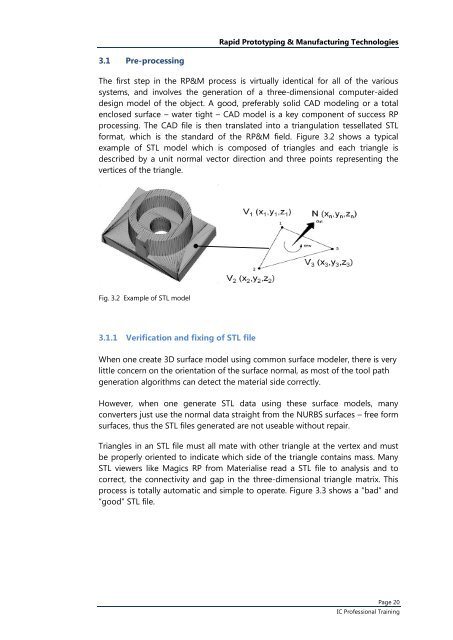
<strong>Rapid</strong> <strong>Pro<strong>to</strong>typing</strong> & <strong>Manufacturing</strong> <strong>Technologies</strong>3.1 Pre-processingThe first step in the RP&M process is virtually identical for all of the varioussystems, and involves the generation of a three-dimensional computer-aideddesign model of the object. A good, preferably solid CAD modeling or a <strong>to</strong>talenclosed surface – water tight – CAD model is a key component of success RPprocessing. The CAD file is then translated in<strong>to</strong> a triangulation tessellated STLformat, which is the standard of the RP&M field. Figure 3.2 shows a typicalexample of STL model which is composed of triangles and each triangle isdescribed by a unit normal vec<strong>to</strong>r direction and three points representing thevertices of the triangle.Fig. 3.2 Example of STL model3.1.1 Verification and fixing of STL fileWhen one create 3D surface model using common surface modeler, there is verylittle concern on the orientation of the surface normal, as most of the <strong>to</strong>ol pathgeneration algorithms can detect the material side correctly.However, when one generate STL data using these surface models, manyconverters just use the normal data straight from the NURBS surfaces – free formsurfaces, thus the STL files generated are not useable without repair.Triangles in an STL file must all mate with other triangle at the vertex and mustbe properly oriented <strong>to</strong> indicate which side of the triangle contains mass. ManySTL viewers like Magics RP from Materialise read a STL file <strong>to</strong> analysis and <strong>to</strong>correct, the connectivity and gap in the three-dimensional triangle matrix. Thisprocess is <strong>to</strong>tally au<strong>to</strong>matic and simple <strong>to</strong> operate. Figure 3.3 shows a “bad” and“good” STL file.Page 20IC Professional Training