2 - vonRoll hydro
2 - vonRoll hydro
2 - vonRoll hydro
- No tags were found...

Create successful ePaper yourself
Turn your PDF publications into a flip-book with our unique Google optimized e-Paper software.
Pressurised piping and fittingsfor gas and water suppliesQuality systemes for secure supply
Catalog pressurised piping and fittingsIntroduction 1Push-in joint products 2Pressure pipe with push-in socket / Sewage pipe with push-in socketAdapter fittings with push-in jointsPush-in joint connectionsAccessories for push-in joint pipingInstallation instructions for push-in joint pipingBicchiere innesto a vite 3tubi pressioneraccordicongiunzioniaccessoriistruzioni di posa per condotte a viteFlanged products 4Pressure pipe with flangesAdapter fittings with flangesInstallation instructions for piping with flange connectionsTapping clamps 5Planning and finishing work 6Cutting pipes to lengthRESICOAT ® RS Repair MaterialInstallation instructions for ducpurPLUS corrosion-protection filmInformation for planners and pipe fittersTransport and storage 7
IntroductionPiping systemsAs one of the most important Swiss manufacturers of piping systems made of ductile cast-iron, <strong>vonRoll</strong> <strong>hydro</strong>develops, manufactures and sells a modular, perfectly matched system of components that meetsall the needs of municipal water and gas suppliers.1For many years now, ductile cast iron, which, apart from its high strength, is also characterised by its elasticity, hasbeen a popular material for the manufacture of pressurised piping.The ecosys® full-protection piping system, which features pipes coated both inside and outside with PUR aswell as fittings protected by an integral coating of epoxy resin, is worth particular mention.This excellent combination of materials and the well-tried sleeve-coupling technology allow this system to offerthe following advantages:• Long service life• Economic pipeline construction• Optimum corrosion prevention – inside and out• Suitable for all types of water from soft to hard• Impeccably hygienic internal lining• High mechanical stability• Excellent flow characteristics• Easy to cut and drill• SVGW certification for drinking water and gasDepending on environmental conditions, pipe-class and dimensions, <strong>vonRoll</strong>’s piping system with sleeveconnectors can be supplied on request for project-specific solutions for over 63 bar: see “pressures for sleevecoupledpiping and adapters to EN 545:2002 standards”, page 6/4.3.The piping systems with sleeve connectors, screw or flange couplings are manufactured using the latesttechnologies and conform to EN 545 and ISO 2531 standards (or, when specially mentioned, our own standards)and have been certified by SVGW / DVGWCoatings for pipes and fittingsecopur ®ducpur ®ecofit ®Mechanically sturdy yet flexible pressure pipe manufactured in ductile cast iron using centrifugalcasting, coated inside and out with corrosion-resistant, smooth polyurethane (PUR).Perfectly suitable for all types of soil.Mechanically sturdy yet flexible pressure pipe manufactured in ductile cast iron using centrifugalcasting, with a corrosion-resistant, smooth polyurethane (PUR) inside lining and zinc/bitumenexternal coating. Together with ducpurPLUS PE-corrosion-prevention foil, also suitable foraggressive soils.Adapter fittings manufactured in ductile cast-iron using sand casting, with integral epoxy resin coating.Perfectly suitable for all types of soil.Subject to alteration without noticephone +41 62 388 14 00, fax +41 62 388 14 20, www.vonroll-<strong>hydro</strong>.ch, info@vonroll-<strong>hydro</strong>.ch1/1
Our catalogue range of pressure pipes and adapter fittingsSleeve-connectorpiping systemFlangedpiping systemLarger nominal diameters available on requestDN 80 100 125 150 200 250 300 350 400 500 600 700Pipes of all diameters are 6 meters longPipe classes according to EN 545 and ISO 2531 standards• Sleeve-coupled pipes K9 standard• Flanged pipes K12 standardOther classes of pipe are available on request.Overview of connection techniquesSleeve connectorsFlanged couplingSealing system Tyton® seal Flat sealConnection variantElectrical conductivityof the coupling systemDeflection withoutrestraint clampDeflection withrestraint clampWith or withoutrestraint clampNot electrically connectedDN 80-300 up to 5°DN 350-400 up to 4°DN 500-700 up to 3°DN 80-700 up to 3°Not electrically connectedNo deflection possibleNo deflection possibleSubject to alteration without noticephone +41 62 388 14 00, fax +41 62 388 14 20, www.vonroll-<strong>hydro</strong>.ch, info@vonroll-<strong>hydro</strong>.ch1/2
Ductile cast ironMaterial characteristics for centrifugally-cast pipes and adapters according to EN 5451Mechanical characteristic Symbol Unit Pipes AdaptersMinimum tensile strength Rm MPa 420 420Yield point Rp 0.2 MPa 300 300Minimum elongation after fracture A % 10 5Minimum vertical pressure rating MPa 550 550Burst pressure rating MPa 300 300Longitudinal bending strength MPa 420 420Density kg/dm3 7,05 7,05Elasticity module E MPa 1,7x10 5 1,7x10 5Thermal expansion coefficient 1/K 10x10 -6 10x10 -6Hardness HB < 230 < 250Ductile cast ironDuctile cast iron with spherically-formed graphite.(Pictured using a scanning electron microscope)Subject to alteration without noticephone +41 62 388 14 00, fax +41 62 388 14 20, www.vonroll-<strong>hydro</strong>.ch, info@vonroll-<strong>hydro</strong>.ch1/3
CoatingsPolyurethane (PUR)Polyurethane protects piping made of ductile cast iron against corrosion and ensures meeting hygienicstandards for drinking water at the same time. Polyurethane is used for both the inside lining and the outsidecoating. Because of polyurethane’s elasticity, the coating remains intact even if the pipe is deformed.The PUR coating was developed in 1972. In comparison with other coatings, the internal polyurethane liningexhibits a high resistance to various different media such as drinking water, wastewater, de-mineralised water,industrial water and gas, as well as to aggressive solutions such as sulphuric acid. The PUR outside coating issuitable for all kinds of soil.Specific properties of PolyurethaneCompositionWall thicknessPolyurethane is composed of a two-component resin.Its three-dimensionally linked molecular structure gives it its mechanicalstability. Polyurethane is a thermosetting plastic with no solvents. It meetsEN 545 and ISO 2531 standardsPolyurethane PUR inside liningDN 80-150 = 1.3 mmDN 200-700 = 1.5 mmPolyurethane PUR outside coating (ecopur ® )DN 80-700 = 0.9 mmColour inside: greenoutside: blackDensity 1.4 – 1.5 kg/dm 3ContinuityBonding strengthDielectric resistancecontinuous coating, no cracks> 14 Mpa(EMPA recommends: 2.5 Mpa on a saturated sample)Bonding strength is tested at regular intervals by our laboratories.> 108 Ωm2Temperature Water: up to 40°C (constant); up to 80°C (short term)Air: 120°CImpact resistance 40 Nm at 20°CEffect of salt sprayno effect after 1000 hoursExpansion > 10%Friction coefficientk > 0.01 mmSubject to alteration without noticephone +41 62 388 14 00, fax +41 62 388 14 20, www.vonroll-<strong>hydro</strong>.ch, info@vonroll-<strong>hydro</strong>.ch1/4
Resistance to chemicals - Acidic or basic with pH values between 1 and 14- Anorganic solvents- Sulphuric acid (wasterwater)- industrial wastewater1Thermal expansion 20 x 10 -6 1/KDepositsUse of chlorineQuality AssuranceCertification for PURnoneThe chlorine concentration in drinking water and the selective amount usedwhen disinfecting have no influence on the quality of the polyurethane.Contract with EMPA in Dübendorf, Switzerland- Swiss Association for Gas and Water (SVGW)- Swiss Federal Office of Health (BAG)- Water Byelaws Advisory Service- Singapore Institute of Standards and Industrial Research- for: Bulgaria, Spain, Italy, Lithuania, Poland, Czech Republic, Rumania etc.Epoxy Resin CoatingThe adapter fittings are provided with an integral coating of epoxy resin with athickness of at least 250µm. Coating with epoxy resin powder is a well-tried andpore-free way of protecting adapters and fittings used in water and gas supplies againstcorrosion. The epoxy resin inside lining, which is as smooth as glass and free of pores,offers comprehensive protection of the foodstuff drinking water, and, of course, fulfils allstatutory requirements on hygiene. The epoxy resin coating is an organic protectivecoating and is environment-friendly in its use.Subject to alteration without noticephone +41 62 388 14 00, fax +41 62 388 14 20, www.vonroll-<strong>hydro</strong>.ch, info@vonroll-<strong>hydro</strong>.ch1/5
Zinc-Bitumen external coatingThe ducpur ® pipes are provided with a zinc-bitumen external coating. The zinc coating is at least150 g/m 2 according to the EN 545 standard. The zinc coating is covered with a layer of bitumen of atleast 70µm.A special property of the zinc coating is its self-healing effect if local damage occurs. A macro-element isformed at the point of damage, whereby the cast-iron surface represents the cathode and the galvanisedsurface of the pipe the anode. The zinc ions migrate to the exposed cast-iron surface an thus cover thedamaged area with a layer of zinc once more.PoresCovering layer of bitumenZincAnnealed surfaceCast-iron raw materialzinc ions Zn++depositionof zinc saltscurrentCovering layer of bitumenZincAnnealed surfaceCast-iron raw materialdamageSubject to alteration without noticephone +41 62 388 14 00, fax +41 62 388 14 20, www.vonroll-<strong>hydro</strong>.ch, info@vonroll-<strong>hydro</strong>.ch1/6
Permissible operating pressures for pipes, adapters and restraint clampsWithout taking up lateral forces(secured against thrust using constructional means)1for waterSleeve connector≤ published operating pressure PFA in barSee table “Pressures according to EN 545:2002 for push-in joint pipes and adapterfittings. Page 6/4.3for gas≤ 1 bar (corresponds to the “low to midle pressure” level as defined in theSVGW guidelines)With mechanical connection that takes up lateral forcesfor water≤ published operating pressure PFA in barSleeve connector See table “Permissible pressures for thrust-resistng rings”. Page 6/4.4FlangeThe values shown in the table (PN) are appropriate to the hole configuration accordingto DIN EN 1092, part 2. These values represent the permissible operating pressure.for gas≤ 1 - 5 bar (corresponds to the “high pressure” level as defined in theSVGW guidelines)For adapter fittings with mixed types of connections (sleeve coupler/flange),the nominal pressure for the flange is decisive.Subject to alteration without noticephone +41 62 388 14 00, fax +41 62 388 14 20, www.vonroll-<strong>hydro</strong>.ch, info@vonroll-<strong>hydro</strong>.ch1/7
LabellingPipes and adapter fittings according to EN 545All pipes and adapter fittings are permanently and legibly labelled with at least the following information:ManufacturerYear of manufactureLabel for ductile cast ironNominal diameter DNNominal pressure for flanges and indicationof this standardWall thickness class, if not K9Cast in the sleeve for pipesCast in the item’s surface for adapter fittingsCast on the flangePrinted on the pipesSealing ringsfor waterfor gasDN, year of manufacture, manufacturer’s code, name of seal, EN 681-1, EPDMDN, year of manufacture, manufacturer’s code, name of seal, EN 682, NBRSubject to alteration without noticephone +41 62 388 14 00, fax +41 62 388 14 20, www.vonroll-<strong>hydro</strong>.ch, info@vonroll-<strong>hydro</strong>.ch1/8
StandardsEN 545Pipes, adapter fittings, accessories made of ductile cast iron and their connections for waterpiping – Requirements and testing procedures1EN 681-1Elastomer seals – Requirements on materials for piping seals for applications in water supply andwastewater disposalEN 805Water supply – Requirements on water supply systems and their components used outside buildingsISO 2531Ductile cast-iron piping, adapter fittings and accessories and their connections for water or gasapplicationsPrEN 682Elastomer seals – Requirements on materials for piping seals for supply piping and associatedcomponents for gas and liquid <strong>hydro</strong>carbonsEN 969Pipes, adapter fittings, accessories made of ductile cast iron and their connections for gas piping– Requirements and testing procedures.Certificates and approvalsPiping systems from <strong>vonRoll</strong> <strong>hydro</strong> sa are SVGW / DVGW certifiedOnly in this way can one be sure that statutory requirements concerning hygiene are perfectly fulfilled and thatall standards and testing procedures are adhered to.Subject to alteration without noticephone +41 62 388 14 00, fax +41 62 388 14 20, www.vonroll-<strong>hydro</strong>.ch, info@vonroll-<strong>hydro</strong>.ch1/9
AbbreviationsDNNominal diameter of pipeDE Outside diameter of pipe as defined in EN 545 and ISO 2531DIEffective calculated pipe inside diameterDI = DE – 2eDMOutside diameter of sleeveTSleeve depth in mm, identical for pipes and adapter fittingse GWall thickness of centrifugally cast pipe made of ductile cast ironK9 according to EN 545 and ISO 2531 standardse PUR1Wall thickness of polyurethane inside lining according to manufacturers standardse PUR2Wall thickness of polyurethane outside coating = 0.9 mmeWall thickness of ducpur ® and ecopur ® K9 sleeve-coupled pipese = e G+ e PUR1+ e PUR2LPipe length in mmPFAOperating pressurePNConnection dimension equivalent to nominal pressure in barSubject to alteration without noticephone +41 62 388 14 00, fax +41 62 388 14 20, www.vonroll-<strong>hydro</strong>.ch, info@vonroll-<strong>hydro</strong>.ch1/10
Push-in joint products 2FigurePageducpur ® pressure pipes with double-chamber socket 2817 2/1.1ducpur ® pressure pipes with single-chamber socket 2815 2/1.1ecopur ® pressure pipes with double-chamber socket 2817 2/1.2ecopur ® pressure pipes with single-chamber socket 2815 2/1.2geopur ® sewage pipes with double-chamber socket 1817 2/1.32geopur ® sewage pipes with single-chamber socket 1815 2/1.3<strong>vonRoll</strong>rock ® pressure pipeswith rock-protection coating ducpur ® 2816 2/2.1<strong>vonRoll</strong>rock ® pressure pipeswith rock-protection coating ducpur ® 2819 2/2.1<strong>vonRoll</strong>rock ® pressure pipeswith rock-protection coating ecopur ® 2816 2/2.2<strong>vonRoll</strong>rock ® pressure pipeswith rock-protection coating ecopur ® 2819 2/2.2<strong>vonRoll</strong>rock ® sewage pipeswith rock-protection coating geopur ® 1816 2/2.3<strong>vonRoll</strong>rock ® sewage pipeswith rock-protection coating geopur ® 1819 2/2.390° -bend, MMQ 2820a.90 2/3.145° -bend, MMK 45 2822a.45 2/3.130° -bend, MMK 30 2823a.30 2/3.222° -bend, MMK 22 2824a.22 2/3.211° -bend, MMK 11 2825a.11 2/3.25° -bend, MMK 5 2826a.5 2/3.390° -bend, MQ 2820.90 2/4.145° -bend, MK 45 2822.45 2/4.130° -bend, MK 30 2823.30 2/4.122° -bend, MK 22 2824.22 2/4.111° -bend, MK 11 2825.11 2/4.2Socket-Tee, UA 2854 2/5.1Socket-Tee, MMB 2856 2/5.2Socket-Tee, MMA 2857 2/5.3-4
FigurePageSocket-Tee-T 2858 2/5.4Spigot-Tee, IT 2859 2/5.4Calibre-change, Taper MMR 2883 2/6.1Collars, U 2870 2/7.1Flange – socket adapter, EU 2877b 2/7.1Flange – socket adapter, EU 2888 2/7.1Flange – spigot adapter, F 2890 2/7.2External thrust-resisting ring 2505 2/8.1External thrust-resisting ring 2506 2/8.1External thrust-resisting ring 2806 2/8.1Internal thrust-resisting ring Tyton-Sit for water 2504-1 2/8.2Internal thrust-resisting ring 2807 2/8.2Tyton seal for water 2810 2/8.3Tyton seal for gas 2811 2/8.3PE-100 connecting piece 5468 2/9.1Neutrex T lubricant 270 2/10.1Transparent corrosion-protection film 300-1 2/10.1Scotchrap 300-2 2/10.1ducpurPLUS corrosion-protection film 310-1 2/10.1Repair-set RESICOAT ® RS- Double-chamber cartridge- Dispenser- Mixing tubeInstallation aids and tools- Set of assembly and laying tools- Hammering accessory- Dismantling leaf- Set of assembly and laying tools- Accu screwdriver284285286254 / 1-5255-1255-2293 / 1-62942/10.22/11.12/11.22/11.22/11.2-32/11.4Installation instructions for push-in joint piping 2/12.1-10
Pressure pipe with push-in socketPressure pipes and adapter fittingsducpur ® pressure pipe with push-in socketMade of ductile cast iron using the centrifugal casting process withPUR (polyurethane) internal lining, outer side zinc sprayed and coatedwith bitumenMinimal pressure loss thanks to hydraulically smooth surface, economic.Application: Drinking water, soft and aggressive water as well as media with pHvaluesbetween 1 and 14.SVGW certification for water and gas pipelines.Manufactured to ISO 2531 and EN 545 standards.Pipe-class standard K9; other classes on request.Permissible system pressure: See "permissible pressures", page 6/4.3.A thrust-resisting ring fig. 2505, 2506, 2806, 2807 can be fitted.Deflection: see "Installation handbook for push-in joint piping".Pipes and adapter fittings – DN 400-600 with standard supporting collar – aredelivered with Tyton seal but without thrust-resisting ring.2Pipe with double-chamber socket Fig. 2817DN L DE e Ge PUR1DM T weightmm mm mm mm mm mm kg/m80 6000 98 6 1.3 167 119 14.0100 6000 118 6 1.3 188 120 16.3125 6000 144 6 1.3 215 123 20.2150 6000 170 6 1.3 242 126 24.0200 6000 222 6.3 1.5 295 131 33.4250 6000 274 6.8 1.5 352 131 45.0300 6000 326 7.2 1.5 410 130 56.3item no.260424260425260426260427260428260429260430suissetec214.118214.119214.121214.122214.123214.124214.125The double-chamber pipe can be fitted with internal thrust-resisting ring (fig. 2807)or external thrust-resisting ring (fig. 2806).Pipe with single-chamber socket Fig. 2815DN L DE e Ge PUR1DM T weightmm mm mm mm mm mm kg/m350 6000 378 7.7 1.5 464 110 70.0400 6000 429 8.1 1.5 518 115 83.6500 6000 532 9 1.5 636 115 113.0600 6000 635 9.9 1.5 750 120 149.0700 6000 738 10.8 1.5 863 150 190.0item no.260431260432260433260434260435suissetec212.126212.127---Subject to alteration without noticephone +41 62 388 14 00, fax +41 62 388 14 20, www.vonroll-<strong>hydro</strong>.ch, info@vonroll-<strong>hydro</strong>.ch 2/1.1
Pressure pipe with push-in socketPressure pipes and adapter fittingsecopur ® pressure pipe with push-in socketMade of ductile cast iron using the centrifugal casting process withPUR (polyurethane) internal lining, external PUR coating.Application: For demanding corrosion conditions. Secure, long service life, minimalpressure loss thanks to hydraulically smooth surface, economic.SVGW certification for water and gas pipelines.Manufactured to ISO 2531 and EN 545 standards.Pipe-class standard K9; other classes on request.Permissible system pressure: See "permissible pressures", page 6/4.3.A thrust-resisting ring fig. 2505, 2506, 2806, 2807 can be fitted.Deflection: see "Installation handbook for push-in joint piping".Pipes and adapter fittings – DN 400-600 with standard supporting collar – aredelivered with Tyton seal but without thrust-resisting ring.Pipe with double-chamber socket Fig. 2817DN L DE e Ge PUR1e PUR2DM T weightmm mm mm mm mm mm mm kg/m80 6000 98 6 1.3 0.9 167 119 14.2100 6000 118 6 1.3 0.9 188 120 16.8125 6000 144 6 1.3 0.9 215 123 20.9150 6000 170 6 1.3 0.9 242 126 24.8200 6000 222 6.3 1.5 0.9 295 131 34.4250 6000 274 6.8 1.5 0.9 352 131 46.5300 6000 326 7.2 1.5 0.9 410 130 57.8item no.260024260025260026260027260028260029260030suissetec212.178212.179212.181212.182212.183212.184212.185The double-chamber pipe can be fitted with internal thrust-resisting ring (fig. 2807)or external thrust-resisting ring (fig. 2806).Pipe with single-chamber socket Fig. 2815DN L DE e Ge PUR1e PUR2DM T weightmm mm mm mm mm mm mm kg/m350 6000 378 7.7 1.5 0.9 464 110 71.7400 6000 429 8.1 1.5 0.9 518 115 85.6500 6000 532 9 1.5 0.9 636 115 115.0600 6000 635 9.9 1.5 0.9 750 120 152.0700 6000 738 10.8 1.5 0.9 863 150 194.0item no.260031260032260033260034260035suissetec212.166212.167---Subject to alteration without noticephone +41 62 388 14 00, fax +41 62 388 14 20, www.vonroll-<strong>hydro</strong>.ch, info@vonroll-<strong>hydro</strong>.ch 2/1.2
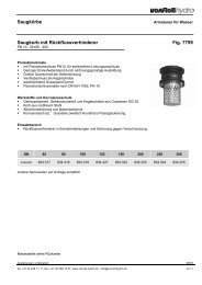
Sewage pipe with push-in socketSewage pipesgeopur ® sewage pipe with push-in socketMade of ductile cast iron using the centrifugal casting process withPUR (polyurethane) internal lining, outer side zinc sprayed and coatedwith bitumenMinimal pressure loss thanks to hydraulically smooth surface, economic.Application: Water and wastewater as well as media with pH-values between1 and 14.Manufactured to EN 598 standards.Pipe-class standard; K7, other classes on request.Permissible system pressure: please contact us.A thrust-resisting ring fig. 2505, 2506, 2806, 2807 can be fitted.Deflection: see "Installation handbook for spigot and socket piping".Pipes and adapter fittings – DN 400-600 with standard supporting collar – aredelivered with Tyton seal but without restraint clamp.2Pipe with double-chamber socket Fig. 1817DN L DE e Ge PUR1DM T weightmm mm mm mm mm mm kg/m100 6000 118 6 1.3 188 120 14.0125 6000 144 6 1.3 215 123 17.4150 6000 170 6 1.3 242 126 20.7200 6000 222 6 1.5 295 131 35.9250 6000 274 6.4 1.5 352 131 45.2300 6000 326 6.4 1.5 410 130 56.3item no.260800260801260802260803260804260805suissetec------The double-chamber pipe can be fitted with internal restraint clamp (fig. 2807)or external restraint clamp (fig. 2806).Pipe with single-chamber socket Fig. 1815DN L DE e Ge PUR1DM T weightmm mm mm mm mm mm kg/m350 6000 378 6.4 1.5 464 110 56.2400 6000 429 6.4 1.5 518 115 67.1500 6000 532 7.0 1.5 636 115 92.5600 6000 635 7.7 1.5 750 120 121.6700 6000 738 8.4 1.5 863 150 152.5800 7000 842 9.1 1.5 974 145 188.9900 7000 945 9.8 1.5 1082 145 228.71000 7000 1048 10.5 1.5 1191 155 272.21200 8260 1255 13.6 1.5 1412 165 395.8item no.260806260807260808260809260810----suissetec---------Subject to alteration without noticephone +41 62 388 14 00, fax +41 62 388 14 20, www.vonroll-<strong>hydro</strong>.ch, info@vonroll-<strong>hydro</strong>.ch 2/1.3
Pressure pipe with push-in socketPressure pipes and adapter fittings<strong>vonRoll</strong>rock ® pressure pipes with rock-protection coating ducpur ®<strong>vonRoll</strong>rock ® pressure pipes with rock-protection coating. These coatedcast-iron pipes are outstandingly suitable for use in rocky ground and areprotected against damage by rocks when back-filling.The robust and hard-wearing coating offers unique performance.The lightweight under cast-iron pipes (see table) is proven to be economicalduring installation in difficult ground conditions and presents no problems whencoping with the most difficult pipe-laying conditions.The protective coating can easily be removed with a knife so that the piping canbe shortened to the required length or can be tapped or a building connectionwithout encountering any problems.Pipe with double-chamber socket Fig. 2816DN L DE e DM T weightmm mm mm mm mm kg/m80 6000 98 8 167 119 14.3100 6000 118 8 188 120 16.7125 6000 144 8 215 123 20.7150 6000 170 8 242 126 24.5200 6000 222 8 295 131 34.1250 6000 274 8 352 131 45.9300 6000 326 8 410 130 57.3item no.-------suissetec214.118214.119214.121214.122214.123214.124214.125The double-chamber pipe can be fitted with internal restraint clamp (fig. 2807)or external restraint clamp (fig. 2806).Pipe with single-chamber socket Fig. 2819DN L DE e DM T weightmm mm mm mm mm kg/m350 6000 378 8 464 110 71.2400 6000 429 8 518 115 84.9500 6000 532 8 636 115 114.7600 6000 635 8 750 120 151.0700 6000 738 8 863 150 192.3item no.-----suissetec212.126212.127---Subject to alteration without noticephone +41 62 388 14 00, fax +41 62 388 14 20, www.vonroll-<strong>hydro</strong>.ch, info@vonroll-<strong>hydro</strong>.ch 2/2.1
Pressure pipe with push-in socketPressure pipes and adapter fittings<strong>vonRoll</strong>rock ® pressure pipes with rock-protection coating ecopur ®<strong>vonRoll</strong>rock ® pressure pipes with rock-protection coating. These coatedcast-iron pipes are outstandingly suitable for use in rocky ground and areprotected against damage by rocks when back-filling.The robust and hard-wearing coating offers unique performance.The lightweight under cast-iron pipes (see table) is proven to be economicalduring installation in difficult ground conditions and presents no problems whencoping with the most difficult pipe-laying conditions.The protective coating can easily be removed with a knife so that the piping canbe shortened to the required length or can be tapped or a building connectionwithout encountering any problems.2Pipe with double-chamber socket Fig. 2816DN L DE e DM T weightmm mm mm mm mm kg/m80 6000 98 8 167 119 14.5100 6000 118 8 188 120 17.2125 6000 144 8 215 123 21.4150 6000 170 8 242 126 25.3200 6000 222 8 295 131 35.1250 6000 274 8 352 131 47.5300 6000 326 8 410 130 58.8item no.-------suissetec212.178212.179212.181212.182212.183212.184212.185The double-chamber pipe can be fitted with internal restraint clamp (fig. 2807)or external restraint clamp (fig. 2806).Pipe with single-chamber socket Fig. 2819DN L DE e DM T weightmm mm mm mm mm kg/m350 6000 378 8 464 110 72.9400 6000 429 8 518 115 86.9500 6000 532 8 636 115 116.7600 6000 635 8 750 120 154.0700 6000 738 8 863 150 196.3item no.-----suissetec212.166212.167---Subject to alteration without noticephone +41 62 388 14 00, fax +41 62 388 14 20, www.vonroll-<strong>hydro</strong>.ch, info@vonroll-<strong>hydro</strong>.ch 2/2.2
Sewage pipe with push-in socketSewage pipes<strong>vonRoll</strong>rock ® sewage pipes with rock-protection coating geopur ®<strong>vonRoll</strong>rock ® pressure pipes with rock-protection coating. These coatedcast-iron pipes are outstandingly suitable for use in rocky ground and areprotected against damage by rocks when back-filling.The robust and hard-wearing coating offers unique performance.The lightweight under cast-iron pipes (see table) is proven to be economicalduring installation in difficult ground conditions and presents no problems whencoping with the most difficult pipe-laying conditions.The protective coating can easily be removed with a knife so that the piping canbe shortened to the required length or can be tapped or a building connectionwithout encountering any problems.Pipe with double-chamber socket Fig. 1816DN L DE e DM T weightmm mm mm mm mm kg/m100 6000 118 8 188 120 14.4125 6000 144 8 215 123 17.9150 6000 170 8 242 126 21.2200 6000 222 8 295 131 36.6250 6000 274 8 352 131 46.1300 6000 326 8 410 130 57.3item no.------suissetec------The double-chamber pipe can be fitted with internal restraint clamp (fig. 2807)or external restraint clamp (fig. 2806).Pipe with single-chamber socket Fig. 1819DN L DE e DM T weightmm mm mm mm mm kg/m350 6000 378 8 464 110 57.4400 6000 429 8 518 115 68.4500 6000 532 8 636 115 94.2600 6000 635 8 750 120 123.6700 6000 738 8 863 150 154.8800 7000 842 8 974 145 191.5900 7000 945 8 1082 145 231.71000 7000 1048 8 1191 155 275.51200 8260 1255 8 1412 165 399.7item no.---------suissetec---------Subject to alteration without noticephone +41 62 388 14 00, fax +41 62 388 14 20, www.vonroll-<strong>hydro</strong>.ch, info@vonroll-<strong>hydro</strong>.ch 2/2.3
Adapter fittings with push-in jointsPressure pipes and adapter fittingsecofit ® bend with push-in socketsAdapter fittings made of ductile cast iron (EN-GJS) to EN 545 standard.Epoxy-resin coating (min. 250 µm) to DIN 3476 standardSingle-chamber socketPipes and adapter fittings – DN 400-600 with standard supporting collar – aredelivered with Tyton seal but without thrust-resisting ring.290°-bend, 2 sockets (MMQ) Fig. 2820a.90DN t weightmmkg80 100 8.0100 125 10.2125 150 14.5150 175 19.1200 225 30.5250 280 45.7300 330 63.7350 410 140.0400 420 128.0500 520 230.0600 620 330.0700 720 486.2item-no.325011325012325013325014325015325016325017325022325018325019325020325021suissetec231.318231.319231.321231.322231.323231.324231.325231.326231.327---45°-bend, 2 sockets (MMK 45) Fig. 2822a.45DN t weightmmkg80 55 7.1100 65 8.8125 75 12.3150 85 15.9200 110 24.6250 130 35.7300 155 48.7350 175 64.9400 195 105.0500 240 139.0600 285 202.0700 330 296.0item-no325036325037325038325039325040325041325042325047325043325044325045325046suissetec231.358231.359231.361231.362231.363231.364231.365231.366231.367---Subject to alteration without noticephone +41 62 388 14 00, fax +41 62 388 14 20, www.vonroll-<strong>hydro</strong>.ch, info@vonroll-<strong>hydro</strong>.ch 2/3.1
Adapter fitting with push-in jointsPressure pipes and adapter fittings30°-bend, 2 sockets (MMK 30) Fig. 2823a.30DN t weightmmkg80 45 6.8100 50 8.3125 55 11.6150 65 14.8200 80 22.0250 95 32.0300 110 43.2350 125 54.5400 150 98.0500 185 125.0600 200 182.0700 230 254.0item-no.325062325063325064325065325066325067325068325073325069325070325071325072suissetec231.378231.379231.381231.382231.383231.384231.385231.386231.387---22°-bend, 2 sockets (MMK 22) Fig. 2824a.22DN t weightmmkg80 40 6.7100 45 8.1125 50 11.2150 55 14.2200 65 21.0250 75 30.7300 90 40.4350 100 50.7400 110 78.0500 130 111.0600 150 157.0700 180 232.0item-no.325088325089325090325091325092325093325094325099325095325096325097325098suissetec231.418231.419231.421231.422231.423231.424231.425231.426231.427---11°-bend, 2 sockets (MMK 11) Fig. 2825a.11DN t weightmmkg80 30 6.5100 35 7.8125 35 10.6150 40 13.4200 45 24.9250 50 34.2300 60 43.0350 65 44.9400 65 72.0500 75 96.0600 85 134.0700 110 200.0item-no.325114325115325116325117325118325119325120325125325121325122325123325124suissetec231.438231.439231.441231.442231.443231.444231.445231.446231.447---Subject to alteration without noticephone +41 62 388 14 00, fax +41 62 388 14 20, www.vonroll-<strong>hydro</strong>.ch, info@vonroll-<strong>hydro</strong>.ch 2/3.2
Adapter fittings with push-in jointsPressure pipes and adapter fittings5°-bend, 2 sockets (MMK 5) Fig. 2826a.5DN t weightmmkgitem-no.suissetec100 30 13.3325139231.459125 35 17.4325140231.461150 35 24.5325141231.462200 40 34.7325142231.463250 50 53.9300 55 69.3325143325144231.464231.4652Subject to alteration without noticephone +41 62 388 14 00, fax +41 62 388 14 20, www.vonroll-<strong>hydro</strong>.ch, info@vonroll-<strong>hydro</strong>.ch 2/3.3
Adapter fittings with push-in jointsPressure pipes and adapter fittingsecofit ® bend with socket and spigotAdapter fittings made of ductile cast iron (EN-GJS) to EN 545 standard.Epoxy-resin coating (min. 250 µm) to DIN 3476 standardSingle-chamber socketPipes and adapter fittings are delivered with Tyton seal but without thrust-resistingring.90°-bend, socket and spigot (MQ) Fig. 2820.90DN t t 1weightmm mm kg80 100 312 10.2100 125 333 11.2125 150 374 16.1150 175 419 21.5200 225 491 35.0item-no.325000325001325002325003325004suissetec231.118231.119231.121231.122231.12345°-bend, socket and spigot (MK 45) Fig. 2822.45DN t t 1weightmm mm kg80 55 265 7.7100 65 274 9.8125 75 301 13.8150 85 331 18.3200 110 374 28.5item-no.325025325026325027325028325029suissetec231.158231.159231.161231.162231.16330°-bend, socket and spigot (MK 30) Fig. 2823.30DN t t 1weightmm mm kg80 45 253 7.4100 50 260 9.4125 55 283 13.1150 65 309 17.2200 80 345 26.5item-no.325051325052325053325054325055suissetec231.178231.179231.181231.182231.18322°-bend, socket and spigot (MK 22) Fig. 2824.22DN t t 1weightmm mm kg80 40 248 7.3100 45 253 9.2125 50 274 12.7150 55 299 16.7200 65 331 25.5item-no.325077325078325079325080325081suissetec231.218231.219231.221231.222231.223Subject to alteration without noticephone +41 62 388 14 00, fax +41 62 388 14 20, www.vonroll-<strong>hydro</strong>.ch, info@vonroll-<strong>hydro</strong>.ch 2/4.1
Adapter fittings with push-in jointsPressure pipes and adapter fittings11°-bend, socket and spigot (MK 11) Fig. 2825.11DN t t 1weightmm mm kgitem-no.suissetec80 30 240 7.1325103231.238100 35 243 8.8325104231.239125 35 261 12.1325105231.241150 40 284 15.7325106231.242200 45 311 24.0325107231.2432Subject to alteration without noticephone +41 62 388 14 00, fax +41 62 388 14 20, www.vonroll-<strong>hydro</strong>.ch, info@vonroll-<strong>hydro</strong>.ch 2/4.2
Adapter fittings with push-in jointsPressure pipes and adapter fittingsecofit ® adapter fittings (1 branch) with push-in jointsAdapter fittings made of ductile cast iron (EN-GJS) to EN 545 standard.Thick epoxy-resin coating (min. 250 µm) to DIN 3476 standardSingle-chamber socket (Fig. 2854 double-chamber)Pipes and adapter fittings – DN 400-600 with standard supporting collar – aredelivered with Tyton seal but without thrust-resisting ring.UNIVERSAL push-in joint tee, double-chamber (UA)Fig. 2854DN 1DN 2PN L h weightbar mm mm kgitem-no.suissetecTo factory standards100 50 10,16,25,40 176 100 20.0261000234.159100 100 10,16 176 100 23.0261002234.119125 50 10,16,25,40 173 110 24.0261003234.161125 100 10,16 173 110 25.0261005234.241150 50 10,16,25,40 170 120 27.0261007234.162150 100 10,16 170 120 28.0261009234.242200 50 10,16,25,40 148 145 38.0261012234.163200 100 10,16 163 145 38.0261014234.243Construction:Double-chamber.Supply includes the adapter fitting with sealing gaskets, stud bolts with nuts andprotective caps.Can be fitted with internal thrust-resisting ring (fig. 2807) or external thrust-resistingring (fig. 2806).Subject to alteration without noticephone +41 62 388 14 00, fax +41 62 388 14 20, www.vonroll-<strong>hydro</strong>.ch, info@vonroll-<strong>hydro</strong>.ch 2/5.1
Adapter fittings with push-in jointsPressure pipes and adapter fittingsTee-connector with 3 sockets (MMB) Fig. 2856DN 1DN 2L h weightmm mm kgitem-no.suissetec80 80 170 85 11.4325145232.418100 80 170 95 13.1325149232.519100 100 190 95 14.1325150232.419125 80 170 105 16.5325146232.521125 100 195 110 17.8125 125 225 110 19.9325151325152232.541232.4212150 80 170 120 19.9325245232.522150 100 195 120 20.9325153232.542150 125 255 125 29.0325154232.562150 150 255 125 25.2325155232.422200 80 175 145 27.2325246232.523200 100 200 145 28.6325156232.543200 125 255 145 31.4325147232.563200 150 255 150 33.4325157232.583200 200 315 155 38.2325158232.423250 100 200 170 37.9325247232.544250 125 200 175 39.9355265232.564250 150 260 175 43.6325148232.584250 200 315 180 49.3325249232.624250 250 375 190 56.0325159232.424300 100 205 195 47.7325250232.545300 125 205 200 48.7355266232.565300 150 260 200 54.3325251232.585300 200 320 205 61.0325160232.625300 250 430 210 80.0325252232.645300 300 435 220 75.0325161232.425400 150 270 270 100.0325253232.587400 200 325 270 110.0325162232.627400 300 440 290 130.0325163232.667400 400 560 280 160.0325164232.427500 100 215 295 108.4325255-500 150 350 345 151.0325404-500 200 425 350 166.0325165-500 250 390 315 185.0325256-500 300 580 350 201.0325166-500 400 565 335 199.2325257-500 500 680 340 244.0325167-600 200 340 355 201.0325168-600 300 460 365 215.0325259-600 400 570 390 250.4325169-600 600 800 400 355.0325171-700 200 345 400 270.6325260-700 400 575 430 345.2355262-700 600 925 430 468.4325264-Subject to alteration without noticephone +41 62 388 14 00, fax +41 62 388 14 20, www.vonroll-<strong>hydro</strong>.ch, info@vonroll-<strong>hydro</strong>.ch 2/5.2
Adapter fittings with push-in jointsPressure pipes and adapter fittingsTee-connector with 2 sockets and a flanged branch (MMA) Fig. 2857DN 1DN 2PN L h weightbar mm mm kg80 80 10,16,25,40 170 165 12.8100 80 10,16,25,40 170 175 14.5100 100 10,16 190 180 15.8125 80 10,16,25,40 170 190 17.9125 100 10,16 195 195 19.3125 125 10,16 225 200 21.6150 80 10,16,25,40 170 205 21.3150 100 10,16 195 210 22.7150 125 10,16 255 220 30.0150 150 10,16 255 250 27.4200 80 10,16,25,40 175 235 28.6200 100 10,16 200 240 30.4200 125 10,16 255 250 32.0200 150 10,16 255 250 36.1200 200 10 315 260 42.2200 200 16 315 260 41.7250 100 10,16 200 270 39.7250 150 10,16 260 280 46.3250 200 10 315 290 42.9250 200 16 315 290 42.9250 250 10 375 300 61.0250 250 16 375 300 60.5300 100 10,16 205 300 50.0300 150 10,16 260 310 57.0300 200 10 320 320 65.0300 200 16 320 320 65.0300 250 10 430 330 74.5300 250 16 430 330 74.5300 300 10 435 340 83.6300 300 16 435 340 83.1350 100 10,16 205 330 59.3350 200 10 325 350 77.2350 200 16 325 350 77.0350 300 10 495 370 110.0350 300 16 495 370 110.0400 100 10,16 210 360 72.0400 150 10,16 270 370 81.4400 200 10 325 380 91.1400 200 16 325 380 90.6400 300 10 440 400 113.5400 300 16 440 400 113.5400 400 10 560 420 135.6400 400 16 560 420 140.6500 100 10,16 215 420 116.0500 150 10,16 275 430 141.0500 200 10 330 440 142.0500 200 16 330 440 141.0500 300 10 450 460 188.2500 300 16 450 460 182.0500 400 10 565 480 199.0Subject to alteration without noticeitem-no.325177325178325174325290325175325176325179325180325181325182325183325184325291325185325186325187325188325189325292325380325190325191325192325193325293325381325294325382325194325195325305325306325307325308325309325402325196325197325198325295325383325199325200325201325404325202325203325297325384325204suissetec233.418233.519233.419233.521233.541233.421233.522233.542233.562233.422233.523233.543233.563233.583233.423-233.544233.584233.624-233.424-233.545233.585233.625-233.645-233.425-233.546233.626-233.666-233.547233.587233.627-233.667-233.427--------phone +41 62 388 14 00, fax +41 62 388 14 20, www.vonroll-<strong>hydro</strong>.ch, info@vonroll-<strong>hydro</strong>.ch 2/5.3
Adapter fittings with push-in jointsPressure pipes and adapter fittingsTee-connector with 2 sockets and a flanged branch (MMA) Fig. 2857DN 1DN 2PN L h weightbar mm mm kg500 400 16 565 480 205.0500 500 10 680 500 232.0500 500 16 680 500 247.0600 100 10,16 220 480 171.0600 150 10,16 280 490 187.0600 200 10 340 500 189.0600 200 16 340 500 189.0600 250 10 395 510 221.0600 250 16 395 510 220.0600 300 10 455 520 240.0600 300 16 455 520 239.0600 400 10 570 540 258.0600 400 16 570 540 263.0600 500 10 685 560 316.0600 500 16 685 560 331.0600 600 10 800 580 340.0600 600 16 800 580 366.0700 200 10 345 525 225.0700 200 16 345 525 366.0700 400 10 575 555 286.0700 400 16 575 555 292.7700 600 10 925 585 457.0700 600 16 925 585 481.0700 700 10 925 600 381.0700 700 16 925 600 396.0item-no.325205325206325207325208325405325209325210325406325412325298325413325211325212325299325414325213325214325215325216325301325385325302325386325219325220suissetec-------------------------2Tee-connector with 2 sockets and a screw branch Fig. 2858DN G L h weightmm mm kg100 2" 161 100 15.3125 2" 180 120 20.0150 2" 224 130 26.0200 2" 215 160 34.0item-no.325370325371325372325373suissetec234.819234.821234.822234.823Spigot Tee-connector (IT) Fig. 2859DN 1DN 2L h weightmm mm kg80 80 540 270 6.5100 100 550 275 14.1150 100 620 320 23.4150 150 620 320 24.3200 200 650 325 35.1item-no.155324155325155326155327155323suissetec234.418234.419234.542234.422234.423Subject to alteration without noticephone +41 62 388 14 00, fax +41 62 388 14 20, www.vonroll-<strong>hydro</strong>.ch, info@vonroll-<strong>hydro</strong>.ch 2/5.4
Adapter fittings with push-in jointsPressure pipes and adapter fittingsecofit ® taper with push-in jointsAdapter fittings made of ductile cast iron (EN-GJS) to EN 545 standard.Thick epoxy-resin coating (min. 250 µm) to DIN 3476 standardSingle-chamber socketsPipes and adapter fittings – DN 400-600 with standard supporting collar – aredelivered with Tyton seal but without thrust-resisting ring.Taper with 2 sockets (MMR) Fig. 2883DN 1DN 2L weightmmkg100 80 90 7.5125 80 140 9.9125 100 100 9.8150 80 190 12.3150 100 150 12.3150 125 100 12.6200 100 250 18.3200 125 200 18.7200 150 150 18.7250 125 300 26.3250 150 250 26.5250 200 150 25.8300 150 350 35.9300 200 250 35.7300 250 150 34.6350 200 360 47.8350 250 260 46.8350 300 160 45.1400 250 360 66.0400 300 260 64.0500 300 500 95.2500 400 260 94.0600 400 460 142.0600 500 260 131.0700 600 280 180.3item-no.325267325268325269325270325271325272325273325274325275325360325276325277325278325279325280325361325362325281325363325364325365325282325283325284325285suissetec236.519236.521236.541236.522236.542236.562236.543236.563236.583236.564236.584236.624236.585236.625236.645236.626236.646236.666236.647236.667-----Subject to alteration without noticephone +41 62 388 14 00, fax +41 62 388 14 20, www.vonroll-<strong>hydro</strong>.ch, info@vonroll-<strong>hydro</strong>.ch 2/6.1
Adapter fittings with push-in jointsPressure pipes and adapter fittingsecofit ® add-in adapter, flange adapter (with push-in joint)Adapter fittings made of ductile cast iron (EN-GJS) to EN 545 standard.Thick epoxy-resin coating (min. 250 µm) to DIN 3476 standardSingle-chamber socketsPipes and adapter fittings – DN 400-600 with standard supporting collar – aredelivered with Tyton seal but without thrust-resisting ring.2Collars (U) Fig. 2870DN PN L weightmmkg80 16 160 8.9100 16 160 10.8125 16 165 13.6150 16 165 16.7200 16 170 23.0250 16 175 31.5300 16 180 40.5item-no.461050461051461052461053461054461055461056suissetec-------Flange – socket adapter, adjustable (EU)Fig. 2877bDN PN L z weightbar mm mm kg80 10,16,25,40 130 86 ± 40 7.5100 10,16 130 87 ± 40 9.1125 10,16 135 91 ± 40 11.4150 10,16 135 92 ± 40 15.3200 10 140 97 ± 40 19.8200 16 140 97 ± 40 19.8250 10 145 102 ± 40 29.2250 16 145 102 ± 40 29.2300 10 150 107 ± 40 36.5300 16 150 107 ± 40 36.0350 10 155 112 ± 40 43.0350 16 155 112 ± 40 46.0700 10 190 147 ± 40 142.1700 16 190 147 ± 40 142.1item-no.325225325226325227325228325229325230325231325232325233325234325243325244325241325242suissetec235.818235.819235.821235.822235.823235.843235.824235.844235.825235.845235.826235.846--Flange – socket adapter (EU) Fig. 2888DN PN L weightbar mm kg400 10 160 52.1400 16 160 57.1500 10 170 76.6500 16 170 76.6600 10 180 106.2600 16 180 106.2Subject to alteration without noticeitem-no.325235325236325237325238325239325240suissetec235.827235.847----phone +41 62 388 14 00, fax +41 62 388 14 20, www.vonroll-<strong>hydro</strong>.ch, info@vonroll-<strong>hydro</strong>.ch 2/7.1
Adapter fittings with push-in jointsPressure pipes and adapter fittingsFlange – spigot adapter (F) Fig. 2890DN PN L weightbar mm kg80 10,16,25,40 350 7.8100 10,16 360 9.7125 10,16 370 12.5150 10,16 380 16.0200 10 400 22.8200 16 400 23.0250 10 420 32.0250 16 420 32.0300 10 440 43.0300 16 440 42.0350 10 460 52.3350 16 460 55.3400 10 480 65.0400 16 480 65.0500 10 520 95.0500 16 520 95.0600 10 560 135.0600 16 560 135.0700 10 600 183.0700 16 600 183.0item-no.155340155341155342155343155344155345155346155347155348155349155338155339155350155351155352155353155354155355155356155357suissetec237.318237.319237.321237.322237.323237.343237.324237.344237.325237.345237.326237.346237.327237.347------Subject to alteration without noticephone +41 62 388 14 00, fax +41 62 388 14 20, www.vonroll-<strong>hydro</strong>.ch, info@vonroll-<strong>hydro</strong>.ch 2/7.2
Push-in joint connectionsPressure pipes and adapter fittingsThrust-resisting rings and sealing gasketsPipes, adapter fittings and valves can be connected to pipes using thrust-resistingrings that take up longitudinal forces.Thrust-resisting ring (external) for <strong>vonRoll</strong> support collar, with weldedbead, not electrically conductingFig. 2505DN PN DF weightbar mm kg400 16 595 47.1item-no.201001suissetec238.8672500 16 710 58.6201002-600 16 826 79.8201003-"Permissible pressures for thrust-resisting rings" page 6/4.4Thrust-resisting ring (external), not electrically conducting Fig. 2506DN PN DF weightbar mm kg400 16 595 43.8"Permissible pressures for thrust-resisting rings" page 6/4.4item-no.211508suissetec238.867Thrust-resisting ring (external), not electrically conducting Fig. 2806DN PN DF weightbar mm kg80 40 235 4.7100 40 256 5.1125 40 287 5.7150 40 310 6.9200 16 325 8.9200 40 325 10.1250 16 421 13.9250 40 421 15.5300 16 479 19.6300 40 479 21.6350 16 534 25.5350 25 534 27.5External thrust-resisting ring for push-in joint connections.Epoxy-resin coated thrust-resisting ring.item-no.262000262001262002262003262004262008262005262009262006262010262007262011suissetec238.838238.839238.841238.842238.843-238.844-238.845-238.846-For pressures > 40 bar, piping of pipe-class K10 or higher should be used.See table "Permissible pressures for thrust-resisting rings" page 6/4.4.Subject to alteration without noticephone +41 62 388 14 00, fax +41 62 388 14 20, www.vonroll-<strong>hydro</strong>.ch, info@vonroll-<strong>hydro</strong>.ch 2/8.1
Push-in joint connectionsPressure pipes and adapter fittingsThrust-resisting ring Tyton-Sit for water (internal) Fig. 2504-1DN PN* weightbarkg80 16 0.2100 16 0.2125 16 0.3150 16 0.3200 16 0.5250 16 0.6300 16 1.0400 16 1.6* 10 bar for ecopur ® pipesTyton-Sit PLUS on requestitem-no.451999452100452101452102452103452104452105452107suissetec238.618238.619238.621238.622238.623238.624238.625238.625Thrust-resisting ring (internal) Fig. 2807DN PN weightbarkg80 25 0.2100 25 0.3125 25 0.3150 25 0.4200 25 0.6250 16 0.7300 16 0.8item-no.455440455441455442455443455444455445455446suissetec238.518238.519238.521238.522238.523238.524238.525Internal thrust-resisting ring for double-chamber socket connections.System pressures: see "Permissible pressures for thrust-resisting rings" page 6/4.4.Subject to alteration without noticephone +41 62 388 14 00, fax +41 62 388 14 20, www.vonroll-<strong>hydro</strong>.ch, info@vonroll-<strong>hydro</strong>.ch 2/8.2
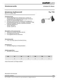
Push-in joint connectionsPressure pipes and adapter fittingsTyton seal for water Fig. 2810DNweightkgitem-no.suissetec80 0.1454976238.118100 0.1454963238.119125 0.2454964238.121150 0.2454965238.122200 0.3250 0.5454966454967238.123238.1242300 0.6454968238.125350 0.8454969238.126400 1.0454970238.127500 1.6451014-600 2.2451015-700 3.1451017-Rubber sealing ring for push-in joints for water, fulfils EN 681-1.Tyton seal for gas Fig. 2811DNweightkg80 0.1100 0.1125 0.2150 0.2200 0.3250 0.5300 0.6Rubber sealing ring for push-in joints for gas, fulfils EN 682.item-no.454152454153454154454155454156454157454158suissetec238.138238.139238.141238.142238.143238.144238.145Subject to alteration without noticephone +41 62 388 14 00, fax +41 62 388 14 20, www.vonroll-<strong>hydro</strong>.ch, info@vonroll-<strong>hydro</strong>.ch 2/8.3
Push-in joint connectionsPressure pipes and adapter fittingsConnecting piecesPE-100 connecting piece (for use in water piping) Fig. 5468DN dR dI L L 1weightmm mm mm mm kg80 90 73.6 286 ±3 170 1.5100 110 90 310 ±3 194 2.2100 125 102.2 330 ±3 214 2.6125 140 114.6 330 ±3 214 3.8150 160 130.8 354 ±5 234 4.8150 180 147.2 380 ±5 260 5.1200 200 163.6 395 ±5 270 8.0200 225 184 413 ±5 288 8.9200 250 204.6 395 ±5 270 8.6item-no.956709567195672956739567495675956769567795678suissetec237.518237.519237.519237.521237.522237.522237.523273.523237.524For use when making connections between slide-valves or piping componentswith push-in joints (double-chamber system) and plastic piping: The push-in jointmust be fitted with a thrust-resisting ring (Fig. 2807).Subject to alteration without noticephone +41 62 388 14 00, fax +41 62 388 14 20, www.vonroll-<strong>hydro</strong>.ch, info@vonroll-<strong>hydro</strong>.ch 2/9.1
Accessories for push-in joint pipingPressure pipes and adapter fittingsInstallation material for push-in joint pipesNeutrex T lubricant Fig. 270weightg250.0 -item-no.452533suissetec-Lubricant for the installation of pipes made of ductile cast ironTransparent corrosion-protection film Fig. 300 - 12DN b weightmmkg/m80 350 0.1100 350 0.1125 400 0.2150 500 0.2200 600 0.2250 700 0.3300 800 0.3350 800 0.3400 950 0.4500 1150 0.5600 1300 0.5item-no.450541450541450542450543450544450545450546450546450547450548450549suissetec281.118281.119281.121281.122281.123281.124281.125281.126---Scotchrap Fig. 300 - 2B length per roll weightmm m kg50 30 0.5item-no.452552suissetec-ducpurPLUS corrosion-protection film Fig. 310 - 1DN b weightmmkg/m80 350 0.1100 350 0.1125 400 0.2150 500 0.2200 600 0.2250 700 0.3300 800 0.3350 800 0.3400 950 0.4500 1150 0.5600 1300 0.5item-no.450532450532450533450534450535450536450537450537450538450539450540suissetec281.118281.119281.121281.122281.123281.124281.125281.126---Subject to alteration without noticephone +41 62 388 14 00, fax +41 62 388 14 20, www.vonroll-<strong>hydro</strong>.ch, info@vonroll-<strong>hydro</strong>.ch 2/10.1
Accessories for push-in joint pipingPressure pipes and adapter fittingsRepair-set RESICOAT ® RSRESICOAT ® RS is a ready-to-use, two-component solvent freeepoxy-repair materialpacked in the correct mixing ratio of 2:1.Colour: blueDouble-chamber cartridge Fig. 284weightg100item-no.451223suissetec-Dispenser Fig. 285weightg180item-no.451224suissetec-Mixing tube Fig. 286weightitem-no.suissetec1451225-Subject to alteration without noticephone +41 62 388 14 00, fax +41 62 388 14 20, www.vonroll-<strong>hydro</strong>.ch, info@vonroll-<strong>hydro</strong>.ch 2/10.2
Accessories for push-in joint pipingPressure pipes and adapter fittingsSet of assembly and laying tools, complete Fig. 254 / 1-5DNweightkg400 56.8500 59.4600 62.7700 75.0item-no.201118201121201123201125suissetec----DN 300 auf Anfrage2Spigot collar Fig. 254 - 1DNweightkg400 12.6500 12.8600 14.0700 20.3item-no.451118451121451123451125suissetec----Socket collar Fig. 254 - 2DNweightkg400 15.0500 17.4600 19.5700 25.5item-no.451119451122451124451126suissetec----Hydraulic unit (1 pair) Fig. 254 - 3DNweightkg400 - 700 28.9item-no.451120suissetec-Groove scraper Fig. 254 - 4DNweightkg400 0.1500 - 700 0.1suissetec--Checking rule Fig. 254 - 5DNweightkg400 - 700 0.1item-no.451048suissetec-Subject to alteration without noticephone +41 62 388 14 00, fax +41 62 388 14 20, www.vonroll-<strong>hydro</strong>.ch, info@vonroll-<strong>hydro</strong>.ch 2/11.1
Accessories for push-in joint pipingPressure pipes and adapter fittingsHammering accessory Fig. 255 - 1DNweightkg80 - 100 0.7125 - 150 0.7200 - 300 0.7item-no.456577456578456579suissetec---Dismantling leaf Fig. 255 - 2DN Number weightkg80 4 0.1100 5 0.1125 6 0.1150 7 0.1200 9 0.1250 12 0.1300 15 0.1item-no.456581456581456581456581456581456581456581suissetec-------Set of assembly and laying tools, complete Fig. 293 / 1-6DNweightkg80 18.7100 19.0125 19.2150 19.5200 20.5250 21.0300 22.5350 23.0item-no.201180201181201182201183201184201185201186201187suissetec--------Spigot collar Fig. 293 - 1DNweightkg80 5.0100 5.5125 5.5150 5.5200 6.0250 6.0300 7.3350 7.5item-no.451180451181451182451183451184451185451186451187suissetec--------Subject to alteration without noticephone +41 62 388 14 00, fax +41 62 388 14 20, www.vonroll-<strong>hydro</strong>.ch, info@vonroll-<strong>hydro</strong>.ch 2/11.2
Accessories for push-in joint pipingPressure pipes and adapter fittingsSocket collar Fig. 293 - 2DNweightkgitem-no.suissetec80 5.0451270-100 5.5451271-125 5.7451272-150 6.0451273-200 6.4250 6.8451274451275--2300 7.1451276-350 7.5451277-Open-ended spanner (1 pair) Fig. 293 - 3DNweightkg80 - 350 7.8item-no.451106suissetec-Groove scraper Fig. 293 - 4DNweightkg80 - 150 0.1200 - 350 0.1suissetec--Checking rule Fig. 293 - 5DNweightkg80 - 350 0.1item-no.451048suissetec-Extensions for the installation of VS 5000 slide-valves (1 pair) Fig. 293 - 6DNweightkg80 - 200 0.0Subject to alteration without noticephone +41 62 388 14 00, fax +41 62 388 14 20, www.vonroll-<strong>hydro</strong>.ch, info@vonroll-<strong>hydro</strong>.ch 2/11.3
Accessories for push-in joint pipingPressure pipes and adapter fittingsAccu screwdriver PIW 14.4SD Fig. 294weightkg2.1 -Technical data14.4.Volt / 1.4 – 2.4 AhIdling speed 0 –2200 rpmHammer 0-2500 blows/minTorque 158 NmWeight – without accu-pack 1.6 kgWeight with accu-pack 2.1 kgLength 193 mmChuck 1/2" squareStandard scope of supply:2x 14.4 V / 1.4 Ah NiCd flatpack accu-packRCA 7224MB chargerABS system caseM20 hexagonal socket-wrench insertitem-no.451400suissetec-Subject to alteration without noticephone +41 62 388 14 00, fax +41 62 388 14 20, www.vonroll-<strong>hydro</strong>.ch, info@vonroll-<strong>hydro</strong>.ch 2/11.4
Installation instructions for push-in joint piping1. General remarksFollowing the instructions below will guaranteeprofessional and correct installation work.2. Removal of caps and dummy plugsOnly remove caps and dummy plugs on-site just before the pipe is laid.2Environmental protection:The caps and dummy plugs are designed to be one-way material.They are made of environment-friendly plastics (green polyethylene andblack ethylene-propylene).A practical way to reuse them is to use them as a protective cushionbetween the pipe body and trench bottom or levelling (e.g. cement slabs).If they are disposed of in an appropriate waste incineration plant,no poisonous or corrosive pollutants are produced.3. Cleaning the socketsCheck that the insides of the socket around the retainer groove (A) andthe sealing chamber (B) are clean.For ducpur ® pipes, bitumen residue and/or other deposits can beremoved using the groove scraper.ecopur ® pipes, adapter fittings and slide-valves are only to becleaned with a cloth.The use of groove scrapers is forbidden.4. Lubricating the socketsUsing a brush, apply the lubricant specially suitable for push-in jointconnections to the sealing chamber (B).The retainer groove (A) should not be lubricated.Subject to alteration without noticephone +41 62 388 14 00, fax +41 62 388 14 20, www.vonroll-<strong>hydro</strong>.ch, info@vonroll-<strong>hydro</strong>.ch 2/12.1
5. Inserting the sealing rings (Fig 2810 / 2811)5.1 The sealing ring is inserted by hand.5.2 Press any bulge remaining flat.5.3 If you have trouble pressing the seal flat, make a second bulge onthe opposite side. These two smaller bulges can then be easilypressed flat.5.1 5.2 5.3The hard edge of the sealing ring should not be allowed to jutout above the aligning ridgeNote:Sealing rings should be stored away from sunlight and moisture(see "transport and storage").They should only be fitted in the sockets just before pipe installation.In winter, it is recommended that the sealing rings be stored in a warmroom – this makes their fitting easier.rightwrong6. Cleaning and lubricating the spigots of pipes andadapter fittings and the socket6.1 Cleaningducpur ® -pipes should be cleaned with a triangular scraper. Ifnecessary, accumulations of coating material and/or otherdeposits should be removed from the spigots.ecopur ® -pipes, adapter fittings and slide-valves are only to becleaned using cloths and sponges.6.2 LubricatingThe spigots and the sealing ring in the socket should be evenlycovered with installation lubricant.Subject to alteration without noticephone +41 62 388 14 00, fax +41 62 388 14 20, www.vonroll-<strong>hydro</strong>.ch, info@vonroll-<strong>hydro</strong>.ch 2/12.2
7. Centring and alignment of push-in joint jointsAttention!If the connection is to be secured with an optional thrust-resisting ring,this must first be installed as described in section 12.- Using a wooden roller, insert the spigot of the pipe into the socketso that it is centred in the sealing ring.In this position, the pipes will centre themselves automatically.- The axes of the pipeline components (pipes, adapters and fittings)must all lie on a straight line.28. AssemblyAfter centring as described in section 7, the final assembly of the pipescan be carried out by using various different methods.The various methods described below are suitable for push-in jointjoints with or without thrust-resisting rings.During and after assembly, the depth of insertion must bechecked. See sections 9 and 108.1 Assembly using the assembling and laying tool (Fig. 293)for DN 80 – 350 pipes and adapter fittingsAfter centring, the pipeline components can be quickly andeasily put together using the assembling and laying tool (Fig. 293).Two open-ended spanners are used to operate the appliance.Attention!When assembling a push-in joint connection with an internalthrust-resisting ring (Fig. 2807), interlocking is achieved by makingtwo or three jerky movements with the spanners in oppositedirections.8.2 Assembly using the assembling and laying tool (Fig. 293)for DN 80 – 200 slide-valves with spigotFor this, two extension pieces, 2 bolts and 2 split pins are needed.Subject to alteration without noticephone +41 62 388 14 00, fax +41 62 388 14 20, www.vonroll-<strong>hydro</strong>.ch, info@vonroll-<strong>hydro</strong>.ch 2/12.3
8.3 Montage Assembly mit using dem the Verlegegerät assembling Fig. and 254 laying tool (Fig. 254)für for Rohre DN 400 und – 700 Formstücke pipes and DN adapter 400-700 fittingsDas The Verlegegerät assembling and wird laying hydraulisch tool operated betätigt und hydraulically ist für das and isZusammenfügen designed for putting von push-in Steckmuffen joints ausgelegt. together.Assembly of adapter fittings and slide-valves with socketMontageconnectionsderusingSteckmuffenformstückethe assembling andundlayingSchiebertool (Fig.mit254).demVerlegegerät Fig. 2548.4 Montage Assembly mit using dem the Verlegegerät assembling Fig. and 252 laying tool (Fig. 252)für for Rohre DN 200 und – 600 Formstücke pipes and DN adapter 200–600 fittingsSchutz The appliance der Geräte is protected gegenüber against Überbeanspruchung overload by a torque-limiter mittelsDrehmomentauslösung on its crank. an der Kurbel.Für For ecopur-Rohre ® pipes, müssen sheathed geschützte wire rope Seilstruppenslings must be used.verwendet werden.Wird If the die pipeline Rohrleitung is protected mittels using ducpurPLUS-Korrosions-Schutzfolieprotective film,geschützt, installation erfolgt should die be Montage carried out analog. as shown.Assembly of adapter fittings and slide-valves with socketMontage connections der using Steckmuffenformstücke the assembling and und laying Schieber tool (Fig. mit 252). demVerlegegerät (sheathed wire Fig. rope 252 slings should be used)(geschützte Seilstruppen verwenden).8.5 Assembly without assembly and laying tool8.5 Montagevarianten Installation using a ohne digger Verlegegerät shovel or winch-AMontagesquare piecemitofBaggerlöffeltimber shouldundalwaysStosswindebe used to protect thepipeBeimfromSteckendamage.der Rohre ist unbedingt ein Kantholz zwischendem Rohr und der Stosswinde zu verwenden.Assembly using a crowbar for DN 80 – 100For the installation of push-in joint pipes, adapter fittings(except bends) and slide-valves. The crowbar is not includedin delivery.- Montage mit Hebeisen (Brechstange) für DN 80-100Assembly Montage für using Steckmuffenrohre, two chain-hoists -Formstücke in opposition (exkl. Bogen) undTo -Schieber. used under Das Hebeisen difficult conditions ist im Lieferprogramm or for large diameters. nicht enthalten.- Montage mit zwei gegenüber angesetzten KettenzügenFor Anwendung ecopur ® pipes bei schweren only sheathed Verhältnissen wire sowie rope slings bei grossen andstirrups Nennweiten. and textile belts may be used.Für ecopur-Rohre sind nur geschützte Drahtseilstruppenund Bügel sowie Textiltraggurten zugelassen.Subject to alteration without noticephone +41 62 388 14 00, fax +41 62 388 14 20, www.vonroll-<strong>hydro</strong>.ch, info@vonroll-<strong>hydro</strong>.ch 2/12.4
8.6 Montage Assembly von of shortened Steckmuffenkurzrohren DN 80– 700 pipes DN with 80-700 push-in jointsMontage Installation analog as in sections Pkt. 8.1-8.5.to 8.5.Das Pipes Zuschneiden should be shortened des Rohres to the auf die required gewünschte length as Länge described istanalog under "Shortening „Kürzen von pipes". Rohren“ auszuführen.Ein „Aufstellen“ der Kurzrohre während des Steckvorganges kannThe short pipes can be prevented from getting out of line whenwie folgt verhindert werden:being installed as follows:Bei DN 80-150 durch Einschieben einer Verlängerung- For DN 80 – 150 by using an extension (e.g. pipe, piece of timber etc.)(z.B. Gussrohr, verkeilter Holzbalken, etc.) und Gleichgewichtsbelastungmit dem Körpergewicht.and balancing out using body weight.- For DN 200 – 700 by installing a brace across the top ofBei DN 200-700 durch Errichten einer Spriessung über demthe short pipe.Scheitel des Kurzrohres.Nach After the Beendigung completion der of Montage installation sind work, die verwendeten all pieces of Holzunterlagenetc. used are unbedingt unconditionally zu entfernen to be !timberremoved!29. 9. Inspection Kontrolle during während and after und nach installation der MontageWährend During and und after nach installation, der Montage the insertion muss die depth Einstecktiefe should be überwacht monitored.werden. The distance between the spigot and the bottom of the socket shouldDer be kept Spielraum within zwischen a tolerance dem (S) of Rohrspitzende 5 – 10 mm. und dem Muffengrundmuss innerhalb der Toleranz (S) = 5-10 mm sein.9.1 9.1 Steckmuffenverbindungen Push-in joints with double-chamber mit DoppelkammermuffesocketDN 80-300 – 300 (Rohre) (pipes)Lage The position der silbergrauen of the silver-grey Markierungslinie marking lines für Steckmuffenverbindungen:are asfor socket connectionsfollows:ohne Without Schubsicherungthrust-resisting jointsIst If the der end Rand of the der socket Rohrmuffe is flush bündig with mit the der first ersten marking Markierungsliniethe spigot liegt das is positioned Rohrspitzende correctly richtig in in the der socket.line,Muffe.With internal thrust-resisting ring Fig. 2807mit If the Schubsicherung edge of the rubber innenliegend sleeve of the Fig. restraining 2807 ring is flush withIst the der second Rand marking der Gummimanschette line, the spigot is des positioned Schubsicherungsringscorrectly in the socket.bündig mit der zweiten Markierungslinie, liegt das Rohrspitzenderichtig With external in der Muffe. thrust-resisting ring Fig. 2806If the end of the socket is flush with the first marking line, themitspigotSchubsicherungis positioned correctlyaussenliegendin the socket.Fig. 2806IstThederthrust-resistingRand der Rohrmuffering maybündigonly bemitfittedderaftererstentheMarkierungsliniesealing ringhas beenliegt dascheckedRohrspitzendeaccordingrichtigto sectionin der10.Muffe.Die Schubsicherung darf erst montiert werden, wenn die9.2KontrollePush-in jointsdes Dichtungsringswith single-chamberanalog Pkt.socket10 erfolgt ist.DN 350 – 700 (pipes and adapter fittings)9.2 Steckmuffenverbindungen DN 80 – 300 (adapter fittings) mit EinkammermuffeDN with 350-700 external (Rohre thrust-resisting und Formstücke), rings Figs. 2806, 2505, 2506DN 80-300 (Formstücke)mit DN 350 Schubsicherung – 700 pipes and aussenliegend adapter fittings Fig. with 2806, and 2505, without 2506thrust-resisting ringsRohre If the end und of Formstücke the socket is flush DN 350-700 with the ohne first marking und mit line, Schubsicherungspigot is positioned correctly in the socket.theIst der Rand der Rohrmuffe bündig mit der ersten MarkierungslinieDN 80 liegt – das 300 Rohrspitzende adapter fittings richtig in der Muffe.Formstücke Measure insertion DN 80-300 depth and apply a marking line on the spigotEinstecktiefe as described messen in section und 12.2 Markierungslinie auf dem Spitzendeanbringen analog Pkt. 12.2.Subject to alteration without noticephone +41 62 388 14 00, fax +41 62 388 14 20, www.vonroll-<strong>hydro</strong>.ch, info@vonroll-<strong>hydro</strong>.ch 2/12.5
10. Correct positioning of the sealing ringImmediately after installation as described in section 8, the distance (U)between the end of the socket and the sealing ring should be checkedusing the control gauge (A)The distance (U) must be consistent over the whole of the pipe’scircumference.If the measured distance (U) is not consistent, the push-in jointconnection must be dismantled and installed anew.11. Deflection of the connection for installations without thrust-resisting jointsAfter assembling and checking have been completed,the pipe can be deflected.The permissible angles of deviation are as follows: 5° for DN 80 – 300 (with Tyton seal) 4° for DN 350 – 400 (with Tyton seal) 3° for DN 500 – 700 (with Tyton seal)For connection deviation for installations with thrust-resistingrings see section 12.12. Fitting of external and internal thrust-resisting ringsExternal and internal thrust-resisting rings can be additionally fitted tothe push-in joint.These thrust-resisting rings provide a secure connection under highoperating pressure.For permissible operating pressures see "Information for planners andpiping installers".Thrust-resisting rings may only be fitted to pipes and adapter fittingswith spigots that are made of ductile cast iron.12.1 Internal thrust-resisting rings (Fig. 2807)Preparation and installation of sealing ring as describedin sections 1 – 6.- Lubrication of the thrust-resisting ring chamber.- Make a bulge in the thrust-resisting ring (C) by pinching it by hand.Attention!The bulge must lie between two locking segments.Subject to alteration without noticephone +41 62 388 14 00, fax +41 62 388 14 20, www.vonroll-<strong>hydro</strong>.ch, info@vonroll-<strong>hydro</strong>.ch 2/12.6
Fit - Schubsicherungsring the thrust-resisting ring (C) (C) in die into Schubsicherungskammerits chamber. The numberof einsetzen. stainless-steel Die Anzahl segments der Edelstahlsegmente varies depending on variiert the size nach of the derthrust-resisting Grösse des Schubsicherungsringes.ring.The Gummi-Lippe rubber lip must nach be aussen on the montieren. outsideThe - Rohrspitzende, spigot end, the eingesetzter sealing ring Dichtring and the und thrust-resisting der Schubsicherungsringbe coated werden evenly rundum with gleichmässig installation lubricant. mit Montagefettringshouldbestrichen.Installation and checking of the push-in joint connection asdescribed in sections 7 – 10.2If necessary, the pipes can be deflected (α max. 3°) after installation.- Montage und Kontrolle der Steckmuffenverbindunganalog Pkt. 7-10.- Wenn notwendig können die Rohre nach der Montage,12.2 External thrust-resisting rings (Fig. 2806)max. 3°, abgewinkelt werden.Preparation and installation of sealing ring as describedin sections 1 – 6Using the appropriate template, the insertion depth (I) for adapterfittings (single-chamber socket) is as follows:80 mm for DN 80/100/12512.2 Aussenliegende Schubsicherungen Fig. 280685 mm for DN 150Vorbereitung und einsetzen des Dichtungsrings analog Pkt. 1–6.90 mm for DN 200/250100 - Mit mm entsprechender for DN Schablone 300/350beträgt die Einstecktiefe (l) fürFormstücke (Einkammermuffe):or, 80 for mm pipes, UN1 bei and slide-valves DN 80/100/125, (double-chamber socket):11085 mm mm for bei DN DN 80/100/125 150,11590 mm mm for bei DN DN 150200/250120 100 mm mm for bei DN DN 200/250/300 300/350Mark respektive insertion depth at (A).für Rohre, UNI 1 und Schieber (Doppelkammermuffe):- Slide 110 mm thrust-resisting bei ring DN (1) 80/100/125, and retainer ring (2) onto the endof 115 the mm pipe. bei DN 150,120 mm bei DN 200/250/300,- Insert bei (A) the Einstecktiefe pipe using markieren. the assembling and laying tool (Fig. 293)up to the mark (A).- Schubsicherungsring (1) und Haltering (2) auf das Rohrendeschieben.- Slide parts (1) and (2) up to the end of the socket to position (A).- Rohr mit Verlegegerät Fig. 293 bis zur Markierung (A)- Tighten montieren. up the fang bolts (3) and nuts (4) diagonally to 120 Nm.(With spanner or accu percussion screwdriver Fig. 294)- Die Teile (1) und (2) bis zur Position (A) an die Steckmuffeschieben.- After completing installation and checking, the pipes- may Die Hakenschrauben deflected. (3) und Muttern (4) mit einem DrehmomentThe von permissible 120 Nm über angle Kreuz of anziehen. deviation α is max. 3°.(Mit Schlüssel oder Akku-Schlagschrauber Fig. 294)- Nach Beendigung der Montage und Kontrolle dürfen die Rohreausgelenkt werden.Der zulässige Auslenkungswinkel beträgt max. 3°.Subject to alteration without noticephone +41 62 388 14 00, fax +41 62 388 14 20, www.vonroll-<strong>hydro</strong>.ch, info@vonroll-<strong>hydro</strong>.ch 2/12.7
12.3 Aussenliegende Schubsicherungen Fig. 250612.3 External Vorbereitung thrust-resisting und einsetzen rings des Dichtungsrings (Fig. 2506) analog Pkt.1–6.Preparation and installation of sealing ring as described in sections 1 – 6.- Schubsicherungsring (A) und Haltering (B) auf Spitzende- Slideschiebenthrust-resisting ring (A) and retainer ring (B) onto the spigotof the pipe.Zentrieren analog Pkt. 7 und mit dem Verlegewerkzeug das- Centre as described in section 7. Using the installation appliance,Spitzende analog Pkt. 8 soweit in die Muffe schieben, bis dasslide the spigot into the socket (as described in section 8) soEnde des eingefügten Rohres in einer Distanz (S ) von 5–10 mmthat the end of the inserted pipe is at a distance (S) of 5 – 10 mmzum Muffengrund steht.from the bottom of the socket.-- Kontrollen während und nach der Montage analog Pkt. 9-10.- Make checks during the installation as described in sections 9 – 10.Den Haltering (B) bis zur Muffe des Rohres Schubsicherungsringüber den Haltering schieben.- Slide the retainer ring (B) up to the end of the socket. Slide the- Hakenschrauben thrust-resisting ring (C) over von the der retainer Rückseite ring. des Schubsicherungsringeseinführen und die Muttern soweit wie möglich von Hand- Insert aufdrehen. the fang bolts (C) from the rear of the thrust-resisting ringand (Es ist screw darauf on zu the achten, nuts as dass tightly die as Schraubenanlagefl possible by hand. ächen am(Pay Muffenbund attention und that Schubsicherungsring the contact areas of anliegen.) the screws are positionedcorrectly on the socket bell and the restraint-clamp ring).- Die Hakenschrauben (C) und Muttern (D) mit einem Drehmomentvon 120 Nm über Kreuz anziehen.- Tighten up the fang bolts (C) and nuts (D) diagonally to 120 Nm.(Mit Schlüssel oder Akku-Schlagschrauber Fig. 294)(With spanner or accu percussion screwdriver Fig. 294)- Nach Beendigung der Montage und Kontrolle dürfen die Rohre- After ausgelenkt completing werden. installation and checking, the pipes maybe Der deflected. zulässige The Auslenkungswinkel permissible angle α beträgt of deviation max. α 3°. is max. 3°.12.4 Aussenliegende Schubsicherungen Fig. 2505für Rohre mit SchweisswulstVorbereitung und einsetzen des Dichtungsrings analog Pkt. 1–6.12.4 External thrust-resisting rings (Fig. 2505) for pipeswith- Schubsicherungsringwelded bead(A) und Haltering (B) auf SpitzendePreparationschiebenand installation of sealing ring as described insections 1 – 6.- Slide thrust-resisting ring (A) and retainer ring (B) onto the spigotof the pipe.Subject to alteration without noticephone +41 62 388 14 00, fax +41 62 388 14 20, www.vonroll-<strong>hydro</strong>.ch, info@vonroll-<strong>hydro</strong>.ch 2/12.8
- Zentrieren analog Pkt. 7 und mit dem Verlegewerkzeug das- Spitzende Centre as analog described Pkt. in 8 section bis zur Markierungslinie 7. Using the installation die Muffe appliance,schieben. slide the spigot into the socket (as described in section 8)up to the line marked on the pipe.- Kontrollen während und nach der Montage analog Pkt. 9-10.- Den Haltering (B) bis zur Muffe des Rohres vorschieben.-SchubsicherungsringMake checks during theüberinstallationden Halteringas describedschieben und zentrierenin sections(z.B. mit92–Hartholzkeilen).10.- Hakenschrauben Slide the retainer (C) ring von (B) der up to Rückseite the end des of the Schubsicherungsringescentre einführen it (e.g. with und two die hard-wood Muttern soweit wedges). wie möglich von Handsocket andaufdrehen.- (Es Insert ist darauf the fang zu bolts achten, (C) from dass the die rear Anlagefl of the ächen thrust-resisting am Muffen-rinbund screw und on Schubsicherungsring the nuts as tightly as possible anliegen.) by hand. (Payand- DieattentionHakenschraubethat the contact(C) undareasMutterof the(D) mitscrewseinemareDrehmomentpositionedvoncorrectly120 Nmonüberthe socketKreuzbellanziehen.and the restraint-clamp ring).(Mit Schlüssel oder Akku-Schlagschrauber Fig. 294)- Tighten up the fang bolts (C) and nuts (D) diagonally to 120 Nm.- Nach (With Beendigung spanner or accu der Montage percussion und screwdriver Kontrolle dürfen Fig. 294) die Rohreausgelenkt werden.- Der After zulässige completing Auslenkungswinkel installation and checking, α beträgt max. the pipes 3°. may bedeflected.The permissible angle of deviation α is max. 3°.213. Demontage Dismantling der push-in SteckmuffenverbindungjointsBei der Demontage ist zu unterscheiden, ob die SteckmuffenverbindungThe dismantling mit oder method ohne varies Schubsicherung depending on zu if demontieren the connection ist. is fittedwith a thrust-resisting ring or not.13.1 Demontage der Steckmuffenverbindung ohne Schubsicherunga push-in joint without thrust-resisting 13.1 Dismantling rings- Mit Hilfe des Verlegegerätes Fig. 293- Mit With Gabelschlüsseln the help of the in assembling Richtung der and Verbindung laying tool drücken. Fig. 293Press the open-ended spanners in the direction of theconnection.- With the help of the assembling and laying tool Fig. 254Reverse the oil-flow in the hydraulics by changing over the- Mit valve Hilfe levers. des The Verlegegerätes cylinders are pushed Fig. 254 out by pumping the leversOelfl and uss the in connection den Hydraulikgeräten will be released. mittels Umstellen der Ventilhebelumkehren. Durch Pumpen an den Hebeln wird derZylinder Dismantling ausgefahren of push-in und joint die connections Verbindung that demontiert. were made along time ago:Demontage Push metal von dismantling Steckmuffenverbindungen, leaves (Fig. 255-2) between die vor längerer the spigotZeit and erstellt the sealing worden ring sind: using the special hammering accessoryEntriegelungsbleche (Fig. 255-1) Fig. 255-2 zwischen Rohrspitzende undDichtring einschlagen unter Verwendung der SchlagköpfeFig. 255-1.Ausgebaute Used sealing Dichtringe rings should dürfen never nicht be weiterverwendetreused.werden.Subject to alteration without noticephone +41 62 388 14 00, fax +41 62 388 14 20, www.vonroll-<strong>hydro</strong>.ch, info@vonroll-<strong>hydro</strong>.ch 2/12.9
-– Mit With Hilfe the des help Verlegegerätes of the assembling Fig. and 252 laying tool Fig. 252Anordnung Place the steel der Seilstruppen cables and the und winch der Winde as shown, analog Abbildung.-Demontage Mit Hilfe des der Verlegegerätes Verbindung durch Fig. Ausfahren 252Dismantle the connection by driving the rack out. der Zahnstange.Anordnung hartnäckigen der Fällen SeilstruppenIn difficult cases, this appliance kann dieses und dercan Gerät Windealso be auch analogused für for Nennweiten Abbildung.pipediametersDN derunterhalb Demontageunder 200 VerbindungDN eingesetzt durch200 werden. Ausfahren der Zahnstange.In hartnäckigen Fällen kann dieses Gerät auch für Nennweitenunterhalb DN 200 eingesetzt werden.13.2 Dismantling a push-in joint with internalthrust-resisting ring Fig. 280713.2 Demontage der Steckmuffenverbindungmit - With innenliegender the help of the Schubsicherung assembling and laying Fig. 2807 tool Fig. 293,13.2 Demontage pull in the spigot der Steckmuffenverbindunguntil it touches the bottom of the socket.-mit Mit innenliegender Hilfe des Verlegegerätes Schubsicherung Fig. 293 das Fig. Rohrspitzende 2807 bis zurBerührung des Muffengrundes einziehen.- Mit Push Hilfe metal des dismantling Verlegegerätes leaves Fig. (2), 293 Fig. das 255-2, Rohrspitzende between the bis zur- Entriegelungsbleche spigot Berührung and des the sealing Muffengrundes Fig. ring 255-2 using (2), einziehen. the zwischen special hammering Rohrspitzendeund accessory Haltering (1), rundum Fig. 255-1. einschlagen unter Verwendung der-Schlagköpfe Entriegelungsbleche Fig. 255-1 Fig. (1). 255-2 (2), zwischen RohrspitzendeBedarf The und following Haltering an Entriegelungsblechen number rundum of einschlagen dismantling pro unter Demontage: leaves Verwendung are need per derdismantling SchlagköpfeDN Pcs.operation: Fig. 255-1 (1).Bedarf an Entriegelungsblechen pro Demontage:80 4DN Pcs.100 580 4125 6100 5150 7125 6200 9150 7250 12200 9300 15250 12300 15Achtung!Ausgebaute Schubsicherungsringe dürfen wiederverwendetAttention!werden, Achtung! wenn sie bei der visuellen Kontrolle keine BeschädigungAusgebaute (keine gebrochenen Schubsicherungsringe Verriegelungssegmente) dürfen wiederverwendet aufweisen.Used thrust-resisting rings can be reused if they display novisual werden, signs wenn of damage sie bei der (no visuellen broken locking Kontrolle elements). keine Beschädigung(keine13.3 Demontage dergebrochenenSteckmuffenverbindungVerriegelungssegmente) aufweisen.mit aussenliegender Schubsicherung Fig. 2806/2505/250613.313.3 Aussenliegende Demontage derDismantling a push-in Schubsicherungen Steckmuffenverbindungjoint with sind external umgekehrter Fig. 2806/2505/2506 Reihenfolgemit aussenliegenderthrust-resisting Montage ring zu demontieren. Schubsicherung Fig. 2806/2505/2506Anschliessende AussenliegendeExternal thrust-resisting Demontage Schubsicherungenrings der are Verbindung sind umgekehrterto be dismounted mit den in VerlegegerätefolgederReihen-the reverseorder of wie Montagetheir oben installation. beschrieben. zu demontieren.Anschliessende Demontage der Verbindung mit den Verlegegerätenwie oben beschrieben.Afterwards, dismantle the joint using the installationAchtung! appliances as described above.Ausgebaute Schubsicherungen dürfen wiederverwendet werden,wenn Achtung! sie bei der visuellen Kontrolle keine Beschädigungen aufweisen.Ausgebaute Schubsicherungen dürfen wiederverwendet werden,Attention!wenn sie bei der visuellen Kontrolle keine Beschädigungen aufweisen.Used restraint-clamp rings can be reused if they display no visualsigns of damage.Subject to alteration without noticephone +41 62 388 14 00, fax +41 62 388 14 20, www.vonroll-<strong>hydro</strong>.ch, info@vonroll-<strong>hydro</strong>.ch 2/12.10
Flanged products 4FigurSeiteducpur ® pressure pipes with 2 flanges 2019 4/4.1-11ducpur ® pressure pipes with 1 flange 2020 4/1.12Wall flange 4/1.1290° -bend, with foot, N 2030a.90 4/2.190° -bend, Q 2030.90 4/2.245° -bend, FFK 45 2032.45 4/2.330° -bend, FFK 30 2033.30 4/2.422° -bend, FFK 22 2035.22 4/2.511° -bend, FFK 11 2036.11 4/2.6Flanged –T, T 2040 4/3.1-2Flanged cross, TT 2045 4/3.3Flanged taper, FFR 2084 4/4.1-24Reduction flange, stud bolts on both sides, XR 2085 4/4.3Reduction flange, stud bolts on one side, XR 2085 4/4.3Dummy flange, flat, X 2098 4/5.1Dummy flange, domed, X 2099 4/5.1Flange connection, PN10, galvanised 2007.10 4/6.1Flange connection, PN16, galvanised 2007.16 4/6.1Flange connection, PN10, V2A 2008.10 4/6.2Flange connection, PN16, V2A 2008.16 4/6.2Joint type G-ST PN 10 in water and gas quality zu 2007/08 4/6.3Joint type G-ST PN 16 in water and gas quality zu 2007/08 4/6.3Installation instructions for piping with flange connections4/7.1-2
Pressure pipe with flangesPressure pipes and adapter fittingsducpur ® pressure pipe with flange(s)Made of ductile cast iron using the centrifugal castig process with PUR(polyurethane) internal lining, outer side zinc sprayed and coated withbitumen.Minimal pressure loss thanks to hydraulically smooth surface, economic.Application: Drinking water, soft and aggressive water as well as media withpH-values between 1 and 14.SVGW certification for water and gas pipelines.Manufactured to ISO 2531 and EN 545 standards.Pipe-class K12; flanges according to EN 1092-2 (screwed on and bonded).PN > 16 on requestVersion in ecopur ® or with undercoat in Aluchrom on requestPipe with threaded flanges DN 80Fig. 2019DN PN L DE e Ge PUR1weithtbar mm mm mm mm kgitem no.Suissetec80 10 200 98 7 1.3 10.9453192241.11880 10 300 98 7 1.3 12.4456868241.13880 10 400 98 7 1.3 13.9456869241.15880 10 500 98 7 1.3 15.4456870241.17880 10 600 98 7 1.3 16.880 10 700 98 7 1.3 18.380 10 800 98 7 1.3 19.880 10 1000 98 7 1.3 22.780 10 1500 98 7 1.3 30.1453193453194453195453197453199241.218241.238241.258241.278241.318Flange with boreholes accordingto DIN EN 1092 part 2480 10 2000 98 7 1.3 37.4453201241.33880 10 3000 98 7 1.3 52.1453205241.35880 10 4000 98 7 1.3 66.8453208241.37880 16 200 98 7 1.3 10.9453192245.11880 16 300 98 7 1.3 12.4456868245.13880 16 400 98 7 1.3 13.9456869245.15880 16 500 98 7 1.3 15.4456870245.17880 16 600 98 7 1.3 16.8453193245.21880 16 700 98 7 1.3 18.3453194245.23880 16 800 98 7 1.3 19.8453195245.25880 16 1000 98 7 1.3 22.7453197245.27880 16 1500 98 7 1.3 30.1453199245.31880 16 2000 98 7 1.3 37.4453201245.33880 16 3000 98 7 1.3 52.1453205245.35880 16 4000 98 7 1.3 66.8453208245.378Overall length (L):Tolerance without any special instructions ± 5 mmTolerance on special order ± 1 mmOverall length (L): 80 – 5900 mm on requestSubject to alteration without notice 09.04phone +41 62 388 14 00, fax +41 62 388 14 20, www.vonroll-<strong>hydro</strong>.ch, info@vonroll-<strong>hydro</strong>.ch 4/1.1
Pressure pipe with flangesPressure pipes and adapter fittingsPipe with threaded flanges DN 100Fig. 2019DN PN L DE e Ge PUR1weithtbar mm mm mm mm kgitem no.Suissetec100 10 200 118 7.2 1.3 12.7453209241.119100 10 300 118 7.2 1.3 14.5456879241.139100 10 400 118 7.2 1.3 16.4456880241.159100 10 500 118 7.2 1.3 18.2456881241.179100 10 600 118 7.2 1.3 20.0100 10 700 118 7.2 1.3 21.9100 10 800 118 7.2 1.3 23.7453210453211453212241.219241.239241.259Flange with boreholes accordingto DIN EN 1092 part 2100 10 1000 118 7.2 1.3 27.4453214241.279100 10 1500 118 7.2 1.3 36.6453216241.319100 10 2000 118 7.2 1.3 45.8453218241.339100 10 3000 118 7.2 1.3 64.2453222241.359100 10 4000 118 7.2 1.3 82.6453225241.379100 16 200 118 7.2 1.3 12.7453209245.119100 16 300 118 7.2 1.3 14.5456879245.139100 16 400 118 7.2 1.3 16.4456880245.159100 16 500 118 7.2 1.3 18.2456881245.179100 16 600 118 7.2 1.3 20.0453210245.219100 16 700 118 7.2 1.3 21.9453211245.239100 16 800 118 7.2 1.3 23.7453212245.259100 16 1000 118 7.2 1.3 27.4453214245.279100 16 1500 118 7.2 1.3 36.6453216245.319100 16 2000 118 7.2 1.3 45.8453218245.339100 16 3000 118 7.2 1.3 64.2453222245.359100 16 4000 118 7.2 1.3 82.6453225245.379Overall length (L):Tolerance without any special instructions ± 5 mmTolerance on special order ± 1 mmOverall length (L): 80 – 5900 mm on requestSubject to alteration without noticephone +41 62 388 14 00, fax +41 62 388 14 20, www.vonroll-<strong>hydro</strong>.ch, info@vonroll-<strong>hydro</strong>.ch 4/1.2
Pressure pipe with flangesPressure pipes and adapter fittingsPipe with threaded flanges DN 125Fig. 2019DN PN L DE e Ge PUR1weightbar mm mm mm mm kgitem no.Sauissetec125 10 200 144 7.5 1.3 16.7453226241.121125 10 300 144 7.5 1.3 19.1456891241.141125 10 400 144 7.5 1.3 21.4456892241.161125 10 500 144 7.5 1.3 23.8456893241.181125 10 600 144 7.5 1.3 26.2125 10 700 144 7.5 1.3 28.5125 10 800 144 7.5 1.3 30.9453227453228453229241.221241.241241.261Flange with boreholes accordingto DIN EN 1092 part 2125 10 1000 144 7.5 1.3 35.6453231241.281125 10 1500 144 7.5 1.3 47.4453233241.321125 10 2000 144 7.5 1.3 59.2453235241.341125 10 3000 144 7.5 1.3 82.8453239241.361125 10 4000 144 7.5 1.3 106.4453242241.381125 16 200 144 7.5 1.3 16.7453226245.121125 16 300 144 7.5 1.3 19.1456891245.141125 16 400 144 7.5 1.3 21.4456892245.161125 16 500 144 7.5 1.3 23.8456893245.181125 16 600 144 7.5 1.3 26.2453227245.221125 16 700 144 7.5 1.3 28.5453228245.241125 16 800 144 7.5 1.3 30.9453229245.261125 16 1000 144 7.5 1.3 35.6453231245.281125 16 1500 144 7.5 1.3 47.4125 16 2000 144 7.5 1.3 59.2453233453235245.321245.3414125 16 3000 144 7.5 1.3 82.8453239245.361125 16 4000 144 7.5 1.3 106.4453242245.381Overall length (L):Tolerance without any special instructions ± 5 mmTolerance on special order ± 1 mmOverall length (L): 100 – 5900 mm on requestSubject to alteration without noticephone +41 62 388 14 00, fax +41 62 388 14 20, www.vonroll-<strong>hydro</strong>.ch, info@vonroll-<strong>hydro</strong>.ch 4.1.3
Pressure pipe with flangesPressure pipes and adapter fittingsPipe with threaded flanges DN 150Fig. 2019DN PN L DE e Ge PUR1weightbar mm mm mm mm kgitem no.Suissetec150 10 200 170 7.8 1.3 19.8453243241.122150 10 300 170 7.8 1.3 22.7456903241.142150 10 400 170 7.8 1.3 25.6456905241.162150 10 500 170 7.8 1.3 28.5456906241.182150 10 600 170 7.8 1.3 31.4150 10 700 170 7.8 1.3 34.3150 10 800 170 7.8 1.3 37.2453244453245453246241.222241.242241.262Flange with boreholes accordingto DIN EN 1092 part 2150 10 1000 170 7.8 1.3 43.0453248241.282150 10 1500 170 7.8 1.3 57.5453250241.322150 10 2000 170 7.8 1.3 72.0453252241.342150 10 3000 170 7.8 1.3 101.0453256241.362150 10 4000 170 7.8 1.3 130.0453259241.382150 16 200 170 7.8 1.3 19.8453243245.122150 16 300 170 7.8 1.3 22.7456903245.142150 16 400 170 7.8 1.3 25.6456905245.162150 16 500 170 7.8 1.3 28.5456906245.182150 16 600 170 7.8 1.3 31.4453244245.222150 16 700 170 7.8 1.3 34.3453245245.242150 16 800 170 7.8 1.3 37.2453246245.262150 16 1000 170 7.8 1.3 43.0453248245.282150 16 1500 170 7.8 1.3 57.5453250245.322150 16 2000 170 7.8 1.3 72.0453252245.342150 16 3000 170 7.8 1.3 101.0453256245.362150 16 4000 170 7.8 1.3 130.0453259245.382Overall length (L):Tolerance without any special instructions ± 5 mmTolerance on special order ± 1 mmOverall length (L): 100 – 5900 mm on requestSubject to alteration without noticephone +41 62 388 14 00, fax +41 62 388 14 20, www.vonroll-<strong>hydro</strong>.ch, info@vonroll-<strong>hydro</strong>.ch 4/1.4
Pressure pipe with flangesPressure pipes and adapter fittingsPipe with threaded flanges DN 200Fig. 2019DN PN L DE e Ge PUR1weightbar mm mm mm mm kgitem no.Suissetec200 10 200 222 8.4 1.5 29.3453260241.123200 10 300 222 8.4 1.5 33.4456915241.143200 10 400 222 8.4 1.5 37.5456916241.163200 10 500 222 8.4 1.5 41.7456917241.183200 10 600 222 8.4 1.5 45.8200 10 700 222 8.4 1.5 49.9200 10 800 222 8.4 1.5 54.0453261453262453263241.223241.243241.263Flange with boreholes accordingto DIN EN 1092 part 2200 10 1000 222 8.4 1.5 62.3453265241.283200 10 1500 222 8.4 1.5 83.0453267241.323200 10 2000 222 8.4 1.5 103.6453269241.343200 10 3000 222 8.4 1.5 144.9453273241.363200 10 4000 222 8.4 1.5 186.2453276241.383200 16 200 222 8.4 1.5 29.3453390245.123200 16 300 222 8.4 1.5 33.4245.143200 16 400 222 8.4 1.5 37.5245.163200 16 500 222 8.4 1.5 41.7245.183200 16 600 222 8.4 1.5 45.8245.223200 16 700 222 8.4 1.5 49.9245.243200 16 800 222 8.4 1.5 54.0245.263200 16 1000 222 8.4 1.5 62.3245.283200 16 1500 222 8.4 1.5 83.0200 16 2000 222 8.4 1.5 103.6245.323245.3434200 16 3000 222 8.4 1.5 144.9245.363200 16 4000 222 8.4 1.5 186.2245.383Overall length (L):Tolerance without any special instructions ± 5 mmTolerance on special order ± 1 mmOverall length (L): 150 – 5900 mm on requestSubject to alteration without noticephone +41 62 388 14 00, fax +41 62 388 14 20, www.vonroll-<strong>hydro</strong>.ch, info@vonroll-<strong>hydro</strong>.ch 4/1.5
Pressure pipe with flangesPressure pipes and adapter fittingsPipe with threaded flanges DN 250Fig. 2019DN PN L DE e Ge PUR1weightbar mm mm mm mm kgitem no.Suissetec250 10 200 274 9 1.5 37.0453277241.124250 10 300 274 9 1.5 42.4456926241.144250 10 400 274 9 1.5 47.9456928241.164250 10 500 274 9 1.5 53.4456929241.184250 10 600 274 9 1.5 58.9250 10 700 274 9 1.5 64.4250 10 800 274 9 1.5 69.8453278453279453280241.224241.244241.264Flange with boreholes accordingto DIN EN 1092 part 2250 10 1000 274 9 1.5 80.8453282241.284250 10 1500 274 9 1.5 108.2453284241.324250 10 2000 274 9 1.5 135.6453286241.344250 10 3000 274 9 1.5 190.4453290241.364250 10 4000 274 9 1.5 245.2453293241.384250 16 200 274 9 1.5 37.0453407245.124250 16 300 274 9 1.5 42.4245.144250 16 400 274 9 1.5 47.9245.164250 16 500 274 9 1.5 53.4245.184250 16 600 274 9 1.5 58.9245.224250 16 700 274 9 1.5 64.4245.244250 16 800 274 9 1.5 69.8245.264250 16 1000 274 9 1.5 80.8245.284250 16 1500 274 9 1.5 108.2245.324250 16 2000 274 9 1.5 135.6245.344250 16 3000 274 9 1.5 190.4245.364250 16 4000 274 9 1.5 245.2245.384Overall length (L):Tolerance without any special instructions ± 5 mmTolerance on special order ± 1 mmOverall length (L): 150 – 5900 mm on requestSubject to alteration without noticephone +41 62 388 14 00, fax +41 62 388 14 20, www.vonroll-<strong>hydro</strong>.ch, info@vonroll-<strong>hydro</strong>.ch 4/1.6
Pressure pipe with flangesPressure pipes and adapter fittingsPipe with threaded flanges DN 300Fig. 2019DN PN L DE e Ge PUR1weightbar mm mm mm mm kg300 10 200 326 9.6 1.5 47.9300 10 300 326 9.6 1.5 54.9300 10 400 326 9.6 1.5 61.8300 10 500 326 9.6 1.5 68.8300 10 600 326 9.6 1.5 75.8300 10 700 326 9.6 1.5 82.7300 10 800 326 9.6 1.5 89.7300 10 1000 326 9.6 1.5 103.6300 10 1500 326 9.6 1.5 138.4300 10 2000 326 9.6 1.5 173.2300 10 3000 326 9.6 1.5 242.8300 10 4000 326 9.6 1.5 312.4300 16 200 326 9.6 1.5 47.9300 16 300 326 9.6 1.5 54.9300 16 400 326 9.6 1.5 61.8300 16 500 326 9.6 1.5 68.8300 16 600 326 9.6 1.5 75.8300 16 700 326 9.6 1.5 82.7300 16 800 326 9.6 1.5 89.7300 16 1000 326 9.6 1.5 103.6300 16 1500 326 9.6 1.5 138.4300 16 2000 326 9.6 1.5 173.2300 16 3000 326 9.6 1.5 242.8300 16 4000 326 9.6 1.5 312.4Overall length (L):Tolerance without any special instructions ± 5 mmTolerance on special order ± 1 mmOverall length (L): 150 – 5900 mm on requestitem no.456936453299453303453306453309453424Suissetec241.125241.145241.165241.185241.225241.245241.265241.285241.325241.345241.365241.385245.125245.145245.165245.185245.225245.245245.265245.285245.325245.345245.365245.385Flange with boreholes accordingto DIN EN 1092 part 24Subject to alteration without noticephone +41 62 388 14 00, fax +41 62 388 14 20, www.vonroll-<strong>hydro</strong>.ch, info@vonroll-<strong>hydro</strong>.ch 4/1.7
Pressure pipe with flangesPressure pipes and adapter fittingsPipe with threaded flanges DN 350Fig. 2019DN PN L DE e Ge PUR1weightbar mm mm mm mm kg350 10 200 378 10.2 1.5 61.2350 10 300 378 10.2 1.5 69.7350 10 400 378 10.2 1.5 78.3350 10 500 378 10.2 1.5 86.9350 10 600 378 10.2 1.5 95.5350 10 700 378 10.2 1.5 104.1350 10 800 378 10.2 1.5 112.6350 10 1000 378 10.2 1.5 129.8350 10 1500 378 10.2 1.5 172.7350 10 2000 378 10.2 1.5 215.6350 10 3000 378 10.2 1.5 301.4350 10 4000 378 10.2 1.5 387.2350 16 200 378 10.2 1.5 61.2350 16 300 378 10.2 1.5 69.7350 16 400 378 10.2 1.5 78.3350 16 500 378 10.2 1.5 86.9350 16 600 378 10.2 1.5 95.5350 16 700 378 10.2 1.5 104.1350 16 800 378 10.2 1.5 112.6350 16 1000 378 10.2 1.5 129.8350 16 1500 378 10.2 1.5 172.7350 16 2000 378 10.2 1.5 215.6350 16 3000 378 10.2 1.5 301.4350 16 4000 378 10.2 1.5 387.2Overall length (L):Tolerance without any special instructions ± 5 mmTolerance on special order ± 1 mmOverall length (L): 200 – 5900 mm on requestSuissetec241.126241.146241.166241.186241.226241.246241.266241.286241.326241.346241.366241.386245.126245.146245.166245.186245.226245.246245.266245.286245.326245.346245.366245.386Flange with boreholes accordingto DIN EN 1092 part 2Subject to alteration without noticephone +41 62 388 14 00, fax +41 62 388 14 20, www.vonroll-<strong>hydro</strong>.ch, info@vonroll-<strong>hydro</strong>.ch 4/1.8
Pressure pipe with flangesPressure pipes and adapter fittingsPipe with threaded flanges DN 400Fig. 2019DN PN L DE e Ge PUR1weightbar mm mm mm mm kg400 10 200 429 10.8 1.5 70.6400 10 300 429 10.8 1.5 80.9400 10 400 429 10.8 1.5 91.2400 10 500 429 10.8 1.5 101.6400 10 600 429 10.8 1.5 111.9400 10 700 429 10.8 1.5 122.2400 10 800 429 10.8 1.5 132.5400 10 1000 429 10.8 1.5 153.1400 10 1500 429 10.8 1.5 204.7400 10 2000 429 10.8 1.5 256.2400 10 3000 429 10.8 1.5 359.3400 10 4000 429 10.8 1.5 462.4400 16 200 429 10.8 1.5 70.6400 16 300 429 10.8 1.5 80.9400 16 400 429 10.8 1.5 91.2400 16 500 429 10.8 1.5 101.6400 16 600 429 10.8 1.5 111.9400 16 700 429 10.8 1.5 122.2400 16 800 429 10.8 1.5 132.5400 16 1000 429 10.8 1.5 153.1400 16 1500 429 10.8 1.5 204.7400 16 2000 429 10.8 1.5 256.2400 16 3000 429 10.8 1.5 359.3400 16 4000 429 10.8 1.5 462.4Overall length (L):Tolerance without any special instructions ± 5 mmTolerance on special order ± 1 mmOverall length (L): 150 – 5900 mm on requestSuissetec241.127241.147241.167241.187241.227241.247241.267241.287241.327241.347241.367241.387245.127245.147245.167245.187245.227245.247245.267245.287245.327245.347245.367245.387Flange with boreholes accordingto DIN EN 1092 part 24Subject to alteration without noticephone +41 62 388 14 00, fax +41 62 388 14 20, www.vonroll-<strong>hydro</strong>.ch, info@vonroll-<strong>hydro</strong>.ch 4/1.9
Pressure pipe with flangesPressure pipes and adapter fittingsPipe with threaded flanges DN 500Fig. 2019DN PN L DE e Ge PUR1weightbar mm mm mm mm kg500 10 200 532 12 1.5 106.4500 10 300 532 12 1.5 120.6500 10 400 532 12 1.5 134.8500 10 500 532 12 1.5 149.1500 10 600 532 12 1.5 163.3500 10 700 532 12 1.5 177.5500 10 800 532 12 1.5 191.7500 10 1000 532 12 1.5 220.1500 10 1500 532 12 1.5 291.2500 10 2000 532 12 1.5 362.2500 10 3000 532 12 1.5 504.3500 10 4000 532 12 1.5 646.4500 16 200 532 12 1.5 106.4500 16 300 532 12 1.5 120.6500 16 400 532 12 1.5 134.8500 16 500 532 12 1.5 149.1500 16 600 532 12 1.5 163.3500 16 700 532 12 1.5 177.5500 16 800 532 12 1.5 191.7500 16 1000 532 12 1.5 220.1500 16 1500 532 12 1.5 291.2500 16 2000 532 12 1.5 362.2500 16 3000 532 12 1.5 504.3500 16 4000 532 12 1.5 646.4Overall length (L):Tolerance without any special instructions ± 5 mmTolerance on special order ± 1 mmOverall length (L): 200 – 5900 mm on requestSuissetec------------------------Flange with boreholes accordingto DIN EN 1092 part 2Subject to alteration without noticephone +41 62 388 14 00, fax +41 62 388 14 20, www.vonroll-<strong>hydro</strong>.ch, info@vonroll-<strong>hydro</strong>.ch 4/1.10
Pressure pipe with flangesPressure pipes and adapter fittingsPipe with threaded flanges DN 600Fig. 2019DN PN L DE e Ge PUR1weightbar mm mm mm mm kg600 10 200 635 13.2 1.5 137.3600 10 300 635 13.2 1.5 156.0600 10 400 635 13.2 1.5 174.6600 10 500 635 13.2 1.5 193.3600 10 600 635 13.2 1.5 211.9600 10 700 635 13.2 1.5 230.6600 10 800 635 13.2 1.5 249.2600 10 1000 635 13.2 1.5 286.5600 10 1500 635 13.2 1.5 379.8600 10 2000 635 13.2 1.5 473.0600 10 3000 635 13.2 1.5 659.5600 10 4000 635 13.2 1.5 846.0600 16 200 635 13.2 1.5 137.3600 16 300 635 13.2 1.5 156.0600 16 400 635 13.2 1.5 174.6600 16 500 635 13.2 1.5 193.3600 16 600 635 13.2 1.5 211.9600 16 700 635 13.2 1.5 230.6600 16 800 635 13.2 1.5 249.2600 16 1000 635 13.2 1.5 286.5600 16 1500 635 13.2 1.5 379.8600 16 2000 635 13.2 1.5 473.0600 16 3000 635 13.2 1.5 659.5600 16 4000 635 13.2 1.5 846.0Overall length (L):Tolerance without any special instructions ± 5 mmTolerance on special order ± 1 mmOverall length (L): 200 – 5900 mm on requestSuissetec------------------------Flange with boreholes accordingto DIN EN 1092 part 24Subject to alteration without noticephone +41 62 388 14 00, fax +41 62 388 14 20, www.vonroll-<strong>hydro</strong>.ch, info@vonroll-<strong>hydro</strong>.ch 4/1.11
Pressure pipe with flangesPressure pipes and adapter fittingsPipe with one threaded flangeFig. 2020DN PN L DE e Ge PUR1weightbar mm mm mm mm kgitem no.Suissetec80 10 1000 98 7 1.3 18.7453925241.57880 16 1000 98 7 1.3 18.7453925245.578100 10 1000 118 7.2 1.3 22.9453942241.579100 16 1000 118 7.2 1.3 22.9453942245.579125 10 1000 144 7.5 1.3 29.6125 16 1000 144 7.5 1.3 29.6150 10 1000 170 7.8 1.3 36.0453959453959453976241.581245.581241.582Flange with boreholes accordingto DIN EN 1092 part 2150 16 1000 170 7.8 1.3 36.0453976245.582200 10 1000 222 8.4 1.5 51.8453993241.583200 16 1000 222 8.4 1.5 51.8245.583250 10 1000 274 9 1.5 67.8454010241.584250 16 1000 274 9 1.5 67.8245.584300 10 1000 326 9.6 1.5 86.6454027241.585300 16 1000 326 9.6 1.5 86.6245.585350 10 1000 378 10.2 1.5 85.8241.586350 16 1000 378 10.2 1.5 85.8245.586400 10 1000 429 10.8 1.5 128.1241.587400 16 1000 429 10.8 1.5 128.1245.587500 10 1000 532 12 1.5 181.1-500 16 1000 532 12 1.5 181.1-600 10 1000 635 13.2 1.5 236.5-600 16 1000 635 13.2 1.5 236.5-Overall length (L):Tolerance without any special instructions ± 5 mmTolerance on special order ± 1 mmOverall length (L): 80 – 5900 mm on requestWall flangeDNweightkgitem no.Suissetec80 4.0-100 4.5-125 6.0-150 7.0-200 10.5-250 13.0-300 17.0-Large DN on requestSubject to alteration without noticephone +41 62 388 14 00, fax +41 62 388 14 20, www.vonroll-<strong>hydro</strong>.ch, info@vonroll-<strong>hydro</strong>.ch 4/1.12
Adapter fittings with flangesPressure pipes and adapter fittingsecofit ® bends with flange connectorsAdapter fittings made of ductile cast iron (EN-GJS) to EN 545 standard.Thick epoxy-resin coating (min. 250 µm) to DIN 3476 standard.PN > 16 on request.90°-bend with foot, 2 flanges (N)Fig. 2030a.90DN PN t h c weightbar mm mm mm kgitem no.Suissetec80 10 165 110 180 13.0150022242.41880 16 165 110 180 13.2150022246.418100 10 180 125 200 16.9150023242.419100 16 180 125 200 16.9150023246.419125 10 200 140 225 22.1150024242.421125 16 200 140 225 22.1150024246.421150 10 220 160 250 28.8150025242.422150 16 220 160 250 28.8150025246.422200 10 260 190 300 46.2200 16 260 190 300 45.2250 10 350 225 350 73.5150026150027150028242.423246.423242.424Flange with boreholes accordingto DIN EN 1092 part 24250 16 350 225 350 72.5150029246.424300 10 400 255 400 103.9150030242.425300 16 400 255 400 102.9150031246.425350 10 450 290 450 137.0455579242.426350 16 450 290 450 142.0456760246.426400 10 500 320 500 176.4150032242.427400 16 500 320 500 186.4150033246.427500 10 600 385 600 281.0150034-500 16 600 385 600 311.0150035-600 10 700 450 700 425.0150036-600 16 700 450 700 478.0150037-Subject to alteration without noticephone +41 62 388 14 00, fax +41 62 388 14 20, www.vonroll-<strong>hydro</strong>.ch, info@vonroll-<strong>hydro</strong>.ch 4/2.1
Adapter fittings with flangesPressure pipes and adapter fittings90°-bend, 2 flanges (Q)Fig. 2030.90DN PN t weightbar mm kgitem no.Suissetec80 10 165 9.5150000242.21880 16 165 9.7150000246.218100 10 180 12.0150001242.219100 16 180 12.0150001246.219125 10 200 15.6150002242.221125 16 200 15.6150 10 220 19.8150002150003246.221242.222Flange with boreholes accordingto DIN EN 1092 part 2150 16 220 19.8150003246.222200 10 260 31.2150004242.223200 16 260 30.2150005246.223250 10 350 50.0150006242.224250 16 350 49.0150007246.224300 10 400 69.9150008242.225300 16 400 68.9150009246.225350 10 450 90.5112133242.226350 16 450 96.0112142246.226400 10 500 114.5150010242.227400 16 500 125.5150011246.227500 10 600 179.0150012-500 16 600 209.0150013-600 10 700 269.0150014-600 16 700 322.0150015-700 10 800 381.5150016-700 16 800 411.5150017-Subject to alteration without noticephone +41 62 388 14 00, fax +41 62 388 14 20, www.vonroll-<strong>hydro</strong>.ch, info@vonroll-<strong>hydro</strong>.ch 4/2.2
Adapter fittings with flangesPressure pipes and adapter fittings45°-bend, 2 flanges (FFK 45)Fig. 2032.45DN t weightmmkgitem no.Suissetec80 10 130 9.2150044242.25880 16 130 9.2150044246.258100 10 140 11.3150045242.259100 16 140 11.3150045246.259125 10 150 14.5150046242.261125 16 150 14.5150 10 160 18.4150 16 160 18.4150046150047150047246.261242.262246.262Flange with boreholes accordingto DIN EN 1092 part 2200 10 180 27.5150048242.263200 16 180 27.0150049246.263250 10 350 54.5150050242.264250 16 350 54.0150051246.264300 10 400 77.2150052242.265300 16 400 76.2150053246.265350 10 298 77.0112173242.266350 16 298 82.5112182246.266400 10 324 94.4150054242.267400 16 324 106.4150055246.267500 10 375 143.5150056-500 16 375 173.5150057-600 10 426 210.0600 16 426 263.0150058150059--4700 10 478 292.5150060-700 16 478 322.5150061-Subject to alteration without noticephone +41 62 388 14 00, fax +41 62 388 14 20, www.vonroll-<strong>hydro</strong>.ch, info@vonroll-<strong>hydro</strong>.ch 4/2.3
Adapter fittings with flangesPressure pipes and adapter fittings30°-bend, 2 flanges (FFK 30)Fig. 2033.33DN PN t weightbar mm kgitem no.SuissetecTo works specifications80 10 130 9.5150067242.27880 16 130 9.5150067246.278100 10 140 11.9150068242.279100 16 140 11.9150068246.279125 10 150 15.3150069242.281125 16 150 15.3150069246.281150 10 160 19.5150 16 160 19.5200 10 180 29.0150070150070150071242.282246.282242.283Flange with boreholes accordingto DIN EN 1092 part 2200 16 180 27.5150072246.283250 10 210 41.5150073242.284250 16 210 40.5150074246.284300 10 255 59.5150075242.285300 16 255 59.0150076246.285350 10 165 57.0112273242.286350 16 165 62.5112282246.286400 10 183 73.0150077242.287400 16 183 82.5150078246.287500 10 220 109.0150079-500 16 220 137.0150080-600 10 309 212.0150081-600 16 309 257.0150082-700 10 346 360.0150083-700 16 346 386.0150084-Subject to alteration without noticephone +41 62 388 14 00, fax +41 62 388 14 20, www.vonroll-<strong>hydro</strong>.ch, info@vonroll-<strong>hydro</strong>.ch 4/2.4
Adapter fittings with flangesPressure pipes and adapter fittings22°-bend, 2 flanges (FFK 30)Fig. 2035.22DN PN t weightbar mm kgitem no.SuissetecTo works specifications80 10 130 9.5150089242.31880 16 130 9.5150089246.318100 10 140 11.9150090242.319100 16 140 11.9150090246.319125 10 150 15.3150091242.321125 16 150 15.3150091246.321150 10 160 19.7150 16 160 19.7200 10 180 29.0150092150092150093242.322246.322242.323Flange with boreholes accordingto DIN EN 1092 part 2200 16 180 27.5150094246.323250 10 210 41.5150095242.324250 16 210 41.0150096246.324300 10 255 60.0150097242.325300 16 255 59.0150098246.325350 10 140 53.0112543242.326350 16 140 58.5112644246.326400 10 153 67.0150099242.327400 16 153 75.5150100246.327500 10 185 99.0150101-500 16 185 127.0150102-600 10 254 182.0600 16 254 227.0150103150104--4700 10 284 313.0150105-700 16 284 339.0150106-Subject to alteration without noticephone +41 62 388 14 00, fax +41 62 388 14 20, www.vonroll-<strong>hydro</strong>.ch, info@vonroll-<strong>hydro</strong>.ch 4/2.5
Adapter fittings with flangesPressure pipes and adapter fittings11°-bend, 2 flanges (FFK 11)Fig. 2036.11DN PN t weightbar mm kgitem no.SuissetecTo works specifications80 10 130 9.5150110242.33880 16 130 9.5150110246.378100 10 140 11.9150111242.339100 16 140 11.9150111246.379125 10 150 15.3150112242.341125 16 150 15.3150112246.381150 10 160 19.0150 16 160 19.0200 10 180 26.0150113150113150114242.342246.382242.343Flange with boreholes accordingto DIN EN 1092 part 2200 16 180 25.0150115246.383250 10 210 41.5150116242.344250 16 210 41.0150117246.384300 10 255 60.0150118242.345300 16 255 59.5150119246.385350 10 105 47.5112558242.346350 16 105 53.0112653246.386400 10 113 58.0150120242.347400 16 113 67.5150121246.387500 10 135 85.0150122-500 16 135 113.0150123-600 10 174 157.0150124-600 16 174 202.0150125-700 10 194 243.0150126-700 16 194 269.0150127-Subject to alteration without noticephone +41 62 388 14 00, fax +41 62 388 14 20, www.vonroll-<strong>hydro</strong>.ch, info@vonroll-<strong>hydro</strong>.ch 4/2.6
Adapter fittings with flangesPressure pipes and adapter fittingsecofit ® flanged adapter fittings (with 1 or 2 branches)Adapter fittings made of ductile cast iron (EN-GJS) to EN 545 standard.Thick epoxy-resin coating (min. 250 µm) to DIN 3476 standard.PN > 16 on request.Flange-Tee (T)Fig. 2040DN 1DN 2PN L h weightbar mm mm kgitem no.Suissetec80 80 10 330 165 15.3150132243.11880 80 16 330 165 15.6150132247.118100* 50 10 360 170 17.1150133243.159100* 50 16 360 170 17.1150133247.159100* 65 10 360 170 19.0150134243.179100* 65 16 360 170 19.0150134247.179100 80 10 360 175 18.3150135243.219100 80 16 360 175 18.4100 100 10 360 180 19.0100 100 16 360 180 19.0150135150136150136247.219243.119247.119Flange with boreholes accordingto DIN EN 1092 part 24125 80 10 400 190 22.8150137243.221125 80 16 400 190 22.8150137247.221125 100 10 400 195 23.8150138243.241125 100 16 400 195 23.8150138247.241125 125 10 400 200 25.2150139243.121125 125 16 400 200 25.2150139247.121150* 50 10 440 200 30.5150140243.162150* 50 16 440 200 30.5150140247.162150 80 10 440 205 28.5150141243.222150 80 16 440 205 28.5150141247.222150 100 10 440 210 29.4150142243.242150 100 16 440 210 29.4150142247.242150 125 10 440 215 30.9150143243.262150 125 16 440 215 30.9150143247.262150 150 10 440 220 32.3150144243.122150 150 16 440 220 32.3150144247.122200 100 10 520 240 43.1150145243.243200 100 16 520 240 42.6150146247.243200* 125 10 520 245 51.0150147243.263200* 125 16 520 245 51.0150148247.263200 150 10 520 250 46.0150149243.283200 150 16 520 250 45.5150150247.283200 200 10 520 260 49.5150151243.123200 200 16 520 260 48.5150152247.123250 100 10 700 275 67.6150153243.244250 100 16 700 275 66.6150154247.244250 150 10 700 300 81.0150155243.284250 150 16 700 300 80.0150156247.284Subject to alteration without noticephone +41 62 388 14 00, fax +41 62 388 14 20, www.vonroll-<strong>hydro</strong>.ch, info@vonroll-<strong>hydro</strong>.ch 4/3.1
Adapter fittings with flangesPressure pipes and adapter fittingsFlange-Tee (T) Fig. 2040DN 1DN 2PN L h weightbar mm mm kg250 200 10 700 325 75.2250 200 16 700 325 74.2250 250 10 700 350 81.0250 250 16 700 350 80.0300 100 10 800 300 93.8300 100 16 800 300 92.8300* 150 10 800 325 101.0300 150 16 800 325 100.0300 200 10 800 350 102.4300 200 16 800 350 101.4300* 250 10 800 400 113.9300 250 16 800 400 112.9300 300 10 800 375 114.0300 300 16 800 375 113.0350 100 10 850 325 117.0350 100 16 850 325 122.0350 200 10 850 325 122.0350 200 16 850 325 128.0350 350 10 850 425 144.0350 350 16 850 425 152.0400 200 10 900 350 147.3400 200 16 900 350 158.3400 400 10 900 450 168.5400 400 16 900 450 185.5500 200 10 1000 400 214.5500 200 16 1000 400 244.5500 500 10 1000 500 243.6500 500 16 1000 500 289.6600 200 10 1100 450 304.0600 200 16 1100 450 356.0600 400 10 1100 550 323.0600 400 16 1100 550 382.0600 600 10 1100 550 343.0600 600 16 1100 550 422.0700 200 10 650 525 265.9700 200 16 650 525 295.9700 400 10 870 555 337.5700 400 16 870 555 372.5700 700 10 1200 585 459.0700 700 16 1200 585 504.0item no.150157150158150159150160150161150162150163150164150165150166150167150168150169150170112078112097112079112098112077112096150171150172150173150174150175150176150177150178150179150180150181150182150183150184150185150186150187150188150189150190Suissetec243.324247.324243.124247.124243.245247.245243.285247.285243.325247.325243.345247.345243.125247.125243.246247.246243.326247.326243.126247.126243.327247.327243.127247.127----------------* to factory standardsSubject to alteration without noticephone +41 62 388 14 00, fax +41 62 388 14 20, www.vonroll-<strong>hydro</strong>.ch, info@vonroll-<strong>hydro</strong>.ch 4/3.2
Adapter fittings with flangesPressure pipes and adapter fittingsFlange-cross (TT)Fig. 2045DN 1DN 2PN L h weightbar mm mm kgitem no.SuissetecTo works specifications80 80 10 330 165 20.0150194243.41880 80 16 330 165 20.0150194247.418100 100 10 360 180 26.0150195243.419100 100 16 360 180 26.0150195247.419125 125 10 400 200 39.0150196243.421125 125 16 400 200 39.0150196247.421150 150 10 440 220 39.0150197243.422150 150 16 440 220 39.0150197247.422200 200 10 520 260 58.0150198243.423200 200 16 520 260 58.0150199247.423250 250 10 700 350 120.0150200243.424250 250 16 700 350 120.0300 300 10 800 400 155.0150201150202247.424243.425Flange with boreholes accordingto DIN EN 1092 part 2300 300 16 800 400 160.0150203247.425400 400 10 900 450 218.0150204243.427400 400 16 900 450 225.0150205247.4274Subject to alteration without noticephone +41 62 388 14 00, fax +41 62 388 14 20, www.vonroll-<strong>hydro</strong>.ch, info@vonroll-<strong>hydro</strong>.ch 4/3.3
Adapter fittings with flangesPressure pipes and adapter fittingsecofit ® taper with flange connectorsAdapter fittings made of ductile cast iron (EN-GJS) to EN 545 standard.Thick epoxy-resin coating (min. 250 µm) to DIN 3476 standard.PN > 16 bar on request.Taper with flanges (FFR)Fig. 2084DN 1DN 2PN L weightbar mm kg80* 40 10 200 6.680* 40 16 200 6.780* 50 10 200 7.280* 50 16 200 7.380 65 10 200 7.980 65 16 200 8.0100* 40 10 200 11.5100* 40 16 200 11.5100 50 10 200 8.1100 50 16 200 8.1100* 65 10 200 8.7100* 65 16 200 8.7100 80 10 200 9.3100 80 16 200 9.4125* 65 10 305 13.2125* 65 16 305 13.2125* 80 10 200 10.5125* 80 16 200 10.6125 100 10 200 11.3125 100 16 200 11.3150 80 10 200 12.0150 80 16 200 12.0150 100 10 200 12.8150 100 16 200 12.8150 125 10 200 14.0150 125 16 200 14.0200 80 10 300 17.9200 80 16 300 17.7200 100 10 300 18.9200 100 16 300 18.6200 125 10 300 20.5200 125 16 300 20.0200 150 10 300 21.9200 150 16 300 21.9250* 100 10 300 26.0250* 100 16 300 26.0250* 125 10 300 41.0250* 125 16 300 40.5250* 150 10 300 44.0Subject to alteration without noticeitem no.150213150213150214150214150215150215150216150216150217150217150218150218150219150219150220150220150221150221150222150222150223150223150224150224150225150225150226150227150228150229150230150231150232150233150236150237150238150239150240Suissetec244.138248.138244.158248.158244.178248.178244.139248.139244.159248.159244.179248.179244.219248.219244.181248.181244.221248.221244.241248.241244.222248.222244.242248.242244.262248.262244.223248.223244.243248.243244.263248.263244.283248.283244.244248.244244.264248.264244.284Flange with boreholes accordingto DIN EN 1092 part 2phone +41 62 388 14 00, fax +41 62 388 14 20, www.vonroll-<strong>hydro</strong>.ch, info@vonroll-<strong>hydro</strong>.ch 4/4.1
Adapter fittings with flangesPressure pipes and adapter fittingsTaper with flanges (FFR) Fig. 2084DN 1DN 2PN L weightbar mm kgitem no.Suissetec250* 150 16 300 43.5150241248.284250* 200 10 300 30.6150242244.324250* 200 16 300 30.1150243248.324300* 150 10 300 33.0150244244.285300* 150 16 300 32.5150245248.285300* 200 10 300 35.9150246244.325300* 200 16 300 35.4150247248.325300 250 10 300 40.8150248244.345300 250 16 300 39.8150249248.345350 250 10 300 45.0112022244.346350 250 16 300 47.5112050248.346350 300 10 300 50.0112023244.366350 300 16 300 52.5112051248.366400* 200 10 300 45.6150256244.327400* 200 16 300 50.5150257248.327400 250 10 300 49.1150258244.347400 250 16 300 54.6150259248.347400 300 10 300 54.4150276244.367400 300 16 300 59.4150277248.367500* 300 10 600 111.0150262-500* 300 16 600 111.0500* 400 10 600 109.6150263150266--4500* 400 16 600 130.6150267-600* 400 10 600 210.0150268-600* 400 16 600 242.0150269-600 500 10 600 148.5150270-600 500 16 600 189.5150271-700 500 10 600 281.0150272-700 500 16 600 311.0150273-700 600 10 600 195.4150274-700 600 16 600 236.4150275-* to factory standardsSubject to alteration without noticephone +41 62 388 14 00, fax +41 62 388 14 20, www.vonroll-<strong>hydro</strong>.ch, info@vonroll-<strong>hydro</strong>.ch 4/4.2
Adapter fittings with flangesPressure pipes and adapter fittingsReduction flange, stud bolts on both sides (XR) Fig. 2085DN 1DN 2PN b weightbar mm kgitem no.Suissetec80 50 10,16 28 5.6-100 50 10,16 40 6.3-100 80 10 60 14.0212350271.279100 80 16 60 14.0212350271.479125 80 10 40 11.0212346271.281125 80 16 40 11.0212346271.481125 100 10 60 11.2125 100 16 60 11.2212332212332271.321271.521Flange with boreholes accordingto DIN EN 1092 part 2150 100 10 40 14.8212334271.322150 100 16 40 14.8212334271.522150 125 10 60 21.0212335271.342150 125 16 60 21.0212335271.542200 150 10 50 24.0212340271.363200 150 16 50 24.0212357271.563250* 200 10 46 32.0271.384250* 200 16 46 32.0271.584* to EN 545 series AReduction flange, stud bolts on one side (XR)Fig. 2085DN 1DN 2PN b weightbar mm kgitem no.SuissetecTo work specifications125 50 10,16 40 7.5212331-150 50 10,16 40 9.5-150 80 10 31 11.0212347271.282150 80 16 31 11.0212347271.482200 50 10 40 13.5-200 50 16 40 13.3-200* 80 10 40 15.0271.283200* 80 16 40 15.0271.483200* 100 10 40 14.0200* 100 16 40 14.0200* 125 10 40 15.0212338271.323271.523271.343Flange with boreholes accordingto DIN EN 1092 part 2200* 125 16 40 15.0271.543250* 80 10 31 23.0271.284250* 80 16 31 23.0271.484* to EN 545 series ASubject to alteration without noticephone +41 62 388 14 00, fax +41 62 388 14 20, www.vonroll-<strong>hydro</strong>.ch, info@vonroll-<strong>hydro</strong>.ch 4/4.3
Adapter fittings with flangesPressure pipes and adapter fittingsecofit ® dummy flanges and connecting pieces with flange connectorsAdapter fittings made of ductile cast iron (EN-GJS) to EN 545 standard.Thick epoxy-resin coating (min. 250 µm) to DIN 3476 standard.PN > 16 on request.Dummy flange, flax (X)Fig. 2098DN PN D b weightbar mm mm kgitem no.Suissetec40 10 150 19 2.5150279271.11540 16 150 19 2.5150279-50 10 165 19 3.0150280271.11650 16 165 19 3.0150280-65 10 185 19 4.0150281271.11765 16 185 19 4.080 10 200 19 3.6150281150282-271.118Flange with boreholes accordingto DIN EN 1092 part 280 16 200 19 3.6150282-100 10 220 19 4.3100 16 220 19 4.3150283150283271.119-4125 10 250 19 5.6150284271.121125 16 250 19 5.6150284-150 10 285 19 7.2150285271.122150 16 285 19 7.2150285-200 10 340 20 11.0150286271.123200 16 340 20 10.8150287271.143250 10 400 22 16.9150288271.124250 16 400 22 16.6150289271.144300 10 455 24.5 26.0150290271.125300 16 455 24.5 25.5150291271.145Option: with threadDummy flange, domes (X)Fig. 2099DN PN D b weightbar mm mm kgitem no.Suissetec350 10 505 24.5 33.0150292271.126350 16 520 26.5 37.0150293271.146400 10 565 24.5 41.0150294271.127400 16 580 28 49.0150295271.147500 10 670 26.5 65.0150296-500 16 715 31.5 85.5150297-600 10 780 30 99.5150298-600 16 840 36 136.0700 10 875 32.5 147.0150299150300--Flange with boreholes accordingto DIN EN 1092 part 2700 16 910 39.5 179.0150301-Option: with threadSubject to alteration without noticephone +41 62 388 14 00, fax +41 62 388 14 20, www.vonroll-<strong>hydro</strong>.ch, info@vonroll-<strong>hydro</strong>.ch 4/5.1
Adapter fittings with flangesPressure pipes and adapter fittingsConnecting pieces and gasketsFlange connection PN 10 / galvanised Fig. 2007.10DN D d b screws nuts weightmm mm mmkg80 142 89 4 M16x70/38 8x M16 0.8100 162 115 5 M16x70/38 8x M16 0.8125 192 141 5 M16x70/38 8x M16 0.8150 218 169 5 M20x80/46 8x M20 1.4200 273 220 6 M20x80/46 8x M20 1.5250 328 273 6 M20x80/46 12x M20 1.6300 378 324 6 M20x80/46 12x M20 1.6350 438 368 7 M20x80/46 16x M20 1.8400 489 407 7 M24x100/54 16x M24 2.1500 594 508 7 M24x100/54 20x M24 2.4600 695 610 7 M27x110/60 20x M27 3.9item no.204973204974204975204976204977204978204979204980204981204982204983Supply includes:Hexagonal-head bolts (DIN 931) with nuts (DIN934) in St. 8.8, galvanised1 Profile joint type G-ST with steel reinforcement / materiel NBR-DUO(DIN EN 1514-1), water and gas qualityThe tightness of fittings with flanges is only ensured by using of profilejoint with steel reinforcement type G-ST.Flange connection > PN 16 on requestSuissetec877.118877.119877.121877.122877.123877.124877.125877.126877.127877.128-Flange connection PN 16 / galvanised Fig. 2007.16DN D d b screws nuts weightmm mm mmkg80 142 89 4 M16x70/38 8x M16 0.8100 162 115 5 M16x70/38 8x M16 0.8125 192 141 5 M16x70/38 8x M16 0.8150 218 169 5 M20x80/46 8x M20 1.4200 273 220 6 M20x80/46 12x M20 1.6250 329 273 6 M24x90/54 12x M24 1.9300 384 324 6 M24x100/54 12x M24 1.9350 445 368 7 M24x100/54 16x M24 2.2400 497 420 7 M27x110/60 16x M27 3.7500 618 520 7 M30x110/66 20x M30 5.2600 735 620 7 M33x130/72 20x M33 7.2item no.204973204974204975204976205005205006205007205008205009205010205011Supply includes:Hexagonal-head bolts (DIN 931) with nuts (DIN934) in St. 8.8, galvanised1 Profile joint type G-ST with steel reinforcement / materiel NBR-DUO(DIN EN 1514-1), water and gas qualityThe tightness of fittings with flanges is only ensured by using of profilejoint with steel reinforcement type G-ST.Flange connection > PN 16 on requestSuissetec877.138877.139877.141877.142877.143877.144877.145877.146877.147877.148-Subject to alteration without noticephone +41 62 388 14 00, fax +41 62 388 14 20, www.vonroll-<strong>hydro</strong>.ch, info@vonroll-<strong>hydro</strong>.ch 4/6.1
Adapter fittings with flangesPressure pipes and adapter fittingsConnecting pieces and gasketsFlange connection PN 10 / V2A Fig. 2008.10DN D d b screws nuts weightmm mm mmkg80 142 89 4 M16x70/38 8x M16 0.8100 162 115 5 M16x70/38 8x M16 0.8125 192 141 5 M16x70/38 8x M16 0.8150 218 169 5 M20x80/46 8x M20 1.4200 273 220 6 M20x80/46 8x M20 1.5250 328 273 6 M20x80/46 12x M20 1.6300 378 324 6 M20x80/46 12x M20 1.6350 438 368 7 M20x80/46 16x M20 1.8400 489 407 7 M24x100/54 16x M24 2.1500 594 508 7 M24x100/54 20x M24 2.4600 695 610 7 M27x110/60 20x M27 3.9item no.Supply includes:Hexagonal-head bolts (DIN 931) with nuts (DIN934) in V2A,1 Profile joint type G-ST with steel reinforcement / materiel NBR-DUO(DIN EN 1514-1), water and gas qualitySuissetec877.318877.319877.321877.322877.323877.324877.325877.326877.327877.328-The tightness of fittings with flanges is only ensured by using of profilejoint with steel reinforcement type G-ST.Flange connection > PN 16 on request4Flange connection PN 16 / V2A Fig. 2008.16DN D d b screws nuts weightmm mm mmkg80 142 89 4 M16x70/38 8x M16 0.8100 162 115 5 M16x70/38 8x M16 0.8125 192 141 5 M16x70/38 8x M16 0.8150 218 169 5 M20x80/46 8x M20 1.4200 273 220 6 M20x80/46 12x M20 1.6250 329 273 6 M24x90/54 12x M24 1.9300 384 324 6 M24x100/54 12x M24 1.9350 445 368 7 M24x100/54 16x M24 2.2400 497 420 7 M27x110/60 16x M27 3.7500 618 520 7 M30x110/66 20x M30 5.2600 735 620 7 M33x130/72 20x M33 7.2item no.Supply includes:Hexagonal-head bolts (DIN 931) with nuts (DIN934) in V2A,1 Profile joint type G-ST with steel reinforcement / materiel NBR-DUO(DIN EN 1514-1), water and gas qualityThe tightness of fittings with flanges is only ensured by using of profilejoint with steel reinforcement type G-ST.Flange connection > PN 16 on requestSuissetec877.338877.339877.341877.342877.343877.344877.345877.346877.347877.348-Subject to alteration without noticephone +41 62 388 14 00, fax +41 62 388 14 20, www.vonroll-<strong>hydro</strong>.ch, info@vonroll-<strong>hydro</strong>.ch 4/6.2
Adapter fittings with flangesPressure pipes and adapter fittingsConnecting pieces and gasketsDichtung Typ G-St PN 10 in water and gas quality zu Fig. 2007/2008.10DN D d bweightmm mm mmkg80 142 89 40.8100 162 115 50.8125 192 141 50.8150 218 169 51.4200 273 220 61.5250 328 273 61.6300 378 324 61.6350 438 368 71.8400 489 407 72.1500 594 508 72.4600 695 610 73.9item no.4958914958924958934958944958954958964958974959424959434959444959451 Profile joint type G-ST with steel reinforcement / materiel NBR-DUO(DIN EN 1514-1), water and gas qualityThe tightness of fittings with flanges is only ensured by using of profilejoint with steel reinforcement type G-ST.Suissetec271.818271.819271.821271.822271.823271.824271.825271.826271.827--Dichtung Typ G-St PN 16 in water and gas quality zu Fig. 2007/2008.16DNDmmdmmbmmweightkg80 142 89 40.8100 162 115 50.8125 192 141 50.8150 218 169 51.4200 273 220 61.6250 329 273 61.9300 384 324 61.9350 445 368 72.2400 497 420 73.7500 618 520 75.2600 735 620 77.2item no.4958914958924958934958944958954958964953984959464959474959484959491 Profile joint type G-ST with steel reinforcement / materiel NBR-DUO(DIN EN 1514-1), water and gas qualityThe tightness of fittings with flanges is only ensured by using of profilejoint with steel reinforcement type G-ST.Suissetec-----------Subject to alteration without noticephone +41 62 388 14 00, fax +41 62 388 14 20, www.vonroll-<strong>hydro</strong>.ch, info@vonroll-<strong>hydro</strong>.ch 4/6.3
Installation instructions for piping with flange connections1. General remarksFollowing the instructions below will guarantee professional and correctinstallation work.2. Making the connectionTo complete the flange connection between the two pipes with theirflanges (A and B), the sealing set with gasket, bolts and nuts (C)is needed.3. Cleaning the flangesThe surfaces of the seal, gasket and the threaded holes must becleaned. Any paint residue must be removed.4. Assembly of the connectionRecommendations for the installation.Pipes and adapter fittings with flanges must be carefully bedded-in.Back-filling to the sides of the piping and over the top of the pipes isto be carried out with care.Varying loads cannot be taken up by the fixed pipe connections. Onno account should the pipes and adapter pieces be laid on rocks orother materials, they should be laid in ground that is free of stones.Rocky ground should be covered with at least a 15 cm thick layer ofsand, gravel or loose chippings.45. Alignment of the flange holesFor flange connections in general, the holes should bepositioned so that no hole lies in the vertical planeat right-angles to the plane of the pipeline.The sequence for tightening up the bolts (in the ordershown by the numbered sketches)The nuts should be tightened using a torque wrench.(the torque is dependent on the size of the bolts andtheir class (5.6, 5.8))We will be pleased to supply you with information onthe required torque.4 bolts 6 boltsFitter 2Fitter 18 bolts 10 boltsSubject to alteration without noticephone +41 62 388 14 00, fax +41 62 388 14 20, www.vonroll-<strong>hydro</strong>.ch, info@vonroll-<strong>hydro</strong>.ch 4/7.1
6. Remarks concerning the installation of flangedadapter fittings (especially Fig. 2084)Because of the differing numbers of bolt-holes on thetwo sides of flanged tapers, there is a danger thatpipes and adapter fittings fitted after the taper couldbe falsely oriented. The possible distortion (dependenton diameter) can beup to 22.5°Attention!For larger diameters, the distortion may hardly benoticeable.Subject to alteration without noticephone +41 62 388 14 00, fax +41 62 388 14 20, www.vonroll-<strong>hydro</strong>.ch, info@vonroll-<strong>hydro</strong>.ch 4/7.2
Tapping clamps 5FigurePageTapping clamp 5980 5/1.1-25
Tapping clampsPressure pipes and adapter fittingsTapping clampSpecial tapping fittings are often used for tapping mains piping(e.g. for domestic supplies).Using tapping valves and tapping drills, mains piping can be tapped even whenunder pressureTapping clamp 5000 with male threadFig. 5980DN R t 1L L 1L 2PN weightmm mm mm mm bar kg65 1 18 124 375 - 16 4.165 1¼ 20 124 375 - 16 4.165 1½ 20 124 375 - 16 4.180 1 18 130 395 375 16 4.180 1¼ 20 130 395 375 16 4.180 1½ 20 130 395 375 16 4.180 2 25 130 395 375 16 4.1100 1 18 141 440 440 16 4.2100 1¼ 20 141 440 440 16 4.2100 1½ 20 141 440 440 16 4.2100 2 25 141 440 440 16 4.2125 1 18 153 505 505 16 4.2125 1¼ 20 153 505 505 16 4.2125 1½ 20 153 505 505 16 4.2125 2 25 153 505 505 16 4.2150 1 18 167 570 570 16 4.3150 1¼ 20 167 570 570 16 4.3150 1½ 20 167 570 570 16 4.3150 2 25 167 570 570 16 4.3200 1 18 193 720 720 16 4.4200 1¼ 20 193 720 720 16 4.4200 1½ 20 193 720 720 16 4.4200 2 25 193 720 720 16 4.4250 1 18 219 890 890 16 4.5250 1¼ 20 219 890 890 16 4.5250 1½ 20 219 890 890 16 4.5250 2 25 219 890 890 16 4.5300 1 18 245 1040 1040 16 4.6300 1¼ 20 245 1040 1040 16 4.6300 1½ 20 245 1040 1040 16 4.6300 2 25 245 1040 1040 16 4.6suissetec262.117262.137262.157262.118262.138262.158262.178262.119262.139262.159262.179262.121262.141262.161262.181262.122262.142262.162262.182262.123262.143262.163262.183262.124262.144262.164262.184262.125262.145262.165262.185To factory standards5Subject to alteration without noticephone +41 62 388 14 00, fax +41 62 388 14 20, www.vonroll-<strong>hydro</strong>.ch, info@vonroll-<strong>hydro</strong>.ch5/1.1
Tapping clampPressure pipes and adapter fittingsTapping clamp 5000 with male thread Fig. 5980DN R t 1L L 1L 2PN weightmm mm mm mm bar kg350 1 18 271 1170 1170 16 4.7350 1¼ 20 271 1170 1170 16 4.7350 1½ 20 271 1170 1170 16 4.7350 2 25 271 1170 1170 16 4.7400 1 18 297 1345 1345 16 4.8400 1¼ 20 297 1345 1345 16 4.8400 1½ 20 297 1345 1345 16 4.8400 2 25 297 1345 1345 16 4.8L 1: clamp length for cast-iron pipesL 2: clamp length for steel pipessuissetec262.126262.146262.166262.186262.127262.147262.167262.187Applications:Suitable for drinking water and oil-free air, other media on request. Pressurised andvacuum operation.Cast-iron parts with integrated thick epoxy resin coating (min. 250 µm), colour: blue.Just one model for mains piping made of cast iron and steel (only the clamp andconnection seal are different).Clamp and bolts made of stainless steel with rubber backing / earthing is SEV-tested.Subject to alteration without noticephone +41 62 388 14 00, fax +41 62 388 14 20, www.vonroll-<strong>hydro</strong>.ch, info@vonroll-<strong>hydro</strong>.ch.ch5/1.2
Planning and finishing work 6PageCutting pipes to length 6/1.1-3RESICOAT ® RS Repair Material 6/2.1-2Installation instructions for ducpurPLUS corrosion-protection film 6/3.1-2Information for planners and pipe fitters 6/4.1-116
Cutting pipes to length1. Safety precautionsAll instructions made by the manufacturer with the aim of guaranteeingaccident prevention are to be followed.Appropriate protective clothing and safety equipment must be usedwhen work is carried out.2. Marking the cutting pointCuts must be made at right-angles to the pipe axis.Before cutting, mark the point where the pipe is to be cut with a linearound the whole circumference of the pipe.Tip: Wrap a wide steel band with straight edges around the pipe,mark along its edge.3. CuttingUse an appropriate cutting tool, e.g. circular saw.4. Round off sharp edges4.1 Push-in joint pipeBevel the spigot end of the cut pipe slightly.A hand grinder is an appropriate tool for doing this.Execution:The radius (R) depends on the size of the push-in joint pipe.DN 80-100 R 5 mm DN 400 R 7 mmDN 200-300 R 6 mm DN 500,600 R 8 mmSharp edges must be sufficiently rounded off. Otherwise theymake it difficult to insert the spigot and may cause damage to thesealing rings.4.2 Threaded pipeSharp edges should be rounded off using a file or a hand grinder.65. Protect cut surface against corrosionCarefully clean all surfaces inside the shortened pipe.Touch up the bare metal surfaces.- for ducpur pipes with a bitumen compound suiable for drinkingwater.- for ecopur pipes using the repair kit as described under“Repairing linings and outside coatings“.Subject to alteration without noticephone +41 62 388 14 00, fax +41 62 388 14 20, www.vonroll-<strong>hydro</strong>.ch, info@vonroll-<strong>hydro</strong>.ch6/1.1
6. Markings on push-in joint pipesThe marking lines should be transferred to the spigot-end of theshortened pipe as appropriate to the type of piping element:6.1 Markings for push-in joint adapter fittings (single-chamber)DNLmm80 80100 82125 85150 88200 94250 94300 95350 98400 100500 105600 110700 1406.2 Markings for push-in joint pipes and adapter fittings suchas UNI 1 / slide-valve (double-chamber) with internalthrust-resisting ring Fig. 2807DN L 2mm80 126100 127125 130150 133200 138250 138300 1376.3 Markings for push-in joint pipes and adapter fittings suchas UNI 1 / slide-valve (double-chamber) without internalthrust-resisting ring Fig. 2807DN L 1mm80 109100 110125 113150 116200 121250 121300 120Subject to alteration without noticephone +41 62 388 14 00, fax +41 62 388 14 20, www.vonroll-<strong>hydro</strong>.ch, info@vonroll-<strong>hydro</strong>.ch6/1.2
7. Positioning welded beadsWelded beads should only be added to piping on-site only if absolutelynecessary and using special welding electrodes for ductile cast iron.As a result of the heat caused by welding, both the inside and outsidecoatings will be damaged. These must be correctly repaired afterwards(see “Repair of linings and outside coatings“)DNammbmmcmm400 113 +/-3 6-8 4 +1500 125 +/-3 6-8 4 +1600 135 +/-3 6-8 4 +16Subject to alteration without noticephone +41 62 388 14 00, fax +41 62 388 14 20, www.vonroll-<strong>hydro</strong>.ch, info@vonroll-<strong>hydro</strong>.ch6/1.3
RESICOAT ® RS Repair Material1. User ManualRESICOAT® RS is a ready-to-use, two-component solvent free epoxyrepairmaterial packed in the correct mixing ratio of 2:1.The user friendly packaging in 2-chamber cartridge enables theimmediate repair of damages after quick assembling.The repair kit consists of- dispenser- double-chamber cartridge (2:1)- mixing tube- Open up the frame- Insert the cartridge into the frame of the dispenser- Close the frame with a „click“- Twist off the plug- Assemble the mixing tube by a 1/4 twist6- Move the plunger with the dispenser into the cartridge. Thispressure causes the material flow through the mixing tube, thebuilt- in spiral elements lead to a homogenuous mixture.For further technical data please refer to the Technical Data Sheet andto the Material Safety Data Sheet.Subject to alteration without noticephone +41 62 388 14 00, fax +41 62 388 14 20, www.vonroll-<strong>hydro</strong>.ch, info@vonroll-<strong>hydro</strong>.ch6/2.1
RESICOAT ® RS 2K-Repair Material1. UsageRepair of faults caused by supporting devices during the coatingprocess. Repair of uncoated areas after sawing drilling or milling.Repair of mechanical damage caused during transportation andinstallation.2. HandlingThe user-friendly touch-up 2-chamber cartouches ensure an exactdosage of resin/hardener components in a ratio of 2:1.3. Cartouche with pistonIn this case a mixing tube ensures the homogenizing of bothconstitents.If no mixing tube is available, both components must be homogenizedthorougly.4. Construction siteIf no special pistol is available on a construction site or during on-siteinstallation, a press out unit can be used alternatively.5. Processing instructionsThe substrate must be free from oil, dust and oxides.Its temperature has to be 3 °C minimum above the dew point of thesurrounding air, but not below 5 °C.Care for a correct outcome of both components before assembling themixing-tube. Dispose the volume of approx. 3ml.6. CuringPot-life at 23 °C : 15 minutesDust-dry at 23 °C : approx. 2 hoursFully cured at 23 °C : 24 hours7. Drinking water contactContact with drinking water has been certified and approved accordingto the UBA Guideline.Subject to alteration without noticephone +41 62 388 14 00, fax +41 62 388 14 20, www.vonroll-<strong>hydro</strong>.ch, info@vonroll-<strong>hydro</strong>.ch6/2.2
Installation instructions forducpurPLUS corrosion-protection film1. General remarksDucpurPLUS corrosion-protection film is delivered as a film tube inhandy rolls.It is made of environment-friendly polypropylene.DucpurPLUS corrosion-protection film is highly resistant.Once laid, it exhibits a practically unlimited resistance to ageing effects.It is used to protect cast-iron piping against the following corrosiveelements:Aggressive soils- in acidic soils (e.g. marshy ground).- In soils with a high salt content, e.g. as a result of treatingroadways against frost and snow.- Around roots.Formation of macro-elements- in the case of varying corrosion potentials between the castironpiping and other metallic parts in contact with it, e.g. ironreinforcements.- in the case of different electrical potentials between the cast-ironpiping and other metallic parts in electrical contact with it, e.g.copper.- in the case of inhomogeneous bedding, e.g. when trenches arefilled in with various types of earth, contact between pipe surfaceand lumps of clay, masonry etc.Stray currents- near railways that run on direct current, e.g. tramways, too.- Near metallic structures that are fitted with cathodic protectiondevices.Our customer service division is at your disposal for:- professional instruction on the laying of ducpurPLUS corrosionprotectionfilm.- taking soil samples.- advice on the corrosion-protection of pipelines.2. PreparationDucpurPLUS corrosion-protection film is fitted in an on-going manneras the pipes and adapter fittings are laid.The film should be cut about 0.3 m longer than for the total pipe lengthrequired (L1).Slide the ducpurPLUS corrosion-protection film over the pipe(make a bellows).Lift the pipe by hand or using lifting gear and pull the film onto thewhole length of the pipe. Push-in joint should be left free.63. Pipe connectionPrepare the piping to be laid – in or outside the trench – as shown.Connect DN 80 – 700 push-in joint pipes using the appropriateinstallation appliances (Fig. 252, Fig. 293 or Fig. 254).Subject to alteration without noticephone +41 62 388 14 00, fax +41 62 388 14 20, www.vonroll-<strong>hydro</strong>.ch, info@vonroll-<strong>hydro</strong>.ch6/3.1
4. Seal the connection- Grasp the ducpurPLUS corrosion-protection film at its topmostpoint and fold it into the pipe.The fold must lie below the apex of the pipe and pointdownwards towards the bottom of the trench.Tape the fold at one-meter intervals along the pipe usingSCOTCHRAP adhesive tape. Avoid pockets of air.- First seal the ducpurPLUS corrosion-protection film onto thespigot-end of the pipe about 2 – 3 cm away from the markings.- Pull the overlapping part of the ducpurPLUS corrosion-protectionfilm over the pipe connection.- Using SCOTCHRAP adhesive tape, fasten the film tightly aroundthe joint (avoid voids).- Use the SCOTCHRAP adhesive tape to both fasten the film andto seal it.Adjust the ducpurPLUS corrosion-protection film to fit closelyonto the pipe.Fasten and seal the ducpurPLUS corrosion-protection film ontothe previously laid and already sealed section of piping using 1 1 / 2turns of SCOTCHRAP adhesive tape.5. Fill in the trench- Embed the sealed-up section of piping in using fine material.In order to protect the ducpurPLUS corrosion-protection filmfrom damage when filling in the trench, place a wooden board onthe top of the pipe. The board should be removed before morecoarse material is filled in.- Fill in the trench with fine material up to 30 cm over the top of thepipe.- Only now may the trench be completely filled with excavated orcoarse material using mechanical means.6. Repairing damage to the ducpurPLUScorrosion-protection filmSmall, visible damage to the ducpurPLUS corrosion-protection filmthat can occur during the laying of the pipes can be repaired usingSCOTCHRAP adhesive tape without incurring any problems.Subject to alteration without noticephone +41 62 388 14 00, fax +41 62 388 14 20, www.vonroll-<strong>hydro</strong>.ch, info@vonroll-<strong>hydro</strong>.ch6/3.2
Information for planners and pipe fitters1. Bedding-in and back-filling pipe trenchesThe following instructions must be followed unconditionally:1.1 In city areassubsidence-free back-filling:When laying ecopur and ducpur pipes:Well-compacted covering material, up to 32 mm grain(sandy gravel, gravel, fine excavated or recycled material).Bedding 10 cm.1.2 OverlandFull use of excavated material:ecopur-pipes:Fuss use of excavated material:ducpur-pipes:Homogeneous covering material, such as ravel, sandor recycled material or reuse of excavated material ifducpurPLUS corrosion-protection film is used.Use finer material (up to 60 mm grain) for bedding-in, thecoarser material to back-fill.Bedding 10 cmTake the EN 805 standard into consideration.<strong>vonRoll</strong> rock with rock protection coating is used in rockyground, in order to protect the pipe against damages byrocks when filling back. <strong>vonRoll</strong> rock is suitable for allapplications where sharp-edged back fill materiel is used.2. Anchoring the pipelineCovering:Before making pressure tests, every pipe is to be sufficiently coveredwith soil, whereby the joints should be left free.6Anchors:Before making pressure tests on non-thrust-resisting piping(i.e. without thrust resisting rings), all bends, T-pieces and theclosures at both ends of the section to be tested should be sufficientlyanchored.Subject to alteration without noticephone +41 62 388 14 00, fax +41 62 388 14 20, www.vonroll-<strong>hydro</strong>.ch, info@vonroll-<strong>hydro</strong>.ch6/4.1
Making the supports:- Usually concrete anchors are used but, in special cases, stiffeningwith wedged-in profiles can also be used.- The dimensioning of the anchors depends on the forces defined bythe internal pressure and the diameter of the pipe on the one handand on the load-carrying capacity of the ground on the other.Adapter fittings:Adapter fittings can be secured against changes in position usinganchors.The push-in joints remain free.P = axial forceR = resulting forceAnchors for bends:R = 2 · P · sin 2in NAnchors for T-pieces:R = Pin NAnchors for tapers:P = P 1– P 2in NP =P2 · sin 2in NResulting forces (R) in daN (1N = 0.102 kp) at 1 Mpa (10 bar) internal pressure:DN DEmmdummyflangebend 90°bend 45°bend 30°bend 22 ½°bend 11 ¼°bend 5 5 /8°80 98 754 1‘067 577 390 294 148 67100 118 1‘094 1‘547 837 566 427 214 98125 144 1‘629 2‘303 1‘246 843 635 319 146150 170 2‘270 3‘210 1‘737 1‘175 886 445 203200 222 3‘871 5‘474 2‘963 2‘004 1‘510 759 346250 274 5‘896 8‘339 4‘513 3‘052 2‘301 1‘156 527300 326 8‘347 11‘804 6‘388 4‘321 3‘257 1‘636 746350 378 11‘222 15‘870 8‘589 5‘809 4‘379 2‘200 1‘003400 429 14‘455 20‘442 11‘063 7‘482 5‘640 2‘834 1‘293500 532 22‘229 31‘436 17‘013 11‘506 8‘673 4‘358 1‘988600 635 31‘669 44‘787 24‘239 16‘393 12‘357 6‘208 2‘832700 738 42‘776 60‘495 32‘740 22‘143 16‘690 8‘386 3‘825Subject to alteration without noticephone +41 62 388 14 00, fax +41 62 388 14 20, www.vonroll-<strong>hydro</strong>.ch, info@vonroll-<strong>hydro</strong>.ch6/4.2
3. Permissible pressures3.1 Pressures according to EN 545:2002 for push-in joint pipesand adapter fittingsPipe class K9Pipe class K10DN PFA PMA PEA PFA PMA PEA40 85 102 107 85 102 10750 85 102 107 85 102 10765 85 102 107 85 102 10780 85 102 107 85 102 107100 85 102 107 85 102 107125 85 102 107 85 102 107150 79 95 100 85 102 107200 62 74 79 71 85 90250 54 65 70 61 73 78300 49 59 64 56 67 72350 45 54 59 51 61 66400 42 51 56 48 58 63500 38 46 51 44 53 58600 36 43 48 41 49 54700 34 41 46 38 46 51(values in bar)PFA:Permissible component operating pressure.Highest <strong>hydro</strong>static pressure that a pipeline component can take incontinuous operation.PMA:Highest permissible component operating pressure.Highest temporarily occurring <strong>hydro</strong>static pressure, including thepressure surge, that a pipeline component can take in continuousoperation.PEA:Permissible component testing pressure.Highest <strong>hydro</strong>static pressure that a newly installed pipeline componentcan take for a relatively short period of time, in order to test thecompleteness and tightness of pipe-work installed above or belowground.Note:This test pressure is not the same as the system test pressure (STP)which refers to the calculated pressure for the pipeline and serves toguarantee its quality and tightness.6Subject to alteration without noticephone +41 62 388 14 00, fax +41 62 388 14 20, www.vonroll-<strong>hydro</strong>.ch, info@vonroll-<strong>hydro</strong>.ch6/4.3
3.1 Permissible pressures for thrust-resisting ringsInternal thrust-resisting ringsFig. 2807 Fig. 2504(Tyton SIT)External thrust-resisting ringsFig. 2806 Fig. 2505 Fig. 2506DN PFA PFA PFA PFA PFA80 25 16* 63**100 25 16* 63**125 25 16* 63**150 25 16* 63**200 25 16* 63**250 16 10 40300 16 10 40350 25400 10 16 16500 16 on request600 16 on request700 on request on request(values in bar)* for ecopur pipes 10 bar** for pressures > 40 bar, class K10 or higher pipes must be used Higher pressureson demandSubject to alteration without noticephone +41 62 388 14 00, fax +41 62 388 14 20, www.vonroll-<strong>hydro</strong>.ch, info@vonroll-<strong>hydro</strong>.ch6/4.4
4. Table of flanges for ductile cast iron flanges independence of DN and PNAccording to ISO 2531 (EN 1092-2): Flanges and their connection– round flanges for pipes, fittings, adapters and accessories, sorted byPN – Part 2: cast-iron flanges.DN PN Ø Dmm40 101625406350 101625406365 101625406380 1016254063100 1016254063125 1016254063150 1016254063200 1016254063250 1016254063300 1016254063350 1016254063400 1016254063500 10162540600 10162540700 101625150150150150170165165165165180185185185185205200200200200215220220235235250250250270270295285285300300345340340360375415400400425450470455455485515530505520555580600565580620660670670715730755780840845890895910960Ø Kmm110110110110125125125125125135145145145145160160160160160170180180190190200210210220220240240240250250280295295310320345350355370385400400410430450460460470490510525515525550585585620650660670725770770795840840875Cmm19.019.019.019.028.019.019.019.019.028.019.019.019.019.028.019.019.019.019.031.019.019.019.019.033.019.019.019.023.537.019.019.020.026.039.020.020.022.030.046.022.022.024.534.550.024.524.527.539.557.024.526.530.044.061.024.528.032.048.065.026.531.536.552.030.036.042.058.032.539.546.5nStk.4444444444448888888888888888888888881212121212121212121212161616161616161616161616162020202020202020242424Ø Lmm1919191923191919192319191919231919191923191923232819192828312323282834232328313723283134372328313437232834374128313741442834374431374150313744boltsM16M16M16M16M20M16M16M16M16M20M16M16M16M16M20M16M16M16M16M20M16M16M20M20M24M16M16M24M24M27M20M20M24M24M30M20M20M24M27M33M20M24M27M30M33M20M24M27M30M33M20M24M30M33M36M24M27M33M36M39M24M30M33M39M27M33M36M45M27M33M396Subject to alteration without noticephone +41 62 388 14 00, fax +41 62 388 14 20, www.vonroll-<strong>hydro</strong>.ch, info@vonroll-<strong>hydro</strong>.ch6/4.5
5. Tables for defining constructional dimensions5.1 Table for defining the dimensions of twospigot/socket or threaded bends each withtwo sockets and a straight piece of pipe (L).HmmL = L 1 - 2tThe bend’s constructional dimension t can be foundin the adapter fittings table: = 5 5 ⁄8 ° = 11 ¼° = 22 ½° = 30° = 45°EmmL 1mmEmmL 1mmEmm1 10.2 10.2 5.0 5.1 2.4 2.6 1.7 2 1 1.42 20.3 20.4 10.1 10.3 4.8 5.2 3.5 4 2 2.83 30.5 30.6 15.1 15.4 7.2 7.8 5.2 6 3 4.24 40.6 40.8 20.1 20.5 9.7 10.5 6.9 8 4 5.75 50.8 51.0 25.1 25.6 12.1 13.1 8.7 10 5 7.16 60.9 61.2 30.2 30.8 14.5 15.7 10.4 12 6 8.57 71.1 71.4 35.2 35.9 16.9 18.3 12.1 14 7 9.98 81.2 81.6 40.2 41.0 19.3 20.9 13.9 16 8 11.39 91.4 91.8 45.2 46.1 21.7 23.5 15.6 18 9 12.710 101.5 102.0 50.3 51.3 24.1 26.1 17.3 20 10 14.120 203.1 204.0 100.5 102.5 48.3 52.3 34.6 40 20 28.330 304.6 306.1 150.8 153.8 72.4 78.4 52.0 60 30 42.440 406.1 408.1 201.1 205.0 96.6 104.5 69.3 80 40 56.650 507.7 510.1 251.4 256.3 120.7 130.7 86.6 100 50 70.760 609.2 612.1 301.6 307.5 144.9 156.8 103.9 120 60 84.970 710.7 714.2 351.9 358.8 169.0 182.9 121.2 140 70 99.080 812.3 816.2 402.2 410.1 193.1 209.1 138.6 160 80 113.190 913.8 918.2 452.5 461.3 217.3 235.2 155.9 180 90 127.3100 1015.3 1020.2 502.7 512.6 241.4 261.3 173.2 200 100 141.4200 2030.6 2040.5 1005.5 1025.2 482.8 522.6 346.4 400 200 282.8300 3046.0 3060.7 1508.2 1537.7 724.3 783.9 519.6 600 300 424.3400 4061.3 4080.9 2010.9 2050.3 965.7 1045.3 692.8 800 400 565.7500 5076.6 5101.1 2513.7 2562.9 1207.1 1306.6 866.0 1000 500 707.1600 6091.9 6121.4 3016.4 3075.5 1448.5 1567.9 1039.2 1200 600 848.5700 7107.2 7141.6 3519.1 3588.1 1689.9 1829.2 1212.4 1400 700 989.9800 8122.5 8161.8 4021.9 4100.7 1931.4 2090.5 1385.6 1600 800 1131.4900 9137.9 9182.1 4524.6 4613.2 2172.8 2351.8 1558.8 1800 900 1272.81000 10153.2 10202.3 5027.3 5125.8 2414.2 2613.1 1732.1 2000 1000 1414.2Calculation example for H = 1312 (the dimension is put together from the individual part-dimensions).L 1mmEmmL 1mmEmL 1mmHmmEmm = 5 5 ⁄8° = 11 ¼° = 22 ½° = 30° = 45°L 1mmEmmL 1mmEmm2 20.3 20.4 10.1 10.3 4.8 5.2 3.5 4 2 2.8+ 10 101.5 102.0 50.3 51.3 24.1 26.1 17.3 20 10 14.1+ 300 3046.0 3060.7 1508.2 1537.7 724.3 783.9 519.6 600 300 424.3+ 1000 10153.2 10202.3 5027.3 5125.8 2414.2 2613.1 1732.1 2000 1000 1414.2= 1312 13321.0 13385.4 6595.9 6725.1 3167.4 3428.3 2272.5 2624 1312 1855.4L 1mmEmmL 1mmEmmL 1mmSubject to alteration without noticephone +41 62 388 14 00, fax +41 62 388 14 20, www.vonroll-<strong>hydro</strong>.ch, info@vonroll-<strong>hydro</strong>.ch6/4.6
5.2 Dimensions for two spigot/socket or threaded bends each with one socketE = (t+t 1 )Hcos H = (t+t 1 )Hsin L = t+t 1 +E5.3 Dimensions for two connected flanged bendsE = 2(t+1)Hcos H = 2(t+1)Hsin L = 2t+E6. Pressure testsGuidelines for carrying out pressure tests can be found under:W4/dGuidelines for the planning, design, construction, operation andmaintenance of drinking water supply systems outside buildings.Available from:Swiss Association of Gas and Water Professionals SVGWGrütlistrasse 44P.O. Box 658CH-8027 Zurich6Subject to alteration without noticephone +41 62 388 14 00, fax +41 62 388 14 20, www.vonroll-<strong>hydro</strong>.ch, info@vonroll-<strong>hydro</strong>.ch6/4.7
7. Pressure losses in water mains7.1 IntroductionThe Hydraulics Laboratory at the Swiss Federal Institute of Technologyin Lausanne was commissioned by us to develop pressure-loss chartsfor water mains made of ductile cast iron with polyurethane (PUR)linings.Measured roughness of the PUR surface in the pipes k 0,01 mm(i.e. hydraulically smooth surface).The pressure-loss calculations are based on COLEBROOK’s formula.The pressure-loss chart on the following page is valid for class K9ducpur push-in joint pipes that are new or as good as new.It is also applicable to ecopur push-in joint pipes of the same pipeclass. The altogether 1.8 mm smaller inside diameter DI must be takenaccount of.The use of the pressure-loss chart is illustrated by the followingexamples.Abbreviations used in the examples:DN = nominal diameter of the pipeDI = effective calculated inside diamater of the pipe in mmQ = flow rate in l/sv = average flow-speed in m/sh = pressure-loss in m water head 1)J = h = pressure-loss in m water head 1) / 1000 m or slope in ‰L1) = 1 m water head = 0,981 barApplication example for ducpur pipesExample 1Given: DN 200, J = 4 m/1000 mFind: Q,vFrom the pressure-loss chart for ducpur push-in joint pipes, pipe class K9:Q = 34 l/s, v= 1 m/sExample 2Given: DN 200, J = 4m / 1000 mFind: DN, vFrom the pressure-loss chart for ducpur push-in joint pipes, pipe class K9:DI = 286,0 mm v = 1,56 m/sSelected for use DN 300: Q= 121,8 l/s, v=1,63 m/sExample 3Given: Q = 100 l/s, J= 4 m/1000 mFind: DN, vFrom the pressure-loss chart for ducpur push-in joint pipes, pipe class K9:DI= 313,0 mm v = 1,30 m/sSelectet for use DN 300 : Q= 97,5 l/s, v=1,30 m/sSubject to alteration without noticephone +41 62 388 14 00, fax +41 62 388 14 20, www.vonroll-<strong>hydro</strong>.ch, info@vonroll-<strong>hydro</strong>.ch6/4.8
7.2 Chart for pressure losses in water mainsFlow rateFig. 2817 and Fig. 2815 Push-in joint pipes, ducpur and ecopur modelsHydraulically smooth inner surfacesKinematic viscosity of the fluid = 1.3 x 10 -6 m 2 s -1ducpur / ecopur = centrifugally-cast pressure pipe in ductile cast iron with polyurethane internal lining Pipe class K9Swiss Federal Institute of Technology, LausanneHydraulics laboratoryAverage velocity of flow [ms -1 ]inside diameternominal sizeorPressure-loss or gradient6Subject to alteration without noticephone +41 62 388 14 00, fax +41 62 388 14 20, www.vonroll-<strong>hydro</strong>.ch, info@vonroll-<strong>hydro</strong>.ch6/4.9
8. Planning tips for pipelines that take up longitudinal forces8.1 General remarksAt bends, junctions, branch terminations and reduction fittings, forcescan be encountered that have to be brought under control by theprovision of concrete anchors or by using piping that takes uplongitudinal forces and so transfers such forces to the surrounding ground.The length of pipe that has to be secured is dependent on its nominalsize and testing pressure as well as the coefficient of friction, coveringthickness and ground pressure of the compacted trench filling.The following forces oppose the forces caused by the internal pressure:- for bends, junctions, end caps and reductions:the frictional forces R between the pipe wall and thesurrounding soil;- for bends, the soil resistance force acting on the adjoiningpipes should also be considered.8.2 Coefficient of friction and ground pressureThe following parameters are defined:Coefficient of friction= 0.5 for non-binding sand and gravel in which there are no orvery few bindings with loamy or clay-like material(soil type 2.23 according to DIN 18300).= 0.25 for very loamy sand, sandy clay, marl, loess and clay(soil type 2.25 according to DIN 18300).8.3 Dimensioning of pipelines that take up longitudinalforces(Basis: DVGW brochure GW 368)Ground pressure= 0.05 N/mm 2 for very good compacted soil= 0.025 N/mm 2 for good compacted soil.Notes:- When securing bends against “air” the length to be secured isequivalent to that of an end-cap (dummy flange).- When ecopur pipes or pipes protected with PE-film are laid,a coefficient of friction of 0.25 should always be usedbecause of the reduced ground friction.N = resulting thrustE = counteracting earth restistenceR = conteracting frictionI = lenght of the pipeL = length to be securedThe following security measures are the minimum thatmust be taken:- for bends:2 socket joints on each side (see illustration)- for junctions and end-caps:2 socket joints- for reductions:2 socket joints on the side with the larger diameter.Please ask our VID for the tables showing“Pipe length to be secured“Subject to alteration without noticephone +41 62 388 14 00, fax +41 62 388 14 20, www.vonroll-<strong>hydro</strong>.ch, info@vonroll-<strong>hydro</strong>.ch6/4.10
8.1 Area of applicabilityIn the DVGW-GW368 rules, the general standard practice forpush-in joint pipe-work is considered that involves completelyfilling the pipe trench even before the pressure tests. Thisleads to shorter pipe lengths that have to be secured againstlongitudinal forces.Instead of completely filling the pipe trench before carrying outpressure tests, the pipe can be partially covered with soil over2/3 of its length6Subject to alteration without noticephone +41 62 388 14 00, fax +41 62 388 14 20, www.vonroll-<strong>hydro</strong>.ch, info@vonroll-<strong>hydro</strong>.ch6/4.11
Transport and storageTransport and storage 7/1-2Page7
Transport and storageGuidelines:For the handling of pipes and adapter fittingsmade of ductile cast ironThe careful handling of piping components should be ensured duringtransport, handling and storage, as well as on site. This is, togetherwith professional laying, one of the most important prerequisites for theperfect operation of piping networks over a period of many years.1. Pipe-bundle / packagingDN 80 – 300 push-in joint pipes made of ductile cast iron are deliveredin bundles.Pipes with DN > 300 are delivered as single pipes.The wooden supports are not part of the delivery for bundled pipes.ecopur pipe-bundles are covered with a UV-protective film. Thiscovering should only be opened when necessary and should always beclosed again afterwards.All types of external effects, mechanical damage and impropertreatment are to be avoided. Out-of-place or unsuitably placedpackaging elements such as steel bands, protective films, pallets etc.should be corrected.2. Pipe bundles / permissible stacking heightPermissible stacking heights or permissible number of layers forstacked pipes for pipe classes K 9DN pipe lenght pipes perbundlepipe lengthper bundlebundleheightbundlewidthbundlelengthweight perbundlemax. no.of bundlesstackablem m cm cm cm kg80 6 14 84 30 74 630 1200 15100 6 12 72 35 78 630 1250 13125 6 10 60 40 78 630 1260 12150 6 8 48 45 77 630 1280 11200 6 6 36 58 73 630 1315 9250 6 4 24 67 62 635 1040 8300 6 4 24 80 75 635 1360 7For each layer, the pipes are to be secured with wooden wedgesagainst rolling apart.The wooden wedges under the outside pipes are to be nailed to thebottom and intermediate wooden supports respectively.7Subject to alteration without noticephone +41 62 388 14 00, fax +41 62 388 14 20, www.vonroll-<strong>hydro</strong>.ch, info@vonroll-<strong>hydro</strong>.ch7/1
3. Loading and unloading pipes- Wide lifting-belt slings are to be used when loading andunloading pipes.- Individual pipes of all dimensions should be loaded and unloadedusing mechanical aids using appropriate lifting gear (belts).- Chains and unsheathed wire slings that can come into contactwith the pipes may not be used.- Under no circumstances are crane hooks to be hooked into thesteel bands or in the sockets or spigot-ends of the pipes.- Pipes should be hooked up one at a time.- Pipes should never be dragged along the ground or rolled.4. Storage of pipesPipe bundles should be stored on two wooden supports (A), about20x15 cm in size. Storage direct on the ground is not allowed.When stacked, two intermediate wooden spacers, about 5x5 cm in size(B) should be placed between each layer.The pipes are to be stored so that socket and spigot ends alternate witheach other.The permissible stacking height shown in the table in section 2 shouldbe observed.Cut the steel bindings using metal shears or diagonal-cutters.Chisels, crowbars, pick-axes etc. may not be used.5. Storage of piping components made of elastomermaterials(sealing rings, thrust-resisting rings, retaining rings)Rubber components can be affected by the following environmental factors:- oxygen - heat - dampness (micro-organisms)- ozone - light - solvents- Storage under tensionStorage of elastomer seals (>6 months)(Recommendations according to ISO 2230, DIN 7716, EN 682).- Temperature under 25°C, preferably 15°C, but not under –10°C.- Keep away from light, especially light with a high proportion of UVlight(sunlight).- Rel. Humidity under 65%.- The storage room should contain no devices that produce ozone(e.g. electric motors) or solvents, fuels or chemicals.- Do not use any films containing softener for packing.- The seals should be stored without tension, pressure or otherdeformation; they should not, for example, be hung up on any partof their circumference.Subject to alteration without noticephone +41 62 388 14 00, fax +41 62 388 14 20, www.vonroll-<strong>hydro</strong>.ch, info@vonroll-<strong>hydro</strong>.ch7/2
<strong>vonRoll</strong> <strong>hydro</strong>tec ltd.von roll-strasse 24ch-4702 oensingenphone +41 62 388 14 00fax +41 62 388 14 20www.vonroll-<strong>hydro</strong>.chinfo@vonroll-<strong>hydro</strong>.ch