Designing Cisco Network Service Architectures - Free Books
Designing Cisco Network Service Architectures - Free Books
Designing Cisco Network Service Architectures - Free Books

You also want an ePaper? Increase the reach of your titles
YUMPU automatically turns print PDFs into web optimized ePapers that Google loves.
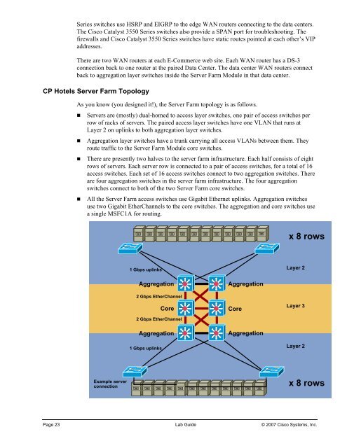
Series switches use HSRP and EIGRP to the edge WAN routers connecting to the data centers.The <strong>Cisco</strong> Catalyst 3550 Series switches also provide a SPAN port for troubleshooting. Thefirewalls and <strong>Cisco</strong> Catalyst 3550 Series switches have static routes pointed at each other’s VIPaddresses.There are two WAN routers at each E-Commerce web site. Each WAN router has a DS-3connection back to one router at the paired Data Center. The data center WAN routers connectback to aggregation layer switches inside the Server Farm Module in that data center.CP Hotels Server Farm TopologyAs you know (you designed it!), the Server Farm topology is as follows.• Servers are (mostly) dual-homed to access layer switches, one pair of access switches perrow of racks of servers. The paired access layer switches have one VLAN that runs atLayer 2 on uplinks to both aggregation layer switches.• Aggregation layer switches have a trunk carrying all access VLANs between them. Theyroute traffic to the Server Farm Module core switches.• There are presently two halves to the server farm infrastructure. Each half consists of eightrows of servers. Each server row is connected to a pair of access switches, for a total of 16access switches. Each set of 16 access switches connect to two aggregation switches. Thereare four aggregation switches in the server farm infrastructure. The four aggregationswitches connect to both of the two Server Farm core switches.• All the Server Farm access switches use Gigabit Ethernet uplinks. Aggregation switchesuse two Gigabit EtherChannels to the core switches. The aggregation and core switches usea single MSFC1A for routing.x 8 rows1 Gbps uplinksLayer 2AggregationAggregation2 Gbps EtherChannelCore2 Gbps EtherChannelCoreLayer 3Aggregation1 Gbps uplinksAggregationLayer 2Example serverconnectionx 8 rowsPage 23 Lab Guide © 2007 <strong>Cisco</strong> Systems, Inc.