Cisco IOS Wide-Area Networking Configuration Guide - Free Books
Cisco IOS Wide-Area Networking Configuration Guide - Free Books
Cisco IOS Wide-Area Networking Configuration Guide - Free Books

You also want an ePaper? Increase the reach of your titles
YUMPU automatically turns print PDFs into web optimized ePapers that Google loves.
<strong>Cisco</strong> <strong>IOS</strong> <strong>Wide</strong>-<strong>Area</strong> <strong>Networking</strong><strong>Configuration</strong> <strong>Guide</strong>Release 12.4Americas Headquarters<strong>Cisco</strong> Systems, Inc.170 West Tasman DriveSan Jose, CA 95134-1706USAhttp://www.cisco.comTel: 408 526-4000800 553-NETS (6387)Fax: 408 527-0883
THE SPECIFICATIONS AND INFORMATION REGARDING THE PRODUCTS IN THIS MANUAL ARE SUBJECT TO CHANGE WITHOUT NOTICE. ALLSTATEMENTS, INFORMATION, AND RECOMMENDATIONS IN THIS MANUAL ARE BELIEVED TO BE ACCURATE BUT ARE PRESENTED WITHOUTWARRANTY OF ANY KIND, EXPRESS OR IMPLIED. USERS MUST TAKE FULL RESPONSIBILITY FOR THEIR APPLICATION OF ANY PRODUCTS.THE SOFTWARE LICENSE AND LIMITED WARRANTY FOR THE ACCOMPANYING PRODUCT ARE SET FORTH IN THE INFORMATION PACKET THATSHIPPED WITH THE PRODUCT AND ARE INCORPORATED HEREIN BY THIS REFERENCE. IF YOU ARE UNABLE TO LOCATE THE SOFTWARE LICENSEOR LIMITED WARRANTY, CONTACT YOUR CISCO REPRESENTATIVE FOR A COPY.The <strong>Cisco</strong> implementation of TCP header compression is an adaptation of a program developed by the University of California, Berkeley (UCB) as part of UCB’s publicdomain version of the UNIX operating system. All rights reserved. Copyright © 1981, Regents of the University of California.NOTWITHSTANDING ANY OTHER WARRANTY HEREIN, ALL DOCUMENT FILES AND SOFTWARE OF THESE SUPPLIERS ARE PROVIDED “AS IS” WITHALL FAULTS. CISCO AND THE ABOVE-NAMED SUPPLIERS DISCLAIM ALL WARRANTIES, EXPRESSED OR IMPLIED, INCLUDING, WITHOUTLIMITATION, THOSE OF MERCHANTABILITY, FITNESS FOR A PARTICULAR PURPOSE AND NONINFRINGEMENT OR ARISING FROM A COURSE OFDEALING, USAGE, OR TRADE PRACTICE.IN NO EVENT SHALL CISCO OR ITS SUPPLIERS BE LIABLE FOR ANY INDIRECT, SPECIAL, CONSEQUENTIAL, OR INCIDENTAL DAMAGES, INCLUDING,WITHOUT LIMITATION, LOST PROFITS OR LOSS OR DAMAGE TO DATA ARISING OUT OF THE USE OR INABILITY TO USE THIS MANUAL, EVEN IF CISCOOR ITS SUPPLIERS HAVE BEEN ADVISED OF THE POSSIBILITY OF SUCH DAMAGES.CCDE, CCENT, <strong>Cisco</strong> Eos, <strong>Cisco</strong> Lumin, <strong>Cisco</strong> Nexus, <strong>Cisco</strong> StadiumVision, <strong>Cisco</strong> TelePresence, the <strong>Cisco</strong> logo, DCE, and Welcome to the Human Network aretrademarks; Changing the Way We Work, Live, Play, and Learn and <strong>Cisco</strong> Store are service marks; and Access Registrar, Aironet, AsyncOS, Bringing the Meeting To You,Catalyst, CCDA, CCDP, CCIE, CCIP, CCNA, CCNP, CCSP, CCVP, <strong>Cisco</strong>, the <strong>Cisco</strong> Certified Internetwork Expert logo, <strong>Cisco</strong> <strong>IOS</strong>, <strong>Cisco</strong> Press, <strong>Cisco</strong> Systems,<strong>Cisco</strong> Systems Capital, the <strong>Cisco</strong> Systems logo, <strong>Cisco</strong> Unity, Collaboration Without Limitation, EtherFast, EtherSwitch, Event Center, Fast Step, Follow Me Browsing,FormShare, GigaDrive, HomeLink, Internet Quotient, <strong>IOS</strong>, iPhone, iQ Expertise, the iQ logo, iQ Net Readiness Scorecard, iQuick Study, IronPort, the IronPort logo,LightStream, Linksys, MediaTone, MeetingPlace, MeetingPlace Chime Sound, MGX, Networkers, <strong>Networking</strong> Academy, Network Registrar, PCNow, PIX, PowerPanels,ProConnect, ScriptShare, SenderBase, SMARTnet, Spectrum Expert, StackWise, The Fastest Way to Increase Your Internet Quotient, TransPath, WebEx, and theWebEx logo are registered trademarks of <strong>Cisco</strong> Systems, Inc. and/or its affiliates in the United States and certain other countries.All other trademarks mentioned in this document or Website are the property of their respective owners. The use of the word partner does not imply a partnership relationshipbetween <strong>Cisco</strong> and any other company. (0807R)Any Internet Protocol (IP) addresses used in this document are not intended to be actual addresses. Any examples, command display output, and figures included in thedocument are shown for illustrative purposes only. Any use of actual IP addresses in illustrative content is unintentional and coincidental.<strong>Cisco</strong> <strong>IOS</strong> <strong>Wide</strong>-<strong>Area</strong> <strong>Networking</strong> <strong>Configuration</strong> <strong>Guide</strong>© 2008 <strong>Cisco</strong> Systems, Inc. All rights reserved.
Documentation ConventionsAbout <strong>Cisco</strong> <strong>IOS</strong> and <strong>Cisco</strong> <strong>IOS</strong> XE Software DocumentationDocumentation ConventionsIn <strong>Cisco</strong> <strong>IOS</strong> documentation, the term router may be used to refer to various <strong>Cisco</strong> products; for example,routers, access servers, and switches. These and other networking devices that support <strong>Cisco</strong> <strong>IOS</strong>software are shown interchangeably in examples and are used only for illustrative purposes. An examplethat shows one product does not necessarily mean that other products are not supported.This section includes the following topics:• Typographic Conventions, page ii• Command Syntax Conventions, page ii• Software Conventions, page iii• Reader Alert Conventions, page iiiTypographic Conventions<strong>Cisco</strong> <strong>IOS</strong> documentation uses the following typographic conventions:Convention^ or CtrlstringDescriptionBoth the ^ symbol and Ctrl represent the Control (Ctrl) key on a keyboard. Forexample, the key combination ^D or Ctrl-D means that you hold down theControl key while you press the D key. (Keys are indicated in capital letters butare not case sensitive.)A string is a nonquoted set of characters shown in italics. For example, whensetting a Simple Network Management Protocol (SNMP) community string topublic, do not use quotation marks around the string; otherwise, the string willinclude the quotation marks.Command Syntax Conventions<strong>Cisco</strong> <strong>IOS</strong> documentation uses the following command syntax conventions:Convention DescriptionboldBold text indicates commands and keywords that you enter as shown.italicItalic text indicates arguments for which you supply values.[x]Square brackets enclose an optional keyword or argument.| A vertical line, called a pipe, indicates a choice within a set of keywordsor arguments.[x | y] Square brackets enclosing keywords or arguments separated by a pipe indicate anoptional choice.{x | y} Braces enclosing keywords or arguments separated by a pipe indicate arequired choice.[x {y | z}] Braces and a pipe within square brackets indicate a required choice within anoptional element.ii
About <strong>Cisco</strong> <strong>IOS</strong> and <strong>Cisco</strong> <strong>IOS</strong> XE Software DocumentationDocumentation OrganizationSoftware Conventions<strong>Cisco</strong> <strong>IOS</strong> uses the following program code conventions:ConventionCourier fontBold Courier fontDescriptionCourier font is used for information that is displayed on a PC or terminal screen.Bold Courier font indicates text that the user must enter.< > Angle brackets enclose text that is not displayed, such as a password. Anglebrackets also are used in contexts in which the italic font style is not supported;for example, ASCII text.! An exclamation point at the beginning of a line indicates that the text that followsis a comment, not a line of code. An exclamation point is also displayed by<strong>Cisco</strong> <strong>IOS</strong> software for certain processes.[ ] Square brackets enclose default responses to system prompts.Reader Alert ConventionsThe <strong>Cisco</strong> <strong>IOS</strong> documentation set uses the following conventions for reader alerts:CautionMeans reader be careful. In this situation, you might do something that could result in equipmentdamage or loss of data.NoteMeans reader take note. Notes contain helpful suggestions or references to material not covered in themanual.TimesaverMeans the described action saves time. You can save time by performing the action described in theparagraph.Documentation OrganizationThis section describes the <strong>Cisco</strong> <strong>IOS</strong> documentation set, how it is organized, and how to access it on<strong>Cisco</strong>.com. Included are lists of configuration guides, command references, and supplementaryreferences and resources that make up the documentation set. The following topics are included:• <strong>Cisco</strong> <strong>IOS</strong> Documentation Set, page iv• <strong>Cisco</strong> <strong>IOS</strong> Documentation on <strong>Cisco</strong>.com, page iv• <strong>Configuration</strong> <strong>Guide</strong>s, Command References, and Supplementary Resources, page viii
Documentation OrganizationAbout <strong>Cisco</strong> <strong>IOS</strong> and <strong>Cisco</strong> <strong>IOS</strong> XE Software Documentation<strong>Cisco</strong> <strong>IOS</strong> Documentation Set<strong>Cisco</strong> <strong>IOS</strong> documentation consists of the following:• Release notes and caveats provide information about platform, technology, and feature support fora release and describe severity 1 (catastrophic), severity 2 (severe), and severity 3 (moderate) defectsin released <strong>Cisco</strong> <strong>IOS</strong> code. Review release notes before other documents to learn whether or notupdates have been made to a feature.• Sets of configuration guides and command references organized by technology and published foreach standard <strong>Cisco</strong> <strong>IOS</strong> release.– <strong>Configuration</strong> guides—Compilations of documents that provide informational andtask-oriented descriptions of <strong>Cisco</strong> <strong>IOS</strong> features.– Command references—Compilations of command pages that provide detailed informationabout the commands used in the <strong>Cisco</strong> <strong>IOS</strong> features and processes that make up the relatedconfiguration guides. For each technology, there is a single command reference that covers all<strong>Cisco</strong> <strong>IOS</strong> releases and that is updated at each standard release.• Lists of all the commands in a specific release and all commands that are new, modified, removed,or replaced in the release.• Command reference book for debug commands. Command pages are listed in alphabetical order.• Reference book for system messages for all <strong>Cisco</strong> <strong>IOS</strong> releases.<strong>Cisco</strong> <strong>IOS</strong> Documentation on <strong>Cisco</strong>.comThe following sections describe the documentation organization and how to access various documenttypes.Use <strong>Cisco</strong> Feature Navigator to find information about platform support and <strong>Cisco</strong> <strong>IOS</strong> and Catalyst OSsoftware image support. To access <strong>Cisco</strong> Feature Navigator, go to http://www.cisco.com/go/cfn. Anaccount on <strong>Cisco</strong>.com is not required.New Features ListThe New Features List for each release provides a list of all features in the release with hyperlinks to thefeature guides in which they are documented.Feature <strong>Guide</strong>s<strong>Cisco</strong> <strong>IOS</strong> features are documented in feature guides. Feature guides describe one feature or a group ofrelated features that are supported on many different software releases and platforms. Your <strong>Cisco</strong> <strong>IOS</strong>software release or platform may not support all the features documented in a feature guide. See theFeature Information table at the end of the feature guide for information about which features in thatguide are supported in your software release.<strong>Configuration</strong> <strong>Guide</strong>s<strong>Configuration</strong> guides are provided by technology and release and comprise a set of individual featureguides relevant to the release and technology.iv
About <strong>Cisco</strong> <strong>IOS</strong> and <strong>Cisco</strong> <strong>IOS</strong> XE Software DocumentationDocumentation OrganizationCommand ReferencesCommand reference books describe <strong>Cisco</strong> <strong>IOS</strong> commands that are supported in many different softwarereleases and on many different platforms. The books are provided by technology. For information aboutall <strong>Cisco</strong> <strong>IOS</strong> commands, use the Command Lookup Tool at http://tools.cisco.com/Support/CLILookupor the <strong>Cisco</strong> <strong>IOS</strong> Master Command List, All Releases, athttp://www.cisco.com/en/US/docs/ios/mcl/all_release/all_mcl.html.<strong>Cisco</strong> <strong>IOS</strong> Supplementary Documents and ResourcesSupplementary documents and resources are listed in Table 2 on page xi.<strong>Configuration</strong> <strong>Guide</strong>s, Command References, and Supplementary ResourcesTable 1 lists, in alphabetical order, <strong>Cisco</strong> <strong>IOS</strong> and <strong>Cisco</strong> <strong>IOS</strong> XE software configuration guides andcommand references, including brief descriptions of the contents of the documents. The <strong>Cisco</strong> <strong>IOS</strong>command references are comprehensive, meaning that they include commands for both <strong>Cisco</strong> <strong>IOS</strong>software and <strong>Cisco</strong> <strong>IOS</strong> XE software, for all releases. The configuration guides and command referencessupport many different software releases and platforms. Your <strong>Cisco</strong> <strong>IOS</strong> software release or platformmay not support all these technologies.For additional information about configuring and operating specific networking devices, go to theProduct Support area of <strong>Cisco</strong>.com at http://www.cisco.com/web/psa/products/index.html.Table 2 lists documents and resources that supplement the <strong>Cisco</strong> <strong>IOS</strong> software configuration guides andcommand references. These supplementary resources include release notes and caveats; mastercommand lists; new, modified, removed, and replaced command lists; system messages; and the debugcommand reference.Table 1<strong>Cisco</strong> <strong>IOS</strong> and <strong>Cisco</strong> <strong>IOS</strong> XE <strong>Configuration</strong> <strong>Guide</strong>s and Command References<strong>Configuration</strong> <strong>Guide</strong> and Command Reference Titles<strong>Cisco</strong> <strong>IOS</strong> AppleTalk <strong>Configuration</strong> <strong>Guide</strong><strong>Cisco</strong> <strong>IOS</strong> XE AppleTalk <strong>Configuration</strong> <strong>Guide</strong><strong>Cisco</strong> <strong>IOS</strong> AppleTalk Command Reference<strong>Cisco</strong> <strong>IOS</strong> Asynchronous Transfer Mode<strong>Configuration</strong> <strong>Guide</strong><strong>Cisco</strong> <strong>IOS</strong> Asynchronous Transfer ModeCommand ReferenceFeatures/Protocols/TechnologiesAppleTalk protocol.LAN ATM, multiprotocol over ATM (MPoA), and WAN ATM.v
Documentation OrganizationAbout <strong>Cisco</strong> <strong>IOS</strong> and <strong>Cisco</strong> <strong>IOS</strong> XE Software DocumentationTable 1<strong>Cisco</strong> <strong>IOS</strong> and <strong>Cisco</strong> <strong>IOS</strong> XE <strong>Configuration</strong> <strong>Guide</strong>s and Command References (continued)<strong>Configuration</strong> <strong>Guide</strong> and Command Reference Titles<strong>Cisco</strong> <strong>IOS</strong> Bridging and IBM <strong>Networking</strong><strong>Configuration</strong> <strong>Guide</strong><strong>Cisco</strong> <strong>IOS</strong> Bridging Command Reference<strong>Cisco</strong> <strong>IOS</strong> IBM <strong>Networking</strong> Command Reference<strong>Cisco</strong> <strong>IOS</strong> Broadband and DSL <strong>Configuration</strong> <strong>Guide</strong><strong>Cisco</strong> <strong>IOS</strong> XE Broadband and DSL <strong>Configuration</strong> <strong>Guide</strong><strong>Cisco</strong> <strong>IOS</strong> Broadband and DSL Command Reference<strong>Cisco</strong> <strong>IOS</strong> Carrier Ethernet <strong>Configuration</strong> <strong>Guide</strong><strong>Cisco</strong> <strong>IOS</strong> Carrier Ethernet Command Reference<strong>Cisco</strong> <strong>IOS</strong> <strong>Configuration</strong> Fundamentals<strong>Configuration</strong> <strong>Guide</strong><strong>Cisco</strong> <strong>IOS</strong> XE <strong>Configuration</strong> Fundamentals<strong>Configuration</strong> <strong>Guide</strong><strong>Cisco</strong> <strong>IOS</strong> <strong>Configuration</strong> FundamentalsCommand Reference<strong>Cisco</strong> <strong>IOS</strong> DECnet <strong>Configuration</strong> <strong>Guide</strong><strong>Cisco</strong> <strong>IOS</strong> XE DECnet <strong>Configuration</strong> <strong>Guide</strong><strong>Cisco</strong> <strong>IOS</strong> DECnet Command Reference<strong>Cisco</strong> <strong>IOS</strong> Dial Technologies <strong>Configuration</strong> <strong>Guide</strong><strong>Cisco</strong> <strong>IOS</strong> XE Dial Technologies <strong>Configuration</strong> <strong>Guide</strong><strong>Cisco</strong> <strong>IOS</strong> Dial Technologies Command Reference<strong>Cisco</strong> <strong>IOS</strong> Flexible NetFlow <strong>Configuration</strong> <strong>Guide</strong><strong>Cisco</strong> <strong>IOS</strong> Flexible NetFlow Command ReferenceFeatures/Protocols/Technologies• Transparent and source-route transparent (SRT) bridging,source-route bridging (SRB), Token Ring Inter-Switch Link(TRISL), and token ring route switch module (TRRSM).• Data-link switching plus (DLSw+), serial tunnel (STUN),block serial tunnel (BSTUN); logical link control, type 2(LLC2), synchronous data link control (SDLC); IBMNetwork Media Translation, including Synchronous DataLogical Link Control (SDLLC) and qualified LLC (QLLC);downstream physical unit (DSPU), Systems NetworkArchitecture (SNA) service point, SNA frame relay access,advanced peer-to-peer networking (APPN), native clientinterface architecture (NCIA) client/server topologies, andIBM Channel Attach.Point-to-Point Protocol (PPP) over ATM (PPPoA) and PPP overEthernet (PPPoE).Connectivity fault management (CFM), Ethernet LocalManagement Interface (ELMI), IEEE 802.3ad link bundling,Link Layer Discovery Protocol (LLDP), media endpointdiscovery (MED), and operations, administration, andmaintenance (OAM).Autoinstall, Setup, <strong>Cisco</strong> <strong>IOS</strong> command-line interface (CLI),<strong>Cisco</strong> <strong>IOS</strong> file system (IFS), <strong>Cisco</strong> <strong>IOS</strong> web browser userinterface (UI), basic file transfer services, and file management.DECnet protocol.Asynchronous communications, dial backup, dialer technology,dial-in terminal services and AppleTalk remote access (ARA),large scale dialout, dial-on-demand routing, dialout, modem andresource pooling, ISDN, multilink PPP (MLP), PPP, virtualprivate dialup network (VPDN).Flexible NetFlow.vi
About <strong>Cisco</strong> <strong>IOS</strong> and <strong>Cisco</strong> <strong>IOS</strong> XE Software DocumentationDocumentation OrganizationTable 1<strong>Cisco</strong> <strong>IOS</strong> and <strong>Cisco</strong> <strong>IOS</strong> XE <strong>Configuration</strong> <strong>Guide</strong>s and Command References (continued)<strong>Configuration</strong> <strong>Guide</strong> and Command Reference Titles<strong>Cisco</strong> <strong>IOS</strong> H.323 <strong>Configuration</strong> <strong>Guide</strong><strong>Cisco</strong> <strong>IOS</strong> High Availability <strong>Configuration</strong> <strong>Guide</strong><strong>Cisco</strong> <strong>IOS</strong> XE High Availability <strong>Configuration</strong> <strong>Guide</strong><strong>Cisco</strong> <strong>IOS</strong> High Availability Command Reference<strong>Cisco</strong> <strong>IOS</strong> Integrated Session Border ControllerCommand Reference<strong>Cisco</strong> <strong>IOS</strong> Intelligent Service Gateway<strong>Configuration</strong> <strong>Guide</strong><strong>Cisco</strong> <strong>IOS</strong> Intelligent Service GatewayCommand Reference<strong>Cisco</strong> <strong>IOS</strong> Interface and Hardware Component<strong>Configuration</strong> <strong>Guide</strong><strong>Cisco</strong> <strong>IOS</strong> XE Interface and Hardware Component<strong>Configuration</strong> <strong>Guide</strong><strong>Cisco</strong> <strong>IOS</strong> Interface and Hardware ComponentCommand Reference<strong>Cisco</strong> <strong>IOS</strong> IP Addressing Services <strong>Configuration</strong> <strong>Guide</strong><strong>Cisco</strong> <strong>IOS</strong> XE Addressing Services <strong>Configuration</strong> <strong>Guide</strong><strong>Cisco</strong> <strong>IOS</strong> IP Addressing Services Command Reference<strong>Cisco</strong> <strong>IOS</strong> IP Application Services <strong>Configuration</strong> <strong>Guide</strong><strong>Cisco</strong> <strong>IOS</strong> XE IP Application Services <strong>Configuration</strong><strong>Guide</strong><strong>Cisco</strong> <strong>IOS</strong> IP Application Services Command Reference<strong>Cisco</strong> <strong>IOS</strong> IP Mobility <strong>Configuration</strong> <strong>Guide</strong><strong>Cisco</strong> <strong>IOS</strong> IP Mobility Command Reference<strong>Cisco</strong> <strong>IOS</strong> IP Multicast <strong>Configuration</strong> <strong>Guide</strong><strong>Cisco</strong> <strong>IOS</strong> XE IP Multicast <strong>Configuration</strong> <strong>Guide</strong><strong>Cisco</strong> <strong>IOS</strong> IP Multicast Command ReferenceFeatures/Protocols/TechnologiesGatekeeper enhancements for managed voice services,Gatekeeper Transaction Message Protocol, gateway codec orderpreservation and shutdown control, H.323 dual tonemultifrequency relay, H.323 version 2 enhancements, NetworkAddress Translation (NAT) support of H.323 v2 Registration,Admission, and Status (RAS) protocol, tokenless callauthorization, and VoIP gateway trunk andcarrier-based routing.A variety of High Availability (HA) features and technologiesthat are available for different network segments (fromenterprise access to service provider core) to facilitate creationof end-to-end highly available networks. <strong>Cisco</strong> <strong>IOS</strong> HA featuresand technologies can be categorized in three key areas:system-level resiliency, network-level resiliency, and embeddedmanagement for resiliency.A VoIP-enabled device that is deployed at the edge of networks.An SBC is a toolkit of functions, such as signaling interworking,network hiding, security, and quality of service (QoS).Subscriber identification, service and policy determination,session creation, session policy enforcement, session life-cyclemanagement, accounting for access and service usage, sessionstate monitoring.LAN interfaces, logical interfaces, serial interfaces, virtualinterfaces, and interface configuration.Address Resolution Protocol (ARP), Network AddressTranslation (NAT), Domain Name System (DNS), DynamicHost <strong>Configuration</strong> Protocol (DHCP), and Next Hop AddressResolution Protocol (NHRP).Enhanced Object Tracking (EOT), Gateway Load BalancingProtocol (GLBP), Hot Standby Router Protocol (HSRP), IPServices, Server Load Balancing (SLB), Stream ControlTransmission Protocol (SCTP), TCP, Web CacheCommunication Protocol (WCCP), User Datagram Protocol(UDP), and Virtual Router Redundancy Protocol (VRRP).Mobile ad hoc networks (MANet) and <strong>Cisco</strong> mobile networks.Protocol Independent Multicast (PIM) sparse mode (PIM-SM),bidirectional PIM (bidir-PIM), Source Specific Multicast(SSM), Multicast Source Discovery Protocol (MSDP), InternetGroup Management Protocol (IGMP), and Multicast VPN(MVPN).vii
Documentation OrganizationAbout <strong>Cisco</strong> <strong>IOS</strong> and <strong>Cisco</strong> <strong>IOS</strong> XE Software DocumentationTable 1<strong>Cisco</strong> <strong>IOS</strong> and <strong>Cisco</strong> <strong>IOS</strong> XE <strong>Configuration</strong> <strong>Guide</strong>s and Command References (continued)<strong>Configuration</strong> <strong>Guide</strong> and Command Reference Titles<strong>Cisco</strong> <strong>IOS</strong> IP Routing Protocols <strong>Configuration</strong> <strong>Guide</strong><strong>Cisco</strong> <strong>IOS</strong> XE IP Routing Protocols <strong>Configuration</strong> <strong>Guide</strong><strong>Cisco</strong> <strong>IOS</strong> IP Routing Protocols Command Reference<strong>Cisco</strong> <strong>IOS</strong> IP SLAs <strong>Configuration</strong> <strong>Guide</strong><strong>Cisco</strong> <strong>IOS</strong> XE IP SLAs <strong>Configuration</strong> <strong>Guide</strong><strong>Cisco</strong> <strong>IOS</strong> IP SLAs Command Reference<strong>Cisco</strong> <strong>IOS</strong> IP Switching <strong>Configuration</strong> <strong>Guide</strong><strong>Cisco</strong> <strong>IOS</strong> XE IP Switching <strong>Configuration</strong> <strong>Guide</strong><strong>Cisco</strong> <strong>IOS</strong> IP Switching Command Reference<strong>Cisco</strong> <strong>IOS</strong> IPv6 <strong>Configuration</strong> <strong>Guide</strong><strong>Cisco</strong> <strong>IOS</strong> XE IPv6 <strong>Configuration</strong> <strong>Guide</strong><strong>Cisco</strong> <strong>IOS</strong> IPv6 Command Reference<strong>Cisco</strong> <strong>IOS</strong> ISO CLNS <strong>Configuration</strong> <strong>Guide</strong><strong>Cisco</strong> <strong>IOS</strong> XE ISO CLNS <strong>Configuration</strong> <strong>Guide</strong><strong>Cisco</strong> <strong>IOS</strong> ISO CLNS Command Reference<strong>Cisco</strong> <strong>IOS</strong> LAN Switching <strong>Configuration</strong> <strong>Guide</strong><strong>Cisco</strong> <strong>IOS</strong> XE LAN Switching <strong>Configuration</strong> <strong>Guide</strong><strong>Cisco</strong> <strong>IOS</strong> LAN Switching Command Reference<strong>Cisco</strong> <strong>IOS</strong> Mobile Wireless Gateway GPRS Support Node<strong>Configuration</strong> <strong>Guide</strong><strong>Cisco</strong> <strong>IOS</strong> Mobile Wireless Gateway GPRS Support NodeCommand Reference<strong>Cisco</strong> <strong>IOS</strong> Mobile Wireless Home Agent<strong>Configuration</strong> <strong>Guide</strong><strong>Cisco</strong> <strong>IOS</strong> Mobile Wireless Home AgentCommand Reference<strong>Cisco</strong> <strong>IOS</strong> Mobile Wireless Packet Data Serving Node<strong>Configuration</strong> <strong>Guide</strong><strong>Cisco</strong> <strong>IOS</strong> Mobile Wireless Packet Data Serving NodeCommand Reference<strong>Cisco</strong> <strong>IOS</strong> Mobile Wireless Radio Access <strong>Networking</strong><strong>Configuration</strong> <strong>Guide</strong><strong>Cisco</strong> <strong>IOS</strong> Mobile Wireless Radio Access <strong>Networking</strong>Command ReferenceFeatures/Protocols/TechnologiesBorder Gateway Protocol (BGP), multiprotocol BGP,multiprotocol BGP extensions for IP multicast, bidirectionalforwarding detection (BFD), Enhanced Interior GatewayRouting Protocol (EIGRP), Interior Gateway Routing Protocol(IGRP), Intermediate System-to-Intermediate System (IS-IS),on-demand routing (ODR), Open Shortest Path First (OSPF),and Routing Information Protocol (RIP).<strong>Cisco</strong> <strong>IOS</strong> IP Service Level Agreements (IP SLAs).<strong>Cisco</strong> Express Forwarding, fast switching, and MulticastDistributed Switching (MDS).For IPv6 features, protocols, and technologies, go to the IPv6“Start Here” document at the following URL:http://www.cisco.com/en/US/docs/ios/ipv6/configuration/guide/ip6-roadmap.htmlISO connectionless network service (CLNS).VLANs, Inter-Switch Link (ISL) encapsulation, IEEE 802.10encapsulation, IEEE 802.1Q encapsulation, and multilayerswitching (MLS).<strong>Cisco</strong> <strong>IOS</strong> Gateway GPRS Support Node (GGSN) in a2.5-generation general packet radio service (GPRS) and3-generation universal mobile telecommunication system (UMTS)network.<strong>Cisco</strong> Mobile Wireless Home Agent, an anchor point for mobileterminals for which mobile IP or proxy mobile IP services areprovided.<strong>Cisco</strong> Packet Data Serving Node (PDSN), a wireless gateway thatis between the mobile infrastructure and standard IP networks andthat enables packet data services in a code division multiple access(CDMA) environment.<strong>Cisco</strong> <strong>IOS</strong> radio access network products.viii
About <strong>Cisco</strong> <strong>IOS</strong> and <strong>Cisco</strong> <strong>IOS</strong> XE Software DocumentationDocumentation OrganizationTable 1<strong>Cisco</strong> <strong>IOS</strong> and <strong>Cisco</strong> <strong>IOS</strong> XE <strong>Configuration</strong> <strong>Guide</strong>s and Command References (continued)<strong>Configuration</strong> <strong>Guide</strong> and Command Reference Titles<strong>Cisco</strong> <strong>IOS</strong> Multiprotocol Label Switching<strong>Configuration</strong> <strong>Guide</strong><strong>Cisco</strong> <strong>IOS</strong> XE Multiprotocol Label Switching<strong>Configuration</strong> <strong>Guide</strong><strong>Cisco</strong> <strong>IOS</strong> Multiprotocol Label SwitchingCommand Reference<strong>Cisco</strong> <strong>IOS</strong> Multi-Topology Routing <strong>Configuration</strong> <strong>Guide</strong><strong>Cisco</strong> <strong>IOS</strong> Multi-Topology Routing Command Reference<strong>Cisco</strong> <strong>IOS</strong> NetFlow <strong>Configuration</strong> <strong>Guide</strong><strong>Cisco</strong> <strong>IOS</strong> XE NetFlow <strong>Configuration</strong> <strong>Guide</strong><strong>Cisco</strong> <strong>IOS</strong> NetFlow Command Reference<strong>Cisco</strong> <strong>IOS</strong> Network Management <strong>Configuration</strong> <strong>Guide</strong><strong>Cisco</strong> <strong>IOS</strong> XE Network Management <strong>Configuration</strong> <strong>Guide</strong><strong>Cisco</strong> <strong>IOS</strong> Network Management Command Reference<strong>Cisco</strong> <strong>IOS</strong> Novell IPX <strong>Configuration</strong> <strong>Guide</strong><strong>Cisco</strong> <strong>IOS</strong> XE Novell IPX <strong>Configuration</strong> <strong>Guide</strong><strong>Cisco</strong> <strong>IOS</strong> Novell IPX Command Reference<strong>Cisco</strong> <strong>IOS</strong> Optimized Edge Routing <strong>Configuration</strong> <strong>Guide</strong><strong>Cisco</strong> <strong>IOS</strong> Optimized Edge Routing Command Reference<strong>Cisco</strong> <strong>IOS</strong> Quality of Service Solutions<strong>Configuration</strong> <strong>Guide</strong><strong>Cisco</strong> <strong>IOS</strong> XE Quality of Service Solutions<strong>Configuration</strong> <strong>Guide</strong><strong>Cisco</strong> <strong>IOS</strong> Quality of Service SolutionsCommand Reference<strong>Cisco</strong> <strong>IOS</strong> Security <strong>Configuration</strong> <strong>Guide</strong><strong>Cisco</strong> <strong>IOS</strong> XE Security <strong>Configuration</strong> <strong>Guide</strong><strong>Cisco</strong> <strong>IOS</strong> Security Command ReferenceFeatures/Protocols/TechnologiesMPLS Label Distribution Protocol (LDP), MPLS Layer 2 VPNs,MPLS Layer 3 VPNs, MPLS Traffic Engineering (TE), andMPLS Embedded Management (EM) and MIBs.Unicast and multicast topology configurations, trafficclassification, routing protocol support, and networkmanagement support.Network traffic data analysis, aggregation caches, exportfeatures.Basic system management; system monitoring and logging;troubleshooting, logging, and fault management;<strong>Cisco</strong> Discovery Protocol; <strong>Cisco</strong> <strong>IOS</strong> Scripting with ToolControl Language (Tcl); <strong>Cisco</strong> networking services (CNS);DistributedDirector; Embedded Event Manager (EEM);Embedded Resource Manager (ERM); Embedded SyslogManager (ESM); HTTP; Remote Monitoring (RMON); SNMP;and VPN Device Manager Client for <strong>Cisco</strong> <strong>IOS</strong> Software(XSM <strong>Configuration</strong>).Novell Internetwork Packet Exchange (IPX) protocol.Optimized edge routing (OER) monitoring, policyconfiguration, routing control, logging and reporting, andVPN IPsec/generic routing encapsulation (GRE) tunnelinterface optimization.Class-based weighted fair queuing (CBWFQ), custom queuing,distributed traffic shaping (DTS), generic traffic shaping (GTS),IP- to-ATM class of service (CoS), low latency queuing (LLQ),modular QoS CLI (MQC), Network-Based ApplicationRecognition (NBAR), priority queuing, Security DeviceManager (SDM), Multilink PPP (MLPPP) for QoS, headercompression, AutoQoS, QoS features for voice, ResourceReservation Protocol (RSVP), weighted fair queuing (WFQ),and weighted random early detection (WRED).Access control lists (ACLs), authentication, authorization, andaccounting (AAA), firewalls, IP security and encryption,neighbor router authentication, network access security, networkdata encryption with router authentication, public keyinfrastructure (PKI), RADIUS, TACACS+, terminal accesssecurity, and traffic filters.ix
Documentation OrganizationAbout <strong>Cisco</strong> <strong>IOS</strong> and <strong>Cisco</strong> <strong>IOS</strong> XE Software DocumentationTable 1<strong>Cisco</strong> <strong>IOS</strong> and <strong>Cisco</strong> <strong>IOS</strong> XE <strong>Configuration</strong> <strong>Guide</strong>s and Command References (continued)<strong>Configuration</strong> <strong>Guide</strong> and Command Reference Titles<strong>Cisco</strong> <strong>IOS</strong> Service Selection Gateway <strong>Configuration</strong> <strong>Guide</strong><strong>Cisco</strong> <strong>IOS</strong> Service Selection Gateway Command Reference<strong>Cisco</strong> <strong>IOS</strong> Software Activation <strong>Configuration</strong> <strong>Guide</strong><strong>Cisco</strong> <strong>IOS</strong> Software Activation Command Reference<strong>Cisco</strong> <strong>IOS</strong> Software Modularity Installation and<strong>Configuration</strong> <strong>Guide</strong><strong>Cisco</strong> <strong>IOS</strong> Software Modularity Command Reference<strong>Cisco</strong> <strong>IOS</strong> Terminal Services <strong>Configuration</strong> <strong>Guide</strong><strong>Cisco</strong> <strong>IOS</strong> Terminal Services Command Reference<strong>Cisco</strong> <strong>IOS</strong> XE Terminal Services Command Reference<strong>Cisco</strong> <strong>IOS</strong> Virtual Switch Command Reference<strong>Cisco</strong> <strong>IOS</strong> Voice <strong>Configuration</strong> Library<strong>Cisco</strong> <strong>IOS</strong> Voice Command Reference<strong>Cisco</strong> <strong>IOS</strong> VPDN <strong>Configuration</strong> <strong>Guide</strong><strong>Cisco</strong> <strong>IOS</strong> XE VPDN <strong>Configuration</strong> <strong>Guide</strong><strong>Cisco</strong> <strong>IOS</strong> VPDN Command Reference<strong>Cisco</strong> <strong>IOS</strong> <strong>Wide</strong>-<strong>Area</strong> <strong>Networking</strong> <strong>Configuration</strong> <strong>Guide</strong><strong>Cisco</strong> <strong>IOS</strong> XE <strong>Wide</strong>-<strong>Area</strong> <strong>Networking</strong> <strong>Configuration</strong> <strong>Guide</strong><strong>Cisco</strong> <strong>IOS</strong> <strong>Wide</strong>-<strong>Area</strong> <strong>Networking</strong> Command Reference<strong>Cisco</strong> <strong>IOS</strong> Wireless LAN <strong>Configuration</strong> <strong>Guide</strong><strong>Cisco</strong> <strong>IOS</strong> Wireless LAN Command ReferenceFeatures/Protocols/TechnologiesSubscriber authentication, service access, and accounting.An orchestrated collection of processes and components toactivate <strong>Cisco</strong> <strong>IOS</strong> software feature sets by obtaining andvalidating <strong>Cisco</strong> software licenses.Installation and basic configuration of software modularityimages, including installations on single and dual routeprocessors, installation rollbacks, software modularity binding,software modularity processes and patches.DEC, local-area transport (LAT), and X.25 packetassembler/disassembler (PAD).Virtual switch redundancy, high availability, and packet handling;converting between standalone and virtual switch modes; virtualswitch link (VSL); Virtual Switch Link Protocol (VSLP).NoteFor information about virtual switch configuration, referto the product-specific software configurationinformation for the <strong>Cisco</strong> Catalyst 6500 series switch orfor the Metro Ethernet 6500 series switch.<strong>Cisco</strong> <strong>IOS</strong> support for voice call control protocols, interoperability,physical and virtual interface management, and troubleshooting.The library includes documentation for IP telephony applications.Layer 2 Tunneling Protocol (L2TP) dial-out load balancing andredundancy, L2TP extended failover, L2TP security VPDN,multihop by Dialed Number Identification Service (DNIS),timer and retry enhancements for L2TP and Layer 2 Forwarding(L2F), RADIUS Attribute 82: tunnel assignment ID, shell-basedauthentication of VPDN users, tunnel authentication viaRADIUS on tunnel terminator.Frame Relay, Layer 2 Tunneling Protocol Version 3 (L2TPv3),Link Access Procedure, Balanced (LAPB), SwitchedMultimegabit Data Service (SMDS), and X.25.Broadcast key rotation, IEEE 802.11x support, IEEE 802.1xauthenticator, IEEE 802.1x local authentication service forExtensible Authentication Protocol-Flexible Authentication viaSecure Tunneling (EAP-FAST), Multiple Basic Service Set ID(BSSID), Wi-Fi Multimedia (WMM) required elements, andWi-Fi Protected Access (WPA).x
About <strong>Cisco</strong> <strong>IOS</strong> and <strong>Cisco</strong> <strong>IOS</strong> XE Software DocumentationAdditional Resources and Documentation FeedbackTable 2<strong>Cisco</strong> <strong>IOS</strong> Supplementary Documents and ResourcesDocument Title<strong>Cisco</strong> <strong>IOS</strong> Master Command List, All Releases<strong>Cisco</strong> <strong>IOS</strong> New, Modified, Removed, andReplaced Commands<strong>Cisco</strong> <strong>IOS</strong> Software System Messages<strong>Cisco</strong> <strong>IOS</strong> Debug Command ReferenceRelease Notes and CaveatsMIBsRFCsDescriptionAlphabetical list of all the commands documented in all<strong>Cisco</strong> <strong>IOS</strong> releases.List of all the new, modified, removed, and replaced commandsfor a <strong>Cisco</strong> <strong>IOS</strong> release.List of <strong>Cisco</strong> <strong>IOS</strong> system messages and descriptions. Systemmessages may indicate problems with your system; beinformational only; or may help diagnose problems withcommunications lines, internal hardware, or thesystem software.Alphabetical list of debug commands including briefdescriptions of use, command syntax, and usage guidelines.Information about new and changed features, systemrequirements, and other useful information about specificsoftware releases; information about defects in specific<strong>Cisco</strong> <strong>IOS</strong> software releases.Files used for network monitoring. To locate and downloadMIBs for selected platforms, <strong>Cisco</strong> <strong>IOS</strong> releases, and featuresets, use <strong>Cisco</strong> MIB Locator at the following URL:http://www.cisco.com/go/mibsStandards documents maintained by the Internet EngineeringTask Force (IETF) that <strong>Cisco</strong> <strong>IOS</strong> documentation referenceswhere applicable. The full text of referenced RFCs may beobtained at the following URL:http://www.rfc-editor.org/Additional Resources and Documentation FeedbackWhat’s New in <strong>Cisco</strong> Product Documentation is published monthly and describes all new and revised<strong>Cisco</strong> technical documentation. The What’s New in <strong>Cisco</strong> Product Documentation publication alsoprovides information about obtaining the following resources:• Technical documentation• <strong>Cisco</strong> product security overview• Product alerts and field notices• Technical assistance<strong>Cisco</strong> <strong>IOS</strong> technical documentation includes embedded feedback forms where you can rate documentsand provide suggestions for improvement. Your feedback helps us improve our documentation.xi
Additional Resources and Documentation FeedbackAbout <strong>Cisco</strong> <strong>IOS</strong> and <strong>Cisco</strong> <strong>IOS</strong> XE Software DocumentationCCDE, CCENT, <strong>Cisco</strong> Eos, <strong>Cisco</strong> Lumin, <strong>Cisco</strong> Nexus, <strong>Cisco</strong> StadiumVision, <strong>Cisco</strong> TelePresence, the <strong>Cisco</strong> logo, DCE, and Welcome to theHuman Network are trademarks; Changing the Way We Work, Live, Play, and Learn and <strong>Cisco</strong> Store are service marks; and Access Registrar,Aironet, AsyncOS, Bringing the Meeting To You, Catalyst, CCDA, CCDP, CCIE, CCIP, CCNA, CCNP, CCSP, CCVP, <strong>Cisco</strong>, the <strong>Cisco</strong> CertifiedInternetwork Expert logo, <strong>Cisco</strong> <strong>IOS</strong>, <strong>Cisco</strong> Press, <strong>Cisco</strong> Systems, <strong>Cisco</strong> Systems Capital, the <strong>Cisco</strong> Systems logo, <strong>Cisco</strong> Unity, CollaborationWithout Limitation, EtherFast, EtherSwitch, Event Center, Fast Step, Follow Me Browsing, FormShare, GigaDrive, HomeLink, Internet Quotient,<strong>IOS</strong>, iPhone, iQ Expertise, the iQ logo, iQ Net Readiness Scorecard, iQuick Study, IronPort, the IronPort logo, LightStream, Linksys, MediaTone,MeetingPlace, MeetingPlace Chime Sound, MGX, Networkers, <strong>Networking</strong> Academy, Network Registrar, PCNow, PIX, PowerPanels, ProConnect,ScriptShare, SenderBase, SMARTnet, Spectrum Expert, StackWise, The Fastest Way to Increase Your Internet Quotient, TransPath, WebEx, andthe WebEx logo are registered trademarks of <strong>Cisco</strong> Systems, Inc. and/or its affiliates in the United States and certain other countries.All other trademarks mentioned in this document or Website are the property of their respective owners. The use of the word partner does not implya partnership relationship between <strong>Cisco</strong> and any other company. (0807R)Any Internet Protocol (IP) addresses used in this document are not intended to be actual addresses. Any examples, command display output, andfigures included in the document are shown for illustrative purposes only. Any use of actual IP addresses in illustrative content is unintentional andcoincidental.© 2007–2008 <strong>Cisco</strong> Systems, Inc. All rights reserved.xii
Using the Command-Line Interface in <strong>Cisco</strong> <strong>IOS</strong>and <strong>Cisco</strong> <strong>IOS</strong> XE SoftwareLast updated: August 6, 2008This document provides basic information about the command-line interface (CLI) in <strong>Cisco</strong> <strong>IOS</strong> and<strong>Cisco</strong> <strong>IOS</strong> XE software and how you can use some of the CLI features. This document contains thefollowing sections:• Initially Configuring a Device, page i• Using the CLI, page ii• Saving Changes to a <strong>Configuration</strong>, page xii• Additional Information, page xiiFor more information about using the CLI, see the “Using the <strong>Cisco</strong> <strong>IOS</strong> Command-Line Interface”section of the <strong>Cisco</strong> <strong>IOS</strong> <strong>Configuration</strong> Fundamentals <strong>Configuration</strong> <strong>Guide</strong>.For information about the software documentation set, see the “About <strong>Cisco</strong> <strong>IOS</strong> and <strong>Cisco</strong> <strong>IOS</strong> XESoftware Documentation” document.Initially Configuring a DeviceInitially configuring a device varies by platform. For information about performing an initialconfiguration, see the hardware installation documentation that is provided with the original packagingof the product or go to the Product Support area of <strong>Cisco</strong>.com athttp://www.cisco.com/web/psa/products/index.html.After you have performed the initial configuration and connected the device to your network, you canconfigure the device by using the console port or a remote access method, such as Telnet or Secure Shell(SSH), to access the CLI or by using the configuration method provided on the device, such as SecurityDevice Manager.i
Using the CLIUsing the Command-Line Interface in <strong>Cisco</strong> <strong>IOS</strong> and <strong>Cisco</strong> <strong>IOS</strong> XE SoftwareChanging the Default Settings for a Console or AUX PortThere are only two changes that you can make to a console port and an AUX port:• Change the port speed with the config-register 0x command. Changing the port speed is notrecommended. The well-known default speed is 9600.• Change the behavior of the port; for example, by adding a password or changing the timeout value.NoteThe AUX port on the Route Processor (RP) installed in a <strong>Cisco</strong> ASR1000 series router does not serveany useful customer purpose and should be accessed only under the advisement of a customer supportrepresentative.Using the CLIThis section describes the following topics:• Understanding Command Modes, page ii• Using the Interactive Help Feature, page v• Understanding Command Syntax, page vi• Understanding Enable and Enable Secret Passwords, page viii• Using the Command History Feature, page viii• Abbreviating Commands, page ix• Using Aliases for CLI Commands, page ix• Using the no and default Forms of Commands, page x• Using the debug Command, page x• Filtering Output Using Output Modifiers, page x• Understanding CLI Error Messages, page xiUnderstanding Command ModesThe CLI command mode structure is hierarchical, and each mode supports a set of specific commands.This section describes the most common of the many modes that exist.Table 1 lists common command modes with associated CLI prompts, access and exit methods, and abrief description of how each mode is used.ii
Using the Command-Line Interface in <strong>Cisco</strong> <strong>IOS</strong> and <strong>Cisco</strong> <strong>IOS</strong> XE SoftwareUsing the CLITable 1CLI Command ModesCommand Access Method Prompt Exit Method Mode UsageModeUser EXEC Log in. Router> Issue the logout or exitcommand.• Change terminalsettings.PrivilegedEXECGlobalconfigurationInterfaceconfigurationLineconfigurationFrom user EXEC mode,issue the enablecommand.From privileged EXECmode, issue theconfigure terminalcommand.From globalconfiguration mode,issue the interfacecommand.From globalconfiguration mode,issue the line vty or lineconsole command.Router#Router(config)#Router(config-if)#Router(config-line)#Issue the disablecommand or the exitcommand to return touser EXEC mode.Issue the exit commandor the end command toreturn to privilegedEXEC mode.Issue the exit commandto return to globalconfiguration mode orthe end command toreturn to privilegedEXEC mode.Issue the exit commandto return to globalconfiguration mode orthe end command toreturn to privilegedEXEC mode.• Perform basic tests.• Display device status.• Issue show and debugcommands.• Copy images to thedevice.• Reload the device.• Manage deviceconfiguration files.• Manage device filesystems.Configure the device.Configure individualinterfaces.Configure individualterminal lines.iii
Using the CLIUsing the Command-Line Interface in <strong>Cisco</strong> <strong>IOS</strong> and <strong>Cisco</strong> <strong>IOS</strong> XE SoftwareTable 1CLI Command Modes (continued)CommandModeROM monitorDiagnostic(available onlyon the <strong>Cisco</strong>ASR1000series router)Access Method Prompt Exit Method Mode UsageFrom privileged EXECmode, issue the reloadcommand. Press theBreak key during thefirst 60 seconds whilethe system is booting.The router boots orenters diagnostic modein the followingscenarios. When a<strong>Cisco</strong> <strong>IOS</strong> process orprocesses fail, in mostscenarios the router willreload.• A user-configuredaccess policy wasconfigured usingthe transport-mapcommand, whichdirected the userinto diagnosticmode.• The router wasaccessed using anRP auxiliary port.• A break signal(Ctrl-C,Ctrl-Shift-6, or thesend breakcommand) wasentered, and therouter wasconfigured to enterdiagnostic modewhen the breaksignal was received.rommon # >The # symbolrepresents the linenumber and incrementsat each prompt.Router(diag)#Issue the continuecommand.If a <strong>Cisco</strong> <strong>IOS</strong> processfailure is the reason forentering diagnosticmode, the failure mustbe resolved and therouter must be rebootedto exit diagnostic mode.If the router is indiagnostic modebecause of atransport-mapconfiguration, accessthe router throughanother port or using amethod that isconfigured to connect tothe <strong>Cisco</strong> <strong>IOS</strong> CLI.If the RP auxiliary portwas used to access therouter, use another portfor access. Accessingthe router through theauxiliary port is notuseful for customerpurposes.• Run as the defaultoperating mode when avalid image cannot beloaded.• Access the fall-backprocedure for loading animage when the devicelacks a valid image andcannot be booted.• Perform passwordrecovery when aCTRL-Break sequence isissued within 60 secondsof a power-on or reloadevent.• Inspect various states onthe router, including the<strong>Cisco</strong> <strong>IOS</strong> state.• Replace or roll back theconfiguration.• Provide methods ofrestarting the <strong>Cisco</strong> <strong>IOS</strong>software or otherprocesses.• Reboot hardware, suchas the entire router, anRP, an ESP, a SIP, a SPA,or possibly otherhardware components.• Transfer files into or offof the router usingremote access methodssuch as FTP, TFTP, andSCP.iv
Using the Command-Line Interface in <strong>Cisco</strong> <strong>IOS</strong> and <strong>Cisco</strong> <strong>IOS</strong> XE SoftwareUsing the CLIEXEC commands are not saved when the software reboots. Commands that you issue in a configurationmode can be saved to the startup configuration. If you save the running configuration to the startupconfiguration, these commands will execute when the software is rebooted. Global configuration modeis the highest level of configuration mode. From global configuration mode, you can enter a variety ofother configuration modes, including protocol-specific modes.ROM monitor mode is a separate mode that is used when the software cannot load properly. If a validsoftware image is not found when the software boots or if the configuration file is corrupted at startup,the software might enter ROM monitor mode. Use the question symbol (?) to view the commands thatyou can use while the device is in ROM monitor mode.rommon 1 > ?aliasbootconfregcontcontextcookie...rommon 2 >set and display aliases commandboot up an external processconfiguration register utilitycontinue executing a downloaded imagedisplay the context of a loaded imagedisplay contents of cookie PROM in hexThe following example shows how the command prompt changes to indicate a different command mode:Router> enableRouter# configure terminalRouter(config)# interface ethernet 1/1Router(config-if)# ethernetRouter(config-line)# exitRouter(config)# endRouter#NoteA keyboard alternative to the end command is Ctrl-Z.Using the Interactive Help FeatureThe CLI includes an interactive Help feature. Table 2 describes how to use the Help feature.Table 2CLI Interactive Help CommandsCommandhelpPurposeProvides a brief description of the help feature in any command mode.? Lists all commands available for a particular command mode.partial command?partial commandcommand ?command keyword ?Provides a list of commands that begin with the character string (nospace between the command and the question mark).Completes a partial command name (no space between the commandand ).Lists the keywords, arguments, or both associated with the command(space between the command and the question mark).Lists the arguments that are associated with the keyword (space betweenthe keyword and the question mark).v
Using the CLIUsing the Command-Line Interface in <strong>Cisco</strong> <strong>IOS</strong> and <strong>Cisco</strong> <strong>IOS</strong> XE SoftwareThe following examples show how to use the help commands:helpRouter> helpHelp may be requested at any point in a command by entering a question mark '?'. Ifnothing matches, the help list will be empty and you must backup until entering a '?'shows the available options.Two styles of help are provided:1. Full help is available when you are ready to enter a command argument (e.g. 'show ?')and describes each possible argument.2. Partial help is provided when an abbreviated argument is entered and you want to knowwhat arguments match the input (e.g. 'show pr?'.)?Router# ?Exec commands:access-enableaccess-profileaccess-templatealpsarchiveCreate a temporary access-List entryApply user-profile to interfaceCreate a temporary access-List entryALPS exec commandsmanage archive filespartial command?Router(config)# zo?zone zone-pairpartial commandRouter(config)# we webvpncommand ?Router(config-if)# pppoe ?enable Enable pppoemax-sessions Maximum PPPOE sessionscommand keyword ?Router(config-if)# pppoe enable ?group attach a BBA groupUnderstanding Command SyntaxCommand syntax is the format in which a command should be entered in the CLI. Commands includethe name of the command, keywords, and arguments. Keywords are alphanumeric strings that are usedliterally. Arguments are placeholders for values that a user must supply. Keywords and arguments maybe required or optional.Specific conventions convey information about syntax and command elements. Table 3 describes theseconventions.vi
Using the Command-Line Interface in <strong>Cisco</strong> <strong>IOS</strong> and <strong>Cisco</strong> <strong>IOS</strong> XE SoftwareUsing the CLITable 3CLI Syntax ConventionsSymbol/Text Function Notes< > (angle brackets) Indicate that the option is anargument.A.B.C.D.WORD (all capital letters)LINE (all capital letters) (carriage return)Indicates that you must enter adotted decimal IP address.Indicates that you must enterone word.Indicates that you must entermore than one word.Indicates the end of the list ofavailable keywords and arguments,and also indicates whenkeywords and arguments areoptional. When is the onlyoption, you have reached theend of the branch or the end ofthe command if the commandhas only one branch.Sometimes arguments are displayedwithout angle brackets.Angle brackets (< >) are not alwaysused to indicate that an IP address isan argument.Angle brackets (< >) are not alwaysused to indicate that a WORD is anargument.Angle brackets (< >) are not alwaysused to indicate that a LINE is anargument.—The following examples show syntax conventions:Router(config)# ethernet cfm domain ?WORD domain nameRouter(config)# ethernet cfm domain dname ?levelRouter(config)# ethernet cfm domain dname level ? maintenance level numberRouter(config)# ethernet cfm domain dname level 7 ?Router(config)# snmp-server file-transfer access-group 10 ?protocol protocol optionsRouter(config)# logging host ?Hostname or A.B.C.D IP address of the syslog serveripv6Configure IPv6 syslog serverRouter(config)# snmp-server file-transfer access-group 10 ?protocol protocol optionsvii
Using the CLIUsing the Command-Line Interface in <strong>Cisco</strong> <strong>IOS</strong> and <strong>Cisco</strong> <strong>IOS</strong> XE SoftwareUnderstanding Enable and Enable Secret PasswordsSome privileged EXEC commands are used for actions that impact the system, and it is recommendedthat you set a password for these commands to prevent unauthorized use. Two types of passwords, enable(not encrypted) and enable secret (encrypted), can be set. The following commands set these passwordsand are issued in global configuration mode:• enable password• enable secret passwordUsing an enable secret password is recommended because it is encrypted and more secure than theenable password. When you use an enable secret password, text is encrypted (unreadable) before it iswritten to the config.text file. When you use an enable password, the text is written as entered (readable)to the config.text file.Each type of password is case sensitive, can contain from 1 to 25 uppercase and lowercase alphanumericcharacters, and can start with a number. Spaces are also valid password characters; for example,“two words” is a valid password. Leading spaces are ignored, but trailing spaces are recognized.NoteBoth password commands have numeric keywords that are single integer values. If you choose a numberfor the first character of your password followed by a space, the system will read the number as if it werethe numeric keyword and not as part of your password.When both passwords are set, the enable secret password takes precedence over the enable password.To remove a password, use the no form of the commands: no enable password orno enable secret password.For more information about password recovery procedures for <strong>Cisco</strong> products, seehttp://www.cisco.com/en/US/products/sw/iosswrel/ps1831/products_tech_note09186a00801746e6.shtml.Using the Command History FeatureThe CLI command history feature saves the commands you enter during a session in a command historybuffer. The default number of commands saved is 10, but the number is configurable within the range of0 to 256. This command history feature is particularly useful for recalling long or complex commands.To change the number of commands saved in the history buffer for a terminal session, issue theterminal history size command:Router# terminal history size numA command history buffer is also available in line configuration mode with the same default andconfiguration options. To set the command history buffer size for a terminal session in line configurationmode, issue the history command:Router(config-line)# history [size num]To recall commands from the history buffer, use the following methods:• Press Ctrl-P or the up arrow key—Recalls commands beginning with the most recent command.Repeat the key sequence to recall successively older commands.viii
Using the Command-Line Interface in <strong>Cisco</strong> <strong>IOS</strong> and <strong>Cisco</strong> <strong>IOS</strong> XE SoftwareUsing the CLI• Press Ctrl-N or the down arrow key—Recalls the most recent commands in the history buffer afterthey have been recalled using Ctrl-P or the up arrow key. Repeat the key sequence to recallsuccessively more recent commands.NoteThe arrow keys function only on ANSI-compatible terminals such as the VT100.• Issue the show history command in user EXEC or privileged EXEC mode—Lists the most recentcommands that you entered. The number of commands that are displayed is determined by thesetting of the terminal history size and history commands.The CLI command history feature is enabled by default. To disable this feature for a terminalsession, issue the terminal no history command in user EXEC or privileged EXEC mode or theno history command in line configuration mode.Abbreviating CommandsTyping a complete command name is not always required for the command to execute. The CLIrecognizes an abbreviated command when the abbreviation contains enough characters to uniquelyidentify the command. For example, the show version command can be abbreviated as sh ver. It cannotbe abbreviated as s ver because s could mean show, set, or systat. The sh v abbreviation also is not validbecause the show command has vrrp as a keyword in addition to version. (Command and keywordexamples from <strong>Cisco</strong> <strong>IOS</strong> Release 12.4(13)T.)Using Aliases for CLI CommandsTo save time and the repetition of entering the same command multiple times, you can use a commandalias. An alias can be configured to do anything that can be done at the command line, but an alias cannotmove between modes, type in passwords, or perform any interactive functions.Table 4 shows the default command aliases.Table 4Default Command AliasesCommand Aliashlopsu or unwOriginal CommandhelplogoutpingshowundebugwhereTo create a command alias, issue the alias command in global configuration mode. The syntax of thecommand is alias mode command-alias original-command. Following are some examples:• Router(config)# alias exec prt partition—privileged EXEC mode• Router(config)# alias configure sb source-bridge—global configuration mode• Router(config)# alias interface rl rate-limit—interface configuration modeix
Using the CLIUsing the Command-Line Interface in <strong>Cisco</strong> <strong>IOS</strong> and <strong>Cisco</strong> <strong>IOS</strong> XE SoftwareTo view both default and user-created aliases, issue the show alias command.For more information about the alias command, seehttp://www.cisco.com/en/US/docs/ios/fundamentals/command/reference/cf_book.html.Using the no and default Forms of CommandsMost configuration commands have a no form that is used to reset a command to its default value ordisable a feature or function. For example, the ip routing command is enabled by default. To disable thiscommand, you would issue the no ip routing command. To re-enable IP routing, you would issue theip routing command.<strong>Configuration</strong> commands may also have a default form, which returns the command settings to theirdefault values. For commands that are disabled by default, using the default form has the same effect asusing the no form of the command. For commands that are enabled by default and have default settings,the default form enables the command and returns the settings to their default values.The no and default forms of commands are described in the command pages of command references.Using the debug CommandA debug command produces extensive output that helps you troubleshoot problems in your network.These commands are available for many features and functions within <strong>Cisco</strong> <strong>IOS</strong> and <strong>Cisco</strong> <strong>IOS</strong> XEsoftware. Some debug commands are debug all, debug aaa accounting, and debug mpls packets. Touse debug commands during a Telnet session with a device, you must first enter the terminal monitorcommand. To turn off debugging completely, you must enter the undebug all command.For more information about debug commands, see the <strong>Cisco</strong> <strong>IOS</strong> Debug Command Reference athttp://www.cisco.com/en/US/docs/ios/debug/command/reference/db_book.html.CautionDebugging is a high priority and high CPU utilization process that can render your device unusable. Usedebug commands only to troubleshoot specific problems. The best times to run debugging are duringperiods of low network traffic and when few users are interacting with the network. Debugging duringthese periods decreases the likelihood that the debug command processing overhead will affect networkperformance or user access or response times.Filtering Output Using Output ModifiersMany commands produce lengthy output that may use several screens to display. Using output modifiers,you can filter this output to show only the information that you want to see.Three output modifiers are available and are described as follows:• begin regular expression—Displays the first line in which a match of the regular expression is foundand all lines that follow.• include regular expression—Displays all lines in which a match of the regular expression is found.• exclude regular expression—Displays all lines except those in which a match of the regularexpression is found.x
Using the Command-Line Interface in <strong>Cisco</strong> <strong>IOS</strong> and <strong>Cisco</strong> <strong>IOS</strong> XE SoftwareUsing the CLITo use one of these output modifiers, type the command followed by the pipe symbol (|), the modifier,and the regular expression that you want to search for or filter. A regular expression is a case-sensitivealphanumeric pattern. It can be a single character or number, a phrase, or a more complex string.The following example illustrates how to filter output of the show interface command to display onlylines that include the expression “protocol.”Router# show interface | include protocolFastEthernet0/0 is up, line protocol is upSerial4/0 is up, line protocol is upSerial4/1 is up, line protocol is upSerial4/2 is administratively down, line protocol is downSerial4/3 is administratively down, line protocol is downUnderstanding CLI Error MessagesYou may encounter some error messages while using the CLI. Table 5 shows the common CLI errormessages.Table 5Common CLI Error MessagesError Message Meaning How to Get Help% Ambiguous command:“show con”You did not enter enoughcharacters for the command tobe recognized.% Incomplete command. You did not enter all thekeywords or values requiredby the command.% Invalid input detected at “^”marker.You entered the command incorrectly.The caret (^) marksthe point of the error.Reenter the command followed by aspace and a question mark (?). Thekeywords that you are allowed toenter for the command appear.Reenter the command followed by aspace and a question mark (?). Thekeywords that you are allowed toenter for the command appear.Enter a question mark (?) to displayall the commands that are available inthis command mode. The keywordsthat you are allowed to enter for thecommand appear.For more system error messages, see the following documents:• <strong>Cisco</strong> <strong>IOS</strong> Release 12.2SR System Message <strong>Guide</strong>• <strong>Cisco</strong> <strong>IOS</strong> System Messages, Volume 1 of 2 (<strong>Cisco</strong> <strong>IOS</strong> Release 12.4)• <strong>Cisco</strong> <strong>IOS</strong> System Messages, Volume 2 of 2 (<strong>Cisco</strong> <strong>IOS</strong> Release 12.4)xi
Saving Changes to a <strong>Configuration</strong>Using the Command-Line Interface in <strong>Cisco</strong> <strong>IOS</strong> and <strong>Cisco</strong> <strong>IOS</strong> XE SoftwareSaving Changes to a <strong>Configuration</strong>To save changes that you made to the configuration of a device, you must issue the copy running-configstartup-config command or the copy system:running-config nvram:startup-config command. Whenyou issue these commands, the configuration changes that you made are saved to the startupconfiguration and saved when the software reloads or power to the device is turned off or interrupted.The following example shows the syntax of the copy running-config startup-config command:Router# copy running-config startup-configDestination filename [startup-config]?You press Enter to accept the startup-config filename (the default), or type a new filename and then pressEnter to accept that name. The following output is displayed indicating that the configuration was saved:Building configuration...[OK]Router#On most platforms, the configuration is saved to NVRAM. On platforms with a Class A flash file system,the configuration is saved to the location specified by the CONFIG_FILE environment variable. TheCONFIG_FILE variable defaults to NVRAM.Additional Information• “Using the <strong>Cisco</strong> <strong>IOS</strong> Command-Line Interface” section of the<strong>Cisco</strong> <strong>IOS</strong> <strong>Configuration</strong> Fundamentals <strong>Configuration</strong> <strong>Guide</strong>:http://www.cisco.com/en/US/docs/ios/fundamentals/configuration/guide/cf_cli-basics.htmlor“Using <strong>Cisco</strong> <strong>IOS</strong> XE Software” chapter of the <strong>Cisco</strong> ASR1000 Series Aggregation Services RoutersSoftware <strong>Configuration</strong> <strong>Guide</strong>:http://www.cisco.com/en/US/docs/routers/asr1000/configuration/guide/chassis/using_cli.html• <strong>Cisco</strong> Product Support Resourceshttp://www.cisco.com/web/psa/products/index.html• Support area on <strong>Cisco</strong>.com (also search for documentation by task or product)http://www.cisco.com/en/US/support/index.html• White Paper: <strong>Cisco</strong> <strong>IOS</strong> Reference <strong>Guide</strong>http://www.cisco.com/en/US/products/sw/iosswrel/ps1828/products_white_paper09186a008018305e.shtml• Software Download Center (downloads; tools; licensing, registration, advisory, and generalinformation) (requires <strong>Cisco</strong>.com User ID and password)http://www.cisco.com/kobayashi/sw-center/• Error Message Decoder, a tool to help you research and resolve error messages for<strong>Cisco</strong> <strong>IOS</strong> softwarehttp://www.cisco.com/pcgi-bin/Support/Errordecoder/index.cgixii
Using the Command-Line Interface in <strong>Cisco</strong> <strong>IOS</strong> and <strong>Cisco</strong> <strong>IOS</strong> XE SoftwareAdditional Information• Command Lookup Tool, a tool to help you find detailed descriptions of <strong>Cisco</strong> <strong>IOS</strong> commands(requires <strong>Cisco</strong>.com user ID and password)http://tools.cisco.com/Support/CLILookup• Output Interpreter, a troubleshooting tool that analyzes command output of supportedshow commandshttps://www.cisco.com/pcgi-bin/Support/OutputInterpreter/home.pl\CCDE, CCENT, <strong>Cisco</strong> Eos, <strong>Cisco</strong> Lumin, <strong>Cisco</strong> Nexus, <strong>Cisco</strong> StadiumVision, <strong>Cisco</strong> TelePresence, the <strong>Cisco</strong> logo, DCE, and Welcome to theHuman Network are trademarks; Changing the Way We Work, Live, Play, and Learn and <strong>Cisco</strong> Store are service marks; and Access Registrar,Aironet, AsyncOS, Bringing the Meeting To You, Catalyst, CCDA, CCDP, CCIE, CCIP, CCNA, CCNP, CCSP, CCVP, <strong>Cisco</strong>, the <strong>Cisco</strong> CertifiedInternetwork Expert logo, <strong>Cisco</strong> <strong>IOS</strong>, <strong>Cisco</strong> Press, <strong>Cisco</strong> Systems, <strong>Cisco</strong> Systems Capital, the <strong>Cisco</strong> Systems logo, <strong>Cisco</strong> Unity, CollaborationWithout Limitation, EtherFast, EtherSwitch, Event Center, Fast Step, Follow Me Browsing, FormShare, GigaDrive, HomeLink, Internet Quotient,<strong>IOS</strong>, iPhone, iQ Expertise, the iQ logo, iQ Net Readiness Scorecard, iQuick Study, IronPort, the IronPort logo, LightStream, Linksys, MediaTone,MeetingPlace, MeetingPlace Chime Sound, MGX, Networkers, <strong>Networking</strong> Academy, Network Registrar, PCNow, PIX, PowerPanels, ProConnect,ScriptShare, SenderBase, SMARTnet, Spectrum Expert, StackWise, The Fastest Way to Increase Your Internet Quotient, TransPath, WebEx, andthe WebEx logo are registered trademarks of <strong>Cisco</strong> Systems, Inc. and/or its affiliates in the United States and certain other countries.All other trademarks mentioned in this document or Website are the property of their respective owners. The use of the word partner does not implya partnership relationship between <strong>Cisco</strong> and any other company. (0807R)Any Internet Protocol (IP) addresses used in this document are not intended to be actual addresses. Any examples, command display output, andfigures included in the document are shown for illustrative purposes only. Any use of actual IP addresses in illustrative content is unintentional andcoincidental.© 2007–2008 <strong>Cisco</strong> Systems, Inc. All rights reserved.xiii
Additional InformationUsing the Command-Line Interface in <strong>Cisco</strong> <strong>IOS</strong> and <strong>Cisco</strong> <strong>IOS</strong> XE Softwarexiv
Configuring Frame Relay
Configuring Frame RelayFeature HistoryRelease<strong>Cisco</strong> <strong>IOS</strong><strong>Cisco</strong> <strong>IOS</strong> XERelease 2.1ModificationFor information about feature support in <strong>Cisco</strong> <strong>IOS</strong> software, use <strong>Cisco</strong>Feature Navigator.This feature was introduced on <strong>Cisco</strong> ASR 1000 series routers.This chapter describes the tasks for configuring Frame Relay on a router or access server. For furthergeneral information about Frame Relay, see the chapter “<strong>Wide</strong>-<strong>Area</strong> <strong>Networking</strong> Overview” at thebeginning of this book.For a complete description of the Frame Relay commands mentioned in this chapter, refer to the chapter“Frame Relay Commands” in the <strong>Cisco</strong> <strong>IOS</strong> <strong>Wide</strong>-<strong>Area</strong> <strong>Networking</strong> Command Reference. To locatedocumentation of other commands that appear in this chapter, use the command reference master indexor search online.To identify the hardware platform or software image information associated with a feature, use theFeature Navigator on <strong>Cisco</strong>.com to search for information about the feature or refer to the softwarerelease notes for a specific release. For more information, see the section “Identifying SupportedPlatforms” in the chapter “Using <strong>Cisco</strong> <strong>IOS</strong> Software.”For information on the following related topics, see the corresponding chapters in other <strong>Cisco</strong>publications:TaskSending DDR traffic over Frame RelayInstalling software on a new router oraccess server by downloading from acentral server over an interface thatsupports Frame RelayResource“Configuring Legacy DDR Spokes” and “ConfiguringLegacy DDR Hubs” chapters in the “Dial-on-DemandRouting <strong>Configuration</strong>” part in the <strong>Cisco</strong> <strong>IOS</strong> DialTechnologies <strong>Configuration</strong> <strong>Guide</strong>“Loading and Maintaining System Images” chapter in the<strong>Cisco</strong> <strong>IOS</strong> <strong>Configuration</strong> Fundamentals <strong>Configuration</strong> <strong>Guide</strong>Americas Headquarters:<strong>Cisco</strong> Systems, Inc., 170 West Tasman Drive, San Jose, CA 95134-1706 USA© 2007 <strong>Cisco</strong> Systems, Inc. All rights reserved.
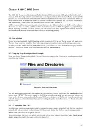
<strong>Cisco</strong> Frame Relay MIBConfiguring Frame RelayTaskUsing AutoInstall over Frame RelayConfiguring transparent bridgingbetween devices over a Frame RelaynetworkConfiguring source-route bridgingbetween SNA devices over a FrameRelay networkConfiguring serial tunnel (STUN) andblock serial tunnel encapsulationbetween devices over a Frame RelaynetworkConfiguring access between SNAdevices over a Frame Relay networkConfiguring Voice over Frame RelayUsing FRF.11 and FRF.12Configuring low latency queueing,PVC interface priority queueing, andlink fragmentation and interleavingusing multilink PPP for Frame RelayResource“Using Autoinstall and Setup” chapter in the <strong>Cisco</strong> <strong>IOS</strong><strong>Configuration</strong> Fundamentals <strong>Configuration</strong> <strong>Guide</strong>“Configuring Transparent Bridging” chapter in the <strong>Cisco</strong> <strong>IOS</strong>Bridging and IBM <strong>Networking</strong> <strong>Configuration</strong> <strong>Guide</strong>“Configuring Source-Route Bridging” chapter in the<strong>Cisco</strong> <strong>IOS</strong> Bridging and IBM <strong>Networking</strong> <strong>Configuration</strong><strong>Guide</strong>“Configuring Serial Tunnel and Block Serial Tunnel” chapterin the <strong>Cisco</strong> <strong>IOS</strong> Bridging and IBM <strong>Networking</strong><strong>Configuration</strong> <strong>Guide</strong>“Configuring SNA Frame Relay Access Support” chapter inthe <strong>Cisco</strong> <strong>IOS</strong> Bridging and IBM <strong>Networking</strong> <strong>Configuration</strong><strong>Guide</strong>“Configuring Voice over Frame Relay” chapter in the<strong>Cisco</strong> <strong>IOS</strong> Voice, Video, and Fax <strong>Configuration</strong> <strong>Guide</strong><strong>Cisco</strong> <strong>IOS</strong> Quality of Service Solutions <strong>Configuration</strong> <strong>Guide</strong><strong>Cisco</strong> Frame Relay MIBThe <strong>Cisco</strong> Frame Relay MIB adds extensions to the standard Frame Relay MIB (RFC 1315). It providesadditional link-level and virtual circuit (VC)-level information and statistics that are mostly specific to<strong>Cisco</strong> Frame Relay implementation. This MIB provides SNMP network management access to most ofthe information covered by the show frame-relay commands such as, show frame-relay lmi, showframe-relay pvc, show frame-relay map, and show frame-relay svc.Frame Relay Hardware <strong>Configuration</strong>sYou can create Frame Relay connections using one of the following hardware configurations:• Routers and access servers connected directly to the Frame Relay switch• Routers and access servers connected directly to a channel service unit/digital service unit(CSU/DSU), which then connects to a remote Frame Relay switchNoteRouters can connect to Frame Relay networks either by direct connection to a Frame Relay switch orthrough CSU/DSUs. However, a single router interface configured for Frame Relay can be configuredfor only one of these methods.The CSU/DSU converts V.35 or RS-449 signals to the properly coded T1 transmission signal forsuccessful reception by the Frame Relay network. Figure 22 illustrates the connections among thecomponents.2
Configuring Frame RelayFrame Relay <strong>Configuration</strong> Task ListFigure 22Typical Frame Relay <strong>Configuration</strong>V.35DSU/CSU4-wire T1Public FrameRelay networkRouterV.3562863RouterThe Frame Relay interface actually consists of one physical connection between the network server andthe switch that provides the service. This single physical connection provides direct connectivity to eachdevice on a network.Frame Relay <strong>Configuration</strong> Task ListYou must follow certain required, basic steps to enable Frame Relay for your network. In addition, youcan customize Frame Relay for your particular network needs and monitor Frame Relay connections.The following sections outline these tasks:• Enabling Frame Relay Encapsulation on an Interface (Required)• Configuring Dynamic or Static Address Mapping (Required)NoteFrame Relay encapsulation is a prerequisite for any Frame Relay commands on an interface.The tasks described in the following sections are used to enhance or customize your Frame Relay:• Configuring the LMI (Optional)• Configuring Frame Relay SVCs (Optional)• Configuring Frame Relay Traffic Shaping (Optional)• Configuring Frame Relay Switching (Optional)• Customizing Frame Relay for Your Network (Optional)• Monitoring and Maintaining the Frame Relay Connections (Optional)See the section “Frame Relay <strong>Configuration</strong> Examples” at the end of this chapter for ideas about how toconfigure Frame Relay on your network. See the chapter “Frame Relay Commands” in the <strong>Cisco</strong> <strong>IOS</strong><strong>Wide</strong>-<strong>Area</strong> <strong>Networking</strong> Command Reference for information about the Frame Relay commands listed inthe following tasks. Use the index or search online for documentation of other commands.Enabling Frame Relay Encapsulation on an InterfaceTo enable Frame Relay encapsulation on the interface level, use the following commands beginning inglobal configuration mode:3
Configuring Dynamic or Static Address MappingConfiguring Frame RelayStep 1Step 2CommandRouter(config)# interface typenumberRouter(config-if)# encapsulationframe-relay [ietf]PurposeSpecifies the interface, and enters interface configuration mode.Enables and specifies the Frame Relay encapsulation method.Frame Relay supports encapsulation of all supported protocols in conformance with RFC 1490, allowinginteroperability among multiple vendors. Use the Internet Engineering Task Force (IETF) form of FrameRelay encapsulation if your router or access server is connected to another vendor’s equipment across aFrame Relay network. IETF encapsulation is supported either at the interface level or on a per-VC basis.Shut down the interface prior to changing encapsulation types. Although shutting down the interface isnot required, it ensures that the interface is reset for the new encapsulation.For an example of enabling Frame Relay encapsulation on an interface, see the section “IETFEncapsulation Examples” later in this chapter.Configuring Dynamic or Static Address MappingDynamic address mapping uses Frame Relay Inverse ARP to request the next-hop protocol address fora specific connection, given its known DLCI. Responses to Inverse ARP requests are entered in anaddress-to-DLCI mapping table on the router or access server; the table is then used to supply thenext-hop protocol address or the DLCI for outgoing traffic.Inverse ARP is enabled by default for all protocols it supports, but can be disabled for specificprotocol-DLCI pairs. As a result, you can use dynamic mapping for some protocols and static mappingfor other protocols on the same DLCI. You can explicitly disable Inverse ARP for a protocol-DLCI pairif you know that the protocol is not supported on the other end of the connection. See the section“Disabling or Reenabling Frame Relay Inverse ARP” later in this chapter for more information.See the following sections for further details on configuring dynamic or static address mapping:• Configuring Dynamic Address Mapping• Configuring Static Address MappingConfiguring Dynamic Address MappingInverse ARP is enabled by default for all protocols enabled on the physical interface. Packets are not sentout for protocols that are not enabled on the interface.Because Inverse ARP is enabled by default, no additional command is required to configure dynamicmapping on an interface.Configuring Static Address MappingA static map links a specified next-hop protocol address to a specified DLCI. Static mapping removesthe need for Inverse ARP requests; when you supply a static map, Inverse ARP is automatically disabledfor the specified protocol on the specified DLCI.You must use static mapping if the router at the other end either does not support Inverse ARP at all ordoes not support Inverse ARP for a specific protocol that you want to use over Frame Relay.4
Configuring Frame RelayConfiguring the LMITo establish static mapping according to your network needs, use one of the following commands ininterface configuration mode:CommandRouter(config-if)# frame-relay map protocol protocol-address dlci[broadcast] [ietf] [cisco]Router(config-if)# frame-relay map clns dlci [broadcast]Router(config-if)# frame-relay map bridge dlci [broadcast] [ietf]PurposeMaps between a next-hop protocoladdress and DLCI destination address.Defines a DLCI used to send ISOCLNS frames.Defines a DLCI destination bridge.The supported protocols and the corresponding keywords to enable them are as follows:• IP—ip• DECnet—decnet• AppleTalk—appletalk• XNS—xns• Novell IPX—ipx• VINES—vines• ISO CLNS—clnsYou can greatly simplify the configuration for the Open Shortest Path First (OSPF) protocol by addingthe optional broadcast keyword when doing this task. Refer to the frame-relay map commanddescription in the <strong>Cisco</strong> <strong>IOS</strong> <strong>Wide</strong>-<strong>Area</strong> <strong>Networking</strong> Command Reference and the examples at the end ofthis chapter for more information about using the broadcast keyword.For examples of establishing static address mapping, refer to the section “Static Address MappingExamples” later in this chapter.Configuring the LMIBeginning with <strong>Cisco</strong> <strong>IOS</strong> Release 11.2, the software supports Local Management Interface (LMI)autosense, which enables the interface to determine the LMI type supported by the switch. Support forLMI autosense means that you are no longer required to configure the LMI explicitly.See the following sections for further details on configuring the LMI:• Activating LMI Autosense• Explicitly Configuring the LMIFor information on using Enhanced Local Management Interface with traffic shaping, see the section“Configuring Frame Relay Traffic Shaping” later in this chapter.For an example of configuring the LMI, see the section “Pure Frame Relay DCE Example” later in thischapter.Activating LMI AutosenseLMI autosense is active in the following situations:5
Configuring the LMIConfiguring Frame Relay• The router is powered up or the interface changes state to up.• The line protocol is down but the line is up.• The interface is a Frame Relay DTE.• The LMI type is not explicitly configured.See the following sections for additional information concerning activating LMI autosense:• Status Request• Status Messages• LMI Autosense• <strong>Configuration</strong> OptionsStatus RequestWhen LMI autosense is active, it sends out a full status request, in all three LMI types, to the switch.The order is ANSI, ITU, cisco, but it is done in rapid succession. <strong>Cisco</strong> <strong>IOS</strong> software provides the abilityto listen in on both DLCI 1023 (cisco LMI) and DLCI 0 (ANSI and ITU) simultaneously.Status MessagesOne or more of the status requests will elicit a reply (status message) from the switch. The router willdecode the format of the reply and configure itself automatically. If more than one reply is received, therouter will configure itself with the type of the last received reply. This is to accommodate intelligentswitches that can handle multiple formats simultaneously.LMI Autosense<strong>Configuration</strong> OptionsIf LMI autosense is unsuccessful, an intelligent retry scheme is built in. Every N391 interval (default is60 seconds, which is 6 keep exchanges at 10 seconds each), LMI autosense will attempt to ascertain theLMI type. For more information about N391, see the frame-relay lmi-n391dte command in the chapter“Frame Relay Commands” in the <strong>Cisco</strong> <strong>IOS</strong> <strong>Wide</strong>-<strong>Area</strong> <strong>Networking</strong> Command Reference.The only visible indication to the user that LMI autosense is under way is that debug frame lmi is turnedon. At every N391 interval, the user will now see three rapid status inquiries coming out of the serialinterface: one in ANSI, one in ITU, and one in cisco LMI-type.No configuration options are provided; LMI autosense is transparent to the user. You can turn off LMIautosense by explicitly configuring an LMI type. The LMI type must be written into NVRAM so thatnext time the router powers up, LMI autosense will be inactive. At the end of autoinstall, a frame-relaylmi-type xxx statement is included within the interface configuration. This configuration is notautomatically written to NVRAM; you must explicitly write the configuration to NVRAM by using thecopy system:running-config or copy nvram:startup-config command.6
Configuring Frame RelayConfiguring the LMIExplicitly Configuring the LMISetting the LMI TypeFrame Relay software supports the industry-accepted standards for addressing the LMI, including the<strong>Cisco</strong> specification. If you want to configure the LMI and thus deactivate LMI autosense, perform thetasks in the following sections:• Setting the LMI Type (Required)• Setting the LMI Keepalive Interval (Required)• Setting the LMI Polling and Timer Intervals (Optional)If the router or access server is attached to a public data network (PDN), the LMI type must match thetype used on the public network. Otherwise, the LMI type can be set to suit the needs of your privateFrame Relay network.You can set one of the following three types of LMIs on <strong>Cisco</strong> devices: ANSI T1.617 Annex D, <strong>Cisco</strong>,and ITU-T Q.933 Annex A. To do so, use the following commands beginning in interface configurationmode:CommandStep 1 Router(config-if)# frame-relay lmi-type {ansi |cisco | q933a}PurposeSets the LMI type.Step 2 Router# copy nvram:startup-config destination Writes the LMI type to NVRAM.For an example of setting the LMI type, see the section “Pure Frame Relay DCE Example” later in thischapter.Setting the LMI Keepalive IntervalA keepalive interval must be set to configure the LMI. By default, this interval is 10 seconds and,according to the LMI protocol, must be less than the corresponding interval on the switch. To set thekeepalive interval, use the following command in interface configuration mode:CommandRouter(config-if)# keepalive numberPurposeSets the LMI keepalive interval.To disable keepalives on networks that do not utilize LMI, use the no keepalive interface configurationcommand. For an example of how to specify an LMI keepalive interval, see the section “Two Routers inStatic Mode Example” later in this chapter.Setting the LMI Polling and Timer IntervalsYou can set various optional counters, intervals, and thresholds to fine-tune the operation of your LMIDTE and DCE devices. Set these attributes by using one or more of the following commands in interfaceconfiguration mode:7
Configuring Frame Relay SVCsConfiguring Frame RelayCommandRouter(config-if)# frame-relay lmi-n392dcethresholdRouter(config-if)# frame-relay lmi-n393dce eventsRouter(config-if)# frame-relay lmi-t392dce secondsRouter(config-if)# frame-relay lmi-n391dtekeep-exchangesRouter(config-if)# frame-relay lmi-n392dtethresholdRouter(config-if)# frame-relay lmi-n393dte eventsPurposeSets the DCE and Network-to-Network Interface (NNI) errorthreshold.Sets the DCE and NNI monitored events count.Sets the polling verification timer on a DCE or NNI interface.Sets a full status polling interval on a DTE or NNI interface.Sets the DTE or NNI error threshold.Sets the DTE and NNI monitored events count.See the chapter “Frame Relay Commands” in the <strong>Cisco</strong> <strong>IOS</strong> <strong>Wide</strong>-<strong>Area</strong> <strong>Networking</strong> Command Referencefor polling and timing interval commands.Configuring Frame Relay SVCsAccess to Frame Relay networks is made through private leased lines at speeds ranging from 56 kbps to45 Mbps. Frame Relay is a connection-oriented packet-transfer mechanism that establishes VCs betweenendpoints.Switched virtual circuits (SVCs) allow access through a Frame Relay network by setting up a path to thedestination endpoints only when the need arises and tearing down the path when it is no longer needed.SVCs can coexist with PVCs in the same sites and routers. For example, routers at remote branch officesmight set up PVCs to the central headquarters for frequent communication, but set up SVCs with eachother as needed for intermittent communication. As a result, any-to-any communication can be set upwithout any-to-any PVCs.On SVCs, quality of service (QoS) elements can be specified on a call-by-call basis to request networkresources.SVC support is offered in the Enterprise image on <strong>Cisco</strong> platforms that include a serial or HSSI interface.You must have the following services before Frame Relay SVCs can operate:• Frame Relay SVC support by the service provider—The service provider’s switch must be capableof supporting SVC operation.• Physical loop connection—A leased line or dedicated line must exist between the router (DTE) andthe local Frame Relay switch.For examples of configuring Frame Relay SVCs, see the section “SVC <strong>Configuration</strong> Examples” laterin this chapter.Operating SVCsSVC operation requires that the Data Link layer (Layer 2) be set up, running ITU-T Q.922 Link AccessProcedures to Frame mode bearer services (LAPF), prior to signalling for an SVC. Layer 2 sets itself upas soon as SVC support is enabled on the interface, if both the line and the line protocol are up. Whenthe SVCs are configured and demand for a path occurs, the Q.933 signalling sequence is initiated. Oncethe SVC is set up, data transfer begins.8
Configuring Frame RelayConfiguring Frame Relay SVCsQ.922 provides a reliable link layer for Q.933 operation. All Q.933 call control information istransmitted over DLCI 0; this DLCI is also used for the management protocols specified in ANSI T1.617Annex D or Q.933 Annex A.You must enable SVC operation at the interface level. Once it is enabled at the interface level, it isenabled on any subinterfaces on that interface. One signalling channel, DLCI 0, is set up for theinterface, and all SVCs are controlled from the physical interface.Enabling Frame Relay SVC ServiceTo enable Frame Relay SVC service and set up SVCs, perform the tasks in the following sections. Thesubinterface tasks are not required, but offer additional flexibility for SVC configuration and operation.The LAPF tasks are not required and not recommended unless you understand thoroughly the impactson your network.• Configuring SVCs on a Physical Interface (Required)• Configuring SVCs on a Subinterface (Optional)• Configuring a Map Class (Required)• Configuring a Map Group with E.164 or X.121 Addresses (Required)• Associating the Map Class with Static Protocol Address Maps (Required)• Configuring LAPF Parameters (Optional)For examples of configuring Frame Relay SVCs, see the section “SVC <strong>Configuration</strong> Examples” laterin this chapter.Configuring SVCs on a Physical InterfaceTo enable SVC operation on a Frame Relay interface, use the following commands beginning in globalconfiguration mode:CommandPurposeStep 1 Router(config)# interface type number Specifies the physical interface.Step 2 Router(config-if)# ip address ip-address mask Specifies the interface IP address, if needed.Step 3 Router(config-if)# encapsulation frame-relay Enables Frame Relay encapsulation on the interface.Step 4 Router(config-if)# map-group group-name Assigns a map group to the interface.Step 5 Router(config-if)# frame-relay svc Enables Frame Relay SVC support on the interface.Map group details are specified with the map-list command.Configuring SVCs on a SubinterfaceTo configure Frame Relay SVCs on a subinterface, complete all the commands in the preceding section,except assigning the map group. After the physical interface is configured, use the following commandsbeginning in global configuration mode:9
Configuring Frame Relay SVCsConfiguring Frame RelayStep 1CommandRouter(config)# interface typenumber.subinterface-number {multipoint |point-to-point}PurposeSpecifies a subinterface configured for SVC operation.Step 2 Router(config-subif)# ip address ip-address mask Specifies the subinterface IP address, if needed.Step 3 Router(config-subif)# map-group group-name Assigns a map group to the subinterface.Configuring a Map ClassPerform the following tasks to configure a map class:• Specify the map class name. (Required)• Specify a custom queue list for the map class. (Optional)• Specify a priority queue list for the map class. (Optional)• Enable BECN feedback to throttle the output rate on the SVC for the map class. (Optional)• Set nondefault QoS values for the map class (no need to set the QoS values; default values areprovided). (Optional)To configure a map class, use the following commands beginning in global configuration mode:CommandPurposeStep 1 Router(config)# map-class frame-relay map-class-name Specifies Frame Relay map class name and entersmap class configuration mode.Step 2Step 3Step 4Router(config-map-class)# frame-relaycustom-queue-list list-numberRouter(config-map-class)# frame-relay priority-grouplist-numberRouter(config-map-class)# frame-relayadaptive-shaping [becn | foresight] 1Specifies a custom queue list to be used for the mapclass.Assigns a priority queue to VCs associated with themap class.Enables the type of BECN feedback to throttle theframe-transmission rate.Step 5 Router(config-map-class)# frame-relay cir in bps Specifies the inbound committed information rate(CIR), in bits per second.Step 6 Router(config-map-class)# frame-relay cir out bps Specifies the outbound CIR, in bits per second.Step 7 Router(config-map-class)# frame-relay mincir in bps 2 Sets the minimum acceptable incoming CIR, in bitsper second.Step 8 Router(config-map-class)# frame-relay mincir out bps 2 Sets the minimum acceptable outgoing CIR, in bitsper second.Step 9 Router(config-map-class)# frame-relay bc in bits 2 Sets the incoming committed burst size (Bc), in bits.Step 10 Router(config-map-class)# frame-relay bc out bits 2 Sets the outgoing Bc, in bits.Step 11 Router(config-map-class)# frame-relay be in bits 2 Sets the incoming excess burst size (Be), in bits.Step 12 Router(config-map-class)# frame-relay be out bits 2 Sets the outgoing Be, in bits.Step 13 Router(config-map-class)# frame-relay idle-timer Sets the idle timeout interval, in seconds.seconds 21. This command replaces the frame-relay becn-response-enable command, which will be removed in a future <strong>Cisco</strong> <strong>IOS</strong> release. If you usethe frame-relay becn-response-enable command in scripts, you should replace it with the frame-relay adaptive-shaping becn command.10
Configuring Frame RelayConfiguring Frame Relay SVCs2. The in and out keywords are optional. Configuring the command without the in and out keywords will apply that value to both the incomingand the outgoing traffic values for the SVC setup. For example, frame-relay cir 56000 applies 56000 to both incoming and outgoing trafficvalues for setting up the SVC.You can define multiple map classes. A map class is associated with a static map, not with the interfaceor subinterface itself. Because of the flexibility this association allows, you can define different mapclasses for different destinations.Configuring a Map Group with E.164 or X.121 AddressesAfter you have defined a map group for an interface, you can associate the map group with a specificsource and destination address to be used. You can specify E.164 addresses or X.121 addresses for thesource and destination. To specify the map group to be associated with a specific interface, use thefollowing command in global configuration mode:CommandRouter(config)# map-list map-group-name source-addr {e164 | x121}source-address dest-addr {e164 | x121} destination-addressPurposeSpecifies the map group associated withspecific source and destination addresses forthe SVC.Associating the Map Class with Static Protocol Address MapsTo define the protocol addresses under a map-list command and associate each protocol address with aspecified map class, use the class command. Use this command for each protocol address to beassociated with a map class. To associate a map class with a protocol address, use the followingcommand in map list configuration mode:CommandRouter(config-map-list)# protocol protocol-address classclass-name [ietf] [broadcast [trigger]]PurposeSpecifies a destination protocol address and a FrameRelay map class name from which to derive QoSinformation.The ietf keyword specifies RFC 1490 encapsulation; the broadcast keyword specifies that broadcastsmust be carried. The trigger keyword, which can be configured only if broadcast is also configured,enables a broadcast packet to trigger an SVC. If an SVC already exists that uses this map class, the SVCwill carry the broadcast.Configuring LAPF ParametersFrame Relay Link Access Procedure for Frame Relay (LAPF) commands are used to tune Layer 2 systemparameters to work well with the Frame Relay switch. Normally, you do not need to change the defaultsettings. However, if the Frame Relay network indicates that it does not support the Frame Reject frame(FRMR) at the LAPF Frame Reject procedure, use the following command in interface configurationmode:11
Configuring Frame Relay Traffic ShapingConfiguring Frame RelayCommandRouter(config-if)# no frame-relay lapf frmrPurposeSelects not to send FRMR frames at the LAPF Frame Reject procedure.By default, the Frame Reject frame is sent at the LAPF Frame Reject procedure.NoteManipulation of Layer 2 parameters is not recommended if you do not know well the resulting functionalchange. For more information, refer to the ITU-T Q.922 specification for LAPF.If you must change Layer 2 parameters for your network environment and you understand the resultingfunctional change, use the following commands as needed:CommandPurposeRouter(config-if)# frame-relay lapf k number Sets the LAPF window size k.Router(config-if)# frame-relay lapf n200 retries Sets the LAPF maximum retransmission count N200.Router(config-if)# frame-relay lapf n201 bytesRouter(config-if)# frame-relay lapf t200 tenths-of-a-secondRouter(config-if)# frame-relay lapf t203 secondsSets maximum length of the Information field of theLAPF I frame N201, in bytes.Sets the LAPF retransmission timer value T200, intenths of a second.Sets the LAPF link idle timer value T203 of DLCI 0, inseconds.Configuring Frame Relay Traffic ShapingTraffic shaping applies to both PVCs and SVCs. For information about creating and configuring SVCs,see the section “Configuring Frame Relay SVCs” earlier in this chapter.To configure Frame Relay traffic shaping, perform the tasks in the following sections:• Enabling Frame Relay Encapsulation on an Interface (earlier in this chapter)• Defining VCs for Different Types of Traffic• Enabling Frame Relay Traffic Shaping on the Interface• Configuring Enhanced Local Management Interface• Specifying a Traffic-Shaping Map Class for the Interface• Defining a Map Class with Queueing and Traffic-Shaping Parameters• Defining Access Lists• Defining Priority Queue Lists for the Map Class• Defining Custom Queue Lists for the Map ClassNoteFrame Relay traffic shaping is not effective for Layer 2 PVC switching using the frame-relay routecommand.12
Configuring Frame RelayConfiguring Frame Relay Traffic ShapingFor examples of configuring Frame Relay traffic shaping, see the section “Frame Relay Traffic ShapingExamples” later in this chapter.Defining VCs for Different Types of TrafficBy defining separate VCs for different types of traffic and specifying queueing and an outbound trafficrate for each VC, you can provide guaranteed bandwidth for each type of traffic. By specifying differenttraffic rates for different VCs over the same line, you can perform virtual time division multiplexing. Bythrottling outbound traffic from high-speed lines in central offices to lower-speed lines in remotelocations, you can ease congestion and data loss in the network; enhanced queueing also preventscongestion-caused data loss.Enabling Frame Relay Traffic Shaping on the InterfaceEnabling Frame Relay traffic shaping on an interface enables both traffic shaping and per-VC queueingon all the PVCs and SVCs on the interface. Traffic shaping enables the router to control the circuit’soutput rate and react to congestion notification information if also configured.To enable Frame Relay traffic shaping on the specified interface, use the following command in interfaceconfiguration mode:CommandRouter(config-if)# frame-relaytraffic-shapingPurposeEnables Frame Relay traffic shaping and per-VC queueing.NoteThe default committed information rate (CIR) of 56K will apply in the following situations:—When traffic shaping is enabled (by using the frame-relay traffic-shaping command), but a map classis not assigned to the VC—When traffic shaping is enabled (by using the frame-relay traffic-shaping command) and a map classis assigned to the VC, but traffic-shaping parameters have not been defined in the map classTo configure a map class with traffic-shaping and per-VC queueing parameters, see the sections“Specifying a Traffic-Shaping Map Class for the Interface” and “Defining a Map Class with Queueingand Traffic-Shaping Parameters”.Frame Relay ForeSightForeSight is the network traffic control software used in some <strong>Cisco</strong> switches. The <strong>Cisco</strong> Frame Relayswitch can extend ForeSight messages over a User-to-Network Interface (UNI), passing the backwardcongestion notification for VCs.ForeSight allows <strong>Cisco</strong> Frame Relay routers to process and react to ForeSight messages and adjust VClevel traffic shaping in a timely manner.ForeSight must be configured explicitly on both the <strong>Cisco</strong> router and the <strong>Cisco</strong> switch. ForeSight isenabled on the <strong>Cisco</strong> router when Frame Relay traffic shaping is configured. However, the router’sresponse to ForeSight is not applied to any VC until the frame-relay adaptive-shaping foresight13
Configuring Frame Relay Traffic ShapingConfiguring Frame Relaycommand is added to the VCs map-class. When ForeSight is enabled on the switch, the switch willperiodically send out a ForeSight message based on the time value configured. The time interval canrange from 40 to 5000 milliseconds.When a <strong>Cisco</strong> router receives a ForeSight message indicating that certain DLCIs are experiencingcongestion, the <strong>Cisco</strong> router reacts by activating its traffic-shaping function to slow down the output rate.The router reacts as it would if it were to detect the congestion by receiving a packet with the backwardexplicit congestion notification (BECN) bit set.When ForeSight is enabled, Frame Relay traffic shaping will adapt to ForeSight messages and BECNmessages.For an example of configuring Foresight, see the section “Traffic Shaping with ForeSight Example” laterin this chapter.Frame Relay ForeSight PrerequisitesFor router ForeSight to work, the following conditions must exist on the <strong>Cisco</strong> router:• Frame Relay traffic shaping must be enabled on the interface.• The traffic shaping for a circuit is adapted to ForeSight.The following additional condition must exist on the <strong>Cisco</strong> switch:• The UNI connecting to the router is Consolidated Link Layer Management (CLLM) enabled, withthe proper time interval specified.Frame Relay router ForeSight is enabled automatically when you use the frame-relay traffic-shapingcommand. However, you must issue the map-class frame-relay command and the frame-relayadaptive-shaping foresight command before the router will respond to ForeSight and apply thetraffic-shaping effect on a specific interface, subinterface, or VC.Frame Relay Congestion Notification MethodsThe difference between the BECN and ForeSight congestion notification methods is that BECN requiresa user packet to be sent in the direction of the congested DLCI to convey the signal. The sending of userpackets is not predictable and, therefore, not reliable as a notification mechanism. Rather than waitingfor user packets to provide the congestion notification, timed ForeSight messages guarantee that therouter receives notification before congestion becomes a problem. Traffic can be slowed down in thedirection of the congested DLCI.Configuring Enhanced Local Management InterfaceEnhanced Local Management Interface (ELMI) allows the router to learn QoS parameters andconnectivity information from the <strong>Cisco</strong> switch and to use this information for traffic shaping,configuration, or management purposes. ELMI simplifies the process of configuring traffic shaping onthe router and reduces chances of specifying inconsistent or incorrect values when configuring therouter. ELMI works between <strong>Cisco</strong> routers and <strong>Cisco</strong> switches (BPX and IGX platforms).14
Configuring Frame RelayConfiguring Frame Relay Traffic ShapingELMI QoS AutosenseWhen used in conjunction with traffic shaping, ELMI enables the router to respond to changes in thenetwork dynamically. ELMI enables automated exchange of Frame Relay QoS parameter informationbetween the <strong>Cisco</strong> router and the <strong>Cisco</strong> switch. Figure 23 illustrates a <strong>Cisco</strong> switch and a <strong>Cisco</strong> router,both configured with ELMI enabled. The switch sends QoS information to the router, which uses it fortraffic rate enforcement.Figure 23Enhanced Local Management Interface—Sent Between the <strong>Cisco</strong> Switch and the<strong>Cisco</strong> Router<strong>Cisco</strong> router configuredwith QoS autosenseUNIRouter<strong>Cisco</strong> switchesQoS status is requested bythe routerQoS values are returned fromthe switch to the routerS6284Routers can base congestion management and prioritization decisions on known QoS values, such as theCommitted Information Rate (CIR), Committed Burst Size (Bc), and Excess Burst Size (Be). The routersenses QoS values from the switch and can be configured to use those values in traffic shaping.It is not necessary to configure traffic shaping on the interface to enable ELMI, but you may want to doso in order to know the values being used by the switch. If you want the router to respond to the QoSinformation received from the switch by adjusting the output rate, you must configure traffic shaping onthe interface. To configure traffic shaping, use the frame-relay traffic-shaping command in interfaceconfiguration mode.ELMI Address RegistrationELMI address registration enables a network management system (NMS) to detect connectivity among<strong>Cisco</strong> switches and routers in a network using the ELMI protocol. During ELMI version negotiation,neighboring devices exchange their management IP addresses and ifIndex. The NMS polls the devicesand uses the <strong>Cisco</strong> Frame Relay MIB to collect this connectivity information. ELMI address registrationallows for autodetection of the complete network topology.Figure 24 shows a typical network in which ELMI address registration is in use.15
Configuring Frame Relay Traffic ShapingConfiguring Frame RelayFigure 24Connectivity Detection Using ELMI Address RegistrationNetworkManagementSystemEthernet42886<strong>Cisco</strong>router<strong>Cisco</strong>switch<strong>Cisco</strong>switch<strong>Cisco</strong>routerELMI address registration linksELMI address registration takes place on all interfaces on which ELMI is enabled, even if all theinterfaces are connected to the same router or switch. The router periodically sends a version inquirymessage with version information, the management IP address, and ifIndex to the switch. The switchsends its management IP address and ifIndex using the version status message. When the managementIP address of the switch changes, an asynchronous ELMI version status message is immediately sent tothe neighboring device.NoteThe ELMI address registration mechanism does not check for duplicate or illegal addresses.When ELMI is enabled, the router automatically chooses the IP address of one of the interfaces to usefor ELMI address registration purposes. The router will choose the IP address of an Ethernet interfacefirst, and then serial and other interfaces. You have the option to use the IP address chosen by the routeror to disable the autoaddress mechanism and configure the management IP address yourself. You canalso choose to disable ELMI address registration on a specific interface or on all interfaces.To configure ELMI, complete the tasks in the following sections:• Enabling ELMI (Required)• Disabling Automatic IP Address Selection (Optional)• Configuring the IP Address to Be Used for ELMI Address Registration (Optional)• Enabling ELMI Address Registration on an Interface (Optional)• Verifying ELMI Address Registration (Optional)For examples of the configurations in this section, see the section “ELMI <strong>Configuration</strong> Examples” atthe end of this chapter.Enabling ELMITo enable ELMI, use the following commands beginning in interface configuration mode:16
Configuring Frame RelayConfiguring Frame Relay Traffic ShapingCommandPurposeStep 1 Router(config)# interface type number Specifies the physical interface.Step 2Router(config-if)# encapsulation frame-relay [cisco| ietf]Step 3 Router(config-if)# frame-relay QoS-autosense Enables ELMI.Enables Frame Relay encapsulation on the interface.Disabling Automatic IP Address SelectionAutomatic IP address selection is enabled by default when ELMI is enabled.To disable the automatic selection of the IP address to be used for ELMI address registration, use thefollowing global configuration command:CommandRouter(config)# no frame-relay address registrationauto-addressPurposeDisables the automatic selection of the IP addressto be used for ELMI address registration.NoteWhen automatic IP address selection is disabled and an IP address has not been configured using theframe-relay address registration ip global configuration command, the IP address for ELMI addressregistration will be set to 0.0.0.0.Configuring the IP Address to Be Used for ELMI Address RegistrationTo configure the IP address for ELMI address registration, use the following global configurationcommand:CommandRouter(config)# frame-relay address registration ip addressPurposeConfigures the IP address to be used for ELMIaddress registration.NoteAutomatic IP address selection is disabled when you configure the management IP address using theframe-relay address registration ip global configuration command.Enabling ELMI Address Registration on an InterfaceTo enable ELMI address registration on an interface, use the following interface configurationcommand:CommandRouter(config-if)# frame-relay address-reg enablePurposeEnables ELMI address registration on aninterface. To disable ELMI address registration onan interface, use the no form of the command.17
Configuring Frame Relay Traffic ShapingConfiguring Frame RelayVerifying ELMI Address RegistrationTo verify that ELMI address registration is configured correctly, use the following privileged EXECconfiguration command:CommandRouter# show frame-relay qos-autosense [interface interface]PurposeDisplays the QoS values and ELMI addressregistration information sensed from the switch.Specifying a Traffic-Shaping Map Class for the InterfaceIf you specify a Frame Relay map class for a main interface, all the VCs on its subinterfaces inherit allthe traffic-shaping parameters defined for the class.To specify a map class for the specified interface, use the following command beginning in interfaceconfiguration mode:CommandRouter(config-if)# frame-relay class map-class-namePurposeSpecifies a Frame Relay map class for the interface.You can override the default for a specific DLCI on a specific subinterface by using the class VCconfiguration command to assign the DLCI explicitly to a different class. See the section “ConfiguringFrame Relay Subinterfaces” for information about setting up subinterfaces.For an example of assigning some subinterface DLCIs to the default class and assigning others explicitlyto a different class, see the section “Frame Relay Traffic Shaping Examples” later in this chapter.Defining a Map Class with Queueing and Traffic-Shaping ParametersWhen defining a map class for Frame Relay, you can specify the average and peak rates (in bits persecond) allowed on VCs associated with the map class. You can also specify either a custom queue listor a priority queue group to use on VCs associated with the map class.To define a map class, use the following commands beginning in global configuration mode:Step 1Step 2Step 3Step 4Step 5CommandRouter(config)# map-class frame-relaymap-class-nameRouter(config-map-class)# frame-relaytraffic-rate average [peak]Router(config-map-class)# frame-relaycustom-queue-list list-numberRouter(config-map-class)# frame-relaypriority-group list-numberRouter(config-map-class)# frame-relayadaptive-shaping {becn | foresight} 1PurposeSpecifies a map class to define.Defines the traffic rate for the map class.Specifies a custom queue list.Specifies a priority queue list.Selects BECN or ForeSight as congestionbackward-notification mechanism to which trafficshaping adapts.1. This command replaces the frame-relay becn-response-enable command, which will be removed in a future <strong>Cisco</strong> <strong>IOS</strong> release. If you usethe frame-relay becn-response-enable command in scripts, you should replace it with the frame-relay adaptive-shaping softwarecommand.18
Configuring Frame RelayConfiguring Frame Relay SwitchingFor an example of map class backward compatibility and interoperability, see the section “BackwardCompatibility Example” later in this section.Defining Access ListsYou can specify access lists and associate them with the custom queue list defined for any map class.The list number specified in the access list and the custom queue list tie them together. See theappropriate protocol chapters for information about defining access lists for the protocols you want totransmit on the Frame Relay network.Defining Priority Queue Lists for the Map ClassYou can define a priority list for a protocol and you can also define a default priority list. The numberused for a specific priority list ties the list to the Frame Relay priority group defined for a specified mapclass.For example, if you enter the frame relay priority-group 2 command for the map class “fast_vcs” andthen you enter the priority-list 2 protocol decnet high command, that priority list is used for the“fast_vcs” map class. The average and peak traffic rates defined for the “fast_vcs” map class are usedfor DECnet traffic.Defining Custom Queue Lists for the Map ClassYou can define a queue list for a protocol and a default queue list. You can also specify the maximumnumber of bytes to be transmitted in any cycle. The number used for a specific queue list ties the list tothe Frame Relay custom queue list defined for a specified map class.For example, if you enter the frame relay custom-queue-list 1 command for the map class “slow_vcs”and then you enter the queue-list 1 protocol ip list 100 command, that queue list is used for the“slow_vcs” map class; access-list 100 definition is also used for that map class and queue. The averageand peak traffic rates defined for the “slow_vcs” map class are used for IP traffic that meets the accesslist 100 criteria.Configuring Frame Relay SwitchingFrame Relay switching is a means of switching packets based on the DLCI, which can be considered theFrame Relay equivalent of a MAC address. You perform switching by configuring your <strong>Cisco</strong> router oraccess server into a Frame Relay network. There are two parts to a Frame Relay network:• Frame Relay DTE (the router or access server)• Frame Relay DCE switchFigure 25 illustrates Frame Relay switched networks. Routers A, B, and C are Frame Relay DTEsconnected to each other via a Frame Relay network.19
Configuring Frame Relay SwitchingConfiguring Frame RelayFigure 25Frame Relay Switched NetworkDTERouter AFrame RelaynetworkDLCI 50DLCI 60NetworkinterfaceDLCI 70Router BDTEFrame Relay DCEswitch implementsthe networkinterfaceDLCI 80DTEImplements theRouter Cuser interface62860Frame Relay switching is supported on the following interface types:• Serial interfaces• ISDN interfacesNoteFrame Relay switching is not supported on subinterfaces.Frame Relay Switching over ISDN B ChannelsFrame Relay switching over ISDN B channels enables you to transport Frame Relay data over ISDN.This feature allows small offices to be hubbed out of larger offices rather than being connected directlyto the core network. The hub router acts as a Frame Relay switch, switching between ISDN and serialinterfaces, as shown in Figure 26.Figure 26Router Used As a Frame Relay Switch over ISDNISDNnetworkRouter acting asa Frame Relay switchFrame RelaynetworkFrame Relayover ISDNFrame Relayover ISDNFrame Relay40081Frame Relay switching over ISDN provides the following functionality:• LMI is supported on ISDN Frame Relay DCE interfaces.• A single BRI/PRI interface can use a combination of switched PVCs and terminated Frame RelayPVCs.• Frame Relay switching supports both leased-line ISDN, on which a B channel is permanentlyconnected, and switched ISDN, on which B channels may be dynamically set up and torn down.20
Configuring Frame RelayConfiguring Frame Relay SwitchingNote the following restrictions for Frame Relay switching over ISDN:• Frame Relay traffic shaping is not supported on ISDN interfaces.• The router configured for Frame Relay switching over ISDN cannot initiate the ISDN call.• PVC-level congestion management is not supported over ISDN. Interface-level congestionmanagement is supported.• When Frame Relay switching is performed by using a dialer profile, encapsulation of the underlyingphysical (BRI) interface must be configured as high-level data link control (HDLC).Frame Relay Switching <strong>Configuration</strong> Task ListEnabling Frame Relay SwitchingTo configure Frame Relay switching, perform the tasks in the following sections. Each task is identifiedas required or optional.• Enabling Frame Relay Switching (Required)• Enabling Frame Relay Encapsulation on an Interface (earlier in this chapter) (Required)• Configuring a Frame Relay DTE Device, DCE Switch, or NNI Support (Required)• Creating Switched PVCs (Required)• Identifying a PVC As Switched (Optional)• Configuring Frame Relay Traffic Shaping on Switched PVCs (Optional)• Configuring Traffic Policing on UNI DCE Devices (Optional)• Configuring Congestion Management on Switched PVCs (Optional)• Configuring FRF.12 Fragmentation on Switched PVCs (Optional)• Verifying Frame Relay Switching (Optional)• Troubleshooting Frame Relay Switching (Optional)For configuration examples of Frame Relay switching, see the section “Frame Relay SwitchingExamples” later in this chapter.You must enable packet switching before you can configure it on a Frame Relay DTE or DCE, or withNetwork-to-Network Interface (NNI) support. Do so by using the following command in globalconfiguration mode before configuring the switch type:CommandRouter(config)# frame-relay switchingPurposeEnables Frame Relay switching.21
Configuring Frame Relay SwitchingConfiguring Frame RelayConfiguring a Frame Relay DTE Device, DCE Switch, or NNI SupportYou can configure an interface as a DTE device or a DCE switch, or as a switch connected to a switchto support NNI connections. (DTE is the default.) To do so, use the following command in interfaceconfiguration mode:CommandRouter(config-if)# frame-relay intf-type [dce | dte| nni]PurposeConfigures a Frame Relay DTE device or DCE switch.Creating Switched PVCsTo create a switched PVC over ISDN, or to create a switched PVC on which traffic shaping, trafficpolicing, and congestion management can be configured, use the following command in globalconfiguration mode:CommandRouter(config)# connect connection-name interface dlciinterface dlciPurposeDefines connections between Frame Relay PVCs.To create a switched PVC with a static route, use the following command in interface configurationmode:CommandRouter(config-if)# frame-relay route in-dlci interfaceout-interface-type out-interface-number out-dlciPurposeSpecifies a static route for PVC switching.Note Static routes cannot be configured over tunnel interfaces on the <strong>Cisco</strong> 800 series, 1600 series, and 1700series platforms. Static routes can only be configured over tunnel interfaces on platforms that have theEnterprise feature set.Identifying a PVC As SwitchedBefore you can associate a map class with a switched PVC, you must identify the PVC as being switched.To identify a PVC as switched, use the following command in interface configuration mode:CommandRouter(config-if)# frame-relay interface-dlci dlci switchedPurposeIdentifies a PVC as switched.22
Configuring Frame RelayConfiguring Frame Relay SwitchingConfiguring Frame Relay Traffic Shaping on Switched PVCsApplying Frame Relay traffic shaping to switched PVCs enables a router to be used as a Frame Relayport concentrator in front of a Frame Relay switch. The Frame Relay switch will shape the concentratedtraffic before sending it into the network. Figure 27 shows the network configuration.Figure 27Router Used As a Frame Relay Port ConcentratorRouteracting as aFrame RelayswitchFrame RelaynetworkCustomerpremises40082When you configure traffic shaping, you will define the traffic-shaping parameters in a Frame Relay mapclass and then attach the map class to the interface or a single switched PVC. All the traffic-shapingmap-class parameters are applicable to switched PVCs: namely, Bc, Be, CIR, minimum CIR, averagerate, peak rate, and adaptive shaping.Frame Relay traffic shaping must be enabled on the interface before traffic-shaping map-classparameters will be effective. Note that when you enable Frame Relay traffic shaping, all PVCs, switchedand terminated, will be shaped on that interface. Switched PVCs that are not associated with a map classwill inherit shaping parameters from the interface or use default values.For the specific configuration tasks for Frame Relay traffic shaping, see the section “Configuring FrameRelay Traffic Shaping” earlier in this chapter.Configuring Traffic Policing on UNI DCE DevicesEnabling Frame Relay PolicingTraffic policing prevents congestion on incoming PVCs by discarding or setting the DE bit on packetsthat exceed specified traffic parameters.To configure traffic policing on UNI DCE devices, perform the following tasks:• Enabling Frame Relay Policing• Configuring Frame Relay Policing ParametersTo enable Frame Relay policing on a interface, use the following command in interface configurationmode:CommandRouter(config-if)# frame-relay policingPurposeEnables Frame Relay policing on all switched PVCson the interface.23
Configuring Frame Relay SwitchingConfiguring Frame RelayConfiguring Frame Relay Policing ParametersTo configure policing parameters in a Frame Relay map class, use one or more of the followingcommands in map-class configuration mode:CommandRouter(config-map-class)# frame-relay cir {in | out} bpsRouter(config-map-class)# frame-relay bc {in | out} bitsRouter(config-map-class)# frame-relay be {in | out} bitsRouter(config-map-class)# frame-relay tc millisecondsPurposeSets the CIR for a Frame Relay PVC, in bits persecond.Sets the committed burst size for a Frame RelayPVC, in bits.Sets the excess burst size for a Frame Relay PVC,in bits.Sets the measurement interval for policingincoming traffic on a PVC when the CIR is zero,in milliseconds.You can associate the map class with the interface or individual switched PVCs. Switched PVCs that arenot associated with a map class will inherit policing parameters from the interface.If you use a map class to configure both traffic policing and shaping, use the in keyword to specifyincoming traffic for policing and the out keyword to specify outgoing traffic for shaping. If youconfigure shaping on one segment of a switched PVC and policing on the other, the shaping parameterswill be derived from the policing parameters unless you specifically define shaping parameters in themap class.Configuring Congestion Management on Switched PVCsFrame Relay congestion management can be used to manage outgoing traffic congestion on switchedPVCs. When Frame Relay congestion management is enabled, one way that the router managescongestion is by setting backward explicit congestion notification (BECN) and forward explicitcongestion notification (FECN) bits on packets. When a switched PVC or interface is congested, packetsexperiencing congestion are marked with the FECN bit, and packets traveling in the reverse direction aremarked with the BECN bit. When these bits reach a user device at the end of the network, the user devicecan react to the ECN bits and adjust the flow of traffic.When the output interface queue reaches or exceeds the ECN excess threshold, all Frame Relay DE bitpackets on all PVCs crossing that interface will be marked with FECN or BECN, depending on theirdirection of travel. When the queue reaches or exceeds the ECN committed threshold, all Frame Relaypackets will be marked with FECN or BECN.A second way the router manages congestion is by discarding Frame Relay packets that are marked withthe discard eligible (DE) bit and that exceed a specified level of congestion.When the queue reaches or exceeds the DE threshold, Frame Relay packets with the DE bit will bediscarded rather than queued.You can define two levels of congestion. The first level applies to individual PVCs transmitting trafficin excess of the committed information rate (CIR). The second level applies to all PVCs at an interface.This scheme allows you to adjust the congestion on PVCs transmitting above the CIR before applyingcongestion management measures to all PVCs.Congestion management parameters can be configured on the output interface queue and ontraffic-shaping queues.24
Configuring Frame RelayConfiguring Frame Relay SwitchingTo configure congestion management on switched PVCs, perform the tasks in the following sections:• Configuring Frame Relay Congestion Management on the Interface• Configuring Frame Relay Congestion Management on Traffic-Shaping QueuesConfiguring Frame Relay Congestion Management on the InterfaceTo configure Frame Relay congestion management on all switched PVCs on an interface, use thefollowing commands beginning in interface configuration mode:CommandConfiguring Frame Relay Congestion Management on Traffic-Shaping QueuesPurposeStep 1 Router(config-if)# frame-relay congestion management Enables Frame Relay congestion management onall switched PVCs on an interface and entersFrame Relay congestion managementconfiguration mode.Step 2 Router(config-fr-congest)# threshold de percentage Configures the threshold at which DE-markedpackets will be discarded from switched PVCs onthe output interface.Step 3Router(config-fr-congest)# threshold ecn {bc | be}percentageConfigures the threshold at which ECN bits willbe set on packets in switched PVCs on the outputinterface.To configure Frame Relay congestion management on the traffic-shaping queues of switched PVCs, useone or more of the following commands in map-class configuration mode:CommandRouter(config-map-class)# frame-relay congestion threshold depercentageRouter(config-map-class)# frame-relay congestion threshold ecnpercentageRouter(config-map-class)# frame-relay holdq queue-sizePurposeConfigures the threshold at which DE-markedpackets will be discarded from the traffic-shapingqueue of a switched PVC.Configures the threshold at which ECN bits willbe set on packets in the traffic-shaping queue of aswitched PVC.Configures the maximum size of a traffic-shapingqueue on a switched PVC.Configuring FRF.12 Fragmentation on Switched PVCsThe FRF.12 Implementation Agreement allows long data frames to be fragmented into smaller pieces.This process allows real-time traffic and non-real-time traffic to be carried together on lower-speed linkswithout causing excessive delay to the real-time traffic. For further information about FRF.12fragmentation, see the section “End-to-End FRF.12 Fragmentation” later in this chapter.Some Frame Relay access devices do not support the FRF.12 standard for end-to-end fragmentation.Large packets sourced from these devices can cause significant serialization delay across low-speedtrunks in switched networks. Using FRF.12 fragmentation can help prevent this delay. An edge routerthat receives large packets from a Frame Relay access device will fragment those packets beforetransmitting them across the switched network. The edge router that receives the fragmented packets will25
Configuring Frame Relay SwitchingConfiguring Frame Relayreassemble those packets before sending them to a Frame Relay access device that does not supportFRF.12. If the receiving Frame Relay access device does support FRF.12, the router will transmit thefragmented packets without reassembling them.Note the following conditions and restrictions on FRF.12 fragmentation on switched PVCs:• Frame Relay traffic shaping must be enabled.• Interface queueing must be dual FIFO queueing or PVC interface priority queueing.• Switched PVCs must be configured using the connect command.• If the Frame Relay access device does not support FRF.12 fragmentation, the FRF.12 Support onSwitched Frame Relay PVCs feature will not benefit the interface between the Frame Relay accessdevice and the edge router. Fragmentation and reassembly occur on the interface between the edgerouter and the switched Frame Relay network.• If the Frame Relay access device is sending voice and unfragmented data on the same PVC, voicequality will suffer. The edge router will not reorder packets on switched PVCs.To configure FRF.12 on switched PVCs, use the following map-class configuration command:CommandRouter(config-map-class)# frame-relay fragment fragment_sizeswitchedPurposeEnables FRF.12 fragmentation on switched FrameRelay PVCs for a Frame Relay map class.The map class can be associated with one or more switched PVCs.Verifying Frame Relay SwitchingTo verify the correct configuration of Frame Relay switching, use one or more of the followingcommands:CommandRouter# show frame-relay fragment [interface interface] [dlci]Router# show frame-relay pvc [interface interface] [dlci]Router# show interfaces [type number]PurposeDisplays statistics about Frame Relayfragmentation.Displays statistics about Frame Relay PVCsincluding detailed reasons for packet drops onswitched PVCs and complete status informationfor switched NNI PVCs.Displays information about the configuration andqueue at the interface.26
Configuring Frame RelayCustomizing Frame Relay for Your NetworkTroubleshooting Frame Relay SwitchingTo diagnose problems in switched Frame Relay networks, use the following EXEC commands:CommandRouter# debug frame-relay switching [interface interface][dlci] [interval seconds]Router# show frame-relay pvc [interface interface] [dlci]PurposeDisplays debug messages for switched FrameRelay PVCs. The interval keyword and secondsargument sets the interval at which the debugmessages will be displayed.Displays statistics about Frame Relay PVCs,including detailed reasons for packet drops onswitched PVCs and complete status informationfor switched NNI PVCs.Customizing Frame Relay for Your NetworkPerform the tasks in the following sections to customize Frame Relay:• Configuring Frame Relay End-to-End Keepalives• Configuring PPP over Frame Relay• Configuring Frame Relay Subinterfaces• Disabling or Reenabling Frame Relay Inverse ARP• Creating a Broadcast Queue for an Interface• Configuring Frame Relay Fragmentation• Configuring Payload Compression• Configuring TCP/IP Header Compression• Configuring Real-Time Header Compression with Frame Relay Encapsulation• Configuring Discard Eligibility• Configuring DLCI Priority LevelsConfiguring Frame Relay End-to-End KeepalivesFrame Relay end-to-end keepalives enable monitoring of PVC status for network monitoring or backupapplications and are configurable on a per-PVC basis with configurable timers. The Frame Relay switchwithin the local PVC segment deduces the status of the remote PVC segment through aNetwork-to-Network Interface (NNI) and reports the status to the local router. If LMI support within theswitch is not end-to-end, end-to-end keepalives are the only source of information about the remoterouter. End-to-end keepalives verify that data is getting through to a remote device via end-to-endcommunication.Each PVC connecting two end devices needs two separate keepalive systems, because the upstream pathmay not be the same as the downstream path. One system sends out requests and handles responses tothose requests—the send side—while the other system handles and replies to requests from the deviceat the other end of the PVC—the receive side. The send side on one device communicates with thereceive side on the other device, and vice versa.27
Customizing Frame Relay for Your NetworkConfiguring Frame RelayThe send side sends out a keepalive request and waits for a reply to its request. If a reply is receivedbefore the timer expires, a send-side Frame Relay end-to-end keepalive is recorded. If no reply isreceived before the timer expires, an error event is recorded. A number of the most recently recordedevents are examined. If enough error events are accumulated, the keepalive status of the VC is changedfrom up to down, or if enough consecutive successful replies are received, the keepalive status of the VCis changed from down to up. The number of events that will be examined is called the event window.The receive side is similar to the send side. The receive side waits for requests and sends out replies tothose requests. If a request is received before the timer expires, a success event is recorded. If a requestis not received, an error event is recorded. If enough error events occur in the event window, the PVCstate will be changed from up to down. If enough consecutive success events occur, the state will bechanged from down to up.End-to-end keepalives can be configured in one of four modes: bidirectional, request, reply, orpassive-reply.• In bidirectional mode, both the send side and the receive side are enabled. The send side of thedevice sends out and waits for replies to keepalive requests from the receive side of the other PVCdevice. The receive side of the device waits for and replies to keepalive requests from the send sideof the other PVC device.• In request mode, only the send side is enabled, and the device sends out and waits for replies to itskeepalive requests.• In reply mode, only the receive side is enabled, and the device waits for and replies to keepaliverequests.• In passive-reply mode, the device only responds to keepalive requests, but does not set any timersor keep track of any events.Because end-to-end keepalives allow traffic flow in both directions, they can be used to carry control andconfiguration information from end to end. Consistency of information between end hosts is critical inapplications such as those relating to prioritized traffic and Voice over Frame Relay. Whereas SVCs canconvey such information within end-to-end signalling messages, PVCs will benefit from a bidirectionalcommunication mechanism.End-to-end keepalives are derived from the Frame Relay LMI protocol and work between peer <strong>Cisco</strong>communications devices. The key difference is that rather than running over the signalling channel, asis the case with LMI, end-to-end keepalives run over individual data channels.Encapsulation of keepalive packets is proprietary; therefore, the feature is available only on <strong>Cisco</strong>devices running a software release that supports the Frame Relay End-to-End Keepalive feature.You must configure both ends of a VC to send keepalives. If one end is configured as bidirectional, theother end must also be configured as bidirectional. If one end is configured as request, the other end mustbe configured as reply or passive-reply. If one end is configured as reply or passive-reply, the other endmust be configured as requestTo configure Frame Relay end-to-end keepalives, use the following commands beginning in globalconfiguration mode:CommandPurposeStep 1 Router(config)# map-class frame-relay map-class-name Specifies a map class for the VC.Step 2Router(config-map-class)# frame-relay end-to-end keepalivemode {bidirectional | request | reply | passive-reply}Specifies Frame Relay end-to-endkeepalive mode.The four modes determine the type of keepalive traffic each device sends and responds to:28
Configuring Frame RelayCustomizing Frame Relay for Your Network• In bidirectional mode, the device will send keepalive requests to the other end of the VC and willrespond to keepalive requests from the other end of the VC.• In request mode, the device will send keepalive requests to the other end of the VC.• In reply mode, the device will respond to keepalive requests from the other end of the VC.• In passive-reply mode, the device will respond to keepalive requests from the other end of the VC,but will not track errors or successes.For an example of configuring bidirectional or request modes with default values, see the section“End-to-End Keepalive Bidirectional Mode with Default <strong>Configuration</strong> Example” or “End-to-EndKeepalive Request Mode with Default <strong>Configuration</strong> Example,” and for an example of configuringrequest mode with modified values, see the section “End-to-End Keepalive Request Mode with Modified<strong>Configuration</strong> Example” later in this chapter.You can modify the end-to-end keepalives default parameter values by using any of the followingmap-class configuration commands:CommandRouter(config-map-class)# frame-relay end-to-end keepaliveerror-threshold {send | receive} countRouter(config-map-class)# frame-relay end-to-end keepaliveevent-window {send | receive} countRouter(config-map-class)# frame-relay end-to-end keepalivesuccess-events {send | receive} countRouter(config-map-class)# frame-relay end-to-end keepalivetimer {send | receive} intervalPurposeModifies the number of errors needed to changethe keepalive state from up to down.Modifies the number of recent events to bechecked for errors.Modifies the number of consecutive success eventsrequired to change the keepalive state from downto up.Modifies the timer interval.Verifying Frame Relay End-to-End KeepalivesTo monitor the status of Frame Relay end-to-end keepalives, use the following command in EXECconfiguration mode:CommandRouter# show frame-relay end-to-end keepalive interfacePurposeShows the status of Frame Relay end-to-endkeepalives.Configuring PPP over Frame RelayPoint-to-point protocol (PPP) over Frame Relay allows a router to establish end-to-end PPP sessionsover Frame Relay. This is done over a PVC, which is the only circuit currently supported. The PPPsession does not occur unless the associated Frame Relay PVC is in an “active” state. The Frame RelayPVC can coexist with other circuits using different Frame Relay encapsulation methods, such as RFC1490 and the <strong>Cisco</strong> proprietary method, over the same Frame Relay link. There can be multiple PPP overFrame Relay circuits on one Frame Relay link.One PPP connection resides on one virtual access interface. This is internally created from a virtualtemplate interface, which contains all necessary PPP and network protocol information and is shared bymultiple virtual access interfaces. The virtual access interface is coexistent with the creation of the29
Customizing Frame Relay for Your NetworkConfiguring Frame RelayFrame Relay circuit when the corresponding DLCI is configured. Hardware compression and fancyqueueing algorithms, such as weighted fair queueing, custom queueing, and priority queueing, are notapplied to virtual access interfaces.PPP over Frame Relay is only supported on IP. IP datagrams are transported over the PPP link using RFC1973 compliant Frame Relay framing. The frame format is shown in Figure 28.Figure 28PPP over Frame Relay Frame Format0 1 2 3Byte count0 1 2 3 4 5 6 7 0 1 2 3 4 5 6 7 0 1 2 3 4 5 6 7 0 1 2 3 4 5 6 7 = 32Bit countFlagQ.922 address (DLCI)ControlNLPIDPPP protocol header12708Table 7 lists the Frame Relay frame format components illustrated in Figure 28.Table 7FieldFlagAddressControlNLPIDPPP protocolPPP Frame Relay Frame Format DescriptionsDescriptionA single byte that indicates the beginning or end of a frame.A two-byte field that indicates the logical connection that maps to the physicalchannel; the DLCI.A single byte that calls for transmission of user data. PPP over Frame Relay uses avalue of 0X03, which indicates that the frame is an unnumbered information (UI)frame.Network layer protocol ID—a single byte that uniquely identifies a PPP packet toFrame Relay.PPP packet type.Figure 29 shows remote users running PPP to access their Frame Relay corporate networks.30
Configuring Frame RelayCustomizing Frame Relay for Your NetworkFigure 29PPP over Frame Relay ScenarioPPP sessionAsyncFrame RelaynetworkCorporate HQISDN12706Enabling PPP over Frame RelayBefore PPP over Frame Relay is configured, Frame Relay must be enabled on the router using theencapsulation frame-relay command. The only task required in order to implement PPP over FrameRelay is to configure the interface with the locally terminated PVC and the associated virtual templatefor PPP and IP, as described in the following section.After configuring Frame Relay encapsulation on the <strong>Cisco</strong> router or access server, you must configurethe physical interface with the PVC and apply a virtual template with PPP encapsulation to the DLCI.To configure the physical interface that will carry the PPP session and link it to the appropriate virtualtemplate interface, perform the following task in interface configuration mode:CommandRouter(config-if)# frame-relay interface-dlci dlci[ppp virtual-template-name]PurposeDefines the PVC and maps it to the virtual template.For an example of configuring PPP over Frame Relay, see the section “PPP over Frame Relay Examples”or “PPP over Frame Relay DCE Example” later in this chapter.Configuring Frame Relay SubinterfacesFor a general explanation of Frame Relay subinterfaces, read the following section, “UnderstandingFrame Relay Subinterfaces.”To configure the Frame Relay subinterface and define subinterface addressing, perform the tasks in thefollowing sections:• Defining Subinterface Addressing (Required)• Configuring Transparent Bridging for Frame Relay (Optional)31
Customizing Frame Relay for Your NetworkConfiguring Frame Relay• Configuring a Backup Interface for a Subinterface (Optional)For a selection of subinterface configuration examples, see the section “Subinterface Examples” later inthis chapter.Understanding Frame Relay SubinterfacesFrame Relay subinterfaces provide a mechanism for supporting partially meshed Frame Relay networks.Most protocols assume transitivity on a logical network; that is, if station A can talk to station B, andstation B can talk to station C, then station A should be able to talk to station C directly. Transitivity istrue on LANs, but not on Frame Relay networks unless A is directly connected to C.Additionally, certain protocols such as AppleTalk and transparent bridging cannot be supported onpartially meshed networks because they require split horizon. Split horizon is a routing technique inwhich a packet received on an interface cannot be sent from the same interface even if received andtransmitted on different VCs.Configuring Frame Relay subinterfaces ensures that a single physical interface is treated as multiplevirtual interfaces. This treatment allows you to overcome split horizon rules. Packets received on onevirtual interface can be forwarded to another virtual interface even if they are configured on the samephysical interface.Subinterfaces address the limitations of Frame Relay networks by providing a way to subdivide apartially meshed Frame Relay network into a number of smaller, fully meshed (or point-to-point)subnetworks. Each subnetwork is assigned its own network number and appears to the protocols as if itwere reachable through a separate interface. (Note that point-to-point subinterfaces can be unnumberedfor use with IP, reducing the addressing burden that might otherwise result.)Figure 30 shows a five-node Frame Relay network that is partially meshed (network A). If the entirenetwork is viewed as a single subnetwork (with a single network number assigned), most protocolsassume that node A can transmit a packet directly to node E, when in fact it must be relayed throughnodes C and D. This network can be made to work with certain protocols (for example, IP), but will notwork at all with other protocols (for example, AppleTalk) because nodes C and D will not relay thepacket out the same interface on which it was received. One way to make this network work fully is tocreate a fully meshed network (network B), but doing so requires a large number of PVCs, which maynot be economically feasible.32
Configuring Frame RelayCustomizing Frame Relay for Your NetworkFigure 30Using Subinterfaces to Provide Full Connectivity on a Partially MeshedFrame Relay NetworkBBACACEDEDNetwork A: Partially meshed Frame Relaynetwork without full connectivityNetwork B: Fully meshed Frame Relaynetwork with full connectivityBACEDNetwork C: Partially meshed Frame Relay network with full connectivity(configuring subinterfaces)62873Using subinterfaces, you can subdivide the Frame Relay network into three smaller subnetworks(network C) with separate network numbers. Nodes A, B, and C are connected to a fully meshednetwork, and nodes C and D, as well as nodes D and E, are connected via point-to-point networks. Inthis configuration, nodes C and D can access two subinterfaces and can therefore forward packetswithout violating split horizon rules. If transparent bridging is being used, each subinterface is viewedas a separate bridge port.Subinterfaces can be configured for multipoint or point-to-point communication. (There is no default.)To configure subinterfaces on a Frame Relay network, use the following commands beginning in globalconfiguration mode:33
Customizing Frame Relay for Your NetworkConfiguring Frame RelayStep 1CommandRouter(config)# interface typenumber.subinterface-number {multipoint |point-to-point}PurposeCreates a point-to-point or multipoint subinterface.Step 2 Router(config-subif)# encapsulation frame-relay Configures Frame Relay encapsulation on the serialinterface.For an example of configuring Frame Relay subinterfaces, see the section “Subinterface Examples” laterin this chapter.Defining Subinterface AddressingFor point-to-point subinterfaces, the destination is presumed to be known and is identified or implied inthe frame-relay interface-dlci command. For multipoint subinterfaces, the destinations can bedynamically resolved through the use of Frame Relay Inverse ARP or can be statically mapped throughthe use of the frame-relay map command.See the following sections for further information about subinterface addressing:• Addressing on Point-to-Point Subinterfaces• Addressing on Multipoint Subinterfaces• Accepting Inverse ARP for Dynamic Address Mapping on Multipoint Subinterfaces• Configuring Static Address Mapping on Multipoint SubinterfacesFor subinterface addressing examples, see the section “Static Address Mapping Examples” later in thischapter.Addressing on Point-to-Point SubinterfacesIf you specified a point-to-point subinterface in the preceding procedure, use the following command insubinterface configuration mode:CommandRouter(config-subif)# frame-relayinterface-dlci dlciPurposeAssociates the selected point-to-point subinterface with a DLCI.NoteThis command is typically used on subinterfaces; however, it can also be applied to main interfaces. Theframe-relay interface-dlci command is used to enable routing protocols on main interfaces that areconfigured to use Inverse ARP. This command is also helpful for assigning a specific class to a singlePVC on a multipoint subinterface.For an explanation of the many available options for this command, refer to the <strong>Cisco</strong> <strong>IOS</strong> <strong>Wide</strong>-<strong>Area</strong><strong>Networking</strong> Command Reference.If you define a subinterface for point-to-point communication, you cannot reassign the same subinterfacenumber to be used for multipoint communication without first rebooting the router or access server.Instead, you can simply avoid using that subinterface number and use a different subinterface number.34
Configuring Frame RelayCustomizing Frame Relay for Your NetworkAddressing on Multipoint SubinterfacesIf you specified a multipoint subinterface in the preceding procedure, perform the configuration tasks inthe following sections:• Accepting Inverse ARP for Dynamic Address Mapping on Multipoint Subinterfaces• Configuring Static Address Mapping on Multipoint SubinterfacesYou can configure some protocols for dynamic address mapping and others for static address mapping.Accepting Inverse ARP for Dynamic Address Mapping on Multipoint SubinterfacesDynamic address mapping uses Frame Relay Inverse ARP to request the next-hop protocol address fora specific connection, given a DLCI. Responses to Inverse ARP requests are entered in anaddress-to-DLCI mapping table on the router or access server; the table is then used to supply thenext-hop protocol address or the DLCI for outgoing traffic.Since the physical interface is now configured as multiple subinterfaces, you must provide informationthat distinguishes a subinterface from the physical interface and associates a specific subinterface witha specific DLCI.To associate a specific multipoint subinterface with a specific DLCI, use the following command ininterface configuration mode:CommandRouter(config-if)# frame-relayinterface-dlci dlciPurposeAssociates a specified multipoint subinterface with a DLCI.Inverse ARP is enabled by default for all protocols it supports, but can be disabled for specificprotocol-DLCI pairs. As a result, you can use dynamic mapping for some protocols and static mappingfor other protocols on the same DLCI. You can explicitly disable Inverse ARP for a protocol-DLCI pairif you know the protocol is not supported on the other end of the connection. See the section “Disablingor Reenabling Frame Relay Inverse ARP” later in this chapter for more information.Because Inverse ARP is enabled by default for all protocols that it supports, no additional command isrequired to configure dynamic address mapping on a subinterface.For an example of configuring Frame Relay multipoint subinterfaces with dynamic address mapping, seethe section “Frame Relay Multipoint Subinterface with Dynamic Addressing Example” later in thischapter.Configuring Static Address Mapping on Multipoint SubinterfacesA static map links a specified next-hop protocol address to a specified DLCI. Static mapping removesthe need for Inverse ARP requests; when you supply a static map, Inverse ARP is automatically disabledfor the specified protocol on the specified DLCI.You must use static mapping if the router at the other end either does not support Inverse ARP at all ordoes not support Inverse ARP for a specific protocol that you want to use over Frame Relay.To establish static mapping according to your network needs, use one of the following commands ininterface configuration mode:35
Customizing Frame Relay for Your NetworkConfiguring Frame RelayCommandRouter(config-if)# frame-relay map protocolprotocol-address dlci [broadcast] [ietf] [cisco]Router(config-if)# frame-relay map clns dlci [broadcast]Router(config-if)# frame-relay map bridge dlci [broadcast][ietf]PurposeMaps between a next-hop protocol address and DLCIdestination address.Defines a DLCI used to send ISO CLNS frames.Defines a DLCI destination bridge.The supported protocols and the corresponding keywords to enable them are as follows:• IP—ip• DECnet—decnet• AppleTalk—appletalk• XNS—xns• Novell IPX—ipx• VINES—vines• ISO CLNS—clnsThe broadcast keyword is required for routing protocols such as OSI protocols and the Open ShortestPath First (OSPF) protocol. See the frame-relay map command description in the <strong>Cisco</strong> <strong>IOS</strong> <strong>Wide</strong>-<strong>Area</strong><strong>Networking</strong> Command Reference and the examples at the end of this chapter for more information aboutusing the broadcast keyword.For an example of establishing static address mapping on multipoint subinterfaces, see the sections “TwoRouters in Static Mode Example,” “AppleTalk Routing Example,” “DECnet Routing Example,” and“IPX Routing Example” later in this chapter.Configuring Transparent Bridging for Frame RelayYou can configure transparent bridging for point-to-point or point-to-multipoint subinterfaces on FrameRelay encapsulated serial and HSSI interfaces. See the following sections for further information:• Point-to-Point Subinterfaces• Point-to-Multipoint InterfacesFor an example of Frame Relay transparent bridging, see the section “Transparent Bridging UsingSubinterfaces Example” later in this chapter.NoteAll PVCs configured on a subinterface belong to the same bridge group.Point-to-Point SubinterfacesTo configure transparent bridging for point-to-point subinterfaces, use the following commandsbeginning in global configuration mode:36
Configuring Frame RelayCustomizing Frame Relay for Your NetworkCommandPurposeStep 1 Router(config)# interface type number Specifies an interface.Step 2 Router(config-if)# encapsulation frame-relay Configures Frame Relay encapsulation on theinterface.Step 3Router(config)# interface typenumber:subinterface-number point-to-pointSpecifies a subinterface.Step 4 Router(config-subif)# frame-relay interface-dlci Associates a DLCI with the subinterface.dlciStep 5 Router(config-subif)# bridge-group bridge-group Associates the subinterface with a bridge group.Point-to-Multipoint InterfacesTo configure transparent bridging for point-to-multipoint subinterfaces, use the following commandsbeginning in global configuration mode:CommandPurposeStep 1 Router(config)# interface type number Specifies an interface.Step 2 Router(config-if)# encapsulation frame-relay Configures Frame Relay encapsulation.Step 3Step 4Router(config)# interface typenumber:subinterface-number multipointRouter(config-subif)# frame-relay map bridge dlci[broadcast] [ietf]Specifies a subinterface.Defines a DLCI destination bridge.Step 5 Router(config-subif)# bridge-group bridge-group Associates the subinterface with a bridge group.Configuring a Backup Interface for a SubinterfaceBoth point-to-point and multipoint Frame Relay subinterfaces can be configured with a backup interface.This approach allows individual PVCs to be backed up in case of failure rather than depending on theentire Frame Relay connection to fail before the backup takes over. You can configure a subinterface forbackup on failure only, not for backup based on loading of the line.If the main interface has a backup interface, it will have precedence over the subinterface’s backupinterface in the case of complete loss of connectivity with the Frame Relay network. As a result, asubinterface backup is activated only if the main interface is up, or if the interface is down and does nothave a backup interface defined. If a subinterface fails while its backup interface is in use, and the maininterface goes down, the backup subinterface remains connected.To configure a backup interface for a Frame Relay subinterface, use the following commands beginningin global configuration mode:37
Customizing Frame Relay for Your NetworkConfiguring Frame RelayCommandPurposeStep 1 Router(config)# interface type number Specifies the interface.Step 2 Router(config-if)# encapsulation frame-relay Configures Frame Relay encapsulation.Step 3Router(config)# interface typenumber.subinterface-number point-to-pointConfigures the subinterface.Step 4 Router(config-subif)# frame-relay interface-dlci Specifies DLCI for the subinterface.dlciStep 5 Router(config-subif)# backup interface type number Configures backup interface for the subinterface.Step 6Router(config-subif)# backup delay enable-delaydisable-delaySpecifies backup enable and disable delay.Disabling or Reenabling Frame Relay Inverse ARPFrame Relay Inverse ARP is a method of building dynamic address mappings in Frame Relay networksrunning AppleTalk, Banyan VINES, DECnet, IP, Novell IPX, and XNS. Inverse ARP allows the routeror access server to discover the protocol address of a device associated with the VC.Inverse ARP creates dynamic address mappings, as contrasted with the frame-relay map command,which defines static mappings between a specific protocol address and a specific DLCI (see the section“Configuring Dynamic or Static Address Mapping” earlier in this chapter for further information).Inverse ARP is enabled by default but can be disabled explicitly for a given protocol and DLCI pair.Disable or reenable Inverse ARP under the following conditions:• Disable Inverse ARP for a selected protocol and DLCI pair when you know that the protocol is notsupported at the other end of the connection.• Reenable Inverse ARP for a protocol and DLCI pair if conditions or equipment change and theprotocol is then supported at the other end of the connection.NoteIf you change from a point-to-point subinterface to a multipoint subinterface, change the subinterfacenumber. Frame Relay Inverse ARP will be on by default, and no further action is required.You do not need to enable or disable Inverse ARP if you have a point-to-point interface, because thereis only a single destination and discovery is not required.To select Inverse ARP or disable it, use one of the following commands in interface configuration mode:CommandRouter(config-if)# frame-relay inverse-arpprotocol dlciRouter(config-if)# no frame relayinverse-arp protocol dlciPurposeEnables Frame Relay Inverse ARP for a specific protocol and DLCI pair,only if it was previously disabled.Disables Frame Relay Inverse ARP for a specific protocol and DLCIpair.38
Configuring Frame RelayCustomizing Frame Relay for Your NetworkCreating a Broadcast Queue for an InterfaceVery large Frame Relay networks may have performance problems when many DLCIs terminate in asingle router or access server that must replicate routing updates and service advertising updates on eachDLCI. The updates can consume access-link bandwidth and cause significant latency variations in usertraffic; the updates can also consume interface buffers and lead to higher packet rate loss for both userdata and routing updates.To avoid such problems, you can create a special broadcast queue for an interface. The broadcast queueis managed independently of the normal interface queue, has its own buffers, and has a configurable sizeand service rate.A broadcast queue is given a maximum transmission rate (throughput) limit measured in both bytes persecond and packets per second. The queue is serviced to ensure that no more than this maximum isprovided. The broadcast queue has priority when transmitting at a rate below the configured maximum,and hence has a guaranteed minimum bandwidth allocation. The two transmission rate limits areintended to avoid flooding the interface with broadcasts. The actual transmission rate limit in any secondis the first of the two rate limits that is reached.To create a broadcast queue, use the following command in interface configuration mode:CommandRouter(config-if)# frame-relay broadcast-queue size byte-ratepacket-ratePurposeCreates a broadcast queue for an interface.Configuring Frame Relay FragmentationEnd-to-End FRF.12 Fragmentation<strong>Cisco</strong> has developed three types of Frame Relay fragmentation, which are described in the followingsections:• End-to-End FRF.12 Fragmentation• Frame Relay Fragmentation Using FRF.11 Annex C• <strong>Cisco</strong>-Proprietary FragmentationFor further information about Frame Relay fragmentation, see the following sections:• Frame Relay Fragmentation and Hardware Compression Interoperability• Frame Relay Fragmentation Conditions and RestrictionsThe purpose of end-to-end FRF.12 fragmentation is to support real-time and non-real-time data packetson lower-speed links without causing excessive delay to the real-time data. FRF.12 fragmentation isdefined by the FRF.12 Implementation Agreement. This standard was developed to allow long dataframes to be fragmented into smaller pieces (fragments) and interleaved with real-time frames. In thisway, real-time and non-real-time data frames can be carried together on lower-speed links withoutcausing excessive delay to the real-time traffic.End-to-end FRF.12 fragmentation is recommended for use on permanent virtual circuits (PVCs) thatshare links with other PVCs that are transporting voice and on PVCs transporting Voice over IP (VoIP).Although VoIP packets should not be fragmented, they can be interleaved with fragmented packets.39
Customizing Frame Relay for Your NetworkConfiguring Frame RelayFRF.12 is configured on a per-PVC basis using a Frame Relay map class. The map class can be appliedto one or many PVCs. Frame Relay traffic shaping must be enabled on the interface in order forfragmentation to work.To configure end-to-end FRF.12 fragmentation, perform the tasks in the following sections. Each task isidentified as required or optional.• Configuring End-to-End FRF.12 Fragmentation (Required)• Verifying the <strong>Configuration</strong> of End-to-End FRF.12 Fragmentation (Optional)Configuring End-to-End FRF.12 FragmentationTo configure FRF.12 fragmentation in a Frame Relay map class, use the following commands beginningin global configuration mode:CommandRouter(config)# map-class frame-relay map-class-nameRouter(config-map-class)# frame-relay fragment fragment_sizePurposeSpecifies a map class to define QoS values for aFrame Relay SVC or PVC.Configures Frame Relay fragmentation for themap class. The fragment_size argument definesthe payload size of a fragment; it excludes theFrame Relay headers and any Frame Relayfragmentation header. The valid range is from16 to 1600 bytes, and the default is 53.The map class can be applied to one or many PVCs.NoteWhen Frame Relay fragmentation is configured, WFQ or LLQ is mandatory. If a map class is configuredfor Frame Relay fragmentation and the queueing type on that map class is not WFQ or LLQ, theconfigured queueing type is automatically overridden by WFQ with the default values. To configureLLQ for Frame Relay, refer to the <strong>Cisco</strong> <strong>IOS</strong> Quality of Service Solutions <strong>Configuration</strong> <strong>Guide</strong>, Release12.2.For an example of configuring FRF.12 fragmentation, see the section “FRF.12 Fragmentation Example”later in this chapter.For information about configuring FRF.12 fragmentation on switched Frame Relay PVCs, see thesection “Configuring FRF.12 Fragmentation on Switched PVCs” earlier in this chapter.Setting the Fragment SizeSet the fragment size so that voice packets are not fragmented and do not experience a serialization delaygreater than 20 ms.To set the fragment size, the link speed must be taken into account. The fragment size should be largerthan the voice packets, but small enough to minimize latency on the voice packets. Turn onfragmentation for low speed links (less than 768 kb/s).Set the fragment size based on the lowest port speed between the routers. For example, if there is a huband spoke Frame Relay topology where the hub has a T1 speed and the remote routers have 64 kb/s portspeeds, the fragment size needs to be set for the 64 kb/s speed on both routers. Any other PVCs that sharethe same physical interface need to configure the fragmentation to the size used by the voice PVC.40
Configuring Frame RelayCustomizing Frame Relay for Your NetworkIf the lowest link speed in the path is 64 kb/s, the recommended fragment size (for 10 ms serializationdelay) is 80 bytes. If the lowest link speed is 128 kb/s, the recommended fragment size is 160 bytes.For more information, refer to the “Fragmentation (FRF.12)” section in the VoIP over Frame Relay withQuality of Service (Fragmentation, Traffic Shaping, LLQ / IP RTP Priority) document.Verifying the <strong>Configuration</strong> of End-to-End FRF.12 FragmentationTo verify FRF.12 fragmentation, use one or more of the following EXEC commands:CommandRouter# show frame-relay fragment [interface interface][dlci]Router# show frame-relay pvc [interface interface] [dlci]PurposeDisplays Frame Relay fragmentation information.Displays statistics about PVCs for Frame Relayinterfaces.Frame Relay Fragmentation Using FRF.11 Annex C<strong>Cisco</strong>-Proprietary FragmentationWhen VoFR (FRF.11) and fragmentation are both configured on a PVC, the Frame Relay fragments aresent in the FRF.11 Annex C format. This fragmentation is used when FRF.11 voice traffic is sent on thePVC, and it uses the FRF.11 Annex C format for data.With FRF.11, all data packets contain fragmentation headers, regardless of size. This form offragmentation is not recommended for use with Voice over IP (VoIP).See the chapter “Configuring Voice over Frame Relay” in the <strong>Cisco</strong> <strong>IOS</strong> Voice, Video, and Fax<strong>Configuration</strong> <strong>Guide</strong> for configuration tasks and examples for Frame Relay fragmentation using FRF.11Annex C.<strong>Cisco</strong>-proprietary fragmentation is used on data packets on a PVC that is also used for voice traffic.When the vofr cisco command is configured on a DLCI and fragmentation is enabled on a map class,the <strong>Cisco</strong> 2600 series, 3600 series, and 7200 series routers can interoperate as tandem nodes (but cannotperform call termination) with <strong>Cisco</strong> MC3810 concentrators running <strong>Cisco</strong> <strong>IOS</strong> releases prior to12.0(3)XG or 12.0(4)T.To configure <strong>Cisco</strong>-proprietary voice encapsulation, use the vofr cisco command. You must thenconfigure a map class to enable voice traffic on the PVCs.See the chapter “Configuring Voice over Frame Relay” in the <strong>Cisco</strong> <strong>IOS</strong> Voice, Video, and Fax<strong>Configuration</strong> <strong>Guide</strong> for configuration tasks and examples for <strong>Cisco</strong>-proprietary fragmentation.Frame Relay Fragmentation and Hardware Compression InteroperabilityFRF.12, FRF.11 Annex C, and <strong>Cisco</strong>-proprietary fragmentation can be used with FRF.9 or data-streamhardware compression on interfaces and virtual circuits (VCs) using <strong>Cisco</strong>-proprietary or InternetEngineering Task Force (IETF) encapsulation types.When payload compression and Frame Relay fragmentation are used at the same time, payloadcompression is always performed before fragmentation.Frame Relay fragmentation can be used with the following hardware compression modules:• <strong>Cisco</strong> 2600 AIM-COMPR241
Customizing Frame Relay for Your NetworkConfiguring Frame Relay• <strong>Cisco</strong> 3620 and 3640 NM-COMPR• <strong>Cisco</strong> 3660 AIM-COMPR4• <strong>Cisco</strong> 7200 SA-COMPRVoice over Frame Relay and Voice over IP packets will not be payload-compressed when Frame Relayfragmentation is configured.NoteOn VCs using IETF encapsulation, FRF.9 hardware and software compression will work with FrameRelay fragmentation but will not work with header compression.For more information about FRF.9 or data-stream compression, see the section “Configuring PayloadCompression” later in this chapter.For an example of Frame Relay fragmentation and hardware compression configured on the sameinterface, see the “Frame Relay Fragmentation with Hardware Compression Example” later in thischapter.Frame Relay Fragmentation Conditions and RestrictionsWhen Frame Relay fragmentation is configured, the following conditions and restrictions apply:• WFQ and LLQ at the PVC level are the only queueing strategies that can be used.• Frame Relay traffic shaping (FRTS) must be configured to enable Frame Relay fragmentation(except on the <strong>Cisco</strong> 7500 series routers on which Versatile Interface Processor-Based DistributedFRF.11 and FRF.12 is enabled).• VoFR frames are never fragmented, regardless of size.• When end-to-end FRF.12 fragmentation is used, the VoIP packets will not include the FRF.12header, provided the size of the VoIP packet is smaller than the fragment size configured. However,when FRF.11 Annex C or <strong>Cisco</strong>-proprietary fragmentations are used, VoIP packets will include thefragmentation header.• If fragments arrive out of sequence, packets are dropped.NoteFragmentation is performed after frames are removed from the WFQ.Configuring Payload CompressionThere are three types of payload compression:• Packet-by-packet payload compression• Standard-based FRF.9 payload compression• <strong>Cisco</strong>-proprietary data-stream payload compressionTo configure payload compression in your Frame Relay network, perform the tasks in the followingsections:• Configuring Packet-by-Packet Payload Compression• Configuring Standard-Based FRF.9 Compression• Configuring Data-Stream Compression42
Configuring Frame RelayCustomizing Frame Relay for Your Network• Verifying Payload CompressionConfiguring Packet-by-Packet Payload CompressionYou can configure payload compression on point-to-point or multipoint interfaces or subinterfaces.Payload compression uses the Stacker method to predict what the next character in the frame will be.Because the prediction is done packet by packet, the dictionary is not conserved across packetboundaries.Payload compression on each VC consumes approximately 40 kilobytes for dictionary memory.To configure payload compression on a specified multipoint interface or subinterface, use the followingcommand in interface configuration mode:CommandRouter(config-if)# frame-relay map protocol protocol-address dlcipayload-compression packet-by-packetPurposeEnables payload compression on amultipoint interface.To configure payload compression on a specified point-to-point interface or subinterface, use thefollowing command in interface configuration mode:CommandRouter(config-if)# frame-relay payload-compression packet-by-packetPurposeEnables payload compression on apoint-to-point interface.Configuring Standard-Based FRF.9 CompressionSelecting FRF.9 Compression MethodFrame Relay compression can now occur on the VIP board, on the Compression Service Adapter (CSA),or on the main CPU of the router. FRF.9 is standard-based and therefore provides multivendorcompatibility. FRF.9 compression uses relatively higher compression ratios, allowing more data to becompressed for faster transmission. FRF.9 compression provides the ability to maintain multipledecompression/compression histories on a per-DLCI basis.The CSA hardware has been in use on the <strong>Cisco</strong> 7200 series and <strong>Cisco</strong> 7500 series platforms, but it hashad no support for Frame Relay compression. The CSA can be used in the <strong>Cisco</strong> 7200 series or in thesecond-generation Versatile Interface Processor (VIP2) in all <strong>Cisco</strong> 7500 series routers. The specificVIP2 model required for the CSA is VIP2-40, which has 2 MB of SRAM and 32 MB of DRAM.See the following sections for further information on FRF.9 compression:• Selecting FRF.9 Compression Method• Configuring FRF.9 Compression Using Map Statements• Configuring FRF.9 Compression on the SubinterfaceThe router enables compression in the following order:1. If the router contains a compression service adapter, compression is performed in the CSA hardware(hardware compression).43
Customizing Frame Relay for Your NetworkConfiguring Frame Relay2. If the CSA is not available, compression is performed in the software installed on the VIP2 card(distributed compression).3. If the VIP2 card is not available, compression is performed in the main processor of the router(software compression).Configuring FRF.9 Compression Using Map StatementsYou can control where you want compression to occur by specifying an interface. To enable FRF.9compression on a specific CSA, VIP CPU, or host CPU, use the following commands beginning in globalconfiguration mode:CommandConfiguring FRF.9 Compression on the SubinterfacePurposeStep 1 Router(config)# interface type number Specifies the interface.Step 2 Router(config-if)# encapsulation frame-relay Specifies Frame Relay as encapsulationtype.Step 3Router(config-if)# frame-relay map payload-compression frf9stac [hardware-options]Enables FRF.9 compression.To configure FRF.9 compression on the subinterface, use the following commands beginning in globalconfiguration mode:CommandConfiguring Data-Stream CompressionPurposeStep 1 Router(config)# interface type number Specifies the subinterface type andnumber.Step 2 Router(config-subif)# encapsulation frame-relay Specifies Frame Relay as encapsulationtype.Step 3Router(config-subif)# frame-relay payload-compression frf9stac [hardware-options]Enables FRF.9 compression.Data-stream compression is a proprietary hardware and software compression protocol that can be usedon the same VC or interface and IP header compression. Data-stream compression is functionallyequivalent to FRF.9 compression and must be used with <strong>Cisco</strong>-proprietary encapsulation. Frame Relayfragmentation can also be used with data-stream compression.To configure data-stream compression with IP header compression, perform the tasks in the followingsections:• Configuring Data-Stream Hardware Compression and IP Header Compression on a Point-to-PointSubinterface• Configuring Data-Stream Hardware Compression and IP Header Compression on a MultipointSubinterface44
Configuring Frame RelayCustomizing Frame Relay for Your NetworkConfiguring Data-Stream Hardware Compression and IP Header Compression on a Point-to-Point SubinterfaceTo configure data-stream hardware compression and TCP or Real-Time Transport Protocol (RTP) headercompression on a point-to-point subinterface, use the following commands beginning in globalconfiguration mode. Note that when you specify data-stream hardware compression, <strong>Cisco</strong>-proprietaryencapsulation is automatically enabled.CommandPurposeStep 1 Router(config)# interface type number point-to-point Configures a subinterface type and enterssubinterface configuration mode.Step 2 Router(config-subif)# ip address address mask Sets the IP address for an interface.Step 3 Router(config-subif)# frame-relay interface-dlci dlci Assigns a DLCI to a specified Frame Relaysubinterface on the router or access server.Step 4Step 5Router(config-subif)# frame-relay payload-compressiondata-stream stac [hardware-options]Router(config-subif)# frame-relay ip tcpheader-compression [passive]orEnables hardware compression on an interface orsubinterface that uses <strong>Cisco</strong>-proprietaryencapsulation.Configures an interface to ensure that theassociated PVCs carry outgoing TCP headers incompressed form.Router(config-subif)# frame-relay ip rtpheader-compression [passive]Enables RTP header compression on the physicalinterface.For an example of data-stream compression and IP header compression configured on a point-to-pointsubinterface, see the section “Data-Stream Hardware Compression with TCP/IP Header Compression ona Point-to-Point Subinterface Example” later in this chapter.Configuring Data-Stream Hardware Compression and IP Header Compression on a Multipoint SubinterfaceTo configure data-stream hardware compression and TCP or RTP header compression on a multipointsubinterface, use the following commands beginning in global configuration mode. Note that when youspecify data-stream hardware compression, <strong>Cisco</strong>-proprietary encapsulation is automatically enabled.CommandPurposeStep 1 Router(config)# interface type number multipoint Configures a subinterface type and enterssubinterface configuration mode.Step 2 Router(config-subif)# frame-relay interface-dlci dlci Assigns a DLCI to a specified Frame Relaysubinterface on the router or access server.45
Customizing Frame Relay for Your NetworkConfiguring Frame RelayStep 3Step 4CommandRouter(config-subif)# frame-relay map protocolprotocol-address dlci [payload-compression data-streamstac [hardware-options]]Router(config-subif)# frame-relay ip tcpheader-compression [passive]orRouter(config-subif)# frame-relay ip rtpheader-compression [passive]PurposeDefines the mapping between a destinationprotocol address and the DLCI used to connect tothe destination address on an interface that uses<strong>Cisco</strong>-proprietary encapsulation.Configures an interface to ensure that theassociated PVCs carry outgoing TCP headers incompressed form.Enables RTP header compression on the physicalinterface.Verifying Payload CompressionFor an example of data-stream compression and IP header compression configured on a multipointsubinterface, see the section “Data-Stream Hardware Compression with TCP/IP Header Compression ona Multipoint Subinterface Example” later in this chapter.For an example of data-stream compression and IP header compression configured with FRF.12fragmentation, see the section “Data-Stream Hardware Compression with RTP Header Compression andFrame Relay Fragmentation Example” later in this chapter.To verify that payload compression is working correctly, use the following privileged EXEC commands:CommandRouter# show compressRouter# show frame-relay pvc dlciRouter# show traffic-shape queuePurposeDisplays compression statistics.Displays statistics about PVCs for Frame Relayinterfaces, including the number of packets in thepost-hardware-compression queue.Displays information about the elements queued ata particular time at the DLCI level, including thenumber of packets in the post-hardwarecompressionqueue.Configuring TCP/IP Header CompressionTCP/IP header compression, as described by RFC 1144, is designed to improve the efficiency ofbandwidth utilization over low-speed serial links. A typical TCP/IP packet includes a 40-byte datagramheader. Once a connection is established, the header information is redundant and need not be repeatedin every packet that is sent. Reconstructing a smaller header that identifies the connection and indicatesthe fields that have changed and the amount of change reduces the number of bytes transmitted. Theaverage compressed header is 10 bytes long.For this algorithm to function, packets must arrive in order. If packets arrive out of order, thereconstruction will appear to create regular TCP/IP packets but the packets will not match the original.Because priority queueing changes the order in which packets are transmitted, enabling priorityqueueing on the interface is not recommended.46
Configuring Frame RelayCustomizing Frame Relay for Your NetworkSee the following sections for information about configuring or disabling TCP/IP header compression:• Configuring an Individual IP Map for TCP/IP Header Compression• Configuring an Interface for TCP/IP Header Compression• Disabling TCP/IP Header CompressionNoteIf you configure an interface with <strong>Cisco</strong>-proprietary encapsulation and TCP/IP header compression,Frame Relay IP maps inherit the compression characteristics of the interface. However, if you configurethe interface with IETF encapsulation, the interface cannot be configured for compression. Frame Relaymaps will have to be configured individually to support TCP/IP header compression.Configuring an Individual IP Map for TCP/IP Header CompressionNoteAn interface configured to support TCP/IP header compression cannot also support priority queueing orcustom queueing.TCP/IP header compression requires <strong>Cisco</strong>-proprietary encapsulation. If you need to have IETFencapsulation on an interface as a whole, you can still configure a specific IP map to use<strong>Cisco</strong>-proprietary encapsulation and TCP header compression. In addition, even if you configure theinterface to perform TCP/IP header compression, you can still configure a specific IP map not tocompress TCP/IP headers.You can specify whether TCP/IP header compression is active or passive. Active compression subjectsevery outgoing packet to TCP/IP header compression. Passive compression subjects an outgoing TCP/IPpacket to header compression only if a packet had a compressed TCP/IP header when it was received.To configure an IP map to use <strong>Cisco</strong>-proprietary encapsulation and TCP/IP header compression, use thefollowing command in interface configuration mode:CommandRouter(config-if)# frame-relay map ip ip-address dlci [broadcast]tcp header-compression [active | passive] [connections number]PurposeConfigures an IP map to use TCP/IP headercompression. <strong>Cisco</strong>-proprietary encapsulationis enabled by default.For an example of how to configure TCP header compression on an IP map, see the section “Using anIP Map to Override TCP/IP Header Compression Example” later in this chapter.Configuring an Interface for TCP/IP Header CompressionYou can configure the interface with active or passive TCP/IP header compression. Active compression,the default, subjects all outgoing TCP/IP packets to header compression. Passive compression subjectsan outgoing packet to header compression only if the packet had a compressed TCP/IP header when itwas received on that interface.To apply TCP/IP header compression to an interface, you must use the following commands in interfaceconfiguration mode:47
Customizing Frame Relay for Your NetworkConfiguring Frame RelayCommandPurposeStep 1 Router(config-if)# encapsulation frame-relay Configures <strong>Cisco</strong>-proprietary encapsulation on theinterface.Step 2Router(config-if)# frame-relay ip tcpheader-compression [passive]Enables TCP/IP header compression.NoteIf an interface configured with <strong>Cisco</strong>-proprietary encapsulation is later configured with IETFencapsulation, all TCP/IP header compression characteristics are lost. To apply TCP/IP headercompression over an interface configured with IETF encapsulation, you must configure individual IPmaps, as described in the section “Configuring an Individual IP Map for TCP/IP Header Compression.”For an example of how to configure TCP header compression on an interface, see the section “Using anIP Map to Override TCP/IP Header Compression Example” later in this chapter.Disabling TCP/IP Header CompressionYou can disable TCP/IP header compression by using either of two commands that have different effects,depending on whether Frame Relay IP maps have been explicitly configured for TCP/IP headercompression or have inherited their compression characteristics from the interface.Frame Relay IP maps that have explicitly configured TCP/IP header compression must also have TCP/IPheader compression explicitly disabled.To disable TCP/IP header compression, use one of the following commands in interface configurationmode:CommandRouter(config-if)# no frame-relay ip tcpheader-compressionorRouter(config-if)# frame-relay map ipip-address dlci nocompressPurposeDisablesTCP/IP header compression on all Frame Relay IP mapsthat are not explicitly configured for TCP header compression.Disables RTP and TCP/IP header compression on a specified FrameRelay IP map.For examples of turning off TCP/IP header compression, see the sections “Disabling Inherited TCP/IPHeader Compression Example” and “Disabling Explicit TCP/IP Header Compression Example” later inthis chapter.Configuring Real-Time Header Compression with Frame Relay EncapsulationReal-time Transport Protocol (RTP) is a protocol used for carrying packetized audio and video trafficover an IP network, providing end-to-end network transport functions intended for these real-time trafficapplications and multicast or unicast network services. RTP is described in RFC 1889. RTP is notintended for data traffic, which uses TCP or UDP.For configuration tasks for and examples of RTP header compression using Frame Relay encapsulation,see the chapter “Configuring IP Multicast Routing” in the <strong>Cisco</strong> <strong>IOS</strong> IP <strong>Configuration</strong> <strong>Guide</strong>.48
Configuring Frame RelayCustomizing Frame Relay for Your NetworkThe commands for configuring this feature appear in the <strong>Cisco</strong> <strong>IOS</strong> IP Command Reference, Volume 3of 3: Multicast.Configuring Discard EligibilitySome Frame Relay packets can be set with low priority or low time sensitivity. These will be the first tobe dropped when a Frame Relay switch is congested. The mechanism that allows a Frame Relay switchto identify such packets is the discard eligibility (DE) bit.Discard eligibility requires the Frame Relay network to be able to interpret the DE bit. Some networkstake no action when the DE bit is set, and others use the DE bit to determine which packets to discard.The best interpretation is to use the DE bit to determine which packets should be dropped first and alsowhich packets have lower time sensitivity.You can create DE lists that identify the characteristics of packets to be eligible for discarding, and youcan also specify DE groups to identify the DLCI that is affected.To define a DE list specifying the packets that can be dropped when the Frame Relay switch is congested,use the following command in global configuration mode:CommandRouter(config)# frame-relay de-list list-number {protocolprotocol | interface type number} characteristicPurposeDefines a DE list.You can create DE lists based on the protocol or the interface, and on characteristics such asfragmentation of the packet, a specific TCP or User Datagram Protocol (UDP) port, an access listnumber, or a packet size. See the frame-relay de-list command in the <strong>Cisco</strong> <strong>IOS</strong> <strong>Wide</strong>-<strong>Area</strong> <strong>Networking</strong>Command Reference for further information.To define a DE group specifying the DE list and DLCI affected, use the following command in interfaceconfiguration mode:CommandRouter(config-if)# frame-relay de-group group-number dlciPurposeDefines a DE group.Configuring DLCI Priority LevelsDLCI priority levels allow you to separate different types of traffic and provides a traffic managementtool for congestion problems caused by following situations:• Mixing batch and interactive traffic over the same DLCI• Queueing traffic from sites with high-speed access at destination sites with lower-speed accessBefore you configure the DLCI priority levels, perform the following tasks:• Define a global priority list.• Enable Frame Relay encapsulation, as described in the section “Enabling Frame RelayEncapsulation on an Interface” earlier in this chapter.• Define dynamic or static address mapping, as described in the section “Configuring Dynamic orStatic Address Mapping” earlier in this chapter.49
Monitoring and Maintaining the Frame Relay ConnectionsConfiguring Frame Relay• Make sure that you define each of the DLCIs to which you intend to apply levels. You can associatepriority-level DLCIs with subinterfaces.• Configure the LMI, as described in the section “Configuring the LMI” earlier in this chapter.NoteDLCI priority levels provide a way to define multiple parallel DLCIs for different types of traffic. DLCIpriority levels do not assign priority queues within the router or access server. In fact, they areindependent of the device’s priority queues. However, if you enable queueing and use the same DLCIsfor queueing, then high-priority DLCIs can be put into high-priority queues.To configure DLCI priority levels, use the following command in interface configuration mode:CommandRouter(config-if)# frame-relaypriority-dlci-group group-number high-dlcimedium-dlci normal-dlci low-dlciPurposeEnables multiple parallel DLCIs for different Frame Relay traffictypes; associates and sets level of specified DLCIs with samegroup.NoteIf you do not explicitly specify a DLCI for each of the priority levels, the last DLCI specified in thecommand line is used as the value of the remaining arguments. At a minimum, you must configure thehigh-priority and the medium-priority DLCIs.Monitoring and Maintaining the Frame Relay ConnectionsTo monitor Frame Relay connections, use any of the following commands in EXEC mode:CommandRouter# clear frame-relay-inarpRouter# show interfaces serial type numberRouter# show frame-relay lmi [type number]Router# show frame-relay mapRouter# show frame-relay pvc [type number [dlci]]Router# show frame-relay routeRouter# show frame-relay trafficRouter# show frame-relay lapfRouter# show frame-relay svc maplistPurposeClears dynamically created Frame Relay maps, which are createdby the use of Inverse ARP.Displays information about Frame Relay DLCIs and the LMI.Displays LMI statistics.Displays the current Frame Relay map entries.Displays PVC statistics.Displays configured static routes.Displays Frame Relay traffic statistics.Displays information about the status of LAPF.Displays all the SVCs under a specified map list.Frame Relay <strong>Configuration</strong> ExamplesThe following sections provide examples of Frame Relay configurations:• IETF Encapsulation Examples50
Configuring Frame RelayFrame Relay <strong>Configuration</strong> Examples• Static Address Mapping Examples• Subinterface Examples• SVC <strong>Configuration</strong> Examples• Frame Relay Traffic Shaping Examples• Backward Compatibility Example• Booting from a Network Server over Frame Relay Example• Frame Relay Switching Examples• Frame Relay End-to-End Keepalive Examples• PPP over Frame Relay Examples• Frame Relay Fragmentation <strong>Configuration</strong> Examples• Payload Compression <strong>Configuration</strong> Examples• TCP/IP Header Compression ExamplesIETF Encapsulation ExamplesThe following sections provide examples of IETF encapsulation on the interface level and on a per-DLCIbasis:• IETF Encapsulation on the Interface Example• IETF Encapsulation on a Per-DLCI Basis ExampleIETF Encapsulation on the Interface ExampleThe following example sets IETF encapsulation at the interface level. The keyword ietf sets the defaultencapsulation method for all maps to IETF.encapsulation frame-relay ietfframe-relay map ip 131.108.123.2 48 broadcastframe-relay map ip 131.108.123.3 49 broadcastIETF Encapsulation on a Per-DLCI Basis ExampleThe following example configures IETF encapsulation on a per-DLCI basis. This configuration has thesame result as the configuration in the first example.encapsulation frame-relayframe-relay map ip 131.108.123.2 48 broadcast ietfframe-relay map ip 131.108.123.3 49 broadcast ietfStatic Address Mapping ExamplesThe following sections provide examples of static address mapping for two routers in static mode andspecific examples for IP, AppleTalk, DECnet, and IPX protocols:• Two Routers in Static Mode Example• AppleTalk Routing Example• DECnet Routing Example51
Frame Relay <strong>Configuration</strong> ExamplesConfiguring Frame Relay• IPX Routing ExampleTwo Routers in Static Mode ExampleThe following example shows how to configure two routers for static mode:<strong>Configuration</strong> for Router 1interface serial 0ip address 131.108.64.2 255.255.255.0encapsulation frame-relaykeepalive 10frame-relay map ip 131.108.64.1 43<strong>Configuration</strong> for Router 2interface serial 0ip address 131.108.64.1 255.255.255.0encapsulation frame-relaykeepalive 10frame-relay map ip 131.108.64.2 43AppleTalk Routing ExampleDECnet Routing ExampleThe following example shows how to configure two routers to communicate with each other usingAppleTalk over a Frame Relay network. Each router has a Frame Relay static address map for the otherrouter. The use of the appletalk cable-range command indicates that this is extended AppleTalk (PhaseII).<strong>Configuration</strong> for Router 1interface serial0ip address 172.21.59.24 255.255.255.0encapsulation frame-relayappletalk cable-range 10-20 18.47appletalk zone engframe-relay map appletalk 18.225 100 broadcast<strong>Configuration</strong> for Router 2interface serial2/3ip address 172.21.177.18 255.255.255.0encapsulation frame-relayappletalk cable-range 10-20 18.225appletalk zone engclockrate 2000000frame-relay map appletalk 18.47 100 broadcastThe following example sends all DECnet packets destined for address 56.4 out on DLCI 101. In addition,any DECnet broadcasts for interface serial 1 will be sent on that DLCI.decnet routing 32.6!interface serial 1encapsulation frame-relayframe-relay map decnet 56.4 101 broadcast52
Configuring Frame RelayFrame Relay <strong>Configuration</strong> ExamplesIPX Routing ExampleThe following example shows how to send packets destined for IPX address 200.0000.0c00.7b21 out onDLCI 102:ipx routing 000.0c00.7b3b!interface ethernet 0ipx network 2abc!interface serial 0ipx network 200encapsulation frame-relayframe-relay map ipx 200.0000.0c00.7b21 102 broadcastSubinterface ExamplesBasic Subinterface ExampleThe following sections provide Frame Relay subinterface examples and variations appropriate fordifferent routed protocols and bridging:• Basic Subinterface Example• Frame Relay Multipoint Subinterface with Dynamic Addressing Example• IPX Routes over Frame Relay Subinterfaces Example• Unnumbered IP over a Point-to-Point Subinterface Example• Transparent Bridging Using Subinterfaces ExampleIn the following example, subinterface 1 is configured as a point-to-point subnet and subinterface 2 isconfigured as a multipoint subnet.interface serial 0encapsulation frame-relayinterface serial 0.1 point-to-pointip address 10.0.1.1 255.255.255.0frame-relay interface-dlci 42!interface serial 0.2 multipointip address 10.0.2.1 255.255.255.0frame-relay map ip 10.0.2.2 18Frame Relay Multipoint Subinterface with Dynamic Addressing ExampleThe following example configures two multipoint subinterfaces for dynamic address resolution. Eachsubinterface is provided with an individual protocol address and subnet mask, and the frame-relayinterface-dlci command associates the subinterface with a specified DLCI. Addresses of remotedestinations for each multipoint subinterface will be resolved dynamically.interface serial0no ip addressencapsulation frame-relayframe-relay lmi-type ansi!interface serial0.103 multipointip address 172.21.177.18 255.255.255.0frame-relay interface-dlci 30053
Frame Relay <strong>Configuration</strong> ExamplesConfiguring Frame Relay!interface serial0.104 multipointip address 172.21.178.18 255.255.255.0frame-relay interface-dlci 400IPX Routes over Frame Relay Subinterfaces ExampleThe following example configures a serial interface for Frame Relay encapsulation and sets up multipleIPX virtual networks corresponding to Frame Relay subinterfaces:ipx routing 0000.0c02.5f4f!interface serial 0encapsulation frame-relayinterface serial 0.1 multipointipx network 1frame-relay map ipx 1.000.0c07.d530 200 broadcastinterface serial 0.2 multipointipx network 2frame-relay map ipx 2.000.0c07.d530 300 broadcastFor subinterface serial 0.1, the router at the other end might be configured as follows:ipx routinginterface serial 2 multipointipx network 1frame-relay map ipx 1.000.0c02.5f4f 200 broadcastUnnumbered IP over a Point-to-Point Subinterface ExampleThe following example sets up unnumbered IP over subinterfaces at both ends of a point-to-pointconnection. In this example, router A functions as the DTE, and router B functions as the DCE. RoutersA and B are both attached to Token Ring networks.<strong>Configuration</strong> for Router Ainterface token-ring 0ip address 131.108.177.1 255.255.255.0!interface serial 0no ip addressencapsulation frame-relay IETF!interface serial0.2 point-to-pointip unnumbered TokenRing0ip pim sparse-modeframe-relay interface-dlci 20<strong>Configuration</strong> for Router Bframe-relay switching!interface token-ring 0ip address 131.108.178.1 255.255.255.0!interface serial 0no ip addressencapsulation frame-relay IETFbandwidth 384clockrate 4000000frame-relay intf-type dce54
Configuring Frame RelayFrame Relay <strong>Configuration</strong> Examples!interface serial 0.2 point-to-pointip unnumbered TokenRing1ip pim sparse-mode!bandwidth 384frame-relay interface-dlci 20Transparent Bridging Using Subinterfaces ExampleThe following example shows Frame Relay DLCIs 42, 64, and 73 as separate point-to-point links withtransparent bridging running over them. The bridging spanning tree views each PVC as a separate bridgeport, and a frame arriving on the PVC can be relayed back out on a separate PVC.interface serial 0encapsulation frame-relayinterface serial 0.1 point-to-pointbridge-group 1frame-relay interface-dlci 42interface serial 0.2 point-to-pointbridge-group 1frame-relay interface-dlci 64interface serial 0.3 point-to-pointbridge-group 1frame-relay interface-dlci 73SVC <strong>Configuration</strong> ExamplesSVC Interface ExampleThe following sections provide examples of Frame Relay SVC configuration for interfaces andsubinterfaces:• SVC Interface Example• SVC Subinterface ExampleThe following example configures a physical interface, applies a map group to the physical interface,and then defines the map group:interface serial 0ip address 172.10.8.6encapsulation frame-relaymap-group bermudaframe-relay lmi-type q933aframe-relay svc!map-list bermuda source-addr E164 123456 dest-addr E164 654321ip 131.108.177.100 class hawaiiappletalk 1000.2 class rainbow!map-class frame-relay rainbowframe-relay idle-timer 60!map-class frame-relay hawaiiframe-relay cir in 64000frame-relay cir out 6400055
Frame Relay <strong>Configuration</strong> ExamplesConfiguring Frame RelaySVC Subinterface ExampleThe following example configures a point-to-point interface for SVC operation. It assumes that the mainserial 0 interface has been configured for signalling and that SVC operation has been enabled on the maininterface:int s 0.1 point-point! Define the map-group; details are specified under the map-list holiday command.map-group holiday!! Associate the map-group with a specific source and destination.map-list holiday local-addr X121 dest-addr E164 ! Specify destination protocol addresses for a map-class.ip 131.108.177.100 class hawaii IETFappletalk 1000.2 class rainbow IETF broadcast!! Define a map class and its QoS settings.map-class hawaiiframe-relay cir in 2000000frame-relay cir out 56000frame-relay be 9000!! Define another map class and its QoS settings.map-class rainbowframe-relay cir in 64000frame-relay idle-timer 2000Frame Relay Traffic Shaping ExamplesThe following sections provide examples of Frame Relay traffic shaping:• Traffic Shaping with Three Point-to-Point Subinterfaces Example• Traffic Shaping with ForeSight Example• ELMI <strong>Configuration</strong> ExamplesTraffic Shaping with Three Point-to-Point Subinterfaces ExampleIn the following example, VCs on subinterfaces Serial0.1 and Serial0.2 inherit class parameters from themain interface—namely, those defined in the map class “slow_vcs”—but the VC defined on subinterfaceSerial0.2 (DLCI 102) is specifically configured to use map class “fast_vcs”.Map class “slow_vcs” uses a peak rate of 9600 and average rate of 4800 bps. Because BECN feedbackis enabled, the output rate will be cut back to as low as 2400 bps in response to received BECNs. Thismap class is configured to use custom queueing using queue-list 1. In this example, queue-list 1 has 3queues, with the first two being controlled by access lists 100 and 115.Map class “fast_vcs” uses a peak rate of 64000 and average rate of 16000 bps. Because BECN feedbackis enabled, the output rate will be cut back to as low as 8000 bps in response to received BECNs. Thismap class is configured to use priority-queueing using priority-group 2.interface serial0no ip addressencapsulation frame-relayframe-relay lmi-type ansiframe-relay traffic-shapingframe-relay class slow_vcs!interface serial0.1 point-to-point56
Configuring Frame RelayFrame Relay <strong>Configuration</strong> Examplesip address 10.128.30.1 255.255.255.248ip ospf cost 200bandwidth 10frame-relay interface-dlci 101!interface serial0.2 point-to-pointip address 10.128.30.9 255.255.255.248ip ospf cost 400bandwidth 10frame-relay interface-dlci 102class fast_vcs!interface serial0.3 point-to-pointip address 10.128.30.17 255.255.255.248ip ospf cost 200bandwidth 10frame-relay interface-dlci 103!map-class frame-relay slow_vcsframe-relay traffic-rate 4800 9600frame-relay custom-queue-list 1frame-relay adaptive-shaping becn!map-class frame-relay fast_vcsframe-relay traffic-rate 16000 64000frame-relay priority-group 2frame-relay adaptive-shaping becn!access-list 100 permit tcp any any eq 2065access-list 115 permit tcp any any eq 256!priority-list 2 protocol decnet highpriority-list 2 ip normalpriority-list 2 default medium!queue-list 1 protocol ip 1 list 100queue-list 1 protocol ip 2 list 115queue-list 1 default 3queue-list 1 queue 1 byte-count 1600 limit 200queue-list 1 queue 2 byte-count 600 limit 200queue-list 1 queue 3 byte-count 500 limit 200Traffic Shaping with ForeSight ExampleThe following example illustrates a router configuration with traffic shaping enabled. DLCIs 100 and101 on subinterfaces Serial 13.2 and Serial 13.3 inherit class parameters from the main interface. Thetraffic shaping for these two VCs will be adaptive to the ForeSight notification.For Serial 0, the output rate for DLCI 103 will not be affected by the router ForeSight function.interface Serial0no ip addressencapsulation frame-relayframe-relay lmi-type ansiframe-relay traffic-shaping!interface Serial0.2 point-to-pointip address 10.128.30.17 255.255.255.248frame-relay interface-dlci 102class fast_vcs!interface Serial0.3 point-to-pointip address 10.128.30.5 255.255.255.24857
Frame Relay <strong>Configuration</strong> ExamplesConfiguring Frame Relayip ospf cost 200frame-relay interface-dlci 103class slow_vcs!interface serial 3no ip addressencapsulation frame-relayframe-relay traffic-shapingframe-relay class fast_vcs!interface Serial3.2 multipointip address 100.120.20.13 255.255.255.248frame-relay map ip 100.120.20.6 16 ietf broadcast!interface Serial3.3 point-to-pointip address 100.120.10.13 255.255.255.248frame-relay interface-dlci 101!map-class frame-relay slow_vcsframe-relay adaptive-shaping becnframe-relay traffic-rate 4800 9600!map-class frame-relay fast_vcsframe-relay adaptive-shaping foresightframe-relay traffic-rate 16000 64000frame-relay cir 56000frame-relay bc 64000ELMI <strong>Configuration</strong> ExamplesThe following sections provide ELMI configuration examples:• ELMI and Frame Relay Traffic Shaping Example• Configuring the IP Address for ELMI Address Registration Example• Disabling ELMI Address Registration on an Interface ExampleELMI and Frame Relay Traffic Shaping ExampleThe following configuration shows a Frame Relay interface enabled with QoS autosense. The routerreceives messages from the <strong>Cisco</strong> switch, which is also configured with QoS autosense enabled. WhenELMI is configured in conjunction with traffic shaping, the router will receive congestion informationthrough BECN or router ForeSight congestion signalling and reduce its output rate to the value specifiedin the traffic shaping configuration.interface serial0no ip addressencapsulation frame-relayframe-relay lmi-type ansiframe-relay traffic-shapingframe-relay QoS-autosense!interface serial0.1 point-to-pointno ip addressframe-relay interface-dlci 10158
Configuring Frame RelayFrame Relay <strong>Configuration</strong> ExamplesConfiguring the IP Address for ELMI Address Registration ExampleThe following example shows how to configure the IP address to be used for ELMI address registration.Automatic IP address selection is automatically disabled when the IP address is configured. ELMI isenabled on serial interface 0.interface Serial 0no ip addressencapsulation frame-relayframe-relay lmi-type ansiframe-relay qos-autosense!frame-relay address registration ip address 139.85.242.195!Disabling ELMI Address Registration on an Interface ExampleIn the following example, ELMI address registration is disabled on serial interface 0. This interface willshare an IP address of 0.0.0.0 and an ifIndex of 0. Automatic IP address selection is enabled by defaultwhen ELMI is enabled, so the management IP address of other interfaces on this router will be chosenautomatically.interface Serial 0no ip addressencapsulation frame-relayframe-relay lmi-type ansiframe-relay qos-autosenseno frame-relay address-reg-enable!Backward Compatibility ExampleThe following configuration provides backward compatibility and interoperability with versions notcompliant with RFC 1490. The ietf keyword is used to generate RFC 1490 traffic. This configuration ispossible because of the flexibility provided by separately defining each map entry.encapsulation frame-relayframe-relay map ip 131.108.123.2 48 broadcast ietf! interoperability is provided by IETF encapsulationframe-relay map ip 131.108.123.3 49 broadcast ietfframe-relay map ip 131.108.123.7 58 broadcast! this line allows the router to connect with a! device running an older version of softwareframe-relay map decnet 21.7 49 broadcastBooting from a Network Server over Frame Relay ExampleWhen booting from a TFTP server over Frame Relay, you cannot boot from a network server via abroadcast. You must boot from a specific TFTP host. Also, a frame-relay map command must exist forthe host from which you will boot.For example, if file “gs3-bfx” is to be booted from a host with IP address 131.108.126.2, the followingcommands would need to be in the configuration:boot system gs3-bfx 131.108.126.2!interface Serial 0encapsulation frame-relay59
Frame Relay <strong>Configuration</strong> ExamplesConfiguring Frame Relayframe-relay map IP 131.108.126.2 100 broadcastThe frame-relay map command is used to map an IP address into a DLCI address. To boot over FrameRelay, you must explicitly give the address of the network server to boot from, and a frame-relay mapentry must exist for that site. For example, if file “gs3-bfx.83-2.0” is to be booted from a host with IPaddress 131.108.126.111, the following commands must be in the configuration:boot system gs3-bfx.83-2.0 131.108.13.111!interface Serial 1ip address 131.108.126.200 255.255.255.0encapsulation frame-relayframe-relay map ip 131.108.126.111 100 broadcastIn this case, 100 is the DLCI that can get to host 131.108.126.111.The remote router must be configured with the following command:frame-relay map ip 131.108.126.200 101 broadcastThis entry allows the remote router to return a boot image (from the network server) to the router bootingover Frame Relay. Here, 101 is a DLCI of the router being booted.Frame Relay Switching ExamplesThe following sections provide examples of configuring one or more routers as Frame Relay switches:• PVC Switching <strong>Configuration</strong> Example• Pure Frame Relay DCE Example• Hybrid DTE/DCE PVC Switching Example• Switching over an IP Tunnel Example• Frame Relay Switching over ISDN B Channels Example• Traffic Shaping on Switched PVCs Example• Traffic Policing on a UNI DCE Example• Congestion Management on Switched PVCs Example• Congestion Management on the Traffic-Shaping Queue of a Switched PVC Example• FRF.12 Fragmentation on a Switched PVC <strong>Configuration</strong> ExamplePVC Switching <strong>Configuration</strong> ExampleYou can configure your router as a dedicated, DCE-only Frame Relay switch. Switching is based onDLCIs. The incoming DLCI is examined, and the outgoing interface and DLCI are determined.Switching takes place when the incoming DLCI in the packet is replaced by the outgoing DLCI, and thepacket is sent out the outgoing interface.In Figure 31, the router switches two PVCs between serial interfaces 1 and 2. Frames with DLCI 100received on serial 1 will be transmitted with DLCI 200 on serial 2.60
Configuring Frame RelayFrame Relay <strong>Configuration</strong> ExamplesFigure 31PVC Switching <strong>Configuration</strong>Router BRouter ARouter CANSILMIS1DCE100101200 S2201 DCE<strong>Cisco</strong>LMI62861The following example shows one router with two interfaces configured as DCEs. The router switchesframes from the incoming interface to the outgoing interface on the basis of the DLCI alone.<strong>Configuration</strong> for Router Aframe-relay switchinginterface Serial1no ip addressencapsulation frame-relaykeepalive 15frame-relay lmi-type ansiframe-relay intf-type dceframe-relay route 100 interface Serial2 200frame-relay route 101 interface Serial2 201clockrate 2000000!interface Serial2encapsulation frame-relaykeepalive 15frame-relay intf-type dceframe-relay route 200 interface Serial1 100frame-relay route 201 interface Serial1 101clockrate 64000Pure Frame Relay DCE ExampleUsing the PVC switching feature, it is possible to build an entire Frame Relay network using routers. InFigure 32, router A and router C act as Frame Relay switches implementing a two-node network. Thestandard Network-to-Network Interface (NNI) signalling protocol is used between router A androuter C.The following example shows a Frame Relay network with two routers functioning as switches andstandard NNI signalling used between them.61
Frame Relay <strong>Configuration</strong> ExamplesConfiguring Frame RelayFigure 32Frame Relay DCE <strong>Configuration</strong>Frame RelaynetworkRouter ARouter CS2 NNINNI S2200200DCE S1S1 DCE100 300DTEDTERouter BRouter D62866<strong>Configuration</strong> for Router Aframe-relay switching!interface serial 1no ip addressencapsulation frame-relayframe-relay intf-type dceframe-relay lmi-type ansiframe-relay route 100 interface serial 2 200!interface serial 2no ip addressencapsulation frame-relayframe-relay intf-type nniframe-relay lmi-type q933aframe-relay route 200 interface serial 1 100clockrate 2048000!<strong>Configuration</strong> for Router Cframe-relay switching!interface serial 1no ip addressencapsulation frame-relayframe-relay intf-type dceframe-relay route 300 interface serial 2 200!interface serial 2no ip addressencapsulation frame-relayframe-relay intf-type nniframe-relay lmi-type q933aframe-relay route 200 interface serial 1 300!62
Configuring Frame RelayFrame Relay <strong>Configuration</strong> ExamplesHybrid DTE/DCE PVC Switching ExampleRouters can be configured as hybrid DTE/DCE Frame Relay switches, as shown in Figure 33.Figure 33Hybrid DTE/DCE PVC SwitchingRouter DDTEFrame Relaynetwork301103DTES3302203Router ADTEDCEDCES2S1 Router B102 201Router C62865The following example shows one router configured with both DCE and DTE interfaces (router B actsas a hybrid DTE/DCE Frame Relay switch). It can switch frames between two DCE ports and betweena DCE port and a DTE port. Traffic from the Frame Relay network can also be terminated locally. In theexample, three PVCs are defined as follows:• Serial 1, DLCI 102, to serial 2, DLCI 201—DCE switching• Serial 1, DLCI 103, to serial 3, DLCI 301—DCE/DTE switching• Serial 2, DLCI 203, to serial 3, DLCI 302—DCE/DTE switchingDLCI 400 is also defined for locally terminated traffic.<strong>Configuration</strong> for Router Bframe-relay switching!interface ethernet 0ip address 131.108.123.231 255.255.255.0!interface ethernet 1ip address 131.108.5.231 255.255.255.0!interface serial 0no ip addressshutdown :Interfaces not in use may be shut down; shut down is not required.!interface serial 1no ip addressencapsulation frame-relayframe-relay intf-type dceframe-relay route 102 interface serial 2 201frame-relay route 103 interface serial 3 301!63
Frame Relay <strong>Configuration</strong> ExamplesConfiguring Frame Relayinterface serial 2no ip addressencapsulation frame-relayframe-relay intf-type dceframe-relay route 201 interface serial 1 102frame-relay route 203 interface serial 3 302!interface serial 3ip address 131.108.111.231encapsulation frame-relayframe-relay lmi-type ansiframe-relay route 301 interface serial 1 103frame-relay route 302 interface serial 1 203frame-relay map ip 131.108.111.4 400 broadcastSwitching over an IP Tunnel ExampleYou can achieve switching over an IP tunnel by creating a point-to-point tunnel across the internetworkover which PVC switching can take place, as shown in Figure 34.Note Static routes cannot be configured over tunnel interfaces on the <strong>Cisco</strong> 800 series, 1600 series, and 1700series platforms. Static routes can only be configured over tunnel interfaces on platforms that have theEnterprise feature set.Figure 34Frame Relay Switch over IP TunnelRouter AS1DTEE0200100IPnetworkRouter DS0200S1300DCEFrame RelaynetworkDTEDTERouter BRouter C62864The following example shows two routers configured to switch Frame Relay PVCs over a point-to-pointIP tunnel, which is the IP network configuration depicted in Figure 34.<strong>Configuration</strong> for Router Aframe-relay switching!interface ethernet0ip address 108.131.123.231 255.255.255.0!interface ethernet1ip address 131.108.5.231 255.255.255.0!64
Configuring Frame RelayFrame Relay <strong>Configuration</strong> Examplesinterface serial0no ip addressshutdown : Interfaces not in use may be shut down; shutdown is not required.!interface serial1ip address 131.108.222.231 255.255.255.0encapsulation frame-relayframe-relay map ip 131.108.222.4 400 broadcastframe-relay route 100 interface Tunnel1 200!interface tunnel1tunnel source Ethernet0tunnel destination 150.150.150.123<strong>Configuration</strong> for Router Dframe-relay switching!interface ethernet0ip address 131.108.231.123 255.255.255.0!interface ethernet1ip address 131.108.6.123 255.255.255.0!interface serial0ip address 150.150.150.123 255.255.255.0encapsulation ppp!interface tunnel1tunnel source Serial0tunnel destination 108.131.123.231!interface serial1ip address 131.108.7.123 255.255.255.0encapsulation frame-relayframe-relay intf-type dceframe-relay route 300 interface Tunnel1 200Frame Relay Switching over ISDN B Channels ExampleThe following example illustrates Frame Relay switching over an ISDN dialer interface:frame-relay switching!interface BRI0isdn switch-type basic-5essdialer pool-member 1dialer pool-member 2!interface dialer1encapsulation frame-relaydialer pool 1dialer-group 1dialer caller 60038dialer string 60038frame-relay intf-type dce!interface dialer2encapsulation frame-relaydialer pool 2dialer-group 1dialer caller 60039dialer string 6003965
Frame Relay <strong>Configuration</strong> ExamplesConfiguring Frame Relayframe-relay intf-type dce!interface serial0encapsulation frame-relayframe-relay intf-type dce!connect one serial0 16 dialer1 100connect two serial0 17 dialer2 100dialer-list 1 protocol ip permitNoteNote that when Frame Relay switching is performed by using a dialer profile, encapsulation of theunderlying physical (BRI) interface must be configured as high-level data link control (HDLC).Traffic Shaping on Switched PVCs ExampleIn the example that follows, traffic on serial interface 0 is being shaped prior to entry to the Frame Relaynetwork. PVC 100/16 is shaped according to the “shape256K” class. PVC 200/17 is shaped using the“shape64K” class inherited from the interface.frame-relay switching!interface serial0encapsulation frame-relayframe-relay intf-type dceframe-relay traffic-shapingframe-relay class shape64Kframe-relay interface-dlci 16 switchedclass shape256K!interface serial1encapsulation frame-relayframe-relay intf-type dce!connect one serial0 16 serial1 100connect two serial0 17 serial1 200!map-class frame-relay shape256Kframe-relay traffic-rate 256000 512000!map-class frame-relay shape64Kframe-relay traffic-rate 64000 64000Traffic Policing on a UNI DCE ExampleIn the following example, incoming traffic is being policed on serial interface 1. The interface usespolicing parameters configured in map class “police256K”. PVC 100/16 inherits policing parametersfrom the interface. PVC 200/17 uses policing parameters configured in “police64K”.frame-relay switching!interface serial0encapsulation frame-relayframe-relay intf-type dce!interface serial1encapsulation frame-relayframe-relay policingframe-relay class police256K66
Configuring Frame RelayFrame Relay <strong>Configuration</strong> Examplesframe-relay intf-type dceframe-relay interface-dlci 200 switchedclass police64K!connect one serial0 16 serial1 100connect two serial0 17 serial1 200!map-class frame-relay police256Kframe-relay cir 256000frame-relay bc 256000frame-relay be 0!map-class frame-relay police64Kframe-relay cir 64000frame-relay bc 64000frame-relay be 64000Congestion Management on Switched PVCs ExampleThe following example illustrates the configuration of congestion management and DE discard levels forall switched PVCs on serial interface 1. Policing is configured on PVC 16.frame-relay switching!interface serial0encapsulation frame-relayframe-relay intf-type dceframe-relay policingframe-relay interface-dlci 16 switchedclass 256K!interface serial1encapsulation frame-relayframe-relay intf-type dceframe-relay congestion-managementthreshold ecn be 0threshold ecn bc 20threshold de 40!connect one serial1 100 serial0 16!map-class frame-relay 256Kframe-relay cir 256000frame-relay bc 256000frame-relay be 256000Congestion Management on the Traffic-Shaping Queue of a Switched PVC ExampleThe following example illustrates the configuration of congestion management in a class called“perpvc_congestion”. The class is associated with the traffic-shaping queue of DLCI 200 on serialinterface 3.map-class frame-relay perpvc_congestionframe-relay holdq 100frame-relay congestion threshold ecn 50interface Serial3frame-relay traffic-shapingframe-relay interface-dlci 200 switchedclass perpvc_congestion67
Frame Relay <strong>Configuration</strong> ExamplesConfiguring Frame RelayFRF.12 Fragmentation on a Switched PVC <strong>Configuration</strong> ExampleIn the following example, FRF.12 fragmentation is configured in a map class called “data”. The “data”map class is assigned to switched pvc 20 on serial interface 3/3.frame-relay switching!interface Serial3/2encapsulation frame-relayframe-relay intf-type dce!interface Serial3/3encapsulation frame-relayframe-relay traffic-shapingframe-relay interface-dlci 20 switchedclass dataframe-relay intf-type dce!map-class frame-relay dataframe-relay fragment 80 switchedframe-relay cir 64000frame-relay bc 640!connect data Serial3/2 16 Serial3/3 20Frame Relay End-to-End Keepalive ExamplesThe following sections provide examples of Frame Relay end-to-end keepalive in different modes andconfigurations:• End-to-End Keepalive Bidirectional Mode with Default <strong>Configuration</strong> Example• End-to-End Keepalive Request Mode with Default <strong>Configuration</strong> Example• End-to-End Keepalive Request Mode with Modified <strong>Configuration</strong> ExampleEnd-to-End Keepalive Bidirectional Mode with Default <strong>Configuration</strong> ExampleIn the following example, the devices at each end of a VC are configured so that a DLCI is assigned toa Frame Relay serial interface, a map class is associated with the interface, and Frame Relay end-to-endkeepalive is configured in bidirectional mode using default values:! router1router1(config) interface serial 0/0.1 point-to-pointrouter1(config-if) ip address 10.1.1.1 255.255.255.0router1(config-if) frame-relay interface-dlci 16router1(config-if) frame-relay class vcgrp1router1(config-if) exit!router1(config)# map-class frame-relay vcgrp1router1(config-map-class)# frame-relay end-to-end keepalive mode bidirectional! router2router2(config) interface serial 1/1.1 point-to-pointrouter2(config-if) ip address 10.1.1.2 255.255.255.0router2(config-if) frame-relay interface-dlci 16router2(config-if) frame-relay class vceekrouter1(config-if) exit!router2(config)# map-class frame-relay vceek68
Configuring Frame RelayFrame Relay <strong>Configuration</strong> Examplesrouter2(config-map-class)# frame-relay end-to-end keepalive mode bidirectionalEnd-to-End Keepalive Request Mode with Default <strong>Configuration</strong> ExampleIn the following example, the devices at each end of a VC are configured so that a DLCI is assigned toa Frame Relay serial interface and a map class is associated with the interface. One device is configuredin request mode while the other end of the VC is configured in reply mode.! router1router1(config) interface serial 0/0.1 point-to-pointrouter1(config-if) ip address 10.1.1.1 255.255.255.0router1(config-if) frame-relay interface-dlci 16router1(config-if) frame-relay class eekrouter1(config-if) exit!router1(config)# map-class frame-relay eekrouter1(config-map-class)# frame-relay end-to-end keepalive mode request! router2router2(config) interface serial 1/1.1 point-to-pointrouter2(config-if) ip address 10.1.1.2 255.255.255.0router2(config-if) frame-relay interface-dlci 16router2(config-if) frame-relay class group_3router1(config-if) exit!router2(config)# map-class frame-relay group_3router2(config-map-class)# frame-relay end-to-end keepalive mode replyEnd-to-End Keepalive Request Mode with Modified <strong>Configuration</strong> ExampleIn the following example, the devices at each end of a VC are configured so that a DLCI is assigned toa Frame Relay serial interface and a map class is associated with the interface. One device is configuredin request mode while the other end of the VC is configured in reply mode. The event window, errorthreshold, and success events values are changed so that the interface will change state less frequently:! router1router1(config) interface serial 0/0.1 point-to-pointrouter1(config-if) ip address 10.1.1.1 255.255.255.0router1(config-if) frame-relay interface-dlci 16router1(config-if) frame-relay class eekrouter1(config-if) exit!router1(config)# map-class frame-relay eekrouter1(config-map-class)# frame-relay end-to-end keepalive mode requestrouter1(config-map-class)# frame-relay end-to-end keepalive event-window send 5router1(config-map-class)# frame-relay end-to-end keepalive error-threshold send 3router1(config-map-class)# frame-relay end-to-end keepalive success-events send 3! router2router2(config) interface serial 1/1.1 point-to-pointrouter2(config-if) ip address 10.1.1.2 255.255.255.0router2(config-if) frame-relay interface-dlci 16router2(config-if) frame-relay class group_3router1(config-if) exit!router2(config)# map-class frame-relay group_3router2(config-map-class)# frame-relay end-to-end keepalive mode reply69
Frame Relay <strong>Configuration</strong> ExamplesConfiguring Frame RelayPPP over Frame Relay ExamplesThe following sections provide examples of PPP over Frame Relay from the DTE and DCE end of thenetwork:• PPP over Frame Relay DTE Example• PPP over Frame Relay DCE ExamplePPP over Frame Relay DTE ExampleThe following example configures a router as a DTE device for PPP over Frame Relay. Subinterface 2.1contains the necessary DLCI and virtual template information. Interface Virtual-Template 1 contains thePPP information that is applied to the PPP session associated with DLCI 32 on serial subinterface 2.1.interface serial 2no ip addressencapsulation frame-relayframe-relay lmi-type ansi!interface serial 2.1 point-to-pointframe-relay interface-dlci 32 ppp virtual-template1!interface Virtual-Template1ip unnumbered ethernet 0ppp authentication chap papNoteBy default, the encapsulation type for a virtual template interface is PPP encapsulation; therefore,encapsulation ppp will not appear when you view the configuration of the router.PPP over Frame Relay DCE ExampleThe following example configures a router to act as a DCE device. Typically, a router is configured as aDCE if it is connecting directly to another router or if connected to a 90i D4 channel unit, which isconnected to a telco channel bank. The three commands required for this type of configuration are theframe-relay switching, frame-relay intf-type dce, and frame-relay route commands:frame-relay switching!interface Serial2/0:0no ip addressencapsulation frame-relay IETFframe-relay lmi-type ansiframe-relay intf-type dceframe-relay route 31 interface Serial1/2 100frame-relay interface-dlci 32 ppp Virtual-Template1!interface Serial2/0:0.2 point-to-pointno ip addressframe-relay interface-dlci 40 ppp Virtual-Template2!interface Virtual-Template1ip unnumbered Ethernet0/0peer default ip address pool defaultppp authentication chap pap!interface Virtual-Template2ip address 100.1.1.2 255.255.255.070
Configuring Frame RelayFrame Relay <strong>Configuration</strong> Examplesppp authentication chap papNoteBy default, the encapsulation type for a virtual template interface is PPP encapsulation; therefore,encapsulation ppp will not appear when you view the configuration of the router.Frame Relay Fragmentation <strong>Configuration</strong> ExamplesFRF.12 Fragmentation ExampleThe following sections provide examples of Frame Relay fragmentation configuration:• FRF.12 Fragmentation Example• Frame Relay Fragmentation with Hardware Compression ExampleThe following example shows the configuration of pure end-to-end FRF.12 fragmentation and weightedfair queueing in the map class called “frag”. The fragment payload size is set to 40 bytes. The “frag”map class is associated with DLCI 100 on serial interface 1.router(config)# interface serial 1router(config-if)# frame-relay traffic-shapingrouter(config-if)# frame-relay interface-dlci 100router(config-fr-dlci)# class fragrouter(config-fr-dlci)# exitrouter(config)# map-class frame-relay fragrouter(config-map-class)# frame-relay cir 128000router(config-map-class)# frame-relay bc 1280router(config-map-class)# frame-relay fragment 40router(config-map-class)# frame-relay fair-queueFrame Relay Fragmentation with Hardware Compression ExampleIn the following example, FRF.12 fragmentation and FRF.9 hardware compression are configured onmultipoint interface 3/1 and point-to-point interface 3/1.1:interface serial3/1ip address 10.1.0.1 255.255.255.0encapsulation frame-relayframe-relay traffic-shapingframe-relay class fragframe-relay map ip 10.1.0.2 110 broadcast ietf payload-compression frf9 stac!interface serial3/1.1 point-to-pointip address 10.2.0.1 255.255.255.0frame-relay interface-dlci 120 ietfframe-relay payload-compression frf9 stac!map-class frame-relay fragframe-relay cir 64000frame-relay bc 640frame-relay fragment 100Payload Compression <strong>Configuration</strong> ExamplesThe following sections provide examples of various methods of configuring payload compression:71
Frame Relay <strong>Configuration</strong> ExamplesConfiguring Frame Relay• FRF.9 Compression for Subinterfaces Using the frame-relay map Command Example• FRF.9 Compression for Subinterfaces Example• Data-Stream Hardware Compression with TCP/IP Header Compression on a Point-to-PointSubinterface Example• Data-Stream Hardware Compression with TCP/IP Header Compression on a MultipointSubinterface Example• Data-Stream Hardware Compression with RTP Header Compression and Frame RelayFragmentation ExampleNoteShut down the interface or subinterface prior to adding or changing compression techniques. Althoughshutdown is not required, shutting down the interface ensures that it is reset for the new data structures.FRF.9 Compression for Subinterfaces Using the frame-relay map Command ExampleThe following example shows a subinterface being configured for FRF.9 compression using theframe-relay map command:interface serial2/0/1ip address 172.16.1.4 255.255.255.0no ip route-cacheencapsulation frame-relay IETFno keepaliveframe-relay map ip 172.16.1.1 105 IETF payload-compression FRF9 stacFRF.9 Compression for Subinterfaces ExampleThe following example shows a subinterface being configured for FRF.9 compression:interface serial2/0/0no ip addressno ip route-cacheencapsulation frame-relayip route-cache distributedno keepalive!interface serial2/0/0.500 point-to-pointip address 172.16.1.4 255.255.255.0no cdp enableframe-relay interface-dlci 500 IETFframe-relay payload-compression FRF9 stacData-Stream Hardware Compression with TCP/IP Header Compression on a Point-to-PointSubinterface ExampleThe following example shows the configuration of data-stream hardware compression and TCP headercompression on point-to-point interface 1/0.1:interface serial1/0encapsulation frame-relayframe-relay traffic-shaping!interface serial1/0.1 point-to-pointip address 10.0.0.1 255.0.0.0frame-relay interface-dlci 10072
Configuring Frame RelayFrame Relay <strong>Configuration</strong> Examplesframe-relay payload-compression data-stream stacframe-relay ip tcp header-compressionData-Stream Hardware Compression with TCP/IP Header Compression on a MultipointSubinterface ExampleThe following example shows the configuration of data-stream hardware compression and TCP headercompression on multipoint interface 3/1:interface serial3/1ip address 10.1.0.1 255.255.255.0encapsulation frame-relayframe-relay traffic-shapingframe-relay map ip 10.1.0.2 110 broadcast cisco payload-compression data-stream stacframe-relay ip tcp header-compressionData-Stream Hardware Compression with RTP Header Compression and Frame RelayFragmentation ExampleThe following example shows the configuration of data-stream hardware compression, RTP headercompression, and FRF.12 fragmentation on point-to-point interface 1/0.1:interface serial1/0encapsulation frame-relayframe-relay traffic-shaping!interface serial1/0.1 point-to-pointip address 10.0.0.1 255.0.0.0frame-relay interface-dlci 100frame-relay class fragframe-relay payload-compression data-stream stacframe-relay ip rtp header-compression!map-class frame-relay fragframe-relay cir 64000frame-relay bc 640frame-relay be 0frame-relay fragment 100frame-relay ip rtp priority 16000 16000 20TCP/IP Header Compression ExamplesThe following sections provide examples of configuring various combinations of TCP/IP headercompression, encapsulation characteristics on the interface, and the effect on the inheritance of thosecharacteristics on a Frame Relay IP map:• IP Map with Inherited TCP/IP Header Compression Example• Using an IP Map to Override TCP/IP Header Compression Example• Disabling Inherited TCP/IP Header Compression Example• Disabling Explicit TCP/IP Header Compression ExampleNoteShut down the interface or subinterface prior to adding or changing compression techniques. Althoughshutdown is not required, shutting down the interface ensures that it is reset for the new data structures.73
Frame Relay <strong>Configuration</strong> ExamplesConfiguring Frame RelayIP Map with Inherited TCP/IP Header Compression ExampleThe following example shows an interface configured for TCP/IP header compression and an IP map thatinherits the compression characteristics. Note that the Frame Relay IP map is not explicitly configuredfor header compression.interface serial 1encapsulation frame-relayip address 131.108.177.178 255.255.255.0frame-relay map ip 131.108.177.177 177 broadcastframe-relay ip tcp header-compression passiveUse of the show frame-relay map command will display the resulting compression and encapsulationcharacteristics; the IP map has inherited passive TCP/IP header compression:Router> show frame-relay mapSerial 1 (administratively down): ip 131.108.177.177dlci 177 (0xB1,0x2C10), static,broadcast,CISCOTCP/IP Header Compression (inherited), passive (inherited)This example also applies to dynamic mappings achieved with the use of Inverse ARP on point-to-pointsubinterfaces where no Frame Relay maps are configured.Using an IP Map to Override TCP/IP Header Compression ExampleThe following example shows the use of a Frame Relay IP map to override the compression set on theinterface:interface serial 1encapsulation frame-relayip address 131.108.177.178 255.255.255.0frame-relay map ip 131.108.177.177 177 broadcast nocompressframe-relay ip tcp header-compression passiveUse of the show frame-relay map command will display the resulting compression and encapsulationcharacteristics; the IP map has not inherited TCP header compression:Router> show frame-relay mapSerial 1 (administratively down): ip 131.108.177.177dlci 177 (0xB1,0x2C10), static,broadcast,CISCONoteShut down the interface or subinterface prior to adding or changing compression techniques. Althoughshutdown is not required, shutting down the interface ensures that it is reset for the new data structures.Disabling Inherited TCP/IP Header Compression ExampleIn this example, the following is the initial configuration:interface serial 1encapsulation frame-relayip address 131.108.177.179 255.255.255.0frame-relay ip tcp header-compression passiveframe-relay map ip 131.108.177.177 177 broadcast74
Configuring Frame RelayFrame Relay <strong>Configuration</strong> Examplesframe-relay map ip 131.108.177.178 178 broadcast tcp header-compressionEnter the following commands to enable inherited TCP/IP header compression:serial interface 1no frame-relay ip tcp header-compressionUse of the show frame-relay map command will display the resulting compression and encapsulationcharacteristics:Router> show frame-relay mapSerial 1 (administratively down): ip 131.108.177.177 177dlci 177(0xB1, 0x2C10), static,broadcastCISCOSerial 1 (administratively down): ip 131.108.177.178 178dlci 178(0xB2,0x2C20), staticbroadcastCISCOTCP/IP Header Compression (enabled)As a result, header compression is disabled for the first map (with DLCI 177), which inherited its headercompression characteristics from the interface. However, header compression is not disabled for thesecond map (DLCI 178), which is explicitly configured for header compression.Disabling Explicit TCP/IP Header Compression ExampleIn this example, the initial configuration is the same as in the preceding example, but you must enter thefollowing set of commands to enable explicit TCP/IP header compression:serial interface 1no frame-relay ip tcp header-compressionframe-relay map ip 131.108.177.178 178 nocompressUse of the show frame-relay map command will display the resulting compression and encapsulationcharacteristics:Router> show frame-relay mapSerial 1 (administratively down): ip 131.108.177.177 177dlci 177(0xB1,0x2C10), static,broadcastCISCOSerial 1 (administratively down): ip 131.108.177.178 178dlci 178(0xB2,0x2C20), staticbroadcastCISCOThe result of the commands is to disable header compression for the first map (with DLCI 177), whichinherited its header compression characteristics from the interface, and also explicitly to disable headercompression for the second map (with DLCI 178), which was explicitly configured for headercompression.75
Frame Relay <strong>Configuration</strong> ExamplesConfiguring Frame RelayCCVP, the <strong>Cisco</strong> logo, and Welcome to the Human Network are trademarks of <strong>Cisco</strong> Systems, Inc.; Changing the Way We Work, Live, Play, and Learn isa service mark of <strong>Cisco</strong> Systems, Inc.; and Access Registrar, Aironet, Catalyst, CCDA, CCDP, CCIE, CCIP, CCNA, CCNP, CCSP, <strong>Cisco</strong>, the <strong>Cisco</strong>Certified Internetwork Expert logo, <strong>Cisco</strong> <strong>IOS</strong>, <strong>Cisco</strong> Press, <strong>Cisco</strong> Systems, <strong>Cisco</strong> Systems Capital, the <strong>Cisco</strong> Systems logo, <strong>Cisco</strong> Unity,Enterprise/Solver, EtherChannel, EtherFast, EtherSwitch, Fast Step, Follow Me Browsing, FormShare, GigaDrive, HomeLink, Internet Quotient, <strong>IOS</strong>,iPhone, IP/TV, iQ Expertise, the iQ logo, iQ Net Readiness Scorecard, iQuick Study, LightStream, Linksys, MeetingPlace, MGX, Networkers,<strong>Networking</strong> Academy, Network Registrar, PIX, ProConnect, ScriptShare, SMARTnet, StackWise, The Fastest Way to Increase Your Internet Quotient,and TransPath are registered trademarks of <strong>Cisco</strong> Systems, Inc. and/or its affiliates in the United States and certain other countries.All other trademarks mentioned in this document or Website are the property of their respective owners. The use of the word partner does not imply apartnership relationship between <strong>Cisco</strong> and any other company. (0711R)Any Internet Protocol (IP) addresses used in this document are not intended to be actual addresses. Any examples, command display output, andfigures included in the document are shown for illustrative purposes only. Any use of actual IP addresses in illustrative content is unintentional andcoincidental.© 2007 <strong>Cisco</strong> Systems, Inc. All rights reserved.76
Adaptive Frame Relay Traffic Shaping forInterface CongestionFeature HistoryRelease12.2(4)TModificationThis feature was introduced.This document describes the Adaptive Frame Relay Traffic Shaping for Interface Congestion feature in<strong>Cisco</strong> <strong>IOS</strong> Release 12.2(4)T. It includes the following sections:• Feature Overview, page 1• Supported Platforms, page 2• Supported Standards, MIBs, and RFCs, page 3• Prerequisites, page 3• <strong>Configuration</strong> Tasks, page 3• <strong>Configuration</strong> Examples, page 5• Command Reference, page 6• Glossary, page 6Feature OverviewThe Adaptive Frame Relay Traffic Shaping for Interface Congestion feature enhances Frame Relaytraffic shaping functionality by adjusting permanent virtual circuit (PVC) sending rates based oninterface congestion. When this new feature is enabled, the traffic-shaping mechanism monitorsinterface congestion. When the congestion level exceeds a configured value called queue depth, thesending rate of all PVCs is reduced to the minimum committed information rate (minCIR). As soon asinterface congestion drops below the queue depth, the traffic-shaping mechanism changes the sendingrate of the PVCs back to the committed information rate (CIR). This process guarantees the minCIR forPVCs when there is interface congestion.Americas Headquarters:<strong>Cisco</strong> Systems, Inc., 170 West Tasman Drive, San Jose, CA 95134-1706 USA© 2007 <strong>Cisco</strong> Systems, Inc. All rights reserved.
Supported PlatformsAdaptive Frame Relay Traffic Shaping for Interface CongestionNoteThe sum of the minCIR values for all PVCs on the interface must be less than the usable interfacebandwidth.This new feature works in conjunction with backward explicit congestion notification (BECN) andForesight functionality. If interface congestion exceeds the queue depth when adaptive shaping forinterface congestion is enabled along with BECN or ForeSight, then the PVC sending rate is reduced tothe minCIR. When interface congestion drops below the queue depth, then the sending rate is adjustedin response to BECN or ForeSight.Before the introduction of this feature, interface congestion caused packets to be delayed or dropped atthe interface. The Adaptive Frame Relay Traffic Shaping for Interface Congestion feature helps ensurethat packet drop occurs at the virtual circuit (VC) queues. When used with FRF.12 fragmentation, thisfeature also ensures that packets are dropped before fragmentation occurs.BenefitsThe Adaptive Frame Relay Traffic Shaping for Interface Congestion feature• Guarantees minCIR for PVCs when there is interface congestion, as long as the sum of the minCIRvalues for the PVCs is less than the usable interface bandwidth.• Increases the useful data rate by ensuring that packets are dropped before FRF.12 fragmentation.• Enables intelligent packet drop by ensuring that packets are dropped at the VC queue rather than theinterface.RestrictionsThis feature is supported on terminated and switched PVCs. It is not supported on switched virtualcircuits (SVCs).Related Features and Technologies• Frame Relay traffic shapingRelated Documents• <strong>Cisco</strong> <strong>IOS</strong> Quality of Service Solutions <strong>Configuration</strong> <strong>Guide</strong>, Release 12.2• <strong>Cisco</strong> <strong>IOS</strong> Quality of Service Solutions Command Reference, Release 12.2• <strong>Cisco</strong> <strong>IOS</strong> <strong>Wide</strong>-<strong>Area</strong> Network <strong>Configuration</strong> <strong>Guide</strong>, Release 12.2• <strong>Cisco</strong> <strong>IOS</strong> <strong>Wide</strong>-<strong>Area</strong> Network Command Reference, Release 12.2Supported Platforms• <strong>Cisco</strong> 2500 series2
Adaptive Frame Relay Traffic Shaping for Interface CongestionSupported Standards, MIBs, and RFCs• <strong>Cisco</strong> 2600 series• <strong>Cisco</strong> 3600 series• <strong>Cisco</strong> 7200 seriesPlatform Support Through Feature Navigator<strong>Cisco</strong> <strong>IOS</strong> software is packaged in feature sets that support specific platforms. To get updatedinformation regarding platform support for this feature, access Feature Navigator. Feature Navigatordynamically updates the list of supported platforms as new platform support is added for the feature.Feature Navigator is a web-based tool that enables you to quickly determine which <strong>Cisco</strong> <strong>IOS</strong> softwareimages support a specific set of features and which features are supported in a specific <strong>Cisco</strong> <strong>IOS</strong> image.To access Feature Navigator, you must have an account on <strong>Cisco</strong>.com. If you have forgotten or lost youraccount information, send a blank e-mail to cco-locksmith@cisco.com. An automatic check will verifythat your e-mail address is registered with <strong>Cisco</strong>.com. If the check is successful, account details with anew random password will be e-mailed to you. Qualified users can establish an account on <strong>Cisco</strong>.comby following the directions at http://www.cisco.com/register.Feature Navigator is updated when major <strong>Cisco</strong> <strong>IOS</strong> software releases and technology releases occur. Asof May 2001, Feature Navigator supports M, T, E, S, and ST releases. You can access Feature Navigatorat the following URL:http://www.cisco.com/go/fnSupported Standards, MIBs, and RFCsStandardsNo new or modified standards are supported by this feature.MIBsNo new or modified MIBs are supported by this feature.To obtain lists of supported MIBs by platform and <strong>Cisco</strong> <strong>IOS</strong> release, and to download MIB modules,go to the <strong>Cisco</strong> MIB website on <strong>Cisco</strong>.com at the following URL:http://www.cisco.com/public/sw-center/netmgmt/cmtk/mibs.shtmlRFCsNo new or modified RFCs are supported by this feature.PrerequisitesIn order to use the Adaptive Frame Relay Traffic Shaping for Interface Congestion feature, Frame Relaytraffic shaping must be enabled on the interface.<strong>Configuration</strong> TasksSee the following sections for configuration tasks for the Adaptive Frame Relay Traffic Shaping forInterface Congestion feature. Each task in the list is identified as either required or optional.3
<strong>Configuration</strong> TasksAdaptive Frame Relay Traffic Shaping for Interface Congestion• Configuring Frame Relay Adaptive Traffic Shaping for Interface Congestion (required)• Verifying Frame Relay Adaptive Traffic Shaping for Interface Congestion (optional)Configuring Frame Relay Adaptive Traffic Shaping for Interface CongestionTo configure a map class for adaptive traffic shaping for interface congestion, use the followingcommands beginning in global configuration mode:CommandPurposeStep 1 Router(config)# map-class frame-relay map-class-name Specifies a map class to define quality ofservice (QoS) values.Step 2 Router(config-map-class)# frame-relay cir {in | out} bps (Optional) Specifies the incoming or outgoingCIR for a Frame Relay VC. The default is56,000 bps.Step 3 Router(config-map-class)# frame-relay mincir {in | out} bps (Optional) Specifies the minimum acceptableincoming or outgoing CIR for a Frame RelayVC. The default is CIR/2.Step 4Router(config-map-class)# frame-relay adaptive-shapinginterface-congestion [queue-depth]Enables adaptive traffic shaping for interfacecongestion and sets the queue depth.Verifying Frame Relay Adaptive Traffic Shaping for Interface CongestionStep 1Use the show frame-relay pvc command to verify that Frame Relay adaptive traffic shaping forinterface congestion is enabled. If it is enabled, the value IF_CONG will be displayed in the “AdaptiveShaping” field.The following is sample output from the show frame-relay pvc command:Router# show frame-relay pvc 41PVC Statistics for interface Serial1 (Frame Relay DTE)DLCI = 41, DLCI USAGE = LOCAL, PVC STATUS = DELETED, INTERFACE = Serial1.1input pkts 0 output pkts 0 in bytes 0out bytes 0 dropped pkts 0 in FECN pkts 0in BECN pkts 0 out FECN pkts 0 out BECN pkts 0in DE pkts 0 out DE pkts 0out bcast pkts 0 out bcast bytes 0pvc create time 4d22h, last time pvc status changed 4d22hcir 56000 bc 7000 be 0 byte limit 875 interval 125mincir 28000 byte increment 875 Adaptive Shaping IF_CONGpkts 0 bytes 0 pkts delayed 0 bytes delayed 0shaping inactivetraffic shaping drops 0Queueing strategy:fifoOutput queue 0/40, 0 drop, 0 dequeuedStep 2Use the show interfaces serial command to verify that Frame Relay adaptive traffic shaping forinterface congestion is working correctly. If it is working correctly, the number of packets in the outputqueue will equal or be close to the queue depth value.4
Adaptive Frame Relay Traffic Shaping for Interface Congestion<strong>Configuration</strong> ExamplesNoteThe number of packets in the output queue changes between CIR and minCIR, so at a specific point intime the value may not equal the queue depth. However, the “average” number of packets in the outputqueue should equal the queue depth.The following is sample output from the show interfaces serial command for an interfacethat is configured with adaptive traffic shaping for interface congestion with a queuedepth of 10 packets. The “Output queue” field indicates 10 packets in the interface queue.Router# show interfaces serial 2Serial2 is up, line protocol is upHardware is HD64570Internet address is 2.0.0.2/8MTU 1500 bytes, BW 1544 Kbit, DLY 20000 usec,reliability 255/255, txload 10/255, rxload 10/255Encapsulation FRAME-RELAY, loopback not setKeepalive not setFR SVC disabled, LAPF state downBroadcast queue 0/64, broadcasts sent/dropped 0/0, interface broadcasts 0Last input 00:06:55, output 00:00:00, output hang neverLast clearing of "show interface" counters 00:11:01Queueing strategy:fifoOutput queue 10/40, 6731 drops; input queue 24/75, 0 drops...NoteFor a description of each output display field, refer to the show interfaces serial command referencepage in the <strong>Cisco</strong> <strong>IOS</strong> Interface Command Reference.<strong>Configuration</strong> ExamplesThis section provides the following configuration example:• Frame Relay Adaptive Traffic Shaping for Interface Congestion ExampleFrame Relay Adaptive Traffic Shaping for Interface Congestion ExampleIn the following example, the rate of traffic destined for PVC 200 will be reduced to the minCIR if thenumber of packets in the interface queue exceeds 10. When the number of packets in the interface queuedrops below 10, then the traffic rate will immediately return to the CIR.interface serial0encapsulation frame-relayframe-relay traffic-shapingframe-relay interface-dlci 200class adjust_vc_class_rate!map-class frame-relay adjust_vc_class_rateframe-relay cir 64000frame-relay mincir 32000frame-relay adaptive-shaping interface-congestion 105
Command ReferenceAdaptive Frame Relay Traffic Shaping for Interface CongestionCommand ReferenceThe following commands are introduced or modified in the feature or features documented in thismodule. For information about these commands, see the <strong>Cisco</strong> <strong>IOS</strong> <strong>Wide</strong>-<strong>Area</strong> <strong>Networking</strong> CommandReference at http://www.cisco.com/en/US/docs/ios/wan/command/reference/wan_book.html. Forinformation about all <strong>Cisco</strong> <strong>IOS</strong> commands, go to the Command Lookup Tool athttp://tools.cisco.com/Support/CLILookup or to the <strong>Cisco</strong> <strong>IOS</strong> Master Commands List.• frame-relay adaptive-shapingGlossaryBECN—backward explicit congestion notification. Bit set by a Frame Relay network in frames travelingin the opposite direction of frames encountering a congested path. DTE receiving frames with the BECNbit set can request that higher-level protocols take flow control action as appropriate.CIR—committed information rate. The rate at which a Frame Relay network agrees to transferinformation under normal conditions, averaged over a minimum increment of time. CIR, measured inbits per second, is one of the key negotiated traffic metrics.ForeSight—A network traffic control feature used in <strong>Cisco</strong> switches. When the ForeSight feature isenabled on the switch, the switch will periodically send out a ForeSight message. When a <strong>Cisco</strong> routerreceives a ForeSight message indicating that certain data-link connection identifiers (DLCIs) areexperiencing congestion, the router reacts by activating its traffic-shaping function to slow down theoutput rate.FRF.12—An implementation agreement developed to allow long data frames to be fragmented intosmaller pieces and interleaved with real-time frames. In this way, real-time voice and nonreal-time dataframes can be carried together on lower-speed links without causing excessive delay to the real-timetraffic.minCIR—The minimum acceptable incoming or outgoing committed information rate (CIR) for aFrame Relay virtual circuit.PVC—permanent virtual circuit or connection. A virtual circuit that is permanently established. PVCssave bandwidth associated with circuit establishment and teardown in situations where certain virtualcircuits must exist all the time.SVC—switched virtual circuit. Virtual circuit that is dynamically established on demand and is torndown when transmission is complete. SVCs are used in situations where data transmission is sporadic.6
Adaptive Frame Relay Traffic Shaping for Interface CongestionGlossaryCCVP, the <strong>Cisco</strong> logo, and Welcome to the Human Network are trademarks of <strong>Cisco</strong> Systems, Inc.; Changing the Way We Work, Live, Play, and Learn isa service mark of <strong>Cisco</strong> Systems, Inc.; and Access Registrar, Aironet, Catalyst, CCDA, CCDP, CCIE, CCIP, CCNA, CCNP, CCSP, <strong>Cisco</strong>, the <strong>Cisco</strong>Certified Internetwork Expert logo, <strong>Cisco</strong> <strong>IOS</strong>, <strong>Cisco</strong> Press, <strong>Cisco</strong> Systems, <strong>Cisco</strong> Systems Capital, the <strong>Cisco</strong> Systems logo, <strong>Cisco</strong> Unity,Enterprise/Solver, EtherChannel, EtherFast, EtherSwitch, Fast Step, Follow Me Browsing, FormShare, GigaDrive, HomeLink, Internet Quotient, <strong>IOS</strong>,iPhone, IP/TV, iQ Expertise, the iQ logo, iQ Net Readiness Scorecard, iQuick Study, LightStream, Linksys, MeetingPlace, MGX, Networkers,<strong>Networking</strong> Academy, Network Registrar, PIX, ProConnect, ScriptShare, SMARTnet, StackWise, The Fastest Way to Increase Your Internet Quotient,and TransPath are registered trademarks of <strong>Cisco</strong> Systems, Inc. and/or its affiliates in the United States and certain other countries.All other trademarks mentioned in this document or Website are the property of their respective owners. The use of the word partner does not imply apartnership relationship between <strong>Cisco</strong> and any other company. (0711R)Any Internet Protocol (IP) addresses used in this document are not intended to be actual addresses. Any examples, command display output, andfigures included in the document are shown for illustrative purposes only. Any use of actual IP addresses in illustrative content is unintentional andcoincidental.© 2007 <strong>Cisco</strong> Systems, Inc. All rights reserved.7
GlossaryAdaptive Frame Relay Traffic Shaping for Interface Congestion8
Frame Relay 64-Bit CountersFeature HistoryReleaseModification12.0(17)SThis feature was introduced on the <strong>Cisco</strong> 12000 series.12.2(4)TThis feature was integrated into <strong>Cisco</strong> <strong>IOS</strong> Release 12.2(4)T.12.2(4)T3Support for the <strong>Cisco</strong> 7500 series routers was added.12.0(21)SThe frame-relay ifmib-counter64 command was introduced.12.3(10) The frame-relay ifmib-counter64 command was integrated into<strong>Cisco</strong> <strong>IOS</strong> Release 12.3(10).12.3(11)TThe frame-relay ifmib-counter64 command was integrated into<strong>Cisco</strong> <strong>IOS</strong> Release 12.3(11)T.12.2(18)SXEThe frame-relay ifmib-counter64 command was integrated into<strong>Cisco</strong> <strong>IOS</strong> Release 12.2(18)SXE.This document describes the Frame Relay 64-Bit Counters feature in <strong>Cisco</strong> <strong>IOS</strong> Release 12.2(4)T. Itincludes the following sections:• Feature Overview, page 2• Supported Platforms, page 2• Supported Standards, MIBs, and RFCs, page 3• Prerequisites, page 3• <strong>Configuration</strong> Tasks, page 3• Monitoring and Maintaining Frame Relay 64-Bit Counters, page 4• <strong>Configuration</strong> Examples, page 4• Command Reference, page 8Americas Headquarters:<strong>Cisco</strong> Systems, Inc., 170 West Tasman Drive, San Jose, CA 95134-1706 USA© 2007 <strong>Cisco</strong> Systems, Inc. All rights reserved.
Feature OverviewFrame Relay 64-Bit CountersFeature OverviewThe Frame Relay 64-Bit Counters feature provides 64-bit counter support on Frame Relay interfaces andsubinterfaces. This feature enables the gathering of statistics through Simple Network ManagementProtocol (SNMP) for faster interfaces operating at OC-3, OC-12, and OC-48 speeds.The following counters are supported by this feature: Bytes In, Bytes Out, Packets In, and Packets Out.The show frame-relay pvc command has been modified to display the 64-bit counters.BenefitsThe values in 32-bit counters sometime wrap because the field is too small. Wrapping causes the valuesin these fields to become meaningless. The 64-bit counters support the reliable gathering of statistics bySNMP by preventing the wrapping of counter values.RestrictionsSNMP cannot retrieve 64-bit virtual-circuit (VC) counters.Related DocumentsFor information on configuring Frame Relay using <strong>Cisco</strong> <strong>IOS</strong> software, refer to the followingdocuments:• The chapter “Configuring Frame Relay” in the <strong>Cisco</strong> <strong>IOS</strong> <strong>Wide</strong>-<strong>Area</strong> <strong>Networking</strong> <strong>Configuration</strong><strong>Guide</strong>, Release 12.2• The chapter “Frame Relay Commands” in the <strong>Cisco</strong> <strong>IOS</strong> <strong>Wide</strong>-<strong>Area</strong> <strong>Networking</strong> CommandReference, Release 12.2For information on configuring SNMP using <strong>Cisco</strong> <strong>IOS</strong> software, see the following documents:• The chapter “Configuring Simple Network Management Protocol” in the <strong>Cisco</strong> <strong>IOS</strong> <strong>Configuration</strong>Fundamentals <strong>Configuration</strong> <strong>Guide</strong>, Release 12.2• The chapter “SNMP Commands” in the <strong>Cisco</strong> <strong>IOS</strong> <strong>Configuration</strong> Fundamentals CommandReference, Release 12.2Supported Platforms• <strong>Cisco</strong> 7200 series• <strong>Cisco</strong> 7500 series (<strong>Cisco</strong> <strong>IOS</strong> Release 12.2(4)T3 and later)Platform Support Through Feature Navigator<strong>Cisco</strong> <strong>IOS</strong> software is packaged in feature sets that support specific platforms. To get updatedinformation regarding platform support for this feature, access Feature Navigator. Feature Navigatordynamically updates the list of supported platforms as new platform support is added for the feature.Feature Navigator is a web-based tool that enables you to quickly determine which <strong>Cisco</strong> <strong>IOS</strong> softwareimages support a specific set of features and which features are supported in a specific <strong>Cisco</strong> <strong>IOS</strong> image.2
Frame Relay 64-Bit CountersSupported Standards, MIBs, and RFCsTo access Feature Navigator, you must have an account on <strong>Cisco</strong>.com. If you have forgotten or lost youraccount information, send a blank e-mail to cco-locksmith@cisco.com. An automatic check will verifythat your e-mail address is registered with <strong>Cisco</strong>.com. If the check is successful, account details with anew random password will be e-mailed to you. Qualified users can establish an account on <strong>Cisco</strong>.comby following the directions at http://www.cisco.com/register.Feature Navigator is updated when major <strong>Cisco</strong> <strong>IOS</strong> software releases and technology releases occur. Asof May 2001, Feature Navigator supports M, T, E, S, and ST releases. You can access Feature Navigatorat the following URL:http://www.cisco.com/go/fnSupported Standards, MIBs, and RFCsStandardsNo new or modified standards are supported by this feature.MIBsThe frame-relay ifmib-counter64 command modifies the interface MIB (IF-MIB) by allowing slowerFrame Relay interfaces and subinterfaces to be included in the 64-bit interface MIB counters.To obtain lists of supported MIBs by platform and <strong>Cisco</strong> <strong>IOS</strong> release, and to download MIB modules,go to the <strong>Cisco</strong> MIB website on <strong>Cisco</strong>.com at the following URL:http://www.cisco.com/public/sw-center/netmgmt/cmtk/mibs.shtmlRFCsNo new or modified RFCs are supported by this feature.PrerequisitesThis document assumes that you know how to configure Frame Relay and SNMP support using<strong>Cisco</strong> <strong>IOS</strong> software.<strong>Configuration</strong> TasksThis section contains the following task:• Enabling Frame Relay Interfaces to Be Included in 64-Bit Interface MIB CountersEnabling Frame Relay Interfaces to Be Included in 64-Bit InterfaceMIB CountersNoteThis task is supported in <strong>Cisco</strong> <strong>IOS</strong> releases 12.0(21)S, 12.3(10), 12.3(11)T, 12.2(18)SXE, and laterreleases.3
Monitoring and Maintaining Frame Relay 64-Bit CountersFrame Relay 64-Bit CountersFrame Relay interfaces and subinterfaces that have a line speed greater than 20 Mbps are included in the64-bit interface MIB counters by default. Perform this task to enable Frame Relay interfaces andsubinterfaces that have a line speed of less than 20 Mbps to be included in the 64-bit interface MIBcounters.CommandPurposeStep 1 Router> enable Enables privileged EXEC mode.• Enter your password if prompted.Step 2 Router# configure terminal Enters global configuration mode.Step 3Step 4Step 5Router(config)# interfaceserial interface-numberRouter(config-if)#encapsulation frame-relayRouter(config-if)#frame-relay ifmib-counter64[if | subif]Specifies an interface to be configured and enters interfaceconfiguration mode.Enables Frame Relay encapsulation.Enables Frame Relay interfaces and subinterfaces that have a linespeed of less than 20 Mbps to be included in 64-bit interface MIBcounters.• This command allows Frame Relay interfaces andsubinterfaces that have a line speed of less than 20 Mbps to beincluded in the following 64-bit interface MIB counters:– ifHCinOctets– ifHCOutOctets– ifHCinUcastPkts– ifHCOutUcastPktsMonitoring and Maintaining Frame Relay 64-Bit CountersTo view the values of the Frame Relay 64-bit counters, use the following command in EXEC mode:CommandRouter# show frame-relay pvc 64-bit [interface interface] [dlci]PurposeDisplays statistics about permanent virtualcircuits (PVCs) for Frame Relay interfaces.<strong>Configuration</strong> ExamplesThis section contains the following example:• Enabling Slower Frame Relay Interfaces and Subinterfaces to Be Included in 64-Bit Interface MIBCounters: Example• Enabling Only Slower Frame Relay Subinterfaces to Be Included in 64-Bit Interface MIB Counters:Example4
Frame Relay 64-Bit Counters<strong>Configuration</strong> ExamplesEnabling Slower Frame Relay Interfaces and Subinterfaces to Be Included in64-Bit Interface MIB Counters: ExampleIn the following example, the frame-relay ifmib-counter64 command is used with the if keyword toenable serial interfaces 6/0/1:0, 6/0/2:0, and 6/0/3:0 and related subinterfaces to be included in the 64-bitinterface MIB counters. The example also shows corresponding output for the show frame-relay pvccommand and the corresponding statistics for the 64-bit interface MIB counters.interface Serial6/0/1:0ip address 1.1.1.1 255.255.255.0encapsulation frame-relayno ip route-cache cefno ip route-cacheframe-relay interface-dlci 101no frame-relay inverse-arpframe-relay ifmib-counter64 ifinterface Serial6/0/2:0no ip addressencapsulation frame-relayno ip route-cache cefno ip route-cacheno frame-relay inverse-arpframe-relay ifmib-counter64 if!interface Serial6/0/2:0.1 point-to-pointip address 2.1.1.1 255.255.255.0no ip route-cacheframe-relay interface-dlci 201!interface Serial6/0/3:0ip address 3.1.1.1 255.255.255.0encapsulation frame-relayframe-relay interface-dlci 301no frame-relay inverse-arpframe-relay ifmib-counter64 ifinterface Serial6/0/3:0.1 point-to-pointip address 3.1.2.1 255.255.255.0frame-relay interface-dlci 302The following example shows corresponding sample output for the show frame-relay pvc commandwith the 64-bit keyword. Note that the frame-relay ifmib-counter64 command does not affect theoutput of the show frame-relay pvc command.Router# show frame-relay pvc 101 64-bitDLCI = 101, INTERFACE = Serial6/0/1:0input pkts 231 output pkts 228in bytes 23604 out bytes 23502Router#Router# show frame-relay pvc 201 64-bitDLCI = 201, INTERFACE = Serial6/0/2:0.1input pkts 1453 output pkts 1408in bytes 335024 out bytes 327272Router#Router# show frame-relay pvc 301 64-bitDLCI = 301, INTERFACE = Serial6/0/3:0input pkts 510 output pkts 5085
<strong>Configuration</strong> ExamplesFrame Relay 64-Bit Countersin bytes 52690 out bytes 52622Router#Router# show frame-relay pvc 302 64-bitDLCI = 302, INTERFACE = Serial6/0/3:0.1input pkts 957 output pkts 912in bytes 283246 out bytes 275493Router#The following output from an SNMP inquiry shows that the 64-bit interface MIB counters include theinterfaces configured above:ifHCInOctets.5 = 0x000000000ifHCInOctets.16 = 0x000000000ifHCInOctets.17 = 0x003360d33ifHCInOctets.18 = 0x000000000ifHCInOctets.19 = 0x000000000ifHCInOctets.20 = 0x000000000ifHCInOctets.24 = 0x000000000ifHCInOctets.25 = 0x000000000ifHCInOctets.26 = 0x0001a7afc !! This is serial interface 6/0/1:0ifHCInOctets.28 = 0x0001a7370 !! This is serial interface 6/0/2:0ifHCInOctets.34 = 0x00006a45a !! This is serial interface 6/0/3:0ifHCInOctets.36 = 0x000051cb0 !! This is serial subinterface 6/0/2:0.1ifHCInOctets.37 = 0x00004526e !! This is serial subinterface 6/0/3:0.1Enabling Only Slower Frame Relay Subinterfaces to Be Included in 64-BitInterface MIB Counters: ExampleIn the following example, the frame-relay ifmib-counter64 command is used with the subif keywordto enable subinterfaces that are associated with serial interfaces 6/0/1:0, 6/0/2:0, and 6/0/3:0 to beincluded in the 64-bit interface MIB counters. Slower main interfaces are not included. The example alsoshows the corresponding statistics for the 64-bit interface MIB counters.interface Serial6/0/1:0ip address 1.1.1.1 255.255.255.0encapsulation frame-relayno ip route-cache cefno ip route-cacheframe-relay interface-dlci 101no frame-relay inverse-arpframe-relay ifmib-counter64 subifinterface Serial6/0/2:0no ip addressencapsulation frame-relayno ip route-cache cefno ip route-cacheno frame-relay inverse-arpframe-relay ifmib-counter64 subifinterface Serial6/0/2:0.1 point-to-pointip address 2.1.1.1 255.255.255.0no ip route-cacheframe-relay interface-dlci 201!interface Serial6/0/3:0ip address 3.1.1.1 255.255.255.0encapsulation frame-relayframe-relay interface-dlci 3016
Frame Relay 64-Bit Counters<strong>Configuration</strong> Examplesno frame-relay inverse-arpframe-relay ifmib-counter64 subifinterface Serial6/0/3:0.1 point-to-pointip address 3.1.2.1 255.255.255.0frame-relay interface-dlci 302The following example shows corresponding sample output for the show frame-relay pvc commandwith the 64-bit keyword. Note that the frame-relay ifmib-counter64 command does not affect theoutput of the show frame-relay pvc command.Router# show frame-relay pvc 101 64-bitDLCI = 101, INTERFACE = Serial6/0/1:0input pkts 231 output pkts 228in bytes 23604 out bytes 23502Router#Router# show frame-relay pvc 201 64-bitDLCI = 201, INTERFACE = Serial6/0/2:0.1input pkts 1453 output pkts 1408in bytes 335024 out bytes 327272Router#Router# show frame-relay pvc 301 64-bitDLCI = 301, INTERFACE = Serial6/0/3:0input pkts 510 output pkts 508in bytes 52690 out bytes 52622Router#Router# show frame-relay pvc 302 64-bitDLCI = 302, INTERFACE = Serial6/0/3:0.1input pkts 957 output pkts 912in bytes 283246 out bytes 275493The following output from an SNMP inquiry shows that the 64-bit interface MIB counters include thesubinterfaces configured above:ifHCInOctets.5 = 0x000000000ifHCInOctets.16 = 0x000000000ifHCInOctets.17 = 0x00337a158ifHCInOctets.18 = 0x000000000ifHCInOctets.19 = 0x000000000ifHCInOctets.20 = 0x000000000ifHCInOctets.24 = 0x000000000ifHCInOctets.25 = 0x000000000ifHCInOctets.36 = 0x000051cb0 !! This is serial subinterface 6/0/2:0.1ifHCInOctets.37 = 0x00004526e !! This is serial subinterface 6/0/3:0.17
Command ReferenceFrame Relay 64-Bit CountersCommand ReferenceThe following commands are introduced or modified in the feature or features documented in thismodule. For information about these commands, see the <strong>Cisco</strong> <strong>IOS</strong> <strong>Wide</strong>-<strong>Area</strong> <strong>Networking</strong> CommandReference at http://www.cisco.com/en/US/docs/ios/wan/command/reference/wan_book.html. Forinformation about all <strong>Cisco</strong> <strong>IOS</strong> commands, go to the Command Lookup Tool athttp://tools.cisco.com/Support/CLILookup or to the <strong>Cisco</strong> <strong>IOS</strong> Master Commands List.• frame-relay ifmib-counter64• show frame-relay pvcCCVP, the <strong>Cisco</strong> logo, and Welcome to the Human Network are trademarks of <strong>Cisco</strong> Systems, Inc.; Changing the Way We Work, Live, Play, and Learn isa service mark of <strong>Cisco</strong> Systems, Inc.; and Access Registrar, Aironet, Catalyst, CCDA, CCDP, CCIE, CCIP, CCNA, CCNP, CCSP, <strong>Cisco</strong>, the <strong>Cisco</strong>Certified Internetwork Expert logo, <strong>Cisco</strong> <strong>IOS</strong>, <strong>Cisco</strong> Press, <strong>Cisco</strong> Systems, <strong>Cisco</strong> Systems Capital, the <strong>Cisco</strong> Systems logo, <strong>Cisco</strong> Unity,Enterprise/Solver, EtherChannel, EtherFast, EtherSwitch, Fast Step, Follow Me Browsing, FormShare, GigaDrive, HomeLink, Internet Quotient, <strong>IOS</strong>,iPhone, IP/TV, iQ Expertise, the iQ logo, iQ Net Readiness Scorecard, iQuick Study, LightStream, Linksys, MeetingPlace, MGX, Networkers,<strong>Networking</strong> Academy, Network Registrar, PIX, ProConnect, ScriptShare, SMARTnet, StackWise, The Fastest Way to Increase Your Internet Quotient,and TransPath are registered trademarks of <strong>Cisco</strong> Systems, Inc. and/or its affiliates in the United States and certain other countries.All other trademarks mentioned in this document or Website are the property of their respective owners. The use of the word partner does not imply apartnership relationship between <strong>Cisco</strong> and any other company. (0711R)Any Internet Protocol (IP) addresses used in this document are not intended to be actual addresses. Any examples, command display output, andfigures included in the document are shown for illustrative purposes only. Any use of actual IP addresses in illustrative content is unintentional andcoincidental.© 2007 <strong>Cisco</strong> Systems, Inc. All rights reserved.8
Frame Relay MIB EnhancementsFeature HistoryRelease12.2(2)TModificationThis feature was introduced.This document describes the Frame Relay MIB Enhancements feature. It includes the following sections:• Feature Overview, page 1• Supported Platforms, page 3• Supported Standards, MIBs, and RFCs, page 3• Prerequisites, page 3• <strong>Configuration</strong> Tasks, page 4• <strong>Configuration</strong> Examples, page 4• Command Reference, page 5Feature OverviewThe <strong>Cisco</strong> Frame Relay MIB describes managed objects that enable users to remotely monitor FrameRelay operations using Simple Network Management Protocol (SNMP). The Frame Relay MIBEnhancements feature extends the <strong>Cisco</strong> Frame Relay MIB by adding MIB objects to monitor thefollowing Frame Relay functionality:• Frame Relay fragmentation• Frame Relay–ATM Network Interworking (FRF.5)• Frame Relay–ATM Service Interworking (FRF.8)• Frame Relay switching• Input and output rates of individual virtual circuits (VCs)Table 1 describes the MIB tables and objects that are introduced by the Frame Relay MIB enhancements.For a complete description of the MIB, see the <strong>Cisco</strong> Frame Relay MIB fileCISCO-FRAME-RELAY-MIB.my, available through <strong>Cisco</strong>.com at the following URL:Americas Headquarters:<strong>Cisco</strong> Systems, Inc., 170 West Tasman Drive, San Jose, CA 95134-1706 USA© 2007 <strong>Cisco</strong> Systems, Inc. All rights reserved.
http://www.cisco.com/public/sw-center/netmgmt/cmtk/mibs.shtmlTable 1MIB Tables and Objects Introduced by the Frame Relay MIB EnhancementsTable or ObjectcfrFragTablecfrFRF5ConnectionTablecfrFRF8ConnectionTablecfrSwitchingTablecfrExtCircuitTxDataRatecfrExtCircuitTxPktRatecfrExtCircuitRcvDataRatecfrExtCircuitRcvPktRateDescriptionTable of Frame Relay fragmentation information.Table of Frame Relay–ATM Network Interworkingconnection information.Table of Frame Relay–ATM Service Interworkingconnection information.Table of Frame Relay switching entries.Average rate, in bytes per second, at which data istransmitted on a circuit.Average number of packets sent per second on acircuit.Average rate, in bytes per second, at which data isreceived on a circuit.Average number of packets received per second on acircuit.The Frame Relay MIB Enhancements feature also modifies the load-interval command to enable youto configure the load interval per permanent virtual circuit (PVC). The load interval is the length of timefor which data is used to compute load statistics, including input rate in bits and packets per second,output rate in bits and packets per second, load, and reliability. Before the introduction of this feature,the load interval could be configured only for the interface.BenefitsThe Frame Relay MIB Enhancements enable you to use SNMP to monitor the following:• Frame Relay fragmentation• Frame Relay–ATM Network Interworking (FRF.5)• Frame Relay–ATM Service Interworking (FRF.8)• Frame Relay switching• Input and output rates of individual virtual circuits (VCs)Related DocumentsFor information on configuring Frame Relay using <strong>Cisco</strong> <strong>IOS</strong> software, refer to the followingdocuments:• The chapter “Configuring Frame Relay” in the <strong>Cisco</strong> <strong>IOS</strong> <strong>Wide</strong>-<strong>Area</strong> <strong>Networking</strong> <strong>Configuration</strong><strong>Guide</strong>, Release 12.2• The chapter “Frame Relay Commands” in the <strong>Cisco</strong> <strong>IOS</strong> <strong>Wide</strong>-<strong>Area</strong> <strong>Networking</strong> CommandReference, Release 12.2For information on configuring SNMP using <strong>Cisco</strong> <strong>IOS</strong> software, refer to the following documents:2
• The chapter “Configuring Simple Network Management Protocol” in the <strong>Cisco</strong> <strong>IOS</strong> <strong>Configuration</strong>Fundamentals <strong>Configuration</strong> <strong>Guide</strong>, Release 12.2• The chapter “SNMP Commands” in the <strong>Cisco</strong> <strong>IOS</strong> <strong>Configuration</strong> Fundamentals CommandReference, Release 12.2Supported Platforms• This MIB feature is platform independent, and is supported on all images that support Frame Relayand SNMP.Determining Platform Support Through Feature NavigatorMIB introductions and updates are not tracked through Feature Navigator. Instead, use the MIB Locatortool at http://www.cisco.com/go/mibs .Supported Standards, MIBs, and RFCsStandardsNo new or modified standards are supported by this feature.MIBsThis feature provides enhancements to the <strong>Cisco</strong> Frame Relay MIB. The MIB fileCISCO-FRAME-RELAY-MIB.my can be downloaded from the <strong>Cisco</strong> MIB website on <strong>Cisco</strong>.com at thefollowing URL:http://www.cisco.com/public/sw-center/netmgmt/cmtk/mibs.shtmlTo obtain lists of supported MIBs by platform and <strong>Cisco</strong> <strong>IOS</strong> release, and to download MIB modules,go to the <strong>Cisco</strong> MIB website on <strong>Cisco</strong>.com at the following URL:http://www.cisco.com/public/sw-center/netmgmt/cmtk/mibs.shtmlRFCsNo new or modified RFCs are supported by this feature.PrerequisitesThe tasks in this document assume that you have configured Frame Relay and SNMP on your devices.To access the information introduced by the Frame Relay MIB enhancements, you must have the <strong>Cisco</strong>Frame Relay MIB in the MIB file called CISCO-FRAME-RELAY-MIB.my compiled in your networkmanagement system (NMS) application. You can find this MIB on the Web at <strong>Cisco</strong>'s MIB website athttp://www.cisco.com/public/sw-center/netmgmt/cmtk/mibs.shtml3
<strong>Configuration</strong> TasksSee the following sections for configuration tasks for the Frame Relay MIB Enhancements feature. Eachtask in the list is identified as either required or optional.• Setting the Load Interval for a PVC (optional)• Verifying the Load Interval (optional)See the “Prerequisites” section earlier in this document for tasks that must be completed andfunctionality that must be configured before you can use the <strong>Cisco</strong> Frame Relay MIB.Setting the Load Interval for a PVCYou can change the period of time over which a set of data is used for computing load statistics.Decisions, such as for dial backup, depend on these statistics. If you decrease the load interval, theaverage statistics are computed over a shorter period of time and are more responsive to bursts of traffic.To change the length of time for which a set of data is used to compute load statistics for a PVC, use thefollowing commands beginning in interface configuration mode:CommandPurposeStep 1 Router(config-if)# frame-relay interface-dlci dlci Assigns a specific PVC to a DLCI 1 , and entersFrame Relay DLCI configuration mode.Step 2 router(config-fr-dlci)# load-interval seconds Changes the length of time for which data is usedto compute load statistics.1. DLCI = data-link connection identifierThe seconds argument must be a multiple of 30.The range is from 30 to 300 seconds. The defaultis 300 seconds.Verifying the Load IntervalUse the show running-config command to verify that you have configured the load interval correctly.<strong>Configuration</strong> ExamplesThis section provides the following configuration example:• Setting the Load Interval for a PVC ExampleSetting the Load Interval for a PVC ExampleIn the following example, the load interval is set to 60 seconds for a Frame Relay PVC with theDLCI 100:interface serial 1/1frame-relay interface-dlci 100load-interval 604
Command ReferenceThe following commands are introduced or modified in the feature or features documented in thismodule. For information about these commands, see the <strong>Cisco</strong> <strong>IOS</strong> <strong>Wide</strong>-<strong>Area</strong> <strong>Networking</strong> CommandReference at http://www.cisco.com/en/US/docs/ios/wan/command/reference/wan_book.html. Forinformation about all <strong>Cisco</strong> <strong>IOS</strong> commands, go to the Command Lookup Tool athttp://tools.cisco.com/Support/CLILookup or to the <strong>Cisco</strong> <strong>IOS</strong> Master Commands List.• load-intervalCCVP, the <strong>Cisco</strong> logo, and Welcome to the Human Network are trademarks of <strong>Cisco</strong> Systems, Inc.; Changing the Way We Work, Live, Play, and Learn isa service mark of <strong>Cisco</strong> Systems, Inc.; and Access Registrar, Aironet, Catalyst, CCDA, CCDP, CCIE, CCIP, CCNA, CCNP, CCSP, <strong>Cisco</strong>, the <strong>Cisco</strong>Certified Internetwork Expert logo, <strong>Cisco</strong> <strong>IOS</strong>, <strong>Cisco</strong> Press, <strong>Cisco</strong> Systems, <strong>Cisco</strong> Systems Capital, the <strong>Cisco</strong> Systems logo, <strong>Cisco</strong> Unity,Enterprise/Solver, EtherChannel, EtherFast, EtherSwitch, Fast Step, Follow Me Browsing, FormShare, GigaDrive, HomeLink, Internet Quotient, <strong>IOS</strong>,iPhone, IP/TV, iQ Expertise, the iQ logo, iQ Net Readiness Scorecard, iQuick Study, LightStream, Linksys, MeetingPlace, MGX, Networkers,<strong>Networking</strong> Academy, Network Registrar, PIX, ProConnect, ScriptShare, SMARTnet, StackWise, The Fastest Way to Increase Your Internet Quotient,and TransPath are registered trademarks of <strong>Cisco</strong> Systems, Inc. and/or its affiliates in the United States and certain other countries.All other trademarks mentioned in this document or Website are the property of their respective owners. The use of the word partner does not imply apartnership relationship between <strong>Cisco</strong> and any other company. (0711R)Any Internet Protocol (IP) addresses used in this document are not intended to be actual addresses. Any examples, command display output, andfigures included in the document are shown for illustrative purposes only. Any use of actual IP addresses in illustrative content is unintentional andcoincidental.© 2007 <strong>Cisco</strong> Systems, Inc. All rights reserved.5
Frame Relay Point-Multipoint WirelessFeature HistoryReleasePrior to 12.2(2)T12.2(2)TModificationThis feature was introduced on various platforms.Support for this feature was added to multipoint fixed wireless.This feature module describes Frame Relay support for multipoint fixed wireless. It includes informationon the benefits of the new feature, supported platforms, related documents, and other information.This document includes the following sections:• Feature Overview, page 1• Supported Platforms, page 3• Prerequisites, page 4• <strong>Configuration</strong> Tasks, page 4• <strong>Configuration</strong> Examples, page 5• Command Reference, page 7Feature OverviewThis feature provides an end-to-end Frame Relay network for customers using wireless interfaces in theirFrame Relay network. Several new commands are used to establish a virtual Frame Relay interface, thenlink it to a specific multipoint destination MAC address. The configuration information is associatedwith a new interface type, virtual Frame Relay and new interface commands, interfacevirtual-framerelay and frame-relay over radio.Using the new interface enables <strong>Cisco</strong> uBR7200 series, <strong>Cisco</strong> 3600 series, and <strong>Cisco</strong> 2600 series routersto provide a seamless transition from a serial interface to a multipoint Frame Relay interface. Byimplementing RFC 1315, Frame Relay DTE MIB, a virtual Frame Relay interface can be linked to aspecific multipoint radio interface and destination MAC address. The headend router acts as a FrameRelay switch, receiving radio frequency signals from subscriber units. Once received, the multipoint linkis switched to a serial link and then to an upstream router.Americas Headquarters:<strong>Cisco</strong> Systems, Inc., 170 West Tasman Drive, San Jose, CA 95134-1706 USA© 2007 <strong>Cisco</strong> Systems, Inc. All rights reserved.
Feature OverviewFrame Relay Point-Multipoint WirelessFigure 1Point to MultipointSubscriber unitsBroadband37695BenefitsThis feature provides a seamless extension of Frame Relay services over fixed wireless. The look andfeel of the interface is consistent with existing Frame Relay services.The existing Frame Relay infrastructure is leveraged by creating a virtual interface. No hardwareupgrade is required.RestrictionsThe wireless network module must be installed and configured correctly and use the <strong>Cisco</strong> <strong>IOS</strong>Release 12.2(2)T image. The virtual Frame Relay interface is used only in conjunction with themultipoint radio interface. It cannot be used in conjunction with the cable interface.Frame Relay over fixed wireless offers a lower payload than over a serial interface. The payload is1488 bytes compared to 1500 bytes when Frame Relay is on a serial link.Related Features and TechnologiesThe multipoint fixed wireless interface must be used to take advantage of the new functionality.2
Frame Relay Point-Multipoint WirelessSupported PlatformsRelated DocumentsFor detailed information about <strong>Cisco</strong> multipoint wireless support on the <strong>Cisco</strong> uBR7200 series universalbroadband routers, and the <strong>Cisco</strong> 2600 series and <strong>Cisco</strong> 3600 series routers, see the followingdocuments:Routers• Router Products Command ReferenceHeadend Documents• <strong>Cisco</strong> uBR7200 Series Multipoint Wireless Modem Card and Subsystem Installation• <strong>Cisco</strong> Multipoint Headend Wireless Transverter Duplexer Replacement Instructions• <strong>Cisco</strong> Multipoint Headend Power Feed Panel Replacement Instructions• <strong>Cisco</strong> Multipoint Headend Wireless Transverter Replacement Instructions• Multipoint Wireless Support for <strong>Cisco</strong> uBR7200 Series Universal Broadband RouterSubscriber Unit Documents• Multipoint Wireless Support for the <strong>Cisco</strong> 2600 and <strong>Cisco</strong> 3600 Series Routers• <strong>Cisco</strong> 2600 Series Hardware Installation <strong>Guide</strong>• Software <strong>Configuration</strong> <strong>Guide</strong> (for <strong>Cisco</strong> 3600 series and <strong>Cisco</strong> 2600 series routers)• <strong>Cisco</strong> Network Modules Hardware Installation <strong>Guide</strong> (for <strong>Cisco</strong> 3600 series and <strong>Cisco</strong> 2600 seriesrouters)Supported PlatformsThe Frame Relay Point-Multipoint Wireless feature is supported on following platforms:• <strong>Cisco</strong> 2610• <strong>Cisco</strong> 2611• <strong>Cisco</strong> 2620• <strong>Cisco</strong> 2621• <strong>Cisco</strong> 2650• <strong>Cisco</strong> 2651• <strong>Cisco</strong> 3620• <strong>Cisco</strong> 3640• <strong>Cisco</strong> 3661• <strong>Cisco</strong> 3662• <strong>Cisco</strong> uBR7223• <strong>Cisco</strong> uBR7246• <strong>Cisco</strong> uBR7246 VXR3
Supported Standards, MIBs, and RFCsFrame Relay Point-Multipoint WirelessSupported Standards, MIBs, and RFCsStandardsDOCSIS 1.0 and 1.0+. The DOCSIS 1.0+ implementation is DOCSIS 1.0 with quality-of-service (QoS)support.MIBsThis feature is supported by:• <strong>Cisco</strong> uBR7200 series MIBs and DOCSIS MIBs• Frame Relay DTE MIB (RFC 1315)To obtain lists of supported MIBs by platform and <strong>Cisco</strong> <strong>IOS</strong> release, and to download MIB modules,go to the <strong>Cisco</strong> MIB web site on cisco.com at the following URL:http://www.cisco.com/public/sw-center/netmgmt/cmtk/mibs.shtml.RFCs• RFC 1315, Management Information Base for Frame Relay DTEsPrerequisitesThe routers and wireless links must be functioning properly to use this feature.<strong>Configuration</strong> TasksSee the following sections for configuration tasks for the Frame Relay Point-Multipoint Wirelessfeature. Each task in the list indicates if the task is optional or required.• Creating the virtual Frame Relay interface.Creating the Virtual Frame Relay InterfaceTo create a virtual Frame Relay interface, enter these commands beginning in the global configurationmode:CommandPurposeStep 1 Router(config)# interface virtual-framerelay number Creates the virtual Frame Relay interface andassigns a number to the interface.Step 2Router(config-if)# frame-relay over radio interfacedestinationIdentifies the slot and port numbers of theinterface.Verifying Virtual Frame RelayTo verify that the interface is present, enter the show interface virtual-framerelay command.4
Frame Relay Point-Multipoint Wireless<strong>Configuration</strong> ExamplesTroubleshooting TipsVerify that the multipoint wireless link is up and is working properly, then follow standard Frame Relaytroubleshooting procedures.<strong>Configuration</strong> ExamplesThis section provides the following configuration examples:• Headend Example• Subscriber Unit ExampleHeadend ExampleThe example shows the virtual Frame Relay interface being created. The number assigned at the end ofthe interface virtual-framerelay command is the number assigned to the virtual interface. Theframe-relay over radio command is used to link the interface to a specific MAC address after theinterface has been created.!interface virtual-framerelay1ip address 10.6.24.20 255.255.0.0frame-relay map ip 11.6.24.21 16frame-relay intf-type dceframe-relay route 100 interface Hssi1/0 100frame-relay route 200 interface Hssi1/0 300frame-relay over Radio3/0 0002.b905.fc30!interface virtual-framerelay2ip address 10.30.36.12 255.255.255.0frame-relay map ip 11.30.36.12 16frame-relay intf-type dceframe-relay route 100 interface Hssi1/0 200frame-relay route 200 interface Hssi1/0 400frame-relay over Radio3/0 0002.fd50.bf90interface Hssi1/0no ip addressencapsulation frame-relayno ip mroute-cachehssi internal-clockframe-relay lmi-type ciscoframe-relay intf-type dceframe-relay route 100 interface Virtual-FrameRelay1 100frame-relay route 200 interface Virtual-FrameRelay2 100frame-relay route 300 interface Virtual-FrameRelay1 200frame-relay route 400 interface Virtual-FrameRelay2 200!interface radio3/0 point-to-multipointip address 10.30.38.0 255.255.255.0no ip mroute-cacheno keepaliveradio cable-loss 1 4 1radio transmit-power 31radio upstream frequency 2156000 width 6.0radio upstream 0 subchannel 3 modulation-profile 8radio upstream 0 target-receive-power -725
<strong>Configuration</strong> ExamplesFrame Relay Point-Multipoint Wirelessno radio upstream 0 shutdownradio upstream 1 target-receive-power -72radio upstream 1 shutdownradio upstream 2 target-receive-power -72radio upstream 2 shutdownradio upstream 3 target-receive-power -72radio upstream 3 shutdownradio downstream frequency 2530000 width 6.0radio downstream subchannel 2 modulation-profile 1radio su-onoff-trap interval 600interface virtual-frameRelay1Virtual-FrameRelay1 is up, line protocol is upHardware is Virtual Frame Relay interfaceMTU 1488 bytes, BW 100000 Kbit, DLY 100000 usec,reliability 255/255, txload 1/255, rxload 1/255Encapsulation FRAME-RELAY, loopback not setKeepalive set (10 sec)LMI enq sent 0, LMI stat recvd 0, LMI upd recvd 0LMI enq recvd 1175, LMI stat sent 1175, LMI upd sent 0, DCE LMI upLMI DLCI 1023 LMI type is CISCO frame relay DCEBroadcast queue 0/64, broadcasts sent/dropped 0/0, interface broadcasts 0Last input 00:00:07, output never, output hang neverLast clearing of "show interface" counters 4d03hQueueing strategy:fifoOutput queue 0/40, 0 drops; input queue 0/75, 0 drops5 minute input rate 9000 bits/sec, 2 packets/sec5 minute output rate 0 bits/sec, 0 packets/sec2094 packets input, 229655 bytes, 0 no bufferReceived 0 broadcasts, 0 runts, 0 giants, 0 throttles0 input errors, 0 CRC, 0 frame, 0 overrun, 0 ignored, 0 abort1175 packets output, 66954 bytes, 0 underruns0 output errors, 0 collisions, 0 interface resets0 output buffer failures, 0 output buffers swapped out0 carrier transitionsSubscriber Unit ExampleThe example shows the interface virtual-framerelay command being used on the subscriber unit tocreate the virtual Frame Relay interface. The frame-relay over radio command is used to link theinterface to a specific MAC address, after the interface has been created.interface virtual-framerelay1ip address 11.6.24.21 255.255.0.0frame-relay over Radio1/0 0030.80ac.a054!interface virtual-framerelay1.1 point-to-pointip address 192.168.0.0 255.255.255.0no cdp enableframe-relay interface-dlci 100!interface virtual-framerelay1.2 multipointip address 192.168.1.1 255.255.255.0frame-relay map ip 192.168.1.0 200!interface radio1/0 point-to-multipointip address docsisno ip route-cacheno ip dvmrp auto-summaryno ip mroute-cachedocsis boot admin 26
Frame Relay Point-Multipoint WirelessCommand Referencedocsis boot oper 5docsis upstream channel 1 onlydocsis mac-timer t2 180000no docsis compliant bridgeradio cable-loss 1 2 1no cdp enableshow interface virtual-frameRelay1Virtual-FrameRelay1 is up, line protocol is upHardware is Virtual Frame Relay interfaceMTU 1488 bytes, BW 100000 Kbit, DLY 100000 usec,reliability 255/255, txload 1/255, rxload 1/255Encapsulation FRAME-RELAY, loopback not setKeepalive set (10 sec)LMI enq sent 1579, LMI stat recvd 1224, LMI upd recvd 0, DTE LMI upLMI enq recvd 0, LMI stat sent 0, LMI upd sent 0LMI DLCI 1023 LMI type is CISCO frame relay DTEBroadcast queue 0/64, broadcasts sent/dropped 0/0, interface broadcasts 0Last input 00:00:08, output never, output hang neverLast clearing of "show interface" counters 4d03hQueueing strategy:fifoOutput queue 0/40, 0 drops; input queue 0/75, 0 drops3 minutes, 30 seconds input rate 0 bits/sec, 0 packets/sec3 minutes, 30 seconds output rate 0 bits/sec, 0 packets/sec1984 packets input, 395391 bytes, 0 no bufferReceived 0 broadcasts, 0 runts, 0 giants, 0 throttles0 input errors, 0 CRC, 0 frame, 0 overrun, 0 ignored, 0 abort2474 packets output, 875444 bytes, 0 underruns0 output errors, 0 collisions, 0 interface resets0 output buffer failures, 0 output buffers swapped out0 carrier transitionsCommand ReferenceThe following commands are introduced or modified in the feature or features documented in thismodule. For information about these commands, see the <strong>Cisco</strong> <strong>IOS</strong> <strong>Wide</strong>-<strong>Area</strong> <strong>Networking</strong> CommandReference at http://www.cisco.com/en/US/docs/ios/wan/command/reference/wan_book.html. Forinformation about all <strong>Cisco</strong> <strong>IOS</strong> commands, go to the Command Lookup Tool athttp://tools.cisco.com/Support/CLILookup or to the <strong>Cisco</strong> <strong>IOS</strong> Master Commands List.• debug frame-relay virtual• frame-relay over radio• interface virtual-framerelay7
Command ReferenceFrame Relay Point-Multipoint WirelessCCVP, the <strong>Cisco</strong> logo, and Welcome to the Human Network are trademarks of <strong>Cisco</strong> Systems, Inc.; Changing the Way We Work, Live, Play, and Learn isa service mark of <strong>Cisco</strong> Systems, Inc.; and Access Registrar, Aironet, Catalyst, CCDA, CCDP, CCIE, CCIP, CCNA, CCNP, CCSP, <strong>Cisco</strong>, the <strong>Cisco</strong>Certified Internetwork Expert logo, <strong>Cisco</strong> <strong>IOS</strong>, <strong>Cisco</strong> Press, <strong>Cisco</strong> Systems, <strong>Cisco</strong> Systems Capital, the <strong>Cisco</strong> Systems logo, <strong>Cisco</strong> Unity,Enterprise/Solver, EtherChannel, EtherFast, EtherSwitch, Fast Step, Follow Me Browsing, FormShare, GigaDrive, HomeLink, Internet Quotient, <strong>IOS</strong>,iPhone, IP/TV, iQ Expertise, the iQ logo, iQ Net Readiness Scorecard, iQuick Study, LightStream, Linksys, MeetingPlace, MGX, Networkers,<strong>Networking</strong> Academy, Network Registrar, PIX, ProConnect, ScriptShare, SMARTnet, StackWise, The Fastest Way to Increase Your Internet Quotient,and TransPath are registered trademarks of <strong>Cisco</strong> Systems, Inc. and/or its affiliates in the United States and certain other countries.All other trademarks mentioned in this document or Website are the property of their respective owners. The use of the word partner does not imply apartnership relationship between <strong>Cisco</strong> and any other company. (0711R)Any Internet Protocol (IP) addresses used in this document are not intended to be actual addresses. Any examples, command display output, andfigures included in the document are shown for illustrative purposes only. Any use of actual IP addresses in illustrative content is unintentional andcoincidental.© 2007 <strong>Cisco</strong> Systems, Inc. All rights reserved.8
Frame Relay Queueing and Fragmentation at theInterfaceFeature HistoryRelease12.2(11)S12.2(13)TModificationThis feature was introduced.This feature was integrated into <strong>Cisco</strong> <strong>IOS</strong> Release 12.2(13)TThis document describes the Frame Relay Queueing and Fragmentation at the Interface feature. Thisdocument includes the following sections:• Feature Overview, page 1• Supported Platforms, page 3• Supported Standards, MIBs, and RFCs, page 4• Prerequisites, page 5• <strong>Configuration</strong> Tasks, page 5• Monitoring and Maintaining Frame Relay Queueing and Fragmentation at the Interface, page 10• <strong>Configuration</strong> Examples, page 10• Command Reference, page 12Feature OverviewThe Frame Relay Queueing and Fragmentation at the Interface feature introduces support forlow-latency queueing (LLQ) and FRF.12 end-to-end fragmentation on a Frame Relay interface. This newfeature simplifies the configuration of low-latency, low-jitter quality of service (QoS) by enabling thequeueing policy and fragmentation configured on the main interface to apply to all permanent virtualcircuits (PVCs) and subinterfaces under that interface. Before the introduction of this feature, queueingand fragmentation had to be configured on each individual PVC. Subrate shaping can also be configuredon the interface.Americas Headquarters:<strong>Cisco</strong> Systems, Inc., 170 West Tasman Drive, San Jose, CA 95134-1706 USA© 2007 <strong>Cisco</strong> Systems, Inc. All rights reserved.
How Frame Relay Queueing and Fragmentation at the Interface WorksWhen FRF.12 end-to-end fragmentation is enabled on an interface, all PVCs on the main interface andits subinterfaces will have fragmentation enabled with the same configured fragment size. To maintainlow latency and low jitter for high-priority traffic, the configured fragment size must be greater than thelargest high-priority frames. This configuration will prevent high-priority traffic from being fragmentedand queued behind lower-priority fragmented frames. If the size of a high-priority frame is larger thanthe configured fragment size, the high-priority frame will be fragmented. Local Management Interface(LMI) traffic will not be fragmented and is guaranteed its required bandwidth.When a low-latency queueing policy map is applied to the interface, traffic through the interface isidentified using class maps and is directed to the appropriate queue. Time-sensitive traffic such as voiceshould be classified as high priority and will be queued on the priority queue. Traffic that does not fallinto one of the defined classes will be queued on the class-default queue. Frames from the priority queueand class queues are subject to fragmentation and interleaving. As long as the configured fragment sizeis larger than the high-priority frames, the priority queue traffic will not be fragmented and will beinterleaved with fragmented frames from other class queues. This approach provides the highest QoStransmission for priority queue traffic. Figure 1 illustrates the interface queueing and fragmentationprocess.Figure 1Frame Relay Queueing and Fragmentation at the InterfacePriority queue V VIncoming packetsV V D D ClassifyD DTransmitted packetsD D V D D VVoicepacketsDatapacketsPriority queue andclass queues72721Subrate shaping can also be applied to the interface, but interleaving of high-priority frames will notwork when shaping is configured. If shaping is not configured, each PVC will be allowed to send burstsof traffic up to the physical line rate.When shaping is configured and traffic exceeds the rate at which the shaper can send frames, the trafficis queued at the shaping layer using fair queueing. After a frame passes through the shaper, the frame isqueued at the interface using whatever queueing method is configured. If shaping is not configured, thenqueueing occurs only at the interface.NoteFor interleaving to work, both fragmentation and the low-latency queueing policy must be configuredwith shaping disabled.The Frame Relay Queueing and Fragmentation at the Interface feature supports the followingfunctionality:• Voice over Frame Relay• Weighted Random Early Detection• Frame Relay payload compression2
NoteWhen payload compression and Frame Relay fragmentation are used at the same time, payloadcompression is always performed before fragmentation.• IP header compressionBenefitsSimple <strong>Configuration</strong>The Frame Relay Queueing and Fragmentation at the Interface feature allows fragmentation, low-latencyqueueing, and subrate shaping to be configured on a Frame Relay interface queue. The fragmentationand queueing and shaping policy will apply to all PVCs and subinterfaces under the main interface,eliminating the need to configure QoS on each PVC individually.Flexible BandwidthThis feature allows PVCs to preserve the logical separation of traffic from different services whilereducing bandwidth partitioning between PVCs. Each PVC can send bursts of traffic up to the interfaceshaping rate or, if shaping is not configured, the physical interface line rate.Restrictions• Interface fragmentation and Frame Relay traffic shaping cannot be configured at the same time.• Interface fragmentation and class-based fragmentation cannot be configured at the same time.• Frame Relay switched virtual circuits (SVCs) are not supported.• Hierarchical shaping and multiple shapers are not supported.Related DocumentsFor more information about shaping and low-latency queueing for Frame Relay, refer to the followingdocuments:• <strong>Cisco</strong> <strong>IOS</strong> Quality of Service Solutions <strong>Configuration</strong> <strong>Guide</strong>, Release 12.2• <strong>Cisco</strong> <strong>IOS</strong> Quality of Service Solutions Command Reference, Release 12.2• Low Latency Queueing for Frame Relay, <strong>Cisco</strong> <strong>IOS</strong> Release 12.1(2)T feature moduleFor more information about Frame Relay fragmentation, refer to the following documents:• <strong>Cisco</strong> <strong>IOS</strong> <strong>Wide</strong>-<strong>Area</strong> <strong>Networking</strong> <strong>Configuration</strong> <strong>Guide</strong>, Release 12.2• <strong>Cisco</strong> <strong>IOS</strong> <strong>Wide</strong>-<strong>Area</strong> <strong>Networking</strong> Command Reference, Release 12.2Supported Platforms• <strong>Cisco</strong> 800 series• <strong>Cisco</strong> 1400 series• <strong>Cisco</strong> 1600 series3
• <strong>Cisco</strong> 2500 series• <strong>Cisco</strong> 2600 series• <strong>Cisco</strong> 3600 series• <strong>Cisco</strong> 7100 series• <strong>Cisco</strong> 7200 series• <strong>Cisco</strong> 7500 series• <strong>Cisco</strong> AS5300 series• <strong>Cisco</strong> AS5400• <strong>Cisco</strong> AS5800• <strong>Cisco</strong> MC3810• <strong>Cisco</strong> ubr7200 seriesDetermining Platform Support Through <strong>Cisco</strong> Feature Navigator<strong>Cisco</strong> <strong>IOS</strong> software is packaged in feature sets that support specific platforms. To get updatedinformation regarding platform support for this feature, access <strong>Cisco</strong> Feature Navigator. <strong>Cisco</strong> FeatureNavigator dynamically updates the list of supported platforms as new platform support is added for thefeature.<strong>Cisco</strong> Feature Navigator is a web-based tool that enables you to determine which <strong>Cisco</strong> <strong>IOS</strong> softwareimages support a specific set of features and which features are supported in a specific <strong>Cisco</strong> <strong>IOS</strong> image.You can search by feature or release. Under the release section, you can compare releases side by sideto display both the features unique to each software release and the features in common.To access <strong>Cisco</strong> Feature Navigator, you must have an account on <strong>Cisco</strong>.com. If you have forgotten orlost your account information, send a blank e-mail to cco-locksmith@cisco.com. An automatic checkwill verify that your e-mail address is registered with <strong>Cisco</strong>.com. If the check is successful, accountdetails with a new random password will be e-mailed to you. Qualified users can establish an accounton <strong>Cisco</strong>.com by following the directions at http://www.cisco.com/register.<strong>Cisco</strong> Feature Navigator is updated regularly when major <strong>Cisco</strong> <strong>IOS</strong> software releases and technologyreleases occur. For the most current information, go to the <strong>Cisco</strong> Feature Navigator home page at thefollowing URL:http://www.cisco.com/go/fnAvailability of <strong>Cisco</strong> <strong>IOS</strong> Software ImagesPlatform support for particular <strong>Cisco</strong> <strong>IOS</strong> software releases is dependent on the availability of thesoftware images for those platforms. Software images for some platforms may be deferred, delayed, orchanged without prior notice. For updated information about platform support and availability ofsoftware images for each <strong>Cisco</strong> <strong>IOS</strong> software release, refer to the online release notes or, if supported,<strong>Cisco</strong> Feature Navigator.Supported Standards, MIBs, and RFCsStandardsFRF.12, Frame Relay Fragmentation Implementation Agreement, December 19974
CommandPurposeStep 1 Router(config)# policy-map policy-map Specifies the name of the policy map to be createdor modified.• Use this command to define the queueingpolicy for the priority queue.Step 2 Router(config-pmap)# class class-name Specifies the name of a class to be created andincluded in the service policy.• The class name that you specify in the policymap defines the characteristics for that classand its match criteria as configured using theclass-map command.Step 3 Router(config-pmap-c)# priority bandwidth-kbps Creates a strict priority class and specifies theamount of bandwidth, in kbps, to be assigned to theclass.Configuring Class Policy for the Bandwidth QueuesTo configure a policy map and create class policies that make up the service policy, use the followingcommands beginning in global configuration mode:CommandPurposeStep 1 Router(config)# policy-map policy-map Specifies the name of the policy map to be createdor modified.• The bandwidth queues and the priority queueuse the same policy map.Step 2 Router(config-pmap)# class class-name Specifies the name of a class to be created andincluded in the service policy.• The class name that you specify in the policymap defines the characteristics for that classand its match criteria as configured using theclass-map command.Step 3 Router(config-pmap-c)# bandwidth bandwidth-kbps Specifies the amount of bandwidth to be assignedto the class, in kbps, or as a percentage of theavailable bandwidth. Bandwidth must be specifiedin kbps or as a percentage consistently acrossclasses. (Bandwidth of the priority queue must bespecified in kbps.)• The sum of all bandwidth allocation on aninterface cannot exceed 75 percent of the totalavailable interface bandwidth. However, if youneed to configure more than 75 percent of theinterface bandwidth to classes, you canoverride the 75 percent maximum by using themax-reserved-bandwidth command.6
Configuring the Shaping Policy Using the Class-Default ClassIn general, the class-default class is used to classify traffic that does not fall into one of the definedclasses. Even though the class-default class is predefined when you create the policy map, you still haveto configure it. If a default class is not configured, traffic that does not match any of the configuredclasses is given best-effort treatment, which means that the network will deliver the traffic if it can,without any assurance of reliability, delay prevention, or throughput.If you configure shaping in addition to queueing on the interface, use the class-default class to configurethe shaping policy. The shaping policy will serve as the parent in a hierarchical traffic policy. Thequeueing policy will serve as the child policy. The class-default class is used for the shaping policy sothat all traffic for the entire interface is shaped and a bandwidth-limited stream can be created.To configure the shaping policy in the class-default class, use the following commands beginning inglobal configuration mode:CommandPurposeStep 1 Router(config)# policy-map policy-map Specifies the name of the policy map to becreated or modified.• Use this command to define the shapingpolicy.Step 2 Router(config-pmap)# class class-default Specifies the default class so that you canconfigure or modify its policy.Step 3Router(config-pmap-c)# shape [average | peak] mean-rate[[burst-size] [excess-burst-size]](Optional) Shapes traffic to the indicated bitrate according to the algorithm specified.Step 4 Router(config-pmap-c)# service-policy policy-map-name Specifies the name of a policy map to beused as a matching criterion (for nestingtraffic policies [hierarchical traffic policies]within one another).• Use this command to attach the policymap for the priority queue (the childpolicy) to the shaping policy (the parentpolicy).Configuring Queueing and Fragmentation on the Frame Relay InterfaceTo configure low-latency queueing and FRF.12 end-to-end fragmentation on a Frame Relay interface,use the following commands beginning in global configuration mode:CommandPurposeStep 1 Router(config)# interface type number Configures an interface type and enters interface configurationmode.Step 2 Router(config-if)# encapsulationframe-relayEnables Frame Relay encapsulation.7
Step 3Step 4CommandRouter(config-if)# service-policy outputpolicy-map-nameRouter(config-if)# frame-relay fragmentfragment-size end-to-endPurposeAttaches a policy map to an output interface, to be used as theservice policy for that interface.• If shaping is being used, use this command to attach theshaping policy (which includes the nested queueing policy) tothe interface.• Interleaving of high-priority frames will not work if shapingis configured on the interface.• If shaping is not being used, use this command to attach thequeueing policy to the interface.Enables fragmentation of Frame Relay frames.• To maintain low latency and low jitter for priority queuetraffic, configure the fragment size to be greater than thelargest high-priority frame that would be expected.Verifying Frame Relay Queueing and Fragmentation at the InterfaceTo verify the configuration and performance of Frame Relay queueing and fragmentation at theinterface, perform the following steps:Step 1Enter the show running-config command to verify the configuration.Router# show running-configBuilding configuration......class-map match-all voicematch ip precedence 5!!policy-map llqclass voicepriority 64policy-map shaperclass class-defaultshape peak 96000service-policy llq!!interface Serial1/1ip address 16.0.0.1 255.255.255.0encapsulation frame-relayservice-policy output shaperframe-relay fragment 80 end-to-end!Step 2Enter the show policy-map interface command to display low-latency queueing information, packetcounters, and statistics for the policy map applied to the interface. Compare the values in the “packets”and the “pkts matched” counters; under normal circumstances, the “packets” counter is much larger thanthe “pkts matched” counter. If the values of the two counters are nearly equal, then the interface isreceiving a large number of process-switched packets or is heavily congested.8
The following sample output for the show policy-map interface command is based on the configurationin Step 1:Router# show policy-map interface serial 1/1Serial1/1Service-policy output:shaperClass-map:class-default (match-any)12617 packets, 1321846 bytes5 minute offered rate 33000 bps, drop rate 0 bpsMatch:anyTraffic ShapingTarget/Average Byte Sustain Excess Interval IncrementRate Limit bits/int bits/int (ms) (bytes)192000/96000 1992 7968 7968 83 1992Adapt Queue Packets Bytes Packets Bytes ShapingActive Depth Delayed Delayed Active- 0 12586 1321540 0 0 noService-policy :llqClass-map:voice (match-all)3146 packets, 283140 bytes5 minute offered rate 7000 bps, drop rate 0 bpsMatch:ip precedence 1Weighted Fair QueueingStrict PriorityOutput Queue:Conversation 24Bandwidth 64 (kbps) Burst 1600 (Bytes)(pkts matched/bytes matched) 0/0(total drops/bytes drops) 0/0Class-map:class-default (match-any)9471 packets, 1038706 bytes5 minute offered rate 26000 bpsMatch:anyStep 3Enter the show interfaces serial command to display information about the queueing strategy, priorityqueue interleaving, and type of fragmentation configured on the interface. You can determine whetherthe interface has reached a congestion condition and packets have been queued by looking at the“Conversations” fields. A nonzero value for “max active” counter shows whether any queues have beenactive. If the “active” counter is a nonzero value, you can use the show queue command to view thecontents of the queues.The following sample output for the show interfaces serial command is based on the configuration inStep 1:Router# show interfaces serial 1/1Serial1/1 is up, line protocol is upHardware is M4TInternet address is 16.0.0.1/24MTU 1500 bytes, BW 1544 Kbit, DLY 20000 usec,reliability 255/255, txload 5/255, rxload 1/255Encapsulation FRAME-RELAY, crc 16, loopback not setKeepalive set (10 sec)Restart-Delay is 0 secsLMI enq sent 40, LMI stat recvd 40, LMI upd recvd 0, DTE LMI upLMI enq recvd 0, LMI stat sent 0, LMI upd sent 0LMI DLCI 1023 LMI type is CISCO frame relay DTE9
Fragmentation type:end-to-end, size 80, PQ interleaves 0Broadcast queue 0/64, broadcasts sent/dropped 0/0, interface broadcasts 0Last input 00:00:03, output 00:00:00, output hang neverLast clearing of "show interface" counters 00:06:34Input queue:0/75/0/0 (size/max/drops/flushes); Total output drops:0Queueing strategy:weighted fairOutput queue:0/1000/64/0 (size/max total/threshold/drops)Conversations 0/1/256 (active/max active/max total)Reserved Conversations 0/0 (allocated/max allocated)Available Bandwidth 1158 kilobits/sec5 minute input rate 0 bits/sec, 0 packets/sec5 minute output rate 33000 bits/sec, 40 packets/sec40 packets input, 576 bytes, 0 no bufferReceived 0 broadcasts, 0 runts, 0 giants, 0 throttles0 input errors, 0 CRC, 0 frame, 0 overrun, 0 ignored, 0 abort15929 packets output, 1668870 bytes, 0 underruns0 output errors, 0 collisions, 0 interface resets0 output buffer failures, 0 output buffers swapped out0 carrier transitions DCD=up DSR=up DTR=up RTS=up CTS=upMonitoring and Maintaining Frame Relay Queueing andFragmentation at the InterfaceTo monitor and maintain Frame Relay queueing and fragmentation at the interface, use the followingcommands in privileged EXEC mode:CommandRouter# debug frame-relay fragment [event |interface type number dlci]Router# show frame-relay fragment [interface typenumber [dlci]]Router# show interfaces serial numberRouter# show queue interface-typeinterface-numberRouter# show policy-map interface number [input |output]PurposeDisplays information related to Frame Relay fragmentation on aPVC.Displays information about Frame Relay fragmentation.Displays information about a serial interface.Displays the contents of packets inside a queue for a particularinterface.Displays the packet statistics of all classes that are configured forall service policies on the specified interface.<strong>Configuration</strong> ExamplesThis section provides the following configuration examples:• Frame Relay Queueing, Shaping, and Fragmentation at the Interface Example• Frame Relay Queueing and Fragmentation at the Interface Example10
Frame Relay Queueing, Shaping, and Fragmentation at the Interface ExampleThe following example shows the configuration of a hierarchical policy for low-latency queueing,FRF.12 fragmentation, and shaping on serial interface 3/2. Note that traffic from the priority queue willnot be interleaved with fragments from the class-default queue because shaping is configured.class-map voicematch access-group 101policy-map llqclass voicepriority 64policy-map shaperclass class-defaultshape average 96000service-policy llqinterface serial 3/2ip address 10.0.0.1 255.0.0.0encapsulation frame-relaybandwidth 128clock rate 128000service-policy output shaperframe-relay fragment 80 end-to-endaccess-list 101 match ip any host 10.0.0.2Frame Relay Queueing and Fragmentation at the Interface ExampleThe following example shows the configuration of low-latency queueing and FRF.12 fragmentation onserial interface 3/2. Because shaping is not being used, a hierarchical traffic policy is not needed andtraffic from the priority queue will be interleaved with fragments from the other queues. Withoutshaping, the output rate of the interface is equal to the line rate or configured clock rate. In this example,the clock rate is 128,000 bps.class-map voicematch access-group 101policy-map llqclass voicepriority 64class videobandwidth 32interface serial 3/2ip address 10.0.0.1 255.0.0.0encapsulation frame-relaybandwidth 128clock rate 128000service-policy output llqframe-relay fragment 80 end-to-endaccess-list 101 match ip any host 10.0.0.211
Command ReferenceThe following commands are introduced or modified in the feature or features documented in thismodule. For information about these commands, see the <strong>Cisco</strong> <strong>IOS</strong> <strong>Wide</strong>-<strong>Area</strong> <strong>Networking</strong> CommandReference at http://www.cisco.com/en/US/docs/ios/wan/command/reference/wan_book.html. Forinformation about all <strong>Cisco</strong> <strong>IOS</strong> commands, go to the Command Lookup Tool athttp://tools.cisco.com/Support/CLILookup or to the <strong>Cisco</strong> <strong>IOS</strong> Master Commands List.• frame-relay fragment end-to-end• show interfaces serialCCVP, the <strong>Cisco</strong> logo, and Welcome to the Human Network are trademarks of <strong>Cisco</strong> Systems, Inc.; Changing the Way We Work, Live, Play, and Learn isa service mark of <strong>Cisco</strong> Systems, Inc.; and Access Registrar, Aironet, Catalyst, CCDA, CCDP, CCIE, CCIP, CCNA, CCNP, CCSP, <strong>Cisco</strong>, the <strong>Cisco</strong>Certified Internetwork Expert logo, <strong>Cisco</strong> <strong>IOS</strong>, <strong>Cisco</strong> Press, <strong>Cisco</strong> Systems, <strong>Cisco</strong> Systems Capital, the <strong>Cisco</strong> Systems logo, <strong>Cisco</strong> Unity,Enterprise/Solver, EtherChannel, EtherFast, EtherSwitch, Fast Step, Follow Me Browsing, FormShare, GigaDrive, HomeLink, Internet Quotient, <strong>IOS</strong>,iPhone, IP/TV, iQ Expertise, the iQ logo, iQ Net Readiness Scorecard, iQuick Study, LightStream, Linksys, MeetingPlace, MGX, Networkers,<strong>Networking</strong> Academy, Network Registrar, PIX, ProConnect, ScriptShare, SMARTnet, StackWise, The Fastest Way to Increase Your Internet Quotient,and TransPath are registered trademarks of <strong>Cisco</strong> Systems, Inc. and/or its affiliates in the United States and certain other countries.All other trademarks mentioned in this document or Website are the property of their respective owners. The use of the word partner does not imply apartnership relationship between <strong>Cisco</strong> and any other company. (0711R)Any Internet Protocol (IP) addresses used in this document are not intended to be actual addresses. Any examples, command display output, andfigures included in the document are shown for illustrative purposes only. Any use of actual IP addresses in illustrative content is unintentional andcoincidental.© 2007 <strong>Cisco</strong> Systems, Inc. All rights reserved.12
Frame Relay PVC Bundles with QoS Support forIP and MPLSFirst Published: November 25, 2002Last Updated: February 28, 2006Frame Relay permanent virtual circuit (PVC) bundle functionality allows you to associate a group ofFrame Relay PVCs with a single next-hop address. When Frame Relay PVC bundles are used with IP,packets are mapped to specific PVCs in the bundle on the basis of the precedence value or differentiatedservices code point (DSCP) settings in the type of service (ToS) field of the IP header. Each packet istreated differently according to the QoS configured for each PVC.MPLS QoS support for Frame Relay PVC bundles extends Frame Relay PVC bundle functionality tosupport the mapping of Multiprotocol Label Switching (MPLS) packets to specific PVCs in the bundle.MPLS packets are mapped to PVCs according to the settings of the experimental (EXP) bits in the MPLSpacket header.History for the Frame Relay PVC Bundles with QoS Support for IP and MPLS FeatureRelease12.2(13)T12.2(28)SBModificationThis feature was introduced.This feature was integrated into <strong>Cisco</strong> <strong>IOS</strong> Release 12.2(28)SB.Finding Support Information for Platforms and <strong>Cisco</strong> <strong>IOS</strong> Software ImagesUse <strong>Cisco</strong> Feature Navigator to find information about platform support and <strong>Cisco</strong> <strong>IOS</strong> software imagesupport. Access <strong>Cisco</strong> Feature Navigator at http://www.cisco.com/go/fn. You must have an account on<strong>Cisco</strong>.com. If you do not have an account or have forgotten your username or password, click Cancel atthe login dialog box and follow the instructions that appear.Contents• Prerequisites for Frame Relay PVC Bundles with QoS Support for IP and MPLS, page 2• Restrictions for Frame Relay PVC Bundles with QoS Support for IP and MPLS, page 2• Information About Frame Relay PVC Bundles with QoS Support for IP and MPLS, page 3Americas Headquarters:<strong>Cisco</strong> Systems, Inc., 170 West Tasman Drive, San Jose, CA 95134-1706 USA© 2007 <strong>Cisco</strong> Systems, Inc. All rights reserved.
Prerequisites for Frame Relay PVC Bundles with QoS Support for IP and MPLSFrame Relay PVC Bundles with QoS Support for IP and MPLS• How to Configure Frame Relay PVC Bundles with QoS Support for IP and MPLS, page 6• <strong>Configuration</strong> Examples for Frame Relay PVC Bundles with QoS Support for IP and MPLS,page 15• Additional References, page 22• Command Reference, page 23• Glossary, page 24Prerequisites for Frame Relay PVC Bundles with QoS Support forIP and MPLSTo implement Frame Relay PVC bundles between two routers, you must enable IP <strong>Cisco</strong> ExpressForwarding switching on the routers.To configure MPLS EXP levels on bundle member PVCs, you must have tag-switching enabled on theinterface.It is recommended (but not required) that you implement PVC Interface Priority Queueing (PIPQ) inconjunction with Frame Relay PVC bundles. This will ensure that if the interface becomes congested,higher-priority traffic can exit the interface ahead of lower-priority traffic.Restrictions for Frame Relay PVC Bundles with QoS Support forIP and MPLS• A PVC can be a part of one and only one PVC bundle.• A PVC bundle may contain no more than eight PVCs.• A PVC that is a bundle member cannot be used in any other capacity, For example a PVC bundlemember cannot be configured in a map statement.• A PVC bundle cannot perform precedence and DSCP matching at the same time. If the wrongmatching scheme is configured, unpredictable behavior will result.• A PVC bundle will not come up unless all the precedence, DSCP, or EXP levels are configured inthe bundle.• Voice over Frame Relay (VoFR) is not supported on PVC-bundle members.• Fast switching over Frame Relay PVC bundles is not supported.2
Frame Relay PVC Bundles with QoS Support for IP and MPLSInformation About Frame Relay PVC Bundles with QoS Support for IP and MPLSInformation About Frame Relay PVC Bundles with QoS Supportfor IP and MPLSBefore configuring and implementing Frame Relay PVC Bundles with QoS Support for IP and MPLS,you should understand the following concepts:• Benefits of Frame Relay PVC Bundles with QoS Support for IP and MPLS, page 3• Frame Relay PVC Bundle Support, page 3• Frame Relay PVC Bundle Management, page 4Benefits of Frame Relay PVC Bundles with QoS Support for IP and MPLS• IP or MPLS packets carrying different types of traffic can be transported on different PVCs withinthe same PVC bundle.• Precedence-based PVC bundles can be converted to EXP-based PVC bundles by enablingtag-switching. EXP-based PVC bundles can be converted to precedence-based PVC bundles bydisabling tag-switching.• This feature provides flexible PVC management within a PVC bundle by allowing traffic assignedto a failed PVC to be redirected to an alternate PVC within the bundle. This feature also allows youto configure the bundle to go down when certain PVCs go down.Frame Relay PVC Bundle SupportThe use of Frame Relay PVC bundles allows you to configure multiple PVCs with different QoScharacteristics between any pair of Frame Relay-connected routers. As shown in Figure 1, a PVC bundlemay contain up to eight PVCs. The individual PVCs within a bundle are called bundle members.To determine which PVC in a bundle will be used to forward a specific type of traffic, the router mapsthe IP precedence level or DSCP value in an IPv4 packet header to a PVC configured with the samevalue. In the case of MPLS, packets are mapped to specific PVCs in a bundle based on the settings ofthe EXP bits in the MPLS packet headers.Once you define a Frame Relay bundle and add PVCs to it, you can configure attributes andcharacteristics to discrete PVC bundle members, or you can apply them collectively at the bundle level.Frame Relay traffic shaping may be applied to every PVC within a bundle. As with individual PVCs, youcan enable rate adaptation to occur in response to incoming backward explicit congestion notifications(BECN) from the network.3
Information About Frame Relay PVC Bundles with QoS Support for IP and MPLSFrame Relay PVC Bundles with QoS Support for IP and MPLSFigure 1Frame Relay PVC bundlePVC 1PVC 2PVC 3IP Precedence level, DSCP value, or MPLS EXP value.88118You can create differentiated service using PVC bundles by distributing IP precedence levels or DSCPvalues over the various bundle members. You can map either a single precedence level or a range ofprecedence levels to each PVC in the bundle. Thus, either you can limit an individual PVC to carry onlypackets marked with a specific precedence level or you can enable a PVC to carry packets marked withdifferent precedence levels.Service Levels and PVC Selection CriteriaThe DSCP and Precedence bits classify IP packet service levels. The Precedence field consists of thefirst three bits of the ToS octet in the IPv4 header. These bits define eight precedence levels. When DSCPmapping is used, the DSCP octet replaces the ToS octet in the IPv4 header. Currently the first six bitsare used, defining 64 service levels.Using precedence-based or DSCP-based mapping, each IPv4 packet is mapped to a specific PVC in thebundle, according to the value of the ToS or DSCP octet in the IP header. There is no special treatmentfor broadcast or multicast or IP routing packets; the only differentiation in treatment is a result of theToS or DSCP octet settings.The MPLS EXP bits make up a three-bit experimental field in the MPLS packet header. They are abit-by-bit copy of the IP Precedence bits and provide the same eight QoS levels. Under MPLSEXP-based mapping, each MPLS packet is mapped to a specific PVC in the bundle, according the settingof the EXP bits.Frame Relay PVC Bundle ManagementIn addition to mapping specific traffic types to specific PVCs according to QoS parameters designatedby the ToS or DSCP values in the IPv4 headers or EXP values in the MPLS headers, PVC bundlemanagement takes care of handling non-IP traffic and determining what happens if a PVC goes down.By default, Inverse Address Resolution Protocol (ARP) traffic and other critical non-IP traffic is carriedby the PVC configured for carrying IP Precedence or EXP level 6 or DSCP level 63. You can select aPVC with a different QoS to carry Inverse ARP traffic if required. Noncritical non-IP traffic is carriedby the PVC that configured for carrying IP precedence, EXP, or DSCP level 0.4
Frame Relay PVC Bundles with QoS Support for IP and MPLSInformation About Frame Relay PVC Bundles with QoS Support for IP and MPLSIt is important during configuration to account for every precedence, EXP, or DSCP level in theconfiguration of the PVC bundle members. If all the packet service levels are not accounted for, the PVCbundle will never come up.Once a PVC bundle is up, if an individual bundle member goes down, an attempt is made to identify analternate PVC to handle the packet service level or levels that were carried by the downed PVC. If noalternate PVC is found, the entire PVC bundle is brought down.Traffic BumpingPVC-Bundle Protection RulesMPLS EXP-based MappingYou can configure each PVC bundle member to bump traffic to another PVC in the bundle in the eventthat the bundle member goes down. You can specify whether the bumping will be implicit or explicitbumping. You can also specify that a particular PVC will never accept bumped traffic from another PVC.The default conditions are to perform implicit traffic bumping and to accept bumped traffic.Implicit bumping diverts the traffic from a failed PVC to the PVC having the next-lower service level.Explicit bumping forces the traffic to a specific PVC rather than allowing it to find a PVC carrying trafficof the next-lower service level. For example, PVC x, responsible for carrying precedence level 3 traffic,can be configured to bump its traffic to PVC y, responsible for carrying precedence level 6traffic—provided that PVC y is configured to accept bumped traffic. If PVC x goes down, PVC y takesover. If PVC y is already down or goes down later, the alternate PVC selected will depend on thebumping rule for PVC y. If no alternate PVC can be found for bumped traffic, the entire PVC bundlegoes down.Traffic bumping provides a way to keep a PVC bundle up and traffic flowing even though someindividual PVCs may be down. Protection rules provide a way to force the PVC bundle down eventhough some individual PVCs are up and might be able to handle all the traffic, though perhaps not in asatisfactory manner.You can configure a PVC bundle member as an individually protected PVC or as part of a PVC bundleprotected group. Only one protected group may exist within a PVC bundle; however, many individuallyprotected PVCs may exist. The protection rules add flexibility for controlling the PVC bundle state.When any one individually protected PVC goes down, the entire bundle goes down. If all the PVCs in aprotected group go down, the entire bundle goes down.If no protection rule is specified, the PVC bundle goes down only when all the PVCs go down. However,protection is overridden if a PVC that has no place to bump its traffic goes down. In this case, the entirebundle will go down despite any protection rules that have been set up.To enable MPLS EXP-based mapping, tag-switching must be enabled on the interface or subinterface byusing the tag-switching ip command. When tag-switching is enabled, MPLS and IP packets can flowacross the interface and PVC bundles that are configured for IP Precedence mapping are converted toMPLS EXP mapping. The PVC bundle functionality remains the same with respect to priority levels,bumping, and so on, but the match precedence command is replaced by match exp, and eachprecedence command is replaced by the exp command. The effect is that a bundle member PVCpreviously configured to carry precedence level 1 IP traffic now carries EXP level 1 MPLS traffic.5
How to Configure Frame Relay PVC Bundles with QoS Support for IP and MPLSFrame Relay PVC Bundles with QoS Support for IP and MPLSPVC bundles configured for DSCP mapping go down when tag-switching is enabled. The DSCPconfiguration for each bundle member PVC is reset, resulting in the PVCs being unmapped and InverseARP, bumping, and protection settings being unconfigured. The match dscp command is replaced bymatch exp command.When tag-switching is disabled, the match precedence and match dscp commands are restored and theexp commands are replaced by precedence commands.When tag-switching is enabled or disabled, PVC bundles configured for IP precedence mapping orMPLS EXP mapping will stay up and traffic will transmit over the appropriate bundle member PVCs.How to Configure Frame Relay PVC Bundles with QoS Supportfor IP and MPLSThis section contains the following configuration tasks.• Configuring Frame Relay PVC Bundles with IP QoS Support, page 6 (required)• Configuring Frame Relay PVC Bundles with MPLS QoS Support, page 10 (required)• Verifying Frame Relay PVC Bundles <strong>Configuration</strong>, page 13 (optional)• Monitoring and Maintaining Frame Relay PVC Bundles, page 14 (optional)Configuring Frame Relay PVC Bundles with IP QoS SupportSUMMARY STEPSTo configure Frame Relay PVC bundles for handling IP packets, perform the following steps:1. enable2. configure terminal3. ip routing4. ip cef5. interface type numberorinterface type number.subinterface-number [multipoint | point-to-point]6. encapsulation frame-relay [cisco | ietf]7. ip address ip-address mask [secondary]8. frame-relay map protocol protocol-address {dlci | vc-bundle vc-bundle-name} [broadcast] [ietf |cisco]9. frame-relay vc-bundle vc-bundle-name10. encapsulation [ cisco| ietf]11. match {dscp dscp-value | precedence precedence-value}12. pvc dlci [vc-name]13. class name6
Frame Relay PVC Bundles with QoS Support for IP and MPLSHow to Configure Frame Relay PVC Bundles with QoS Support for IP and MPLS14. precedence {level | other}ordscp {level | other}15. bump {explicit level | implicit | traffic}16. protect {group | vc}17. inarp18. end19. Configure the PVC bundle on the peer router.DETAILED STEPSStep 1Step 2Command or ActionenableExample:Router> enableconfigure terminalPurposeEnables privileged EXEC mode.• Enter your password if prompted.Enters global configuration mode.Step 3Example:Router# configure terminalip routingEnables IP routing.Step 4Step 5Example:Router(config)# ip routingip cefExample:Router(config)# ip cefinterface type numberorinterface type number.subinterface-number[multipoint | point-to-point]Example:Router(config)# interface serial 0orExample:Router(config)# interface serial 1.1 multipointEnables <strong>Cisco</strong> Express Forwarding.NoteFor the <strong>Cisco</strong> 7500, enter ip cef distributed.Specifies the interface type and number and enters interfaceconfiguration mode.• Physical interfaces are multipoint subinterfaces bydefault.orSpecifies the interface type and subinterface and enterssubinterface configuration mode.• Once you create a specific type of subinterface(point-to-point or multipoint), you cannot change itwithout a reload. To change it, you must either reloadthe router or create another subinterface.7
How to Configure Frame Relay PVC Bundles with QoS Support for IP and MPLSFrame Relay PVC Bundles with QoS Support for IP and MPLSStep 6Step 7Step 8Step 9Step 10Step 11Step 12Step 13Command or Actionencapsulation frame-relay [cisco |ietf]Example:Router(config-if)# encapsulation frame-relayip address ip-address mask [secondary]Example:Router(config-if)# ip address 10.1.1.1255.0.0.0frame-relay map protocol protocol-address {dlci| vc-bundle vc-bundle-name} [broadcast] [ietf |cisco]Example:Router(config-if)# frame-relay map ip 10.2.2.2vc-bundle MAIN-1frame-relay vc-bundle vc-bundle-nameExample:Router(config-if)# frame-relay vc-bundle MAIN-1encapsulation [cisco | ietf]Example:Router(config-fr-vcb)# encapsulation ietfmatch {dscp dscp-value | precedenceprecedence-value}Example:Router(config-fr-vcb)# match precedence 5pvc dlci [vc-name]Example:Router(config-fr-vcb)# pvc 100 1aclass nameExample:Router(config-fr-vcb-vc)# class premiumPurposeEnables Frame Relay encapsulation.• The default encapsulation method is cisco.Sets a primary IP address for the interface.• The optional secondary keyword specifies that theconfigured address is a secondary IP address. If thiskeyword is omitted, the configured address is theprimary IP address.(Optional) Maps between a next-hop protocol address and adata-link connection identifier (DLCI) destination address,and creates a PVC bundle if it does not already exist.• The protocol-address is the destination IP address.• The frame-relay map command is required formultipoint interfaces if Inverse ARP has been disabledor is not supported at the other end of the connection.Creates a PVC bundle if it does not already exist, and entersFrame Relay VC-bundle configuration mode.(Optional) Overrides the encapsulation type configured onthe interface and configures the Frame Relay encapsulationtype for the PVC bundle.• This command is available only when the PVC bundleis configured on a point-to-point subinterface.Establishes the type of matching to use between incomingpacket headers and PVC-bundle members.• The default match type is precedence.Creates a PVC-bundle member and enters Frame RelayVC-bundle-member configuration mode.• The vc-name argument is an optional name that can beused for referring to the PVC.(Optional) Assigns a map class to the PVC-bundle memberdefined in the previous step.8
Frame Relay PVC Bundles with QoS Support for IP and MPLSHow to Configure Frame Relay PVC Bundles with QoS Support for IP and MPLSStep 14Step 15Step 16Step 17Command or Actionprecedence {level | other}ordscp {level | other}Example:Router(config-fr-vcb-vc)# precedence 6-7orExample:Router(config-fr-vcb-vc)# dscp otherbump {explicit level | implicit | traffic}Example:Router(config-fr-vcb-vc)# bump explicit 7protect {group | vc}Example:Router(config-fr-vcb-vc)# protect groupinarpExample:Router(config-fr-vcb-vc)# inarpPurpose(Optional) Enters the mapped service level or range for thePVC-bundle member.• The precedence command is available when thePVC-bundle match type is set to precedence.• The precedence range is from 0 to 7.• The dscp command is available when the PVC-bundlematch type is set to dscp.• The dscp range is from 0 to 63.• The other keyword is used to designate a PVC tohandle all the remaining levels that have not beenassigned to other PVCs in the bundle.• Critical non-IP traffic will automatically useprecedence level 0.(Optional) Specifies the bumping rule for the PVC-bundlemember.• The default bumping rule is implicit bumping.• Use the explicit level option to specify the service levelto which traffic on this PVC will be bumped if the PVCgoes down. In that event, the traffic will be directed toa PVC mapped with the service level configured here.If the PVC that picks up and carries the traffic also goesdown, the traffic is subject to the bumping rules for thatPVC. You can specify only one service level forbumping.• The PVC-bundle member accepts bumped traffic bydefault when the PVC-bundle match type isprecedence. To configure the PVC to reject bumpedtraffic from another PVC-bundle member, use the nobump traffic command.(Optional) Specifies the protection rule for the PVC-bundlemember.• By default, the PVC-bundle member is not protected.• If you use the vc keyword, the PVC bundle goes downwhenever this PVC goes down.• If you use the group keyword, the PVC bundle goesdown when the last PVC in the protected group goesdown.(Optional) Enables Inverse ARP for the PVC-bundlemember.• By default, Inverse ARP traffic uses the PVCconfigured for precedence level 6 or DSCP level 63.9
How to Configure Frame Relay PVC Bundles with QoS Support for IP and MPLSFrame Relay PVC Bundles with QoS Support for IP and MPLSStep 18Command or ActionendPurposeExits to privileged EXEC mode.Example:Router(config-fr-vcb-vc)# endStep 19 Configure the PVC bundle on the peer router. (Optional) While it is not necessary to configure a PVCbundle on the peer router, it is recommended that you do sofor applications that rely on communications on the samePVC (such as TCP header-compression.)Configuring Frame Relay PVC Bundles with MPLS QoS SupportSUMMARY STEPSTo configure Frame Relay PVC bundles for handling MPLS packets, perform the following steps:1. enable2. configure terminal3. ip routing4. ip cef5. interface type numberorinterface {type slot | port-adapter | port.subinterface-number}[multipoint | point-to-point]6. encapsulation frame-relay [cisco | ietf]7. tag-switching ip8. ip address ip-address mask [secondary]9. frame-relay map protocol protocol-address {dlci | vc-bundle vc-bundle-name} [broadcast] [ietf |cisco]10. frame-relay vc-bundle vc-bundle-name11. encapsulation [ietf | cisco]12. pvc dlci [vc-name]13. class name14. exp {level | other}15. bump {explicit level | implicit | traffic}16. protect {group | vc}17. inarp18. end19. Configure the PVC bundle on the peer router.10
Frame Relay PVC Bundles with QoS Support for IP and MPLSHow to Configure Frame Relay PVC Bundles with QoS Support for IP and MPLSDETAILED STEPSStep 1Step 2Command or ActionenableExample:Router> enableconfigure terminalPurposeEnables privileged EXEC mode.• Enter your password if prompted.Enters global configuration mode.Step 3Example:Router# configure terminalip routingEnables IP routing.Step 4Step 5Example:Router(config)# ip routingip cefExample:Router(config)# ip cefinterface type numberorinterface {type slot | port-adapter |port.subinterface-number}[multipoint |point-to-point]Example:Router(config)# interface serial 0orEnables <strong>Cisco</strong> Express Forwarding.NoteFor the <strong>Cisco</strong> 7500, enter ip cef distributed.Specifies the interface type and number and enters interfaceconfiguration mode.• Physical interfaces are multipoint subinterfaces bydefault.orSpecifies the interface type and subinterface and enterssubinterface configuration mode.• Once you create a specific type of subinterface(point-to-point or multipoint), you cannot change itwithout a reload. To change it, you need to either reloadthe router or create another subinterface.Step 6Step 7Example:Router(config)# interface serial 1.1 multipointencapsulation frame-relay [cisco | ietf]Example:Router(config-if)# encapsulation frame-relaytag-switching ipEnables Frame Relay encapsulation.• The default encapsulation method is cisco.Enables label switching of IPv4 packets on an interface.Example:Router(config-if)# tag-switching ip11
How to Configure Frame Relay PVC Bundles with QoS Support for IP and MPLSFrame Relay PVC Bundles with QoS Support for IP and MPLSStep 8Step 9Step 10Step 11Step 12Step 13Command or Actionip address ip-address mask [secondary]Example:Router(config-if)# ip address 10.1.1.1255.0.0.0frame-relay map protocol protocol-address {dlci| vc-bundle vc-bundle-name} [broadcast] [ietf |cisco]Example:Router(config-if)# frame-relay map ip 10.2.2.2vc-bundle MAIN-1frame-relay vc-bundle vc-bundle-nameExample:Router(config-if)# frame-relay vc-bundle MAIN-1encapsulation [ietf | cisco]Example:Router(config-fr-vcb)# encapsulation ietfpvc dlci [vc-name]Example:Router(config-fr-vcb)# pvc 100 1aclass namePurposeSets a primary IP address for the interface.• The optional secondary keyword specifies that theconfigured address is a secondary IP address. If thiskeyword is omitted, the configured address is theprimary IP address.(Optional) Maps between a next-hop protocol address and aDLCI destination address, and creates a PVC bundle if itdoes not already exist.• The protocol-address is the destination IP address.• The frame-relay map command is required formultipoint interfaces if Inverse ARP has been disabledor is not supported at the other end of the connection.Creates a PVC bundle if it does not already exist, and entersFrame Relay VC-bundle configuration mode.(Optional) Overrides the encapsulation type configured onthe interface and configures the Frame Relay encapsulationtype for the PVC bundle.• This command is available only when the PVC bundleis configured on a point-to-point subinterface.Creates a PVC-bundle member and enters Frame RelayVC-bundle-member configuration mode.• The vc-name argument is an optional name that can beused for referring to the PVC.(Optional) Assigns a map class to the PVC-bundle member.Step 14Example:Router(config-fr-vcb-vc)# class premiumexp {level | other}Example:Router(config-fr-vcb-vc)# exp 6-7(Optional) Enters the mapped EXP level or range for thePVC-bundle member.• The exp command is available only when tag-switchinghas been enabled.• The EXP level values are from 0 to 7.• The other keyword is used to designate a PVC tohandle all the remaining levels that have not beenassigned to other PVCs in the bundle.12
Frame Relay PVC Bundles with QoS Support for IP and MPLSHow to Configure Frame Relay PVC Bundles with QoS Support for IP and MPLSStep 15Step 16Step 17Step 18Command or Actionbump {explicit level | implicit | traffic}Example:Router(config-fr-vcb-vc)# bump explicit 7protect {group | vc}Example:Router(config-fr-vcb-vc)# protect groupinarpExample:Router(config-fr-vcb-vc)# inarpendPurpose(Optional) Specifies the bumping rule for the PVC-bundlemember defined above.• The default bumping rule is implicit bumping.• Use the explicit level option to specify the EXP level towhich traffic on this PVC will be bumped if the PVCgoes down. In that event, the traffic will be directed toa PVC mapped with the EXP level configured here. Ifthe PVC that picks up and carries the traffic also goesdown, the traffic is subject to the bumping rules for thatPVC. You can specify only one EXP level for bumping.• To configure the PVC to reject bumped traffic fromanother PVC-bundle member, use the no bump trafficcommand.(Optional) Specifies the protection rule for the PVC-bundlemember defined above.• By default, the PVC-bundle member is not protected.• If you use the vc keyword, the PVC bundle goes downwhenever this PVC goes down.• If you use the group keyword, the PVC bundle goesdown when the last PVC in the protected group goesdown.(Optional) Enables Inverse ARP for the PVC-bundlemember defined above.• By default, Inverse ARP traffic uses the PVCconfigured for EXP level 6.(Optional) Exits to privileged EXEC mode.Example:Router(config-fr-vcb-vc)# endStep 19 Configure the PVC bundle on the peer router. (Optional) While it is not necessary to configure a PVCbundle on the peer router, it is recommended that you do sofor applications that rely on communications on the samePVC (such as TCP header-compression.)Verifying Frame Relay PVC Bundles <strong>Configuration</strong>SUMMARY STEPSTo verify the configuration and operation of Frame Relay PVC bundles with QoS support, perform thefollowing optional steps:1. enable2. show frame-relay vc-bundle vc-bundle-name [detail]3. show frame-relay map13
How to Configure Frame Relay PVC Bundles with QoS Support for IP and MPLSFrame Relay PVC Bundles with QoS Support for IP and MPLS4. show frame-relay pvc5. show frame-relay ip rtp header-compression [interface type number]6. show frame-relay ip tcp header-compression [interface type number]7. show adjacency [type number] [detail] [summary]DETAILED STEPSStep 1Step 2Step 3Step 4Command or ActionenableExample:Router> enableshow frame-relay vc-bundle vc-bundle-name[detail]Example:Router# show frame-relay vc-bundle mp-3-staticshow frame-relay mapExample:Router# show frame-relay mapshow frame-relay pvcPurposeEnables privileged EXEC mode.• Enter your password if prompted.Displays status, bumping information, protectioninformation, and active and configured precedence or DSCPlevels for the PVCs in a PVC bundle.Displays the current Frame Relay map entries andinformation about the connections.Displays PVC statistics for the PVC-bundle members.Step 5Example:Router# show frame-relay pvcshow frame-relay ip rtp header-compression[interface type number]Displays Frame Relay Real-Time Transport Protocol (RTP)header compression statistics for PVC bundles.Step 6Example:Router# show frame-relay ip rtpheader-compressionshow frame-relay ip tcp header-compression[interface type number]Displays Frame Relay TCP/IP header compression statisticsfor PVC bundles.Step 7Example:Router# show frame-relay ip tcpheader-compression serial 1/4show adjacency [type number] [detail] [summary]Example:Router# show adjacencyDisplays <strong>Cisco</strong> Express Forwarding adjacency tableinformation.Monitoring and Maintaining Frame Relay PVC BundlesTo monitor and maintain Frame Relay PVC bundles, perform this task.14
Frame Relay PVC Bundles with QoS Support for IP and MPLS<strong>Configuration</strong> Examples for Frame Relay PVC Bundles with QoS Support for IP and MPLSSUMMARY STEPS1. enable2. debug frame-relay adjacency {pvc [dlci] | vc-bundle [vc-bundle-name]}3. debug frame-relay vc-bundle {detail | state-change} [vc-bundle-name]DETAILED STEPSStep 1Command or ActionenableExample:Router> enableStep 2 debug frame-relay adjacency {pvc [dlci] |vc-bundle [vc-bundle-name]}Example:Router# debug frame-relay adjacency pvcStep 3 debug frame-relay vc-bundle {detail |state-change} [vc-bundle-name]Example:Router# debug frame-relay vc-bundlestate-changePurposeEnables higher privilege levels, such as privileged EXECmode.• Enter your password if prompted.Displays information pertaining to an adjacent node that hasone or more Frame Relay PVCs or PVC bundles.• Use this command to monitor adjacency activity.Displays information about the Frame Relay PVC bundlesconfigured on a router.• Use this command to monitor state changes and InverseARP activity for one or all of the PVC bundles andbundle members configured on a router.NoteUsing the detail keyword generates a large numberof debugs that can quickly fill up a log buffer.<strong>Configuration</strong> Examples for Frame Relay PVC Bundles with QoSSupport for IP and MPLSThis section provides the following configuration examples:• PVC Bundles with IP QoS Support on Main, Multipoint, and Point-to-Point Interfaces Example,page 16• PVC Bundle with IP QoS Support with Multiple QoS Parameters Example, page 17• PVC Bundle with MPLS QoS Support Example, page 18• Verifying Frame Relay PVC Bundle <strong>Configuration</strong> Examples, page 18• Monitoring and Maintaining Frame Relay PVC Bundles Examples, page 2015
<strong>Configuration</strong> Examples for Frame Relay PVC Bundles with QoS Support for IP and MPLSFrame Relay PVC Bundles with QoS Support for IP and MPLSPVC Bundles with IP QoS Support on Main, Multipoint, and Point-to-PointInterfaces ExampleThe following example shows the configuration of five PVC bundles with IP precedence and DSCPmapping. Two bundles are configured on the main interface, one bundle with static mapping and onewith dynamic mapping. Two bundles are configured on a multipoint subinterface, one bundle with staticmapping and one with dynamic mapping. One bundle is configured on a point-to-point subinterface.configure terminalip routingip cefinterface Serial 1/4encapsulation frame-relayframe-relay intf-type dteip address 10.1.1.1 255.0.0.0frame-relay map ip 192.168.2.2 vc-bundle MAIN-1-staticframe-relay vc-bundle MAIN-1-staticmatch precedencepvc 100 1aprecedence otherpvc 101 1bprecedence 1pvc 102 1cprecedence 2pvc 103 1dprecedence 3pvc 104 1eprecedence 4pvc 105 1fprecedence 5pvc 106 1gprecedence 6pvc 107 1hframe-relay vc-bundle MAIN-2-dynamicmatch precedencepvc 200precedence 0pvc 201precedence 1pvc 202precedence 2pvc 203precedence 3pvc 204precedence 4pvc 205precedence 5pvc 206precedence 6pvc 207precedence 7interface Serial 1/4.1 multipointip address 172.16.1.1 255.0.0.0frame-relay map ip 172.17.2.2 vc-bundle MP-3-staticframe-relay vc-bundle MP-3-staticmatch precedencepvc 300 3aprecedence 0pvc 301 3bprecedence 116
Frame Relay PVC Bundles with QoS Support for IP and MPLS<strong>Configuration</strong> Examples for Frame Relay PVC Bundles with QoS Support for IP and MPLSpvc 302 3cprecedence 2pvc 303 3dprecedence 3pvc 304 3eprecedence 4pvc 305 3fprecedence 5pvc 306 3gprecedence 6pvc 307 3hprecedence 7interface Serial 1/4.1 multipointframe-relay vc-bundle MP-4-dynamicmatch precedencematch dscppvc 400 4adscp otherpvc 401 4bdscp 10-19pvc 402 4cdscp 20-29pvc 403 4ddscp 30-39pvc 404 4edscp 40-49pvc 405 4fdscp 50-59pvc 406 4gdscp 60-62pvc 407 4hdscp 63endinterface Serial 1/4.2 point-to-pointip address 192.168.2.1 255.0.0.0frame-relay vc-bundle P2P-5match precedencepvc 500 5aprecedence 0pvc 501 5bprecedence 1pvc 502 5cprecedence 2pvc 503 5dprecedence 3pvc 504 5eprecedence 4pvc 505 5fprecedence 5pvc 506 5gprecedence 6pvc 507 5hprecedence 7PVC Bundle with IP QoS Support with Multiple QoS Parameters ExampleThe following example shows the configuration of a Frame Relay PVC bundle with DSCP-basedmapping. The bundle member PVCs are configured with bumping, protection, and other parameters.interface Serial 1/4.2 point-to-point17
<strong>Configuration</strong> Examples for Frame Relay PVC Bundles with QoS Support for IP and MPLSFrame Relay PVC Bundles with QoS Support for IP and MPLSframe-relay vc-bundle BUNDLE-SEFENencapsulation ietfmatch dscppvc 301dscp otherbump explicit 45protect groupclass CIR-64000pvc 302dscp 40-49bump explicit 20no bump trafficprotect vcinarppvc 303dscp 30-39bump implicitprotect groupPVC Bundle with MPLS QoS Support ExampleThe following example shows the configuration of four Frame Relay PVC bundle members with MPLSEXP level support in the PVC bundle named “user1”.interface serial 0.1 point-to-pointencapsulation frame-relayip address 10.1.1.1tag-switching ipframe-relay vc-bundle user1pvc 100 ny-controlclass controlexp 7protect vcpvc 101 ny-premiumclass premiumexp 6-5bump explicit 7no bump trafficprotect grouppvc 102 my-priorityclass priorityexp 4-2protect grouppvc 103 ny-basicclass basicexp otherprotect groupVerifying Frame Relay PVC Bundle <strong>Configuration</strong> ExamplesThe following examples show output for the commands that can be used to verify Frame Relay PVCbundle configuration.18
Frame Relay PVC Bundles with QoS Support for IP and MPLS<strong>Configuration</strong> Examples for Frame Relay PVC Bundles with QoS Support for IP and MPLSSample Output for the show frame-relay vc-bundle CommandThe following example shows the Frame Relay PVC bundle named “MP-4-dynamic” with PVCprotection applied. Note that in this PVC bundle, DLCI 400 is configured to bump traffic explicitly tothe PVC that handles DSCP level 40, which is DLCI 404. All the other DLCIs are configured for implicitbumping. In addition, all the DLCIs are configured to accept bumped traffic.The asterisk (*) before PVC 4a indicates that this PVC was configured with the precedence othercommand, which means the PVC will handle all levels that are not explicitly configured on other PVCs.In this example all PVCs are up so the values in the “Active level” fields match the values in the “Configlevel” fields. If a PVC goes down and its traffic is bumped, the “Active level” field value for the PVCthat went down is cleared. The “Active level” field values for the PVC that the traffic bumped to will beupdated to include the levels of the PVC that went down.The first three PVCs in the following example make up a protected group. All three of these PVCs mustgo down before the bundle will go down. The last two PVCs are protected PVCs: if either of these PVCsgo down, the bundle will go down.Router# show frame-relay vc-bundle MP-4-dynamicMP-4-dynamic on Serial 1/4.1 - Status: UP Match-type: DSCPName DLCI Config. Active Bumping PG/ CIR Statuslevel level to/accept PV kbps*4a 400 0-9 0-9 40/Yes pg up4b 401 10-19 10-19 9/Yes pg up4c 402 20-29 20-29 19/Yes pg up4d 403 30-39 30-39 29/Yes - up4e 404 40-49 40-49 39/Yes - up4f 405 50-59 50-59 49/Yes - up4g 406 60-62 60-62 59/Yes pv up4h 407 63 63 62/Yes pv upPackets sent out on vc-bundle MP-4-dynamic : 0:Router#The following example shows the detail output of a PVC bundle. Note in this example that because allpacket service levels are not handled, and because the PVCs are currently down, this bundle can nevercome up.Router# show frame-relay vc-bundle x41 detailx41 on Serial1/1 - Status: DOWN Match-type: DSCPName DLCI Config. Active Bumping PG/ CIR Statuslevel level to/accept PV kbps410 50-62 49/Yes - down411 30,32,34,36,3.. 29/Yes - downPackets sent out on vc-bundle x41 : 0Active configuration and statistics for each member PVCDLCI Output pkts Active level410 0 50-62411 0 30,32,34,36,38-40Router#19
<strong>Configuration</strong> Examples for Frame Relay PVC Bundles with QoS Support for IP and MPLSFrame Relay PVC Bundles with QoS Support for IP and MPLSSample Output for the show frame-relay map CommandThe following sample output displays map and connection information for a PVC bundle called“MAIN-1-static”:Router# show frame-relay mapSerial1/4 (up):ip 10.2.2.2 vc-bundle MAIN-1-static, static,CISCO, status upSample Output for the show frame-relay pvc CommandThe following sample output indicates that PVC 202 is a member of VC bundle “MAIN-1-static”:Router# show frame-relay pvc 202PVC Statistics for interface Serial1/4 (Frame Relay DTE)DLCI = 202, DLCI USAGE = LOCAL, PVC STATUS = STATIC, INTERFACE = Serial1/4input pkts 0 output pkts 45 in bytes 0out bytes 45000 dropped pkts 0 in FECN pkts 0in BECN pkts 0 out FECN pkts 0 out BECN pkts 0in DE pkts 0 out DE pkts 0out bcast pkts 0 out bcast bytes 05 minute input rate 0 bits/sec, 0 packets/sec5 minute output rate 2000 bits/sec, 2 packets/secpvc create time 00:01:25, last time pvc status changed 00:01:11VC-Bundle MAIN-1-staticSample Output for the show adjacency CommandThe following is sample output for the show adjacency command for a PVC bundle configured on serialsubinterface 1/4.1. Each bundle member is listed. The bundle itself is indicated by “incomplete” becauseno traffic actually transmitted on that entry.Router# show adjacencyProtocol InterfaceAddressIP Serial1/4.1 10.2.2.2(4)IP Serial1/4.1 10.2.2.2(4)IP Serial1/4.1 10.2.2.2(4)IP Serial1/4.1 10.2.2.2(4)IP Serial1/4.1 10.2.2.2(4)IP Serial1/4.1 10.2.2.2(4)IP Serial1/4.1 10.2.2.2(4)IP Serial1/4.1 10.2.2.2(4)IP Serial1/4.1 10.2.2.2(5) (incomplete)Monitoring and Maintaining Frame Relay PVC Bundles ExamplesThe following examples show output for the debug frame-relay adjacency and debug frame-relayvc-bundle commands, which can be used to troubleshoot Frame Relay PVC bundle operation.“FR-VCB” indicates output from the debug frame-relay vc-bundle command, and “FR-ADJ” indicatesoutput from the debug frame-relay adjacency command.NoteDebug messages that are prefixed with “FR_ADJ” (instead of FR-ADJ”) or “FR_VCB” (instead of“FR-VCB”) indicate serious failures in the Frame Relay PVC bundle performance. Contact the <strong>Cisco</strong>Technical Assistance Center (TAC) if you see debug messages with these prefixes.20
Frame Relay PVC Bundles with QoS Support for IP and MPLS<strong>Configuration</strong> Examples for Frame Relay PVC Bundles with QoS Support for IP and MPLSThe following is sample output that shows a PVC bundle that uses static map coming up. PVC bundlemember 100 comes up first, then the PVC bundle itself can come up.Router# debug frame-relay vc-bundle state-changeRouter# debug frame-relay adjacency vc-bundle00:35:58:FR-VCB:MAIN-1-static:member 100 state changed to UP00:35:58:FR-VCB:MAIN-1-static:state changed to UP00:35:58:FR-ADJ:vcb MAIN-1-static:ip 10.2.2.2:adding primary adj00:35:58:FR-ADJ:vcb MAIN-1-static:member 100:adding adj00:35:58:FR-ADJ:vcb MAIN-1-static:member 100:locking adj at index 0 00:35:58:FR-ADJ:vcbMAIN-1-static:member 100:locking adj at index 100:35:58:FR-ADJ:vcb MAIN-1-static:member 100:locking adj at index 200:35:58:FR-ADJ:vcb MAIN-1-static:member 100:locking adj at index 300:35:58:FR-ADJ:vcb MAIN-1-static:member 100:locking adj at index 400:35:58:FR-ADJ:vcb MAIN-1-static:member 100:locking adj at index 500:35:58:FR-ADJ:vcb MAIN-1-static:member 100:locking adj at index 600:35:58:FR-ADJ:vcb MAIN-1-static:member 100:locking adj at index 700:35:58:%FR-5-DLCICHANGE:Interface Serial1/4 - DLCI 100 state changed to ACTIVE00:35:58:FR-VCB:MAIN-1-static:member 101 state changed to UP00:35:58:FR-ADJ:vcb MAIN-1-static:ip 10.2.2.2:updating primary adj00:35:58:FR-ADJ:vcb MAIN-1-static:member 100:updating adj00:35:58:FR-ADJ:vcb MAIN-1-static:member 101:adding adj00:35:58:FR-ADJ:vcb MAIN-1-static:member 100:unlocking adj at index 100:35:58:FR-ADJ:vcb MAIN-1-static:member 101:locking adj at index 1The following is sample output that shows a PVC bundle going down. Each bundle member PVC ismarked for removal from <strong>Cisco</strong> Express Forwarding adjacency table, and then the adjacency for the PVCbundle itself is marked for removal. The adjacencies are actually removed from the table later when abackground clean-up process runs.00:38:35:FR-VCB:MP-3-static:state changed to DOWN00:38:35:FR-ADJ:vcb MP-3-static:ip 172.17.2.2:member 300:removing adj00:38:35:FR-ADJ:vcb MP-3-static:ip 172.17.2.2:member 301:removing adj00:38:35:FR-ADJ:vcb MP-3-static:ip 172.17.2.2:member 302:removing adj00:38:35:FR-ADJ:vcb MP-3-static:ip 172.17.2.2:member 303:removing adj00:38:35:FR-ADJ:vcb MP-3-static:ip 172.17.2.2:member 304:removing adj00:38:35:FR-ADJ:vcb MP-3-static:ip 172.17.2.2:member 305:removing adj00:38:35:FR-ADJ:vcb MP-3-static:ip 172.17.2.2:removing primary adjThe following is sample output that shows Inverse ARP information for the PVC bundle. PVC bundlemember 406 is the only PVC in the bundle to handle Inverse ARP packets. The Inverse ARP packetscoming in on other bundle member PVCs are dropped.00:23:48:FR-VCB:MP-4-dynamic:inarp received on elected member 40600:23:48:FR-VCB:MP-4-dynamic:installing dynamic map00:23:48:FR-VCB:MP-4-dynamic:dropping inarp received on member 40700:23:52:FR-VCB:MP-4-dynamic:sending inarp pkt on member 406In the following example the PVC bundle goes down because the protected group goes down. Allinformation about active transmission on each PVC is removed.00:58:27:FR-VCB:MP-4-dynamic:member 402 state changed to DOWN00:58:27:FR-VCB:MP-4-dynamic:protected group is DOWN00:58:27:FR-VCB:MP-4-dynamic:state changed to DOWN00:58:27:FR-VCB:MP-4-dynamic:active table reset21
Additional ReferencesFrame Relay PVC Bundles with QoS Support for IP and MPLSAdditional ReferencesThe following sections provide references related to Frame Relay PVC Bundles with QoS Support forIP and MPLS.Related DocumentsRelated TopicFrame Relay configuration tasksFrame Relay commandsFrame Relay PVC interface priority queueingconfiguration tasksDocument Title“Configuring Frame Relay” chapter in the <strong>Cisco</strong> <strong>IOS</strong> <strong>Wide</strong>-<strong>Area</strong><strong>Networking</strong> <strong>Configuration</strong> <strong>Guide</strong>, Release 12.2“Frame Relay Commands” chapter in the <strong>Cisco</strong> <strong>IOS</strong> <strong>Wide</strong>-<strong>Area</strong><strong>Networking</strong> Command Reference, Release 12.2“Configuring Weighted Fair Queueing” section in the CongestionManagement chapter in the <strong>Cisco</strong> <strong>IOS</strong> Quality of Service<strong>Configuration</strong> <strong>Guide</strong>, Release 12.2StandardsStandardsTitleNone —MIBsMIBsNoneMIBs LinkTo locate and download MIBs for selected platforms, <strong>Cisco</strong> <strong>IOS</strong>releases, and feature sets, use <strong>Cisco</strong> MIB Locator found at thefollowing URL:http://www.cisco.com/go/mibsRFCsRFCsTitleNone —22
Frame Relay PVC Bundles with QoS Support for IP and MPLSCommand ReferenceTechnical AssistanceDescriptionThe <strong>Cisco</strong> Technical Support & Documentationwebsite contains thousands of pages of searchabletechnical content, including links to products,technologies, solutions, technical tips, and tools.Registered <strong>Cisco</strong>.com users can log in from this page toaccess even more content.Linkhttp://www.cisco.com/techsupportCommand ReferenceThe following commands are introduced or modified in the feature or features documented in thismodule. For information about these commands, see the <strong>Cisco</strong> <strong>IOS</strong> <strong>Wide</strong>-<strong>Area</strong> <strong>Networking</strong> CommandReference at http://www.cisco.com/en/US/docs/ios/wan/command/reference/wan_book.html. Forinformation about all <strong>Cisco</strong> <strong>IOS</strong> commands, go to the Command Lookup Tool athttp://tools.cisco.com/Support/CLILookup or to the <strong>Cisco</strong> <strong>IOS</strong> Master Commands List.• bump (Frame Relay VC-bundle-member)• class• debug frame-relay adjacency• debug frame-relay vc-bundle• dscp (Frame Relay VC-bundle-member)• encapsulation (Frame Relay VC-bundle)• exp• frame-relay inverse-arp• frame-relay map• frame-relay vc-bundle• inarp (Frame Relay VC-bundle-member)• match• precedence (Frame Relay VC-bundle-member)• protect (Frame Relay VC-bundle-member)• pvc (Frame Relay VC-bundle)• show frame-relay ip rtp header-compression• show frame-relay ip tcp header-compression• show frame-relay map• show frame-relay pvc• show frame-relay vc-bundle23
GlossaryFrame Relay PVC Bundles with QoS Support for IP and MPLSGlossaryDLCI—data-link connection identifier. Value that specifies a permanent virtual circuit (PVC) orswitched virtual circuit (SVC) in a Frame Relay network.FIFO queueing—First-in, first-out queueing. FIFO involves buffering and forwarding of packets in theorder of arrival. FIFO embodies no concept of priority or classes of traffic. There is only one queue, andall packets are treated equally. Packets are sent out an interface in the order in which they arrive.Frame Relay traffic shaping—See FRTS.FRF.12—The FRF.12 Implementation Agreement was developed to allow long data frames to befragmented into smaller pieces and interleaved with real-time frames. In this way, real-time voice andnonreal-time data frames can be carried together on lower-speed links without causing excessive delayto the real-time traffic.FRTS—Frame Relay traffic shaping. FRTS uses queues on a Frame Relay network to limit surges thatcan cause congestion. Data is buffered and then sent into the network in regulated amounts to ensure thatthe traffic will fit within the promised traffic envelope for the particular connection.PIPQ—Permanent virtual circuit (PVC) interface priority queueing. An interface-level priorityqueueing scheme in which prioritization is based on destination PVC rather than packet contents.quality of service—Measure of performance for a transmission system that reflects its transmissionquality and service availability.VoFR—Voice over Frame Relay. Enables a router to carry voice traffic over a Frame Relay network.When voice traffic is sent over Frame Relay, the voice traffic is segmented and encapsulated for transitacross the Frame Relay network using FRF.12 encapsulation.Voice over Frame Relay—See VoFR.WFQ—weighted fair queueing. Congestion management algorithm that identifies conversations (in theform of traffic streams), separates packets that belong to each conversation, and ensures that capacity isshared fairly among these individual conversations. WFQ is an automatic way of stabilizing networkbehavior during congestion and results in increased performance and reduced retransmission.WRED—Weighted Random Early Detection. Combines IP Precedence and standard Random EarlyDetection (RED) to allow for preferential handling of voice traffic under congestion conditions withoutexacerbating the congestion. WRED uses and interprets IP Precedence to give priority to voice trafficover data traffic, dropping only data packets.CCVP, the <strong>Cisco</strong> logo, and Welcome to the Human Network are trademarks of <strong>Cisco</strong> Systems, Inc.; Changing the Way We Work, Live, Play, and Learn isa service mark of <strong>Cisco</strong> Systems, Inc.; and Access Registrar, Aironet, Catalyst, CCDA, CCDP, CCIE, CCIP, CCNA, CCNP, CCSP, <strong>Cisco</strong>, the <strong>Cisco</strong>Certified Internetwork Expert logo, <strong>Cisco</strong> <strong>IOS</strong>, <strong>Cisco</strong> Press, <strong>Cisco</strong> Systems, <strong>Cisco</strong> Systems Capital, the <strong>Cisco</strong> Systems logo, <strong>Cisco</strong> Unity,Enterprise/Solver, EtherChannel, EtherFast, EtherSwitch, Fast Step, Follow Me Browsing, FormShare, GigaDrive, HomeLink, Internet Quotient, <strong>IOS</strong>,iPhone, IP/TV, iQ Expertise, the iQ logo, iQ Net Readiness Scorecard, iQuick Study, LightStream, Linksys, MeetingPlace, MGX, Networkers,<strong>Networking</strong> Academy, Network Registrar, PIX, ProConnect, ScriptShare, SMARTnet, StackWise, The Fastest Way to Increase Your Internet Quotient,and TransPath are registered trademarks of <strong>Cisco</strong> Systems, Inc. and/or its affiliates in the United States and certain other countries.All other trademarks mentioned in this document or Website are the property of their respective owners. The use of the word partner does not imply apartnership relationship between <strong>Cisco</strong> and any other company. (0711R)Any Internet Protocol (IP) addresses used in this document are not intended to be actual addresses. Any examples, command display output, andfigures included in the document are shown for illustrative purposes only. Any use of actual IP addresses in illustrative content is unintentional andcoincidental.© 2007 <strong>Cisco</strong> Systems, Inc. All rights reserved.24
Frame Relay Voice-Adaptive Traffic Shaping andFragmentationThe Frame Relay Voice-Adaptive Traffic Shaping and Fragmentation feature helps ensure voice qualityby adjusting the rate of traffic and activating fragmentation on the basis of the presence of voice on thepermanent virtual circuit (PVC). Frame Relay voice-adaptive traffic shaping enables a PVC to adjust therate of traffic if packets are detected in the priority queue or if H.323 call setup signaling packets aredetected. Frame Relay voice-adaptive fragmentation allows fragmentation to be activated whenpriority-queue or H.323 signaling packets are detected. When priority-queue traffic and signalingpackets are not present, Frame Relay voice-adaptive fragmentation allows fragmentation to bedeactivated.Feature Specifications for Frame Relay Voice-Adaptive Traffic Shaping and FragmentationFeature HistoryRelease12.2(15)TModificationThis feature was introduced.Supported Platforms<strong>Cisco</strong> 1700 series, <strong>Cisco</strong> 2600 series, <strong>Cisco</strong> 3600 series, <strong>Cisco</strong> 3700 series, <strong>Cisco</strong> 4500, <strong>Cisco</strong> 7200series, <strong>Cisco</strong> 7400 series, <strong>Cisco</strong> 7500 series (without Versatile Interface Processor.)Finding Support Information for Platforms and <strong>Cisco</strong> <strong>IOS</strong> Software ImagesUse <strong>Cisco</strong> Feature Navigator to find information about platform support and <strong>Cisco</strong> <strong>IOS</strong> software imagesupport. Access <strong>Cisco</strong> Feature Navigator at http://www.cisco.com/go/fn. You must have an account on<strong>Cisco</strong>.com. If you do not have an account or have forgotten your username or password, click Cancel atthe login dialog box and follow the instructions that appear.Contents• Prerequisites for Frame Relay Voice-Adaptive Traffic Shaping and Fragmentation, page 2• Restrictions for Frame Relay Voice-Adaptive Traffic Shaping and Fragmentation, page 2• Information About Frame Relay Voice-Adaptive Traffic Shaping and Fragmentation, page 2Americas Headquarters:<strong>Cisco</strong> Systems, Inc., 170 West Tasman Drive, San Jose, CA 95134-1706 USA© 2007 <strong>Cisco</strong> Systems, Inc. All rights reserved.
Prerequisites for Frame Relay Voice-Adaptive Traffic Shaping and FragmentationFrame Relay Voice-Adaptive Traffic Shaping and Fragmentation• How to Configure Frame Relay Voice-Adaptive Traffic Shaping and Fragmentation, page 4• <strong>Configuration</strong> Examples for Frame Relay Voice-Adaptive Traffic Shaping and Fragmentation,page 11• Additional References, page 14• Command Reference, page 16Prerequisites for Frame Relay Voice-Adaptive Traffic Shapingand FragmentationPrerequisites for Frame Relay Voice-Adaptive Traffic Shaping• Traffic shaping and low latency queueing must be configured using the Modular QoS CLI (MQC).Prerequisites for Frame Relay Voice-Adaptive Fragmentation• End-to-end fragmentation must be configured in a map class or on the interface.• Frame Relay traffic shaping or traffic shaping using the MQC must be configured. If end-to-endfragmentation is configured on the interface, traffic shaping must be configured using the MQC.• Low latency queueing must be configured.• End-to-end fragmentation must be configured on the peer router. Although the peer router may notsee the expected fragmented packets from the router doing voice-adaptive fragmentation, the peerwill be able to handle large unfragmented packets in addition to fragmented packets.Restrictions for Frame Relay Voice-Adaptive Traffic Shapingand FragmentationThe feature supports FRF.12 fragmentation only. Neither FRF.11 Annex C nor <strong>Cisco</strong> proprietaryfragmentation is supported.Information About Frame Relay Voice-Adaptive Traffic Shapingand Fragmentation• Benefits of Frame Relay Voice-Adaptive Traffic Shaping and Fragmentation, page 3• Frame Relay Voice-Adaptive Traffic Shaping, page 3• Frame Relay Voice-Adaptive Fragmentation, page 32
Frame Relay Voice-Adaptive Traffic Shaping and FragmentationInformation About Frame Relay Voice-Adaptive Traffic Shaping and FragmentationBenefits of Frame Relay Voice-Adaptive Traffic Shaping and FragmentationBefore the introduction of this new feature, Frame Relay adaptive shaping could be used to reduce thesending rate when a network was congested. Because the adaptive shaping mechanism was triggered bynetwork congestion, voice traffic might already have been delayed by the time the sending rate wasreduced. The Frame Relay Voice-Adaptive Traffic Shaping and Fragmentation feature helps to ensurevoice quality by adjusting the rate of traffic based on the presence of voice on the PVC.Frame Relay voice-adaptive traffic shaping and fragmentation• Prevents delay of voice packets when network congestion occurs by reducing the traffic rate to theminimum committed information rate (minCIR) and turning on fragmentation when voice packetsare present on a PVC.• Maximizes utilization of the PVC by increasing the traffic rate to committed information rate (CIR)when voice packets are not present.• Reduces CPU utilization by turning off fragmentation when there are no voice packets present.Frame Relay Voice-Adaptive Traffic ShapingFrame Relay voice-adaptive traffic shaping enables a router to reduce the PVC sending rate to theminCIR whenever packets (usually voice) are detected in the low latency queueing priority queue orH.323 call setup signaling packets are present. When there are no packets in the priority queue andsignaling packets are not present for a configured period of time, the router increases the PVC sendingrate from minCIR to CIR to maximize throughput.NoteAlthough the priority queue is generally used for voice traffic, Frame Relay voice-adaptive trafficshaping will respond to any packets (voice or data) in the priority queue.Frame Relay voice-adaptive traffic shaping can be used at the same time as other types of adaptive trafficshaping. For example, if both Frame Relay voice-adaptive traffic shaping and adaptive shaping based oninterface congestion are configured, the router will reduce the sending rate to minCIR if there are packetsin the priority queue or the interface queue size exceeds the configured threshold.Frame Relay voice-adaptive traffic shaping can be used in conjunction with or independently ofvoice-adaptive fragmentation.Frame Relay Voice-Adaptive FragmentationFrame Relay voice-adaptive fragmentation enables a router to fragment large data packets wheneverpackets (usually voice) are detected in the low latency queueing priority queue or H.323 call setupsignaling packets are present. When there are no packets in the priority queue for a configured period oftime and signaling packets are not present, fragmentation is stopped.NoteAlthough the priority queue is generally used for voice traffic, Frame Relay voice-adaptivefragmentation will respond to any packets (voice or data) in the priority queue.Frame Relay voice-adaptive fragmentation can be used in conjunction with or independent ofvoice-adaptive traffic shaping.3
How to Configure Frame Relay Voice-Adaptive Traffic Shaping and FragmentationFrame Relay Voice-Adaptive Traffic Shaping and FragmentationTo use voice-adaptive fragmentation, you must also have end-to-end fragmentation configured in a mapclass or on the interface.How to Configure Frame Relay Voice-Adaptive Traffic Shapingand FragmentationThe following tasks describe how to configure low latency queueing in addition to Frame Relayvoice-adaptive traffic shaping and fragmentation.NoteThe following tasks enable both Frame Relay voice-adaptive traffic shaping and fragmentation. Thesetwo features can also be used separately. If you choose to use voice-adaptive fragmentation by itself, youcan configure either MQC traffic shaping (as in the tasks that follow) or Frame Relay traffic shaping. Ifyou use Frame Relay traffic shaping, end-to-end fragmentation must be configured in a map class.• Configuring Class Policy for the Priority Queue and Bandwidth Queues, page 4 (required)• Configuring Frame Relay Voice-Adaptive Traffic Shaping Using the Class-Default Class, page 6(required)• Configuring a Map Class for Frame Relay Voice-Adaptive Traffic Shaping and Fragmentation,page 7 (required)• Enabling Frame Relay Voice-Adaptive Traffic Shaping and Fragmentation on the Interface, page 8(required)• Verifying Frame Relay Voice-Adaptive Traffic Shaping and Fragmentation, page 10 (optional)Configuring Class Policy for the Priority Queue and Bandwidth QueuesPerform this task to configure a policy map for the priority class and other classes.SUMMARY STEPS1. enable2. configure terminal3. policy-map policy-map4. class class-name5. priority bandwidth-kbps6. exit7. class class-name8. bandwidth bandwidth-kbps9. end4
Frame Relay Voice-Adaptive Traffic Shaping and FragmentationHow to Configure Frame Relay Voice-Adaptive Traffic Shaping and FragmentationDETAILED STEPSStep 1Step 2Command or ActionenableExample:Router> enableconfigure terminalPurposeEnables privileged EXEC mode.• Enter your password if prompted.Enters global configuration mode.Step 3Step 4Step 5Step 6Example:Router# configure terminalpolicy-map policy-mapExample:Router(config)# policy-map FR-VATSclass class-nameExample:Router(config-pmap)# class VOICEpriority bandwidth-kbpsExample:Router(config-pmap-c)# priority 10exitSpecifies the name of the policy map to be created ormodified.• Use this command to define the queueing policy for thepriority queue.Specifies the name of a class to be created and included inthe service policy.• The class name that you specify in the policy mapdefines the characteristics for that class and its matchcriteria as configured using the class-map command.Creates a strict priority class and specifies the amount ofbandwidth, in kbps, to be assigned to the class.Returns to policy map configuration mode.Step 7Step 8Step 9Example:Router(config-pmap-c)# exitclass class-nameExample:Router(config-pmap)# class DATAbandwidth bandwidth-kbpsExample:Router(config-pmap-c)# bandwidth 10endSpecifies the name of a class to be created and included inthe service policy.• The class name that you specify in the policy mapdefines the characteristics for that class and its matchcriteria as configured using the class-map command.Specifies the amount of bandwidth to be assigned to theclass, in kbps or as a percentage of the available bandwidth.Bandwidth must be specified in kbps or as a percentageconsistently across classes. (Bandwidth of the priorityqueue must be specified in kbps.)Exits to privileged EXEC mode.Example:Router(config-pmap-c)# end5
How to Configure Frame Relay Voice-Adaptive Traffic Shaping and FragmentationFrame Relay Voice-Adaptive Traffic Shaping and FragmentationConfiguring Frame Relay Voice-Adaptive Traffic Shaping Using theClass-Default ClassSUMMARY STEPSDETAILED STEPSPerform the following task to configure the shaping policy, including Frame Relay voice-adaptive trafficshaping, in the class-default class.1. enable2. configure terminal3. policy-map policy-map4. class class-default5. shape [average | peak] mean-rate [[burst-size] [excess-burst-size]]6. shape adaptive mean-rate-lower-bound7. shape fr-voice-adapt [deactivation seconds]8. service-policy policy-map-name9. endStep 1Step 2Command or ActionenableExample:Router> enableconfigure terminalPurposeEnables privileged EXEC mode.• Enter your password if prompted.Enters global configuration mode.Step 3Step 4Step 5Example:Router# configure terminalpolicy-map policy-mapExample:Router(config)# policy-map SHAPEclass class-defaultExample:Router(config-pmap)# class class-defaultshape [average | peak] mean-rate [[burst-size][excess-burst-size]]Specifies the name of the policy map to be created ormodified.• Use this command to define the shaping policy.Specifies the default class so that you can configure ormodify its policy.Shapes traffic to the indicated bit rate according to thealgorithm specified.Example:Router(config-pmap-c)# shape average 600006
Frame Relay Voice-Adaptive Traffic Shaping and FragmentationHow to Configure Frame Relay Voice-Adaptive Traffic Shaping and FragmentationStep 6Step 7Command or Actionshape adaptive mean-rate-lower-boundExample:Router(config-pmap-c)# shape adaptive 30000shape fr-voice-adapt [deactivation seconds]Purpose(Optional) Configures a Frame Relay interface or apoint-to-point subinterface to estimate the availablebandwidth while traffic shaping is active.Enables Frame Relay voice-adaptive traffic shaping.Step 8Example:Router(config-pmap-c)# shape fr-voice-adaptdeactivation 10Service-policy policy-map-nameExample:Router(config-pmap-c)#service-policy FR-VATSSpecifies the name of a policy map to be used as a matchingcriterion (for nesting traffic policies [hierarchical trafficpolicies] within one another).• Use this command to attach the policy map for thepriority queue and bandwidth queues (the childpolicies) to the shaping policy (the parent policy).Step 9 end (Optional) Exits to privileged EXEC mode.Configuring a Map Class for Frame Relay Voice-Adaptive Traffic Shaping andFragmentationSUMMARY STEPSDETAILED STEPSPerform the following task to configure a map class for Frame Relay voice-adaptive traffic shaping andfragmentation.1. enable2. configure terminal3. map-class frame-relay map-class-name4. frame-relay fragment fragment_size5. service-policy output policy-map-name6. endStep 1Step 2Command or ActionenableExample:Router> enableconfigure terminalPurposeEnables privileged EXEC mode.• Enter your password if prompted.Enters global configuration mode.Example:Router# configure terminal7
How to Configure Frame Relay Voice-Adaptive Traffic Shaping and FragmentationFrame Relay Voice-Adaptive Traffic Shaping and FragmentationStep 3Step 4Step 5Step 6Command or Actionmap-class frame-relay map-class-nameExample:Router(config)# map-class frame-relayVOICE-CLASSframe-relay fragment fragment_sizeExample:Router(config-map-class)# frame-relayfragment 80service-policy output policy-map-nameExample:Router(config-map-class)# service-policy outputSHAPEendPurposeSpecifies the name of a Frame Relay map class that is to becreated or modified.Enables Frame Relay fragmentation.NoteFor voice-adaptive fragmentation to work,fragmentation must be enabled here in a map class,or it can be configured directly on the interface.Attaches a policy map to an output interface, to be used asthe service policy for that interface.• Use this command to attach the shaping policy to themap class.Exits to privileged EXEC mode.Example:Router(config-map-class)# endEnabling Frame Relay Voice-Adaptive Traffic Shaping andFragmentation on the InterfaceSUMMARY STEPSPerform the following task to enable Frame Relay voice-adaptive traffic shaping and fragmentation onthe interface.1. enable2. configure terminal3. interface type number4. encapsulation frame-relay5. frame-relay fragmentation voice-adaptive [deactivation seconds]6. frame-relay fragment fragment-size end-to-end7. frame-relay interface-dlci dlci [ietf | cisco] [voice-cir cir]8. class name9. end8
Frame Relay Voice-Adaptive Traffic Shaping and FragmentationHow to Configure Frame Relay Voice-Adaptive Traffic Shaping and FragmentationDETAILED STEPSStep 1Step 2Command or ActionenableExample:Router> enableconfigure terminalPurposeEnables privileged EXEC mode.• Enter your password if prompted.Enters global configuration mode.Step 3Step 4Example:Router# configure terminalinterface type numberExample:Router(config)# interface serial0encapsulation frame-relaySpecifies the interface to be configured and enters interfaceconfiguration mode.Enables Frame Relay encapsulation.Step 5Example:Router(config-if)# encapsulation frame-relayframe-relay fragmentation voice-adaptive[deactivation seconds]Enables Frame Relay voice-adaptive fragmentation.Step 6Step 7Example:Router(config-if)# frame-relay fragmentationvoice-adaptive deactivation 50frame-relay fragment fragment-size end-to-endExample:Router(config-if)# frame-relay fragment 80end-to-endframe-relay interface-dlci dlci [ietf | cisco][voice-cir cir]Enables Frame Relay fragmentation on an interface.NoteFor voice-adaptive fragmentation to work,fragmentation must be enabled here on theinterface, or it can be configured in a map class.• When fragmentation is enabled on an interface, allPVCs on the main interface and its subinterfaces willhave fragmentation enabled with the same configuredfragment size.• To maintain low latency and low jitter for priorityqueue traffic, configure the fragment size to be greaterthan the largest high-priority frame that would beexpected.Specifies a PVC to be configured.Example:Router(config-if)#9
How to Configure Frame Relay Voice-Adaptive Traffic Shaping and FragmentationFrame Relay Voice-Adaptive Traffic Shaping and FragmentationStep 8Step 9Command or Actionclass nameExample:Router(config-fr-dlci)#endPurposeAssociates a map class with a specified data-linkconnection identifier (DLCI).• Use this command to assign the map class that wasconfigured with Frame Relay voice-adaptive trafficshaping to the PVC.Exits to privileged EXEC mode.Step 10Example:Router(config-fr-dlci)# endVerifying Frame Relay Voice-Adaptive Traffic Shaping and FragmentationSUMMARY STEPSDETAILED STEPSPerform this task to verify the configuration and operation of Frame Relay voice-adaptive traffic shapingand fragmentation.1. enable2. show policy-map [policy-map]3. show policy-map interface interface-name [dlci dlci] [input | output]4. show frame-relay pvc [interface interface] [dlci] [64-bit]Step 1Step 2Command or ActionenableExample:Router> enableshow policy-map [policy-map]Example:Router# show policy-mapPurposeEnables privileged EXEC mode.• Enter your password if prompted.Displays the configuration of all classes for a specifiedservice policy map or all classes for all existing policymaps.10
Frame Relay Voice-Adaptive Traffic Shaping and Fragmentation<strong>Configuration</strong> Examples for Frame Relay Voice-Adaptive Traffic Shaping and FragmentationStep 3Step 4Command or Actionshow policy-map interface interface-name [dlcidlci] [input | output]Example:Router# show policy interface Serial3/1.1show frame-relay pvc [interface interface][dlci] [64-bit]PurposeDisplays the packet statistics of all classes that areconfigured for all service policies either on the specifiedinterface or subinterface or on a specific permanent virtualcircuit (PVC) on the interface.Displays statistics about permanent virtual circuits (PVCs)for Frame Relay interface.Example:Router# show frame-relay pvc 202<strong>Configuration</strong> Examples for Frame Relay Voice-Adaptive TrafficShaping and Fragmentation• Frame Relay Voice-Adaptive Traffic Shaping and Fragmentation Examples, page 11• Verifying Frame Relay Voice-Adaptive Traffic Shaping and Fragmentation Example, page 12Frame Relay Voice-Adaptive Traffic Shaping and Fragmentation ExamplesThe following examples show the configuration of Frame Relay voice-adaptive traffic shaping andfragmentation. The first example shows end-to-end fragmentation configured in a map class that isassociated with PVC 100. In the second example, end-to-end fragmentation is configured directly on theinterface.With both example configurations, priority-queue packets or H.323 call setup signaling packets destinedfor PVC 100 will result in the reduction of the sending rate from CIR to minCIR and the activation ofFRF.12 end-to-end fragmentation. If signaling packets and priority-queue packets are not detected for50 seconds, the sending rate will increase to CIR and fragmentation will be deactivated.Frame Relay Voice-Adaptive Traffic Shaping and Fragmentation with End-to-End Fragmentation Configured in aMap Classinterface serial0encapsulation frame-relayframe-relay fragmentation voice-adaptive deactivation 50frame-relay interface-dlci 100class voice_adaptive_class!map-class frame-relay voice_adaptive_classframe-relay fragment 80service-policy output shapeclass-map match-all voicematch access-group 102class-map match-all datamatch access-group 101policy-map vatsclass voicepriority 10class data11
Frame Relay Voice-Adaptive Traffic Shaping and Fragmentation<strong>Configuration</strong> Examples for Frame Relay Voice-Adaptive Traffic Shaping and Fragmentationbandwidth 10policy-map shapeclass class-defaultshape average 60000shape adaptive 30000shape fr-voice-adapt deactivation 50service-policy vatsFrame Relay Voice-Adaptive Traffic Shaping and Fragmentation with End-to-End Fragmentation Configured on theInterfaceinterface serial0encapsulation frame-relayframe-relay fragmentation voice-adaptive deactivation 50frame-relay interface-dlci 100class voice_adaptive_classframe-relay fragment 80 end-to-end!map-class frame-relay voice_adaptive_classservice-policy output shapeclass-map match-all voicematch access-group 102class-map match-all datamatch access-group 101policy-map vatsclass voicepriority 10class databandwidth 10policy-map shapeclass class-defaultshape average 60000shape adaptive 30000shape fr-voice-adapt deactivation 50service-policy vatsVerifying Frame Relay Voice-Adaptive Traffic Shaping and FragmentationExampleSample Output for the show policy-map CommandThe following sample output for the show-policy map command indicates that Frame Relayvoice-adaptive traffic shaping is configured in the class-default class in the policy map“MQC-SHAPE-LLQ1” and that the deactivation timer is set at 30 seconds.Router# show policy-mapPolicy Map VSD1Class VOICE1Strict PriorityBandwidth 10 (kbps) Burst 250 (Bytes)Class SIGNALS1Bandwidth 8 (kbps) Max Threshold 64 (packets)Class DATA1Bandwidth 15 (kbps) Max Threshold 64 (packets)12
Frame Relay Voice-Adaptive Traffic Shaping and Fragmentation<strong>Configuration</strong> Examples for Frame Relay Voice-Adaptive Traffic Shaping and FragmentationPolicy Map MQC-SHAPE-LLQ1Class class-defaultTraffic ShapingAverage Rate Traffic ShapingCIR 63000 (bps) Max. Buffers Limit 1000 (Packets)Adapt to 8000 (bps)Voice Adapt Deactivation Timer 30 Secservice-policy VSD1Sample Output for the show policy interface CommandThe following sample output shows that Frame Relay voice-adaptive traffic shaping is active and has 29seconds left on the deactivation timer. This means that the current sending rate on DLCI 201 is minCIR,but if no voice packets are detected for 29 seconds, the sending rate will increase to CIR.Router# show policy interface Serial3/1.1Serial3/1.1:DLCI 201 -Service-policy output:MQC-SHAPE-LLQ1Class-map:class-default (match-any)1434 packets, 148751 bytes30 second offered rate 14000 bps, drop rate 0 bpsMatch:anyTraffic ShapingTarget/Average Byte Sustain Excess Interval IncrementRate Limit bits/int bits/int (ms) (bytes)63000/63000 1890 7560 7560 120 945Adapt Queue Packets Bytes Packets Bytes ShapingActive Depth Delayed Delayed ActiveBECN 0 1434 162991 26 2704 yesVoice Adaptive Shaping active, time left 29 secsService-policy :VSD1Class-map:VOICE1 (match-all)9 packets, 621 bytes30 second offered rate 0 bps, drop rate 0 bpsMatch:access-group 111Match:not access-group 112QueueingStrict PriorityOutput Queue:Conversation 24Bandwidth 10 (kbps) Burst 250 (Bytes)(pkts matched/bytes matched) 18/1242(total drops/bytes drops) 0/0Class-map:SIGNALS1 (match-all)0 packets, 0 bytes30 second offered rate 0 bps, drop rate 0 bpsMatch:access-group 112QueueingOutput Queue:Conversation 25Bandwidth 8 (kbps) Max Threshold 64 (packets)(pkts matched/bytes matched) 0/0(depth/total drops/no-buffer drops) 0/0/0Class-map:DATA1 (match-all)1424 packets, 148096 bytes30 second offered rate 14000 bps, drop rate 0 bpsMatch:access-group 113Queueing13
Additional ReferencesFrame Relay Voice-Adaptive Traffic Shaping and FragmentationOutput Queue:Conversation 26Bandwidth 15 (kbps) Max Threshold 64 (packets)(pkts matched/bytes matched) 1442/149968(depth/total drops/no-buffer drops) 0/0/0Class-map:class-default (match-any)1 packets, 34 bytes30 second offered rate 0 bps, drop rate 0 bpsMatch:anySample Output for the show frame-relay pvc CommandThe following sample output indicates that Frame Relay voice-adaptive fragmentation is active on DLCI202 and there are 29 seconds left on the deactivation timer. If no packets are detected in the priorityqueue and no H.323 signaling packets are detected in the next 29 seconds, fragmentation will stop.Router# show frame-relay pvc 202PVC Statistics for interface Serial3/1 (Frame Relay DTE)DLCI = 202, DLCI USAGE = LOCAL, PVC STATUS = STATIC, INTERFACE = Serial3/1.2input pkts 0 output pkts 479 in bytes 0out bytes 51226 dropped pkts 0 in pkts dropped 0out pkts dropped 0 out bytes dropped 0in FECN pkts 0 in BECN pkts 0 out FECN pkts 0out BECN pkts 0 in DE pkts 0 out DE pkts 0out bcast pkts 0 out bcast bytes 05 minute input rate 0 bits/sec, 0 packets/sec5 minute output rate 5000 bits/sec, 5 packets/secpvc create time 00:23:36, last time pvc status changed 00:23:31fragment type end-to-end fragment size 80 adaptive active, time left 29 secsAdditional ReferencesThe following sections provide additional information related to Frame Relay voice-adaptive trafficshaping and fragmentation:• Related Documents, page 14• Standards, page 15• MIBs, page 15• RFCs, page 15• Technical Assistance, page 16Related DocumentsRelated TopicTraffic shaping, low latency queueing for Frame Relay,and Modular QoS CLI configuration tasksTraffic shaping, low latency queueing for Frame Relay,and Modular QoS CLI commandsFrame Relay fragmentation configuration tasksDocument Title<strong>Cisco</strong> <strong>IOS</strong> Quality of Service <strong>Configuration</strong> <strong>Guide</strong>, Release 12.2<strong>Cisco</strong> <strong>IOS</strong> Quality of Service Command Reference, Release 12.2 T<strong>Cisco</strong> <strong>IOS</strong> <strong>Wide</strong>-<strong>Area</strong> <strong>Networking</strong> <strong>Configuration</strong> <strong>Guide</strong>,Release 12.214
Frame Relay Voice-Adaptive Traffic Shaping and FragmentationAdditional ReferencesRelated TopicFrame Relay fragmentation commandsFrame Relay interface queueing and fragmentationconfiguration tasks and commandsAdaptive Frame Relay traffic shaping for interfacecongestion configuration tasks and commandsDocument Title<strong>Cisco</strong> <strong>IOS</strong> <strong>Wide</strong>-<strong>Area</strong> <strong>Networking</strong> Command Reference,Release 12.2 T“Frame Relay Queueing and Fragmentation at the Interface,”<strong>Cisco</strong> <strong>IOS</strong> Release 12.2(13)T feature module“Adaptive Frame Relay Traffic Shaping for Interface Congestion,”<strong>Cisco</strong> <strong>IOS</strong> Release 12.2(4)T feature moduleStandardsStandardsNo new or modified standards are supported by thisfeature. Support for existing standards has not beenmodified by this feature.Title—MIBsMIBsNo new or modified MIBs are supported by thisfeature. Support for existing MIBs has not beenmodified by this feature.MIBs LinkTo obtain lists of supported MIBs by platform and <strong>Cisco</strong> <strong>IOS</strong>release, and to download MIB modules, go to the <strong>Cisco</strong> MIB websiteon <strong>Cisco</strong>.com at the following URL:http://www.cisco.com/public/sw-center/netmgmt/cmtk/mibs.shtmlTo locate and download MIBs for selected platforms, <strong>Cisco</strong> <strong>IOS</strong> releases, and feature sets, use<strong>Cisco</strong> MIB Locator found at the following URL:http://tools.cisco.com/ITDIT/MIBS/servlet/indexIf <strong>Cisco</strong> MIB Locator does not support the MIB information that you need, you can also obtain a list ofsupported MIBs and download MIBs from the <strong>Cisco</strong> MIBs page at the following URL:http://www.cisco.com/public/sw-center/netmgmt/cmtk/mibs.shtmlTo access <strong>Cisco</strong> MIB Locator, you must have an account on <strong>Cisco</strong>.com. If you have forgotten or lost youraccount information, send a blank e-mail to cco-locksmith@cisco.com. An automatic check will verifythat your e-mail address is registered with <strong>Cisco</strong>.com. If the check is successful, account details with anew random password will be e-mailed to you. Qualified users can establish an account on <strong>Cisco</strong>.comby following the directions found at this URL:http://www.cisco.com/registerRFCsRFCsNo new or modified RFCs are supported by thisfeature. Support for existing RFCs has not beenmodified by this feature.Title—15
Command ReferenceFrame Relay Voice-Adaptive Traffic Shaping and FragmentationTechnical AssistanceDescriptionTechnical Assistance Center (TAC) home page,containing 30,000 pages of searchable technicalcontent, including links to products, technologies,solutions, technical tips, and tools. Registered<strong>Cisco</strong>.com users can log in from this page to accesseven more content.Linkhttp://www.cisco.com/public/support/tac/home.shtmlCommand ReferenceThe following commands are introduced or modified in the feature or features documented in thismodule. For information about these commands, see the <strong>Cisco</strong> <strong>IOS</strong> <strong>Wide</strong>-<strong>Area</strong> <strong>Networking</strong> CommandReference at http://www.cisco.com/en/US/docs/ios/wan/command/reference/wan_book.html. Forinformation about all <strong>Cisco</strong> <strong>IOS</strong> commands, go to the Command Lookup Tool athttp://tools.cisco.com/Support/CLILookup or to the <strong>Cisco</strong> <strong>IOS</strong> Master Commands List.• frame-relay fragmentation voice-adaptive• shape fr-voice-adapt• show frame-relay pvc• show policy-map• show policy-map interfaceCCVP, the <strong>Cisco</strong> logo, and Welcome to the Human Network are trademarks of <strong>Cisco</strong> Systems, Inc.; Changing the Way We Work, Live, Play, and Learn isa service mark of <strong>Cisco</strong> Systems, Inc.; and Access Registrar, Aironet, Catalyst, CCDA, CCDP, CCIE, CCIP, CCNA, CCNP, CCSP, <strong>Cisco</strong>, the <strong>Cisco</strong>Certified Internetwork Expert logo, <strong>Cisco</strong> <strong>IOS</strong>, <strong>Cisco</strong> Press, <strong>Cisco</strong> Systems, <strong>Cisco</strong> Systems Capital, the <strong>Cisco</strong> Systems logo, <strong>Cisco</strong> Unity,Enterprise/Solver, EtherChannel, EtherFast, EtherSwitch, Fast Step, Follow Me Browsing, FormShare, GigaDrive, HomeLink, Internet Quotient, <strong>IOS</strong>,iPhone, IP/TV, iQ Expertise, the iQ logo, iQ Net Readiness Scorecard, iQuick Study, LightStream, Linksys, MeetingPlace, MGX, Networkers,<strong>Networking</strong> Academy, Network Registrar, PIX, ProConnect, ScriptShare, SMARTnet, StackWise, The Fastest Way to Increase Your Internet Quotient,and TransPath are registered trademarks of <strong>Cisco</strong> Systems, Inc. and/or its affiliates in the United States and certain other countries.All other trademarks mentioned in this document or Website are the property of their respective owners. The use of the word partner does not imply apartnership relationship between <strong>Cisco</strong> and any other company. (0711R)Any Internet Protocol (IP) addresses used in this document are not intended to be actual addresses. Any examples, command display output, andfigures included in the document are shown for illustrative purposes only. Any use of actual IP addresses in illustrative content is unintentional andcoincidental.© 2007 <strong>Cisco</strong> Systems, Inc. All rights reserved.16
MQC-Based Frame Relay Traffic ShapingThe MQC-Based Frame Relay Traffic Shaping feature provides users with the ability to configure FrameRelay traffic shaping (FRTS) using Modular Quality of Service (QoS) Command Line Interface (CLI)commands. Modular QoS CLI is known as MQC.This feature was already available for routers in the <strong>Cisco</strong> 7500 and above product range; MQC FRTSis now available for the <strong>Cisco</strong> routers specified in the “Supported Platforms” section.Feature Specifications for MQC-Based Frame Relay Traffic ShapingFeature HistoryRelease12.2(13)TModificationThis feature was introduced.Supported Platforms<strong>Cisco</strong> 1700 series, <strong>Cisco</strong> 2500 series, <strong>Cisco</strong> 2600 series, <strong>Cisco</strong> 3620 router, <strong>Cisco</strong> 3631 router,<strong>Cisco</strong> 3640 router, <strong>Cisco</strong> 3660 router, <strong>Cisco</strong> 3725 router, <strong>Cisco</strong> 3745 router, <strong>Cisco</strong> 7200 series,<strong>Cisco</strong> 7400 seriesDetermining Platform Support Through <strong>Cisco</strong> Feature Navigator<strong>Cisco</strong> <strong>IOS</strong> software is packaged in feature sets that are supported on specific platforms. To get updatedinformation regarding platform support for this feature, access <strong>Cisco</strong> Feature Navigator. <strong>Cisco</strong> FeatureNavigator dynamically updates the list of supported platforms as new platform support is added for thefeature.<strong>Cisco</strong> Feature Navigator is a web-based tool that enables you to determine which <strong>Cisco</strong> <strong>IOS</strong> softwareimages support a specific set of features and which features are supported in a specific <strong>Cisco</strong> <strong>IOS</strong> image.You can search by feature or release. Under the release section, you can compare releases side by sideto display both the features unique to each software release and the features in common.To access <strong>Cisco</strong> Feature Navigator, you must have an account on <strong>Cisco</strong>.com. If you have forgotten orlost your account information, send a blank e-mail to cco-locksmith@cisco.com. An automatic checkwill verify that your e-mail address is registered with <strong>Cisco</strong>.com. If the check is successful, accountdetails with a new random password will be e-mailed to you. Qualified users can establish an accounton <strong>Cisco</strong>.com by following the directions found at this URL:http://www.cisco.com/registerAmericas Headquarters:<strong>Cisco</strong> Systems, Inc., 170 West Tasman Drive, San Jose, CA 95134-1706 USA© 2007 <strong>Cisco</strong> Systems, Inc. All rights reserved.
ContentsMQC-Based Frame Relay Traffic Shaping<strong>Cisco</strong> Feature Navigator is updated regularly when major <strong>Cisco</strong> <strong>IOS</strong> software releases and technologyreleases occur. For the most current information, go to the <strong>Cisco</strong> Feature Navigator home page at thefollowing URL:http://www.cisco.com/go/fnAvailability of <strong>Cisco</strong> <strong>IOS</strong> Software ImagesPlatform support for particular <strong>Cisco</strong> <strong>IOS</strong> software releases is dependent on the availability of thesoftware images for those platforms. Software images for some platforms may be deferred, delayed, orchanged without prior notice. For updated information about platform support and availability ofsoftware images for each <strong>Cisco</strong> <strong>IOS</strong> software release, refer to the online release notes or, if supported,<strong>Cisco</strong> Feature Navigator.Contents• Prerequisites for MQC-Based Frame Relay Traffic Shaping, page 2• Restrictions for MQC-Based Frame Relay Traffic Shaping, page 2• Information About MQC-Based Frame Relay Traffic Shaping, page 3• How to Configure MQC-Based Frame Relay Traffic Shaping, page 5• <strong>Configuration</strong> Examples for MQC-Based Frame Relay Traffic Shaping, page 11• Command Reference, page 12Prerequisites for MQC-Based Frame Relay Traffic ShapingEvery permanent virtual circuit (PVC) to which FRTS using MQC is applied must have Frame Relayencapsulation enabled on the associated interface with the encapsulation frame-relay command.NoteFor FRTS using MQC for the routers specified in the “Supported Platforms” section, distributed <strong>Cisco</strong>Express Forwarding (dCEF) is not required. For FRTS using MQC for routers in the <strong>Cisco</strong> 7500 andabove product range, dCEF is required.Restrictions for MQC-Based Frame Relay Traffic ShapingYou must create a default class for the service policy as specified with the class class-default commandto configure FRTS using MQC on a Frame Relay PVC. The default class will have all the FRTSparameters applied to it. Refer to the “Creating a Policy Map and Entering CBWFQ Parameters for theClass Map” section for more information on creating a default class structure for a service policy.If FRTS and fragmentation are applied to a PVC using MQC, the interface queue will change to dualFIFO queueing. The two queues will consist of a high-priority queue to carry Voice over IP (VoIP) andcertain control packets, and a low-priority queue to carry all other packets.NoteIn configurations created by using traditional FRTS commands, the minimum acceptable outgoingcommitted information rate (minCIR) will be used as the total available bandwidth for a policy map thathas class-based weighted fair queueing (CBWFQ) attached to the map class for the PVC.2
MQC-Based Frame Relay Traffic ShapingInformation About MQC-Based Frame Relay Traffic ShapingIf the MQC-Based Frame Relay Traffic Shaping feature is used to configure FRTS, the shaping rate thatwas configured in the parent policy map using MQC will be used as the total available bandwidth for thechild policy map, if CBWFQ is configured. If both the shape average and shape adaptive commandsare used for traffic-shaping, the available bandwidth will be based on the parameters specified by theshape adaptive commandInformation About MQC-Based Frame Relay Traffic ShapingTo configure MQC-Based Frame Relay Traffic Shaping, you must understand the following concepts:• MQC Overview, page 3• FRTS Overview, page 3• Feature Design of MQC-Based Frame Relay Traffic Shaping, page 4• Supported MQC Frame Relay Traffic Shaping Commands, page 4• Benefits of MQC-Based Frame Relay Traffic Shaping, page 5MQC OverviewMQC is used to configure FRTS. MQC is a framework that provides a clear separation between aclassification policy and the specification of other parameters that act on the results of that appliedclassification policy.Previously, FRTS for the <strong>Cisco</strong> routers specified in the “Supported Platforms” section could beconfigured only by using traditional FRTS commands (refer to the “How to Configure MQC-BasedFrame Relay Traffic Shaping” section for more information). With the addition of the MQC-BasedFrame Relay Traffic Shaping feature, FRTS can be configured on routers throughout the <strong>Cisco</strong> routerproduct line by using MQC.Broadly, MQC is configured and implemented as follows:• Define a traffic class with the class-map command.• Create a service policy by associating the traffic class with one or more QoS features (using thepolicy-map command).• Attach the service policy to the interface with the service-policy command.For more detailed information on MQC, refer to the document “Modular Quality of ServiceCommand-Line Interface.” MQC commands used for FRTS are further explained in the “How toConfigure MQC-Based Frame Relay Traffic Shaping” section of this document.FRTS OverviewFRTS allows you to control the traffic going out through a PVC in order to match its flow to the speedof the remote target interface and to ensure that the traffic conforms to the parameters that have been setfor it. Traffic that matches a particular profile can be shaped to meet downstream requirements, therebyeliminating the bottlenecks that occur in topologies that have data-rate mismatches.The primary reasons you would use FRTS are the following:3
Information About MQC-Based Frame Relay Traffic ShapingMQC-Based Frame Relay Traffic Shaping• To allow high-priority packets to take precedence over other packets as they are encapsulated andforwarded over the Frame Relay network. FRTS is useful for applications such as VoIP andstreaming video, which require a low latency to be effective.• To control access to available bandwidth.• To ensure that traffic conforms to the parameters established for it.• To regulate the flow of traffic in order to avoid congestion that can occur when the sent trafficexceeds the access speed of its remote target interface.• To eliminate bottlenecks in Frame Relay networks that have high-speed connections at the centralsite and low-speed connections at branch sites by configuring rate enforcement to limit the rate atwhich data is sent on the virtual circuit (VC) at the central site. Rate enforcement is a peak rateconfigured to limit outbound traffic.Feature Design of MQC-Based Frame Relay Traffic ShapingThe MQC-Based Frame Relay Traffic Shaping feature allows the <strong>Cisco</strong> routers specified in the“Supported Platforms” section to have FRTS configured using MQC instead of traditional FRTScommands.Before this feature was introduced, FRTS for the <strong>Cisco</strong> routers specified in the “Supported Platforms”section could be configured only by using traditional FRTS commands (for example, the frame-relaytraffic-shaping command). For traditional FRTS, all traffic shaping and fragmentation values areentered under the map class. Traffic shaping is defined by entering the map-class frame-relaycommand, then entering the traffic shaping and, optionally, fragmentation values.For routers in the <strong>Cisco</strong> 7500 and above product range, Distributed Traffic Shaping (DTS) is used fortraffic shaping. With DTS, the traffic-shaping values are configured by entering the policy-mapcommand, then entering the traffic-shaping values. However, fragmentation values are still entered underthe map class—the map-class frame-relay command is still used before any fragmentation values areentered.The traffic-shaping commands supported by the MQC-Based Frame Relay Traffic Shaping feature arelisted in the “Supported MQC Frame Relay Traffic Shaping Commands” section.CBWFQ can also be configured under the policy map by entering the policy-map command and thenentering the traffic-shaping CBWFQ values.NoteConfiguring traffic shaping using MQC and configuring traffic shaping using traditional FRTScommands are mutually exclusive. Traffic shaping cannot be configured on the same interface using bothmethods.Supported MQC Frame Relay Traffic Shaping CommandsThe following MQC traffic-shaping commands are supported by the MQC-Based Frame Relay TrafficShaping feature:• shape {average | peak}• shape adaptive• shape fecn-adapt• shape max-buffers4
MQC-Based Frame Relay Traffic ShapingHow to Configure MQC-Based Frame Relay Traffic ShapingThe frame-relay ip rtp priority command is not supported.NotePreviously, FRTS for the <strong>Cisco</strong> routers specified in the “Supported Platforms” section could beconfigured only by using traditional FRTS commands (refer to the “How to Configure MQC-BasedFrame Relay Traffic Shaping” section for more information).Benefits of MQC-Based Frame Relay Traffic ShapingMQC allows users to specify a traffic class independently of QoS parameters.This feature allows users to apply FRTS parameters using MQC across the entire <strong>Cisco</strong> router productline.The MQC-Based Frame Relay Traffic Shaping feature ensures that FRTS is defined in the same mannerfor routers across the <strong>Cisco</strong> router product line, rather than only for routers in the <strong>Cisco</strong> 7500 and aboveproduct range.Previously, FRTS for the <strong>Cisco</strong> routers specified in the “Supported Platforms” section could only bedefined by using traditional FRTS commands. Using different methods to define FRTS for differentrouters can introduce inconsistency and complexity when FRTS is being implemented on different routerplatforms.How to Configure MQC-Based Frame Relay Traffic ShapingThis section contains the following procedures. Each procedure is identified as either required oroptional.• Creating a Class Map and Specifying Match Criteria for CBWFQ (optional)• Creating a Policy Map and Entering CBWFQ Parameters for the Class Map (optional)• Creating a Shaping Policy Map and Entering FRTS Parameters for the Default Class Map (required)• Attaching the Class-Based Weighted Fair Queueing Policy Map to the Shaping Policy Map(optional)• Specifying a Map Class and Attaching a Service Policy for the PVC (required)• Configuring an Interface or Subinterface for Frame Relay and Associating a Map Class with a PVC(required)• Defining Fragmentation Parameters for the PVC (optional)• Adding the Policy Map to the Map Class (required)Creating a Class Map and Specifying Match Criteria for CBWFQTo create a class map and specify match criteria for CBWFQ, use the following commands:SUMMARY STEPS1. class-map class-map-name2. match match-criteria5
How to Configure MQC-Based Frame Relay Traffic ShapingMQC-Based Frame Relay Traffic ShapingDETAILED STEPSStep 1Step 2Command or Actionclass-map class-map-nameExample:Router(config)# class-map voicematch match-criteriaExample:Router(config-cmap)# match ip dscp efPurposeCreates a class map to be used for matching packets to aspecified class.• The example command creates a class map named“voice”.Identifies packets that will belong to the class map.• The example command identifies an IP differentiatedservice code point (DSCP) value of EF (101110) as amatch criterion for the class map named “voice”.Creating a Policy Map and Entering CBWFQ Parameters for the Class MapTo create a policy map and enter CBWFQ parameters for the class map, use the following commands:SUMMARY STEPS1. policy-map policy-map-name2. class name3. priority {bandwidth-kbps | percent percentage} [burst]DETAILED STEPSStep 1Step 2Step 3Command or Actionpolicy-map policy-map-nameExample:Router(config)# policy-map llqclass nameExample:Router(config-pmap)# class voicepriority {bandwidth-kbps | percent percentage}[burst]Example:Router(config-pmap-c)# priority 32PurposeCreates a policy map that can be attached to one or moreinterfaces to specify a service policy.• The example command creates a policy map named“llq”. This policy map will be used for low latencyqueueing (LLQ).Specifies the name of the class whose policy you want tocreate.• The example command creates a traffic class named“voice”.(Optional) Gives priority to a class of traffic belonging to apolicy map.• The example command provides a guaranteed allowedbandwidth of 32 kbps and a guaranteed low latency forup to 32 kbps to the traffic class “voice” that wascreated in Step 2.6
MQC-Based Frame Relay Traffic ShapingHow to Configure MQC-Based Frame Relay Traffic ShapingCreating a Shaping Policy Map and Entering FRTS Parameters for the DefaultClass MapSUMMARY STEPSDETAILED STEPSTo create a shaping policy map and enter FRTS values for the default class map, use the followingcommands:1. policy-map policy-map-name2. class class-default3. shape [average | peak] mean-rate [[burst-size] [excess-burst-size]]4. shape adaptive mean-rate-lower-bound5. shape fecn-adaptStep 1Step 2Step 3Command or Actionpolicy-map policy-map-nameExample:Router(config-pmap-c)# policy-mapshape_policy_mapclass class-defaultExample:Router(config-pmap)# class class-defaultshape [average | peak] mean-rate [[burst-size][excess-burst-size]]Example:Router(config-pmap-c)# shape average 64000PurposeCreates a policy map that can be attached to one or moreinterfaces to specify a service policy.• The example command creates a policy map namedshape_policy_map.Specifies the default class (commonly known as theclass-default class) before you configure its policy. Theclass-default class is the class to which traffic is directed ifthat traffic does not satisfy the match criteria of otherclasses whose policy is defined in the policy map.• There is only one class defined with this command (theclass-default class); therefore, it will match all traffic.Shapes traffic to the indicated bit rate according to thealgorithm specified.• The example command configures a shape entity with acommitted information rate (CIR) of 64 kbps.• Any FRTS commands supported by this feature can beused for traffic shaping. Refer to the “Restrictions forMQC-Based Frame Relay Traffic Shaping” section fora list of supported FRTS commands.7
How to Configure MQC-Based Frame Relay Traffic ShapingMQC-Based Frame Relay Traffic ShapingStep 4Step 5Command or Actionshape adaptive mean-rate-lower-boundExample:Router(config-pmap-c)# shape adaptive 32000shape fecn-adaptExample:Router(config-pmap-c)# shape fecn-adaptPurpose(Optional) Configures a Frame Relay PVC to estimate theavailable bandwidth by backward explicit congestionnotification (BECN) integration while traffic shaping isenabled.• The example command sets the lower bound CIR to 32kbps when BECNs are received.(Optional) Configure a Frame Relay interface to reflectreceived forward explicit congestion notification (FECN)bits as BECN bits in Q.922 “Test Response” messages.• The example command adapts the Frame Relaymessage with FECN to BECN.Attaching the Class-Based Weighted Fair Queueing Policy Map to the ShapingPolicy MapSUMMARY STEPSDETAILED STEPSTo attach the CBWFQ policy map to the shaping policy map, use the following commands:1. service-policy policy-map-nameStep 1Command or Actionservice-policy policy-map-nameExample:Router(config-pmap-c)# service-policy llqPurposeAttaches a service policy as a traffic shaping policy withina policy map. This parent-child service policy association iscalled a hierarchical service policy.• The example command creates a hierarchical servicepolicy with the parent policy map being “shape”, andthe child policy map being “llq”.Specifying a Map Class and Attaching a Service Policy for the PVCTo specify a map class and attach a service policy for the PVC, use the following commands:SUMMARY STEPS1. map-class frame-relay map-class-name8
MQC-Based Frame Relay Traffic ShapingHow to Configure MQC-Based Frame Relay Traffic ShapingDETAILED STEPSStep 1Command or Actionmap-class frame-relay map-class-nameExample:Router(config)# map-class frame-relayshape_map_classPurposeSpecifies a map class to define fragmentation parametersfor both a PVC and a MQC policy map attachment.• The example command specifies a map class namedshape_map_class.Configuring an Interface or Subinterface for Frame Relay and Associating aMap Class with a PVCSUMMARY STEPSDETAILED STEPSTo configure an interface or subinterface for Frame Relay and associate a map class with a PVC, use thefollowing commands:1. interface type number [name-tag]2. encapsulation frame-relay [cisco | ietf]3. interface type slot/port.subinterface-number [multipoint | point-to-point]4. ip address ip-address mask [secondary]5. frame-relay interface-dlci dlci [ietf | cisco]6. class nameStep 1Step 2Command or Actioninterface type number [name-tag]Example:Router(config)# interface serial0/0encapsulation frame-relay [cisco | ietf]PurposeConfigures an interface type and enters interfaceconfiguration mode.Enables Frame Relay encapsulation.Step 3Example:Router(config-if)# encapsulation frame-relayinterface type slot/port.subinterface-number[multipoint | point-to-point]Configures a subinterface.Example:Router(config-if)# interface serial0/0.1point-to-point9
How to Configure MQC-Based Frame Relay Traffic ShapingMQC-Based Frame Relay Traffic ShapingStep 4Command or Actionip address ip-address mask [secondary]PurposeSets the primary IP address and mask for the subinterface.Step 5Step 6Example:Router(config-subif)# ip address 192.168.1.1255.255.255.0frame-relay interface-dlci dlci [ietf | cisco]Example:Router(config-subif)# frame-relayinterface-dlci 100class nameExample:Router(config-fr-dlci)# class shape_map_classAssigns a data-link connection identifier (DLCI) to aspecified Frame Relay subinterface on the router.• The example creates a PVC with a DLCI number of 100under subinterface serial0/0.1.Associates a map class with the subinterface.• The example command associates the map class namedshape_map_class with the PVC created in Step 5.Defining Fragmentation Parameters for the PVCTo define fragmentation parameters for the PVC, use the following commands.SUMMARY STEPS7. frame-relay fragment fragment_size [switched]DETAILED STEPSStep 1Command or Actionframe-relay fragment fragment_size [switched]Example:Router(config-map-class)# frame-relay fragment80Purpose(Optional) Enables fragmentation of Frame Relay framesfor a Frame Relay map class.• The example command specifies that 80 payload bytesfrom the original Frame Relay frame will go into eachfragment.Adding the Policy Map to the Map ClassTo add the policy map to the map class, use the following commands:SUMMARY STEPS1. service-policy policy-map10
MQC-Based Frame Relay Traffic Shaping<strong>Configuration</strong> Examples for MQC-Based Frame Relay Traffic ShapingDETAILED STEPSStep 1Command or Actionservice-policy policy-mapExample:Router(config-map-class)# service-policy outputshape_policy_mapPurposeAdds a policy map to a map class.• The example command attaches the policy map namedshape_policy_map and its child policy map named llqto the PVC with the DLCI number 100. This commandwill also attach the policy map shape to any other PVCsthat are using the map class.<strong>Configuration</strong> Examples for MQC-Based Frame Relay TrafficShapingThis section provides configuration examples to match the identified configuration tasks in the previoussection.• Configuring Class-Based Weighted Fair Queueing Example, page 11• Configuring Class-Based Weighted Fair Queueing with Fragmentation Example, page 12Configuring Class-Based Weighted Fair Queueing ExampleThe following example provides a sample configuration for Class-Based Weighted Fair Queueing(CBWFQ) with FRTS.class-map voicematch ip dscp efpolicy-map llqclass voicepriority 32policy-map shape_policy_mapclass class-defaultshape average 64000shape adaptive 32000service-policy llqmap-class frame-relay shape_map_classinterface serial0/0encapsulation frame-relayinterface serial0/0.1 point-to-pointip address 192.168.1.1 255.255.255.0frame-relay interface-dlci 100class shape11
Command ReferenceMQC-Based Frame Relay Traffic Shapingservice-policy output shape_policy_mapConfiguring Class-Based Weighted Fair Queueing with Fragmentation ExampleThe following example provides a sample configuration for CBWFQ and fragmentation with FRTS. Thisconfiguration example is exactly the same as the example shown in the section “ConfiguringClass-Based Weighted Fair Queueing Example”, with the addition of the frame-relay fragmentcommand to configure fragmentation.class-map voicematch ip dscp efpolicy-map llqclass voicepriority 32policy-map shape_policy_mapclass class-defaultshape average 64000shape adaptive 32000service-policy llqmap-class frame-relay shape_map_classframe-relay fragment 80service-policy output shape_policy_mapinterface serial0/0encapsulation frame-relayinterface serial0/0.1 point-to-pointip address 192.168.1.1 255.255.255.0frame-relay interface-dlci 100class shapeCommand ReferenceThe following commands are introduced or modified in the feature or features documented in thismodule. For information about these commands, see the <strong>Cisco</strong> <strong>IOS</strong> <strong>Wide</strong>-<strong>Area</strong> <strong>Networking</strong> CommandReference at http://www.cisco.com/en/US/docs/ios/wan/command/reference/wan_book.html. Forinformation about all <strong>Cisco</strong> <strong>IOS</strong> commands, go to the Command Lookup Tool athttp://tools.cisco.com/Support/CLILookup or to the <strong>Cisco</strong> <strong>IOS</strong> Master Commands List.Modified Commands• shape adaptive• shape fecn-adapt12
MQC-Based Frame Relay Traffic ShapingCommand ReferenceCCVP, the <strong>Cisco</strong> logo, and Welcome to the Human Network are trademarks of <strong>Cisco</strong> Systems, Inc.; Changing the Way We Work, Live, Play, and Learn isa service mark of <strong>Cisco</strong> Systems, Inc.; and Access Registrar, Aironet, Catalyst, CCDA, CCDP, CCIE, CCIP, CCNA, CCNP, CCSP, <strong>Cisco</strong>, the <strong>Cisco</strong>Certified Internetwork Expert logo, <strong>Cisco</strong> <strong>IOS</strong>, <strong>Cisco</strong> Press, <strong>Cisco</strong> Systems, <strong>Cisco</strong> Systems Capital, the <strong>Cisco</strong> Systems logo, <strong>Cisco</strong> Unity,Enterprise/Solver, EtherChannel, EtherFast, EtherSwitch, Fast Step, Follow Me Browsing, FormShare, GigaDrive, HomeLink, Internet Quotient, <strong>IOS</strong>,iPhone, IP/TV, iQ Expertise, the iQ logo, iQ Net Readiness Scorecard, iQuick Study, LightStream, Linksys, MeetingPlace, MGX, Networkers,<strong>Networking</strong> Academy, Network Registrar, PIX, ProConnect, ScriptShare, SMARTnet, StackWise, The Fastest Way to Increase Your Internet Quotient,and TransPath are registered trademarks of <strong>Cisco</strong> Systems, Inc. and/or its affiliates in the United States and certain other countries.All other trademarks mentioned in this document or Website are the property of their respective owners. The use of the word partner does not imply apartnership relationship between <strong>Cisco</strong> and any other company. (0711R)Any Internet Protocol (IP) addresses used in this document are not intended to be actual addresses. Any examples, command display output, andfigures included in the document are shown for illustrative purposes only. Any use of actual IP addresses in illustrative content is unintentional andcoincidental.© 2007 <strong>Cisco</strong> Systems, Inc. All rights reserved.13
Command ReferenceMQC-Based Frame Relay Traffic Shaping14
Multilink Frame Relay (FRF.16.1)First Published: May 14, 2001Last Updated: August 08, 2007The Multilink Frame Relay (FRF.16.1) feature introduces functionality based on the Frame Relay ForumMultilink Frame Relay UNI/NNI Implementation Agreement (FRF.16.1). This feature provides acost-effective way to increase bandwidth for particular applications by enabling multiple serial links tobe aggregated into a single bundle of bandwidth. Multilink Frame Relay (MFR) is supported onUser-to-Network Interfaces (UNI) and Network-to-Network Interfaces (NNI) in Frame Relay networks.History for the Multilink Frame Relay (FRF.16.1) FeatureRelease Modification12.0(17)S This feature was introduced on the <strong>Cisco</strong> 12000 series.12.2(8)T This feature was integrated into <strong>Cisco</strong> <strong>IOS</strong> Release 12.2(8)T.12.2(14)S This feature was integrated into <strong>Cisco</strong> <strong>IOS</strong> Release 12.2(14)S.12.3(9) Frame Relay fragmentation (FRF.12) support was integrated into <strong>Cisco</strong> <strong>IOS</strong>Release 12.3(9).12.3(11)T Frame Relay fragmentation (FRF.12) support was integrated into <strong>Cisco</strong> <strong>IOS</strong>Release 12.3(11)T.12.0(30)S Variable bandwidth class support was integrated into <strong>Cisco</strong> <strong>IOS</strong> Release 12.0(30)S.12.4(2)T Variable bandwidth class support was integrated into <strong>Cisco</strong> <strong>IOS</strong> Release 12.4(2)T.12.2(30)S Frame Relay fragmentation (FRF.12) support was integrated into <strong>Cisco</strong> <strong>IOS</strong>Release 12.2(30)S.12.2(28)SB This feature was integrated into <strong>Cisco</strong> <strong>IOS</strong> Release 12.2(28)SB.12.2(33)SRA This feature was integrated into <strong>Cisco</strong> <strong>IOS</strong> Release 12.2(33)SRA.12.2(31)SB2 Support was added for the <strong>Cisco</strong> 10000 Series Router.12.2(33)SXH This feature was integrated into <strong>Cisco</strong> <strong>IOS</strong> Release 12.2(33)SXH.Finding Support Information for Platforms and <strong>Cisco</strong> <strong>IOS</strong> and Catalyst OS Software ImagesUse <strong>Cisco</strong> Feature Navigator to find information about platform support and <strong>Cisco</strong> <strong>IOS</strong> and Catalyst OSsoftware image support. To access <strong>Cisco</strong> Feature Navigator, go to http://www.cisco.com/go/cfn. Anaccount on <strong>Cisco</strong>.com is not required.Americas Headquarters:<strong>Cisco</strong> Systems, Inc., 170 West Tasman Drive, San Jose, CA 95134-1706 USA© 2007 <strong>Cisco</strong> Systems, Inc. All rights reserved.
ContentsMultilink Frame Relay (FRF.16.1)Contents• Prerequisites for Multilink Frame Relay (FRF.16.1), page 2• Restrictions for Multilink Frame Relay (FRF.16.1), page 2• Information About Multilink Frame Relay (FRF.16.1), page 2• How to Enable Multilink Frame Relay (FRF.16.1), page 4• <strong>Configuration</strong> Examples for Multilink Frame Relay (FRF.16.1), page 11• Additional References, page 12• Command Reference, page 13• Glossary, page 14Prerequisites for Multilink Frame Relay (FRF.16.1)• Multilink Frame Relay must be configured on the peer device.Restrictions for Multilink Frame Relay (FRF.16.1)• ISDN interfaces and any type of virtual interface cannot be a bundle link.• Frame Relay fragmentation (FRF.12) is not supported in <strong>Cisco</strong> <strong>IOS</strong> releases 12.0(17)S, 12.2(8)T,and 12.2(14)S.• The multilink Frame Relay MIB (RFC 3020) is not supported.• FRF.9 hardware compression over multilink Frame Relay is not supported.Information About Multilink Frame Relay (FRF.16.1)To enable multilink Frame Relay (FRF.16.1) variable bandwidth class support, you should understandthe following concepts:• Benefits of Multilink Frame Relay (FRF.16.1), page 2• Link Integrity Protocol Control Messages, page 3• Variable Bandwidth Class Support, page 3• Load Balancing with Multilink Frame Relay (FRF.16.1), page 4Benefits of Multilink Frame Relay (FRF.16.1)Flexible Pool of BandwidthBy combining multiple physical interfaces into a bundle, you can design a Frame Relay interface thathas more bandwidth than is available from any single physical interface. For example, many newnetwork applications require more bandwidth than is available on a T1 line. One option is to invest in a2
Multilink Frame Relay (FRF.16.1)Information About Multilink Frame Relay (FRF.16.1)T3 line; however, T3 lines can be expensive and are not available in some locations. Multilink FrameRelay provides a cost-effective solution to this problem by allowing multiple T1 lines to be aggregatedinto a single bundle of bandwidth.Greater Service Resilience When Links FailGreater service resilience is provided when multiple physical interfaces are provisioned as a singlebundle. When a link fails, the bundle continues to support the Frame Relay service by transmitting acrossthe remaining bundle links.Link Integrity Protocol Control MessagesFor link management, each end of a bundle link follows the MFR Link Integrity Protocol and exchangeslink-control messages with its peer (the other end of the bundle link). For a bundle link to be brought up,each end of the link must complete an exchange of ADD_LINK and ADD_LINK_ACK messages. Tomaintain the link, both ends periodically initiate the exchange of HELLO and HELLO_ACK messages.This exchange of hello messages and acknowledgments serves as a keepalive mechanism for the link. Ifa router is sending hello messages but not receiving acknowledgments, it will resend the hello messageup to a configured maximum number of times. If the router exhausts the maximum number of retries,the bundle link line protocol is considered down (nonoperational).The bundle link interface’s line protocol status is considered up (operational) when the peer deviceacknowledges that it will use the same link for the bundle. The line protocol remains up when the peerdevice acknowledges the hello messages from the local router.The bundle interface’s line protocol status is considered up when the Frame Relay data-link layer at thelocal router and peer device is synchronized using the Local Management Interface (LMI), when LMI isenabled. The bundle line protocol remains up as long as the LMI keepalives are successful.Variable Bandwidth Class SupportMultilink Frame Relay (FRF.16.1) variable bandwidth class support allows you to specify the criterionused to activate or deactivate a Frame Relay bundle. Consistent with the Frame Relay Forum MultilinkFrame Relay UNI/NNI Implementation Agreement (FRF.16.1), bandwidth classes A (single link), B (alllinks), and C (threshold) are supported.Class A (Single Link)The Frame Relay bundle is provisioned when one or more bundle links indicate by issuing aBL_ACTIVATE message that operational bandwidth is available. When this occurs, the bundle emulatesa physical link by issuing a PH_ACTIVATE message to the data-link layer.When the operational bandwidth of a bundle link fails to meet operational requirements (for instance, ifit is in rollback mode), the bundle link issues a BL_DEACTIVATE message. When all bundle links aredown in a class A bundle, a PH_DEACTIVATE message is sent to the data-link layer, indicating that theFrame Relay bundle cannot accept frames.Class B (All Links)The Frame Relay bundle is provisioned when all bundle links indicate by issuing a BL_ACTIVATEmessage that operational bandwidth is available. When this occurs, the bundle emulates a physical linkby issuing a PH_ACTIVATE message to the data-link layer.3
How to Enable Multilink Frame Relay (FRF.16.1)Multilink Frame Relay (FRF.16.1)When the operational bandwidth of a bundle link fails to meet operational requirements (for instance, ifit is in loopback mode), the bundle link issues a BL_DEACTIVATE message. When any bundle link isdown in a class B bundle, a PH_DEACTIVATE message is sent to the data-link layer, indicating that theFrame Relay bundle cannot accept frames.Class C (Threshold)The Frame Relay bundle is provisioned when the minimum number of links in the configured bundleissue a BL_ACTIVATE message. When this occurs, the bundle emulates a physical link by issuing aPH_ACTIVATE message to the data-link layer.When the number of bundle links that are issuing a BL_ACTIVATE message falls below the configuredthreshold value, a PH_DEACTIVATE message is sent to the data-link layer, indicating that the FrameRelay bundle cannot accept frames.Load Balancing with Multilink Frame Relay (FRF.16.1)Multilink Frame Relay provides load balancing across the bundle links within a bundle. If a bundle linkchosen for transmission happens to be busy transmitting a long packet, the load-balancing mechanismcan try another link, thus solving the problems seen when delay-sensitive packets have to wait.How to Enable Multilink Frame Relay (FRF.16.1)This section contains the following procedures:• Configuring a Multilink Frame Relay Bundle, page 4• Configuring a Multilink Frame Relay Bundle Link, page 7• Monitoring and Maintaining Multilink Frame Relay (FRF.16.1), page 9Configuring a Multilink Frame Relay BundleTo configure the bundle interface for multilink Frame Relay, perform the steps in this section.SUMMARY STEPS1. enable2. configure terminal3. interface mfr interface-number4. frame-relay multilink bandwidth-class [a | b | c [threshold]]5. frame-relay intf-type dce6. frame-relay multilink bid name7. frame-relay multilink output-threshold bytes8. interface mfr interface-number.subinterface-number point-to-point9. ip address ip-address mask4
Multilink Frame Relay (FRF.16.1)How to Enable Multilink Frame Relay (FRF.16.1)10. frame-relay interface-dlci dlci11. end12. show frame-relay multilinkDETAILED STEPSStep 1Step 2Command or ActionenableExample:Router> enableconfigure terminalPurposeEnables privileged EXEC mode.• Enter your password if prompted.Enters global configuration mode.Step 3Example:Router# configure terminalinterface mfr interface-numberConfigures a multilink Frame Relay bundle interface.Step 4Example:Router(config)# interface mfr mfr1frame-relay multilink bandwidth-class [a | b | c[threshold]]Example:Router(config-if)# frame-relay multilinkbandwidth-class aorRouter(config-if)# frame-relay multilinkbandwidth-class borRouter(config-if)# frame-relay multilinkbandwidth-class c 3(Optional) Specifies the bandwidth class criterionused to activate or deactivate a Frame Relay bundle.• Class A (single link)—The bundle will activatewhen any bundle link is up and will deactivatewhen all bundle links are down (default).• Class B (all links)—The bundle will activatewhen all bundle links are up and will deactivatewhen any bundle link is down.• Class C (threshold)—The bundle will activatewhen the minimum configured number of bundlelinks is up (the threshold) and will deactivatewhen the minimum number of configured bundlelinks fails to meet the threshold.NoteIf no bandwidth class criterion is specified byusing the frame-relay multilinkbandwidth-class command, the Frame Relaybundle will default to class A (single link).5
How to Enable Multilink Frame Relay (FRF.16.1)Multilink Frame Relay (FRF.16.1)Step 5Step 6Step 7Step 8Command or Actionframe-relay intf-type dceExample:Router(config-if)# frame-relay intf-type dceframe-relay multilink bid nameExample:Router(config-if)# frame-relay multilink bid router1frame-relay multilink output-threshold bytesExample:Router(config-if)# frame-relay multilinkoutput-threshold 500interface mfr interface-number.subinterface-numberpoint-to-pointPurposeConfigures a device to function as the datacircuit-terminating equipment (DCE).• Only one end of a link should be configured as theDCE. The other end will function as the dataterminal equipment (DTE), which is the defaultsetting.• This command can be used only if Frame Relayswitching has been enabled by entering theframe-relay switching command in globalconfiguration mode.(Optional) Assigns a bundle identification name to amultilink Frame Relay bundle.• The bundle identification (BID) will not go intoeffect until the interface has gone from the“down” state to the “up” state. One way to bringthe interface down and back up again is by usingthe shutdown and no shutdown commands ininterface configuration mode.(Optional) Configures the number of bytes that abundle link will transmit before the load-balancingmechanism causes transmission to roll over to the nextavailable link.• When configured on the bundle interface, thiscommand applies to all bundle links in thebundle.Configures a point-to-point multilink Frame Relaysubinterface.Step 9Example:Router(config-if)# interface mfr1.1 point-to-pointip address ip-address maskConfigures the IP address for the subinterface.Step 10Example:Router(config-subif)# ip address 10.0.1.1255.255.255.0frame-relay interface-dlci dlciExample:Router(config-subif)# frame-relay interface-dlci 100Assigns a data-link connection identifier (DLCI) to aFrame Relay subinterface.6
Multilink Frame Relay (FRF.16.1)How to Enable Multilink Frame Relay (FRF.16.1)Step 11Step 12Command or ActionendExample:Router(config-subif)# endshow frame-relay multilinkExample:Router# show frame-relay multilinkPurposeEnds the configuration session and returns toprivileged EXEC mode.(Optional) Displays the current Frame Relaymultilink configuration.Configuring a Multilink Frame Relay Bundle LinkTo configure a bundle link interface for multilink Frame Relay, perform the steps in this section.TipTo minimize latency that results from the arrival order of packets, we recommend bundlingphysical links of the same line speed in one bundle.SUMMARY STEPS1. enable2. configure terminal3. interface serial number4. encapsulation frame-relay mfr number [name]5. frame-relay multilink output-threshold bytes6. frame-relay multilink lid name7. frame-relay multilink hello seconds8. frame-relay multilink ack seconds9. frame-relay multilink retry number10. end11. show frame-relay multilinkDETAILED STEPSStep 1Step 2Command or ActionenableExample:Router> enableconfigure terminalPurposeEnables privileged EXEC mode.• Enter your password if prompted.Enters global configuration mode.Example:Router# configure terminal7
How to Enable Multilink Frame Relay (FRF.16.1)Multilink Frame Relay (FRF.16.1)Step 3Step 4Step 5Step 6Step 7Step 8Step 9Step 10Step 11Command or Actioninterface serial numberExample:Router(config)# interface serial 5/0encapsulation frame-relay mfr number [name]Example:Router(config-if)# encapsulation frame-relay mfr1frame-relay multilink output-threshold bytesExample:Router(config-if)# frame-relay multilinkoutput-threshold 500frame-relay multilink lid nameExample:Router(config-if)# frame-relay multilink lid first-linkframe-relay multilink hello secondsExample:Router(config-if)# frame-relay multilink hello 9frame-relay multilink ack secondsExample:Router(config-if)# frame-relay multilink ack 6frame-relay multilink retry numberExample:Router(config-if)# frame-relay multilink retry 3endExample:Router(config-if)# endshow frame-relay multilinkExample:Router# show frame-relay multilinkPurposeSelects a physical interface and enters interfaceconfiguration mode.Creates a multilink Frame Relay bundle link andassociates the link with a bundle.(Optional) Configures the number of bytes that abundle link will transmit before theload-balancing mechanism causes transmission toroll over to the next available link.(Optional) Assigns a bundle link identificationname with a multilink Frame Relay bundle link.• The bundle link identification (LID) will notgo into effect until the interface has gone fromthe “down” state to the “up” state. One way tobring the interface down and back up again isby using the shutdown and no shutdowncommands in interface configuration mode.(Optional) Configures the interval at which abundle link will send out hello messages.• The default value is 10 seconds.(Optional) Configures the number of seconds thata bundle link will wait for a hello messageacknowledgment before resending the hellomessage.• The default value is 4 seconds.(Optional) Configures the maximum number oftimes that a bundle link will resend a hellomessage while waiting for an acknowledgment.• The default value is 2 tries.Ends the configuration session and returns toprivileged EXEC mode.(Optional) Displays the current Frame Relaymultilink configuration.8
Multilink Frame Relay (FRF.16.1)How to Enable Multilink Frame Relay (FRF.16.1)Monitoring and Maintaining Multilink Frame Relay (FRF.16.1)To monitor and maintain multilink Frame Relay, perform the steps in this section.SUMMARY STEPS1. enable2. debug frame-relay multilink [control [mfr number | serial number]]3. show frame-relay multilink [mfr number | serial number] [detailed]4. show interfaces mfr numberDETAILED STEPSStep 1Command or ActionenableExample:Router> enableStep 2 debug frame-relay multilink [control [mfr number |serial number]]PurposeEnables privileged EXEC mode.• Enter your password if prompted.(Optional) Displays debug messages for multilinkFrame Relay bundles and bundle links.Step 3Step 4Example:Router# debug frame-relay multilink control mfr1show frame-relay multilink [mfr number | serial number][detailed]Example:Router# show frame-relay multilink mfr1 detailedshow interfaces mfr numberExample:Router# show interfaces mfr1(Optional) Displays configuration information andstatistics about multilink Frame Relay bundles andbundle links.(Optional) Displays information and packetstatistics for the bundle interface.ExamplesThe following example shows output for the show frame-relay multilink command. Because aparticular bundle or bundle link is not specified, information for all bundles and bundle links isdisplayed:Router# show frame-relay multilinkBundle: MFR0, state up, class A, no fragmentationID: Bundle-DallasSerial5/1, state up/up, ID: BL-Dallas-1Serial5/3, state up/add-sent, ID: BL-Dallas-3Bundle: MFR1, state down, class B, fragmentationID: Bundle-NewYork#1Serial3/0, state up/up, ID: BL-NewYork-1Serial3/2, state admin-down/idle, ID: BL-NewYork-29
How to Enable Multilink Frame Relay (FRF.16.1)Multilink Frame Relay (FRF.16.1)The following example shows output for the show frame-relay multilink command when a FrameRelay bundle is configured as bandwidth class C (threshold):Router# show frame-relay multilinkBundle: MFR0, state down, class C (threshold 3), no fragmentationID: Bundle-DallasSerial5/1, state up/up, ID: BL-Dallas-1Serial5/3, state up/add-sent, ID: BL-Dallas-3The following example shows output for the show frame-relay multilink command when the serialnumber keyword and argument are specified. It displays information about the specified bundle link:Router# show frame-relay multilink serial 3/2Bundle links :Serial3/2, HW state :down, Protocol state :Down_idle, LID :Serial3/2Bundle interface = MFR0, BID = MFR0The following examples show output for the show frame-relay multilink command when the serialnumber keyword and argument and the detailed option are specified. Detailed information about thespecified bundle links is displayed. The first example shows a bundle link in the “idle” state. The secondexample shows a bundle link in the “up” state:Router# show frame-relay multilink serial 3 detailBundle links:Serial3, HW state = up, link state = Idle, LID = Serial3Bundle interface = MFR0, BID = MFR0Cause code = none, Ack timer = 4, Hello timer = 10,Max retry count = 2, Current count = 0,Peer LID = Serial5/3, RTT = 0 msStatistics:Add_link sent = 0, Add_link rcv'd = 10,Add_link ack sent = 0, Add_link ack rcv'd = 0,Add_link rej sent = 10, Add_link rej rcv'd = 0,Remove_link sent = 0, Remove_link rcv'd = 0,Remove_link_ack sent = 0, Remove_link_ack rcv'd = 0,Hello sent = 0, Hello rcv'd = 0,Hello_ack sent = 0, Hello_ack rcv'd = 0,outgoing pak dropped = 0, incoming pak dropped = 0Router# show frame-relay multilink serial 3 detailBundle links:Serial3, HW state = up, link state = Up, LID = Serial3Bundle interface = MFR0, BID = MFR0Cause code = none, Ack timer = 4, Hello timer = 10,Max retry count = 2, Current count = 0,Peer LID = Serial5/3, RTT = 4 msStatistics:Add_link sent = 1, Add_link rcv'd = 20,Add_link ack sent = 1, Add_link ack rcv'd = 1,Add_link rej sent = 19, Add_link rej rcv'd = 0,Remove_link sent = 0, Remove_link rcv'd = 0,Remove_link_ack sent = 0, Remove_link_ack rcv'd = 0,Hello sent = 0, Hello rcv'd = 1,Hello_ack sent = 1, Hello_ack rcv'd = 0,outgoing pak dropped = 0, incoming pak dropped = 010
Multilink Frame Relay (FRF.16.1)<strong>Configuration</strong> Examples for Multilink Frame Relay (FRF.16.1)<strong>Configuration</strong> Examples for Multilink Frame Relay (FRF.16.1)This section provides the following configuration examples:• Configuring Multilink Frame Relay: Example, page 11• Configuring Variable Bandwidth Class Support: Example, page 11Configuring Multilink Frame Relay: ExampleThe following example shows the configuration of bundle “MFR1.” Serial interfaces 5/0 and 6/0 areconfigured as bundle links:interface MFR1no ip addressmls qos trust dscpframe-relay intf-type dceframe-relay multilink bid router1!interface MFR1.1 point-to-pointip address 10.0.1.1 255.255.255.0ip pim sparse-modemls qos trust dscpframe-relay interface-dlci 100interface Serial5/0encapsulation frame-relay MFR1frame-relay multilink lid first-linkframe-relay multilink hello 9frame-relay multilink retry 3interface Serial6/0encapsulation frame-relay MFR1frame-relay multilink ack 4Configuring Variable Bandwidth Class Support: ExampleThe following example configures the Frame Relay bundle “MFR1” to use the class B (all links)criterion to be activated or deactivated:interface MFR1ip address 10.1.1.1 255.255.255.0frame-relay interface-dlci 100frame-relay multilink bandwidth-class b11
Additional ReferencesMultilink Frame Relay (FRF.16.1)Additional ReferencesThe following sections provide references related to multilink Frame Relay (FRF.16.1).Related DocumentsRelated TopicDocument TitleFrame Relay configuration <strong>Cisco</strong> <strong>IOS</strong> <strong>Wide</strong>-<strong>Area</strong> <strong>Networking</strong> <strong>Configuration</strong> <strong>Guide</strong>, Release 12.4TFrame Relay commands <strong>Cisco</strong> <strong>IOS</strong> <strong>Wide</strong>-<strong>Area</strong> <strong>Networking</strong> Command Reference, Release 12.4TStandardsStandardTitleFRF.16.1 Multilink Frame Relay UNI/NNI Implementation Agreement, May 2002MIBsMIBNoneMIBs LinkTo locate and download MIBs for selected platforms, <strong>Cisco</strong> <strong>IOS</strong>releases, and feature sets, use <strong>Cisco</strong> MIB Locator found at thefollowing URL:http://www.cisco.com/go/mibsRFCsRFCTitleNone —12
Multilink Frame Relay (FRF.16.1)Command ReferenceTechnical AssistanceDescriptionThe <strong>Cisco</strong> Support website provides extensive onlineresources, including documentation and tools fortroubleshooting and resolving technical issues with<strong>Cisco</strong> products and technologies.To receive security and technical information aboutyour products, you can subscribe to various services,such as the Product Alert Tool (accessed from FieldNotices), the <strong>Cisco</strong> Technical Services Newsletter, andReally Simple Syndication (RSS) Feeds.Access to most tools on the <strong>Cisco</strong> Support websiterequires a <strong>Cisco</strong>.com user ID and password.Linkhttp://www.cisco.com/techsupportCommand ReferenceThe following commands are introduced or modified in the feature or features documented in thismodule. For information about these commands, see the <strong>Cisco</strong> <strong>IOS</strong> <strong>Wide</strong>-<strong>Area</strong> <strong>Networking</strong> CommandReference at http://www.cisco.com/en/US/docs/ios/wan/command/reference/wan_book.html. Forinformation about all <strong>Cisco</strong> <strong>IOS</strong> commands, go to the Command Lookup Tool athttp://tools.cisco.com/Support/CLILookup or to the <strong>Cisco</strong> <strong>IOS</strong> Master Commands List.• debug frame-relay multilink• encapsulation frame-relay mfr• frame-relay multilink ack• frame-relay multilink bandwidth-class• frame-relay multilink bid• frame-relay multilink hello• frame-relay multilink lid• frame-relay multilink output-threshold• frame-relay multilink retry• interface mfr• show frame-relay multilink13
GlossaryMultilink Frame Relay (FRF.16.1)GlossaryBID—Bundle identification. The BID is the name used to identify the bundle. The BID can be assigned,or the default can be used.BL_ACTIVATE—A message that controls the addition of a bundle link to a Frame Relay bundle.BL_DEACTIVATE—A message that controls the removal a bundle link from a Frame Relay bundle.bundle—A logical grouping of one or more physical interfaces using the formats and procedures ofmultilink Frame Relay. A bundle emulates a physical interface to the Frame Relay data-link layer. Thebundle is also referred to as the MFR interface.bundle link—An individual physical interface that is a member of a bundle.DLCI—data-link connection identifier. A value that identifies a permanent virtual circuit (PVC) in aFrame Relay network.HELLO message—A message that notifies a peer endpoint that the local endpoint is in the operationalstate (up).HELLO_ACK—A message that notifies a peer endpoint that a hello message has been received.LID—link identification. The LID is the name used to identify a bundle link. The LID can be assigned,or the default can be used.LMI—Local Management Interface. A set of enhancements to the basic Frame Relay specification. LMIincludes support for a keepalive mechanism, which verifies that data is flowing; a multicast mechanism,which provides the network server with its local DLCI and the multicast DLCI; global addressing, whichgives DLCIs global rather than local significance in Frame Relay networks; and a status mechanism,which provides an ongoing status report on the DLCIs known to the switch.NNI—Network-to-Network Interface. The interface between two Frame Relay devices that are bothlocated in a private network or both located in a public network.PH_ACTIVATE—A message that indicates that the Frame Relay bundle is up.PH_DEACTIVATE—A message that indicates that the Frame Relay bundle is down.UNI—User-to-Network Interface. The interface between a Frame Relay device in a public network anda Frame Relay device in a private network.CCVP, the <strong>Cisco</strong> logo, and Welcome to the Human Network are trademarks of <strong>Cisco</strong> Systems, Inc.; Changing the Way We Work, Live, Play, and Learn isa service mark of <strong>Cisco</strong> Systems, Inc.; and Access Registrar, Aironet, Catalyst, CCDA, CCDP, CCIE, CCIP, CCNA, CCNP, CCSP, <strong>Cisco</strong>, the <strong>Cisco</strong>Certified Internetwork Expert logo, <strong>Cisco</strong> <strong>IOS</strong>, <strong>Cisco</strong> Press, <strong>Cisco</strong> Systems, <strong>Cisco</strong> Systems Capital, the <strong>Cisco</strong> Systems logo, <strong>Cisco</strong> Unity,Enterprise/Solver, EtherChannel, EtherFast, EtherSwitch, Fast Step, Follow Me Browsing, FormShare, GigaDrive, HomeLink, Internet Quotient, <strong>IOS</strong>,iPhone, IP/TV, iQ Expertise, the iQ logo, iQ Net Readiness Scorecard, iQuick Study, LightStream, Linksys, MeetingPlace, MGX, Networkers,<strong>Networking</strong> Academy, Network Registrar, PIX, ProConnect, ScriptShare, SMARTnet, StackWise, The Fastest Way to Increase Your Internet Quotient,and TransPath are registered trademarks of <strong>Cisco</strong> Systems, Inc. and/or its affiliates in the United States and certain other countries.All other trademarks mentioned in this document or Website are the property of their respective owners. The use of the word partner does not imply apartnership relationship between <strong>Cisco</strong> and any other company. (0711R)Any Internet Protocol (IP) addresses used in this document are not intended to be actual addresses. Any examples, command display output, andfigures included in the document are shown for illustrative purposes only. Any use of actual IP addresses in illustrative content is unintentional andcoincidental.© 2007 <strong>Cisco</strong> Systems, Inc. All rights reserved.14
Distributed Multilink Frame Relay (FRF.16)Feature HistoryRelease12.0(24)S12.3(4)TModificationThe Distributed Multilink Frame Relay feature was introduced. Thisfeature introduced Multilink Frame Relay (FRF.16) on VIP-enabled<strong>Cisco</strong> 7500 series routers.This feature on VIP-enabled <strong>Cisco</strong> 7500 series routers was integrated into<strong>Cisco</strong> <strong>IOS</strong> Release 12.3(4)T.This document describes the Distributed Multilink Frame Relay (dMFR) feature in<strong>Cisco</strong> <strong>IOS</strong> Release 12.0(24)S and <strong>Cisco</strong> <strong>IOS</strong> Release 12.3(4)T. The dMFR feature introduces MFR onVIP-enabled <strong>Cisco</strong> 7500 series routers. For information on MFR on other platforms, see the MultilinkFrame Relay (FRF.16) document.This document includes the following sections:• Feature Overview, page 1• Supported Platforms, page 4• Supported Standards, MIBs, and RFCs, page 5• Prerequisites, page 5• <strong>Configuration</strong> Tasks, page 5• Monitoring and Maintaining Distributed Multilink Frame Relay, page 8• <strong>Configuration</strong> Examples, page 9• Command Reference, page 10• Glossary, page 10Feature OverviewThe Distributed Multilink Frame Relay feature introduces functionality based on the Frame Relay ForumMultilink Frame Relay UNI/NNI Implementation Agreement (FRF.16) to VIP-enabled <strong>Cisco</strong> 7500 seriesrouters. The Distributed Multilink Frame Relay feature provides a cost-effective way to increaseAmericas Headquarters:<strong>Cisco</strong> Systems, Inc., 170 West Tasman Drive, San Jose, CA 95134-1706 USA© 2007 <strong>Cisco</strong> Systems, Inc. All rights reserved.
Feature OverviewDistributed Multilink Frame Relay (FRF.16)bandwidth for particular applications by enabling multiple serial links to be aggregated into a singlebundle of bandwidth. Multilink Frame Relay is supported on User-to-Network Interfaces (UNI) andNetwork-to-Network Interfaces (NNI) in Frame Relay networks.Multilink Frame Relay Bundles and Bundle LinksThe Multilink Frame Relay feature enables you to create a virtual interface called a bundle or bundleinterface. The bundle interface emulates a physical interface for the transport of frames. The FrameRelay data link runs on the bundle interface, and Frame Relay virtual circuits are built upon it.The bundle is made up of multiple serial links, called bundle links. Each bundle link within a bundlecorresponds to a physical interface. Bundle links are invisible to the Frame Relay data-link layer, soFrame Relay functionality cannot be configured on these interfaces. Regular Frame Relay functionalitythat you want to apply to these links must be configured on the bundle interface. Bundle links are visibleto peer devices. The local router and peer devices exchange link integrity protocol control messages todetermine which bundle links are operational and to synchronize which bundle links should beassociated with which bundles.Link Integrity Protocol Control MessagesFor link management, each end of a bundle link follows the MFR Link Integrity Protocol and exchangeslink control messages with its peer (the other end of the bundle link). To bring up a bundle link, bothends of the link must complete an exchange of ADD_LINK and ADD_LINK_ACK messages. Tomaintain the link, both ends periodically exchange HELLO and HELLO_ACK messages. This exchangeof hello messages and acknowledgments serve as a keepalive mechanism for the link. If a router issending hello messages but not receiving acknowledgments, it will resend the hello message up to aconfigured maximum number of times. If the router exhausts the maximum number of retries, the bundlelink line protocol is considered down (unoperational).The bundle link interface’s line protocol status is considered up (operational) when the peer deviceacknowledges that it will use the same link for the bundle. The line protocol remains up when the peerdevice acknowledges the hello messages from the local router.The bundle interface’s line status becomes up when at least one bundle link has its line protocol statusup. The bundle interface’s line status goes down when the last bundle link is no longer in the up state.This behavior complies with the class A bandwidth requirement defined in FRF.16.The bundle interface’s line protocol status is considered up when the Frame Relay data-link layer at thelocal router and peer device synchronize using the Local Management Interface (LMI), when LMI isenabled. The bundle line protocol remains up as long as the LMI keepalives are successful.Load BalancingDistributed Multilink Frame Relay provides load balancing across the bundle links within a bundle. If abundle link chosen for transmission happens to be busy transmitting a long packet, the load balancingmechanism can try another link, thus solving the problems seen when delay-sensitive packets have towait.2
Distributed Multilink Frame Relay (FRF.16)Feature OverviewBenefitsFlexible Pool of BandwidthBy combining multiple physical interfaces into a bundle, you can design a Frame Relay interface withmore bandwidth than is available from any single physical interface. For example, many new networkapplications require more bandwidth than is available on a T1 line. One option is to invest in a T3 line;however, T3 lines can be expensive and are not available in some locations. Distributed Multilink FrameRelay provides a cost-effective solution to this problem by allowing multiple T1 lines to be aggregatedinto a single bundle of bandwidth.Greater Service Resilience When Links FailGreater service resilience is provided when multiple physical interfaces are provisioned as a singlebundle. When a link fails, the bundle continues to support the Frame Relay service by transmitting acrossthe remaining bundle links.RestrictionsThe Distributed Multilink Frame Relay feature has the following restrictions:• ISDN interfaces and any type of virtual interfaces cannot be a bundle link.• Distributed CEF is limited to IP traffic only; all other protocols are processed using the Route SwitchProcessor (RSP).• Frame Relay fragmentation (FRF.12) is not supported.• Multilink Frame Relay MIB (RFC 3020) is not supported.• FRF.9 hardware compression over multilink Frame Relay is not supported.• Each link in a bundle must reside on the same port adapter and all links in a bundle must haveidentical configurations. The same bandwidth for each link in the bundle is also recommendedbecause bundles that contain individual links with different bandwidths process packets lessefficiently.• Fragmentation is not supported on the transmitting interface when used in conjunction withDistributed Multilink Frame Relay.• The maximum differential delay is 50 ms.• All T1 lines can be combined into one bundle. A VIP2-50 with 4 or 8 MB of SRAM supports up to16 T1 bundles per VIP and a VIP2-50 with 2 MB of SRAM supports up to 8 T1 bundles per VIP. Amaximum of 40 T1 bundles per VIP can be used on a VIP4-80.• All E1 lines can be combined into one bundle. A VIP2-50 with 4 or 8 MB of SRAM supports up to12 E1 bundles per VIP and a VIP2-50 with 2 MB or SRAM supports up to 8 E1 bundles per VIP. Amaximum of 32 E1 bundles per VIP can be used on a VIP4-80.Related Documents• <strong>Cisco</strong> <strong>IOS</strong> <strong>Wide</strong>-<strong>Area</strong> <strong>Networking</strong> <strong>Configuration</strong> <strong>Guide</strong>, Release 12.3• <strong>Cisco</strong> <strong>IOS</strong> <strong>Wide</strong>-<strong>Area</strong> <strong>Networking</strong> Command Reference, Release 12.3• Multilink Frame Relay (FRF.16) (provides information on nondistributed Multilink Frame Relay)• <strong>Cisco</strong> <strong>IOS</strong> Release 12.3 T command references (information on 12.0 S and 12.3 T commands)3
Supported PlatformsDistributed Multilink Frame Relay (FRF.16)Supported Platforms• <strong>Cisco</strong> 7500 series router with a VIP2-50 or greaterThis feature works on the following port adapters:– PA-MC-T3– PA-MC-2T3+– PA-MC-E3– PA-MC-2E1– PA-MC-2T1– PA-MC-4T1– PA-MC-8T1– PA-MC-8E1– PA-MC-STM-1– PA-MC-8TE1+– PA-4T+– PA-8TDetermining Platform Support Through <strong>Cisco</strong> Feature Navigator<strong>Cisco</strong> <strong>IOS</strong> software is packaged in feature sets that are supported on specific platforms. To get updatedinformation regarding platform support for this feature, access <strong>Cisco</strong> Feature Navigator. <strong>Cisco</strong> FeatureNavigator dynamically updates the list of supported platforms as new platform support is added for thefeature.<strong>Cisco</strong> Feature Navigator is a web-based tool that enables you to determine which <strong>Cisco</strong> <strong>IOS</strong> softwareimages support a specific set of features and which features are supported in a specific <strong>Cisco</strong> <strong>IOS</strong> image.You can search by feature or release. Under the release section, you can compare releases side by sideto display both the features unique to each software release and the features in common.To access <strong>Cisco</strong> Feature Navigator, you must have an account on <strong>Cisco</strong>.com. If you have forgotten orlost your account information, send a blank e-mail to cco-locksmith@cisco.com. An automatic checkwill verify that your e-mail address is registered with <strong>Cisco</strong>.com. If the check is successful, accountdetails with a new random password will be e-mailed to you. Qualified users can establish an accounton <strong>Cisco</strong>.com by following the directions found at this URL:http://www.cisco.com/register<strong>Cisco</strong> Feature Navigator is updated regularly when major <strong>Cisco</strong> <strong>IOS</strong> software releases and technologyreleases occur. For the most current information, go to the <strong>Cisco</strong> Feature Navigator home page at thefollowing URL:http://www.cisco.com/go/fnAvailability of <strong>Cisco</strong> <strong>IOS</strong> Software ImagesPlatform support for particular <strong>Cisco</strong> <strong>IOS</strong> software releases is dependent on the availability of thesoftware images for those platforms. Software images for some platforms may be deferred, delayed, orchanged without prior notice. For updated information about platform support and availability ofsoftware images for each <strong>Cisco</strong> <strong>IOS</strong> software release, refer to the online release notes or, if supported,<strong>Cisco</strong> Feature Navigator.4
Distributed Multilink Frame Relay (FRF.16)Supported Standards, MIBs, and RFCsSupported Standards, MIBs, and RFCsStandardsMultilink Frame Relay UNI/NNI Implementation Agreement (FRF.16.1), July 2001MIBsNo new or modified MIBs are supported by this feature.To locate and download MIBs for selected platforms, <strong>Cisco</strong> <strong>IOS</strong> releases, and feature sets, use<strong>Cisco</strong> MIB Locator found at the following URL:http://tools.cisco.com/ITDIT/MIBS/servlet/indexIf <strong>Cisco</strong> MIB Locator does not support the MIB information that you need, you can also obtain a list ofsupported MIBs and download MIBs from the <strong>Cisco</strong> MIBs page at the following URL:http://www.cisco.com/public/sw-center/netmgmt/cmtk/mibs.shtmlTo access <strong>Cisco</strong> MIB Locator, you must have an account on <strong>Cisco</strong>.com. If you have forgotten or lost youraccount information, send a blank e-mail to cco-locksmith@cisco.com. An automatic check will verifythat your e-mail address is registered with <strong>Cisco</strong>.com. If the check is successful, account details with anew random password will be e-mailed to you. Qualified users can establish an account on <strong>Cisco</strong>.comby following the directions found at this URL:http://www.cisco.com/registerRFCsNo new or modified RFCs are supported by this feature.Prerequisites• Distributed <strong>Cisco</strong> Express Forwarding (CEF) must be enabled globally.• Multilink Frame Relay must be configured on the peer device.• The multilink Frame Relay peer device must not send frames that require assembly.<strong>Configuration</strong> TasksSee the following sections for configuration tasks for the Distributed Multilink Frame Relay feature.Each task in the list is identified as either optional or required.• Configuring a Multilink Frame Relay Bundle (required)• Configuring a Multilink Frame Relay Bundle Link (required)• Verifying Multilink Frame Relay (optional)5
<strong>Configuration</strong> TasksDistributed Multilink Frame Relay (FRF.16)Configuring a Multilink Frame Relay BundleTo configure the bundle interface for Distributed Multilink Frame Relay, use the following commandsbeginning in global configuration mode:CommandPurposeStep 1 Router(config)# interface mfr number Configures a multilink Frame Relay bundleinterface.Step 2 Router(config-if)# frame-relay multilink bid name (Optional) Assigns a bundle identification name toa multilink Frame Relay bundle.NoteThe bundle identification (BID) will notgo into effect until the interface has gonefrom the down state to the up state. Oneway to bring the interface down and backup again is by using the shut and no shutcommands in interface configurationmode.Configuring a Multilink Frame Relay Bundle LinkTo configure a bundle link interface for multilink Frame Relay, use the following commands beginningin global configuration mode:CommandPurposeStep 1 Router(config)# interface serial number Selects a physical interface and enters interfaceconfiguration mode.Step 2Router(config-if)# encapsulation frame-relay mfr number[name]Creates a multilink Frame Relay bundle link andassociates the link with a bundle.Tip To minimize latency that results from thearrival order of packets, we recommendbundling physical links of the same linespeed in one bundle.Step 3 Router(config-if)# frame-relay multilink lid name (Optional) Assigns a bundle link identificationname to a multilink Frame Relay bundle link.Note The bundle link identification (LID) willnot go into effect until the interface hasgone from the down state to the up state.One way to bring the interface down andback up again is by using the shut and noshut commands in interface configurationmode.Step 4 Router(config-if)# frame-relay multilink hello seconds (Optional) Configures the interval at which abundle link will send out hello messages. Thedefault value is 10 seconds.6
Distributed Multilink Frame Relay (FRF.16)<strong>Configuration</strong> TasksCommandPurposeStep 5 Router(config-if)# frame-relay multilink ack seconds (Optional) Configures the number of seconds thata bundle link will wait for a hello messageacknowledgment before resending the hellomessage. The default value is 4 seconds.Step 6 Router(config-if)# frame-relay multilink retry number (Optional) Configures the maximum number oftimes a bundle link will resend a hello messagewhile waiting for an acknowledgment. The defaultvalue is 2 tries.Verifying Multilink Frame RelayTo verify multilink Frame Relay configuration, use the show frame-relay multilink command.The following example shows output for the show frame-relay multilink command. Because aparticular bundle or bundle link is not specified, information for all bundles and bundle links isdisplayed.Router# show frame-relay multilinkBundle: MFR0, state up, class A, no fragmentationID: Bundle-DallasSerial5/1, state up/up, ID: BL-Dallas-1Serial5/3, state up/add-sent, ID: BL-Dallas-3Bundle: MFR1, state down, class B, fragmentationID: Bundle-NewYork#1Serial3/0, state up/up, ID: BL-NewYork-1Serial3/2, state admin-down/idle, ID: BL-NewYork-2The following example shows output for the show frame-relay multilink command with the serialnumber option. It displays information about the specified bundle link.Router# show frame-relay multilink serial3/2Bundle links :Serial3/2, HW state :Administratively down, Protocol state :Down_idle, LID :Serial3/2Bundle interface = MFR0, BID = MFR0The following examples show output for the show frame-relay multilink command with the serialnumber and detail options. Detailed information about the specified bundle links is displayed. The firstexample shows a bundle link in the “idle” state. The second example shows a bundle link in the “up”state.Router# show frame-relay multilink serial3 detailBundle links:Serial3, HW state = up, link state = Idle, LID = Serial3Bundle interface = MFR0, BID = MFR0Cause code = none, Ack timer = 4, Hello timer = 10,Max retry count = 2, Current count = 0,Peer LID = Serial5/3, RTT = 0 msStatistics:Add_link sent = 0, Add_link rcv'd = 10,Add_link ack sent = 0, Add_link ack rcv'd = 0,Add_link rej sent = 10, Add_link rej rcv'd = 0,Remove_link sent = 0, Remove_link rcv'd = 0,Remove_link_ack sent = 0, Remove_link_ack rcv'd = 0,7
Monitoring and Maintaining Distributed Multilink Frame RelayDistributed Multilink Frame Relay (FRF.16)Hello sent = 0, Hello rcv'd = 0,Hello_ack sent = 0, Hello_ack rcv'd = 0,outgoing pak dropped = 0, incoming pak dropped = 0Router# show frame-relay multilink serial3 detailBundle links:Serial3, HW state = up, link state = Up, LID = Serial3Bundle interface = MFR0, BID = MFR0Cause code = none, Ack timer = 4, Hello timer = 10,Max retry count = 2, Current count = 0,Peer LID = Serial5/3, RTT = 4 msStatistics:Add_link sent = 1, Add_link rcv'd = 20,Add_link ack sent = 1, Add_link ack rcv'd = 1,Add_link rej sent = 19, Add_link rej rcv'd = 0,Remove_link sent = 0, Remove_link rcv'd = 0,Remove_link_ack sent = 0, Remove_link_ack rcv'd = 0,Hello sent = 0, Hello rcv'd = 1,Hello_ack sent = 1, Hello_ack rcv'd = 0,outgoing pak dropped = 0, incoming pak dropped = 0Monitoring and Maintaining Distributed Multilink Frame RelayTo monitor and maintain Distributed Multilink Frame Relay, use one or more of the following commandsin privileged EXEC mode:CommandRouter# debug frame-relay multilink [control [mfr number |serial number]]Router# show frame-relay multilink [mfr number | serialnumber] [detailed]Router# show interfaces mfr numberPurposeDisplays debug messages for multilink FrameRelay bundles and bundle links.Displays configuration information and statisticsabout multilink Frame Relay bundles and bundlelinks.Displays information and packet statistics for thebundle interface.8
Distributed Multilink Frame Relay (FRF.16)<strong>Configuration</strong> Examples<strong>Configuration</strong> ExamplesThis section provides a Distributed Multilink Frame Relay configuration example.Distributed Multilink Frame Relay <strong>Configuration</strong> ExampleThe following example shows the configuration of bundle “MFR1”. Serial interfaces 5/0 and 6/0 areconfigured as bundle links.interface MFR1frame-relay multilink bid first-bundleframe-relay traffic-shapingframe-relay class oceaninterface MFR1.1 point-to-pointip address 1.1.1.1 255.255.255.0frame-relay interface-dlci 100interface Serial5/0encapsulation frame-relay MFR1frame-relay multilink lid first-linkframe-relay multilink hello 9frame-relay multilink retry 3interface Serial6/0encapsulation frame-relay MFR1frame-relay multilink ack 49
Command ReferenceDistributed Multilink Frame Relay (FRF.16)Command ReferenceThe following commands are introduced or modified in the feature or features documented in thismodule. For information about these commands, see the <strong>Cisco</strong> <strong>IOS</strong> <strong>Wide</strong>-<strong>Area</strong> <strong>Networking</strong> CommandReference at http://www.cisco.com/en/US/docs/ios/wan/command/reference/wan_book.html. Forinformation about all <strong>Cisco</strong> <strong>IOS</strong> commands, go to the Command Lookup Tool athttp://tools.cisco.com/Support/CLILookup or to the <strong>Cisco</strong> <strong>IOS</strong> Master Commands List.• debug frame-relay multilink• encapsulation frame-relay mfr• frame-relay multilink ack• frame-relay multilink bid• frame-relay multilink hello• frame-relay multilink lid• frame-relay multilink retry• interface mfr• show frame-relay multilinkGlossaryBID—bundle identification. BID is the name used to identify the bundle. The BID can be assigned orthe default can be used.bundle—A logical grouping of one or more physical interfaces using the formats and procedures ofmultilink Frame Relay. A bundle emulates a physical interface to the Frame Relay data-link layer. Thebundle is also referred to as the mfr interface.bundle link—An individual physical interface that is a member of a bundle.DLCI—data-link connection identifier. Value that identifies a permanent virtual circuit (PVC) in FrameRelay network.HELLO message—Message that notifies a peer endpoint that the local endpoint is in the operationalstate (up).HELLO_ACK—Message that notifies a peer endpoint that a hello message has been received.LID—link identification. LID is the name used to identify a bundle link. The LID can be assigned or thedefault can be used.LMI—Local Management Interface. Set of enhancements to the basic Frame Relay specification. LMIincludes support for a keepalive mechanism, which verifies that data is flowing; a multicast mechanism,which provides the network server with its local DLCI and the multicast DLCI; global addressing, whichgives DLCIs global rather than local significance in Frame Relay networks; and a status mechanism,which provides an ongoing status report on the DLCIs known to the switch.NNI—Network-to-Network Interface. The interface between two Frame Relay devices that are bothlocated in a private network or both located in a public network.UNI—User-to-Network Interface. The interface between a Frame Relay device in a public network anda Frame Relay device in a private network.10
Distributed Multilink Frame Relay (FRF.16)GlossaryCCVP, the <strong>Cisco</strong> logo, and Welcome to the Human Network are trademarks of <strong>Cisco</strong> Systems, Inc.; Changing the Way We Work, Live, Play, and Learn isa service mark of <strong>Cisco</strong> Systems, Inc.; and Access Registrar, Aironet, Catalyst, CCDA, CCDP, CCIE, CCIP, CCNA, CCNP, CCSP, <strong>Cisco</strong>, the <strong>Cisco</strong>Certified Internetwork Expert logo, <strong>Cisco</strong> <strong>IOS</strong>, <strong>Cisco</strong> Press, <strong>Cisco</strong> Systems, <strong>Cisco</strong> Systems Capital, the <strong>Cisco</strong> Systems logo, <strong>Cisco</strong> Unity,Enterprise/Solver, EtherChannel, EtherFast, EtherSwitch, Fast Step, Follow Me Browsing, FormShare, GigaDrive, HomeLink, Internet Quotient, <strong>IOS</strong>,iPhone, IP/TV, iQ Expertise, the iQ logo, iQ Net Readiness Scorecard, iQuick Study, LightStream, Linksys, MeetingPlace, MGX, Networkers,<strong>Networking</strong> Academy, Network Registrar, PIX, ProConnect, ScriptShare, SMARTnet, StackWise, The Fastest Way to Increase Your Internet Quotient,and TransPath are registered trademarks of <strong>Cisco</strong> Systems, Inc. and/or its affiliates in the United States and certain other countries.All other trademarks mentioned in this document or Website are the property of their respective owners. The use of the word partner does not imply apartnership relationship between <strong>Cisco</strong> and any other company. (0711R)Any Internet Protocol (IP) addresses used in this document are not intended to be actual addresses. Any examples, command display output, andfigures included in the document are shown for illustrative purposes only. Any use of actual IP addresses in illustrative content is unintentional andcoincidental.© 2007 <strong>Cisco</strong> Systems, Inc. All rights reserved.11
GlossaryDistributed Multilink Frame Relay (FRF.16)12
Configuring Frame Relay-ATM InterworkingThe Frame Relay-ATM Interworking features enable Frame Relay and ATM networks to exchange data,despite differing network protocols. There are two types of Frame Relay-ATM Interworking:• FRF.5 Frame Relay-ATM Network Interworking• FRF.8 Frame Relay-ATM Service InterworkingFor further general information about Frame Relay-ATM Interworking, see the “<strong>Wide</strong>-<strong>Area</strong> <strong>Networking</strong>Overview” chapter at the beginning of this book.For a description of the commands used to configure Frame Relay-ATM Interworking, refer to thechapter “Frame Relay-ATM Interworking Commands” in the <strong>Cisco</strong> <strong>IOS</strong> <strong>Wide</strong>-<strong>Area</strong> <strong>Networking</strong>Command Reference. To locate documentation of other commands that appear in this chapter, use thecommand reference master index or search online.To identify the hardware platform or software image information associated with a feature, use theFeature Navigator on <strong>Cisco</strong>.com to search for information about the feature or refer to the softwarerelease notes for a specific release. For more information, see the section “Identifying SupportedPlatforms” in the chapter “Using <strong>Cisco</strong> <strong>IOS</strong> Software.”For <strong>Cisco</strong> <strong>IOS</strong> Release 12.2, Frame Relay-ATM Interworking is supported on the following platformsand interface types:• <strong>Cisco</strong> MC3810: T1/E1 ATM interface• <strong>Cisco</strong> 3600 series routers: OC-3 and inverse multiplexing over ATM (IMA) network modules• <strong>Cisco</strong> 2600 series routers: OC-3 and IMA network modules• <strong>Cisco</strong> 7200 series routers: all <strong>Cisco</strong> 7200 series ATM interface typesPrerequisitesIf the end station is a <strong>Cisco</strong> router that is connected to an FRF.8 router or switch in translation mode, youmust configure the end station with IETF encapsulation (not <strong>Cisco</strong> encapsulation, which is the default).To do so, you use the encapsulation frame relay ietf command.IETF encapsulation on the end station is not required for FRF.8 in transparent mode (or for FRF.5 intranslation mode or transparent mode). The FRF.5 or FRF.8 router or switch itself does not need IETFencapsulation in translation mode or transparent mode.Americas Headquarters:<strong>Cisco</strong> Systems, Inc., 170 West Tasman Drive, San Jose, CA 95134-1706 USA© 2007 <strong>Cisco</strong> Systems, Inc. All rights reserved.
FRF.5 Frame Relay-ATM Network InterworkingConfiguring Frame Relay-ATM InterworkingFRF.5 Frame Relay-ATM Network InterworkingFRF.5 provides network interworking functionality that allows Frame Relay end users to communicateover an intermediate ATM network that supports FRF.5. Multiprotocol encapsulation and otherhigher-layer procedures are transported transparently, just as they would be over leased lines. Figure 35illustrates this concept.Figure 35Frame Relay-to-ATM Network Interworking (FRF.5)FRF.5interworkingfunctionATMPVCATMnetworkATMPVCFRF.5interworkingfunctionFrame RelayPVCFrame RelayPVCFrame Relayend stationFrame Relayend station41440FRF.5 describes network interworking requirements between Frame Relay Bearer Services andBroadband ISDN (BISDN) permanent virtual circuit (PVC) services.The FRF.5 standard is defined by the Frame Relay Forum Document Number FRF.5: Frame Relay/ATMPVC Network Interworking Implementation Agreement. For more information about which sections ofthis implementation agreement are supported by <strong>Cisco</strong> <strong>IOS</strong> software, see the appendix “FrameRelay-ATM Interworking Supported Standards” in this book.NoteOn <strong>Cisco</strong> 7200 series routers, Frame Relay-ATM interworking does not support congestion managementbit mapping.Configuring FRF.5To configure FRF.5 Frame Relay-ATM Network Interworking, perform the tasks in the followingsections. Each task is identified as either required or optional.• Configuring an FRF.5 One-to-One Network Interworking Connection (Required)• Configuring an FRF.5 Many-to-One Network Interworking Connection (Required)• Verifying FRF.5 <strong>Configuration</strong> (Optional)For FRF.5 configuration Examples, see the section “FRF.5 <strong>Configuration</strong> Examples” later in this chapter.2
Configuring Frame Relay-ATM InterworkingFRF.5 Frame Relay-ATM Network InterworkingConfiguring an FRF.5 One-to-One Network Interworking ConnectionTo configure FRF.5 encapsulation for a one-to-one connection between two Frame Relay end users overan intermediate ATM network, use the following commands beginning in global configuration mode:CommandPurposeStep 1 Router(config)# interface serial number Configures the Frame Relay interface and enters interfaceconfiguration mode.Step 2Router(config-if)# frame-relay interface-dlcidlci switchedConfigures a switched Frame Relay DLCI.Step 3 Router(config)# interface atm number Configures the ATM interface and enters interfaceconfiguration mode.Step 4 Router(config-if)# pvc [PVC-name] vpi/vci Creates the ATM PVC and virtual path identifier/virtualchannel identifier (VPI/VCI). The VCI is a 16-bit field inthe header of the ATM cell.Step 5Step 6Router(config-if-atm-vc)# encapsulation aal5muxframe-relayRouter(config)# connect connection-nameFR-interface FR-DLCI ATM-interface ATM-PVCnetwork-interworkingConfigures the ATM adaption layer (AAL) andencapsulation type for the ATM PVC.Creates a connection to connect the Frame Relay DLCI tothe ATM PVC and configures FRF.5 encapsulation.Step 7 Router(config-frf5)# clp-bit {0 | 1 | map-de}orRouter(config-frf5)# de-bit map-clp(On <strong>Cisco</strong> MC3810, 2600 series, and 3600 series routersonly) Sets the ATM cell loss priority (CLP) field in theATM cell header.(On <strong>Cisco</strong> MC3810, 2600 series, and 3600 series routersonly) Sets discard eligible (DE) bit mapping from ATM toFrame Relay.Step 8 Router(config-frf5)# end Ends configuration mode and enters EXEC mode.Use the exit command to exit a submode and reenter globalconfiguration command mode.To disconnect the FRF.5 interworking connection, use the shutdown connect subcommand.Configuring an FRF.5 Many-to-One Network Interworking ConnectionTo configure FRF.5 encapsulation for a many-to-one connection between two Frame Relay end usersover an intermediate ATM network, use the following commands beginning in global configurationcommand mode:CommandPurposeStep 1 Router(config)# interface serial number Configures the Frame Relay interface and enters interfaceconfiguration mode.Step 2Router(config-if)# frame-relay interface-dlcidlci switchedConfigures a switched Frame Relay DLCI.Step 3 Router(config)# vc-group group-name Assigns multiple Frame Relay DLCIs to a VC group.3
FRF.5 Frame Relay-ATM Network InterworkingConfiguring Frame Relay-ATM InterworkingStep 4Router(config-vc-group)# FR-interface-nameFR-DLCI [FR-SSCS-DLCI]Specifies the Frame Relay DLCIs in the VC group andmaps them to the Frame Relay-SSCS DLCIs. If theoptional Frame Relay-SSCS DLCI value is not specified,its value will default to 1022.Step 5 Router(config)# interface atm number Configures the ATM interface and enters interfaceconfiguration mode.Step 6 Router(config-if)# pvc [PVC-name] vpi/vci Creates the ATM PVC and VPI/VCI. The VCI is a 16-bitfield in the header of the ATM cell.Step 7Step 8Step 9CommandRouter(config-if-atm-vc)# encapsulation aal5muxframe-relayRouter(config)# connect connection-name vc-groupgroup-name ATM-interface ATM-vpi/vciRouter(config-frf5)# clp-bit {0 | 1 | map-de}orPurposeConfigures the AAL and encapsulation type for the ATMPVC.Creates a connection to connect the VC group to the ATMPVC.(On <strong>Cisco</strong> MC3810, 2600 series, and 3600 series routersonly) Sets the ATM CLP field in the ATM cell header.Router(config-frf5)# de-bit map-clp(On <strong>Cisco</strong> MC3810, 2600 series, and 3600 series routersonly) Sets DE bit mapping from ATM to Frame Relay.Step 10 Router(config-frf5)# end Ends configuration mode and enters EXEC mode.Use the exit command to exit a submode and reenter globalconfiguration command mode.To disconnect the FRF.5 interworking connection, use the shutdown connect subcommand.Verifying FRF.5 <strong>Configuration</strong>To verify correct configuration of the Frame Relay-to-ATM Network Interworking (FRF.5) feature,perform the following tasks:Step 1Enter the show connect id EXEC command to view information, including interworking parameters set,for the specified connection identifier:C3640# show connect id 5FR/ATM Network Interworking Connection: network-1Status - UPSegment 1 - VC-Group network-1Segment 2 - ATM3/0 VPI 1 VCI 34Interworking Parameters -de-bit map-clpclp-bit map-deStep 2Step 3Enter the show connect port EXEC command to view information about the connection on a specificinterface:C3640# show connect port atm3/0ID Name Segment 1 Segment 2 State========================================================================5 network-1 VC-Group network-1 ATM3/0 1/34 UPEnter the show frame-relay pvc EXEC command to view statistics about Frame Relay interfaces:4
Configuring Frame Relay-ATM InterworkingFRF.8 Frame Relay-ATM Service InterworkingC3640# show frame-relay pvcPVC Statistics for interface Serial1/0 (Frame Relay DCE)Active Inactive Deleted StaticLocal 0 0 0 0Switched 1 0 0 0Unused 0 0 0 0DLCI = 18, DLCI USAGE = FRF.5, PVC STATUS = ACTIVE, INTERFACE =Serial1/0input pkts 22 output pkts 21 in bytes 2140out bytes 2110 dropped pkts 0 in FECN pkts 0in BECN pkts 0 out FECN pkts 0 out BECN pkts 0in DE pkts 0 out DE pkts 0out bcast pkts 0 out bcast bytes 0 Num PktsSwitched 22pvc create time 02:02:49, last time pvc status changed 02:02:42Step 4Enter the show atm pvc EXEC command to view ATM PVCs and statistics:C3640# show atm pvcVCD/ Peak Avg/Min BurstInterface Name VPI VCI Type Encaps SC Kbps Kbps Cells Sts3/0 10 1 32 PVC FR-ATM UBR 155000 UPFRF.8 Frame Relay-ATM Service InterworkingFRF.8 provides service interworking functionality that allows a Frame Relay end user to communicatewith an ATM end user. Traffic is translated by a protocol converter that provides communication betweendissimilar Frame Relay and ATM equipment. Figure 36 illustrates this concept.Figure 36Frame Relay-to-ATM Service Interworking (FRF.8)Frame Relayend stationFrame RelayPVCFRF.8interworkingfunctionATMPVCATMend station41439FRF.8 describes a one-to-one mapping between a Frame Relay and an ATM PVC.The FRF.8 standard is defined by the Frame Relay Forum Document Number FRF.8: Frame Relay/ATMPVC Network Service Interworking Implementation Agreement. For more information about whichsections of this implementation agreement are supported, see the appendix “Frame Relay-ATMInterworking Supported Standards” in this book.NoteOn <strong>Cisco</strong> 7200 series routers, Frame Relay-ATM interworking does not support congestion managementbit mapping.5
FRF.8 Frame Relay-ATM Service InterworkingConfiguring Frame Relay-ATM InterworkingConfiguring FRF.8See the following sections for configuration tasks for the FRF.8 Frame Relay-to-ATM ServiceInterworking feature. Each task in the list is identified as either optional or required.• Configuring an FRF.8 Service Interworking Connection (Required)• Verifying FRF.8 <strong>Configuration</strong> (Optional)Configuring an FRF.8 Service Interworking ConnectionTo configure FRF.8 one-to-one protocol mapping between a Frame Relay end user and an ATM end user,use the following commands beginning in global configuration command mode:CommandPurposeStep 1 Router(config)# interface serial number Configures the Frame Relay interface and enters interfaceconfiguration mode.Step 2Router(config-if)# frame-relay interface-dlcidlci switchedConfigures a switched Frame Relay DLCI.Step 3 Router(config)# interface atm number Configures the ATM interface and enters interfaceconfiguration mode.Step 4 Router(config-if)# pvc [PVC-name] vpi/vci Creates the ATM PVC and virtual path identifier/virtualchannel identifier (VPI/VCI). The VCI is a 16-bit field inthe header of the ATM cell.Step 5Step 6Step 7Router(config-if)# encapsulation aal5muxfr-atm-srvRouter(config)# connect connection-nameFR-interface FR-DLCI ATM-interface ATM-vpi/vciservice-interworkingRouter(config-frf8)# clp-bit {0 | 1 | map-de}orConfigures the ATM adaption layer (AAL) andencapsulation type for the ATM PVC.Creates a connection to connect the Frame Relay DLCI tothe ATM PVC and configures FRF.8 encapsulation.(On <strong>Cisco</strong> MC3810, 2600 series, and 3600 series routersonly) Sets the ATM cell loss priority (CLP) field in theATM cell header.Router(config-frf8)# de-bit {0 | 1 | map-clp}or(On <strong>Cisco</strong> MC3810, 2600 series, and 3600 series routersonly) Sets the Frame Relay discard eligible (DE) bit fieldin the Frame Relay cell header.Router(config-frf8)# efci-bit {0 | map-fecn}(On <strong>Cisco</strong> MC3810, 2600 series, and 3600 series routersonly) Sets the explicit forward congestion indication(EFCI) bit field in the ATM cell header.Step 8 Router(config-frf8)# service translation Enables upper layer user protocol encapsulation for FrameRelay-to-ATM service interworking.Step 9 Router(config-frf8)# end Ends configuration mode and enters EXEC mode.Use the exit command to exit a submode and reenter globalconfiguration command mode.To disconnect the FRF.8 interworking connection, use the shutdown connect subcommand.6
Configuring Frame Relay-ATM InterworkingFRF.8 Frame Relay-ATM Service InterworkingVerifying FRF.8 <strong>Configuration</strong>To verify correct configuration of the Frame Relay-to-ATM Service Interworking (FRF.8) feature,perform the following tasks:Step 1Enter the show connect id EXEC command to view information, including interworking parameters set,about the specified connection identifier:C3640# show connect id 10FR/ATM Service Interworking Connection: service-1Status - UPSegment 1 - Serial1/0 DLCI 16Segment 2 - ATM3/0 VPI 1 VCI 32Interworking Parameters -service translationefci-bit 0de-bit map-clpclp-bit map-deStep 2Enter the show connect port EXEC command to view information about the connection on a specificinterface:C3640# show connect port atm3/0ID Name Segment 1 Segment 2 State========================================================================10 service-1 Serial1/0 16 ATM3/0 1/32 UPStep 3Enter the show frame-relay pvc EXEC command to view statistics about Frame Relay interfaces:C3640# show frame-relay pvcPVC Statistics for interface Serial1/0 (Frame Relay DCE)Active Inactive Deleted StaticLocal 0 0 0 0Switched 1 0 0 0Unused 0 0 0 0DLCI = 18, DLCI USAGE = FRF.5, PVC STATUS = ACTIVE, INTERFACE =Serial1/0input pkts 22 output pkts 21 in bytes 2140out bytes 2110 dropped pkts 0 in FECN pkts 0in BECN pkts 0 out FECN pkts 0 out BECN pkts 0in DE pkts 0 out DE pkts 0out bcast pkts 0 out bcast bytes 0 Num PktsSwitched 22pvc create time 02:02:49, last time pvc status changed 02:02:42Step 4Enter the show atm pvc EXEC command to view ATM PVCs and statistics:C3640# show atm pvcVCD/ Peak Avg/Min BurstInterface Name VPI VCI Type Encaps SC Kbps Kbps Cells Sts3/0 10 1 32 PVC FRATMSRV UBR 155000 UP7
Monitoring and Maintaining Frame Relay-to-ATM InterworkingConfiguring Frame Relay-ATM InterworkingMonitoring and Maintaining Frame Relay-to-ATM Interworking:To display the status of the virtual circuits and the Frame Relay-to-ATM interworking connections, useany of the following commands in EXEC modeCommandRouter# show atm pvc [signalling | interface | vcd]Router# show connect [all | element | ID | name |port]Router# show frame-relay pvcRouter# show vc-groupPurposeDisplays all ATM PVCs, switched virtual circuits (SVCs),and traffic information. Use the signalling keyword todisplay ATM interface signalling information for allinterfaces. Use the interface keyword to display all PVCsand SVCs on the interface or subinterface. Use the vcdargument to specify the ATM VCD number (1–1023) aboutwhich to display information.Displays connection statistics. Use the optional allkeyword to display statistics about all connections. Use theoptional element, ID, name, and port arguments to displayparticular connection details.Displays statistics about Frame Relay interfaces.Displays the names of all VC groups.FRF.5 and FRF.8 <strong>Configuration</strong> ExamplesThe following sections provide examples to help you understand how to configure FRF.5 FrameRelay-ATM Network Interworking and FRF.8 Frame Relay-ATM Service Interworking:• FRF.5 <strong>Configuration</strong> Examples• FRF.8 <strong>Configuration</strong> ExampleFRF.5 <strong>Configuration</strong> ExamplesThis section contains the following examples of FRF.5 Frame Relay-ATM Network Interworking:• FRF.5 One-to-One Connection Example• FRF.5 Many-to-One Connection ExampleFRF.5 One-to-One Connection ExampleThe following example shows how to configure an FRF.5 one-to-one connection:! Configure a switched Frame Relay DLCI!interface serial0frame-relay interface-dlci 100 switched!! Configure ATM PVC with FRF.5 encapsulation!interface atm3/0pvc 0/32encapsulation aal5mux frame-relay8
Configuring Frame Relay-ATM InterworkingFRF.5 and FRF.8 <strong>Configuration</strong> Examples!! Create a connection to connect Frame Relay DLCI 100 to ATM PVC 0/32!connect serial0 100 atm3/0 0/32 network-interworkingclp-bit 1de-bit map-clpNoteCongestion management parameters are not available for Frame Relay-ATM Interworking on the <strong>Cisco</strong>7200 series routers.FRF.5 Many-to-One Connection ExampleThe following example shows how to configure an FRF.5 many-to-one connection:! Configure a Frame Relay VC group!! The vc-group command assigns Frame Relay DLCI 16, 17, 18,! and 19 to a VC group named ’friends’.!vc-group friendsserial0 16 16serial0 17 17serial0 18 18serial0 19 19!! Configure an ATM PVC with FRF.5 encapsulation!interface atm3/0pvc 0/32encapsulation aal5mux frame-relay!! Create a connection which connects VC group ’friends’ to ATM PVC 0/32! and configure FR DE field mapping to match ATM CLP field!connect vc-group friends atm3/0 0/32de-bit map-clpNoteCongestion management parameters are not available for Frame Relay-ATM Interworking on the <strong>Cisco</strong>7200 series routers.FRF.8 <strong>Configuration</strong> ExampleThis section contains the FRF.8 Service Interworking Example.FRF.8 Service Interworking ExampleThe following example shows how to configure an FRF.8 service interworking connection:! Configure a switched Frame Relay DLCI!interface serial 0frame-relay interface-dlci 100 switched!! Configure an ATM PVC with FRF.8 encapsulation!9
FRF.5 and FRF.8 <strong>Configuration</strong> ExamplesConfiguring Frame Relay-ATM Interworkinginterface atm1/0pvc 0/32encapsulation aal5mux fr-atm-srv!! Create a connection that connects Frame Relay DLCI 100 to ATM PVC 1/32!connect service-1 Serial0 100 ATM3/0 0/32 service-interworkingefci-bit map-fecnNoteCongestion management parameters are not available for Frame Relay-ATM Interworking on the <strong>Cisco</strong>7200 series routers.CCVP, the <strong>Cisco</strong> logo, and Welcome to the Human Network are trademarks of <strong>Cisco</strong> Systems, Inc.; Changing the Way We Work, Live, Play, and Learn isa service mark of <strong>Cisco</strong> Systems, Inc.; and Access Registrar, Aironet, Catalyst, CCDA, CCDP, CCIE, CCIP, CCNA, CCNP, CCSP, <strong>Cisco</strong>, the <strong>Cisco</strong>Certified Internetwork Expert logo, <strong>Cisco</strong> <strong>IOS</strong>, <strong>Cisco</strong> Press, <strong>Cisco</strong> Systems, <strong>Cisco</strong> Systems Capital, the <strong>Cisco</strong> Systems logo, <strong>Cisco</strong> Unity,Enterprise/Solver, EtherChannel, EtherFast, EtherSwitch, Fast Step, Follow Me Browsing, FormShare, GigaDrive, HomeLink, Internet Quotient, <strong>IOS</strong>,iPhone, IP/TV, iQ Expertise, the iQ logo, iQ Net Readiness Scorecard, iQuick Study, LightStream, Linksys, MeetingPlace, MGX, Networkers,<strong>Networking</strong> Academy, Network Registrar, PIX, ProConnect, ScriptShare, SMARTnet, StackWise, The Fastest Way to Increase Your Internet Quotient,and TransPath are registered trademarks of <strong>Cisco</strong> Systems, Inc. and/or its affiliates in the United States and certain other countries.All other trademarks mentioned in this document or Website are the property of their respective owners. The use of the word partner does not imply apartnership relationship between <strong>Cisco</strong> and any other company. (0711R)Any Internet Protocol (IP) addresses used in this document are not intended to be actual addresses. Any examples, command display output, andfigures included in the document are shown for illustrative purposes only. Any use of actual IP addresses in illustrative content is unintentional andcoincidental.© 2007 <strong>Cisco</strong> Systems, Inc. All rights reserved.10
Layer 2 Tunnel Protocol Version 3First Published: December 15, 2001Last Updated: November 20, 2009The Layer 2 Tunnel Protocol Version 3 feature expands <strong>Cisco</strong> support of the Layer 2 Tunnel ProtocolVersion 3 (L2TPv3). L2TPv3 is an Internet Engineering Task Force (IETF) l2tpext working group draftthat provides several enhancements to L2TP for the capability to tunnel any Layer 2 payload over L2TP.Specifically, L2TPv3 defines the L2TP protocol for tunneling Layer 2 payloads over an IP core networkusing Layer 2 virtual private networks (VPNs). Benefits of this feature include the following:• L2TPv3 simplifies deployment of VPNs.• L2TPv3 does not require Multiprotocol Label Switching (MPLS).• L2TPv3 supports Layer 2 tunneling over IP for any payload.Finding Feature InformationYour software release may not support all the features documented in this module. For the latest featureinformation and caveats, see the release notes for your platform and software release. To find informationabout the features documented in this module, and to see a list of the releases in which each feature issupported, see the “Feature Information for Layer 2 Tunnel Protocol Version 3” section on page 112.Use <strong>Cisco</strong> Feature Navigator to find information about platform support and <strong>Cisco</strong> <strong>IOS</strong> and Catalyst OSsoftware image support. To access <strong>Cisco</strong> Feature Navigator, go to http://www.cisco.com/go/cfn. Anaccount on <strong>Cisco</strong>.com is not required.Contents• Prerequisites for Layer 2 Tunnel Protocol Version 3, page 2• Restrictions for Layer 2 Tunnel Protocol Version 3, page 2• Information About Layer 2 Tunnel Protocol Version 3, page 29• How to Configure Layer 2 Tunnel Protocol Version 3, page 47• <strong>Configuration</strong> Examples for Layer 2 Tunnel Protocol Version 3, page 89Americas Headquarters:<strong>Cisco</strong> Systems, Inc., 170 West Tasman Drive, San Jose, CA 95134-1706 USA
• Additional References, page 109• Feature Information for Layer 2 Tunnel Protocol Version 3, page 112• Glossary, page 116Prerequisites for Layer 2 Tunnel Protocol Version 3• Before you configure an xconnect attachment circuit for a customer edge (CE) device (see thesection “Configuring the Xconnect Attachment Circuit”), the CEF feature must be enabled. Toenable CEF on an interface, use the ip cef or ip cef distributed command.• You must configure a loopback interface on the router for originating and terminating theL2TPv3 traffic. The loopback interface must have an IP address that is reachable from the remoteprovider edge (PE) device at the other end of an L2TPv3 control channel.• To enable Simple Network Management Protocol (SNMP) notifications of L2TP session up anddown events, enter the snmp-server enable traps l2tun session command before configuringL2TPv3.Restrictions for Layer 2 Tunnel Protocol Version 3The following subsections contain information on restrictions:• Supported Port Adapters for the <strong>Cisco</strong> 7200 Series and <strong>Cisco</strong> 7500 Series Routers• General L2TPv3 Restrictions• <strong>Cisco</strong> 7200 Series-Specific Restrictions• <strong>Cisco</strong> 7301 Specific Restrictions• <strong>Cisco</strong> 7304 Specific Restrictions• <strong>Cisco</strong> 7500 Series-Specific Restrictions• Supported Shared Port Adapters for the <strong>Cisco</strong> 7600 Series Router• <strong>Cisco</strong> 7600 Series-Specific Restrictions• <strong>Cisco</strong> 10720-Specific Restrictions• <strong>Cisco</strong> 12000 Series-Specific Restrictions• Frame Relay-Specific Restrictions• VLAN-Specific Restrictions• ATM VP Mode Single Cell Relay over L2TPv3 Restrictions• ATM AAL5 SDU over L2TPv3 and Single Cell Relay VC Mode over L2TPv3 Restrictions• ATM Port Mode Cell Relay over L2TPv3 Restrictions• ATM Cell Packing over L2TPv3 Restrictions• Protocol Demultiplexing for L2TPv3 Restrictions• L2TPv3 Control Message Hashing Restrictions• L2TPv3 Digest Secret Graceful Switchover Restrictions• Quality of Service Restrictions in L2TPv3 Tunneling2
Supported Port Adapters for the <strong>Cisco</strong> 7200 Series and <strong>Cisco</strong> 7500Series RoutersThe following port adapters support L2TPv3 on the <strong>Cisco</strong> 7200 series and <strong>Cisco</strong> 7500 series routers:• Single-port Fast Ethernet 100BASE-TX• Single-port Fast Ethernet 100BASE-FX• Dual-port Fast Ethernet 100BASE-TX• Dual-port Fast Ethernet 100BASE-FX• Gigabit Ethernet port adapter• 12-port Ethernet/2-port FE adapter• 4-port synchronous serial port adapter• Enhanced 4-port synchronous serial port adapter• 8-port synchronous serial port adapter• Single-port HSSI adapter• Dual-port HSSI adapter• Single-port enhanced OC-3 ATM port adapter• 8-port multichannel E1 G.703/G.704 120-ohm interfaces• 2-port multichannel E1 G.703/G.704 120-ohm interfaces• 8-port multichannel T1 with integrated data service units (DSUs)• 8-port multichannel T1 with integrated channel service units (CSUs) and DSUs• 4-port multichannel T1 with integrated CSUs and DSUs• 2-port multichannel T1 with integrated CSUs and DSUs• 8-port multichannel T1/E1• 1-port multichannel T3 interface• 1-port multichannel E3 interface• 2-port enhanced multichannel T3 port adapter• Single-port T3 port adapter• Single-port E3 port adapter• 2-port T3 port adapter• 2-port T3 port adapter• Single-port Packet over SONET (PoS), single-mode, long reach• Single-port PoS, single-mode, intermediate reach• Single-port PoS, multimode• Eight-port T1 ATM port adapter with inverse multiplexing over ATM (IMA)• Eight-port E1 ATM port adapter with IMAThe following port adapters support L2TPv3 on the <strong>Cisco</strong> 7200 series routers only:• 8-port Ethernet adapter• 4-port Ethernet adapter3
General L2TPv3 Restrictions• CEF must be enabled for the L2TPv3 feature to function. The xconnect configuration mode isblocked until CEF is enabled. On distributed platforms, such as the <strong>Cisco</strong> 7500 series, if CEF isdisabled while a session is established, the session is torn down and remains down until CEF isreenabled. To enable CEF, use the ip cef or ip cef distributed command.• The IP local interface must be a loopback interface. Configuring any other interface with the ip localinterface command will result in a nonoperational setting.• The number of sessions on a PPP, High-Level Data Link Control (HDLC), Ethernet, or 802.1qVLAN port is limited by the number of interface descriptor blocks (IDBs) that the router cansupport. For PPP, HDLC, Ethernet, and 802.1q VLAN circuit types, an IDB is required for eachcircuit.When L2TPv3 is used to tunnel Frame Relay D channel data-link connection identifiers (DLCIs),an IDB is not required for each circuit. As a result, the memory requirements are much lower. Thescalability targets for the Engineering Field Test (EFT) program are 4000 L2TP session.• Frame Relay support includes only 10-bit DLCI addressing. The L2TPv3 feature does not supportFrame Relay extended addressing.• The interface keepalive feature is automatically disabled on the interface to which xconnect isapplied, except for Frame Relay encapsulation, which is required for Local Management Interface(LMI).• Static L2TPv3 sessions do not support Frame Relay LMI interworking.• Static L2TPv3 sessions do not interoperate with Universal Tunnel Interface (UTI) using keepalives.• The ip pmtu command used to configure the pseudowire class (see the section “Configuring theL2TPv3 Pseudowire”) is not supported for static L2TPv3 sessions. As a result, Layer 2fragmentation of IP packets and Intermediate System-to-Intermediate System (IS-IS) fragmentationthrough a static L2TPv3 session are not supported.• The L2TPv3 Layer 2 (IP packet) fragmentation feature (see “Configuring the L2TPv3 Pseudowire”)is not supported when the CE router is running special Layer 2 options such as Layer 2 sequencing,compression, or encryption. Examples of these options are Frame Relay compression andfragmentation or PPP compression. In these scenarios, the IP payload is not in a format that iscompatible with IP fragmentation.• The Stateful Switchover (SSO), Route Processor Redundancy (RPR) and RPR+ components of theHA functions are only supported at the coexistence level. If you attempt a switchover using SSO,RPR, or RPR+, the tunnels will fail and then eventually recover after an undetermined time duration.This includes both IPv4 and IPv6 traffic.<strong>Cisco</strong> 7200 Series-Specific Restrictions• ATM port mode cell relay is supported only on the PA-A3-T3, PA-A3-E3, and PA-A3-OC-3 ATMport adapters.• VPI or VPI/VCI rewrite is not supported for any ATM transport mode. Both pairs of PE to CE peerrouters must be configured with matching VPI and VCI values except in OAM local emulationmode. For example, if PE1 and CE1 are connected by PVC 10/100, PE2 and CE2 should also beconnected by PVC 10/100.4
• In OAM local emulation mode only, the VPI/VCI values used for each pair of PE to CE routers neednot match. PE1 and CE1 may be configured with one VPI/VCI value, and PE2 and CE2 may beconfigured with a different VPI/VCI value. For example, if PE1 and CE1 are connected byPVC 10/100, PE2 and CE2 may be connected by PVC 20/200.<strong>Cisco</strong> 7301 Specific Restrictions• The ATM VP Mode Single Cell Relay over L2TPv3 feature is supported only on the PA-A3-T3,PA-A3-E3, and PA-A3-OC-3 ATM port adapters.• The ATM Single Cell Relay VC Mode over L2TPv3 feature is supported only on the PA-A3-T3,PA-A3-E3, and PA-A3-OC-3 ATM port adapters.<strong>Cisco</strong> 7304 Specific Restrictions• The L2TPv3 Distributed Sequencing feature in <strong>Cisco</strong> <strong>IOS</strong> Release 12.2(27)SBC is supported onlyon the <strong>Cisco</strong> 7304 NPE-G100.• The Protocol Demultiplexing feature in <strong>Cisco</strong> <strong>IOS</strong> Release 12.2(27)SBC is supported only on the<strong>Cisco</strong> 7304 NPE-G100.• On the <strong>Cisco</strong> 7304 platforms, ATM cell relay is supported only on the PA-A3-T3, PA-A3-E3, andPA-A3-OC-3 ATM port adapters. ATM cell relay is not supported on the native line cards7300-1OC-12ATM and 7300-2OC-3ATM.<strong>Cisco</strong> 7500 Series-Specific Restrictions• Distributed sequencing is supported on <strong>Cisco</strong> 7500 series routers only. The ip cef distributedcommand must be configured.• ATM port mode cell relay is supported only on the PA-A3-T3, PA-A3-E3, and PA-A3-OC-3 ATMport adapters.• VPI or VPI/VCI rewrite is not supported for any ATM transport mode. The peer routers must beconfigured with matching VPI or VCI values.5
Supported Shared Port Adapters for the <strong>Cisco</strong> 7600 Series RouterThe following shared port adapters (SPAs) support L2TPv3 on the <strong>Cisco</strong> 7600 series routers.Ethernet• SPA_TYPE_ETHER_2xGE (2-port Gigabit Ethernet)• SPA_TYPE_ETHER_2xGE_V2 (2-port Gigabit Ethernet)• SPA_TYPE_ETHER_5xGE_V2 (5-port Gigabit Ethernet)• SPA_TYPE_ETHER_1x10GE_V2 (single-port 10-Gigabit Ethernet)ATM• SPA_TYPE_KATM_2xOC3 (ATM, 2-port OC3)• SPA_TYPE_KATM_4xOC3 (ATM, 4-port OC3)• SPA_TYPE_KATM_1xOC12 (ATM, 1-port OC12)• SPA_TYPE_KATM_1xOC48 (ATM, 1-port OC48)• SPA_TYPE_CEOP_24xT1E1(CEoP 24-port T1/E1)• SPA_TYPE_CEOP_1xOC3 (CEoP 1-port OC3)• SPA_TYPE_CEOP_2xT3E3 (CEoP 2-port T3/E3)<strong>Cisco</strong> 7600 Series-Specific RestrictionsOn the <strong>Cisco</strong> 7600 series routers, L2TPv3 is a linecard feature that is implemented only on the SIP-400linecard. The minimum hardware requirement for enabling the L2TPv3 service on a 7600 router are anL2TPv3-aware linecard( such as the SIP-400) at the Layer 2 CE- facing side and an IP interface on anylinecard at the IP coring-facing side. A service card is not required for L2TPv3.General RestrictionsL2TPv3 imposes the following general restrictions:• The layer 2-facing linecard must be an L2TPv3-supporting linecard.• There must be at least one distinct L2TPv3 tunnel per Layer 2-facing linecard.• Only IPv4 tunneling is supported for Layer 2 frames (configurations such as EoL2TPv3oMPLS (onthe encapsulating provider edge (PE) device are not supported).EVC/EFP RestrictionsL2TPv3 is not supported in conjunction with EVC features. L2TPv3 can coexist with EVC on the sameport, meaning that while one subinterface is used to tunnel dot1q-tagged traffic over L2TP, anothersubinterface can be used to perform EVC features.SVI VLAN Interfaces RestrictionsL2TPv3 is not supported on SVI VLAN interfaces.MIB Support RestrictionsThere is no L2TPv3-specific MIB support.6
Layer Frame Fragmentation RestrictionsLayer 2 frame fragmentation is not supported. Even if the Layer 2 frame recovered after the L2TPv3decapsulation exceeds the Layer 2 MTU on the CE-facing interface, the SIP-400 linecard still sends theentire Layer 2 frame to the CE device. The Layer 2 frame may be dropped on the CE device because ofMRU violations.Layer 2 Virtual Private Network Interworking RestrictionsThe SIP-400 linecard does not support Layer 2 VPN interworking (“like to like” is the only modesupported for L2TPv3 tunneling).Packet Sequencing RestrictionsThe initial release of L2TPv3 focuses on tunneling Ethernet and ATM traffic over L2TPv3. Because ofperformance issues, the SIP-400 linecard does not support L2TPv3 packet sequencing for Ethernet andATM traffic. As a result, the 4-byte Layer 2-specific sublayer control word is not supported for Ethernetpseudowires. Configuring sequencing on a pseudowire will cause L2VPN traffic corruption.By default, sequencing is disabled. However, you can configure sequencing in the pseudowire class,because the pseudowire class may be applied to pseudowires on other 7600 linecards that supportsequencing. You must keep sequencing disabled when the pseudowire is handled on the SIP-400linecard.Counters RestrictionsPer-session counters are provided by the linecard. Per-tunnel counters are not provided.Security and QoS ACLs RestrictionsThe security QoS ACLs are not supported on the Layer 2 interfaces facing customer device, which meansthat you cannot apply ACLs to Layer 2 VPN traffic. (The Security ACL and the QoS ACL can still beapplied to the IP interfaces at the core-facing side.)DF Bit Reflection from Inner IP to Outer IP RestrictionsYou cannot enable or disable DF bit reflection. The SIP-400 linecard makes DF bit reflection a defaultbehavior for traffic on Ethernet interfaces. When an Ethernet frame is received from the CE device, theSIP-400 linecard checks the IP header inside the frame. Once an IP header is found, the DF bit is copiedto the outer tunnel IP during L2TPv3 encapsulation. If no IP header is found inside the Layer 2 frame,the DF bit in the outer IP is set 0.Traffic on ATM interfaces may have a deep stack of Layer 2 encapsulations. For example, the IP packetmay be embedded first in Ethernet, then in SNAP and AAL5. There is no guarantee that the SIP-400linecard will find the IP packet inside the AAL5 envelope. Therefore, DF bit reflection from inner IP toouter IP is not the default behavior for traffic on ATM interfaces.Session CookieA cookie check is supported for data packets. Cookies (remote and local) can be part of the decapsulationtable indexed by session-id.ScalabilityUp to 8,000 pseudowires and 512 tunnels are supported.Set DF Bit in Outer IPWhen the ip dfbit set command is configured for the pseudowire, the SIP-400 linecard sets the DF bitin the outer IP header during L2TPv3 encapsulation. This DF bit handling is subject to ISIS packetfragmentation.7
Set TTL in Outer IPWhen the ip ttl value command is configured for the pseudowire, the SIP-400 linecard sets the TTLvalue in the outer IP header during L2TPv3 encapsulation. When the TTL value is not set, the TTL valuein the outer IP header is set to 254.Layer 2-Specific Sublayer Control WordThe Layer 2-specific sublayer control word is defined in L2TPv3 RFCs solely for the purpose of packetsequencing (with the exception of AAL5 payload). On <strong>Cisco</strong> 7200 series, <strong>Cisco</strong> 7500 series, and <strong>Cisco</strong>12000 series routers, the control word is omitted when sequencing is disabled on non-ATM AAL5pseudowires. To interoperate with <strong>Cisco</strong> 7200 series, <strong>Cisco</strong> 7500 series, and <strong>Cisco</strong> 12000 series routers,the SIP-400 linecard does not support control words on all non-AAL5 pseudowire types in the initialrelease.Table 1Layer 2 VPN over L2TPv3 Protocol Stack (without Sequencing)L2TPv3 Packet Stack for AAL5 PayloadL2TPv3 Packet Stack for Non-AAL5 Payload20 bytes IP headerProtocol ID = 11520 bytes IP headerProtocol ID = 1154 bytes session ID 4 bytes session ID0, 4 or 8 bytes cookie 0, 4 or 8 bytes cookie4 bytes control word Layer 2 frame (non-AAL5AAL5 frameMTU SupportMTU processing is done on the ingress path on the SIP-400 linecard. The SIP-400 linecard enforcesLayer 2 MRU checking for every Layer 2 frame received from the CE device. All frames that fail MRUchecking are dropped, and the accepted frames are entered into the L2TPv3 encapsulation process.During the process, the whole L2TPV3 packets (including outer IP) are checked again using IP MTU.The packets that pass IP MTU checking are sent to Enhanced Address Recognition Logic (EARL) forIP routing. The failed packets are sent to RP for IP fragmentation or for drop accounting and notifying.Path MTU discovery is enabled when the ip pmtu command is configured for the pseudowire. Thisfeature requires an ingress Layer 2 frame to be dropped if, after L2TPv3 encapsulation, the total packetlength exceeds L2TP tunnel path MTU, and the DF bit of the IP header inside the Layer 2 frame is 1. Tosupport this feature, the SIP-400 linecard performs tunnel path MTU checking on each ingress Layer 2frame during L2TPv3 encapsulation phase. If the total packet length after encapsulation exceeds pathMTU, the SIP-400 linecard forwards the original Layer 2 frame to the route processor. On receiving theLayer 2 frame, the route processor may send an Internet Control Message Protocol (ICMP) unreachablemessage to the source of the IP packet, depending on how deep the IP packet is embedded in the Layer2 frame.L2TPv3 IP packet fragmentation and reassembly is done by software on the route processor. TheSIP-400 linecard performs core-facing interface IP MTU checking on all packets encapsulated inL2TPv3. If the MTU checking fails, the original Layer 2 frames are sent to the route processor for IPfragmentation. Fragmented L2TPV3 IP packets received from the IP core are received by the routeprocessor from the core facing interface by EARL. The route processor handles L2TPv3 packetreassembly and recovers the inner Layer 2 frame. The route processor also sends the Layer 2 frame tothe CE-facing interface by using index-directed WAN dbus frames.8
With ISIS packet fragmentation, ISIS packets are often padded to the maximum MTU size. L2TPv3encapsulation increases the packet size by 28 to 36 bytes. A Layer 2 frame with an ISIS packet embeddedmay exceed the tunnel path MTU after L2TPV3 encapsulation. Therefore, L3 fragmentation is oftenneeded. To support fragmentation, the SIP-400 linecard searches for ISIS packets in a Layer 2 Frame. Ifan ISIS packet is found during L2TPv3 encapsulation, the SIP-400 linecard clears the DF bit in the outerIP and sets IP precedence to 6. This allows the IP packet to be fragmented when traveling through theIP core.Ethernet Attachment CircuitsThe SIP-400 linecard supports Ethernet over L2TPv3 in compliance with RFC4719. Two types ofpseudowire are supported: Ethernet VLAN pseudowire type (0x0004) and Ethernet pseudowire type(0x0005). When xconnect is configured on an Ethernet main interface, Ethernet frames are tunneled overL2TPv3 using Ethernet port pseudowires (type 0x0005). In this mode, Ethernet frames received on theport (tagged or untagged) are delivered to the remote CE device unaltered.When xconnect is configured on a dot1q subinterface, the tagged Ethernet frames are tunneled using anEthernet VLAN pseudowire (type 0x0004). In this case, the pseudowire connects one Ethernet VLANto another Ethernet VLAN. Received Ethernet VLAN frames from the CE device are tunneled overL2TPv3 unchanged. When arriving on the destination PE device, the original VLAN tag is written to usethe destination VLAN ID. While doing so, the priority field in the VLAN tag is preserved.Ethernet OAM SupportThe SIP-400 linecard supports service-level OAM and link-level OAM features on Ethernet interfaces.Service-level OAM packets, also known as Connectivity Fault Management (CFM) packets, are sentusing SNAP header with type 0x0126. Link-level OAM packets, also known as Link Monitoring (LM)packets are sent on Ether-Type 0x8809.The SIP-400 linecard monitors the above two types of ingress OAM frames from the CE device. Whenthe OAM frames are found and OAM features are configured on the Ethernet interface, the OAM framesare intercepted and forwarded to the route processor. If there is no Ethernet OAM configuration, all OAMframes are tunneled in L2TPv3 as normal data frames.ATM Attachment CircuitsThe SIP-400 linecard supports ATM over L2TPv3 in compliance with RFC 4454 with minor deviation.RFC 4454 defines four types of ATM pseudowire:• ATM AAL5 SDU VCC transport (0x0002)• ATM Cell transport port mode (0x0003)• ATM cell transport VCC mode (0x0009)• ATM cell transport VPC mode (0x000A).ATM cell transport port mode is not supportedWhen xconnect is configured on a PVC with encapsulation AAL5, ATM AAL5 pseudowire (0x0002) isused to tunnel AAL5 frames between PE devices. The SIP-400 linecard supports Layer 2sublayer-specific control words for AAL5 pseudowire. This is the only type of pseudowire allowed tocarry control words.When xconnect is configured on PVC in AAL0 mode, an ATM cell transport VCC pseudowire (type0x0009) is used. When xconnect is configured on PVP in AAL0 mode, an ATM cell transport VPCpseudowire (type 0x000A) is used. In both types of pseudowire, each L2TPv3 packet carries one ATMcell. Cell packing is not supported.9
ATM OAM CellsThe SIP-400 linecard supports ATM OAM cells operating at VP and VC levels. F4 cells operate at theVP level. They use the same VPI as the user data cells. However, they use two different reserved VCIs,as follows:• VCI = 3 Segment OAM F4 cells• VCI = 4 End-to-end OAM F4 cellsOAM F5 cells operate at the VC level. They use the same VPI and VCI as the user cells. To distinguishbetween data and OAM cells, the PTI field is used as follows:• PTI = 100 (4) Segment OAM F5 cells processed by the next segment• PTI =101 (5) End-to-end OAM F5 cells which are only processed by end stations terminating anATM linkIn the ingress direction (CE to PE), because of OAM emulation not supported in the 12.2(33)SRCrelease, all OAM cells are handled the same as data cells on the SIP-400 linecard. Both segment andend-to-end OAM F4/F5 cells are tunneled over L2TPv3 to the remote PE device. They are senttransparently across the IP core in L2TPv3 tunnels.In the egress direction (PE to CE), the SIP-400 linecard sends all OAM cells to the CE device similar tosending ATM data cells.Loopback Interface ReservationYou must reserve a loopback interface used as a source of the L2TPv3 tunnel for a particular linecard toprevent it from being used across multiple linecards. These loopback interfaces host the local IPaddresses used by the L2TP tunnels. A minimum of one such IP address is needed for every CE-facinglinecard. In most cases, you must create multiple loopback interfaces to accommodate routing protocolconfiguration and L2TPv3 configuration. Also, you must explicitly use the mpls ldp router-id commandto avoid LDP router ID changes after system reload.To reserve a loopback interface, use the following command on the route processor in interfaceconfiguration mode:mls reserve l2tpv3 slot slot-number [processor processor-number]This command binds the loopback interface to the specified slot/NP. Once configured, the loopbackcannot be used to configure L2TPv3 tunnels on other LC/NPs. You must create another loopbackinterface in order to configure an L2TPv3 pseudowire on an interface that resides on another LC/NP.QoSQoS is handled on the linecard. EARL does not perform QoS operations on L2TPv3 packets.QoS at L2TPv3 Tunnel IngressThe SIP-400 linecard applies QoS to ingress traffic before doing L2TPv3 encapsulation. Given the orderof traffic processing, the SIP-400 linecard can support full-fledged interface/PVC level MQC on Layer2 traffic. QoS on IP tunnel traffic is limited to ToS marking only.The supported QoS-on-ingress Layer 2 frames are as follows.• Classification. Ethernet interfaces: match on vlan, cos, ip dscp, ip precedence. ATM interfaces:match on atm clp• Marking:– Ethernet interfaces: set cos– ATM interfaces: none10
• Policing on both Ethernet and ATM interfaces• Queuing on Ethernet interfacesQoS at L2TPv3 Tunnel EgressWith egress traffic flow on the SIP-400 linecard, QoS is again applied to Layer 2 traffic after L2TPv3de-encapsulation. While the SIP-400 linecard can support full-fledged Layer 2 MQC at theinterface/PVC level, no QoS can be done on the IP tunnel traffic.The supported QoS-on-egress Layer 2 frames are as follows.• Classification:– Ethernet interfaces: match on vlan, cos, ip dscp, ip precedence– ATM interfaces: none• Marking:– Ethernet interfaces: set cos, ip dscp, ip precedence– ATM interfaces: set atm clp• Policing on both Ethernet and ATM interfaces• Queuing on both Ethernet and ATM interfacesL2TPv3 Packet ToS MarkingL2TPv3 packet ToS marking is done on the SIP-400 ingress path. There are three ways of marking theToS field:• Configure the ip tos value value command on each pseudowire to set the ToS field• Configure the ip tos reflect command on each pseudowire to allow the inner IP ToS copied to theouter IP ToS• By default, Layer 2 QoS is automatically reflected to outer IP ToS. For example, if the Layer 2 frameis an 802.Q frame, the 3-bit priority field in the VLAN tag is copied to the precedence bits in theouter IP ToS fieldWhen the ip tos reflect command is configured, the SIP-400 linecard searches for an IP header insideeach received Layer 2 frame. If an IP packet is found, its ToS is copied to the outer ToS. Otherwise, theToS value in the L2TPv3 IP header is set 0.When neither the ip tos value command nor the ip tos reflect command is configured, the SIP-400linecard searches for a VLAN tag in each Ethernet frame. If a tag is found, the inner Layer 2 QoS isreflected to the outer IP ToS. Otherwise, the L2TPv3 IP ToS field is set 0.<strong>Cisco</strong> 10720-Specific Restrictions• Variable cookie size and L2TPv3 sequencing are not supported.• Starting in <strong>Cisco</strong> <strong>IOS</strong> Release 12.0(32)SY, the L2TPv3 Layer 2 Fragmentation feature is supportedon the <strong>Cisco</strong> 10720 Internet router to enable the fragmentation of IP packets to occur before dataenters the pseudowire. When you enable this feature in an L2TPv3 pseudowire configuration usingthe ip pmtu command, the Don’t Fragment (DF) bit in the outer Layer 2 packet header isautomatically set on so that (for performance reasons) tunneled packets are not reassembled on thedecapsulation router.11
• The <strong>Cisco</strong> 10720 Internet router supports the reassembly only of fragmented IS-IS packets in anL2TPv3 pseudowire. IS-IS packet reassembly is performed by the Route Processor (RP) at theprocess level, not in the Parallel eXpress Forwarding (PXF) forwarding path.• On the <strong>Cisco</strong> 10720 Internet router, the uti translation command is not migrated for xconnectservice and is not supported. Although the uti command is supported in L2TPv3 releases, thetranslation option is lost in the migration.• On the <strong>Cisco</strong> 10720 Internet router, although it is not required, we highly recommend that youconfigure a loopback interface as the IP local interface.You can also configure a LAN interface as the IP local interface so that the tunnel control session istied to an operational LAN (Gigabit Ethernet or Fast Ethernet) interface or subinterface. However,in this case, the tunnel control plane is used only as long as the Gigabit Ethernet or Fast Ethernetinterface is operational.<strong>Cisco</strong> 12000 Series-Specific RestrictionsTunnel Server Card Versus Native L2TPv3 ImplementationOn the <strong>Cisco</strong> 12000 series Internet router, L2TPv3 is implemented in two different ways:• The 1-port OC-48c/STM-16c POS/SDH line card is required as the dedicated tunnel server card(TSC) to accelerate the encapsulation and decapsulation of Layer 2 data on engine 2 (and earlierengine types) line cards in an L2TPv3 tunnel session.• The enhanced edge capabilities of IP services engine (ISE) and engine 5 line cards do not require atunnel server card for Layer 2 data encapsulation and decapsulation in an L2TPv3 tunnel. This iscalled a native L2TPv3 session.NoteNative L2TPv3 tunnel sessions on customer-facing ISE and Engine 5 line cards can coexist withtunnel sessions that use a tunnel server card.Different combinations of engine types are supported as customer-facing and backbone-facing line cardsfor encapsulation and decapsulation in L2TPv3 tunneling.NoteIf you have native cards (engine 3 and engine 5) in the PE routers and the Tunnel Server Card isconfigured to support the non-native cards, then you must remove the TSC configuration by using theno hw-module slot mode server command. If the TSC configuration exists in the PE routerand the TSC card is removed, all the tunnels will fail.L2TPv3 EncapsulationWhen a Layer 2 packet arrives on a customer-facing interface, if the interface is bound to anL2TPv3 tunnel, L2TPv3 encapsulation is supported as follows:• If the customer-facing line card is engine 2 or an earlier engine type, the line card forwards thepacket to the tunnel server card, which performs L2TPv3 encapsulation.• If the customer-facing line card is ISE or engine 5, the line card performs L2TPv3 encapsulation.A backbone-facing line card of any engine type sends the packet across the service provider backbonenetwork.12
L2TPv3 DecapsulationWhen an L2TPv3 packet arrives on a backbone-facing interface, L2TPv3 decapsulation is supported asfollows:• If the backbone-facing line card is non-ISE/E5 (any engine type besides ISE and Engine 5), the linecard forwards the packet to the tunnel server card. The tunnel server card determines if the packetis bound to an Engine 2 (or earlier engine) or an ISE/E5 customer-facing line card.– If the packet is bound to an Engine 2 (or earlier engine) customer-facing line card, the TSCcompletes packet decapsulation and sends the Layer 2 packet to the customer-facing interface.– If the packet is bound to an ISE/E5 customer-facing line card, the TSC sends the packet to theline card for further decapsulation.• If the backbone-facing line card is ISE/E5, the line card determines if the packet is bound to anEngine 2 (or earlier engine) or an ISE/E5 customer-facing line card.– If the packet is bound to an Engine 2 (or earlier engine) customer-facing line card, the packet issent to the tunnel server card for further decapsulation. Afterward, the decapsulated Layer 2packet is sent to the Engine 2 (or earlier engine) customer-facing interface.– If the packet is bound to an ISE/E5 customer-facing line card, the packet is sent to the ISE/E5line card for decapsulation.NoteIf no tunnel server card is installed, L2TPv3 decapsulation is not supported in the following conditions:- The customer-facing line card is Engine 2 or an earlier engine line card.- The customer-facing line card is ISE/E5 and the backbone-facing line card is non-ISE/5.In these cases, packets received on the backbone-facing interface are dropped. The following warningmessage is logged: L2TPv3 decapsulation packet dropped.<strong>Cisco</strong> 12000 Series Line Cards—General Restrictions• IS-IS protocol packet fragmentation is supported only for dynamic L2TPv3 sessions.• Hairpinning is not supported for local-to-local switching. The start and end of an L2TPv3 sessionmust terminate on different routers linked by an IP or MPLS backbone.• The L2TPv3 feature set is supported as follows. If a tunnel server card is:– Installed, and only Engine 2 or older customer-facing line cards are used, normal L2TPv3tunnel sessions are supported with the L2TPv3 feature set described in L2TPv3 Features,page 32.– Is not installed and ISE/E5 backbone-facing and ISE/E5 customer-facing line cards are used,native L2TPv3 tunnel sessions are supported with the native L2TPv3 feature set described inTable 4.– Installed and a combination of Engine 2 or older and ISE/E5 line cards is used ascustomer-facing line cards, a mixed L2TPv3 tunnel session is supported with the native L2TPv3feature set described in Table 4.– Installed and a ISE/E5 customer-facing and Engine 2 or older backbone-facing line cards areused, a mixed L2TPv3 tunnel session is supported with the native L2TPv3 feature set describedin L2TPv3 Encapsulation and L2TPv3 Decapsulation.• Engine 4 and Engine 4 Plus (E4+) line cards are not supported as the customer-facing line cards inan L2TPv3 tunnel session. However, Engine 4 and Engine 4+ line cards may be used to provideother services in a Layer 2 VPN.13
• In a native L2TPv3 tunnel session configured on ISE/E5 interfaces, 802.1q (VLAN) is supported asan L2TPv3 payload starting in <strong>Cisco</strong> <strong>IOS</strong> Release 12.0(31)S.Engine 2 and Earlier Engine-Specific Restrictions• A dedicated 1-port OC-48c/STM-16c POS/SDH tunnel server card is required for L2TPv3 tofunction. The server card does not run Engine 2 features.• TSC-based L2TPv3 tunnel sessions are supported only if a tunnel server card is configured.To configure the server card, you must enter the ip unnumbered command and configure theIP address on the PoS interface of the server card before you configure hardware modules. Thenenter the hw-module slot slot-number mode server command.This initial configuration makes the server card IP-aware for backbones requiring an AddressResolution Protocol (ARP) to be generated by the line card. The backbone types that require thisconfiguration are Ethernet and Spatial Reuse Protocol (SRP).This configuration is also a requirement for session keepalives. The interface port of the server cardis automatically set to loopback internal and no keepalives when the hw-module slot slot-numbermode server command is configured.NoteStarting in <strong>Cisco</strong> <strong>IOS</strong> Release 12.0(30)S, you must first remove all L2TPv3 xconnect attachmentcircuits on all Engine-2 or earlier engine customer-facing line cards before you enter the nohw-module slot slot-number mode server command to unconfigure a tunnel server card.• On the tunnel server card:– The IP local interface must be a local loopback interface. Configuring any other interface as theIP local interface results in nonoperational sessions.– The IP local interface must be dedicated for the use of L2TPv3 sessions. This interface must notbe shared by any other routing or tunneling protocols.– The maximum performance of 2.5 million packets per second (pps) is achieved only if you usetransmit buffer management (TBM) ASIC ID 60F1. Other ASIC ID versions can cause theperformance to be reduced by half. To determine the ASIC value of the line card, use theexecute-on slot slot-number show controller frfab bma reg | include asic command, whereslot-number is the slot number of the server card.• Cover the optics of the tunnel server card because of possible interference or noise causing cyclicredundancy check (CRC) errors on the line card. These errors are caused by a framer problem in theline card.• The aggregate performance is bound by the server card limit of 2.5 million pps.• Because of a framer problem, the server card interfaces accounting in (packets out) are not accurate.• Only features found in the Vanilla uCode bundle are supported on Engine 2 line cards that areassociated with an L2TPv3 session and on a different interface, DLCI, or VLAN of the same linecard.• When you configure an Engine 2 feature, which is not in the Vanilla uCode bundle on an Engine 2line card, on an interface bound to an L2TPv3 tunnel session, the Vanilla uCode is swapped out. Asa result, all traffic through the L2TPv3 session stops on the Engine 2 line card. In this case, you mustrestore the Vanilla uCode bundle on the line card, and rebind the attachment circuit to the L2TPv3session as described in Configuring the Xconnect Attachment Circuit, page 62.14
• Configuring output access control lists (ACLs) on any line card swaps out the running Engine 2 linecard Vanilla uCode bundle in favor of the ACL uCode bundle. This configuration causes all trafficthrough the L2TPv3 session to stop on those Engine 2 line cards. If output ACLs are essential onthe router, we advise you to originate all L2TPv3 sessions on Engine 0 line cards. Output ACLs donot swap out the server card uCode bundle because of the higher priority.• Engine 2 line cards do not support Frame Relay switching and Frame Relay L2TPv3 DLCI sessionon the same line card.• On Engine 2 line cards, the input Frame Relay permanent virtual circuit (PVC) counters are notupdated.• If the 8-port Fast Ethernet (Engine 1) line card is connected to a hub or switch when L2TPv3 isconfigured on the ingress side of one or more of its ports, duplicate packets are generated, causingthe router to be flooded with packets. This restriction results from the requirement that CAMfiltering is disabled when L2TPv3 is used.• On the 3-port Gigabyte Ethernet (Engine 2) line card, performance degradation can occur ifIP packets coming from a port are sent to the slow path for forwarding. This performancedegradation occurs if both the following conditions are met:– The port has at least one 802.1q subinterface that is in an L2TPv3 session.– The IP packet comes from the port interface itself (not 802.1q encapsulated) or from an 802.1qsubinterface that is under the port interface but has no L2TPv3 session bound to it.Edge Line Card-Specific RestrictionsThe following restrictions apply to L2TPv3 sessions configured on IP Services Engine (ISE) andEngine 5 edge line cards:• Native L2TPv3 sessions are supported only if the feature mode is configured on a customer-facingISE/E5 line card.To configure the feature mode, enter the hw-module slot slot-number np mode feature command.You cannot unconfigure the feature mode on a customer-facing ISE/E5 line card until all L2TPv3xconnect attachment circuits on the line card are removed.A backbone-facing ISE/E5 line card can operate in any mode and no special feature modeconfiguration is required.• Starting in <strong>Cisco</strong> <strong>IOS</strong> Release 12.0(31)S, 802.1q (VLAN) is supported as an L2TPv3 payload in anative L2TPv3 tunnel session configured on ISE/E5 interfaces.• Native L2TPv3 tunnel sessions on customer-facing ISE/E5 line cards can coexist with tunnelsessions that use a tunnel server card.• L2TPv3 encapsulation on a customer-facing ISE/E5 line card does not support the L2TPv3 Layer 2Fragmentation feature.This means that if you enter the ip pmtu command to enable the discovery of a path maximumtransmission unit (PMTU) for L2TPv3 traffic, and a customer IP packet exceeds the PMTU,IP fragmentation is not performed on the IP packet before L2TPv3 encapsulation. These packets aredropped. For more information, see L2TPv3 Layer 2 Fragmentation, page 34.Table 2 and Table 3 show the ISE and E5 interfaces that are supported in a native L2TPv3 tunnel on:• Customer-facing line cards (ingress encapsulation and egress decapsulation)• Backbone-facing line cards (ingress decapsulation and egress encapsulation)15
Table 2ISE Interfaces Supported in a Native L2TPv3 Tunnel SessionISE Line CardNative L2TPv3 Session onCustomer-Facing InterfaceNative L2TPv3 Session onBackbone-Facing Interface4-port OC-3 POS ISE Supported Supported8-port OC-3 POS ISE Supported Supported16-port OC-3 POS ISE Supported Supported4-port OC-12 POS ISE Supported Supported1-port OC-48 POS ISE Supported Supported1-port channelized OC-12 (DS1) ISE Supported Not supported2.5G ISE SPA Interface Processor 1 : SupportedNot supported• 2-port T3/E3 serial SPA• 4-port T3/E3 serial SPA• 2-port channelized T3 to DS0 SPA• 4-port channelized T3 to DS0 SPA1-port channelized OC-48 POS ISE Not supported Not supported4-port OC-3 ATM ISE Supported Supported4-port OC-12 ATM ISE Supported Supported4-port Gigabit Ethernet ISE 2SupportedSupported1. For more information about the shared port adapters (SPAs) and SPA interface platforms (SIPs) supported on <strong>Cisco</strong> 12000series routers, refer to the <strong>Cisco</strong> 12000 Series Router SIP and SPA Hardware Installation <strong>Guide</strong>.2. The 4-port Gigabit Ethernet ISE line card supports VLAN membership (port-based and VLAN-based) in a native L2TPv3tunnel session on customer-facing and backbone-facing interfaces. See 802.1q (VLAN) for more information.Table 3Engine 5 Interfaces Supported in a Native L2TPv3 Tunnel SessionEngine 5 SPANative L2TPv3 Session onCustomer-facing InterfaceNative L2TPv3 Session onBackbone-facing Interface1-port channelized STM-1/OC-3 to DS0 SupportedNot supported8-port channelized T1/E1 Supported Not supported1-port 10-Gigabit Ethernet Supported Supported5-port Gigabit Ethernet Supported Supported10-port Gigabit Ethernet Not supported Supported8-port Fast Ethernet Supported Supported4-port OC-3/STM4 POS Supported Not supported8-port OC-3/STM4 POS Supported Not supported2-port OC-12/STM4 POS Supported Not supported4-port OC-12/STM4 POS Supported Not supported8-port OC-12/STM4 POS Supported Not supported16
Table 3Engine 5 Interfaces Supported in a Native L2TPv3 Tunnel Session (Continued)Engine 5 SPANative L2TPv3 Session onCustomer-facing Interface2-port OC-48/STM16 POS/RPR Not supported Supported1-port OC192/STM64 POS/RPR Not supported SupportedNative L2TPv3 Session onBackbone-facing InterfaceTable 4 describes the L2TPv3 features supported in a native L2TPv3 tunnel session and thecustomer-facing ISE/E5 line cards that support each feature. Note that although native L2TPv3 sessionsdo not support L2TPv3 Layer 2 (IP packet) fragmentation and slow-path switching features, ATM (as atransport type) and QoS features (traffic policing and shaping) across all media types are supported.Table 4L2TPv3 Features Supported in a Native L2TPv3 SessionNative L2TPv3 FeatureNative L2TPv3 tunneling (fast-path)Supports the same L2TPv3 features that aresupported by server card-based L2TPv3tunneling, except that L2TPv3 Layer 2 (IPpacket) fragmentation is not supported.For more information, see the “L2TPv3Features” section.L2TP class and pseudowire classconfigurationYou can create an L2TP template of L2TPcontrol channel parameters that can beinherited by different pseudowire classesconfigured on a PE router.You can also configure a pseudowire templateof L2TPv3 session-level parameters that canbe used to configure the transport Layer 2traffic over an xconnect attachment circuit.For more information, see the sections“Configuring L2TP Control ChannelParameters” and “Configuring the L2TPv3Pseudowire.”ISE Line Cards (Customer-facing)Supported4-port OC-3 POS ISE8-port OC-3 POS ISE16-port OC-3 POS ISE4-port OC-12 POS ISE1-port OC-48 POS ISE4-port OC-3 ATM ISE4-port OC-12 ATM ISE4-port Gigabit Ethernet ISE1-port channelized OC-12 (DS1) ISEISE SPAs:- 2-port T3/E3 Serial- 4-port T3/E3 Serial- 2-port channelized T3 to DS0- 4-port channelized T3 to DS04-port OC-3 POS ISE8-port OC-3 POS ISE16-port OC-3 POS ISE4-port OC-12 POS ISE1-port OC-48 POS ISE4-port OC-3 ATM ISE4-port OC-12 ATM ISE4-port Gigabit Ethernet ISE1-port channelized OC-12 (DS1) ISEISE SPAs:- 2-port T3/E3 Serial- 4-port T3/E3 Serial- 2-port channelized T3 to DS0- 4-port channelized T3 to DS0E5 Line Cards (Customer-facing)SupportedEngine 5 SPAs:- 1-port channelized STM-1c/OC-3cto DS0- 8-port channelized T1/E1- 8-port fast Ethernet- 5-port Gigabit Ethernet- 10-port Gigabit Ethernet- 4-port OC-3/STM4 POS- 8-port OC-3/STM4 POS- 2-port OC-12/STM4 POS- 4-port OC-12/STM4 POS- 8-port OC-12/STM4 POSEngine 5 SPAs:- 1-port channelized STM-1c/OC-3cto DS0- 8-port channelized T1/E1- 8-port Fast Ethernet- 5-port Gigabit Ethernet- 10-port Gigabit Ethernet- 4-port OC-3/STM4 POS- 8-port OC-3/STM4 POS- 2-port OC-12/STM4 POS- 4-port OC-12/STM4 POS- 8-port OC-12/STM4 POS17
Table 4L2TPv3 Features Supported in a Native L2TPv3 Session (Continued)Native L2TPv3 FeatureL2TPv3 tunnel marking and traffic policingon the following types of ingress interfaces,when bound to a native L2TPv3 tunnelsession:- 802.1q (VLAN)- ATM- Channelized- Ethernet- Frame Relay DLCIsThe following conform, exceed, and violatevalues for the action argument are supportedfor the police command when QoS policiesare configured on an ISE/E5 ingress interfacebound to a native L2TPv3 tunnel.The set commands can also be used to set theIP precedence or DSCP value in the tunnelheader of a L2TPv3 tunneled packet on aningress interface.conform-action actions:set-prec-tunnelset-dscp-tunneltransmitexceed-action actions:dropset-clp (ATM only)set-dscp-tunnelset-dscp-tunnel and set-clp (ATM only)set-dscp-tunnel and set-frde(Frame Relay only)set-frde (Frame Relay only)set-prec-tunnelset-prec-tunnel and set-clp (ATM only)set-prec-tunnel and set-frde(Frame Relay only)transmitviolate-action actions:dropSee “QoS: Tunnel Marking for L2TPv3Tunnels” for information about how to use theL2TPv3 tunnel marking and traffic policingfeatures on Engine 2 (and earlier engine)interfaces bound to a TSC-based L2TPv3tunnel session.ISE Line Cards (Customer-facing)Supported4-port OC-3 POS ISE8-port OC-3 POS ISE16-port OC-3 POS ISE4-port OC-12 POS ISE1-port OC-48 POS ISE4-port OC-3 ATM ISE4-port OC-12 ATM ISE4-port Gigabit Ethernet ISE1-port channelized OC-12 (DS1) ISEISE SPAs:- 2-port T3/E3 serial- 4-port T3/E3 serial- 2-port channelized T3 to DS0- 4-port channelized T3 to DS0E5 Line Cards (Customer-facing)SupportedEngine 5 SPAs:- 1-port channelized STM-1c/OC-3cto DS0- 8-port channelized T1/E1- 8-port Fast Ethernet- 5-port Gigabit Ethernet- 10-port Gigabit Ethernet- 4-port OC-3/STM4 POS- 8-port OC-3/STM4 POS- 2-port OC-12/STM4 POS- 4-port OC-12/STM4 POS- 8-port OC-12/STM4 POS18
Table 4L2TPv3 Features Supported in a Native L2TPv3 Session (Continued)Native L2TPv3 FeatureFrame Relay DLCI-to-DLCI tunnelingFrame Relay DLCIs are connected to createan end-to-end Frame Relay PVC. Trafficarriving on a DLCI on one interface isforwarded across an L2TPv3 tunnel to anotherDLCI on the other interface.For more information, see “DLCI-to-DLCISwitching” in the “Frame Relay” section.ATM single cell and packed cell relay: VCmodeEach VC is mapped to a single L2TPv3 tunnelsession. The following ATM cell relay modesare supported:• ATM cells arriving at an ATM interfacewith the specified VPI and VCI areencapsulated into a single L2TP packet(single cell relay).• ATM cells arriving at an ingress ATMinterface are packed into L2TPv3 datapackets and transported to the egressATM interface (packed cell relay).For more information, see the “ATM” section.ATM single cell and packed cell relay: VPmodeATM cells arriving into a predefined PVP onthe ATM interface are transported to apredefined PVP on the egress ATM interface.The following ATM cell relay modes aresupported:• A single ATM cell is encapsulated intoeach L2TPv3 data packet (single cellrelay).• Multiple ATM cells are packed into asingle L2TPv3 data packet (packed cellrelay).For more information, see the “ATM” section.ISE Line Cards (Customer-facing)Supported4-port OC-3 POS ISE8-port OC-3 POS ISE16-port OC-3 POS ISE4-port OC-12 POS ISE1-port OC-48 POS ISE1-port channelized OC-12 (DS1) ISEISE SPAs:- 2-port T3/E3 serial- 4-port T3/E3 serial- 2-port channelized T3 to DS0- 4-port channelized T3 to DS04-port OC-3 ATM ISE4-port OC-12 ATM ISE4-port OC-3 ATM ISE4-port OC-12 ATM ISEE5 Line Cards (Customer-facing)SupportedEngine 5 SPAs:- 1-port channelized STM-1c/OC-3cto DS0- 8-port channelized T1/E1- 4-port OC-3/STM4 POS- 8-port OC-3/STM4 POS- 2-port OC-12/STM4 POS- 4-port OC-12/STM4 POS- 8-port OC-12/STM4 POS- 2-port OC-48/STM16 POS/RPRNot supportedNot supported19
Table 4L2TPv3 Features Supported in a Native L2TPv3 Session (Continued)Native L2TPv3 FeatureATM single cell relay and packed cell relay:Port modeATM cells arriving at an ingress ATMinterface are encapsulated into L2TPv3 datapackets and transported to the egress ATMinterface.The following ATM cell relaymodes are supported:• A single ATM cell is encapsulated intoeach L2TPv3 data packet (single cellrelay).• Multiple ATM cells are packed into asingle L2TPv3 data packet (packed cellrelay).For more information, see the “ATM” section.ATM AAL5 PVC tunnelingThe ATM AAL5 payload of an AAL5 PVC ismapped to a single L2TPv3 session.For more information, see “ATM AAL5” inthe “ATM” section.OAM emulation mode for ATM AAL5OAM local emulation mode for ATM AAL5payloads is supported. Instead of being passedthrough the pseudowire, OAM cells areterminated and handled locally. On theL2TPv3-based pseudowire, the CE devicesends an SLI message across the pseudowireto notify the peer PE node about the defect,rather than tearing down the session.For more information, see “ATM AAL5 overL2TPv3: OAM Local Emulation Mode” in the“ATM” section.OAM transparent mode for ATM AAL5OAM transparent mode for ATM AAL5payloads is supported. The PE routers passOAM cells transparently across the L2TPv3tunnel.For more information, see “ATM AAL5 overL2TPv3: OAM Transparent Mode” in the“ATM” section.ISE Line Cards (Customer-facing)Supported4-port OC-3 ATM ISE4-port OC-12 ATM ISE4-port OC-3 ATM ISE4-port OC-12 ATM ISE4-port OC-3 ATM ISE4-port OC-12 ATM ISE4-port OC-3 ATM ISE4-port OC-12 ATM ISEE5 Line Cards (Customer-facing)SupportedNot supportedNot supportedNot supportedNot supported20
Table 4L2TPv3 Features Supported in a Native L2TPv3 Session (Continued)Native L2TPv3 FeatureEthernet port-to-port tunnelingEthernet frames are tunneled through anL2TP pseudowire.For more information, see the “Ethernet”section.VLAN-to-VLAN tunnelingThe following types of VLAN membershipare supported in an L2TPv3 tunnel:• Port-based, in which undated Ethernetframes are received• VLAN-based, in which tagged Ethernetframes are receivedFor more information, see the “802.1q(VLAN)” section.Dual rate, 3-Color Marker for traffic policingon Frame Relay DLCIs of ingress interfaces,when bound to a native L2TPv3 tunnelsession 1The dual rate, 3-Color Marker in color-awareand color-blind modes, as defined in RFC2698 for traffic policing, is supported oningress ISE interfaces to classify packets.For more information, refer to“QoS:Color-Aware Policer.”ISE Line Cards (Customer-facing)Supported4-port Gigabit Ethernet ISE4-port Gigabit Ethernet ISE4-port OC-3 POS ISE8-port OC-3 POS ISE16-port OC-3 POS ISE4-port OC-12 POS ISE1-port OC-48 POS ISE4-port Gigabit Ethernet ISE1-port channelized OC-12 (DS1) ISEISE SPAs:- 2-port T3/E3 serial- 4-port T3/E3 serial- 2-port channelized T3 to DS0- 4-port channelized T3 to DS0E5 Line Cards (Customer-facing)SupportedEngine 5 SPAs:- 8-port Fast Ethernet- 5-port Gigabit Ethernet- 10-port Gigabit EthernetEngine 5 SPAs:- 8-port Fast Ethernet- 5-port Gigabit Ethernet- 10-port Gigabit EthernetEngine 5 SPAs:- 1-port channelized STM-1c/OC-3cto DS0- 8-port channelized T1/E1- 4-port OC-3/STM4 POS- 8-port OC-3/STM4 POS- 2-port OC-12/STM4 POS- 4-port OC-12/STM4 POS- 8-port OC-12/STM4 POS- 2-port OC-48/STM16 POS/RPR21
Table 4L2TPv3 Features Supported in a Native L2TPv3 Session (Continued)Native L2TPv3 FeatureTraffic shaping on ATM and Frame Relayegress interfaces based on class mapconfiguration is supported.Traffic shaping is supported on ATM egressinterfaces for the following servicecategories:• Lowest priority: UBR (unspecified bitrate)• Second priority: VBR-nrt (variable bitrate nonreal-time)• Highest priority: VBR-rt (VBR real time)• Highest priority: CBR (constant bit rate) 2For more information, see “QoSTrafficShaping on ATM Line Cards for the <strong>Cisco</strong>12000 Series.”Layer 2 Virtual Private Network (L2VPN)interworkingL2VPN interworking allows attachmentcircuits using different Layer 2 encapsulationtypes to be connected over an L2TPv3pseudowire.On an ISE interface configured for L2TPv3tunneling, the following Layer 2encapsulations are supported:ATM AAL5Ethernet802.1q (VLAN)Frame Relay DLCIOn an Engine 5 interface configured forL2TPv3 tunneling, the following Layer 2encapsulations are supported:Ethernet802.1q (VLAN)Frame Relay DLCIISE Line Cards (Customer-facing)Supported4-port OC-3 POS ISE8-port OC-3 POS ISE16-port OC-3 POS ISE4-port OC-12 POS ISE1-port OC-48 POS ISE4-port OC-3 ATM ISE4-port OC-12 ATM ISE4-port Gigabit Ethernet ISE1-port channelized OC-12 (DS1) ISEISE SPAs:- 2-port clear channel T3/E3- 4-port clear channel T3/E3- 2-port channelized T3 to DS0- 4-port channelized T3 to DS04-port OC-3 POS ISE8-port OC-3 POS ISE16-port OC-3 POS ISE4-port OC-12 POS ISE1-port OC-48 POS ISE4-port OC-3 ATM ISE4-port OC-12 ATM ISE4-port Gigabit Ethernet ISE1-port channelized OC-12 (DS1) ISEISE SPAs:- 2-port T3/E3 serial- 4-port T3/E3 serial- 2-port channelized T3 to DS0- 4-port channelized T3 to DS0E5 Line Cards (Customer-facing)SupportedEngine 5 SPAs:- 1-port channelized STM-1c/OC-3cto DS0- 8-port channelized T1/E1- 4-port OC-3/STM4 POS- 8-port OC-3/STM4 POS- 2-port OC-12/STM4 POS- 4-port OC-12/STM4 POS- 8-port OC-12/STM4 POS- 2-port OC-48/STM16 POS/RPREngine 5 SPAs:- 1-port channelized STM-1c/OC-3cto DS0- 8-port channelized T1/E1- 8-port Fast Ethernet- 8-port 10/100 Ethernet- 1-port 10-Gigabit Ethernet- 2-port Gigabit Ethernet- 5-port Gigabit Ethernet- 10-port Gigabit Ethernet- 4-port OC-3/STM4 POS- 8-port OC-3/STM4 POS- 2-port OC-12/STM4 POS- 4-port OC-12/STM4 POS- 8-port OC-12/STM4 POS- 2-port OC-48/STM16 POS/RPR- 1-port OC192/STM64 POS/RPR1. Although the dual-rate, 3-Color Marker policer is not supported on ATM ISE/E5 interfaces, the ATM Forum Traffic Management Version 4.1-compliantGeneric Cell Rate Algorithm (GCRA) policer is supported. The GCRA policer uses rate, peak rate, delay tolerance, and ATM maximum burst size, andsupports the following options:- set-dscp-tunnel- set-dscp-tunnel and set-clp-transmit- set-prec-tunnel- set-prec-tunnel and set-clp-transmit2. Note that VBR-rt and CBR share the same high priority shaping. ATM traffic shaping restricts traffic to the maximum rate configured on an ATM VC orPVP with due priority among the respective service categories.You can configure queue limits for an ATM VC or PVP. The queue limits are dual thresholds in which two different thresholds can be configured forCLP=1 cells and CLP0+1 cells. The CLP1 threshold must be lower than the queue limit threshold so that CLP=1 cells are dropped earlier than CLP=0cells when packets start to fill the queue.22
Frame Relay-Specific Restrictions• Frame Relay per-DLCI forwarding and port-to-port trunking are mutually exclusive. L2TPv3 doesnot support the use of both on the same interface at the same time.• The xconnect command is not supported on Frame Relay interfaces directly. For Frame Relay,xconnect is applied under the connect command specifying the DLCI to be used.• Changing the encapsulation type on any interface removes any existing xconnect command appliedto that interface.• To use DCE or a Network-to-Network Interface (NNI) on a Frame Relay port, you must configurethe frame-relay switching command.• The configuration of an L2TPv3 session on a Multilink Frame Relay (MLFR) bundle interface issupported only on <strong>Cisco</strong> 12000 series 2-port channelized OC-3/STM-1 (DS1/E1) and 6-portChannelized T3 (T1) line cards. (For more information, see Binding L2TPv3 Sessions to MultilinkFrame Relay Interfaces, page 43.)• Frame Relay policing is nondistributed on the <strong>Cisco</strong> 7500 series. By configuring Frame Relaypolicing, you cause traffic on the affected PVCs to be sent to the RSP for processing.• Frame Relay support is for 10-bit DLCI addresses. Frame Relay Extended Addressing is notsupported.• Multipoint DLCI is not supported.• The keepalive is automatically disabled on interfaces that have an xconnect applied to them, exceptfor Frame Relay encapsulation, which is a requirement for LMI.• Static L2TPv3 sessions do not support Frame Relay LMI interworking.VLAN-Specific Restrictions• A PE router is responsible only for static VLAN membership entries that are manually configuredon the router. Dynamic VLAN membership entries, entry aging, and membership discovery are notsupported.• Implicit tagging for VLAN membership operating on the other layers (such as at Layer 2,membership by MAC address or protocol type, at Layer 3, or membership by IP subnet) is notsupported.• Point-to-multipoint and multipoint-to-point configurations are not supported. There is a 1:1relationship between an attachment circuit and an L2TPv3 session.ATM VP Mode Single Cell Relay over L2TPv3 Restrictions• The ATM VP Mode Single Cell Relay over L2TPv3 feature is supported only on the <strong>Cisco</strong> 7200 and<strong>Cisco</strong> 7500 series routers with ATM Deluxe PA-A3 interfaces.• After the ATM VP Mode Single Cell Relay feature is configured for a virtual path connection(VPC), no other permanent virtual circuits (PVCs) are allowed for the same virtual path identifier(VPI).23
ATM AAL5 SDU over L2TPv3 and Single Cell Relay VC Mode over L2TPv3Restrictions• The ATM AAL5 OAM Emulation over L2TPv3 feature and the ATM Single Cell Relay VC Modeover L2TPv3 feature are supported only on the <strong>Cisco</strong> 7200, <strong>Cisco</strong> 7301, <strong>Cisco</strong> 7304 NSE-100,<strong>Cisco</strong> 7304 NPE-G100, and <strong>Cisco</strong> 7500 series routers with ATM Deluxe PA-A3 interfaces.• Sequencing is supported only for ATM adaptation layer 5 (AAL5) service data unit (SDU) framesor ATM cell relay packets. Sequencing of Operation, Administration, and Maintenance (OAM) cellsis not supported.• Sequencing is supported in CEF mode. If sequencing is enabled with dCEF, all L2TP packets thatrequire sequence number processing are sent to the RSP module.• L2TPv3 manual mode configuration does not support ATM alarm signaling over the pseudowire.• The <strong>Cisco</strong> 7200 series and the <strong>Cisco</strong> 7500 series ATM driver cannot forward Resource Management(RM) OAM cells over the packet-switched network (PSN) for available bit rate (ABR) ToS. TheRM cells are locally terminated.ATM Port Mode Cell Relay over L2TPv3 Restrictions• Port mode and virtual path (VP) or VC mode cell relay are mutually exclusive. After theATM interface is configured for cell relay, no permanent virtual path (PVP) or PVC commands areallowed on that interface.• ATM port mode cell relay is supported only on the PA-A3-T3, PA-A3-E3, and PA-A3-OC-3 ATMport adapters.• ATM port mode cell relay is not supported on the PA-A3-8T1IMA and PA-A3-8E1IMA portadapters.ATM Cell Packing over L2TPv3 Restrictions• The ATM Cell Packing over L2TPv3 feature is supported only on PA-A3 ATM interfaces on<strong>Cisco</strong> 7200 and <strong>Cisco</strong> 7500 routers. Cell packing cannot be configured on other platforms orinterface cards.• A minimum of 2 and a maximum of 28 ATM cells can be packed into an L2TPv3 data packet.Protocol Demultiplexing for L2TPv3 Restrictions• IPv6 protocol demultiplexing is supported for Ethernet and terminated DLCI Frame Relayinterfaces, PPP traffic, and HDLC traffic.• Frame Relay demultiplexing is supported for point-to-point or multipoint.• FRF.12 end-to-end fragmentation is supported on the <strong>Cisco</strong> 7500 and <strong>Cisco</strong> 12000 series routersonly between the CE and the PE routers.• FRF.9 hardware payload compression is supported on the <strong>Cisco</strong> 7200 series and <strong>Cisco</strong> 7500 seriesrouters only between the CE and the PE routers.• FRF.9 software payload compression is supported on the <strong>Cisco</strong> 7500 series routers only between theCE and the PE routers.24
• FRF.9 process switched payload compression is not supported.• IETF encapsulation must be used with FRF.9.• FRF.16 is supported only between the CE and the PE routers.• HDLC restrictions for protocol demultiplexing:– IP must be enabled on the interface if you want to configure protocol demultiplexing using thexconnect command.– IPv6 cannot be enabled on the interface at the same time as the xconnect command (with orwithout protocol demultiplexing).– Payload compression is not supported.• <strong>Cisco</strong> 12000 series router restrictions for protocol demultiplexing:– If a <strong>Cisco</strong> 12000 series router is acting as the PE with IPv6 protocol demultiplexing using PPP,the remote PE must also be a <strong>Cisco</strong> 12000 series router.– IPv6 protocol demultiplexing for Ethernet encapsulation on Engine-5 line cards is onlysupported with Version-2 Ethernet SPAs. It is not supported with Version-1 Ethernet SPAs.– IPv6 protocol demultiplexing is not supported on the SIP-400 Engine-3 line card.• IPv6 protocol demultiplexing with PPP encapsulation must be configured in the following order toensure a working tunnel session:1. Configure the IP address on the interface.2. Enter the encapsulation PPP command.3. Enter the PPP ipv6cp id proxy command.4. Enter the xconnect command with the match protocol ipv6 command.If this configuration order is not followed, the tunnel session cannot operate until you issue ashut/no shut command on the protocol demultiplexing interface or do an OIR.L2TPv3 Control Message Hashing Restrictions• L2TPv3 control channel authentication configured with the digest command requires bidirectionalconfiguration on the peer routers, and a shared secret must be configured on the communicatingnodes.• See Table 8 for a compatibility matrix of all the L2TPv3 authentication methods available in<strong>Cisco</strong> <strong>IOS</strong> Release 12.0(29)S and <strong>Cisco</strong> <strong>IOS</strong> Release 12.2(27)SBC and later releases.L2TPv3 Digest Secret Graceful Switchover Restrictions• This feature works only with authentication passwords configured using the L2TPv3 ControlMessage Hashing feature. L2TPv3 control channel authentication passwords configured with theolder, CHAP-like authentication system cannot be updated without tearing down L2TPv3 tunnelsand sessions.• In <strong>Cisco</strong> <strong>IOS</strong> Release 12.0(30)S, a maximum of two passwords can be configured simultaneouslyusing the digest secret command.25
Quality of Service Restrictions in L2TPv3 TunnelingQuality of service (QoS) policies configured with the modular QoS command-line interface (MQC) aresupported in L2TPv3 tunnel sessions with the following restrictions:Frame Relay Interface (Non-ISE/E5)• On the <strong>Cisco</strong> 7500 series with distributed CEF (dCEF), in a QoS policy applied to a Frame Relayinterface configured for L2TPv3, only the MQC commands match fr-dlci in class-mapconfiguration mode and bandwidth in policy-map configuration mode are supported. (SeeConfiguring QoS for L2TPv3 on the <strong>Cisco</strong> 7500 Series: Example, page 101.)• On the <strong>Cisco</strong> 12000 series, a QoS policy is supported in TSC-based L2TPv3 tunnel sessions on theFrame Relay interfaces of a 2-port channelized OC-3/STM-1 (DS1/E1) or 6-port channelized T3(T1) line card with the following restrictions:– The police command is supported as follows:• Only the transmit option for the action keyword is supported with the conform-actioncommand.• Only the set-frde-transmit option for the action keyword is supported with the exceed-actioncommand.• Only the drop option for the action keyword is supported with the violate-action command.• Backward explicit congestion notification (BECN) and forward explicit congestion notification(FECN) configuration are not supported.• The type of service (ToS) byte must be configured in IP headers of tunneled Frame Relaypackets when you configure the L2TPv3 pseudowire (see Configuring the L2TPv3 Pseudowire,page 58).• All standard restrictions for configuring QoS on <strong>Cisco</strong> 12000 series line cards apply toconfiguring QoS for L2TPv3 on <strong>Cisco</strong> 12000 series 2-port Channelized OC-3/STM-1 (DS1/E1)or 6-port Channelized T3 line cards.– On the ingress side of a <strong>Cisco</strong> 12000 series Frame Relay interface configured for TSC-basedL2TPv3 tunneling:• Weighted random early detection (WRED) and modified deficit round robin (MDRR)configurations are not supported.– On the egress side of a <strong>Cisco</strong> 12000 series Frame Relay interface configured for TSC-basedL2TPv3 tunneling:• MDRR is the only queueing strategy supported.• WRED is the only packet drop strategy supported.• MDRR is supported only in the following modes:—With both a low latency (priority) queue and class-default queue configured. (The low latencyqueue is supported only in combination with the class-default queue, and cannot be configuredwith normal distributed round robin (DRR) queues.)—Without a low latency queue configured. (In this case, only six queues are supported,including the class-default queue.)26
• Egress queueing is determined according to the IP precedence values configured for classes ofL2TPv3 Frame Relay traffic using the match ip precedence command, instead of on aper-DLCI basis.For an example, see Configuring QoS on a Frame Relay Interface in a TSC-Based L2TPv3 TunnelSession, page 101.Edge Engine (ISE/E5) InterfaceOn the <strong>Cisco</strong> 12000 series, a QoS policy is supported in native L2TPv3 tunnel sessions on ISE/E5interfaces (see Table 2 and Table 3 on page 16 for a list of supported line cards) with the followingrestrictions:• On a Frame Relay or ATM ISE/E5 interface, traffic policing supports only the following conform,exceed, and violate values for the action argument of the police command:conform-action actions:set-prec-tunnelset-dscp-tunneltransmitexceed-action actions:dropset-clp (ATM only)set-dscp-tunnelset-dscp-tunnel and set-clp (ATM only)set-dscp-tunnel and set-frde (Frame Relay only)set-frde (Frame Relay only)set-prec-tunnelset-prec-tunnel and set-clp (ATM only)set-prec-tunnel and set-frde (Frame Relay only)transmitviolate-action actions:drop• On a Frame Relay ISE/E5 interface:– FECN and BECN configuration are not supported.– Marking the Frame Relay discard eligible (DE) bit using a MQC set command is not supported.To set (mark) the DE bit, use the police exceed-action actions command in policy-mapconfiguration mode.– Configuring Tofab MDRR or WRED using legacy QoS (not MQC) commands is supported andis based on the tunnel precedence value.– Egress queueing on a Packet-over-SONET ISE/E5 interface is class-based when configuredusing MQC.– Egress queueing on a per-DLCI basis is not supported.27
• On an ATM ISE/E5 interface:– Traffic shaping is supported on ATM egress interfaces for the following service categories:• Lowest priority: UBR (unspecified bit rate)Second priority: VBR-nrt (variable bit rate nonreal-time)Highest priority: VBR-rt (VBR real time)Highest priority: CBR (constant bit rate)• Note that VBR-rt and CBR share the same high-priority shaping. ATM traffic shaping restrictstraffic to the maximum rate configured on an ATM VC or PVP with due priority among therespective service categories.• You can configure queue limits for an ATM VC or PVP. The queue limits are dual thresholds inwhich two different thresholds can be configured for CLP=1 cells and CLP0+1 cells. The CLP1threshold must be lower than the queue limit threshold so that CLP=1 cells are dropped earlierthan CLP=0 cells when packets start to fill the queue.– Although the dual-rate, 3-Color Marker policer is not supported on ATM ISE/E5 interfaces (ason Frame Relay ISE/E5 interfaces), the ATM Forum Traffic Management Version 4.1-compliantGeneric Cell Rate Algorithm (GCRA) policer is supported. The GCRA policer uses rate, peakrate, delay tolerance, and ATM maximum burst size, and supports the following actions:set-dscp-tunnelset-dscp-tunnel and set-clp-transmitset-prec-tunnelset-prec-tunnel and set-clp-transmitProtocol Demultiplexing Interface• Protocol demultiplexing requires a combination of an IP address and the xconnect commandconfigured on the interface. The interface is then treated as a regular L3. To apply QoS on the Layer2 IPv6 traffic, you must classify the IPv6 traffic into a separate class before applying any feature(s)to it.The following match criteria are used to classify Layer 2 IPv6 traffic on a protocol demultiplexinginterface:class-map match-ipv6match protocol ipv6In the absence of a class to handle Layer 2 IPv6 traffic, the service policy is not accepted on aprotocol demultiplexing interface.For detailed information about QoS configuration tasks and command syntax, refer to:• <strong>Cisco</strong> <strong>IOS</strong> Quality of Service Solutions <strong>Configuration</strong> <strong>Guide</strong>• <strong>Cisco</strong> <strong>IOS</strong> Quality of Service Solutions Command Reference28
Information About Layer 2 Tunnel Protocol Version 3To configure the Layer 2 Tunnel Protocol Version 3 feature, you must understand the following concepts:• Migration from UTI to L2TPv3, page 29• L2TPv3 Operation, page 29• Benefits of Using L2TPv3, page 31• L2TPv3 Header Description, page 31• L2TPv3 Features, page 32• L2TPv3 and UTI Feature Comparison, page 39• Supported L2TPv3 Payloads, page 41Migration from UTI to L2TPv3UTI is a <strong>Cisco</strong> proprietary protocol that offers a simple high-speed transparent Layer 2-to-Layer 2service over an IP backbone. The UTI protocol lacks the signaling capability and standards supportnecessary for large-scale commercial service. To begin to answer the need for a standard way to providelarge-scale VPN connectivity over an IP core network, limited migration from UTI to L2TPv3 wasintroduced in <strong>Cisco</strong> <strong>IOS</strong> Release 12.0(21)S. The L2TPv3 feature in <strong>Cisco</strong> <strong>IOS</strong> Release 12.0(23)Sintroduced a more robust version of L2TPv3 to replace UTI.As described in the section “L2TPv3 Header Description,” the UTI data header is identical to theL2TPv3 header but with no sequence numbers and an 8-byte cookie. By manually configuring anL2TPv3 session using an 8-byte cookie (see the section “Manually Configuring L2TPv3 SessionParameters”) and by setting the IP protocol number of outgoing data packets to 120 (as described in thesection “Configuring the L2TPv3 Pseudowire”), you can ensure that a PE running L2TPv3 mayinteroperate with a peer PE running UTI. However, because UTI does not define a signaling plane,dynamically established L2TPv3 sessions cannot interoperate with UTI.When a customer upgrades from a pre-L2TPv3 <strong>Cisco</strong> <strong>IOS</strong> release to a post-L2TPv3 release, an internalUTI-to-xconnect command-line interface (CLI) migration utility will automatically convert the UTIcommands to xconnect and pseudowire class configuration commands without the need for any userintervention. After the CLI migration, the UTI commands that were replaced will not be available. Theold-style UTI CLI is hidden from the user.NoteThe UTI keepalive feature will not be migrated. The UTI keepalive feature will no longer be supportedin post-L2TPv3 releases. You should convert to using dynamic L2TPv3 sessions to preserve thefunctionality provided by the UTI keepalive.L2TPv3 OperationL2TPv3 provides similar and enhanced services to replace the current UTI implementation, includingthe following features:• Xconnect for Layer 2 tunneling through a pseudowire over an IP network• Layer 2 VPNs for PE-to-PE router service using xconnect that supports Ethernet, 802.1q (VLAN),Frame Relay, HDLC, and PPP Layer 2 circuits, including both static (UTI-like) and dynamic (usingthe new L2TPv3 signaling) forwarded sessions29
The initial <strong>Cisco</strong> <strong>IOS</strong> Release 12.0(23)S features supported only the following features:• Layer 2 tunneling (as used in an L2TP access concentrator, or LAC) to an attachment circuit, notLayer 3 tunneling• L2TPv3 data encapsulation directly over IP (IP protocol number 115), not using User DatagramProtocol (UDP)• Point-to-point sessions, not point-to-multipoint or multipoint-to-point sessions• Sessions between the same Layer 2 protocols; for example, Ethernet-to-Ethernet, VLAN-to-VLAN,but not VLAN-to-Ethernet or Frame RelayThe attachment circuit is the physical interface or subinterface attached to the pseudowire.Figure 1 shows how the L2TPv3 feature is used for setting up VPNs using Layer 2 tunneling over anIP network. All traffic between two customer network sites is encapsulated in IP packets carrying L2TPdata messages and sent across an IP network. The backbone routers of the IP network treat the traffic asany other IP traffic and need not know anything about the customer networks.Figure 1XconnectedinterfaceL2TPv3 Operation—ExamplePseudowire tu1L2TPv3-basedL2 tunnelXconnectedinterfaceCE R3int1int2IP networkint3int4CE R4PE R1e1Pseudowire tu2e2PE R2LAN1LAN2L2TPv3 tunneled LANL2TPv3 tunneled LAN80653In Figure 1, the PE routers R1 and R2 provide L2TPv3 services. The R1 and R2 routers communicatewith each other using a pseudowire over the IP backbone network through a path comprising theinterfaces int1 and int2, the IP network, and interfaces int3 and int4.In this example, the CE routers R3 and R4 communicate through a pair of xconnect Ethernet or 802.1qVLAN interfaces using an L2TPv3 session. The L2TPv3 session tu1 is a pseudowire configured betweeninterface int1 on R1 and interface int4 on R2. Any packet arriving on interface int1 on R1 is encapsulatedand sent through the pseudowire control channel (tu1) to R2. R2 decapsulates the packet and sends it oninterface int4 to R4. When R4 needs to send a packet to R3, the packet follows the same path in reverse.Note the following features regarding L2TPv3 operation:• All packets received on interface int1 are forwarded to R4. R3 and R4 cannot detect the interveningnetwork.• For Ethernet interfaces, any packet received from LAN1 by R1 on Ethernet interface e1 areencapsulated directly in IP and sent through the pseudowire session tu2 to R2 interface e2, where itis sent on LAN2.• A VLAN on an Ethernet interface can be mapped to an L2TPv3 session.30
Benefits of Using L2TPv3L2TPv3 Simplifies Deployment of VPNsL2TPv3 is an industry-standard Layer 2 tunneling protocol that ensures interoperability among vendors,increasing customer flexibility and service availability.L2TPv3 Does Not Require MPLSWith L2TPv3 service providers need not deploy MPLS in the core IP backbone to set up VPNs usingL2TPv3 over the IP backbone, resulting in operational savings and increased revenue.L2TPv3 Supports Layer 2 Tunneling over IP for Any PayloadL2TPv3 provides enhancements to L2TP to support Layer 2 tunneling of any payload over an IP corenetwork. L2TPv3 defines the base L2TP protocol as being separate from the Layer 2 payload that istunneled.L2TPv3 Header DescriptionThe migration from UTI to L2TPv3 also requires the standardization of the UTI header. As a result, theL2TPv3 header has the new format shown in Figure 2.Figure 2L2TPv3 Header FormatIP Delivery Header (20 bytes)Protocol ID: 115L2TPV3 Header consisting of:Session ID (4 bytes)Cookie (0, 4, or 8 bytes)Pseudowire Control Encapsulation(4 bytes by default)Layer 2 Payload103361Each L2TPv3 packet contains an L2TPv3 header that includes a unique session ID representing onesession and a variable cookie length. The L2TPv3 session ID and the Tunnel Cookie field length areassigned through the CLI. See the section “How to Configure Layer 2 Tunnel Protocol Version 3” formore information on the CLI commands for L2TPv3.Session IDThe L2TPv3 session ID is similar to the UTI session ID, and identifies the session context on thedecapsulating system. For dynamic sessions, the value of the session ID is selected to optimize thecontext identification efficiency of the decapsulating system. A decapsulation implementation maytherefore elect to support a smaller session ID bit field. In this L2TPv3 implementation, an upper valuefor the L2TPv3 session ID was set at 023. The L2TPv3 session ID value 0 is reserved for use by theprotocol. For static sessions, the session ID is manually configured.NoteThe local session ID must be unique on the decapsulating system and is restricted to the least significantten bits.31
Session CookieThe L2TPv3 header contains a control channel cookie field that is similar to the UTI control channel keyfield. The control channel cookie field, however, has a variable length of 0, 4, or 8 bytes according to thecookie length supported by a given platform for packet decapsulation. The control channel cookie lengthcan be manually configured for static sessions, or dynamically determined for dynamic sessions.The variable cookie length does not present a problem when the same platform is at both ends of anL2TPv3 control channel. However, when different platforms interoperate across an L2TPv3 controlchannel, both platforms need to encapsulate packets with a 4-byte cookie length.Pseudowire Control EncapsulationThe L2TPv3 pseudowire control encapsulation consists of 32 bits (4 bytes) and contains informationused to sequence L2TP packets (see the section “Sequencing”) and to distinguish AAL5 data and OAMcells for AAL5 SDU mode over L2TPv3. For the purposes of sequencing, only the first bit and bits 8 to31 are relevant.Bit 1 indicates whether the Sequence Number field, bits 8 to 31, contains a valid sequence number andis to be updated.L2TPv3 FeaturesL2TPv3 provides xconnect support for Ethernet, 802.1q (VLAN), Frame Relay, HDLC, and PPP, usingthe sessions described in the following sections:• Static L2TPv3 Sessions (nonnegotiated, PVC-like forwarded sessions)• Dynamic L2TPv3 Sessions (negotiated, forwarded sessions using the L2TPv3 control plane forsession negotiation)L2TPv3 also includes support for the features described in the following sections:• Sequencing• Local Switching• Distributed Switching• L2TPv3 Layer 2 Fragmentation• L2TPv3 Type of Service Marking• Keepalive• MTU Handling• L2TPv3 Control Message Hashing• L2TPv3 Control Message Rate Limiting• L2TPv3 Digest Secret Graceful Switchover• Manual Clearing of L2TPv3 Tunnels• L2TPv3 Tunnel Management• L2TPv3 Protocol Demultiplexing• Color Aware Policer on Ethernet over L2TPv3• Site of Origin for Border Gateway Protocol VPNs32
Static L2TPv3 SessionsTypically, the L2TP control plane is responsible for negotiating session parameters (such as the sessionID or the cookie) to set up the session. However, some IP networks require sessions to be configured sothat no signaling is required for session establishment. Therefore, you can set up static L2TPv3 sessionsfor a PE router by configuring fixed values for the fields in the L2TP data header. A static L2TPv3session allows the PE to tunnel Layer 2 traffic as soon as the attachment circuit to which the session isbound comes up.NoteIn an L2TPv3 static session, you can still run the L2TP control channel to perform peer authenticationand dead-peer detection. If the L2TP control channel cannot be established or is torn down because of ahello failure, the static session is also torn down.When you use a static L2TPv3 session, you cannot perform circuit interworking, such as LMI, becausethere is no facility to exchange control messages. To perform circuit interworking, you must use adynamic session.Dynamic L2TPv3 SessionsSequencingA dynamic L2TP session is established through the exchange of control messages containingattribute-value (AV) pairs. Each AV pair contains information about the nature of the Layer 2 link beingforwarded: the payload type, virtual circuit (VC) ID, and so on.Multiple L2TP sessions (one for each forwarded Layer 2 circuit) can exist between a pair of PEs, andcan be maintained by a single control channel. Session IDs and cookies are dynamically generated andexchanged as part of a dynamic session setup. Information such as sequencing configuration is alsoexchanged. Circuit state changes (UP/DOWN) are conveyed using the set link info (SLI) message.Although the correct sequence of received Layer 2 frames is guaranteed by some Layer 2 technologies(by the nature of the link, such as a serial line) or the protocol itself, forwarded Layer 2 frames may belost, duplicated, or reordered when they traverse a network as IP packets. If the Layer 2 protocol doesnot provide an explicit sequencing mechanism, you can configure L2TP to sequence its data packetsaccording to the data channel sequencing mechanism described in the L2TPv3 IETF l2tpext workinggroup draft.A receiver of L2TP data packets mandates sequencing through the Sequencing Required AV pair whenthe session is being negotiated. A sender that receives this AV pair (or that is manually configured tosend sequenced packets) uses the Layer 2-specific pseudowire control encapsulation defined in L2TPv3.You can configure L2TP to only drop out-of-order packets; you cannot configure L2TP to deliver thepackets out-of-order. No reordering mechanism is available.<strong>Cisco</strong> <strong>IOS</strong> Release 12.0(28)S and <strong>Cisco</strong> <strong>IOS</strong> Release 12.2(25)S introduced support for L2TPv3distributed sequencing on the <strong>Cisco</strong> 7500 series routers only.33
Local SwitchingDistributed SwitchingLocal switching (from one port to another port in the same router) is supported for both static anddynamic sessions. You must configure separate IP addresses for each xconnect statement.See the section “<strong>Configuration</strong> Examples for Layer 2 Tunnel Protocol Version 3” for an example of howto configure local port switching.Distributed CEF switching is supported for L2TP on the <strong>Cisco</strong> 7500 series routers.NoteFor the <strong>Cisco</strong> 7500 series, sequencing is supported, but all L2TP packets that require sequence numberprocessing are sent to the RSP.L2TPv3 Layer 2 FragmentationBecause the reassembly of fragmented packets is computationally expensive, it is desirable to avoidfragmentation issues in the service provider network. The easiest way to avoid fragmentation issues isto configure the CE routers with an path maximum transmission unit (MTU) value that is smaller thanthe pseudowire path MTU. However, in scenarios where this is not an option, fragmentation issues mustbe considered. L2TP initially supported only the following options for packet fragmentation when apacket is determined to exceed the L2TP path MTU:• Unconditionally drop the packet• Fragment the packet after L2TP/IP encapsulation• Drop the packet and send an Internet Control Message Protocol (ICMP) unreachable message backto the CE routerThe L2TPv3 Layer 2 Fragmentation feature introduces the ability to allow IP traffic from the CE routerto be fragmented before the data enters the pseudowire, forcing the computationally expensivereassembly to occur in the CE network rather than in the service-provider network. The number offragments that must be generated is determined based on the discovered pseudowire path MTU.To enable the discovery of the path MTU for Layer 2 traffic, enter the ip pmtu command in a pseudowireclass configuration (see “Configuring the L2TPv3 Pseudowire” section on page 58). On the PE router,the original Layer 2 header is then copied to each of the generated fragments, the L2TP/IP encapsulationis added, and the frames are forwarded through the L2TPv3 pseudowire.Because the Don’t Fragment (DF) bit in the Layer 2 encapsulation header is copied from the inner IPheader to the encapsulation header, fragmentation of IP packets is performed on any packets receivedfrom the CE network that have a DF bit set to 0 and that exceed the L2TP path MTU in size. To preventthe reassembly of fragmented packets on the decapsulation router, you can enter the ip dfbit setcommand in the pseudowire class configuration to enable the DF bit in the outer Layer 2 header.34
L2TPv3 Type of Service MarkingKeepaliveMTU HandlingWhen Layer 2 traffic is tunneled across an IP network, information contained in the ToS bits may betransferred to the L2TP-encapsulated IP packets in one of the following ways:• If the tunneled Layer 2 frames encapsulate IP packets themselves, it may be desirable to simply copythe ToS bytes of the inner IP packets to the outer IP packet headers. This action is known as “ToSbyte reflection.”• Static ToS byte configuration. You specify the ToS byte value used by all packets sent across thepseudowire.See the section “Configuring a Negotiated L2TPv3 Session for Local HDLC Switching: Example” formore information about how to configure ToS information.The keepalive mechanism for L2TPv3 extends only to the endpoints of the tunneling protocol. L2TP hasa reliable control message delivery mechanism that serves as the basis for the keepalive mechanism. Thekeepalive mechanism consists of an exchange of L2TP hello messages.If a keepalive mechanism is required, the control plane is used, although it may not be used to bring upsessions. You can manually configure sessions.In the case of static L2TPv3 sessions, a control channel between the two L2TP peers is negotiatedthrough the exchange of start control channel request (SCCRQ), start control channel replay (SCCRP),and start control channel connected (SCCCN) control messages. The control channel is responsible onlyfor maintaining the keepalive mechanism through the exchange of hello messages.The interval between hello messages is configurable per control channel. If one peer detects that theother has gone down through the keepalive mechanism, it sends a StopCCN control message and thennotifies all of the pseudowires to the peer about the event. This notification results in the teardown ofboth manually configured and dynamic sessions.It is important that you configure an MTU appropriate for a each L2TPv3 tunneled link. The configuredMTU size ensures the following:• The lengths of the tunneled Layer 2 frames fall below the MTU of the destination attachment circuit• The tunneled packets are not fragmented, which forces the receiving PE to reassemble themL2TPv3 handles the MTU as follows:• The default behavior is to fragment packets that are larger than the session MTU.• If you enable the ip dfbit set command in the pseudowire class, the default MTU behavior changesso that any packets that cannot fit within the tunnel MTU are dropped.• If you enable the ip pmtu command in the pseudowire class, the L2TPv3 control channelparticipates in the path MTU discovery. When you enable this feature, the following processing isperformed:– ICMP unreachable messages sent back to the L2TPv3 router are deciphered and the tunnel MTUis updated accordingly. To receive ICMP unreachable messages for fragmentation errors, theDF bit in the tunnel header is set according to the DF bit value received from the CE, orstatically if the ip dfbit set option is enabled. The tunnel MTU is periodically reset to the defaultvalue based on a periodic timer.35
– ICMP unreachable messages are sent back to the clients on the CE side. ICMP unreachablemessages are sent to the CE whenever IP packets arrive on the CE-PE interface and have apacket size greater than the tunnel MTU. A Layer 2 header calculation is performed before theICMP unreachable message is sent to the CE.L2TPv3 Control Message HashingThe L2TPv3 Control Message Hashing feature introduces a new and more secure authentication systemthat replaces the Challenge Handshake Authentication Protocol (CHAP)-like authentication systeminherited from L2TPv2, which uses the Challenge and Challenge Response AV pairs in the SCCRQ,SCCRP, and SCCCN messages.The per-message authentication introduced by the L2TPv3 Control Message Hashing feature is designedto perform a mutual authentication between L2TP nodes, check integrity of all control messages, andguard against control message spoofing and replay attacks that would otherwise be trivial to mountagainst the network.The L2TPv3 Control Message Hashing feature incorporates an optional authentication or integrity checkfor all control messages. The new authentication method uses a computed one-way hash over the headerand body of the L2TP control message, a pre-configured shared secret that must be defined oncommunicating L2TP nodes, and a local and remote random value exchanged using the Nonce AV pairs.Received control messages that lack any of the required security elements are dropped.L2TPv3 control message integrity checking is a unidirectional mechanism that does not require theconfiguration of a shared secret. If integrity checking is enabled on the local PE router, control messagesare sent with the message digest calculated without the shared secret or Nonce AV pairs, and are verifiedby the remote PE router. If verification fails, the remote PE router drops the control message.L2TPv3 Control Message Rate LimitingThe L2TPv3 Control Message Rate Limiting feature was introduced to counter the possibility of adenial-of-service attack on a router running L2TPv3. The L2TPv3 Control Message Rate Limitingfeature limits the rate at which SCCRQ control packets arriving at the PE that terminates the L2TPv3tunnel can be processed. SCCRQ control packets initiate the process of bringing up the L2TPv3 tunneland require a large amount of the control plane resources of the PE router.On distributed platforms, most control packet filtering occurs at the line card level, and the CPU of theRP is minimally impacted even in a worst-case denial-of-service attack scenario. This feature hasminimal impact on the shared bus or switching fabric, which are typically the bottleneck of a router.No configuration is required for the L2TPv3 Control Message Rate Limiting feature. This featureautomatically runs in the background in supported releases.L2TPv3 Digest Secret Graceful SwitchoverAuthentication of L2TPv3 control channel messages occurs using a password that is configured on allparticipating peer PE routers. In <strong>Cisco</strong> <strong>IOS</strong> releases earlier than Release 12.0(30)S, changing thispassword requires removing the old password from the configuration before adding the new password,causing an interruption in L2TPv3 services.The authentication password must be updated on all peerPE routers, which are often at different physical locations. It is difficult for all peer PE routers be updatedwith the new password simultaneously to minimize interruptions in L2TPv3 services.<strong>Cisco</strong> <strong>IOS</strong> Release 12.0(30)S introduces the L2TPv3 Digest Secret Graceful Switchover feature. Thisfeature allows the password used to authenticate L2TPv3 control channel messages to be changedwithout tearing down established L2TPv3 tunnels. This feature works only for authentication passwords36
configured with the L2TPv3 Control Message Hashing feature. Authentication passwords configuredwith the older, CHAP-like authentication system cannot be updated without tearing downL2TPv3 tunnels.The L2TPv3 Digest Secret Graceful Switchover feature allows two control channel passwords to beconfigured simultaneously, so a new control channel password can be enabled without first removing theold password. Established tunnels are rapidly updated with the new password, but continues to use theold password until it is removed from the configuration. This allows authentication to continue normallywith peer PE routers that have not yet been updated to use the new password. After all peer PE routersare configured with the new password, the old password can be removed from the configuration.Manual Clearing of L2TPv3 Tunnels<strong>Cisco</strong> <strong>IOS</strong> Release 12.0(30)S introduces the ability to clear L2TPv3 tunnels manually. In <strong>Cisco</strong> <strong>IOS</strong>releases earlier than Release 12.0(30)S, no provision was made to manually clear a specific L2TPv3tunnel at will. This functionality provides users more control over an L2TPv3 network.L2TPv3 Tunnel ManagementNew and enhanced commands have been introduced to facilitate managing xconnect configurations anddiagnosing problems with xconnect configurations. No specific configuration tasks are associated withthese commands.For information about these <strong>Cisco</strong> <strong>IOS</strong> commands, go to the Command Lookup Tool athttp://tools.cisco.com/Support/CLILookup or to the <strong>Cisco</strong> <strong>IOS</strong> Master Commands List, All Releases.New and enhanced commands were introduced in the following releases:• Syslog, SNMP Trap, and show Command Enhancements for L2TPv3 in <strong>Cisco</strong> <strong>IOS</strong>Release 12.0(31)S, <strong>Cisco</strong> <strong>IOS</strong> Release 12.2(27)SBC.• Control Message Statistics and Conditional Debugging Command Enhancements37
Syslog, SNMP Trap, and show Command Enhancements for L2TPv3 in <strong>Cisco</strong> <strong>IOS</strong> Release 12.0(31)S, <strong>Cisco</strong> <strong>IOS</strong>Release 12.2(27)SBC.<strong>Cisco</strong> <strong>IOS</strong> Release 12.0(31)S and <strong>Cisco</strong> <strong>IOS</strong> Release 12.2(27)SBC introduce new or enhancedcommands for managing and diagnosing problems with xconnect configurations:• debug vpdn—The output of this command includes authentication failure messages.• show l2tun session—The hostname keyword option allows the peer hostname to be displayed inthe output.• show l2tun tunnel—The authentication keyword option allows the display of global informationabout L2TP control channel authentication attribute-value pairs (AV pairs).• show xconnect—Displays xconnect-specific information, providing a sortable single point ofreference for information about all xconnect configurations.• snmp-server enable traps l2tun pseudowire status—Enables the sending of Simple NetworkManagement Protocol (SNMP) notifications when a pseudowire changes state.• xconnect logging pseudowire status—Enables syslog reporting of pseudowire status events.Control Message Statistics and Conditional Debugging Command EnhancementsThis feature introduces new commands and modifies existing commands for managing control messagestatistics and conditionally filtering xconnect debug messages.For this feature, the following commands were introduced:• clear l2tun counters—Clears session counters for Layer 2 tunnels.• clear l2tun counters tunnel l2tp—Clears global or per-tunnel control message statistics.• debug condition xconnect—Allows the conditional filtering of debug messages related to xconnectconfigurations (allows pseudowire conditional debugging)• monitor l2tun counters tunnel l2tp—Enables or disables the collection of per-tunnel controlmessage statistics.• show l2tun counters tunnel l2tp—Displays global or per-tunnel control message statistics.For this feature, the following command was modified:• show l2tun tunnel—The authentication keyword was removed. The statistics previously displayedby the show l2tun tunnel authentication command are now displayed by the show l2tun counterstunnel l2tp authentication command.38
L2TPv3 Protocol DemultiplexingThe Protocol Demultiplexing feature introduces the ability to provide native IPv6 support by utilizing aspecialized IPv6 network to offload IPv6 traffic from the IPv4 network. IPv6 traffic is transparentlytunneled to the IPv6 network using L2TPv3 pseudowires without affecting the configuration of the CErouters. IPv4 traffic is routed as usual within the IPv4 network, maintaining the existing performanceand reliability of the IPv4 network.The IPv4 PE routers must be configured to demultiplex incoming IPv6 traffic from IPv4 traffic. The PErouters facing the IPv6 network do not require demultiplexing configuration. The configuration of theIPv6 network is beyond the scope of this document. For more information on configuring an IPv6network, refer to the <strong>Cisco</strong> <strong>IOS</strong> IPv6 <strong>Configuration</strong> <strong>Guide</strong>.Color Aware Policer on Ethernet over L2TPv3The QoS: Color-Aware Policer was introduced in <strong>Cisco</strong> <strong>IOS</strong> Release 12.0(29)S. <strong>Cisco</strong> <strong>IOS</strong> Release12.0(33)S provides support for the Color Aware Policer on Engine-3/Engine-5 line cards for Ethernetover L2TPv3.The Color-Aware Policer enables a “color-aware” method of traffic policing. This feature allows you topolice traffic according to the color classification of a packet. The packet color classification is based onpacket matching criteria defined for two user-specified traffic classes—the conform-color class and theexceed-color class. These two traffic classes are created using the conform-color command and themetering rates are defined using the police command.Site of Origin for Border Gateway Protocol VPNsSite of Origin (SoO) for Border Gateway Protocol Virtual Private Networks (BGP-VPNs) is supportedin <strong>Cisco</strong> <strong>IOS</strong> Release 12.0(33)S. Site of Origin (SoO) is a concept in a distributed VPN architecture thatprevents routing loops in a site which is multi-homed to the VPN backbone and uses AS-OVERRIDE.The mechanism works by applying the SoO tag at the VPN entry point, the provider's edge (PE)equipment. When SoO is enabled, the PE only forwards prefixes to the customer premises equipment(CPE) when the SoO tag of the prefix does not match the SoO tag configured for the CPE.Each site should be assigned a unique ID value, which is used as the second half of the SoO tag. TheseID values used can be repeated for different customers, but not for the same customer. A “site” isconsidered SoO enabled if it has two or more CPEs that are connected to different PEs and includes atleast one non-PE link between them.SoO is a BGP extended community attribute used to identify when a prefix that originated from acustomer site is re-advertised back into that site from a backdoor link. The following format can be usedto address the SoO extended community::SoO can now be configured either using inbound route-maps or using the per-neighbor neighbor soocommand. The SoO value set through the neighbor soo command should override the legacy inboundroute-map settings when both are configured at the same time.L2TPv3 and UTI Feature ComparisonTable 5 compares L2TPv3 and UTI feature support for the <strong>Cisco</strong> 7200 and <strong>Cisco</strong> 7500 series routers.39
Table 5Comparison of L2TPv3 and UTI Feature SupportFeature L2TPv3 UTIMaximum number of sessions <strong>Cisco</strong> 7200 and <strong>Cisco</strong> 7500 series:3000 <strong>Cisco</strong> 7200 and <strong>Cisco</strong> 7500 series: 1000Tunnel cookie length0-, 4-, or 8-byte cookies are supported forthe <strong>Cisco</strong> 7200 series and the <strong>Cisco</strong> 7500series routers.8 bytesStatic sessionsSupported in <strong>Cisco</strong> <strong>IOS</strong>SupportedRelease 12.0(21)S.Dynamic sessionsSupported in <strong>Cisco</strong> <strong>IOS</strong>Not supportedRelease 12.0(23)S.Static ToSSupported in <strong>Cisco</strong> <strong>IOS</strong>SupportedRelease 12.0(23)S.MQC ToSSupported in <strong>Cisco</strong> <strong>IOS</strong>SupportedRelease 12.0(27)S.Inner IP ToS mappingSupported on the <strong>Cisco</strong> 7200 series Not supportedrouters and <strong>Cisco</strong> 7500 series routers.802.1p mapping Not supported. Not supportedKeepaliveSupported in <strong>Cisco</strong> <strong>IOS</strong>Not supportedRelease 12.0(23)S.Path MTU discoverySupported on the <strong>Cisco</strong> 7200 series and Not supported<strong>Cisco</strong> 7500 series routers.ICMP unreachableSupported on the <strong>Cisco</strong> 7200 series and Not supported<strong>Cisco</strong> 7500 series routers.VLAN rewriteSupported on the <strong>Cisco</strong> 7200 series and<strong>Cisco</strong> 7500 series routers in <strong>Cisco</strong> <strong>IOS</strong>Release 12.0(23)S.SupportedVLAN and non-VLAN translation To be supported in a future release. Not supportedPort trunkingSupported in <strong>Cisco</strong> <strong>IOS</strong>SupportedRelease 12.0(23)S.IS-IS packet fragmentation throughan L2TPv3 sessionL2TPv3 Layer 2 (IP packet)fragmentation through an L2TPv3sessionPayload sequence number checkingMIB supportSupported on the <strong>Cisco</strong> 7200 series and<strong>Cisco</strong> 7500 series routers, and on the<strong>Cisco</strong> 10720 Internet router in <strong>Cisco</strong> <strong>IOS</strong>Release 12.0(24)S.Supported on the <strong>Cisco</strong> 7200 series and<strong>Cisco</strong> 7500 series routers in <strong>Cisco</strong> <strong>IOS</strong>Release 12.0(24)S.Supported on the <strong>Cisco</strong> 10720 Internetrouter in <strong>Cisco</strong> <strong>IOS</strong> Release 12.0(32)SY.Supported on the <strong>Cisco</strong> 7500 series in<strong>Cisco</strong> <strong>IOS</strong> Release 12.0(28)S.VPDN MIB for the pseudowireIfTable MIB for the attachment circuit.Not supportedNot supportedNot supportedIfTable MIB for the session interface.40
Supported L2TPv3 PayloadsL2TPv3 supports the following Layer 2 payloads that can be included in L2TPv3 packets tunneled overthe pseudowire:• Frame Relay• Ethernet• 802.1q (VLAN)• HDLC• PPP• ATM• IPv6 Protocol DemultiplexingNoteEach L2TPv3 tunneled packet includes the entire Layer 2 frame of the payloads described in this section.If sequencing is required (see the section “Sequencing”), a Layer 2-specific sublayer (see the section“Pseudowire Control Encapsulation”) is included in the L2TPv3 header to provide the Sequence Numberfield.Frame RelayL2TPv3 supports the Frame Relay functionality described in the following sections:• Port-to-Port Trunking• DLCI-to-DLCI Switching• PVC Status Signaling• Sequencing• ToS Marking• CIR Guarantees• Binding L2TPv3 Sessions to Multilink Frame Relay InterfacesPort-to-Port TrunkingDLCI-to-DLCI SwitchingPort-to-port trunking is where two CE Frame Relay interfaces are connected as by a leased line (UTI rawmode). All traffic arriving on one interface is forwarded transparently across the pseudowire to the otherinterface.For example, in Figure 1, if the two CE routers are connected by a virtual leased line, the PE routerstransparently transport all packets between CE R3 and CE R4 over a pseudowire. PE R1 and PE R2 donot examine or change the DLCIs, and do not participate in the LMI protocol. The two CE routers areLMI peers. There is nothing Frame Relay-specific about this service as far as the PE routers areconcerned. The CE routers should be able to use any encapsulation based on HDLC framing withoutneeding to change the provider configuration.Frame Relay DLCI-to-DLCI switching is where individual Frame Relay DLCIs are connected to createan end-to-end Frame Relay PVC. Traffic arriving on a DLCI on one interface is forwarded across thepseudowire to another DLCI on the other interface.41
For example, in Figure 1, CE R3 and PE R1 are Frame Relay LMI peers; CE R4 and PE R2 are alsoLMI peers. You can use a different type of LMI between CE R3 and PE R1 compared to what you usebetween CE R4 and PE R2.The CE devices may be a Frame Relay switch or end-user device. Each Frame Relay PVC is composedof multiple segments. The DLCI value is local to each segment and is changed as traffic is switched fromsegment to segment. Note that, in Figure 1, two Frame Relay PVC segments are connected by apseudowire. Frame Relay header flags (FECN, BECN, C/R, DE) are preserved across the pseudowire.PVC Status SignalingPVC status signaling is propagated toward Frame Relay end users by the LMI protocol. You canconfigure the LMI to operate in any of the following modes:• UNI DTE mode—PVC status is not reported, only received.• UNI DCE mode—PVC status is reported but not received.• NNI mode—PVC status is reported and received independently.L2TPv3 supports all three modes.The PVC status should be reported as ACTIVE only if the PVC is available from the reporting device tothe Frame Relay end-user device. All interfaces, line protocols, and pseudowires must be operationalbetween the reporting device and the Frame Relay end-user device.Note that any keepalive functions on the session are independent of Frame Relay, but any state changesthat are detected are fed into the PVC status reporting. For example, the L2TP control channel uses hellopackets as a keepalive function. If the L2TPv3 keepalive fails, all L2TPv3 sessions are torn down. Lossof the session is notified to Frame Relay, which can then report PVCs INACTIVE to the CE devices.For example, in Figure 1, CE R3 reports ACTIVE to PE R1 only if the PVC is available within CE R3.When CE R3 is a switch, it reports all the way to the user device in the customer network.PE R1 reports ACTIVE to CE R3 only if the PVC is available within PE R1 and all the way to theend-user device (through PE R2 and CE R3) in the other customer VPN site.The ACTIVE state is propagated hop-by-hop, independently in each direction, from one end of theFrame Relay network to the other end.SequencingFrame Relay provides an ordered service in which packets sent to the Frame Relay network by oneend-user device are delivered in order to the other end-user device. When switching is occurring over thepseudowire, packet ordering must be able to be preserved with a very high probability to closely emulatea traditional Frame Relay service. If the CE router is not using a protocol that can detect misorderingitself, configuring sequence number processing may be important. For example, if the Layer 3 protocolis IP and Frame Relay is therefore used only for encapsulation, sequencing is not required. To detectmisordering, you can configure sequence number processing separately for transmission or reception.For more information about how to configure sequencing, see the section “Configuring a NegotiatedL2TPv3 Session for Local HDLC Switching: Example.”ToS MarkingThe ToS bytes in the IP header can be statically configured or reflected from the internal IP header. TheFrame Relay discard eligible (DE) bit does not influence the ToS bytes.42
CIR GuaranteesTo provide committed information rate (CIR) guarantees, you can configure a queueing policy thatprovides bandwidth to each DLCI to the interface facing the customer network on the egress PE.NoteCIR guarantees are supported only on the <strong>Cisco</strong> 7500 series with dCEF. This support requires that thecore has sufficient bandwidth to handle all CE traffic and that the congestion occurs only at the egressPE.Binding L2TPv3 Sessions to Multilink Frame Relay InterfacesEthernetThe configuration of an L2TPv3 session on a Multilink Frame Relay (MLFR) bundle interface issupported only on <strong>Cisco</strong> 12000 series 2-port channelized OC-3/STM-1 (DS1/E1) and 6-port channelizedT3 (T1) line cards.The Multilink Frame Relay feature introduces functionality based on the Frame Relay Forum MultilinkFrame Relay UNI/NNI Implementation Agreement (FRF.16). This feature provides a cost-effective wayto increase bandwidth for particular applications by enabling multiple serial links to be aggregated intoa single bundle of bandwidth.For an example of how to configure L2TPv3 tunneling on a multilink Frame Relay bundle interface, seeConfiguring MLFR for L2TPv3 on the <strong>Cisco</strong> 12000 Series: Example, page 108.For information about how configure and use the MLFR feature, refer to the Multilink Frame Relay(FRF.16) publication.An Ethernet frame arriving at a PE router is simply encapsulated in its entirety with an L2TP data header.At the other end, a received L2TP data packet is stripped of its L2TP data header. The payload, anEthernet frame, is then forwarded to the appropriate attachment circuit.Because the L2TPv3 tunneling protocol serves essentially as a bridge, it need not examine any part ofan Ethernet frame. Any Ethernet frame received on an interface is tunneled, and any L2TP-tunneledEthernet frame is forwarded out the interface.NoteBecause of the way in which L2TPv3 handles Ethernet frames, an Ethernet interface must be configuredto promiscuous mode to capture all traffic received on the Ethernet segment attached to the router. Allframes are tunneled through the L2TP pseudowire.802.1q (VLAN)L2TPv3 supports VLAN membership in the following ways:• Port-based, in which undated Ethernet frames are received• VLAN-based, in which tagged Ethernet frames are receivedIn L2TPv3, Ethernet xconnect supports port-based VLAN membership and the reception of taggedEthernet frames. A tagged Ethernet frame contains a tag header (defined in 802.1Q), which is 4 byteslong and consists of a 2-byte tag protocol identifier (TPID) field and a 2-byte tag control information(TCI) field. The TPID indicates that a TCI follows. The TCI is further broken down into the followingthree fields:43
• User priority field• Canonical format indicator (CFI)• A 12-bit VLAN ID (VID)For L2TPv3, an Ethernet subinterface configured to support VLAN switching may be bound to anxconnect service so that all Ethernet traffic, tagged with a VID specified on the subinterface, is tunneledto another PE. The VLAN Ethernet frames are forwarded in their entirety. The receiving PE may rewritethe VID of the tunneled traffic to another value before forwarding the traffic onto an attachment circuit.To successfully rewrite VLANs, it may be necessary to disable the Spanning Tree Protocol (STP). Thiscan be done on a per-VLAN basis by using the no spanning-tree vlan command.NoteBecause of the way in which L2TPv3 handles 802.1q VLAN packets, the Ethernet interface must beconfigured in promiscuous mode to capture all traffic received on the Ethernet segment attached to therouter. All frames are tunneled through the L2TP pseudowire.HDLCL2TPv3 encapsulates an HDLC frame arriving at a PE in its entirety (including the Address, Control,and Protocol fields, but not the Flag fields and the frame check sequence) with an L2TP data header.PPPPEs that support L2TPv3 forward PPP traffic using a “transparent pass-through” model, in which thePEs play no role in the negotiation and maintenance of the PPP link. L2TPv3 encapsulates a PPP framearriving at a PE in its entirety (including the HDLC Address and Control fields) with an L2TP dataheader.ATML2TPv3 can connect two isolated ATM clouds over a packet-switched network (PSN) while maintainingan end-to-end ATM Service Level Agreement (SLA). The ATM Single Cell Relay features forward oneATM cell per packet. The ATM Cell Packing over L2TPv3 features allows multiple ATM frames to bepacked into a single L2TPv3 data packet. All packets are transparently forwarded over theL2TPv3 pseudowire.NoteVPI or VPI/VCI rewrite is not supported for any ATM transport mode. Both pairs of PE to CE peerrouters must be configured with matching VPI or VCI values except in OAM local emulation mode. Forexample, if PE1 and CE1 are connected by PVC 10/100, PE2 and CE2 should also be connected byPVC 10/100.Table 6 shows the releases that introduced support for the ATM cell relay features.Table 6Release Support for the ATM Cell Relay FeaturesTransport Type Single Cell Relay Packed Cell RelayVC mode 12.0(28)S, 12.2(25)S 12.0(29)S44
Table 6Release Support for the ATM Cell Relay FeaturesTransport Type Single Cell Relay Packed Cell RelayVP mode 12.0(25)S, 12.2(25)S 12.0(29)SPort mode 12.0(29)S, 12.2(25)S4 12.0(29)SATM Single Cell Relay VC Mode over L2TPv3The ATM Single Cell Relay VC mode over L2TPv3 feature maps one VC to a single L2TPv3 session.All ATM cells arriving at an ATM interface with the specified VPI and VCI are encapsulated into a singleL2TP packet. Each ATM cell will have a 4-byte ATM cell header without Header Error ControlChecksum (HEC) and a 48-byte ATM cell payload.The ATM Single Cell Relay VC mode feature can be used to carry any type of AAL traffic over thepseudowire. It will not distinguish OAM cells from User data cells. In this mode, Performance andSecurity OAM cells are also transported over the pseudowire.ATM VP Mode Single Cell Relay over L2TPv3ATM Port Mode Cell Relay over L2TPv3ATM Cell Packing over L2TPv3ATM AAL5 over L2TPv3The ATM VP Mode Single Cell Relay over L2TPv3 feature allows cells coming into a predefined PVPon the ATM interface to be transported over an L2TPv3 pseudowire to a predefined PVP on the egressATM interface. A single ATM cell is encapsulated into each L2TPv3 data packet.The ATM Port Mode Cell Relay over L2TPv3 feature packs ATM cells arriving at an ingress ATMinterface into L2TPv3 data packets and transports them to the egress ATM interface. A single ATM cellis encapsulated into each L2TPv3 data packet.The ATM Cell Packing over L2TPv3 feature enhances throughput and uses bandwidth more efficientlythan the ATM cell relay features. Instead of a single ATM cell being packed into each L2TPv3 datapacket, multiple ATM cells can be packed into a single L2TPv3 data packet. ATM cell packing issupported for Port mode, VP mode, and VC mode. Cell packing must be configured on the PE devices.No configuration is required on the CE devices.The ATM AAL5 over L2TPv3 feature maps the AAL5 payload of an AAL5 PVC to a single L2TPv3session. This service will transport OAM and RM cells, but does not attempt to maintain the relativeorder of these cells with respect to the cells that comprise the AAL5 common part convergence sublayerprotocol data unit (CPCS-PDU). OAM cells that arrive during the reassembly of a single AAL5CPCS-PDU are sent immediately over the pseudowire, followed by the AAL5 payload without the AAL5pad and trailer bytes.VC Class Provisioning for L2TPv3Beginning in <strong>Cisco</strong> <strong>IOS</strong> Release 12.0(30)S, ATM AAL5 encapsulation over L2TPv3 can be configuredin VC class configuration mode in addition to ATM VC configuration mode. The ability to configureATM encapsulation parameters in VC class configuration mode provides greater control and flexibilityfor AAL5 encapsulation configurations.45
OAM Transparent ModeIn OAM transparent mode, the PEs will pass the following OAM cells transparently across thepseudowire:• F5 segment and end-to-end Fault Management (FM) OAM cells• RM OAM cells, except Performance Management (PM) and Security OAM cellsNoteThe <strong>Cisco</strong> 7200 and the <strong>Cisco</strong> 7500 ATM driver cannot forward RM cells over the PSN for ABRToS. The RM cells are locally terminated.VPI or VPI/VCI rewrite is not supported for any ATM transport mode. Both pairs of PE to CE peerrouters must be configured with matching VPI and VCI values except in OAM local emulation mode.For example, if PE1 and CE1 are connected by PVC 10/100, PE2 and CE2 should also be connected byPVC 10/100.OAM Local Emulation ModeIn OAM Local Emulation mode, OAM cells are not passed through the pseudowire. All F5 OAM cellsare terminated and handled locally. On the L2TPv3-based pseudowire, the CE device sends an SLImessage across the pseudowire to notify the peer PE node about the defect, rather than tearing down thesession. The defect can occur at any point in the link between the local CE and the PE. OAMmanagement can also be enabled on the PE node using existing OAM management configurations.IPv6 Protocol DemultiplexingUpgrading a service provider network to support IPv6 is a long and expensive process. As an interimsolution, the Protocol Demultiplexing for L2TPv3 feature introduces the ability to provide native IPv6support by setting up a specialized IPv6 network and offloading IPv6 traffic from the IPv4 network. IPv6traffic is transparently tunneled to the IPv6 network using L2TPv3 pseudowires without affecting theconfiguration of the CE routers. IPv4 traffic is routed as usual within the IPv4 network, maintaining theexisting performance and reliability of the IPv4 network.Figure 3 shows a network deployment that offloads IPv6 traffic from the IPv4 network to a specializedIPv6 network. The PE routers demultiplex the IPv6 traffic from the IPv4 traffic. IPv6 traffic is routed tothe IPv6 network over an L2TPv3 pseudowire, while IPv4 traffic is routed normally. The IPv4 PE routersmust be configured to demultiplex incoming IPv6 traffic from IPv4 traffic. The PE routers facing theIPv6 network do not require demultiplexing configuration.46
Figure 3Protocol Demultiplexing of IPv6 Traffic from IPv4 TrafficIPv6 networkL2TPv3 pseudowireIPv6 PEsL2TPv3 pseudowireIPv4 networkIPv4/v6 CEIPv4 PEIPv6 trafficIPv4 trafficIPv4 PEIPv4/v6 CE121105IPv6 protocol demultiplexing is supported only for Ethernet and Frame Relay traffic on <strong>Cisco</strong> 7500series routers beginning in <strong>Cisco</strong> <strong>IOS</strong> Release 12.0(29)S and <strong>Cisco</strong> <strong>IOS</strong> Release 12.2(27)SBC.<strong>Cisco</strong> <strong>IOS</strong> Release 12.0(33)S adds IPv6 protocol demultiplexing support for PPP and HDLC traffic tothe <strong>Cisco</strong> 7500 series routers. <strong>Cisco</strong> <strong>IOS</strong> Release 12.0(33)S adds IPv6 protocol demultiplexing supportfor all transports on the <strong>Cisco</strong> 12000 series routers. Protocol demultiplexing requires supporting thecombination of an IP address and an xconnect command configuration on the IPv4 PE interface. Thiscombination of configurations is not allowed without enabling protocol demultiplexing, with theexception of switched Frame Relay PVCs. If no IP address is configured, the protocol demultiplexingconfiguration is rejected. If an IP address is configured, the xconnect command configuration is rejectedunless protocol demultiplexing is enabled in xconnect configuration mode before exiting that mode. Ifan IP address is configured with an xconnect command configuration and protocol demultiplexingenabled, the IP address cannot be removed. To change or remove the configured IP address, the xconnectcommand configuration must first be disabled.Table 7 shows the valid combinations of configurations.Table 7Valid <strong>Configuration</strong> ScenariosScenario IP Address xconnect <strong>Configuration</strong>Protocol Demultiplexing<strong>Configuration</strong>Routing Yes No —L2VPN No Yes NoIPv6 ProtocolDemultiplexingYes Yes YesHow to Configure Layer 2 Tunnel Protocol Version 3This section contains the following procedures:• Configuring L2TP Control Channel Parameters, page 48 (optional)• Configuring the L2TPv3 Pseudowire, page 58 (required)47
• Configuring the Xconnect Attachment Circuit, page 62 (required)• Manually Configuring L2TPv3 Session Parameters, page 64 (required)• Configuring the Xconnect Attachment Circuit for ATM VP Mode Single Cell Relay over L2TPv3,page 66 (optional)• Configuring the Xconnect Attachment Circuit for ATM Single Cell Relay VC Mode over L2TPv3,page 67 (optional)• Configuring the Xconnect Attachment Circuit for ATM Port Mode Cell Relay over L2TPv3, page 68(optional)• Configuring the Xconnect Attachment Circuit for ATM Cell Packing over L2TPv3, page 69(optional)• Configuring the Xconnect Attachment Circuit for ATM AAL5 SDU Mode over L2TPv3, page 74(optional)• Configuring OAM Local Emulation for ATM AAL5 over L2TPv3, page 78 (optional)• Configuring Protocol Demultiplexing for L2TPv3, page 82 (optional)• Manually Clearing L2TPv3 Tunnels, page 88 (optional)Configuring L2TP Control Channel ParametersThe L2TP class configuration procedure creates a template of L2TP control channel parameters that canbe inherited by different pseudowire classes. L2TP control channel parameters are used in controlchannel authentication, keepalive messages, and control channel negotiation. In an L2TPv3 session, thesame L2TP class must be specified in the pseudowire configured on the PE router at each end of thecontrol channel. Configuring L2TP control channel parameters is optional. However, the L2TP classmust be configured before it is with associated a pseudowire class (see the section “Configuring theL2TPv3 Pseudowire”).The three main groups of L2TP control channel parameters that you can configure in an L2TP class aredescribed in the following sections:• Configuring L2TP Control Channel Timing Parameters• Configuring L2TPv3 Control Channel Authentication Parameters• Configuring L2TP Control Channel Maintenance ParametersAfter you enter L2TP class configuration mode, you can configure L2TP control channel parameters inany order. If you have multiple authentication requirements you can configure multiple sets of L2TPclass control channel parameters with different L2TP class names. However, only one set of L2TP classcontrol channel parameters can be applied to a connection between any pair of IP addresses.Configuring L2TP Control Channel Timing ParametersThe following L2TP control channel timing parameters can be configured in L2TP class configurationmode:• Packet size of the receive window used for the control channel• Retransmission parameters used for control messages• Timeout parameters used for the control channel48
This task configures a set of timing control channel parameters in an L2TP class. All of the timingcontrol channel parameter configurations are optional and may be configured in any order. If theseparameters are not configured, the default values are applied.SUMMARY STEPS1. enable2. configure terminal3. l2tp-class [l2tp-class-name]4. receive-window size5. retransmit {initial retries initial-retries | retries retries | timeout {max | min} timeout}6. timeout setup secondsDETAILED STEPSStep 1Step 2Command or ActionenableExample:Router> enableconfigure terminalPurposeEnables privileged EXEC mode.• Enter your password if prompted.Enters global configuration mode.Step 3Step 4Example:Router# configure terminall2tp-class [l2tp-class-name]Example:Router(config)# l2tp-class class1receive-window sizeExample:Router(config-l2tp-class)# receive-window 30Specifies the L2TP class name and enters L2TP classconfiguration mode.• The l2tp-class-name argument is optional. However, ifyou want to configure multiple L2TP classes you mustspecify a unique l2tp-class-name for each one.(Optional) Configures the number of packets that can bereceived by the remote peer before backoff queueing occurs.• The valid values range from 1 to the upper limit the peerhas for receiving packets. The default value is the upperlimit.49
Step 5 retransmit {initial retries initial-retries |retries retries | timeout {max | min} timeout}Step 6Command or ActionExample:Router(config-l2tp-class)# retransmit retries10timeout setup secondsExample:Router(config-l2tp-class)# timeout setup 400Purpose(Optional) Configures parameters that affect theretransmission of control packets.• initial retries—specifies how many SCCRQs arere-sent before giving up on the session. Valid values forthe initial-retries argument range from 1 to 1000. Thedefault value is 2.• retries—specifies how many retransmission cyclesoccur before determining that the peer PE router doesnot respond. Valid values for the retries argument rangefrom 1 to 1000. The default value is 15.• timeout {max | min}—specifies maximum andminimum retransmission intervals (in seconds) forresending control packets. Valid values for the timeoutargument range from 1 to 8. The default maximuminterval is 8; the default minimum interval is 1.(Optional) Configures the amount of time, in seconds,allowed to set up a control channel.• Valid values for the seconds argument range from 60 to6000. The default value is 300.Configuring L2TPv3 Control Channel Authentication ParametersTwo methods of control channel message authentication are available beginning in <strong>Cisco</strong> <strong>IOS</strong>Release 12.0(29)S and <strong>Cisco</strong> <strong>IOS</strong> Release 12.2(27)SBC. The L2TPv3 Control Message Hashing featureintroduces a more robust authentication method than the older CHAP-style L2TP control channelmethod of authentication. You may choose to enable both methods of authentication to ensureinteroperability with peers that support only one of these methods of authentication, but thisconfiguration will yield control of which authentication method is used to the peer PE router. Enablingboth methods of authentication should be considered an interim solution to solvebackward-compatibility issues during software upgrades.The principal difference between the L2TPv3 Control Message Hashing feature and CHAP-style L2TPcontrol channel authentication is that, instead of computing the hash over selected contents of a receivedcontrol message, the L2TPv3 Control Message Hashing feature uses the entire message in the hash. Inaddition, instead of including the hash digest in only the SCCRP and SCCCN messages, it includes it inall messages.Support for L2TP control channel authentication is maintained for backward compatibility. Either orboth authentication methods can be enabled to allow interoperability with peers supporting only one ofthe authentication methods.Table 8 shows a compatibility matrix for the different L2TPv3 authentication methods. PE1 is running<strong>Cisco</strong> <strong>IOS</strong> 12.0(29)S, and the different possible authentication configurations for PE1 are shown in thefirst column. Each remaining column represents PE2 running software with different availableauthentication options, and the intersections indicate the different compatible configuration options forPE2. If any PE1/PE2 authentication configuration poses ambiguity on which method of authenticationis used, the winning authentication method is indicated in bold. If both the old and new authenticationmethods are enabled on PE1 and PE2, both types of authentication occur.50
Table 8Compatibility Matrix for L2TPv3 Authentication MethodsPE1Authentication<strong>Configuration</strong>PE2 Supporting OldAuthentication 1PE2 Supporting NewAuthentication 2PE2 Supporting Old andNew Authentication 3None None NoneNew integrity checkNoneNew integrity checkOldauthenticationOld authentication — Old authenticationOld authentication andnew authenticationOld authentication andnew integrity checkNewauthenticationNew integritycheckOld and newauthenticationOldauthenticationand new integritycheck— New authentication New authenticationOld authentication andnew authenticationNoneNoneNew integrity checkNoneNew integrity checkOld authentication New authentication Old authenticationNew authenticationOld and newauthenticationOld authentication andnew integrity checkOld authentication — Old authenticationOld authentication andnew authenticationOld authentication andnew integrity check1. Any PE software that supports only the old CHAP-like authentication system.2. Any PE software that supports only the new message digest authentication and integrity checking authentication system,but does not understand the old CHAP-like authentication system. This type of software may be implemented by othervendors based on the latest L2TPv3 draft.3. Any PE software that supports both the old CHAP-like authentication and the new message digest authentication andintegrity checking authentication system, such as <strong>Cisco</strong> <strong>IOS</strong> Release 12.0(29)S or <strong>Cisco</strong> <strong>IOS</strong> Release 12.2(27)SBC.Perform one or both of the following tasks to configure authentication parameters for the L2TPv3 controlchannel messages:• Configuring Authentication for the L2TP Control Channel, page 52 (optional)• Configuring L2TPv3 Control Message Hashing, page 53 (optional)If you choose to configure authentication using the L2TPv3 Control Message Hashing feature, you mayperform the following optional task:• Configuring L2TPv3 Digest Secret Graceful Switchover, page 55 (optional)51
Configuring Authentication for the L2TP Control ChannelSUMMARY STEPSDETAILED STEPSThe L2TP control channel method of authentication is the older, CHAP-like authentication systeminherited from L2TPv2.The following L2TP control channel authentication parameters can be configured in L2TP classconfiguration mode:• Authentication for the L2TP control channel• Password used for L2TP control channel authentication• Local hostname used for authenticating the control channelThis task configures a set of authentication control channel parameters in an L2TP class. All of theauthentication control channel parameter configurations are optional and may be configured in anyorder. If these parameters are not configured, the default values are applied.1. enable2. configure terminal3. l2tp-class [l2tp-class-name]4. authentication5. password [0 | 7] password6. hostname nameStep 1Step 2Command or ActionenableExample:Router> enableconfigure terminalPurposeEnables privileged EXEC mode.• Enter your password if prompted.Enters global configuration mode.Step 3Step 4Example:Router# configure terminall2tp-class [l2tp-class-name]Example:Router(config)# l2tp-class class1authenticationExample:Router(config-l2tp-class)# authenticationSpecifies the L2TP class name and enters L2TP classconfiguration mode.• The l2tp-class-name argument is optional. However, ifyou want to configure multiple L2TP classes you mustspecify a unique l2tp-class-name for each one.(Optional) Enables authentication for the control channelbetween PE routers.52
Step 5Step 6Command or Actionpassword [0 | 7] passwordExample:Router(config-l2tp-class)# password ciscohostname nameExample:Router(config-l2tp-class)# hostname yb2Purpose(Optional) Configures the password used for controlchannel authentication.• [0 | 7]—(Optional) Specifies the input format of theshared secret. The default value is 0.– 0—Specifies that a plain-text secret is entered.– 7—Specifies that an encrypted secret is entered.• password—Defines the shared password between peerrouters.(Optional) Specifies a hostname used to identify the routerduring L2TP control channel authentication.• If you do not use this command, the default hostnameof the router is used.Configuring L2TPv3 Control Message HashingSUMMARY STEPSThe L2TPv3 Control Message Hashing feature introduced in <strong>Cisco</strong> <strong>IOS</strong> Release 12.0(29)S and<strong>Cisco</strong> <strong>IOS</strong> Release 12.2(27)SBC is a new authentication system that is more secure than the CHAP-styleL2TP control channel method of authentication. L2TPv3 Control Message Hashing incorporates anoptional authentication or integrity check for all control messages. This per-message authentication isdesigned to guard against control message spoofing and replay attacks that would otherwise be trivial tomount against the network.Enabling the L2TPv3Control Message Hashing feature will impact performance during control channeland session establishment because additional digest calculation of the full message content is requiredfor each sent and received control message. This is an expected trade-off for the additional securityafforded by this feature. In addition, network congestion may occur if the receive window size is toosmall. If the L2TPv3 Control Message Hashing feature is enabled, message digest validation must beenabled. Message digest validation deactivates the data path received sequence number update andrestricts the minimum local receive window size to 35.You may choose to configure control channel authentication or control message integrity checking.Control channel authentication requires participation by both peers, and a shared secret must beconfigured on both routers. Control message integrity check is unidirectional, and requires configurationon only one of the peers.This task configures L2TPv3 Control Message Hashing feature for an L2TP class.1. enable2. configure terminal3. l2tp-class [l2tp-class-name]4. digest [secret [0 | 7] password] [hash {md5 | sha}]5. digest check6. hidden53
DETAILED STEPSStep 1Step 2Command or ActionenableExample:Router> enableconfigure terminalPurposeEnables privileged EXEC mode.• Enter your password if prompted.Enters global configuration mode.Step 3Example:Router# configure terminall2tp-class [l2tp-class-name]Example:Router(config)# l2tp-class class1Step 4 digest [secret [0 | 7] password] [hash {md5 |sha}]Example:Router(config-l2tp-class)# digest secret ciscohash shaSpecifies the L2TP class name and enters L2TP classconfiguration mode.• The l2tp-class-name argument is optional. However, ifyou want to configure multiple L2TP classes you mustspecify a unique l2tp-class-name for each one.(Optional) Enables L2TPv3 control channel authenticationor integrity checking.• secret—(Optional) Enables L2TPv3 control channelauthentication.NoteIf the digest command is issued without the secretkeyword option, L2TPv3 integrity checking isenabled.• [0 | 7]—Specifies the input format of the shared secret.The default value is 0.– 0—Specifies that a plain-text secret is entered.– 7—Specifies that an encrypted secret is entered.• password—Defines the shared secret between peerrouters. The value entered for the password argumentmust be in the format that matches the input formatspecified by the [0 | 7] keyword option.• hash {md5 | sha}—(Optional) Specifies the hashfunction to be used in per-message digest calculations.– md5—Specifies HMAC-MD5 hashing.– sha—Specifies HMAC-SHA-1 hashing.The default hash function is md5.54
Step 5Step 6Command or Actiondigest checkExample:Router(config-l2tp-class)# digest checkhiddenExample:Router(config-l2tp-class)# hiddenPurpose(Optional) Enables the validation of the message digest inreceived control messages.• Validation of the message digest is enabled by default.Note Validation of the message digest cannot be disabledif authentication has been enabled using the digestsecret command. If authentication has not beenconfigured with the digest secret command, thedigest check can be disabled to increaseperformance.(Optional) Enables AV pair hiding when sending controlmessages to an L2TPv3 peer.• AV pair hiding is disabled by default.• In <strong>Cisco</strong> <strong>IOS</strong> Release 12.0(29)S and <strong>Cisco</strong> <strong>IOS</strong>Release 12.2(27)SBC, only the hiding of the cookie AVpair is supported.• If a cookie is configured in L2TP class configurationmode (see the section “Manually Configuring L2TPv3Session Parameters”), enabling AV pair hiding causesthat cookie to be sent to the peer as a hidden AV pairusing the password configured with the digest secretcommand.NoteAV pair hiding is enabled only if authentication hasbeen enabled using the digest secret command, andno other authentication method is configured.Configuring L2TPv3 Digest Secret Graceful SwitchoverSUMMARY STEPSL2TPv3 control channel authentication occurs using a password that is configured on all participatingpeer PE routers. The L2TPv3 Digest Secret Graceful Switchover feature allows a transition from an oldcontrol channel authentication password to a new control channel authentication password withoutdisrupting established L2TPv3 tunnels. This feature was introduced in <strong>Cisco</strong> <strong>IOS</strong> Release 12.0(30)S.During the period when both a new and an old password are configured, authentication will occur onlywith the new password if the attempt to authenticate using the old password fails.Perform this task to make the transition from an old L2TPv3 control channel authentication password toa new L2TPv3 control channel authentication password without disrupting established L2TPv3 tunnels.PrerequisitesBefore performing this task, you must enable control channel authentication as documented in the task“Configuring L2TPv3 Control Message Hashing.”RestrictionsThis task is not compatible with authentication passwords configured with the older, CHAP-like controlchannel authentication system.1. enable55
2. configure terminal3. l2tp-class [l2tp-class-name]4. digest [secret [0 | 7] password] [hash {md5 | sha}]5. end6. show l2tun tunnel all7. configure terminal8. l2tp-class [l2tp-class-name]9. no digest [secret [0 | 7] password] [hash {md5 | sha}]10. end11. show l2tun tunnel allDETAILED STEPSStep 1Step 2Command or ActionenableExample:Router> enableconfigure terminalPurposeEnables privileged EXEC mode.• Enter your password if prompted.Enters global configuration mode.Step 3Example:Router# configure terminall2tp-class [l2tp-class-name]Example:Router(config)# l2tp-classclass1Step 4 digest [secret [0 | 7]password] [hash {md5 | sha}]Step 5Example:Router(config-l2tp-class)#digest secret cisco2 hash shaendSpecifies the L2TP class name and enters L2TP class configuration mode.• The l2tp-class-name argument is optional. However, if you want toconfigure multiple L2TP classes you must specify a uniquel2tp-class-name for each one.Configures a new password to be used in L2TPv3 control channelauthentication.• A maximum of two passwords may be configured at any time.NoteAuthentication will now occur using both the old and new passwords.Ends your configuration session by exiting to privileged EXEC mode.Example:Router(config-l2tp-class)# end56
Step 6Step 7Command or Actionshow l2tun tunnel allExample:Router# show l2tun tunnel allconfigure terminalPurpose(Optional) Displays the current state of Layer 2 tunnels and information aboutconfigured tunnels, including local and remote Layer 2 Tunneling Protocol(L2TP) hostnames, aggregate packet counts, and control channel information.• Tunnels should be updated with the new control channel authenticationpassword within a matter of seconds. If a tunnel does not update to showthat two secrets are configured after several minutes have passed, thattunnel can be manually cleared and a defect report should be filed with the<strong>Cisco</strong> Technical Assistance Center (TAC). To manually clear an L2TPv3tunnel, perform the task “Manually Clearing L2TPv3 Tunnels.”NoteIssue this command to determine if any tunnels are not using the newpassword for control channel authentication. The output displayed foreach tunnel in the specified L2TP class should show that two secretsare configured.Enters global configuration mode.Step 8Example:Router# configure terminall2tp-class [l2tp-class-name]Example:Router(config)# l2tp-classclass1Step 9 no digest [secret [0 | 7]password] [hash {md5 | sha}]Step 10Example:Router(config-l2tp-class)# nodigest secret cisco hash shaendSpecifies the L2TP class name and enters L2TP class configuration mode.• The l2tp-class-name argument is optional. However, if you want toconfigure multiple L2TP classes you must specify a uniquel2tp-class-name for each one.Removes the old password used in L2TPv3 control channel authentication.NoteDo not remove the old password until all peer PE routers have beenupdated with the new password.Ends your configuration session by exiting to privileged EXEC mode.Step 11Example:Router(config-l2tp-class)# endshow l2tun tunnel allExample:Router# show l2tun tunnel all(Optional) Displays the current state of Layer 2 tunnels and information aboutconfigured tunnels, including local and remote Layer 2 Tunneling Protocol(L2TP) hostnames, aggregate packet counts, and control channel information.• Tunnels should no longer be using the old control channel authenticationpassword. If a tunnel does not update to show that only one secret isconfigured after several minutes have passed, that tunnel can be manuallycleared and a defect report should be filed with TAC. To manually clear anL2TPv3 tunnel, perform the task “Manually Clearing L2TPv3 Tunnels.”NoteIssue this command to ensure that all tunnels are using only the newpassword for control channel authentication. The output displayed foreach tunnel in the specified L2TP class should show that one secret isconfigured.57
Configuring L2TP Control Channel Maintenance ParametersSUMMARY STEPSDETAILED STEPSThe L2TP hello packet keepalive interval control channel maintenance parameter can be configured inL2TP class configuration mode.This task configures the interval used for hello messages in an L2TP class. This control channelparameter configuration is optional. If this parameter is not configured, the default value is applied.1. enable2. configure terminal3. l2tp-class [l2tp-class-name]4. hello intervalStep 1Step 2Command or ActionenableExample:Router> enableconfigure terminalPurposeEnables privileged EXEC mode.• Enter your password if prompted.Enters global configuration mode.Step 3Step 4Example:Router# configure terminall2tp-class [l2tp-class-name]Example:Router(config)# l2tp-class class1hello intervalExample:Router(config-l2tp-class)# hello 100Specifies the L2TP class name and enters L2TP classconfiguration mode.• The l2tp-class-name argument is optional. However, ifyou want to configure multiple L2TP classes you mustspecify a unique l2tp-class-name for each one.(Optional) Specifies the exchange interval (in seconds) usedbetween L2TP hello packets.• Valid values for the interval argument range from 0 to1000. The default value is 60.Configuring the L2TPv3 PseudowireThe pseudowire class configuration procedure creates a configuration template for the pseudowire. Usethis template, or class, to configure session-level parameters for L2TPv3 sessions that are used totransport attachment circuit traffic over the pseudowire.The pseudowire configuration specifies the characteristics of the L2TPv3 signaling mechanism,including the data encapsulation type, the control protocol, sequencing, fragmentation, payload-specificoptions, and IP properties. The setting that determines if signaling is used to set up the pseudowire isalso included.58
For simple L2TPv3 signaling configurations on most platforms, pseudowire class configuration isoptional. However, specifying a source IP address to configure a loopback interface is highlyrecommended. If you do not configure a loopback interface, the router will choose the best availablelocal address, which could be any IP address configured on a core-facing interface. This configurationcould prevent a control channel from being established. On the <strong>Cisco</strong> 12000 series Internet routers,specifying a source IP address is mandatory, and you should configure a loopback interface that isdedicated for the use of L2TPv3 sessions exclusively. If you do not configure other pseudowire classconfiguration commands, the default values are used.Once you specify the encapsulation l2tpv3 command, you cannot remove it using the no encapsulationl2tpv3 command. Nor can you change the command's setting using the encapsulation mpls command.Those methods result in the following error message:Encapsulation changes are not allowed on an existing pw-class.To remove the command, you must delete the pseudowire with the no pseudowire-class command. Tochange the type of encapsulation, remove the pseudowire with the no pseudowire-class command andre-establish the pseudowire and specify the new encapsulation type.SUMMARY STEPS1. enable2. configure terminal3. pseudowire-class [pw-class-name]4. encapsulation l2tpv35. protocol {l2tpv3 | none} [l2tp-class-name]6. ip local interface interface-name7. ip pmtu8. ip tos {value value | reflect}9. ip dfbit set10. ip ttl value11. ip protocol {l2tp | uti | protocol-number}12. sequencing {transmit | receive | both}DETAILED STEPSStep 1Step 2Command or ActionenableExample:Router> enableconfigure terminalPurposeEnables privileged EXEC mode.• Enter your password if prompted.Enters global configuration mode.Example:Router# configure terminal59
Step 3Step 4Step 5Step 6Command or Actionpseudowire-class [pw-class-name]Example:Router(config)# pseudowire-class etherpwencapsulation l2tpv3Example:Router(config-pw)# encapsulation l2tpv3protocol {l2tpv3 | none}[l2tp-class-name]Example:Router(config-pw)# protocol l2tpv3 class1ip local interface interface-nameExample:Router(config-pw)# ip local interface e0/0PurposeEnters pseudowire class configuration mode and optionallyspecifies the name of the L2TP pseudowire class.Specifies that L2TPv3 is used as the data encapsulationmethod to tunnel IP traffic.(Optional) Specifies the L2TPv3 signaling protocol to beused to manage the pseudowires created with the controlchannel parameters in the specified L2TP class (see thesection “Configuring L2TP Control Channel Parameters”).• If the l2tp-class-name argument is not specified, thedefault values for L2TP control channel parameters areused. The default protocol option is l2tpv3.• If you do not want to use signaling in the L2TPv3sessions created with this pseudowire class, enterprotocol none. (The protocol none configuration isnecessary when configuring interoperability with aremote peer that runs UTI.)Specifies the PE router interface whose IP address is to beused as the source IP address for sending tunneled packets.• The same or a different local interface name can beused for each pseudowire classes configured between apair of PE routers.NoteThis command must be configured forpseudowire-class configurations using L2TPv3 asthe data encapsulation method.60
Step 7Step 8Step 9Step 10Command or Actionip pmtuExample:Router(config-pw)# ip pmtuip tos {value value | reflect}Example:Router(config-pw)# ip tos reflectip dfbit setExample:Router(config-pw)# ip dfbit setip ttl valueExample:Router(config-pw)# ip ttl 100Purpose(Optional) Enables the discovery of the path MTU fortunneled traffic.• This command enables the processing of ICMPunreachable messages that indicate fragmentationerrors in the backbone network that carries L2TPv3session traffic. Also, this command enables MTUchecking for IP packets sent into the session and thathave the DF bit set. Any IP packet larger than the MTUis dropped and an ICMP unreachable message is sent.MTU discovery is disabled by default.NoteThe ip pmtu command is not supported if youdisabled signaling with the protocol nonecommand in Step 5.• This command must be enabled in the pseudowire classconfiguration for fragmentation of IP packets beforethe data enters the pseudowire to occur.NoteFor fragmentation of IP packets before the dataenters the pseudowire, <strong>Cisco</strong> recommends that youalso enter the ip dfbit set command in thepseudowire class configuration. This allows thePMTU to be obtained more rapidly.(Optional) Configures the value of the ToS byte inIP headers of tunneled packets, or reflects the ToS bytevalue from the inner IP header.• Valid values for the value argument range from 0 to255. The default ToS byte value is 0.(Optional) Configures the value of the DF bit in the outerheaders of tunneled packets.• Use this command if (for performance reasons) you donot want reassembly of tunneled packets to beperformed on the peer PE router. This command isdisabled by default.Note On the <strong>Cisco</strong> 10720 Internet router and <strong>Cisco</strong> 12000series Internet routers, the DF bit is set on bydefault. The no ip dfbit set command is notsupported.(Optional) Configures the value of the time to live (TTL)byte in the IP headers of tunneled packets.• Valid values for the value argument range from 1 to255. The default TTL byte value is 255.61
Step 11Step 12Command or Actionip protocol {l2tp | uti | protocol-number}Example:Router(config-pw)# ip protocol utisequencing {transmit | receive | both}Example:Router(config-pw)# sequencing bothPurpose(Optional) Configures the IP protocol to be used fortunneling packets.• For backward compatibility with UTI, enter uti or 120,the UTI protocol number. The default IP protocol valueis l2tp or 115, the L2TP protocol number.(Optional) Specifies the direction in which sequencing ofdata packets in a pseudowire is enabled:• transmit—Updates the Sequence Number field in theheaders of data packets sent over the pseudowireaccording to the data encapsulation method that is used.• receive—Keeps the Sequence Number field in theheaders of data packets received over the pseudowire.Out-of-order packets are dropped.• both—Enables both the transmit and receive options.Configuring the Xconnect Attachment CircuitSUMMARY STEPSDETAILED STEPSThis configuration procedure binds an Ethernet, 802.1q VLAN, or Frame Relay attachment circuit to anL2TPv3 pseudowire for xconnect service. The virtual circuit identifier that you configure creates thebinding between a pseudowire configured on a PE router and an attachment circuit in a CE device. Thevirtual circuit identifier configured on the PE router at one end of the L2TPv3 control channel must alsobe configured on the peer PE router at the other end.1. enable2. configure terminal3. interface type slot/port4. xconnect peer-ip-address vcid pseudowire-parameters [sequencing {transmit | receive | both}]Step 1Step 2Command or ActionenableExample:Router> enableconfigure terminalPurposeEnables privileged EXEC mode.• Enter your password if prompted.Enters global configuration mode.Example:Router# configure terminal62
Step 3Step 4Command or Actioninterface type slot/portExample:Router(config)# interfaceethernet 0/0xconnect peer-ip-address vcidpseudowire-parameters[sequencing {transmit | receive| both}]Example:Router(config-if)# xconnect10.0.3.201 123 pw-classvlan-xconnectPurposeSpecifies the interface by type (for example, Ethernet) and slot and portnumber, and enters interface configuration mode.Specifies the IP address of the peer PE router and the 32-bit virtual circuitidentifier shared between the PE at each end of the control channel.• The peer router ID (IP address) and virtual circuit ID must be a uniquecombination on the router.• At least one of the following pseudowire class parameters must beconfigured for the pseudowire-parameters argument:– encapsulation {l2tpv3 [manual] | mpls}—Specifies the tunnelingmethod used to encapsulate data in the pseudowire:• l2tpv3—L2TPv3 is the tunneling method to be used.• manual—(Optional) No signaling is to be used in the L2TPv3 controlchannel. This command places the router in xconnect configurationmode for manual configuration of L2TPv3 parameters for theattachment circuit.• mpls—MPLS is the tunneling method to be used.– pw-class {pw-class-name}—The pseudowire class configurationfrom which the data encapsulation type (L2TPv3) is taken.• The optional encapsulation parameter specifies the method of pseudowiretunneling used: L2TPv3 or MPLS. Enter manual if you do not wantsignaling used in the L2TPv3 control channel. The encapsulation l2tpv3manual keyword combination enters xconnect configuration submode.See the section “Manually Configuring L2TPv3 Session Parameters” forthe other L2TPv3 commands that you must enter to complete theconfiguration of the L2TPv3 control channel. If you do not enter anencapsulation value, the encapsulation method entered with thepassword command in the section “Configuring the Xconnect AttachmentCircuit” is used.• The optional pw-class parameter binds the xconnect statement to aspecific pseudowire class. The pseudowire class then serves as thetemplate configuration for all attachment circuits bound to it. Specify thepseudowire-class option if you need to configure more advanced options.NoteYou must configure either the encapsulation or the pw-class option.You may configure both options.NoteIf you select L2TPv3 as your data encapsulation method, you mustspecify the pw-class keyword.• The optional sequencing parameter specifies whether sequencing isrequired for packets that are received, sent, or both received and sent.63
Manually Configuring L2TPv3 Session ParametersSUMMARY STEPSDETAILED STEPSWhen you bind an attachment circuit to an L2TPv3 pseudowire for xconnect service using the xconnectl2tpv3 manual command (see the section “Configuring the Xconnect Attachment Circuit”) because youdo not want signaling, you must then configure L2TP-specific parameters to complete the L2TPv3control channel configuration.1. enable2. configure terminal3. interface type slot/port4. xconnect peer-ip-address vc-id encapsulation l2tpv3 manual pw-class pw-class-name5. l2tp id local-session-id remote-session-id6. l2tp cookie local size low-value [high-value]7. l2tp cookie remote size low-value [high-value]8. l2tp hello l2tp-class-nameStep 1Step 2Command or ActionenableExample:Router> enableconfigure terminalPurposeEnables privileged EXEC mode.• Enter your password if prompted.Enters global configuration mode.Step 3Step 4Example:Router# configure terminalinterface type slot/portExample:Router(config)# interface ethernet 0/0xconnect peer-ip-address vc-id encapsulationl2tpv3 manual pw-class pw-class-nameExample:Router(config-if)# xconnect 10.0.3.201 123encapsulation l2tpv3 manual pw-classvlan-xconnectSpecifies the interface by type (for example, Ethernet) andslot and port number, and enters interface configurationmode.Specifies the IP address of the peer PE router and the 32-bitvirtual circuit identifier shared between the PE at each endof the control channel.• The peer router ID (IP address) and virtual circuit IDmust be a unique combination on the router.• The encapsulation l2tpv3 manual parameter specifiesthat L2TPv3 is to be used as the pseudowire tunnelingmethod, and enters xconnect configuration mode.• The mandatory pw-class pw-class-name keyword andargument combination specifies the pseudowire classconfiguration from which the data encapsulation type(L2TPv3) is taken.64
Step 5Step 6Step 7Step 8Command or Actionl2tp id local-session-id remote-session-idExample:Router(config-if-xconn)# l2tp id 222 111l2tp cookie local size low-value [high-value]Example:Router(config-if-xconn)# l2tp cookie local 454321l2tp cookie remote size low-value [high-value]Example:Router(config-if-xconn)# l2tp cookie remote 412345l2tp hello l2tp-class-nameExample:Router(config-if-xconn)# l2tp hellol2tp-defaultsPurposeConfigures the identifiers for the local L2TPv3 session andfor the remote L2TPv3 session on the peer PE router.• This command is required to complete the attachmentcircuit configuration and for a static L2TPv3 sessionconfiguration.(Optional) Specifies the value that the peer PE must includein the cookie field of incoming (received) L2TP packets.• The size of the cookie field can be 4 or 8 bytes. If youdo not enter this command, no cookie value is includedin the header of L2TP packets.• If you configure the cookie length in incoming packetsas 8 bytes, you must specify a 4-byte high value and a4-byte low value.(Optional) Specifies the value that the router includes in thecookie field of outgoing (sent) L2TP packets.• The size of the cookie field can be 4 or 8 bytes. If youdo not enter this command, no cookie value is includedin the header of L2TP packets.• If you configure the cookie length in outgoing packetsas 8 bytes, you must specify a 4-byte high value and a4-byte low value.(Optional) Specifies the L2TP class name to use (see thesection “Configuring L2TP Control Channel Parameters”)for control channel configuration parameters, including theinterval to use between hello keepalive messages.NoteThis command assumes that there is no controlplane to negotiate control channel parameters andthat a control channel is to be used to providekeepalive support through an exchange of L2TPhello messages. By default, no hello messages aresent.65
Configuring the Xconnect Attachment Circuit for ATM VP Mode Single CellRelay over L2TPv3SUMMARY STEPSDETAILED STEPSThe ATM VP Mode Single Cell Relay over L2TPv3 feature allows cells coming into a predefined PVPon the ATM interface to be transported over an L2TPv3 pseudowire to a predefined PVP on the egressATM interface. This task binds a PVP to an L2TPv3 pseudowire for xconnect service.1. enable2. configure terminal3. interface type slot/port4. atm pvp vpi [l2transport]5. xconnect peer-ip-address vcid pw-class pw-class-nameStep 1Step 2Command or ActionenableExample:Router> enableconfigure terminalPurposeEnables privileged EXEC mode.• Enter your password if prompted.Enters global configuration mode.Step 3Step 4Step 5Example:Router# configure terminalinterface type slot/portExample:Router(config)# interface ATM 4/1atm pvp vpi [l2transport]Example:Router(config-if)# atm pvp 5l2transportxconnect peer-ip-address vcidpw-class pw-class-nameExample:Router(config-if-atm-l2trans-pvp)#xconnect 10.0.3.201 888 pw-classatm-xconnectSpecifies the interface by type, slot, and port number, and enters interfaceconfiguration mode.Specifies that the PVP is dedicated to transporting ATM cells.• The l2transport keyword indicates that the PVP is for cell relay. Afteryou enter this command, the router enters l2transport PVPconfiguration mode. This configuration mode is for Layer 2 transportonly; it is not for terminated PVPs.Specifies the IP address of the peer PE router and the 32-bit VCI sharedbetween the PE at each end of the control channel.• The peer router ID (IP address) and virtual circuit ID must be a uniquecombination on the router.• pw-class pw-class-name—The pseudowire class configuration fromwhich the data encapsulation type (L2TPv3) is taken. The pw-classparameter binds the xconnect statement to a specific pseudowire class.The pseudowire class then serves as the template configuration for allattachment circuits bound to it.66
Configuring the Xconnect Attachment Circuit for ATM Single Cell Relay VCMode over L2TPv3SUMMARY STEPSDETAILED STEPSThe ATM Single Cell Relay VC Mode over L2TPv3 feature maps one VCC to a single L2TPv3 session.All ATM cells arriving at an ATM interface with the specified VPI and VCI are encapsulated into a singleL2TP packet.The ATM Single Cell Relay VC mode feature can be used to carry any type of AAL traffic over thepseudowire. It will not distinguish OAM cells from User data cells. In this mode, PM and Security OAMcells are also transported over the pseudowire.Perform this task to enable the ATM Single Cell Relay VC Mode over L2TPv3 feature.1. enable2. configure terminal3. interface type slot/port4. pvc [name] vpi/vci l2transport5. encapsulation aal06. xconnect peer-ip-address vcid pw-class pw-class-nameStep 1Step 2Command or ActionenableExample:Router> enableconfigure terminalPurposeEnables privileged EXEC mode.• Enter your password if prompted.Enters global configuration mode.Step 3Step 4Example:Router# configure terminalinterface type slot/portExample:Router(config)# interface ATM4/1pvc [name] vpi/vci l2transportExample:Router(config-if)# pvc 5/500l2transportSpecifies the interface by type, slot, and port number, and enters interfaceconfiguration mode.Creates or assigns a name to an ATM PVC, specifies the encapsulation type onan ATM PVC, and enters ATM VC configuration mode.• The l2transport keyword indicates that the PVC is for Layer 2 switchedconnections. After you enter this command, the router enters ATM VCconfiguration mode.67
Step 5Command or Actionencapsulation aal0PurposeSpecifies ATM AAL0 encapsulation for the PVC.Step 6Example:Router(config-atm-vc)#encapsulation aal0xconnect peer-ip-address vcidpw-class pw-class-nameExample:Router(config-atm-vc)# xconnect10.0.3.201 888 pw-classatm-xconnectSpecifies the IP address of the peer PE router and the 32-bit VCI sharedbetween the PE at each end of the control channel.• The peer router ID (IP address) and virtual circuit ID must be a uniquecombination on the router.• pw-class pw-class-name—The pseudowire class configuration fromwhich the data encapsulation type (L2TPv3) is taken. The pw-classparameter binds the xconnect statement to a specific pseudowire class. Thepseudowire class then serves as the template configuration for allattachment circuits bound to it.NoteThe L2TPv3 session can also be provisioned manually. See the section“Manually Configuring L2TPv3 Session Parameters” for informationabout manually configuring the L2TPv3 session parameters.Configuring the Xconnect Attachment Circuit for ATM Port Mode Cell Relayover L2TPv3SUMMARY STEPSThe ATM Port Mode Cell Relay feature packs ATM cells arriving at an ingress ATM interface intoL2TPv3 data packets and transports them to the egress ATM interface. A single ATM cell is encapsulatedinto each L2TPv3 data packet.Perform this task to enable the ATM Port Mode Cell Relay over L2TPv3 feature.1. enable2. configure terminal3. interface type slot/port4. xconnect peer-ip-address vcid pw-class pw-class-name68
DETAILED STEPSStep 1Step 2Command or ActionenableExample:Router> enableconfigure terminalPurposeEnables privileged EXEC mode.• Enter your password if prompted.Enters global configuration mode.Step 3Step 4Example:Router# configure terminalinterface type slot/portExample:Router(config)# interface ATM4/1xconnect peer-ip-address vcidpw-class pw-class-nameExample:Router(config-if)# xconnect10.0.3.201 888 pw-classatm-xconnectSpecifies the interface by type, slot, and port number, and enters interfaceconfiguration mode.Specifies the IP address of the peer PE router and the 32-bit VCI sharedbetween the PE at each end of the control channel.• The peer router ID (IP address) and virtual circuit ID must be a uniquecombination on the router.• pw-class pw-class-name—The pseudowire class configuration fromwhich the data encapsulation type (L2TPv3) is taken. The pw-classparameter binds the xconnect statement to a specific pseudowire class. Thepseudowire class then serves as the template configuration for allattachment circuits bound to it.NoteThe L2TPv3 session can also be provisioned manually. See the section“Manually Configuring L2TPv3 Session Parameters” for informationabout manually configuring the L2TPv3 session parameters.Configuring the Xconnect Attachment Circuit for ATM Cell Packing over L2TPv3The ATM Cell Packing over L2TPv3 feature allows multiple ATM frames to be packed into a singleL2TPv3 data packet. ATM cell packing can be configured for Port mode, VP mode, and VC mode.Perform one of the following tasks to configure the ATM Cell Packing over L2TPv3 feature:• Configuring Port Mode ATM Cell Packing over L2TPv3, page 70• Configuring VP Mode ATM Cell Packing over L2TPv3, page 71• Configuring VC Mode ATM Cell Packing over L2TPv3, page 7369
Configuring Port Mode ATM Cell Packing over L2TPv3Perform this task to configure port mode ATM cell packing over L2TPv3.SUMMARY STEPS1. enable2. configure terminal3. interface type slot/port4. atm mcpt-timers [timeout-value-1 timeout-value-2 timeout-value-3]5. cell packing [cells] [mcpt-timer timer]6. xconnect peer-ip-address vcid pseudowire-parameters [sequencing {transmit | receive | both}]DETAILED STEPSStep 1Step 2Command or ActionenableExample:Router> enableconfigure terminalPurposeEnables privileged EXEC mode.• Enter your password if prompted.Enters global configuration mode.Step 3Step 4Example:Router# configure terminalinterface type slot/portExample:Router(config)# interface ATM4/1atm mcpt-timers[timeout-value-1timeout-value-2timeout-value-3]Specifies the interface by type, slot, and port number, and enters interfaceconfiguration mode.(Optional) Sets up the cell-packing timers, which specify how long the PErouter can wait for cells to be packed into an L2TPv3 packet.Example:Router(config-if)# atmmcpt-timers 10 100 100070
Step 5Step 6Command or Actioncell-packing [cells][mcpt-timer timer]Example:Router(config-if)# cell-packing10 mcpt-timer 2xconnect peer-ip-address vcidpseudowire-parameters[sequencing {transmit | receive| both}]PurposeEnables the packing of multiple ATM cells into each L2TPv3 data packet.• cells—(Optional) The number of cells to be packed into an L2TPv3 datapacket. The default number of ATM cells to be packed is the maximumtransmission unit (MTU) of the interface divided by 52.• mcpt-timer timer—(Optional) Specifies which maximum cell packingtimeout (MCPT) timer to use. The MCPT timers are set using themcpt-timers command. The default value is 1.Binds an attachment circuit to a Layer 2 pseudowire and enters xconnectconfiguration mode.Example:Router(config-if)# xconnect10.0.3.201 888 encapsulationl2tpv3Configuring VP Mode ATM Cell Packing over L2TPv3Perform this task to configure VP mode ATM cell packing over L2TPv3.SUMMARY STEPS1. enable2. configure terminal3. interface type slot/port4. atm mcpt-timers [timeout-value-1 timeout-value-2 timeout-value-3]5. atm pvp vpi [peak-rate] [l2transport]6. cell packing [cells] [mcpt-timer timer]7. xconnect peer-ip-address vcid pseudowire-parameters [sequencing {transmit | receive | both}]DETAILED STEPSStep 1Step 2Command or ActionenableExample:Router> enableconfigure terminalPurposeEnables privileged EXEC mode.• Enter your password if prompted.Enters global configuration mode.Example:Router# configure terminal71
Step 3Step 4Command or Actioninterface type slot/portExample:Router(config)# interface ATM4/1atm mcpt-timers[timeout-value-1timeout-value-2timeout-value-3]PurposeSpecifies the interface by type, slot, and port number, and enters interfaceconfiguration mode.(Optional) Sets up the cell-packing timers, which specify how long the PErouter can wait for cells to be packed into an L2TPv3 packet.Step 5Example:Router(config-if)# atmmcpt-timers 10 100 1000atm pvp vpi [peak-rate][l2transport]Create a PVP used to multiplex (or bundle) one or more VCs.Step 6Step 7Example:Router(config-if)# atm pvp 10l2transportcell-packing [cells][mcpt-timer timer]Example:Router(config-if)# cell-packing10 mcpt-timer 2xconnect peer-ip-address vcidpseudowire-parameters[sequencing {transmit | receive| both}]Enables the packing of multiple ATM cells into each L2TPv3 data packet.• cells—(Optional) The number of cells to be packed into an L2TPv3 datapacket. The default number of ATM cells to be packed is the MTU of theinterface divided by 52.• mcpt-timer timer—(Optional) Specifies which MCPT timer to use. TheMCPT timers are set using the mcpt-timers command. The default valueis 1.Binds an attachment circuit to a Layer 2 pseudowire and enters xconnectconfiguration mode.Example:Router(config-if)# xconnect10.0.3.201 888 encapsulationl2tpv372
Configuring VC Mode ATM Cell Packing over L2TPv3Perform this task to configure VC mode ATM cell packing over L2TPv3.SUMMARY STEPS1. enable2. configure terminal3. interface type slot/port4. atm mcpt-timers [timeout-value-1 timeout-value-2 timeout-value-3]5. pvc [name] vpi/vci [ces | ilmi | qsaal | smds | l2transport]6. encapsulation aal07. cell packing [cells] [mcpt-timer timer]8. xconnect peer-ip-address vcid pseudowire-parameters [sequencing {transmit | receive | both}]DETAILED STEPSStep 1Step 2Command or ActionenableExample:Router> enableconfigure terminalPurposeEnables privileged EXEC mode.• Enter your password if prompted.Enters global configuration mode.Step 3Step 4Example:Router# configure terminalinterface type slot/portExample:Router(config)# interface ATM4/1atm mcpt-timers[timeout-value-1timeout-value-2timeout-value-3]Specifies the interface by type, slot, and port number, and enters interfaceconfiguration mode.(Optional) Sets up the cell-packing timers, which specify how long the PErouter can wait for cells to be packed into an L2TPv3 packet.Step 5Example:Router(config-if)# atmmcpt-timers 10 100 1000pvc [name] vpi/vci [ces | ilmi| qsaal | smds | l2transport]Creates or assigns a name to an ATM PVC, specifies the encapsulation type onan ATM PVC, and enters ATM VC configuration mode.Example:Router(config-if)# pvc 1/32l2transport73
Step 6Command or Actionencapsulation aal0PurposeSpecifies ATM AAL0 encapsulation for the PVC.Step 7Step 8Example:Router(config-if-atm-vc)#encapsulation aal0cell-packing [cells][mcpt-timer timer]Example:Router(config-if-atm-vc)#cell-packing 10 mcpt-timer 2xconnect peer-ip-address vcidpseudowire-parameters[sequencing {transmit | receive| both}]Enables the packing of multiple ATM cells into each L2TPv3 data packet.• cells—(Optional) The number of cells to be packed into an L2TPv3 datapacket. The default number of ATM cells to be packed is the MTU of theinterface divided by 52.• mcpt-timer timer—(Optional) Specifies which timer to use. The mcpttimers are set using the mcpt-timers command. The default value is 1.Binds an attachment circuit to a Layer 2 pseudowire and enters xconnectconfiguration mode.Example:Router(config-if-atm-vc)#xconnect 10.0.3.201 888encapsulation l2tpv3Configuring the Xconnect Attachment Circuit for ATM AAL5 SDU Mode overL2TPv3The ATM AAL5 SDU Mode feature maps the AAL5 payload of an AAL5 PVC to a single L2TPv3session. This service will transport OAM and RM cells, but does not attempt to maintain the relativeorder of these cells with respect to the cells that comprise the AAL5 CPCS-PDU. OAM cells that arriveduring the reassembly of a single AAL5 CPCS-PDU are sent immediately over the pseudowire, followedby the AAL5 SDU payload.Beginning in <strong>Cisco</strong> <strong>IOS</strong> Release 12.0(30)S, you may choose to configure the ATM AAL5 SDU Modefeature in ATM VC configuration mode or in VC class configuration mode.To enable the ATM AAL5 SDU Mode feature, perform one of the following tasks:• Configuring ATM AAL5 SDU Mode over L2TPv3 in ATM VC <strong>Configuration</strong> Mode, page 75• Configuring ATM AAL5 SDU Mode over L2TPv3 in VC Class <strong>Configuration</strong> Mode, page 7674
Configuring ATM AAL5 SDU Mode over L2TPv3 in ATM VC <strong>Configuration</strong> ModePerform this task to bind a PVC to an L2TPv3 pseudowire for ATM AAL5 SDU mode xconnect service.SUMMARY STEPS1. enable2. configure terminal3. interface type slot/port4. pvc [name] vpi/vci [l2transport]5. encapsulation aal56. xconnect peer-ip-address vcid pw-class pw-class-nameDETAILED STEPSStep 1Step 2Command or ActionenableExample:Router> enableconfigure terminalPurposeEnables privileged EXEC mode.• Enter your password if prompted.Enters global configuration mode.Step 3Step 4Example:Router# configure terminalinterface type slot/portExample:Router(config)# interface ATM4/1pvc [name] vpi/vci[l2transport]Example:Router(config-if)# pvc 5/500l2transportSpecifies the interface by type, slot, and port number, and enters interfaceconfiguration mode.Creates or assigns a name to an ATM permanent virtual circuit (PVC),specifies the encapsulation type on an ATM PVC, and enters ATM VCconfiguration mode.• The l2transport keyword indicates that the PVC is for Layer 2 switchedconnections. After you enter this command, the router enters ATM VCconfiguration mode.75
Step 5Command or Actionencapsulation aal5PurposeSpecifies ATM AAL5 encapsulation for the PVC.Step 6Example:Router(config-atm-vc)#encapsulation aal5xconnect peer-ip-address vcidpw-class pw-class-nameExample:Router(config-atm-vc)# xconnect10.0.3.201 888 pw-classatm-xconnectSpecifies the IP address of the peer PE router and the 32-bit VCI sharedbetween the PE at each end of the control channel.• The peer router ID (IP address) and virtual circuit ID must be a uniquecombination on the router.• pw-class pw-class-name—The pseudowire class configuration fromwhich the data encapsulation type (L2TPv3) is taken. The pw-classkeyword binds the xconnect statement to a specific pseudowire class. Thepseudowire class then serves as the template configuration for allattachment circuits bound to it.NoteThe L2TPv3 session can also be provisioned manually. See the section“Manually Configuring L2TPv3 Session Parameters” for informationabout manually configuring the L2TPv3 session parameters.Configuring ATM AAL5 SDU Mode over L2TPv3 in VC Class <strong>Configuration</strong> ModeRestrictionsSUMMARY STEPSYou can create a VC class that specifies AAL5 encapsulation and then attach the VC class to an interface,subinterface, or PVC. Perform this task to create a VC class configured for AAL5 encapsulation andattach the VC class to an interface.This task requires <strong>Cisco</strong> <strong>IOS</strong> Release 12.0(30)S or a later release.1. enable2. configure terminal3. vc-class atm vc-class-name4. encapsulation aal55. end6. interface type slot/port7. class-int vc-class-name8. pvc [name] vpi/vci l2transport9. xconnect peer-router-id vcid encapsulation l2tpv376
DETAILED STEPSStep 1Step 2Command or ActionenableExample:Router> enableconfigure terminalPurposeEnables privileged EXEC mode.• Enter your password if prompted.Enters global configuration mode.Step 3Step 4Example:Router# configure terminalvc-class atm nameExample:Router(config)# vc-class atm aal5classencapsulation aal5Creates a VC class and enters VC class configurationmode.Specifies ATM AAL5 encapsulation for the PVC.Step 5Step 6Step 7Step 8Step 9Example:Router(config-vc-class)# encapsulation aal5endExample:Router(config-vc-class)# endinterface type slot/portExample:Router(config)# interface atm 1/0class-int vc-class-nameExample:Router(config-if)# class-int aal5classpvc [name] vpi/vci l2transportExample:Router(config-if)# pvc 1/200 l2transportxconnect peer-router-id vcid encapsulationl2tpv3Ends your configuration session by exiting to privilegedEXEC mode.Specifies the interface by type, slot, and port number, andenters interface configuration mode.Applies a VC class on an the ATM main interface orsubinterface.NoteYou can also apply a VC class to a PVC.Creates or assigns a name to an ATM permanent virtualcircuit (PVC), specifies the encapsulation type on anATM PVC, and enters ATM VC configuration mode.• The l2transport keyword indicates that the PVC isfor Layer 2 switched connections. After you enterthis command, the router enters ATM VCconfiguration mode.Binds the attachment circuit to a pseudowire VC.Example:Router(config-if-atm-l2trans-pvc)# xconnect10.13.13.13 100 encapsulation l2tpv377
Configuring OAM Local Emulation for ATM AAL5 over L2TPv3If a PE router does not support the transport of OAM cells across an L2TPv3 session, you can use OAMcell emulation to locally terminate or loopback the OAM cells. You configure OAM cell emulation onboth PE routers. You use the oam-ac emulation-enable command on both PE routers to enable OAMcell emulation.After you enable OAM cell emulation on a router, you can configure and manage the ATM VC in thesame manner as you would a terminated VC. A VC that has been configured with OAM cell emulationcan send loopback cells at configured intervals toward the local CE router. The endpoint can be either ofthe following:• End-to-end loopback, which sends OAM cells to the local CE router.• Segment loopback, which responds to OAM cells to a device along the path between the PE and CErouters.The OAM cells have the following information cells:• Alarm indication signal (AIS)• Remote defect indication (RDI)These cells identify and report defects along a VC. When a physical link or interface failure occurs,intermediate nodes insert OAM AIS cells into all the downstream devices affected by the failure. Whena router receives an AIS cell, it marks the ATM VC as down and sends an RDI cell to let the remote endknow about the failure.Beginning in <strong>Cisco</strong> <strong>IOS</strong> Release 12.0(30)S, you may choose to configure the OAM Local Emulation forATM AAL5 over L2TPv3 feature in ATM VC configuration mode or in VC class configuration mode.To enable the OAM Local Emulation for ATM AAL5 over L2TPv3 feature, perform one of the followingtasks:• Configuring OAM Local Emulation for ATM AAL5 over L2TPv3 in ATM VC <strong>Configuration</strong> Mode,page 78• Configuring OAM Local Emulation for ATM AAL5 over L2TPv3 in VC Class <strong>Configuration</strong> Mode,page 80Configuring OAM Local Emulation for ATM AAL5 over L2TPv3 in ATM VC <strong>Configuration</strong> ModeSUMMARY STEPSPerform this task to enable the OAM Local Emulation for ATM AAL5 over L2TPv3 feature in ATM VCconfiguration mode.1. enable2. configure terminal3. interface type slot/port4. pvc [name] vpi/vci [l2transport]5. encapsulation aal56. xconnect peer-ip-address vcid pw-class pw-class-name7. oam-ac emulation-enable [ais-rate]8. oam-pvc manage [frequency]78
DETAILED STEPSStep 1Step 2Command or ActionenableExample:Router> enableconfigure terminalPurposeEnables privileged EXEC mode.• Enter your password if prompted.Enters global configuration mode.Step 3Step 4Step 5Example:Router# configure terminalinterface type slot/portExample:Router(config)# interface ATM4/1pvc [name] vpi/vci[l2transport]Example:Router(config-if)# pvc 5/500l2transportencapsulation aal5Specifies the interface by type, slot, and port number, and enters interfaceconfiguration mode.Creates or assigns a name to an ATM PVC, specifies the encapsulation type onan ATM PVC, and enters ATM VC configuration mode.• The l2transport keyword indicates that the PVC is for Layer 2 switchedconnections. After you enter this command, the router enters ATM VCconfiguration mode.Specifies ATM AAL5 encapsulation for the PVC.Step 6Example:Router(config-atm-vc)#encapsulation aal5xconnect peer-ip-address vcidpw-class pw-class-nameExample:Router(config-atm-vc)# xconnect10.0.3.201 888 pw-classatm-xconnectSpecifies the IP address of the peer PE router and the 32-bit VCI sharedbetween the PE at each end of the control channel.• The peer router ID (IP address) and virtual circuit ID must be a uniquecombination on the router.• pw-class pw-class-name—The pseudowire class configuration fromwhich the data encapsulation type (L2TPv3) is taken. The pw-classparameter binds the xconnect statement to a specific pseudowire class. Thepseudowire class then serves as the template configuration for allattachment circuits bound to it.NoteThe L2TPv3 session can also be provisioned manually. See the section“Manually Configuring L2TPv3 Session Parameters” for informationabout manually configuring the L2TPv3 session parameters.79
Step 7Step 8Command or Actionoam-ac emulation-enable[ais-rate]Example:Router(config-atm-vc)# oam-acemulation-enable 30oam-pvc manage [frequency]Example:Router(config-atm-vc)# oam-pvcmanagePurposeEnables OAM cell emulation on AAL5 over L2TPv3.• The oam-ac emulation-enable command lets you specify the rate atwhich AIS cells are sent. The default is one cell every second. The rangeis 0 to 60 seconds.(Optional) Enables the PVC to generate end-to-end OAM loopback cells thatverify connectivity on the virtual circuit.• The optional frequency argument is the interval between transmission ofloopback cells and ranges from 0 to 600 seconds. The default value is10 seconds.NoteYou can configure the oam-pvc manage command only after youissue the oam-ac emulation-enable command.Configuring OAM Local Emulation for ATM AAL5 over L2TPv3 in VC Class <strong>Configuration</strong> ModeRestrictionsSUMMARY STEPSThis task configures OAM Cell Emulation as part of a VC class. After a VC class is configured, you canapply the VC class to an interface, a subinterface, or a VC.When you apply a VC class to an interface, the settings in the VC class apply to all the VCs on thatinterface unless you specify otherwise at a lower level, such as the subinterface or VC level. For example,if you create a VC class that specifies OAM cell emulation and sets the AIS cell rate to 30 seconds andapply that VC class to an interface, every VC on that interface will use the AIS cell rate of 30 seconds.If you then enable OAM cell emulation on a single PVC and set the AIS cell rate to 15 seconds, the 15second AIS cell rate configured at the PVC level will take precedence over the 30 second AIS cell rateconfigured at the interface level.Perform this task to create a VC class configured for OAM emulation and to attach the VC class to aninterface.This task requires <strong>Cisco</strong> <strong>IOS</strong> Release 12.0(30)S or a later release.1. enable2. configure terminal3. vc-class atm name4. encapsulation layer-type5. oam-ac emulation-enable [ais-rate]6. oam-pvc manage [frequency]7. end8. interface type slot/port9. class-int vc-class-name10. pvc [name] vpi/vci l2transport11. xconnect peer-router-id vcid encapsulation l2tpv380
DETAILED STEPSStep 1Step 2Command or ActionenableExample:Router> enableconfigure terminalPurposeEnables privileged EXEC mode.• Enter your password if prompted.Enters global configuration mode.Step 3Step 4Step 5Step 6Step 7Step 8Example:Router# configure terminalvc-class atm nameExample:Router(config)# vc-class atm oamclassencapsulation layer-typeExample:Router(config-vc-class)# encapsulation aal5oam-ac emulation-enable [ais-rate]Example:Router(config-vc-class)# oam-ac emulation-enable30oam-pvc manage [frequency]Example:Router(config-vc-class)# oam-pvc manageendExample:Router(config-vc-class)# endinterface type slot/portExample:Router(config)# interface atm1/0Creates a VC class and enters vc-class configurationmode.Configures the ATM adaptation layer (AAL) andencapsulation type.Enables OAM cell emulation for AAL5 over L2TPv3.• The ais-rate variable lets you specify the rate atwhich AIS cells are sent. The default is one cellevery second. The range is 0 to 60 seconds.(Optional) Enables the PVC to generate end-to-endOAM loopback cells that verify connectivity on thevirtual circuit.• The optional frequency argument is the intervalbetween transmission of loopback cells and rangesfrom 0 to 600 seconds. The default value is10 seconds.Note You can configure the oam-pvc managecommand only after you issue the oam-acemulation-enable command.Ends your configuration session by exiting to privilegedEXEC mode.Specifies the interface by type, slot, and port number, andenters interface configuration mode.81
Step 9Step 10Step 11class-int vc-class-nameExample:Router(config-if)# class-int oamclasspvc [name] vpi/vci l2transportExample:Router(config-if)# pvc 1/200 l2transportxconnect peer-router-id vcid encapsulationl2tpv3Applies a VC class on an the ATM main interface orsubinterface.NoteYou can also apply a VC class to a PVC.Creates or assigns a name to an ATM PVC, specifies theencapsulation type on an ATM PVC, and enters ATM VCconfiguration mode.• The l2transport keyword indicates that the PVC isfor Layer 2 switched connections. After you enterthis command, the router enters ATM VCconfiguration mode.Binds the attachment circuit to a pseudowire VC.Example:Router(config-if-atm-l2trans-pvc)# xconnect10.13.13.13 100 encapsulation l2tpv3Configuring Protocol Demultiplexing for L2TPv3The Protocol Demultiplexing feature introduces the ability to provide native IPv6 support by utilizing aspecialized IPv6 network to offload IPv6 traffic from the IPv4 network. IPv6 traffic is transparentlytunneled to the IPv6 network using L2TPv3 pseudowires without affecting the configuration of the CErouters. IPv4 traffic is routed as usual within the IPv4 network, maintaining the existing performanceand reliability of the IPv4 network.The IPv4 PE routers must be configured to demultiplex incoming IPv6 traffic from IPv4 traffic. The PErouters facing the IPv6 network do not require demultiplexing configuration. The configuration of theIPv6 network is beyond the scope of this document. For more information on configuring an IPv6network, refer to the <strong>Cisco</strong> <strong>IOS</strong> IPv6 <strong>Configuration</strong> <strong>Guide</strong>.Perform one of the following tasks on the customer-facing IPv4 PE routers to enable IPv6 protocoldemultiplexing:• Configuring Protocol Demultiplexing for Ethernet Interfaces, page 83• Configuring Protocol Demultiplexing for Frame Relay Interfaces, page 84• Configuring Protocol Demultiplexing for PPP Interfaces, page 85• Configuring Protocol Demultiplexing for HDLC Interfaces, page 8782
Configuring Protocol Demultiplexing for Ethernet InterfacesPerform this task to configure the Protocol Demultiplexing feature on an Ethernet interface.SUMMARY STEPS1. enable2. configure terminal3. interface type slot/port4. ip address ip-address mask [secondary]5. xconnect peer-ip-address vcid pw-class pw-class-name6. match protocol ipv6DETAILED STEPSStep 1Step 2Command or ActionenableExample:Router> enableconfigure terminalPurposeEnables privileged EXEC mode.• Enter your password if prompted.Enters global configuration mode.Step 3Step 4Example:Router# configure terminalinterface type slot/portExample:Router(config)# interfaceethernet 0/1ip address ip-address mask[secondary]Specifies the interface by type, slot, and port number, and enters interfaceconfiguration mode.Sets a primary or secondary IP address for an interface.Example:Router(config-if)# ip address172.16.128.483
Step 5Step 6Command or Actionxconnect peer-ip-address vcidpw-class pw-class-nameExample:Router(config-if)# xconnect10.0.3.201 888 pw-class demuxmatch protocol ipv6PurposeSpecifies the IP address of the peer PE router and the 32-bit VCI sharedbetween the PE at each end of the control channel and enters xconnectconfiguration mode.• The peer router ID (IP address) and virtual circuit ID must be a uniquecombination on the router.• pw-class pw-class-name—The pseudowire class configuration fromwhich the data encapsulation type (L2TPv3) is taken. The pw-classparameter binds the xconnect statement to a specific pseudowire class. Thepseudowire class then serves as the template configuration for allattachment circuits bound to it.Note The L2TPv3 session can also be provisioned manually. See the section“Manually Configuring L2TPv3 Session Parameters” for informationabout manually configuring the L2TPv3 session parameters.Enables protocol demultiplexing of IPv6 traffic.Example:Router(config-if-xconn)# matchprotocol ipv6Configuring Protocol Demultiplexing for Frame Relay InterfacesPerform this task to configure the Protocol Demultiplexing feature on a Frame Relay interface.SUMMARY STEPS1. enable2. configure terminal3. interface type slot/port-adapter.subinterface-number [multipoint | point-to-point]4. ip address ip-address mask [secondary]5. frame-relay interface-dlci dlci [ietf | cisco] [voice-cir cir] [ppp virtual-template-name]6. xconnect peer-ip-address vcid pw-class pw-class-name7. match protocol ipv6DETAILED STEPSStep 1Step 2Command or ActionenableExample:Router> enableconfigure terminalPurposeEnables privileged EXEC mode.• Enter your password if prompted.Enters global configuration mode.Example:Router# configure terminal84
Step 3Command or Actioninterface typeslot/port-adapter.subinterfacenumber[multipoint |point-to-point]PurposeSpecifies the interface by type, slot, and port number, and enters interfaceconfiguration mode.Step 4Example:Router(config)# interfaceserial 1/1.2 multipointip address ip-address mask[secondary]Sets a primary or secondary IP address for an interface.Step 5Step 6Step 7Example:Router(config-if)# ip address172.16.128.4frame-relay interface-dlci dlci[ietf | cisco] [voice-cir cir][ppp virtual-template-name]Example:Router(config-if)# frame-relayinterface-dlci 100xconnect peer-ip-address vcidpw-class pw-class-nameExample:Router(config-fr-dlci)#xconnect 10.0.3.201 888pw-class atm-xconnectmatch protocol ipv6Assigns a DLCI to a specified Frame Relay subinterface on the router or accessserver, assigns a specific PVC to a DLCI, or applies a virtual templateconfiguration for a PPP session and enters Frame Relay DLCI interfaceconfiguration mode.Specifies the IP address of the peer PE router and the 32-bit VCI sharedbetween the PE at each end of the control channel and enters xconnectconfiguration mode.• The peer router ID (IP address) and virtual circuit ID must be a uniquecombination on the router.• pw-class pw-class-name—The pseudowire class configuration fromwhich the data encapsulation type (L2TPv3) is taken. The pw-classparameter binds the xconnect statement to a specific pseudowire class. Thepseudowire class then serves as the template configuration for allattachment circuits bound to it.Note The L2TPv3 session can also be provisioned manually. See the section“Manually Configuring L2TPv3 Session Parameters” for informationabout manually configuring the L2TPv3 session parameters.Enables protocol demultiplexing of IPv6 traffic.Example:Router(config-if-xconn)# matchprotocol ipv6Configuring Protocol Demultiplexing for PPP InterfacesSUMMARY STEPSPerform this task to configure the Protocol Demultiplexing feature on a Point-to-Point Protocol (PPP)interface.1. enable85
2. configure terminal3. interface type slot/port4. ip address ip-address mask [secondary]5. encapsulation physical-interface6. ppp interface-address7. xconnect peer-ip-address vcid pw-class pw-class-name8. match protocol ipv6DETAILED STEPSStep 1Step 2Command or ActionenableExample:Router> enableconfigure terminalPurposeEnables privileged EXEC mode.• Enter your password if prompted.Enters global configuration mode.Step 3Step 4Example:Router# configure terminalinterface type slot/portExample:Router(config)# interfaceserial 0/1ip address ip-address mask[secondary]Specifies the interface by type, slot, and port number, and enters interfaceconfiguration mode.Sets a primary or secondary IP address for an interface.Step 5Example:Router(config-if)# ip address192.167.1.1 255.255.255.252encapsulationphysical-interfaceSpecifies PPP encapsulation for IPv6.Step 6Example:Router(config-if)#encapsulation pppppp interface-addressExample:Router(config-if)# ppp ipv6cpid proxy A8BB:CCFF:FE00:700086
Step 7Step 8Command or Actionxconnect peer-ip-address vcidpw-class pw-class-nameExample:Router(config-if)# xconnect10.0.3.201 888 pw-classatm-xconnectmatch protocol ipv6PurposeSpecifies the IP address of the peer PE router and the 32-bit VCI sharedbetween the PE at each end of the control channel and enters xconnectconfiguration mode.• The peer router ID (IP address) and virtual circuit ID must be a uniquecombination on the router.• pw-class pw-class-name—The pseudowire class configuration fromwhich the data encapsulation type (L2TPv3) is taken. The pw-classparameter binds the xconnect statement to a specific pseudowire class. Thepseudowire class then serves as the template configuration for allattachment circuits bound to it.Note The L2TPv3 session can also be provisioned manually. See the section“Manually Configuring L2TPv3 Session Parameters” for informationabout manually configuring the L2TPv3 session parameters.Enables protocol demultiplexing of IPv6 traffic.Example:Router(config-if-xconn)# matchprotocol ipv6Configuring Protocol Demultiplexing for HDLC InterfacesSUMMARY STEPSDETAILED STEPSPerform this task to configure the Protocol Demultiplexing feature on a High-Level Data Link Control(HDLC) interface.1. enable2. configure terminal3. interface type slot/port4. ip address ip-address mask [secondary]5. xconnect peer-ip-address vcid pw-class pw-class-name6. match protocol ipv6Step 1Step 2Command or ActionenableExample:Router> enableconfigure terminalPurposeEnables privileged EXEC mode.• Enter your password if prompted.Enters global configuration mode.Example:Router# configure terminal87
Step 3Step 4Command or Actioninterface type slot/portExample:Router(config)# interfaceserial 0/0ip address ip-address mask[secondary]PurposeSpecifies the interface by type, slot, and port number, and enters interfaceconfiguration mode.Sets a primary or secondary IP address for an interface.Step 5Step 6Example:Router(config-if)# ip address172.16.128.4 255.255.255.252xconnect peer-ip-address vcidpw-class pw-class-nameExample:Router(config-if)# xconnect10.0.3.201 888 pw-classatm-xconnectmatch protocol ipv6Specifies the IP address of the peer PE router and the 32-bit VCI sharedbetween the PE at each end of the control channel and enters xconnectconfiguration mode.• The peer router ID (IP address) and virtual circuit ID must be a uniquecombination on the router.• pw-class pw-class-name—The pseudowire class configuration fromwhich the data encapsulation type (L2TPv3) is taken. The pw-classparameter binds the xconnect statement to a specific pseudowire class. Thepseudowire class then serves as the template configuration for allattachment circuits bound to it.Note The L2TPv3 session can also be provisioned manually. See the section“Manually Configuring L2TPv3 Session Parameters” for informationabout manually configuring the L2TPv3 session parameters.Enables protocol demultiplexing of IPv6 traffic.Example:Router(config-if-xconn)# matchprotocol ipv6Manually Clearing L2TPv3 TunnelsSUMMARY STEPSPerform this task to manually clear a specific L2TPv3 tunnel and all the sessions in that tunnel.1. enable2. clear l2tun {l2tp-class l2tp-class-name | tunid tunnel-id | local ip ip-address | remote ip ip-address| all}88
DETAILED STEPSStep 1Step 2enableExample:Router> enableclear l2tun {l2tp-classl2tp-class-name | tunidtunnel-id | local ip ip-address| remote ip ip-address | all}Example:Router# clear l2tun tunid 56789Enables privileged EXEC mode.• Enter your password if prompted.(Optional) Clears the specified L2TPv3 tunnel.• l2tp-class l2tp-class-name—All L2TPv3 tunnels with the specifiedL2TP class name are torn down.• tunid tunnel-id—The L2TPv3 tunnel with the specified tunnel ID are torndown.• local ip ip-address—All L2TPv3 tunnels with the specified localIP address are torn down.• remote ip ip-address—All L2TPv3 tunnels with the specified remoteIP address are torn down.• all—All L2TPv3 tunnels are torn down.<strong>Configuration</strong> Examples for Layer 2 Tunnel Protocol Version 3This section provides the following configuration examples:• Configuring a Static L2TPv3 Session for an Xconnect Ethernet Interface: Example, page 90• Configuring a Negotiated L2TPv3 Session for an Xconnect VLAN Subinterface: Example, page 91• Configuring a Negotiated L2TPv3 Session for Local HDLC Switching: Example, page 91• Verifying an L2TPv3 Session: Example, page 91• Verifying an L2TP Control Channel: Example, page 92• Configuring L2TPv3 Control Channel Authentication: Examples, page 93• Configuring L2TPv3 Digest Secret Graceful Switchover: Example, page 93• Verifying L2TPv3 Digest Secret Graceful Switchover: Example, page 93• Configuring Frame Relay DLCI-to-DLCI Switching: Example, page 100• Configuring ATM VP Mode Single Cell Relay over L2TPv3: Example, page 94• Verifying ATM VP Mode Single Cell Relay over L2TPv3 <strong>Configuration</strong>: Example, page 94• Configuring ATM Single Cell Relay VC Mode over L2TPv3: Example, page 95• Verifying ATM Single Cell Relay VC Mode over L2TPv3: Example, page 95• Configuring ATM Port Mode Cell Relay over L2TPv3: Example, page 96• Configuring ATM Cell Packing over L2TPv3: Examples, page 96• Configuring ATM AAL5 SDU Mode over L2TPv3: Examples, page 96• Verifying ATM AAL5 SDU Mode over L2TPv3 <strong>Configuration</strong>: Examples, page 97• Configuring OAM Local Emulation for ATM AAL5 over L2TPv3: Examples, page 97• Verifying OAM Local Emulation for ATM AAL5 over L2TPv3 <strong>Configuration</strong>: Examples, page 9989
• Configuring Protocol Demultiplexing for L2TPv3: Examples, page 99• Manually Clearing an L2TPv3 Tunnel: Example, page 100• Configuring Frame Relay DLCI-to-DLCI Switching: Example, page 100• Configuring Frame Relay Trunking: Example, page 100• Configuring QoS for L2TPv3 on the <strong>Cisco</strong> 7500 Series: Example, page 101• Configuring QoS for L2TPv3 on the <strong>Cisco</strong> 12000 Series: Examples, page 101• Configuring a QoS Policy for Committed Information Rate Guarantees: Example, page 107• Setting the Frame Relay DE Bit <strong>Configuration</strong>: Example, page 107• Matching the Frame Relay DE Bit <strong>Configuration</strong>: Example, page 107• Configuring MLFR for L2TPv3 on the <strong>Cisco</strong> 12000 Series: Example, page 108• Configuring an MQC for Committed Information Rate Guarantees: Example, page 109NoteAny Internet Protocol (IP) addresses used in this document are not intended to be actual addresses. Anyexamples, command display output, and figures included in the document are shown for illustrativepurposes only. Any use of actual IP addresses in illustrative content is unintentional and coincidental.Configuring a Static L2TPv3 Session for an Xconnect EthernetInterface: ExampleL2TPv3 is the only encapsulation method that supports a manually provisioned session setup. Thisexample shows how to configure a static session configuration in which all control channel parametersare set up in advance. There is no control plane used and no negotiation phase to set up the controlchannel. The PE router starts sending tunneled traffic as soon as the Ethernet interface (int e0/0) comesup. The virtual circuit identifier, 123, is not used. The PE sends L2TP data packets with session ID 111and cookie 12345. In turn, the PE expects to receive L2TP data packets with session ID 222 and cookie54321.l2tp-class l2tp-defaultsretransmit initial retries 30cookie-size 8pseudowire-class ether-pwencapsulation l2tpv3protocol noneip local interface Loopback0interface Ethernet 0/0xconnect 10.0.3.201 123 encapsulation l2tpv3 manual pw-class ether-pwl2tp id 222 111l2tp cookie local 4 54321l2tp cookie remote 4 12345l2tp hello l2tp-defaults90
Configuring a Negotiated L2TPv3 Session for an Xconnect VLANSubinterface: ExampleThe following is a sample configuration of a dynamic L2TPv3 session for a VLAN xconnect interface.In this example, only VLAN traffic with a VLAN ID of 5 is tunneled. In the other direction, the L2TPv3session identified by a virtual circuit identifier of 123 receives forwarded frames whose VLAN ID fieldsare rewritten to contain the value 5. L2TPv3 is used as both the control plane protocol and the dataencapsulation.l2tp-class class1authenticationpassword secretpseudowire-class vlan-xconnectencapsulation l2tpv3protocol l2tpv3 class1ip local interface Loopback0interface Ethernet0/0.1encapsulation dot1Q 5xconnect 10.0.3.201 123 pw-class vlan-xconnectConfiguring a Negotiated L2TPv3 Session for Local HDLC Switching: ExampleThe following is a sample configuration of a dynamic L2TPv3 session for local HDLC switching. In thisexample, note that it is necessary to configure two different IP addresses at the endpoints of the L2TPv3pseudowire because the virtual circuit identifier must be unique for a given IP address.interface loopback 1ip address 10.0.0.1 255.255.255.255interface loopback 2ip address 10.0.0.2 255.255.255.255pseudowire-class loopback1encapsulation l2tpv3ip local interface loopback1pseudowire-class loopback2encapsulation l2tpv3ip local interface loopback2interface s0/0encapsulation hdlcxconnect 10.0.0.1 100 pw-class loopback2interface s0/1encapsulation hdlcxconnect 10.0.0.2 100 pw-class loopback1Verifying an L2TPv3 Session: ExampleTo display detailed information about current L2TPv3 sessions on a router, use the show l2tun sessionall command:Router# show l2tunnel session all91
Session Information Total tunnels 0 sessions 1Session id 111 is up, tunnel id 0Call serial number is 0Remote tunnel name isInternet address is 10.0.0.1Session is manually signalledSession state is established, time since change 00:06:050 Packets sent, 0 received0 Bytes sent, 0 receivedReceive packets dropped:out-of-order: 0total: 0Send packets dropped:exceeded session MTU: 0total: 0Session vcid is 123Session Layer 2 circuit, type is ATM VPC CELL, name is ATM3/0/0:1000007Circuit state is UPRemote session id is 222, remote tunnel id 0DF bit off, ToS reflect disabled, ToS value 0, TTL value 255Session cookie information:local cookie, size 8 bytes, value 00 00 00 00 00 00 00 64remote cookie, size 8 bytes, value 00 00 00 00 00 00 00 C8SSS switching enabledSequencing is offVerifying an L2TP Control Channel: ExampleTo display detailed information the L2TP control channels that are set up to other L2TP-enabled devicesfor all L2TP sessions on the router, use the show l2tun tunnel all command. The L2TP control channelis used to negotiate capabilities, monitor the health of the peer PE router, and set up various componentsof an L2TPv3 session.Router# show l2tun tunnel allTunnel id 26515 is up, remote id is 41814, 1 active sessionsTunnel state is established, time since change 03:11:50Tunnel transport is IP (115)Remote tunnel name is tun1Internet Address 172.18.184.142, port 0Local tunnel name is RouterInternet Address 172.18.184.116, port 0Tunnel domain isVPDN group for tunnel is0 packets sent, 0 received0 bytes sent, 0 receivedControl Ns 11507, Nr 11506Local RWS 2048 (default), Remote RWS 800Tunnel PMTU checking disabledRetransmission time 1, max 1 secondsUnsent queuesize 0, max 0Resend queuesize 1, max 1Total resends 0, ZLB ACKs sent 11505Current nosession queue check 0 of 5Retransmit time distribution: 0 0 0 0 0 0 0 0 0Sessions disconnected due to lack of resources 092
Configuring L2TPv3 Control Channel Authentication: ExamplesThe following example configures CHAP-style authentication of the L2TPv3 control channel:l2tp-class class0authenticationpassword ciscoThe following example configures control channel authentication using the L2TPv3 Control MessageHashing feature:l2tp-class class1digest secret cisco hash shahiddenThe following example configures control channel integrity checking and disables validation of themessage digest using the L2TPv3 Control Message Hashing feature:l2tp-class class2digest hash shano digest checkThe following example disables validation of the message digest using the L2TPv3 Control MessageHashing feature:l2tp-class class3no digest checkConfiguring L2TPv3 Digest Secret Graceful Switchover: ExampleThe following example uses the L2TPv3 Digest Secret Graceful Switchover feature to change the L2TPcontrol channel authentication password for the L2TP class named class1. This example assumes thatyou already have an old password configured for the L2TP class named class1.Router(config)# l2tp-class class1Router(config-l2tp-class)# digest secret cisco2 hash sha!! Verify that all peer PE routers have been updated to use the new password before! removing the old password.!Router(config-l2tp-class)# no digest secret cisco hash shaVerifying L2TPv3 Digest Secret Graceful Switchover: ExampleThe following show l2tun tunnel all command output shows information about the L2TPv3 DigestSecret Graceful Switchover feature:Router# show l2tun tunnel all! The output below displays control channel password information for a tunnel which has! been updated with the new control channel authentication password.!Tunnel id 12345 is up, remote id is 54321, 1 active sessionsControl message authentication is on, 2 secrets configuredLast message authenticated with first digest secret!! The output below displays control channel password information for a tunnel which has! only a single control channel authentication password configured.93
!Tunnel id 23456 is up, remote id is 65432, 1 active sessions!Control message authentication is on, 1 secrets configuredLast message authenticated with first digest secret!! The output below displays control channel password information for a tunnel which is! communicating with a peer that has only the new control channel authentication password! configured.!Tunnel id 56789 is up, remote id is 98765, 1 active sessions!Control message authentication is on, 2 secrets configuredLast message authenticated with second digest secretConfiguring a Pseudowire Class for Fragmentation of IP Packets: ExampleThe following is a sample configuration of a pseudowire class that will allow IP traffic generated fromthe CE router to be fragmented before entering the pseudowire:pseudowire class class1encapsulation l2tpv3ip local interface Loopback0ip pmtuip dfbit setConfiguring ATM VP Mode Single Cell Relay over L2TPv3: ExampleThe following configuration binds a PVP to an xconnect attachment circuit to forward ATM cells overan established L2TPv3 pseudowire:pw-class atm-xconnectencapsulation l2tpv3interface ATM 4/1atm pvp 5 l2transportxconnect 10.0.3.201 888 pw-class atm-xconnectVerifying ATM VP Mode Single Cell Relay over L2TPv3 <strong>Configuration</strong>: ExampleTo verify the configuration of a PVP, use the show atm vp command in privileged EXEC mode:Router# show atm vp 5ATM4/1/0 VPI: 5, Cell-Relay, PeakRate: 155000, CesRate: 0, DataVCs: 0,CesVCs: 0, Status: ACTIVEVCD VCI Type InPkts OutPkts AAL/Encap Status8 3 PVC 0 0 F4 OAM ACTIVE9 4 PVC 0 0 F4 OAM ACTIVETotalInPkts: 0, TotalOutPkts: 0, TotalInFast: 0, TotalOutFast: 0,TotalBroadcasts: 094
Configuring ATM Single Cell Relay VC Mode over L2TPv3: ExampleThe following example shows how to configure the ATM Single Cell Relay VC Mode over L2TPv3feature:pw-class atm-xconnectencapsulation l2tpv3interface ATM 4/1pvc 5/500 l2transportencapsulation aal0xconnect 10.0.3.201 888 pw-class atm-xconnectVerifying ATM Single Cell Relay VC Mode over L2TPv3: ExampleThe following show atm vc command output displays information about VCC cell relay configuration:Router# show atm vcVCD/ Peak Avg/Min BurstInterface Name VPI VCI Type Encaps Kbps Kbps Cells Sts2/0 4 9 901 PVC AAL0 149760 N/A UPThe following show l2tun session command output displays information about VCC cell relayconfiguration:Router# show l2tun session allSession Information Total tunnels 1 sessions 2Session id 41883 is up, tunnel id 18252Call serial number is 3211600003Remote tunnel name is khur-l2tpInternet address is 10.0.0.2Session is L2TP signalledSession state is established, time since change 00:00:388 Packets sent, 8 received416 Bytes sent, 416 receivedReceive packets dropped:out-of-order: 0total: 0Send packets dropped:exceeded session MTU: 0total: 0Session vcid is 124Session Layer 2 circuit, type is ATM VCC CELL, name is ATM2/0:9/901Circuit state is UPRemote session id is 38005, remote tunnel id 52436DF bit off, ToS reflect disabled, ToS value 0, TTL value 255No session cookie information availableFS cached header information:encap size = 24 bytes00000000 00000000 00000000 0000000000000000 00000000Sequencing is off95
Configuring ATM Port Mode Cell Relay over L2TPv3: ExampleThe following example shows how to configure the ATM Port Mode Cell Relay over L2TPv3 feature:pw-class atm-xconnectencapsulation l2tpv3interface atm 4/1xconnect 10.0.3.201 888 pw-class atm-xconnectConfiguring ATM Cell Packing over L2TPv3: ExamplesThe following examples show how to configure the ATM Cell Packing over L2TPv3 feature for Portmode, VP mode, and VC mode:Port Modeinterface atm 4/1atm mcpt-timers 10 100 1000cell-packing 10 mcpt-timer 2xconnect 10.0.3.201 888 encapsulation l2tpv3VP Modeinterface atm 4/1atm mcpt-timers 10 100 1000atm pvp 10 l2transportcell-packing 10 mcpt-timer 2xconnect 10.0.3.201 888 encapsulation l2tpv3VC Modeinterface atm 4/1atm mcpt-timers 10 100 1000pvc 1/32 l2transportencapsulation aal0cell-packing 10 mcpt-timer 2xconnect 10.0.3.201 888 encapsulation l2tpv3Configuring ATM AAL5 SDU Mode over L2TPv3: ExamplesConfiguring ATM AAL5 SDU Mode over L2TPv3 in ATM VC <strong>Configuration</strong> ModeThe following configuration binds a PVC to an xconnect attachment circuit to forward ATM cells overan established L2TPv3 pseudowire:pw-class atm-xconnectencapsulation l2tpv3interface atm 4/1pvc 5/500 l2transportencapsulation aal5xconnect 10.0.3.201 888 pw-class atm-xconnectConfiguring ATM AAL5 SDU Mode over L2TPv3 in VC-Class <strong>Configuration</strong> ModeThe following example configures ATM AAL5 over L2TPv3 in VC class configuration mode. The VCclass is then applied to an interface.vc-class atm aal5class96
encapsulation aal5!interface atm 1/0class-int aal5classpvc 1/200 l2transportxconnect 10.13.13.13 100 encapsulation l2tpv3Verifying ATM AAL5 SDU Mode over L2TPv3 <strong>Configuration</strong>: ExamplesVerifying ATM AAL5 over MPLS in ATM VC <strong>Configuration</strong> ModeTo verify the configuration of a PVC, use the show atm vc command in privileged EXEC mode:Router# show atm vcVCD/ Peak Avg/Min BurstInterface Name VPI VCI Type Encaps Kbps Kbps Cells Sts2/0 pvc 9 900 PVC AAL5 2400 200 UP2/0 4 9 901 PVC AAL5 149760 N/A UPThe following show l2tun session command output displays information about ATM VC modeconfigurations:Router# show l2tun session briefSession Information Total tunnels 1 sessions 2LocID TunID Peer-address State Username, Intf/sess/cirVcid, Circuit41875 18252 10.0.0.2 est,UP 124, AT2/0:9/901111 0 10.0.0.2 est,UP 123, AT2/0:9/900Verifying ATM AAL5 over MPLS in VC Class <strong>Configuration</strong> ModeTo verify that ATM AAL5 over L2TPv3 is configured as part of a VC class, issue the show atmclass-links command. The command output shows the type of encapsulation and that the VC class wasapplied to an interface.Router# show atm class links 1/100Displaying vc-class inheritance for ATM1/0.0, vc 1/100:no broadcast - Not configured - using defaultencapsulation aal5 - VC-class configured on main interface...Configuring OAM Local Emulation for ATM AAL5 over L2TPv3: ExamplesConfiguring OAM Cell Emulation for ATM AAL5 over L2TPv3 in ATM VC <strong>Configuration</strong> ModeThe following configuration binds a PVC to an xconnect attachment circuit to forward ATM AAL5frames over an established L2TPv3 pseudowire, enables OAM local emulation, and specifies that AIScells are sent every 30 seconds:pw-class atm-xconnectencapsulation l2tpv3interface ATM 4/1pvc 5/500 l2transport97
encapsulation aal5xconnect 10.0.3.201 888 pw-class atm-xconnectoam-ac emulation-enable 30Configuring OAM Cell Emulation for ATM AAL5 over L2TPv3 in VC Class <strong>Configuration</strong> ModeThe following example configures OAM cell emulation for ATM AAL5 over L2TPv3 in VC classconfiguration mode. The VC class is then applied to an interface.vc-class atm oamclassencapsulation aal5oam-ac emulation-enable 30oam-pvc manage!interface atm1/0class-int oamclasspvc 1/200 l2transportxconnect 10.13.13.13 100 encapsulation l2tpv3The following example configures OAM cell emulation for ATM AAL5 over L2TPv3 in VC classconfiguration mode. The VC class is then applied to a PVC.vc-class atm oamclassencapsulation aal5oam-ac emulation-enable 30oam-pvc manage!interface atm1/0pvc 1/200 l2transportclass-vc oamclassxconnect 10.13.13.13 100 encapsulation l2tpv3The following example configures OAM cell emulation for ATM AAL5 over L2TPv3 in VC classconfiguration mode. The OAM cell emulation AIS rate is set to 30 for the VC class. The VC class is thenapplied to an interface. One PVC is configured with OAM cell emulation at an AIS rate of 10. That PVCuses the AIS rate of 10 instead of 30.vc-class atm oamclassencapsulation aal5oam-ac emulation-enable 30oam-pvc manage!interface atm1/0class-int oamclasspvc 1/200 l2transportoam-ac emulation-enable 10xconnect 10.13.13.13 100 encapsulation l2tpv398
Verifying OAM Local Emulation for ATM AAL5 over L2TPv3 <strong>Configuration</strong>:ExamplesThe following show atm pvc command output shows that OAM cell emulation is enabled and workingon the ATM PVC:Router# show atm pvc 5/500ATM4/1/0.200: VCD: 6, VPI: 5, VCI: 500UBR, PeakRate: 1AAL5-LLC/SNAP, etype:0x0, Flags: 0x34000C20, VCmode: 0x0OAM Cell Emulation: enabled, F5 End2end AIS Xmit frequency: 1 second(s)OAM frequency: 0 second(s), OAM retry frequency: 1 second(s)OAM up retry count: 3, OAM down retry count: 5OAM Loopback status: OAM DisabledOAM VC state: Not ManagedVerifiedILMI VC state: Not ManagedInPkts: 564, OutPkts: 560, InBytes: 19792, OutBytes: 19680InPRoc: 0, OutPRoc: 0InFast: 4, OutFast: 0, InAS: 560, OutAS: 560InPktDrops: 0, OutPktDrops: 0CrcErrors: 0, SarTimeOuts: 0, OverSizedSDUs: 0Out CLP=1 Pkts: 0OAM cells received: 26F5 InEndloop: 0, F5 InSegloop: 0, F5 InAIS: 0, F5 InRDI: 26OAM cells sent: 77F5 OutEndloop: 0, F5 OutSegloop: 0, F5 OutAIS: 77, F5 OutRDI: 0OAM cell drops: 0Status: UPConfiguring Protocol Demultiplexing for L2TPv3: ExamplesThe following examples show how to configure the Protocol Demultiplexing feature on the IPv4 PErouters. The PE routers facing the IPv6 network do not require demultiplexing configuration.Ethernet Interfaceinterface ethernet 0/1ip address 172.16.128.4xconnect 10.0.3.201 888 pw-class demuxmatch protocol ipv6Frame Relay Interfaceinterface serial 1/1.1 multipointip address 172.16.128.4frame-relay interface-dlci 100xconnect 10.0.3.201 888 pw-class atm-xconnectmatch protocol ipv6PPP Interfaceinterface serial 0/0ip address 192.167.1.1 2555.2555.2555.252encapsulation pppppp ipv6cp id proxy A8BB:CCFF:FE00:7000xconnect 75.0.0.1 1 pw-class 12tpmatch protocol ipv699
HDLC Interfaceinterface serial 0/0ip address 192.168.1.2 2555.2555.2555.252xconnect 75.0.0.1 1 pw-class 12tpmatch protocol ipv6Manually Clearing an L2TPv3 Tunnel: ExampleThe following example demonstrates how to manually clear a specific L2TPv3 tunnel using the tunnelID:clear l2tun tunid 65432Configuring Frame Relay DLCI-to-DLCI Switching: ExampleThe following is a sample configuration for switching a Frame Relay DLCI over a pseudowire:pseudowire-class fr-xconnectencapsulation l2tpv3protocol l2tpv3ip local interface Loopback0sequencing both!interface Serial0/0encapsulation frame-relayframe-relay intf-type dce!connect one Serial0/0 100 l2transportxconnect 10.0.3.201 555 pw-class fr-xconnect!connect two Serial0/0 200 l2transportxconnect 10.0.3.201 666 pw-class fr-xconnectConfiguring Frame Relay Trunking: ExampleThe following is a sample configuration for setting up a trunk connection for an entire serial interfaceover a pseudowire. All incoming packets are switched to the pseudowire regardless of content.Note that when you configure trunking for a serial interface, the trunk connection does not require anencapsulation method. You do not, therefore, need to enter the encapsulation frame-relay command.Reconfiguring the default encapsulation removes all xconnect configuration settings from the interface.interface Serial0/0xconnect 10.0.3.201 555 pw-class serial-xconnect100
Configuring QoS for L2TPv3 on the <strong>Cisco</strong> 7500 Series: ExampleThe following example shows the MQC commands used on a <strong>Cisco</strong> 7500 series router to configure aCIR guarantee of 256 kbps on DLCI 100 and 512 kbps for DLCI 200 on the egress side of a Frame Relayinterface that is also configured for L2TPv3 tunneling:ip cef distributedclass-map dlci100match fr-dlci 100class-map dlci200match fr-dlci 200!policy-map dlciclass dlci100bandwidth 256class dlci200bandwidth 512!interface Serial0/0encapsulation frame-relayframe-relay interface-type dceservice-policy output dlci!connect one Serial0/0 100 l2transportxconnect 10.0.3.201 555 encapsulation l2tpv3 pw-class mqc!connect two Serial0/0 200 l2transportxconnect 10.0.3.201 666 encapsulation l2tpv3 pw-class mqcConfiguring QoS for L2TPv3 on the <strong>Cisco</strong> 12000 Series: ExamplesThis section contains the following examples for configuring QoS for L2TPv3 on the <strong>Cisco</strong> 12000series:• Configuring QoS on a Frame Relay Interface in a TSC-Based L2TPv3 Tunnel Session, page 101• Configuring Traffic Policing on an ISE/E5 Interface in a Native L2TPv3 Tunnel Session, page 103• Configuring Tunnel Marking in a Native L2TPv3 Tunnel Session, page 105• Configuring Traffic Shaping in a Native L2TPv3 Tunnel Session, page 105Configuring QoS on a Frame Relay Interface in a TSC-Based L2TPv3 Tunnel SessionTo apply a QoS policy for L2TPv3 to a Frame Relay interface on a <strong>Cisco</strong> 12000 series 2-portChannelized OC-3/STM-1 (DS1/E1) or 6-port Channelized T3 line card in a tunnel server card-basedL2TPv3 tunnel session, you must:• Use the map-class frame-relay class-name command in global configuration mode to apply a QoSpolicy to a Frame Relay class of traffic.• Use the frame-relay interface-dcli dcli-number switched command (in interface configurationmode) to enter Frame Relay DLCI interface configuration mode and then the class command toconfigure a QoS policy for a Frame Relay class of traffic on the specified DLCI. You must enter aseparate series of these configuration commands to configure QoS for each Frame Relay DLCI onthe interface.101
As shown in the following example, when you configure QoS for L2TPv3 on the ingress side of a<strong>Cisco</strong> 12000 series Frame Relay interface, you may also configure the value of the ToS byte used in IPheaders of tunneled packets when you configure the L2TPv3 pseudowire (see the section “Configuringthe L2TPv3 Pseudowire”).The following example shows the MQC commands and ToS byte configuration used on a <strong>Cisco</strong> 12000series router to apply a QoS policy for DLCI 100 on the ingress side of a Frame Relay interfaceconfigured for server card-based L2TPv3 tunneling:policy-map frtp-policyclass class-defaultpolice cir 8000 bc 6000 pir 32000 be 4000 conform-action transmit exceed-actionset-frde-transmit violate-action drop!map-class frame-relay fr-mapservice-policy input frtp-policy!interface Serial0/1/1:0encapsulation frame-relayframe-relay interface-dlci 100 switchedclass fr-mapconnect frol2tp1 Serial0/1/1:0 100 l2transportxconnect 10.0.3.201 666 encapsulation l2tpv3 pw-class aaa!pseudowire-class aaaencapsulation l2tpv3ip tos value 96To apply a QoS policy for L2TPv3 to the egress side of a Frame Relay interface on a <strong>Cisco</strong> 12000 series2-port Channelized OC-3/STM-1 (DS1/E1) or 6-port Channelized T3 line card, you must:• Use the match ip precedence command in class-map configuration mode to configure the IPprecedence value used to determine the egress queue for each L2TPv3 packet with a Frame Relaypayload.• Use the random-detect command in policy-map class configuration mode to enable a WRED droppolicy for a Frame Relay traffic class that has a bandwidth guarantee. Use the random-detectprecedence command to configure the WRED and MDRR parameters for particular IP precedencevalues.The next example shows the MQC commands used on a <strong>Cisco</strong> 12000 series Internet router to apply aQoS policy with WRED/MDRR settings for specified IP precedence values to DLCI 100 on the egressside of a Frame Relay interface configured for a server card-based L2TPv3 tunnel session:class-map match-all d2match ip precedence 2class-map match-all d3match ip precedence 3!policy-map oclass d2bandwidth percent 10random-detectrandom-detect precedence 1 200 packets 500 packets 1class d3bandwidth percent 10random-detectrandom-detect precedence 1 1 packets 2 packets 1!map-class frame-relay fr-mapservice-policy output o!interface Serial0/1/1:0102
encapsulation frame-relayframe-relay interface-dlci 100 switchedclass fr-mapconnect frol2tp1 Serial0/1/1:0 100 l2transportxconnect 10.0.3.201 666 encapsulation l2tpv3 pw-class aaaConfiguring Traffic Policing on an ISE/E5 Interface in a Native L2TPv3 Tunnel SessionStarting in <strong>Cisco</strong> <strong>IOS</strong> Release 12.0(30)S, QoS traffic policing is supported on the following types ofEdge Engine (ISE/E5) ingress interfaces bound to a native L2TPv3 tunnel session:• ATM• Frame Relay DLCIsQoS traffic shaping in a native L2TPv3 tunnel session is supported on ATM ISE/E5 egress interfaces forthe following service categories:• UBR (unspecified bit rate)• VBR-nrt (variable bit rate nonreal-time)Traffic policing allows you to control the maximum rate of traffic sent or received on an interface and topartition a network into multiple priority levels or classes of service (CoS). The dual rate, 3-ColorMarker in color-aware and color-blind modes, as defined in RFC 2698 for traffic policing, is supportedon ingress ISE/E5 interfaces to classify packets.The police command configures traffic policing using two rates, the committed information rate (CIR)and the peak information rate (PIR). The following conform, exceed, and violate values for the actionsargument are supported with the police command in policy-map configuration mode on an ISE/E5interface bound to an L2TPv3 tunnel session:• conform-action actions: Actions taken on packets that conform to the CIR and PIR.– set-prec-tunnel: Sets the IP precedence value in the tunnel header of a packet encapsulated fornative L2TPv3 tunneling.– set-dscp-tunnel: Sets the IP differentiated services code point (DSCP) value in the tunnelheader of a packet encapsulated for native L2TPv3 tunneling.– transmit: Sends the packet with no alteration.• exceed-action actions: Actions taken on packets that conform to the CIR but not the PIR.– drop: Drops the packet.– set-clp (ATM only): Sets the Cell Loss Priority (CLP) bit from 0 to 1 in an ATM cellencapsulated for native L2TPv3 tunneling.– set-dscp-tunnel: Sets the DSCP value in the tunnel header of a packet encapsulated for nativeL2TPv3 tunneling.– set-dscp-tunnel and set-clp (ATM only): Sets the DSCP value in the tunnel header and the CLPbit in an ATM cell encapsulated for native L2TPv3 tunneling.– set-dscp-tunnel and set-frde (Frame Relay only): Sets the DSCP value in the tunnel header anddiscard eligible (DE) bit in a Frame Relay packet encapsulated for native L2TPv3 tunneling.– set-frde (Frame Relay only): Sets the DE bit in a Frame Relay packet encapsulated for nativeL2TPv3 tunneling.– set-prec-tunnel and set-clp (ATM only): Sets the precedence value in the tunnel header and theCLP bit in an ATM cell encapsulated for native L2TPv3 tunneling.103
– set-prec-tunnel and set-frde (Frame Relay only): Sets the precedence value in the tunnelheader and the Frame Relay DE bit in a Frame Relay packet encapsulated for native L2TPv3tunneling.– transmit: Sends the packet with no alteration.• violate-action actions: Actions taken on packets that exceed the PIR.– drop: Drops the packet.You can configure these conform, exceed, and violate values for the actions argument of the policecommand in policy-map configuration mode on an ATM or Frame Relay ISE/E5 interface at the sametime you use the ip tos command to configure the value of the ToS byte in IP headers of tunneled packetsin a pseudowire class configuration applied to the interface (see the sections “Configuring the L2TPv3Pseudowire” and “Manually Configuring L2TPv3 Session Parameters”).However, the values you configure with the police command on an ISE/E5 interface for native L2TPv3tunneling take precedence over any IP ToS configuration. This means that the traffic policing youconfigure always rewrites the IP header of the tunnel packet and overwrites the values set by an ip toscommand. The priority of enforcement is as follows when you use these commands simultaneously:1. set-prec-tunnel or set-dscp-tunnel (QoS policing in native L2TPv3 tunnel)2. ip tos reflect3. ip tos tos-valueNoteThis behavior is designed. We recommend that you configure only native L2TPv3 tunnel sessions andreconfigure any ISE/E5 interfaces configured with the ip tos command to use the QoS policy configuredfor native L2TPv3 traffic policing.The following example shows how to configure traffic policing using the dual rate, 3-Color Marker onan ISE/E5 Frame Relay interface in a native L2TPv3 tunnel session.NoteThis example shows how to use the police command in conjunction with the conform-color commandto specify the policing actions to be taken on packets in the conform-color class and the exceed-colorclass. This is called a color-aware method of policing and is described in “QoS: Color-Aware Policer.”However, you can also configure color-blind traffic policing on an ISE/E5 Frame Relay interface in anative L2TPv3 tunnel session, using only the police command without the conform-color command.class-map match-any match-not-frdematch not fr-de!class-map match-any match-frdematch fr-de!policy-map 2R3C_CAclass class-defaultpolice cir 16000 bc 4470 pir 32000 be 4470conform-color match-not-frde exceed-color match-frdeconform-action set-prec-tunnel-transmit 2exceed-action set-prec-tunnel-transmit 3exceed-action set-frde-transmitviolate-action dropThe following example shows how to configure a QoS policy for traffic on the egress side of an ISE/E5Frame Relay interface configured for a native L2TPv3 tunnel session.104
Note that the sample output policy configured for a TSC-based L2TPv3 tunnel session in the section“Configuring QoS on a Frame Relay Interface in a TSC-Based L2TPv3 Tunnel Session” is not supportedon a Frame Relay ISE/E5 interface. QoS policies on per-DLCI output traffic are not supported on ISE/E5interfaces configured for a native L2TPv3 tunnel.policy-map oclass d2bandwidth percent 10random-detect precedence 1 200 packets 500 packets 1class d3bandwidth percent 10random-detect precedence 1 1 packets 2 packets 1!interface Serial0/1/1:0encapsulation frame-relayframe-relay interface-dlci 100 switchedclass fr-mapservice output oConfiguring Tunnel Marking in a Native L2TPv3 Tunnel SessionThe QoS: Tunnel Marking for L2TPv3 Tunnels feature allows you to set (mark) either the IP precedencevalue or the differentiated services code point (DSCP) in the header of an L2TPv3 tunneled packet, usingthe set-prec-tunnel or set-dscp-tunnel command without configuring QoS traffic policing. Tunnelmarking simplifies administrative overhead previously required to control customer bandwidth byallowing you to mark the L2TPv3 tunnel header on an ingress ISE/E5 interface.The following example shows how to configure tunnel marking using MQC set commands for the defaulttraffic class and a traffic class that matches a specified Frame Relay DE bit value:class-map match-any match-frdematch fr-depolicy-map set_prec_tunclass match-frdeset ip precedence tunnel 1class class-defaultset ip precedence tunnel 2!map-class frame-relay fr_100service-policy input set_prec_tunL2TPv3 Customer-Facing ISE/E5 Interfaceinterface POS0/0frame-relay interface-dlci 100 switchedclass fr_100Configuring Traffic Shaping in a Native L2TPv3 Tunnel SessionThe following example shows how to configure traffic shaping on a Frame Relay ISE/E5 egress interfacebound to a native L2TPv3 tunnel session. You can configure traffic shaping on a Frame Relay mainegress interface by classifying traffic with different class maps.NoteYou cannot configure per-DLCI shaping using the method shown in this example to configure trafficshaping.105
To configure class-based shaping, configure the match qos-group and random-detect discard-classvalues according to the incoming IP precedence and DSCP values from packets received on thebackbone-facing ingress interface. Use these values to define traffic classes on the customer-facingegress interface.class-map match-any match_prec1match ip precedence 1class-map match-any match_prec2match ip precedence 2class-map match-any match_prec3match ip precedence 3!class-map match-all match_qos3match qos-group 3!class-map match-any match_qos12match qos-group 1match qos-group 2!policy-map customer_egress_policyclass match_qos3bandwidth percent 5shape average 160000000class match_qos12shape average 64000000random-detect discard-class-basedrandom-detect discard-class 1 500 packets 1000 packetsrandom-detect discard-class 2 1000 packets 2000 packetsbandwidth percent 10class class-defaultshape average 64000000queue-limit 1000 packetsbandwidth percent 1!policy-map backbone_ingress_policyclass match_prec1set qos-group 1set discard-class 1class match_prec2set qos-group 2set discard-class 2class match_prec3set qos-group 3set discard-class 3class class-defaultset qos-group 5set discard-class 5L2TPv3 Customer-Facing ISE/E5 Interfaceinterface POS0/0service-policy output customer_egress_policyframe-relay interface-dlci 100 switchedclass fr_100L2TPv3 Backbone-Facing ISE/E5 Interfaceinterface POS1/0service-policy input backbone_ingress_policy106
Configuring a QoS Policy for Committed Information Rate Guarantees: ExampleThe following example shows how to configure a QoS policy that guarantees a CIR of 256 kbps on DLCI100 and 512 kbps for DLCI 200 on a serial interface at one end of a TSC-based L2TPv3 tunnel session:ip cef distributedclass-map dlci100match fr-dlci 100class-map dlci200match fr-dlci 200!policy-map dlciclass dlci100bandwidth 256class dlci200bandwidth 512!interface Serial 0/0encapsulation frame-relayframe-relay intf-type dceservice-policy output dlci!connect one Serial 0/0 100 l2transportxconnect 10.0.3.201 555 encapsulation l2tpv3 pw-class mqc!connect two Serial 0/0 200 l2transportxconnect 10.0.3.201 666 encapsulation l2tpv3 pw-class mqcSetting the Frame Relay DE Bit <strong>Configuration</strong>: ExampleThe following example shows how to configure the service policy called set-de and attach it to an outputserial interface bound to a TSC-based L2TPv3 tunnel session. Note that setting the Frame Relay DE bitis not supported on a Frame Relay ISE/E5 interface bound to a native L2TPv3 tunnel session.In this example, the class map called data evaluates all packets exiting the interface for an IP precedencevalue of 1. If the exiting packet has been marked with the IP precedence value of 1, the packet’s DE bitis set to 1.class-map datamatch qos-group 1!policy-map SET-DEclass dataset fr-de!interface Serial 0/0/0encapsulation frame-relayservice-policy output SET-DE!connect fr-mpls-100 serial 0/0/0 100 l2transportxconnect 10.10.10.10 pw-class l2tpv3Matching the Frame Relay DE Bit <strong>Configuration</strong>: ExampleThe following example shows how to configure the service policy called match-de and attach it to aninterface bound to a TSC-based L2TPv3 tunnel session. In this example, the class map called “data”evaluates all packets entering the interface for a DE bit setting of 1. If the entering packet has been a DEbit value of 1, the packet’s IP precedence value is set to 3.107
class-map datamatch fr-de!policy-map MATCH-DEclass dataset ip precedence tunnel 3!ip routingip cef distributed!mpls label protocol ldpinterface Loopback0ip address 10.20.20.20 255.255.255.255!interface Ethernet1/0/0ip address 172.16.0.2 255.255.255.0tag-switching ip!interface Serial4/0/0encapsulation frame-relayservice input MATCH-DE!connect 100 Serial4/0/0 100 l2transportxconnect 10.10.10.10 100 encapsulation l2tpv3The next example shows how to configure the service policy called set_prec_tunnel_from_frde andattach it to a <strong>Cisco</strong> 12000 series ISE/E5 interface bound to a native L2TPv3 tunnel session. Note that ina native L2TPv3 session, you must attach the service policy to a DLCI (in the example, DCLI 100)instead of to a main interface (as in the preceding example).class-map match-any match-frdematch fr-de!policy-map set_prec_tunnel_from_frdeclass match-frdeset ip precedence tunnel 6class class-defaultset ip precedence tunnel 3!map-class frame-relay fr_100service-policy input set_prec_tunnel_from_frde!interface POS0/0description ISE: L2TPv3 Customer-facing interfaceframe-relay interface-dlci 100 switchedclass fr_100Configuring MLFR for L2TPv3 on the <strong>Cisco</strong> 12000 Series: ExampleThe following example shows how to configure L2TPv3 tunneling on a multilink Frame Relay bundleinterface on a <strong>Cisco</strong> 12000 series 2-port Channelized OC-3/STM-1 (DS1/E1) or 6-port Channelized T3line card:frame-relay switching!pseudowire-class mfrencapsulation l2tpv3ip local interface Loopback0!interface mfr0frame-relay intf-type dce108
!interface Serial0/0.1/1:11encapsulation frame-relay MFR0!interface Serial0/0.1/1:12encapsulation frame-relay MFR0!connect L2TPoMFR MFR0 100 l2transportxconnect 10.10.10.10 3 pw-class mfrConfiguring an MQC for Committed Information Rate Guarantees: ExampleThe following is a sample configuration of the MQC to guarantee a CIR of 256 kbps on DLCI 100 and512 kbps for DLCI 200:ip cef distributedclass-map dlci100match fr-dlci 100class-map dlci200match fr-dlci 200!policy-map dlciclass dlci100bandwidth 256class dlci200bandwidth 512!interface Serial0/0encapsulation frame-relayframe-relay intf-type dceservice-policy output dlci!connect one Serial0/0 100 l2transportxconnect 10.0.3.201 555 encapsulation l2tpv3 pw-class mqc!connect two Serial0/0 200 l2transportxconnect 10.0.3.201 666 encapsulation l2tpv3 pw-class mqcAdditional ReferencesThe following sections provide references related to the L2TPv3 feature.Related DocumentsRelated TopicL2TPv3L2VPN interworkingL2VPN pseudowire switchingL2VPN pseudowire redundancyDocument TitleLayer 2 Tunneling Protocol Version 3 Technical Overview“L2VPN Interworking” chapter in the <strong>Cisco</strong> <strong>IOS</strong> MultiprotocolLabel Switching <strong>Configuration</strong> <strong>Guide</strong>“L2VPN Pseudowire Switching” chapter in the <strong>Cisco</strong> <strong>IOS</strong>Multiprotocol Label Switching <strong>Configuration</strong> <strong>Guide</strong>“L2VPN Pseudowire Redundancy” chapter in the <strong>Cisco</strong> <strong>IOS</strong><strong>Wide</strong>-<strong>Area</strong> <strong>Networking</strong> <strong>Configuration</strong> <strong>Guide</strong>109
Related TopicL2TP • Layer 2 Tunnel ProtocolConfiguring CEFMTU discovery and packet fragmentationTunnel marking for L2TPv3 tunnelsMultilink Frame Relay over L2TPv3/AToMAdditional VPN commands: complete commandsyntax, command mode, defaults, usage guidelines,and examplesAdditional Frame Relay commands: completecommand syntax, command mode, defaults, usageguidelines and examplesUTIIPv6Additional IPv6 commands: complete commandsyntax, command mode, defaults, usage guidelines andexamplesDocument Title• Layer 2 Tunneling Protocol: A Feature in <strong>Cisco</strong> <strong>IOS</strong> Software“Part 1: <strong>Cisco</strong> Express Forwarding” in the <strong>Cisco</strong> <strong>IOS</strong> IP Switching<strong>Configuration</strong> <strong>Guide</strong>MTU Tuning for L2TPQoS: Tunnel Marking for L2TPv3 TunnelsMultilink Frame Relay over L2TPv3/AToM<strong>Cisco</strong> <strong>IOS</strong> Dial Technologies Command Reference<strong>Cisco</strong> <strong>IOS</strong> <strong>Wide</strong>-<strong>Area</strong> <strong>Networking</strong> Command ReferenceUniversal Transport Interface (UTI)<strong>Cisco</strong> <strong>IOS</strong> IPv6 <strong>Configuration</strong> <strong>Guide</strong><strong>Cisco</strong> <strong>IOS</strong> IPv6 Command ReferenceStandardsStandarddraft-ietf-l2tpext-l2tp-base-03.txtTitleLayer Two Tunneling Protocol (Version 3) “L2TPv3”MIBsMIB• VPDN MIB—MIB support for L2TPv3 is based onthe VPDN MIBMIBs LinkTo locate and download MIBs for selected platforms, <strong>Cisco</strong> <strong>IOS</strong>releases, and feature sets, use <strong>Cisco</strong> MIB Locator found at thefollowing URL:http://www.cisco.com/go/mibsRFCsRFCRFC 2661RFC 1321RFC 2104RFC 3931TitleLayer Two Tunneling Protocol “L2TP”The MD5 Message Digest AlgorithmHMAC-Keyed Hashing for Message AuthenticationLayer Two Tunneling Protocol Version 3 “L2TPv3110
Technical AssistanceDescriptionThe <strong>Cisco</strong> Support website provides extensive onlineresources, including documentation and tools fortroubleshooting and resolving technical issues with<strong>Cisco</strong> products and technologies.To receive security and technical information aboutyour products, you can subscribe to various services,such as the Product Alert Tool (accessed from FieldNotices), the <strong>Cisco</strong> Technical Services Newsletter, andReally Simple Syndication (RSS) Feeds.Access to most tools on the <strong>Cisco</strong> Support websiterequires a <strong>Cisco</strong>.com user ID and password.Linkhttp://www.cisco.com/techsupport111
Feature Information for Layer 2 Tunnel Protocol Version 3Table 9 lists the features in this module and provides links to specific configuration information. Onlyfeatures that were introduced or modified in <strong>Cisco</strong> <strong>IOS</strong> Releases 12.2(1) or 12.0(3)S or a later releaseappear in the table.Not all commands may be available in your <strong>Cisco</strong> <strong>IOS</strong> software release. For release information about aspecific command, see the command reference documentation.Use <strong>Cisco</strong> Feature Navigator to find information about platform support and software image support.<strong>Cisco</strong> Feature Navigator enables you to determine which <strong>Cisco</strong> <strong>IOS</strong> and Catalyst OS software imagessupport a specific software release, feature set, or platform. To access <strong>Cisco</strong> Feature Navigator, go tohttp://www.cisco.com/go/cfn. An account on <strong>Cisco</strong>.com is not required.The following commands were introduced or modified for the Layer 2 Tunnel Protocol Version 3 featureand related features: atm mcpt-timers, atm pvp, authentication (L2TP), cell-packing, clear l2tun,clear l2tun counters, clear l2tun counters tunnel l2tp, clear l2tun tunnel counters, debug acircuit,debug atm cell-packing, debug condition xconnect, debug vpdn, debug xconnect, digest, digestcheck, encapsulation l2tpv3, hello, hidden, hostname (L2TP), ip dfbit set, ip local interface, ippmtu, ip protocol, ip tos (L2TP), ip ttl, l2tp cookie local, l2tp cookie remote, l2tp hello, l2tp id,l2tp-class, match fr-de, match protocol (L2TPv3), monitor l2tun counters tunnel l2tp, oam-acemulation-enable, password (L2TP), protocol (L2TP), pseudowire-class, receive-window,retransmit, sequencing, show atm cell-packing, show l2tun, show l2tun counters tunnel l2tp, showl2tun session, show l2tun tunnel, show xconnect, snmp-server enable traps l2tun pseudowirestatus, snmp-server enable traps l2tun session, snmp-server host, timeout setup, xconnect, andxconnect logging pseudowire status.NoteTable 9 lists only the <strong>Cisco</strong> <strong>IOS</strong> software release that introduced support for a given feature in a given<strong>Cisco</strong> <strong>IOS</strong> software release train. Unless noted otherwise, subsequent releases of that <strong>Cisco</strong> <strong>IOS</strong>software release train also support that feature.Table 9 Feature Information for Layer 2 Tunnel Protocol Version 3ReleaseModification<strong>Cisco</strong> <strong>IOS</strong> Release 12.012.0(21)S Initial data plane support for L2TPv3 was introduced on the <strong>Cisco</strong> 7200series, <strong>Cisco</strong> 7500 series, <strong>Cisco</strong> 10720, and <strong>Cisco</strong> 12000 series platforms.12.0(23)SL2TPv3 control plane support was introduced on the <strong>Cisco</strong> 7200 series,<strong>Cisco</strong> 7500 series, <strong>Cisco</strong> 10720, and <strong>Cisco</strong> 12000 series platforms.12.0(24)SL2TPv3 was enhanced to support the Layer 2 Fragmentation feature(fragmentation of IP packets before they enter the pseudowire) on the<strong>Cisco</strong> 7200 series, <strong>Cisco</strong> 7500 series, and <strong>Cisco</strong> 12000 series Internetrouters.12.0(25)SSupport was added for the ATM VP Mode Single Cell Relay over L2TPv3feature on the <strong>Cisco</strong> 7200 and <strong>Cisco</strong> 7500 series routers with ATM DeluxePA-A3 interfaces.L2TPv3 control plane support was introduced on the <strong>Cisco</strong> 12000 series1-port channelized OC-12 (DS3) line card.12.0(23)S3L2TPv3 control plane support was introduced on the <strong>Cisco</strong> 12000 series1-port channelized OC-12 (DS3) line card.112
Table 912.0(24)S112.0(27)S12.0(28)S12.0(29)S12.0(30)S12.0(31)SFeature Information for Layer 2 Tunnel Protocol Version 3 (Continued)L2TPv3 control plane support was introduced on the <strong>Cisco</strong> 12000 series1-port channelized OC-12 (DS3) line card.Support was added for the following features to <strong>Cisco</strong> 12000 series 2-portchannelized OC-3/STM-1 (DS1/E1) and 6-port Channelized T3 (T1) linecards:• Binding L2TPv3 sessions to Multilink Frame Relay (MLFR) interfaces• Quality of service (QoS) for Frame Relay attachment circuitsSupport was added for the following features on the <strong>Cisco</strong> 7200 series and<strong>Cisco</strong> 7500 series routers:• ATM AAL5 OAM Emulation over L2TPv3• ATM Single Cell Relay VC Mode over L2TPv3• L2TPv3 Distributed Sequencing• L2TPv3 Support for PA-A3-8T1IMA PA and PA-A3-8E1IMA PortAdaptersSupport was added for the following features:• ATM Cell Packing over L2TPv3• ATM Port Mode Cell Relay over L2TPv3• L2TPv3 Control Message Hashing• L2TPv3 Control Message Rate Limiting• Protocol Demultiplexing for L2TPv3Support was added for the following features to <strong>Cisco</strong> <strong>IOS</strong>Release 12.0(30)S:• L2TPv3 Digest Secret Graceful Switchover• Manual Clearing of L2TPv3 Tunnels• VC Class Provisioning for L2VPNSupport was added for native L2TPv3 tunneling on IP services engine (ISE)line cards on the <strong>Cisco</strong> 12000 series Internet router.Support was added for the following feature to <strong>Cisco</strong> <strong>IOS</strong>Release 12.0(31)S:• Layer 2 VPN (L2VPN): Syslog, SNMP Trap, and show CommandEnhancements for AToM and L2TPv3Support was added for native L2TPv3 tunneling on the following ISE linecards on the <strong>Cisco</strong> 12000 series Internet router:• 2.5G ISE SPA Interface Processor (SIP):– 2-port T3/E3 serial shared port adapter (SPA)– 4-port T3/E3 serial SPA– 2-port channelized T3 SPA– 4-port channelized T3 Serial SPA• 4-port Gigabit Ethernet ISE113
Table 9Feature Information for Layer 2 Tunnel Protocol Version 3 (Continued)12.0(31)S212.0(32)SY12.0(33)S<strong>Cisco</strong> <strong>IOS</strong> Release 12.2S12.2(25)SSupport was added for customer-facing IP Services Engine (ISE) interfacesconfigured for Layer 2 local switching on a <strong>Cisco</strong> 12000 series Internetrouter (see Layer 2 Local Switching).Support was added for Engine 5 line cards — shared port adapters (SPAs)and SPA interface processors (SIPs) — on the <strong>Cisco</strong> 12000 series Internetrouter, including:• Engine-5 customer-facing interfaces that are configured for localswitching (see Layer 2 Local Switching).• Engine-5 and ISE (Engine-3) interfaces that are configured for Layer 2VPN interworking (see L 2VPN Interworking).Support was added for the L2TPv3 Layer 2 fragmentation feature on the<strong>Cisco</strong> 10720 Internet router.Support was added for the following features to <strong>Cisco</strong> <strong>IOS</strong> Release12.0(33)S:• Protocol Demultiplexing for L2TPv3 for PPP traffic• Protocol Demultiplexing for L2TPv3 for HDLC traffic• Protocol Demultiplexing for L2TPv3 on Engine-3/Engine-5 line cardsin the <strong>Cisco</strong> 12000 series platforms• Protocol Demultiplexing for L2TPv3 on Engine-3/Engine-5 line cardsin the <strong>Cisco</strong> 12000 series platforms for PPP, HDLC, Ethernet andFrame-relay encapsulations• Color Aware Policer on Engine-3/Engine-5 line cards for Ethernet overL2TPv3• Site of Origin for Border Gateway Protocol Virtual Private Networks(BGP-VPNs)• Control Message Statistics and Conditional Debugging CommandEnhancements (including L2VPN Pseudowire Conditional Debugging)Support was added for the following features to <strong>Cisco</strong> <strong>IOS</strong>Release 12.2(25)S:• L2TPv3: Layer 2 Tunneling Protocol• ATM AAL5 OAM Emulation over L2TPv3• ATM Single Cell Relay VC Mode over L2TPv3• ATM VP Mode Single Cell Relay over L2TPv3• L2TPv3 Distributed Sequencing• L2TPv3 Layer 2 fragmentation• L2TPv3 Support for PA-A3-8T1IMA PA and PA-A3-8E1IMA PortAdapters114
Table 9Feature Information for Layer 2 Tunnel Protocol Version 3 (Continued)12.2(25)S4<strong>Cisco</strong> <strong>IOS</strong> Release 12.2SB12.2(27)SBC12.2(28(SB)<strong>Cisco</strong> <strong>IOS</strong> Release 12.2SR12.2(33)SRC<strong>Cisco</strong> <strong>IOS</strong> Release 12.3T12.3(2)T<strong>Cisco</strong> <strong>IOS</strong> Release 12.4T12.4(11)TSupport was added for the following features on the <strong>Cisco</strong> 7304 NPE-G100and the <strong>Cisco</strong> 7304 NSE-100:• L2TPv3: Layer 2 Tunneling Protocol• ATM AAL5 OAM Emulation over L2TPv3• ATM Port Mode Cell Relay over L2TPv3• ATM Single Cell Relay VC Mode over L2TPv3• ATM VP Mode Single Cell Relay over L2TPv3• L2TPv3 Layer 2 fragmentationSupport was added for this feature on the <strong>Cisco</strong> 7304 NPE-G100 only:• L2TPv3 Distributed SequencingSupport was added for the following features:• L2TPv3 Control Message Hashing• L2TPv3 Control Message Rate Limiting• Layer 2 VPN (L2VPN): Syslog, SNMP Trap, and show CommandEnhancements for AToM and L2TPv3• Protocol Demultiplexing for L2TPv3Support was added for Control Message Statistics and ConditionalDebugging Command Enhancements (including L2VPN PseudowireConditional Debugging)The Layer 2 Tunnel Protocol Version 3 feature was integrated into <strong>Cisco</strong><strong>IOS</strong> Release 12.2(33)SRC and implemented on the <strong>Cisco</strong> 7600 series SPAInterface Processor-400 (SIP-400) linecard.The Layer 2 Tunnel Protocol Version 3 feature was integrated into <strong>Cisco</strong><strong>IOS</strong> Release 12.3(2)T and implemented on the <strong>Cisco</strong> 2600XM seriesMultiservice platforms, the <strong>Cisco</strong> 2691 Multiservice routers, the <strong>Cisco</strong>3662 Multiservice Access platforms, the <strong>Cisco</strong> 3725 Modular Accessrouters, and the <strong>Cisco</strong> 3745 Modular Access routers.Support was added for the following features:• L2TPv3 Control Message Hashing• L2TPv3 Control Message Rate Limiting• Protocol Demultiplexing for L2TPv3115
GlossaryAV pairs—attribute-value pairs.BECN—backward explicit congestion notification. Bit set by a Frame Relay network in frames travelingin the opposite direction of frames encountering a congested path. DTE receiving frames with the BECNbit set can request that higher-level protocols take flow control action as appropriate.CE—customer edge (Frame Relay switch or user device).CIR—committed information rate. Rate at which a Frame Relay network agrees to transfer informationunder normal conditions, averaged over a minimum increment of time. CIR, measured in bits per second,is one of the key negotiated tariff metrics.data-link control layer—Layer 2 in the SNA architectural model. Responsible for the transmission ofdata over a particular physical link. Corresponds approximately to the data link layer of the OSI model.DCE—data circuit-terminating equipment (ITU-T expansion). Devices and connections of acommunications network that comprise the network end of the user-to-network interface.dCEF—distributed <strong>Cisco</strong> Express Forwarding.DLCI—data-link connection identifier. A unique number assigned to a PVC endpoint in a Frame Relaynetwork. Identifies a particular PVC endpoint within an access channel in a Frame Relay network andhas local significance only to that channel.DTE—data terminal equipment. Device at the user end of a user-network interface that serves as a datasource, destination, or both.FECN—forward explicit congestion notification. Bit set by a Frame Relay network to inform DTEreceiving the frame that congestion was experienced in the path from source to destination. DTEreceiving frames with the FECN bit set can request that higher-level protocols take flow-control actionas appropriate.HDLC—High-Level Data Link Control. A generic link-level communications protocol developed by theInternational Organization for Standardization (ISO). HDLC manages synchronous, code-transparent,serial information transfer over a link connection.ICMP—Internet Control Message Protocol. A network protocol that handles network errors and errormessages.IDB—interface descriptor block.IS-IS—Intermediate System-to-Intermediate System. OSI link-state hierarchical routing protocol basedon DECnet Phase V routing, whereby ISs (routers) exchange routing information based on a singlemetric to determine network topology.L2TP—An extension to PPP merging features of two tunneling protocols: Layer 2 Forwarding (L2F)from <strong>Cisco</strong> Systems and Point-to-Point Tunneling (PPTP) from Microsoft. L2TP is an InternetEngineering Task Force (IETF) standard endorsed by <strong>Cisco</strong> Systems, and other networking industryleaders.L2TPv3—Draft version of L2TP that enhances functionality in RFC 2661 (L2TP).LMI—Local Management Interface.MPLS—Multiprotocol Label Switching. Switching method that forwards IP traffic using a label. Thislabel instructs the routers and the switches in the network where to forward the packets based onpreestablished IP routing information.MQC—modular quality of service command-line interface.116
MTU—maximum transmission unit. Maximum packet size, in bytes, that a particular interface canhandle.NNI—Network-to-Network Interface. ATM Forum standard that defines the interface between two ATMswitches that are both located in a private network or are both located in a public network. The UNIstandard defines the interface between a public switch and a private one. Also, the standard interfacebetween two Frame Relay switches meeting the same criteria.PE—Provider edge router providing Frame Relay over L2TPv3 functionality.PPP—Point-to-Point Protocol. A link-layer encapsulation method for dialup or dedicated circuits. Asuccessor to Serial Line IP (SLIP), PPP provides router-to-router and host-to-network connections oversynchronous and asynchronous circuits.PVC—permanent virtual circuit. A virtual circuit that is permanently established. A Frame Relay logicallink, whose endpoints and class of service are defined by network management. Analogous to an X.25permanent virtual circuit, a PVC consists of the originating Frame Relay network element address,originating data-link control identifier, terminating Frame Relay network element address, andtermination data-link control identifier. Originating refers to the access interface from which the PVC isinitiated. Terminating refers to the access interface at which the PVC stops. Many data networkcustomers require a PVC between two points. PVCs save bandwidth associated with circuitestablishment and tear down in situations where certain virtual circuits must exist all the time. Dataterminating equipment with a need for continuous communication uses PVCs.PW—pseudowire.SNMP—Simple Network Management Protocol. Network management protocol used almostexclusively in TCP/IP networks. SNMP provides a means to monitor and control network devices, andto manage configurations, statistics collection, performance, and security.tunneling—Architecture that is designed to provide the services necessary to implement any standardpoint-to-point encapsulation scheme.UNI—User-Network Interface.UTI—Universal Transport Interface.VPDN—virtual private dialup network. A network that allows separate and autonomous protocoldomains to share common access infrastructure, including modems, access servers, and ISDN routers.A VPDN enables users to configure secure networks that take advantage of ISPs that tunnel remoteaccess traffic through the ISP cloud.WAN—wide-area network. Data communications network that serves users across a broad geographicarea and often uses transmission devices provided by common carriers. Frame Relay, SMDS, and X.25are examples of WANs.117
CCDE, CCENT, CCSI, <strong>Cisco</strong> Eos, <strong>Cisco</strong> HealthPresence, <strong>Cisco</strong> IronPort, the <strong>Cisco</strong> logo, <strong>Cisco</strong> Lumin, <strong>Cisco</strong> Nexus, <strong>Cisco</strong> Nurse Connect,<strong>Cisco</strong> Pulse, <strong>Cisco</strong> StackPower, <strong>Cisco</strong> StadiumVision, <strong>Cisco</strong> TelePresence, <strong>Cisco</strong> Unified Computing System, <strong>Cisco</strong> WebEx, DCE, Flip Channels,Flip for Good, Flip Mino, Flipshare (Design), Flip Ultra, Flip Video, Flip Video (Design), Instant Broadband, and Welcome to the Human Networkare trademarks; Changing the Way We Work, Live, Play, and Learn, <strong>Cisco</strong> Capital, <strong>Cisco</strong> Capital (Design), <strong>Cisco</strong>:Financed (Stylized), <strong>Cisco</strong> Store,and Flip Gift Card are service marks; and Access Registrar, Aironet, AllTouch, AsyncOS, Bringing the Meeting To You, Catalyst, CCDA, CCDP,CCIE, CCIP, CCNA, CCNP, CCSP, CCVP, <strong>Cisco</strong>, the <strong>Cisco</strong> Certified Internetwork Expert logo, <strong>Cisco</strong> <strong>IOS</strong>, <strong>Cisco</strong> Press, <strong>Cisco</strong> Systems,<strong>Cisco</strong> Systems Capital, the <strong>Cisco</strong> Systems logo, <strong>Cisco</strong> Unity, Collaboration Without Limitation, Continuum, EtherFast, EtherSwitch, Event Center,Explorer, Fast Step, Follow Me Browsing, FormShare, GainMaker, GigaDrive, HomeLink, iLYNX, Internet Quotient, <strong>IOS</strong>, iPhone, iQuick Study,IronPort, the IronPort logo, Laser Link, LightStream, Linksys, MediaTone, MeetingPlace, MeetingPlace Chime Sound, MGX, Networkers,<strong>Networking</strong> Academy, Network Registrar, PCNow, PIX, PowerKEY, PowerPanels, PowerTV, PowerTV (Design), PowerVu, Prisma, ProConnect,ROSA, ScriptShare, SenderBase, SMARTnet, Spectrum Expert, StackWise, The Fastest Way to Increase Your Internet Quotient, TransPath, WebEx,and the WebEx logo are registered trademarks of <strong>Cisco</strong> Systems, Inc. and/or its affiliates in the United States and certain other countries.All other trademarks mentioned in this document or website are the property of their respective owners. The use of the word partner does not implya partnership relationship between <strong>Cisco</strong> and any other company. (0908R)Any Internet Protocol (IP) addresses and phone numbers used in this document are not intended to be actual addresses and phone numbers. Anyexamples, command display output, network topology diagrams, and other figures included in the document are shown for illustrative purposes only.Any use of actual IP addresses or phone numbers in illustrative content is unintentional and coincidental.© 2001–2009 <strong>Cisco</strong> Systems, Inc. All rights reserved.118
Configuring SMDSSMDS Hardware RequirementsThe Switched Multimegabit Data Service (SMDS) is a WAN service offered by a variety of serviceproviders. This chapter describes the configuration tasks for the SMDS packet-switched software.For further general information about SMDS, see the chapter “<strong>Wide</strong>-<strong>Area</strong> <strong>Networking</strong> Overview” at thebeginning of this book.For a complete description of the commands mentioned in this chapter, refer to the chapter “SMDSCommands” in the <strong>Cisco</strong> <strong>IOS</strong> <strong>Wide</strong>-<strong>Area</strong> <strong>Networking</strong> Command Reference. To locate documentation ofother commands that appear in this chapter, use the command reference master index or search online.To identify the hardware platform or software image information associated with a feature, use theFeature Navigator on <strong>Cisco</strong>.com to search for information about the feature or refer to the softwarerelease notes for a specific release. For more information, see the section “Identifying SupportedPlatforms” in the chapter “Using <strong>Cisco</strong> <strong>IOS</strong> Software.”You need the following hardware, equipment, and special software to configure SMDS:• CSC-MCI or CSC-SCI serial interface controller card, or a HSSI interface on chassis-based systems,or the serial port on a routerTo operate on CSC-SCI or CSC-MCI cards, SMDS requires that the appropriate microcode versionbe installed. Version numbers are 1.2 (or later) for CSC-SCI and 1.7 (or later) for CSC-MCI.• EIA/TIA-449 or V.35 applique• SMDS data service unit (SDSU) deviceFigure 37 illustrates the connections among the components.Figure 37Typical SMDS <strong>Configuration</strong>Router ASDSUSMDSnetworkHost orrouter62852Americas Headquarters:<strong>Cisco</strong> Systems, Inc., 170 West Tasman Drive, San Jose, CA 95134-1706 USA© 2007 <strong>Cisco</strong> Systems, Inc. All rights reserved.
SMDS AddressesConfiguring SMDSSMDS AddressesAll addresses for SMDS service are assigned by the service provider and can be assigned to individualsand groups.You must enter addresses in the <strong>Cisco</strong> SMDS configuration software using an E prefix for multicastaddresses and a C prefix for unicast addresses.<strong>Cisco</strong> <strong>IOS</strong> software expects the addresses to be entered in E.164 format, which is 64 bits (15-digitaddressing). The first 4 bits are the address type, and the remaining 60 bits are the address. If the first 4bits are 1100 (0xC), the address is a unicast SMDS address, which is the address of an individual SMDShost. If the first 4 bits are 1110 (0xE), the address is a multicast SMDS address, which is used tobroadcast a packet to multiple end points. The 60 bits of the address are in binary-coded decimal (BCD)format. Each 4 bits of the address field presents a single telephone number digit, allowing for up to 15digits. At a minimum, you must specify at least 11 digits (44 bits). Unused bits at the end of this fieldare filled with ones.NoteThe arp smds command supports 48-bit addresses only (C or E followed by 11 digits). The addressesmust be entered in dotted notation—for example, C141.5556.1414.An example of a 15-digit E.164 address follows:C14155561313FFFFNoteOlder versions of <strong>Cisco</strong> <strong>IOS</strong> software supported 48-bit SMDS addresses. If, when using the currentversion of the software, you write the configuration to NVRAM, the full 64-bit SMDS address is written.Older versions of the software will no longer be able to read the new SMDS configuration fromNVRAM. However, the current version of the software can read previous versions of the configurationin NVRAM.The addresses can be entered with periods in a manner similar to Ethernet-style notation, or simply as astring of digits.The following is an example of an individual address entered in Ethernet-style notation:C141.5555.1212.FFFFThe following is an example of a group address:E180.0999.9999.FFFFSMDS <strong>Configuration</strong> Task ListBefore you can begin the configuration tasks, you must have already obtained your SMDS addressesfrom your service provider. You need the following two types of addresses:• The group address for broadcasts• The SMDS hardware (individual) address for each router that interfaces directly into the SMDSnetwork (that is, customer premises equipment)You must perform basic steps to enable SMDS. In addition, you can customize SMDS for your particularnetwork needs and monitor SMDS connections. Perform the tasks in the following sections:• Enabling SMDS on the Interface2
Configuring SMDSEnabling SMDS on the Interface• Customizing Your SMDS Network• Monitoring the SMDS ConnectionSee the section “SMDS <strong>Configuration</strong> Examples,” at the end of this chapter, for ideas of how to configureSMDS on your network.Enabling SMDS on the InterfacePerform the tasks in the following sections to enable SMDS:• Setting SMDS Encapsulation• Specifying the SMDS Address• Establishing Address Mapping• Mapping a Multicast Address to an SMDS Address• Enabling ARP• Enabling Broadcast ARP Messages• Enabling Dynamic Address Mapping for IPX over SMDSSetting SMDS EncapsulationTo set SMDS encapsulation at the interface level, use the following command in interface configurationmode:CommandRouter(config-if)# encapsulation smdsPurposeEnables SMDS on the interface.For examples of enabling SMDS encapsulation, see the “SMDS <strong>Configuration</strong> Examples” section laterin this chapter.Specifying the SMDS AddressTo specify the SMDS individual address for a particular interface, use the following command ininterface configuration mode:CommandRouter(config-if)# smds address smds-addressPurposeEnters an individual address provided by the SMDS service provider.For examples of specifying the SMDS address, see the examples in the section “SMDS <strong>Configuration</strong>Examples” later in this chapter.3
Enabling SMDS on the InterfaceConfiguring SMDSEstablishing Address MappingRouting tables are configured dynamically when DECnet, extended AppleTalk, IP, IPX, and ISO CLNSrouting are configured. However, you can configure static mapping for these protocols, if needed. Forother protocols, you must configure a static map between an individual SMDS address and a higher-levelprotocol address.To establish address mapping, use the following command in interface configuration mode:CommandRouter(config-if)# smds static-map protocol protocol-addresssmds-address [broadcast]PurposeDefines static entries for those routers thatare SMDS remote peers.The supported protocols and the keywords to enable them are as follows:• AppleTalk—appletalk• Banyan VINES—vines• DECnet—decnet• IP—ip• ISO CLNS—clns• Novell IPX—ipx• XNS—xnsFor examples of establishing address mapping, see the “SMDS <strong>Configuration</strong> Examples” section laterin this chapter.Mapping a Multicast Address to an SMDS AddressYou can map an SMDS group address to a broadcast or multicast address used by a higher-level protocol.If you do so, you need not specify the broadcast keyword in the smds static-map command, and the<strong>Cisco</strong> <strong>IOS</strong> software need not replicate each broadcast address.To map an SMDS group address to a multicast address, use the following command in interfaceconfiguration mode:CommandRouter(config-if)# smds multicastprotocol smds-addressPurposeMaps an SMDS group address to a multicast address used by a higher-levelprotocol.The protocols supported and the keywords to enable them are as follows. Note that bridging is not aprotocol, but the bridge keyword is valid for providing a map to a multicast address.• AppleTalk—appletalk• AppleTalk ARP address—aarp• Banyan VINES—vines• Bridging—bridge• DECnet—decnet4
Configuring SMDSEnabling SMDS on the Interface• DECnet multicast address for all Level 1 routers—decnet_router-L1• DECnet multicast address for all Level 2 routers—decnet_router-L2• DECnet multicast address for all end systems—decnet_node• IP—ip• ISO CLNS—clns• Multicast address for all CLNS intermediate systems—clns_is• Multicast address for all CLNS end systems—clns_es• Novell IPX—ipx• XNS—xnsFor examples of mapping to a multicast address, see the “SMDS <strong>Configuration</strong> Examples” later in thischapter.Enabling ARPWhen you enable the Address Resolution Protocol (ARP), you can choose to enable either a dynamicARP cache or one built statically. To enable ARP, use one of the following commands in the specifiedconfiguration mode:CommandRouter(config-if)# smds enable-arpRouter(config)# arp ip-address smds-address smdsPurposeEnables ARP and dynamic address resolution (interface).Enables ARP with a static entry for the remote router (global).An SMDS network can be thought of in much the same way as an X.25 cloud. The premises equipment(in this case <strong>Cisco</strong> routers) represents the edge of the cloud. The service provider enables communicationacross the cloud. However, proper configuration is needed for communication to occur. Thisconfiguration will differ from one protocol family to another.One major difference between protocol families is dynamic versus static routing among the routers(called remote peers) on the periphery of the cloud. For IP, routing across the SMDS cloud is fullydynamic. No action on the user’s part is needed to map higher-level protocol addresses to SMDSaddresses. Both IP and ARP can be configured and a dynamic ARP routing table enabled.NoteThe arp smds command requires 12-digit dotted-notation SMDS addresses—for example,C141.5678.9012.See the section “Configuring Specific Protocols,” later in this chapter, for more information aboutconfiguring higher-level protocols.Enabling Broadcast ARP MessagesWhen an ARP server is present in the network, you can enable broadcast ARP messages that are sent toall ARP SMDS addresses or to all IP SMDS multicast addresses when ARP addresses are not present.To enable broadcast ARP messages, use the following commands in interface configuration mode:5
Customizing Your SMDS NetworkConfiguring SMDSCommandPurposeStep 1 Router(config-if)# smds enable-arp Enables ARP and dynamic address resolution.Step 2Router(config-if)# smds multicast arp smds-address[ip-address mask]Enables broadcast ARP messages.For an example of how to enable broadcast ARP messages, see the section “Typical Multiprotocol<strong>Configuration</strong> Example” later in this chapter.Enabling Dynamic Address Mapping for IPX over SMDSTo enable dynamic address mapping for IPX on an SMDS interface, use the following command ininterface configuration mode:CommandRouter(config-if)# smds glean ipx [timeout-value][broadcast]PurposeEnables dynamic address mapping for IPX.For an example of how to enable dynamic address mapping for IPX over SMDS, see the section “IPXDynamic Address Mapping Example” later in this chapter.Customizing Your SMDS NetworkPerform the tasks in the following sections to customize your SMDS network:• Configuring Specific Protocols• Enabling Transparent Bridging over SMDS• Configuring SMDS Subinterfaces for Multiple Logical IP Subnetworks• Reenabling Data Exchange Interface Version 3.2 with Heartbeat Support• Configuring Pseudobroadcasting• Enabling Fast SwitchingConfiguring Specific ProtocolsSome protocol families are dynamically routed. For IP and CLNS, routing is fully dynamic, and noaction on your part is needed to map higher-level protocol addresses to SMDS addresses. But for theother supported protocols, you must make a static entry for each router to communicate with all otherpeer routers. The static entries need to be made only for those routers that are SMDS remote peers.Nothing additional needs to be done to assure communication with other nodes behind the peer routers.For an example of how to configure specific protocols, see the section “Typical Multiprotocol<strong>Configuration</strong> Example” later in this chapter.Table 8 lists protocol families and the multicasts that are needed.6
Configuring SMDSCustomizing Your SMDS NetworkTable 8Protocol FamilyIPDECnetCLNSNovell IPXXNSAppleTalkBanyan VINESProtocol Families and Types of Multicasts NeededMulticasts NeededIPDECNET, DECNET_NODE, DECNET_ROUTER-L1,DECNET_ROUTER-L2CLNS, CLNS_ES,CLNS_ISIPXXNSAPPLETALK, AARPVINESConfiguring ARP and IPFor both IP and ARP, the multicast address must be configured and ARP must be enabled. ARP multicastis required only for ARP servers; the IP multicast is used for ARP and routing updates.Configuring DECnetStatic maps must be configured for DECnet. In addition, a separate smds multicast command is neededfor DECNET, DECNET_NODE, DECNET_ROUTER-L1, and DECNET_ROUTER-L2.Configuring CLNSMulticasts must be configured for CLNS_ES and CLNS_IS. No static maps are necessary. End systemhello (ESH), intermediate system hello (ISH), and router hello packets are sent to the multicast address,and neighbor entries are created automatically.Configuring IPXConfiguring XNSFor Novell IPX, the multicast address must be configured. A static map entry can be made for eachremote peer, or you can use the smds glean command to dynamically map addresses. Static map entriesoverride any dynamic map entries.Routing Information Protocol (RIP) routing packets, Service Advertisement Protocol (SAP) packets,NetB<strong>IOS</strong> Name Lookups, directed broadcasts, and traffic to the helper addresses (if that helper addressis a broadcast address) are sent to the SMDS IPX multicast address.For XNS, the multicast address must be configured, and a static map entry must be made for each remotepeer. Only RIP, directed broadcasts, and helper traffic are sent to the XNS multicast address.7
Customizing Your SMDS NetworkConfiguring SMDSConfiguring AppleTalkConfiguring Banyan VINESThe SMDS cloud must be treated by all AppleTalk routers connected to it as either extended ornonextended. The network types cannot be mixed on the same SMDS cloud. Instead, all AppleTalkrouters on an SMDS cloud must agree about the network type: extended or nonextended.If any router in the SMDS cloud uses <strong>Cisco</strong> <strong>IOS</strong> Release 10.3(3) (or earlier), use a nonextendedAppleTalk configuration for the SMDS cloud. To use nonextended AppleTalk, use the appletalk addresscommand and configure static maps.If all routers in the SMDS cloud use <strong>Cisco</strong> <strong>IOS</strong> Release 10.3(4) (or later), you can use extendedAppleTalk to support dynamic AARP for SMDS addresses. To use extended AppleTalk, use theappletalk cable-range command.For information on the appletalk address and appletalk cable-range commands, refer to the <strong>Cisco</strong> <strong>IOS</strong>AppleTalk and Novell IPX Command Reference.For an example of how to configure AppleTalk, see the section “AppleTalk <strong>Configuration</strong> Examples”later in this chapter.For Banyan VINES, the multicast address must be configured. Also note that VINES works only withstatic maps.Enabling Transparent Bridging over SMDSYou can enable transparent bridging for SMDS encapsulated serial and HSSI interfaces. <strong>Cisco</strong>’simplementation of IEEE 802.6i transparent bridging for SMDS supports 802.3, 802.5, and FDDI frameformats. The router can accept frames with or without frame check sequence (FCS).Fast-switched transparent bridging is the default and is not configurable. If a packet cannot be fastswitched, it will be process switched.To enable transparent bridging, use the following commands beginning in global configuration mode:CommandPurposeStep 1 Router(config)# interface type number Specifies a serial or HSSI interface.Step 2 Router(config-if)# encapsulation smds Configures SMDS encapsulation on the serial interface.Step 3 Router(config-if)# bridge-group bridge-group Associates the interface with a bridge group.Step 4 Router(config-if)# smds multicast bridge Configures bridging across SMDS.smds-addressFor more information about bridge groups and the bridge-group command, see the “ConfiguringTransparent Bridging” chapter in the <strong>Cisco</strong> <strong>IOS</strong> Bridging and IBM <strong>Networking</strong> <strong>Configuration</strong> <strong>Guide</strong>.Configuring SMDS Subinterfaces for Multiple Logical IP SubnetworksMultiple logical IP subnetworks are supported as defined by RFC 1209. This RFC explains routing IPover an SMDS cloud where each connection is considered a host on one specific private network, anddescribes cases where traffic must transit from network to network.8
Configuring SMDSCustomizing Your SMDS NetworkThis solution allows a single SMDS interface to be treated as multiple logical IP subnetworks and tosupport routing of packets from one network to the next without using intervening routers. Whenmultiple logical IP subnetworks are enabled, the router performs routing between the subnetworks usingIP addresses on an SMDS interface. Each supported subnetwork has an IP address, a unicast SMDSE.164 address, and a multicast SMDS E.164 address configured on the SMDS interface. Broadcastpackets are duplicated and transmitted to all IP networks on the specified SMDS interface and use theassociated multicast SMDS address for the network.Only routers that require knowledge of multiple IP networks need to be configured with multipointsubinterfaces that correspond to different networks.To configure the <strong>Cisco</strong> <strong>IOS</strong> software to have multipoint subinterfaces for multiple logical IPsubnetworks, use the following commands beginning in global configuration mode:Step 1CommandRouter(config)# interface serialinterface.subinterface multipointPurposeDefines a logical subinterface for each IP network.Router(config)# interface serialslot/port.subinterface multipoint(for <strong>Cisco</strong> 7000 series routers 1 )Step 2 Router(config-if)# ip address ip-address mask Configures the subinterface as an IP network.Step 3 Router(config-if)# smds address smds-address Assigns unicast SMDS E.164 address to thesubinterface.Step 4Router(config-if)# smds multicast protocolsmds-addressAssigns multicast SMDS E.164 address for eachprotocol supported on the subinterface.Step 5 Router(config-if)# smds enable-arp Enables ARP on the subinterface, if required by theprotocol.1. Beginning in <strong>Cisco</strong> <strong>IOS</strong> Release 11.3, all commands supported on the <strong>Cisco</strong> 7500 series are also supported on the <strong>Cisco</strong> 7000 series.For an example of how to configure multiple logical IP subnetworks, see the “Multiple Logical IPSubnetworks over SMDS Example” section later in this chapter.Reenabling Data Exchange Interface Version 3.2 with Heartbeat SupportBy default, SMDS provides the Data Exchange Interface (DXI) Version 3.2 heartbeat process asspecified in the SIG-TS-001/1991 standard. The DXI mechanism encapsulates SMDS packets in a DXIframe before they are transmitted. The heartbeat mechanism automatically generates a heartbeat pollframe every 10 seconds. The Interim Local Management Interface (ILMI) is not supported. See the<strong>Cisco</strong> <strong>IOS</strong> <strong>Wide</strong>-<strong>Area</strong> <strong>Networking</strong> Command Reference for more information about DXI 3.2.NoteIf you are running serial lines back-to-back, disable keepalive on SMDS interfaces. Otherwise, DXIdeclares the link down.If you find you must reenable the DXI heartbeat, use the following command in interface configurationmode:9
Monitoring the SMDS ConnectionConfiguring SMDSCommandPurposeRouter(config-if)# smds dxi Enables DXI 3.2.Configuring PseudobroadcastingSome hosts do not support multicast E.164 addresses. This is a problem in IP where frequent broadcastpackets are sent because routing updates are generally broadcast. IP and ARP depend on the use ofmulticast addresses to determine a route to a destination IP address. A mechanism was needed toartificially support the use of broadcast where multicast E.164 addresses do not exist; the result ispseudobroadcasting. If a multicast address is not available to a destination, pseudobroadcasting can beenabled to broadcast packets to those destinations using a unicast address.To configure pseudobroadcasting, use the following command in interface configuration mode:CommandRouter(config-if)# smds static-map protocol protocol-addresssmds-address broadcastPurposeConfigures pseudobroadcasting.For an example of how to configure pseudobroadcasting, see the section “Pseudobroadcasting Example”later in this chapter.Enabling Fast SwitchingSMDS fast switching of IP, IPX, and AppleTalk packets provides faster packet transfer on serial linkswith speeds above 56 kbps. Use fast switching if you use high-speed, packet-switched, datagram-basedWAN technologies such as Frame Relay offered by service providers.By default, SMDS fast switching is enabled.To re-enable fast switching, use the following commands beginning in global configuration mode:Step 1CommandRouter(config)# interface typenumberPurposeDefines and enters interface configuration mode.Step 2 Router(config-if)# encapsulation Sets SMDS encapsulation.smdsStep 3 Router(config-if)# ip route-cache Enables the interface for IP fast switching.Step 4 Router(config-if)# ipx route-cache Enables the interface for IPX fast switching.Step 5 Router(config-if)# appletalk Enables the interface for AppleTalk fast switching.route-cacheMonitoring the SMDS ConnectionTo monitor the SMDS connection, use one or more of the following commands in EXEC mode:10
Configuring SMDSSMDS <strong>Configuration</strong> ExamplesCommandRouter# show arpRouter# show smds addressesRouter# show smds mapRouter# show smds trafficPurposeMonitors ARP activity.Displays the individual addresses and the interface with which they areassociated.Displays all SMDS addresses that are mapped to higher-level protocoladdresses.Displays packet traffic activity.SMDS <strong>Configuration</strong> ExamplesThe following section provides typical configuration file examples you can use as models for yournetwork configurations:• Typical Multiprotocol <strong>Configuration</strong> Example• Remote Peer on the Same Network Example• IPX Dynamic Address Mapping Example• AppleTalk <strong>Configuration</strong> Examples• Multiple Logical IP Subnetworks over SMDS Example• Pseudobroadcasting ExampleTypical Multiprotocol <strong>Configuration</strong> ExampleThe following example is a typical interface configured for IP, DECnet, ISO CLNS, Novell IPX, XNS,and AppleTalk. DECnet needs to be configured globally and at the interface level.interface serial 4ip address 1.1.1.2 255.0.0.0decnet cost 4appletalk address 92.1appletalk zone smdsclns router igrp FOOipx net 1axns net 17encapsulation SMDS! SMDS configuration followssmds address c120.1580.4721smds static-map APPLETALK 92.2 c120.1580.4592smds static-map APPLETALK 92.3 c120.1580.4593smds static-map APPLETALK 92.4 c120.1580.4594smds static-map NOVELL 1a.0c00.0102.23ca c120.1580.4792smds static-map XNS 17.0c00.0102.23ca c120.1580.4792smds static-map NOVELL 1a.0c00.0102.23dd c120.1580.4728smds static-map XNS 17.0c00.0102.23aa c120.1580.4727smds multicast NOVELL e180.0999.9999smds multicast XNS e180.0999.9999smds multicast ARP e180.0999.9999smds multicast IP e180.0999.9999smds multicast APPLETALK e180.0999.9999smds multicast AARP e180.0999.9999smds multicast CLNS_IS e180.0999.999011
SMDS <strong>Configuration</strong> ExamplesConfiguring SMDSsmds multicast CLNS_ES e180.0999.9990smds multicast DECNET_ROUTER e180.0999.9992smds multicast DECNET_NODE e180.0999.9992smds multicast DECNET e180.0999.9992smds enable-arpRemote Peer on the Same Network ExampleThe following example illustrates a remote peer on the same SMDS network. DECnet needs to beconfigured globally and at the interface level.interface serial 0ip address 1.1.1.1 255.0.0.0decnet cost 4appletalk address 92.2appletalk zone smdsclns router igrp FOOipx net 1axns net 17encapsulation SMDS! SMDS configuration followssmds address c120.1580.4792smds static-map APPLETALK 92.1 c120.1580.4721smds static-map APPLETALK 92.3 c120.1580.4593smds static-map APPLETALK 92.4 c120.1580.4594smds static-map NOVELL 1a.0c00.0102.23cb c120.1580.4721smds static-map XNS 17.0c00.0102.23cb c120.1580.4721smds static-map NOVELL 1a.0c00.0102.23dd c120.1580.4728smds static-map XNS 17.0c00.0102.23aa c120.1580.4727smds multicast NOVELL e180.0999.9999smds multicast XNS e180.0999.9999smds multicast IP e180.0999.9999smds multicast APPLETALK e180.0999.9999smds multicast AARP e180.0999.9999smds multicast CLNS_IS e180.0999.9990smds multicast CLNS_ES e180.0999.9990smds multicast DECNET_ROUTER e180.0999.9992smds multicast DECNET_NODE e180.0999.9992smds multicast DECNET e180.0999.9992smds enable-arpIPX Dynamic Address Mapping ExampleThe following example enables dynamic address mapping for IPX on interface serial 0 and sets the timeto live (TTL) to 14 minutes.interface serial 0encapsulation smdssmds address c141.5797.1313smds multicast ipx e180.0999.9999smds glean ipx 14AppleTalk <strong>Configuration</strong> ExamplesThe following two sections provide basic examples of configuration for an extended AppleTalk networkand for a nonextended AppleTalk network. For more information on AppleTalk commands, refer to the<strong>Cisco</strong> <strong>IOS</strong> AppleTalk and Novell IPX Command Reference.12
Configuring SMDSSMDS <strong>Configuration</strong> ExamplesExtended AppleTalk Network ExampleIf all AppleTalk routers on the SMDS cloud are running <strong>Cisco</strong> <strong>IOS</strong> Release 10.3(4) or later releases, youcan use an AppleTalk extended network. To do so, use the appletalk cable-range interface command.When SMDS is configured for an extended AppleTalk network, SMDS static maps are not required andnot used. Dynamic AARP is supported on the multicast channel.interface Serial0ip address 192.168.200.1 255.255.255.0encapsulation smdsappletalk cable-range 10-10appletalk zone SMDSsmds address c151.0988.1923smds static-map ip 192.168.200.2 c151.0988.8770smds multicast APPLETALK e151.0988.2232smds multicast AARP e151.0988.2232smds multicast IP e151.0988.2232smds multicast ARP e151.0988.2232smds enable-arpNonextended Appletalk Network ExampleThe following example configures SMDS for a nonextended AppleTalk network. When SMDS isconfigured for a nonextended AppleTalk network, SMDS static maps are required and the appletalkaddress command is used. Dynamic AppleTalk Address Resolution Protocol (AARP) is not supportedon the multicast channel.interface Serial0ip address 192.168.200.1 255.255.255.0encapsulation smdsappletalk address 10.1appletalk zone SMDSsmds address c151.0988.1923smds static-map ip 192.168.200.2 c151.0988.8770smds static-map appletalk 10.2 c151.0988.8770smds multicast APPLETALK e151.0988.2232smds multicast IP e151.0988.2232smds multicast ARP e151.0988.2232smds enable-arpMultiple Logical IP Subnetworks over SMDS ExampleIn the following example, routers A, B, and C are connected to an SMDS cloud by means of two logicalsubnetworks labeled 1 and 2, as shown in Figure 38.Router A recognizes two IP networks and can communicate with Routers B and C directly. Router B cancommunicate with router A directly, and with router C through router A. Router C can communicate withrouter A directly and with router B through router A.Notice that a packet destined to router B from router C must make two hops on the cloud through thesame interface on router A. Notice also that this configuration is nonstandard. This issue was consideredwhen the multiple logical IP subnetworks proposal was made, and was deemed not to be critical.13
SMDS <strong>Configuration</strong> ExamplesConfiguring SMDSFigure 38Multiple Logical IP Subnetworks <strong>Configuration</strong>Router ARouter B12SMDS networkRouter C62872The following example shows all routers as <strong>Cisco</strong> 7200 routers, but they can be other platforms.<strong>Configuration</strong> for Router Ainterface serial 2/0encapsulation smds!interface serial 2/0.1 multipointsmds addr c111.3333.3333ip address 2.2.2.1 255.0.0.0smds multicast ip e122.2222.2222smds enable-arpsmds multicast ARP e122.2222.2222<strong>Configuration</strong> for Router Binterface serial 4/0encapsulation smdssmds address c111.2222.2222ip address 1.1.1.3 255.0.0.0smds multicast ip e180.0999.9999smds enable-arp<strong>Configuration</strong> for Router Cinterface serial 1/0encapsulation smdssmds address c111.4444.4444ip address 2.2.2.2 255.0.0.0smds multicast ip e122.2222.2222smds enable-arpPseudobroadcasting ExampleIn the following example, an ARP broadcast from router A is sent to multicast addressE180.0999.9999.FFFF to router B and to unicast address C120.1234.5678.FFFF to router C. The replyfrom router C uses the unicast address C120.1111.2222.FFFF for the return reply if it is the target of theARP request. IGRP broadcast updates follow the same rules.<strong>Configuration</strong> for Router Ainterface s 0encapsulation smdssmds address c120.1111.2222ip address 172.20.1.30 255.255.255.0smds multicast ip e180.0999.999914
Configuring SMDSSMDS <strong>Configuration</strong> Examplessmds static-map ip 172.20.1.10 c120.1234.5678 broadcastsmds enable-arp<strong>Configuration</strong> for Router Binterface s 4smds address c120.9999.8888ip address 172.20.1.20smds multicast ip e180.0999.9999smds enable-arp<strong>Configuration</strong> for Router Cinterface serial 2smds address c120.1234.5678ip address 172.20.1.10smds static-map ip 172.20.1.30 c120.1111.2222 broadcastsmds enable-arpCCVP, the <strong>Cisco</strong> logo, and Welcome to the Human Network are trademarks of <strong>Cisco</strong> Systems, Inc.; Changing the Way We Work, Live, Play, and Learn isa service mark of <strong>Cisco</strong> Systems, Inc.; and Access Registrar, Aironet, Catalyst, CCDA, CCDP, CCIE, CCIP, CCNA, CCNP, CCSP, <strong>Cisco</strong>, the <strong>Cisco</strong>Certified Internetwork Expert logo, <strong>Cisco</strong> <strong>IOS</strong>, <strong>Cisco</strong> Press, <strong>Cisco</strong> Systems, <strong>Cisco</strong> Systems Capital, the <strong>Cisco</strong> Systems logo, <strong>Cisco</strong> Unity,Enterprise/Solver, EtherChannel, EtherFast, EtherSwitch, Fast Step, Follow Me Browsing, FormShare, GigaDrive, HomeLink, Internet Quotient, <strong>IOS</strong>,iPhone, IP/TV, iQ Expertise, the iQ logo, iQ Net Readiness Scorecard, iQuick Study, LightStream, Linksys, MeetingPlace, MGX, Networkers,<strong>Networking</strong> Academy, Network Registrar, PIX, ProConnect, ScriptShare, SMARTnet, StackWise, The Fastest Way to Increase Your Internet Quotient,and TransPath are registered trademarks of <strong>Cisco</strong> Systems, Inc. and/or its affiliates in the United States and certain other countries.All other trademarks mentioned in this document or Website are the property of their respective owners. The use of the word partner does not imply apartnership relationship between <strong>Cisco</strong> and any other company. (0711R)Any Internet Protocol (IP) addresses used in this document are not intended to be actual addresses. Any examples, command display output, andfigures included in the document are shown for illustrative purposes only. Any use of actual IP addresses in illustrative content is unintentional andcoincidental.© 2007 <strong>Cisco</strong> Systems, Inc. All rights reserved.15
SMDS <strong>Configuration</strong> ExamplesConfiguring SMDS16
Configuring X.25 and LAPB
Configuring X.25 and LAPBThis chapter describes how to configure connections through Link Access Procedure, Balanced (LAPB)connections and X.25 networks. LAPB tasks are presented first for users who only want to configure asimple, reliable serial encapsulation method. This chapter contains the following sections:• LAPB Overview• LAPB <strong>Configuration</strong> Task List• X.25 <strong>Configuration</strong> Task ListFor further general information about X.25 and LAPB, see the chapter “<strong>Wide</strong>-<strong>Area</strong> <strong>Networking</strong>Overview” at the beginning of this book.For a complete description of the commands mentioned in this chapter, refer to the chapter “X.25 andLAPB Commands” in the <strong>Cisco</strong> <strong>IOS</strong> <strong>Wide</strong>-<strong>Area</strong> <strong>Networking</strong> Command Reference. To locatedocumentation of other commands that appear in this chapter, use the command reference master indexor search online.To identify the hardware platform or software image information associated with a feature, use theFeature Navigator on <strong>Cisco</strong>.com to search for information about the feature or refer to the softwarerelease notes for a specific release. For more information, see the section “Identifying SupportedPlatforms” in the chapter “Using <strong>Cisco</strong> <strong>IOS</strong> Software.”For information on the following related topics, see the corresponding <strong>Cisco</strong> publications:TaskConfiguring PAD accessTranslating between an X.25 PADconnection and another protocolConfiguring X.25 traffic over an ISDN DchannelReferencing a complete list of DialcommandsResource“Configuring the <strong>Cisco</strong> PAD Facility for X.25 Connections”chapter in the <strong>Cisco</strong> <strong>IOS</strong> Terminal Services <strong>Configuration</strong><strong>Guide</strong><strong>Cisco</strong> <strong>IOS</strong> Terminal Services Command Reference(commands in alphabetical order.“Configuring X.25 on ISDN” and “Configuring X.25 onISDN using Always On/Direct ISDN (AO/DI)” chapters inthe <strong>Cisco</strong> <strong>IOS</strong> Dial Technologies <strong>Configuration</strong> <strong>Guide</strong><strong>Cisco</strong> <strong>IOS</strong> Dial Technologies Command Reference(commands in alphabetical order)Americas Headquarters:<strong>Cisco</strong> Systems, Inc., 170 West Tasman Drive, San Jose, CA 95134-1706 USA© 2007 <strong>Cisco</strong> Systems, Inc. All rights reserved.
LAPB OverviewConfiguring X.25 and LAPBLAPB OverviewYou use LAPB as a serial encapsulation method only if you have a private serial line. You must use oneof the X.25 packet-level encapsulations when attaching to an X.25 network.LAPB standards distinguish between the following two types of hosts:• Data terminal equipment (DTE)• Data circuit-terminating equipment (DCE)At Level 2 (data link layer) in the OSI model, LAPB allows orderly and reliable exchange of databetween a DTE and a DCE device. A router using LAPB encapsulation can act as a DTE or DCE at theprotocol level, which is distinct from the hardware DTE or DCE identity.Using LAPB under heavy traffic conditions can result in greater throughput than is possible usingHigh-Level Data Link Control (HDLC) encapsulation. When LAPB detects a missing frame, the routerresends the frame instead of waiting for the higher layers to recover the lost information. This behavioris useful only if the host timers are relatively slow. In the case of quickly expiring host timers, however,LAPB spends much time sending host retransmissions. If the line is not busy with data traffic, HDLCencapsulation is more efficient than LAPB. When long-delay satellite links are used, for example, thelockstep behavior of LAPB makes HDLC encapsulation the better choice.LAPB <strong>Configuration</strong> Task ListTo configure LAPB, perform the tasks in the following sections:• Configuring a LAPB Datagram Transport (Required)• Configuring Compression of LAPB Data (Optional)• Modifying LAPB Protocol Parameters (Optional)• Configuring Priority and Custom Queueing for LAPB (Optional)• Configuring Transparent Bridging over Multiprotocol LAPB (Optional)To monitor and maintain LAPB, see the section “Monitoring and Maintaining LAPB and X.25” later inthis chapter.For an example of configuring LAPB operation, see the sections “Typical LAPB <strong>Configuration</strong>Example” and “Transparent Bridging for Multiprotocol LAPB Encapsulation Example” later in thischapter.Configuring a LAPB Datagram TransportTo set the appropriate LAPB encapsulation to run datagrams over a serial interface, use the followingcommand in global configuration mode. One end of the link must be a DTE device, and the other mustbe DCE. Because the default serial encapsulation is HDLC, you must explicitly configure a LAPBencapsulation method. You should shut down the interface before changing the encapsulation.CommandRouter(config)# interface type numberPurposeSpecifies a serial interface.2
Configuring X.25 and LAPBLAPB <strong>Configuration</strong> Task ListTo select an encapsulation and protocol (if you are using a single protocol), or to select the multipleprotocol operation, use one or more of the following commands in interface configuration mode:CommandRouter(config-if)# encapsulation lapb dce[protocol] 1Router(config-if)# encapsulation lapb dte[protocol] 1Router(config-if)# encapsulation lapb dcemultiRouter(config-if)# encapsulation lapb dtemulti 2PurposeEnables encapsulation of a single protocol on the line using DCEoperation.Enables encapsulation of a single protocol on the line using DTEoperation.Enables use of multiple protocols on the line using DCE operation.Enable use of multiple protocols on the line using DTE operation.1. Single protocol LAPB defaults to IP encapsulation.2. Multiprotocol LAPB does not support source-route bridging or TCP/IP header compression, but does support transparent bridging. A multiprotocolLAPB encapsulation supports all of the protocols available to a single-protocol LAPB encapsulation plus transparent bridging.For an example of configuring LAPB operation, see the section “Typical LAPB <strong>Configuration</strong> Example”later in this chapter.Configuring Compression of LAPB DataYou can configure point-to-point software compression on serial interfaces that use a LAPB ormulti-LAPB encapsulation. Compression reduces the size of a LAPB or multi-LAPB frame via losslessdata compression. Compression is performed in the software and can substantially affect systemperformance. You should disable compression if the router CPU load exceeds 65 percent. To display theCPU load, use the show process cpu command.Predictor compression is recommended when the bottleneck is caused by the load on the router or accessserver. Stacker compression is recommended when the bottleneck is the result of line bandwidth.Compression is not recommended if the majority of your traffic is already compressed files.Compression is also not recommended for line speeds greater than T1. The added processing time slowsperformance on fast lines.To configure compression over LAPB, use the following commands in interface configuration mode:CommandPurposeStep 1 Router(config-if)# encapsulation lapb [protocol] Enables encapsulation of a single protocol on theserial line.Step 2 Router(config-if)# compress [predictor | stac] Enables compression.To configure compression over multi-LAPB, use the following commands in interface configurationmode:CommandPurposeStep 1 Router(config-if)# encapsulation lapb multi Enables encapsulation of multiple protocols on the serial line.Step 2 Router(config-if)# compress [predictor | stac] Enables compression.3
LAPB <strong>Configuration</strong> Task ListConfiguring X.25 and LAPBWhen using compression, adjust the maximum transmission unit (MTU) for the serial interface and theLAPB N1 parameter as in the following example, to avoid informational diagnostics regarding excessiveMTU or N1 sizes:interface serial 0encapsulation lapbcompress predictormtu 1509lapb n1 12072For information about configuring X.25 TCP/IP header compression and X.25 payload compression, seethe sections “Setting X.25 TCP/IP Header Compression” and “Configuring X.25 Payload Compression”later in this chapter.Modifying LAPB Protocol ParametersLAPB specifies methods for exchanging data (frames), detecting out-of-sequence or missing frames,retransmitting frames, and acknowledging frames. Several protocol parameters can be modified tochange LAPB protocol performance on a particular link. Because X.25 operates the Packet LevelProtocol (PLP) on top of the LAPB protocol, these tasks apply to both X.25 links and LAPB links. Theparameters and their default values are summarized in Table 9. Detailed descriptions of each parameterare given after the table.Table 9LAPB ParametersCommand Purpose (LAPB Parameter) Values or Ranges Defaultlapb modulo modulus Sets the modulo. 8 or 128 8lapb k window-size Sets the window size (K). 1– (modulo minus 1) 7frameslapb n1 bits Sets the maximum bits per frame (N1). Bits (multiple of 8) Based on hardware MTUand protocol overheadlapb n2 tries Sets the count for sending frames (N2). 1–255 tries 20lapb t1 milliseconds Sets the retransmission timer (T1). 1–64000 milliseconds 3000lapb interface-outage Sets the hardware outage period.0 (disabled)millisecondslapb t4 seconds Sets the idle link period (T4). 0 (disabled)The following sections provide more information about the LAPB parameters in the Table 9:• LAPB modulo—The LAPB modulo determines the operating mode. Modulo 8 (basic mode) iswidely available because it is required for all standard LAPB implementations and is sufficient formost links. Modulo 128 (extended mode) can achieve greater throughput on high-speed links thathave a low error rate (satellite links) by increasing the number of frames that can be sent before thesending device must wait for acknowledgment (as configured by LAPB parameter K).• LAPB parameter K—LAPB K must be at most one less than the operating modulo. Modulo 8 linkscan send seven frames before an acknowledgment must be received by the sending device; modulo128 links can send as many as 127 frames. By default, LAPB links use the basic mode with a windowof 7.4
Configuring X.25 and LAPBLAPB <strong>Configuration</strong> Task List• LAPB N1—When you configure a connection to an X.25 network, use the N1 parameter value setby the network administrator. This value is the maximum number of bits in a LAPB frame, whichdetermines the maximum size of an X.25 packet. When you use LAPB over leased lines, the N1parameter should be eight times the hardware MTU size plus any protocol overhead. The LAPB N1range is dynamically calculated by the <strong>Cisco</strong> <strong>IOS</strong> software whenever an MTU change, a Layer2/Layer 3 modulo change, or a compression change occurs on a LAPB interface.CautionThe LAPB N1 parameter provides little benefit beyond the interface MTU, and can easily cause linkfailures if misconfigured. <strong>Cisco</strong> recommends that you leave this parameter at its default value.• LAPB N2—The transmit counter (N2) is the number of unsuccessful transmit attempts that are madebefore the link is declared down.• LAPB T1—The retransmission timer (T1) determines how long a sent frame can remainunacknowledged before the <strong>Cisco</strong> <strong>IOS</strong> software polls for an acknowledgment. For X.25 networks,the retransmission timer setting should match that of the network.For leased-line circuits, the T1 timer setting is critical because the design of LAPB assumes that aframe has been lost if it is not acknowledged within period T1. The timer setting must be largeenough to permit a maximum-sized frame to complete one round trip on the link. If the timer settingis too small, the software will poll before the acknowledgment frame can return, which may resultin duplicated frames and severe protocol problems. If the timer setting is too large, the softwarewaits longer than necessary before requesting an acknowledgment, slowing throughput.• LAPB interface outage—Another LAPB timer function that allows brief hardware failures while theprotocol is up, without requiring a protocol reset. When a brief hardware outage occurs, the linkcontinues uninterrupted if the outage corrects before the specified outage period expires.• LAPB T4—The LAPB standards define a timer to detect unsignaled link failures (T4). The T4 timerresets every time a frame is received from the partner on the link. If the T4 timer expires, a ReceiverReady frame with the Poll bit set is sent to the partner, which is required to respond. If the partnerdoes not respond, the standard polling mechanism is used to determine whether the link is down.The period of T4 must be greater than the period of T1.For an example of configuring the LAPB T1 timer, see the section “Typical LAPB <strong>Configuration</strong>Example” later in this chapter.Configuring Priority and Custom Queueing for LAPBLAPB uses priority and custom queueing, which improves the responsiveness of a link to a given typeof traffic by specifying the handling of that type of traffic for transmission on the link.Priority queueing is a mechanism that classifies packets based on certain criteria and then assignspackets to one of four output queues, with high, medium, normal, or low priority.Custom queueing similarly classifies packets, assigns them to one of ten output queues, and controls thepercentage of the available bandwidth of an interface that is used for a queue.For example, you can use priority queueing to ensure that all Telnet traffic is processed promptly andthat Simple Mail Transfer Protocol (SMTP) traffic is sent only when there is no other traffic to send.Priority queueing in this example can starve the non-Telnet traffic; custom queueing can be used insteadto ensure that some traffic of all categories is sent.5
X.25 <strong>Configuration</strong> Task ListConfiguring X.25 and LAPBBoth priority and custom queueing can be defined, but only one can be assigned to a given interface. Toconfigure priority and custom queueing for LAPB, perform these tasks in the following order:1. Perform standard priority and custom queueing tasks except the task of assigning a priority orcustom group to the interface, as described in the chapters“Configuring Prioirity Queueing” and“Configuring Custom Queueing” in the <strong>Cisco</strong> <strong>IOS</strong> Quality of Service Solutions <strong>Configuration</strong><strong>Guide</strong>.2. Perform standard LAPB encapsulation tasks, as specified in the section “Configuring a LAPBDatagram Transport” earlier in this chapter.3. Assign either a priority group or a custom queue to the interface,as described in the chapters“Configuring Prioirity Queueing” and “Configuring Custom Queueing” in the <strong>Cisco</strong> <strong>IOS</strong> Quality ofService Solutions <strong>Configuration</strong> <strong>Guide</strong>.4. The lapb hold-queue command is no longer supported, but the same functionality is provided bythe standard queue control command hold-queue size out.Configuring Transparent Bridging over Multiprotocol LAPBTo configure transparent bridging over multiprotocol LAPB, use the following commands beginning inglobal configuration mode:CommandPurposeStep 1 Router(config)# interface serial number Enters interface configuration mode.Step 2 Router(config-if)# no ip address Assigns no IP address to the interface.Step 3 Router(config-if)# encapsulation lapb multi Configures multiprotocol LAPB encapsulation.Step 4 Router(config-if)# bridge-group bridge-group Assigns the interface to a bridge group.Step 5 Router(config)# bridge bridge-group protocol {ieee | dec} Defines the type of Spanning-Tree Protocol.NoteYou must use the encapsulation lapb multi command rather than the encapsulation lapb protocolbridge command to configure transparent bridging over multiprotocol LAPB.For an example of configuring transparent bridging over multiprotocol LAPB, see the section“Transparent Bridging for Multiprotocol LAPB Encapsulation Example” later in this chapter.X.25 <strong>Configuration</strong> Task ListTo configure X.25, complete the tasks in the following sections. The interface, datagram transport, androuting tasks are divided into sections based on how common the feature is and how often it is used.Those features and parameters that are less common are found in the sections “Configuring AdditionalX.25 Interface Parameters,” “Configuring Additional X.25 Datagram Transport Features,” and“Configuring Additional X.25 Routing Features.” LAPB frame parameters can be modified to optimizeX.25 operation, as described earlier in this chapter. All these features can coexist on an X.25 interface.• Configuring an X.25 Interface (Required)• Configuring Additional X.25 Interface Parameters (Optional)6
Configuring X.25 and LAPBX.25 <strong>Configuration</strong> Task List• Configuring an X.25 Datagram Transport (Optional)• Configuring Additional X.25 Datagram Transport Features (Optional)• Configuring X.25 Routing (Required)• Configuring Additional X.25 Routing Features (Optional)• Configuring DNS-Based X.25 Routing (Optional)• Configuring X.25 over Frame Relay (Annex G) (Optional)• Configuring CMNS Routing (Optional)• Configuring Priority Queueing or Custom Queueing for X.25 (Optional)• Configuring X.25 Closed User Groups (Optional)• Configuring DDN or BFE X.25 (Optional)• Configuring X.25 Remote Failure Detection (Optional)• Creating X.29 Access Lists (Optional)• Creating an X.29 Profile Script (Optional)• Monitoring and Maintaining LAPB and X.25 (Optional)Default parameters are provided for X.25 operation. However, you can change the settings to meet theneeds of your X.25 network or as defined by your X.25 service supplier. <strong>Cisco</strong> also provides additionalconfiguration settings to optimize your X.25 usage.NoteIf you connect a router to an X.25 network, use the parameters set by your network administrator for theconnection. These parameters will typically be those described in the sections “Configuring an X.25Interface” and “Modifying LAPB Protocol Parameters” in this chapter. Also, note that the X.25 Level 2parameters described in the section “Modifying LAPB Protocol Parameters” affect X.25 Level 3operations.For examples of configuring X.25, see the “X.25 and LAPB <strong>Configuration</strong> Examples” section later inthis chapter.Configuring an X.25 InterfaceThe following tasks describe essential parameters for correct X.25 behavior. To configure an X.25interface, perform the tasks in the following sections. The first task is required, the others might berequired or optional, depending on what the router is expected to do with the X.25 attachment.• Configuring X.25 Encapsulation (Required)• Setting the Virtual Circuit Ranges (Required/Optional)• Setting the Packet-Numbering Modulo (Required/Optional)• Setting the X.121 Address (Required/Optional)• Configuring X.25 Switch Local Acknowledgment (Required/Optional)• Enabling Flow Control Parameter Negotiation (Required/Optional)• Setting Default Flow Control Values (Required/Optional)• Enabling Asymmetrical Flow Control (Required/Optional)7
X.25 <strong>Configuration</strong> Task ListConfiguring X.25 and LAPBYou can also configure less common parameters as specified in the section “Configuring AdditionalX.25 Interface Parameters.”Configuring X.25 EncapsulationA router using X.25 Level 3 encapsulation can act as a DTE or DCE protocol device (according to theneeds of your X.25 service supplier), can use DDN or BFE encapsulation, or can use the InternetEngineering Task Force (IETF) standard encapsulation, as specified by RFC 1356.Because the default serial encapsulation is HDLC, you must explicitly configure an X.25 encapsulationmethod.NoteWe recommend that you use the no encapsulation x25 command to remove all X.25 configurations fromthe interface before changing the encapsulation.To configure the mode of operation and encapsulation type for a specified interface, use the followingcommand in interface configuration mode:CommandRouter(config-if)# encapsulation x25 [dte | dce] [[ddn| bfe] | [ietf]]PurposeSets the X.25 mode of operation.Typically a public data network (PDN) will require attachment as a DTE device. (This requirement isdistinct from the hardware interface DTE or DCE identity.) The default mode is DTE, and the defaultencapsulation method is the <strong>Cisco</strong> pre-IETF method. If either DDN or BFE operation is needed, it mustbe explicitly configured. For an example of configuring X.25 DTE operation, see the section “TypicalX.25 <strong>Configuration</strong> Example” later in this chapter.Setting the Virtual Circuit RangesX.25 maintains multiple connections—virtual circuits (VCs) or logical circuits (LCs)—over onephysical link between a DTE and a DCE device. X.25 can maintain up to 4095 VCs. A VC is identifiedby its logical channel identifier (LCI) or virtual circuit number (VCN).NoteMany documents use the terms virtual circuit and LC, VCN, LCN, and LCI interchangeably. Each ofthese terms refers to the VC number.An important part of X.25 operation is the range of VC numbers. These numbers are broken into thefollowing four ranges:1. Permanent virtual circuits (PVCs)2. Incoming-only circuits3. Two-way circuits4. Outgoing-only circuitsThe incoming-only, two-way, and outgoing-only ranges define the VC numbers over which a switchedvirtual circuit (SVC) can be established by the placement of an X.25 call, much as a telephone networkestablishes a switched voice circuit when a call is placed.8
Configuring X.25 and LAPBX.25 <strong>Configuration</strong> Task ListThe rules about DCE and DTE devices initiating calls are as follows:• Only the DCE can initiate a call in the incoming-only range.• Only the DTE can initiate a call in the outgoing-only range.• Both the DCE and DTE can initiate a call in the two-way range.NoteThe International Telecommunication Union-Telecommunication Standardization Sector (ITU-T)functions in place of the former Consultative Committee for International Telegraph and Telephone(CCITT). ITU-T Recommendation X.25 defines “incoming” and “outgoing” in relation to the DTE orDCE interface role. <strong>Cisco</strong> documentation uses the more intuitive sense. Unless the ITU-T sense isexplicitly referenced, a call received from the interface is an incoming call and a call sent out to theinterface is an outgoing call.There is no difference in the operation of SVCs in the different ranges except the restrictions on whichdevice can initiate a call. These ranges can be used to prevent one side from monopolizing the VCs,which is important for X.25 interfaces with a small number of SVCs available. Six X.25 parametersdefine the upper and lower limit of each of the three SVC ranges. These ranges cannot overlap. A PVCmust be assigned a number lower than those assigned to the SVC ranges.NoteBecause X.25 requires the DTE and DCE devices to have identical VC ranges, changes you make to theVC range limits when the interface is up are held until X.25 restarts the packet service.To configure X.25 VC ranges, use the following commands in interface configuration mode:CommandPurposeRouter(config-if)# x25 lic circuit-number Sets the lowest incoming-only circuit number. The default is 0.Router(config-if)# x25 hic circuit-number Sets the highest incoming-only circuit number. The default is 0Router(config-if)# x25 ltc circuit-number Sets the lowest two-way circuit number. The default is 1.Router(config-if)# x25 htc circuit-number Sets the highest two-way circuit number. The default is 1024 for X.25;4095 for CMNS.Router(config-if)# x25 loc circuit-number Sets the lowest outgoing-only circuit number. The default is 0.Router(config-if)# x25 hoc circuit-number Sets the highest outgoing-only circuit number. The default is 0.Each of these parameters can range from 1 to 4095. The values for these parameters must be the sameon both ends of the X.25 link. For connection to a PDN, these values must be set to the values assignedby the network. An SVC range is unused if its lower and upper limits are set to 0; other than this use formarking unused ranges, VC 0 is not available. For an example of configuring VC ranges, see the “VCRanges Example” section later in this chapter.Setting the Packet-Numbering ModuloThe <strong>Cisco</strong> implementation of X.25 supports modulo 8 (default) and modulo 128 packet sequencenumbering.To set the packet-numbering modulo, use the following command in interface configuration mode:9
X.25 <strong>Configuration</strong> Task ListConfiguring X.25 and LAPBCommandRouter(config-if)# x25 modulo {8 | 128}PurposeSets the packet-numbering modulo.NoteBecause X.25 requires the DTE and DCE devices to have identical modulos, changes you make to themodulo when the interface is up remain until X.25 restarts the packet service.The X.25 modulo and the LAPB modulo are distinct and serve different purposes. LAPB modulo 128(or extended mode) can be used to achieve higher throughput across the DTE or DCE interface, whichaffects only the local point of attachment. X.25 PLP modulo 128 can be used to achieve higherend-to-end throughput for VCs by allowing more data packets to be in transit across the X.25 network.Setting the X.121 AddressIf your router does not originate or terminate calls but only participates in X.25 switching, this task isoptional. However, if your router is attached to a PDN, you must set the interface X.121 address assignedby the X.25 network service provider. Interfaces that use the DDN or BFE mode will have an X.121address generated from the interface IP address; for correct DDN or BFE operation, any such X.121address must not be modified.To set the X.121 address, use the following command in interface configuration mode:CommandRouter(config-if)# x25 address x121-addressPurposeSets the X.121 address.For an example of configuring the X.25 interface address, see the section “Typical X.25 <strong>Configuration</strong>Example” later in this chapter.Configuring X.25 Switch Local AcknowledgmentX.25 switch local acknowledgment allows you the choice of configuring local or end-to-endacknowledgment on your router. End-to-end acknowledgment can result in lower overall throughput andrestrictive performance because an endpoint can only have a limited number of its packets in transit atany given time. End-to-end acknowledgment cannot send more packets until all have been acknowledgedby the transmission and receipt of the delivery-confirming packet containing the D-bit.Local acknowledgment means that the <strong>Cisco</strong> router can send acknowledgments for packets that do nothave the D-bit set, before receiving an acknowledgment from the interface to which the packet wasforwarded. This results in higher throughput of packets because acknowledgment is sent between localhops much faster and more efficiently than between end-to-end hops.Figure 39 shows the <strong>Cisco</strong> router receiving packets from DTE A destined for DTE B. Without localacknowledgment enabled, the router forwards packets to the X.25 network and then forwardsacknowledgments from the network back to DTE A. With local acknowledgment enabled, the router canacknowledge packets received from DTE A before it has received acknowledgments from the networkfor the forwarded packets. In this illustration, the X.25 network may also generate localacknowledgments.10
Configuring X.25 and LAPBX.25 <strong>Configuration</strong> Task ListFigure 39Local Acknowledgment Between DTE A and DTE BFour devices where X.25 local acknowledgment occursDTE A1 2 3 4X.25 networkX.25 X.25DCEinterface<strong>Cisco</strong>routerDCEinterfaceDTE BTo configure local acknowledgment, use the following command in global configuration mode:28023CommandRouter(config)# x25 routing acknowledge localPurposeEnables X.25 switching with local acknowledgment.Verifying Local AcknowledgmentFor an example of configuring local acknowledgment, see the section “Configuring LocalAcknowledgment Example” later in this chapter, and for verification see the section “Verifying LocalAcknowledgment,” next.To verify that local acknowledgment is configured on your router, use the show running-configurationcommand in EXEC mode. In the following example, X.25 encapsulation has been set on serial interface1/4 with acknowledgment set to “local”:Router# show running-configurationx25 routing acknowledge localYou can also use the show protocol command in EXEC mode to verify local acknowledgment:Router# show protocolGlobal values:Internet Protocol routing is enabledX.25 routing is enabled, acknowledgements have local significance onlyEnabling Flow Control Parameter NegotiationFlow control is an X.25 optional user facility. When the x25 subscribe flow-control command is used,it permits flow control parameter negotiation of packet sizes and window sizes. This command can bealtered to one of three states: default behavior (no x25 subscribe flow-control), facilities alwaysincluded, or facilities never included (flow control parameter negotiation is not enabled). By default,these flow control parameter negotiation facilities are included in call setup (outgoing) packets onlywhen their values differ from the default values.When flow control parameter negotiation is enabled, the x25 subscribe windowsize and x25 subscribepacketsize commands allow you to configure flow control restrictions by specifying window size andpacket size ranges for permitted and target values. A value that cannot be negotiated into the permittedrange is treated as illegal, causing the call to fail. The router first attempts values within the target range,11
X.25 <strong>Configuration</strong> Task ListConfiguring X.25 and LAPBbut allows values outside the target range to be considered as long as the range complies with proceduresdefined in the ITU-T Recommendation X.25. With this feature, the <strong>Cisco</strong> router allows different flowcontrol value configurations and acceptable window and packet size formats for both DTE devices.The ability to disable flow control parameter negotiation provides compatibility with equipment thatdoes not support flow control parameter negotiation. Similarly, forcing flow control parameternegotiation provides compatibility with devices that require the flow control parameter negotiationfacilities to be present in all calls.To control packet transmission flow values on the interface, use one or more of the flow controlcommands—x25 subscribe flow-control, x25 subscribe windowsize, or x25 subscribe packetsize—ininterface configuration mode.CommandRouter(config-if)# x25 subscribe flow-control {always | never}Router(config-if)# x25 subscribe windowsize {permit wmin wmax |target wmin wmax}Router(config-if)# x25 subscribe packetsize {permit pmin pmax |target pmin pmax}PurposeDetermines flow control parameternegotiation behavior.Sets permitted and target ranges for windowsize negotiation.Sets permitted and target ranges for packetsize negotiation.The flow control subscription commands may be applied to an X.25 interface, to an X.25 profile, or toa LAN interface on which the cmns enable command has been configured. For X.25 over TCP (XOT),the flow control parameter negotiation facilities are always included (the equivalent of x25 subscribeflow-control always).For an example of setting flow control parameter negotiation, see the sections “Setting AsymmetricalWindow and Packet Sizes Flow Control Never Example” and “Configuring Flow Control AlwaysExample” later in this chapter, and for verification see the following section, “Verifying Flow ControlParameter Negotiation.”Verifying Flow Control Parameter NegotiationTo verify flow control parameter settings, use the show running-configuration command in EXECmode. In the following example, X.25 encapsulation has been set on serial interface 1/4 with flow controlnegotiation set to “always.” Permitted packet sizes are set at 64 (minimum) and 1024 (maximum), withtarget packet sizes set at 128 (minimum) and 1024 (maximum). Permitted window sizes are set at 1(minimum) and 7 (maximum), with target window sizes set at 2 (minimum) and 4 (maximum).Router# show running-configurationx25 subscribe flow-control alwaysx25 subscribe packetsize permit 64 1024 target 128 1024x25 subscribe windowsize permit 1 7 target 2 4Setting Default Flow Control ValuesSetting correct default flow control parameters of window size and packet size is essential for correctoperation of the link because X.25 is a strongly flow controlled protocol. However, it is easy to overlookthis task because many networks use standard default values. Mismatched default flow control valueswill cause X.25 local procedure errors, evidenced by Clear and Reset events.12
Configuring X.25 and LAPBX.25 <strong>Configuration</strong> Task ListTo configure flow control parameters, complete the tasks in the following sections. These tasks areoptional if your X.25 attachment uses the standard default values for maximum packet sizes (128 bytesincoming and outgoing) and window sizes (2 packets incoming and outgoing).• Setting Default Window Sizes• Setting Default Packet SizesNoteBecause X.25 requires the DTE and DCE devices to have identical default maximum packet sizes anddefault window sizes, changes made to the window and packet sizes when the interface is up are helduntil X.25 restarts the packet service.Setting Default Window SizesX.25 networks have a default input and output window size (the default is 2) that is defined by yournetwork administrator. You must set the <strong>Cisco</strong> <strong>IOS</strong> software default input and output window sizes tomatch those of the network. These defaults are the values that an SVC takes on if it is set up withoutexplicitly negotiating its window sizes. Any PVC also uses these default values unless different valuesare configured.To set the default window sizes, use the following commands in interface configuration mode:CommandPurposeStep 1 Router(config-if)# x25 win packets Sets input maximum window size.Step 2 Router(config-if)# x25 wout packets Sets output maximum window size.For an example of setting the default window sizes, see the sections “Typical X.25 <strong>Configuration</strong>Example” and “DDN X.25 <strong>Configuration</strong> Example” later in this chapter.Setting Default Packet SizesX.25 networks have a default maximum input and output packet size (the default is 128) that is definedby your network administrator. You must set the <strong>Cisco</strong> <strong>IOS</strong> software default input and output maximumpacket sizes to match those of the network. These defaults are the values that an SVC takes on if it is setup without explicit negotiatiation of its maximum packet sizes. Any PVC also uses these default valuesunless different values are configured.To set the default input and output maximum packet sizes, use the following commands in interfaceconfiguration mode:CommandPurposeStep 1 Router(config-if)# x25 ips bytes Sets input maximum packet size.Step 2 Router(config-if)# x25 ops bytes Sets output maximum packet size.To send a packet larger than the agreed-on X.25 packet size over an X.25 VC, the <strong>Cisco</strong> <strong>IOS</strong> softwaremust break the packet into two or more X.25 packets with the M-bit (“more data” bit) set. The receivingdevice collects all packets in the M-bit sequence and reassembles them into the original packet.13
Configuring Additional X.25 Interface ParametersConfiguring X.25 and LAPBIt is possible to define default packet sizes that cannot be supported by the lower layer (see the LAPBN1 parameter). However, the router will negotiate lower maximum packet sizes for all SVCs so theagreed-on sizes can be carried. The <strong>Cisco</strong> <strong>IOS</strong> software will also refuse a PVC configuration if theresulting maximum packet sizes cannot be supported by the lower layer.For an example of setting the default maximum packet sizes, see the sections “Typical X.25<strong>Configuration</strong> Example” and “DDN X.25 <strong>Configuration</strong> Example” later in this chapter.Enabling Asymmetrical Flow ControlAsymmetrical flow control is supported by the permitted configuration of asymmetrical window andpacket sizes. For data flow from a channel with a smaller packet size than its outbound channel, theswitch may combine data packets, and for a channel with a larger packet size than its outbound channel,the switch will fragment the packets.Figure 40 shows asymmetrical configuration of the <strong>Cisco</strong> router. DTE A (window size 3; packet size128) and DTE B (window size 5; packet size 256) are able to communicate despite differing window andpacket sizes.Figure 40Asymmetrical Window and Packet Sizes Between DTE A and DTE BDTE AX.25 X.25Window size = 3Packet size = 128Window size = 5Packet size = 256DTE B28647To use asymmetrical flow control effectively, use the x25 subscribe flow-control never command todisable flow control parameter negotiation, and use the x25 routing acknowledge local command toenable local acknowledgment.CommandPurposeStep 1 Router(config)# x25 routing acknowledge local Enables X.25 switching with local acknowledgment.Step 2 Router(config-if)# x25 subscribe flow-control Disables flow control parameter negotiation behavior.neverFor an example of enabling asymmetrical flow control, see the section “Setting Asymmetrical Windowand Packet Sizes Flow Control Never Example” later in this chapter.Configuring Additional X.25 Interface ParametersSome X.25 applications have unusual or special needs. Several X.25 parameters are available to modifyX.25 behavior for these applications.To configure X.25 interface parameters for these special needs, perform the tasks in the followingsections, as needed:• Configuring X.25 Failover• Configuring the X.25 Level 3 Timers• Configuring X.25 Addresses• Establishing a Default VC Protocol14
Configuring X.25 and LAPBConfiguring Additional X.25 Interface Parameters• Disabling PLP RestartsConfiguring X.25 FailoverMultiple routes can be configured in an X.25 routing table to allow one or more secondary or backupinterfaces to be used when a preferred (primary) interface is not usable. Routes are examined in the orderin which they appear in the X.25 routing table, and the first matching route is taken. However, since X.25traffic is circuit-oriented, once a connection is established via the secondary interface, the connectionremains active even after the primary interface returns to service. This situation is undesirable when thepath via the secondary interface is slower or more expensive than the path via the primary interface.X.25 Failover enables you to configure the secondary or backup interface to reset once the primaryinterface has come back up and remained operational for a specified amount of time, terminating anyconnections that are still using the secondary interface. Subsequent calls will then be forwarded over thepreferred interface.X.25 Failover supports Annex G (X.25 over Frame Relay), but it does not support XOT.You can configure X.25 Failover on an X.25 interface or X.25 profile.Configuring X.25 Failover on an InterfaceTo configure X.25 failover on an interface, use the following commands beginning in globalconfiguration mode:CommandPurposeStep 1 Router(config)# interface type number Configures an interface type and enters interfaceconfiguration mode.Step 2 Router(config-if)# encapsulation x25 Specifies the operation of a serial interface as anX.25 device.Step 3Router(config-if)# x25 fail-over seconds interfacetype number [dlci | MAC address]Specifies a secondary interface and sets the numberof seconds for which the primary interface must beup before the secondary interface resets.For an example X.25 failover configuration, see the section “X.25 Failover Example” later in thischapter.Configuring X.25 Failover on an X.25 ProfileTo configure X.25 failover on an X.25 profile, use the following commands beginning in globalconfiguration mode:CommandPurposeStep 1 Router(config)# x25 profile name {dce | dte | dxe} Configures an X.25 profile.Step 2Router(config-x25)# x25 fail-over seconds interfacetype number [dlci | MAC address]Specifies a secondary interface and sets the numberof seconds for which the primary interface must beup before the secondary interface resets.15
Configuring Additional X.25 Interface ParametersConfiguring X.25 and LAPBVerifying X.25 FailoverTo display information about the X.25 Failover feature, use the following EXEC command:CommandRouter# show x25 contextPurposeDisplays information about all X.25 links.Configuring the X.25 Level 3 TimersThe X.25 Level 3 event timers determine how long the <strong>Cisco</strong> <strong>IOS</strong> software waits for acknowledgment ofcontrol packets. You can set these timers independently. Only those timers that apply to the interface areconfigurable. (A DTE interface does not have the T1x timers, and a DCE interface does not have the T2xtimers.)To set the event timers, use any of the following commands in interface configuration mode:CommandRouter(config-if)# x25 t20 secondsRouter(config-if)# x25 t10 secondsRouter(config-if)# x25 t21 secondsRouter(config-if)# x25 t11 secondsRouter(config-if)# x25 t22 secondsRouter(config-if)# x25 t12 secondsRouter(config-if)# x25 t23 secondsRouter(config-if)# x25 t13 secondsPurposeSets DTE T20 Restart Request timeout.Sets DCE T10 Restart Indication timeout.Sets DTE T21 Call Request timeout.Sets DCE T11 Incoming Call timeout.Sets DTE T22 Reset Request timeout.Sets DCE T12 Reset Indication timeout.Sets DTE T23 Clear Request timeout.Sets DCE T13 Clear Indication timeout.For an example of setting the event timers, see the section “DDN X.25 <strong>Configuration</strong> Example” later inthis chapter.Configuring X.25 AddressesWhen you establish SVCs, X.25 uses addresses in the form defined by ITU-T Recommendation X.121(or simply an “X.121 address”). An X.121 address has from zero to 15 digits. Because of the importanceof addressing to call setup, several interface addressing features are available for X.25.The X.121 address of an X.25 interface is used when it is the source or destination of an X.25 call. TheX.25 call setup procedure identifies both the calling (source) and the called (destination) X.121addresses. When an interface is the source of a call, it encodes the interface X.121 address as the sourceaddress. An interface determines that it is the destination of a received call if the destination addressmatches the address of the interface.<strong>Cisco</strong> <strong>IOS</strong> X.25 software can also route X.25 calls, which involves placing and accepting calls, but therouter is neither the source nor the destination for these calls. Routing X.25 does not modify the sourceor destination addresses, thus preserving the addresses specified by the source host. Routed (switched)X.25 simply connects two logical X.25 channels to complete an X.25 VC. An X.25 VC, then, is aconnection between two hosts (the source host and the destination host) that is switched between zeroor more routed X.25 links.16
Configuring X.25 and LAPBConfiguring Additional X.25 Interface ParametersThe null X.121 address (the X.121 address that has zero digits) is a special case. The router acts as thedestination host for any call it receives that has the null destination address.A subaddress is an X.121 address that matches the digits defined for the X.121 address of the interface,but has one or more additional digits after the base address. X.25 acts as the destination host for anincoming PAD call with a destination that is a subaddress of the address of the interface; the trailingdigits specify which line a PAD connection is requesting. This feature is described in the chapter“Configuring Protocol Translation and Virtual Asynchronous Devices” in the <strong>Cisco</strong> <strong>IOS</strong> TerminalServices <strong>Configuration</strong> <strong>Guide</strong>. Other calls that use a subaddress can be accepted if the trailing digit ordigits are zeros; otherwise, the router will not act as the destination host of the call.To configure X.25 addresses, perform the tasks in the following sections:• Configuring an Interface Alias Address• Suppressing or Replacing the Calling Address• Suppressing the Called AddressConfiguring an Interface Alias AddressYou can supply alias X.121 addresses for an interface. Supplying alias addresses allows the interface toact as the destination host for calls having a destination address that is neither the address of theinterface, an allowed subaddress of the interface, nor the null address.Local processing (for example, IP encapsulation) can be performed only for incoming calls whosedestination X.121 address matches the serial interface or alias of the interface.To configure an alias, use the following command in interface configuration mode:CommandRouter(config-if)# x25 aliasx121-address-pattern [cud pattern]PurposeEnables an alias X.121 address for the interface.Suppressing or Replacing the Calling AddressSome attachments require that no calling (source) address be presented in outgoing calls. Thisrequirement is called suppressing the calling address. When attached to a PDN, X.25 may need to ensurethat outgoing calls use only the assigned X.121 address for the calling (source) address. Routed X.25normally uses the original source address. Although individual X.25 route configurations can modify thesource address, <strong>Cisco</strong> provides a simple command to force the use of the interface address in all callssent; this requirement is called replacing the calling address.To suppress or replace the calling address, use the appropriate command in interface configuration mode:CommandRouter(config-if)# x25 suppress-calling-addressRouter(config-if)# x25 use-source-addressPurposeSuppresses the calling (source) X.121 address in outgoing calls.Replaces the calling (source) X.121 address in switched calls.Suppressing the Called AddressSome attachments require that no called (destination) address be presented in outgoing calls; thisrequirement is called suppressing the called address.17
Configuring an X.25 Datagram TransportConfiguring X.25 and LAPBTo suppress the called address, use the following command in interface configuration mode:CommandRouter(config-if)# x25 suppress-called-addressPurposeSuppresses the called (destination) X.121 address in outgoing calls.Establishing a Default VC ProtocolThe Call Request packet that sets up a VC can encode a field called the Call User Data (CUD) field.Typically the first few bytes of the CUD field identify which high-level protocol is carried by the VC.The router, when acting as a destination host, normally refuses a call if the CUD is absent or the protocolidentification is not recognized. The PAD protocol, however, specifies that unidentified calls be treatedas PAD connection requests. Other applications require that they be treated as IP encapsulationconnection requests, in accordance with RFC 877, A Standard for the Transmission of IP Datagramsover Public Data Networks.To configure either PAD or IP encapsulation treatment of unidentified calls, use the following commandin interface configuration mode:CommandRouter(config-if)# x25 default {ip | pad}PurposeEstablishes a default VC protocol.Disabling PLP RestartsBy default, a PLP restart is performed when the link level resets (for example, when LAPB reconnects).Although PLP restarts can be disabled for those few networks that do not allow restarts, we do notrecommend disabling these restarts because doing so can cause anomalous packet layer behavior.CautionVery few networks require this feature. We do not recommend that it be enabled except when you areattaching to a network that requires it.To disable PLP restarts, use the following command in interface configuration mode:CommandRouter(config-if)# no x25 linkrestartPurposeDisables packet-level restarts.Configuring an X.25 Datagram TransportX.25 support is most commonly configured as a transport for datagrams across an X.25 network.Datagram transport (or encapsulation) is a cooperative effort between two hosts communicating acrossan X.25 network. You configure datagram transport by establishing a mapping on the encapsulatinginterface between the protocol address of the far host (for example, IP or DECnet) and its X.121 address.Because the call identifies the protocol that the VC will carry (by encoding a Protocol Identifier, or PID,in the first few bytes of the CUD field), the terminating host can accept the call if it is configured toexchange the identified traffic with the source host.18
Configuring X.25 and LAPBConfiguring an X.25 Datagram TransportFigure 41 illustrates two routers sending datagrams across an X.25 PDN.Figure 41Transporting LAN Protocols Across an X.25 PDNRouter XX.25public data networkRouter Y62858To complete the X.25 configuration for your network needs, perform the tasks in the following sections:• Configuring Point-to-Point and Multipoint Subinterfaces• Mapping Protocol Addresses to X.121 Addresses• Establishing an Encapsulation PVC• Setting X.25 TCP/IP Header Compression• Configuring X.25 BridgingConfiguring the X.25 parameters and special features, including payload compression and X.25 userfacilities, is described in the section “Configuring Additional X.25 Datagram Transport Features” laterin this chapter.Configuring Point-to-Point and Multipoint SubinterfacesSubinterfaces are virtual interfaces that can be used to connect several networks to each other through asingle physical interface. Subinterfaces are made available on <strong>Cisco</strong> routers because routing protocols,especially those using the split horizon principle, may need help to determine which hosts need a routingupdate. The split horizon principle, which allows routing updates to be distributed to other routedinterfaces except the interface on which the routing update was received, works well in a LANenvironment in which other routers reached by the interface have already received the routing update.However, in a WAN environment using connection-oriented interfaces (like X.25 and Frame Relay),other routers reached by the same physical interface might not have received the routing update. Ratherthan forcing you to connect routers by separate physical interfaces, <strong>Cisco</strong> provides subinterfaces that aretreated as separate interfaces. You can separate hosts into subinterfaces on a physical interface, X.25 isunaffected, and routing processes recognize each subinterface as a separate source of routing updates,so all subinterfaces are eligible to receive routing updates.There are two types of subinterfaces: point-to-point and multipoint. Subinterfaces are implicitlymultipoint unless configured as point-to-point.A point-to-point subinterface is used to encapsulate one or more protocols between two hosts. An X.25point-to-point subinterface will accept only a single encapsulation command (such as the x25 map orx25 pvc command) for a given protocol, so there can be only one destination for the protocol. (However,you can use multiple encapsulation commands, one for each protocol, or multiple protocols for one mapor PVC.) All protocol traffic routed to a point-to-point subinterface is forwarded to the one destinationhost defined for the protocol. (Because only one destination is defined for the interface, the routingprocess need not consult the destination address in the datagrams.)A multipoint subinterface is used to connect one or more hosts for a given protocol. There is norestriction on the number of encapsulation commands that can be configured on a multipointsubinterface. Because the hosts appear on the same subinterface, they are not relying on the router todistribute routing updates among them. When a routing process forwards a datagram to a multipoint19
Configuring an X.25 Datagram TransportConfiguring X.25 and LAPBsubinterface, the X.25 encapsulation process must be able to map the destination address of the datagramto a configured encapsulation command. If the routing process cannot find a map for the datagramdestination address, the encapsulation will fail.NoteBecause of the complex operations dependent on a subinterface and its type, the router will not allow asubinterface’s type to be changed, nor can a subinterface with the same number be reestablished once ithas been deleted. After a subinterface has been deleted, you must reload the <strong>Cisco</strong> <strong>IOS</strong> software (byusing the reload command) to remove all internal references. However, you can easily reconstitute thedeleted subinterface by using a different subinterface number.To configure subinterfaces on your X.25 network, perform the tasks in the section “Creating andConfiguring X.25 Subinterfaces,” next.Creating and Configuring X.25 SubinterfacesTo create and configure a subinterface, use the Step 1 command and one or both of the Step 2 commandsbeginning in global configuration mode:Step 1Step 2CommandRouter(config)# interface serial type number.subinterface-number[point-to-point | multipoint]Router(config-subif)# x25 map protocol address [protocol2 address2[... [protocol9 address9]]] x121-address [option]and/orRouter(config-subif)# x25 pvc circuit protocol address [protocol2address2 [...[protocol9 address9]]] x121-address [option]PurposeCreates a point-to-point ormultipoint subinterface.Configures an X.25encapsulation map for thesubinterface.Establishes an encapsulationPVC for the subinterface.For an example of configuring an X.25 subinterface and using multiple encapsulation commands for asingle destination address, see the section “Point-to-Point Subinterface <strong>Configuration</strong> Example” later inthis chapter.For more general information about configuring subinterfaces, refer to the chapter “Configuring SerialInterfaces” in the <strong>Cisco</strong> <strong>IOS</strong> Interface <strong>Configuration</strong> <strong>Guide</strong>.When configuring IP routing over X.25, you might need to make adjustments to accommodate splithorizon effects. Refer to the chapter “Configuring RIP” in the <strong>Cisco</strong> <strong>IOS</strong> IP <strong>Configuration</strong> <strong>Guide</strong> fordetails about possible split horizon conflicts. By default, split horizon is enabled for X.25 attachments.Mapping Protocol Addresses to X.121 AddressesThis section describes the X.25 single-protocol and multiprotocol encapsulation options that areavailable and describes how to map protocol addresses to an X.121 address for a remote host. Thefollowing sections include reference information about how protocols are identified:• Understanding Protocol Encapsulation for Single-Protocol and Multiprotocol VCs• Understanding Protocol IdentificationPerform the mapping tasks in the following sections, as necessary:20
Configuring X.25 and LAPBConfiguring an X.25 Datagram Transport• Mapping Datagram Addresses to X.25 Hosts• Configuring PAD AccessUnderstanding Protocol Encapsulation for Single-Protocol and Multiprotocol VCs<strong>Cisco</strong> has long supported encapsulation of a number of datagram protocols across X.25, using a standardmethod when available or a proprietary method when necessary. These traditional methods assign aprotocol to each VC. If more than one protocol is carried between the router and a given host, each activeprotocol will have at least one VC dedicated to carrying its datagrams.<strong>Cisco</strong> also supports a newer standard, RFC 1356, Multiprotocol Interconnect on X.25 and ISDN in thePacket Mode,which standardizes a method for encapsulating most datagram protocols over X.25. It alsospecifies how one VC can carry datagrams from more than one protocol.The <strong>Cisco</strong> <strong>IOS</strong> software can be configured to use any of the available encapsulation methods with aparticular host.After you establish an encapsulation VC using any method, the <strong>Cisco</strong> <strong>IOS</strong> software sends and receivesa datagram by simply fragmenting it into and reassembling it from an X.25 complete packet sequence.An X.25 complete packet sequence is one or more X.25 data packets that have the M-bit set in all butthe last packet. A VC that can carry multiple protocols includes protocol identification data as well asthe protocol data at the start of each complete packet sequence.Understanding Protocol IdentificationThis section contains background material only.The various methods and protocols used in X.25 SVC encapsulation are identified in a specific field ofthe call packet; this field is defined by X.25 to carry CUD. Only PVCs do not use CUD to identify theirencapsulation (because PVCs do not use the X.25 call setup procedures).The primary difference between the available <strong>Cisco</strong> and IETF encapsulation methods is the specificvalue used to identify a protocol. When any of the methods establishes a VC for carrying a singleprotocol, the protocol is identified in the call packet by the CUD.Table 10 summarizes the values used in the CUD field to identify protocols.Table 10Protocol Identification in the CUD FieldProtocol <strong>Cisco</strong> Protocol Identifier IETF RFC 1356 Protocol IdentifierApollo Domain 0xD4 0x80 (5-byte SNAP encoding) 1AppleTalk 0xD2 0x80 (5-byte SNAP encoding)Banyan VINES 0xC0 00 80 C4 2 0x80 (5-byte SNAP encoding)Bridging 0xD5 Not implementedISO CLNS 0x81 0x81 3Compressed TCP 0xD8 0x00 (multiprotocol) 4DECnet 0xD0 0x80 (5-byte SNAP encoding)IP 0xCC 0xCC 5or0x80 (5-byte SNAP encoding)Novell IPX 0xD3 0x80 (5-byte SNAP encoding)21
Configuring an X.25 Datagram TransportConfiguring X.25 and LAPBTable 10Protocol Identification in the CUD Field (continued)Protocol <strong>Cisco</strong> Protocol Identifier IETF RFC 1356 Protocol IdentifierPAD 0x01 00 00 00 6 0x01 00 00 00 6QLLC 0xC3 Not availableXNS 0xD1 0x80 (5-byte SNAP encoding)Multiprotocol Not available 0x001. SNAP encoding is defined according to the Assigned Numbers RFC; the <strong>Cisco</strong> implementation recognizes only the IETF organizational unique identifier(OUI) 0x00 00 00 followed by a 2-byte Ethernet protocol type.2. The use of 0xC0 00 80 C4 for Banyan VINES is defined by Banyan.3. The use of 0x81 for CLNS is compatible with ISO/IEC 8473-3:1994.4. Compressed TCP traffic has two types of datagrams, so IETF encapsulation requires a multiprotocol VC.5. The use of 0xCC for IP is backward-compatible with RFC 877.6. The use of 0x01 00 00 00 for PAD is defined by ITU-T Recommendation X.29.Once a multiprotocol VC has been established, datagrams on the VC have protocol identification databefore the actual protocol data; the protocol identification values are the same as those used byRFC 1356 in the CUD field for an individual protocol.Note IP datagrams can be identified with a 1-byte identification (0xCC) or a 6-byte identification (0x80followed by the 5-byte SNAP encoding). The 1-byte encoding is used by default, although the SNAPencoding can be configured.Mapping Datagram Addresses to X.25 HostsEncapsulation is a cooperative process between the router and another X.25 host. Because X.25 hostsare reached with an X.121 address (an X.121 address has 0 to 15 decimal digits), the router must have ameans to map protocols and addresses of the host to its X.121 address.Each encapsulating X.25 interface must be configured with the relevant datagram parameters. Forexample, an interface that encapsulates IP typically will have an IP address.A router set up for DDN or BFE service uses a dynamic mapping technique to convert between IP andX.121 addresses. These techniques have been designed specifically for attachment to the DDN networkand to Blacker encryption equipment. Their design, restrictions, and operation make them work well forthese specific applications, but not for other networks.You must also establish the X.121 address of an encapsulating X.25 interface using the x25 addressinterface configuration command. This X.121 address is the address to which encapsulation calls aredirected, and is also the source X.121 address used for originating an encapsulation call. It is used by thedestination host to map the source host and protocol to the protocol address. An encapsulation VC mustbe a mapped at both the source and destination host interfaces. A DDN or BFE interface will have anX.121 address generated from the interface IP address, which, for proper operation, should not bemodified.For each X.25 interface, you must explicitly map the protocols and addresses for each destination hostto its X.121 address. If needed and the destination host has the capability, one host map can beconfigured to support several protocols; alternatively, you can define one map for each supportedprotocol.To establish an X.25 map, use the following command in interface configuration mode:22
Configuring X.25 and LAPBConfiguring an X.25 Datagram TransportCommandRouter(config-if)# x25 map protocol address [protocol2 address2[...[protocol9 address9]]] x121-address [option]PurposeMaps one or more host protocol addresses to theX.121 address of the host.For example, if you are encapsulating IP over a given X.25 interface, you must define an IP address forthe interface and, for each of the desired destination hosts, map the IP address of the host to its X.121address.NoteYou can map an X.121 address to as many as nine protocol addresses, but each protocol can be mappedonly once in the command line.An individual host map can use keywords to specify the following protocols:• apollo—Apollo Domain• appletalk—AppleTalk• bridge—Bridging• clns—OSI Connectionless Network Service• compressedtcp—TCP/IP header compression• decnet—DECnet• ip—IP• ipx—Novell IPX• pad—Packet assembler/disassembler• qllc—IBM QLLC• vines—Banyan VINES• xns—XNSEach mapped protocol, except bridging and CLNS, takes a datagram address. All bridged datagrams areeither broadcast to all bridging destinations or sent to the X.121 address of a specific destination host,and CLNS uses the mapped X.121 address as the subnetwork point of attachment (SNPA), which isreferenced by a clns neighbor command. The configured datagram protocols and their relevantaddresses are mapped to the X.121 address of the destination host. All protocols that are supported forRFC 1356 operation can be specified in a single map. (Bridging and QLLC are not supported for RFC1356 encapsulation.) If IP and TCP/IP header compression are both specified, the same IP address mustbe given for both protocols.When setting up the address map, you can include options such as enabling broadcasts, specifying thenumber of VCs allowed and defining various user facility settings.NoteMultiprotocol maps, especially those configured to carry broadcast traffic, can result in significantlylarger traffic loads, requiring a larger hold queue, larger window sizes, or multiple VCs.For specific information about how to establish a protocol to run over X.25, refer to the appropriateprotocol chapters in the <strong>Cisco</strong> <strong>IOS</strong> IP <strong>Configuration</strong> <strong>Guide</strong>, <strong>Cisco</strong> <strong>IOS</strong> AppleTalk and Novell IPX<strong>Configuration</strong> <strong>Guide</strong>, and <strong>Cisco</strong> <strong>IOS</strong> Apollo Domain, Banyan VINES, DECnet, ISO CLNS, and XNS<strong>Configuration</strong> <strong>Guide</strong>.23
Configuring an X.25 Datagram TransportConfiguring X.25 and LAPBYou can simplify the configuration for the Open Shortest Path First (OSPF) protocol by adding theoptional broadcast keyword. See the x25 map command description in the chapter “X.25 and LAPBCommands” in the <strong>Cisco</strong> <strong>IOS</strong> <strong>Wide</strong>-<strong>Area</strong> <strong>Networking</strong> Command Reference for more information.Configuring PAD AccessBy default, PAD connection attempts are processed for session creation or protocol translation (subjectto the configuration of those functions) from all hosts. To restrict PAD connections only to staticallymapped X.25 hosts, use the following commands in interface configuration mode:CommandPurposeStep 1 Router(config-if)# x25 pad-access Restricts PAD access.Step 2 Router(config-if)# x25 map pad x121-address [option] Configures a host for PAD access.You can configure outgoing PAD access using the optional features of the x25 map pad commandwithout restricting incoming PAD connections to the configured hosts.Establishing an Encapsulation PVCPVCs are the X.25 equivalent of leased lines; they are never disconnected. You need not configure anaddress map before defining a PVC; an encapsulation PVC implicitly defines a map.To establish a PVC, use the following command in interface configuration mode:CommandRouter(config-if)# x25 pvc circuit protocol address [protocol2 address2[...[protocol9 address9]]] x121-address [option]PurposeSets an encapsulation PVC.The x25 pvc command uses the same protocol keywords as the x25 map command. See the section“Mapping Datagram Addresses to X.25 Hosts” earlier in this chapter for a list of protocol keywords.Encapsulation PVCs also use a subset of the options defined for the x25 map command.The user may establish multiple, parallel PVCs that carry the same set of encapsulation traffic byspecifying the identical mappings for each PVC. Additionally, the user can permit a mixture of SVCsand PVCs to carry the traffic set by using the x25 map command to specify an nvc count that exceedsthe number of configured PVCs. The total number of VCs, of whatever type, can never exceed 8.For an example of configuring a PVC, see the section “PVC Used to Exchange IP Traffic Example” laterin this chapter.Setting X.25 TCP/IP Header Compression<strong>Cisco</strong> supports RFC 1144 TCP/IP header compression (THC) on serial lines using HDLC and X.25encapsulation. THC encapsulation is only slightly different from other encapsulation traffic, but thedifferences are worth noting. The implementation of compressed TCP over X.25 uses one VC to pass thecompressed packets. Any IP traffic (including standard TCP) is separate from THC traffic; it is carriedover separate IP encapsulation VCs or identified separately in a multiprotocol VC.24
Configuring X.25 and LAPBConfiguring Additional X.25 Datagram Transport FeaturesNoteIf you specify both ip and compressedtcp in the same x25 map compressedtcp command, they mustboth specify the same IP address.To set up a separate VC for X.25 THC, use the following command in interface configuration mode:CommandRouter(config-if)# x25 map compressedtcp ip-address [protocol2 address2[...[protocol9 address9]]] x121-address [option]PurposeAllows a separate VC forcompressed packets.Configuring X.25 Bridging<strong>Cisco</strong> <strong>IOS</strong> transparent bridging software supports bridging over X.25 VCs. Bridging is not supported forRFC 1356 operation. Bridge maps must include the broadcast option for correct operation.To enable the X.25 bridging capability, use the following command in interface configuration mode:CommandRouter(config-if)# x25 map bridge x121-address broadcast [option]PurposeDefines bridging of X.25 frames.Configuring Additional X.25 Datagram Transport FeaturesThe <strong>Cisco</strong> <strong>IOS</strong> software allows you to configure additional X.25 datagram transport features, includingvarious user facilities defined for X.25 call setup.This section describes the X.25 datagram transport features you can configure by using the options inthe x25 map or x25 pvc encapsulation command (or by setting an interface default). The tasks youperform depend upon your needs, the structure of your network, and the requirements of the serviceprovider.To configure the optional parameters, user facilities, and special features, perform one or more of thetasks described in the following sections:• Configuring X.25 Payload Compression• Configuring the Encapsulation VC Idle Time• Increasing the Number of VCs Allowed• Configuring the Ignore Destination Time• Establishing the Packet Acknowledgment Policy• Configuring X.25 User Facilities• Defining the VC Packet Hold Queue Size• Restricting Map Usage25
Configuring Additional X.25 Datagram Transport FeaturesConfiguring X.25 and LAPBConfiguring X.25 Payload CompressionFor increased efficiency on relatively slow networks, the <strong>Cisco</strong> <strong>IOS</strong> software supports X.25 payloadcompression of outgoing encapsulation traffic.The following restrictions apply to X.25 payload compression:• The compressed VC must connect two <strong>Cisco</strong> routers, because X.25 payload compression is notstandardized.The data packets conform to X.25 rules, so a compressed VC can be switched through standard X.25equipment. However, only <strong>Cisco</strong> routers can compress and decompress the data.• Only datagram traffic can be compressed, although all the encapsulation methods supported by<strong>Cisco</strong> routers are available (for example, an IETF multiprotocol VC can be compressed).SVCs cannot be translated between compressed and uncompressed data, nor can PAD data becompressed.• X.25 payload compression must be applied carefully.Each compressed VC requires significant memory resources (for a dictionary of learned datapatterns) and computation resources (every data packet received is decompressed and every datapacket sent is compressed). Excessive use of compression can cause unacceptable overallperformance.• X.25 compression must be explicitly configured for a map command.A received call that specifies compression will be rejected if the corresponding host map does notspecify the compress option. An incoming call that does not specify compression can, however, beaccepted by a map that specifies compression.To enable payload compression over X.25, use the following command in interface configuration mode:CommandRouter(config-if)# x25 map protocol address [protocol2 address2[...[protocol9 address9]]] x121-address compressPurposeEnables payload compression over X.25.This command specifies that X.25 compression is to be used between the two hosts. Because each VCestablished for compressed traffic uses significant amounts of memory, compression should be used withcareful consideration of its impact on the performance.The compress keyword may be specified for an encapsulation PVC.Configuring the Encapsulation VC Idle TimeThe <strong>Cisco</strong> <strong>IOS</strong> software can clear a datagram transport or PAD SVC after a set period of inactivity.Routed SVCs are not timed for inactivity.To set the time, use the following commands in interface configuration mode:26
Configuring X.25 and LAPBConfiguring Additional X.25 Datagram Transport FeaturesCommandPurposeStep 1 Router(config-if)# x25 idle minutes Sets an idle time for clearingencapsulation.Step 2Router(config-if)# x25 map protocol address [protocol2address2 [...[protocol9 address9]]] x121-address idle minutesSpecifies idle time for clearing SVCs of amap.For an example of configuring the SVC idle timer, see the section “Typical X.25 <strong>Configuration</strong>Example” later in this chapter. See the section “Monitoring and Maintaining LAPB and X.25,” later inthis chapter, for additional commands that clear VCs.Increasing the Number of VCs AllowedFor X.25 datagram transport, you can establish up to eight VCs to one host for each map.To increase the number of VCs allowed, use one or both of the following commands in interfaceconfiguration mode:CommandRouter(config-if)# x25 nvc countRouter(config-if)# x25 map protocol address [protocol2address2 [...[protocol9 address9]]] x121-address nvc countPurposeSpecifies the default maximum number of SVCs thatcan be open simultaneously to one host for each map.Specifies the maximum number of SVCs allowed fora map.For an example of increasing the number of VCs allowed, see the sections “Typical X.25 <strong>Configuration</strong>Example” and “DDN X.25 <strong>Configuration</strong> Example” later in this chapter.Configuring the Ignore Destination TimeUpon receiving a Clear for an outstanding datagram transport Call Request, the X.25 encapsulation codeimmediately tries another Call Request if it has more traffic to send. This action can overrun some X.25switches.To define the number of minutes for which the <strong>Cisco</strong> <strong>IOS</strong> software will prevent calls from going to apreviously failed destination, use the following command in interface configuration mode (incomingcalls will still be accepted and cancel the timer):CommandRouter(config-if)# x25 hold-vc-timer minutesPurposeConfigures the ignore destination time.27
Configuring Additional X.25 Datagram Transport FeaturesConfiguring X.25 and LAPBEstablishing the Packet Acknowledgment PolicyYou can instruct the <strong>Cisco</strong> <strong>IOS</strong> software to send an acknowledgment packet when it has received athreshold of data packets it has not acknowledged, instead of waiting until its input window is full. Avalue of 1 sends an acknowledgment for each data packet received if it cannot be acknowledged in anoutgoing data packet. This approach improves line responsiveness at the expense of bandwidth. A valueof 0 restores the default behavior of waiting until the input window is full.To establish the acknowledgment threshold, use the following command in interface configuration mode(the packet acknowledgment threshold also applies to encapsulation PVCs):CommandRouter(config-if)# x25 threshold delay-countPurposeSets data packet acknowledgement threshold.Configuring X.25 User FacilitiesX.25 software provides commands to support X.25 user facilities options (specified by the ITU-TRecommendation X.25) that allow you to use network features such as reverse charging, useridentification, and flow control negotiation. You can choose to configure facilities on a per-map basis oron a per-interface basis. In the following table, the x25 map commands configure facilities on a per-mapbasis; the x25 facility commands specify the values set for all encapsulation calls originated by theinterface. Routed calls are not affected by the facilities specified for the outgoing interface.To set the supported X.25 user facilities options, use one or more of the following commands in interfaceconfiguration mode:CommandRouter(config-if)# x25 facility cug numberPurposeSelects the closed user group (CUG).orx25 map protocol address [protocol2 address2 [...[protocol9address9]]] x121-address cug group-numberRouter(config-if)# x25 facility packetsize in-size out-sizeorRouter(config-if)# x25 map protocol address [protocol2address2 [...[protocol9 address9]]] x121-address packetsizein-size out-sizeSets the flow control parameter negotiation values tobe requested on outgoing calls.orRouter(config-if)# x25 facility windowsize in-size out-sizeorRouter(config-if)# x25 map protocol address [protocol2address2 [...[protocol9 address9]]] x121-address windowsizein-size out-size28
Configuring X.25 and LAPBConfiguring Additional X.25 Datagram Transport FeaturesRouter(config-if)# x25 facility reverseSets reverse charging.orRouter(config-if)# x25 map protocol address [protocol2address2 [...[protocol9 address9]]] x121-address reverseRouter(config-if)# x25 accept-reverseAllows reverse charging acceptance.orRouter(config-if)# x25 map protocol address [protocol2address2 [...[protocol9 address9]]] x121-addressaccept-reverseRouter(config-if)# x25 facility throughput in outSelects throughput class negotiation.orRouter(config-if)# x25 map protocol address [protocol2address2 [...[protocol9 address9]]] x121-address throughputin outRouter(config-if)# x25 facility transit-delay millisecondsSelects transit delay.orRouter(config-if)# x25 map protocol address [protocol2address2 [...[protocol9 address9]]] x121-addresstransit-delay millisecondsRouter(config-if)# x25 facility roa nameorRouter(config-if)# x25 map protocol address [protocol2address2 [...[protocol9 address9]]] x121-address roa nameRouter(config-if)# x25 map protocol address [protocol2address2 [...[protocol9 address9]]] x121-address nuidusername passwordRouter(config-if)# x25 map protocol address [protocol2address2 [...[protocol9 address9]]] x121-address nudatastringSets which Recognized Operating Agency (ROA) touse.Sets the <strong>Cisco</strong> standard network user identification.Sets a user-defined network user identification,allowing the format to be determined by yournetwork administrator.The packetsize and windowsize and options are supported for PVCs, although the options have aslightly different meaning on PVCs from what they they mean on interfaces because PVCs do not usethe call setup procedure. If the PVC does not use the interface defaults for the flow control parameters,these options must be used to specify the values. Not all networks will allow a PVC to be defined witharbitrary flow control values.Additionally, the D-bit is supported, if negotiated. PVCs allow the D-bit procedure because there is nocall setup to negotiate its use. Both restricted and unrestricted fast select are also supported and aretransparently handled by the software. No configuration is required for use of the D-bit or fast selectfacilities.Defining the VC Packet Hold Queue SizeTo define the maximum number of packets that can be held while a VC is unable to send data, use thefollowing command in interface configuration mode:29
Configuring X.25 RoutingConfiguring X.25 and LAPBCommandRouter(config-if)# x25 hold-queue packetsPurposeDefines the VC packet hold queue size.A hold queue size of an encapsulation VC is determined when it is created; the x25 hold-queuecommand does not affect existing VCs. This command also defines the hold queue size of encapsulationPVCs.Restricting Map UsageAn X.25 map can be restricted so that it will not be used to place calls or so that it will not be consideredwhen incoming calls are mapped.To restrict X.25 map usage, use the following commands in interface configuration mode:CommandRouter(config-if)# x25 map protocol address [protocol2 address2[...[protocol9 address9]]] x121-address no-incomingRouter(config-if)# x25 map protocol address [protocol2 address2[...[protocol9 address9]]] x121-address no-outgoingPurposeRestricts incoming calls from a map.Restricts outgoing calls from a map.Configuring X.25 RoutingThe X.25 software implementation allows VCs to be routed from one X.25 interface to another and fromone router to another. The routing behavior can be controlled with switching and XOT configurationcommands, based on a locally built table.X.25 encapsulation can share an X.25 serial interface with the X.25 switching support. Switching orforwarding of X.25 VCs can be done two ways:• Incoming calls received from a local serial interface running X.25 can be forwarded to another localserial interface running X.25. This method is known as local X.25 switching because the routerhandles the complete path. It does not matter whether the interfaces are configured as DTE or DCEdevices, because the software takes the appropriate actions.• An incoming call can also be forwarded using the XOT service (previously remote switching ortunneling). Upon receipt of an incoming X.25 call, a TCP connection is established to thedestination XOT host (for example, another <strong>Cisco</strong> router) that will, in turn, handle the call using itsown criteria. All X.25 packets are sent and received over the reliable TCP data stream. Flow controlis maintained end-to-end. It does not matter whether the interface is configured for DTE or DCEdevices, because the software takes the appropriate actions.Running X.25 over TCP/IP provides a number of benefits. The datagram containing the X.25 packet canbe switched by other routers using their high-speed switching abilities. X.25 connections can be sentover networks running only the TCP/IP protocols. The TCP/IP protocol suite runs over many differentnetworking technologies, including Ethernet, Token Ring, T1 serial, and FDDI. Thus X.25 data can beforwarded over these media to another router, where it can, for example, be switched to an X.25interface.30
Configuring X.25 and LAPBConfiguring X.25 RoutingWhen the connection is made locally, the switching configuration is used; when the connection is acrossa LAN, the XOT configuration is used. The basic function is the same for both types of connections, butdifferent configuration commands are required for each type of connection.The X.25 switching subsystem supports the following facilities and parameters:• D-bit negotiation (data packets with the D-bit set are passed through transparently)• Variable-length interrupt data (if not operating as a DDN or BFE interface)• Flow control parameter negotiation:– Window size up to 7, or 127 for modulo 128 operation– Packet size up to 4096 (if the LAPB layers used are capable of handling the requested size)• Basic CUG selection• Throughput class negotiation• Reverse charging and fast selectThe handing of these facilities is described in the appendix “X.25 Facility Handling.”To configure X.25 routing, perform the tasks in the following sections:• Enabling X.25 Routing• Configuring an X.25 Route• Configuring a PVC Switched Between X.25 Interfaces• Configuring X.25 Switching Between PVCs and SVCsSee the section “Configuring Additional X.25 Routing Features” for further configuration options foryour network.Enabling X.25 RoutingYou must enable X.25 routing to use switch VCs.To enable X.25 routing, use the following command in global configuration mode:CommandRouter(config)# x25 routing [use-tcp-if-defs]PurposeEnables X.25 routing.The use-tcp-if-defs keyword is used by some routers that receive remote routed calls from older versionsof XOT; it might be needed if the originating router cannot be updated to a new software release. Theuse of this keyword is described in the section “Configuring XOT to Use Interface Default Flow ControlValues” later in this chapter.For examples of configuring X.25 routing, see the sections “X.25 Route Address Pattern MatchingExample” and “X.25 Routing Examples” later in this chapter.31
Configuring X.25 RoutingConfiguring X.25 and LAPBConfiguring an X.25 RouteAn X.25 route table enables you to control which destination is selected for several applications. Whenan X.25 service receives a call that must be forwarded, the X.25 route table determines which X.25service (X.25, CMNS, or XOT) and destination should be used. When a PAD call is originated by therouter, either from a user request or from a protocol translation event, the route table similarlydetermines which X.25 service and destination should be used.You create the X.25 route table and add route entries to it. You can optionally specify the order of theentries in the table, the criteria to match against the VC information, and whether to modify thedestination or source addresses. Each entry must specify the disposition of the VC (that is, what is donewith the VC). Each route can also specify XOT keepalive options.The route table is used as follows:• VC information is matched against selection criteria specified for each route.• The table is scanned sequentially from the top.• The first matching route determines how the VC is handled.• Once a matching entry is found, the call addresses can be modified and the call disposed of(forwarded or cleared) as instructed by the entry.Each application can define special conditions if a route will not be used or what occurs if no routematches. For instance, switched X.25 will skip a route if the disposition interface is down and clear acall if no route matches. X.25 PAD and PAD-related applications, such as protocol translation usingX.25, will route the call to the default X.25 interface, which is the first X.25 interface configured.To configure an X.25 route (thus adding the route to the X.25 routing table), use the following commandin global configuration mode:CommandRouter(config)# x25 route [#position] [selection-options][modification-options] disposition-options [xot-keepalive-options]PurposeConfigures an X.25 route.The following options offer versatility and flexibility when you use the x25 route command:• #position—Position in the table. You can use the optional #position element to indicate the numberof the entry in the route able. For example, #9 indicates the ninth entry from the top. The route tableis always searched sequentially from the top, and the first match found will be used.• selection-options—Criteria to define to which VCs the route will apply. You can match against zeroto four of the following optional selection elements:– destination-pattern– source source-pattern– dest-ext nsap-destination-pattern– cud user-data-pattern• modification-options—Modifications to the source or destination address for address translation.You can use neither, one, or both of the following optional modification elements to change thesource or destination address before forwarding the call to the destination:– substitute-source rewrite-source– substitute-dest rewrite-destination32
Configuring X.25 and LAPBConfiguring X.25 RoutingNoteYou must include a selection option or a modification option in an x25 route command.• disposition-options—Where the VC will be forwarded or whether it will be cleared. You arerequired to use one of the following disposition elements:– interface serial-interfaceA route to a specific serial-interface will send the VC to an X.25 service on a synchronous serialinterface.– interface cmns-interface mac mac-addressA route to a broadcast interface will send the VC to a CMNS partner reachable on a broadcastmedium at a specified MAC address. The CMNS interface can be an Ethernet, Token Ring, orFDDI interface.– xot ip-address [ip2-address [...[ip6-address]]] [xot-source interface]A route to an xot destination (formerly called a remote or tunneled configuration) will send theVC to the XOT service for establishment of a TCP connection across which the XOT VCpackets will travel. An xot disposition may specify alternate destinations to try if a TCPconnection cannot be established for all preceding destinations.– clearA route to a clear destination will deny further service to the VC by shutting down theconnection.• xot-keepalive-options—You can use neither, one, or both of the following optional xot-keepaliveelements:– xot-keepalive-period seconds– xot-keepalive-tries countConfiguring a PVC Switched Between X.25 InterfacesYou can configure an X.25 PVC in the X.25 switching software. As a result, DTE devices that requirepermanent circuits can be connected to a router acting as an X.25 switch and have a properly functioningconnection. X.25 resets will be sent to indicate when the circuit comes up or goes down. Both interfacesmust define complementary locally switched PVCs.To configure a locally switched PVC, use the following command in interface configuration mod:CommandRouter(config-if)# x25 pvc number1 interface type number pvcnumber2 [option]PurposeConfigures a locally switched PVC.The command options are packetsize in out and windowsize in out; they allow the flow control valuesof a PVC to be defined if they differ from the interface defaults.For an example of configuring a locally switched PVC, see the section “PVC Switching on the SameRouter Example” later in this chapter.To ensure that TCP sessions remain connected in the absence of XOT traffic, use the following commandin global configuration mode :33
Configuring Additional X.25 Routing FeaturesConfiguring X.25 and LAPBCommandRouter(config)# service tcp-keepalives-inRouter(config)# service tcp-keepalives-outPurposeEnables received keepalives for TCP sessions to ensure timelydetection of a connection failure.Enables sent keepalives for TCP sessions to ensure timelydetection of a connection failure.TCP keepalives also inform a router when an XOT SVC session is not active, thus freeing routerresources.For examples of enabling keepalives, see the sections “Simple Switching of a PVC over XOT Example”and “PVC Switching over XOT Example” later in this chapter.Configuring X.25 Switching Between PVCs and SVCsIn order for PVC to SVC switching to be configured between two serial interfaces, both interfaces mustalready be configured for X.25. In addition, X.25 switching must be enabled using the x25 routingglobal configuration command. The PVC interface must be a serial interface configured with X.25encapsulation. (The SVC interface may use X.25, XOT, or CMNS.)To configure X.25 switching between PVCs and SVCs, use the following command in interfaceconfiguration mode. X.25 switching must already be configured on the interace.CommandRouter(config-if)# x25 pvc number1 svc x121-address[flow-control-options] [call-control-options]PurposeConfigures PVC traffic to be forwarded to an SVC.To display information about the switched PVC to SVC circuit, use the following command in EXECmode:CommandRouter(config)# show x25 vc [lcn]PurposeDisplays information about the active SVCs and PVCs.For an example of configuring switching between a PVC and SVC, see the section “X.25 SwitchingBetween PVCs and SVCs Example” later in this chapter.Configuring Additional X.25 Routing FeaturesTo configure additional X.25 routing features, perform the tasks in the following sections:• Configuring X.25 Load Balancing• Configuring XOT to Use Interface Default Flow Control Values• Configuring Calling Address Interface-Based Insertion and Removal• Substituting Addresses in an X.25 Route• Configuring XOT Alternate Destinations34
Configuring X.25 and LAPBConfiguring Additional X.25 Routing FeaturesConfiguring X.25 Load BalancingX.25 load balancing was created to solve the problem that arises when the number of users accessing thesame host causes an overload on Internet service provider (ISP) application resources.In the past, in order to increase the number of users they could support, ISPs had to increase the numberof X.25 lines to the host. To support a large number of VCs to a particular destination, they had toconfigure more than one serial interface to that destination. When a serial interface is configured tosupport X.25, a fixed number of VCs is available for use. However, the X.25 allocation method for VCsacross multiple serial lines filled one serial line to its VC capacity before utilizing the second line at all.As a result, the first serial line was frequently carrying its maximum data traffic before it ran out of VCs.Using a facility called hunt groups, the X.25 Load Balancing feature causes a switch to view a pool ofX.25 lines going to the same host as one address and assign VCs on an idle logical channel basis. Withthis feature, X.25 calls can be load-balanced among all configured outgoing interfaces to fully use andbalance performance of all managed lines. X.25 load balancing allows two load-balancing distributionmethods—rotary and vc-count—utilizing multiple serial lines.The rotary method sends every call to the next available interface, regardless of line speed and thenumber of available VCs on that interface.The vc-count method sends calls to the interface that has the largest number of available logicalchannels. This method ensures a good load balance when lines are of equal speed. If the line speeds areunequal, the vc-count method will favor the line with the higher speed. To distribute calls equally amonginterfaces regardless of line speed, configure each interface with the same number of VCs. In caseswhere interfaces have the same line speed, the call is sent to the interface that is defined earliest in thehunt group.With the vc-count distribution method, if a hunt group does not contain an operational interface, the callis forwared to the next route if one has been specified. An interface is considered unoperational if thatinterface is down or full. If a session is terminated on an interface within the hunt group, that interfacenow has more available VCs, and it will be chosen next.NoteXOT cannot be used in hunt groups configured with the vc-count distribution method. XOT does notlimit the number of calls that can be sent to a particular destination, so the method of selecting the huntgroup member with the largest number of available VCs will not work. XOT can be used in hunt groupsconfigured with the rotary distribution method.Only one distribution method can be selected for each hunt group, although one interface can participatein one or more hunt groups. Reconfiguration of hunt groups does not affect functionality, but distributionmethods are limited to rotary and vc-count only.Before enabling X.25 load balancing, you must activate the X.25 routing software and configure theinterfaces participating in the hunt group for X.25 encapsulation. To configure X.25 load balancing, usethe following commands beginning in global configuration mode:CommandPurposeStep 1 Router(config)# x25 routing Activates X.25 routing software.Step 2 Router(config)# encapsulation x25 Specifies X.25 encapsulation on each hunt group interface.35
Configuring Additional X.25 Routing FeaturesConfiguring X.25 and LAPBStep 3 Router(config)# x25 hunt-group name {rotary |vc-count}Step 4CommandRouter(config)# x25 route [#position][selection-options] [modification-options]disposition-options [xot-keepalive-options]PurposeCreates the hunt group.Adds the hunt group to the routing table.For examples of configuring X.25 load balancing, see the section “X.25 Load Balancing Examples” laterin this chapter.Verifying X.25 Load BalancingTo verify X.25 load balancing, use the following command in EXEC mode:CommandRouter# show x25 hunt-groupPurposeDisplays hunt groups and detailed interface statistics and distribution methods.Configuring XOT to Use Interface Default Flow Control ValuesWhen a connection is set up, the source and destination XOT implementations must cooperate todetermine the flow control values that apply to the SVC. The source XOT ensures cooperation byencoding the X.25 flow control facilities (the window sizes and maximum packet sizes) in the X.25 Callpacket; the XOT implementation of the far host can then correctly negotiate the flow control values atthe destination interface and, if needed, indicate the final values in the X.25 Call Confirm packet.When XOT receives a call that leaves one or both flow control values unspecified, it supplies the values.The values supplied are a window size of 2 packets and maximum packet size of 128 bytes; accordingto the standards, any SVC can be negotiated to use these values. Thus when XOT receives a call from anolder XOT implementation, it can specify in the Call Confirm packet that these flow control values mustrevert to the lowest common denominator.The older XOT implementations required that the source and destination XOT router use the samedefault flow control values on the two X.25 interfaces that connect the SVC. Consequently, connectionswith mismatched flow control values were created when this assumption was not true, which resulted inmysterious problems. In the <strong>Cisco</strong> <strong>IOS</strong> Release 12.2 XOT implementation, the practice of signalling thevalues used in the Call Confirm packet avoids these problems.Occasionally the older XOT implementation will be connected to a piece of X.25 equipment that cannothandle modification of the flow control parameters in the Call Confirm packet. These configurationsshould be upgraded to use a more recent version of XOT; when upgrade is not possible, the behavior ofXOT causes a migration problem. In this situation, you may configure the <strong>Cisco</strong> <strong>IOS</strong> software to causeXOT to obtain unspecified flow control facility values from the default values of the destinationinterface.To configure this behavior, use the following command when enabling X.25 routing in globalconfiguration mode:CommandRouter(config)# x25 routing [tcp-use-if-defs]PurposeEnables X.25 routing and optionally modifies XOT source ofunencoded flow control values.36
Configuring X.25 and LAPBConfiguring Additional X.25 Routing FeaturesConfiguring Calling Address Interface-Based Insertion and RemovalThis feature describes a modification to the x25 route command that allows interface-based insertionand removal of the X.121 address in the X.25 routing table.This capability allows <strong>Cisco</strong> routers running X.25 to conform to the standard that specifies that X.25DCE devices should not provide the X.25 calling address, but instead that it should be inserted by theX.25 DTE based on interface. This calling address insertion and removal feature was designed for allrouters performing X.25 switching and requiring that an X.121 address be inserted or removed by theX.25 DTE based on the interface.This feature does not support XOT to X.25 routing using the input-interface keyword introduced by theCalling Address Insertion and Removal feature.To configure an input interface-based route statement into the X.121 address routing table, use either ofthe following commands beginning in global configuration command mode:CommandRouter(config)# x25 route input-interface interface sourcesource-pattern substitute-source rewrite-source [continue]orRouter(config)# x25 route input-interface interfacedispositionPurposeInserts an input interface-based route statement intothe routing table.Inserts simplest input interface-based statement intothe routing table.The continue keyword is optional. It performs address substitution without address forwarding. That is,it executes the address substitution instructions in each statement, but then stops short of actual callswitching, thereby postponing the actual switching process until a matching route statement with adisposition other than continue is reached. The continue keyword is most useful when you switch callsamong four or more routes. If your network has three or fewer routes, the continue keyword will notsave any steps.For examples of configuring interface-based call address insertion and removal, see the sections“Inserting and Removing X.121 Addresses As Calls Are Routed Example” and “Forwarding Calls Usingthe continue Keyword Example” later in this chapter.Verifying Interface-Based Calling Address InsertionTo display the routes assigned by the x25 route command, use the show x25 route command in EXECmode. A sample display follows.Router# show x25 route# Match Substitute Route to1 dest ^01 input-int Serial0 Sub-dest \1 Sub-source 00\0 Serial1Substituting Addresses in an X.25 RouteWhen interconnecting two separate X.25 networks, you must sometimes provide address substitution forroutes. The x25 route command supports modification of X.25 source and destination addresses.To modify addresses, use either or both of the following commands in global configuration mode:37
Configuring DNS-Based X.25 RoutingConfiguring X.25 and LAPBCommandRouter(config)# x25 route [#position] destination-pattern {sourcesource-pattern | substitute-source rewrite-source} interface interfacenumberRouter(config)# x25 route [#position] destination-pattern {sourcesource-pattern | substitute-dest rewrite-dest} interface interface numberPurposeModifies the X.25 source address.Modifies the X.25 destinationaddress.Address substitution is available for all applications of X.25 routes.Configuring XOT Alternate DestinationsRoutes to XOT hosts can be configured with alternate destination hosts. On routing a call, XOT will tryeach XOT destination host in sequence; if the TCP connection attempt fails, the next destination will betried. Up to six XOT destination addresses can be entered.To configure an XOT route with alternate destinations (thus adding it to the X.25 routing table), use thefollowing command in global configuration mode (the sequence of alternate destination XOT hostaddresses is added to the x25 route command using the xot keepalive-options):CommandRouter(config)# x25 route [#position] destination-pattern xotip-address [ip-address2... [ip-address6]]PurposeConfigures an XOT route. Optionallydefines alternate XOT destination hosts.NoteBecause of TCP timings, it can take up to 50 seconds to try an alternate route.For an example of constructing the routing table, see the section “X.25 Routing Examples” later in thischapter.Configuring DNS-Based X.25 RoutingManaging a large TCP/IP network requires accurate and up-to-date maintenance of IP addresses andX.121 address mapping information on each router database in the network. Because these IP addressesare constantly being added and removed in the network, the routing table of every router needs to beupdated, which is a time consuming and error-prone task. This process has also been a problem formnemonics (an easy-to-remember alias name for an X.121 address).X.25 has long operated over an IP network using XOT. However, large networks and financial legacyenvironments experienced problems with the amount of route configuration that needed to be donemanually, as each router switching calls over TCP needed every destination configured. Everydestination from the host router needed a static IP route statement, and for larger environments, thesedestinations could be as many as several thousand per router. Until the release of Domain Name System(DNS)-based X.25 routing, the only way to map X.121 addresses and IP addresses was on a one-to-onebasis using the x25 route x121address xot ipaddress command.38
Configuring X.25 and LAPBConfiguring DNS-Based X.25 RoutingThe solution was to centralize route configurations that routers could then access for their connectivityneeds. This centralization is the function of DNS-based X.25 routing, because the DNS server is adatabase of all domains and addresses on a network.DNS-based X.25 routing scales well with networks that have multiple XOT routers, simplifiesmaintenance of routing table and creation of new routes, and reduces labor-intensive tasks and thepossibility of human error during routing table maintainance. You must have DNS activated and X.25configured for XOT to enable DNS-based X.25 routing.DNS has the following three components:• Domain name space or resource records—Define the specifications for a tree-structured domainname space.• Name servers—Hold information about the domain tree structure.• Resolvers—Receive a client request and return the desired information in a form compatible with alocal hosts data formats.You need to maintain only one route statement in the host router to connect it to the DNS. When DNSis used, the following rules apply:• You must use <strong>Cisco</strong> <strong>IOS</strong> name server configuration commands.• X.28 mnemonic restrictions apply (for example, not using -, ., P, or D in the mnemonic).• You cannot specify any x25 route command options on the DNS. These options must be configuredwithin the x25 route command itself.• Names must consist of printable characters.• No embedded white space is permitted.• Periods must separate subdomains.• Names are case sensitive.• You must append any domain configured for the router to the user-specified name format.• The total length of the name must not exceed 255 characters.For more information on configuring the DNS, see the chapter “Configuring the DNS Service” in the<strong>Cisco</strong> DNS/DHCP Manager Administrator’s <strong>Guide</strong>.See the following sections for details about address and mnemonic resolution and verification of thisfeature:• Address Resolution• Mnemonic Resolution• Verifying DNS-Based X.25 Routing• Verifying DNS-Based X.25 Mnemonic ResolutionNoteThis feature should not be used in the public Internet. It should be used only for private networkimplementations because in the Internet world the DNS has conventions for names and addresses withwhich DNS-based X.25 routing does not comply.39
Configuring DNS-Based X.25 RoutingConfiguring X.25 and LAPBAddress ResolutionWith DNS-based X.25 routing, managing the X.121-to-IP addressing correlation and themnemonic-to-X.121 addressing correlation is easy. Instead of supplying the router multiple routestatements to all destinations, it may be enough to use a single wildcard route statement that covers alladdresses in the DNS.The x25 route disposition xot command option has been modified to include the dns pattern argumentafter the xot keyword, where pattern is a rewrite element that works in the same way that addresssubstitution utilities work (see the <strong>Cisco</strong> <strong>IOS</strong> <strong>Wide</strong>-<strong>Area</strong> <strong>Networking</strong> Command Reference for furtherdetails).The wildcard ^.* characters and \0 pattern of the modified x25 route ^.* xot dns \0 command give thecommand more universality and effectiveness and make DNS-based X.25 routing simple and easy to use.These characters and pattern already exist and are explained in detail under the x25 route command inthe <strong>Cisco</strong> <strong>IOS</strong> <strong>Wide</strong>-<strong>Area</strong> <strong>Networking</strong> Command Reference. This command functions only if the DNSroute table mapping has been configured in a method recognized and understood by X.25 and the DNSserver.The following example is a setup from a DNS route table showing which X.121 address relates to whichIP address:222 IN A 172.18.79.60444 IN A 10.1.1.3555 IN A 10.1.1.2 10.1.2.2 10.1.3.2 10.1.4.2 10.1.5.7 10.1.6.3The command line x25 route 444 xot dns \0 shown in the DNS-based X.25 routing configurationexample is what extracts the IP address from the DNS. The \0 pattern replaces itself with 444. The 444is then used as the index into the DNS route table to generate the IP address 10.1.1.3. Other characterscan be combined with the pattern; for example, A-\0. In the DNS database, the index would appear asA-444.As the example in Figure 42 shows, a call sent by the router goes to the DNS. The DNS checks its routetable and identifies the X.121 address 444 and its related IP address 10.1.1.3. The DNS returns the IPaddress to the host router, which then creates a route statement and forwards the data to the IP addressof the destination router (10.1.1.3).If the DNS-based X.25 routing configuration example included the command x25 route 555 xot dns \0,then a call to the X.121 address 555 would also go to the DNS. Since multiple IP addresses have beenconfigured in the domain name space records, all of the IP addresses for that domain name would bereturned to the router. Each address would be tried in sequence, just as if the X.25 routing configurationhad been x25 route 555 xot 10.1.1.2 10.1.2.2 10.1.3.2 10.1.4.2 10.1.5.7 10.1.6.3. The router will acceptup to 6 IP addresses from DNS for the domain name. If there are more than six, there will be an errormessage, and the list will be trucated to the first six received.40
Configuring X.25 and LAPBConfiguring DNS-Based X.25 RoutingFigure 42DNS-Based X.25 Routing Using XOT over an IP CloudAQuestionWhat is IP address for444?X.25DNS IP address 10.1.1.40X.121 address444equals10.1.1.3X.25 hostAnswer10.1.1.3IP cloudRouter IPaddress10.1.1.3B444Data 10.1.1.3XOTX.2523836X.25 destinationMnemonic ResolutionDNS-based X.25 routing can be used for mnemonic resolution with or without use of XOT routing. Formore information on mnemonic addressing, refer to the chapter “Configuring the <strong>Cisco</strong> PAD Facility forX.25 Connections” chapter in the <strong>Cisco</strong> <strong>IOS</strong> Terminal Services <strong>Configuration</strong> <strong>Guide</strong>.When mnemonics are used with XOT, the same communication with the DNS occurs, except that therouter needs to contact the DNS twice—first to get the X.121 address using the mnemonic, and then toget the IP address using the X.121 address. However, there is no substantial performance issue becausethe process happens very quickly.The following example is a setup from the DNS route table showing a mnemonic and its related X.121address (“destination_host” represents 222). The X25 keyword ensures that this line will be recognizedby DNS-based X.25 routing in the DNS server.destination_host IN X25 222Using X.28 to retrieve this address, you would enter the following commands:Router# x28*destination_hostTranslating "destination_host"...domain server (10.1.1.40)Notice the output line requesting mnemonic resolution from the DNS server with IP address 10.1.1.40.If you were using PAD, you would need to enter only the mnemonic name, as in the following example:Router# pad destination_hostCautionYou must remove any permanent entry for X.25 located in the host table of the router that has beenduplicated in the DNS route table (as part of the enabling process for DNS-based X.25 routing).Otherwise, DNS-based X.25 routing will be overridden by the host table entries of the router.To configure DNS-based X.25 routing, use the following command in global configuration mode. Thistask assumes that you already have XOT and DNS configured and enabled and that the route table in theDNS server has been correctly organized.41
Configuring X.25 over Frame Relay (Annex G)Configuring X.25 and LAPBCommandRouter(config)# x25 route x121address xot dnspatternPurposeConfigures XOT routing to search for IP addresses in DNS.For an example of configuring DNS-based X.25 routing, see the section “DNS-Based X.25 RoutingExample” later in this chapter.Verifying DNS-Based X.25 RoutingTo verify that the DNS-Based X.25 Routing feature is configured, use the show x25 route command inEXEC mode:Router# show x25 route# Match Substitute Route to1 dest 444 xot dns \02 dest 555 xot dns \0If DNS-based X.25 routing is not functioning correctly, check that your DNS is configured properly andoperating correctly as follows:• Use the show hosts command to display temporary entries cached by DNS at the router.• Use debug x25 events and debug domain commands to display current data flow. See the <strong>Cisco</strong> <strong>IOS</strong>Debug Command Reference for more information.Verifying DNS-Based X.25 Mnemonic ResolutionTo verify DNS-based X.25 mnemonic resolution, use the show hosts command in EXEC mode. Allpermanent (perm) entries of type X.121 should be removed from the route table for DNS-based X.25routing to work.In the following example, the mnemonic “destination_host” is showing itself to be a permanent entry:Router# show hostsDefault domain is home.comName/address lookup uses domain serviceName servers are 10.1.1.40Host Flags Age Type Address(es)destination_host (perm, OK) 1 X.121 222Configuring X.25 over Frame Relay (Annex G)Annex G (X.25 over Frame Relay) facilitates the migration of traffic from an X.25 backbone to a FrameRelay backbone by permitting encapsulation of X.25 traffic within a Frame Relay connection. WithAnnex G, transporting X.25 over Frame Relay has been simplified by allowing direct and transparentX.25 encapsulation over a Frame Relay network. Annex G is supported only on Frame Relay maininterfaces (not subinterfaces) and over Frame Relay PVCs. However, X.25 PVC connections are notsupported, but only X.25 SVC connections.42
Configuring X.25 and LAPBConfiguring CMNS RoutingX.25 profiles make Annex G easy to configure for both X.25 and LAPB because they consist of bundledX.25 and LAPB commands. Once created and named, X.25 profiles can be simultaneously associatedwith more than one DLCI connection, using just the profile name. This process means that you need notenter the same X.25 or LAPB commands for each DLCI you are configuring. Multiple Annex G DLCIscan use the same X.25 profile, but the DLCIs can be configured for only one Frame Relay service at atime. The creation of X.25 profiles allows the specification of X.25 and LAPB configurations withoutthe need to allocate hardware interface data block (IDB) information. X.25 profiles do not support IPencapsulation.Annex G provides multiple logical X.25 SVCs per Annex G link, and modulo 8 and 128 are supported.X.25 Layers 2 and 3 are transparently supported over Annex G. LAPB treats the Frame Relay networklike an X.25 network link and passes all of the data and control messages over the Frame Relay network.Before enabling Annex G connections you must establish a Frame Relay connection.To configure an Annex G connection (assuming you have already configured a Frame Relay connectionon your router), use the following commands beginning in global configuration mode:CommandPurposeStep 1 Router(config)# x25 profile name Creates the X.25 profile.Step 2 Router(config)# interface type number Configures an interface.Step 3 Router(config-if)# encapsulation frame-relay Activates Frame Relay encapsulation on eachinterface that will be using Annex G connections.Step 4 Router(config-if)# frame-relay interface-dlci Configures the Frame Relay DLCI.Step 5 Router(config-fr-dlci)# x25-profile name Assigns the named X.25 profile to the DLCI.Step 6 Router(config)# x25 routing (Optional) Enables X.25 routing of outgoing calls.Step 7Router(config)# x25 route number interfaceserial-interface dlci number(Optional) Assigns an X.25 route for the DLCI onthat interface. Required if you want the router toaccept switched calls, as well as originating them.For an example of configuring an Annex G (X.25 over Frame Relay) connection, see the section “X.25over Frame Relay (Annex G) Example” later in this chapter.Configuring CMNS RoutingCMNS provides a mechanism through which X.25 services can be extended to nonserial media throughthe use of packet-level X.25 over frame-level logical link control (LLC2).NoteFor information about configuring LLC2 parameters, refer to the chapter “Configuring SDLC and LLC2Parameters” in the <strong>Cisco</strong> <strong>IOS</strong> Bridging and IBM <strong>Networking</strong> <strong>Configuration</strong> <strong>Guide</strong>.The <strong>Cisco</strong> CMNS implementation permits most X.25 services to be extended across a LAN, althoughdatagram encapsulation and QLLC operations are not available. For example, a DTE host and a Sunworkstation can be interconnected via the router’s LAN interfaces and to a remote OSI-based DTEthrough a WAN interface to an X.25 packet-switched network (PSN).To implement CMNS routing, perform the tasks in the following sections:• Enabling CMNS on an Interface43
Configuring Priority Queueing or Custom Queueing for X.25Configuring X.25 and LAPB• Configuring a Route to a CMNS HostEnabling CMNS on an InterfaceTo enable CMNS on a nonserial interface, use the following command in interface configuration mode:CommandRouter(config-if)# cmns enablePurposeEnables CMNS.For an example of enabling CMNS on an interface, see the section “CMNS Switching Example” later inthis chapter.Configuring a Route to a CMNS HostOnce CMNS is enabled on a nonserial interface, the router can forward calls over that medium byconfiguring x25 route commands that define the MAC address of each CMNS host that can be reached.To define routes to CMNS hosts, use the following command—plus pattern and character match optionsfor the x25 route command—in interface configuration mode:CommandRouter(config)# x25 route pattern-character match optionsinterface cmns-interface mac mac-addressPurposeDefines route to CMNS host.Configuring Priority Queueing or Custom Queueing for X.25Two types of output queueing are available for X.25:• Priority queueing—Classifies packets on the basis of certain criteria and then assigns the packets toone of four output queues, with high, medium, normal, or low priority.• Custom queueing—Classifies packets, assigns them to one of 16 output queues, and controls thepercentage of available bandwidth for an interface that is used for a queue.Output queueing for X.25 interfaces differs subtly from its use with other protocols because X.25 is astrongly flow-controlled protocol. Each X.25 VC has an authorized number of packets it can send beforeit must suspend transmission to await acknowledgment of one or more of the packets that were sent.Queue processing is also subject to a VC’s ability to send data; a high priority packet on a VC that cannotsend data will not stop other packets from being sent if they are queued for a VC that can send data. Inaddition, a datagram that is being fragmented and sent may have its priority artificially promoted ifhigher-priority traffic is blocked by the fragmentation operation.Both priority queueing and custom queueing can be defined, but only one method can be active on agiven interface.To configure priority queueing and custom queueing for X.25, perform the following steps:44
Configuring X.25 and LAPBConfiguring X.25 Closed User GroupsStep 1Perform the standard priority and custom queueing tasks except the task of assigning a priority or customgroup to the interface, as described in the chapters “Configuring Priority Queueing” and “ConfiguringCustom Queueing” in the <strong>Cisco</strong> <strong>IOS</strong> Quality of Service Solutions <strong>Configuration</strong> <strong>Guide</strong>.Step 2 Perform the standard X.25 encapsulation tasks, as specified in the section “Configuring an X.25Datagram Transport” earlier in this chapter.Step 3Assign either a priority group or a custom queue to the interface, as described in the chapters“Configuring Priority Queueing” and “Configuring Custom Queueing” in the <strong>Cisco</strong> <strong>IOS</strong> Quality ofService Solutions <strong>Configuration</strong> <strong>Guide</strong>.NoteConnection-oriented VCs (for example, QLLC, PAD, and switched X.25) will use the default queue ofthe interface. To maintain the correct order, all connection-oriented VCs use a single output queue forsending data.Configuring X.25 Closed User GroupsA closed user group (CUG) is a collection of DTE devices for which the network controls access betweentwo members and between a member and a nonmember. An X.25 network can support up to 10,000CUGs (numbered from 0 to 9999), each of which can have any number of member DTE devices. Anindividual DTE becomes a member of a specific network CUG by subscription. The subscription dataincludes the local number the DTE will use to identify the network CUG (which may or may not be thesame as the network number, as determined by network administration and the requirements of the DTEdevice), and any restriction that prohibits the DTE from placing a call within the CUG or, conversely,prohibits the network from presenting a call within the CUG to the DTE device.The X.25 DCE interfaces of the router can be configured to perform the standard CUG access controlsnormally associated with a direct attachment to an X.25 network POP. The DCE interface of the routeracts as the boundary between the DTE and the network, and CUG use ensures that only those incomingand outgoing SVCs consistent with the configured CUG subscriptions are permitted. X.25 CUGconfiguration commands on the router are specified at every POP, and CUG security decisions are madesolely from those commands. However, CUG service is not supported on XOT connections.CUG security depends on CUG decisions made by the two POPs used to connect an SVC through thenetwork, so CUG security depends on the collective configuration of all POPs that define the networkboundary. The standalone interface configuration determines if the POP will permit user access for agiven incoming or outgoing call within the authorized CUG.CUGs are a network service designed to allow various network subscribers (DTE devices) to besegregated into private subnetworks with limited incoming or outgoing access. This means that a DTEmust obtain membership from its network service (POP) for the set of CUGs it needs access to. A DTEmay subscribe to zero, one, or several CUGs at the same time. A DTE that does not require CUGmembership for access is considered to be in the open part of the network. Each CUG typically permitssubscribing users to connect to each other, but precludes connections with nonsubscribing DTE devices.However, CUG behavior is highly configurable. For instance, a CUG configuration may subscribe a DTEto a given CUG, but bar it from originating calls within the CUG or, conversely, bar it from receivingcalls identified as being within the CUG. CUG configuration can also selectively permit the DTE tooriginate calls to a DTE on the open network, or permit the DTE to receive calls from a DTE on the opennetwork.45
Configuring X.25 Closed User GroupsConfiguring X.25 and LAPBCUG access control is first applied when the originating DTE places a call to the POP, and again whenthe POP of the destination DTE device receives the call for presentation. Changes to the POP CUGsubscriptions will not affect any SVCs that have already been established.When a DTE belongs to more than one CUG, it must specify its preferential CUG, unless a call isspecifically aimed at devices outside the CUG network. However, the number of CUGs to which a DTEcan belong depends on the size of the network. Unsubscribing from one CUG or the overall CUG servicewill not result in the termination of the SVC connections.CUG behavior is a cooperative process between two network devices. The DCE offers this service to theconnecting subscribers via the DTE device. There is no global database regarding CUG membership;therefore, the <strong>Cisco</strong> router uses information configured for the various X.25 devices and the encodedCUG information in the outgoing and incoming packets.X.25 CUGs are used for additional X.25 access protection and security. In a setup where DTE devicesare attached to a PDN, you can derive a private subnetwork by subscribing your DTE devices to a set ofCUGs, which allows closer control of your DTE devices, such as permitting or restricting which DTEcan talk to other DTE devices and for what particular purpose. For example, a distinct CUG can bedefined to handle each of the different modes of connectivity, such as the following:• Datagram encapsulation operation among all company sites• PAD services for customers seeking public information• PAD services for system administration internal access to consoles• QLLC access restricted to the company financial centersOne site could have different CUG subscriptions, depending on connectivity requirements. These sitescould all have restrictions regarding which other company devices can be reached (within a CUG),whether a device is permitted to call the open network for a given function, and whether a public terminalcan access the device for a given function.By default, no CUG behavior is implemented. Therefore, in order to observe CUG restrictions, all usersattached to the network must be subscribed to CUG behavior (CUG membership) even if they are notsubscribed to a specific CUG.Figure 43 shows two CUGs (CUG 1 and CUG 2). DTE devices A, B, and C are members of CUG 1. Theycan initiate and receive calls only from the other members of CUG 1. They are therefore members of aprivate subnet with no access to other DTE devices. DTE A is also a member of CUG 2 with DTE D, butDTE D cannot send calls to or receive calls from DTE B or DTE C. The router checks each received callto determine if it is intended for their CUG. If not, the router rejects the call.You can subscribe to multiple CUGs per interface, but each CUG that is permitted must be specificallyconfigured. All CUGs are sorted by their local identifier. The main limitation to the number of CUGsconfigured is the amount of nonvolatile memory to store the configuration. Having subscribed to a CUG,the DTE indicates which CUG is being called. If the DTE does not indicate a CUG, its DCE determineswhich CUG is used and if the call should be allowed.NoteCUG service is implemented at the DCE interface, which means that it specifies a network function. Fora summary of DCE operations, refer to ITU-T 1996 Recommendation X.301 tables 7-6 and 7-8.46
Configuring X.25 and LAPBConfiguring X.25 Closed User GroupsFigure 43DTE Devices A, B, C, and D Connecting to CUGs 1 and 2 over a PDNPDN backboneDTEADTEBCUG 1CUG 2Any transport typeover PDN backbone(for example: X.25, XOT)28227DTEDDTECUnderstanding CUG <strong>Configuration</strong>Answering the following questions will help you set up your CUG service and CUGs:• Do you want to permit incoming public access to the DTE device?If so, configure the x25 subscribe cug-service incoming-access command on the DCE so that theCUG service from the open network allows incoming calls to the DTE device.• Do you want to permit outgoing public access for the DTE device?If so, configure the x25 subscribe cug-service outgoing-access command on the DCE so that theCUG service allows public outgoing calls from the DTE to the open network.• Will the CUG users require restricted access to the PDN?If so, configure the x25 subscribe local-cug command for mapping the local CUG to the networkCUG for the same CUG entity. To obtain full access to the PDN, the CUG service will need to besubscribed to by both incoming and outgoing access.If you want a secure CUG with no access to the PDN, subscribe the CUG to no incoming or outgoingaccess, and configure it to communicate only with other attachments within CUGs that it hasdefined.After establishing that you want PDN CUG access, you must then answer the following questions:– Can the user place calls within the CUG?The default is set for users to be able to place calls. If you do not want this setting, use theno-outgoing keyword.– Can the user receive calls within the CUG?The default is set for users to be able to receive calls. If you do not want this setting, use theno-incoming keyword.– Do you want a subscribed CUG to be assumed when a CUG member places a call withoutspecifying a CUG?If so, use the preferential keyword.47
Configuring X.25 Closed User GroupsConfiguring X.25 and LAPBPoint of PresenceX.25 is not a POP by default, and POP behavior does not automatically enforce CUG security. WithinPDNs, all devices are connected by POPs, which are open entry points into a network and, as such, posea potential security risk.When you enable X.25 CUG service, you are configuring your network like a PDN, and so for everyPOP with attachments in the network you must configure CUG security. CUG security is particularlyimportant on those POPs that do not subscribe to CUGs, because they could act as a “back door” intoyour CUGs.NoteIf you do not configure CUG security on your network POPs, you are creating a security risk for yournetwork. <strong>Configuration</strong> must be done manually for every POP in your network.CUG Membership SelectionPreferential CUGsCUG membership selection occurs from the calling DTE in an outgoing (call request) packet to specifythe CUG membership selected for the call. CUG membership selection is requested or received by a DTEonly after the DTE has subscribed to one or more of the following facilities:• Relevant CUG service• Outgoing access CUG, which allows the source DTE to identify the CUG within which it is placingthe call• Incoming access CUG, which allows the destination DTE to identify the CUG to which both DTEdevices belongSee the following sections for details of different types of CUG membership:• Preferential CUGs• Incoming and Outgoing Access CUGs• Incoming and Outgoing Calls Barred Within a CUGA DTE that subscribes to more than one CUG (and permits neither incoming nor outgoing access fromor to the open network) must designate a preferential CUG. Its use is assumed when no CUG selectionis enabled in the outgoing call (call request) or incoming call. Using a preferential CUG achieves ahigher level of security. Preferential CUG designation is for DTE devices meant to operate withoutrequiring a CUG selection facility in every outgoing call, or for DTE devices not capable of encoding aCUG selection.Preferential CUG designation options are as follows:• If no preferential CUG has been designated and a CUG member presents a call without specifyinga receiving CUG, the call will be rejected, unless incoming access from the open network isconfigured.• If a preferential CUG has been designated and the user presents a call without specifying a CUG,the call will be directed to the preferential CUG.• If outgoing access is permitted on your CUG and you present an outgoing call without designatinga preferential CUG, then your CUG assumes the call is meant either for the open network or for thepreferential CUG.• A single CUG specified at a DCE interface is treated as the preferential CUG.48
Configuring X.25 and LAPBConfiguring X.25 Closed User GroupsIncoming and Outgoing Access CUGsCUG service with incoming access allows you to receive incoming calls from the open part of thenetwork and from DTE devices belonging to other outgoing access CUGs. If the DTE does not subscribeto incoming access, any incoming call without the CUG membership selection facility will not beaccepted.A CUG with outgoing access allows you to make outgoing calls to the open part of the network and toDTE devices with incoming access capability. Subscribing to the outgoing access CUG allows a DTE tobelong to one or more CUGs and to originate calls to DTE devices in the open part of the network (DTEdevices not belonging to any CUGs) and to DTE devices belonging to incoming access CUGs. If the DTEhas not subscribed to outgoing access, the outgoing packets must contain a valid CUG membershipselection facility. If a CUG membership selection facility is not present, the local DCE defaults to thepreferential CUG, or rejects the call if a preferential CUG is not specified.Incoming and Outgoing Calls Barred Within a CUGWhen a DTE wishes to initiate only outgoing calls, it specifies “incoming calls barred.” With this CUGoption subscribed to, a subscriber DTE is permitted only to originate calls and not to receive calls withinthe CUG. The DCE will clear an incoming call before it reaches the DTE.If a DTE subscribes to the “outgoing calls barred” option, it is permitted to receive calls but not tooriginate calls within the CUG. An attempted outgoing call will be cleared by the DCE, which in turnwill notify the DTE of its actions.X.25 CUG <strong>Configuration</strong> Task ListTo configure X.25 CUGs, perform the tasks in the following sections. Each section is identified asrequired or optional.• Configuring X.25 CUG Service, Access, and Properties (Required)• Configuring a POP with No CUG Access (Optional)• Configuring a POP with Access Restricted to One CUG (Optional)• Configuring a POP with Multiple CUGs and No Public Access (Optional)• Configuring a POP with Multiple CUGs and Public Access (Optional)• Configuring CUG Selection Facility Suppression (Optional)• Verifying X.25 CUG Service (Optional)• Troubleshooting Tips for X.25 CUG Service (Optional)Configuring X.25 CUG Service, Access, and PropertiesNoteIf you do not want to enable the x25 subscribe cug-service command, you will be subscribed to CUGservice automatically the first time you subscribe to a CUG (using the x25 subscribe local-cugcommand), with CUG service default settings of no incoming and no outgoing access.You must establish X.25 DCE encapsulation and X.25 CUG service on the interface to enable thisfeature. Within the x25 subscribe cug-service command, establish the type of CUG public access(incoming or outgoing) you want. If you do not enter this command, the default will be enabled.49
Configuring X.25 Closed User GroupsConfiguring X.25 and LAPBTo set up the individual CUGs, use the x25 subscribe local-cug command to specify each local CUGand map it to a network CUG, setting the access properties of the local CUG—no-incoming,no-outgoing, preferential, all, or none—at the same time.To configure X.25 CUG service, access, and properties, use the following commands beginning in globalconfiguration mode:CommandPurposeStep 1 Router(config)# interface number Selects the interface to be configured.Step 2 Router(config-if)# encapsulation x25 dce Enables X.25 DCE network operation.Step 3Step 4Router(config-if)# x25 subscribe cug-service[incoming-access | outgoing-access]Router(config-if)# x25 subscribe local-cug numbernetwork-cug number [no-incoming | no-outgoing |preferential]Enables and controls standard CUGbehavior on an X.25 DCE interface.Maps the desired local CUG number to itscorresponding network CUG.For an example of configuring X.25 CUG service, access and properties, see the section “X.25 CUGService, Access, and CUG Properties Example” at the end of this chapter.Configuring a POP with No CUG AccessCautionThis configuration is critical to enforcing full CUG security on your network. You must conduct thisconfiguration on every POP in your network. If you do not configure this for all POPs in your network,you will not have a secure network, and a security breach could occur.With the POP configuration of no individual CUG subscriptions, the POP is a member of the opennetwork. Even though it does not have a CUG attached, you must configure CUG security on it to ensurethat the rest of your network remains secure. The POP has CUG incoming access and outgoing accesspermitted—the least restrictive setting. The POP will allow calls that do not require CUG authorizationto and from the open network, but it will refuse any CUG-specified calls because the POP does notbelong to a CUG. A call from an intranetwork connection with no CUG selected is permitted as incomingaccess from the open network, but a call that requires CUG access will be refused.To configure a POP with no CUG access, use the following commands beginning in global configurationmode:CommandPurposeStep 1 Router(config)# interface number Selects the interface to be configured.Step 2 Router(config-if)# encapsulation x25 dce Enables X.25 DCE network operation.Step 3Router(config-if)# x25 subscribe cug-serviceincoming-access outgoing-accessPermits incoming and outgoing CUG access on anX.25 DCE interface.For an example of configuring a POP with no CUG access, see the section “POP with No CUG AccessExample” at the end of this chapter.50
Configuring X.25 and LAPBConfiguring X.25 Closed User GroupsConfiguring a POP with Access Restricted to One CUGIn the POP configuration with one CUG subscribed, it is important to have no public access permittedon it. You do this by configuring the default setting (no incoming and no outgoing access) for the x25subscribe cug-service command. When an outgoing call not specifying a CUG is made, the POPassumes the call to be for its one subscribed CUG. An incoming call that does not specify that CUG isrejected. This single CUG configuration assumes the CUG to be the preferential CUG.To configure a POP with access restricted to one CUG, use the following commands beginning in globalconfiguration mode:CommandPurposeStep 1 Router(config)# interface number Selects the interface to be configured.Step 2 Router(config-if)# encapsulation x25 dce Enables X.25 DCE network operation.Step 3 Router(config-if)# x25 subscribe cug-service Sets default behavior on an X.25 DCE interface.Step 4Router(config-if)# x25 subscribe local-cug numbernetwork-cug number [no-incoming | no-outgoing |preferential]Maps the desired local CUG number to itscorresponding network CUG.For an example of configuring a POP with access restricted to one CUG, see the section “POP withAccess Restricted to One CUG Example” at the end of this chapter.Configuring a POP with Multiple CUGs and No Public AccessWith the POP configuration of multiple CUGs and no public access permitted, the only difference fromthe POP configuration with one subscribed CUG is that one of the CUGs must be chosen as preferential.If you do not specify a preferential CUG, no calls can be made or accepted. Notice the omission of thekeywords from the x25 subscribe cug-service command. This omission enables the default settings ofno incoming and no outgoing access.To configure a POP with multiple CUGs and no public access, use the following commands beginningin global configuration mode:CommandPurposeStep 1 Router(config)# interface number Selects the interface to be configured.Step 2 Router(config-if)# encapsulation x25 dce Enables X.25 DCE network operation.Step 3 Router(config-if)# x25 subscribe cug-service Sets default CUG behavior on an X.25 DCEinterface.Step 4Step 5Router(config-if)# x25 subscribe local-cug number network-cugnumber [no-incoming | no-outgoing | preferential]Router(config-if)# x25 subscribe local-cug number network-cugnumber [no-incoming | no-outgoing | preferential]Maps the desired local CUG number to itscorresponding network CUG.Configures another CUG interface.For an example of configuring a POP with multiple CUGs and no public access, see the section “POPwith Multiple CUGs and No Public Access Example” at the end of this chapter.51
Configuring X.25 Closed User GroupsConfiguring X.25 and LAPBConfiguring a POP with Multiple CUGs and Public AccessThe least restrictive POP configuration is a POP configured to allow public access to members of severalCUG and to originate and receive calls from the open network (that is, to or from users that do notsubscribe to one of the CUGs to which this POP subscribes). Configuring the POP with multiple CUGsand public access is achieved using the x25 subscribe cug-service command with the addition of thekeywords incoming-access and outgoing-access to allow calls to be made and received to and fromoutside hosts not in the specified CUG network.To set up the individual CUGs, use the x25 subscribe local-cug command to specify each local CUGand map it to a network CUG, setting the access properties of the local CUG—no-incoming,no-outgoing, preferential, all, or none—at the same time.An outgoing call may select any of the local CUGs or not. When no CUG is selected, it is assumed thatthe call is intended for the open network. The call will be refused if it specifies a local CUG differentfrom the one to which the POP is subscribed. An incoming call may or may not select related networkCUGs. If no CUG is selected, the call is accepted as coming from the open network. A call that requiresaccess to a different CUG will be refused.To configure a POP with multiple CUGs and public access, use the following commands beginning inglobal configuration mode:CommandPurposeStep 1 Router(config)# interface number Selects the interface to be configured.Step 2 Router(config-if)# encapsulation x25 dce Enables X.25 DCE network operation.Step 3Step 4Step 5Router(config-if)# x25 subscribe cug-serviceincoming-access outgoing-accessRouter(config-if)# x25 subscribe local-cug numbernetwork-cug number [no-incoming | no-outgoing |preferential]Router(config-if)# x25 subscribe local-cug numbernetwork-cug number [no-incoming | no-outgoing |preferential]Permits incoming and outgoing CUG accesson an X.25 DCE interface.Maps the desired local CUG number to itscorresponding network CUG.Configures another CUG interface.For an example of configuring a POP with multiple CUGs and public access, see the section “POP withMultiple CUGs and Public Access Example” at the end of this chapter.Configuring CUG Selection Facility SuppressionA CUG selection facility is a specific encoding element that can be presented in a call request or anincoming call. A CUG selection facility in a call request allows the source DTE to identify the CUGwithin which it is placing the call. A CUG selection facility in an incoming call allows the destinationDTE to identify the CUG to which both DTEs belong.You can configure an X.25 DCE interface or X.25 profile with a DCE station type to selectively removethe CUG selection facility before presenting an incoming call packet to a subscribed DTE. The CUGselection facility can be removed from incoming call packets destined for the preferential CUG only orfor all CUGs. You can also remove the selection facility from a CUG with outgoing access (CUG/OA).The CUG selection facility suppression mechanism does not distinguish between CUGs and CUG/OAs.NoteThe CUG Selection Facility Suppress Option feature will not in any way compromise CUG security.52
Configuring X.25 and LAPBConfiguring X.25 Closed User GroupsCUG selection facility supression is supported by X.25 over Frame Relay (Annex G). If Annex G isbeing used, you must configure CUG selection facility supression in an X.25 profile.To configure X.25 CUG selection facility suppression, perform the tasks in the following sections:• Configuring CUG Selection Facility Suppression on an Interface• Configuring CUG Selection Facility Suppression on an X.25 ProfileConfiguring CUG Selection Facility Suppression on an InterfaceTo configure X.25 CUG selection facility suppression on an interface, use the following commandsbeginning in global configuration mode:CommandPurposeStep 1 Router(config)# interface type number Configures an interface type and enters interfaceconfiguration mode.Step 2 Router(config-if)# encapsulation x25 dce Specifies that a serial interface will operate as anX.25 DCE device.Step 3Router(config-if)# x25 subscribe cug-service[incoming-access | outgoing-access] [suppresspreferential | suppress all]Enables and controls standard CUG behavior onan X.25 DCE interface.For an example of CUG selection facility suppression on an interface, see the section “CUG SelectionFacility Suppression for the Preferential CUG Example” later in this chapter.Configuring CUG Selection Facility Suppression on an X.25 ProfileTo configure X.25 CUG selection facility suppression on an X.25 profile, use the following commandsbeginning in global configuration mode:CommandPurposeStep 1 Router(config)# x25 profile name dce Configures an X.25 profile and specifies a DCEstation type.Step 2Router(config-x25)# x25 subscribe cug-service[incoming-access | outgoing-access] [suppresspreferential | suppress all]Enables and controls standard CUG behavior onan X.25 DCE interface.For an example of CUG selection facility suppression on an X.25 profile, see the section “CUG SelectionFacility Suppression for All CUGs Example” later in this chapter.Verifying X.25 CUG ServiceTo show current settings of the X.25 CUGs feature, use the show x25 cug (either keyword local-cug ornetwork-cug must be designated) command in EXEC mode. In the following example local CUGs 100,200, 300, and 5000 are shown mapped to their related network CUGs 11, 22, 33, and 55, respectively,all with incoming and outgoing public access, and with network CUG 55 being set as the preferential:Router# show x25 cug local-cugX.25 Serial0, 4 CUGs subscribed with incoming and outgoing public accesslocal-cug 100 network-cug 11local-cug 200 network-cug 2253
Configuring DDN or BFE X.25Configuring X.25 and LAPBlocal-cug 300 network-cug 33local-cug 5000 network-cug 55, preferentialTroubleshooting Tips for X.25 CUG ServiceYou can use debug x25 events command to verify if and when CUG calls are being made and how theCUGs are behaving. The following example shows messages concerning a rejection of a call by a DCEbecause CUG 40 is not configured at the DCE interface, either by design or by administrative mistake:Router# debug x25 events00:48:33:Serial1:X.25 I R1 Call (14) 8 lci 102400:48:33: From (3):111 To (3):44400:48:33: Facilities:(2)00:48:33: Closed User Group (basic):4000:48:33: Call User Data (4):0x01000000 (pad)00:48:33:X.25 Incoming Call packet, Closed User Group (CUG) protection, selected networkCUG not subscribed00:48:33:Serial1:X.25 O R1 Clear (5) 8 lci 102400:48:33: Cause 11, Diag 65 (Access barred/Facility code not allowed)Configuring DDN or BFE X.25The Defense Data Network (DDN) X.25 protocol has two versions: Basic Service and Standard Service.<strong>Cisco</strong> System’s X.25 implementation supports only the Standard Service which also includes BlackerFront End (BFE).DDN X.25 Standard Service requires that the X.25 data packets carry IP datagrams. The DDN packetswitching nodes (PSNs) can extract the IP datagram from within the X.25 packet and pass data to anotherStandard Service host.The DDN X.25 Standard is the required protocol for use with DDN PSNs. The Defense CommunicationsAgency (DCA) has certified <strong>Cisco</strong> Systems’ DDN X.25 Standard implementation for attachment to theDefense Data Network. As part of the certification, <strong>Cisco</strong> <strong>IOS</strong> software is required to provide a schemefor dynamically mapping Internet addresses to X.121 addresses. See the section “Understanding DDNX.25 Dynamic Mapping” that follows for details on that scheme.To enable DDN X.25 service, refer to the following sections:• Understanding DDN X.25 Dynamic Mapping• Enabling DDN X.25• Defining IP Precedence HandlingTo enable BFE X.25 service, perform the task in the following section:• Configuring Blacker Front End (BFE) X.25Understanding DDN X.25 Dynamic MappingThe DDN X.25 standard implementation includes a scheme for dynamically mapping all classes of IPaddresses to X.121 addresses without a table. This scheme requires that the IP and X.121 addressesconform to the formats shown in Figure 44 and Figure 45. These formats segment the IP addresses intonetwork (N), host (H), logical address (L), and PSN (P) portions. For the BFE encapsulation, the IPaddress is segmented into Port (P), Domain (D), and BFE ID number (B). The DDN algorithm requiresthat the host value be less than 64.54
Configuring X.25 and LAPBConfiguring DDN or BFE X.25Figure 44DDN IP Address ConventionsClass A: Net.Host.LH.PSN 0000 0 PPPHH00Bits: 8 8 8 8Class B: Net.Net.Host.PSN 0000 0 PPPHH00Bits: 8 8 8 8Class C: Net.Net.Net.Host.PSN 0000 0 PPPHH00Bits: 8 8 8 4 462862Figure 45BFE IP Address ConventionsBFE Class A : Net.unused.Port.Domain.BFE 0000 0 PDDDBBBBits: 8 1 3 10 1062868The DDN conversion scheme uses the host and PSN portions of an IP address to create the correspondingX.121 address. The DDN conversion mechanism is limited to Class A IP addresses; however, the<strong>Cisco</strong> <strong>IOS</strong> software can convert Class B and Class C addresses as well. As indicated, this method usesthe last two octets of a Class B address as the host and PSN identifiers, and the upper and lower four bitsin the last octet of a Class C address as the host and PSN identifiers, respectively. The BFE conversionscheme requires a Class A IP address.The DDN conversion scheme uses a physical address mapping if the host identifier is numerically lessthan 64. (This limit derives from the fact that a PSN cannot support more than 64 nodes.) If the hostidentifier is numerically larger than 64, the resulting X.121 address is called a logical address. The DDNdoes not use logical addresses.The format of physical DDN X.25/X.121 addresses is ZZZZFIIIHHZZ(SS). Each character represents adigit, described as follows:• ZZZZ represents four zeros.• F is zero to indicate a physical address.• III represents the PSN octet from the IP address padded with leading zeros.• HH is the host octet from the IP address padded with leading zeros.• ZZ represents two zeros.• (SS) represents the optional and unused subaddress.The physical and logical mappings of the DDN conversion scheme always generate a 12-digitX.121 address. Subaddresses are optional; when added to this scheme, the result is a 14-digitX.121 address. The DDN does not use subaddressing.Packets using routing and other protocols that require broadcast support can successfully traverse X.25networks, including the DDN. This traversal requires the use of network protocol-to-X.121 maps,because the router must know explicitly where to deliver broadcast datagrams. (X.25 does not supportbroadcasts.) You can mark network protocol-to-X.121 map entries to accept broadcast packets; therouter then sends broadcast packets to hosts with marked entries. For DDN or BFE operation, the routergenerates the interface X.121 addresses from the interface IP address using the DDN or BFE mappingtechnique.55
Configuring DDN or BFE X.25Configuring X.25 and LAPBEnabling DDN X.25Both DCE and DTE operation causes the <strong>Cisco</strong> <strong>IOS</strong> software to specify the Standard Service facility inthe Call Request packet, which notifies the PSNs to use Standard Service.To enable DDN X.25, use one of the following commands in interface configuration mode, asappropriate for your network:CommandRouter(config-if)# encapsulation x25 ddnRouter(config-if)# encapsulation x25 dce ddnPurposeSets DDN X.25 DTE operation.Sets DDN X.25 DCE operation.For an example of enabling DDN X.25, see the section “DDN X.25 <strong>Configuration</strong> Example” later in thischapter.Defining IP Precedence HandlingUsing Standard Service, the DDN can be configured to provide separate service for datagrams with highprecedence values. When IP precedence handling is enabled, the router uses a separate X.25 SVC tohandle each of four precedence classes of IP traffic—routine, priority, immediate, and other. An IPdatagram is transmitted only across the SVC that is configured with the appropriate precedence.By default, the DDN X.25 software opens one VC for all types of service values. To enable theprecedence-sensitivity feature, use the following command in interface configuration mode:CommandRouter(config-if)# x25 ip-precedencePurposeAllows a new VC based on the type of service (TOS) field.Verify that your host does not send nonstandard data in the TOS field. Nonstandard data can causemultiple, wasteful VCs to be created.Configuring Blacker Front End (BFE) X.25For environments that require a high level of security, the <strong>Cisco</strong> <strong>IOS</strong> software supports attachment toDefense Data Network (DDN) Blacker Front End (BFE) equipment.BFE encapsulation operates to map between Class A IP addresses and the X.121 addresses expected bythe BFE encryption device.To set BFE encapsulation on the router attached to a BFE device, use the following command in interfaceconfiguration mode:CommandRouter(config-if)# encapsulation x25 bfePurposeSets BFE encapsulation on the router attached to a BFE device.For an example of configuring Blacker Front End, see the section “Blacker Front End Example” at theend of this chapter.56
Configuring X.25 and LAPBConfiguring X.25 Remote Failure DetectionConfiguring X.25 Remote Failure DetectionX.25 remote failure detection is important because after a primary link failure, the router can establisha secondary link and continue sending data. The router detects a call failure and uses a secondary routeto send subsequent packets to the remote destination, at the same time making periodic attempts toreconnect to its primary link. The number of these attempts and the interval between such attempts iscontrolled using the x25 retry command. The failed link is marked up again when any of the followingoccurs:• An attempt to reestablish the link via the retry mechanism is successful.• An incoming call is received on the subinterface.• The X.25 packet layer on the interface is restarted.X.25 remote failure detection needs to be manually configured on each intended subinterface. However,because it is a per-destination configuration rather than a per-user configuration, you need it enabledonly on the subinterface requiring the retry option—typically your primary interface. This feature is notautomatically enabled and only responds to failed outgoing call attempts. The feature applies only topoint-to-point subinterfaces and works only on SVCs. It is not necessary if you are running IP routing,because IP routing already implements alternate routing. This feature is targeted at environments thathave static IP routing across an X.25 network, where these static IP routes currently need to be manuallyadded to the route tables.The x25 retry command is activated by a call failure notification. Retry occurs only with calls initiatedon a subinterface configured with the x25 retry command. This command works only when no VCs areup. When reconnection occurs, traffic begins to reuse the primary interface. This resetting of the lineprotocol to up is the last activity that the x25 retry command conducts. Issuing the clear x25 commandon the remote failure detection configured interface, or receiving a call during retry, will disable the x25retry and the subinterface will be marked “up.” An incoming call can be conducted in a way similar tohow the ping command is used to check connectivity (by definition, a successful incoming call indicatesthat connectivity is functioning). Also, if the router reaches its retry attempts limit, the x25 retrycommand will discontinue and the subinterface will remain down.X.25 remote failure detection is designed to work with any network layer routed protocol. However, thefeature depends on the ability of the protocol to handle more than one static route to the same destinationat the same time. Currently, only IP can accomplish this multistatic route handling.Alternatively, X.25 remote failure detection can be used to activate a backup link should the subinterfaceconfigured for retry be marked down via the retry mechanism. See the “X.25 Remote Failure Detectionand the Backup Interface” configuration tasks for further details.The benefits of this feature are network cost savings because IP routing updates (requiring dynamic butcostly network connectivity) are not necessary; improved responsiveness and versatility of X.25 primaryand alternate links; and more robust networking options for data transmission.Figure 46 shows how X.25 remote failure detection works:1. The data cannot reach its destination using its primary route.2. A call failure notification is sent to the transmitting router.3. The x25 retry command is activated, and IP then activates the preassigned secondary route in itsroute table and begins sending data. The x25 retry command also shuts down subinterface 1.1 andbegins its retry attempts on this link.57
Configuring X.25 Remote Failure DetectionConfiguring X.25 and LAPBFigure 46X.25 Remote Failure Detection in Action over an X.25 CloudRouter BIPnetworkRouter ASerial interface 1172.30.22.1Subinterface 1.11.1 (primary link)21Call failureServer3Subinterface 1.2X.25 remote failuredetection is activated1.2 (secondary link)X.25 cloudRouter C172.30.11.124620IPX.25 IPFor examples of configuring remote failure detection, see the “X.25 Remote Failure DetectionExamples” section, containing the “X.25 Remote Failure Detection with IP Static Routes Example” and“X.25 Remote Failure Detection and the Backup Interface Example,” later in this chapter.X.25 Remote Failure Detection with IP Static RoutesTo configure X.25 remote failure detection with IP static routes, use the following commands beginningin global configuration mode:CommandPurposeStep 1 Router(config)# interface number Enters specified interface configuration mode.Step 2 Router(config-if)# encapsulation x25 Enables X.25 encapsulation on the interface.Step 3 Router(config-if)# x25 address x121-address Sets X.121 address of the network interface.Step 4Router(config-if)# interface subinterface numberpoint-to-pointEnters specified subinterface and enablespoint-to-point for it.Step 5 Router(config-subif)# ip address address mask Creates IP address and mask for the subinterface.Step 6 Router(config-subif)# x25 map ipaddress x121address Maps IP address to an X.121 address.Step 7Step 8Step 9Router(config-subif)# x25 retry interval secondsattempts countRouter(config)# ip route address mask serialsubinterface number weightRouter(config)# ip route address mask serialnextsubinterface number weightEnables the X.25 retry option on the subinterface.Configures static route from point-to-point interfacespecified to a destination.Configures static route from next point-to-pointinterface specified for the same destination.58
Configuring X.25 and LAPBConfiguring X.25 Remote Failure DetectionX.25 Remote Failure Detection and the Backup InterfaceTo configure X.25 remote failure detection and create a backup interface, use the following commandsbeginning in global configuration mode. Note that IP static routes need not be configured because thisbackup route is being only configured as a secondary route.CommandPurposeStep 1 Router(config)# interface number Enters specified interface configuration mode.Step 2 Router(config-if)# encapsulation x25 Enables X.25 encapsulation on the interface.Step 3 Router(config-if)# x25 address x121-address Sets X.121 address of the network interface.Step 4Router(config)# interface subinterface numberpoint-to-pointEnters specified subinterface and configurespoint-to-point for it.Step 5 Router(config-subif)# ip address address mask Creates IP address and mask for the subinterface.Step 6 Router(config-subif)# x25 map ipaddress x121address Maps IP address to an X.121 address.Step 7Router(config-subif)# x25 retry interval secondsattempts countEnables the X.25 retry option on the subinterface.Step 8 Router(config-subif)# backup interface serial number Configures specified interface as the backup.Step 9 Router(config)# interface number Enters specified interface configuration mode toconfigure the backup.Step 10 Router(config-if)# encapsulation x25 Enables X.25 encapsulation on the interface.Step 11 Router(config-if)# x25 address x121-address Sets X.121 address of the network interface.Step 12 Router(config-if)# ip address address mask Creates IP address and mask for the subinterface.Step 13 Router(config-if)# x25 map ipaddress x121address Maps IP address to an X.121 address.For examples of configuring remote failure detection, see the section “X.25 Remote Failure DetectionExamples,” containing the “X.25 Remote Failure Detection with IP Static Routes Example” and “X.25Remote Failure Detection and the Backup Interface Example,” later in this chapter. For verification, seethe section “Verifying X.25 Remote Failure Detection,” next.Verifying X.25 Remote Failure DetectionTo verify X.25 remote failure detection, use the show interfaces serial command on the interface withthe x25 retry command configured. The last line in the following output shows the X.25 retrymechanism currently in action on subinterface 1.1, which is currently down—as indicated by the “(retryin progress)” statement—and which has “tried” one out of its possible 100 retry attempts.Router# show interfaces serial1Serial1 is up, line protocol is upHardware is QUICC SerialMTU 1500 bytes, BW 1544 Kbit, DLY 20000 usec,reliability 255/255, txload 1/255, rxload 1/255Encapsulation X25, loopback not setX.25 DTE, address 11111, state R1, modulo 8, timer 0Defaults:idle VC timeout 0cisco encapsulationinput/output window sizes 2/2, packet sizes 128/128Timers:T20 180, T21 200, T22 180, T23 180Channels:Incoming-only none, Two-way 1-1024, Outgoing-only none59
Creating X.29 Access ListsConfiguring X.25 and LAPBRESTARTs 2/0 CALLs 0+0/0+0/0+0 DIAGs 0/0Interface Serial1.1:retry-interval 5, attempts 100, tried 1 (retry in progress)To verify which route is currently in use by IP, use the show ip route command.The debug x25 events command can be also activated, so that you can see a call being attempted by theX.25 retry mechanism every configured interval.Creating X.29 Access ListsProtocol translation software supports access lists, which make it possible to limit access to the accessserver from X.25 hosts. Access lists take advantage of the message field defined by RecommendationX.29, which describes procedures for exchanging data between two PADs or between a PAD and a DTEdevice.To create and enable access lists, perform the tasks in the following sections:• Creating an X.29 Access List• Applying an Access List to a Virtual Terminal LineWhen configuring protocol translation, you can specify an access list number with each translatecommand. When translation sessions result from incoming PAD connections, the corresponding X.29access list is used. Refer to the <strong>Cisco</strong> <strong>IOS</strong> Dial Technologies Command Reference for more informationabout the translate command.For an example of defining an X.29 access list, see the section “X.29 Access List Example” at the endof this chapter.Creating an X.29 Access ListTo specify the access conditions, use the following command beginning in global configuration mode:CommandRouter(config)# x29 access-list access-list-number{deny | permit} x121-addressPurposeRestricts incoming and outgoing connections between aparticular vty (into a <strong>Cisco</strong> access server) and the addressesin an access list.An access list can contain any number of lines. The lists are processed in the order in which you typethe entries. The first match causes the permit or deny condition. If an X.121 address does not match anyof the entries in the access list, access is denied.Applying an Access List to a Virtual Terminal LineTo apply an access list to a virtual line, use the following command in line configuration mode:CommandRouter(config)# access-class access-list-number inPurposeRestricts incoming and outgoing connections between aparticular vty (into a <strong>Cisco</strong> access server) and the addressesin an access list.60
Configuring X.25 and LAPBCreating an X.29 Profile ScriptThe access list number is used for incoming TCP access, for incoming local-area transport (LAT) access,and for incoming PAD access. For TCP access, the protocol translator uses the defined IP access lists.For LAT access, the protocol translator uses the defined LAT access list. For incoming PAD connections,the protocol translator uses an X.29 access list. If you want to have access restrictions only on one of theprotocols, you can create an access list that permits all addresses for the other protocol.Creating an X.29 Profile ScriptYou can create an X.29 profile script for use by the translate command. When an X.25 connection isestablished, the protocol translator then acts as if an X.29 Set Parameter packet had been sent thatcontained the parameters and values set by this command.To create an X.29 profile script, use the following command beginning in global configuration mode:CommandRouter(config)# x29 profile {default | name} parameter:value[parameter:value]PurposeCreates an X.29 profile script.For an example of a profile script, see the section “X.29 Profile Script Example” at the end of thischapter.Monitoring and Maintaining LAPB and X.25To monitor and maintain X.25 and LAPB, use any of the following commands in EXEC mode:CommandRouter# clear x25 {serial number | cmns-interfacemac-address} [vc-number]Router# clear xot remote ip-address port localip-address portRouter# show cmns [type number]Router# show interfaces serial numberRouter# show llc2Router# show x25 interface [serial number |cmns-interface mac mac-address]Router# show x25 mapRouter# show x25 remote-redRouter# show x25 routeRouter# show x25 servicesRouter# show x25 vc [lcn]Router# show x25 xot [local ip-address [port port]][remote ip-address [port port]]PurposeClears an SVC, restarts an X.25 or CMNS service, or resetsa PVC.Clears an XOT SVC or resets an XOT PVC.Displays CMNS information.Displays operation statistics for an interface.Displays CMNS connections over LLC2.Displays information about VCs on an X.25 interface (aserial interface) or a CMNS interface (an Ethernet, TokenRing, or FDDI interface).Displays the protocol-to-X.121 address map.Displays the one-to-one mapping of the IP addresses of thehost and the IP addresses of the remote BFE device.Displays routes assigned by the x25 route command.Displays information about X.25 services.Displays details of active VCs.Displays information for all XOT VCs or, optionally, forVCs that match a specified set of criteria.61
X.25 and LAPB <strong>Configuration</strong> ExamplesConfiguring X.25 and LAPBNoteSee the appendix “X.25 Cause and Diagnostic Codes” in the <strong>Cisco</strong> <strong>IOS</strong> Debug Command Reference fora description of PVC states that can appear in these show command displays.X.25 and LAPB <strong>Configuration</strong> ExamplesThe following sections provide examples to help you understand how to configure LAPB and X.25 foryour network:• Typical LAPB <strong>Configuration</strong> Example• Transparent Bridging for Multiprotocol LAPB Encapsulation Example• Typical X.25 <strong>Configuration</strong> Example• VC Ranges Example• X.25 Failover Example• PVC Switching on the Same Router Example• X.25 Route Address Pattern Matching Example• X.25 Routing Examples• PVC Used to Exchange IP Traffic Example• Point-to-Point Subinterface <strong>Configuration</strong> Example• Simple Switching of a PVC over XOT Example• PVC Switching over XOT Example• X.25 Load Balancing Examples• X.25 Switching Between PVCs and SVCs Example• Inserting and Removing X.121 Addresses As Calls Are Routed Example• Forwarding Calls Using the continue Keyword Example• DNS-Based X.25 Routing Example• X.25 over Frame Relay (Annex G) Example• CMNS Switching Example• CMNS Switching over a PDN Example• CMNS Switched over Leased Lines Example• Configuring Local Acknowledgment Example• Setting Asymmetrical Window and Packet Sizes Flow Control Never Example• Configuring Flow Control Always Example• X.25 CUGs Examples• DDN X.25 <strong>Configuration</strong> Example• Blacker Front End Example• X.25 Ping Support over Multiple Lines Example• Booting from a Network Server over X.25 Example• X.25 Remote Failure Detection Examples62
Configuring X.25 and LAPBX.25 and LAPB <strong>Configuration</strong> Examples• X.29 Access List Example• X.29 Profile Script ExampleTypical LAPB <strong>Configuration</strong> ExampleIn the following example, the frame size (N1), window size (k), and maximum retransmission (N2)parameters retain their default values. The encapsulation interface configuration command sets DCEoperation to carry a single protocol, IP by default. The lapb t1 interface configuration command sets theretransmission timer to 4,000 milliseconds (4 seconds) for a link with a long delay or slow connectingDTE device.interface serial 3encapsulation lapb dcelapb t1 4000Transparent Bridging for Multiprotocol LAPB Encapsulation ExampleThe following example configures transparent bridging for multiprotocol LAPB encapsulation:no ip routing!interface Ethernet 1no ip addressno mop enabledbridge-group 1!interface serial 0no ip addressencapsulation lapb multibridge-group 1!bridge 1 protocol ieeeTypical X.25 <strong>Configuration</strong> ExampleThe following example shows the complete configuration for a serial interface connected to acommercial X.25 PDN for routing the IP protocol. The IP subnetwork address 172.25.9.0 has beenassigned for the X.25 network.NoteWhen you are routing IP over X.25, you must treat the X.25 network as a single IP network orsubnetwork. Map entries for routers that have addresses on subnetworks other than the one on which theIP address of the interface is stored are ignored by the routing software. Additionally, all routers usingthe subnet number must have map entries for all other routers. Moreover, using the broadcast option withdynamic routing can result in significantly larger traffic loads, requiring a larger hold queue, largerwindow sizes, or multiple VCs.interface serial 2ip address 172.25.9.1 255.255.255.0!encapsulation X25!! The “bandwidth” command is not part of the X.25! configuration; it is especially important to understand that it does not63
X.25 and LAPB <strong>Configuration</strong> ExamplesConfiguring X.25 and LAPB! have any connection with the X.25 entity of the same name.! “bandwidth” commands are used by IP routing processes (currently only IGRP)! to determine which lines are the best choices for traffic.! Since the default is 1544 Kbaud, and X.25 service at that rate is not generally! available, most X.25 interfaces that are being used with IGRP in a! real environment will have “bandwidth” settings.!! This is a 9.6 Kbaud line:!bandwidth 10! You must specify an X.121 address to be assigned to the X.25 interface by the PDN.!x25 address 31370054065!! The following Level 3 parameters have been set to match the network.! You generally need to change some Level 3 parameters, most often! those listed below. You might not need to change any Level 2! parameters, however.!x25 htc 32!! These Level 3 parameters are default flow control values; they need to! match the PDN defaults. The values used by an SVC are negotiable on a per-call basis:!x25 win 7x25 wout 7x25 ips 512x25 ops 512!!! The following commands configure the default behavior for our encapsulation! SVCs!x25 idle 5x25 nvc 2!! The following commands configure the X.25 map. If you want to exchange! routing updates with any of the routers, they would need! “broadcast” flags.! If the X.25 network is the only path to the routers, static routes are! generally used to save on packet charges. If there is a redundant! path, it might be desirable to run a dynamic routing protocol.!x25 map IP 172.25.9.3 31370019134 ACCEPT-REVERSE! ACCEPT-REVERSE allows collect callsx25 map IP 172.25.9.2 31370053087!! If the PDN cannot handle fast back-to-back frames, use the!”transmitter-delay” command to slow down the interface.!transmitter-delay 1000VC Ranges ExampleThe following example sets the VC ranges of 5 to 20 for incoming calls only (from the DCE to the DTE)and 25 to 1024 for either incoming or outgoing calls. It also specifies that no VCs are reserved foroutgoing calls (from the DTE to the DCE). Up to four permanent VCs can be defined on VCs 1 through 4.x25 lic 5x25 hic 20x25 ltc 2564
Configuring X.25 and LAPBX.25 and LAPB <strong>Configuration</strong> ExamplesX.25 Failover ExampleIn the following example, X.25 failover is configured on a network that is also configured for Annex G.If data-link connection identifier (DLCI) 13 or DLCI 14 on serial interface 1/0 goes down, dialerinterface 1 will serve as the secondary interface. After DLCI 13 or 14 comes back up and remains up for20 seconds, dialer interface 1 will reset, sending all calls back to the primary interface.interface serial1/0encapsulation frame-relayframe-relay interface-dlci 13x25-profile frame1exitframe-relay interface-dlci 14x25-profile frame1exit!interface dialer1encapsulation x25exitx25 route ^1234 interface serial1/0 dlci 13x25 route ^1234 interface serial1/0 dlci 14x25 route ^1234 interface dialer1!x25 profile frame1 dtex25 fail-over 20 interface dialer1exit!PVC Switching on the Same Router ExampleIn the following example, a PVC is connected between two serial interfaces on the same router. In thistype of interconnection configuration, the destination interface must be specified along with the PVCnumber on that interface. To make a working PVC connection, two commands must be specified, eachpointing to the other.interface serial 0encapsulation x25x25 ltc 5x25 pvc 1 interface serial 1 pvc 4!interface serial 1encapsulation x25x25 ltc 5x25 pvc 4 interface serial 0 pvc 1X.25 Route Address Pattern Matching ExampleThe following example shows how to route X.25 calls with addresses whose first four Data NetworkIdentification Code (DNIC) digits are 1111 to interface serial 3. This example also shows how to changethe DNIC field to 2222 in the addresses presented to equipment connected to that interface. The \1 in therewrite pattern indicates the portion of the original address matched by the digits following the 1111DNIC.x25 route ^1111(.*) substitute-dest 2222\1 interface serial 3Figure 47 shows a more contrived command intended to illustrate the power of the rewriting scheme.65
X.25 and LAPB <strong>Configuration</strong> ExamplesConfiguring X.25 and LAPBFigure 47X.25 Route Address Pattern Matching Examplex25 route ^(....)..(..)..(..)(..)$ substitute-dest \2\4\3\1 interface serial 0\4\3\2\162854The command in Figure 47 causes all X.25 calls with 14-digit called addresses to be routed throughinterface serial 0. The incoming DNIC field is moved to the end of the address. The fifth, sixth, ninth,and tenth digits are deleted, and the thirteenth and fourteenth are moved before the eleventh and twelfth.X.25 Routing ExamplesThe following examples illustrate how to enable the X.25 switch service and how to configure a routeron a Tymnet/PAD switch to accept and forward calls.The first example shows enabling X.25 switching and entering routes in the X.25 routing table:! Enable X.25 forwardingx25 routing! Enter routes into the table. Without a positional parameter, entries! are appended to the end of the tablex25 route ^100$ interface serial 0x25 route 100 cud ^pad$ interface serial 2x25 route 100 interface serial 1x25 route ^3306 interface serial 3x25 route .* ip 10.2.0.2The routing table forwards calls for X.121 address 100 out interface serial 0. Otherwise, calls areforwarded onto serial 1 if the X.121 address contains 100 anywhere within it and contains no call userdata (CUD), or if the CUD is not the string “pad.” If the X.121 address contains the digits 100 and theCUD is the string “pad,” the call is forwarded onto serial 2. All X.121 addresses that do not match thefirst three routes are checked for a DNIC of 3306 as the first four digits. If they do match, they areforwarded over serial 3. All other X.121 addresses will match the fifth entry, which is a match-all patternand will have a TCP connection established to the IP address 10.2.0.2. The router at 10.2.0.2 will thenhandle the call according to its configuration.This second example configures a router that sits on a Tymnet/PAD switch to accept calls and have themforwarded to a DEC VAX system. This feature permits running an X.25 network over a generalizedexisting IP network, thereby making another physical line for one protocol unnecessary. The routerpositioned next to the DEC VAX system is configured with X.25 routes, as follows:x25 route vax-x121-address interface serial 0x25 route .* ip cisco-on-tymnet-ipaddressThese commands route all calls to the DEC VAX X.121 address out to serial 0, where the VAX isconnected running PSI. All other X.121 addresses are forwarded to the “cisco-on-tymnet” addressthrough its IP address. As a result, all outgoing calls from the VAX are sent to “cisco-on-tymnet” forfurther processing.On the router named “cisco-on-tymnet”, you enter these commands:x25 route vax-x121-address ip cisco-on-vaxx25 route .* interface serial 066
Configuring X.25 and LAPBX.25 and LAPB <strong>Configuration</strong> ExamplesThese commands force all calls with the VAX X.121 address to be sent to the router that has the VAXconnected to it. All other calls with X.121 addresses are forwarded out to Tymnet. If Tymnet can routethem, a Call Accepted packet is returned, and everything proceeds normally. If Tymnet cannot handlethe calls, it clears each call and the Clear Request packet is forwarded back toward the VAX.PVC Used to Exchange IP Traffic ExampleThe following example, illustrated in Figure 48, demonstrates how to use the PVC to exchange IP trafficbetween router X and router Y.Figure 48Establishing an IP Encapsulation PVC Through an X.25 NetworkPVC 3Router X172.20.1.3Serial 2AX.25public networkSerial 3BRouter YPVC 4172.20.1.462857<strong>Configuration</strong> for Router Xinterface serial 2ip address 172.20.1.3 255.255.255.0x25 pvc 4 ip 172.20.1.4<strong>Configuration</strong> for Router Yinterface serial 3ip address 172.20.1.4 255.255.255.0x25 pvc 3 ip 172.20.1.3In this example, the PDN has established a PVC through its network, connecting PVC number 3 ofaccess point A to PVC number 4 of access point B. On router X, a connection is established betweenrouter X and router Y’s IP address, 172.20.1.4. On router Y, a connection is established between routerY and router X’s IP address, 172.20.1.3.Point-to-Point Subinterface <strong>Configuration</strong> ExampleThe following example creates a point-to-point subinterface, maps IP and AppleTalk to a remote host,and creates an encapsulating PVC for DECnet to the same remote host, identified by the X.121 addressin the commands:interface Serial0.1 point-to-pointx25 map ip 172.20.170.90 170090 broadcastx25 map appletalk 4.50 170090 broadcastx25 pvc 1 decnet 1.2 170090 broadcastSimple Switching of a PVC over XOT ExampleIn the following simple example, a connection is established between two PVCs across a LAN. Becausethe connection is remote (across the LAN), the XOT service is used. This example establishes a PVCbetween router X, serial 0, PVC 1 and router Y, serial 1, PVC 2. Keepalives are enabled to maintainconnection notification. Figure 49 provides a visual representation of the configuration.67
X.25 and LAPB <strong>Configuration</strong> ExamplesConfiguring X.25 and LAPBFigure 49X.25 PVC ConnectionIP network 172.20.x.xSerial 0Serial 1PVC 1Router XRouter Y172.20.1.1 172.20.1.2PVC 262859<strong>Configuration</strong> for Router Xservice tcp-keepalives-inservice tcp-keepalives-outinterface serial 0x25 pvc 1 xot 172.20.1.2 interface serial 1 pvc 2<strong>Configuration</strong> for Router Yservice tcp-keepalives-inservice tcp-keepalives-outinterface serial 1x25 pvc 2 xot 172.20.1.1 interface serial 0 pvc 1PVC Switching over XOT ExampleIn the more complex example shown in Figure 50, the connection between points A and B is switched,and the connections between point C and points A and B are made using XOT. Keepalives are enabledto maintain connection notification.Figure 50PVC Switching over XOTEthernet/IP LAN172.20.1.1 172.20.1.2E0E0X.25AS0S1Router XBRouter YCS0X.2562867X.25<strong>Configuration</strong> for Router Xservice tcp-keepalives-inservice tcp-keepalives-outinterface ethernet 0ip address 172.20.1.1 255.255.255.0!interface serial 0x25 ltc 5x25 pvc 1 interface serial 1 pvc 1x25 pvc 2 xot 172.20.1.2 interface serial 0 pvc 168
Configuring X.25 and LAPBX.25 and LAPB <strong>Configuration</strong> Examples!interface serial 1x25 ltc 5x25 pvc 1 interface serial 0 pvc 1x25 pvc 2 xot 172.20.1.2 interface serial 0 pvc 2<strong>Configuration</strong> for Router Yservice tcp-keepalives-inservice tcp-keepalives-outinterface ethernet 0ip address 172.20.1.2 255.255.255.0!interface serial 0x25 ltc 5x25 pvc 1 xot 172.20.1.1 interface serial 0 pvc 2x25 pvc 2 xot 172.20.1.1 interface serial 1 pvc 2X.25 Load Balancing ExamplesFor examples of X.25 load balancing, see the following sections:• X.25 Load Balancing Using VC-Count Distribution Method Example• X.25 Load Balancing with Multiple Hunt Groups ExampleX.25 Load Balancing Using VC-Count Distribution Method ExampleIn the following example, the vc-count distribution method is used on two serial interfaces that havedifferent numbers of VCs. Assuming that no sessions are being terminated at this time, the first 450 callswill be sent to Serial1, and subsequent calls will alternate between Serial0 and Serial1 until the interfacesare full.!interface serial0description 56k link supporting 50 virtual circuitsx25 htc 50!interface serial1description T1 line supporting 500 virtual circuitsx25 htc 500!x25 hunt-group hg-vc vc-countinterface serial0interface serial1!X.25 Load Balancing with Multiple Hunt Groups ExampleThe following example enables X.25 encapsulation on relevant serial interfaces and configures serialinterfaces 1 and 2 to participate in X.25 hunt group “HG1,” and serial interfaces 0 and 3 to participatein X.25 hunt group “HG2.” Serial interfaces 1 and 2 and XOT IP addresses 172.17.125.54 and172.17.125.34 are then associated with hunt group “HG1” (with rotary distribution assigned); and serialinterfaces 0 and 3 are associated with hunt group “HG2” (with vc-count distribution assigned). Thesehunt groups are then added to the routing table, where X.25 route 1111 will use “HG1” and X.25 route1112 will use “HG2”.x25 routing69
X.25 and LAPB <strong>Configuration</strong> ExamplesConfiguring X.25 and LAPBinterface serial 0encapsulation x25interface serial 1encapsulation x25interface serial 2encapsulation x25interface serial 3encapsulation x25!x25 hunt-group HG1 rotaryinterface serial 1interface serial 2xot 172.17.125.54xot 172.17.125.34exit!x25 hunt-group HG2 vc-countinterface serial0interface serial3exit!x25 route 1111 hunt-group HG1x25 route 1112 hunt-group HG2X.25 Switching Between PVCs and SVCs ExampleThe following example allows X.25 switching between a PVC on the first interface and an SVC on thesecond interface. X.25 traffic arriving on PVC 20 on serial interface 0 will cause a call to be placed to000000160100, if one does not already exist.x25 routinginterface serial0encapsulation x25x25 address 000000180100x25 ltc 128x25 pvc 20 svc 000000160100 packetsize 128 128 windowsize 2 2interface serial2encapsulation x25 dcex25 route ^000000160100$ interface Serial2x25 route ^000000180100$ interface Serial0The x25 route command adds the two X.121 addresses to the X.25 routing table. Data traffic receivedon PVC 20 on serial interface 0 will cause a call to be placed with a Called (destination) Address of000000160100; this call will be routed to serial interface 2. Alternatively, an X.25 call received with aCalled Address of 000000180100 and a Calling Address of 000000160100 will be associated withPVC 20 on serial interface 0. In either case, subsequent X.25 traffic on either the SVC or the PVC willbe forwarded to the other circuit. Because no idle timeout has been specified for the interface or for thecircuit, the router will not clear the call.Inserting and Removing X.121 Addresses As Calls Are Routed ExampleThe following example shows insertions and removals in the X.121address as calls from the X.25network get routed to X.25 devices. Figure 51 shows the topology for this example.70
Configuring X.25 and LAPBX.25 and LAPB <strong>Configuration</strong> ExamplesFigure 51Typical X.25 Network <strong>Configuration</strong>X.25 device 1Serial 1Serial 0X.2526251Serial 2X.25 device 2Example <strong>Configuration</strong>x25 route ^2(.*) input-interface serial1 substitute-dest \1 interface serial2x25 route input-interface serial2 source .* substitute-source 2\0 interface serial0For a call coming from interface serial 1 with a called address starting with 2, the 2 is stripped off thecalled address and the call forwarded to serial interface 2.For a call coming from interface serial 2 with any calling address, a 2 will be inserted to its callingaddress and the call forwarded to serial interface 0.Forwarding Calls Using the continue Keyword ExampleThis section provides two examples of the same configuration. Both examples show how to forward callsamong a number of local X.25 devices; however, the second example shows how the continue keywordreduces the number of routing statements. (Keep in mind that the continue keyword is most useful whenyou will be switching calls among four or more routes.)Figure 52 illustrates the network topology for both examples.Figure 52X.25 Network with Multiple InterfacesSerial 1Serial 2Serial 3X.2526250Serial 4Serial 571
X.25 and LAPB <strong>Configuration</strong> ExamplesConfiguring X.25 and LAPBX.25 Routing Statements Before continue KeywordThe following example shows how to forward calls among a number of local X.25 devices without usingthe continue keyword:x25 route ^02 input-interface serial 1 substitute-source 01\0 substitute-dest \1 interface serial 2x25 route ^03 input-interface serial 1 substitute-source 01\0 substitute-dest \1 interface serial 3x25 route ^04 input-interface serial 1 substitute-source 01\0 substitute-dest \1 interface serial 4x25 route ^05 input-interface serial 1 substitute-source 01\0 substitute-dest \1 interface serial 5!x25 route ^01 input-interface serial 2 substitute-source 02\0 substitute-dest \1 interface serial 1x25 route ^03 input-interface serial 2 substitute-source 02\0 substitute-dest \1 interface serial 3x25 route ^04 input-interface serial 2 substitute-source 02\0 substitute-dest \1 interface serial 4x25 route ^05 input-interface serial 2 substitute-source 02\0 substitute-dest \1 interface serial 5!x25 route ^02 input-interface serial 3 substitute-source 03\0 substitute-dest \1 interface serial 2x25 route ^01 input-interface serial 3 substitute-source 03\0 substitute-dest \1 interface serial 1x25 route ^04 input-interface serial 3 substitute-source 03\0 substitute-dest \1 interface serial 4x25 route ^05 input-interface serial 3 substitute-source 03\0 substitute-dest \1 interface serial 5!x25 route ^02 input-interface serial 4 substitute-source 04\0 substitute-dest \1 interface serial 2x25 route ^03 input-interface serial 4 substitute-source 04\0 substitute-dest \1 interface serial 3x25 route ^01 input-interface serial 4 substitute-source 04\0 substitute-dest \1 interface serial 1x25 route ^05 input-interface serial 4 substitute-source 04\0 substitute-dest \1 interface serial 5!x25 route ^02 input-interface serial 5 substitute-source 05\0 substitute-dest \1 interface serial 2x25 route ^03 input-interface serial 5 substitute-source 05\0 substitute-dest \1 interface serial 3x25 route ^04 input-interface serial 5 substitute-source 05\0 substitute-dest \1 interface serial 4x25 route ^01 input-interface serial 5 substitute-source 05\0 substitute-dest \1 interface serial 1Same X.25 Network <strong>Configuration</strong> with continue KeywordThe following example shows how to forward calls among a number of local X.25 devices using thecontinue keyword:x25 route input-interface serial 1 source .* substitute-source 01\0 continuex25 route input-interface serial 2 source .* substitute-source 02\0 continuex25 route input-interface serial 3 source .* substitute-source 03\0 continuex25 route input-interface serial 4 source .* substitute-source 04\0 continuex25 route input-interface serial 5 source .* substitute-source 05\0 continuex25 route ^01(.*) substitute-dest \1 interface serial 1x25 route ^02(.*) substitute-dest \1 interface serial 2x25 route ^03(.*) substitute-dest \1 interface serial 3x25 route ^04(.*) substitute-dest \1 interface serial 4x25 route ^05(.*) substitute-dest \1 interface serial 5DNS-Based X.25 Routing ExampleThe following example shows XOT switch configuration for XOT switching via the DNS:Router(config)# ip tcp synwait-time 5Router(config)# ip name-server 10.1.1.40Router(config)# x25 routingRouter(config)# service pad to-xotRouter(config)# service pad from-xotRouter(config)# ip domain-name home.comRouter(config)# ip domain-list home.comRouter(config)# ip domain-lookupRouter(config)# interface Ethernet1Router(config-if)# ip address 10.1.1.2 255.255.255.072
Configuring X.25 and LAPBX.25 and LAPB <strong>Configuration</strong> ExamplesRouter(config-if)# exitRouter(config)# interface Serial0Router(config-if)# encapsulation x25 dceRouter(config-if)# exitRouter(config)# x25 route 444 xot dns \0Router(config)# x25 route 555 xot dns \0X.25 over Frame Relay (Annex G) ExampleThe following example configures X.25 profile “NetworkNodeA” (using the X.25 commands x25 htc,x25 idle, x25 accept-reverse and x25 modulo) on DLCI interfaces 20 and 30; and X.25 profile“NetworkNodeB” (using the X.25 command x25 address) on DLCI interface 40; all on serial interface1. The example shows the final step of assigning your X.25 profile to the DLCI interface by using theframe-relay interface-dlci command, and then assigning X.25 routes to DLCIs 20, 30, and 40 using thex25 route command.The new x25 profile command mode (config-x25) can be seen in this example. This mode is used forconfiguring the parameters of your X.25 profile. For a complete description of this command and mode,refer to the x25 profile command section in the chapter “X.25 and LAPB Commands” in the <strong>Cisco</strong> <strong>IOS</strong><strong>Wide</strong>-<strong>Area</strong> <strong>Networking</strong> Command Reference.This example assumes that you already have Frame Relay enabled on your router.Router(config)# x25 routingRouter(config)# x25 profile NetworkNodeA dceRouter(config-x25)# x25 htc 128Router(config-x25)# x25 idle 5Router(config-x25)# x25 accept-reverseRouter(config-x25)# x25 modulo 128Router(config-x25)# endRouter(config)# x25 profile NetworkNodeB dceRouter(config-x25)# x25 address 1111Router(config-x25)# endRouter(config)# interface serial1Router(config-if)# encapsulation frame-relayRouter(config-if)# frame-relay interface-dlci 20Router(config-fr-dlci)# x25-profile NetworkNodeARouter(config-fr-dlci)# endRouter(config)# interface serial1Router(config-if)# frame-relay interface-dlci 30Router(config-fr-dlci)# x25-profile NetworkNodeARouter(config-fr-dlci)# endRouter(config)# interface serial1Router(config-if)# frame-relay interface-dlci 40Router(config-fr-dlci)# x25-profile NetworkNodeBRouter(config-fr-dlci)# endRouter(config)# x25 route 2000 interface serial1 dlci 20Router(config)# x25 route 3000 interface serial1 dlci 30Router(config)# x25 route 4000 interface serial1 dlci 40CMNS Switching ExampleThe following example illustrates enabling CMNS and configuring X.25 routes to the available CMNShost and the PDN connectivity:interface ethernet 0cmns enable!interface serial 073
X.25 and LAPB <strong>Configuration</strong> ExamplesConfiguring X.25 and LAPBencapsulation x25!interface serial 1encapsulation x25!x25 route dest-ext ^38.8261.1000.0150.1000.17 interface Ethernet0 mac 0000.0c00.ff89! Above maps NSAP to MAC-address on Ethernet0!x25 route dest-ext ^38.8261.1000.0150.1000.18 substitute-dest 3110451 interface Serial0! Above maps NSAP to X.121-address on Serial0 assuming the link is over a PDN!x25 route dest-ext ^38.8261.1000.0150.1000.20 interface Serial1! Above specifies cmns support for Serial1! assuming that the link is over a leased lineCMNS Switching over a PDN ExampleThe following example depicts switching CMNS over a packet-switched PDN. Figure 53 illustrates thegeneral network topology for a CMNS switching application where calls are being made betweenresources on opposite sides of a remote link to Host A (on an Ethernet) and Host B (on a Token Ring),with a PDN providing the connection.Figure 53Example Network Topology for Switching CMNS over a PDNHost AMAC address 0800.4e02.2abc38.8261.1800.0150.0010.0000.17EthernetSerial X.121 address 4085551234Token Ring 0 MAC address 0000.0c00.ff89Router C2T0S0Router C1PDNS1E0Serial X.121 address 2095551000Ethernet 0 MAC address 0000.0c00.130962855TokenRingHost BMAC address 0800.4e02.1f9f38.8261.1700.0150.0029.8431.02The following configuration listing allows resources on either side of the PDN to call host A or host B.This configuration allows traffic intended for the remote NSAP address specified in the x25 routecommands (for the serial ports) to be switched through the serial interface for which CMNS isconfigured.74
Configuring X.25 and LAPBX.25 and LAPB <strong>Configuration</strong> Examples<strong>Configuration</strong> for Router C2interface token 0cmns enable!interface serial 0encapsulation x25x25 address 4085551234!x25 route dest-ext ^38.8261.17 interface Token0 mac 0800.4e02.1f9f!! The line above specifies that any traffic from any other interface! intended for any NSAP address with NSAP prefix 38.8261.17 will be! switched to MAC address 0800.4e02.1f9f through Token Ring 0!x25 route dest-ext ^38.8261.18 substitute-dest 2095551000 interface Serial0!! The line above specifies that traffic from any other interface! on <strong>Cisco</strong> Router C2 that is intended for any NSAP address with! NSAP-prefix 38.8261.18 will be switched to! X.121 address 2095551000 through Serial 0<strong>Configuration</strong> for Router C1interface ethernet 0cmns enable!interface serial 1encapsulation x25x25 address 2095551000!x25 route dest-ext ^38.8261.18 interface Ethernet0 mac 0800.4e02.2abc!! The line above specifies that any traffic from any other! interface intended for any NSAP address with NSAP 38.8261.18! will be switched to MAC address 0800.4e02.2abc through Ethernet 0!x25 route dest-ext ^38.8261.17 substitute-dest 4085551234 interface Serial1!! The line above specifies that traffic from any other interface! on <strong>Cisco</strong> Router C1 that is intended for any NSAP address with! NSAP-prefix 38.8261.17 will be switched to X.121 address! 4085551234 through Serial 1CMNS Switched over Leased Lines ExampleThe following example illustrates switching CMNS over a leased line. Figure 54 illustrates the generalnetwork topology for a CMNS switching application where calls are being made by resources on theopposite sides of a remote link to host C (on an Ethernet) and host B (on a Token Ring), with a dedicatedleased line providing the connection.The following configuration listing allows resources on either side of the leased line to call host C orhost B. This configuration allows traffic intended for the remote NSAP address specified in the x25route commands (for the serial ports) to be switched through the serial interface for which CMNS isconfigured.75
X.25 and LAPB <strong>Configuration</strong> ExamplesConfiguring X.25 and LAPBFigure 54Example Network Topology for Switching CMNS over a Leased LineHost CMAC address 0800.4e02.123f38.8261.2000.0150.0555.1212.07Serial X.25 address 00002Token Ring 0 MAC address 0000.0c00.ee01EthernetRouter C4S0T0Private X.25 networkRouter C3S1E0Serial X.25 address 00001Ethernet 0 MAC address 0000.0c00.ab01TokenRingHost BMAC address 0800.4e02.bcd038.8261.2100.0150.0688.4543.0162856A key difference for this configuration compared with the previous example is that with no PDN, thesubstitution of the destination X.121 address in the x25 route command is not necessary. Thespecification of an X.25 address also is not needed, but it is included for symmetry with the previousexample.<strong>Configuration</strong> for Router C4interface token 0cmns enable!interface serial 0encapsulation x25x25 address 4085551234!x25 route dest-ext ^38.8261.17 interface Token0 mac 0800.4e02.1f9f!! The line above specifies that any traffic from any other interface! intended for any NSAP address with NSAP prefix 38.8261.17 will be! switched to MAC address 0800.4e02.1f9f through Token Ring 0!x25 route dest-ext ^38.8261.18 interface Serial0!! The line above specifies that traffic from any other interface! on <strong>Cisco</strong> Router C2 that is intended for any NSAP address with! NSAP-prefix 38.8261.18 will be switched to! X.121 address 2095551000 through Serial 0<strong>Configuration</strong> for Router C3interface ethernet 0cmns enable!interface serial 1encapsulation x25x25 address 209555100076
Configuring X.25 and LAPBX.25 and LAPB <strong>Configuration</strong> Examples!x25 route dest-ext ^38.8261.18 interface Ethernet0 mac 0800.4e02.2abc!! The line above specifies that any traffic from any other! interface intended for any NSAP address with NSAP 38.8261.18! will be switched to MAC address 0800.4e02.2abc through Ethernet 0!x25 route dest-ext ^38.8261.17 interface Serial1!! The line above specifies that traffic from any other interface! on <strong>Cisco</strong> Router C1 that is intended for any NSAP address with! NSAP-prefix 38.8261.17 will be switched to X.121 address! 4085551234 through Serial 1Configuring Local Acknowledgment ExampleThe following example shows X.25 local acknowledgment being configured on the router:Router(config)# x25 routing acknowledge localSetting Asymmetrical Window and Packet Sizes Flow Control Never ExampleThe following example shows asymmetrical window and packet sizes being set on the router on serialinterfaces 0 and 1, with local acknowledgment enabled globally, and flow control disabled on bothinterfaces to allow asymmetrical flow control to occur:Router(config)# interface serial0Router(config-if)# x25 win 2Router(config-if)# x25 wout 3Router(config-if)# x25 ips 256Router(config-if)# x25 ops 512Router(config-if)# x25 ops 512Router(config-if)# exitRouter(config)# interface serial1Router(config-if)# x25 win 4Router(config-if)# x25 wout 5Router(config-if)# x25 ips 128Router(config-if)# x25 ops 512Router(config-if)# exitRouter(config)# x25 routing acknowledge localRouter(config)# interface serial 0Router(config-if)# encapsulation x25 dteRouter(config-if)# x25 subscribe flow-control neverRouter(config-if)# exitRouter(config)# interface serial 1Router(config-if)# encapsulation x25 dteRouter(config-if)# x25 subscribe flow-control neverConfiguring Flow Control Always ExampleThe following example shows X.25 routing with local acknowledgment being enabled globally and flowcontrol negotiation being enabled on serial interface 1/4. Window size ranges are set at a permitted rateof 1 (minimum) and 7 (maximum) and target rate of 2 (minimum) and 4 (maximum).Packet size ranges are set at a permitted rate of 64 (minimum) and 1024 (maximum), and target rate of128 (minimum) and 1024 (maximum).Router(config)# x25 routing acknowledge local77
X.25 and LAPB <strong>Configuration</strong> ExamplesConfiguring X.25 and LAPBRouter(config)# interface serial 1/4Router(config-if)# encapsulation x25 dteRouter(config-if)# x25 subscribe flow-control alwaysRouter(config-if)# x25 subscribe windowsize permit 1 7 target 2 4Router(config-if)# x25 subscribe packetsize permit 64 1024 target 128 1024You do not have to configure window and packet size ranges because their default settings areappropriate for most configurations. The following example shows X.25 routing with localacknowledgment being enabled globally and flow control negotiation being enabled on serial interface1/4 with default window and packet size settings:Router(config)# interface serial 1/4Router(config-if)# encapsulation x25 dteRouter(config-if)# x25 subscribe flow-control alwaysX.25 CUGs ExamplesThe following sections provide examples of different X.25 closed user groups (CUGs) configurations:• X.25 CUG Service, Access, and CUG Properties Example• POP with No CUG Access Example• POP with Access Restricted to One CUG Example• POP with Multiple CUGs and No Public Access Example• POP with Multiple CUGs and Public Access Example• CUG Selection Facility Suppression for the Preferential CUG Example• CUG Selection Facility Suppression for All CUGs ExampleX.25 CUG Service, Access, and CUG Properties ExampleIn the following example, X.25 CUG service is being subscribed to on serial 0, which then permits thesubscription to local CUGs (5000, 100, 200, and 300). Subscription to local CUGs cannot be achievedwithout subscription to X.25 CUG service (although this occurs automatically—with CUG servicedefault settings of no incoming and no outgoing access—the first time you subscribe to a specific CUGusing the x25 subscribe local-cug command).Local CUG 5000 has been designated as the preferential CUG, which means that it will be used when acall with no CUG membership selection is made. These local CUGs all belong to different networkidentifiers (IDs) (local 5000 = network 55; local 100 = network 11; local 200 = network 22; local 300 =network 33), but they could also subscribe to the same network ID if desired.Router(config)# interface serial0Router(config-if)# encapsulation x25 dceRouter(config-if)# x25 subscribe cug-service incoming-access outgoing-accessRouter(config-if)# x25 subscribe local-cug 5000 network-cug 55 preferentialRouter(config-if)# x25 subscribe local-cug 100 network-cug 11Router(config-if)# x25 subscribe local-cug 200 network-cug 22Router(config-if)# x25 subscribe local-cug 300 network-cug 33POP with No CUG Access ExampleIn the following example, serial interface 0 is being configured as a POP for a user that has no access toany of the CUGs in the network, but full public access (incoming and outgoing access)—the leastrestrictive setting:78
Configuring X.25 and LAPBX.25 and LAPB <strong>Configuration</strong> ExamplesRouter(config)# interface serial0Router(config-if)# encapsulation x25 dceRouter(config-if)# x25 subscribe cug-service incoming-access outgoing-accessPOP with Access Restricted to One CUG ExampleIn the following example, serial interface 0 is configured as a POP with access only to members of itsown CUG and no public access. The POP is being configured for CUG service security using the mostrestrictive settings (the default) of the x25 subscribe cug-service command—no incoming and nooutgoing access permitted. Local CUG 5000, which is associated with network 55, is being subscribedto this POP.An outgoing call from the DTE may select local CUG 5000 or not. Because there is only one CUGsubscribed to, its use is implicit. CUG 5000 will always select its related network CUG 55. An outgoingcall that specifies a different local CUG will be refused. An incoming call must specify network CUG55; otherwise the call will be refused.Router(config)# interface serial0Router(config-if)# encapsulation x25 dceRouter(config-if)# x25 subscribe cug-serviceRouter(config-if)# x25 subscribe local-cug 5000 network-cug 55POP with Multiple CUGs and No Public Access ExampleIn the following example, serial interface 0 is being configured as a POP with access to members ofseveral CUGs, using the most restrictive settings (the default) of the x25 subscribe cug-servicecommand—no incoming and no outgoing access permitted. Local CUGs (5000, 100, 200, and 300) arethen subscribed to this POP. Local CUG 5000 has been designated as the preferential CUG, which meansthat it will be used when a call with no CUG membership selection was made.These local CUGs all belong to different networks (local 5000 = network 55; local 100 = network 11;local 200 = network 22; local 300 = network 33), but they could also subscribe to the same network ifdesired.An outgoing call from the DTE may select any of the local CUGs (5000, 100, 200, and 300) or not.Because there is a preferential CUG (5000), its use will be implicit when no CUG is specified. Therelated network CUG (55) will be selected when switched to an intranetwork connection. A callspecifying a different local CUG will be refused. An incoming call must select one of the network CUGs(55, 11, 22, or 33); otherwise the call will be refused.Router(config)# interface serial0Router(config-if)# encapsulation x25 dceRouter(config-if)# x25 subscribe cug-serviceRouter(config-if)# x25 subscribe local-cug 5000 network-cug 55 preferentialRouter(config-if)# x25 subscribe local-cug 100 network-cug 11Router(config-if)# x25 subscribe local-cug 200 network-cug 22Router(config-if)# x25 subscribe local-cug 300 network-cug 33POP with Multiple CUGs and Public Access ExampleIn the following example, serial interface 0 is being configured as a POP with public access to membersof several CUGs and the means to originate and receive calls from the open network (that is, to or fromusers that do not subscribe to one of the CUGs to which this POP subscribes).79
X.25 and LAPB <strong>Configuration</strong> ExamplesConfiguring X.25 and LAPBAn outgoing call from the DTE may select any of the local CUGs (1, 2, 3, or 4) or not. When no CUGis selected, it is assumed that the call is intended for the open network. When a CUG is selected, therelated network CUG will be selected when the call is switched to an intranetwork connection. The callwill be refused if it specifies a different local CUG from the one to which the POP is subscribed.An incoming call to the DTE from an intra network connection may select related network CUGs (101,202, 303, or 404) or no CUG. If no CUG is selected, the call is accepted as coming from the opennetwork. A call that requires access to a different CUG will be refused.Router(config)# interface serial0Router(config-if)# encapsulation x25 dceRouter(config-if)# x25 subscribe cug-service incoming-access outgoing-accessRouter(config-if)# x25 subscribe local-cug 1 network-cug 101Router(config-if)# x25 subscribe local-cug 2 network-cug 202Router(config-if)# x25 subscribe local-cug 3 network-cug 303Router(config-if)# x25 subscribe local-cug 4 network-cug 404CUG Selection Facility Suppression for the Preferential CUG ExampleIn the following example, CUG selection facility suppression is configured for the preferential CUGonly on serial interface 0:interface serial0encapsulation x25 dcex25 subscribe cug-service suppress preferentialx25 subscribe local-cug 0 network-cug 10 preferentialx25 subscribe local-cug 50 network-cug 500CUG Selection Facility Suppression for All CUGs ExampleIn the following example, CUG selection facility suppression and incoming access are configured for allCUGs, including the preferential CUG on the X.25 profile:x25 profile CUG-SUPRS-ALL dcex25 subscribe cug-service incoming-access suppress allx25 subscribe local-cug 0 network-cug 10 preferentialx25 subscribe local-cug 20 network-cug 202x25 subscribe local-cug 40 network-cug 40DDN X.25 <strong>Configuration</strong> ExampleThe following example illustrates how to configure a router interface to run DDN X.25:interface serial 0ip address 192.31.7.50 255.255.255.240encapsulation x25 ddnx25 win 6x25 wout 6x25 ips 1024x25 ops 1024x25 t20 10x25 t21 10x25 t22 10x25 t23 10x25 nvc 2x25 map IP 192.31.7.49 000000010300 BROADCAST80
Configuring X.25 and LAPBX.25 and LAPB <strong>Configuration</strong> ExamplesBlacker Front End ExampleIn the following example, interface serial 0 is configured to attach to the DDN X.25 network via aBlacker Front End.interface serial 0ip address 21.0.0.2 255.0.0.0encapsulation x25 bfeX.25 Ping Support over Multiple Lines ExampleFor ping commands to work in an X.25 environment (when load sharing is occurring over multiple seriallines), you must include entries for all adjacent interface IP addresses in the x25 map command for eachserial interface. The following example illustrates this point.Consider two routers, router A and router B, communicating with each other over two serial lines via anX.25 PDN (see Figure 55) or over leased lines. In either case, all serial lines must be configured for thesame IP subnet address space. The configuration that follows allows for successful ping commands. Asimilar configuration is required for the same subnet IP addresses to work across X.25.Figure 55Parallel Serial Lines to an X.25 NetworkRouter AS1E0S2X.25packet-switchednetworkRouter BS0E1S362853NoteAll four serial ports configured for the two routers in the following configuration example must beassigned to the same IP subnet address space. In this case, the subnet is 172.20.170.0.<strong>Configuration</strong> for Router Ainterface serial 1ip 172.20.170.1 255.255.255.0x25 address 31370054068x25 alias ^31370054069$x25 map ip 172.20.170.3 31370054065x25 map ip 172.20.170.4 31370054065!interface serial 2ip 172.20.170.2 255.255.255.0x25 address 31370054069x25 alias ^31370054068$x25 map ip 172.20.170.4 31370054067x25 map ip 171.20.170.3 31370054067! allow either destination address<strong>Configuration</strong> for Router Binterface serial 081
X.25 and LAPB <strong>Configuration</strong> ExamplesConfiguring X.25 and LAPBip 172.20.170.3 255.255.255.0x25 address 31370054065x25 alias ^31370054067$x25 map ip 172.20.170.1 31370054068x25 map ip 172.20.170.2 31370054068!interface serial 3ip 172.20.170.4 255.255.255.0x25 address 31370054067x25 alias ^31370054065$x25 map ip 172.20.170.2 31370054069x25 map ip 172.20.170.1 31370054069! allow either destination addressBooting from a Network Server over X.25 ExampleYou cannot boot a router over an X.25 network using broadcasts. Instead, you must boot from a specifichost. Also, an x25 map command must exist for the host that you boot from. The x25 map commandmaps an IP address to an X.121 address. The x25 map command must match the IP address given on theboot system command line. The following is an example of such a configuration:boot system gs3-k.100 172.18.126.111interface Serial 1ip address 172.18.126.200 255.255.255.0encapsulation X25x25 address 10004x25 map IP 172.18.126.111 10002 broadcastlapb n1 12040clockrate 56000In this case, 10002 is the X.121 address of the remote router that can get to host 172.18.126.111. Theremote router must have the following x25 map entry for the remote router to return a boot image fromthe host to the router booting over X.25.x25 map IP 172.18.126.200 10004 broadcastX.25 Remote Failure Detection ExamplesYou must have X.25 encapsulation activated for X.25 remote failure detection to function. See thesection “Configuring X.25 Encapsulation” for further details. You must also have IP static routes or abackup link configured for X.25 encapsulation.These examples show the x25 retry command being used only with a secondary route. However, the x25retry command can be configured for as many subinterfaces that require an alternative route. Use eitherone of the following examples to configure X.25 remote failure detection:• X.25 Remote Failure Detection with IP Static Routes Example• X.25 Remote Failure Detection and the Backup Interface ExampleX.25 Remote Failure Detection with IP Static Routes ExampleThe following is an example of X.25 remote failure detection being configured on subinterfaces 1.1 and1.2 using the x25 retry command. Subinterface 1.1 has been set at a retry every 60 seconds up to amaximum of 10 attempts.82
Configuring X.25 and LAPBX.25 and LAPB <strong>Configuration</strong> ExamplesObserve the weighting of 100 on subinterface 1.1 over 200 on subinterface 1.2 in the ip route command,because subinterface 1.1 is the primary route and 1.2 is the secondary route. The latter becomes activatedonly when subinterface 1.1 is unable to function. Weights make for predictable routing events andtherefore promote the concept of primary and secondary routes.Router(config)# interface serial1Router(config-if)# encapsulation x25Router(config-if)# x25 address 11111Router(config-if)# exitRouter(config)# interface serial1.1 point-to-pointRouter(config-subif)# ip address 172.30.22.1 255.255.255.0Router(config-subif)# x25 map ip 172.30.22.2 22222Router(config-subif)# x25 retry interval 60 attempts 10Router(config-subif)# exitRouter(config)# interface serial1.2 point-to-pointRouter(config-subif)# ip address 172.30.22.1 255.255.255.0Router(config-subif)# x25 map ip 172.30.22.4 44444Router(config-subif)# exitRouter(config)# ip route 172.30.11.1 255.255.255.0 serial1.1 100Router(config)# ip route 172.30.11.1 255.255.255.0 serial1.2 200X.25 Remote Failure Detection and the Backup Interface ExampleThe following configuration example is an alternative to the method previously described. X.25 remotefailure detection is configured on subinterface 1.1, and interface 2 is made the backup interface. The x25retry command has been set with an interval of 50 seconds up to a maximum of 20 attempts. In thisexample, there is no need to configure any IP static routes (as is done with the above configuration)because the backup interface is functioning as the secondary route. In other situations, there may be aneed for static IP routes, depending on how the backup interface is configured.For more details about backup, see the backup interface command in the chapter in the <strong>Cisco</strong> <strong>IOS</strong> DialTechnologies Command Reference.Router(config)# interface serial1Router(config-if)# encapsulation x25Router(config-if)# x25 address 11111Router(config-if)# exitRouter(config)# interface serial1.1 point-to-pointRouter(config-subif)# ip address 172.30.22.1 255.255.255.0Router(config-subif)# x25 map ip 172.30.22.2 22222Router(config-subif)# x25 retry interval 50 attempts 20Router(config-subif)# backup interface serial2Router(config-subif)# exitRouter(config)# interface serial2Router(config-if)# encapsulation x25Router(config-if)# x25 address 11111Router(config-if)# ip address 172.30.22.1 255.255.255.0Router(config-if)# x25 map ip 172.30.22.3 33333Router(config-if)# exitX.29 Access List ExampleThe following example illustrates an X.29 access list. Incoming permit conditions are set for all IP hostsand LAT nodes that have specific characters in their names. All X.25 connections to a printer are denied.Outgoing connections are list restricted.!Permit all IP hosts and LAT nodes beginning with “VMS”.!Deny X.25 connections to the printer on line 5.!83
X.25 and LAPB <strong>Configuration</strong> ExamplesConfiguring X.25 and LAPBaccess-list 1 permit 0.0.0.0 255.255.255.255lat access-list 1 permit ^VMS.*x29 access-list 1 deny .*!line vty 5access-class 1 in!!Permit outgoing connections for other lines.!!Permit IP access with the network 172.30access-list 2 permit 172.30.0.0 0.0.255.255!!Permit LAT access to the boojum/snark complexes.lat access-list 2 permit ^boojum$lat access-list 2 permit ^snark$!!Permit X.25 connections to Infonet hosts only.x29 access-list 2 permit ^31370!line vty 0 16access-class 2 outX.29 Profile Script ExampleThe following profile script turns local edit mode on when the connection is made and establishes localecho and line termination upon receipt of a Return. The name linemode is used with the translatecommand to effect use of this script.x29 profile linemode 2:1 3:2 15:1translate tcp 172.30.1.26 x25 55551234 profile linemodeThe X.3 PAD parameters set in the profile file and the translate command are described in the chapter“Configuring Protocol Translation and Virtual Asynchronous Devices” in the <strong>Cisco</strong> <strong>IOS</strong> TerminalServices <strong>Configuration</strong> <strong>Guide</strong>.CCVP, the <strong>Cisco</strong> logo, and Welcome to the Human Network are trademarks of <strong>Cisco</strong> Systems, Inc.; Changing the Way We Work, Live, Play, and Learn isa service mark of <strong>Cisco</strong> Systems, Inc.; and Access Registrar, Aironet, Catalyst, CCDA, CCDP, CCIE, CCIP, CCNA, CCNP, CCSP, <strong>Cisco</strong>, the <strong>Cisco</strong>Certified Internetwork Expert logo, <strong>Cisco</strong> <strong>IOS</strong>, <strong>Cisco</strong> Press, <strong>Cisco</strong> Systems, <strong>Cisco</strong> Systems Capital, the <strong>Cisco</strong> Systems logo, <strong>Cisco</strong> Unity,Enterprise/Solver, EtherChannel, EtherFast, EtherSwitch, Fast Step, Follow Me Browsing, FormShare, GigaDrive, HomeLink, Internet Quotient, <strong>IOS</strong>,iPhone, IP/TV, iQ Expertise, the iQ logo, iQ Net Readiness Scorecard, iQuick Study, LightStream, Linksys, MeetingPlace, MGX, Networkers,<strong>Networking</strong> Academy, Network Registrar, PIX, ProConnect, ScriptShare, SMARTnet, StackWise, The Fastest Way to Increase Your Internet Quotient,and TransPath are registered trademarks of <strong>Cisco</strong> Systems, Inc. and/or its affiliates in the United States and certain other countries.All other trademarks mentioned in this document or Website are the property of their respective owners. The use of the word partner does not imply apartnership relationship between <strong>Cisco</strong> and any other company. (0711R)Any Internet Protocol (IP) addresses used in this document are not intended to be actual addresses. Any examples, command display output, andfigures included in the document are shown for illustrative purposes only. Any use of actual IP addresses in illustrative content is unintentional andcoincidental.© 2007 <strong>Cisco</strong> Systems, Inc. All rights reserved.84
Terminal Line Security for PAD ConnectionsFeature HistoryRelease12.2(13)TModificationThis feature was introduced.This document describes the Terminal Line Security for PAD Connections feature in 12.2(13)T. Itincludes the following sections:• Feature Overview, page 1• Supported Platforms, page 5• Supported Standards, MIBs, and RFCs, page 7• Prerequisites, page 7• <strong>Configuration</strong> Tasks, page 7• Monitoring and Maintaining X.25 CUG Support on Terminal Lines, page 9• <strong>Configuration</strong> Examples, page 9• Command Reference, page 10• Glossary, page 11Feature OverviewX.25 closed user group (CUG) service is a network service that allows subscribers to be segregated intoprivate subnetworks with limited outgoing and incoming access. A data terminal equipment (DTE)device becomes a member of a CUG by subscription; the DTE must obtain membership from its networkservice for the set of CUGs to which it needs access.The Terminal Line Security for PAD Connections feature allows a CUG service to be configured onterminal lines, enabling terminal lines to participate in X.25 CUG security for packetassembler/disassembler (PAD) connections. A CUG service can be applied to console lines, auxiliarylines, and tty and vty devices. Configuring a CUG service on terminal lines allows you to specify CUGAmericas Headquarters:<strong>Cisco</strong> Systems, Inc., 170 West Tasman Drive, San Jose, CA 95134-1706 USA© 2007 <strong>Cisco</strong> Systems, Inc. All rights reserved.
Feature OverviewTerminal Line Security for PAD Connectionsprotection for lines that are part of the point of presence (POP). Before the introduction of this feature,a CUG service could be configured only on X.25 synchronous data communications equipment (DCE)interfaces.A line configured for CUG service will apply CUG security to PAD, X.28 mode, and protocol translationsessions. The Terminal Line Security for PAD Connections feature ensures that CUG protection isapplied to incoming calls destined for the terminal line and call requests specified from the line. Thisfeature also supports the signaling of the CUG selection facility in call requests that originated on theline and incoming calls received on an X.25 service that are terminated by the line.Figure 1 shows a typical topology in which CUG service would be configured on asynchronous terminallines.Figure 1Network Topology with Asynchronous Lines Configured for CUG ServiceCustomerpremisesequipmentAsynchronouslinesPOPPublic datanetwork (X.25, XOT,CMNS, Annex G)RemotePOP72687Security ConsiderationsCautionX.25 CUG security relies on the correct, complementary configuration of CUG sets at all the boundariesbetween client premises equipment (CPE) and POPs. Any POP that is connected to a CPE device that isnot configured for CUG security has compromised the X.25 network security because that CPE devicewill be a considered a trusted host, even though it is not secure.PAD Call Behavior When a Line Is Configured for CUG SubscriptionThis section describes the overall behavior of PAD-initiated calls when a terminal line or an X.25interface is configured for CUG subscription.The x25 map pad and x25 facility cug commands can be used to cause a CUG selection facility to beencoded in calls placed within the networks. The following rules describe which CUG selection facilityis encoded in the call:• A call initiated using the pad command or in X.28 mode without a CUG subscription set encodesthe interface CUG selection facility, if one was specified.• A call initiated using the pad command with the /use-map option encodes the CUG selectionfacility for the matching map entry, if one was specified.• A call initiated in X.28 mode with a specified CUG encodes the specified X.28 CUG.The following sections provide examples that illustrate the behavior of PAD-initiated calls.PAD Call Behavior When Only the Line is Configured for CUG ServiceThis section describes PAD call behavior when only the line is configured for CUG service.2
Terminal Line Security for PAD ConnectionsFeature Overview<strong>Configuration</strong> AIn the following example, a line is configured for CUG subscription, and the interface on which theresulting call is to be placed is configured with the x25 facility cug and x25 map pad commands. CUGsubscription is not configured on the interface.interface Serial1encapsulation x25 dcex25 facility cug 99x25 map pad 1221 cug 10 no-outgoingx25 map pad 1222 cug 99x25 map pad 1234 cug 10!line tty 1x25 subscribe cug-servicex25 subscribe local-cug 99 network-cug 9999 preferentialx25 subscribe local-cug 10 network-cug 100x25 subscribe local-cug 20 network-cug 200![...]!x25 route ^12..$ interface Serial1[...]When the line initiates an X.28 mode or PAD call without a CUG subscription set, the line will decodethe interface’s CUG selection facility, and the network will encode the line’s signaled CUG selectionfacility. The x25 facility cug command implicitly identifies the local CUG to use for PAD-originatedcalls.Table 1 shows the CUG value sent when a line initiates a PAD or an X.28 mode call without a CUGsubscription set.Table 1CUG Value Sent for Line-Initiated Calls Without a CUG SubscriptionUser CommandResultpad 1234 Call 1234, CUG 9999 sent on Serial 1.*1234 Call 1234, CUG 9999 sent on Serial 1.Using configuration A, if a call is initiated on a line using the pad command with the /use-map option,the line will decode the matching map entry’s CUG, and the network will encode the line’s signaled CUGselection facility. The map’s CUG identifies the local CUG to use for PAD-originated calls and overridesthe interface's CUG selection facility on a per-call basis.If the pad command is used with the /use-map option, the interface on which the resulting call is to beplaced must have a matching X.25 map statement for the PAD call and must permit outgoing calls. AnyCUG specified in the map statement must identify the local CUG ID to be used for generating the call.Table 2 shows the values sent when a line initiates a PAD call with the /use-map option.Table 2CUG Value Sent for Line-Initiated PAD Calls Initiated with the /use-map OptionUser CommandResultpad 1234 /use-map Call 1234, CUG 100 sent on Serial 1.pad 1221 /use-mapCall is cleared, outgoing calls are barred.pad 1255 /use-mapCall is cleared (no matching map found onSerial 1).3
Feature OverviewTerminal Line Security for PAD ConnectionsUsing configuration A, if an X.28 mode call specifies a CUG, the line will decode the specified CUG,and the network will encode the line's signaled CUG selection facility. The X.28 mode commands do notuse X.25 map statements when originating calls.Table 3 shows the CUG value sent when a line initiates a call using an X.28 interface with CUGspecified.Table 3CUG Value Sent for Line-Initiated Calls Using an X.28 Mode with CUG SpecifiedUser CommandResult*g10-1234 Call 1234, CUG 100 sent on Serial 1.PAD Call Behavior When Both a Line and an Interface Are Configured for CUG ServiceThis section describes PAD call behavior when a line and an interface are both configured for CUGservice.<strong>Configuration</strong> BIn the following example a line and an interface are configured for CUG subscription:interface Serial1encapsulation x25 dcex25 subscribe cug-servicex25 subscribe local-cug 5599 network-cug 9999 preferentialx25 subscribe local-cug 5510 network-cug 100x25 subscribe local-cug 5520 network-cug 200x25 facility cug 99x25 map pad 1234 cug 10x25 map pad 1221 cug 10 no-outgoingx25 map pad 1222 cug 99!line tty 1x25 subscribe cug-servicex25 subscribe local-cug 10 network-cug 100x25 subscribe local-cug 20 network-cug 200x25 subscribe local-cug 99 network-cug 9999 preferential![...]!x25 route ^12..$ interface Serial1[...]Table 4 shows examples of line-initiated PAD commands and the CUG values sent when the terminalline and the X.25 interface are both configured for CUG subscription.Table 4CUG Values Sent for Line-Initiated Calls When the Line and Interface Are Configuredfor CUG SubscriptionUser CommandResultpad 1234 Call 1234, CUG 5599 sent on Serial 1.pad 1221 Call 1221, CUG 5599 sent on Serial 1.pad 1222 Call 1222, CUG 5599 sent on Serial 1.pad 1234 /use-map Call 1234, CUG 5510 send on Serial 1.4
Terminal Line Security for PAD ConnectionsSupported PlatformsTable 4CUG Values Sent for Line-Initiated Calls When the Line and Interface Are Configuredfor CUG SubscriptionUser CommandResultpad 1221 /use-mapCall is cleared, outgoing calls are barredpad 1222 /use-map Call 1222, CUG 5599 sent on Serial 1BenefitsBefore the introduction of this feature, CUG functionality required all CPE devices to be attached to therouter at an X.25 synchronous DCE interface. The Terminal Line Security for PAD Connections featureextends the existing X.25 CUG functionality to terminal lines, allowing PAD access devices (consolelines, auxiliary lines, and tty and vty devices) to be configured for CUG security enforcement.RestrictionsThe CUG selection facility suppression options are not available for terminal lines because incomingPAD calls are terminated by the terminal line.Related DocumentsFor information about X.25 CUGs, refer to the following documents:• “Configuring X.25 and LAPB” chapter, <strong>Cisco</strong> <strong>IOS</strong> <strong>Wide</strong>-<strong>Area</strong> <strong>Networking</strong> <strong>Configuration</strong> <strong>Guide</strong>,Release 12.2• “X.25 and LAPB Commands” chapter, <strong>Cisco</strong> <strong>IOS</strong> <strong>Wide</strong>-<strong>Area</strong> <strong>Networking</strong> Command Reference,Release 12.2For information about PAD connections, refer to the following documents:• “Configuring the <strong>Cisco</strong> PAD Facility for X.25 Connections” chapter, <strong>Cisco</strong> <strong>IOS</strong> Terminal Services<strong>Configuration</strong> <strong>Guide</strong>, Release 12.2• <strong>Cisco</strong> <strong>IOS</strong> Terminal Services Command Reference, Release 12.2Supported Platforms• <strong>Cisco</strong> 1400 series• <strong>Cisco</strong> 1600 series• <strong>Cisco</strong> 1700 series• <strong>Cisco</strong> 2500 series• <strong>Cisco</strong> 2600 series• <strong>Cisco</strong> 2600XM• <strong>Cisco</strong> 2691• <strong>Cisco</strong> 3600 series5
Supported PlatformsTerminal Line Security for PAD Connections• <strong>Cisco</strong> 3725• <strong>Cisco</strong> 3745• <strong>Cisco</strong> 7100 series• <strong>Cisco</strong> 7200 series• <strong>Cisco</strong> 800 series• <strong>Cisco</strong> AS5300• <strong>Cisco</strong> AS5350• <strong>Cisco</strong> AS5400 series• <strong>Cisco</strong> AS5800• <strong>Cisco</strong> AS5850• <strong>Cisco</strong> IAD2400 series• <strong>Cisco</strong> MC3810• <strong>Cisco</strong> uBR7200 Series• Universal Router Module (URM) for <strong>Cisco</strong> IGX 8400Determining Platform Support Through <strong>Cisco</strong> Feature Navigator<strong>Cisco</strong> <strong>IOS</strong> software is packaged in feature sets that are supported on specific platforms. To get updatedinformation regarding platform support for this feature, access <strong>Cisco</strong> Feature Navigator. <strong>Cisco</strong> FeatureNavigator dynamically updates the list of supported platforms as new platform support is added for thefeature.<strong>Cisco</strong> Feature Navigator is a web-based tool that enables you to quickly determine which <strong>Cisco</strong> <strong>IOS</strong>software images support a specific set of features and which features are supported in a specific <strong>Cisco</strong><strong>IOS</strong> image. You can search by feature or release. Under the release section, you can compare releasesside by side to display both the features unique to each software release and the features in common.To access <strong>Cisco</strong> Feature Navigator, you must have an account on <strong>Cisco</strong>.com. If you have forgotten orlost your account information, send a blank e-mail to cco-locksmith@cisco.com. An automatic checkwill verify that your e-mail address is registered with <strong>Cisco</strong>.com. If the check is successful, accountdetails with a new random password will be e-mailed to you. Qualified users can establish an accounton <strong>Cisco</strong>.com by following the directions found at this URL:http://www.cisco.com/register<strong>Cisco</strong> Feature Navigator is updated regularly when major <strong>Cisco</strong> <strong>IOS</strong> software releases and technologyreleases occur. For the most current information, go to the <strong>Cisco</strong> Feature Navigator home page at thefollowing URL:http://www.cisco.com/go/fnAvailability of <strong>Cisco</strong> <strong>IOS</strong> Software ImagesPlatform support for particular <strong>Cisco</strong> <strong>IOS</strong> software releases is dependent on the availability of thesoftware images for those platforms. Software images for some platforms may be deferred, delayed, orchanged without prior notice. For updated information about platform support and availability ofsoftware images for each <strong>Cisco</strong> <strong>IOS</strong> software release, refer to the online release notes or, if supported,<strong>Cisco</strong> Feature Navigator.6
Terminal Line Security for PAD ConnectionsSupported Standards, MIBs, and RFCsSupported Standards, MIBs, and RFCsStandardsNo new or modified standards are supported by this feature.MIBsNo new or modified MIBs are supported by this feature.To locate and download MIBs for selected platforms, <strong>Cisco</strong> <strong>IOS</strong> releases, and feature sets, use <strong>Cisco</strong>MIB Locator found at the following URL:http://tools.cisco.com/ITDIT/MIBS/servlet/indexIf <strong>Cisco</strong> MIB Locator does not support the MIB information that you need, you can also obtain a list ofsupported MIBs and download MIBs from the <strong>Cisco</strong> MIBs page at the following URL:http://www.cisco.com/public/sw-center/netmgmt/cmtk/mibs.shtmlTo access <strong>Cisco</strong> MIB Locator, you must have an account on <strong>Cisco</strong>.com. If you have forgotten or lost youraccount information, send a blank e-mail to cco-locksmith@cisco.com. An automatic check will verifythat your e-mail address is registered with <strong>Cisco</strong>.com. If the check is successful, account details with anew random password will be e-mailed to you. Qualified users can establish an account on <strong>Cisco</strong>.comby following the directions found at this URL:http://www.cisco.com/registerRFCsNo new or modified RFCs are supported by this feature.PrerequisitesThe tasks in this document assume a basic understanding of the X.25 CUG service and how it works.<strong>Configuration</strong> TasksSee the following sections for configuration tasks for the Terminal Line Security for PAD Connectionsfeature. Each task in the list is identified as either required or optional.• Configuring X.25 CUG Support on Terminal Lines (required)• Verifying X.25 CUG Support on Terminal Lines (optional)Configuring X.25 CUG Support on Terminal LinesTo configure X.25 CUG support on terminal lines, use the following commands beginning in globalconfiguration mode:7
<strong>Configuration</strong> TasksTerminal Line Security for PAD ConnectionsStep 1Step 2Step 3CommandRouter(config)# line [aux | console | tty| vty] line-number [ending-line-number]Router(config-line)# x25 subscribecug-service [incoming-access |outgoing-access]Router(config-line)# x25 subscribelocal-cug number network-cug number[no-incoming | no-outgoing |preferential]PurposeIdentifies a specific line or range of lines for configuration andenters line configuration mode.Enables and controls standard CUG behavior. CUG protectionwill be applied to PAD calls destined for and originated on theline.NoteThe CUG selection facility suppression option is notavailable for terminal lines because incoming PAD callsare terminated by the line.Configures subscription to a specific CUG and maps the desiredlocal CUG number to its corresponding network CUG.This command can be entered as many times as needed toconfigure the access needs of a line.Verifying X.25 CUG Support on Terminal LinesTo verify support for X.25 CUG service on terminal lines, perform the following steps:Step 1Step 2Enter the show running-config command to verify that the configuration is correct.Enter the show line command to display the configured CUG capability in the Capabilities field:Router# show line vty 2Tty Typ Tx/Rx A Modem Roty AccO AccI Uses Noise Overruns Int132 VTY - - - - - 0 0 0/0 -Line 132, Location: "", Type: ""Length: 24 lines, Width: 80 columnsBaud rate (TX/RX) is 9600/9600Status: No Exit BannerCapabilities: CUG Security EnabledModem state: IdleGroup codes: 0Special Chars: Escape Hold Stop Start Disconnect Activation^^x none - - noneTimeouts: Idle EXEC Idle Session Modem Answer Session Dispatch00:10:00 never none not setIdle Session Disconnect WarningneverLogin-sequence User Response00:00:30Autoselect Initial Waitnot setModem type is unknown.Session limit is not set....Step 3Enter the show x25 cug command with the local-cug keyword to display information about all localCUGs configured on the router:Router# show x25 cug local-cug8
Terminal Line Security for PAD ConnectionsMonitoring and Maintaining X.25 CUG Support on Terminal LinesX.25 Serial1/1, 3 CUGs subscribed with no public accesslocal-cug 99 network-cug 9999, no-incoming, preferentiallocal-cug 100 network-cug 1000local-cug 101 network-cug 1001PROFILE cugs, 2 CUGs subscribed with with incoming public accesslocal-cug 1 network-cug 10, no-outgoinglocal-cug 2 network-cug 20, no-incoming, preferentialLine: 129 aux 0 , 1 CUGs subscribed with outgoing public accesslocal-cug 1 network-cug 10Line: 130 vty 0 , 4 CUGs subscribed with incoming and outgoing public accesslocal-cug 1 network-cug 10local-cug 50 network-cug 5, preferentiallocal-cug 60 network-cug 6, no-incominglocal-cug 70 network-cug 7, no-outgoingLine: 131 vty 1 , 1 CUGs subscribed with no public accesslocal-cug 1 network-cug 10Step 4Enter the show x25 cug command with the network-cug keyword to display information about allnetwork CUGs configured on the router. The following sample output displays the local CUGsassociated with network CUG 10:Router# show x25 cug network-cug 10PROFILE cugs, 2 CUGs subscribed with no public accessnetwork-cug 10 local-cug 1 , no-outgoingLine: 129 aux 0 , 1 CUGs subscribed with no public accessnetwork-cug 10 local-cug 1Line: 130 vty 0 , 4 CUGs subscribed with incoming and outgoing public accessnetwork-cug 10 local-cug 1Line: 131 vty 1 , 1 CUGs subscribed with no public accessnetwork-cug 10 local-cug 1Monitoring and Maintaining X.25 CUG Support on TerminalLinesTo monitor and maintain X.25 CUG support on terminal lines, use the following command in privilegedEXEC mode:CommandRouter# debug padPurposeDisplays debug messages for all PAD connections.<strong>Configuration</strong> ExamplesThis section provides the following configuration example:• Configuring X.25 CUG Support on Terminal Lines9
Command ReferenceTerminal Line Security for PAD ConnectionsConfiguring X.25 CUG Support on Terminal Lines ExampleThe following example shows the configuration of CUG behavior on asynchronous line 1 and virtualterminal lines 0 to 9. The user of async line 1 has only outgoing access to CPE that is subscribed to thecorporate CUG designated for finance (CUG 1101) but can receive calls from those same CUG membersor from the open network (that is, calls from a network X.25-class service that are destined for the lineand have no CUG restriction).The users of virtual terminal lines 0 to 9 have access only within the corporate CUGs designated forengineering (CUGs 1102 or 1103). Any call from a network X.25-class service destined for the line willbe refused unless the inbound POP validates it as a member of one of those two CUGs.Line 1Location Company A. Finance Connectionx25 subscribe cug-service incoming-accessx25 subscribe local-cug 1 network-cug 1101 preferential!line vty 0 9Location Company A. Engineering Accessx25 subscribe cug-servicex25 subscribe local-cug 2 network-cug 1102 preferentialx25 subscribe local-cug 3 network-cug 1103!Command ReferenceThe following commands are introduced or modified in the feature or features documented in thismodule. For information about these commands, see the <strong>Cisco</strong> <strong>IOS</strong> <strong>Wide</strong>-<strong>Area</strong> <strong>Networking</strong> CommandReference at http://www.cisco.com/en/US/docs/ios/wan/command/reference/wan_book.html. Forinformation about all <strong>Cisco</strong> <strong>IOS</strong> commands, go to the Command Lookup Tool athttp://tools.cisco.com/Support/CLILookup or to the <strong>Cisco</strong> <strong>IOS</strong> Master Commands List.• debug pad• show line• show x25 cug• x25 subscribe cug-service• x25 subscribe local-cug10
Terminal Line Security for PAD ConnectionsGlossaryGlossarycall request—An X.25 call packet sent from a DTE to a DCE that initiates a connection to a destinationDTE.closed user group selection facility—A specific encoding element that can be presented in a callrequest or incoming call. A CUG selection facility in a call request allows the source DTE to identifythe CUG within which it is placing the call. A CUG selection facility in an incoming call allows thedestination DTE to identify the CUG to which both DTEs belong.CPE—customer premises equipment. Terminating equipment, such as terminals, telephones, andmodems, supplied by the telephone company, installed at customer sites, and connected to the telephonecompany network. This equipment is available for customer modification and is considered insecure bythe network.CUG—closed user group. A collection of DTE devices for which the network controls access amongmembers and between members and nonmembers. A DTE may subscribe to zero, one, or more CUGs.A DTE that does not subscribe to a CUG is referred to as being in the open part of the network.DCE—data communications equipment. A network connection where a subscriber can be attached. ADCE is configured with the operational details for which a given subscriber (DTE) has contracted.DTE—data terminal equipment. A network subscriber that can be reached at a specific networkattachment point. A network identifies each DTE device by assigning an X.121 address.incoming call—An X.25 call packet sent from a DCE to a DTE that presents a connection requested bythe source DTE.PAD—packet assembler/disassembler. Device used to connect simple devices (like character-modeterminals) that do not support the full functionality of a particular protocol to a network. PADs bufferdata and assemble and disassemble packets sent to such end devices.POP—point of presence. In the context of a public data network, a POP is the part of the network towhich CPE is attached. A POP is configured and controlled by the public network and serves as theboundary equipment between the trusted network and insecure client attachments.preferential closed user group—The CUG that is assumed when a CUG is not specified in call setup.A DTE that subscribes to more than one CUG and does not have incoming or outgoing access mustdesignate a preferred CUG.CCVP, the <strong>Cisco</strong> logo, and Welcome to the Human Network are trademarks of <strong>Cisco</strong> Systems, Inc.; Changing the Way We Work, Live, Play, and Learn isa service mark of <strong>Cisco</strong> Systems, Inc.; and Access Registrar, Aironet, Catalyst, CCDA, CCDP, CCIE, CCIP, CCNA, CCNP, CCSP, <strong>Cisco</strong>, the <strong>Cisco</strong>Certified Internetwork Expert logo, <strong>Cisco</strong> <strong>IOS</strong>, <strong>Cisco</strong> Press, <strong>Cisco</strong> Systems, <strong>Cisco</strong> Systems Capital, the <strong>Cisco</strong> Systems logo, <strong>Cisco</strong> Unity,Enterprise/Solver, EtherChannel, EtherFast, EtherSwitch, Fast Step, Follow Me Browsing, FormShare, GigaDrive, HomeLink, Internet Quotient, <strong>IOS</strong>,iPhone, IP/TV, iQ Expertise, the iQ logo, iQ Net Readiness Scorecard, iQuick Study, LightStream, Linksys, MeetingPlace, MGX, Networkers,<strong>Networking</strong> Academy, Network Registrar, PIX, ProConnect, ScriptShare, SMARTnet, StackWise, The Fastest Way to Increase Your Internet Quotient,and TransPath are registered trademarks of <strong>Cisco</strong> Systems, Inc. and/or its affiliates in the United States and certain other countries.All other trademarks mentioned in this document or Website are the property of their respective owners. The use of the word partner does not imply apartnership relationship between <strong>Cisco</strong> and any other company. (0711R)Any Internet Protocol (IP) addresses used in this document are not intended to be actual addresses. Any examples, command display output, andfigures included in the document are shown for illustrative purposes only. Any use of actual IP addresses in illustrative content is unintentional andcoincidental.© 2007 <strong>Cisco</strong> Systems, Inc. All rights reserved.11
GlossaryTerminal Line Security for PAD Connections12
X.25 Annex G Session Status Change ReportingThis feature module describes the X.25 Annex G Session Status Change Reporting feature and includesthe following sections:• Feature Overview, page 1• Supported Platforms, page 2• Supported Standards, MIBs, and RFCs, page 2• <strong>Configuration</strong> Tasks, page 3• <strong>Configuration</strong> Examples, page 3• Command Reference, page 4Feature OverviewThe X.25 Annex G Session Status Change Reporting feature introduces the logging event frame-relayx25 interface configuration command, which provides console or system log notification of X.25 AnnexG session status changes when an X.25 Annex G session changes state. Before this feature wasintroduced, there was no notification.This feature detects changes in X.25 Annex G session status using an X.25 Link Access Procedure,Balanced (LAPB) N2 counter. The LAPB N2 counter records the number of unsuccessful transmitattempts that are made before the link is declared down. If the N2 consecutive polled commands havenot been answered, a notification is generated, indicating that the X.25 profile or context associated withthe data-link connection identifier (DLCI) that is running across the failed link has gone down. Amessage is generated to the console or system log when the link goes down. A message is also generatedto the console or system log when the link comes back up. The notification response time is contingenton the values assigned to the LAPB N2 counter and the LAPB the retransmission timer in milliseconds(T1) timer.BenefitsFor X.25 Annex G sessions, if Local Management Interface (LMI) keepalives are disabled, Frame Relay(FR) DLCI status changes can be detected using the logging event frame-relay x25 interfaceconfiguration commandAmericas Headquarters:<strong>Cisco</strong> Systems, Inc., 170 West Tasman Drive, San Jose, CA 95134-1706 USA© 2007 <strong>Cisco</strong> Systems, Inc. All rights reserved.
Supported PlatformsX.25 Annex G Session Status Change ReportingRestrictionsThe following restrictions apply to the X.25 Annex G Session Status Change Reporting feature:• Notification is displayed for the UP or DOWN event only if traffic is initiated when an X.25 AnnexG session is active.• The notification response time is contingent on the values assigned to the LAPB N2 counter and theLAPB T1 timer.• The PVCs continue to be reported as UP unless the serial link directly connected to the router goesdown.Related Documents• <strong>Cisco</strong> <strong>IOS</strong> <strong>Wide</strong>-<strong>Area</strong> <strong>Networking</strong> <strong>Configuration</strong> <strong>Guide</strong>, Release 12.2• <strong>Cisco</strong> <strong>IOS</strong> <strong>Wide</strong>-<strong>Area</strong> <strong>Networking</strong> Command Reference, Release 12.2Supported Platforms• <strong>Cisco</strong> 1600 series• <strong>Cisco</strong> 2500• <strong>Cisco</strong> 2600• <strong>Cisco</strong> 3640• <strong>Cisco</strong> 3660• <strong>Cisco</strong> 4000• <strong>Cisco</strong> 4500• <strong>Cisco</strong> 7000 series• <strong>Cisco</strong> 7200 series• <strong>Cisco</strong> 7500 seriesSupported Standards, MIBs, and RFCsStandardsMIBsRFCsNo new or modified standards are supported by this feature.No new or modified MIBs are supported by this feature.To obtain lists of supported MIBs by platform and <strong>Cisco</strong> <strong>IOS</strong> release, and to download MIBmodules, go to the <strong>Cisco</strong> MIB website on <strong>Cisco</strong>.com athttp://www.cisco.com/public/sw-center/netmgmt/cmtk/mibs.shtml.No new or modified RFCs are supported by this feature.2
X.25 Annex G Session Status Change ReportingPrerequisitesPrerequisitesThe logging event frame-relay x25 interface configuration command is available for all interfacesthat have Frame Relay ecapsulation.<strong>Configuration</strong> TasksSee the following sections for configuration tasks for the X.25 Annex G Session Status ChangeReporting feature. Each task in the list is identified as either required or optional.• Enabling X.25 Annex G Session Status Change Reporting (required)• Verifying X.25 Annex G Session Status Change Reporting (optional)Enabling X.25 Annex G Session Status Change ReportingCommandRouter(config-if)# logging event frame-relay x25PurposeEnables notification of X.25 Annex G sessionstatus changes to be displayed on a console orsystem log.Verifying X.25 Annex G Session Status Change ReportingCommandRouter(config-if)# show run logging event frame-relay x25PurposeShows whether the command is enabled.<strong>Configuration</strong> ExamplesThis section provides the following configuration example:X.25 Annex G Session Status Change Reporting <strong>Configuration</strong> ExampleThe following configuration example shows how to enable notification of X.25 Annex G sessionstatus changes to be displayed on a console or system log using the logging event frame-relay x25interface configuration command:router(config-if)# logging event frame-relay x25The following is an example of the Annex G session status change notifications:%X25-5-UPDOWN: Interface - DLCI X.25 packet layer changed stateto DOWN%X25-5-UPDOWN: Interface - DLCI X25 packet layer changed stateto UP3
Command ReferenceX.25 Annex G Session Status Change ReportingCommand ReferenceThe following commands are introduced or modified in the feature or features documented in thismodule. For information about these commands, see the <strong>Cisco</strong> <strong>IOS</strong> <strong>Wide</strong>-<strong>Area</strong> <strong>Networking</strong> CommandReference at http://www.cisco.com/en/US/docs/ios/wan/command/reference/wan_book.html. Forinformation about all <strong>Cisco</strong> <strong>IOS</strong> commands, go to the Command Lookup Tool athttp://tools.cisco.com/Support/CLILookup or to the <strong>Cisco</strong> <strong>IOS</strong> Master Commands List.• logging event frame-relay x25CCVP, the <strong>Cisco</strong> logo, and Welcome to the Human Network are trademarks of <strong>Cisco</strong> Systems, Inc.; Changing the Way We Work, Live, Play, and Learn isa service mark of <strong>Cisco</strong> Systems, Inc.; and Access Registrar, Aironet, Catalyst, CCDA, CCDP, CCIE, CCIP, CCNA, CCNP, CCSP, <strong>Cisco</strong>, the <strong>Cisco</strong>Certified Internetwork Expert logo, <strong>Cisco</strong> <strong>IOS</strong>, <strong>Cisco</strong> Press, <strong>Cisco</strong> Systems, <strong>Cisco</strong> Systems Capital, the <strong>Cisco</strong> Systems logo, <strong>Cisco</strong> Unity,Enterprise/Solver, EtherChannel, EtherFast, EtherSwitch, Fast Step, Follow Me Browsing, FormShare, GigaDrive, HomeLink, Internet Quotient, <strong>IOS</strong>,iPhone, IP/TV, iQ Expertise, the iQ logo, iQ Net Readiness Scorecard, iQuick Study, LightStream, Linksys, MeetingPlace, MGX, Networkers,<strong>Networking</strong> Academy, Network Registrar, PIX, ProConnect, ScriptShare, SMARTnet, StackWise, The Fastest Way to Increase Your Internet Quotient,and TransPath are registered trademarks of <strong>Cisco</strong> Systems, Inc. and/or its affiliates in the United States and certain other countries.All other trademarks mentioned in this document or Website are the property of their respective owners. The use of the word partner does not imply apartnership relationship between <strong>Cisco</strong> and any other company. (0711R)Any Internet Protocol (IP) addresses used in this document are not intended to be actual addresses. Any examples, command display output, andfigures included in the document are shown for illustrative purposes only. Any use of actual IP addresses in illustrative content is unintentional andcoincidental.© 2007 <strong>Cisco</strong> Systems, Inc. All rights reserved.4
X.25 Dual Serial Line ManagementFeature HistoryRelease12.2(13)TModificationThis feature was introduced.This document describes the X.25 Dual Serial Line Management feature in <strong>Cisco</strong> <strong>IOS</strong> Release12.2(13)T. It includes the following sections:• Feature Overview, page 1• Supported Platforms, page 4• Supported Standards, MIBs, and RFCs, page 5• <strong>Configuration</strong> Tasks, page 5• X.25 Dual Serial Line Management <strong>Configuration</strong> Example, page 7• Command Reference, page 8• Glossary, page 8Feature OverviewTelco service providers use data communications networks (DCNs) to provide communications betweennetwork management applications (also called operations support systems or OSSs) and networkelements. The telco DCNs use the X.25 protocol (or a variation of X.25) to send network managementinformation across the DCN.Figure 1 shows a typical DCN that uses the BX.25 protocol developed by Bell CommunicationsResearch (now Telcordia Technologies). The Lucent 5ESS switch in this network uses the BX.25protocol for monitoring, provisioning and collecting billing data.Americas Headquarters:<strong>Cisco</strong> Systems, Inc., 170 West Tasman Drive, San Jose, CA 95134-1706 USA© 2007 <strong>Cisco</strong> Systems, Inc. All rights reserved.
Feature OverviewX.25 Dual Serial Line ManagementFigure 1Network Management Application Monitors Lucent 5ESS Switch over DatakitNetworkNetworkmanagementapplicationFiberlinkDatakitnodeBX.25SCC0SCC1Sam 64ProprietarytrunkSam 16EIA/TIA-232cablesBX.25SCC062565SCC1Lucent 5ESSThe Datakit node provides the communications front end to a network management application andprovides two links, SCC0 and SCC1, for link redundancy. One link is active and passes data across thenetwork; the other remains in standby mode.The Datakit node acts as a transport, so that to the network management application and the Lucent 5ESSswitch, the node looks like it has two individual circuits. The network management application host issupplying leads on both interfaces but ignoring Set Asynchronous Balanced Mode (SABM) messages onthe standby interface. If communication is lost on the active interface, the network managementapplication host responds to the SABM messages on the standby interface and it becomes the activeinterface.In the past, incumbent local exchange carriers (ILECs) have built either Lucent Datakit or X.25 networksto carry the network management data. Large ILEC customers are currently replacing the Lucent Datakitportion of the networks with <strong>Cisco</strong> IP core routers in their DCN. Figure 2 shows a typical migration pathusing X.25 over TCP/IP (XOT) and the <strong>Cisco</strong> Serial Tunneling (STUN) features.Figure 2Network Management Application Monitors Lucent 5ESS Switch Using XOT andSTUNNetworkmanagementapplicationFiberLinkDatakitnodeBX.25SCC0SCC1EIA/TIA-232cablesBX.25SCC062566SCC1Lucent 5ESSswitchAlthough the solution shown in Figure 2 eliminates some of the Lucent Datakit network elements inILEC networks, the network still requires a Lucent Datakit node as a front end to the networkmanagement application from the Lucent 5ESS switch.Additionally, competitive local exchange carriers (CLECs) do not have DCNs or have very limited ones.Furthermore, the CLECs are not interested in purchasing the legacy Lucent Datakit solution shown inFigure 1, nor do they want to install a network management application with a Lucent Datakit front endas shown in Figure 2.Both the CLECs and the ILECs want the DCN based on IP intranet technologies shown in Figure 3.2
X.25 Dual Serial Line ManagementFeature OverviewFigure 3Network Management Application Monitors Lucent 5ESS Switch over IP NetworkNetworkmanagementapplicationTCP/IP7 TCP sessionsIP cloudX.25 protocoltranslationSCC0X.25SCC1Lucent 5ESS7 X.25 PVCsAs Figure 3 shows, <strong>Cisco</strong> offers solutions that allow telco service providers to reduce operating costs,translate and migrate existing X.25-based DCNs to IP-based DCNs, and bridge traditional telephonyoperations to newer ones. The X.25 Dual Serial Line Management feature is a part of the <strong>Cisco</strong> <strong>IOS</strong>Telco Feature Set, a bundle of applications specific to the DCN environment. Specifically, this featuresupports X.25-to-TCP protocol translation, and provides dual serial interfaces to preserve theredundancy and monitoring capability available from the SCC0 and SCC1 links on the Lucent 5ESSswitch in the DCN network.BenefitsThe X.25 Dual Serial Line Management feature provides the following benefits:• Preserves the redundancy and monitoring capability available from the SCC0 and SCC1 links on theLucent 5ESS switch in the DCN network.• Allows telco service providers to reduce operating costs by migrating existing X.25-based DCNs toIP-based DCNs.Additionally, the <strong>Cisco</strong> <strong>IOS</strong> translate tcp command has been updated with the dynamic keyword forPVC options. The dynamic keyword provides a backup facility for PVC applications. Dynamic PVCscan be made part of an active backup configuration by using the dual serial line management feature.RestrictionsThe X.25 Dual Serial Line Management feature is used in DCN networks utilizing the Lucent 5ESSswitch and running the X.25 protocol.Related DocumentsThe chapter “Configuring X.25 and LAPB” in the <strong>Cisco</strong> <strong>IOS</strong> <strong>Wide</strong>-<strong>Area</strong> <strong>Networking</strong> <strong>Configuration</strong><strong>Guide</strong>, Release 12.2, describes how to configure X.25.The <strong>Cisco</strong> protocol translation feature is described in the <strong>Cisco</strong> <strong>IOS</strong> Terminal Services <strong>Configuration</strong><strong>Guide</strong>, Release 12.2, in the chapter, “Configuring Protocol Translation and Virtual AsynchronousDevices.”The translate command used for protocol translation is described in the <strong>Cisco</strong> <strong>IOS</strong> Terminal ServicesCommand Reference, Release 12.2T.The section “Switch Monitoring Networks: <strong>Cisco</strong> X.25 BAI OSS Connectivity Solution” in the “<strong>Cisco</strong>Network Solutions for the Telco DCN: Telephone Switch Environments” white paper provides tasks andexamples for configuring a backup interface using dual serial lines in a telco DCN.3
Supported PlatformsX.25 Dual Serial Line ManagementThe “X.25 Record Boundary Preservation for Data Communications Networks” feature module providesrelated information about X.25 Record Boundary Preservation.Supported Platforms• <strong>Cisco</strong> 2500 series• <strong>Cisco</strong> 2600 series• <strong>Cisco</strong> 2600 XM series• <strong>Cisco</strong> 3600 series• <strong>Cisco</strong> 3725 router• <strong>Cisco</strong> 3745 router• <strong>Cisco</strong> 7100 series• <strong>Cisco</strong> 7200 series• <strong>Cisco</strong> 7400 series• <strong>Cisco</strong> 7500 series• <strong>Cisco</strong> AS5350 access server• <strong>Cisco</strong> AS5300 access server• <strong>Cisco</strong> AS5400 access server• <strong>Cisco</strong> AS5800 access server• <strong>Cisco</strong> IGX 8400 Universal Router Module• <strong>Cisco</strong> MC3810 router• <strong>Cisco</strong> MGX 8850 Route Processor ModuleDetermining Platform Support Through Feature Navigator<strong>Cisco</strong> <strong>IOS</strong> software is packaged in feature sets that support specific platforms. To get updatedinformation regarding platform support for this feature, access Feature Navigator. Feature Navigatordynamically updates the list of supported platforms as new platform support is added for the feature.Feature Navigator is a web-based tool that enables you to quickly determine which <strong>Cisco</strong> <strong>IOS</strong> softwareimages support a specific set of features and which features are supported in a specific <strong>Cisco</strong> <strong>IOS</strong> image.To access Feature Navigator, you must have an account on <strong>Cisco</strong>.com. If you have forgotten or lost youraccount information, send a blank e-mail to cco-locksmith@cisco.com. An automatic check will verifythat your e-mail address is registered with <strong>Cisco</strong>.com. If the check is successful, account details with anew random password will be e-mailed to you. Qualified users can establish an account on <strong>Cisco</strong>.comby following the directions at http://www.cisco.com/register.Feature Navigator is updated regularly when major <strong>Cisco</strong> <strong>IOS</strong> software releases and technology releasesoccur. For the most current information, go to the Feature Navigator home page at the following URL:http://www.cisco.com/go/fn4
X.25 Dual Serial Line ManagementSupported Standards, MIBs, and RFCsSupported Standards, MIBs, and RFCsStandardsNoneMIBsNoneTo obtain lists of supported MIBs by platform and <strong>Cisco</strong> <strong>IOS</strong> release, and to download MIB modules,go to the <strong>Cisco</strong> MIB website on <strong>Cisco</strong>.com at the following URL:http://www.cisco.com/public/sw-center/netmgmt/cmtk/mibs.shtmlRFCsNone<strong>Configuration</strong> TasksSee the following sections for the configuration tasks for the X.25 Dual Serial Line Management feature.Each task in the list is identified as either required or optional:• Configuring X.25 Dual Serial Line Management (required)• Verifying X.25 Dual Serial Line Management (optional)• Troubleshooting Tips (optional)• Monitoring and Maintaining X.25 Dual Serial Line Management (optional)Configuring X.25 Dual Serial Line ManagementTo configure the X.25 Dual Serial Line Management feature, you must configure dual serial linesrunning the X.25 protocol, and activate a backup function on one of the interfaces. To enter theseconfigurations, use the following commands beginning in global configuration mode:CommandPurposeStep 1 Router(config)# interface serial x/y Begins interface configuration on a serial interface (serial1/6,for example, which could be the primary interface).Step 2Router(config-if)# backup active interfaceserial x/yAssigns a serial interface (serial 1/7, for example) as backup orstandby, for the primary serial interface.Step 3 Router(config-if)# encapsulation x25 dce Specifies operation of a serial interface as an X.25 DCE device.Step 4 Router(config-if)# x25 address address (Optional) Sets the X.121 address on the interface.Refer to the documents listed in the “Related Documents” section for additional configurationinformation. The section “X.25 Dual Serial Line Management <strong>Configuration</strong> Example” also listscommands that you might enter to configure X.25 and X.25-to-TCP protocol translation.5
<strong>Configuration</strong> TasksX.25 Dual Serial Line ManagementVerifying X.25 Dual Serial Line ManagementThe verification process described in this section is based on the following configuration:!interface Serial0/0description connects to X.25 switchip address 10.10.0.15 255.255.255.0encapsulation x25 dcebackup active interface Serial0/1x25 ltc 10clockrate 64000To verify correct operation of the X.25 Dual Serial Line Management feature, perform the followingsteps in EXEC mode:Step 1Use the show backup command to display which interface is the active backup:Router# show backupPrimary Interface Secondary Interface Status----------------- ------------------- ------Serial0/0 Serial0/1 active backupStep 2Use the show interfaces command to monitor the serial interfaces. In the following display, serialinterface 0/1 is up (active), and its backup interface is serial interface 0/0:Router# show interfaces s0/1Serial0/1 is up, line protocol is upHardware is PowerQUICC SerialDescription: connects to X.25 switchInternet address is 10.10.0.30/24Backup interface Serial0/0, failure delay 0 sec, secondary disabledelay 0 sec,kickin load not set, kickout load not setMTU 1500 bytes, BW 1544 Kbit, DLY 20000 usec,reliability 255/255, txload 1/255, rxload 1/255Encapsulation X25, loopback not setX.25 DCE, address 3034, state R1, modulo 8, timer 0Defaults: idle VC timeout 0cisco encapsulationinput/output window sizes 2/2, packet sizes 128/128Timers: T10 60, T11 180, T12 60, T13 60Channels: Incoming-only none, Two-way 10-1024, Outgoing-only noneRESTARTs 2/0 CALLs 4+0/2+0/0+0 DIAGs 0/0LAPB DCE, state CONNECT, modulo 8, k 7, N1 12056, N2 20T1 3000, T2 0, interface outage (partial T3) 0, T4 0VS 1, VR 1, tx NR 1, Remote VR 1, Retransmissions 0Queues: U/S frames 0, I frames 0, unack. 0, reTx 0IFRAMEs 130/130 RNRs 0/0 REJs 0/0 SABM/Es 2/1 FRMRs 0/0 DISCs 0/0Last input never, output 1w3d, output hang neverLast clearing of "show interface" counters 2w2dQueueing strategy: fifoOutput queue 0/40, 0 drops; input queue 0/75, 0 drops5 minute input rate 0 bits/sec, 0 packets/sec5 minute output rate 0 bits/sec, 0 packets/sec242 packets input, 4224 bytes, 0 no bufferReceived 0 broadcasts, 0 runts, 0 giants, 0 throttles2 input errors, 0 CRC, 2 frame, 0 overrun, 0 ignored, 0 abort183 packets output, 1337 bytes, 0 underruns0 output errors, 0 collisions, 131 interface resets6
X.25 Dual Serial Line ManagementX.25 Dual Serial Line Management <strong>Configuration</strong> Example0 output buffer failures, 0 output buffers swapped out5 carrier transitionsDCD=up DSR=up DTR=up RTS=up CTS=upTroubleshooting TipsTo troubleshoot operation of the X.25 Dual Serial Line Management feature, use the debug backupprivileged EXEC command.Monitoring and Maintaining X.25 Dual Serial Line ManagementTo monitor and maintain the X.25 Dual Serial Line Management feature, use the commands and stepslisted in the “Verifying X.25 Dual Serial Line Management” section.X.25 Dual Serial Line Management <strong>Configuration</strong> ExampleIn the following example, dual serial lines (serial 1/6 and 1/7) are configured for the X.25 protocol.Serial interface 1/6 is configured as the primary interface, and serial interface 1/7 is configured as thebackup interface. X.25-to-TCP protocol translation is also configured.interface Serial1/6description SCC0backup active interface serial 1/7encapsulation x25 dcex25 address 66666666x25 ltc 8x25 ips 256x25 ops 256clockrate 9600!interface Serial1/7description SCC1encapsulation x25 dcex25 address 66666666x25 ltc 8x25 ips 256x25 ops 256clockrate 9600!x25 route ^66666666 interface Serial1/6x25 route ^66666666 interface Serial1/7!translate tcp 172.20.21.188 port 1025 x25 66666666 pvc 1 dynamic max-users 1translate tcp 172.20.21.188 port 1026 x25 66666666 pvc 2 dynamic max-users 1translate tcp 172.20.21.188 port 1027 x25 66666666 pvc 3 dynamic max-users 1translate tcp 172.20.21.188 port 1028 x25 66666666 pvc 4 dynamic max-users 1translate tcp 172.20.21.188 port 1029 x25 66666666 pvc 5 dynamic max-users 1translate tcp 172.20.21.188 port 1030 x25 66666666 pvc 6 dynamic max-users 1translate tcp 172.20.21.188 port 1031 x25 66666666 pvc 7 dynamic max-users 17
Command ReferenceX.25 Dual Serial Line ManagementCommand ReferenceThe following commands are introduced or modified in the feature or features documented in thismodule. For information about these commands, see the <strong>Cisco</strong> <strong>IOS</strong> <strong>Wide</strong>-<strong>Area</strong> <strong>Networking</strong> CommandReference at http://www.cisco.com/en/US/docs/ios/wan/command/reference/wan_book.html. Forinformation about all <strong>Cisco</strong> <strong>IOS</strong> commands, go to the Command Lookup Tool athttp://tools.cisco.com/Support/CLILookup or to the <strong>Cisco</strong> <strong>IOS</strong> Master Commands List.• backup active interface• debug backup• show backupGlossarydata communications network—See DCN.DCN—data communications network. An out-of-band network that provides connectivity betweennetwork elements and their respective operations support system (OSS). Its primary function is enablingthe surveillance and the status of a telco network, yet it also facilitates network operations andmanagement functions such as provisioning, billing, planning, and service assurance.CLEC—competitive local exchange carrier. Company that builds and operates communication networksin metropolitan areas and provides its customers with an alternative to the local telephone company.competitive local exchange carrier—See CLEC.ILEC— incumbent local exchange carrier. The local telephone company that controls the cable thatmakes up the telephone network.incumbent local exchange carrier—See ILEC.Lucent 5ESS switch—A Class 5 local telephony switch that connects a local subscriber to a telephonenetwork.network element—A single piece of telecommunications equipment used to perform a function orservice integral to the underlying network.network management application—A application for managing elements in a service providers’network. For a Class 5 local telephony switch, the applications are used monitor the switch, provisionthe switch, collect call detail records, and collect traffic data. Examples of these applications include anOSS such as Lucent’s Network Fault Management (NFM) application and Telcordia Technologies’Network Monitoring and Assurance (NMA) System.operations support system—See OSS.OSS—operations support system. DCN network management and operations applications.SABM—Set Asynchronous Balanced Mode. Link Access Procedure, Balanced (LAPB) data link layermessage that sets the operational mode of a link.Set Asynchronous Balanced Mode—See SABM.telco—Abbreviated form of the two words “telephone company.”X.25 protocol—ITU-T standard that defines how connections between data terminal equipment and datacommunications equipment are maintained for remote terminal access and computer communications ina network.8
X.25 Dual Serial Line ManagementGlossaryCCVP, the <strong>Cisco</strong> logo, and Welcome to the Human Network are trademarks of <strong>Cisco</strong> Systems, Inc.; Changing the Way We Work, Live, Play, and Learn isa service mark of <strong>Cisco</strong> Systems, Inc.; and Access Registrar, Aironet, Catalyst, CCDA, CCDP, CCIE, CCIP, CCNA, CCNP, CCSP, <strong>Cisco</strong>, the <strong>Cisco</strong>Certified Internetwork Expert logo, <strong>Cisco</strong> <strong>IOS</strong>, <strong>Cisco</strong> Press, <strong>Cisco</strong> Systems, <strong>Cisco</strong> Systems Capital, the <strong>Cisco</strong> Systems logo, <strong>Cisco</strong> Unity,Enterprise/Solver, EtherChannel, EtherFast, EtherSwitch, Fast Step, Follow Me Browsing, FormShare, GigaDrive, HomeLink, Internet Quotient, <strong>IOS</strong>,iPhone, IP/TV, iQ Expertise, the iQ logo, iQ Net Readiness Scorecard, iQuick Study, LightStream, Linksys, MeetingPlace, MGX, Networkers,<strong>Networking</strong> Academy, Network Registrar, PIX, ProConnect, ScriptShare, SMARTnet, StackWise, The Fastest Way to Increase Your Internet Quotient,and TransPath are registered trademarks of <strong>Cisco</strong> Systems, Inc. and/or its affiliates in the United States and certain other countries.All other trademarks mentioned in this document or Website are the property of their respective owners. The use of the word partner does not imply apartnership relationship between <strong>Cisco</strong> and any other company. (0711R)Any Internet Protocol (IP) addresses used in this document are not intended to be actual addresses. Any examples, command display output, andfigures included in the document are shown for illustrative purposes only. Any use of actual IP addresses in illustrative content is unintentional andcoincidental.© 2007 <strong>Cisco</strong> Systems, Inc. All rights reserved.9
GlossaryX.25 Dual Serial Line Management10
X.25 over TCP ProfilesFeature HistoryRelease12.2(8)TModificationThis feature was introduced.This document describes the X.25 over TCP Profiles feature in <strong>Cisco</strong> <strong>IOS</strong> Release 12.2(8)T. It includesthe following sections:• Feature Overview, page 1• Supported Platforms, page 4• Supported Standards, MIBs, and RFCs, page 5• Prerequisites, page 5• <strong>Configuration</strong> Tasks, page 5• <strong>Configuration</strong> Examples, page 7• Command Reference, page 8• Glossary, page 9Feature Overview<strong>Cisco</strong>’s X.25 over TCP (XOT) service was originally developed as an X.25 class of service that was onlydesigned to switch X.25 traffic across an IP network. This functionality allowed network administratorsto connect X.25 devices across the rich connectivity and media features available to IP traffic. XOT usesa set of default parameters to make this type of network easy to design.When XOT’s capabilities were enhanced to support packet assembler/disassembler (PAD) traffic on anXOT session, network designers saw a need to be able to configure parameters for increased flexibility.For instance, because XOT does not have any physical interfaces that an administrator can configure,PAD over XOT sessions cannot be configured with interface map or facility commands to establish aPAD connection using nondefault values.The introduction of X.25 profiles for XOT allows the network designer the added flexibility to controlthe X.25 class services of XOT for PAD and XOT switching usage.Americas Headquarters:<strong>Cisco</strong> Systems, Inc., 170 West Tasman Drive, San Jose, CA 95134-1706 USA© 2007 <strong>Cisco</strong> Systems, Inc. All rights reserved.
Feature OverviewX.25 over TCP ProfilesAnother important aspect of this feature is that it affords you to associate access lists with XOTconnections, enabling you to apply security on the basis of IP addresses and to have a unique X.25configuration for specified IP addresses.X.25 over TCP Profiles Functional DescriptionXOT Access GroupsX.25 Profiles for XOTThe following sections provide a functional description of the X.25 over TCP Profiles feature:• XOT Access Groups• X.25 Profiles for XOTThe X.25 over TCP Profiles feature introduces the xot access-group command, which allows you tocreate XOT access groups by associating IP access lists with XOT. An access list provides a pass or failindicator of whether a particular IP address is authorized.Only standard IP access lists are supported. Standard IP access lists use the remote address, which canbe either a source or destination address, depending on where a call originated. For outgoing XOT calls,the destination IP address is tested against the access lists. For incoming XOT calls, the source IP addressis tested.The XOT access groups are sorted by access-group number. When a new XOT connection is made, theIP address is tested against the access list of the first access group. If the IP address does not match thefirst list, the second list is tested, and so on.Deleting an access list while it is still associated with XOT will cause the access list to be skipped whena new XOT connection is evaluated. If the access list has been deleted and is being recreated, any XOTaccess not yet permitted (because the commands have not been configured) will be denied.A nonexistent access list will deny all access in the same way that an access list configured to “deny all”will. The result is that a call fails to match that access list and moves on to the next XOT access-groupentry. If the deleted access list is the last one on the access-group list, then the call is rejected.The xot access-group command disables the legacy XOT behavior and enables the new XOT accessbehavior. If you enter the xot access-group command after the legacy XOT context has been created,the message “Active connection(s) will terminate [confirm]” will be displayed if any XOT connectionsare active. If the message is confirmed, any active XOT connections using the legacy context will bedetached and the legacy context will be deleted.Deleting an XOT access group by entering the no xot access-group command will also cause themessage “Active connection(s) will terminate [confirm]” to be displayed if any connections are active.Confirming the message will cause active connections using the access list to be detached and theassociated XOT context to be deleted.XOT access groups can be associated with X.25 profiles. By this means, the IP addresses specified inthe access list can have a unique X.25 configuration. An access group can be associated with one X.25profile. If an access group is not associated with an X.25 profile, then the XOT connections associatedwith the access group will use the default X.25 configuration.An X.25 profile must already have been created and must specify a data exchange equipment (DXE)station type before it can be associated with an XOT access group. An X.25 profile can be associatedwith multiple access groups.2
X.25 over TCP ProfilesFeature OverviewThe station type of a profile cannot be changed once the profile has been created.An X.25 profile cannot be deleted as long as it is associated with one or more XOT access groups.Application of X.25 Profiles on XOT Switched Virtual CircuitsThe X.25 parameter settings will be applied to incoming or an outgoing XOT switched virtual circuits(SVCs) according to the following rules:1. If one or more access lists are applied to XOT, an XOT call will be rejected unless it matches at leastone of the access lists.2. The first access list that permits the XOT connection defines the X.25 settings that apply to the XOTconnection. If an X.25 profile was associated with the first qualifying access list, the X.25 settingsfrom that profile are used. If an X.25 profile was not associated with the qualifying access list, thedefault X.25 settings are used.3. If no access lists are applied to XOT, the default X.25 settings are used.Application of X.25 Profiles on Remote Switched XOT Permanent Virtual CircuitsThe X.25 parameter settings will be applied to remote switched XOT permanent virtual circuits (PVCs)according to the following rules:1. If the destination of the XOT PVC does not pass any of the access lists because the access lists havenot been defined, the PVC setup will be retried every 20 seconds until the access list is defined.2. The PVC setup retry will be canceled if the XOT PVC is deleted.3. The first access list that includes the destination of the XOT PVC defines the X.25 settings that applyto the XOT PVC setup. If an X.25 profile was associated with the qualifying access list, the X.25settings from that profile are used. If an X.25 profile was not associated with the qualifying accesslist, the default X.25 settings are used.BenefitsThe X.25 over TCP Profiles feature• Enables you to apply X.25 profiles to XOT connections so you can configure the X.25 parametersfor use by the XOT service.• Allows a <strong>Cisco</strong> router to have multiple X.25 configurations that can be used for XOT connection.• Allows IP access lists to be associated with XOT, enabling you to apply security on the basis of IPaddresses.• Allows the IP addresses specified in the access list to have a unique X.25 configuration.Restrictions• An X.25 profile must already have been created and must specify a DXE station type before it canbe referenced by the XOT command. To create an X.25 profile with a DXE station type, use the x25profile command with the dxe keyword in global configuration mode.• Closed user group (CUG) service cannot be configured for XOT. CUG behavior is defined to occurat the boundary between user and network. XOT connections are defined as internetworkconnections. The CUG facility in a switched Call or Call Confirm packet can only be passedtransparently over XOT.3
Supported PlatformsX.25 over TCP Profiles• Named and extended access lists are not supported by XOT access groups.• LAPB parameters do not apply to XOT and are ignored if configured under an X.25 profile appliedto XOT connections. For information about why LAPB parameters do not apply to XOT, see RFC1613, <strong>Cisco</strong> Systems X.25 over TCP (XOT).• The x25 subscribe flow-control command with the never keyword should not be configured in anX.25 profile that will be used for XOT connections. The never keyword means that negotiation offlow-control parameters is disabled and that flow-control parameters will not be included with callsetup packets and will not be permitted on inbound packets. Because XOT always sends window andpacket size facilities in call setup packets, the application of the x25 subscribe flow-control nevercommand to XOT services will cause calls to fail.Related DocumentsFor more information about configuring X.25, see the following documents:• The chapter “Configuring X.25” in the <strong>Cisco</strong> <strong>IOS</strong> <strong>Wide</strong>-<strong>Area</strong> <strong>Networking</strong> <strong>Configuration</strong> <strong>Guide</strong>,Release 12.2• The chapter “X.25 Commands” in the <strong>Cisco</strong> <strong>IOS</strong> <strong>Wide</strong>-<strong>Area</strong> <strong>Networking</strong> Command Reference,Release 12.2For information about configuring IP access lists, see the following documents:• The chapter “Configuring IP Services” in the <strong>Cisco</strong> <strong>IOS</strong> IP <strong>Configuration</strong> <strong>Guide</strong>, Release 12.2.• The chapter “IP Services Commands” in the <strong>Cisco</strong> <strong>IOS</strong> IP Command Reference, Volume 1 of 3:Addressing and Services, Release 12.2.Supported Platforms• <strong>Cisco</strong> 805 Serial Router• <strong>Cisco</strong> 1400 series• <strong>Cisco</strong> 1600 series• <strong>Cisco</strong> 1751• <strong>Cisco</strong> 2600 series• <strong>Cisco</strong> 3600 series• <strong>Cisco</strong> 3725• <strong>Cisco</strong> 3745• <strong>Cisco</strong> 7100 series• <strong>Cisco</strong> 7200 series• <strong>Cisco</strong> 7500 series• <strong>Cisco</strong> MC3810XOT is available on any <strong>Cisco</strong> router that runs <strong>Cisco</strong> <strong>IOS</strong> software and supports X.25.4
X.25 over TCP ProfilesSupported Standards, MIBs, and RFCsDetermining Platform Support Through Feature Navigator<strong>Cisco</strong> <strong>IOS</strong> software is packaged in feature sets that support specific platforms. To get updatedinformation regarding platform support for this feature, access Feature Navigator. Feature Navigatordynamically updates the list of supported platforms as new platform support is added for the feature.Feature Navigator is a web-based tool that enables you to quickly determine which <strong>Cisco</strong> <strong>IOS</strong> softwareimages support a specific set of features and which features are supported in a specific <strong>Cisco</strong> <strong>IOS</strong> image.To access Feature Navigator, you must have an account on <strong>Cisco</strong>.com. If you have forgotten or lost youraccount information, send a blank e-mail to cco-locksmith@cisco.com. An automatic check will verifythat your e-mail address is registered with <strong>Cisco</strong>.com. If the check is successful, account details with anew random password will be e-mailed to you. Qualified users can establish an account on <strong>Cisco</strong>.comby following the directions at http://www.cisco.com/register.Feature Navigator is updated regularly when major <strong>Cisco</strong> <strong>IOS</strong> software releases and technology releasesoccur. For the most current information, go to the Feature Navigator home page at the following URL:http://www.cisco.com/go/fnSupported Standards, MIBs, and RFCsStandardsNo new or modified standards are supported by this feature.MIBsNo new or modified MIBs are supported by this feature.To obtain lists of supported MIBs by platform and <strong>Cisco</strong> <strong>IOS</strong> release, and to download MIB modules,go to the <strong>Cisco</strong> MIB website on <strong>Cisco</strong>.com at the following URL:http://www.cisco.com/public/sw-center/netmgmt/cmtk/mibs.shtmlRFCsRFC 1613, <strong>Cisco</strong> Systems X.25 over TCPPrerequisitesThe configuration tasks in the following sections assume you know how to configure IP access lists andX.25 profiles.<strong>Configuration</strong> TasksSee the following sections for configuration tasks for the X.25 over TCP Profiles feature. Each task inthe list is identified as either required or optional.• Configuring an XOT Access Group (required)• Verifying XOT Access Groups (optional)5
<strong>Configuration</strong> TasksX.25 over TCP ProfilesConfiguring an XOT Access GroupTo configure an XOT access group and associate an X.25 profile with it, use the following command inglobal configuration mode:CommandRouter(config)# xot access-group access-list-number [profileprofile-name]PurposeCreates an XOT access group.Verifying XOT Access GroupsTo verify XOT access group configuration and performance, perform the tasks in the following steps.For descriptions of the output fields, see the command pages later in this document.Step 1Use the show x25 xot command with the access-group keyword to find out which X.25 profiles areassociated with each XOT access group.Router# show x25 xot access-groupxot access-group 1 using built-in default configurationxot access-group 10 using x.25 profile xot-ciscoxot access-group 55 using x.25 profile xot-sitaStep 2Use the show x25 profile command to view the X.25 parameter settings that apply to XOT connections.Router# show x25 profileX.25 profile name: XOT-DEFAULTIn use by:Access-group 2Access-group 10PROFILE dxe/DTE, address 12345, state R/Inactive, modulo 128, timer 0Defaults: idle VC timeout 0input/output window sizes 20/20, packet sizes 256/256Timers: T20 180, T21 200, T22 180, T23 180Channels: Incoming-only none, Two-way 1-4095, Outgoing-only noneStep 3Use the show x25 context command with the xot keyword to display information about the operationalstate of XOT links.Router# show x25 context xotXOT Access-group 2PROFILE mod128 station DXE/DTE, address 2222, state R1, modulo 128, timer 0Defaults: idle VC timeout 0input/output window sizes 80/80, packet sizes 256/256Timers: T20 180, T21 200, T22 180, T23 180RESTARTs 0/0 CALLs 5+0/7+0/0+0 DIAGs 0/0XOT Access-group 3station DXE/DTE, address , state R1, modulo 8, timer 0Defaults: idle VC timeout 0input/output window sizes 2/2, packet sizes 128/128Timers: T20 180, T21 200, T22 180, T23 180RESTARTs 0/0 CALLs 21+0/50+0/0+0 DIAGs 0/0 D6
X.25 over TCP Profiles<strong>Configuration</strong> ExamplesTroubleshooting TipsTo troubleshoot XOT connections, use the following commands in EXEC mode:CommandRouter# debug x25 eventsRouter# show x25 servicesPurposeDisplays information about all X.25 traffic exceptdata and resource record packets.Displays information pertaining to X.25 services.<strong>Configuration</strong> ExamplesThis section provides the following configuration examples:• Unrestricted XOT Access with Defined X.25 Parameters for All XOT Connections Example• Restricted XOT Access with Default X.25 Parameters for All XOT Connections Example• Restricted XOT Access with Multiple X.25 Parameter <strong>Configuration</strong>s ExampleUnrestricted XOT Access with Defined X.25 Parameters for All XOTConnections ExampleIn the following example, an access list is defined to permit all XOT connections. All XOT connectionswill use the X.25 configuration defined in the X.25 profile called “NEW-DEFAULT”.! Create a DXE station type profile with any name and configure the X.25 parameters under! the named profile!x25 profile NEW-DEFAULT dxex25 address 12345x25 modulo 128x25 win 15x25 wout 15x25 ips 256x25 ops 256!! Define an IP standard access list to permit any XOT connection!access-list 10 permit any!! Apply the access list and X.25 profile to all XOT connections!xot access-group 10 profile NEW-DEFAULTRestricted XOT Access with Default X.25 Parameters for All XOT ConnectionsExampleIn the following example, an X.25 profile is not associated with the access group, so the default X.25configuration will be applied to all permitted XOT connections.! Define an IP access list by specifying an IP access list number and access condition!7
Command ReferenceX.25 over TCP Profilesaccess-list 12 permit 192.89.55.0 0.0.0.255!! Apply the access list to XOT connections!xot access-group 12Restricted XOT Access with Multiple X.25 Parameter <strong>Configuration</strong>s ExampleIn the following example, XOT connections permitted by access list 10 will use the default X.25configuration. XOT connections permitted by access list 22 will use the X.25 configuration that isdefined in the X.25 profile “TRANSPAC”.! Define the IP access lists by specifying an IP access list number and access condition!ip access-list standard 10permit 10.0.155.9deny anyip access-list standard 22permit 171.69.0.0 0.0.255.255 logdeny any!! Apply the default X.25 configuration to XOT connections permitted by access list 10!xot access-group 10!! Configure an X.25 profile with station type DXE!x25 profile TRANSPAC dxex25 modulo 128x25 win 80x25 wout 80x25 default pad!! Apply the X.25 profile to XOT connections permitted by access list 22!xot access-group 22 profile TRANSPACCommand ReferenceThe following commands are introduced or modified in the feature or features documented in thismodule. For information about these commands, see the <strong>Cisco</strong> <strong>IOS</strong> <strong>Wide</strong>-<strong>Area</strong> <strong>Networking</strong> CommandReference at http://www.cisco.com/en/US/docs/ios/wan/command/reference/wan_book.html. Forinformation about all <strong>Cisco</strong> <strong>IOS</strong> commands, go to the Command Lookup Tool athttp://tools.cisco.com/Support/CLILookup or to the <strong>Cisco</strong> <strong>IOS</strong> Master Commands List.• xot access-group• show x25 context• show x25 profile• show x25 xot8
X.25 over TCP ProfilesGlossaryGlossaryaccess list—List kept by routers to control access to or from the router for a number of services (forexample, to prevent packets with a certain IP address from leaving a particular interface on the router).CMNS—Connection Mode Network Service. Extends local X.25 switching to a variety of media(Ethernet, FDDI, Token Ring).CUG—closed user group. A collection of DTE devices for which the network controls access betweenmembers and between members and nonmembers. A DTE may subscribe to zero, one, or more CUGs.A DTE that does not subscribe to a CUG is referred to as being in the open part of the network.DCE—data communications equipment. Devices and connections of a communications network thatmake up the network end of the user-to-network interface. The DCE provides a physical connection tothe network, forwards traffic, and provides a clocking signal used to synchronize data transmissionbetween DCE and DTE devices. Modems and interface cards are examples of DCE.DTE—data terminal equipment. Device at the user end of a user-network interface that serves as a datasource, destination, or both. DTE connects to a data network through a DCE device (for example, amodem) and typically uses clocking signals generated by the DCE. DTE includes such devices ascomputers, protocol translators, and multiplexers.HDLC—high-level data link control. Bit-oriented synchronous data link layer protocol developed byISO. HDLC specifies a data encapsulation method on synchronous serial links using frame charactersand checksums.LAPB—Link Access Procedure, Balanced. Data link layer protocol in the X.25 protocol stack. LAPBis a bit-oriented protocol derived from high-level data link control (HDLC).PVC—permanent virtual circuit. Virtual circuit that is permanently established.SVC—switched virtual circuit. Virtual circuit that is dynamically established on demand and is torndown when transmission is complete.X.25—ITU-T standard that defines how connections between DTE and DCE are maintained for remoteterminal access and computer communications in PDNs. X.25 specifies LAPB, a data-link-layerprotocol, and PLP, a network-layer protocol.X.25 profile—Bundled X.25 and LAPB commands that can be applied to specific connections.XOT—X.25 over TCP.CCVP, the <strong>Cisco</strong> logo, and Welcome to the Human Network are trademarks of <strong>Cisco</strong> Systems, Inc.; Changing the Way We Work, Live, Play, and Learn isa service mark of <strong>Cisco</strong> Systems, Inc.; and Access Registrar, Aironet, Catalyst, CCDA, CCDP, CCIE, CCIP, CCNA, CCNP, CCSP, <strong>Cisco</strong>, the <strong>Cisco</strong>Certified Internetwork Expert logo, <strong>Cisco</strong> <strong>IOS</strong>, <strong>Cisco</strong> Press, <strong>Cisco</strong> Systems, <strong>Cisco</strong> Systems Capital, the <strong>Cisco</strong> Systems logo, <strong>Cisco</strong> Unity,Enterprise/Solver, EtherChannel, EtherFast, EtherSwitch, Fast Step, Follow Me Browsing, FormShare, GigaDrive, HomeLink, Internet Quotient, <strong>IOS</strong>,iPhone, IP/TV, iQ Expertise, the iQ logo, iQ Net Readiness Scorecard, iQuick Study, LightStream, Linksys, MeetingPlace, MGX, Networkers,<strong>Networking</strong> Academy, Network Registrar, PIX, ProConnect, ScriptShare, SMARTnet, StackWise, The Fastest Way to Increase Your Internet Quotient,and TransPath are registered trademarks of <strong>Cisco</strong> Systems, Inc. and/or its affiliates in the United States and certain other countries.All other trademarks mentioned in this document or Website are the property of their respective owners. The use of the word partner does not imply apartnership relationship between <strong>Cisco</strong> and any other company. (0711R)Any Internet Protocol (IP) addresses used in this document are not intended to be actual addresses. Any examples, command display output, andfigures included in the document are shown for illustrative purposes only. Any use of actual IP addresses in illustrative content is unintentional andcoincidental.© 2007 <strong>Cisco</strong> Systems, Inc. All rights reserved.9
GlossaryX.25 over TCP Profiles10
X.25 Record Boundary Preservation forData Communications NetworksFeature HistoryRelease12.2(8)T12.4(5th)TModificationThis feature was introduced.Capability was added for conveying Q-bit data packets between X.25 andTCP/IP hosts.This document describes the X.25 Record Boundary Preservation for Data Communications Networksfeature in <strong>Cisco</strong> <strong>IOS</strong> Release 12.2(8)T. It includes the following sections:• Feature Overview, page 1• Supported Platforms, page 4• Supported Standards, MIBs, and RFCs, page 5• Prerequisites, page 5• <strong>Configuration</strong> Tasks, page 5• Monitoring and Maintaining RBP, page 9• <strong>Configuration</strong> Examples, page 9• Command Reference, page 11• Glossary, page 11Feature OverviewThe X.25 Record Boundary Preservation for Data Communications Networks feature enables hostsusing TCP/IP-based protocols to exchange data with devices that use the X.25 protocol, retaining thelogical record boundaries indicated by use of the X.25 “more data” bit (M-bit).Americas Headquarters:<strong>Cisco</strong> Systems, Inc., 170 West Tasman Drive, San Jose, CA 95134-1706 USA© 2007 <strong>Cisco</strong> Systems, Inc. All rights reserved.
When to Use Record Boundary PreservationBefore the introduction of the X.25 Record Boundary Preservation for Data Communications Networksfeature, <strong>Cisco</strong> <strong>IOS</strong> software provided two methods for enabling the exchange of data between X.25 hostsand hosts using TCP/IP-based protocols: protocol translation and X.25 over TCP (XOT). Protocoltranslation supports a variety of configurations, including translation of a data stream between an X.25circuit that is using X.29 and a TCP session. The X.29 protocol is an integral part of protocol translation.One aspect of X.29 is that it is asymmetric and allows the packaging of data into X.25 packets to becontrolled in one direction only. The TCP protocol is stream-oriented, rather than packet-oriented. TCPdoes not attach significance to TCP datagram boundaries, and those boundaries can change when adatagram is retransmitted. This inability to preserve boundaries makes protocol translation appropriateonly for configurations in which the X.25 packet boundary is not significant.The XOT feature allows X.25 packets to be forwarded over a TCP session. This allows full control overthe X.25 circuit, but the host terminating the TCP session must implement the XOT protocol and theX.25 packet layer protocol.The Record Boundary Preservation (RBP) feature offers a solution positioned between these twooptions: it allows logical message boundaries to be indicated without requiring the TCP host to be awareof X.25 protocol details.How Record Boundary Preservation WorksThe TCP protocol does not attach significance to datagram boundaries, so a protocol must be layeredover a TCP session to convey record boundary information. The Record Boundary Preservation protocolimplements a 6-byte record header that specifies the amount of data following and indicates whether thatdata should be considered the final part of a logical record. Table 1 describes the format and contents ofthe record header.Table 1Record Header FormatByteDescriptionByte 0Protocol identifier. This byte must contain the value 0xD7.Byte 1Protocol identifier. This byte must contain the value 0x4A.Bytes 2 and 3Payload length, in bytes, not including the header. Byte 2 contains themost significant byte of the length; byte 3 contains the least significantbyte.Byte 4“More data” flag. This byte must contain one of the following values:• 0x00—Indicates that this record is the final part of the data unit.• 0x01—Indicates that this record is not the final part of the data unit.Byte 5 Must contain the value 0x00.When a router configured with RBP receives an X.25 call that matches a configured X.25 RBP map, therouter attempts to open a TCP connection to the specified TCP destination. Each TCP session is mappedto one X.25 virtual circuit. If the TCP session is established, then X.25 data packets received from thecaller are combined into logical records as indicated by use of the X.25 M-bit, and the contents of thedata packets are forwarded to the TCP destination. The boundaries of these records are preserved by therecord header.2
The router will not split an X.25 data packet across multiple records unless the data packet exceeds theconfigured maximum record size; however, TCP will segment the data stream at arbitrary byteboundaries in accordance with TCP specifications.X.25 data packets with the M-bit set may be combined as long as the resulting record does not exceedthe configured maximum record size or, if a maximum record size was not configured, the maximumdatagram size for the X.25 interface. The “more data” flag in the record header will reflect the value ofthe M-bit in the final X.25 data packet. This process of combining packets results in a series of zero ormore records whose “more data” flag is set to the value 1 followed by a record whose “more data” flagis set to 0.Incoming X.25 calls with the “delivery confirmation” bit (D-bit) set will be answered with the D-bit set.However, since the router is the endpoint of the X.25 circuit, X.25 data packets will be acknowledged assoon as their contents have been passed to the TCP connection without waiting for an acknowledgmentfor the TCP data, regardless of the value of the D-bit. TCP data will be acknowledged as soon as it hasbeen converted to X.25 data packets.The router will not send Receiver Not Ready (RNR) packets on the X.25 circuit; flow control will beaccomplished by withholding acknowledgment.The following situations will cause the X.25 circuit to be cleared (for an SVC) or reset (for a PVC) andthe TCP connection to be closed: receipt of a data packet with the “qualified” bit (Q-bit) set; receipt ofany packet type other than data, Receiver Ready (RR), or RNR; or a restart or lower-layer reset on theX.25 interface. When the circuit is cleared or reset, any data not yet passed to the TCP connection willbe discarded.When the router receives the records from the TCP session, it strips the record header and, on the basisof the information in the record header, reassembles the records into X.25 data packets. The data isinterpreted as a fixed-length header followed by a variable-length payload whose length is specified inthe record header. If the protocol ID or flag field in the header is invalid, the TCP connection will beclosed and the X.25 circuit will be cleared or reset. The payload length may be greater than the X.25packet size and need not be a multiple of the X.25 packet size.A record that has the “more data” flag set will be logically combined with following records until arecord that has the “more data” flag cleared is received. This process results in a sequence ofmaximum-sized X.25 data packets, each with the M-bit set, followed by an X.25 data packet containingthe remaining data that does not have the M-bit set. The router will not wait for an entire record to bereceived before sending a maximum-size X.25 data packet.As the records are reassembled into X.25 data packets, the packets are forwarded to the correspondingX.25 circuit.The router will not set the D-bit or Q-bit on X.25 data packets being sent over circuits that are configuredwith RBP.Data received by a router from a TCP session will be buffered while waiting for the other connection tobe established. If the connection attempt fails, the data will be discarded. When a TCP connection isclosed, the X.25 circuit will be cleared or reset, and any data not yet sent on the X.25 circuit will bediscarded.BenefitsThe X.25 Record Boundary Preservation for Data Communications Networks feature enables X.25 andTCP/IP hosts to exchange data while preserving X.25 packet boundaries and without having to carry thefull X.25 protocol over the TCP session.3
Restrictions• X.25 connections will be supported over leased-line X.25 interfaces only.• Only the contents of the X.25 data packets and the record boundary information defined by the X.25M-bit are conveyed to the TCP session. The contents of the X.25 call packet are used only to identifythe corresponding x25 map rbp command; information from the call packet is not otherwiseforwarded to the TCP host.• When the X.25 circuit is cleared or reset, the X.25 cause and diagnostic codes are not forwarded tothe TCP host.• The call user data specified in incoming or outgoing calls must not conflict with protocol ID valuesrecognized by the router.Related DocumentsFor more information about configuring X.25 networks, refer to the following documents:• The chapter “Configuring X.25 and LAPB” in the <strong>Cisco</strong> <strong>IOS</strong> <strong>Wide</strong>-<strong>Area</strong> <strong>Networking</strong> <strong>Configuration</strong><strong>Guide</strong>, Release 12.2• The section “X.25 and LAPB Commands” in the <strong>Cisco</strong> <strong>IOS</strong> <strong>Wide</strong>-<strong>Area</strong> <strong>Networking</strong> CommandReference, Release 12.2Supported Platforms• <strong>Cisco</strong> 2600 series• <strong>Cisco</strong> 3620• <strong>Cisco</strong> 3631• <strong>Cisco</strong> 3640• <strong>Cisco</strong> 3660• <strong>Cisco</strong> 3725• <strong>Cisco</strong> 3745• <strong>Cisco</strong> 7100 Series• <strong>Cisco</strong> 7200 Series• <strong>Cisco</strong> 7500 Series• <strong>Cisco</strong> MC3810 Series — Multiservice Access ConcentratorsDetermining Platform Support Through Feature Navigator<strong>Cisco</strong> <strong>IOS</strong> software is packaged in feature sets that support specific platforms. To get updatedinformation regarding platform support for this feature, access Feature Navigator. Feature Navigatordynamically updates the list of supported platforms as new platform support is added for the feature.Feature Navigator is a web-based tool that enables you to quickly determine which <strong>Cisco</strong> <strong>IOS</strong> softwareimages support a specific set of features and which features are supported in a specific <strong>Cisco</strong> <strong>IOS</strong> image.4
To access Feature Navigator, you must have an account on <strong>Cisco</strong>.com. If you have forgotten or lost youraccount information, send a blank e-mail to cco-locksmith@cisco.com. An automatic check will verifythat your e-mail address is registered with <strong>Cisco</strong>.com. If the check is successful, account details with anew random password will be e-mailed to you. Qualified users can establish an account on <strong>Cisco</strong>.comby following the directions at http://www.cisco.com/register.Feature Navigator is updated regularly when major <strong>Cisco</strong> <strong>IOS</strong> software releases and technology releasesoccur. For the most current information, go to the Feature Navigator home page at the following URL:http://www.cisco.com/go/fnSupported Standards, MIBs, and RFCsStandardsNo new or modified standards are supported by this feature.MIBsNo new or modified MIBs are supported by this feature.To obtain lists of supported MIBs by platform and <strong>Cisco</strong> <strong>IOS</strong> release, and to download MIB modules,go to the <strong>Cisco</strong> MIB website on <strong>Cisco</strong>.com at the following URL:http://www.cisco.com/public/sw-center/netmgmt/cmtk/mibs.shtmlRFCsNo new or modified RFCs are supported by this feature.PrerequisitesDocumentation of the configuration tasks in this document assumes that you know how to configureX.25 networks.<strong>Configuration</strong> TasksSee the following sections for configuration tasks for the X.25 Record Boundary Preservation for DataCommunications Networks feature. One or more of the following tasks must be completed:• Configuring a PVC to Use RBP for Incoming X.25 Connections• Configuring SVCs to Use RBP for Incoming X.25 Connections• Configuring a PVC to Use RBP for Incoming TCP Connections• Configuring SVCs to Use RBP for Incoming TCP ConnectionsConfiguring a PVC to Use RBP for Incoming X.25 ConnectionsTo configure the router to establish a TCP session in response to data received on an X.25 PVC and touse RBP protocol to transfer data between the X.25 host and the TCP session, use the followingcommand in interface configuration mode:5
CommandRouter(config-if)# x25 pvc circuit rbp remotehost ip-address port port [packetsize in-sizeout-size] [source-interface interface][recordsize size] [windowsize in-size out-size]PurposeConfigures the router to establish a TCP session in response todata received on an X.25 PVC and to use RBP protocol to transferdata between the X.25 host and the TCP session.• When a PVC is configured to use RBP, the VC must beunique. Multiple commands referencing the same VC(matching logical channel identifier and interface) are notpermitted.When the x25 pvc rbp remote command is configured, the router will wait until a data packet is receivedon the specified X.25 PVC; in the meantime, the router will acknowledge any X.25 reset packets on thecircuit. When a data packet is received, the router will attempt to establish a TCP connection to theconfigured IP address and TCP port, using a dynamically assigned local TCP port number. If theconnection attempt fails, the router will reset the permanent virtual circuit and will wait for another datapacket before attempting to establish the TCP connection. Since this command is associated with aspecific X.25 circuit, at most one connection may be active per command.Configuring SVCs to Use RBP for Incoming X.25 ConnectionsTo configure the router to establish TCP sessions in response to incoming X.25 calls, and to use RBP totransfer data between the X.25 circuit and the corresponding TCP session, use the following commandin interface configuration mode:CommandRouter(config-if)# x25 map rbp x121-address [cudstring] remote host ip-address port port[accept-reverse] [recordsize size][source-interface interface]PurposeConfigures the router to establish TCP sessions in response toincoming X.25 calls and to use RBP to transfer data between theX.25 circuit and the corresponding TCP session.When the x25 map rbp remote command is configured, the router will accept an incoming X.25 call ifthe destination address matches an X.25 address configured on the interface on which the call isreceived, and if the calling address and call user data matches the configured value. When the call isaccepted, the router will attempt to open a TCP connection to the configured IP address and TCP port,using a dynamically assigned local TCP port number. If the TCP connection cannot be opened, the X.25call will be cleared. The number of X.25 calls that may be accepted is limited only by router resources.No information from the X.25 call packet is provided to the TCP/IP host.Configuring a PVC to Use RBP for Incoming TCP ConnectionsTo configure the router to accept an incoming TCP connection on a specified TCP port, and to use RBPover that session to transfer data between the TCP host and an X.25 PVC, use the following commandin interface configuration mode:6
CommandRouter(config-if)# x25 pvc circuit rbp local portport [packetsize in-size out-size] [recordsizesize] [windowsize in-size out-size]PurposeConfigures the router to establish a TCP session to a specifiedTCP host and port in response to incoming data on an X.25 PVCand to use the RBP protocol over that TCP session to transfer databetween the TCP host and the X.25 PVC.• The local TCP port number must be unique, with theexception that the same TCP port number may be configuredonce on each of multiple X.25 interfaces that will not beactive simultaneously; this includes the case in which oneX.25 interface is configured as a backup interface for anotherX.25 interface.• When a PVC is configured to use RBP, the VC must beunique. Multiple commands referencing the same VC(matching logical channel identifier and interface) are notpermitted.When the x25 pvc rbp local command is configured, the router will listen for a TCP connection requestto the configured TCP port. Until the connection request is received, any data packets received on theX.25 PVC will cause the PVC to be reset. When the TCP connection request is received, the connectionwill be accepted, and the router will send an X.25 reset packet over the configured X.25 destinationcircuit. If the reset packet is not acknowledged, the TCP connection will be closed. Since this commandis associated with a specific X.25 circuit, only one connection may be active per command.Configuring SVCs to Use RBP for Incoming TCP ConnectionsTo configure the router to establish X.25 circuits in response to incoming TCP connections, and to useRBP to transfer data between the TCP session and the corresponding X.25 circuit, use the followingcommand in interface configuration mode:CommandRouter(config-if)# x25 map rbp x121-address [cudstring] local port port [cug group-number][packetsize in-size out-size] [recordsize size][reverse] [roa name] [throughput in out][transit-delay milliseconds] [windowsize in-sizeout-size]PurposeConfigures the router to establish X.25 circuits in response toincoming TCP connections on a specified TCP port and to useRBP to transfer data between the TCP session and thecorresponding X.25 circuit.• The local TCP port number must be unique, with theexception that the same TCP port number may be configuredonce on each of multiple X.25 interfaces that will not beactive simultaneously; this includes the case in which oneX.25 interface is configured as a backup interface for anotherX.25 interface.When the x25 map rbp local port command is configured, the router will listen for a TCP connectionrequest to the configured TCP port. When the connection is accepted, the router will place an X.25 callusing the configured X.25 destination interface, destination address, and call user data. If the call is not7
successfully completed, the TCP connection will be closed. The number of connections that may beestablished to the TCP port is limited only by router resources. No information from the TCP connectionis included in the X.25 call packet sent to the X.25 host.Verifying Record Boundary PreservationTo verify that RBP connections are configured and performing correctly, complete the following steps.Step 1Enter the show x25 map command to display information about the configured address maps.The following is sample output of the show x25 map command for a router that is configured with RBPusing the x25 pvc rbp remote command:Router# show x25 mapSerial1/0:-> rbp, destination host 10.0.0.33 port 9999PVC, 1 VC:1/PThe following is sample output of the show x25 map command for a router that is configured with RBPusing the x25 map rbp remote command:Router# show x25 mapSerial3/0:12132 -> rbp, destination host 10.0.0.32 port 9999permanent, 1 VC:1024The following is sample output of the show x25 map command for a router that is configured with RBPusing the x25 pvc rbp local command:Router# show x25 mapSerial3/0:
data bytes 8000/8000 packets 80/80 Resets 9/0 RNRs 0/0 REJs 0/0 INTs 0/0For descriptions of the show x25 pvc display fields, see the show x25 vc command page later in thisdocument.Step 3Enter the show tcp command to display the status of TCP connections.The following is sample output of the show tcp command:Router# show tcpStand-alone TCP connection from host 10.0.0.5Connection state is ESTAB, I/O status:1, unread input bytes:0Local host:10.0.0.1, Local port:9999Foreign host:10.0.0.5, Foreign port:11003Enqueued packets for retransmit:0, input:0 mis-ordered:0 (0 bytes)TCP driver queue size 0, flow controlled FALSEEvent Timers (current time is 0x1D0CF8):Timer Starts Wakeups NextRetrans 11 0 0x0TimeWait 0 0 0x0AckHold 10 0 0x0SendWnd 0 0 0x0KeepAlive 20 0 0x1DF68CGiveUp 0 0 0x0PmtuAger 0 0 0x0DeadWait 0 0 0x0iss:2946187848 snduna:2946188909 sndnxt:2946188909 sndwnd: 7132irs:1353667951 rcvnxt:1353669012 rcvwnd: 7132 delrcvwnd: 1060SRTT:231 ms, RTTO:769 ms, RTV:538 ms, KRTT:0 msminRTT:0 ms, maxRTT:300 ms, ACK hold:200 msFlags:passive open, retransmission timeout, keepalive runninggen tcbsDatagrams (max data segment is 1460 bytes):Rcvd:22 (out of order:0), with data:10, total data bytes:1060Sent:21 (retransmit:0, fastretransmit:0), with data:10, total data bytes:1060Monitoring and Maintaining RBPTo monitor RBP, use the following command in privileged EXEC mode:CommandRouter# debug x25PurposeDisplays information about X.25 traffic.<strong>Configuration</strong> ExamplesThis section provides the following configuration examples:9
• PVC Configured to Use RBP for Incoming X.25 Connections Example• SVCs Configured to Use RBP for Incoming X.25 Connections Example• PVC Configured to Use RBP for Incoming TCP Connections Example• SVCs Configured to Use RBP for Incoming TCP Connections ExamplePVC Configured to Use RBP for Incoming X.25 Connections ExampleIn the following example, when PVC 1 receives a data packet from the X.25 host, the router will attemptto establish a TCP connection to port 9999 at the TCP/IP host that has the IP address 10.0.0.1.Interface Serial1/0encapsulation x25x25 pvc 1 rbp remote host 10.0.0.1 port 9999SVCs Configured to Use RBP for Incoming X.25 Connections ExampleIn the following example, if serial interface 1/0 receives an X.25 call from 12132, the router will mapthe call and open a TCP connection to port number 9999 at the remote TCP/IP host that has the IPaddress 10.0.0.1.interface Serial1/0encapsulation x25 dcex25 address 12030x25 map rbp 12132 remote host 10.0.0.1 port 9999PVC Configured to Use RBP for Incoming TCP Connections ExampleIn the following example, the router is configured to listen for a TCP connection request on port 9999.When a TCP connection is established, the router will send an X.25 reset over the configured X.25destination circuit.Interface serial2/1encapsulation x25x25 pvc 2 rbp local port 9999SVCs Configured to Use RBP for Incoming TCP Connections ExampleIn the following example, if the router receives a request for a TCP connection at port 9999, the routerwill make an X.25 call with no call user data to address 12131.interface Serial1/0encapsulation x25 dcex25 address 13133x25 map rbp 12131 local port 999910
Command ReferenceThe following commands are introduced or modified in the feature or features documented in thismodule. For information about these commands, see the <strong>Cisco</strong> <strong>IOS</strong> <strong>Wide</strong>-<strong>Area</strong> <strong>Networking</strong> CommandReference at http://www.cisco.com/en/US/docs/ios/wan/command/reference/wan_book.html. Forinformation about all <strong>Cisco</strong> <strong>IOS</strong> commands, go to the Command Lookup Tool athttp://tools.cisco.com/Support/CLILookup or to the <strong>Cisco</strong> <strong>IOS</strong> Master Commands List.• x25 map rbp local• x25 map rbp remote• x25 pvc rbp local• x25 pvc rbp remote• debug x25• show x25 map• show x25 vcGlossaryCUD—call user data. Field in an X.25 data packet that contains encapsulated upper-layer information.CUG—closed user group. A collection of DTE devices for which the network controls access amongmembers and between members and nonmembers. A DTE may subscribe to zero, one, or more CUGs.A DTE that does not subscribe to a CUG is referred to as being in the open part of the network.D-bit—“delivery confirmation” bit. Data packet flag used to request end-to-end acknowledgment for thepacket.DCE—data communications equipment. Devices and connections of a communications network thatmake up the network end of the user-to-network interface. The DCE provides a physical connection tothe network, forwards traffic, and provides a clocking signal used to synchronize data transmissionbetween DCE and DTE devices. Modems and interface cards are examples of DCE.DTE—data terminal equipment. Device at the user end of a user-network interface that serves as a datasource, destination, or both. DTE connects to a data network through a DCE device (for example, amodem) and typically uses clocking signals generated by the DCE. DTE includes such devices ascomputers, protocol translators, and multiplexers.local acknowledgment—Method whereby a switch acknowledges a received data packet before it hasreceived acknowledgment of the data from the next hop.M-Bit—“more data” bit. Data packet flag that indicates that at least one more data packet is required forcompletion of a message of contiguous data.PVC—permanent virtual circuit. Virtual circuit that is permanently established.Q-bit—“qualified” bit. Data packet flag that signifies that the packet’s user data is a control signal forthe remote device, not a message for the user.RBP—record boundary preservation. Protocol that defines a way for hosts using TCP/IP-basedprotocols to exchange data with devices that use the X.25 protocol, preserving the logical recordboundaries conveyed by the X.25 M-bit (“more data” bit).SVC—switched virtual circuit. Virtual circuit that is dynamically established on demand and is torndown when transmission is complete. SVCs are used in situations in which data transmission is sporadic.11
X.121—ITU-T standard describing an addressing scheme used in X.25 networks. Sometimes called theX.25 address.X.25— ITU-T standard that defines how connections between DTE and DCE are maintained for remoteterminal access and computer communications in PDNs. X.25 specifies LAPB, a data-link layerprotocol, and PLP, a network layer protocol.XOT—X.25 over TCP.CCDE, CCENT, CCSI, <strong>Cisco</strong> Eos, <strong>Cisco</strong> HealthPresence, <strong>Cisco</strong> IronPort, the <strong>Cisco</strong> logo, <strong>Cisco</strong> Nurse Connect, <strong>Cisco</strong> Pulse, <strong>Cisco</strong> SensorBase,<strong>Cisco</strong> StackPower, <strong>Cisco</strong> StadiumVision, <strong>Cisco</strong> TelePresence, <strong>Cisco</strong> Unified Computing System, <strong>Cisco</strong> WebEx, DCE, Flip Channels, Flip for Good,Flip Mino, Flipshare (Design), Flip Ultra, Flip Video, Flip Video (Design), Instant Broadband, and Welcome to the Human Network are trademarks;Changing the Way We Work, Live, Play, and Learn, <strong>Cisco</strong> Capital, <strong>Cisco</strong> Capital (Design), <strong>Cisco</strong>:Financed (Stylized), <strong>Cisco</strong> Store, Flip Gift Card,and One Million Acts of Green are service marks; and Access Registrar, Aironet, AllTouch, AsyncOS, Bringing the Meeting To You, Catalyst, CCDA,CCDP, CCIE, CCIP, CCNA, CCNP, CCSP, CCVP, <strong>Cisco</strong>, the <strong>Cisco</strong> Certified Internetwork Expert logo, <strong>Cisco</strong> <strong>IOS</strong>, <strong>Cisco</strong> Lumin, <strong>Cisco</strong> Nexus,<strong>Cisco</strong> Press, <strong>Cisco</strong> Systems, <strong>Cisco</strong> Systems Capital, the <strong>Cisco</strong> Systems logo, <strong>Cisco</strong> Unity, Collaboration Without Limitation, Continuum, EtherFast,EtherSwitch, Event Center, Explorer, Follow Me Browsing, GainMaker, iLYNX, <strong>IOS</strong>, iPhone, IronPort, the IronPort logo, Laser Link, LightStream,Linksys, MeetingPlace, MeetingPlace Chime Sound, MGX, Networkers, <strong>Networking</strong> Academy, PCNow, PIX, PowerKEY, PowerPanels, PowerTV,PowerTV (Design), PowerVu, Prisma, ProConnect, ROSA, SenderBase, SMARTnet, Spectrum Expert, StackWise, WebEx, and the WebEx logo areregistered trademarks of <strong>Cisco</strong> Systems, Inc. and/or its affiliates in the United States and certain other countries.All other trademarks mentioned in this document or website are the property of their respective owners. The use of the word partner does not implya partnership relationship between <strong>Cisco</strong> and any other company. (0910R)Any Internet Protocol (IP) addresses used in this document are not intended to be actual addresses. Any examples, command display output, andfigures included in the document are shown for illustrative purposes only. Any use of actual IP addresses in illustrative content is unintentional andcoincidental.© 2007 <strong>Cisco</strong> Systems, Inc. All rights reserved.12
X.25 Suppression of Security Signaling FacilitiesThe X.25 Suppression of Security Signaling Facilities feature allows the X.25 Call Redirection/CallDeflection Notification (CRCDN) and Called Line Address Modified Notification (CLAMN) securitysignaling facilities to be disabled (suppressed) in X.25 Call and Call Confirm packets (respectively) sentby an X.25-class service. This feature may be required when connecting to equipment that implementsa proprietary or nonstandard X.25 service that does not accept X.25 security signaling facilities.Feature Specifications for the X.25 Suppression of Security Signaling FacilitiesFeature HistoryRelease12.2(13)TModificationThis feature was introduced.Supported Platforms<strong>Cisco</strong> Catalyst 4000 Gateway, <strong>Cisco</strong> 800 series, <strong>Cisco</strong> 805 router, <strong>Cisco</strong> 1400 series, <strong>Cisco</strong> 1600series, <strong>Cisco</strong> 1600R series, <strong>Cisco</strong> 1710 router, <strong>Cisco</strong> 2500 series, <strong>Cisco</strong> 2610 to 2613 series,<strong>Cisco</strong> 2620 and 2621 routers, <strong>Cisco</strong> 2650 and 2651 routers, <strong>Cisco</strong> 2691 router, <strong>Cisco</strong> 3620 router,<strong>Cisco</strong> 3631 router, <strong>Cisco</strong> 3640 router, <strong>Cisco</strong> 3660 router, <strong>Cisco</strong> 3725 router, <strong>Cisco</strong> 3745 router,<strong>Cisco</strong> 5300 series, <strong>Cisco</strong> 5350 router, <strong>Cisco</strong> 5400 series, <strong>Cisco</strong> 5800 series, <strong>Cisco</strong> 5850 router,<strong>Cisco</strong> 7100 series, <strong>Cisco</strong> 7200 series, <strong>Cisco</strong> 7400 series, <strong>Cisco</strong> 8850-RPM, IGX8400-URM,<strong>Cisco</strong> MC3810 router, <strong>Cisco</strong> uBR 7200 routerDetermining Platform Support Through <strong>Cisco</strong> Feature Navigator<strong>Cisco</strong> <strong>IOS</strong> software is packaged in feature sets that are supported on specific platforms. To get updatedinformation regarding platform support for this feature, access <strong>Cisco</strong> Feature Navigator. <strong>Cisco</strong> FeatureNavigator dynamically updates the list of supported platforms as new platform support is added for thefeature.<strong>Cisco</strong> Feature Navigator is a web-based tool that enables you to quickly determine which <strong>Cisco</strong> <strong>IOS</strong>software images support a specific set of features and which features are supported in a specific <strong>Cisco</strong><strong>IOS</strong> image. You can search by feature or release. Under the release section, you can compare releasesside by side to display both the features unique to each software release and the features in common.Americas Headquarters:<strong>Cisco</strong> Systems, Inc., 170 West Tasman Drive, San Jose, CA 95134-1706 USA© 2007 <strong>Cisco</strong> Systems, Inc. All rights reserved.
ContentsX.25 Suppression of Security Signaling FacilitiesTo access <strong>Cisco</strong> Feature Navigator, you must have an account on <strong>Cisco</strong>.com. If you have forgotten orlost your account information, send a blank e-mail to cco-locksmith@cisco.com. An automatic checkwill verify that your e-mail address is registered with <strong>Cisco</strong>.com. If the check is successful, accountdetails with a new random password will be e-mailed to you. Qualified users can establish an accounton <strong>Cisco</strong>.com by following the directions found at this URL:http://www.cisco.com/register<strong>Cisco</strong> Feature Navigator is updated regularly when major <strong>Cisco</strong> <strong>IOS</strong> software releases and technologyreleases occur. For the most current information, go to the <strong>Cisco</strong> Feature Navigator home page at thefollowing URL:http://www.cisco.com/go/fnAvailability of <strong>Cisco</strong> <strong>IOS</strong> Software ImagesPlatform support for particular <strong>Cisco</strong> <strong>IOS</strong> software releases is dependent on the availability of thesoftware images for those platforms. Software images for some platforms may be deferred, delayed, orchanged without prior notice. For updated information about platform support and availability ofsoftware images for each <strong>Cisco</strong> <strong>IOS</strong> software release, refer to the online release notes or <strong>Cisco</strong> FeatureNavigator.Contents• Information About the X.25 Suppression of Security Signaling Facilities Feature, page 2• How to Suppress the X.25 Security Signaling Facilities, page 4• <strong>Configuration</strong> Example for Suppressing X.25 Security Signaling Facilities, page 6• Additional References, page 6• Command Reference, page 8Information About the X.25 Suppression of Security SignalingFacilities FeatureTo configure the X.25 Suppression of Security Signaling Facilities feature, you need to understand theconcepts described in the following sections:• X.25 Security Facilities Suppression Scenarios, page 2• When Suppressing the Security Signaling Facilities Is Necessary, page 3X.25 Security Facilities Suppression ScenariosX.25 networks encode security facilities in X.25 Call, Call Confirm, and Clear packets to notify bothstations participating in the setup of a switched virtual circuit (SVC) of events that may result in a stationconnecting to an unexpected partner.2
X.25 Suppression of Security Signaling FacilitiesInformation About the X.25 Suppression of Security Signaling Facilities FeatureNoteThis document refers to Call packets and Call Confirm packets. These names differ from thosestandardized by X.25. The standard distinguishes between a Call packet sent by the DTE station (a CallRequest) and one sent by the DCE station (an Incoming Call), and similarly between a Call Confirmpacket sent by the DTE (a Call Accepted) and one sent by the DCE (a Call Connected).The packets are encoded identically and, in many cases, the processing that X.25 does is identical;however, there are cases where the behavior is predicated on the station type receiving or sending thepacket.For example, when an X.25 Call is redistributed by a network through a hunt group, a standardimplementation will encode a CRCDN facility in the forwarded call. Thus, the receiver is notified thatthe Call packet was redistributed by a hunt group and is notified of the original destination address. Astandard network will also, if such a Call is accepted by a returned Call Confirm packet, encode aCLAMN facility when forwarding the Call Confirm packet. This encoding notifies the originator that theaccepting destination was reached by distribution through a hunt group, and may also encode thedestination address of the accepting station. Both stations receive notification of what happened so eachcan decide to either proceed with the SVC, if the resulting connection is permissible, or to clear thechannel if not.When Suppressing the Security Signaling Facilities Is NecessaryWarningX.25 security signaling facilities are used to explicitly notify the connecting stations of events thatmay raise security issues if they were not signaled. Suppression of these facilities should only beconfigured when the attached equipment and network configurations are sufficiently secure that thesignaled information is unnecessary.There are many X.25 implementations that will not operate as intended if presented with X.25 featuresor facilities beyond a narrow set of those that occur most commonly. The security signaling facilities areless common, and there are a significant number of X.25 implementations that will not proceed with anSVC that encodes them during Call setup. This can cause connection failures when <strong>Cisco</strong> equipment isused to implement an X.25 hunt group. There are two security facilities that the <strong>Cisco</strong> hunt group featureencodes: An X.25 Call packet forwarded out from a hunt group has the CRCDN facility encoded in thepacket and, when accepted, the returning X.25 Call Confirm packet has the CLAMN facility encoded inthe packet.Both the originator of the Call packet and the destination it reaches should be notified of the hunt groupevent, thus allowing each side to clear the SVC if communication is not permitted by the station’ssecurity policy. For this reason, the <strong>Cisco</strong> implementation of hunt groups is designed to signal bothstations participating in the Call setup using the X.25-designated CRCDN and CLAMN facilities. TheX.25 Suppression of Security Signaling Facilities feature allows this signaling to be suppressed by theCRCDN facility in a Call packet. The no x25 security crcdn command introduced in this featureprovides this function, and there are no implications for correct protocol behavior by using it.X.25 operation can also be modified to suppress a CLAMN facility in X.25 Call Confirm packets whenthe no x25 security clamn command is configured to disable that signaling. Configuring suppression ofthe CLAMN security signaling facility has an implication for correct protocol behavior: The X.25Recommendations specify that the CLAMN facility must be present in a Call Confirm packet if thatpacket encodes a destination address that is not the null address and that differs from the address encodedin the Call packet. When X.25 is configured to suppress the encoding of a CLAMN facility, it will also3
How to Suppress the X.25 Security Signaling FacilitiesX.25 Suppression of Security Signaling Facilitiessuppress the encoding of the destination address. That is, when the address block is encoded in the CallConfirm packet, the destination address will be encoded as the null address (zero digits) because norepresentation should be made as to what destination was reached.An X.25 profile may also be configured to suppress the X.25 security signaling facilities. This profilecan be useful if the network administrator wants to localize the suppression of these facilities. Forexample, a hunt group that switches a connection using X.25 over TCP/IP (XOT) may be configured sothat the security signaling facilities are not transmitted to either hop participating in the Call setup.As another example, some telephone company data communications networks (telco DCNs) use anonstandard X.25 implementation that blends elements of the 1980 and 1984 InternationalTelecommunication Union Telecommunication Standardization Sector (ITU-T) Recommendations.Figure 1 shows a portion of a telco DCN network where X.25 devices, also called CPE, are connectedto <strong>Cisco</strong> routers and the IP backbone network using serial links.Figure 1DCN Network Devices Connected to a <strong>Cisco</strong> IP Backbone NetworkSerialEthernetIP backboneCPE<strong>Cisco</strong>7200Serial<strong>Cisco</strong>7200CPE82679Early equipment in the telco DCN conformed to the ITU-T 1980 X.25 Recommendation, and <strong>Cisco</strong>provides support for this standard. However, substantial ITU-T 1984 X.25 Recommendation elements,such as maximum packet sizes of 2048 and 4096 and X.25 Annex G operation, have since beenincorporated into the DCN. This mix of ITU-T 1980 and 1984 X.25 Recommendations in the telco DCNhas resulted in a design requirement that would allow the CPE to operate according to the ITU-T 1984X.25 Recommendation, but with a modification that would allow suppressing security signalingfacilities encoded by the <strong>Cisco</strong> hunt group feature. Because the ITU-T 1980 X.25 Recommendation doesnot define these security signaling facilities, the <strong>Cisco</strong> X.25 implementation can now be configured tosuppress them in the packets where they would otherwise be encoded.How to Suppress the X.25 Security Signaling FacilitiesThis section contains the following optional procedure:• Disabling the X.25 Security Signaling Facilities, page 4 (optional)Disabling the X.25 Security Signaling FacilitiesTo disable the X.25 CLAMN and CRCDN signaling facilities, perform the following steps:4
X.25 Suppression of Security Signaling FacilitiesHow to Suppress the X.25 Security Signaling FacilitiesSUMMARY STEPS1. enable2. configure {terminal | memory | network}3. interface serial interface-number4. encapsulation x255. no x25 security crcdn6. no x25 security clamn7. exitDETAILED STEPSStep 1Step 2Command or ActionenableExample:Router> enableconfigure {terminal | memory | network}PurposeEnables higher privilege levels, such as privileged EXECmode.• Enter your password if prompted.Enters global configuration mode.Step 3Example:Router# configure terminalinterface serial interface-numberEnters interface configuration mode.Step 4Example:Router(config)# interface serial 0encapsulation x25Enables the default X.25 DTE operation mode.Step 5Step 6Step 7Example:Router(config-if) encapsulation x25no x25 security crcdnExample:Router(config-if) no x25 security crcdnno x25 security clamnExample:Router(config-if) no x25 security clamnexitExample:Router(config-if) exitDisables the CRCDN security signaling facility in X.25Call packets transmitted.Disables the CLAMN security signaling facility in X.25Call Confirm packets and suppresses any destinationaddress.Ends interface configuration mode.• Enter the exit command once more to exit globalconfiguration mode.5
<strong>Configuration</strong> Example for Suppressing X.25 Security Signaling FacilitiesX.25 Suppression of Security Signaling FacilitiesTroubleshooting TipsUse the debug x25 EXEC command to determine when the X.25 facilities are present and when they aresuppressed by the configured feature.<strong>Configuration</strong> Example for Suppressing X.25 Security SignalingFacilitiesThe following example shows how to suppress both the CRCDN and CLAMN security signalingfacilities:interface serial 0no ip addressencapsulation x25no x25 security crcdnno x25 security clamnAdditional ReferencesFor additional information related to the X.25 Suppression of Security Signaling Facilities feature, referto the following references:Related DocumentsRelated TopicDocument TitleX.25 commands <strong>Cisco</strong> <strong>IOS</strong> <strong>Wide</strong>-<strong>Area</strong> <strong>Networking</strong> Command Reference,Release 12.2X.25 configuration tasks <strong>Cisco</strong> <strong>IOS</strong> <strong>Wide</strong>-<strong>Area</strong> <strong>Networking</strong> <strong>Configuration</strong> <strong>Guide</strong>,Release 12.2StandardsStandards 1TitleITU-T X.25 • ITU-T 1980 X.25 Recommendation• ITU-T 1984 X.25 Recommendation• ITU-T 1988 X.25 Recommendation• ITU-T 1993 X.25 Recommendation1. Not all supported standards are listed.6
X.25 Suppression of Security Signaling FacilitiesAdditional ReferencesMIBsMIBNoneMIBs LinkTo obtain lists of supported MIBs by platform and <strong>Cisco</strong> <strong>IOS</strong>release, and to download MIB modules, go to the <strong>Cisco</strong> MIB websiteon <strong>Cisco</strong>.com at the following URL:http://www.cisco.com/public/sw-center/netmgmt/cmtk/mibs.shtmlTo locate and download MIBs for selected platforms, <strong>Cisco</strong> <strong>IOS</strong> releases, and feature sets, use <strong>Cisco</strong>MIB Locator found at the following URL:http://tools.cisco.com/ITDIT/MIBS/servlet/indexIf <strong>Cisco</strong> MIB Locator does not support the MIB information that you need, you can also obtain a list ofsupported MIBs and download MIBs from the <strong>Cisco</strong> MIBs page at the following URL:http://www.cisco.com/public/sw-center/netmgmt/cmtk/mibs.shtmlTo access <strong>Cisco</strong> MIB Locator, you must have an account on <strong>Cisco</strong>.com. If you have forgotten or lost youraccount information, send a blank e-mail to cco-locksmith@cisco.com. An automatic check will verifythat your e-mail address is registered with <strong>Cisco</strong>.com. If the check is successful, account details with anew random password will be e-mailed to you. Qualified users can establish an account on <strong>Cisco</strong>.comby following the directions found at this URL:http://www.cisco.com/registerRFCsRFCsTitleNone —Technical AssistanceDescriptionTechnical Assistance Center (TAC) home page,containing 30,000 pages of searchable technicalcontent, including links to products, technologies,solutions, technical tips, tools, and lots more.Registered <strong>Cisco</strong>.com users can log in from this page toaccess even more content.Linkhttp://www.cisco.com/public/support/tac/home.shtml7
Command ReferenceX.25 Suppression of Security Signaling FacilitiesCommand ReferenceThe following commands are introduced or modified in the feature or features documented in thismodule. For information about these commands, see the <strong>Cisco</strong> <strong>IOS</strong> <strong>Wide</strong>-<strong>Area</strong> <strong>Networking</strong> CommandReference at http://www.cisco.com/en/US/docs/ios/wan/command/reference/wan_book.html. Forinformation about all <strong>Cisco</strong> <strong>IOS</strong> commands, go to the Command Lookup Tool athttp://tools.cisco.com/Support/CLILookup or to the <strong>Cisco</strong> <strong>IOS</strong> Master Commands List.• x25 security clamn• x25 security crcdnCCVP, the <strong>Cisco</strong> logo, and Welcome to the Human Network are trademarks of <strong>Cisco</strong> Systems, Inc.; Changing the Way We Work, Live, Play, and Learn isa service mark of <strong>Cisco</strong> Systems, Inc.; and Access Registrar, Aironet, Catalyst, CCDA, CCDP, CCIE, CCIP, CCNA, CCNP, CCSP, <strong>Cisco</strong>, the <strong>Cisco</strong>Certified Internetwork Expert logo, <strong>Cisco</strong> <strong>IOS</strong>, <strong>Cisco</strong> Press, <strong>Cisco</strong> Systems, <strong>Cisco</strong> Systems Capital, the <strong>Cisco</strong> Systems logo, <strong>Cisco</strong> Unity,Enterprise/Solver, EtherChannel, EtherFast, EtherSwitch, Fast Step, Follow Me Browsing, FormShare, GigaDrive, HomeLink, Internet Quotient, <strong>IOS</strong>,iPhone, IP/TV, iQ Expertise, the iQ logo, iQ Net Readiness Scorecard, iQuick Study, LightStream, Linksys, MeetingPlace, MGX, Networkers,<strong>Networking</strong> Academy, Network Registrar, PIX, ProConnect, ScriptShare, SMARTnet, StackWise, The Fastest Way to Increase Your Internet Quotient,and TransPath are registered trademarks of <strong>Cisco</strong> Systems, Inc. and/or its affiliates in the United States and certain other countries.All other trademarks mentioned in this document or Website are the property of their respective owners. The use of the word partner does not imply apartnership relationship between <strong>Cisco</strong> and any other company. (0711R)Any Internet Protocol (IP) addresses used in this document are not intended to be actual addresses. Any examples, command display output, andfigures included in the document are shown for illustrative purposes only. Any use of actual IP addresses in illustrative content is unintentional andcoincidental.© 2007 <strong>Cisco</strong> Systems, Inc. All rights reserved.8
X.25 Call Confirm Packet Address ControlThe X.25 Call Confirm Packet Address Control feature provides options for controlling the source anddestination addresses that are encoded in outgoing Call Confirm packets. You can suppress the addressescompletely or specify that the addresses originally proposed in the received Call packet be encoded inthe Call Confirm packet. This feature may be necessary when connecting to equipment that implementsa nonstandard or proprietary X.25 service.Feature Specifications for the X.25 Call Confirm Packet Address Control FeatureFeature HistoryRelease12.3(2)TModificationThis feature was introduced.Supported Platforms<strong>Cisco</strong> 1400 series, <strong>Cisco</strong> 1710, <strong>Cisco</strong> 2500 series, <strong>Cisco</strong> 2691, <strong>Cisco</strong> 3631, <strong>Cisco</strong> 3640, <strong>Cisco</strong> 3660,<strong>Cisco</strong> 3725, <strong>Cisco</strong> 3745, <strong>Cisco</strong> 4500 series, <strong>Cisco</strong> 7100 series, <strong>Cisco</strong> 7200 series, <strong>Cisco</strong> 7400 series,<strong>Cisco</strong> 800 series, <strong>Cisco</strong> AS5300, <strong>Cisco</strong> AS5350, <strong>Cisco</strong> AS5400, <strong>Cisco</strong> AS5800, <strong>Cisco</strong> AS5850, <strong>Cisco</strong>UBR720Finding Support Information for Platforms and <strong>Cisco</strong> <strong>IOS</strong> Software ImagesUse <strong>Cisco</strong> Feature Navigator to find information about platform support and <strong>Cisco</strong> <strong>IOS</strong> software imagesupport. Access <strong>Cisco</strong> Feature Navigator at http://www.cisco.com/go/fn. You must have an account on<strong>Cisco</strong>.com. If you do not have an account or have forgotten your username or password, click Cancel atthe login dialog box and follow the instructions that appear.Contents• Information About X.25 Call Confirm Packet Address Control, page 2• How to Configure X.25 Call Confirm Packet Address Control, page 3• <strong>Configuration</strong> Examples for X.25 Call Confirm Packet Address Control, page 5• Additional References, page 6• Command Reference, page 7Americas Headquarters:<strong>Cisco</strong> Systems, Inc., 170 West Tasman Drive, San Jose, CA 95134-1706 USA© 2007 <strong>Cisco</strong> Systems, Inc. All rights reserved.
Information About X.25 Call Confirm Packet Address ControlX.25 Call Confirm Packet Address ControlInformation About X.25 Call Confirm Packet Address ControlTo configure X.25 Call Confirm packet address control, you should understand the following concepts:• Address Encoding in X.25 Call Confirm Packets, page 2• X.25 Call Confirm Packet Address Control, page 2• Benefits of X.25 Call Confirm Packet Address Control, page 3Address Encoding in X.25 Call Confirm PacketsNoteThis document refers to Call packets and Call Confirm packets. These names differ from thosestandardized by X.25. The standard distinguishes between a Call packet sent by the data terminalequipment (DTE) station (a Call Request) and one sent by the data communications equipment (DCE)station (an Incoming Call), and similarly between a Call Confirm packet sent by the DTE (a CallAccepted) and one sent by the DCE (a Call Connected).The packets are encoded identically, and in many cases the processing that X.25 does is identical;however, there are cases where the behavior is predicated on the station type that is receiving or sendingthe packet.An X.25 switched virtual circuit (SVC) is established between two stations through the exchange of aCall and a Call Confirm packet. The X.25 standards specify that Call packets include source anddestination addresses. Call Confirm packets might also encode source and destination addresses,depending on the circumstances.When the source address is encoded in a Call Confirm packet, the X.25standards require that it be the same address that was specified in the Call packet. When the destinationaddress is encoded in a Call Confirm packet and is different from the destination address in the Callpacket, the newer X.25 standards (those after ITU-T 1980 X.25) require that the reason for the differencebe signaled by the encoding of the Called Line Address Modified Notification (CLAMN) facility.For example,when an X.25 Call is routed through a configured hunt group, a Call Redirection/CallDeflection Notification (CRCDN) facility is encoded in the forwarded call along with the originaldestination address. This encoding notifies the receiver that the Call packet was redistributed by a huntgroup. If such a Call is accepted by a returned Call Confirm packet, a CLAMN facility and thedestination address of the accepting station will be encoded in the Call Confirm packet. This encodingnotifies the originator that the accepting destination was reached by distribution through a hunt group.X.25 Call Confirm Packet Address ControlNetwork devices that implement nonstandard X.25 service may have different requirements for addressencoding in the Call Confirm packet. The no x25 security call-confirm address out command enablesyou to control the source and destination addresses that are encoded in outgoing Call Confirm packets.You can suppress the addresses completely, or you can specify that the addresses originally presented inthe received Call packet be encoded unmodified in the Call Confirm packet. When address suppressionis configured, any address block in the Call Confirm packet will specify the null address (zero digits) forthe suppressed addresses.2
X.25 Call Confirm Packet Address ControlHow to Configure X.25 Call Confirm Packet Address ControlCautionX.25 specifies address signaling behavior as a security measure to ensure that connecting devices aregiven clear notice of a Call setup that encountered redirection, deflection, or distribution to an alternatedestination. Disabling these security features should be done only when the risks of doing so areunderstood and acceptable.X.25 Call Confirm packet address control can be configured on an interface or in an X.25 profile. Whenthe feature is configured on an interface, all Call Confirm packets sent over the services that use thatinterface will be affected, including SVCs that use a configuration from a subinterface. When the featureis configured in an X.25 profile, all services using that profile will be affected.Benefits of X.25 Call Confirm Packet Address ControlUsers implementing nonstandard X.25 service may have specific requirements for the encoding ofsource and destination addresses in Call Confirm packets. The X.25 Call Confirm Packet AddressControl feature enables you to control the source and destination addresses that are encoded in outgoingCall Confirm packets. This feature allows you to suppress the addresses completely or specify that theaddresses originally proposed in the received Call packet be encoded in the Call Confirm packet.How to Configure X.25 Call Confirm Packet Address ControlPerform one of the following tasks to configure X.25 Call Confirm packet control:• Configuring X.25 Call Confirm Packet Address Control on an Interface, page 3• Configuring X.25 Call Confirm Packet Address Control in an X.25 Profile, page 4Configuring X.25 Call Confirm Packet Address Control on an InterfaceSUMMARY STEPSTo suppress the addresses in a Call Confirm packet, or to specify that the addresses presented in theoriginal Call packet are to be encoded in the Call Confirm packet, perform the following steps:1. enable2. configure terminal3. interface serial number4. encapsulation x255. no x25 security call-confirm address out source {suppress | unmodified} dest {suppress |unmodified}6. end3
How to Configure X.25 Call Confirm Packet Address ControlX.25 Call Confirm Packet Address ControlDETAILED STEPSStep 1Step 2Command or ActionenableExample:Router> enableconfigure terminalPurposeEnables privileged EXEC mode.• Enter your password if prompted.Enters global configuration mode.Step 3Step 4Example:Router# configure terminalinterface serial numberExample:Router(config)# interface serial 0encapsulation x25Specifies an interface and enters interface configurationmode.Enables the default X.25 DTE operation mode.Step 5Example:Router(config-if)# encapsulation x25no x25 security call-conf address out source{suppress | unmodified} dest {suppress |unmodified}Suppresses the addresses in transmitted X.25 Call Confirmpackets or specifies that the addresses originally received ina Call packet are to be encoded in the Call Confirm packet.Step 6Example:Router(config-if)# no x25 security call-confaddress out source suppress dest suppressexitReturns to global configuration mode.Example:Router(config-if)# exitTroubleshooting TipsUse the debug x25 events command to determine when the source and destination addresses in CallConfirm packets have been suppressed or configured to remain unmodified from the addresses proposedin the original Call packet.Configuring X.25 Call Confirm Packet Address Control in an X.25 ProfileSUMMARY STEPSTo suppress the addresses in a Call Confirm packet, or to specify that the addresses presented in theoriginal Call packet are to be encoded in the Call Confirm packet, perform the following steps:1. enable2. configure terminal4
X.25 Call Confirm Packet Address Control<strong>Configuration</strong> Examples for X.25 Call Confirm Packet Address Control3. x25 profile name {dce | dte | dxe}4. no x25 security call-conf address out source {suppress | unmodified} dest {suppress |unmodified}5. exitDETAILED STEPSStep 1Step 2Command or ActionenableExample:Router> enableconfigure terminalPurposeEnables privileged EXEC mode.• Enter your password if prompted.Enters global configuration mode.Step 3Example:Router# configure terminalx25 profile name {dce | dte | dxe}Configures an X.25 profile.Step 4Example:x25 profile NetworkNodeA dceno x25 security call-conf address out source{suppress | unmodified} dest {suppress |unmodified}Suppresses the addresses in transmitted X.25 Call Confirmpackets or specifies that the addresses originally received ina Call packet are to be encoded in the Call Confirm packet.Step 5Example:Router(config-if)# no x25 security call-confaddress out source suppress dest suppressexitReturns to global configuration mode.Example:Router(config-if)# exitTroubleshooting TipsUse the debug x25 events command to determine when the source and destination addresses in CallConfirm packets have been suppressed or configured to remain unmodified from the addresses proposedin the original Call packet.<strong>Configuration</strong> Examples for X.25 Call Confirm PacketAddress Control• Suppressing Addresses in Call Confirm Packets: Example, page 6• Using Addresses from Original Call Packets in the Call Confirm Packets: Example, page 65
Additional ReferencesX.25 Call Confirm Packet Address ControlSuppressing Addresses in Call Confirm Packets: ExampleThe following example shows how to suppress both the source and destination addresses in Call Confirmpackets:interface serial 0no ip addressencapsulation x25no x25 security call-conf address out source suppress dest suppressUsing Addresses from Original Call Packets in the Call Confirm Packets:ExampleThe following example show how to specify that the addresses presented in the original Call packet areencoded in the Call Confirm packet:interface serial 0no ip addressencapsulation x25no x25 security call-conf address out source unmodified dest unmodifiedAdditional ReferencesFor additional information related to X.25 call confirm packet address control, consult the references inthe following sections.Related DocumentsRelated TopicDocument TitleX.25 commands <strong>Cisco</strong> <strong>IOS</strong> <strong>Wide</strong>-<strong>Area</strong> <strong>Networking</strong> Command Reference,Release 12.3X.25 configuration tasks and examples <strong>Cisco</strong> <strong>IOS</strong> <strong>Wide</strong>-<strong>Area</strong> <strong>Networking</strong> <strong>Configuration</strong> <strong>Guide</strong>,Release 12.3Commands and tasks for configuring suppression ofCRCDN and CLAMN security signaling facilitiesX.25 Suppression of Security Signaling Facilities, 12.2(13)T newfeature documentStandardsStandards 1TitleITU-T X.25 • ITU-T 1980 X.25 Recommendation• ITU-T 1984 X.25 Recommendation• ITU-T 1988 X.25 Recommendation• ITU-T 1993 X.25 Recommendation1. Not all supported standards are listed.6
X.25 Call Confirm Packet Address ControlCommand ReferenceMIBsMIBs 1None1. Not all supported MIBs are listed.MIBs LinkTo locate and download MIBs for selected platforms, <strong>Cisco</strong> <strong>IOS</strong>releases, and feature sets, use <strong>Cisco</strong> MIB Locator found at thefollowing URL:http://www.cisco.com/go/mibsRFCsRFCsTitleNone —Technical AssistanceDescriptionTechnical Assistance Center (TAC) home page,containing 30,000 pages of searchable technicalcontent, including links to products, technologies,solutions, technical tips, and tools. Registered<strong>Cisco</strong>.com users can log in from this page to accesseven more content.Linkhttp://www.cisco.com/public/support/tac/home.shtmlCommand ReferenceThe following commands are introduced or modified in the feature or features documented in thismodule. For information about these commands, see the <strong>Cisco</strong> <strong>IOS</strong> <strong>Wide</strong>-<strong>Area</strong> <strong>Networking</strong> CommandReference at http://www.cisco.com/en/US/docs/ios/wan/command/reference/wan_book.html. Forinformation about all <strong>Cisco</strong> <strong>IOS</strong> commands, go to the Command Lookup Tool athttp://tools.cisco.com/Support/CLILookup or to the <strong>Cisco</strong> <strong>IOS</strong> Master Commands List.• x25 security call-conf address out7
Command ReferenceX.25 Call Confirm Packet Address ControlCCVP, the <strong>Cisco</strong> logo, and Welcome to the Human Network are trademarks of <strong>Cisco</strong> Systems, Inc.; Changing the Way We Work, Live, Play, and Learn isa service mark of <strong>Cisco</strong> Systems, Inc.; and Access Registrar, Aironet, Catalyst, CCDA, CCDP, CCIE, CCIP, CCNA, CCNP, CCSP, <strong>Cisco</strong>, the <strong>Cisco</strong>Certified Internetwork Expert logo, <strong>Cisco</strong> <strong>IOS</strong>, <strong>Cisco</strong> Press, <strong>Cisco</strong> Systems, <strong>Cisco</strong> Systems Capital, the <strong>Cisco</strong> Systems logo, <strong>Cisco</strong> Unity,Enterprise/Solver, EtherChannel, EtherFast, EtherSwitch, Fast Step, Follow Me Browsing, FormShare, GigaDrive, HomeLink, Internet Quotient, <strong>IOS</strong>,iPhone, IP/TV, iQ Expertise, the iQ logo, iQ Net Readiness Scorecard, iQuick Study, LightStream, Linksys, MeetingPlace, MGX, Networkers,<strong>Networking</strong> Academy, Network Registrar, PIX, ProConnect, ScriptShare, SMARTnet, StackWise, The Fastest Way to Increase Your Internet Quotient,and TransPath are registered trademarks of <strong>Cisco</strong> Systems, Inc. and/or its affiliates in the United States and certain other countries.All other trademarks mentioned in this document or Website are the property of their respective owners. The use of the word partner does not imply apartnership relationship between <strong>Cisco</strong> and any other company. (0711R)Any Internet Protocol (IP) addresses used in this document are not intended to be actual addresses. Any examples, command display output, andfigures included in the document are shown for illustrative purposes only. Any use of actual IP addresses in illustrative content is unintentional andcoincidental.© 2007 <strong>Cisco</strong> Systems, Inc. All rights reserved.8
X.25 Data Display TraceThe X.25 Data Display Trace feature enhances the <strong>Cisco</strong> <strong>IOS</strong> debugging capability for X.25. This featureenables an authorized user to display the entire X.25-encoded traffic stream, including user data, forthose packets specified by an X.25 debug command.Feature History for the X.25 Data Display Trace FeatureFeature HistoryRelease12.3(2)TModificationThis feature was introduced.Finding Support Information for Platforms and <strong>Cisco</strong> <strong>IOS</strong> Software ImagesUse <strong>Cisco</strong> Feature Navigator to find information about platform support and <strong>Cisco</strong> <strong>IOS</strong> software imagesupport. Access <strong>Cisco</strong> Feature Navigator at http://www.cisco.com/go/fn. You must have an account on<strong>Cisco</strong>.com. If you do not have an account or have forgotten your username or password, click Cancel atthe login dialog box and follow the instructions that appear.Contents• Displaying the Contents of X.25 Packets, page 1• Additional References, page 3• Command Reference, page 4Displaying the Contents of X.25 PacketsTo augment the reporting of X.25 traffic information to include the contents of the X.25 packets, use thecommands listed in the following task. Note that an entry of the debug x25, debug x25 interface, debugx25 vc, or debug x25 xot commands will override any prior entry of any of these commands.Americas Headquarters:<strong>Cisco</strong> Systems, Inc., 170 West Tasman Drive, San Jose, CA 95134-1706 USA© 2007 <strong>Cisco</strong> Systems, Inc. All rights reserved.
Displaying the Contents of X.25 PacketsX.25 Data Display TraceCautionThe reported X.25 packet information may contain sensitive data; for example, clear-text accountidentities and passwords. The network access policies and router configuration should be controlledappropriately to address this risk.CautionThe X.25 debug commands can generate large amounts of debugging output. If logging of debug outputto the router console is enabled (the default condition), this output may fill the console buffer, preventingthe router from processing packets until the contents of the console buffer have been printed.SUMMARY STEPS1. enable2. debug x25 [only | cmns | xot] [events | all] [dump]3. debug x25 interface {serial-interface | cmns-interface [mac mac-address]} [vc number] [events |all] [dump]4. debug x25 vc number [events | all] [dump]5. debug x25 xot [remote ip-address [port number]] [local ip-address [port number]] [events | all][dump]DETAILED STEPSStep 1Step 2Command or ActionenableExample:Router> enabledebug x25 [only | cmns | xot] [events | all][dump]Example:Router# debug x25 eventsStep 3 debug x25 interface {serial-interface |cmns-interface [mac mac-address]} [vc number][events | all] [dump]Example:Router# debug x25 interface serial 0 dumpPurposeEnables privileged EXEC mode.• Enter your password if prompted.Displays information about all X.25 traffic or a specificX.25 service class.• Use the dump keyword to display the contents,including user data, of X.25 packets.Displays information about X.25, Annex G or CMNScontexts or virtual circuits that occur on the identifiedinterface.• CMNS reports may be restricted to packets occurringon the interface with the specified remote host.• Use the dump keyword to display the contents,including user data, of X.25 packets.2
X.25 Data Display TraceAdditional ReferencesStep 4Step 5Command or Actiondebug x25 vc number [events | all] [dump]Example:Router# debug x25 vc 1 eventsdebug x25 xot [remote ip-address [port number]][local ip-address [port number]] [events | all][dump]Example:Router# debug x25 xot remote 10.0.155.71 port1998PurposeDisplays information about traffic for all virtual circuitsthat use a given number.• Use the dump keyword to display the contents,including user data, of X.25 packets.Displays information about traffic to or from a specific X.25over TCP (XOT) host.• Use the dump keyword to display the contents,including user data, of X.25 packets.Additional ReferencesThe following sections provide references related to X.25.Related DocumentsRelated TopicDocument TitleX.25 configuration tasks <strong>Cisco</strong> <strong>IOS</strong> <strong>Wide</strong>-<strong>Area</strong> <strong>Networking</strong> <strong>Configuration</strong> <strong>Guide</strong>,Release 12.3X.25 commands <strong>Cisco</strong> <strong>IOS</strong> <strong>Wide</strong>-<strong>Area</strong> <strong>Networking</strong> Command Reference,Release 12.3StandardsStandardsITU-T 1993 Recommendation X.25TitleInterface between DTE and DCE for terminals operating in thepacket mode and connected to public data networks by dedicatedcircuitTechnical AssistanceDescriptionTechnical Assistance Center (TAC) home page,containing 30,000 pages of searchable technicalcontent, including links to products, technologies,solutions, technical tips, and tools. Registered<strong>Cisco</strong>.com users can log in from this page to accesseven more content.Linkhttp://www.cisco.com/public/support/tac/home.shtml3
Command ReferenceX.25 Data Display TraceCommand ReferenceThe following commands are introduced or modified in the feature or features documented in thismodule. For information about these commands, see the <strong>Cisco</strong> <strong>IOS</strong> <strong>Wide</strong>-<strong>Area</strong> <strong>Networking</strong> CommandReference at http://www.cisco.com/en/US/docs/ios/wan/command/reference/wan_book.html. Forinformation about all <strong>Cisco</strong> <strong>IOS</strong> commands, go to the Command Lookup Tool athttp://tools.cisco.com/Support/CLILookup or to the <strong>Cisco</strong> <strong>IOS</strong> Master Commands List.• debug x25• debug x25 interface• debug x25 vcCCVP, the <strong>Cisco</strong> logo, and Welcome to the Human Network are trademarks of <strong>Cisco</strong> Systems, Inc.; Changing the Way We Work, Live, Play, and Learn isa service mark of <strong>Cisco</strong> Systems, Inc.; and Access Registrar, Aironet, Catalyst, CCDA, CCDP, CCIE, CCIP, CCNA, CCNP, CCSP, <strong>Cisco</strong>, the <strong>Cisco</strong>Certified Internetwork Expert logo, <strong>Cisco</strong> <strong>IOS</strong>, <strong>Cisco</strong> Press, <strong>Cisco</strong> Systems, <strong>Cisco</strong> Systems Capital, the <strong>Cisco</strong> Systems logo, <strong>Cisco</strong> Unity,Enterprise/Solver, EtherChannel, EtherFast, EtherSwitch, Fast Step, Follow Me Browsing, FormShare, GigaDrive, HomeLink, Internet Quotient, <strong>IOS</strong>,iPhone, IP/TV, iQ Expertise, the iQ logo, iQ Net Readiness Scorecard, iQuick Study, LightStream, Linksys, MeetingPlace, MGX, Networkers,<strong>Networking</strong> Academy, Network Registrar, PIX, ProConnect, ScriptShare, SMARTnet, StackWise, The Fastest Way to Increase Your Internet Quotient,and TransPath are registered trademarks of <strong>Cisco</strong> Systems, Inc. and/or its affiliates in the United States and certain other countries.All other trademarks mentioned in this document or Website are the property of their respective owners. The use of the word partner does not imply apartnership relationship between <strong>Cisco</strong> and any other company. (0711R)Any Internet Protocol (IP) addresses used in this document are not intended to be actual addresses. Any examples, command display output, andfigures included in the document are shown for illustrative purposes only. Any use of actual IP addresses in illustrative content is unintentional andcoincidental.© 2007 <strong>Cisco</strong> Systems, Inc. All rights reserved.4
X.25 Version <strong>Configuration</strong>The X.25 Version <strong>Configuration</strong> feature introduces the x25 version command. The x25 versioncommand allows you to specify the International Telecommunication Union TelecommunicationStandardization Sector (ITU-T) X.25 recommendation and corresponding behavior set to be used by aninterface or profile.Feature History for the X.25 Version <strong>Configuration</strong> FeatureReleaseModification12.3(8)TThis feature was introduced.12.3(9) This feature was integrated into <strong>Cisco</strong> <strong>IOS</strong> Release 12.3(9).Finding Support Information for Platforms and <strong>Cisco</strong> <strong>IOS</strong> Software ImagesUse <strong>Cisco</strong> Feature Navigator to find information about platform support and <strong>Cisco</strong> <strong>IOS</strong> software imagesupport. Access <strong>Cisco</strong> Feature Navigator at http://www.cisco.com/go/fn. You must have an account on<strong>Cisco</strong>.com. If you do not have an account or have forgotten your username or password, click Cancel atthe login dialog box and follow the instructions that appear.Contents• Information About X.25 Version <strong>Configuration</strong>• How to Specify the X.25 Version• <strong>Configuration</strong> Examples for X.25 Version <strong>Configuration</strong>• Additional References• Command ReferenceInformation About X.25 Version <strong>Configuration</strong>Before you configure the X.25 version, you should understand the following concepts:• X.25 Version <strong>Configuration</strong>, page 2Americas Headquarters:<strong>Cisco</strong> Systems, Inc., 170 West Tasman Drive, San Jose, CA 95134-1706 USA© 2007 <strong>Cisco</strong> Systems, Inc. All rights reserved.
Information About X.25 Version <strong>Configuration</strong>X.25 Version <strong>Configuration</strong>• Typical Uses of the x25 version Command, page 2• Description of <strong>Cisco</strong> <strong>IOS</strong> X.25 Behavior Sets, page 3• X.25 Facility Support, page 5X.25 Version <strong>Configuration</strong><strong>Cisco</strong> <strong>IOS</strong> X.25 support was designed to conform to the Consultative Committee for InternationalTelegraph and Telephone (CCITT) 1984 X.25 recommendation, both because it represented the largestset of X.25 devices deployed at that time and because protocol conformance testing to the 1984 standardwas readily available.The introduction of the x25 version command allows you to specify alternative X.25 behavior sets asdefined by the 1980, 1988, or 1993 X.25 recommendation. By default, <strong>Cisco</strong> <strong>IOS</strong> operates to the CCITT1984 X.25 recommendation. The X.25 version command can be used to change the version for bothX.25-class services (for example, X.25 and Connection-Mode Network Service (CMNS)) and X.25configuration profiles.A common use of the X.25 version command is the specification of 1980 X.25 behavior set in order tosuppress the signaling of facilities that are not defined by that recommendation. This functionalitybenefits customers with an attached X.25 device that is not capable of correctly handling one or more ofthe facilities defined in the subsequent standards.NoteThe <strong>Cisco</strong> <strong>IOS</strong> implementations of the 1980, 1988, and 1993 X.25 behavior sets have not been tested forcompliance with the recommendations. For example, configuring an interface with the x25 version 1988command will not necessarily create an interface that offers an X.25 connection that is in full compliancewith the 1988 recommendation; it only enables select features from the 1988 standard that are supportedby the <strong>Cisco</strong> <strong>IOS</strong> X.25 implementation.Typical Uses of the x25 version CommandThe x25 version command is typically used to access functionality that is available in other X.25behavior sets and to prevent problems that arise when a network is attached to X.25 devices that usenonstandard or older behavior sets. Table 1 describes some common problems that can be solved byspecifying a particular X.25 behavior set.Table 1Common Problems That Are Solved by the x25 version CommandProblem Cause SolutionSome X.25 hosts reject callsthat include Internetwork CallRedirection and DeflectionNotification (ICRD) or CalledLine Address ModificationNotification (CLAMN).An incoming call that includesProtection QoS facilities (anITU-T–specified DTE facility)is cleared by the <strong>Cisco</strong> router.X.25 hosts may conform to the1980 standard, which does notsupport these facilities, or thehost may be nonstandard.The interface defaults to the1984 X.25 behavior set, whichdoes not define the ProtectionQoS facility.Specify the 1980 X.25 behavior seton the interface or X.25 profile.Specify the 1988 or 1993 behaviorset on the interface to allowProtection QoS facilities to beencoded and passed throughtransparently by the router.2
X.25 Version <strong>Configuration</strong>Information About X.25 Version <strong>Configuration</strong>Table 1Common Problems That Are Solved by the x25 version CommandProblem Cause SolutionIncoming calls requesting athroughput of 64,000 bits persecond (bps) are rejected whileother calls requesting athroughput of 48,000 bps areaccepted.After a packetassembler/disassembler (PAD)call is initiated over X.25 overTCP (XoT), the Call packet iscleared by the router when theCall Confirm packet includes amodified destination address.The throughput facility in the1984 recommendation defines amaximum value of 48,000 bps.The called X.25 address has beenmodified on the Call Confirm bythe remote X.25 host withoutsignaling the fact by alsoencoding a CLAMN facility—apotential security issue.Specify the 1988 behavior set forservices where you needthroughput facility values up to64,000 bps, and the 1993 behaviorset for services where you needthroughput facility values up to2,048,000 bps.If the security risks are acceptable,specify the 1980 behavior set on anX.25 profile configured for theXoT connection.Description of <strong>Cisco</strong> <strong>IOS</strong> X.25 Behavior SetsThe following sections describe the X.25 behavior sets that can be configured using the x25 versioncommand:• <strong>Cisco</strong> <strong>IOS</strong> Implementation of the 1980 X.25 Behavior Set, page 3• <strong>Cisco</strong> <strong>IOS</strong> Implementation of the 1984 X.25 Behavior Set, page 4• <strong>Cisco</strong> <strong>IOS</strong> Implementation of the 1988 X.25 Behavior Set, page 4• <strong>Cisco</strong> <strong>IOS</strong> Implementation of the 1993 X.25 Behavior Set, page 5<strong>Cisco</strong> <strong>IOS</strong> Implementation of the 1980 X.25 Behavior SetThe 1980 X.25 behavior set differs from the default 1984 behavior set in the following ways:• Only the facilities and facility value encodings defined by the CCITT 1980 X.25 recommendationwill be accepted on packets received; receipt of a facility encoding not specified by that standardwill cause the packet to be rejected as specified in the 1980 recommendation.• Packets sent will use only the facilities and facility value encodings defined by the CCITT 1980 X.25recommendation.• The maximum Data packet size is 1024 bytes of user data. This limit affects configurable packetsizes (for example, PVCs and interface flow control default values) as well as flow controlnegotiation for X.25 switching.• The maximum throughput facility value that can be encoded is 48,000 bps. This limit affectsconfigurable throughput facility values, as well as truncating larger values when an X.25 Call packetis switched to the service.• The maximum closed user group (CUG) that can be identified is 99. This limit affects configurableCUG facility values as well as interoperability for X.25 switching.• The facility block that is used to encode X.25 facilities (for example, in a Call packet) cannot exceed64 bytes.• The Interrupt packet must have 1 byte of user data.3
Information About X.25 Version <strong>Configuration</strong>X.25 Version <strong>Configuration</strong>• A Clear packet cannot have an address block encoded.• A Clear Confirm packet cannot have an address block encoded.• A received Call Confirm packet is permitted to have a destination address that differs from theaddress encoded in the original Call packet.• The cause and diagnostic codes encoded under various circumstances can differ from the defaultbehavior.<strong>Cisco</strong> <strong>IOS</strong> Implementation of the 1984 X.25 Behavior SetThe 1984 X.25 behavior set is the default X.25 behavior set used by <strong>Cisco</strong> <strong>IOS</strong> software and uses thefollowing default protocol procedures:• The 1984 X.25 behavior for both Layer 2 and Layer 3 has been tested for compliance with the NET2and GOSIP test suites. This does not mean that all elements of the standard are implemented, butthe protocol features implemented and tested were accepted as compliant.• Only the facilities and facility value encodings defined by the CCITT 1984 X.25 recommendationwill be accepted on packets received. Receipt of a facility encoding not specified by that standardwill cause the packet to be rejected as specified in the 1984 recommendation.• Packets sent will use only the facilities and facility value encodings defined by the CCITT 1984 X.25recommendation.• The maximum Data packet size is 4096 bytes of user data.• The maximum throughput facility value that can be encoded is 48,000 bps. This limit affectsconfigurable throughput facility values, as well as truncating larger values when an X.25 Call packetis switched to the service.• The maximum closed user group (CUG) that can be identified is 9999.• The facility block that is used to encode X.25 facilities (for example, in a Call packet) cannot exceed110 bytes.• The Interrupt packet can encode between 1 and 32 bytes of user data.• A Clear packet may, under certain conditions, encode an address block.• A Clear Confirm packet can encode an empty address block (that is, both address lengths arerequired to be 0).• If a received Call Confirm or Clear packet encodes a destination address that differs from the addressencoded in the original Call packet, the Call Confirm or Clear packet is also required to encode aCLAMN facility to signal the reason.<strong>Cisco</strong> <strong>IOS</strong> Implementation of the 1988 X.25 Behavior SetThe 1988 X.25 behavior set differs from the default 1984 behavior set in the following ways:• Only the facilities and facility value encodings defined by the CCITT 1988 X.25 recommendationwill be accepted on packets received; receipt of a facility encoding not specified by that standardwill cause the packet to be rejected as specified in the 1988 recommendation.• Packets sent will use only the facilities and facility value encodings defined by the CCITT 1988 X.25recommendation.• The maximum throughput facility value that can be encoded is 64,000 bps. This limit affectsconfigurable throughput facility values, and it truncates larger values when an X.25 Call packet isswitched to the service.4
X.25 Version <strong>Configuration</strong>Information About X.25 Version <strong>Configuration</strong>• A Call, Call Confirm, Clear, or Clear Confirm packet that has the A-bit set is not treated as a badGeneral Format Identifier, but A-bit encoded addresses are not otherwise supported.• The cause and diagnostic codes encoded under various circumstances can differ from the defaultbehavior.<strong>Cisco</strong> <strong>IOS</strong> Implementation of the 1993 X.25 Behavior SetThe 1993 X.25 behavior set differs from the default 1984 behavior set in the following ways:• The 1993 behavior set is the default for XoT service because it simplifies X.25 switching serviceconfiguration.• Only the facilities and facility value encodings defined by the ITU-T 1993 X.25 recommendationwill be accepted on packets received. Receipt of a facility encoding not specified by that standardwill cause the packet to be rejected as specified in the 1993 recommendation.• Packets sent will use only the facilities and facility value encodings defined by the ITU-T 1993 X.25recommendation.• The maximum throughput facility value that can be encoded is 2,048,000 bps using the extendedthroughput class negotiation facility, or 192,000 bps using the facility defined in the prior standards.This limit affects configurable throughput facility values, as well as truncating larger values whenan X.25 Call packet is switched to the service.• The Internetwork Call Redirection and Deflection (ICRD) facility can be encoded and decoded.• A Call, Call Confirm, Clear, or Clear Confirm packet may be encoded up to a total length of 259bytes.• A Call, Call Confirm, Clear, or Clear Confirm packet that has the A-bit set is not treated as a badGeneral Format Identifier, but A-bit encoded addresses are not otherwise supported.• The cause and diagnostic codes encoded under various circumstances can differ from the defaultbehavior.X.25 Facility SupportTable 2 lists the X.25 standard facilities and shows which X.25 versions permit those facilities to beencoded in each packet type. A dash (—) in a cell means that the facility is not permitted by any standard.5
Information About X.25 Version <strong>Configuration</strong>X.25 Version <strong>Configuration</strong>Table 2Summary of X.25 Standard FacilitiesFacilityFlow ControlPacket Types in Which the Facility May Be UsedCallRequest• Packet size 1980198419881993• Window size 1980198419881993IncomingCall19801984198819931980198419881993CallAccepted19801984198819931980198419881993CallConnected19801984198819931980198419881993ClearRequestClearIndicationDCE ClearConfirm— — — 42— — — 43• Extended window size — — — — — — — D5Throughput• Basic 1980198419881993198019841988199319801984198819931980198419881993— — — 02• Extended 1993 1993 1993 1993 4CClosed User Group• Basic 1980198419881993• Extended 198419881993• CUG/OA basic 198419881993• CUG/OA extended 198419881993• Bilateral 1980198419881993Reverse Charging 1 1980198419881993198019841988199319841988199319841988199319841988199319801984198819931980198419881993— — — — — 03— — — — — 47— — — — — 09— — — — — 48— — — — — 41— — — — — 01Code6
X.25 Version <strong>Configuration</strong>Information About X.25 Version <strong>Configuration</strong>Table 2Summary of X.25 Standard Facilities (continued)CallFacilityRequestFast Select 19801984198819931980198419881993— — — — — 01ICRD Status Selection 1993 — — — — — — 01NUI Selection 198419881993Charging Information• Request 198419881993— 198419881993 2 — — — — C6— 198419881993— — — — 04• Monetary report — — — — — 198419881993• Segment report — — — — — 198419881993• Duration report — — — — — 198419881993ROA Selection• Basic 1980198419881993• Extended 198419881993198419881993198419881993198419881993— — — — — — 44— — — — — — C4Call Deflection Selection — — — — — 19881993 3 — D1Call Redirection or CallDeflection NotificationCalled Line AddressModified NotificationTransit Delay 198419881993Packet Types in Which the Facility May Be UsedIncomingCall1993 4 1984198819931984— — 19841993 5 19931988 1988198419881993CallAcceptedCallConnected— — — — — C3— 198419881993ClearRequest198419881993ClearIndicationDCE ClearConfirmC5C2C11984 — 081993 61988— — — 49Code7
Information About X.25 Version <strong>Configuration</strong>X.25 Version <strong>Configuration</strong>Table 2Summary of X.25 Standard Facilities (continued)FacilityMarker 1980198419881993198019841988199319801984198819931980198419881993198019841988199319801984198819931980 00198419881993 7Reserved — — — — — — — FF1. The Reverse Charging, Fast Select and ICRD Status Selection values are encoded as bit fields in the single byte value of this facility code.2. The NUI Selection facility can be encoded in a Call Accepted packet (for those Recommendations that permit it) only in conjunction with the NUISubscription option.3. A DTE cannot encode both the Call Deflection Selection and Called Line Address Modified Notification facilities in the same Clear Request packet.4. A Call Redirection or Call Deflection Notification facility can only encode the reason “Calling DTE originated” in a Call Request packet.5. The Called Line Address Modified Notification facility can only encode the reason “Called DTE originated” in a Call Accepted or Clear Request packet.6. Both notes 3 and 4 applyPacket Types in Which the Facility May Be UsedCallRequestIncomingCallCallAcceptedCallConnectedClearRequestClearIndicationDCE ClearConfirm7. The 1988 CCITT Recommendation X.25 Table 29/X.25 indicates that a Marker facility is not permissible in a DCE Clear Confirmation packet, howeverthat interpretation is not stated in the text of the Recommendation, nor does there seem to be such a restriction in the prior Recommendations. It isadvisable to permit it.CodeTable 3 lists the X.25 ITU-T-Specified DTE facilities and shows which X.25 versions permit thosefacilities to be encoded in each packet type. A dash (—) in a cell means that the facility is not permittedby any standard.Table 3 Summary of Support for X.25 ITU-T-Specified DTE Facilities (X.25 Annex G)CallFacilityRequestCalling Address Extension 198419881993Called Address Extension 198419881993Minimum Throughput ClassQos• Basic 198419881993Packet Types in Which the Facility May Be UsedIncomingCall198419881993198419881993198419881993CallAcceptedCallConnectedClearRequest 1ClearIndication 1DCE ClearConfirmCode— — 19881993 2 — — CB198419881993198419881993198419881993198419881993— C9— — 19881993 2 — — 0A• Extended 1993 1993 — — 1993 2 — — 4DEnd-to-End Transit DelayQoS198419881993Priority QoS 19881993198419881993198819931984198819931988199319841988199319881993198419881993 2 — — CA1988 — — D21993 28
X.25 Version <strong>Configuration</strong>How to Specify the X.25 VersionTable 3Summary of Support for X.25 ITU-T-Specified DTE Facilities (X.25 Annex G) (continued)FacilityProtection QoS 19881993Expedited Data Negotiation 198419881993Packet Types in Which the Facility May Be UsedCallRequestIncomingCall19881993198419881993CallAccepted19881993198419881993CallConnected19881993198419881993ClearRequest 1ClearIndication 1DCE ClearConfirmCode1988 — — D31993 21984 — — 0B1993 219881. The facilities specified for a Clear Request and Clear Indication packet can only be encoded if the virtual circuit is in state P3—that is, when an IncomingCall has been delivered to the DTE but no Call Accepted packet has been sent to the DCE (for a Clear Request) or received by the DCE (for a ClearIndication). The facilities specified for a Clear Request packet can only be encoded when the standard X.25 Call Deflection Selection facility is alsoencoded (1984 exempted).2. The facilities specified for a Clear Request packet can only be encoded when the standard X.25 Call Deflection Selection facility is also encoded (1984exempted).How to Specify the X.25 VersionThis section contains the following task:• Specifying the X.25 Behavior Set to Be Used by an Interface or X.25 Profile, page 9Specifying the X.25 Behavior Set to Be Used by an Interface or X.25 ProfilePerform this task to specify the X.25 behavior set that is to be used by an interface or X.25 profile.SUMMARY STEPS1. enable2. configure terminal3. interface type numberorx25 profile name {dce | dte | dxe}4. x25 version {1980 | 1984 | 1988 | 1993}9
How to Specify the X.25 VersionX.25 Version <strong>Configuration</strong>DETAILED STEPSStep 1Step 2Command or ActionenableExample:Router> enableconfigure terminalPurposeEnables privileged EXEC mode.• Enter your password if prompted.Enters global configuration mode.Step 3Example:Router# configure terminalinterface type numberorx25 profile name {dce | dte | dxe}Example:Router(config)# interface serial 1orConfigures an interface type and enters interfaceconfiguration mode.orConfigures an X.25 profile and enters X.25 profileconfiguration mode.Router(config)# x25 profileStep 4 x25 version {1980 | 1984 | 1988 | 1993}Example:Router(config-if)# x25 version 1980Specifies an X.25 behavior set.• The behavior sets are defined by the CCITT 1980,1984, and 1988 and ITU-T 1993 X.25recommendations.Verifying the X.25 Behavior Set for an Interface or X.25 ProfileSUMMARY STEPSPerform this task to verify which X.25 behavior set is being used by an interface or X.25 profile.1. enable2. show interfaces [type number]3. show x25 profile [name]4. show x25 context [xot | interface serial number [dlci number] | cmns-interface-type number [macmac-address]]10
X.25 Version <strong>Configuration</strong><strong>Configuration</strong> Examples for X.25 Version <strong>Configuration</strong>DETAILED STEPSStep 1Step 2Step 3Command or ActionenableExample:Router> enableshow interfaces [type number]Example:Router# show interfaces serial 0/1show x25 profile [name]PurposeEnables privileged EXEC mode.• Enter your password if prompted.Displays statistics for all interfaces configured on the routeror access server.Displays details of the X.25 profiles on your router.Step 4Example:Router# show x25 profile profile1show x25 context [xot | interface serial number[dlci number] | cmns-interface-type number [macmac-address]]Displays operating configuration status details of an X.25link.Example:Router# show x25 context interface serial 1/1<strong>Configuration</strong> Examples for X.25 Version <strong>Configuration</strong>This section contains the following examples:• Specifying the X.25 Version to Be Used by an Interface in a Hunt Group: Example, page 11• Specifying the X.25 Version to Be Used by Both Interfaces in a Hunt Group: Example, page 12Specifying the X.25 Version to Be Used by an Interface in a Hunt Group: ExampleThe X.25 hunt group feature will signal a Call's destination device of the hunt group handling byforwarding the Call with a Call Redirection or Call Deflection Notification (CRCDN) facility. Inaddition, the Call's originating device will be notified by forwarding a Call Confirm reply back with aCalled Line Address Modified Notification (CLAMN) facility.The following example configures an interface to use the 1980 X.25 behavior set:Router# configure terminalEnter configuration commands, one per line. End with CNTL/Z.Router(config)# interface serial 3/2Router(config-if)# x25 version 1980Router(config-if)# endThis interface, on receipt of a Call packet that is processed through a hunt group, will now suppress theCLAMN facility on the returned Call Confirm, as demonstrated by the following output of the x25 debugcommand:*14:14:51.899: Serial3/2: X.25 I R1 Call (13) 8 lci 1024*14:14:51.899: From (6): 170093 To (2): 9111
<strong>Configuration</strong> Examples for X.25 Version <strong>Configuration</strong>X.25 Version <strong>Configuration</strong>*14:14:51.899: Facilities: (0)*14:14:51.899: Call User Data (4): 0xCC000000 (ip)*14:14:51.899: Serial3/3: X.25 O R1 Call (22) 8 lci 1*14:14:51.899: From (6): 170093 To (6): 170091*14:14:51.899: Facilities: (7)*14:14:51.899: Call redirection/deflection notice, reason 0x80 specified by source(6): 170091*14:14:51.899: Call User Data (4): 0xCC000000 (ip)*14:14:51.903: Serial3/3: X.25 I R1 Call Confirm (3) 8 lci 1*14:14:51.903: : X.25 Stripped facility: Called Line Address Modified notice*14:14:51.903: Serial3/2: X.25 O R1 Call Confirm (9) 8 lci 1024*14:14:51.903: From (6): 170093 To (2): 91*14:14:51.903: Facilities: (0)Specifying the X.25 Version to Be Used by Both Interfaces in a Hunt Group:ExampleThe following example configures the 1980 X.25 behavior set on both interfaces participating in a huntgroup:Router# configure terminalEnter configuration commands, one per line. End with CNTL/Z.Router(config)# interface serial 3/2Router(config-if)# x25 version 1980Router(config)# interface serial 3/3Router(config-if)# x25 version 1980Router(config-if)# endThe interfaces, on receipt of a Call packet that is processed through a hunt group, will now suppress boththe CRCDN facility on the forwarded Call packet and the CLAMN facility on the returned Call Confirm,as demonstrated by the following output of the x25 debug command:*14:16:33.167: Serial3/2: X.25 I R1 Call (13) 8 lci 1024*14:16:33.167: From (6): 170093 To (2): 91*14:16:33.167: Facilities: (0)*14:16:33.171: Call User Data (4): 0xCC000000 (ip)*14:16:33.171: : X.25 Stripped facility: Call redirection/deflection notice*14:16:33.171: Serial3/3: X.25 O R1 Call (15) 8 lci 1*14:16:33.171: From (6): 170093 To (6): 170091*14:16:33.171: Facilities: (0)*14:16:33.171: Call User Data (4): 0xCC000000 (ip)*14:16:33.171: Serial3/3: X.25 I R1 Call Confirm (3) 8 lci 1*14:16:33.171: : X.25 Stripped facility: Called Line Address Modified notice*14:16:33.171: Serial3/2: X.25 O R1 Call Confirm (9) 8 lci 1024*14:16:33.171: From (6): 170093 To (2): 91*14:16:33.171: Facilities: (0)Verifying the X.25 Version for an Interface or X.25 ProfileThe following examples show output for the commands that can be used to verify X.25 versionconfiguration.show interfaces Sample Output: ExampleRouter# show interfaces serial 1/1Serial1/1 is up, line protocol is upHardware is CD2430 in sync mode12
X.25 Version <strong>Configuration</strong><strong>Configuration</strong> Examples for X.25 Version <strong>Configuration</strong>Description: connected to stroll Serial1/1Internet address is 1.0.0.2/8MTU 1500 bytes, BW 128 Kbit, DLY 20000 usec,reliability 255/255, txload 1/255, rxload 1/255Encapsulation X25, loopback not setX.25 DCE, version 1984, address 170092, state R1, modulo 8, timer 0Defaults: idle VC timeout 0cisco encapsulationinput/output window sizes 2/2, packet sizes 128/128Timers: T10 60, T11 180, T12 60, T13 60Channels: Incoming-only none, Two-way 10-100, Outgoing-only 200-210RESTARTs 1/0 CALLs 0+0/0+0/0+0 DIAGs 0/0LAPB DCE, state CONNECT, modulo 8, k 7, N1 12056, N2 20...show x25 profile Sample Output: ExampleRouter# show x25 profile profile1X.25 profile name: profile1PROFILE DTE, version 1993, address , state R/Inactive, modulo 8, timer 0Defaults: idle VC timeout 0input/output window sizes 2/2, packet sizes 128/128Timers: T20 180, T21 200, T22 180, T23 180Channels: Incoming-only none, Two-way 1-1024, Outgoing-only noneshow x25 context Sample Output: ExamplesRouter# show x25 context interface serial 1/1X.25 DCE, version 1984, address 170092, state R1, modulo 8, timer 0Defaults: idle VC timeout 0cisco encapsulationinput/output window sizes 2/2, packet sizes 128/128Timers: T10 60, T11 180, T12 60, T13 60Channels: Incoming-only none, Two-way 10-100, Outgoing-only 200-210RESTARTs 0/0 CALLs 0+0/0+0/0+0 DIAGs 0/0LAPB DCE, state CONNECT, modulo 8, k 7, N1 12056, N2 20T1 3000, T2 0, interface outage (partial T3) 0, T4 0VS 2, VR 2, tx NR 2, Remote VR 2, Retransmissions 0Queues: U/S frames 0, I frames 0, unack. 0, reTx 0IFRAMEs 2/2 RNRs 0/0 REJs 0/0 SABM/Es 1/0 FRMRs 0/0 DISCs 0/0Router# show x25 context xotXOTstation DXE/DTE, version 1993, address , state R1, modulo 8Defaults: idle VC timeout 0input/output window sizes 2/2, packet sizes 128/128Timers: T20 180, T21 200, T22 180, T23 180RESTARTs 0/0 CALLs 0+1/0+0/0+0 DIAGs 0/0Router# show x25 context interface serial 1/0Serial1/0 DLCI 16PROFILE dxe/DTE, version 1993, address 2001510, state R1, modulo 8, timer 0Defaults: idle VC timeout 0input/output window sizes 2/2, packet sizes 128/128Timers: T20 180, T21 200, T22 180, T23 180Channels: Incoming-only none, Two-way 1-4095, Outgoing-only noneRESTARTs 0/0 CALLs 0+0/0+0/0+0 DIAGs 0/013
Additional ReferencesX.25 Version <strong>Configuration</strong>LAPB dxe/DTE, state CONNECT, modulo 8, k 7, N1 12056, N2 20T1 3000, T2 0, interface outage (partial T3) 0, T4 0VS 1, VR 1, tx NR 1, Remote VR 1, Retransmissions 0Queues: U/S frames 0, I frames 0, unack. 0, reTx 0IFRAMEs 1/1 RNRs 0/0 REJs 0/0 SABM/Es 1/0 FRMRs 0/0 DISCs 0/0Additional ReferencesThe following sections provide references related to X.25 configuration.Related DocumentsRelated TopicDocument TitleX.25 configuration information The section “<strong>Wide</strong>-<strong>Area</strong> <strong>Networking</strong> Protocols” in the <strong>Cisco</strong> <strong>IOS</strong><strong>Wide</strong>-<strong>Area</strong> <strong>Networking</strong> <strong>Configuration</strong> <strong>Guide</strong>, Release 12.3X.25 commands <strong>Cisco</strong> <strong>IOS</strong> <strong>Wide</strong>-<strong>Area</strong> <strong>Networking</strong> Command Reference,Release 12.3 TInformation about X.25 facility handlingThe appendix “X.25 Facility Handling” in the <strong>Cisco</strong> <strong>IOS</strong> <strong>Wide</strong>-<strong>Area</strong><strong>Networking</strong> <strong>Configuration</strong> <strong>Guide</strong>, Release 12.2StandardsStandardsCCITT 1980 Recommendation X.25CCITT 1984 Recommendation X.25CCITT 1988 Recommendation X.25ITU-T 1993 Recommendation X.25TitleInterface Between Data Terminal Equipment (DTE) and DataCircuit-Terminating Equipment (DCE) for Terminals Operating inthe Packet Mode and Connected to Public Data Networks byDedicated CircuitInterface Between Data Terminal Equipment (DTE) and DataCircuit-Terminating Equipment (DCE) for Terminals Operating inthe Packet Mode and Connected to Public Data Networks byDedicated CircuitInterface Between Data Terminal Equipment (DTE) and DataCircuit-Terminating Equipment (DCE) for Terminals Operating inthe Packet Mode and Connected to Public Data Networks byDedicated CircuitInterface Between Data Terminal Equipment (DTE) and DataCircuit-Terminating Equipment (DCE) for Terminals Operating inthe Packet Mode and Connected to Public Data Networks byDedicated Circuit14
X.25 Version <strong>Configuration</strong>Command ReferenceMIBsMIBsNo new or modified MIBs are supported by thisfeature.MIBs LinkTo locate and download MIBs for selected platforms, <strong>Cisco</strong> <strong>IOS</strong>releases, and feature sets, use <strong>Cisco</strong> MIB Locator found at thefollowing URL:http://www.cisco.com/go/mibsRFCsRFCsNo new or modified RFCs are supported by thisfeature.Title—Technical AssistanceDescriptionTechnical Assistance Center (TAC) home page,containing 30,000 pages of searchable technicalcontent, including links to products, technologies,solutions, technical tips, and tools. Registered<strong>Cisco</strong>.com users can log in from this page to accesseven more content.Linkhttp://www.cisco.com/public/support/tac/home.shtmlCommand ReferenceThe following commands are introduced or modified in the feature or features documented in thismodule. For information about these commands, see the <strong>Cisco</strong> <strong>IOS</strong> <strong>Wide</strong>-<strong>Area</strong> <strong>Networking</strong> CommandReference at http://www.cisco.com/en/US/docs/ios/wan/command/reference/wan_book.html. Forinformation about all <strong>Cisco</strong> <strong>IOS</strong> commands, go to the Command Lookup Tool athttp://tools.cisco.com/Support/CLILookup or to the <strong>Cisco</strong> <strong>IOS</strong> Master Commands List.• x25 version15
Command ReferenceX.25 Version <strong>Configuration</strong>CCVP, the <strong>Cisco</strong> logo, and Welcome to the Human Network are trademarks of <strong>Cisco</strong> Systems, Inc.; Changing the Way We Work, Live, Play, and Learn isa service mark of <strong>Cisco</strong> Systems, Inc.; and Access Registrar, Aironet, Catalyst, CCDA, CCDP, CCIE, CCIP, CCNA, CCNP, CCSP, <strong>Cisco</strong>, the <strong>Cisco</strong>Certified Internetwork Expert logo, <strong>Cisco</strong> <strong>IOS</strong>, <strong>Cisco</strong> Press, <strong>Cisco</strong> Systems, <strong>Cisco</strong> Systems Capital, the <strong>Cisco</strong> Systems logo, <strong>Cisco</strong> Unity,Enterprise/Solver, EtherChannel, EtherFast, EtherSwitch, Fast Step, Follow Me Browsing, FormShare, GigaDrive, HomeLink, Internet Quotient, <strong>IOS</strong>,iPhone, IP/TV, iQ Expertise, the iQ logo, iQ Net Readiness Scorecard, iQuick Study, LightStream, Linksys, MeetingPlace, MGX, Networkers,<strong>Networking</strong> Academy, Network Registrar, PIX, ProConnect, ScriptShare, SMARTnet, StackWise, The Fastest Way to Increase Your Internet Quotient,and TransPath are registered trademarks of <strong>Cisco</strong> Systems, Inc. and/or its affiliates in the United States and certain other countries.All other trademarks mentioned in this document or Website are the property of their respective owners. The use of the word partner does not imply apartnership relationship between <strong>Cisco</strong> and any other company. (0711R)Any Internet Protocol (IP) addresses used in this document are not intended to be actual addresses. Any examples, command display output, andfigures included in the document are shown for illustrative purposes only. Any use of actual IP addresses in illustrative content is unintentional andcoincidental.© 2007 <strong>Cisco</strong> Systems, Inc. All rights reserved.16
X.25 Station Type for ISDN D-channel InterfaceThe X.25 Station Type for ISDN D-channel Interface feature permits configuration of the X.25 stationtype for the ISDN D-channel interface with the encapsulation x25 command on this interface. Thisfeature allows the mapping of closed user group (CUG) of the X.25 packets that originates from thepoint-of-sale devices terminating the ISDN-BRI D-channel interface configured as an X.25 datacommunications equipment (DCE) station of <strong>Cisco</strong> routers with an ISDN BRI interface.The default encapsulation of the BRI D-channel interface is X.25 encapsulation in data terminalequipment (DTE) mode. To change the X.25 station type on the ISDN BRI D-channel interface, use theencapsulation 25 command with the appropriate keyword in the interface configuration mode. If nokeyword is specified, the interface will be configured with X.25 encapsulation in DTE mode.When a router boots up with the new ISDN BRI interface, the encapsulation will not show up explicitlyin the ISDN BRI D-channel interface configuration although the encapsulation will be set as anX.25 DTE station, the default for this interface. When the no encapsulation command is issued on theISDN BRI D-channel interface, the interface will be set as an X.25 DTE station, the default. This willshow up in the running configuration of the interface as encapsulation x25.Feature History for X.25 Station Type for ISDN D-channel InterfaceRelease12.3(7)XR12.3(14)TModificationThis feature was introduced.This feature was integrated into <strong>Cisco</strong> <strong>IOS</strong> Release 12.3(14)T.Finding Support Information for Platforms and <strong>Cisco</strong> <strong>IOS</strong> Software ImagesUse <strong>Cisco</strong> Feature Navigator to find information about platform support and <strong>Cisco</strong> <strong>IOS</strong> software imagesupport. Access <strong>Cisco</strong> Feature Navigator at http://www.cisco.com/go/fn. You must have an account on<strong>Cisco</strong>.com. If you do not have an account or have forgotten your username or password, click Cancel atthe login dialog box and follow the instructions that appear.Americas Headquarters:<strong>Cisco</strong> Systems, Inc., 170 West Tasman Drive, San Jose, CA 95134-1706 USA© 2007 <strong>Cisco</strong> Systems, Inc. All rights reserved.
ContentsX.25 Station Type for ISDN D-channel InterfaceContents• Prerequisites for X.25 Station Type for ISDN D-channel Interface, page 2• Information About X.25 Station Type for ISDN D-channel Interface, page 2• How to Configure X.25 Encapsulation on ISDN BRI D-channel Interface, page 3• <strong>Configuration</strong> Examples for X.25 Encapsulation on ISDN BRI D-channel Interface, page 5• Additional References, page 6• Command Reference, page 7Prerequisites for X.25 Station Type for ISDN D-channel Interface• The BRI interface needs to be configured for X.25 traffic over an ISDN D-channel using theisdn x25 dchannel command in interface configuration mode.For more details, see the following URL:http://www.cisco.com/univercd/cc/td/doc/product/software/ios123/123cgcr/dial_r/dia_i2g.htm#1050084• The ISDN BRI D-channel interface of the peer that is connected to this interface should be acomplementary station type.Information About X.25 Station Type for ISDN D-channelInterfaceTo configure the X.25 Station Type for ISDN D-channel Interface feature, you should understand thefollowing concepts:• Configuring X.25 on ISDN D-channel Interface, page 2• X.25 Closed User Groups, page 3Configuring X.25 on ISDN D-channel InterfaceIf the D channel of an ISDN BRI interface will carry X.25 traffic, you need to configure the feature thatis described in the Configuring X.25 on ISDN feature guide.A BRI is an ISDN interface. It consists of two B channels (B1 and B2) and one D-channel. TheB channels are used to transfer data, voice, and video. The D channel controls the B channels.ISDN uses the D-channel to carry signal information. ISDN can also use the D-channel in a BRI to carryX.25 packets. The D-channel has a capacity of 16 kbps; the X.25 over D-channel can use up to 9.6 kbps.When this feature is configured, a separate X.25-over-D-channel logical interface is created. You can setits parameters without disrupting the original ISDN interface configuration. The original BRI interfacewill continue to represent the D, B1, and B2 channels.An interface configured for X.25 traffic over the D channel can be used as a primary interface wherelow-volume, sporadic, interactive traffic is the normal mode of operation. Supported traffic includesIPX, AppleTalk, transparent bridging, XNS, DECnet, and IP.2
X.25 Station Type for ISDN D-channel InterfaceHow to Configure X.25 Encapsulation on ISDN BRI D-channel InterfaceFor more details on how to configure the X.25 over ISDN D-channel Interface feature, see the followingURL:http://www.cisco.com/univercd/cc/td/doc/product/software/ios113ed/113ed_cr/dial_c/dcprt10/dcxisdn.htmX.25 Closed User GroupsA closed user group (CUG) is a collection of DTE devices for which the network controls access betweentwo members and between a member and a non-member. An X.25 network can support up to 10,000CUGs (numbered between 0 and 9999), each of which can have any number of member DTE devices.An individual DTE becomes a member of a specific network CUG by subscription. The subscription dataincludes the local number that the DTE will use to identify the network CUG (which may or may not bethe same as the network number, as determined by network administration and the DTE device’srequirements), and any restriction that prohibits the DTE from placing a call within the CUG or,conversely, prohibits the network from presenting a call within the CUG to the DTE.With the X.25 CUGs feature, the router’s X.25 DCE interfaces can be configured to perform the standardCUG access controls that are normally associated with a direct attachment to an X.25 networkpoint of presence (POP). The router’s DCE interface acts as the boundary between the DTE and thenetwork, and CUG use ensures that only those incoming and outgoing switched virtual circuits (SVCs)consistent with the configured CUG subscriptions are permitted. X.25 CUG configuration commands onthe router are specified at every POP, and CUG security decisions are made solely from those commands.The X.25 CUGs feature is used for additional X.25 access protection and security. In a setup where DTEdevices are attached to a public data network (PDN), you can derive a private subnetwork by subscribingyour DTE devices to a set of CUGs, which allows closer control of your DTE devices, such as permittingor restricting which DTE can talk to other DTE devices and for what particular purpose. For example, adistinct CUG can be defined to handle each of the different modes of connectivity, such as following:• Datagram encapsulation operation between all company sites• Packet assembler/disassembler (PAD) services for customers seeking public information• PAD services for system administration internal access to consoles• Qualified Logical Link Control (QLLC) access restricted to the company financial centersFor more details, see the following URL:http://www.cisco.com/univercd/cc/td/doc/product/software/ios120/120newft/120t/120t7/x25scugs.htmHow to Configure X.25 Encapsulation on ISDN BRI D-channelInterfaceThis section contains following procedure:• Configuring X.25 Encapsulation on ISDN BRI D-channel Interface, page 3Configuring X.25 Encapsulation on ISDN BRI D-channel InterfaceTo configure X.25 encapsulation on ISDN BRI D-channel Interface, perform the following steps.3
How to Configure X.25 Encapsulation on ISDN BRI D-channel InterfaceX.25 Station Type for ISDN D-channel InterfaceSUMMARY STEPS1. enable2. configure terminal3. interface BRI2/04. isdn x25 dchannel5. interface BRI2/0:06. encapsulation X.25 dce7. endNoteUse the interface BRI2/0 and isdn x25 dchannel commands if the configurable interface for X.25 trafficover ISDN D-channel does not exist.DETAILED STEPSStep 1Step 2Command or ActionenableExample:Router> enableconfigure terminalPurposeEnables privileged EXEC mode.• Enter your password if prompted.Enters global configuration mode.Step 3Step 4Step 5Example:Router# configure terminalinterface BRI2/0Example:Router# interface BRI2/0isdn x25 dchannelExample:Router# isdn x25 dchannelinterface BRI2/0:0(Optional) Specifies an ISDN BRI interface.NoteUse this command if the configurable interface forX.25 traffic over ISDN D-channel does not exist.(Optional) Creates a configurable interface for X.25 trafficover the ISDN D-channel.Note Use this command if the configurable interface forX.25 traffic over ISDN D-channel does not exist.Specify an ISDN BRI D-channel interface.Step 6Example:Router# interface BRI2/0:0encapsulation X25 dceEnables X.25 encapsulation in DCE mode.Step 7Example:Router# encapsulation X.25 dceendExample:Router# end(Optional) Exits the configuration mode and returns toprivileged EXEC mode.4
X.25 Station Type for ISDN D-channel Interface<strong>Configuration</strong> Examples for X.25 Encapsulation on ISDN BRI D-channel InterfaceExamplesThe following example configures the X.25 encapsulation in DCE mode on an BRI interface 2/0:0:interface BRI2/0:0ip address 1.1.1.2 255.255.255.0encapsulation X.25 dceno ip mroute-cacheX.25 subscribe cug-serviceX.25 subscribe local-cug 10 network-cug 100!<strong>Configuration</strong> Examples for X.25 Encapsulation on ISDN BRID-channel InterfaceThis section provides following configuration example:• Configuring X.25 Encapsulation on ISDN BRI D-channel Interface, page 3X.25 Encapsulation on an ISDN BRI D-channel Interface: ExampleThe following example shows X.25 encapsulation configured on interface BRI2/0:Current configuration: 2275 bytes!version 12.3service timestamps debug datetime msecservice timestamps log datetime msecno service password-encryption!hostname Router!boot system flash c1700-voice-mzenable password cisco!memory-size iomem 15tdm clock bri-autovoice-card 2!no aaa new-modelip subnet-zero!!!no ftp-server write-enableisdn switch-type basic-net3!no voice hpi capture bufferno voice hpi capture destination!interface FastEthernet0/0ip address 10.0.2.199 255.255.255.0speed 100!interface BRI2/0no ip addressisdn switch-type basic-net35
Additional ReferencesX.25 Station Type for ISDN D-channel Interfaceisdn protocol-emulate networkisdn layer1-emulate networkno isdn outgoing display-ieisdn x25 static-tei 1isdn x25 dchannelisdn skipsend-idverify!interface BRI2/0:0no ip addressencapsulation x25 dcex25 subscribe cug-service incoming-access outgoing-accessx25 subscribe local-cug 5000 network-cug 55 preferential!interface BRI2/1no ip addressshutdownisdn switch-type basic-net3!ip classlessno ip http server!voice-port 2/0!voice-port 2/1!line con 0line aux 0line vty 0 4login!endAdditional ReferencesThe following sections provide references related to the X.25 Station Type for ISDN D-channel Interfacefeature.Related DocumentsRelated Topic<strong>Cisco</strong> <strong>IOS</strong> Release 12.3 <strong>Configuration</strong> <strong>Guide</strong>s andCommand References<strong>Cisco</strong> <strong>IOS</strong> Dial Technologies Command Reference,Release 12.3Document Title<strong>Cisco</strong> <strong>IOS</strong> Release 12.3 <strong>Configuration</strong> <strong>Guide</strong>s and CommandReferences“Dial Technologies Commands: isdn all through isdn x25” sectionin <strong>Cisco</strong> <strong>IOS</strong> Dial Technologies Command Reference, Release 12.3StandardsStandardsTitleNone —6
X.25 Station Type for ISDN D-channel InterfaceCommand ReferenceMIBsMIBsMIBs Link• None To locate and download MIBs for selected platforms, <strong>Cisco</strong> <strong>IOS</strong>releases, and feature sets, use <strong>Cisco</strong> MIB Locator found at thefollowing URL:http://www.cisco.com/go/mibsRFCsRFCsTitleNone —Technical AssistanceDescriptionTechnical Assistance Center (TAC) home page,containing 30,000 pages of searchable technicalcontent, including links to products, technologies,solutions, technical tips, and tools. Registered<strong>Cisco</strong>.com users can log in from this page to accesseven more content.Linkhttp://www.cisco.com/public/support/tac/home.shtmlCommand ReferenceThe following commands are introduced or modified in the feature or features documented in thismodule. For information about these commands, see the <strong>Cisco</strong> <strong>IOS</strong> <strong>Wide</strong>-<strong>Area</strong> <strong>Networking</strong> CommandReference at http://www.cisco.com/en/US/docs/ios/wan/command/reference/wan_book.html. Forinformation about all <strong>Cisco</strong> <strong>IOS</strong> commands, go to the Command Lookup Tool athttp://tools.cisco.com/Support/CLILookup or to the <strong>Cisco</strong> <strong>IOS</strong> Master Commands List.• debug x25• encapsulation x25• show x25 cug• x25 subscribe cug-service• x25 subscribe local cug7
Command ReferenceX.25 Station Type for ISDN D-channel InterfaceCCVP, the <strong>Cisco</strong> logo, and Welcome to the Human Network are trademarks of <strong>Cisco</strong> Systems, Inc.; Changing the Way We Work, Live, Play, and Learn isa service mark of <strong>Cisco</strong> Systems, Inc.; and Access Registrar, Aironet, Catalyst, CCDA, CCDP, CCIE, CCIP, CCNA, CCNP, CCSP, <strong>Cisco</strong>, the <strong>Cisco</strong>Certified Internetwork Expert logo, <strong>Cisco</strong> <strong>IOS</strong>, <strong>Cisco</strong> Press, <strong>Cisco</strong> Systems, <strong>Cisco</strong> Systems Capital, the <strong>Cisco</strong> Systems logo, <strong>Cisco</strong> Unity,Enterprise/Solver, EtherChannel, EtherFast, EtherSwitch, Fast Step, Follow Me Browsing, FormShare, GigaDrive, HomeLink, Internet Quotient, <strong>IOS</strong>,iPhone, IP/TV, iQ Expertise, the iQ logo, iQ Net Readiness Scorecard, iQuick Study, LightStream, Linksys, MeetingPlace, MGX, Networkers,<strong>Networking</strong> Academy, Network Registrar, PIX, ProConnect, ScriptShare, SMARTnet, StackWise, The Fastest Way to Increase Your Internet Quotient,and TransPath are registered trademarks of <strong>Cisco</strong> Systems, Inc. and/or its affiliates in the United States and certain other countries.All other trademarks mentioned in this document or Website are the property of their respective owners. The use of the word partner does not imply apartnership relationship between <strong>Cisco</strong> and any other company. (0711R)Any Internet Protocol (IP) addresses used in this document are not intended to be actual addresses. Any examples, command display output, andfigures included in the document are shown for illustrative purposes only. Any use of actual IP addresses in illustrative content is unintentional andcoincidental.© 2007 <strong>Cisco</strong> Systems, Inc. All rights reserved.8
Appendixes
Frame Relay-ATM Interworking SupportedStandardsThis appendix describes the Frame Relay Forum standards that are supported by the following features:• FRF.5 Frame Relay-ATM Network Interworking• FRF.8 Frame Relay-ATM Service InterworkingFRF.5 Frame Relay-ATM Network InterworkingThis section compares the networking standards defined in Frame Relay Forum document numberFRF.5, Frame Relay/ATM PVC Network Interworking Implementation Agreement, with those defined forthe <strong>Cisco</strong> FRF.5 Frame Relay-to-ATM Network Interworking feature.The following sections and subsections in this implementation agreement are supported as follows:• 4.1 Frame Formatting and Delimiting: Only the default (2 octet) address field is supported.• 4.3 Connection Multiplexing: Mapping one-to-one connections between a Frame Relay data-linkconnection identifier (DLCI) and Frame Relay service specific convergence sublayer (SSCS) DLCIis done using the default DLCI value of 1022. Mapping many-to-one connections from FrameRelay DLCI to Frame Relay-SSCS DLCI and vice versa is user-configured (and it must be agreedupon between the two ATM end systems).• 4.5.2.2 Frame Relay to B-ISDN Direction: Backward congestion indication is not supported.• 5.1 Traffic Management: There is no direct mapping between Frame Relay and ATM trafficparameters; these parameters are configured independently.• 5.2 PVC Management: PVC management is not supported.• 5.3 Description of Upper Layer User Protocol Encapsulation Methods: This section applies only toterminal equipment and is not supported.• 5.4.1 Operations for the Common Part of the AAL Type 5: The error counters mentioned in thissection are reset at startup, and are counted until they are reset.For information about how to configure FRF.5 Frame Relay-ATM Network Interworking, see the chapter“Configuring Frame Relay-ATM Interworking.”Americas Headquarters:<strong>Cisco</strong> Systems, Inc., 170 West Tasman Drive, San Jose, CA 95134-1706 USA© 2007 <strong>Cisco</strong> Systems, Inc. All rights reserved.
FRF.8 Frame Relay-ATM Service InterworkingFrame Relay-ATM Interworking Supported StandardsFRF.8 Frame Relay-ATM Service InterworkingThis section compares the networking standards defined in Frame Relay Forum Document NumberFRF.8, Frame Relay/ATM PVC Service Interworking Implementation Agreement, with those defined forthe <strong>Cisco</strong> FRF.8 Frame Relay-to-ATM Service Interworking feature.The following sections and subsections in the FRF.8 agreement are supported as follows:• 5.1 Traffic Management: There is no direct mapping between the Frame Relay and ATM trafficparameters; these parameters are configured independently.• 5.2 Frame Relay PVC Management Procedures: Procedures for the asynchronous status messagedefined in Q.933 annex A are not supported.• 5.3.1.4 Fragmentation and Reassembly: Fragmentation and reassembly are not supported.• 5.4 Address Resolution: The IP and IPX protocols are supported.• 6.0 Operations for the Common Part of the AAL Type 5: The error counters mentioned in thissection are reset at startup, and are counted until they are reset.For information about how to configure FRF.8 Frame Relay-ATM Service Interworking, see the chapter“Configuring Frame Relay-ATM Interworking.”CCVP, the <strong>Cisco</strong> logo, and Welcome to the Human Network are trademarks of <strong>Cisco</strong> Systems, Inc.; Changing the Way We Work, Live, Play, and Learn isa service mark of <strong>Cisco</strong> Systems, Inc.; and Access Registrar, Aironet, Catalyst, CCDA, CCDP, CCIE, CCIP, CCNA, CCNP, CCSP, <strong>Cisco</strong>, the <strong>Cisco</strong>Certified Internetwork Expert logo, <strong>Cisco</strong> <strong>IOS</strong>, <strong>Cisco</strong> Press, <strong>Cisco</strong> Systems, <strong>Cisco</strong> Systems Capital, the <strong>Cisco</strong> Systems logo, <strong>Cisco</strong> Unity,Enterprise/Solver, EtherChannel, EtherFast, EtherSwitch, Fast Step, Follow Me Browsing, FormShare, GigaDrive, HomeLink, Internet Quotient, <strong>IOS</strong>,iPhone, IP/TV, iQ Expertise, the iQ logo, iQ Net Readiness Scorecard, iQuick Study, LightStream, Linksys, MeetingPlace, MGX, Networkers,<strong>Networking</strong> Academy, Network Registrar, PIX, ProConnect, ScriptShare, SMARTnet, StackWise, The Fastest Way to Increase Your Internet Quotient,and TransPath are registered trademarks of <strong>Cisco</strong> Systems, Inc. and/or its affiliates in the United States and certain other countries.All other trademarks mentioned in this document or Website are the property of their respective owners. The use of the word partner does not imply apartnership relationship between <strong>Cisco</strong> and any other company. (0711R)Any Internet Protocol (IP) addresses used in this document are not intended to be actual addresses. Any examples, command display output, andfigures included in the document are shown for illustrative purposes only. Any use of actual IP addresses in illustrative content is unintentional andcoincidental.© 2007 <strong>Cisco</strong> Systems, Inc. All rights reserved.2
X.25 Facility HandlingThis appendix provides reference material describing how X.25 facilities are handled by the <strong>Cisco</strong> <strong>IOS</strong>software.X.25 Facility Handling in Datagram Transport Virtual CircuitsA router either originates or accepts datagram transport (encapsulation) switched virtual circuits (SVCs)to transport LAN traffic through an X.25 network.When the router originates a call for LAN traffic encapsulation, the facilities in the call are controlledby the facilities configured for the interface and the map statement that specifies the LAN and X.25encapsulation. Because a router can be attached to a public data network (PDN), the interface and mapconfigurations allow a number of facilities to be specified in outgoing calls. These facilities are specifiedin all originated calls relating to the given interface and map, with one exception: the incoming andoutgoing maximum packet sizes proposed are lowered if the LAPB cannot support the specified datapacket size.When the router accepts an encapsulation call, many facilities are simply ignored. The maximum packetsizes are lowered if the LAPB cannot support the sizes proposed. A reverse-charge call is cleared ifneither the interface nor the map allows it. A call that specifies a network user identification (NUID) iscleared if the user authentication fails.If an interface is configured as a DCE that is subscribed to closed user group (CUG) services, datagramencapsulation calls that originate and terminate on the interface will be subject to the requirements ofCUG security.X.25 Facility Handling in Switching Virtual CircuitsAs a general rule, the X.25 switch services will forward facilities encoded in Call, Call Confirm, Clear,and Clear Confirm packets. This handling, however, is subject to the following restrictions:• The facilities must be valid for the X.25-class service on which they were received and must beconsistent with the other information presented in the packet and any prior signaling for the SVC.Americas Headquarters:<strong>Cisco</strong> Systems, Inc., 170 West Tasman Drive, San Jose, CA 95134-1706 USA© 2007 <strong>Cisco</strong> Systems, Inc. All rights reserved.
X.25 Facility Handling in Switching Virtual CircuitsX.25 Facility Handling• The facilities must be valid for the X.25-class service to which they are forwarded and must beconsistent with the other information being encoded in the packet and any prior signaling for theSVC. Some limited amount of modification of facility values may be performed to meet variousstandard requirements; for example, some facility values have restrictions based on the stationidentity of the DTE/DCE sending the packet.• Some facilities are subject to modification, insertion, or deletion by specific features configured forthe incoming or outgoing X.25-class service, or by the X.25 switch service itself.X.25 Standard FacilitiesTable 11 describes how X.25 standard facilities are treated when a switched virtual circuit (SVC) isrouted. If the facility was introduced in a recommendation later than the 1980 X.25 recommendation, therecommendation in which the facility was introduced is listed in parentheses after the facility name. Bydefault, <strong>Cisco</strong> <strong>IOS</strong> software supports the 1984 recommendation.Table 11Treatment of Standard X.25 Facilities by <strong>Cisco</strong> <strong>IOS</strong> SoftwareFacilityFlow Control Negotiation• Packet size• Window size• Extended window size (1996)Note The 1980 recommendation definesmaximum Data packet sizes from 32to 1024 bytes. The 1984recommendation extends the upperlimit to 4096 bytes.Throughput Negotiation• Throughput facility, basic encoding• Throughput facility, extended encoding(1993)Closed User Group Selection• CUG facility, basic encoding• CUG facility, extended encoding (1984)• CUG with Outgoing Access facility,basic encoding (1984)• CUG with Outgoing Access facility,extended encoding (1984)• Bilateral CUG facilityReverse ChargingFast SelectInternetwork Call Redirection andDeflection (ICRD) Status Selection (1993)Network User Identification (NUID) (1984)Treatment When Switched by <strong>Cisco</strong> <strong>IOS</strong> SoftwareAdds, removes, or changes flow control parametervalues, depending on the requirements of theX.25-class services supporting the connection and theX.25 switch service. For information about flowcontrol parameters, see the “Enabling Flow ControlParameter Negotiation” section of the “ConfiguringX.25 and LAPB” chapter.Forwards incoming Throughput facilities.Forwards Closed User Group (CUG) selectionfacilities.If an interface is configured as a DCE that issubscribed to CUG services, all calls that originatedand terminated on the interface will be subject to therequirements of CUG security.Forwards the incoming Reverse Charging facility.Forwards the incoming Fast Select facility.Forwards the ICRD Status Selection facility.Forwards the incoming NUID facility.2
X.25 Facility HandlingX.25 Facility Handling in Switching Virtual CircuitsTable 11Treatment of Standard X.25 Facilities by <strong>Cisco</strong> <strong>IOS</strong> Software (continued)FacilityCharging• Charging request (1984)• Monetary report (1984)• Segment report (1984)• Duration report (1984)ROA• ROA facility, basic encoding• ROA facility, extended encoding (1984)Called Line Address Modified Notification(CLAMN) (1984)Call Deflection Selection (1988)Call Redirection or Call DeflectionNotification (CRCDN) (1984)Transit Delay (1984)Marker Facilities, including the following:Treatment When Switched by <strong>Cisco</strong> <strong>IOS</strong> SoftwareForwards Charging facilities.Forwards ROA facilities.Forwards the CLAMN facility.A router will insert a CLAMN facility in the callconfirm if the call was routed through a hunt group.Forwards the Call Deflection Selection facility.Forwards the CRCDN facility.A router will insert a CRCDN facility in a call that isrouted through a hunt group.Forwards the Transit Delay facility.• Local and remote network marker Forwards a block of private network facilities precededby either a local network marker or a remote networkmaker, presuming that the information following thenetwork marker can be parsed according to the X.25rules that define encoding for Class A, B, C, and Dfacilities.An X.25 interface configured for DDN or BFE canencode facilities behind a local network marker. TheX.25 switching service will forward these facilities.• ITU-T Specified DTE facilities marker An ITU-T Specified DTE facilities marker will bevalidated according to the facilities defined for theX.25-class service handling the packet.ITU-T-Specified Marker FacilitiesTable 12 describes how CCITT/ITU-T-specified marker facilities are treated when an SVC is routed.Table 12Default Treatment of ITU-T-Specified Marker FacilitiesFacilityCalling Address Extension (1984)Called Address Extension (1984)Treatment When Switched by <strong>Cisco</strong> <strong>IOS</strong> SoftwareForwards the incoming Calling Address Extensionfacility.Forwards the incoming Called Address Extensionfacility.3
X.25 Facility Handling in Switching Virtual CircuitsX.25 Facility HandlingTable 12Default Treatment of ITU-T-Specified Marker FacilitiesFacilityQuality of Service (QoS) Negotiation• Minimum Throughput Class QoSfacility, basic encoding (1984)• Minimum Throughput Class QoSfacility, extended encoding (1993)• End-to-End Transit Delay QoS facility(1984)• Priority QoS (1988)• Protection QoS (1988)Expedited Data Negotiation (1984)Treatment When Switched by <strong>Cisco</strong> <strong>IOS</strong> SoftwareForwards the QoS facilities and their associatedvalues.Forwards the Expedited Data Negotiation facility.CMNS hosts commonly use the Called Address Extension facility, which can be used to make X.25routing decisions.The encoding of any CCITT/ITU-T facilities is preceded by a marker, as displayed in the output of thedebug x25 command.CCVP, the <strong>Cisco</strong> logo, and Welcome to the Human Network are trademarks of <strong>Cisco</strong> Systems, Inc.; Changing the Way We Work, Live, Play, and Learn isa service mark of <strong>Cisco</strong> Systems, Inc.; and Access Registrar, Aironet, Catalyst, CCDA, CCDP, CCIE, CCIP, CCNA, CCNP, CCSP, <strong>Cisco</strong>, the <strong>Cisco</strong>Certified Internetwork Expert logo, <strong>Cisco</strong> <strong>IOS</strong>, <strong>Cisco</strong> Press, <strong>Cisco</strong> Systems, <strong>Cisco</strong> Systems Capital, the <strong>Cisco</strong> Systems logo, <strong>Cisco</strong> Unity,Enterprise/Solver, EtherChannel, EtherFast, EtherSwitch, Fast Step, Follow Me Browsing, FormShare, GigaDrive, HomeLink, Internet Quotient, <strong>IOS</strong>,iPhone, IP/TV, iQ Expertise, the iQ logo, iQ Net Readiness Scorecard, iQuick Study, LightStream, Linksys, MeetingPlace, MGX, Networkers,<strong>Networking</strong> Academy, Network Registrar, PIX, ProConnect, ScriptShare, SMARTnet, StackWise, The Fastest Way to Increase Your Internet Quotient,and TransPath are registered trademarks of <strong>Cisco</strong> Systems, Inc. and/or its affiliates in the United States and certain other countries.All other trademarks mentioned in this document or Website are the property of their respective owners. The use of the word partner does not imply apartnership relationship between <strong>Cisco</strong> and any other company. (0711R)Any Internet Protocol (IP) addresses used in this document are not intended to be actual addresses. Any examples, command display output, andfigures included in the document are shown for illustrative purposes only. Any use of actual IP addresses in illustrative content is unintentional andcoincidental.© 2007 <strong>Cisco</strong> Systems, Inc. All rights reserved.4