Designing Cisco Network Service Architectures - Free Books
Designing Cisco Network Service Architectures - Free Books
Designing Cisco Network Service Architectures - Free Books

Create successful ePaper yourself
Turn your PDF publications into a flip-book with our unique Google optimized e-Paper software.
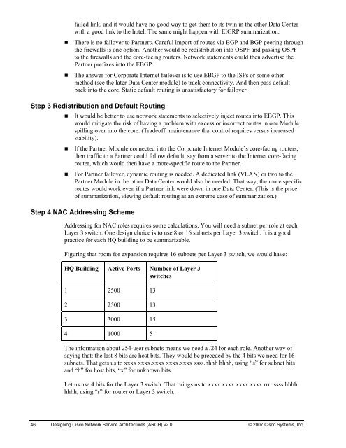
failed link, and it would have no good way to get them to its twin in the other Data Centerwith a good link to the hotel. The same might happen with EIGRP summarization.• There is no failover to Partners. Careful import of routes via BGP and BGP peering throughthe firewalls is one option. Another would be redistribution into OSPF and passing OSPFto the firewalls and the core-facing routers. <strong>Network</strong> statements could then advertise thePartner prefixes into the EBGP.• The answer for Corporate Internet failover is to use EBGP to the ISPs or some othermethod (see the later Data Center module) to track connectivity. And then pass defaultback into the core. Static default routing is unsatisfactory for failover.Step 3 Redistribution and Default Routing• It would be better to use network statements to selectively inject routes into EBGP. Thiswould mitigate the risk of having a problem with excess or incorrect routes in one Modulespilling over into the core. (Tradeoff: maintenance that control requires versus increasedstability).• If the Partner Module connected into the Corporate Internet Module’s core-facing routers,then traffic to a Partner could follow default, say from a server to the Internet core-facingrouter, which would then have a more-specific route to the Partner.• For Partner failover, dynamic routing is needed. A dedicated link (VLAN) or two to thePartner Module in the other Data Center would also be needed. That way, the more specificroutes would work even if a Partner link were down in one Data Center. (This is the priceof summarization, viewing default routing as an extreme case of summarization.)Step 4 NAC Addressing SchemeAddressing for NAC roles requires some calculations. You will need a subnet per role at eachLayer 3 switch. One design choice is to use 8 or 16 subnets per Layer 3 switch. It is a goodpractice for each HQ building to be summarizable.Figuring that room for expansion requires 16 subnets per Layer 3 switch, we would have:HQ Building Active Ports Number of Layer 3switches1 2500 132 2500 133 3000 154 1000 5The information about 254-user subnets means we need a /24 for each role. Another way ofsaying that: the last 8 bits are host bits. They would be preceded by the 4 bits we need for 16subnets. That gets us to xxxx xxxx.xxxx xxxx.xxxx ssss.hhhh hhhh, using “s” for subnet bitsand “h” for host bits, “x” for unknown bits.Let us use 4 bits for the Layer 3 switch. That brings us to xxxx xxxx.xxxx xxxx.rrrr ssss.hhhhhhhh, using “r” for router or Layer 3 switch.46 <strong>Designing</strong> <strong>Cisco</strong> <strong>Network</strong> <strong>Service</strong> <strong>Architectures</strong> (ARCH) v2.0 © 2007 <strong>Cisco</strong> Systems, Inc.