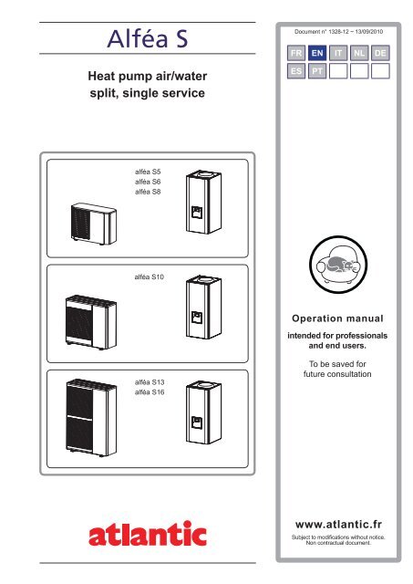
Alféa S - Atlantic-comfort.com
Alféa S - Atlantic-comfort.com
Alféa S - Atlantic-comfort.com
- No tags were found...

Create successful ePaper yourself
Turn your PDF publications into a flip-book with our unique Google optimized e-Paper software.
Split systemContentsInstructions to be read before using the equipment . . . . . . . . . . . . . . 3Safety instructions . . . . . . . . . . . . . . . . . . . 3Start-up . . . . . . . . . . . . . . . . . . . . . 3Use . . . . . . . . . . . . . . . . . . . . . . . 3Maintenance. . . . . . . . . . . . . . . . . . 3Precautions and warnings regarding your installation. . . 4The outdoor unit . . . . . . . . . . . . . . . . 4The hydraulic unit . . . . . . . . . . . . . . . . 4Control system . . . . . . . . . . . . . . . . . 4Fan convectors with integrated control system. 4The radiators . . . . . . . . . . . . . . . . . . 4Floor-heating systems. . . . . . . . . . . . . 4Domestic hot water (DHW) . . . . . . . . . . . 4Overall view of the installation. . . . . . . . . . . . . . . . . . . . . . . . . . 5Operation of the installation . . . . . . . . . . . . . . . . . . . . . . . . . . . 6User interface and room control unit (option) . . . . . 6Appliance start up. . . . . . . . . . . . . . . . . . . . 8Quick start-up . . . . . . . . . . . . . . . . . . . . . 8Programming examples . . . . . . . . . . . . . . . . 9Structure of the "End user" control menu . . . . . . 10Parametering the setting . . . . . . . . . . . . . . . 11General . . . . . . . . . . . . . . . . . . . . 11Setting parameters . . . . . . . . . . . . . . 11List of “End user” settings. . . . . . . . . . . 11Information display . . . . . . . . . . . . . . . . . . 15Details . . . . . . . . . . . . . . . . . . . . . . . . 15Operation of the DHW system . . . . . . . . . . . . 15Selecting cooling mode . . . . . . . . . . . . . . . 15Configuring room control unit (Option) . . . . . . . . 16Maintenance. . . . . . . . . . . . . . . . . . . . . . . . . . . . . . . . . . . 16Checking that the floor system is full. . . . . . . . . 16Checking the outdoor unit . . . . . . . . . . . . . . 16Checking the refrigeration circuit. . . . . . . . . . . 16- 2 -Operation manual "1328 - EN"
Split system1 Instructions to be read before using the equipmentPlease <strong>com</strong>ply with the following instructions in orderto avoid any risk of injury or inappropriate use of theappliance.1.1 Safety instructions1.1.1 Start-up""Do not switch the appliance on until everyfillings have been done.""Do not try to install this appliance yourself.""This heat pump requires an appropriatelyqualified person to install it.""The installation must always be connected tothe Earth and fitted with a protective circuitbreaker.""Do not modify the electricity supply.""The appliances are not fireproof and shouldtherefore not be installed in a potentiallyexplosive atmosphere.1.1.2 Use""Do not let children insert foreign bodies intothe fan protection grill or climb on top of theoutdoor unit. The fins on the air exchanger areextremely fine and cause cuts.""Nothing should obstruct the air circulationthrough the evaporator and from the fan.""Do not climb on the top of the outdoor unit.""The room in which the appliance is operatingmust be correctly ventilated in order to preventany loss of oxygen if there is an escape ofrefrigerant gas.""Consult your Installer before making anychanges or modifications to the premises wherethe appliance is installed.""Do not place any heat source under the roomcontrol unit .1.1.3 Maintenance""Do not try to repair this appliance yourself.""This appliance does not contain any <strong>com</strong>ponentscapable of being repaired by the user himself.Removing one or other of the covers can exposeyou to dangerous electrical voltages.""In any case, switching off the current is notsufficient to protect you from any externalelectrical shocks (capacitors).""Do not open the outdoor unit or the hydraulicunit while they are operating.""Switch off the power supply if there are anyabnormal noises, smells or smoke <strong>com</strong>ing fromthe appliance and contact your installer.""Switch off the power to the appliance beforeyou clean it.""Do not use aggressive cleaning liquid orsolvents to clean the body work.""Do not use a pressure washer to clean theoutdoor unit. This could damage the airexchanger and the water might penetrate intothe electrical circuits.Operation manual "1328 - EN" - 3 -
Split system1.2 Precautions and warnings regardingyour installation.1.2.1 The outdoor unitThe outdoor unit contains the equipment for capturingenergy from the ambient air.Your installer has placed this unit in a location thatenables it to operate in an optimum manner.Nothing should obstruct the air circulation through theevaporator and from the fan.The control system for your heating system is designedin flow temperature for the water based on the outdoortemperature (water control).In cold periods, this water freezes in contact with theexchanger and is drained away by regular defrostingcycles.The control system automatically controls the defrostingcycle, whose operation can lead to the quite normalemission of steam.1.2.2 The hydraulic unitThe hydraulic unit contains the heat pump <strong>com</strong>pletecontrol system, in charge of controlling the heating<strong><strong>com</strong>fort</strong> level and the production of domestic hot water(if the installation is fitted with a DHW tank with electricalback-up heating).The heat pump is equipped with an electric back-upsystem, which is designed to provide additional heatduring the coldest periods.1.2.3 Control systemYour installer has carefully adjusted your installation. Donot modify setting parameters without his agreement. Ifin doubt, do not hesitate to contact him.The control system for your heating system is designedin flow temperature for the water based on the outdoortemperature (water control).The installation of a room thermostat (option) allows toimprove operation of the regulation (the influence of theroom temperature is taken into account).1.2.4 Fan convectors with integrated control systemDo not use a room sensor in the area.1.2.5 The radiatorsTo ensure the function of the regulation with roominfluence, it's necessary that the room in which the roomthermostat is installed has no thermostatic valve or thatthey must be <strong>com</strong>pletely open.1.2.6 Floor-heating systemsNew floor-heating systems require to be initially heatedslowly to avoid any problems with cracking. Checkwith your installer that this initial heating procedurehas indeed been performed before using your heatingsystem freely.To be efficient, floor-heating systems do not need tobe very hot and never should be. At most, the systemsshould be warm to the touch in cold weather.The great stability in a regulation system for floor-heatingsystems avoids sharp differences in temperature.However, this stability involves a reaction time of theorder of several hours, (approx 6 hours).Any changes to the setting must be made slowly, leavingthe installation time to react. Adjusting the system toexaggerated setting or in an untimely manner alwaysresults in significant temperature fluctuations duringcourse of the day.Similarly if your dwelling has a floor-heating system,do not reduce the heating or switch it off if you will beabsent for a short period. The reheating period is alwaysquite long (approx 6 hours).1.2.7 Domestic hot water (DHW)This function is designed as an option through the useof a DHW tank with electrical backup heating.When the DHW production is required, the heat pumpadapts to this demand with higher priority.No space heating is produced while the domestic hotwater is being prepared.Domestic hot water (DHW) is produced by the heatpump and then topped up, if necessary, by electricalbackup heating or the boiler.To ensure a DHW setting over 45°C, the electricalbackup heating or the boiler must be left on.The electrical backup heating enables anti-legionellacycles to be conducted efficiently.- 4 -Operation manual "1328 - EN"
Split system2 Overall view of the installationYour heat pump has been configured by your installer. Itis <strong>com</strong>posed of the following main elements :--The outdoor unit is positioned, as its name indicates,outside your dwelling and extracts energy from theoutside air.--The hydraulic unit positioned in your boiler room, cellar,garage or even your kitchen, transfers the energy tothe heating circuit (and the domestic hot water).--The outdoor sensor detects the outdoor temperature.Optional equipment :--Room thermostat.--Room control unit.Heat pumps are systems that can be connected to anyform of low temperature heat distribution systems : theheat captured by the heat pump can therefore be usedin different ways :--Floor-heating systems.--Radiators or fan coil heaters.--Domestic hot water (DHW).OutdoorsensorRoomthermostatRoomcontrol unitHeating circuitFloor heating systemor / andControl optionsOptionsdependingon the systemconfigurationsHeating circuitRadiators orfan convectorsor2nd circuit kitDHW kitDHW tank(with electricalback-up heating)The hydraulic unitBoilerconnexion kitThe outdoor unitfigure 1 - Overall view of the configuration of a <strong>com</strong>plete installationOperation manual "1328 - EN" - 5 -
Split system3 Operation of the installation3.1 User interfaceand room control unit (option)1Auto52630 4 8 12 16 20 24ESCOK7894RESETUser interface1Auto5Auto1021130 4 8 12 16 20 24ESCOK7131248°C136Room control unit (option)Room thermostat (option)figure 2 - User interface, room control unit (option) and room thermostat (option)- 6 -Operation manual "1328 - EN"
Split systemRef. Functions - Definitions1 Selecting of the DHW operating mode(Domestic hot water).On MarcheOff Arrêt--If the installation is fitted with a DHW tank.--On : Production of DHW according to the time program.--Off : Preparing the domestic hot water for stopping with the anti-frostfunction active.--Manual start button : Hold down the DHW key for 3 seconds. Switch from"reduced" to "<strong><strong>com</strong>fort</strong>" until the next time the ECS timer switches over.2 Digital display. --Operating control. Readout of the current temperature, of the heating modeand of any faults .--View the settings.3 Exit "ESC". --Quit the menu.4 Navigation and setting. --Selecting the menu.--Setting parameters.--Adjusting the ambient temperature setpoint.5 Selecting the heating mode. --Auto Heating operating according to the heating programme(Summer/winter mode switchover is automatic).--Constant <strong><strong>com</strong>fort</strong> temperature.--Constant reduced temperature.--Stand-by mode with anti-frost protection(Provided that the heat pump's electrical power supply is not interrupted).6 Information display. --Various data (please see page 15).--Reading error codes.--Information concerning maintenance, special mode.7 Confirm "OK". --Input into the selected menu.--Confirmation of the parameter settings.--Confirmation of the adjustment to the <strong><strong>com</strong>fort</strong> temp. setting.8 Selecting cooling mode.Auto--If the installation is fitted with the cooling kit :--Cooling operating according to the heating programme(Summer/winter mode switchover is automatic).9 RESET button(Hold down the "RESET" key for 3 sec).--Reinitialising the parameters and cancelling error messages.Do not use during normal operation.10 Selecting the heating mode. --Auto Heating operating according to the heating programme(Summer/winter mode switchover is automatic).--Constant <strong><strong>com</strong>fort</strong> temperature.--Constant reduced temperature.--Stand-by mode with anti-frost protection(Provided that the heat pump's electrical power supply is not interrupted).11 Digital display. --Operating control. Readout of the current temperature, of the heating modeand of any faults .12 Control knob. --Adjusting the ambient temperature setpoint.13 Presence key. --Comfort / Reduced switchover.Operation manual "1328 - EN" - 7 -
Split system3.2 Appliance start up.• The installation and 1st start up of the appliancemust be done by a qualified installer. That person willalso give you instructions on starting and running theappliance.• Ensure that the installation is fully filled with waterand has been correctly bled and that there is asufficient pressure of 1.5 to 2 bars on the manometer(Ref. 2, figure 4).• Close the installation's main circuit breaker.In winter, so that the <strong>com</strong>pressor can bepreheated, close the installation's main circuitbreaker (outdoor unit's power supply) somehours before pressing the on/off button.3.3 Quick start-upOnce your installer has started your installation for thefirst time :• Engage the start/stop switch.During the regulator initialisation phase,the display shows all the symbols and then"Data, update" and then "State heat pump".• Select the "AUTO" heating mode (figure 5).• Select the DHW mode (figure 5).If the installation is fitted with a DHW tank with electricalback-up heating :• Set the current date and time (figure 6).Press OK►_ _ _ _ _ _ _ _ _ _ _ _ _ _ _Time of day and dateOperator sectionChoose menuTime and datefigure 3 - Opening the door1Press OK2XxxxxxxxxxxxxxxxxxxxxxxxxxXxxxxxxxxxxxxxxxxxxxxxxxxxXxxxxxxxxxxxxxxxxxxxxxxxxx3►Time of day and dateHours / minutesSelect line:Hours / minutesor Day / Monthor Year.1. User interface2. Manometer (installationhydraulic pressure)3. Start/stop switchPress OKfigure 4 - Start-up►Time of day and dateHours / minutesMake allthe settingsPress OKto confirmeach setting.Press heating mode keyto return to basic display(n°1, figure 7).figure 5 - Selecting the heating mode (AUTO)and selecting the DHW operating modefigure 6 - Setting the time and the date- 8 -Operation manual "1328 - EN"
Split system3.4 Programming examplesSetting the time.Keys Display example Description1AUTOBasic displayRoom setpoint 1If the basic display is not shown,press ESC to return to it0 4 8 12 16 20 24Press OK.2AUTOTurn the knob, choose menuTime and date.Time of day and dateOperator section0 4 8 12 16 20 24Press OK to confirm.3AUTOTurn the knob, Select line 1Hours / minutes,Time of day and dateHours /minutes0 4 8 12 16 20 24Press OK to confirm.4AUTOThe hour display flashesTime of day and dateHours /minutesTurn the knobto set the time,0 4 8 12 16 20 24Press OK.5AUTOThe minutes display flashes,Time of day and dateHours /minutes0 4 8 12 16 20 24Turn the knobto set the minutes.Press OK6AUTOThe setting are recordedTime of day and dateHours /minutes0 4 8 12 16 20 24Turn the knobto make other settingsorPress heating mode key to return tobasic display.figure 7 - Setting the timeOperation manual "1328 - EN" - 9 -
Split system3.5 Structure of the "End user"control menuBasicdisplayBriefpressEnd user Commissioning Engineer OEMTime of day and dateHours / minutesDay / MonthYear123HoursMinutes1...24 h0...60 minOperator sectionLanguage20English, German...Time prog heating circuit 1Time prog heating circuit 2Time program 4/DHWPre-selection1st phase on1st phase off2nd phase on2nd phase off3rd phase on3rd phase offDefault values500501502503504505506516Mon-SunMon-FriSat-SunMondayTuesday…SundayHolidays heating circuit 1Holidays heating circuit 2Pre-selection1st phase on1st phase offOperation level641642643648Period 1Period 2...Period 8Heating circuit 1Heating circuit 2Comfort setpoint 710Reduced setpoint 712Frost protect. setpoint 714Reduced temp... 35 °CTemp. frost protect... <strong><strong>com</strong>fort</strong>4 °C... reduced temp.Domestic hot water Nominal setpoint 1610 Reduced temp...65 °CFault Reset HP 6711 No, YesService/special operation Emergency operation7141Off, OnDiagnostics heat generationDiagnostics consumersReturn temp HP 8410Flow temp HP 8412Compressor modulation 8413Outdside temp. 8700Reset outside temp min87028701Reset outside temp max 8702......Relay output QX7 9037Off, Onfigure 8 - Programming example- 10 -Operation manual "1328 - EN"
Split system3.6 Parametering the setting3.6.1 General• Only the parameters accessible to levels :End userare described in this document.• The parameters accessible at level :Commissioning levelEngineer… are described in the document reserved forthese professional specialists. Do not make anymodifications to these parameters without advicefrom these professional specialists.3.6.2 Setting parametersWith the screen on basic display.--Press OK.Once in "End user" level.--Scroll the menu list.--Choose the desired menu.--Scroll the function lines.--Choose the desired line.--Adjust the parameter.--Check the setting by pressing OK.--To return the menu, press ESC.If no setting is made for 8 minutes, the screen returnsautomatically to the basic display.BasicdisplayOKBriefpressEnd userOK OK OKTime of day and date Hours / minutes 1 Hours 1...24 hOperator section Day / Month 2 Minutes 0...60 minTime prog heating circuit 1 Year 3...3.6.3 List of “End user” settingsLineFunctionSetting rangeor displaySettingincrementBasicsettingDate and time1 Hours / minutes 00:00... 23:59 12 Day / Month 01.01... 31.12 13 Year 1900... 2099 1User interface20 Language English, Deutsch, Français,Italiano, Nederlands...Heating time program, circuit 1500 Pre-selection (day / week)Mon-Sun Mon-Fri Sat-Sun Monday Tuesday…Mon-Sun501 1st phase On (start) 00:00... --:-- 10 min 6:00502 1st phase Off (end) 00:00... --:-- 10 min 22:00503 2nd phase On (start) 00:00... --:-- 10 min --:--504 2nd phase Off (end) 00:00... --:-- 10 min --:--505 3rd phase On (start) 00:00... --:-- 10 min --:--506 3rd phase Off (end) 00:00... --:-- 10 min --:--516 Default values, Circuit 1 No, Yes NoYes + OK: The default values memorised in the regulator replace and cancel the customised heating programmes.Your customised settings are therefore lost.Operation manual "1328 - EN" - 11 -
Split systemLineFunctionSetting rangeor displaySettingincrementBasicsettingHeating time program, circuit 2If the installation consists of 2 heating circuits (Only with the 2nd circuit kit option).520 Pre-selection (day / week)Mon-Sun Mon-Fri Sat-Sun Monday Tuesday…Mon-Sun521 1st phase On (start) 00:00... --:-- 10 min 6:00522 1st phase Off (end) 00:00... --:-- 10 min 22:00523 2nd phase On (start) 00:00... --:-- 10 min --:--524 2nd phase Off (end) 00:00... --:-- 10 min --:--525 3rd phase On (start) 00:00... --:-- 10 min --:--526 3rd phase Off (end) 00:00... --:-- 10 min --:--536 Default values, Circuit 2 No, Yes NoTime program 4 / DHWYes + OK: The default values memorised in the regulator replace and cancel the customised heating programmes.Your customised settings are therefore lost.If the installation is fitted with a DHW tank. (Only with the DHW kit option).560 Pre-selection (day / week)Mon-Sun Mon-Fri Sat-Sun Monday Tuesday…Mon-Sun561 1st phase On (start) 00:00... --:-- 10 min 00:00562 1st phase Off (end) 00:00... --:-- 10 min 05:00563 2nd phase On (start) 00:00... --:-- 10 min --:--564 2nd phase Off (end) 00:00... --:-- 10 min --:--565 3rd phase On (start) 00:00... --:-- 10 min --:--566 3rd phase Off (end) 00:00... --:-- 10 min --:--576 Default values No, Yes NoTime program 5 / CoolingYes + OK: The default values memorised in the regulator replace and cancel the customised heating programmes.Your customised settings are therefore lost.If the installation is fitted with the cooling kit (Only with the cooling kit option).600 Pre-selection (day / week)Mon-Sun Mon-Fri Sat-Sun Monday Tuesday…Mon-Sun601 1st phase On (start) 00:00... --:-- 10 min 8:00602 1st phase Off (end) 00:00... --:-- 10 min 20:00603 2nd phase On (start) 00:00... --:-- 10 min --:--604 2nd phase Off (end) 00:00... --:-- 10 min --:--605 3rd phase On (start) 00:00... --:-- 10 min --:--606 3rd phase Off (end) 00:00... --:-- 10 min --:--616 Default values No, Yes NoYes + OK: The default values memorised in the regulator replace and cancel the customised heating programmes.Your customised settings are therefore lost.- 12 -Operation manual "1328 - EN"
Split systemLineFunctionSetting rangeor displaySettingincrementBasicsettingHolidays, heating circuit 1641 Preselection Period 1 to 8 Period 1642 Start (Day / Month) 01.01... 31.12 1643 End (Day / Month) 01.01... 31.12 1648 Operating level (during the holidays) Frost protection, Reduced FrostprotectionHolidays, heating circuit 2If the installation consists of 2 heating circuits (Only with the 2 nd circuit kit option).651 Preselection Period 1 to 8 Period 1652 Start (Day / Month) 01.01... 31.12 1653 End (Day / Month) 01.01... 31.12 1658 Operating level (during the holidays) Frost protection, Reduced FrostprotectionHeating Circuit 1710 Comfort heating setpoint from reduced setpoint to 35°C 0,5 °C 20 °C712 Reduced setpoint from frost protection setpoint…to <strong><strong>com</strong>fort</strong> setpoint714 Frost protection setpoint from 4°C…to reduced setpoint0,5 °C 18 °C0,5 °C 8 °CCooling circuit 1901 Operating mode Off, Automatic Off902 Comfort cooling setpoint 17... 40 °C 0,5 °C 24 °C907 Release 24h/day, Time program HC,Time program 5 / CoolingTimeprogram 5Heating Circuit 2If the installation is fitted with a DHW tank, set the parameter 907 to "Time program 5 / Cooling"(In order to activate cooling only during the day and leave the DHW system to operate during the night).If the installation consists of 2 heating circuits (Only with the 2nd circuit kit option).1010 Comfort heating setpoint from reduced setpoint to 35°C 0,5 °C 20 °C1012 Reduced setpoint from frost protection setpoint…to <strong><strong>com</strong>fort</strong> setpoint0,5 °C 18 °C1014 Frost protection setpoint from 4°C… to reduced setpoint 0,5 °C 8 °CDomestic hot water (DHW) (Only with the DHW kit option)1610 Nominal setpoint Reduced setting (line 1612)…to 65 °C1 50 °CThe backup electrical system is required to reach this level.1612 Reduced setpoint 8 °C...to Nominal setpoint (line 1610)1 25 °CSwimming pool (Only with swimming pool kit option)2056 Setpoint source heating 8... 35 °C 22 °CFault6711 Reset HP No, Yes NoService / Special operation7141 Emergency operation Off, On OffOff : The heat pump does not use the backup electrical heating system or the boiler connection when a fault occurs (error 370)On : The heat pump uses the backup electrical system or the boiler connection when a fault occurs (error 370).In the "On" position, the energy costs can be onerous if the error is not eliminated.Operation manual "1328 - EN" - 13 -
Split systemLineFunctionSetting rangeor displaySettingincrementBasicsettingDiagnostics heat generation8410 Return temp HP 0... 140 °CSetpoint (return) HP 0... 140 °C8412 Flow temp HP 0... 140 °CSetpoint (flow) HP 0... 140 °C8413 Compressor modulation 0... 100%Diagnostics consumers8700 Outdside temperature -50... 50 °C8701 Outside temp minReset ? (No, Yes)8702 Outside temp maxReset ? (No, Yes)-50... 50 °C-50... 50 °C8740 Room temperature 1 0... 50 °C 20 °CRoom setpoint 1 4... 35 °C 20 °C8743 Flow temperature 1 0... 140 °C 50 °CFlow temperature setpoint 1 0... 140 °C 50 °C8756 Flow temp cooling 1 0... 140 °C 0 °CFlow temp setpoint cooling 1 0... 140 °C 0 °C8770 Room temperature 2 0... 50 °C 20 °CRoom setpoint 2 4... 35 °C 20 °C8773 Flow temperature 2 0... 140 °C 50 °CFlow temperature setpoint 2 0... 140 °C 50 °C8830 DHW (domestic hot water) temperature 0... 140 °CDHW temperature setpoint 5... 80 °C 50 °C8900 Swimming pool temperature 0... 140 °CSwimming pool temperature setpoint 0... 35 °C 22 °C- 14 -Operation manual "1328 - EN"
Split system3.7 Information displayVarious data can be displayed by pressing the infobutton.Depending on the type of unit, configuration andoperating state, some of the info lines listed below maynot appear.--Possible error messages from the error code list. Thedisplay shows the "Bell" symbol .""Consult your heating technician.--Possible service messages from the maintenancecode list. The display shows the “Key” symbol .""Consult your heating technician.--Possible special mode messages. The display showsthe “Key” symbol .""Consult your heating technician.Various data (See below).DesignationLineFloor drying current setpoint . -Current drying day. -Terminated drying days. -State heat pump. 8006State supplementary source. 8022State DHW. 8003State swimming pool. 8011State heating circuit 1. 8000State heating circuit 2. 8001State cooling circuit 1. 8004Outdoor temperature. 8700Room temperature 1.Room setpoint 1.8740Flow temperature 1.Flow temperature setpoint1.8743Room temperature 2.Room setpoint 2.8770Flow temperature 2.Flow temperature setpoint 2.8773DHW (domestic hot water) temperature. 8830Heat pump return temperature.Setpoint (return) HP.8410Heat pump flow temperature.Setpoint (flow) HP.8412Swimming pool temperature.Swimming pool temperature setpoint.89003.8 DetailsBriefpressfigure 9 - Information keyIf the electrical power supply has been cut off whilethe heat pump is operating (electrical power failure orunprogrammed pressing of the on/off switch on thehydraulic unit) the display will show error 370 when theappliance restarts.Do not be concerned, the <strong>com</strong>munication between theoutdoor and hydraulic unit will re-establish itself in a fewmoments.3.9 Operation of the DHW systemThe key enables you toswitch the DHW (domestichot water) mode on andoff (If the installation isfitted with a DHW tank withelectrical back-up heating).The selection is shown bya bar, which appears underthe corresponding symbol.Press the info key toobtain the details on theDHW (temperature settingoperation).To ensure a DHW setting over 45°C, the electricalbackup heating or the boiler must be left on.3.10 Selecting cooling modeIf the installation is fitted withthe cooling kit.The key activates anddeactivates cooling mode.Details of any errorOperating values...figure 10 - Selectingthe DHW operating mode(domestic hot water)figure 11 -Selecting cooling modeOperation manual "1328 - EN" - 15 -
3.11 Configuring room control unit (Option)Installation equipped with a room control unitDuring <strong>com</strong>missioning, after an initialisation period ofapprox. 3 minutes, the user’s language must be set :--Press the key OK.--Choose menu (User interface).--Choose language : English.4 MaintenanceIn order to insure your appliance operates correctly formany years, the maintenance operations described beloware required at the start of each heating season.Generally, these are performed as part of a servicecontract.4.1 Checking that the floor system is fullThe pressure in the floor system when it is cold and whenit has stopped must be 1,5 bars.If filling and re-pressurization are required, check whattype of fluid has been used initially.If in any doubt, contact your installer.Warning : If frequent filling is required, have the installation'ssealing checked.4.2 Checking the outdoor unitDust off the heat exchanger if necessary, being careful notto damage the fins.Check that there is nothing obstructing the passage of air.4.3 Checking the refrigeration circuitWhen the refrigerant fluid charge is in excess of 2kg(S 10, S 13 and S 16 models), it is <strong>com</strong>pulsory to have anapproved after sales service check the refrigeration circuitevery year.Consult your heating technician.Date of installation :This appliance is marked with this symbol. This means that electrical and electronic products shall not be mixed with general household waste.European Community countries(*), Norway, Iceland and Liechtenstein should have a dedicated collection system for these products.Do not try to dismantle the system yourself as this could have harmful effects on your health and on the environment.The dismantling and treatment of refrigerant, oil and other parts must be done by a qualified installer in accordance with relevant local and national regulations.This appliance must be treated at a specialized treatment facility for re-use, recycling and other forms of recovery and shall not be disposed of in the municipalwaste stream.Please contact the installer or local authority for more information.* subject to the national law of each member stateContact of your heating technician or your after-sales service.www.atlantic.frSociété Industrielle de ChauffageSATC - BP 64 - 59660 MERVILLE - FRANCERC Dunkerque - Siren 440 555 886Subject to modifications without notice. Non contractual document.