belt drive models - Whirlpool
belt drive models - Whirlpool
belt drive models - Whirlpool

You also want an ePaper? Increase the reach of your titles
YUMPU automatically turns print PDFs into web optimized ePapers that Google loves.
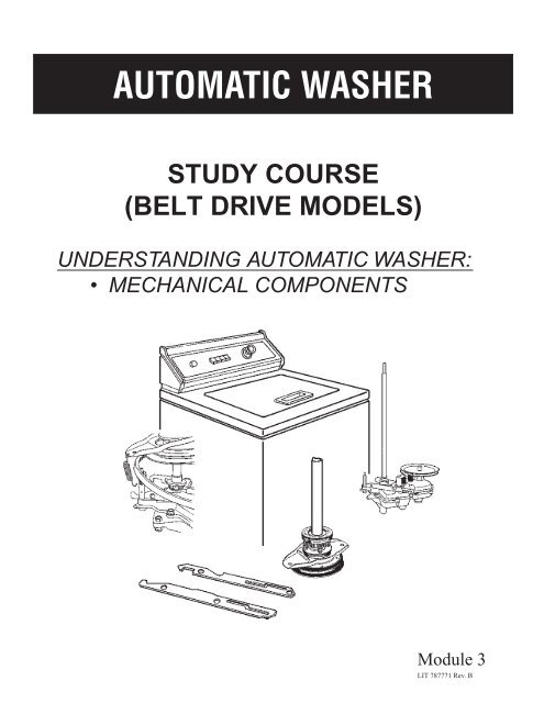
INTRODUCTIONThe material presented in this module is intended to provide you with an understanding of thefundamentals of automatic washer servicing.Major appliances have become more sophisticated, taking them out of the screw<strong>drive</strong>r and plierscategory. Their electrical circuits include several different types of automatic controls, switches,heaters, valves, etc.. Semiconductors, solid-state controls, and other components usuallyassociated with radio and television electronic circuits are being engineered into automaticwashers, dryers, dishwashers, and refrigerators.The appliance technician is emerging into a professional status of his own. He must preparehimself now to be able to perform his duties today as well as to retain his professionalism in thefuture.No longer is on-the-job training sufficient to prepare technicians for the complicated proceduresrequired for todays sophisticated appliances. This training can best be obtained through organizedclassroom study and application. However, much of the knowledge necessary to service todaysappliances can be obtained through study courses. Completion of this and other courses willprovide you with sufficient understanding of appliances and their operation to enable you to dominor service. It will also serve as a valuable stepping stone to more advanced study and on-thejobtraining to improve your servicing skills.Information contained in this module is used on WHIRLPOOL® appliances.1
TABLE of CONTENTSPAGECHAPTER 1 ......................................................................................... 3MECHANICAL COMPONENTS*TEST ........................................................ See Test Book LIT787774*NOTE:We recommend taking the TEST for MODULE 3, rightafter studying it.2
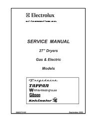
CHAPTER 1MECHANICAL COMPONENTSThe mechanical components of an automatic washerinclude the cabinet, suspension, spin-basket <strong>drive</strong>,and braking mechanism, as well as the gearcase.These are the components that most often determinethe useful life of the washer.GEARCASE ASSEMBLYSUPERSTRUCTURE(MAIN DRIVE PULLEY)MAIN DRIVEPULLEYGEARCASE and SUPERSTRUCTURECONTROL MAGNET(WIG WAG)For the purpose of describing the construction andfunctions of these mechanical assemblies, they willbe divide into two major operating units — thegearcase assembly (which controls agitation for thewash and rinse functions) and the spin basket <strong>drive</strong>and brake assembly, or superstructure, (for spin andbraking).SUPERSTRUCTURE(MAIN DRIVE PULLEY)DRIVEBELTMAIN DRIVEPULLEYCONTROL MAGNET(WIG WAG)DRIVE MOTORPULLEYGEARCASESPINCAM BARGEARCASEAGITATECAM BARThe main function of the gearcase assembly is toprovide a means for driving the agitator; first in onedirection, then in the other, providing the necessarywashing action. The size of the arc in which theagitator travels in each direction, and the number ofstrokes it makes per minute, is determined by theparticular design of the gears that are in the gearcaseassembly, the size of the pulleys, and the motor speedwhich <strong>drive</strong>s these gears. Many automatic washersare equipped with a normal-stroke gear case which<strong>drive</strong>s the agitator in a 195 arc, approximately 68strokes per minute at high motor speed.Both of these units have separate pulleys <strong>drive</strong>n bya common motor and a flexible V-<strong>belt</strong> to provide adeep, nonslip <strong>drive</strong>. The function of these two unitsis controlled by the control magnet assembly (wigwag) and two cam bars mounted on top of thegearcase. Each unit operates independently; theynever operate at the same time on a properly adjustedmachine.The gears in the gearcase are <strong>drive</strong>n by the largepulley secured to the top of the main <strong>drive</strong> pinion bymeans of a self-locking set screw. This pulley is knownas the main <strong>drive</strong> pulley.3
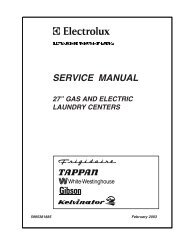
AGITATORSHAFTGEARFORKAGITATORGEARThe illustration above shows the gearcase assemblyafter the pulley has been removed and the coverraised prior to complete disassembly.SECTORGEARSince the sector gear meshes with the agitator gear,this gear will turn first in one direction and then inthe other.The main <strong>drive</strong> pinion meshes with the main <strong>drive</strong>gear, which is mounted on a one-inch diameter stud.CONNECTINGRODMAIN DRIVEGEARSECTORGEARThe main <strong>drive</strong> gear is coupled to the sector gear (thesection of a total gear), by means of a heavy steelconnecting rod. Therefore, as the main <strong>drive</strong> gearrotates the sector gear oscillates.To begin agitation, the agitator gear fork will movedownward, causing two of the slots in the bottom ofthe agitator gear to engage the <strong>drive</strong> pin in theagitator shaft. Thus, the agitator shaft will oscillateas the sector gear moves the agitator gear, providingthe washing action (or agitation).Both the agitator shaft and the gear-fork shaft areequipped with compression springs which constantlyexert a downward pressure. The agitator gear fork israised by means of the agitate cam bar. This actiondisengages the agitator gear from the <strong>drive</strong> pin inthe shaft, stopping the action.The agitate cam bar is mounted on top of the gearcaseand is controlled by the plunger which moves up anddown in the agitator solenoid.4
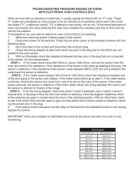
BASKET DRIVE and BRAKEASSEMBLY (Superstructure)BRAKE YOKEDRIVEPULLEYBASKETDRIVE TUBEUPPERBRAKELOWERBRAKECONTROLMAGNETAGITATESOLENOIDSPINCAM BARMounted directly above the pulley on the <strong>drive</strong> tubeis the basket <strong>drive</strong> disc. A clutch lining which makescontact with the basket <strong>drive</strong> pulley during SPIN ismounted on the <strong>drive</strong> disc.SPINSOLENOIDAGITATECAM BARNUTDRIVEPULLEYParts making up the superstructure on top of thegearcase are associated with the basket <strong>drive</strong> (spin)and braking. The same <strong>belt</strong> and motor pulley thatsupplies the power to the agitator <strong>drive</strong> pulley also<strong>drive</strong>s the basket <strong>drive</strong> pulley.SPRINGCLUTCHSHAFTUPPERSLOTCONTROLMAGNETSPINPLUNGERPINSPINCAM BARGEARCASEAGITATECAM BARThe basket <strong>drive</strong> pulley is a part of the basket <strong>drive</strong>and brake assembly. It slips over the agitator shaftand rests on the basket support collar on top of thegearcase assembly. The basket <strong>drive</strong> pulley is alwaysturning clockwise whenever the main <strong>drive</strong> motor isrunning. This pulley turns freely on the basket <strong>drive</strong>tube.Like the agitator solenoid and cam bar, when the spinsolenoid is energized its plunger is pulled upward bymagnetic attraction. The bottom end of this plungerstraddles the spin cam bar, as shown above. A pinthrough this plunger rides in the slot in the cam bar.The pin in the plunger will move to the upperportion of the slot in the cam bar when the solenoidis energized. Since the control magnet assembly ismoving back and forth with the sector gear, this pinpulls the cam bar away from the basket clutch shaft.5
Because the opposite end of the cam bar is taperedand inserted in a slot in the basket clutch shaft, itcauses the brake yoke to move downward. This causesthe basket clutch to come into contact with therevolving basket <strong>drive</strong> pulley. Pressure is providedby the clutch and brake pressure springs.BASEPLATEUPPER BRAKELININGUPPERBRAKE DRUMLOWERBRAKE DRUMSPLINESSPRINGBRAKE YOKESPINCAM BARAt the same time, the upward force of the brake yokebrings it in contact with the lower brake lining. Theentire superstructure will be moved upward by thisaction causing the upper brake lining to contact thebase plate assembly.The upper and lower brake drum assemblies turnwith the basket <strong>drive</strong> disc since they are splined toits hub. When the spin solenoid is energized, thebrake linings do not contact the braking surfaces,since the brake yoke is not applying pressure to thebrake. The brake lining may be riveted to the drumor it may be free floating.These two simultaneous braking actions bring thebasket to a fast, smooth stop. Four compressionsprings between the two brake drums provide thenecessary force for both upper and lower brakingaction.The upper brake drum is secured to the basket <strong>drive</strong>tube by a self-locking screw. This tube always turnswhen the basket <strong>drive</strong> disc is engaged with thebasket <strong>drive</strong> pulley.At the end of each SPIN period, the timer switchcontacts break the circuit to the spin solenoid. Whenthis action occurs, the plunger in the solenoid drops,since there is no longer any magnetic force pulling itupward. The pin in this plunger then rides in thelower portion of the slot in the spin cam bar andpushes the cam bar forward. The tapered end of thecam bar lifts the basket clutch shaft. This forces thebrake yoke upward, separating the basket clutch fromthe basket pulley.6
GEARCASE and SUPERSTRUCTUREREMOVALwWARNING4. Lay the washer on its front, on a padded surface,and remove the <strong>drive</strong> <strong>belt</strong> from the motor pulleyand the pump from the gearcase.5. Disconnect all the electrical wires (or connectors)from the control magnet solenoids.6. Remove the three screws which hold the gearcaseto the baseplate.BOLTBRACEElectrical Shock HazardDisconnect power before servicing.Replace all panels before operating.Failure to do so can result in deathor electrical shock.NUTSNUTSNUTWhen removing the gearcase and superstructure, thefollowing procedures should be used.1. Unplug washer or disconnect power.2. Remove the agitator cap and the agitator, alongwith the tub ring.NOTE: On older machines that used an agitator<strong>drive</strong> lug, it is necessary to remove the lug beforedisassembly can be continued. The <strong>drive</strong> lug canbe removed by using a <strong>drive</strong> lug puller. You canpour hot water over the lug which will expand itand ease its removal.BRACEBRACE7. Remove the gearcase support braces attached toboth the gearcase and baseplate.NOTE: It is very important that these braces bereinstalled during reassembly for proper machinefunction . Noise and damage to the machine canotherwise result.The complete gearcase and superstructure assemblycan now be pulled from the bottom of the machine.PLASTICRETAINERBRAKEYOKEBRAKEYOKEYOKESUPPORTSPRING3. Remove the spanner nut and the wash basket.4. Insert a screw<strong>drive</strong>r to expand the slot in thetapered basket <strong>drive</strong> block. This will release the<strong>drive</strong> block from the spin tube.NOTE: Sometimes it’seasier to remove the washbasket and <strong>drive</strong> block together.There is a plastic retainer which snaps into the brakeyoke. The yoke support then snaps into this plasticretainer.7
“T” BEARINGBALLTake the brake shoe yoke spring off or unsnap theplastic retainer. Now the complete basket <strong>drive</strong> andbrake assembly will slip off of the agitator shaft.Next, take out the cap screw holding the cam barbrake spring and lift it off. Then remove the screwthat holds the control magnet to the sector gear shaft.Lift the control magnet and cam bars off.Most machines used a steel ball mounted in a hole inthe agitator shaft. The “T” bearing has a groove in itso that when you slide it down the agitator shaft, thegroove fits over the steel ball. Be careful, as this steelball may fall out of the hole in the agitator shaft.NOTE: Some real old machines may have used asetscrew and metal support collar bearing or a fiberitecombination support collar and thrust bearing.The gearcase will now be free and easy to work with.PLUNGERSPECIALTOOLAGITATECAM BARFORK“T” BEARINGUsing a special tool, slide the cam bars through theagitator control shaft and the basket clutch shaft.The special tool gives you leverage to overcome thespring pressure on the agitator fork shaft. Loosenthe set screw from the main <strong>drive</strong> pulley and take itoff.After removing the cap screws holding the cover tothe gearcase, lift the cover off. Careful prying with ascrew<strong>drive</strong>r may be necessary to release the coverfrom the dowel pins positioning it to the case.NOTE: Use extreme care so as not to damage themating surfaces.8
REBUILDING the GEARCASEWhen completely rebuilding a gearcase the followingprocedures are recommended. First, disassemblethe gearcase and clean all parts in a solvent. Use awire brush to help. It is important that the case beas clean as possible; any dirt or grit can quickly ruina bearing or shaft. You can blow out the pinion,sector, agitator, and fork shaft holes to remove anyhidden dirt or metal particles.NOTE: Be sure to wear safety glasses while doingthese procedures.Visually examine the following parts for excessivewear:AGITATORSHAFTGEARFORKAGITATORGEARSECTORGEARCONNECTINGRODPINIONGEARMAIN DRIVEGEARPinion Gear — Insert the shaft of the pinion gear inthe cover bearing; there should be no play. A slightscoring of the shaft at the bearing is acceptable aslong as the area is not undersized. Teeth areas of thegear should appear to have uniform wear and be freeof sharp nicks.Sector Gear — The teeth should have uniform wearand be free of any pitting and sharp nicks. Check theconnecting rod hole for wear. A slight amount of playis acceptable but the hole should not be egg shaped.Make sure the shaft is tight in the gear.Agitator Gear — If the gear is badly rounded whereit slides on the <strong>drive</strong> pin, replace it. A small amountof wear will not affect gear operation.Agitator Shaft — The plating on the shaft should notbe scored or damaged in the seal or bearing area.The <strong>drive</strong> pin on the end of the shaft should not haveexcessive wear.Gear Case Cover — Check the cam bar slots for anybroken sides. If the pinion bearing is worn, only thebearing need be replaced. If the cam bar has wornthe cover in the area of the gear fork, then a specialhardened steel washer should be used. The washerfits over the gear fork shaft between the cam bar andcover.Micellaneous Items — Carefully check such thingsas the agitator shaft, thrust washer, and bearing fordistortion. Inspect cam bars, pins, and plungers forwear.Reassemble the gearcase using only new parts whererequired. Refill the gearcase with 12 to 15 ounces ofS.A.E. No. 60, nondetergent motor oil (check specifications)before installing the cover. Prior to securingthe cover bolts, make sure that the pinion has at least1/8 inch of vertical travel. This will insure adequateclearance between the pinion bearing and pinionwasher after the cover bolts are tightened.Main Drive Gear — The teeth should appear to haveuniform wear and should be free of pitting, brokenareas, and sharp nicks.Connecting Rod — Be sure the studs are securelystaked (fastened) to the bar. The stud should showno appreciable wear.9
GEARCASE ADJUSTMENTREPLACING CENTERPOSTBEARINGS and SEALSWhen installing the gearcase and superstructure,always check the tub centerpost bearings. Worncenterpost bearings and seals should be replaced.BEARINGPULLER1 INCH DRIVE STUDThere are two general types of gearcases that havebeen used. They can be recognized by the size of the<strong>drive</strong> gear studs and the presence or absence of aneccentric adjustment screw. Those gearcases with a1 inch <strong>drive</strong> gear stud require no gear adjustment.BEARINGINSERTERRemoval of and replacements of the upper and lowerbearings and seals is accomplished by using thesespecial tools.LOWERBEARINGECCENTRICADJUSTMENTLOCKNUTTo check the eccentric adjustment in the home, fillthe washer with water and let it agitate. If, with themachine agitating under a full load of water, there isa knocking sound in the gearcase, the adjustment istoo loose. If this occurs, readjust the eccentric studuntil the knocking stops. Ease off the adjustment, asmuch as possible without permitting a knock. Thentighten the locking nut.NOTE: The gearcase should not be carried or handledby the agitator shaft. The spring that is between theagitator gear and cover will allow upward travel ofthe shaft. If the shaft is pulled up too far, the thrustbearing washer may cock out of position and preventthe shaft from proper seating on the bearing.BASEPLATEUsing the puller tool the bearings and seals can beremoved.NOTE: Before installing new centerpost beh ings andseals, it is important that the inner wall of the entiretube centerpost be cleaned with a wire brush. As thereis no seal directly above the lower bearing, anyforeign matter left in the centerpost could fall intothe bearing area.10
CHECKING CENTERPOST andGEARCASE ALIGNMENTUPPERBEARINGWith the machine completely reassembled (except forthe agitator), you need to check the alignment of thegearcase with the centerpost bearings by using thefollowing procedures.MAIN DRIVEPULLEYSEALLOWERBEARINGSPINCAM BARPLUNGERUsing the special bearing inserter tool, install a singlelip seal (with the seal lip up) in the top of thecenterpost. Then press a new bearing only into thetop and bottom of the centerpost.Install a new single lip seal into the bottom of thecenterpost beneath the bearing, being sure that thelip of the seal is up. Add approximately 1/2 ounce ofRykon No. 2 grease in the lower bearing sectionbefore installing the gearcase and superstructure.When installing the gearcase and superstructure, becareful not to damage the new centerpost seals wheninserting the top of the basket <strong>drive</strong> tube throughthem.Before installing the agitator shaft seal and topcenterpost seal, add turbine oil in each cavity to alevel just above the bearing. Each cavity has a sealinstalled just below to retain the oil.The spin cam bar will need to be advanced to thespin position. Push up on the spin control solenoidplunger and rotate the main <strong>drive</strong> pulley until thecam bar advances to the spin position.Then, lift the basket and release it. When released,the basket should return to its original position ifthe gearcase alignment is correct.Misalignment can be corrected by loosening the <strong>belt</strong>tension, the three gearcase mounting screws and thethree support braces. This allows the agitator shaftand spin tube to properly align themselves in thecenterpost bearings. Retighten the three gearcasemounting screws and braces. Then readjust the <strong>belt</strong>tension.NOTE: Install the agitator shaft seal and the topcenterpost seals with the lip up.SPACERIf the basket does not readily move up and down,you can correct the problem by loosening one gearcase11
mounting screw at a time until the misalignment isrelieved. If the misalignment occurs at the gearcasemounting screw where the support spacer is inserted,replace the spacer. However, if it takes place at oneof the other two gearcase supports, then shim themas needed with the special horseshoe shim washerswhich are available for this purpose.NUTSBOLTBRACENUTComplete the reinstallation of the gearcase andsuperstructure by heating the <strong>drive</strong> lug, if used, inhot water so that the lug can be positioned with 2 or3 light taps of a hammer.NOTE: The <strong>drive</strong> lug must fit the shaft tightly toprevent noisy operation.DRIVE BELT REPLACEMENTRemove the rear access panel and loosen the nutholding the motor mounting bracket in the slottedbaseplate hole. Rotate the motor to the right torelieve the <strong>belt</strong> tension, and remove the <strong>belt</strong> fromthe motor pulley. Then move the motor to the left asfar as the baseplate slot will permit.The spin cam bar must be advanced to the spinposition. Push up on the spin control solenoidplungner and rotate the main <strong>drive</strong> pulley until thecam bar advances to the spin position.BRACERemove the three gearcase support braces from thegearcase. It will be necessary to loosen the nuts atthe baseplate ends of the braces. These braces mustbe replaced after the <strong>belt</strong> replacement is completed.Remove the two pump mounting bolts and swing thepump clear of the gearcase. When replacing thepump, make certain that the pump lever is engagedin the notch in the agitator cam bar before securingthe pump to the gearcase. Use only the pump boltswith the special retaining washer to mount the pump.Take out the gearcase mounting screw which has thespacer. Remove the spacer.YOKEAGITATORSHAFTBRACENUTSBRAKESPRINGSPINCAM BARYOKESPRINGCLUTCHSPRINGPLUNGERPLASTICRETAINERSPECIALPULLERBOLTSPACERGEARCASEYOKESUPPORTRemove the brake yoke spring. Grasp the bottom loopof the spring with a pair of pliers and disengage thespring from the hole in the upper gearcase cover.Use a puller to raise the clutch shaft sufficiently toclear the cam bar, (Channel-lock pliers can also beused in place of the puller), and then slide the cambar out of the clutch shaft. Then remove the puller,allowing the shaft to fall. Insert the new <strong>belt</strong> throughthe gap between the shaft and the yoke and reinsertthe cam bar.12
Replace the spacer and position the new <strong>belt</strong> overthe pulleys. Replace the pump and the three supportbraces. A socket wrench is an excellent timesavingtool.Use the following procedures to make any <strong>drive</strong> <strong>belt</strong>adjustments.the clutch surface when the clutch is disengaged. Onthose automatics that use three clutch pads on thebasket <strong>drive</strong> discs, it is necessary to line up one ofthe three pads with the clutch shaft before makingthe adjustment.AGITATORSWith the <strong>belt</strong> positioned properly over the pulleys,adjust the <strong>belt</strong> tension by inserting a hammer handleor some other lever between the motor mountingbrackets. Rotate the motor to the left as far as it willgo. Tighten the nut holding the motor mountingbracket. Check the tension of the <strong>belt</strong>; it shoulddeflect about 1/2 inch, midway between the twopulleys.BASKET DRIVE CLUTCHADJUSTMENTTo adjust the clutch after service, start the machinein agitation so that the clutch is disengaged and thenstop it.Agitators used on automatic washers are molded fromeither bakelite or polypropylene. Although the shapesof the agitators may vary among <strong>models</strong>, there areonly two different means of driving the agitators.Many agitators are <strong>drive</strong>n by a hexagon tapered <strong>drive</strong>lug which is pressed onto the agitator shaft. A hexhead stud screws into the top of the agitator shaft.The agitator cap screws onto the top of the stud andholds the agitator down.NOTE: Always make sure that the rubber washer isbetween the agitator and cap.CLUTCHPADCLUTCHADJUSTMENTNUTAnother method of driving agitators is by utilizingan agitator which is pressed directly onto the splinedagitator shaft, eliminating the <strong>drive</strong> lug. This typeagitator can be used on automatics with <strong>drive</strong> lugsby removing the lug.1/16" CLEARANCEAdjust the nut on the basket clutch shaft to obtain aclearance of 1/16 inch between the clutch lining and13
SPIN BASKETSNUBBERThe porcelain-finished basket is perforated to allowfree-flow draining. A conical-shaped bottom with ahigh centerpost provides a clean smooth surface thatdoes not trap sediment and soil deposits.If the basket is loose on the spin tub, it will causeexcessive noise. Correct by tightening the spannernut. Make sure the spin tube ears are positioned inthe <strong>drive</strong> block notches. Any wear in the <strong>drive</strong> blocknotches requires replacement.Examine the inside of the basket to be certain thatthere are no sharp edges or perforations that mightcause clothing damage. If rough spots are found, sandor buff them off. Seal the sanded areas with epoxy.SNUBBERPLATESNUBBERSNUBBERSPRINGBASEPLATESUSPENSIONRODSA snubber is used on each machine to reduce themotion of the baseplate and tub assembly during spinacceleration. This should prevent an unbalanced loadfrom causing the baseplate to strike the cabinet.The snubber assembly consists of a tempered-steelwire spring secured to the right rear corner gusset ofthe cabinet, and a snubber pad that presses againstthe top of the tub ring.If there is excessive vibration or noise due to a worn,loose, or oily snubber, the snubber pad must bereplaced. To replace it, unlatch and raise the topassembly and then lift up the snubber spring andremove the snubber pad.TUBThe baseplate provides the mounting for the tub,gearcase assembly, and main motor. The baseplateis suspended from the top of the cabinet assembly bythree suspension rods. These rods are mountedin a manner that permits limited movement ofthe mechanism without transmitting vibration to thecabinet.There are two types of tubs used — porcelain orDuratite (a plastic). They cause almost no serviceproblems.Each suspension rod is fitted with a rubber ball atits upper and lower ends. These suspension balls areunder tension when enclosed between the socket andcap. The flexing of the ball permits a limited amountof movement to the baseplate assembly.14
CENTERPOST BEARINGS and SEALSHINGED TOPBecause of oversudsing, lack of lubricant, or normalwear, it is sometimes necessary to replace thecenterpost bearings and seals. To check for such wear,raise the top, and grasp the agitator cap with onehand and the spin basket with the other hand. Holdthe basket firmly, and vigorously shake the agitatorback and forth. A worn bearing will click slightly orfeel loose. This condition can cause a noise complaintand/or torn clothing.TUB RINGOn machines where the top of the flange is straight,the brown or green and black clips must be used.TUBFLANGEBLACKCLIP(SHORT)BROWN ORGREEN CLIP(LONG)The cabinet top is hinged at the rear to provideaccess for servicing many of the components of theautomatic washer. To raise the hinged top assembly,raise the lid, grasp the top assembly at the front ofthe lid opening, pull slightly forward and raise thetop upward. It will pivot back on its hinges.ORFRONT OFWASHEROn machines where the top of the tub flange curls out,the red clips must be used.CLIPTUBFLANGEREDCLIPFRONT OFWASHERThe tub ring, or splash shield, is seated on top of thetub. The tub ring is held in place by four clips. Theclip located at the trough area is shorter than theother three.A rubber gasket is used to provide a cushion betweenthe tub ring and the tub. The gasket provides a tightseal around the top rim to prevent water from goingout over the top of the tub during the spin cycle. Italso helps to prevent water from splashing over thetop during agitation.Using a putty knife, place the blade between the topand front cabinet panel in one corner, about 2-1/2inches in from the edge. Push in on the putty knife torelease the clip while lifting up on the corner of thetop. Do the same to the other front corner.NOTE: Do not pry or you may ruin the finish.15
CHANGES to LATER MODEL LARGECAPACITY WASHERSChanges were phased into production on all largecapacity <strong>models</strong>. The modifications that were madeinvolved the basket, baseplate, superstructure, andgearcase.The basket is the same size that was used on earlierlarge capacity <strong>models</strong>, except that it has a shortercenterpost. The baseplate centerpost is also shorter.A standard 14-pound gearcase and superstructureassembly is used in the modified large capacity unit.AGITATORSHAFTSEALSEALSPACERBEARINGTURBINE OILDRIVETUBECENTERPOSTFILL CAVITY WITHRYKON #2 GREASESEALS14"BEARINGSEALSEALSFILL CAVITY WITHEXTRA HEAVYTURBINE OILSPACERFILL CAVITY WITHRYKON #2 GREASEBEARINGSEALSince the basic tub and basket size remained thesame, the high water level in the large capacity unitis still about fourteen inches in the basket. Usingthe standard gearcase, superstructure, and shortercenterpost now places the water level above thecenterpost and agitator seals.To prevent water from entering the centerpost oragitator shaft areas, three seals were added and thelocation of two (2) bearings was changed. The uppercenterpost bearing is pressed in about 5/8 inch deeper.This allows room for two upper centerpost seals.16
HIGH WATERLEVELBASKETPOSTRevised bearing tools and seal installers are requiredfor the modified unit. Because of the upper bearingposition and the additional seal, a deeper bearingpuller cap and a longer screw are needed to pull thebearing. The shoulder on the upper mandrel has beenlengthened to properly seat the upper bearing.Procedures for using the revised tools are unchanged.The new bearing tools are available from Robinairthrough your local parts distributor.SHIELDAIR POCKETWATERDRIVEBLOCKThe position of the agitator bearing in the spin tubewas also lowered 5/8 of an inch and a second sealwas added to this area. A third new seal is the spintube shield. The shield is slipped over the spin tubeand rests about 1/2 inch above the centerpost. Theshield forms an air pocket in the basket centerpost.This keeps water from entering the centerpost sealarea.RYKON #2GREASESHIELDTURBINEOILBEARING KITSHIELDSHAFTSEALSCover both the centerpost bearing and agitator shaftbearing with turbine oil and install the first of twoupper seals with the new seal installer. Thoroughlylubricate the inner surfaces of the second seal withRykon No. 2 grease. Install these as in the past. Allseals must be correctly installed. To install the spintube shield, lightly lubricate the inner lip of the shieldwith Rykon No. 2. Place the shield about one and ahalf inches down on the spin tube. Seating the <strong>drive</strong>block on the spin tube ears will properly position theshield.A replacement bearing kit is available. In additionto the bearings and bottom seals, the kit containstwo upper seals. As before, the agitator shaft sealswill be provided separately. The spin tube shield isalso listed as a separate component.NOTE: This unit uses the large capacity flat bottom<strong>drive</strong> block.17
SUMMARYGenerally speaking, it is the mechanical componentsthat determine the useful life of the washer. The twomajor operating units are the gearcase and thesuperstructure. The gearcase controls the agitationfunction while the superstructure will control thebasket during spin and braking. The two units are<strong>drive</strong>n by a common motor and <strong>belt</strong>, however, thetwo units never work simultaneously. The controlmagnet assembly in conjunction with two cam barscontrols the independent operation of the units.Due to the configuration of the gears in the gearcase,the agitator gear rotates first in one direction andthen in the opposite direction. During agitation, theagitate solenoid pulls the agitate cam bar, allowingthe agitator gear to engage with the two pins on theagitator shaft which causes the agitator shaft torotate with the agitator gear. At the end of the spinperiod, or if the lid is opened during spin, the circuitto the spin solenoid is opened. This action causes thespin cam bar to move forward, forcing the brake yokeupward and separating the basket clutch from the<strong>drive</strong> pulley. It also causes the upper and lower brakelinings to engage, bringing the basket to a fast,smooth stop.Before reassembly of the gearcase, examine all gearsfor excessive wear or sharp nicks. A hardened steelwasher is available to repair a worn gearcase cover.When transporting a gearcase it should never becarried by the agitator shaft. It is possible to dislodgethe thrust bearing washer which would prevent theshaft from proper seating on the bearing.Before installing the gearcase, always check thecondition of the centerpost bearings and seals, andreplace them if they show the slightest wear.After installation of the gearcase and superstructure,it is imperative that the alignment of the gearcaseand centerpost be checked. If the spin basket is looseon the spin tube it will cause excessive noise. If the<strong>drive</strong> block notches are worn the <strong>drive</strong> block must bereplaced. The snubber is used to reduce baseplateand tub assembly motion during machine operation.18
NOTES19
20NOTES
BLANK
BLANK