Dishwasher Training/Repair Manual
Dishwasher Training/Repair Manual
Dishwasher Training/Repair Manual

Create successful ePaper yourself
Turn your PDF publications into a flip-book with our unique Google optimized e-Paper software.
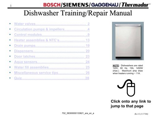
1/ /<strong>Dishwasher</strong> <strong>Training</strong>/<strong>Repair</strong> <strong>Manual</strong>/• Water valves…………………………………..… 2• Circulation pumps & impellers……………… .4• Control modules………………………………. ..9• Heater assemblies & NTC’s………...……….. 13• Drain pumps……………………………………. 19• Dispensers……………………………………... 20• Door latches…………………………………… 23• Aqua sensors………………………..…...…… 24• Water fill assemblies…………………………. 25• Miscellaneous service tips………………….. 26• Quiz……………………………………………….28702_58300000133621_ara_en_aNOTE: <strong>Dishwasher</strong>s are rated120V, 60 Hz, 15A, 1450W(max.). Maximum amp drawwhen heaters running ~ 11A.Click onto any link tojump to that pageRev 0 (1/17/08)
2/ /Part # 1 -- Water Valve (1)/DisassemblyAccess the water valve from the front of the dishwasher base byremoving the toe kick.To remove water valve:Tools needed: T20 Torx screwdriver & pliers.1. Remove two (2) T-20 Torx screws from toe kick and tilt toe kick outfrom under dishwasher.2. Remove base insulation (on models with insulation).3. Move sump inlet hose away from water valve (without disconnecting it).4. Disconnect wires from water valve, including ground wire.5. Remove two (2) T-20 Torx screws from water valve.6. Pull valve out from dishwasher and disconnect water hose from rear ofvalve. Remove any water from sump & base.Old stylevalveshownCONNECTION HINTS: Waterconnection 3/8” NPT female.Inlet water pressure range 5 -120 psi (0.3 – 8.27 bars).Removing toe kick Moving sump hose Removing hose clampOld stylevalve shownOld style valve shown702_58300000133621_ara_en_aRev 0 (1/17/08)
3/ /Part # 1 -- Water Valve (2)/Service Tips607335“Rast 5”425458 &189533580009(yellowstem) or167081(white stem)HINTS:NOTE: Water valves have been upgraded several times since 1st 1/4 of 1999.• 607335 “Rast 5” time-fill water valve (UC/43 & above dw’s) has a keyedterminal connector and can’t replace 425458 or 189533 valves. It replaces all“Rast 5” time-fill or pressure-fill valves.• Time-fill valve # 425458 (UC/42 & below) also replaces pressure-fill valve #189533. It looks like pressure-fill valve # 189533, but isn’t the same.Pressure-fill valves can’t replace time-fill valves.• Pressure-fill valve (part # 189533) has a horizontally mounted solenoid andwater fitting held in place by the metal mounting bracket. It replaced olderpressure-fill valves (580009 & 167081) until time-fill valve 425458 was used.702_58300000133621_ara_en_a• When reconnecting thewater supply to the watervalve, don’t overtighten theelbow fitting. On valveswith vertical solenoids, theplastic can crack andcause leaking if excessiveforce is used.• Using Teflon tape on waterfittings can help preventleaking.• The water valve can beaccessed without removingouter door or base cover.However, removing themwill provide easier access.Rev 0 (1/17/08)
5/ /Part # 2 -- Circulation Pump & Impeller (2)To remove toe kick:Tools needed: T20 Torx screwdriver.1. Remove two T-20 Torx screws from toe kick (1).2. Tilt toe kick out from under dishwasher (2).To remove right & left side panels:Tools needed: T20 Torx screwdriver.<strong>Dishwasher</strong>s may have long or short side panels, depending on model. Removing the left side panelisn’t necessary for access, but allows the right side of the tank to be blocked upward.1. For models with long side panels, remove two T-20 Torx side panel screws through holes inright & left trim strips (1).2. To remove long side panels, lift panels with trim strips up and out from dishwasher (2).3. To remove short side panels, remove two T-20 Torx screws (3). To avoid damaging trim strips(while blocking tanks), slide trim strips up until they clear dishwasher bases.12/For models UC/36& above, toe kicksscrew directly intoplastic bases usinglonger screws.1Longsidepanelsshown233Long sidepanels shownShort sidepanels shownLong sidepanels shownShort sidepanels shown702_58300000133621_ara_en_aRev 0 (1/17/08)
6/ /Part # 2 -- Circulation Pump & Impeller (3)To raise right side of tank for circulation pump access:Tools needed: T20 Torx screwdriver and pliers.1. Remove one T-20 Torx screw from both rear corners holding tank to base (1) -- removing screwfrom both sides allows tank to be blocked upward.2. Remove right toe kick bracket by removing T-20 Torx screw (2).3. Remove T-20 Torx screws from front right bottom corner holding tank to base (3).4. Remove right hinge cover (4a), release right door tension cord from hinge (4b) & remove groundwire (4c).5. Raise and block up tank as shown with strut onto base (5a), sliding a piece of wood or other solidmaterial between the tank and base to keep tank from falling back onto base (5b)./Screw1 2 34a4bCAUTION: Don’t turn dishwashersupside-down for tank access. Whendishwashers are turned upside-down,water can flow into the water fill assemblydiaphragm and cause water to not fillproperly.4c5a5b702_58300000133621_ara_en_aRev 0 (1/17/08)
7/ /Part # 2 -- Circulation Pump & Impeller (4)DisassemblyTo remove motor to access impeller or change complete pump:Tools needed: flat blade screwdriver.1. Disconnect wire harness from motor after carefully noting connections (1).2. For UC/11 & later models with softer bearing, lift up rubber straps from both sides of motor (2). Forolder models, lift motor up from base.3. To release plastic latch on pump/motor housing (@ 2:30 position), carefully push onto latch withscrewdriver (3).4. To release motor from pump housing, twist motor to the right (clockwise). Some force may berequired. Capacitor should be ~ 11:00 position (4). Pull motor out from pump housing.HINT: When replacingcirculation pumps for softerbearing models (UC/11 & later),reusing existing front pumphousings can save time by notchanging hose clamps. Ifdesired, order # 172272 hoseclamps & replace entire pumps./1 233 44CAUTION: Don’t grabmotor next to the capacitorto avoid jamming yourhand on the capacitor.See page 8 forpump types.Latch702_58300000133621_ara_en_aRev 0 (1/17/08)
9/ /Part # 3 -- Control Modules/Disassembly(SHU 9922 shown)Control modules are easily removed from fasciapanels by bending console tabs.Tools needed: T-20 Torx & flat blade screwdrivers.1. Remove fascia panel by removing T-20 Torx inner door screws.2. Disconnect wire harnesses from module after noting connector locations.3. Pry out metal console tabs holding module to console.4. Carefully pry back plastic tabs, then slide module from console.Check connections beforereplacing modules!Removing door screws Removing fascia panel Viewing control module Disconnecting wiresTIP: Modules have been replaced when problem wasloose connections. Before replacing modules, checkconnections first!Bending back tabsSliding module outNOTE: Control modules for non-integrated models lookdifferently and have different tabs, but are removed using thesame procedure.702_58300000133621_ara_en_aRev 0 (1/17/08)
10/ /Part # 3 – Apexx Control ModulesDisassemblyApexx (SHV99A/SHX99A-B/SHY99A, DWHD94) control modules aredifferent than other models and are removed differently. Modules aremounted on the base (where base wiring connectors were), not behindfascia panels. This means:• <strong>Dishwasher</strong>s must be pulled out to change control modules.• <strong>Dishwasher</strong>s must be pulled out to measure voltages &resistances./These instructions apply toSHE/SHV/SHX98-99 models.HINT: Apexx controlmodules cannot bechecked or haveresistances measuredfrom the front ofdishwashers.For access to Apexx control modules:Tools needed: T-20 Torx screwdriver & pliers.1. Remove outer door – see page 3.2. Remove toe kick – see page 4.3. Remove right/left side panels – see page 4.4. Raise right side of tank – see page 5.NOTE: Modules weremoved to the base to makeroom for the larger full textdisplays in the fascia panel.HINT: Its helpful, but notnecessary, to remove outerdoors to access Apexxcontrol modules.HINT: It may be possible to reachbehind modules without blockingup tanks. If not, then follow theseinstructions to block up tanks.702_58300000133621_ara_en_aRev 0 (1/17/08)
11/ / /Fault Codes & Control CodingService Tips – Fault Codes & Control CodingControls contain codes for factory tests, customer service test program, dishwasher configuration andfault codes. Consult test programs and fault codes for each dishwasher before using codes below.P(X) Program codesP0 = Functional test - used for assemblyP1 = Customer service test programP3 = Endurance/Life testP4 = Control coding (see “C(X)” control codes below)E(X) Error codesE0 = No errorsE1 = Heating errorE2 = NTC errorE3 = Filling errorE4 = Water switch cannot be positionedE5 = Safety level reachedE6 = Aqua sensor errorC(X) Control CodesCodes C1 to C9 possible, depending on dw modelHINT: Customers pushing Cancel-Drain orCancel-Reset buttons while dw’s are offcan see codes, leading to service calls.702_58300000133621_ara_en_aRev 0 (1/17/08)
12Service Tips --/ / /-- Modules Displaying “1”Occasionally dishwashers can run for hours, not finish washing & show a “1” in the display. Thismeans the module has timed out due to an unidentified heating problem -- all heating related partsmust be checked until the problem is found.If no, module isworking fine.NOTE: The heating problemmust be fixed before themodule will reset and stopshowing a “1” in the display.NTC(~ 55kΩ@72ºF)Replacing NTC’salso replaces Hi-Limit’s.NOSTARTHas dishwasherstoppedwashing and isshowing a “1”in the display?YES3-winding circulation pumps can measure ~7Ω or 9.4Ω, depending on motor starter.Controlmodule(heater relay &solder joints)Wireharness &terminalsTIP: Modules have been replaced whenproblem was loose connections. Beforereplacing modules, check connections first!If yes, control modulehas timed out showingthere’s an unidentifiedheater problem.Have theseparts beenchecked??High Limit(~ 0.3Ω)IMPORTANT:Whenever a “1”shows in themodule display,the module mustbe reset (after theheating problemhas been fixed)by running thedishwasher. Themodule resetsafter the 1 st run.Replacing heaters alsoreplaces NTC’s, flowswitches & Hi-Limit’s.Heater(~ 11Ω)CirculationpumpIf flow switch is OK &water doesn’t flow,check circulation pump.Flow Switch(~ 0.4Ω)HINT: Check module heater relays, wireharnesses / terminals & heaters beforechecking NTC’s, flow switches & high limits.702_58300000133621_ara_en_aRev 0 (1/17/08)
13Disassembly/ /Part # 4 -- Heater & NTC (1)For access to heaters & NTC’s:Tools needed: T-20 Torx screwdriver & pliers.1. Remove outer door – see page 3.2. Remove toe kick – see page 4.3. Remove right/left side panels – see page 4.4. Raise right side of tank – see page 5.To separate base from tank (1):1. Carefully lay dishwasher on its back.2. Carefully pull door springs out from base.The heater & NTC can be accessed or measured from the right side of thedishwasher, but can only be removed by dropping the entire base (by flippingthe dishwasher on its back) since they are wedged underneath the tank.HINT: The fascia panel and door don’t need to beremoved to access the heater & NTC. However, the doormust be removed to completely remove the tank.HINT: Remove all water from the sump and hosesbefore accessing the heater -- when the dishwasher isflipped on its back, water can enter the water fill assemblydiaphragm and cause the dishwasher to not fill properly./Placing on backPulling out door springs from base & disconnecting cords702_58300000133621_ara_en_aRev 0 (1/17/08)
14/ /Part # 4 -- Heater & NTC (2)To separate base from tank (2):3. Remove terminal blocks from base (for two-piece harnesses).4. Disconnect hose from water valve (or remove water valve from base if easier).5. Disconnect J-box ground wire, then pull wires out of J-box.6. Pull out inlet hose from sump.7. Carefully pull base away from tank and sump.Old stylevalve shown/HINT: Remove waterfrom sump and hosesbefore laying dishwasheron its back (to avoidwater entering water fillassembly & causingfaulty water filling).Removing terminal blocks from baseDisconnecting hose from water valvePulling J-box wires Pulling out sump hose Pulling base carefully from tank & sump702_58300000133621_ara_en_aRev 0 (1/17/08)
15/ /Part # 4 -- Heater & NTC (3)To remove heater & NTC:1. Remove two (2) T-20 Torx screws holding heater assembly to sump.2. Disconnect wires from heater, flow switch, NTC & Hi-Limit after notingconnections.3. Pull clips, then carefully pull heater assembly from sump & pump.Note heater comes as an assembly (with housing & gasket)./NOTE: Softer bearing & nonsofterbearing heaterassemblies, circulationpumps and sumps cannot bemixed and matched. Softerbearing heaters don’t fit inolder models and olderheaters don’t fit in softerbearing models.HINT: If needed, use rinseaidto lubricate gaskets tomake it easier to assembleheater to sump and pump.Pull clipsHeater assemblyRemoving heater screws Removing heater from sump/pumpNOTE: Softer bearing & non-softer bearing heater assemblies areconnected to circulation pumps differently:• Softer bearing models (UC/11 & above) have gasket assembledto heater and have a separate hose clamp (order # 172272).• Older models (UC/06) have a separate gasket and do not have ahose clamp.Hose clamp“Softerbearing” heaterHINT: Heaterassemblies containNTC’s, Hi-Limit’s &flow switches (& aquasensors whereapplicable). If heatersare replaced, theseparts are replaced too.702_58300000133621_ara_en_aRev 0 (1/17/08)
16Service Tips --/ / /-- Heater Troubleshooting FlowchartCan also measure heater current@ module red heater wire (~ 9.5A).If ~ 11A, heater isworking fine.STARTWith heater on(during testprogram), measuredishwasherincoming current(black wire).If ~ 1.5A, heatercircuit has failed.Measurevoltage @controlmodule.TIP: If controldisplayed “1”,reset it by runningthe dishwasher.NOTE: Flow throughheaters heat water ~2ºF / minute.TIP: Modules timing out &displaying “1” means there’s anunidentified heating problem.If ~120 VAC,check heatercircuit.If ~ 0 VAC, controlmodule (heater relay)has failed. Replacefaulty module.Measureresistance@ heaterterminals.If ~11Ω, check highlimit, flow switch &circulation pump.Measure high limit& flow switchresistance & checkcirculation pump.If ∞ , heater hasfailed (opened).Replace heater.If ~ 0, heater hasfailed (shorted).Replace heater.If high limit ~ 0.3Ω, flow switch ~ 0.4Ω &circulation pump is OK, check wireharnesses. Replace faulty harness.If high limit, flowswitch or circulationpump = ∞ , replacefaulty part.702_58300000133621_ara_en_aRev 0 (1/17/08)
17/ /Service Tips – Heater Operation/Flow through heater heats water without an exposedtank element. Filtered water enters the heater fromthe circulation pump. The heater heats water whenthe flow switch signals water is present.NTC/Hi-limitSealHeating elementFlowswitchAquasensorNTCHi-limitTo upperspray armTo upperspray armTo lowerspray armHeatingelementTo lowerspray armFrom circulation pumpBackflowvalvePump motorDrain pumpcoverDrain pumpSumpImpellerSealThe sump also contains an aqua sensor, drain pump,NTC, Hi-limit and backflow valve. The aqua sensorsenses water cleanliness – dishwashers add rinses ifneeded. The NTC senses water temperature. The Hi-limitshuts off the heater if the water gets too hot. The backflowvalve prevents waste water from entering the dishwasher.702_58300000133621_ara_en_aRev 0 (1/17/08)
19/ /Part # 5 -- Drain PumpsDrain pumps are mounted to sumps in the front of dishwashers -- they’re easily accessible from the frontof dishwashers by removing toe kicks.To remove & install drain pump:Tools needed: small flat blade screwdriver (for unlocking terminals).• Remove toe kick/base cover, pull up terminal cover anddisconnect wires (using screwdriver to unlock locking terminals).• To remove pump, pull latch (on circular collar) & rotate pumpclockwise (cw). To install new pump, insert @ 2:00 position &rotate counterclockwise (ccw).• Clean water & debris from base, then check float operation.• Connect wires, then install base cover & toe kick./NOTE: Drainpump is rated120V, 60 Hz,35W, 0.85A.DRAIN HOSE INSTALLATION TIPS:• Must have drain hoses with high loops (min. 20” high), even with air gaps *.• Drain hoses can be up to 10’ long – can add up to 4’ to dishwasher hose.• Secure drain hoses to rear of dishwashers with non-metal bands.• Make sure drain hoses aren’t kinked.• UC/43 & later drain pumps have (Rast 5) connectors, which aren’tinterchangeable with older pumps with spade terminals (listed below).NOTE: Drain pumps in installations withJohnson Tees (in Washington State) mustuse stronger 4-vane pumps (# 184178).Standard 9-vane drain pumps (# 167082)are quieter and smoother than 4-vanepumps. Older pumps had 6-vanes.* NOTE: High loopsare needed to preventcavitating.TIP: Often improperinstallations, not drainpump issues, causedishwashers to notdrain properly.702_58300000133621_ara_en_aDrain pumpTerminalsWater valveLatchRev 0 (1/17/08)
21/ /Part # 6 -- Dispensers (2)/During each wash program, the wax motor opens twice, once to dispense detergent and again todispense rinse-aid. The wax motor opens the same -- linkages open the detergent door & operate therinse-aid dosage plunger. Dispensers can have reed switches or optical rinse-aid sensors.490472 shownDosage plungerLinkageOpticalsensorReedswitchMagneticfloatWaxmotorNOTE: The white plastic linkage opens the detergent dispenser door,then cocks in place to dispense rinse-aid when the wax motor operatesagain. After the 2nd operation, the linkage resets for the next wash.Condensationtube (olderventeddispenser)HINT: Optical dispensershave different connectionsand can’t be substituted forreed switch dispensers. Note431413 top load dispensersalso use solenoid actuatorsinstead of wax motors.CableguideA wax motor heats wax, which expandsand pushes a plunger. When the waxcools, a spring pushes the plunger back.702_58300000133621_ara_en_aRev 0 (1/17/08)
22/ /Service Tips – Optical Sensor Dispensers/Optical and top-load dispensers measure rinse-aid levels with optical sensors instead of reedswitches.Optical rinseaidsensorTransmitter diodeOptical rinseaidsensorTransmitter diodePrismPrismReceiverdiodeReceiverdiodeWith rinse-aid present, the opticalreceiver senses a diffused light beam.When rinse-aid has run out, the opticalreceiver senses a strong light beam.Cable guideHINT: Opticaldispensers havedifferent connectionsand can’t besubstituted for reedswitch dispensers.‣Standard dispenserTop-loaddispenser ‣NOTE: Top-load and standarddispensers are NOT interchangeable.702_58300000133621_ara_en_aRev 0 (1/17/08)
23/ /Part # 7 -- Door Latches/Disassembly/InstallationOther than occasional misalignment, the only door latch repairs will bereplacing microswitches. Older SHU43/53/68 dishwashers used doorlatches with rods connecting them with on/off switches.To disassemble door latches:1. Remove T-20 Torx fascia panelscrews from inner door.2. Lower fascia panel from door.3. Locate door latch in console.4. Bend out console metal tabs toallow latch removal.NOTE: Use only latchesspecified for each model.Latches can have differingclosing forces, be suitable forspecific door seals & can havechild locks.NOTE: Door latches for UC/14 & up models are different than UC/06 - UC/12 models-- they cannot be interchanged. Must replace strike plate & door latch together.Remove panel screwsLower fascia panel Door latch in console Tabs (inner view) Bend out metal tabs702_58300000133621_ara_en_aRev 0 (1/17/08)
24/ /Part # 8 -- Aqua SensorsThe aqua sensor only affects energy usage, eliminating a pre-wash and/or pre-rinse cycle if water isclean. Most customers won’t notice if an aqua sensor fails. It’s located on the rear of the sump and canbe reached through the left side of the dishwasher (after the left side panel is removed – see page 4). Itsnot necessary to block up the tank to reach the aqua sensor./TankReceiver diodeSumpBaseTransmitter diodeWaterNOTE: Aquasensors provide~ 20% energysavings.HINT: To change out the aqua sensor, pull off theconnector and pull out the aqua sensor (toward therear of the dishwasher). The aqua sensor slides intoslots in the sump. Make sure the aqua sensor isproperly inserted into the slots.NOTE: The Apexx Sensotronic 2 aqua sensor #175340 is similar to standard aqua sensor # 165279,except it has two (red & green) soil sensors. Theymount the same way, but are not interchangeable.702_58300000133621_ara_en_aRev 0 (1/17/08)
25/ /Part # 9 -- Water Fill Assembly/The water fill assembly is easily accessed from the left side by just removing the left side panel (seepage 4). It can be a pressure-fill (with diaphragm) or time-fill, depending on model.DiaphragmWater fill switchFloatswitchNo diaphragm or water fillswitch on time fill modelsFloatswitchFloatFloatPressure-fillHINT: Most water fill assembly repairs involve replacingmicroswitches. Occasionally tank insulation or otherdebris can prevent the diaphragm switch lever fromoperating, allowing overfilling.Time-fillNOTE: Water inlet valves for time and pressure-filllook the same, but pressure-fill valves can’t be usedon time-fill models. Presently, both pressure-fill andtime-fill models use time-fill valve 425458.TIP: Floats should be checked and bases should be cleared ofwater & debris whenever water fill assemblies are worked on.702_58300000133621_ara_en_aRev 0 (1/17/08)
26/ /Miscellaneous Service Tips – Hinge Levers & BushingsSince 12/15/03, all dishwashers have upgraded hinge levers and hinge bushings. New hinge leversand bushings can’t be used with old bushings and levers – must replace levers and bushings together./New 15mm hingebushing with latchesOld 14mmhingebushingwith lockHingeLeverHingePlateLockNOTE: New and old hinge levers and bushings can’t be mixedand matched since new hinge levers have 15mm holes to fit newhinge bushings and old hinge levers had 14mm holes for old hingebushings (and locks).Replacement Hinge Levers and BushingsSide Part # Description Replaced by DescriptionLeft 492033 Lever (14mm) 494876 + 165296 Lever + bushing (15mm)Left 488250 Bushing (14mm) 494876 + 165296 Lever + bushing (15mm)Left 263115 Lever + bushing (14mm) 494876 + 165296 Lever + bushing (15mm)Right 492034 Lever (14mm)Right 488250 Bushing (14mm)Right 263119 Lever + bushing (14mm)494875 + 165296 Lever + bushing (15mm)494875 + 165296 Lever + bushing (15mm)494875 + 165296 Lever + bushing (15mm)OldHingeBushingLockBushingPulleyLatchesNewCordDoorSpringRemove old hingebushing locks byinserting smallscrewdrivers intothe lock hole andtwisting them out.TIP: Unlike old hinge bushings, new hinge bushings areself-locking and don’t need separate locks. To removedoors when new hinge bushings are used, spread latchesapart until door pins clear latches.NOTE: When new 15mm hinge bushings (with latches)are opened, replace them instead of reusing them.702_58300000133621_ara_en_aRev 0 (1/17/08)
27/ /Miscellaneous Service Tips – FAQ/FAQ’s s (2)• Wood door spring usage chart – Once original door spring has beenidentified (Orange 182640 or Violet 168568), use chart below to adjustspring tensions:Door Wood Panel WeightExisting DoorSpringLess than 5.5 lbs (2.5kg)5.5 to 9 lbs(2.5 to 4.1 kg)9 to 15 lbs(4.1 to 6.8 kg)15 to 18 lbs(6.8 to 8.2 kg)18 to 21 lbs(8.2 to 9.5 kg)Violet(168568)Change to 173696Yellow spring - usetension screw if neededChange to 168576 Bluespring - use tensionscrew if neededNo actionUse tension screw toincrease tensionChange to 182640Orange spring - usetension screw if neededOrange(182640)Change to 168576 Bluespring - use tensionscrew if neededChange to 168568 VioletspringNo actionUse tension screw ifneeded to increasetensionUse tension screw toincrease tension702_58300000133621_ara_en_aRev 0 (1/17/08)
28/ /?? <strong>Dishwasher</strong> Service Pop Quiz ??1. A high loop in the drain hose must be used in installations with air gaps(T/F).2. A cheater cord can be used to check all circulation pumps (T/F).3. All dishwashers have a control module mounted in the top of the door (T/F).4. A dishwasher showing a “P” or “C” code after installation is faulty from thefactory and must be exchanged (T/F).5. One water valve can be kept on your truck for all replacements (T/F).6. Any time a dishwasher runs for several hours or times out, the problem willbe solved if the control module is replaced (T/F).7. Match each circulation pump with it’s starter:a) Pump # 239144 a) PTC motor starterb) Pump w/ water switch # 437345 b) 3-phase motor starterc) Sicasym pump # 442548 c) Software in main controld) BLDC pump # 665510 d) Start capacitor w/ cutout switch8. If a door latch is on backorder, another type can be used (T/F).9. Aqua sensors don’t have to be replaced if they fail (T/F).10. Drain pumps have changed little over the years and are interchangeablewith all dishwasher models (T/F)./702_58300000133621_ara_en_aRev 0 (1/17/08)
29/ /?? <strong>Dishwasher</strong> Service Pop Quiz ?? Answers1. A high loop in the drain hose must be used in installations with air gaps(T/F).2. A cheater cord can be used to check all circulation pumps (T/F).3. All dishwashers have a control module mounted in the top of the door (T/F).4. A dishwasher showing a “P” or “C” code after installation is faulty from thefactory and must be exchanged (T/F). Exit control coding mode5. One water valve can be kept on your truck for all replacements (T/F).6. Any time a dishwasher runs for several hours or times out, the problem willbe solved if the control module is replaced (T/F). Check heater system7. Match each circulation pump with it’s starter:a) Pump # 239144 a) PTC motor starterb) Pump w/ water switch # 437345 b) 3-phase motor starterc) Sicasym pump # 442548 c) Software in main controld) BLDC pump # 665510 d) Start capacitor w/ cutout switch8. If a door latch is on backorder, another type can be used (T/F).9. Aqua sensors don’t have to be replaced if they fail (T/F).10. Drain pumps have changed little over the years and are interchangeablewith all dishwasher models (T/F). Rast 5 connector starting UC/43/Not Sicasym,BLDCTFFFFFFTF702_58300000133621_ara_en_aRev 0 (1/17/08)