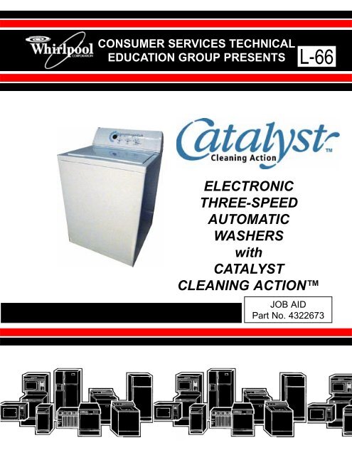
ELECTRONIC THREE-SPEED AUTOMATIC WASHERS with ...
ELECTRONIC THREE-SPEED AUTOMATIC WASHERS with ...
ELECTRONIC THREE-SPEED AUTOMATIC WASHERS with ...

Create successful ePaper yourself
Turn your PDF publications into a flip-book with our unique Google optimized e-Paper software.
CONSUMER SERVICES TECHNICAL<br />
EDUCATION GROUP PRESENTS L-66<br />
<strong>ELECTRONIC</strong><br />
<strong>THREE</strong>-<strong>SPEED</strong><br />
<strong>AUTOMATIC</strong><br />
<strong>WASHERS</strong><br />
<strong>with</strong><br />
CATALYST<br />
CLEANING ACTION<br />
JOB AID<br />
Part No. 4322673<br />
I
INTRODUCXTION<br />
This Job Aid, “<strong>ELECTRONIC</strong> <strong>THREE</strong>-<strong>SPEED</strong> <strong>AUTOMATIC</strong> <strong>WASHERS</strong> <strong>with</strong> CATALYST CLEANING<br />
ACTION,” (Part No. 4322673), has been compiled to provide the most recent information on design,<br />
features, troubleshooting, service and repair procedures. For additional information on the basic washer<br />
components, refer to Job Aid #787930. For additional information on AccuWash, Automatic Temperature<br />
Control, refer to Job Aid #4322334.<br />
GOALS AND OBJECTIVES<br />
The goal of this Job Aid is to provide detailed information that will enable the service technician to<br />
properly diagnose malfunctions and repair of the clothes washer.<br />
The objectives of the Job Aid are:<br />
The service technician will -<br />
• Understand proper safety precautions.<br />
• Successfully troubleshoot and diagnose malfunction.<br />
• Successfully perform necessary repairs.<br />
• Successfully return the air conditioner to proper operational status.<br />
RPRT<br />
WHIRLPOOL CORPORATION ASSUMES NO RESPONSIBILITY<br />
FOR ANY REPAIRS MADE ON OUR PRODUCTS BY ANYONE<br />
OTHER THAN AUTHORIZED SERVICE TECHNICIANS.<br />
© 2000 Whirlpool Corporation, Benton Harbor, MI 49022<br />
PB
TABLE OF CONTENTS<br />
SAFETY ............................................ III<br />
SECTION ONE<br />
FEATURES ............................................ 1<br />
SECTION TWO<br />
THEORY OF OPERATION ................................. 7<br />
SECTION <strong>THREE</strong><br />
COMPONENT ACCESS<br />
COMPONENT LOCATION ............................................................... 15<br />
ACCESSING CRITICAL COMPONENTS ........................................ 16<br />
SECTION FOUR<br />
COMPONENT TESTING & DIAGNOSIS<br />
SERVICE DIAGNOSTIC TESTS ...................................................... 25<br />
ERROR CODES ............................................................................... 27<br />
TROUBLESHOOTING TEST PROCEDURES ................................. 29<br />
SECTION FIVE<br />
TECH TIPS<br />
WIRING DIAGRAM .......................................................................... 35<br />
WARRANTY INFORMATION ........................................................... 35<br />
MODEL/SERIAL NUMBER LOCATION ........................................... 36<br />
MODEL/SERIAL NUMBER DESIGNATION .................................... 36<br />
SAFETY<br />
! WARNING<br />
ELECTRICAL SHOCK HAZARD<br />
Disconnect power before servicing the washer.<br />
Replace all panels before operating the washer.<br />
Failure to do so can result in death or electrical shock.<br />
III
-- NOTES --<br />
PB
Section One<br />
FEATURES<br />
Catalyst Cleaning<br />
CATALYST CLEANING allows detergent to soak and penetrate the<br />
entire load giving improved stain and soil removal.<br />
CATALYST CLEANING uses laundry detergent in a unique way. Water flushes the detergent from<br />
the dispenser to dissolve the detergent. Then the concentrated detergent mixture is sprayed on to the<br />
load while the washer spins at low speed.<br />
CATALYST CLEANING will last one to five minutes, depending on the cycle selected. The washer<br />
then stops spinning and fills to the selected water level and continues washing <strong>with</strong> the selected cycle.<br />
RECIRCULATION<br />
PRESSURE<br />
SWITCH<br />
RECIRCULATION<br />
SPRAY<br />
TUB INLET<br />
RECIRCULATION<br />
HOSE<br />
RECIRCULATION<br />
PRESSURE DOME<br />
DIVERTER<br />
VALVE<br />
FROM PUMP<br />
CATALYST CLEANING ACTION RECIRCULATION SYSTEM<br />
1
QUIET PAK<br />
The QUIET PAK System is designed to reduce water sounds and mechanical noises. The cabinet<br />
and base are insulated <strong>with</strong> sound-dampening materials over which an additional tub wrap is added for<br />
superior vibration and sound-dampening characteristics.<br />
RING<br />
GUARD<br />
SOUND ABSORBING<br />
TUB WRAP<br />
The bleach venturi causes a siphoning action to<br />
draw bleach from the bleach dispenser. Water<br />
passing across the venturi opening creates a low<br />
pressure area behind the venturi pulling the bleach<br />
into the passing water flow.<br />
BLEACH VENTURI<br />
TUB RING<br />
Bleach/Fresh Water Mixture Inlet<br />
Fresh Water Inlet<br />
Catalyst<br />
Cleaning<br />
Action<br />
Spray Inlet<br />
Fabric Softener<br />
Mixture Inlet<br />
Detergent/<br />
Fresh Water<br />
Mixture Inlet<br />
2
PRESSURE TRANSDUCER<br />
TRANSDUCER<br />
HARNESS<br />
PLUGS<br />
The water level transducer is located at the left end of the console area and is used to regulate the level<br />
of wash and rinse water in the tub. The electronic pressure transducer converts air pressure created<br />
in the pressure dome to a low voltage square wave signal. The microcomputer on the control board<br />
reads the signal directly. The microcomputer then translates the frequency into inches of water. This<br />
is then compared to the setting selected by the user during the wash cycle.<br />
The transducer also contains a mechanical overfill switch in the same transducer body. This operates<br />
the same as the standard pressure switch. The overfill operates (opens) when the water level in the<br />
tub is beyond the standard high fill level (flood level).<br />
The Out of Balance Switch controls the motor operation during the Catalyst Cleaning portion of the<br />
cycle, as well as during the spin. If an out of balance condition occurs during Catalyst Clean, the motor<br />
circuit is interrupted. The motor will stop momentarily to allow the load to settle, then restart. If the Out<br />
of Balance Switch is actuated four times, the Electronic Control will skip the Catalyst Clean cycle and<br />
jump to the wash increment.<br />
If an out of balance condition occurs during spin,<br />
the motor circuit will again be interrupted<br />
momentarily to allow the load to settle. If the Out<br />
of Balance switch is actuated four times during<br />
the spin cycle, the cycle will stop and the control<br />
will display “OB”.<br />
OUT OF BALANCE SWITCH<br />
3
BALANCE RING<br />
Balance Ring shown upside-down<br />
The Balance Ring is a special dual chambered ring <strong>with</strong> the traditional water ballast in the top chamber<br />
and an oil charge <strong>with</strong> steel balls in the lower chamber. The additional ballast is required to counteract<br />
the clothing load during the Catalyst Cleaning mode.<br />
The ring is attached to the spin basket and is not available as a separate component.<br />
The oil chamber contains approximately 320 cc of oil and should be treated as any other oil when<br />
disposal becomes necessary.<br />
4
DISPENSERS<br />
Bleach<br />
Dispenser<br />
Fabric<br />
Softener<br />
Dispenser<br />
Clothing<br />
Diverter<br />
Splash<br />
Shield<br />
Detergent<br />
Dispenser<br />
Bleach, Detergent and Fabric Softener dispensers are provided to allow the consumer to load the<br />
laundry additives <strong>with</strong> the clothing load. The dispensers allow the additives to be introduced to the<br />
laundry load at the proper time in the cycle.<br />
A diverter is molded into the tub ring to push the dry clothing into the basket during the Catalyst Cleaning<br />
portion of the cycle.<br />
5
INLET AND DISPENSER VALVE ASSEMBLY<br />
Bleach Dispenser Outlet Valve<br />
(<strong>with</strong> Back-Flow Restrictor)<br />
Fabric Softener Dispenser<br />
Outlet Valve<br />
Detergent Dispenser<br />
Outlet Valve<br />
Fresh Water Outlet Valve<br />
(<strong>with</strong> Back-Flow Restrictor<br />
and Thermistor)<br />
Cold Water Inlet Valve<br />
Hot Water Inlet Valve<br />
A new inlet valve assembly is used on this model. It is made up of the hot and cold inlet valves and the<br />
dispenser valves that operate the dispensers as well as the fresh water fill. Also included is the<br />
thermistor used <strong>with</strong> the AccuWash option to control incoming water temperature.<br />
HIDDEN LID SWITCH<br />
Hinge<br />
Lid<br />
Switch<br />
A hidden lid switch is used on the Catalyst Clean model. It is located under the right rear corner of the<br />
washer top and is actuated by the lid hinge.<br />
6
Section Two<br />
THEORY OF OPERATION<br />
CONTROL PANEL<br />
Fig. 2-1<br />
OPERATING THE CLOTHES WASHER<br />
Choosing Cycles<br />
Use the SELECT CYCLE keypads to choose the wash cycle for the type of fabrics being washed.<br />
Fig. 2-2<br />
GENERAL INFORMATION<br />
The Electronic Control allows the consumer to add or subtract agitation time in all cycles.<br />
• For most loads, use the time recommended in the preset settings.<br />
• For heavy soil and sturdy fabrics, more time can be used.<br />
• For light soil and delicate fabrics, less time can be used.<br />
HEAVY DUTY<br />
This cycle provides between 4 and 18 minutes of wash time for loads of sturdy, colorfast fabrics such<br />
as work clothes. Cycle combines fast speed agitation and fast spin speeds. The preset wash time for<br />
this cycle is 12 minutes.<br />
7
WHITEST WHITES<br />
Detergent and bleach are dispensed at the proper time for the best possible performance.<br />
This cycle introduces liquid chlorine bleach sooner to the load than the other cycles for improved<br />
whitening of heavily soiled white fabrics. The default motor speeds for agitation and spin are both high<br />
speed. The preset wash time for this cycle is 10 minutes.<br />
NORMAL<br />
This cycle provides between 4 and 18 minutes of wash time for normally soiled cottons and linens.<br />
This cycle combines high speed agitation <strong>with</strong> a step down to medium speed and high speed spin.<br />
The preset wash time for this cycle is 10 minutes.<br />
PERMANENT PRESS<br />
The PERMANENT PRESS Cycle includes a load cool-down process that reduces wrinkling<br />
compared to other cycles.<br />
To begin the cool-down process, the washer will perform a ½ tub drain, pause, and then fill at the<br />
selected rinse temperature. This cools the load before the first spin.<br />
This cycle provides between 4 and 18 minutes of wash time for use <strong>with</strong> no-iron fabrics, sports shirts,<br />
blouses and cotton slacks. This cycle includes a deep rinse at fast speed agitation <strong>with</strong> “stepped” spin<br />
speeds (spins start at an extra-slow speed before finishing at a low speed to reduce wrinkling). The<br />
preset wash time for this cycle is 8 minutes.<br />
QUICK WASH<br />
This cycle begins <strong>with</strong> a continuous spray of water and detergent mixture as the load is spun at low<br />
speed. This is followed by 4 to 10 minutes of wash time for small, lightly soiled loads that need<br />
refreshing. The preset wash time for this cycle is 4 minutes.<br />
EXTRA DELICATE<br />
This cycle provides between 4 and 18 minutes of extra-low speed agitation for sheer fabrics and<br />
lingerie. The agitation is followed by a deep rinse and a slow spin speed. The preset wash time for this<br />
cycle is 6 minutes.<br />
HAND WASH<br />
The wash cycle starts <strong>with</strong> a continuous spray of water and detergent mixture as the load is spun at<br />
low speed. This is followed by a normal tub fill to the selected level. This is followed <strong>with</strong> between 4<br />
and 18 minutes of wash time <strong>with</strong> intermittent periods of extra-slow agitation and soaking. The preset<br />
wash time for this cycle is 4 minutes.<br />
FAVORITE CYCLE<br />
This cycle allows the user to store a customized wash cycle.<br />
To set a FAVORITE WASH cycle:<br />
1. Select a Wash Cycle<br />
2. Select the desired Options<br />
3. Select the desired Modifiers<br />
4. Press and hold FAVORITE CYCLE until a “beep” sounds (approximately three (3) seconds.)<br />
The Favorite Cycle is now stored for future use. To reuse, press the FAVORITE CYCLE keypad and<br />
press START.<br />
8
Choosing Options<br />
Use the OPTIONS control to select the desired options for the wash cycle.<br />
CATALYST CLEANING<br />
CATALYST CLEANING allows detergent to soak and penetrate the entire load giving improved<br />
stain and soil removal. This option will last one (1) to five (5) minutes depending on the<br />
cycle selected. The washer then stops spinning and fills to the selected water level and continues<br />
washing <strong>with</strong> the selected cycle.<br />
SOAK<br />
This option should be used for set-in stains and soils that needs extra time for removal. The SOAK<br />
option can be used in two (2) different ways:<br />
• Choosing SOAK <strong>with</strong> a cycle gives a brief period of soak added to the wash cycle.<br />
• Choosing SOAK alone gives up to 60 minutes of soak time.<br />
RINSE OPTIONS<br />
STAND ALONE CYCLES:<br />
• DRAIN/SPIN - This cycle will drain the water and spin the load. The spin will be 6 minutes at<br />
high speed.<br />
• RINSE/SPIN - This option will provide a deep rinse <strong>with</strong> low-speed agitation followed by a<br />
drain and a two-step spin. (Spin begins at high-speed and steps down to low-speed. The time<br />
display will include an estimate of how long it will take to fill and drain the water.<br />
SELECTED WITH ANOTHER CYCLE:<br />
• DRAIN/SPIN-This option will provide an additional six minutes to the spin. The spin speed will<br />
depend on the cycle selected.<br />
• RINSE/SPIN-This option provides a second deep rinse <strong>with</strong> the same water temperature as<br />
selected for the first rinse. A second rinse can be added to any main wash cycle.<br />
Choosing Modifiers<br />
These controls allow the selection of desired Water Level, Wash and Rinse Temperatures, Agitation<br />
Time, or End of Cycle Signal volume for your wash cycle.<br />
SOIL LEVEL<br />
The Soil Level option will add or subtract agitation time, depending on whether “more” or “less” soil is<br />
selected.<br />
9
WATER LEVEL<br />
Up to five (5) different water levels can be selected ranging from SMALL LOAD to LARGE LOAD. In<br />
most cycles, reducing the water level will result in the motor operating at a slower agitation speed. See<br />
chart on page 9.<br />
WASH/RINSE TEMP CONTROL<br />
This allows the selection of four (4) different wash and rinse water temperature combinations based on<br />
the type of load being washed.<br />
Wash Water<br />
Temperature<br />
HOT<br />
111°F (44°C)<br />
or above<br />
WARM<br />
90° - 110°F<br />
(32° - 43°C)<br />
COLD*<br />
70° - 90°F<br />
(21° - 32°C)<br />
SELECTING WATER TEMPERATURE<br />
Suggested Fabrics<br />
• Work clothes<br />
• Sturdy whites/<br />
colorfast pastels<br />
• Diapers<br />
• Dark/non-colorfast colors<br />
• Permanent press items<br />
• Nylon, polyester, acrylics<br />
silk, woolens<br />
• Knits/delicate<br />
• Extra-sensitive colors<br />
• Non-colorfast items<br />
• Handwashables<br />
Comments<br />
• Best cleaning for heavily soiled items<br />
• Removes oils, perspiration, greasy soils<br />
and stains<br />
• Reverts graying or yellowing<br />
• Best for moderately soiled to lightly soiled items<br />
• Safe for most fabrics<br />
• Less fading and dye bleeding<br />
• Reduces wrinkling<br />
• Best for very lightly soiled items<br />
• Saves hot water<br />
<strong>AUTOMATIC</strong> TEMPERATURE CONTROL, (ACCUWASH)<br />
* In wash water<br />
temperatures colder<br />
than 70°F (21°C),<br />
detergents do not<br />
dissolve well and soils<br />
may be difficult to<br />
remove. Some fabrics<br />
may retain wear<br />
wrinkles and have<br />
increased pilling - the<br />
formation of small lintlike<br />
balls on the surface<br />
of the garment. Pilling<br />
is the natural result of<br />
wearing and washing<br />
of a garment.<br />
<strong>AUTOMATIC</strong> TEMPERATURE CONTROL (ATC) electronically senses and maintains a uniform<br />
water temperature by regulating incoming hot and cold water.<br />
• Even in cold wash, some hot water is introduced into the washer to maintain a temperature of<br />
approximately 75°F (24°C).<br />
• Warm wash is regulated at approximately 100°F (32°C).<br />
• Warm rinse is regulated at approximately 75°F (24°C), whether AccuWash is selected or not.<br />
• The second fill in the PERMANENT PRESS Cycle is for cooling the load and uses unregulated<br />
cold water.<br />
ADJUSTABLE CYCLE SIGNAL<br />
A tone will sound at the end of the wash cycle.<br />
The sound level of this tone can be adjusted from<br />
LOUD to OFF by pressing the SIGNAL keypad.<br />
10
Operating Controls<br />
Press the START keypad to start the washer after<br />
a cycle has been selected.<br />
Press the PAUSE/CANCEL keypad to pause or stop<br />
the washer at any time.<br />
Press the START keypad to complete the cycle from<br />
where it was stopped.<br />
Press the PAUSE/CANCEL keypad twice to turn the<br />
washer off.<br />
WASHER TOP FEATURES<br />
Bleach<br />
Dispenser<br />
Fabric<br />
Softener<br />
Dispenser<br />
Clothing<br />
Diverter<br />
Splash<br />
Shield<br />
Detergent<br />
Dispenser<br />
11
OPERATIONAL CYCLES<br />
CYCLES<br />
MODIFIERS -<br />
OPTIONS<br />
D = Default<br />
S = Selectable<br />
BLANK = Not Available<br />
HEAVY DUTY<br />
NORMAL<br />
P. PRESS/CASUAL<br />
EXTRA DELICATE<br />
HAND WASH<br />
QUICK WASH<br />
WHITEST WHITES<br />
SOAK<br />
SPIN<br />
RINSE/SPIN<br />
WATER LEVEL<br />
Super Plus (5)<br />
Med. High (4)<br />
Medium (3)<br />
Med. Small (2)<br />
Small (1)<br />
WASH/RINSE TEMP<br />
D<br />
S<br />
S<br />
S<br />
S<br />
D<br />
S<br />
S<br />
S<br />
S<br />
D<br />
S<br />
S<br />
S<br />
S<br />
S<br />
S<br />
S<br />
D<br />
S<br />
S<br />
S<br />
S<br />
D<br />
S<br />
S<br />
S<br />
D<br />
S<br />
S<br />
D<br />
S<br />
S<br />
S<br />
S<br />
D<br />
S<br />
S<br />
S<br />
S<br />
D<br />
S<br />
S<br />
S<br />
S<br />
SOIL LEVEL<br />
Hot/Cold<br />
Warm/Warm<br />
Warm/Cold<br />
Cold/Cold<br />
S<br />
S<br />
D<br />
S<br />
S<br />
S<br />
D<br />
S<br />
S<br />
S<br />
D<br />
S<br />
S<br />
S<br />
D<br />
S<br />
S<br />
S<br />
S<br />
D<br />
S<br />
D<br />
S<br />
S<br />
D<br />
S<br />
S<br />
S<br />
S<br />
S<br />
D<br />
S<br />
S<br />
S<br />
D<br />
S<br />
More<br />
Normal<br />
Less<br />
SOAK 12 min. only<br />
CATALYST CLEAN<br />
AUTO TEMP.<br />
RINSE OPT., 2nd RINSE<br />
EXTRA SPIN OPT.<br />
D<br />
S<br />
S<br />
S<br />
D<br />
D<br />
S<br />
S<br />
S<br />
D<br />
S<br />
S<br />
S<br />
D<br />
S<br />
S<br />
S<br />
D<br />
S<br />
S<br />
S<br />
D<br />
S<br />
S<br />
S<br />
D<br />
S<br />
S<br />
S<br />
D<br />
S<br />
S<br />
S<br />
D<br />
S<br />
S<br />
on<br />
D<br />
S<br />
S<br />
S<br />
D<br />
S<br />
S<br />
on<br />
D<br />
S<br />
S<br />
S<br />
D<br />
S<br />
S<br />
D<br />
D<br />
D<br />
S<br />
S<br />
D<br />
S<br />
S<br />
D<br />
S<br />
S<br />
D<br />
NOTES:<br />
• If Rinse/Spin is added to any cycle, it becomes an Extra Rinse<br />
• If Spin Only is added to any cycle, it becomes an additional 4 minutes<br />
of spin.<br />
• Soak will provide both some agitation and spin.<br />
• Catalyst Clean is selectable in all cycles except Quick Wash and Hand<br />
Wash.<br />
12
AGITATE <strong>SPEED</strong>S<br />
CYCLES<br />
HEAVY DUTY<br />
NORMAL<br />
(see notes)<br />
PERM PRESS/CASUAL<br />
EXTRA DELICATE<br />
QUICK WASH<br />
HAND WASH<br />
WHITEST WHITES<br />
SOAK<br />
RINSE/SPIN<br />
SPIN ONLY<br />
SUPER +<br />
Hi<br />
4 Hi, Med<br />
/<br />
1 Hi, Med<br />
Med<br />
Low<br />
Med<br />
Intermit<br />
Hi<br />
Med<br />
Med<br />
NA<br />
4<br />
Hi<br />
4 Hi, Med<br />
/<br />
1 Hi, Med<br />
Med<br />
Low<br />
Med<br />
Intermit<br />
Hi<br />
Med<br />
Med<br />
NA<br />
WATER LEVELS<br />
MEDIUM<br />
Hi<br />
Med<br />
Med<br />
Low<br />
Med<br />
Intermit<br />
Hi<br />
Med<br />
Med<br />
NA<br />
2<br />
Med<br />
Low<br />
Low<br />
Low<br />
Low<br />
Intermit<br />
Med<br />
Med<br />
Med<br />
NA<br />
SMALL<br />
Med<br />
Low<br />
Low<br />
Low<br />
Low<br />
Intermit<br />
Med<br />
Med<br />
Med<br />
NA<br />
NOTES:<br />
• Speeds are dependent on water level and cycle selected.<br />
• Defaults are shaded areas.<br />
• 4 Hi, Med/1 Hi, Med = 1st 4 minutes of core wash agitate = Hi, then remaining core wash<br />
agitate = Med. Also 1st 1 minute of rinse agitate = Hi, then remaining rinse agitate = Med.<br />
• Intermit = Intermittent agitate at low speed.<br />
CYCLES<br />
1 - HEAVY<br />
2 - REGULAR<br />
3 - PERM PRESS<br />
4 - DELICATE<br />
5 - HAND WASH<br />
6 - QUICK WASH<br />
7 - WHITEST WHITES<br />
8 - SOAK<br />
9 - RINSE/SPIN<br />
10 - SPIN ONLY<br />
NOTES:<br />
SPIN <strong>SPEED</strong>S<br />
• All Catalyst Cleaning Action takes place at 420.<br />
SPIN <strong>SPEED</strong><br />
640<br />
640<br />
420<br />
420<br />
420<br />
640<br />
640<br />
640<br />
NA<br />
NA<br />
13
-- NOTES --<br />
14
Section Three<br />
COMPONENT ACCESS<br />
COMPONENT LOCATION<br />
WATER LEVEL<br />
TRANSDUCER<br />
<strong>ELECTRONIC</strong><br />
CONTROL BOARD<br />
RECIRCULATION<br />
PRESSURE<br />
SWITCH<br />
OUTLET<br />
VALVES<br />
INLET<br />
VALVES<br />
RECIRCULATION<br />
PRESSURE DOME<br />
OUT-OF-BALANCE<br />
SWITCH<br />
DIVERTER<br />
VALVE<br />
Fig. 1<br />
15
ACCESSING COMPONENTS IN THE CONSOLE<br />
1. Disconnect the power supply to the washer.<br />
2. Remove the two (2) Phillips Head screws<br />
securing the lower left and right rear corners<br />
of the console to the washer top. (Fig. 2)<br />
Fig. 2<br />
3. Tilt the console back on the hinges that<br />
secure the top of the console to the washer<br />
back.<br />
All components in the console are now accessible for service.<br />
IMPORTANT SERVICING POINTS<br />
Electrostatic Discharge (ESD) Sensitive Electronics<br />
Do not open the package containing the Electronic Printed Circuit Board until it is time to install it.<br />
ESD may damage or weaken the electronic board.<br />
•Use an anti-static wrist strap. Connect wrist strap to a green ground connection point or unpainted metal on the<br />
appliance.<br />
OR<br />
Touch your finger repeatedly to a green ground connection point or unpainted metal on the appliance.<br />
•Avoid touching electronic parts or terminal contacts; handle the electronic board by the edges only.<br />
Removing the Electronic Control Board<br />
The Electronic Control Board is located in the center of the console area.<br />
1. Disconnect the four (4) wiring harness plugs and two (2) ribbon connectors from the electronic<br />
control board. (Fig. 3)<br />
2. Remove the hex-head screw securing the electronic control board to the control bracket.<br />
WIRING<br />
HARNESS<br />
CONNECTOR<br />
RIBBON<br />
CONNECTORS<br />
SCREW<br />
WIRING<br />
HARNESS<br />
CONNECTORS<br />
Fig. 3<br />
SCREW<br />
16
3. To remove the Electronic Control Board from the control bracket, squeeze the sides of both<br />
mounting clips and pull up on the entire assembly. (Fig. 4)<br />
DEPRESS<br />
Fig. 4<br />
DEPRESS<br />
17
ACCESSING COMPONENTS IN THE WASHER CABINET<br />
Components inside the washer cabinet can be accessed by completely removing<br />
the outer cabinet as one unit. Refer to Figure 5 for the following instructions.<br />
1. Remove the console mounting screws and<br />
tilt the console into the service position.<br />
Fig. 5<br />
INSET 1<br />
2. Unplug the lid switch harness connector<br />
from the receptacle in the washer top.<br />
CLIP<br />
3. Remove the cabinet mounting clips<br />
by placing the flat blade of a screwdriver<br />
in the clip as shown in Figure 5, Inset 1.<br />
CLIP<br />
4. Rotate the access cover on the washer top clockwise to expose the hose assemblies underneath.<br />
(Fig. 6)<br />
5. Disconnect the bleach dispenser venturi hoses and the detergent and fabric softener inlet<br />
hoses as indicated in Figure 6.<br />
BLEACH DISPENSER<br />
VENTURI HOSE<br />
VENTURI<br />
FABRIC SOFTENER<br />
DISPENSER<br />
OUTLET HOSE<br />
BLEACH DISPENSER<br />
VENTURI HOSES<br />
DETERGENT<br />
DISPENSER<br />
INLET HOSE<br />
Fig. 6<br />
6. Pull the inner basket forward, to avoid damage to the tub ring, splash guard and shield. Remove<br />
the cabinet by tilting it forward and pulling it away from the washer. (Fig. 7)<br />
Fig. 7<br />
CABINET<br />
18
NOTE:If the washer must be operated <strong>with</strong> the<br />
cabinet removed, the dispenser hoses<br />
previously disconnected must be held<br />
into the basket to avoid water spray.<br />
Install a jumper wire (Part No. 285784) in<br />
the lid switch harness connector as<br />
shown.<br />
IMPORTANT: Use extreme caution when<br />
operating the washer <strong>with</strong><br />
the cabinet removed as electri<br />
cal shock may occur.<br />
GRAY<br />
VIOLET<br />
JUMPER<br />
WIRE<br />
HARNESS<br />
CONNECTOR<br />
! IMPORTANT<br />
For the purposes of illustration certain components are shown <strong>with</strong>out<br />
protective covers or shields. If any of these components are serviced or replaced<br />
the protective covers or shields MUST be reinstalled.<br />
Removing Components Attached to the Washer Top<br />
Components attached to the underside of the washer top (Fig. 8) are:<br />
• Bleach and Fabric Softener Dispenser Assembly<br />
• Detergent Dispenser<br />
• Hidden Lid Switch<br />
DETERGENT<br />
DISPENSER<br />
BLEACH and<br />
FABRIC SOFTENER<br />
DISPENSER<br />
ASSEMBLY<br />
HIDDEN LID<br />
SWITCH<br />
LID SWITCH<br />
PLUG<br />
Fig. 8<br />
19
Removing the Bleach and Fabric Softener Dispenser Assembly<br />
1. Disconnect the two (2) inlet hoses from the bleach and fabric softener dispenser assembly.<br />
2. Disengage the tabs around the perimeter of the assembly from the washer top and remove the<br />
assembly from the topside of the washer top.<br />
Removing the Detergent Dispenser<br />
1. Disconnect the inlet hose from the detergent dispenser cup.<br />
2. Disengage the four (4) locking tabs from the washer top and remove the detergent dispenser<br />
cup from the topside of the washer top.<br />
Removing the Hidden Lid Switch<br />
LOCKING<br />
TAB<br />
1. Remove the two (2) Phillips-head screws<br />
securing the hidden lid switch to the washer<br />
top. (Fig. 9)<br />
2. Disengage the two (2) locking tabs that<br />
secure the lid switch in place.<br />
3. Disconnect the lid switch plug from the<br />
connector on the underside of the washer top.<br />
4. Remove the lid switch from the underside<br />
of the washer top.<br />
Removing the Water Inlet Valve Assembly<br />
LOCKING<br />
TAB<br />
5. To reinstall the switch, the lid MUST be in the open position.<br />
Removing Components Attached to the Feature Panel<br />
Components attached to the rear feature panel include:<br />
• Water Inlet Valve Assembly<br />
• Valve Assembly Shield<br />
• Out-of-Balance Switch<br />
• Recirculation Pressure Dome<br />
• Recirculation Diverter Valve<br />
SCREW<br />
Fig. 9<br />
The Water Inlet Valve Assembly is attached to the left inside surface of the rear feature panel. Refer<br />
to Figure 10 for the following procedures.<br />
NOTE: The Fresh Water Outlet is equipped <strong>with</strong> a Thermistor and a Back-Flow Restrictor<br />
(Duck Bill). The Bleach Outlet is equipped <strong>with</strong> a Duck Bill as well. When<br />
servicing or replacing a valve assembly, make sure these items are<br />
reinstalled.<br />
SCREW<br />
20
BLEACH DISPENSER OUTLET VALVE<br />
(<strong>with</strong> Back-Flow Restrictor)<br />
FABRIC SOFTENER DISPENSER OUTLET VALVE<br />
DETERGENT DISPENSER OUTLET VALVE<br />
FRESH WATER OUTLET VALVE<br />
(<strong>with</strong> Back-Flow Restrictor and Thermistor)<br />
COLD WATER INLET VALVE<br />
HOT WATER INLET VALVE<br />
1. Shut off the water supply and disconnect<br />
the hot and cold inlet hoses.<br />
2. Remove the two (2) hex-head screws<br />
securing the valve assembly to the<br />
feature panel. (Fig. 11) The assembly<br />
will remain in place until it is lifted slightly.<br />
3. Disconnect all wiring harness plugs from<br />
the four (4) outlet valve solenoids and the<br />
two inlet solenoids, making note of their<br />
locations.<br />
4. Disconnect the four (4) outlet hoses from<br />
the four (4) outlets.<br />
5. Lift the assembly to disengage the mounting<br />
bracket ears from the slots in the feature<br />
panel and remove the assembly.<br />
Fig. 10<br />
Fig. 11<br />
21
Removing the Out-of-Balance Switch<br />
The Out-of-Balance Switch is located on the inside surface of the feature panel.<br />
1. Reach into the bottom of the plastic protective cover of the Out-of-Balance Switch and disconnect<br />
the wiring harness plug from the switch terminals.<br />
2. Remove the hex-head screw on the outside surface of the feature panel. (Fig. 12)<br />
3. Slide the Out-of-Balance Switch so the tabs of the mounting bracket disengage from the key<br />
slots as show in Figure 12 and remove the switch assembly.<br />
NOTE: The Service Replacement Out-of-Balance Switch is equipped <strong>with</strong> a clear<br />
plastic protective cover. This MUST be installed <strong>with</strong> the switch. (Fig. 13)<br />
SLIDE TO LEFT TO<br />
DISENGAGE TABS<br />
Servicing the Catalyst Cleaning Action Recirculation System<br />
Figure 17 illustrates the various components of the Catalyst Cleaning Action recirculation system.<br />
These components are:<br />
• Pump<br />
• Diverter Valve<br />
Fig. 12 Fig. 13<br />
SCREW<br />
• Recirculation Pressure Dome<br />
• Recirculation Pressure Switch<br />
• Recirculation Spray Inlet (part of Tub Ring)<br />
22
RECIRCULATION<br />
PRESSURE<br />
SWITCH<br />
RECIRCULATION<br />
SPRAY<br />
TUB INLET<br />
RECIRCULATION<br />
HOSE<br />
RECIRCULATION<br />
PRESSURE DOME<br />
FROM PUMP<br />
DIVERTER VALVE<br />
Fig. 17<br />
NOTE: The Diverter Valve is equipped <strong>with</strong> a plastic protective cover. If the diverter<br />
valve is serviced or replaced the protective cover MUST be reinstalled.<br />
23
-- NOTES --<br />
24
Section Four<br />
COMPONENT TESTING AND DIAGNOSIS<br />
Water Inlet and<br />
Dispenser Valve<br />
Test<br />
Recirculation<br />
Pressure Switch<br />
Test<br />
(NOTE: Empty the<br />
tub before continuing<br />
<strong>with</strong> this test.)<br />
SERVICE DIAGNOSTIC TESTS<br />
The control must be in the OFF state before pressing the keys to initiate the diagnostic tests. To start<br />
the test routine, press the following key pads in this sequence:<br />
WASH/RINSE > ACCUWASH > WASH/RINSE > ACCUWASH<br />
<strong>with</strong>in five (5) seconds. The LED will display DT The required diagnostic test(s) can now be activated.<br />
Any diagnostic test can be stopped by pressing the STOP/CANCEL keypad. Diagnostic test will selfterminate<br />
after running for about three (3) minutes.<br />
COMPONENT KEY PAD DISPLAY CONTROL ACTION<br />
HEAVY DUTY<br />
repeat<br />
repeat<br />
repeat<br />
repeat<br />
repeat<br />
WHITEST<br />
WHITES<br />
repeat<br />
repeat<br />
repeat<br />
T1T1<br />
T1T1<br />
T1T1<br />
T1T1<br />
T1T1<br />
T1T1<br />
Oscillates<br />
between<br />
T2 and E R<br />
E R<br />
T 2<br />
T 2<br />
T 2<br />
No Valve ON<br />
All valves ON<br />
Cold, Fabric Softener and Fresh valves ON<br />
Hot, Detergent and Bleach valves ON<br />
No valves ON<br />
Exits test<br />
The washer starts to fill through the Hot, Cold<br />
and Fresh water valves. Water is recirculating<br />
and the basket spins at med. speed. the Recirculation<br />
Pressure switch should be closed.<br />
NOTE: If “E E R” R<br />
is displayed immediately and<br />
persists, the recirculation pressure switch or<br />
tubing may have failed, or the pump is not recirculating<br />
water. As the water level approaches<br />
the switching point, the display may oscillate<br />
between “T T 2” or “E E R” a few times if the pressure<br />
switch is operating properly.<br />
Once the proper level of water is reached for<br />
recirculation, the valve turns off and “E R” is<br />
displayed. The basket continues to spin at med.<br />
speed and water recirculates. NOTE: If “T 2”<br />
is displayed, there is a failure. Replace the recirculation<br />
switch.<br />
The basket continues to spin at med. speed and<br />
water recirculates<br />
Spinning and recirculation stop<br />
Exit test<br />
25
SERVICE DIAGNOSTIC TESTS<br />
COMPONENT KEY PAD DISPLAY CONTROL ACTION<br />
Pressure<br />
NORMAL<br />
ER<br />
Hot, cold and fresh water valves are on until a<br />
Transducer/<br />
low water level is reached, and the small load<br />
Agitate Test<br />
water level LED comes on.<br />
repeat<br />
repeat<br />
repeat<br />
repeat<br />
repeat<br />
repeat<br />
T 3<br />
T 3<br />
T 3<br />
T 3<br />
T 3<br />
ER<br />
T 3<br />
T 3<br />
Agitation occurs at high speed. The small load<br />
LED is on.<br />
Agitation occurs at med. speed. The small load<br />
LED is on.<br />
Agitation occurs at low speed. The small load<br />
LED is on.<br />
Agitation stops, and the large load water level<br />
LED comes on.<br />
Hot, cold and fresh water valves come on. The<br />
large load water level LED is on.<br />
“ER<br />
ER” appears when water reaches full level.<br />
Motor agitates at low speed and the large load<br />
water level LED is on.<br />
Agitation stops. The large load water level LED<br />
is on.<br />
Exit test<br />
Neutral Drain<br />
/Spin Test<br />
PERMANENT<br />
PRESS<br />
T 4<br />
Motor drains at high speed<br />
repeat<br />
T 4<br />
Motor drains at med speed<br />
repeat<br />
T 4<br />
Motor drains at low speed<br />
repeat<br />
T 4<br />
No action<br />
repeat<br />
T 4<br />
Exit test<br />
CONSOLE SWITCHES AND INDICATOR TEST<br />
To start the test press the following touchpad sequence <strong>with</strong>in five (5) seconds:<br />
WASH/RINSE > ACCUWASH > WASH/RINSE > ACCUWASH<br />
• Press the START pad. All LEDS should light and the display should show “88<br />
88”.<br />
• Each touchpad controls the LED next to it.<br />
26
DISPLAY<br />
F F<br />
(Fill Failure)<br />
L F (Long Fill)<br />
L D (Long Drain)<br />
O L (Open Lid)<br />
O B (Out-Of- Balance)<br />
F 1 (Spin/Agitate Failure)<br />
ERROR CODES<br />
EXPLANATION<br />
If the transducer signals a high or a low water level for more than 16<br />
seconds the washer will shut off and FF will flash.<br />
• Press the RINSE OPTIONS button and select DRAIN/SPIN to drain<br />
washer.<br />
• Check the water level transducer hose and wire connections.<br />
• Also check the pressure dome hose to be sure they are properly<br />
connected.<br />
• Check the water level transducer, see TEST #7.<br />
Flashes when the fill time exceeds 1 hour or the water valve(s) are<br />
turned off. Press PAUSE/CANCEL to clear display.<br />
Flashes if it takes longer than 1 hour to pump out water down to a<br />
reset level (approx. 4 inches). Press PAUSE/CANCEL to clear display.<br />
Flashes if the lid is opened during a spin cycle.<br />
• Close lid or press PAUSE/CANCEL to clear display.<br />
• If OL continues to flash, check lid switch.<br />
Flashes when washer basket exceeds out-of-balance limits during<br />
spin. The washer automatically attempts the spin cycle 4 times when<br />
an out-of-balance load is detected. If the clothes are not redistributed<br />
enough after these attempts, OB is displayed and the washer<br />
goes into the STANDBY mode.<br />
• To clear display, evenly distribute the clothes load and close lid.<br />
• If OB continues to flash, check out-of-balance solenoid switch, see<br />
Test No. 3.<br />
Flashes when basket has spun in error during the agitation portion of<br />
the cycle. Press PAUSE/CANCEL to clear display.<br />
• Select any cycle <strong>with</strong> agitation. Once agitation begins, “F F 1” should<br />
not flash, and washer should not spin during agitation.<br />
• If “F F 1” continues to flash, replace recirculation pressure switch and<br />
make sure there are no kinks or blockages in the tubing.<br />
• Select any cycle <strong>with</strong> agitation. Once agitation begins, “F F 1” should<br />
not flash. If “F F 1” continues to flash, replace the control board, see<br />
page 8.<br />
F 3 (Lid Switch Failure) Flashes if the lid is NOT opened after the cycle was completed. The<br />
electronic control board must detect that PAUSE/CANCEL was<br />
pressed during a cycle or the lid was opened at least once at the end<br />
of any cycle. This is continually tested to ensure proper lid switch<br />
operation. If “F 3” is flashing, check continuity of the lid switch.<br />
• With the lid closed, lid switch contacts should be closed.<br />
• With the lid open, lid switch contacts should be open.<br />
• If the lid switch has failed, replace it.<br />
• If the lid switch is good, replace the electronic control board.<br />
27
TROUBLESHOOTING TEST PROCEDURES<br />
Test #1 - 120 VAC Electrical Supply<br />
Check for 110-125 VAC to the control board.<br />
1. With the washer off but connected to the AC outlet, measure the AC voltage between Pins 2<br />
and 1 at connector P5.<br />
2. If 110-125 VAC is present, continue <strong>with</strong> the remaining Troubleshooting Tests as needed. If<br />
voltage is not present, check circuit breaker or fuse box, power cord connection at outlet and<br />
washer.<br />
Test #2 - Water Inlet & Dispenser Solenoid Valve Test<br />
This test checks for 110 - 125 VAC to these valves, the electrical connections to the<br />
valves, and the valves themselves.<br />
A: Check the relays and electrical connections to the valves.<br />
1. See the Service Tests and perform the Water Inlet and Dispenser Valve Test. Each step in<br />
the test activates a group of valves. The table shows where voltage measurements are to be<br />
checked for each valve. The voltage should be from 110 VAC to 125 VAC.<br />
Connector P6<br />
Pin # 1<br />
Pin # 2<br />
Pin # 5<br />
Pin # 3<br />
Pin # 4<br />
Pin # 6<br />
Pin # 9<br />
Connector P5<br />
Pin # 2<br />
Pin # 2<br />
Pin # 2<br />
Pin # 2<br />
Pin # 2<br />
Pin # 2<br />
Pin # 2<br />
FUNCTION<br />
Cold water valve<br />
Hot water valve<br />
Fresh water valve<br />
Detergent dispense valve<br />
Fabric softener dispense valve<br />
Bleach dispense valve<br />
Drain recirculation valve<br />
2. If no voltage is present at any of these test points and the voltage at the wall outlet is normal<br />
(See Test No. 1), the control board has a faulty relay. Replace the control board.<br />
If this test is OK, go to B.<br />
B: Check the individual solenoid valves.<br />
1. Unplug the washer and disconnect connectors P5 and P6 from the control board before checking<br />
the resistance. Make the checks at contacts shown.<br />
SOLENOID<br />
Bleach Valve<br />
Fresh Valve<br />
Fabric Softener<br />
Valve<br />
Detergent Valve<br />
Hot Water<br />
Valve<br />
Cold Water<br />
Valve<br />
RESISTANCE<br />
800 - 1200Ω<br />
600 - 1000Ω<br />
800 - 1200Ω<br />
800 - 1200Ω<br />
800 - 1200Ω<br />
800 - 1200Ω<br />
MEASURE BETWEEN<br />
P5 contact 2 P6 contact 6<br />
WH LBU<br />
P5 contact 2 P6 contact 5<br />
WH WH/BU<br />
P5 contact 2 P6 contact 4<br />
WH OR/BK<br />
P5 contact 2 P6 contact 3<br />
WH PK/BK<br />
P5 contact 2 P6 contact 2<br />
WH TN/RD<br />
P5 contact 2 P6 contact 1<br />
WH Y/RD<br />
28
2. If the resistance is outside of range, replace the valve assembly.<br />
Test #3 - Off-Balance Solenoid Switch Test<br />
1. Unplug the washer and disconnect connectors P5 and P6 from the control board before checking<br />
the resistance. Make the checks at contacts shown. NOTE: Off balance arm must be<br />
depressed to read solenoid resistance. Move basket to rear of unit to actuate arm.<br />
SOLENOID<br />
Off Balance<br />
Coil<br />
RESISTANCE<br />
1200Ω<br />
MEASURE BETWEEN<br />
Lid Sw Harness<br />
GY/WH<br />
P5 contact 3<br />
GY<br />
Test #4. Motor Control System Test<br />
This test checks that the appropriate relays are delivering voltage to the motor and<br />
that the wiring connections from the control board to the motor are good.<br />
1. See the Pressure Transducer / Agitate Test in the Service Diagnostic Tests table.<br />
As test progresses, 110 - 125 VAC should be measured across the following test points for<br />
each agitation speed.<br />
High Speed Across P9-2 and P7-2<br />
Medium Speed Across P9-2 and P9-1<br />
Low Speed Across P9-2 and P7-4<br />
2. If 110 - 125 VAC is not measured across any of the points, replace the control board.<br />
3. If 110 - 125 VAC is measured across these points but the motor does not run, go to the motor<br />
test. This test will check the wiring to the motor and the motor.<br />
Alternate Motor Test<br />
1. Unplug the washer. Check resistance of Low, Med, and High speed motor windings as shown<br />
in the chart. Note: The start winding coil must be checked at the motor.<br />
WINDING<br />
Low<br />
Medium<br />
High<br />
Start<br />
RESISTANCE<br />
2.6Ω<br />
1.5Ω<br />
2.3Ω<br />
5.1Ω<br />
MEASURE BETWEEN<br />
P7 - 4 P9 - 2<br />
WH/OR WH/BK<br />
P7 - 1 P9 - 2<br />
OR WH/BK<br />
P7 - 2 P9 - 2<br />
WH/VT WH/BK<br />
Measured at the motor across<br />
the RD and YL colored wires.<br />
2. If the measurement shows infinite ohms, there is either an open circuit in the motor winding or<br />
in the connection between the control board and the motor. To locate the open circuit, measure<br />
the resistance at the motor instead of across P7 and P9.<br />
3. If the resistance is still infinite, replace the motor.<br />
4. If the resistance at the motor test OK, there is an open circuit in the wiring between the<br />
motor and control board. Repair or replace the wiring harness.<br />
29
Test #5 - Console Touch Switches and Indicator Test<br />
Refer to the Service Diagnostic Tests and run the Console Switches and Indicator<br />
Test routine.<br />
Start the test by pressing the Start button.<br />
1. No LEDs light up<br />
a) Visually check that connectors P3 and P4 are inserted all the way into the control board.<br />
b) If these connections are good, remove P3 and P4 from the control board while the<br />
power is still on. Check the DC supply voltage to the indicator and switch assembly by<br />
measuring the voltage between P3-4 (black lead of meter) and the following points:<br />
• P3-10<br />
• P3-11<br />
• P3-12<br />
• P3-13<br />
• P3-14<br />
• P4-2<br />
• P4-3<br />
A voltage of at least 3 VDC should be measured at all of these points. If not, replace the<br />
control board.<br />
c) If at least 3 VDC is measured, replace the key switch/console assembly.<br />
2. A group of LEDs do not light up<br />
a) A “group” or combination of LEDs share a common connection. If this connection is open,<br />
all of the LEDs in the group will be disabled.<br />
b) Replace the key switch/console assembly.<br />
3. A single LED is OFF<br />
a) Press the touch switch button that is associated <strong>with</strong> the LED several times.<br />
b) If the LED does not light up, the LED has failed.<br />
c) Replace the key switch/console assembly.<br />
30
4. Beeps are NOT heard<br />
If beeps are not heard but associated<br />
LED(s) turn on and off, it is possible<br />
that the beeper circuit has failed or that<br />
the control board has failed. Before<br />
replacing the control board, check<br />
for proper touchpad functioning:<br />
a. Disconnect the power cord from the<br />
outlet.<br />
b. Remove connector P3 and P4 from<br />
the microcomputer board. Using the<br />
table in the tech sheet, measure the<br />
resistance across the switch when the<br />
switch button is pressed. The meter<br />
must be connected <strong>with</strong> the proper<br />
polarity.<br />
• If using an analog readout: the<br />
resistance reading should go from<br />
infinity (open circuit) down to about<br />
10 or 20 ohms.<br />
• If using a digital readout: the<br />
resistance reading should go from<br />
infinity down to about 2 megohms<br />
- 4 megohms. If available you<br />
could use the “diode test” function<br />
of a digital meter, which will give a<br />
voltage af about 1.2 VDC during<br />
the test.<br />
TOUCHPAD + LEAD - LEAD<br />
HEAVY DUTY<br />
WHITEST WHITES<br />
NORMAL<br />
PERM PRESS<br />
QUICK WASH<br />
EXTRA DELICATE<br />
HAND WASH<br />
SOAK<br />
SPIN<br />
RINSE/SPIN<br />
CATALYST<br />
START<br />
PAUSE/CANCEL<br />
END OF CYCLE<br />
AUTO TEMP.<br />
LOAD SIZE<br />
WASH/RINSE<br />
TEMP<br />
FAVORITE<br />
CYCLE<br />
SOIL LEVEL<br />
P3-1<br />
P3-3<br />
P3-2<br />
P3-3<br />
P3-1<br />
P3-1<br />
P3-2<br />
P3-2<br />
P3-3<br />
P3-3<br />
P3-1<br />
P3-1<br />
P3-2<br />
P3-3<br />
P3-1<br />
P3-3<br />
P3-1<br />
P3-2<br />
P3-2<br />
P3-4<br />
P3-5<br />
P3-4<br />
P3-4<br />
P3-6<br />
P3-5<br />
P3-5<br />
P3-7<br />
P3-8<br />
P3-6<br />
P3-7<br />
P4-5<br />
P4-5<br />
P4-5<br />
P4-6<br />
P3-7<br />
P3-8<br />
P3-6<br />
P3-8<br />
c. If any switches fail, this test, replace<br />
the key switch/console assembly.<br />
d. If they test OK, replace the control<br />
board.<br />
5. No washer function is activated when<br />
a particular touchpad is pressed.<br />
If the associated LEDs do light up, it is<br />
possible that the control board has failed.<br />
Check touchpad functioning before replacing<br />
control board.<br />
31
Test #6 - Automatic Temperature Control (ATC) Test<br />
This test checks the water inlet relays, the temperature sensor, and the control<br />
board.<br />
A: Test the fill valves<br />
1. Check that the hot and cold water valves are working. Use the procedure in Test #2.<br />
Note: This test MUST be done <strong>with</strong> the Automatic Temperature Control off.<br />
2. If working properly, go to B.<br />
B: Test the temperature sensor<br />
1. Turn on the Automatic Temperature<br />
Control feature.<br />
2. Set the water level setting to the “Low”<br />
setting. Use the WASH/RINSE TEMP<br />
selector button and set the Wash water<br />
temperature to “Warm”.<br />
3. Press the “Regular” or “Heavy Duty” cycle.<br />
4. Press “Start”. After the tub fills, press the<br />
“Stop/Pause” button. Measure the temperature<br />
of the water. For the Warm setting,<br />
the temperature range should be 90 - 110<br />
degrees F which indicates proper operation.<br />
5. If the temperature is not in this range,<br />
check the Automatic Temperature Control<br />
sensor as follows:<br />
150<br />
10k - 11k<br />
• Remove connector P5 from the microcomputer board.<br />
• Measure the resistance between P5-5 and P5-4 in the connector. The resistance should be<br />
between 74 kΩ and 24 kΩ. If not, check for continuity between the connector and the sensor.<br />
If continuity is good, replace the temperature sensor/inlet valve assembly.<br />
C: If system passes Steps A & B - Replace the control board.<br />
THERMISTOR RESISTANCE CHART<br />
Temperature<br />
Degrees (F)<br />
40<br />
50<br />
60<br />
70<br />
80<br />
90<br />
100<br />
110<br />
120<br />
130<br />
140<br />
Resistance<br />
(Ohms)<br />
126k - 135k<br />
97k - 102k<br />
75k - 78k<br />
58k - 61k<br />
46k - 47k<br />
36k - 37k<br />
28k - 30k<br />
23k - 24k<br />
18k - 19k<br />
15k - 16k<br />
12k - 13k<br />
32
Test #7 - Water Level Transducer Test<br />
The FF diagnostic code is displayed on console or, the customer complains of<br />
unexpected water levels.<br />
Customer complains of unexpected water levels.<br />
A. Verify the complaint <strong>with</strong> the following procedure by checking for proper water level fills.<br />
Use the table below:<br />
WATER LEVEL SELECTION<br />
Large Load<br />
Medium Load<br />
Small Load<br />
LEVEL IN BASKET (inches)<br />
14 ±½<br />
11½ ±½<br />
9 ±½<br />
If the complaint is not verified, do the Pressure Transducer/Agitator Test in the Service Diagnostic<br />
Test Table. Note the results of the first steps and the third from the last step of the<br />
routine.<br />
If the complaint is verified:<br />
B. Check that the hose connections between the pressure transducer in the console and the<br />
pressure dome attached to the tub are OK. If they are, do the following test:<br />
1. With AC power on and the tub empty, measure the DC voltage between pins P1-1 and P1-2<br />
while the connector is still attached to the control board.<br />
2. If the voltage is between 2 and 3 VDC, replace the control board. If the voltage is outside of<br />
this range, check the harness connnections.<br />
3. If these connections are OK, replace the water level transducer.<br />
FF Diagnostic Code is displayed.<br />
Perform the same procedures as described in B above.<br />
Test #8 - Recirculation Pressure Switch Test<br />
Perform Recirculation Pressure Switch Test in the Service Diagnostic Test table.<br />
1. If water recirculation does not take place, do the following test:<br />
2. Connect a voltmeter (set to measure AC volts) across P5-4 and P5-2. At the times in the<br />
service diagnostic routine where recirculation should take place, the AC voltage reading should<br />
go from a reading of about 120 VAC down to about 0 VAC.<br />
3. If this does not happen, replce the drain/recirculation pressure switch. NOTE: When the tub is<br />
empty, the drain/recirculation pressure switch is closed and line voltage (125 VAC) must be<br />
measured across P5-4 and P5-2. If test fails, replace the drain/recirculation pressure switch.<br />
4. If test shows that the drain/recirculation pressure switch is OK, the problem is either in the<br />
electronic control board or the drain/recirculation solenoid valve.<br />
• Unlike other solenoids, the coil resistance in the drain/recirculation solenoid valve can not<br />
be measured. Replace the solenoid.<br />
• If the washer still does not recirculate, replace the electronic control board.<br />
33
-- NOTES --<br />
34
Section Five<br />
TECH TIPS<br />
WIRING DIAGRAM<br />
WARRANTY INFORMATION<br />
1 year Parts and Labor - entire unit<br />
2-5 yr. Parts only - Gearcase assembly<br />
Top and Lid rust<br />
Electronic Controls-includes Keyswitch<br />
2-10yr Parts only - Outer tub<br />
Lifetime Parts only- White porcelain spin basket for chipping or rust.<br />
35
MODEL/SERIAL NUMBER PLATE LOCATOR<br />
The Model/Serial Number Plate is located at the<br />
back of the opening of the washer top underneath<br />
the lid.<br />
Model/Serial<br />
Number Plate<br />
MODEL NUMBER DESIGNATOR<br />
PRODUCT GROUP<br />
G = WHIRLPOOL GOLD<br />
S = SUPER CAPACITY PLUS<br />
X = CATALYST<br />
CYCLES<br />
<strong>SPEED</strong> COMBINATIONS<br />
TEMPERATURES<br />
WATER LEVELS<br />
YEAR OF INTRODUCTION<br />
COLOR<br />
G<br />
ENGINEERING CHANGES (NUMERIC)<br />
S X 9<br />
8 8 5 J Q 0<br />
SERIAL NUMBER DESIGNATOR<br />
SERIAL NUMBER<br />
MANUFACTURING SITE<br />
C = Clyde, OH<br />
YEAR OF MANUFACTURE<br />
K = 2000<br />
WEEK OF MANUFACTURE<br />
PRODUCT SEQUENCE NUMBER<br />
C K 36 50001<br />
36
-- NOTES --<br />
37
-- NOTES --<br />
38
PRODUCT SPECIFICATIONS<br />
AND<br />
WARRANTY INFORMATION SOURCES<br />
IN THE UNITED STATES:<br />
FOR PRODUCT SPECIFICATIONS AND WARRANTY INFORMATION CALL:<br />
FOR WHIRLPOOL PRODUCTS: 1-800-253-1301<br />
FOR KITCHENAID PRODUCTS: 1-800-422-1230<br />
FOR ROPER PRODUCTS: 1-800-447-6737<br />
FOR TECHNICAL ASSISTANCE WHILE AT THE CUSTOMER’S HOME CALL:<br />
THE TECHNICAL ASSISTANCE LINE: 1-800-253-2870<br />
HAVE YOUR STORE NUMBER READY TO IDENTIFY YOU AS AN AUTHORIZED SERVICER<br />
FOR LITERATURE ORDERS:<br />
PHONE #: 1-800-851-4605<br />
_____________________________________________________________________<br />
IN CANADA:<br />
FOR PRODUCT SPECIFICATIONS AND WARRANTY INFORMATION CALL:<br />
1-800-461-5681<br />
FOR TECHNICAL ASSISTANCE WHILE AT THE CUSTOMER’S HOME CALL:<br />
THE TECHNICAL ASSISTANCE LINE: 1-800-488-4791<br />
HAVE YOUR STORE NUMBER READY TO IDENTIFY YOU AS AN AUTHORIZED SERVICER<br />
39
40<br />
RPRT