Neptune TL - Appliance Blog
Neptune TL - Appliance Blog
Neptune TL - Appliance Blog

You also want an ePaper? Increase the reach of your titles
YUMPU automatically turns print PDFs into web optimized ePapers that Google loves.
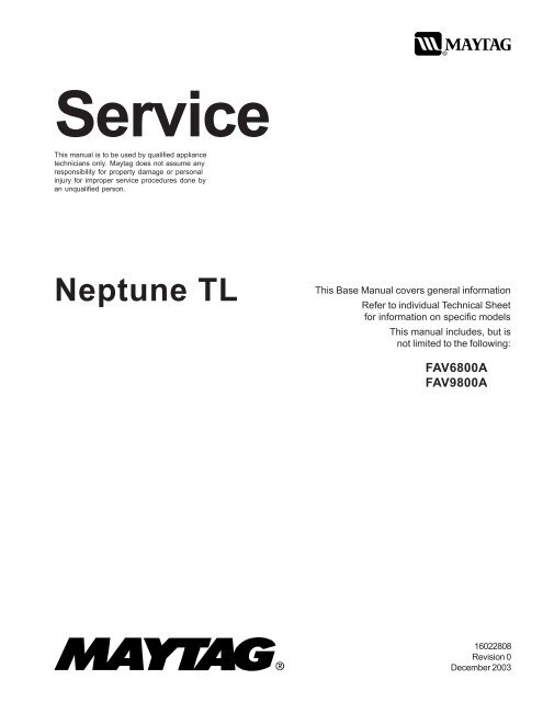
Service<br />
This manual is to be used by qualified appliance<br />
technicians only. Maytag does not assume any<br />
responsibility for property damage or personal<br />
injury for improper service procedures done by<br />
an unqualified person.<br />
<strong>Neptune</strong> <strong>TL</strong><br />
This Base Manual covers general information<br />
Refer to individual Technical Sheet<br />
for information on specific models<br />
This manual includes, but is<br />
not limited to the following:<br />
FAV6800A<br />
FAV9800A<br />
16022808<br />
Revision 0<br />
December 2003
Important Information<br />
Important Notices for Technicians and Consumers<br />
Maytag will not be responsible for personal injury or property damage from improper service procedures. Pride and<br />
workmanship go into every product to provide our customers with quality products. It is possible, however, that during<br />
its lifetime a product may require service. Products should be serviced only by a qualified service technician who is<br />
familiar with the safety procedures required in the repair and who is equipped with the proper tools, parts, testing<br />
instruments and the appropriate service information. IT IS THE TECHNICIANS RESPONSIBILITY TO REVIEW ALL<br />
APPROPRIATE SERVICE INFORMATION BEFORE BEGINNING REPAIRS.<br />
! WARNING<br />
To avoid risk of severe personal injury or death, disconnect power before working/servicing on appliance to avoid<br />
electrical shock.<br />
To locate an authorized technician, please consult your telephone book or the dealer from whom you purchased this<br />
product. For further assistance, please contact:<br />
Customer Service Support Center<br />
CAIR Center<br />
Web Site<br />
Telephone Number<br />
WWW.AMANA.COM................................................ 1-800-843-0304<br />
WWW.JENNAIR.COM ............................................. 1-800-536-6247<br />
WWW.MAYTAG.COM ............................................. 1-800-688-9900<br />
CAIR Center in Canada ........................................... 1-800-688-2002<br />
Amana Canada Product ........................................... 1-866-587-2002<br />
Recognize Safety Symbols, Words, and Labels<br />
!<br />
DANGER<br />
DANGER—Immediate hazards which WILL result in severe personal injury or death.<br />
!<br />
WARNING<br />
WARNING—Hazards or unsafe practices which COULD result in severe personal injury or death.<br />
!<br />
CAUTION<br />
CAUTION—Hazards or unsafe practices which COULD result in minor personal injury, product or property<br />
damage.<br />
2 16022808 Rev. 0 ©2003 Maytag <strong>Appliance</strong>s Company
Table of Contents<br />
Important Information .................................................... 2<br />
Important Safety Information ......................................... 4<br />
General Information<br />
Model Identification .................................................... 8<br />
Serial Label Location ................................................. 8<br />
Model Nomenclature .................................................. 9<br />
Model Specifications .................................................10<br />
FAV 6800AW Trouble Shooting<br />
Trouble Shooting General Symptoms ....................... 12<br />
Consumer Help Codes ..............................................13<br />
Service Mode ............................................................14<br />
Accessing Service Tests...........................................14<br />
Quick Spin Test ........................................................ 14<br />
Hold Quick Spin Step ................................................15<br />
Fast Time Down Test ................................................15<br />
Quick Service Cycle .................................................15<br />
Membrane Pad Test.................................................. 15<br />
Motor Control Board Output Test ..............................15<br />
Board Functional Test Input Control Keys................. 16<br />
Board Output Test..................................................... 16<br />
Display Diagnostic Codes ......................................... 17<br />
Diagnostic Codes ..................................................... 17<br />
Exit Service Mode..................................................... 18<br />
Hose Reversal Detection And Correction...................18<br />
Torque Specifications ................................................18<br />
Tub Displacement Sensor Diagnostics .....................19<br />
Component Diagnostics ............................................ 19<br />
Water Leak Around Pulley Tub Bottom .....................19<br />
Control Board Inputs Table ........................................20<br />
Membrane Pad Continuity Checks ...........................20<br />
FAV 9800AW Trouble Shooting<br />
Trouble Shooting General Symptoms ....................... 21<br />
Removing A Favorite Cycle .......................................22<br />
Enter/Exit Service Mode ...........................................23<br />
Accessing Service Tests/Diagnostic Features ..........23<br />
User Interface Test ....................................................23<br />
Quick Spin Test ........................................................ 23<br />
Hold Quick Spin Test ................................................24<br />
System Check ..........................................................24<br />
Service Cycle ........................................................... 25<br />
Display Diagnostic Codes ......................................... 25<br />
Diagnostic Codes ..................................................... 25<br />
Exit Service Mode..................................................... 26<br />
Hose Reversal Detection And Correction...................27<br />
Torque Specifications ................................................ 27<br />
Tub Displacement Sensor Diagnostics ..................... 27<br />
Component Diagnostics ............................................ 28<br />
Water Leak Around Pulley Tub Bottom ..................... 28<br />
Control Board Inputs Table ........................................29<br />
Membrane Pad Continuity Checks ........................... 29<br />
Disassembly Procedures<br />
Console Removal ...................................................... 30<br />
Control Board Removal ............................................. 30<br />
Lid Disassembly/Removal ......................................... 32<br />
Top Cover Removal ................................................... 32<br />
Splash Guard Removal ..............................................33<br />
Bleach/Softener Dispenser Removal .........................33<br />
Lid Lock/Reed Switch Removal ................................ 34<br />
Inlet Water Valve Removal ........................................35<br />
Detergent Dispenser Water Valve Removal ............... 36<br />
Top Cover Removal ................................................... 37<br />
Tumbler Removal ...................................................... 37<br />
Tumbler Bearing Removal ......................................... 39<br />
Transmission/O-Ring Seal Removal .......................... 40<br />
Rear Strut Removal ................................................... 40<br />
Front Panel Removal .................................................41<br />
Tub Displacement Sensor Removal .......................... 41<br />
Front Strut Removal .................................................. 43<br />
Drain Pump/Pressure Switch Removal ..................... 44<br />
Spinner Removal .......................................................45<br />
Outer Tub Removal ................................................... 45<br />
Drive Motor Removal .................................................46<br />
Pulley/Clutch Removal ..............................................47<br />
Drive Belt Removal ....................................................47<br />
Heater Assembly Removal ........................................47<br />
Motor Control Removal ..............................................47<br />
Spinner Support Removal .......................................... 48<br />
Appendix A<br />
Installation Instructions ............................................. 50<br />
Appendix B<br />
Use And Care ........................................................... 57<br />
©2003 Maytag <strong>Appliance</strong>s Company 16022808 Rev. 0 3
Important Safety Information<br />
!<br />
WARNING<br />
To reduce the risk of fire, electric shock, serious injury<br />
or death to persons when using your washer, follow<br />
these basic precautions:<br />
• Read all instructions before using the washer.<br />
• Refer to the Grounding Instructions in the Installation<br />
Manual for the proper grounding of the washer.<br />
• Do not wash articles that have been previously<br />
cleaned in, washed in, soaked in, or spotted with<br />
gasoline, dry-cleaning solvents, or other flammable or<br />
explosive substances as they give off vapors that<br />
could ignite or explode.<br />
• Do not add gasoline, dry-cleaning solvents, or other<br />
flammable or explosive substances to the wash<br />
water. These substances give off vapors that could<br />
ignite or explode.<br />
• Under certain conditions, hydrogen gas may be<br />
produced in a hot water system that has not been<br />
used for two weeks or more. Hydrogen gas is<br />
explosive. If the hot water system has not been used<br />
for such a period, before using a washing machine or<br />
combination washer-dryer, turn on all hot water<br />
faucets and let the water flow from each for several<br />
minutes. This will release any accumulated hydrogen<br />
gas. The gas is flammable, do not smoke or use an<br />
open flame during this time.<br />
• Do not allow children to play on or in the washer.<br />
Close supervision of children is necessary when the<br />
washer is used near children. This is a safety rule for<br />
all appliances.<br />
• Before the washer is removed from service or<br />
discarded, remove the lid to the washing<br />
compartment.<br />
• Do not reach into the washer if the wash tub is<br />
moving.<br />
• Do not install or store the washer where it will be<br />
exposed to water and/or weather.<br />
• Do not tamper with the controls.<br />
• Do not repair or replace any part of the washer, or<br />
attempt any servicing unless specifically<br />
recommended in the User-Maintenance instructions<br />
or in published user-repair instructions that you<br />
understand and have the skills to carry out.<br />
• To reduce the risk of an electric shock or fire, do not<br />
use an extension cord or an adapter to connect the<br />
washer to the electrical power source.<br />
• Use your washer only for its intended purpose,<br />
washing clothes.<br />
• Always disconnect the washer from electrical supply<br />
before attempting any service. Disconnect the power<br />
cord by grasping the plug, not the cord.<br />
• Install the washer according to the Installation<br />
Instructions. All connections for water, drain,<br />
electrical power and grounding must comply with<br />
local codes and be made by licensed personnel<br />
when required. Do not do it yourself unless you know<br />
how!<br />
• To reduce the risk of fire, clothes which have traces<br />
of any flammable substances such as vegetable oil,<br />
cooking oil, machine oil, flammable chemicals,<br />
thinner, etc. or anything containing wax or chemicals<br />
such as in mops and cleaning cloths, must not be<br />
put into the washer. These flammable substances<br />
may cause the fabric to catch on fire by itself.<br />
• Do not use fabric softeners or products to eliminate<br />
static unless recommended by the manufacturer of<br />
the fabric softener or product.<br />
• Keep your washer in good condition. Bumping or<br />
dropping the washer can damage safety features. If<br />
this occurs, have your washer checked by a qualified<br />
service person.<br />
• Replace worn power cords and/or loose plugs.<br />
• Be sure water connections have a shut-off valve and<br />
that fill hose connections are tight. Close the shut-off<br />
valves at the end of each wash day.<br />
• Loading lid must be closed any time the washer is in<br />
operational fill, tumble, or spin. Do not attempt to<br />
bypass the loading lid switch by permitting the<br />
washer to operate with the loading lid open.<br />
• Always read and follow manufacturer’s instructions<br />
on packages of laundry and cleaning aids. Heed all<br />
warnings or precautions. To reduce the risk of<br />
poisoning or chemical burns, keep them out of the<br />
reach of children at all times (preferably in a locked<br />
cabinet).<br />
• Always follow the fabric care instructions supplied by<br />
the garment manufacturer.<br />
• Never operate the washer with any guards and/or<br />
panels removed.<br />
• Do not operate the washer with missing or broken<br />
parts.<br />
• Do not bypass any safety devices.<br />
• Failure to install, maintain, and/or operate this<br />
washer according to the manufacturer’s instructions<br />
may result in conditions which can produce bodily<br />
injury and/or property damage.<br />
NOTE: The Warnings and Important Safety Instructions<br />
appearing in this manual are not meant to cover<br />
all possible conditions and situations that may<br />
occur. Common sense, caution and care must<br />
be exercised when installing, maintaining, or<br />
operating the washer.<br />
Always contact your dealer, distributor, service agent or<br />
the manufacturer about any problems or conditions you<br />
do not understand.<br />
4 16022808 Rev. 0 ©2003 Maytag <strong>Appliance</strong>s Company
Important Safety Information<br />
! WARNING<br />
To avoid personal injury or death from improper servicing,<br />
make sure you read and understand the descriptions and<br />
meaning of various safety symbols, words and labels<br />
used in this manual, before attempting any procedures<br />
described in the manual. Failure to understand and<br />
comply with safety information may result in severe<br />
personal injury or death.<br />
General Information<br />
This Service Manual describes the operation,<br />
disassembly, troubleshooting, and repair of the <strong>Neptune</strong><br />
<strong>TL</strong> washer. It is intended for use by authorized<br />
technician’s who troubleshoot and repair these units.<br />
NOTE: It is assumed that users of this manual are<br />
familiar with the use of tools and equipment used<br />
to troubleshoot and repair electrical, and<br />
mechanical systems; and understand the<br />
terminology used to describe and discuss them.<br />
Related Publications<br />
This is a base service manual, covering a range of similar<br />
models. It is intended to be used in conjunction with the<br />
Parts Manual and Technical Sheet covering the specific<br />
model being serviced.<br />
Electrical Service Information<br />
Proper Grounding and Polarization of<br />
120 Volts Wall Outlets<br />
For the safety of our customers and the Service<br />
Technician ALL appliances have a three–prong power cord<br />
and MUST be connected to a properly polarized AND<br />
grounded wall outlet.<br />
This information was written for those who do not<br />
understand grounding and polarization of a wall outlet.<br />
A 120 volt wall outlet must always be wired as shown<br />
below.<br />
L1<br />
Ground<br />
Neutral<br />
About Ground Wires<br />
In the event of an electrical short circuit, a ground wire<br />
reduces the risk of electric shock by providing an escape<br />
wire for the electric current.<br />
Standard accepted color coding for ground wires is green<br />
or green with a yellow stripe.<br />
Grounding wires and wires colored like grounding wires<br />
are NOT to be used as current carrying conductors.<br />
!<br />
!<br />
WARNING<br />
To reduce the risk of fire, electric shock, serious injury<br />
or death, all wiring and grounding must conform with<br />
the latest edition of the National Electric Code, ANSI/<br />
NFPA 70, or the Canadian Electrical Code, CSA<br />
C22.1, and such local regulations as might apply. It is<br />
the customer’s responsibility to have the wiring and<br />
fuses checked by a qualified electrician to make sure<br />
your home has adequate electrical power to operate<br />
the washer.<br />
WARNING<br />
To avoid risk of personal injury or death due to<br />
electrical shock:<br />
• Observe all local codes and ordinances.<br />
• Disconnect electrical power to unit before servicing.<br />
• Ground appliance properly.<br />
• Check with a qualified electrician if you are not sure<br />
this appliance is properly grounded.<br />
• DO NOT ground to gas line.<br />
• DO NOT ground to cold water pipe if pipe is<br />
interrupted by plastic, nonmetallic gaskets, or other<br />
insulating (nonconducting) materials.<br />
• DO NOT modify plug on power cord. If plug does not<br />
fit electrical outlet, have proper outlet installed<br />
by qualified electrician.<br />
• DO NOT have a fuse in the neutral or ground circuit.<br />
A fuse in the neutral or ground circuit could result in<br />
an electrical shock.<br />
• DO NOT use an extension cord with this appliance.<br />
• DO NOT use an adapter plug with this appliance.<br />
• DO NOT pinch power cord.<br />
Neutral<br />
side<br />
115±12<br />
V.A.C.<br />
0<br />
V.A.C.<br />
Round<br />
grounding<br />
prong<br />
115±12<br />
V.A.C.<br />
©2003 Maytag <strong>Appliance</strong>s Company 16022808 Rev. 0 5
Important Safety Information<br />
Explanation<br />
Polarization–This means that the larger slot must be<br />
neutral and the small slot must be at line voltage.<br />
Mispolarized–The outlet is incorrectly wired so that the<br />
larger slot is at line voltage and the smaller slot is neutral.<br />
Grounded–This means the round hole connection is connected<br />
to earth ground through a connection to the main<br />
power panel.<br />
Ungrounded–The round hole connection is not complete to<br />
earth ground and/or the main power panel.<br />
Grounding Instructions<br />
!<br />
WARNING<br />
• To avoid the risk of electrical shock or death, do not<br />
alter the plug.<br />
• Do not remove grounding prong when installing<br />
grounded appliance in a home that does not have<br />
three wire grounding receptacle. Under no condition<br />
is grounding prong to be cut off or removed. It is the<br />
personal responsibility of the consumer to contact a<br />
qualified electrician and have properly grounded three<br />
prong wall receptacle installed in accordance with<br />
appropriate electrical codes.<br />
• To avoid the risk of electrical shock or death, this<br />
equipment must be grounded.<br />
This equipment MUST be grounded. In the event of an<br />
electrical short circuit, grounding reduces the risk of<br />
electric shock by providing an escape wire for the electric<br />
current. This unit is equipped with a cord having a<br />
grounding wire with a grounding plug. The plug must be<br />
plugged into an outlet that is properly installed and<br />
grounded.<br />
Consult a qualified electrician or technician if grounding<br />
instructions are not completely understood, or if doubt<br />
exists as to whether the equipment is properly grounded.<br />
Do not use an extension cord. If the product power cord<br />
is too short, have a qualified electrician install a three-slot<br />
receptacle. This unit should be plugged into a separate 60<br />
hertz circuit with the electrical rating as shown in the<br />
appropriate drawing. Models operate with a supply voltage<br />
of 120 Volts.<br />
i<br />
6 16022808 Rev. 0 ©2003 Maytag <strong>Appliance</strong>s Company
Important Safety Information<br />
i<br />
KEEP CLEAR<br />
ROTATING BELTS AND PULLEYS<br />
i<br />
©2003 Maytag <strong>Appliance</strong>s Company 16022808 Rev. 0 7
General Information<br />
Model Identification<br />
Complete registration card and promptly return. If<br />
registration card is missing:<br />
• For Maytag product call 1-800-688-9900 or visit the<br />
Web Site at www.maytag.com<br />
• For product in Canada call 1-866-587-2002 or visit the<br />
Web Site at www.maytag.com.<br />
When contacting provide product information located on<br />
rating label. Record the following:<br />
Model Number:<br />
___________________<br />
Manufacturing Number: ___________________<br />
Serial or S/N Number: ___________________<br />
Date of purchase:<br />
___________________<br />
Dealer’s name and address: ___________________<br />
Service<br />
Keep a copy of sales receipt for future reference or in<br />
case warranty service is required. To locate an authorized<br />
technician:<br />
• For Maytag call 1-800-462-9824 or visit the Web Site at<br />
www.maytag.com.<br />
• For product in Canada call 1-866-587-2002 or visit the<br />
Web Site at www.maytag.com.<br />
Warranty service must be performed by an authorized<br />
technician. We also recommend contacting an authorized<br />
technician, if service is required after warranty expires.<br />
Parts and Accessories<br />
Purchase replacement parts and accessories over the<br />
phone. To order accessories for your product call:<br />
• For Maytag product call 1-800-462-9824 or visit the<br />
Web Site at www.maytag.com.<br />
• For product in Canada call 1-866-587-2002 or visit the<br />
Web Site at www.maytag.com.<br />
Extended Service Plan<br />
We offer long-term service protection for this new washer.<br />
• Dependability Plus TM Extended Service Plan is<br />
specially designed to supplement Maytag’s strong<br />
warranty. This plan covers parts, labor, and travel<br />
charges.<br />
Call 1-800-925-2020 for information.<br />
Serial Label is located in the upper left hand corner of the<br />
cabinet back panel.<br />
8 16022808 Rev. 0 ©2003 Maytag <strong>Appliance</strong>s Company
General Information<br />
<strong>Neptune</strong> Nomenclature<br />
F A V 6 8 0 0 A Y W<br />
Build Location<br />
A Amana<br />
C Cleveland<br />
F Florence<br />
H Herrin<br />
J Jackson<br />
S Searcy<br />
N Newton<br />
Color<br />
W White<br />
Q Bisque<br />
Product Type<br />
A Automatic<br />
Listing<br />
W 120V-60hz<br />
Y 240V-60hz<br />
Z Canada 240V-60hz<br />
Y 220-240 V / 50-60 Hz<br />
Wash Position<br />
H Horizontal<br />
V Vertical<br />
Marketing Code<br />
This identifies which<br />
version of production the<br />
unit is.<br />
Feature Content<br />
6800 Feature Package<br />
©2003 Maytag <strong>Appliance</strong>s Company 16022808 Rev. 0 9
General Information<br />
10 16022808 Rev. 0 ©2003 Maytag <strong>Appliance</strong>s Company
General Information<br />
5<br />
©2003 Maytag <strong>Appliance</strong>s Company 16022808 Rev. 0 11
Troubleshooting Procedures<br />
! WARNING<br />
To avoid risk of electrical shock, personal injury or death, disconnect power to unit before servicing, unless testing<br />
requires power.<br />
g<br />
Maytag <strong>Neptune</strong> <strong>TL</strong> FAV6800AW Washer<br />
Diagnostic Code table follows later in this document.<br />
Will Not Start<br />
• Plug cord into live electrical outlet.<br />
• Check fuse or reset circuit breaker to outlet.<br />
• Close lid and push the START/PAUSE button to start<br />
washer. The START/PAUSE LED should change from<br />
flashing to on continuously.<br />
• Check to see if the washer is in a pause or soak<br />
period of the cycle. Wait briefly for cycle to advance.<br />
• Check for restricted drain system.<br />
• Check the lid, lid latch mechanism, and circuitry (see<br />
Will Not Lock).<br />
Leaking<br />
• Make sure supply hose connections are not leaking.<br />
Check for rubber gasket damage due to overtightening.<br />
• Make sure end of drain hose is correctly inserted and<br />
secured to drain facility.<br />
• Check bottom of tub around the pulley. See special<br />
instructions page 19.<br />
• Check internal hose connections (fill & drain systems,<br />
hoses & clamps).<br />
• Check tub cover. Remove, reposition and reinstall<br />
the tub cover seal. Seal seam must be at the top of<br />
the tub cover.<br />
• Make sure water dispensing system on inner lid is<br />
securely attached to lid.<br />
• Make sure dispenser valve is securely attached to<br />
mounting bracket.<br />
• Check standpipe for leak. Wrap a dry rag around the<br />
standpipe opening. If rag becomes wet leak is fault of<br />
home plumbing. Be sure the standpipe is capable of<br />
accepting the flow of water from the washer.<br />
• Check the lid hinges if water is coming out behind the<br />
lid.<br />
• Check for bowing of lid where water enters detergent<br />
dispenser.<br />
Display Lights Up When Lid is Opened<br />
• This is normal behavior.<br />
Will Not Spin<br />
• During fill cycle – If machine tumbles and spins<br />
simultaneously replace clutch assembly.<br />
• During spin cycle – If machine tumbles and spins<br />
simultaneously replace clutch assembly.<br />
• Perform Motor and Motor Control Test.<br />
• Check belt.<br />
• Check that the machine control correctly senses that<br />
all 3 water levels are empty. See Board Input Test.<br />
• Tub Displacement Sensor disconnected, or loose<br />
wire.<br />
No Water Fill<br />
• Go to No Fill Test.<br />
• Check to make sure water supply is turned on fully.<br />
• Normal water level is 1 to 7 inches inside the spinner.<br />
• Check electrical circuit and connections at the water<br />
valve, and pressure switch.<br />
• Check for kinks in inlet hoses.<br />
• Check for clogged inlet screens.<br />
• Visually check hot and cold separately for fill.<br />
• Check for low water pressure. May be dependent on<br />
pressure entering home. Variations may occur due to<br />
usage in the home at the time machine is used.<br />
• Check for frozen pipes and hoses.<br />
Tub Full of Suds<br />
• Check for restricted drain system.<br />
• Check for loose wire connections at control board<br />
and pump.<br />
• Perform Motor and Motor Control Test.<br />
• Use high efficiency or low sudsing detergent specially<br />
formulated for front load washers.<br />
• Run the clothes washer through another complete<br />
cycle using the coldest water and no detergent.<br />
• Reduce detergent amount for that specific load size<br />
and soil level. Towel loads have a minimal amount of<br />
soil present and typically create more suds.<br />
• Check to see if belt is off motor and pulley.<br />
Wet Clothes<br />
• Very small clothes loads can cause unbalanced<br />
No Tumble<br />
loads - add additional towels.<br />
• Start normal cycle with an empty machine and allow • Excessive suds may have been present.<br />
a fill to check tumble.<br />
• Check Tub Displacement Sensor connection and<br />
• Fabric cycles such as NORMAL, DELICATES, HAND main harness connector at machine control board.<br />
WASH, & WRINKLE CONTROL only tumble • Check Tub Displacement Sensor for 0 to 3.0 Volts<br />
periodically, every 60 seconds.<br />
DC output voltage between ground and the board<br />
• Check for loose connections at machine control<br />
input. Check for 12 Volts DC input voltage between<br />
board, motor control board and motor.<br />
the ground and the board output. Only check for<br />
• Perform Motor and Motor Control Test.<br />
voltage at the Tub Displacement Sensor. Do not<br />
• Washer does not tumble during most fills or during perform a continuity check. See Tub Displacement<br />
presoak.<br />
Diagnostics.<br />
• Washer with heat option does not tumble while<br />
heating.<br />
• Check belt.<br />
12 16022808 Rev. 0 ©2003 Maytag <strong>Appliance</strong>s Company
Troubleshooting Procedures<br />
! WARNING<br />
To avoid risk of electrical shock, personal injury or death, disconnect power to unit before servicing, unless testing<br />
requires power.<br />
• Excessive motion was detected in spin (dc or LL)<br />
Run Quick Spin Test with an empty tub to check Tub<br />
Displacement Sensor and Machine Control Board.<br />
• Check for restricted drain system.<br />
• Perform Motor and Motor Control Test.<br />
Will Not Lock<br />
• Lid not all the way closed or not properly aligned.<br />
• Check electrical connections at lock assemblies,<br />
machine control board, and Motor Control Board.<br />
• Magnet missing. (Located on the back side of<br />
dispenser assembly inner lid, front Left corner).<br />
• Laundry load is too large to close lid.<br />
• Check system relay for welded contacts. (Diagnostic<br />
code 34) Disconnect power. Continuity between p.6<br />
pin 1 to p.8. pin 1 at the Machine Control Board<br />
connector.<br />
• Go to Lid Lock Test.<br />
• Make sure inner lid is properly assembled to lid.<br />
• Make sure door lock bumpers are fully seated to top<br />
cover.<br />
Will Not Unlock<br />
• Press off. The motor control is not responding if it<br />
takes 4 minutes to unlock. The motor control is<br />
either bad or disconnected.<br />
• Unplug and reconnect power cord. Wait 20 seconds<br />
for machine to unlock.<br />
• Check lid locked switch circuit. Circuit should be<br />
closed at machine control. (See board input/output<br />
chart)<br />
• Check for loose electrical connections at lid lock and<br />
at machine control board.<br />
• Push lid closed to make sure nothing from inside is<br />
pressing against it which may keep it from unlocking.<br />
• Perform Motor and Motor Control Test. (see Motor<br />
and Motor Control Test section).<br />
• If necessary, remove clothes by disconnecting power<br />
to washer, and open top cover with a putty knife.<br />
Will Not Drain<br />
• Check for restricted drain system.<br />
• Check low, medium, and high water fill completion. Go<br />
to No Fill Test<br />
• Check for 120 VAC at the pump when a spin cycle is<br />
selected < 550 rpm.<br />
• Go to Board Output Test and perform Pump out test.<br />
• In cold climates check for frozen Drain Hose.<br />
Wrong Water Temperature<br />
• Too Hot/Too Cold: This washer uses a reduced<br />
amount of water, while the control board meters the<br />
incoming flow to regulate the actual temperature of the<br />
water in the tub. This may appear to be significantly<br />
warmer/cooler than expected.<br />
• Check that both faucets are on fully.<br />
• Make sure the temperature selection is correct.<br />
• This washer will compensate for reversed fill hoses.<br />
See Hose Reversal Detection.<br />
• Make sure water heater is set to deliver a minimum of<br />
120°F (49°C) hot water at the tap. Also check water<br />
heater capacity and recovery rate.<br />
• If the water heater is located a long distance from<br />
washer, the water line may need to be purged prior to<br />
starting wash cycle.<br />
• Disconnect inlet hoses and clean screens.<br />
• The washer will need to go through a Hot / Cold cycle<br />
if the fill hoses were previously installed incorrectly<br />
and then corrected.<br />
• Check Water Valve Thermistor. Resistance a room<br />
temperature is 61700 ohms. (See board input/output<br />
chart)<br />
Noise / Cabinet Hits<br />
• Level the machine<br />
• Check sensor (refer to Tub Sensor Test).<br />
• Check Strut and Strut Isolator for proper operation.<br />
• Check for Diagnostic Code “10”.<br />
Consumer Information Codes<br />
If the consumer observes codes on display, see table<br />
below.<br />
LED<br />
Display<br />
Description<br />
©2003 Maytag <strong>Appliance</strong>s Company 16022808 Rev. 0 13<br />
CL<br />
dc<br />
FL<br />
LO<br />
Lr<br />
nd<br />
OP<br />
od<br />
nF<br />
PF<br />
Sd<br />
UL<br />
UC<br />
Closed: Lid is closed.<br />
Distribute Clothes: The load is<br />
unbalanced, preventing high speed<br />
spin. Redistribute clothes.<br />
Failed to Lock: The machine has<br />
repeatedly tried to lock the lid. Make<br />
sure the lid is shut com pletely.<br />
Locked: Lid has failed to unlock -<br />
the machine has repeatedly tried to<br />
unlock the lid. Push lid closed to<br />
make sure nothing from the inside is<br />
pressing against the lid, preventing<br />
unlocking.<br />
Locked Rotor: The machine has<br />
repeatedly tried to turn the motor.<br />
No Drain: The machine has tried to<br />
drain.<br />
Lid is Open: Make sure it is fully<br />
closed before starting cycle.<br />
Open the Lid: The lid has not been<br />
opened for the last three completed<br />
cycles.<br />
No fill: the machine has tried to fill.<br />
See No W ater Fill.<br />
Power failure: Power to the machine<br />
has been lost during the last cycle.<br />
This may also occur on start up of a<br />
new machine due to factory testing.<br />
Check the lid. Press any key to<br />
return the display to norm al activity.<br />
Suds: Machine has detected high<br />
level of suds. The machine will alter<br />
its cycle for this situation. Use hE<br />
detergent or reduce the amount of<br />
detergent.<br />
Latch Unlocked: Close lid tightly to<br />
enable locking.<br />
Continuous Unbalanced Circuit.<br />
See W et Clothes Troubleshooting.<br />
Improper signal from Tub<br />
Displacement Sensor.
Troubleshooting Procedures<br />
! WARNING<br />
To avoid risk of electrical shock, personal injury or death, disconnect power to unit before servicing, unless testing<br />
requires power.<br />
LED<br />
Display<br />
Description<br />
UB See Diagnostic Code 10<br />
LL<br />
CL<br />
oL<br />
Large Load Detected<br />
Clear To Reset Cycle Counts<br />
Machine Paused-Load Wedging<br />
Service Mode<br />
Service Mode enables service personnel to verify the<br />
operation of the washing machine and diagnose<br />
problems. Service Mode can be entered in the middle of<br />
any wash cycle without interrupting the cycle. While in<br />
Service Mode, the technician can cancel the current<br />
cycle, set a continuous running mode, start a variety of<br />
special service tests and view diagnostic displays.<br />
Enter / Exit Service Mode<br />
To enter Service Mode press the Enviro Plus and Spin<br />
Only keys for three seconds or until the control beeps.<br />
The motor speed will be displayed when started (motor<br />
not running display will be 00). The present state of the<br />
machine will not be changed. (i.e., the current cycle in<br />
progress will not be interrupted and only the display will<br />
change).<br />
To exit: 1) Press Enviro Plus and Spin Only keys for 3<br />
seconds again, or 2) press Off, or 3) unplug the<br />
machine.<br />
The following table summarizes special tests and<br />
features available in Service Mode, along with methods<br />
of activation and cancellation.<br />
Accessing Service Tests and Diagnostic Features<br />
while in Service Mode.<br />
Test or Display<br />
Quick Spin<br />
Test<br />
Hold Quick<br />
Spin Step<br />
(holds<br />
predefined<br />
RPM)<br />
Fast<br />
Time-<br />
Down /<br />
Advance<br />
to Next<br />
Step<br />
Press LED to<br />
Start<br />
Press Hand<br />
Wash<br />
Press Hand<br />
Wash (during<br />
test)<br />
Press Quick<br />
Wash during<br />
cycle<br />
Press LED to<br />
Cancel<br />
Press Off (exits<br />
Service Mode)<br />
Press Hand<br />
Wash (cancels<br />
hold & resumes<br />
next step)<br />
Test or Display<br />
Hold Quick<br />
Service Cycle<br />
Step<br />
Membrane<br />
Test<br />
Board<br />
Input<br />
Test<br />
Board<br />
Output<br />
Test /<br />
System Check<br />
Diagnostic<br />
Code Display<br />
(Initial)<br />
All Diagnostic<br />
Codes<br />
Cycle Count<br />
No. for<br />
Diagnostic<br />
Code<br />
Clear All<br />
Diagnostic<br />
Codes<br />
Display<br />
Software<br />
Version<br />
Press LED to<br />
Start<br />
Press Signal ↑<br />
(up) and ↓<br />
(down) together<br />
Press Presoak<br />
(then individual<br />
buttons to test)<br />
Press Super<br />
Wash<br />
Press<br />
Delicates<br />
Press Wrinkle<br />
Control – 1 st<br />
code displays<br />
Press Set<br />
Delay ↑ or ↓<br />
Press and hold<br />
Normal while<br />
diagnostic code<br />
is displayed<br />
Press Quick<br />
Wash + Whites<br />
together while<br />
displaying<br />
diagnostic<br />
codes<br />
Press Bulky<br />
Items 3 times<br />
1 st press- major<br />
soft. revision<br />
2 nd – minor soft<br />
revision<br />
Cycle Count Signal +: 10’s<br />
and 1’s digits<br />
Signal -: 100’s<br />
and 1000’s<br />
digits<br />
Colors/Jeans:<br />
10-thousands &<br />
100-thousand<br />
digits<br />
Press LED to<br />
Cancel<br />
Press Signal ↑<br />
(up) and ↓<br />
(down) to<br />
resume<br />
Press Off twice<br />
after starting<br />
test<br />
Press Super<br />
Wash<br />
Press<br />
Delicates<br />
Press Wrinkle<br />
Control again<br />
N/A<br />
Release<br />
Normal<br />
(returns to<br />
diagnostic code<br />
display)<br />
Press Bulky<br />
Items a 4 th time<br />
Quick Spin Test<br />
While in Service Mode, press the Hand Wash<br />
key to start a Quick Spin Test.<br />
Quick Press<br />
Press Off (also<br />
Quick Spin test steps are as follows:<br />
Service Wash/Rinse exits Service<br />
1) Lock the lid.<br />
Cycle Temp ↑ (up) Mode)<br />
2) Spin to index speed 90 rpm and hold for 60<br />
seconds. Pump drains machine.<br />
key<br />
3) Spin to index speed 150 rpm and hold for 6<br />
seconds.<br />
14 16022808 Rev. 0 ©2003 Maytag <strong>Appliance</strong>s Company<br />
IN
Troubleshooting Procedures<br />
! WARNING<br />
To avoid risk of electrical shock, personal injury or death, disconnect power to unit before servicing, unless testing<br />
requires power.<br />
4) Spin to index speed 350 rpm and hold for 6 seconds.<br />
5) Spin to index speed 550 rpm and hold for 6 seconds.<br />
6) Spin to index speed 700 rpm and hold for 6 seconds.<br />
7) Spin to index speed 850 rpm and hold for 6 seconds.<br />
Pump out.<br />
8) Coast down to 0 rpm chimes 3 times.<br />
Speed Range<br />
Stage of<br />
Wash Cycle<br />
Presoak<br />
Wash<br />
Spin/Drain<br />
Rinse<br />
@<br />
Displayed<br />
a) 0-99 rpm 0-99 (actual)<br />
b) 100-999 rpm Speed X 10 ex: 85.= 850rpm<br />
¾<br />
Hold Quick Spin Step<br />
If the Hand Wash key is pressed again during<br />
the Quick Spin test, the machine will hold at the<br />
next highest index speed for up to 30 minutes.<br />
To cancel press the Hand Wash key again.<br />
Fast Time Down Test<br />
While any test or cycle is running in Service<br />
Mode, pressing the Quick Wash key will<br />
advance the program to the next cycle<br />
stage.<br />
For example if in one of the following:<br />
Advances To<br />
End of Presoak<br />
Every 5 Minutes of<br />
Wash Time<br />
End of the<br />
Spin Profile<br />
End of Rinse<br />
Quick Service Cycle<br />
While in Service Mode, pressing the<br />
Wash/Rinse Temp key will start a Quick<br />
Service Cycle. This will be a quick check of all<br />
systems. If display shows od then open and close lid.<br />
Pressing Quick Wash will advance to the next cycle.<br />
The following steps are performed: Display shows “sc”.<br />
1. Lock lid and pump starts.<br />
2. Cold bleach fill. Energize the cold and bleach water<br />
valves to low setting. Advance to next step if water is<br />
not connected to machine.<br />
3. Tumble using 48 rpm tumble for 10 seconds.<br />
4. Tumble with hot fill: Continue tumble while energizing<br />
hot water valve for 5 seconds.<br />
5. Warm softener fill: Energize cold water and fabric<br />
softener valves until medium level is reached.<br />
Advance to next step if water is not connected to<br />
machine.<br />
6. Drain and Spin to 850 rpm.<br />
7. Display a “PA” (Passed) continuously for 5 seconds<br />
if no diagnostic codes were logged during the test.<br />
8. Unlock the lid when the RPM is zero.<br />
If a diagnostic code is logged during the test, the rightmost<br />
dot will turn on and stay on until quick service cycle<br />
test has ended. Any diagnostic code logged during this<br />
test will result in failure of the test, but will not necessarily<br />
stop the test.<br />
During the Quick Service Cycle, pressing the Quick<br />
Wash key will advance to the next step.<br />
Pressing the Hand Wash key will suspend<br />
the machine at the current step for up to 30<br />
minutes or until Hand Wash is pressed<br />
again. All LEDs should flash on and off<br />
while the system is suspended or on hold.<br />
Membrane Pad Test<br />
While in Service Mode, pressing the Presoak key will<br />
start a membrane switch check that verifies switch<br />
operation. All the LEDs (except Presoak ) can be toggled<br />
or slewed by pressing the key associated with the LED or<br />
set of LEDs. Each time either set delay arrow is pressed<br />
the digits toggle between a blank and 8. All keys<br />
(including the OFF button) must be pressed within 5<br />
minutes for this test to pass. “PA” will be displayed for<br />
five (5) seconds once all keys have been pressed and the<br />
test is completed. Following 10 seconds of inactivity at<br />
any point, this test will exit without any display.<br />
Motor Control Board Output Test<br />
1. Disconnect power to the washer.<br />
2. Remove the front panel and disconnect the JP4<br />
Connector from the Motor Control Board.<br />
3. Reconnect the washer power cord to supply voltage.<br />
Make sure the lid is closed.<br />
4. Press Enviro Plus and Spin Only keys for 3<br />
seconds to activate Service Mode.<br />
5. Access Board Output Test by pressing the<br />
Delicates key. Display shows “ot”.<br />
6. The lid must be locked to access Motor Control<br />
Board Output Test. To lock the lid press<br />
Colors/Jeans. To verify the test, the quick wash LED<br />
will be on, indicating the system relay is activated. If<br />
off, press Quick Wash with the lid shut to activate.<br />
7. Press Whites to start the motor control output test.<br />
This will send 120VAC to the motor control board.<br />
The motor control will execute a test routine and the<br />
motor should run, rotating the spinner at 50 rpm.<br />
There could be up to a 20 second delay before the<br />
spinner starts rotating.<br />
©2003 Maytag <strong>Appliance</strong>s Company 16022808 Rev. 0 15
Troubleshooting Procedures<br />
! WARNING<br />
To avoid risk of electrical shock, personal injury or death, disconnect power to unit before servicing, unless testing<br />
requires power.<br />
8. If motor does not run: Check for 120 VAC at the<br />
motor control board harness between L1 and Neutral.<br />
See Illustration<br />
If voltage is present, then problem exists with the motor<br />
and motor control system.<br />
• Check for loose electrical connections at motor, and<br />
motor control board.<br />
• Check phase windings of the motor. See Illustration. If<br />
motor windings are good, replace the motor control<br />
board.<br />
This test turns on a specified output after a key press.<br />
Pressing the Super Wash key again cancels the test.<br />
(Display shows in).<br />
While in Service Mode press the following key to check<br />
respective function.<br />
Key<br />
Function<br />
*Display<br />
Normal Lid Position<br />
or<br />
Wrinkle Control Lock State<br />
or<br />
Whites **High Water Level or<br />
Colors / Jeans **Medium Water Level or<br />
Bulky Items **Low Water Level or<br />
Enviro Plus *** Water Temperature<br />
* Indicates Pressure Switch not satisfied for that water<br />
level.<br />
Indicates Pressure Switch satisfied for that water<br />
level.<br />
**The appropriate water level must be added before<br />
running test.<br />
1. For “High Water Level” enter the “Board Output<br />
Test” and select Spin Only. Exit “Board Output<br />
Test” after water fill and enter “Board Functional<br />
Test”.<br />
2. For “Medium Water Level” start a Normal cycle.<br />
After water fill stop cycle and enter “Board<br />
Functional Test”.<br />
3. For “Low Water Level” start a Enviro Plus cycle.<br />
After water fill stop cycle and enter “Board<br />
Functional Test”.<br />
***Note: For the water temperature, the value could be<br />
three digits, in which case the first digit will be displayed<br />
separately from the other two (2) digits. The two displays<br />
will be shown alternately. Each temperature will be<br />
displayed by default in Fahrenheit units and can be<br />
changed to Celsius units by pressing either Set Delay<br />
Time Arrow key (up or down).<br />
Board Output Test<br />
While in Service Mode, pressing the Delicates key will begin<br />
the Board Output Test. This test turns on a<br />
specified output after a key press. (Pressing the<br />
Delicates key again cancels the test.) All outputs<br />
will be turned off after five (5) minutes.<br />
If voltage is not present;<br />
• Check for loose electrical connections at Machine<br />
Control Board or broken wires in harness.<br />
• Check lid actuator switch and related wiring. The lid<br />
must be closed and locked by pressing colors/jeans.<br />
The system relay is then activated and the quick wash<br />
LED is lit.<br />
IN<br />
Board Functional Test Input Control<br />
Keys<br />
While in Service Mode, pressing the Super<br />
Wash key will begin the Board Input Test.<br />
While in Service Mode press the following key to check<br />
respective function.<br />
Key<br />
Normal<br />
Wrinkle Control<br />
Whites<br />
Colors / Jeans<br />
Bulky Items<br />
Spin Only<br />
Quick Wash*<br />
Presoak<br />
Extra Rinse<br />
Function<br />
Hot Water Valve<br />
Fabric Softner Valve<br />
Motor Control<br />
Lid Lock*<br />
Bleach Valve<br />
Cold Water Valve<br />
Toggle System Relay<br />
Drain Pump<br />
Lid Unlock*<br />
16 16022808 Rev. 0 ©2003 Maytag <strong>Appliance</strong>s Company
Troubleshooting Procedures<br />
! WARNING<br />
To avoid risk of electrical shock, personal injury or death, disconnect power to unit before servicing, unless testing<br />
requires power.<br />
*Note: Function may not occur for up to 20 seconds.<br />
While in the Board Output Test, the Quick<br />
Wash LED is always ON.<br />
When the <strong>Neptune</strong> <strong>TL</strong> is plugged in, the<br />
Machine Control Board will check the lid<br />
latch mechanism every 20 seconds. If found<br />
to be locked with no cycle running, the<br />
Control Board will send a signal to the switch<br />
to unlock the lid.<br />
Display Diagnostic Codes<br />
The diagnostic code display can be<br />
toggled on and off from Service Mode<br />
by pressing the Wrinkle Control key.<br />
The display will show a “d”.<br />
The diagnostic codes can be viewed by using the Set<br />
Delay Time arrow keys. The Set Delay Time down<br />
arrow key will cycle down the list one code at time each<br />
time it is pushed. The Set Delay Time up arrow key will<br />
cycle up the list one code each time it is pushed. The<br />
first time the Set Delay Time down arrow key is pushed,<br />
the newest code will be displayed. A code generated<br />
during or after the current cycle will be displayed with<br />
the rightmost dot “.” turned “ON”.<br />
Access Other Features<br />
While a diagnostic code is displayed, if the Normal<br />
Cycle key is pressed and held, the machine will display<br />
the number of cycles since the diagnostic code<br />
occurred. To clear the diagnostic list press the Quick<br />
Wash and Whites key while viewing the list. The cycle<br />
count for each diagnostic code will also be reset to 0,<br />
but not the machine cycle count.<br />
Diagnostic Codes<br />
Diag.<br />
Code<br />
Description Trigger Action to be<br />
taken<br />
1 No Drain<br />
The water<br />
level fails to<br />
drop below<br />
Displays "nd"<br />
Go to "Will Not<br />
Drain"<br />
the Low level Troubleshooting<br />
before a spin Section<br />
2<br />
The lid fails<br />
to unlock<br />
3 No Fill<br />
4<br />
The lid fails<br />
to lock<br />
Lid failed to<br />
unlock after<br />
multiple<br />
attempts<br />
Total fill 14<br />
minutes<br />
exceeded.<br />
Lid failed to<br />
lock after 11<br />
attempts<br />
Displays "LO"<br />
Go to "Will Not<br />
Unlock"<br />
Troubleshooting<br />
Section<br />
Displays "nF"<br />
Go to "No Water<br />
Fill"<br />
Troubleshooting<br />
Section<br />
Displays "FL"<br />
Go to "Will not<br />
unlock"<br />
Troubleshooting<br />
Section<br />
Diag.<br />
Code<br />
5<br />
6<br />
8<br />
10<br />
11<br />
Description Trigger Action to be<br />
taken<br />
Continuous See section Displays "uC"<br />
unbalanced for unbal. Go to "Wet<br />
circuit. Out loads. Clothes"<br />
of balance (During spin Troubleshooting<br />
circuit only) Section<br />
Locked<br />
Rotor forcing<br />
a shut down.<br />
Water level<br />
sensor fault.<br />
Unbalance<br />
or cabinet hit<br />
detected<br />
during final<br />
spin, which<br />
prevented<br />
the spinner<br />
from<br />
exceeding<br />
500 rpm<br />
Will not<br />
remember<br />
machine<br />
settings<br />
15 Stuck Key<br />
16<br />
17<br />
High speed<br />
not achieved<br />
due to<br />
torque.<br />
The lid was<br />
not opened<br />
after<br />
completed<br />
wash cycles.<br />
Locked rotor<br />
is still locked<br />
after 10<br />
attempts.<br />
Higher water<br />
levels were<br />
sensed while<br />
the lower<br />
water levels<br />
were not.<br />
Less than 500<br />
rpm due to an<br />
unbalanced<br />
load.<br />
Difficulty in<br />
reading<br />
memory<br />
Detected a<br />
key pressed<br />
more than 75<br />
seconds. The<br />
key is<br />
assumed to<br />
be stuck.<br />
Speed less<br />
than 400 rpm<br />
during a main<br />
wash cycle.<br />
Did not sense<br />
lid open after<br />
the last three<br />
completed<br />
cycles.<br />
Displays "Lr"<br />
Go to "Motor<br />
Control Board<br />
Output Test"<br />
Go to "No Water<br />
Fill Test"<br />
LED – Will display<br />
“ub”<br />
Go to "Wet<br />
Clothes"<br />
Troubleshooting<br />
Section"<br />
Go to "Clear<br />
diagnostic codes"<br />
Disconnect and<br />
reconnect the<br />
washer power cord<br />
at power supply<br />
outlet.<br />
If condition still<br />
exists, replace<br />
machine control<br />
board.<br />
Go to "Membrane<br />
Pad Check"<br />
Check connection<br />
of keypad to control<br />
board.<br />
Replace console if<br />
necessary.<br />
Go to "Wet<br />
Clothes"<br />
Troubleshooting<br />
Section"<br />
LED – Will display<br />
“od”<br />
Customer may have<br />
tried to repeat wash<br />
cycle without<br />
opening the lid. Go<br />
to "Lid Lock Test"<br />
©2003 Maytag <strong>Appliance</strong>s Company 16022808 Rev. 0 17
Troubleshooting Procedures<br />
! WARNING<br />
To avoid risk of electrical shock, personal injury or death, disconnect power to unit before servicing, unless testing<br />
requires power.<br />
Diag.<br />
Code<br />
18<br />
22<br />
23<br />
24<br />
25<br />
28<br />
34<br />
40<br />
Description Trigger Action to be<br />
taken<br />
Detected lid<br />
lock switch<br />
open during<br />
cycle when<br />
not<br />
expected.<br />
Detected lid<br />
switch open<br />
during cycle<br />
(when not<br />
paused).<br />
Lid is locked<br />
at start of<br />
cycle<br />
Motor high<br />
RPM<br />
detected two<br />
times<br />
Motor tach<br />
signal exists<br />
without<br />
motor<br />
running<br />
Water valve<br />
thermistor<br />
failure<br />
Welded<br />
system relay<br />
Washer not<br />
operating<br />
due to<br />
tumble not<br />
functioning<br />
Open lid lock<br />
switch with<br />
motor<br />
running.<br />
Detected lid<br />
sensor switch<br />
open and the<br />
lid locked<br />
switch locked.<br />
Lid lock is<br />
locked and a<br />
user tries to<br />
start a cycle.<br />
Motor tach<br />
signal is seen<br />
at maximum<br />
speed.<br />
Tach signal<br />
exists without<br />
torque input.<br />
(Abnormal<br />
condition<br />
only)<br />
Check for loose<br />
wire connections.<br />
Clear the diagnostic<br />
code and recheck;<br />
if reoccurs, perform<br />
Diagnostic<br />
Motor/Motor<br />
Control Board test<br />
Check for faulty<br />
motor relay on the<br />
machine control<br />
board.<br />
Go to "Lid Lock<br />
Test"<br />
Troubleshooting<br />
Section<br />
Go to "Will Not<br />
Unlock"<br />
Troubleshooting<br />
Section<br />
Replace motor<br />
control board.<br />
Replace motor<br />
control board.<br />
Abnormal Go to "Wrong<br />
high/low temp Water<br />
or ohm Temperature"<br />
resistance Troubleshooting<br />
seen Section<br />
Change of<br />
state of the<br />
relay<br />
Load bound<br />
up.<br />
Disconnect power.<br />
Continuity between<br />
p.6 pin 1 to p.8. pin<br />
1 at the Machine<br />
Control Board<br />
connector.<br />
LED – Will display<br />
“oL”<br />
The washer is<br />
unable to complete<br />
its cycle. The<br />
paddles cannot<br />
move. To continue,<br />
separate and<br />
redistribute the<br />
load, then press<br />
“start/pause”.<br />
Exit Service Mode<br />
To exit: 1) Press Enviro Plus and Spin Only keys for 3<br />
seconds again, or 2) press Off, or 3) unplug the<br />
machine. After five (5) minutes of inactivity (user key<br />
presses) in Service Mode, the machine will exit the<br />
Service Mode and resume normal operations. Pressing<br />
the Off key will completely exit Service Mode. If a cycle<br />
is running, cancel the cycle. Pressing the Start/Pause<br />
key while running a test will pause the individual test,<br />
while remaining in Service Mode. A power loss during<br />
Service Mode will cancel this mode.<br />
Hose Reversal Detection and Correction<br />
The washing machine has diagnostic features that<br />
determine if the hoses are reversed on the first<br />
complete cycle after power up. The control board<br />
monitors water temperatures during the wash cycle.<br />
The control system is capable of detecting hot and cold<br />
water intake hose reversal and will change the fill<br />
temperature as necessary after the first cycle.<br />
The control system stores and retains hot and cold<br />
water intake hose reversal information which is detected<br />
on the first three complete cycles after power up.<br />
The system reverts to factory defaults for the cold and<br />
hot water valves and cancels hose reversal detection if<br />
a diagnostic code 28 has been logged in a cycle.<br />
See “Wrong Water Temperature” in the trouble<br />
shooting tips, at the beginning of this document for more<br />
information.<br />
Torque Specifications<br />
Pulley clutch Bolt<br />
96 in. lbs.<br />
Clamp Ring 15-<br />
20 ft. lbs.<br />
18 16022808 Rev. 0 ©2003 Maytag <strong>Appliance</strong>s Company
Troubleshooting Procedures<br />
! WARNING<br />
To avoid risk of electrical shock, personal injury or death, disconnect power to unit before servicing, unless testing<br />
requires power.<br />
Torque Specifications Continued<br />
Spinner Support Shaft Nut 64-80 ft. lbs. Special<br />
wrench required.<br />
Tub Displacement Sensor Diagnostics<br />
CAUTION: Do not perform continuity check directly on<br />
Displacement Sensor due to the potential for damaging<br />
the microprocessor chip in the sensor.<br />
1. Enter the Service Mode by pressing and holding<br />
the Enviro Plus and Spin Only keys for three<br />
seconds.<br />
2. Press the Super Wash key.<br />
3. Press Delicates.<br />
4. Push tub to back right corner so sensor extends<br />
beyond the #2 mark molded on slider. Display will<br />
show “UO” (Unbalance open).<br />
1 2<br />
5. Press Hand Wash.<br />
6. Pull tub to front left corner and push down so<br />
sensor collapses to before the #1 mark molded on<br />
slider. Display will show “UO” (Unbalance open).<br />
1<br />
#2 Mark<br />
#1 Mark<br />
Tub<br />
Displacement<br />
Sensor<br />
NOTE: Moving the sensor midway between mark #1<br />
and mark #2 represents normal operation.<br />
Press Hand Wash or Delicates. Display will<br />
show “UC” (Unbalance Closed).<br />
Component Diagnostics<br />
NOTE: Unplug lower harness connector under<br />
console and test from wire insertion side.<br />
Pin #14<br />
Component<br />
Check<br />
Pin Wire<br />
Color<br />
Drain Pump 2 and 11 WH<br />
and<br />
RD/BK<br />
Pressure 4 and 13 BR and<br />
Switch Low<br />
RD/W<br />
Level<br />
H<br />
Pressure<br />
Switch Med<br />
Level<br />
Pressure<br />
Switch High<br />
Level<br />
13 and 14 PU and<br />
RD/W<br />
H<br />
1 and 9 GY/BK<br />
and<br />
YL/BL<br />
Range<br />
0 to 30<br />
Ohms<br />
0 to 20<br />
Ohms (no<br />
water in<br />
machine)<br />
0 to 20<br />
Ohms (no<br />
water in<br />
machine)<br />
0 to 20<br />
Ohms (no<br />
water in<br />
machine)<br />
Insertion Side Lower Harness<br />
Pin #8 Pin #1<br />
Pin #9<br />
Special Instructions Water Leak Around Pulley On<br />
Tub Bottom<br />
Water leaking around the pulley on the bottom of the<br />
tub, check the following:<br />
1. Remove the Transmission. The Transmission<br />
should be approx. 1/3 full of oil. The oil in the<br />
Transmission should be thick, similar to a high<br />
viscosity motor oil. Tip the Transmission slightly, the<br />
oil should move slowly. If the Transmission is nearly<br />
full or if the fluid is very thin and moves quickly, the<br />
Transmission has water in it. Replace the<br />
Transmission, O-Ring, Spinner Support, Tub Seal<br />
and Outer Tub.<br />
2. If no water is inside the Transmission, check the<br />
integrity of the O-Ring. Look for signs of water or<br />
rust on and around the Input Shaft. If the O-Ring is<br />
bad or there are signs of water or rust around the<br />
input shaft, replace the spinner support, tub seal<br />
and the outer tub.<br />
3. If there was no water in the Transmission or around<br />
the top of the Input Shaft, it is likely the water was<br />
leaking through the Tub Seal. Replace the Outer<br />
Tub and Tub Seal. Inspect the Spinner Support for<br />
damage around the Tub Seal area. Replace the<br />
Spinner Support if it is damaged.<br />
4. The Clutch Assembly should be inspected for signs<br />
of water or oil contamination. Clean Clutch<br />
Assembly as needed. Replace Clutch Assembly<br />
when water or oil contaminates the roller clutches.<br />
Note: Oil in a new Transmission is clear. During<br />
operation, the oil will turn a dark color caused by the<br />
special compounds in some of the bushings.<br />
©2003 Maytag <strong>Appliance</strong>s Company 16022808 Rev. 0 19
Troubleshooting Procedures<br />
! WARNING<br />
To avoid risk of electrical shock, personal injury or death, disconnect power to unit before servicing, unless testing<br />
requires power.<br />
Titan LED Washer Control Board Inputs Table<br />
Item Description Voltage Input type Input to Where Comments<br />
Water Valve<br />
Thermistor<br />
0 - 3.3 VDC Analog Input to Microprocessor<br />
Power Cord Line 120 VAC Input to some relays<br />
Lid Lock Switch<br />
Lid Closed Switch<br />
Neutral 120 VAC Input to some relays<br />
Ground<br />
This switch senses if the lid is<br />
locked<br />
This switch senses if the lid is<br />
closed<br />
Chassis<br />
ground<br />
0 - 12 VDC Digital Input to Microprocessor<br />
and safety is locked<br />
Closed when lid<br />
circuitry<br />
0 - 12 VDC Digital Input to Microprocessor<br />
and<br />
system relay coil<br />
User Interface Membrane switch key pad 0 - 12 VDC Digital Input to Microprocessor<br />
Tach from Variable<br />
Speed Motor Control<br />
Tach signal 0 - 12 VDC Digital Input to Microprocessor<br />
and safety<br />
circuitry<br />
Pressure switch Low water level 0 - 12 VDC Digital Input to Microprocessor<br />
Medium water level 0 - 12 VDC Digital Input to Microprocessor<br />
High water level 120 VAC Input to Microprocessor<br />
and some<br />
relays<br />
Closed when lid<br />
is closed<br />
Open when key<br />
is not pressed<br />
Closed when not<br />
satisfied<br />
Closed when not<br />
satisfied<br />
Closed when not<br />
satisfied<br />
Membrane Pad Continuity Checks<br />
Unplug ribbon connector from display board. Touch probe of meter to the appropriate pin numbers listed in the chart.<br />
Meter will show infinite unless the appropriate key is pressed.<br />
Pin # 2<br />
Button<br />
Pin<br />
Number<br />
Button Pin Number<br />
Super Wash 18 & 3 Start/Pause 6 & 4<br />
Normal 5 & 3 Off 6 & 13<br />
Wrinkle Control 6 & 3 Presoak 18 & 7<br />
Delicates 18 & 12 Extra Rinse 18 & 13<br />
Hand Wash 6 & 14 Signal - 18 & 4<br />
Quick Wash 5 & 14 Signal + 6 & 7<br />
Whites 18 & 14 Wash/ Rinse Temp 5 & 12<br />
Colors/Jeans 6 & 12 Soil Level 5 & 13<br />
Bulky Items 18 & 11 Spin 5 & 4<br />
Enviro Plus 6 &11 Delay Time Increase 5 & 7<br />
Spin Only 5 & 11 Delay Time Decrease 6 & 8<br />
Note: When the <strong>Neptune</strong> <strong>TL</strong> is plugged in, the Machine Control Board will check the lid latch mechanism every 20<br />
seconds. If found to be locked with no cycle running , the Control Board will send a signal to the switch to unlock the<br />
lid.<br />
20 16022808 Rev. 0 ©2003 Maytag <strong>Appliance</strong>s Company
Troubleshooting Procedures<br />
! WARNING<br />
To avoid risk of electrical shock, personal injury or death, disconnect power to unit before servicing, unless testing<br />
requires power.<br />
Trouble Shooting<br />
! WARNING<br />
To avoid risk of electrical shock, personal injury, or death, disconnect power to washer before servicing, unless<br />
testing requires it.<br />
Maytag <strong>Neptune</strong> <strong>TL</strong> FAV9800AW Washer<br />
Diagnostic Code table follows later in this document.<br />
Will Not Start<br />
• Plug cord into live electrical outlet.<br />
• Check fuse or reset circuit breaker to outlet.<br />
• Close lid and push the START/PAUSE button to start<br />
washer. The START/PAUSE LED should change from<br />
flashing to on continuously.<br />
• Check to see if the washer is in a pause or soak<br />
period of the cycle. Wait briefly for cycle to advance.<br />
• Check for restricted drain system.<br />
• Check the lid, lid latch mechanism, and circuitry. See<br />
Will Not Lock.<br />
Leaking<br />
• Make sure supply hose connections are not leaking.<br />
Check for rubber gasket damage due to overtightening.<br />
• Make sure end of drain hose is correctly inserted and<br />
secured to drain facility.<br />
• Check bottom of tub around the pulley. See special<br />
instructions page 28.<br />
• Check internal hose connections (fill & drain systems,<br />
hoses & clamps)<br />
• Check tub cover. Remove, reposition and reinstall<br />
the tub cover seal. Seal seam must be at the top of<br />
the tub cover.<br />
• Make sure water dispensing system on inner lid is<br />
securely attached to lid.<br />
• Make sure dispenser valve is securely attached to<br />
mounting bracket.<br />
• Check standpipe for leak. Wrap a dry rag around the<br />
standpipe opening. If rag becomes wet leak is fault of<br />
home plumbing. Be sure the standpipe is capable of<br />
accepting the flow of water from the washer.<br />
• Check the lid hinges if water is coming out behind the<br />
lid.<br />
• Check for bowing of lid where water enters detergent<br />
dispenser.<br />
Display Lights Up When Lid is Opened or Closed<br />
• This is normal behavior.<br />
No Tumble<br />
Will Not Spin<br />
• During fill cycle – If machine tumbles and spins<br />
simultaneously replace clutch assembly.<br />
• During spin cycle – If machine tumbles and spins<br />
simultaneously replace clutch assembly.<br />
• Perform Motor and Motor Control Test.<br />
• Check belt.<br />
• Check that the machine control correctly senses all 3<br />
water levels are empty. See Board Input Test.<br />
• Tub Displacement Sensor disconnected, or loose<br />
wire.<br />
No Water Fill<br />
• Go to No Fill Test.<br />
• Check to make sure water supply is turned on fully.<br />
• Normal water level is 1 to 7 inches inside the spinner.<br />
• Check electrical circuit and connections at the water<br />
valve, and pressure switch.<br />
• Check for kinks in inlet hoses.<br />
• Check for clogged inlet screens.<br />
• Visually check hot and cold separately for fill.<br />
• Check for low water pressure. May be dependent on<br />
pressure entering home. Variations may occur due to<br />
usage in the home at the time machine is used.<br />
• Check for frozen pipes and hoses.<br />
Tub Full of Suds<br />
• Check for restricted drain system.<br />
• Check for loose wire connections at control board<br />
and pump.<br />
• Perform Motor and Motor Control Test.<br />
• Use high efficiency or low sudsing detergent specially<br />
formulated for front load washers.<br />
• Run the clothes washer through another complete<br />
cycle using the coldest water and no detergent.<br />
• Reduce detergent amount for that specific load size<br />
and soil level. Towel loads have a minimal amount of<br />
soil present and typically create more suds.<br />
• Check to see if belt is off motor and pulley.<br />
Wet Clothes<br />
• Very small clothes loads can cause unbalanced<br />
loads - add additional towels.<br />
• Excessive suds may have been present.<br />
• Check Tub Displacement Sensor connection and<br />
main harness connector at machine control board.<br />
• Check Tub Displacement Sensor for 0 to 3.0 Volts<br />
DC output voltage between ground and the board<br />
input. Check for 12 Volts DC input voltage between<br />
the ground and the board output. Only check for<br />
voltage at the Tub Displacement Sensor. Do not<br />
perform a continuity check. See Tub Displacement<br />
Diagnostics<br />
• Excessive motion was detected in spin Run Quick<br />
Spin Test with an empty tub to check Tub<br />
Displacement Sensor and machine control board.<br />
• Start normal cycle with an empty machine and allow<br />
a fill to check tumble.<br />
• Fabric cycles such as NORMAL, DELICATES, HAND<br />
WASH, & WRINKLE CONTROL only tumble<br />
periodically, every 60 seconds.<br />
• Check for loose connections at machine control<br />
board, motor control board and motor.<br />
• Perform Motor and Motor Control Test.<br />
• Washer does not tumble during most fills or during<br />
presoak.<br />
• Washer with heat option does not tumble while<br />
heating.<br />
• Check belt.<br />
• Check for restricted drain system.<br />
©2003 Maytag <strong>Appliance</strong>s Company 16022808 Rev. 0 21
Troubleshooting Procedures<br />
! WARNING<br />
To avoid risk of electrical shock, personal injury or death, disconnect power to unit before servicing, unless testing<br />
requires power.<br />
• Perform Motor and Motor Control Test.Will Not<br />
Lock<br />
• Lid not all the way closed or not properly aligned.<br />
• Check electrical connections at lock assemblies,<br />
machine control board, and Motor Control Board.<br />
• Magnet missing. (Located on the back side of<br />
dispenser assembly inner lid, front Left corner).<br />
• Laundry load is too large to close lid.<br />
• Check system relay for welded contacts. (Diagnostic<br />
code 34) Disconnect power. Continuity between p.6<br />
pin 1 to p.8. pin 1 at the Machine Control Board<br />
connector.<br />
• Make sure inner lid is properly assembled to lid.<br />
• Make sure door lock bumpers are fully seated to top<br />
cover.<br />
• Go to Lid Lock Test.<br />
Will Not Unlock<br />
• Press off. The motor control is not responding if it<br />
takes 4 minutes to unlock. The motor control is<br />
either bad or disconnected.<br />
• Unplug and reconnect power cord. Wait 20 seconds<br />
for machine to unlock.<br />
• Check lid locked switch circuit. Circuit should be<br />
closed at machine control. (See board input/output<br />
chart) .<br />
• Check for loose electrical connections at lid lock and<br />
at machine control board.<br />
• Push lid closed to make sure nothing from inside is<br />
pressing against it which may keep it from unlocking.<br />
• Perform Motor and Motor Control Test. (see Motor<br />
and Motor Control Test section).<br />
• If necessary, remove clothes by disconnecting power<br />
to washer, and open top cover with a putty knife.<br />
Will Not Drain<br />
• Check for restricted drain system.<br />
• Check low, medium, and high water fill completion. Go<br />
to No Fill test.<br />
• Check for 120 VAC at the pump when a spin cycle is<br />
selected < 550 rpm.<br />
• Go to Board output test and perform Pump out test.<br />
• In cold climates check for frozen Drain Hose.<br />
Wrong Water Temperature<br />
• Too Hot/Too Cold: This washer uses a reduced<br />
amount of water, while the control board meters the<br />
incoming flow to regulate the actual temperature of the<br />
water in the tub. This may appear to be significantly<br />
warmer/cooler than expected.<br />
• Check that both faucets are on fully.<br />
• Make sure the temperature selection is correct.<br />
• This washer will compensate for reversed fill hoses.<br />
See Hose Reversal Detection.<br />
• Make sure water heater is set to deliver a minimum of<br />
120°F (49°C) hot water at the tap. Also check water<br />
heater capacity and recovery rate.<br />
• If the water heater is located a long distance from<br />
washer, the water line may need to be purged prior to<br />
starting wash cycle.<br />
• Disconnect inlet hoses and clean screens.<br />
• The washer will need to go through a Hot / Cold cycle<br />
if the fill hoses were previously installed incorrectly<br />
and then corrected.<br />
• Check Water Valve Thermistor. Resistance a room<br />
temperature is 61700 ohms. (See board input/output<br />
chart)<br />
Noise / Cabinet Hits<br />
• Level the machine<br />
• Check sensor (refer to Tub Sensor Test).<br />
• Check Strut and Strut Isolator for proper operation.<br />
• Check for Diagnostic Code “10”.<br />
Removing A Favorite Cycle<br />
If the consumer wants a favorite cycle removed, see<br />
below:<br />
Service Mode<br />
Service Mode enables service personnel to verify the<br />
operation of the washing machine and diagnose<br />
problems. Service Mode can be entered in the middle of<br />
any wash cycle without interrupting the cycle. While in<br />
Service Mode, the technician can cancel the current<br />
cycle, set a continuous running mode, start a variety of<br />
special service tests and view diagnostic displays.<br />
22 16022808 Rev. 0 ©2003 Maytag <strong>Appliance</strong>s Company
Troubleshooting Procedures<br />
! WARNING<br />
To avoid risk of electrical shock, personal injury or death, disconnect power to unit before servicing, unless testing<br />
requires power.<br />
Enter / Exit Service Mode<br />
To enter Service Mode press the Help and Back keys for<br />
three seconds or until the control beeps. The motor<br />
speed will be displayed when started (motor not running<br />
display will be 0). Diagnostic codes will be shown and the<br />
System Check or Service utility can be started. The<br />
present state of the machine will not be changed. (i.e.,<br />
the current cycle in progress will not be interrupted and<br />
only the display will change).<br />
User Interface<br />
Enter User Interface and follow the directions on screen.<br />
This test will check the Membrane Pads and Touch<br />
Screen. The Membrane Pad and Touch Screen Test<br />
must be completed in approximately 10 seconds or a<br />
failure will be shown on the display.<br />
To exit: 1) Press exit service mode, or 2) press Off, or<br />
3) unplug the machine.<br />
The following steps summarize special tests and features<br />
available in Service Mode, along with methods of<br />
activation and cancellation.<br />
Accessing Service Tests and Diagnostic Features<br />
while in Service Mode.<br />
Quick Spin Test<br />
While in Service Mode, select the Quick Spin Test<br />
option.<br />
Quick Spin test steps are as follows:<br />
1) Lock the lid.<br />
2) Spin to index speed 90 rpm and hold for 60 seconds.<br />
Pump drains machine.<br />
3) Spin to index speed 150 rpm and hold for 6 seconds.<br />
4) Spin to index speed 350 rpm and hold for 6 seconds.<br />
5) Spin to index speed 550 rpm and hold for 6 seconds.<br />
6) Spin to index speed 700 rpm and hold for 6 seconds.<br />
7) Spin to index speed 850 rpm and hold for 6 seconds.<br />
8) Spin to index speed 1000 rpm and hold for 6<br />
seconds.<br />
9) Coast down to 0 rpm.<br />
10) Unlock lid.<br />
©2003 Maytag <strong>Appliance</strong>s Company 16022808 Rev. 0 23
Troubleshooting Procedures<br />
! WARNING<br />
To avoid risk of electrical shock, personal injury or death, disconnect power to unit before servicing, unless testing<br />
requires power.<br />
Hold Quick Spin Test<br />
If the Hold at this step option is selected during the<br />
Quick Spin test, the machine will hold at the next highest<br />
index speed for up to 30 minutes.<br />
Note: When the <strong>Neptune</strong> <strong>TL</strong> is plugged in, the Machine<br />
Control Board will check the lid latch mechanism<br />
every 20 seconds. If found to be locked with no<br />
cycle running , the Control Board will send a signal<br />
to the switch to unlock the lid.<br />
If motor does not run; Check for 120 VAC at the motor<br />
control board harness between L1 and Neutral. See<br />
Illustration<br />
System Check<br />
Select the desired output to test. The system relay must<br />
be on to test components. The highlighted area indicates<br />
the state of each output.<br />
If voltage is present, then problem exists with the motor<br />
and motor control system.<br />
• Check for loose electrical connections at motor, and<br />
motor control board.<br />
• Check phase windings of the motor. See Illustration. If<br />
motor windings are good, replace the motor control<br />
board.<br />
If voltage is not present;<br />
• Check for loose electrical connections at Machine<br />
Control Board or broken wires in harness.<br />
24 16022808 Rev. 0 ©2003 Maytag <strong>Appliance</strong>s Company
Troubleshooting Procedures<br />
! WARNING<br />
To avoid risk of electrical shock, personal injury or death, disconnect power to unit before servicing, unless testing<br />
requires power.<br />
Service Cycle<br />
This will be a quick check of all systems.<br />
1. Lid locks.<br />
2. Press Start\Pause.<br />
3. Lid unlocks.<br />
4. Open lid.<br />
5. Close lid.<br />
6. Press Start\Pause.<br />
7. Lid locks.<br />
8. Cold water bleach fill.<br />
9. Bleach fill. Advance to next step if water is not<br />
connected to machine.<br />
10. Tumble using 48 rpm tumble for 10 seconds.<br />
11. Hot fill.<br />
12. Fabric softener fill. Advance to next step if water is<br />
not connected to machine.<br />
13. Drain.<br />
14. Spin to 150 rpm.<br />
15. Spin to 350 rpm.<br />
16. Spin to 850 rpm.<br />
17. Pump cycles on and off.<br />
18. Coast to 0 rpm.<br />
19. Lid unlocks.<br />
Access Other Features<br />
To view details about the software version and the total<br />
cycle count, select the diagnostic code portion of the<br />
screen. You will also be able to view details about the<br />
number of cycles since a diagnostic code occurred, if a<br />
code is logged.<br />
If a failure occurs during the test, an error screen will<br />
appear. Select OK to continue. The test will continue<br />
depending on the nature of the failure.<br />
Display Diagnostic Codes<br />
Enter Service Mode to display diagnostic codes.<br />
Diagnostic codes will be shown in the right pane as<br />
shown.<br />
Diagnostic Codes<br />
Diag.<br />
Code<br />
Description Trigger Action to be<br />
taken<br />
The water<br />
Go to "Will Not<br />
level fails to<br />
Drain"<br />
drop below<br />
Troubleshooting<br />
the Low level<br />
Section<br />
before a spin<br />
1 No Drain<br />
2<br />
The lid fails<br />
to unlock<br />
3 No Fill<br />
4<br />
The lid fails<br />
to lock<br />
Lid failed to<br />
unlock after<br />
multiple<br />
attempts<br />
Total fill 14<br />
minutes<br />
exceeded.<br />
Lid failed to<br />
lock after 11<br />
attempts<br />
Go to "Will Not<br />
Unlock"<br />
Troubleshooting<br />
Section<br />
Go to "No Water<br />
Fill"<br />
Troubleshooting<br />
Section<br />
Go to "Will not<br />
unlock"<br />
Troubleshooting<br />
Section<br />
©2003 Maytag <strong>Appliance</strong>s Company 16022808 Rev. 0 25
Troubleshooting Procedures<br />
! WARNING<br />
To avoid risk of electrical shock, personal injury or death, disconnect power to unit before servicing, unless testing<br />
requires power.<br />
Diagnostic Codes<br />
Diag.<br />
Code<br />
5<br />
6<br />
8<br />
10<br />
11<br />
Description Trigger Action to be<br />
taken<br />
Continuous See section<br />
Go to "Wet<br />
unbalanced for unbal.<br />
Clothes"<br />
circuit. Out loads.<br />
Troubleshooting<br />
of balance (During spin<br />
Section<br />
circuit only)<br />
Locked<br />
Rotor forcing<br />
a shut down.<br />
Water level<br />
sensor fault.<br />
Unbalance<br />
or cabinet hit<br />
detected<br />
during final<br />
spin, which<br />
prevented<br />
the spinner<br />
from<br />
exceeding<br />
500 rpm<br />
Will not<br />
remember<br />
machine<br />
settings<br />
15 Stuck Key<br />
16<br />
17<br />
High speed<br />
not achieved<br />
due to<br />
torque.<br />
The lid was<br />
not opened<br />
after<br />
completed<br />
wash cycles.<br />
Locked rotor<br />
is still locked<br />
after 10<br />
attempts.<br />
Higher water<br />
levels were<br />
sensed while<br />
the lower<br />
water levels<br />
were not.<br />
Go to "Motor<br />
Control Board<br />
Output Test"<br />
Go to "No Water<br />
Fill Test"<br />
Less than 500 Go to "Wet<br />
rpm due to an Clothes"<br />
unbalanced Troubleshooting<br />
load. Section"<br />
Difficulty in<br />
reading<br />
memory<br />
Detected a<br />
key pressed<br />
more than 75<br />
seconds. The<br />
key is<br />
assumed to<br />
be stuck.<br />
Go to "Clear<br />
diagnostic codes"<br />
Disconnect and<br />
reconnect the<br />
washer power cord<br />
at power supply<br />
outlet.<br />
If condition still<br />
exists, replace<br />
machine control<br />
board.<br />
Go to "Membrane<br />
Pad Check"<br />
Check connection<br />
of keypad to control<br />
board.<br />
Replace console if<br />
necessary.<br />
Speed less Go to "Wet<br />
than 400 rpm Clothes"<br />
during a main Troubleshooting<br />
wash cycle. Section"<br />
Did not sense<br />
lid open after<br />
the last three<br />
completed<br />
cycles.<br />
Customer may have<br />
tried to repeat wash<br />
cycle without<br />
opening the lid. Go<br />
to "Lid Lock Test"<br />
Diag.<br />
Code<br />
26 16022808 Rev. 0 ©2003 Maytag <strong>Appliance</strong>s Company<br />
18<br />
22<br />
23<br />
24<br />
25<br />
28<br />
34<br />
40<br />
Description Trigger Action to be<br />
taken<br />
Check for loose<br />
wire connections.<br />
Clear the diagnostic<br />
Detected lid<br />
code and recheck;<br />
lock switch Open lid lock if reoccurs, perform<br />
open during switch with Diagnostic<br />
cycle when motor Motor/Motor<br />
not running. Control Board test<br />
expected.<br />
Check for faulty<br />
motor relay on the<br />
machine control<br />
board.<br />
Detected lid<br />
switch open<br />
during cycle<br />
(when not<br />
paused).<br />
Lid is locked<br />
at start of<br />
cycle<br />
Motor high<br />
RPM<br />
detected two<br />
times<br />
Motor tach<br />
signal exists<br />
without<br />
motor<br />
running<br />
Water valve<br />
thermistor<br />
failure<br />
Welded<br />
system relay<br />
Washer not<br />
operating<br />
due to<br />
tumble not<br />
functioning<br />
Exit Service Mode<br />
Detected lid<br />
sensor switch<br />
open and the<br />
lid locked<br />
switch locked.<br />
Lid lock is<br />
locked and a<br />
user tries to<br />
start a cycle.<br />
Motor tach<br />
signal is seen<br />
at maximum<br />
speed.<br />
Tach signal<br />
exists without<br />
torque input.<br />
(Abnormal<br />
condition<br />
only)<br />
Abnormal<br />
high/low temp<br />
or ohm<br />
resistance<br />
seen<br />
Change of<br />
state of the<br />
relay<br />
Load bound<br />
up.<br />
Go to "Lid Lock<br />
Test"<br />
Troubleshooting<br />
Section<br />
Go to "Will Not<br />
Unlock"<br />
Troubleshooting<br />
Section<br />
Replace motor<br />
control board.<br />
Replace motor<br />
control board.<br />
Go to "Wrong<br />
Water<br />
Temperature"<br />
Troubleshooting<br />
Section<br />
Disconnect power.<br />
Continuity between<br />
p.6 pin 1 to p.8. pin<br />
1 at the Machine<br />
Control Board<br />
connector.<br />
The washer is<br />
unable to complete<br />
its cycle. The<br />
paddles cannot<br />
move. To continue,<br />
separate and<br />
redistribute the<br />
load, then press<br />
“start/pause”.<br />
To exit: 1) Press exit service mode, or 2) press Off, or<br />
3) unplug the machine.<br />
After five (5) minutes of inactivity (user key presses) in<br />
Service Mode, the machine will exit the Service Mode
Troubleshooting Procedures<br />
! WARNING<br />
To avoid risk of electrical shock, personal injury or death, disconnect power to unit before servicing, unless testing<br />
requires power.<br />
and resume normal operations. Pressing the Off key will<br />
completely exit Service Mode. If a cycle is running,<br />
cancel the cycle. Pressing the Start/Pause key while<br />
running a test will pause the individual test, while<br />
remaining in Service Mode. A power loss during Service<br />
Mode will cancel this mode.<br />
Hose Reversal Detection and Correction<br />
The washing machine has diagnostic features that<br />
determine if the hoses are reversed on the first<br />
complete cycle after power up. The control board<br />
monitors water temperatures during the wash cycle.<br />
Spinner Support Shaft Nut 64-80 ft. lbs. Special<br />
wrench required.<br />
The control system is capable of detecting hot and cold<br />
water intake hose reversal and will change the fill<br />
temperature as necessary after the first cycle.<br />
The control system stores and retains hot and cold<br />
water intake hose reversal information through a powerdown.<br />
The system reverts to factory defaults for the cold and<br />
hot water valves and cancels hose reversal detection if<br />
a diagnostic code 28 has been logged in a cycle.<br />
See “Wrong Water Temperature” in the trouble<br />
shooting tips, at the beginning of this document for more<br />
information.<br />
Tub Displacement Sensor Diagnostics<br />
CAUTION: Do not perform continuity check directly on<br />
Displacement Sensor due to the potential for damaging<br />
the microprocessor chip in the sensor.<br />
1. Enter the Service Mode by pressing the Help and<br />
Back keys for three seconds.<br />
2. Press System Check on the display<br />
3. Push tub to back right corner so sensor extends<br />
beyond the #2 mark molded on slider. Display will<br />
show “tub unbalance”.<br />
Torque Specifications<br />
Pulley clutch Bolt<br />
96 in. lbs.<br />
1 2<br />
Tub<br />
Displacement<br />
Sensor<br />
#2 Mark<br />
4. Pull tub to front left corner and push down so<br />
sensor collapses to before the #1 mark molded on<br />
slider. Display will show “tub unbalance”.<br />
1<br />
#1 Mark<br />
Clamp Ring 15-<br />
20 ft. lbs.<br />
NOTE: Moving the tube midway between mark #1 and<br />
mark #2 represents normal operation. Display<br />
will show “no unbalance”.<br />
©2003 Maytag <strong>Appliance</strong>s Company 16022808 Rev. 0 27
Troubleshooting Procedures<br />
! WARNING<br />
To avoid risk of electrical shock, personal injury or death, disconnect power to unit before servicing, unless testing<br />
requires power.<br />
Component Diagnostics<br />
NOTE: Unplug lower harness connector under<br />
console and test from wire insertion side.<br />
Component<br />
Check<br />
Pin Wire<br />
Color<br />
Drain Pump 2 and 11 WH<br />
and<br />
RD/BK<br />
Pressure 4 and 13 BR and<br />
Switch Low<br />
RD/W<br />
Level<br />
H<br />
Pressure<br />
Switch Med<br />
Level<br />
Pressure<br />
Switch High<br />
Level<br />
Insertion Side Lower Harness Connector<br />
Pin #8<br />
13 and 14 PU and<br />
RD/W<br />
H<br />
1 and 9 GY/BK<br />
and<br />
YL/BL<br />
Range<br />
0 to 30<br />
Ohms<br />
0 to 20<br />
Ohms (no<br />
water in<br />
machine)<br />
0 to 20<br />
Ohms (no<br />
water in<br />
machine)<br />
0 to 20<br />
Ohms (no<br />
water in<br />
machine)<br />
Pin #1<br />
Special Instructions Water Leak Around Pulley On<br />
Tub Bottom<br />
Water leaking around the pulley on the bottom of the tub,<br />
check the following:<br />
1. Remove the Transmission. The Transmission should<br />
be approx. 1/3 full of oil. The oil in the Transmission<br />
should be thick, similar to a high viscosity motor oil.<br />
Tip the Transmission slightly, the oil should move<br />
slowly. If the Transmission is nearly full or if the fluid<br />
is very thin and moves quickly, the Transmission has<br />
water in it. Replace the Transmission, O-Ring,<br />
Spinner Support, Tub Seal and Outer Tub.<br />
2. If no water is inside the Transmission, check the<br />
integrity of the O-Ring. Look for signs of water or rust<br />
on and around the Input Shaft. If the O-Ring is bad<br />
or there are signs of water or rust around the input<br />
shaft, replace the spinner support, tub seal and the<br />
outer tub.<br />
3. If there was no water in the Transmission or around<br />
the top of the Input Shaft, it is likely the water was<br />
leaking through the Tub Seal. Replace the Outer Tub<br />
and Tub Seal. Inspect the Spinner Support for<br />
damage around the Tub Seal area. Replace the<br />
Spinner Support if it is damaged.<br />
4. The Clutch Assembly should be inspected for signs<br />
of water or oil contamination. Clean Clutch Assembly<br />
as needed. Replace Clutch Assembly when water or<br />
oil contaminates the roller clutches.<br />
Note: Oil in a new Transmission is clear. During<br />
operation, the oil will turn a dark color caused by the<br />
special compounds in some of the bushings.<br />
Pin #14 Pin #9<br />
28 16022808 Rev. 0 ©2003 Maytag <strong>Appliance</strong>s Company
Troubleshooting Procedures<br />
! WARNING<br />
To avoid risk of electrical shock, personal injury or death, disconnect power to unit before servicing, unless testing<br />
requires power.<br />
Titan LED Washer Control Board Inputs Table<br />
Item Description Voltage Input type Input to Where Comments<br />
Water Valve<br />
Thermistor<br />
0 - 3.3 VDC Analog Input to Microprocessor<br />
Power Cord Line 120 VAC Input to some relays<br />
Lid Lock Switch<br />
Lid Closed Switch<br />
Neutral 120 VAC Input to some relays<br />
Ground<br />
This switch senses if the lid is<br />
locked<br />
This switch senses if the lid is<br />
closed<br />
Chassis<br />
ground<br />
0 - 12 VDC Digital Input to Microprocessor<br />
and safety<br />
circuitry<br />
0 - 12 VDC Digital Input to Microprocessor<br />
and<br />
system relay coil<br />
User Interface Membrane switch key pad 0 - 12 VDC Digital Input to Microprocessor<br />
Tach from Variable<br />
Speed Motor Control<br />
Tach signal 0 - 12 VDC Digital Input to Microprocessor<br />
and safety<br />
circuitry<br />
Pressure switch Low water level 0 - 12 VDC Digital Input to Microprocessor<br />
Medium water level 0 - 12 VDC Digital Input to Microprocessor<br />
High water level 120 VAC Input to Microprocessor<br />
and some<br />
relays<br />
Closed when lid<br />
is locked<br />
Closed when lid<br />
is closed<br />
Open when key<br />
is not pressed<br />
Closed when not<br />
satisfied<br />
Closed when not<br />
satisfied<br />
Closed when not<br />
satisfied<br />
Membrane Pad Continuity Checks<br />
Unplug ribbon connector from display board. Touch probe of meter to the appropriate pin numbers listed in the chart.<br />
Meter will show infinite unless the appropriate key is pressed.<br />
Pin # 2<br />
Button Pin Number<br />
Home 5 & 3<br />
Favorites 6 & 3<br />
Back 5 & 4<br />
Off 5 & 7<br />
Start/Pause 6 & 7<br />
Help 6 & 4<br />
Stain Brain 5 & 8<br />
Cycle Library 6 & 8<br />
©2003 Maytag <strong>Appliance</strong>s Company 16022808 Rev. 0 29
Disassembly Procedures<br />
!<br />
WARNING<br />
To avoid risk of electrical shock, personal injury or<br />
death; disconnect power to unit before servicing.<br />
Console Removal<br />
1. Disconnect power supply to unit.<br />
2. Remove 3 T-15 Torx screws from back Console<br />
Cover.<br />
3. Separate Back Panel from Console.<br />
4. Press the right side of the console and slightly rotate<br />
forward to disengage the two side hooks; the back<br />
panel may need to be held away from the console.<br />
Slide the entire console to the right to remove.<br />
5. Lift ribbon out of connector.<br />
Control Board Removal<br />
1. Disconnect power supply to unit.<br />
2. Remove Console.<br />
3. Separate Back Panel from Console.<br />
4. Pull up on side lock tabs of Ribbon Connector.<br />
30 16022808 Rev. 0 ©2003 Maytag <strong>Appliance</strong>s Company
Disassembly Procedures<br />
!<br />
WARNING<br />
To avoid risk of electrical shock, personal injury or<br />
death; disconnect power to unit before servicing.<br />
6. Disconnect the remaining harness connectors.<br />
7. Remove two T –15 Torx screws, attaching Control<br />
Board to Console.<br />
9. Main Wiring Harness Separates at plug, allowing<br />
Console to be completely removed.<br />
8. Slide Control Board up and to the left to disengage<br />
tabs locking the right side in place.<br />
©2003 Maytag <strong>Appliance</strong>s Company 16022808 Rev. 0 31
Disassembly Procedures<br />
!<br />
WARNING<br />
To avoid risk of electrical shock, personal injury or<br />
death; disconnect power to unit before servicing.<br />
Lid Disassembly/Removal<br />
1. Disconnect power supply to unit.<br />
2. Remove Detergent Dispenser by inserting a quarter<br />
to release catch. Pull Dispenser out and down.<br />
3. Remove Inner panel, by pulling the bottom out on the<br />
left and right sides. The dart molded in the Inner<br />
Panel will disengage from the Outer Lid.<br />
5. Remove Outer Lid by releasing catch in back corner<br />
on either side.<br />
6. Separate hinge from Outer Lid. Slide lid to side, and<br />
remove.<br />
4. Slide panel down, to disengage tabs and release<br />
Inner Panel.<br />
32 16022808 Rev. 0 ©2003 Maytag <strong>Appliance</strong>s Company
Disassembly Procedures<br />
!<br />
WARNING<br />
To avoid risk of electrical shock, personal injury or<br />
death; disconnect power to unit before servicing.<br />
Top Cover Removal<br />
1. Disconnect power supply to unit.<br />
2. Insert a plastic putty knife in line with the lid seam and<br />
push in to release catches on the left and right side.<br />
Top cover is hinged at the rear.<br />
Bleach/Softener Dispenser Removal<br />
1. Disconnect power supply to unit.<br />
2. Lift lid, and with a putty knife pry on long side of the<br />
triangle to release the cover from tabs underneath.<br />
Splash Guard Removal<br />
1. Disconnect power supply to unit.<br />
2. Lift Top Cover.<br />
3. Unsnap Splash Guard by starting in the lower right<br />
corner and working around perimeter until guard is<br />
free.<br />
Push in direction of<br />
arrow while lifting<br />
and rotating cover<br />
up.<br />
3. Reinstall cover by placing onto tabs at point of<br />
triangle. Then rotate down and snap into place across<br />
the long side of the triangle while pushing up on the<br />
reservoir underneath.<br />
©2003 Maytag <strong>Appliance</strong>s Company 16022808 Rev. 0 33
Disassembly Procedures<br />
!<br />
WARNING<br />
To avoid risk of electrical shock, personal injury or<br />
death; disconnect power to unit before servicing.<br />
4. Remove Dispenser Housing by lifting Top Cover.<br />
5. Depress Housing wall to release catch from Top<br />
Cover.<br />
Lid Lock/Reed Switch Removal<br />
1. Disconnect power supply to unit.<br />
2. Lift Top Cover.<br />
3. Disconnect wiring harness to Lid Lock.<br />
Catch<br />
6. Pull Housing away from Top Cover.<br />
4. Remove 1/4” Hex screw attaching Lid Lock to Top<br />
Cover.<br />
Pull<br />
Away<br />
Housing<br />
5. Repeat procedure for Lid Lock on right side.<br />
6. The left Lid Lock is a combination lock and Reed<br />
Switch. Access the magnet by lifting the lid and<br />
removing the Inner Lid.<br />
Depress<br />
Depress<br />
34 16022808 Rev. 0 ©2003 Maytag <strong>Appliance</strong>s Company
Disassembly Procedures<br />
!<br />
WARNING<br />
To avoid risk of electrical shock, personal injury or<br />
death; disconnect power to unit before servicing.<br />
5. Remove screw attaching Water Valve to Top Cover.<br />
Inlet Water Valve Removal<br />
1. Disconnect power supply to unit.<br />
2. Remove water lines to the back of washer.<br />
7. Pry up on the right side vapor seal flange while sliding<br />
the valve to the right to release it from the top cover.<br />
3. Lift Top Cover.<br />
4. Remove wire harness from Water Valve.<br />
8. Slide Water Valve to the right to release from Top<br />
Cover.<br />
©2003 Maytag <strong>Appliance</strong>s Company 16022808 Rev. 0 35
Disassembly Procedures<br />
!<br />
WARNING<br />
To avoid risk of electrical shock, personal injury or<br />
death; disconnect power to unit before servicing.<br />
9. Remove wire harness from valve right and left<br />
solenoid.<br />
10.Remove hose clamp.<br />
4. Remove screw attaching valve assembly to Top<br />
Cover.<br />
11. Vapor Shield slides off Water Valve.<br />
NOTE: When replacing Water Valve grease terminal<br />
according to instructions. Grease is provided<br />
with kit.<br />
5. Remove hose clamp.<br />
NOTE: Reattach hose clamp with screw head facing the<br />
water valve assembly.<br />
6. Remove screw attaching valve to housing.<br />
Detergent Dispenser Water Valve Removal<br />
1. Disconnect power supply to unit.<br />
2. Lift Top Cover.<br />
3. Remove wire harness from left and right side of<br />
valve.<br />
36 16022808 Rev. 0 ©2003 Maytag <strong>Appliance</strong>s Company
Disassembly Procedures<br />
!<br />
WARNING<br />
To avoid risk of electrical shock, personal injury or<br />
death; disconnect power to unit before servicing.<br />
Tub Cover Removal<br />
1. Disconnect power supply to unit.<br />
2. Lift Top Cover.<br />
4. Press down on Tub Cover while lifting up on latches.<br />
Tumbler Removal<br />
1. Disconnect power supply to unit.<br />
2. Lift lid.<br />
3. Rotate inner tub until arrow formed in Stainless Steel<br />
points to the back of the machine.<br />
5. After removing the tumbler<br />
cap with a flat bladed<br />
screwdriver, remove the<br />
screw for the Inner Sleeve<br />
of the Tumbler with a Torx<br />
driver.”<br />
BACK<br />
LEFT<br />
RIGHT<br />
FRONT<br />
4. Remove Tumbler Cap with a flat blade screwdriver.<br />
Do not mar or create a burr on the Tumbler, or<br />
Tumbler Cap, which could snag clothes.<br />
.<br />
©2003 Maytag <strong>Appliance</strong>s Company 16022808 Rev. 0 37
Disassembly Procedures<br />
!<br />
WARNING<br />
6. Tip Tumbler Assembly forward and pull up to remove.<br />
Tumbler Assembly may need to be rocked back and<br />
forth to free it from bearing surface.<br />
Tip<br />
Pull<br />
To avoid risk of electrical shock, personal injury or<br />
death; disconnect power to unit before servicing.<br />
IMPORTANT: Right and left Tumbler Assemblies are<br />
not the same, and should not be reversed. Identify the<br />
correct Tumbler by looking at the back for an “L” or “R”<br />
molded into the plastic. The Tumbler Assemblies also<br />
have timing marks that must be aligned for proper<br />
operation. Rotate the Tumbler by hand to align the<br />
timing marks at the bottom of the Tumbler revolution as<br />
shown.<br />
7. Reinstall Tumbler Assembly in reverse of<br />
disassembly by setting bottom edge in place first, and<br />
rotating back into position. The Tumbler, when<br />
properly seated will “POP” into place.<br />
NOTE: When sliding Tumbler past Balance Ring on<br />
spinner, orient the Tumbler upside down to reduce<br />
the risk of marring the Balance Ring.<br />
Tumbler Side<br />
Designation<br />
During reassembly orient the Tumbler facing up.<br />
Tumbler Side<br />
Designation<br />
Angle<br />
IMPORTANT: The spinner also has “L” and “R” molded<br />
into the plastic under the tumbler. Insure the correct<br />
tumbler is used for the corresponding side of the spinner.<br />
38 16022808 Rev. 0 ©2003 Maytag <strong>Appliance</strong>s Company
Disassembly Procedures<br />
!<br />
WARNING<br />
To avoid risk of electrical shock, personal injury or<br />
death; disconnect power to unit before servicing.<br />
NOTE: Teeth On Journal Lock Into The Tumbler To<br />
Prevent Rotation.<br />
BACK<br />
LEFT<br />
RIGHT<br />
Note: Arrow Direction for the Left and Right Timing<br />
Marks. The point of the triangle on the right<br />
Tumbler must align between the 2 points of the<br />
left Tumbler along the base of the triangle. Any<br />
other configuration such as the two flat sides<br />
aligned, or the points of the triangle facing each<br />
other, indicates two left or right side Tumblers.<br />
Replace one of the Tumblers.<br />
Identify left and right Tumbler location by the “L”<br />
and “R” visible in the bottom of the Spinner when<br />
the Tumbler is removed.<br />
Left Timing Mark<br />
Right Timing Mark<br />
Tumbler Bearing Removal<br />
1. Disconnect power supply to unit.<br />
2. Lift lid.<br />
3. Remove Tumbler.<br />
4. Remove Torx screws 3 each side.<br />
BACK<br />
LEFT<br />
RIGHT<br />
©2003 Maytag <strong>Appliance</strong>s Company 16022808 Rev. 0 39
Disassembly Procedures<br />
!<br />
5. Lift out Tumbler Bearing.<br />
WARNING<br />
Transmission/O-Ring Seal Removal<br />
1. Disconnect power supply to unit.<br />
2. Lift lid.<br />
3. Remove left and right Tumbler.<br />
4. Remove left and right Tumbler Bearing.<br />
5. Remove 4 Transmission mounting bolts.<br />
BACK<br />
To avoid risk of electrical shock, personal injury or<br />
death; disconnect power to unit before servicing.<br />
7. When installing Transmission align arrow on Spin<br />
ner Support with arrow on Transmission Housing.<br />
8. Tighten Transmission mounting bolts in a cross<br />
pattern. Seat the bolt to the Transmission Housing<br />
and then snug bolt down.<br />
Rear Strut Removal<br />
1. Disconnect power supply to unit.<br />
2. Lift Top Cover.<br />
3. Remove the Strut Assembly mounting screws.<br />
LEFT<br />
RIGHT<br />
6. Lift Transmission Assembly from washer.<br />
CAUTION: When working around stamped metal,<br />
edges may be sharp.<br />
NOTE: Bolt pattern is designed to orient Transmission<br />
one way.<br />
NOTE: It is recommended the O-Ring Seal be replaced<br />
if the Transmission is removed. When Replac<br />
ing Transmission O-Ring Seal. Apply a small<br />
amount of detergent for lubrication before install<br />
ing new O-Ring Seal.<br />
NOTE: A small amount of oil under the transmission is<br />
normal.<br />
Strut Assembly<br />
Mounting Screws<br />
Transmission O-Ring Seal<br />
40 16022808 Rev. 0 ©2003 Maytag <strong>Appliance</strong>s Company
Disassembly Procedures<br />
!<br />
WARNING<br />
NOTE: Remove and replace one Strut Assembly at a<br />
time. Allow Tub to hang with one Rear Strut Assembly<br />
while making repairs.<br />
4. Lift suspended tub assembly and swing Strut through<br />
opening into tub mounting slot.<br />
To avoid risk of electrical shock, personal injury or<br />
death; disconnect power to unit before servicing.<br />
Tub Displacement Sensor Removal<br />
1. Disconnect power supply to unit.<br />
2. Lift Top Cover.<br />
3. Remove Front Panel.<br />
Caution: Do not perform continuity check directly on<br />
Displacement Sensor due to the potential for damaging<br />
the microprocessor chip in the sensor.<br />
Note: For diagnostics, refer to the Trouble Shooting<br />
guide located inside the Console of washer.<br />
Note: Observe wire routing before removing Tub Sensor.<br />
Wires must be routed through the wire clips and<br />
strain relief’s during reassembly.<br />
NOTE: When replacing strut grease according to<br />
instructions provided with kit.<br />
Front Panel Removal<br />
1. Disconnect power supply to unit.<br />
2. Lift Top Cover.<br />
3. Remove 2 screws on the back side of the Front<br />
Panel.<br />
Strain Relief<br />
Wire Clip<br />
4. Tip the Front Panel forward and lift upward, clearing<br />
the J clips through the bottom of the panel.<br />
©2003 Maytag <strong>Appliance</strong>s Company 16022808 Rev. 0 41
Slide<br />
Disassembly Procedures<br />
!<br />
WARNING<br />
To avoid risk of electrical shock, personal injury or<br />
death; disconnect power to unit before servicing.<br />
Strain<br />
Relief’s<br />
Press Tab to Release<br />
Slide<br />
4. Release locking tab and slide sensor to release.<br />
NOTE: When installing a new Tub DisplacementSensor,<br />
apply a small amount of grease provided with the<br />
new Tub Displacement Sensor to the terminal<br />
area. Slide the wire harness connector onto the<br />
sensor. Reroute wires through wire clips and<br />
strain relief’s.<br />
42 16022808 Rev. 0 ©2003 Maytag <strong>Appliance</strong>s Company
Disassembly Procedures<br />
!<br />
WARNING<br />
To avoid risk of electrical shock, personal injury or<br />
death; disconnect power to unit before servicing.<br />
Front Strut Removal<br />
1. Disconnect power supply to unit.<br />
2. Lift Top Cover.<br />
3. Remove Front Panel.<br />
4. Remove Tub Displacement Sensor.<br />
5. Raise washer off floor.<br />
8. Remove 3/8" lock nut on bottom of strut while holding<br />
white collar nut.<br />
6. Use a 4"x4" wood block or<br />
equivalent to support tub.<br />
7. Remove strut ball from tub socket.<br />
©2003 Maytag <strong>Appliance</strong>s Company 16022808 Rev. 0 43
Disassembly Procedures<br />
!<br />
WARNING<br />
To avoid risk of electrical shock, personal injury or<br />
death; disconnect power to unit before servicing.<br />
9. Remove nut, washer, and isolator from below and lift<br />
out strut.<br />
NOTE: When replacing the strut, replace them one at a<br />
time, making sure the nut below the base is<br />
tightened for the proper compression of the strut<br />
isolator. This should be done prior to placing the<br />
strut rod into the socket on the tub.<br />
8. Lift Drain Pump away from washer base and remove.<br />
Drain Pump/ Pressure Switch Removal<br />
1. Disconnect power supply to unit.<br />
2. Lift Top Cover.<br />
3. Remove Front Panel.<br />
4. Disconnect hose at tub drain.<br />
5. Disconnect outlet hose at pump.<br />
6. Disconnect wiring harness plugs.<br />
7. Turn Drain Pump counterclockwise approximately<br />
45°.<br />
44 16022808 Rev. 0 ©2003 Maytag <strong>Appliance</strong>s Company
Disassembly Procedures<br />
!<br />
WARNING<br />
To avoid risk of electrical shock, personal injury or<br />
death; disconnect power to unit before servicing.<br />
Spinner Removal<br />
1. Disconnect power supply to unit.<br />
2. Lift Top Cover.<br />
3. Remove Outer Tub Cover.<br />
4. Remove left and right Tumblers.<br />
6. Remove left and right Tumbler Bearings.<br />
7. Remove 4 Transmission mounting bolts.<br />
8. Lift Transmission Assembly from washer.<br />
9. Remove 6 Spinner mounting bolts. Lock Spinner<br />
position with a short extension placed into empty hole<br />
in Spinner Support. Rotate Spinner until extension<br />
locks the tub in place.<br />
LEFT<br />
BACK<br />
Lock Spinner Position with<br />
Short Extension.<br />
10.Lift Spinner from washer.<br />
Outer Tub Removal<br />
1. Disconnect power supply to unit.<br />
2. Lift Top Cover.<br />
3. Remove Front Panel.<br />
4. Remove cabinet Corner Supports.<br />
Six Spinner Bolts<br />
Torque to 15-20 ft. lbs.<br />
# 15 Torx screws<br />
CAUTION: When working around stamped metal,<br />
edges may be sharp.<br />
5. Remove Outer Tub Cover.<br />
6. Remove left and right Tumblers.<br />
©2003 Maytag <strong>Appliance</strong>s Company 16022808 Rev. 0 45
Disassembly Procedures<br />
!<br />
WARNING<br />
7. Remove left and right Tumbler Bearings.<br />
8. Remove 4 Transmission mounting bolts.<br />
9. Lift Transmission Assembly from washer.<br />
10.Lock Spinner position with Short extension.<br />
11. Remove 6 Spinner mounting bolts.<br />
12.Lift Spinner From Washer.<br />
13.Remove Drain Pump Hose From Outer Tub.<br />
14.Unplug Motor Harness from Motor.<br />
15.Remove Motor Harness Strain Relief attached to<br />
Outer Tub.<br />
To avoid risk of electrical shock, personal injury or<br />
death; disconnect power to unit before servicing.<br />
18.Unhook Rear Struts From Outer Tub. Press the Rear<br />
Strut Rod near the connection point to the tub.<br />
19.Roll Outer Tub over pivoting on the Front Struts for<br />
support.<br />
Strain Relief And<br />
Screw<br />
20.Lift Outer Tub from washer and set on side or top.<br />
Drive Motor Removal<br />
1. Disconnect power supply to unit.<br />
2. Lift Top Cover.<br />
3. Remove Front Panel.<br />
4. Unplug Motor Harness from Motor.<br />
5. Loosen Drive Motor tension bolt.<br />
16.Unplug Heater Harness from Heater Assembly.<br />
Remove Heater Harness Strain Relief from Outer<br />
Tub (Heater Models Only).<br />
17.Unhook Tub Displacement Sensor and tuck out of<br />
way.<br />
Loosen Bolt<br />
46 16022808 Rev. 0 ©2003 Maytag <strong>Appliance</strong>s Company
Disassembly Procedures<br />
!<br />
WARNING<br />
6. Remove Drive Belt.<br />
7. Remove tension bolt.<br />
8. Lift Motor to clear pivot shaft from tub mount.<br />
9. Remove Motor.<br />
Drive Belt Removal<br />
1. Disconnect power supply to unit.<br />
2. Lift Top Cover.<br />
3. Remove Front Panel.<br />
4. Roll Drive Belt off Pulley. (Do not loosen motor bolts).<br />
Pulley/Clutch Removal<br />
1. Disconnect power supply to unit.<br />
2. Lift Top Cover.<br />
3. Remove Front Panel.<br />
4. Loosen Drive Motor Tension Bolt.<br />
5. Remove Drive Belt.<br />
To avoid risk of electrical shock, personal injury or<br />
death; disconnect power to unit before servicing.<br />
Heater Assembly Removal (Heater Not<br />
included on all models. Non heater models see<br />
note.)<br />
1. Disconnect power supply to unit.<br />
2. Lift Top Cover.<br />
3. Remove Front Panel.<br />
4. Remove Heater Harness plugs.<br />
5. Remove Spark Gap plug.<br />
6. Release locking tab and twist Heater Assembly or<br />
Cap to remove.<br />
NOTE: Models without a factory installed heater are<br />
supplied with a removable cap in the heater location.<br />
Follow steps 1 thru 3 and 6 to remove the cap.<br />
Pulley Bolt<br />
Motor Control Removal<br />
1. Disconnect power supply to unit.<br />
2. Lift Top Cover.<br />
3. Remove Front Panel.<br />
Locking Tab<br />
Heater<br />
Model<br />
4. Remove 5/16 screw securing Motor Control to Base<br />
Pan.<br />
5. Remove wire harness from clips.<br />
6. Remove Pulley Bolt.<br />
7. Remove Pulley.<br />
NOTE: When reinstalling, properly seat Pulley with a<br />
1/16-1/8" gap between the Pulley face and shaft<br />
end. On reinstallation, tighten Pulley Bolt to 96<br />
inch pounds.<br />
LEFT<br />
BACK<br />
5/16 Screw<br />
RIGHT<br />
Release Wire Harness<br />
from Clips<br />
©2003 Maytag <strong>Appliance</strong>s Company 16022808 Rev. 0 47
Disassembly Procedures<br />
!<br />
WARNING<br />
To avoid risk of electrical shock, personal injury or<br />
death; disconnect power to unit before servicing.<br />
6. Slide Motor Control between Motor and Strut.<br />
BACK<br />
LEFT<br />
RIGHT<br />
7. Release the locking tabs to remove cover.<br />
BACK<br />
LEFT<br />
RIGHT<br />
Spinner Support Removal<br />
1. Disconnect power supply to unit.<br />
2. Lift Top Cover.<br />
3. Remove Front Panel.<br />
4. Remove cabinet Corner Supports.<br />
5. Remove Outer Tub Cover.<br />
6. Remove left and right Tumblers.<br />
7. Remove left and right Tumbler Bearings.<br />
8. Remove 4 Transmission mounting bolts.<br />
9. Lift Transmission Assembly from washer.<br />
10.Lock Spinner position with Short extension.<br />
11. Remove 6 Spinner mounting bolts.<br />
12.Lift Spinner From Washer.<br />
13.Remove Drain Pump Hose From Outer Tub.<br />
14.Unplug Motor Harness from Motor.<br />
15.Remove Motor Harness Strain Relief attached to<br />
Outer Tub.<br />
16.Unplug Heater Harness from Heater Assembly.<br />
Remove Heater Harness Strain Relief from Outer<br />
Tub (Heater Models Only).<br />
17.Unhook Tub Displacement Sensor and tuck out of<br />
way.<br />
18.Unhook Rear Struts From Outer Tub. Press the Rear<br />
Strut Rod near the connection point to the tub.<br />
19.Roll Outer Tub over pivoting on the Front Struts for<br />
support.<br />
20.Lift Outer Tub from washer and set on side or top.<br />
21.Loosen Drive Motor tension bolt.<br />
22.Remove Drive Belt.<br />
23.Remove Pulley Bolt and Pulley.<br />
24.Remove the Spinner Nut. Special wrench is available<br />
from Maytag to aid in removal. Place the Spinner<br />
Support Removal Tool over nut and locked in place.<br />
BACK<br />
8. Unplug connectors from board.<br />
BACK<br />
LEFT<br />
RIGHT<br />
LEFT<br />
48 16022808 Rev. 0 ©2003 Maytag <strong>Appliance</strong>s Company
Disassembly Procedures<br />
!<br />
WARNING<br />
25.Insert wrench handle in shaft with graphic facing up.<br />
Make sure the handle is fully seated on the shaft and<br />
turn clockwise.<br />
To avoid risk of electrical shock, personal injury or<br />
death; disconnect power to unit before servicing.<br />
BACK<br />
BACK<br />
LEFT<br />
LEFT<br />
27. Insert the sleeve into the seal and press.<br />
26.Lift out Spinner Support.<br />
BACK<br />
LEFT<br />
NOTE: The sleeve from the seal can come out on the<br />
Spinner Support Shaft. If Spinner Support is<br />
reinstalled, remove the seal sleeve. A new seal and<br />
sleeve should be inserted into the Outer Tub.<br />
NOTE: When installing a new seal, make sure the<br />
sleeve from the previous seal has been removed<br />
and discarded.<br />
©2003 Maytag <strong>Appliance</strong>s Company 16022808 Rev. 0 49
Appendix<br />
A<br />
50 16022808 Rev. 0 ©2003 Maytag <strong>Appliance</strong>s Company
©2003 Maytag <strong>Appliance</strong>s Company 16022808 Rev. 0 51
52 16022808 Rev. 0 ©2003 Maytag <strong>Appliance</strong>s Company
©2003 Maytag <strong>Appliance</strong>s Company 16022808 Rev. 0 53
54 16022808 Rev. 0 ©2003 Maytag <strong>Appliance</strong>s Company
©2003 Maytag <strong>Appliance</strong>s Company 16022808 Rev. 0 55
56 16022808 Rev. 0 ©2003 Maytag <strong>Appliance</strong>s Company
Appendix B<br />
©2003 Maytag <strong>Appliance</strong>s Company 16022808 Rev. 0 57
58 16022808 Rev. 0 ©2003 Maytag <strong>Appliance</strong>s Company
©2003 Maytag <strong>Appliance</strong>s Company 16022808 Rev. 0 59
60 16022808 Rev. 0 ©2003 Maytag <strong>Appliance</strong>s Company
©2003 Maytag <strong>Appliance</strong>s Company 16022808 Rev. 0 61
62 16022808 Rev. 0 ©2003 Maytag <strong>Appliance</strong>s Company
©2003 Maytag <strong>Appliance</strong>s Company 16022808 Rev. 0 63
64 16022808 Rev. 0 ©2003 Maytag <strong>Appliance</strong>s Company
©2003 Maytag <strong>Appliance</strong>s Company 16022808 Rev. 0 65
66 16022808 Rev. 0 ©2003 Maytag <strong>Appliance</strong>s Company
©2003 Maytag <strong>Appliance</strong>s Company 16022808 Rev. 0 67
68 16022808 Rev. 0 ©2003 Maytag <strong>Appliance</strong>s Company
©2003 Maytag <strong>Appliance</strong>s Company 16022808 Rev. 0 69
70 16022808 Rev. 0 ©2003 Maytag <strong>Appliance</strong>s Company
©2003 Maytag <strong>Appliance</strong>s Company 16022808 Rev. 0 71
72 16022808 Rev. 0 ©2003 Maytag <strong>Appliance</strong>s Company
©2003 Maytag <strong>Appliance</strong>s Company 16022808 Rev. 0 73
74 16022808 Rev. 0 ©2003 Maytag <strong>Appliance</strong>s Company
©2003 Maytag <strong>Appliance</strong>s Company 16022808 Rev. 0 75
76 16022808 Rev. 0 ©2003 Maytag <strong>Appliance</strong>s Company
©2003 Maytag <strong>Appliance</strong>s Company 16022808 Rev. 0 77
78 16022808 Rev. 0 ©2003 Maytag <strong>Appliance</strong>s Company
©2003 Maytag <strong>Appliance</strong>s Company 16022808 Rev. 0 79
80 16022808 Rev. 0 ©2003 Maytag <strong>Appliance</strong>s Company
©2003 Maytag <strong>Appliance</strong>s Company 16022808 Rev. 0 81
82 16022808 Rev. 0 ©2003 Maytag <strong>Appliance</strong>s Company
©2003 Maytag <strong>Appliance</strong>s Company 16022808 Rev. 0 83
84 16022808 Rev. 0 ©2003 Maytag <strong>Appliance</strong>s Company
©2003 Maytag <strong>Appliance</strong>s Company 16022808 Rev. 0 85
86 16022808 Rev. 0 ©2003 Maytag <strong>Appliance</strong>s Company
©2003 Maytag <strong>Appliance</strong>s Company 16022808 Rev. 0 87
88 16022808 Rev. 0 ©2003 Maytag <strong>Appliance</strong>s Company
©2003 Maytag <strong>Appliance</strong>s Company 16022808 Rev. 0 89
90 16022808 Rev. 0 ©2003 Maytag <strong>Appliance</strong>s Company
©2003 Maytag <strong>Appliance</strong>s Company 16022808 Rev. 0 91
92 16022808 Rev. 0 ©2003 Maytag <strong>Appliance</strong>s Company
©2003 Maytag <strong>Appliance</strong>s Company 16022808 Rev. 0 93
94 16022808 Rev. 0 ©2003 Maytag <strong>Appliance</strong>s Company
©2003 Maytag <strong>Appliance</strong>s Company 16022808 Rev. 0 95
96 16022808 Rev. 0 ©2003 Maytag <strong>Appliance</strong>s Company
©2003 Maytag <strong>Appliance</strong>s Company 16022808 Rev. 0 97
98 16022808 Rev. 0 ©2003 Maytag <strong>Appliance</strong>s Company