4049-229C EDV Series.indd - At Andiron Fireplace Shop
4049-229C EDV Series.indd - At Andiron Fireplace Shop
4049-229C EDV Series.indd - At Andiron Fireplace Shop

Create successful ePaper yourself
Turn your PDF publications into a flip-book with our unique Google optimized e-Paper software.
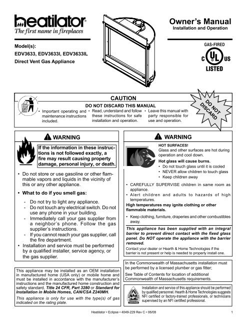
Model(s):<br />
<strong>EDV</strong>3633, <strong>EDV</strong>3633I, <strong>EDV</strong>3633IL<br />
Direct Vent Gas Appliance<br />
• Important operating and<br />
maintenance instructions<br />
included.<br />
WARNING<br />
If the information in these instructions<br />
is not followed exactly, a<br />
fi re may result causing property<br />
damage, personal injury, or death.<br />
• Do not store or use gasoline or other fl ammable<br />
vapors and liquids in the vicinity of<br />
this or any other appliance.<br />
• What to do if you smell gas:<br />
- Do not try to light any appliance.<br />
- Do not touch any electrical switch. Do not<br />
use any phone in your building.<br />
- Immediately call your gas supplier from<br />
a neighbor’s phone. Follow the gas<br />
supplier’s instructions.<br />
- If you cannot reach your gas supplier, call<br />
the fi re department.<br />
• Installation and service must be performed<br />
by a qualifi ed installer, service agency, or<br />
the gas supplier.<br />
This appliance may be installed as an OEM installation<br />
in manufactured home (USA only) or mobile home and<br />
must be installed in accordance with the manufacturer’s<br />
instructions and the manufactured home construction and<br />
safety standard, Title 24 CFR, Part 3280 or Standard for<br />
Installation in Mobile Homes, CAN/CSA Z240MH.<br />
This appliance is only for use with the type(s) of gas<br />
indicated on the rating plate.<br />
CAUTION<br />
DO NOT DISCARD THIS MANUAL<br />
• Read, understand and follow<br />
these instructions for safe<br />
installation and operation.<br />
• Leave this manual with<br />
party responsible for<br />
use and operation.<br />
Owner’s Manual<br />
Installation and Operation<br />
WARNING<br />
DO NOT<br />
DISCARD<br />
HOT SURFACES!<br />
Glass and other surfaces are hot during<br />
operation and cool down.<br />
Hot glass will cause burns.<br />
• Do not touch glass until it is cooled<br />
• NEVER allow children to touch glass<br />
• Keep children away<br />
• CAREFULLY SUPERVISE children in same room as<br />
appliance.<br />
• Alert children and adults to hazards of high<br />
temperatures.<br />
High temperatures may ignite clothing or other<br />
fl ammable materials.<br />
• Keep clothing, furniture, draperies and other combustibles<br />
away.<br />
This appliance has been supplied with an integral<br />
barrier to prevent direct contact with the fi xed glass<br />
panel. Do NOT operate the appliance with the barrier<br />
removed.<br />
Contact your dealer or Hearth & Home Technologies if the<br />
barrier is not present or help is needed to properly install one.<br />
In the Commonwealth of Massachusetts installation must<br />
be performed by a licensed plumber or gas fi tter;<br />
See Table of Contents for location of additional<br />
Commonwealth of Massachusetts requirements.<br />
Installation and service of this appliance should be performed<br />
by qualifi ed personnel. Hearth & Home Technologies suggests<br />
NFI certifi ed or factory-trained professionals, or technicians<br />
supervised by an NFI certifi ed professional.<br />
Heatilator • Eclipse • <strong>4049</strong>-229 Rev C • 06/08 1
A. Congratulations<br />
Congratulations on selecting a Heatilator gas fi replace, an<br />
elegant and clean alternative to wood burning fi replaces.<br />
The Heatilator gas fi replace you have selected is designed<br />
to provide the utmost in safety, reliability, and effi ciency.<br />
As the owner of a new fi replace, you’ll want to read and<br />
carefully follow all of the instructions contained in this<br />
owner’s manual. Pay special attention to all cautions and<br />
warnings.<br />
Listing Label Information/Location<br />
2<br />
Homeowner Reference Information<br />
Model Name: ___________________________________________ Date purchased/installed: __________________<br />
Serial Number: __________________________________________ Location on fi replace: _____________________<br />
Dealership purchased from: _______________________________ Dealer Phone: __________________________<br />
Notes: _______________________________________________________________________________________<br />
_____________________________________________________________________________________________<br />
Model #<br />
Read this manual before installing or operating this appliance.<br />
Please retain this owner’s manual for future reference.<br />
Hearth & Home Technologies Inc<br />
1915 W. Saunders Street<br />
Mt. Pleasant, IA 52641<br />
ANSI Standard<br />
Heatilator • Eclipse • <strong>4049</strong>-229 Rev C • 06/08<br />
This owner’s manual should be retained for future reference.<br />
We suggest that you keep it with your other important<br />
documents and product manuals.<br />
The information contained in this owner’s manual, unless<br />
noted otherwise, applies to all models and gas control<br />
systems.<br />
Your new Heatilator gas fi replace will give you years of<br />
durable use and trouble-free enjoyment. Welcome to the<br />
Heatilator family of fi replace products!<br />
We recommend that you record the following pertinent<br />
information about your fi replace.<br />
The model information regarding your specifi c fi replace can be found on<br />
the rating plate usually located in the control area of the fi replace.<br />
SERIAL<br />
NO. DE SÉRIE<br />
MODEL<br />
MODÈLE<br />
XXXXXX<br />
MFG. DATE<br />
DATE DE FAB.<br />
GAS TYPE/TYPE DE GAZ NATURAL/NATUREL PROPANE<br />
ALTITUDE 0-2000 2000-4000 FT/PI 0-2000 2000-4000 FT/PI<br />
MAX INPUT/DÉBIT XX,XXX XX,XXX BTUH XX,XXX XX,XXX BTUH<br />
MIN INPUT/DÉBIT XX,XXX XX,XXX BTUH XX,XXX XX,XXX BTUH<br />
MANIFOLD PRESSURE/PRESSION TUBULAIRE<br />
MAX. XX IN. W.C./C. D'EAU XX IN. W.C./C. D'EAU<br />
MIN. XX IN. W.C./C. D'EAU XX IN. W.C./C. D'EAU<br />
MIN. INLET PRESS. XX IN. W.C./C. D'EAU 1XX IN. W.C./C. D'EAU<br />
FOR THE PURPOSE OF INPUT ADJUSTMENT<br />
PRESS. MIN. D'ALIMENTATION<br />
ORIFICE SIZE<br />
DIAM. DE L'INJECTEUR XX/XX DIA. in./mm XX/XX DIA. in./mm<br />
LESS THAN/MOINS DE 3 AMPÈRES., 115V., 60 Hz<br />
Gas Type<br />
DO NOT REMOVE OR COVER THIS LABEL.<br />
VENTED GAS FIREPLACE - NOT FOR USE WITH SOLID FUEL.<br />
FOYER À GAZ À ÉVACUATION - NE DOIT PAS ÊTRE UTILISÉ<br />
AVEC UN COMBUSTIBLE SOLIDE.<br />
Serial #<br />
XXXXXXXXX<br />
XXXX<br />
CERTIFIED<br />
FOR CANADA<br />
CERTIFIÉ POUR LE<br />
CANADA<br />
Orifice<br />
Size
Safety Alert Key:<br />
• DANGER! Indicates a hazardous situation which, if not avoided will result in death or serious injury.<br />
• WARNING! Indicates a hazardous situation which, if not avoided could result in death or serious injury.<br />
• CAUTION! Indicates a hazardous situation which, if not avoided, could result in minor or moderate injury.<br />
• NOTICE: Used to address practices not related to personal injury.<br />
A. Congratulations 2<br />
B. Limited Lifetime Warranty<br />
1 Listing and Code Approvals<br />
5<br />
A. Appliance Certifi cation 6<br />
B. Tempered Glass Specifi cations 6<br />
C. BTU Specifi cations 6<br />
D. High Altitude Installations 6<br />
E. Non-Combustible Materials Specifi cation 6<br />
F. Combustible Materials Specifi cation 6<br />
G. Requirements for<br />
the Commonwealth of Massachusetts 7<br />
User Guide<br />
2 Operating Instructions<br />
A. Gas <strong>Fireplace</strong> Safety 8<br />
B. Your <strong>Fireplace</strong> 8<br />
C. Fan Kit 9<br />
D. Clear Space 9<br />
E. Fixed Glass Assembly 9<br />
F. Remote Controls, Wall Controls and Wall Switches 9<br />
G. Before Lighting <strong>Fireplace</strong> 9<br />
H. Lighting Instructions (IPI) 10<br />
I. Lighting Instructions (Standing Pilot) 11<br />
J. After <strong>Fireplace</strong> is Lit 12<br />
K. Frequently Asked Questions<br />
3 Maintenance and Service<br />
12<br />
A. Maintenance Tasks-Homeowner 13<br />
B. Maintenance Tasks-Qualifi ed Service Technician 14<br />
Installer Guide<br />
4 Getting Started<br />
A. Typical Appliance System 16<br />
B. Design and Installation Considerations 17<br />
C. Tools and Supplies Needed 17<br />
D. Inspect Appliance and Components<br />
5 Framing and Clearances<br />
17<br />
A. Selecting Appliance Location 18<br />
B. Constructing the Appliance Chase 19<br />
C. Clearances 19<br />
D. Mantel and Wall Projections 20<br />
Table of Contents<br />
6 Termination Locations<br />
A. Vent Termination Minimum Clearances<br />
7 Vent Information and Diagrams<br />
21<br />
A. Approved Pipe 23<br />
B. Vent Table Key 23<br />
C. Use of Elbows 23<br />
D. Measuring Standards 23<br />
E. Vent Diagrams<br />
8 Vent Clearances and Framing<br />
24<br />
A. Pipe Clearances to Combustibles 29<br />
B. Wall Penetration Framing 29<br />
C. Install the Ceiling Firestop 30<br />
D. Install <strong>At</strong>tic Insulation Shield<br />
9 Appliance Preparation<br />
31<br />
A. Securing and Leveling the Appliance<br />
10 Installing SLP Vent Pipe<br />
32<br />
A. Assemble Vent Sections 33<br />
B. Assemble Slip Sections 33<br />
C. Securing the Vent Sections 34<br />
D. Disassemble Vent Sections 34<br />
E. Installing Metal Roof Flashing 35<br />
F. Install RF4-8 36<br />
G. Installing Vertical Termination Cap 37<br />
H. Assemble and Install Storm Collar 37<br />
I. Install Heat Shields and<br />
Horizontal Termination Cap<br />
11 Gas Information<br />
38<br />
A. Fuel Conversion 40<br />
B. Gas Pressure 40<br />
C. Gas Connection 40<br />
D. High Altitude Installations<br />
12 Electrical Information<br />
40<br />
A. Wiring Requirements 41<br />
B. Standing Pilot Ignition System Wiring 41<br />
C. Intellifi re Ignition System Wiring 41<br />
D. Optional Accessories Requirements 41<br />
E. Electrical Service and Repair 42<br />
F. Junction Box Installation 43<br />
G. Wall Switch Installation for Fan (Optional)<br />
13 Finishing<br />
43<br />
A. Mantel and Wall Projections 44<br />
B. Facing Material 45<br />
Heatilator • Eclipse • <strong>4049</strong>-229 Rev C • 06/08 3
14 Appliance Setup<br />
A. Remove Packaging Materials 46<br />
B. Remove Glass Assembly 46<br />
C. Logs 46<br />
D. Place Lava Rock, Rockwool 46<br />
E. Replace Glass 47<br />
F. Install Floor Cover 47<br />
G. Grilles and Screen 47<br />
H. Air Shutter Setting 48<br />
I. Accessories 48<br />
15 Troubleshooting<br />
A. Standing Pilot Ignition System 49<br />
B. Intellifi re Ignition System<br />
16 Reference Materials<br />
51<br />
A. Appliance Dimension Diagram 53<br />
B. Vent Components Diagrams 54<br />
C. Service Parts 56<br />
D. Optional Components 58<br />
E. Contact Information 60<br />
4<br />
� = Contains updated information.<br />
Heatilator • Eclipse • <strong>4049</strong>-229 Rev C • 06/08
B. Limited Lifetime Warranty<br />
Gas Appliance (<strong>Fireplace</strong>)<br />
Limited Lifetime Warranty<br />
HEARTH & HOME TECHNOLOGIES INC. (“HHT”) extends the following warranty for HEATILATOR® gas<br />
appliances installed in the United States of America or Canada (the "Appliance"). Dealers and employees of HHT<br />
have no authority to make any warranty or authorize any remedies in addition to or inconsistent with the terms of<br />
this warranty.<br />
Limited Lifetime Warranty<br />
HHT warrants the Appliance for component failure due to a manufacturing defect of any of the following components: combustion chamber, burner<br />
pan, and logs. The Limited Lifetime Warranty specifi ed above is subject to the conditions, exclusions and limitations listed below, is for the period<br />
the Appliance is owned by the original homeowner only, and is nontransferable.<br />
1 Year Limited Warranty<br />
HHT warrants the Appliance to be free from failure of any of the following components for a period of one year after installation: valve, fl exible gas<br />
line connector, glass panel, fan, direct vent chimney components, factory paint, gasket, piezo ignitor, thermopile, thermocouple, junction box, pilot<br />
assembly, shutoff valve, high limit switch, refractory liners, transformer, and control box. If the Heatilator Appliance is found to be defective in either<br />
material or workmanship within one year of the date of original installation, HHT will provide replacement parts at no charge and pay reasonable<br />
labor and freight costs, and is for the period of one year following the date of original installation of the Appliance.<br />
Conditions, Exclusions, & Limitations of Liability<br />
A. Both the Limited Lifetime and 1 Year Limited Warranties supplied by HHT apply only while the Appliance is in its location of original<br />
installation. HHT’s obligation under this warranty does not extend to damages resulting from (1) installation, operation or maintenance<br />
of the Appliance not in accordance with the Installation Instructions, Operating Instructions, and the Listing Agent Identifi cation Label<br />
furnished with the Appliance; (2) installation which does not comply with local building codes; (3) shipping, improper handling, improper<br />
operation, abuse, misuse, accident or unworkmanlike repairs; (4) environmental conditions, inadequate ventilation or drafting caused by<br />
tight sealing construction of the structure, air handling devices such as exhaust fans or forced air furnaces, or other causes; (5) use of<br />
fuels other than those specifi ed in the Operating Instructions; (6) installation or use of components not supplied with the Appliance or any<br />
other components not expressly authorized and approved by HHT; and/or (7) modifi cation of the Appliance not expressly authorized and<br />
approved by HHT in writing. This warranty is limited to only the component parts manufactured or supplied by HHT.<br />
B. HHT’s liability under both the Limited Lifetime Warranty and the 1 Year Limited Warranty is limited to the replacement and repair of<br />
defective components or workmanship during the applicable period. HHT may fully discharge all of its obligations under such warranties<br />
by repairing the defective component(s) or at HHT’s discretion, providing replacement parts at no charge and paying reasonable labor and<br />
freight costs.<br />
C. EXCEPT TO THE EXTENT PROVIDED BY LAW, HHT MAKES NO EXPRESS WARRANTIES OTHER THAN THE WARRANTY<br />
SPECIFIED HEREIN. THE DURATION OF ANY IMPLIED WARRANTY IS LIMITED TO DURATION OF THE WARRANTY SPECIFIED<br />
ABOVE.<br />
D. Some states do not allow exclusions or limitations of incidental or consequential damages, so those limitations may not apply to you. This<br />
warranty gives you specifi c rights; you may also have other rights which vary from state to state.<br />
How to Obtain Service<br />
To obtain service under this warranty you must:<br />
1. Send written notice of the claimed condition to Heatilator Technical Service Department, Hearth & Home Technologies, 1915 W. Saunders<br />
Street, Mt. Pleasant, Iowa 52641-1563. You may also register your claim online at www.heatilator.com.<br />
2. Provide proof of purchase, model number, serial number, and manufacturing date code to HHT.<br />
3. Provide HHT reasonable opportunity to investigate the claim, including reasonable opportunity to inspect the Appliance prior to any repair<br />
or replacement work and before the Appliance or any component of the Appliance has been removed from the place of original installation.<br />
4. Obtain HHT’s consent to any warranty work before the work is done.<br />
ADDITIONAL INFORMATION:<br />
If you would like information on current HEATILATOR products or want to locate a dealer in your area, call 1-800-927-6841.<br />
©2003 Heatilator® is a Registered Trademark of Hearth & Home Technologies Inc.<br />
Heatilator • Eclipse • <strong>4049</strong>-229 Rev C • 06/08 5
1<br />
MODELS: <strong>EDV</strong>3633, <strong>EDV</strong>3633I, <strong>EDV</strong>3633IL<br />
LABORATORY: Underwriters Laboratories, Inc. (UL)<br />
TYPE: Vented Gas <strong>Fireplace</strong><br />
STANDARD: ANSI Z21.88-2005•CSA2.33-2005•UL307B<br />
This product is listed to ANSI standards for “Vented Gas<br />
<strong>Fireplace</strong>” and applicable sections of “Gas Burning Heating<br />
Appliances for Manufactured Homes and Recreational<br />
Vehicles”, and “Gas Fired Appliances for Use at High<br />
Altitudes”.<br />
B. Tempered Glass Specifi cations<br />
Hearth & Home Technologies appliances manufactured<br />
with tempered glass may be installed in hazardous<br />
locations such as bathtub enclosures as defi ned by the<br />
Consumer Product Safety Commission (CPSC). The<br />
tempered glass has been tested and certifi ed to the<br />
requirements of ANSI Z97.1 and CPSC 16 CFR 1202<br />
(Safety Glazing Certifi cation Council SGCC# 1595 and<br />
1597. Architectural Testing, Inc. Reports 02-31919.01 and<br />
02-31917.01).<br />
This statement is in compliance with CPSC 16 CFR<br />
Section 1201.5 “Certifi cation and labeling requirements”<br />
which refers to 15 U.S. Code (USC) 2063 stating “…Such<br />
certifi cate shall accompany the product or shall otherwise<br />
be furnished to any distributor or retailer to whom the<br />
product is delivered.”<br />
Some local building codes require the use of tempered<br />
glass with permanent marking in such locations. Glass<br />
meeting this requirement is available from the factory.<br />
Please contact your dealer or distributor to order.<br />
6<br />
Listing and Code Approvals<br />
A. Appliance Certifi cation<br />
NOTICE: This installation must conform with local codes.<br />
In the absence of local codes you must comply with the<br />
National Fuel Gas Code, ANSI Z223.1-latest edition in<br />
the U.S.A. and the CAN/CGA B149 Installation Codes in<br />
Canada.<br />
NOT INTENDED FOR USE AS A PRIMARY HEAT SOURCE.<br />
This appliance is tested and approved as either supplemental<br />
room heat or as a decorative appliance. It should not be factored<br />
as primary heat in residential heating calculations.<br />
C. BTU Specifi cations<br />
Heatilator • Eclipse • <strong>4049</strong>-229 Rev C • 06/08<br />
<strong>EDV</strong>3633 <strong>Series</strong> SP IPI<br />
Input Rate (NG) 20,000 20,000<br />
Orifi ce Size (NG) 0.083 0.083<br />
Input Rate (LP) 20,000 20,000<br />
Orifi ce Size (LP) 0.053 0.053<br />
D. High Altitude Installations<br />
NOTICE: If the heating value of the gas has been reduced,<br />
these rules do not apply. Check with your local gas utility or<br />
authorities having jurisdiction.<br />
When installing above 2000 feet elevation:<br />
• In the USA: Reduce input rate 4% for each 1000 feet<br />
above 2000 feet.<br />
• In CANADA: Reduce input rate 10% for elevations<br />
between 2000 feet and 4500 feet. Above 4500 feet,<br />
consult local gas utility.<br />
Check with your local gas utility to determine proper<br />
orifi ce size.<br />
E. Non-Combustible Materials Specifi cation<br />
Material which will not ignite and burn. Such materials are<br />
those consisting entirely of steel, iron, brick, tile, concrete,<br />
slate, glass or plasters, or any combination thereof.<br />
Materials that are reported as passing ASTM E 136,<br />
Standard Test Method for Behavior of Materials in a<br />
Vertical Tube Furnace at 750 ºC and UL763 shall be<br />
considered non-combustible materials.<br />
F. Combustible Materials Specifi cation<br />
Materials made of or surfaced with wood, compressed<br />
paper, plant fi bers, plastics, or other material that can ignite<br />
and burn, whether fl ame proofed or not, or plastered<br />
or unplastered shall be considered combustible materials.
Note: The following requirements reference various<br />
Massachusetts and national codes not contained in this<br />
document.<br />
G. Requirements for the Commonwealth of<br />
Massachusetts<br />
For all side wall horizontally vented gas fueled equipment<br />
installed in every dwelling, building or structure used in<br />
whole or in part for residential purposes, including those<br />
owned or operated by the Commonwealth and where the<br />
side wall exhaust vent termination is less than seven (7)<br />
feet above fi nished grade in the area of the venting, including<br />
but not limited to decks and porches, the following<br />
requirements shall be satisfi ed:<br />
Installation of Carbon Monoxide Detectors<br />
<strong>At</strong> the time of installation of the side wall horizontal<br />
vented gas fueled equipment, the installing plumber or<br />
gas fi tter shall observe that a hard wired carbon monoxide<br />
detector with an alarm and battery back-up is<br />
installed on the fl oor level where the gas equipment is<br />
to be installed. In addition, the installing plumber or gas<br />
fi tter shall observe that a battery operated or hard wired<br />
carbon monoxide detector with an alarm is installed on<br />
each additional level of the dwelling, building or structure<br />
served by the side wall horizontal vented gas fueled<br />
equipment. It shall be the responsibility of the property<br />
owner to secure the services of qualifi ed licensed professionals<br />
for the installation of hard wired carbon monoxide<br />
detectors.<br />
In the event that the side wall horizontally vented gas<br />
fueled equipment is installed in a crawl space or an attic,<br />
the hard wired carbon monoxide detector with alarm and<br />
battery back-up may be installed on the next adjacent<br />
fl oor level.<br />
In the event that the requirements of this subdivision can<br />
not be met at the time of completion of installation, the<br />
owner shall have a period of thirty (30) days to comply<br />
with the above requirements; provided, however, that during<br />
said thirty (30) day period, a battery operated carbon<br />
monoxide detector with an alarm shall be installed.<br />
Approved Carbon Monoxide Detectors<br />
Each carbon monoxide detector as required in accordance<br />
with the above provisions shall comply with NFPA<br />
720 and be ANSI/UL 2034 listed and IAS certifi ed.<br />
Signage<br />
A metal or plastic identifi cation plate shall be permanently<br />
mounted to the exterior of the building at a minimum<br />
height of eight (8) feet above grade directly in line with<br />
the exhaust vent terminal for the horizontally vented gas<br />
fueled heating appliance or equipment. The sign shall<br />
read, in print size no less than one-half (1/2) in. in size,<br />
“GAS VENT DIRECTLY BELOW. KEEP CLEAR OF ALL<br />
OBSTRUCTIONS”.<br />
Inspection<br />
The state or local gas inspector of the side wall horizontally<br />
vented gas fueled equipment shall not approve the<br />
installation unless, upon inspection, the inspector observes<br />
carbon monoxide detectors and signage installed<br />
in accordance with the provisions of 248 CMR 5.08(2)(a)1<br />
through 4.<br />
Exemptions<br />
The following equipment is exempt from 248 CMR<br />
5.08(2)(a)1 through 4:<br />
• The equipment listed in Chapter 10 entitled “Equipment<br />
Not Required To Be Vented” in the most current edition<br />
of NFPA 54 as adopted by the Board; and<br />
• Product Approved side wall horizontally vented gas<br />
fueled equipment installed in a room or structure<br />
separate from the dwelling, building or structure used<br />
in whole or in part for residential purposes.<br />
MANUFACTURER REQUIREMENTS<br />
Gas Equipment Venting System Provided<br />
When the manufacturer of Product Approved side wall<br />
horizontally vented gas equipment provides a venting<br />
system design or venting system components with the<br />
equipment, the instructions provided by the manufacturer<br />
for installation of the equipment and the venting system<br />
shall include:<br />
• Detailed instructions for the installation of the venting<br />
system design or the venting system components;<br />
and<br />
• A complete parts list for the venting system design or<br />
venting system.<br />
Gas Equipment Venting System NOT Provided<br />
When the manufacturer of a Product Approved side<br />
wall horizontally vented gas fueled equipment does not<br />
provide the parts for venting the fl ue gases, but identifi<br />
es “special venting systems”, the following requirements<br />
shall be satisfi ed by the manufacturer:<br />
• The referenced “special venting system” instructions<br />
shall be included with the appliance or equipment<br />
installation instructions; and<br />
• The “special venting systems” shall be Product<br />
Approved by the Board, and the instructions for that<br />
system shall include a parts list and detailed installation<br />
instructions.<br />
A copy of all installation instructions for all Product Approved<br />
side wall horizontally vented gas fueled equipment,<br />
all venting instructions, all parts lists for venting<br />
instructions, and/or all venting design instructions shall<br />
remain with the appliance or equipment at the completion<br />
of the installation.<br />
See Gas Connection section for additional Commonwealth<br />
of Massachusetts requirements.<br />
Heatilator • Eclipse • <strong>4049</strong>-229 Rev C • 06/08 7
2<br />
8<br />
Operating Instructions<br />
A. Gas <strong>Fireplace</strong> Safety • Install a physical barrier such as:<br />
- A decorative fi rescreen.<br />
WARNING<br />
HOT SURFACES!<br />
Glass and other surfaces are hot<br />
during operation and cool down.<br />
Hot glass will cause burns.<br />
• Do not touch glass until it is cooled<br />
• NEVER allow children to touch glass<br />
• Keep children away<br />
• CAREFULLY SUPERVISE children in<br />
same room as appliance.<br />
• Alert children and adults to hazards of high<br />
temperatures.<br />
High temperatures may ignite clothing or other<br />
fl ammable materials.<br />
• Keep clothing, furniture, draperies and other<br />
combustibles away.<br />
This appliance has been supplied with an integral<br />
barrier to prevent direct contact with the fi xed glass<br />
panel. Do NOT operate the appliance with the barrier<br />
removed.<br />
Contact your dealer or Hearth & Home Technologies if the<br />
barrier is not present or help is needed to properly install one.<br />
If you expect that small children or vulnerable adults may<br />
come into contact with this fi replace, the following precautions<br />
are recommended:<br />
Figure 2.1 General Operating Parts<br />
Fan Kit<br />
SECTION 2.C<br />
Log Set<br />
(not shown)<br />
SECTION 2.B.<br />
User Guide<br />
Fixed Glass Assembly<br />
SECTION 14.K.<br />
Hearth<br />
(not required)<br />
Clear Space<br />
SECTION 2.D.<br />
Mantel<br />
SECTION 13.A.<br />
Heatilator • Eclipse • <strong>4049</strong>-229 Rev C • 06/08<br />
- Adjustable safety gate.<br />
• Install a switch lock or a wall/remote control with child<br />
protection lockout feature.<br />
• Keep remote controls out of reach of children.<br />
• Never leave children alone near a hot fi replace, whether<br />
operating or cooling down.<br />
• Teach children to NEVER touch the fi replace.<br />
• Consider not using the fi replace when children will be<br />
present.<br />
Contact your dealer for more information, or visit: www.<br />
hpba.org/staysafe.<br />
To prevent unintended operation when not using your<br />
fi replace for an extended period of time (summer months,<br />
vacations, trips, etc):<br />
• Remove batteries from remote controls.<br />
• Turn off wall controls.<br />
• Unplug 3 volt adapter plug and remove batteries on IPI<br />
models.<br />
• Turn off gas controls valve on standing pilot models.<br />
When lighting the pilot light on fi replaces with a standing<br />
pilot, remove the fi xed glass assembly so you can detect<br />
presence of residual gas build-up. See Standing Pilot<br />
Lighting instructions and Maintenance Tasks.<br />
B. Your <strong>Fireplace</strong><br />
WARNING! DO NOT operate fi replace before reading and<br />
understanding operating instructions. Failure to operate<br />
fi replace according to operating instructions could cause<br />
fi re or injury.
C. Fan Kit<br />
• Optional<br />
• Contact your dealer for the correct fan kit.<br />
D. Clear Space<br />
WARNING! DO NOT place combustible objects in front of<br />
the fi replace or block louvers. High temperatures may start<br />
a fi re. See Figure 2.2.<br />
Avoid placing candles and other heat-sensitive objects on<br />
mantel or hearth. Heat may damage these objects.<br />
Clear space 3 ft (914 mm)<br />
in front of appliance<br />
Figure 2.2 Clear Space<br />
E. Fixed Glass Assembly<br />
See Section 14.E.<br />
F. Remote Controls, Wall Controls and Wall<br />
Switches<br />
Follow the instructions supplied with the control installed<br />
to operate your fi replace:<br />
For safety:<br />
• Install a switch lock or a wall/remote control with child<br />
protection lockout feature.<br />
• Keep remote controls out of reach of children.<br />
See your dealer if you have questions.<br />
G. Before Lighting <strong>Fireplace</strong><br />
Before operating this fi replace for the fi rst time, have a<br />
qualifi ed service technician:<br />
• Verify all shipping materials have been removed from<br />
inside and/or underneath the fi rebox.<br />
• Review proper placement of logs, ember material and/or<br />
other decorative materials.<br />
• Check the wiring.<br />
• Check the air shutter adjustment.<br />
• Ensure that there are no gas leaks.<br />
• Ensure that the glass is sealed and in the proper position<br />
and that the integral barrier is in place.<br />
WARNING! Risk of Fire or Asphyxiation! DO NOT operate<br />
fi replace with fi xed glass assembly removed.<br />
Determine if this fi replace has a standing pilot or an<br />
Intellifi re ignition system. Ask your dealer or open control<br />
access panel, look at gas valve assembly.<br />
• A standing pilot ignition will have a red or black ignitor<br />
button (refer to Figure 2.3).<br />
• An Intellifi re ignition system will not have a button.<br />
Red or Black<br />
Button<br />
Figure 2.3 Ignitor Button<br />
Heatilator • Eclipse • <strong>4049</strong>-229 Rev C • 06/08 9
H. Lighting Instructions (IPI)<br />
The IPI system may be operated with two D-cell batteries. When using batteries, unplug the transformer. To prolong battery<br />
life, remove them when using the transformer.<br />
10<br />
This appliance needs fresh air for safe operation and must<br />
be installed so there are provisions for adequate<br />
combustion and ventilation air.<br />
FOR YOUR SAFETY READ BEFORE LIGHTING<br />
This appliance must be installed in accordance<br />
with local codes, if any; if not, follow ANSI<br />
Z223.1 or, in Canada, current CAN/CGA-B149.<br />
WARNING: If you do not follow these instructions exactly, a<br />
fire or explosion may result causing property<br />
damage, personal injury or loss of life.<br />
This appliance must be properly connected to a<br />
venting system in accordance with the<br />
manufacturer's installation instructions.<br />
• If you cannot reach your gas supplier, call the fire<br />
department.<br />
C. Use only your hand to push in and move the gas control<br />
valve or turn the gas control knob. Never use tools. If the<br />
lever or knob will not move by hand, don't try to repair it,<br />
call a qualified service technician. Force or attempted<br />
repair may result in a fire or explosion.<br />
D. Do not use this appliance if any part has been under<br />
water. Immediately call a qualified service technician to<br />
inspect the appliance and to replace any part of the<br />
control system and any gas control which has been<br />
A. This appliance is equipped with an ignition device which<br />
automatically lights the pilot. Do not try to light the pilot<br />
by hand.<br />
B. BEFORE LIGHTING smell all around the appliance area<br />
for gas. Be sure to smell next to the floor because some<br />
gas is heavier than air and will settle on the floor.<br />
WARNING: Improper installation,<br />
adjustment, alteration, service or maintenance<br />
can cause injury or property damage. Refer to<br />
the owner's information manual provided with<br />
the appliance. For assistance or additional<br />
information consult a qualified installer, service<br />
agency or the gas supplier.<br />
CAUTION: Hot while in operation. Do not touch.<br />
Keep children, clothing, furniture, gasoline and other liquids<br />
having flammable vapors away.<br />
WHAT TO DO IF YOU SMELL GAS<br />
• Do not try to light any appliance.<br />
• Do not touch any electric switch; do not use any<br />
phone in your building.<br />
• Immediately call your gas supplier from a neighbor's<br />
under water.<br />
phone. Follow the gas supplier's instructions.<br />
LIGHTING INSTRUCTIONS<br />
WARNING RISK OF FIRE<br />
This appliance is intended to burn a specified gas fuel only. Do<br />
not attempt to use with solid wood fuel or another type of fuel.<br />
Do not attempt to modify or use any other type of gas burner<br />
system.<br />
5. Wait five minutes to clear out any gas. If you then smell gas,<br />
STOP! Follow "B" in the safety information above on this label. If<br />
you don't smell gas, go to the next step.<br />
6. To turn on the burner, turn on all electric power to this appliance<br />
and turn on the wall switch or set the thermostat to the desired<br />
setting.<br />
7. If the appliance will not operate, follow the instructions "TO TURN<br />
OFF GAS TO APPLIANCE" and call your service technician or gas<br />
supplier.<br />
1. STOP! Read the safety information above on this label.<br />
2. Turn wall switch to the "OFF" position or thermostat to<br />
the lowest setting.<br />
3. Turn off all electric power to the appliance.<br />
4. This appliance is equipped with an ignition device which<br />
automatically lights the pilot. Do NOT try to light the pilot<br />
by hand.<br />
WARNING: Disconnect the electric power before<br />
servicing. If for any reason the original wire supplied with the<br />
appliance must be replaced, it must be replaced with 105° C or its<br />
equivalent.<br />
TO TURN OFF GAS TO APPLIANCE<br />
For use with natural gas or propane. A conversion<br />
kit as supplied by the manufacturer shall be used<br />
to convert this appliance to the alternative fuel.<br />
3. Push the gas control lever in and move to the "OFF"<br />
position or push the gas control lever to the "OFF"<br />
position. Do not force.<br />
4. Replace the control access panel.<br />
1. Turn off wall switch or set thermostat to lowest setting.<br />
2. Turn off all electric power to the appliance if service is to<br />
be performed.<br />
Heatilator • Eclipse • <strong>4049</strong>-229 Rev C • 06/08<br />
* Also certified for installation in a bedroom or<br />
a bed-sitting room.<br />
* For U.S. only!<br />
NATURAL GAS<br />
Due to high surface temperatures, keep children, clothing and furniture away.<br />
Keep burner and control compartment clean. See installation and operating instructions accompanying the appliance.<br />
33631D
I. Lighting Instructions (Standing Pilot)<br />
This appliance needs fresh air for safe operation<br />
and must be installed so there are provisions for<br />
adequate combustion and ventilation air.<br />
FOR YOUR SAFETY READ BEFORE LIGHTING<br />
This appliance must be installed in accordance with<br />
local codes, if any; if not, follow ANSI Z223.1 or, in<br />
Canada, current CAN/CGA-B149.<br />
This appliance must be properly connected to a<br />
venting system in accordance with the<br />
manufacturer's installation instructions.<br />
WARNING: Improper installation,<br />
adjustment, alteration, service or maintenance can<br />
cause injury or property damage. Refer to the owner's<br />
information manual provided with the appliance. For<br />
assistance or additional information consult a<br />
qualified installer, service agency or the gas supplier.<br />
WARNING: If you do not follow these instructions exactly, a fire or<br />
explosion may result causing property damage,<br />
personal injury or loss of life.<br />
A. This appliance has a pilot which must be lighted by hand.<br />
• If you cannot reach your gas supplier, call the fire<br />
When lighting the pilot, follow these instructions exactly.<br />
department.<br />
B. BEFORE LIGHTING smell all around the appliance area for<br />
C. Use only your hand to push in or turn knob. Never use tools. If<br />
gas. Be sure to smell next to the floor because some gas is<br />
the manual gas valve will not push in or turn by hand, don't try<br />
heavier than air and will settle on the floor.<br />
to repair it; call a qualified service technician. Force or<br />
WHAT TO DO IF YOU SMELL GAS<br />
attempted repair may result in a fire or explosion.<br />
• Do not try to light any appliance.<br />
D. Do not use this appliance if any part has been under water.<br />
• Do not touch any electric switch; do not use any phone in<br />
Immediately call a qualified service technician to inspect the<br />
your building.<br />
appliance and to replace any part of the control system and<br />
• Immediately call your gas supplier from a neighbor's phone.<br />
any gas control which has been under water.<br />
Follow the gas supplier's instructions.<br />
CAUTION: Hot while in operation. Do not touch.<br />
Keep children, clothing, furniture, gasoline and other liquids<br />
having flammable vapors away.<br />
LIGHTING INSTRUCTIONS<br />
Stop! Read the safety information above on this label.<br />
WARNING RISK OF FIRE<br />
This appliance is intended to burn a specified gas<br />
fuel only. Do not attempt to use with solid wood fuel<br />
or another type of fuel. Do not attempt to modify or<br />
use any other type of gas burner system.<br />
WARNING: Disconnect the electric power<br />
before servicing. If for any reason the original wire<br />
supplied with the appliance must be replaced, it must be<br />
replaced with 105° C or its equivalent.<br />
For use with natural gas or propane. A conversion<br />
kit as supplied by the manufacturer shall be used to<br />
convert this appliance to the alternative fuel.<br />
* Also certified for installation in a bedroom or a<br />
bed-sitting room.<br />
* For U.S. only!<br />
1. Turn wall switch to the "OFF" position or thermostat to the<br />
lowest setting.<br />
2. Remove control access panel.<br />
3. Turn manual gas valve to CLOSED. Wait five [5] minutes to<br />
clear out any gas. If you then smell gas, STOP! Follow "B" in<br />
the safety information above on this label. If you don't smell<br />
gas, go to next step.<br />
4. Turn gas line to "OPEN".<br />
5. Turn pilot knob clockwise to "OFF". (Knob may have to be<br />
depressed to pass "PILOT" position.)<br />
6. Locate pilot assembly inside appliance.<br />
7. Locate red ignitor button.<br />
8. Turn pilot knob to "PILOT" and push in.<br />
9. Continue to hold in pilot knob and push the red ignitor button<br />
12-15 times until small blue pilot flame appears.<br />
10. Continue to hold in pilot knob for approximately one minute.<br />
Pilot should remain lit. If pilot goes out, wait 5 minutes and<br />
repeat Steps 3-9.<br />
11. Release and turn knob counterclockwise to "ON".<br />
12. If appliance will not operate, follow the instructions "TO TURN<br />
OFF GAS TO APPLIANCE" and call your service technician or<br />
gas supplier.<br />
NOTE: To light main burner, turn wall switch to "ON". Do not light by<br />
hand.<br />
3. CLOSED<br />
VENT<br />
OFF<br />
ON<br />
7<br />
4. OPEN<br />
OFF<br />
5 8 11<br />
ON<br />
PILOT<br />
ON<br />
PILOT<br />
OFF<br />
ON<br />
PILOT<br />
OFF<br />
5<br />
TO TURN OFF GAS TO APPLIANCE<br />
NATURAL GAS<br />
1. Turn off wall switch or set thermostat to lowest setting. 3. Turn manual gas valve to "CLOSED position. Do not force.<br />
2. Remove control access panel.<br />
4. Replace control access panel.<br />
Due to high surface termperatures, keep children, clothing and furniture away.<br />
Keep burner and control compartment clean. See installation and operating instructions accompanying the appliance. 29097D<br />
Heatilator • Eclipse • <strong>4049</strong>-229 Rev C • 06/08 11
J. After <strong>Fireplace</strong> is Lit<br />
Initial Break-in Procedure<br />
• The fireplace should be run three to four hours<br />
continuously on high.<br />
• Turn the fi replace off and allow it to completely cool.<br />
• Remove fi xed glass assembly. See Section 14.B.<br />
• Clean fi xed glass assembly. See Section 3.<br />
• Replace the fi xed glass assembly and run continuously<br />
on high an additional 12 hours.<br />
This cures the materials used to manufacture the fi replace.<br />
NOTICE! Open windows for air circulation during fi replace<br />
break-in.<br />
12<br />
• Some people may be sensitive to smoke and<br />
odors.<br />
• Smoke detectors may activate.<br />
K. Frequently Asked Questions<br />
Condensation on the glass<br />
Blue fl ames<br />
Odor from fi replace<br />
Film on the glass<br />
Metallic noise<br />
ISSUE SOLUTIONS<br />
This is a result of gas combustion and temperature variations. As the fi replace warms, this<br />
condensation will disappear.<br />
This is a result of normal operation and the fl ames will begin to yellow as the fi replace is allowed<br />
to burn for 20 to 40 minutes.<br />
When fi rst operated, this fi replace may release an odor for the fi rst several hours. This is<br />
caused by the curing of materials from manufacturing. Odor may also be released from<br />
fi nishing materials and adhesives used near the fi replace. These circumstances may require<br />
additional curing related to the installation environment.<br />
This is a normal result of the curing process of the paint and logs. Glass should be cleaned<br />
within 3 to 4 hours of initial burning. A non-abrasive cleaner such as gas appliance glass<br />
cleaner may be necessary. See your dealer.<br />
Noise is caused by metal expanding and contracting as it heats up and cools down, similar to<br />
the sound produced by a furnace or heating duct. This noise does not affect the operation or<br />
longevity of the fi replace.<br />
Heatilator • Eclipse • <strong>4049</strong>-229 Rev C • 06/08
3<br />
Maintenance and Service<br />
Any safety screen or guard removed for servicing must be<br />
replaced prior to operating the fi replace.<br />
When properly maintained, your fi replace will give you<br />
many years of trouble-free service. We recommend annual<br />
service by a qualifi ed service technician.<br />
A. Maintenance Tasks-Homeowner<br />
Installation and repair should be done by a qualifi ed<br />
service technician only. The fi replace should be inspected<br />
before use and at least annually by a professional<br />
service person.<br />
The following tasks may be performed annually by the<br />
homeowner. If you are uncomfortable performing any of<br />
the listed tasks, please call your dealer for a service appointment.<br />
More frequent cleaning may be required due to lint from<br />
carpeting or other factors. Control compartment, burner<br />
and circulating air passageway of the fi replace must be<br />
kept clean.<br />
CAUTION! Risk of Burns! The fi replace should be<br />
turned off and cooled before servicing.<br />
Glass Cleaning<br />
Frequency: Seasonally<br />
By: Homeowner<br />
Tools Needed: Protective gloves, glass cleaner, drop<br />
cloth and a stable work surface.<br />
CAUTION! Handle fi xed glass assembly with care.<br />
Glass is breakable.<br />
• Avoid striking, scratching or slamming glass<br />
• Avoid abrasive cleaners<br />
• DO NOT clean glass while it is hot<br />
• Prepare a work area large enough to accommodate fi xed<br />
glass assembly and door frame by placing a drop cloth<br />
on a fl at, stable surface.<br />
Note: Fixed glass assembly and gasketing may have<br />
residue that can stain carpeting or fl oor surfaces.<br />
• Remove door or decorative front from fi replace and set<br />
aside on work surface.<br />
• See Section 14.B for instructions to remove fi xed glass<br />
assembly.<br />
• Clean glass with a non-abrasive commercially available<br />
cleaner.<br />
- Light deposits: Use a soft cloth with soap and<br />
water<br />
- Heavy deposits: Use commercial fi replace glass<br />
cleaner (consult with your dealer)<br />
• Carefully set fi xed glass assembly in place on fi replace.<br />
Hold glass in place with one hand and secure glass<br />
latches with the other hand. See Section 14.E. for glass<br />
replacement.<br />
• Reinstall door or decorative front.<br />
Doors, Surrounds, Fronts<br />
Frequency: Annually<br />
By: Homeowner<br />
Tools needed: Protective gloves, stable work surface<br />
• Assess condition of screen and replace as necessary.<br />
• Inspect for scratches, dents or other damage and repair<br />
as necessary.<br />
• Check that louvers are not blocked.<br />
• Vacuum and dust surfaces.<br />
Remote Control<br />
Frequency: Seasonally<br />
By: Homeowner<br />
Tools needed: Replacement batteries and remote control<br />
instructions.<br />
• Locate remote control transmitter and receiver.<br />
• Verify operation of remote. Refer to remote control<br />
operation instructions for proper calibration and setup<br />
procedure.<br />
• Place batteries as needed in remote transmitters and<br />
battery-powered receivers.<br />
• Place remote control out of reach of children.<br />
If not using your fi replace for an extended period of time<br />
(summer months, vacations/trips, etc), to prevent unintended<br />
operation:<br />
• Remove batteries from remote controls.<br />
• Unplug 3 volt adapter plug on IPI models.<br />
Heatilator • Eclipse • <strong>4049</strong>-229 Rev C • 06/08 13
Venting<br />
Frequency: Seasonally<br />
By: Homeowner<br />
Tools needed: Protective gloves and safety glasses.<br />
• Inspect venting and termination cap for blockage or<br />
obstruction such plants, bird nests, leaves, snow, debris,<br />
etc.<br />
• Verify termination cap clearance to subsequent<br />
construction (building additions, decks, fences, or<br />
sheds). See Section 6.<br />
• Inspect for corrosion or separation.<br />
• Verify weather stripping, sealing and fl ashing remains<br />
intact.<br />
• Inspect draft shield to verify it is not damaged or<br />
missing.<br />
B. Maintenance Tasks-Qualifi ed Service<br />
Technician<br />
The following tasks must be performed by a qualifi ed<br />
service technician.<br />
Gasket Seal and Glass Assembly Inspection<br />
Frequency: Annually<br />
By: Qualifi ed Service Technician<br />
Tools needed: Protective gloves, drop cloth and a stable<br />
work surface.<br />
• Inspect gasket seal and its condition.<br />
• Inspect fi xed glass assembly for scratches and nicks<br />
that can lead to breakage when exposed to heat.<br />
• Confi rm there is no damage to glass or glass frame.<br />
Replace as necessary.<br />
• Verify that fi xed glass assembly is properly retained and<br />
attachment components are intact and not damaged.<br />
Replace as necessary.<br />
Logs<br />
Frequency: Annually<br />
By: Qualifi ed Service Technician<br />
Tools needed: Protective gloves.<br />
• Inspect for damaged or missing logs. Replace as<br />
necessary. Refer to Section 14 for log reference.<br />
• Verify correct log placement and no fl ame impingement<br />
causing sooting. Correct as necessary.<br />
Firebox<br />
Frequency: Annually<br />
By: Qualifi ed Service Technician<br />
Tools needed: Protective gloves, sandpaper, steel wool,<br />
cloths, mineral spirits, primer and touch-up paint.<br />
• Inspect for paint condition, warped surfaces, corrosion<br />
or perforation. Sand and repaint as necessary.<br />
• Replace fi replace if fi rebox has been perforated.<br />
14<br />
Heatilator • Eclipse • <strong>4049</strong>-229 Rev C • 06/08<br />
Control Compartment and Firebox Top<br />
Frequency: Annually<br />
By: Qualifi ed Service Technician<br />
Tools needed: Protective gloves, vacuum cleaner, dust<br />
cloths<br />
• Vacuum and wipe out dust, cobwebs, debris or pet hair.<br />
Use caution when cleaning these areas. Screw tips that<br />
have penetrated the sheet metal are sharp and should<br />
be avoided.<br />
• Remove all foreign objects.<br />
• Verify unobstructed air circulation.<br />
Burner Ignition and Operation<br />
Frequency: Annually<br />
By: Qualifi ed Service Technician<br />
Tools needed: Protective gloves, vacuum cleaner, whisk<br />
broom, fl ashlight, voltmeter, indexed drill bit set, and a<br />
manometer.<br />
• Verify burner is properly secured and aligned with pilot<br />
or igniter.<br />
• Clean off burner top, inspect for plugged ports, corrosion<br />
or deterioration. Replace burner if necessary.<br />
• Replace rockwool materials with new dime-size pieces.<br />
DO NOT block ports or obstruct lighting paths. Refer to<br />
Section 14 for proper rockwool placement.<br />
• Verify batteries have been removed from battery backup<br />
IPI systems to prevent premature battery failure or<br />
leaking.<br />
• Check for smooth lighting and ignition carryover to all<br />
ports. Verify that there is no ignition delay.<br />
• Inspect for lifting or other fl ame problems.<br />
• Verify air shutter setting is correct. See Section 14 for<br />
required air shutter setting. Verify air shutter is clear of<br />
dust and debris.<br />
• Inspect orifi ce for soot, dirt and corrosion. Verify orifi ce<br />
size is correct. See Service Parts List for proper orifi ce<br />
sizing.<br />
• Verify manifold and inlet pressures. Adjust regulator as<br />
required.<br />
• Inspect pilot fl ame pattern and strength. See Figure 3.1<br />
and 3.2 for proper pilot fl ame pattern. Clean or replace<br />
orifi ce spud as necessary.<br />
• Inspect thermocouple/thermopile or IPI fl ame sensing<br />
rod for soot, corrosion and deterioration. Clean with<br />
emery cloth or replace as required.<br />
• Verify thermocouple/thermopile or IPI millivolt output.<br />
Replace as necessary.
(Either cobrahead or SIT)<br />
PRODUCT SPECIFIC<br />
Figure 3.1 IPI Pilot Flame Patterns<br />
Figure 3.2 Standing Pilot Flame Patterns<br />
Heatilator • Eclipse • <strong>4049</strong>-229 Rev C • 06/08 15
4<br />
16<br />
Getting Started<br />
A. Typical Appliance System<br />
NOTICE: Illustrations and photos refl ect typical installations and are for design purposes only. Illustrations/diagrams are not<br />
drawn to scale. Actual product may vary from pictures in manual<br />
Figure 4.1 Typical System<br />
Noncombustible roof<br />
flashing maintains minimum<br />
clearance around pipe<br />
(SECTION 10)<br />
Vent Pipe<br />
(SECTIONS 7, 8, 10)<br />
Ceiling Firestop<br />
on floor of attic<br />
(SECTION 8)<br />
Framing/Header<br />
(SECTION 5)<br />
Gas Line<br />
(SECTION 11)<br />
Installer Guide<br />
Vertical Termination Cap<br />
(SECTION 10)<br />
Storm Collar<br />
(SECTION 10)<br />
Vent pipe penetrates roof,<br />
preferably without affecting<br />
roof rafters<br />
(SECTION 8)<br />
Heatilator • Eclipse • <strong>4049</strong>-229 Rev C • 06/08<br />
<strong>At</strong>tic insulation shield (not shown) must be used here to<br />
keep insulation away from vent pipe if attic is insulated.<br />
(SECTION 8)<br />
Framing Headed off<br />
in Ceiling Joists<br />
(SECTION 8)<br />
Optional<br />
Wall Switch<br />
Mantel & Mantel Leg<br />
(SECTION 13)<br />
Surround<br />
Hearth Extension<br />
(not required)
B. Design and Installation Considerations<br />
Heatilator direct vent gas appliances are designed to operate<br />
with all combustion air siphoned from outside of the<br />
building and all exhaust gases expelled to the outside. No<br />
additional outside air source is required.<br />
Installation MUST comply with local, regional, state and<br />
national codes and regulations. Consult insurance carrier,<br />
local building inspector, fi re offi cials or authorities having<br />
jurisdiction over restrictions, installation inspection and<br />
permits.<br />
Before installing, determine the following:<br />
• Where the appliance is to be installed.<br />
• The vent system confi guration to be used.<br />
• Gas supply piping.<br />
• Electrical wiring requirements.<br />
• Framing and fi nishing details.<br />
• Whether optional accessories—devices such as a fan or<br />
remote control—are desired.<br />
Improper installation, adjustment, alteration, service or<br />
maintenance can cause injury or property damage. For<br />
assistance or additional information, consult a qualifi ed<br />
service technician, service agency or your dealer.<br />
C. Tools and Supplies Needed<br />
Before beginning the installation be sure that the following<br />
tools and building supplies are available.<br />
Tape measure Framing material<br />
Pliers<br />
High temperature caulking material<br />
Hammer Phillips screwdriver<br />
Gloves Framing square<br />
Voltmeter Electric drill and bits (1/4 in.)<br />
Plumb line Safety glasses<br />
Level Reciprocating saw<br />
Manometer Flat blade screwdriver<br />
Non-corrosive leak check solution<br />
1/2 - 3/4 in. length, #6 or #8 Self-drilling screws<br />
One 1/4 in. female connection (for optional fan).<br />
D. Inspect Appliance and Components<br />
• Carefully remove the appliance and components from<br />
the packaging.<br />
• The vent system components and decorative doors and<br />
fronts may be shipped in separate packages.<br />
• If packaged separately, the log set and appliance grate<br />
must be installed.<br />
• Report to your dealer any parts damaged in shipment,<br />
particularly the condition of the glass.<br />
• Read all of the instructions before starting the installation.<br />
Follow these instructions carefully during the installation<br />
to ensure maximum safety and benefi t.<br />
WARNING! Risk of Fire or Explosion! Damaged parts<br />
could impair safe operation. DO NOT install damaged, incomplete<br />
or substitute components. Keep appliance dry.<br />
Hearth & Home Technologies disclaims any responsibility for,<br />
and the warranty will be voided by, the following actions:<br />
• Installation and use of any damaged appliance or vent system<br />
component.<br />
• Modifi cation of the appliance or vent system.<br />
• Installation other than as instructed by Hearth & Home<br />
Technologies.<br />
• Improper positioning of the gas logs or the glass door.<br />
• Installation and/or use of any component part not approved<br />
by Hearth & Home Technologies.<br />
Any such action may cause a fi re hazard.<br />
WARNING! Risk of Fire, Explosion or Electric Shock!<br />
DO NOT use this appliance if any part has been under water.<br />
Call a qualifi ed service technician to inspect the appliance<br />
and to replace any part of the control system and/or<br />
gas control which has been under water.<br />
Heatilator • Eclipse • <strong>4049</strong>-229 Rev C • 06/08 17
5<br />
18<br />
Framing and Clearances<br />
A. Selecting Appliance Location<br />
When selecting a location for the appliance it is important<br />
to consider the required clearances to walls (see Figure<br />
5.1).<br />
WARNING! Risk of Fire or Burns! Provide adequate<br />
clearance around air openings and for service access. Due<br />
to high temperatures, the appliance should be located out<br />
of traffi c and away from furniture and draperies.<br />
3/4 in./19 mm<br />
minimum<br />
appliance<br />
to combustibles<br />
36-7/8 in.<br />
934 mm<br />
Figure 5.1 Appliance Locations<br />
36-7/8 in.<br />
934 mm<br />
36 in./914 mm<br />
Drywall<br />
Heatilator • Eclipse • <strong>4049</strong>-229 Rev C • 06/08<br />
NOTICE: Illustrations refl ect typical installations and are<br />
FOR DESIGN PURPOSES ONLY. Illustrations/diagrams<br />
are not drawn to scale. Actual installation may vary due to<br />
individual design preference.<br />
36 in.<br />
914 mm<br />
Horiz Term<br />
17-7/8 in.<br />
454 mm
B. Constructing the Appliance Chase<br />
A chase is a vertical box-like structure built to enclose the<br />
gas appliance and/or its vent system. In cooler climates<br />
the vent should enclosed inside the chase.<br />
NOTICE: Treatment of ceiling fi restops and wall shield<br />
fi restops and construction of the chase may vary with the<br />
type of building. These instructions are not substitutes for the<br />
requirements of local building codes. Therefore, you MUST<br />
check local building codes to determine the requirements<br />
to these steps.<br />
Chases should be constructed in the manner of all outside<br />
walls of the home to prevent cold air drafting problems.<br />
The chase should not break the outside building<br />
envelope in any manner.<br />
Walls, ceiling, base plate and cantilever fl oor of the chase<br />
should be insulated. Vapor and air infi ltration barriers<br />
should be installed in the chase as per regional codes for<br />
the rest of the home. Additionally, in regions where cold<br />
air infi ltration may be an issue, the inside surfaces may<br />
be sheetrocked and taped for maximum air tightness.<br />
Combustible Object<br />
Combustible flooring may be installed<br />
next to the front of the appliance.<br />
36 in.<br />
(914 mm)<br />
Figure 5.2 Clearances to Combustibles<br />
3/4 in.<br />
(19 mm)<br />
Drywall<br />
0 in.<br />
30 in.<br />
(762 mm)<br />
to ceiling<br />
0 in. to floor<br />
To further prevent drafts, the wall shield and ceiling fi restops<br />
should be caulked with high temperature caulk to<br />
seal gaps. Gas line holes and other openings should be<br />
caulked with high temp caulk or stuffed with unfaced insulation.<br />
If the appliance is being installed on a cement slab,<br />
a layer of plywood may be placed underneath to prevent<br />
conducting cold up into the room.<br />
C. Clearances<br />
NOTICE: Install appliance on hard metal or wood surfaces<br />
extending full width and depth. DO NOT install directly on<br />
carpeting, vinyl, tile or any combustible material other than<br />
wood.<br />
WARNING! Risk of Fire! Maintain specifi ed air space<br />
clearances to appliance and vent pipe:<br />
• Insulation and other materials must be secured to<br />
prevent accidental contact.<br />
• Failure to maintain airspace may cause overheating and<br />
a fi re.<br />
A<br />
B<br />
C<br />
D<br />
Rough Opening Rough Opening Rough Opening Rough Opening<br />
Model<br />
(Width) (Height) (Depth) (SLP Pipe)<br />
<strong>EDV</strong>3633 inches 36 34 17 7/8 9<br />
mm 914 864 454 229<br />
Heatilator • Eclipse • <strong>4049</strong>-229 Rev C • 06/08 19<br />
B<br />
A<br />
C<br />
D
D. Mantel and Wall Projections<br />
WARNING! Risk of Fire! Comply with all minimum clearances<br />
to combustibles as specifi ed. Framing or fi nishing<br />
material closer than the minimums listed must be constructed<br />
entirely of noncombustible materials (i.e., steel studs,<br />
concrete board, etc).<br />
Mantels<br />
20<br />
Note: All<br />
measurements<br />
in inches.<br />
18<br />
17<br />
16<br />
15<br />
20<br />
14<br />
19-1/4<br />
13<br />
18-1/2<br />
12<br />
17-3/4<br />
11<br />
17<br />
10 16-1/4<br />
9<br />
15-1/2<br />
8<br />
14-3/4<br />
7<br />
14<br />
6<br />
13-1/4<br />
5<br />
12-1/2<br />
4<br />
11-3/4<br />
3<br />
11<br />
10-1/4<br />
9-1/2<br />
8-3/4<br />
Measured from top of fireplace opening (in inches)<br />
Figure 5.3 Minimum Vertical and Maximum Horizontal<br />
Dimensions<br />
30 in. minimum<br />
to ceiling<br />
A 2 in. (51 mm) min.<br />
from fireplace opening<br />
to perpendicular wall<br />
Heatilator • Eclipse • <strong>4049</strong>-229 Rev C • 06/08<br />
Mantel Legs or Wall Projections<br />
Top of<br />
Appliance<br />
A<br />
Drywall<br />
Mantel Leg or<br />
Perpendicular Wall<br />
Figure 5.4 Mantel Leg or Wall Projections (Acceptable on both<br />
sides of opening)
6<br />
A. Vent Termination Minimum Clearances<br />
24 in. min.<br />
(610 mm)<br />
Termination<br />
Cap<br />
Storm Collar<br />
Roof<br />
Flashing<br />
Termination Locations<br />
WARNING<br />
Fire Risk.<br />
Maintain vent clearance to combustibles as<br />
specifi ed.<br />
• DO NOT pack air space with insulation or other<br />
materials.<br />
Failure to keep insulation or other materials away<br />
from vent pipe may cause overheating and fi re.<br />
20 in.<br />
(508 mm)<br />
Lowest<br />
Discharge<br />
Opening<br />
X<br />
12<br />
Horizontal<br />
overhang<br />
Vertical<br />
wall<br />
Roof Pitch<br />
is X / 12<br />
H (min.) - Minimum height<br />
from roof to lowest<br />
discharge opening.<br />
Roof Pitch H (Min.) Ft. Roof Pitch H (Min.) Ft.<br />
Flat to 6/12 1.0* Over 11/12 to 12/12 4.0<br />
Over 6/12 to 7/12 1.25* Over 12/12 to 14/12 5.0<br />
Over 7/12 to 8/12 1.5* Over 14/12 to 16/12 6.0<br />
Over 8/12 to 9/12 2.0* Over 16/12 to 18/12 7.0<br />
Over 9/12 to 10/12 2.5 Over 18/12 to 20/12 7.5<br />
Over 10/12 to 11/12 3.25 Over 20/12 to 21/12 8.0<br />
* 3 ft. minimum in snow regions<br />
Figure 6.1 Minimum Height From Roof To Lowest Discharge<br />
Opening<br />
Measure vertical clearances from this surface.<br />
Measure horizontal clearances from this surface.<br />
(See Figure 6.5 for specifi c clearances)<br />
Figure 6.2 Clearance To Horizontal Termination Cap<br />
Gas<br />
Termination<br />
Direct Vent Gas, Wood or Fuel<br />
Oil Termination<br />
A Gas Termination Wood or Fuel Oil Termination<br />
B 6 in. (152 mm) min. 20 in. (508 mm) min.<br />
Figure 6.3 Staggered Termination Caps<br />
Wood, Gas or<br />
Fuel Oil<br />
Termination<br />
18 in.<br />
(457 mm)<br />
Figure 6.4 Leveled Termination Caps<br />
20 in.<br />
(508 mm)<br />
(minimum) to<br />
Perpendicular<br />
Wall<br />
(DV only)<br />
Heatilator • Eclipse • <strong>4049</strong>-229 Rev C • 06/08 21<br />
B<br />
Termination Caps Staggered Height<br />
Direct Vent Gas, Wood or Fuel<br />
Oil Termination<br />
20 in. min. *<br />
(508 mm)<br />
A<br />
20 in.<br />
(508 mm)<br />
(minimum) to<br />
Perpendicular<br />
Wall<br />
(DV only)<br />
Termination Caps Same Height<br />
* If using decorative cap cover(s), this distance may<br />
need to be increased. Refer to the installation instructions<br />
supplied with the decorative cap cover.
Dimension Descriptions<br />
A Clearance above the ground, a veranda, porch, deck or balcony - 12 in.<br />
(30 cm) minimum. *<br />
B Clearance to window or door that may be opened – 10,000 BTUs or less,<br />
6 in. (15 cm) minimum; 10,000-50,000 BTUs, 9 in. (23 cm) minimum; over<br />
50,000 BTUs, 12 in. (30 cm) minimum. *<br />
C Clearance to permanently closed window – 12 in. (30 cm) minimum -<br />
recommended to prevent condensation on window.<br />
D Vertical clearance to ventilated soffi t located above the termination within<br />
a horizontal distance of 2 ft (60 cm) from the centerline of the termination<br />
– 18 in. (46 cm) minimum. **<br />
E Vertical clearance to unventilated soffi t - 12 in. (30 cm) minimum. **<br />
F Clearance to outside corner - 6 in. (15 cm) minimum.<br />
G Clearance to inside corner - 6 in. (15 cm) minimum.<br />
H Not to be installed above a meter/regulator assembly within 3 ft (90 cm)<br />
horizontally* from the center line of the regulator (Canada only)<br />
I Clearance to service regulator vent outlet – 3 ft (.91 m) U.S. minimum and<br />
3 ft (.91 m) Canada minimum. *<br />
J Clearance to non-mechanical air supply inlet into building or the combustion<br />
air inlet to any other appliance – 9” (23 cm) U.S. minimum and 12 in. (30<br />
cm) Canada minimum. *<br />
K Clearance to mechanical air supply inlet - 3 ft (.91 m) U.S. minimum and<br />
6 ft (1.8 m) Canada minimum. *<br />
L Clearance above a paved sidewalk or paved driveway located on public<br />
property - 7 ft (2.1 m) minimum.<br />
A vent may not terminate directly above a sidewalk or paved driveway<br />
which is located between two single family dwellings and serves both<br />
dwellings.<br />
M Clearance under veranda, porch, deck or balcony - 12 in. (30 cm) minimum.<br />
* Recommended 30 in. (76 cm) for vinyl or plastic.<br />
Only permitted if veranda, porch, deck or balcony is fully open on a<br />
minimum of 2 sides beneath the fl oor. *<br />
N Vertical clearance between two horizontal termination caps – 12 in. (30<br />
cm) minimum.<br />
O Horizontal clearance between two horizontal termination caps – 12 in. (30<br />
cm) minimum.<br />
22<br />
D<br />
E<br />
V<br />
L B<br />
Measure vertical clearances<br />
from this surface<br />
Measure horizontal clearances<br />
from this surface.<br />
F<br />
V<br />
V<br />
C<br />
B<br />
Fixed<br />
Closed<br />
Figure 6.5 Minimum Clearances for Termination<br />
V<br />
B<br />
V TERMINATION CAP<br />
B<br />
Openable Fixed<br />
Closed<br />
V<br />
T<br />
A<br />
J<br />
O<br />
X<br />
P 6” - Non-vinyl sidewalls<br />
12” – Vinyl sidewalls<br />
Q 18” – Non-vinyl soffi t and overhang<br />
42” – Vinyl soffi t and overhang<br />
R 8 ft.<br />
Heatilator • Eclipse • <strong>4049</strong>-229 Rev C • 06/08<br />
V<br />
B<br />
V<br />
H<br />
N<br />
GAS METER<br />
X AIR SUPPLY INLET<br />
R<br />
Q P<br />
V<br />
S<br />
Covered Alcove<br />
Applications<br />
I<br />
M<br />
V K X<br />
RESTRICTION ZONE<br />
(TERMINATION NOT<br />
ALLOWED)<br />
V<br />
U<br />
G<br />
V<br />
A<br />
V<br />
Electrical<br />
Service<br />
V<br />
W<br />
D*<br />
Clearances to Electrical Service<br />
S min<br />
V<br />
U<br />
V<br />
T max<br />
1 cap 3 ft 2 x S actual<br />
2 caps 6 ft 1 x S actual<br />
3 caps 9 ft 2/3 x S actual<br />
4 caps 12 ft 1/2 x S actual<br />
S min = # term caps x 3 T max = (2/# term caps) x S (actual)<br />
U 6” min. – Clearance from sides of electrical service.<br />
W 12” min. – Clearance above electrical service.<br />
* As specifi ed in CGA B149 Installation Codes<br />
Note: Local codes or regulations may require different clearances.<br />
** Clearance required to vinyl soffi t material – 30 in. (76 cm) minimum.<br />
Note: Location of the vent termination must not interfere with access to<br />
the electrical service.<br />
WARNING!<br />
In the U.S.: Vent system termination is NOT permitted in screened porches.<br />
You must follow side wall, overhang and ground clearances as stated in<br />
the instructions.<br />
In Canada: Vent system termination is NOT permitted in screened porches.<br />
Vent system termination is permitted in porch areas with two or more sides<br />
open. You must follow all side wall, overhang and ground clearances as<br />
stated in the instructions.<br />
Hearth & Home Technologies assumes no responsibility for the improper<br />
performance of the appliance when the venting system does not meet<br />
these requirements.<br />
CAUTION: IF EXTERIOR WALLS ARE FINISHED WITH VINYL SIDING, IT IS SUGGESTED THAT A VINYL PROTECTOR KIT BE INSTALLED.
7<br />
Vent Information and Diagrams<br />
A. Approved Pipe<br />
This appliance is approved for use with Hearth & Home<br />
Technologies SLP venting systems. Refer to Section 16B<br />
for vent component information.<br />
DO NOT mix pipe, fi ttings or joining methods from different<br />
manufacturers.<br />
The pipe is tested to be run inside an enclosed wall.<br />
There is no requirement for inspection openings at each<br />
joint within the wall.<br />
WARNING! Risk of Fire or Asphyxiation. This appliance<br />
requires a separate vent. DO NOT vent to a pipe serving a<br />
separate solid fuel burning appliance.<br />
B. Vent Table Key<br />
The abbreviations listed in this vent table key are used in<br />
the vent diagrams.<br />
Symbol Description<br />
V1<br />
V2<br />
H1<br />
H2<br />
First section (closest to appliance) of vertical length<br />
Second section of vertical length<br />
First section (closest to appliance) of horizontal length<br />
Subsequent sections of horizontal length<br />
C. Use of Elbows<br />
Diagonal runs have both vertical and horizontal vent aspects<br />
when calculating the effects. Use the rise for the<br />
vertical aspect and the run for the horizontal aspect (see<br />
Figure 7.1).<br />
Two 45º elbows may be used in place of one 90º elbow.<br />
On 45º runs, one foot of diagonal is equal to 8-1/2 in. (216<br />
mm) horizontal run and 8-1/2 in. (216 mm) vertical run. A<br />
length of straight pipe is allowed between two 45º elbows<br />
(see Figure 7.1).<br />
D. Measuring Standards<br />
Vertical and horizontal measurements listed in the vent<br />
diagrams were made using the following standards.<br />
• Pipe measurements are shown using the effective length<br />
of pipe (see Figure 7.2).<br />
• Measurements are made from the appliance outer wrap,<br />
not from the standoffs.<br />
• Horizontal terminations are measured to the outside<br />
mounting surface (fl ange of termination cap) (refer to<br />
Figure 6.2).<br />
• Vertical terminations are measured to bottom of<br />
termination cap.<br />
• Horizontal pipe installed level with no rise.<br />
Vertical<br />
8-1/2 in.<br />
Horizontal<br />
Heatilator • Eclipse • <strong>4049</strong>-229 Rev C • 06/08 23<br />
12 in.<br />
8-1/2 in.<br />
On 45° runs, 1 ft (.3 m) of diagonal is equal to 8-1/2 in. (216<br />
mm) horizontal run and 8-1/2 in. (216 mm) vertical run.<br />
Figure 7.1 Using Two 45° Elbows<br />
SLP Pipe<br />
(see chart)<br />
Effective<br />
Height/Length<br />
Figure 7.2 Pipe Effective Length<br />
Effective Height/Length<br />
Pipe inches mm<br />
SLP4 4 102<br />
SLP6 6 152<br />
SLP12 12 305<br />
SLP24 24 610<br />
SLP36 36 914<br />
SLP48 48 1219<br />
SLP6A 2 - 6 51 - 152<br />
SLP12A 2 - 12 51 - 305
E. Vent Diagrams<br />
To replace the fi rst starter elbow with two 45° elbows,<br />
refer to Figure 7.4. All other 90° elbows can be replaced<br />
with two 45° elbows.<br />
General Rules:<br />
• SUBTRACT 3 ft. from the total H measurement for each<br />
90° elbow installed horizontally.<br />
• SUBTRACT 1-1/2 ft. from the total H measurement for<br />
each 45° elbow installed horizontally.<br />
• A maximum of three 90° elbows (or six 45° elbows)<br />
may be used in any vent confi guration. Some elbows<br />
may be installed horizontally. See Figure 7.9.<br />
• Elbows may be placed back to back anywhere in the<br />
system as long as the fi rst 90° elbow is a starter elbow<br />
except as shown in Figure 7.4.<br />
• When penetrating a combustible wall, a wall shield<br />
fi restop must be installed on both sides.<br />
• When penetrating a combustible ceiling, a ceiling<br />
fi restop must be installed.<br />
• Horizontal runs of vent do not require vertical rise;<br />
horizontal runs may be level.<br />
1. Top Vent - Horizontal Termination - (continued)<br />
24<br />
One Elbow<br />
Figure 7.3<br />
H 1<br />
V 1<br />
Heatilator • Eclipse • <strong>4049</strong>-229 Rev C • 06/08<br />
V min. 1 V max. 1 H max. 1<br />
ft m ft m ft m<br />
0* - - 1.67 0.51<br />
0.5 0.15 - - 6 1.83<br />
1 0.30 - - 11 3.35<br />
1.5 0.46 - - 18 5.49<br />
2 0.61 - - 25 7.62<br />
- - 25 7.62 25 7.62<br />
* You may install elbow directly on top of appliance.
1. Top Vent - Horizontal Termination - (continued)<br />
Two 45° Elbows replacing One 90° Elbow<br />
Figure 7.4<br />
Two Elbows<br />
Figure 7.5<br />
H 2<br />
H 2<br />
H 3<br />
25 ft max.<br />
(7.62 m)<br />
Note: For corner installations: A<br />
6 in. (152 mm) section of straight<br />
pipe may need to be attached<br />
to the appliance before a 90º<br />
elbow, to allow the vent pipe to<br />
clear the top standoffs.<br />
Installed<br />
Horizontally<br />
4 ft min.<br />
(1.22 m)<br />
V 1 min. V 1 max. H 1 +H 2 max. H 1 +H 2 +H 3 max.<br />
ft m ft m ft m ft m<br />
0.5 0.15 - - 6 1.83 - -<br />
1 0.30 - - 11 3.35 11 3.35<br />
1.5 0.46 - - 18 5.49 18 5.49<br />
2 0.61 - - 25 7.62 25 7.62<br />
- - 25 7.62 25 7.62 25 7.62<br />
H 1<br />
Installed<br />
Vertically<br />
Heatilator • Eclipse • <strong>4049</strong>-229 Rev C • 06/08 25<br />
V 1
1. Top Vent - Horizontal Termination - (continued)<br />
26<br />
Three Elbows<br />
Figure 7.6<br />
H 2<br />
V 2<br />
H 1<br />
Heatilator • Eclipse • <strong>4049</strong>-229 Rev C • 06/08<br />
V 1 min. V 1 + V 2 max. H 1 +H 2 max.<br />
ft m ft m ft m<br />
1 0.30 24 7.32 19 5.79<br />
V 1
2. Top Vent - Vertical Termination<br />
No Elbow<br />
Figure 7.7<br />
Two Elbows<br />
Figure 7.8<br />
12 ft (3.66 m) min.<br />
60 ft (18.29 m) max.<br />
12 ft (3.66 m) min.<br />
60 ft (18.29 m) min.<br />
Maximum horizontal<br />
run is 100% of<br />
vertical, but cannot<br />
exceed 26 ft (7.92 m)<br />
Note: If installing a vertical vent/<br />
termination off the top of the appliance,<br />
the fl ue restrictor should<br />
be used.<br />
Heatilator • Eclipse • <strong>4049</strong>-229 Rev C • 06/08 27
2. Top Vent - Vertical Termination - (continued)<br />
28<br />
Three Elbows<br />
Figure 7.9<br />
12 ft (3.66 m) min.<br />
60 ft (18.29 m) max.<br />
Maximum horizontal run is<br />
100% of vertical, but cannot<br />
exceed 26 ft (7.92 m)<br />
Heatilator • Eclipse • <strong>4049</strong>-229 Rev C • 06/08
8<br />
Vent Clearances and Framing<br />
A. Pipe Clearances to Combustibles<br />
WARNING! Risk of Fire! Maintain air space clearance to<br />
vent. DO NOT pack insulation or other combustibles:<br />
• Between ceiling fi restops<br />
• Between wall shield fi restops<br />
• Around vent system<br />
Failure to keep insulation or other material away from vent<br />
pipe may cause over heating and fi re.<br />
Note: Heat shields MUST overlap by a minimum of 1 1/2 in. (38 mm).<br />
• SLP heat shield - designed to be used on a wall 4-3/8 in. to 7-5/8<br />
in. (111 mm to 194 mm thick).<br />
• If wall thickness is less than 4-3/8 the existing heat shields must<br />
be field trimmed. If wall thickness is greater than 7-5/8 in. an<br />
extended heat shield will be required.<br />
Drywall<br />
1 in. (25 mm)<br />
2 x 4 or<br />
2 x 6<br />
header<br />
3 in.<br />
(76 mm)<br />
WALL<br />
Air space clearance to<br />
bottom and sides of<br />
horizontal pipe must be<br />
at least 1 in. (25 mm)<br />
No combustible<br />
framing to be<br />
located within<br />
shaded area.<br />
3/4 in. (19 mm)<br />
minimum to<br />
perpendicular<br />
wall.<br />
* When using SLP pipe, minimum clearances from the vent pipe to<br />
combustible materials at inside wall firestops are:<br />
Top: 2-1/2 in. (64 mm)<br />
Bottom: 1/2 in. (13 mm)<br />
Sides: 1 in. (25 mm)<br />
Figure 8.1 Horizontal Venting Clearances To Combustible Materials<br />
B. Wall Penetration Framing<br />
Combustible Wall Penetration<br />
Whenever a combustible wall is penetrated, you must<br />
frame a hole for the wall shield fi restops. A wall shield<br />
fi restop maintains minimum clearances and prevents cold<br />
air infi ltration.<br />
• The opening must be framed on all four sides using the<br />
same size framing materials as those used in the wall<br />
construction.<br />
• A wall shield fi restop must be placed on each side of<br />
an interior wall. A minimum 1 1/2 in. (38 mm) overlap of<br />
attached heat shields must be maintained.<br />
• See Section 10.L. for information for regarding the<br />
installation of a horizontal termination cap.<br />
Non-Combustible Wall Penetration<br />
If the hole being penetrated is surrounded by noncombustible<br />
materials such as concrete, a hole with diameter one<br />
inch greater than the pipe is acceptable.<br />
Whenever a non-combustible wall is penetrated, the wall<br />
shield fi restop is only required on one side and no heat<br />
shield is necessary.<br />
10 in.<br />
[254mm]<br />
The center of the<br />
framing hole is<br />
1 in. [25mm] above<br />
the center of the<br />
horizontal vent pipe.<br />
Framing should be<br />
constructed of 2 X 4<br />
lumber or heavier.<br />
Figure 8.2 Wall Penetration<br />
10 in.<br />
[254mm]<br />
Vent<br />
framing<br />
hole<br />
36 1/2 in. [927 mm]<br />
(Center of pipe)<br />
Heatilator • Eclipse • <strong>4049</strong>-229 Rev C • 06/08 29
C. Install the Ceiling Firestop<br />
A ceiling fi restop MUST be used between<br />
fl oors and attics.<br />
• Frame opening 9 in. x 9 in. (229 mm x<br />
229 mm) whenever the vent penetrates<br />
a ceiling/floor (see Figure 8.3).<br />
• Frame the area with the same sized lumber<br />
as used in ceiling/fl oor joist.<br />
• The ceiling fi restop may be installed above<br />
or below the ceiling joists when installed<br />
with a attic insulation shield. It must be<br />
under joists between fl oors that are not<br />
insulated. Refer to Figure 8.4.<br />
• Secure with three fasteners on each side.<br />
WARNING! Risk of Fire! DO NOT pack<br />
insulation around the vent. Insulation must be<br />
kept back from the pipe to prevent overheating.<br />
30<br />
Figure 8.3 Installing Ceiling Firestop<br />
Ceiling firestop<br />
installed below ceiling.<br />
Figure 8.4 Installing the <strong>At</strong>tic Shield<br />
Heatilator • Eclipse • <strong>4049</strong>-229 Rev C • 06/08<br />
Install attic insulation<br />
shields before<br />
or after installation<br />
of vent system.<br />
3 fasteners<br />
per side<br />
<strong>At</strong>tic Above<br />
9 in. (229 mm)<br />
9 in.<br />
(229 mm)<br />
Hole should measure<br />
9 in. x 9 in.<br />
(229 mm x 229 mm)<br />
inside to inside<br />
Ceiling firestop<br />
installed above ceiling.
D. Install <strong>At</strong>tic Insulation Shield<br />
WARNING! Fire Risk. DO NOT allow loose materials or<br />
insulation to touch vent. Hearth & Home Technologies Inc.<br />
requires the use of an attic shield.<br />
The National Fuel Gas Code ANSI Z223.1 and NFPA 54<br />
requires an attic shield constructed of 26 gauge minimum<br />
metal that extends at least 2 in. (51 mm) above insulation.<br />
<strong>At</strong>tic shields must meet specifi ed clearance and be secured<br />
in place.<br />
Flat Ceiling Installation<br />
• Remove one shield from box.<br />
NOTICE: Cut previously installed batt insulation to make<br />
room for the attic insulation shield.<br />
• Wrap shield around pipe if pipe is already installed in<br />
area to be insulated.<br />
• Match the three holes in each side and fasten with three<br />
screws to form a tube.<br />
• Bend three tabs on the bottom of the shield outward to<br />
allow attachment to the ceiling fi restop.<br />
• Bend the remaining bottom tabs inward 90° to maintain<br />
the air space between the pipe and the shield. Set the<br />
shield on the ceiling fi restop and attach to the fi restop.<br />
• Bend all tabs inward 90° around the top of the shield.<br />
These tabs must be used to prevent blown insulation<br />
from getting between the shield and vent pipe, and to<br />
maintain air space clearance.<br />
Vaulted Ceiling Installation<br />
• The attic insulation shield has been laser-etched with<br />
ceiling pitch cut lines to make fi eld trimming easier.<br />
• Remove one shield from box.<br />
NOTICE: Cut previously installed batt insulation to make<br />
room for the attic insulation shield.<br />
• Cut the attic insulation shield (if application is for vaulted<br />
ceiling) using a laser-etched cut line, to fi t your ceiling<br />
pitch. Snip cut edge to recreate 1 in. bend tabs all the<br />
way around the bottom.<br />
• Wrap shield around pipe if pipe is already installed in<br />
area to be insulated.<br />
• Match the three holes in each side and fasten with three<br />
screws to form a tube.<br />
• Bend three tabs on the bottom of the shield outward to<br />
allow attachment to the ceiling fi restop.<br />
• Bend the remaining bottom tabs inward 90° to maintain<br />
the air space between the pipe and the shield. Set<br />
the shield on the ceiling fi restop and attach to the<br />
fi restop.<br />
• Bend all tabs inward 90° around the top of the shield.<br />
These tabs must be used to prevent blown insulation<br />
from getting between the shield and vent pipe, and to<br />
maintain air space clearance.<br />
Bend all tabs inward<br />
90° to maintain<br />
clearance and<br />
prevent insulation<br />
from falling inside<br />
Figure 8.5 <strong>At</strong>tic Insulation Shield<br />
Insert 3<br />
screws<br />
Laser-etched<br />
cut lines<br />
Bend 4 tabs<br />
inward 90°<br />
to maintain<br />
clearance<br />
Heatilator • Eclipse • <strong>4049</strong>-229 Rev C • 06/08 31
9<br />
A. Securing and Leveling the Appliance<br />
WARNING! Risk of Fire! Prevent contact with:<br />
• Sagging or loose insulation<br />
• Insulation backing or plastic<br />
• Framing and other combustible materials<br />
Block openings into the chase to prevent entry of<br />
blown-in insulation. Make sure insulation and other<br />
materials are secured.<br />
DO NOT notch the framing around the appliance<br />
standoffs.<br />
Failure to maintain air space clearance may cause<br />
overheating and fi re.<br />
The diagram shows how to properly position, level, and secure<br />
the appliance (see Figure 9.11). Nailing tabs are provided<br />
to secure the appliance to the framing members.<br />
• Bend out nailing tabs on each side.<br />
• Place the appliance into position.<br />
• Keep nailing tabs fl ush with the framing.<br />
• Level the appliance from side to side and front to<br />
back.<br />
• Shim the appliance as necessary. It is acceptable to<br />
use wood shims underneath the appliance.<br />
• Secure the appliance to the framing by using nails or<br />
screws through the nailing tabs.<br />
• Secure the appliance to the fl oor by inserting two screws<br />
through the pilot holes at the bottom of the appliance.<br />
32<br />
Appliance Preparation<br />
Heatilator • Eclipse • <strong>4049</strong>-229 Rev C • 06/08<br />
Figure 9.1 Proper Positioning, Leveling And Securing Of An Appliance
10<br />
Installing SLP Vent Pipe<br />
A. Assemble Vent Sections<br />
To attach the fi rst vent component to the starting collars<br />
of the appliance<br />
• Lock the vent components into place by sliding the pipe<br />
section onto the collar.<br />
• Align the seam of the pipe and seam of collar to allow<br />
engagement. Rotate the vent component to lock into<br />
place. Use this procedure for all vent components. See<br />
Figure 10.1.<br />
• Slide the gasket over the fi rst vent section and place<br />
it flush to the appliance. This will prevent cold air<br />
infi ltration. High temperature caulk may be used to hold<br />
the part in place.<br />
• Continue adding vent components, locking each<br />
succeeding component into place.<br />
• Ensure that each succeeding vent component is securely<br />
fi tted and locked into the preceding component.<br />
Commercial, Multi-family (Multi-level exceeding<br />
two stories), or High-Rise Applications<br />
For Installation into a commercial, multi-family (multi-level<br />
exceeding two stories) or high-rise applications: All outer<br />
pipe joints must be sealed with high temperature silicone,<br />
including the slip section that connects directly to the<br />
horizontal termination cap.<br />
• Apply a bead of silicone sealant inside the female outer<br />
pipe joint prior to joining sections.<br />
• Only outer pipes need to be sealed. All unit collar, pipe,<br />
slip section, elbow and cap outer fl ues shall be sealed<br />
in this manner, unless otherwise stated.<br />
WARNING! Risk of Fire or Explosion! DO NOT break<br />
silicone seals on slip sections. Use care when removing<br />
termination cap from slip pipe. If slip section seals are broken<br />
during removal of the termination cap, vent may leak.<br />
1 - Align Seams<br />
Figure 10.1 Adding Venting Components<br />
2 - Rotate<br />
B. Assemble Slip Sections<br />
WARNING! Risk of Fire or Asphyxiation! Overlap pipe<br />
sections at least 1 1/2 in. (38 mm). Secure slip sections<br />
with two screws which must not exceed 1/2 in. (13 mm)<br />
in length. Use the pilot holes. Pipe could separate if not<br />
properly joined.<br />
• Slide the inner fl ue of the slip section into the inner fl ue of<br />
the pipe section and the outer fl ue of the slip section over<br />
the outer fl ue of the pipe section. See Figure 11.2.<br />
• Slide together to the desired length.<br />
Figure 10.2 Slip Section Pilot Holes<br />
• Maintain a 1-1/2 in. (38 mm) overlap between the slip<br />
section and the pipe section.<br />
• Secure the pipe and slip section with two screws no<br />
longer than 1/2 in. (13 mm), using the pilot holes in the<br />
slip section. See Figure 10.3.<br />
Figure 10.3 Screws into Slip Section<br />
• Continue adding pipe as necessary following instructions<br />
in “Assembling Pipe Sections.”<br />
NOTICE: If slip section is too long, the inner and outer fl ues<br />
of the slip section can be cut to the desired length.<br />
NOTICE: When installing a vent system with an HRC<br />
termination cap, all pipe system joints shall be sealed using<br />
a high temperature silicone sealant.<br />
• Apply a bead of silicone sealant inside the female outer<br />
pipe joint prior to joining sections.<br />
• Only outer pipes are sealed, sealing the inner fl ue is not<br />
required.<br />
• All unit collar, pipe, slip section, elbow and cap outer fl ues<br />
shall be sealed.<br />
Heatilator • Eclipse • <strong>4049</strong>-229 Rev C • 06/08 33
C. Securing the Vent Sections<br />
• Vertical runs of SLP pipe must be supported every 8 ft.<br />
(2.44 m).<br />
• Horizontal sections of vent must be supported every 5 ft.<br />
(1.52 m) with a vent support or plumber’s strap.<br />
• Wall shield fi restops may be used to provide horizontal<br />
support.<br />
• Vent support or plumber’s strap (spaced 120° apart)<br />
may be used for support. See Figures 10.4 and 10.5.<br />
• SLP ceiling fi restops have tabs that may be used to<br />
provide vertical support.<br />
34<br />
WARNING! Risk of Fire, Explosion or Asphyxiation!<br />
Improper support may allow vent to sag and<br />
separate. Use vent run supports and connect vent<br />
sections per installation instructions. DO NOT allow<br />
vent to sag below connection point to appliance.<br />
Figure 10.4 Securing Vertical Pipe Sections<br />
Figure 10.5 Securing Horizontal Pipe Sections<br />
Heatilator • Eclipse • <strong>4049</strong>-229 Rev C • 06/08<br />
D. Disassemble Vent Sections<br />
• Rotate either section (see Figure 10.6) so the seams<br />
on both pipe sections are aligned as shown in Figure<br />
10.7.<br />
• Pull carefully to separate the pieces of pipe.<br />
Figure 10.6 Rotate Seams for Disassembly<br />
Figure 10.7 Align and Disassemble Vent Sections
E. Installing Metal Roof Flashing<br />
Note: Skip this section if using the RF4-8.<br />
• See minimum vent heights for various pitched roofs<br />
(Figure 10.8) to determine the length of pipe to extend<br />
through the roof.<br />
• Slide the roof fl ashing over the pipe sections extending<br />
through the roof as shown in Figure 10.9.<br />
24 in. min.<br />
(610 mm)<br />
Termination<br />
Cap<br />
Storm Collar<br />
Roof<br />
Flashing<br />
20 in.<br />
(508 mm)<br />
Lowest<br />
Discharge<br />
Opening<br />
X<br />
12<br />
Horizontal<br />
overhang<br />
Vertical<br />
wall<br />
Roof Pitch<br />
is X / 12<br />
H (min.) - Minimum height<br />
from roof to lowest<br />
discharge opening.<br />
Roof Pitch H (Min.) Ft. Roof Pitch H (Min.) Ft.<br />
Flat to 6/12 1.0* Over 11/12 to 12/12 4.0<br />
Over 6/12 to 7/12 1.25* Over 12/12 to 14/12 5.0<br />
Over 7/12 to 8/12 1.5* Over 14/12 to 16/12 6.0<br />
Over 8/12 to 9/12 2.0* Over 16/12 to 18/12 7.0<br />
Over 9/12 to 10/12 2.5 Over 18/12 to 20/12 7.5<br />
Over 10/12 to 11/12 3.25 Over 20/12 to 21/12 8.0<br />
* 3 ft. minimum in snow regions<br />
Figure 10.8 Minimum Height From Roof To Lowest Discharge<br />
Opening<br />
NOTICE: Failure to properly caulk the roof fl ashing could<br />
cause water entry.<br />
• Caulk the gap between the roof fl ashing and the outside<br />
diameter of the pipe.<br />
• Caulk the perimeter of the fl ashing where it contacts the<br />
roof surface. See Figure 10.9.<br />
Figure 10.9<br />
Pipe<br />
Flashing<br />
Caulk<br />
Heatilator • Eclipse • <strong>4049</strong>-229 Rev C • 06/08 35
F. Install RF4-8<br />
The RF4-8 may be used in place of the roof fl ashing and<br />
storm collar (Sections 10.E. and 10.H.)<br />
Pipe must be supported within 12 in. (305 mm) of the<br />
roofl ine using plumbers strapping or an SLP-FS when<br />
using the RF4-8 Flashing. Refer to Sect. 10.C. Securing<br />
Vent Sections.<br />
36<br />
SLP-FS<br />
Figure 10.10 Secure Pipe with SLP-FS<br />
Secure with 4<br />
screws no longer<br />
than 1/2 in./13 mm<br />
• Trim the rubber boot (using scissors or a utility knife),<br />
cutting along the marked measurement lines. See Figure<br />
10.11. Use the 150 mm line.<br />
• Lubricate pipe or fl ue with water and slide the fl ashing<br />
down. It may be necessary to trim the top shingles<br />
around the base of the rubber boot to ensure a good<br />
fi t.<br />
• Draw around fl ashing, remove.<br />
• Apply silicone sealant to roof inside the lines (Figure 10.12)<br />
• Lubricate pipe or fl ue with water and slide fl ashing down.<br />
Seat fi rmly in sealant. Nail roof fl ashing to the roof.<br />
• Apply silicone sealant on the top outside of the base<br />
plate on the sides and on top edge. See Figure 10.13.<br />
Install shingles, Apply sealant at the top edge of the<br />
rubber boot. See Figure 10.14.<br />
• We recommend that you top coat with conventional<br />
acrylic house paint to improve the appearance of your<br />
galvanized base fl ashing.<br />
Figure 10.11 Trim Rubber Boot<br />
Figure 10.12 Apply Sealant<br />
Heatilator • Eclipse • <strong>4049</strong>-229 Rev C • 06/08<br />
Figure 10.13 Slide Flashing Down, Secure & Apply Sealant<br />
Silicone Sealant<br />
(top of boot)<br />
Flashing over<br />
Shingles<br />
Shingles over<br />
Flashing<br />
Figure 10.14 Installation Complete<br />
Apply Sealant<br />
Top & Partial Sides<br />
Shingles Trimmed
G. Installing Vertical Termination Cap<br />
• <strong>At</strong>tach the vertical termination cap by sliding the inner<br />
collar of the cap into the inner fl ue of the pipe section<br />
while placing the outer collar of the cap over the outer<br />
fl ue of the pipe section.<br />
• Secure the cap by driving three self-tapping screws<br />
(supplied) through the pilot holes in the outer collar of the<br />
cap into the outer fl ue of the pipe (see Figure 10.15).<br />
Brackets/<br />
Bolts<br />
Caulk<br />
Figure 10.15<br />
Termination Cap<br />
(1 of three)<br />
Storm<br />
Collar<br />
Screws<br />
H. Assemble and Install Storm Collar<br />
CAUTION! Risk of Cuts, Abrasions or Flying Debris.<br />
Wear protective gloves and safety glasses during installation.<br />
Sheet metal edges are sharp.<br />
• Connect both halves of the storm collar with two screws<br />
(see Figure 10.15).<br />
• Wrap the storm collar around the exposed pipe section<br />
closest to the roof and align brackets. Insert a bolt<br />
(provided) through the brackets and tighten the nut to<br />
complete the storm collar assembly. Make sure the collar<br />
is tight against the pipe section.<br />
• Slide the assembled storm collar down the pipe section<br />
until it rests on the roof fl ashing (see Figure 10.16).<br />
• Caulk around the top of the storm collar (see Figure<br />
10.15).<br />
Figure 10.15 Assembling the Storm Collar<br />
Figure 10.16 Assembling the Storm Collar Around the Pipe<br />
Heatilator • Eclipse • <strong>4049</strong>-229 Rev C • 06/08 37
I. Install Heat Shields and Horizontal Termination<br />
Cap<br />
WARNING! Risk of Fire! To prevent overheating and fi re,<br />
heat shields must extend through the entire wall thickness.<br />
• DO NOT remove the heat shields attached to the<br />
wall shield fi restop and the horizontal termination<br />
cap (shown in Figure 10.26).<br />
• Heat shields must overlap 1-1/2 in. (38 mm) minimum.<br />
There are two sections of the heat shield. One section<br />
is factory-attached to the wall shield fi restop. The other<br />
section is factory-attached to the cap. See Figure 10.17.<br />
If the wall thickness does not allow the required 1-1/2 in.<br />
(38 mm) heat shield overlap when installed, an extended<br />
heat shield must be used.<br />
• If the wall thickness is less than 4-3/8 in./111 mm, the<br />
heat shields on the cap and wall shield fi restop must to<br />
be trimmed. A minimum 1-1/2 in. (38 mm) overlap MUST<br />
be maintained.<br />
• Use an extended heat shield if the fi nished wall thickness<br />
is greater than 7-1/4 in. (184 mm).<br />
• The extended heat shield may need to be cut to length<br />
maintaining suffi cient length for a 1-1/2 in. (38 mm)<br />
overlap between heat shields.<br />
• <strong>At</strong>tach the extended heat shield to either of the existing<br />
heat shields using the screws supplied with the extended<br />
heat shield. Refer to “Vent Components Diagrams” in<br />
the back of this manual.<br />
• Rest the small leg on the extended heat shield on top<br />
of the pipe section to properly space it from the pipe<br />
section.<br />
38<br />
Important Notice: Heat shields may not be fi eld constructed.<br />
Heatilator • Eclipse • <strong>4049</strong>-229 Rev C • 06/08
Install Horizontal Termination Cap<br />
WARNING! Risk of Fire! The telescoping fl ue section<br />
of the termination cap MUST be used when connecting<br />
vent.<br />
• 1-1/2 (38 mm) minimum overlap of fl ue telescoping<br />
section is required.<br />
Failure to maintain overlap may cause overheating and<br />
fi re.<br />
• Vent termination must not be recessed in the wall. Siding<br />
may be brought to the edge of the cap base.<br />
• Flash and seal as appropriate for siding material at<br />
outside edges of cap.<br />
Wall Shield<br />
Firestop<br />
Inner Vent<br />
Outer Vent<br />
Heat Shield or<br />
Extended<br />
Heat Shield<br />
Slip Section<br />
can be extended<br />
INTERIOR<br />
Vent depth from back of appliance to<br />
outside surface of exterior wall<br />
(see chart below)<br />
Figure 10.17 Venting through the wall<br />
• When installing a horizontal termination cap, follow<br />
the cap location guidelines as prescribed by current<br />
ANSI Z223.1 and CAN/CGA-B149 installation codes<br />
and refer to Section 6 of this manual.<br />
CAUTION! Risk of Burns! Local codes may require<br />
installation of a cap shield to prevent anything or anyone<br />
from touching the hot cap.<br />
NOTICE: For certain exposures which require superior<br />
resistance to wind-driven rain penetration, a fl ashing kit and<br />
HRC caps are available. When penetrating a brick wall, a<br />
brick extension kit is available for framing the brick.<br />
Note: When using termination caps with factory-supplied<br />
heat shield attached, no additional wall shield fi restop is<br />
required on the exterior side of a combustible wall.<br />
Heat Shield<br />
1-1/2 in. (38 mm) min.<br />
overlap<br />
SHEATHING<br />
Cap Specifi cation Chart (depth without<br />
using additional pipe sections)<br />
<strong>EDV</strong> <strong>Series</strong><br />
SLP-TRAP1<br />
Top Vent Depth<br />
2 to 3 7/8 in.<br />
SLP-TRAP2<br />
Top Vent Depth<br />
4 3/8 to 8 3/8 in.<br />
SLP-TRAP1 can adjust 1 5/8 in. (3 1/8 to 4 3/4)<br />
SLP-TRAP2 can adjust 4 in. (5 1/4 to 9 1/4)<br />
EXTERIOR<br />
Heatilator • Eclipse • <strong>4049</strong>-229 Rev C • 06/08 39
11<br />
A. Fuel Conversion<br />
• Make sure the appliance is compatible with available<br />
gas types.<br />
• Conversions must be made by a qualified service<br />
technician using Hearth & Home Technologies specifi ed<br />
and approved parts.<br />
B. Gas Pressure<br />
• Optimum appliance performance requires proper input<br />
pressures.<br />
• Gas line sizing requirements will be determined in ANSI<br />
Z221.3 National Fuel Gas Code in the USA and CAN/<br />
CGA B149 in Canada.<br />
• Pressure requirements are:<br />
WARNING! Risk of Fire or Explosion! High pressure<br />
will damage valve. Low pressure may cause explosion.<br />
• Verify inlet pressures. Verify minimum pressures when<br />
other household gas appliances are operating.<br />
• Install regulator upstream of valve if line pressure is<br />
greater than 1/2 psig.<br />
40<br />
Gas Information<br />
Gas Pressure Natural Gas Propane<br />
Minimum inlet pressure 5.0 in. w.c. 11.0 in. w.c.<br />
Maximum inlet pressure 14.0 in. w.c. 14.0 in. w.c.<br />
Manifold pressure 3.5 in. w.c. 10.0 in. w.c.<br />
WARNING<br />
Fire Risk.<br />
Explosion Hazard.<br />
High pressure will damage valve.<br />
• Disconnect gas supply piping BEFORE<br />
pressure testing gas line at test pressures<br />
above 1/2 psig.<br />
• Close the manual shutoff valve BEFORE<br />
pressure testing gas line at test pressures<br />
equal to or less than 1/2 psig.<br />
Note: Have the gas supply line installed in accordance with<br />
local codes, if any. If not, follow ANSI 223.1. Installation<br />
should be done by a qualifi ed installer approved and/or<br />
licensed as required by the locality. (In the Commonwealth<br />
of Massachusetts installation must be performed by a<br />
licensed plumber or gas fi tter).<br />
Note: A listed (and Commonwealth of Massachusetts<br />
approved) 1/2 in. (13 mm) T-handle manual shut-off valve<br />
and fl exible gas connector are connected to the 1/2 in. (13<br />
mm) control valve inlet.<br />
• If substituting for these components, please consult<br />
local codes for compliance.<br />
C. Gas Connection<br />
Heatilator • Eclipse • <strong>4049</strong>-229 Rev C • 06/08<br />
• Refer to Reference Section 16 for location of gas line<br />
access in appliance.<br />
• Gas line may be run through knockout(s) provided.<br />
• The gap between supply piping and gas access hole<br />
may be caulked with high temperature caulk or stuffed<br />
with non-combustible, unfaced insulation to prevent cold<br />
air infi ltration.<br />
• Ensure that gas line does not come in contact with outer<br />
wrap of the appliance. Follow local codes.<br />
• Pipe incoming gas line into valve compartment.<br />
• Connect incoming gas line to the 1/2 in. (13 mm)<br />
connection on manual shutoff valve.<br />
WARNING! Risk of Fire or Explosion! Support control<br />
when attaching pipe to prevent bending gas line.<br />
• A small amount of air will be in the gas supply lines.<br />
WARNING! Risk of Fire or Explosion! Gas build-up during<br />
line purge could ignite.<br />
• Purge should be performed by qualified service<br />
technician.<br />
• Ensure adequate ventilation.<br />
• Ensure there are no ignition sources such as sparks or<br />
open fl ames.<br />
Light the appliance. It will take a short time for air to purge<br />
from lines. When purging is complete the appliance will<br />
light and operate normally.<br />
WARNING! Risk of Fire, Explosion or Asphyxiation!<br />
Check all fi ttings and connections with a non-corrosive<br />
commercially available leak-check solution. DO NOT use<br />
open fl ame. Fittings and connections could have loosened<br />
during shipping and handling.<br />
WARNING! Risk of Fire! DO NOT change valve settings.<br />
This valve has been preset at the factory.<br />
D. High Altitude Installations<br />
NOTICE: If the heating value of the gas has been reduced,<br />
these rules do not apply. Check with your local gas utility or<br />
authorities having jurisdiction.<br />
When installing above 2000 feet elevation:<br />
• In the USA: Reduce burner orifi ce 4% for each 1000 feet<br />
above 2000 feet.<br />
• In CANADA: Reduce burner orifi ce 10% for elevations<br />
between 2000 feet and 4500 feet. Above 4500 feet,<br />
consult local gas utility.
12<br />
Electrical Information<br />
A. Wiring Requirements<br />
NOTICE: This appliance must be electrically wired<br />
and grounded in accordance with local codes or, in the<br />
absence of local codes, with National Electric Code<br />
ANSI/NFPA 70-latest edition or the Canadian Electric<br />
Code CSA C22.1.<br />
• Wire the appliance junction box to 110-120 VAC. This is<br />
required for use of optional accessories (standing pilot<br />
ignition) or proper operation of the appliance (Intellifi re<br />
ignition).<br />
• Low voltage and 110 VAC voltage cannot be shared<br />
within the same wall box.<br />
WARNING! Risk of Shock or Explosion! DO NOT wire<br />
110V to the valve or to the appliance wall switch. Incorrect<br />
wiring will damage controls.<br />
Determine if the appliance uses an Intellifi re ignition system<br />
or standing pilot ignition system:<br />
• Open the control access panel.<br />
• A red or black ignitor button (as shown in Figure 12.1)<br />
indicates this appliance is standing pilot ignition.<br />
Red or Black<br />
Button<br />
Figure 12.1 Ignitor Button<br />
B. Standing Pilot Ignition System Wiring<br />
• Refer to Figure 12.2, Standing Pilot Wiring Diagram<br />
• The standing pilot ignition system wiring does not require<br />
a 110 VAC supply to operate.<br />
• A 110 VAC junction box MUST be installed for use with<br />
a fan or remote control. See Figure 12.5 for junction box<br />
wiring. Keep wire lengths short as possible.<br />
C. Intellifi re Ignition System Wiring<br />
• Wire the appliance junction box to 110 VAC for proper<br />
operation of the appliance.<br />
WARNING! Risk of Shock or Explosion! DO NOT wire<br />
IPI controlled appliance junction box to a switched circuit.<br />
Incorrect wiring will override IPI safety lockout.<br />
• Refer to Figure 12.3, Intellifi re Pilot Ignition (IPI) Wiring<br />
Diagram.<br />
• This appliance is equipped with an Intellifi re control valve<br />
which operates on a 3 volt system.<br />
• Plug the 3-volt AC transformer into the appliance junction<br />
box to supply power to the unit OR install two D cell<br />
batteries (not included) into the battery pack before<br />
use.<br />
NOTICE: Batteries should not be placed in the battery<br />
pack while using the transformer. Remove batteries before<br />
using the transformer, and unplug the transformer before<br />
installing the batteries. Battery polarity must be correct or<br />
module damage will occur.<br />
D. Optional Accessories Requirements<br />
• This appliance may be used with a wall switch or a<br />
remote control.<br />
• Wiring for optional Hearth & Home Technologies<br />
approved accessories should be done now to avoid<br />
reconstruction. Follow instructions that come with those<br />
accessories.<br />
Heatilator • Eclipse • <strong>4049</strong>-229 Rev C • 06/08 41
E. Electrical Service and Repair<br />
WARNING! Risk of Shock! Label all wires prior to<br />
disconnection when servicing controls. Wiring errors can<br />
cause improper and dangerous operation. Verify proper<br />
operation after servicing.<br />
42<br />
RED<br />
GRN<br />
(not used)<br />
Switch<br />
Ignitor<br />
Thermocouple<br />
Push<br />
Button<br />
Ignitor<br />
Copper<br />
Tubing<br />
ORG<br />
Gas Inlet<br />
GAS<br />
VALVE<br />
Figure 12.2 Standing Pilot Ignition Wiring Diagram<br />
WHT<br />
WHT<br />
RED<br />
Battery<br />
Pack<br />
+<br />
Pilot<br />
- +<br />
3V<br />
Adapter<br />
BLK<br />
Figure 12.3 Intellifi re Pilot Ignition (IPI) Wiring Diagram<br />
-<br />
To<br />
Junction<br />
Box<br />
RED<br />
Thermopile<br />
Inlet Tap<br />
BRN<br />
Valve<br />
TAN<br />
BRN<br />
RED<br />
Control<br />
Box<br />
BLK<br />
ORG<br />
GRN<br />
To Burner<br />
Ignitor<br />
ORG<br />
Heatilator • Eclipse • <strong>4049</strong>-229 Rev C • 06/08<br />
WARNING! Risk of Shock! Replace damaged wire with<br />
type 105° C rated wire. Wire must have high temperature<br />
insulation.<br />
Outlet Tap<br />
RED<br />
WHT<br />
Switch<br />
WHT<br />
GRN<br />
(not used)<br />
Flame<br />
Sensor<br />
Pilot Assembly<br />
WHT
F. Junction Box Installation<br />
If the box is being wired from the OUTSIDE of the appliance:<br />
• Remove the cover plate located on the outer shell - right<br />
side (see Figure 12.4).<br />
• Install the supplied Romex connector in the cover<br />
plate.<br />
If the box is being wired from the INSIDE of the appliance:<br />
• Remove the screw attaching the junction box/receptacle<br />
to the outer shell, rotate the junction box inward to<br />
disengage it from the outer shell (see Figure 12.4).<br />
• Pull the electrical wires from outside the appliance through<br />
this opening into the valve compartment. See Figure<br />
12.4.<br />
G. Wall Switch Installation for Fan (Optional)<br />
If the box is being wired to a wall mounted switch for use<br />
with a fan (See Figure 12.5):<br />
• The power supply for the appliance must be brought into<br />
a switch box.<br />
• The power can then be supplied from the switch box<br />
to the appliance using a minimum of 14-3 with ground<br />
wire.<br />
• <strong>At</strong> the switch box connect the black (hot) wire and red<br />
(switch leg) wire to the wall switch as shown.<br />
• <strong>At</strong> the appliance connect the black (hot), white (neutral)<br />
and green (ground) wires to the junction box as<br />
shown.<br />
• Add a 1/4 in. insulated female connector to the red<br />
(switch leg) wire, route it through the knockout in the face<br />
of the junction box, and connect to the top fan switch<br />
connector (1/4 in. male) as shown.<br />
WHT WHT<br />
BLK<br />
BLK<br />
GRN wire<br />
inside box<br />
Figure 12.4 Junction Box Detail<br />
Minimum 14-3 AWG<br />
with Ground<br />
Junction Box<br />
Red<br />
Red<br />
Black<br />
White<br />
Green<br />
Romex<br />
Connector<br />
14/2WG<br />
Cover Plate<br />
outside firebox<br />
Copper<br />
ground attached<br />
to GRN screw with<br />
GRN wire<br />
NOTICE: DO NOT wire<br />
110 VAC to wall switch.<br />
Red<br />
Black<br />
White<br />
Green<br />
Black<br />
White<br />
Green<br />
Knockout<br />
Switch Box<br />
Figure 12.5 Junction Box Wired to Wall Switch or BC10<br />
Switch<br />
Power<br />
Supply<br />
Wires<br />
Heatilator • Eclipse • <strong>4049</strong>-229 Rev C • 06/08 43
13 Finishing<br />
A. Mantel and Wall Projections<br />
WARNING! Risk of Fire! Comply with all minimum clearances<br />
to combustibles as specifi ed. Framing or fi nishing<br />
material closer than the minimums listed must be constructed<br />
entirely of noncombustible materials (i.e., steel studs,<br />
concrete board, etc).<br />
Mantels<br />
44<br />
Note: All<br />
measurements<br />
in inches.<br />
18<br />
17<br />
16<br />
15<br />
20<br />
14<br />
19-1/4<br />
13<br />
18-1/2<br />
12<br />
17-3/4<br />
11<br />
17<br />
10 16-1/4<br />
9<br />
15-1/2<br />
8<br />
14-3/4<br />
7<br />
14<br />
6<br />
13-1/4<br />
5<br />
12-1/2<br />
4<br />
11-3/4<br />
3<br />
11<br />
10-1/4<br />
9-1/2<br />
8-3/4<br />
Measured from top of fireplace opening (in inches)<br />
Figure 13.1 Minimum Vertical and Maximum Horizontal<br />
Dimensions<br />
30 in. minimum<br />
to ceiling<br />
A 2 in. (51 mm) min.<br />
from fireplace opening<br />
to perpendicular wall<br />
Heatilator • Eclipse • <strong>4049</strong>-229 Rev C • 06/08<br />
Combustible Mantel Legs/Wall Projections<br />
Top of<br />
Appliance<br />
A<br />
Drywall<br />
Mantel Leg or<br />
Perpendicular Wall<br />
Figure 13.2 Mantel Leg or Wall Projections (Acceptable on both<br />
sides of opening)
B. Facing Material<br />
• Metal front faces may be covered with non-combustible<br />
materials only.<br />
• Facing and/or fi nishing materials must not interfere with<br />
air fl ow through louvers, operation of louvers or doors,<br />
or access for service.<br />
• Facing and/or fi nishing materials must never overhang<br />
into the glass opening.<br />
• Observe all clearances when applying combustible<br />
materials.<br />
• Seal joints between the fi nished wall and appliance top<br />
and sides using a 300 °F minimum sealant. Refer to<br />
Figure 13.3.<br />
WARNING! Risk of Fire! DO NOT apply combustible materials<br />
beyond the minimum clearances. Comply with all<br />
minimum clearances to combustibles as specifi ed in this<br />
manual. Overlapping materials could ignite and will interfere<br />
with proper operation of doors and louvers.<br />
Finish wall material may be<br />
combustible - Top and Sides<br />
0 in.<br />
0 in. 0 in.<br />
High Temperature Sealant (300° F/149° C min.)<br />
Top and Side Seal Joint<br />
Figure 13.3 Noncombustible Facing Diagram<br />
Heatilator • Eclipse • <strong>4049</strong>-229 Rev C • 06/08 45
14<br />
46<br />
Appliance Setup<br />
A. Remove Packaging Materials<br />
Face parts are shipped in tube on glass protector. To<br />
remove glass protector unlatch top glass latches and<br />
remove glass protector.<br />
Figure 14.1 Face Parts Location<br />
Figure 14.2 Parts Identifi cation<br />
Glass Latches<br />
Face Parts Inside<br />
Top Grill<br />
Screen<br />
Bottom Grill<br />
Floor Cover<br />
B. Remove Glass Assembly<br />
WARNING! Risk of Asphyxiation! Handle fi xed glass<br />
assembly with care. Inspect the gasket to ensure it is<br />
undamaged and inspect the glass for cracks, chips or<br />
scratches.<br />
• DO NOT strike, slam or scratch glass.<br />
• DO NOT operate fi replace with glass removed, cracked,<br />
broken or scratched.<br />
• Replace as a complete assembly.<br />
C. Logs<br />
Logs are factory installed.<br />
Heatilator • Eclipse • <strong>4049</strong>-229 Rev C • 06/08<br />
• Pull the four glass assembly latches out of the groove<br />
on the glass frame. See Figure 14.3<br />
Latches<br />
(both bottom<br />
and top)<br />
Glass<br />
Assembly<br />
Figure 14.3 Glass Assembly<br />
• Remove the glass panel from the appliance.<br />
• Lay aside on a nonabrasive surface.<br />
Figure 14.4 Log Set<br />
D. Place Lava Rock, Rockwool<br />
WARNING! Risk of Explosion! Follow rockwool placement<br />
instructions. DO NOT place rockwool directly over<br />
burner ports. Replace rockwool material annually. Improperly<br />
placed rockwool interferes with proper burner operation.<br />
• Place the lava rock in front of air slots and to the areas<br />
left and right of burner pan. See Figure 14.5.<br />
Figure 14.5 Placement of Lava Rock
• Place a small amount of 1/2 in. (13 mm) diameter pieces<br />
(dime-size) of rockwool on the burner pan so that the<br />
rockwool touches but does not cover the holes in the<br />
burner pan. This will provide the “glowing embers”<br />
look. It is not necessary to use the entire bag. Save the<br />
remaining rockwool for future use. See Figure 14.6.<br />
Figure 14.6 Placement of Rockwool<br />
E. Replace Glass<br />
Replace the glass assembly on the lower access latches<br />
and rotate the upper portion of the glass assembly into<br />
place. Engage the top access latches. Engage lower access<br />
latches.<br />
F. Install Floor Cover<br />
Place fl oor cover (painted side up) as shown in Figure<br />
14.7.<br />
Figure 14.7 Place Floor Cover<br />
G. Grilles and Screen<br />
• Lay top grille face down so the thin tabs are pointing<br />
up.<br />
• Spread screen out next to the tab side of the grille.<br />
• Starting with one corner of the screen, thread the fi rst<br />
loop of the screen over the fi rst tab on top grille and<br />
continue threading the screen over tabs along edge of<br />
top grille. Adjust screen so it lays evenly (not bunched<br />
or too tight between tabs).<br />
Figure 14.8 Lay Out Screen<br />
Tab<br />
• Bend tabs 90 degrees away from the screen with needle<br />
nose pliers to secure the screen to top grille. See<br />
Figure 14.9.<br />
Figure 14.9 Bend Tabs to Hold Screen<br />
• Place the tabs of the top grill over the shoulder screws<br />
on each end. See Figure 14.10.<br />
Figure 14.10 <strong>At</strong>tach Top Grill - Left Side Shown<br />
Heatilator • Eclipse • <strong>4049</strong>-229 Rev C • 06/08 47
• Swivel the top grill toward the unit and apply slight<br />
pressure downward and push forward until the notch<br />
locks into the slot. Refer to Figure 14.11.<br />
• To remove grill, apply slight pressure downward (center<br />
of grill) and pull out.<br />
• <strong>At</strong>tach the bottom grille by aligning slots of bottom grille<br />
with shoulder screws in columns. See Figure 14.12.<br />
48<br />
Figure 14.12 <strong>At</strong>tach Bottom Grille<br />
Slot<br />
Figure 14.11 <strong>At</strong>tach Top Grill - Middle<br />
Notch<br />
H. Air Shutter Setting<br />
Heatilator • Eclipse • <strong>4049</strong>-229 Rev C • 06/08<br />
This appliance has an adjustable air shutter (which<br />
controls the primary air) that can be accessed under the<br />
valve compartment located under the fi rebox assembly<br />
(Figure 14.13). The air shutter is factory set for the minimum<br />
vertical vent run. If your installation has more than<br />
the minimum required vertical vent length, adjustment of<br />
the air shutter may be necessary to obtain optimal fl ame<br />
appearance. This should be adjusted by a qualifi ed<br />
installer at the time of installation.<br />
Figure 14.13 Air Shutter<br />
Air Shutter<br />
Thumb Screw<br />
NOTICE: Do not force thumb screw - air shutter slide<br />
could be damaged!<br />
In the event of soot accumulation inside your appliance,<br />
the air shutter should be opened further. When the shutter<br />
adjustment handle is all the way down, the air shutter<br />
is in the open position. When the shutter adjustment<br />
handle is all the way up, the air shutter is in the fully<br />
closed position.<br />
I. Accessories<br />
Install approved accessories per instructions included<br />
with accessories. Contact your dealer for a list of approved<br />
accessories.<br />
WARNING! Rick of Fire and Electric Shock! Use ONLY<br />
Hearth & Home Technologies-approved optional accessories<br />
with this appliance. Using non-listed accessories<br />
could result in a safety hazard and will void the warranty.
15 Troubleshooting<br />
With proper installation, operation, and maintenance your gas appliance will provide years of trouble-free service. If you<br />
do experience a problem, this troubleshooting guide will assist a qualifi ed service technician in the diagnosis of a problem<br />
and the corrective action to be taken. This troubleshooting guide can only be used by a qualifi ed service technician. Contact<br />
your dealer to arrange a service call by a qualifi ed service technician.<br />
A. Standing Pilot Ignition System<br />
Symptom Possible Causes Corrective Action<br />
1. After repeated triggering<br />
of the red or black piezo<br />
ignitor button, the spark<br />
ignitor will not light the<br />
pilot. Check for spark.<br />
2. The pilot will not stay lit<br />
after carefully following the<br />
lighting instructions.<br />
3. The pilot is burning, there<br />
is no burner fl ame, the<br />
valve knob is in the ON<br />
position, and the ON/OFF<br />
switch is in the ON<br />
position.<br />
A. No gas or low gas pressure. Check the remote shut-off valves from the appliance. Usually, there<br />
is a valve near the gas main. There can be more than one valve<br />
between the appliance and the main.<br />
B. No lp in tank. Check the LP (propane) tank. You may be out of fuel.<br />
C. Ignitor. Check the spark at the electrode and pilot. If no spark and electrode<br />
wire is properly connected, replace the ignitor. Verify that there is<br />
no short in electrode wire.<br />
D. Pilot or misaligned electrode<br />
(spark at electrode).<br />
Using match, light the pilot. If the pilot lights, turn off the pilot and<br />
trigger the piezo ignitor button again. If the pilot lights, an improper<br />
gas/air mixture caused the bad lighting and a longer purge period<br />
is recommended. If the pilot will not light, ensure the gap at the<br />
electrode and pilot is one-eighth inch to have a strong spark. If the<br />
gap is OK, replace the pilot.<br />
A. Thermocouple. Check that the pilot fl ame impinges on the thermocouple. Adjust the<br />
pilot for proper fl ame impingement.<br />
Ensure that the thermocouple connection at the gas valve is fully<br />
inserted and tight (hand tighten plus 1/4 turn).<br />
Verify proper voltage output from the thermocouple to the valve.<br />
Place one millivolt meter lead wire on the thermocouple copper<br />
lead. Place the second lead wire on the solder button on the back<br />
of the valve (blue wire). Start the pilot and hold the valve knob in.<br />
The millivolt reading should read 8-16 millivolts. If millivolt reading<br />
is less than 8 millivolts, replace thermocouple.<br />
B. Improper gas inlet pressure. Natural gas should be 5-14 in. w.c. LP should be 10-14 in. w.c.<br />
Verify pressure with manometer.<br />
C. Control valve. If the thermocouple is producing 8-16 millivolts, replace control<br />
valve.<br />
A. On/off switch or wires<br />
defective.<br />
B. Thermopile may not be<br />
generating suffi cient<br />
millivoltage.<br />
Check the ON/OFF switch and wires for proper connections. Place<br />
the jumper wires across the terminals at the switch. If the burner<br />
comes on, replace the defective switch. If the switch is OK, place<br />
the jumper wires across the switch wires at the gas valve. If the<br />
burner comes on, the wires are faulty or connections are bad.<br />
Check that the pilot fl ame impinges thermopile properly.<br />
Be sure the wire connections from the thermopile at the gas valve<br />
terminals are tight and that the thermopile is fully inserted into the<br />
pilot bracket.<br />
Check the thermopile with a millivolt meter. Take the reading at<br />
TH-TP&TP terminals of the gas valve. The meter should read 350<br />
millivolts minimum, while holding the valve knob depressed in the<br />
pilot position, with the pilot lit, and the ON/OFF switch in the OFF<br />
position. Replace the thermopile if the reading is below the specifi ed<br />
minimum.<br />
With the pilot in the ON position, disconnect the thermopile leads<br />
from the valve. Take a reading at the thermopile leads. The reading<br />
should be 350 millivolts minimum. Replace the thermopile if the<br />
reading is below the minimum.<br />
Heatilator • Eclipse • <strong>4049</strong>-229 Rev C • 06/08 49
Troubleshooting (continued)<br />
Symptom Possible Cause Corrective Action<br />
3. (Continued) C. Failed valve. Turn the valve knob to the ON position. Place the ON/OFF switch<br />
in the ON position. Check the millivolt meter a the thermopile<br />
terminals. The millivolt meter should read greater than 125mV. If the<br />
reading is acceptable, and if the burner does not come on, replace<br />
the gas valve.<br />
D. Plugged burner orifi ce. Check the burner orifi ce for stoppage. Remove stoppage.<br />
50<br />
4. Frequent pilot outage<br />
problem.<br />
5. The pilot and main<br />
burner extinguish while in<br />
operation.<br />
E. Wall switch or wires. Follow the corrective action in Symptom and Possible Cause 1.a<br />
above. Check the switch and wiring.<br />
A. Pilot fl ame may be too high or<br />
too low, or blowing out (high<br />
pressure), causing pilot safety<br />
to drop out.<br />
Clean thermocouple and adjust the pilot fl ame for proper fl ame<br />
impingement. Follow lighting instructions carefully.<br />
A. No LP in tank. Check the LP (propane) tank. Refi ll the fuel tank.<br />
B. Improper gas inlet pressure. Verify with manometer. NG should read 5-14 inches w.c. LP should<br />
read 10-14 inches w.c.<br />
C. Inner vent pipe leaking exhaust Check venting system for damage. Replace/repair improperly<br />
gases back into the system. assembled pipe sections.<br />
D. Glass installed improperly. Check to ensure glass is installed properly. Replace glass panel<br />
assembly.<br />
E. Failed thermopile or<br />
Replace pilot if necessary.<br />
thermocouple.<br />
F. Improper vent cap installation. Check for proper installation and freedom from debris or blockage.<br />
6. Glass soots. A. Flame impingement. Adjust the log set so that the fl ame does not excessively impinge on<br />
it. Refer to log instructions.<br />
B. Improper air shutter setting. Refer to manual for shutter set points. Ensure that set point is<br />
correct for appliance/gas type. If unit has adjustable shutter, it may<br />
be necessary to increase shutter opening.<br />
C. Debris around air shutter. Inspect the opening at the base of the burner. NO MATERIAL<br />
SHOULD BE PLACED IN THIS OPENING.<br />
7. Flame burns blue and lifts<br />
off burner.<br />
A. Insuffi cient oxygen being<br />
supplied.<br />
Ensure that the vent cap is installed properly and free of debris.<br />
Ensure that the vent system joints are tight and have no leaks.<br />
Ensure that no debris has been placed at the base of, or in the area<br />
of the air holes in the center of the base pan beneath the burner.<br />
Ensure that the glass is tightened properly on the unit, particularly<br />
on top corners.<br />
Heatilator • Eclipse • <strong>4049</strong>-229 Rev C • 06/08
B. Intellifi re Ignition System<br />
Symptom Possible Cause Corrective Action<br />
1. Pilot won’t light. The<br />
ignitor/module makes<br />
noise, but no spark.<br />
2. Pilot won’t light, there is no<br />
noise or spark.<br />
3. Pilot sparks, but Pilot will<br />
not light.<br />
A. Incorrect wiring. Verify “S” wire (white) for sensor and “I” wire (orange) for ignitor are<br />
connected to correct terminals on module and pilot assembly.<br />
B. Loose connections or electrical<br />
shorts in the wiring.<br />
Verify no loose connections or electrical shorts in wiring from<br />
module to pilot assembly. Verify connections underneath pilot<br />
assembly are tight; also verify connections are not grounding out to<br />
metal chassis, pilot burner, pilot enclosure, mesh screen if present,<br />
or any other metal object.<br />
C. Ignitor gap is too large. Verify gap of igniter to right side of pilot hood. The gap should be<br />
approximately .17 inch or 1/8 in. (3 mm).<br />
D. Module. Turn ON/OFF rocker switch or wall switch to OFF position. Remove<br />
ignitor wire “I” from module. Place a grounded wire about 3/16 in. (5<br />
mm) away from “I” terminal on module. Place ON/OFF rocker switch<br />
or wall switch in ON position. If there is no spark at “I” terminal<br />
module must be replaced. If there is a spark at “I” terminal, module<br />
is fi ne. Inspect pilot assembly for shorted sparker wire or cracked<br />
insulator around electrode. Replace pilot if necessary.<br />
A. No power or transformer<br />
installed incorrectly.<br />
Verify that transformer is installed and plugged into module. Check<br />
voltage of transformer under load at spade connection on module<br />
with ON/OFF switch in ON position. Acceptable readings of a good<br />
transformer are between 3.2 and 2.8 volts AC.<br />
B. A shorted or loose connection Remove and reinstall the wiring harness that plugs into module.<br />
in wiring confi guration or wiring Verify there is a tight fi t. Verify pilot assembly wiring to module.<br />
harness.<br />
Remove and verify continuity of each wire in wiring harness.<br />
Replace any damaged components.<br />
C. Improper wall switch wiring. Verify that 110/VAC power is “ON” to junction box.<br />
D. Module not grounded. Verify black ground wire from module wire harness is grounded to<br />
metal chassis of appliance.<br />
E. Module. Turn ON/OFF rocker switch or wall switch to OFF position. Remove<br />
ignitor wire “I” from module. Place ON/OFF rocker switch or wall<br />
switch in ON position. If there is no spark at “I” terminal module<br />
must be replaced. If there is a spark at “I” terminal, module is fi ne.<br />
Inspect pilot assembly for shorted sparker wire or cracked insulator<br />
around electrode.<br />
A. Gas supply. Verify that incoming gas line ball valve is “open”. Verify that inlet<br />
pressure reading is within acceptable limits, inlet pressure must not<br />
exceed 14 in. W.C.<br />
B. Ignitor gap is incorrect. Verify that spark gap from ignitor to pilot hood is .17 in. or 1/8 in (3<br />
mm).<br />
C. Module is not grounded. Verify module is securely grounded to metal chassis of appliance.<br />
D. Module voltage output / Valve/<br />
Pilot solenoid ohms readings.<br />
Verify battery voltage is at least 2.7 volts. Replace batteries if<br />
voltage is below 2.7.<br />
Heatilator • Eclipse • <strong>4049</strong>-229 Rev C • 06/08 51
Intellifi re Ignition System - (continued)<br />
52<br />
Symptom Possible Cause Corrective Action<br />
4. Pilot lights but continues<br />
to spark, and main burner<br />
will not ignite. (If the pilot<br />
continues to spark after<br />
the pilot fl ame has been lit,<br />
fl ame rectifi cation has not<br />
occurred.)<br />
A. A shorted or loose connection<br />
in fl ame sensing rod.<br />
B. Poor fl ame rectifi cation or<br />
contaminated fl ame sensing<br />
rod.<br />
Verify all connections to wiring diagram in manual. Verify<br />
connections underneath pilot assembly are tight. Verify connections<br />
are not grounding out to metal chassis, pilot burner, pilot enclosure<br />
or screen if present, or any other metal object.<br />
With fi xed glass assembly in place, verify that fl ame is engulfi ng<br />
fl ame sensing rod on left side of pilot hood. Flame sensing rod<br />
should glow shortly after ignition. Verify correct pilot orifi ce is<br />
installed and gas inlet is set to pressure specifi cations.<br />
C. Module is not grounded. Verify module is securely grounded to metal chassis of appliance.<br />
Verify that wire harness is fi rmly connected to the module.<br />
D. Damaged pilot assembly or<br />
contaminated fl ame sensing<br />
rod.<br />
Verify that ceramic insulator around the fl ame sensing rod is not<br />
cracked, damaged, or loose. Verify connection from fl ame sensing<br />
rod to white sensor wire. Clean fl ame sensing rod with emery cloth<br />
to remove any contaminants that may have accumulated on fl ame<br />
sensing rod. Verify continuity with a multimeter with ohms set at<br />
lowest range. Replace pilot if any damage is detected.<br />
E. Module. Turn ON/OFF rocker switch or wall switch to OFF position. Remove<br />
ignitor wire “I” from module. Place ON/OFF rocker switch or wall<br />
switch in ON position. If there is no spark at “I” terminal module<br />
must be replaced. If there is a spark at “I” terminal, module is fi ne.<br />
Heatilator • Eclipse • <strong>4049</strong>-229 Rev C • 06/08
16<br />
Reference Materials<br />
A. Appliance Dimension Diagram<br />
Dimensions are actual appliance dimensions. Use for reference only. For framing dimensions and clearances refer to Section 3.<br />
6-1/2 in.<br />
165 mm<br />
Figure 16.1 Appliance Dimensions<br />
33-1/2 in.<br />
851 mm<br />
3 in.<br />
76 mm<br />
33 in./838 mm<br />
35-1/2 in./902 mm<br />
17-1/8 in.<br />
435 mm<br />
10-7/8 in.<br />
276 mm<br />
20-5/8 in.<br />
524 mm<br />
2-3/16 in.<br />
56 mm<br />
3/4 in.<br />
19 mm<br />
5-3/8 in.<br />
137 mm<br />
Alternative<br />
Gas<br />
Access<br />
12-5/8 in.<br />
321 mm<br />
Heatilator • Eclipse • <strong>4049</strong>-229 Rev C • 06/08 53
B. Vent Components Diagrams<br />
54<br />
Effective<br />
Height/<br />
Length<br />
SLP-Pipe<br />
8-3/4 in.<br />
222 mm<br />
6-5/8 in.<br />
168 mm<br />
SLP-45 - 45° Elbow<br />
Figure 16.2 SLP <strong>Series</strong> Vent Components<br />
6-1/2 in.<br />
165 mm<br />
Effective Height/Length<br />
Pipe inches mm<br />
SLP4 4 102<br />
SLP6 6 152<br />
SLP12 12 305<br />
SLP24 24 610<br />
SLP36 36 914<br />
SLP48 48 1219<br />
SLP6A 2 - 6 51 - 152<br />
SLP12A 2 - 12 51 - 305<br />
SLP-FLEX-2 24 610<br />
SLP-FLEX-3 36 914<br />
SLP-FLEX-5 60 1524<br />
SLP-FLEX-10 120 3048<br />
SLP-FS<br />
Ceiling Firestop<br />
6 in.<br />
152 mm<br />
Heatilator • Eclipse • <strong>4049</strong>-229 Rev C • 06/08<br />
6-5/8 in.<br />
168 mm<br />
SLP-HVS<br />
Horizontal Pipe<br />
Support<br />
6-1/2 in.<br />
165 mm<br />
9-7/8 in.<br />
251 mm<br />
SLP-WS<br />
Wall Shield Firestop<br />
SLP-90ST - 90° Elbow<br />
6-1/2 in.<br />
165 mm 9-1/4 in.<br />
235 mm<br />
RF4-8<br />
Roof Flashing<br />
26 in.<br />
(660 mm)<br />
DVP-HSM-B<br />
Extended Heat Shield
B. Vent Components Diagrams (continued)<br />
SLK-SNKD<br />
Snorkel<br />
Termination Cap<br />
SLP-TRAP1<br />
Horizontal<br />
Termination Cap<br />
SLP-TRAP2<br />
Horizontal<br />
Termination Cap<br />
Figure 16.3 SLP <strong>Series</strong> Vent Components<br />
DVP-FBHT<br />
Horizontal Termination Cap<br />
(This termination cap requires<br />
an SL-2DVP adapter when<br />
used with SLP Pipe)<br />
SLP-TVHW<br />
Vertical<br />
Termination Cap<br />
15 in.<br />
(381 mm)<br />
Effective Length<br />
5-3/4 to 8-3/8 in.<br />
146 to 213 mm<br />
5-1/2 in.<br />
140 mm<br />
87°<br />
SL-2DVP<br />
Adapter<br />
3°<br />
8-1/8 in.<br />
(206 mm)<br />
SLP-HRC-SS<br />
8-3/8 in.<br />
213 mm<br />
SLP-HRC-ZC-SS<br />
10-1/2 in.<br />
267 mm<br />
10-7/8 in.<br />
276 mm<br />
PVK-80<br />
Power Vent<br />
13 in.<br />
(330 mm)<br />
Heatilator • Eclipse • <strong>4049</strong>-229 Rev C • 06/08 55
C. Service Parts<br />
Service Parts <strong>EDV</strong>3633, <strong>EDV</strong>3633I<br />
56<br />
Stocked<br />
at Depot<br />
IMPORTANT: THIS IS DATED INFORMATION. When requesting service or replacement<br />
parts for your appliance please provide model number and serial number. All parts listed<br />
in this manual may be ordered from an authorized dealer.<br />
ITEM DESCRIPTION SERIAL # PART NUMBER<br />
Log Assembly <strong>4049</strong>-015 Y<br />
1 Front Log Assembly <strong>4049</strong>-031 N<br />
2 Side Log Assembly <strong>4049</strong>-032 N<br />
3 Back Log Assembly <strong>4049</strong>-033 N<br />
4 Glass Clip Support Assembly Qty 4 req. 33858 Y<br />
Burner Pan Assembly NG <strong>4049</strong>-034 Y<br />
5<br />
Burner Pan Assembly LP <strong>4049</strong>-035 Y<br />
Burner Pan Top NG <strong>4049</strong>-170 N<br />
6<br />
Burner Pan Top LP <strong>4049</strong>-171 N<br />
7 Burner Pan Gasket <strong>4049</strong>-053 N<br />
8 Burner Pan Bottom <strong>4049</strong>-123 N<br />
9 Glass/Frame Assembly <strong>4049</strong>-028 Y<br />
10 Top Face <strong>4049</strong>-217 N<br />
11 Screen <strong>4049</strong>-193 Y<br />
12 Bottom Face <strong>4049</strong>-218 N<br />
13 Floor Cover <strong>4049</strong>-226 N<br />
14 Air Shutter <strong>4049</strong>-160 Y<br />
15 Air Shutter Bracket <strong>4049</strong>-161 N<br />
Junction Box 4021-013 Y<br />
Junction Box Cover Plate 4031-222 N<br />
90 DEGREE Elbow SL-90D N<br />
Trapezoid Term Cap 6 5/8 SLK-01TRD N<br />
Ecilpse Installation Instructions <strong>4049</strong>-229 N<br />
Lava Rock Bag Assembly 4042-341 N<br />
Mineral Wool 14333B N<br />
Lava Rock 4021-295 N<br />
Standing Pilot Conversion Kits<br />
Conversion Kit NG N/A Y<br />
Conversion Kit LP SCKP-EHS Y<br />
Pilot Orifi ce NG 29476 Y<br />
Pilot Orifi ce LP 29477 Y<br />
Regulator NG NGK-11 Y<br />
Regulator LP LPK-11 Y<br />
IPI Conversion Kits<br />
Conversion Kit NG DCKN-EHS Y<br />
Conversion Kit LP DCKP-EHS Y<br />
Pilot Orifi ce NG 593-528 Y<br />
Pilot Orifi ce LP 593-527 Y<br />
Regulator NG NPK-DXF Y<br />
Regulator LP LPK-DXF Y<br />
4<br />
5<br />
6<br />
7<br />
8<br />
9<br />
15<br />
14<br />
10<br />
11<br />
12<br />
13<br />
Heatilator • Eclipse • <strong>4049</strong>-229 Rev C • 06/08<br />
2 3<br />
1<br />
Additional service part numbers on following page.
C. Service Parts (continued)<br />
Service Parts <strong>EDV</strong>3633, <strong>EDV</strong>3633I<br />
IMPORTANT: THIS IS DATED INFORMATION. When requesting service or replacement<br />
parts for your appliance please provide model number and serial number. All parts listed<br />
in this manual may be ordered from an authorized dealer.<br />
<strong>4049</strong>-412 IPI Valve Assembly<br />
1<br />
Stocked<br />
at Depot<br />
ITEM DESCRIPTION SERIAL # PART NUMBER<br />
Valve Assembly NG <strong>4049</strong>-050 N<br />
Valve Assembly LP <strong>4049</strong>-051 N<br />
Pilot Assembly NG 2090-012 Y<br />
1<br />
Pilot Assembly LP 2090-013 Y<br />
2 Pilot Gasket 4021-042 N<br />
Orifi ce NG, Threaded (.083) 4021-435 Y<br />
3<br />
Orifi ce LP, Threaded (.053) 4021-426 Y<br />
4 Bulkhead 4021-428 Y<br />
5 Male connector Brass-Flex 17069 N<br />
Valve NG 593-500 Y<br />
6<br />
Valve LP 593-501 Y<br />
7 Flex Ball Valve Assembly 302-320A Y<br />
8 Valve Bracket <strong>4049</strong>-169 N<br />
9 Bulkhead Gasket 4021-429 N<br />
10 3V Adapter Plug 593-593A Y<br />
11 Control Module 593-592 Y<br />
12 Wire Assembly 593-590A Y<br />
Wall Switch Wire Assembly M/M 4018-018 Y<br />
Battery Pack 593-594A Y<br />
2<br />
7<br />
12<br />
6<br />
3<br />
11<br />
4<br />
5<br />
10<br />
8<br />
9<br />
<strong>4049</strong>-048 SP Valve Assembly<br />
Stocked<br />
at Depot<br />
IMPORTANT: THIS IS DATED INFORMATION. When requesting service or replacement<br />
parts for your appliance please provide model number and serial number. All parts listed<br />
in this manual may be ordered from an authorized dealer.<br />
3<br />
ITEM DESCRIPTION SERIAL # PART NUMBER<br />
1<br />
Valve Assembly NG <strong>4049</strong>-048 N<br />
Heatilator • Eclipse • <strong>4049</strong>-229 Rev C • 06/08 57<br />
Valve Assembly LP <strong>4049</strong>-049 N<br />
2<br />
Pilot Assembly NG 2103-010 Y<br />
1<br />
Pilot Assembly LP 2103-011 Y<br />
Valve NG 30494 Y<br />
2<br />
Valve LP 30495 Y<br />
3 Flex Ball Valve Assembly 302-320A Y<br />
4 Piezo Ignitor 291-513 Y<br />
5 Valve Bracket <strong>4049</strong>-169 N<br />
6 Male connector Brass-Flex 17069 N<br />
7 Bulkhead Gasket 4021-429 N<br />
8 Bulkhead 4021-428 Y<br />
Orifi ce NG, Threaded (.083) 4021-435 Y<br />
9<br />
Orifi ce LP, Threaded (.053) 4021-426 Y<br />
10 Pilot Gasket 4041-042 N<br />
Wall Switch Wire Assembly M/M 28602 Y<br />
10<br />
9<br />
4<br />
6<br />
8<br />
5<br />
7
D. Optional Components<br />
• GFK10 Transaxial Fan Kit<br />
• RC BATT-HTL Battery-operated Remote Control<br />
• RC SMART-HTL Remote Control (Requires 110 volt)<br />
• SCKP-EHS Standing Pilot Natural to Propane Gas Conversion Kit<br />
• DCKP-EHS Intermittent Pilot Natural to Propane Gas Conversion Kit<br />
• DCKN-EHS Intermittent Pilot Propane to Natural Gas Conversion Kit<br />
• HEARTH-EHS Precasted Hearth Extension Kit<br />
• ESUR33SS Precasted Surround Kit<br />
58<br />
Heatilator • Eclipse • <strong>4049</strong>-229 Rev C • 06/08
This page intentionally left blank.<br />
Heatilator • Eclipse • <strong>4049</strong>-229 Rev C • 06/08 59
E. Contact Information<br />
60<br />
Please contact your Heatilator dealer with any questions or concerns.<br />
For the location of your nearest Heatilator dealer,<br />
please visit www.heatilator.com.<br />
- NOTES -<br />
________________________________________________________________________________<br />
________________________________________________________________________________<br />
________________________________________________________________________________<br />
________________________________________________________________________________<br />
________________________________________________________________________________<br />
________________________________________________________________________________<br />
________________________________________________________________________________<br />
________________________________________________________________________________<br />
________________________________________________________________________________<br />
• Important operating<br />
and maintenance<br />
instructions included.<br />
NOTICE<br />
DO NOT DISCARD THIS MANUAL<br />
• Read, understand and follow<br />
these instructions for safe<br />
installation and operation.<br />
This product may be covered by one or more of the following patents: (United States) 4593510, 4686807, 4766876, 4793322, 4811534, 5000162,<br />
5016609, 5076254, 5113843, 5191877, 5218953, 5263471, 5328356, 5341794, 5347983, 5429495, 5452708, 5542407, 5601073, 5613487, 5647340,<br />
5688568, 5762062, 5775408, 5890485, 5931661, 5941237, 5947112, 5996575, 6006743, 6019099, 6048195, 6053165, 6145502, 6170481, 6237588,<br />
6296474, 6374822, 6413079, 6439226, 6484712, 6543698, 6550687, 6601579, 6672860, 6688302B2, 6715724B2, 6729551, 6736133, 6748940,<br />
6748942, 6769426, 6774802, 6796302, 6840261, 6848441, 6863064, 6866205, 6869278, 6875012, 6880275, 6908039, 6919884, D320652, D445174,<br />
D462436; (Canada) 1297749, 2195264, 2225408, 2313972; (Australia) 780250, 780403, 1418504 or other U.S. and foreign patents pending.<br />
Printed in U.S.A. - Copyright 2008<br />
Heatilator • Eclipse • <strong>4049</strong>-229 Rev C • 06/08<br />
• Leave this manual with<br />
party responsible for use<br />
and operation.