CNXT4236IH - At Andiron Fireplace Shop
CNXT4236IH - At Andiron Fireplace Shop
CNXT4236IH - At Andiron Fireplace Shop
- No tags were found...

Create successful ePaper yourself
Turn your PDF publications into a flip-book with our unique Google optimized e-Paper software.
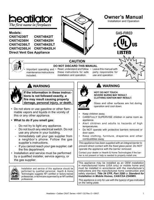
Read this manual before installing or operating this appliance.Please retain this owner’s manual for future reference.CongratulationsCongratulations on selecting a Heatilator gas appliance—anelegant and clean alternative to wood burning appliances.The Heatilator gas appliance you have selected is designedto provide the utmost in safety, reliability, and effi ciency.As the owner of a new appliance, you’ll want to read andcarefully follow all of the instructions contained in this owner’smanual. Pay special attention to all cautions and warnings.This owner’s manual should be retained for future reference.We suggest you keep it with your other important documentsand product manuals.The information contained in this owner’s manual, unlessnoted otherwise, applies to all models and gas controlsystems.Your new Heatilator gas appliance will give you years ofdurable use and trouble-free enjoyment. Welcome to theHeatilator family of appliance products!Homeowner Reference InformationWe recommend that you record the following pertinentinformation about your appliance:Model Name:Serial Number:Dealership purchased from:Date purchased/installed:Location on appliance:Dealer phone:Notes:Listing Label Information/LocationThe model information regarding your specifi c appliance can be found on the rating plate located in the control area of theappliance.Gas TypeSerial #Model #Hearth & Home Technologies Inc1915 W. Saunders StreetMt. Pleasant, IA 52641ANSI StandardSERIALNO. DE SÉRIEXXXXXXXXXMODELMFG. DATEXXXXXXMODÈLEDATE DE FAB.GAS TYPE/TYPE DE GAZ NATURAL/NATUREL PROPANEALTITUDE 0-2000 2000-4000 FT/PI 0-2000 2000-4000 FT/PIMAX INPUT/DÉBIT XX,XXX XX,XXX BTUH XX,XXX XX,XXX BTUHMIN INPUT/DÉBIT XX,XXX XX,XXX BTUH XX,XXX XX,XXX BTUHMANIFOLD PRESSURE/PRESSION TUBULAIREMAX. XX IN. W.C./C. D'EAU XX IN. W.C./C. D'EAUMIN. XX IN. W.C./C. D'EAU XX IN. W.C./C. D'EAUMIN. INLET PRESS. XX IN. W.C./C. D'EAU 1XX IN. W.C./C. D'EAUFOR THE PURPOSE OF INPUT ADJUSTMENTPRESS. MIN. D'ALIMENTATIONORIFICE SIZEDIAM. DE L'INJECTEUR XX/XX DIA. in./mm XX/XX DIA. in./mmXXXXCERTIFIEDFOR CANADACERTIFIÉ POUR LECANADAOrificeSizeLESS THAN/MOINS DE 3 AMPÈRES., 115V., 60 HzDO NOT REMOVE OR COVER THIS LABEL.VENTED GAS FIREPLACE - NOT FOR USE WITH SOLID FUEL.FOYER À GAZ À ÉVACUATION - NE DOIT PAS ÊTRE UTILISÉAVEC UN COMBUSTIBLE SOLIDE.2 Heatilator • Caliber CNXT Series • 4047-132 Rev O • 09/07
Table of Contents1 Listing and Code Approvals 4A. Appliance Certifi cation . . . . . . . . . . . . . . . . . . . . . . . . . 4B. Glass Specifi cations . . . . . . . . . . . . . . . . . . . . . . . . . . 4C. BTUH Specifi cations . . . . . . . . . . . . . . . . . . . . . . . . . . 4D. High Altitude Installations . . . . . . . . . . . . . . . . . . . . . . 4E. Non-Combustible Materials . . . . . . . . . . . . . . . . . . . . . 4F. Combustible Materials . . . . . . . . . . . . . . . . . . . . . . . . . 4G. Requirements for theCommonwealth of Massachusetts. . . . . . . . . . . . . . . . 52 Getting Started 6A. Design and Installation Considerations . . . . . . . . . . . . 6B. Tools and Supplies Needed . . . . . . . . . . . . . . . . . . . . . 6C. Inspect the Appliance and Components . . . . . . . . . . . 63 Framing and Clearances 7A. Select Appliance Location . . . . . . . . . . . . . . . . . . . . . . 7B. Construct the Appliance Chase . . . . . . . . . . . . . . . . . . 8C. Clearances . . . . . . . . . . . . . . . . . . . . . . . . . . . . . . . . . 9D. Mantel Projections . . . . . . . . . . . . . . . . . . . . . . . . . . . 104 Termination Locations 11A. Vent Termination Minimum Clearances . . . . . . . . . . . 115 Vent Information and Diagrams 14A. Vent Table Key . . . . . . . . . . . . . . . . . . . . . . . . . . . . . . 14B. Use of Elbows . . . . . . . . . . . . . . . . . . . . . . . . . . . . . . 14C. Measuring Standards. . . . . . . . . . . . . . . . . . . . . . . . . 14D. Vent Diagrams . . . . . . . . . . . . . . . . . . . . . . . . . . . . . . 15E. Installing Vertical Termination Baffl e . . . . . . . . . . . . . 246 Vent Clearances and Framing 26A. Pipe Clearances to Combustibles . . . . . . . . . . . . . . . 26B. Wall Penetration Framing . . . . . . . . . . . . . . . . . . . . . 26C. Install the Ceiling Firestop . . . . . . . . . . . . . . . . . . . . . 27D. Install <strong>At</strong>tic Insulation Shield . . . . . . . . . . . . . . . . . . . 287 Appliance Preparation 29A. Convert from Top Vent to Rear Vent . . . . . . . . . . . . . 29B. Securing and Leveling the Appliance . . . . . . . . . . . . 338 Installing Vent Pipe 34A. Assemble Vent Sections . . . . . . . . . . . . . . . . . . . . . . 34B. Disassemble Vent Sections . . . . . . . . . . . . . . . . . . . . 37C. Install the Heat Shieldand Horizontal Termination Cap . . . . . . . . . . . . . . . . 38D. Install Roof Flashingand Vertical Termination Cap . . . . . . . . . . . . . . . . . . . 40E. Assemble and Install Storm Collar . . . . . . . . . . . . . . 419 Gas Information 42A. Fuel Conversion . . . . . . . . . . . . . . . . . . . . . . . . . . . . 42B. Gas Pressure. . . . . . . . . . . . . . . . . . . . . . . . . . . . . . . 42C. Gas Connection . . . . . . . . . . . . . . . . . . . . . . . . . . . . . 42D. High Altitude Installations . . . . . . . . . . . . . . . . . . . . . 4310 Electrical Information 44A. Recommendation for Wire . . . . . . . . . . . . . . . . . . . . . 44B. Connecting to the Appliance . . . . . . . . . . . . . . . . . . . 44C. Intellifi re Ignition System Wiring . . . . . . . . . . . . . . . . 44D. Junction Box Installation . . . . . . . . . . . . . . . . . . . . . . 44E. WSK-MLT Multifunction Wall Switch . . . . . . . . . . . . . 45F. Installing the Flame Solenoid . . . . . . . . . . . . . . . . . . 47G. Hook up the Temperature Sensor Switch for Fan . . . 47H. Install the Remote Cover Plate . . . . . . . . . . . . . . . . . 48I. WSK-MLT Operating Instructions . . . . . . . . . . . . . . . 49J. Setting Flame Height/Manifold Pressure . . . . . . . . . . 49K. Wall Switch Button Operation . . . . . . . . . . . . . . . . . . 5011 Finishing 52A. Mantel Projections . . . . . . . . . . . . . . . . . . . . . . . . . . . 52B. Facing Material . . . . . . . . . . . . . . . . . . . . . . . . . . . . . 5212 Appliance Setup 53A. Remove Glass Assembly. . . . . . . . . . . . . . . . . . . . . . 53B. Remove the Shipping Materials. . . . . . . . . . . . . . . . . 53C. Clean the Appliance. . . . . . . . . . . . . . . . . . . . . . . . . . 53D. Accessories . . . . . . . . . . . . . . . . . . . . . . . . . . . . . . . . 53E Lava Rock, Vermiculite, Rockwool Placement . . . . . 53F. Log Assembly . . . . . . . . . . . . . . . . . . . . . . . . . . . . . . 54G. Glass Assembly . . . . . . . . . . . . . . . . . . . . . . . . . . . . . 55H. Grilles and Trim . . . . . . . . . . . . . . . . . . . . . . . . . . . . . 55I. Hood . . . . . . . . . . . . . . . . . . . . . . . . . . . . . . . . . . . . . 55J. Air Shutter Setting . . . . . . . . . . . . . . . . . . . . . . . . . . . 5513 Operating Instructions 56A. Before Lighting Appliance . . . . . . . . . . . . . . . . . . . . . 56B. Lighting the Appliance . . . . . . . . . . . . . . . . . . . . . . . . 57C. After the Appliance is Lit . . . . . . . . . . . . . . . . . . . . . . 58D. Frequently Asked Questions . . . . . . . . . . . . . . . . . . . 5814 Troubleshooting 59Intellifi re Ignition System . . . . . . . . . . . . . . . . . . . . . . . . . 5915 Maintaining and Servicing the Appliance 6116 Reference Materials 63A. Appliance Dimension Diagram . . . . . . . . . . . . . . . . . 63B. Vent Components Diagrams . . . . . . . . . . . . . . . . . . . 64C. Service Parts List. . . . . . . . . . . . . . . . . . . . . . . . . . . . 70D. Optional Components . . . . . . . . . . . . . . . . . . . . . . . . 86E. Limited Lifetime Warranty . . . . . . . . . . . . . . . . . . . . . 91F. Contact Information . . . . . . . . . . . . . . . . . . . . . . . . . . 92Note: An arrow () found in the text signifi es change in content.Heatilator • Caliber CNXT Series • 4047-132 Rev O • 09/07 3
NOTE: The following requirements reference variousMassachusetts and national codes not contained in thisdocument.G. Requirements for the Commonwealth ofMassachusettsFor all side wall horizontally vented gas fueled equipmentinstalled in every dwelling, building or structure used inwhole or in part for residential purposes, including thoseowned or operated by the Commonwealth and where theside wall exhaust vent termination is less than seven (7)feet above finished grade in the area of the venting, includingbut not limited to decks and porches, the followingrequirements shall be satisfied:Installation of Carbon Monoxide Detectors<strong>At</strong> the time of installation of the side wall horizontal ventedgas fueled equipment, the installing plumber or gas fittershall observe that a hard wired carbon monoxide detectorwith an alarm and battery back-up is installed on the floorlevel where the gas equipment is to be installed. In addition,the installing plumber or gas fitter shall observe that abattery operated or hard wired carbon monoxide detectorwith an alarm is installed on each additional level of thedwelling, building or structure served by the side wallhorizontal vented gas fueled equipment. It shall be theresponsibility of the property owner to secure the servicesof qualified licensed professionals for the installation of hardwired carbon monoxide detectors.In the event that the side wall horizontally vented gas fueledequipment is installed in a crawl space or an attic, the hardwired carbon monoxide detector with alarm and batteryback-up may be installed on the next adjacent floor level.In the event that the requirements of this subdivision cannot be met at the time of completion of installation, theowner shall have a period of thirty (30) days to comply withthe above requirements; provided, however, that duringsaid thirty (30) day period, a battery operated carbon monoxidedetector with an alarm shall be installed.Approved Carbon Monoxide DetectorsEach carbon monoxide detector as required in accordancewith the above provisions shall comply with NFPA 720 andbe ANSI/UL 2034 listed and IAS certified.SignageA metal or plastic identification plate shall be permanentlymounted to the exterior of the building at a minimum heightof eight (8) feet above grade directly in line with the exhaustvent terminal for the horizontally vented gas fueled heatingappliance or equipment. The sign shall read, in print size noless than one-half (1/2) inch in size, “GAS VENTDIRECTLY BELOW. KEEP CLEAR OF ALL OBSTRUC-TIONS”.InspectionThe state or local gas inspector of the side wall horizontallyvented gas fueled equipment shall not approve the installationunless, upon inspection, the inspector observes carbonmonoxide detectors and signage installed in accordancewith the provisions of 248 CMR 5.08(2)(a)1 through 4.ExemptionsThe following equipment is exempt from 248 CMR5.08(2)(a)1 through 4:• The equipment listed in Chapter 10 entitled “EquipmentNot Required To Be Vented” in the most current editionof NFPA 54 as adopted by the Board; and• Product Approved side wall horizontally vented gasfueled equipment installed in a room or structure separatefrom the dwelling, building or structure used inwhole or in part for residential purposes.MANUFACTURER REQUIREMENTSGas Equipment Venting System ProvidedWhen the manufacturer of Product Approved side wallhorizontally vented gas equipment provides a ventingsystem design or venting system components with theequipment, the instructions provided by the manufacturerfor installation of the equipment and the venting systemshall include:• Detailed instructions for the installation of the ventingsystem design or the venting system components; and• A complete parts list for the venting system design orventing system.Gas Equipment Venting System NOT ProvidedWhen the manufacturer of a Product Approved side wallhorizontally vented gas fueled equipment does not providethe parts for venting the flue gases, but identifies “specialventing systems”, the following requirements shall be satisfiedby the manufacturer:• The referenced “special venting system” instructionsshall be included with the appliance or equipmentinstallation instructions; and• The “special venting systems” shall be ProductApproved by the Board, and the instructions for thatsystem shall include a parts list and detailed installationinstructions.A copy of all installation instructions for all ProductApproved side wall horizontally vented gas fueled equipment,all venting instructions, all parts lists for ventinginstructions, and/or all venting design instructions shallremain with the appliance or equipment at the completion ofthe installation.See Gas Connection section for additional Commonwealthof Massachusetts requirements.Heatilator • Caliber CNXT Series • 4047-132 Rev O • 09/07 5
2Getting StartedA. Design and Installation ConsiderationsHeatilator direct vent gas appliances are designed to operatewith all combustion air siphoned from outside of thebuilding and all exhaust gases expelled to the outside. Noadditional outside air source is required.CAUTIONCheck building codes prior to installation.• Installation MUST comply with local, regional,state and national codes and regulations.• Consult insurance carrier, local building, fireoffi cials or authorities having jurisdiction aboutrestrictions, installation inspection, and permits.When planning an appliance installation, it’s necessary todetermine the following information before installing:• Where the appliance is to be installed.• The vent system confi guration to be used.• Gas supply piping.• Electrical wiring.• Framing and fi nishing details.• Whether optional accessories—devices such as a fan,wall switch, or remote control—are desired.C. Inspect the Appliance and ComponentsWARNINGInspect appliance and components fordamage. Damaged parts may impair safeoperation.• Do NOT install damaged components.• Do NOT install incomplete components.• Do NOT install substitute components.Report damaged parts to dealer.• Carefully remove the appliance and components from thepackaging.• The vent system components and trim doors are shippedin separate packages.• The gas logs may be packaged separately and must befi eld installed.• Report to your dealer any parts damaged in shipment,particularly the condition of the glass.• Read all of the instructions before starting theinstallation. Follow these instructions carefullyduring the installation to ensure maximum safety andbenefit.WARNINGWARNINGKeep appliance dry.• Mold or rust may causeodors.• Water may damage controls.B. Tools and Supplies NeededBefore beginning the installation be sure that the followingtools and building supplies are available.Reciprocating saw Framing materialPliersHi temp caulking materialHammerGlovesPhillips screwdriver Framing squareFlat blade screwdriver Electric drill and bits (1/4 in.)Plumb lineSafety glassesLevelManometerVoltmeterTape measureNon-corrosive leak check solution1/2 - 3/4 in. length, #6 or #8 Self-drilling screwsOne 1/4 in. female spade connection (for optional fan)Hearth & Home Technologies disclaims anyresponsibility for, and the warranty will bevoided by, the following actions:• Installation and use of any damaged appliance orvent system component.• Modifi cation of the appliance or vent system.• Installation other than as instructed by Hearth & HomeTechnologies.• Improper positioning of the gas logs or the glassdoor.• Installation and/or use of any component part notapproved by Hearth & Home Technologies.Any such action may cause a fire hazard.6 Heatilator • Caliber CNXT Series • 4047-132 Rev O • 09/07
3Framing and ClearancesNote:• Illustrations refl ect typical installations and are FORDESIGN PURPOSES ONLY.• Illustrations/diagrams are not drawn to scale.• Actual installation may vary due to individual designpreference.A. Select Appliance LocationWhen selecting a location for your appliance it is important toconsider the required clearances to walls (See Figure 3.1).WARNINGFire RiskProvide adequate clearance:• Around air openings.• For service access.Locate appliance away from traffi c areas.Note: For actual appliance dimensions refer toSection 16.1/2 in. (13 mm) min.appliance tocombustiblesBCE1/2 in. (13 mm) min.appliance tocombustibles1 in. (25 mm) min.pipe tocombustiblesDrywallAGHBADAlcoveInstallationAETop VentOne 90° elbowHoriz TermRear ventOne 45° elbowHoriz TermIn addition to these framing dimensions, also reference thefollowing sections:• Clearances and Mantel Projections (Section 3.C.)• Vent Clearances and Framing (Section 6)FARear VentOne 90° elbowVert TermNo elbowsHoriz TermARear VentTwo 90° elbowsHoriz TermAIC1 in. (25 mm) min.pipe to combustiblesFIModel # A B C D E F G H ICNXT4236 in. 42 50-5/8 23-1/2 71-5/8 50-5/8 52-5/8 43 48 59-3/4mm 1067 1286 597 1819 1286 1337 1092 1220 1518CNXT4842 in. 48 55-1/4 23-1/2 78-1/4 55-1/4 55-1/4 49 48 59-3/4mm 1219 1403 597 1988 1403 1403 1245 1220 1518Figure 3.1Appliance LocationsHeatilator • Caliber CNXT Series • 4047-132 Rev O • 09/07 7
B. Construct the Appliance ChaseA chase is a vertical boxlike structure built to enclose the gasappliance and/or its vent system. Vertical vents that run onthe outside of a building may be, but are not required to be,installed inside a chase.Construction of the chase may vary with the type of building.These instructions are not substitutes for the requirementsof local building codes. Local building codes MUSTbe checked.Chases should be constructed in the manner of all outsidewalls of the home to prevent cold air drafting problems. Thechase should not break the outside building envelope in anymanner.Walls, ceiling, base plate and cantilever fl oor of the chaseshould be insulated. Vapor and air infi ltration barriers shouldbe installed in the chase as per regional codes for the rest ofthe home. Additionally, in regions where cold air infi ltrationmay be an issue, the inside surfaces may be sheetrockedand taped (or the use of an equivalent method) for maximumair tightness.To further prevent drafts, the ceiling fi restops should becaulked with high temperature caulk to seal gaps. Gas lineholes and other openings should be caulked with high temperaturecaulk or stuffed with unfaced insulation. If the applianceis being installed on a cement slab, a layer of plywoodmay be placed underneath to prevent conducting cold upinto the room.Fire RiskWARNING• Construct chase to all clearancespecifi cations in manual.• Locate and install appliance to allclearance specifi cations in manual.8 Heatilator • Caliber CNXT Series • 4047-132 Rev O • 09/07
C. Clearances1/2 in. (13 mm)1/2 in.(13 mm)Fire RiskOdor RiskWARNING• Install appliance on hard metal or woodsurfaces extending full width and depthof appliance.• Do NOT install appliance directly oncarpeting, vinyl, tile or any combustiblematerial other than wood.Combustible flooring may be installed nextto the front of the appliance.Drywall0 in.Note: If the inside of the framed cavity is to befi nished, the framing dimensions must includethe fi nished surface. If drywall is to be attachedto the rear wall, the depth must be measured fromthe drywall surface.D30 in.(762 mm)to ceiling0 in. TO LEVELOF STANDOFFSBCombustible Object36 in.(914 mm)0 in.ACModelARoughOpening(Width)BRoughOpening(Height)CRoughOpening(Depth)DRoughOpening(DVP Pipe)CNXT4236 in. 42 38-3/4 23-1/2 10mm 1067 984 597 254CNXT4842 in. 48 38-3/4 23-1/2 10mm 1219 984 597 254Figure 3.2Clearances to CombustiblesHeatilator • Caliber CNXT Series • 4047-132 Rev O • 09/07 9
D. Mantel Projections34-1/2 in. minimumto ceiling345678914-3/41413-1/412-1/218171615 20-3/414 2013 19-1/412 18-1/21110 17-3/41716-1/415-1/210-1/4 1111-3/46Measured from top of hood (in inches)Figure 3.3Clearances to Mantels or Other Combustibles Above ApplianceTop ofApplianceDrywallBA48 in.(1219 mm)max.Mantel Leg orPerpendicular WallAB1 in. (25 mm) min.to perpendicular wall3-1/2 in. (89 mm) min.from fireplace openingto perpendicular wallFigure 3.4Clearances to Perpendicular Wall10 Heatilator • Caliber CNXT Series • 4047-132 Rev O • 09/07
4Termination LocationsA. Vent Termination Minimum ClearancesWARNINGFire RiskExplosion RiskInspect external vent cap regularly.• Ensure no debris blocks cap.• Combustible materials blocking cap mayignite.• restricted air flow affects burneroperation.Measure vertical clearances from this surfaceWARNINGFire RiskExplosion RiskMaintain vent clearance to combustibles asspecifi ed.• Do not pack air space with insulation orother materials.Failure to keep insulation or other materialsaway from vent pipe may cause fi re.Measure horizontal clearances from this surface.(see Figure 4.4 for specific clearances)Figure 4.1 Clearances from Cap SurfacesHeatilator • Caliber CNXT Series • 4047-132 Rev O • 09/07 11
Figure 4.2 specifi es minimum vent heights for variouspitched roofs.Horizontaloverhang24 in. min.(610 mm)TerminationCap20 in.(508 mm)LowestDischargeOpeningVerticalwallStorm CollarRoofFlashingX12Roof Pitchis X / 12H (min.) - Minimum heightfrom roof to lowestdischarge opening.Roof Pitch H (Min.) Ft. Roof Pitch H (Min.) Ft.Flat to 6/12 1.0* Over 11/12 to 12/12 4.0Over 6/12 to 7/12 1.25* Over 12/12 to 14/12 5.0Over 7/12 to 8/12 1.5* Over 14/12 to 16/12 6.0Over 8/12 to 9/12 2.0* Over 16/12 to 18/12 7.0Over 9/12 to 10/12 2.5 Over 18/12 to 20/12 7.5Over 10/12 to 11/12 3.25 Over 20/12 to 21/12 8.0* 3 ft. minimum in snow regionsMinimum Height from Roof to Lowest Discharge Open-Figure 4.2ingGasTerminationDirect Vent Gas, Wood or FuelOil Termination18 in.(457 mm)BA20 in.(508 mm)(minimum) toPerpendicularWall(gas only)Wood orGas TerminationTermination Caps Same HeightDirect Vent Gas, Wood or FuelOil Termination20 in. min. *(508 mm)20 in.(508 mm)(minimum) toPerpendicularWall(gas only)Termination Caps Staggered HeightA Gas Termination Wood or Fuel Oil TerminationB 6 in. (152 mm) min. 20 in. (508 mm) min.* If using decorative cap cover(s), this distance mayneed to be increased. Refer to the installation instructionssupplied with the decorative cap cover.Figure 4.3Multiple Vertical Termination12 Heatilator • Caliber CNXT Series • 4047-132 Rev O • 09/07
HDEVL BFCVVBFixedClosedVBBOpenableFixedClosedVAJOXVBVNGAS METERIMV K XGVVAMeasure vertical clearancesfrom this surfaceVTERMINATION CAPXAIR SUPPLY INLETQPRESTRICTION ZONE(TERMINATION NOTALLOWED)VTRVVUWElectricalServiceUVMeasure horizontal clearancesfrom this surface.SAlcove ClearancesVD*Clearances to Electrical ServiceDimension DescriptionsA Clearance above the ground, a veranda, porch, deck or balcony - 12in. (30 cm) minimum. *B Clearance to window or door that may be opened – 10,000 BTUsor less, 6 in. (15 cm) minimum; 10,000-50,000 BTUs, 9 in. (23 cm)minimum; over 50,000 BTUs, 12 in. (30 cm) minimum. *C Clearance to permanently closed window – 12 in. (30 cm) minimum- recommended to prevent condensation on window.D Vertical clearance to ventilated soffi t located above the terminationwithin a horizontal distance of 2 ft (60 cm) from the centerline of thetermination – 18 in. (46 cm) minimum. **E Vertical clearance to unventilated soffi t - 12 in. (30 cm) minimum. **F Clearance to outside corner - 6 in. (15 cm) minimum.G Clearance to inside corner - 6 in. (15 cm) minimum.H Not to be installed above a meter/regulator assembly within 3 ft (90cm) horizontally* from the center line of the regulator (Canada only)I Clearance to service regulator vent outlet – 3 ft (.91 m) U.S. minimumand 3 ft (.91 m) Canada minimum.*J Clearance to non-mechanical air supply inlet into building or thecombustion air inlet to any other appliance – 9” (23 cm) U.S. minimumand 12 in. (30 cm) Canada minimum. *K Clearance to mechanical air supply inlet - 3 ft (.91 m) U.S. minimumand 6 ft (1.8 m) Canada minimum. *L Clearance above a paved sidewalk or paved driveway located on publicproperty - 7 ft (2.1 m) minimum.A vent may not terminate directly above a sidewalk or paved drivewaywhich is located between two single family dwellings and serves bothdwellings.M Clearance under veranda, porch, deck or balcony - 12 in. (30 cm)minimum. * Recommended 30 in. (76 cm) for vinyl or plastic.Only permitted if veranda, porch, deck or balcony is fully open on aminimum of 2 sides beneath the fl oor. *N Vertical clearance between two horizontal termination caps – 12 in. (30cm) minimum.O Horizontal clearance between two horizontal termination caps – 12 in.(30 cm) minimum.P 6” - Non-vinyl sidewalls12” – Vinyl sidewallsQ 18” – Non-vinyl soffi t and overhang42” – Vinyl soffi t and overhangR 8 ft.S minT max1 cap 3 ft 2 x S actual2 caps 6 ft 1 x S actual3 caps 9 ft 2/3 x S actual4 caps 12 ft 1/2 x S actualS min = # term caps x 3 T max = (2/# term caps) x S (actual)U 6” min. – Clearance from sides of electrical service.W 12” min. – Clearance above electrical service.* As specifi ed in CGA B149 Installation CodesNote: Local codes or regulations may require different clearances.** Clearance required to vinyl soffi t material – 30 in. (76 cm) minimum.Note: Location of the vent termination must not interfere with accessto the electrical service.WARNING!In the U.S.: Vent system termination is NOT permitted in screenedporches. You must follow side wall, overhang and ground clearancesas stated in the instructions.In Canada: Vent system termination is NOT permitted in screenedporches. Vent system termination is permitted in porch areas with twoor more sides open. You must follow all side wall, overhang and groundclearances as stated in the instructions.Hearth & Home Technologies assumes no responsibility for the improperperformance of the appliance when the venting system does not meetthese requirements.Figure 4.4Minimum Clearances for TerminationsHeatilator • Caliber CNXT Series • 4047-132 Rev O • 09/07 13
5Vent Information and DiagramsA. Vent Table KeyThe abbreviations listed in this vent table key are used in thevent diagrams.SymbolDescriptionV 1V 2H 1First section (closest to appliance) of vertical lengthSecond section of vertical lengthFirst section (closest to appliance) of horizontal lengthVertical12 in.8-1/2 in.H 2Second section of horizontal length8-1/2 in.B. Use of ElbowsWARNINGFire RiskExplosion RiskAsphyxiation RiskDo NOT connect this gas appliance to achimney fl ue serving a separate solid-fuelor gas burning appliance.• Vent this appliance directly outside.• Use separate vent system for thisappliance.May impair safe operation of this appliance orother appliances connected to the fl ue.CAUTIONALL vent configuration specifications MUST befollowed.• This product is tested and listed to thesespecifi cations.• Appliance performance will suffer if specificationsare not followed.Diagonal runs have both vertical and horizontal vent aspectswhen calculating the effects. Use the rise for the vertical aspectand the run for the horizontal aspect (see Figure 5.1).Two 45° elbows may be used in place of one 90° elbow. On45° runs, 1 ft of diagonal is equal to 8-1/2 in. horizontal runand 8-1/2 in. vertical run. A length of straight pipe is allowedbetween two 45° elbows (see Figure 5.1).Figure 5.1Using Two 45° ElbowsHorizontalC. Measuring StandardsVertical and horizontal measurements listed in the vent diagramswere made using the following standards.• Pipe measurements are shown using the effective lengthof pipe (see Figure 5.2).• Measurements are made from the appliance outer wrap,not from the standoffs.• Horizontal terminations are measured to the outsidemounting surface (flange of termination cap) (seeFigure 4.1).• Vertical terminations are measured to top of last pipebefore termination cap.• Horizontal pipe installed level with no rise.DVP Pipe(see chart)EffectiveLengthPipeDVP4DVP6DVP12DVP24DVP36DVP48DVP6ADVP12ADVP12MIDVP24MIEffective Length4 in. (102 mm)6 in. (152 mm)12 in. (305 mm)24 in. (610 mm)36 in. (914 mm)48 in. (1219 mm)3to6in.(76to152mm)3to12in.(76to305mm)3 to 12 in. (76 to 305 mm)3 to 24 in. (76 to 610 mm)Figure 5.2DVP Pipe Effective Length14 Heatilator • Caliber CNXT Series • 4047-132 Rev O • 09/07
D. Vent DiagramsWARNINGFire RiskExplosion RiskDo NOT pack insulation or other combustibles between fi restops.• ALWAYS maintain specifi ed clearances around venting and fi restop systems.• Install fi restops as specifi ed.Failure to keep insulation or other material away from vent pipe may cause fi re.The fi rst 90° elbow MUST be a starter elbow.To replace the fi rst starter elbow with two 45° elbows, refer to Figure 5.4. All other 90° elbows can be replaced with two 45°elbows.General Rules:• SUBTRACT 3 ft from the total H measurement for each 90° elbow installed horizontally.SUBTRACT 1-1/2 ft from the total H measurement for each 45° elbow installed horizontally.• A maximum of three 90° elbows (or six 45° elbows) may be used in any vent configuration. Some elbows may be installedhorizontally. See Figure 5.6.• Elbows may be placed back to back anywhere in the system except as shown in Figure 5.4.• When penetrating a combustible wall, a wall shield fi restop must be installed.• When penetrating a combustible ceiling, a ceiling fi restop must be installed.• Horizontal runs of vent do not require vertical rise; horizontal runs may be level.Top Vent—Horizontal Termination—One ElbowTable 5.1V1 min. V1 max. H1 max.0* - 18 in./457 mm4 in/102 mm - 4 ft/1.22 m6 in./152 mm - 6 ft/1.83 m12 in./305 mm - 11 ft/3.35 m18 in./457 mm - 18 ft/5.49 m24 in./610 mm - 25 ft/7.62 m- 25 ft/7.62 m 25 ft/7.62 m* You may install the elbow directly on top ofthe CNXT4236 or CNXT4842.H 1V 1Figure 5.3Top Vent-Horizontal Termination-One ElbowHeatilator • Caliber CNXT Series • 4047-132 Rev O • 09/07 15
Top Vent—Horizontal Termination—Two 45° ElbowsInstallation requirements to replace the fi rst 90° elbow with two 45° elbows:4 ft min.(1.22 m)25 ft max.(7.62 m)Figure 5.4 Minimum Installation Requirements forTwo 45° Elbows-Top Vent-Horizontal TerminationTop Vent—Horizontal Termination—Three Vertical ElbowsSee Figure 5.6 for information about installing elbows horizontally.V 1min. V 1+V 2max. H 1+H 2max.1 ft.30 m24 ft7.32 m19 ft5.79 mInstalledVerticallyH 2V 2H 1V 1Figure 5.5Three Vertically Installed 90° Elbows16 Heatilator • Caliber CNXT Series • 4047-132 Rev O • 09/07
Top Vent—Horizontal Termination—Two or Three ElbowsYou may use a maximum of three 90° elbows (or six 45° elbows) in any vent confi guration, Some may be installed horizontally.Note: Subtract 3 ft (914 mm) from the total horizontalmeasurement for each 90° elbow installed horizontally.Subtract 1-1/2 ft (457 mm) from the total horizontalmeasurement for each 45° elbow installed horizontally.V 1 min. V 1 max. H 1 +H 2 max. H 1 +H 2 +H 3 max.6 in./152 mm x 6 ft/1.83 m x12 in./305 mm x 11 ft/3.35 m 11 ft/3.35 m18 in./457 mm x 18 ft/5.49 m 18 ft/5.49 m24 in./610 mm x 25 ft/7.62 m 25 ft/7.62 mx 25 ft/7.62 m 25 ft/7.62 m 25 ft/7.62 mInstalledVerticallyH 2H 3InstalledHorizontallyH 2H 1V 1Figure 5.6Two or Three Elbows, some HorizontalHeatilator • Caliber CNXT Series • 4047-132 Rev O • 09/07 17
Top Vent—Vertical Termination—No ElbowsNote: If installing a vertical vent/terminationrun off the top of the appliance, the verticaltermination baffl e supplied with the appliancemay be used. See Section E.12 ft (3.66 m) min.60 ft (18.29 m) max.Figure 5.7Vertical Termination - No ElbowsTop Vent—Vertical Termination—Two ElbowsNote: If installing a vertical vent/termination run off the top of theappliance, the vertical terminationbaffl e supplied with the appliance maybe used. See Section E.12 ft (3.66 m) min.60 ft (18.29 m) max.Maximum horizontalrun is 100% ofvertical, but cannotexceed 26 ft (7.92 m)Figure 5.8Vertical Termination - Two Elbows18 Heatilator • Caliber CNXT Series • 4047-132 Rev O • 09/07
Top Vent—Vertical Termination—Three ElbowsNote: Subtract 3 ft (914 mm) from the total horizontalmeasurement for each 90° elbow installed horizontally.Subtract 1-1/2 ft (457 mm) from the total horizontalmeasurement for each 45° elbow installed horizontally.Maximum horizontal run is100% of vertical, but cannotexceed 26 ft (7.92 m)12 ft (3.66 m) min.60 ft (18.29 m) max.Note: If installing a vertical vent/terminationrun off the top of the appliance, the verticaltermination baffl e supplied with the appliancemay be used. See Section E.Figure 5.9Vertical Termination - Three Elbows (some horizontal)Rear Vent—Horizontal Termination—No Elbows18 in. (457 mm) max.Figure 5.10 Horizontal Termination - No ElbowsHeatilator • Caliber CNXT Series • 4047-132 Rev O • 09/07 19
Rear Vent—Horizontal Termination—One 45° Elbow18 in. (457 mm) max.Figure 5.11 Horizontal Termination - One 45° ElbowRear Vent—Horizontal Termination—Two ElbowsH 2V 1H 1H 1 Max V 1 Min H 1 + H 2 Max2 ft/.61 m 1 ft/.30 m 3 ft/.91 m4 ft/1.22 m 2 ft/.61 m 6 ft/1.83 m6 ft/1.83 m 3 ft/.91 m 9 ft/2.74 m8 ft/2.44 m 4 ft/1.22 m 12 ft/3.66 m8 ft/2.44 m 5 ft/1.52 m 15 ft/4.57 m8ft/2.44 m 6 ft/1.83 m 18 ft/5.49 mFigure 5.12 Horizontal Termination - Two Elbows20 Heatilator • Caliber CNXT Series • 4047-132 Rev O • 09/07
Rear Vent—Horizontal Termination—Three ElbowsNote: Subtract 3 ft (914 mm) from the total horizontalmeasurement for each 90° elbow installed horizontally.Subtract 1-1/2 ft (457 mm) from the total horizontalmeasurement for each 45° elbow installed horizontally.InstalledHorizontallyH 2V 1H 3H 1H 1 Max V 1 Min H 1 + H 2 + H 3 Max2 ft/.61 m 1 ft/.30 m 3 ft/.91 m4 ft/1.22 m 2 ft/.61 m 6 ft/1.83 m6 ft/1.83 m 3 ft/.91 m 9 ft/2.74 m8 ft/2.44 m 4 ft/1.22 m 12 ft/3.66 m8 ft/2.44 m 5 ft/1.52 m 15 ft/4.57 m8 ft/2.44 m 6 ft/1.83 m 18 ft/5.49 mFigure 5.13 Horizontal Termination - Three ElbowsHeatilator • Caliber CNXT Series • 4047-132 Rev O • 09/07 21
Rear Vent—Vertical Termination—One ElbowNote: If installing a verticalvent/termination run off therear of the appliance, thevertical termination bafflesupplied with the appliancemay be used. See Section E.0 min.6 ft (1.83 m) max.12 ft (3.66 m) min.60 ft (18.29 m) max.Figure 5.14 Vertical Termination - One ElbowRear Vent—Vertical Termination—Two ElbowsNote: Subtract 3 ft (914 mm) from the total horizontalmeasurement for each 90° elbow installed horizontally.Subtract 1-1/2 (457 mm) ft from the total horizontalmeasurement for each 45° elbow installed horizontally.12 ft (3.66 m) min.60 ft (18.29 m) max.0 min.6 ft (1.83 m) max.Maximum horizontalrun is 100% ofvertical, but cannotexceed 26 ft (7.92 m)Note: If installing a vertical vent/terminationrun off the rear of the appliance, the verticaltermination baffl e supplied with the appliancemay be used. See Section E.Figure 5.15 Vertical Termination - Two Elbows22 Heatilator • Caliber CNXT Series • 4047-132 Rev O • 09/07
Rear Vent—Vertical Termination—Three Vertical Elbows0 min.6 ft (1.83 m) max.12 ft (3.66 m) min.60 ft (18.29 m) max.Maximum horizontal run is100% of vertical, but cannotexceed 26 ft (7.92 m).Note: If installing a vertical vent/terminationrun off the rear of the appliance, the verticaltermination baffl e supplied with the appliancemay be used. See Section E.Figure 5.16 Vertical Termination - Three Vertical ElbowsHeatilator • Caliber CNXT Series • 4047-132 Rev O • 09/07 23
E. Installing Vertical Termination BaffleNote: For vertically terminated installations only.3. Part of the refractory must be removed before installingthe vertical baffl e.• Remove the four screws holding the refractory retainersin place. See Figure 5.19.Note: If installing a vertical vent/termination run off thetop or rear of the appliance, the vertical termination baffl esupplied with the appliance may be used.1. Remove the glass (refer to Section 12.H.) to access thefi rebox and 5 in. inner fl ue.2. Fold the baffle (Figure 5.17) to an approximate 90° angle(see Figure 5.18).Figure 5.19 Remove Refractory Retainers• Remove the retainers.• Remove the right or left side refractory (only one sidemust be removed) by gently raising the front of thetop refractory and lifting the side piece up slightly andpulling out. See Figure 5.20.Figure 5.17 Flat BafflePush & hold thefront edge up.Figure 5.20 Remove One Side RefractoryFigure 5.18 Baffle Bent to 90° Angle• Remove top by gently lowering toward side justremoved and gently twisting out. See Figure 5.21.Figure 5.21 Remove Top Refractory24 Heatilator • Caliber CNXT Series • 4047-132 Rev O • 09/07
4. Squeeze the open end of the bent baffl e with one hand.Insert the baffl e bent side up into the inner fl ue so thatthe bottom of the baffl e is above the bead on the insideof the collar. See Figure 5.22.Figure 5.22 Placing the Baffle5. Release pressure on the baffle so that it is wedged againstthe sides of the fl ue collar. See Figure 5.23.Figure 5.23 Baffle in Place6. Reinstall refractory in reverse order of removal (see#3).7. Replace the glass (refer to Section 12.H.).8. Start the appliance.Heatilator • Caliber CNXT Series • 4047-132 Rev O • 09/07 25
6Vent Clearances and FramingA. Pipe Clearances to CombustiblesWARNINGFire RiskExplosion RiskMaintain vent clearance to combustibles asspecifi ed.• Do not pack air space with insulation orother materials.Failure to keep insulation or other materialsaway from vent pipe may cause fi re.Note: Heat shields MUST overlap by a minimum of 1-1/2 in.(38 mm). The heat shield is designed to be used on a wall4 in. to 7-1/4 in. (102 mm to 184 mm) thick. If wall thicknessis less than 4 in. (102 mm) the existing heat shields must befield trimmed. If wall thickness is greater than 7-1/4 in. (184mm) a DVP-HSM-B will be required.HeatShield3 in. (76 mm)top clearanceHeatShieldDrywall3 in.(76 mm)Air space clearancesto bottom and sidesof horizontal pipemust be at least1 in. (25 mm)WallShieldFirestop1 in. (25 mm)clearancebottom & sides1 in. (25 mm)WALL2 x 4 or2 x 6headerNo combustibleframing to belocated withinshaded area.Figure 6.2Horizontal Venting Clearances to Combustible MaterialsFigure 6.1Pipe ClearancesWALL1/2 in. (13 mm)minimum toperpendicularwall.12 in.10 in. B. Wall Penetration Framing• Wherever a combustible wall is penetrated, the hole mustbe framed with a wall shield firestop. This shield maintainsminimum clearances and restricts cold air infi ltration.• If the wall being penetrated is of noncombustible materials(material which will not ignite or burn, or has a UL fire ratingof zero), a 9 in. (229 mm) diameter hole is acceptable.• Whenever a wall is penetrated the wall shield fi restopis only required on one side and no heat shield isnecessary.• If your local inspector requires the wall shield fi restop onboth sides of the wall, then both wall shield fi restops musthave a heat shield attached to them.The center of theframing hole is1 in. (25mm) abovethe center of thehorizontal vent pipe.Figure 6.3Framing should beconstructed of 2 X 4lumber or heavier.Exterior Wall Hole* Measured to centerof pipe.42-1/4 in.(1073 mm)*27-1/4 in.(692 mm)*26 Heatilator • Caliber CNXT Series • 4047-132 Rev O • 09/07
C. Install the Ceiling Firestop• Frame an opening 10 in. by 10 in. whenever the ventsystem penetrates a ceiling/fl oor (see Figure 6.4).• Frame the area with the same sized lumber as used inceiling/fl oor joist.• When installing a top vent vertical termination appliancethe hole should be directly above the appliance, unlessthe fl ue is offset.• The ceiling fi restop may be installed above or below theceiling. Refer to Figure 6.5.• Secure with three fasteners on each side.• Do not pack insulation around the vent. Insulation mustbe kept away from the pipe.<strong>At</strong>tic Above10 in. (254 mm)10 in.(254 mm)Hole should measure10 in. x 10 in.(254 mm x 254 mm)inside to insideFigure 6.4Installing Ceiling FirestopInstall attic insulationshields beforeor after installationof vent system.3 fastenersper sideCeiling firestopinstalled below ceiling.Ceiling firestopinstalled above ceiling.Figure 6.5Installing Ceiling Firestop & <strong>At</strong>tic Insulation ShieldHeatilator • Caliber CNXT Series • 4047-132 Rev O • 09/07 27
D. Install <strong>At</strong>tic Insulation ShieldWARNINGFire RiskKeep loose materials or blown insulationfrom touching the vent pipe.• National building codes recommend usingattic shield to keep loose materials/blowninsulation from contacting vent.• Hearth & Home Technologies requiresthe use of an attic shield.Bend all tabs inward90° to maintainclearance andprevent insulationfrom falling insideInsert 3screwsLaser-etchedcut linesBend 4 tabsinward 90°to maintainclearanceFlat Ceiling Installation• Remove one shield from box.Note: Cut previously installed batt insulation to makeroom for the attic insulation shield.• Wrap shield around pipe if pipe is already installed inarea to be insulated.• Match the three holes in each side and fasten with threescrews to form a tube.• Bend four tabs inward on bottom of shield where it restson the ceiling firestop to maintain the air space betweenthe pipe and shield. Cover the resulting holes withaluminum tape. Set the shield on the ceiling fi restop.• Bend all tabs inward 90° around the top of the shield.These tabs must be used to prevent blow-in insulationfrom getting between the shield and vent pipe, and tomaintain clearance.Vaulted Ceiling Installation• The attic insulation shield has been laser-etched with cutlines and ceiling pitches to make fi eld trimming easier.• Remove one shield from box.Note: Cut previously installed batt insulation to make roomfor the attic insulation shield.• Cut the attic insulation shield (if application is for vaultedceiling) using a laser-etched cut line, to fi t your ceilingpitch. Snip cut edge to create three bend tabs.• Wrap shield around pipe if pipe is already installed in areato be insulated.• Match the three holes in each side and fasten with threescrews to form a tube.• Bend four of the remaining tabs inward 90° on bottomof shield to maintain the air space between the pipe andshield. Cover the resulting holes with aluminum tape. Setthe shield on the ceiling fi restop.• Bend all tabs inward 90° around the top of the shield.These tabs must be used to prevent blow-in insulation fromgetting between the shield and vent pipe, and to maintainclearance.Figure 6.6<strong>At</strong>tic Insulation Shield28 Heatilator • Caliber CNXT Series • 4047-132 Rev O • 09/07
7Appliance PreparationCAUTIONSharp Edges• Wear protective glovesand safety glasses duringinstallation.• Remove three remaining screws holding the platesurrounding fl ue. See Figure 7.3. Remove plate and setaside.A. Convert from Top Vent to Rear Vent• Remove the screw holding heat shield cover plate to topof appliance and set aside. See Figure 7.1Note: If the appliance is to be top vented discard this plateand replace the screw you removed. If the appliance is tobe rear vented, continue to the next step and Figure 7.2.Figure 7.3Cover Plate, Remove Screws• Remove four screws holding inner plate surrounding thefl ue. See Figure 7.4. Remove inner plate and discard.Figure 7.1Cover Plate, Top of Appliance• Remove the white insulation and set aside. SeeFigure 7.2.Figure 7.4Inner Plate, Top of ApplianceFigure 7.2Remove White InsulationHeatilator • Caliber CNXT Series • 4047-132 Rev O • 09/07 29
• Remove four screws holding outer collar to appliance top.See Figure 7.5. Remove outer collar.• Remove four screws holding outer cover plate to applianceback. See Figure 7.8. Remove outer cover.Figure 7.8Outer Cover, Rear - Remove PlateFigure 7.5Outer Collar, Remove Four Screws• Remove four screws holding inner cover plate to applianceback. See Figure 7.9. Remove inner cover.• Remove four screws holding inner collar to appliance top.See Figure 7.6. Remove inner collar.Figure 7.9Remove Inner Cover PlateFigure 7.6Remove Four Inner Collar Screws• Remove four screws holding outer shell cover. SeeFigure 7.7. Remove outer shell cover and set aside.• Place inner collar on appliance back and replace fourscrews to hold this collar in place. See Figure 7.10. Makesure insulation is attached to the collar base!Figure 7.10 Place inner collar on Rear of ApplianceFigure 7.7Outer Shell Cover30 Heatilator • Caliber CNXT Series • 4047-132 Rev O • 09/07
• Place outer collar on rear of appliance and replace fourscrews to hold collar in place. See Figure 7.11. Make sureinsulation is attached to the collar base!• Place inner cover plate on appliance top and replace fourscrews to hold inner cover plate in place. See Figure 7.14.Make sure gasket is replaced with the cover plate!Figure 7.11 Place Outer Collar on Rear of Appliance• Locate the cover plate removed in the second step. Placeplate around rear vented collars and replace four screwsto hold plate in place. See Figure 7.12.Figure 7.14 Inner Cover-Top• Place outer cover plate on appliance top and replace fourscrews to hold outer cover plate in place. See Figure 7.15.Make sure insulation is replaced with cover plate!Figure 7.12 Cover Plate Placed on Rear of Appliance• Place the white insulation with the slot around the outercollar. See Figure 7.13.Figure 7.15 Outer Cover-TopFigure 7.13 Place Insulation over the Cover PlateHeatilator • Caliber CNXT Series • 4047-132 Rev O • 09/07 31
• Locate heat shield cover plate removed in the fi rst step.Place the heat shield cover plate on top of heat shield.Replace four screws to hold this plate in place. SeeFigure 7.16.Figure 7.18 Screw Cover into PlaceFigure 7.16 Cover Plate-Replace• The appliance should look like the one shown in Figure 7.19after it has been converted to a rear vent appliance.• Locate outer shell cover removed in the sixth step(Figure 7.7). Place the cover on top of appliance. SeeFigure 7.17. Replace four screws to hold plate in place.See Figure 7.18.Figure 7.19 Completed ConversionFigure 7.17 Place Cover Plate on Top of Appliance32 Heatilator • Caliber CNXT Series • 4047-132 Rev O • 09/07
B. Securing and Leveling the ApplianceWARNINGFire Risk!• Prevent contact with sagging, looseinsulation.• Do NOT install against combustiblematerials such as exposed insulation,plastic and insulation backer.The diagram shows how to properly position, level, and securethe appliance (see Figure 7.20). Nailing tabs are providedto secure the appliance to the framing members.• Rear venting - refer to Vent Clearances and Framing(Section 6) for hole location.• Place the appliance into position.• Level the appliance from side to side and front to back.• Shim the appliance as necessary. It is acceptable to usewood shims.• Bend out nailing tabs on each side.• Keep nailing tabs fl ush with the framing.• Secure the appliance to the framing by using nails orscrews through the nailing tabs.WARNINGFire Risk!• ALWAYS maintain specifi ed clearancesaround the appliance.• Do NOT notch into the framing aroundthe appliance spacers.Failure to keep insulation, framing or other materialaway from the appliance may cause fi re.CAUTIONDo NOT notch into the framing around the appliancespacers.Nailing Flanges(both sides)Figure 7.20 Proper Positioning, Leveling and Securing of anApplianceHeatilator • Caliber CNXT Series • 4047-132 Rev O • 09/07 33
8Installing Vent PipeA. Assemble Vent SectionsWARNINGFire RiskExplosion Risk.Do not mix pipe, fi ttings or joining methodsfrom different manufacturersWARNINGFire RiskExhaust Fumes Risk• Overlap pipe slip sections at least1-1/2 in.• Use pilot holes for screws.• Screws must not exceed 1 in. long.• Pipe may separate if not properlyjoined.WARNINGFire RiskExplosion RiskIf slip section seals are broken during theremoval of the termination cap, gas will leakand a fi re or explosion may occur.do not break silicone seals on slip sections.<strong>At</strong>taching Vent to the Firebox AssemblyTo attach the fi rst pipe section to the collars, slide the maleend of the inner vent of the pipe section over the inner collaron the fi rebox assembly. <strong>At</strong> the same time, slide the outerfl ue over the outer collar on the appliance. Push the pipesection into the appliance collar until all the lances (see Figure8.1) have snapped in place. Tug slightly on the sectionto confi rm it has completely locked into place.Commercial, Multi-family (multi-level exceedingtwo stories), or High-rise ApplicationsFor installation into a commercial, multi-family (multi-levelexceeding two stories), or high-rise application: All outerpipe joints must be sealed with high temperature silicone,including the slip section that connects directly to the horizontaltermination cap.• Apply a bead of silicone sealant inside the female outerpipe joint prior to joining sections. See Figure 8.1.• Only outer pipes are to be sealed. Do not seal the innerfl ue. All unit collar, pipe, slip section, elbow and cap outerfl ues shall be sealed in this manner, unless otherwisestated.Note: The end of the pipe sections with the lances/tabs onit will face towards the appliance.34 Heatilator • Caliber CNXT Series • 4047-132 Rev O • 09/07
Assemble Pipe SectionsInsert the inner fl ue of section A into the fl ared inner flue ofsection B.Start the outer fl ue of section A over the outer fl ue of sectionB (see Figure 8.2).Once both inner and outer fl ues are started, press sectionA onto section B fi rmly until all lances have snapped intoplace. Check to make sure they have snapped together (seeFigure 8.3) and the seams are not aligned (see Figure 8.4).Tug slightly on section A to confi rm it has completely lockedinto place. It is acceptable to use screws no longer than 1in. (25 mm) to hold outer pipe sections together. If predrillingholes, do NOT penetrate inner pipeFor 90° and 45° elbows that are changing the vent directionfrom horizontal to vertical, one screw minimum should beput in the outer fl ue at the horizontal elbow joint to preventthe elbow from rotating. Use screws no longer than 1 in. (25mm). If predrilling holes, do NOT penetrate inner pipe.Figure 8.1High Temperature Silicone SealantCommercial, Multi-family (multi-level exceeding twostories), or High-rise Applications onlyLancesAABBFigure 8.2Inner/OuterFigure 8.3SnappedMake sure the seams are not aligned to prevent unintentionaldisconnection.CORRECTINCORRECTFigure 8.4SeamsHeatilator • Caliber CNXT Series • 4047-132 Rev O • 09/07 35
Assemble Minimum Installation (MI) SectionsMI sections are non-unitized so that they can be cut to acertain length. Cut these sections to length from the nonexpandedend (see Figure 8.5).They can then be attached by fi rst connecting the expandedend of the MI inner fl ue with the inner pipe from the adjacentpipe section and securing with three screws. The expandedportion of the MI inner flue must overlap completely with theunexpanded end of the adjacent pipe section.The outer fl ue can then be inserted into the adjacent outerfl ue expanded end and attached to the next pipe section withthree screws. The other end of the MI pipe section can thenbe attached by fi tting another pipe section to it and snappingit together, as normal.Assemble Slip SectionsThe outer fl ue of the slip section should slide over the outerfl ue of the pipe section and into (inner flue) the last pipe section(see Figure 8.6).Slide together to the desired length, making sure that a1-1/2 in. outer fl ue overlap is maintained between the pipesection and slip section.The pipe and slip section need to be secured by driving twoscrews through the overlapping portions of the outer fl uesusing the pilot holes (see Figure 8.7).This will secure the slip section to the desired length andprevent it from separating. The slip section can then be attachedto the next pipe section.If the slip section is too long, the inner and outer fl ues of theslip section can be cut to the desired length.Figure 8.5 MI SectionsFigure 8.6 Slip Section Pilot HolesNote: When installing a vent system with an HRCtermination cap, all pipe system joints shall be sealed usinga high-temperature silicone sealant.• Apply a bead of silicone sealant inside the female outerpipe joint prior to joining sections.• Only outer pipes are sealed, sealing the inner fl ue is notrequired. All unit collar, pipe, slip section, elbow and capouter fl ues shall be sealed in this manner.Figure 8.7Screws into Slip Section36 Heatilator • Caliber CNXT Series • 4047-132 Rev O • 09/07
Secure the Vent SectionsVertical sections of pipe must be supported every 8 ft afterthe 25 ft maximum unsupported rise. The vent support orplumber’s strap (spaced 120° apart) may be used to do this(see Figures 8.8 and 8.9).Horizontal sections of vent must be supported every 5 ft witha vent support or plumber’s strap.B. Disassemble Vent SectionsTo disassemble any two pieces of pipe, rotate either section(see Figure 8.10), so that the seams on both pipe sectionsare aligned (see Figure 8.11). They can then be carefullypulled apart.Figure 8.8Securing Vertical Pipe SectionsWARNINGFire RiskExplosion RiskAsphyxiation RiskUse vent run supports per installationinstructions.Connect vent sections per installationinstructions• Maintain all clearances to combustibles.• Do NOT allow vent to sag belowconnection point to appliance.Improper support may allow vent to sag orseparate.Figure 8.9Securing Horizontal Pipe SectionsFigure 8.10 Rotate Seams for DisassemblyFigure 8.11 Align and Disassemble Vent SectionsHeatilator • Caliber CNXT Series • 4047-132 Rev O • 09/07 37
C. Install the Heat Shield and Horizontal Termination CapWARNINGFire RiskImpaired performance of appliance.• Telescoping fl ue section of terminationcap MUST be used when connecting pipesection to termination cap.• Maintain a 1-1/2 in. minimum overlap ontelescoping fl ue section of terminationcap.Heat Shield Requirements for Horizontal TerminationFor all horizontally vented appliances, a heat shield MUSTbe placed 1 in. (25 mm) above the top of the vent betweenthe wall shield fi restop and the base of the termination cap.There are two sections of the standard heat shield. One sectionis factory-attached to the wall shield fi restop. The othersection is factory-attached to the cap. See Figure 3.1.If the wall thickness does not allow the required 1-1/2 in.(38 mm) heat shield overlap when installed, an extendedheat shield must be used.WARNINGFire RiskExhaust Fumes RiskImpaired performance of appliance.• Overlap pipe slip sections at least1-1/2 in.• Use pilot holes for screws.• Screws must not exceed 1 in. long.• Pipe may separate if not properlyjoined.Imporant Notice: Heat shields may NOT be fieldconstructed.The extended heat shield may need to be cut to length. Youwill attach the cut heat shield to the existing cap heat shieldor wall shield fi restop heat shield (refer to Figure 3.1) usingthe supplied screws. You MUST maintain a 1-1/2 in. (38 mm)overlap of the extended heat shield and the existing shields(both ends of the heat shield). The small leg on the extendedheat shield should rest on the top of the vent (pipe section)to properly space it from the pipe section.WARNINGDo NOT connect a pipe section to a termination capwithout using the telescoping fl ue section found on thetermination cap.38 Heatilator • Caliber CNXT Series • 4047-132 Rev O • 09/07
Install the Horizontal Termination CapVent termination must not be recessed in the wall. Sidingmay be brought to the edge of the cap base.Flash and seal as appropriate for siding material at outsideedges of cap.When installing a horizontal termination cap, follow the caplocation guidelines as prescribed by current ANSI Z223.1and CAN/CGA-B149 installation codes.WARNINGBurn Risk• Local codes may require installation of acap shield to prevent anything or anyonefrom touching the hot cap.Wall ShieldFirestopHeat Shield orExtendedHeat ShieldHeat Shield1-1/2 in. (38 mm) min.overlapSlip Sectioncan be extendedINTERIOREXTERIORSHEATHINGVent depth from back of appliance tooutside surface of exterior wall(see chart below)CNXT SeriesCap Specification Chart (depth without using additional pipe sections)DVP-TRAPK1Top Vent DepthDVP-TRAP1Rear Vent DepthDVP-TRAPK2Top Vent DepthDVP-TRAP2Rear Vent Depth4-1/8 to 6 in. 4-5/8 to 6-1/2 in. 6-1/2 to 10-1/2 in. 7 to 11 in.DVP-HPC1Top Vent DepthDVP-HPC1Rear Vent DepthDVP-HPC2Top Vent DepthDVP-HPC2Rear Vent Depth4-1/8 to 6-1/4 in. 4-5/8 to 6-3/4 in. 6-1/4 to 10-3/8 in. 6-3/4 to 10-7/8 in.DVP-TRAP1 can adjust 1-7/8 in. (4-3/16 to 6-1/16)DVP-TRAP2 can adjust 4 in. (6-9/16 to 10-9/16)DVP-HPC1 can adjust 2-1/8 in. (4-1/4 to 6-3/8)DVP-HPC2 can adjust 4-1/8 in. (6-3/8 to 10-1/2)Figure 8.12 Venting through the WallNote: Where required, an exterior wall fl ashing is available.When penetrating a brick wall, a brick extension kit isavailable for framing the brick.Heatilator • Caliber CNXT Series • 4047-132 Rev O • 09/07 39
D. Install Roof Flashing and Vertical Termination CapTo install roof fl ashing see Figures 8.13 and 8.14.For installation of vertical termination cap see minimum ventheights for various pitched roofs (Figure 8.13) .Caulk the gap between the roof fl ashing and the outside diameterof the pipe. Caulk the perimeter of the fl ashing whereit contacts the roof surface. See Figure 4.4.Horizontaloverhang24 in. min.(610 mm)TerminationCap20 in.(508 mm)LowestDischargeOpeningVerticalwallPipeCaulkStorm CollarRoofFlashingX12Roof Pitchis X / 12H (min.) - Minimum heightfrom roof to lowestdischarge opening.Figure 8.14 Caulk the GapFlashingRoof Pitch H (Min.) Ft. Roof Pitch H (Min.) Ft.Flat to 6/12 1.0* Over 11/12 to 12/12 4.0Over 6/12 to 7/12 1.25* Over 12/12 to 14/12 5.0Over 7/12 to 8/12 1.5* Over 14/12 to 16/12 6.0Over 8/12 to 9/12 2.0* Over 16/12 to 18/12 7.0Over 9/12 to 10/12 2.5 Over 18/12 to 20/12 7.5Over 10/12 to 11/12 3.25 Over 20/12 to 21/12 8.0* 3 ft. minimum in snow regionsFigure 8.13 Minimum Height from Roof to Lowest Discharge OpeningTo attach the vertical termination cap, slide the inner collarof the cap into the inner fl ue of the pipe section and placethe outer collar of the cap over the outer fl ue of the pipesection.Secure with three screws into the outer fl ue. Secure the capby driving the three self-tapping screws (supplied) throughthe pilot holes in the outer collar of the cap into the outer fl ueof the pipe (see Figure 8.14).Termination CapWARNINGFire RiskExplosion RiskInspect external vent cap regularly.• Ensure no debris blocks cap.• Combustible materials blocking cap mayignite.• Restricted air flow affects burneroperation.Brackets/BoltsCaulk(1 of three)StormCollarScrewsFigure 8.15 Secure with Screws40 Heatilator • Caliber CNXT Series • 4047-132 Rev O • 09/07
E. Assemble and Install Storm CollarCAUTIONSharp Edges!• Wear protective gloves and safetyglasses during installation.Connect both halves of the storm collar with two screws (seeFigure 8.16).Wrap the storm collar around the exposed pipe section andalign brackets. Insert a bolt (provided) through the bracketsand tighten the nut to complete the storm collar assembly.Make sure the collar is tight against the pipe section. SeeFigure 8.17.Slide the assembled storm collar down the pipe section untilit rests on the roof fl ashing.Caulk around the top of the storm collar (see Figure 8.15).Figure 8.16 Assembling the Storm CollarFigure 8.17 Assembling the Storm Collar Around thePipeHeatilator • Caliber CNXT Series • 4047-132 Rev O • 09/07 41
9Gas InformationA. Fuel ConversionBefore making gas connections ensure appliance being installedis compatible with the available gas type.Any natural or propane gas conversions necessary to meetthe appliance and locality needs must be made by a qualified technician using Hearth & Home Technologies specifi edand approved parts.B. Gas PressureProper input pressures are required for optimum applianceperformance. Gas line sizing requirements need to be madefollowing NFPA51.WARNINGFire RiskExplosion RiskHigh pressure will damage valve.• Disconnect gas supply piping BEFOREpressure testing gas line at test pressuresabove 1/2 psig.• Close the manual shutoff valve BEFOREpressure testing gas line at test pressuresequal to or less than 1/2 psig.WARNINGFire RiskExplosion RiskVerify inlet pressures.• High pressure may cause overfirecondition.• Low pressure may cause explosion.• Verify minimum pressures when otherhousehold gas appliances are operating.Install regulator upstream of valve if linepressure is greater than 1/2 psig.Note: Have the gas supply line installed in accordancewith local building codes, if any. If not, follow ANSI223.1. Installation should be done by a qualifi ed installerapproved and/or licensed as required by the locality. (Inthe Commonwealth of Massachusetts installation must beperformed by a licensed plumber or gas fi tter.)Note: A listed (and Commonwealth of Massachusettsapproved) 1/2 in. (13 mm) T-handle manual shut-off valveand fl exible gas connector are connected to the 1/2 in.(13 mm) control valve inlet.• If substituting for these components, please consult localcodes for compliance.C. Gas ConnectionNote: Gas line may be run from either side or through thebottom of appliance through the gas knockouts provided.WARNINGGas Leak Risk• Support control when attaching pipe toprevent bending gas line.Note: The gap between supply piping and gas access holemay be caulked with high temperature caulk or stuffedwith non-combustible, unfaced insulation to prevent coldair infi ltration.Refer to Reference Section 16 for location of gas line accessin appliance.• Ensure that gas line does not come in contact withouter wrap of appliance. Follow local codes.Pressure requirements for appliance are shown in the tablebelow. Minimum pressures must be met when other householdgas appliances are operating.Pressure Natural Gas PropaneMinimum Inlet Pressure 5.0 in. w.c. 11.0 in. w.c.Maximum Inlet Pressure 7.0 in. w.c. 14.0 in. w.c.Manifold Pressure 3.5 in. w.c. 10.0 in. w.c.42 Heatilator • Caliber CNXT Series • 4047-132 Rev O • 09/07
WARNINGFire RiskExplosion Risk• Gas build-up during line purge mayignite.• Purge should be performed by qualifi edtechnician.• Ensure adequate ventilation.• Ensure there are no ignition sources suchas sparks or open fl ames.• Incoming gas line should be piped into the valvecompartment and connected to the 1/2 in. connectionon the manual shutoff valve.• A small amount of air will be in the gas supply lines.When fi rst lighting appliance it will take a short timefor air to purge from lines. When purging is completethe appliance will light and operate normally.D. High Altitude InstallationsU.L. listed gas appliances are tested and approved withoutrequiring changes for elevations from 0 to 2000 ft in the USAand Canada.When installing this appliance at an elevation above 2000 ft,it may be necessary to decrease the input rating by changingthe existing burner orifi ce to a smaller size. Input rateshould be reduced by 4% for each 1000 ft above a 2000 ftelevation in the U.S.A., or 10% for elevations between 2000and 4500 ft in Canada. If the heating value of the gas hasbeen reduced, these rules do not apply. To identify the properorifi ce size, check with the local gas utility.If installing this appliance at an elevation above 4500 ft (inCanada), check with local authorities.WARNINGCHECK FOR GAS LEAKSFire RiskExplosion RiskAsphyxiation Risk• Check all fi ttings and connections.• Do not use open fl ame.• After the gas line installation is complete,all connections must be tightened andchecked for leaks with a commerciallyavailable, non-corrosive leak checksolution. Be sure to rinse off all leak checksolution following testing.Fittings and connections may have loosenedduring shipping and handling.WARNINGFire RiskDo NOT change the valve settings.• This valve has been preset at thefactory.• Changing valve settings may result in firehazard or bodily injury.Heatilator • Caliber CNXT Series • 4047-132 Rev O • 09/07 43
10Electrical InformationA. Recommendation for WireThis appliance requires 110-120 VAC to be wired to the junctionbox for proper operation of the appliance (Intellifi re ignition).Note: This appliance must be electrically wired andgrounded in accordance with local codes or, in the absenceof local codes, with National Electric Code ANSI/NFPA70-latest edition or the Canadian Electric Code CSAC22.1.B. Connecting to the ApplianceWARNINGShock RiskExplosion RiskDo NOT wire 110V to valve.Do NOT wire 110V to wall switch• Incorrect wiring will damage millivoltvalues.• Incorrect wiring will override IPI safetylockout and may cause explosion.• This appliance is inoperable without the WSK-MLT Multi-Function Wall Switch supplied with the appliance.• See Section D for locating the wall switch to ensure properoperation of the appliance.• Use low resistance thermostat wire for wiring from ignitionsystem to the wall switch and thermostat.• Keep wire lengths short as possible by removing anyexcess wire length.• Low voltage and 110 VAC voltage cannot be shared withinthe same wall box.C. Intellifire Ignition System WiringThis appliance requires a 110 VAC supply to the appliancejunction box for operation. A wiring diagram is shown in Figure10.2.This appliance is equipped with an Intellifi re control valvewhich operates on a 3 volt system.This appliance is supplied with a battery pack and a WSK-MLT Multi-Function Wall Switch which requires the installationof the supplied junction box. It is highly recommendedthat the junction box be wired at this time to avoid reconstruction.The battery pack requires two D cell batteries (not included).Batteries can be placed in the battery pack at any time.CAUTIONBattery polarity must be correct or module damage willoccur.D. Junction Box InstallationIf the box is being wired from the OUTSIDE of the appliance:• Remove the cover plate located on the outer shell - rightside (see Figure 10.4).• Install the supplied Romex connector in the coverplate.• Feed the necessary length of wire through theconnector.• Make all necessary wire connections and reattach thecover plate to the outer shell.If the box is being wired from the INSIDE of the appliance:• Remove the screw attaching the junction box/receptacle tothe outer shell, rotate the junction box inward to disengageit from the outer shell (see Figure 10.1).• Pull the electrical wires from outside the appliance throughthis opening into the valve compartment.• Feed the necessary length of wire through theconnector.• Make all necessary wire connections to the junction box/receptacle and reassemble the junction box/receptacle tothe outer shell.WHTBLKWHTBLKFigure 10.1 Junction Box DetailGRN wireinside boxCAUTIONRomexConnector14/2WGCover Plateoutside fireboxCopperground attachedto GRN screw withGRN wireNote: Do NOT wire 110VAC to wall switch.Label all wires prior to disconnection when servicingcontrols. Wiring errors can cause improper anddangerous operation. Verify proper operation afterservicing.44 Heatilator • Caliber CNXT Series • 4047-132 Rev O • 09/07
WARNINGShock Risk• Replace damaged wire with type 105°C rated wire.• Wire must have high temperatureinsulation.E. WSK-MLT Multifunction Wall SwitchThe WSK-MLT multifunctional wall switch is designed tocontrol fl ame height, blower speed and auxilary functions onyour gas fi replace. For models equipped with the intellifi resystem (*IPI), the cold climate function can control the pilotfl ame as well. The wall switch is equipped with thermostatfunctions which can automatically control the temperaturein the room in which it is installed. An auxiliary function provides110-120 VAC source for added features the fi replacemay have installed. Electrical ratings for the control box are110 VAC, 60 Hz, and is required for operation of this device.PrecautionsThis remote is tested and safe when installed in accordancewiththis installation manual. It is your responsibility to readall instructions before starting installation and to follow theseinstructions carefully during installation. Do not install anycomponents that may be damaged. Do not modify, disassemble,or substitute any of the components included withthis kit. Installation of this unit must be done by a qualifi edservice technician.Placement of this wall switch may affect performance or accuracyof the automatic (thermostat) control. An assessmentof the space should be done prior to installation for optimalperformance. See “Determine Location” for recommendations.Determine LocationDetermine the location for the wall switch. The chosen locationshould provide an accessible location in the same spaceas the gas fi replace. Never place this unit in a separateroom. The control wire supplied with this unit is 17 ft (5.2 m)in length. The distance from the fi replace to the switch maybe lengthened provided that the wire used never exceeds50 ft, and that the distance from the fi replace to the switchnever exceeds 30 ft.The switch should be mounted into a listed electrical junctionbox. The junction box should be dedicated to this wallswitch. Never install this wall switch into a junction box thatis shared with other electrical service or devices. If possible,install this unit on an interior wall of the residence at a recommendedheight of 5 ft from the fl ooring. Should the switchbe installed on an exterior wall, be certain wall insulation iskept intact and not damaged or dislodged during the installationof the electrical junction box.For exterior wall installations, it is recommended that thejunction box be sealed with caulking material. This will minimizeheat loss through this location and improve the accuracyof the automatic (thermostat) operation.Note: The electrical junction box provided with the fireplacemust be wired with 110 VAC before installing this kit.All wiring should be done by a qualifi ed electrician and shallbe in compliance with local codes and with the NationalElectric Code ANSI/NFGA No. 70- current (in the UnitedStates), or with the current CSA C22.1 CANADIAN ELEC-TRIC CODE (in Canada).Heatilator • Caliber CNXT Series • 4047-132 Rev O • 09/07 45
Wiring the Wall SwitchOnce a location is chosen and the electrical box is installedproceed as follows. Install the provided control wire from thefi replace to the switch location. (Control wire for Heatilatorproducts is supplied with the fi replace). Use caution not tostress the wire around tight or sharp corners. Do not run thecontrol wire adjacent to existing or future phone, data, cable,or electrical lines. The wire should not come into contact withany part of the fi replace exterior with the exception of whereit exits the outer wrap. Feed the wire to the electrical junctionbox and through a provided or approved strain relief. Usinga screw driver, connect the red wire to the “R” terminal,the yellow or white wire to the “W” or “Y” terminal, and thegreen wire to the “G” terminal. Do not over-tighten. Usingthe screws provided, mount the switch to the electrical junctionbox right side up. Install provided cover plate using thescrews provided. Do not use a substitute cover even thoughit may fi t. The provided one is specifi cally designed for theautomatic (thermostat) function of the unit.CAUTIONLabel all wires prior to disconnection when servicingcontrols. Wiring errors can cause improper anddangerous operation. Verify proper operation afterservicing.BLACKBATTERIESWHITEIPIVALVEORANGEGROUNDBLACKGREENBROWNBLACKBLACKREDREDYELLOW ORWHITEREDGREENREAR VIEWFLAMESOLENOIDRed(MALE/FEMALE)Red(MALE/FEMALE)IPIMODULE123456783V DCBROWNBROWNREDBLACK**FRONT VIEWFLAME ONREDREDORANGEADAPTER WIRESFLAME HIGH/LOWACPLUGBLACKORANGEYELLOWYELLOWTEMPERATURESENSOR SWITCH* May be labeled as “W” or “Y”.AUXCONNECTIONBLACKGROUND PIGTAILGREENFAN THERMOSTATBLACKFANCONNECTIONFigure 10.2 Intellifire (IPI) Wiring Diagram46 Heatilator • Caliber CNXT Series • 4047-132 Rev O • 09/07
F. Installing the Flame SolenoidGas ControlValveKnobScrewWasherVariableRegulatorNutWasherVariableRegulatorSolenoidFlame ControlSolenoidVariableRegulatorPlungerJam NutFigure 10.3 Install the Flame Solenoid• Remove the screw and knob from the variable regulatorand discard.• Remove the nut from the regulator and discard.• Remove the bag containing a washer and blue and redplungers from the side of the fl ame control solenoid.• Place washer on flame control solenoid. SeeFigure 10.3.• Insert the correct plunger (blue - natural gas, red - propane)into the fl ame control solenoid. See Figure 10.3.• Thread the flame control solenoid with correct plunger intothe thread hole in the variable regulator. Turn into valveapproximately two full turns. Do not tighten or damagemay occur.• Connect orange wires from control box to the flame controlsolenoid.G. Hook up the Temperature Sensor Switch for Fan• Find the two yellow wires from the WSK-MLT control boxand disconnect them.• Connect one yellow wire to one jumper wire hanging fromthe thermodisc.• Connect the other yellow wire to remaining jumper wirehanging from thermodisc.• See Figure 10.2 for wiring diagram.Heatilator • Caliber CNXT Series • 4047-132 Rev O • 09/07 47
H. Install the Remote Cover PlateThe remote cover plate shipped in the bottom of the applianceMUST be placed over the control plate before operatingthe appliance. Not doing so may result in overheating thecontrols on the plate.• Place over control plate so that all of the control plate iscovered and legs are on bottom pan of appliance. SeeFigures 10.6 and 10.7.Install the Cover Plate• Locate cover plate (see Figure 10.4) and remove fromappliance.Figure 10.6 Placing Remote Cover PlateFigure 10.4 Remote Cover Plate - Shipping Location• Bend four legs at 90° angle. See Figure 10.5.Figure 10.7 Remote Cover Plate - In Place• Make sure all wires are under the top of the cover plateand that there are no wires pinched between legs and thebottom pan.Figure 10.5 Bend Legs48 Heatilator • Caliber CNXT Series • 4047-132 Rev O • 09/07
I. WSK-MLT Operating InstructionsThe ON/OFF rocker switch in the fi replace (located near thegas valve) must be in the “OFF” position for use with theWSK-MLT system. The ON/OFF rocker switch will NOT functionwith this device on Intellifire (IPI) models except during apower outage. The ON/OFF rocker switch will only be usedto control the fi replace in a no-power condition.After all connections are made and the control box is grounded,plug power cord into the fi replace junction box. The wallswitch will be functional at this time.For IPI system, refer to “Operation Under Battery Power” forinstructions.Note: The temperature displayed by the wall switch maytake up to 30 minutes to stablize on initial power-up.Note: Check control box and assure switch is in the “OFF”position. This switch is only used on Intellifi re (IPI) controlsystems under battery operation.J. Setting Flame Height/Manifold Pressure(To be done by a qualifi ed service technician.) Upon initialpower-up of this device, valve pressure must be set forfl ame adjustment.• Loosen output pressure tap on valve and connect withpressure manometer.• Press fl ame button once (see Figure 10.8); fi replace willlight with fl ames on high.• Turn solenoid clockwise to increase pressure,counterclockwise to decrease pressure until manifoldpressure on high is 3.5 in. water column for natural gas(NG), 10.0 in. water column for propane (LP).• Once pressure is achieved sping jam nut on solenoidstep tight against regulator face to prevent rotation. Donot overtighten.• Press fl ame button twice to turn fi replace off.• Remove manometer tube and tighten or close pressuretap. Use a commercially available, non-corrosive leakcheck solution to carefully check the pressure tap forleaks. Be sure to rinse off all leak check solution followingtesting.Figure 10.8 Wall SwitchHeatilator • Caliber CNXT Series • 4047-132 Rev O • 09/07 49
K. Wall Switch Button Operation(Refer to Figure 10.8.)Flame Button• Button Press: Unit On / Flames High, turns on auxilarypower• Button Press: Flames Low• Button Press: Unit Off / Flames Off, turns off auxilarypowerFan / Blower Button• Button Press: Fan High (“3”)• Button Press: Fan Medium (“2”)• Button Press: Fan Low (“1”)• Button Press: Fan OffTemperature Button• Button Press will toggle between Automatic and ManualOperation.• Press and Hold the button for 3 seconds to toggle betweenFahrenheit and Centigrade Temperature Display.Automatic Operation: Controller will monitor temperatureand control unit according to the set point.Manual Operation: Controller will not automatically changesettings.SET Set Temperature Button• Button Press: Displays Set Point• Use UP and Down Arrows to adjust set point• Press Set Button to store new set pointTemperature Set Point can be adjusted between the rangesof 45-90° Fahrenheit or 7-32° Centigrade.Note: The controller will turn off the fi replace at 2° F overset point and turn it back on at 2° F below set point.Up and Down Arrows• Push to adjust set point temperature under automaticcontrol.Child Proof ModeTo Enter Child Proof Mode:• Press the Up Arrow Button twice and Down Arrow Buttononce. The unit will send out three beeps and an indicatorin the LCD panel will show that the child proof is on.To Leave Child Proof Mode:• Press the Up Arrow Button twice and Donw Arrow Buttononce. The unit will send out three beeps and the indicatorin the LCD panel showing that child proof is on willdisappear.Note: When in Child Proof Mode, only the arrow buttonswill have functionality. Unit can enter Child Proof when thefi replace is on or off.Cold Climate Button• Button Press: Turns on Climate Control• Button Press: Turns off Climate ControlThis allows the pilot fl ame to stay lit when activated. A benefit of this is reduced condensation on the glass at start-upin colder climate conditions.Operation Under Battery PowerA switch on the control box allows for battery power underno-power conditions (see Figure 10.9). By controlling thepower supply with this switch, the batteries are supplyingpower only when needed, thus extending battery life. Theswitch also provides a convenient means for switching tobattery power should there be a loss of 110 VAC power tothe control box.• In the event of a power failure, switch the battery operationswitch to the “Battery ON” position.• The fi replace can now be turned on and off with the ON/OFF rocker switch located near the gas valve.• The wall switch functions will not operate under batterypower.• Under battery control the only available function is fl ame“ON” and “OFF” in the high position.• To maximize battery life, and to restore full functioncapability of the wall switch, fl ip switch to “OFF” positionafter 120 VAC power is restored.AUX Auxilary Button• Button Press: Turns on auxilary power• Button Press: Turns off auxilary powerCan be operated independently of all functions.50 Heatilator • Caliber CNXT Series • 4047-132 Rev O • 09/07
BatteryOperationSwitchControlBox"OFF"Position"Battery On"PositionFigure 10.9 Control BoxService Parts ListDescription Service Part #SolenoidHTI-17-006Wall Switch/Key PadHTI-12-007Cover PlateHTI-21-007Control BoxHTI-13-007Actuator PinsHTI-17-116Switch Kit 060-511Wire Assy Male Terminals 4003-128Wire Assy 1-Male/1-Female Terminal 4003-129Heatilator • Caliber CNXT Series • 4047-132 Rev O • 09/07 51
11A. Mantel ProjectionsFigure 11.1 shows the minimum vertical and corresponding maximum horizontal dimensions of appliance mantels or othercombustible projections above the top front edge of the appliance.B. Facing Material11 Finishing Fire Risk34510-1/4 1111-3/4634-1/2 in. minimumto ceiling18171615 20-3/414 2013 19-1/412 18-1/21110 17-3/49 17816-1/4715-1/2614-3/41413-1/412-1/2WARNINGFire RiskDo NOT obstruct air inlet or outlet grilles.Do NOT modify grilles.• Modifying or covering grilles could causetemperature rise and fi re hazard.Finishing materials must not interfere with:• Air fl ow through grilles or louvers.• Operation of louvers or doors.• Access for service.Measured from top of hood (in inches)Figure 11.1 Clearances to Mantels or other Combustibles aboveAppliance.Finish wall material may becombustible - Top and Sides0 in.Top ofApplianceDrywallABBA1 in. (25 mm) min.to perpendicular wall3-1/2 in. (89 mm) min.from fireplace openingto perpendicular wall48 in.(1219 mm)max.Mantel Leg orPerpendicular WallFigure 11.2 Mantel Leg or Wall Projections(Acceptable on both sides of opening)WARNINGFire RiskExplosion Risk• Facing and/or finishing materials must neveroverhang into the glass opening.• Overhanging materials may ignite.• May interfere with proper operation of glassassembly.0 in. 0 in.High Temperature Sealant (300° F/149° C min.)Top and Side Seal JointFigure 11.3 Noncombustible Facing DiagramWARNINGFinish all edges and fronts to clearances andspecifi cations listed in manual.• Black metal appliance front may be covered with noncombustiblematerial only.• Do NOT overlap combustible materials onto appliancefront.• Install combustible materials only up to specifi edclearances on top, front and sides.• Seal joints between the fi nished wall and appliancetop and sides using only a 300° F minimum sealant.52 Heatilator • Caliber CNXT Series • 4047-132 Rev O • 09/07
12 Appliance Setup E Lava Rock, Vermiculite, Rockwool PlacementA. Remove Glass AssemblySee Section 12.G.B. Remove the Shipping MaterialsRemove shipping materials from inside or underneath thefi rebox.C. Clean the ApplianceClean/vacuum any sawdust that may have accumulated insidethe fi rebox or underneath in the control cavity.D. AccessoriesInstall approved accessories per instructions included withaccessories. Refer to Section 16.Vermiculite andlava rockplacement onsides and frontof hearth pan.Rock woolplacement(shaded areas)Vermiculite andlava rockplacement onsides and frontof hearth pan.Figure 12.1 Placement of Lava Rock, Vermiculite, RockwoolWARNINGShock RiskFire RiskUse ONLY optional accessories approvedfor this appliance.• Using non-listed accessories voidswarranty.• Using non-listed accessories may resultin a safety hazard.• Only Hearth & Home Technologiesapproved accessories may be usedsafely.Place the lava rock and vermiculite.• See Figures 12.1 - 12.3.• It is not necessary to use the entire bag. Save theremaining amount for future use.Figure 12.2 Placement of Lava RockFigure 12.3 Placement of VermiculiteHeatilator • Caliber CNXT Series • 4047-132 Rev O • 09/07 53
Place the rockwool.• See Figures 12.1 and 12.4.• Place a small amount of 1/2 in. diameter pieces (dime-size)of rockwool on the burner pan so that rockwool touchesbut does not cover the holes in the burner pan.• It is not necessary to use the entire bag. Save theremaining amount for future use.F. Log Assembly• Base logs have been permanently mounted on the grateassembly and should not be moved. See Figure 12.5.Figure 12.5 Base LogsFigure 12.4 Placement of Rockwool• Install “Y” log on left hand side of grate using locating pinsto position. See Figure 12.6WARNINGExplosion Risk• Follow rockwool placement instructionsin this manual.• Do NOT place rockwool directly overburner ports.• Replace rockwool material annually.Improperly placed rockwool interferes withproper burner operation.Figure 12.6 Placing Left Top Log• Install right top log as shown in Figure 12.7 using locatingpins to position log properly.Figure 12.7 Placing Right Top Log54 Heatilator • Caliber CNXT Series • 4047-132 Rev O • 09/07
G. Glass AssemblyWARNINGHandle glass doors with care.• Inspect the gasket to ensure it isundamaged.• Inspect the glass for cracks, chips orscratches.• Do NOT strike, slam or scratch glass.• Do NOT operate appliance with glassdoor removed, cracked, broken orscratched.• Replace glass door assembly as acomplete assembly.H. Grilles and Trim• Install optional marble kits using the installation instructionsincluded with them.• Marble, brass, brick, tile or other non-combustiblematerials can be used to cover gap between sheet rockand appliance.• Do not obstruct or modify the air inlet/outlet openings.• Allow space to lower and remove the bottom accesspanel.I. Hood• Align back edge of hood with attachment clips and pressfi rmly in place.• Removing Glass AssemblyRemove face according to face instructions to expose thetwo (36 in. model) or three (42 in. model) Quick AccessLatches. Open the control access panel to expose thetwo (36 in. model) or three (42 in. model) Quick AccessLatches. Release the top and bottom access latches androtate the top of the glass door panel away from the topof the appliance. Place the glass panel on a surface thatwill not scratch the surface of the glass panel.• Replacing Glass AssemblyReplace the glass panel on the lower access latches androtate the upper portion of the glass assembly into place.Engage the top access latches. Engage the lower latchesin a similar manner.• Reinstall the face according to face instructions.J. Air Shutter SettingThis appliance has an adjustable air shutter (which controlsthe primary air mixture) that can be accessed from under thevalve compartment located under the fi rebox assembly (seeFigure 12.9). If your installation has more than the minimumvertical vent length, adjustments to the air shutter may be requiredto obtain the optimal fl ame appearance. A qualifiedinstaller should adjust this at the time of installation.It takes 16 full turns of the shutter adjustment handle to movethe air shutter from fully open to fully closed. In the eventof soot accumulation inside your appliance, the air shuttershould be opened further. When the shutter adjustmenthandle is all the way down, the air shutter is in the closedposition. When the shutter adjustment handle is all the wayup, the air shutter is in the fully open position.Latches(both bottomand top)ClosedGlassAssemblyFigure 12.8 Glass AssemblyFigure 12.9 Air ShutterHeatilator • Caliber CNXT Series • 4047-132 Rev O • 09/07 55
13Operating InstructionsA. Before Lighting ApplianceBefore lighting this appliance, determine if it has a standingpilot or Intellifi re ignition system by opening the controlaccess panel to view wiring system and gas valve. If thisappliance has a red or black ignitor button (See Figure 10.1)this appliance has a standing pilot ignition system. If there isno red or black ignitor button, this appliance has an Intellifireignition system.CAUTIONIf installing Intellifi re Ignition battery backup:• Do not install batteries if the backup mode maynot be used for extended time.• Batteries may leak.• Install batteries only when needed for poweroutage.Before operating this appliance, have a qualifiedtechnician:• Verify all shipping materials have been removed frominside and/or underneath the fi rebox.• Review proper placement of logs, rockwool, lava rock andvermiculite.• Check the wiring.• Check the air shutter adjustment.• Ensure that there are no gas leaks.• Ensure that the glass is sealed and in the properposition.• Ensure that the fl ow of combustion and ventilation air isnot obstructed (front grilles and vent caps).WARNINGFire RiskAsphyxiation RiskGlass door MUST be in place when applianceis operating. Do NOT operate appliance withglass door removed.• Open viewing glass for servicing only.• Glass door MUST be in place and sealedbefore operating appliance.• Only use glass doors certified for use withthe appliance.• Glass replacement should be done byqualifi ed technician.WARNINGFire RiskBurn RiskHOT! DO NOT TOUCH.SEVERE BURNS MAY RESULT.CLOTHING IGNITION MAY RESULTGlass and other surfaces are hot duringoperation and cool down.• Keep children away.• CAREFULLY SUPERVISE children in same room asappliance.• Alert children and adults to hazards of hightemperatures.• Do NOT operate with protective barriers open orremoved.• Keep clothing, furniture, draperies and othercombustibles away.This appliance has been supplied with an integralbarrier to prevent direct contact with the fixedglass panel. Do NOT operate the appliance with theprotective barrier removed.Contact your dealer or Hearth & Home Technologies ifthe barrier is not present or help is needed to properlyinstall one.WARNINGImproper installation, adjustment, alteration, serviceor maintenance can cause injury or property damage.Refer to the owner’s information manual provided withthis appliance. For assistance or additional informationconsult a qualifi ed installer, service agency or the gassupplier.WARNINGDo NOT use this appliance if any part has been underwater. Immediately call a qualifi ed service technicianto inspect the appliance and to replace any part of thecontrol system and any gas control which has beenunder water.56 Heatilator • Caliber CNXT Series • 4047-132 Rev O • 09/07
B. Lighting the ApplianceIntellifire IgnitionFOR YOUR SAFETY READ BEFORE LIGHTINGWARNING: If you do not follow these instructions exactly, a fireor explosion may result causing property damage,personal injury or loss of life.A. This appliance is equipped with an ignition device whichautomatically lights the pilot. Do not try to light the pilot byhand.B. BEFORE LIGHTING smell all around the appliance area forgas. Be sure to smell next to the floor because some gas isheavier than air and will settle on the floor.WHAT TO DO IF YOU SMELL GAS• Do not try to light any appliance.• Do not touch any electric switch; do not use any phone inyour building.• Immediately call your gas supplier from a neighbor'sphone. Follow the gas supplier's instructions.• If you cannot reach your gas supplier, call the firedepartment.C. Use only your hand to push in and move the gas controlvalve or turn the gas control knob. Never use tools. If thelever or knob will not move by hand, don't try to repair it, calla qualified service technician. Force or attempted repair mayresult in a fire or explosion.D. Do not use this appliance if any part has been under water.Immediately call a qualified service technician to inspect theappliance and to replace any part of the control system andany gas control which has been under water.LIGHTING INSTRUCTIONS1. STOP! Read the safety information above on this label.2. Turn wall switch to the "OFF" position or thermostat to thelowest setting.3. Turn off all electric power to the appliance.4. This appliance is equipped with an ignition device whichautomatically lights the pilot. Do NOT try to light the pilot byhand.5. Wait five minutes to clear out any gas. If you then smell gas, STOP!Follow "B" in the safety information above on this label. If you don'tsmell gas, go to the next step.6. To turn on the burner, turn on all electric power to this appliance andturn on the wall switch or set the thermostat to the desired setting.7. If the appliance will not operate, follow the instructions "TO TURN OFFGAS TO APPLIANCE" and call your service technician or gas supplier.TO TURN OFF GAS TO APPLIANCE1. Turn off wall switch or set thermostat to lowest setting.2. Turn off all electric power to the appliance if service is to beperformed.3. Push the gas control lever in and move to the "OFF" positionor push the gas control lever to the "OFF" position. Do notforce.4. Replace the control access panel.Due to high surface temperatures, keep children, clothing and furniture away.Keep burner and control compartment clean. See installation and operating instructions accompanying the appliance.33631DThis appliance needs fresh air for safe operationand must be installed so there are provisions foradequate combustion and ventilation air.This appliance must be installed in accordance withlocal codes, if any; if not, follow ANSI Z223.1 or, inCanada, current CAN/CGA-B149.This appliance must be properly connected to aventing system in accordance with themanufacturer's installation instructions.WARNING: Improper installation,adjustment, alteration, service or maintenance cancause injury or property damage. Refer to theowner's information manual provided with theappliance. For assistance or additional informationconsult a qualified installer, service agency or thegas supplier.CAUTION: Hot while in operation. Donot touch. Keep children, clothing, furniture,gasoline and other liquids having flammable vaporsaway.WARNING RISK OF FIREThis appliance is intended to burn a specified gasfuel only. Do not attempt to use with solid wood fuelor another type of fuel. Do not attempt to modify oruse any other type of gas burner system.WARNING: Disconnect the electric powerbefore servicing. If for any reason the original wiresupplied with the appliance must be replaced, it mustbe replaced with 105° C or its equivalent.For use with natural gas or propane. A conversion kitas supplied by the manufacturer shall be used toconvert this appliance to the alternative fuel.* Also certified for installation in a bedroom or abed-sitting room.* For U.S. only!NATURAL GASHeatilator • Caliber CNXT Series • 4047-132 Rev O • 09/07 57
C. After the Appliance is LitInitial Break-in ProcedureWhen you light the appliance, you may notice that it producesheat which does have an associated odor or smell. Ifyou feel this odor is excessive it may require the initial threeto four hour continuous burn on high followed by a secondburn up to 12 hours to fully drive off any odor from paint andlubricants used in the manufacturing process. Condensationof the glass is normalNote: This appliance should be run three to four hourson the initial start-up. Turn it off and let it cool completely.Remove and clean the glass. Replace the glass and runthe appliance for an additional 12 hours. This will help curethe products used in the paint and logs.During this break-in period it is recommended that somewindows in the house be opened for air circulation. This willhelp avoid setting off smoke detectors, and help eliminateany odors associated with the appliance’s initial burning.WARNINGFire RiskHigh TemperaturesKeep combustible household items awayfrom appliance.Do NOT obstruct combustion and ventilationair.• Do NOT place combustible items on topof or in front of appliance.• Keep furniture, draperies away fromappliance.CAUTION• Prevent accidental appliance operation when notattended.• Unplug or remove batteries from remote control ifabsent or if appliance will not be used for an extendedperiod of time.• Property damage possible from elevatedtemperatures.CAUTIONSmoke and odors are released during initialoperation.• Open windows for air circulation.• Leave room during initial operation.• Smoke may set off smoke detectors.Smoke and odors may be irritating to sensitiveindividuals.WARNINGFire RiskKeep combustible materials, gasoline andother fl ammable vapors and liquids clear ofappliance.• Do NOT store flammable materials in thevicinity of the appliance.• Do NOT use gasoline, lantern fuel,kerosene, charcoal lighter fl uid or similarliquids in this appliance.Combustible materials may ignite.D. Frequently Asked QuestionsIssueSolutions1. Condensation on the glass. 1. This is a result of gas combustion and temperature variations. As the appliance warms, thiscondensation should disappear.2. Blue fl ames. 2. This is a result of normal operation and the fl ames will begin to yellow as the appliance is allowed toburn for 20-40 minutes.3. Odor from appliance. 3. When fi rst operated, this appliance may release an odor for the fi rst several hours. This is caused bythe curing of the paint and the burning off any oils remaining from manufacturing.4. Film on the glass. 4. This is a normal result of the curing process of the paint and logs. Glass should be cleaned within 3-4hours of initial burning to remove deposits left by oils from the manufacturing process. A non-abrasivecleaner such as a gas fi replace glass cleaner may be necessary. See your dealer.5. Metallic noise. 5. Noise is caused by metal expanding and contracting as it heats up and cools down, similar to thesound produced by a furnace or heating duct. This noise does not affect the operation or longevity ofthe appliance.6. Is it normal to see the pilot fl ameburn continually?6. In an Intellifi re ignition system it is normal to see the pilot fl ame, but it should turn off when ON/OFFswitch is turned off. In a standing pilot system the pilot will always stay on.58 Heatilator • Caliber CNXT Series • 4047-132 Rev O • 09/07
14 TroubleshootingWith proper installation, operation and maintenance your gas appliance will provide years of trouble-free service. If you doexperience a problem, this troubleshooting guide will assist a qualifi ed service person in the diagnosis of a problem and thecorrective action to be taken. This troubleshooting guide can only be used by a qualifi ed service technician.Intellifire Ignition SystemSymptom Possible Causes Corrective Actions1. The ignitor/module makesnoise, but no spark.2. Pilots won’t light, there isno noise or spark.A. Incorrect wiring. Verify “S” wire (white) for sensor and “I” wire (orange) for ignitor areconnected to the correct terminals on the module and the pilot assembly.Reversed wires at the module may cause the system to make a sparkingnoise, but the spark may not be present at pilot hood.B. Loose connections orelectrical shorts in thewiring.Verify there are no loose connections or electrical shorts in wiring frommodule to pilot assembly. The rod closest to the pilot hood should be ignitor.Verify connections underneath pilot assembly are tight; also verify theconnections are not grounding out to the metal chassis, pilot burner, pilotenclosure, mesh screen if present, or any other metal object.C. Ignitor gap is too large. Verify gap of ignitor to pilot hood. The gap should be approximately .17 in. or1/8 in.D. Faulty module. Turn ON/OFF rocker switch or wall switch to OFF position. Remove ignitorwire “I” from module. Place ON/OFF rocker switch or wall switch in ONposition. Hold ground wire about 3/16 in. away from “I” terminal on module. Ifthere is no spark at “I” terminal, module must be replaced. If there is a sparkat “I” terminal, module is fi ne. Inspect pilot assembly for shorted sparker wireor cracked insulator around electrode.A. Transformer installedcorrectly.B. A shorted or looseconnection in wiringconfi guration or wiringharness.C. Improper wall switchwiring.Verify that transformer is installed and plugged into module. Check voltage oftransformer under load at space connection on module with ON/OFF switchin ON position. Acceptable readings of a good transformer are between 3.2and 2.8 volts AC.Remove and reinstall the wiring harness that plugs into module. Verify there isa tight fi t. Verify pilot assembly wiring to module. Remove and verify continuityof each wire in wiring harness.Verify wall switch is wired correctly.D. Module not grounded. Verify black ground wire from module wire harness is grounded to metalchassis of appliance.E. Faulty module. Turn ON/OFF rocker switch or wall switch to OFF position. Remove ignitorwire “I” from module. Place ON/OFF rocker switch or wall switch in ONposition. Hold ground wire about 3/16 in. away from “I” terminal on module. Ifthere is no spark at “I” terminal module must be replaced. If there is a spark at“I” terminal, module is fi ne. Inspect pilot assembly for shorted sparker wire orcracked insulator around electrode.Heatilator • Caliber CNXT Series • 4047-132 Rev O • 09/07 59
Symptom Possible Causes Corrective Actions3. Pilot lights but continuesto spark, and main burnerwill not ignite. (If the pilotcontinues to spark afterthe pilot fl ame has beenlit, fl ame rectifi cation hasnot occurred.)4. Pilot sparks, but pilot willnot light.A. A shorted or looseconnection in sensor rod.B. Poor fl ame rectifi cation orcontaminated sensor rod.Verify all connections to wiring diagram in manual. Verify connectionsunderneath pilot assembly are tight. Verify connections are not grounding outto metal chassis, pilot burner, pilot enclosure or screen if present, or any othermetal object.Verify fl ame is engulfi ng sensor rod. If the pilot assembly does not have aground strap, consider installing one to increase fl ame rectifi cation. Verifycorrect pilot orifi ce is installed and inlet gas specifi cations are met. Flamecarries rectifi cation current, not the gas. If fl ame lifts from pilot hood, thecircuit is broken. A wrong orifi ce or too high an inlet pressure can cause pilotfl ame to lift. The sensor rod may be contaminated. Clean sensor rod withemery cloth.C. Module is not grounded. Verify that module is securely grounded to metal chassis of appliance. Verifythat the wire harness is fi rmly connected to module.D. Damaged pilot assemblyor dirty sensor rod.Verify that ceramic insulator around the sensor rod is not cracked, damaged,or loose. Verify connection from sensor rod to white sensor wire. Cleansensor rod with emery cloth to remove any contaminants that may haveaccumulated on sensor rod. Verify continuity with a multimeter with ohms setat lowest range.E. Faulty module. Turn ON/OFF rocker switch or wall switch to OFF position. Remove ignitorwire “I” from module. Place ON/OFF rocker switch or wall switch in ONposition. Hold ground wire about 3/16 in. away from “I” terminal on module. Ifthere is no spark at “I” terminal, module must be replaced. If there is a sparkat “I” terminal, module is fi ne. Inspect pilot assembly for shorted sparker wireor cracked insulator around electrode.A. Correct gas supply. Verify that incoming gas line ball valve is “open”. Verify that inlet pressurereading is within acceptable limits, inlet pressure must not exceed 14 in. w.c.B. Ignitor gap is too large. Verify that spark gap from ignitor to pilot hood is .17 in. or 1/8 in.C. Module is not grounded. Verify module is securely grounded to metal chassis of appliance.D. Module voltage output/valve/pilot solenoid ohmsreadings.Verify battery voltage is at least 2.7 volts. Replace batteries if voltage is below2.7.60 Heatilator • Caliber CNXT Series • 4047-132 Rev O • 09/07
15Maintaining and Servicing the ApplianceAlthough the frequency of appliance servicing and maintenance will depend on use and the type of installation, a qualifi edservice technician should perform an appliance check-up at the beginning of each heating season.WARNINGRisk of injury or property damageBefore servicing:• Turn off gas.• Turn off electricity to appliance.• Disable remote control, if one is present.• Ensure appliance is completely cooled.After Servicing:• Replace any screen or barrier that was removed.• Reseal and reinstall any venting removed forservicing.WARNINGAnnual inspection by qualified technicianrecommended.Check:• Condition of doors, surrounds and fronts.• Condition of glass, glass assembly and glassseal.• Obstructions of combustion and ventilationair.• Condition of logs.• Condition of fi rebox.• Burner ignition and operation.• Burner air shutter adjustment.• Gas connections and fi ttings.• Obstructions of termination cap.Clean:• Glass.• Air passageways, grilles, controlcompartment.• Burner, burner ports.Risk of:• Fire• Delayed ignition or explosion• Exposure to combustion fumes• OdorsCAUTIONHandle glass assembly with care.Note: Clean glass after initial 3-4 hoursoperation. Longer operation withoutcleaning glass may cause a permanentwhite film on glass.When cleaning glass door:• Avoid striking, scratching or slammingdoors.• Do NOT use abrasive cleaners.• Use a hard water deposit glass cleaner onwhite fi lm.• Do NOT clean glass when it is hot.• Turn off appliance after 3-4 hours ofoperation and ALLOW TO COOL.• Remove and clean glass assembly.• Replace glass assembly and operateappliance for an additional 12 hours.Refer to maintenance instructions.WARNINGFire RiskExplosion RiskInspect external vent cap regularly.• Ensure no debris blocks cap.• Combustible materials blocking cap mayignite.• Restricted air flow affects burneroperation.Heatilator • Caliber CNXT Series • 4047-132 Rev O • 09/07 61
Maintenance and Service Tasks:InspectMaintenance TasksDoors, surrounds and fronts 1. Access condition of screen and replace as necessary. Recommend addition of screen ifone is not present.2. Inspect for scratches, dents or other damage and repair as necessary.3. Verify no obstructions to airfl ow through the louvers.4. Verify proper clearance to combustible household objects is maintained.Gasket seal, glass assembly and glass 1. Inspect gasket seal and its condition.2. Inspect glass panels for scratches and nicks that can lead to breakage when exposed to heat.3. Confi rm there is no damage to glass or glass frame. Replace as necessary.4. Verify that latches engage properly, clip studs are not stripped, and glass attachmentcomponents are intact and operating properly. Replace as necessary.5. Clean glass using a nonabrasive cleaner such as Brasso®. Replace glass assembly ifseverely coated with silicate deposits that cannot be removed.Valve compartment and fi rebox top 1. Vacuum and wipe out dust, cobwebs, debris or pet hair. Use caution when cleaning theseareas. Screw tips that have penetrated the sheet metal are sharp and should be avoided.2. Remove any foreign objects.3. Verify unobstructed air circulation.Logs 1. Inspect for broken, damaged, or missing logs. Replace as necessary.2. Verify correct log placement and no fl ame impingement causing sooting. Correct asnecessary.Firebox 1. Inspect for paint condition, warpage, corrosion or perforation. Sand and repaint as necessary.2. Replace appliance if fi rebox has been perforated.Burner ignition and operation 1. Verify burner is properly secured and aligned with pilot or ignitor.2. Clean off burner top, inspect for plugged ports, corrosion or deterioration. Replace burner ifnecessary.3. Replace rockwool with new dime-sized and shaped pieces. Do not block ports or obstructlighting paths.4. Check for smooth lighting and ignition carryover to all ports. Verify there is no ignition delay.5. Inspect for lifting or other fl ame problems.6. Verify air shutter is clear of dust and debris.7. Inspect orifi ce for soot, dirt or corrosion.8. Verify manifold and inlet pressures. Adjust regulator as required.9. Inspect pilot fl ame strength. Clean or replace orifi ce as necessary.10. Inspect IPI sensor rod for soot, corrosion and deterioration. Clean with emery cloth or replaceas required.Venting 1. Inspect venting for blockage or obstruction such as birds’ nests, leaves, etc.2. Confi rm that termination cap remains clear and unobstructed by plants, etc.3. Verify that termination cap clearance to subsequent construction (building additions, decks,fences or sheds) has been maintained.4. Inspect for corrosion or separation.5. Verify weather stripping sealing and fl ashing remain intact.6. Inspect draft shield to verify it is not bent, damaged or missing.Remote controls 1. Verify operation of remote.2. Replace batteries in remote transmitters and battery-powered receivers.3. Verify batteries have been removed from battery back-up in IPI systems to prevent prematurebattery failure or leaking.62 Heatilator • Caliber CNXT Series • 4047-132 Rev O • 09/07
16A. Appliance Dimension DiagramDimensions are actual appliance dimensions. Use for reference only. For framing dimensions and clearances refer to Section3.3 in.(76 mm)33-1/2 in.(851 mm)38-1/2 in.(978 mm)16 Reference Materials BC23 in.(584 mm)15-1/4 in.(387 mm)AGas LineAccess38-1/4 in.(972 mm)AlternativeGas LineAccessElectricalAccess2 in.(51 mm)6-1/2 in.(165 mm)1-1/2 in.(38 mm)2-3/8 in.(60 mm)5-7/8 in.(149 mm)14-1/8 in.(365 mm)27-1/4 in.(692 mm)Model # A B CCNXT4236 in. 41 36 24-1/4mm 1041 914 616CNXT4842 in. 47 42 30-1/4mm 1194 1067 768Figure 16.1 Appliance DimensionsHeatilator • Caliber CNXT Series • 4047-132 Rev O • 09/07 63
B. Vent Components DiagramsComponents DescriptionDVP4 4 in. length Vent PipeDVP6 6 in. length Vent PipeDVP12 12 in. length Vent PipeDVP24 24 in. length Vent PipeDVP6A 3 in. - 6 in. Slip Section Vent Pipe (to be used with another piece of pipe)DVP36 36 in. length Vent PipeDVP48 48 in. length Vent PipeDVP12A 3 in. - 12 in. Slip Section Vent Pipe (to be used with another piece of pipe)DVP12MI 12 in. Vent Pipe - non-unitized (can be cut to length)DVP24MI 24 in. Vent Pipe - non-unitized (can be cut to length)DVP45 45° ElbowDVP90ST 90° ElbowDVP-AS2 <strong>At</strong>tic Insulation ShieldDVP-FS Ceiling FirestopDVP-HVS Vent Support - HorizontalDVP-WS Wall shield fi restop (used to ensure horizontal clearances)RF6M Roof Flashing (vertical termination for 0/12 to 6/12 pitch) - pack of fourRF12M Steep Pitch Roof Flashing (for 7/12 to 12/12 pitch) - pack of sixBEK Brick Extension Kit - 10 pcs.DVP-BEK2 Brick Extension Kit for High Performance CapDVP-TRAPFL Trap Cap Rain Flashing - qty. 4COOL-ADDM Cap Shield (for DVP-TRP) - pack of sixDRC-RADIUS Cap Shield (for DVP-TRAP and DVP-HPC)DVP-TVHW Vertical Termination Cap (High Wind). Includes storm collar and fastener pack.PVK-80 Power Vent KitDVP-TV Vertical Termination Cap - Includes storm collar & fastener pack.DVP-TB1 Basement/window well termination cap. Includes fastener pack.DVP-FBHT Fire Brick Termination CapDVP-TRAP Rear Vent Horizontal Termination CapDVP-TRAP1 Horizontal Termination Cap with 1-7/8 in. telescoping fl ue, wall shield fi restop with heat shield & fastener. pack.DVP-TRAPK1 Top Vent Horizontal Kit with DVP-TRAP1 Termination Cap, wall shield fi restop with heat shield, 90° elbow & fastener pack.DVP-TRAP2 Horizontal Termination Cap with 4 in. telescoping fl ue, wall shield fi restop with heat shield & fastener pack.DVP-TRAPK2 Top Vent Horizontal Kit with DVP-TRAP2 Termination Cap, wall shield fi restop with heat shield, 90° elbow & fastener pack.DVP-HPC1 Horizontal Termination Cap with 2-1/8 in. telescoping fl ue, wall shield fi restop with heat shield & fastener pack.DVP-HPC2 Horizontal Termination Cap with 4-1/8 in. telescoping fl ue, wall shield fi restop with heat shield & fastener pack.DVP-HSM-B Extended Heat ShieldDVP-HRC-SS High Rise Termination Cap - Unpainted Stainless Steel (not approved for all units)DVP-HRC-ZC-SS High Rise Termination Cap - Zero Clearance - Unpainted Stainless Steel (not approved for all units)4033-016 DVP-TRAP to DVP-HPC Side Filler Kit64 Heatilator • Caliber CNXT Series • 4047-132 Rev O • 09/07
Vent Components Diagrams (con’t)DVP Pipe(see chart)EffectiveLengthPipeDVP4DVP6DVP12DVP24DVP36DVP48DVP6ADVP12ADVP12MIDVP24MIEffective Length4 in. (102 mm)6 in. (152 mm)12 in. (305 mm)24 in. (610 mm)36 in. (914 mm)48 in. (1219 mm)3to6in.(76to152mm)3to12in.(76to305mm)3 to 12 in. (76 to 305 mm)3 to 24 in. (76 to 610 mm)10-1/2 in.(267 mm)4-7/8 in.(124 mm)10-7/8 in.(276 mm)DVP4545° Elbow45°10 in.(254 mm)1 in.(25 mm)11-3/8 in.(289 mm)7-3/8 in.(187 mm)AssembledHeight: 24 in./610 mmDiameter: 10 in./254 mmDVP-AS2DVP-FSCeiling Firestop9-1/4 in.(235 mm)13-1/4 in.(337 mm)DVP90ST90° Elbow1-1/4 in.1/2 in.(32 mm)(13 mm) TYP10 in.(254 mm)UP1-1/2 in.(38 mm)12 in.(305 mm)14 in.(356 mm)12 in.(305 mm)6 in.(152 mm)8 in.(203 mm)1 in.(25 mm)5 in.(127 mm)DVP-HVSVent SupportDVP-WSWall Shield FirestopHeatilator • Caliber CNXT Series • 4047-132 Rev O • 09/07 65
Vent Components Diagrams (con’t)31 in.(787 mm)13-1/4 in.(367 mm)24-5/8 in.(625 mm)24-5/8 in.(625 mm)27-1/2 in.(698 mm)13-1/4 in.(367 mm)RF6MRoof Flashing Multi-pakRF12MRoof Flashing Multi-pak13-3/4 in.(349 mm)5 in.(127 mm)11-7/8 in.(302 mm)5 in.(127 mm)13-3/4 in.(349 mm)13-7/8 in.(352 mm)BEKTrap Cap Brick ExtensionDVP-BEK2DVP-HPC Cap Brick Extension11-5/8 in.(295 mm)7-1/8 in.(181 mm)12-1/8 in.(308 mm)5-3/4 in.(146 mm)COOL-ADDCap ShieldDVP-TRAPFLFlashing13-7/8 in.(352 mm)9-1/2 in.(241 mm)14 in.(356 mm)DRC-RADIUSCap Shield66 Heatilator • Caliber CNXT Series • 4047-132 Rev O • 09/07
Vent Components Diagrams (con’t)1-1/2 in.(38 mm)7-3/8 in.(187 mm)14 in.(356 mm)17-3/4 in.(451 mm)PVK-80(For use with IPI and DSI appliances only.)12 in.(305 mm)DVP-TB1Basement Vent Cap10-1/2 in.(267 mm)3-7/8 in.(98 mm)7-1/4 in.(184 mm)12-1/2 in.(318 mm)DVP-TVVertical Termination Cap5-1/4 in.(133 mm)DVP-TVHWVertical Termination Cap (High wind)1 in.(25 mm)7-1/4 in.(184 mm)16-7/8 in.(429 mm)14 in.(356 mm)14 in.(356 mm)3/8 in. (10 mm)1 in. (25 mm)12 in.(305 mm)12-1/8 in.(314 mm)7-1/8 in.(181 mm)7-3/4 to 10-3/8 in.(197 to 264 mm)DVP-FBHTFire Brick Termination Cap8-3/4 in.(222 mm)1-5/8 in.(41 mm)DVP-HPCHigh Performance CapHeatilator • Caliber CNXT Series • 4047-132 Rev O • 09/07 67
Vent Components Diagrams (con’t)Note: Heat shields MUST overlap by a minimum of 1-1/2 in. (38 mm). The heat shield is designed to beused on a wall 4 in. to 7-1/4 in. (102 mm to 184 mm) thick. If wall thickness is less than 4 in. (102 mm) theexisting heat shields must be field trimmed. If wall thickness is greater than 7-1/4 in. (184 mm) a DVP-HSM-Bwill be required.8 in.(203 mm)HeatShield15-1/8 in.(384 mm)12 in.(305 mm)MaxEffectiveLengthMinimum MaximumTerm Cap Effective Length Effective LengthTRAP1 4-1/8 in. 5-5/8 in.105 mm 143 mmTRAP2 6-3/4 in. 10-5/8 in.171 mm 270 mmDVP-TRAPHorizontal Termination CapDVP-TRAP1DVP-TRAPK1DVP-TRAP2DVP-TRAPK2DVP-HPC1DVP-HPC268 Heatilator • Caliber CNXT Series • 4047-132 Rev O • 09/07
Vent Components Diagrams (con’t)FillersDVP-TRAP to DVP-HPC Side Filler Kit8-1/8 in.(206 mm)13 in.(330 mm)15 in.(381 mm)DVP-HRC-SSEffective Length5-3/4 to 8-3/8 in.146 to 213 mm5-1/2 in.140 mm87°3°8-3/8 in.213 mm10-1/2 in.267 mm10-7/8 in.276 mmDVP-HRC-ZC-SSHeatilator • Caliber CNXT Series • 4047-132 Rev O • 09/07 69
C. Service Parts ListService PartsService Parts Diagram36 in. Caliber NXT SeriesCNXT4236 SERIESBeginning Manufacturing Date: N/AEnding Manufacturing Date: Active228293121041817 1016171119115720615113(Valve Assy.)142170 Heatilator • Caliber CNXT Series • 4047-132 Rev O • 09/07
Service PartsService Parts List36 in. Caliber NXT SeriesCNXT4236 SERIESBeginning Manufacturing Date: N/AEnding Manufacturing Date: Active# Description of Part CNXT4236IT CNXT4236ILT <strong>CNXT4236IH</strong> CNXT4236ILH Qty.Exhaust Baffl e 4000-197 4000-197 4000-197 4000-197 11 Glass Frame Assembly 4040-095 4040-095 4040-095 4040-095 12 Glass Clip Support Assembly 33858 33858 33858 33858 43 Intake Collar Assembly 4040-041 4040-041 4040-041 4040-041 1Flue Gasket 4000-225 4000-225 4000-225 4000-225 14 Exhaust Collar Assembly 4040-042 4040-042 4040-042 4040-042 1Exhaust Gasket 31238 31238 31238 31238 15 Hearth Pan 4040-255 4040-255 4040-255 4040-255 16 Burner Support 4040-259 4040-259 4040-259 4040-259 17 Grate Retainer 4040-272 4040-272 4040-272 4040-272 18 Flue Adapter Plate 25882 25882 25882 25882 19 Flue Cover Plate 25901 25901 25901 25901 110 Heat Zone Cover Plate 31051 31051 31051 31051 211 Nailing Flange 31190 31190 31190 31190 412 Flue Adapter Plate with Hole 4000-226 4000-226 4000-226 4000-226 113 Junction Box (plastic) 4021-013 4021-013 4021-013 4021-013 114 Junction Box Cover Plate 4031-222 4031-222 4031-222 4031-222 115 Junction Box Radiation Shield 4047-128 4047-128 4047-128 4047-128 116 Top Front 29573 29573 29573 29573 117 Top Standoffs 4044-111 4044-111 4044-111 4044-111 418 Top Pan Shield 4047-109 4047-109 4047-109 4047-109 119 Burner Pan Assembly 4047-009 4047-010 4047-009 4047-010 1Burner Neck Gasket 17196 17196 17196 17196 120 Blower GFK160B GFK160B GFK160B GFK160B 121 Valve Plate Gasket 4040-198 4040-198 4040-198 4040-198 122 Gasket 4031-252 4031-252 4031-252 4031-252 1Blower Assembly 4047-016 4047-016 4047-016 4047-016 1Front Face 4040-274 4040-274 4040-274 4040-274 1Installation Instructions/Owner’s Manual 4047-132 4047-132 4047-132 4047-132 1Gas Operations Manual 71680 71680 71680 71680 1Heatilator • Caliber CNXT Series • 4047-132 Rev O • 09/07 71
Service PartsService Parts Diagram36 in. Caliber NXT SeriesCNXT4236 SERIESBeginning Manufacturing Date: N/AEnding Manufacturing Date: Active364512Log/Grate Assembly1010989877Traditional Brick RefractoryHerringbone Brick Refractory72 Heatilator • Caliber CNXT Series • 4047-132 Rev O • 09/07
Service PartsService Parts List36 in. Caliber NXT SeriesCNXT4236 SERIESBeginning Manufacturing Date: N/AEnding Manufacturing Date: Active# Description of part Serial # Cutoff CNXT4236IT CNXT4236ILT <strong>CNXT4236IH</strong> CNXT4236ILH QtyLog/Grate Assembly 4047-007 4047-007 4047-007 4047-007 11 Front Left Log 4047-141 4047-141 4047-141 4047-141 12 Front Right Log 4047-140 4047-140 4047-140 4047-140 1Top Log Assembly 4040-038 4040-038 4040-038 4040-038 13 Top Y Log 4040-202 4040-202 4040-202 4040-202 14 Top Log 4040-203 4040-203 4040-203 4040-203 15 Middle LogPre GA164700 4040-206 4040-206 4040-206 4040-206 1Post GA164700 4000-316 4000-316 4000-316 4000-316 16 Back Log Assembly 4040-207 4040-207 4040-207 4040-207 1Back Log 4040-204 4040-204 4040-204 4040-204 1Refractory Assembly 4047-225 4047-225 4047-235 4047-235 17 Back Refractory 4047-227 4047-227 4047-237 4047-237 18 Right Side Refractory 4047-229 4047-229 4047-239 4047-239 19 Left Side Refractory 4047-230 4047-230 4047-240 4047-240 110 Top Refractory 4047-231 4047-231 4047-231 4047-231 1Refractory Bracket 4047-118 4047-118 4047-118 4047-118 2Lava Rock Bag Assembly 4040-094 4040-094 4040-094 4040-094 1Mineral Wool 14333B 14333B 14333B 14333B 1Vermiculite 28746 28746 28746 28746 1Lava Rock (3lb. Bag) 4021-297 4021-297 4021-297 4021-297 1Heatilator • Caliber CNXT Series • 4047-132 Rev O • 09/07 73
Service PartsValve Assembly Diagram36 in. Caliber NXT SeriesCNXT4236 SERIESBeginning Manufacturing Date: N/AEnding Manufacturing Date: ActiveValve Assembly813112121096435114 774 Heatilator • Caliber CNXT Series • 4047-132 Rev O • 09/07
Service PartsService Parts List36 in. Caliber NXT SeriesCNXT4236 SERIESBeginning Manufacturing Date: N/AEnding Manufacturing Date: Active# Description of part CNXT4236IT CNXT4236ILT <strong>CNXT4236IH</strong> CNXT4236ILH Qty1 Threaded Orifi ce (.120) - NG 4021-328 4021-328 11 Threaded Orifi ce (.068) - LP 4021-326 4021-326 1Valve Assembly 4047-011 4047-012 4047-011 4047-012 12 ON/OFF Valve 15697 15697 15697 15697 13 Brass Connector - Male - Flex 17069 17069 17069 17069 14 16 in. Stainless Steel Flex Gas Line 17245B 17245B 17245B 17245B 15 Valve Bracket 31824 31824 31824 31824 16 Bulkhead Insulation 4021-043 4021-043 4021-043 4021-043 17 3/8 Flare x 3/8 NPT Elbow 4021-045 4021-045 4021-045 4021-045 18 Pilot Assembly 4021-324 4021-325 4021-234 4021-235 19 Bulkhead 4031-192 4031-192 4031-192 4031-192 110 Shutter Box Bottom 4040-189 4040-189 4040-189 4040-189 111 Shutter Box Top 4040-190 4040-190 4040-190 4040-190 112 Valve Bracket 4040-193 4040-193 4040-193 4040-193 113 Pilot Bracket 4047-126 4047-126 4047-126 4047-126 114 Variable Valve 750-500 750-501 750-500 750-501 1Heatilator • Caliber CNXT Series • 4047-132 Rev O • 09/07 75
Service PartsService Parts Diagram36 in. Caliber NXT SeriesCNXT4236 SERIESBeginning Manufacturing Date: N/AEnding Manufacturing Date: Active864523101791176 Heatilator • Caliber CNXT Series • 4047-132 Rev O • 09/07
Service PartsService Parts List36 in. Caliber NXT SeriesCNXT4236 SERIESBeginning Manufacturing Date: N/AEnding Manufacturing Date: Active# Description of part CNXT4236IT CNXT4236ILT <strong>CNXT4236IH</strong> CNXT4236ILH QtyWall Control Pack 4047-017 4047-017 4047-017 4047-017 1Thermostat Bracket 27233 27233 27233 27233 1WSK-MLT Assembly 4021-338 4021-338 4021-338 4021-338 11 ON/OFF Rocker Switch 060-511 060-511 060-511 060-511 1SJ3541 Velcro-Hook 17439A 17439A 17439A 17439A 14in.SJ3542 Velcro-Loop 17440A 17440A 17440A 17440A 14in.2 Wire Assembly (Male Terminals) 4003-128 4003-128 4003-128 4003-128 13 Wire Assembly (1Male & 1Fem Term) 4003-129 4003-129 4003-129 4003-129 14 Remote Wall Cover 4021-008 4021-008 4021-008 4021-008 15 Wall Switch/Key Pad HTI-12-007 HTI-12-007 HTI-12-007 HTI-12-007 16 Control Box HTI-13-007 HTI-13-007 HTI-13-007 HTI-13-007 17 Solenoid-110V Hi/Lo HTI-17-006 HTI-17-006 HTI-17-006 HTI-17-006 1Actuator Pins HTI-17-116 HTI-17-116 HTI-17-116 HTI-17-116 18 Heat Shield 4047-129 4047-129 4047-129 4047-129 19 Wire Assembly 593-590A 593-590A 593-590A 593-590A 110 Control Module 593-592 593-592 593-592 593-592 111 Battery Pack 593-594A 593-594A 593-594A 593-594A 1Heatilator • Caliber CNXT Series • 4047-132 Rev O • 09/07 77
Service PartsService Parts Diagram42 in. Caliber NXT SeriesCNXT4842 SERIESBeginning Manufacturing Date: N/AEnding Manufacturing Date: Active228293121041817 1016171119115720615113(Valve Assy.)142178 Heatilator • Caliber CNXT Series • 4047-132 Rev O • 09/07
Service PartsService Parts List42 in. Caliber NXT SeriesCNXT4842 SERIESBeginning Manufacturing Date: N/AEnding Manufacturing Date: Active# Description of Part CNXT4842IT CNXT4842ILT CNXT4842IH CNXT4842ILH Qty.Exhaust Baffl e 4000-197 4000-197 4000-197 4000-197 11 Glass Frame Assembly 4040-096 4040-096 4040-096 4040-096 1Exhaust Gasket 31238 31238 31238 31238 12 Glass Clip Support Assembly 33858 33858 33858 33858 6Flue Gasket 4000-225 4000-225 4000-225 4000-225 13 Intake Collar Assembly 4040-041 4040-041 4040-041 4040-041 1Flue Gasket 4000-225 4000-225 4000-225 4000-225 14 Exhaust Collar Assembly 4040-042 4040-042 4040-042 4040-042 1Exhaust Gasket 31238 31238 31238 31238 15 Hearth Pan 4040-256 4040-256 4040-256 4040-256 16 Burner Support 4040-259 4040-259 4040-259 4040-259 17 Grate Retainer 4040-272 4040-272 4040-272 4040-272 18 Flue Adapter Plate 25882 25882 25882 25882 19 Flue Cover Plate 25901 25901 25901 25901 110 Heat Zone Cover Plate 31051 31051 31051 31051 211 Nailing Flange 31190 31190 31190 31190 412 Flue Adapter Plate with Hole 4000-226 4000-226 4000-226 4000-226 113 Junction Box (plastic) 4021-013 4021-013 4021-013 4021-013 114 Junction Box Cover Plate 4031-222 4031-222 4031-222 4031-222 115 Junction Box Radiation Shield 4047-128 4047-128 4047-128 4047-128 116 Top Front 29574 29574 29574 29574 117 Top Standoffs 4044-111 4044-111 4044-111 4044-111 418 Top Pan Shield 4047-109 4047-109 4047-109 4047-109 119 Burner Pan Assembly 4047-009 4047-010 4047-009 4047-010 1Burner Neck Gasket 17196 17196 17196 17196 1Installation Instructions/Owner’s Manual 4047-132 4047-132 4047-132 4047-132 1Gas Operations Manual 71680 71680 71680 71680 1Blower Assembly 4047-016 4047-016 4047-016 4047-016 120 Blower GFK160B GFK160B GFK160B GFK160B 121 Valve Plate Gasket 4040-198 4040-198 4040-198 4040-198 122 Gasket 4031-252 4031-252 4031-252 4031-252 1Heatilator • Caliber CNXT Series • 4047-132 Rev O • 09/07 79
Service PartsService Parts Diagram42 in. Caliber NXT SeriesCNXT4842 SERIESBeginning Manufacturing Date: N/AEnding Manufacturing Date: Active364512Log/Grate Assembly1010989877Traditional Brick RefractoryHerringbone Brick Refractory80 Heatilator • Caliber CNXT Series • 4047-132 Rev O • 09/07
Service PartsService Parts List42 in. Caliber NXT SeriesCNXT4842 SERIESBeginning Manufacturing Date: N/AEnding Manufacturing Date: Active# Description of part Serial # Cutoff CNXT4842IT CNXT4842ILT CNXT4842IH CNXT4842ILH QtyLog/Grate Assembly 4047-008 4047-008 4047-008 4047-008 11 Front Left Log 4047-141 4047-141 4047-141 4047-141 12 Front Right Log 4047-140 4047-140 4047-140 4047-140 1Top Log Assembly 4040-038 4040-038 4040-038 4040-038 13 Top Y Log 4040-202 4040-202 4040-202 4040-202 14 Top Log 4040-203 4040-203 4040-203 4040-203 15 Middle LogPre GA1647700 4040-206 4040-206 4040-206 4040-206 1Post GA1647700 4000-316 4000-316 4000-316 4000-316 16 Back Log Assembly 4040-208 4040-208 4040-208 4040-208 1Back Log 4040-205 4040-205 4040-205 4040-205 1Refractory Assembly 4047-226 4047-226 4047-236 4047-236 17 Back Refractory 4047-228 4047-228 4047-238 4047-238 18 Right Side Refractory 4047-229 4047-229 4047-241 4047-241 19 Left Side Refractory 4047-230 4047-230 4047-242 4047-242 110 Top Refractory 4047-232 4047-232 4047-232 4047-232 1Refractory Bracket 4047-118 4047-118 4047-118 4047-118 2Lava Rock Bag Assembly 4040-094 4040-094 4040-094 4040-094 1Mineral Wool 14333B 14333B 14333B 14333B 1Vermiculite 28746 28746 28746 28746 1Lava Rock (3lb. Bag) 4021-297 4021-297 4021-297 4021-297 1Heatilator • Caliber CNXT Series • 4047-132 Rev O • 09/07 81
Service PartsValve Assembly Diagram42 in. Caliber NXT SeriesCNXT4842 SERIESBeginning Manufacturing Date: N/AEnding Manufacturing Date: ActiveValve Assembly813112121096435114 782 Heatilator • Caliber CNXT Series • 4047-132 Rev O • 09/07
Service PartsService Parts List42 in. Caliber NXT SeriesCNXT4842 SERIESBeginning Manufacturing Date: N/AEnding Manufacturing Date: Active# Description of part CNXT4842IT CNXT4842ILT CNXT4842IH CNXT4842ILH Qty1 Threaded Orifi ce (.128) - NG 4042-317 4042-317 11 Threaded Orifi ce (.073) - LP 4021-327 4021-327 1Valve Assembly 4047-011 4047-012 4047-011 4047-012 12 ON/OFF Valve 15697 15697 15697 15697 13 Brass Connector - Male - Flex 17069 17069 17069 17069 14 16 in. Stainless Steel Flex Gas Line 17245B 17245B 17245B 17245B 1Long Cable Tie 19954A 19954A 19954A 19954A 1Dust Cap 23491 23491 23491 23491 15 Valve Bracket 31824 31824 31824 31824 16 Bulkhead Insulation 4021-043 4021-043 4021-043 4021-043 17 3/8 Flare x 3/8 NPT Elbow 4021-045 4021-045 4021-045 4021-045 18 Pilot Assembly 4021-324 4021-325 4021-234 4021-235 19 Bulkhead 4031-192 4031-192 4031-192 4031-192 110 Shutter Box Bottom 4040-189 4040-189 4040-189 4040-189 111 Shutter Box Top 4040-190 4040-190 4040-190 4040-190 112 Valve Bracket 4040-193 4040-193 4040-193 4040-193 113 Pilot Bracket 4047-126 4047-126 4047-126 4047-126 114 Variable Valve 750-500 750-501 750-500 750-501 1Heatilator • Caliber CNXT Series • 4047-132 Rev O • 09/07 83
Service PartsService Parts Diagram42 in. Caliber NXT SeriesCNXT4842 SERIESBeginning Manufacturing Date: N/AEnding Manufacturing Date: Active864523101791184 Heatilator • Caliber CNXT Series • 4047-132 Rev O • 09/07
Service PartsService Parts List42 in. Caliber NXT SeriesCNXT4842 SERIESBeginning Manufacturing Date: N/AEnding Manufacturing Date: Active# Description of part CNXT4842IT CNXT4842ILT CNXT4842IH CNXT4842ILH QtyWall Control Pack 4047-017 4047-017 4047-017 4047-017 1Thermostat Bracket 27233 27233 27233 27233 1WSK-MLT Assembly 4021-338 4021-338 4021-338 4021-338 11 ON/OFF Rocker Switch 060-511 060-511 060-511 060-511 1SJ3541 Velcro-Hook 17439A 17439A 17439A 17439A 14in.SJ3542 Velcro-Loop 17440A 17440A 17440A 17440A 14in.2 Wire Assembly (Male Terminals) 4003-128 4003-128 4003-128 4003-128 13 Wire Assembly (1Male & 1Fem Term) 4003-129 4003-129 4003-129 4003-129 14 Remote Wall Cover 4021-008 4021-008 4021-008 4021-008 15 Wall Switch/Key Pad HTI-12-007 HTI-12-007 HTI-12-007 HTI-12-007 16 Control Box HTI-13-007 HTI-13-007 HTI-13-007 HTI-13-007 17 Solenoid-110V Hi/Lo HTI-17-006 HTI-17-006 HTI-17-006 HTI-17-006 1Actuator Pins HTI-17-116 HTI-17-116 HTI-17-116 HTI-17-116 18 Heat Shield 4047-129 4047-129 4047-129 4047-129 19 Wire Assembly 593-590A 593-590A 593-590A 593-590A 110 Control Module 593-592 593-592 593-592 593-592 111 Battery Pack 593-594A 593-594A 593-594A 593-594A 1Heatilator • Caliber CNXT Series • 4047-132 Rev O • 09/07 85
D. Optional ComponentsArts & Crafts Faux FrontFFCACModernist Faux FrontFFCMJamestown Faux FrontFFCJ86 Heatilator • Caliber CNXT Series • 4047-132 Rev O • 09/07
(D. Optional Components con’t)CNXT4236 41 in. Caliber Top/Rear Direct Vent CirculatingGas ApplianceModelFFCM36FFCM36PTFFCM36BNFFCAC36FFCAC36PTFFCAC36BNFFCJ36FFCJ36PTDCKVP-NXT-BDCKVN-NXT-BDescriptionModernist-style black decorative faux frontModernist-style pewter decorative faux frontModernist-style brushed nickel decorative faux frontArts & Crafts-style black decorative faux frontArts & Crafts-style pewter decorative faux frontArts & Crafts-style brushed nickel decorative fauxfrontJamestown-style black decorative faux frontJamestown-style pewter decorative faux frontNG to LP Conversion KitLP to NG Conversion KitCNXT4842 47 in. Caliber Top-Rear Direct Vent CirculatingGas ApplianceModelFFCM42FFCM42PTFFCM42BNFFCAC42FFCAC42PTFFCAC36BNFFCJ42FFCJ42PTDCKVP-NXT-BDCKVN-NXT-BDescriptionModernist-style black decorative faux frontModernist-style pewter decorative faux frontModernist-style brushed nickel decorative faux frontArts & Crafts-style black decorative faux frontArts & Crafts-style pewter decorative faux frontArts & Crafts-style brushed nickel decorative fauxfrontJamestown-style black decorative faux frontJamestown-style pewter decorative faux frontNC to LP Conversion KitLP to NG Conversion KitHeatilator • Caliber CNXT Series • 4047-132 Rev O • 09/07 87
This page intentionally left blank.88 Heatilator • Caliber CNXT Series • 4047-132 Rev O • 09/07
This page intentionally left blank.Heatilator • Caliber CNXT Series • 4047-132 Rev O • 09/07 89
This page intentionally left blank.90 Heatilator • Caliber CNXT Series • 4047-132 Rev O • 09/07
E. Limited Lifetime WarrantyGas Appliance (<strong>Fireplace</strong>)Limited Lifetime WarrantyHEARTH & HOME TECHNOLOGIES INC. (“HHT”) extends the following warranty for HEATILATOR® gasappliances installed in the United States of America or Canada (the "Appliance"). Dealers and employees of HHThave no authority to make any warranty or authorize any remedies in addition to or inconsistent with the terms ofthis warranty.Limited Lifetime WarrantyHHT warrants the Appliance for component failure due to a manufacturing defect of any of the following components: combustion chamber,burner pan, and logs. The Limited Lifetime Warranty specifi ed above is subject to the conditions, exclusions and limitations listed below, is forthe period the Appliance is owned by the original homeowner only, and is nontransferable.1 Year Limited WarrantyHHT warrants the Appliance to be free from failure of any of the following components for a period of one year after installation: valve, fl exiblegas line connector, glass panel, fan, direct vent chimney components, factory paint, gasket, piezo ignitor, thermopile, thermocouple, junctionbox, pilot assembly, shutoff valve, high limit switch, refractory liners, transformer, and control box. If the Heatilator Appliance is found to bedefective in either material or workmanship within one year of the date of original installation, HHT will provide replacement parts at no chargeand pay reasonable labor and freight costs, and is for the period of one year following the date of original installation of the Appliance.Conditions, Exclusions, & Limitations of LiabilityA. Both the Limited Lifetime and 1 Year Limited Warranties supplied by HHT apply only while the Appliance is in its location of originalinstallation. HHT’s obligation under this warranty does not extend to damages resulting from (1) installation, operation or maintenanceof the Appliance not in accordance with the Installation Instructions, Operating Instructions, and the Listing Agent Identifi cation Labelfurnished with the Appliance; (2) installation which does not comply with local building codes; (3) shipping, improper handling, improperoperation, abuse, misuse, accident or unworkmanlike repairs; (4) environmental conditions, inadequate ventilation or drafting caused bytight sealing construction of the structure, air handling devices such as exhaust fans or forced air furnaces, or other causes; (5) use offuels other than those specifi ed in the Operating Instructions; (6) installation or use of components not supplied with the Appliance or anyother components not expressly authorized and approved by HHT; and/or (7) modifi cation of the Appliance not expressly authorized andapproved by HHT in writing. This warranty is limited to only the component parts manufactured or supplied by HHT.B. HHT’s liability under both the Limited Lifetime Warranty and the 1 Year Limited Warranty is limited to the replacement and repair ofdefective components or workmanship during the applicable period. HHT may fully discharge all of its obligations under such warrantiesby repairing the defective component(s) or at HHT’s discretion, providing replacement parts at no charge and paying reasonable laborand freight costs.C. EXCEPT TO THE EXTENT PROVIDED BY LAW, HHT MAKES NO EXPRESS WARRANTIES OTHER THAN THE WARRANTYSPECIFIED HEREIN. THE DURATION OF ANY IMPLIED WARRANTY IS LIMITED TO DURATION OF THE WARRANTY SPECIFIEDABOVE.D. Some states do not allow exclusions or limitations of incidental or consequential damages, so those limitations may not apply to you.This warranty gives you specifi c rights; you may also have other rights which vary from state to state.How to Obtain ServiceTo obtain service under this warranty you must:1. Send written notice of the claimed condition to Heatilator Technical Service Department, Hearth & Home Technologies, 1915 W.Saunders Street, Mt. Pleasant, Iowa 52641-1563. You may also register your claim online at www.heatilator.com.2. Provide proof of purchase, model number, serial number, and manufacturing date code to HHT.3. Provide HHT reasonable opportunity to investigate the claim, including reasonable opportunity to inspect the Appliance prior to anyrepair or replacement work and before the Appliance or any component of the Appliance has been removed from the place of originalinstallation.4. Obtain HHT’s consent to any warranty work before the work is done.ADDITIONAL INFORMATION:If you would like information on current HEATILATOR products or want to locate a dealer in your area, call 1-800-927-6841.©2003 Heatilator® is a Registered Trademark of Hearth & Home Technologies Inc.Heatilator • Caliber CNXT Series • 4047-132 Rev O • 09/07 91
F. Contact InformationHearth & Home Technologies Inc.1915 W. Saunders StreetMt. Pleasant, Iowa 52641www.heatilator.com- NOTES -CAUTIONDO NOT DISCARD THIS MANUAL• Important operating • Read, understand and follow theseand maintenance instructions for safe installationinstructions included. and operation.• Leave this manual withparty responsible for useand operation.This product may be covered by one or more of the following patents: (United States) 4593510, 4686807, 4766876,4793322, 4811534, 5000162, 5016609, 5076254, 5113843, 5191877, 5218953, 5263471, 5328356, 5341794, 5347983,5429495, 5452708, 5542407, 5601073, 5613487, 5647340, 5688568, 5762062, 5775408, 5890485, 5931661, 5941237,5947112, 5996575, 6006743, 6019099, 6048195, 6053165, 6145502, 6170481, 6237588, 6296474, 6374822, 6413079,6439226, 6484712, 6543698, 6550687, 6601579, 6672860, 6688302B2, 6715724B2, 6729551, 6736133, 6748940,6748942, 6769426, 6774802, 6796302, 6840261, 6848441, 6863064, 6866205, 6869278, 6875012, 6880275, 6908039,6919884, D320652, D445174, D462436; (Canada) 1297749, 2195264, 2225408, 2313972; (Australia) 780250, 780403,1418504 or other U.S. and foreign patents pending.92 Heatilator • Caliber CNXT Series • 4047-132 Rev O • 09/07