BioDocAnalyze (BDA) digital - Biometra
BioDocAnalyze (BDA) digital - Biometra
BioDocAnalyze (BDA) digital - Biometra

Create successful ePaper yourself
Turn your PDF publications into a flip-book with our unique Google optimized e-Paper software.
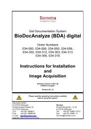
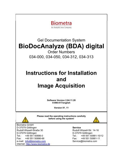
Gel Documentation System<br />
<strong>BioDocAnalyze</strong> (<strong>BDA</strong>) <strong>digital</strong><br />
Order Numbers<br />
034-000, 034-050, 034-312, 034-313<br />
Instructions for Installation<br />
and<br />
Image Acquisition<br />
Software Version 2.64.11.20<br />
9-990-017/english<br />
Version 01_11<br />
Please read the operating instructions carefully<br />
before using the system!<br />
<strong>Biometra</strong> GmbH<br />
D-37079 Göttingen Service<br />
Rudolf-Wissell-Straße 30 Rudolf-Wissell-Str. 14-16<br />
D-37079 Göttingen D-37079 Göttingen<br />
Tel.: +49 551 50686-0 Tel.: +49 551 50881-10/12<br />
Fax: +49 551 50686-66 Fax: +49 551 50881-11<br />
e-mail: Info@biometra.com Service@biometra.com<br />
internet: http://www.biometra.de
2<br />
All rights reserved. No part of this publication may be reproduced, stored in a retrieval system, or transmitted, in any form or by any means<br />
without the prior written permission of <strong>Biometra</strong> biomedizinische Analytik GmbH nor be otherwise circulated electonically or in print.<br />
In no event <strong>Biometra</strong> biomedizinische Analytik GmbH shall be liable for indirect, incidential or consequential damages resulting from the<br />
use of the information supplied by this manual. This manual was written with due care and <strong>Biometra</strong> biomedizinische Analytik GmbH shall<br />
not be liable for any fault or omission.<br />
March 2011.<br />
Tradenames of software or hardware cited herein, esp. those of the Microsoft Corp., are registered, patented or protected by other legal<br />
means.<br />
<strong>BDA</strong><strong>digital</strong> Manual, Vers. 01_11
Contents<br />
<strong>BDA</strong><strong>digital</strong> Manual, Vers. 01_11<br />
3<br />
Contents<br />
1 INSTALLATION OF <strong>BDA</strong> DIGITAL ...........................................................................................................4<br />
1.1 COMPONENTS ...........................................................................................................................................4<br />
1.2 ASSEMBLY ................................................................................................................................................4<br />
1.2.1 Personal computer and monitor........................................................................................................4<br />
1.2.2 Copy protection (Dongle, Hardlock)................................................................................................4<br />
1.2.3 Attaching of the lens adapter to the camera .....................................................................................5<br />
1.2.4 Installation of camera with anti-theft mounting to the darkhood BDR 1 .........................................5<br />
1.2.5 Mounting of camera at <strong>BDA</strong> Box ....................................................................................................6<br />
1.2.6 Bandpass Filter.................................................................................................................................8<br />
1.2.7 Filter wheel labels „590 nm EtBr“ and „520 nm SYBR ® Green“....................................................8<br />
1.2.8 Darkhood, transilluminator and converter plate...............................................................................8<br />
1.2.9 Thermal printer.................................................................................................................................8<br />
1.3 INSTALLATION OF THE SOFTWARE............................................................................................................9<br />
1.3.1 Overview..........................................................................................................................................9<br />
1.3.2 Installation of the Camera Canon PowerShot G10/G9/A640/A620/G6/G5/G3/G2 .........................9<br />
1.3.3 Screen Settings...............................................................................................................................11<br />
1.3.4 Installation of the <strong>BioDocAnalyze</strong> Program ..................................................................................11<br />
1.3.5 Installation of Thermal Printer Mitsubishi P93DW .......................................................................12<br />
2 START OF THE PROGRAM.....................................................................................................................13<br />
2.1 CHOICE OF MAIN WINDOWS.....................................................................................................................13<br />
3 <strong>BDA</strong> DIGITAL IMAGE CAPTURE............................................................................................................14<br />
3.1 THE IMAGE CAPTURE..............................................................................................................................15<br />
3.2 FUNCTIONS AND CAPTURE PARAMETERS................................................................................................15<br />
3.2.1 Profiles with Capture Parameters...................................................................................................15<br />
3.2.2 The Card „Settings“ .......................................................................................................................16<br />
3.2.3 The Card „Advanced“ ....................................................................................................................18<br />
3.2.4 Camera Settings for Typical Gels ..................................................................................................19<br />
3.2.5 Further Functions for Image Capture .............................................................................................20<br />
3.2.6 The Gel Picture Window................................................................................................................22<br />
5 SERVICE ......................................................................................................................................................23<br />
6 EQUIPMENT DECONTAMINATION CERTIFICATE ............................................................................24<br />
7 DISPOSAL ...................................................................................................................................................26
4<br />
Installation<br />
1 Installation of <strong>BDA</strong><strong>digital</strong><br />
concerning<br />
034-000 <strong>BDA</strong><strong>digital</strong> core set<br />
034-050 <strong>BDA</strong><strong>digital</strong> compact<br />
034-312 <strong>BDA</strong><strong>digital</strong> System 20<br />
034-313 <strong>BDA</strong><strong>digital</strong> System 30<br />
1.1 Components<br />
The system comes with:<br />
- <strong>BDA</strong> software (CD-ROM) and manual<br />
- Dongle (copy protection key, hardlock)<br />
- Digital camera, e.g. Canon PowerShot incl. Canon standard accessories<br />
- Lens adapter<br />
- Bandpass filter BP595 for EtBr stained gels<br />
Additionally with <strong>BDA</strong><strong>digital</strong> compact:<br />
- Darkhood BDR1<br />
Additionally with <strong>BDA</strong><strong>digital</strong> System 20 and <strong>BDA</strong><strong>digital</strong> System 30:<br />
- darkhood <strong>BDA</strong> Box 2 incl. camera mounting<br />
- Transilluminator UVstar 20 resp. UVstar 30<br />
- UV converter plate<br />
- Thermal printer incl. USB cable<br />
- TFT monitor<br />
- Personal computer, Englisch OS, installed<br />
1.2 Assembly<br />
1.2.1 Personal computer and monitor<br />
Attach the cable of the monitor to the VGA port of the graphic card of the PC.<br />
Connect also mouse and keyboard to the computer. Connect monitor and PC via cable with the appropriate<br />
power supply system.<br />
1.2.2 Copy protection (Dongle, Hardlock)<br />
The <strong>BioDocAnalyze</strong> software is protected by a copy protection key (dongle, hardlock). The dongle is the software<br />
licence.<br />
The dongle is supplied as key for the USB port of the computer.<br />
This dongle is plugged to the USB port of the computer.<br />
After installation the dongle is automatically detected and flashes in red.<br />
<strong>BDA</strong><strong>digital</strong> Manual, Vers. 01_11
<strong>BDA</strong><strong>digital</strong> Manual, Vers. 01_11<br />
5<br />
Installation<br />
1.2.3 Attaching of the lens adapter to the camera<br />
Please screw off the ring around the lens counter-clockwise by pressing the button next to the lens.<br />
The bayonet nut connector gives the ring free after about a quarter of turn.<br />
After this please put the lens adapter over the lens and screw it clockwise while pressing the button until it is<br />
locked in place.<br />
Applying the black small darkhood BDR1 of <strong>BDA</strong><strong>digital</strong> compact or <strong>BDA</strong> Box 1:<br />
For documentation of Ethidiumbromide stained gels please screw the red bandpass filter BP595 to the lens<br />
adapter.<br />
For documentation of colored samples, e.g. silver or Coomassie Blue stained gels you don´t need a filter.<br />
Applying the camera A640 we recommend to put the included rubber ring to the lower edge of the lens adapter.<br />
This supports a light-tight sealing to the hood.<br />
1.2.4 Installation of camera with anti-theft mounting to the darkhood BDR 1<br />
(Models Canon PowerShot G10, G9, A640, A620, G6, G5 or G3)<br />
Screw the lock block to the tripod thread of the camera with the included screw and the allen wrench. The lock<br />
block must be fixed to the camera in the way that the two noses of the block are equally positioned against the<br />
camera (see markers below):<br />
lens adapter<br />
band pass filter<br />
Place the camera at the darkhood and attach the lock bolt.<br />
The bolt and the safety pins must be inserted into the corresponding holes.<br />
Turn the key clockwise at 180 ° and take it off.
6<br />
Installation<br />
The camera is finally fixed with the knurled screw.<br />
1.2.5 Mounting of camera at <strong>BDA</strong> Box<br />
With darkhood type <strong>BDA</strong> Box please mount the camera as follows:<br />
1)<br />
Ready to use<br />
Knurled head screws<br />
Hexagon socket<br />
Camera bracket<br />
Adapter bloc<br />
In case of changing<br />
the UV filter:<br />
After removal of the knurled screw the camera<br />
can be lifted and easily turned to the side. Now<br />
it is possible to change the UV filter.<br />
It is not possible to take off the camera!<br />
It remains locked!<br />
Digital camera (first unscrew<br />
lens ring)<br />
Lens adapter with O-Ring<br />
Light trap<br />
<strong>BDA</strong><strong>digital</strong> Manual, Vers. 01_11
2)<br />
3)<br />
Side view<br />
For an optimal camera position the camera must<br />
be adjusted in height that way that the mounted<br />
O-Ring leaves 5,6 mm free at the lower part of the<br />
lens adapter (see adjoining picture).<br />
Mounting of the anti-theft device, back view<br />
Special screw driver<br />
Special screws<br />
Security bracket<br />
<strong>BDA</strong><strong>digital</strong> Manual, Vers. 01_11<br />
O ring<br />
Front view<br />
7<br />
Installation<br />
Lichtfalle, oberer Teil<br />
Light trap, upper part
8<br />
Installation<br />
1.2.6 Bandpass Filter<br />
Standard delivery is a bandpass filter with transmission maximum of 590 nm for the typically used fluorescent<br />
stain ethidium bromide.<br />
With darkhood <strong>BDA</strong> Box 2 or <strong>BDA</strong> Box 3 please insert the UV filter into the filter wheel: Open the darkhood<br />
sliding door and open the UV protection shield up to a horizontal position. Slowly pull out the filter wheel with<br />
the knob inside the darkhood, below the filter wheel. The filter wheel is slided out and the filter can be inserted<br />
into the wheel. Please choose the wheel position which is opposite to the corresponding filter label (see 1.2.7).<br />
Note:<br />
Filters with slightly higher filter holder shall be inserted in borehole Nr. 3 of the filter wheel. Then Nr. 1<br />
is seen at filter wheel front.<br />
1.2.7 Filter wheel labels „590 nm EtBr“ and „520 nm SYBR ® Green“<br />
Delivery of a <strong>BDA</strong> Box includes two small filter wheel labels.<br />
These labels can be applied to darkhoods with filter wheel (<strong>BDA</strong> Box 2, <strong>BDA</strong> Box 3) at the front panel of the<br />
filter wheel. Please note that the visible front position number corresponds to the opposite filter wheel position.<br />
The standard delivery of <strong>BDA</strong> systems includes the red „590 nm/ethidium bromide filter“, the green „520<br />
nm/SYBR Green filter“ can be bought as optional component.<br />
1.2.8 Darkhood, transilluminator and converter plate<br />
Please refer to the separate operating instructions of the darkhood and the transilluminator.<br />
The converter plate for application on top of the UV transilluminator for documentation of samples with visible<br />
colour stains is delivered ready to use.<br />
1.2.9 Thermal printer<br />
! To avoid any Windows problems with the USB ports it is recommended to connect USB devices to<br />
the same USB port as used for installation of the devices.<br />
Connect the thermal printer Mitsubishi P93DW under Windows XP/2000 via USB cable with the PC. Connect<br />
the printer with the power supply system and put a roll of paper into the printer.<br />
Windows XP and 2000 are automatically recognizing the printer which is connected via USB cable as a new<br />
instrument. Therefore the printer should only be switched on just before it shall be installed. To avoid installation<br />
errors we recommend to install the thermal printer as last component of the system.<br />
<strong>BDA</strong><strong>digital</strong> Manual, Vers. 01_11
1.3 Installation of the Software<br />
<strong>BDA</strong><strong>digital</strong> Manual, Vers. 01_11<br />
9<br />
Installation<br />
<strong>BDA</strong><strong>digital</strong> has been developed for the operating systems Windows XP professional and Windows 2000<br />
professional.<br />
The installation is only necessary in case you bought the sets 034-000 and 034-050 without a computer<br />
from <strong>Biometra</strong>. If <strong>BioDocAnalyze</strong> comes with a <strong>Biometra</strong> computer, all the software is completely installed<br />
and the system is ready to use after unpacking and installing the cables.<br />
PC minimum requirements: Personal computer with Windows XP or Windows 2000, processor 1,8 GHz, graphic<br />
card 1024 x 768, 512 MB RAM, 2 USB2.0 ports, CD-ROM drive.<br />
Software installation: This will take, depending on the computer and how often the user did things like that before,<br />
between 15 and 45 minutes. In case you have some problems during or after installation, please contact the<br />
<strong>Biometra</strong> <strong>BioDocAnalyze</strong> customers service, phone +49(0)551-5068612, fax +49(0)551-5088111, e-mail<br />
Herbert.Becker@whatman.com.<br />
1.3.1 Overview<br />
! For installation procedure please refer to following chapters with detailed information.<br />
completed<br />
1.3.1.1 Installation of camera (s. 1.3.2) .................................................................................... �<br />
Installation of <strong>digital</strong> camera driver from Canon CD-ROM.<br />
Afterwards connect camera to PC.<br />
1.3.1.2 Screen settings (s. 1.3.3)............................................................................................... �<br />
1.3.1.3 Installation of <strong>BDA</strong> software incl. dongle (s. 1.3.4) .................................................... �<br />
from <strong>BDA</strong> CD-ROM<br />
1.3.1.4 Installation of thermal printer (s. 1.3.5)........................................................................ �<br />
from <strong>BDA</strong> CD-ROM<br />
1.3.2 Installation of the Camera Canon PowerShot<br />
G10/G9/A640/A620/G6/G5/G3/G2<br />
!<br />
The camera driver from the Canon Digital Camera Solution CD must be installed<br />
before connecting the camera to the PC!<br />
1.3.2.1 Installation of the Canon programs<br />
Users of Windows XP professional and Windows 2000<br />
must be logged in as system administrator!<br />
1. Insert Canon Digital Camera Solution CD into PC drive.
10<br />
Installation<br />
2. Choose „Installation of Digital Camera Software“.<br />
3. Confirm request.<br />
4. Confirm software licence agreement.<br />
5. Confirm or choose the installation path.<br />
6. Choose desired programs and start installing.<br />
It depends on operating system and camera model whether or which USB driver for the camera has to be<br />
installed.<br />
- Windows XP/G10, G9, A640, A620, G6, G5: No USB driver must be installed.<br />
- Windows XP/G3, G2: WIA driver for Canon cameras<br />
- Windows 2000/G5, G3, G2: TWAIN driver for Canon cameras.<br />
When the camera shall also be used separately from the <strong>BDA</strong> software for taking other pictures it is recommended<br />
to install all Canon programs.<br />
7. Reboot the computer.<br />
1.3.2.2 Basic camera settings<br />
The camera is not yet connected to the PC.<br />
1. Switch the camera G2 resp. G3 with the mode switch to record or play, activate the menue and set „auto<br />
power down“ to „off“ on card settings. Otherwise the camera will switch off automatically after some minutes<br />
of inactivity which causes a program breakdown the next time <strong>BioDocAnalyze</strong> asks for the camera.<br />
With camera G10, G9, A640, A620, G6 and G5 it is not necessary to set it manually because these cameras<br />
automatically deactivate the auto power down function in their PC mode.<br />
2. To have correct dates on your pictures, the time and date in the cameras menue, card settings, must be set.<br />
3. Connect the camera with mains adapter with the power supply system.<br />
4. In control panel, energy options the standby mode of the computer and the switch off of the harddisk<br />
should be set to „never“ as after reactivation the connection to the camera may be lost. Switching off the<br />
computer monitor after some minutes of inactivity or the screen saver will not disturb the camera function.<br />
After this connect the camera to the computer by its USB cable.<br />
! To avoid any Windows problems with the USB ports it is recommended to connect USB devices to<br />
the same USB port as used for installation of the devices.<br />
Differences in camera models:<br />
G9, G10: Switch on the camera with main switch „on/off“.<br />
A640: Please set the switch on the camera back to play „ �“ and switch on the camera with the main switch<br />
“ON/OFF”.<br />
The camera models G6, G5 and G3 will switch on automatically, if the camera´s loaded battery is installed or the<br />
mains adaptor is connected. With camera model G2. the mode switch has to be set to play „ �“.<br />
The camera automatically switches to the PC mode which is shown on the small upper camera display (not<br />
displayed with A640).<br />
! In case that the Canon program or Windows window for operating the camera is automatically<br />
opened please close it.<br />
<strong>BDA</strong><strong>digital</strong> Manual, Vers. 01_11
1.3.3 Screen Settings<br />
<strong>BDA</strong><strong>digital</strong> Manual, Vers. 01_11<br />
11<br />
Installation<br />
Set it with „Start, control panel, appearance and themes, change screen resolution“ (WinXP) resp. „Start, settings,<br />
control panel, display, settings“ (Win 2000):<br />
- Screen area: 1024 x 768 pixels<br />
- Colors: True Color (32 bit)<br />
Set „Start, control panel, appearance and themes“ (WinXP):<br />
- font size to normal<br />
Win2000:<br />
The function „Use large icons“ on the index card „effects“ should not be activated.<br />
1.3.4 Installation of the <strong>BioDocAnalyze</strong> Program<br />
incl. the driver for the copy protection key (hardlock, dongle)<br />
1. Insert the <strong>BioDocAnalyze</strong> installation CD into the PC drive.<br />
2. Start „my computer“ or the Windows Explorer and choose the CD-ROM drive.<br />
3. Start installation with double-click on the file „<strong>BDA</strong><strong>digital</strong>_setup.bat“ in the main directory.<br />
Now the drivers for the dongle and the <strong>BioDocAnalyze</strong> software are installed.<br />
4. Confirm the request for completing the installation.<br />
Note:<br />
Starting the <strong>BDA</strong><strong>digital</strong> image acquisition window for the first time you are asked to type in a 4-digit activation<br />
code to get free access to this software part. You will find the requested code labeled to the copy<br />
protection key (see also section 3).<br />
********************************************************************<br />
It is also possible to install the <strong>BioDocAnalyze</strong> software and the drivers of the dongle separately:<br />
<strong>BioDocAnalyze</strong> software Start the file „setup.exe“ in the main directory of the <strong>BioDocAnalyze</strong> CD and confirm<br />
all requests.<br />
Dongle Start the file „hdd32.exe“ in the directory „HASP“ and confirm all requests.<br />
********************************************************************<br />
<strong>BioDocAnalyze</strong> Software Update<br />
When the <strong>BioDocAnalyze</strong> software shall be installed to an existing system as software update only the Bio-<br />
DocAnalyze software has to be installed newly.<br />
A new installation of other drivers and programs is not necessary.<br />
Installation:<br />
1. Please uninstall the existing <strong>BioDocAnalyze</strong> software version by „Start, control panel, Software, <strong>BioDocAnalyze</strong>“<br />
with the„delete“ button.<br />
2. Now please install the <strong>BioDocAnalyze</strong> software from CD by double-click on the file „setup.exe“ in the<br />
main directory of the <strong>BioDocAnalyze</strong> CD.<br />
3. Confirm all requests.
12<br />
Installation<br />
Restart your computer. Switch on the thermal printer before so you will be asked for the printer driver automatically.<br />
1.3.5 Installation of Thermal Printer Mitsubishi P93DW<br />
The default settings for printing in the configuration file biom1.ini of the <strong>BioDocAnalyze</strong> program are optimized<br />
for the thermal printer Mitsubishi P93DW with thermal paper KP65HM or KP91HG-CE and for the thermal<br />
printer Sony UP-D895 with Sony UPP-110HG paper. In case another printer or another paper are used the<br />
printouts can be too dark. Then an individual adaptation of setting values (printcontrast, printbrightness, printgamma)<br />
in the biom1.ini is recommended.<br />
1.3.5.1 Installation under Windows 2000 and Windows XP<br />
The drivers for Windows XP and Windows 2000 are in the directory MitsubishiP93DW.<br />
The printer installation at the USB port runs widely automatically. Please confirm the different requests as recommended<br />
from the system. In case that there are any open questions please refer to the Sony installation guide<br />
on the <strong>BioDocAnalyze</strong> CD in directory MitsubishiP93DW.<br />
A possibility to use the thermal paper more efficiently is to activate the paper save mode in the printer settings:<br />
Choose „Start, settings, printer & fax“ and open the dialog box of the thermal printer P93D. Choose card „settings“<br />
and set the paper save mode to „on“.<br />
<strong>BDA</strong><strong>digital</strong> Manual, Vers. 01_11
2 Start of the Program<br />
<strong>BDA</strong><strong>digital</strong> Manual, Vers. 01_11<br />
13<br />
Start of Program<br />
The program is started from the desktop by a LEFT MOUSE BUTTON DOUBLECLICK on to the icon "<strong>BioDocAnalyze</strong>"<br />
or alternatively the command sequence "Start, Programs,...,<strong>BioDocAnalyze</strong>".<br />
The <strong>BioDocAnalyze</strong>-Logo is opened and after several seconds displaced by the full frame window "BioDoc-<br />
Analyze" with a menu bar and a function bar.<br />
2.1 Choice of main windows<br />
The desired function is activated by a click on the icon in the function bar. You have<br />
the choice between<br />
� Image capture with CCD video camera (<strong>BDA</strong>video)<br />
� Image capture with <strong>digital</strong> camera (<strong>BDA</strong><strong>digital</strong>)<br />
� Image capture with <strong>digital</strong> CCD camera (<strong>BDA</strong> live)<br />
� Gel analysis.<br />
This manual only refers to the image capture with the <strong>digital</strong> camera.<br />
The gel analysis is described in the separate manual „<strong>BioDocAnalyze</strong>“.
14<br />
Image Capture<br />
3 <strong>BDA</strong><strong>digital</strong> Image Capture<br />
The <strong>BDA</strong><strong>digital</strong> image capture software is started with a LEFT MOUSE BUTTON CLICK on the<br />
icon „<strong>digital</strong> camera“.<br />
! When starting the <strong>BDA</strong><strong>digital</strong> capture software for the<br />
first time after installation you will be asked for a 4-digit<br />
software code to activate the capture screen.<br />
The code comes along with the dongle.<br />
The window „Capture <strong>digital</strong> camera“ is opened and a loading bar indicates that the software just initializes the<br />
<strong>digital</strong> camera.<br />
Fig. 3-1 Window „Capture <strong>digital</strong> camera“<br />
The line „Camera“ should show e.g. „PowerShot AG10“. In case that only „Model“ is shown the camera is not<br />
correctly installed or not switched on. The camera needs to be on replay and then shows „PC“ on the camera<br />
display (display is not existing at all camera models).<br />
When the capture window is opened it starts with the camera settings of the last opened profile.<br />
<strong>BDA</strong><strong>digital</strong> Manual, Vers. 01_11
3.1 The Image Capture<br />
These are the typical steps for image capture:<br />
1. Switch on the live preview: .<br />
2. Place the electrophoresis gel on the transilluminator.<br />
3. Switch on the light source of the darkhood.<br />
4. Place the gel with the help of the live preview in the transilluminator center.<br />
5. Choose the desired zoom area by window „Settings“:<br />
6. Choose the appropriate settings profile:<br />
7. Take a photo:<br />
<strong>BDA</strong><strong>digital</strong> Manual, Vers. 01_11<br />
15<br />
Image Capture<br />
8. If necessary optimize the exposure time Tv and the lens aperture Av in window „Settings“ in set „Shooting<br />
Mode“ „Manual“ and take another photo.<br />
9. Save and print the image:<br />
Please see details of the different functions in section 3.2.<br />
3.2 Functions and Capture Parameters<br />
The window „Capture <strong>digital</strong> camera“ is widely self-explaining and very similar to general known parameters in<br />
photography. In spite of that the individual functions are explained in short in the following.<br />
3.2.1 Profiles with Capture Parameters<br />
Profile This includes some profiles with working parameters for the image acquisition of certain gel types.<br />
A mouse click on the profile will set the parameters in the camera. The corresponding parameters are<br />
shown in the cards Settings and Advanced. It is essential that the Shooting Mode is „manual“ otherwise<br />
the settings shown in the card Settings will not really be the used parameters.<br />
It is also possible to enter names for individual settings. After typing in the new name and setting the<br />
parameters the new profile has to be saved .<br />
Switch off of the „live image“ will accelerate the change of profiles.<br />
Save This saves user-defined profiles under the active profile name.<br />
Before saving you should check whether already a profile with the same name exists because it<br />
would be overwritten.<br />
Clear This deletes the active profile. The <strong>Biometra</strong> saved profiles can not be deleted.
16<br />
Image Capture<br />
3.2.2 The Card „Settings“<br />
Shooting Mode For choice of capture mode. Typical settings are „Manual“ or „Auto“.<br />
- Manual Exposure time and lens aperture can be set in lines „Av“ and „Tv“. Even for the use of<br />
profile parameters the mode should be „Manual“.<br />
It should be kept in mind that the camera can not set the largest apertures (= small aperture<br />
number) together with a large zoom factor. In these cases the camera automatically<br />
chooses the largest possible lens aperture. After the picture is taken the aperture display on<br />
the card is actualized to the really used one.<br />
- Auto The camera sets the capture parameters exposure time and lens aperture automatically.<br />
Be aware that these settings are not displayed in the camera settings.<br />
Be aware that the displayed and printed settings are not the true settings the cameras has<br />
automatically chosen for the photo!<br />
- Tv The camera automatically chooses the optimal lens aperture in relation to the manually<br />
set exposure time. After the picture is taken the automatically used aperture is displayed in<br />
the card Settings.<br />
- Av The camera automatically chooses the optimal exposure time in relation to the manually<br />
set lens aperture. After the picture is taken the automatically used exposure time is displayed<br />
in the card Settings.<br />
Lens aperture, Av For setting the lens aperture. A small aperture number stands for a wide open lens, a high<br />
aperture number for a more closed lens. The depth of focus increases with rising aperture<br />
number (= smaller lens aperture). Agarose gels, especially thicker gels, should be photographed<br />
with high aperture number (= small aperture). Otherwise photos may not be focussed.<br />
Exposure time, Tv For setting the exposure time. The time is to be set in dependance of sample/illumination<br />
and lens aperture. For smaller apertures (= high aperture number, e.g. 8) exposure times of<br />
up to 8 seconds can be necessary for a photo of fluorescent gels.<br />
Resolution For choice of image resolution in pixels. The higher the resolution the bigger the file size.<br />
High resolutions will cause longer data transfer times from camera to PC on computers<br />
with slow processors and memory below 512 MB RAM. For an efficient operating it is<br />
recommended to use a computer with at least 1 GB RAM and a 2.8 GHz processor.<br />
In pixels PowerShot G10 PowerShot G9 PowerShot A640<br />
High<br />
Medium1<br />
Medium2<br />
Low<br />
4416 x 3312<br />
3456 x 2592<br />
2592 x 1944<br />
1600 x 1200<br />
4000 x 3000<br />
3264 x 2448<br />
2592 x 1994<br />
640 x 480<br />
3648 x 2736<br />
2816 x 2112<br />
2272 x 1704<br />
640 x 480<br />
PowerShot<br />
A620/G6<br />
3072 x 2304<br />
2592 x 1944<br />
2048 x 1536<br />
640 x 480<br />
Zoom The optical zoom can be set with the slider or by typing in a value between 0 and 13 (G10,<br />
G9), 0 and 8 (A640/A620), 0 and 12 (G6/G5/G3) resp. 1 to 10 (G2).<br />
A higher zoom reduces the amount of light that reaches the camera sensors. This can cause<br />
difficulties for the autofocus. When the autofocus does not succeed to take a focussed<br />
picture although there is a clear object in the image center please<br />
- set a longer exposure time (Shooting Mode Manual)<br />
- set less zoom.<br />
- Use the function “AF Lock” for fixation of the autofocus. (see 3.2.5)<br />
- use the function „manual Focus“ (MF button on camera back). This manual focus is<br />
not available for use with remote control by the computer. For use of the manual focus<br />
please disconnect the USB cable of the camera from the PC and run the camera<br />
<strong>BDA</strong><strong>digital</strong> Manual, Vers. 01_11
<strong>BDA</strong><strong>digital</strong> Manual, Vers. 01_11<br />
17<br />
Image Capture<br />
separately. Please set also the macro mode (flower symbol on camera back). The photos<br />
are saved on the compact flash card.<br />
Fig. 3-2 Card „Settings“
18<br />
Image Capture<br />
3.2.3 The Card „Advanced“<br />
Quality For choice of compression of picture data in JPG format. In general quality „normal“<br />
will be sufficient. Quality „superfine“ with only low compression needs more saving capacity<br />
and time for image analysis.<br />
ISO For setting of the sensitivity. Value ISO 400 is recommended for low illumination and big<br />
zoom, but in contrast to photos at ISO 50 a certain background noise appears.<br />
In most cases it is advised to use ISO 50. Only for the acquisition of very faint signals at<br />
high zoom factors it can be necessary to raise the sensitivity to ISO 400.<br />
Flash For activation or deactivation of the flash. Applications with darkhoods should be done<br />
with flash „off“. Flash „on“ or „auto“ can be used for photographs with stand in a dark<br />
room, but reflections on the gel surface can not be excluded.<br />
Exposure<br />
Compensation<br />
For setting an exposure correction. A fine-tuning of the optimal exposure can be done in<br />
small steps.<br />
This function is not available in shooting mode „Manual“ because lens aperture and exposure<br />
time are specifically set in the manual mode.<br />
White Balance For setting the white balance. Colors can be mirrored more true to original when the<br />
illumination source is set. This factor is of only minor relevance for black&white photos.<br />
Autofocus<br />
Distance<br />
For definition of distance where the autofocus will look for the sample. For image acquisition<br />
with <strong>Biometra</strong> darkhoods „Close up“ has to be set. This setting will lead within the<br />
limited distance of camera to gel to well-focussed pictures over the whole range of zoom.<br />
Fig. 3-3 Card „Advanced“<br />
<strong>BDA</strong><strong>digital</strong> Manual, Vers. 01_11
3.2.4 Camera Settings for Typical Gels<br />
<strong>BDA</strong><strong>digital</strong> Manual, Vers. 01_11<br />
19<br />
Image Capture<br />
The software provides camera settings for two typical gel types in Profiles. Starting with these settings it is very<br />
easy and fast to optimize the camera settings for individual gels.<br />
Gel type EtBr Stained Agarose Gel<br />
on UV table<br />
Coloured Polyacrylamide Gel<br />
on UV table with yellow converter<br />
plate, without UV filter on<br />
camera lens,<br />
e. g. silver or Coomassie Blue<br />
stained Polyacrylamide gel<br />
Profile „DNA/EtBr“ Profile „Converter“<br />
Shooting Mode Manual Manual<br />
Lens aperture Av 6.3 4.0<br />
Exposure time Tv 4 s 1/125 s<br />
Autofocus distance Close up Close up<br />
ISO 50 50<br />
Flash Off Off<br />
Quality Normal Normal<br />
Resolution Medium 1 Medium 1<br />
Zoom e. g. 5 e. g. 5<br />
Exposure compensation 0 0<br />
White balance Auto Fluorescent
20<br />
Image Capture<br />
3.2.5 Further Functions for Image Capture<br />
AF Lock Function for fixation of the autofocus. This function can be used for<br />
photos which cannot be focussed with the autofocus. This may happen<br />
with gels which have no bands or have only very weak bands in the gel<br />
center or when using a high zoom.<br />
The principle of this function is that first a clear bright tool is placed in<br />
the center and the autofocus is directed to that. After fixing the autofocus<br />
in this position the tool is removed and the photo can be taken.<br />
Please note:<br />
When you are changing the zoom you have to set the autofocus again!<br />
Procedure:<br />
A. with fluorescent agarose gels:<br />
a) Switch on white light from above (+ place a thin ruler on the gel),<br />
activate the autofocus button (or take a photo),<br />
activate the AF Lock function,<br />
switch off the white light from above (and remove the ruler),<br />
switch on the UV light,<br />
take the photo.<br />
b) place a fluorescent ruler on the gel,<br />
activate the autofocus button (or take a photo),<br />
activate the AF Lock function,<br />
remove the ruler,<br />
take the photo.<br />
B. with coloured gels on converter plate:<br />
Place a non-fluorescent ruler on the gel,<br />
activate the autofocus button (or take a photo),<br />
remove the ruler,<br />
take the photo.<br />
Delay With activated Delay function the camera updates the internal settings<br />
with a 5 seconds delay after the last change of settings parameters in<br />
the cards Setting and Advanced. The use of the delay function is recommended<br />
for a faster operating if the user wants to change several<br />
parameters before taking the next picture.<br />
If it is intended only to change one parameter it is more practical to<br />
deactivate the delay function. Then the camera will react directly after<br />
the parameter on the card is changed.<br />
Refresh It is possible to manually trigger the updating of internal camera<br />
settings with the Refresh button. Then it is not necessary to wait the 5<br />
seconds standard delay for automatic updating.<br />
Live image on/off For switch on/off the live preview in window „Live Preview“. Due to<br />
the high iteration frequency of the picture and for this reason short exposure<br />
times it is possible that the live preview will not be as bright and<br />
focussed as the real gel picture.<br />
Autofocus For manual activation of the autofocus. This can be helpful in case<br />
that the camera fails to focus automatically.<br />
<strong>BDA</strong><strong>digital</strong> Manual, Vers. 01_11
<strong>BDA</strong><strong>digital</strong> Manual, Vers. 01_11<br />
21<br />
Image Capture<br />
Take picture Click on the button releases the camera. The picture is transferred from camera to PC and<br />
is displayed in the gel window in the right of the Capture window.<br />
The “additional” functions Rotate, Invert, Black&White Mode and Saturation are deactivated<br />
after taking a photo or printing. These functions have to be activated again when it is<br />
desired to have.<br />
Rotate 180° For rotating the picture 180°, for example when the gel is positioned the opposite way<br />
round on the illumination table or when the camera is fixed on the darkhood or stand with<br />
the camera control panel ahead.<br />
Invert For inverting of the gel picture. The use of this function is only senseful with<br />
black&white pictures.<br />
Black&White Mode Activation of this function results in a change of the colour picture to a grey-scale picture.<br />
Saturation Activation of this function sets areas of the photo to blue colour if the signal reaches saturation.<br />
The photo display automatically switches to black&white mode.<br />
The pixels of the area to be quantitatively analyzed later must not be saturated, neither<br />
true white or true black. That means that the area of interest must not be in blue colour.<br />
This can be achieved by shorter exposure times or with smaller lens apertures (= larger<br />
lens aperture number).<br />
When using longer exposure times it is possible that the live preview is darker than the<br />
photo. This will cause differences in the saturation display of preview and photo.<br />
Copy Conditions Click on this button loads the settings parameters of the gel picture (BD1 format!)<br />
which was loaded into the gel window. The new setting parameters can now be used for<br />
taking a new picture or for saving as profile.<br />
Analysis For saving of the picture in the <strong>Biometra</strong>-specific BD1 format, JPG or TIF format and the<br />
following transfer to the <strong>BDA</strong> analysis software. After saving the gel picture will automatically<br />
be opened as black&white picture in the analysis part for further gel analysis.<br />
Exit For closing of the capture window.<br />
Fig. 3-4 Functions for image capture
22<br />
Image Capture<br />
File open Via the folder icon already saved pictures in JPG, TIF or <strong>Biometra</strong> specific BD1 format<br />
can be loaded to the capture window.<br />
Save Via disc icon the active gel picture is saved in JPG, TIF or <strong>Biometra</strong> specific BD1 format<br />
by typing in a name. Default is BD1 format which generates a black&white image<br />
including image acquisition camera settings. BD1 is standard format in the gel analysis<br />
part of the <strong>BioDocAnalyze</strong> software.<br />
Print Via printer icon the active gel picture is printed on the current Windows standard printer<br />
(DIN A4 printer or thermal printer).<br />
Thermal printer<br />
mode<br />
For prints with a thermal printer (e.g. Sony UP-D890 or UP-D895) the function „Thermal<br />
printer mode“ has to be activated.<br />
Print parameter It can be chosen whether the gel picture is printed with or without the camera settings.<br />
Fig. 3-5 Save, load, and print file<br />
3.2.6 The Gel Picture Window<br />
Fig. 3-6 Cards of the gel picture window<br />
Image Display of the photo or loaded gel picture.<br />
Shot Conditions Setting parameters of the gel photo or the loaded gel file are shown.<br />
The complete parameters are only saved with photos in BD1 files.<br />
Comments For addition of file comments. These comments are only saved in BD1-format files!<br />
The comments are printed with the gel photo and can also be seen in the <strong>BioDocAnalyze</strong><br />
analysis window under „Analyze, Comments, General Comment“.<br />
Please regard: It is only possible to print around 20 chars per line and 5 lines.<br />
<strong>BDA</strong><strong>digital</strong> Manual, Vers. 01_11
4 Service<br />
<strong>BDA</strong><strong>digital</strong> Manual, Vers. 01_11<br />
23<br />
Service<br />
In case you have any problem with the device please contact our service division or your local <strong>Biometra</strong><br />
dealer.<br />
<strong>Biometra</strong> GmbH<br />
Service Department<br />
Rudolf-Wissell-Straße 14-16, D-37079 Göttingen, Germany<br />
Tel: +49 551 50686-10 or -12<br />
Fax: +49 551 50881-11<br />
e-mail: service@biometra.com<br />
Please follow the return instructions when returning the device:<br />
Return instructions<br />
Please contact our service department for providing a return authorization number (RAN). This<br />
number has to be applied clearly visible to the outer box.<br />
Returns without the RAN will be not be accepted!<br />
Return only faulty devices. For any technical problem that is not clearly identifiable as a device<br />
failure, please contact the Service Department of <strong>Biometra</strong>.<br />
Use the original packing or a similar robust packing when returning the material.<br />
The darkhood must be shipped on a pallet. The transilluminator has to removed from the<br />
hood and must be shipped separately! The drawer must be secured with some packing<br />
material to avoid that the drawer is moving and touching the UV protection shield during<br />
transport.<br />
Mark the outer packing with “CAUTION! SENSITIVE ELECTRONIC INSTRUMENT!”<br />
Please include a precise description of the problem and preferably one that also describes by which<br />
procedure the failure occurs or how it is caused.<br />
Important:<br />
Clean every part of the device from residues such as chemical, radioactive and dangerous<br />
biological contamination. Please confirm in writing (Equipment Decontamination<br />
Certificate) before every return that the device is free of radioactive and dangerous biological<br />
contamination. Contaminated devices sent to <strong>Biometra</strong> will be refused!<br />
The sender will be liable for the repair order in case of damage resulting from an inadequate<br />
decontamination of the device.<br />
Please include a note with the following information:<br />
a) Sender’s name and address<br />
b) Contact person and phone number in case of inquiry.
24<br />
Service<br />
5 Equipment Decontamination Certificate<br />
To enable us to comply with german law (i.e. §71 StrlSchV, §17 GefStoffV and §19 ChemG) and to<br />
avoid exposure to hazardous materials during handling or repair, please complete this form, prior to<br />
the equipment leaving your laboratory.<br />
COMPANY / INSTITUTE ____________________________________________________________________<br />
ADDRESS ________________________________________________________________________________<br />
PHONE NO _______________________________ FAX NO _______________________________________<br />
E-MAIL ___________________________________________________________________________________<br />
EQUIPMENT Model Serial No<br />
__________________ __________________<br />
__________________ __________________<br />
__________________ __________________<br />
__________________ __________________<br />
If on loan / evaluation Start Date: ________________ Finish Date ____________________<br />
Hazardous materials used with this equipment<br />
_________________________________________________________________________________<br />
_________________________________________________________________________________<br />
_________________________________________________________________________________<br />
Has the equipment been cleaned and decontaminated? YES / NO (delete)<br />
Method of cleaning / decontamination<br />
_________________________________________________________________________________<br />
_________________________________________________________________________________<br />
_________________________________________________________________________________<br />
NAME ________________________________ POSITION ___________________________<br />
(HEAD OF DIV./ DEP./ INSTITUTE / COMPANY)<br />
SIGNED ______________________________ DATE _______________________________<br />
PLEASE RETURN THIS FORM TO BIOMETRA GMBH OR YOUR LOCAL BIOMETRA DISTRIBU-<br />
TOR TOGETHER WITH THE EQUIPMENT.<br />
PLEASE ATTACH THIS CERTIFICATE OUTSIDE THE PACKAGING. INSTRUMENTS WITHOUT<br />
THIS CERTIFICATE ATTACHED WILL BE RETURNED TO SENDER.<br />
<strong>BDA</strong><strong>digital</strong> Manual, Vers. 01_11
General Information for Decontamination:<br />
Please contact your responsible health & safety officer for details.<br />
Use of radioactive substances:<br />
Please contact your responsible person for details.<br />
Use of genetically change organism or parts of those:<br />
Please contact your responsible person for details.<br />
<strong>BDA</strong><strong>digital</strong> Manual, Vers. 01_11<br />
25<br />
Service
26<br />
Service<br />
6 Disposal<br />
Due to the application in a laboratory the system must be decontaminated before return as electronic<br />
waste.<br />
Hinweis<br />
Note<br />
Renseignement<br />
für die Entsorgung von Elektroaltgeräten<br />
for disposal of electric / electronical<br />
waste<br />
du traitement des déchets des appareils<br />
électrique / électronique<br />
Das Symbol der durchgestrichenen Abfalltonne bedeutet für unsere Kunden in Deutschland, daß dieses Produkt<br />
von der Firma <strong>Biometra</strong> kostenlos zur Entsorgung zurückgenommen wird.<br />
Zu diesem Zweck kontaktieren Sie bitte unsere Service-Abteilung!<br />
Außerhalb Deutschlands wenden Sie sich bitte an den für Sie zuständigen Händler.<br />
Dieses Symbol gilt nur in Staaten des EWR*.<br />
*EWR = Europäischer Wirtschaftsraum, umfasst die EU-Mitgliedsstaaten sowie Norwegen, Island und Liechtenstein.<br />
----------------------------------------------------------------------------------------------------------------------------------------------------------------------<br />
This symbol (the crossed-out wheelie bin) means, that this product should be brought to the return or separate<br />
systems available to end-users according to yours country regulations, when this product has reached the end of<br />
its lifetime.<br />
For details, please contact your local distributor!<br />
This symbol applies only to the countries within the EEA*.<br />
*EEA = European Economics Area, comprising all EU-members plus Norway, Iceland and Liechtenstein.<br />
----------------------------------------------------------------------------------------------------------------------------------------------------------------------<br />
Cet symbole (conteneur à déchets barré d´une croix) signifie que le produit, en fin de vie, doit être retourné à un<br />
des systèmes de collecte mis à la disposition des utilisateurs finaux en conséquence des régulations par la loi de<br />
votre pays.<br />
Pour des information additionel nous Vous demandons de contacter votre distributeur!<br />
Cet symbole s´applique uniquement aux pays de l´EEE*.<br />
*EEE = Espace économique européen, qui regroupe les États membres de l´UE et la Norvège, Islande et le<br />
Liechtenstein.<br />
<strong>BDA</strong><strong>digital</strong> Manual, Vers. 01_11