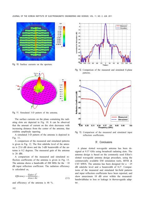
JOURNAL OF THE KOREAN INSTITUTE OF ELECTROMAGNETIC ENGINEERING AND SCIENCE, VOL. 11, NO. 2, JUN. 2011Fig. 10. Surface currents on the aperture.Fig. 12. Comparison <strong>of</strong> the measured and simulated E-planepatterns.Fig. 11. Simulated 3-D pattern <strong>of</strong> the antenna.The surface currents on the plane containing the radiatingslots are depicted in Fig. 10. It can be observedthat the amount <strong>of</strong> current on the slots decreases withincreasing distance from the center <strong>of</strong> the antenna, thatexhibits amplitude tapering.A simulated 3-D pattern <strong>of</strong> the antenna is depicted inFig. 11.A comparison <strong>of</strong> the measured and simulated patternsis given in Fig. 12. The first sidelobe level <strong>of</strong> the antennais 25.6 dB down and the 3-dB beamwidth <strong>of</strong> the antennais 8.2 degrees. The measured gain <strong>of</strong> the antennais 26 dBi.A comparison <strong>of</strong> the measured and simulated reflectioncoefficients <strong>of</strong> the antenna is given in Fig. 13.The antenna shows a <strong>band</strong>width <strong>of</strong> 200 MHz <strong>for</strong> the —10dB input reflection coefficient. The radiation efficiencyis calculated as,2Gain ´ lEfficiency = , Area ´ 4pand efficiency <strong>of</strong> the antenna is 46 %.(11)Fig. 13. Comparison <strong>of</strong> the measured and simulated inputreflection coefficients.Ⅳ. ConclusionsA planar slotted waveguide antenna has been designedat 9.37 GHz using broadwall radiating slots. Theantenna design is based on the commonly used Elliot’sslotted waveguide antenna design procedure, using thecommercially available EM simulation tools, HFSS &CST MWS. The antenna has been designed <strong>for</strong> a —25dB sidelobe level and a beamwidth <strong>of</strong> 8.2°. Comparisons<strong>of</strong> the measured and simulated far-field patternsand input reflection coefficients have been reported, andshow amaximum 10 dB error within the measured<strong>band</strong>widthdueto loss or leakage in thewaveguide adapter.102
BHATTI et al. : DESIGN OF A PLANAR SLOTTED WAVEGUIDE ARRAY ANTENNA FOR X-BAND RADAR APPLICATIONSThis research was financially supported by the Ministry<strong>of</strong> Education, Science Technology (MEST) andKorea Institute <strong>for</strong> Advancement <strong>of</strong> Technology (KIAT)through the Human Resource Training Project <strong>for</strong>Regional Innovation.References[1] Phillip N. Richardson, H. Y. Lee, "<strong>Design</strong> and analysis<strong>of</strong> slotted waveguide arrays," Microwave Journal,pp. 109-125, Jun. 1988.[2] Robert S. Elliot, L. A. Kurtz, "The design <strong>of</strong> smallslot arrays," IEEE Trans. <strong>Antenna</strong>s Propagation, vol.AP-26, pp. 214-219, Mar. 1978.[3] Robert S. Elliot, "An improved design procedure <strong>for</strong>small arrays <strong>of</strong> shunt slots," IEEE Trans. <strong>Antenna</strong>sPropagation, vol. Ap-31, pp. 48-53, Jan. 1983.[4] Robert S. Elliot, W. R. O’Loughlin, "The design <strong>of</strong>slot arrays including internal mutual coupling," IEEETrans. <strong>Antenna</strong>s Propagation. vol. Ap-34, pp. 1149-1154, Sep. 1986.[5] H. Y. Yee, "The design <strong>of</strong> large waveguide arrays<strong>of</strong> shunt slots," IEEE Trans. <strong>Antenna</strong>s Propagation,vol. 40, no. 7, pp. 775-781, Jul. 1992.[6] Alan J. Sangster, A. H. I. McCromick, "Theoreticaldesign and synthesis <strong>of</strong> slotted waveguide arrays,"IEE Proc. H. Microwaves, <strong>Antenna</strong> and Propagation,vol. 136, no. 1, Feb. 1989.[7] George J. Stern, R. S. Elliot, "Resonant length <strong>of</strong>longitudinal slots and validity <strong>of</strong> circuit representation:theory and experiments," IEEE Trans. <strong>Antenna</strong>sPropagation, vol. Ap-33, no. 11, pp. 1264-1271, Nov.1985.[8] Lars G. Josefsson, "Analysis <strong>of</strong> longitudinal slots inrectangular waveguides," IEEE Trans. <strong>Antenna</strong>s Propagation,vol. AP-33, pp. 1351-1357, Dec. 1987.[9] Robert S. Elliot, <strong>Antenna</strong> Theory and <strong>Design</strong>, No. 6,Prentice Hall, Inc, 1981.Rashid Ahmad Bhattiwas born in Bahawal-Nagar, Pakistan, onJuly 14, 1975. He received the B.Sc. degreein electrical engineering from University<strong>of</strong> Engineering and Technology, Taxila,in 1999 and the M.Sc. degree in electricalengineering from National University <strong>of</strong>sciences and Technology (NUST), Rawalpindi,Pakistan, in August, 2005. Currentlyhe isworking toward the Ph.D. degree in electrical engineering atthe Korea Advanced Institute <strong>of</strong> Science and Technology(KAIST), Daejeon, Korea. From September 1999 to December2005, he worked as an RF and <strong>Antenna</strong> Research Engineer atAdvanced Engineering Research Organization (AERO), Pakistan.Here, he has been involved in the EMI/EMC testing anddesign <strong>of</strong> slotted waveguide array antennas <strong>for</strong> trackingradars.His current research interests include the design <strong>of</strong> MI-MO antennaarrays, multi<strong>band</strong> antennas <strong>for</strong> portable communicationdevices, slotted waveguideantennas and numerical methodsin electromagnetics.Byeong-Yong Parkwas born in Daejeon, Korea. He receivedthe B.S. degree in division <strong>of</strong> electricalengineering from ChungNam NationalUniversity, Korea, in 2008, the M.S. degreein electrical engineering from Korea AdvancedInstitute <strong>of</strong> Science and Technology(KAIST), Daejeon, Korea, in 2010, and iscurrently working toward the Ph.D. degreein electrical engineering atKorea Advanced Institute <strong>of</strong>Science and Technology (KAIST), Daejeon, Korea. His currentresearch interest is the design <strong>of</strong> MIMO antenna arrays<strong>for</strong> portable communication devices.103