Lab & Pre-lab #5: Voltage
Lab & Pre-lab #5: Voltage
Lab & Pre-lab #5: Voltage

Create successful ePaper yourself
Turn your PDF publications into a flip-book with our unique Google optimized e-Paper software.
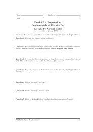
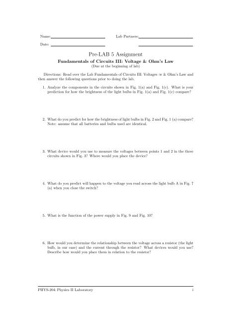
Name:<strong>Lab</strong> Partners:Date:<strong>Pre</strong>-LAB 5 AssignmentFundamentals of Circuits III: <strong>Voltage</strong> & Ohm’s Law(Due at the beginning of <strong>lab</strong>)Directions: Read over the <strong>Lab</strong> Fundamentals of Circuits III: <strong>Voltage</strong>s :w & Ohm’s Law andthen answer the following questions prior to doing the <strong>lab</strong>.1. Analyze the components in the circuits shown in Fig. 1(a) and Fig. 1(c). What is yourprediction for how the brightness of the light bulbs in Fig. 1(a) and Fig. 1(c) compare?2. WhatdoyoupredictforhowthebrightnessoflightbulbsinFig.2andFig.1(a)compare?Note: assume that all batteries and bulbs used are identical.3. What device would you use to measure the voltages between points 1 and 2 in the threecircuits shown in Fig. 3? Where would you place the device?4. What do you predict will happen to the voltage you read across the light bulb A in Fig. 7(a) when you close the switch?5. What is the function of the power supply in Fig. 9 and Fig. 10?6. How would you determine the relationship between the voltage across a resistor (the lightbulb, in our case) and the current through the resistor? What devices would you use?Describe how would you place them in relation to the resistor?PHYS-204:Physics II <strong>Lab</strong>oratoryi
Name:<strong>Lab</strong> Partners:Date:ObjectivesLAB 5Fundamentals of Circuits III: <strong>Voltage</strong> & Ohm’s Law• Tofurtherourunderstandingoftheconceptofpotentialdifference(voltage)andtoexplainthe role of a power supply in a circuit.• To understand how potential difference (voltage) varies across the components in a circuitinvolving resistors that are connected in series.• To understand how potential difference (voltage) varies across the components in a circuitinvolving resistors that are connected in parallel.• To understand the quantitative relationship between the potential difference across aresistor and current through the resistor, and to understand the difference between componentsthat obey Ohm’s Law (Ohmic) and the components that do not obey Ohm’s Law(non-Ohmic).This <strong>lab</strong> has been adapted from the Real Time Physics Active Learning <strong>Lab</strong>oratories [?].The goals, guiding principles and procedures of this <strong>lab</strong>s parallel the implementation found inthe work of those authors [?, ?, ?].OverviewIn previous <strong>lab</strong> activities you examined currents through different elements in series and parallelcircuits. You saw that in a series circuit, the current is the same through all elements, and thatin a parallel circuit, the current is distributed among the branches in such a way that the totalcurrent through the battery equals the sum of the currents in each branch. You also saw thatin circuits with two or more parallel branches connected directly across a battery, making achange in one branch does not affect the current in the other branch or branches, while in seriescircuits, making a change in one part of the circuit changes the current in all parts of that seriescircuit.You also saw that connecting multiple light bulbs in series results in alarger net resistance tocurrent and therefore a smaller current results in the circuit, while adding multiple light bulbsin parallel results in a smaller net resistance in the circuit and consequently a larger current.You have also learned about electric potential difference, or <strong>Voltage</strong>, and its relationship towork. In this <strong>lab</strong>, you will establish that a battery produces an electric potential difference,and that this potential difference can cause a current in a circuit. You will then compare thepotential differences (voltages) across different parts of series and parallel circuits. In the lastpart of this <strong>lab</strong> you will explore the quantitative relationship between the current through aresistor and the potential difference (voltage) across the resistor and arrive at a mathematicalrelationship between current, voltage and resistance. When this relationship is a linear one, itis known as Ohm’s law.PHYS-204:Physics II <strong>Lab</strong>oratory 1
Fundamentals of Circuits III: <strong>Voltage</strong> & Ohm’s Law v 0.1Investigation 1:Batteries and <strong>Voltage</strong>s in Series CircuitsIn previous <strong>lab</strong>s on the fundamentals of circuits, you developed a current model and utilizedthe concept of resistance to explain the relative brightness of bulbs in simple circuits. Yourmodel says that when a battery is connected to a circuit that provides a closed path, there is acurrent in the circuit. For a given battery, the magnitude of the current depends on the totalresistance of the circuit. In this <strong>lab</strong> you will investigate how adding batteries in series and inparallel changes the potential differences (voltages) between various points in circuits.In order to do this you will need the following items:• Computer with Logger-Pro software• <strong>Lab</strong> Pro interface• two voltage probes• Two 1.5 V D cell battery with holder• connecting wires• alligator clips• Two #14 bulbs in sockets• contact switchIn a previous <strong>lab</strong> you saw what happens to the brightness of a bulb in the circuit shown inFig. 1(a) if you add another bulb in series as shown in circuit 1(b). Neither of the two bulbs isas bright as the original bulb. Adding another bulb (resistor) to the first one in series increasedthe overall resistance in the circuit has increased, resulting in less current through the bulbs.SSS+−A+−BC+−+−BC(a)(b)(c)Figure 1: Series circuits with (a) one battery and one bulb, (b) one battery and two bulbs and(c) two batteries and two bulbs. (All batteries and all bulbs are identical.)<strong>Pre</strong>diction 1.1 What do you predict would happen to the brightness of the two bulbs if youadded a second battery in series with the first at the same time that you added the second bulbas in Fig. 1 (c)? How would the brightness of bulb A in circuit 1 (a) compare to bulb B incircuit 1(c) and to to bulb C?PHYS-204:Physics II <strong>Lab</strong>oratory 2
Fundamentals of Circuits III: <strong>Voltage</strong> & Ohm’s Law v 0.1Activity 1.1: Battery ActionStep 1: Set up the circuit as shown in Fig. 1(a), and examine how bright the bulb is.Step 2: Now set up the circuit as shown in Fig. 1 (c). (Make sure that the batteries are connectedin series – this means that the positive terminal of one battery must be connectedto the negative terminal of the other.)Question 1.1 Compare the brightness of the bulbs in circuit of Fig. 1 (c) with that ofthe bulb in Fig. 1(a).Question 1.2 What do you deduce about the quantitative relationship between the currentin the two-bulb, two-battery circuit as compared with that in the single-bulb, single-batterycircuit? Explain.Question 1.3 What happens to the overall resistance of the circuit as more bulbs areadded in series? What do you need to do if you want to keep the current the same?<strong>Pre</strong>diction 1.2 How in your opinion would the the brightness of bulb D in Fig. 2 comparewith the brightness of bulb A in Fig. 1(a)? Explain your reasoning.S+−D+−Figure 2: Series circuit with two batteries and one bulbPHYS-204:Physics II <strong>Lab</strong>oratory 3
Fundamentals of Circuits III: <strong>Voltage</strong> & Ohm’s Law v 0.1Step 3: Connect the circuit in Fig. 2. Close the switch only for a moment to observe thebrightness of the bulb to avoid burning out the bulb.Question 1.4 Compare the brightness of bulb D to bulb A in the single bulb circuit with onlyone battery [Fig. 1(a)].Question 1.5 How does connecting more than one battery in series affect the current in aseries circuit?The voltage marked on a new battery is actually a measure of the electromotive force (emf)or electric potential difference between its terminals. The term voltage is often used in everydayusage but the precise term and one you should try to use in a physics <strong>lab</strong> is emf or potentialdifference.In the following exercise, we explore the potential differences obtained by connecting batteriesand bulbs in series and parallel circuits. We will try to come up with rules for them throughexercises analogous to what we did in earlier exercises for currents.We will investigate what is the resulting potential difference of two batteries when thebatteries are connected (i) in series (ii) in parallel. Figs. 3(a), (b) and (c) illustrate these casesand show a single battery, two identical batteries connected in series, and two identical batteriesconnected in parallel.(a)1(b)1(c)1++−++−+−−−222Figure 3: Identical batteries (a) single, (b) two connected in series and (c) two connected inparallel.<strong>Pre</strong>diction 1.3 Given the potential difference between points 1 and 2 in Fig. 3 (a), predictwhat the potential difference between points 1 and 2 would be in Fig. 3 (b) (series connection)and in 3 (c) (parallel connection). Explain your prediction.PHYS-204:Physics II <strong>Lab</strong>oratory 4
Fundamentals of Circuits III: <strong>Voltage</strong> & Ohm’s Law v 0.1Activity 1.2: Batteries in Series and ParallelThe predictions you make can be tested by measuring potential differences with the voltageprobes connected across the two points you want to measure the potential difference betweenas shown in Fig. 4.VP1(a)++A−−+−+−BVP2(b)VP1AB++−−+−+VP2VP1(c)++A−−++−BVP2−−Figure 4: <strong>Voltage</strong> probes connected to measure the potential difference across (a) single batteries,(b) a single battery and two batteries connected in series, and (c) a single battery andtwo batteries connected in parallel.Step 1: Open the experiment file L4A1-2 (Batteries).Step 2: Zero the probes. Make sure that they are not connected to anything.Step 3: Connect voltage probe l across a single battery (as in Fig. 4 (a) and voltage probe 2across the other battery.Step 4: Record the potential difference measured for each battery below.Potential difference of battery A:Potential difference of battery B:Question 1.6 How do your measured values agree with those marked on the batteries?Step 5: Next, connect the batteries in series as in Fig. 4 (b). Now connect probe 1 so itmeasures the potential difference across battery A and connect probe 2 so it measuresthe potential difference across the series combination of the two batteries. Record yourmeasurements below.<strong>Voltage</strong> of battery A:<strong>Voltage</strong> of A and B in series:PHYS-204:Physics II <strong>Lab</strong>oratory 5
Fundamentals of Circuits III: <strong>Voltage</strong> & Ohm’s Law v 0.1Question 1.7 Do your measured values agree with your predictions? How do you explainany differences?Step 6: Next, connect the batteries in parallel as in Fig. 4(c). Connect probe 1 so it measuresthe potential difference across battery A and connect probe 2 so it measures the potentialdifference across the parallel combination of the two batteries. Record your measurementsbelow.<strong>Voltage</strong> of battery A:<strong>Voltage</strong> of A and B in parallel:Question 1.8 Do your measured values agree with your predictions? How do you explainany differences?Question 1.9 Now, based on your observations, deduce a rule for the combined potentialdifference (voltage) of a number of identical batteries connected in series.Question 1.10 Next, also based on your observations, deduce a rule for the combinedpotential difference (voltage) of a number of identical batteries connected in parallel.Activity 1.3: <strong>Voltage</strong>s in Series CircuitsNow let’s learn about the potential difference across different parts of a simple series circuit.We begin with the circuit with two bulbs in series with a battery, which you looked at in a <strong>Lab</strong>4, Activities 1-1 and 1-2. It is shown in Fig. 5(a).<strong>Pre</strong>diction 1.4 If you have two identical bulbs A and B, predict how the potential difference(voltage) across bulb A in Fig. 5 (b) will compare to the potential difference across the battery.Do the same for bulb B. How does the potential difference across the series combination of bulbsA and B compare with the potential difference across the battery?Test your prediction.PHYS-204:Physics II <strong>Lab</strong>oratory 6
Fundamentals of Circuits III: <strong>Voltage</strong> & Ohm’s Law v 0.1+B+A++−CVP1−−BVP2(a)(b)−Figure 5: (a) A series circuit with one battery and two bulbs, and (b) the same circuit withvoltage probe 1 connected to measure the potential difference across the battery and probe 2connected to measure the potential difference across the series combination of bulbs A and B.Step 1: Use the same experiment file L4A1-2 (Batteries) that you used in the previous activity.Step 2: Zero both probes with nothing connected to them.Step 3: Connect the circuit shown in Fig. 5(b).Comment: Always zero current and voltage probes without connecting them to anythingbefore you start taking measurements.Step 4: Measure the potential differences and record your readings below.Potential difference across the battery:Potential difference across bulbs A and B in series:Question 1.11 How do the two potential differences compare? How did your observationscompare with what you predicted?Step 5: Connect the voltage probes as in Fig. 6 to measure the potential difference across bulbA and across bulb B. Record your measurements below.Potential difference across bulb A:Potential difference across bulb B:Question 1.12 Did your measurements agree with your predictions?PHYS-204:Physics II <strong>Lab</strong>oratory 7
Fundamentals of Circuits III: <strong>Voltage</strong> & Ohm’s Law v 0.1+A+−VP1−+B−VP2Figure 6: Connection of voltage probes to measure the potential difference across bulb A andacross bulb B.Question 1.13 Now, based on your observations, deduce a rule for how the potential differenceacross individual bulbs connected in series relate to the total potential difference across thecombination of the bulbs. How is this related to the potential difference supplied by the battery?Investigation 2:<strong>Voltage</strong> in Parallel CircuitsWe will also need to learn about the potential differences across different parts of a simpleparallel circuit. Let’s begin with the circuit with two bulbs in parallel with a battery. Youlooked at this circuit in a previous <strong>lab</strong>. It is shown in Fig. 7(a).SS+++−ABVP1+−−A−VP2B(a)(b)Figure 7: (a) Parallel circuit with two bulbs and a battery, and (1)) same circuit with voltageprobe 1 connected to measure the potential difference across the battery and probe 2 connectedto measure the potential difference across bulb A.<strong>Pre</strong>diction 2.1 What do you predict will happen to the potential difference across the batterywhen you close the switch in Fig. 7(a)? Will it increase, decrease or remain essentially thesame? Explain.<strong>Pre</strong>diction 2.2 With the switch in Fig. 7(a) closed, how will the potential difference acrossbulb A compare to the potential difference of the battery? How will the potential difference acrossbulb B compare to the potential difference of the battery?PHYS-204:Physics II <strong>Lab</strong>oratory 8
Fundamentals of Circuits III: <strong>Voltage</strong> & Ohm’s Law v 0.1To test your predictions you will need:• Computer with Logger-Pro software• <strong>Lab</strong> Pro interface• Two voltage probes• 1.5 V D cell battery with holder• connecting wires• alligator clips• Two #14 bulbs in sockets• contact switchActivity 2.1: <strong>Voltage</strong>s in a parallel CircuitStep 1: The experiment file L4A1-2 (Batteries) should still be open, and the axes that followshould be on the screen.<strong>Voltage</strong> 2 (V)<strong>Voltage</strong> 1(V)Time (s)Step 2: Zero both probes with nothing connected to them.Step 3: Connect the circuit shown in Fig. 7(b).Step 4: Begin graphing, and then close and open the switch as you have done before.Step 5: Sketch the graphs on the axes above.Step 6: Read the voltages using the analysis feature of the software.Switch open:<strong>Voltage</strong> across battery: <strong>Voltage</strong> across bulb A:Switch closed:<strong>Voltage</strong> across battery: <strong>Voltage</strong> across bulb A:PHYS-204:Physics II <strong>Lab</strong>oratory 9
Fundamentals of Circuits III: <strong>Voltage</strong> & Ohm’s Law v 0.1Question 2.1 Did your measurements agree with your predictions? Did closing andopening the switch significantly affect the potential difference across the battery (by morethan several %? Did it significantly affect the potential difference across bulb A?Step 7: Connect the voltage probes as shown in Fig. 8. Measure and graph the individualpotential differences across bulb A and bulb B. Again close and open the switch whilegraphing.S+++−VP1A−B−VP2Figure 8: <strong>Voltage</strong> probes connected to measure the potential differences across bulbs A and B.Step 8: Sketch your graphs on the axes below.<strong>Voltage</strong> 2 (V)<strong>Voltage</strong> 1(V)Time (s)Step 9: Record your measurements using the analysis feature of the software.Switch open:<strong>Voltage</strong> across bulb A: <strong>Voltage</strong> across bulb B:Switch closed:<strong>Voltage</strong> across bulb A: <strong>Voltage</strong> across bulb B:PHYS-204:Physics II <strong>Lab</strong>oratory 10
Fundamentals of Circuits III: <strong>Voltage</strong> & Ohm’s Law v 0.1Question 2.2 Did your measurements agree with your predictions? Did closing andopening the switch significantly affect the potential difference across bulb A (by more thanseveral %?Question 2.3 Did closing and opening the switch significantly affect the potential differenceacross bulb B by more than several %? Under what circumstances is there a potentialdifference across a bulb?Question 2.4 Based on your observations, deduce a rule for the potential differences acrossdifferent branches of a parallel circuit. How do these relate to the potential difference across thebattery?Question 2.5 In analyzing your observations, would you deduce that the battery is a constantcurrent source which delivers essentially a fixed amount of current regardless of the componentsconnected to it or would you deduce that it is a constant voltage source which essentially appliesa fixed potential difference regardless of the circuit connected to it or do you think that neitherdeductions necessarily follow from your observations? Explain, based on your observations inthis and the previous <strong>lab</strong>.Question 2.6 What is the potential difference between two points on a short length of wirewhen there is no bulb, battery or resistor between the points? You may assume that the wirehas negligible resistance.Investigation 3:Ohm’s LawWhat is the relationship between current and potential difference? You have observed in previousinvestigations that there is a potential difference across a bulb or resistor only when thereis a current through that circuit element. So how does the potential difference depend on thecurrent? In order to examine this, you will need the following:• Computer with Logger-Pro software• <strong>Lab</strong> Pro interface• voltage probe• current probe• variable DC power supply• 10 Ohm resistorPHYS-204:Physics II <strong>Lab</strong>oratory 11
Fundamentals of Circuits III: <strong>Voltage</strong> & Ohm’s Law v 0.1• connecting wires• alligator clipsThe circuit shown below contains a power supply. A power supply has the same purposeas a battery. Both raise the potential energy of the electric charges that flow through them;the battery uses chemical energy to do this, while the power supply uses electrical energy. Avariable DC power supply lets you adjust the potential difference. When you turn the dial, youchange the voltage between its terminals. Therefore, this circuit allows you to measure how thecurrent through the resistor varies as you change the potential difference across it.CP2DC Power Supply+−+ −+−VP1Figure 9: Circuit with a variable power supply to explore the relationship between current andpotential difference for a resistor.<strong>Pre</strong>diction 3.1 What will happen to the current through the resistor as you increase the appliedvoltage from zero?<strong>Pre</strong>diction 3.2 What will happen to the potential difference across the resistor as the currentthrough it increases from zero?<strong>Pre</strong>diction 3.3 What do you predict for the mathematical relationship between the potentialdifference across the resistor and the current through the resistor?Activity 3.1: Current and Potential Difference for a ResistorStep 1: Open the experiment file called L4A3-1 (Ohm’s Law).Step 2: Zero both probes with nothing connected to them.Step 3: Be sure the power supply is turned off. Also, check to see that the voltage control(the knob on the left) is turned down all the way (counter clockwise). Connect the circuitin Fig. 9. Note that the current probe is connected to measure the current through theresistor, and the voltage probe is connected to measure the potential difference across theresistor.Step 4: Turn on the power supply. Begin graphing current and voltage starting with the powersupply set to zero voltage, and graph as you turn the voltage control up slowly to about3 volts.Warning: Do not exceed 3 volts!PHYS-204:Physics II <strong>Lab</strong>oratory 12
Fundamentals of Circuits III: <strong>Voltage</strong> & Ohm’s Law v 0.1Question 3.1 What happened to the current in the circuit as the power supply voltagewas increased? How did this compare with your prediction?Question 3.2 How did the potential difference across the resistor change as the currentthrough the resistor changed? How did this compare with your prediction?Step 5: You can display axes for voltage vs. current on the top graph. Click on the word timebelow the horizontal axis, then select current in the dialog box that comes up. Close thedialog box. You will also need to change the maximum value on the horizontal axis. 0.5A would be an appropriate value. The axes should now appear as shown below.<strong>Voltage</strong> 1(V)Current 2 (A)Current 2 (A)Time (s)Reminder: We are interested in the mathematical relationship between the voltage acrossthe resistor and the current through the resistor. This can be determined from the graphby drawing a smooth curve that fits the plotted data points. Some definitions of possiblemathematical relationships are shown below. In these examples, y might be the voltagereading and x the current.PHYS-204:Physics II <strong>Lab</strong>oratory 13
Fundamentals of Circuits III: <strong>Voltage</strong> & Ohm’s Law v 0.1yyyxxxy is a function of x, whichincreases as x increases.y is a linear function ofx which increases as xincreases according to themathematical relationshipy = mx + b, where b isa constant called the yintercept.y is proportional to x. Thisis a special case of a linearrelationship where y = mx,and b, the y intercept, iszero.These graphs show the differences between these three types of mathematical relationship.y canincreaseasxincreases, andtherelationshipdoesn’thavetobelinearorproportional.Proportionality refers only to the special linear relationship where the y intercept is zero,as shown in the example graph on the right.Step 6: Usethefitroutineinthesoftware toseeiftherelationshipbetweenvoltage andcurrentfor a resistor is a proportional one.Step 7: Sketch your graphs on the axes shown previously.Question 3.3 Describe in words, what the mathematical relationship between the potentialdifference across a resistor and the current through that resistor is. Explain, based on yourgraphs.When the relationship between potential difference and current for a resistor is linear, itmeans that current changes proportionally to the change in voltage and the value of this proportionalitydoes not change no matter what the voltage is. When such a linear relationshipexists between current and voltage, the mathematical relationship between current and voltageis known as Ohm’s law. We now define a quantity known as resistance. Resistance is definedas the slope of the voltage vs. current graph.If potential difference is measured in volts and current is measured in amperes, then theunit of resistance is the Ohm, which is usually represented by the Greek letter ”omega” Ω.Question 3.4 Write a mathematical equation that expresses the relationship between V, I, andR.PHYS-204:Physics II <strong>Lab</strong>oratory 14
Fundamentals of Circuits III: <strong>Voltage</strong> & Ohm’s Law v 0.1Question 3.5 Based on your graph, what can you say about the value of R for a resistor–is itconstant or does it change as the current through the resistor changes? Explain.Question 3.6 From the slope of your graph, what is the experimentally determined value of theresistance of your resistor in ohms? How does this agree with the value written on the resistor?(Remember that your resistance has a tolerance coded on it.)Note: Not all circuit elements obey Ohm’s law. The definition for resistance is still thesame as the relation you obtained, but the resistance changes as the current changes. Circuitelements that follow Ohm’s law–like resistors–are said to be ohmic, circuit elements that do notare called non-ohmic.In the last activity you explored the relationship between the potential difference across aresistor and the current through the resistor. It is a proportional relationship. In the followingextension you will explore the relationship between current and potential difference for a lightbulb instead of a resistor.Extension 3-2: Relationship between Current and Potential Differencefor a Light BulbStep 1: Connect a light bulb in the place of the resistor, as shown in the circuit in Fig. 10.CP2DC Power Supply+−+ −+−VP1Figure 10: Circuit with a variable power supply to explore the quantitative relationship betweenthe current and potential difference for a light bulb.<strong>Pre</strong>diction 3.4 What do you predict will happen to the brightness of the bulb as you turnthe dial on the power supply and increase the voltage from zero? Explain.<strong>Pre</strong>diction 3.5 What do you predict for the mathematical relationship between the voltageacross the bulb and the current through the bulb?PHYS-204:Physics II <strong>Lab</strong>oratory 15
Fundamentals of Circuits III: <strong>Voltage</strong> & Ohm’s Law v 0.1Step 2: <strong>Pre</strong>pare to graph current vs. time with current probe 1 and voltage vs. time withvoltage probe 2. (Adjust the horizontal axis on the top graph back to time, and adjustthe horizontal scale to give a range from 0 to 30 seconds).Step 3: Begin graphing with the power supply set to zero voltage, and graph current andvoltage as you turn the dial and increase the voltage slowly to about 3 volts.Warning: Do not exceed 3 volts, since this may burn out the bulb! Also,return the voltage of the power supply to zero as soon as you are done withyour measurements.Question E3.1 What happened to the brightness of the bulb as the power supply voltagewas increased? How did this compare with your prediction?Question E3.2 How is the brightness of the bulb related to the potential difference acrossthe bulb? To the current through the bulb?Step 4: You can again display a graph of potential difference vs. current by changing thevariable on the horizontal axis on the bottom graph to current as before.<strong>Voltage</strong> 1(V)Current 2 (A)Current 2 (A)Time (s)Question E3.3 Compare your graph of voltage vs. current for the bulb to that for theresistor in the previous activity. In what ways are they similar, and in what ways are theydifferent?Step 5: Use the fit routine in the software to determine if the relationship between voltageand current for a light bulb is a proportional one.Step 6: Sketch the graphs, or print and affix them over the axes.PHYS-204:Physics II <strong>Lab</strong>oratory 16
Fundamentals of Circuits III: <strong>Voltage</strong> & Ohm’s Law v 0.1Question E3.4 Based on your graph of voltage vs. current for a bulb, what can yousay about the value of the resistance R for a bulb–is it constant or does it change as thecurrent through the bulb changes? Explain.Question E3.5 Is a light bulb an ohmic device? Explain.This <strong>lab</strong>oratory exercise has been adapted from the references below.PHYS-204:Physics II <strong>Lab</strong>oratory 17