Pre-LAB 4 Assignment Fundamentals of Circuits II: Currents ...
Pre-LAB 4 Assignment Fundamentals of Circuits II: Currents ...
Pre-LAB 4 Assignment Fundamentals of Circuits II: Currents ...

You also want an ePaper? Increase the reach of your titles
YUMPU automatically turns print PDFs into web optimized ePapers that Google loves.
Name:<br />
Lab Partners:<br />
Date:<br />
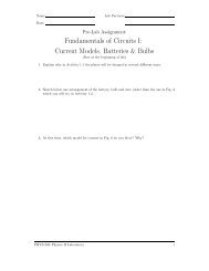
<strong>Pre</strong>-<strong>LAB</strong> 4 <strong>Assignment</strong><br />
<strong>Fundamentals</strong> <strong>of</strong> <strong>Circuits</strong> <strong>II</strong>:<br />
<strong>Currents</strong> & <strong>Circuits</strong><br />
(Due at the beginning <strong>of</strong> lab)<br />
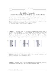
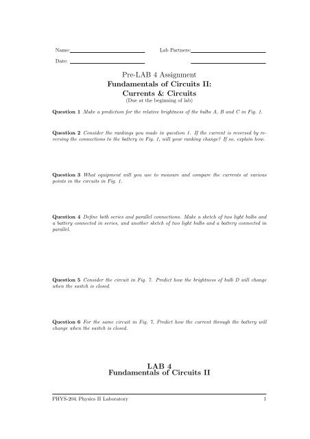
Question 1 Make a prediction for the relative brightness <strong>of</strong> the bulbs A, B and C in Fig. 1.<br />
Question 2 Consider the rankings you made in question 1. If the current is reversed by reversing<br />
the connections to the battery in Fig. 1, will your ranking change? If so, explain how.<br />
Question 3 What equipment will you use to measure and compare the currents at various<br />
points in the circuits in Fig. 1.<br />
Question 4 Define both series and parallel connections. Make a sketch <strong>of</strong> two light bulbs and<br />
a battery connected in series, and another sketch <strong>of</strong> two light bulbs and a battery connected in<br />
parallel.<br />
Question 5 Consider the circuit in Fig. 7. <strong>Pre</strong>dict how the brightness <strong>of</strong> bulb D will change<br />
when the switch is closed.<br />
Question 6 For the same circuit in Fig. 7, <strong>Pre</strong>dict how the current through the battery will<br />
change when the switch is closed.<br />
<strong>LAB</strong> 4<br />
<strong>Fundamentals</strong> <strong>of</strong> <strong>Circuits</strong> <strong>II</strong><br />
PHYS-204:Physics <strong>II</strong> Laboratory 1
<strong>Fundamentals</strong> <strong>of</strong> <strong>Circuits</strong> <strong>II</strong>: <strong>Currents</strong> & <strong>Circuits</strong> v 0.3<br />
Objectives<br />
• To understand current in a circuit where a battery lights a bulb.<br />
• To understand series connections in an electric circuit.<br />
• To understand the relationship between the current in all parts <strong>of</strong> a series circuit.<br />
• To understand the meaning <strong>of</strong> parallel connections in an electric circuit.<br />
• To understand the relationship between the currents in all parts <strong>of</strong> a parallel circuit.<br />
• To begin to understand the concept <strong>of</strong> resistance.<br />
Overview<br />
In the previous lab you found that a bulb only lights when there is an electric current passing<br />
through the bulb. You also found that the bulb must be connected to a battery in a complete,<br />
continuous circuit in order for there to be a current. Specifically, there must be a continuous<br />
connection from the positive terminal <strong>of</strong> the battery, through the connecting wire to the bulb,<br />
through the bulb, through the connecting wire to the negative terminal <strong>of</strong> the battery and<br />
through the battery.<br />
Recall that you measured the current both as it entered current elements like a battery or<br />
a bulb and when it left. From these measurements you discovered that the electric current<br />
flowing out <strong>of</strong> a device is equal to the current flowing into it. These devices did not seem to<br />
“use up” any current which passed through. Current it seems doesn’t just disappear. This<br />
suggests that electrical current is the flow <strong>of</strong> some conserved quantity i.e., electric charge. In<br />
addition, by measuring voltage in circuits with one bulb and with two bulbs you observed that<br />
the potential difference (voltage) across a battery (if one can neglect its internal resistance) is<br />
fairly constant whether it is connected to one light bulb or two. In other words, the voltage <strong>of</strong><br />
a battery is a property <strong>of</strong> the battery and not <strong>of</strong> the circuit.<br />
By contrast, you found that adding a second bulb in series to the first lead to a decrease in<br />
the current. Circuit elements like bulbs provide a resistance to electrical currents. The total<br />
resistance <strong>of</strong> a circuit determines the current when the circuit is connected to a battery. The<br />
larger the resistance, the smaller the current.<br />
In this lab we will consider more complicated circuits in order to extend and reinforce what<br />
we have learned previously. You will be comparing currents at different points in these circuits<br />
by making measurements using current probes and by comparing the brightness <strong>of</strong> bulbs. This<br />
lab has been adapted from the Real Time Physics Active Learning Laboratories [?]. The goals,<br />
guiding principles and procedures <strong>of</strong> this labs closely parallel the implementation found in the<br />
work <strong>of</strong> those authors [?, ?, ?].<br />
Investigation 1:<br />
Current in Series <strong>Circuits</strong><br />
In the spirit <strong>of</strong> scientific discovery, you will make a series <strong>of</strong> predictions about currents in<br />
various circuits. Afterwords, you will compare these predictions with measurements and observations.<br />
If you find that your experimental measurements and/or observations disagree with<br />
your predictions you should identify which if any <strong>of</strong> the assumptions which lead you to your<br />
PHYS-204:Physics <strong>II</strong> Laboratory 2
<strong>Fundamentals</strong> <strong>of</strong> <strong>Circuits</strong> <strong>II</strong>: <strong>Currents</strong> & <strong>Circuits</strong> v 0.3<br />
initial prediction have been shown to be false. Subsequently, you should develop and adopt new<br />
concepts which are consistent with the results <strong>of</strong> your measurements.<br />
Our fist activity requires the following equipment:<br />
• Computer with Logger-Pro s<strong>of</strong>tware<br />
• Lab Pro interface<br />
• two current probes<br />
• Two 1.5 V D cell battery with holder<br />
• connecting wires<br />
• alligator clips<br />
• Two #14 bulbs in sockets<br />
• contact switch<br />
Note: the battery holder, light bulbs and contact switch are part <strong>of</strong> the Pasco circuit board.<br />
B<br />
+<br />
−<br />
A<br />
+<br />
−<br />
C<br />
(a)<br />
(b)<br />
Figure 1: Two different circuits: (a) a battery with a single bulb and (b) a battery with two<br />
bulbs. All three bulbs are identical.<br />
<strong>Pre</strong>diction 1.1 Consider the two circuits shown in Fig. 1. <strong>Pre</strong>dict the relative brightness <strong>of</strong><br />
the three bulbs shown in Figs 1(a) and 1(b) from brightest to dimmest. In making this prediction<br />
you should assuming that the batteries and bulbs have identical characteristics. (Recall that the<br />
voltage across a battery is essentially independent <strong>of</strong> the number <strong>of</strong> bulbs it is connected to.) In<br />
your prediction you should identify which bulbs, if any, are equal in brightness. Hint: Helpful<br />
symbols are > ”is greater than”, < ”is less than”, = ”is equal to,” for example B > C = A.<br />
PHYS-204:Physics <strong>II</strong> Laboratory 3
<strong>Fundamentals</strong> <strong>of</strong> <strong>Circuits</strong> <strong>II</strong>: <strong>Currents</strong> & <strong>Circuits</strong> v 0.3<br />
Transistor Socket<br />
Batteries Holders<br />
Switch<br />
Bulb Sockets<br />
Potentiometer<br />
Inductor<br />
+<br />
A B C<br />
L = 8mH<br />
−<br />
E<br />
B<br />
C<br />
+<br />
−<br />
Figure 2: One possible way <strong>of</strong> wiring the circuit in Fig. ?? on the Pasco circuit board. An<br />
Annotated picture <strong>of</strong> the Pasco circuit board can be found in the appendix <strong>of</strong> this lab handout.<br />
Activity 1.1: The Relative Brightness <strong>of</strong> Bulbs<br />
Step 1: Connect the circuits in Fig. 1, observe the relative brightness <strong>of</strong> the bulbs, and rank<br />
the bulbs in order <strong>of</strong> the brightness you actually observed.<br />
Comment from Real-Time Physics:<br />
“These activities assume identical bulbs. Differences in brightness may arise if the bulbs<br />
are not exactly identical. In this and later activities, to determine whether a difference in<br />
brightness is caused by a difference in the currents through the bulbs or by a difference<br />
in the bulbs, you should exchange the bulbs. Sometimes a bulb will not light noticeably,<br />
even if there is a small but significant current through it. If a bulb is really <strong>of</strong>f, that is,<br />
if there is no current through it, then unscrewing the bulb will not affect the rest <strong>of</strong> the<br />
circuit. To verify whether a non-glowing bulb actually has a current through it, unscrew<br />
the bulb and see if anything else in the circuit changes.”<br />
Observed ranking <strong>of</strong> the brightness <strong>of</strong> the bulbs:<br />
Question 1.1 Do your observations and your predictions agree? If not, identify any<br />
assumption(s) that you have now shown to be false.<br />
PHYS-204:Physics <strong>II</strong> Laboratory 4
<strong>Fundamentals</strong> <strong>of</strong> <strong>Circuits</strong> <strong>II</strong>: <strong>Currents</strong> & <strong>Circuits</strong> v 0.3<br />
<strong>Pre</strong>diction 1.2 Consider reversing the batteries in the circuits shown in Fig. 1. What<br />
will happen to the brightness <strong>of</strong> bulbs A, B and C if the positive and negative terminals <strong>of</strong><br />
the battery are reversed? Explain the reason(s) for your prediction.<br />
Step 2: Test your prediction by reversing the terminals <strong>of</strong> the battery in each <strong>of</strong> your circuits.<br />
Question 1.2 Did your observation agree with your prediction? Explain. Identify any assumptions(s)<br />
which you have now falsified.<br />
Question 1.3 Considering the observations you have made above, without knowing how the<br />
battery is hooked up, does the brightness <strong>of</strong> the bulbs tell you what the direction <strong>of</strong> the current<br />
is? Explain.<br />
Activity 1.2: Current in a Simple Circuit with Bulbs<br />
This activity is designed to further investigate how a bulb and a series <strong>of</strong> bulbs affects the<br />
current in a circuit.<br />
<strong>Pre</strong>diction 1.3 How do you predict the currents going through each <strong>of</strong> the bulbs in Fig. 1 will<br />
compare? Write down your predicted rankings <strong>of</strong> the currents through bulbs A, B and C, and<br />
explain your reasoning.<br />
You will test your prediction by using current probes. We want the current probe to measure<br />
the current which goes through a bulb. Therefore we must connect the current probes so that<br />
the current which passes through a bulb also passes through the current probe. Study Fig. 3<br />
and convince yourself that the the current probes there measure the currents as described in<br />
the figure caption.<br />
Real-Time Physics Comment: “In carrying out your measurements, it is important to realize<br />
that the measurements made by the current probes are only as good as their calibrations. Small<br />
differences in calibration can result in small differences in readings.”<br />
Step 1: Open the file L2A1-2 (Two <strong>Currents</strong>). You should see two sets <strong>of</strong> current axes similar<br />
to the picture below.<br />
Step 2: Zero the probes with them disconnected from the circuit.<br />
PHYS-204:Physics <strong>II</strong> Laboratory 5
<strong>Fundamentals</strong> <strong>of</strong> <strong>Circuits</strong> <strong>II</strong>: <strong>Currents</strong> & <strong>Circuits</strong> v 0.3<br />
S<br />
S<br />
+<br />
CP1<br />
−<br />
B<br />
+<br />
CP1<br />
−<br />
+<br />
−<br />
A<br />
+<br />
−<br />
+<br />
CP2<br />
−<br />
+<br />
CP2<br />
−<br />
C<br />
(a)<br />
(b)<br />
Figure 3: Current probes connected to measure the current through bulbs. In circuit (a), CP1<br />
measures the current into bulb A, and CP2 measures the current out <strong>of</strong> bulb A. In circuit (b),<br />
CP1 measures the current into bulb B while CP2 measures the current out <strong>of</strong> bulb B and the<br />
current into bulb C.<br />
Step 3: Connect circuit shown in Fig. 3(a).<br />
Step 4: Begin graphing. Close the switch for a second or so, open it for a second or so and<br />
then close it again. Sketch your graphs on the axes provided below.<br />
Current 2 (A)<br />
Current 1(A)<br />
Time (s)<br />
Step 5: Use the analysis feature <strong>of</strong> the s<strong>of</strong>tware to measure the currents into and out <strong>of</strong> bulb<br />
A when the switch is closed: Measure the current at points where the current is steady,<br />
not at the spike that appears at the moment the switch is closed.<br />
Current into bulb A: Current out <strong>of</strong> bulb A:<br />
Question 1.4 How does the current into bulb A compare to the current which comes out<br />
<strong>of</strong> bulb A? Are they equal, or do they differ by an amount which is larger than can be<br />
explained by the calibration <strong>of</strong> the current probes. What can you say about the direction<br />
<strong>of</strong> the current on either side <strong>of</strong> the bulb? Is this what you expected? Explain.<br />
PHYS-204:Physics <strong>II</strong> Laboratory 6
<strong>Fundamentals</strong> <strong>of</strong> <strong>Circuits</strong> <strong>II</strong>: <strong>Currents</strong> & <strong>Circuits</strong> v 0.3<br />
Step 6: Connect circuit shown in Fig. ??(b). Begin graphing current as above, and record the<br />
measured values <strong>of</strong> the currents.<br />
Current through bulb B: Current through bulb C:<br />
Step 7: Sketch the graphs on the axes provided:<br />
Current 2 (A)<br />
Current 1(A)<br />
Time (s)<br />
Question 1.5 Consider your observation <strong>of</strong> the circuit shown in Fig. 3(b). Was any current<br />
”used up” in the first bulb or is it the same in both bulbs? Explain, based on your observations.<br />
Question 1.6 Do the measured values <strong>of</strong> the currents in bulbs A, B and C agree with your<br />
predicted ranking? If not, explain what assumption(s), if any, you have now shown to be false.<br />
Question 1.7 Based on your measurements and observations, how does the brightness <strong>of</strong> a<br />
bulb depend on the current passing through it?<br />
Question 1.8 Compare the current produced by the battery when there is a single bulb in the<br />
circuit,as in Fig 1(a), to the current produced by the battery when there are two bulbs,as in Fig<br />
1(b). How did the addition <strong>of</strong> a second bulb affect the current through in the circuit? Explain.<br />
Question 1.9 These observations suggest that we think <strong>of</strong> the bulb as providing a resistance<br />
PHYS-204:Physics <strong>II</strong> Laboratory 7
<strong>Fundamentals</strong> <strong>of</strong> <strong>Circuits</strong> <strong>II</strong>: <strong>Currents</strong> & <strong>Circuits</strong> v 0.3<br />
to the current in a circuit as opposed to something that uses up current. If each bulb provides<br />
its own resistance, how is the total resistance <strong>of</strong> a circuit is affected by the addition <strong>of</strong> bulbs as<br />
in Fig. 1(b)?<br />
Question 1.10 Create a qualitative rule which can be used to predict whether current increases<br />
or decreases as the total resistance <strong>of</strong> a circuit is increased.<br />
Real-Time Physics Comment: “The rule you have formulated based on your observations<br />
with bulbs may be qualitatively correct–correctly predicting an increase or decrease in current–<br />
but it won’t be quantitatively correct. That is, it won’t allow you to predict the exact sizes<br />
<strong>of</strong> the currents correctly. This is because the resistance <strong>of</strong> a bulb to current changes as the<br />
current through the bulb changes. Another common circuit element is a resistor. A resistor<br />
has a constant resistance to current regardless <strong>of</strong> how large the current through it. In the next<br />
activity you will reformulate your rule using resistors.”<br />
<strong>Pre</strong>diction 1.4 Fig. 4 shows circuit diagrams where the light bulbs <strong>of</strong> Fig. 1 have been replaced<br />
by identical resistors. Consider the amount <strong>of</strong> current going through each resistor in Figures<br />
4(a) and 4(b)? Rank the currents through each resistor resistors A, B and C. Explain your<br />
reasoning. (You may consider these resistors as ideal resistors: an ideal resistor has a constant<br />
resistance independent <strong>of</strong> the current passing through it.)<br />
To test your predictions, in addition to the equipment you have been using, you will need<br />
• Two 10-ohm resistors<br />
Activity 1.3: Current in a simple circuit with resistors<br />
Step 1: Continue to use the experiment file L2A1-2 (Two <strong>Currents</strong> ).<br />
Step 2: Zero the probes with them disconnected from the circuit.<br />
Step 3: Connect circuit shown in Fig. 5(a).<br />
Step 4: Withthecurrentprobes, usetheanalysisfeatureinthes<strong>of</strong>twaretomeasurethecurrent<br />
through resistor A in circuit 5(a) and the currents through resistors B and C in circuit<br />
5(b).<br />
PHYS-204:Physics <strong>II</strong> Laboratory 8
<strong>Fundamentals</strong> <strong>of</strong> <strong>Circuits</strong> <strong>II</strong>: <strong>Currents</strong> & <strong>Circuits</strong> v 0.3<br />
R B<br />
+<br />
−<br />
R A<br />
+<br />
−<br />
R C<br />
(a)<br />
(b)<br />
Figure 4: Two different circuits: (a) a battery with a single resistor, and (b) a battery with two<br />
resistors identical to the one in (a).<br />
Current through resistor A:<br />
Current through resistor B:<br />
Current through resistor C:<br />
Question 1.11 Do the measured values <strong>of</strong> the currents in resistors A, B and C agree with the<br />
ranking that you predicted? If not, can you identify what assumption(s), if any, you have now<br />
shown to be false?<br />
Question 1.12 Compare the amount <strong>of</strong> current produced by a battery which is connected to a<br />
single resistor, as in Fig. 4(a), to the amount <strong>of</strong> current produced when the battery is connected<br />
to two resistors, as in Fig. 4(b). How does the presence <strong>of</strong> the second resistor affect the current<br />
in the circuit? Explain.<br />
Question 1.13 How did your observations with resistors differ from your observations with<br />
bulbs in Activity 1.2.<br />
Question 1.14 Extrapolating from your observations, write down a quantitative formula which<br />
predicts how the current in the circuit decreases as <strong>of</strong> resistors connected in series, as shown in<br />
PHYS-204:Physics <strong>II</strong> Laboratory 9
<strong>Fundamentals</strong> <strong>of</strong> <strong>Circuits</strong> <strong>II</strong>: <strong>Currents</strong> & <strong>Circuits</strong> v 0.3<br />
S<br />
S<br />
+<br />
CP1<br />
−<br />
+<br />
CP1<br />
−<br />
R B<br />
+<br />
−<br />
R A<br />
+<br />
−<br />
+<br />
CP2<br />
−<br />
+<br />
CP2<br />
−<br />
R C<br />
(a)<br />
(b)<br />
Figure 5: Current probes connected to measure the current through resistors. In circuit (a),<br />
CP1 measures the current into resistor A, and measures the current out <strong>of</strong> resistor A. In circuit<br />
(b), CP1 measures the current into resistor B while CP2 measures the current out <strong>of</strong> resistor<br />
B and into resistor C.<br />
Fig. 4(b), increases.<br />
Question 1.15 Does the quantitative rule you formulated work for bulbs which are connected<br />
as in Figures 1 (a) and (b)? Explain.<br />
Investigation 2:<br />
Current in Parallel <strong>Circuits</strong><br />
There are two distinct ways to connect a pair <strong>of</strong> resistors, bulbs or other elements in a circuit:<br />
series and parallel. In the circuits you connected so far in this lab, the bulbs and resistors<br />
have all been connected in series. Below we summarize a more formal definition <strong>of</strong> series and<br />
parallel.<br />
PHYS-204:Physics <strong>II</strong> Laboratory 10
<strong>Fundamentals</strong> <strong>of</strong> <strong>Circuits</strong> <strong>II</strong>: <strong>Currents</strong> & <strong>Circuits</strong> v 0.3<br />
x<br />
y<br />
x<br />
Two resistors or bulbs are in series if they are connected so that the<br />
same current that passes through each. In the series connection pictured<br />
to the left, there is only one path available for a current which<br />
runs from x to y.<br />
y<br />
Two resistors or bulbs are in parallel if their terminals are connected<br />
together such that at each junction one end <strong>of</strong> a resistor or bulb is<br />
directly connected to one end <strong>of</strong> the other, as at the junctions above<br />
and below the bulbs at the left.<br />
It is important to keep in mind that in more complex circuits, say with three or more<br />
elements, not every element is necessarily connected in series or parallel with other elements.<br />
Let’s compare the behavior <strong>of</strong> a circuit with two bulbs wired in parallel to the behavior <strong>of</strong><br />
a circuit with a single bulb. (See Fig. 6.)<br />
+<br />
−<br />
A<br />
+<br />
−<br />
D<br />
E<br />
(a)<br />
(b)<br />
Figure 6: Two different circuits: (a) a single bulb circuit and (b) a circuit with two bulbs<br />
identical to the one in (a) connected in parallel to each other and in parallel to the battery.<br />
Note that if bulbs A, D and E are identical, then the circuit in Fig. 7 is equivalent to circuit<br />
6(a) when the switch is open (as shown) and equivalent to circuit 6(b) when the switch is closed.<br />
Question 2.1 Explain how you know that the caption <strong>of</strong> Fig. 7 correctly describes the circuit.<br />
<strong>Pre</strong>diction 2.1 <strong>Pre</strong>dict how the brightness <strong>of</strong> bulbs D and E in the parallel circuit <strong>of</strong> Fig. 6 (b)<br />
will compare to bulb A in the single bulb circuit <strong>of</strong> Fig. 6 (a). How will D and E compare with<br />
each other? Rank the brightness <strong>of</strong> all three bulbs. Explain the reasons for your predictions.<br />
PHYS-204:Physics <strong>II</strong> Laboratory 11
<strong>Fundamentals</strong> <strong>of</strong> <strong>Circuits</strong> <strong>II</strong>: <strong>Currents</strong> & <strong>Circuits</strong> v 0.3<br />
S<br />
+<br />
−<br />
D<br />
E<br />
Figure 7: When the switch is open, only bulb D is connected to the battery. When the switch<br />
is closed, bulbs D and E are connected in parallel to each other and in parallel to the battery.<br />
To test this and other predictions, you will need:<br />
• Computer with Logger-Pro s<strong>of</strong>tware<br />
• Lab Pro interface<br />
• Two current probes<br />
• 1.5 V D cell battery with holder<br />
• connecting wires<br />
• alligator clips<br />
• Three #14 bulbs in sockets<br />
• contact switch<br />
Note: the battery holder, light bulbs and contact switch are part <strong>of</strong> the Pasco circuit board.<br />
Activity 2.1: Brightness <strong>of</strong> Bulbs in a Parallel Circuit<br />
Set up the circuit in Fig. 7, and describe your observed rankings for the brightness <strong>of</strong> bulb D<br />
with the switch open, and D and F with the switch closed.<br />
Question 2.2 Did the observed rankings agree with your prediction? If not, can you explain<br />
what assumptions you were making that now seem false?<br />
<strong>Pre</strong>diction 2.2 Based on your observations <strong>of</strong> brightness, what do you predict about the relative<br />
amount <strong>of</strong> current through each bulb in a parallel connection, i.e., bulbs D and E in Fig. 6<br />
(b)?<br />
PHYS-204:Physics <strong>II</strong> Laboratory 12
<strong>Fundamentals</strong> <strong>of</strong> <strong>Circuits</strong> <strong>II</strong>: <strong>Currents</strong> & <strong>Circuits</strong> v 0.3<br />
<strong>Pre</strong>diction 2.3 Based on your observations <strong>of</strong> brightness, how do you think that closing the<br />
switch in Fig. 7 affects the current through bulb D?<br />
Activity 2.2: Current in Parallel Branches<br />
You can test <strong>Pre</strong>dictions 2.2 and 2.3 by connecting current probes to measure the currents<br />
through bulbs D and B.<br />
Step 1: Open the experiment file called L2A1-2 (Two <strong>Currents</strong>), if it is not already opened.<br />
Step 2: Zero the probes with them disconnected from the circuit.<br />
Step 3: Connect the circuit shown below in Fig. 8.<br />
S<br />
+<br />
−<br />
D<br />
+<br />
CP1<br />
−<br />
E<br />
+<br />
CP2<br />
−<br />
Figure 8: Current probes connected to measure the current through bulb D and the current<br />
through bulb E.<br />
Step 4: Begin graphing the currents through both probes then close the switch for a second<br />
or so, open it for a second or so, and then close it again.<br />
Step 5: Sketch the graphs on the axes below.<br />
PHYS-204:Physics <strong>II</strong> Laboratory 13
<strong>Fundamentals</strong> <strong>of</strong> <strong>Circuits</strong> <strong>II</strong>: <strong>Currents</strong> & <strong>Circuits</strong> v 0.3<br />
Current 2 (A)<br />
Current 1(A)<br />
Time (s)<br />
Step 6: Use the analysis feature <strong>of</strong> the s<strong>of</strong>tware to measure both currents. Record the results<br />
below:<br />
Switch open: Current through bulb D: Current through bulb E:<br />
Switch closed: Current through bulb D: Current through bulb E:<br />
Question 2.3 Based on your graphs and measurements, were the currents through bulbs D and<br />
E what you predicted based on their brightness? If not, can you now explain why your prediction<br />
was incorrect?<br />
Question 2.4 Did closing the switch and connecting bulb E in parallel with bulb D significantly<br />
affect the current through bulb D? How do you know? (Note: you are making a very significant<br />
change in the circuit. Think about whether the new current through D when the switch is closed<br />
reflects this,m or if it only a few per cent.)<br />
You have already seen in Lab 2 that the voltage maintained by a battery doesn’t change<br />
appreciablynomatterwhatisconnectedtoit. Butwhataboutthecurrentthroughthebattery?<br />
Is it always the same no matter what is connected to it, or does it change depending on the<br />
circuit? (Is the current through the battery the same whether the switch in Fig. 8 is open or<br />
closed?) This is what you will investigate next.<br />
<strong>Pre</strong>diction 2.4 Based on your observations <strong>of</strong> the brightness <strong>of</strong> bulbs D and E in Activity 2.2,<br />
what do you predict about the amount <strong>of</strong> current through the battery in the parallel bulb circuit,<br />
Fig. 6 (b), compared to that through the single bulb circuit, Fig. 6 (a)? Explain.<br />
PHYS-204:Physics <strong>II</strong> Laboratory 14
<strong>Fundamentals</strong> <strong>of</strong> <strong>Circuits</strong> <strong>II</strong>: <strong>Currents</strong> & <strong>Circuits</strong> v 0.3<br />
Activity 2.3: Current Through the Battery<br />
Step 1: Test your prediction. Connect the circuit with the current probes positioned to measure<br />
the current through the battery and through light bulb D, shown in Fig. 9. Use the<br />
same experiment file, L2A1-2 (Two <strong>Currents</strong>), as in the previous activities.<br />
S<br />
−<br />
CP2<br />
+<br />
+<br />
CP1<br />
−<br />
+<br />
−<br />
D<br />
E<br />
Figure 9: Current probes connected to measure the current through the battery (CP2) and the<br />
current through bulb D (CP1).<br />
Step 2: Begin graphing while closing and opening the switch as before. Sketch your graphs on<br />
the axes that follow. Label on your graphs when the switch is open and when it is closed.<br />
Current 2 (A)<br />
Current 1(A)<br />
Time (s)<br />
Step 3: MeasurethecurrentsthroughthebatteryandthroughbulbD.Recordtheresultbelow<br />
Switch open: Current through battery: Current through bulb D:<br />
Switch closed: Current through battery: Current through bulb D:<br />
Question 2.5 Describe how the connection <strong>of</strong> current probes in Fig. 9 differs from that in<br />
Fig. 8. How do you know that probe 2 is measuring the current through the battery?<br />
PHYS-204:Physics <strong>II</strong> Laboratory 15
<strong>Fundamentals</strong> <strong>of</strong> <strong>Circuits</strong> <strong>II</strong>: <strong>Currents</strong> & <strong>Circuits</strong> v 0.3<br />
Question 2.6 Use your observations to formulate a rule to predict how the current through<br />
a battery will change as the number <strong>of</strong> bulbs connected in parallel increases. Can you explain<br />
why?<br />
Question 2.7 Comparing your rule in Question 2.6 to the rule you stated in Questions 1.10<br />
and 1.14 relating the current through the battery to the total resistance <strong>of</strong> the circuit, does the<br />
addition <strong>of</strong> more bulbs in parallel increase, decrease, or not change the total resistance <strong>of</strong> the<br />
circuit? Explain.<br />
Question 2.8 Can you explain your answer to Question 2.7 in terms <strong>of</strong> the number <strong>of</strong> paths<br />
for current available in the circuit? Explain.<br />
Question 2.9 Considering your experiences with series and parallel circuits in Investigations<br />
1 and 2, does the current through the battery only depend on the number <strong>of</strong> bulbs or resistors<br />
in the circuit, or does the arrangement <strong>of</strong> the circuit elements matter?<br />
Question 2.10 Since current and resistance are related, does the resistance just depend on the<br />
number <strong>of</strong> bulbs or resistors, or does it depend on the arrangement <strong>of</strong> the circuit elements as<br />
well? Explain.<br />
Investigation 3:<br />
More Complex Series and Parallel <strong>Circuits</strong><br />
Now you can apply your knowledge to some more complex circuits. Consider the circuit consisting<br />
<strong>of</strong> a battery and two bulbs, A and B, in series shown in Fig. 10(a). What will happen<br />
if you add a third bulb, C, in parallel with bulb B as shown in Fig. 10(b)? You should be able<br />
to predict the relative brightness <strong>of</strong> A, B, and C based on previous observations. The tough<br />
question is: how does the brightness <strong>of</strong> A change when C is connected in parallel to B?<br />
Question 3.1 In Fig. 10 (b) is bulb A in series with bulb B, with bulb C, or with a combination<br />
PHYS-204:Physics <strong>II</strong> Laboratory 16
<strong>Fundamentals</strong> <strong>of</strong> <strong>Circuits</strong> <strong>II</strong>: <strong>Currents</strong> & <strong>Circuits</strong> v 0.3<br />
A<br />
A<br />
+<br />
−<br />
+<br />
−<br />
B<br />
B<br />
C<br />
(a)<br />
(b)<br />
Figure 10: Two circuits with different arrangements <strong>of</strong> identical light bulbs<br />
<strong>of</strong> bulbs B and C? (You may want to go back to the definitions <strong>of</strong> series and parallel connections<br />
at the beginning <strong>of</strong> Investigation 2.)<br />
Question 3.2 In Fig. 10 (b) are bulbs B and C connected in series or in parallel with each<br />
other, or neither? Explain.<br />
Question 3.3 Is the resistance <strong>of</strong> the combination <strong>of</strong> bulbs B and C larger than, smaller than,<br />
or the same as bulb B alone? Explain.<br />
Question 3.4 Is the resistance <strong>of</strong> the combination A, B and C in Fig. 10 (b) larger than,<br />
smaller than or the same as the combination <strong>of</strong> A and B in Fig. 10 (a)? Explain.<br />
<strong>Pre</strong>diction 3.1 <strong>Pre</strong>dict how the current through bulb A will change, if at all, when circuit<br />
10(a) is changed to 10(b) (when bulb C is added in parallel to bulb B). What will happen to the<br />
brightness <strong>of</strong> bulb A? Explain the reasons for your predictions.<br />
PHYS-204:Physics <strong>II</strong> Laboratory 17
<strong>Fundamentals</strong> <strong>of</strong> <strong>Circuits</strong> <strong>II</strong>: <strong>Currents</strong> & <strong>Circuits</strong> v 0.3<br />
<strong>Pre</strong>diction 3.2 <strong>Pre</strong>dict how the current through bulb B will change, if at all, when circuit<br />
10(a) is changed to 10(b) (when bulb C is added in parallel to bulb B). What will happen to the<br />
brightness <strong>of</strong> bulb B? Explain the reasons for your predictions.<br />
<strong>Pre</strong>diction 3.3 Also predict the relative rankings <strong>of</strong> brightness for all the bulbs, A, B, and C,<br />
after bulb C is in the circuit. Explain the reasons for your predictions.<br />
Activity 3.1: A More Complex Circuit<br />
Step 1: Set up the circuit shown in Fig. 11(a). Convince yourself that this circuit is identical<br />
to Fig. 10(a) when the switch, S, is open, and to Fig. 10(b) when the switch is closed.<br />
+ −<br />
CP1<br />
A<br />
A<br />
+<br />
−<br />
S<br />
+<br />
−<br />
+<br />
CP2<br />
−<br />
S<br />
B<br />
C<br />
B<br />
C<br />
(a)<br />
(a)<br />
Figure 11: (a) Circuit equivalent to Fig. 10(a) when the switch, S, is open and to Fig. 10(b)<br />
when the switch is closed. (b) The same circuit with current probes connected to measure the<br />
current through bulb A (CP1) and the current through bulb B (CP2).<br />
Step 2: Observe the brightness <strong>of</strong> bulbs A and B when the switch is open, and then the<br />
brightness <strong>of</strong> the three bulbs when the switch is closed. Compare the brightness <strong>of</strong> bulb<br />
A with the switch open and closed, and rank the brightness <strong>of</strong> bulbs A, B, and C with<br />
the switch closed.<br />
Question 3.5: If you did not observe what you predicted about the brightness, what<br />
changes do you need to make in your original reasoning? Explain.<br />
Step 3: Connect the two current probes as shown in Fig. 11(b). Use same the experiment file<br />
L2A1-2 (Two <strong>Currents</strong>) that you have used in the previous activities.<br />
PHYS-204:Physics <strong>II</strong> Laboratory 18
<strong>Fundamentals</strong> <strong>of</strong> <strong>Circuits</strong> <strong>II</strong>: <strong>Currents</strong> & <strong>Circuits</strong> v 0.3<br />
Step 4: Begin graphing and observe what happens to the current through bulb A (through<br />
the battery) and the current through bulb B when the switch is opened and closed.<br />
Question 3.5 What happens to the current through the battery and through bulbs A and<br />
B when bulb C is added in parallel with bulb B? What do you conclude happens to the<br />
total resistance in the circuit? Explain.<br />
This laboratory exercise closely follows the references below.<br />
PHYS-204:Physics <strong>II</strong> Laboratory 19
<strong>Fundamentals</strong> <strong>of</strong> <strong>Circuits</strong> <strong>II</strong>: <strong>Currents</strong> & <strong>Circuits</strong> v 0.3<br />
Appendix: The Pasco Circuit Board<br />
Batteries & Holders<br />
Switch<br />
Bulb Sockets<br />
Transistor Socket<br />
Potentiometer<br />
Inductor<br />
+<br />
A B C<br />
L = 8mH<br />
−<br />
E<br />
B<br />
C<br />
+<br />
−<br />
PHYS-204:Physics <strong>II</strong> Laboratory 20