Fundamentals of Circuits I: Current Models, Batteries & Bulbs
Fundamentals of Circuits I: Current Models, Batteries & Bulbs
Fundamentals of Circuits I: Current Models, Batteries & Bulbs

You also want an ePaper? Increase the reach of your titles
YUMPU automatically turns print PDFs into web optimized ePapers that Google loves.
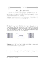
Name:<br />
Lab Partners:<br />
Date:<br />
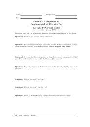
Pre-Lab Assignment:<br />
<strong>Fundamentals</strong> <strong>of</strong> <strong>Circuits</strong> I:<br />
<strong>Current</strong> <strong>Models</strong>, <strong>Batteries</strong> & <strong>Bulbs</strong><br />
(Due at the beginning <strong>of</strong> lab)<br />
1. Explain why in Activity 1.1 the plates will be charged in several different ways.<br />
2. Sketch below one arrangement <strong>of</strong> the battery, bulb and wire (other than the one in Fig. 3<br />
which you will try in Activity 1.2.<br />
3. At this time, which model for current in Fig. 6 do you favor Why<br />
PHYS-204: Physics II Laboratory<br />
i
Name:<br />
Date:<br />
Lab Partners:<br />
<strong>Fundamentals</strong> <strong>of</strong> <strong>Circuits</strong> I:<br />
<strong>Current</strong> <strong>Models</strong>, <strong>Batteries</strong> & <strong>Bulbs</strong><br />
Objectives<br />
• To understand the nature <strong>of</strong> electric currents and why the current is the same at all points<br />
in simple circuits.<br />
• To understand that an electric potential difference (voltage) can cause a flow <strong>of</strong> electric<br />
charge in a conductor.<br />
• To gain practice in designing and building simple circuits with batteries, light bulbs and<br />
switches.<br />
• To learn to draw circuit diagrams using electrical symbols.<br />
• To learn to make measurements <strong>of</strong> current ant voltage using microcomputer-based probes<br />
Overview<br />
In the labs during the first part <strong>of</strong> this semester you are going to do a series <strong>of</strong> activities<br />
designed to help you develop a strong conceptual understanding <strong>of</strong> the nature <strong>of</strong> electric current<br />
and electric potential difference (commonly referred to as Voltage), and the essential features<br />
<strong>of</strong> simple electric circuits. These labs have been adapted from the Real Time Physics Active<br />
Learning Laboratories [1]. The goals, guiding principles and procedures <strong>of</strong> these labs closely<br />
parallel the implementations found in the work <strong>of</strong> those authors [1, 2, 3]. The ideas that you<br />
will learn in these labs are the same ones that go into making all the electrical devices that play<br />
an important role in our modern world-everything from electric lights and motors to TV sets,<br />
computers and photocopy machines.<br />
In several <strong>of</strong> these labs the electrical components we will work with are batteries and light<br />
bulbs. A battery is a device that uses chemical energy to do work on the electric charges that<br />
flow in it. As it does work it increases the electrical potential energy <strong>of</strong> these charges, which<br />
generates an electric potential difference.<br />
The energy added to the electric charge by the battery can be used to operate an electrical<br />
device. In today’s experiment that device will be a light bulb. But in order to deliver the<br />
energy to the light bulb the electric charge must flow through the battery and light bulb. This<br />
requires the light bulb and battery to be connected using conductors, materials that allow<br />
electric charges to flow in them.<br />
In this lab you will consider several models that might explain the flow <strong>of</strong> charge and<br />
predict the measurements that would result if the model is correct. You will then make the<br />
measurements to determine which <strong>of</strong> the models correctly describes the flow <strong>of</strong> charge, and<br />
which models do not.<br />
PHYS-204: Physics II Laboratory 1
<strong>Fundamentals</strong> <strong>of</strong> <strong>Circuits</strong> I: <strong>Current</strong> <strong>Models</strong>, <strong>Batteries</strong> & <strong>Bulbs</strong> v 0.1<br />
Investigation 1:<br />
<strong>Models</strong> describing electric current<br />
What is electric current Today, as you can read in any textbook, we believe that current is<br />
produced by electric charges in motion. The electric current in a copper wire, for example is<br />
produced by the motion <strong>of</strong> electrons through the wire. Do we know this If so, how do we<br />
know How can we experimentally distinguish this model <strong>of</strong> current from other models<br />
These questions were studied and tested by Michael Faraday, a famous early nineteenth<br />
century scientist. Faraday examined the effects <strong>of</strong> electricity from many different sources,<br />
including animals such as electric eels, batteries, and electromagnetic induction in addition to<br />
the electric charge produced by rubbing objects, and concluded that ”electricity, whatever may<br />
be its source, is identical in its nature.”<br />
Let’s put Michael Faraday’s conclusion to a small test. Is the electricity in “static electricity”<br />
identical in nature to the electricity in a battery or power supply Objects which are rubbed in<br />
particular ways are found to attract or repel other objects which have been rubbed in particular<br />
ways. These forces between objects are attributed to a property <strong>of</strong> matter known as charge.<br />
Rubbing the objects produces and induced charge on the objects. This induced charge is an<br />
example <strong>of</strong> static electricity.<br />
The purpose <strong>of</strong> the first activity is to compare the current produced the static charges<br />
deposited by rubbing materials together. to the current produced by a battery or power supply.<br />
You will observe a demonstration using the following materials:<br />
• Large variable capacitor with two metal plates<br />
• Electroscope<br />
• foil covered Styr<strong>of</strong>oam ball on a string<br />
• 300 V battery pack or power supply<br />
• PVC rod and wool cloth<br />
• acrylic rod and polyester or silk cloth<br />
• alligator clip leads<br />
Activity 1.1: Comparing charge from a power supply and charge produced<br />
by rubbing<br />
Step 1: The metal plates <strong>of</strong> a variable capacitor and the conducting ball will be set up as<br />
shown in Fig. 1.<br />
By charging the metal plates in two ways, we can test whether or not the different charging<br />
methods have different effects on the ball dangling between the plates. The two methods<br />
we will test are:<br />
a. Electrostatic Charging by Rubbing. Stroke one plate with a PVC (gray) rod that has<br />
been rubbed with the cat fur or wool. Repeat this several times. Stroke the other<br />
plate with the acrylic (clear) rod that has been rubbed with the silk or polyester<br />
cloth.<br />
PHYS-204: Physics II Laboratory 2
<strong>Fundamentals</strong> <strong>of</strong> <strong>Circuits</strong> I: <strong>Current</strong> <strong>Models</strong>, <strong>Batteries</strong> & <strong>Bulbs</strong> v 0.1<br />
+<br />
+<br />
+<br />
+<br />
+<br />
−<br />
−<br />
−<br />
−<br />
−<br />
Figure 1: Visualizing <strong>Current</strong><br />
b. Charging with a Battery or power supply. Connect a wire from the negative terminal<br />
<strong>of</strong> the battery pack to one <strong>of</strong> the angle irons. At the same time connect a wire from<br />
the positive terminal <strong>of</strong> the battery pack to the other plate.<br />
Step 2: With the metal-covered ball removed from between the plates, charge the plates using<br />
the charged rubber and glass rods (method a). Measure the effects with an electroscope.<br />
Step 3: Adjust the metal plates so that the gap between them is just barely larger that the<br />
diameter <strong>of</strong> the metal covered ball. Again charge the plates using the charged rubber and<br />
glass rods. Then carefully lower the ball between the plates. You should see something<br />
pretty unusual.<br />
Question 1.1 What happened when the ball was placed between the plates In terms<br />
<strong>of</strong> the attraction and repulsion <strong>of</strong> different types <strong>of</strong> charges, explain why this unusual<br />
phenomenon happened.<br />
Step 4: With the ball removed from between the plates, charge the plates by connecting the<br />
power supply (method b).<br />
Step 5: Then carefully lower the ball between the plates, and again observe its behavior.<br />
Question 1.2 Describe what happened when the power supply was used to ”charge” the<br />
plates. What differences (if any) between method (a) and method (b) did you observe in<br />
the response <strong>of</strong> the ball to the charges on the plates<br />
PHYS-204: Physics II Laboratory 3
<strong>Fundamentals</strong> <strong>of</strong> <strong>Circuits</strong> I: <strong>Current</strong> <strong>Models</strong>, <strong>Batteries</strong> & <strong>Bulbs</strong> v 0.1<br />
Question 1.3 Do the charges generated by rubbing and by the power supply cause different<br />
effects If so, describe them. Do the charges generated in these two ways appear to<br />
be different<br />
The rate <strong>of</strong> flow <strong>of</strong> electric charge is more commonly called electric current. If charge ∆Q<br />
flows through a conductor in time ∆t, then the current can be expressed mathematically<br />
by the relationship<br />
I = ∆Q<br />
∆t .<br />
The SI unit <strong>of</strong> current is called the ampere (A). One ampere represents the flow <strong>of</strong> one<br />
coulomb <strong>of</strong> charge through a conductor in a time interval <strong>of</strong> one second. Another common<br />
unit <strong>of</strong> current is the milli-ampere (mA). (1 ampere = 1000 milli-amperes). It is common<br />
to refer to current as ”amps” or ”milliamps.”<br />
(a)<br />
+<br />
−<br />
(b)<br />
+<br />
−<br />
+<br />
−<br />
+<br />
−<br />
+<br />
+<br />
+<br />
+ +<br />
+ +<br />
+ +<br />
+<br />
v<br />
−<br />
−<br />
+<br />
+<br />
−<br />
−<br />
−<br />
− −<br />
−<br />
−<br />
−<br />
v<br />
−<br />
−<br />
+<br />
−<br />
+<br />
−<br />
Figure 2: Moving Charges<br />
Question 1.4 Consider Figs. 2(a) and 2(b). Do both figures show a current to the right<br />
Explain.<br />
Activity 1.2: Arrangements that Cause a Bulb to Light<br />
In this activity, you can begin to explore electric current by lighting a bulb with a battery. You<br />
will need the following:<br />
• flashlight bulb (#14)<br />
• flashlight battery (1.5 V D cell)<br />
PHYS-204: Physics II Laboratory 4
<strong>Fundamentals</strong> <strong>of</strong> <strong>Circuits</strong> I: <strong>Current</strong> <strong>Models</strong>, <strong>Batteries</strong> & <strong>Bulbs</strong> v 0.1<br />
• one wire (6 inches or more in length)<br />
Step 1: Use the materials listed above to find some arrangements in which the bulb lights and<br />
some in which it does not light. For instance, try the arrangement shown below.<br />
Figure 3: A wiring configuration that might make a bulb light with a battery.<br />
Question 1.5 Sketch below two different arrangements in which the bulb lights. (Note:<br />
there are a total <strong>of</strong> four including the one pictured above).<br />
Question 1.6 Sketch below two arrangements in which the bulb doesn’t light.<br />
Question 1.7 Describe as fully as possible what conditions are needed if the bulb is to<br />
light, and why the bulb fails to light in the arrangements drawn in answer to Question 1.6.<br />
Activity 1.3: Other Materials Between the Battery and Bulb<br />
In the previous activity you found that a wire, properly connected to a battery and a<br />
bulb, allows current to flow. By definition we refer to materials that allow current flow<br />
as conductors. By contrast materials which do not allow current flow are called nonconductors.<br />
PHYS-204: Physics II Laboratory 5
<strong>Fundamentals</strong> <strong>of</strong> <strong>Circuits</strong> I: <strong>Current</strong> <strong>Models</strong>, <strong>Batteries</strong> & <strong>Bulbs</strong> v 0.1<br />
Lets examine some common materials to see which are conductors and which are nonconductors.<br />
We can do that by determining which materials allow the bulb to light. You<br />
will need<br />
• common objects: paper clips, pencils, coins, rubber bands, fingers, paper, keys etc.<br />
Connect a single wire, the battery, and a bulb so that the bulb lights. Choose one <strong>of</strong> the<br />
arrangements drawn in your answer to Question 1.5. Then, with the help <strong>of</strong> your partner,<br />
stick in a variety <strong>of</strong> the common objects available between the battery and the bulb.<br />
Question 1.8 List the materials that allow the bulb to light.<br />
Question 1.9 List the materials that prevent the bulb from lighting.<br />
Question 1.10 What types <strong>of</strong> materials seem to be conductors What types seem to be<br />
non-conductors<br />
By now you will have discovered that it is difficult to hold your circuits together From<br />
here on, you can make it easier by using a battery holder and a bulb socket. These things, with<br />
the addition <strong>of</strong> a switch are found on the circuit board provided.<br />
Activity 1.4: Using a Battery Holder, Bulb Socket and Switch<br />
For this activity, in addition to the materials you’ve already used, you will need:<br />
• battery holder (for a D cell)<br />
• several wires (6 inches or more in length)<br />
• flashlight bulb socket<br />
• contact switch<br />
Step 1: Examine the bulb socket carefully. Examine what happens when you unscrew the<br />
bulb. Note which parts <strong>of</strong> the bulb make contact with which parts <strong>of</strong> the socket.<br />
Step 2: Examine the bulb closely.<br />
PHYS-204: Physics II Laboratory 6
<strong>Fundamentals</strong> <strong>of</strong> <strong>Circuits</strong> I: <strong>Current</strong> <strong>Models</strong>, <strong>Batteries</strong> & <strong>Bulbs</strong> v 0.1<br />
Figure 4: Diagram <strong>of</strong> wiring inside a light bulb: The dashed lines show wires hidden from view.<br />
The black portion is a ceramic insulator, while the grey pieces are a conductors.<br />
Question 1.11 Why is the filament <strong>of</strong> the bulb connected in this way<br />
Question 1.12 Explain which parts <strong>of</strong> the bulb socket come in contact with which parts<br />
<strong>of</strong> the bulb. Why doesn’t the bulb light when it is unscrewed<br />
Prediction 1.1 Consider the circuit shown in Fig. 5. If the switch is open, will the bulb<br />
light Will the bulb light when the switch closed Explain your predictions.<br />
Figure 5: A circuit with a battery, light bulb and switch.<br />
Step 3: Wire the circuit shown in Fig. 5 and test it. Use the battery holder, bulb socket, and<br />
switch on the circuit board provided.<br />
Step 4: Close the switch and leave it closed so that the bulb remains lit for 20 seconds. Release<br />
the switch and immediately feel the bulb.<br />
PHYS-204: Physics II Laboratory 7
<strong>Fundamentals</strong> <strong>of</strong> <strong>Circuits</strong> I: <strong>Current</strong> <strong>Models</strong>, <strong>Batteries</strong> & <strong>Bulbs</strong> v 0.1<br />
Question 1.13 What did you feel<br />
when there is a current through it<br />
Besides giving <strong>of</strong>f light, what happens to the bulb<br />
Question 1.14 What can you say about the path needed by the current to make the bulb<br />
glow Your explanation should be based on the observations you have made so far.<br />
Model A<br />
Next we explore and contrast some competing models for current in a circuit. Consider<br />
a circuit equivalent to the one shown in Fig. 5 with the switch closed. Fig. 6 depicts<br />
four different models for current in this circuit. These models are based on models that<br />
students <strong>of</strong>ten propose. These models are described below.<br />
1<br />
Model B<br />
1<br />
2<br />
2<br />
Model C<br />
1<br />
Model D<br />
1<br />
2<br />
2<br />
Figure 6: Four possible models for current.<br />
Model A: <strong>Current</strong> flows from the positive terminal <strong>of</strong> the battery through wire #1 and into the<br />
bulb. The bulb uses up all <strong>of</strong> the current and no current flows back to the battery<br />
in wire #2.<br />
Model B: <strong>Current</strong>s flow from both terminals <strong>of</strong> the into the bulb.<br />
Model C: The current flows from the positive terminal <strong>of</strong> the battery into the bulb. The bulb<br />
uses up some <strong>of</strong> the current and a smaller current returns to the negative terminal<br />
<strong>of</strong> the battery.<br />
Model D: A <strong>Current</strong> flows from the positive terminal <strong>of</strong> the battery into the bulb, and the<br />
exact same current returns to the negative terminal <strong>of</strong> the battery.<br />
PHYS-204: Physics II Laboratory 8
<strong>Fundamentals</strong> <strong>of</strong> <strong>Circuits</strong> I: <strong>Current</strong> <strong>Models</strong>, <strong>Batteries</strong> & <strong>Bulbs</strong> v 0.1<br />
Question 1.15 How can you determine which model, if any, correctly describes the current<br />
through the bulb What would you measure, and where would you measure it Discuss<br />
what measurements you might make to eliminate at least three <strong>of</strong> the four competing<br />
models for current. Talk things over with your partners, and explain your reasoning.<br />
In Activity 1.5 you will use the computer based laboratory system and two current probes<br />
in your circuit to measure current and test the four models above. In addition to the<br />
battery, bulb and wires you used above, you will need:<br />
• Computer with Logger-Pro s<strong>of</strong>tware<br />
• Lab Pro interface<br />
• two current probes<br />
The current probe is a device that measures current. Your computer will take measurements<br />
from the current probe and display them, as a function <strong>of</strong> time, on the computer<br />
screen. The current proble will allow us to measure the current at different locations and<br />
under different conditions in electric circuits.<br />
− +<br />
CP<br />
Figure 7: Measuring current in a circuit with a battery, bulb and current probe.<br />
In order to measure a current, the current must pass through the current probe. For<br />
example, to measure the current in the bottom wire <strong>of</strong> the circuit in Fig. 5, the current<br />
probe should be connected as shown in Fig. 7. To connect the current probe at this<br />
location we must disconnect the circuit at the point where you want to measure the<br />
current (the bottom wire), and insert the current probe. That is, disconnect the circuit,<br />
put in the current probe, and reconnect with the probe in place.<br />
Keep in mind that the current probe measures both the magnitude and direction <strong>of</strong> the<br />
current. Just like we did for velocities, forces, and other vector quantities in Physics I,<br />
we distinguish opposite directions for current flow by positive and negative. A current<br />
in through the + terminal and out through the - terminal (in the direction <strong>of</strong> the arrow)<br />
will be displayed as a positive current. By contrast, when the current probe measures a<br />
negative current, the current is directed into the − terminal and out <strong>of</strong> the + terminal <strong>of</strong><br />
the probe.<br />
Take a close look at Fig. 8. If the current in the loop is clockwise both ammeters will<br />
measure currents which are positive.<br />
PHYS-204: Physics II Laboratory 9
<strong>Fundamentals</strong> <strong>of</strong> <strong>Circuits</strong> I: <strong>Current</strong> <strong>Models</strong>, <strong>Batteries</strong> & <strong>Bulbs</strong> v 0.1<br />
+ −<br />
CP1<br />
− +<br />
CP2<br />
Figure 8: Circuit with two current probes, one measuring current from the positive terminal <strong>of</strong><br />
the battery, the other measuring current into the negative terminal <strong>of</strong> the battery. Note how<br />
the + and − terminals <strong>of</strong> the current probes are connected,<br />
Prediction 1.2 The table below is a prediction table for each <strong>of</strong> the four models. Before<br />
making any measurements fill in Table 1 to show how the readings <strong>of</strong> current probe 1 and<br />
current probe 2 in the circuit in Fig. 8 would compare with each other for each <strong>of</strong> the<br />
current models described in Fig. 6.<br />
Model A<br />
Model B<br />
Model C<br />
Model D<br />
Probe<br />
CP1<br />
CP2<br />
CP1<br />
CP2<br />
CP1<br />
CP2<br />
CP1<br />
CP2<br />
<strong>Current</strong><br />
+, − or 0<br />
CP1>CP2, CP1
<strong>Fundamentals</strong> <strong>of</strong> <strong>Circuits</strong> I: <strong>Current</strong> <strong>Models</strong>, <strong>Batteries</strong> & <strong>Bulbs</strong> v 0.1<br />
<strong>Current</strong> 2 (A)<br />
<strong>Current</strong> 1(A)<br />
Time (s)<br />
Step 3: Zero the probes with the switch open.<br />
Step 4: Set up the circuit in Fig. 8 with the terminals marked + and − as shown. Begin<br />
graphing, and try closing the switch for a couple <strong>of</strong> seconds and then opening it for a<br />
couple <strong>of</strong> seconds. Repeat this several times while you are graphing. Sketch your graphs<br />
on the axes above.<br />
Note: You should observe carefully whether the current through both probes is essentially<br />
the same, or if there is a significant difference (more than a few per cent), and whether it<br />
is positive or negative.<br />
Question 1.16 How could you determine if an observed difference in the currents read by the<br />
top and bottom current probes is real or if it is the result <strong>of</strong> small calibration differences in the<br />
current probes<br />
Question 1.17 Did you observe a significant difference in the currents at these two locations<br />
in the circuit, or was the current the same<br />
Question 1.18 Based on your observations, which models seems to correctly describe the behavior<br />
<strong>of</strong> the current in your circuit. Explain carefully based on your observations.<br />
PHYS-204: Physics II Laboratory 11
<strong>Fundamentals</strong> <strong>of</strong> <strong>Circuits</strong> I: <strong>Current</strong> <strong>Models</strong>, <strong>Batteries</strong> & <strong>Bulbs</strong> v 0.1<br />
Investigation 2:<br />
Using electric circuit symbols<br />
Representing electric circuits by drawings, like Fig. 5, can be very tedious. It can also be<br />
confusing for circuits that have many components. To make it easier to design electric circuits<br />
standard symbols have been established to represent the various components that make up an<br />
electric circuit. A few <strong>of</strong> these are shown below. More will be introduced in future experiments.<br />
V = 1.5V<br />
S<br />
+ −<br />
Battery<br />
Switch<br />
R<br />
I<br />
Bulb<br />
Figure 9: Circuit Elements<br />
Wire<br />
Activity 2.1: Drawing circuits<br />
Question 2.1 Draw the circuit represented by Fig. 5 using the symbols above.<br />
Question 2.2 On the battery symbol, which line represents the positive terminal-the long one<br />
or the short one (Note: you should try to remember this convention. There are many situations<br />
in which it is important to distinguish the positive and negative terminals.)<br />
PHYS-204: Physics II Laboratory 12
<strong>Fundamentals</strong> <strong>of</strong> <strong>Circuits</strong> I: <strong>Current</strong> <strong>Models</strong>, <strong>Batteries</strong> & <strong>Bulbs</strong> v 0.1<br />
Investigation 3:<br />
<strong>Current</strong> and Electric Potential Difference<br />
Since a battery is a device that has an electric potential difference across its terminals, it<br />
is capable <strong>of</strong> giving energy to charges, which can then flow as a current through a circuit.<br />
Exploring the relationship between the potential differences in a circuit and the currents that<br />
flow in that circuit is an essential part <strong>of</strong> developing an understanding <strong>of</strong> electrical circuits.<br />
Since potential differences are measured in volts, a potential difference is informally referred<br />
to as a voltage, and usually denoted by the symbol V . Voltage is an informal term for potential<br />
difference. If you want to talk to physicists, you should refer to potential difference. Communicating<br />
with a sales person at the local Radio Shack store or buying batteries at a hardware<br />
store is another story. There you should probably refer to voltage. We will use these two terms<br />
interchangeably.<br />
You will use voltage probes to measure electric potential difference. The voltage probe has<br />
two clips. When the clips at the ends <strong>of</strong> the wires are connected at two points in a circuit the<br />
computer can measure the potential difference. Fig. 10 shows our simple circuit from Fig. 5<br />
with a voltage probe connected to measure the voltage across the battery. Note that the word<br />
across describes how the voltage probes are connected.<br />
+<br />
VP1<br />
−<br />
Figure 10: Voltage probe connected to measure potential difference <strong>of</strong> the battery<br />
Let’s measure the potential difference across different elements <strong>of</strong> this circuit. You have<br />
available the following equipment.<br />
• Computer with Logger-Pro s<strong>of</strong>tware<br />
• Lab Pro interface<br />
• D-cell battery and holder<br />
• light bulb and socket<br />
• SPST switch<br />
• two voltage probes<br />
PHYS-204: Physics II Laboratory 13
<strong>Fundamentals</strong> <strong>of</strong> <strong>Circuits</strong> I: <strong>Current</strong> <strong>Models</strong>, <strong>Batteries</strong> & <strong>Bulbs</strong> v 0.1<br />
Activity 3.1: Electric Potential (Voltage)<br />
Step 1: Unplug the current probes from the interface, and connect the voltage probes to<br />
channels 1 and 2.<br />
Step 2: Open the experiment file L1A3-1(Two Voltages) to display the axes that will allow<br />
you to compare two voltages.<br />
Step 3: Connect the circuit shown in Fig. 9, but do not connect the voltage probes yet.<br />
Step 4: Zero the voltage probes, being sure that the clips <strong>of</strong> the voltage probes are not connected<br />
to anything.<br />
Step 5: Connect both clips to the negative end <strong>of</strong> the battery holder in the circuit. Click on<br />
the collect button to start graphing. Collect data with the switch open, and with the<br />
switch closed. Record the potential difference with the switch open, and with the switch<br />
closed.<br />
V open = volts V closed = volts<br />
Step 6: Move the red clip and connect it at the other end <strong>of</strong> the wire connecting the negative<br />
terminal <strong>of</strong> the battery to the light bulb. Connected this way the voltage probe will<br />
measure the potential difference between the ends <strong>of</strong> the wire.<br />
Step 7: Collect data to determine the potential difference with the switch open, and with the<br />
switch closed.<br />
V open = volts V closed = volts<br />
Question 3.1 What do you conclude about the potential difference when the two leads<br />
from the voltage probe are connected to the same point What do you conclude about the<br />
potential difference between the two ends <strong>of</strong> the same wire<br />
Prediction 3.1 In the circuit in Fig. 11, how would you expect the voltage difference<br />
across the battery to compare to the voltage across the bulb with the switch open and with<br />
the switch closed Explain.<br />
Step 8: Now test your prediction. Connect voltage probe 1 across the battery, and voltage<br />
probe 2 across the light bulb, as in Fig. 11.<br />
Step 9: Collect data and make graphs <strong>of</strong> the two potential differences. Make sure the switch<br />
is closed during part <strong>of</strong> the time that the computer is collecting data, and open during<br />
part <strong>of</strong> the time.<br />
PHYS-204: Physics II Laboratory 14
<strong>Fundamentals</strong> <strong>of</strong> <strong>Circuits</strong> I: <strong>Current</strong> <strong>Models</strong>, <strong>Batteries</strong> & <strong>Bulbs</strong> v 0.1<br />
+<br />
+<br />
VP1<br />
−<br />
−<br />
VP2<br />
Figure 11: Circuit with two voltage probes<br />
Step 10: Sketch the graphs on the axes below. On the graph show the time intervals during<br />
which the switch was closed and when the switch was open.<br />
Voltage 1 (V)<br />
Voltage 2 (V)<br />
2<br />
0<br />
-2<br />
2<br />
0<br />
-2<br />
Time (s)<br />
Question 3.2 What do you conclude about the voltage across the battery and the voltage across<br />
the bulb when the switch is open and when it is closed Are the graphs the same Why or why<br />
not Is this in agreement with your prediction 3.1 What is the effect <strong>of</strong> closing the switch<br />
Activity 3.2: Electric potential difference and current<br />
Now we want to find out about the potential difference across the battery, and the current that<br />
flows around the circuit.<br />
Step 1: Unplug the voltage probe from channel 2, and plug a current sensor into channel 2.<br />
PHYS-204: Physics II Laboratory 15
<strong>Fundamentals</strong> <strong>of</strong> <strong>Circuits</strong> I: <strong>Current</strong> <strong>Models</strong>, <strong>Batteries</strong> & <strong>Bulbs</strong> v 0.1<br />
+<br />
VP1<br />
−<br />
− +<br />
CP<br />
Figure 12: Measuring both current and potential difference.<br />
Step 2: Connect a circuit with the battery, switch and light bulb. Include the current sensor<br />
and voltage probe in the circuit connected as in Fig. 12.<br />
Step 3: Open experiment file L1A3-2 (<strong>Current</strong> and Voltage) to display the axes that follow.<br />
Voltage 1 (V)<br />
2.0<br />
0<br />
-2.0<br />
<strong>Current</strong> 2 (A)<br />
Time (s)<br />
Step 4: Collect data to make graphs <strong>of</strong> the potential difference across the battery and the<br />
current through the circuit while you open and close the switch several times. Use the<br />
”Store Latest Run” command in the Data menu to keep your results. Sketch the graphs.<br />
Be as accurate as you can to show the magnitudes <strong>of</strong> the potential difference and the<br />
current.<br />
Potential difference V <strong>Current</strong> amps.<br />
Question 3.3 What happens to the current through the circuit as the switch is closed<br />
and opened What happens to the potential difference across the battery<br />
PHYS-204: Physics II Laboratory 16
<strong>Fundamentals</strong> <strong>of</strong> <strong>Circuits</strong> I: <strong>Current</strong> <strong>Models</strong>, <strong>Batteries</strong> & <strong>Bulbs</strong> v 0.1<br />
Prediction 3.2 Now suppose you connect a second bulb in the circuit, as in Fig. 12.<br />
How do you think the potential difference across the battery will compare to the potential<br />
difference with only one light bulb Will it change significantly<br />
+<br />
VP1<br />
−<br />
− +<br />
CP<br />
Figure 13: Circuit with two light bulbs<br />
Step 5: Connect the circuit as in Fig. 13.<br />
Step 6: Again collect data to make graphs <strong>of</strong> Potential difference and current. Sketch your<br />
graphs, using dotted lines to show your results with two bulbs. Represent the magnitudes<br />
<strong>of</strong> the current and potential as accurately as you can.<br />
Question 3.4 Was the current through the circuit significantly different with two bulbs than it<br />
was with one bulb (more than a few per cent)<br />
Question 3.5 Was the potential difference significantly different with two bulbs than it was<br />
with one bulb (more than a few per cent)<br />
Question 3.6 Does the battery appear to be a source <strong>of</strong> constant current, constant potential<br />
difference, or neither when additional elements are placed in the circuit<br />
PHYS-204: Physics II Laboratory 17
<strong>Fundamentals</strong> <strong>of</strong> <strong>Circuits</strong> I: <strong>Current</strong> <strong>Models</strong>, <strong>Batteries</strong> & <strong>Bulbs</strong> v 0.1<br />
These laboratory exercise has been adapted from the references below.<br />
References<br />
[1] David R. Sokol<strong>of</strong>f, Priscilla W. Laws, Ronald K. Thornton, and et.al. Real Time Physics,<br />
Active Learning Laboratories, Module 3: Electric <strong>Circuits</strong>. John Wiley & Sons, Inc., New<br />
York, NY, 1st edition, 2004.<br />
[2] Priscilla W. Laws. Workshop Physics Activity Guide, Module 4: Electricity and Magnetism.<br />
John Wiley & Sons, Inc., New York, NY, 1st edition, 2004.<br />
[3] Lilian C. McDermott, et.al. Physics by Inquiry, Volumes I & II. John Wiley & Sons, Inc.,<br />
New York, NY, 1st edition, 1996.<br />
PHYS-204: Physics II Laboratory 18