Fundamentals of Circuits I: Current Models, Batteries & Bulbs
Fundamentals of Circuits I: Current Models, Batteries & Bulbs
Fundamentals of Circuits I: Current Models, Batteries & Bulbs

You also want an ePaper? Increase the reach of your titles
YUMPU automatically turns print PDFs into web optimized ePapers that Google loves.
<strong>Fundamentals</strong> <strong>of</strong> <strong>Circuits</strong> I: <strong>Current</strong> <strong>Models</strong>, <strong>Batteries</strong> & <strong>Bulbs</strong> v 0.1<br />
Question 1.15 How can you determine which model, if any, correctly describes the current<br />
through the bulb What would you measure, and where would you measure it Discuss<br />
what measurements you might make to eliminate at least three <strong>of</strong> the four competing<br />
models for current. Talk things over with your partners, and explain your reasoning.<br />
In Activity 1.5 you will use the computer based laboratory system and two current probes<br />
in your circuit to measure current and test the four models above. In addition to the<br />
battery, bulb and wires you used above, you will need:<br />
• Computer with Logger-Pro s<strong>of</strong>tware<br />
• Lab Pro interface<br />
• two current probes<br />
The current probe is a device that measures current. Your computer will take measurements<br />
from the current probe and display them, as a function <strong>of</strong> time, on the computer<br />
screen. The current proble will allow us to measure the current at different locations and<br />
under different conditions in electric circuits.<br />
− +<br />
CP<br />
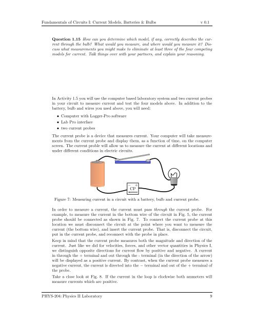
Figure 7: Measuring current in a circuit with a battery, bulb and current probe.<br />
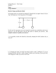
In order to measure a current, the current must pass through the current probe. For<br />
example, to measure the current in the bottom wire <strong>of</strong> the circuit in Fig. 5, the current<br />
probe should be connected as shown in Fig. 7. To connect the current probe at this<br />
location we must disconnect the circuit at the point where you want to measure the<br />
current (the bottom wire), and insert the current probe. That is, disconnect the circuit,<br />
put in the current probe, and reconnect with the probe in place.<br />
Keep in mind that the current probe measures both the magnitude and direction <strong>of</strong> the<br />
current. Just like we did for velocities, forces, and other vector quantities in Physics I,<br />
we distinguish opposite directions for current flow by positive and negative. A current<br />
in through the + terminal and out through the - terminal (in the direction <strong>of</strong> the arrow)<br />
will be displayed as a positive current. By contrast, when the current probe measures a<br />
negative current, the current is directed into the − terminal and out <strong>of</strong> the + terminal <strong>of</strong><br />
the probe.<br />
Take a close look at Fig. 8. If the current in the loop is clockwise both ammeters will<br />
measure currents which are positive.<br />
PHYS-204: Physics II Laboratory 9