Fundamentals of Circuits I: Current Models, Batteries & Bulbs
Fundamentals of Circuits I: Current Models, Batteries & Bulbs
Fundamentals of Circuits I: Current Models, Batteries & Bulbs

You also want an ePaper? Increase the reach of your titles
YUMPU automatically turns print PDFs into web optimized ePapers that Google loves.
<strong>Fundamentals</strong> <strong>of</strong> <strong>Circuits</strong> I: <strong>Current</strong> <strong>Models</strong>, <strong>Batteries</strong> & <strong>Bulbs</strong> v 0.1<br />
+ −<br />
CP1<br />
− +<br />
CP2<br />
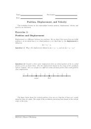
Figure 8: Circuit with two current probes, one measuring current from the positive terminal <strong>of</strong><br />
the battery, the other measuring current into the negative terminal <strong>of</strong> the battery. Note how<br />
the + and − terminals <strong>of</strong> the current probes are connected,<br />
Prediction 1.2 The table below is a prediction table for each <strong>of</strong> the four models. Before<br />
making any measurements fill in Table 1 to show how the readings <strong>of</strong> current probe 1 and<br />
current probe 2 in the circuit in Fig. 8 would compare with each other for each <strong>of</strong> the<br />
current models described in Fig. 6.<br />
Model A<br />
Model B<br />
Model C<br />
Model D<br />
Probe<br />
CP1<br />
CP2<br />
CP1<br />
CP2<br />
CP1<br />
CP2<br />
CP1<br />
CP2<br />
<strong>Current</strong><br />
+, − or 0<br />
CP1>CP2, CP1