Pre-Lab 7 Assignment: Capacitors and RC Circuits
Pre-Lab 7 Assignment: Capacitors and RC Circuits
Pre-Lab 7 Assignment: Capacitors and RC Circuits
- No tags were found...

You also want an ePaper? Increase the reach of your titles
YUMPU automatically turns print PDFs into web optimized ePapers that Google loves.
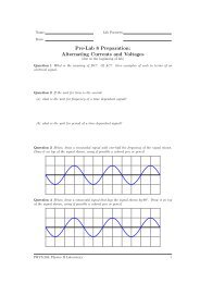
Name:<strong>Lab</strong> Partners:Date:<strong>Pre</strong>-<strong>Lab</strong> 7 <strong>Assignment</strong>:<strong>Capacitors</strong> <strong>and</strong> <strong>RC</strong> <strong>Circuits</strong>(Due at the beginning of lab)Directions: Read over the <strong>Lab</strong> H<strong>and</strong>out <strong>and</strong> then answer the following questions about theprocedures.Question 1 How do you think the capacitance of a parallel plate capacitor changes as the areaof the plates is increased?Question 2 How do you think the capacitance of a parallel plate capacitor changes as theseparation between the plates is increased?Question 3 What observations will you make in activity 1-2 to test your answer either toquestion 1 or 2.Question 4 What do you predict is the net capacitance of two identical capacitors connectedin parallel?Question 5 What observations will you make in activity 2-1 to test this prediction?Question 6 Sketch the complete circuits in Fig. 5 (a) with the switch in position 1, <strong>and</strong> (b)with the switch in position2.PHYS-204:Physics II <strong>Lab</strong>oratoryi
Name:<strong>Lab</strong> Partners:Date:LAB 7 // <strong>Capacitors</strong> <strong>and</strong> <strong>RC</strong> <strong>Circuits</strong>Objectives• To define capacitance <strong>and</strong> learn how to measure it.• To discover how the capacitance of a parallel plate capacitor is related to the area of theplates <strong>and</strong> the distance separating them.• To examine the how the net capacitance in a circuit is related to the capacitances ofindividual capacitors when several capacitors are wired in parallel or in series through theprocess of conceptual reasoning as well as through direct measurements.• To explore the effect of connecting a capacitor in a circuit in series with a resistor or lightbulb <strong>and</strong> a battery.• To discover how the electric charge on a capacitor <strong>and</strong> the electric current in a circuitchange with time when a charged capacitor is placed in a circuit in series with a resistor.This lab has been adapted from the Real Time Physics Active Learning <strong>Lab</strong>oratories [?].The goals, guiding principles <strong>and</strong> procedures of this labs closely parallel the implementationfound in the work of those authors [?, ?, ?].OverviewTwo conducting surfaces that are separated by an insulator can be electrically charged in sucha way that one conductor has a positive charge <strong>and</strong> the other conductor has an equal amountof negative charge; such an arrangement is called a capacitor. A capacitor can be made up ofconductors of regular or irregular shapes such as a hollow cylinder inside another, or two blobsof metal separated by a distance.Cylindrical CapacitorParallel Plate CapacitorFigure 1: Some different capacitor geometries.The type of capacitor most commonly used as prototype is the parallel plate capacitor. Thecapacitance of a parallel plate capacitor is related to the geometry of the capacitor througha simple relationship <strong>and</strong> is a relatively easy device to construct. <strong>Capacitors</strong> are widely usedPHYS-204:Physics II <strong>Lab</strong>oratory 1
<strong>Capacitors</strong> <strong>and</strong> <strong>RC</strong> <strong>Circuits</strong> v 0.3in electronic circuits that require storage of electrical energy (camera flash) or a specific timedependentfeature (e.g., intermittent wipers). Finally, although capacitors show some veryinteresting properties when connected in alternating current circuits, for this lab, we will limitourselves to the behavior of capacitors in direct current circuits like those you are familiar withfrom the lab exercises of the last few weeks. The circuit symbol for a capacitor is a pair of linesas shown in Fig. 2.CFigure 2: The circuit diagram symbol for a capacitor.Investigation 1:Capacitance, Area, <strong>and</strong> SeparationThe easiest method for transferring equal <strong>and</strong> opposite charges onto the plates of a capacitor(charging the capacitor) is to use a voltage source such as a battery or a power supply to createa potential difference between the two conducting plates. This potential difference causeselectrons to flow from one conductor (leaving positive charges behind) <strong>and</strong> onto the other untilthe potential difference between the two conductors is the same as that provided by the voltagesource. In general, the amount of charge transferred before this condition is met depends onthe size, shape, <strong>and</strong> location of the conductors relative to each other. The capacitance of thegiven capacitor is defined mathematically as the ratio of the magnitude of the charge, q, oneither one of the conductors to the voltage, V, applied across the two conductors so that:C = q/VIn words, capacitance is a measure of the amount of excess charge on either one of theconductors per unit potential difference between the plates.Draw on your underst<strong>and</strong>ing of potential difference to examine what might happen to thecharge as it flows in a circuit containing a parallel plate capacitor <strong>and</strong> a battery as shown inFig. 3. Such a thought experiment can help you develop an intuitive underst<strong>and</strong>ing for themeaning of capacitance. For a fixed voltage from a battery, the net charge found on eitherplate is proportional to the capacitance of the capacitor.Activity 1.1: <strong>Pre</strong>dicting the dependence of Capacitance on Area <strong>and</strong>SeparationTo visualize our circuit with a parallel plate capacitor, consider two identical metal plates ofarea A, separated by a non-conducting material that has a thickness d. They are connectedto a battery through a switch, as shown above. When the switch is open, there is no excesscharge on either plate. The switch is then closed completing the path between the battery <strong>and</strong>the capacitor.Question 1.1 What does the reasoning you pursued in your though experiment predict willhappen to the conducting plate attached to the negative terminal of the battery? What do youPHYS-204:Physics II <strong>Lab</strong>oratory 2
<strong>Capacitors</strong> <strong>and</strong> <strong>RC</strong> <strong>Circuits</strong> v 0.3(a)(b)VSCAdFigure 3: A parallel plate capacitor in series with a battery <strong>and</strong> switch: (a) pictorial representation,(b) circuit diagram.predict will happen to the conducting plate that is connected to the positive terminal of thebattery? Explain.Question 1.2 Can excess charges on one plate of a charged parallel plate capacitor exert forceson the excess charges on the other plate? If so, how?Question 1.3 What limits the amount of charge that will flow onto either plate?Question 1.4 Use qualitative reasoning to predict how the amount of charge that a pair ofparallel plate conductors can hold changes as the area of the plates is increased. What does thisimply about the capacitance?Question 1.5 What happens to the electric field between the plates when the spacing, d, betweenthe plates is increased? Will the magnitude of the electric field increase, decrease or stay thesame? Explain.PHYS-204:Physics II <strong>Lab</strong>oratory 3
<strong>Capacitors</strong> <strong>and</strong> <strong>RC</strong> <strong>Circuits</strong> v 0.3Question 1.6 Does the amount of charge a given battery can pile onto the plates of a capacitorincrease or decrease as the spacing, d, between the plates of the capacitor increases? What doesthis imply about the capacitance?The unit of capacitance is the farad, F, named after Michael Faraday. One farad is equalto one coulomb/volt. One farad is a very large capacitance <strong>and</strong> actual capacitances are usuallyexpressed in smaller units with the notation shown below:microfarad: 10 −6 F = 1µFnanofarad: 10 −9 F = 1nF = 10 −3 µF = 10 3 µµFpicofarad: 10 −12 F = 1pF = 10 −6 µF = 1µµFTable 1: Units of capacitanceTechnical note: Because of the occasional lack of availability of Greek fonts to capacitormanufacturers, sometimes the symbol m is used as a label on capacitors instead of the symbolµ to represent 10 −6 , despite the fact that in other situations m always represents 10 −3 .In the next few activities you will construct a parallel plate capacitor <strong>and</strong> use a multimeterto measure its capacitance. You will need the following items:• 2 pieces aluminum foil, approximately 20 cm × 20 cm• 1 thick textbook• 1 digital multimeter (with a capacitance mode)• 2 insulated wires (stripped at the ends, approximately 12” long)• 1 rulerUse two rectangular sheets of aluminum foil separated by pieces of paper to make yourparallel plate capacitor. Leaving small tabs in the aluminum sheets that can stick out providesan easy way to connect the leads from the multimeter to the sheets of aluminum foil. Usethe textbook pages as the separator for the foil the textbook pages constitute a convenientinsulator. Use not more than 8 pages between the two foil sheets. <strong>Pre</strong>ss down on the book tomake sure the pieces of aluminum foil are smoothed out. Then use your digital multimeter inits capacitance mode for the measurements before connecting the capacitor to a power source.Warning: When you use the multimeter to measure the capacitance of your lab-made parallelplate capacitor, make sure that the capacitor is not connected to any source of power. This isvery important, otherwise the multimeter can get damaged.Activity 1.2: Measuring how the capacitance depends on area of theplates or how capacitance depends on the distance ofseparation between the platesStep 1: Decide whether you are going to determine how the capacitance depends on the foilarea or alternately, how the capacitance depends on the separation between the foil sheets.PHYS-204:Physics II <strong>Lab</strong>oratory 4
<strong>Capacitors</strong> <strong>and</strong> <strong>RC</strong> <strong>Circuits</strong> v 0.3Step 2: If you <strong>and</strong> your lab partner decided that you will examine the relationship betweenthe capacitance <strong>and</strong> the distance of separation between the aluminum foil sheets, describehow you will change the separation <strong>and</strong> keep the area constant. On the other h<strong>and</strong>, ifyoull decided to examine the relationship between the capacitance <strong>and</strong> the area of thefoil sheets, describe how you will vary the area while keeping the separation constant. Inboth cases, describe in detail all of the quantities that you will need to measure for eachdata point. Take at least five data points in either case <strong>and</strong> record your data in Table 2.Caution: When measuring the capacitance of your ”parallel plate capacitor” make surethat the sheets of aluminum foil don’t touch each other <strong>and</strong> ”short out.”Separation (m) Length (m) Width (m) Area (m 2 ) Capacitance (nF)Table 2:Step 3: After collecting all of the required data, open the relevant file for the activity you choseto do i.e. either experiment file L7A1-2a (Capacitance vs Separation) or experiment fileL7A1-2b (Capacitance vs Area). Enter your data for the capacitance <strong>and</strong> either theseparation distance or the foil area, depending on which investigation you chose, fromtable 2. Write in the appropriate labels on the vertical <strong>and</strong> horizontal axes shown below,<strong>and</strong> give the vertical <strong>and</strong> horizontal scales appropriate values. Draw your graph usingthese axes.Step 4: If your graph looks like a straight line, use the linear fit comm<strong>and</strong> in the analysismenu. If not, try other functional relationships until you find the best fit for your datapoints.PHYS-204:Physics II <strong>Lab</strong>oratory 5
<strong>Capacitors</strong> <strong>and</strong> <strong>RC</strong> <strong>Circuits</strong> v 0.3Question 1.7 What function best describes the relationship between capacitance <strong>and</strong> spacingor capacitance <strong>and</strong> foil area? How do the results you obtain from an analysis of the graphcompare with those that you predicted based on conceptual reasoning (your answers to questions1.4 <strong>and</strong> 1.6)?The quantitative relationship between the area of the plates A, the separation of the platesd, <strong>and</strong> the capacitance, C, of a parallel plate capacitor isC = κǫ 0Adwhere A is the area of the plates d is their separation, <strong>and</strong> ǫ 0 = 8.85 × 10 −12 C 2 /Nm 2 is thepermittivity of free space.The quantity κ (kappa) is called the dielectric constant <strong>and</strong> is a property of the insulatingmaterial that separates the two plates. κ = 1 for air <strong>and</strong> is greater than 1 for other materials.Paper, the insulating material we have used, has a dielectric constant of between 1.5-4.0Question 1.8 Do the predictions you made as well as your observations agree qualitativelywith this relation? What does this relation indicate will happen when the area of the platesincreases? Or when the separation increases? Explain.Question 1.9 Use one of your actual areas <strong>and</strong> distance of separation from the measurementsyou made in Activity 1-2 to calculate a value of C. Assume that the dielectric constant, κ forpaper is about 3.5. How does the calculated value of C compare with the directly measured value?Question 1.10 Let’s apply this relation to see how realistic a capacitance of 1 F is. You wantto make a parallel place capacitor like the one you just made, but with a capacitance of 1 F. If youwere to use two square foil sheets, separated by paper with a dielectric constant of 3.5 that is 1mm thick, how long (in miles) would each side of the square foil sheet have to be in order to havecapacitance C = 1 F? Show all your calculations. Note: 1000 m = 1 kilometer = 0.62 miles.L =milesInvestigation 2:<strong>Capacitors</strong> in Series <strong>and</strong> ParallelTwo capacitors can be combined either in series or in parallel in a circuit, as shown in Fig. 4.The terms series <strong>and</strong> parallel refer to the same arrangements that you carried out for otherPHYS-204:Physics II <strong>Lab</strong>oratory 6
<strong>Capacitors</strong> <strong>and</strong> <strong>RC</strong> <strong>Circuits</strong> v 0.3circuit elements such as resistors. In a series combination there is only one path for the flowof electric charge, <strong>and</strong> whatever charge is placed on one capacitor must also be transferred tothe other. In a parallel connection, the two terminals of each capacitor are connected to theterminals of the other. While each capacitor has the same potential difference across it, eachconstitutes a branch so that the total charge transferred to the capacitor combination is splitamong the two capacitors.C 1C 1C 2C 2C 1C 1 C 2C 2(a) <strong>Capacitors</strong> in Series(b) <strong>Capacitors</strong> in parallelFigure 4: <strong>Capacitors</strong> wired in (a) series <strong>and</strong> (b) parallelTo examine the equivalent capacitance of two capacitors connected in series or in parallelyou will need:• 2 capacitors, on the order of 0.1µF• 1 multimeter with capacitance range.• Pasco circuit board• connecting wires.Pasco Circuit Board:PHYS-204:Physics II <strong>Lab</strong>oratory 7
<strong>Capacitors</strong> <strong>and</strong> <strong>RC</strong> <strong>Circuits</strong> v 0.3+A B CL = 8mH−EBC+−Activity 2.1: Equivalent Capacitance of <strong>Capacitors</strong> in Parallel<strong>Pre</strong>diction 2.1 Reason using your underst<strong>and</strong>ing of capacitance to predict the equivalent capacitanceof a pair of identical capacitors wired in parallel. Explain your reasoning. Hint: Whatis the effective area of two parallel plate capacitors wired in parallel in Fig. 4? Does the effectivespacing between plates change?PHYS-204:Physics II <strong>Lab</strong>oratory 8
<strong>Capacitors</strong> <strong>and</strong> <strong>RC</strong> <strong>Circuits</strong> v 0.3Step 1: Measure the capacitance of each of your capacitors with the multimeter.C 1 = F C 2 = FStep 2: Connect the two capacitors in parallel, <strong>and</strong> measure the equivalent capacitance of theparallel combination using a multimeter.C eq =FQuestion 2.1 Using your measured data, propose a general equation for the equivalent capacitance(C eq ) of two capacitors connected in parallel in terms of the individual capacitances C 1<strong>and</strong> C 2 . Be sure that your measured values fit your equation.C eq =Question 2.2 Does the form of this equation agree with your prediction 2.1?Activity 2.2: Equivalent Capacitance of <strong>Capacitors</strong> in Series<strong>Pre</strong>diction 2.2 Reason using your underst<strong>and</strong>ing of capacitance to predict the equivalent capacitanceof two capacitors wired in series. Explain your reasoning. Hint: If you connect twocapacitors in series, what will happen to the charges along the conductor between them? Whatwill the effective separation of the ”plates” be? Will the effective area change?Step 1: Measure, usingamultimeter, theequivalentcapacitancewhentwolab-madecapacitors(two pairs of aluminum sheets) or two store-bought capacitors are wired in series.C eq =FQuestion 2.3 Are your measurements consistent with the following equation for the equivalentcapacitance of two capacitors connected in series? Show the calculations you used to reach yourconclusion.1C eq= 1 C 1+ 1 C 2Question 2.4 Does the equation given in Equation 2.3 agree with your <strong>Pre</strong>diction 2.2?PHYS-204:Physics II <strong>Lab</strong>oratory 9
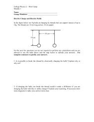
<strong>Capacitors</strong> <strong>and</strong> <strong>RC</strong> <strong>Circuits</strong> v 0.3Question 2.5 How do the quantitative relationships for series <strong>and</strong> parallel capacitors compareto those of resistors? Do series capacitors combine more like series resistors or parallelresistors?Investigation 3:Charge Build-up <strong>and</strong> Decay in <strong>Capacitors</strong><strong>Capacitors</strong>canbeconnectedwithothercircuitelementssuchasresistors. Connectingcapacitorsin series with resistors in a circuit gives rise to interesting time-dependent phenomena. In thislast activity you will investigate what happens to the voltage across a capacitor when it isplaced in series with a resistor in a direct current circuit. Use your observations to come upwith qualitative as well as quantitative explanations of what happens in these circuits.For the activities in this investigation you will need:• computer-based laboratory system.• experiment configuration files.• differential voltage probe.• current probe.• 2 D-cell 1.5 volt batteries.• Pasco circuit boards• flashlight bulb• 33000µF (or larger) capacitor.• 3300µF (or larger) capacitor.• 10Ω resistor• 100Ω resistor.Activity 3.1: Observations with a Capacitor, Battery <strong>and</strong> BulbStep 1: Set up the circuit shown in Fig. 5 with a capacitor with a capacitance of at least33,000µF. (If you are using a polar capacitor, make sure that the positive <strong>and</strong> negativeterminals of the capacitor are connected correctly.)Question 3.1 Sketch one-loop circuits equivalent to the circuit in Fig. 5, showing justthe portion of the circuit that current flows in when the switch is in position 1, <strong>and</strong> theportion of the circuit that current flows in when the switch is in position 2.PHYS-204:Physics II <strong>Lab</strong>oratory 10
<strong>Capacitors</strong> <strong>and</strong> <strong>RC</strong> <strong>Circuits</strong> v 0.31C2Figure 5: Circuit to examine the charging <strong>and</strong> discharging of a capacitor through a light bulb.position 1 position 2Step 2: Move the switch to position 2. After at least 10 seconds, switch it to position 1.Describe, in detail, what happens to the brightness of the bulb.Question 3.2 Draw a qualitative sketch on the axes below of the approximate brightnessof the bulb as a function of time where you move the switch to position 1 after it has beenin position 2 for a long time. Let t = 0 be the time when the switch was moved to position1.BrightnessTimePHYS-204:Physics II <strong>Lab</strong>oratory 11
<strong>Capacitors</strong> <strong>and</strong> <strong>RC</strong> <strong>Circuits</strong> v 0.3Step 3: Next, move the switch back to position 2. Describe, in detail, what happens to thebrightness of the bulb. Note that this removes the battery from the circuit, but completesa circuit that contains just the capacitor <strong>and</strong> the light bulb. Did the bulb light againwithout the battery in the circuit? If so, where did the bulb get the electrical energyfrom?Question 3.3 Draw a qualitative sketch on the axes below of the approximate brightnessof the bulb as a function of time when it is connected to the capacitor without the battery,i.e., when the switch has been moved to position 2. Start with t = 0 as the time when theswitch was moved to position 2.BrightnessTimeQuestion 3.4 Explain why the bulb behaves in this fashion. Is there a charge on thecapacitor after the switch is in position 1 for a little while? What happens to this chargewhen the switch is moved back to position 2?Step 4: Openthe experiment file called Capacitor Decay(L7A3-1), <strong>and</strong>display the axes shownon the next page.Step 5: Connect the current probe <strong>and</strong> the voltage probe to the interface, <strong>and</strong> zero the probeswith nothing attached to them.Step 6: Connect the current <strong>and</strong> voltage probes as shown in Fig. 6 so that the current probemeasures the current through the light bulb <strong>and</strong> the voltage probe measures the potentialdifference across the capacitor.Step 7: Next, move the switch to position 2. Begin taking the data. When the graph linesappear on the screen, move the switch to position 1. When the current <strong>and</strong> voltage datastop changing with time, move the switch back to position 2.PHYS-204:Physics II <strong>Lab</strong>oratory 12
<strong>Capacitors</strong> <strong>and</strong> <strong>RC</strong> <strong>Circuits</strong> v 0.31+ −CP1C+ −2VP2Figure 6: Same circuit as Fig. 5, with current <strong>and</strong> voltage probes added.Voltage 2 (V)Current 1 (A)Time (s)Step 8: Sketch the graphs on the axes above. Indicate on the graphs the times at which thepositions of the switch was changed, i.e. the time at which the switch was moved fromposition 2 to position 1, <strong>and</strong> the time at which it was moved back to position 2 again.Question 3.5 Does the actual behavior over time observed on the current graph agree withyour sketches in questions 3-2 <strong>and</strong> 3-3? Comment on any features of the graph that you didnot expect or account for in your sketch. Explain.Question 3.6 Use the graph of potential difference across the capacitor to explain why the bulblights up when the switch is moved from position 1 to position 2 even though in this position ofthe switch the bulb is connected to the capacitor with no battery in the circuit. Also explain whythe brightness of the bulb changes with time.As you have seen in the lab activity on underst<strong>and</strong>ing resistance, a light bulb does not havea constant resistance. Instead, its resistance is temperature dependent <strong>and</strong> increases when thePHYS-204:Physics II <strong>Lab</strong>oratory 13
<strong>Capacitors</strong> <strong>and</strong> <strong>RC</strong> <strong>Circuits</strong> v 0.3current through the filament heats it up. For more quantitative studies of the behavior of acircuit with resistance <strong>and</strong> capacitance, you should replace the bulb with a 10Ω resistor.Activity 3.2: The Rise <strong>and</strong> Decay of a voltage in an <strong>RC</strong> CircuitStep 1: Replace the light bulb in the circuit shown in Fig. 6 with a 10Ω resistor. Move theswitch to position 2. Begin taking the data. When the graph lines appear on the screen,move the switch to position 1. When the current <strong>and</strong> voltage data stop changing withtime, move the switch back to position 2.Voltage 2 (V)Current 1 (A)Time (s)Step 2: Sketch the graphs on the axes above. Indicate on the graphs the times at which thepositions of the switch was changed, i.e. the time at which the switch was moved fromposition 2 to position 1, <strong>and</strong> the time at which it was moved back to position 2 again.Question 3.7 Do the graphs you sketched for the resistor appear similar to those for thelight bulb? Are there any significant differences?The time interval for the voltage across the capacitor to decay to 37% of its initial valueis known as the time constant. The time constant of a circuit containing a resistor <strong>and</strong> acapacitor (commonly called a <strong>RC</strong> circuit) depends on the values of the capacitance <strong>and</strong>resistance in the circuit.Step 3: Use the Examine feature in the Analysis menu to determine the time <strong>and</strong> the initialvoltage across the capacitor at the moment the switch was moved to position 2.Thendetermine the time at which the voltage was 37% of this initial value. You have nowdetermined the time constant of your <strong>RC</strong> circuit.Initial voltage: time:37% of initial voltage: time constant:Careful measurements of the dependence of the potential difference V across a capacitorvs. time t, for a capacitor (C) discharging through a resistor (R) should reveal an exponentialdecay behavior for the potential difference across the capacitor. Such exponentialPHYS-204:Physics II <strong>Lab</strong>oratory 14
<strong>Capacitors</strong> <strong>and</strong> <strong>RC</strong> <strong>Circuits</strong> v 0.3forms for decay or growth describe many physical <strong>and</strong> natural phenomena, such as radioactivedecay, the concentration of a reactant in a chemical reaction <strong>and</strong> the growth ofbacterial colonies.Mathematical reasoning based on the application of the definitions of resistance, current<strong>and</strong> capacitance can be used to show that the following equation represents the potentialdifference across the capacitor, V, as a function of time:V(t) = V 0 e −t/<strong>RC</strong>In this equation, V 0 is the initial potential difference across the capacitor. (Note that V 0is not necessarily the voltage of the battery.)Step 4: Utilize the fit routine in the software to examine whether an exponential decay accuratelyrepresents the behavior of the voltage across the capacitor as a function of time.Make sure you select <strong>and</strong> fit only that portion of the voltage graph where the voltage isdecaying (decreasing) - up to the point where the voltage just reaches its minimum value.Question 3.8 Record the equation as determined by the fit routine you used. How welldid the exponential function fit your data? Is the decay of voltage across the capacitor anexponential decay?Question 3.9 Find the value of <strong>RC</strong> from the exponent in the function that fit the data. Comparethis value to the one you calculated from the values of resistance <strong>and</strong> capacitance. Do theyagree? (Note that the resistance <strong>and</strong> capacitance values are each only known to an accuracy(tolerance) of about 10%.)When t = <strong>RC</strong> in the equation above, V = V 0 e −1 = 0.37V 0 . Thus <strong>RC</strong> is equal to the timeconstant.Question 3.10 How does the time constant you determined in step 3 compare with the value ofthe time constant you obtained by using the fit procedure in the later part of the above activity?If you have time after the above activities, do the following extension.Activity 3.3: Extension: Decay with Other Resistances <strong>and</strong> Capacitances<strong>Pre</strong>diction 3.1 How will the discharging behavior of a capacitor change if the capacitance ismade smaller? How do you think it will affect the time constant?PHYS-204:Physics II <strong>Lab</strong>oratory 15
<strong>Capacitors</strong> <strong>and</strong> <strong>RC</strong> <strong>Circuits</strong> v 0.3Test your prediction.Step 1: Replace the 1F capacitor with the 3300µF capacitor. Note: Since this is a polarizedcapacitor, make sure you connect the positive end of the capacitor as shown in Fig. 6.Step 2: Start with the switch in position 2. Begin taking the data. When the graph linesappear on the screen, move the switch to position 1. Then move the switch to position 2.Step 3: Since this capacitor is considerably smaller than the one you first used, the decay issignificantly faster. Change the time scale on your graph so that you can clearly see thedecay of the voltage <strong>and</strong> current.Step 4: Select the portion of your graph that shows the decay after you moved the switch toposition 2. Record the equation as determined by the fit routine you used.Question E3.1 Use the constant in the exponent of the function given by the fit routineto determine the time constant for this circuit.Time constant:Did the time constant increase, decrease or stay the same? How does this compare withthe prediction you made prior to starting this activity?Question E3.2 Calculate the value of <strong>RC</strong> with the new capacitor. Is the time constantyou determined using the fit equal to the calculated value of <strong>RC</strong>?<strong>Pre</strong>diction 3.2 How will the discharge of a capacitor change if the resistance it is connectedto doubled? How will this affect the time constant?Step 5: Increase the resistance to 20 ohms by adding a second 10 ohm resistor. (Use yourknowledge from resistors in series <strong>and</strong> parallel to figure out the appropriate configurationfor your two resistors i.e., in series or in parallel)Step 6: Collect data <strong>and</strong> graph the values for current <strong>and</strong> voltage while the capacitor is beingcharged <strong>and</strong> discharged. Use the fit routine to determine the mathematical form of thedischarging part of the graph, <strong>and</strong> write the formula with the values of the constantsgiven by the fit routine belowQuestion E3.3 Use the constant in the exponent of the function given by the fit routine todetermine the time constant. Did the time constant increase, decrease or stay the same? Howdoes the value obtained through the fit compare with your prediction?Time constant:PHYS-204:Physics II <strong>Lab</strong>oratory 16
<strong>Capacitors</strong> <strong>and</strong> <strong>RC</strong> <strong>Circuits</strong> v 0.3This laboratory exercise closely follows the references below.PHYS-204:Physics II <strong>Lab</strong>oratory 17