Pre-LAB 6 Preparation: Fundamentals of Circuits IV: Kirchhoff's ...
Pre-LAB 6 Preparation: Fundamentals of Circuits IV: Kirchhoff's ...
Pre-LAB 6 Preparation: Fundamentals of Circuits IV: Kirchhoff's ...
- No tags were found...

You also want an ePaper? Increase the reach of your titles
YUMPU automatically turns print PDFs into web optimized ePapers that Google loves.
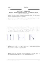
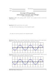
<strong>Fundamentals</strong> <strong>of</strong> <strong>Circuits</strong> <strong>IV</strong>: Kirchh<strong>of</strong>f’s Circuit Rules v 0.3VV+−+−(a)(b)Figure 3: Two possible but not necessarily correct ways to connect a multimeter to measurevoltage - (a) in series with a bulb, and (b) in parallel with a bulb.Question 1.3 If the multimeter is connected correctly to measure the voltage across a bulb, itshould not cause any significant change in the current through the bulb. Which circuit in Fig. 3shows the correct way to connect a multimeter? Explain why, based on your observations.Question 1.4 Does the multimeter set to measure voltage act as a large resistance, or a smallresistance? Explain, based on your observations. Why does it need to be designed this way?The three quantities that are important in the analysis <strong>of</strong> electric circuits are current,voltage, and resistance. In the previous two activities you have used the multimeter to measurecurrent and voltage. You will now learn to use the multimeter to measure resistance.In the previous labs you discovered that a light bulb is not an ohmic device - its resistancechanges as more current passes through it. In contrast, a resistor is made out <strong>of</strong> materials suchthat its resistance varies by only a negligible amount when the current changes.The most common kind <strong>of</strong> electrical resistor contains a form <strong>of</strong> carbon, known as graphite,suspended in a hard glue binder. It usually is surrounded by a plastic case with a color codepainted on it. It is instructive to look at samples <strong>of</strong> carbon resistors that have been cut downthe middle as shown in Fig. 4.If the potential difference in a circuit is measured in volts and the current in amperes, theresistance is measured in ohms, represented by the capital Greek letter Ω.A carbon resistor is usually marked with colored bands. These bands tell you the value<strong>of</strong> the resistance and the tolerance (the accuracy <strong>of</strong> the given value <strong>of</strong> the resistor). Thevalue <strong>of</strong> the resistance is given to two significant figures. The first two bands indicate thetwo significant digits <strong>of</strong> the value <strong>of</strong> the resistance, with different colors indicating numbers 0through 9 according to the following table.PHYS-204:Physics II Laboratory 4
<strong>Fundamentals</strong> <strong>of</strong> <strong>Circuits</strong> <strong>IV</strong>: Kirchh<strong>of</strong>f’s Circuit Rules v 0.3Activity 1.3: Reading Resistor Codes and Measuring ResistanceStep 1: Choose three resistors <strong>of</strong> different values, and read their color codes. Record theresistances and tolerances in the first two columns <strong>of</strong> Table ??.R from code (Ω) Tolerance from code Measured R (Ω) Percent discrepancyTable 2: Resistance, Tolerance & AccuracyStep 2: After setting the multimeter to measure ”resistance”, measure the resistance <strong>of</strong> eachresistor, and enter the values in the table in the column labeled ”Measured R.”Step 3: Determine the percentage difference between the coded value <strong>of</strong> each resistor and thevalue you measured. In general, percentage difference is given by the expressionPercent difference =Accepted value - Experimental value∣ Accepted value ∣ ×100Question 1.5 How do the values <strong>of</strong> the resistors measured with the multimeter compareto the values indicated by the color code? Assuming that your measured values are correct,are the values indicated by the color code within the stated tolerance?Investigation 2:Series and Parallel Combinations <strong>of</strong> ResistorsSeveral resistors can be wired in series to increase the effective length and in parallel to increasethe effective cross sectional area <strong>of</strong> the resistive graphite, as shown in Fig. 6.You will next explore the equivalent resistances <strong>of</strong> various combinations <strong>of</strong> resistors connectedin series or in parallel. You will need the following:• Three 56Ω resistors• 22Ω and 68Ω resistors• digital multimeter• Pasco circuit board• connecting wiresPHYS-204:Physics II Laboratory 6
<strong>Fundamentals</strong> <strong>of</strong> <strong>Circuits</strong> <strong>IV</strong>: Kirchh<strong>of</strong>f’s Circuit Rules v 0.3Step 4: Connect all three resistors in series. Measure the resistance <strong>of</strong> the combination usingthe multimeterMeasured resistance <strong>of</strong> R 1 , R 2 , and R 3 in series = Ω.Question 2.3 How do the measured values compare with your predictions for two andthree resistors in series? If the measured values do not agree with your predicted ones,devise a new rule that describes the equivalent resistance when n resistors are wired inseries. Use the notation R eq to represent the equivalent resistance and R 1 ,R 2 ,R 3 ,...R nto represent the values <strong>of</strong> the individual resistors.Question 2.4 Does your rule agree with your observations in this activity, and in previouslabs, that the current through two identical resistors connected in series is half thecurrent through a single resistor connected to the same battery? Explain why this mightbe so.Activity 2.2: Equivalent resistance <strong>of</strong> resistorsconnected in parallel<strong>Pre</strong>diction 2.2 If you have the values for three different carbon resistors, what would bethe total resistance to the flow <strong>of</strong> electrical current if the resistors are wired in parallel?Explain, based on your previous observations with batteries and bulbs.Question 2.5 Using the method you gave as your prediction 2.2, calculate the equivalentresistance if R 1 and R 2 are connected in parallel:<strong>Pre</strong>dicted resistance <strong>of</strong> R 1 and R 2 in parallel = Ω.Step 5: Connect R 1 and R 2 in parallel. Measure the resistance <strong>of</strong> the combination using themultimeterMeasured resistance <strong>of</strong> R 1 and R 2 in parallel = Ω.Question 2.6 Using the method you gave as your prediction 2.2, calculate the equivalentresistance if all three resistors are connected in parallel.<strong>Pre</strong>dicted resistance <strong>of</strong> R 1 , R 2 , and R 3 in parallel = Ω.Step 6: Draw a diagram for the resistance network for the three different resistors wired inparallel. Above each resistor symbol write the measured value <strong>of</strong> the resistance.PHYS-204:Physics II Laboratory 8
<strong>Fundamentals</strong> <strong>of</strong> <strong>Circuits</strong> <strong>IV</strong>: Kirchh<strong>of</strong>f’s Circuit Rules v 0.3Question 2.10 Using the method you gave as your prediction 2.2, calculate the equivalentresistance if R 1 , R 4 and R 5 are connected in parallel. Show your calculation. Does this valueagree with your measured value, within a few per cent?<strong>Pre</strong>dicted resistance <strong>of</strong> R 1 , R 4 and R 5 in parallel =ΩInvestigation 3:Kirchh<strong>of</strong>f’s Circuit RulesIn complex circuits with many components and branches, a simplified analysis in terms <strong>of</strong> seriesand parallel combinations is <strong>of</strong>ten impossible. Instead we can state and apply a formal set <strong>of</strong>rules known as Kirchh<strong>of</strong>f’s laws to use in the analysis <strong>of</strong> current flow in circuits.We first need to define the terms ”junction” and ”branch”. Fig. 7 illustrates what we meanby these terms. As shown in Fig. 7(a), a junction is a point where two or more wires areconnected together. Different amounts <strong>of</strong> current can flow in each <strong>of</strong> the wires connected at thejunction. As shown in Fig. 7(b), a branch is a portion <strong>of</strong> a circuit such that all the elementsin the branch are in series. Thus the current is the same through every circuit element in thebranch.junction 1R 3++(a) V 1 R 2 V 2−−R 1junction 2branch 1R 3branch 2++(b) V 1 V 2−−R 1R 2branch 3Figure 7: Junctions and branches <strong>of</strong> a circuit, as referred to in Kirchh<strong>of</strong>f’s RulesThese rules can now be stated as follows:PHYS-204:Physics II Laboratory 10
<strong>Fundamentals</strong> <strong>of</strong> <strong>Circuits</strong> <strong>IV</strong>: Kirchh<strong>of</strong>f’s Circuit Rules v 0.31. Junction (or node) Rule (based on charge conservation): The sum <strong>of</strong> all the currentsentering any junction <strong>of</strong> a circuit must equal the sum <strong>of</strong> all currents leaving the junction.2. Loop Rule (based on energy conservation): Around any closed loop in a circuit, the sum<strong>of</strong> all changes in potential (voltage gains provided by batteries or other power sources andall the potential drops across resistors and other circuit elements) must equal zero.Steps for Applying Rules:1. Assign a current symbol to each branch <strong>of</strong> the circuit and label the current in each branchI 1 , I 2 , I 3 , etc.; then assign a direction to each current. (The direction chosen for thecircuit for each branch doesn’t matter. If you chose the ”wrong” direction, the value <strong>of</strong>the current will simply turn out to be negative.) Remember that the current flowing out<strong>of</strong> a battery is always the same as the current flowing into a battery.2. Apply the loop rule to each <strong>of</strong> the loops by (a) letting the potential drop across eachresistor be the negative <strong>of</strong> the product <strong>of</strong> the resistance and the net current through thatresistor. That is, a battery can do ”work” pushing current through a circuit, and eachtime the current is pushed through a resistor, some <strong>of</strong> that work is used up (”lost”).Reverse the ”minus” sign to ”plus” if you are traversing a resistor in a direction oppositethat <strong>of</strong> the current; (b) assigning a positive potential difference when the loop traversesfrom the − to the + terminal <strong>of</strong> a battery. (If you are going through a battery in theopposite direction, assign a negative potential difference to the trip across the batteryterminals.)3. Find each <strong>of</strong> the junctions and apply the junction rule to it. You can place currentsleaving the junction on one side <strong>of</strong> the equation and currents coming into the junction onthe other side <strong>of</strong> the equation.In order to illustrate the application <strong>of</strong> the rules, let’s consider the circuit in Fig. 8.I 1I 3R 3I 3I 2++V 1 R 2V 2−−I 1R 1Figure 8: A complex circuit in which loops 1 and 2 share the resistor R 2 . The currents I 1 andI 3 flow through R 2 in opposite directions and the net current through R 2 is denoted by I 1 .Question 3.1 Are the resistors R 1 and R 2 in series? in parallel? Why or why not?PHYS-204:Physics II Laboratory 11
<strong>Fundamentals</strong> <strong>of</strong> <strong>Circuits</strong> <strong>IV</strong>: Kirchh<strong>of</strong>f’s Circuit Rules v 0.3In Fig. 8, the directions for the currents through the branches and for I 2 are assignedarbitrarily. If the internal resistances <strong>of</strong> the batteries are negligible, then by applying the loopand junction rules we find that:Loop 1: V 1 − I 2 R 2 − I 1 R 1 = 0 (1)Loop 2: −V 2 + I 2 R 2 + I 3 R 3 = 0 (2)And applying the junction rule gives usJunction 1: I 1 + I 3 = I 2 (3)It is not obvious that the loops and their directions can be chosen arbitrarily.Let’s explore this assertion theoretically for a simple situation and then more concretelywith some specific calculations. In order to do the following activity you’ll need a couple <strong>of</strong>resistors and a multimeter as follows:• 1 carbon resistor, 39Ω• 1 carbon resistor, 68Ω• Circuit board with variable resistor• 1 multimeter• 1 battery, 6V• connecting wiresActivity 3.1: Applying the Loop and Junction Rules again.Fig. 9 shows the same circuit as Fig. 8, but with different choices <strong>of</strong> directions for the loops andcurrent through R 2 .I 1I 3R 3I 3++V 1 R 2V 2−−I 2I 1R 1Figure 9: A circuit identical to that in Fig. 8, but showing opposite direction for the loops, andopposite choice for the positive direction <strong>of</strong> current flowing through R 2 .Step 1: Use the loop and junction rules along with the new direction chosen for I 2 to rewritethe three equations relating values <strong>of</strong> battery voltages, resistance, and current in thecircuit shown in Fig. 9.PHYS-204:Physics II Laboratory 12
<strong>Fundamentals</strong> <strong>of</strong> <strong>Circuits</strong> <strong>IV</strong>: Kirchh<strong>of</strong>f’s Circuit Rules v 0.3Step 2: Show that if the I 2 <strong>of</strong> Fig. 9 = −I 2 <strong>of</strong> Fig. 8, then the three equations you justconstructed can be rearranged algebraically so they are exactly the same as equations(1), (2), and (3).Step 3: Since you are going to test your theoretical results for Kirchh<strong>of</strong>f’s law calculations forthis circuit experimentally, you should measure the actual values <strong>of</strong> the two fixed resistors(rated at 68,Ω and 39Ω) and the two battery voltages with a multimeter. List the resultsbelow.Measured voltage <strong>of</strong> the battery rated at 6 V: V 1 = VoltsMeasured voltage <strong>of</strong> the battery rated at 1.5 V: V 2 = VoltsMeasured resistance <strong>of</strong> the resistor rated at 68Ω: R 1 = ΩMeasured resistance <strong>of</strong> the resistor rated at 39Ω: R 3 = Ω.Step 4: Rewrite Equations (1), (2) and (3) with the appropriate measured (not rated) valuesfor voltage and resistances substituted into them. Use 25Ω for the value <strong>of</strong> R 2 in yourcalculation. In the experiment, you will be setting a variable resistor to a value <strong>of</strong> 25Ω.Step 5: Solve these three equations for the three unknowns I 1 , I 2 , and I 3 in amps. Show yourcalculation in the space below.Question 3.2 Do the currents you have calculated satisfy the junction and loop equations?Show by substitution back into equations (1), (2), and (3).Now you can verify your Kirchh<strong>of</strong>f’s rules solutions for this circuit.Activity 3.2: Testing Kirchh<strong>of</strong>f’s Rules with a real circuitStep 1: Use the resistance mode <strong>of</strong> the digital multimeter to measure the resistance betweenthe center connection to the variable resistor and one <strong>of</strong> the other connections. WhatPHYS-204:Physics II Laboratory 13
<strong>Fundamentals</strong> <strong>of</strong> <strong>Circuits</strong> <strong>IV</strong>: Kirchh<strong>of</strong>f’s Circuit Rules v 0.31.2.3.Measured Measured Measured TheoreticalR (Ω) ∆V (volts) I = ∆V/R (amps) I (amps)Table 3:Percent discrepancyhappens to the resistance as you turn the knob on the variable resistance clockwise?Counterclockwise?Step 2: Set the variable resistor so that there is 25Ω between the center connection and one<strong>of</strong> the other connections.Step 3: Construct the circuit pictured in Fig. 8, using the variable resistor set at 25Ω as R 2 .Step 4: Use the multimeter to measure the current in each branch <strong>of</strong> the circuit and enter yourdata in table 2. Compare the measured and calculated values <strong>of</strong> the current by computingthe percent difference in each case.Note: The most accurate and quickest way to measure current with a digital multimeteris to measure the potential difference across each <strong>of</strong> the resistors and use Ohm’s law tocalculate I from ∆V and R.Question 3.3 How well do your measured currents agree with the theoretical values calculatedusing Kirchh<strong>of</strong>f’s rules? The multimeter is accurate to about 3%. Do your calculatedand measured values agree to this accuracy?<strong>Pre</strong>diction 3.1 What do you predict will happen to each <strong>of</strong> the currents as the resistance<strong>of</strong> the variable resistor is decreased? That is, will the currents I 1 , I 2 , and I 3 increase ordecrease? Explain your predictions.Step 5: Decrease R 2 by turning the knob on the variable resistor. How good were your predictions?This laboratory exercise has been adapted from the references below.PHYS-204:Physics II Laboratory 14